
SECTION 2C - CAB & INTERIOR TRIM
Windshield
Rear Window Assembly
Front Door Assembly
Rear Door Assembly (Crew Cab)
Instrument Panel
Floor Console
Headlining
Interior Trim Panels
Fuel Filler Lid Opener Lever/Cable
Quarter Glass (Extend Cab)
Front Seat
Rear Seat (Crew Cab)
Jump Seat (Extend Cab)
Front Seat Belt
Rear Seat Belt (Crew Cab)
Rear Seat Belt (Extend Cab)
Front Wheel Extension
Rear Wheel Extension
Tail Gate Assembly
Techline
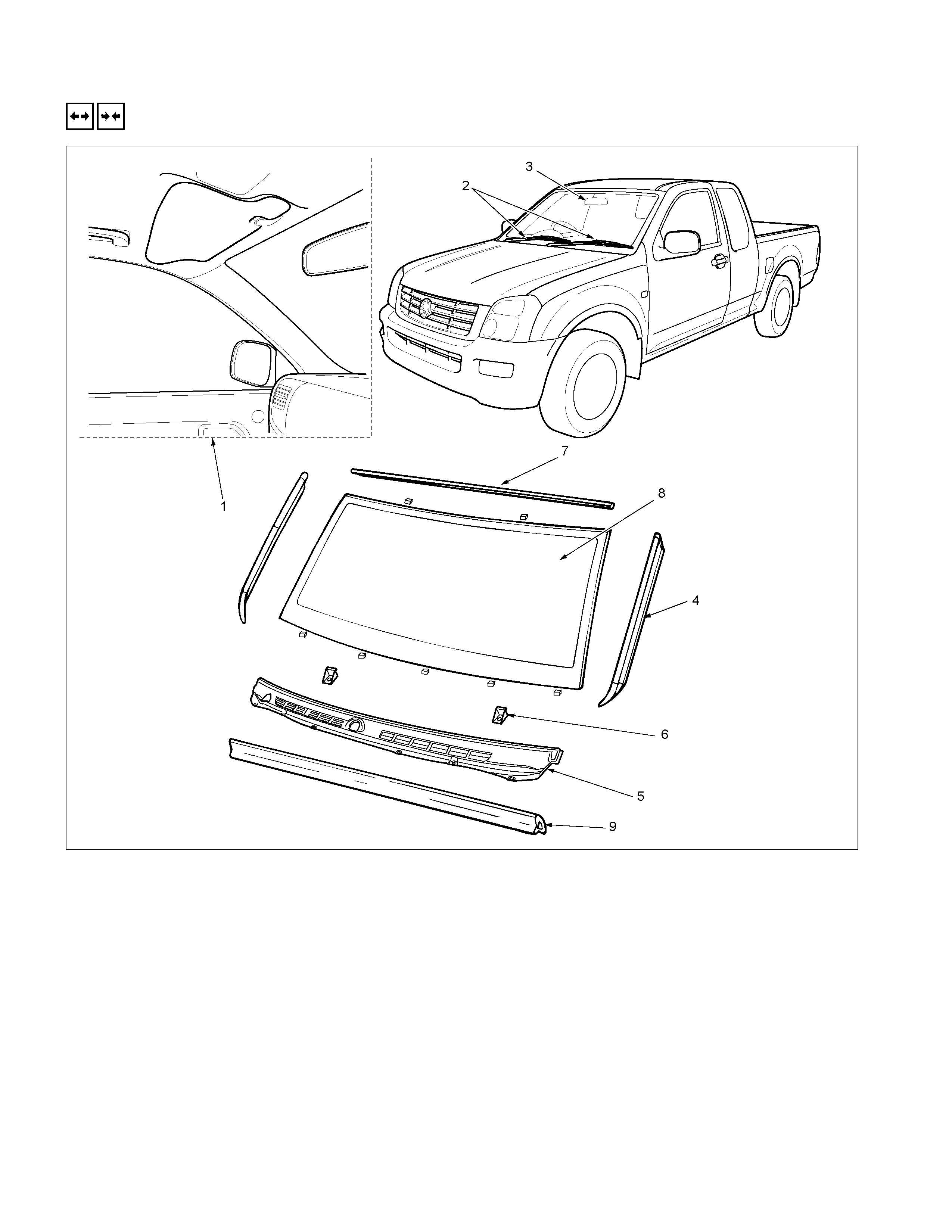
WINDSHIELD
REMOVAL A ND INSTALLATION
RTW3A0LF0002C1
Removal Steps
1. Interior trim panels (Front side)
/Headlining/Instrument panel assembly
2. Wiper arm assembly
▲ 3. Room mirror
4. Side moulding
5. Vent cowl cover
6. Windshield stopper
7. Upper moulding
▲ 8. Windshield glass
9. Engine hood rear seal
Installation Steps
▲ 9. Engine hood rear seal
▲ 8. Windshield glass
7. Upper moulding
6. Windshield stopper
5. Vent cowl cover
▲ 4. Side moulding
3. Room mirror
▲ 2. Wiper arm assembly
1. Interior trim panels (Front side)
/Headlining/Instrument panel assembly
Important Operations - Removal
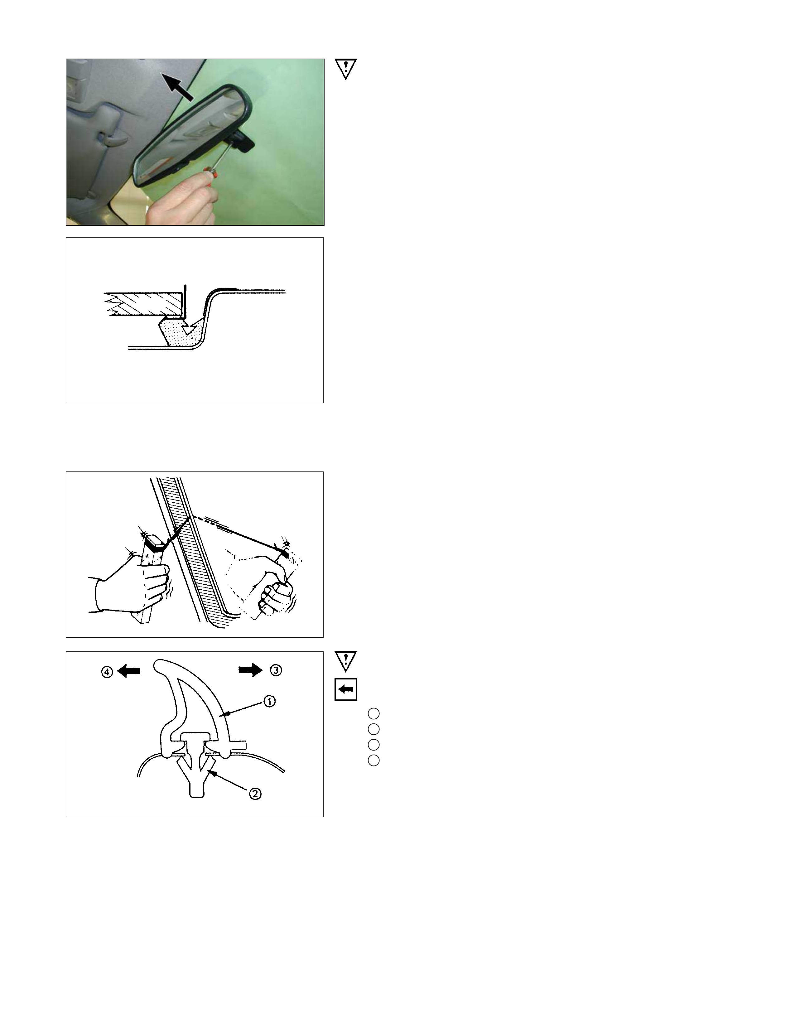
3. Room Mirror
Remove the screw and pull the room mirror to upper side.
8. Windshield Glass
Remove the windshield glass, carefully following the steps
listed below:
1) Use a knife to cut through part of the adhesive caulking
material.
2) Secure one end of a piece of steel piano wire (0.02 inches
in diameter) to a piece of wood that can serve as a handle.
3) Use a pair of needle nose pliers to insert the other end o
f
the piano wire thr ough the adhesive caulk ing m aterial at the
edge of the windshield glass.
4) Secure the other end of the piano wire to another piece o
f
wood.
5) With the aid of an assistant, carefully move the piano wire
with a sawing motion to cut through the adhesive caulking
material around the entire circumference of the windshield
glass.
6) Lift the windshield from the body.
7) Clean any remaining adhesive caulking material from the
area of the body which holds the windshield.
8) Use a soft rag and unleaded gasoline to wipe off an
y
adhesive remaining on the windshield glass.
Important Operations - Installation
9. Engine Hood Rear Seal
Install the engine hood rear seal as shown in the illustration.
1 : Seal
2 : Clip
3 : Rear (windshield glass side)
4 : Front
RTW3A0SH000201
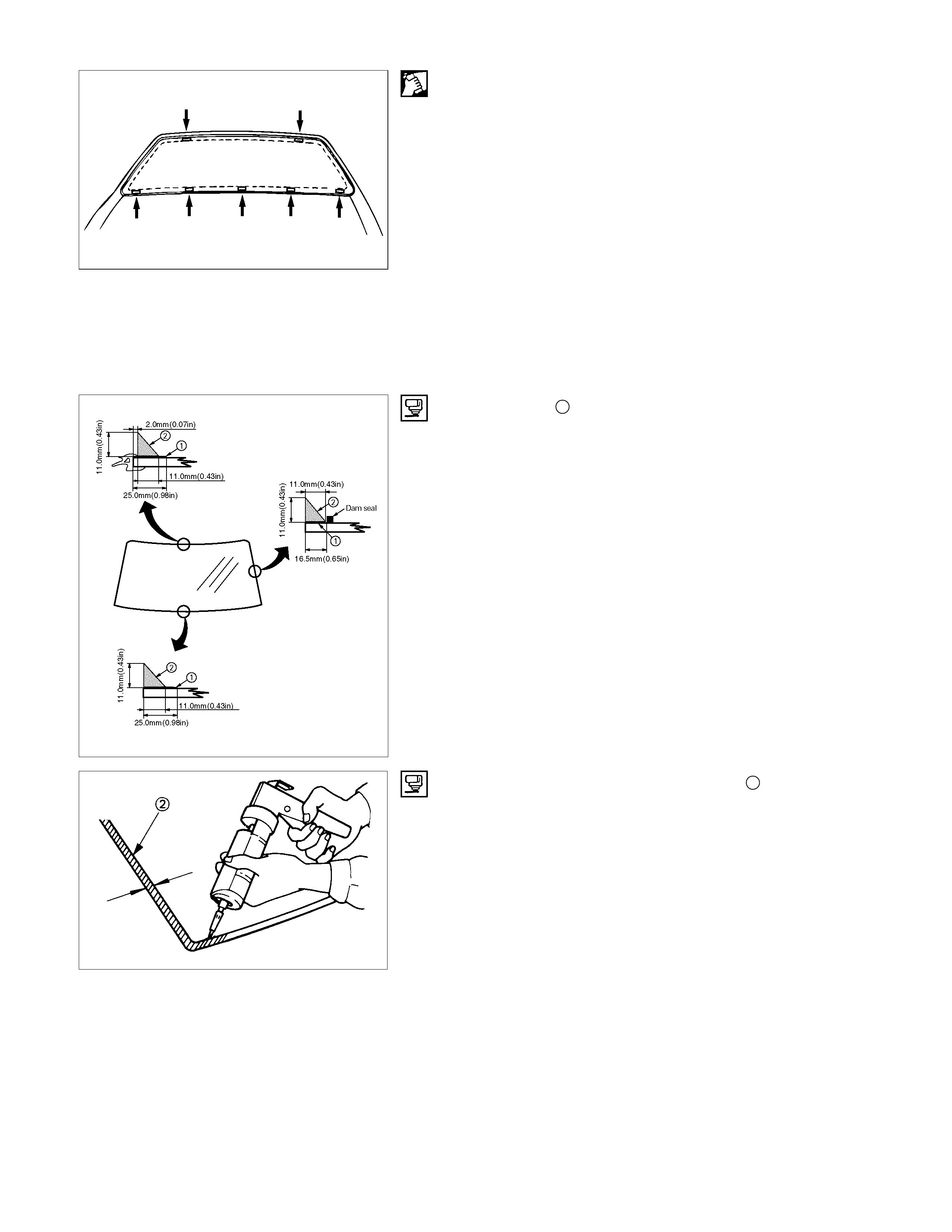
8. Windshield Glass
1) Clean the windshield glass bonding surface.
2) Use a soft rag and unleaded gasoline to wipe off an
y
adhesive remaining on the body.
3) Mount the body window glass as shown in the illustration.
Attach spacers at seven locations.
• Always use new spacer.
4) Install the windshield upper molding.
• Peel off the tear-away paper from the windshield uppe
r
molding, and start applying it with one end of the glass
and cut away the surplus at the other end of the glass
for length adjustment.
• Always use new upper molding.
5) Temporarily install the windshield support.
6) Apply primer 1 Sunstar #435-98 or equivalent to the bod
y
side bonding surf ace. T he prim er should extend at leas t 25
mm (1 in).
Apply primer Sunstar #435-40 or equivalent to the
windshield glass side bonding surface.
The primer s hould extend 16.5 m m ( 0.6 in) and 25 m m ( 1.0
in) from end of the glass.
7) Apply the window glass sealing adhesive 2.
If you are using an air gun, air pressure should be
maintained at 147 - 294 kPa.
After drying primer completely, apply a sealing adhesive
(Sunstar #557 or equivalent) along the edge of the glass so
that the sealing adhesive has a 20 m m (0.79 in) junction at
middle of the vase of the glass.
Note :
Open time (1 min. or more) should be set after application
of the primer.
Bonding shall be done within 5 minutes after the sealing
adhesive has been applied.
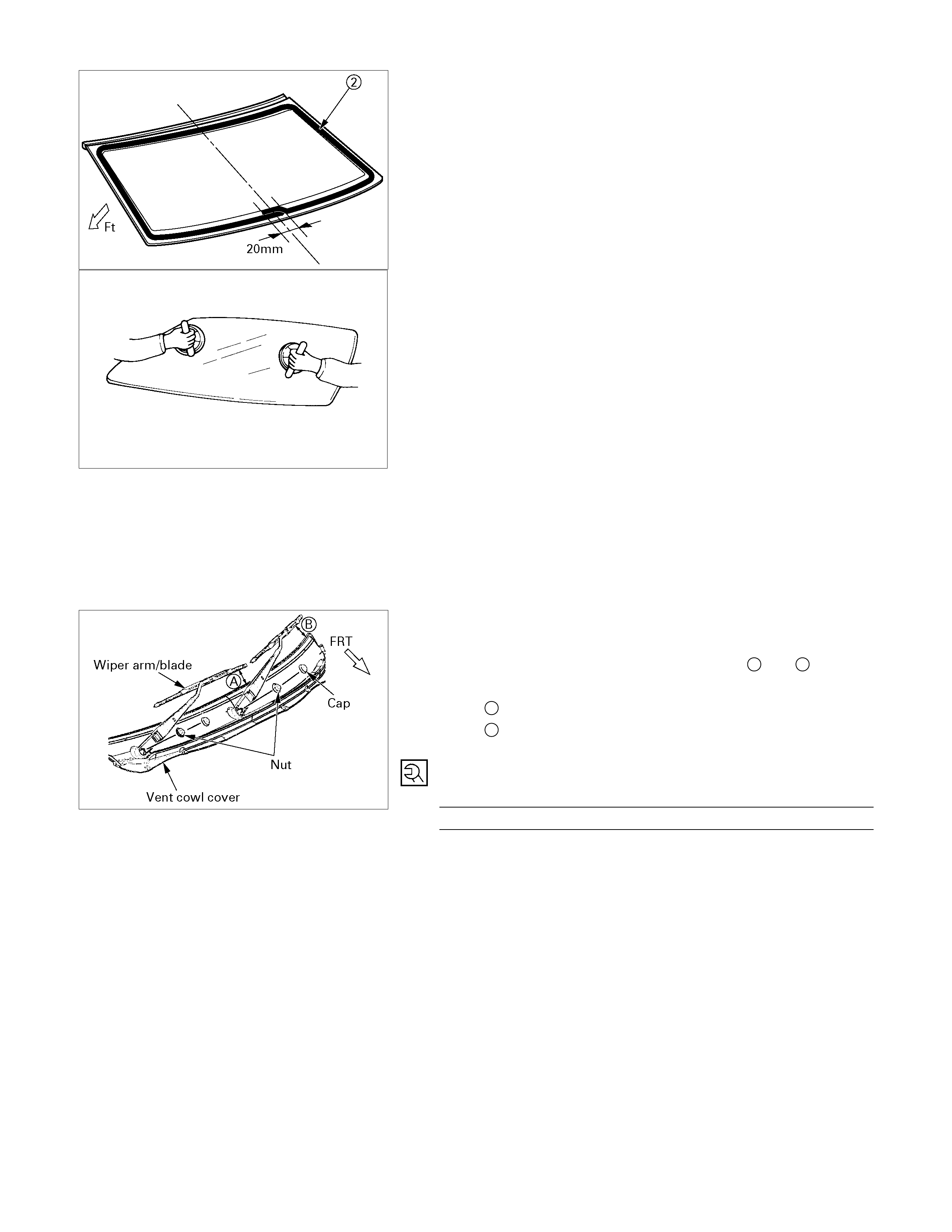
8) Adjust the setting of the windshield glass with suction discs.
Set the windshield with sealing adhesive applied to entire
circumference in the body panel. Specifically, adjust
windshield support with the upper molding making contact
with the body panel, press the glass, and tighten the
windshield support.
9) Use unleaded gasoline and a soft cloth to wipe away an
y
excess adhesive.
Cure the bonding at a temperature of 68° - 86°F (20° -
30°C) for twenty-four hours.
Check that the windshield does not leak water.
1. Wiper Arm Assembly
• Set the wiper arm/blade so that the tips of both blades
are positioned the specified value of A and B from the
upper edge of the cowl cover as shown in the figure.
A 40 mm (1.57 in)
B 52 mm (2.05 in)
• Tighten the wiper arm assembly fixing nuts to the
specified torque.
Torque N⋅m (kgf⋅m/lb⋅ft)
31 (3.1/23)
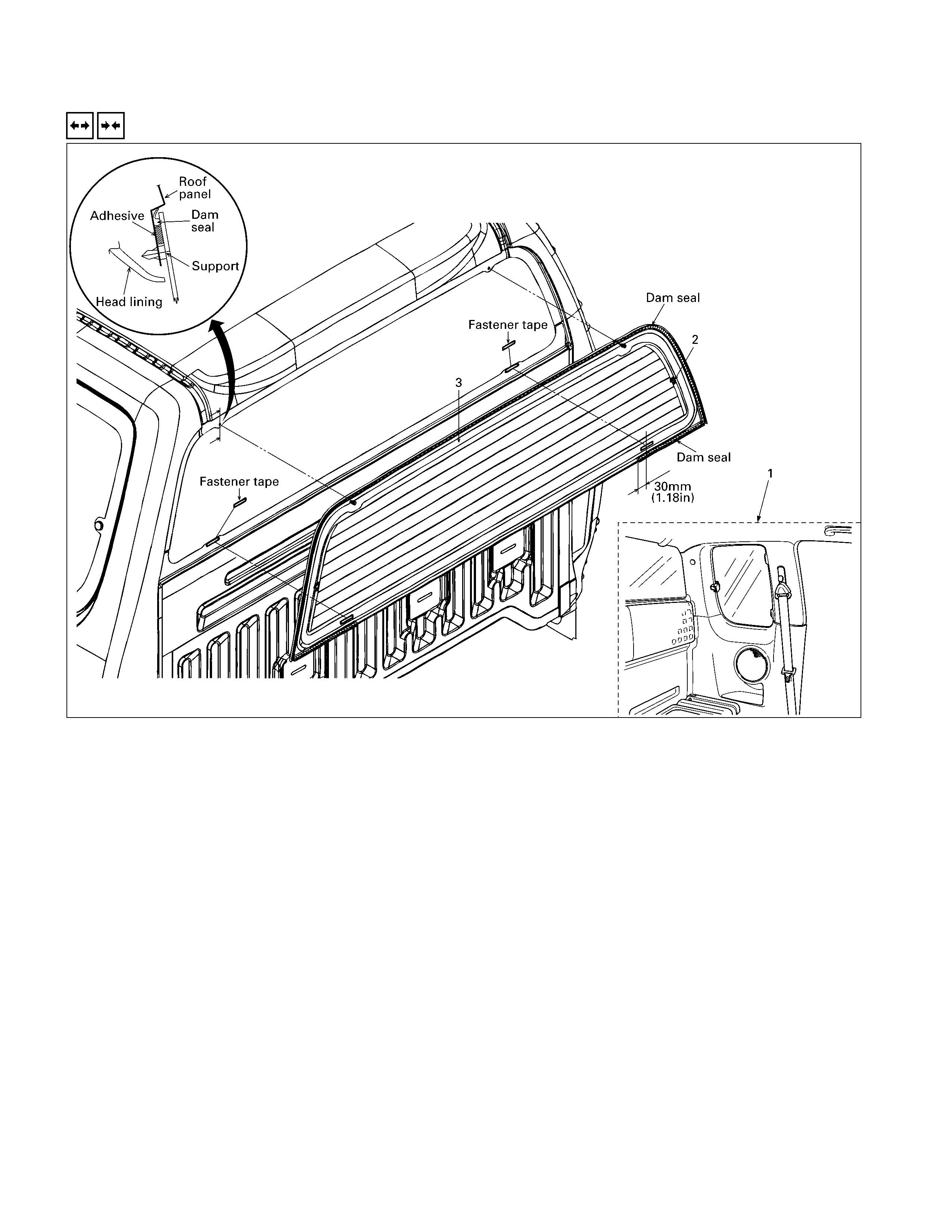
REAR WINDOW ASSEMBLY
REMOVE AND INSTALLATION
Removal Steps
1. Interior trim panels/Headlining
2. Rear defogger connector (W/Rear
defogger)
▲ 3. Rear window
Installation Steps
▲ 3. Rear window
2. Rear defogger connector (W/Rear
defogger)
1. Interior trim panels/Headlining
Important Operation - Removal
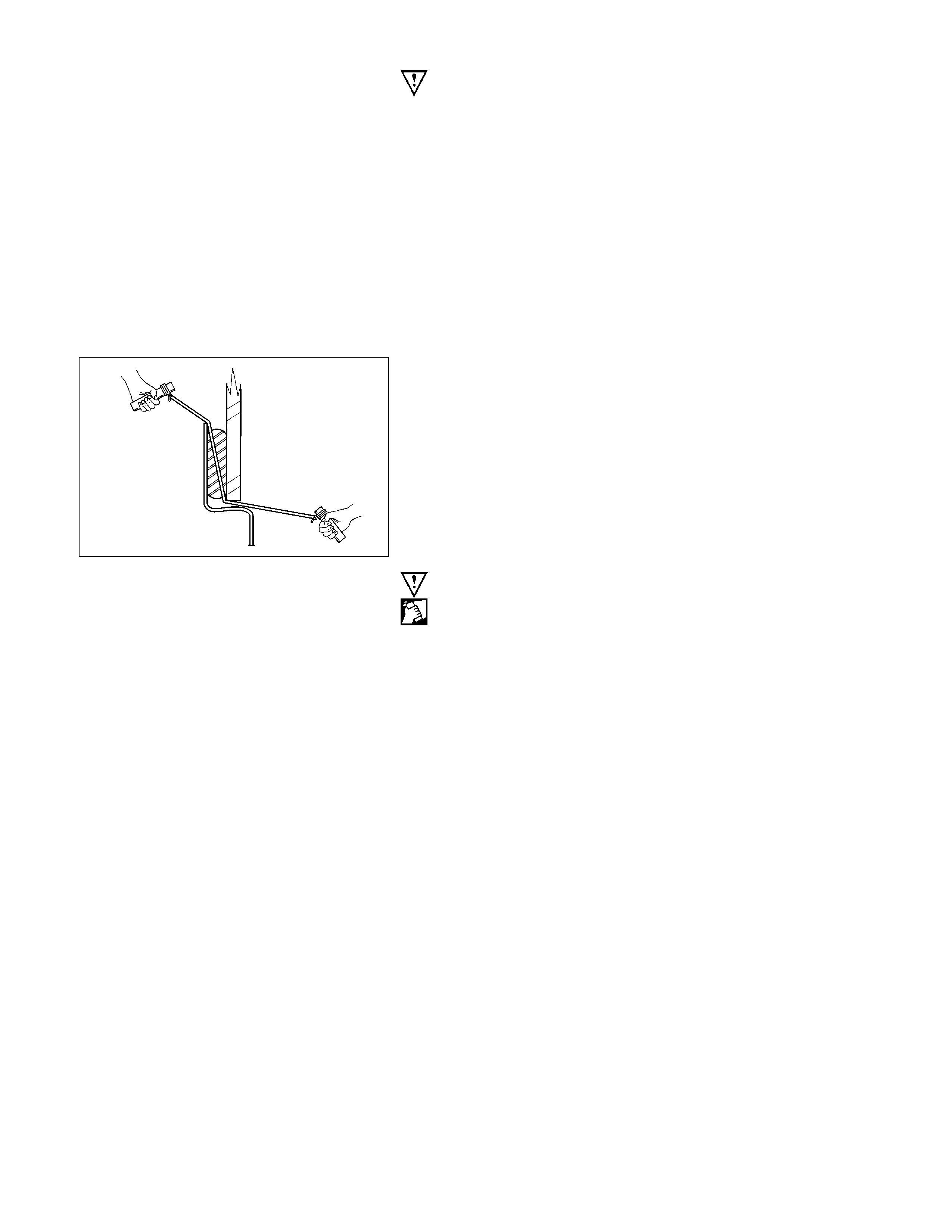
3. Rear Window Glass
Remove the glass, carefully following the steps listed below :
1) Use a knife to cut through part of the adhesive caulking
material.
2) Secure one end of a piece of steel piano wire (0.02 inches
in diameter) to a piece of wood that can serve as a handle.
3) Use a pair of needle nose pliers to insert the other end o
f
the piano wire thr ough the adhesive caulk ing m aterial at the
edge of the rear window glass.
4) Secure the other end of the piano wire to another piece o
f
wood.
5) With the aid of an assistant, carefully move the piano wire
with a sawing motion to cut through the adhesive caulking
mater ial around the entir e c irc umfer ence of the r ear windo
w
glass.
6) Lift the rear window glass from the body.
7) Clean any remaining adhesive caulking material from the
area of the body which holds the rear window glass.
8) Use a soft rag and unleaded gasoline to wipe off an
y
adhesive remaining on the rear window glass.
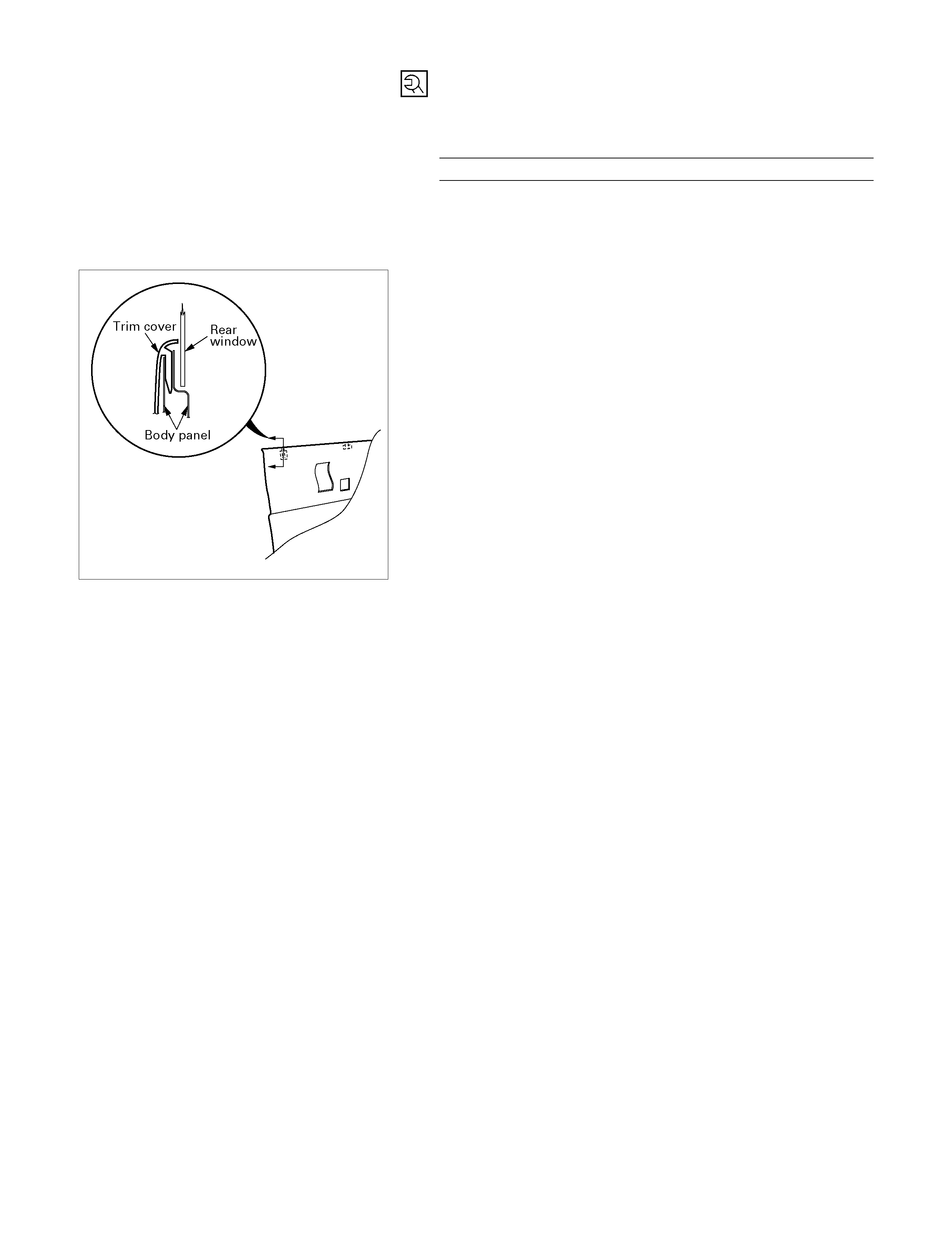
Important Opera tion - Installation
3. Rear Window Glass
1) Clean the rear window glass bonding surface.
2) Use a soft rag and unleaded gasoline to wipe off an
y
adhesive remaining on the body.
3) Install the fastener tape to body panel flange.
4) Apply primer 1 Sunstar #435-98 or equivalent it to bod
y
side bonding surface.
Apply primer Sunstar #435-40 or equivalent to the rea
r
window glass side bonding surface.
The primer should extend 23 mm (0.9 in.) form end of the
glass.

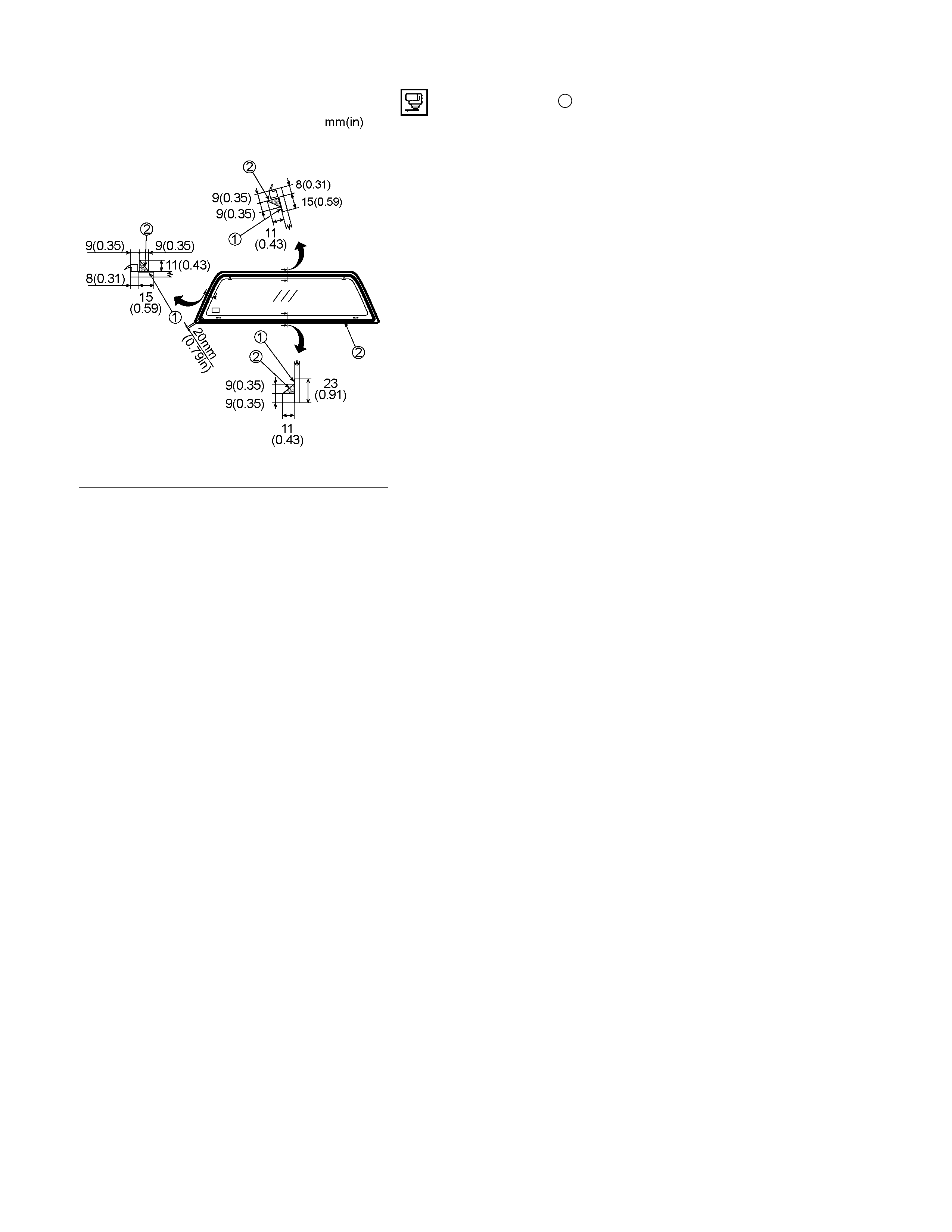
5) Apply the rear window glass sealing adhesive 2.
If you are using an air gun, air pressure should be
maintained at 147 – 294 kPa.
A
fter drying primer completely, apply a sealing adhesive
(Sunstar #557 or equivalent) along the edge of the glass s o
that the sealing adhesive has a 20 m m (0.79 in.) junction at
left corner of the base of the glass.
Note:
Open time (1 min. or more) should be set after application
of the primer.
Bonding shall be done within 5 minutes after the sealing
adhesive has been applied.
6) Insert the glass supports into the panel and then push the
glass against the panel to affix it in place.
Wipe away any adhesive that oozes out around the edges.
7) Check that the rear window glass does not leak water.
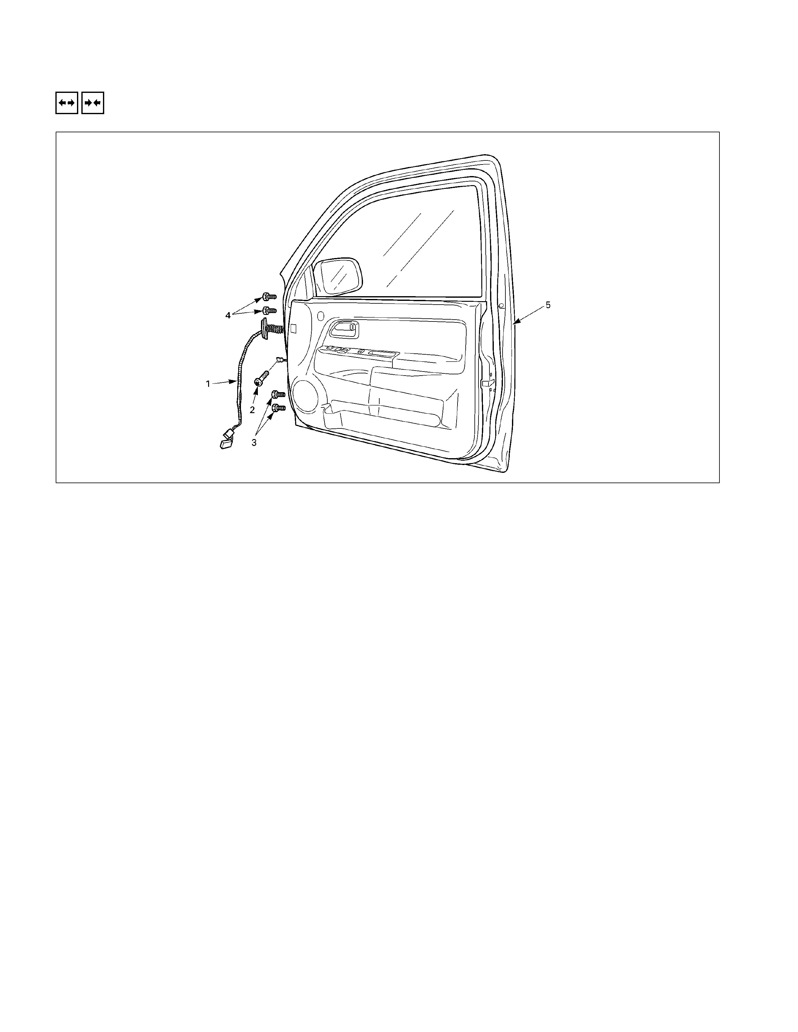
FRONT DOOR ASSEMBLY
REMOVAL A ND INSTALLATION
Removal Steps
▲ 1. Door harness
▲ 2. Checker arm screw
▲ 3. Lower hinge bolt
4. Upper hinge bolt
5. Door assembly
Installation Steps
5. Door assembly
4. Upper hinge bolt
▲ 3. Lower hinge bolt
▲ 2. Check arm screw
1. Door harness
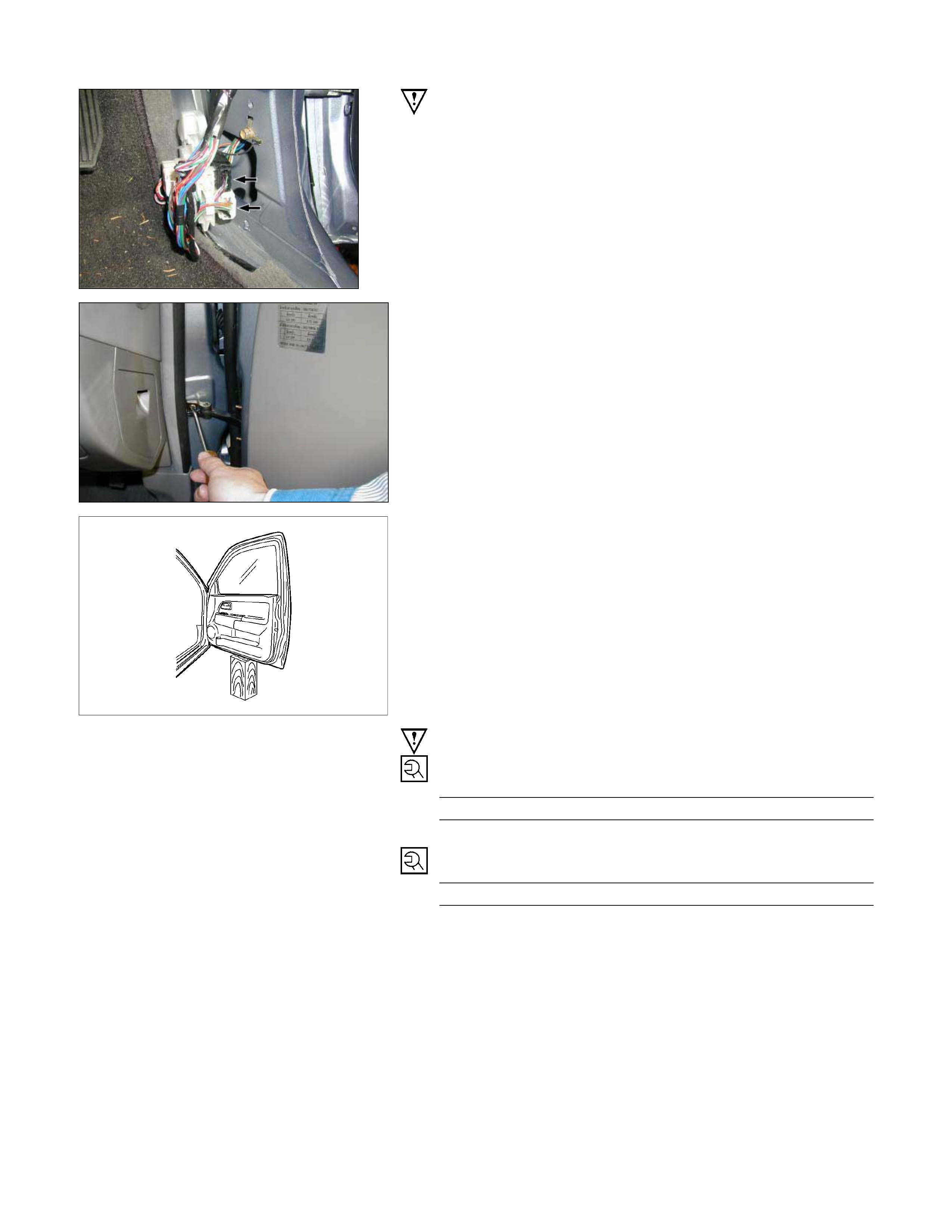
Important Operations - Removal
1. Door Harness
Remove the harness bracket and disconnect the doo
r
harness connectors.
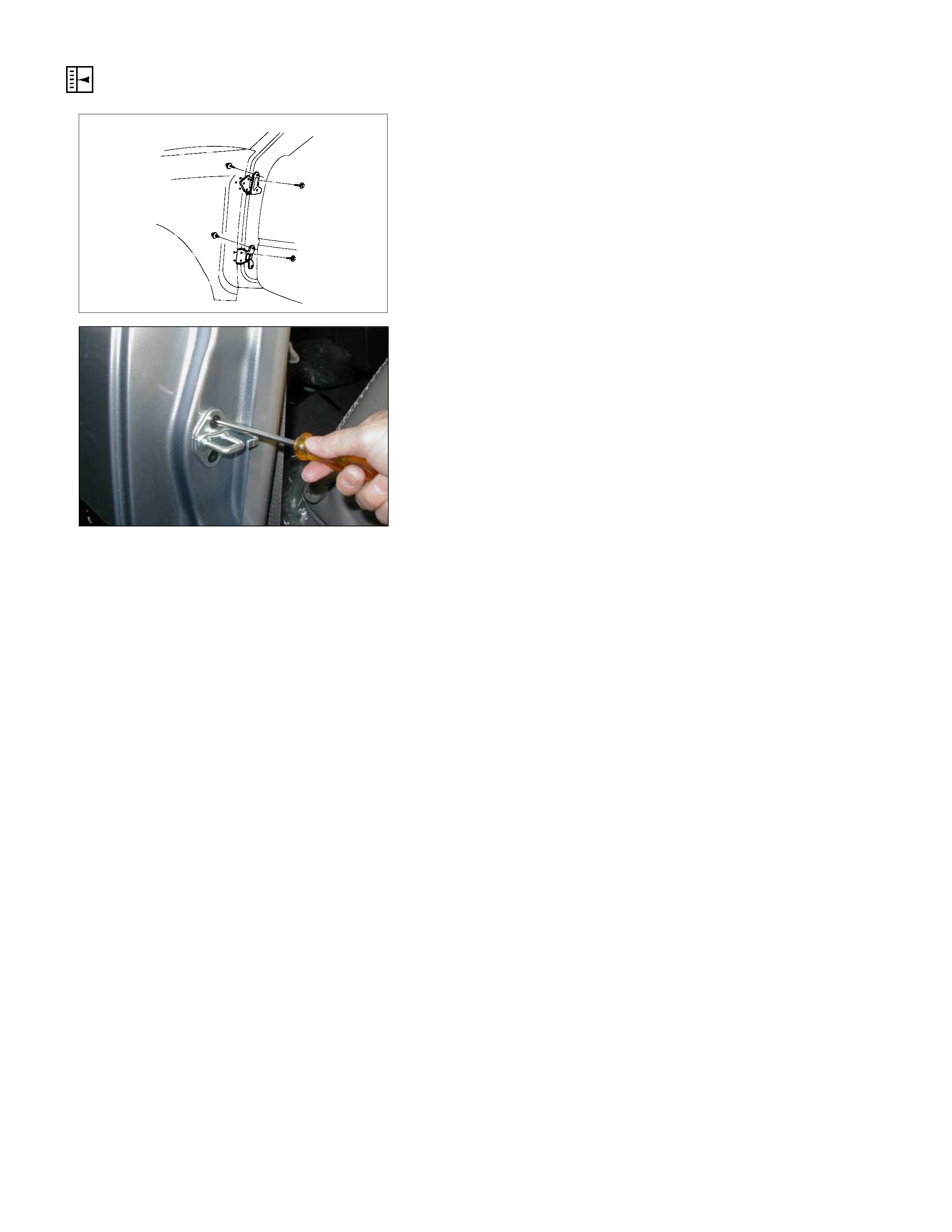
2. Check Arm Screw
3. Lower Hinge Bolt
Position a wood block under the door for protection and
support the door assembly with hands at removal or
installation.
Important Operations – Installation
3. Lower Hinge Bolt; Hinge to Door
Torque N⋅m (kgf⋅m/lb⋅ft)
34 (3.5/25)
2. Check Arm Screw; Check Arm to Body
Torque N⋅m (kgf⋅m/lb⋅ft)
24 (2.4/17)
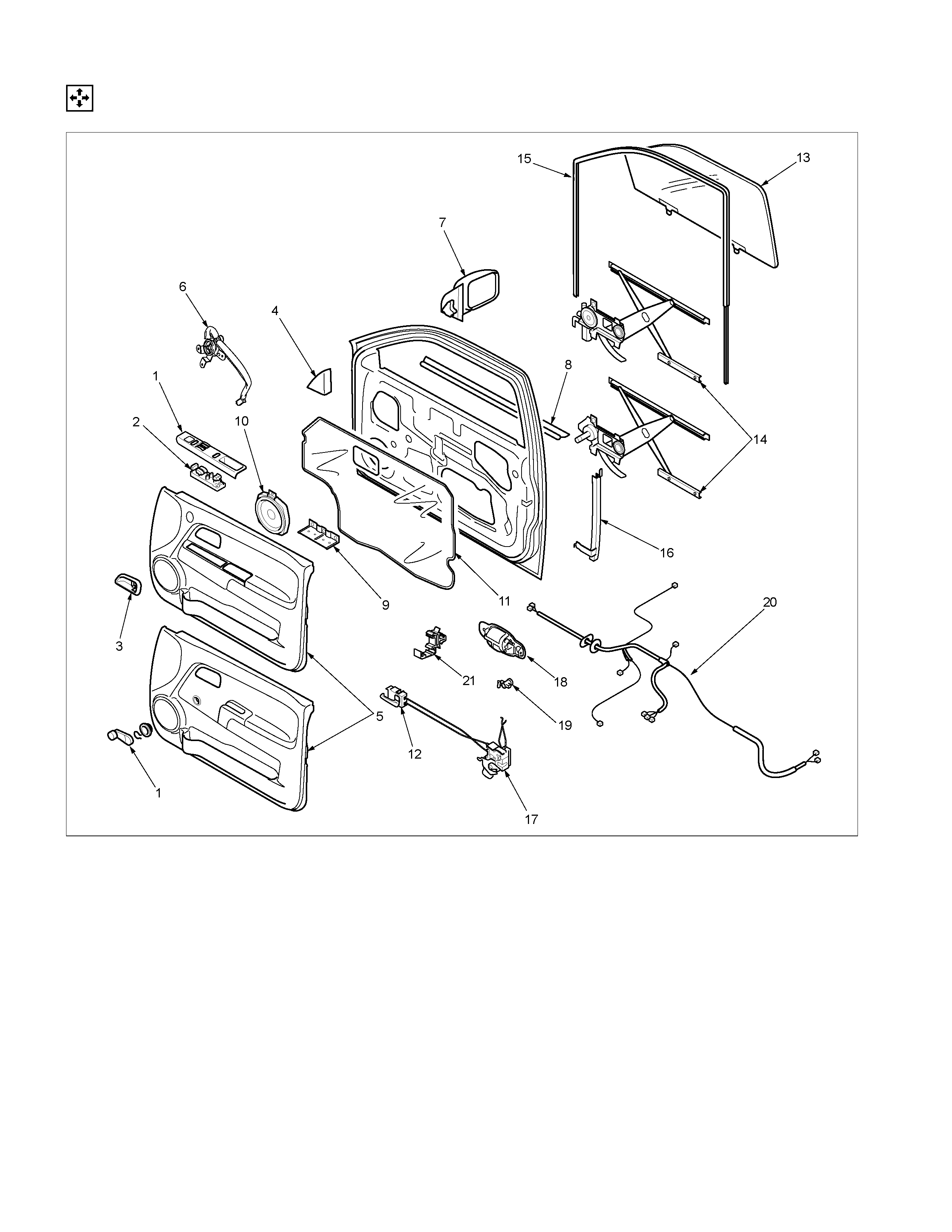
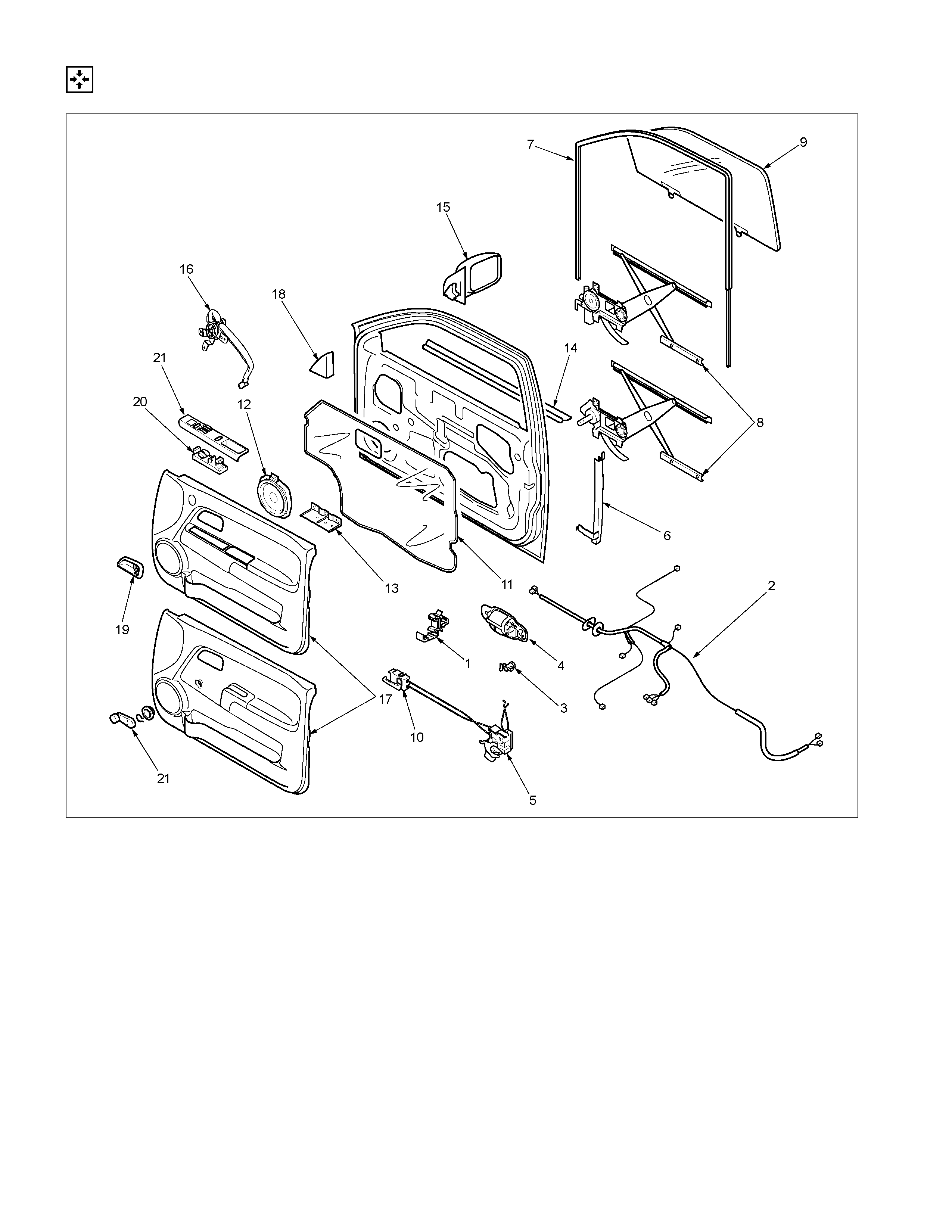
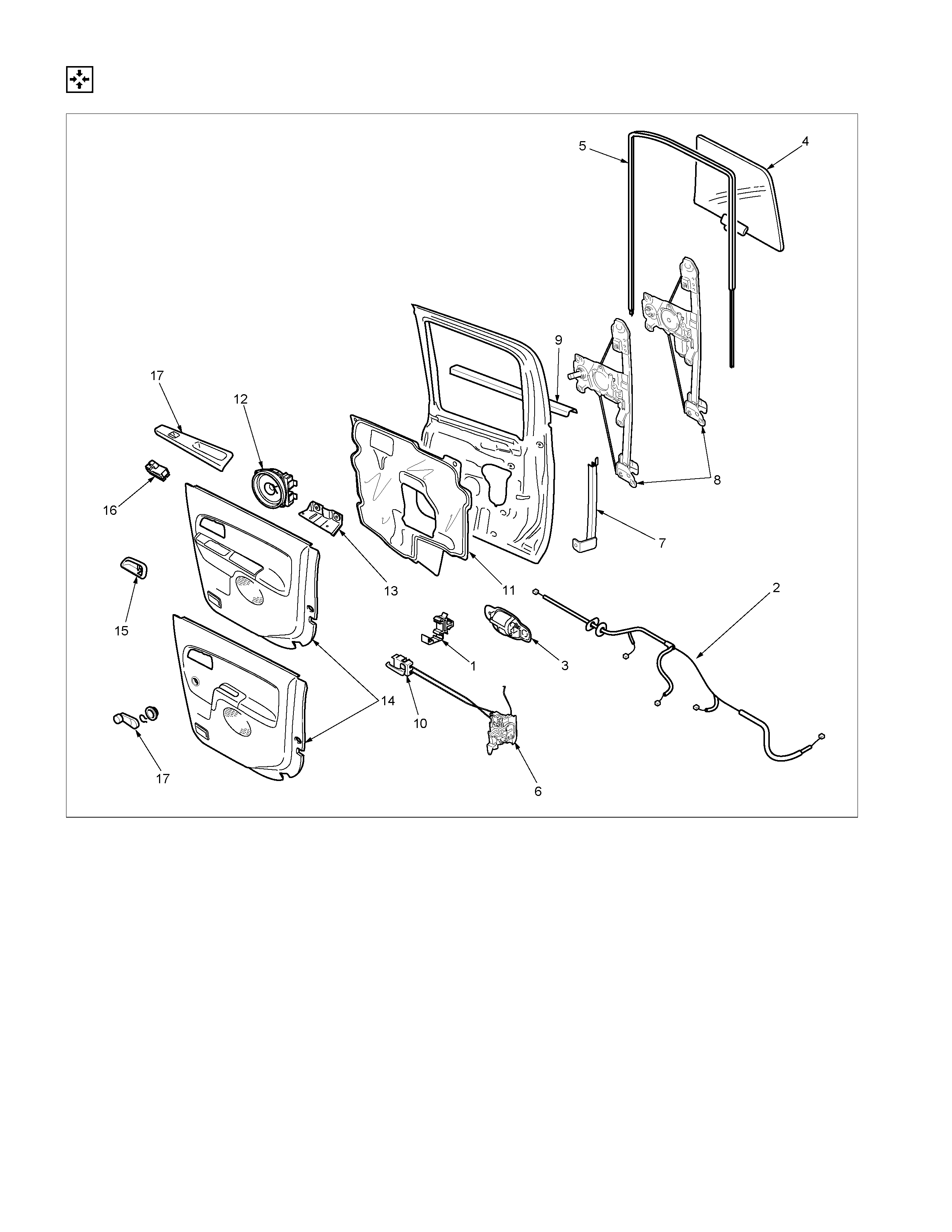
DISASSEMBLY
RTW3A0LF000401
Disassembly Steps
▲ 1. Switch bezel/Window regulator handle
▲ 2. Power window switch
▲ 3. Bezel
▲ 4. Door mirror cove r
▲ 5. Door trim panel
▲ 6. Tweeter (Required Option)
▲ 7. Door mirror assembly
▲ 8. Outer waste seal
▲ 9. Bracket
▲10. Speaker assembly
▲11. Waterproof sheet
▲12. Inside lever
▲13. Window glass
▲14. Window regulator/Power window
regulator
▲ 15. Glass run
▲ 16. Glass run rear channel
▲ 17. Door lock assembly
▲ 18. Outside handle
▲ 19. Door lock cylinder
20. Door harness assembly
21. Anti rattler
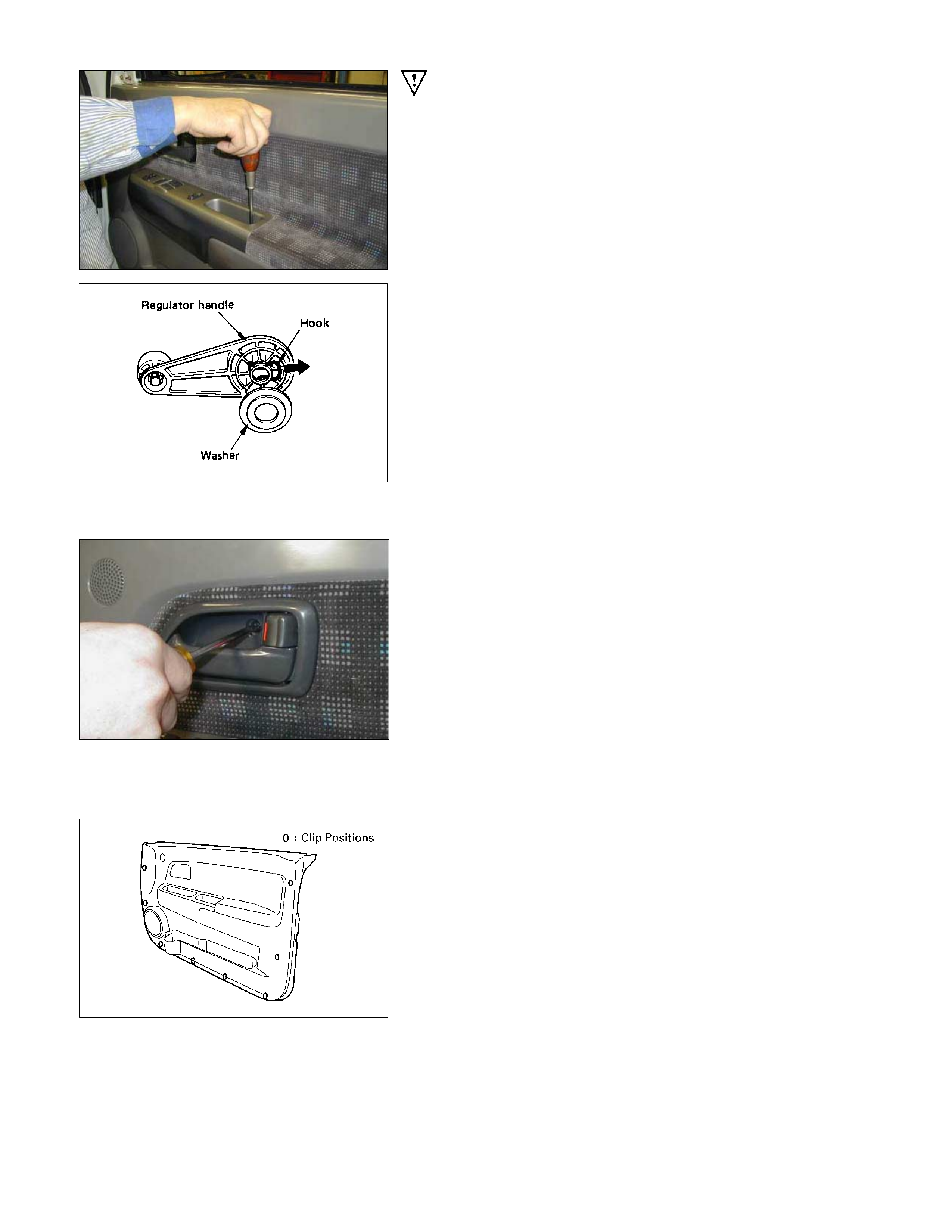
Important Operations
1. Switch Bezel/Window Regulator Handle
• Remove the 2 screws and disconnect the connectors.
• To remove the regulator handle, remove the clip at the
root of the handle by using wire.
2. Power Window Switch
• Remove the 3 screws.
3. Bezel
• Remove the screw.
4. Door Mirror Cover
• Pull out the upper clip, and then take out the cove
r
upward.
5. Door Trim Panel
• Pull out the trim panel at the 8 clip positions (Powe
r
window type).
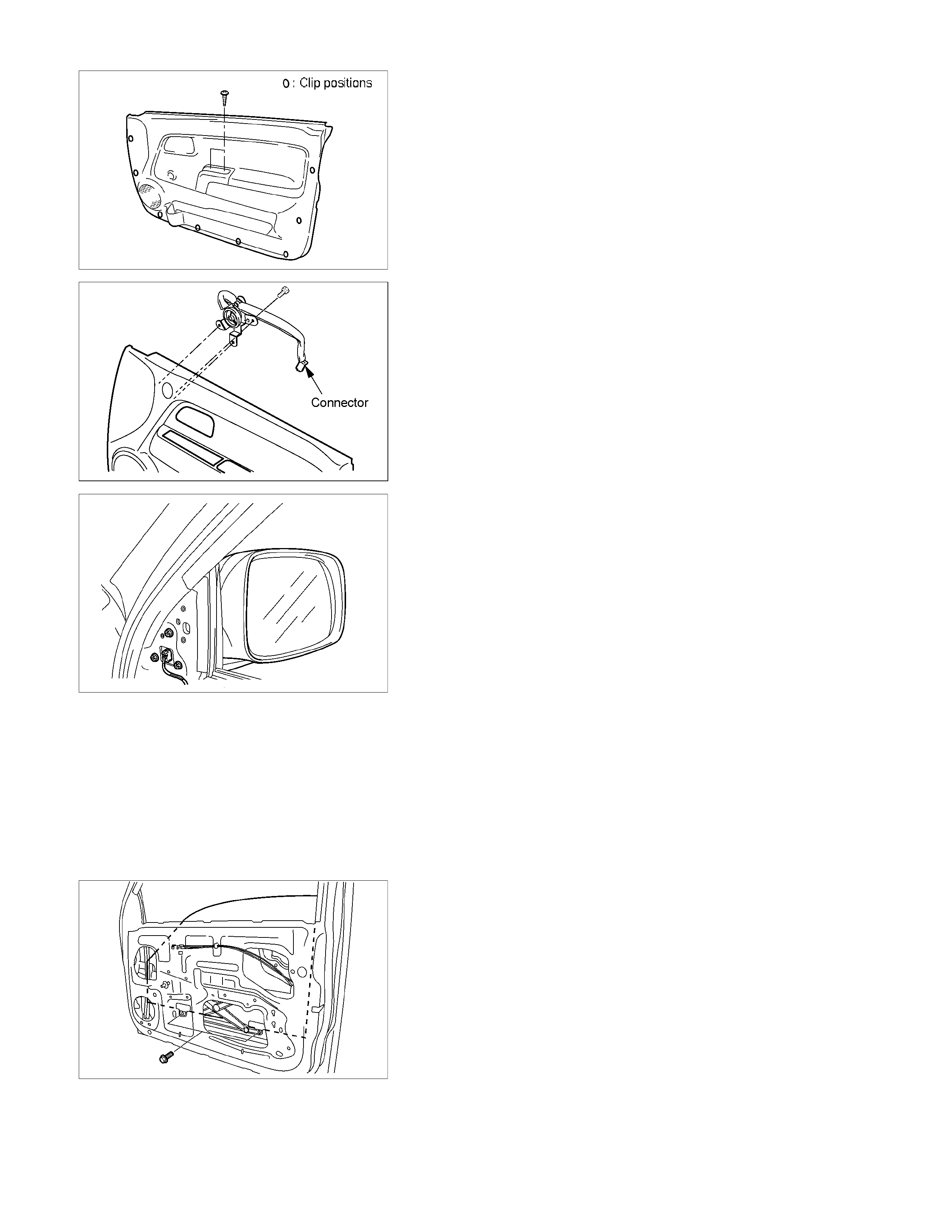
• Remove the 2 screws and pull out the trim panel at the 8
clip positions (Window regulator handle type).
RTW3A0SH000701
6. Tweeter (Required option)
• Disconnect the tweeter harness connector and remove
the 3 screws.
7. Door Mirror Assembly
• Remove 3 fixing bolts and then remove the connector.
8. Outer Waste Seal
9. Bracket
10. Speaker Assembly
• Remove the fixing screw and then remove the
connector.
11. Waterproof Sheet
• Take care not to damage the sheet when peeling it off.
12. Inside Lever
• Disconnect the door lock cables.
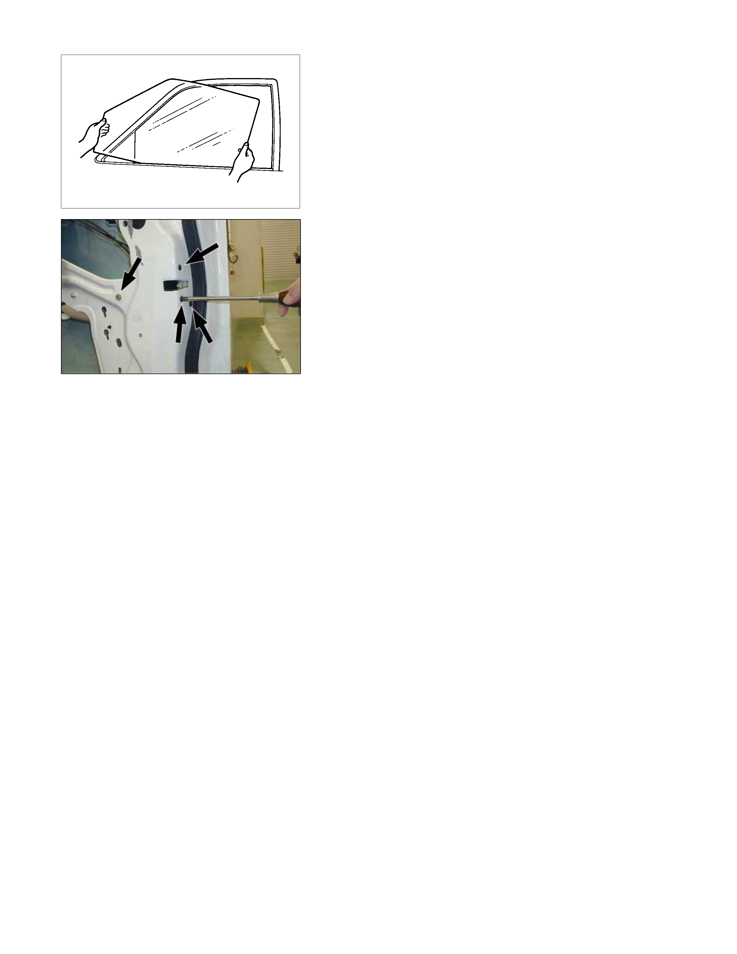
13. Window Glass
• Remove 2 bolts thr ough the acc es s hole and pull out the
window glass upward.
14. Window Regulator/Power Window Regulator
• Remove the 4 fixing bolts and the 2 fixing nuts.
• Disconnect the power window motor connector.
15. Glass Run
• Pull it out from the door frame of the channel.
16. Glass Run Rear Channel
• Remove the bolt.
17. Door Lock Assembly
• Disconnect the lock cable from the anti rattler.
• Remove the 3 fixing screws and the bolt.
• Disconnect the linkage at the outside handle and the
lock cylinder.
• Disconnect the harness connector.
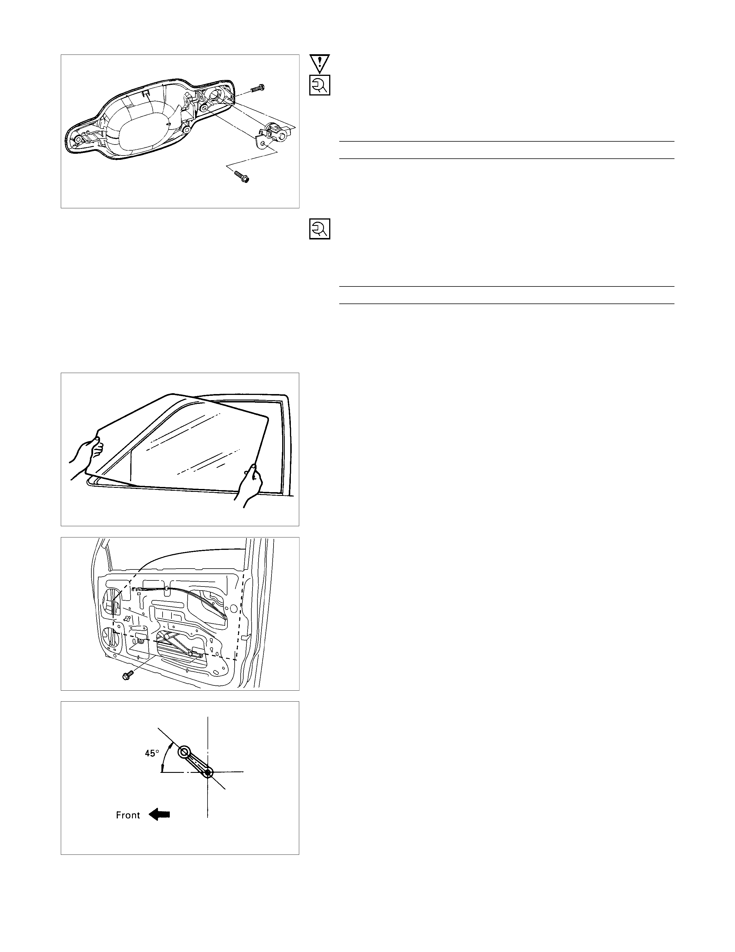
18. Outside Handle
19. Door Lock Cylinder
• Remove the 2 fixing bolts from the out side handle.
REASSEMBLY
RTW3A0LF000501
Reassembly Steps
1. Anti rattler
2. Door harness assembly
▲ 3. Door lock cylinder
▲ 4. Outside handle
5. Door lock assembly
6. Glass run rear channel
7. Glass run
8. Window regulator/Power window
regulator
▲ 9. Window glass
10. Inside lever
11. Waterproof sheet
12. Speaker assembly
13. Bracket
14. Outer waste seal
15. Door mirror assembly
16. Tweeter (Required option)
17. Door trim panel
18. Door mirror cover
19. Bezel
20. Power window switch
▲ 21. Switch bezel/Window regulator handle
Important Operations
3. Door Lock Cylinder
• Tighten the door loc k cylinder fixing bolts to the s pec if ied
torque.
Torque N⋅m (kgf⋅m/lb⋅in)
9 (0.9/78)
4. Outside Handle
• Tighten the outside handle fixing bolts to the specified
torque.
Torque N⋅m (kgf⋅m/lb⋅in)
9 (0.9/78)
9. Window Glass
• Insert the window glass into position by tilting it as
necessar y, then set it against the channel of the windo
w
regulator.
•
A
ttach the window glass to the window regulator with the
2 bolts.
21. Window Regulator Handle
• Install the regulator handle as illustrated when closing
the window glass.
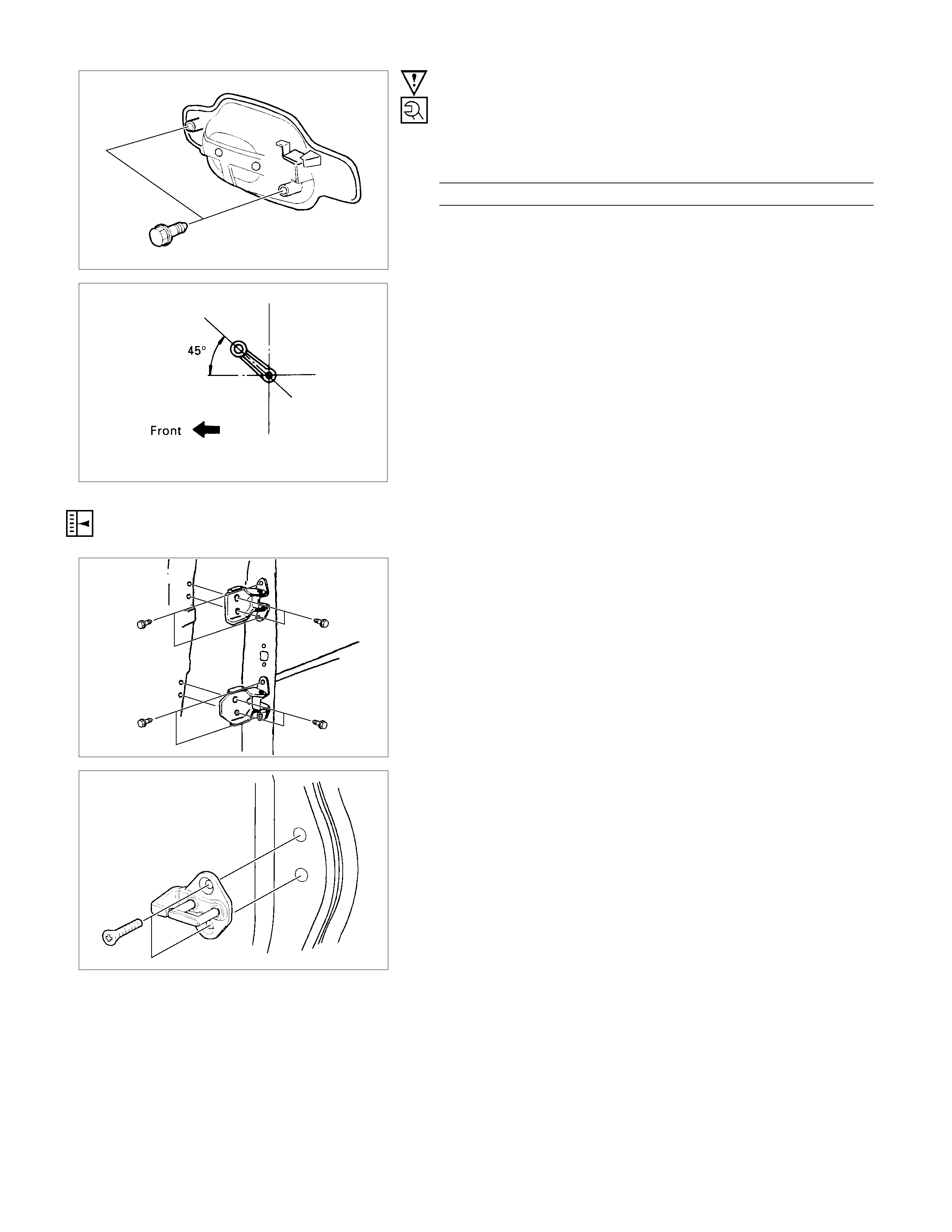
ADJUSTMENT (FRONT)
Door Hinge
Door alignment can be obtained by moving door hinges.
Prior to adjustment, remove the fender and set the door
temporarily.
Loosen hinge to door bolts when adjusting steps between the
door and body.
Loosen hinge to body bolts to adjust the clearance between the
door and body.
Door Striker
Loosen the striker screws and adjust the position of the striker
by holding a piece of wood against the striker and tapping it
with a hammer.
To obtain correct adjustment, move the position of the striker
vertically so that the lower face of the dovetail becomes parallel
to the striker.
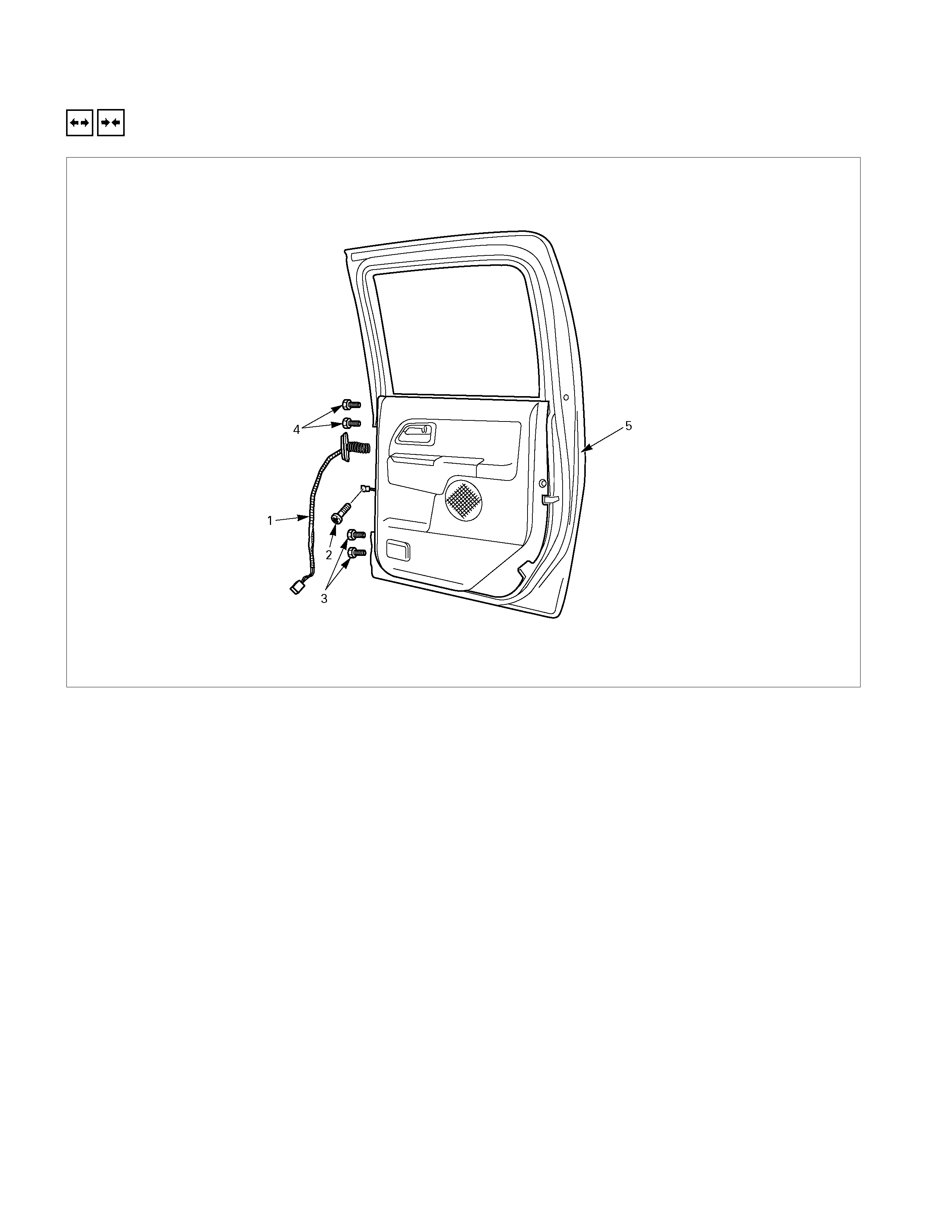
REAR DOOR ASSEMBLY (CREW CAB)
REMOVAL A ND INSTALLATION
Removal Steps
▲ 1. Door harness
▲ 2. Checker arm screw
▲ 3. Lower hinge bolt
4. Upper hinge bolt
5. Door assembly
Installation Steps
5. Door assembly
4. Upper hinge bolt
▲ 3. Lower hinge bolt
▲ 2. Check arm screw
1. Door harness
Important Operations - Removal
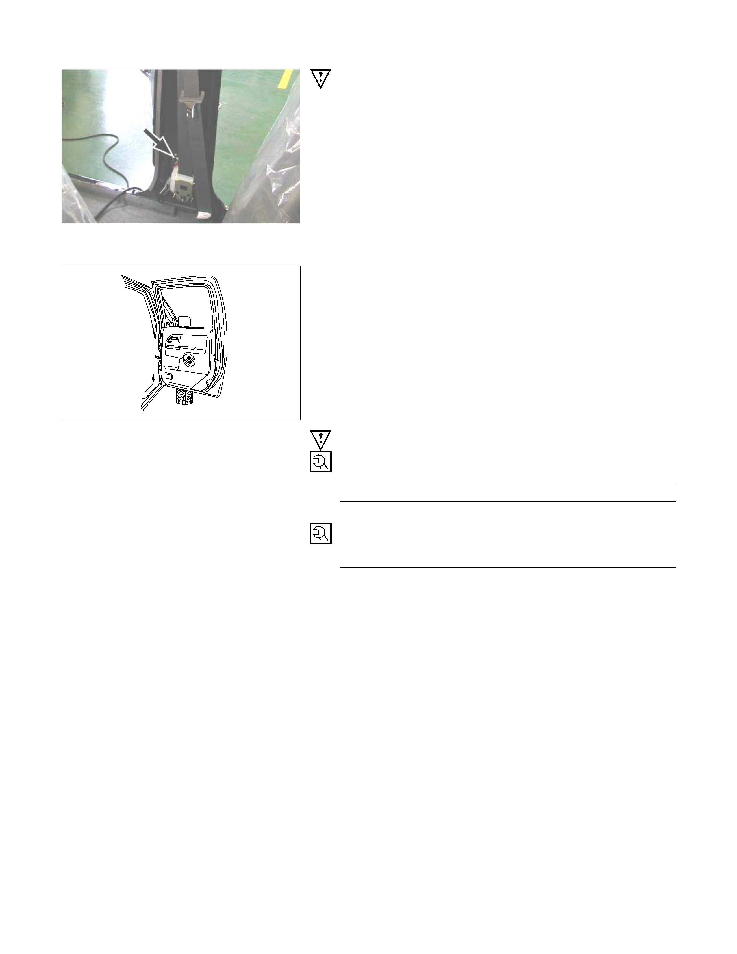
1. Door Harness
Remove the center pillar lower trim cover and disconnect
the door harness connector.
2. Check Arm Screw
3. Lower Hinge Bolt
Position a wood block under the door for protection and
support the door assembly with hands at removal or
installation.
Important Operations – Installation
3. Lower Hinge Bolt; Hinge to Door
Torque N⋅m (kgf⋅m/lb⋅ft)
34 (3.5/25)
2. Check Arm Screw; Check Arm to Body
Torque N⋅m (kgf⋅m/lb⋅ft)
24 (2.4/17)

DISASSEMBLY
RTW3A0LF000601
Disassembly Steps
▲ 1. Switch bezel/Window regulator handle
▲ 2. Power window switch
▲ 3. Bezel
▲ 4. Door trim panel
▲ 5. Bracket
▲ 6. Speaker assembly
▲ 7. Waterproof sheet
▲ 8. Inside lever
▲ 9. Outer waste seal
▲ 10. Window regulator/Power window
regulator
▲ 11. Glass run rear channel
▲ 12. Door lock assembly
▲ 13. Glass run
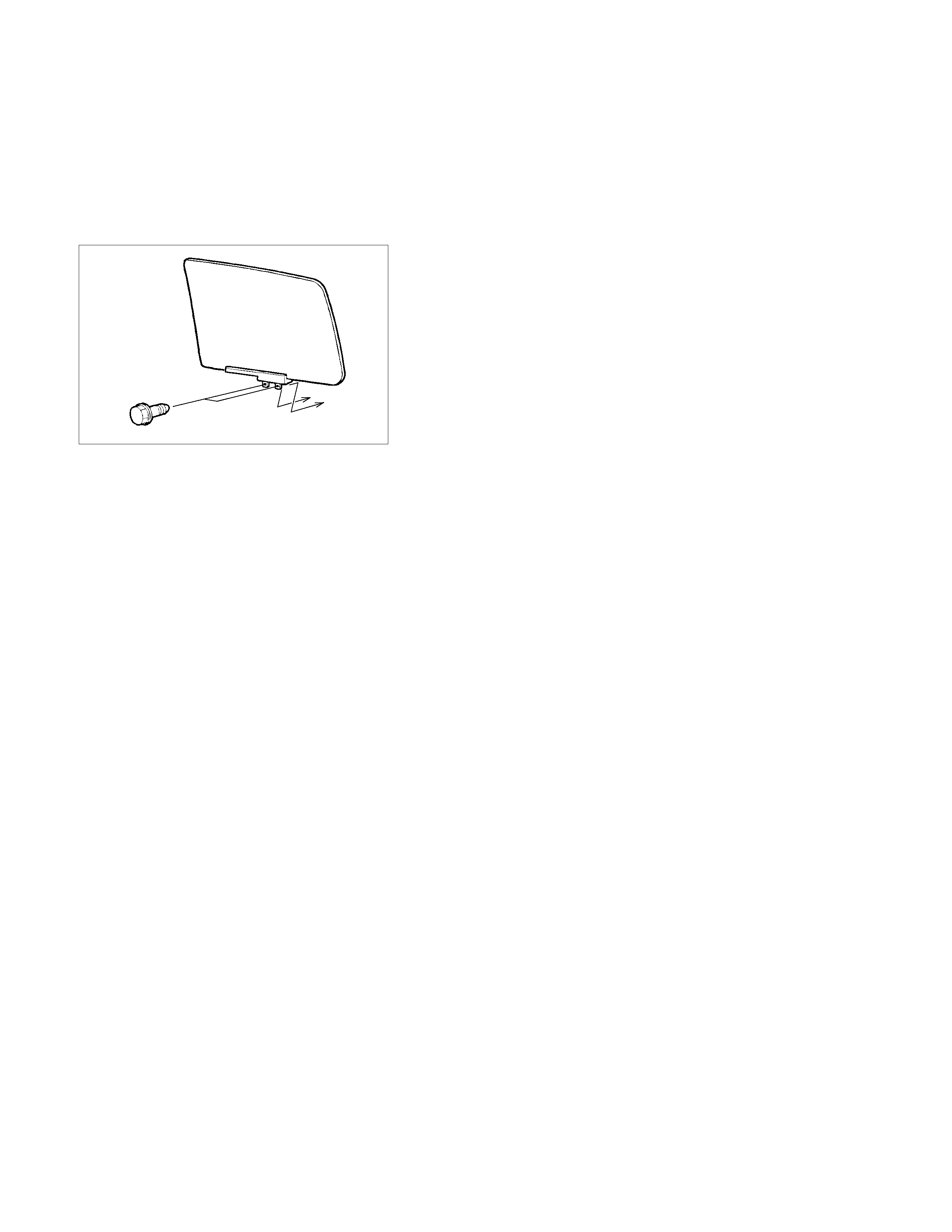
▲ 14. Window glass
▲ 15. Outside handle
16. Door harness assembly
17. Anti rattler
RTW3A0SH000401
Important Operations
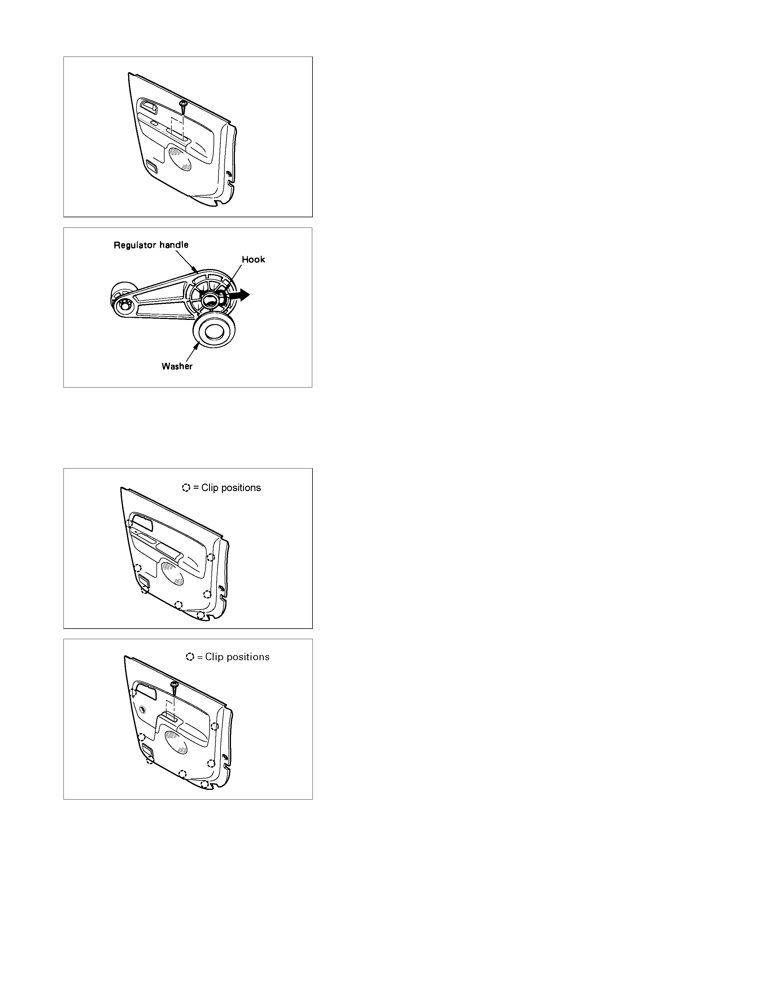
1. Switch Bezel/Window Regulator Handle
• Remove the 2 screws and disconnect the connector.
• To remove the regulator handle, remove the clip at the
root of the handle by using wire.
2. Power Window Switch
• Pry the 4 clip positions.
3. Bezel
• Remove the screw.
RTQ3A0SH000501
4. Door Trim Panel
• Pull out the trim panel at the 7 clip positions (Powe
r
window type).
• Remove the 2 screws and pull out the trim panel at the 7
clip positions (Window regulator handle type).
5. Bracket
6. Speaker assembly
• Remove the fixing bolt and then remove the connector.
7. Waterproof Sheet
• Take care not to damage the sheet when peeling it off.
8. Inside Lever
• Disconnect the door lock cables.
9. Outer Waste Seal
10. Window Regulator/Power Window Regulator
• Remove the 2 bolts fixing the window glass through the
access hole.
• Move the window glass upward and hold it with adhesive
tape.
• Remove the 5 bolts fixing the window regulator.
• Disconnect the power window motor connector.
11. Glass Run Rear Channel
• Remove the bolt.
12. Door Lock Assembly
• Disconnect the lock cable from the anti rattler.
• Remove the 3 fixing screws and the bolt.
• Disconnect the linkage and harness connector.
13. Glass Run
• Remove the adhesive tape and move the window glass
downward.
• Pull it out from the door frame of the channel.
14. Window Glass
• Pull out the window glass upward.
15. Outside Handle
• Remove the 2 fixing bolts.
REASSEMBLY
RTW3A0LF000701
Reassembly Steps
1. Anti rattler
2. Door harness assembly
▲ 3. Outside handle
4. Window glass
5. Glass run
6. Door lock assembly
7. Glass run rear channel
8. Window regulator/Power window
regulator
9. Outer waste seal
10. Inside lever
11. Waterproof sheet
12. Speaker assembly
13. Bracket
14. Door trim panel
15. Bezel
16. Power window switch
▲ 17. Switch bezel/Window regulator handle
Important Operations
3. Outside Handle
• Tighten the outside handle fixing bolts to the specified
torque.
Torque N⋅m (kgf⋅m/lb⋅in)
9 (0.9/78)
17. Window Regulator Handle
• Install the regulator handle as illustrated when closing
the window glass.
ADJUSTMENT (REAR)
Door Hinge
Door alignment can be obtained by moving door hinges.
Prior to adjustment, set the door temporarily.
Loosen hinge to door bolts when adjusting steps between the
door and body.
Loosen hinge to body bolts to adjust the clearance between the
door and body.
Door Striker
Loosen the striker screws and adjust the position of the striker
by holding a piece of wood against the striker and tapping it
with a hammer.
To obtain correct adjustment, move the position of the striker
vertically so that the lower face of the dovetail becomes parallel
to the striker.
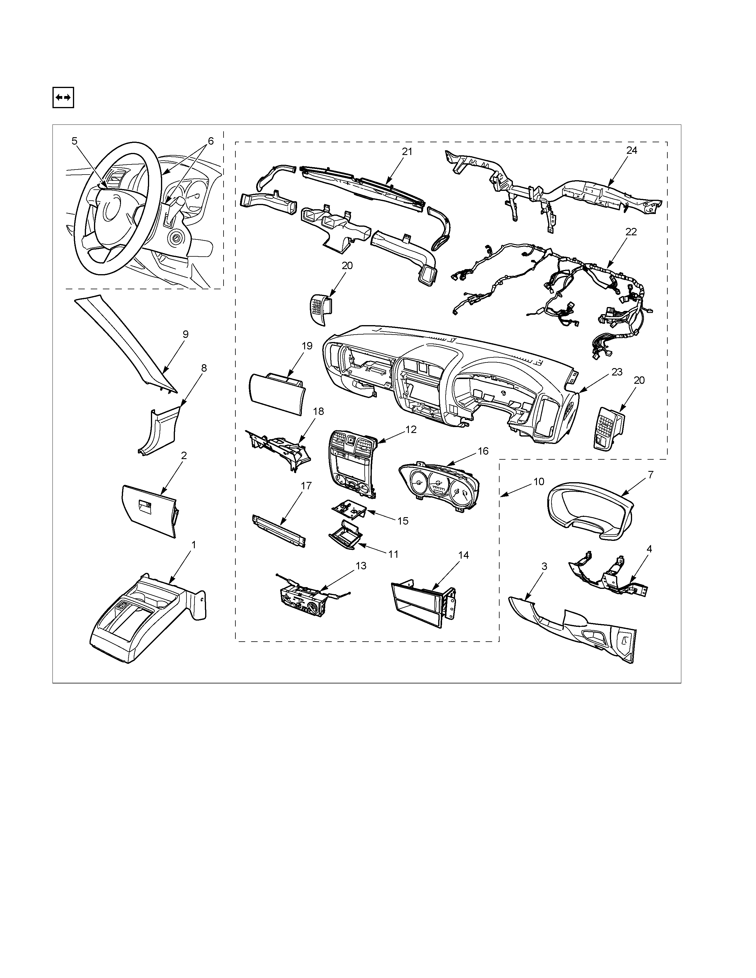
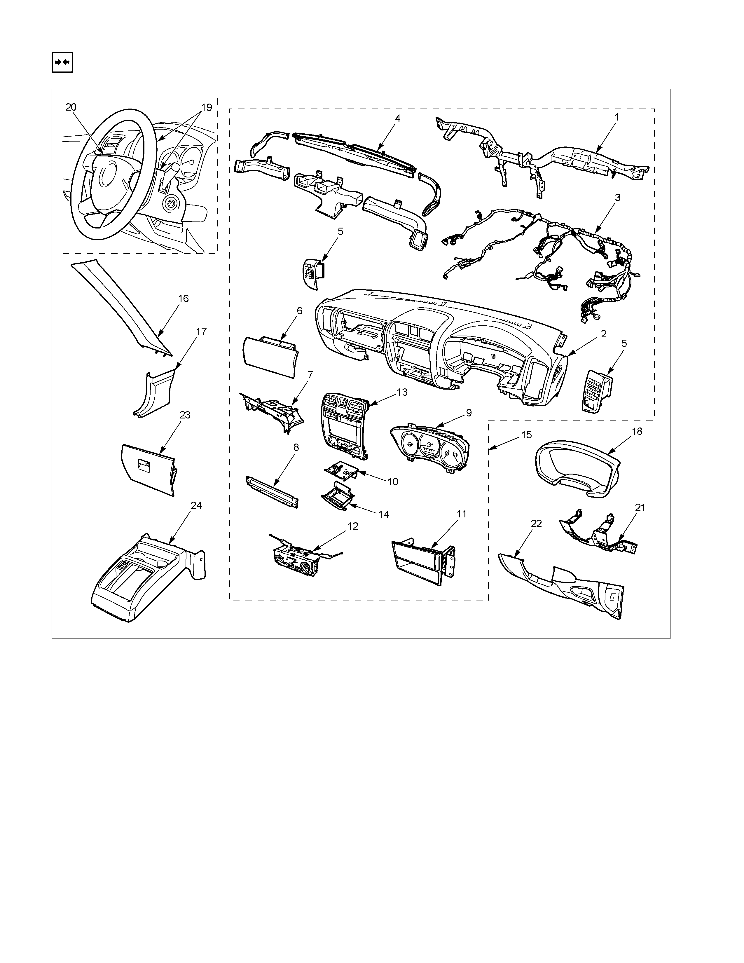
INSTRUMENT PANEL
REMOVAL
RTW3A0LF000201
Disassembly Steps
▲ 1. Front console assembly
▲ 2. Glove box
▲ 3. Instrument panel driver lower cover
assembly
▲ 4. Driver knee bolster assembly
▲ 5. Driver air bag
▲ 6. Steering wheel/ steering cowl
▲ 7. Meter cluster assembly
8. Dash side trim cover
9. Front pillar trim cover
▲ 10. Instrument panel & Cross beam
assembly
▲ 11. Ashtray case
▲ 12. Center cluster assembly
▲ 13. Control lever assembly
14. Storage box assembly
▲ 15. Ashtray bracket
16. Meter assembly
17. Passenger lower bracket
18. Glove box cover
▲ 19. Passenger air bag (if so equipped)
▲ 20. Side ventilation grille
▲ 21. Vent duct assembly /Defroster nozzle
assembly
22. Instrument harness assembly
▲ 23. Instrument panel
▲ 24. Cross beam
Important Operations
1. Front Console Assembly
• Refer to Floor Console in this section.
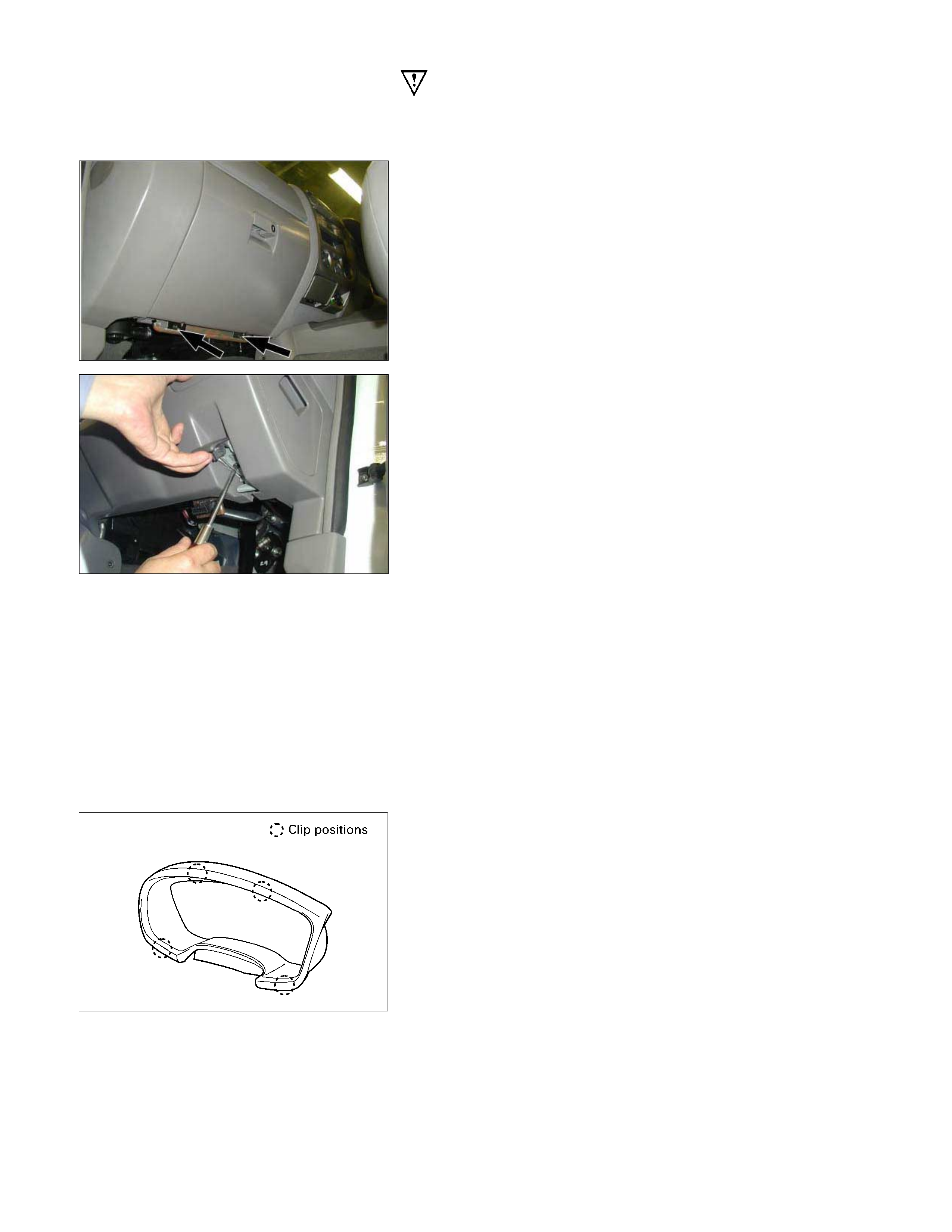
2. Glove Box
• Remove 2 fixing screws and pulling the handle.
3. Instrument Panel Driver Lower Cover Assembly
1) Remove the engine hood opener 2 fixing screws.
2) Remove the lower cover one fixing screw.
3) Pull out the cover (Stick type parking brake only).
4) Pull out the lower cover assembly.
4. Driver Knee Bolster Assembly
• Remove 6 fixing bolts.
Caution:
For precaution on installation or removal of SRS-air bag
system, refer to Section 9 “Supplemental Restraint System
(SRS) - AIR BAG”
5. Driver Air Bag
6. Steering Wheel/Steering Cowl
• Refer to Section 3B “STEERING COLUMN” for steering
lock assembly removal steps.
7. Meter Cluster Assembly
• Pull out the 4 clip positions.
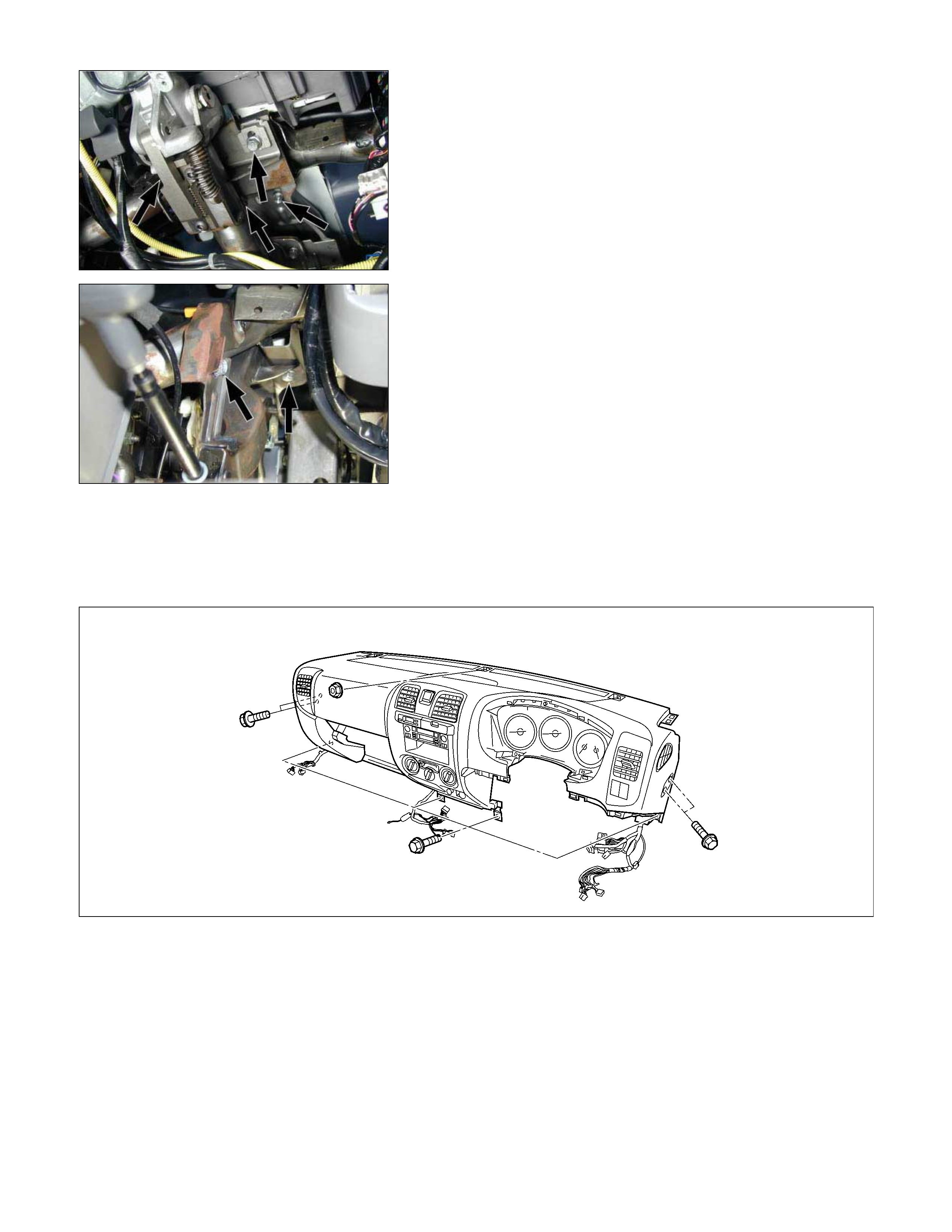
10. Instrument Panel & Cross Beam Assembly
1) Remove the two bolts fixing the steering column to the
cross beam and the two bolts fixing the brake pedal
bracket to the cross beam.
2) Rem ove the two bolts f ixing the park ing brak e brack et to
the cross beam (Stick type parking brake only).
3) Disconnect the control cables at the blower unit and
heater unit.
4) Remove the fasteners fixing the instrument panel &
cross beam assembly to the body panel.
5) Disconnect the instrument harness connectors.
11.Ashtray Case
• Pull out the ashtray case.
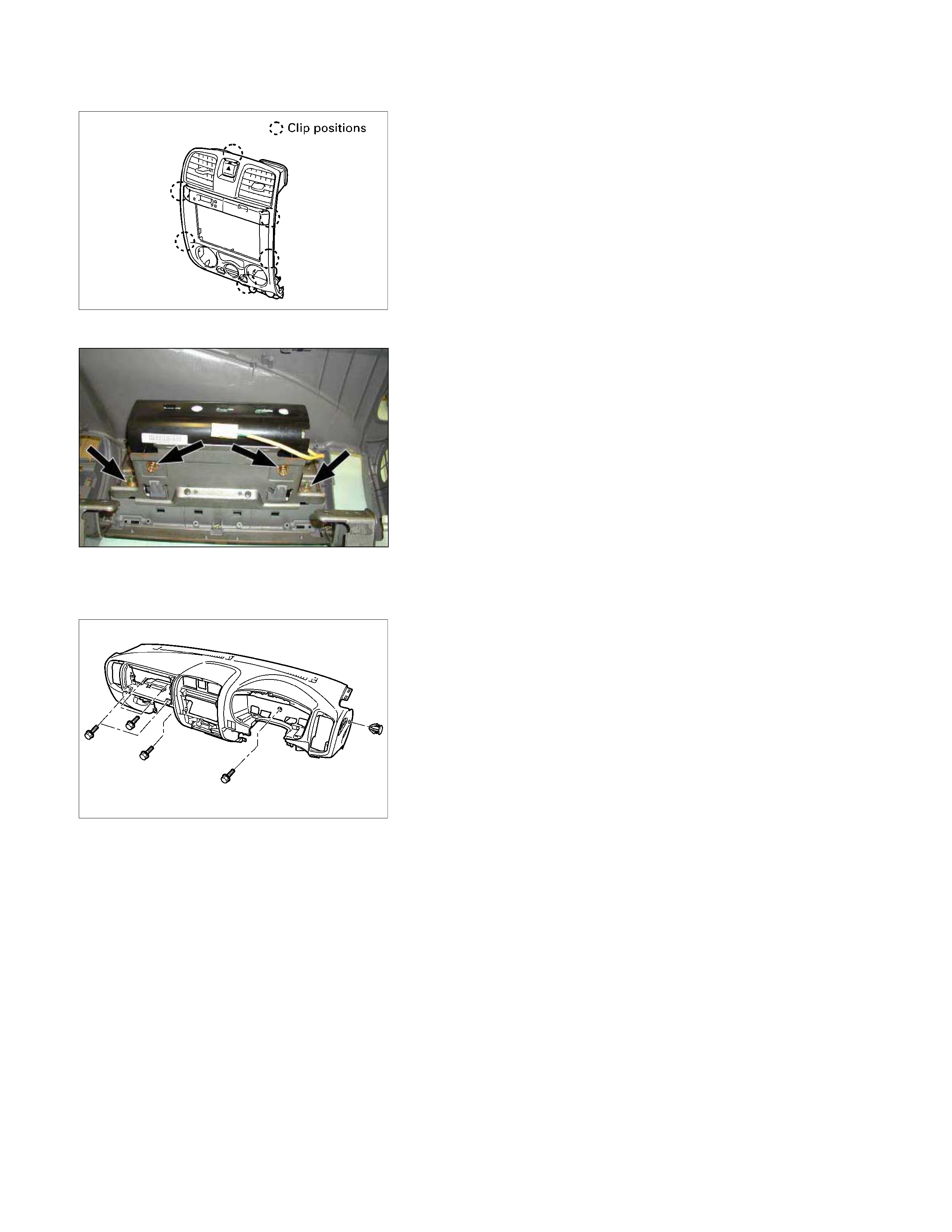
12. Center Cluster Assembly
1) Pull out the cluster at the 6 clip positions.
2) Disconnect the cigarette lighter, accessory socket,
hazard switch and clock connectors.
13. Control Lever Assembly
• Remove the 2 fixing screws.
15.Ashtray Bracket
• Remove the 3 fixing screws and illumination connector.
Caution:
For precautions on installation or removal of SRS-air bag
system, refer to Section 9 "Supplemental Restraint System
(SRS) - AIR BAG".
19. Passenger Air Bag
• Remove 2 fixing bolts, 2 fixing nuts and connector.
20. Side Ventilation Grille.
• Pull out the grilles and disconnect switch connector
(Driver’s side).
21. Vent Duct Assembly/Defroster Nozzle Assembly
• Refer to Section 1 “HVAC” for defroster nozzle and
ventilation duct removal steps.
23. Instrument Panel
• Remove the clip and 6 fixing bolts.
24. Cross Beam
INSTALLATION
RTW3A0LF000301
Installation Steps
1. Cross beam
2. Instrument panel
3. Instrument harness assembly
4. Vent duct assembly/Defroster nozzle
assembly
5. Side ventilation grille
6. Passenger air bag
7. Glove box cover
8. Passenger lower bracket
9. Meter assembly
10. Ashtray bracket
11. Storage box assembly
12. Control lever assembly
13. Center cluster assembly
14. Ashtray case
▲ 15. Instrument panel & Cross beam
assembly
16. Front pillar trim cover
17. Dash side trim cover
18. Meter cluster assembly
▲ 19. Steering wheel/Steering cowl
20. Driver air bag
21. Driver knee bolster assembly
22. Instrument panel driver lower cover
assembly
23. Glove box
24. Front console assembly
Important Operations
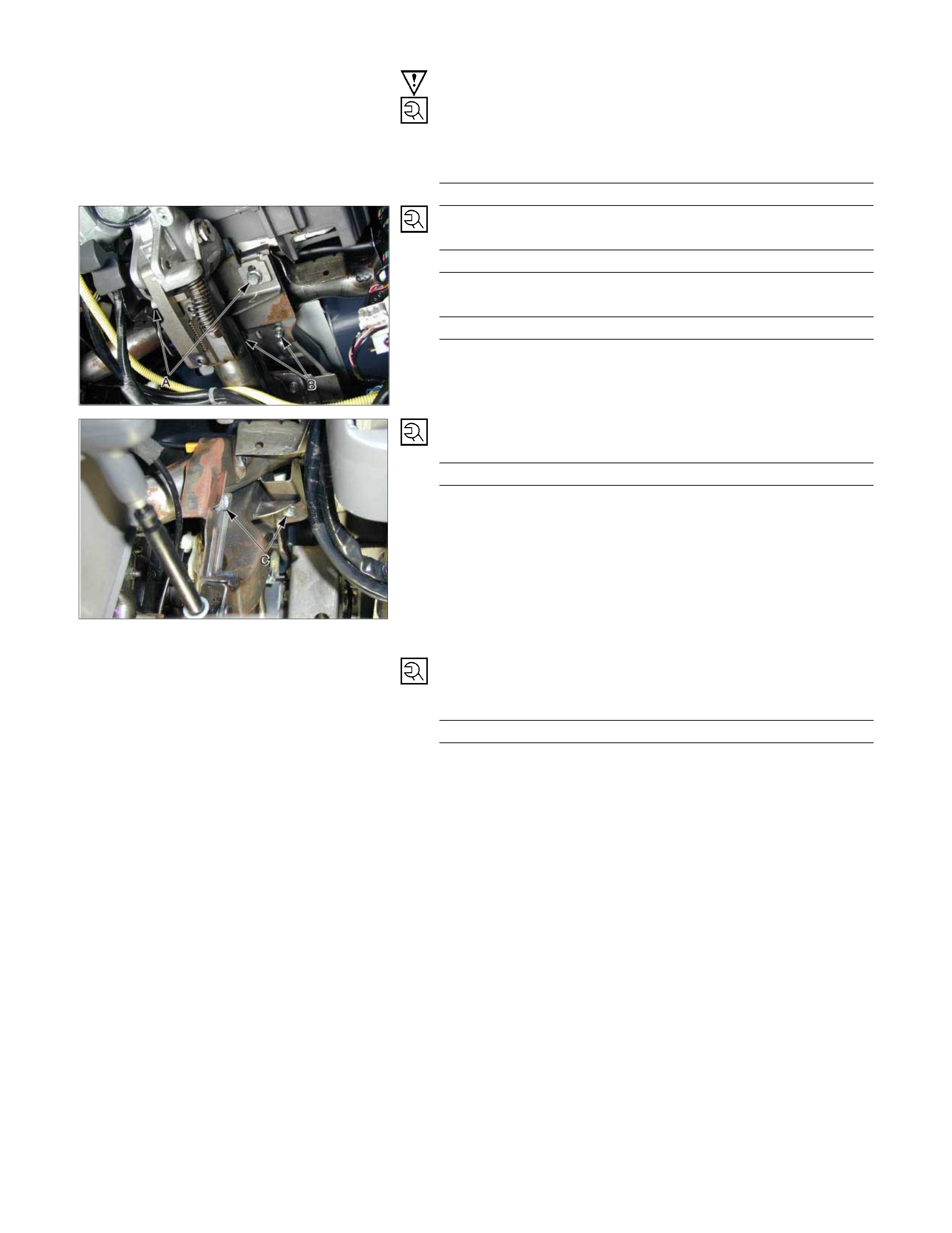
15. Instrument Panel & Crass Beam Assembly
1) T ighten the 4 bolts fixing the cross beam and body panel
to the specified torque.
Torque N⋅m (kgf⋅m/lb⋅ft)
19 (1.9/14)
2) A Bolt: Steering Column to Cross Beam
Torque N⋅m (kgf⋅m/lb⋅ft)
20 (2.0/14)
B Bolt: Pedal Bracket to Cross Beam
Torque N⋅m (kgf⋅m/lb⋅ft)
15 (1.5/11)
3) C Bolt: Parking Brake Bracket to Cross Beam
Torque N⋅m (kgf⋅m/lb⋅ft)
15 (1.5/11)
19. Steering Wheel/Steering Cowl
• Tighten the steering wheel fixing nut to the specified
torque.
Torque N⋅m (kgf⋅m/lb⋅ft)
34 (3.5/25)
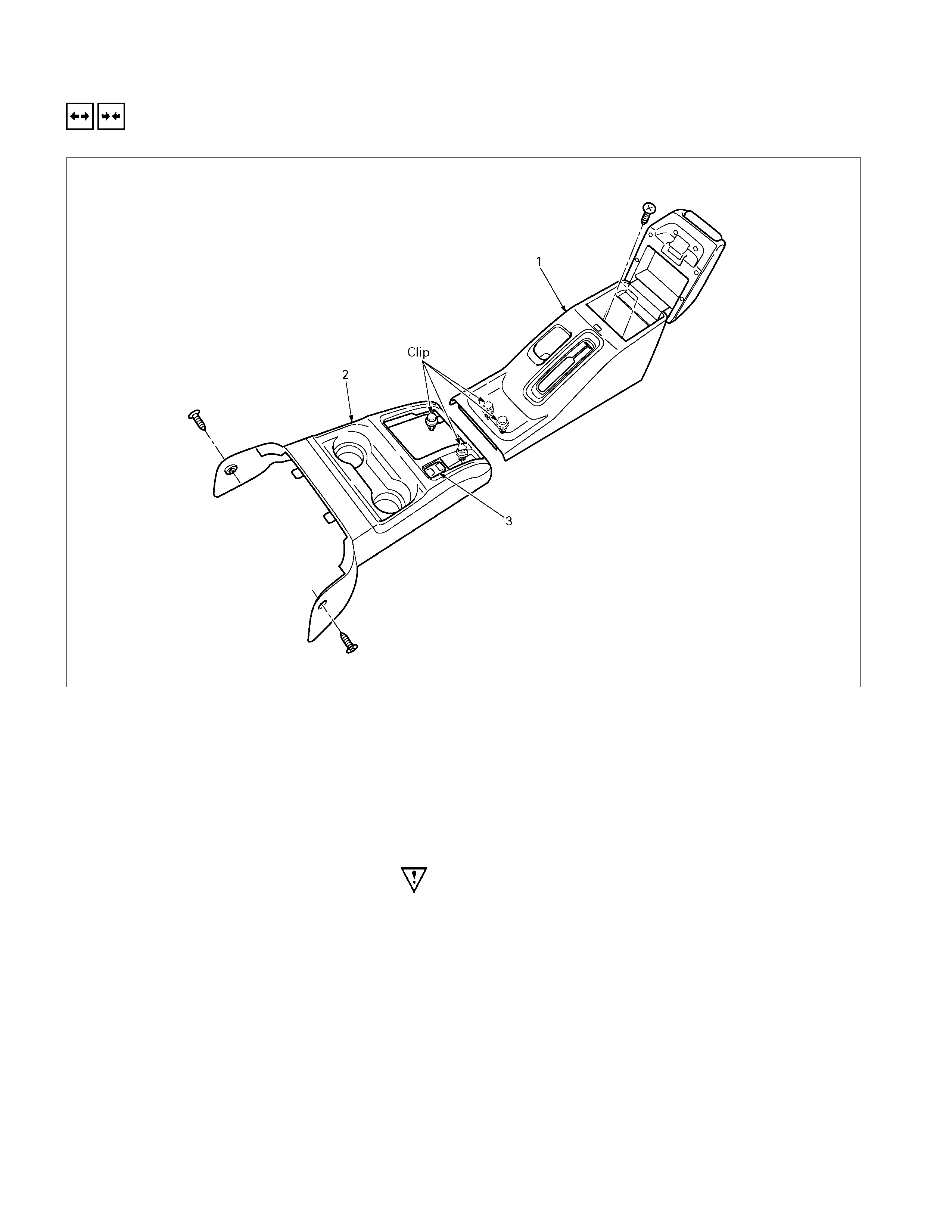
FLOOR CONSOLE
REMOVAL A ND INSTALLATION
A/T Model
Removal Steps
▲ 1. Rear floor console (Bucket seat model
only )
▲ 2. Front floor console
3. 3rd start switch
Installation Steps
3. 3rd start switch
2. Front floor console
1. Rear floor console (Bucket seat model
only )
Important Operations - Removal
1. Rear Floor Console (Bucket Seat Model Only)
1) Open the rear console lid and remove 2 screws.
2) Pull out the front part of rear console at the 2 clip
positions.
2. Front Floor Console
1) Remove the 2 screws.
2) Pull out the rear part of front console at the 2 clip
positions and disconnect the switch connecter.
3) Remove the front console by pull out it rear ward.
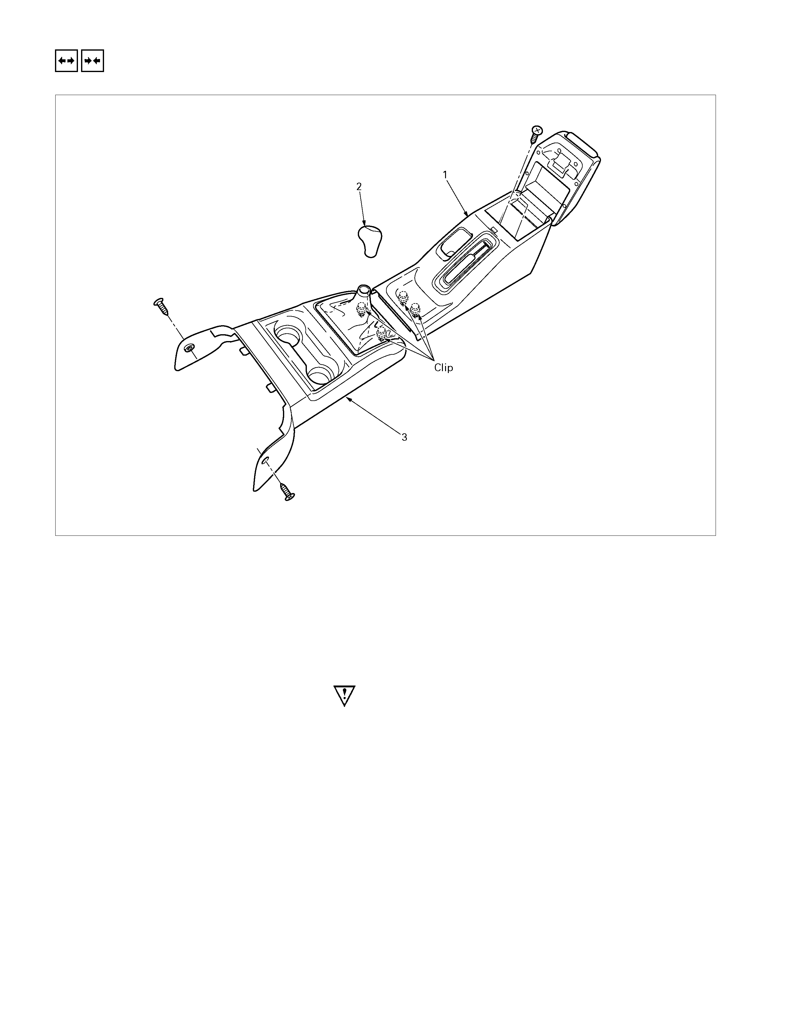
REMOVAL A ND INSTALLATION
M/T Model
Removal Steps
▲ 1. Rear floor console (Bucket seat model
only )
2. Shift knob
▲ 3. Front floor console
Installation Steps
3. Front floor console
2. Shift knob
1. Rear floor console (Bucket seat model
only )
Important Operations - Removal
1. Rear Floor Console (Bucket Seat Model Only)
1) Open the rear console lid and remove 2 screws.
2) Pull out the front part of rear console at the 2 clip
positions.
3. Front Floor Console
1) Remove the 2 screws.
2) Pull out the rear part of front console at the 2 clip
positions.
3) Remove the front console by pull out it rear ward.
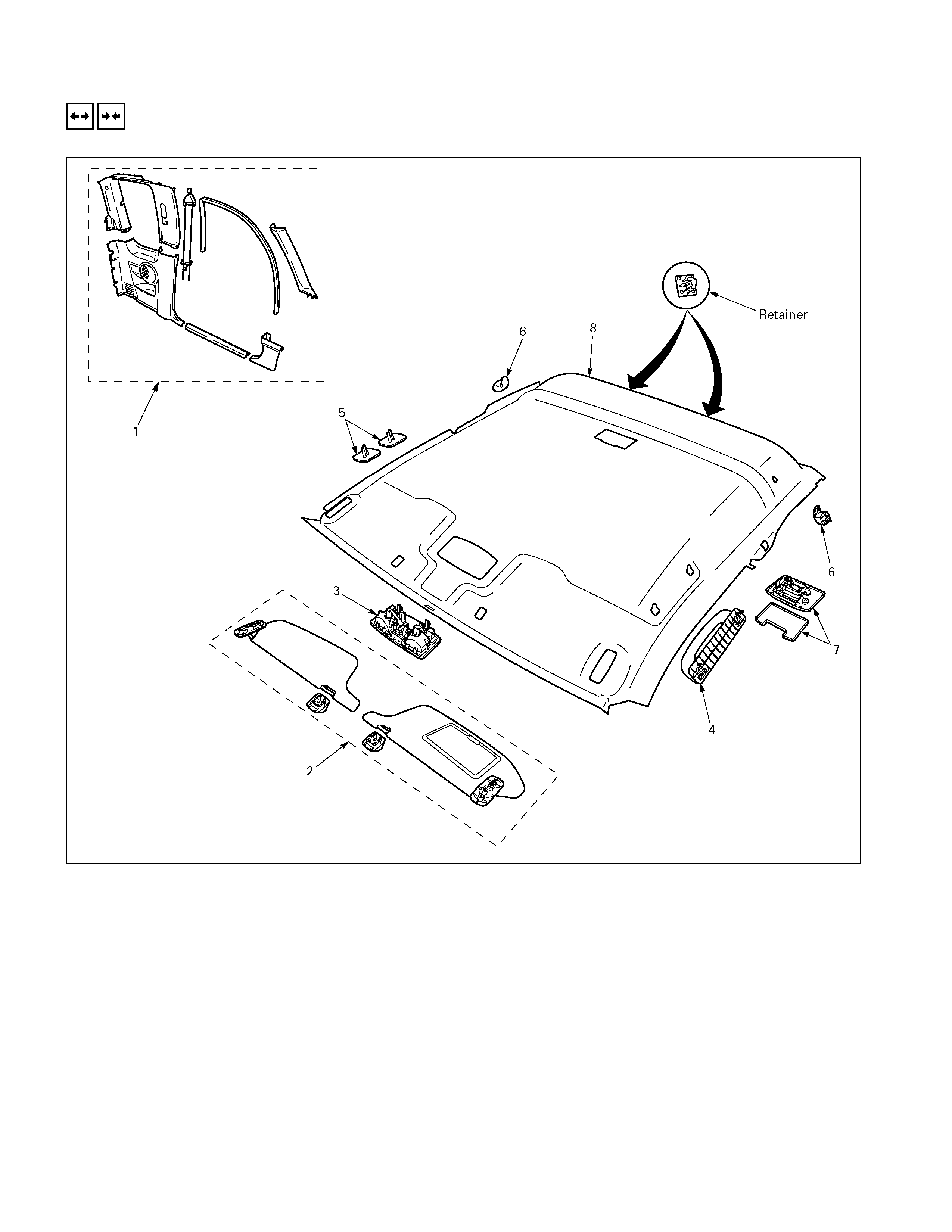
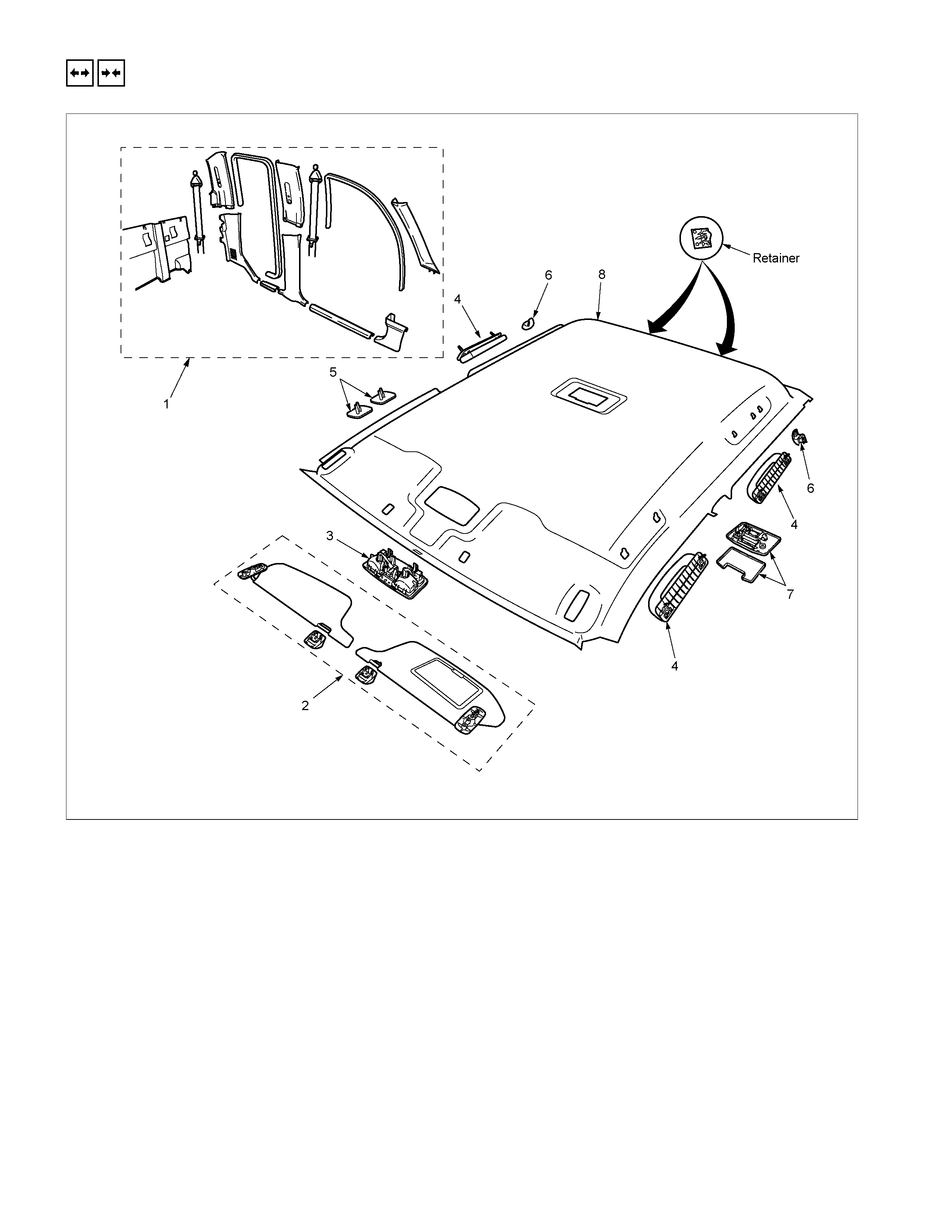
HEADLINING
REMOVAL A ND INSTALLATION
EXTEND CAB Model
Removal Steps
▲ 1. Interior trim panels
▲ 2. Sunvisor/Sunvisor holder
▲ 3. Spot light
▲ 4. Assist grip
5. Hole cover
▲ 6. Coat hook
▲ 7. Dome light
▲ 8. Headlining
Installation Steps
8. Headlining
7. Dome light
6. Coat hook
5. Hole cover
4. Assist grip
3. Spot light
2. Sunvisor/Sunvisor holder
1. Interior trim panels
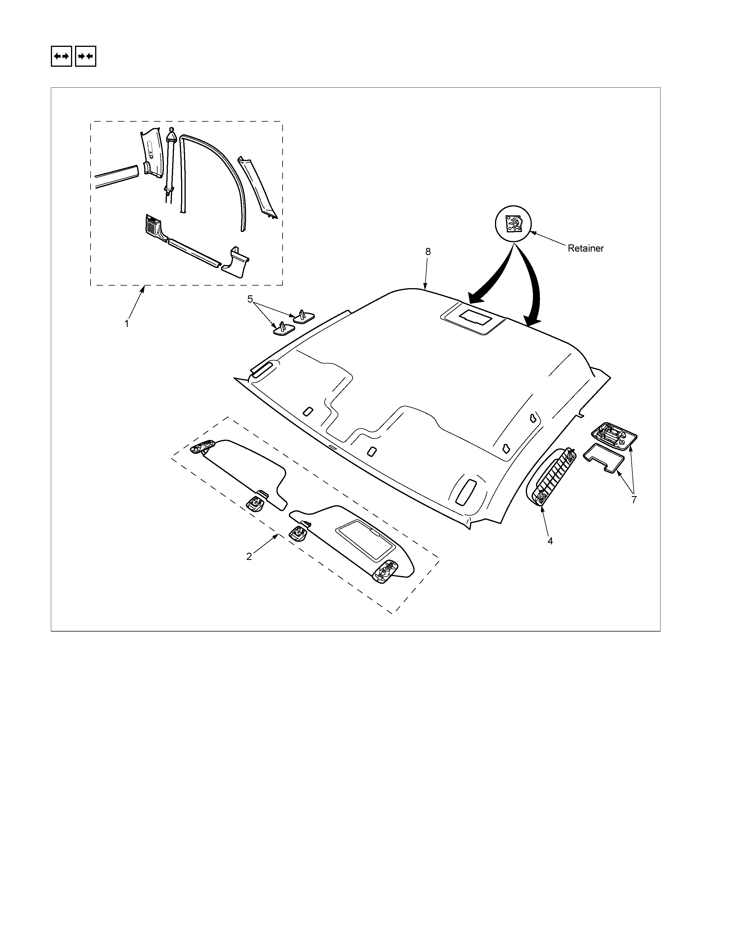
REMOVAL A ND INSTALLATION
RTW3A0LF001101
REGULAR CAB Model
Removal Steps
▲ 1. Interior trim panels
▲ 2. Sunvisor/Sunvisor holder
▲ 4. Assist grip
5. Hole cover
▲ 7. Dome light
▲ 8. Headlining
Installation Steps
8. Headlining
7. Dome light
5. Hole cover
4. Assist grip
2. Sunvisor/Sunvisor holder
1. Interior trim panels
REMOVAL A ND INSTALLATION
RTW3A0LF001001
CRER CAB Model
Removal Steps
▲ 1. Interior trim panels
▲ 2. Sunvisor/Sunvisor holder
▲ 3. Spot light
▲ 4. Assist grip
5. Hole cover
▲ 6. Coat hook
▲ 7. Dome light
▲ 8. Headlining
Installation Steps
8. Headlining
7. Dome light
6. Coat hook
5. Hole cover
4. Assist grip
3. Spot light
2. Sunvisor/Sunvisor holder
1. Interior trim panels
Important Operations - Removal
1. Interior Trim Panels
• Refer to Interior Trim Panels in this section.
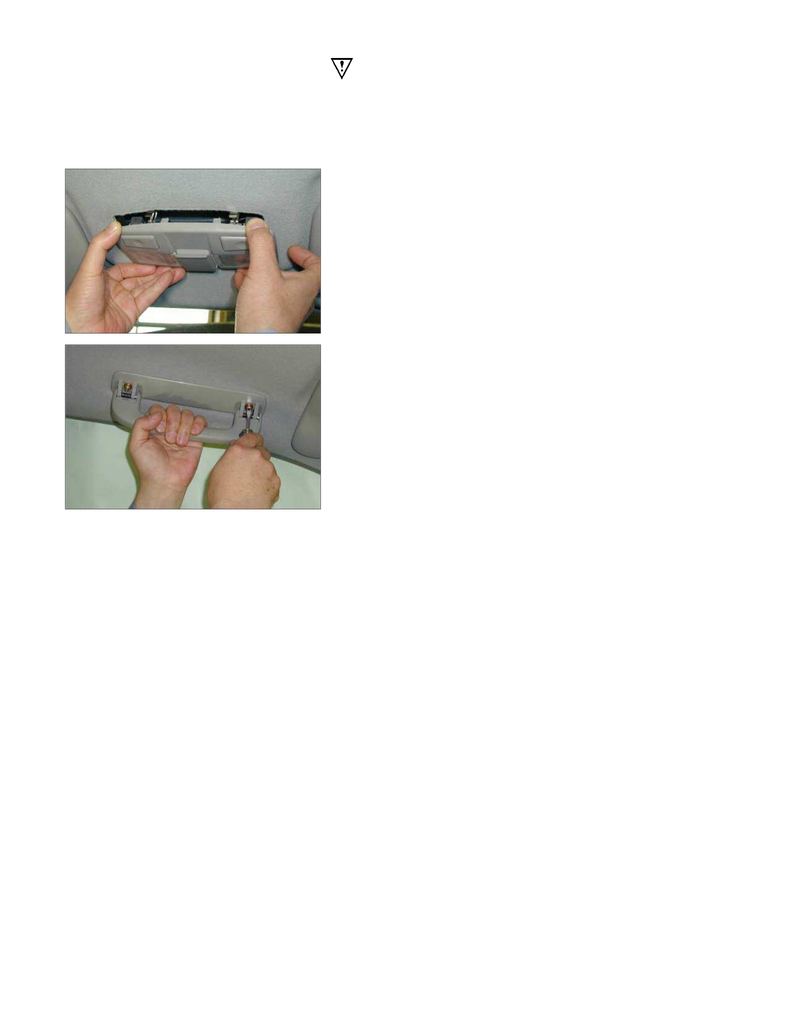
2. Sunvisor/Sunvisor Holder
1) Remove the 2 screws fixing the sunvisor.
2) Remove the screw fixing the sunvisor holder.
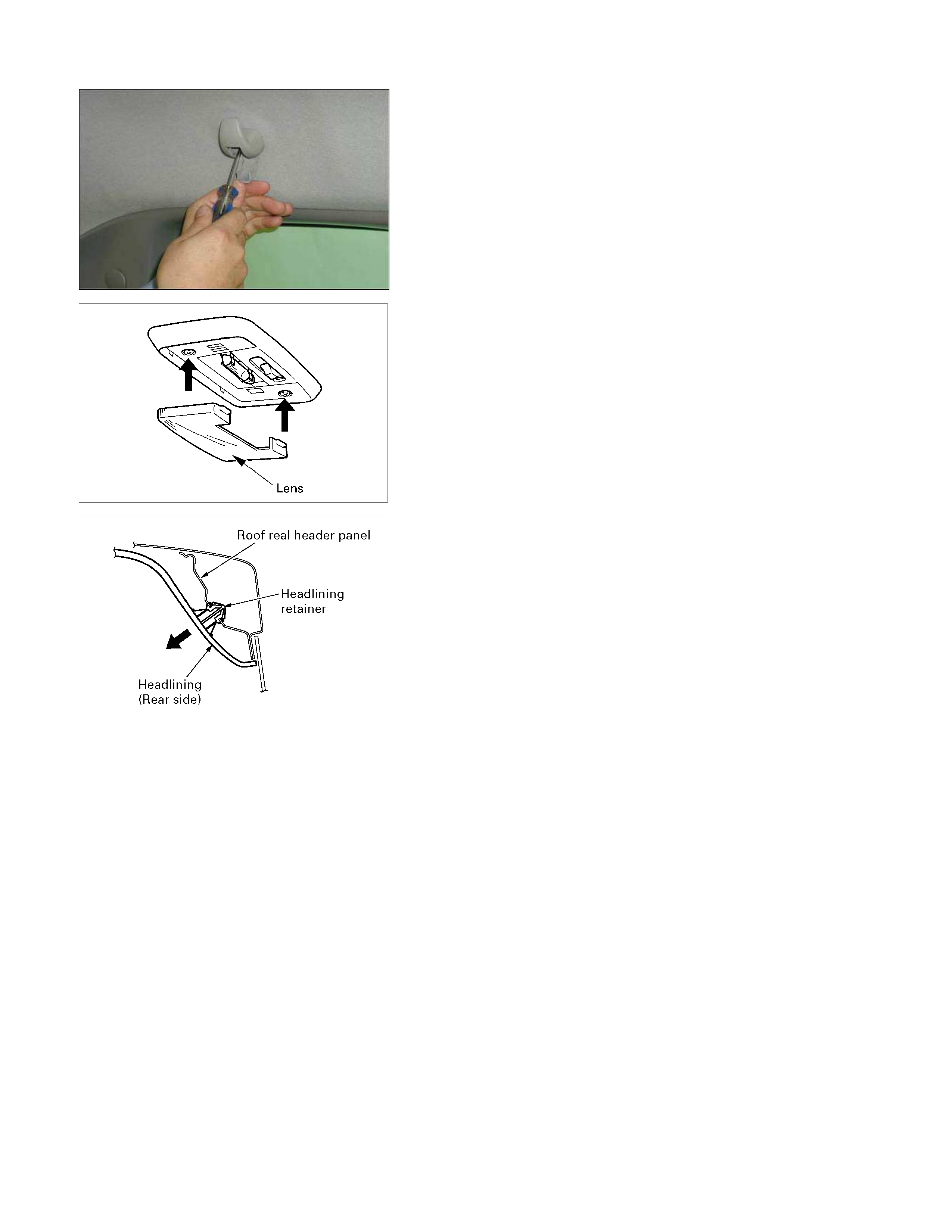
3. Spot Light
• Pull out the spot light and disconnect the connector.
4. Assist Grip
• Remove the 2 fixing screw.
6. Coat Hook
• Open the cover and remove the fixing screw.
7. Dome Light
1) Remove the dome light lens and the fixing screws.
2) Disconnect the dome light connector.
8. Headlining
• Pull out the headlining with the retainer from roof rea
r
header panel as direction of shown in the illustration.
Note :
Remove steps (2-7) can be removed from the headlining in
any order.
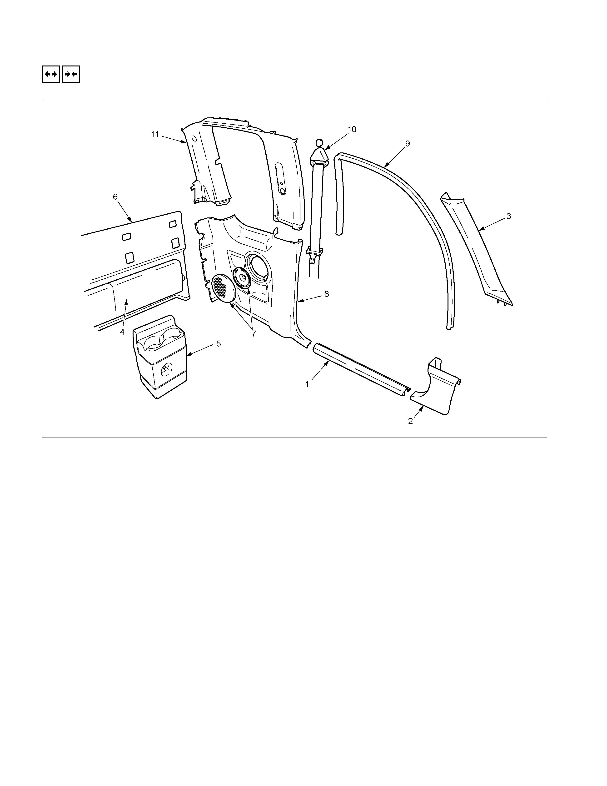
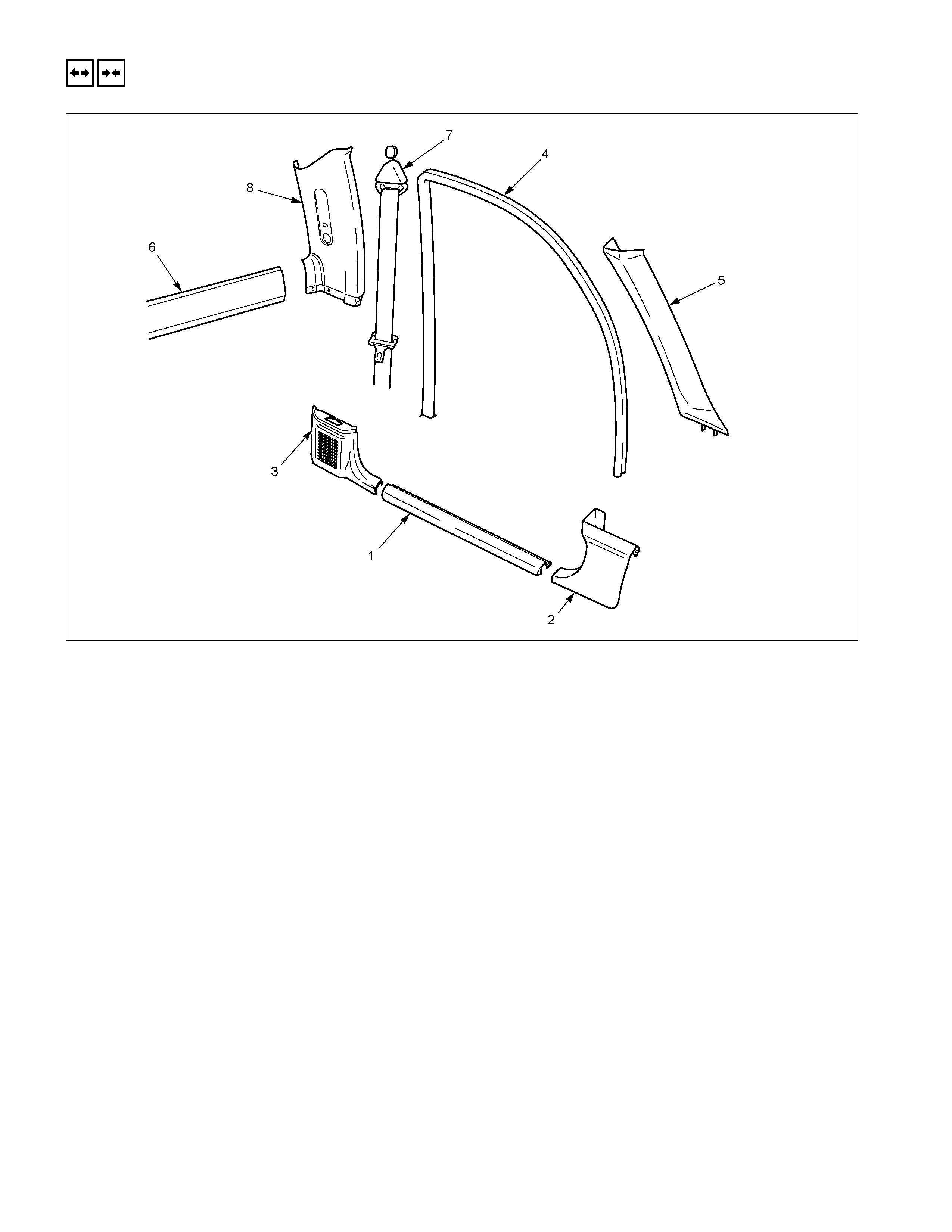
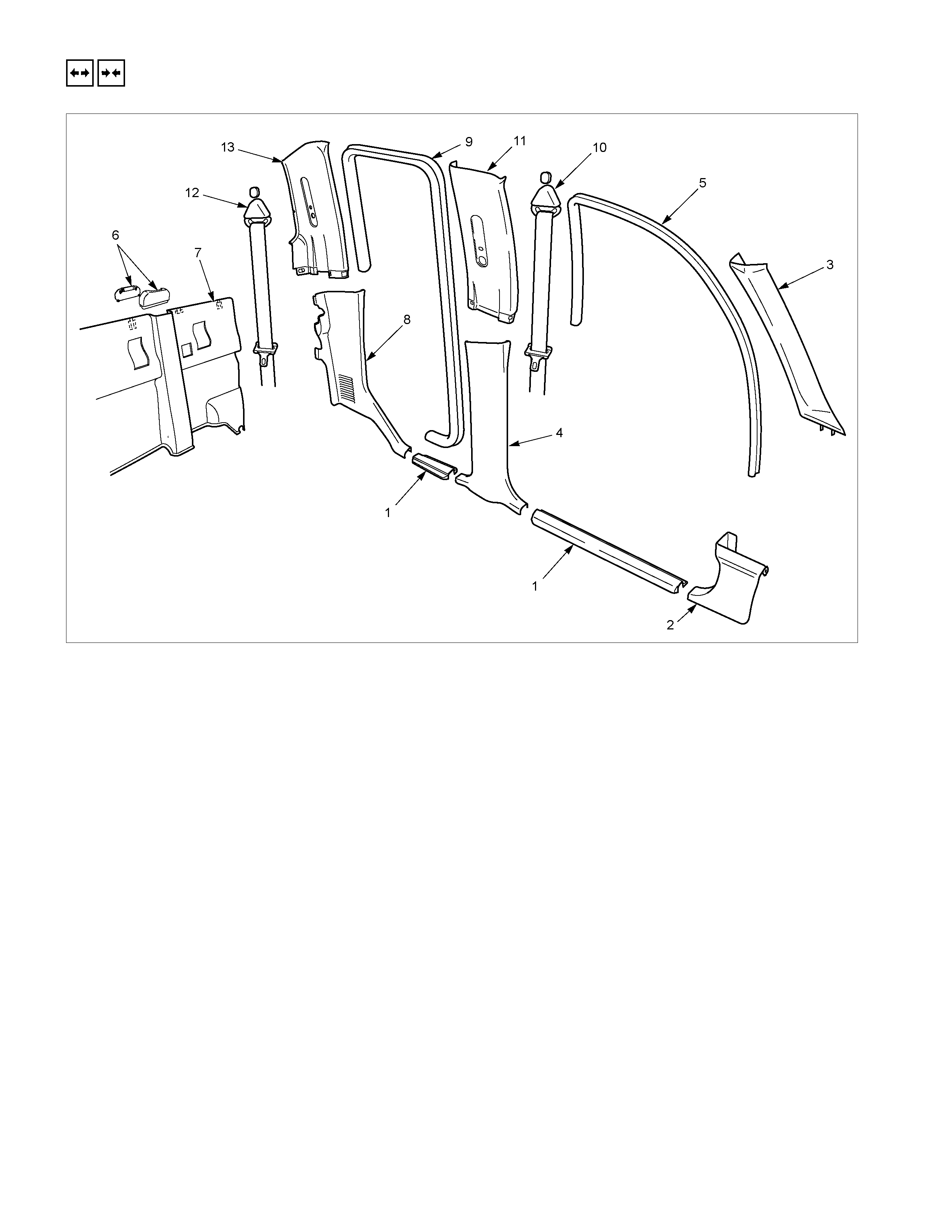
INTERIOR TRIM PANELS
REMOVAL A ND INSTALLATION
RTW3A0MF001301
EXTEND CAB Model
Removal Steps
1. Sill plate
2. Dash side trim cover
▲ 3. Front pillar trim cover
▲ 4. Rear upper cushion
5. Jack cover
▲ 6. Rear end trim cover
▲ 7. Rear speaker grille/Rear speaker
▲ 8. Body side rear lower trim cover
9. Door finisher
▲10. Tongue side seat belt
▲11. Body side rear upper trim cover
Installation Steps
11. Body side rear upper trim cover
▲ 10. Torque side seat belt
9. Door finisher
8. Body side rear lower trim cover
7. Rear speaker grille/Rear speaker
▲ 6. Rear end trim cover
5. Jack cover
4. Rear upper cushion
3. Front pillar trim assembly
2. Dash side trim cover
1. Sill plate
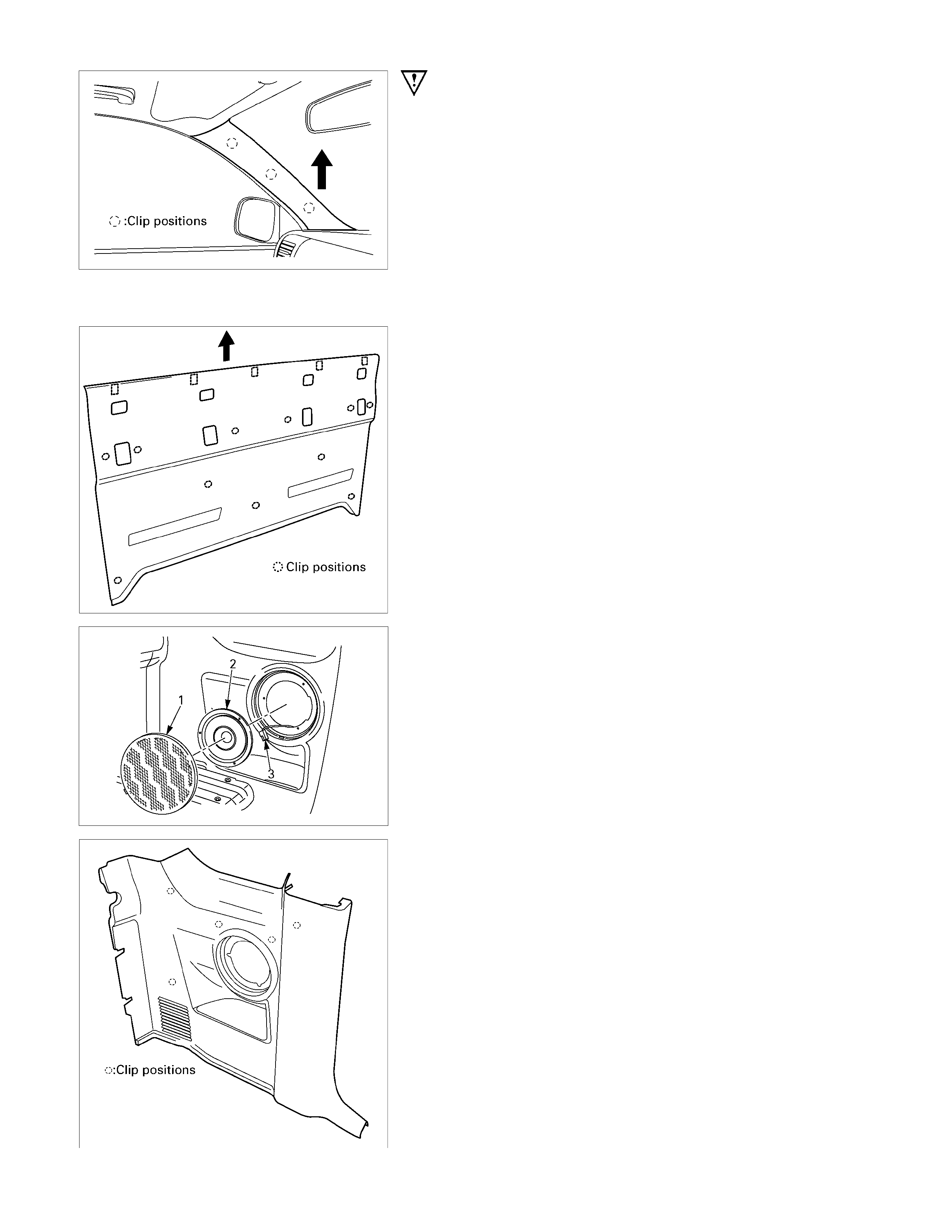
Important Operations - Removal
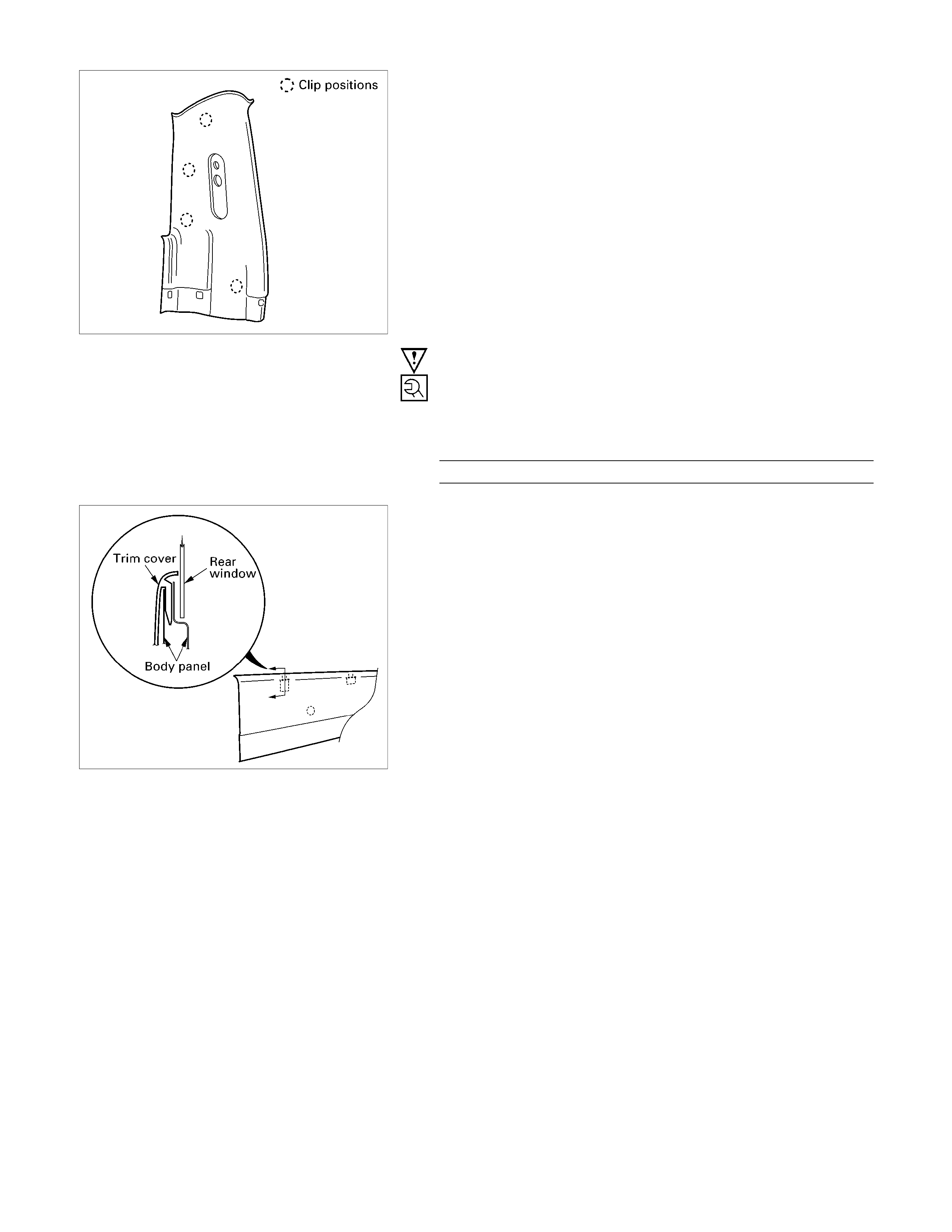
3. Front Pillar Trim Cover
• Turn up the finisher and pry the trim cover clips free
from the body panel.
Then remove the trim cover by pulling upward at the
lower part of it.
4. Rear Upper Cushion
• Slide the upper cushion upward to remove it.
6. Rear End Trim Cover
• Pry the trim cover clips free from the body panel, and
slide the trim cover upward to remove it.
7. Rear Speaker Grille/Rear Speaker
1) Remove the rear speaker grille (1).
2) Remove the 3 screws fixing the rear speaker (2) and
disconnect the connector (3).
8. Body Side Rear Lower Trim Cover
• Pry the trim cover clips free from the body panel.

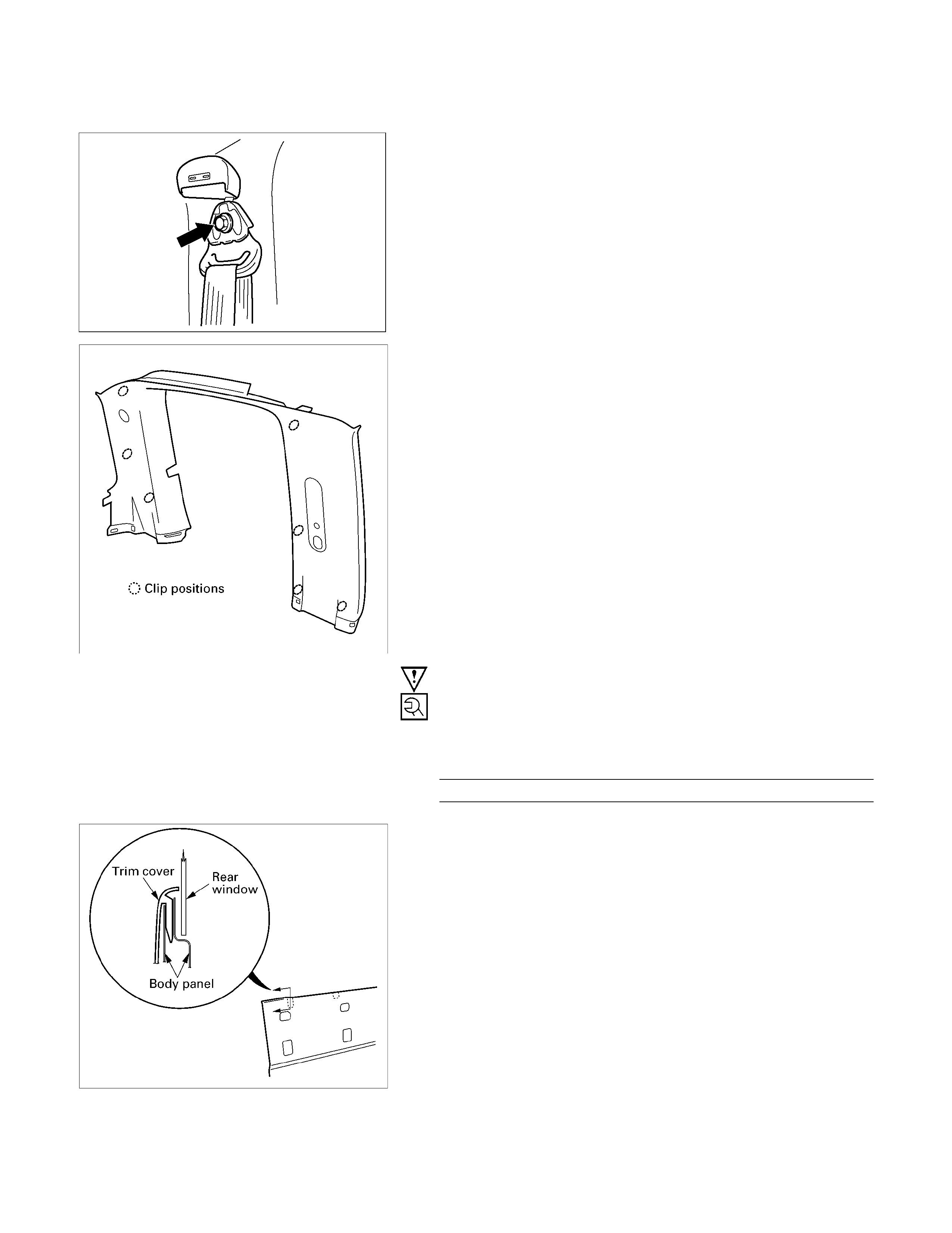
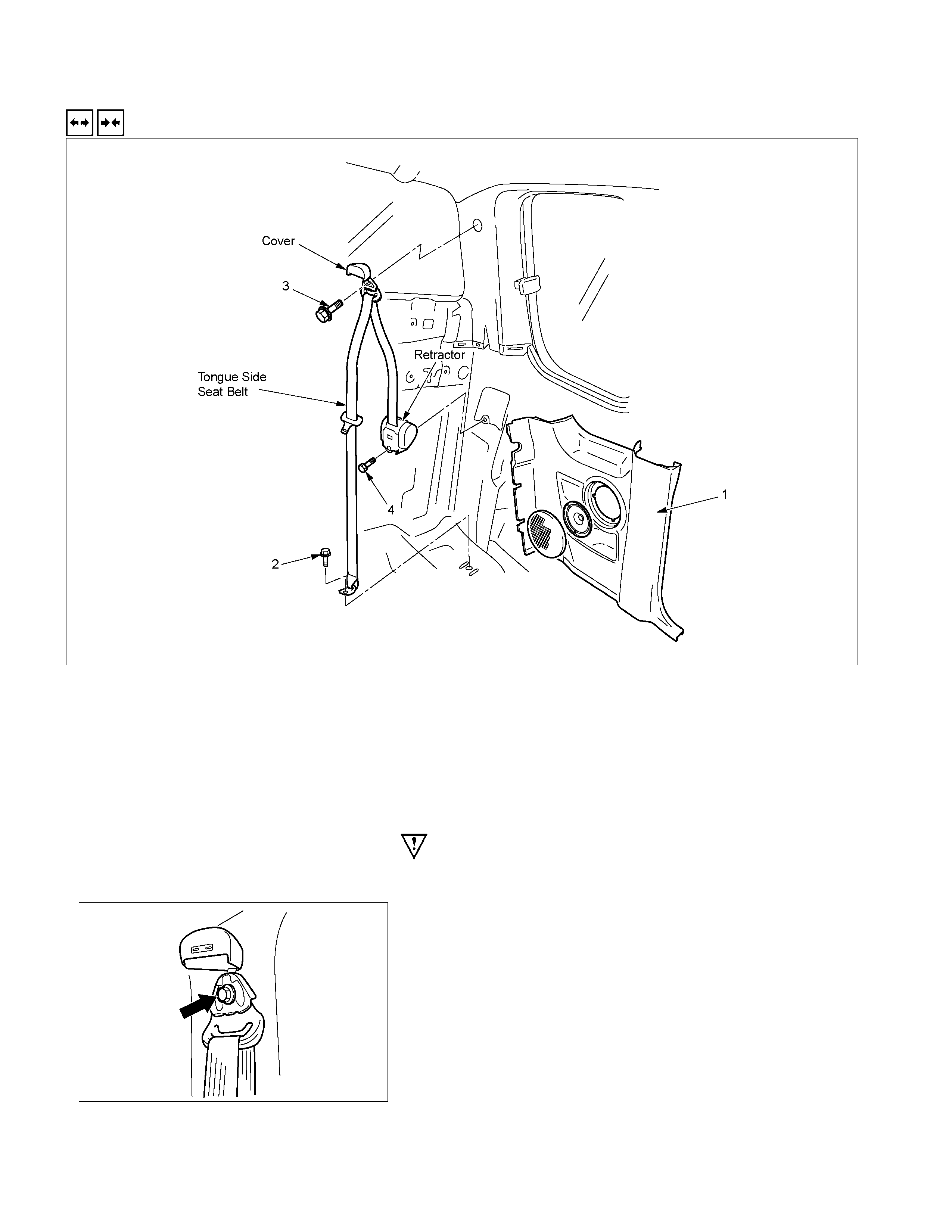
10. Tongue Side Seat Belt
1) Pull out the adjuster knob.
RTW3A0SH000301
2) Open the through ring anchor cover and remove the
seat belt upper anchor bolt.
11. Body Side Rear Upper Trim Cover
• Pry the trim cover clips free from the body panel.
Important Operations - Installation
10. Tongue Side Sea t Belt
• Tighten the seat belt upper anchor bolt to the specified
torque.
Torque N⋅m (kgf⋅m/lb⋅ft)
40 (4.1/30)
6. Rear End Trim Cover
• Insert the hook s on the back upper portion of trim cove
r
to the body panel.
REMOVAL A ND INSTALLATION
RTW3A0MF000601
REGULAR CAB Model
Removal Steps
1. Sill plate
2. Dash side trim cover
▲ 3. Body side rear lower trim cover
4. Door finisher
▲ 5. Front pillar trim cover
▲ 6. Rear end trim cover
▲ 7. Tongue side seat belt
▲ 8. Body side rear upper trim cover
Installation Steps
8. Body side rear upper trim cover
▲ 7. Tongue side seat belt
▲ 6. Rear end trim cover
5. Front pillar trim cover
4. Door finisher
3. Body side rear lower trim cover
2. Dash side trim cover
1. Sill plate
Important Operations - Removal
3. Body Side Rear Lower Trim Cover
• Pry the trim cover clips free from the body panel.
5. Front Pillar Trim Cover
• Turn up the finisher and pry the trim cover clips free
from the body panel.
Then remove the trim cover by pulling upward at the
lower part of it.
6. Rear End Trim Cover
• Pry the trim cover clips free from the body panel, and
slide the trim cover upward to remove it.
7. Tongue Side Seat Belt
1) Pull out the adjuster knob.
RTW3A0SH000301
2) Open the through ring anchor cover and remove the
seat belt upper anchor bolt.
8. Body Side Rear Upper Trim Cover
• Pry the trim cover clips free from the body panel.
Important Operations - Installation
7. Tongue Side Seat Belt
• Tighten the seat belt upper anchor bolt to the specified
torque.
Torque N⋅m (kgf⋅m/lb⋅ft)
40 (4.1/30)
6. Rear End Trim Cover
• Insert the hook s on the back upper portion of trim cove
r
to the body panel.
REMOVAL A ND INSTALLATION
RTW3A0MF001101
CREW CAB Model
Removal Steps
▲ 1. Front sill plate/Rear sill plate
2. Dash side trim cover
▲ 3. Front pillar trim cover
▲ 4. Center pillar lower trim cover
5. Front door finisher
6. Cover
▲ 7. Rear end trim cover
▲ 8. Body side rear lower trim cover
9. Rear door finisher
▲10. Front tongue side seat belt
▲11. Center pillar upper trim cover
12. Rear tongue side seat belt
▲ 13. Body side rear upper trim cover
Installation Steps
13. Body side rear upper trim cover
▲ 12. Rear tongue side seat belt
11. Center pillar upper trim cover
▲10. Front tongue side seat belt
9 Rear door finisher
8. Body side rear lower trim cover
▲ 7. Rear end trim cover
6. Cover
5. Front door finisher
4. Center pillar lower trim cover
3. Front pillar trim cover
2. Dash side trim cover
1. Front sill plate/Rear sill plate
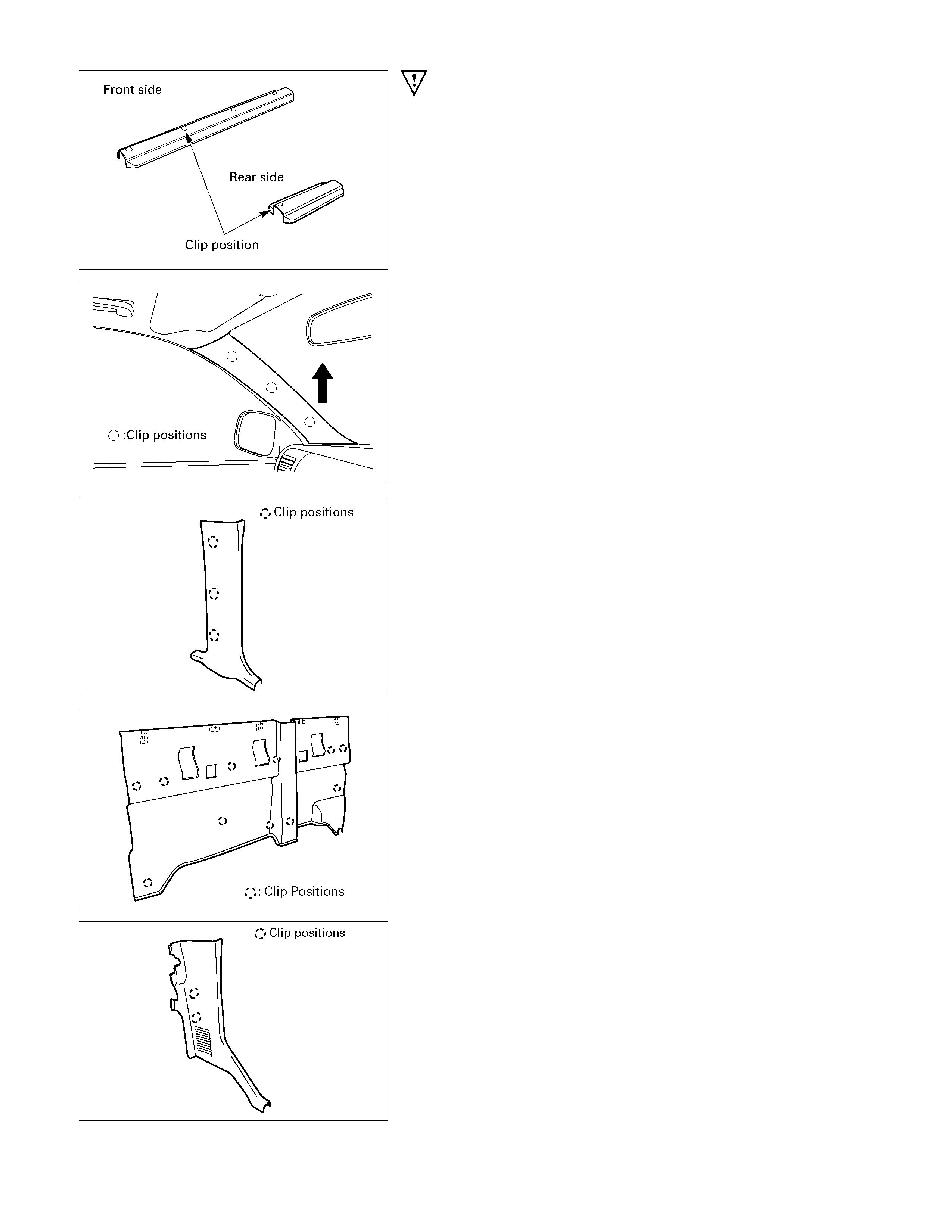
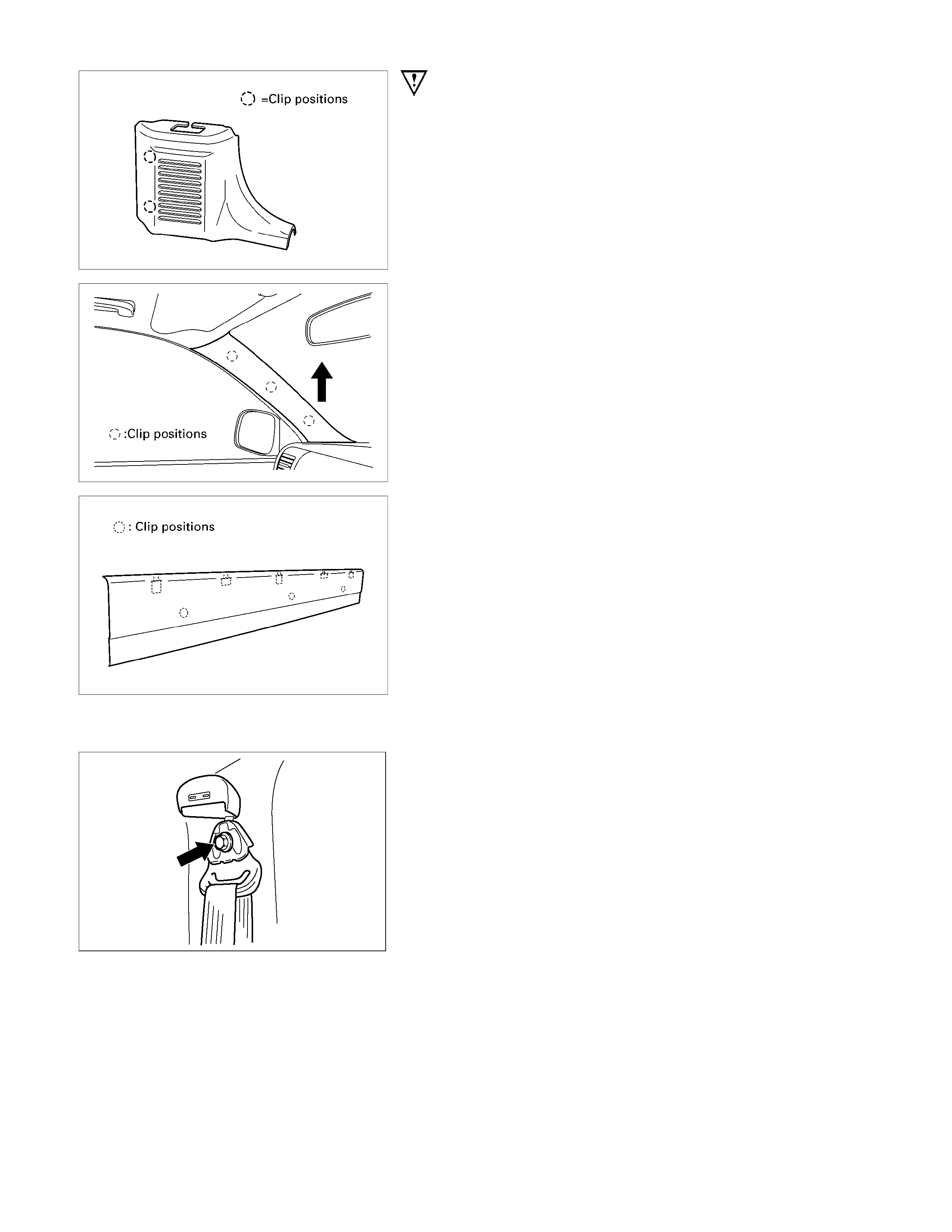
Important Operations - Removal
1. Front Sill Plate/Rear Sill Plate
• Pull out the 4 clip positions (Front).
• Pull out the 2 clip positions (Rear).
3. Front Pillar Trim Cover
• Turn up the finisher and pry the trim cover clips free
from the body panel.
Then remove the trim cover by pulling upward the lowe
r
part of it.
4. Center Pillar Lower Trim Cover
• Pry the trim cover lips free from the body panel.
7. Rear End Trim Cover
• Pry the trim cover clips free from the body panel, and
slide the trim cover upward to remove it.
8. Body Side Rear Lower Trim Cover
• Pry the trim cover clips free from the body panel.
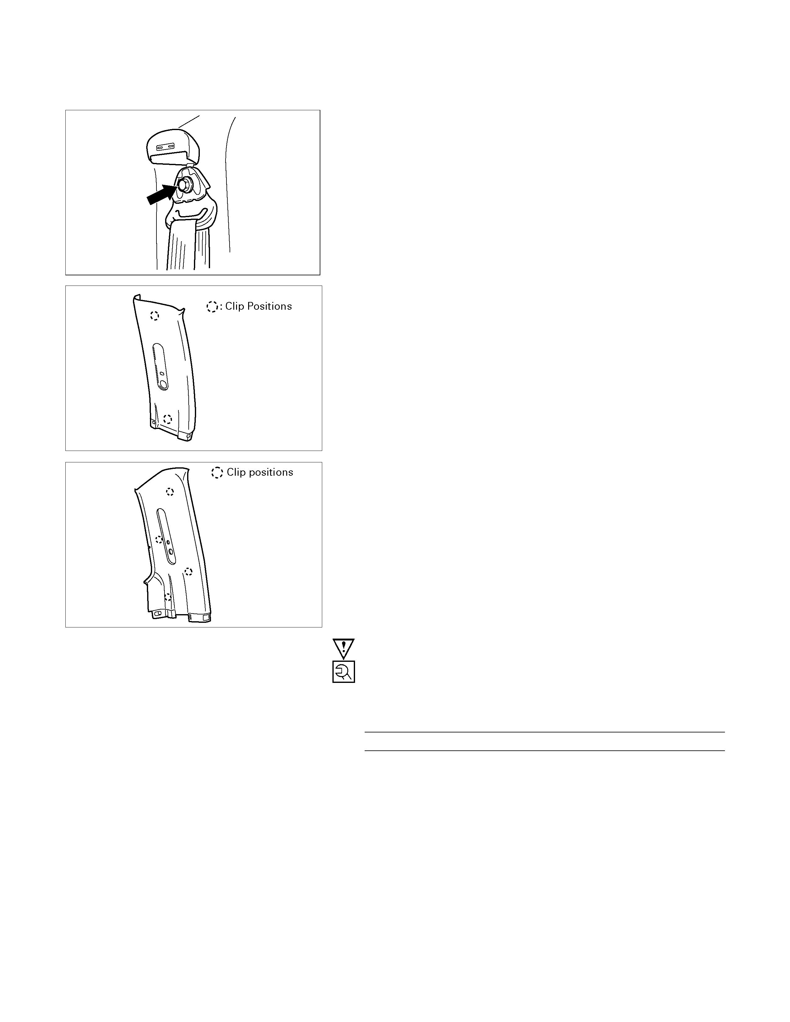
10. Front Tongue Side Seat Belt
1) Pull out the adjuster knob.
RTW3A0SH000301
2) Open the through ring anchor cover and remove the
seat belt upper anchor bolt.
11. Center Pillar Upper Trim Cover
• Pry the trim cover clips free from the body panel.
13. Body Side Rear Upper Trim Cover
• Pry the trim cover clips free from the body panel.
Important Operations - Installation
12. Rear Tongue Side Seat Belt
• Tighten the seat belt upper anchor bolt to the specified
torque.
Torque N⋅m (kgf⋅m/lb⋅ft)
40 (4.1/30)
10. Front Tongue Side Seat Belt
• Tighten the seat belt upper anchor bolt to the specified
torque.
Torque N⋅m (kgf⋅m/lb⋅ft)
40 (4.1/30)
7. Rear End Trim Cover
• Insert the hook s on the back upper portion of trim cove
r
to the body panel.
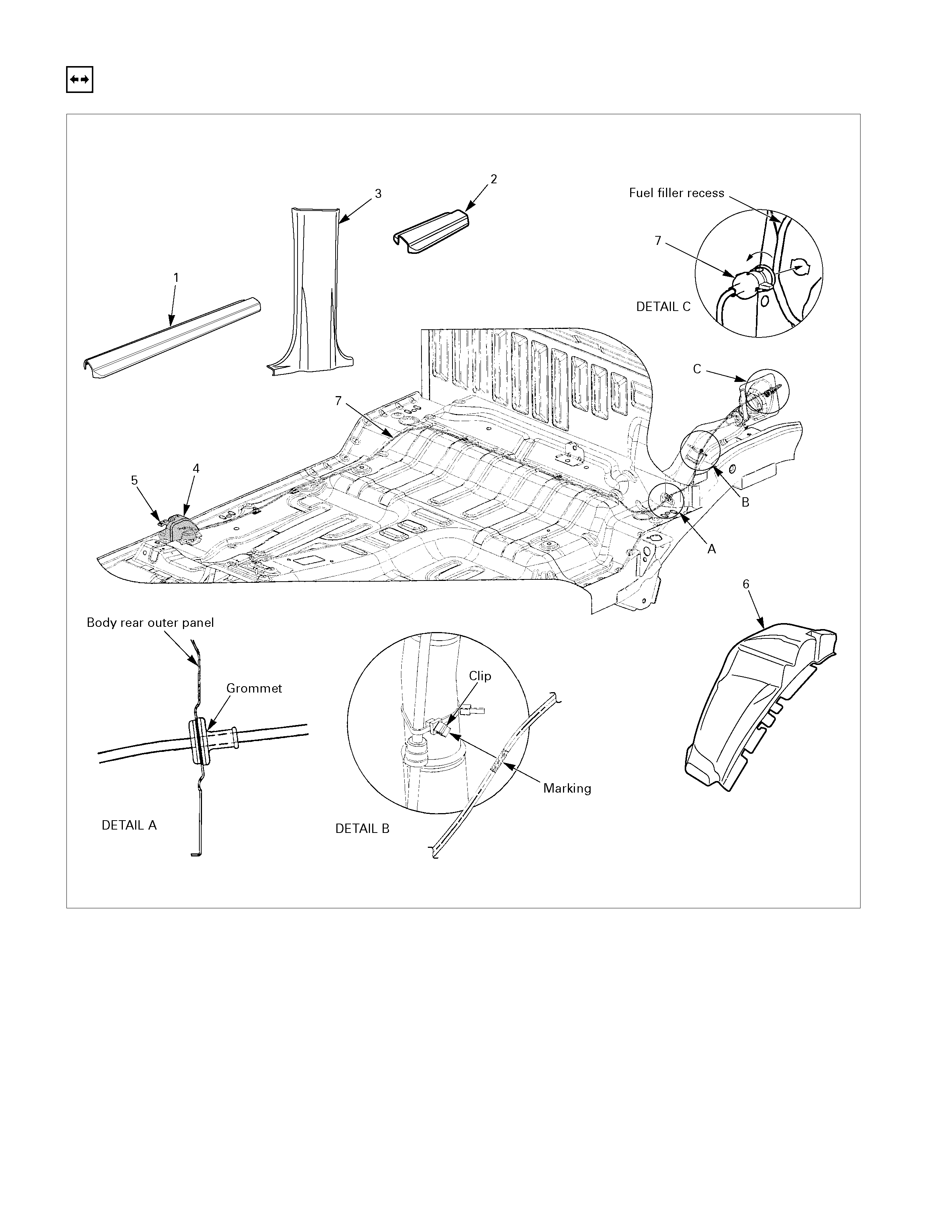
FUEL FILLER LID OPENER LEVER/CABLE
REMOVAL (REGULAR CAB)
Removal Steps
▲ 1. Front sill plate
▲ 2. Fuel filler lid opener cover
▲ 3. Fuel filler lid opener lever
4. Rear wheel housing extension panel
▲ 5. Fuel filler lid cable assembly
REMOVAL (EXTEND CAB)
Removal Steps
▲ 1. Front sill plate
▲ 2. Fuel filler lid opener cover
▲ 3. Fuel filler lid opener lever
4. Rear wheel housing extension panel
▲ 5. Fuel filler lid cable assembly
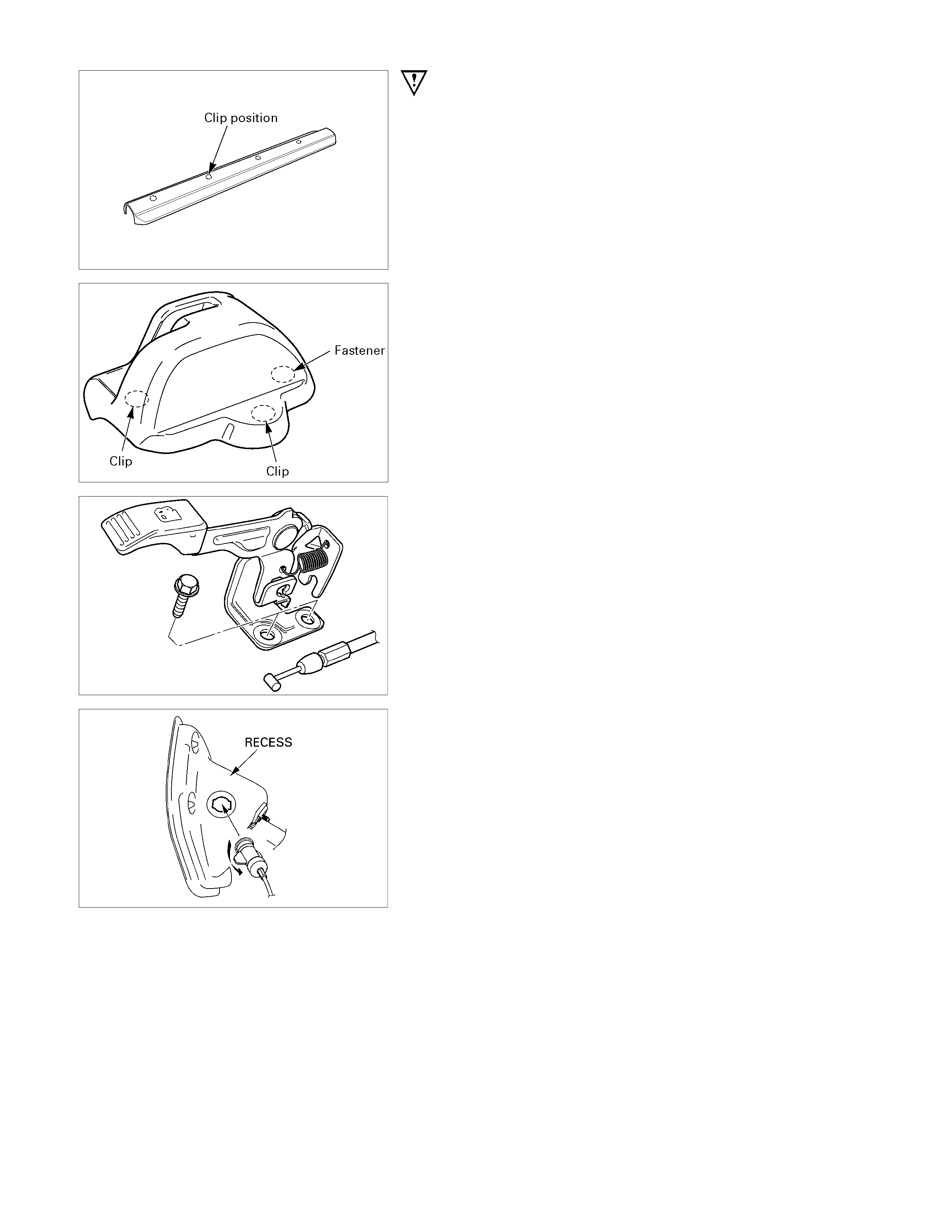
Important Operations - Removal
1. Front Sill Plate
• Pull out the 4 clip positions.
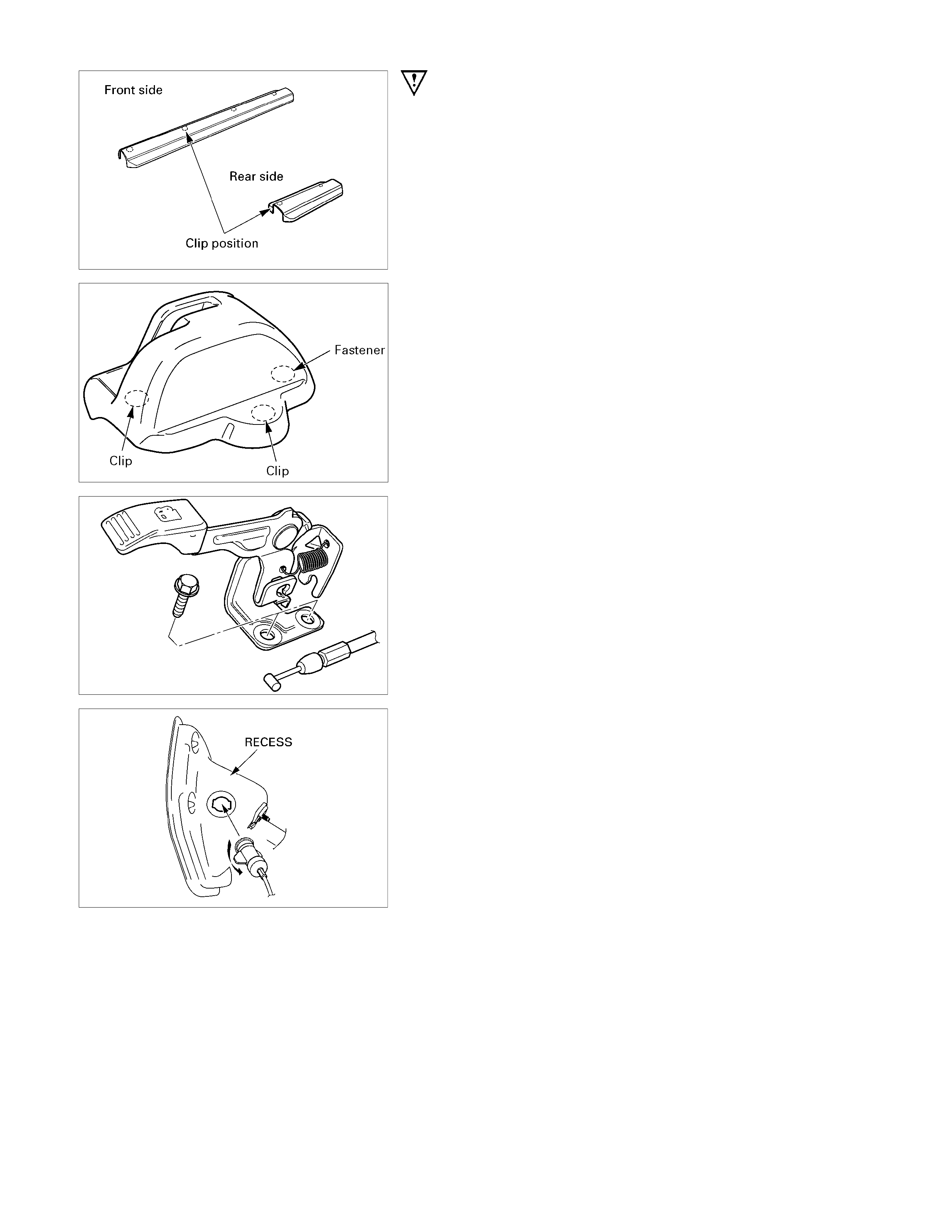
2. Fuel Filler Lid Opener Cover
• Pull out the 3 clip positions.
3. Fuel Filler Lid Opener Lever
• Remove the 2 opener fixing bolts and disconnect the
cable.
5. Fuel Filler Lid Cable Assembly
• Remove some fixing clips, turn the cable holder on the
side of recess in 90° counterclockwise and remove it
from the recess. Pull out the grommet to frontward o
f
vehicle and remove the cable assembly.
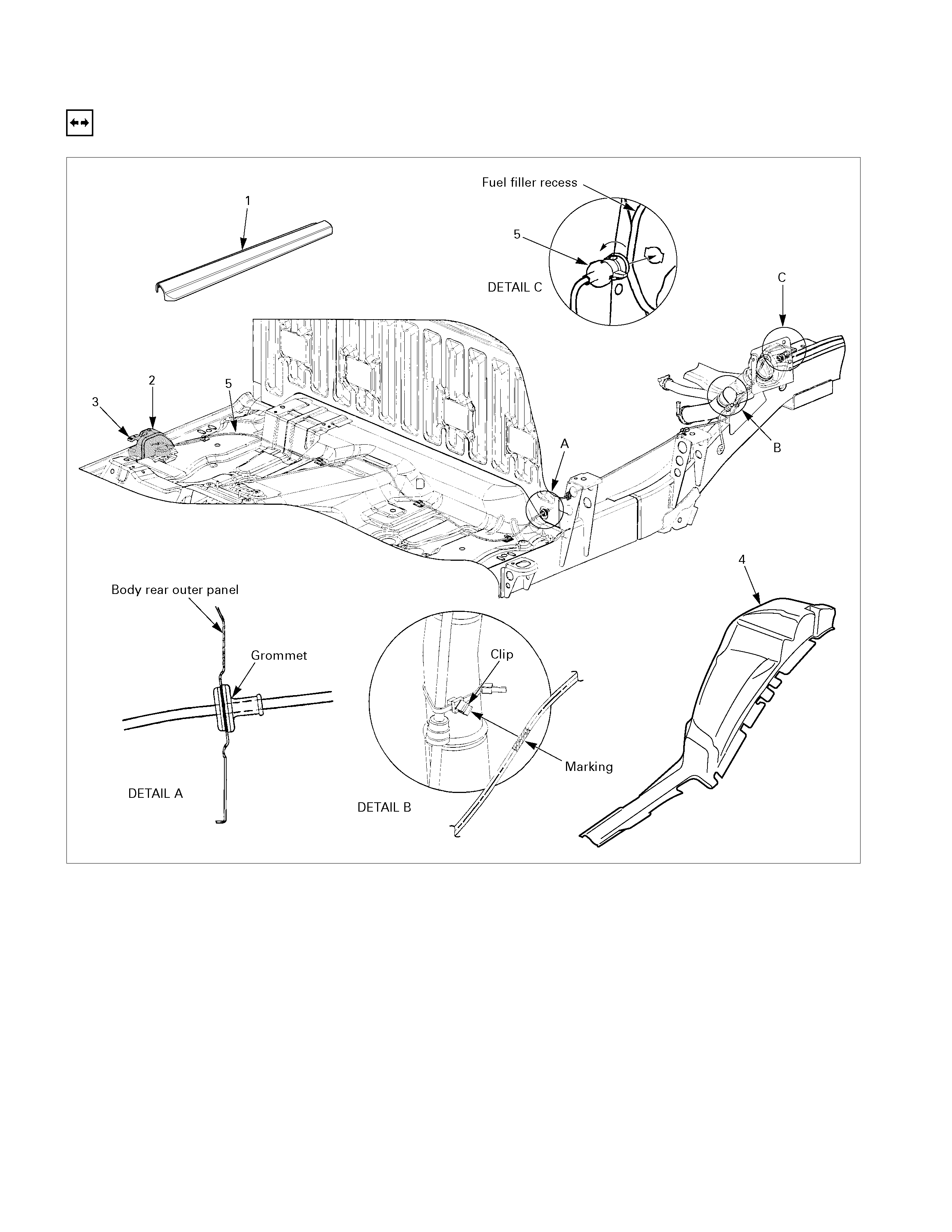
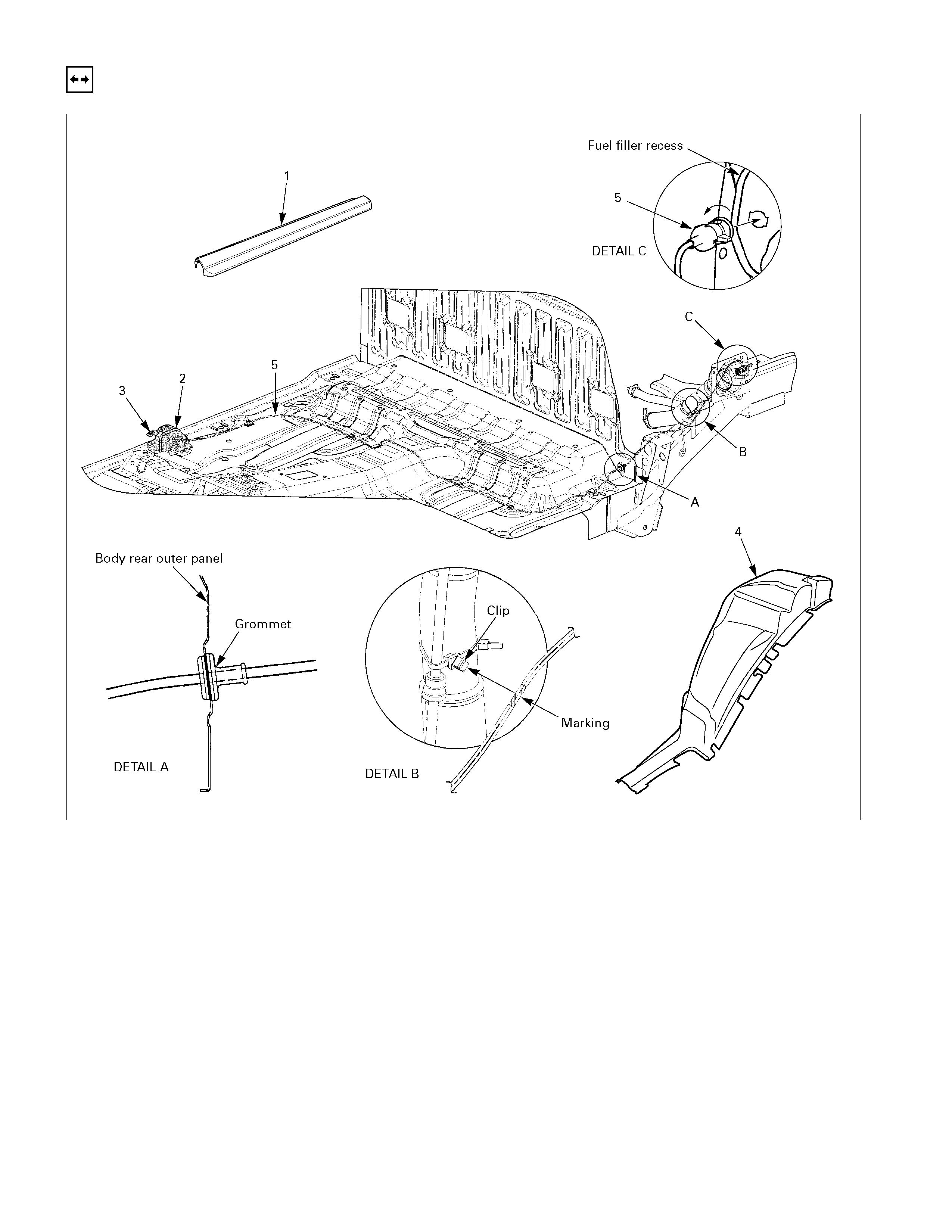
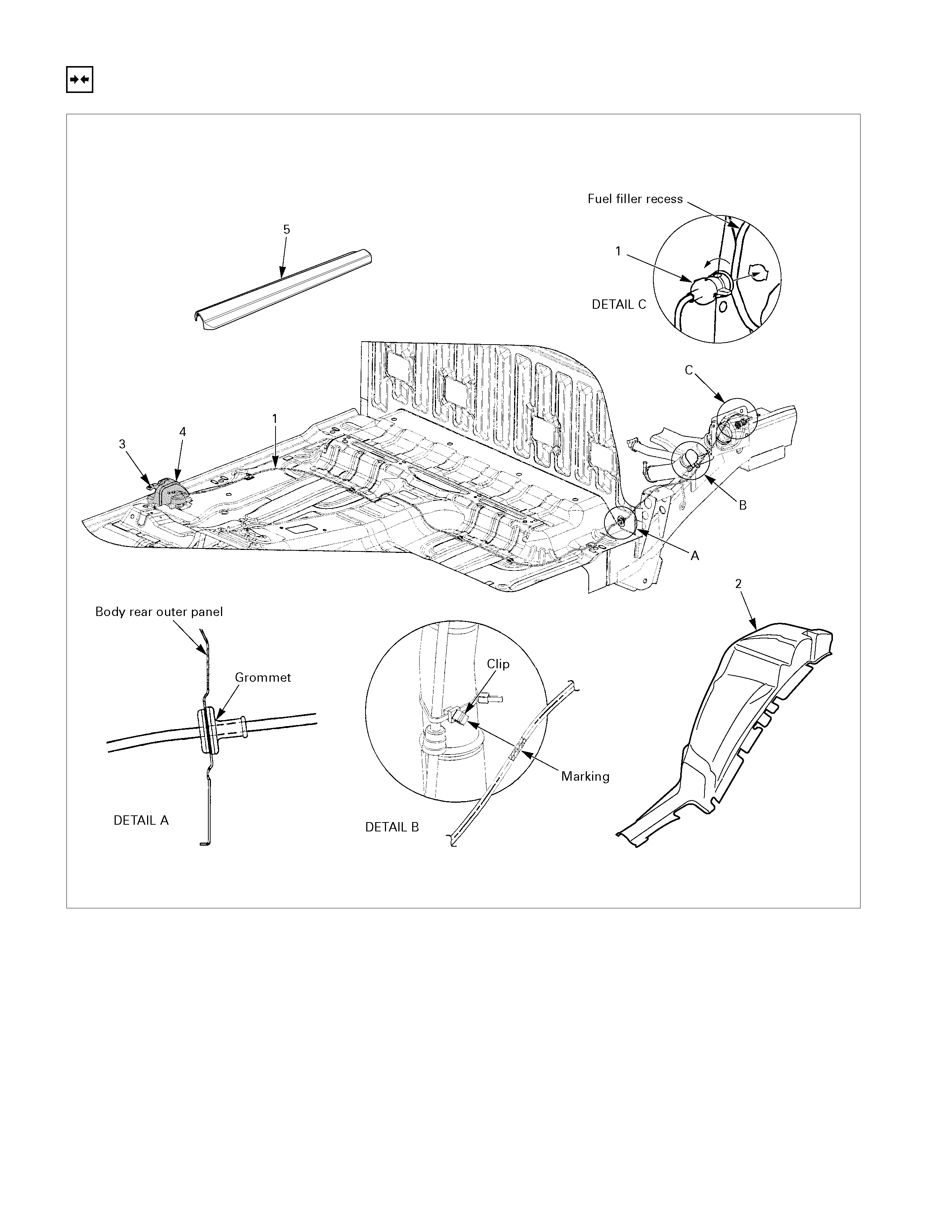
REMOVAL (CREW CAB)
686R300010
Removal Steps
▲ 1. Front sill plate
▲ 2. Rear sill plate
3. Center pillar lower trim cover
▲ 4. Fuel filler lid opener cover
▲ 5. Fuel filler lid opener lever
6. Rear wheel housing extension panel
▲ 7. Fuel filler lid cable assembly
Important Operations - Removal
1. Front Sill Plate
• Pull out 4 clip positions.
2. Rear Sill Plate
• Pull out 2 clip positions.
4. Fuel Filler Lid Opener Cover
• Pull out the 3 clip positions.
5. Fuel Filler Lid Opener Lever
• Remove the 2 opener fixing bolts and disconnect the
cable.
7. Fuel Filler Lid Cable Assembly
• Remove some fixing clips, turn the cable holder on the
side of recess in 90° counterclockwise and remove it
from the recess. Pull out the grommet to frontward o
f
vehicle and remove the cable assembly.

INSTALLATION (REGULAR CAB)
686R300017
Installation Steps
▲ 1. Fuel filler lid cable assembly
2. Rear wheel housing extension panel
3. Fuel filler lid opener lever
4. Fuel filler lid opener cover
5. Front sill plate
INSTALLATION (EXTEND CAB)
Installation Steps
▲ 1. Fuel filler lid cable assembly
2. Rear wheel housing extension panel
3. Fuel filler lid opener lever
4. Fuel filler lid opener cover
5. Front sill plate
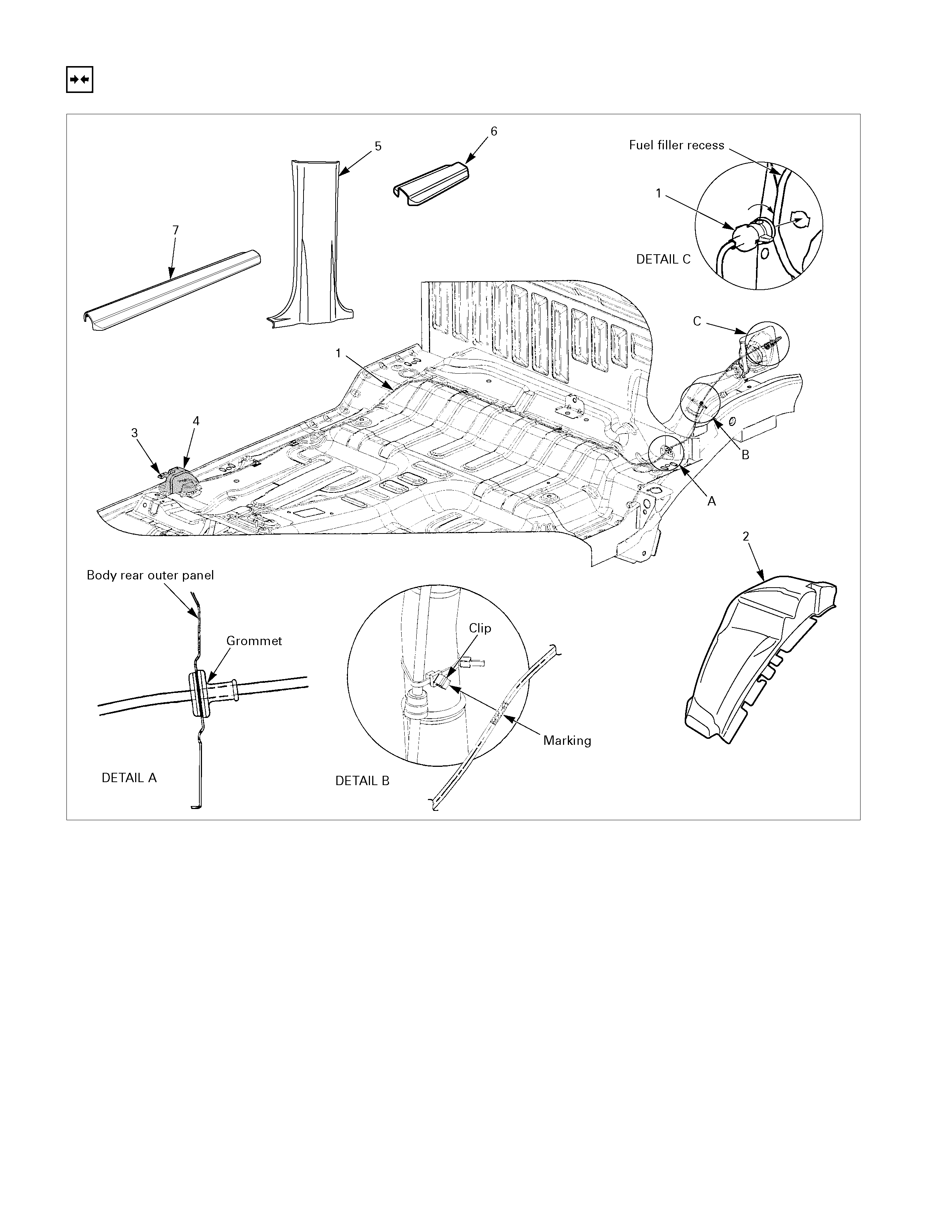
INSTALLATION (CREW CA B)
686R300013
Installation Steps
▲ 1. Fuel filler lid cable assembly
2. Rear wheel housing extension panel
3. Fuel filler lid opener lever
4. Fuel filler lid opener cover
5. Center pillar lower trim cover
6. Rear sill plate
7. Front sill plate

Important Opera tion - Installation
1. Fuel Filler Lid Cable Assembly
• Install the cable holder of cable assembly to the recess
and push the grom m et in to the back panel. Fix the c lips
to the pointed places.
Note:
To install, follow the removal steps in the reverse order,
noting the following points.
•
••
• Do not make extreme curve on the cable.
•
••
• Install the cable from inside of the cab.
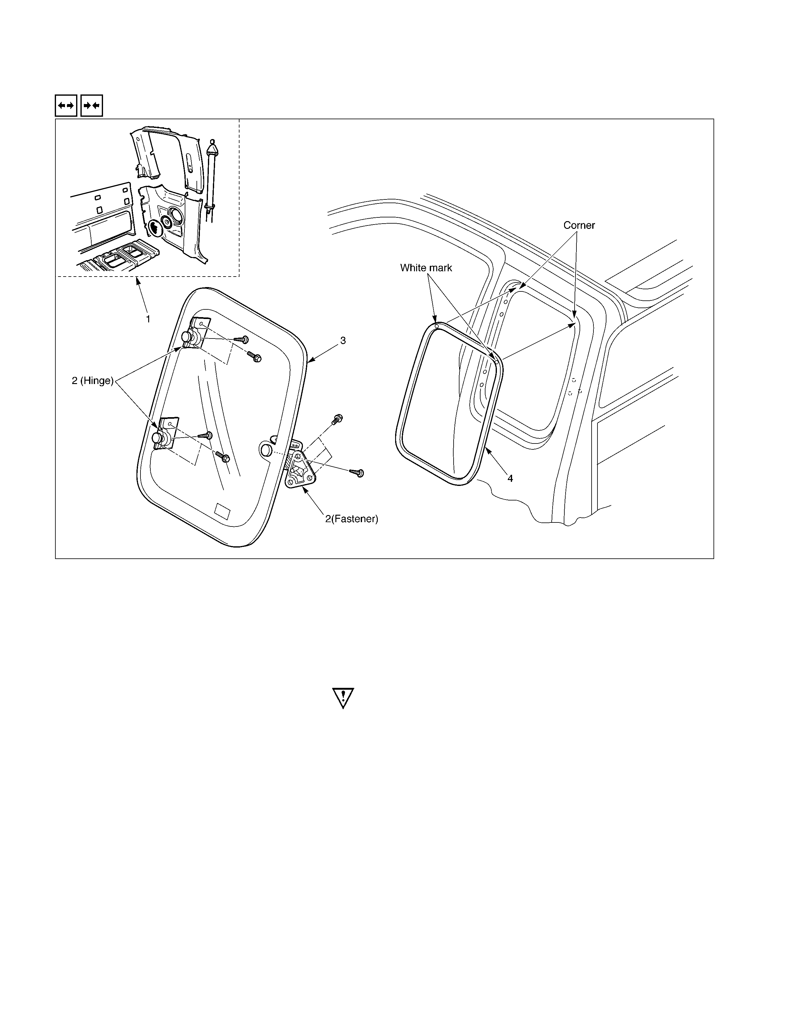
QUARTER GLASS (EXTEND CAB)
REMOVAL A ND INSTALLATION
Removal Steps
▲ 1. Body side rear trim covers
2. Hinge/Faster
3. Quarter glass
4. Weather strip
Installation Steps
▲ 4. Weather strip
3. Quarter glass
2. Hinge/Faster
1. Body side rear trim covers
Important Operation - Removal
1. Body Side Rear Trim Covers
• Refer to Interior Trim Panels in this section.
Important Operation – Installation
4. Weather Strip
• Install the weather strip by aligning to corners with white
mark to the upper coners on the body panel.
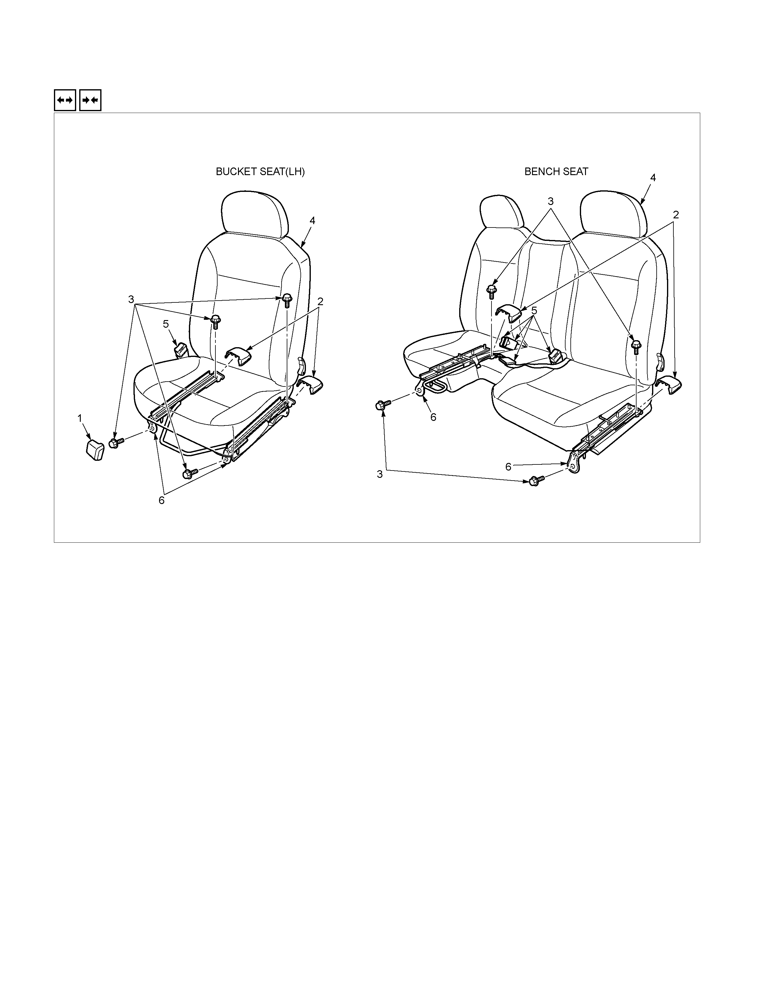
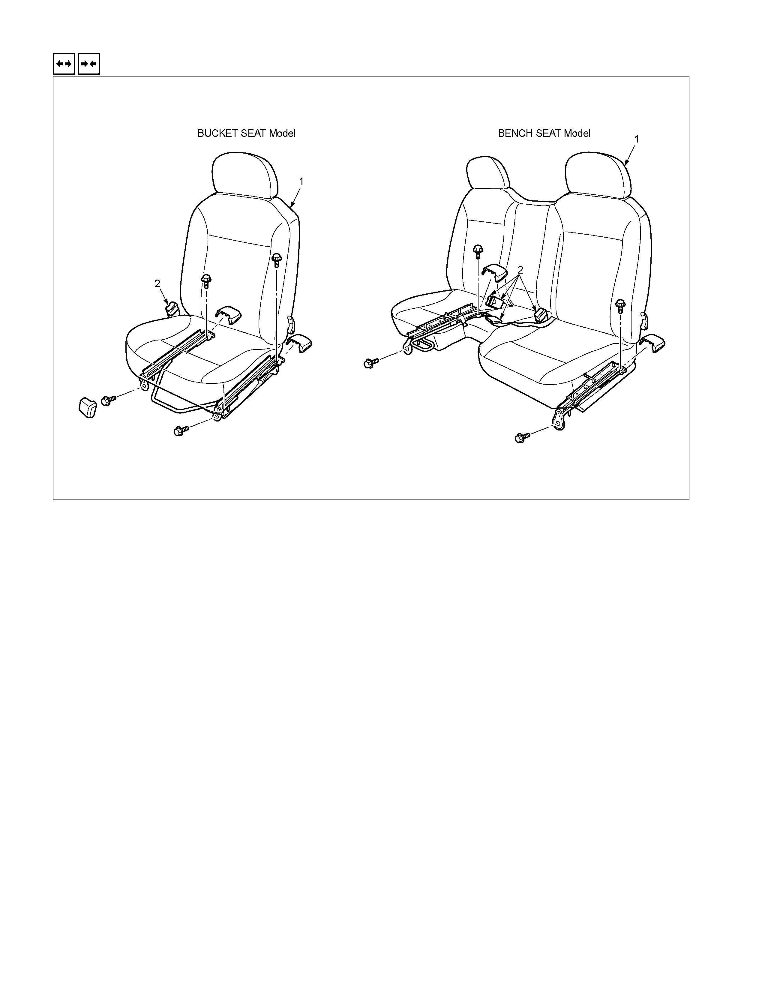
FRONT SEAT
REMOVAL A ND INSTALLATION
RTW3A0MF000301
Removal Steps
▲ 1. Front cover
2. Rear cover
3. Bolt
▲ 4. Seat assembly
▲ 5. Side seat belt buckle/Center seat belt
6. Seat adjuster
Installation Steps
6. Seat adjuster
▲ 5. Side seat belt buckle/Center seat belt
4. Seat assembly
▲ 3. Bolt
2. Rear cover
1. Front cover
Important Operations - Removal
1. Front Cover
• While pushing the cover downward, pull it.
4. Seat Assembly
• Disconnect the seat belt warning harness connecto
r
(Driver’s side only).
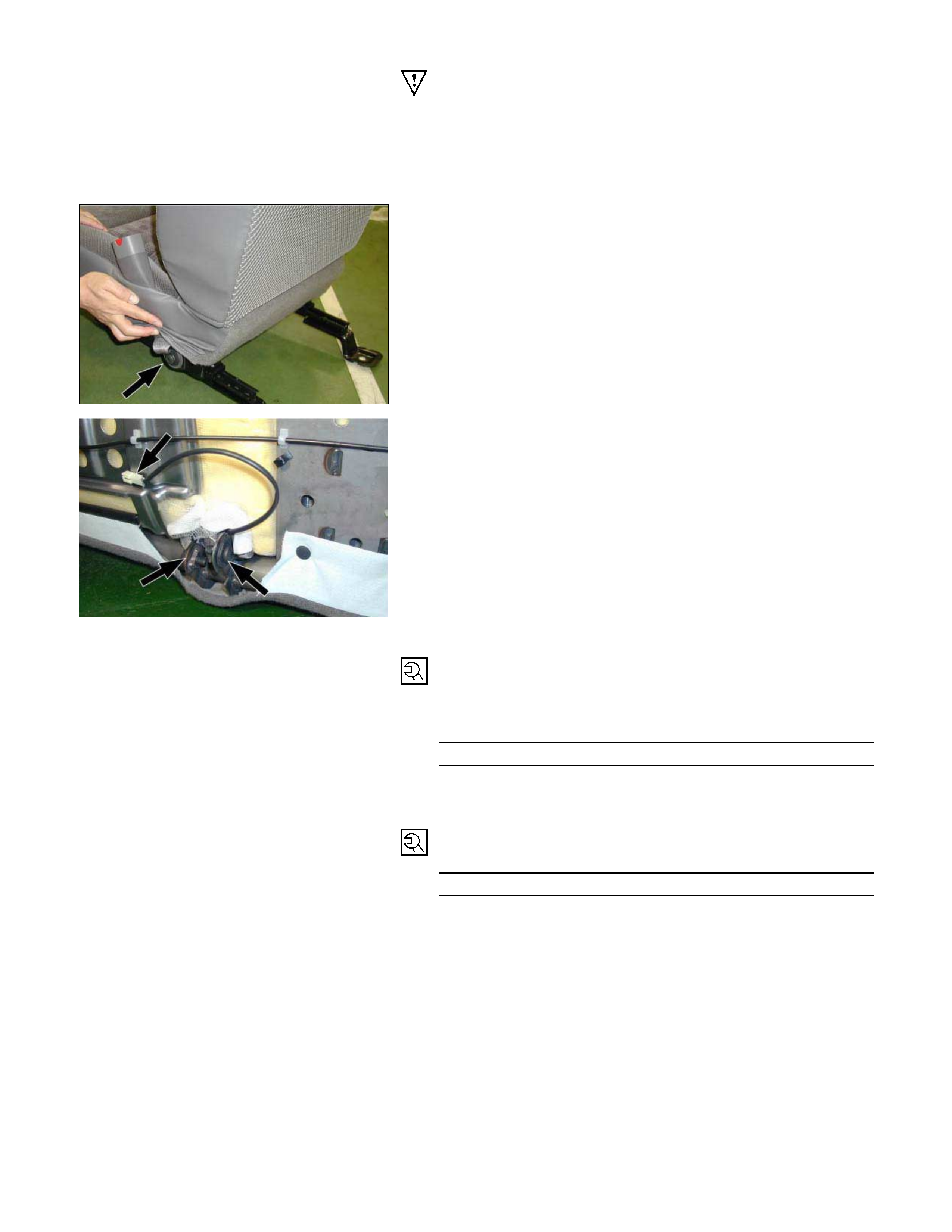
5. Side Seat Belt Buckle/Center Seat Belt
• Remove the seat belt fixing screw and the warning
harness connector clip (Bucket seat model).
24.jpg
• Remove the seat belt fixing screws and the warning
harness connector clip (Bench seat model).
Important Operations – Installation
5. Buckle Side Seat Belt/Center Seat Belt
• Tighten the seat belt fixing screws to the specified
torque.
Torque N⋅m (kgf⋅m/lb⋅ft)
40 (4.1 / 30)
3. Bolt: Seat Assembly to Floor Panel
Torque N⋅m (kgf⋅m/lb⋅ft)
40 (4.1 / 30)
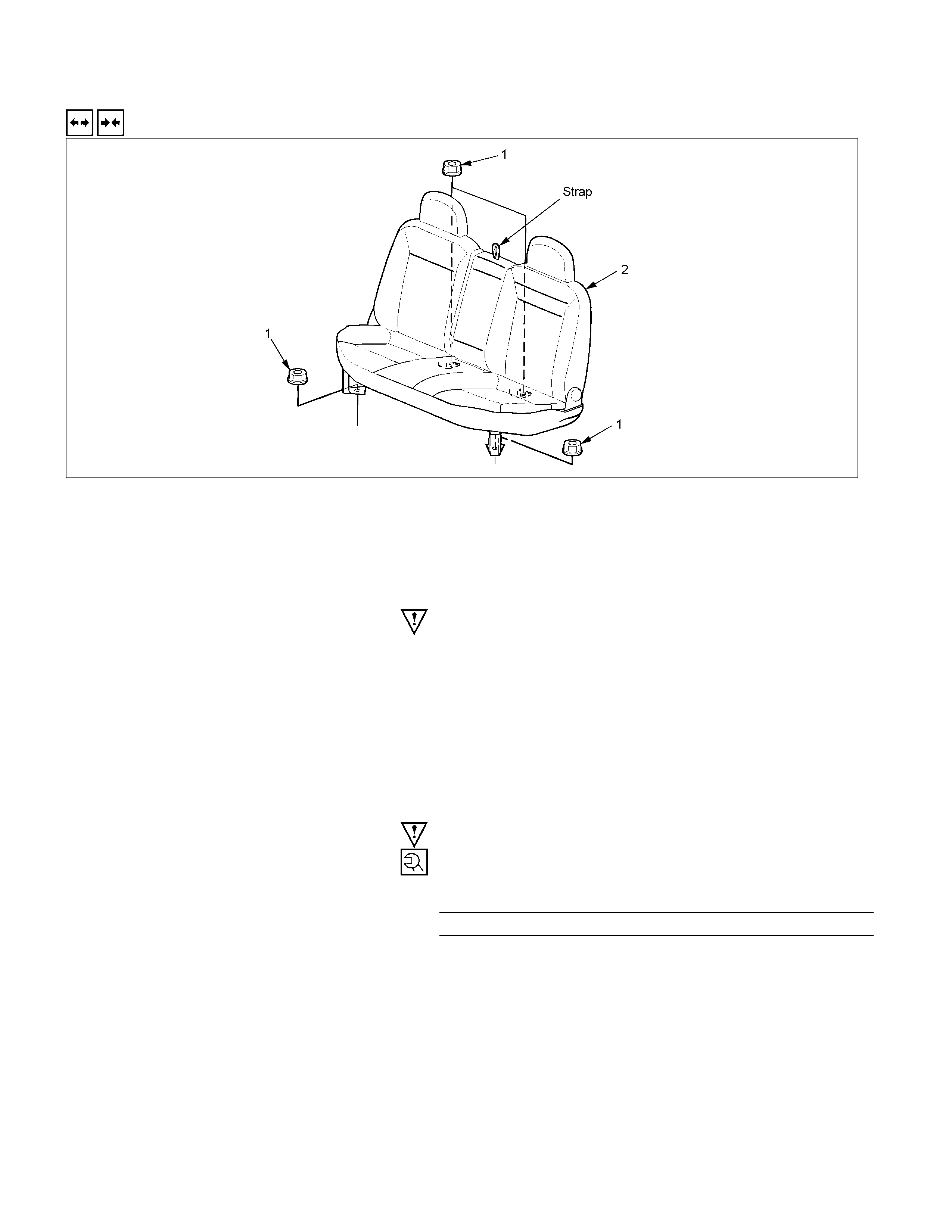
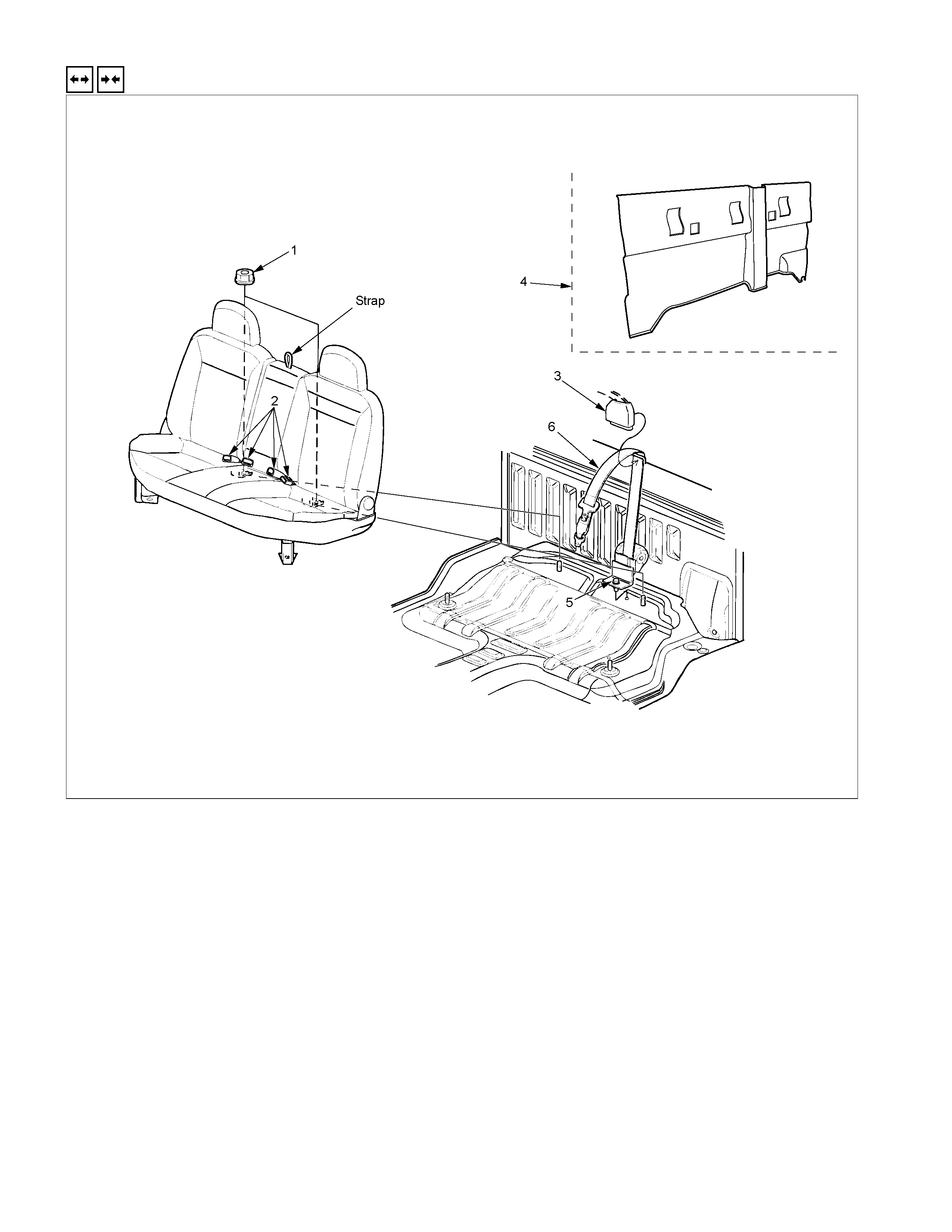
REAR SEAT (CREW CAB)
REMOVAL A ND INSTALLATION
RTW3A0SF000101
Removal Steps
▲ 1. Nut
2. Rear seat assembly
Installation Steps
2. Rear seat assembly
▲ 1. Nut
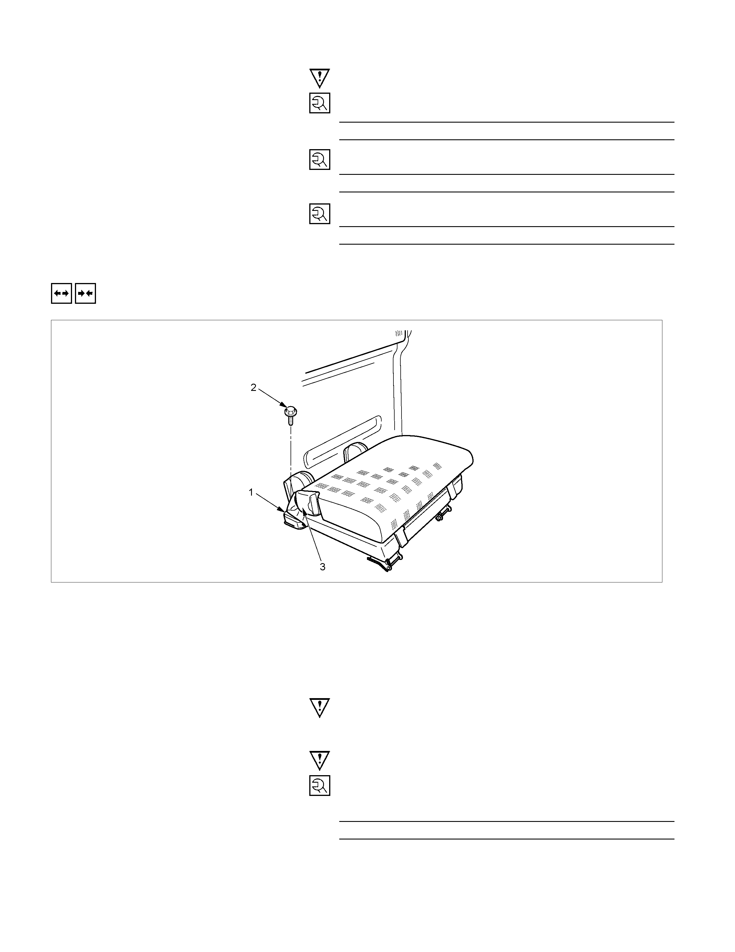
Important Operation - Removal
1. Nut
• Pull the strap to release the seat back lock and fold
down the seat back.
Important Opera tion - Installation
1. Nut
Torque N⋅m (kgf⋅m/lb⋅ft)
40 (4.1 / 30)
JUMP SEAT (EXTEND CAB)
REMOVAL A ND INSTALLATION
RTW3A0MF001201
Removal Steps
1. Cover
2. Bolt
3. Jump seat assembly
4. Storage box
Installation Steps
4. Storage box
3. Jump seat assembly
▲ 2. Bolt
1. Cover
Important Opera tion - Installation
2. Bolt
Bolt Torque N⋅m (kg⋅m/lb⋅ft)
40 (4.1 / 30)
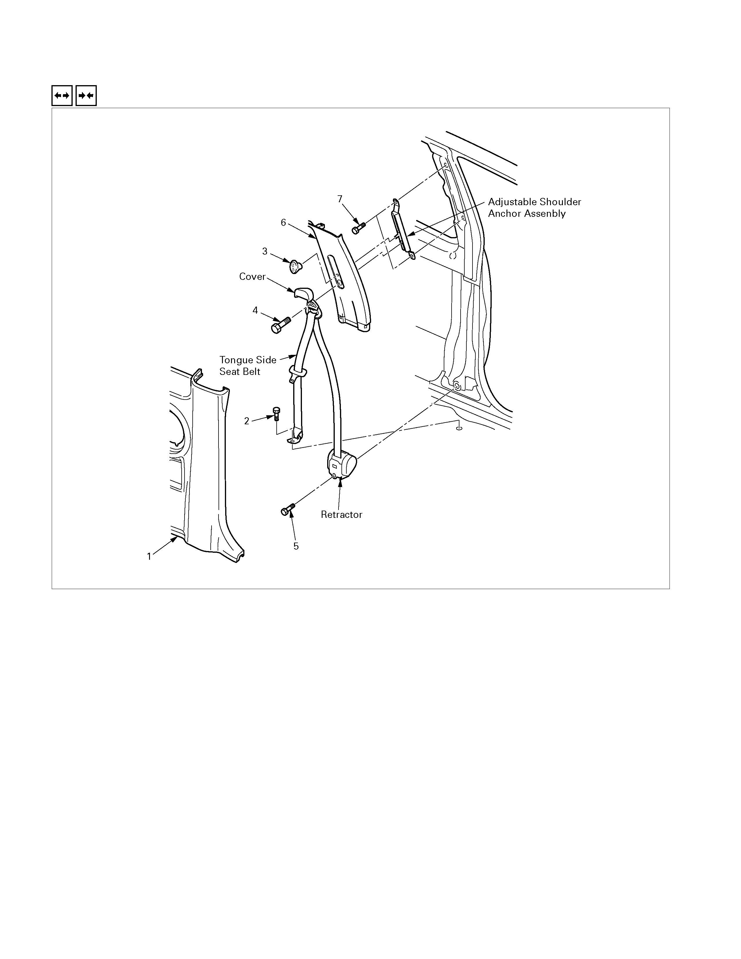
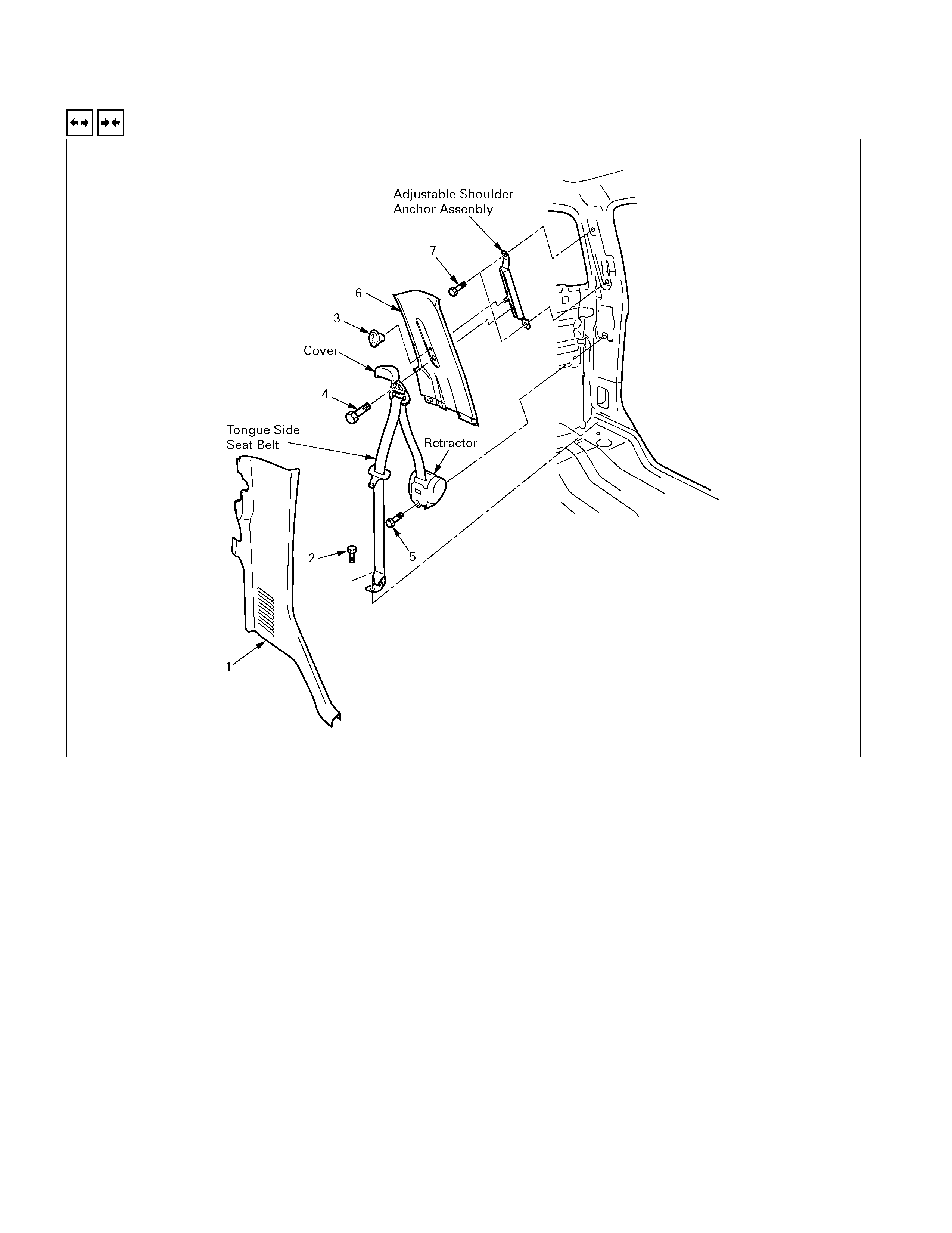
FRONT SEAT BELT
REMOVAL AND INSTA LLATION (TONGUE SIDE SEAT BELT)
Removal Steps
1. Body side rear lower trim cover
2. Lower anchor bolt
▲ 3. Knob
▲ 4. Upper anchor bolt
5. Retractor fixing bolt
6. Body side rear upper trim cover
7. Adjustable shoulder anchor fixing bolts
Installation Steps
▲ 7. Adjustable shoulder anchor fixing bolts
6. Body side rear upper trim cover
▲ 5. Retractor fixing bolt
▲ 4. Upper anchor bolt
3. Knob
▲ 2. Lower anchor bolt
1. Body side rear lower trim cover
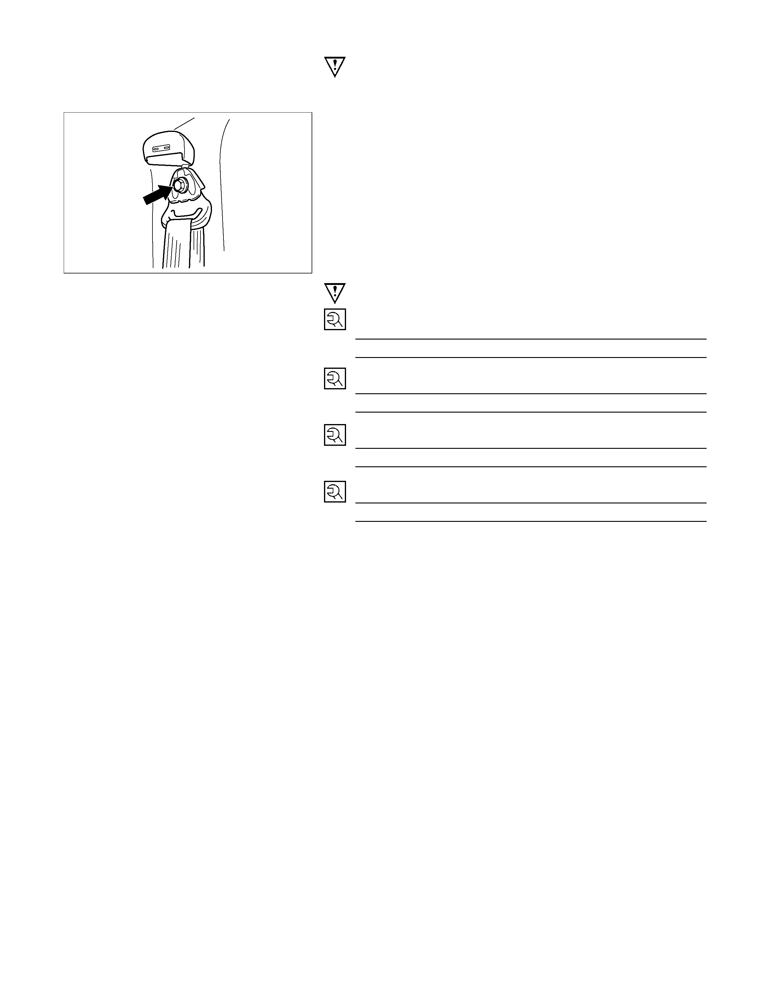
Important Operations - Removal
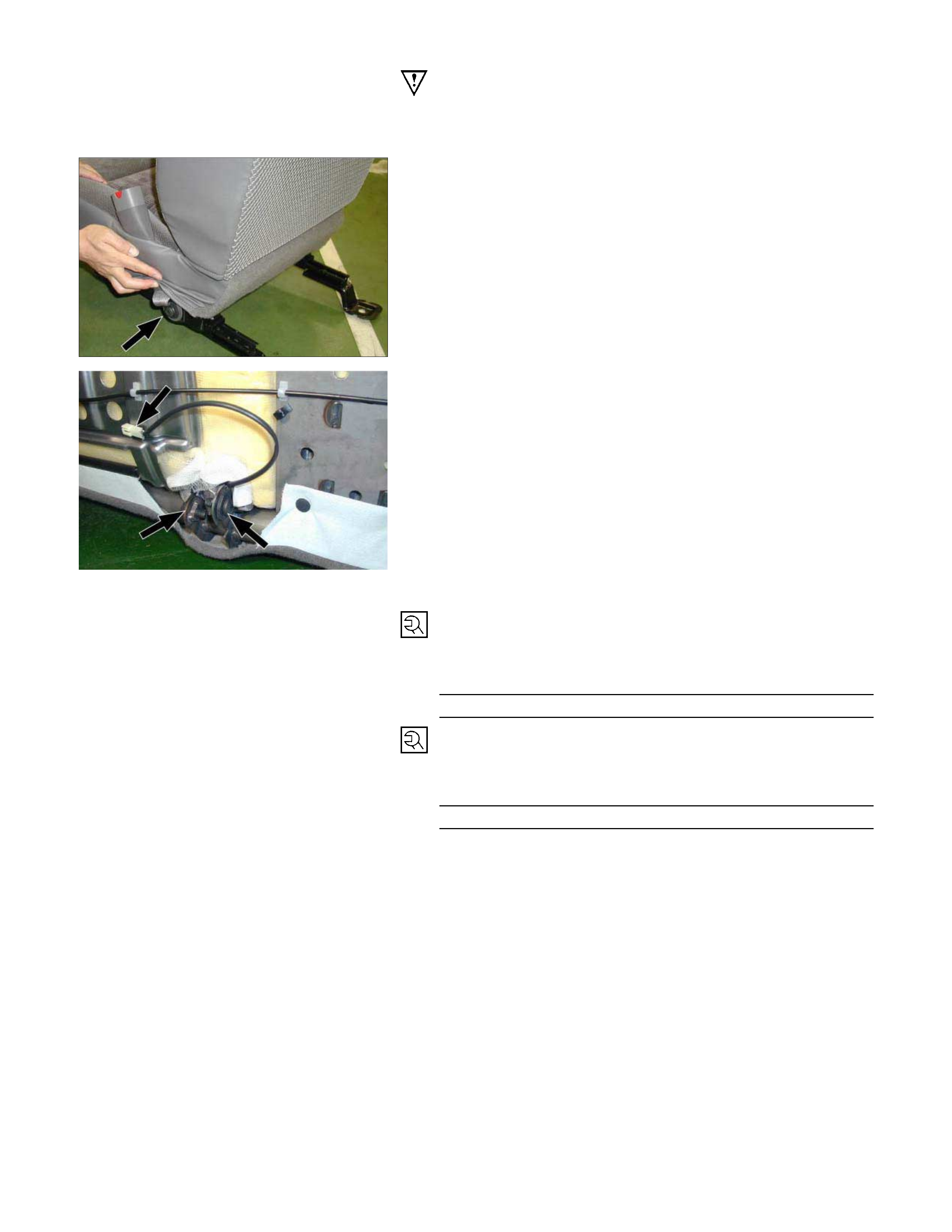
3. Knob
• Pull out the knob.
RTW3A0SH000301
4. Upper anchor bolt
• Open the through ring anchor cover and remove the
seat belt upper anchor bolt.
Important Operations - Installation
7. Adjustable shoulder anchor fixing bolts
Bolt torque N⋅m (kgf⋅m/lb⋅ft)
40 (4.1 / 30)
5. Retractor fixing bolt
Bolt torque N⋅m (kgf⋅m/lb⋅ft)
40 (4.1 / 30)
4. Upper anchor bolt
Bolt torque N⋅m (kgf⋅m/lb⋅ft)
40 (4.1 / 30)
2. Lower anchor bolt
Bolt torque N⋅m (kgf⋅m/lb⋅ft)
40 (4.1 / 30)
REMOVAL AND INSTALLATION (SIDE SEAT BELT BUCKLE/CENTER SEAT BELT)
RTW3A0MF000401
Removal Steps
▲ 1. Front seat assembly
▲ 2. Side seat belt buckle/Center seat belt
Installation Steps
▲ 2. Side seat belt buckle/Center seat belt
▲ 1. Front seat assembly
Important Operations - Removal
1. Front Seat Assembly
• Refer to Front Seat in this section.
2. Side Seat Belt Buckle/Center Seat Belt
• Remove the seat belt fixing screw and the warning
harness connector clip (Bucket seat model).
24.jpg
• Remove the seat belt fixing screws and the warning
harness connector clip (Bench seat model).
Important Operations - Installation
2.Side Seat Belt Buckle/Center Seat Belt
• Tighten the seat belt fixing screws to the specified
torque.
Torque N⋅m (kgf⋅m/lb⋅ft)
40 (4.1 / 30)
1. Front Seat Assembly
• Tighten the seat assembly fixing bolts to the specified
torque.
Torque N⋅m (kgf⋅m/lb⋅ft)
40 (4.1 / 30)
REAR SEAT BELT (CREW CAB)
REMOVAL AND INSTA LLATION (TONGUE SIDE SEAT BELT)
Removal Steps
1. Body side rear lower trim cover
2. Lower anchor bolt
▲ 3. Knob
▲ 4. Upper anchor bolt
5. Retractor fixing bolt
6. Body side rear upper trim cover
7. Adjustable shoulder anchor fixing bolts
Installation Steps
▲ 7. Adjustable shoulder anchor fixing bolts
6. Body side rear upper trim cover
▲ 5. Retractor fixing bolt
▲ 4. Upper anchor bolt
3. Knob
▲ 2. Lower anchor bolt
1. Body side rear lower trim cover

Important Operations - Removal
3. Knob
• Pull out the knob.
RTW3A0SH000301
4. Upper anchor bolt
• Open the through ring anchor cover and remove the
seat belt upper anchor bolt.
Important Operations - Installation
7. Adjustable shoulder anchor fixing bolts
Bolt torque N⋅m (kgf⋅m/lb⋅ft)
40 (4.1 / 30)
5. Retractor fixing bolt
Bolt torque N⋅m (kgf⋅m/lb⋅ft)
40 (4.1 / 30)
4. Upper anchor bolt
Bolt torque N⋅m (kgf⋅m/lb⋅ft)
40 (4.1 / 30)
2. Lower anchor bolt
Bolt torque N⋅m (kgf⋅m/lb⋅ft)
40 (4.1 / 30)
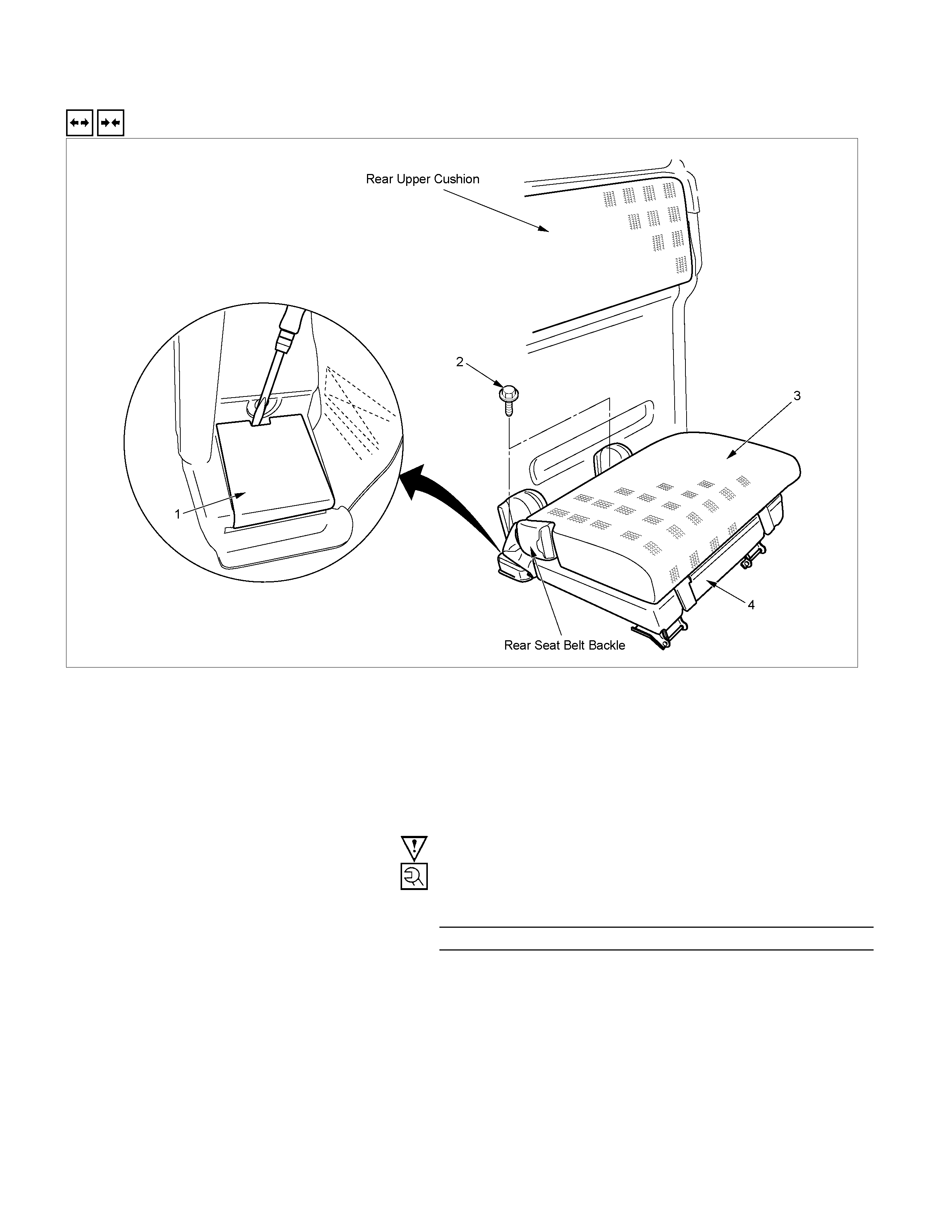
REMOVAL AND INSTALLATION (REAR CENTER SEAT BELT/REAR SEAT BELT BACKLE)
RTW3A0LF000901
Removal Steps
1. Nut
2. Rear seat belt buckle
▲ 3. Cover
▲ 4. Rear end trim cover
5. Bolt
6. Rear center seat belt
Installation Steps
▲ 6. Rear center seat belt
▲ 5. Bolt
4. Rear end trim cover
3. Cover
2. Rear seat belt buckle
▲ 1. Nut
RTW3A0SH000601
Important Operations - Removal
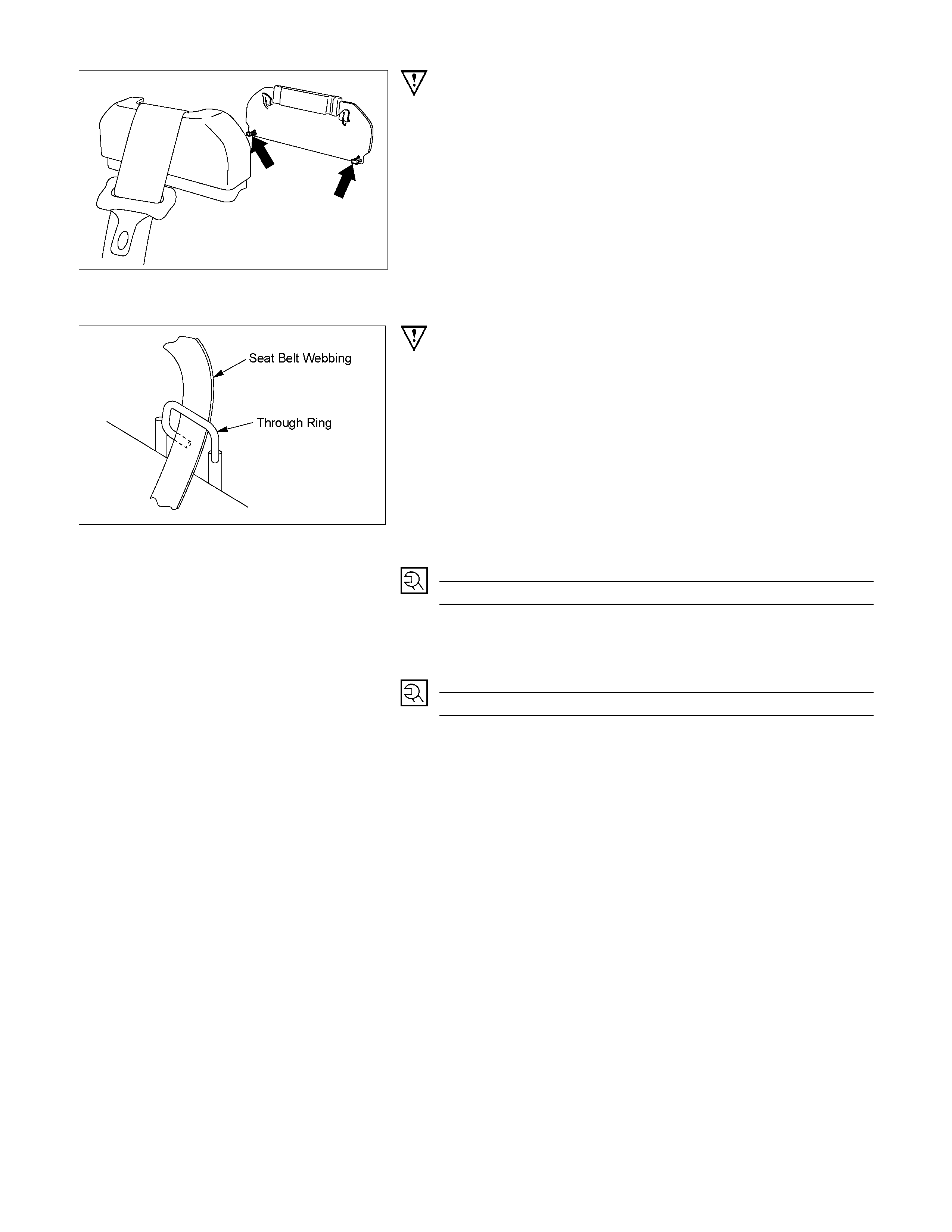
3. Cover
• Pry the lower portion of the cover and remove it.
4. Rear End Trim Cover
• Refer to Interior Trim Panels in this section.
RTW3A0SH001601
Important Operations - Installation
6. Rear center seat belt
• Install the seat belt webbing through the through ring on
the back panel as shown in the illustration.
5. Bolt: Rear Center Seat Belt to Floor Panel
Torque N⋅m (kgf⋅m/lb⋅ft)
40 (4.1 / 30)
1. Nu t: Rear Seat Assembly/Rear Seat Belt Bu ckle to Flo o
r
Panel
Torque N⋅m (kgf⋅m/lb⋅ft)
40 (4.1 / 30)
REAR SEAT BELT (EXTEND CAB)
REMOVAL AND INSTA LLATION (TONGUE SIDE SEAT BELT)
RTW3A0MF000701
Removal Steps
▲ 1. Body side rear lower trim cover
2. Lower anchor bolt
▲ 3. Upper anchor bolt
4. Retractor fixing bolt
Installation Steps
▲ 4. Retractor fixing bolt
▲ 3. Upper anchor bolt
▲ 2. Lower anchor bolt
1. Body side rear lower trim cover
Important Operations - Removal
1. Body side rear lower trim cover
• Refer to Interior Trim Panels in this section..
RTW3A0SH000301
3. Upper anchor bolt
• Open the through ring anchor cover and remove the
seat belt upper anchor bolt
Important Operations - Installation
4. Retractor fixing bolt
Bolt torque N⋅m (kgf⋅m/lb⋅ft)
40 (4.1 / 30)
3. Upper anchor bolt
Bolt torque N⋅m (kgf⋅m/lb⋅ft)
40 (4.1 / 30)
2. Lower anchor bolt
Bolt torque N⋅m (kgf⋅m/lb⋅ft)
40 (4.1 / 30)
REMOVAL AND INSTALLATION (REAR SEAT BELT BACKLE)
RTW3A0SF000201
Removal Steps
▲ 1. Cover
2. Bolt
3. Rear seat belt buckle
Installation Steps
3. Rear seat belt buckle
▲ 2. Bolt
1. Cover
Important Operation - Removal
1. Cover
• Refer to Jump Seat (Extend Cab) in this section.
Important Opera tion - Installation
2. Bolt: Jump Seat Assembly/Rear Seat Belt Buckle to
Floor Panel
Torque N⋅m (kgf⋅m/lb⋅ft)
40 (4.1 / 30)
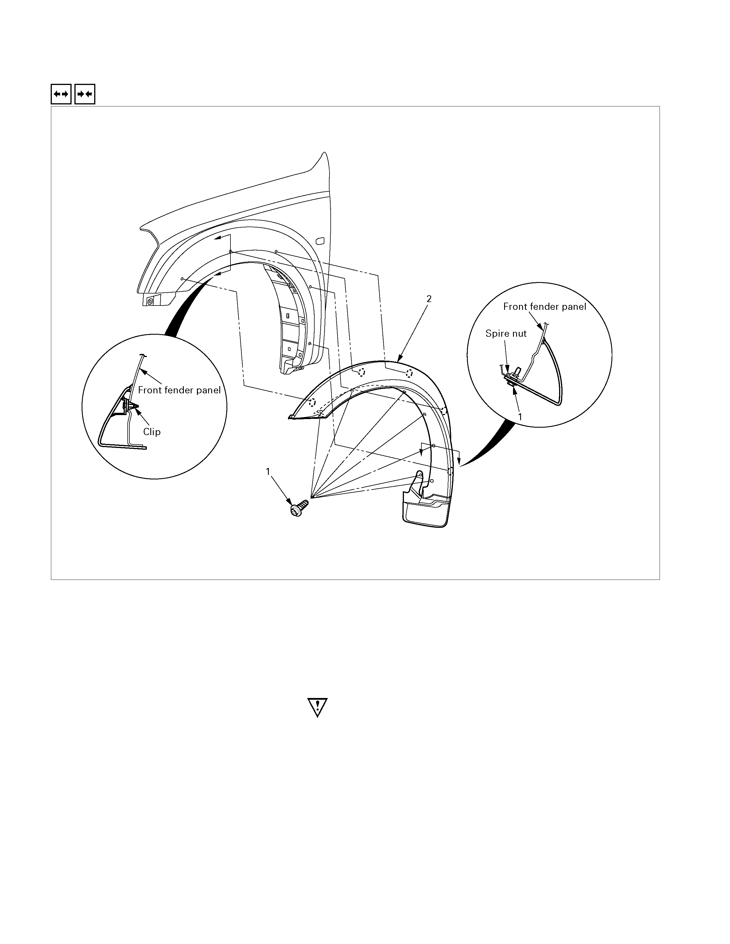
FRONT WHEEL EXTENTION
REMOVAL A ND INSTALLATION
Removal Steps
1. Screw
▲ 2. Front wheel extension
Installation Steps
2. Front wheel extension
1. Screw
Important Operation - Removal
2. Front Wheel Extension
• pull out the 5 clip positions
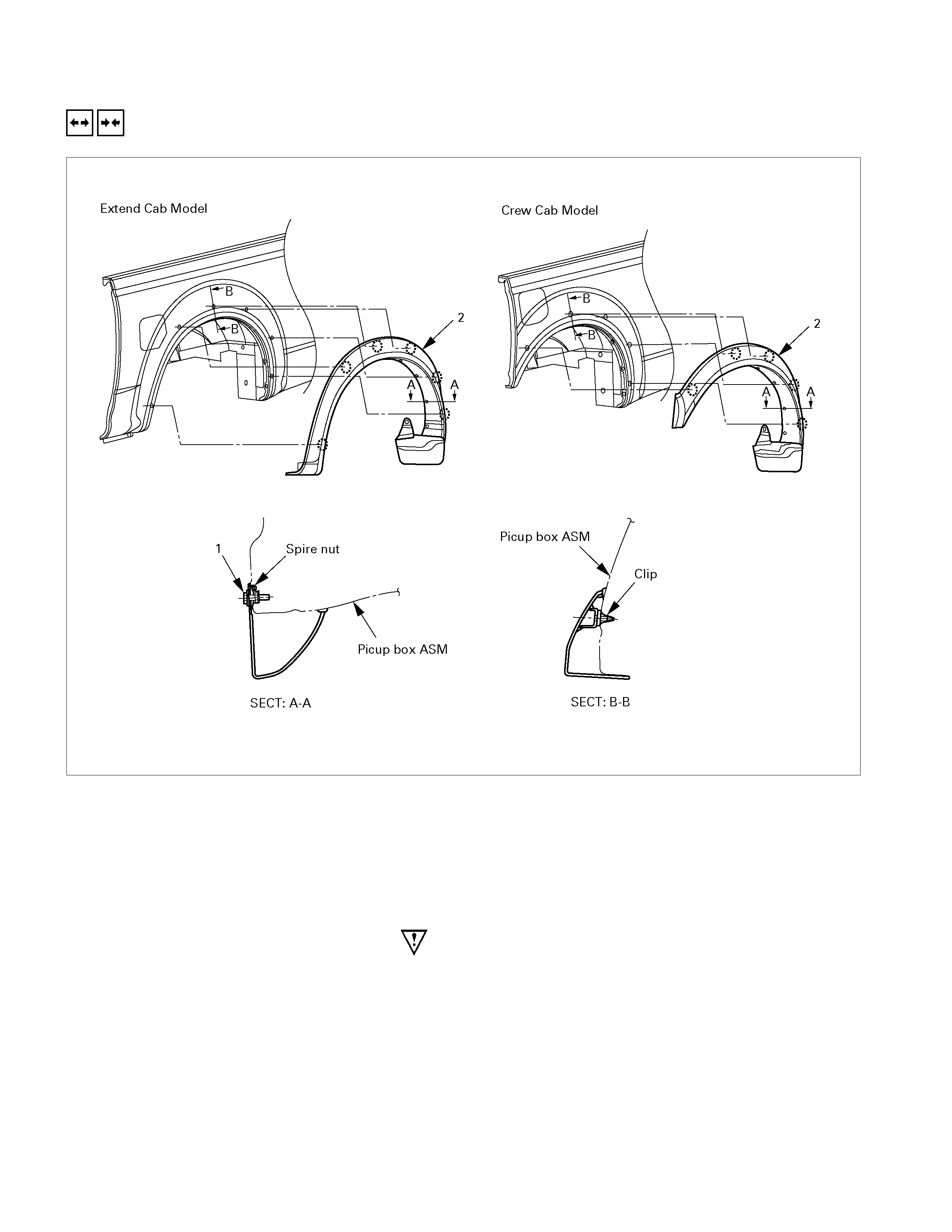
REAR WHEEL EXTENTION
REMOVAL A ND INSTALLATION
Removal Steps
1. Screw
▲ 2. Rear wheel extension
Installation Steps
2. Rear wheel extension
1. Screw
Important Operation - Removal
2. Rear Wheel Extension
• Pull out the 6 clip positions (Extend cab)
• Pull out the 5 clip positions (Crew cab)
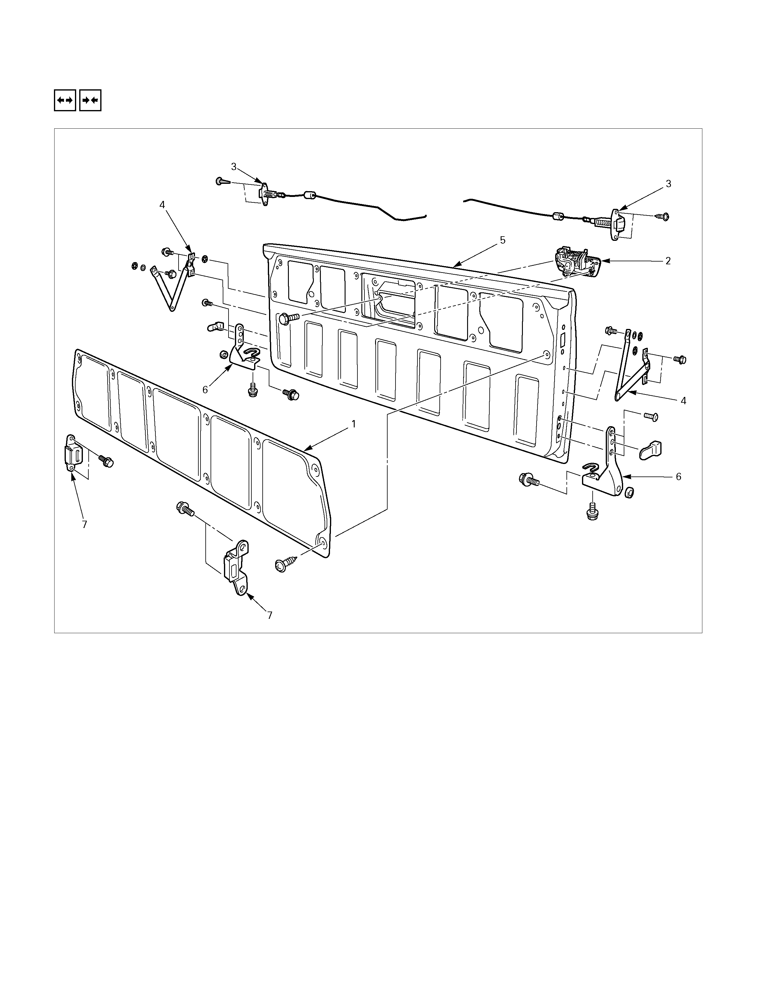
TAIL GATE ASSEMBLY
REMOVAL A ND INSTALLATION
CENTER PULL HANDLE MODEL
Removal Steps
1. Hole cover plate
▲ 2. Outside handle assembly
3. Tail gate lock assembly
4. Tail gate link
▲ 5. Tail gate
6. Tail gate hinge
7. Tail gate lock striker
Installation Steps
▲ 7. Tail gate lock striker
▲ 6. Tail gate hinge
▲ 5. Tail gate
4. Tail gate link
▲ 3. Tail gate lock assembly
▲ 2. Outside handle assembly
1. Hole cover plate
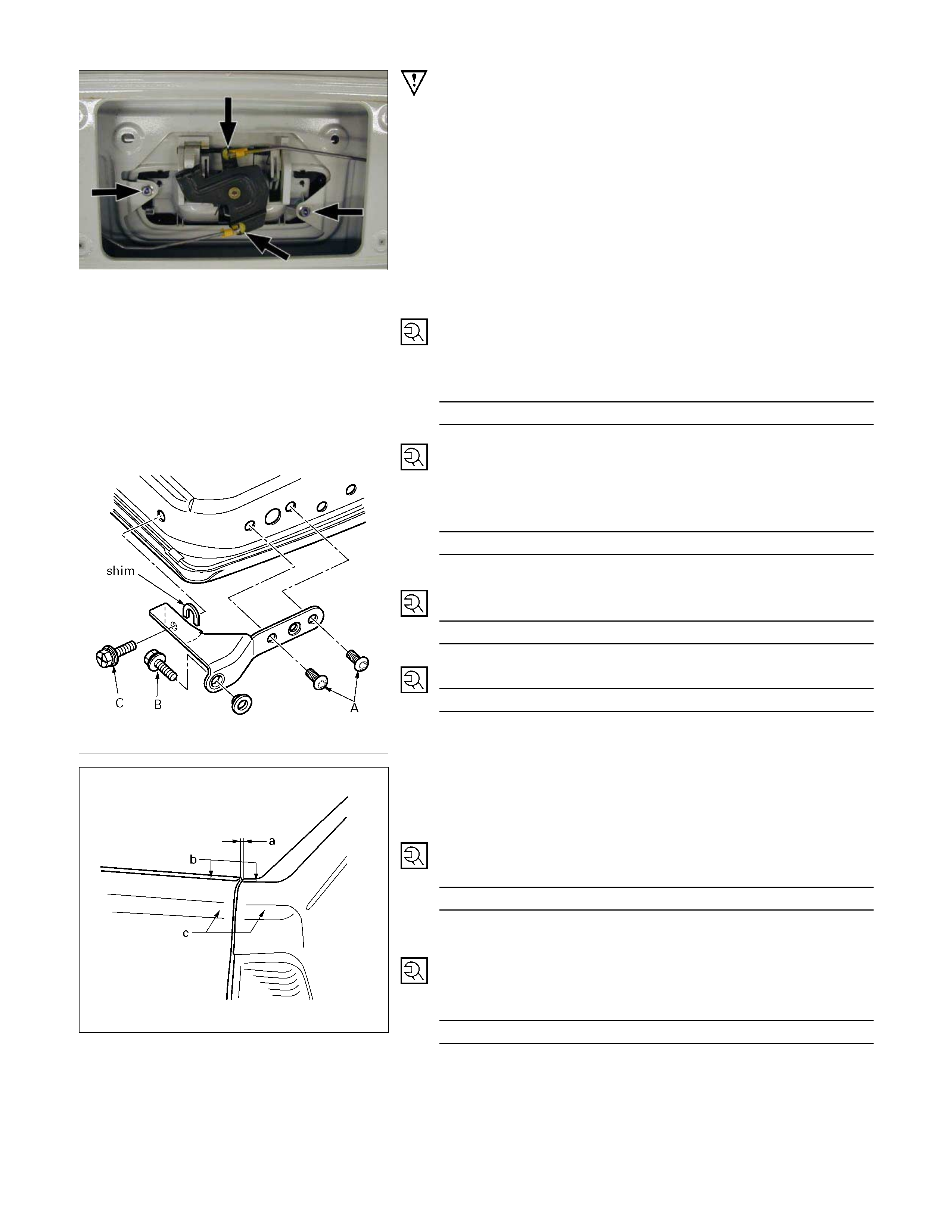
Important Operations - Removal
2. Outside Handle Assembly
• Disconnect the lock link and remove the 2 fixing bolts.
5. Tail Gate
1) Removing the tailgate assembly may require two people.
2) Remove the tailgate hinge fixing bolts.
Important Operations - Installation
7. Tail Gate Lock Striker
• Tighten the lock striker fixing bolts to the specified
torque.
Torque N⋅m(kgf⋅m/lb⋅ft)
15 (1.5 / 11)
6. Tail Gate Hinge
• Tighten the hinge fixing bolts to the specified torque.
C: Bolt
Torque N⋅m(kgf⋅m/lb⋅ft)
40 (4.1 / 30)
5. Tail Gate
1) A: Bolts
Torque N⋅m(kgf⋅m/lb⋅in)
13 (1.3 / 113)
2) B: Bolt
Torque N⋅m(kgf⋅m/lb⋅in)
25 (2.5 / 18)
3) Check the tailgate and rear body.
a. Clearance: 5.0 mm (0.20 in.)
b. Height (Step): Flush
c. Height (Step): Flush
3. Tail Gate Lock Assembly
• Tighten the lock assembly fixing bolts to the specified
torque.
Torque N⋅m(kgf⋅m/lb⋅ft)
15 (1.5 / 11)
2. Outside Handle Assembly
• Tighten the outside handle assembly fixing bolts to the
specified torque and if remove the key cylinder (i
f
equipped) tighten it to the specified torque.
Torque N⋅m(kgf⋅m/lb⋅in)
9 (0.9 / 78)