
HOLDEN RA RODEO BODY BUILDER’S GUIDE ID —1
Introduction . . . . . . . . . . . . . . . . . . . . . . . . . . . . . . . . . . . .1D—2
Warranty and Conditions . . . . . . . . . . . . . . . . . . . . . . . . . .1D—3
Chassis Frame . . . . . . . . . . . . . . . . . . . . . . . . . . . . . . . . . .1D—4
Important Guide Lines . . . . . . . . . . . . . . . . . . . . . . . . . . . .1D—7
Accessory Weight and Commodity
Mass Guide . . . . . . . . . . . . . . . . . . . . . . . . . . . . . . . . . . . .1D—9
Recommended Sizes of Tray and
Van Bodies . . . . . . . . . . . . . . . . . . . . . . . . . . . . . . . . . . . . .1D—10
Chassis Dimensional Drawings
Single Cab . . . . . . . . . . . . . . . . . . . . . . . . . . . . . . . . . . .1D—12
Crew Cab . . . . . . . . . . . . . . . . . . . . . . . . . . . . . . . . . . .1D—13
Space Cab . . . . . . . . . . . . . . . . . . . . . . . . . . . . . . . . . . .1D—14
Cab Chassis Body Mounting . . . . . . . . . . . . . . . . . . . . . . . .1D—15
SECTION 2D - BODY BUILDER'S GUIDE
Techline

ID —2HOLDEN RA RODEO BODY BUILDER’S GUIDE
Introduction
This guide is published by Holden Limited.
The information it presents is of a general nature and is not specific to any particular Holden Rodeo model.
It must be emphasised that any major change to the basic vehicle may severely inhibit the ability of the
vehicle to perform its function. Mechanical failures, structural failures, component unreliability, vehicle
instability and general dissatisfaction by the owner or operator can often be traced to inappropriate design
and application of body, equipment and/or accessories.
The information contained within this publication takes the form of recommended instructions to be followed
when vehicle modifications are undertaken to ensure a totally satisfactory product. It must be remembered
that certain modifications may invalidate Australian Design Rule Approval and application for re-certification
may be necessary.
THIS IS THE BODY BUILDER’S RESPONSIBILITY
It is the Body Builder’s responsibility to ensure compliance to the various vehicle and transport regulations
that may exist in the particular vehicles area of operation.
All information relating to the technical specification of the vehicle should be obtained from the selling
Authorised Holden Retailer.

HOLDEN RA RODEO BODY BUILDER’S GUIDE ID —3
Warranty and Conditions
WARRANTY
Holden Limited’s new vehicle warranty applies to the vehicle and all Holden approved accessories installed by
a Holden Retailer or authorized service outlet to the new vehicle at the time of purchase. The new vehicle
warranty applies in addition to all rights conferred by law.
Inappropriate modifications to the standard vehicle specification may affect vehicle performance and safety,
and may also affect your Holden new vehicle warranty to the extent that Holden considers that those
modifications affect the specification and quality of your vehicle.
CONDITIONS
1. Repairs or replacements conducted under Holden’s new vehicle warranty shall (unless Holden authorizes
otherwise) be carried out by an authorized Holden Retailer.
2. The New Vehicle Warranty applies if the defect complained of is one of materials or
workmanship and is not caused by:
A. misuse or abuse of the vehicle such as by racing, rallying, overloading etc.,
or by neglect.
B. operation of the vehicle after the defect is known.
C. failure to carry out proper maintenance service in accordance with the
schedules published by Holden.
D. use of incorrect types and grades of fuel, oil or lubricants.
E. alteration of the vehicle by anyone not authorised by Holden.
F. the fitting of parts or accessories not marked by Holden.
G. any work carried out on the vehicle by anyone except an authorised Holden Retailer.
3. The terms, conditions and exclusions applicable to Holden’s new vehicle warranty are in the Rodeo
owner’s handbook.
ID —4HOLDEN RA RODEO BODY BUILDER’S GUIDE
Chassis Frame
CHASSIS FRAME MATERIAL
The Holden Rodeo features a box section frame chassis with cross members for added strength and
durability. Material Specification of the chassis frame is SAE J1392 050YLK and the body mounts are
JSH 40 0J-P.
CHASSIS FRAME MODIFICATIONS
Modifications to the original chassis design are not permitted.
NOTE: The installation of special equipment can result in localisation of stresses on certain areas of the
chassis frame and may cause cracking or bending of the chassis frame members if the special equipment
is not properly installed.
When mounting rigid bodies the designed chassis frame flexing must be allowed with the appropriate
flexible mountings.
The existing body mounting points should be used – refer to illustration below.
Existing body mounting points should be used.

HOLDEN RA RODEO BODY BUILDER’S GUIDE ID —5
DRILLING AND WELDING
1. Welding and drilling is strictly not permitted in the shaded areas of the chassis frame members as shown
on the illustration below.
(Any portions within 20mm from edge of holes should not be welded)
2. Length of welding beads should be held within 30-50mm and at least 40mm spacing should be
maintained between adjacent welding beads.
3. To make holes in frames do not use a gas flame. Drill all holes using sharp drills.
4. Use cold riveting only when attaching brackets with rivets.
5. Use high tensile bolts and appropriate nuts when bolted attachments are used.
Bolt specifications:
SAE – Grade 8
Metric – Property class 8.8 or 10.9
Japanese – 7T or 9T
6. Deburr holes after drilling to fit bolts or rivets. Chamfer 1.0mm x 45 degree on the bolt head side of
the hole to facilitate bolt seating.
7. Holes must NOT be drilled near side member profile changes.
8. Existing holes in top and bottom flanges must NOT be bored out.
9. No more than two holes are to be drilled in a vertical line down the frame web.
A= Not more than 13mm diameter
C= 25mm or more
B= 20mm or more
D= 10mm or more
D
D
B
B
A
C
B
B
D
Side Member

ID —6HOLDEN RA RODEO BODY BUILDER’S GUIDE
WELDING
General Precautions:
1. Before any arc welding is carried out on the vehicle disconnect the battery and other electrical/electronic
equipment, such as alternator, regulator, radio, directional indicator unit, and interior lamp/s.
Disconnecting battery leads may not always be adequate to overcome voltage surges that occur during
welding operations
2. Weld earth points should be as close as practicable to the weld.
3. Ensure location of weld earth points do not result in damage to bearings.
4. Keep reinforcement plates and chassis frame members free from moisture and water.
5. Do not cool with water after welding.
6. Use a suitable means to protect pipes, wires, rubber parts, leaf springs, etc., against heat and the effect
of weld splatter.
7. Remove paint completely when welding painted areas.
8. Remove fuel tank assembly when welding portions near the fuel tank.

HOLDEN RA RODEO BODY BUILDER’S GUIDE ID —7
Important Guidelines
VEHICLE SELECTION
The following points should be considered when selecting a vehicle for use with known body or equipment:
Type of Load
All calculations are carried out by the Body Builder’s Design Engineers and assume that, within reasonable
limits, the load to be placed in the body will be evenly distributed along and across the body. If the body or
equipment to be mounted constitute an unevenly distributed load, calculations should be made with regard
to axle loads in laden, unladen and part laden conditions.
Body and Payload Weight
The type of body, its weight and the payload capacity required, must be determined.
Performance,Power and Gradeability
Calculations must be carried out to ensure that the complete vehicle meets the customers’ expectations and
requirements with respect to these characteristics. These must be met without interfering with or modifying
the base vehicle specifications.
Fuel Tank
Avoid unnecessary relocation of the fuel tank. If relocation is necessary ADR compliance may be affected.
The following points should be noted:
•Adequate clearance should be maintained between the fuel tank and any other
component.
•Use new fuel hoses when lengthening is required
•Care must be taken with the location of the fuel tank filler to ensure that the spillage of fuel onto
exhaust or electrical system components cannot occur.
Wheels And T yres
Adequate clearance must be provided between the rear tyres and the underside of the body.The clearance
must allow the axle to reach its maximum bump travel without the tyre fouling on the body.

ID —8HOLDEN RA RODEO BODY BUILDER’S GUIDE
EXPLANATION OF TERMS
Operating Mass: (GVM & GCM).
To ensure a Holden Rodeo performs satisfactorily and reliably, it is most important that the manufacturer’s
specified Gross V ehicle Mass and Gross Combination Mass for the specific vehicle are not exceeded.The
maximum GVM and GCM mass limits are specified on Sales Specifications sheets available from Authorised
Holden Retailers. GVM is also stamped on the safety compliance plate affixed to the vehicle.
GVM: Gross V ehicle Mass is the total weight that a vehicle is allowed to weigh when fully loaded. This must
include luggage, passengers and a full tank of fuel. The maximum allowable GVM for the 20 03 model
Holden Rodeo 2WD vehicles is 280 0kg and 4WD is 290 0kg.
GCM: Gross Combination Mass is the maximum allowable combined weight of a vehicle (with passengers,
luggage and full tank of fuel) plus the weight of a loaded trailer or caravan. If the trailer or caravan is fitted
with brakes initiated by the driver (NOT over-run operated brakes) then the maximum allowable GCM for
2WD is 3750kg and 3750kg for 4WD vehicles.
NOTE: if the trailer or caravan is not fitted with driver initiated braking the maximum
legal allowable GCM for2WD vehicles is 3250kg and 3250kg for 4WD vehicles.
Kerb Mass
The weight of the base vehicle including oil, water and full tank of fuel.
Load Capacity
Maximum load able to be carried. Usually expressed as difference between GVM and Kerb Mass:
eg: Holden Rodeo 4x2 single Cab Chassis
GVM 280 0kg
(subtract) Kerb Mass 1410kg
Load Capacity = 1390kg
(Include Body, Accessories, Passengers, Luggage Payload)
Payload
This varies with the weight of the rear body and number of accessories added. Payload is the maximum
weight that can be loaded after rear body and all accessories and fittings are attached to the vehicle.
(Refer above calculation)
Front and Rear Axle Loads
The maximum allowable front axle load for 2WD vehicles is 120 0kg. 4WD is 1300kg.The maximum
allowable rear axle load for both types is 1680kg. However, the combination for front and rear axle load
should never exceed the maximum GVM. Remember to take the towbar ball load into account when
determining the rear axle load. To ensure satisfactory driveability, it is recommended that a minimum front
axle weight of 90 0kg at full load is maintained.
Important Guidelines
CONTINUED

HOLDEN RA RODEO BODY BUILDER’S GUIDE ID —9
Holden Rodeo Accessory Weight and
Commodity Mass Guide
RODEO ACCESSORY WEIGHTS approximate:
Tray: 8x6 Aluminium 100k g
8x6 Steel 230kg
Canopy: Crew Cab 27kg
Single Cab 45kg
Accessories: Air-Conditioning 26kg
Towbar & Tongue 28kg
Bull Bar 27kg
Cargo Liner 23kg
TRAILER WEIGHTS approximate:
6X4 Single Axle Tr ailer 240k g
8X5 Double Axle Steel 440kg
COMMON COMMODITY
MASS GUIDE approximate:
kg per cubic metre
Basalt (Blue Metal) 2390kg
Granite Solid 2145kg
Granite Crushed 1233kg
Marble Solid 2120kg
Marble Crushed 1233kg
Sand and Quartz (Dry) 10 0 0kg
Cement 24 bags per tonne
Bricks 296 per tonne
ID —10 HOLDEN RA RODEO BODY BUILDER’S GUIDE
Recommended Sizes of Tray
and Van Bodies
CLEARANCE BETWEEN CAB AND REAR BODY
(TRAY AND VAN BODIES)
To prevent direct cab to body contact due to flexing of the chassis frame, minimum necessary clearance
of 30mm must be maintained between cab and rear body as specified in the illustration below.
RODEO – recommended maximum tray sizes (mm)
A - B C - D
OVERALL TRAY LENGTH
MODEL MAXIMUM LENGTH REC. EXTERIOR WIDTH
4X2 and 4x4 – Single Cab Models 2740 mm 2710 mm 1842 mm
4x2 and 4x4 – Space Cab Models 2280 mm 2250 mm 1842 mm
4x4 – Crew Cab Models 1825 mm 1795 mm 1842 mm
NOTE: The rear axle capacity should never exceed 1680kg.
30mm
30mm
C - D
Length Tray
Width
A - B
Overall Length
HOLDEN RA RODEO BODY BUILDER’S GUIDE ID —11
RODEO – recommended maximum van sizes (mm)
A - B
OVERALL
MODEL MAXIMUM LENGTH WIDTH HEIGHT
4X2 and 4x4 – Single Cab Models 2740 mm 1842 mm 1950 mm
4x2 and 4x4 – Space Cab Models 2280 mm 1842 mm 1950 mm
4x4 – Crew Cab Models 1825 mm 1842 mm 1950 mm
NOTE: The rear axle capacity should never exceed 1680kg.
Height
30mm
A - B
Overall Length
ID —12 HOLDEN RA RODEO BODY BUILDER’S GUIDE
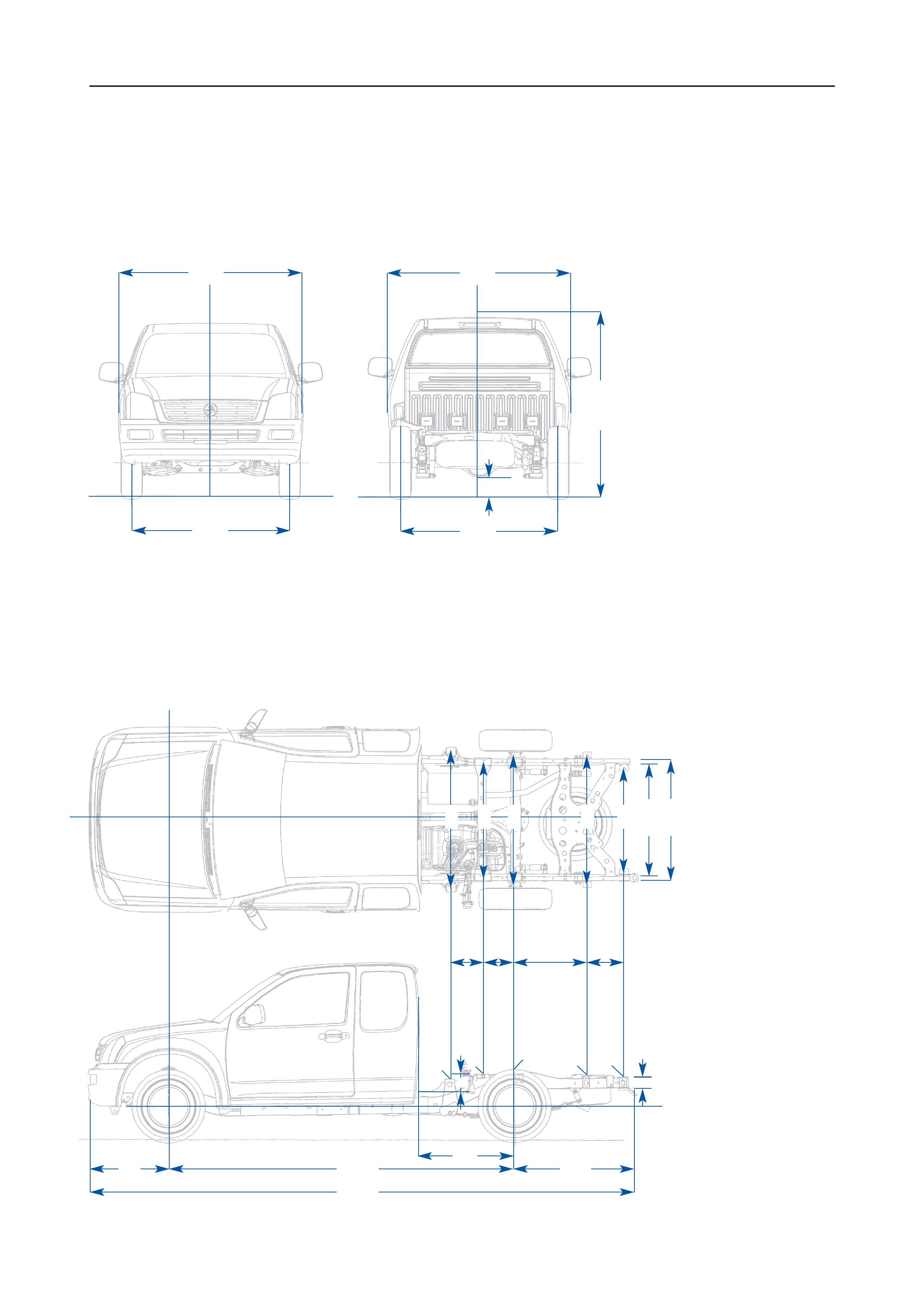
RODEO 4X2 AND 4X4 SINGLE CAB
(CHASSIS DIMENSIONAL DRAWINGS)
NOTE: Dimensions in brackets ( ) apply to 4x4 models.
E (i) (ii) (iii) (iv)
1020
1250
1250
900
930
1190
960
1120
3200
5000
745 1055
1340
C
(i) (ii) (iii) (iv) D
(i) (ii) (iii) (iv)
B
(i)
(ii)
(iii)
(iv)
A
(i) (ii) (iii) (iv) A
(i) (ii) (iii) (iv)
621
A
287 351 470 490
BCDEF
Height of Cargo Box Mounting
point from the rear end of the
Sidemember
(A)108mm (B)108mm (C)145mm
(D)145mm (E)108mm (F)100mm
FT Height of the top of the
Fuel Tank (FT) from the top
of the Sidemember 193mm
ST Height of the top of the
Spare Tyre (ST) Mounting Bracket
from the rear end bottom of the
Sidemember 132mm
ABody Width
(i) 1720mm DX 2.4L Petrol 4x2 models
(ii) 1720mm LX 3.0L Turbo Diesel 4x2 models
(iii) 1800mm LX 3.5L V6 Petrol 4x2 models
(iv) 1800mm DX, LX 4x4 models
BBody Height
(i) 1630mm DX 2.4L Petrol 4x2 models
(ii) 1635mm LX 3.0L Turbo Diesel 4x2 models
(iii) 1710mm LX 3.5L V6 Petrol 4x2 models
(iv) 1725mm DX, LX 4x4 models
CFront Track
(i) 1460mm DX 2.4L Petrol
(ii) 1460mm 3.0L Turbo Diesel 4x2 models
(iii) 1515mm LX 3.5L V6 Petrol 4x2 models
(iv) 1520mm DX, LX 4x4 models
DRear Track
(i) 1460mm DX 2.4L Petrol
(ii) 1460mm LX 3.0L Turbo Diesel 4x2 models
(iii) 1520mm LX 3.5L V6 Petrol 4x2 models
(iv) 1525mm DX, LX 4x4 models
EGround Clearance
(i) 190mm – DX 2.4L Petrol 4x2 models
(ii) 195mm – LX 3.0L Turbo Diesel 4x2 models
(iii) 210mm – LX 3.5L V6 Petrol 4x2 models
(iv) 225mm – DX, LX 4x4 models
FT ST
HOLDEN RA RODEO BODY BUILDER’S GUIDE ID —13
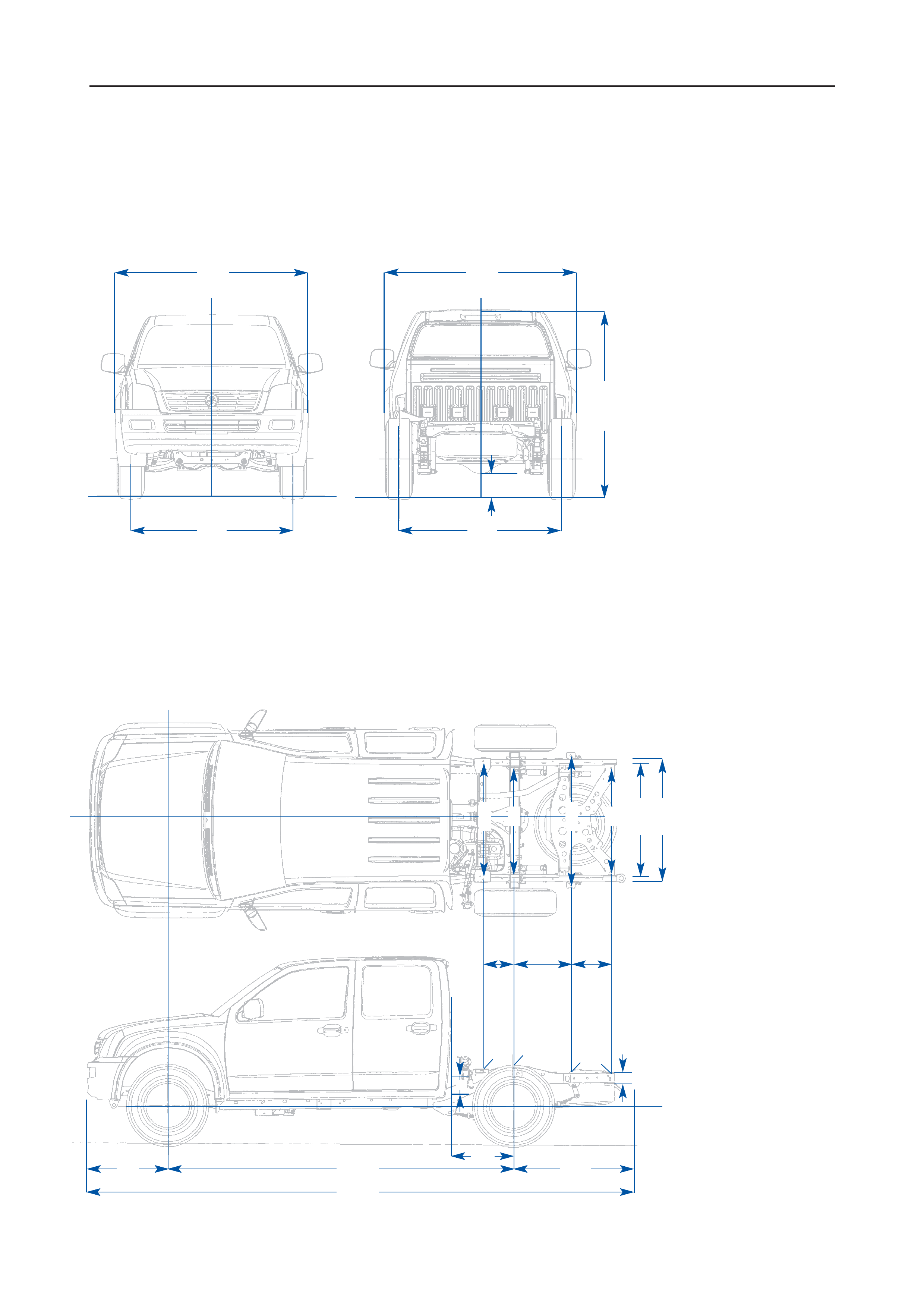
ABody Width
(i) 1800mm LX 3.5L V6 Petrol 4x2 model
(ii) 1800mm LX 3.0L Turbo Diesel 4x4 model
BBody Height
(i) 1715mm LX 3.5L V6 Petrol 4x2 model
(ii) 1730mm LX 3.0L Turbo Diesel 4x4 model
CFront Track
(i) 1515mm LX 3.5L V6 Petrol 4x2 model
(ii) 1520mm LX 3.0L Turbo Diesel 4x4 model
DRear Track
(i) 1520mm LX 3.5L V6 Petrol 4x2 model
(ii) 1525mm LX 3.0L Turbo Diesel 4x4 model
EGround Clearance
(i) 210mm – LX 3.5L V6 Petrol 4x2 model
(ii) 225mm – LX 3.0L Turbo Diesel 4x4 model
NOTE: Dimensions in brackets ( ) apply to 4x4 models.
RODEO 4X2 AND 4X4 SPACE CAB
(CHASSIS DIMENSIONAL DRAWINGS)
D
(i) (ii)
B
(i)
(ii)
E (i) (ii)
1020
1120
A
(i) (ii)
3200
5000
745 1055
1250
900
930
1190
960
A
287 351 470 490
BCDE
Height of Cargo Box Mounting
point from the rear end of the
Sidemember
(A)108mm (B)145mm (C)145mm
(D)108mm (E)100mm
FT Height of the top of the
Fuel Tank (FT) from the top
of the Sidemember 193mm
ST Height of the top of the
Spare Tyre (ST) Mounting Bracket
from the rear end bottom of the
Sidemember 132mm
FT ST
A
(i) (ii)
C
(i) (ii)
870
ID —14 HOLDEN RA RODEO BODY BUILDER’S GUIDE
RODEO 4X4 CREW CAB
(CHASSIS DIMENSIONAL DRAWINGS)
B
(i)
(ii)
E (i) (ii)
1020
1090
1120
3200
4880
745 935
C
(i) (ii) D
(i) (ii)
A
(i) (ii) A
(i) (ii)
Height of Cargo Box Mounting
point from the rear end of the
Sidemember
(A)145mm (B)145mm
(C)108mm (D)100mm
FT Height of the top of the
Fuel Tank (FT) from the top
of the Sidemember 193mm
ST Height of the top of the
Spare Tyre (ST) Mounting Bracket
from the rear end bottom of the
Sidemember 132mm
FT ST
930
960
1190
336 470 370
ABCD
575
ABody Width
(i) 1800mm LX 3.5L V6 Petrol 4x4 model
(ii) 1800mm LX 3.0L Turbo Diesel 4x4 model
BBody Height
(i) 1735mm LX 3.5L V6 Petrol 4x4 model
(ii) 1735mm LX 3.0L Turbo Diesel 4x4 model
CFront Track
(i) 1520mm LX 3.5L V6 Petrol 4x4 model
(ii) 1520mm LX 3.0L Turbo Diesel 4x4 model
DRear Track
(i) 1525mm LX 3.5L V6 Petrol 4x4 model
(ii) 1525mm LX 3.0L Turbo Diesel 4x4 model
EGround Clearance
(i) 225mm – LX 3.5L V6 Petrol 4x4 model
(ii) 225mm – LX 3.0L Turbo Diesel 4x4 model

HOLDEN RA RODEO BODY BUILDER’S GUIDE ID —15
Cab Chassis Body Mounting – Typical
Bodies
Bodies should be mounted utilising each of the mounting points (Refer to page four for location of mounting
points).
Attaching Bolts
Attaching bolts should be zinc plated high tensile. SAE Grade 8 specification and a rubber equivalent
material should be inserted between the mounting points and the body sub frame.
When mounting bodies of a rigid nature, such as steel trays with incorporated steel storage compartments
and work benches, the flexibility of the frame must not be restricted.This may necessitate the use of trunnion
type mountings to avoid vehicle frame damage.