
Front End Alignment Inspection and Adjustment
General Description
“Front End Alignment” refers to the angular relationship
between the front wheels, the front suspension attaching parts
and the ground.
Proper front end alignment must be maintained in order to
insure efficient steering, good directional stability and to
prevent abnormal tire wear.
The most important factors of front end alignment are wheel
toe-in, wheel camber and axle caster.
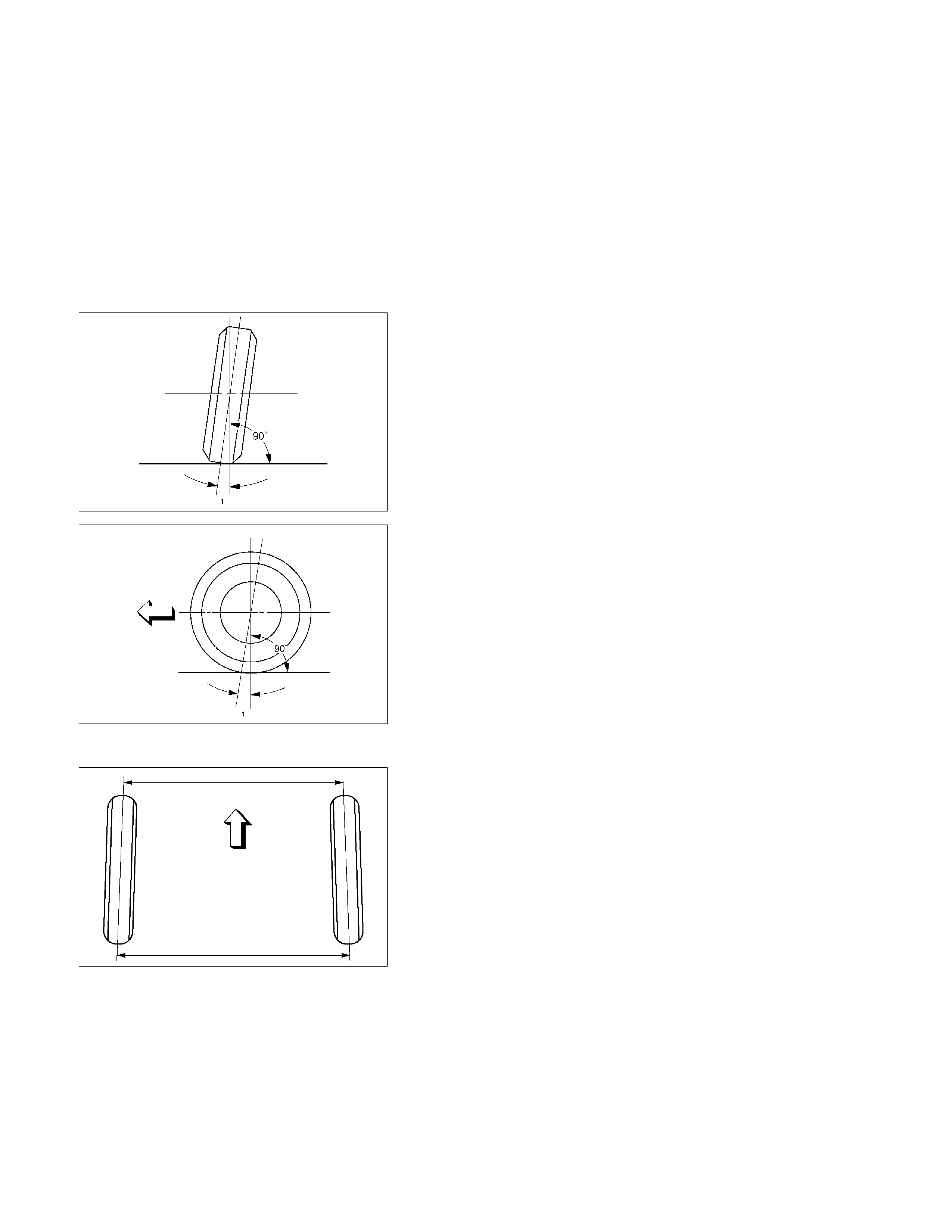
Camber:
This illustration shows the view from the front of the vehicle.
Camber is the vertical tilting inward or outward of the front
wheels. When the wheels tilt outward at the top, the camber is
positive (+). When the wheels tilt inward at the top, the camber
is negative (-). The amount of tilt measured in degrees from
the vertical is called the camber angle (1). If camber is
extreme or unequal between the wheels, improper steering
and excessive tire wear will result. Negative camber causes
wear on the inside of the tire, while positive camber causes
wear to the outside.
Caster:
This illustration shows the view from the side of the vehicle.
Caster (1) is the vertical tilting of the wheel axis either
forward or backward (when viewed from the side of the
vehicle). A backward tilt is positive (+) and a forward tilt is
negative (-). On the short and long arm type suspension
you cannot see a caster angle without a special instrument,
but if you look straight down from the top of the upper control
arm to the ground, the ball joints do not line up (fore and aft)
when a caster angle other than 0 degree is present. With a
positive angle, the lower ball joint would be slightly ahead
(toward the front of the vehicle) of the upper ball joint center
line.
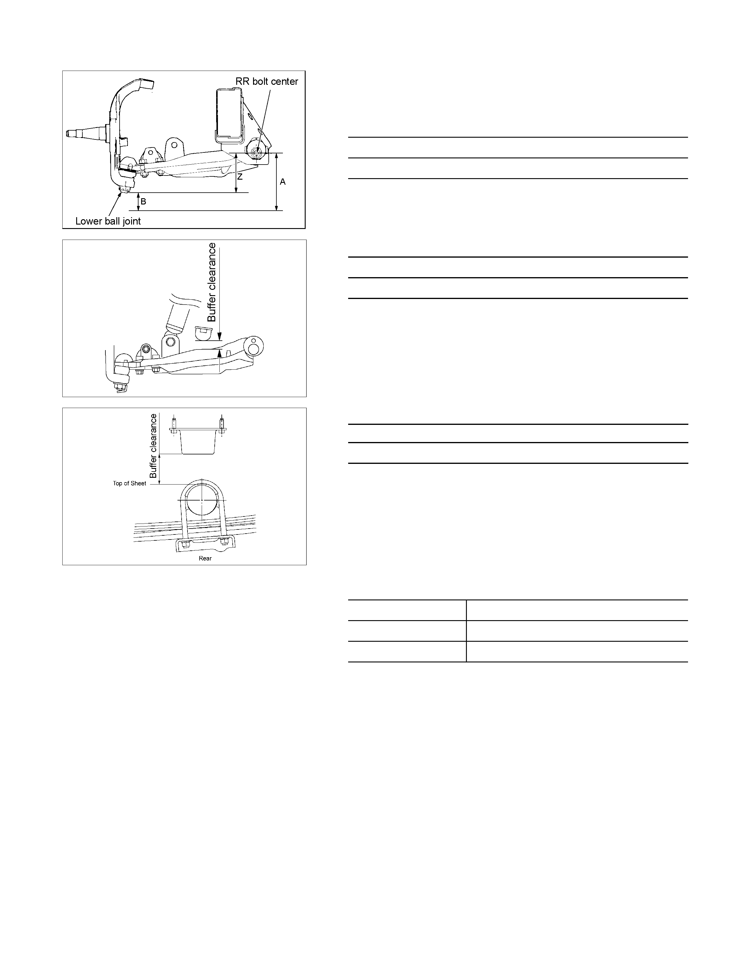
Toe-in:
This illustration shows the view from the top of the vehicle.
Toe-in is the measured amount the front wheels are turned in.
The actual amount of toe-in is normally a fraction of a degree.
Toe-in is measured from the center of the tire treads or from
the inside of the tires. The purpose of toe-in is to insure
parallel rolling of the front wheels and to offset any small
deflections of the wheel support system, which occurs when
the vehicle is rolling forward. Incorrect toe-in results in
excessive toe-in and
unstable steering. Toe-in is the last alignment to be set in
the front end alignment procedure.

Inspection
Before making any adjustments affecting caster, camber or
toe-in, the following front end inspection should be made.
1. Inspect the tires for proper inflation pressure. Refer to
Main Data and Specifications in Wheel and Tire System
section.
2. Make sure that the vehicle is in an unlade condition
(Without passenger or loading).
3. Make sure that the spare tire is installed at the normal
position.
4. Inspect the front wheel bearings for proper adjustment.
Refer to Front Hub and Disc Overhaul in Suspension
section.
5. Inspect the ball joints and tie rod ends. If excessive
looseness is noted, correct before adjusting. Refer to
Steering Linkage in this section.
6. Inspect the wheel and tires for run-out. Refer to
Wheel Replacement in Wheel and Tire System section.
7. Inspect the trim height. If not within specifications, the
correction must be made before adjusting caster.
8. Inspect the steering unit for looseness at the frame.
9. Inspect shock absorbers for leaks or any noticeable noise.
Refer to Shock Absorber in Suspension section.
10. Inspect the control arms or stabilizer bar attachment fo
r
looseness. Refer to Suspension section.
11. Inspect the front end alignment using alignment equipment.
Follow the manufacturer’s instructions.
Alignment for 4×2 (Except High Ride Suspension)
Caster and camber Adjustment
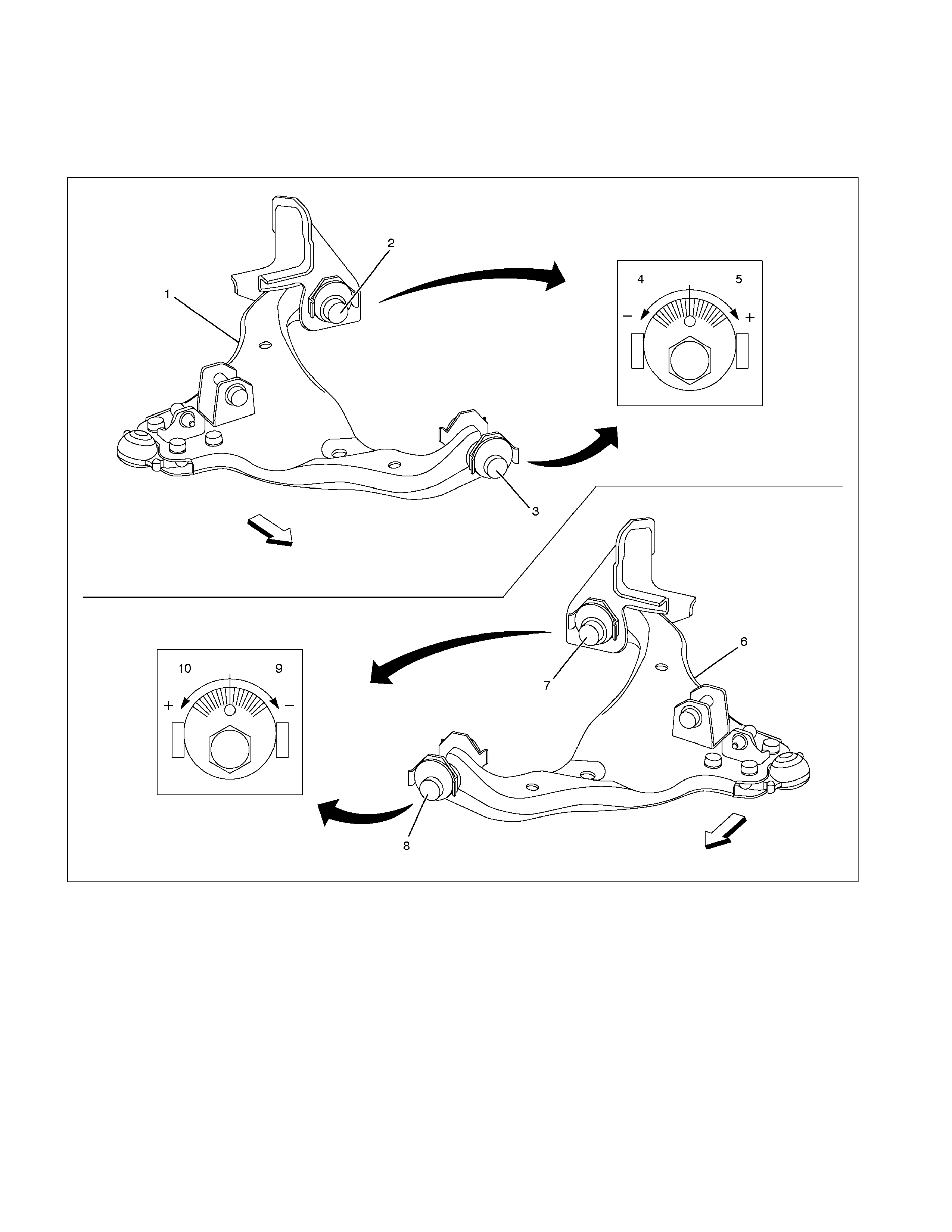
The lower links of the 4X2 vehicle front suspension have an adjusting cam at either end (front and rear). This permits
simultaneous adjustment of camber and caster angle.
Front
Front
RTW340LF000301
Legend
1. Lower link ASM RH
2. Adjust cam RR
3. Adjust cam FRT
4. -direction The lower link ASM protrudes
toward the inside
5. +direction The lower link ASM protrudes
toward the outside
6. Lower link ASM LH
7. Adjust cam RR
8. Adjust cam FRT
9. -direction The lower link ASM protrudes
toward the inside
10. +direction The lower link ASM protrudes
toward the outside
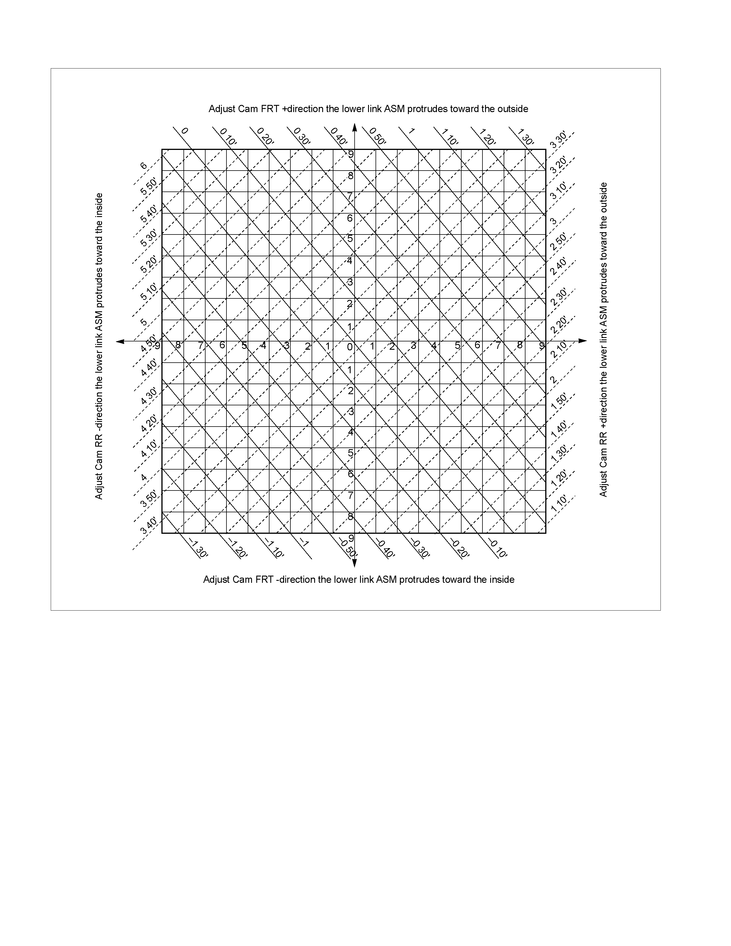
The follow illustration shows the alignment procedure.
RTW340LF000401
Example
Measured value
Camber angle 1°10' Caster angle 3°10'
Standard value
Camber angle 0°±30' Caster angle 3°35'±45'
RTW340SH001001
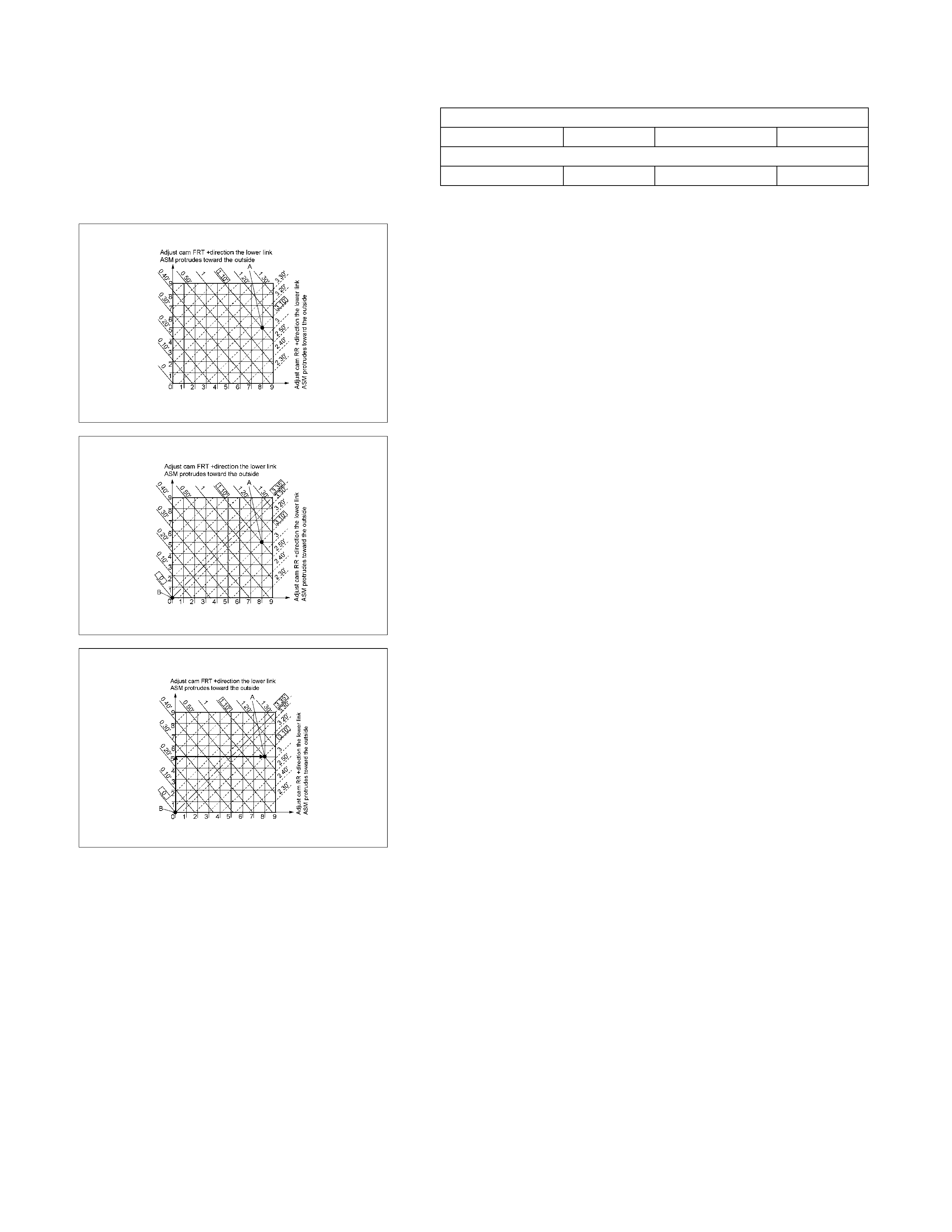
1. Mark an ‘A’ at the intersection point of the measured
camber angle value (solid line) and the measured caster
angle value (dotted line).
RTW340SH001101
2. Mark a ‘B’ at the intersection point of the standard camber
angle value (solid line) and the standard caster angle value
(dotted line).
RTW340SH001201
3. The vertical distance between points ‘A’ and ‘B’ represents
the adjustment required at the front cam. The horizontal
distance between points ‘A’ and ‘B’ represents the
adjustment required at the rear cam.
In this example, the front cam would be moved 5 integers
to the positive and the rear cam would be moved 8 integers
to the positive.
CAUTION:
Maximum possible adjustment from the center point of
the cams is 9 integers to either side.
CASTER
3°35'±45'
Note:
Left and right side to be equal within 30'
CAMBER
0°±30'
Note:
Left and right side to be equal within 30'
STEERING AXIS INCLINATION
12°30'±30'
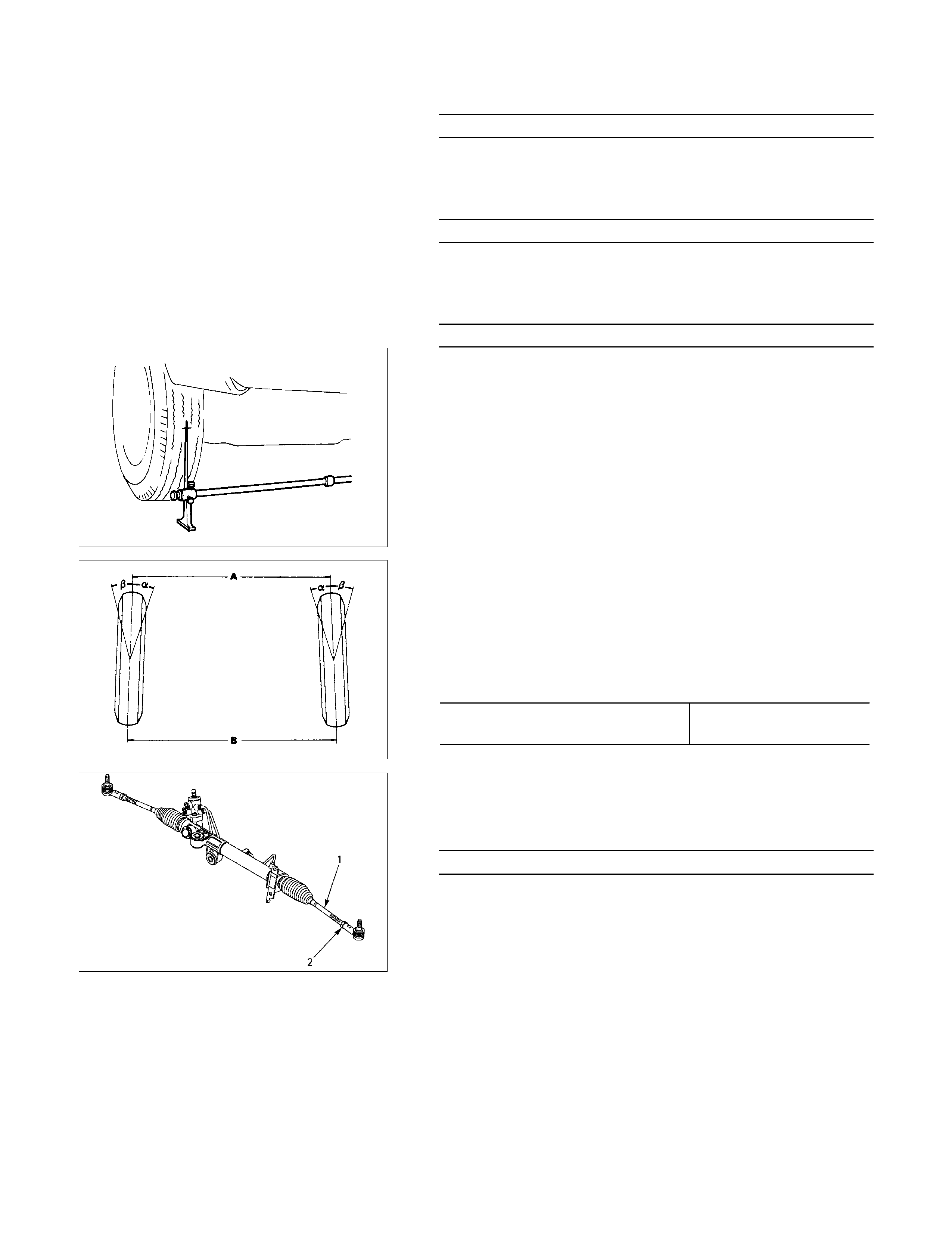
Toe-in Adjustment
Measurement should be taken with the vehicle on a surface
plate.
If a surface plate is not available, toe-in should be checked
with the vehicle parked on a level floor.
1. Set front wheels to straight ahead position.
2. Align the toe-in gauge with center height of each wheel at
front end.
3.
A
pply center marks to each wheel, then take measurement
of distance A between the center marks on each wheel.
4. Slowly move the vehicle rearward until the center marks
reach the rear end position.
5. Take measurement of distance B between the cente
r
marks at rear end.
The toe-in can be calculated with next formula.
Toe-in = B - A
Toe-in mm (in)
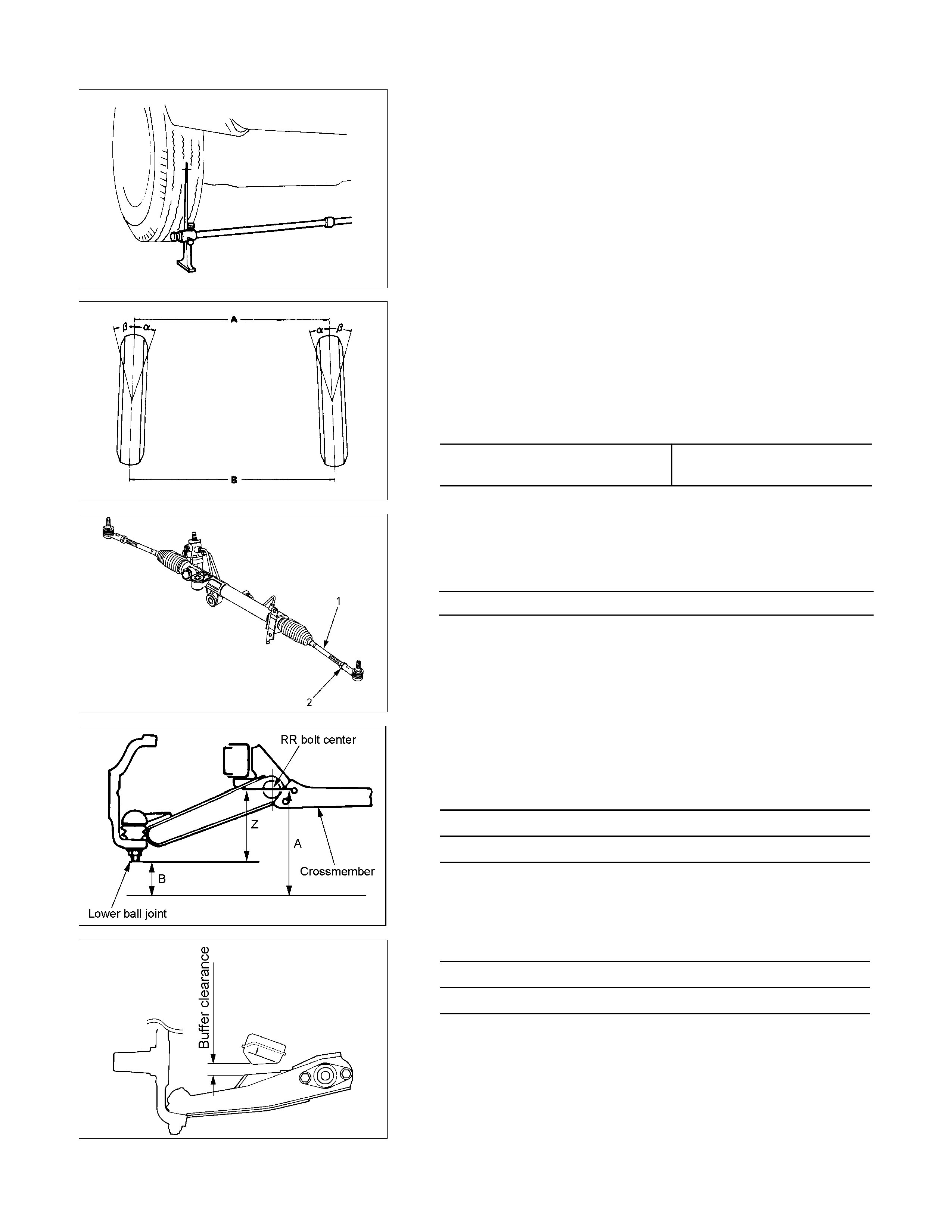
4×2
(Except high ride suspension) 0±2 (0±0.08)
To adjust the toe-in angle, loosen the lock nuts (2) on the tie
rod (1) and turn the tie rod. Turn both rods the same amount,
to keep the steering wheel centered.
Lock Nut Torque N⋅m (kgf⋅m/lb⋅ft)
98±6.0 (10.0±0.6 / 72.3±4.3)
RTW330SH000101
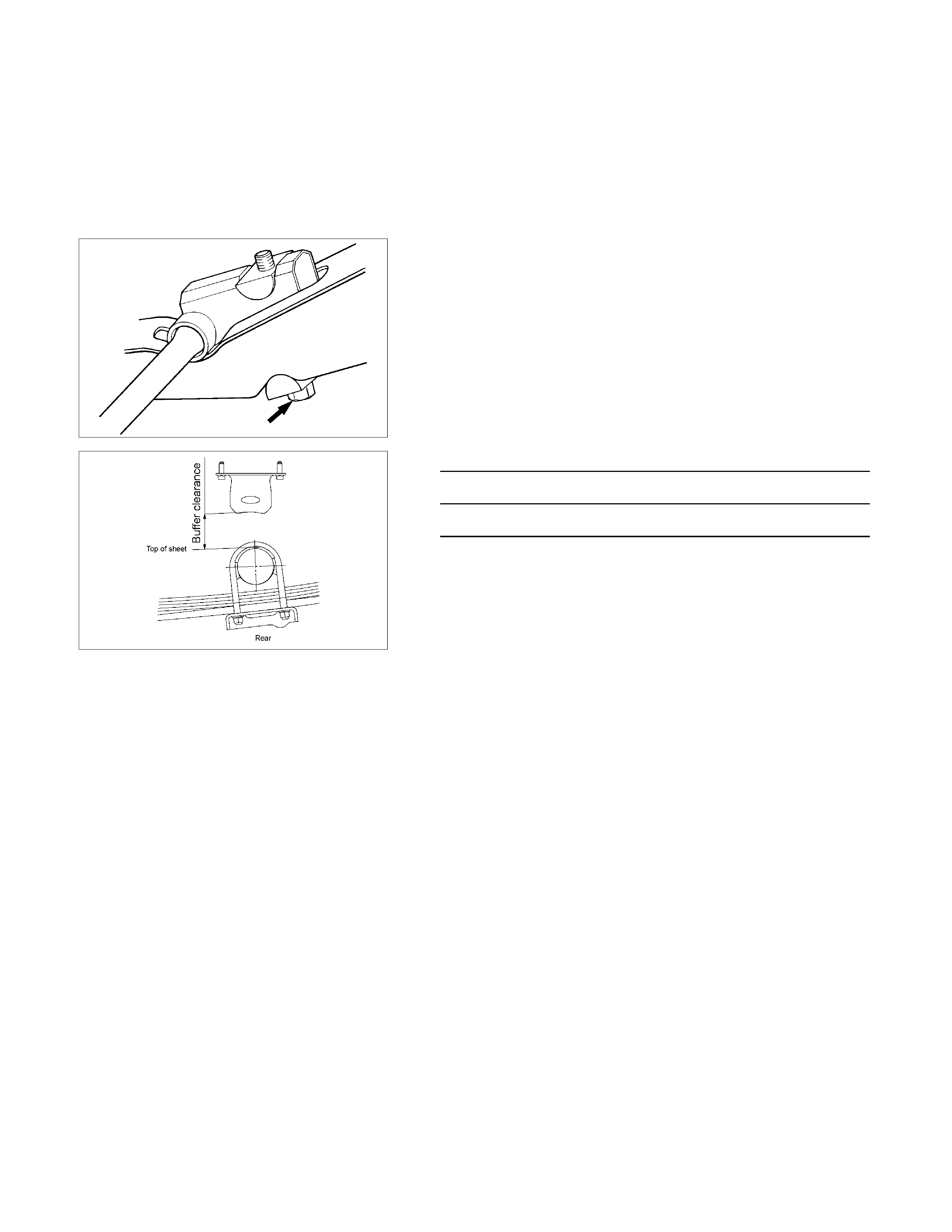
Trim Height
Trim Height : at Curb Weight (Reference Data)
Trim height (Z) = A - B
Front mm (in)
Z
105(4.13)
RTW340SH001301-X
FRT Buffer clearance (Reference Data)
4×2 (Except high ride suspension)
25.9(1.02)
RTW340SH000101-X
RR Buffer clearance (Reference Data) mm(in)
4×2 (Except high ride suspension)
82.1 (3.23)
MAXIMUM STEERING ANGLE
4×2 (Except high ride suspension)
Outside wheel 33.5°
Inside wheel 37.1°

Alignment for 4×2 (High Ride Suspension) and 4×4
Caster and camber Adjustment
The camber angle and caster angle can be adjusted by means of the camber shims and caster shims installed in
position between the chassis frame and fulcrum pins.
RTW340LF001901
Legend
1. Camber shim
2. Caster shim
3. Upper link ASM RH
4. Lower link ASM LH
5. Adjust cam

Adjust Method addition / subtraction of shim
front side rear side move direction
of upper b/j caster angle
alteration camber angle alteration
addition subtraction a decrease decrease (to negative
direction)
subtraction addition b increase increase (to positive
direction)
no change subtraction c decrease no alteration
caster
adjustment
no change addition d increase no alteration
addition e no alteration
decrease (to negative
direction)
camber
adjustment subtraction f no alteration
increase (to positive
direction)
Note:
1. Adjust cam is set at initial position (the hole &
projection are upward as shown in the illustration)
before making a shim adjustment.
2. Difference of caster shim front/rear thickness shall be
3.6mm(0.142in) or less.
Overall thickness of caster shim and camber shim shall
be 10.8mm(0.426in) or less.
3. choose a combination that uses a minimum amount of
shims.
Fulcrum Pin Bolt Torque N⋅m (kgf⋅m/lb⋅ft)
152.0±15 (15.5±1.5 / 112.1±10.8)
CASTER
310’±45’
Note:
Left and right side to be equal within 30’.
CAMBER
0±30’
Note:
Left and right side to be equal within 30’.
STEERING AXIS INCLINATION
1230’±30’
Toe-in Adjustment
Measurement should be taken with the vehicle on a surface
plate.
If a surface plate is not available, toe-in should be checked
with the vehicle parked on a level floor.
1. Set front wheels to straight ahead position.
2. Align the toe-in gauge with center height of each wheel at
front end.
3.
A
pply center marks to each wheel, then take measurement
of distance A between the center marks on each wheel.
4. Slowly move the vehicle rearward until the center marks
reach the rear end position.
5. Take measurement of distance B between the cente
r
marks at rear end.
The toe-in can be calculated with next formula.
Toe-in = B - A
Toe-in mm (in)
4×2 (High ride suspension)
4×4 0±2 (0±0.08)
To adjust the toe-in angle, loosen the lock nuts (2) on the tie
rod (1) and turn the tie rod. Turn both rods the same amount,
to keep the steering wheel centered.
Lock Nut Torque N⋅m (kgf⋅m/lb⋅ft)
98±6.0 (10.0±0.6 / 72.3±4.3)
RTW330SH000201
Trim Height
Trim Height : at Curb Weight
Trim height (Z) = A - B
mm (in)
Z
140±5 (5.51)
450R100002-X
FRT Buffer clearance (Reference Data)
4×2 (High ride suspension), 4×4
29.7(1.17)
Adjustment
Adjust the trim height by means of the adjusting bolt on the
height control arms.
1. Check and adjust the tire inflation pressures.
2. Park the vehicle on a level ground and move the front o
f
the vehicle up and down several times to settle the
suspension.
410RS001
3. Make necessary adjustment with the adjusting bolt on the
height control arms.
RTW340SH000201-X
RR Buffer clearance (Reference Data) mm(in)
4×2 (High ride suspension), 4×4
80.0 (3.15)