
SECTION 3B - POWER-ASSISTED
STEERING SYSTEM
General Description
Power Steering Unit
Hydraulic Pump
Steering Column
Power Steering System Test
Test Procedure
Maintenance
Fluid Level
Bleeding The Power Steering System
Bleeding Procedure
Flushing The Power Steering System
Steering Wheel Free Play Inspection
Front End Alignment Inspection and Adjustment
Torque Specification
Special Tools
Power Steering Unit
Power Steering Unit and Associated Parts
Removal
Installation
Power Steering Unit Disassembled View
Disassembly
Inspection and Repair
Reassembly
Main Data and Specifications
Special Tools
Power Steering Pump (4JH1-TC)
Power Steering Pump and
Associated Parts (4JH1-TC)
Removal
Installation
Power Steering Pump Disassembled View
Disassembly
Inspection and Repair
Reassembly
Main Data and Specifications
Power Steering Pump (C24SE)
Power Steering Pump and Associated Parts (C24SE)
Removal
Installation
Power Steering Pump Disassembled View
Disassembly
Inspection and Repair
Reassembly
Main Data and Specifications
Power Steering Pump (6VE1)
Power Steering Pump and Associated Parts (6VE1)
Removal
Installation
Power Steering Pump Disassembled View
Disassembly
Inspection and Repair
Reassembly
Main Data and Specifications
Supplemental Restraint System Steering Wheel &
Column
Service Precaution
SRS Connectors
Inflator Module
Inflator Module and Associated Parts
Removal
Inspection and Repair (with SRS air bag)
Installation
Steering Wheel
Steering Wheel and Associated Parts
Removal
Installation
The adjustment method in case a mark is not
attached
Combination Switch
Combination Switch and Associated Parts
Removal
Installation
Lock Cylinder
Lock Cylinder and Associated Parts
Removal
Installation
System Inspection (with SRS air bag)
Steering Column
Steering Column and Associated Parts
Removal
Inspection
Installation
System Inspection (with SRS air bag)
Supplemental Restraint System Steering Wheel &
Column and Associated Parts
Main Data and Specifications
Special Tools
Techline
General Description
The hydraulic power steering system consists of a pump, an oil reservoir, a steering unit, a pressure hose and a return
hose.
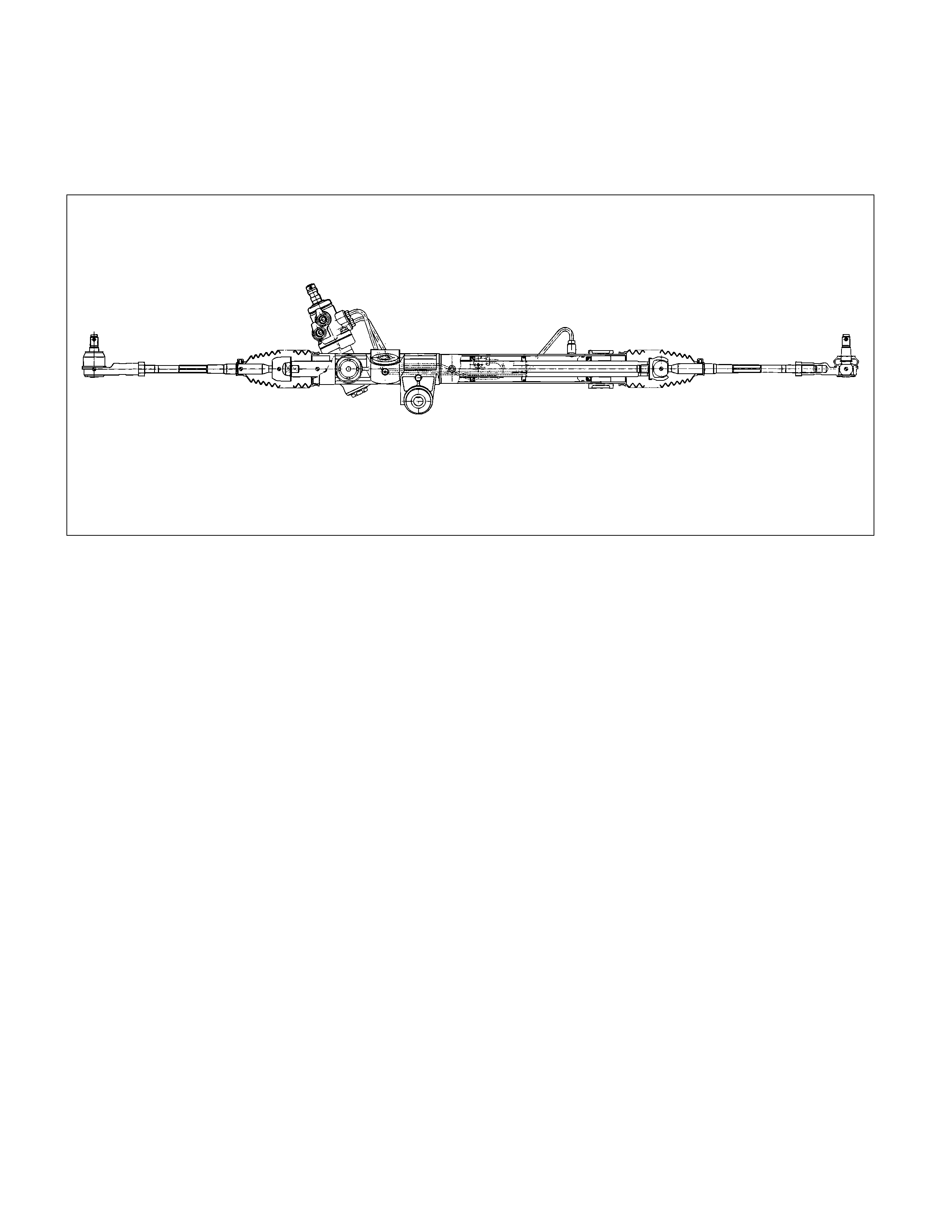
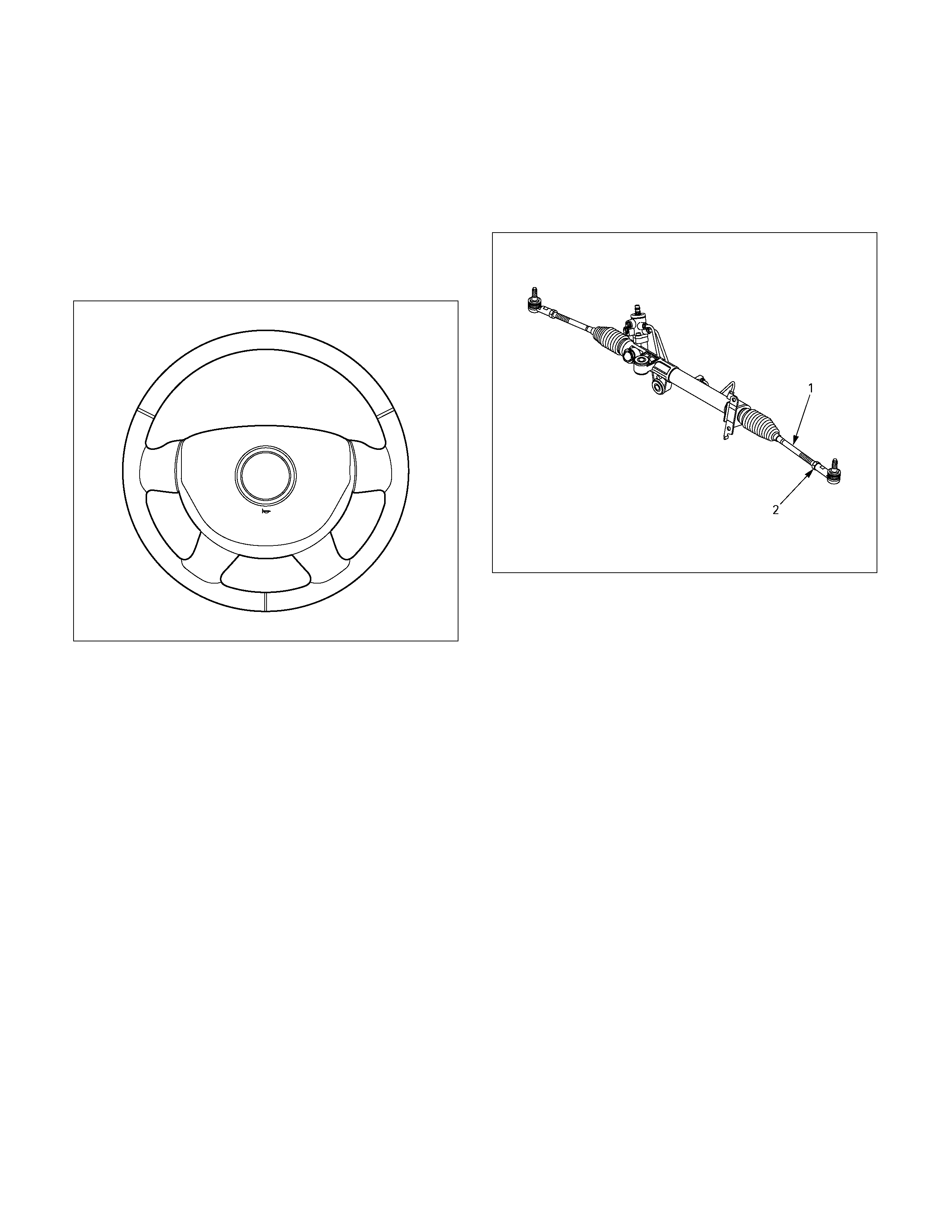
Power Steering Unit
440R300001
The power steering unit is rack and pinion type.
The toe-in angle can be adjusted by turning the rod on each side.
NOTE:
The steering housing cannot be disassembl ed.
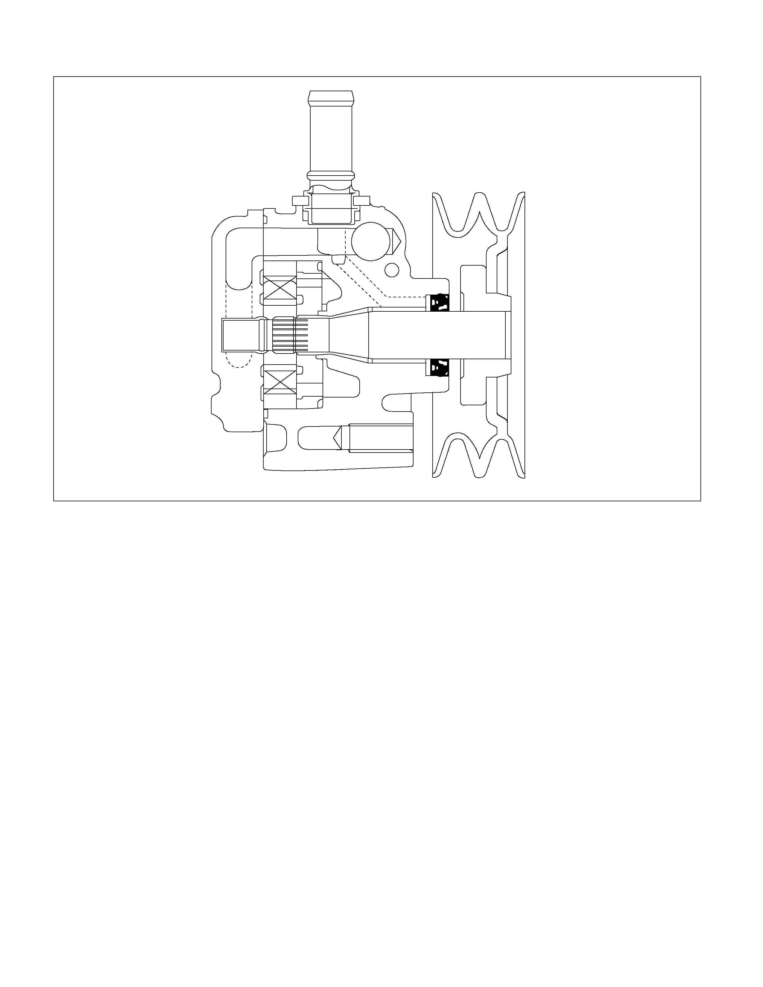
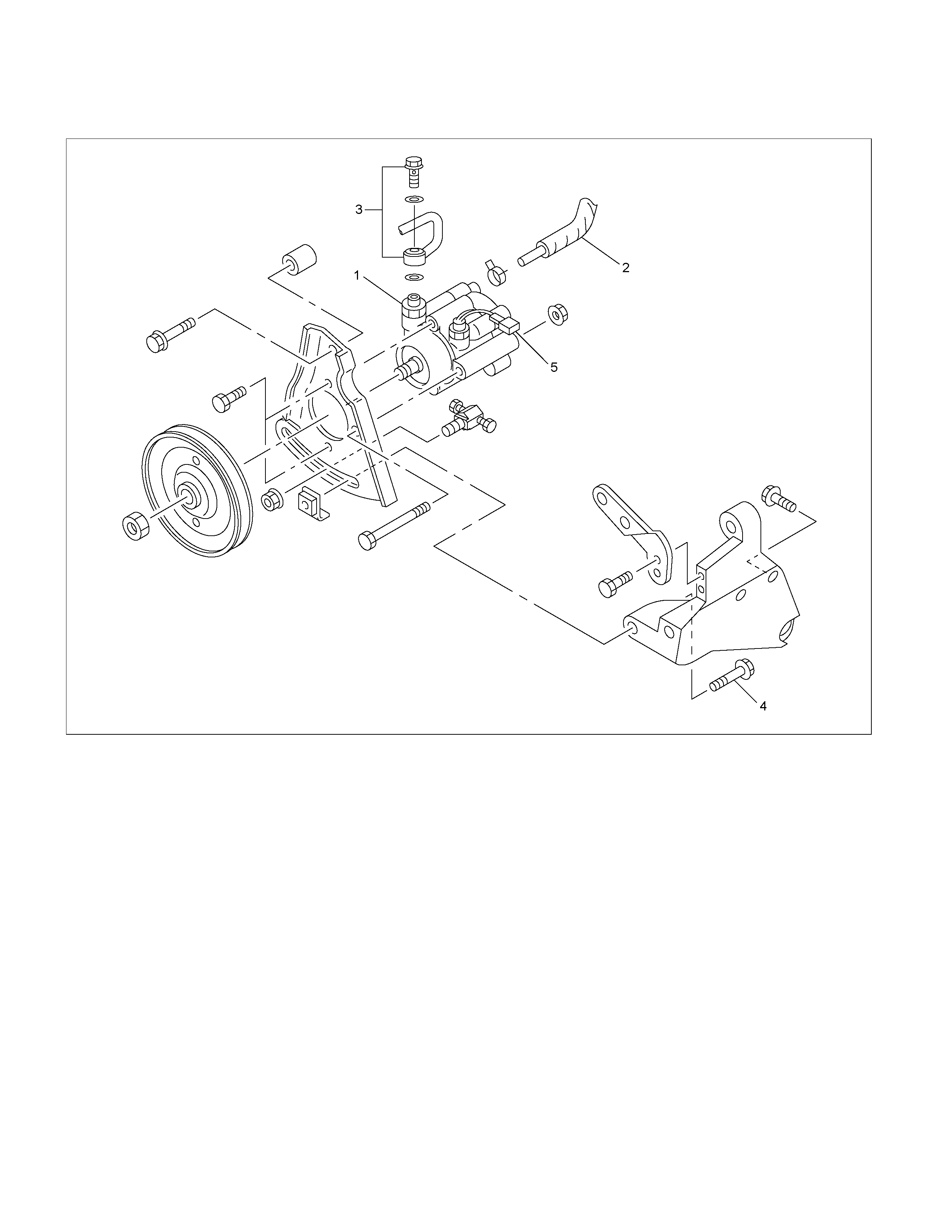
Hydraulic Pump
442R300004
The hydraulic pump is vane-type design. The submerged pump has housing and internal parts that are inside the
reservoir and operate submerged in oil. There are two bore openings at the rear of the pump housing. The larger
opening contains the cam ring, pressure plate, thrust plate, rotor and vane assembly, and end plate. The smaller
opening contains the pressure line union, flow control valve and spring.
The flow control orifice is part of the pressure line union. The pressure relief valve inside the flow control valve limits the
pump pressure.
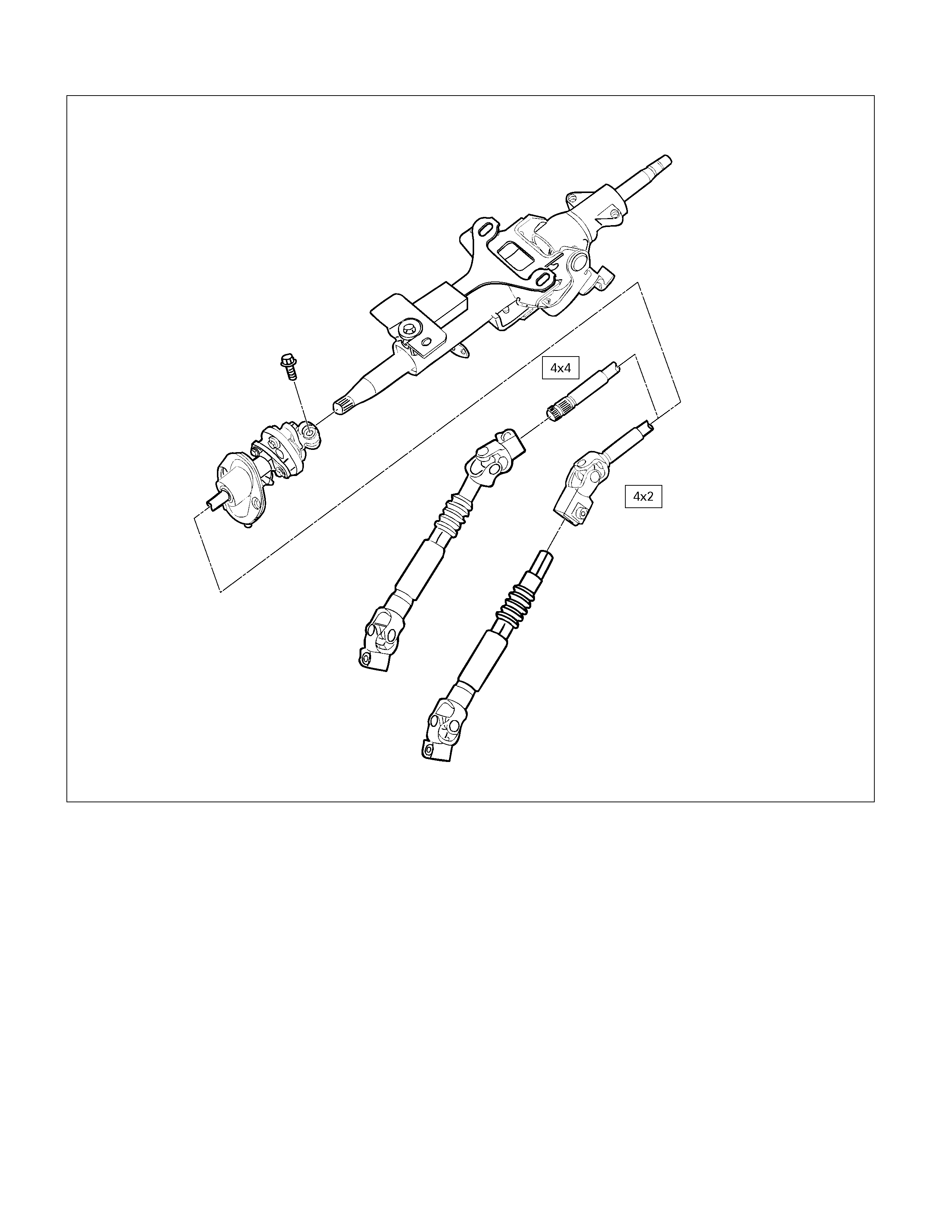
Steering Column
431R300011
WARNING: TO AVOID DEPLOYMENT WHEN TROUBLE-SHOOTING THE SRS SYSTEM, DO NOT USE
ELECTRICAL TEST EQUIPMENT, SUCH AS BATTERY-POWERED OR A/C-POWERED VOLT-METER,
OHMMETER, ETC., OR ANY TYPE OF ELECTRICAL EQUIPMENT OTHER THAN SPECIFIED IN THIS MANUAL.
DO NOT USE A NON-POWERED PROBE-TYPE TESTER. INSTRUCTION IN THIS MANUAL MUST BE FOLLOWED
CAREFULLY, OTHERWISE PERSONAL INJURY MAY RESULT.
When servicing a vehicle equipped with Supplemental Restraint System, pay close attention to all WARNINGS and
CAUTIONS.
For detailed explanation about SRS, refer to Restraints section.
The steering column has three important features in addition to the steering function:
1. The column is energy absorbing, designed to compress in a front-end collision to minimize the possibility of injury to
the driver of the vehicle.
2. The ignition switch and lock are mounted conveniently on the column.
3. With the column mounted lock, the ignition and steering operation can be locked to prevent theft of the vehicle.
The column can be disassembled and reassembled.
NOTE: To insure the energy absorbing action, use only the specified screws, bolts and nuts as designated,
and tighten them to the specified torque.
Handle the column with care when it is removed from the vehicle. A sharp blow on the end of steering shaft or shift
lever, or dropping the assembly could shear or loosen the fasteners that maintain column rigidity.
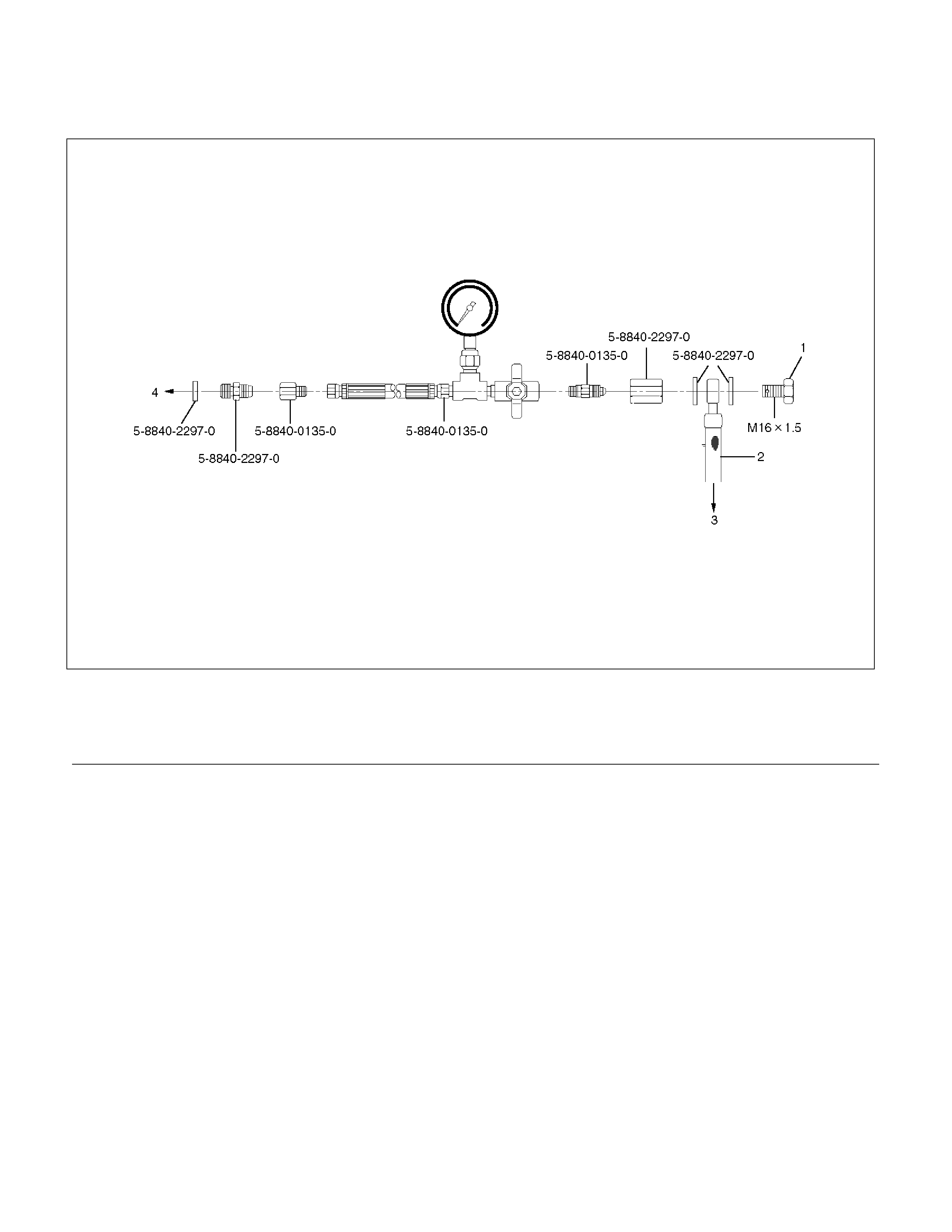
Power Steering System Test
Test Procedure
F02RX002
Legend
(1) Bolt
(2) Hose
(3) Power Steering Unit
(4) Power Steering Pump
Test of fluid pressure in the power steering system is
performed to determine whether or not the oil pump and
power steering unit are functioning normally.
The power steering system test is used to identify and
isolate hydraulic circuit difficulties. Prior to performing
this test, the following inspections and corrections, if
necessary, must be made.
• Inspect pump reservoir for proper fluid level.
• Inspect pump belt for proper tension.
• Inspect pump driver pulley condition.
1. Place a container under the pump to catch the fluid
when disconnecting or connecting the hoses.
2. With the engine NOT running, disconnect the
pressure hose at the power steering pump and
install power steering tester 5-8840-0135-0 as
shown in the illustration. The gage must be between
the shutoff valve and pump. Open the shutoff valve.
3. Check the fluid level. Fill the reservoir with power
steering fluid, to the "Full" mark. Start the engine,
then turn the steering wheel and momentarily hold it
against a stop (right or left). Turn the engine off and
check the connections at tester for leakage.
4. Bleed the system. Refer to Bleeding the Power
Steering System in this section.
5. Start the engine and check the fluid level. Add
power steering fluid if required. When the engine is
at normal operating temperature, increase engine
speed to 1500 rpm.
CAUTION: To prevent internal pump damage, Do
not leave shutoff valve fully closed for more than 5
seconds.

6. Fully close the shutoff valve. Record the highest
pressures.
• If the pressure recorded is within 9300-9800 kPa
(95-100 kg/cm2/1350-1420 psi), the pump is
functioning within its specifications.
• If the pressure recorded is higher than 9800 kPa
(100 kg/cm2/1420 psi), the valve in the pump is
defective.
• If the pressure recorded is lower than 9300 kPa (95
kg/cm2/1350 psi), the valve or the rotating group in
the pump is defective.
7. If the pump pressures are within specifications,
leave the valve open and turn (or have someone
else turn) the steering wheel fully in both directions.
Record the highest pressures and compare with the
maximum pump pressure recorded in step 6. If this
pressure cannot be built in either side of the power
steering unit, the power steering unit is leaking
internally and must be replaced.
8. Shut the engine off, remove the testing gauge.
9. Reconnect the pressure hose, check the fluid level
and make the needed repairs.
10. If the problem still exists, the steering and front
suspension must be thoroughly examined.
Maintenance
The hydraulic system should be kept clean and fluid
level in the reservoir should be checked at regular
intervals and fluid added when required. Refer to
Recommended Fluids and Lubricants in General
Information section for the type of fluid to be used and
the intervals for filling.
If the system contains some dirt, flush it as described in
this section. If it is exceptionally dirty, the pump must be
completely disassembled before further usage. (The
steering unit cannot be disassembled.)
All tubes, hoses, and fittings should be inspected for
leakage at regular intervals. Fittings must be tight. Make
sure the clips, clamps and supporting tubes and hoses
are in place and properly secured.
Power steering hoses and lines must not be twisted,
kinked or tightly bent. Air in the system will cause
spongy action and noisy operation. When a hose is
disconnected or when fluid is lost, for any reason, the
system must be bled after refilling. Refer to Bleeding the
Power Steering System in this section.
• Inspect belt for tightness.
• Inspect pulley for looseness or damage. The pulley
should not wobble with the engine running.
• Inspect hoses so they are not touching any other
parts of the vehicle.
• Inspect fluid level and fill to the proper level.
Fluid Level
1. Run the engine until the power steering fluid
reaches normal operating temperature, about 55°C
(130°F), then shut the engine off.
2. Check the level of fluid in the reservoir.
3. If the fluid level is low, add power steering fluid as
specified in General Information to the proper level
and install the receiver cap.
4. When checking the fluid level after the steering
system has been serviced, air must be bled from
the system. Refer to Bleeding the Power Steering
System in this section.
Bleeding The Power Steering System
When a power steering pump or unit has been installed,
or an oil line has been disconnected, the air that has
entered the system must be bled out before the vehicle
is operated. If air is allowed to remain in the power
steering fluid system, noisy and unsatisfactory operation
of the system may result.
Bleeding Procedure
When bleeding the system, and any time fluid is added
to the power steering system, be sure to use only power
steering fluid as specified in General Information.
1. Fill the pump fluid reservoir to the proper level and
let the fluid settle for at least two minutes.
2. Start the engine and let it run for a few seconds. Do
not turn the steering wheel. Then turn the engine
off.
3. Add fluid if necessary.
4. Repeat the above procedure until the fluid level
remains constant after running the engine.
5. Raise and support the front end of the vehicle so
that the wheels are off the ground.
6. Start the engine. Slowly turn the steering wheel right
and left, lightly contacting the wheel stops.
7. Add power steering fluid if necessary.
8. Lower the vehicle, set the steering wheel at the
straight forward position after turning it to its full
steer positions 2 or 3 times, and stop the engine.
9. Check the fluid level and refill as required.
10. If the fluid is extremely foamy , allow the vehicle to
set a few minutes, then repeat the above procedure.
Flushing The Pow e r Steering System
1. Raise and support the front end of the vehicle off
the ground until the wheels are free to turn.
2. Remove the fluid return line at the pump inlet
connector and plug the connector port on the pump.
Position the line toward a large container to catch
the draining fluid.
3. While running the engine at idle, fill the reservoir
with new power steering fluid. Turn the steering
wheel in both directions. Do not contact or hold the
steering wheel to the wheel stops. This will cause
the pump to go to pressure relief mode, which may
cause a sudden fluid overflow at the reservoir.
4. Install all the lines and hoses. Fill the system with
new power steering fluid and bleed the system as
described in Bleeding The Power Steering System.
Operate the engine for about 15 minutes.
Remove the pump return line at the pump inlet and
plug the connection on the pump. While refilling the
reservoir, check the draining fluid for contamination.
If foreign material is still evident, replace all lines,
disassemble and clean or replace the power
steering system components. Do not re-use any
drained power steering fluid.
Steering Wheel Free Play Inspection
060R300016
1. With the tires in the straight-ahead position, check
the amount of steering wheel play by turning the
wheel in both directions until the tires begin to move.
NOTE: The wheel free play should be checked with the
engine running.
Free play: 0 - 30 mm (0 - 1.18 in)
2. Also check the steering wheel for play and
looseness in the mount by moving it back and forth
and sideways. When test driving, check for hard
steering, steering shimmy and tendency to pull to
one side.
Front End Alignment Inspection and
Adjustment
Toe-in Adjustment
Toe-in: Refer to Section 3A FRONT ALIGNMENT
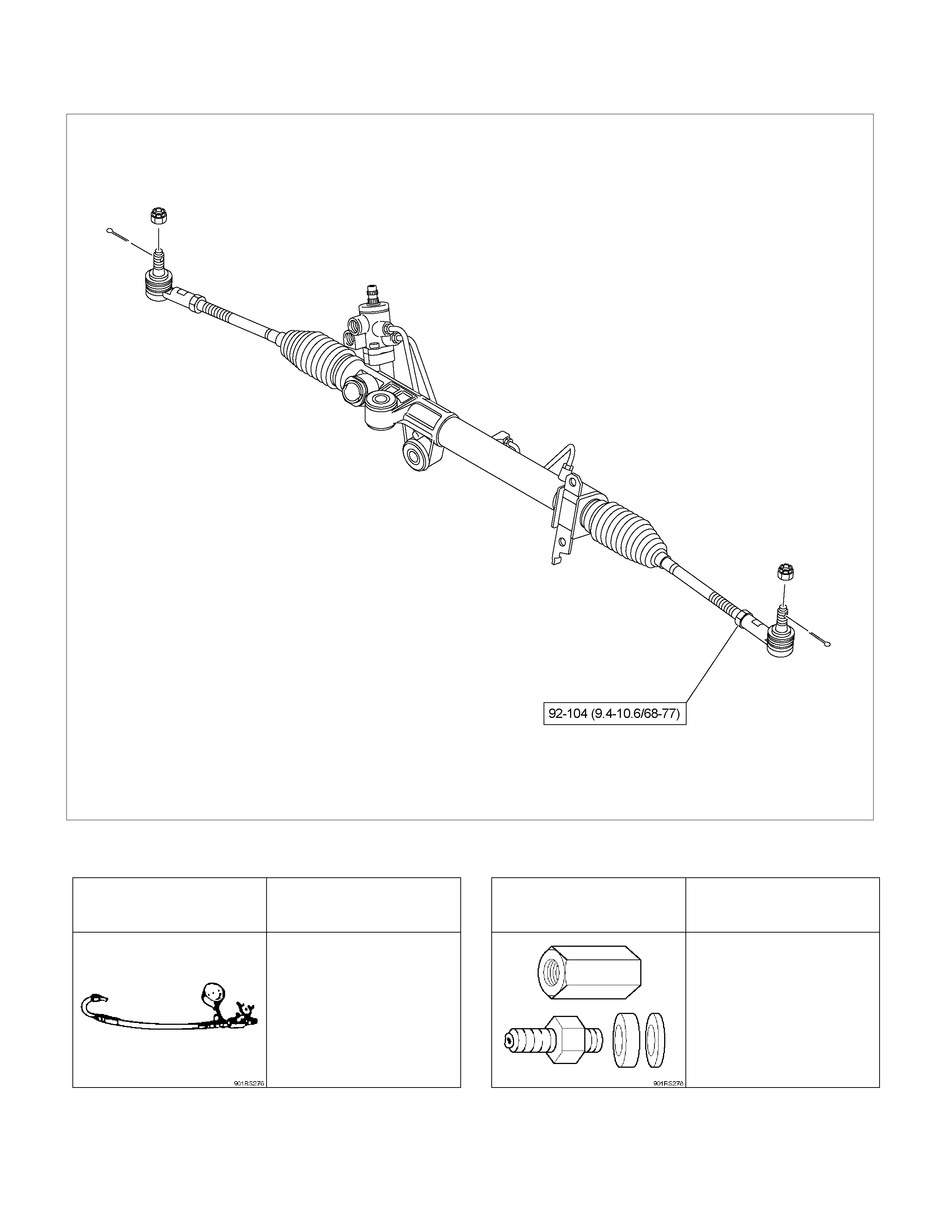
1. To adjust the toe-in angle, loosen the lock nuts (2)
on the tie rod (1) and turn the tie rod. Turn both rods
the same amount, to keep the steering wheel
centered .
431R30006
2. Tighten the lock nut to the specified torque.
Torque:
92 - 104 Nm (9.4 - 10.6 kgm/68 - 77 lb ft)
Torque Specification Nm (kgm/Ibft)
RTW33BLF000101
Special Tools
ILLUSTRATION
TOOL NO.
TOOL NAME
ILLUSTRATION
TOOL NO.
TOOL NAME
5-8840-0135-0
Tester;
Power steering
5-8840-2297-0
Adapter;
Power steering tester
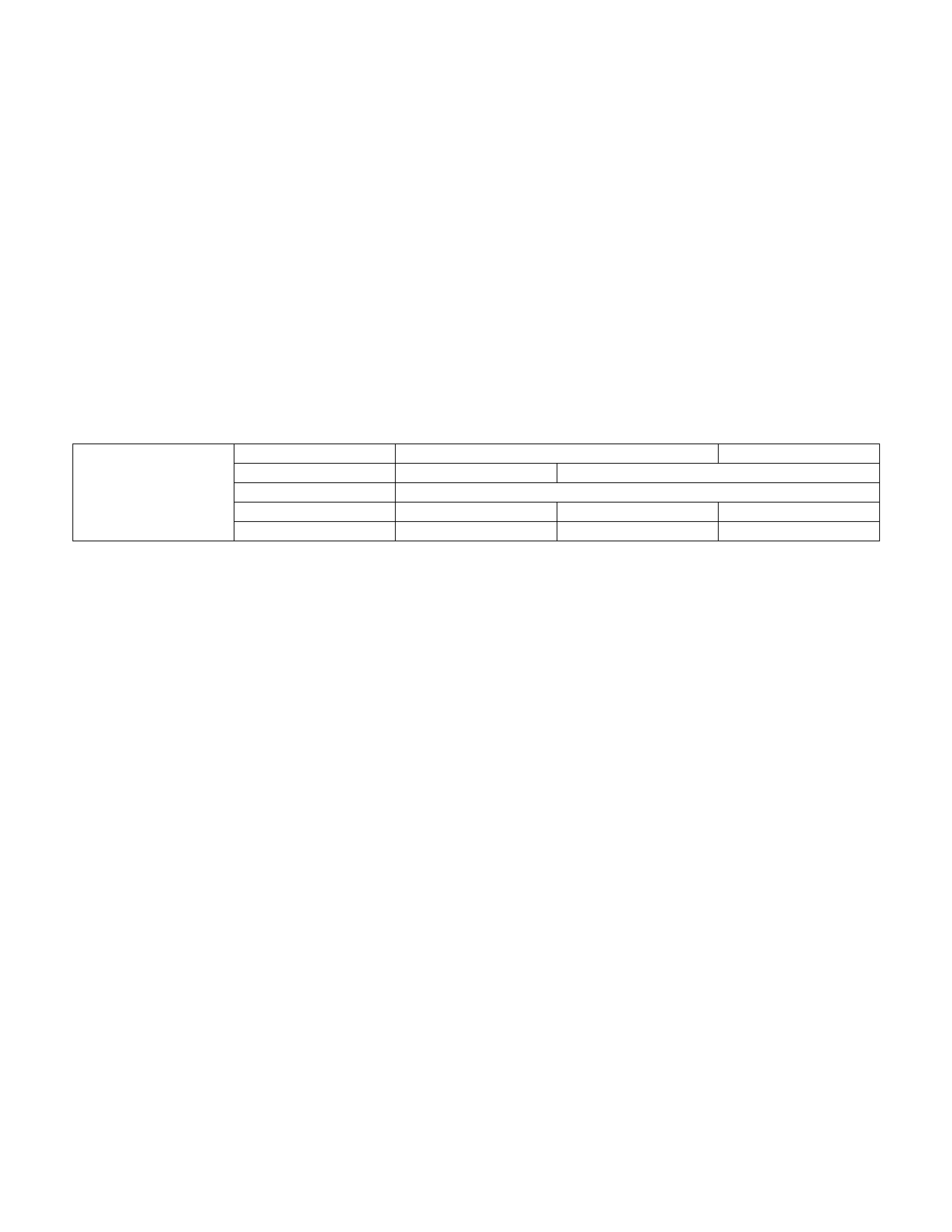
Power Steering Unit
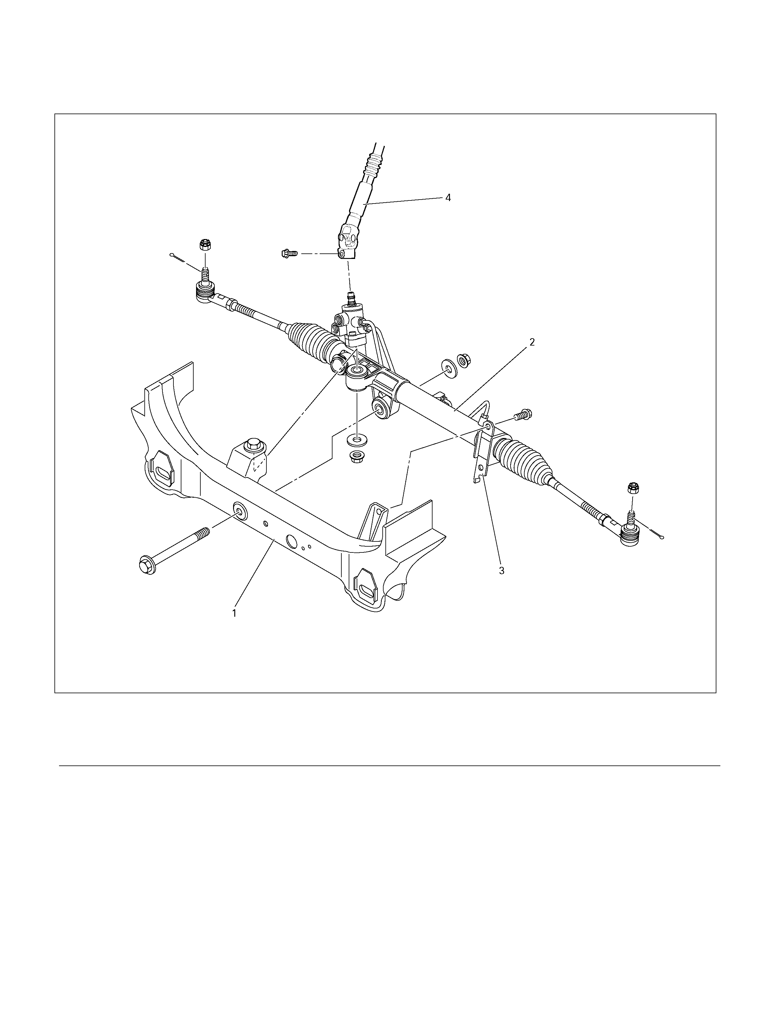
Powe r Steering Unit and Associated Parts
431R300016
Legend
(1) Crossmember
(2) Power Steering Un it Assembly
(3) Bracket
(4) Universal joint (Steering shaft)
Removal
1. Remove the universal joint assembly.
Make a setting mark across the coupling flange and
steering unit to ensure reassembly of the parts in
the original position.
2. Drain power steering fluid.
3. Remove the tie rod end assembly from knuckle.
Use tie rod end remover 5-8840-2005-0.
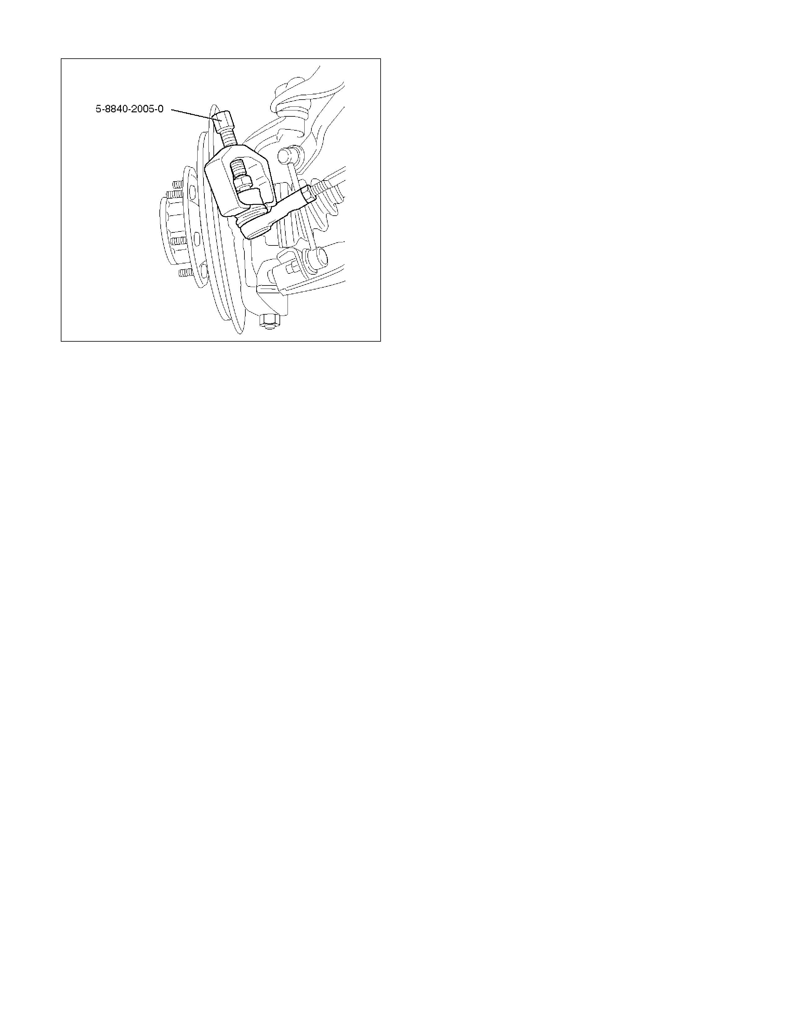
901RW270
4. Disconnect the feed line and return line from
steering unit.
Remove the clips on the crossmember and frame.
Wire the power steering line to frame.
NOTE: Take care to prevent foreign matter from entry
when disconnect the power steering line.
5. Remove the power steering unit from the
crossmember.
Installation
1. Install power steering unit to crossmember.
Tighten fixing bolt and nut to specified torque.
Torque:
106 – 126 Nm (10.8 – 12.8 kgm/78 - 93 lb ft)
Torque:
198 - 242 Nm (20.2 – 24.7 kgm/146 - 178 lb ft)
2. Connect the feed line and return line.
Torque:
20 - 29 Nm (2.0 – 3.0 kgm/14 - 22 lb ft)
3. Install tie-rod end assembly to knuckle.
Torque:
88 – 127 Nm (9.0 – 13.0 kgm/65 - 94 lb ft)
4. Align the setting marks on the universal joint
(applied at disassembly) w ith the setting marks on
the power steering unit. Connect the universal joint
assembly to the power steering unit. Temporarily
tighten the universal joint bolts on the universal joint
assembly side.
5. Tighten the universal joint bolts (bolts at either end
of the joint temporarily tightened in Step 1 and 2) to
the specified torque.
6. Install the stone guard.
7. Bleed the system.
Refer to Bleeding the Power Steering System in
this section.
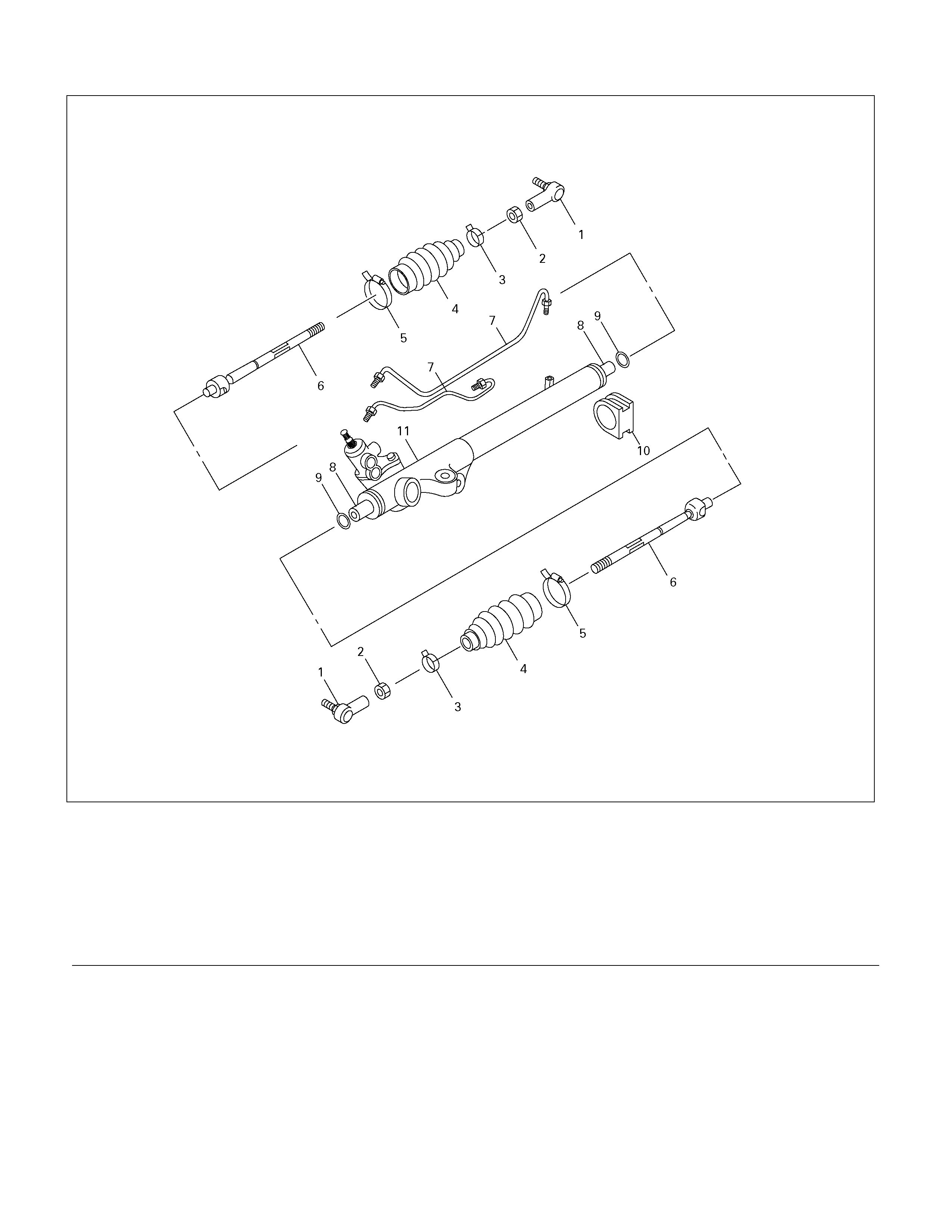
Powe r Steering Unit Disassembled View
440R300003
Legend
(1) Tie-rod End
(2) Lock Nut
(3) Clip
(4) Bellows
(5) Band
(6) Tie-rod Assembly
(7) Oil Line
(8) Inner Ball Joint Assembly
(9) Tab Washer
(10) Mounting Rubber
(11) Housing Assembly
Disassembly
NOTE: The valve housing is made of aluminum and
care should be exercised when clamping in a vise, etc.
to prevent distortion or damage.
1. Loosen lock nut and remove tie-rod end.
2. Remove clip and band, then remove bellows.
3. Remove tie-rod assembly.
To remove, move the boot toward the tie-rod end,
then remove tab washer.
4. Remove oil line, mounting rubber and dust cover.
Inspection and Repair
Inspect the following parts for wear, damage or any
abnormal conditions.
Tie-rod End
If looseness or play is found when checked by moving
the end of ball joint at tie-rod end, replace tie-rod end.
Tie-rod Assembly
If the resistance is insufficient or play is felt when
checked by moving the ball on the tie-rod, replace the
tie-rod assembly.
Rubber Parts
If wear or damage is found through inspection, replace
with new ones.
Reassembly
1. Install mounting rubber and dust cover (If removed).
2. Install oil line.
Torque: 10 - 15 Nm (1.0 – 1.5 kgm/87 - 130 lb in)
3. Install tie-rod assembly w ith tab washer.
Apply grease to ball joint, install tie-rod and tab
washer, then tighten to specified torque.
Torque: 69 - 98 Nm (7.0 – 10.0 kgm/51 - 72 lb ft)
After tightening, bend tab washer against width
across flat of inner ball joint.
4. Apply a thin coat of grease to the shaft for smooth
installation. Then install bellows.
5. Install band and clip.
6. Install tie-rod end and tighten lock nut.
Torque:
92 - 104 Nm (9.4
–
10.6 kgm/68 - 77 lb ft)
Main Data and Specifications
General Specifications 2WD 4WD
Power steering Without With
Type Rack and pinion
Rack stroke mm (in) 138 (5.43) 138 (5.43) 152 (5.98)
Steering unit
Lock to lock 4.84 3.38 3.26
Torque Specifications Nm (kgm/Ibft)
RTW33LF000201
Special Tools
ILLUSTRATION
TOOL NO.
TOOL NAME
5-8840-2005-0
(J-29107)
Tie rod end remover
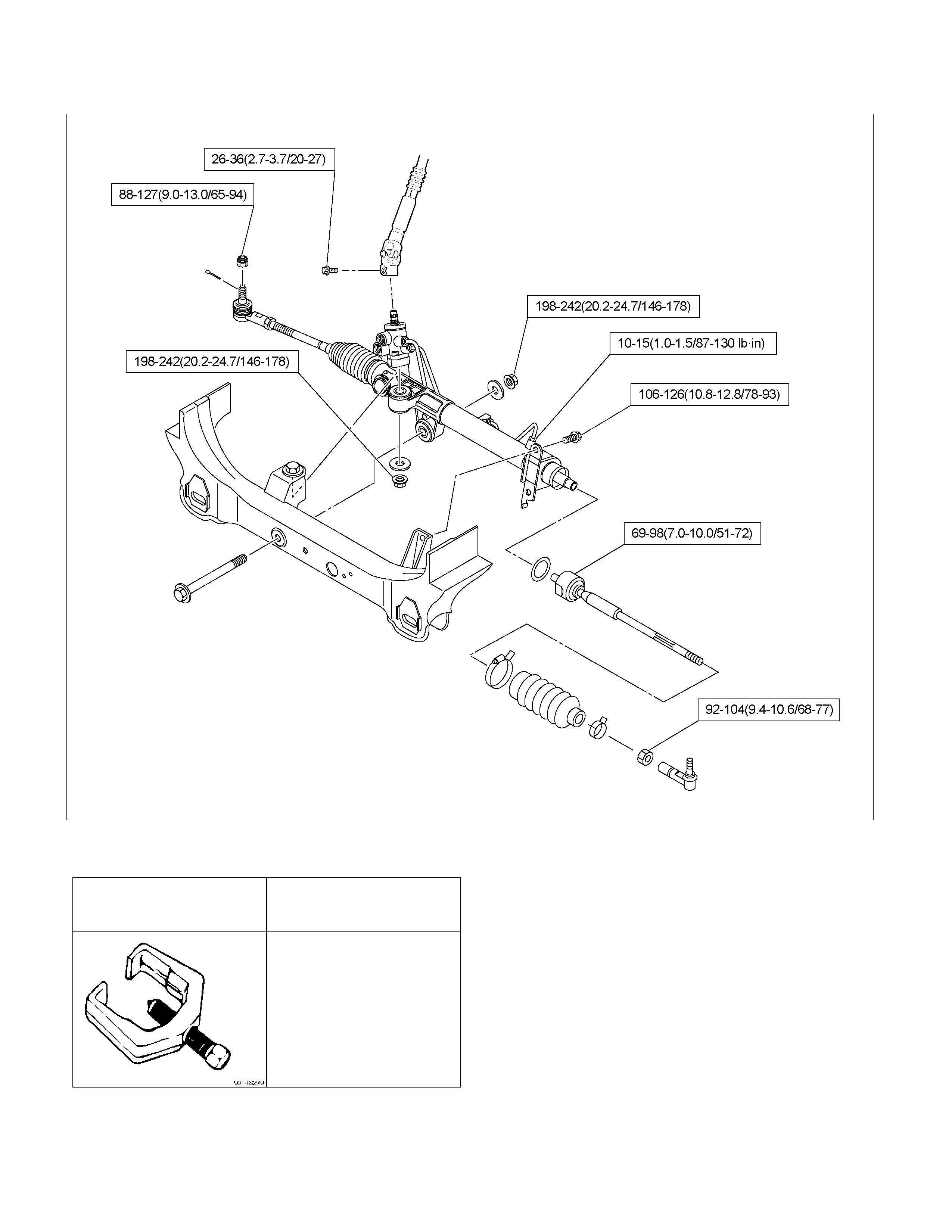
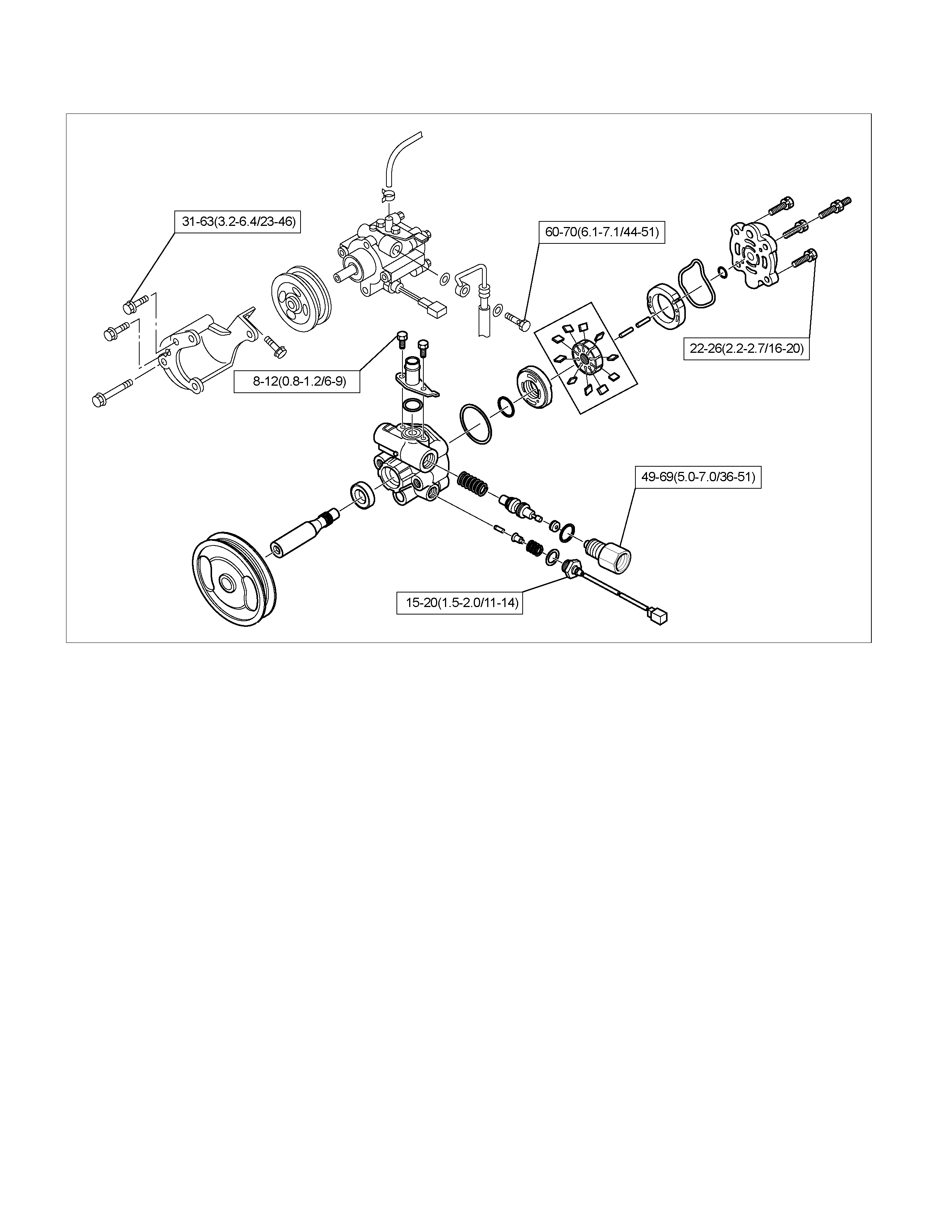
Power Steering Pump (4JH1-TC)
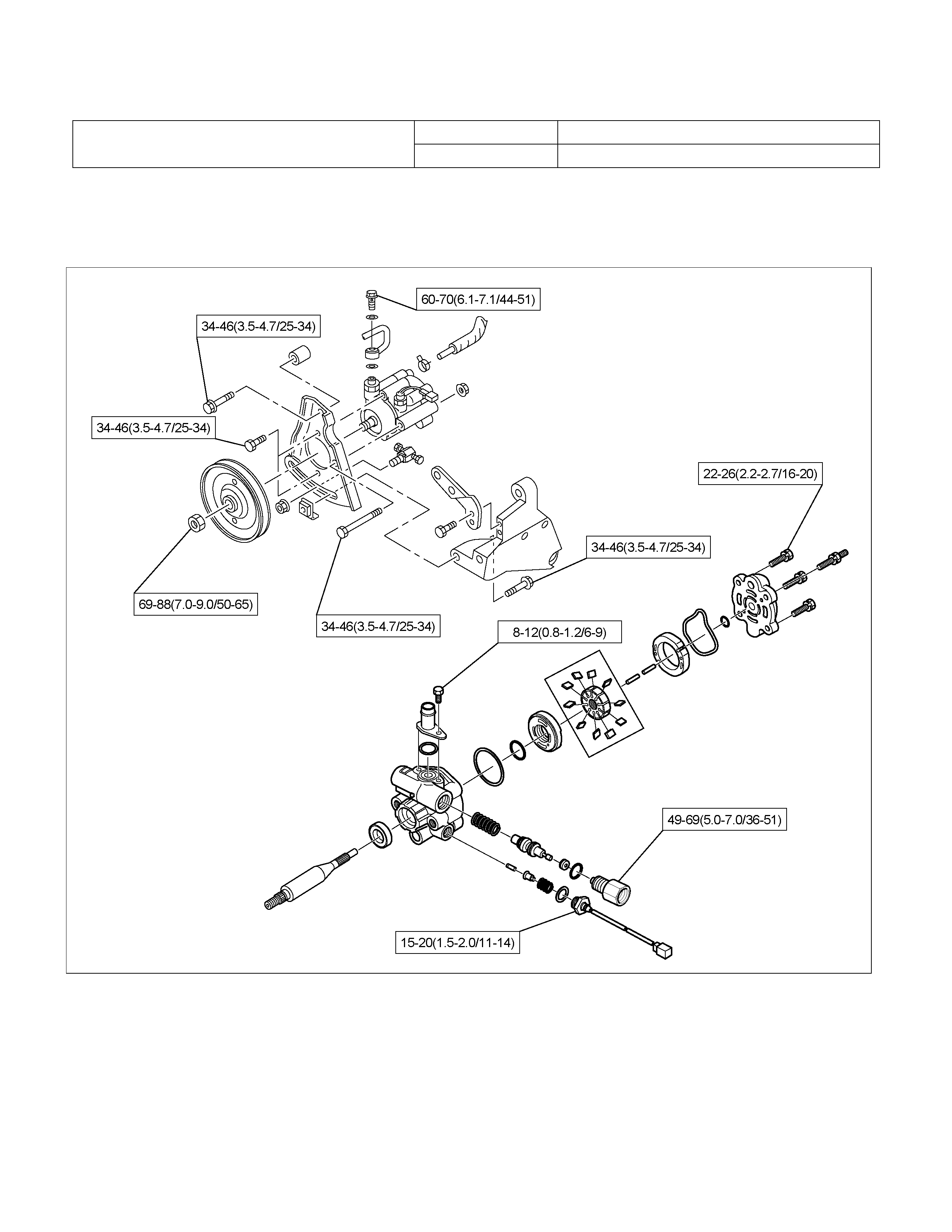
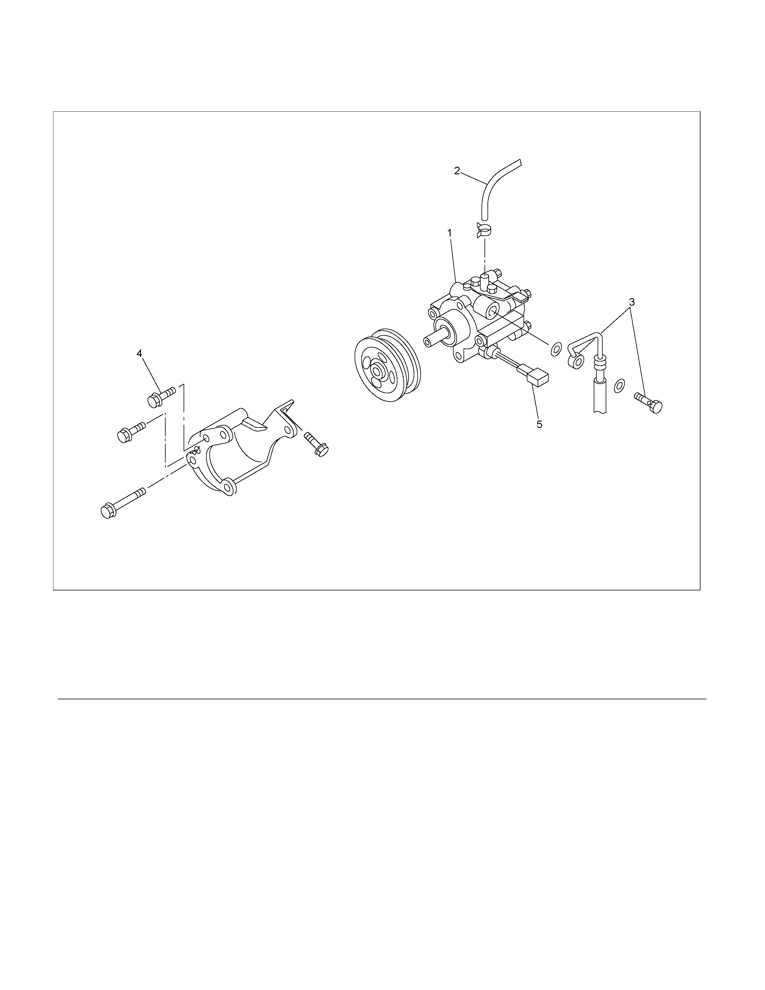
Powe r Steering Pump and Associated Parts (4JH1-TC)
442R300002
Legend
(1) Pump Assembly
(2) Hose, Suction
(3) Hose, Flexible
(4) Bolt
Removal
1. Remove the drive belt.
2. Remove the pulley
3. Place a drain pan below the pump.
4. Disconnect the suction hose.
5. Disconnect the flexible hose.
6. Remove the power steering fixing bolt and remove
the pump assembly.
Installation
1. Install the pump assembly to the pump braket,
tighten the fixing bolt to the specified torque.
Torque: 34 - 46 N·m (3.5 – 4.7 kg·m/25 - 34 lb ft)
2. Install the flexible hose.
Tighten the eye bolt to specified torque.
Torque: 60 - 70 N·m (6.1 – 7.1 kg·m/44 - 51 lb ft)
3. Install the pulley and tighten the bolt to the specified
torque.
Torque: 26 - 30 N·m (2.7 –3.1 kg·m/20 - 22 lb ft)
4. Install the drive belt.
5. Connect the suction hose, then fill and bleed system.
Refer to Bleeding the Power Steering System in
this section.
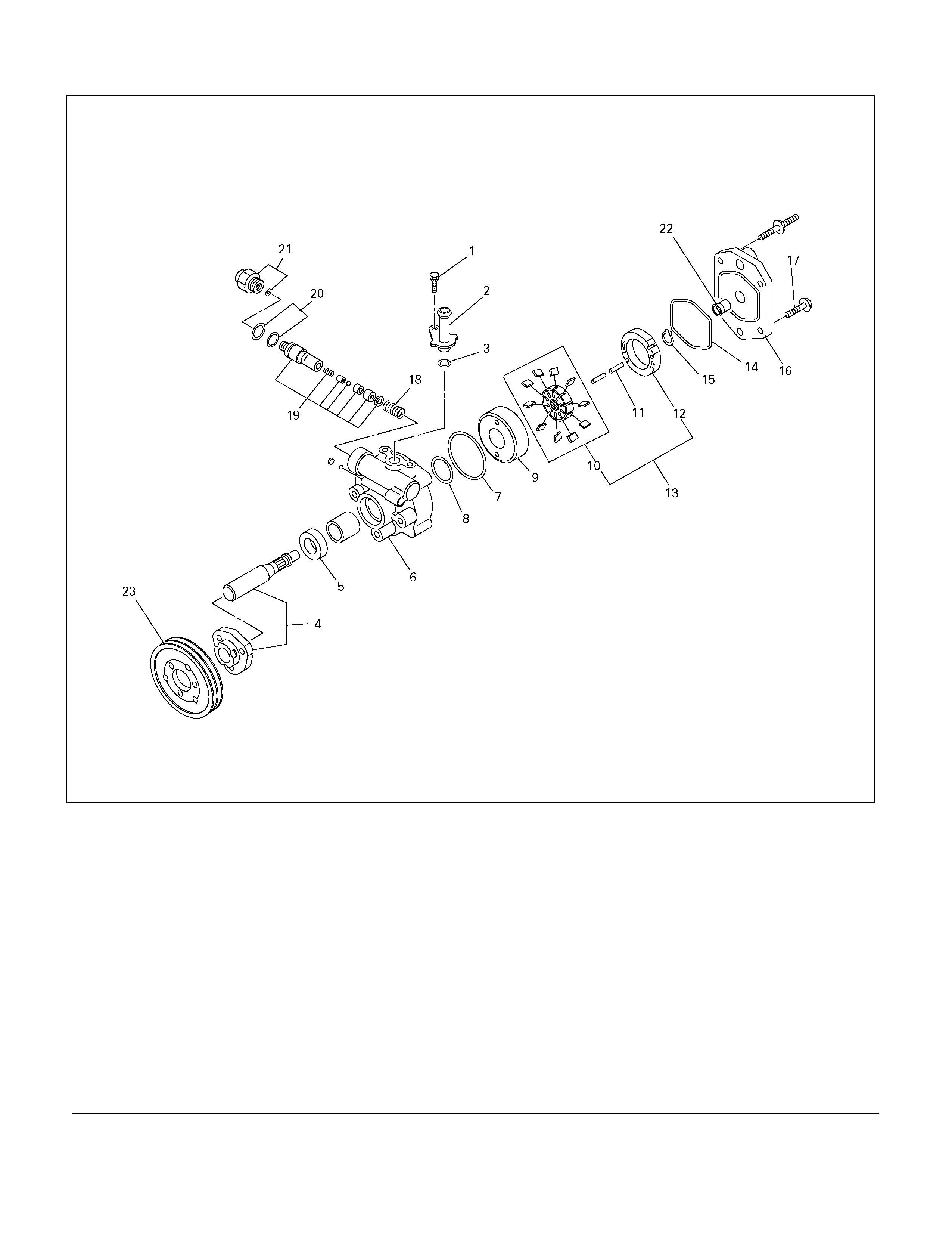
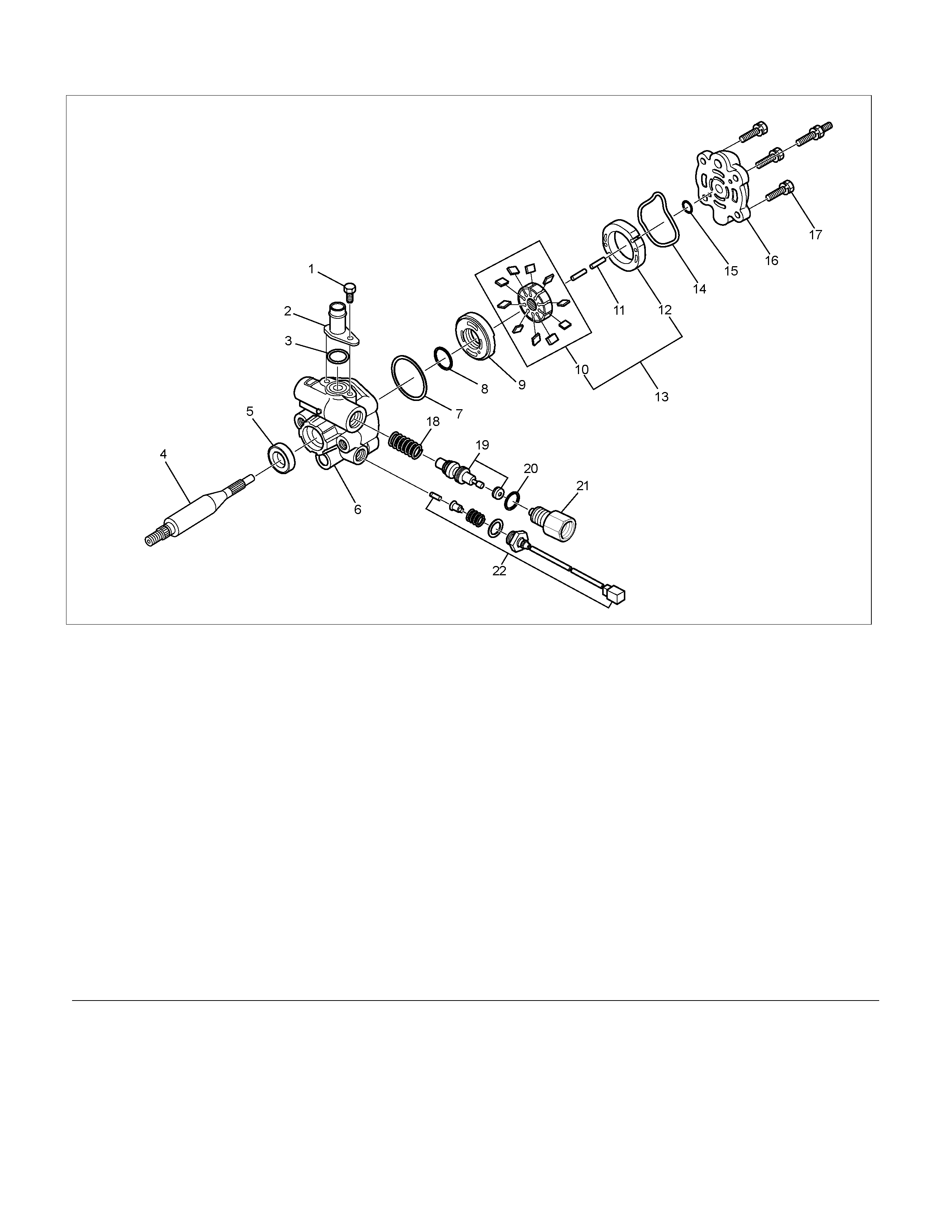
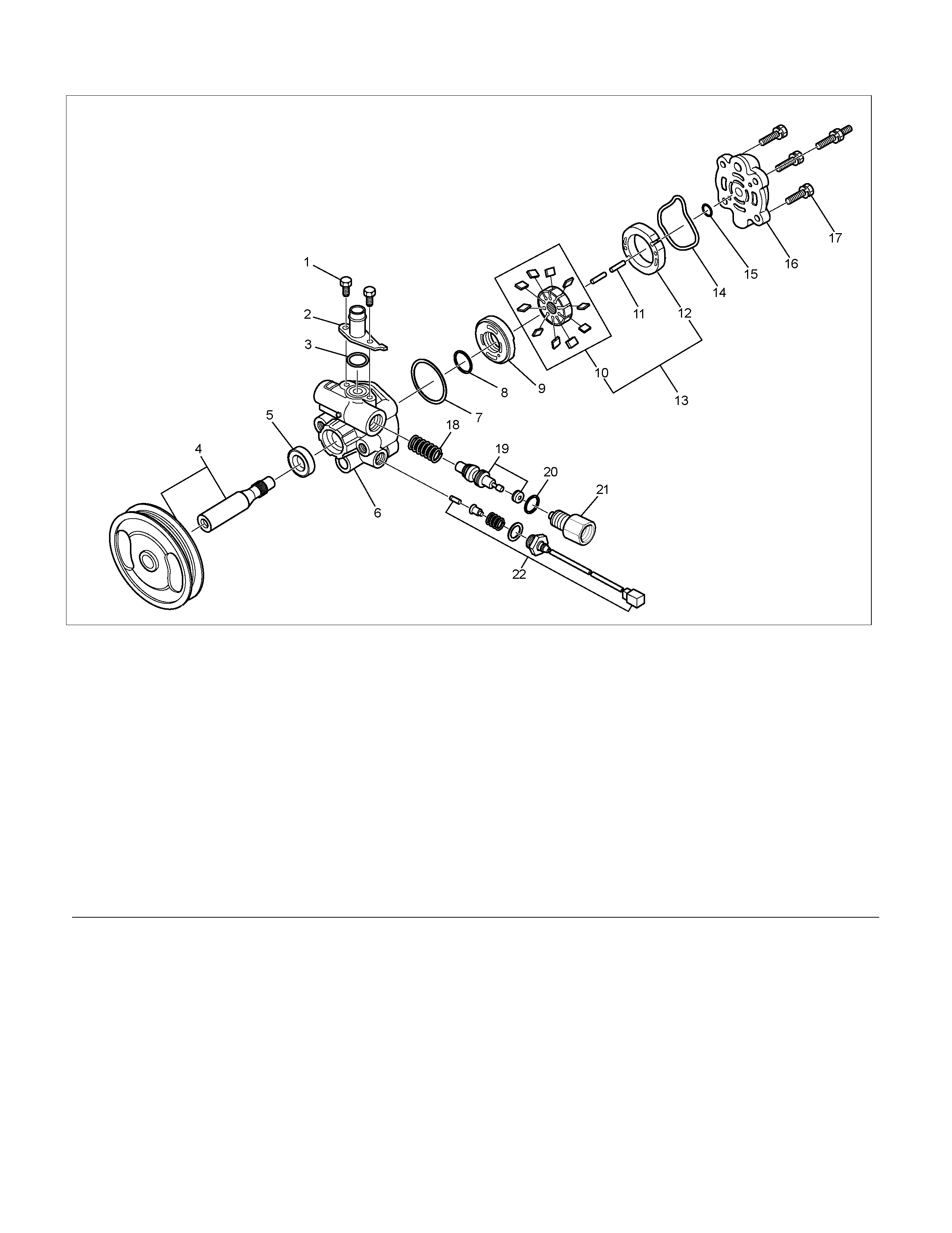
Powe r Steering Pump Disassembled View
442R300001
Legend
(1) Bolt
(2) Suction Pipe
(3) O-ring
(4) Shaft Assembly
(5) Oil Seal
(6) Front Housing
(7) O-ring
(8) O-ring
(9) Side Plate
(10) Rotor and Vane
(11) Pin
(12) Cam
(13) Pump Cartridge Assembly
(14) O-ring
(15) Snap Ring
(16) Rear Housing
(17) Bolt
(18) Spring
(19) Relief Valve
(20) O-ring
(21) Connector
(22) Bush
(23) Plley
Disassembly
1. Clean the oil pump with solvent (plug the discharge
and suction ports to prevent the entry of solvent).
Be careful not to expose the oil seal of shaft
assembly to solvent.
2. Remove the bolt, suction pipe and O-ring.
3. Remove the connector, O-ring, relief valve and
spring.
4. Remove the bolt, rear housing and O-ring.
5. Remove the snap ring.
6. Remove the shaft assembly.
7. Remove the oil seal.
CAUTION: When removing the oil seal, be careful
not to damage the housing.
8. Remove the pump cartridge assembly from the front
housing.
9. Remove two O-rings.
Inspection and Repair
Make all necessary adjustments, repairs, and part
replacements if wear, damage, or other problems are
discovered during inspection.
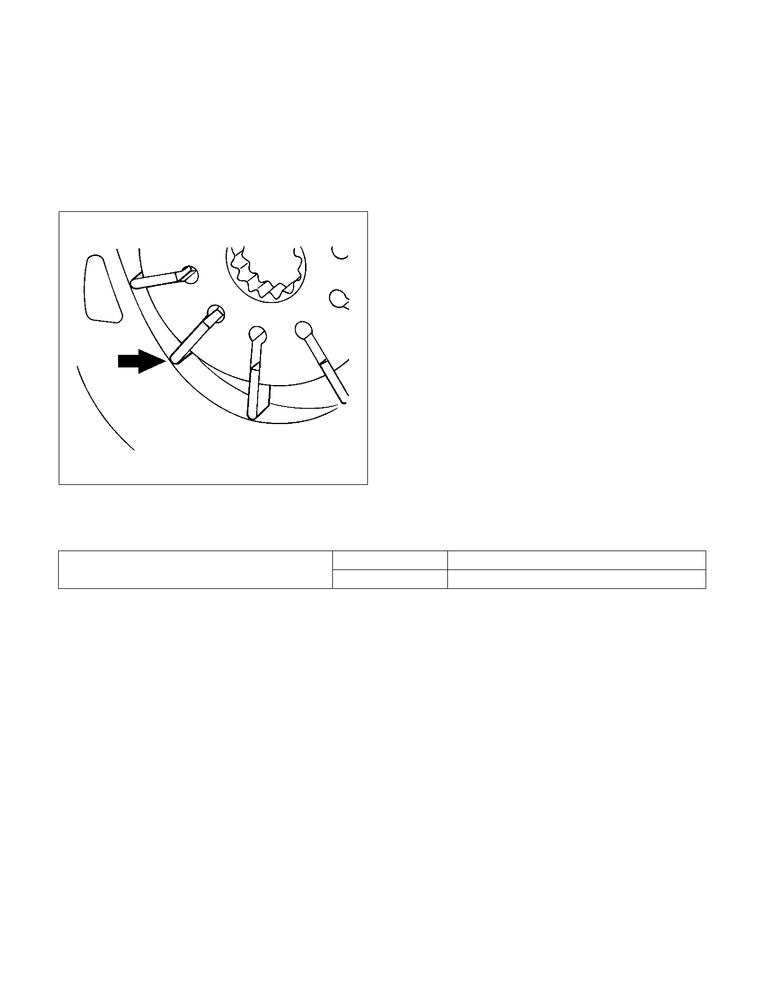
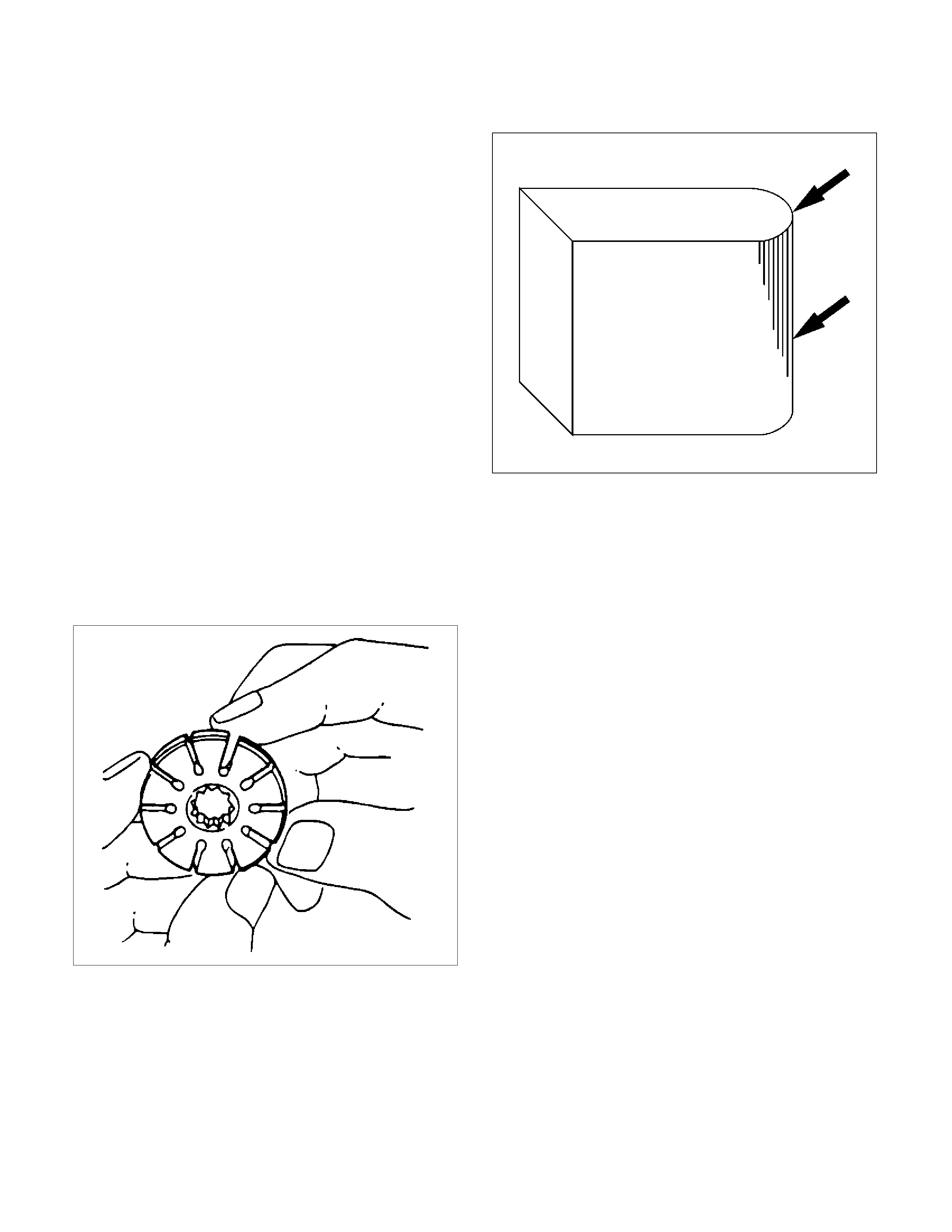
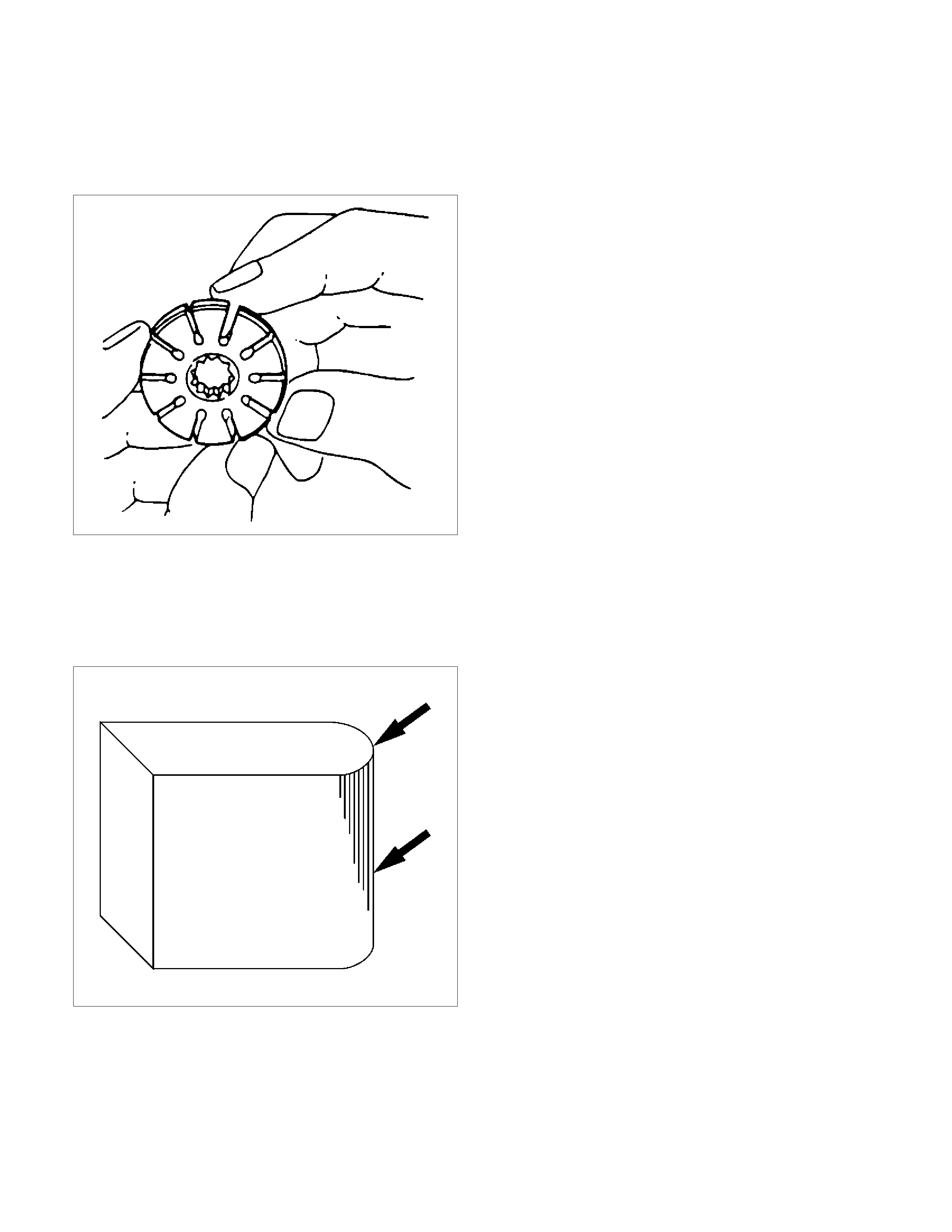
Rotor
442RS002
Check that the groove in the vane is free from excessive
wear and that the vane slides smoothly. When part
replacement becomes necessary, the pump cartridge
should be replaced as a subassembly .
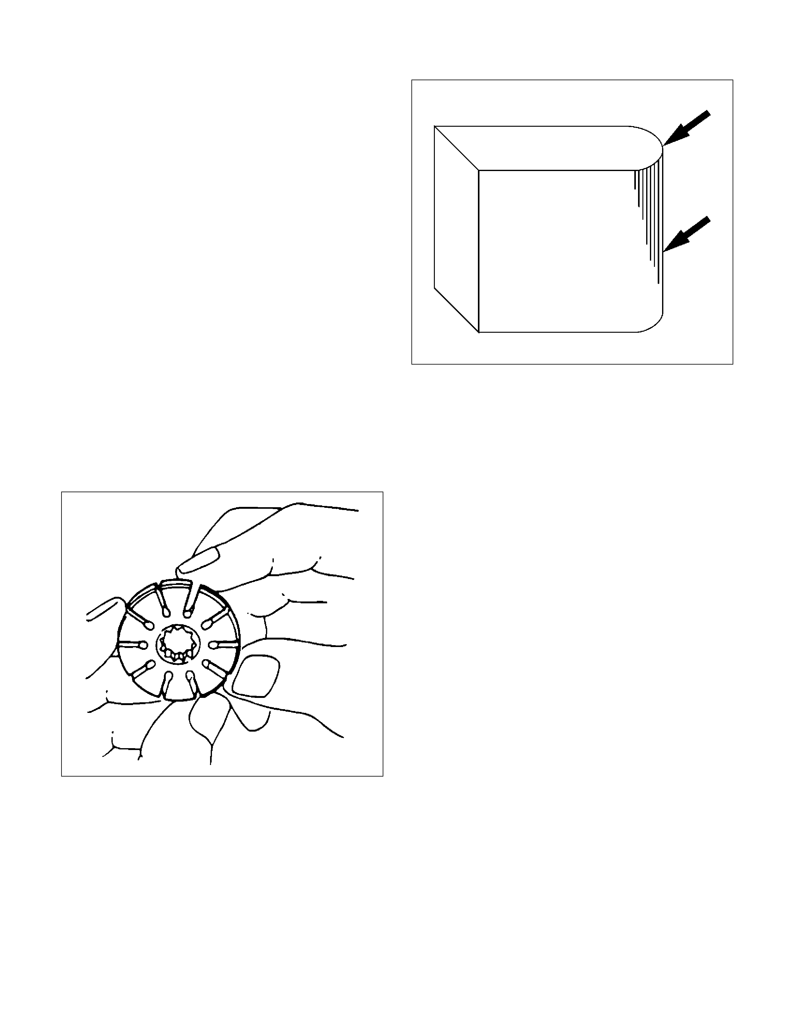
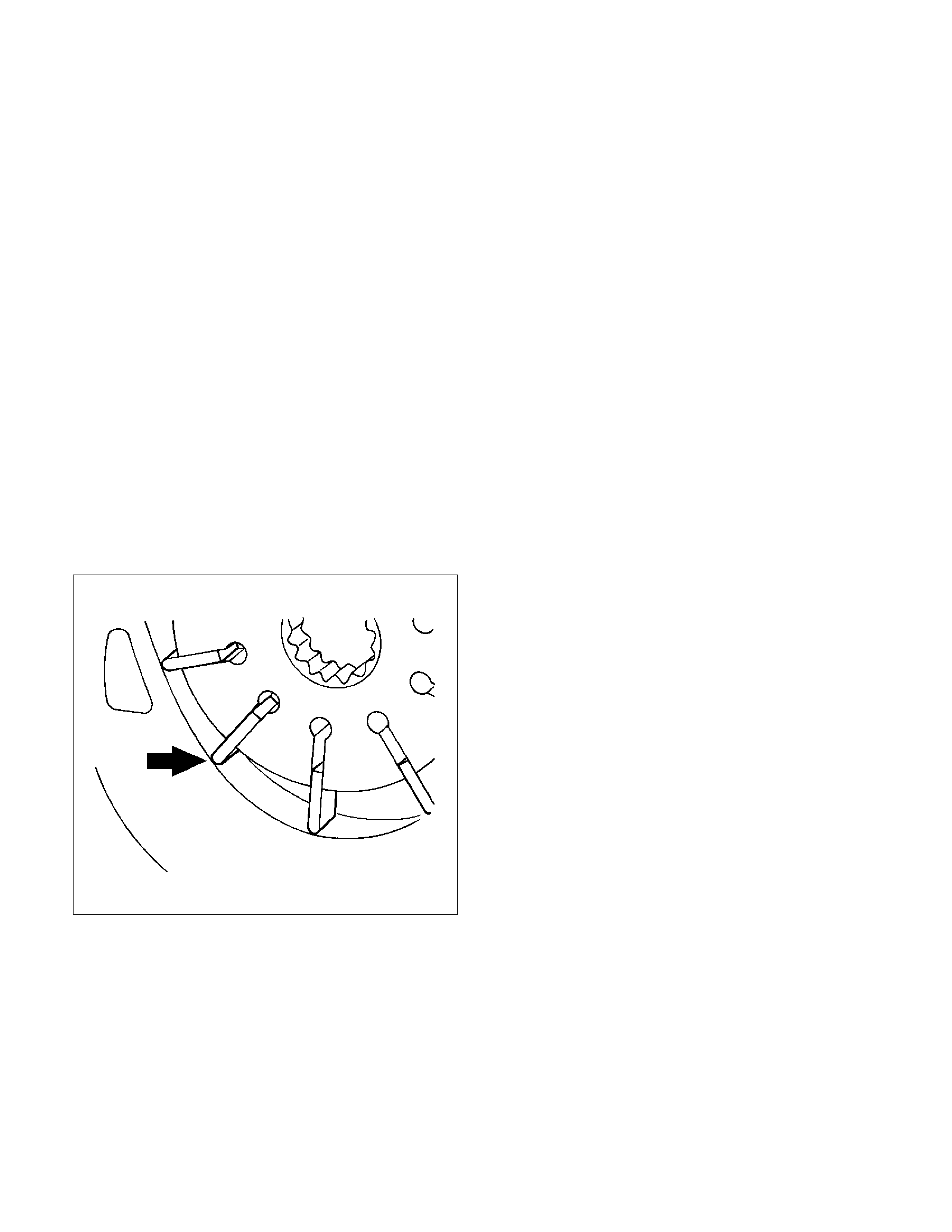
Vane
442RS003
Sliding faces of the vane should be free from wear.
(Particularly the curved face at the tip that contact with
the cam should be free from wear and distortion). When
part replacement becomes necessary, the pump
cartridge should be replaced as a subassembly.
Cam
The inner face of the arm should have a uniform contact
pattern without a sign of step wear. When part
replacement becomes necessary, the pump cartridge
should be replaced as a subassembly .
Side Plate
The sliding faces of parts must be free from step wear
(more than 0.01 mm), which can be felt by the finger
nail.
The parts with minor scores may be reused after lapping
the face.
Relief Valve
The sliding face of the valve must be free from burrs
and damage. The parts with minor scores may be
reused after smoothing with emery cloth (#800 or finer).
Shaft
Oil seal sliding faces must be free from a step wear
which can be felt by the finger nail. Bushing fitting face
must be free from damage and wear.
O-ring, Oil Seal, Snap Ring
Be sure to discard used parts, and always use new
parts for installation. Prior to installation, lubricate all
seals and rings with power steering fluid.
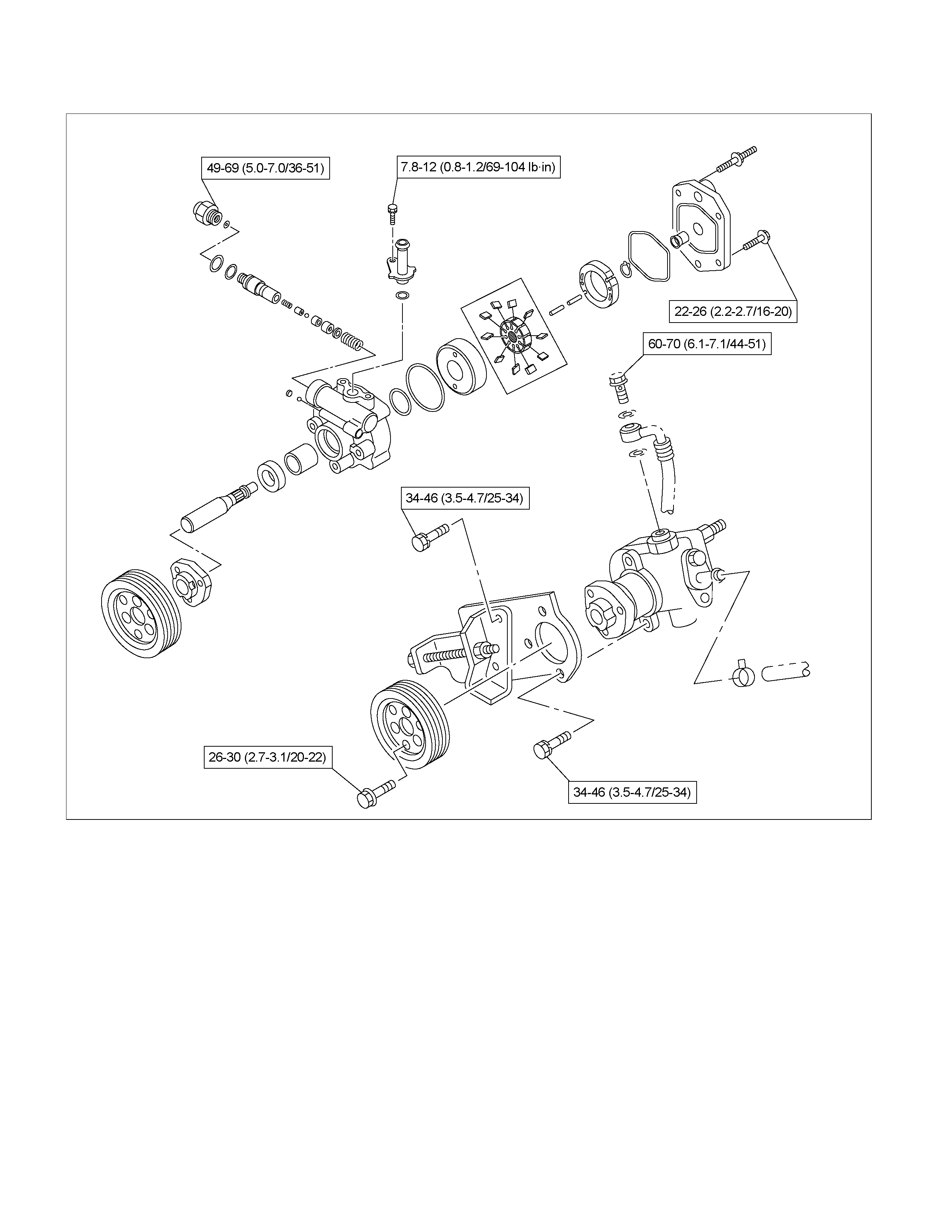
Reassembly
1. Install oil seal to front housing. Be sure to discard
used oil seal, and always use new parts for
installation.
CAUTION: When installing the oil seal, be careful
not to damage the oil seal contacting surface of the
housing.
2. Install shaft assembly.
3. Install the vanes to roter with curved face in contact
with the inner wall of cam.
442RS005
4. Install roter and vanes to cam.
5. Install pin to front housing.
6. Install two new O-rings to front housing. Be sure to
discard used O-ring.
7. Install side plate.
CAUTION: When installing side plate, be careful not
to damage its inner surface. Damaged side plate
may cause poor pump performance, pump seizure
or oil leakage.
8. Install pump cartridge assembly to front housing.
9. Install snap ring to shaft end.
10. Install rear housing with a new O-ring. Be sure to
discard used O-ring. Then install bolt and tighten it
to specified torque.
Torque: 22-26 Nm (2.2-2.7kgm/16-20 lb ft)
11. Install suction pipe with a new O-ring. Be sure to
discard used O-ring. Then install bolt and tighten it
to specified torque.
Torque: 7.8-12 Nm (0.8-1.2kgm/69-104 lb in)
12. Install relief valve and spring.
13. Install connector with a new O-ring. Be sure to
discard used O-ring. Tighten the connector to
specified torque.
Torque: 49-69 Nm (5.0-7.0kgm/36-51 lb ft)
Main Data and Specifications
General Specifications
Oil pump Type Vane
Operating fluid ATF DEXRON®III
Torque Specifications
4JH1-TC Nm (kgm/Ib ft)
RTW33BLF001001
Power Steering Pump (C24SE)
Powe r Steering Pump and Associated Parts (C24SE)
RTW33BLF000801
Legend
(1) Pump Assembly
(2) Hose, Suction
(3) Hose, Flexible
(4) Bolt
(5) Connector, Pressure switch
Removal
1. Remove the drive belt.
2. Remove the pulley
3. Place a drain pan below the pump.
4. Disconnect the suction hose.
5. Disconnect the flexible hose.
6. Disconnect the oil pressure switch connector.
7. Remove the power steering fixing bolt and remove
the pump assembly.
Installation
1. Install the pump assembly to the pump braket,
tighten the fixing bolt to the specified torque.
Torque: 34-46 N·m (3.5-4.7 kg·m/25-34 lb ft)
2. Connector the oil pressure switch connector.
3. Install the flexible hose.
Tighten the eye bolt to specified torque.
Torque: 60-70 N·m (6.1-7.1 kg·m/44-51 lb ft)
4. Install the pulley and tighten the bolt to the specified
torque.
Torque: 69-88 N·m (7.0-9.0 kg·m/51-65 lb ft)
5. Install the drive belt.
6. Connect the suction hose, then fill and bleed
system. Refer to Bleeding the Power Steering
System in this section.
Powe r Steering Pump Disassembled View
RTW33BMF000301
Legend
(1) Bolt
(2) Suction Pipe
(3) O-ring
(4) Front Housing
(5) Snap Ring
(6) Shaft Assembly
(7) Bearing
(8) Shaft
(9) Retaining Ring
(10) Oil Seal
(11) O-ring
(12) O-ring
(13) Gasket
(14)Rear Housing Assembly and Pump Cartridge
(15) Side Plate
(16) Rotor and Vane
(17) Pin
(18) Cam
(19) Rear Housing
(20) Bolt
(21) Spring
(22) Retaining Ring
(23)Filter
(24) Valve
(25) O-ring
(26) Connector
(27) Pressure Switch
Disassembly
1. Clean the oil pump with solvent (plug the discharge
and suction ports to prevent the entry of s olvent). Be
careful not to expose the oil seal of shaft assembl
y
to solvent.
2. Remove the bolt, suction pipe and O-ring.
Remove the O-ring.
3. Remove the connector, O-ring, relief valve and
spring.
4. Remove the pressure switch assembly.
5. Remove the bolt, rear housing and O-ring.
6. Remove the snap ring.
7. Remove the shaft assembly.
8. Remove the oil seal.
CAUTION: When removing the oil seal, be careful
not to damage the housing.
9. Remove the pump c ar tridge as sembly from the fr ont
housing.
10. Remove two O-rings.
Inspection and Repair
Make all necessary adjustments, repairs, and part
replacements if wear, damage, or other problems are
discovered during inspection.
Rotor
442RS002
Check that the groove in the vane is free from excessive
wear and that the vane slides smoothly. When part
replacement becomes necessary, the pump cartridge
should be replaced as a subassembly .
Vane
442RS003
Sliding faces of the vane should be free from wear.
(Particularly the curved face at the tip that contact with
the cam should be f ree f rom wear and distortion) . When
part replacement becomes necessary, the pump
cartridge should be replaced as a subassembly.
Cam
The inner face of the ar m should have a unif o rm c ontact
pattern without a sign of step wear. When part
replacement becomes necessary, the pump cartridge
should be replaced as a subassembly .
Side Plate
The sliding faces of parts must be free from step wear
(more than 0.01 mm), which can be felt by the finger
nail. The parts with minor scores may be reused after
lapping the face.
Valve
The sliding face of the valve must be free from burrs
and damage. The parts with minor scores may be
reused after smoothing with emery cloth (#800 or finer).
Shaft
Oil seal sliding faces must be free from a step wear
which can be felt by the finger nail. Needle bearing fitting
face must be free from damage and wear.
O-ring, Oil Seal, Retaining Ring
Be sure to discard used parts, and always use new
parts for installation. Prior to installation, lubricate all
seals and rings with power steering fluid.
Pressure Switch
Check the switch operation as follows:
With engine idling and A/C on, turn the steering wheel
fully to the left; compressor should interrupt and engine
idle speed will increase. Shut off A/C and again turn
steering fully to the left; engine idle will increase. I
f
system fails to function properly, disconnect connecto
r
at the pressure switch and repeat system check while
testing continuity across disconnected SW connector.
Reassembly
1. Install oil seal to front housing. Be sure to discard
used oil seal, and always use new parts fo
r
installation.
CAUTION: When installing the oil seal, be careful
not to damage the oil seal contacting surface of the
housing.
2. Install shaft assembly.
3. Ins tall the vanes to roter with curved face in contact
with the inner wall of cam.
442RS005
.
4. Install rotor and vanes to cam
5. Install pin to front housing.
6. Install two new O-rings to front housing. Be sure to
discard used O-ring.
7. Install side plate.
CAUTION: When installing side plate, be careful not
to damage its inner surface. Damaged side plate
may cause poor pump performance, pump seizure
or oil leakage.
8. Install pump cartridge assembly to front housing.
9. Install snap ring to shaft end.
10. Install rear housing with a new O-ring. Be sure to
discard used O-ring. Then install bolt and tighten it
to specified torque.
Torque: 22-26 N⋅
⋅⋅⋅m (2.2-2.7 kg⋅
⋅⋅⋅m/16-20 lb ft)
11. Install suction pipe with a new O-ring. Be sure to
discard used O-ring. Then install bolt and tighten it
to specified torque.
Torque: 7.8-12 N⋅
⋅⋅⋅m (0.8-1.2 kg⋅
⋅⋅⋅m/6-9 lb ft)
12. Install relief valve and spring.
13. Install connector with a new O-ring. Be sure to
discard used O-ring. Tighten the connector to
specified torque.
Torque: 49-69 N⋅
⋅⋅⋅m (5.0-7.0 kg⋅
⋅⋅⋅m/36-51 lb ft)
14. Install pressure switch assembly and tighten it to
specified torque.
Torque: 15-20 N⋅
⋅⋅⋅m (1.5-2.0 kg⋅
⋅⋅⋅m/11-14 lb ft)
Main Data and Specifications
General Specifications
Oil pump Type Vane
Operating fluid
ATF DEXRON®―III
Torque Specifications Nm (kgm/Ib ft)
RTW33BLF000901
Power Steering Pump (6VE1)
Powe r Steering Pump and Associated Parts (6VE1)
RTW33BLF000701
Legend
(1) Pump Assembly
(2) Hose, Suction
(3) Hose, Flexible
(4) Bolt
(5) Connector, Pressure switch
Removal
1. Remove the drive belt.
2. Place a drain pan below the pump.
3. Disconnect the suction hose.
4. Disconnect the flexible hose.
5. Disconnect the oil pressure switch connector.
6. Remove the power steering fixing bolt and remove
the pump assembly.
Installation
1. Install the pump assembly to the pump braket,
tighten the fixing bolt to the specified torque.
Torque: 31-63 N·m (3.2-6.4 kg·m/23-46 lb ft)2.
Connector the oil pressure switch connector.
3. Install the flexible hose.
Tighten the eye bolt to specified torque.
Torque: 60-71 N·m (6.1-7.1 kg·m/44-51 lb ft)
4. Install the drive belt.
5. Connect the suction hose, then fill and bleed
system.
Refer to Bleeding the Power Steering System in
this section.
Powe r Steering Pump Disassembled View
RTW33BMF000201
Legend
(1) Bolt
(2) Suction Pipe
(3) O-ring
(4) Shaft Assembly
(5) Oil Seal
(6) Front Housing
(7) O-ring
(8) O-ring
(9) Side Plate
(10) Rotor and Vane
(11) Pin
(12) Cam
(13) Pump Cartridge Assembly
(14) O-ring
(15) Snap Ring
(16) Rear Housing
(17) Bolt
(18) Spring
(19) Relief Valve
(20) O-ring
(21) Connector
(22) P ressure Switch Assembly
Disassembly
1. Clean the oil pump with solvent (plug the discharge
and suction ports to prevent the entry of s olvent). Be
careful not to expose the oil seal of shaft assembl
y
to solvent.
2. Remove the bolt, suction pipe and O-ring.
Remove the O-ring.
3. Remove the connector, O-ring, relief valve and
spring.
4. Remove the pressure switch assembly.
5. Remove the bolt, rear housing and O-ring.
6. Remove the snap ring.
7. Remove the shaft assembly.
8. Remove the oil seal.
CAUTION: When removing the oil seal, be careful
not to damage the housing.
9. Remove the pump c ar tridge as sembly from the fr ont
housing.
10. Remove two O-rings.
Inspection and Repair
Make all necessary adjustments, repairs, and part
replacements if wear, damage, or other problems are
discovered during inspection.
Rotor
442RS002
Check that the groove in the vane is free from excessive
wear and that the vane slides smoothly. When part
replacement becomes necessary, the pump cartridge
should be replaced as a subassembly .
Vane
442RS003
Sliding faces of the vane should be free from wear.
(Particularly the curved face at the tip that contact with
the cam should be free from wear and distortion). When
part replacement becomes necessary, the pump
cartridge should be replaced as a subassembly.
Cam
The inner face of the arm should have a uniform contact
pattern without a sign of step wear. When part
replacement becomes necessary, the pump cartridge
should be replaced as a subassembly .
Side Plate
The sliding faces of parts must be free from step wear
(more than 0.01 mm), which can be felt by the fingernail.
The parts with minor scores may be reused after lapping
the face.
Relief Valve
The sliding face of the valve must be free from burrs
and damage. The parts with minor scores may be
reused after smoothing with emery cloth (#800 or finer).
Shaft
Oil seal sliding faces must be free from a step wear
which can be felt by the finger nail. Bushing fitting face
must be free from damage and wear.
O-ring, Oil Seal, Snap Ring
Be sure to discard used parts, and always use new
parts for installation. Prior to installation, lubricate all
seals and rings with power steering fluid.
Pressure Switch
Check the switch operation as follows:
With engine idling and A/C on, turn the steering wheel
fully to the left; compressor should interrupt and engine
idle speed will increase. Shut off A/C and again turn
steering fully to the left; engine idle will increase. If
system fails to function properly, disconnect connector
at the pressure switch and repeat system check while
testing continuity across disconnected SW connector.
Reassembly
1. Install oil seal to front housing. Be sure to discard
used oil seal, and always use new parts for
installation.
CAUTION: When installing the oil seal, be careful
not to damage the oil seal contacting surface of the
housing.
2. Install shaft assembly.
3. Ins tall the vanes to roter with curved face in contact
with the inner wall of cam.
442RS005
4. Install rotor and vanes to cam.
5. Install pin to front housing.
6. Install two new O-rings to front housing. Be sure to
discard used O-ring.
7. Install side plate.
CAUTION: When installing side plate, be careful not
to damage its inner surface. Damaged side plate
may cause poor pump performance, pump seizure
or oil leakage.
8. Install pump cartridge assembly to front housing.
9. Install snap ring to shaft end.
10. Install rear housing with a new O-ring. Be sure to
discard used O-ring. Then install bolt and tighten it
to specified torque.
Torque: 22-26 N⋅
⋅⋅⋅m (2.2-2.7 kg⋅
⋅⋅⋅m/16-20 lb ft)
11. Install suction pipe with a new O-ring. Be sure to
discard used O-ring. Then install bolt and tighten it
to specified torque.
Torque: 7.8-12 N⋅
⋅⋅⋅m (0.8-1.2 kg⋅
⋅⋅⋅m/6-9 lb ft)
12. Install relief valve and spring.
13. Install connector with a new O-ring. Be sure to
discard used O-ring. Tighten the connector to
specified torque.
Torque: 49-69 N⋅
⋅⋅⋅m (5.0-7.0 kg⋅
⋅⋅⋅m/36-51 lb ft)
14. Install pressure switch assembly and tighten it to
specified torque.
Torque: 15-20 N⋅
⋅⋅⋅m (1.5-2.0 kg⋅
⋅⋅⋅m/11-14 lb ft)
Main Data and Specifications
General Specifications
Oil pump Type Vane
Operating fluid
ATF DEXRON®―III
Torque Specifications Nm (kgm/Ib ft)
RTW33BMF000101

Supplemental Restraint System Steering Wheel & Column
Service Precaution
This steering wheel and column repair section covers
the Supplemental Restraint System (SRS) steering
column. The following repair procedures are specific to
SRS components. When servicing a vehicle equipped
with Supplemental Restraint System, pay close attention
to all WARNINGS and CAUTIONS.
For detailed explanation about SRS, refer to
Restraints section.
WARNING: THIS VEHICLE HAS A SUPPLEMENTAL
RESTRAINT SYSTEM (SRS). REFER TO THE SRS
COMPONENT AND WIRING LOCATION VIEW IN
ORDER TO DETERMINE WHETHER YOU ARE
PERFORMING SERVICE ON OR NEAR THE SRS
COMPONENTS OR THE SRS WIRING. WHEN YOU
ARE PERFORMING SERVICE ON OR NEAR THE
SRS COMPONENTS OR THE SRS WIRING, REFER
TO THE SRS SERVICE INFORMATION. FAILURE TO
FOLLOW WARNINGS COULD RESULT IN POSSIBLE
AIR BAG DEPLOYMENT, PERSONAL INJURY, OR
OTHERWISE UNNEEDED SRS SYSTEM REPAIRS.
SAFE HANDLING OF INFLATOR MODULES
REQUIRES FOLLOWING THE PROCEDURES
DESCRIBED BELOW FOR BOTH LIVE AND
DEPLOYED MODULES.
SAFETY PRECAUTIONS MUST BE FOLLOWED
WHEN HANDLING A DEPLOYED AIR BAG
ASSEMBLY (AIR BAG). AFTER DEPLOYMENT, THE
AIR BAG ASSEMBLY (AIR BAG) SURFACE MAY
CONTAIN A SMALL AMOUNT OF SODIUM
HYDROXIDE, A BY-PRODUCT OF THE
DEPLOYMENT REACTION, THAT IS IRRITATING TO
THE SKIN AND EYES. MOST OF THE POWDER ON
THE AIR BAG ASSEMBLY (AIR BAG) IS HARMLESS.
AS A PRECAUTION, WEAR GLOVES AND SAFETY
GLASSES WHEN HANDLING A DEPLOYED AIR BAG
ASSEMBLY, AND WASH YOUR HANDS WITH MILD
SOAP AND WATER AFTERWARDS.
WHEN CARRYING A LIVE AIR BAG ASSEMBLY,
MAKE SURE THE BAG AND TRIM COVER ARE
POINTED AWAY FROM YOU. NEVER CARRY AN AIR
BAG ASSEMBLY BY THE WIRES OR CONNECTOR
ON THE UNDERSIDE OF MODULE. IN THE CASE OF
AN ACCIDENTAL DEPLOYMENT, THE BAG WILL
THEN DEPLOY WITH MINIMAL CHANCE OF INJURY.
WHEN PLACING A LIVE AIR BAG ASSEMBLY ON A
BENCH OR OTHER SURFACE, ALWAYS FACE THE
BAG A ND TRIM COVER UP, AWAY FROM THE
SURFACE.
NEVER REST A STEERING COLUMN ASSEMBLY
ON THE STEERING WHEEL WITH THE AIR BAG
ASSEMBLY FACE DOWN AND COLUMN VERTICAL.
THIS IS NECESSARY SO THAT A FREE SPACE IS
PROVIDED TO ALLOW THE AIR BAG ASSEMBLY
TO EXPAND IN THE UNLIKELY EVENT OF
ACCIDENTAL DEPLOYMENT. OTHERWISE,
PERSONAL INJURY COULD RESULT.
TO AVOID DEPLOYMENT WHEN
TROUBLESHOOTING THE SRS SYSTEM, DO NOT
USE ELECTRICAL TEST EQUIPMENT, SUCH AS
BATTERY-POWERED OR A/C-POWERED VOLT-
METER, OHMMETER, ETC., OR ANY TYPE OF
ELECTRICAL EQUIPMENT OTHER THAN SPECIFIED
IN THIS MANUAL. DO NOT USE A NON-POWERED
PROBE-TYPE TESTER.
INSTRUCTIONS IN THIS MANUAL MUST BE
FOLLOWED CAREFULLY, OTHERWISE PERSONAL
INJURY MAY RESULT.
SRS Connectors
CAUTION: The special yellow color connectors are
used for supplemental restraint system-air bag
circuit.
When removing the cable harness, do not pull the
cables. Otherwise, cable disconnection may occur.
When connect the SRS connector, insert the
connector completely. Imperfect locking may cause
malfunction of SRS circuit.
Inflator Module
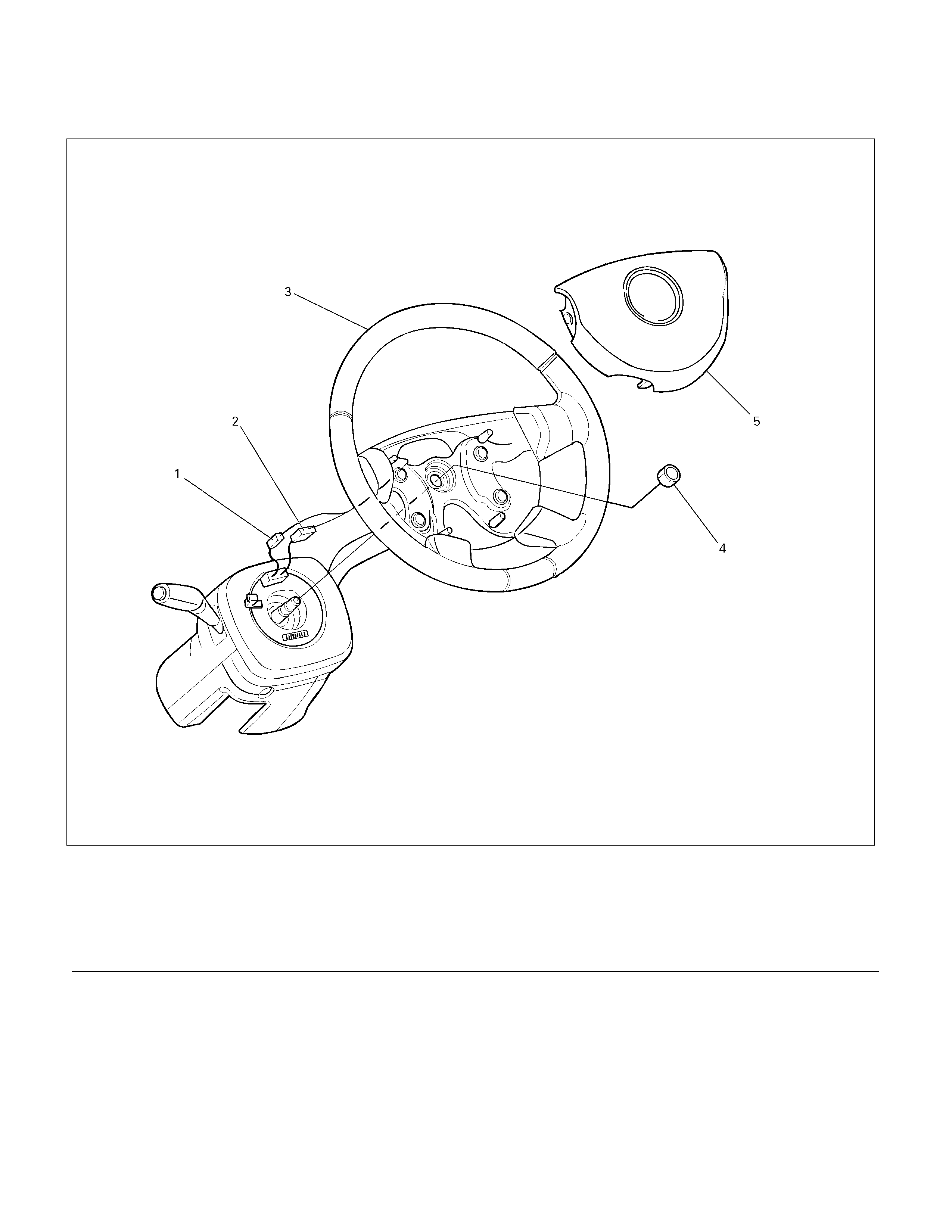
Inflator Module and Associated Parts
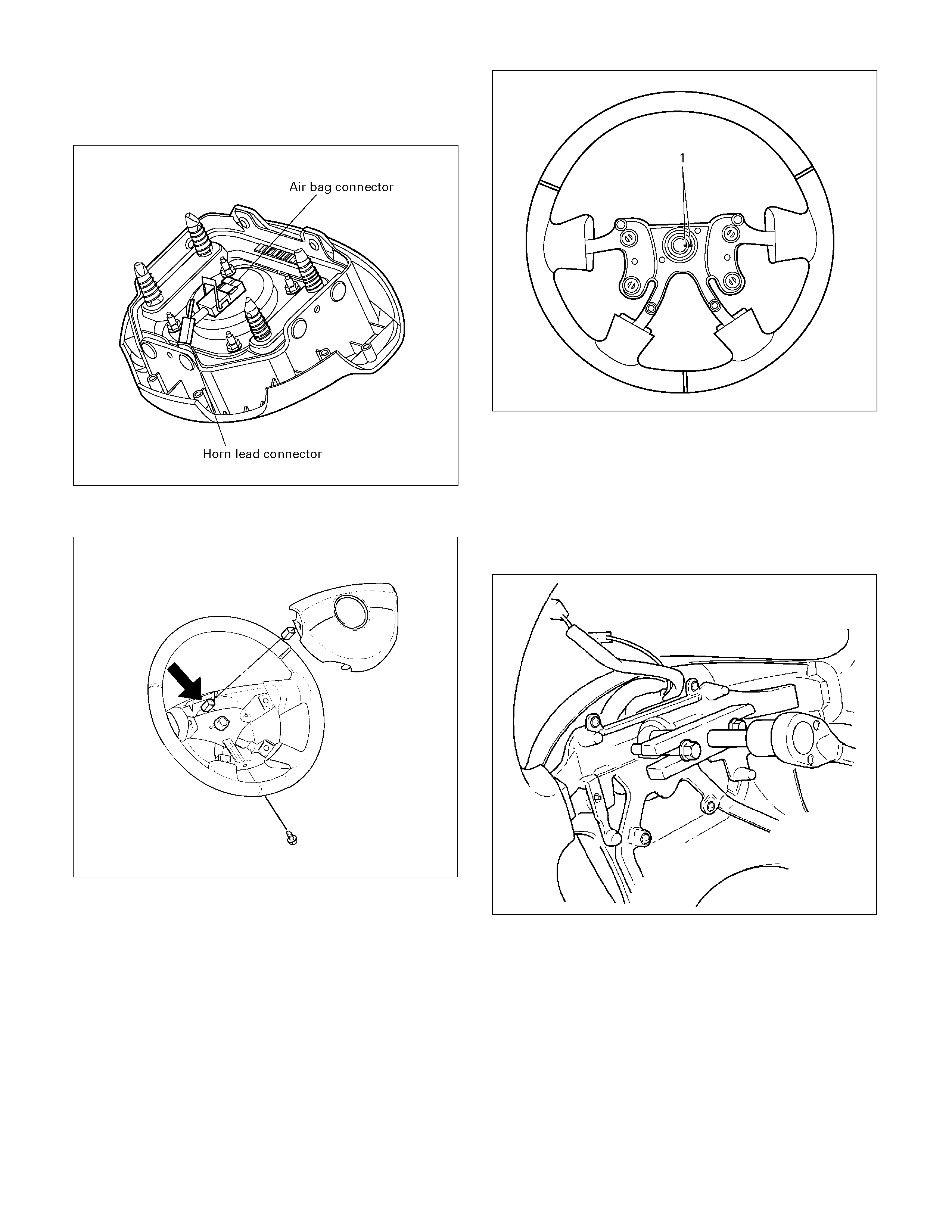
430R300013
Legend
(1) Horn Lead
(2) SRS Connector
(3) Steering Wheel
(4) Steering Wheel Fixing Nut
(5) Inflator Module or Horn Pad
Removal
1. Turn the steering wheel so that the vehicle's wheels
are pointing straight ahead.
2. Turn the ignition switch to "LOCK".
3. Disconnect the battery "-" terminal cable, and wait at
least 5 minutes. (with SRS air bag)
4. Disconnect the yellow 2-way SRS connector located
under the steering column. (with SRS air bag)
CAUTION: The wheels of the vehicle must be
straight ahead and the steering column in the
"LOCK" position before disconnecting the steering
wheel. Failure to do so will cause the coil assembly
to become uncentered which will cause damage to
the coil assembly. (with SRS air bag)
5. Disable the SRS (Refer to "Disabling the SRS" in
this section). (with SRS air bag)
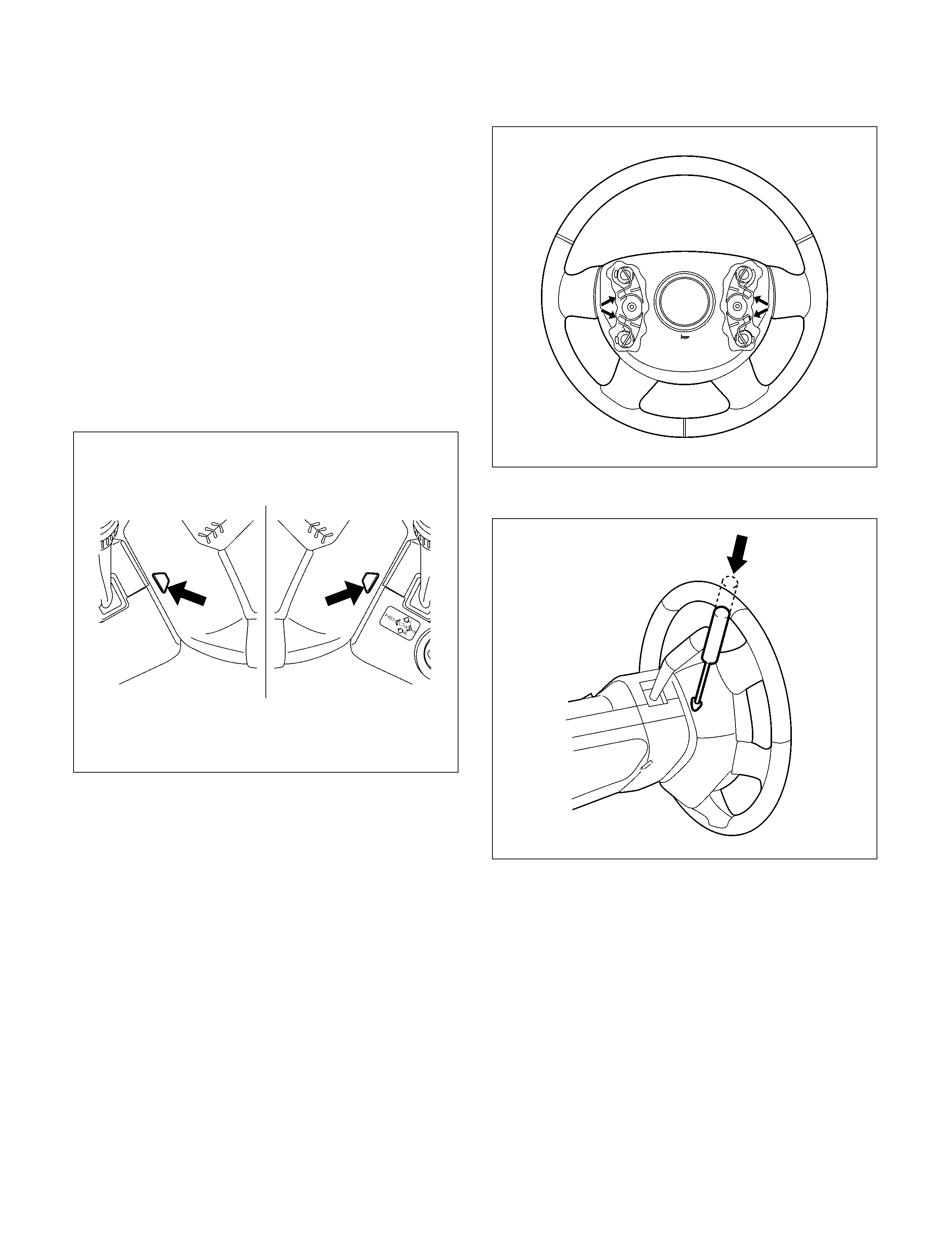
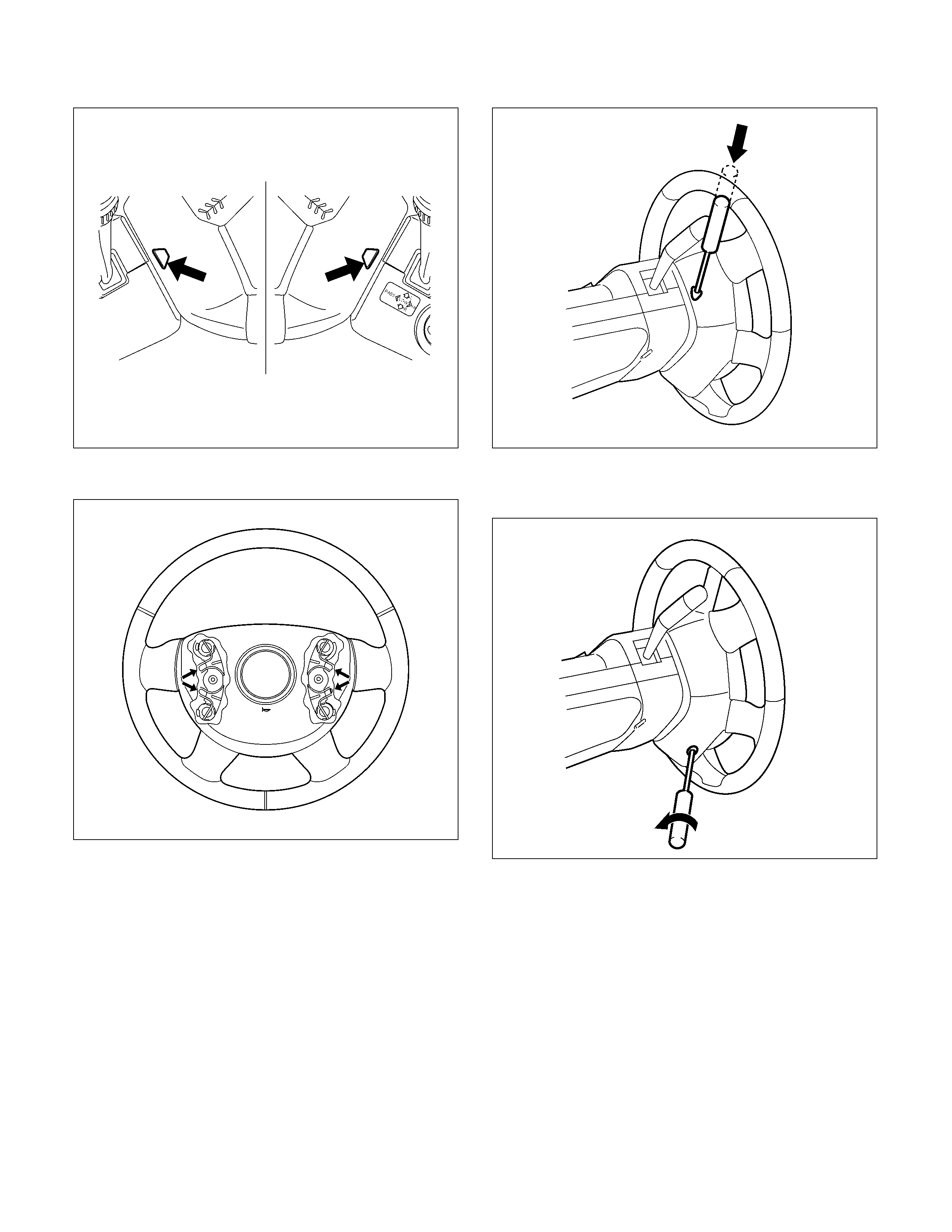
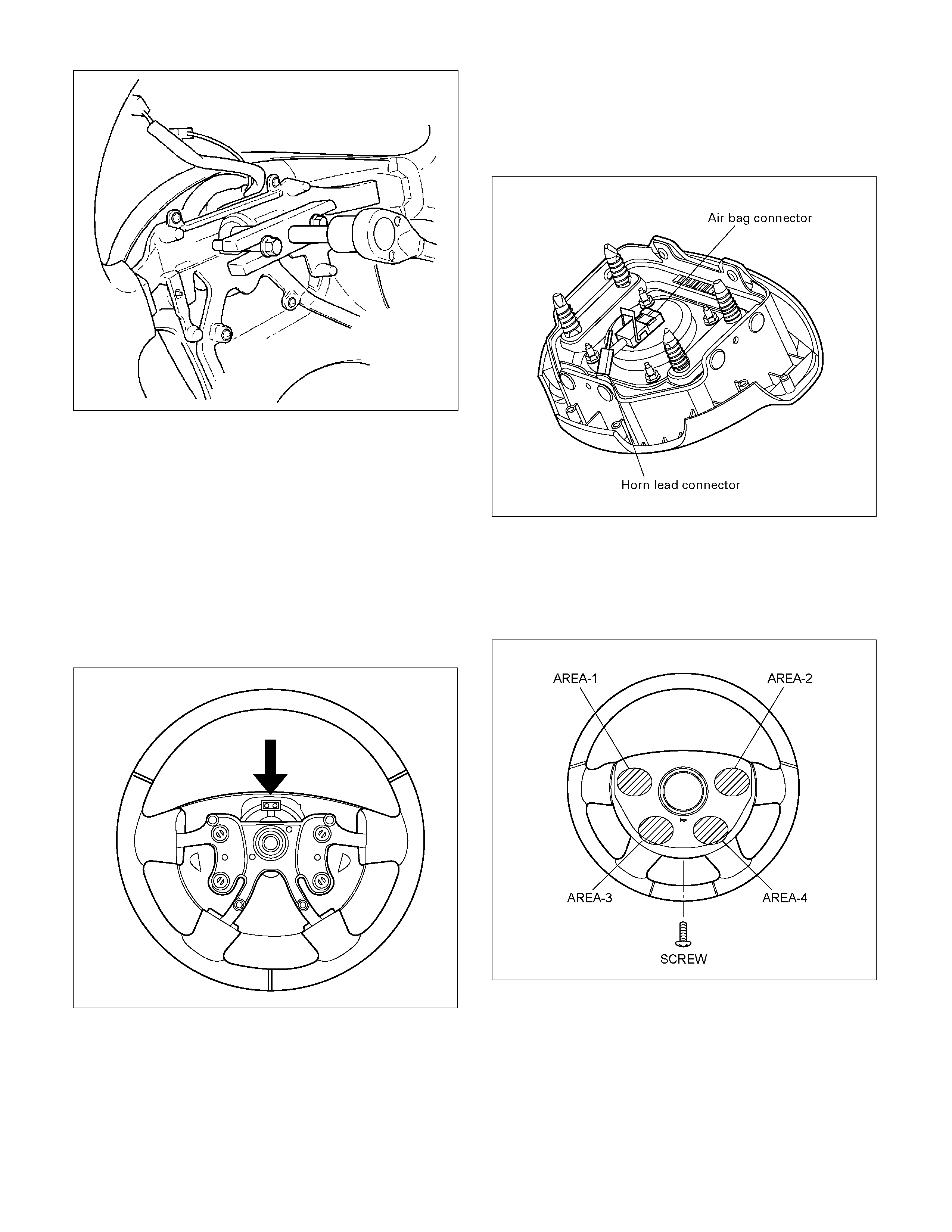
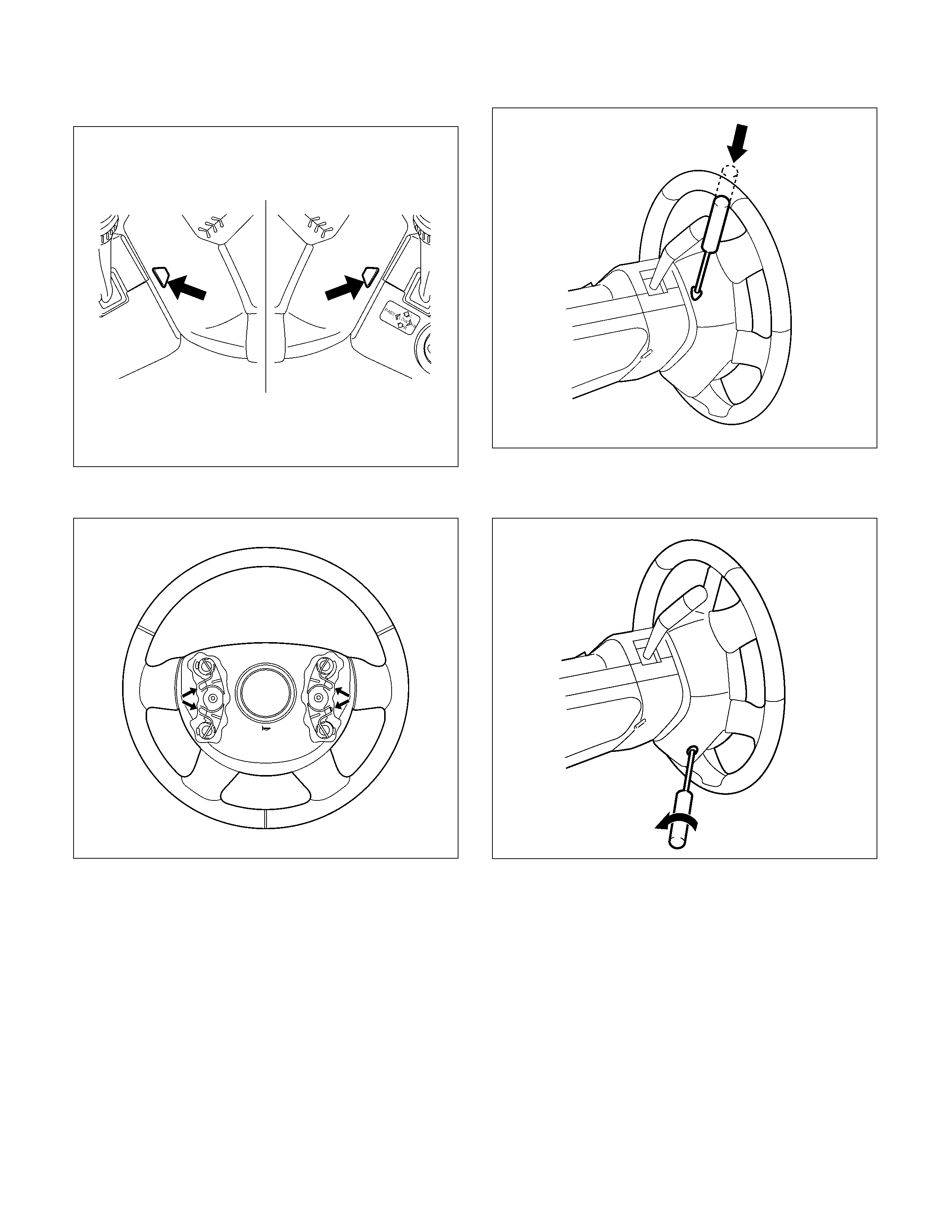
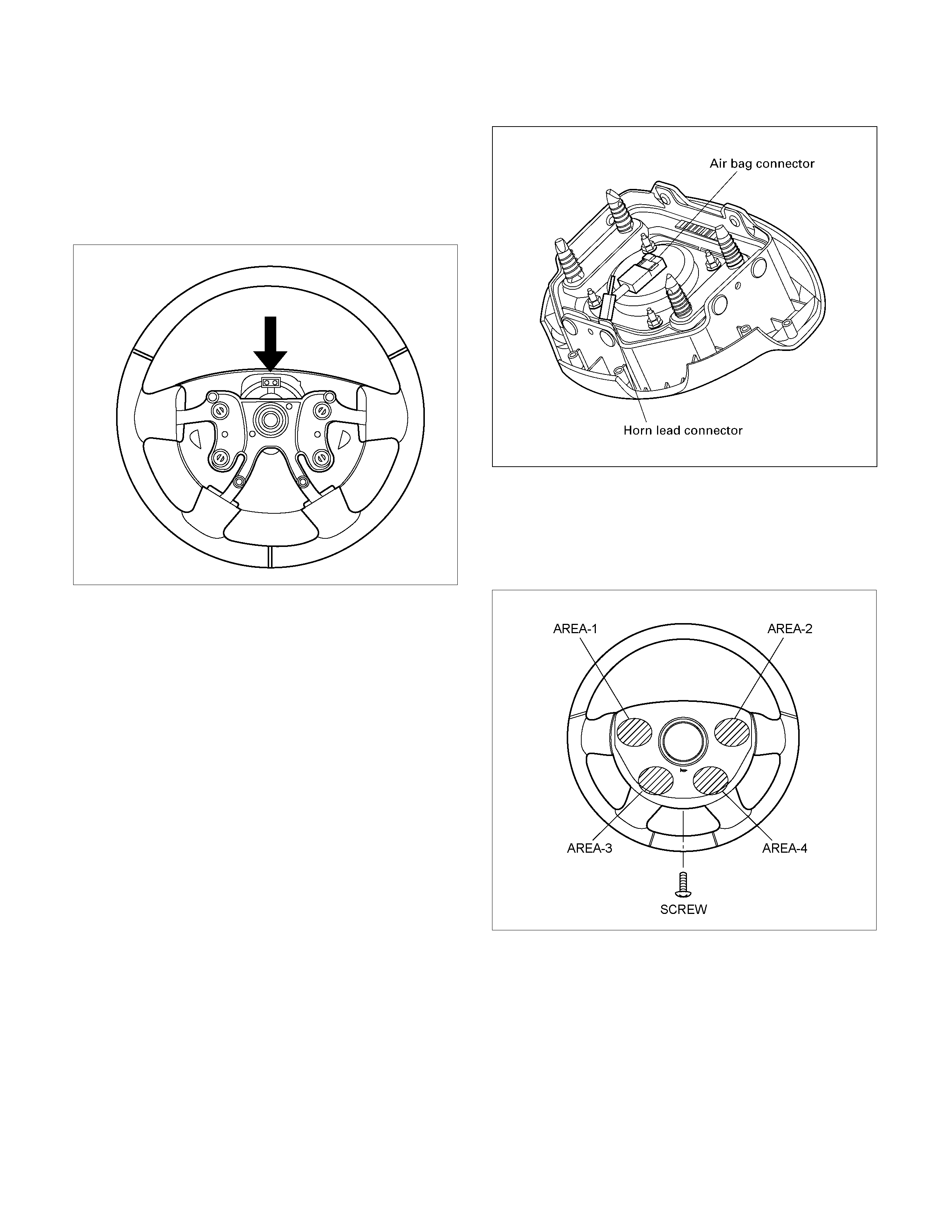
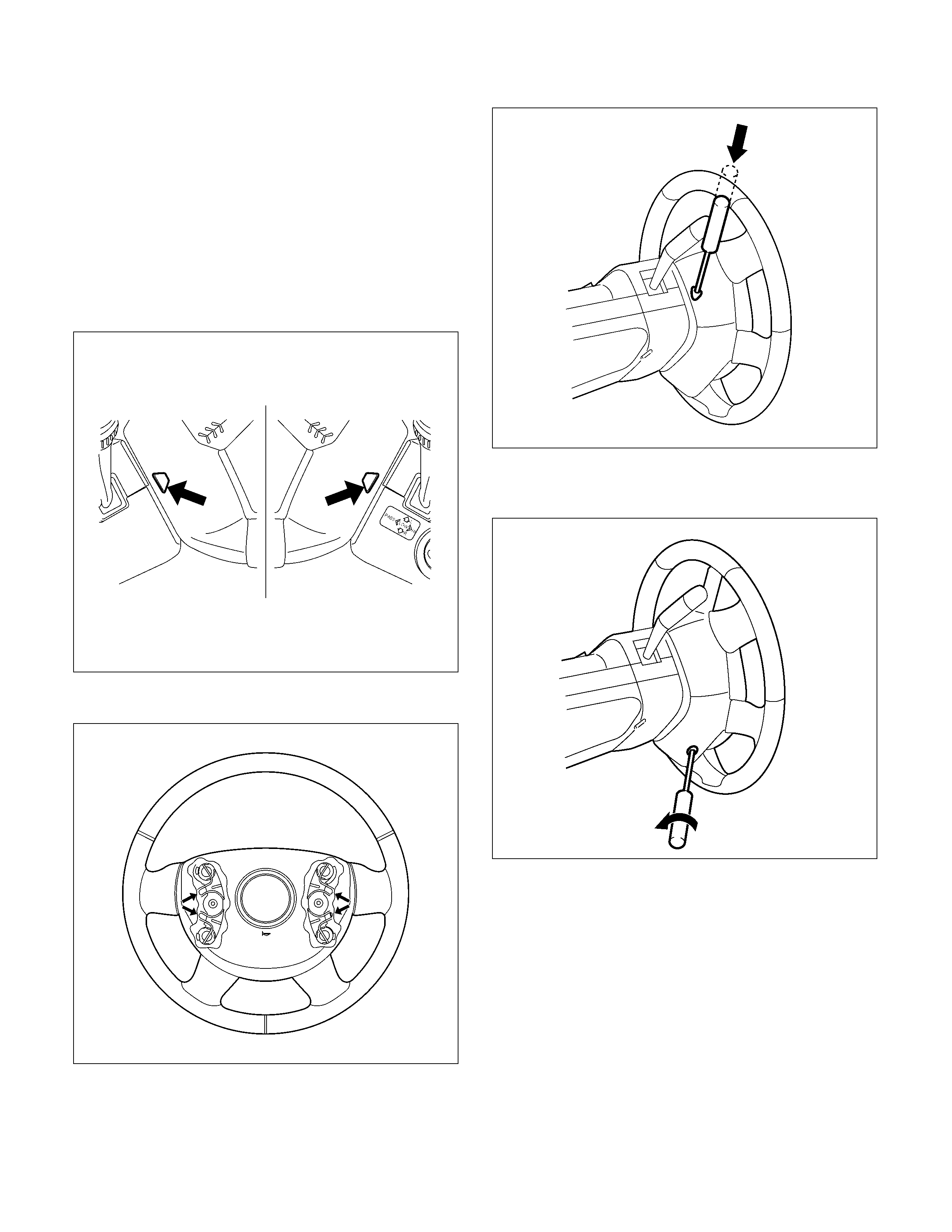
6. Locate the two access holes on the underside of the
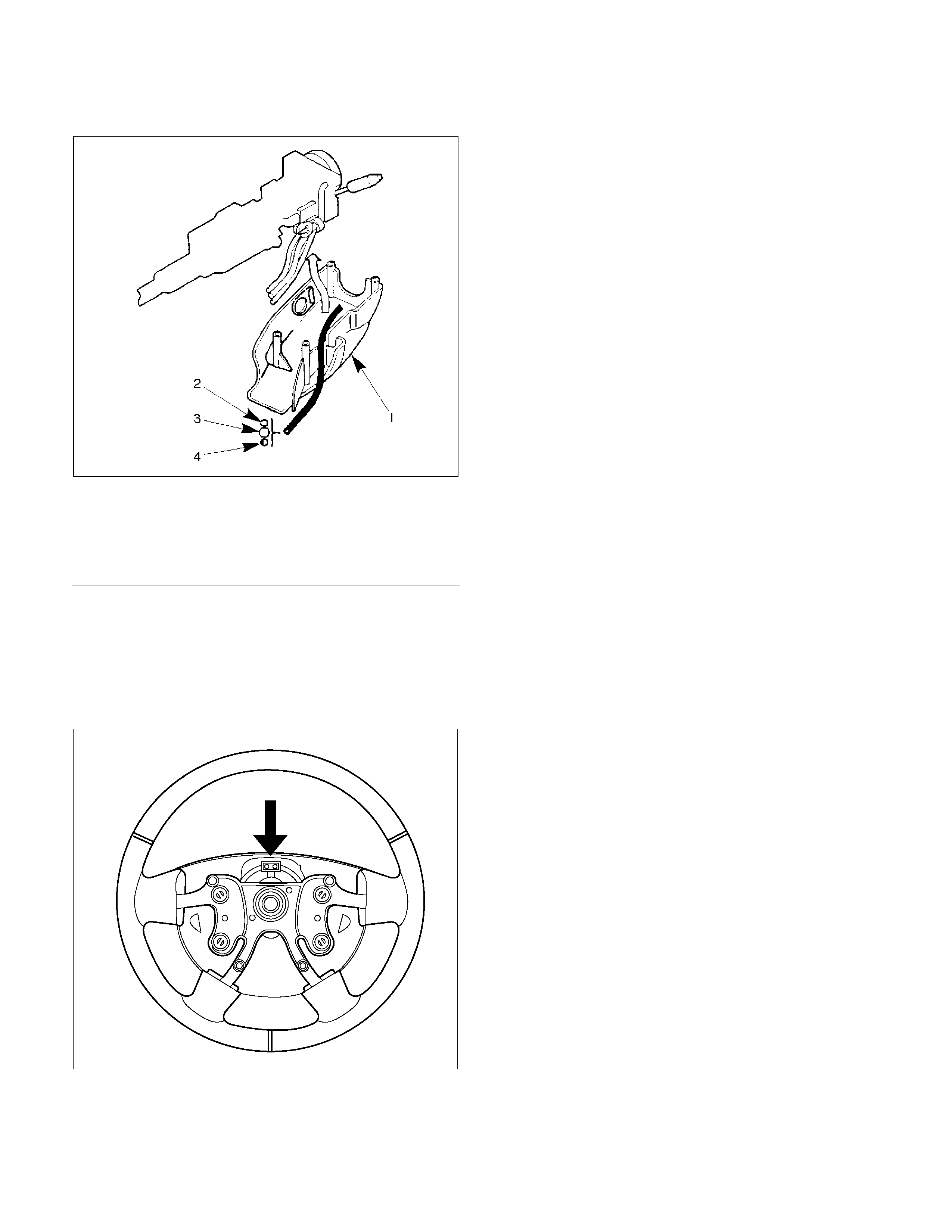
steering wheel cover. (with SRS air bag)
060R300025
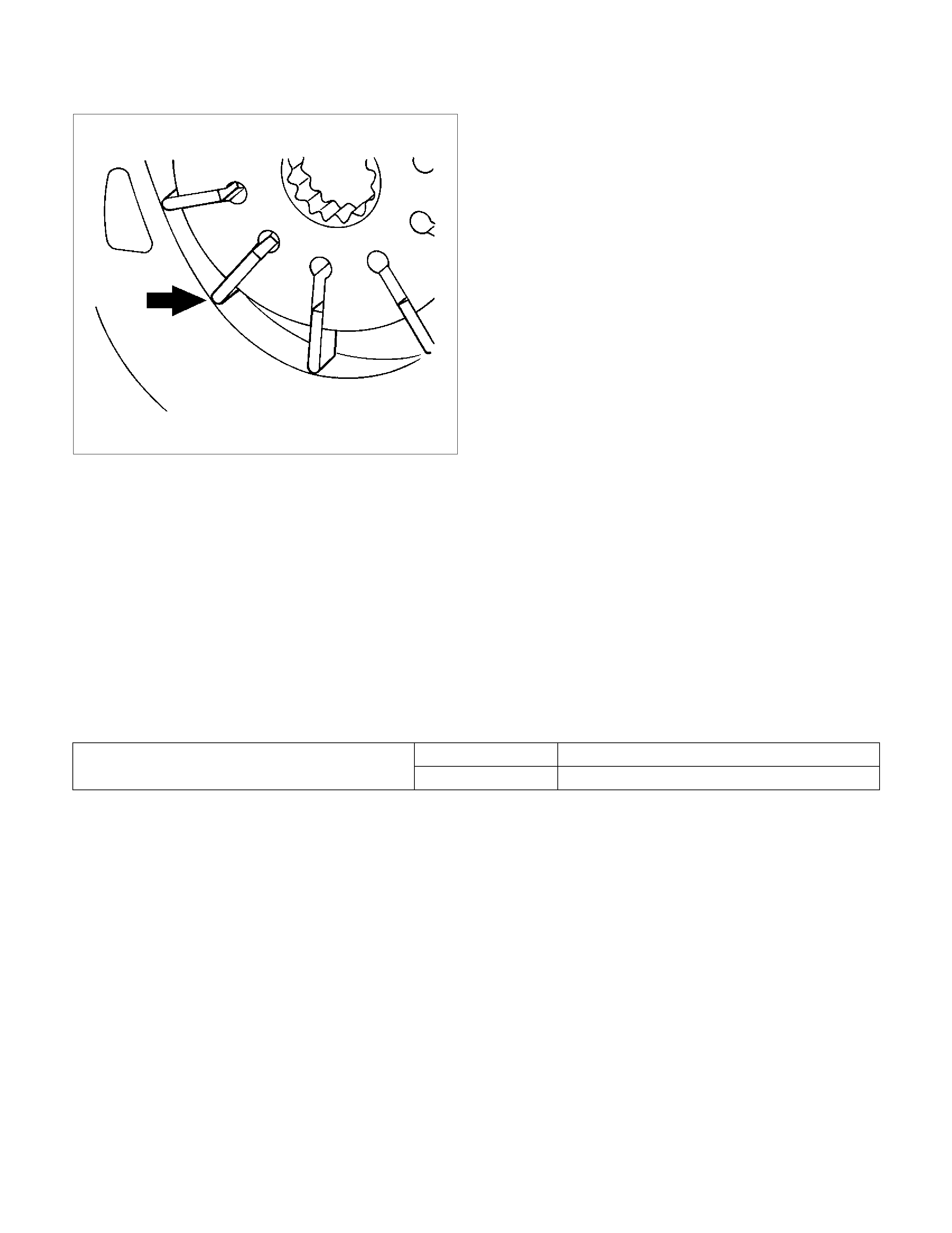
7. Check the position of the pins in the holes. Push the
pin in the direction of an arrow. (with SRS air bag)
060R300032
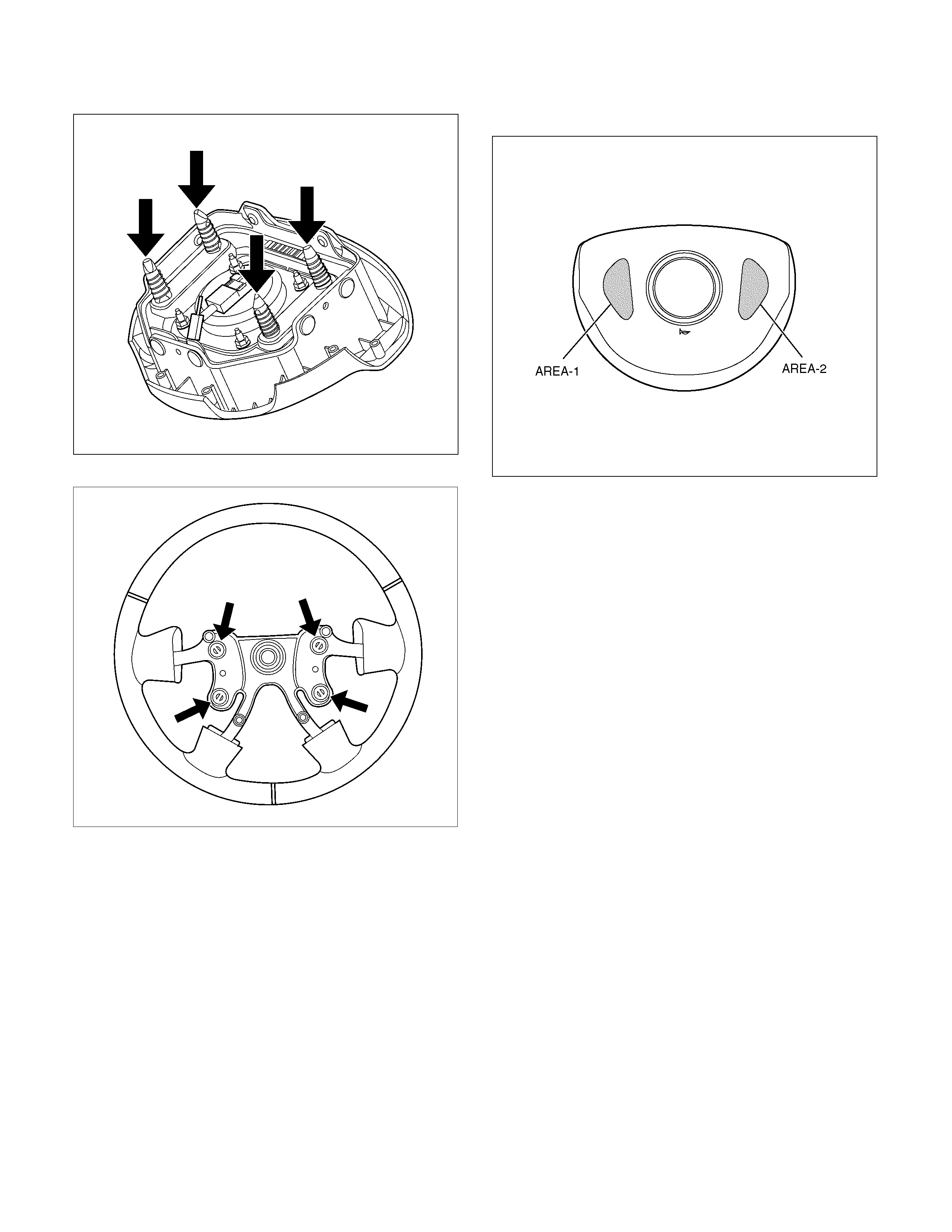
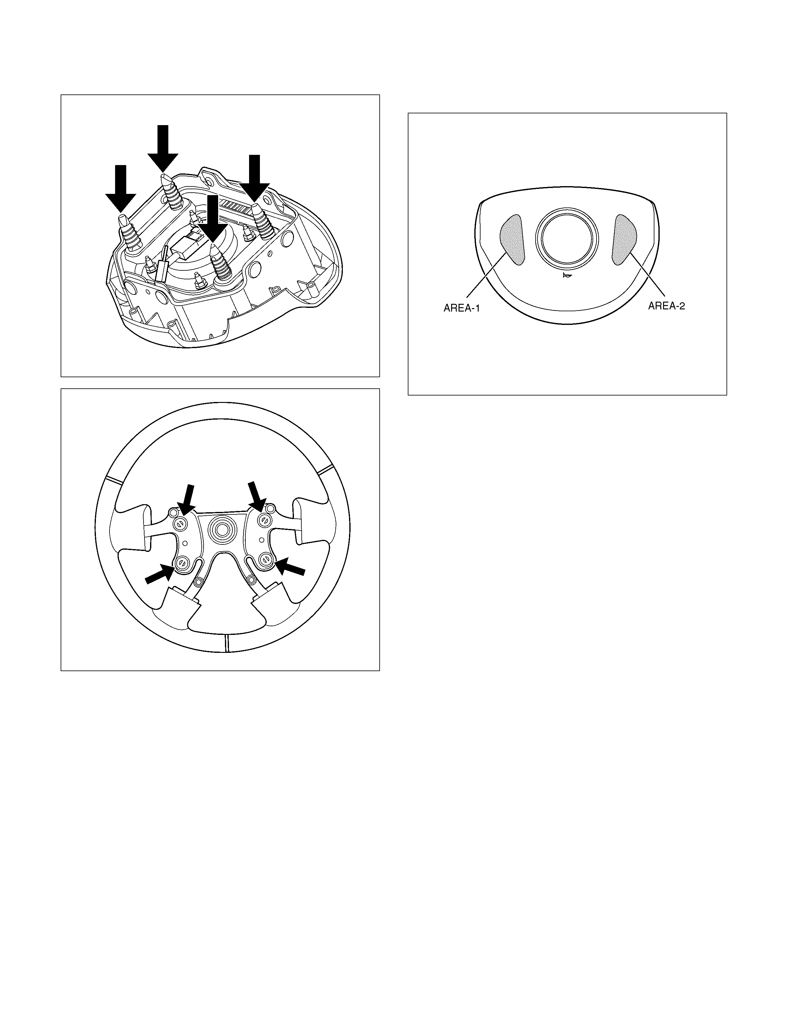
8. Push the four pins at 5-6 mm diameter bar. (with
SRS air bag)
060R300031
9. Cancel the lock four pins. (with SRS air bag)
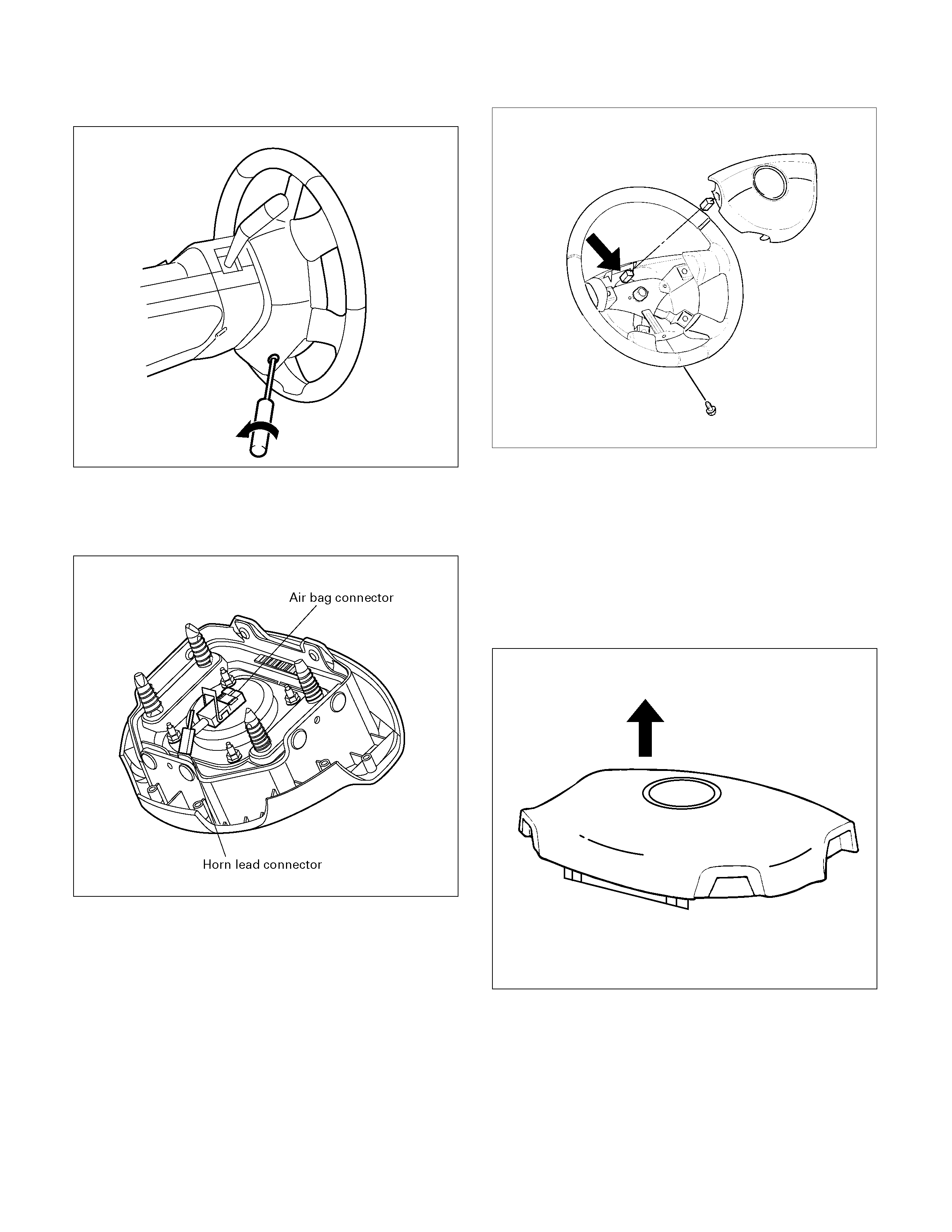
10. NOTE: For those vehicles without SRS Air Bag,
simply loosen the horn pad fixing screw at the rear
of the steering wheel
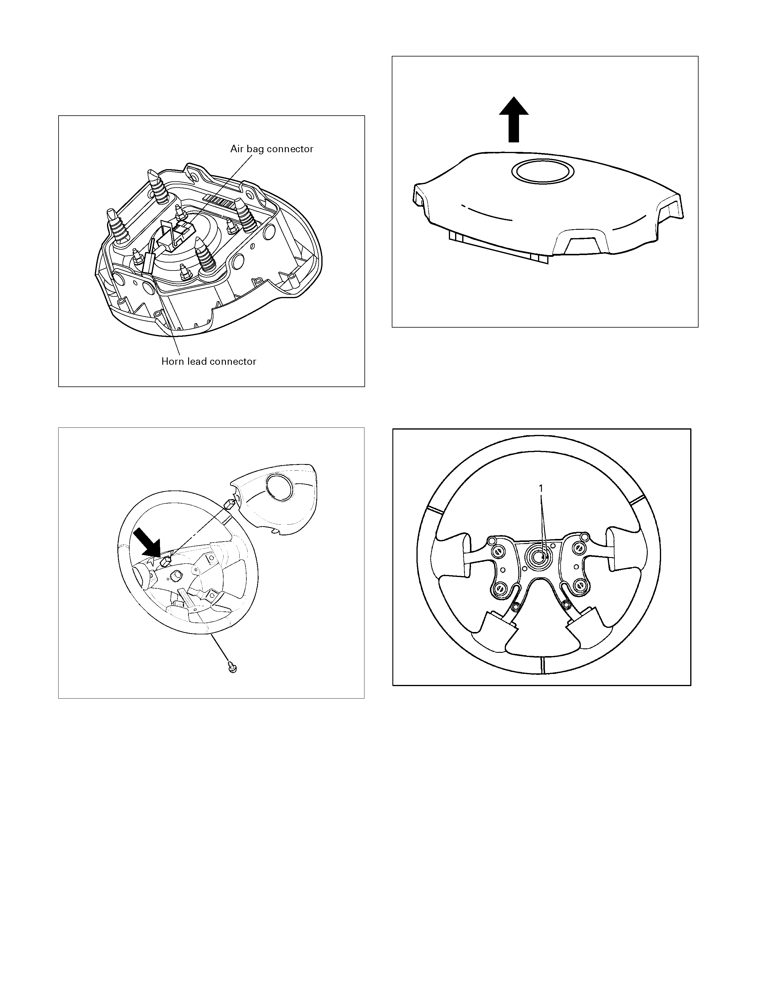
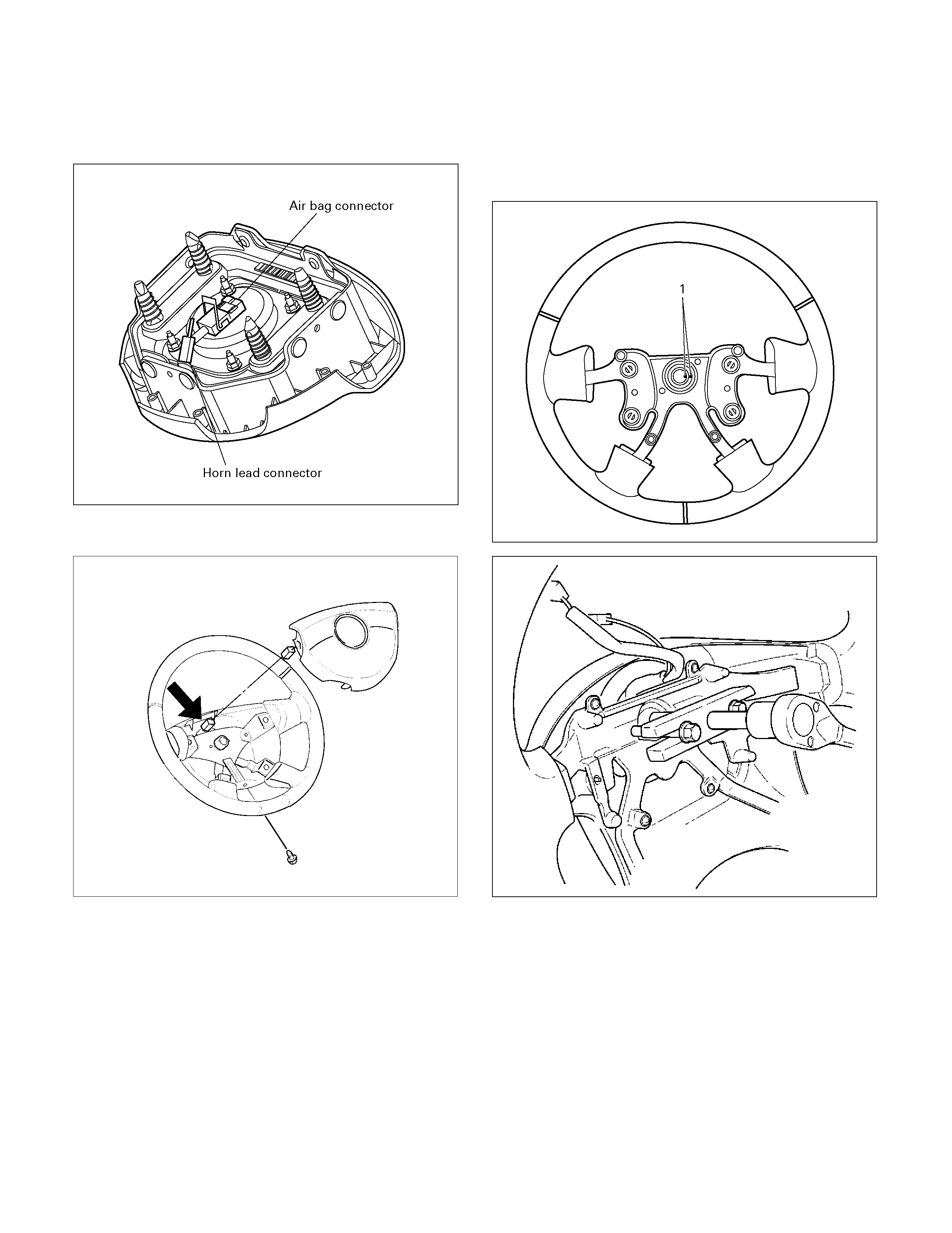
430R300009
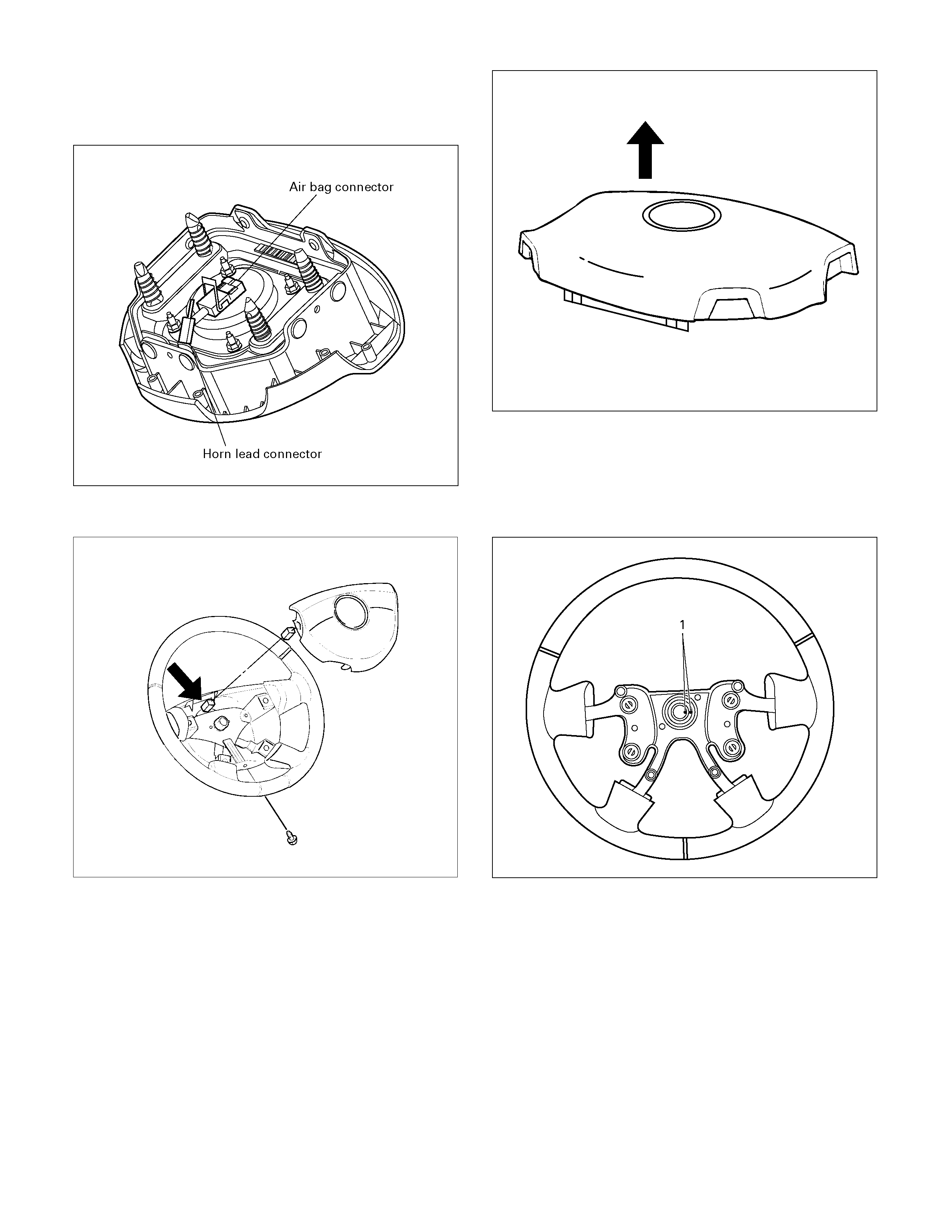
11. Disconnect the SRS air bag connector and horn
lead connector located behind the air bag assembly
and remove the air bag assembly. (with SRS air
bag)
060R300041
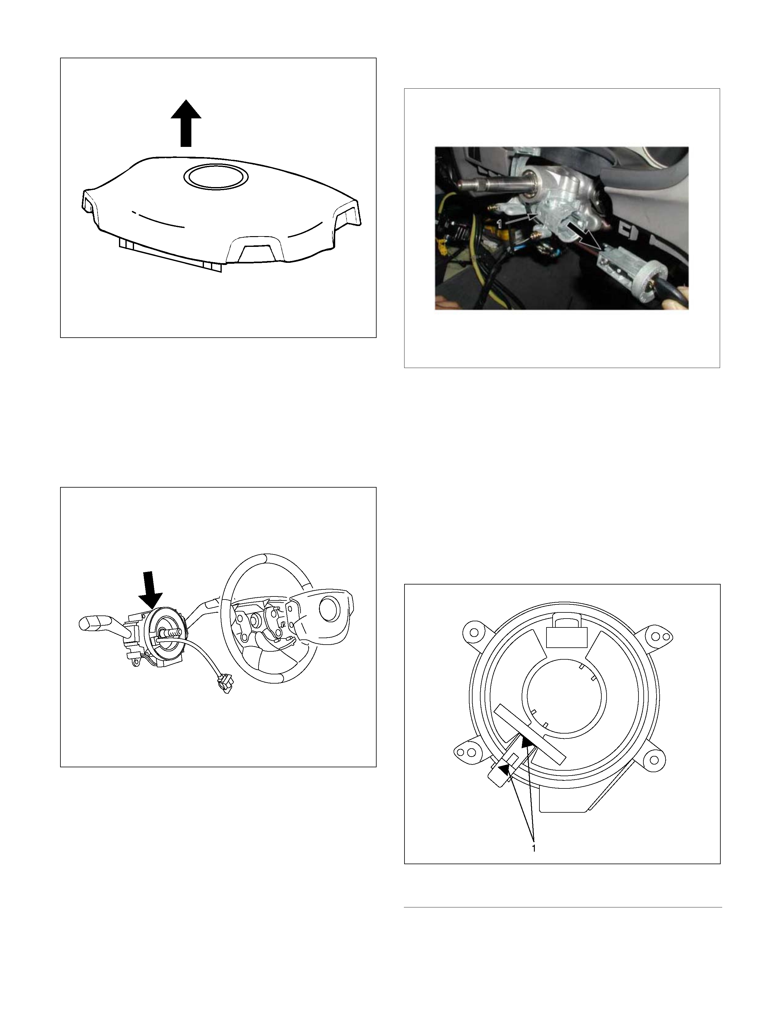
12. Remove the horn pad and the horn leads at the
center of the wheel (without SRS air bag).
RTW33BSH000401
WARNING: THE INFLATOR MODULE SHOULD
ALWAYS BE CARRIED WITH THE COVER AWAY
FROM YOUR BODY AND SHOULD ALWAYS BE
LAID ON A FLAT SURFACE WITH THE COVER SIDE
UP. THIS IS NECESSARY BECAUSE A FREE SPACE
IS PROVIDED TO ALLOW THE AIR CUSHION TO
EXPAND IN THE UNLIKELY EVENT OF
ACCIDENTAL DEPLOYMENT. OTHERWISE,
PERSONAL INJURY MAY RESULT. (with SRS air
bag)
430R300007
Inspection and Repair (w ith SRS air bag)
The inflator module consists of a cover, air bag, inflator,
and retainer. Inspect the inflator module mainly for the
following:
• Check for holes, cracks, severe blemishes and
deformation on the cover.
• Check that the retainer is not deformed.
• Check for defects such as damage and breakage in
the lead wire for the igniter.
If an abnormality is found as the result of the inspection,
replace the inflator module with a new one.
Installation
1. Support the inflator m odule and caref ully connect the
SRS connector and horn lead. (with SRS air bag)
060R300041
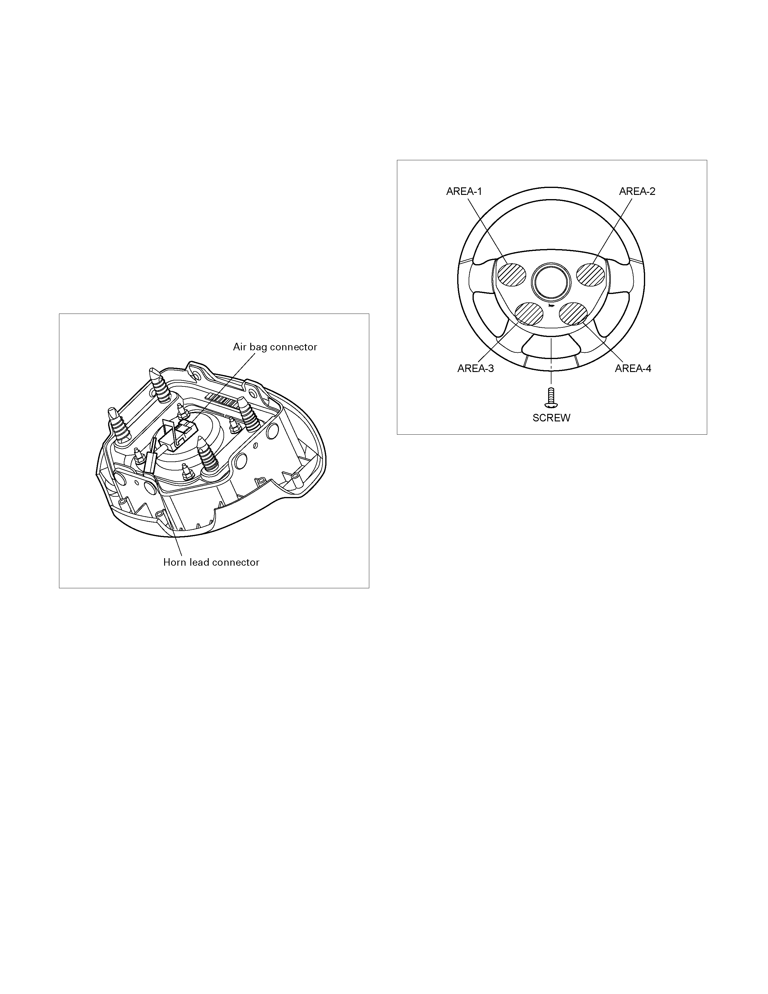
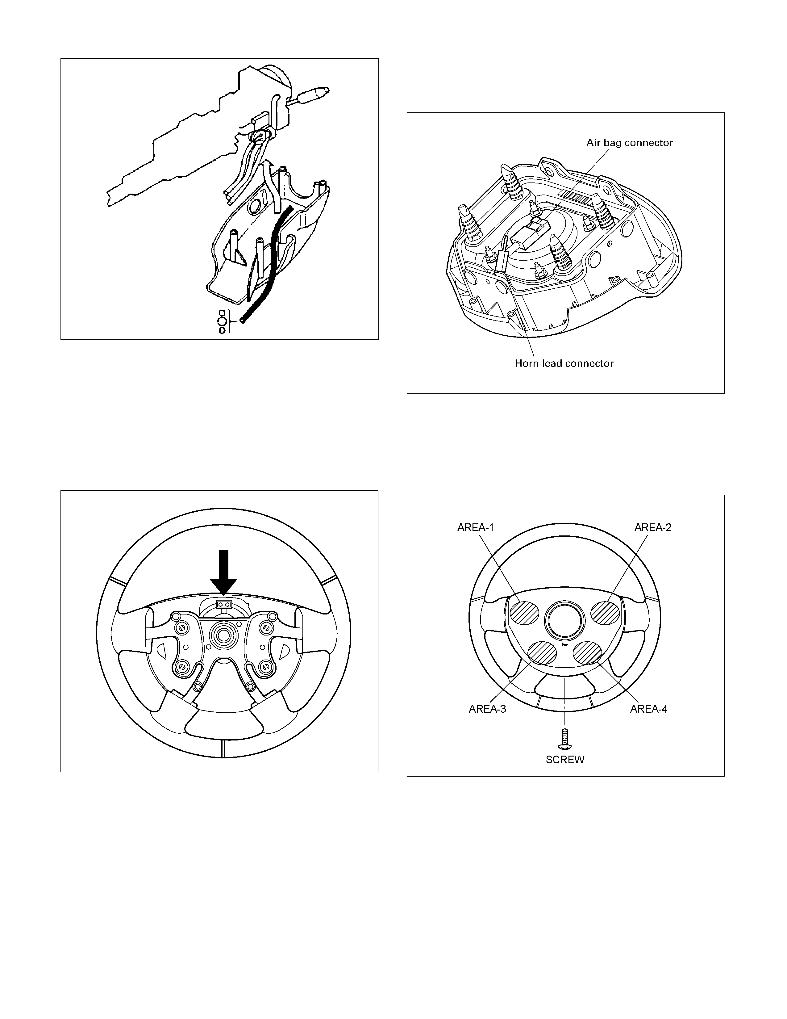
2. Connect the horn leads at center of wheel. Push the
horn pad area 1-4 to check correct horn operation.
Tighten the horn pad fixing screw to the specified
torque (without SRS air bag)
Torque: 2 – 4 Nm (0.2 – 0.4 kgm/17 - 35 lb in)
RTW33BSH000201
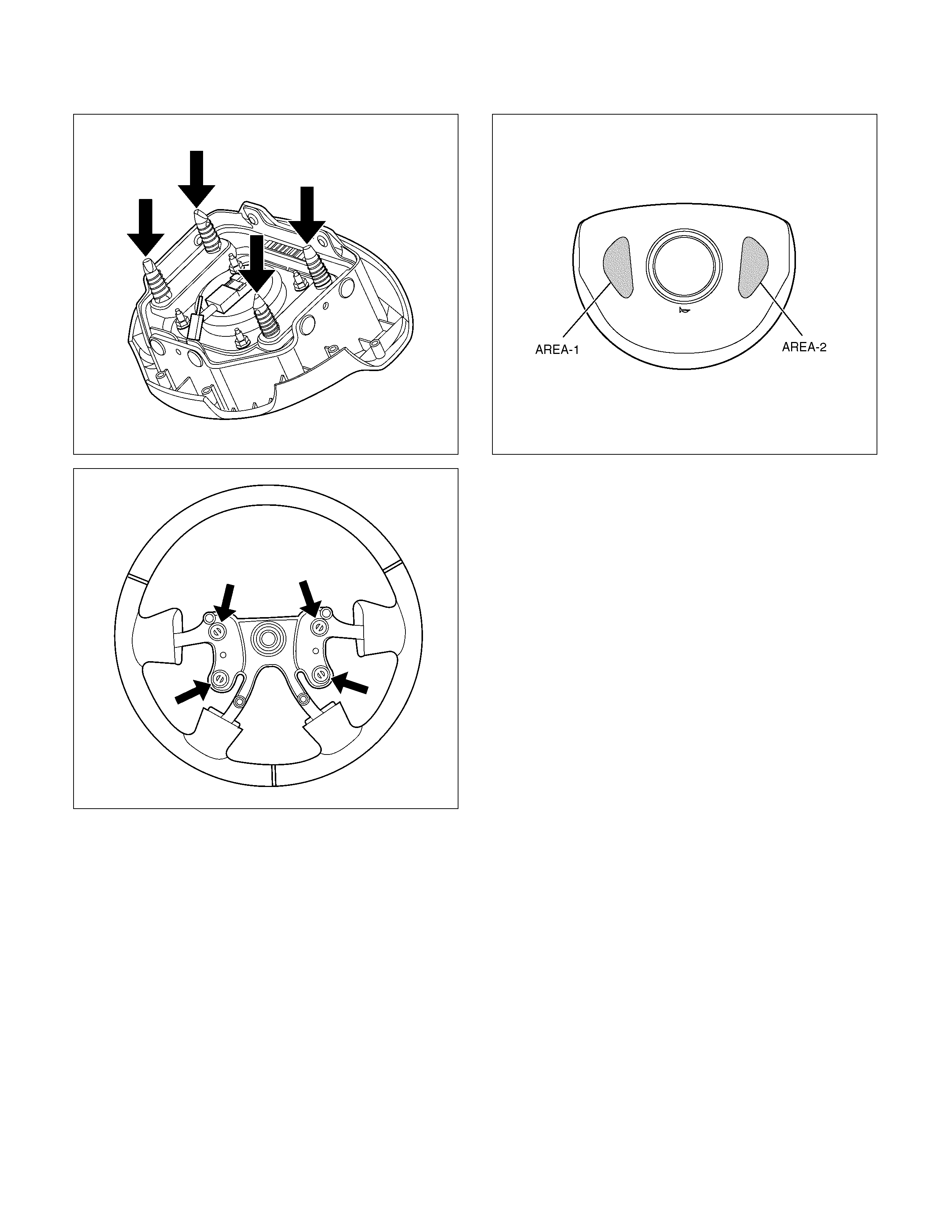
3.
A
lign the each s nap stud of driver air bag to the hole
of steering wheel. (with SRS air bag)
060R300030
060R300020
4. Push the SRS air bag area1 and area2. At that tim e
confirm the audible noise of each stud.
060R300036
5. Enable the SRS (Refer to "Enabling t he SRS" in this
section). (with SRS air bag)
6. Connect the SRS connector. (with SRS air bag)
7. Connect the battery "-" terminal cable. (with SRS air
bag)
8. Turn the ignition switch to "ON" while watching
warning light and check the light should f lash 7 tim es
and then go off. If lamp does not operate correctly,
refer to Restraints section.

Steering Wheel
Steering Wheel and Associated Parts
430R300013
Legend
(1) Horn Lead
(2) SRS Connector
(3) Steering Wheel
(4) Steering Wheel Fixing Nut
(5) Inflator Module or Horn Pad
Removal
1. Turn the steering wheel so that the vehicle's wheels
are pointing straight ahead.
2. Turn the ignition switch to "LOCK".
3. Disconnect the battery "-" terminal cable, and wait at
least 5 minutes. (with SRS air bag)
4. Disconnect the yellow 2-way SRS connector located
under the steering column. (with SRS air bag)
CAUTION: The wheels of the vehicle must be
straight ahead and the steering column in the
"LOCK" position before disconnecting the steering
wheel. Failure to do so will cause the coil assembly
to become uncentered which will cause damage to
the coil assembly. (with SRS air bag)
5. Disable the SRS (Refer to "Disabling the SRS" in
this section). (with SRS air bag)
6. Check the both side hole of the steering cover. (with
SRS air bag)
060R300025
7. Check the position of the pins in a hole. Push the
pin in the direction of an arrow. (with SRS air bag)
060R300032
8. Push the four pins at 5-6 mm diameter bar. (with
SRS air bag)
060R300031
9. Cancel the lock four pins. (with SRS air bag)
10. Loosen the horn pad fixing screw at the rear of the
steering wheel (without SRS air bag).
430R300009
11. Disconnect the SRS air bag connector and horn
lead connector located behind the air bag assembly
and remove the air bag assembly. (with SRS air
bag)
060R300041
12. Remove the horn pad and the horn leads at the
center of the wheel (without SRS air bag).
RTW33BSH000401
WARNING: THE INFLATOR MODULE SHOULD
ALWAYS BE CARRIED WITH THE COVER AWAY
FROM YOUR BODY AND SHOULD ALWAYS BE
LAID ON A FLAT SURFACE WITH THE COVER SIDE
UP. THIS IS NECESSARY BECAUSE A FREE SPACE
IS PROVIDED TO ALLOW THE AIR CUSHION TO
EXPAND IN THE UNLIKELY EVENT OF
ACCIDENTAL DEPLOYMENT. OTHERWISE,
PERSONAL INJURY MAY RESULT. (with SRS air
bag)
430R300007
13. Apply a setting mark (1) across the steering wheel
and shaft so parts can be reassembled in their
original position. Move the front wheels to the
straight ahead position, then use steering wheel
remover 5-8521-0016-0 to remove the steering
wheel.
430R300008
CAUTION: Never apply force to the steering wheel in
direction of the shaft by using a hammer or other
impact tools in an attempt to remove the steering
wheel. The steering shaft is designed as an energy
absorbing unit.
430RX005
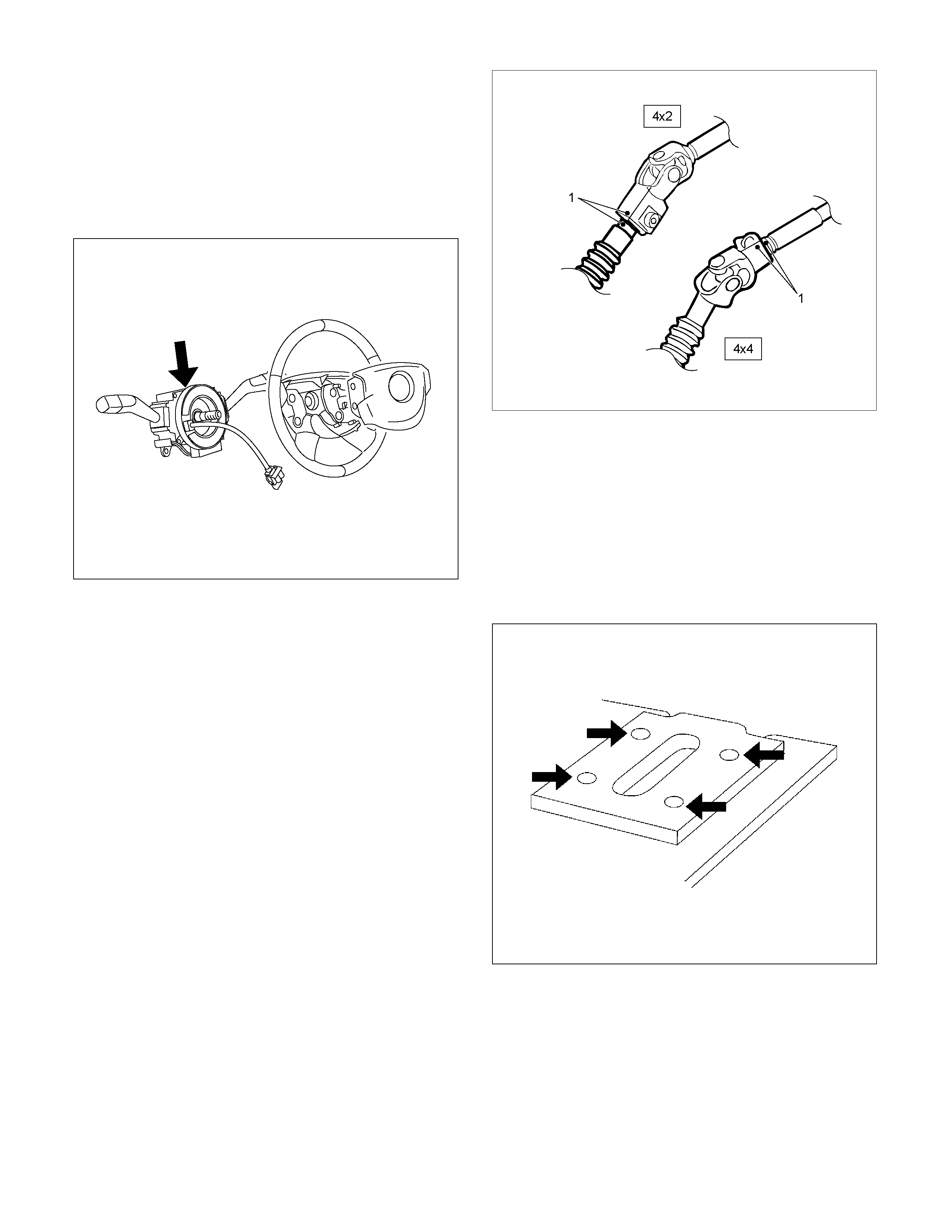
14. Remove steering column cover.
15. Disconnect the wiring harness connectors located
under the steering column then remove combination
switch and SRS coil assembly.
Installation
1.
A
lign the setting marks made when removing then
install steering wheel.
Refer to the adjustment method in case a mark is
not attached in this section.
NOTE: Confirm SRS and Horn harness connector is
fixed by the steering wheel.
RTW33BSH000601
CAUTION: Never apply force to the steering wheel in
direction of the shaft by using a hammer or other
impact tools in an attempt to remove the steering
wheel. The steering shaft is designed as an energy
absorbing unit.
2. Tighten the steering wheel fixing nut to the specified
torque.
Torque: 31 - 39 Nm (3.2 – 4.0 kgm/23 - 29 lb ft)
3. Support the inflator m odule and caref ully connect the
SRS connector and horn lead. (with SRS air bag)
060R300041
4. Connect the horn leads at center of wheel. Push the
horn pad area 1-4.
Tighten the horn pad fixing screw to the specified
torque (without SRS air bag)
Torque: 2 – 4 Nm (0.2 – 0.4 kgm/17 - 35 lb in)
RTW33BSH000201
5.
A
lign the each s nap stud of driver air bag to the hole
of steering wheel. (with SRS air bag)
060R300030
060R300020
6. Push the SRS air bag area1 and area2. At that tim e
confir m the audible nois e of each st ud. ( with SRS air
bag)
060R300036
7. Enable the SRS (Refer to "Enabling t he SRS" in this
section). (with SRS air bag)
8. Connect the SRS connector. (with SRS air bag)
9. Connect the battery "-" terminal cable. (with SRS air
bag)
10. Turn the ignition switch to "ON" while watching
warning light and check the light should f lash 7 tim es
and then go off. If lamp does not operate correctly,
refer to Restraints section.
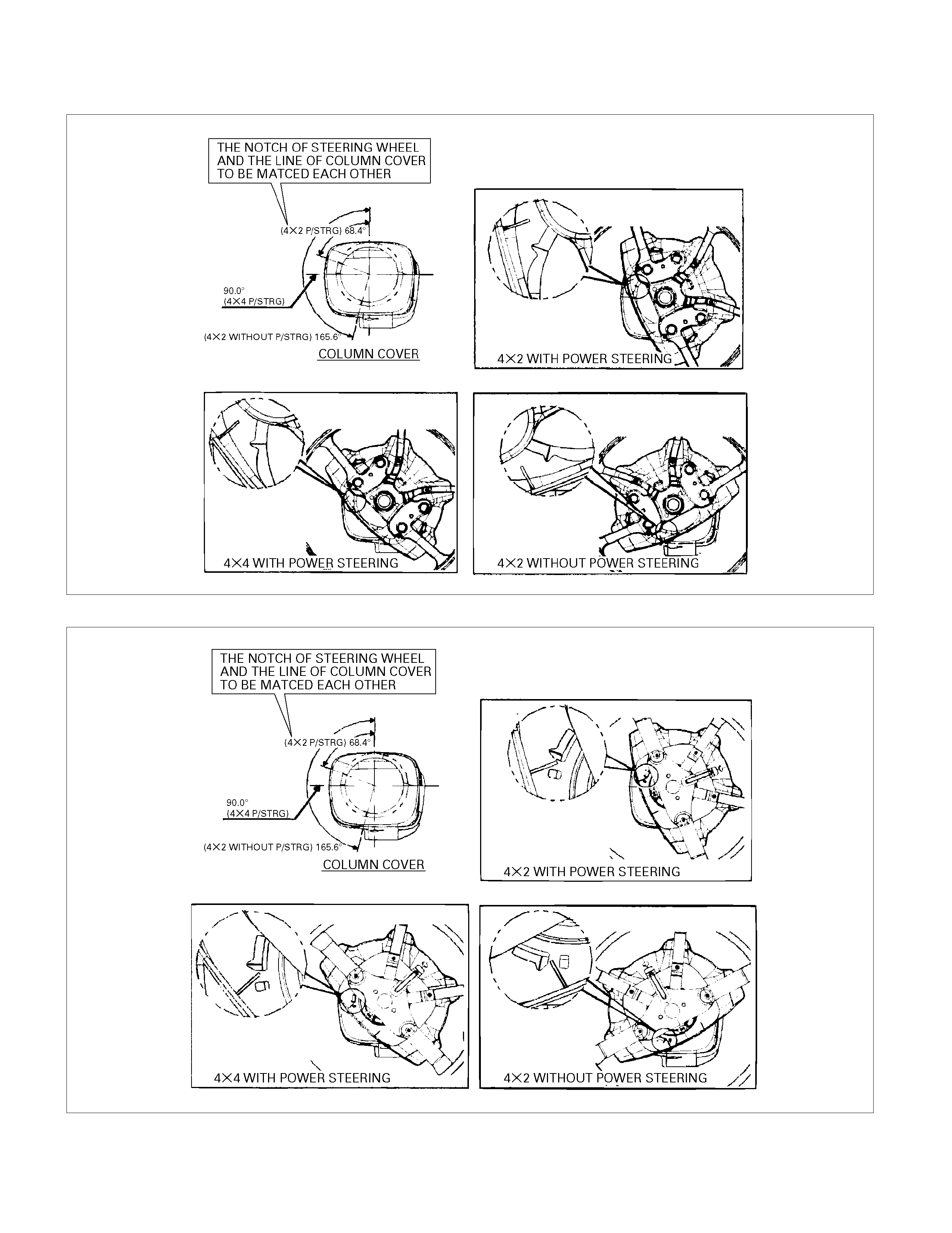
The adjustment method in case a mark is not attached
with SRS air bag
430R300011
without SRS air bag
430R300010
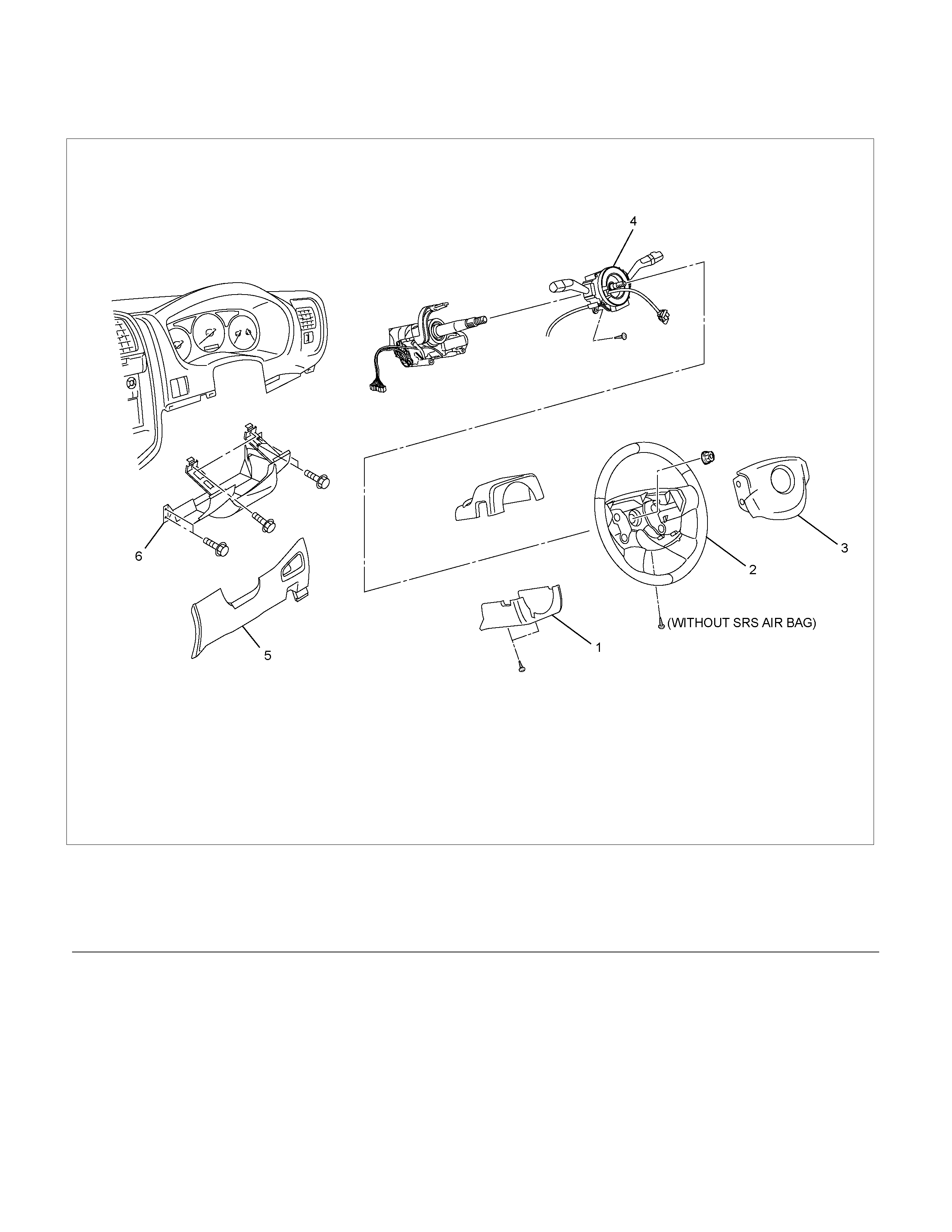
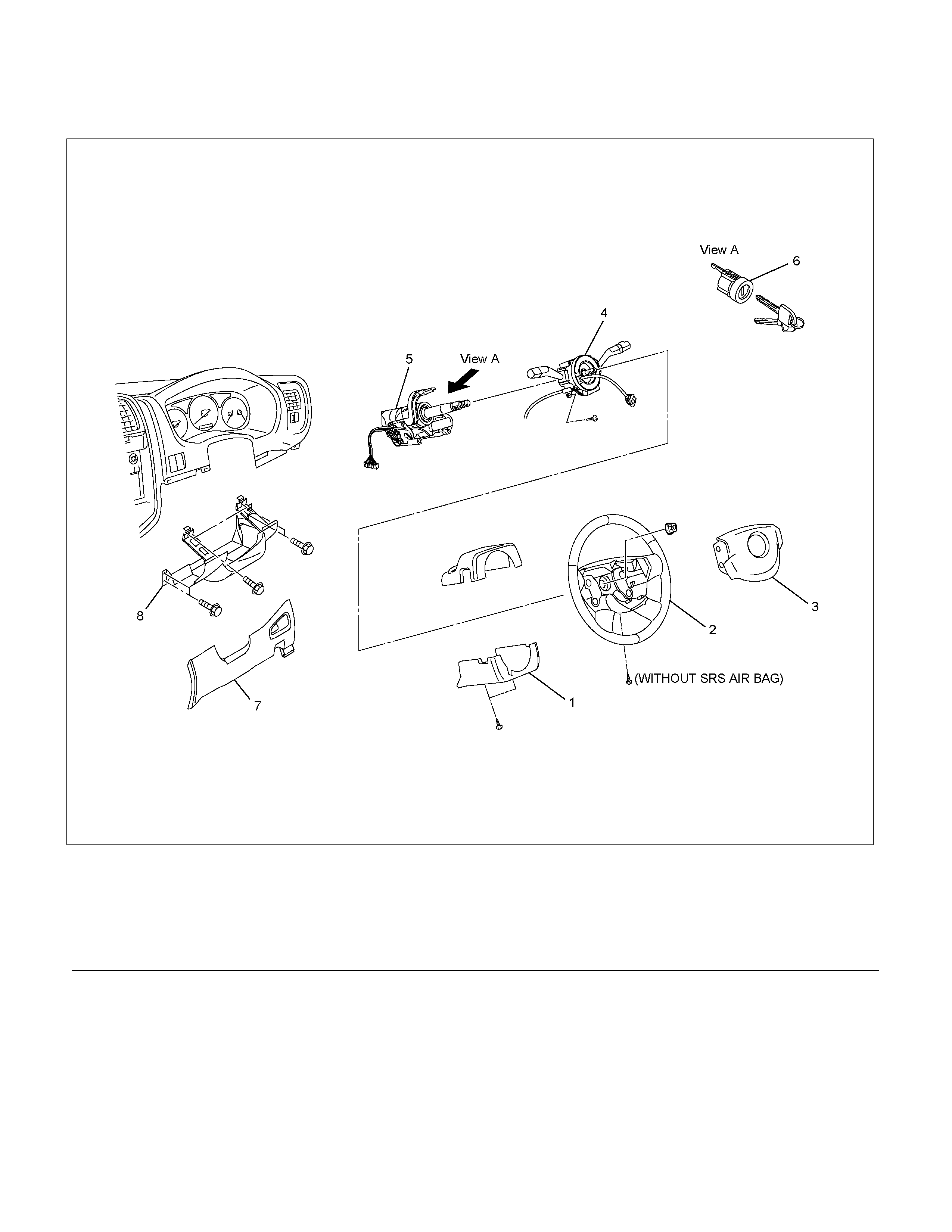
Combination Switch
Combination Switch and Associated Parts
RTW33BLF000601
Legend
(1) Steering Column Cover
(2) Steering Wheel
(3) Inflator Module or Horn Pad
(4) Combination Switch and SRS Coil Assembly
(5) Instrument Panel Lower Cover
(6) Driver Knee Bolster (reinforcement)
Removal
1. Turn the steering wheel so that the vehicle's wheels
are pointing straight ahead.
2. Turn the ignition switch to "LOCK".
3. Disconnect the battery "-" terminal cable, and wait at
least 5 minutes. (with SRS air bag)
4. Disconnect the yellow 2-way SRS connector located
under the steering column. (with SRS air bag)
CAUTION: The wheels of the vehicle must be
straight ahead and the steering column in the
"LOCK" position before disconnecting the steering
wheel. Failure to do so will cause the coil assembly
to become uncentered which will cause damage to
the coil assembly. (with SRS air bag)
5. Remove the engine hood opening lever, then
remove instrument panel lower cover.
6. Remove the driver knee bolster (reinforcement).
7. Disable the SRS (Refer to "Disabling the SRS" in
this section). (with SRS air bag)
8. Check the both side hole of the steering cover.
060R300025
9. Check the position of the pins in a hole. Push the
pin in the direction of an arrow. (with SRS air bag)
060R300032
10. Push the four pins at φ56 mm bar. (with SRS air
bag)
060R300031
11. Cancel the lock four pins. (with SRS air bag)
12. Loosen the horn pad fixing screw at the rear of the
steering wheel (without SRS air bag).
430R300009
13. Disconnect the SRS air bag connector and horn
lead connector located behind the air bag assembly
and remove the air bag assembly. (with SRS air
bag)
060R300041
14. Remove the horn pad and the horn leads at the
center of the wheel (without SRS air bag).
RTW33BSH00401
WARNING: THE INFLATOR MODULE SHOULD
ALWAYS BE CARRIED WITH THE COVER AWAY
FROM YOUR BODY AND SHOULD ALWAYS BE
LAID ON A FLAT SURFACE WITH THE COVER SIDE
UP. THIS IS NECESSARY BECAUSE A FREE SPACE
IS PROVIDED TO ALLOW THE AIR CUSHION TO
EXPAND IN THE UNLIKELY EVENT OF
ACCIDENTAL DEPLOYMENT. OTHERWISE,
PERSONAL INJURY MAY RESULT. (with SRS air
bag)
430R300007
15. Apply a setting mark (1) across the steering wheel
and shaft so parts can be reassembled in their
original position. Move the front wheels to the
straight ahead position, then use steering wheel
remover 5-8521-0016-0 to remove the steering
wheel.
430R300008
CAUTION: Never apply force to the steering wheel in
direction of the shaft by using a hammer or other
impact tools in an attempt to remove the steering
wheel. The steering shaft is designed as an energy
absorbing unit.
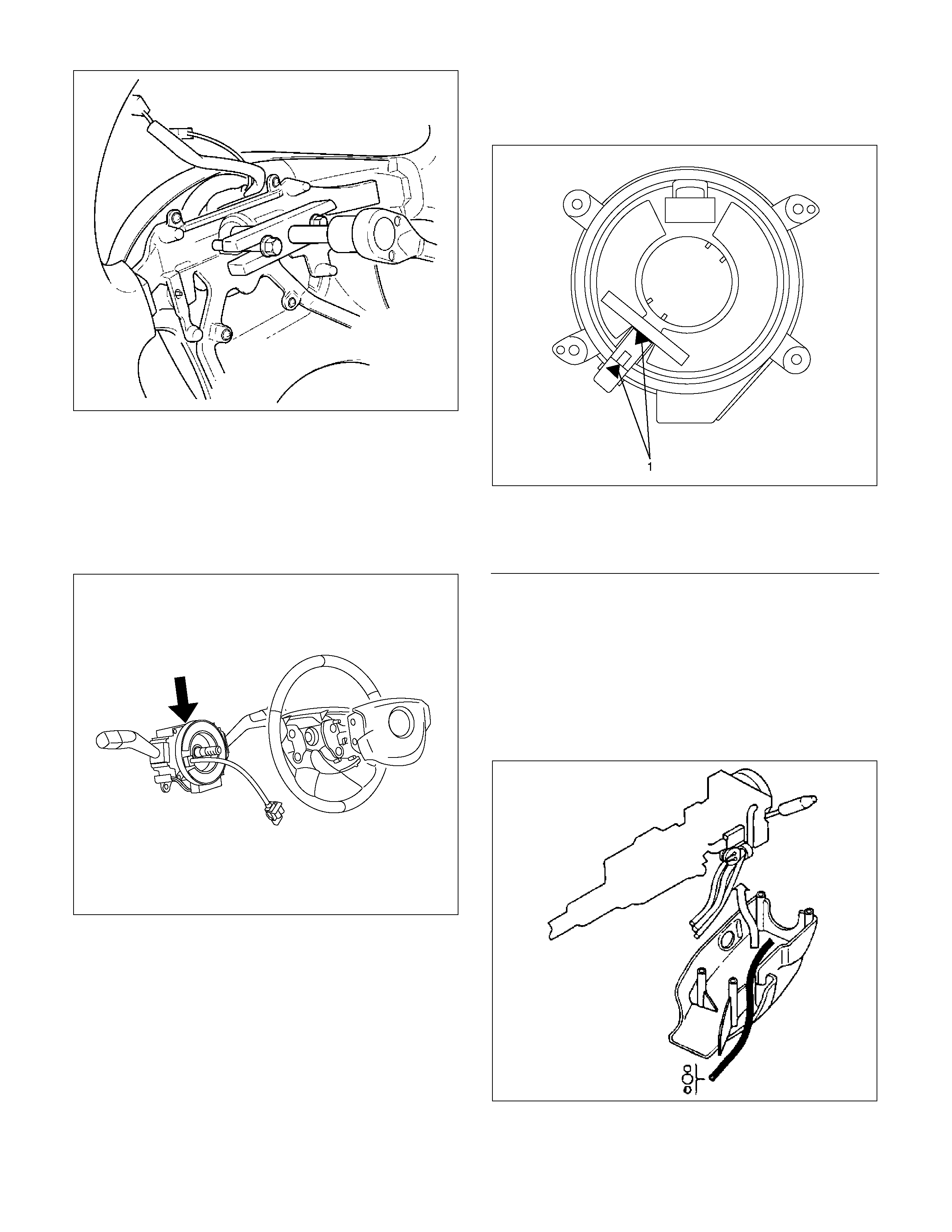
CAUTION: When turning the SRS coil
counterclockwise to full, stop turning if resistance
is felt. Forced further turning may damage the cable
in the SRS coil. (with SRS air bag)
826RW014
Legend
(1) Neutral mark
430RX005
16. Remove steering column cover.
17. Disconnect the wiring harness connectors located
under the steering column then remove combination
switch and SRS coil assembly. (with SRS air bag)
NOTE: The SRS coil is a part of the combination switch
assembly, which can not be replaced separately.
Therefore, be sure not to remove the SRS coil from the
combination switch assembly. (with SRS air bag)
430R300014
Installation
1. Install the combination switch assembly with SRS
coil. (with SRS air bag)
2. Turn the SRS coil counterclockwise to full, return
about 3 turns and align the neutral mark. (with SRS
air bag)
3. Connect the wiring harness connectors located at
the base of steering column.
4. Install the air conditioning lower duct.
5. Install the steering column cover.
CAUTION: When installing the steering column
cover, be sure to wire (through each harness) as
illustrated so that the harness starter switch,
combination switch and SRS coil may not catch
wiring. (with SRS air bag)
825RS048
6. Install the driver knee bolster assembly.
7. Install the steering lower cover and engine hood
opening lever.
8. Install the steering wheel and align the setting
marks.
Refer to the adjustment method in case a mark is
not attached in this section.
NOTE: Confirm SRS and Horn harness connector is
fixed by the steering wheel.
RTW33BSH000601
CAUTION: Never apply force to the steering wheel in
direction of the shaft by using a hammer or other
impact tools in an attempt to remove the steering
wheel. The steering shaft is designed as an energy
absorbing unit.
9. Tighten the steering wheel fixing nut to the specified
torque.
Torque: 31 - 39 Nm (3.2 – 4.0 kg m/23 - 29 lb ft)
10. Support the inflator module and carefully connect
the SRS connector and horn lead. (with SRS air
bag)
060R300010
11. Connect the horn leads at center of wheel. Push the
horn pad area 1-4.
Tighten the horn pad fixing screw to the specified
torque (without SRS air bag)
Torque: 2 – 4 Nm (0.2 – 0.4 kgm/17 - 35 lb in)
RTW33BSH000201
12.
A
lign the each s nap stud of driver air bag to the hole
of steering wheel. (with SRS air bag)
060R300030
060R300020
13. Push the SRS air bag area1 and area2. At that tim e
confir m the audible nois e of each st ud. ( with SRS air
bag)
060R300036
14. Enable the SRS (Refer to "Enabling t he SRS" in this
section). (with SRS air bag)
15. Install driver knee bolster (reinforcement).
16. Install instrument panel lower cover then Install the
engine hood opening lever.
17. Connect the SRS connector. (with SRS air bag)
18. Connect the battery "-" terminal cable. (with SRS air
bag)
19. Turn the ignition switch to "ON" while watching
warning light and check the light should f lash 7 tim es
and then go off. If lamp does not operate correctly,
refer to Restraints section.
Lock Cylinder
Lock Cylinder and Associated Parts
RTW33BLF000401
Legend
(1) Steering Column Cover
(2) Steering Wheel
(3) Inflator Module or Horn pad
(4) Combination Switch and SRS Coil Assembly
(5) Steering Column Assembly
(6) Lock Cylinder Assembly
(7) Instrument Panel Lower Cover
(8) Driver Knee Bolster (reinforcement)
Removal
1. Turn the steering wheel so that the vehicle's wheels
are pointing straight ahead.
2. Turn the ignition switch to "LOCK".
3. Disconnect the battery "-" terminal cable, and wait at
least 5 minutes. (with SRS air bag)
4. Disconnect the yellow 2-way SRS connector located
under the steering column. (with SRS air bag)
CAUTION: The wheels of the vehicle must be
straight ahead and the steering column in the
"LOCK" position before disconnecting the steering
wheel. Failure to do so will cause the coil assembly
to become uncentered which will cause damage to
the coil assembly. (with SRS air bag)
5. Remove the engine hood opening lever and
steering lower cover.
6. Remove driver knee bolster (reinforcement).
7. Disable the SRS (Refer to "Disabling the SRS" in
this section). (with SRS air bag)
8. Check the both side hole of the steering cover. (with
SRS air bag)
060R300025
9. Check the position of the pins in a hole. Push the
pin in the direction of an arrow. (with SRS air bag)
060R300032
10. Push the four pins at φ56 mm bar. (with SRS air
bag)
060R300031
11. Cancel the lock four pins. (with SRS air bag)
12. Loosen the horn pad fixing screw at the rear of the
steering wheel (without SRS air bag).
430R300009
13. Disconnect the SRS air bag connector and horn
lead connector located behind the air bag assembly
and remove the air bag assembly. (with SRS air
bag)
060R300041
14. Remove the horn pad and the horn leads at the
center of the wheel (without SRS air bag).
RTW33BSH00401
15. Apply a setting mark (1) across the steering wheel
and shaft so parts can be reassembled in their
original position.
430R300008
16. Move the front wheels to the straight ahead position,
then use steering wheel remover 5-8521-0016-0 to
remove the steering wheel.
CAUTION: Never apply force to the steering wheel in
direction of the shaft by using a hammer or other
impact tools in an attempt to remove the steering
wheel. The steering shaft is designed as an energy
absorbing unit.
430RX005
WARNING: THE INFLATOR MODULE SHOULD
ALWAYS BE CARRIED WITH THE COVER AWAY
FROM YOUR BODY AND SHOULD ALWAYS BE
LAID ON A FLAT SURFACE WITH THE COVER SIDE
UP. THIS IS NECESSARY BECAUSE A FREE SPACE
IS PROVIDED TO ALLOW THE AIR CUSHION TO
EXPAND IN THE UNLIKELY EVENT OF
ACCIDENTAL DEPLOYMENT. OTHERWISE,
PERSONAL INJURY MAY RESULT. (with SRS air
bag)
430R300007
17. Remove steering column cover.
18. Disconnect the wiring harness connectors located
under the steering column.
19. Remove the combination switch assembly with SRS
coil.
NOTE: The SRS coil is a part of the combination switch
assembly, which can not be replaced separately.
Therefore, be sure not to remove the SRS coil from the
combination switch assembly. (with SRS air bag)
430R300014
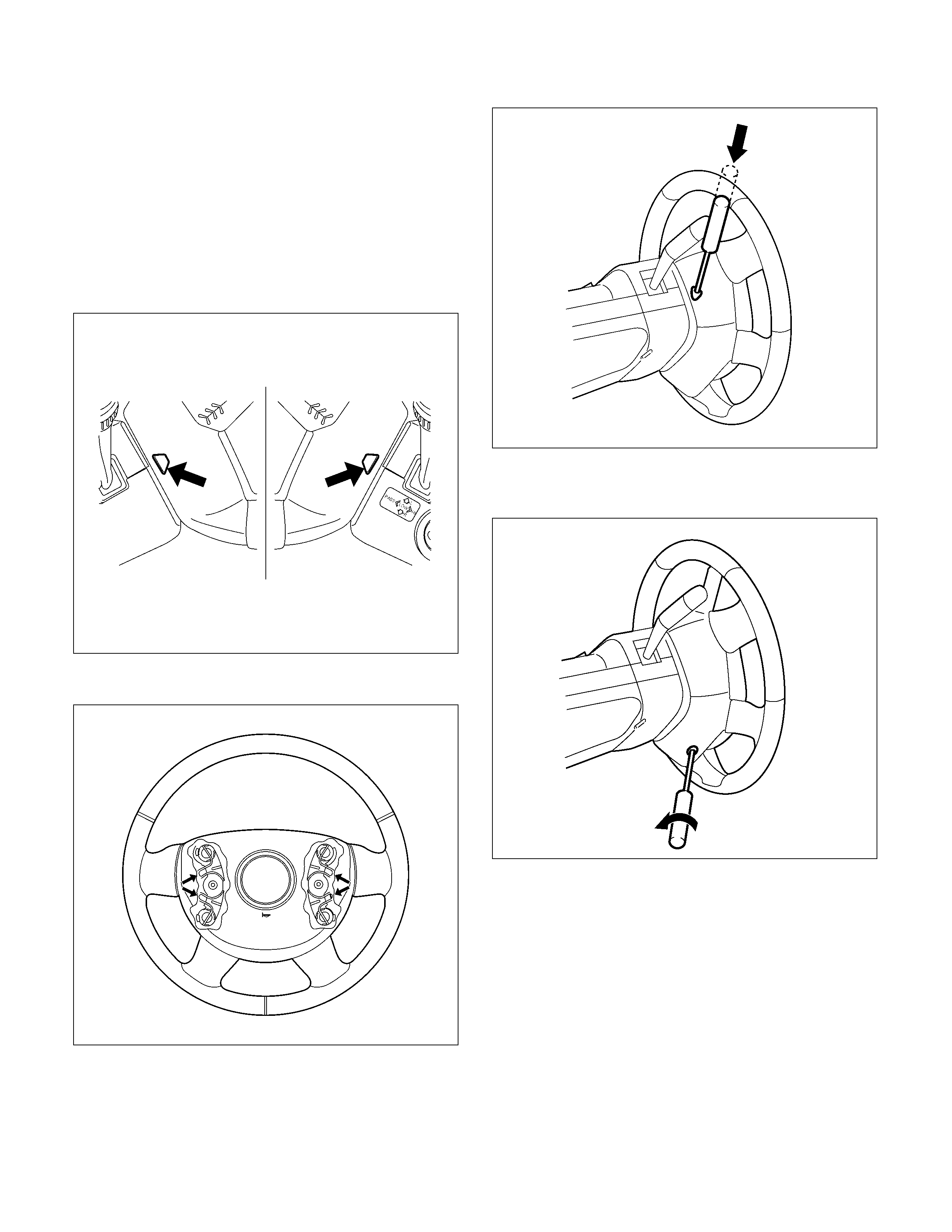
20. Turn the ignition switch to the ACC position.
21. Insert a pin (1) into the hole and push on it. Pull the
key cylinder free.
P1010003
Installation
1. Install lock cylinder assembly.
2. Install the combination switch assembly with SRS
coil. (with SRS air bag)
3. Turn the SRS coil counterclockwise to full, return
about 3 turns and align the neutral mark. (with SRS
air bag)
CAUTION: When turning the SRS coil
counterclockwise to full, stop turning if resistance
is felt. Forced further turning may damage the cable
in the SRS coil. (with SRS air bag)
826RW014
Legend
(1) Neutral mark
825RS048
4. Install the driver knee bolster assembly.
5. Install the steering lower cover and engine hood
opening lever.
6. Install the steering wheel and align the setting marks.
Refer to the adjustment method in case a mark is not
attached in this section.
NOTE: Confirm SRS and Horn harness connector is
fixed by the steering wheel.
RTW33BSH000601
CAUTION: Never apply force to the steering wheel in
direction of the shaft by using a hammer or other
impact tools in an attempt to remove the steering
wheel. The steering shaft is designed as an energy
absorbing unit.
7. Tighten the steering wheel fixing nut to the specified
torque.
Torque: 31 - 39 Nm (3.2 – 4.0 kgm/23 - 29 lb ft)
8. Support inflator module and carefully connect the
SRS connector and horn lead, then install inflator
module. (with SRS air bag)
060R300010
9. Connect the horn leads at center of wheel. Push the
horn pad area 1-4.
Tighten the horn pad fixing screw to the specified
torque (without SRS air bag)
Torque: 2 – 4 Nm (0.2 – 0.4 kgm/17 - 35 lb in)
RTW33BSH000201

10.
A
lign the each s nap stud of driver air bag to the hole
of steering wheel. (with SRS air bag)
060R300030
060R300020
11. Push the SRS air bag area1 and area2. At that tim e
confir m the audible nois e of each stud. ( with SRS air
bag)
060R300036
12. Enable the SRS (Refer to "Enabling t he SRS" in this
section). (with SRS air bag)
13. Install driver knee bolster (reinforcement).
14. Install instrument panel lower cover, then install the
engine hood opening lever.
15. Connect the yellow 2-way SRS connector located
under the steering column. (with SRS air bag)
16. Connect the battery "-" terminal cable. (with SRS air
bag)
System Inspection (with SRS air bag)
Turn the ignition switch to "ON" while watching warning
light.
The light should flash 7 times and then go off. If lamp
does not operate correctly, refer to Restraints section.
Steering Column
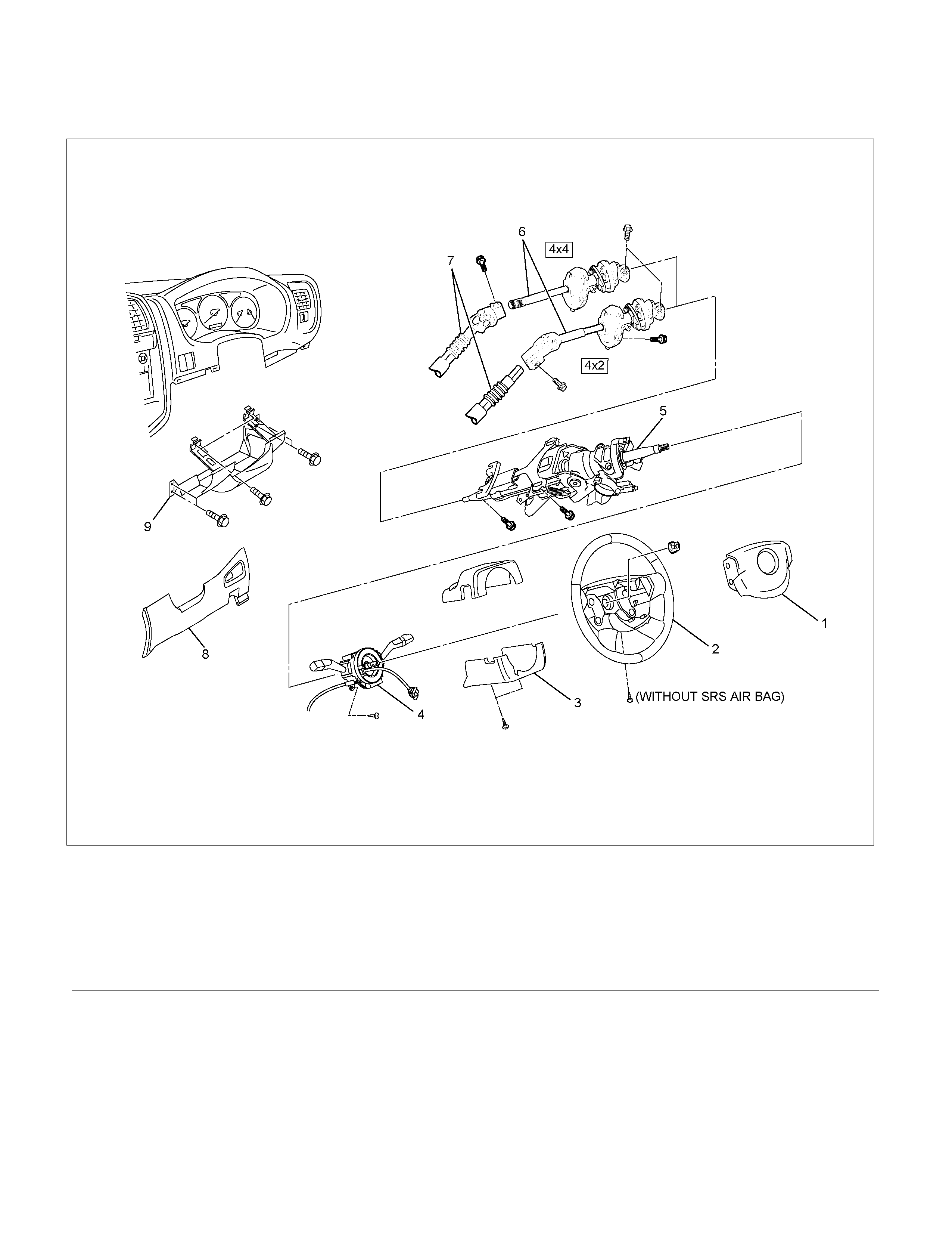
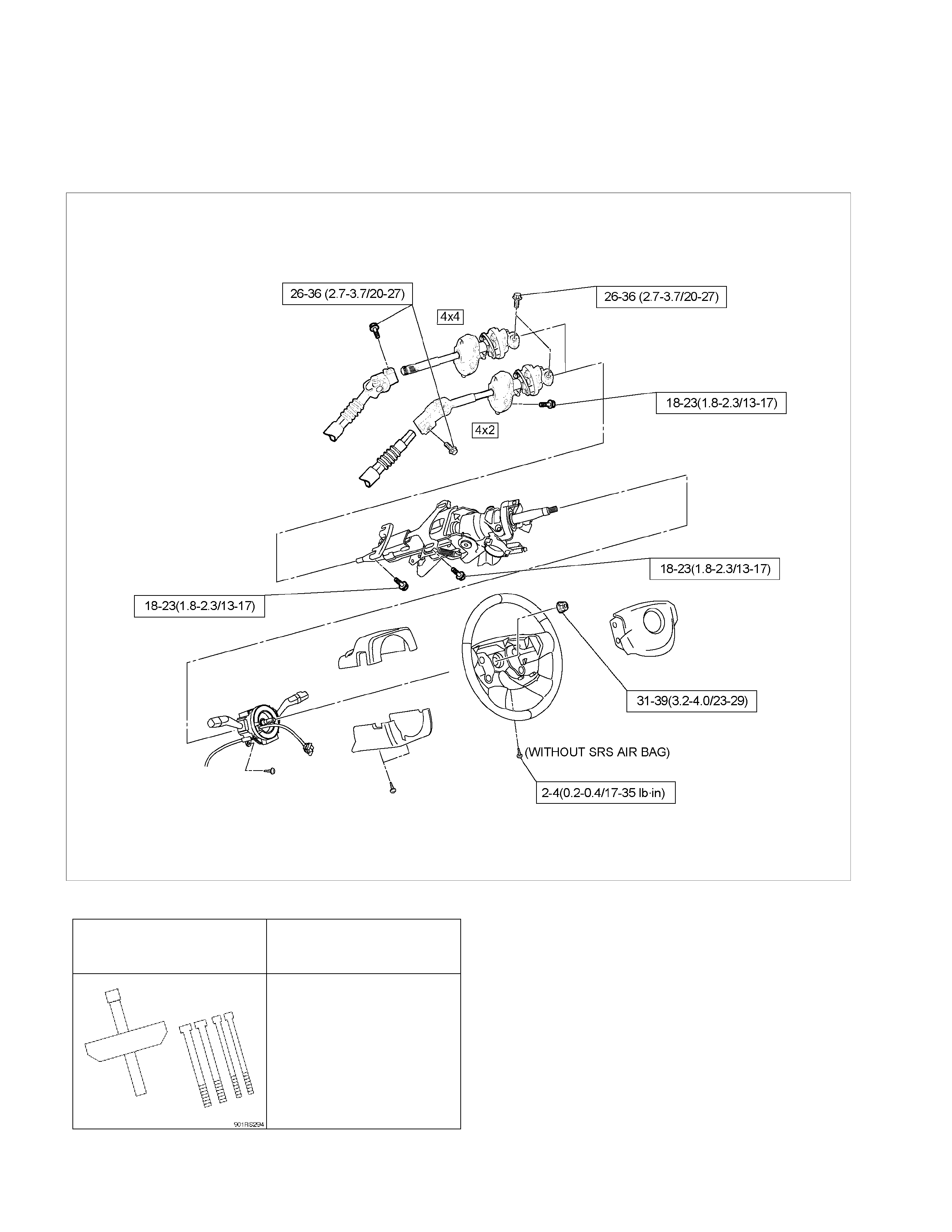
Steering Column and Associated Parts
RTW33BLF000501
Legend
(1) Inflator Module
(2) Steering Wheel
(3) Steering Column Cover
(4) Combination Switch and SRS Coil Assembly
(5) Steering Column Assembly
(6) Second Steering Shaft
(7) Lower Second Steering Shaft
(8) Instrument Panel Lower Cover
(9) Driver Knee Bolster (reinforcement)
Removal
1. Turn the steering wheel so that the vehicle's wheels
are pointing straight ahead.
2. Turn the ignition switch to "LOCK".
3. Disconnect the battery "-" terminal cable, and wait at
least 5 minutes. (with SRS air bag)
4. Disconnect the yellow 2-way SRS connector located
under the steering column. (with SRS air bag)
CAUTION: The wheel of the vehicle must be straight
ahead and the steering column in the "LOCK"
position before disconnecting the steering column
from the steering gear. Failure to do so will cause
the SRS coil assembly to become uncentered which
will cause damage to the SRS coil assembly. (with
SRS air bag)
5. Remove the engine hood opening lever and
steering lower cover.
6. Remove the driver knee bolster (reinforcement).
7. Disable the SRS (Refer to "Disabling the SRS" in
this section). (with SRS air bag)
8. Check the both side hole of the steering cover. (with
SRS air bag)
060R300025
9. Check the position of the pins in a hole. Push the
pin in the direction of an arrow. (with SRS air bag)
060R300032
10. Push the four pins at φ56 mm bar. (with SRS air
bag)
060R300031
11. Cancel the lock four pins. (with SRS air bag)
12. Loosen the horn pad fixing screw at the rear of the
steering wheel (without SRS air bag).
430R300009
13. Disconnect the SRS air bag connector and horn
lead connector located behind the air bag assembly
and remove the air bag assembly. (with SRS air
bag)
060R300041
14. Remove the horn pad and the horn leads at the
center of the wheel (without SRS air bag).
RTW33BSH000401
15. Apply a setting mark (1) across the steering wheel
and shaft so parts can be reassembled in their
original position. Move the front wheels to the
straight ahead position, then use steering wheel
remover 5-8521-0016-0 to remove the steering
wheel.
430R300008
430RX005
16. Remove steering column cover.
17. Disconnect the wiring harness connectors located
under the steering column.
18. Remove the combination switch assembly with SRS
coil.
NOTE: The SRS coil is a part of the combination switch
assembly, which can not be replaced separately.
Therefore, be sure not to remove the SRS coil from the
combination switch assembly.
430R300014
19. Remove snap ring.
20. Remove cushion rubber.
21. Remove shift lock cable (For A/T).
22. Disconnect the starter switch harness connector
located under the steering column, then remove
lock cylinder assembly.
23. Apply a setting mark (1) across the universal joint
and transfer gear to reassemble the parts in their
original position, then remove steering column
assembly and second shaft.
NOTE: A setting mark can be easily made if the shaft is
withdrawn a little by loosening the steering shaft
universal joint.
RTW33BSH000501
Inspection
If the abnormal conditions are found through inspection,
replace the steering column assembly.
Column Capsule
Check capsules on steering column bracket assembly;
all must be securely seated in bracket slots and
checked for any loose conditions when pushed or pulled
by hand.
431RW030
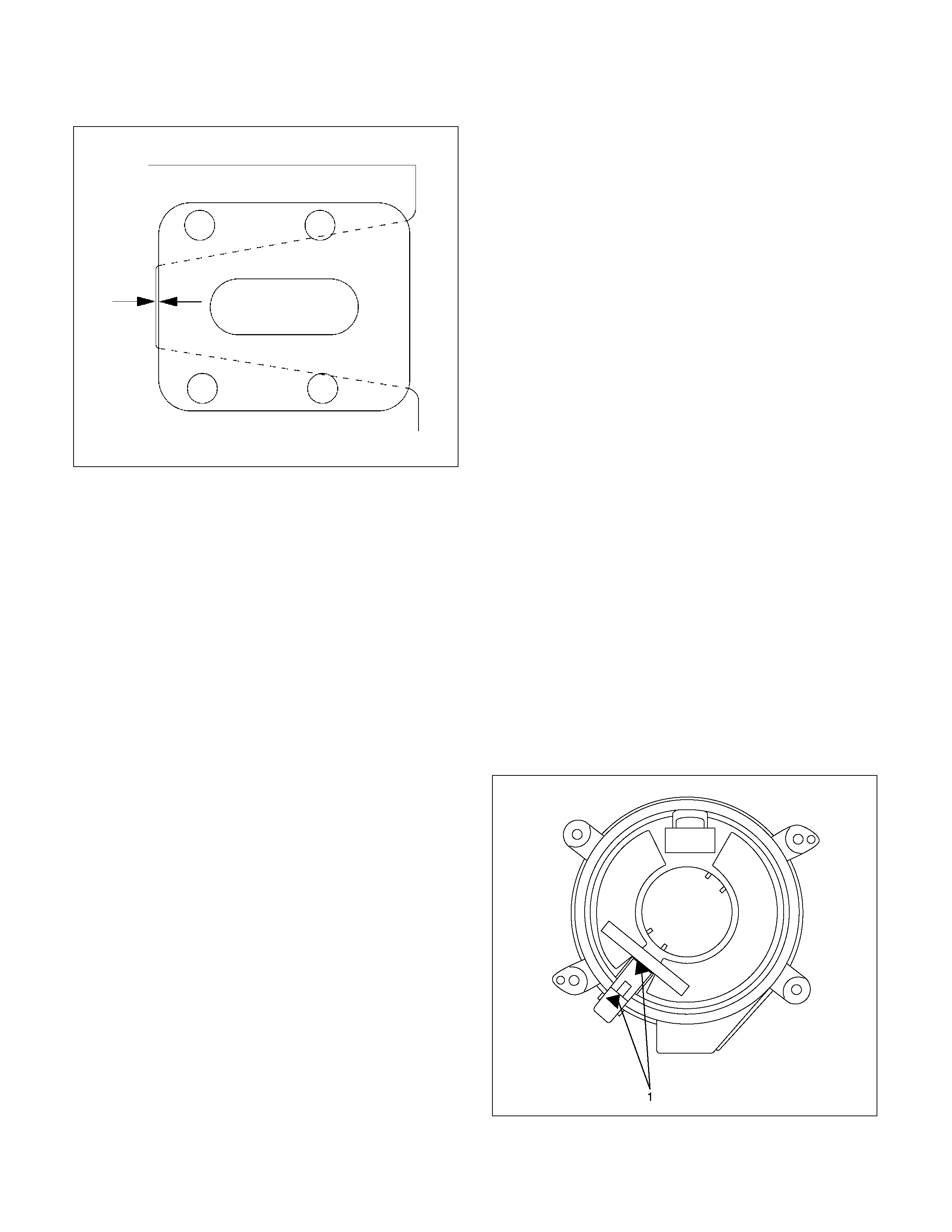
Check clearance between capsule and bracket. If must
be within 1mm (0.039 in).
431RW031
Column Universal Joint (between the power
steering unit and the steering shaft)
If the resistance is felt when checked by rotate the joint,
replace the lower second steering shaft.
Shaft Universal Joint (between the lower second
steering shaft and the second steering shaft)
If the resistance is felt when checked by rotate the joint,
replace the second steering shaft assembly.
Tilt Mechanism
Tilt mechanism should moves smoothly.
While locked the tilt mechanism, be sure the steering
column latch securely by pushing the steering wheel
upward and downward.
Installation
1. Align the setting marks on the second steering shaft
and the steering column assembly (applied at
disassem bly).
2. Connec t the steering colum n ass embly to the second
steering shaft. Tighten the bolts to the specified
torque.
Torque: 26 - 36 Nm (2.7 – 3.7 kgm/20 - 27 lb ft)
3. Thread the steering column assembly through the
hole in the dashpanel. Temporarily tighten the
steering column and the second steering shaft fixing
bolt.
4. Connect the lower second steering shaft and the
second steering shaft. Tighten the universal joint
bolts to the specified torque.
Torque: 26 - 36 Nm (2.7 – 3.7 kgm/20 - 27 lb ft)
5. Tighten the second steering shaft fixing bolt to the
specified torque (This bolt was temporarily tightened
in Step 3)
Torque: 18 -23 Nm (1.8 – 2.3 kgm/13 - 17 lb ft)
6. Tighten the steering column fixing bolt (dashpanel
side) to the specified torque (This bolt was
temporarily tighten in Step 3).
Torque: 18 -23 Nm (1.8 – 2.3 kgm/13 - 17 lb ft)
7. Tighten the steering column fixing bolt (pedal brkt
side) to the specified torque (This bolt was
temporarily tighten in Step 3).
Torque: 18 -23 Nm (1.8 – 2.3 kgm/13 - 17 lb ft)
8. Install combination switch and SRS coil assembly.
A
fter installation of combination switch assembly,
connect the combination switch wiring harness
connector and the SRS 2-way connector located
under the steering column.
9. Turn the SRS coil counter clockwise to full, return
about 3 turns and align the neutral mark. (with SRS
air bag)
CAUTION: When turning the SRS coil counter
clockwise to full, stop turning if resistance is felt.
Forced further turning may damage to the cable in
the SRS coil.
826RW014
10. When installing the steering column cover, be sure to
route each wire harness as illustrated so that the
harnesses do not catch any moving parts.
825RW017
Legend
(1) Steering Column Cover
(2) Starter Switch Harness
(3) Combination Switch Harness
(4) Inflator Module Harness
11. Install steering wheel and align the setting marks
made when removing.
Refer to the adjustment method in case a mark is
not attached in this section.
NOTE: Confirm SRS and Horn harness connector is
fixed by the steering wheel.
RTW33BSH000601
CAUTION: Never apply force to the steering wheel in
direction of the shaft by using a hammer or other
impact tools in an attempt to remove the steering
wheel. The steering shaft is designed as an energy
absorbing unit.
12. Tighten the steering wheel fixing nut to the specified
torque.
Torque: 31 - 39 Nm (3.2 – 4.0 kgm/23 - 29 lb ft)
13. Support the module and carefully connect the
module connector and horn lead, then install inflator
module.
NOTE: Pass the lead wire through the tabs on the
plastic cover (wire protector) of inflator to prevent lead
wire from being pinched.
14. Tighten bolts to specified torque.
Torque: 2 - 4 Nm (0.2 – 0.4 kgm/17 - 35 lb in)
15. Install driver knee bolster (reinforcement).
16. Install instrument panel lower cover.
17. Install the engine hood opening lever.
18. Connect the yellow 2-way SRS connector and horn
lead located under the steering column.
19. Connect the battery "-" terminal cable. (with SRS air
bag)
System Inspection (with SRS air bag)
Turn the ignition switch to "ON" while watching warning
light.
The light should flash 7 times and then go off. If lamp
does not operate correctly, refer to Restraints section.
Supplemental Restraint System Steering Wheel &
Column and Associated Parts
Main Data and Specifications
Torque Specifications N⋅m (kg⋅m/lb ft)
RTW33BLF001101
Special Tools
ILLUSTRATION
TOOL NO.
TOOL NAME
5-8521-0016-0
(J-29752)
Steering wheel remover