
Main Data and Specifications
4×
××
×2 C24SE ENGINE MODEL
Front suspension Type Independent wishbone arms, coil spring
with stabilizer bar.
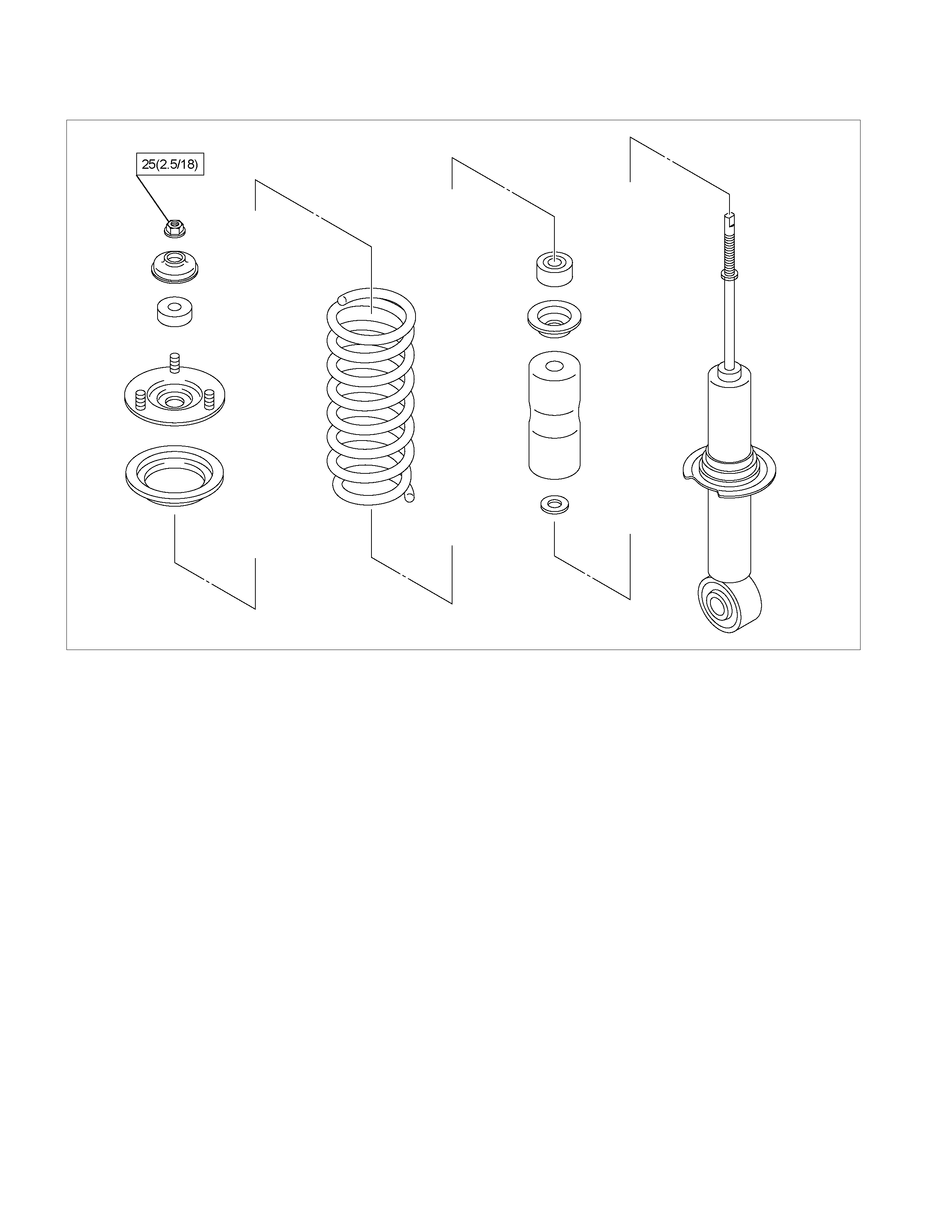
Coil spring Spring Rate 7.94 kg/mm (77.9 N/mm)
Type Gas-sealed. Hy draulic, double acting
Stroke 116.5 mm (4.59 in)
Compressed length 284.0 mm (11.18 in)
Front shock absorber
Extended length 400.5 mm (15.77 in)
Stabilizer bar Diameter 25.0 mm (0.98 in)
4×
××
×2 6VE1-W and 4JH1-TC ENGINE MODELS (HIGH-RIDE SUSPENSION)
Front suspension Type Independent wishbone arms, torsion bar spring
with stabilizer bar.
Length 1142 mm (44.96 in) Torsion bar spring Diameter 29.0 mm (1.14 in)
Type Gas-sealed. Hy draulic, double acting
Stroke 121.0 mm (4.76 in)
Compressed length 257.0 mm (10.12 in)
Front shock absorber
Extended length 378.0 mm (14.88 in)
Stabilizer bar Diameter 26.0 mm (1.02 in)
4×
××
×4 MODEL
Front suspension Type Independent wishbone arms, torsion bar spring
with stabilizer bar.
Length 1142 mm (44.96 in) Torsion bar spring Diameter 29.0 mm (1.14 in)
Type Gas-sealed. Hy draulic, double acting
Stroke 121.0 mm (4.76 in)
Compressed length 257.0 mm (10.12 in)
Front shock absorber
Extended length 378.0 mm (14.88 in)
Stabilizer bar Diameter 26.0 mm (1.02 in)
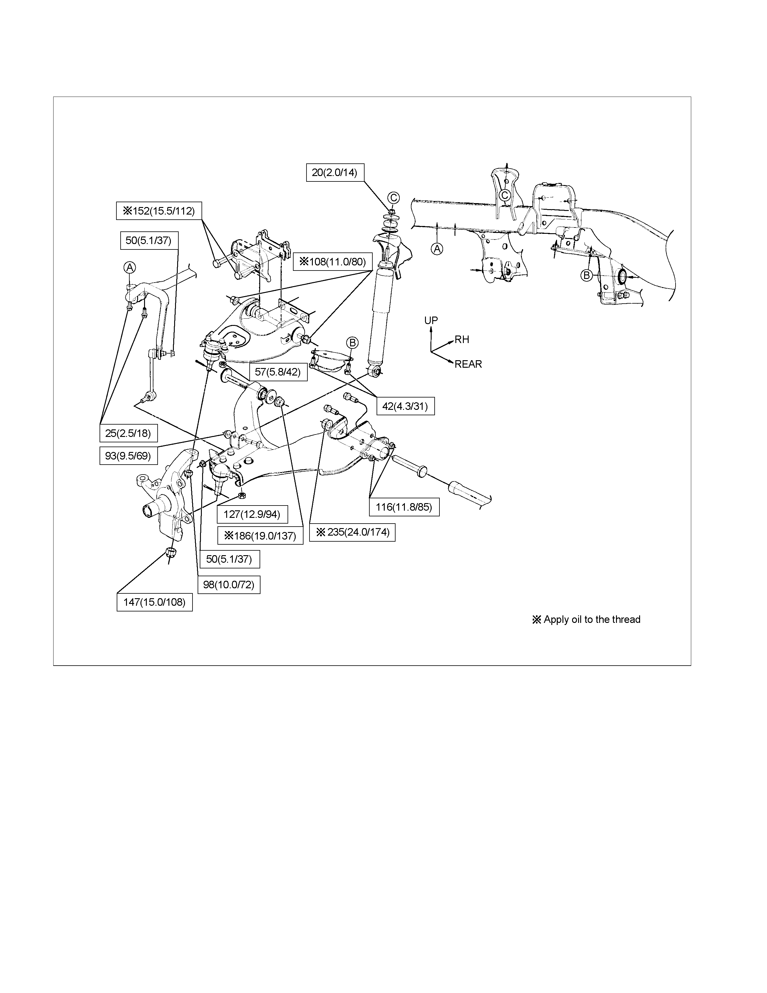
Torque Specifications
Special Parts Fixing Nuts and Bolts
4×
××
×2 C24SE Engine Model
N⋅m (kgf⋅m/lb⋅ft)
RTW340LF002401
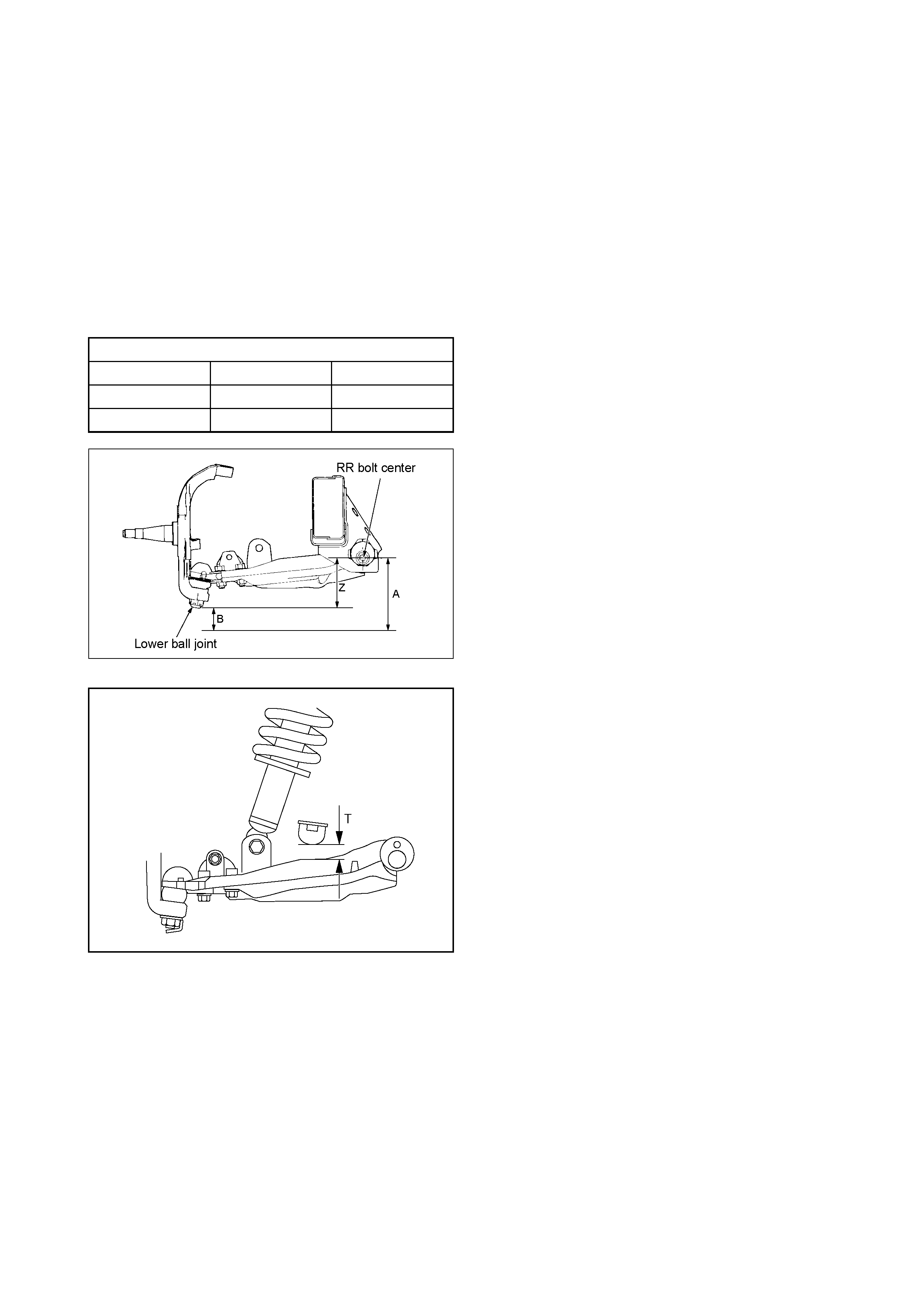
Trim Height Specification – Laden Vehicle
Should excessive spring deflection be reported when the
vehicle is laden, then the procedure detailed here, should
be followed.
Checking Procedure
1 Have the vehicle presented in the laden condition
where the spring deflection occurs.
2 Check that all tyre pressures are as spec ified on the
tyre pressure label.
Gross Vehicle Weight – Axle Loadings (kg)
4x2 Vehicle 4x4 Vehicle
Front Axle 1,120 1,220
Rear Axle 1,680 1,680
Front Trim Height (‘Z’ = A – B)
Front Bump Stop Clearance ‘T ’ (Reference Only)
3 With the vehicle on a weighing platform, check
whether the specified Gross Vehicle Weight (GVW)
axle loadings, are achieved. If not, then adjust (using
sand bags if necessary), to achieve the GVW axle
loading specifications shown.
4 After achieving the recommended front and rear axle
loadings, check and note the dimensions, indicated
in the following diagrams.
Important: Ensure that all measurements are taken with
the vehicle on a flat surface.
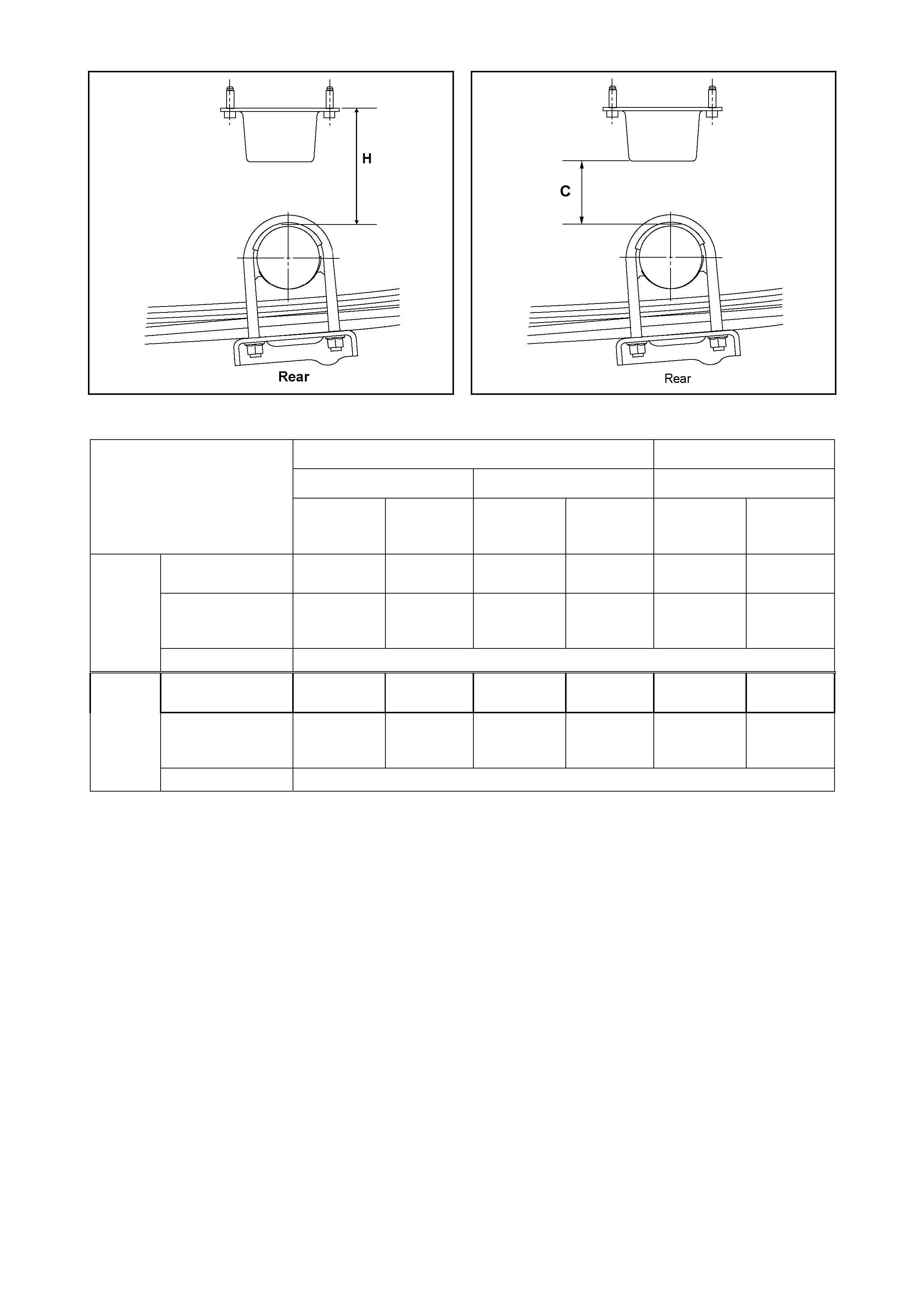
Rear Suspension Heigh t ‘H’
Rear Bump Stop Clearance ‘C’ (Reference Only)
4 x 2 4 x 4
4JH1 & 6VE1 C24SE 4JH1 & 6VE1
RA Rodeo
Vehicle Trim Height
Specifications at GVW
(All Dimensions are in mm) Standard
Rear Springs
(5 leaves)
HD Rear
Springs
(7 leaves)
Standard
Rear Springs
(5 leaves)
HD Rear
Springs
(7 leaves)
Standard
Rear Springs
(5 leaves)
HD Rear
Springs
(7 leaves)
Trim Height
Z 83.2 83.2 60.8 60.8 108.0 108.0
Bump Stop
Clearance ‘T’
(Ref. only) 17.8 17.8 9.4 9.4 17.0 17.0
Front
Tolerance ± 7
Suspension
Height H 75.2 88.3 75.2 88.3 91.9 104.0
Bump Stop
Clearance ‘C’
(Ref. Only) 9.4 22.5 9.4 22.5 9.5 21.6
Rear
Tolerance ± 6
4×
××
×2 C24SE Engine Model
N⋅m (kgf⋅m/lb⋅ft)
RTW340MF000201
4×
××
×2 (High Ride Suspension) and 4×
××
×4 Model
N⋅m (kgf⋅m/lb⋅ft)
RTW340LF002501
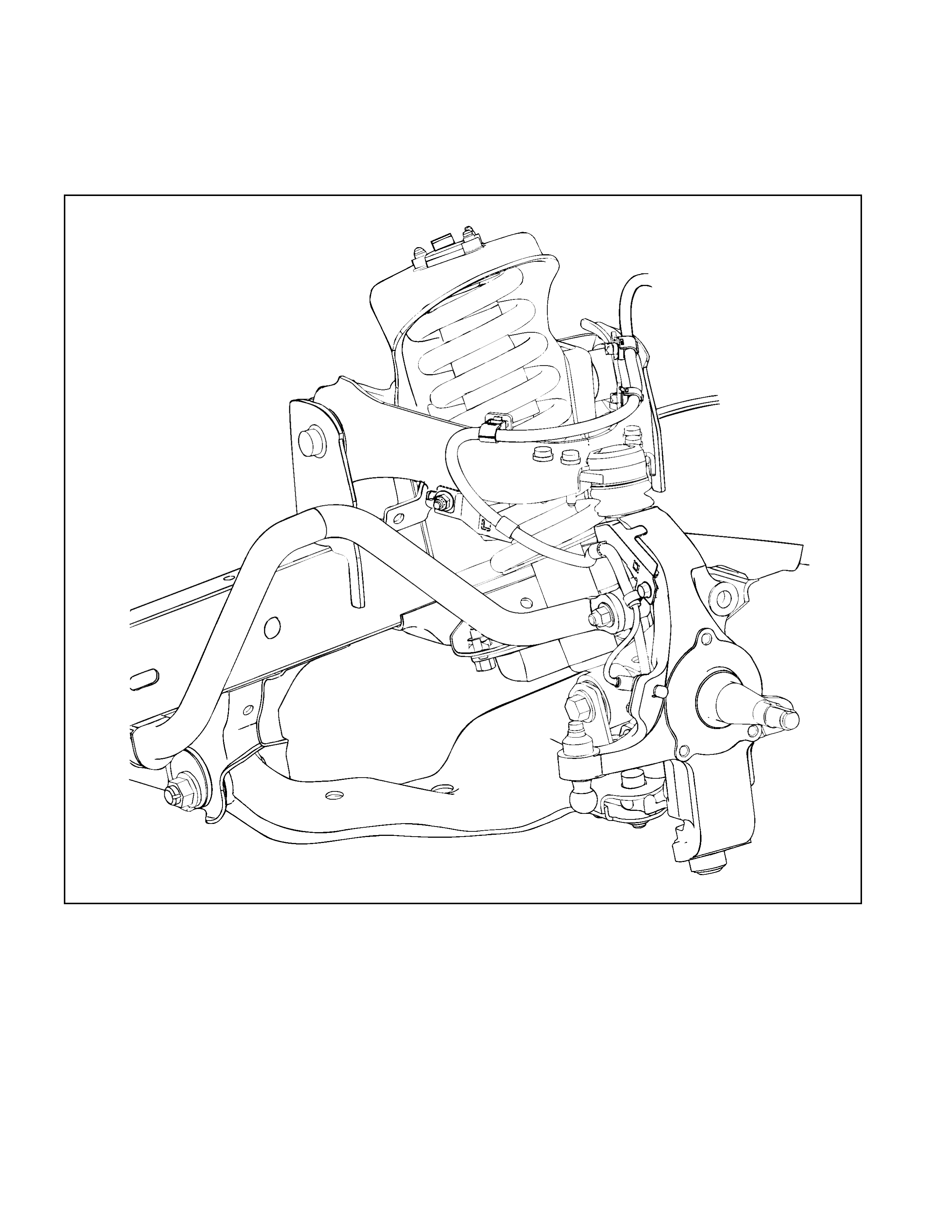
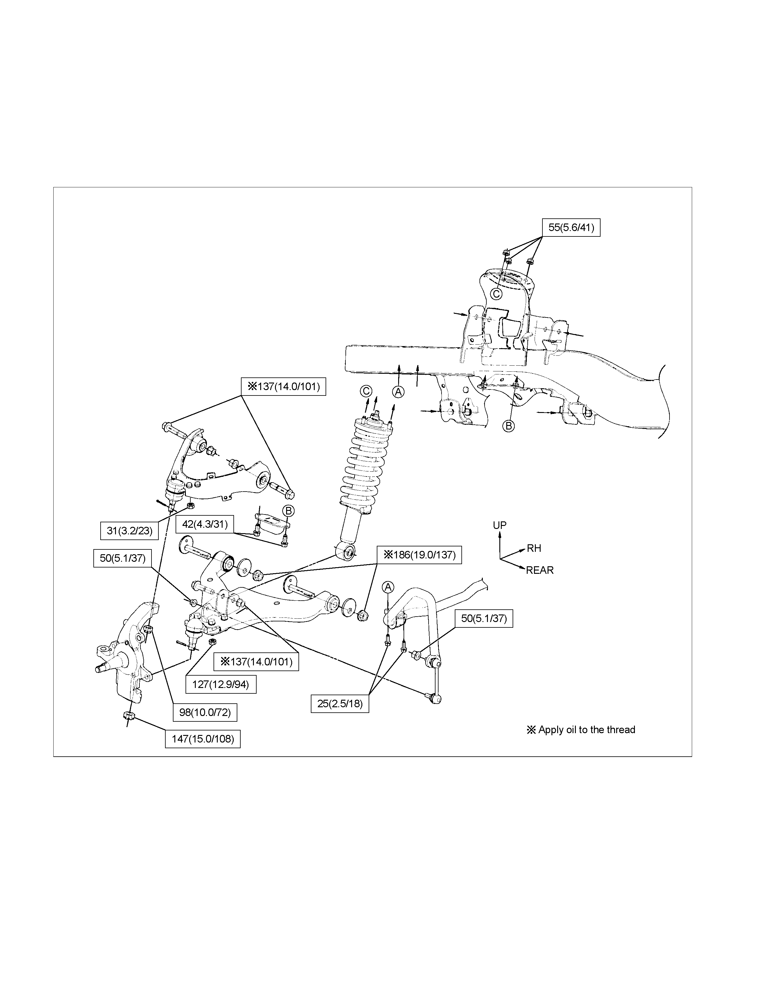
Front Suspension
General Description
4×
××
×2 C24SE Engine Model
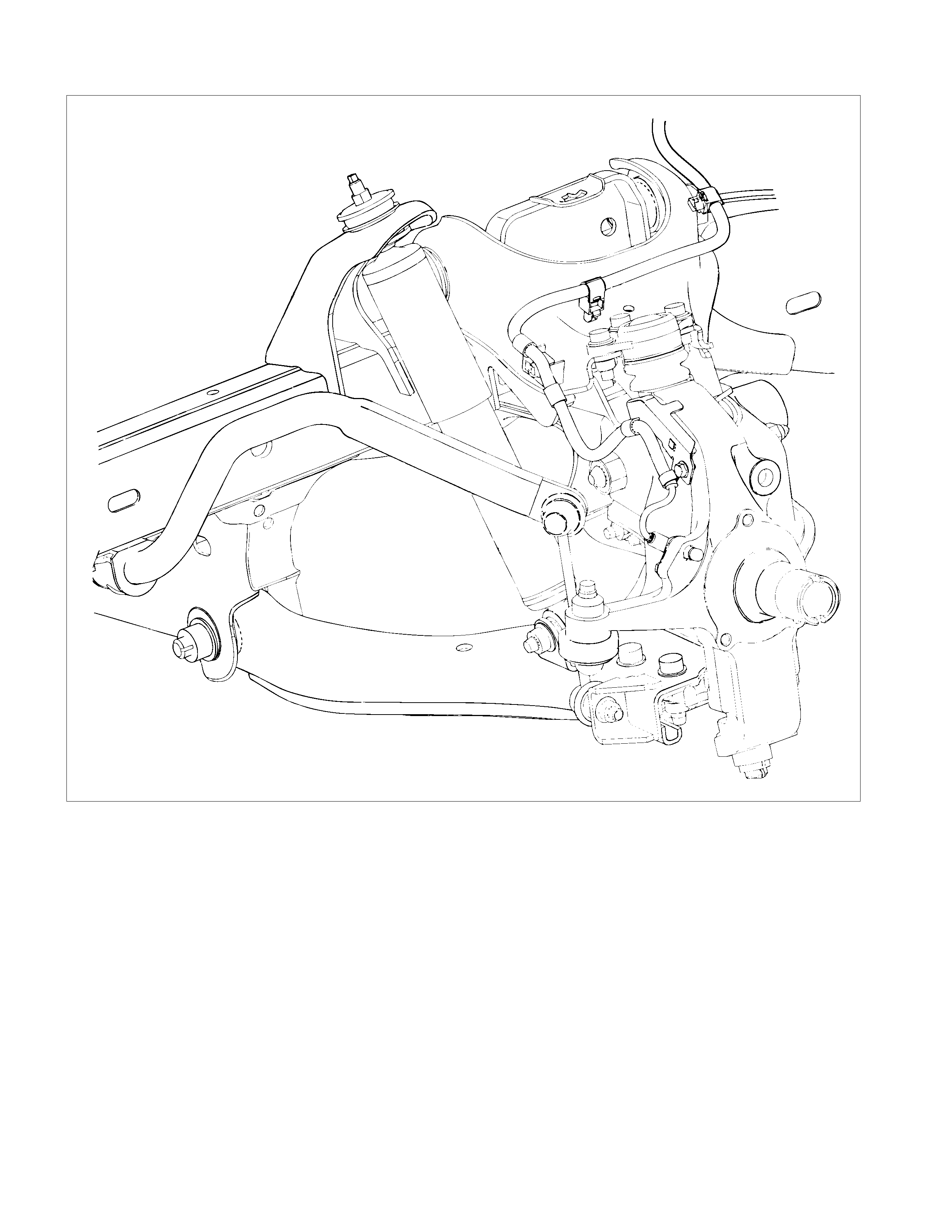
4×
××
×2 (High Ride Suspension) and 4×
××
×4 Model
RTW340LF000801
The links attach to the vehicle with bolts and bushings at their inner pivot points and to the steering knuckle, which is
part of the front wheel spindle, at their outer points.
The knuckle is mounted to the upper and lower links each of which has a ball joint to permit pivoting of the knuckle for
steering operations. The hub is supported in position on the knuckle spindle by means of the two bearings and the rotor
is mounted to the hub.
The front suspension is an independent type utilizing torsion bar springs (4×4, 4×2 (High ride suspension)) and coil
springs (4×2 (Except High ride suspension)). The torsion bar spring has splines on each end. Height control is provided
on the third crossmember. Both the upper and lower links are pressed steel and the torsion bar is supported at the ends
by lower link in front and by height control arm in rear.
For more detailed information on the front suspension for 4×2 C24SE engine model and 4×2 High Ride
Suspension, 4×4 please refer to Section 3C-1 FRONT SUSPENSION (4×
××
×2 C24SE ENGINE MODELS) or
Section 3C-2 FRONT SUSPENSION (4×
××
×2 HIGH RIDE SUSPENSION, 4×
××
×4)
TROUBLESHOOTING
1. VIBRATION, SHOCK, AND SHIMMY OF STEERING WHEEL
Checkpoint Trouble Cause Countermeasure
Check front axle
Check wheel alignment
Check suspension ball joint
Check shock absorber or
attaching nut and bolt
Replace
Adjust
Replace
Replace or retighten
Check steering unit and
linkage
Faulty
Worn
Malfunction or loose
Check upper and lower link
bushings
Replace
Adjust
Worn
Incorrect
OK
OK
OK
NG
NG
NG
NG
NG
NG
OK
OK
Check vehicle trim height
• Improperly adjusted or worn front
wheel bearing.
• Worn or incorrectly adjusted wheel
bearing.
Replace; refer to Section 4C1 Front
Wheel Drive
• Insufficiently tightened steering gea
r
housing.
• Wear of steering linkage.
• Excessive backlash due to imprope
r
adjustment of the steering gear box.
• Worn column bearing weakened
column bearing spring, or loose
clamp.
Replace; refer to Section 3B
Steering
• Improper tire pressure.
• Imbalance and deformation of frond
wheel.
• Unevenly worn tire or insufficient
tightening of wheel nuts.
Replace; refer to Section 3E Wheel
and Tires
2. VEHICLE PULLS TO RIGHT OR LEFT
Checkpoint Trouble Cause Countermeasure
Steering linkage, and upper
and lower link
Rubber bushing for upper and
lower link
Wheel alignment
Vehicle trim height
Replace
Replace
Adjust
Adjust
Deformed
Worn
Incorrect
Incorrect
Brake adjustment (binding)
Adjust
Replace
Incorrect
Collapsed or break (4×2
Except high ride suspension)
Collapsed or twisted (4×4, 4×2
High ride suspension)
Continued on the next page
OK
OK
OK
OK
NG
NG
NG
NG
NG
NG
OK
OK
Coil spring (4×2 Except high
ride suspension)
Torsion bar (4×4, 4×2 High
ride suspension)
Front wheel bearing
Adjust or replace
Incorrect adjustment or
abrasion
NG
Checkpoint Trouble Cause Countermeasure
Tire tread (right and left)
Replace (tire)
Difference in wear and tear
Adjust or tighten
Improper or instufficient
tightening
NG
NG
OK
Tire pressure or wheel nuts
Continued from the previous page
3. INSTABILITY OF VEHICLE
Checkpoint Trouble Cause Countermeasure
Tire pressure
Wheel alignment
Rubber bushings for upper
and lower links. (4 × 2 Except
high ride suspension)
Adjust
Adjust
Replace
Incorrect
Incorrect
Worn
Steering linkage and upper
and lower links
Replace
Adjust
Worn or deformed
Incorrect
OK
OK
OK
NG
NG
NG
NG
NG
OK
OK
Vehicle trim height
Road wheel
Adjust
Deformed or unbalanced
NG
4. STIFF STEERING WHEEL
Checkpoint Trouble Cause Countermeasure
Steering gear box or steering
linkage
Steering linkage
Steering gear
Wheel alignment
Replace the part
Replace
Replace
Adjust
Insufficient lubricants or
impurities present; or
excessively worn
Deformed
Worn or damaged
Incorrect
Replace
Stiff or damaged or lack of
grease
OK
OK
OK
OK
OK
NG
NG
NG
NG
NG
OK
Upper and ball joint
Steering column with turn
signal switch
Replace
Interference abrasion
NG
Tire pressure
Adjust
Improper
NG
5. NOISES
Checkpoint Trouble Cause Countermeasure
Lubricating oil and grease for
upper and lower ball joint
Shock absorber
Stabilizer fixing nuts and bolts
Upper and lower links
bushings
Replace
Replace
Retighten
Replace
Insufficient
Faulty
Loose
Worn
Shock absorber fixing nut and
bolt
Retighten
Loose
Continued on the next page
OK
OK
OK
OK
NG
NG
NG
NG
NG
OK
Upper and lower ball joint
Replace
Damaged
NG
Checkpoint Trouble Cause Countermeasure
Steering linkage and steering
gear ReplaceWorn
AdjustImproper
OK
NG
NG
OK
Tire pressure
Continued from the previous page
Steering unit fixing bolts and
linkage RetightenLoose
Adjust or replace
Incorrect adjustment or
abrasion
OK
NG
NG
OK
Front wheel bearing
Lubricating oil and grease to
steering linkage ReplaceInsufficient
NG
OK
6. EXCESSIVE STEERING WHEEL PLAY
Checkpoint Trouble Cause Countermeasure
Front wheel bearing
Steering linkage
Adjust or replace
Replace
Incorrect adjustment or
abrasion
Worn
Replace
Worn
NG
NG
NG
OK
OK
Upper, and lower links,
bushing (4 × 2 Except high
ride suspension)
7. GRATING TIRE NOISE
Checkpoint Trouble Cause Countermeasure
Tire pressure
Knuckle spindle and steering
linkage
Adjust
Replace
Improper
Deformed
Suspension fixing bolt Replace
Adjust
Loose
Incorrect
OK
NG
NG
NG
NG
OK
OK
Wheel alignment
8. EXCESSIVELY OR PARTIALLY WORN TIRE
Checkpoint Trouble Cause Countermeasure
Brake adjustment
Wheel alignment
Adjust
Adjust
Incorrect
Incorrect
Front wheel bearing Replace
Adjust
Faulty
Improper
OK
NG
NG
NG
NG
OK
OK
Tire pressure
Tire rotation Rotate tires at recomended
intervals
Not rotated
OK
NG