
SECTION 3C-1 - FRONT SUSPENSION
(4×
××
×2 C24SE ENGINE MODELS)
Service Precaution
Shock Absorber
Shock Absorber and Associated Parts
Removal
Installation
Shock Absorber with Coil Spring
Stabilizer Bar
Stabilizer Bar and Associated Parts
Removal
Inspection and Repair
Installation
Knuckle
Knuckle and Associated Parts
Removal
Inspection and Repair
Installation
Upper Control Arm
Upper Control Arm and Asso ci ate d
Parts
Removal
Inspection and Repair
Installation
Lower Control Arm
Lower Control Arm and Associated
Parts
Removal
Inspe cti on an d Repa ir
Installation
Upper Ball Joint
Upper Ball Joint and Associated Parts
Removal
Inspe cti on an d Repa ir
Installation
Low er Ball Joint
Lower Ball Joint and Associated Parts
Removal
Inspe cti on an d Repa ir
Installation
Bump Rubber
Bump Rubber Joint and Associated
Parts
Removal
Inspe cti on an d Repa ir
Installation
Special Tools

Service Precaution
WARNING: THIS VEHICLE HAS A SUPPLEMENTAL RESTRAINT SYSTEM (SRS). REFER TO THE SRS
COMPONENT AND WIRING LOCATION VIEW IN ORDER TO DETERMINE WHETHER YOU ARE PERFORMING
SERVICE ON OR NEAR THE SRS COMPONENTS OR THE SRS WIRING. WHEN YOU ARE PERFORMING
SERVICE ON OR NEAR THE SRS COMPONENTS OR THE SRS WIRING, REFER TO THE SRS SERVICE
INFORMATION. FAILURE TO FOLLOW WARNINGS COULD RESULT IN POSSIBLE AIR BAG DEPLOYMENT,
PERSONAL INJURY, OR OTHERWISE UNNEEDED SRS SYSTEM REPAIRS.
CAUTION: Always use the correct fastener in the proper location. When you replace a fastener, use ONLY the
exact part number for that application. HOLDEN will call out those fasteners that require a replacement after
removal. HOLDEN will also call out the fasteners that require thread lockers or thread sealant. UNLESS
OTHERWISE SPECIFIED, do not use supplemental coatings (Paints, greases, or other corrosion inhibitors)
on threaded fasteners or fastener joint interfaces. Generally, such coatings adversely affect the fastener
torque and the joint clamping force, and may damage the fastener. When you install fasteners, use the
correct tightening sequence and specifications. Following these instructions can help you avoid damage to
parts and systems.
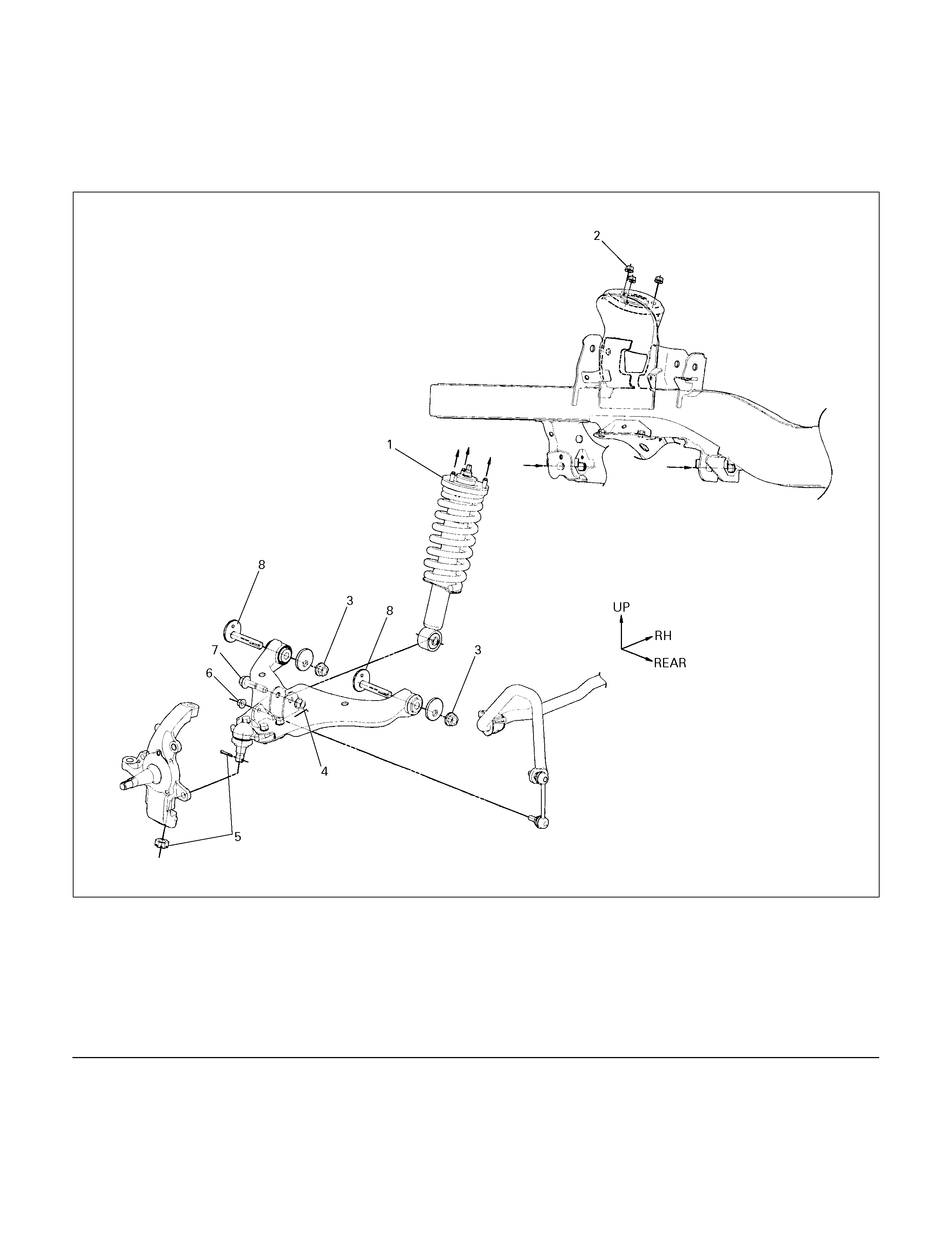
Shock Absorber
Shock Absorber and Associated Parts
450R300032
Legend
(1) Shock Absorber ASM with coil
(2) Nut
(3) Nut
(4) Nut
(5) Lower ball joint Nut and cot ter pin
(6) Nut
(7) Bolt
(8) Cam bolt
Removal
1. Raise the vehicle and support it with suitable
safety stands.
2. Remove wheel and tire assembly. Refer to
Wheel Replacement in this section.
3. Remove nut (6).
CAUTION: Be careful not o break the ball joint boot.
4. Support lower control arm with a jack.
5. Remove the bolt (7) and nut (4).
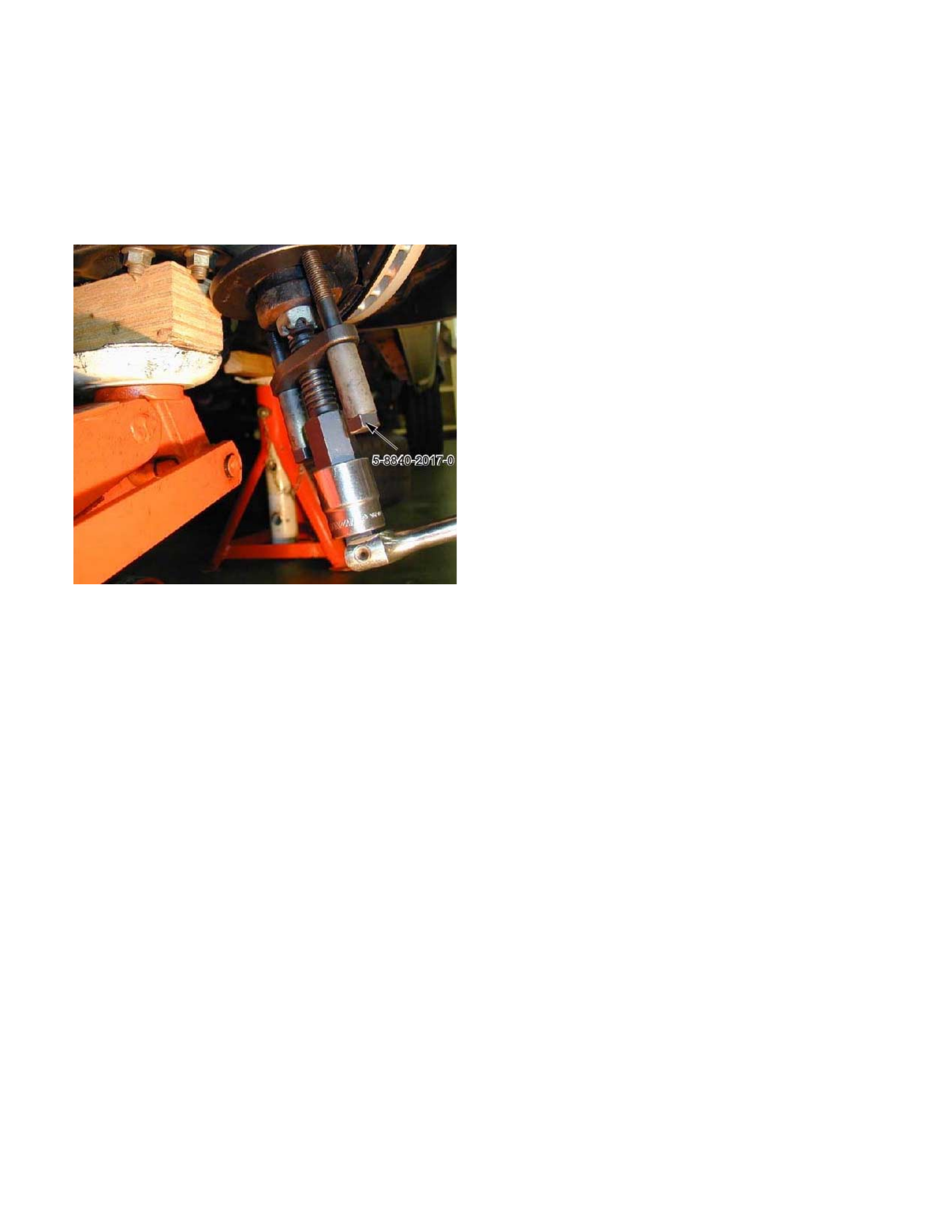
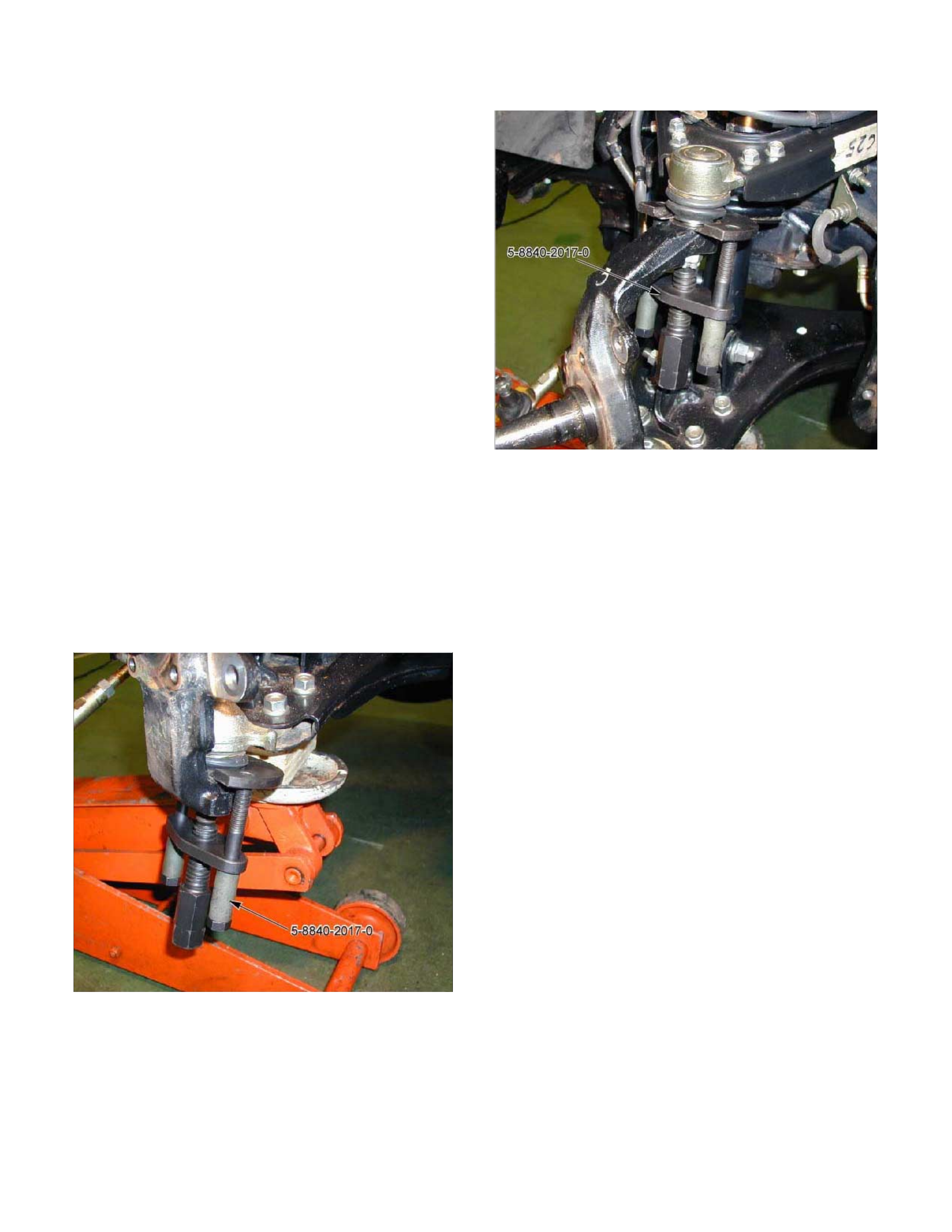
6. Remove lower ball joint nut and cotter pin(5), then
use remover 5-8840-2017-0 to remove the lowe
r
ball joint from the knuckle.
P1010003
7.
A
pply the setting marks to the front and rear cam
bolt and cross mem ber, then loosen nut, and cam
bolt.
8. Remove the nut (2).
9. Remove to Shock Absorber ASM.
Installation
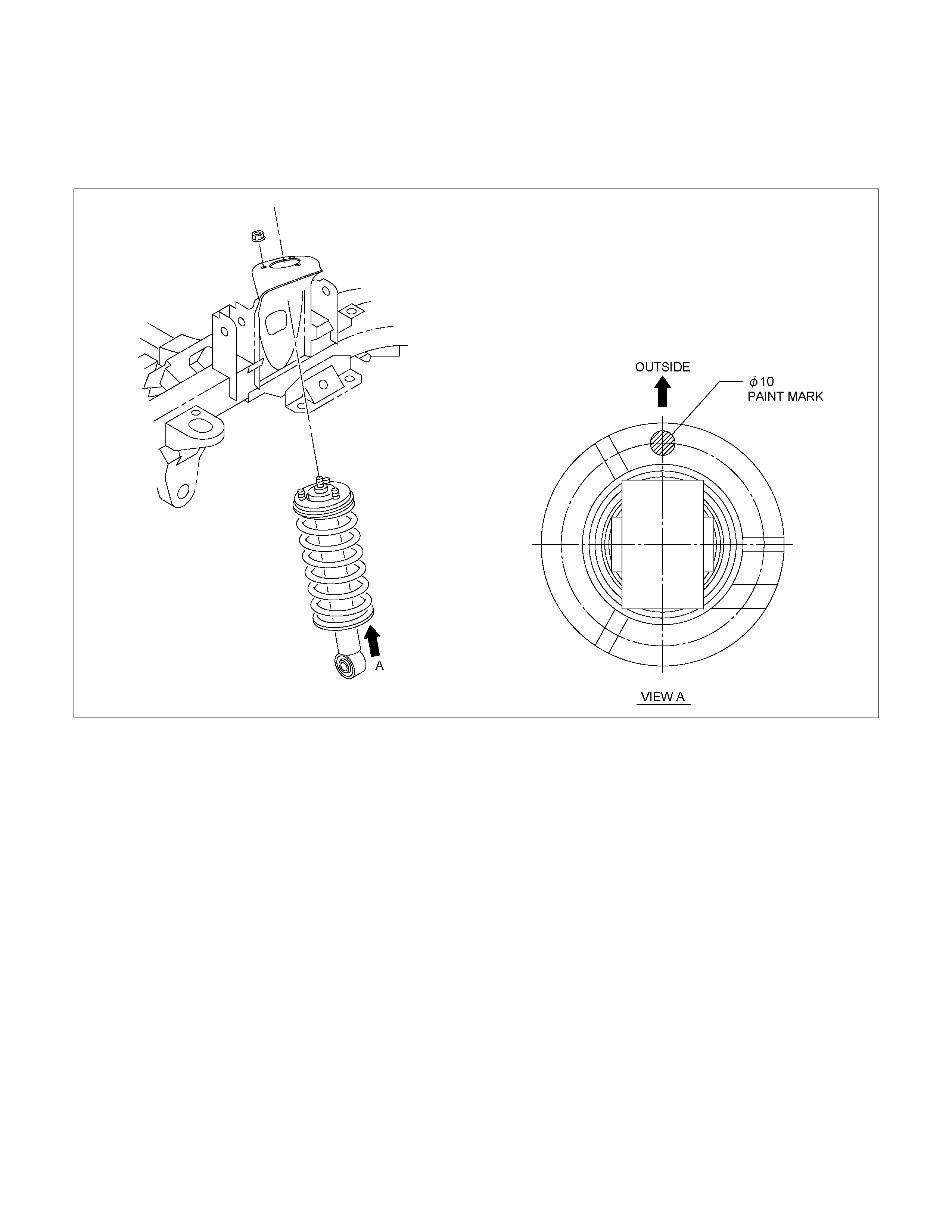
1. Install shock absorber.
RTW340MF000801
NOTE: Paint mark to be outer side of after assembly to
vehicle.
2. Install nut (2), then tighten it to the specified
torque.
Torque: 55N⋅
⋅⋅⋅m (5.6kg⋅
⋅⋅⋅m/41lb ft)
3. Install bolt (7) and nut (4), then tighten to the
specified torque.
Buffer clearance: 25.9 mm (1.02 in)
Torque: 137N⋅
⋅⋅⋅m (14.0kg⋅
⋅⋅⋅m/101 lb ft)
NOTE: Tighten the bolt and nut with the parts in the
position shown in the illustration below. Apply oil to the
thread.
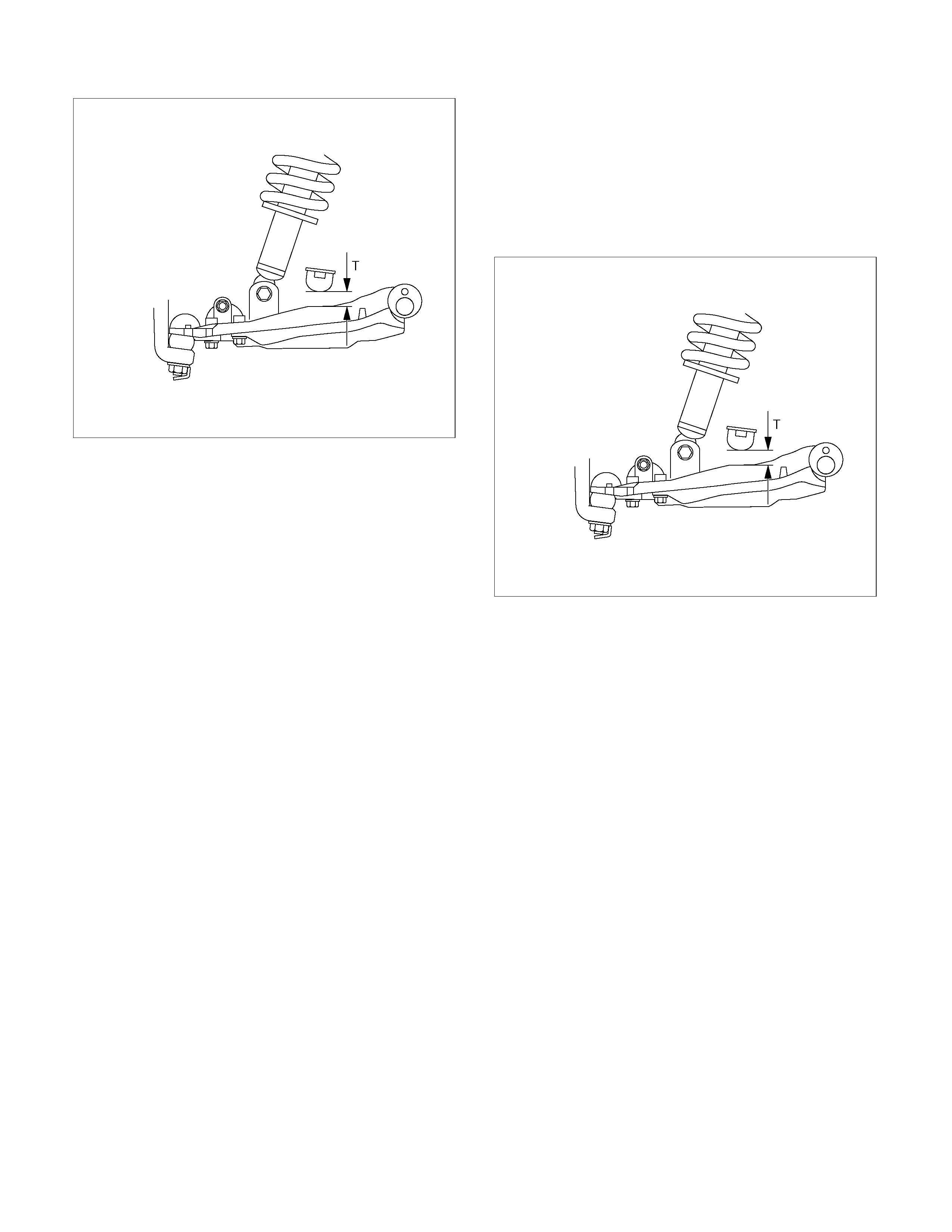
RTW340SH001301
4. Install nut (6), then tighten it to the specified
torque.
Torque: 50N⋅
⋅⋅⋅m (5.1kg⋅
⋅⋅⋅m/37 lb ft)
5. Tighten the cam bolt (8) and nut (3), it to the
interim torque, then turn the cam bolt to the s etting
mark applied during disassembly.
6. Install ball joint nut, then tighten it to the specified
torque with just enough additional torque to align
cotter pin holes. Install new cotter pin (5).
Torque: 147N⋅
⋅⋅⋅m (15.0kg⋅
⋅⋅⋅m/108 lb ft)
NOTE: Check the trim height. Refer to
Front Alignment Inspection and Adjustment.
7. Nut (3) tighten it to the specified torque.
Buffer clearance: 25.9 mm (1.02 in)
Torque: 186N⋅
⋅⋅⋅m (19.0kg⋅
⋅⋅⋅m/137 lb ft)
NOTE: Tighten the bolt and nut with the parts in the
position shown in the illustration below. Apply oil to the
thread.
RTW340SH001301
8. Install wheel and tire assembly. Refer to wheel in
this section.
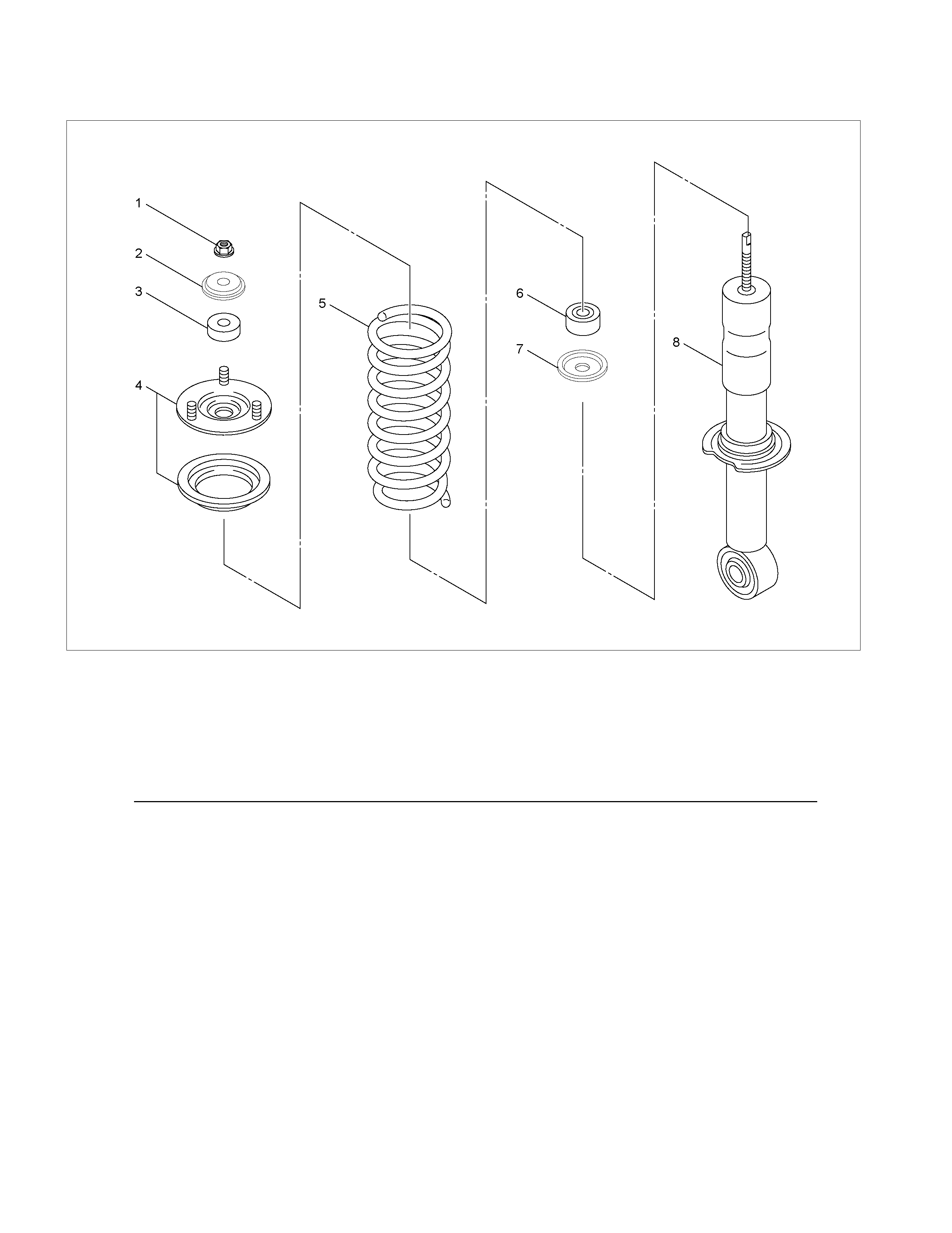
Shock Absorber with Coil Spring
RTW340LF002101
Legend
1. Nut
2. Washer
3. Bushing ; Rubber
4. Mounting Bracket
5. Coil Spring
6. Bushing ; Rubber
7. Washer
8. Shock Absorber Assembly
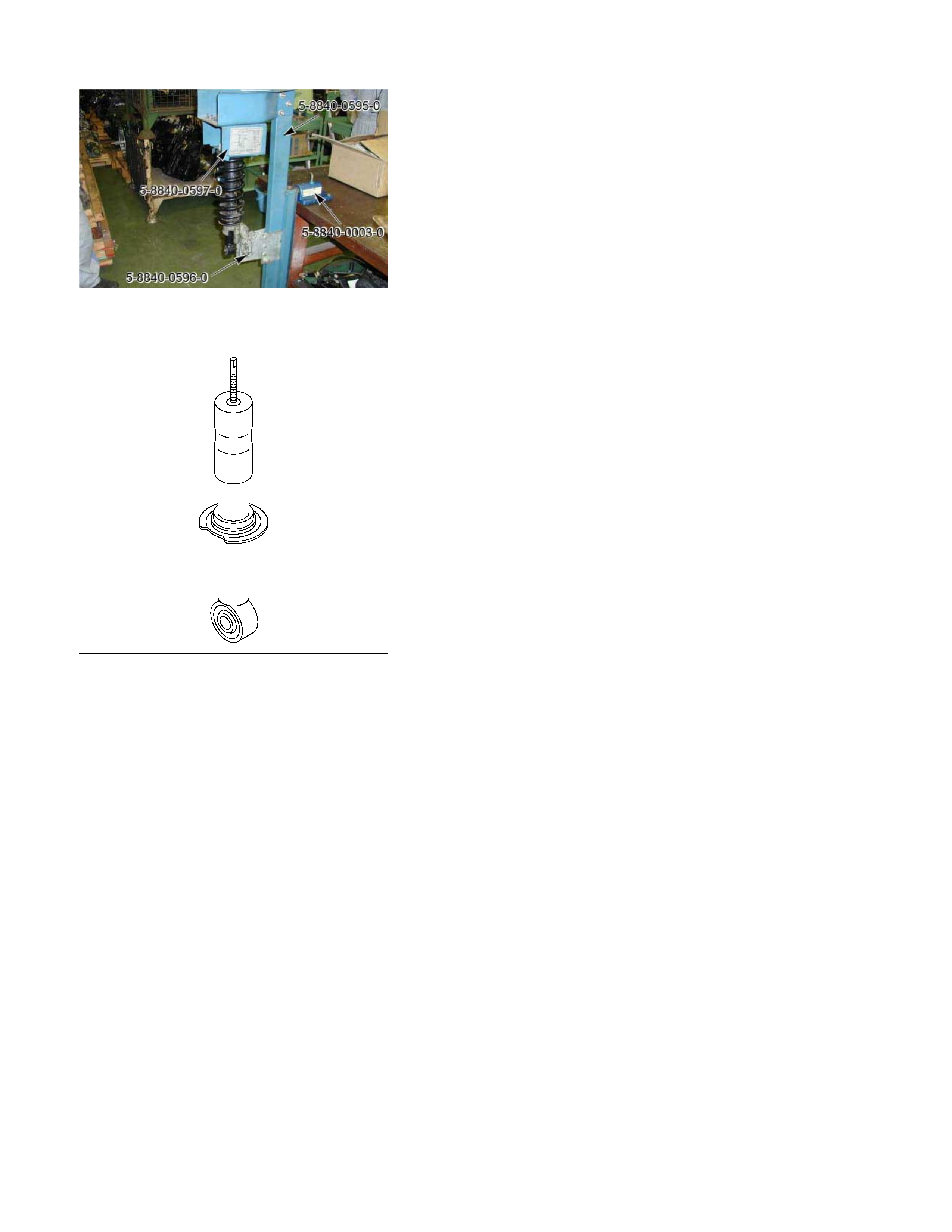
Disassembly
1. Install the support fixture (5-8840-0595-0) to the base (5-
8840-003-0).
2. Install the upper adapter (5-8840-0597-0) and the lower
adapter (5-8840-0596-0) to the base and support fixture
assembly.
3. Install the shock absorber assembly to the support fixture.
4. Remove the nut with spring in place.
CAUTION:
Take care not to apply excessive force to the nut during
removal.
CAUTION :
The shock absorbers have been charged with gas at the
factory. Exposur e to high temperatures or an open flame
can result in a dangerous explosion.
Keep the shock absorbers away from high temperatures
and open flames.
Inspection and Repair
Make all necessary adjustments, repairs, and part replacements if wear, damage, or other problems are discovered
during inspections.
Visual Check
Inspect the following parts for wear, damage or other abnormal
conditions.
• Shock absorber
• Rubber bushing
• Coil spring
Reassembly
1. Reassemble the parts inside the support fixture.
2. When tightening the bolt, compress the spring so that it
does not apply pressure to the spring seat.
3. Install the nut (1), then tighten to the specified torque.
Torque : 25 N⋅
⋅⋅⋅m (2.5 kg⋅
⋅⋅⋅m/19 lb ft)
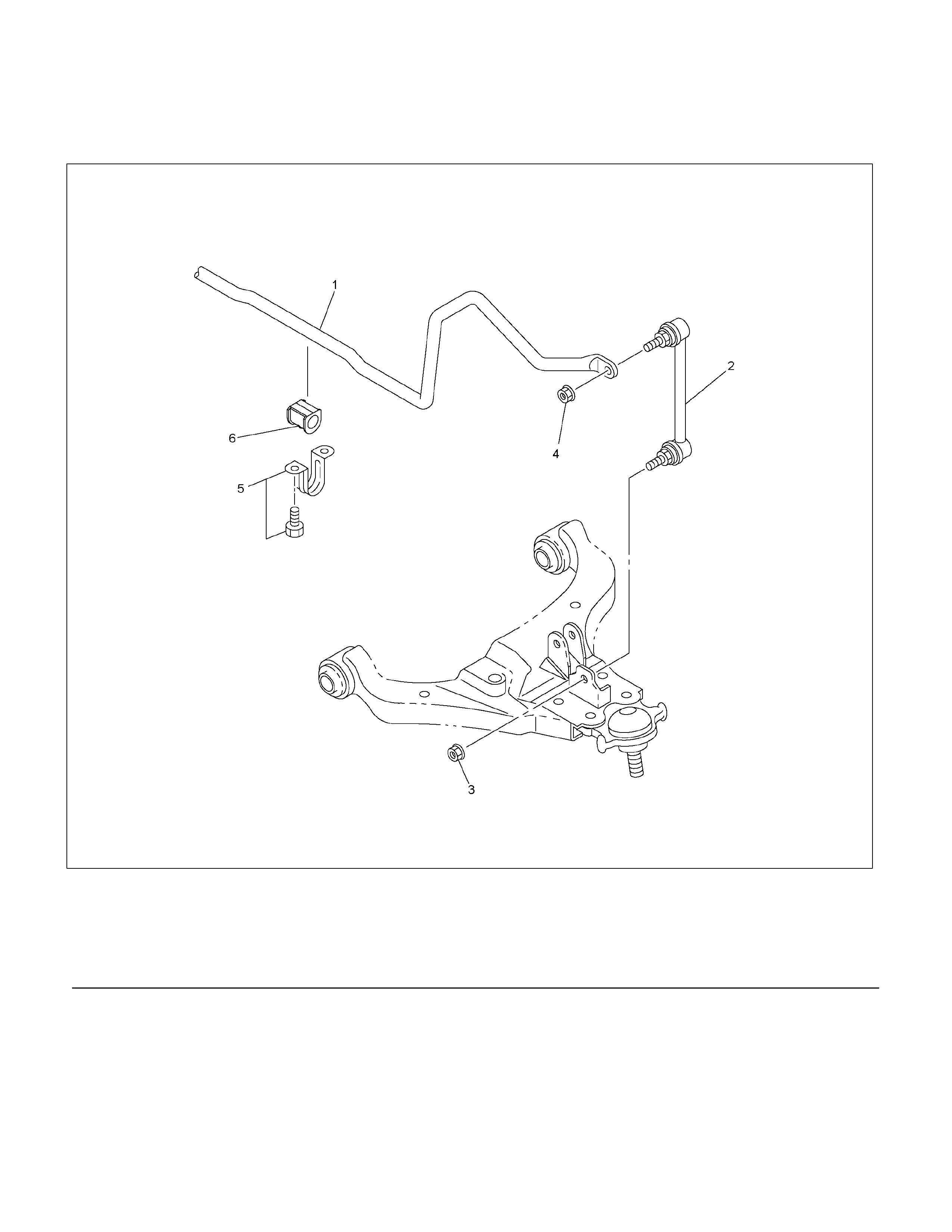
Stabiliser Bar
Stabiliser Bar and Associated Parts
RTW340LF000901
Legend
(1) Stabiliser Bar
(2) Link
(3) Nut
(4) Nut
(5) Bracket and Bolt
(6) Rubber Bushing

Removal
1. Raise the vehicle and support the frame with
suitable safety stands.
2. Remove wheel and tyre assembly. Refer to
Wheel Replacement in this section.
3. Remove nut (3) and (4).
CAUTION: Be careful not to break the ball joint
boot.
4. Remove link.
5. Remove bracket and bolt.
6. Remove Stabiliser bar.
7. Remove rubber bushing.
Inspection and Repair
Make necessary correction or parts replacement if
wear, damage, corrosion or any other abnormal
condition is found through inspection.
Check the following parts :
• Stabiliser bar
• Rubber bushing
• Link ball joint
Installation
1. Install rubber bushing.
2. Install Stabiliser bar.
3. Install bracket and bolt (5), then tighten it to the
specified torque.
Torque: 25 N⋅
⋅⋅⋅m (2.5kg⋅
⋅⋅⋅m/18 lb ft)
4. Install link.
5. Install nut (3), (4), then tighten it to the specified
torque.
Torque: 50 N⋅
⋅⋅⋅m (5.1kg⋅
⋅⋅⋅m/37 lb ft)
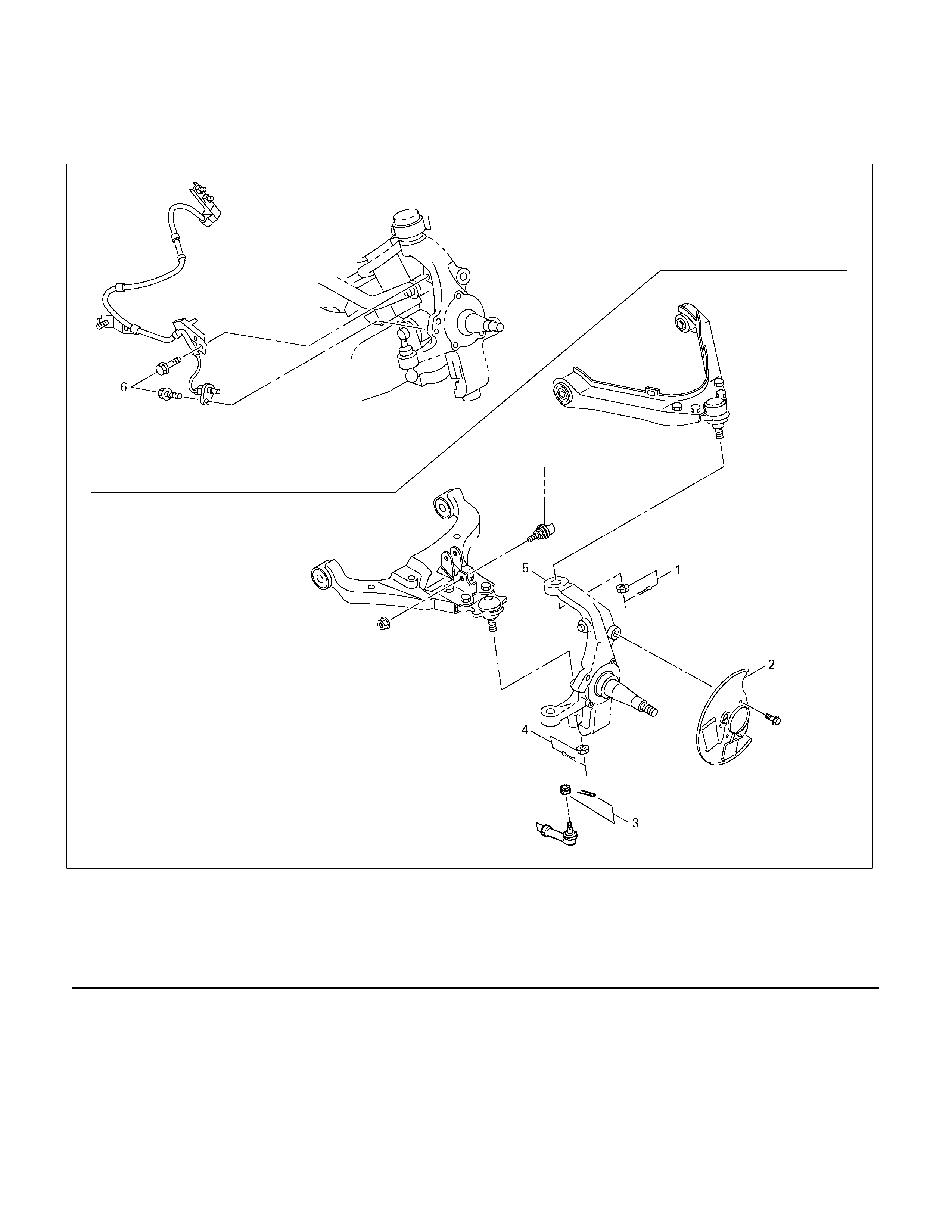
Knuckle
Knuckle and Associated Parts
450R300037
Legend
(1) Nut and Cotter Pin
(2) Back Plate
(3) Nut and Cotter Pin
(4) Nut and Cotter Pin
(5) Knuckle
(6) Bolt
Removal
1. Raise the vehicle and support the frame with
suitable safety stands.
2. Remove wheel and tyre assembly. Refer to
Wheel in this section.
3. Remove the brake caliper. Refer to Disc Brakes
in Brake section.
4. Remove the hub assembly. Refer to
Front Hub and Disk in this section.
5. Remove tie-rod end from the knuckle. Refer to
Power Steering Unit in Steering section.
P1010011
11. Remove knuckle.
6. Remove the Stabiliser link nut. Right and left.
7. Remove the wheel speed sensor from the knuckle.
8. Remove back plate.
9. Remove lower ball joint by using remover 5-8840-
2017-0.
CAUTION: Be careful not to damage the ball joint
boot.
P1010009
10. Rem ove upper ball joint by using remover 5-8840-
2017-0.
CAUTION: Be careful not to damage the ball joint
boot.
Inspection and Repair
Make necessary correction or parts replacement if
wear, damage, corrosion or any other abnormal
condition is found through inspection.
Check the following parts:
• Knuckle
• Knuckle arm
Installation
1. Install knuckle assembly.
2. Install upper ball joint and tighten the nut to the
specif ied tor que, with just enough additional tor que
to align cotter pin holes. Install new cotter pin (1).
Torque: 98 N⋅
⋅⋅⋅m (10.0kg⋅
⋅⋅⋅m/72 lb ft)
3. Install lower ball joint and tighten the nut to the
specif ied tor que, with just enough additional tor que
to align cotter pin holes. Install new cotter pin (4).
Torque: 147N⋅
⋅⋅⋅m (15.0kg⋅
⋅⋅⋅m/108 lb ft)
4. Install back plate.
5. Install wheel speed sensor.
6. Install Stabiliser link nut. Right and left.

Upper Control Arm
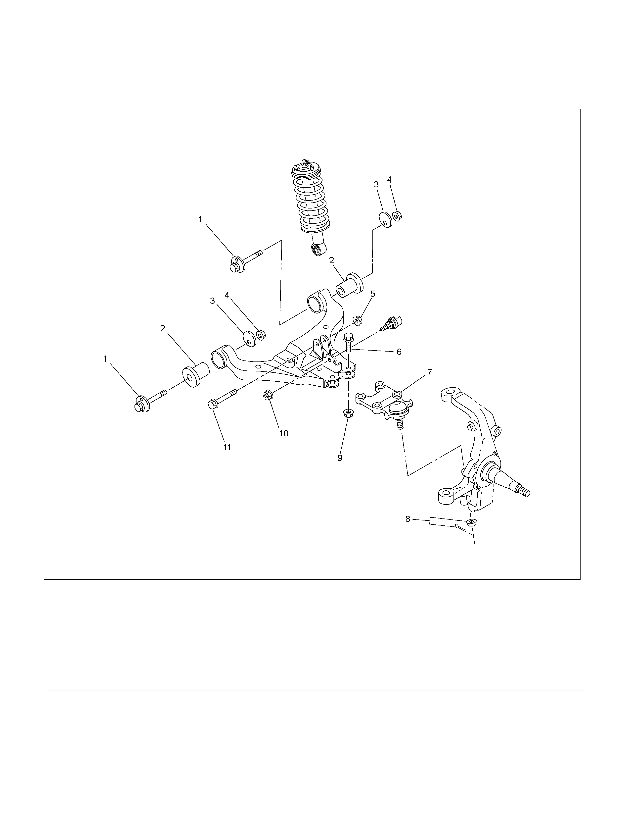
Upper Control Arm and Associated Parts
450R300038
Legend
(1) Bolt
(2) Bushing
(3) Nut
(4) Upper Control Arm Assembly
(5) Upper Ball Joint
(6) Nut and Cotter Pin
(7) Knuckle
(8) Nut
(9) Nut
(10) Bolt
(11) Nut
(12) Nut
Removal
1. Raise the vehicle and support the frame with
suitable safety stands.
2. Remove wheel and tyre assem bly. Refer to Wheel
in this section.
3. Remove nut (11).
4. Remove nut (12).
5. Remove nut (8).
6. Remove upper ball joint by using remover 5-8840-
2017-0.
CAUTION: Be careful not to damage the ball joint
boot.
P1010005
7. Remove nut (3).
8. Remove bolt (1).
9. Remove bolt (10) and nut (9).
10. Remove upper ball joint.
11. Remove upper control arm assembly.
12. Remove bushing.
Inspection and Repair
Make necessary parts replacement if wear, damage,
corrosion or any other abnormal conditions are found
through inspection.
Check the following parts:
• Upper control arm
• Bushing
Installation
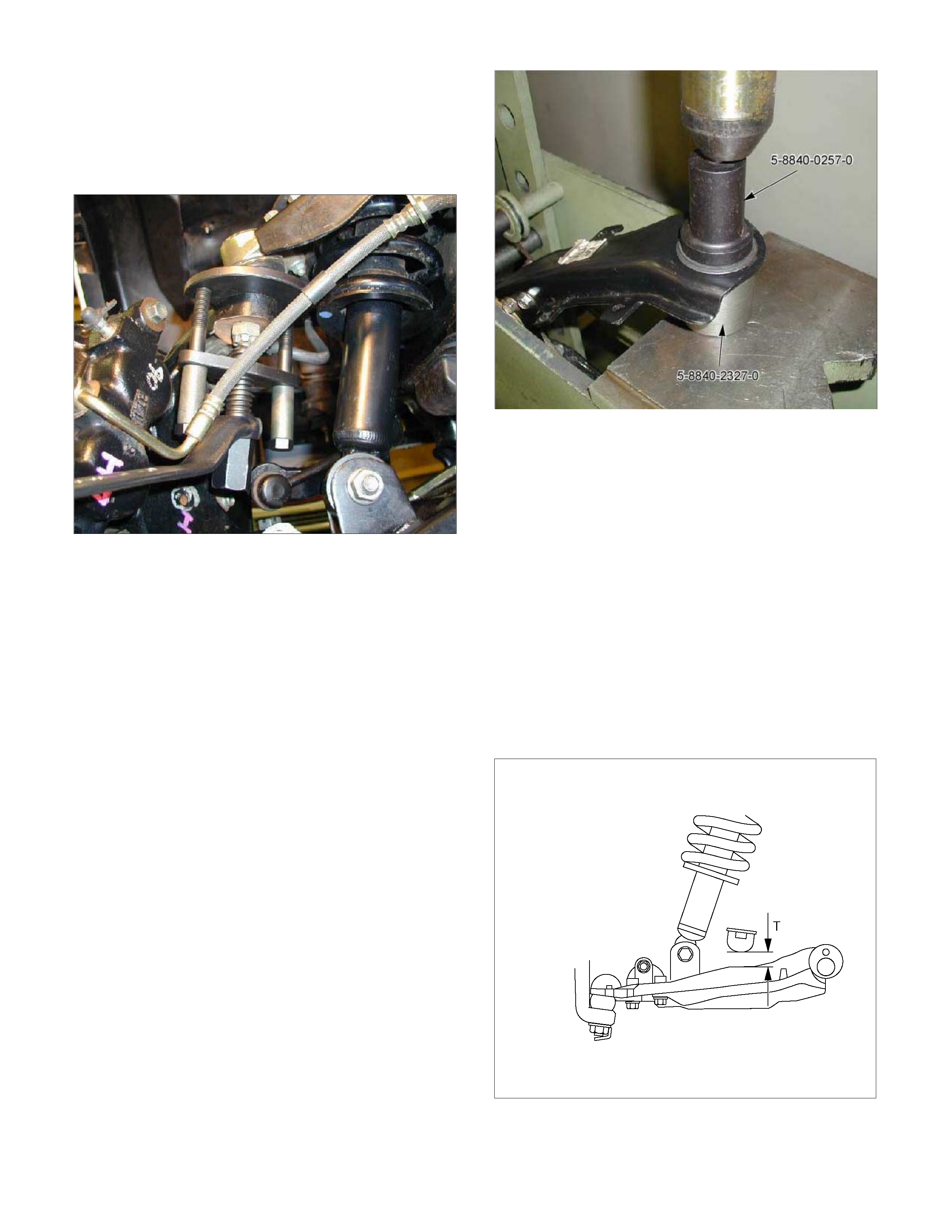
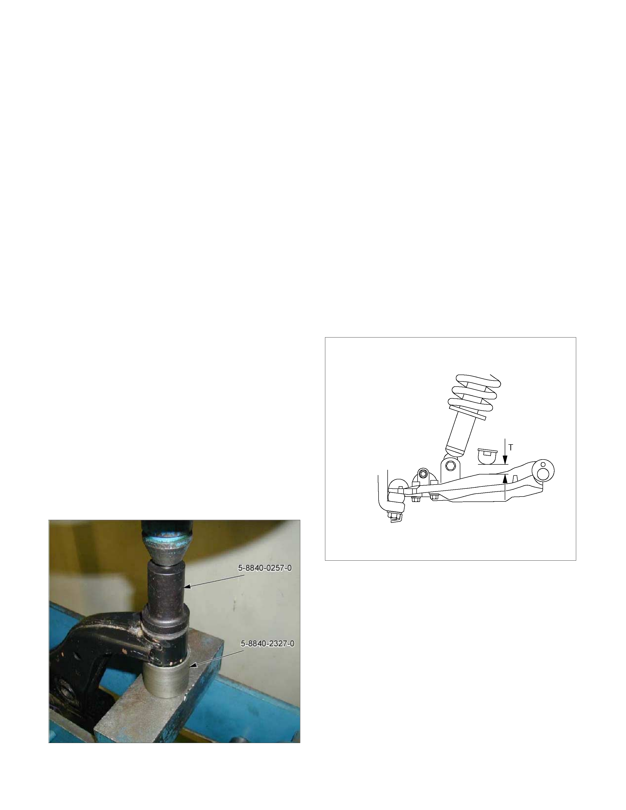
1. Install bushing by using installer 5-8840-0257-0
and 5-8840-2327-0.
P1010062
2. Install upper ball joint and tighten it to the spec ified
torque (9).
Torque: 31 N⋅
⋅⋅⋅m (3.2kg⋅
⋅⋅⋅m/23 lb ft)
3. Ins tall nut (6) and cotter pin then tighten the nut to
the specified torque, with just enough additional
torque to align cotter pin holes. Install new cotter
pin.
Torque: 98 N⋅
⋅⋅⋅m (10.0kg⋅
⋅⋅⋅m/72 lb ft)
4. Install upper control arm assembly.
5. Install bolt (1) and nut (3).
NOTE: Apply oil to the thread.
NOTE: Tighten the bolt (1) with the parts in the position
shown in the illustration below.
Buffer clearance: 25.9 mm (1.02 in)
Torque: 137 N⋅
⋅⋅⋅m (14.0kg⋅
⋅⋅⋅m/101 lb ft)
RTW340SH001301
6. Install nut (12).
7. Install nut (11).
Lower Control Arm
Lower Control Arm and Associated Parts
RTW340LF002301
Legend
(1) Cam bolt
(2) Bush
(3) Cam plate
(4) Nut
(5) Nut
(6) Bolt
(7) Lower Ball Joint
(8) Nut and cotter pin
(9) Nut
(10) Nut
(11) Bolt
Removal
1. Raise the vehicle and support the frame with
suitable safety stands.
2. Remove wheel and tyre assem bly. Refer to Wheel
in this section.
3. Remove the tie- rod end from the k nuckle. Refer to
Power Steering Unit in Steering section.4.
Support lower control arm with a jack.
5. Remove the nut (10).
6. Remove the nut (8).
7. Remove the shock absorber lower end from the
lower control arm.
8. Remove the lower ball joint from the lower control
arm.
9. Remove nut (4) and cam plate.
10. Remove cam bolt.
11. Remove lower control arm.
12. Remove bushing.
Inspection and Repair
Make necessary correction or parts replacement if
wear, damage, corrosion or any other abnormal
condition is found through inspection.
Check the following parts:
• Lower control arm
• Bushing
Installation
1. Install rear bushing by using installer 5-8840-
0257-0 and 5-8840-2327-0.
P1010063
2. Install lower control arm.
3. Install cam bolt.
4. Ins tall lower ball joint and tighten it to the specified
torque (9).
Torque: 127 N⋅
⋅⋅⋅m (12.9kg⋅
⋅⋅⋅m/94 lb ft)
5. Install shock absorber and tighten it to the
specified torque (5).
Torque: 137 N⋅
⋅⋅⋅m (14.0kg⋅
⋅⋅⋅m/101 lb ft)
NOTE: Apply oil to the thread.
6. Install Stabiliser link and tighten it to the specified
torque (10).
Torque: 50 N⋅
⋅⋅⋅m (5.1kg⋅
⋅⋅⋅m/37 lb ft)
7. Install nut (4) and cam plate and tighten lower link
nut finger-tight.
NOTE: Apply oil to the thread.
NOTE: Tighten the nut (4) with the parts in the position
shown in the illustration below.
Buffer clearance: 25.9 mm (1.02 in)
Torque: 186 N⋅
⋅⋅⋅m (19.0kg⋅
⋅⋅⋅m/137 lb ft)
RTW340SH001301
8. Install nut (8) and cotter pin then tighten the nut to
the specified torque, with just enough additional
torque to align cotter pin holes. Install new cotter
pin.
Torque: 147 N⋅
⋅⋅⋅m (15.0kg⋅
⋅⋅⋅m/108 lb ft)
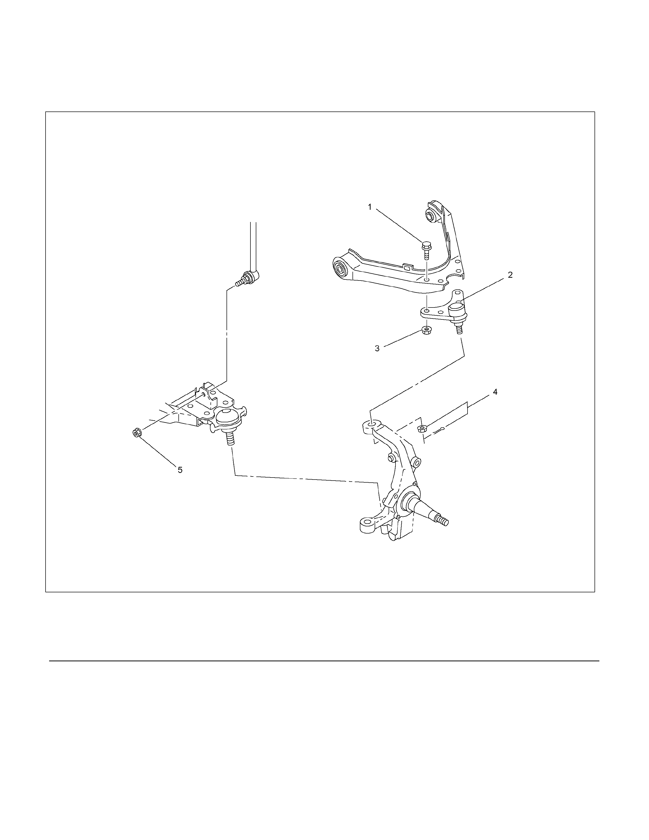
Upper Ball Joint
Upper Ball Joint and Associated Parts
RTW340LF001101
Legend
(1) Bolt
(2) Upper Ball Joint
(3) Nut
(4) Nut and Cotter Pin
(5) Nut
Removal
1. Raise the vehicle and support the frame with
suitable safety stands.
2. Rem ove wheel and tyre assem bly. Refer to wheel
in this section.
3. Remove nut (5).
4. Remove upper ball joint nut and cotter pin, then
use remover 5-8840-2017-0 to remove the upper
ball joint from the knuckle.
CAUTION: Be careful not to damage the ball joint
boot and brake hose.
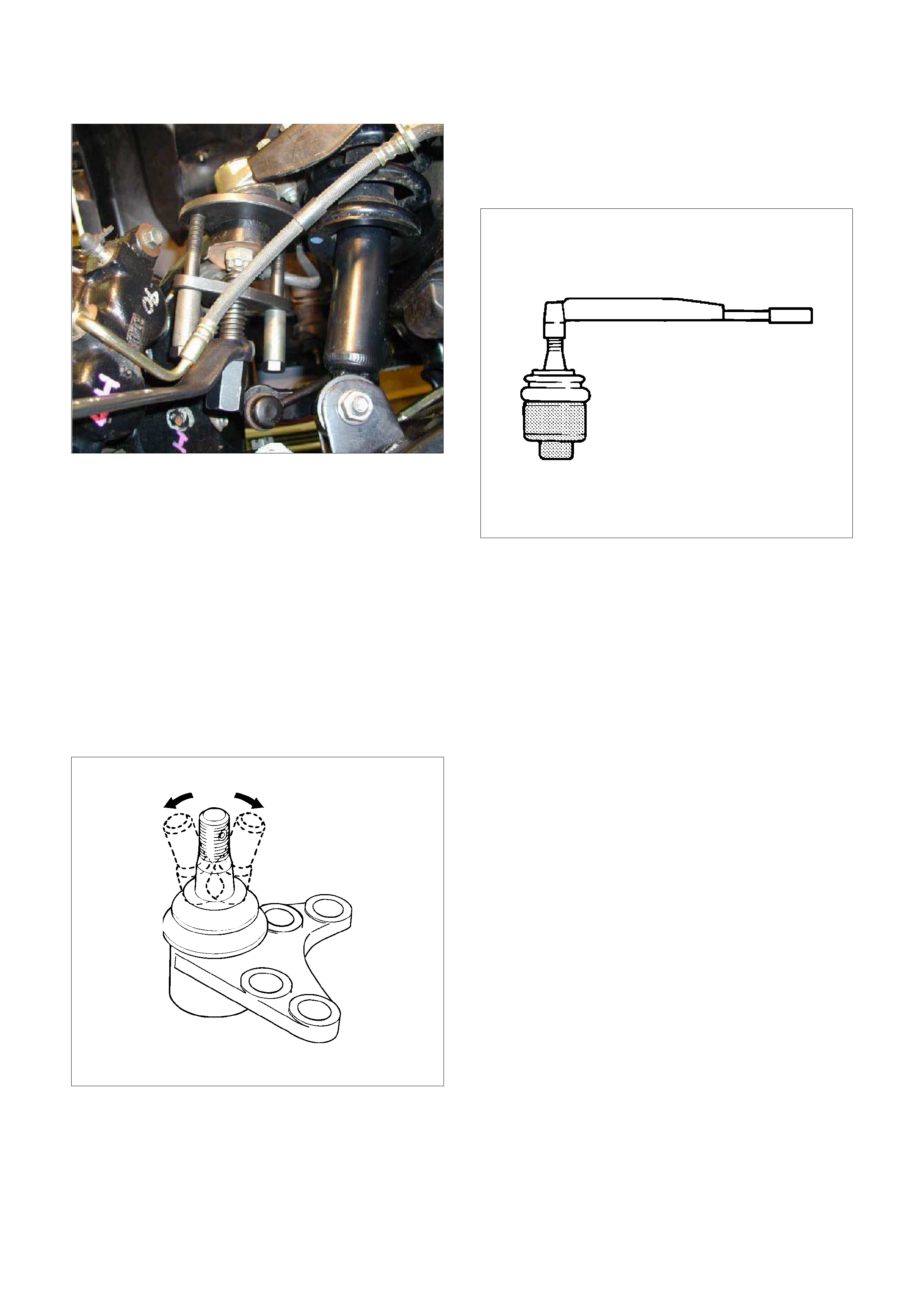
P1010005
5. Remove bolt (1) and nut (3).
6. Remove upper ball joint.
Inspe cti on an d Repa ir
Make necessary parts replacement if wear, damage,
corrosion or any other abnormal conditions are found
through inspection.
• Inspect the lower end boot for damage or grease
leak. Move the ball joint as shown in the figure to
confirm its norm al m ovement.
• Inspect screw/taper area of ball for damage.
• If any defects are found by the above inspections,
replace the ball jo int assembly with new one.
450R300030
• After moving the ball joint 4 or 5 times, attach nut
then measure the preload.
Starting torque: 1.3-3.2 N⋅
⋅⋅⋅m (0.13-0.33kg⋅
⋅⋅⋅
m/0.9-2.4 lb ft)
450RS024
If the above limits specified are exceeded, replace the
ball joint assembly.
Installation
1. Install upper ball joint.
2. Install bolt (1) and nut (3), then tighten them to the
specified torque.
Torque: 31N⋅
⋅⋅⋅m (3.2kg⋅
⋅⋅⋅m/23 lb ft)
3. Install nut and cotter pin, and then tighten the nut
to the specified torque with just enough additional
torque to align cotter pin holes. Install new cotter
pin (4).
Torque: 98 N⋅
⋅⋅⋅m (10.0kg ⋅
⋅⋅⋅m/72 lb ft)
4. Instal l nut (5), then tig hten to the specified torque.
Torque: 50 N⋅
⋅⋅⋅m (5.1kg ⋅
⋅⋅⋅m/37 lb ft)
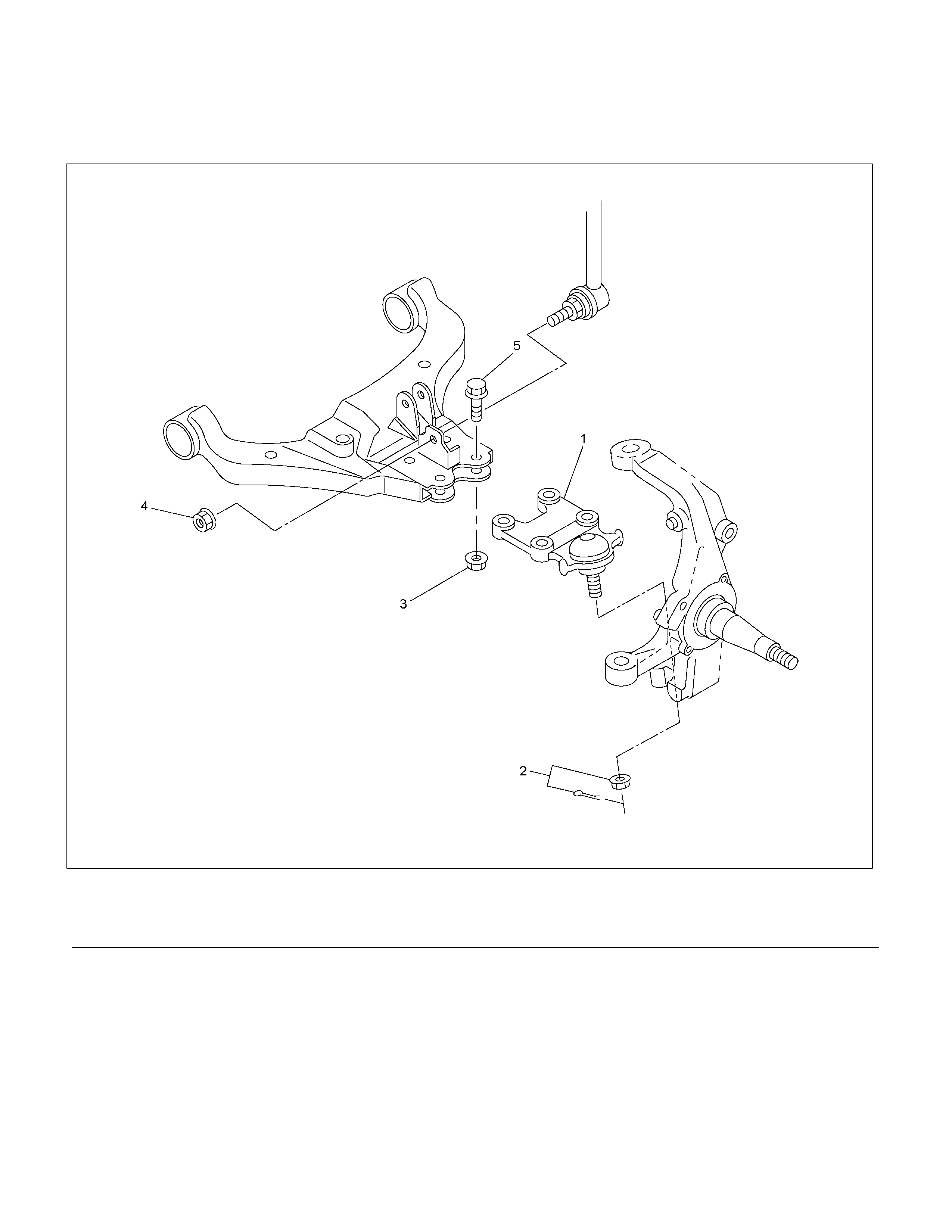
Lower Ball Joint
Lower Ball Joint and Associated Parts
RTW340LF002201
Legend
(1) Lower Ball Joint
(2) Nut and Cotter Pin
(3) Nut
(4) Nut
(5) Bolt
Removal
1. Raise the vehicle and support the frame with
suitable safety stands.
2. Remove wheel and tyre assem bly. Refer to Wheel
in this section.
3. Remove the nut (4).
4. Support lower control arm with a jack.
5. Remove lower ball joint nut and cotter pin, then
use remover 5-8840-2017-0 to remove the lower
ball joint from the knuckle.
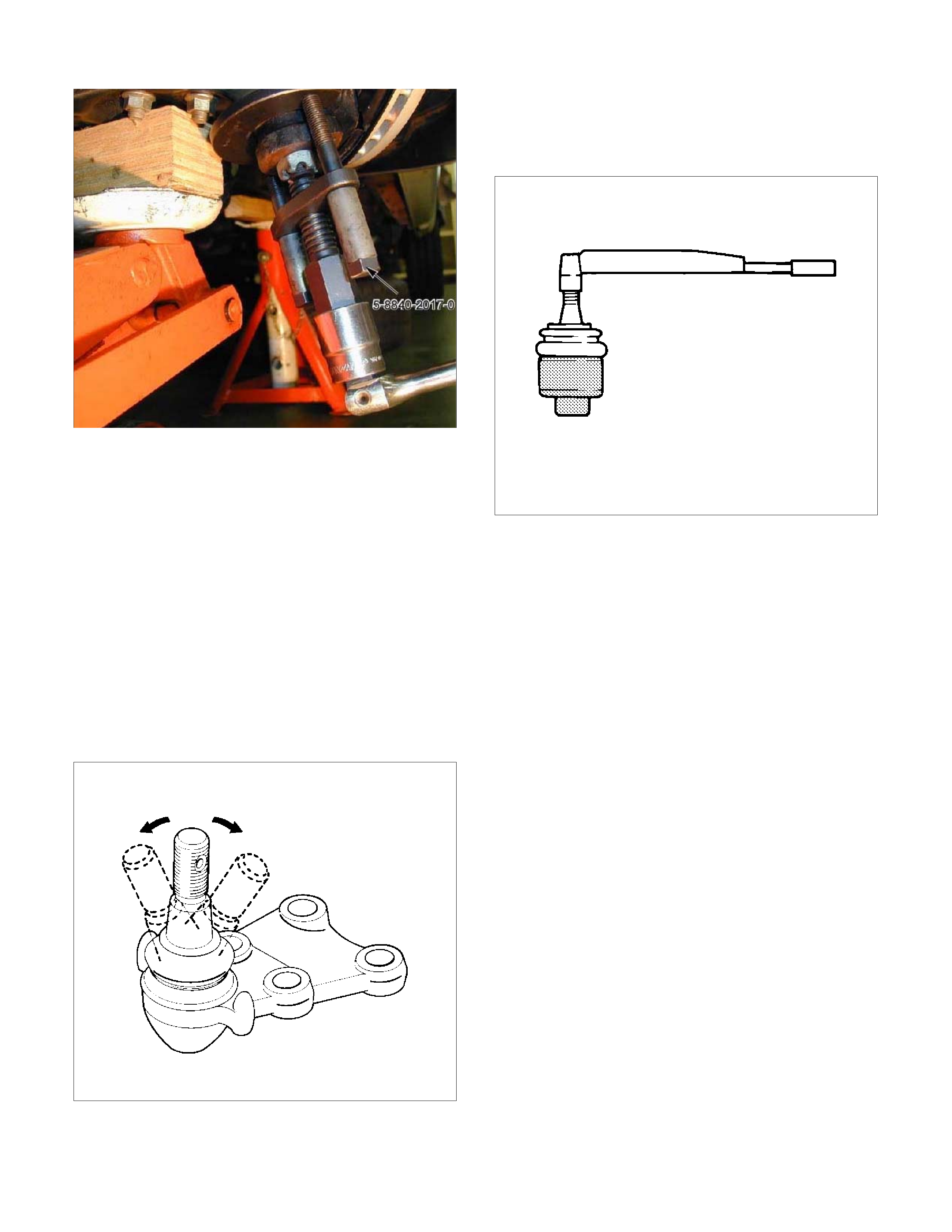
P1010003
6. Remove nut (3).
7. Remove bolt (5).
8. Remove lower ball joint.
Inspection and Repair
Make necessary parts replacement if wear, damage,
corrosion or any other abnormal condition are found
through inspection.
• Inspect the lower end boot for damage or grease
leak. Move the ball joint as shown in the figure to
confirm its normal movement.
• Inspect screw/taper area of ball for damage.
• If any defects are found by the above inspections,
replace the ball joint assembly with new one.
450RS026
•
A
fter moving the ball joint 4 or 5 times, attach nut
then measure the preload.
Starting torque: 2.5-6.4 N⋅
⋅⋅⋅m (0.26-0.65kg⋅
⋅⋅⋅m/1.9-
4.7 lb ft)
450RS024
• If the above lim its specif ied are exc eeded, replace
the ball joint assembly.
Installation
1. Install lower ball joint.
2. Install bolt (5).
3. Install nut (3) and tighten it to the specified torque.
Torque: 127 N⋅
⋅⋅⋅m (12.9kg⋅
⋅⋅⋅m/94 lb ft)
4. Install ball joint nut, then tighten it to the specified
torque with just enough additional torque to align
cotter pin holes. Install new cotter pin (2).
Torque: 147 N⋅
⋅⋅⋅m (15.0kg⋅
⋅⋅⋅m/108 lb ft)
5. Install nut (4), then tighten to the specified torque.
Torque: 50 N⋅
⋅⋅⋅m (5.1kg⋅
⋅⋅⋅m/37 lb ft)
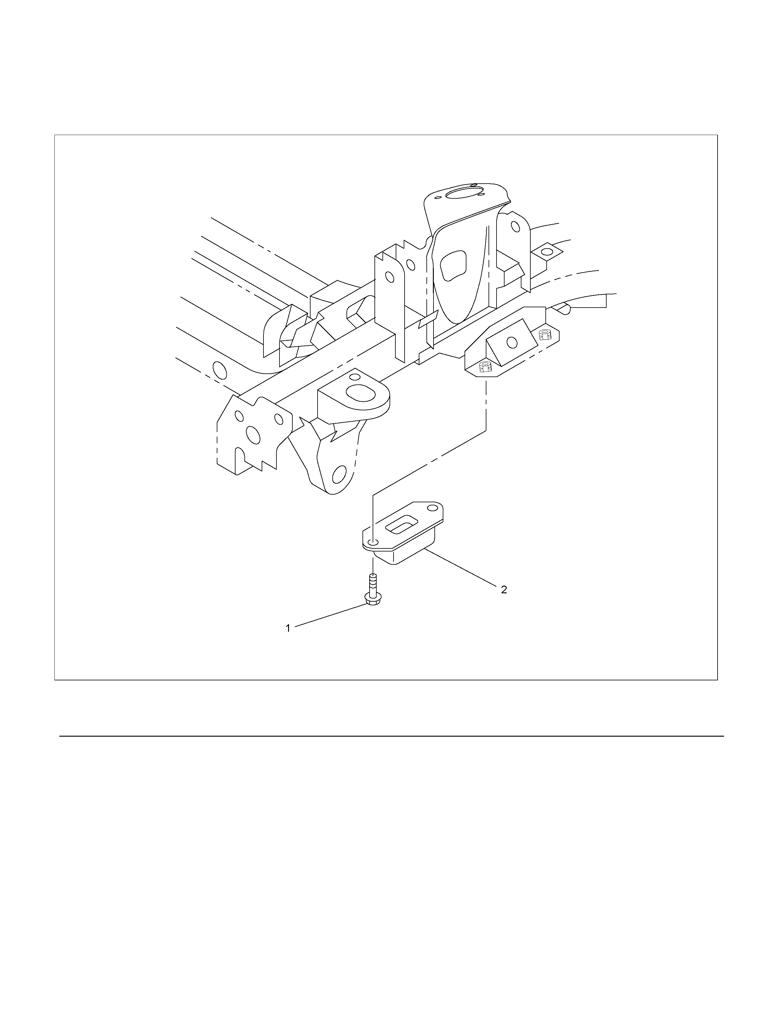
Bump Rubber
Bump Rubber and Associated Parts
RTW340LF002601
Legend
(1) Bolt
(2) Bump Rubber
Removal
1. Raise the vehicle and support the frame with
suitable safety stands.
2. Remove bolt.
3. Remove bump rubber.
Inspection and Repair
Make necessary correction or parts replacement if
wear, damage, corrosion or any other abnormal
condition are found through inspection.
Check the following parts :
• Bump Rubber
Installation
1. Install bump rubber.
2. Install bolt (1), then tighten it to the specified
torque.
Torque: 42 N⋅
⋅⋅⋅m (4.3kg⋅
⋅⋅⋅m/31 lb ft)
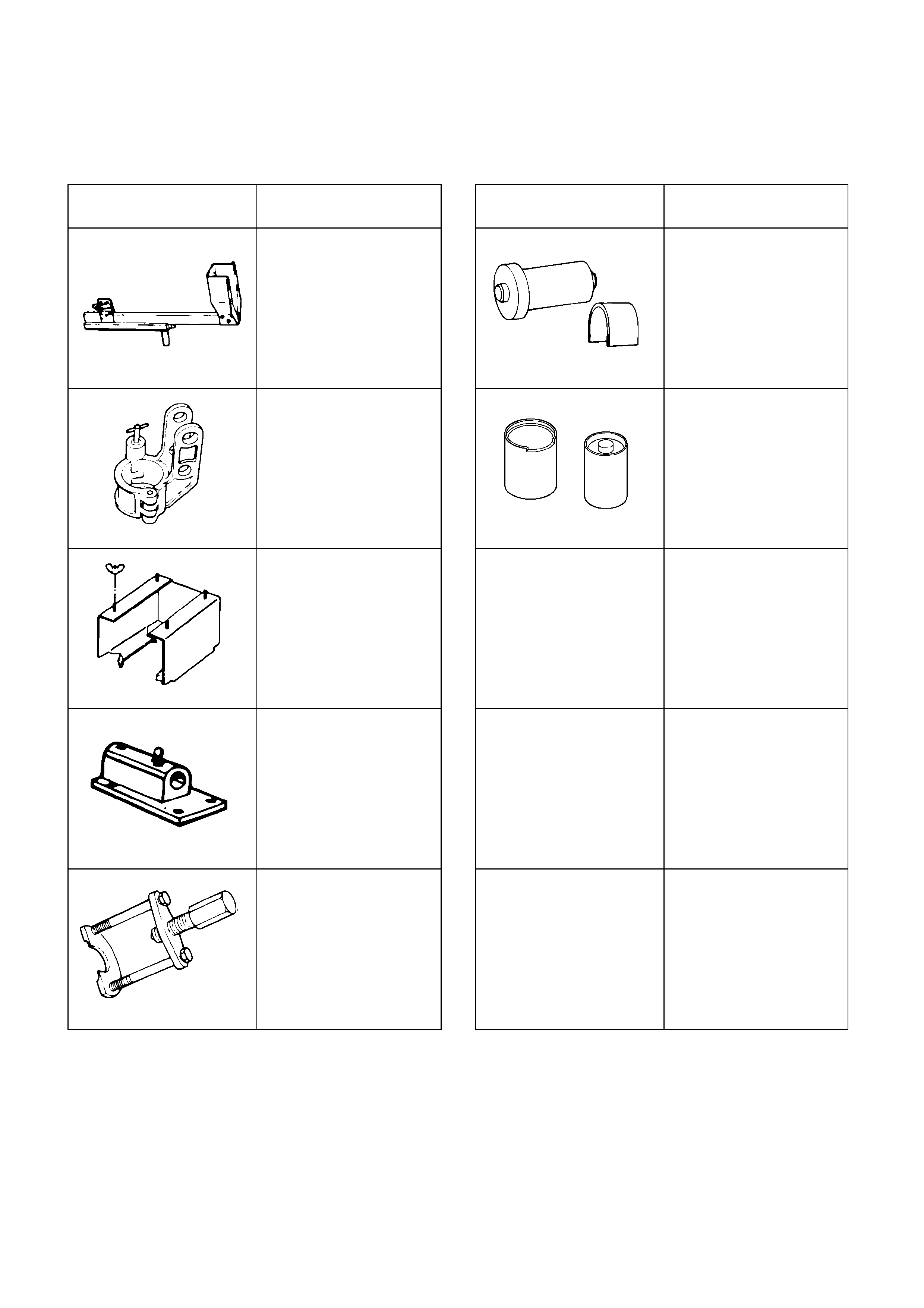
Special Tools
ILLUSTRATION PART NO.
PART NAME ILLUSTRATION PAR T NO.
PA RT NAME
5-8840-0595-0
Support; fixture
5-8840-0257-0
Installer; Upper and
lower arm bushing
5-8840-2828-0
Adapter; lower
5-8840-2327-0
Installer; Upper and
lower arm bushing
5-8840-2829-0
Adapter; Upper
5-8840-0003-0
Base
5-8840-2017-0
Ball joint remover