
Section 3C-2 - Front Suspension (4x2 High Ride
Suspension, 4x4)
Service Precaution
Shock Absorber
Shock Absorber and Associated Parts
Removal
Inspection and Repair
Installation
Stabilizer Bar
Stabilizer Bar and Associated Parts
Removal
Inspection and Repair
Installation
Torsion Bar
Torsion Bar and Associated Parts
Removal
Inspection and Repair
Installation
Knuckle
Knuckle and Associated Parts
Removal
Inspection and Repair
Installation
Upper Control Arm
Upper Control Arm and Associated
Parts
Removal
Inspection and Repair
Installation
Lower Control Arm
Lower Control Arm and Associated
Parts
Removal
Inspection and Repair
Installation
Upper Ball Joint
Upper Ball Joint and Associated Parts
Removal
Inspection and Repair
Installation
Lower Ball Joint
Lower Ball Joint and Associated Parts
Removal
Inspection and Repair
Installation
Bump Rubber
Bump Rubber and Associated Parts
Removal
Inspection and Repair
Installation
Special Tools

Service Precaution
WARNING: THIS VEHICLE HAS A SUPPLEMENTAL
RESTRAINT SYSTEM (SRS). REFER TO THE SRS
COMPONENT AND WIRING LOCATION VIEW IN
ORDER TO DETERMINE WHETHER YOU ARE
PERFORMING SERVICE ON OR NEAR THE SRS
COMPONENTS OR THE SRS WIRING. WHEN YOU
ARE PERFORMING SERVICE ON OR NEAR THE
SRS COMPONENTS OR THE SRS WIRING, REFER
TO THE SRS SERVICE INFORMATION. FAILURE TO
FOLLOW WARNINGS COULD RESULT IN
POSSIBLE AIR BAG DEPLOYMENT, PERSONAL
INJURY, OR OTHERWISE UNNEEDED SRS SYSTEM
REPAIRS.
CAUTION: Always use the correct fastener in the
proper location. When you replace a fastener, use
ONLY the exact part number for that application.
HOLDEN will call out those fasteners that require a
replacement after removal. HOLDEN will also call
out the fasteners that require thread lockers or
thread sealant. UNLESS OTHERWISE SPECIFIED,
do not use supplemental coatings (Paints, greases,
or other corrosion inhibitors) on threaded fasteners
or fastener joint interfaces. Generally, such
coatings adversely affect the fastener torque and
the joint clamping force, and may damage the
fastener. When you install fasteners, use the
correct tightening sequence and specifications.
Following these instructions can help you avoid
damage to parts and systems.
Shock Absorber
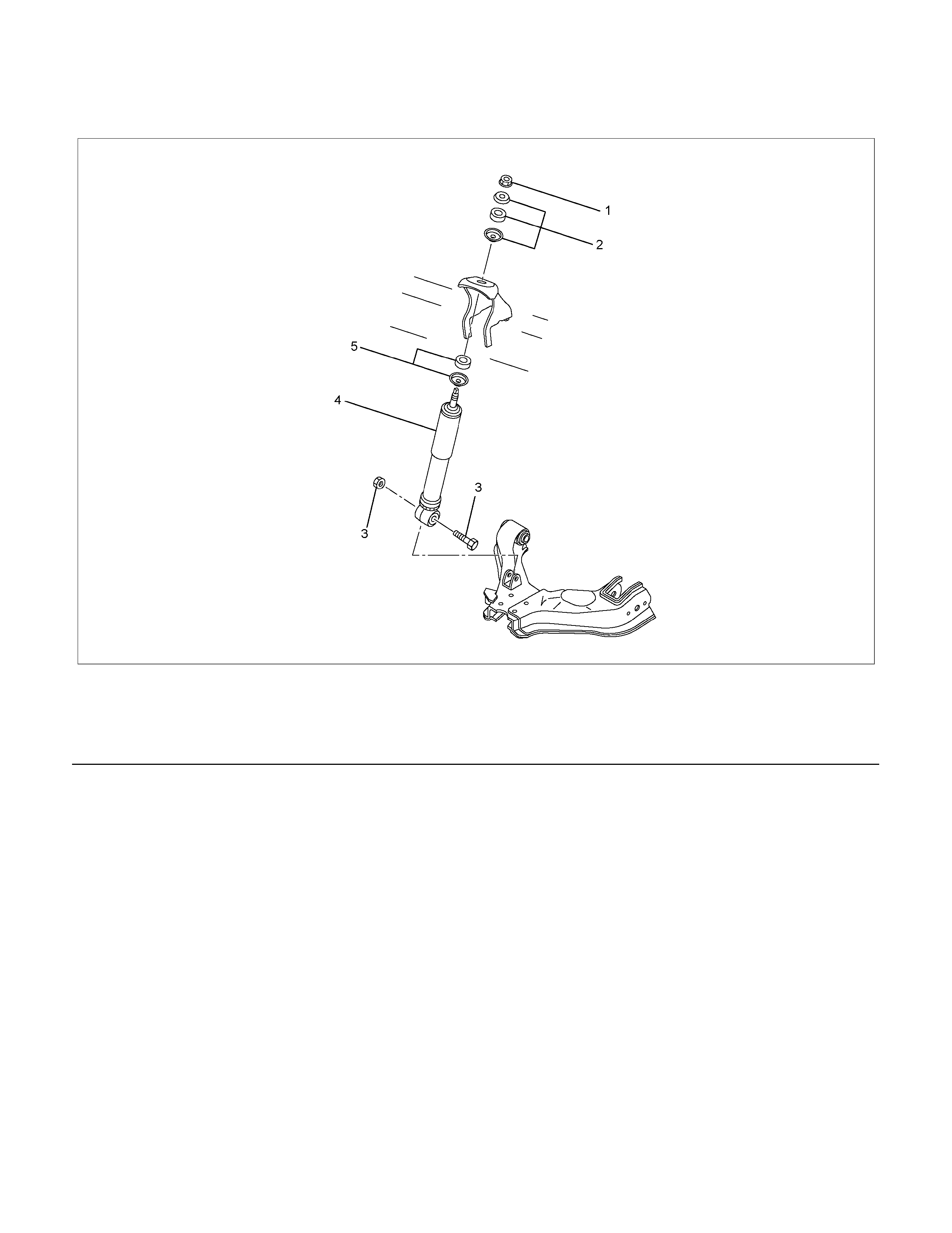
Shock Absorber and Associated Parts
RTW340MF000901
Legend
(1) Nut
(2) Rubber Bushing and Washer
(3) Bolt and Nut
(4) Shock Absorber
(5) Rubber Bushing and Washer
Removal
1. Raise the vehicle and support it with suitable
safety stands.
2. Remove wheel and tire assembly. Refer to Wheel
Replacement in this section.
3. Remove bolt and nut.
4. Remove nut.
5. Remove rubber bushing and washer.
6. Remove shock absorber.
7. Remove rubber bushing and washer.
Inspection and Repair
Make necessary correction or parts replacement if
wear, damage, corrosion or any other abnormal
conditions are found through inspection.
Check the following parts :
• Shock absorber
• Rubber bushing
Installation
1. Install rubber bushing and washer.
2. Install shock absorber.
3. Install rubber bushing and washer.
4. Install nut (1), then tighten it to the specified
torque.
Torque: 20 N⋅m (2.0kg⋅m/14 lb ft)
5. Install bolt and nut (3), then tighten to the specified
torque.
Torque: 93 N⋅m (9.5kg⋅m/69 lb ft)
Stabilizer Bar
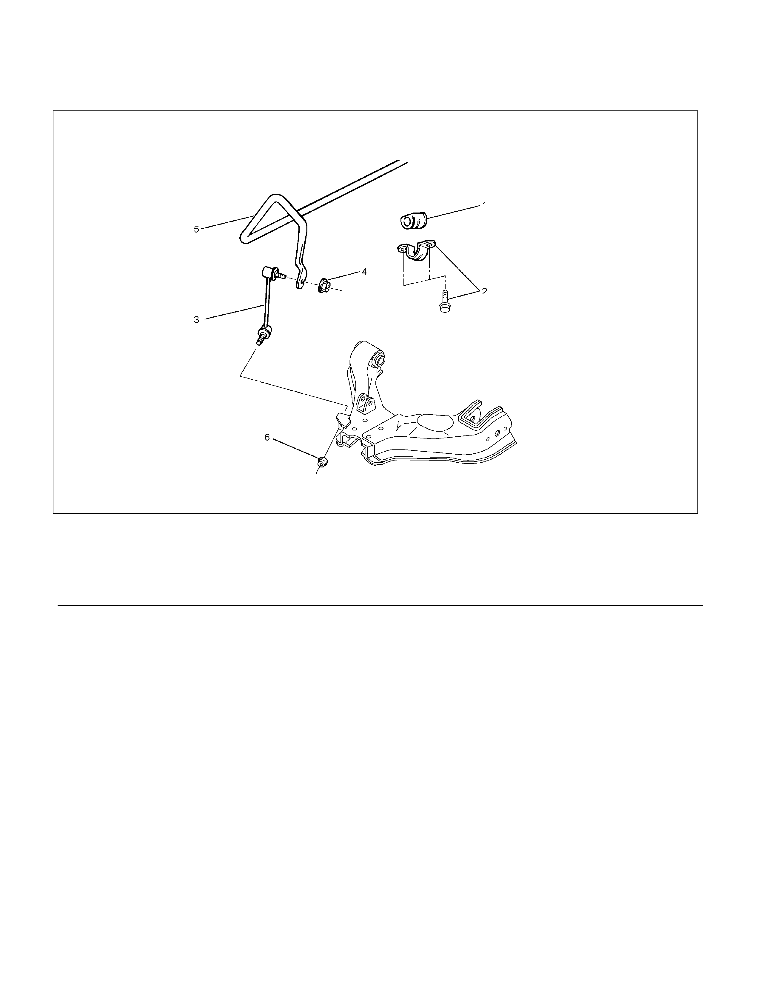
Stabilizer Bar and Associated Parts
RTW340MF000401
Legend
(1) Rubber Bushing
(2) Bracket and Bolt
(3) Link
(4) Nut
(5) Stabilizer Bar
(6) Nut

Removal
1. Raise the vehicle and support the frame with
suitable safety stands.
2. Remove the stone guard.
3. Remove wheel and tire assembly. Refer to Wheel
Replacement in this section.
4. Remove nut (4) and (6).
CAUTION: Be careful not to break the ball joint
boot.
5. Remove link.
6. Remove bracket.
7. Remove stabilizer bar.
8. Remove rubber bushing.
Inspection and Repair
Make necessary correction or parts replacement if
wear, damage, corrosion or any other abnormal
conditions are found through inspection.
Check the following parts :
• Stabilizer bar
• Rubber bushing
• Link ball joint
Installation
1. Install rubber bushing.
2. Install stabilizer bar.
3. Install bracket and bolt (2), then tighten it to the
specified torque.
Torque: 25 N⋅m (2.5kg⋅m/18 lb ft)
4. Install link.
5. Install nut (4), (6), then tighten it to the specified
torque.
Torque: 50 N⋅m (5.1kg⋅m/37 lb ft)
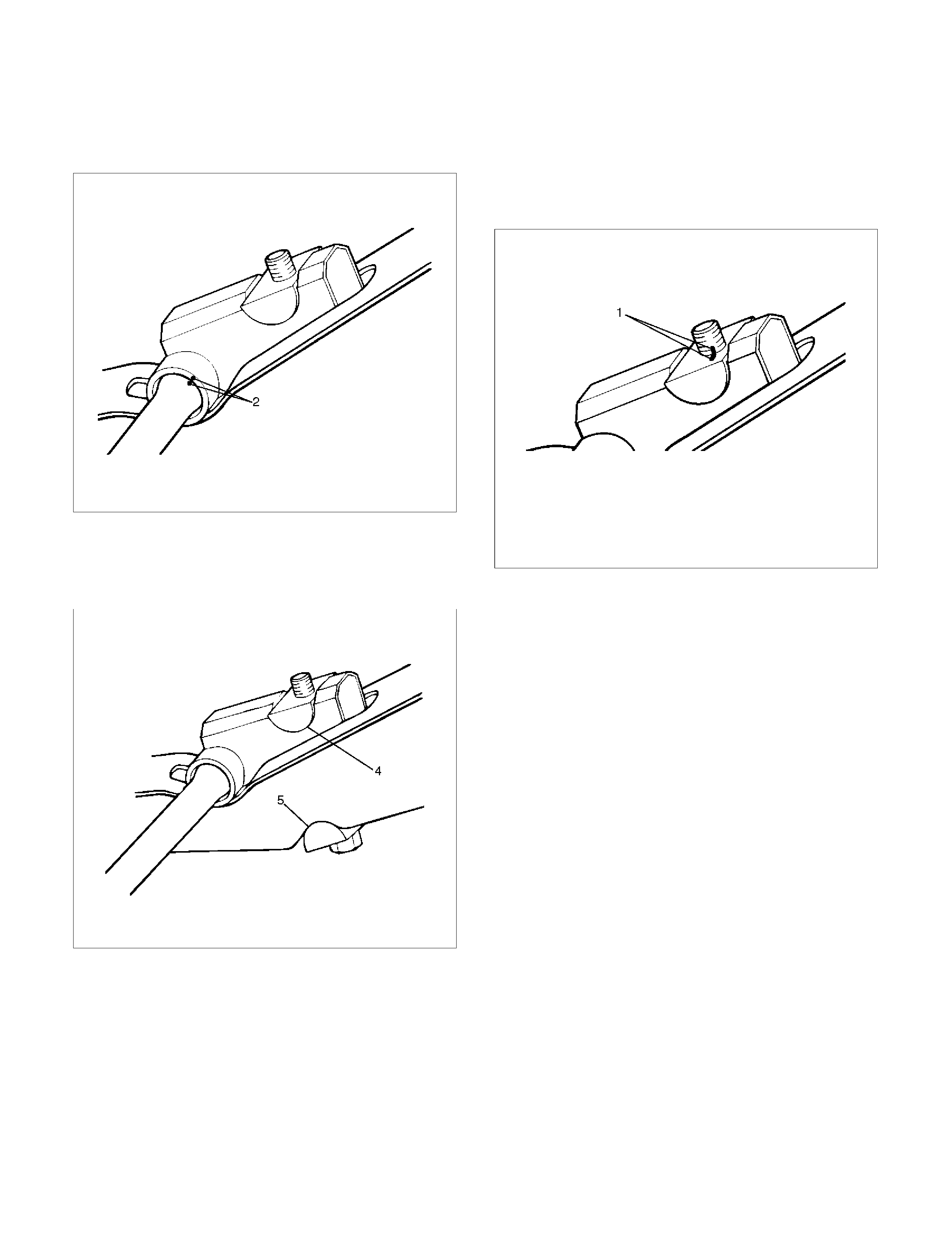
Torsion Bar
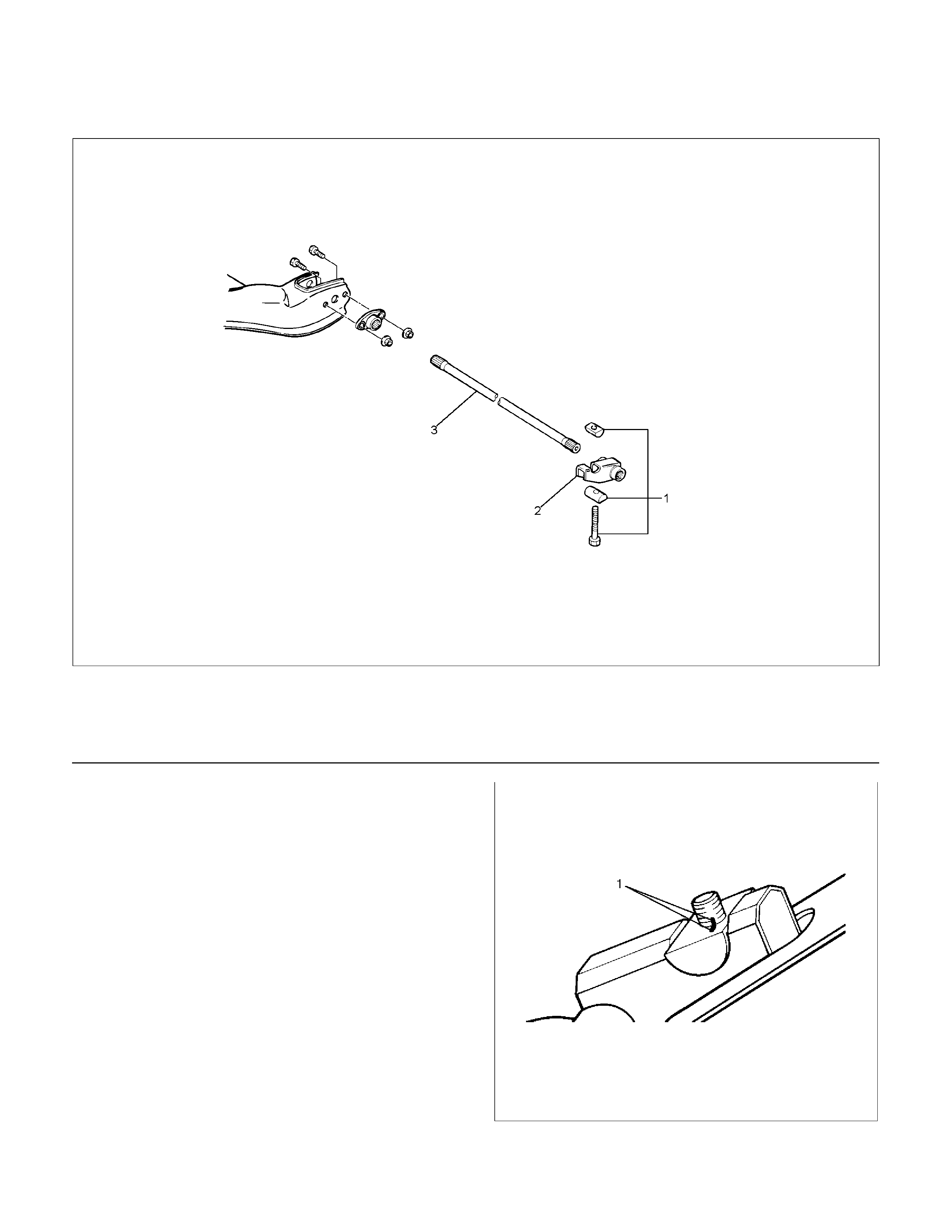
Torsion Bar and Associated Parts
RTW340MF000501
Legend
(1) Adjust Bolt, End Piece and Seat
(2) Height Control Arm
(3) Torsion Bar
Removal
1. Raise the vehicle and support the frame with
suitable safety stands.
2. Apply the setting marks (1) to the adjust bolt and
end piece, then remove adjust bolt, end piece and
seat.
410RS004
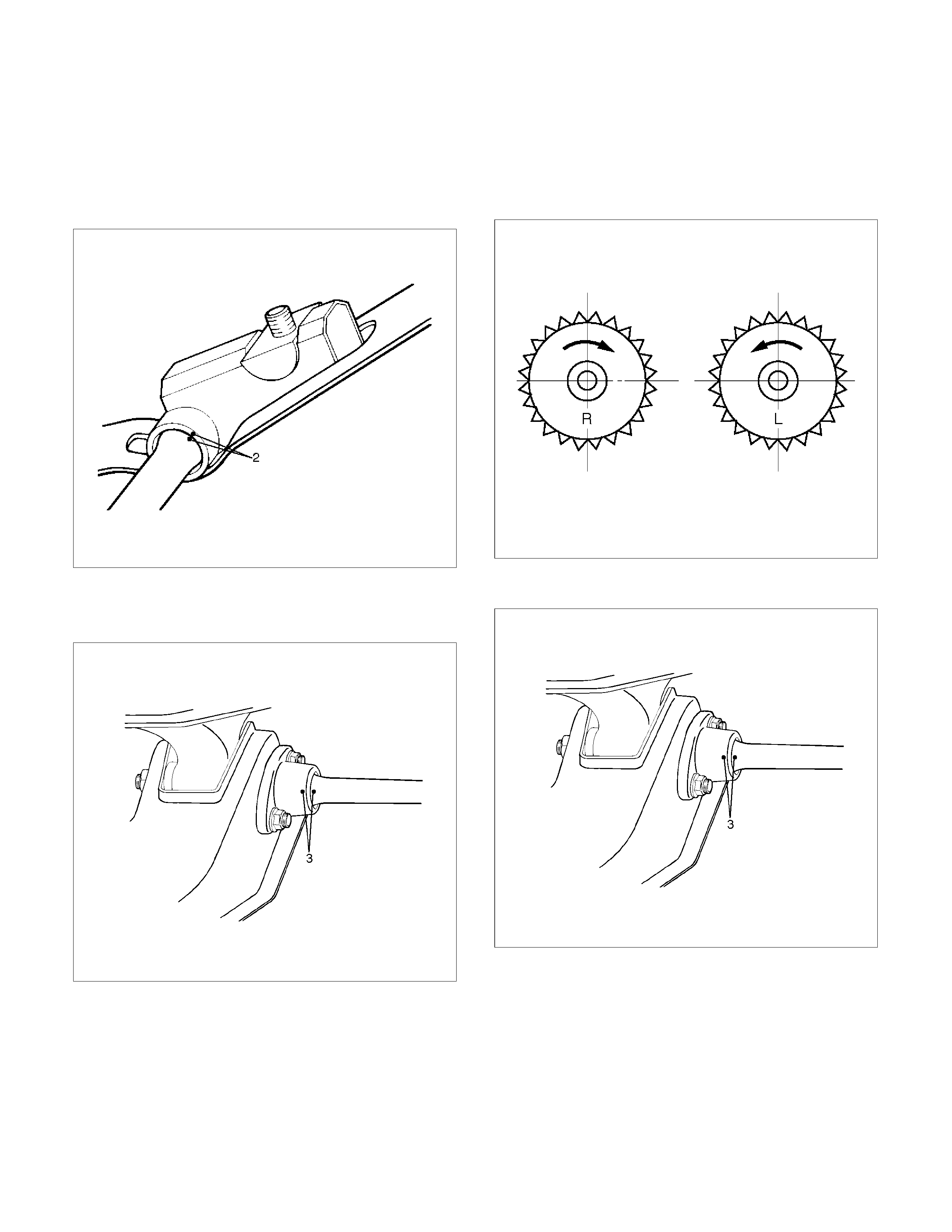
3.
A
pply the setting marks (2) to the height control
arm and torsion bar, then remove height control
arm.
NOTE: “Besco chassis grease” shall be applied on
contact area of height control arm with frame.
(RH & LH Both side)
410RS005
4. Apply the setting marks (3) to the torsion bar and
lower control arm, then remove torsion bar.
RTW340SH000301
Inspection and Repair
Make necessary correction or parts replacement if
wear, damage, corrosion or any other abnormal
conditions are found through inspection.
Check the following parts:
• Torsion bar
• Height control arm
• Adjust bolt
• Rubber seat
Installation
1.
A
pply grease to the serrated portions, then install
torsion bar. Make sure the bars are on thei
r
correct respective sides and align the setting
marks (3).
410RS007
RTW340SH000301
2. Apply grease to the portion that fits into the
bracket then install height control arm and align
the setting marks (2).
410RS005
3. Apply grease to the bolt portion of the end piece
(4). Apply grease to the portion of the seat (5) that
fits into the bracket.
410RS008
4. Apply grease to the serrated portions.
5. Install adjust bolt and seat, then turn adjust bolt to
the setting mark (1) applied during disassembly.
NOTE: Adjust the trim height. Refer to Front End
Alignment Inspection and Adjustment in Steering
section.
410RS004
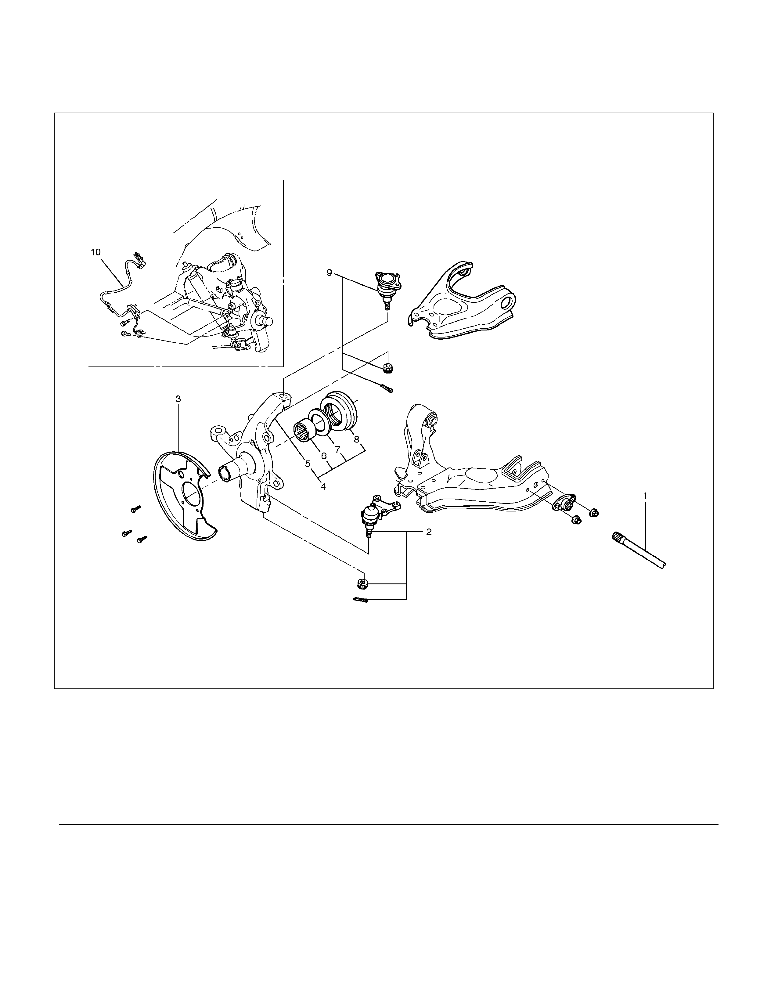
Knuckle
Knuckle and Associated Parts
RTW340LF001301
Legend
(1) Torsion Bar
(2 )Lower Ball Joint, Nut and Cotter Pin
(3) Back Plate
(4) Knuckle Assembly
(5) Knuckle
(6) Needle Bearing (4×4 Model Only)
(7) Thrust Washer (4×4 Model Only)
(8) Oil Seal (4×4 Model Only)
(9) Upper Ball Joint, Nut and Cotter Pin
(10) Speed Sensor harness
Removal
1. Raise the vehicle and support the frame with
suitable safety stands.
2. Remove wheel and tire assembly. Refer to Wheel
in this section.
3. Remove the brake caliper. Refer to Disc Brakes
in Brake section.
4. Remove the hub assembly. Refer to Front Hub
and Disc in this section.
5. Remove tie-rod end from the knuckle. Refer to
Power Steering Unit in Steering section.
6. Remove the speed sensor from the knuckle.
7. Loosen torsion bar, by removing height control
arm adjust bolt, then remove torsion bar. Refer to
Torsion Bar in this section.
8. Remove speed sensor harness.
9. Remove back plate.
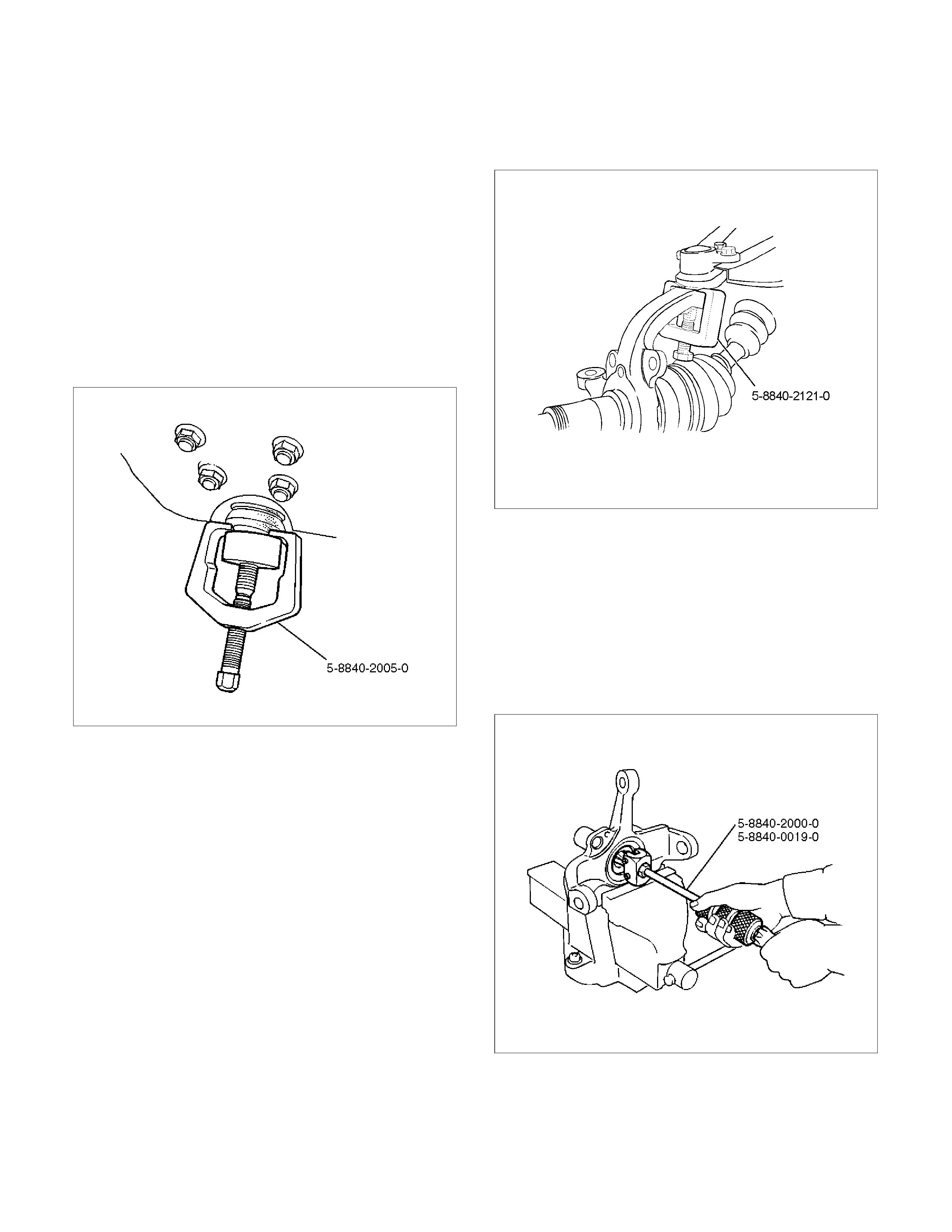
10. Remove lower ball joint by using remover 5-8840-
2005-0.
CAUTION: Be careful not to damage the ball joint
boot.
901RW271
11. Remove upper ball joint by using remover 5-8840-
2121-0.
CAUTION: Be careful not to damage the ball joint
boot.
901RW272
12. Remove knuckle assembly.
13. Remove oil seal. If replacement required.
(4×4 Model Only)
14. Remove thrust washer. If replacement required.
(4×4 Model Only)
15. Remove needle bearing by using remover 5-8840-
2000-0 and sliding hammer 5-8840-0019-0.
If replacement required. (4×4 Model Only)
(4×4 Model Only)
RTW340SH00401
Inspection and Repair
Make necessary correction or parts replacement if
wear, damage, corrosion or any other abnormal
conditions are found through inspection.
Check the following parts:
• Knuckle
• Knuckle arm
• Thrust washer (4×4 Model Only)
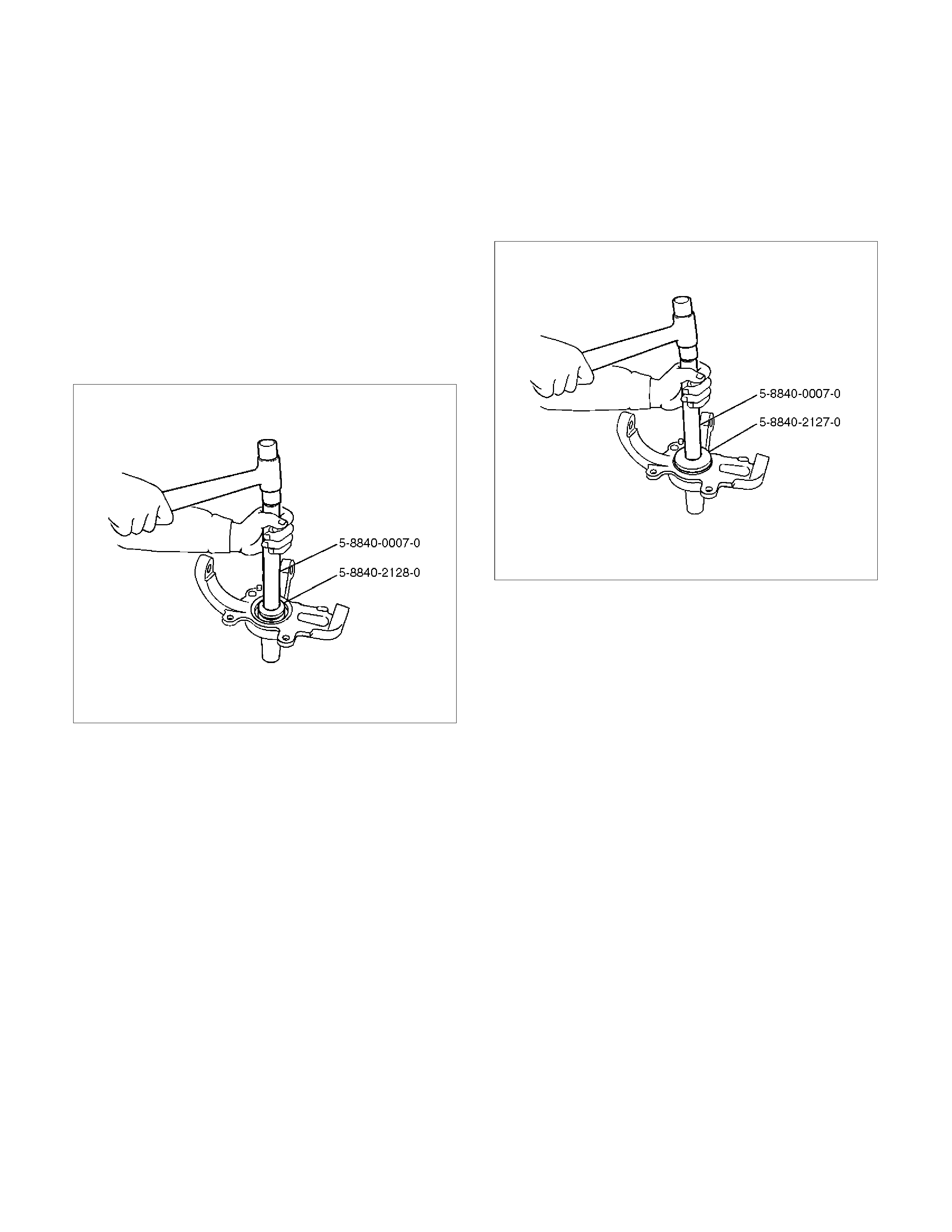
Installation
1.
A
pply appropriate amount of multipurpose type
grease to the new bearing (Approx. 5 g) and
install needle bearing by using installer 5-8840-
2128-0 and grip 5-8840-0007-0. (4×4 Model Only)
(4×4 Model Only)
901RW275
2.
A
pply multipurpose type grease to the thrust
washer, and install washer with chamfered side
facing knuckle. (4×4 Model Only)
3. Use a new oil seal, and apply multipurpose type
grease to the area surrounded by the lip (approx.
2 g). Then use installer 5-8840-2127-0 and grip 5-
8840-0007-0 to install oil seal. After fitting the oil
seal to the installer, drive it to the knuckle using a
hammer or bench press until the tool front face
contacts with the thrust washer. (4×4 Model Only)
(4×4 Model Only)
901RW274
4. Install knuckle assembly.
5. Install upper ball joint and tighten the nut to the
specified torque, with just enough additional
torque to align cotter pin holes. Install new cotte
r
pin (9).
Torque: 98 N⋅m (10.0kg⋅m/72 lb ft)
6. Install lower ball joint and tighten the nut to the
specified torque, with just enough additional
torque to align cotter pin holes. Install new cotte
r
pin (2).
Torque: 147 N⋅m (15.0kg⋅m/108 lb ft)
7. Install back plate.
8. Install speed sensor harness.
9. Install torsion bar. Refer to Torsion Bar in this
section.
NOTE: Adjust the trim height. Refer to Front End
Alignment Inspection and Adjustment in Steering.
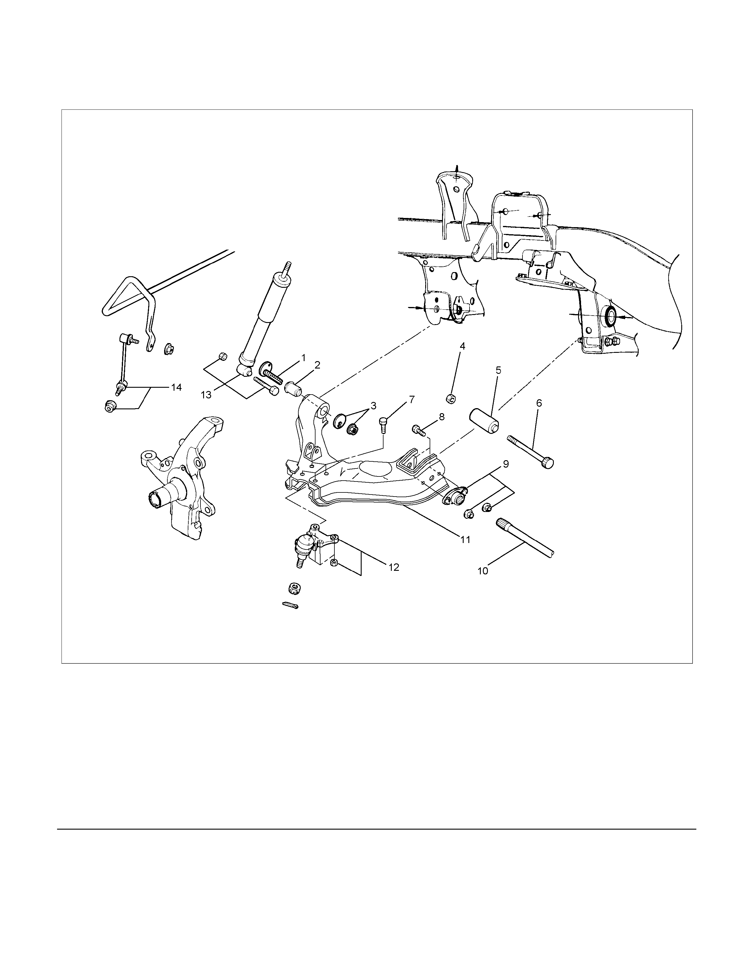
Upper Control Arm
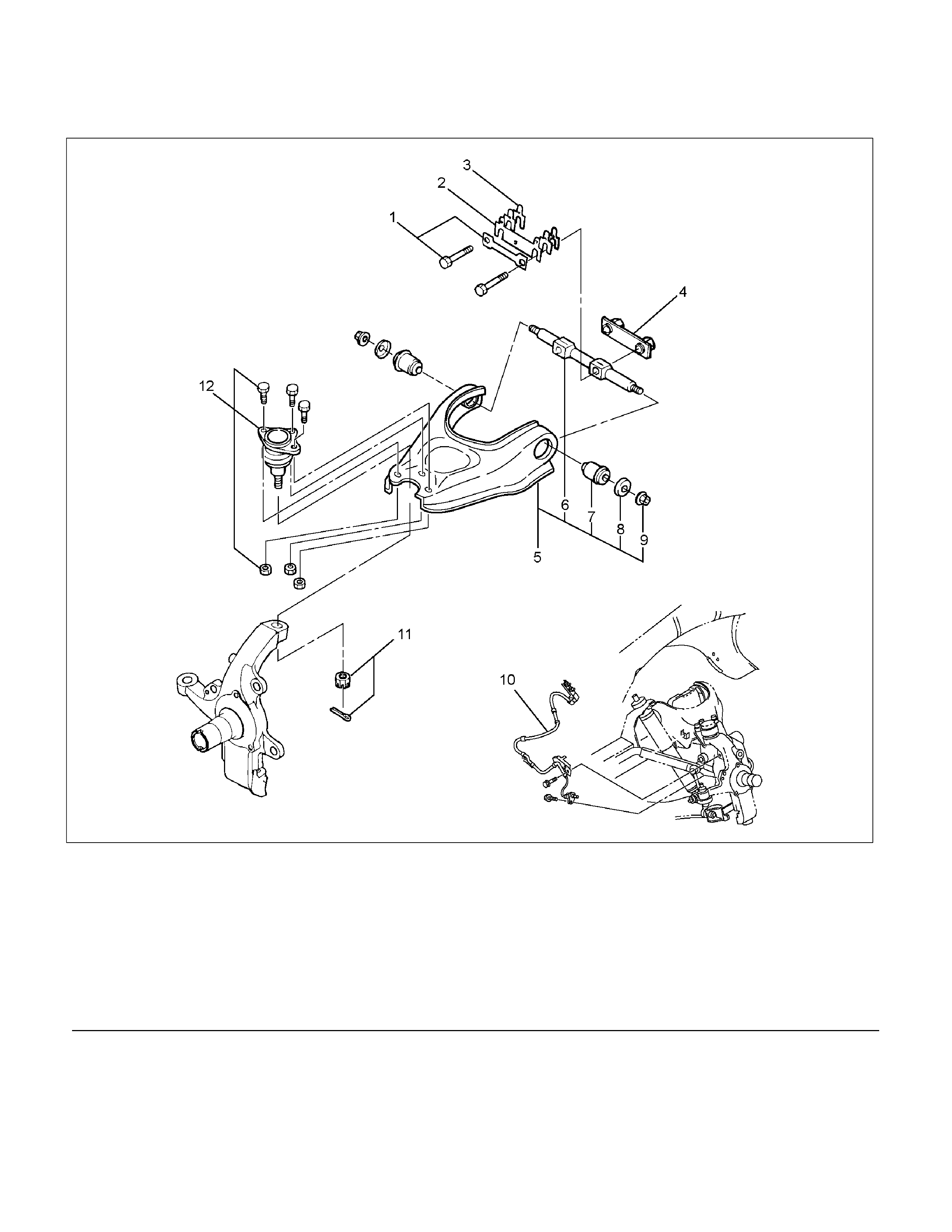
Upper Control Arm and Associated Parts
RTW440LF001301
Legend
(1)Bolt and Plate
(2)Camber Shims
(3)Caster Shims
(4)Nut Assembly
(5)Upper Control Arm Assembly
(6)Fulcrum Pin
(7)Bushing
(8)Plate
(9)Nut
(10)Speed Sensor harness
(11)Nut and Cotter Pin
(12)Upper Ball Joint, Bolt and Nut
Removal
1. Raise the vehicle and support the frame with
suitable safety stands.
2. Remove wheel and tire assembly. Refer to Wheel
in this section.
3. Remove the brake caliper and disconnect brake
pipe. Refer to Disc Brakes in Brake section.
4. Support lower control arm with a harness.
5. Remove speed sensor harness.
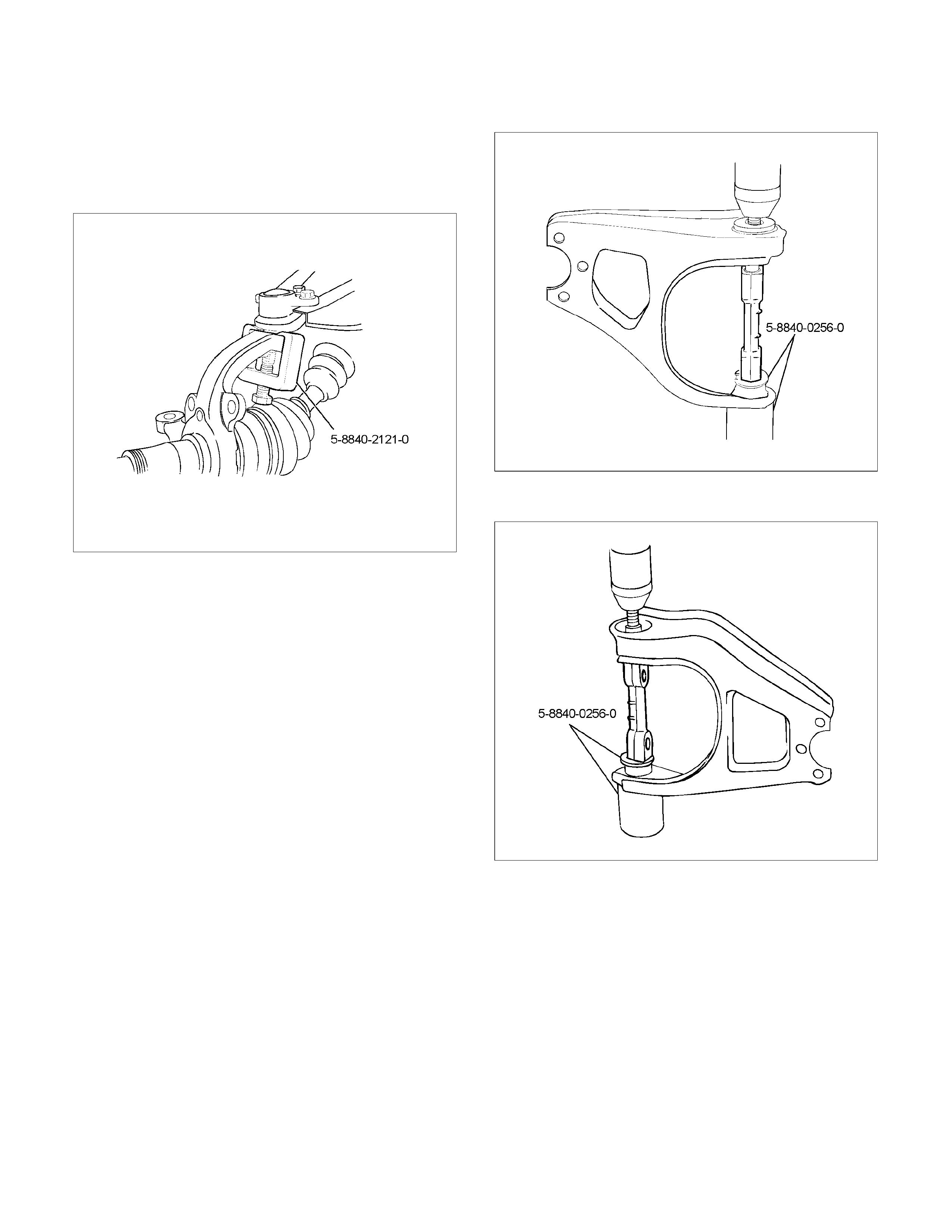
6. Remove nut and cotter pin then remove knuckle
using remover 5-8840-2121-0.
CAUTION: Be careful not to damage the ball joint
boot.
RTW340SH000401
7. Remove upper ball joint.
8. Remove bolt and plate.
9. Remove nut assembly.
10. Remove camber shims and note the positions and
number of shims.
11. Remove caster shims and note the positions and
number of shims.
12. Remove upper control arm assembly.
13. Remove nut (9).
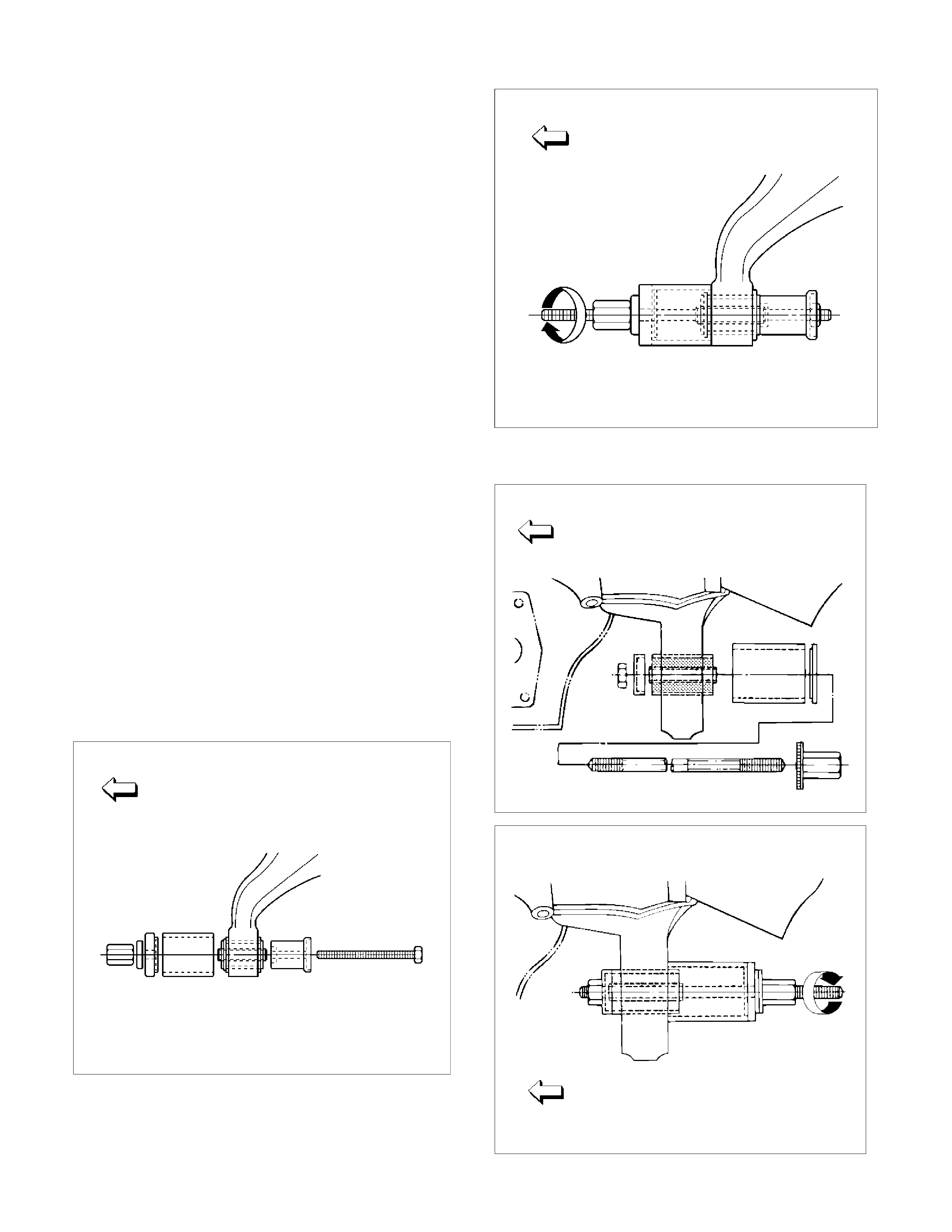
14. Remove plate (8).
15. Remove bushing (7) by using remover 5-8840-
0256-0.
RTW340SH000501
RTW340SH000601
16. Remove fulcrum pin (6).
Inspection and Repair
Make necessary parts replacement if wear, damage,
corrosion or any other abnormal conditions are found
through inspection.
Check the following parts:
• Upper control arm
• Bushing
• Fulcrum pin
Installation
1. Install fulcrum pin.
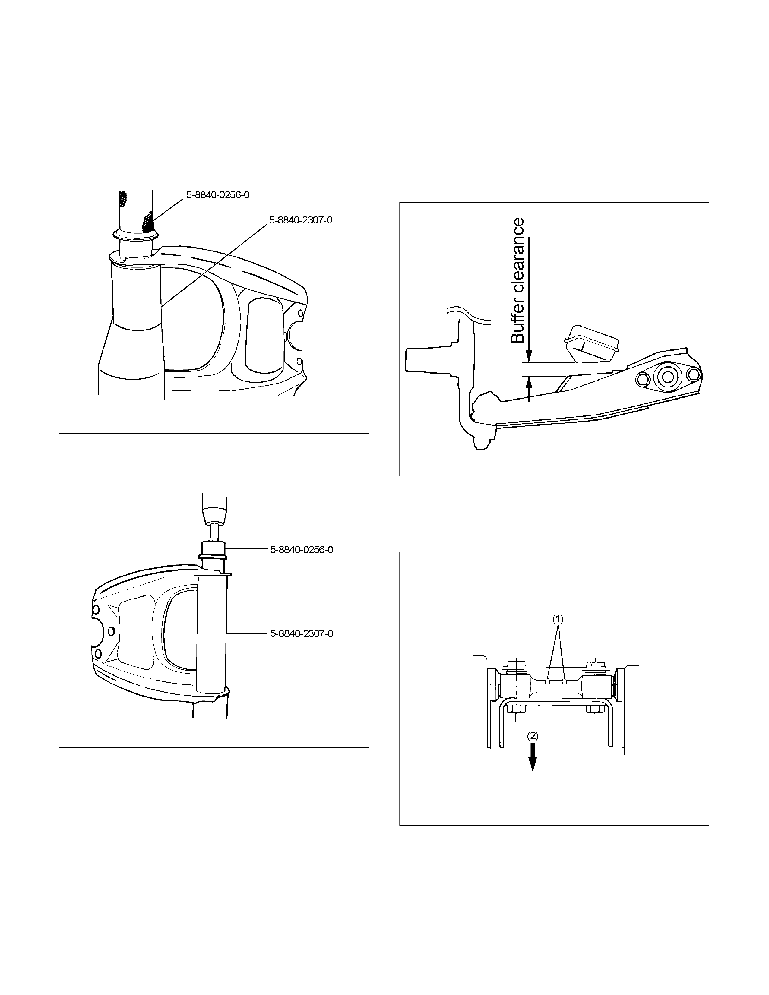
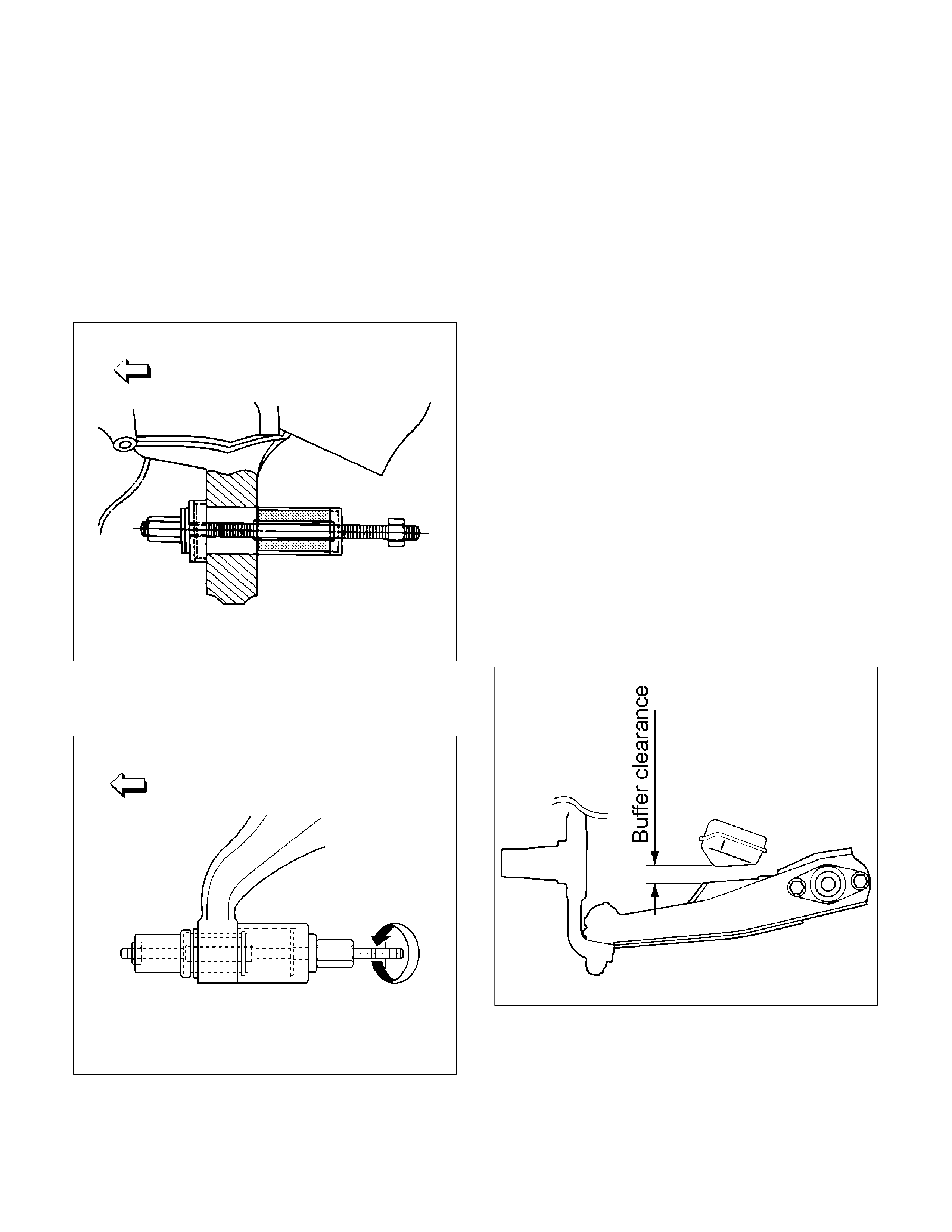
2. Install bushing by using installer 5-8840-0256-0
and 5-8840-2307-0.
RTW340SH000701
RTW340SH000801
3. Install upper ball joint and tighten it to the specified
torque (12).
Torque: 57 N⋅m (5.8kg⋅m/42 lb ft)
4. Install nut and cotter pin then tighten the nut to the
specified torque, with just enough additional
torque to align cotter pin holes. Install new cotte
r
pin (11).
Torque: 98 N⋅m (10.0kg⋅m/72 lb ft)
5. Install plate (8).
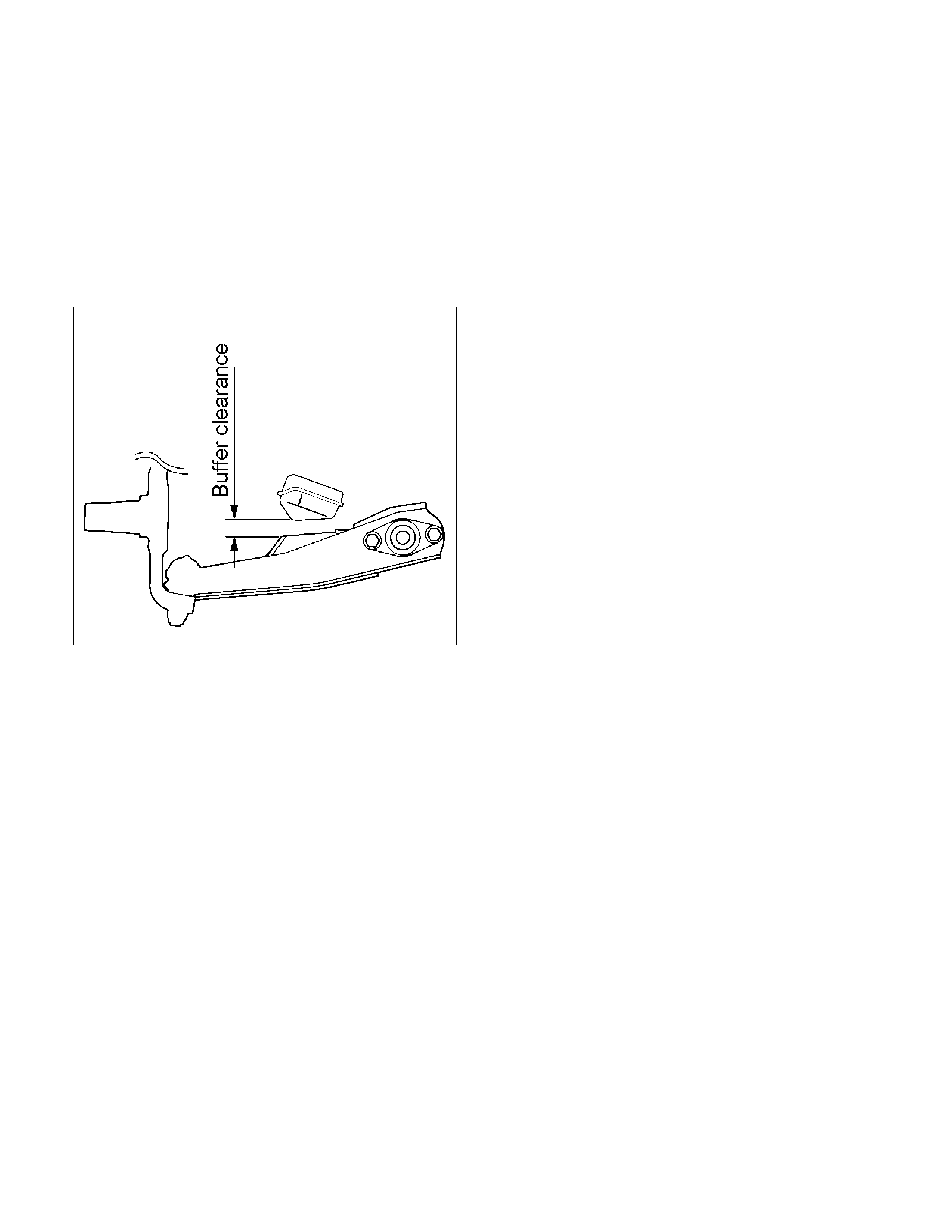
6. Install nut (9) and tighten fulcrum pin nut finger-
tight.
NOTE: Apply oil to the thread.
NOTE: Tighten the nut with the parts in the position
shown in the illustration below.
Buffer clearance: 29.7 mm (1.17 in)
Torque: 108 N⋅m (11.0kg⋅m/80 lb ft)
450R100002
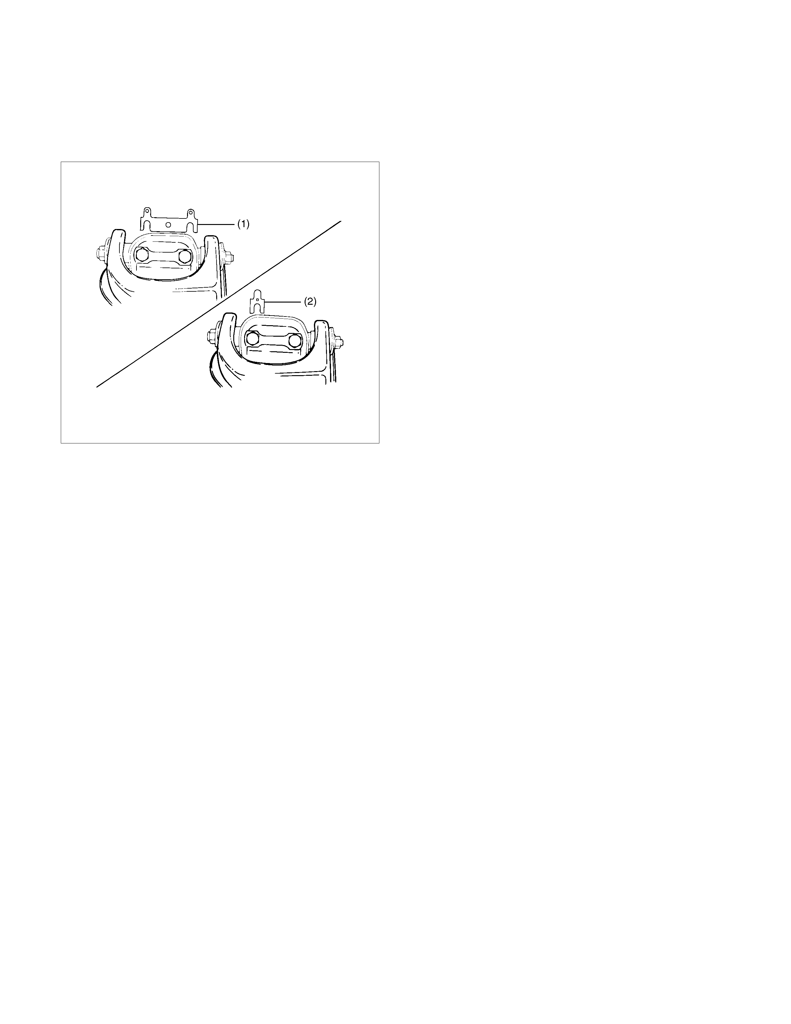
7. Install upper control arm assembly with the
fulcrum pin projections turned inward.
RTW340SH000901
Legend
(1) Projection
(2) Outward
8. Install the caster shims (2) between the chassis
frame and fulcrum pin.
9. Install the camber shims (1) between the chassis
frame and fulcrum pin.
450R100004
10. Install nut assembly.
11. Install bolt and plate (1), then tighten the bolt to
the specified torque.
Torque: 152 N⋅m (15.5kg⋅m/112 lb ft)
NOTE: Apply oil to the thread.
12. Install speed sensor harness.
Lower Control Arm
Lower Control Arm and Associated Parts
RTW33CLF000201
Legend
(1) Cam Bolt
(2)Bush, Front
(3) Cam Plate and Nut
(4) Nut, Rear
(5) Bush, Rear
(6) Bolt, Rear
(7) Bolt, Lower Ball Joint
(8) Bolt, Torsion Bar Arm
(9) Torsion Bar Arm Bracket and Nut
(10) Torsion Bar
(11) Lower Control Arm
(12) Lower Ball Joint and Nut
(13) Shock Absorber, Bolt and Nut
(14) Stabilizer Link and Nut
Removal
1. Raise the vehicle and support the frame with
suitable safety stands.
2. Remove wheel and tire assembly. Refer to Wheel
in this section.
3. Remove the tie-rod end from the knuckle. Refer to
Power Steering Unit in Steering section.
4. Remove the retaining ring from the front axle drive
shaft to release the shaft from hub. Refer to
Front Hub and Disc in Driveline/Axle section.
5. Support lower control arm with a jack.
6. Remove cam plate and nut.
7. Remove rear nut.
8. Remove torsion bar, refer to Torsion Bar in this
section.
9. Remove torsion bar arm bracket.
10. Disconnect the stabilizer link at the lower control
arm.
11. Remove the shock absorber lower end from the
lower control arm.
12. Remove the lower ball joint from the lower control
arm.
13. Remove cam bolt.
14. Remove rear bolt.
15. Remove lower control arm.
16. Remove torsion bar arm bolt.
17. Remove lower ball joint bolt.
18. Remove front bushing by using remover 5-8840-
2123-0.
Front
901RW154
Front
901RW155
19. Remove rear bushing by using remover 5-8840-
2124-0.
Front
901RW051
Front
901RW052
Inspection and Repair
Make necessary correction or parts replacement if
wear, damage, corrosion or any other abnormal
conditions are found through inspection.
Check the following parts:
• Lower control arm
• Bushing
Installation
1. Install rear bushing by using installer 5-8840-
2124-0.
Front
901RW053
2. Install front bushing by using installer 5-8840-
2123-0.
Front
901RW156
3. Install lower ball joint bolt.
4. Install torsion bar arm bolt.
5. Install lower control arm.
6. Install rear bolt.
7. Install cam bolt the hole and projection are
upward.
8. Install lower ball joint and tighten it to the specified
torque (12).
Torque: 127 N⋅m (12.9kg⋅m/94 lb ft)
9. Install shock absorber and tighten it to the
specified torque (13).
Torque: 93 N⋅m (9.5kg⋅m/69 lb ft)
10. Install stabilizer link and tighten it to the specified
torque (14).
Torque: 50 N⋅m (5.1kg⋅m/37 lb ft)
11. Install torsion bar arm bracket and tighten it to the
specified torque.
Torque: 116 N⋅m (11.8kg⋅m/85 lb ft)
12. Install Torsion bar, refer to Torsion Bar in this
section.
13. Install rear nut and tighten lower link nut finger-
tight (4).
NOTE: Apply oil to the thread.
NOTE: Tighten the nut or bolt with the parts in the
position shown in the illustration below.
Buffer clearance: 29.7 mm (1.17 in)
Torque: 235 N⋅m (24.0kg⋅m/174 lb ft)
450R100002
14. Install cam plate and nut then tighten lower link
nut finger-tight.
NOTE: Apply oil to the thread.
NOTE: Tighten the nut (3) or bolt with the parts in the
position shown in the illustration below.
Buffer clearance: 29.7 mm (1.17 in)
Torque: 186 N⋅m (19.0kg⋅m/137 lb ft)
NOTE: Adjust the trim height. Refer to Front End
Alignment Inspection and Adjustment in Steering
section.
450R100002
Upper Ball Joint
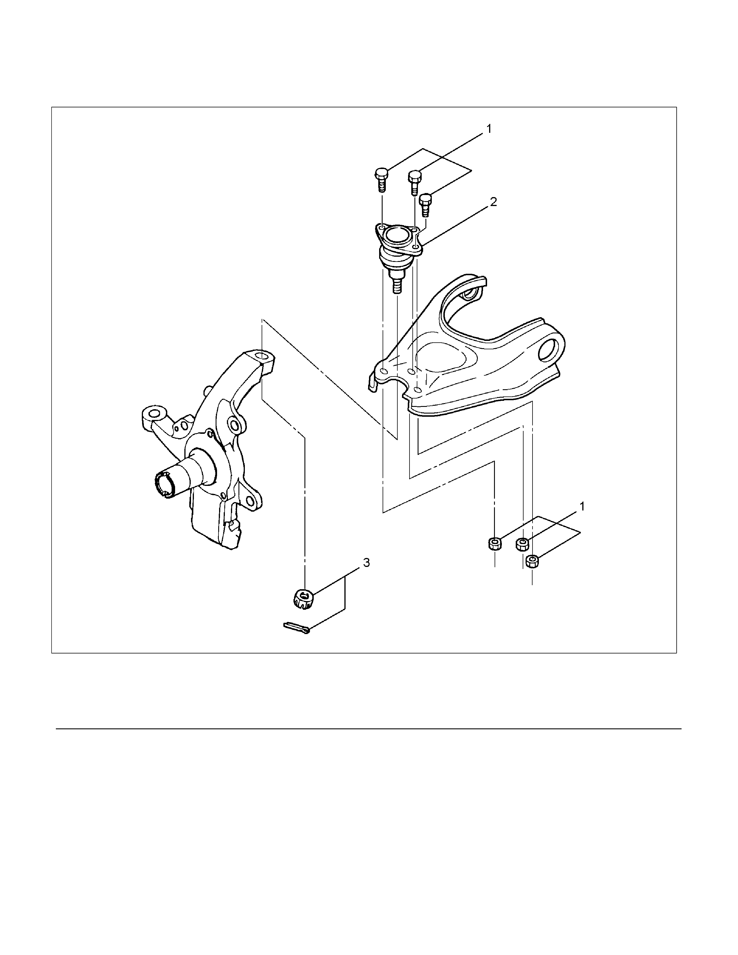
Upper Ball Joint and Associated Parts
RTW440LF001401
Legend
(1) Bolt and Nut
(2) Upper Ball Joint
(3) Nut and Cotter Pin
Removal
1. Raise the vehicle and support the frame with
suitable safety stands.
2. Remove the speed sensor from the knuckle.
3. Remove upper ball joint nut and cotter pin, then
use remover 5-8840-2121-0 to remove the uppe
r
ball joint from the knuckle.
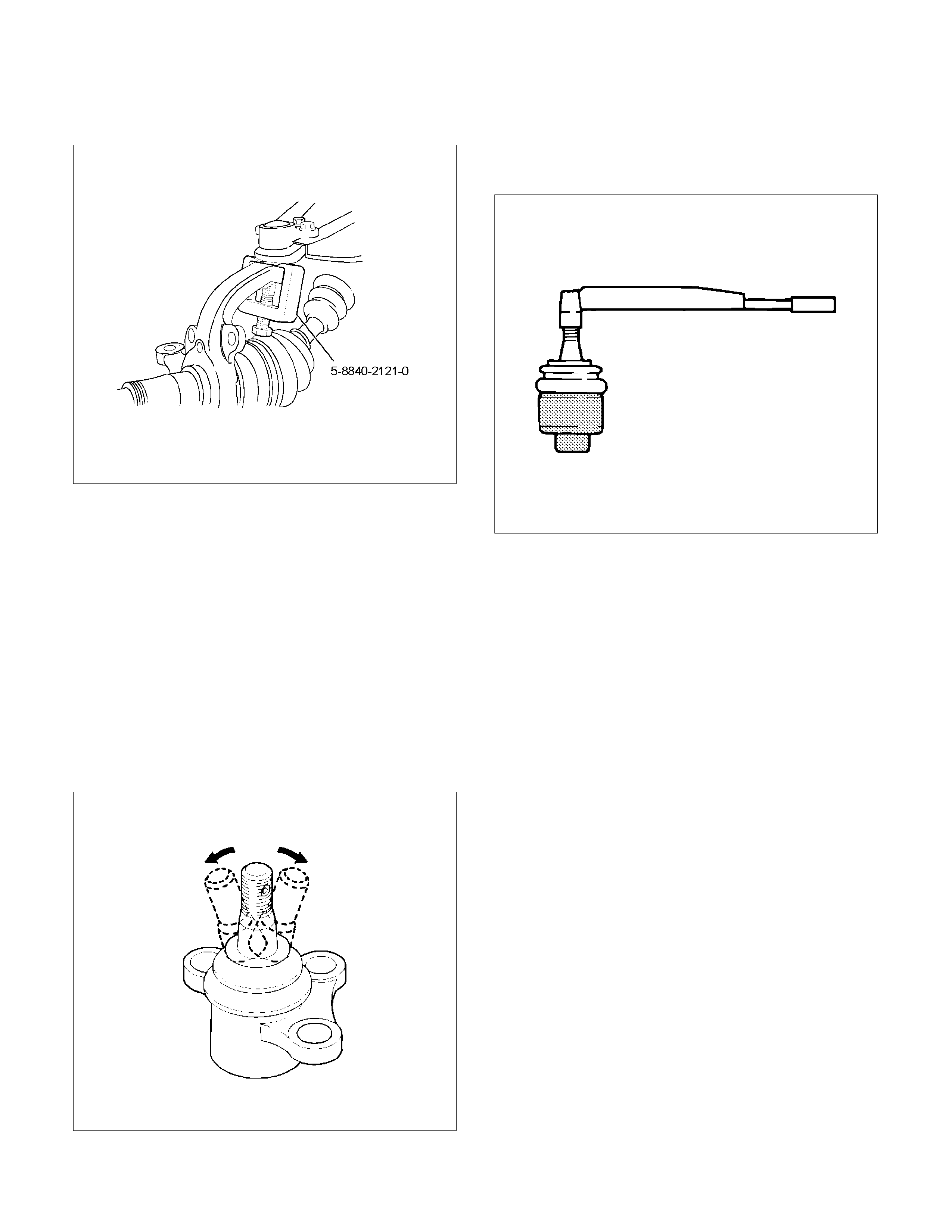
CAUTION: Be careful not to damage the ball joint
boot.
RTW340SH000401
4. Remove bolt and nut.
5. Remove upper ball joint.
Inspection and Repair
Make necessary parts replacement if wear, damage,
corrosion or any other abnormal conditions are found
through inspection.
• Inspect the lower end boot for damage or grease
leak. Move the ball joint as shown in the figure to
confirm its normal movement.
• Inspect screw/taper area of ball for damage.
• If any defects are found by the above inspections,
replace the ball joint assembly with new one.
450RS023
• After moving the ball joint 4 or 5 times, attach nut
then measure the preload.
Starting torque: 1.3–3.2 N⋅m (0.13-0.33kg⋅m/0.9-
2.4 lb ft)
450RS024
If the above limits specified are exceeded, replace the
ball joint assembly.
Installation
1. Install upper ball joint.
2. Install bolt and nut (1), then tighten them to the
specified torque.
Torque: 57 N⋅m (5.8kg⋅m/42 lb ft)
3. Install nut and cotter pin, then tighten the nut to
the specified torque with just enough additional
torque to align cotter pin holes. Install new cotte
r
pin (3).
Torque: 98 N⋅m (10.0kg⋅m/72 lb ft)
Lower Ball Joint
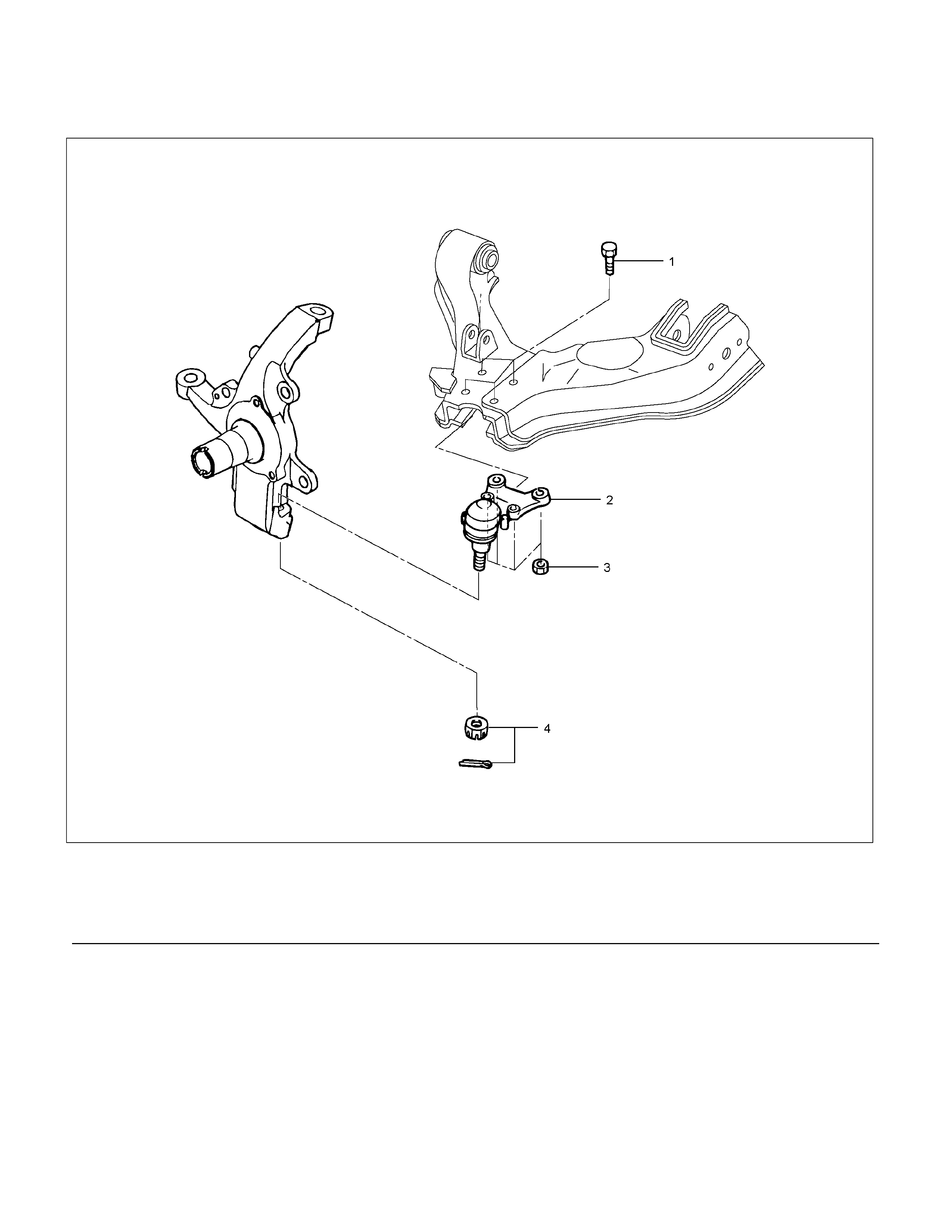
Lower Ball Joint and Associated Parts
RTW340LF001601
Legend
(1) Bolt
(2) Lower Ball Joint
(3) Nut
(4) Nut and Cotter Pin
Removal
1. Raise the vehicle and support the frame with
suitable safety stands.
2. Remove wheel and tire assembly. Refer to Wheel
in this section.
3. Remove the tie-rod end from the knuckle. Refer to
Power Steering Unit in Steering section.
4. Remove the retaining ring from the front axle drive
shaft to release the shaft from hub. Refer to
Front Hub and Disc in Driveline/Axle section.
5. Support lower control arm with a jack.
6. Remove lower ball joint nut and cotter pin, then
use remover 5-8840-2005-0 to remove the lowe
r
ball joint from the knuckle.
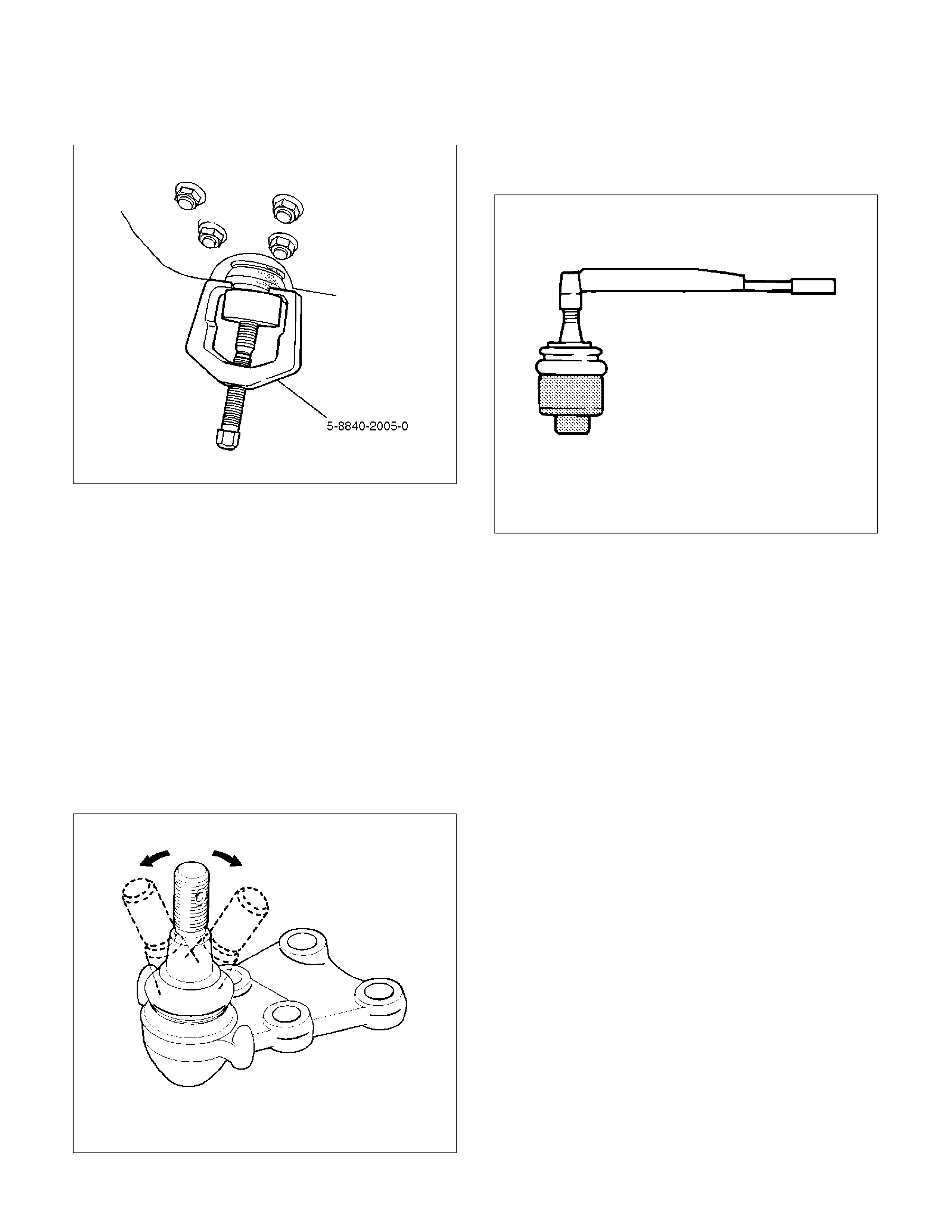
CAUTION: Be careful not to damage the ball joint
boot.
901RW271
7. Remove nut.
8. Remove bolt.
9. Remove lower ball joint.
Inspection and Repair
Make necessary parts replacement if wear, damage,
corrosion or any other abnormal conditions are found
through inspection.
• Inspect the lower end boot for damage or grease
leak. Move the ball joint as shown in the figure to
confirm its normal movement .
• Inspect screw/taper area of ball for damage.
• If any defects are found by the above inspections,
replace the ball joint assembly with new one.
450RS026
•
A
fter moving the ball joint 4 or 5 times, attach nut
then measure the preload.
Starting torque: 2.5-6.4 N⋅m (0.25-0.65kg⋅m/1.8-
4.7 lb ft)
450RS024
• If the above limits specified are exceeded, replace
the ball joint assembly.
Installation
1. Install lower ball joint.
2. Install bolt.
3. Install nut (3) and tighten it to the specified torque.
Torque: 127 N⋅m (12.9kg⋅m/94 lb ft)
4. Install ball joint nut, then tighten it to the specified
torque with just enough additional torque to align
cotter pin holes. Install new cotter pin (4).
Torque: 147 N⋅m (15.0kg⋅m/108 lb ft)
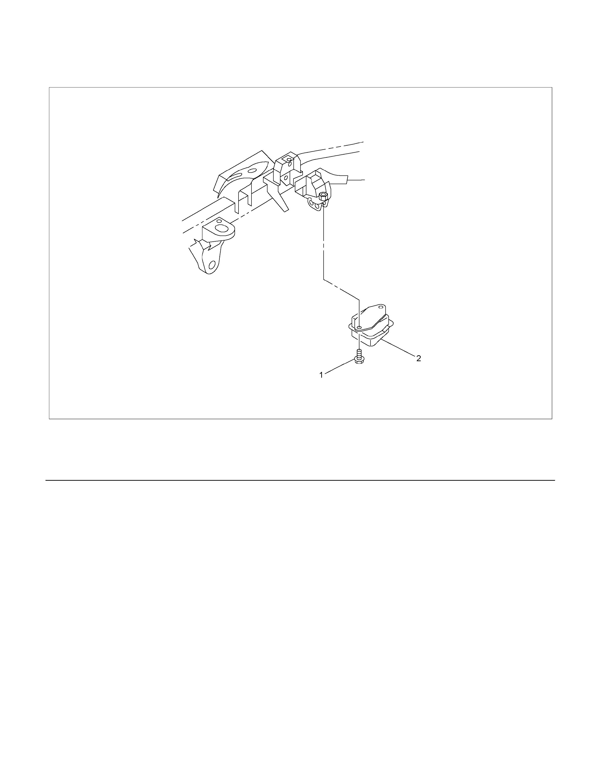
Bump Rubber
Bump Rubber and Associated Parts
RTW340MF001001
Legend
(1) Bolt
(2) Bump Rubber
Removal
1. Raise the vehicle and support the frame with
suitable safety stands.
2. Remove bolt.
3. Remove bump rubber.
Inspection and Repair
Make necessary correction or parts replacement if
wear, damage, corrosion or any other abnormal
condition are found through inspection.
Check the following parts :
• Bump Rubber
Installation
1. Install bump rubber.
NOTE: Arrow points to be vehicle outer side of after
assembly to vehicle.
2. Install bolt (1), then tighten it to the specified
torque.
Torque: 42 N⋅m (4.3kg⋅m/31 lb ft)
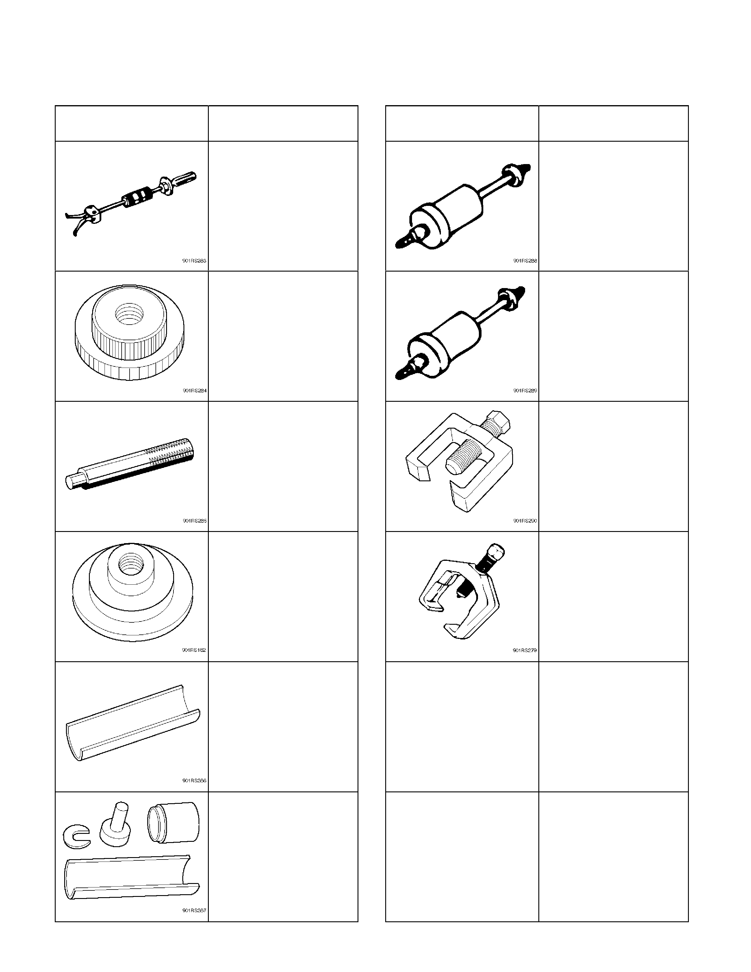
Special Tools (4×2 High Ride Suspension, 4×4)
ILLUSTRATION PART NO.
PART NAME ILLUSTRATION PART NO.
PART NAME
5-8840-2000-0
(J-23907)
Remover; Needle bearing
5-8840-0019-0
Sliding hammer
5-8840-2123-0
(J-36833)
Remover and Installer kit;
Lower arm front bushing
5-8840-2128-0
(J-36838)
Installer; Needle bearing
5-8840-2124-0
(J-36834)
Remover and Installer kit;
Lower arm rear bushing
5-8840-0007-0
(J-8092)
Grip
5-8840-2121-0
(J-36831)
Ball joint remover
5-8840-2127-0
(J-36837)
Installer; Oil seal
5-8840-2005-0
(J-29107)
Tie-rod end remover
5-8840-2307-0
(J-39376)
Installer; Upper arm
bushing
5-8840-0256-0
(J-29775)
Remover and Installer
Upper arm bushing