
SECTION 3D - REAR SUSPENSION
Main Data and Specifications
General Specifications
Torque Specifications
Rear Suspension
General Description
Leaf Spring and Shock Absorber
Leaf Spring and Associated Parts
Removal
Inspection and Repair
Installation
Leaf Spring Assembly
Disassembly
Inspection and Repair
Reassembly
Troubleshooting
Main Data And Specifications
General Specifications
Models Standard Heavy-duty Suspension
Items
4 × 2
(Except High Ride Sus)
4 × 2
(High Ride Sus)
4 × 4
4 × 2
(Except High Ride Sus)
4 × 2
(High Ride Sus)
4 × 4
Type Semi-elliptic, rubber bushed, leaf type sprin gs and direct double acting shock
absorbers.
Leaf spring
No. of leaves 5 7
Spring eye type Berlin eye type Up turned eye type
Bushing outside dia mm(in) Front; 40 (1.57), Rear; 30 (1.18)
Length mm(in) 1200 (47.24)
Width mm(in) 60 (2.36)
Rear shock absorbers
Type
Gas-sealed Hydraulic, double acting telescopic
Mean stroke mm(in) 198 (7.80) 199 (7.83) 198 (7.80) 199 (7.83)
Compressed length mm(in) 323 (12.7) 349 (13.8) 323 (12.7) 349 (13.7)
Extended length mm(in) 521 (20.5) 549 (21.6) 521 (20.5) 549 (21.9)
Techline
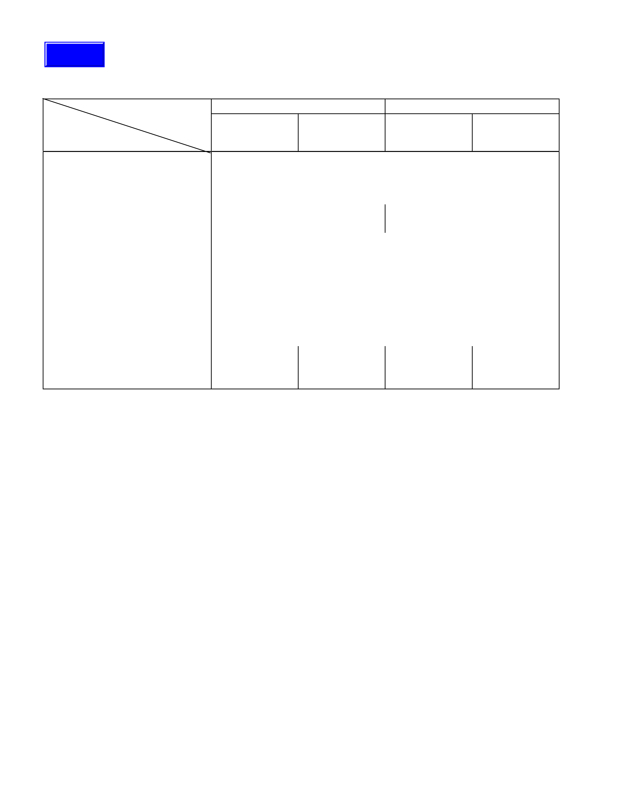
Torque Specifications
N⋅m(kg⋅m/lb⋅ft)
RTW430LF000101

Rear Suspension
General Description
Rear suspension absorbs vibration from the road surface thus preventing vehicle damage, as well as provid ing a good
ride.
Components parts
• Spring between the body and the axle case
• Spring shackle connecting the spring to the body
• Clamp and U-bolt fixing the axle case to the spring
• Shock absorber as a countermeasure for vibration
Leaf Spring And Shock Absorber
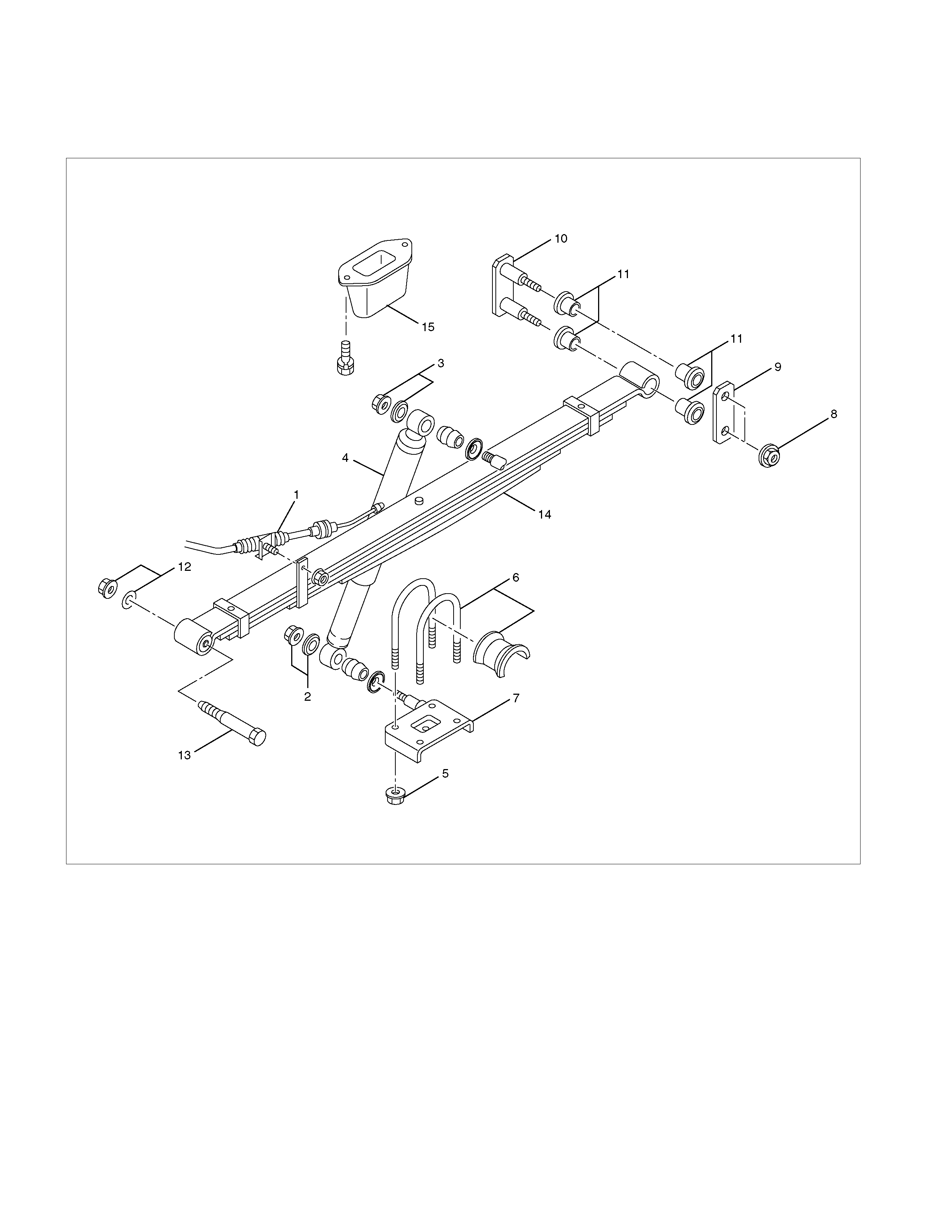
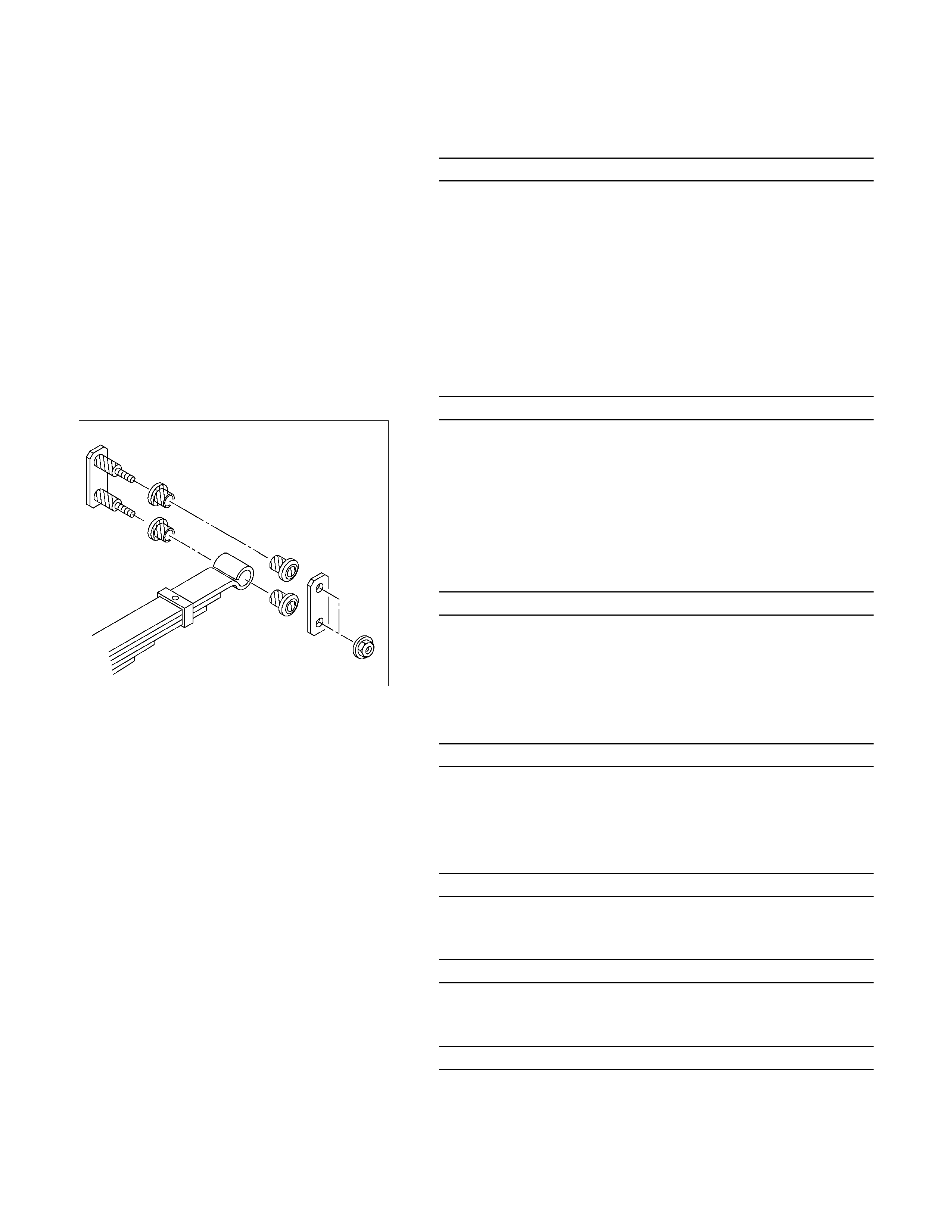
Leaf Spring And Associated Parts
460R300001
Legend
1. Parking Brake Cable Bracket
2. Nut and Washer
3. Nut and Washer
4. Shock Absorber
5. Nut
6. U Bolt and Seat
7. Lower Clamp
8. Nut
9. Shackle Plate
10. Shackle Pin
11. Rubber Bushing
12. Nut and Plain Washer
13. Spring Pin
14. Leaf Spring
15. Bump Rubber
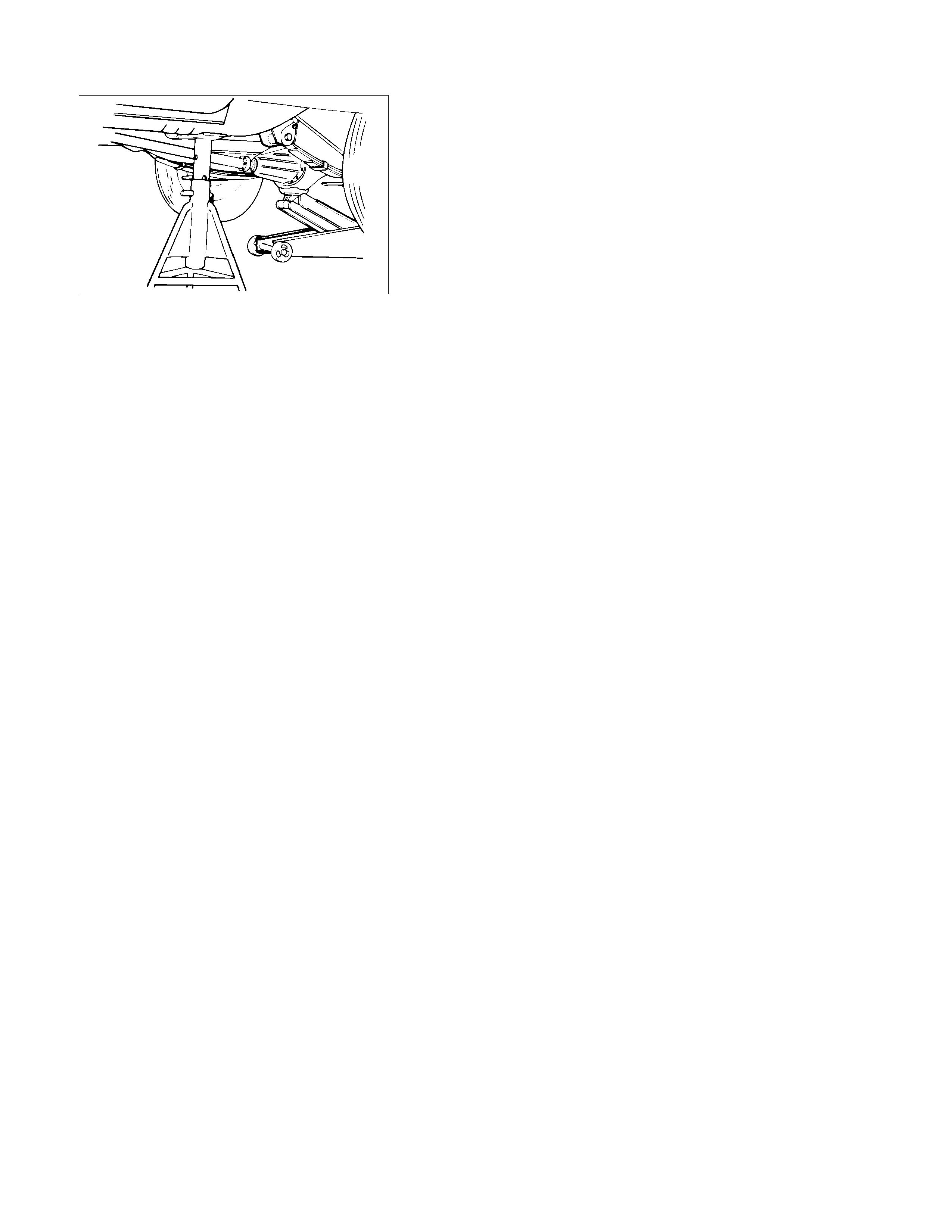
Removal
F03L100003
• Jack up the rear axle and place chassis stands under the
frame near the front end of the rear spring brackets.
Note:
• Be careful not to stretch the flexible brake hose o
r
parking brake cable.
• Support the vehicle on the specified jack point.
1. Remove the parking brake cable (1) from the leaf spring.
2. Loosen the shock absorber fixing nut and remove the nu
t
and special washer (2) from the lower clamp.
3. Remove the shock absorber fixing nut and washer (3) at
frame side.
4. Lifting the rear axle by a jack, remove the shock absorbe
r
(4) and lower the jack.
5. Remove the U bolt fixing nut (5).
6. Take out the U bolt (6), seat and lower clamp (7).
7. Support the leaf spring by a jack and remove the shackle
pin fixing nuts (8).
8. Drive out the shackle pin (10), using a brass bar and
hammer.
9. Remove the shackle plate (9) a nd rubber bushings (11).
10. Remove the nut (12) and drive out the shackle with a
hammer using a bras s bar.
11. Remove the leaf spring (14).
12. Remove the bump rubber (15).

Inspection And Repair
Carry out repairs or replace parts if wear, damage or any abnormal conditions are found during inspection.
Visual Check
Inspect the following parts for wear, damage, or other
abnormal conditions.
• Leaf spring assembly
• Clip
• Center bolt
• U-bolt
• Spring pin
• Shackle pin
• Shock absorber
• Rubber bumper
• Rubber bushing
• Bump rubber seat
Shackle Pin
Shackle Pin diameter mm (in)
17.93 - 18.00 (0.706 - 0.709)
Spring Pin
Spring Pin Diameter mm (in)
13.8 - 14.0 (0.543 - 0.551)
Shock Absorber
Inspection operation of shock absorb er
If no resistance is felt while expandi ng the shock absorber, this
indicates the absorber is faulty.
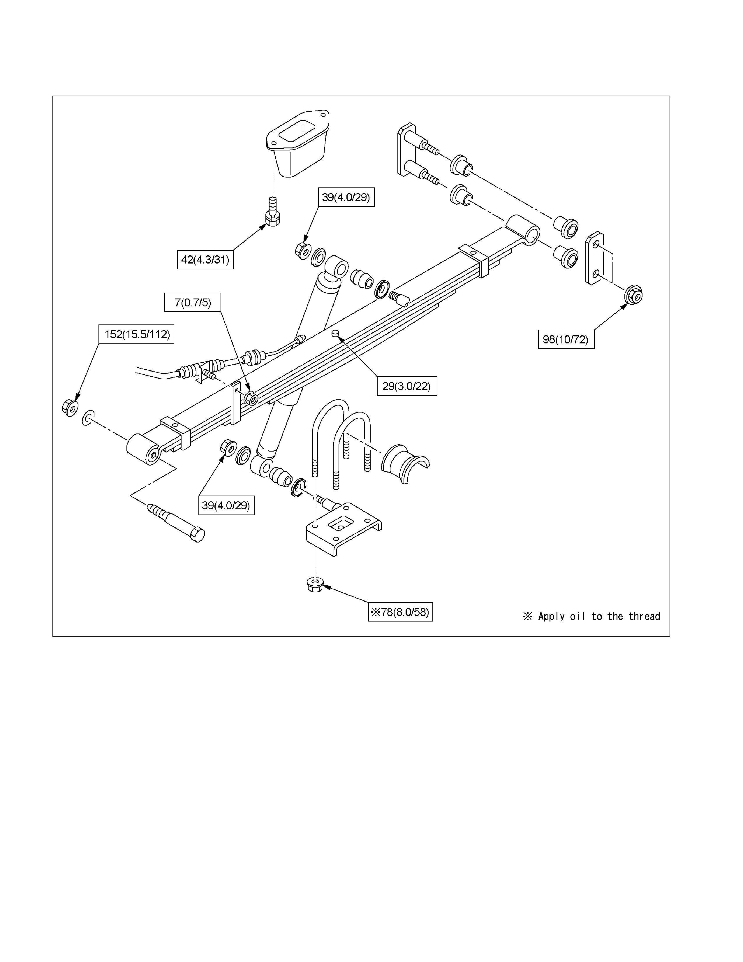
Installation
1. Install the bump rubber (15) and bolt and tighten it to the
specified torque.
Torque N⋅m (kg⋅m/lb⋅ft)
42 (4.3/31)
2. Install the leaf spring (14).
• The leaf spring assembly should be installed so that the
built-in rubber bush is toward the front.
• Align the holes of the spring eye and frame bracket.
• Insert the spring pin (13) toward vehicle inner side
through the frame bracket holes and the spring bush
hole.
• Tighten the nut (12) a little and after the vehicle is
lowered, tighten it to the specified torque .
Torque N⋅m (kg⋅m/lb⋅ft)
152 (15.5/112)
RTW340LF000101
• Apply rubber grease to inside and outside of the rubbe
r
bushing.
• Install the rubber bushings (11) into the hole of the
frame side bracket and the spring rear eye.
• Install the shackle pin (10 ) and shackle plate (9).
• Tighten the nuts (8) a little and after vehicle is lowered,
tighten it to the specified torque.
Torque N⋅m (kg⋅m/lb⋅ft)
98 (10/72)
3. Support the lower clamp (7) un der the leaf spring.
4. Apply oil to the thread portion of U bolt (6).
Install the U bolt and seat on the rear axle and insert the U
bolt in the lower clamp holes.
5. Tighten the nut (5) to the specified torque.
Torque N⋅m (kg⋅m/lb⋅ft)
78 (8.0/58)
6. Install the shock absorber (4) and inner washer on the
lower clamp pin and frame side pin.
7. Install the washer and nut (3) on the frame side pin and
tighten the nut to the specified torque.
Torque N⋅m (kg⋅m/lb⋅ft)
39 (4.0/29)
8. Install the washer and nut (2) on the lower clamp pin and
tighten the nut to the specified torque.
Torque N⋅m (kg⋅m/lb⋅ft)
39 (4.0/29)
9. Install the parking brake cable (1) on the leaf spring and
tighten the nut at its bracket.
Torque N⋅m (kg⋅m/lb⋅ft)
7 (0.7/5)
Leaf Spring Assembly
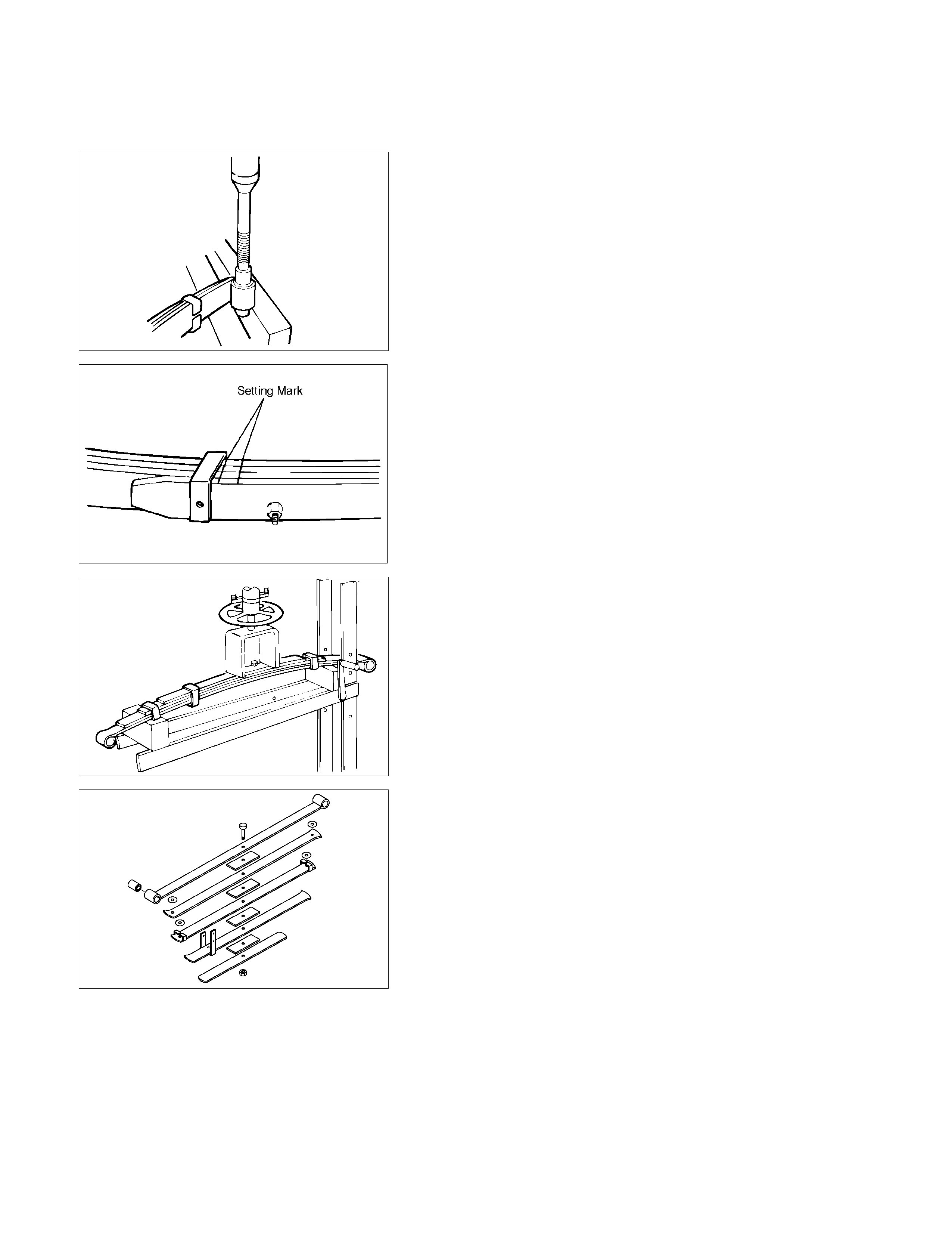
Disassembly
F03L100004
1. Remove the bushing using a bench press and a suitable
metal fitting.
RTW430SH000101
2. Apply a setting mark across the springs before
disassembling the leaf spring assembly.
F03L100006
3. Use a bench press and re move the center bolt.
• Discard center bolt and install a new one.
465R300001
4. Disassemble the leaf spring assem bly.
Inspection and Repair
Inspect leaf spring, bush, clips, liners and center spacer for
wear, damage, rust or other abnormal condition s and if
necessary, repair or replace it.
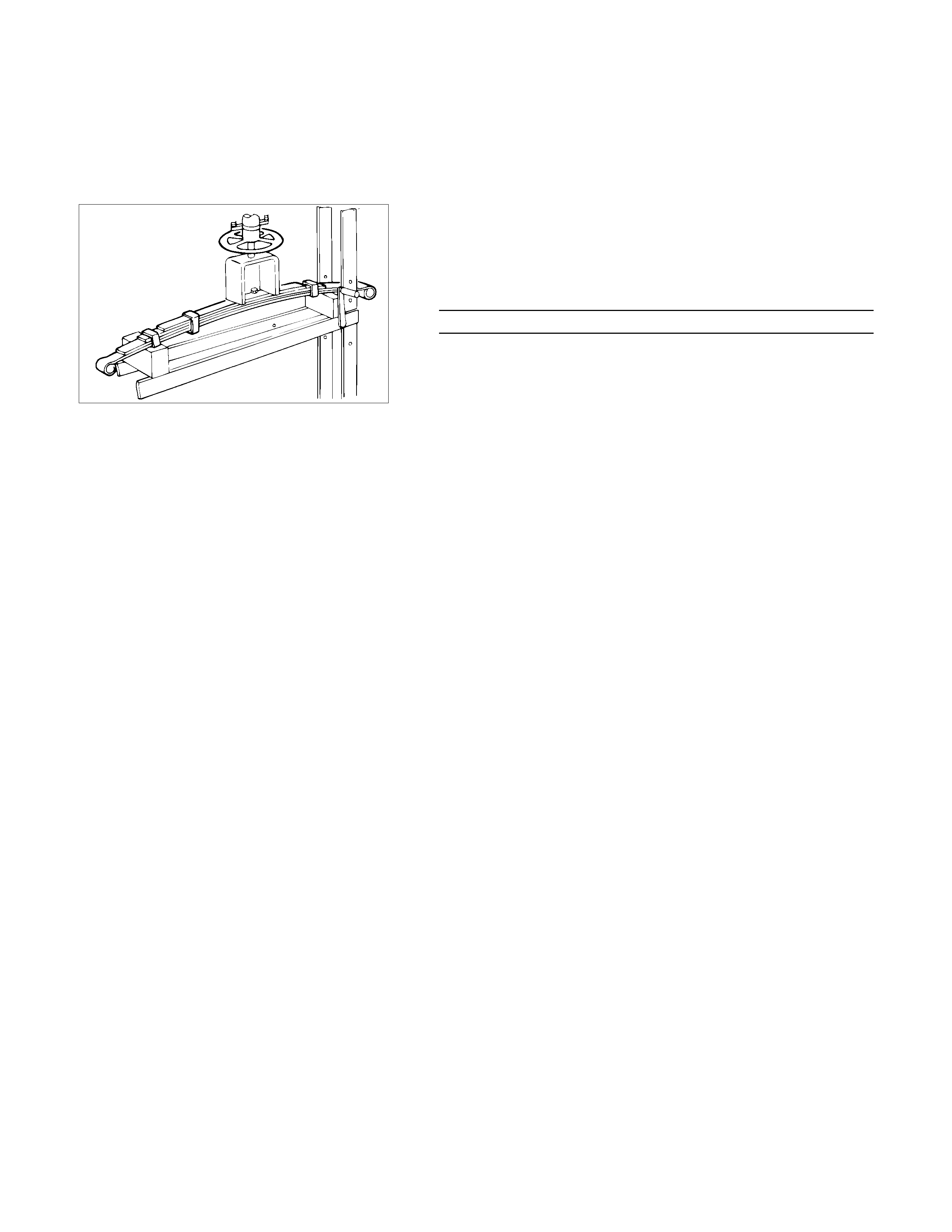
Reassembly
1.
A
pply grease to both faces of each leaf spring at
reassembly.
2. Set the leaf springs aligning the setting mark before
disassemble.
F03L100006
3. Assemble the leaf springs using a bench press.
4. Apply grease to the outside of the bushing.
Install a new center bolt and tighten it to the specified
torque.
Torque N⋅m (kg⋅m/lb⋅ft)
29 (3.0/22)
5. Install the bushing using a bench press and a suitable
metal fitting.
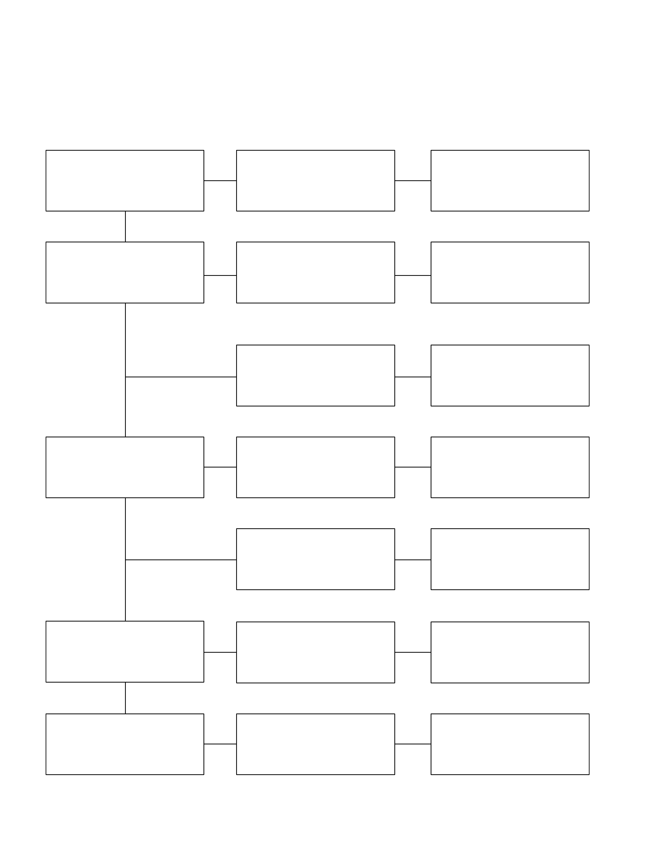
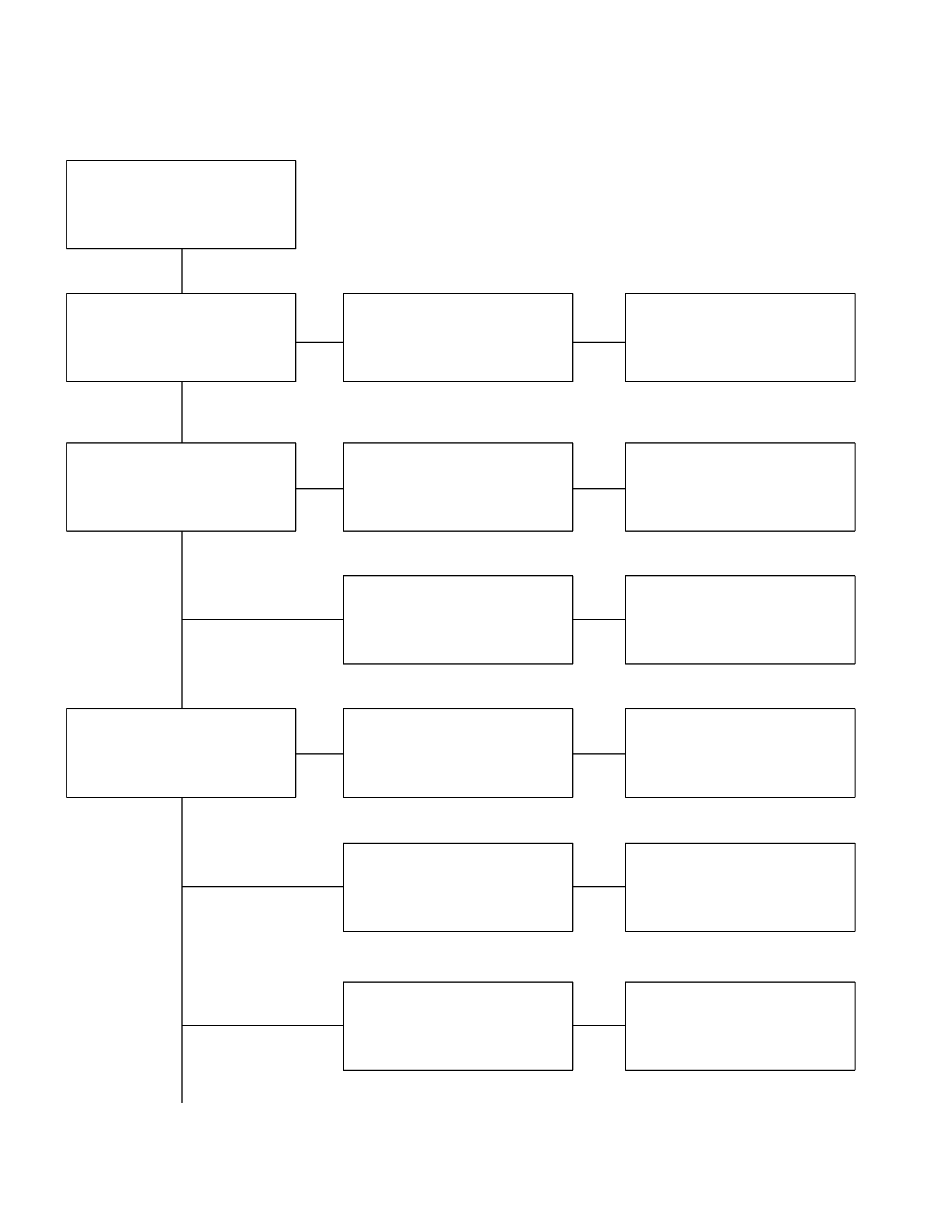
Troubleshooting
1. BODY INCLINATION
Checkpoint Trouble Cause Countermeasure
Replace
Bushings worn or
disintegrated
NG
Mounting brackets
Shock absorbers
ReplaceDefective
Spring brackets and U-bolts
Shackle pins and bushings
Replace
Retighten
Replace
Cracked
Bolt loosened
Worn or disintegrated
Regrease
Replace
Poorly lubricated
Weak or broken
OK
OK
OK
NG
NG
NG
NG
NG
NG
OK
Spring
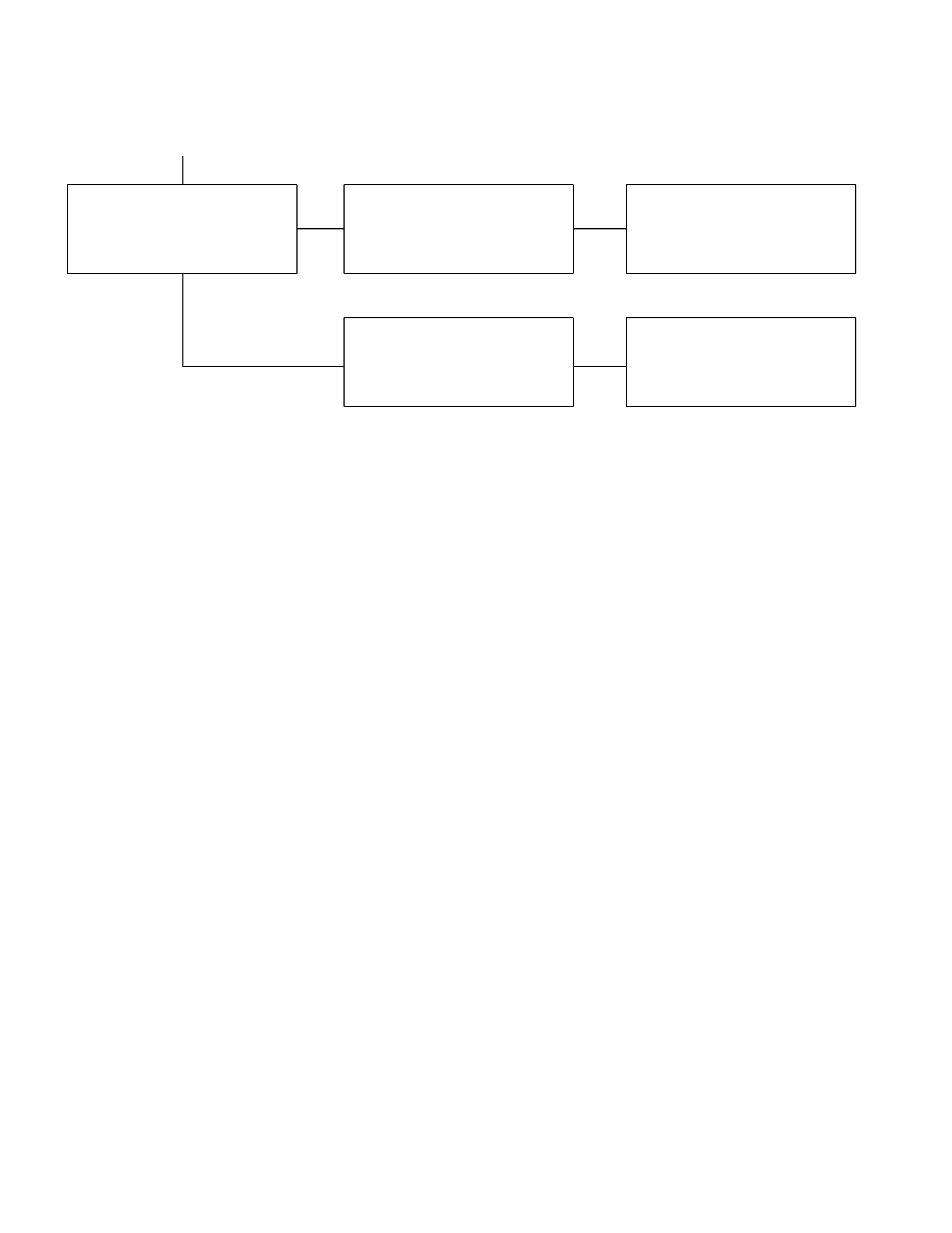
2. REDUCED GROUND CLEA RANCE
Checkpoint Trouble Cause Countermeasure
Bushings
Leaf springs
Regrease
Replace
Retighten
Replace
Poorly lubricated
Deteriorated or disintegrated
Loosened
Broken
Springs clip bands ReplaceWorn or broken
Continued on the next page
OK
NG
NG
NG
NG
NG
OK
OK
Condition of load
Wipe off excess greaseOver lubricated
NG
Checkpoint Trouble Cause Countermeasure
Replace
Cracked or damaged
Retighten
Loose
OK
NG
NG
Parts for looseness
Continued from the previous page
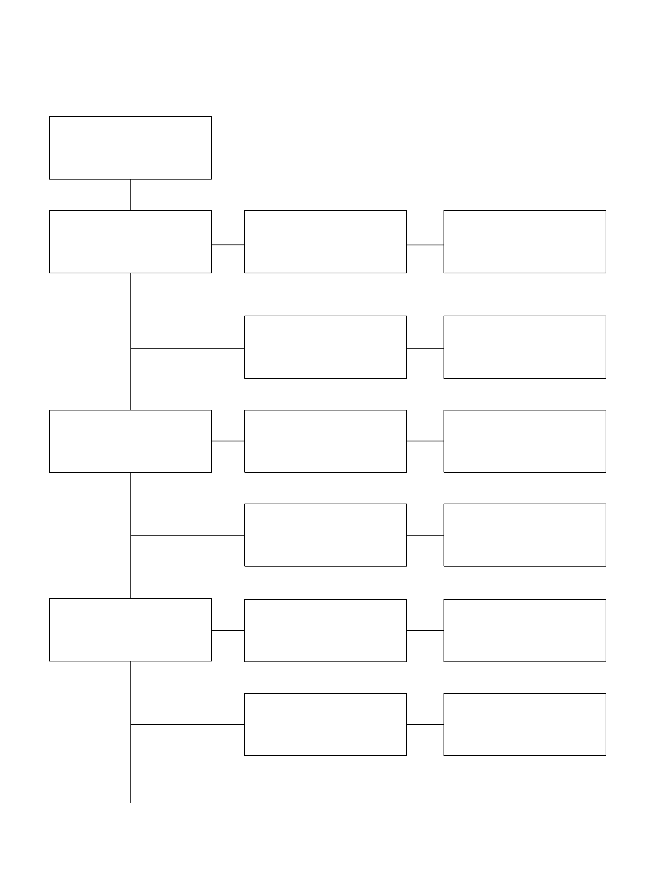
3. SPRING BREAKAGE
Checkpoint Trouble Cause Countermeasure
Replace
Oil leakage
NG
Shock absorber
Replace
Bushing worn
U-bolts
Shackle pins and pivot pins
Replace
Retighten
Retighten
Damaged
Bolts and nuts for loosening
Bolts and nuts for loosening
Replace
Worn or damaged
OK
OK
NG
NG
NG
NG
NG
OK
Condition of loading
Continued on the next page
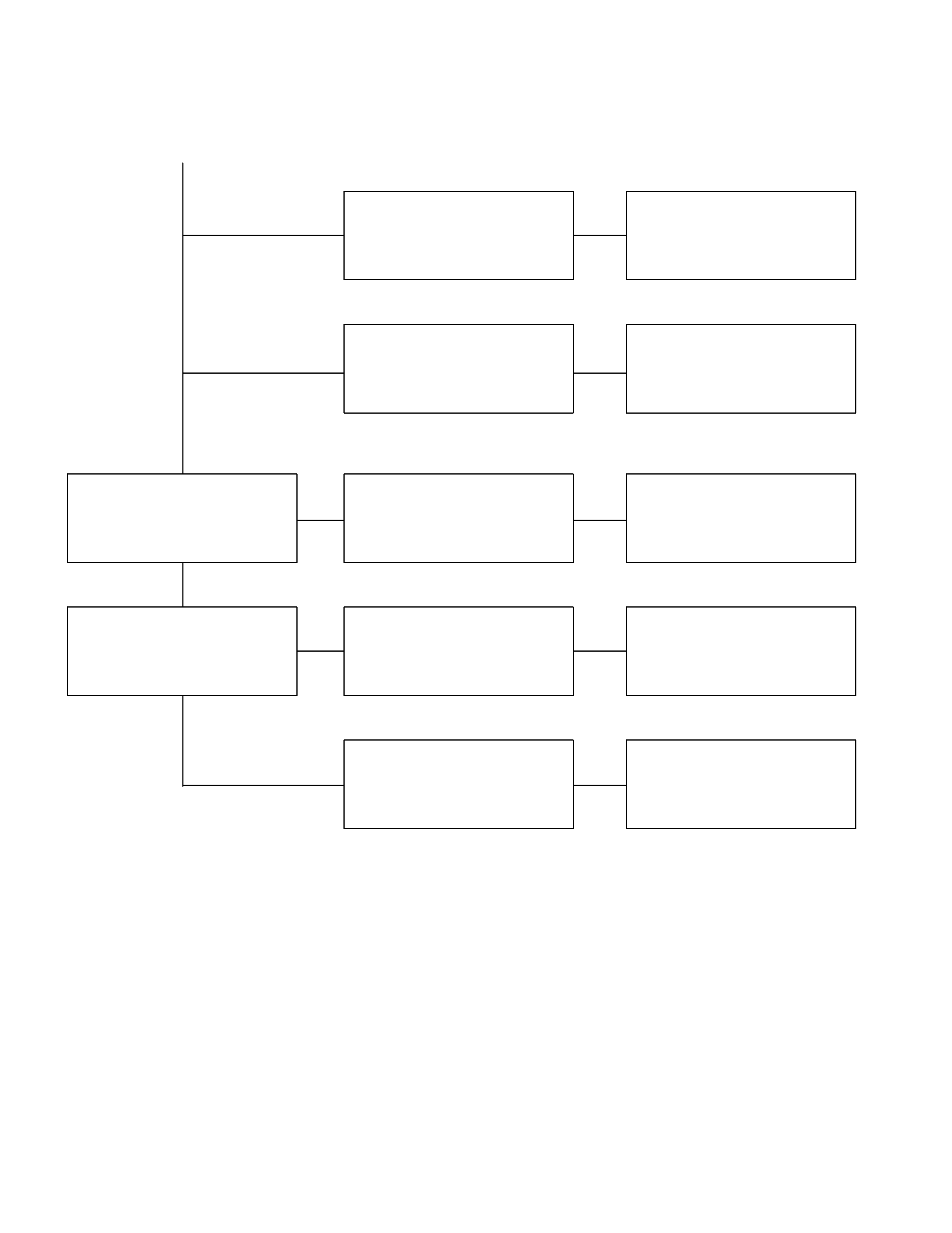
Checkpoint Trouble Cause Countermeasure
Center bolts
Replace
Retighten
Replace
Damaged
Loosened
Defective
Spring bushing
Replace
Replace
Worn or disintegrated
Brackets cracked
OK
NG
NG
NG
NG
NG
OK
Continued from the previous page
4. HARSHNESS
Checkpoint Trouble Cause Countermeasure
Bushings in suspension
Sy stem
Tire inflation pressure
Retighten or replace
Replace
Adjust
Loose or broken
Defective
Incorrect
Tires for out of balance
Adjust or replace
Replace tires
Incorrect
Noise does not have any
specific pattern
OK
NG
NG
NG
NG
NG
OK
OK
Road test vehicle(Noise has a
certain pattern)