
SECTION 4A - PROPELLER SHAFT
Service Precaution
Main Data and Specifications
Rear Propell er Shaft
Front Pr opeller Shaf t
Torque Specifications
Rear Propeller Shaft
General Description
Removal
Installation
Universal Joi nt Disassembly
Inspection and Repair
Universal Joint Reassembly
Rear Propeller Shaft Assembly
Disassembly
Reassembly
Front Propeller Shaft (4JH1-TC)
Removal and Installation
Universal Joint Disassembly and Reassembly
DOJ Disassembly and Reassembly
Front Propeller Shaft (6VE1)
Removal and Installation
Disassembly
Universal Joint Disassembly and Reassembly
Reassembly

Service Precaution
WARNING: THIS VEHICLE HAS A SUPPLEMENTAL RESTRAINT SYSTEM (SRS). REFER TO THE SRS
COMPONENT AND WIRING LOCATION VIEW IN ORDER TO DETERMINE WHETHER YOU A RE PERFORMING
SERVICE ON OR NEAR THE SRS COMPONENTS OR THE SRS WIRING. WHEN YOU ARE PEREFORMING
SERVICE ON OR NEAR THE SRS COMPONENTS OR THE SRS WIRING, REFER TO THE SRS SERVICE
INFORMATION. FAILURE TO FOLLOW WARNING COULD RESULT IN POSSIBLE AIR BAG DEPLOYMENT,
PERSONAL INJURY, OR OTHERWISE UNNEEDED SRS SYSTEM REPAIRS.
CAUTION: Always use the correct fastener in the proper location. When you replace a fastener, use ONLY the
exact part number for that application. HOLDEN will call out those fasteners that require a replacement after
removal. HOLDEN will also call out the fasteners that require thread lockers or thread sealant. UNLESS
OTHERWISE SPECIFIED, do not use supplemental coatings (Paints, greases, or other corrosion inhibitors) on
threaded fasteners or fastener joint interfaces. Generally, such coatings adversely affect the fastener torque
and the joint clamping force, and may damage the fastener. When you install fasteners, use the correct
tightening sequence and specifications. Following these instructions can help you avoid damage to parts and
systems.
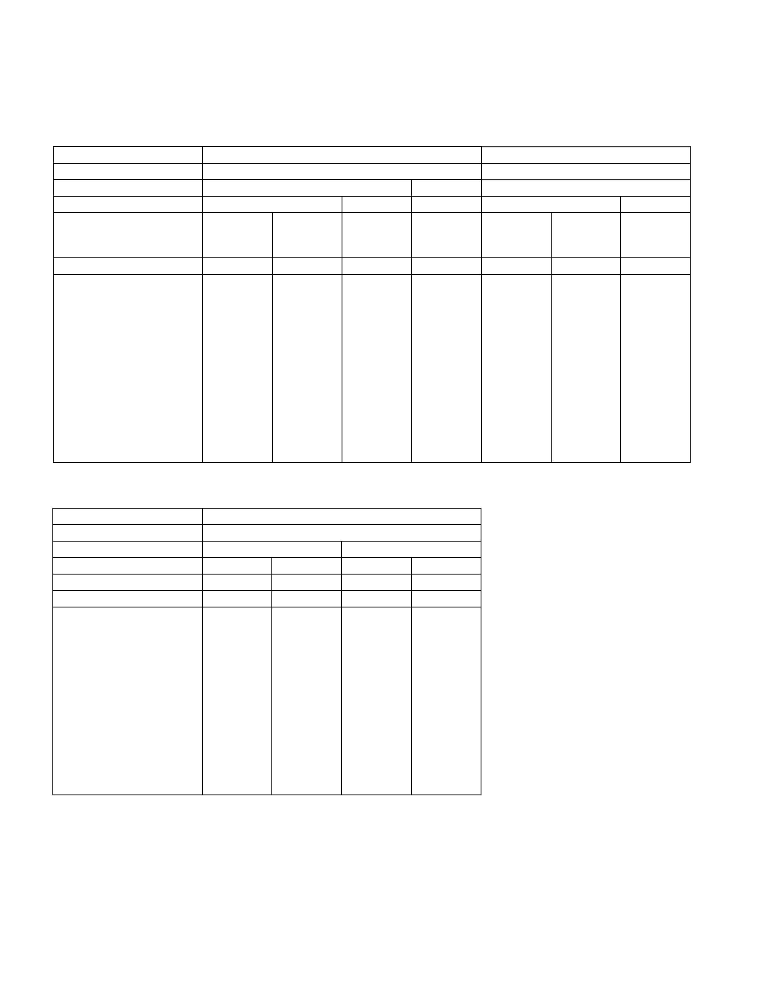
Main Data and Specifications
Rear Propeller Shafts
mm(in)
4×2 Model 4×2 Model
Engine Model 4JH1-TC HEC
Transmission Type 5M/T (MUA) 4A/T 5M/T (MUA)
Wheel Base Long Extra Long Long Long Extra Long
Front Suspension High Ride
Suspension Except High
Ride
Suspension High Ride
Suspension
Except High
Ride
Suspension
Rear Axle 220mm ← ← ← ← ← ←
Type OBS ← ← ← ← ← ←
Outside Diameter mm 68.9 68.9 68.9 63.5 75 75 75
(in) (2.71) (2.71) (2.71) (2.50) (2.95) (2.95) (2.95)
Inside Diameter mm 64.9 64.9 64.9 60.3 71.8 71.8 71.8
(in) (2.63) (2.63) (2.63) (2.44) (2.89) (2.89) (2.89)
Length 1st(L1) mm 798.5 801.5 946.5 720.5 823.5 820.5 970.5
(in) (31.44) (31.56) (37.26) (28.37) (32.42) (32.30) (38.21)
2nd(L2) mm 801 796 801 801 801 796 796
(in) (31.54) (31.34) (31.54) (31.54) (31.54) (31.34) (31.34)
Spline Major mm 29.89 29.89 29.89 29.89 29.89 29.89 29.89
Diameter (in) (1.18) (1.18) (1.18) (1.18) (1.18) (1.18) (1.18)
Fix Bolt Size M10 M10 M10 M10 M10 M10 M10
* OBS - Outboard Slip (Spline Engagement To T/M)
mm(in)
4×2 Model
Engine Model 6VE1
Transmission Type 5M/T (MUA) 4A/T
Wheel Base Long Extra Long Long Extra Long
Front Suspension
Rear Axle 220mm ← ← ←
Type OBS ← ← ←
Outside Diameter mm 68.9 68.9 75 75
(in) (2.71) (2.71) (2.95) (2.95)
Inside Diameter mm 64.9 64.9 71.8 71.8
(in) (2.63) (2.63) (2.89) (2.89)
Length 1st(L1) mm 823.5 971.5 778.5 928.5
(in) (32.42) (38.25) (30.65) (36.56)
2nd(L2) mm 801 801 801 801
(in) (31.54) (31.54) (31.54) (31.54)
Spline Major mm 29.89 29.89 30.48 30.48
Diameter (in) (1.18) (1.18) (1.20) (1.20)
Fix Bolt Size M10 M10 M10 M10
* OBS - Outboard Slip (Spline Engagement To T/M)
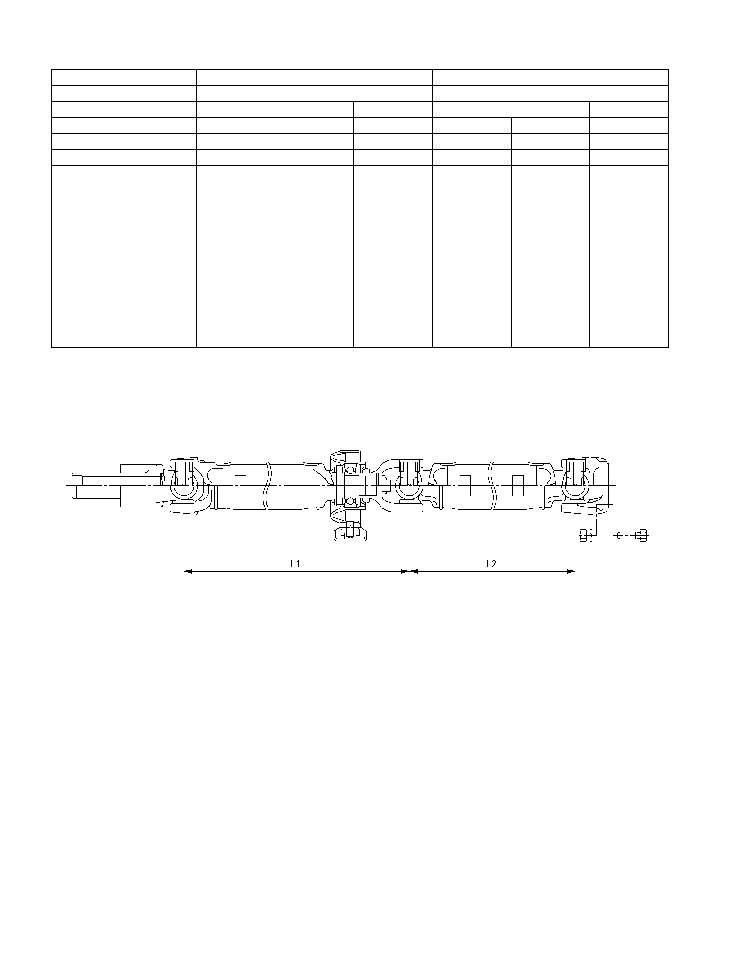
mm(in)
4×4 Model 4×4 Model
Engine Model 4JH1-TC 6VE1
Transmission Type 5M/T (MUA) 4A/T 5M/T (MUA) 4A/T
Wheel Base Long Extra Long Long Long Extra Long Long
Front Suspension
Rear Axle 220mm ← ← ← ← ←
Type OBS ← ← ← ← ←
Outside Diameter mm 68.9 68.9 63.5 68.9 68.9 75
(in) (2.71) (2.71) (2.50) (2.71) (2.71) (2.95)
Inside Diameter mm 64.9 64.9 60.3 64.9 64.9 71.8
(in) (2.63) (2.63) (2.44) (2.63) (2.63) (2.89)
Length 1st(L1) mm 468.5 616.5 402.5 492.5 641.5 484.5
(in) (18.44) (24.27) (15.85) (19.39) (25.26) (19.07)
2nd(L2) mm 801 801 801 801 801 801
(in) (31.54) (31.54) (31.65) (31.54) (31.54) (31.54)
Spline Major mm 29.89 29.89 29.89 29.89 29.89 29.89
Diameter (in) (1.18) (1.18) (1.18) (1.18) (1.18) (1.18)
Fix Bolt Size M10 M10 M10 M10 M10 M10
* OBS - Outboard Slip (Spline Engagement To T/M)
401R300006
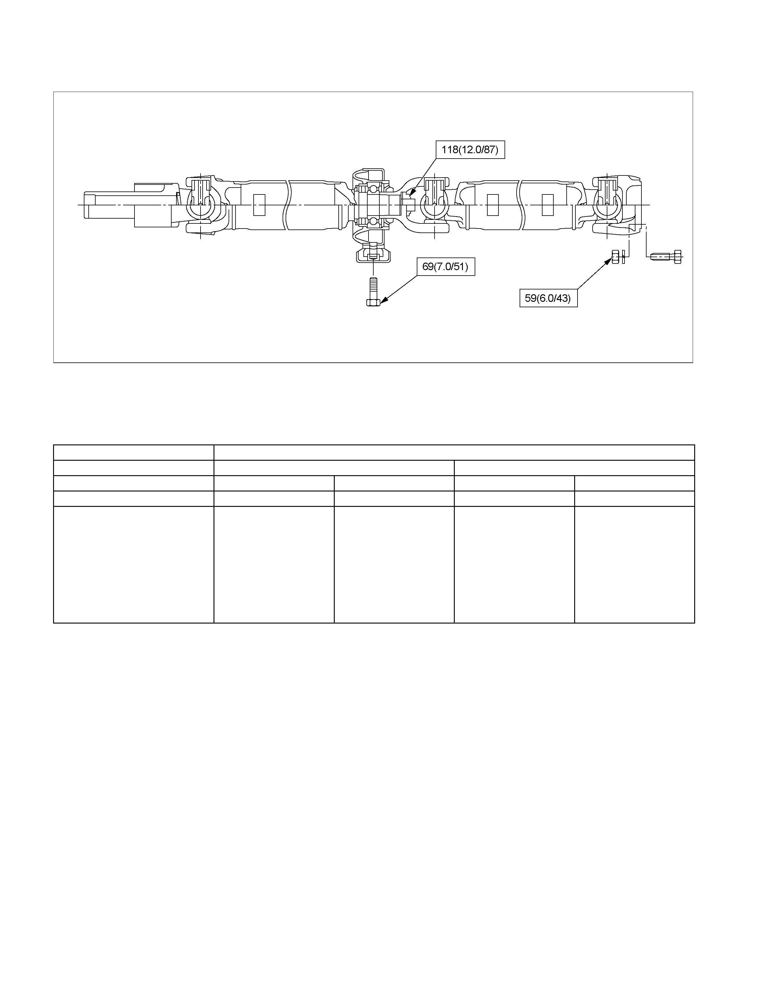
Torque Specifications N⋅m (kgf⋅m/lb⋅ft)
RTW34ASF000301
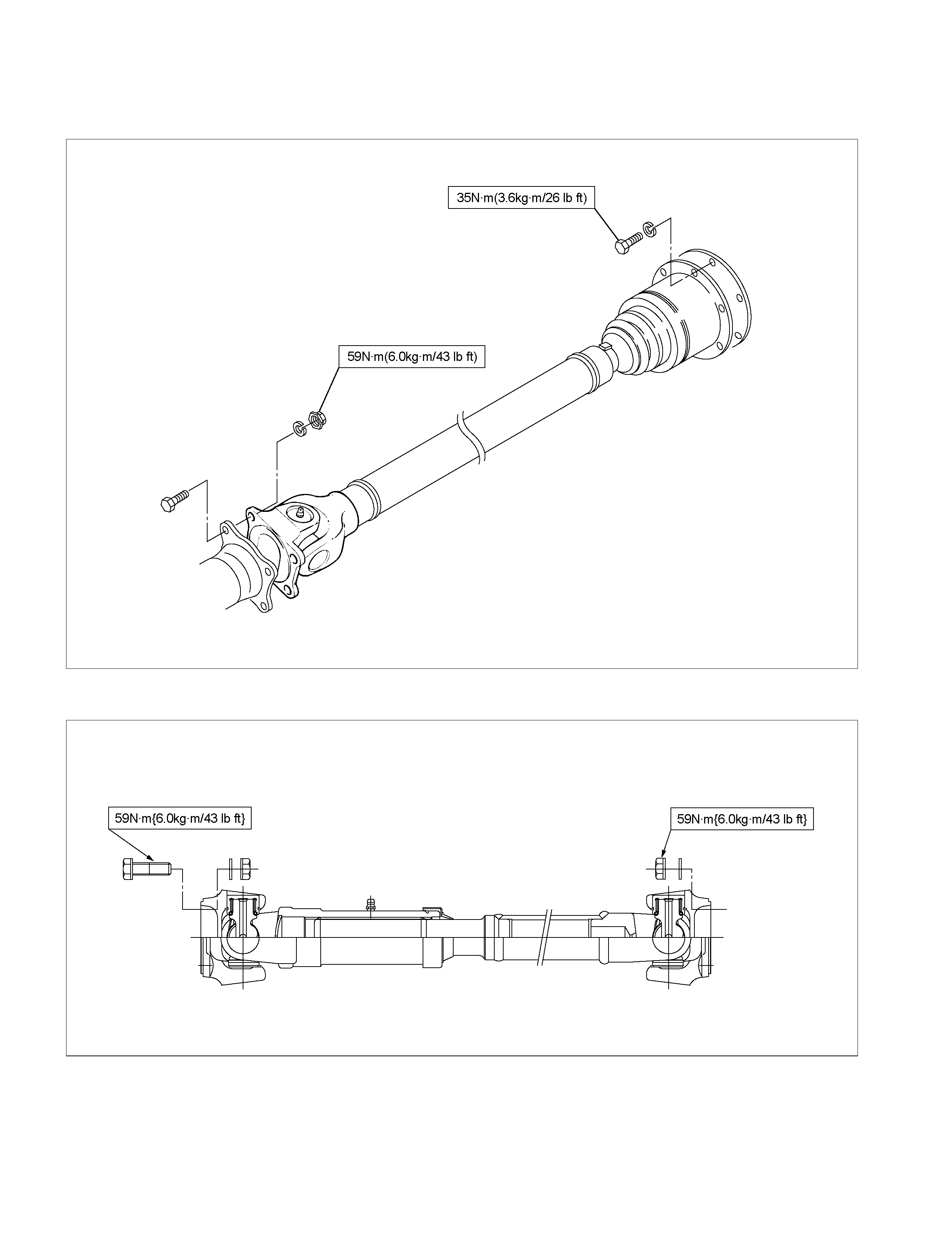
Front Propeller Shaft
mm(in)
4×4 Model
Engine Model 4JH1-TC 6VE1
Transmission Type 5M/T (MUA) 4A/T 5M/T (MUA) 4A/T
Wheel Base Long Long Long Long
Outside Diameter mm 40 40 40 40
(in) (1.57) (1.57) (1.57) (1.57)
Inside Diameter mm 36 36 36 36
(in) (1.42) (1.42) (1.42) (1.42)
Length (L) mm 645 712 586 607
(in) (25.39) (28.03) (23.07) (23.90)
Fix Bolt Size T/F M8 M8 M10 M10
Axle M10 M10 M10 M10
4JH1-TC
401R300026
6VE1
RTW34ASF000101
Torque Specifications
4JH1-TC
RTW34AMF000101
6VE1
RTW34ASF000201
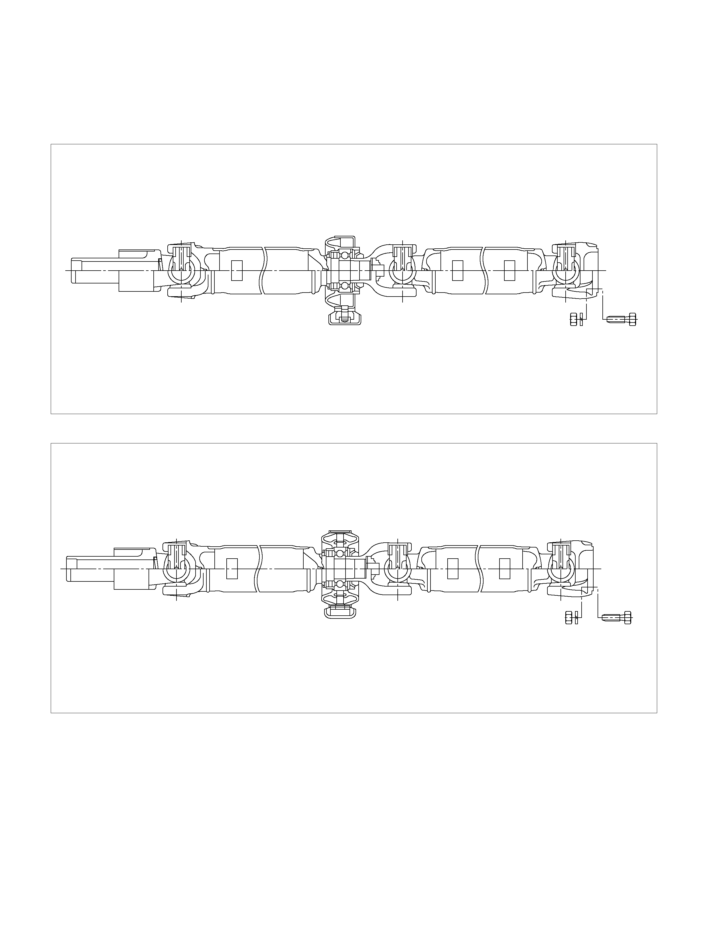
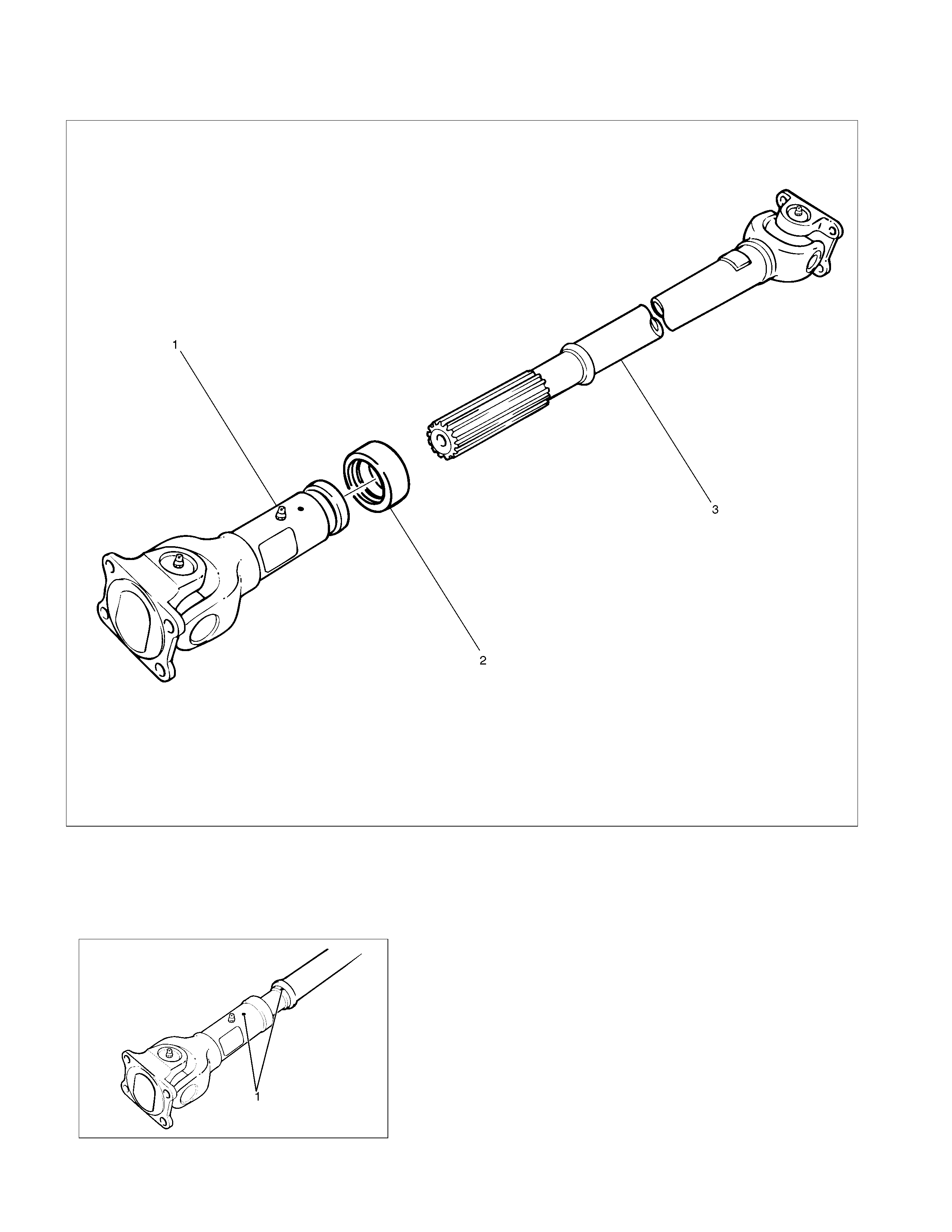
Rear Propeller Shaft
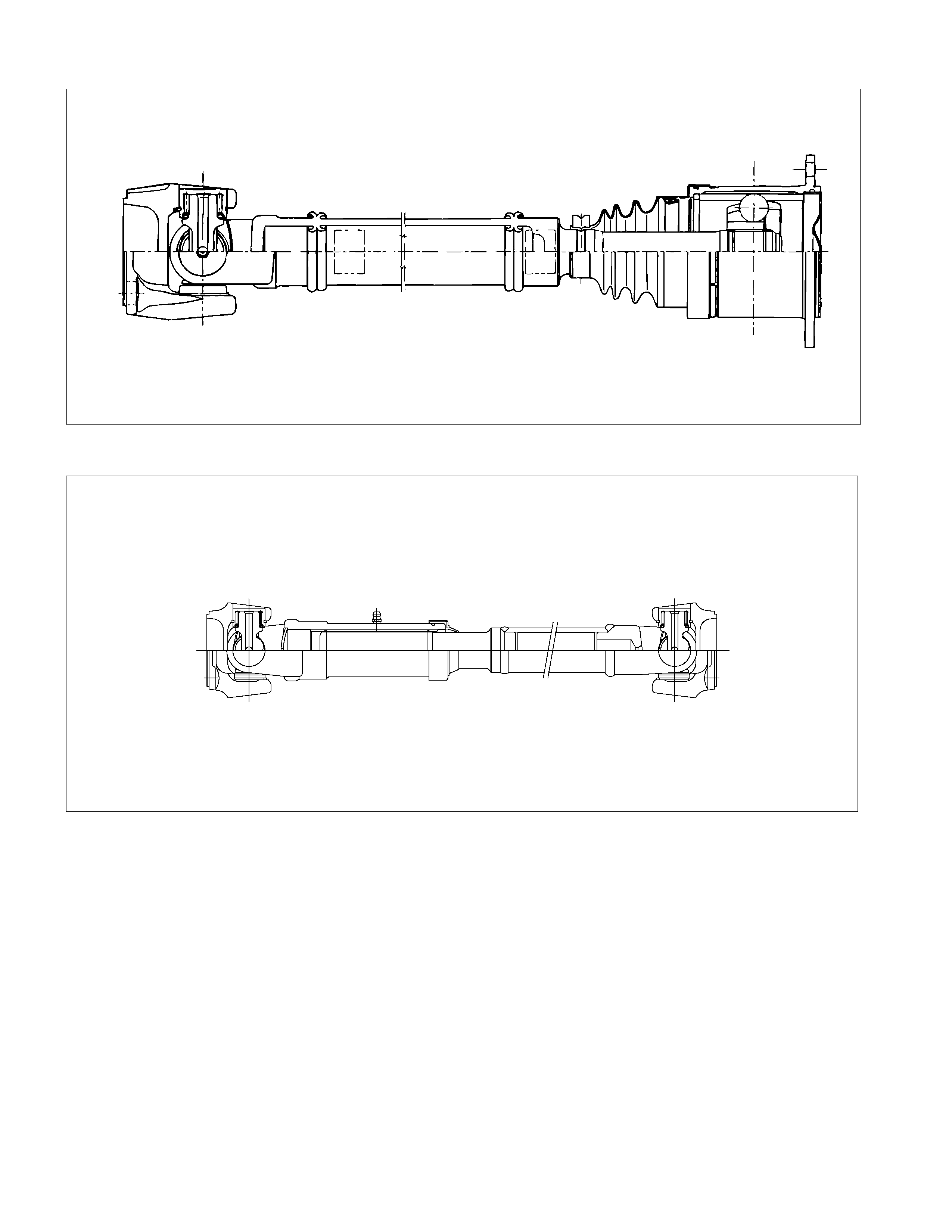
General Description
4×2 (Except High Ride Suspension) Model
F04R300001
4×2 (High Ride Suspension), 4×4 Model
401R300007
Torque is transmitted from the transmission to the
axle through propeller shaft and universal joint
assembles. All propeller shafts are the balanced
tubular type. A splined slip joint is provided in some
drivelines.
• Since the propeller shaft is total balanced carefully,
welding or any other modification are not permitted.
• Alignment marks should be applied to each
propeller shaft before removal.
• Be sure vehicle is stopped, engine is not running,
brake is secured and vehicle is secured to prevent
injury.
• Be careful not to grip the propeller shaft tube too
tightly in the bise as this will be cause deformation.
Phasing
The propeller shaft is designer and built with the yoke lugs
(ears) in line with each other. This design produces the
smoothest running shaft possible, called phasing. Vibration can
be caused by an out-of-phase propeller shaft. The propeller
shaft down each time the universal joint goes around. This
vibration would be the same as a person snapping rope and
watching the “wave” reaction flow to the end. A propeller shaft
working in phase would be similar to two persons snapping a
rope at the same time, and watching the “waves” meet and
cancel each other out. In comparison, this would be the same
as the universal joints on a propeller shaft. A total cancellation
of vibration produces a smooth flow of power in the driveline. It
is very important to apply a reference mark to the propeller
shaft before removal, to assure installation alignment.
401RW015
Universal Joint
A universal joint consists of two Y-shaped yokes
connected by a crossmember called a spider.
The spider is shaped like a cross. Universal joints are
designed to handle the effects of various loadings and
front or rear axle windup during acceleration. Within the
designed angle variations, the universal joint will operate
efficiently and safely. When the design angle is changed
or exceeded the operational life of the joint may decrease.
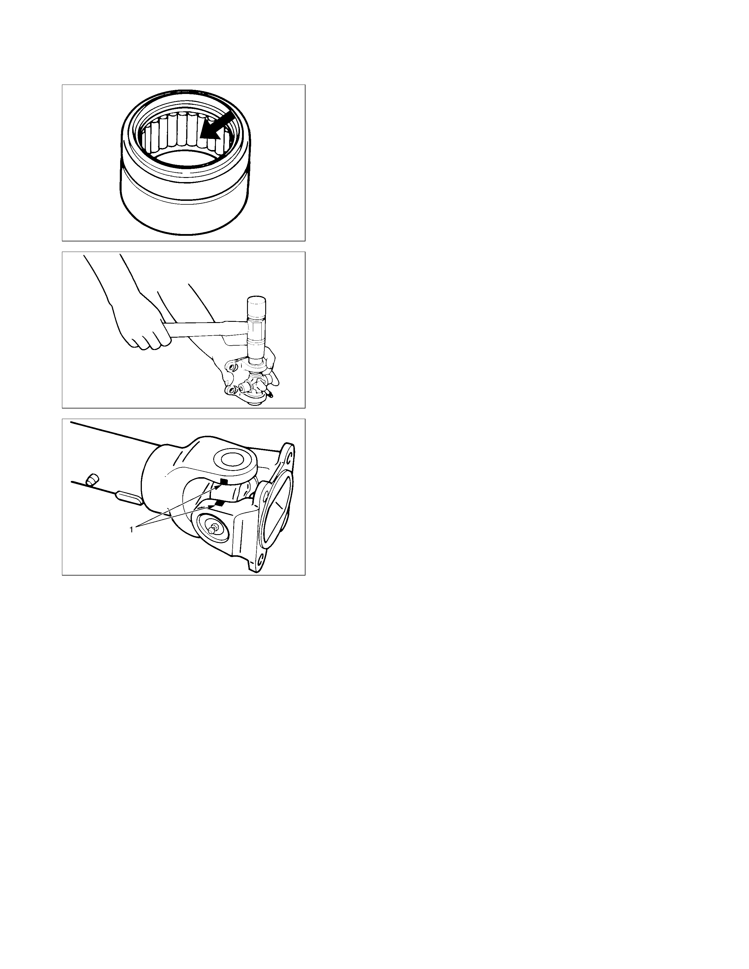
The bearings used in universal joints are of the needle
roller type. The needle rollers are held in place on the
trunnions by round bearing cups. The bearing cups are
held inside the yokes by snap rings.
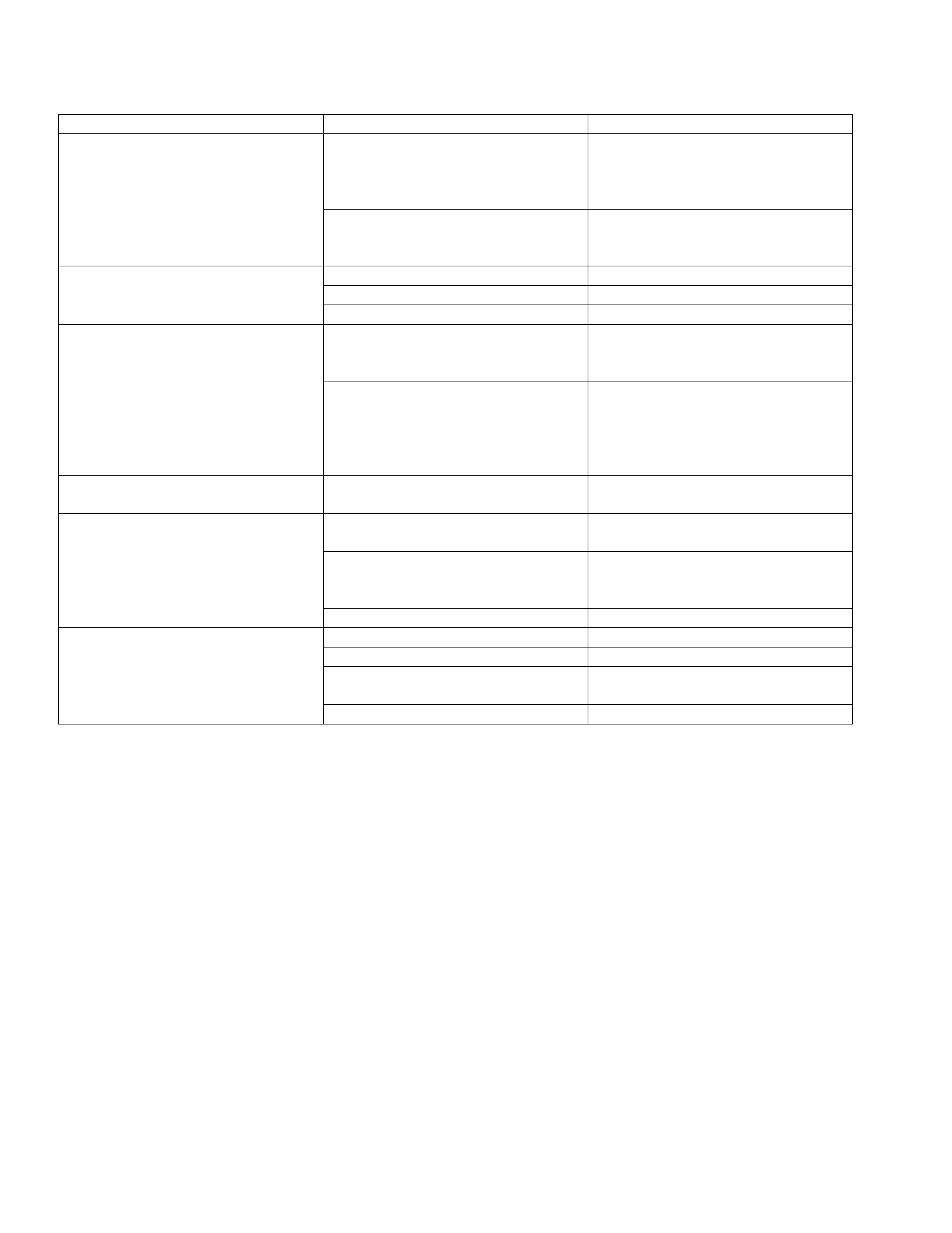
Diagnosis of Propeller Shaft and Universal Joint
Condition Possible cause Correction
Rough surface on splined yoke;
burred nicked or worn. Replace the seal. Minor burrs can
be Smoothed by careful use of
crocus cloth or fine stone honing.
Replace the yoke if badly burred.
Leak at the Front Slip Yoke (An
Occasional Drop of Lubricant
Leaking from the Splined Yoke is
Normal) Defective transmission rear oil seal. Replace the transmission rear oil
seal and replenish the transmission
oil.
Worn universal joint bearings. Replace.
Improper lubrication. Lubricate as directed.
Universal Joint Noise.
Loose flange bolts. Tighten to specifications.
Loose bushing bolts on the rear
springs or upper and lower control
arms.
Tighten the bolts to specified
torque.
Ping, Snap, or Click in Drive Line
(Usually Heard on Initial Load after
the Transmission is in Forward or
Reverse Gear) Loose or out-of-phase end yoke. Remove end yoke, turn 180
degrees from its original position,
lubricate the splines and reinstall.
Tighten the bolts and pinion nut to
specified torque.
Squeak Lack of lubricant. Lubricate joints and splines. Also
check for worn or brinelled parts.
Loose or missing bolts at the
flanges. Replace or tighten bolts to specified
torque.
Incorrectly set front joint angle. Install shim under the transmission
support mount to change the front
joint angle.
Shudder on Acceleration (Low
Speed)
Worn universal joint. Replace.
Incorrect shaft runout. Replace.
Shaft out of balance. Adjust.
Transmission rear housing bushing,
transfer case housing bushing worn. Replace.
Vibration
Yoke spline jammed. Replace.
Removal
401RS023
1. Raise the vehicle on a hoist.
NOTE:
Apply alignment marks on the flange at the rear
propeller shaft both front and rear side.
2. Remove center bearing fixing bolt.
3. Remove rear axle side bolt, nut and washer.
4. Remove rear propeller shaft.
NOTE:
Plug the hole of the transmission rear end to prevent oil
leakage.
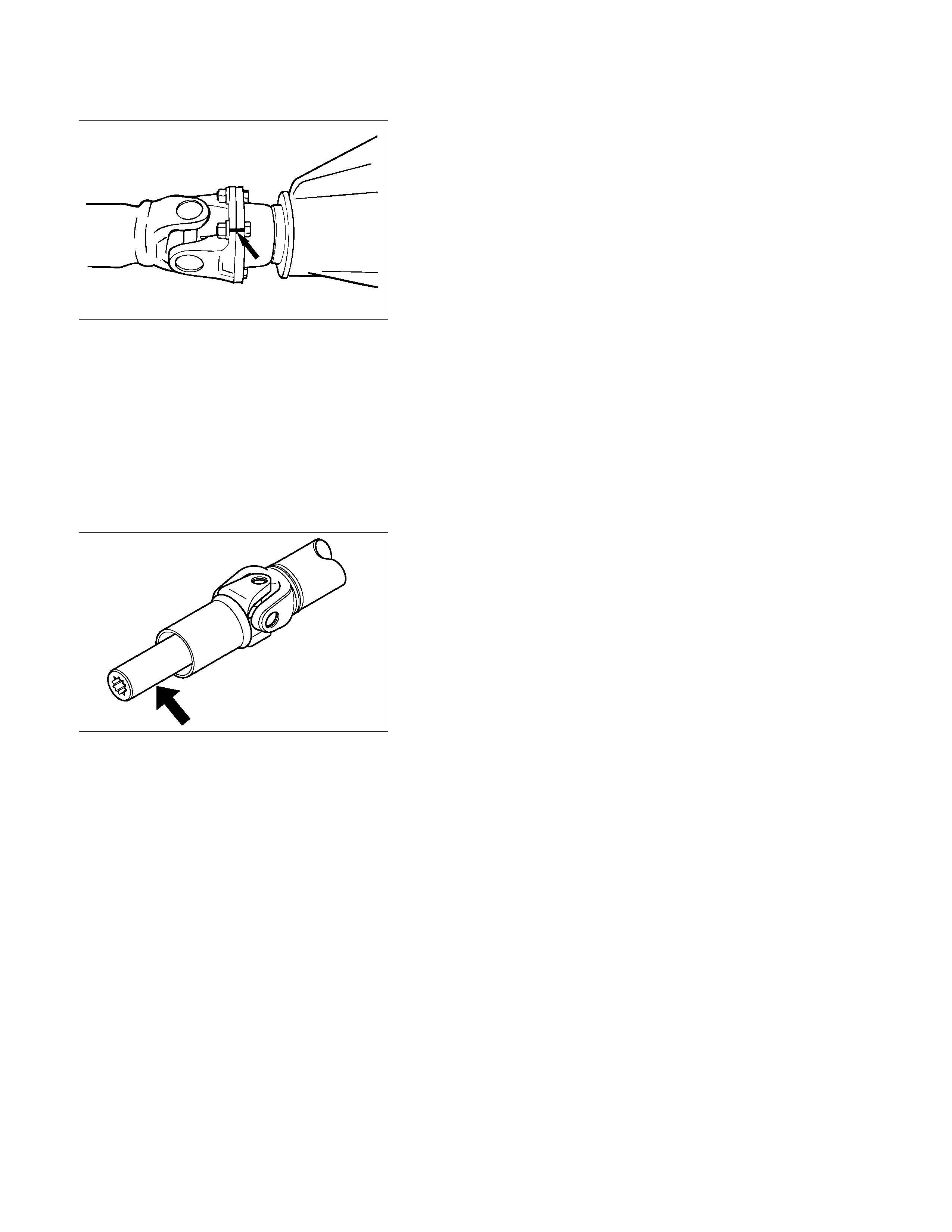
Installation
401L100007
NOTE:
Cover the slip yoke with cloth to avoid damage to the oil seal
contact surface, when removing propeller shaft from
transmission. Do not damage the oil seal contact surface of
slip yoke with other parts at removal and installation.
Completely remove the dust or foreign matter from the
connecting surface of flange coupling on each end of the
propeller shaft.
1. Align the mark which is applied at removal and insert the
propeller shaft in the transmission.
2. Install rear propeller shaft and tighten the bolts to the
specified torque.
Torque: 63 N⋅
⋅⋅⋅m(6.4kg⋅
⋅⋅⋅m/46 lb⋅
⋅⋅⋅ft)
3. Install center bearing and tighten the bolts to the specified
torque.
Torque: 69 N⋅
⋅⋅⋅m(7.0kg⋅
⋅⋅⋅m/51 lb⋅
⋅⋅⋅ft)
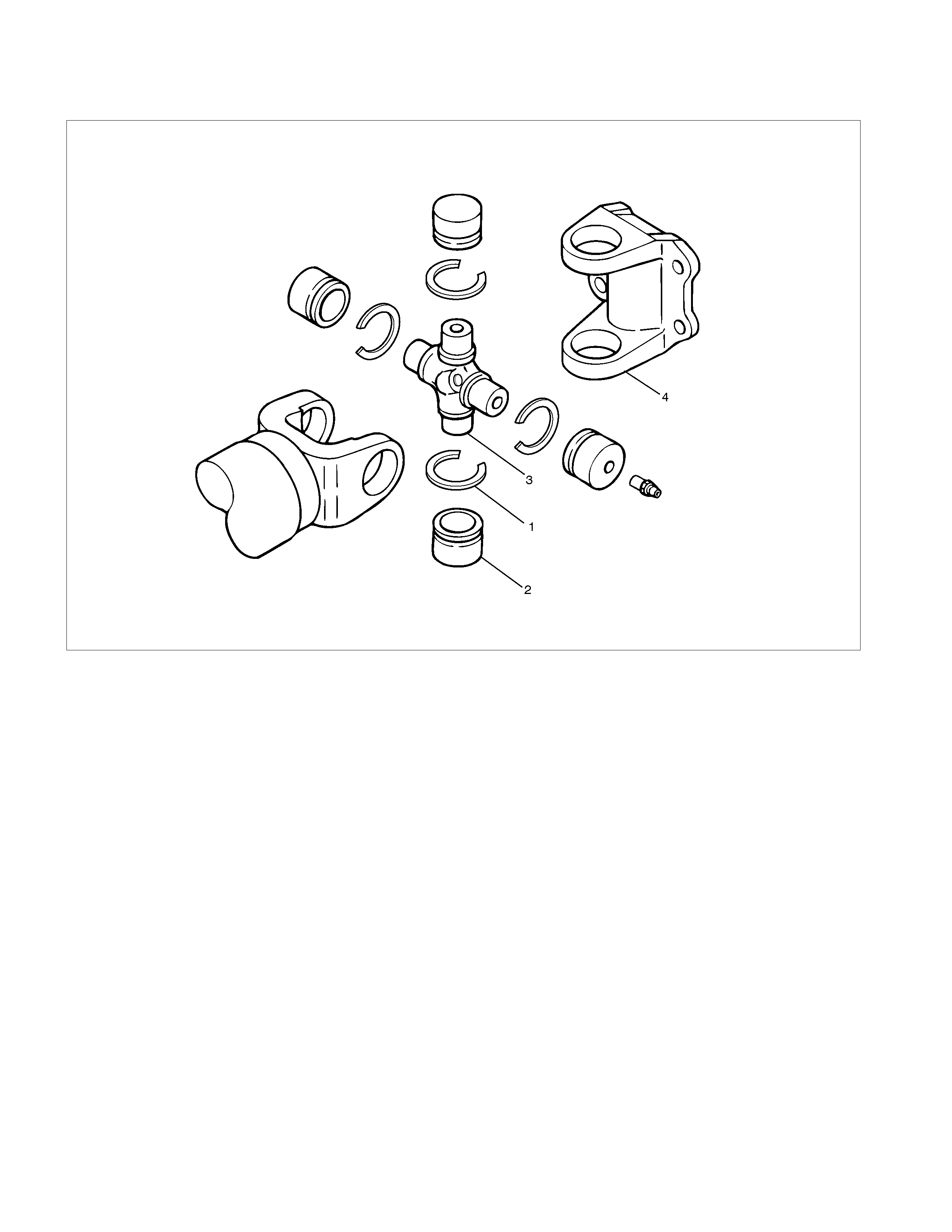
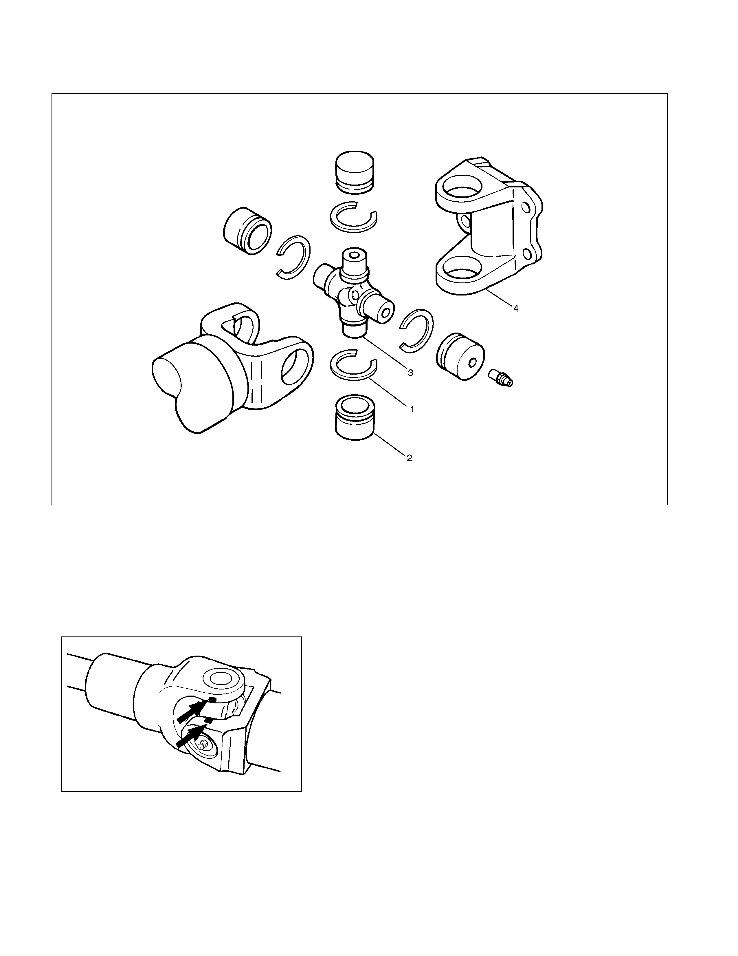
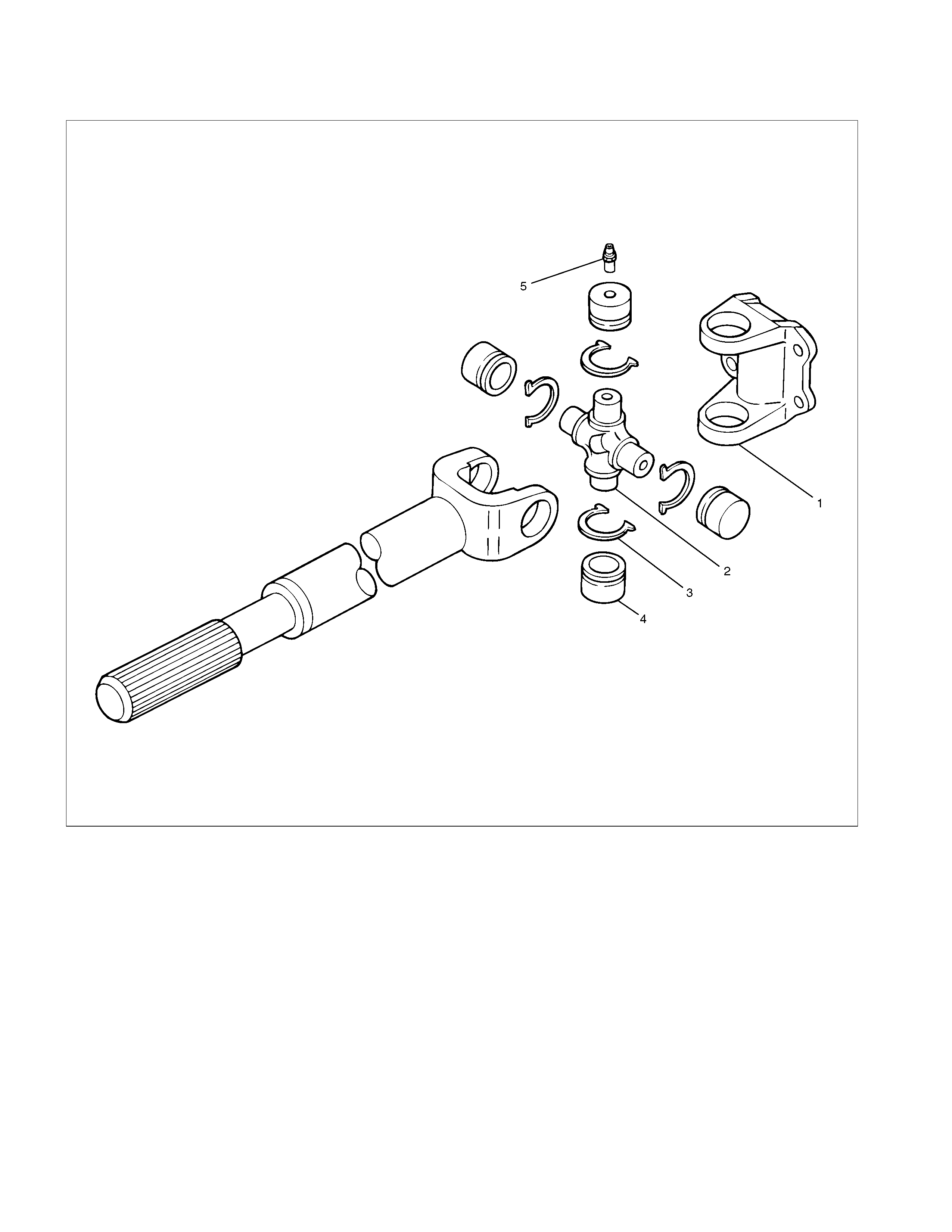
Universal Joint Disassembly
401R300002
Legend
(1). Snap Ring
(2). Needle Roller Bearing
(3). Spider
(4). Propeller Shaft
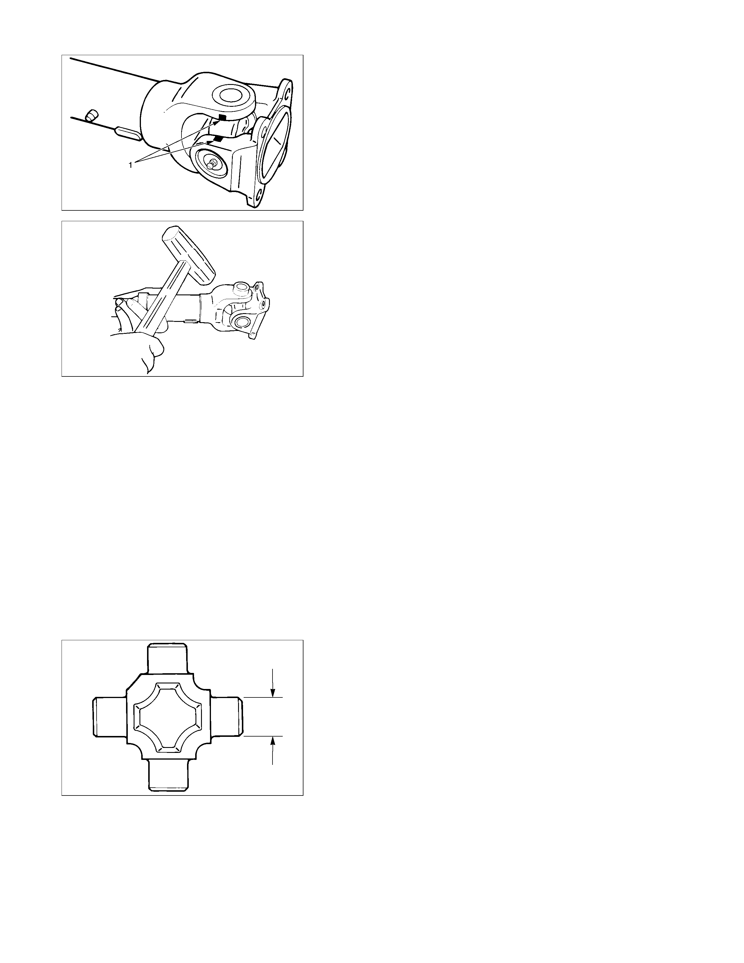
401R300003
1. Remove the snaprings.
• Apply alignment marks on the yokes of the universal
joint.
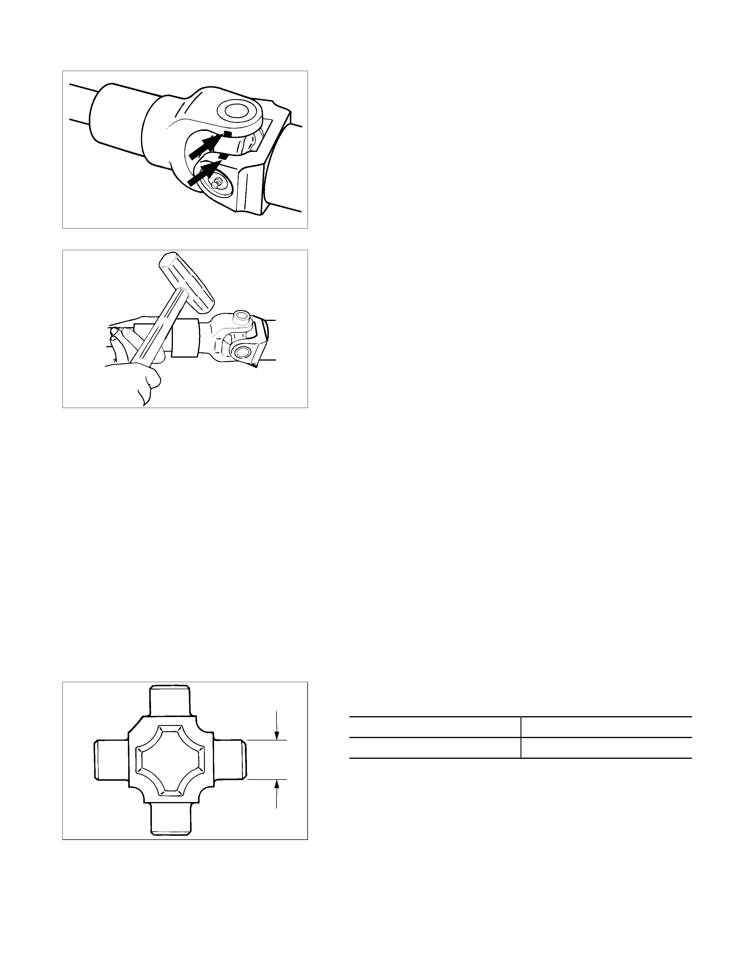
401R300004
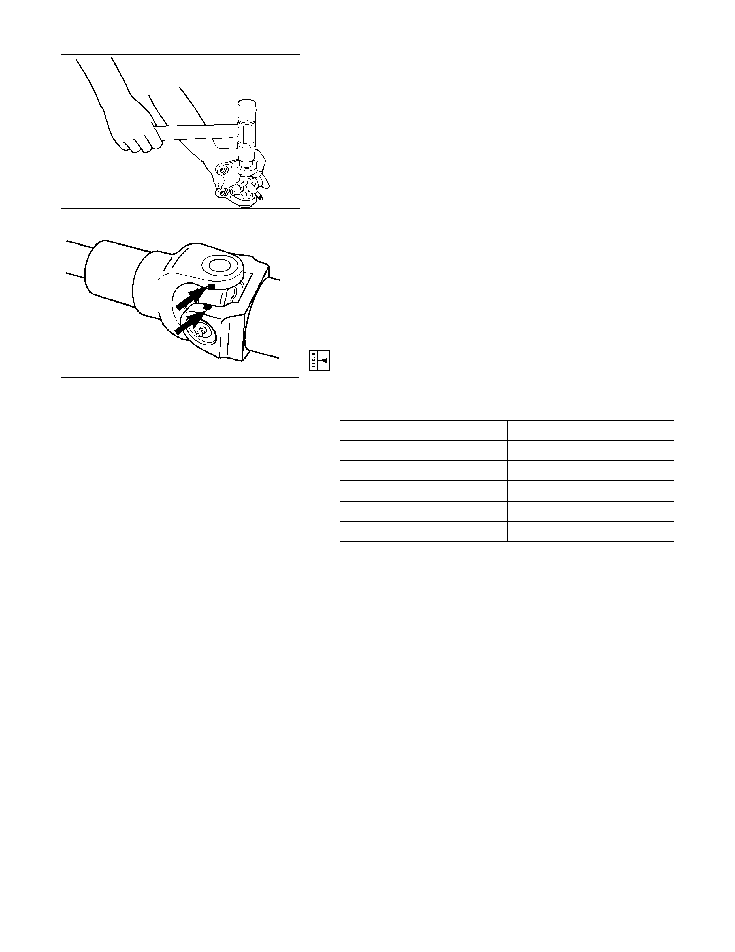
2. Remove the needle roller bearings.
• Tap out the bearing by gently striking the shoulder of the
yoke, using a mallet or a copper hammer.
3. Remove the spider.
• Make sure of proper position for reinstallation b
y
applying setting marks.
4. Remove the propeller shaft.
Inspection and Repair
Make all necessary adjustment, repairs, and part replacements if wear, damage, or other problems are discovered
during inspection.
Visual Check
Inspect following parts for wear, damage, or other abnormal
conditions.
Spider
Needle roller bearing
Yoke
Flange
Center bearing
Cushioning rubber
Bracket
401RS007
Spider Pin Outside Diameter mm(in)
Standard Limit
17 (0.67) 16.99 (0.669)
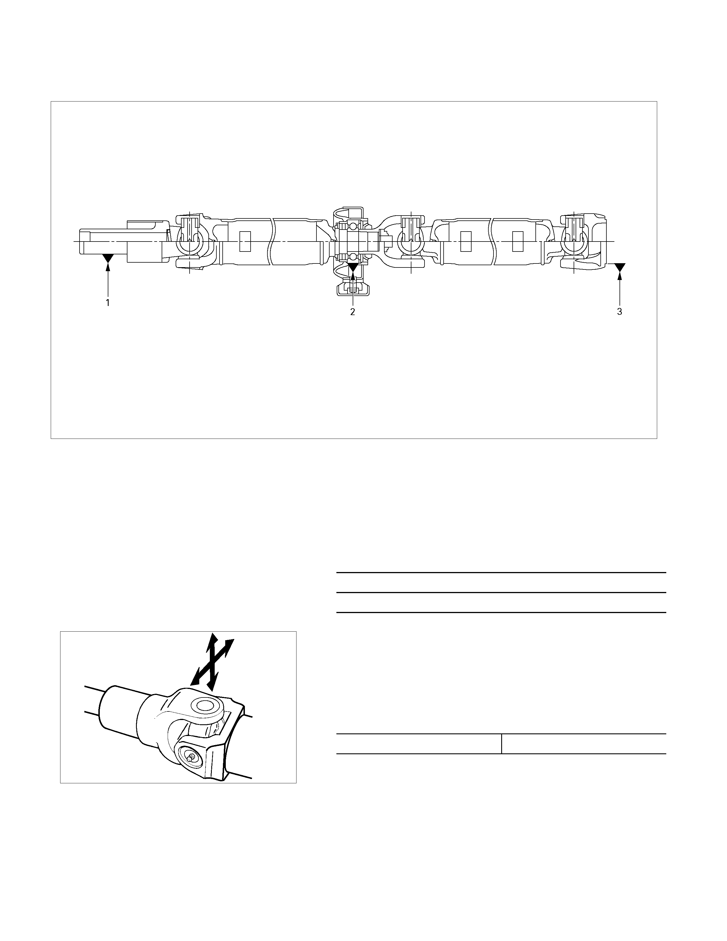
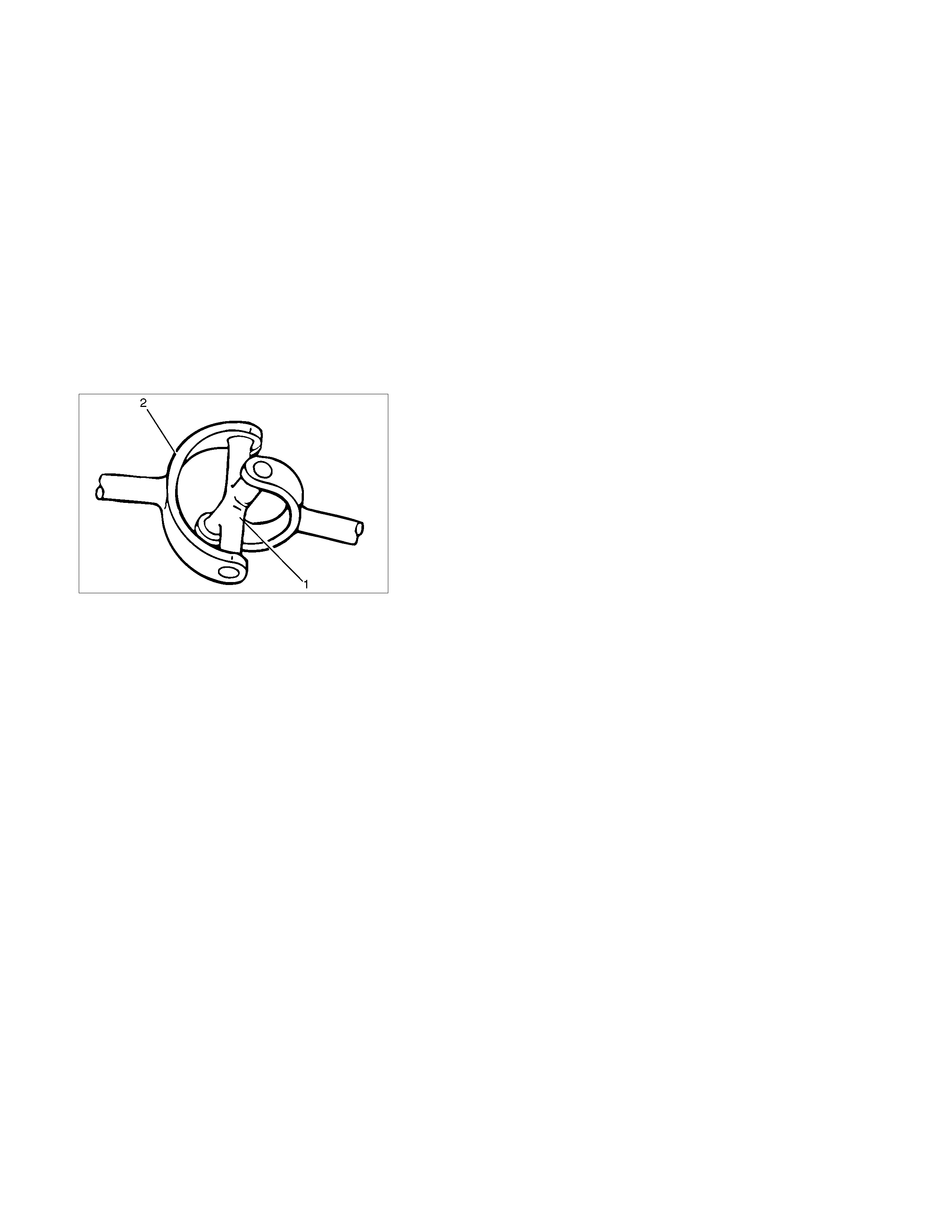
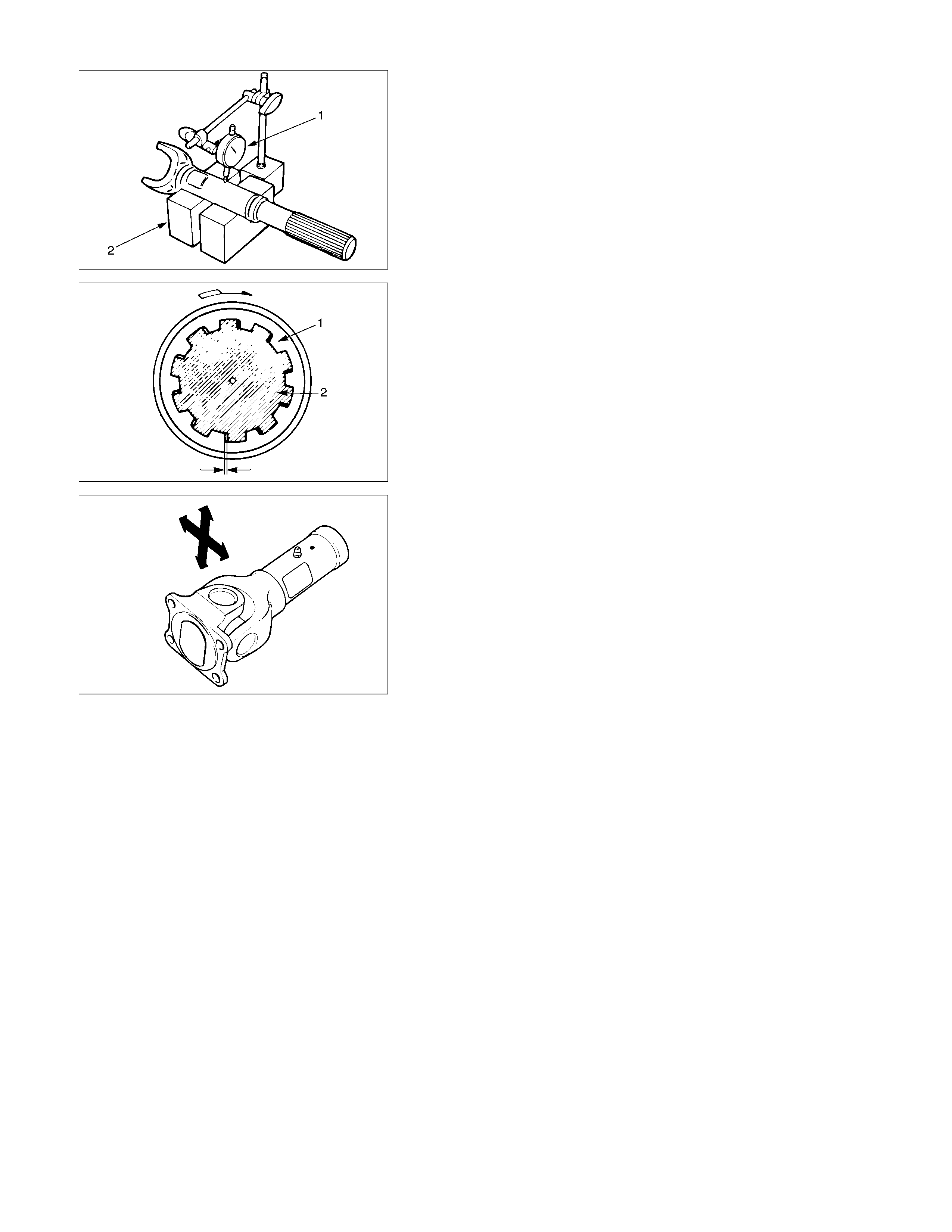
Propeller Shaft Run-Out
401R300005
Support 1 of splined yoke, 2 of center bearing and 3 of flange
yoke and check for static run-out by holding the probe of a dial
indicator in contact with the center part of the shaft and turning
the propeller shaft.
If the amount of run-out is beyond the limit value, correct with a
bench press or replace the shaft with a new one. mm(in)
Limit
1.0 (0.04)
401R300008
Spider Bearing Play
(1) Check the spider bearings for wear or damage.
(2) Check the amount of axial and radial play in spider bearing
by moving the yoke back and forth on the spider axes and
shaft axis. mm(in)
Limit 0.1(0.004)
If the limit is exceeded, replace the shaft assembly.

Universal Joint Reassembly
401RS011
1. Set the propeller shafts.
• Be sure to set the propeller shaft yoke by aligning the
setting marks made during dissassembly.
2. Spider
• Be sure to install the spider by aligning the setting marks
made during disassembly.
3. Needle Roller Bearing
1) Apply a molybdenum-disulfide grease or a multi-purpose.
type grease NLGI No.2 to inside of the bearing cap.
Grease Amount g(oz)
Approx. 1.2 (0.042)
401RS012
2) Using either a mallet (or copper hamm er) or a press, ins tall
the needle roller bearing into the yoke s o that snap ring c an
be installed in its groove.
CAUTION:
•
••
• The needle roller bearing cannot be installed smoothly
if it is set at an incorrect angle with the flange.
•
••
• Excessive hammering will damage the needle rolle
r
bearing.
401R300003
3) Align setting marks and join the yokes.
NOTE:
Assemble the spider and spline yoke so that their grease
fittings are arranged on the same side.(4×4)
4. Snap ring
NOTE:
Discard used snap rings and install new ones.
When the bearing cap is in position, select and attach a snap
ring of suitable thickness so that the end play of the spider pin
is held within 0.1mm (0.004in). mm(in)
Snap ring thickness Identification color
1.5 (0.059) Blue
1.545 (0.061) White
1.59 (0.063) Yellow
1.635 (0.064) Green
1.68 (0.066) Not colored
NOTE:
Be sure to use snap rings of the same thickness on both sides.
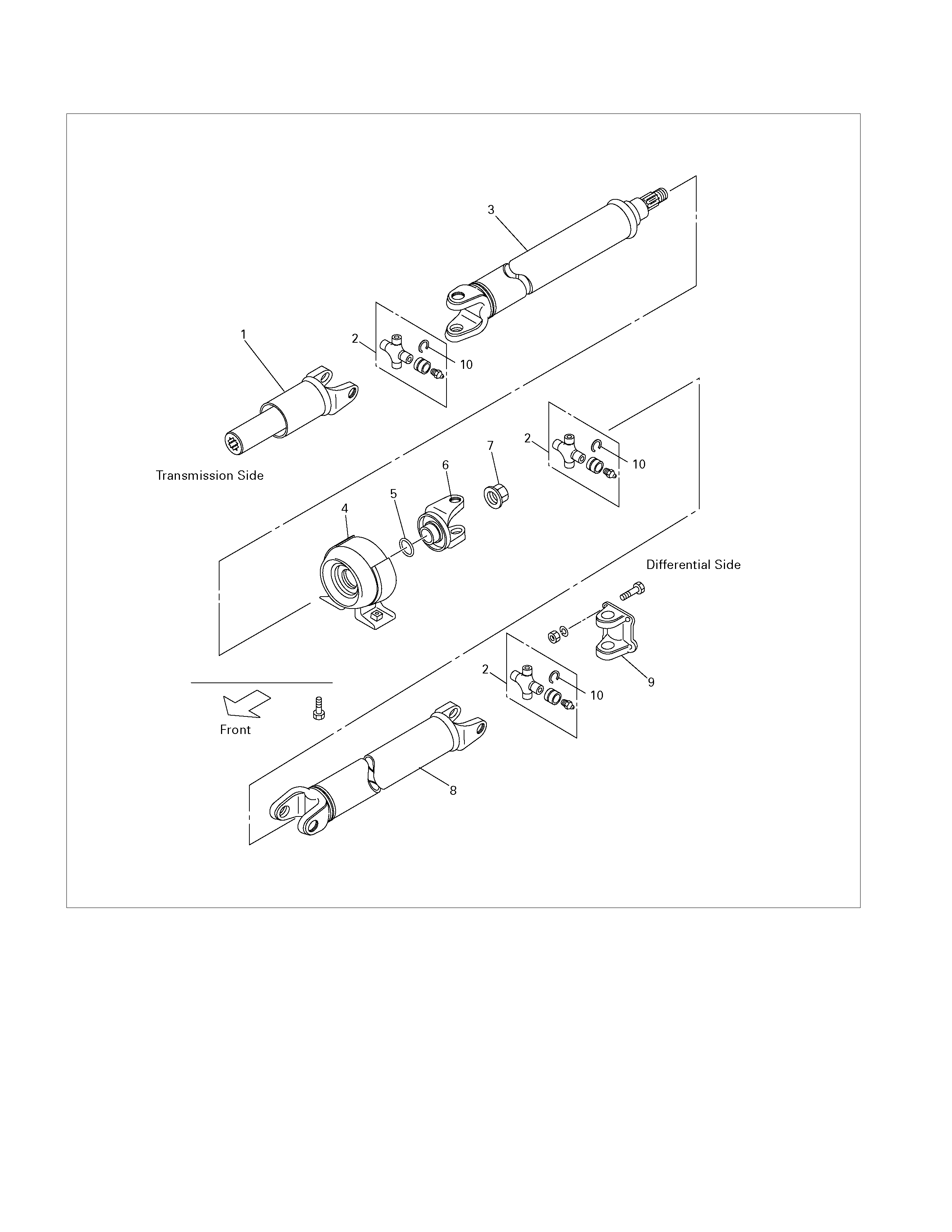
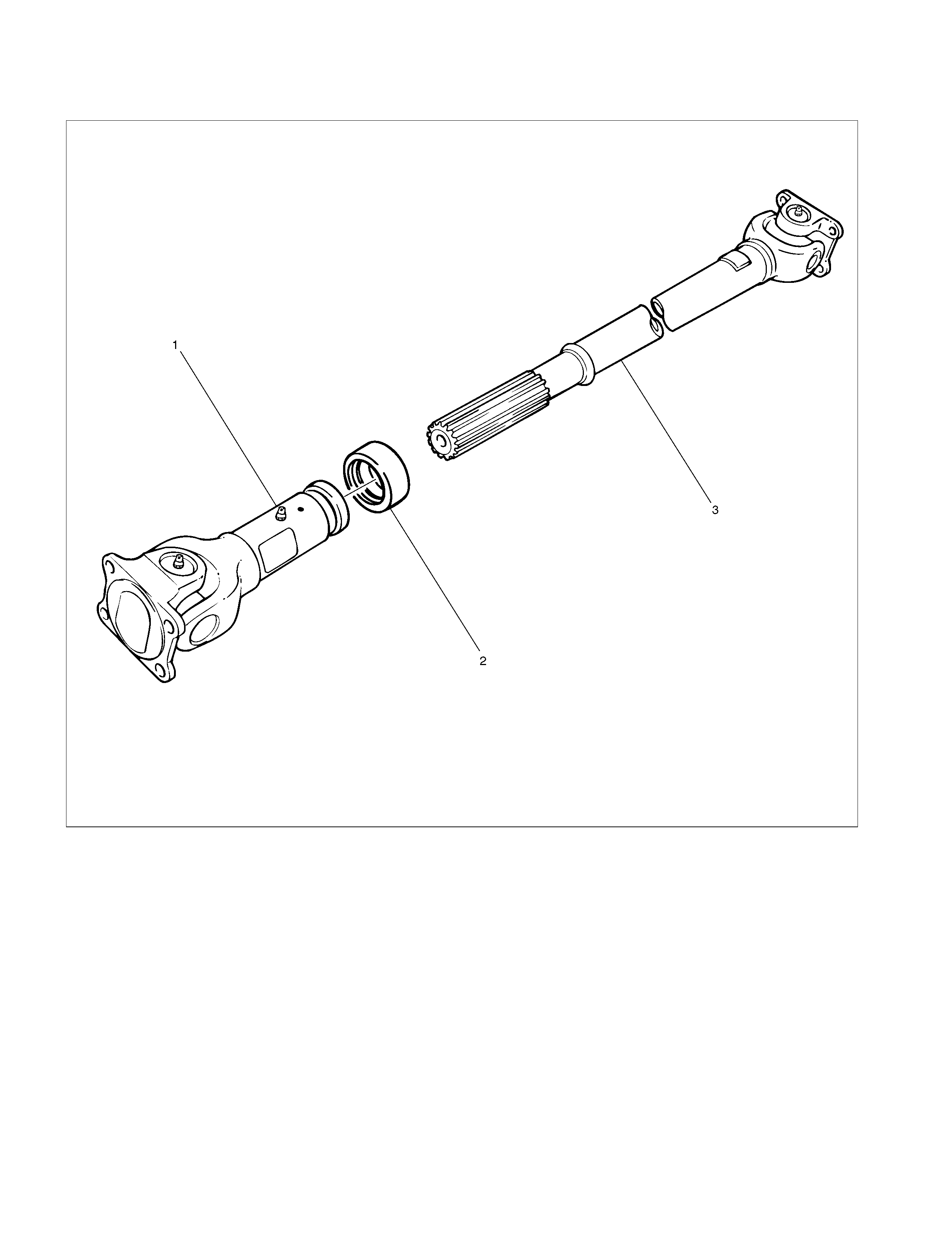
Rear Propeller Shaft Assembly
401R300009
Legend
(1). Splined Yoke
(2). Journal Assembly
(3). 1st Tube Assembly
(4). Center Bearing
(5). Plain Washer
(6). Center Yoke
(7). Lock Nut
(8). 2nd Tube Assembly
(9). Flange Yoke
(10). Snap Ring
Disassembly
1. Disassembly the three portions of the journal assemblies.
2. Remove the s plined yoke, the 1st tube ass em bly with cente
r
bearing, the 2nd tube assembly and the flange yoke.
3. Remove the lock nut.
4. Remove the center yoke, the plain washer the cente
r
bearing and the 1st tube assembly.
Reassembly
1. Install the center bearing on the 1st tube assembly.
Clean the bearing fitting face.
Repack the grease.
Amount of grease
required g(oz)
Approx. 12 (0.42)
2. Install the plain washer and the center yoke.
3. Install the lock nut and tighten it to the specified torque.
Lock nut Torque : 118 N⋅
⋅⋅⋅m (12.0kg⋅
⋅⋅⋅m/87lb⋅
⋅⋅⋅ft)
(1) Discard the flange nut and install a new one.
(2) Stak e the outer f ace of the flange nut agains t the slot in the
shaft.
4. Install the splined yoke, the 1st tube assembly with cente
r
bearing, the 2nd tube assembly and the flange yoke b
y
assembling the universal joint.
Front Propeller Shaft (4JH1-TC)
Removal and Installation
401R300014
Legend
(1) Bolt, Nut and Washer (Front Axle Side)
(2) Front Propeller Shaft
(3) Bolt and Washer (Transfer Side)
401RS023
Removal
1. Raise the vehicle on a hoist.
NOTE:
Apply alignment marks on the flange at the rear
propeller shaft both front and rear side.
2. Remove front axle side bolt, nut and washer.
3. Remove transfer side bolt and washer.
4. Remove rear propeller shaft.
401R300017
Inspection and Repair
Propell er Shaft Run-Out
Support the propeller shaft on V-blocks and check for runout
by holding the probe of a dial indicator in contact with the shaft.
If the amount of run-out is beyond the limit value, correct with a
bench press or replace the shaft with a new one. mm(in)
Limit
1.0 (0.04)
401R300008
Spider Bearing Play
(1) Check the spider bearings for wear or damage.
(2) Check the amount of axial and radial play in spider bearing
by moving the yoke back and forth on the spider axes and
shaft axis. mm(in)
Limit 0.1(0.004)
If the limit is exceeded, replace the shaft assembly.
Installation
NOTE:
Completely remove the dust or foreign matter from the
connecting surface of flange coupling on each end of the
propeller shaft.
1. Align the mark which is applied at removal.
Install front propeller shaft and tighten the bolts to the
specified torque.
Transfer Side Bolt Torque: 35N⋅
⋅⋅⋅m (3.6kg⋅
⋅⋅⋅m/26 lb⋅
⋅⋅⋅ft)
Front Axle Bolt Torque: 59N⋅
⋅⋅⋅m (6.0kg⋅
⋅⋅⋅m/43 lb⋅
⋅⋅⋅ft)
Universal Joint Disassembly and Reassembly
401R300002
Legend
(1) Snap Ring
(2) Needle Roller Bearing
(3) Spider
(4) Propeller Shaft
401R300003
Disassembly
1. Remove the snaprings.
•
A
pply alignment marks on the yokes of the universal
joint.

401R300004
2. Remove the needle roller bearings.
• Tap out the bearing by gently s trik ing the shoulder of the
yoke, using a mallet or a copper hammer.
3. Remove the spider.
• Make sure of proper position for reinstallation b
y
applying setting marks.
4. Remove the propeller shaft.
Inspection and Repair
Make all necessary adjustment, repairs, and part replacements
if wear, damage, or other problems are discovered during
inspection.
Visual Check
Inspect following parts for wear, damage, or other abnormal
conditions.
Spider
Needle roller bearing
Yoke
Flange
Center bearing
Cushioning rubber
Bracket
401RS007
Spider Pin Outside Diameter mm(in)
Standard Limit
17 (0.67) 16.99 (0.669)
401RS011
Reassembly
1. Set the propeller shafts.
• Be sure to set the propeller shaft yoke by aligning the
setting marks made during dissassembly.
2. Spider
• Be sur e to ins tall the s pider by aligning the setting mark s
made during disassembly.
3. Needle Roller Bearing
1) Apply a molybdenum-disulfide grease or a multi-
purpose. type grease NLGI No.2 to ins ide of the bearing
cap.
Grease Amount g(oz)
Approx. 1.2 (0.042)
401R5012
2) Using either a mallet (or copper hammer) or a press,
install the needle roller bearing into the yoke so that
snap ring can be installed in its groove.
CAUTION:
•
••
• The needle roller bearing cannot be installed smoothly
if it is set at an incorrect angle with the flange.
•
••
• Excessive hammering will damage the needle rolle
r
bearing.
401R300003
3) Align setting marks and join the yokes.
NOTE:
Assemble the spider and spline yoke so that their grease
fittings are arranged on the same side.(4×4)
4. Snap ring
NOTE:
Discard used snap rings and install new ones.
When the bearing cap is in position, select and attach a snap
ring of suitable thickness so that the end play of the spider pin
is held within 0.1mm (0.004in). mm(in)
Snap ring thickness Identification color
1.5 (0.059) Blue
1.545 (0.061) White
1.59 (0.063) Yellow
1.635 (0.064) Green
1.68 (0.066) Not colored
NOTE:
Be sure to use snap rings of the same thickness on both sides.
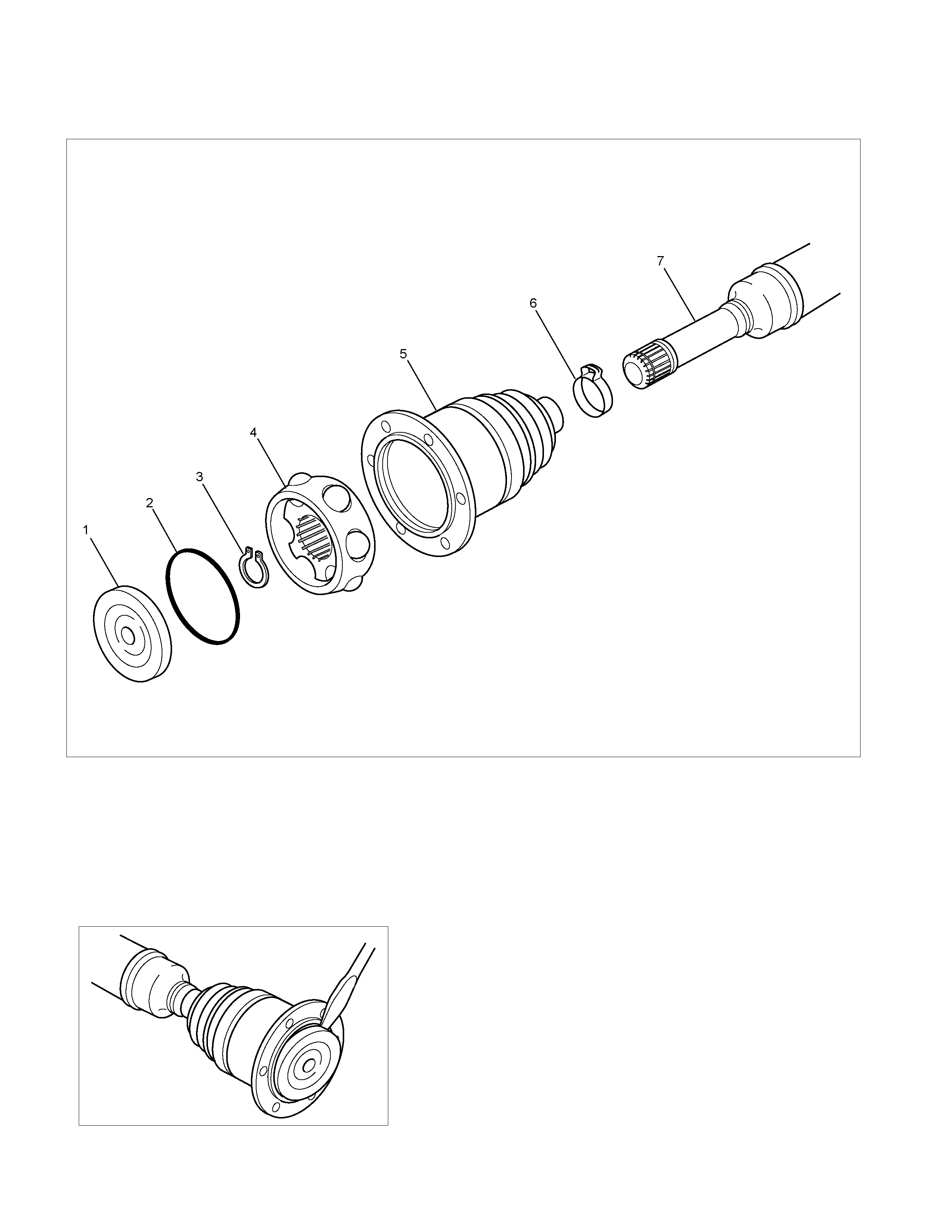
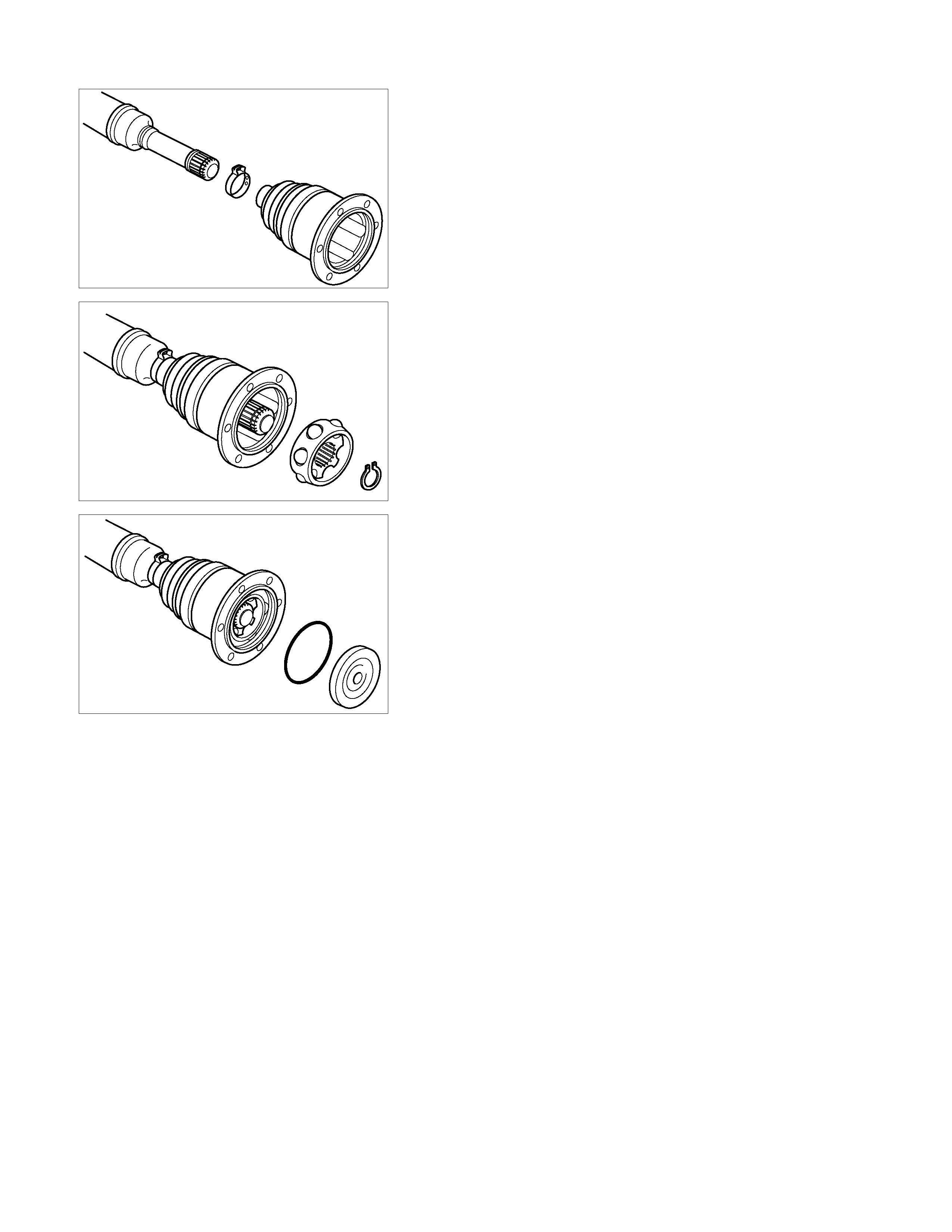
DOJ Disassembly and Reassembly
RTW34MF000201
Legend
(1) Seal Plate
(2) O-ring
(3) Snap Ring
(4) Ball, Ball Retainer, Ball Guide
(5) DOJ Case and Bellows ASM
(6) Band
(7) Shaft
RTW34ASH000101
Disassembly
1. Pry off the seal plate
2. Remove the O-ring.
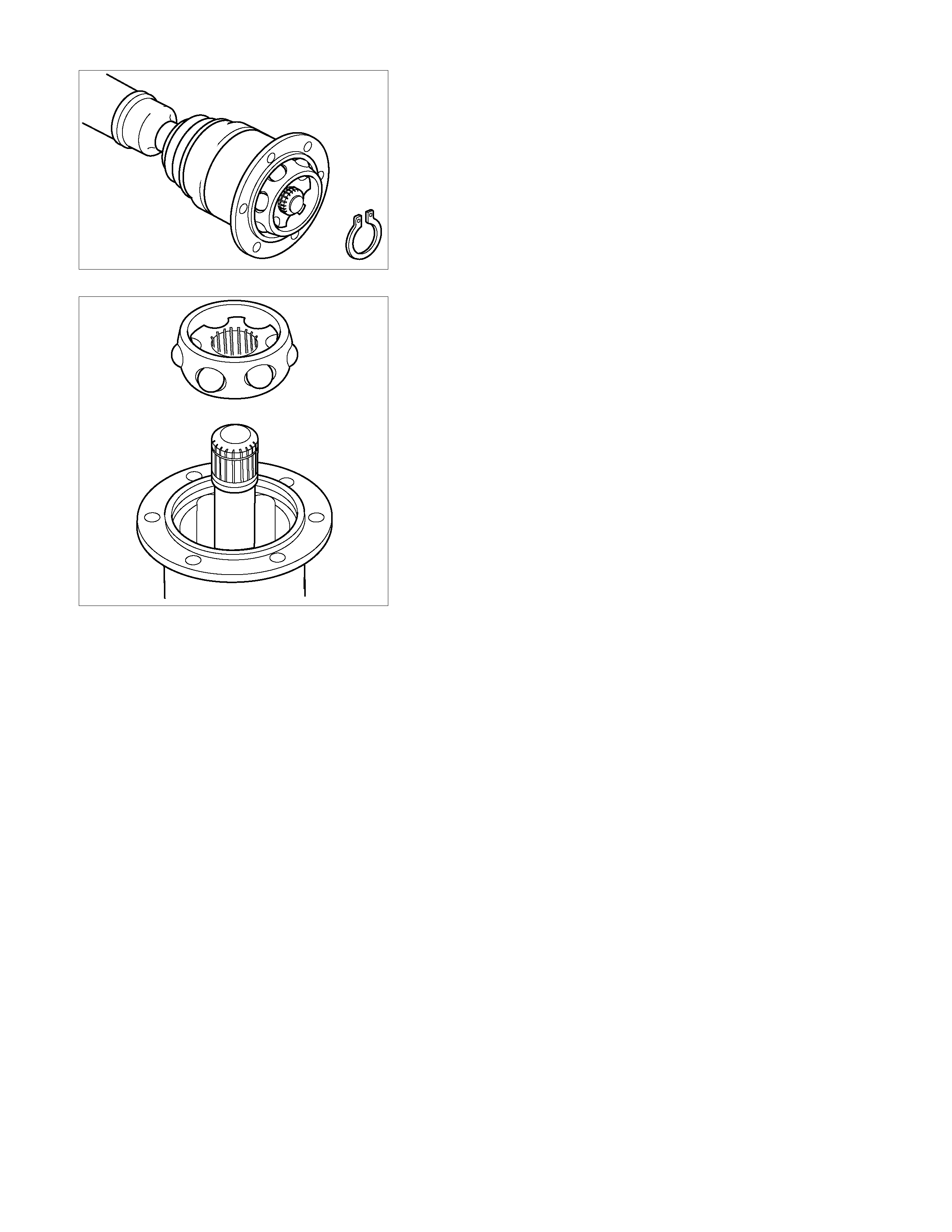
RTW34ASH000201
3. Remove the snap ring.
RTW34ASH000701
4. Remove the ball, ball retainer and ball guide.
5. Remove the band.
6. Remove DOJ case bellows ASM.
Inspection And Repair
Make necessary correction or parts replacement if wear,
damage, corrosion or any other abnormal condition are found
through inspection.
RTW34ASH000401
Reassembly
1. Install a new band.
2. Pack 75g of specified grease in bellows.
The specified grease is included in the DOJ kit.
3. Apply a thin coat of grease to the shaft for smooth
installation then install DOJ case and bellows ASM.
RTW34ASH000501
4. Install the ball, ball retainer and ball guide with the small
diameter side ahead onto the shaft.
5. Use snap ring pliers, install a new snap ring securing the
ball retainer to the shaft.
NOTE:
• Do not extend the snap ring too much.
Snap ring stretching will result in reduce snap ring tension.
• Use only new snap rings. Do not install the old ones.
RTW34ASH000601
6. Pack 45g of specified grease in DOJ case.
The specified grease is included in the DOJ kit.
7. Install a new O-ring into the DOJ case groove.
8. Install a new seal plate.
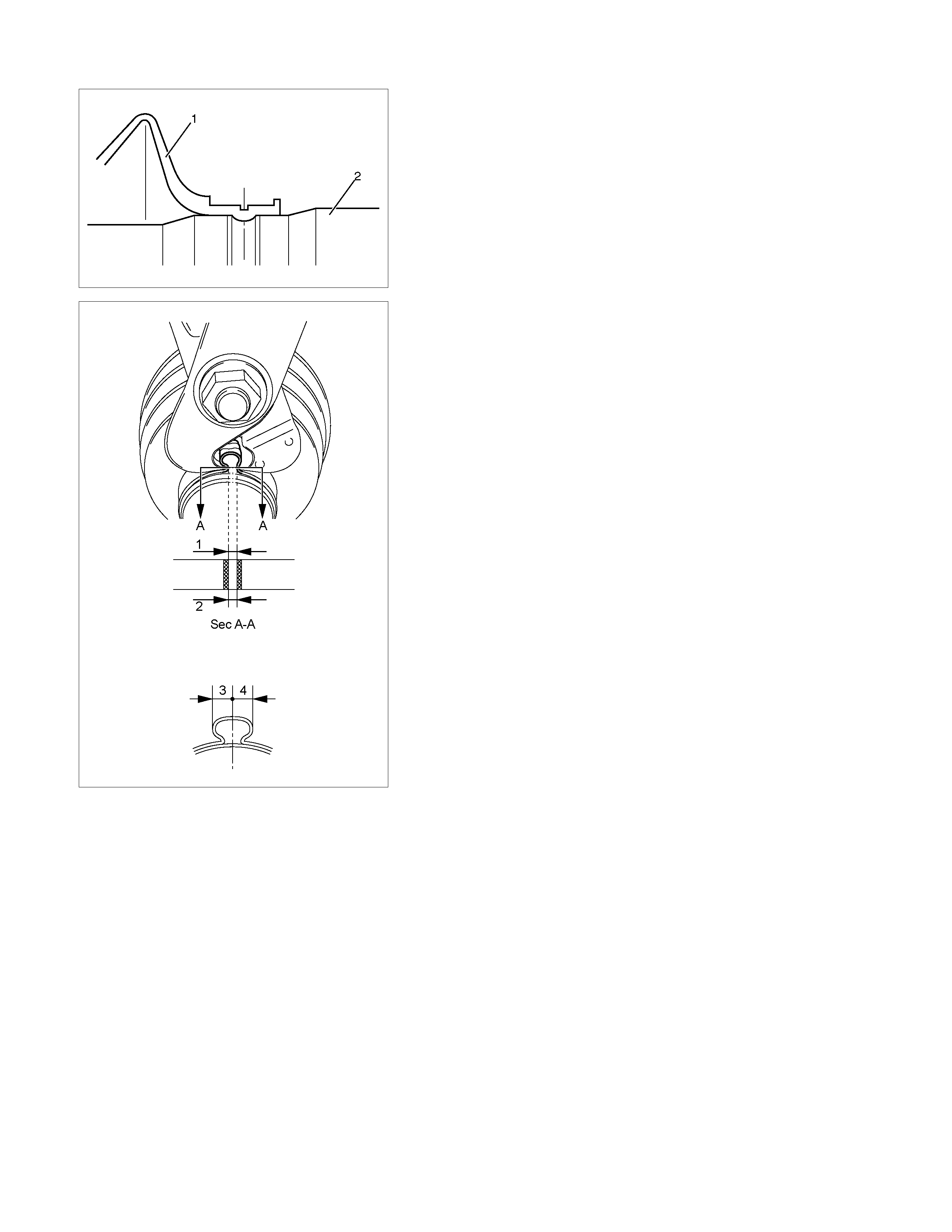
412R100007
9. During bellows assem bly, be sure to insert sm all end of the
bellows (1) into the shaft (2) groove.
RTW24AMH000101
10. Use the special tool pliers 5-8840-2745-0 to caulk the
bands to the specified value.
After installation, check Standard Caulk Measure.
Standard Caulk Measure
• 1.2mm (0.05in) <= (1) and (2) <= 4.0mm (0.16in)
• (1) − (2) or (2) − (1) <= 0.4mm (0.016in)
• (3) ≈ (4)
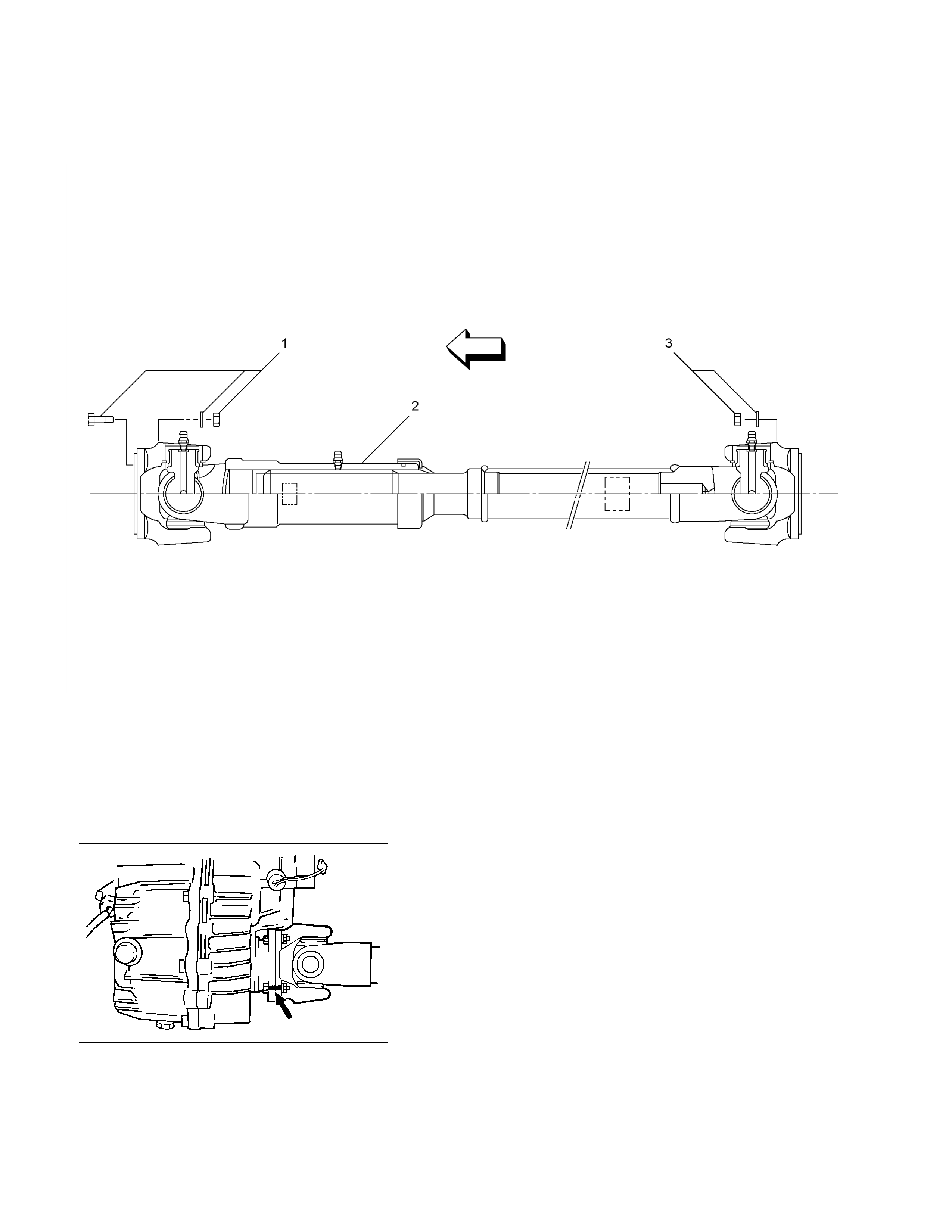
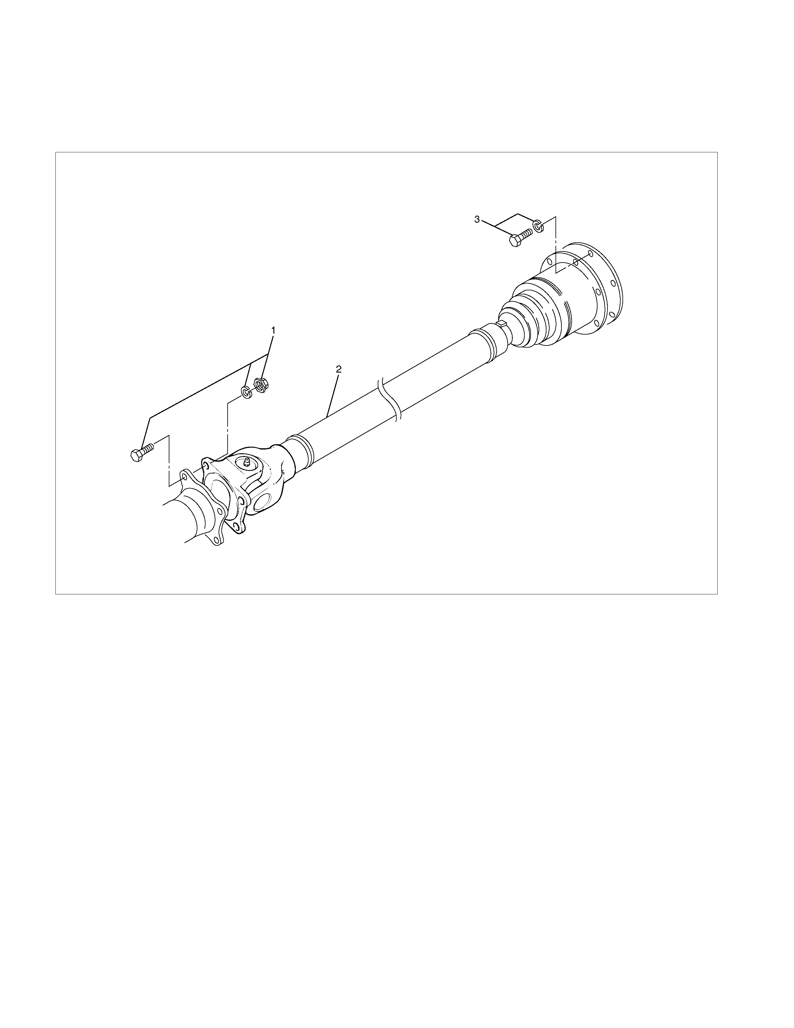
Front Propeller Shaft (6VE1)
Removal and Installation
RTW34AMF000301
Legend
(1) Bolt, Nut and Washer (Front Axle Side)
(2) Front Propeller Shaft
(3) Nut and Washer (Transfer Side)
401RS020
Removal
1. Jack up the vehicle and support it on the chassis stands.
2. Gear shift lever should be placed in neutral position and
parking brake released.
3. Remove the exhaust and transfer protectors.
NOTE:
Apply alignment marks on the flange at the front propeller shaft
both front and rear side.
4. Remove bolt, nut and washer (Front axle side).
5. Remove bolt, nut and washer (Transfer side).
6. Remove front propeller shaft.
Installation
NOTE:
Never install the shaft assembly backwards. Completely
remove the black paint from the connecting surface of flange
coupling on each end of propeller shaft. Clean so that no
foreign matter will be caught in between.
1.
A
lign the mark which was applied at removal. Install front
propeller shaft and tighten the bolts and nuts to the
specified torque.
Torque: 59 N⋅
⋅⋅⋅m (6.0 kg⋅
⋅⋅⋅m/43 lb ft)
2. Install the exhaust and transfer protectors.
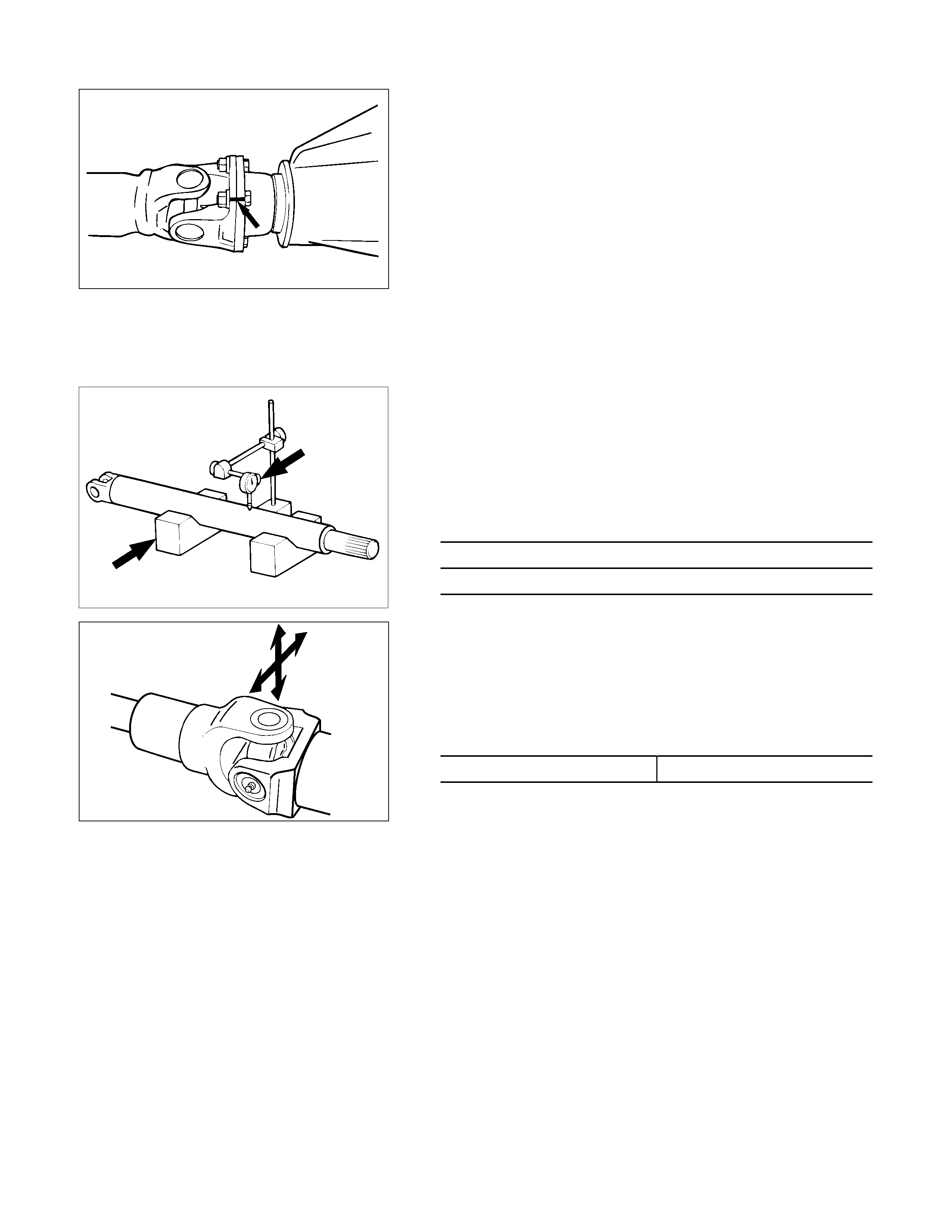
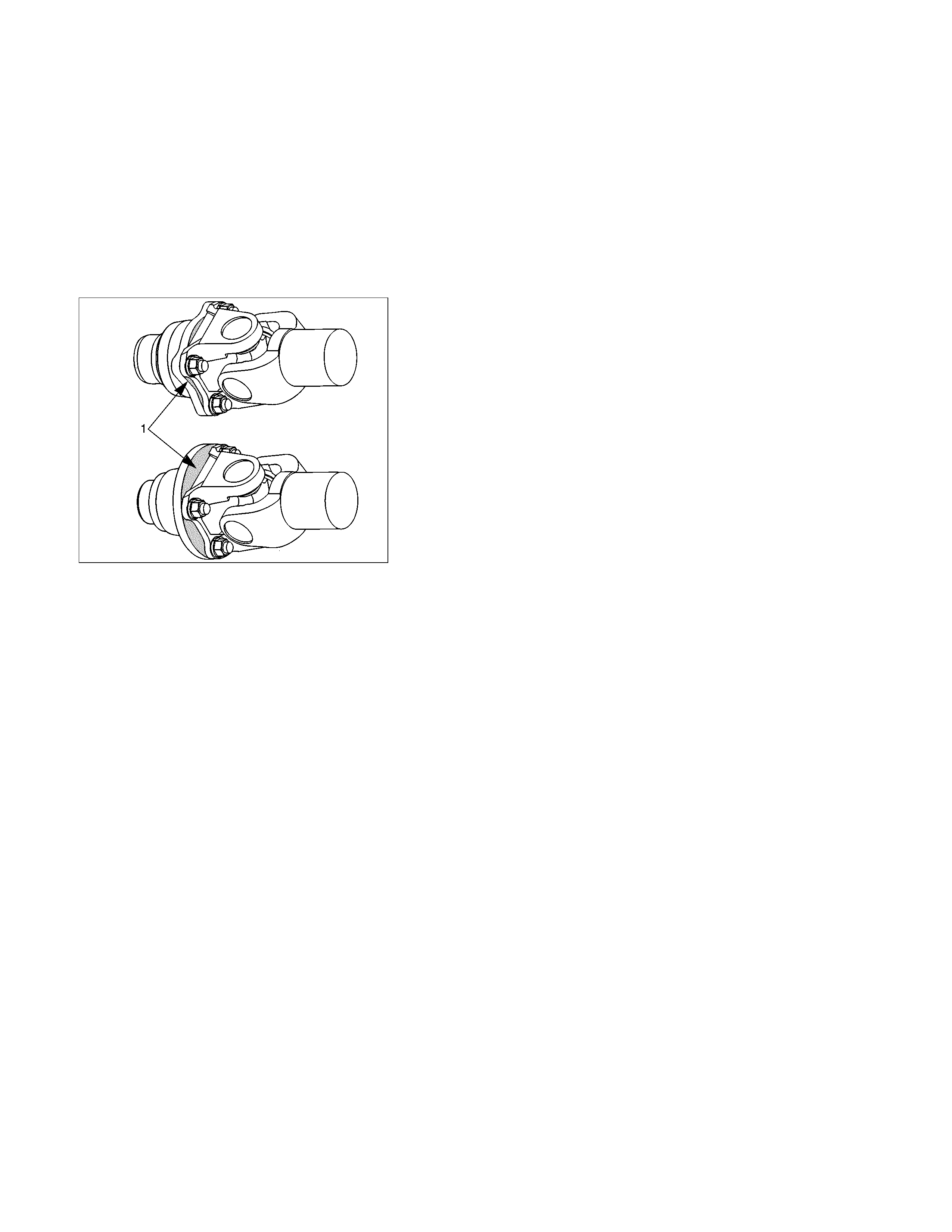
401RS019
3.
A
fter installing the propeller shaft, be sure to apply black
paint (1) to exposed area (other than connec ting surf ace) o
f
the entire surface of flange coupling.
Disassembly
401RW057
Legend
(1) Sleeve Yoke
(2) Seal
(3) Tube Assembly
401RW056
1.
A
pply alignment marks (1) on the sleeve yoke and tube
assembly then remove sleeve yoke.
2. Remove seal.
3. Remove tube assembly.
Universal Joint Disassembly and Reassembly
401RW055
Legend
(1) Flange Yoke
(2) Spider
(3) Snap Ring
(4) Needle Roller Bearing
(5) Grease Fitting
401RS028
1.
A
pply alignment marks (1) on the yokes of the universal
joint, then remove snap ring.
401RS006
2. Tap out the needle roller bearing by gently striking the
shoulder of the yoke, using a mallet or a copper hammer.
3. Make sure of proper position for reinstallation by applying
setting marks, then remove spider.
Inspection and Repair
Make necessary correction or parts replacement if wear,
damage, corrosion or any other abnormal condition is found
through inspection.
NOTE:
When any part of the journal assembly (spider, needle roller
bearing) requires replacement, be sure to replace the entire
assembly.
Check the following parts for wear, damage, noise or any other
abnormal conditions:
1. Spider
2. Needle roller bearing
3. Yoke
4. Flange
5. Constant velocity joint
401RS007
Outside Diameter of Spider Pin
Standard: 17.00 mm (0.669 in)
Limit: 16.90 mm (0.665 in)
401RS027
Propeller Shaft Runout
Support the ends of the propeller shaft on V-blocks (2) and
check for runout by holding the probe of a dial indicator (1) in
contact with the center part of the shaft. If the amount of run
out is beyond the standard value for assembly, correct with a
bench press or replace the shaft with a new propeller shaft
assembly.
Standard: 0.3 mm (0.012 in)
Limit: 0.5 mm (0.02 in)
401RS009
Play in Splines in Normal Direction of Rotation
Check the amount of play between the sleeve yoke (1) and the
propeller shaft spline (2) in the direction of rotation, using a
pointed feeler gauge.
Standard: 0.073 0.156 mm (0.003 0.006 in)
Limit: 0.3 mm (0.012 in)
401RS010
Play in Universal Joint
Limit: Less than 0.1 mm (0.004 in)
401RS011
Reassembly
1. Install spider to f lange yok e. Be sure to install the spider b
y
aligning the setting marks made during disassembly.
2. Apply a molybdenumdisulfide grease or a multipurpose
type grease NLGI No. 2 to inside of the bearing cap.
Grease Amount: Approx. 1.2 g (0.042 oz)
401RS012
3. Using either a mallet (or c opper hamm er) or a press , install
the needle roller bearing into the yoke so that the snap ring
can be installed in its groove.
CAUTION:
The needle roller bearing cannot be installed smoothly if it
is set at an incorrect angle with the flange and excessive
hammering will damage the needle roller bearing.
401RS028
4. Align setting marks (1) and join the yokes.
5. Install snap ring.
NOTE:
Discard used snap rings and install new ones.
When the bearing cap is in position, select and attach a snap
ring of suitable thickness so that the end play of the spider pin
is held within 0.1 mm (0.004 in).
Snap ring thickness and Identification color
1.5 mm (0.059 in); Blue
1.53 mm (0.060 in); White
1.59 mm (0.063 in); Yellow
1.62 mm (0.064 in); Green
1.68 mm (0.066 in); Not colored
NOTE:
Be sure to use snap rings of the same thickness
on both sides.
Reassembly
401RW057
Legend
(1) Sleeve Yoke
(2) Seal
(3) Tube Assembly
1. Discard used seal and install new one.
2.
A
lign the alignment marks and install tube assembly to
sleeve yoke.