
SECTION 4B - REAR AXLE
Service Precaution
Main Data and Specifications
Torque Specifications
Recommended Liquid Gasket
Reco mmended Thread Locki ng Agents
Rear Axle Assembly
General Description
Servicing
Rear Axle
Disassembly
Inspection and Repair
Reassembly
Differential Assembly
Disa ss emble d Vie w
Disassembly
Reassembly
Differential Cage Assembly
Disa ss emble d Vie w
Disassembly
Inspection and Repair
Reassembly
Limited Slip Differential (LSD)
Disa ss emble d Vie w
Disassembly
Inspection and Repair
Reassembly
Troubleshooting
Special Service Tool
Techline
Techline

Service Precaution
WARNING:
THIS VEHICLE HAS A SUPPLEMENTAL RESTRAINT SYSTEM (SRS). REFER TO THE SRS COMPONENT AND
WIRING LOCATION VIEW IN ORDER TO DETERMINE WHETHER YOU ARE PERFORMING SERVICE ON OR
NEAR THE SRS COMPONENTS OR THE SRS WIRING. WHEN YOU ARE REFORMING SERVICE ON OR NEAR
THE SRS COMPONENTS OR THE SRS WIRING, REFER TO THE SRS SERVICE INFORMATION. FAILURE TO
FOLLOW WARNINGS COULD RESULT IN POSSIBLE AIR BAG DEPLOYMENT, PERSONAL INJURY, OR
OTHERWISE UNNEEDED SRS SYSTEM REPAIRS.
CAUTION:
Always use the correct fastener in the proper location. When you replace a fastener, use ONLY the exact part
number for that application. HOLDEN will call out those fasteners that require a replacement after removal.
HOLDEN will also call out the fasteners that require thread lockers or thread sealant. UNLESS OTHERWISE
SPECIFIED, do not use supplemental coatings (Paints, greases, or other corrosion inhibitors) on threaded
fasteners or fastener joint interfaces. Generally, such coatings adversely affect the fastener torque and the
joint clamping force, and may damage the fastener. When you install fasteners, use the correct tightening
sequence and specification. Following these instructions can help you avoid damage to parts and systems.

Main Data and Specifications
Rear Axle
Ring gear size mm(in
)
220 (8.66)
Rear axle type Banjo, semi-floating
Rear axle capacity N (kg/lb
)
16475 (1680/3700)
Rear axle case
Axle tube section
Outside diameter mm(in
)
80 (3.15)
Thickness mm(in
)
4.5 (0.118)
Final drive type Single speed
Final gear type Hypoid
Drive pinion bearing preload kg-cm(lb.in
)
Starting torque (At drive pinion flange nut) 7-13 (6.1-11.3)
Preload adjusting method Collapsible
Final gear backlash mm(in
)
0.15-0.20 (0.006-0.008)
Differential carrier assembly
Weight (Dry) kg/l
b
29.0/63.9
Lubrication
Specified gear oil (APL grade) GL5 (STD), GL5LSD (LSD)
Oil capacity lit (US/UK gal
)
2.4 (0.63/0.53)
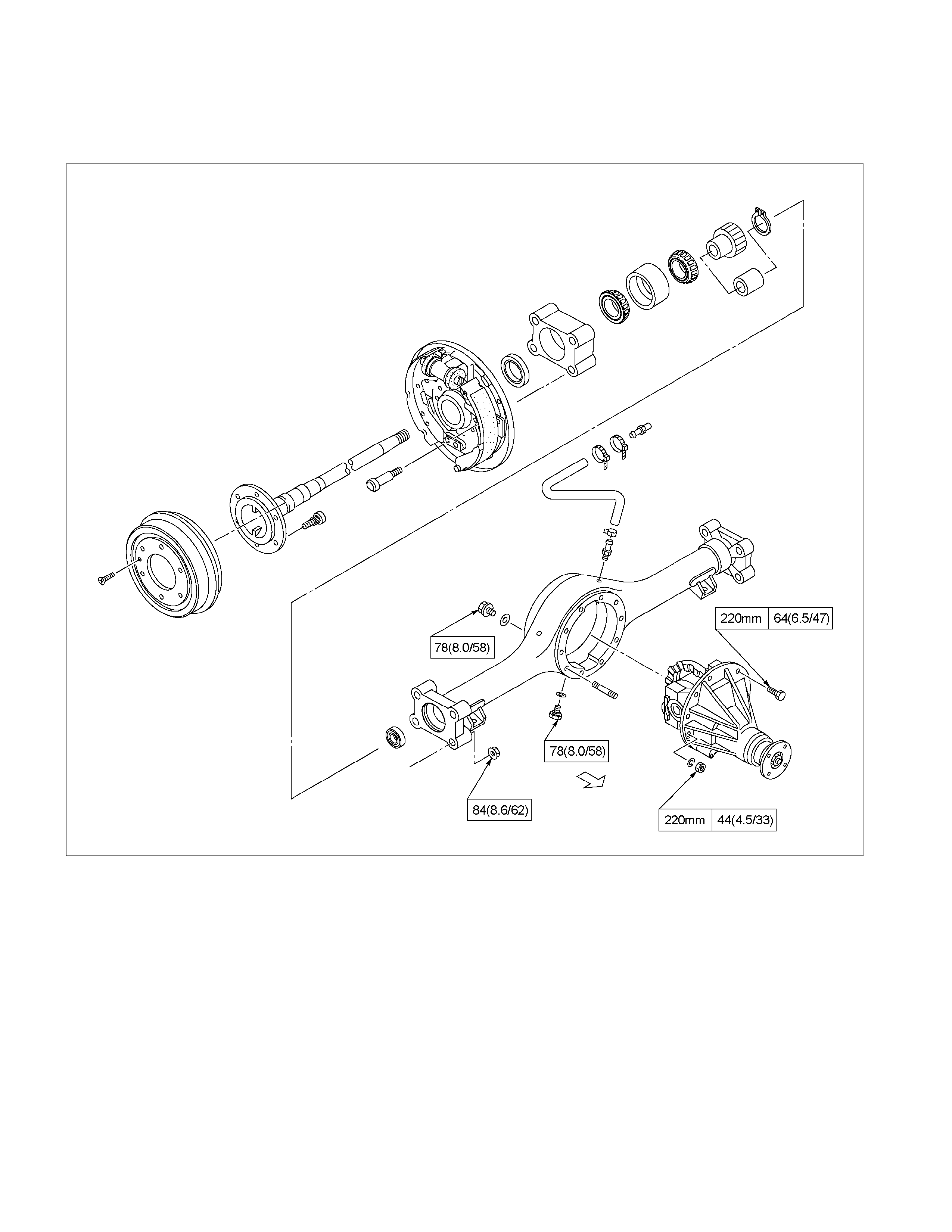
Torque Specifications
Rear Axle N⋅m (kgf⋅m/lb⋅ft)
RTW34BLF000101
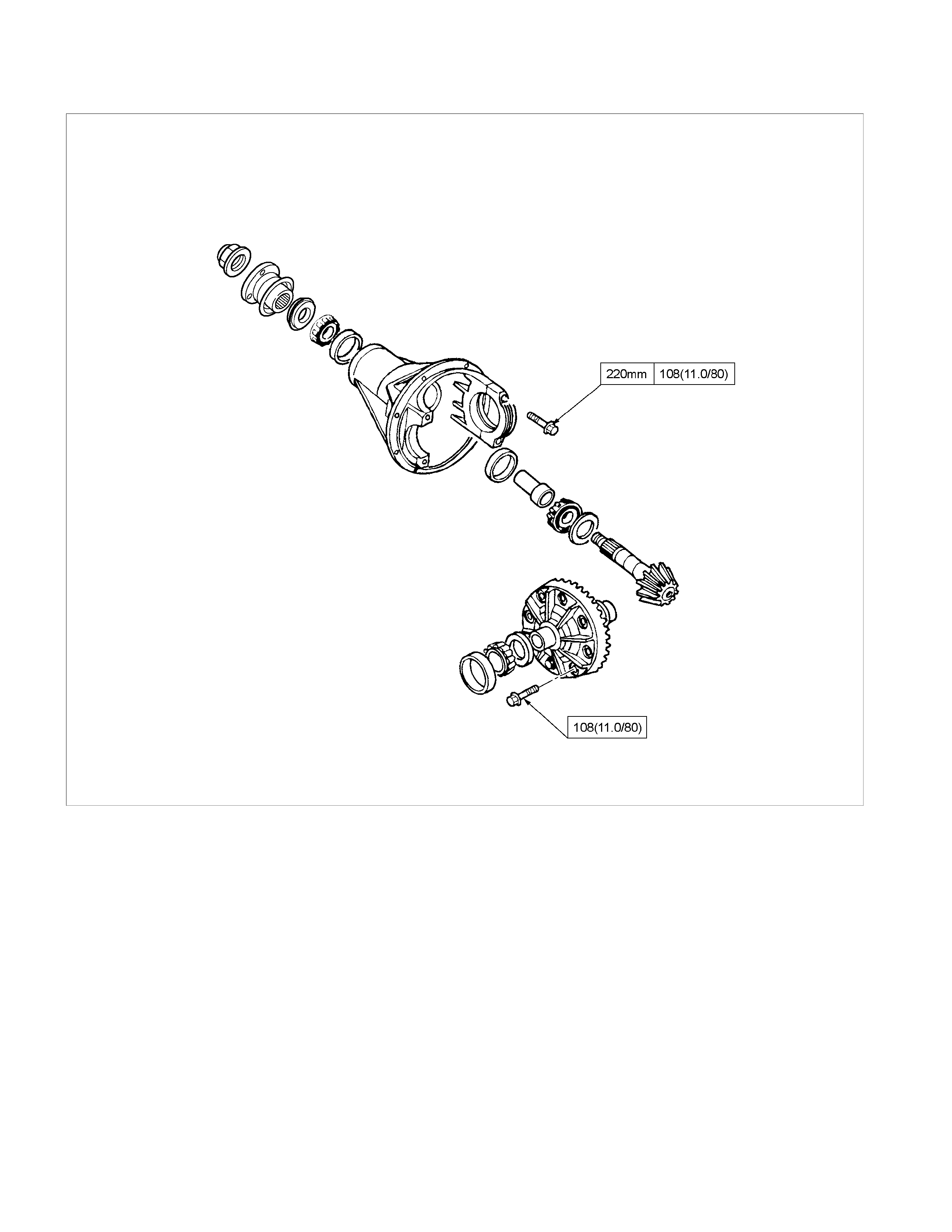
Differential N⋅m (kgf⋅m/lb⋅ft)
RTW34BLF000201
Recommended Liquid Gasket
Type Brand Name Manufacture Remarks
RTV*
Silicon Base
ThreeBond 1207B
ThreeBond 1207C
ThreeBond 1215
Three Bond
Three Bond
Three Bond
For Engine Repairs
For Axle Case
Repairs, T/M
Water Base ThreeBond 1141E Three Bond For Engine Repairs
Solvent
ThreeBond 1104
BelcoBond 4
BelcoBond 401
BelcoBond 402
Three bond
HOLDEN
HOLDEN
HOLDEN
For Engine Repairs
Anaerobic LOCTITE 515
LOCTITE 518 Loctite
Loctite All
* RTV : Room Temperature Vulcanizer
Note :
1. It is very important that the liquid gaskets listed
above or their exact equivalent be used on the
vehicle.
2. Be careful to use the specified amount of liquid
gasket.
Follow the manufacture's instructions at all
times.
3. Be absolutely sure to remove all lubricants and
moisture from the connecting surfaces before
applying the liquid gasket.
The connecting surfaces must be perfectly dry.
4. LOCTITE 515 and LOCTITE 518 harden upon
contact with a metal surface.
Do not apply LOCTITE 515 or LOCTITE 518
between two metal surfaces having a clearance
of greater than 0.25 mm (0.01 in). Poor
adhesion will result.
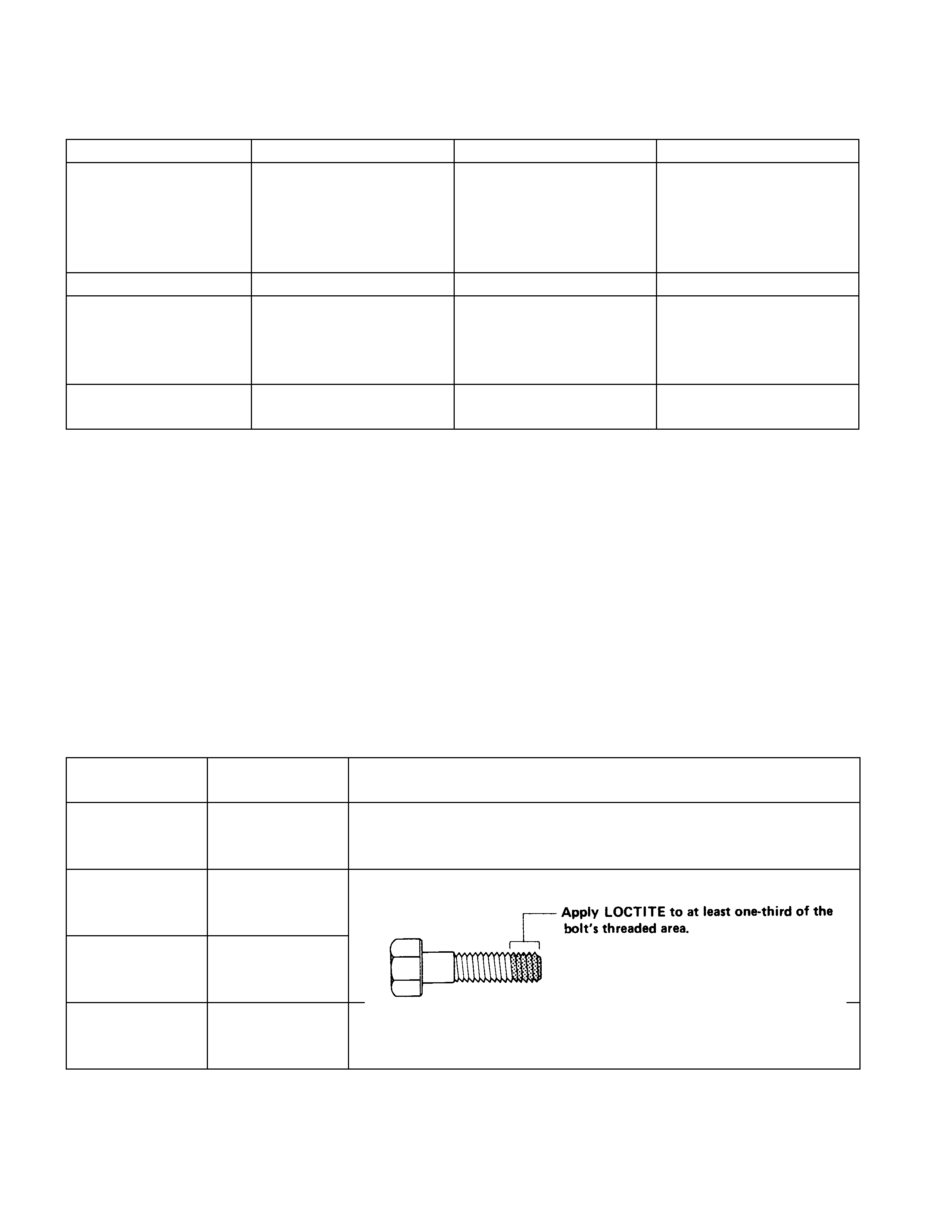
Recommended Thread Locking Agents
LOCTITE Type LOCTITE
Colour Application Steps
LOCTITE 242
Blue 1. Completely remove all lubricant and moisture from the bolts and
the female threaded surfaces of the parts to be joined.
The surfaces must be perfectly dry.
LOCTITE 262
Red 2. Apply LOCTITE to the bolts.
LOCTITE 270
Green
LOCTITE 271
Red
3. Tighten the bolts to the specified torque.
4. Wait at least one hour before continuing the installation procedure.
Rear Axle Assembly
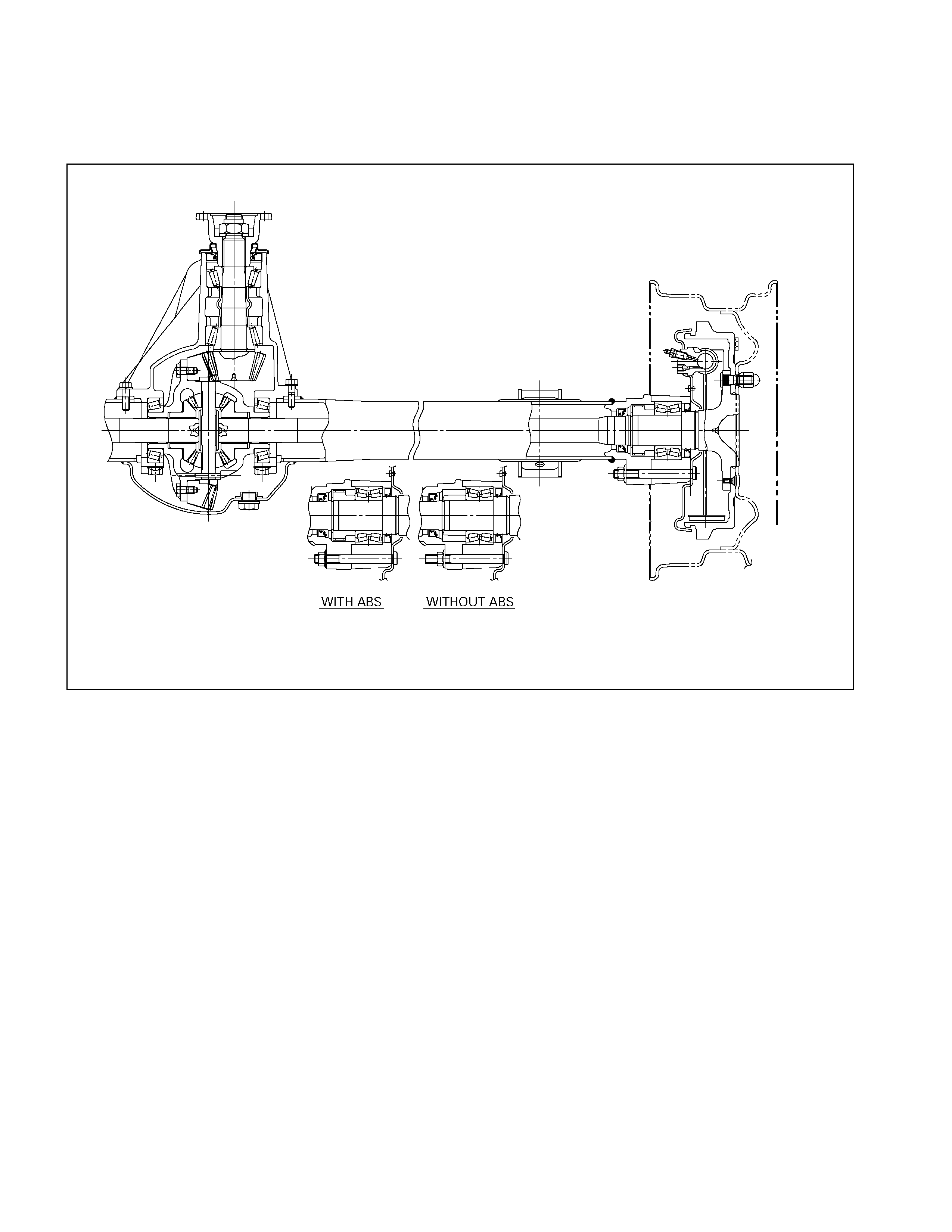
General Description
A03R300001
The rear axle assembly is of the semi–floating type in
which the vehicle weight is carried on the axle housing
.
The centre line of the pinion gear is below the centre
line of the ring gear (hypoid drive).
All parts necessary to transmit power from the
propeller shaft to the rear wheels are enclosed in a
banjo type axle housing.
The 220 mm (8.6 in) ring gear rear axle uses a
conventional ring and pinion gear set to transmit the
driving force of the engine to the rear wheels. This
gear set transfers this driving force at a 90 degree
angle from the propeller shaft to the drive shafts.
The axle shafts are supported at the wheel end of the
shaft by a double tapered roller bearing.
The pinion gear is supported by two tapered roller
bearings. The pinion depth is set by a shim pack
located between the gear end of the pinion and the
roller bearing that is pressed onto the pinion. The
pinion bearing preload is set by crushing a collapsible
spacer between the bearings in the axle housing.
The ring gear is bolted onto the differential cage with
12 bolts.
The differential cage is supported in the axle housing
by two tapered roller bearings. The differential and ring
gear are located in relationship to the pinion by using
selective shims and spacers between the bearing and
the differential cage. To move the ring gear, shims are
deleted from one side and an equal amount are added
to the other side. These shims are also used to
preload the bearings which are pressed onto the
differential cage. Two bearing caps are used to hold
the differential into the rear axle housing.
The differential is used to allow the wheels to turn at
different rates of speed while the rear axle continues
to transmit the driving force. This prevents TYRE
scuffing when going around corners and prevents
premature wear on internal axle parts.
The rear axle is sealed with a pinion seal, a seal at
each axle shaft end, and by a liquid gasket between
the differential carrier and the axle housing
Servicing
Rear Axle Oil Replacement
Oil Capacity liters (US/UK gal.
)
2.4 (0.63/0.53)
Specified gear oil GL5 (API grade)(STD)
GL5LSD (LSD)
Filler Plug and Drain Plug Torque N⋅m (k gf⋅m/lb⋅ft)
78 (8.0/58)
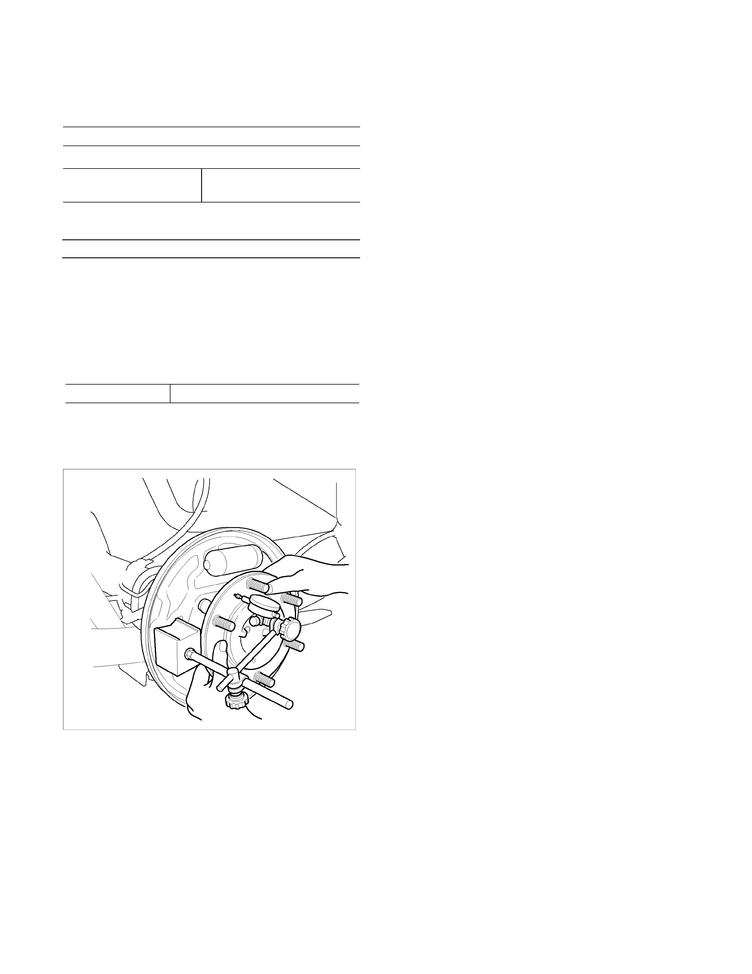
Axle Shaft Roller Bearing Endplay Inspection
1. Raise and suitably support vehicle.
2. Remove the wheel and brake drum.
3. Inspect the axle shaft roller bearing endplay using
dial gauge.
Endplay mm (in
)
Standard 0 ∼ 0.2 (0 ∼ 0.008)
If the endplay exceeds 0.2mm (0.008 in), replace the
axle shaft roller bearings.
Refer to Rear Axle Reassembly.
RTW34BSH000101
Rear Axle
1. Refer to "WHEEL and TYRE" Section for road
wheel disassembly procedure.
2. Refer to Section 5 "BRAKE" for rear brake
removal procedure.
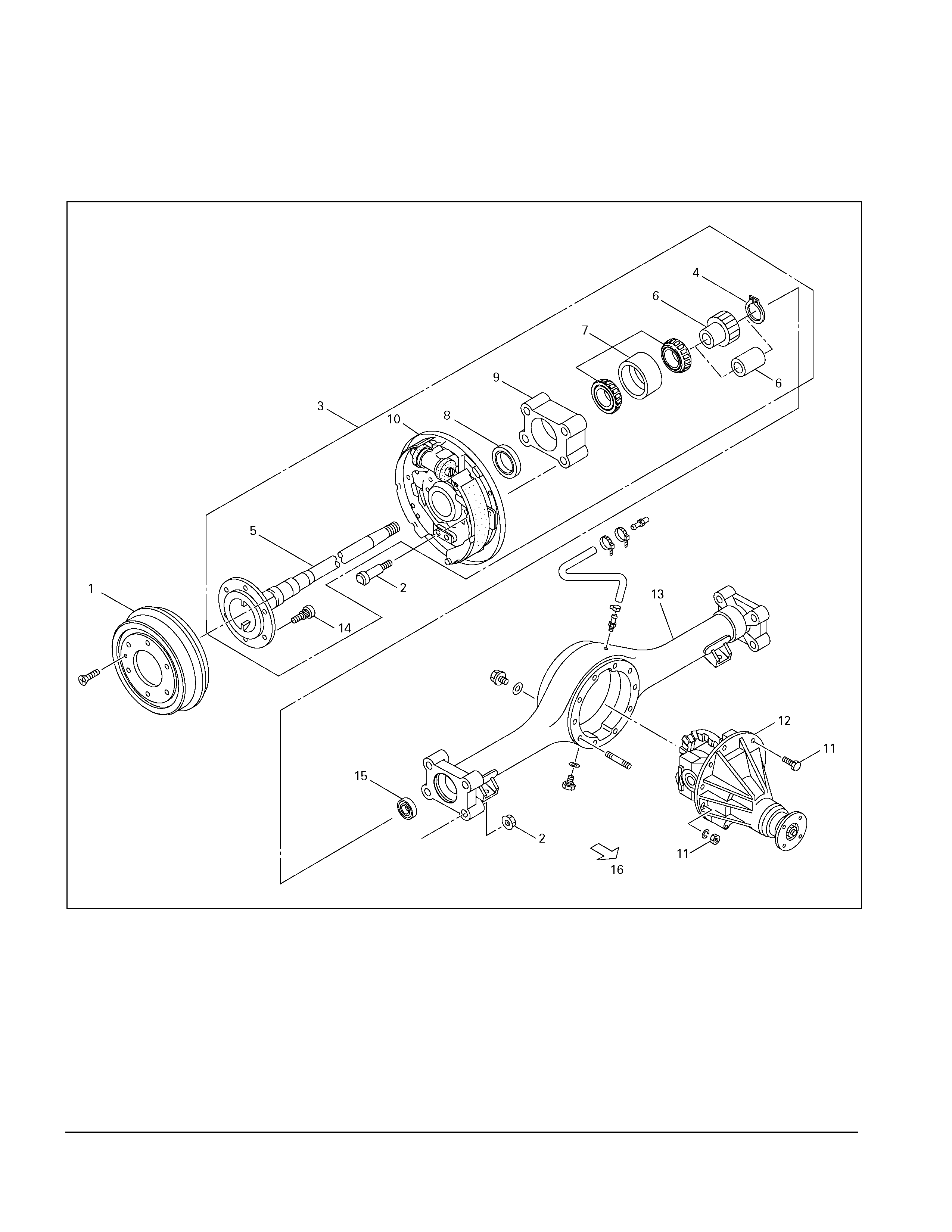
420R300009
Legend
1. Brake Drum
2. Bolt and Nut
3. Axle Shaft Assembly with Brake
4. Snap Ring
5. Axle Shaft
6. Sensor Rotor (with ABS)
Spacer (without ABS)
7. Double Taper Roller Bearing
8. Oil Seal
9. Bearing Holder
10. Rear Brake
11. Bolt and Nut
12. Differential Assembly
13. Rear Axle Case Assembly
14. Wheel Pin
15. Axle Case Oil Seal
16. Front
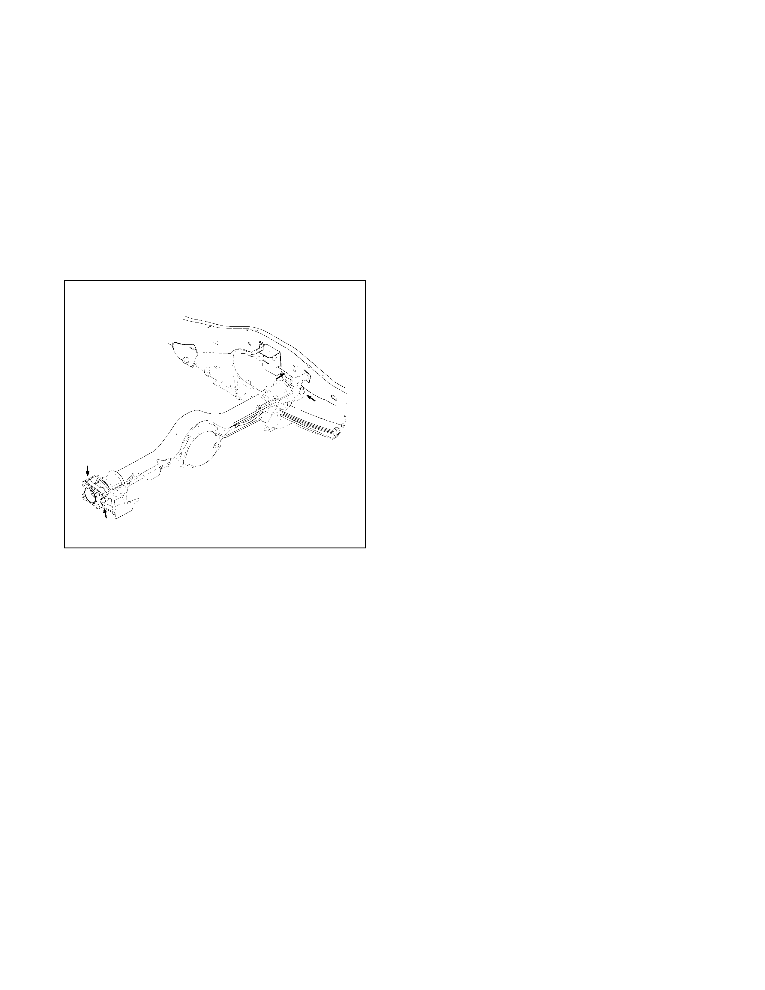
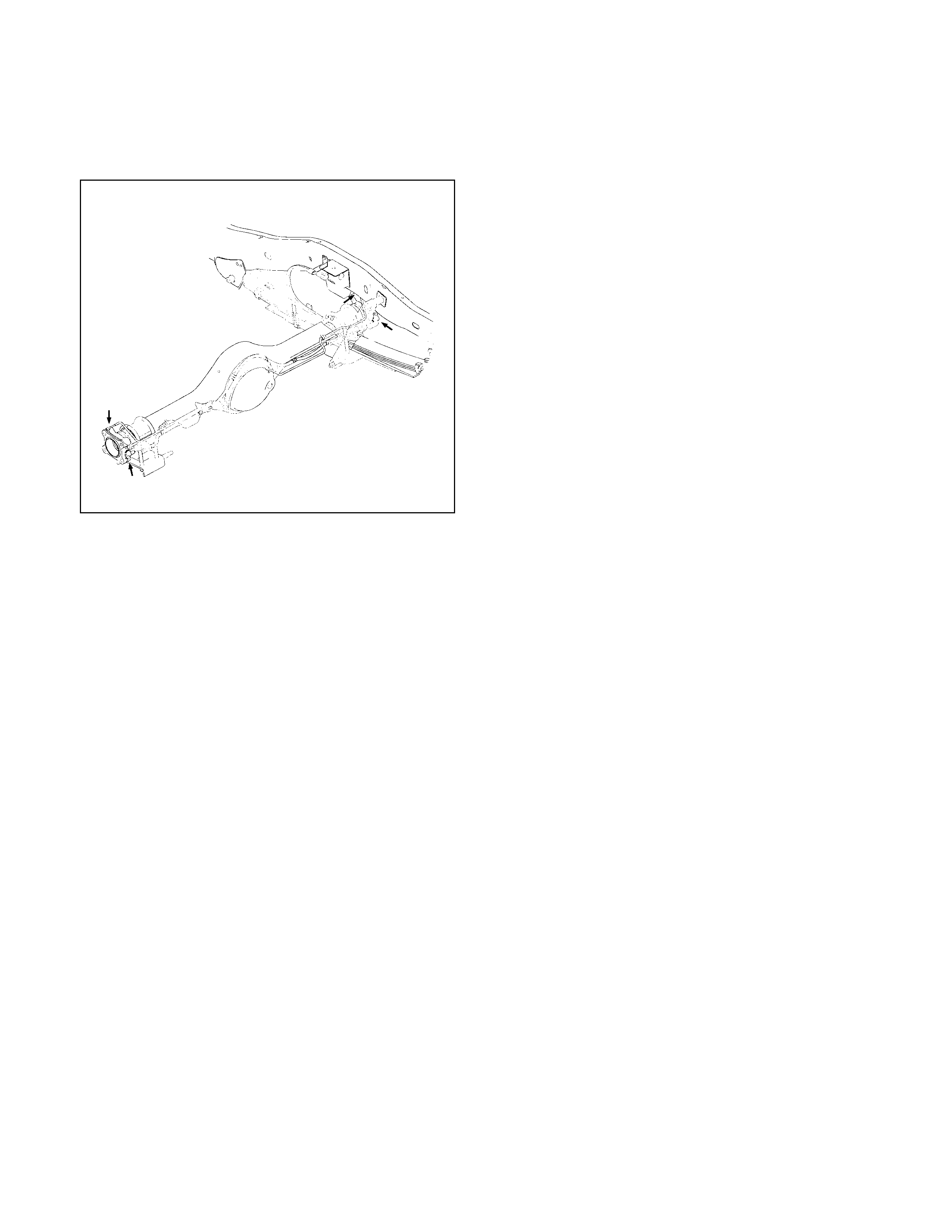
Disassembly
• Raise vehicle to the working level.
• Support the axle assembly with the proper jack
and chassis stands.
• Remove wheel and TYRE.
• Drain differential oil.
• Remove propeller shaft. (Refer to the section
“Rear Propeller Shaft”.)
1. Remove brake drum.
2. Remove ABS sensor. (Refer to the section “ABS”.)
3. Remove brake pipe from wheel cylinder.
420R300003
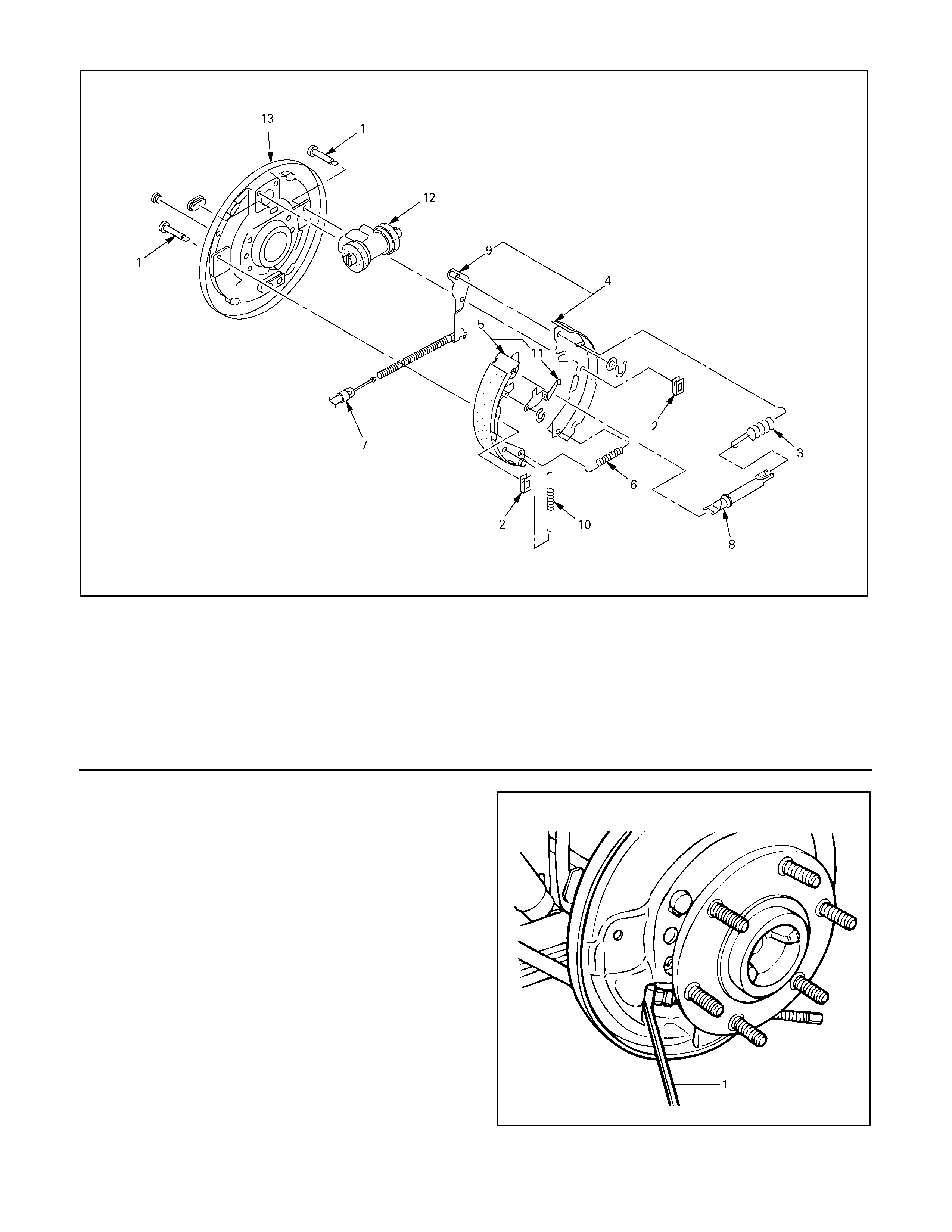
305R30000
Legend
1. Tension Pin
2. Shoe Clamp Spring
3. Return Spring
4. Shoe Assembly with Parking Brake Lever
5. Shoe Assembly with Adjuster Lever
6. Spring
7. Parking Brake Cable
8. Adjuster
9. Parking Brake Lever
10. Adjuster Spring
11. Adjuster Lever
12. Wheel Cylinder
13. Back plate
4. Remove tension pin and shoe clamp spring.
5. Remove return spring.
6. Remove shoe assembly with parking brake lever.
7. Remove shoe assembly with adjuster lever and
spring.
8. Remove parking brake inner cable from parking
brake lever.
9. Use offset box wrench to compress locking lugs
on the cable, then remove parking brake outer
cable from back plate.
311RS012
Legend
1. Offset Box Wrench
10. Remove wheel cylinder.
11. Remove bearing holder fixing nuts.
Note:
Upper two (2) bolts are reamer bolt.
When installation, install them in the upper holes.
12. Tak e out axle shaf t assem bly with back plate and
set it on a bench press as following illustration.
Put bolt head on thick steel plate.
Be car eful not to scratc h or damage axle c ase oil
seal with axle shaft.
13. Remove Snap ring.
14. Remove sensor rotor (or spacer), double tape
r
roller bearing, oil seal, bearing holder, and back
plate from axle shaft by means of a press.
• Discard used oil seal, double taper roller
bearing, snap ring, ABS sensor rotor and
spacer.
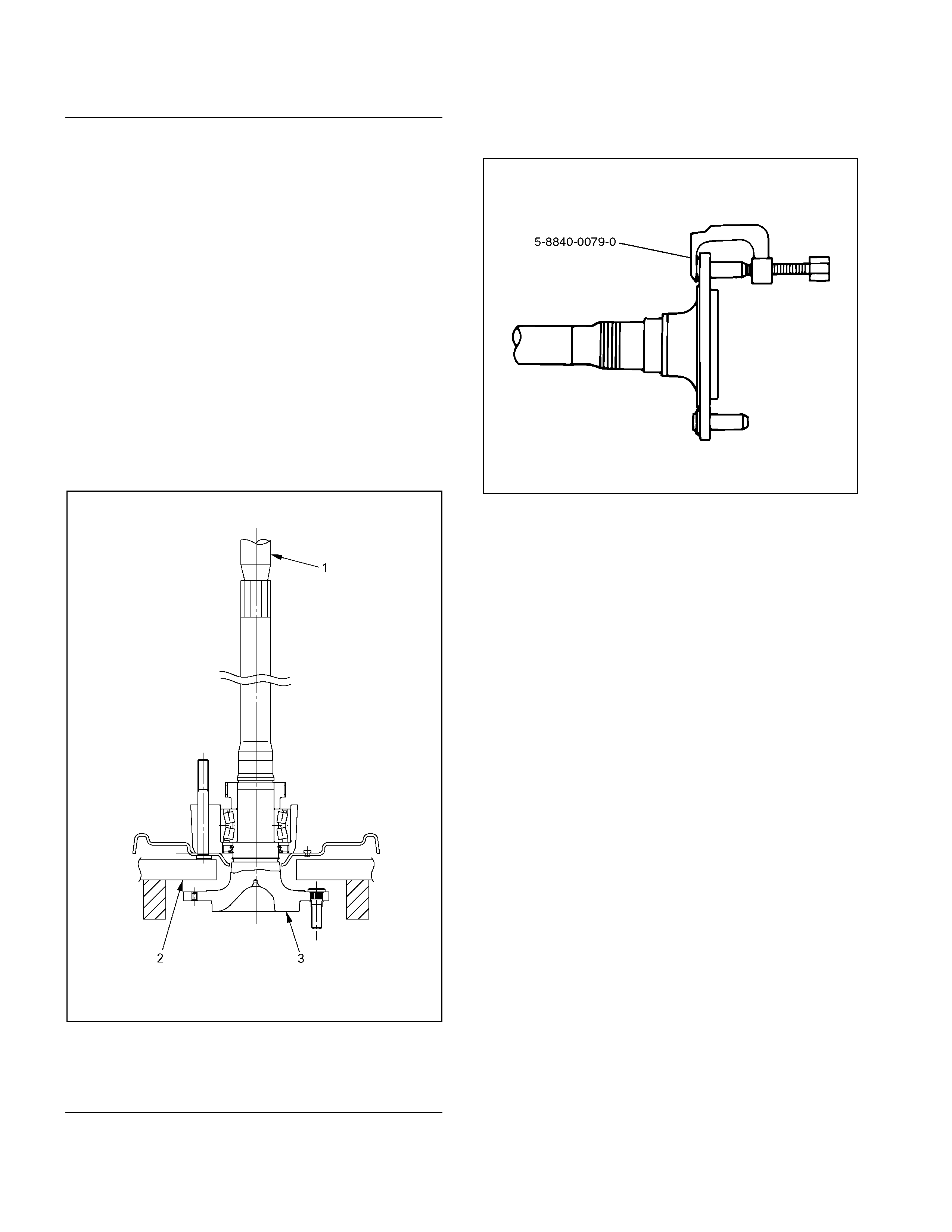
A03R300002
Legend
1. Bench Press Fitting
2. Steel Plate (25-30 mm thickness)
3. Axle Shaft
15. Remove differential assembly fixing bolts and
nuts and take out differential assembly .
16. Remove wheel pin from axle shaft, using the
remover 5-8840-0079-0.
420L100009
17. Remove axle case oil seal.
• Discard used oil seal.
Inspe cti on an d Repa ir
Make all necessary adjustments, repairs, and part
replacements if wear, damage, or other problems are
discovered during inspections.
Visual Check
Inspect the followi ng parts for wear, damage or other
abnormal conditions.
• Axle Shaft
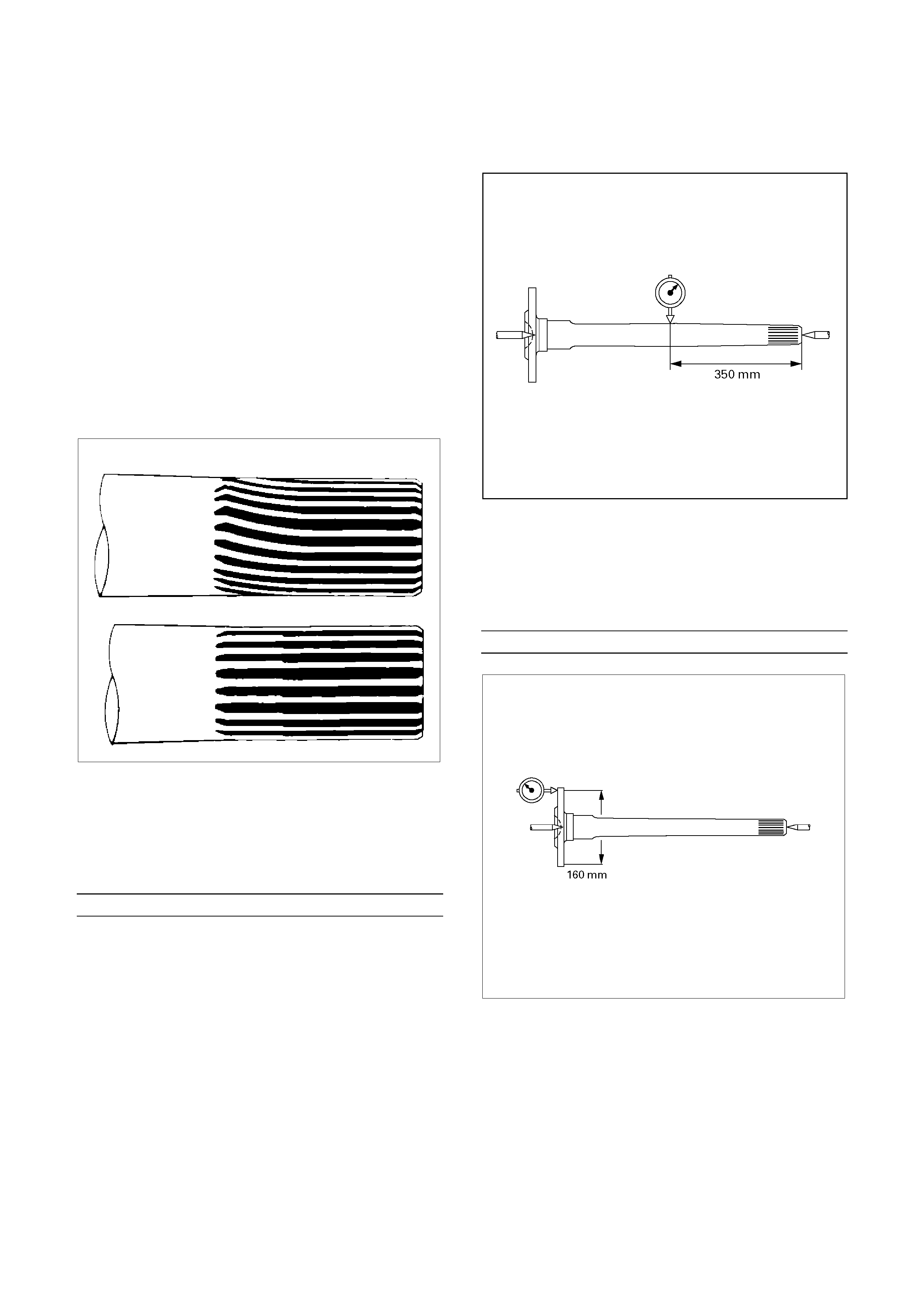
Axle Shaft
When checking the axle shaft, pay special att ention to
the spline d porti ons and replace the shaft if distortion
or step wear is noticeable. Correct slight step wear
with a penci l grinder.
420RS008
Axle Shaft Run-Out
Check the shafts for bending with the use of a dial
indicator in contact with t he shaft. Rotate the shaf t
slowly and observe the dial indic ator.
Limit mm(in
)
1.0 (0.039)
Note :
Never use heat to correct bending.
420RY00019
A xle Shaft Flange Run-Out
Check the axle shaft flange for run-out. Hold the
probe of a dial indicator in contact with t he flange.
Rotate the shaft slowly and observe the dial.
Limit mm(in
)
0.08 (0.003)
420RY00018
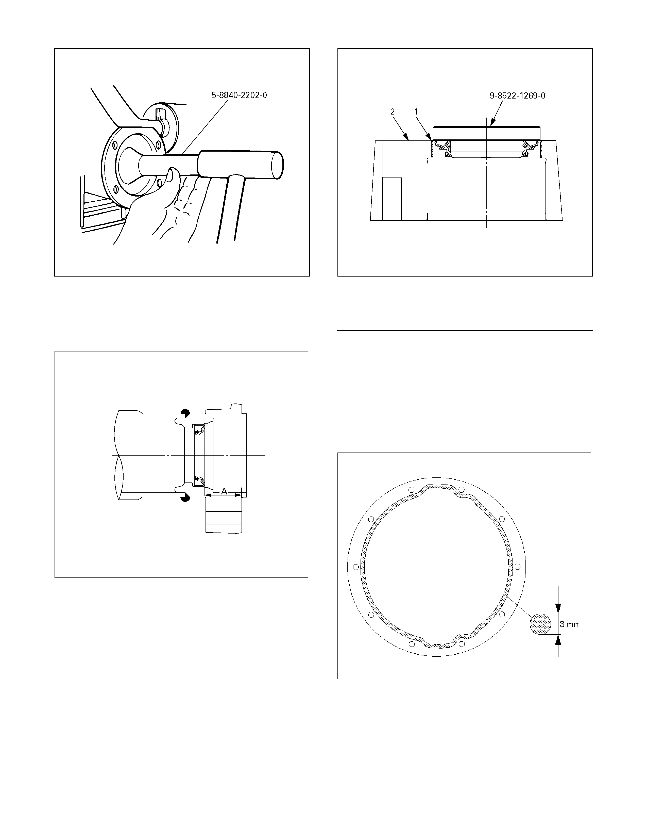
Reassembly
1.
Using the oil seal instal ler 5-8840-2202-0, install
new axle c ase oi l seal .
420R300004
Note :
Confirm that the dimention : A should be 34.5 –
36.1 mm (1.36 – 1.42 in)
A03R300004
2. Install new oil seal in bearing holder, using the oil
seal installer 9-8522-1269-0.
F04R300002
Legend
1. Oil Seal
2. Bearing Holder
3. Drive wheel pin into axle shaft flange, using a
hammer.
4. Differential assembly
a. Clean the mating surface of axle case and
differential carrier.
b. Apply Three Bond 1215 (TB1215) or
equivalent on the surface of differential
assembly as flowing illustration.
425RS006
c. Tighten bolts and nuts to the specified torque.
Torque : Bolt 64 N⋅m (6.5 kg⋅m/47 lb⋅ft)
Nut 44 N⋅m (4.5 kg⋅m/33 lb⋅ft)
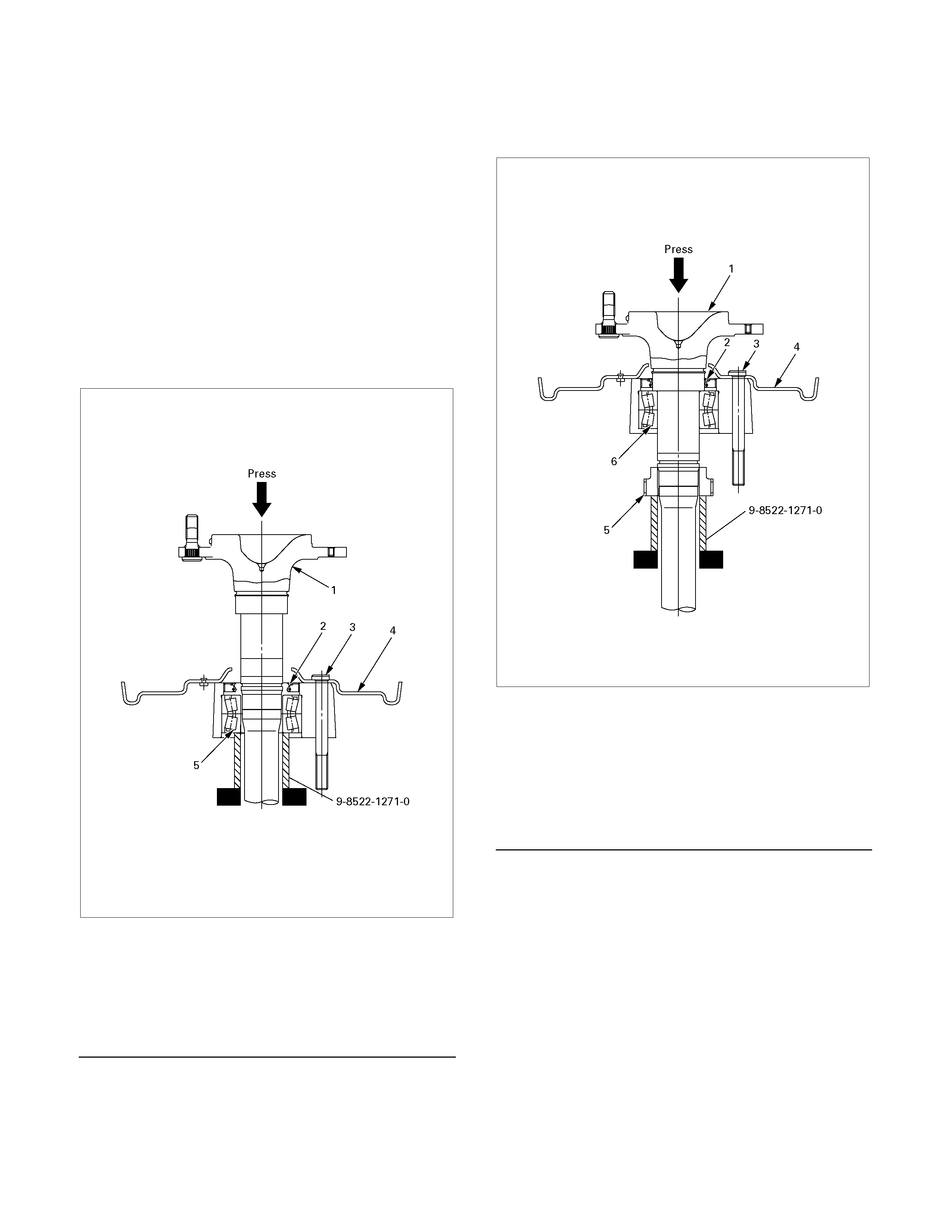
5. Axle Shaft Assembly
a. Insert new double taper roller bearing in the
bearing holder with oil seal.
b. Set special tool (support stand : 9-8522-1271-
0) on a bench press.
c. Put bearing holder with bearing and oil seal
and back plate on the support stand as
following illustration.
d. Insert bolts and axle shaft, aligning center of
holes.
Note:
Reamer bolts should be used upper side of the
vehicle.
e. Press fit axle shaft into double taper roller
bearing.
420R300010
Legend
1. Axle shaft
2. Oil Seal
3. Bolt
4. Back Plate
5. Double Taper Roller Bearing
6. Put new sensor rotor on the special tool 9-8522-
1271-0.
7. Press fit axle shaft with the bearing into sensor
rotor and make axle shaft assembly.
420R300011
Legend
1. Axle shaft
2. Oil Seal
3. Bolt
4. Back Plate
5. Sensor Rotor
6. Double Taper Roller Bearing
8. Certainly install new snap ring.
9. Install axle shaft assembly in rear axle case
assembly.
Note:
When inserting an axle shaft, it inserts so that an
oil seal may not be damaged.
10. Install and tighten bearing holder fixing nut to the
specified torque.
Torque : 84 N⋅m (8.6 kg⋅m/62 lb⋅ft)
11. Install wheel cylinder and tighten the bolt to the
specified torque.
Torque : 9 N⋅m (0.9 kg⋅m/78 lb⋅ft)
12. Install parking brake outer cable in back plate and
inner cable in parking brake lever

13. Install shoe assembly with adjuster lever, shoe
assembly with parking brake lever and spring.
14. Install return spring.
15. Install shoe clamp spring and tension pin.
305R300001
Legend
1. Tension Pin
2. Shoe Clamp Spring
3. Return Spring
4. Shoe Assembly with Parking Brake Lever
5. Shoe Assembly with Adjuster Lever
6. Spring
7. Parking Brake Cable
8. Adjuster
9. Parking Brake Lever
10. Adjuster Spring
11. Adjuster Lever
12. Wheel Cylinder
13. Back plate
16. Install brake pipe and ABS sensor and tighten it to
the specified torque.
Torque :
ABS Sensor 8 N⋅m (0.8 kg⋅m/69 lb⋅ft)
Brake Pipe 16 N⋅m (1.6 kg⋅m/12 lb⋅ft)
420R30003
17. Bleed brake pipe at the wheel cylinder. (Refer to
the section “Power-assisted Brake System”)
18. Install brake drum.
• Install propeller shaft. (Refer to Section “Rear
Propeller Shaft”.)
• Refill differential oil.
• Install wheel and tire.
• Lower vehicle.

Differential Assembly
Disassembled View
Legend
1. Bolt
2. Bearing Cap
3. Differential Cage Assembly
4. Side Bearing Outer Race
5. Side Bearing
6. Adjust Shim
7. Flange Nut
8. Flange Assembly
9. Drive Pinion Shaft Assembly
415RY00005
10. Collapsible Spacer
11. Inner Bearing
12. Adjust Shim
13. Oil Seal
14. Outer Bearing
15. Inner Bearing Outer Race
16. Outer Bearing Outer Race
17. Differential Carrier

Disassembly
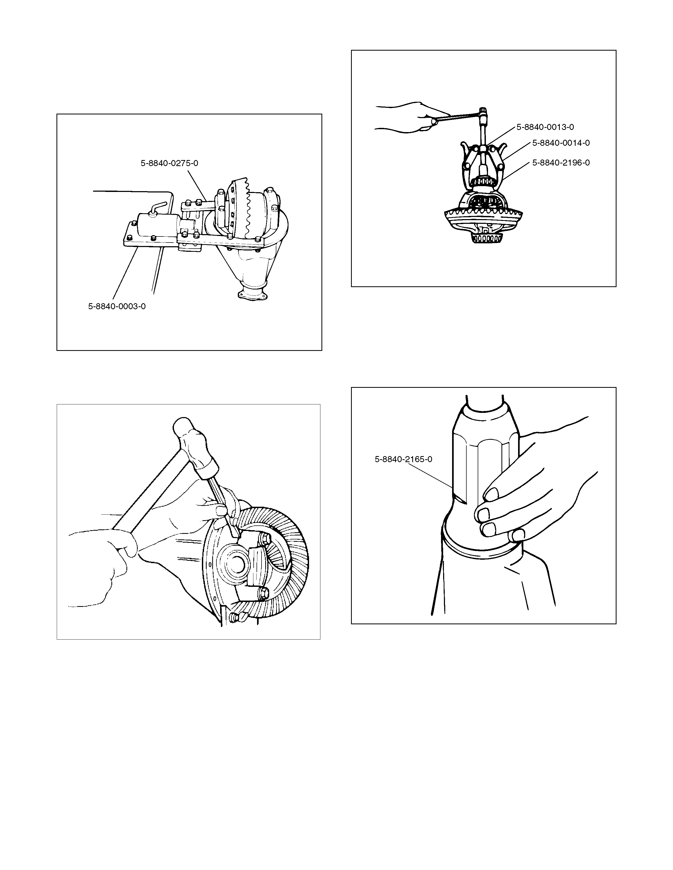
1. Using holding fixture 5-8840-0275-0 and holding
fixture base 5-8840-0003-0, fix the differential
assembly to the bench.
425L100007
2. Apply a setting mark to the side bearing cap and
the differential carrier then remove bearing cap.
425RS009
3. Remove differential cage assembly.
4. Remove side bearing outer race. After removal,
keep the right and left hand side bearing
assemblies separate to maintain inner and outer
race combinations.
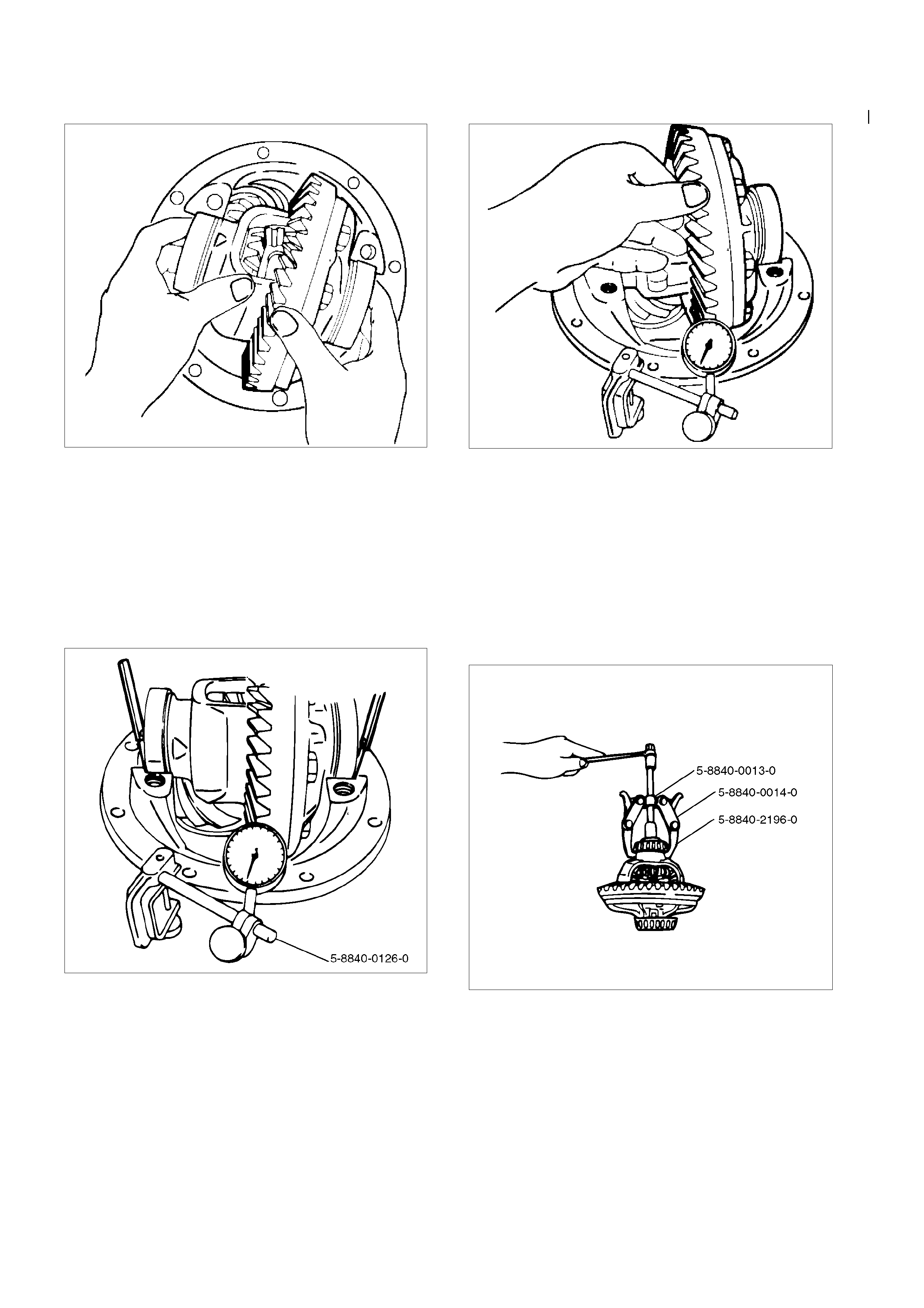
5. Remove side bearing by using remover 5-8840-
0013-0, 5-8840-0014-0 and adapter
5-8840-2196-0.
415L100001
6. Note the thickness and position of the shims then
remove adjust shim.
7. Remove the flange nut by using pinion flange
holder 5-8840-0133-0 after raising up its staked
parts completely.
415RW040
8. Removed flange assembly.
9. Remove the drive pinion assembly using a soft
metal rod and a hammer.
425RY005
10. Remove collapsible spacer.
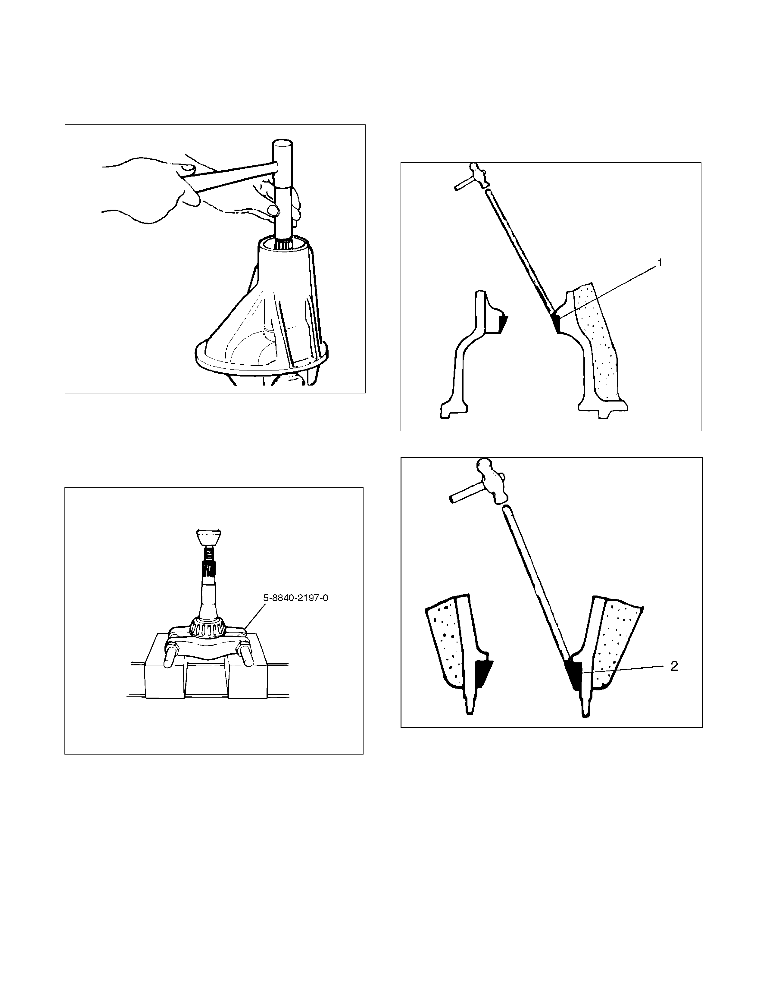
11. Remove the inner bearing by using separator 5-
8840-2197-0
415L100002
12. Remove adjust shim.
13. Remove oil seal.
14. Remove outer bearing.
15. Remove the inner bearing outer race (1) and the
outer bearing outer race (2) by using a brass bar
and a hammer.
425RS014
425RS015
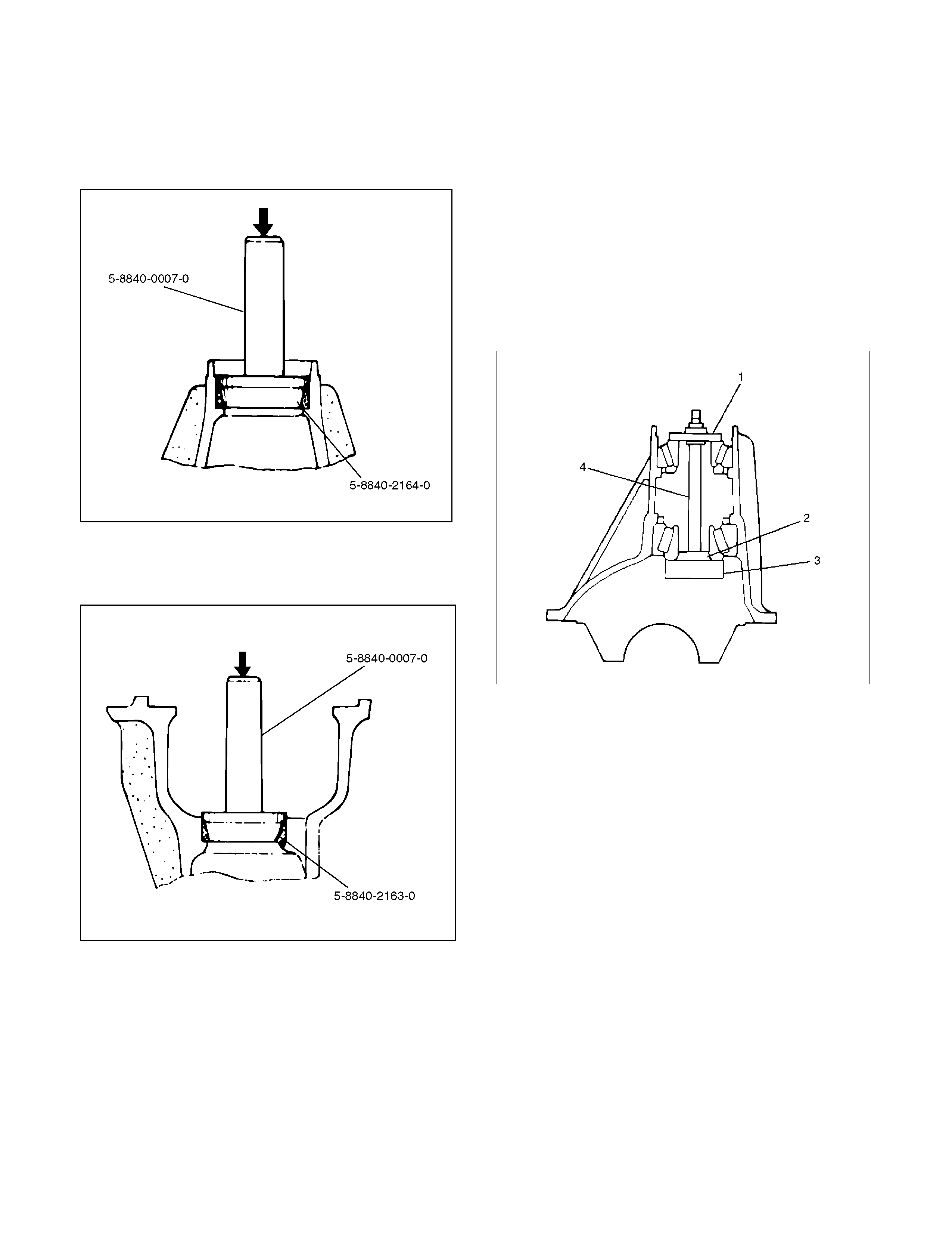
Reassembly
1. Install outer bearing outer race by using installer 5-
8840-2164-0 and grip 5-8840-0007-0.
425L100002
2. Install inner bearing outer race by using installer 5-
8840-2163-0 and grip 5-8840-0007-0.
425L100003
3. Adjust the drive pinion mounting distance as
follows:
a. Apply gear oil to the inner and outer drive
pinion bearing. Clean the pinion setting
gauge set. Then install the gauge set
together with the inner and outer bearings.
Install gauge plate 5-8840-2166-0 (3), inner
pilot 5-8840-0129-0 (2), stud and nut 5-8840-
0127-0 (4) and outer pilot 5-8840-2085-0 (1)
through inner and outer bearings.
b. Tighten the nut to the specified torque.
Torque: 2.3 N⋅m (0.23 kg⋅m/20 lb in)
425RW030
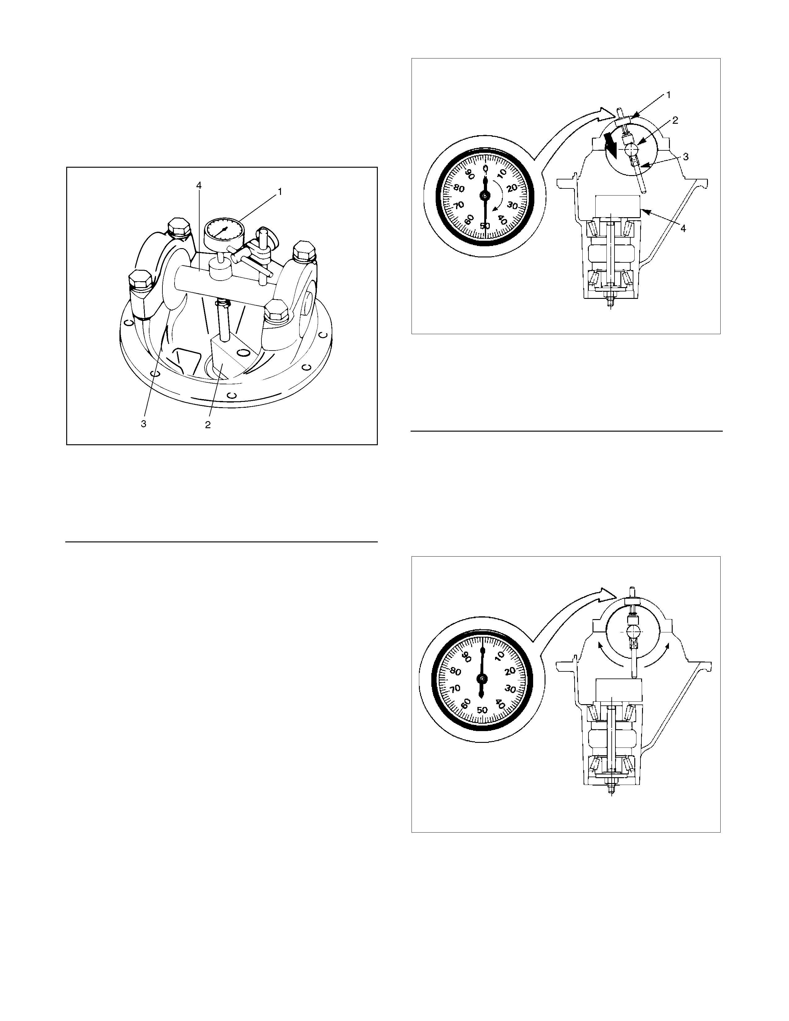
c. Clean the side bearing bores. Place discs and
dial indicator on to arbor, and place tool into
position in side bearing bores. Install and
tighten the bearing caps to the specified
torque.
Torque :
108 N⋅m (11 kg⋅m/80 lb in)
425RW031
Legend
1. Dial Indicator : 5-8840-0126-0
2. Gauge Plate : 5-8840-2166-0
3. Disc (2 pcs.) : 5-8840-2167-0
4. Arbor : 5-8840-0128-0
Note :
The scale on the dial indicator (5-8840-0126-0) is
inch unit.
d. Set the dial indicator 5-8840-0126-0 to “0".
Place it on the mounting post of the gauging
arbor with the contact button touching the
indicator pad. Force the dial indicator
downward until the needle has made a half
turn clockwise. Tighten down the dial
indicator in this position.
425RS020
Legend
1. Dial Indicator
2. Gauging Arbor
3. Plunger
4. Gauge Plate
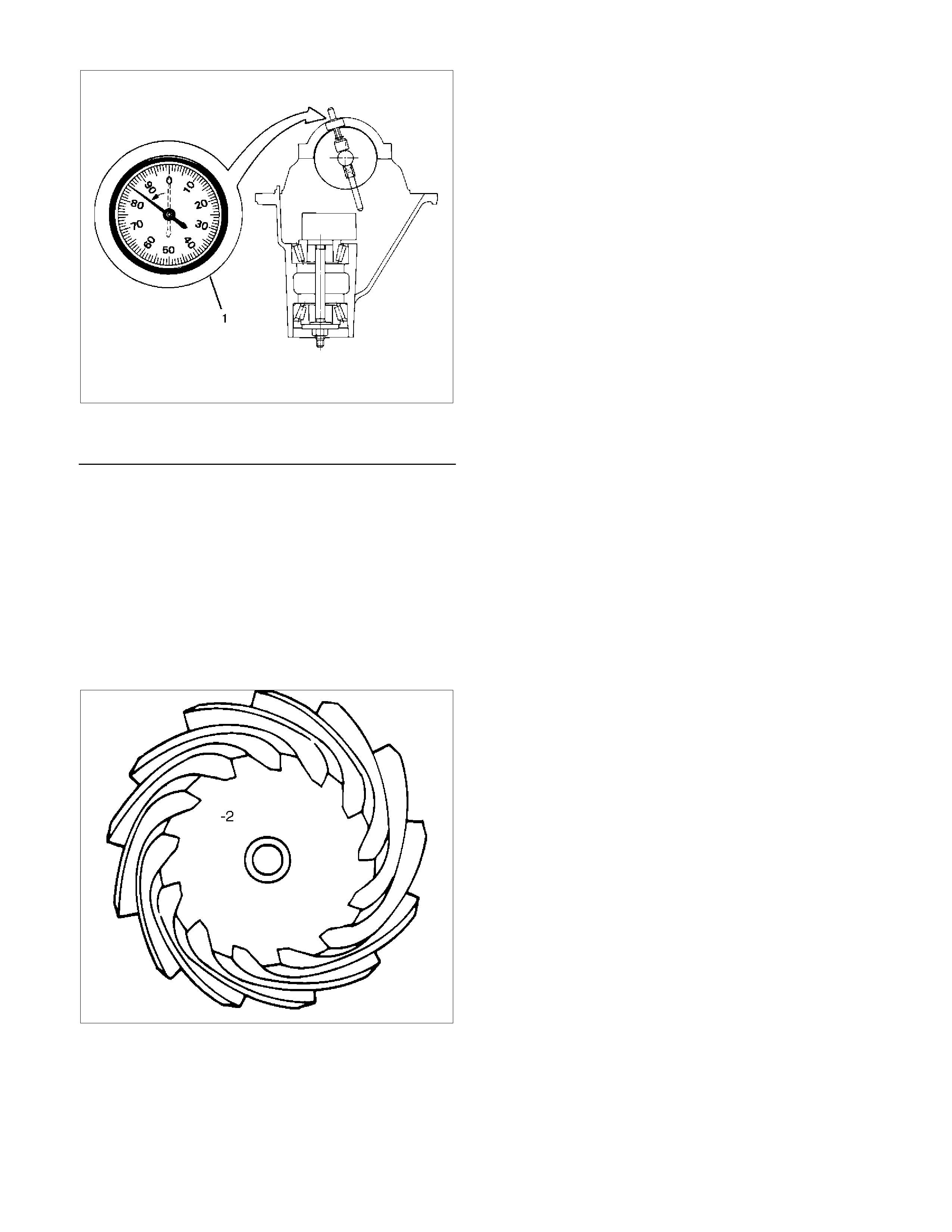
e. Position the plunger on the gauge plate. Move
the gauging arbor slowly back and forth and
locate the position at which the dial indicator
shows the greatest deflection. At this point,
once again set the dial indicator to “0".
Repeat the procedure to verify the “0"
setting.
425RS021
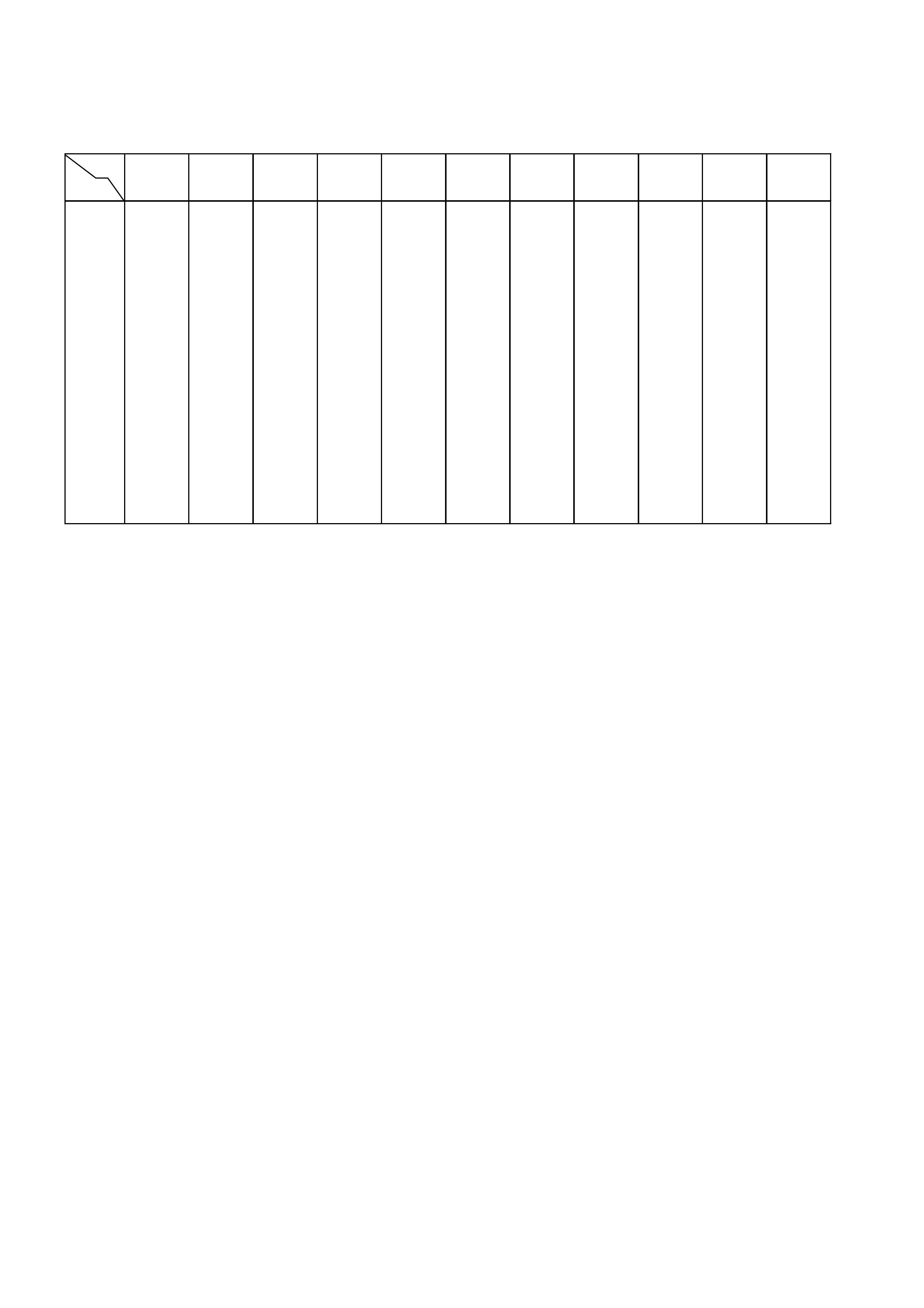
f. After the ZERO setting is obtained, rotate the
gauging arbor until the dial indicator rod does
not touch the gauging plate. Record the
number the dial indicator needle points to.
425RS022
Legend
1. Example=Dial indicator reading od 0.085
g. Record the pinion depth code on the head of
the drive pinion. The number indicates a
necessary change in the pinion mounting
distance. A plus number indicates the need
for a greater mounting distance (which can be
achieved by decreasing the shim thickness).
A minus number indicates the need for a
smaller mounting distance (which can be
achieved by increasing the shim thickness).
If examination reveals pinion depth code “0",
the pinion is “nominal".
425RS023
h. Select the shim using table below.
mm (in)
Pinion
marking
+10 +8 +6 +4 +2 0 -2 -4 -6 -8 -10
Dial indica tor
read ing (inche s)
0.073 1.94 (0.0764) 1.96 (0.0772)
0.074 1.94 (0.0764) 1.96 (0.0772) 1.98 (0.0779)
0.075 1.94 (0.0764) 1.96 (0.0772) 1.98 (0.0779) 2.00 (0.0787)
0.076 1.94 (0.0764) 1.96 (0.07 72) 1.98 (0.0779) 2.00 (0. 0787) 2.02 (0.079 5) 2.04 (0.0803)
0.077 1.96 (0.0772) 1.98 (0.07 79) 2.00 (0.0787) 2.02 (0. 0787) 2.04 (0.080 3) 2.06 (0.0811)
0.078 1.94 (0.0764) 1.96 (0.0772) 1.98 (0.0779) 2. 00 (0.0787) 2.02 (0.0787) 2.04 (0.0803) 2.06 (0.081 1) 2.08 (0.0819)
0.079 1.94 (0.0764) 1.96 (0.0772) 1.98 (0.0779) 2.00 (0.0787) 2. 02 (0.0787) 2.04 (0.0803) 2.06 (0.081 1) 2.08 (0.081 9) 2.10 (0.0827)
0.080 1.94 (0.076 4) 1.96 (0.0772) 1.98 (0.0779) 2.00 (0.0787) 2 .02 (0.0787) 2. 04 (0.0803) 2.06 (0 .08 11) 2.08 (0.0819) 2.10 (0. 0827) 2.12 (0.0835) 2.14 (0.0842)
0.081 1.96 (0.077 2) 1.98 (0.0779) 2.00 (0.0787) 2.02 (0.0787) 2.04 (0.0803) 2.06 (0.0811) 2.08 (0.0819) 2.10 (0.0827) 2.12 (0.0835) 2.14 (0.084 2) 2.16 (0.0850)
0.082 1.98 (0.077 9) 2.00 (0.0787) 2.02 (0.0787) 2.04 (0.0803) 2.06 (0.0811) 2.08 (0.0819) 2.10 (0.0827) 2.12 (0.0835) 2.14 (0.0842) 2.16 (0.085 0) 2.18 (0.0858)
0.083 2.00 (0.078 7) 2.02 (0.0787) 2.04 (0.0803) 2.06 (0.0811) 2.08 (0.0819) 2.10 (0.0827) 2.12 (0.0835) 2.14 (0.0842) 2.16 (0.0850) 2.18 (0.085 8) 2.20 (0.0866)
0.084 2.04 (0.080 3) 2.06 (0.0811) 2.08 (0.0819) 2.10 (0.0827) 2.12 (0.0835) 2.14 (0.0842) 2.16 (0.0850) 2.18 (0.0858) 2.20 (0.0866) 2.22 (0.087 4) 2.24 (0.0882)
0.085 2.06 (0.081 1) 2.08 (0.0819) 2.10 (0.0827) 2.12 (0.0835) 2.14 (0.0842) 2.16 (0.0850) 2.18 (0.0858) 2.20 (0.0866) 2.22 (0.0874) 2.24 (0.088 2) 2.26 (0.0890)
0.086 2.08 (0.081 9) 2.10 (0.0827) 2.12 (0.0835) 2.14 (0.0842) 2.16 (0.0850) 2.18 (0.0858) 2.20 (0.0866) 2.22 (0.0874) 2.24 (0.0882) 2.26 (0.089 0) 2.28 (0.0898)
0.087 2.12 (0.083 5) 2.14 (0.0842) 2.16 (0.0850) 2.18 (0.0858) 2.20 (0.0866) 2.22 (0.0874) 2.24 (0.0882) 2.26 (0.0890) 2.28 (0.0898) 2.30 (0.090 6) 2.32 (0.0913)
0.088 2.14 (0.084 2) 2.16 (0.0850) 2.18 (0.0858) 2.20 (0.0866) 2.22 (0.0874) 2.24 (0.0882) 2.26 (0.0890) 2.28 (0.0898) 2.30 (0.0906) 2.32 (0.091 3) 2.34 (0.0921)
0.089 2.16 (0.085 0) 2.18 (0.0858) 2.20 (0.0866) 2.22 (0.0874) 2.24 (0.0882) 2.26 (0.0890) 2.28 (0.0898) 2.30 (0.0906) 2.32 (0.0913) 2.34 (0.092 1) 2.36 (0.0929)
0.090 2.18 (0.085 8) 2.20 (0.0866) 2.22 (0.0874) 2.24 (0.0882) 2.26 (0.0890) 2.28 (0.0898) 2.30 (0.0906) 2.32 (0.0913) 2.34 (0.0921) 2.36 (0.092 9)
0.091 2.22 (0.0874) 2.24 (0.0882) 2.26 (0.0890) 2.28 (0.0898) 2.30 (0.0906) 2.32 (0.0913) 2.34 (0.0921) 2.36 (0.0929)
0.092 2.24 (0.0882) 2.26 (0.0890) 2.28 (0.0898) 2.30 (0.0906) 2.32 (0.0913) 2.34 (0.0921) 2.36 (0.0929)
0.093 2.26 (0.0890) 2.28 (0.0898) 2.30 (0.0906) 2.32 (0.0913) 2.34 (0.0921) 2.36 (0.0929)
0.094 2.28 (0.0898) 2.30 (0.0906) 2.32 (0.0913) 2.34 (0.0921) 2.36 (0.0929)
0.095 2.32 (0.0913) 2.34 (0.0921) 2.36 (0.0929)
0.096 2.34 (0.0921) 2.36 (0.0929)
0.097 2.36 (0.0929)
Note :
When ordering shims, find the correct part number
in Holden Partfinder by using the thickness of the
shims list ed in t he ab ov e table.
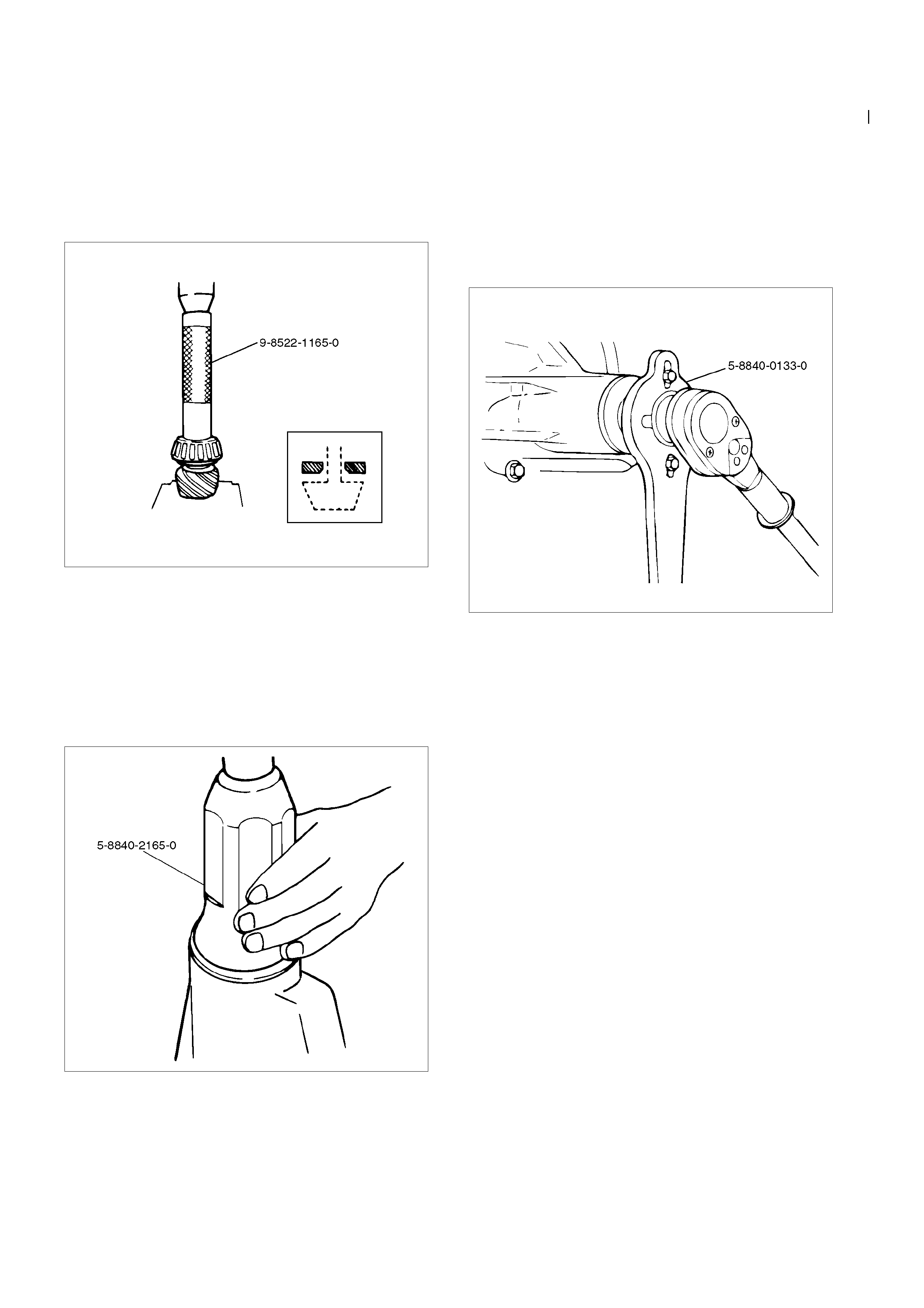
4. Place the shim on the drive pinion, then install the
inner bearing onto the pinion by using installer 9-
8522-1165-0 and a press.
Note:
Do not apply pressure to the roller cage. Apply
NOTE: pressure only to the inner race.
425L100008
5. Install collapsible spacer. Discard the used
collapsible spacer and install a new one.
6. Install drive pi nion shaft assembly.
7. Install outer bearing and oil seal.
8. Use oil seal installer 5-8840-2165-0 to in stall a
new oil seal that has grease on seal li p.
415RW029
9. Install flange assembly.
10. Install flange nut.
a. Apply lubricant to the pinion threa ds.
b. Using the pinion flange holder 5-8840-0133-0,
tighten the nut only enough to remove the shaft
end play.
Note :
Discard used flan ge nut and install new one.
415RW040
c. Adjust pinion bearing preload.
• Measure the bearing preload by using a torque
meter and note the scale reading required to
rotate the f lange.
• Continue tightening flange nut unt il the specified
starting torque is obtai ned.
Starting torque :
0.7-1.3 N⋅m (0.07-0.13 kg⋅m/6-11 lb⋅ft)
Note :
•
••
• Do not overtigh ten or l o osen and then
retighten the nut.
•
••
• Pinion nut torque will be in the range of 245-
294 N⋅
⋅⋅⋅m (25-30 kg⋅
⋅⋅⋅m/181-217 lb⋅
⋅⋅⋅ft).
425RW018
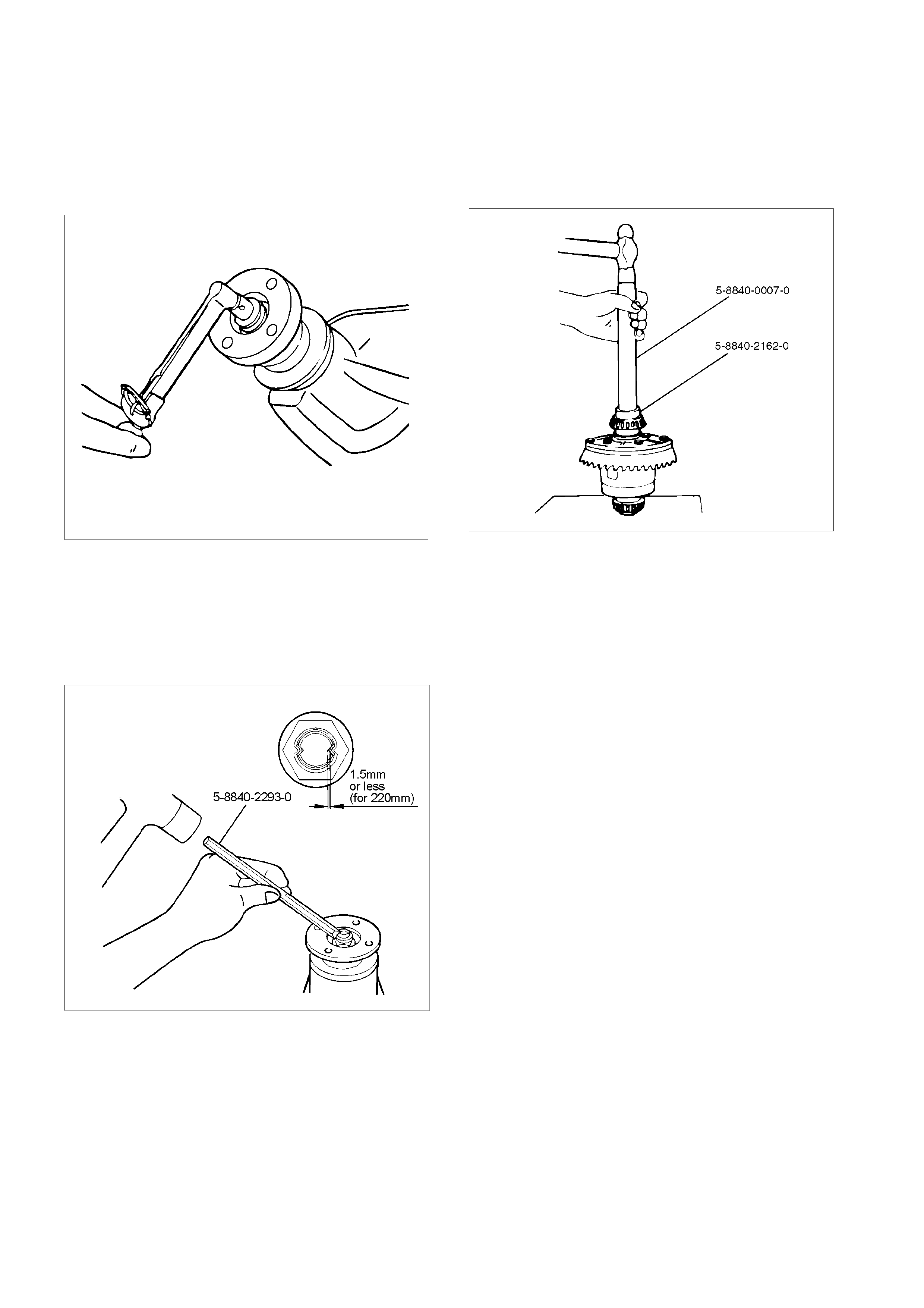
d. Using punch 5-8840-2293-0, stake the flange
nut at two points.
Note :
When staking, be sure to turn the nut to ensure
that there is no change in bearing preload. Make
sure NOTE: of preload again as instructed in c.
RTW34BSH000201
11. Adjust ring gear backlash.
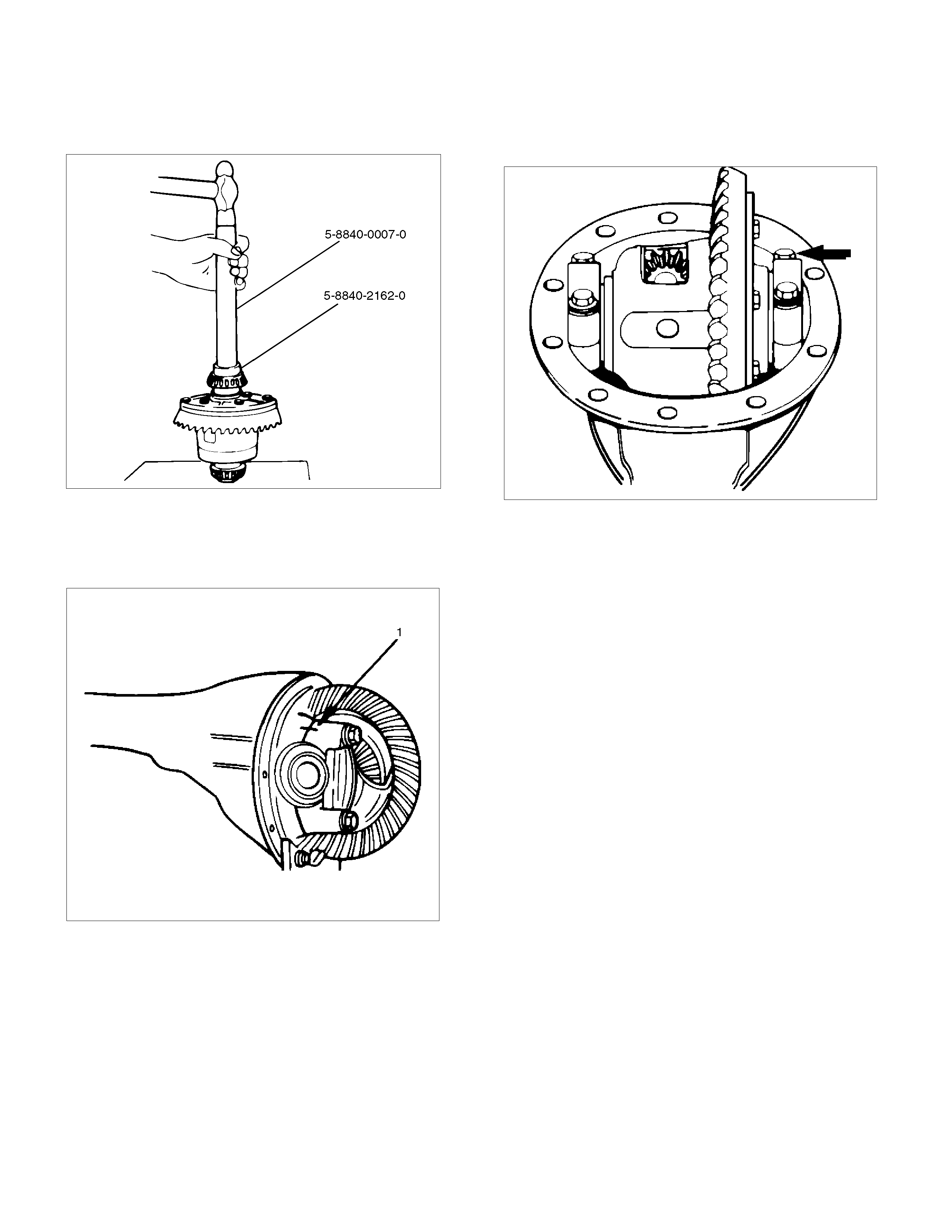
a. Attach the side bearing to the differential
assembly without shims by using installer 5-
8840-2162-0 and grip 5-8840-0007-0.
425L100010
b. Insert the differential cage assembly with
bearing outer races into the side bearing bores
of t he carrier.
425RS030
c. Using two sets of feeler gauges, insert a feele
r
stock of sufficient thickness between each
bearing outer race and the carrier to remove all
end play. Make certain the feeler stock is
pushed to the bottom of the bearing bores.
Mount the dial indicator 5-8840-0126-0 on the
carrier so that the indicator stem is at right
angles to a tooth on the ring gear.
425RW049
d. Adjust feeler gauge thickness from side to side
until ring gear backlash is in the specified range.
Backlash :
0.15–0.20 mm (0.006–0.008 in)
425RS032
With zero end pla y and correct backlash
established, remove the feeler gauge packs,
determine the thickness of the shims required
and add 0.05 mm (0.002 in) to each shim pack
to provide side bearing preload. Always use
new shims.
e. Remove side bea ring by using remover 5-
8840-0013-0 and 5-8840-0014-0 and adapter
5-8840-2196-0.
415L100001
12. Install the side bearings together with the selected
shims by using installer 5-8840-2162-0, drive
handle 5-8840-0007-0.
425L100010
13. Install side bearing outer race.
14. Install differential cage assembly.
15. Align the setting marks (1) applied at disassembly
then install the bearing cap.
425RS035
16. Tighten the bolt to the specified torque.
Torque :
108 N⋅m (11 kg⋅m/80 lb⋅ft)
425RS036
• Measure the amount of run-out of the ring gear at
its rear face. It should be 0.05 mm (0.002 in) or less
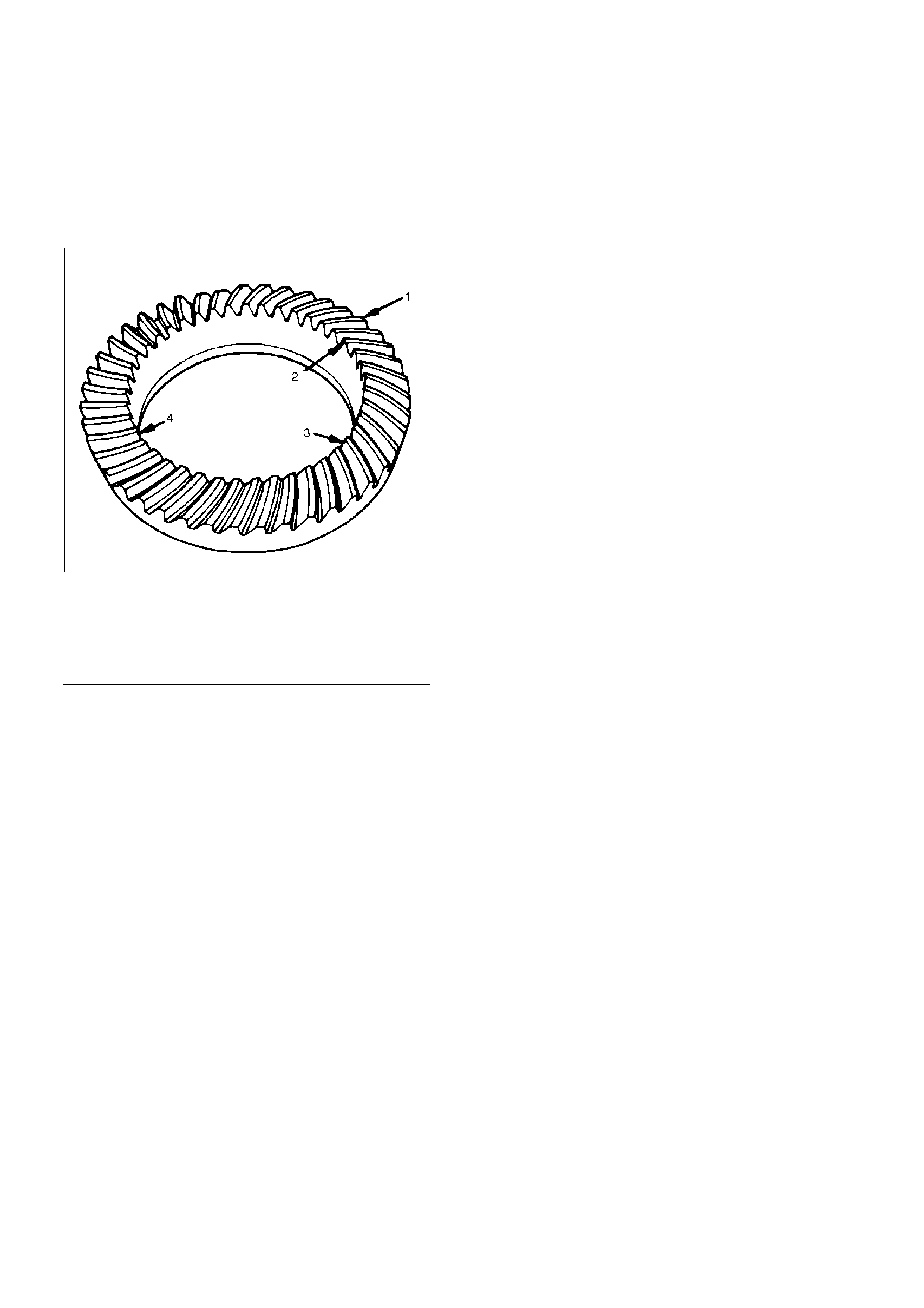
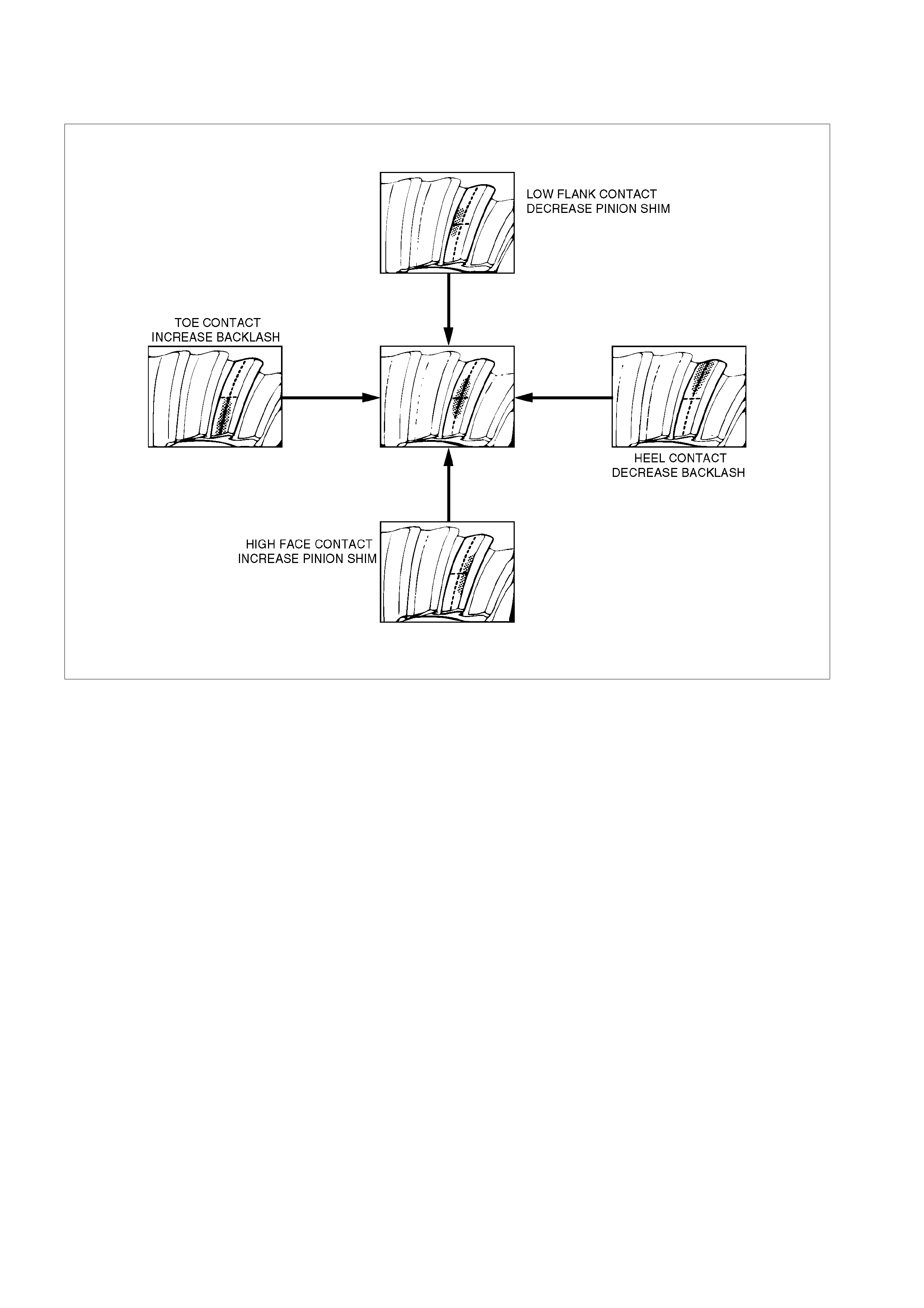
Gear Tooth Contact Pattern Check and Adjustment
1. Apply a thin coat of Prussian blue or equiv alent to
the faces of the 7–8 teeth of the ring gear. Check
the impression of contact on the ring gear teeth
and mak e necessary adjustment as described in
illustration if the contact is abnormal.
425RS038
Legend
1.
Heel
2.
Toe
3.
Concave Side(Coast)
4.
Convex Side(Driv e)
425RS039
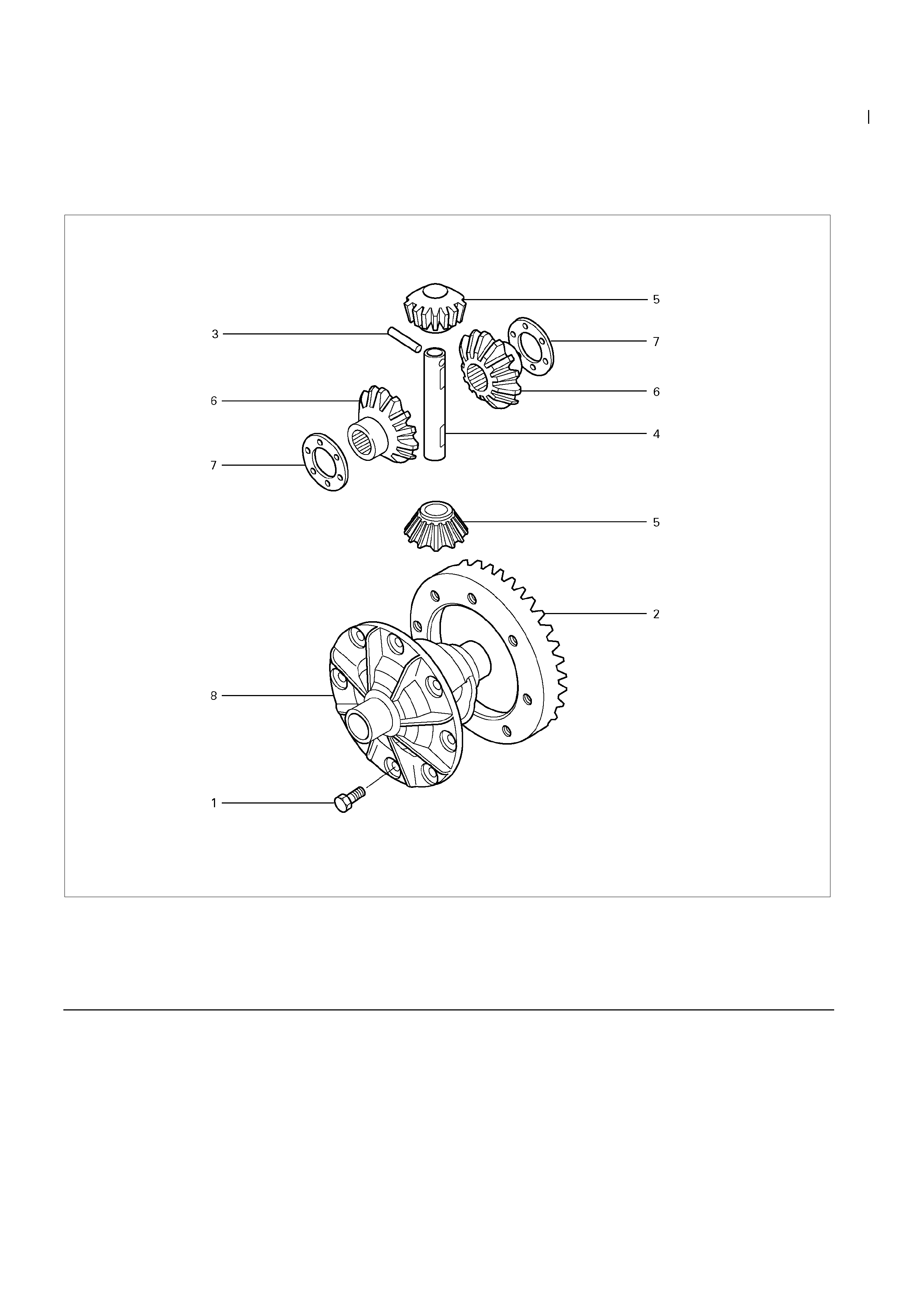
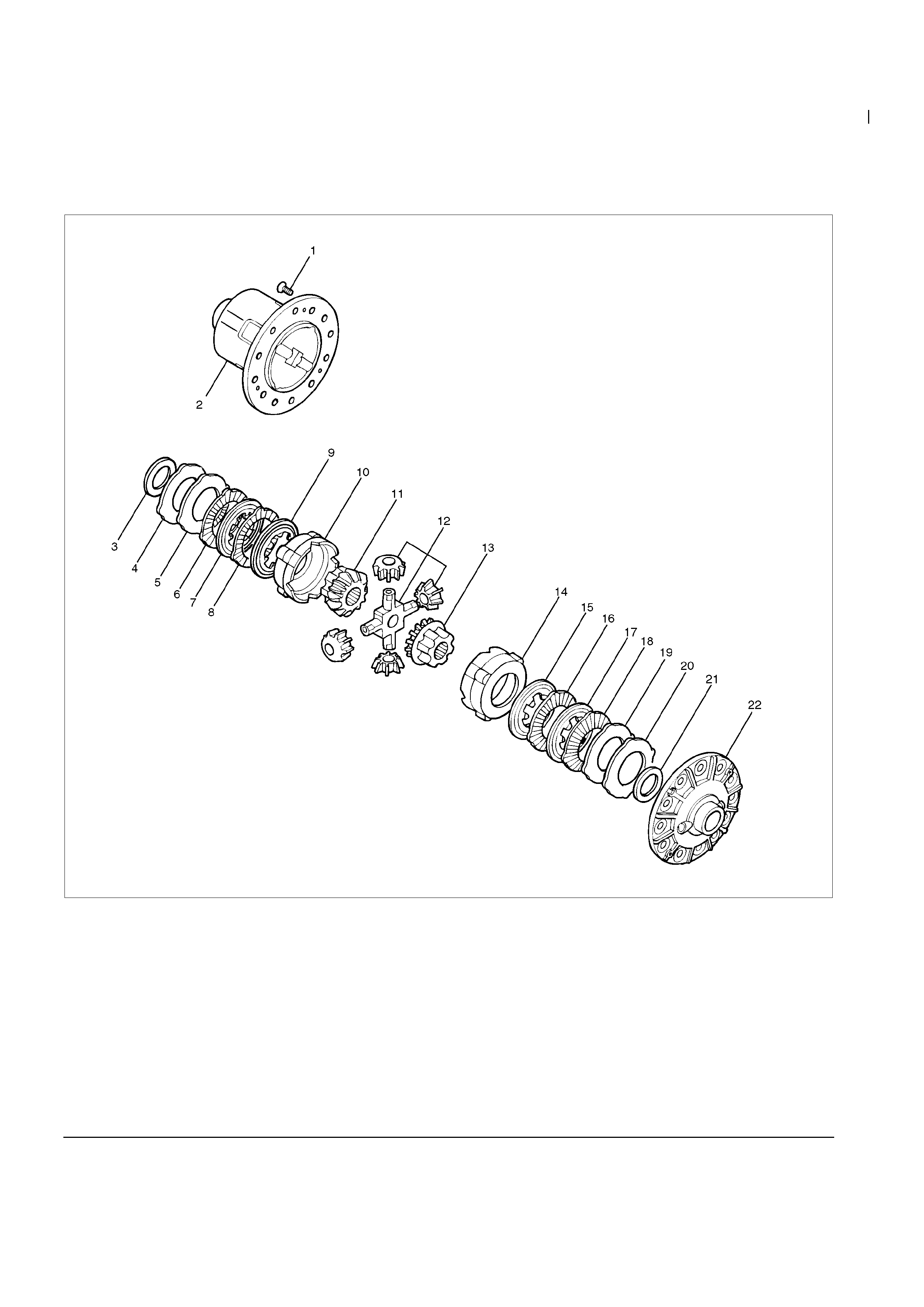
Differential Cage Assembly
Disassembled View
425R300005
Legend
1. Bolt
2. Ring Gear
3. Lock Pin
4. Cross Pin
5. Pinion Gear
6. Side Gear
7. Thrust Washer (for Side Gear)
8. Differential Cage
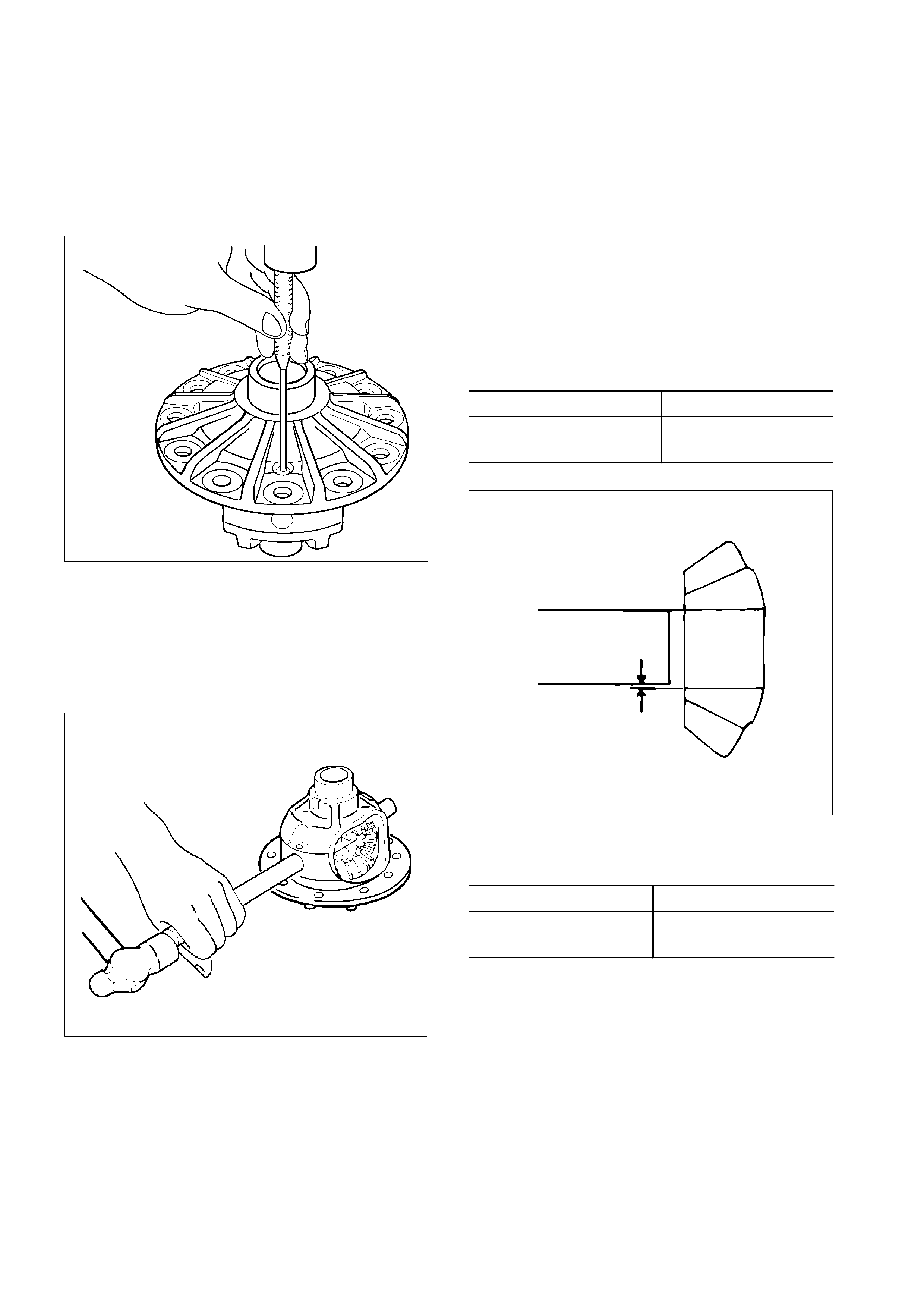
Disassembly Inspection and Repair
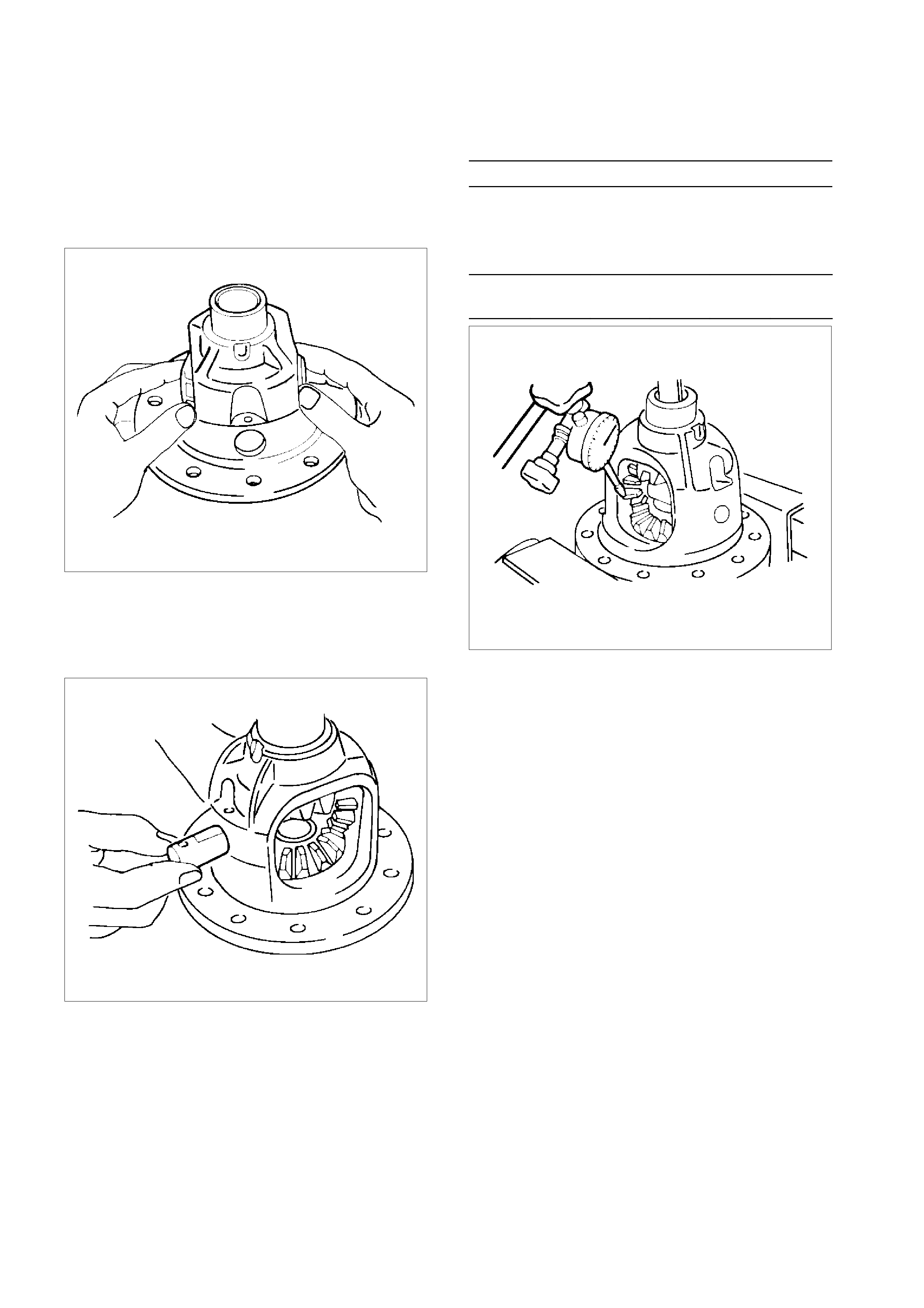
1. Remove bolt.
2. Remove ring gear.
3. Drive out lock pin us ing a long drift Punch.
425RS042
4. Check the amount of backlash between pinion
gear on side gear before removal of cross pin.
Backlash :
0.13-0.18 mm (0.005–0.007 in)
5. Remove the cross pin by usi ng a brass drift
punch and hammer.
425RS043
6. Take out pinion gear, side gea r and thrust
washer.
Make necessary correction or parts replacement if
wear, damage, corrosion or any other abnormal
conditions are found through inspection.
Check the following parts:
• Ring gear, pinion gear
• Bearing
• Side gear, pinion gear, cros s pin
• Differential cage, carrier
• Thrust washer
• Oil seal
Clearance between pinion gear and cross pin: mm(in)
Standard Limit
0.06 - 0.12
(0.002 - 0.005) 0.2 (0.008)
425L100012
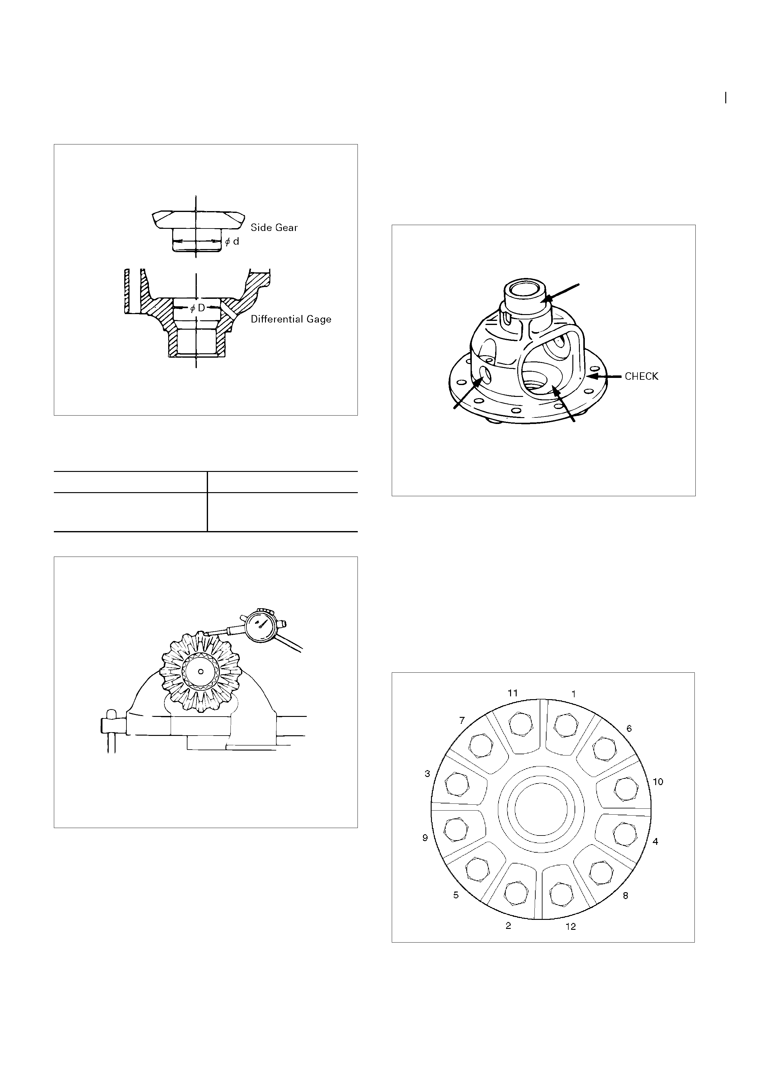
Clearance between side gear and differential c age.
mm(in)
Standard Limit
0.05 - 0. 11
(0.002 - 0.004) 0. 15 (0. 006)
Reassembly
425R300010
Play in splines between the side gear and ax le shaf ts.
mm(in)
Standard Limit
0.08 - 0. 38
(0.003 - 0. 015) 0.5 (0.02)
425L100014
Differential cage
Check the ring gear th e side gea r fitting faces and the
cross pin hole for scores or roughness. Correct as
necessary . S light sco r es or roughn ess may be
corrected with an oil stone or fine sand paper.
425R300006
Ring gear rep lacement:
1. The ring gear should always be repl aced with the
drive pinio n as a set.
2. Discard use bolts and install new ones.
3. Apply LOCTITE 271 on bolt from the end of thread
to the middle of straight portion.
4. Tighten the f ixing bolts in a diagonal sequence as
illustrated.
Torque : 108 N⋅m (11 k g⋅m/80 lb⋅ft)
425RW033
1. Install side gear wit h th rust w asher in di fferential
cage.
2. Install the pini on gear by engagin g it with the side
gears while turning bot h pinion gears
simultaneously in the same direction.
425RS048
3. Install cross pin.
• Be sure to install the cross pin so that it is in
alignment with th e lock pin hole in th e
differential cage.
425RS049
4. Check the amount of backlash.
Backlash between the side gear and the pi nion
gear.
mm (in)
0.13-0.18 (0.005-0. 007)
If the backlash is beyond the limits, adjust w it h a thrust
wa sher of select ed thickness.
Thick ness es of thrust washers available.
Backlash mm (in
)
0.80
(0.031) 0.90
(0.035) 1.00
(0.039) 1.10
(0.043) 1.20
(0.047) 1.30
(0.051)
425RY00008
5. Install lock pin.
After lock pin inst allation, stake the c ase to
secure the lock pin.
6. Install ring gear.
Refer to “
Ring gear rep l acement
” on this
section.
Limited Slip Differential
Disassembled View
425R300007
Legend
1. Screw
2. Differentia l Ca ge A
3. Thrust Washer
4. Spring Plate
5. Spring Plate
6. Friction plate
7. Friction disc
8. Friction plate
9. Friction disc
10. Pressure Ring
11. Side Gear
12. Pinion and Pinion Shaft
13. Side Gear
14. Pressure Ring
15. Friction Disc
16. Friction Plate
17. Friction Disc
18. Friction Plate
19. Spring Plate
20. Spring Plate
21. Thrust Washer
22. Differential Cage B
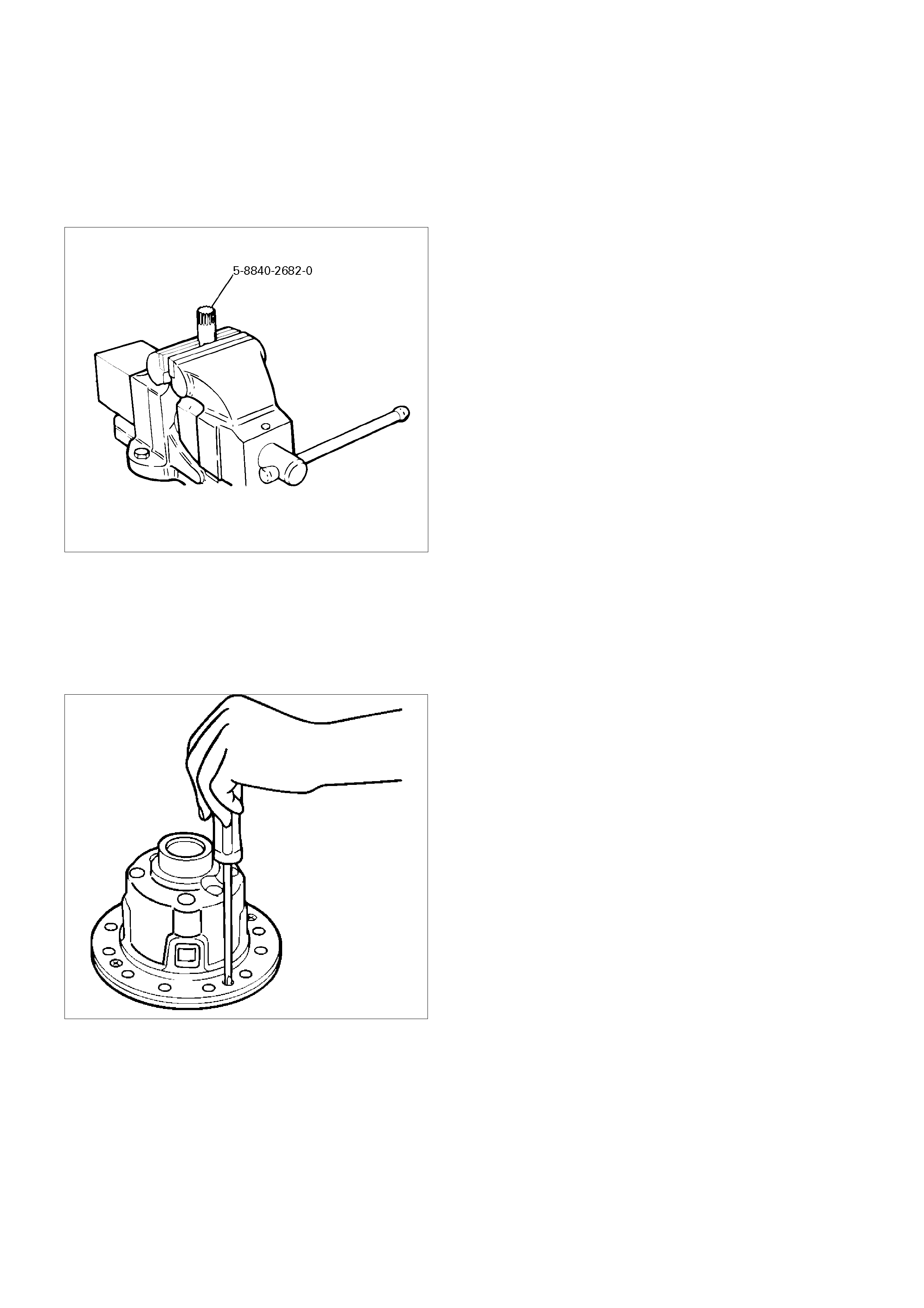
Disassembly
•
Prepare a side gear holder : 5-884 0-2682-0 as
shown in the left figure, clamp it with a stock vice,
and set a differential.
425R300008
1. Screw
•
Apply a setting mark to the differential cage
A and differential cage B remove the bolt
using the press.
•
Loosen four screws fixing differential cage A
to cage B equally and remove the m.
425RS055
2. Remove differential cage A and B.
3. Remove thrust washer and two spring plates.
4. Remove friction plate and friction disc.
5. Remove friction plate and friction disc.
6. Remove pressure ring and side gear.
7. Remove pinion and pini on sha ft.
8. Remove side gear and pressure ring.
9. Remove friction disc and friction plate.
10. Remove friction disc and friction plate.
11. Remove two spring plates and thrust washer.
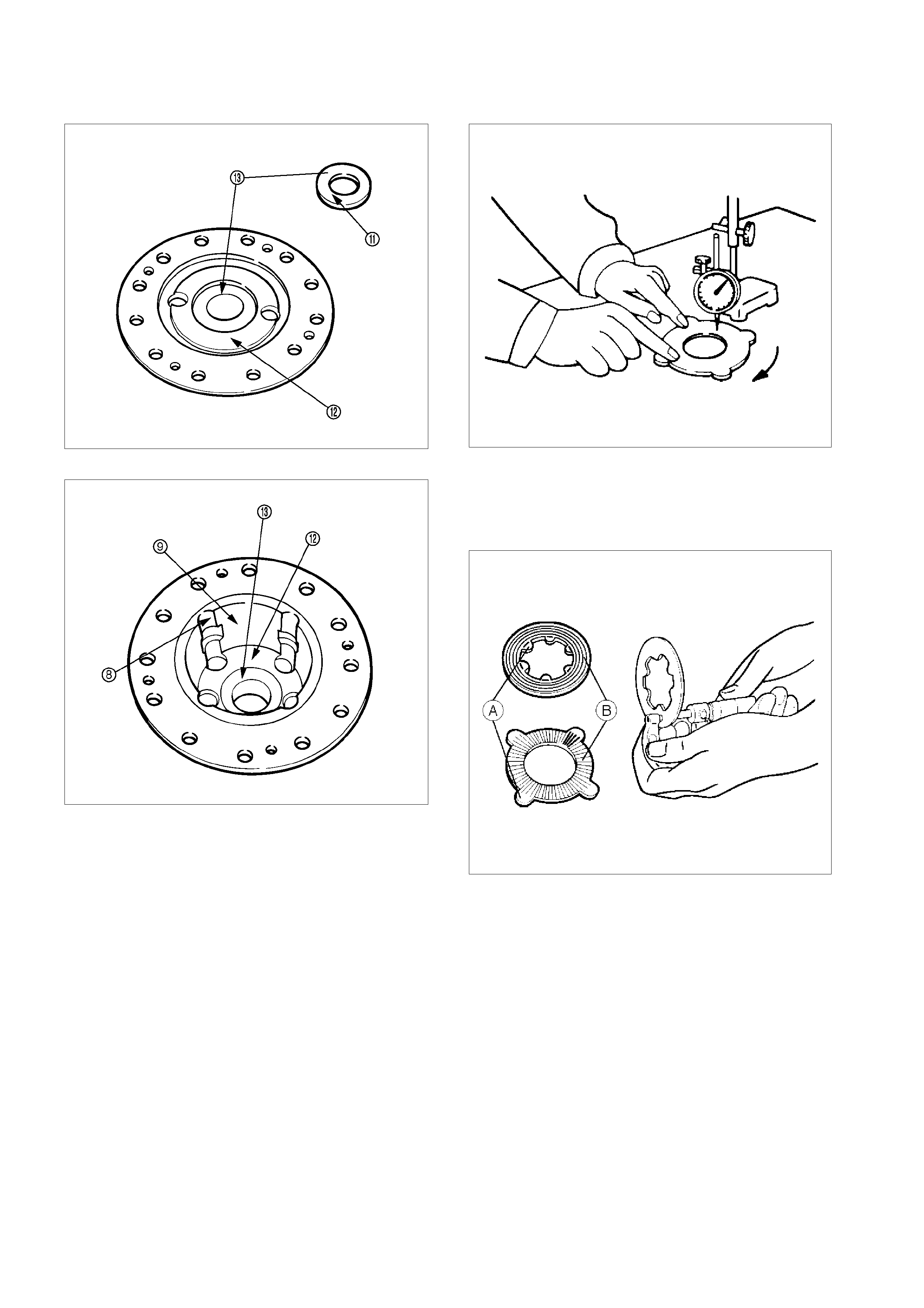
Inspe cti on an d Repa ir
Make all necessa r y adj u stment s, r epairs, an d part
replacements if wear, damage, rust or other problems
are discovered during inspection.
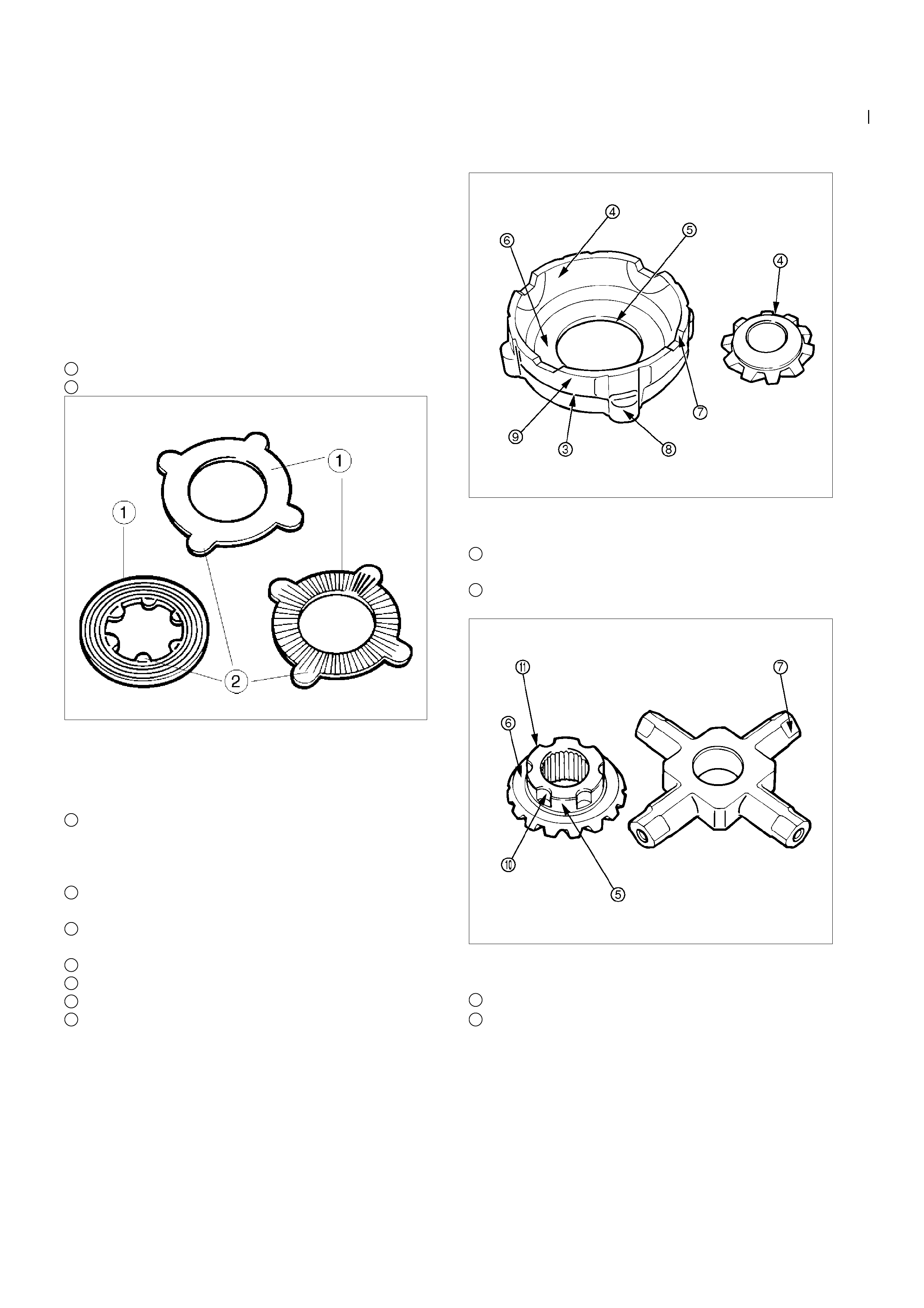
Visual Check
Inspect the following part s for wear, damage or other
abnormal conditions.
•
Friction disc
•
Friction plate
•
Spring plate
1
Sliding surface
2
Protrusion
425RS056
Pressure ring
Check the parts for damage or other abnormal
conditions.
3
Sliding surface for friction disc
If dents or damages are discovered, grind them
with oil stone, and repair them with compound on
surface plate.
4
Sl iding surface of pressure ring i nner surface and
pinion gear.
5
Slinding surface of pressure ring bor e and side
gear.
6
sliding surface of pressure ring and side gear.
7
Sl iding surface of pressure ring and pinion shaft.
8
Mating surface to differential cage A.
9
Burrs or dents on sliding surface of pressure ring
and rear differential cage should be repaired,
using oil stone.
425RY00022
•
Thrust Washer
10
Groove on side gear circumference small burrs of
dens should be repaired, using oil stone.
11
Slidi ng surface betwe en sid e gear and thrust
washer.
425RY00024
•
Differential cage A and B
12
Contact surface to spring plate
13
Differential cage A and B contact surfaces to
thrust washers Small burrs or dents should be
repair, using oil stone.
425RY00025
425RY00023
Friction Desc and Friction Plate
•
Check friction disc and friction plate for distorsion.
Limit : 0. 08 mm
425RS061
•
Check friction plate and friction disc for wear.
Limit : (A-B) 0.1 mm
A : Protrusion Portion
B : Slid ing Portion
425RS062
•
Check thrust washer for wear.
Limit : 1.3 mm
425RS063
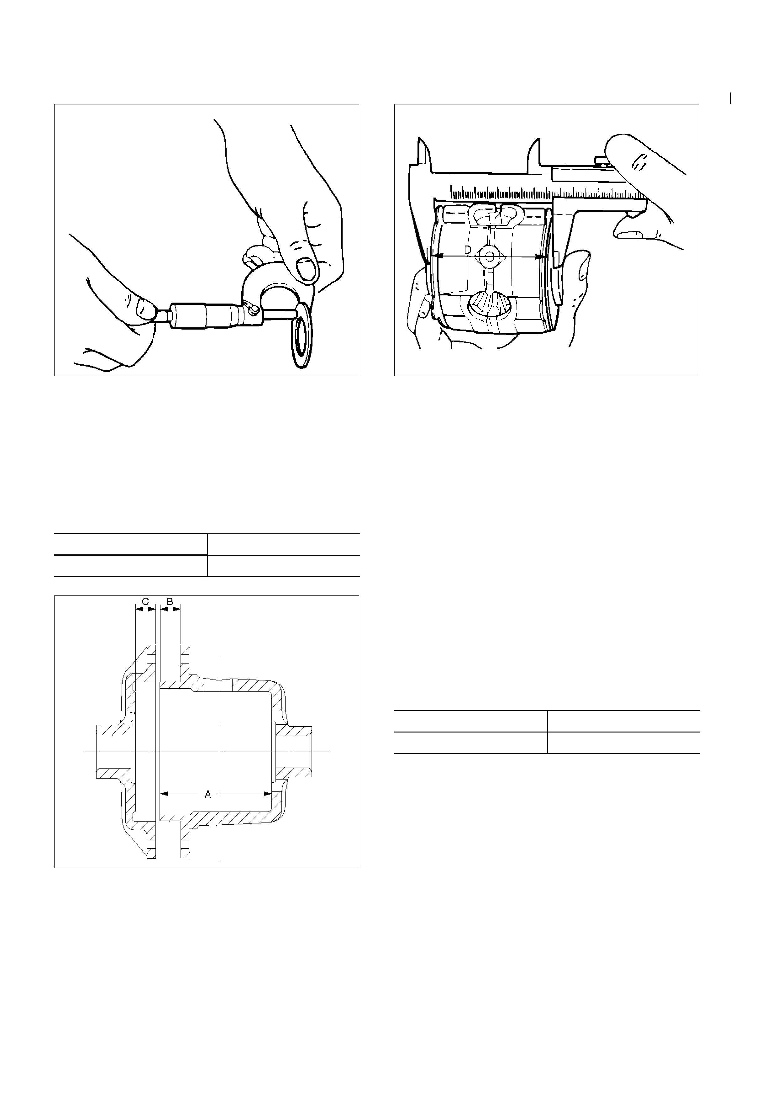
Reassembly
Adjustment of Clearance between Friction Disc
and Plate
1. Measuring depth of differential case mm(in)
Standard (A-B) 80.58 (3.17)
(C) 10.58 (0.42)
425RS064
2. Measuring overall length of pressure ring, friction
disc and plate assembly
•
Assemble pinion shaft wit h pressure ring,
then friction disc and plate.
•
Measure length between plates at both ends
over V-shape gr oove. (D)
425RS065
3. After A, B, C and D dimensions are measured,
perform adjustment with the following procedure.
•
Measure spring plate :
1. 75 mm (0.69 in)
×
4 pcs (E)
•
Measure thickness of plate spring
Standard dimension :
1.75 mm (0.069 in)
×
2 pcs (F)
4. Select a friction di sc or plate so that ((A-B+C) -
(D+E) = 0.06 to 0.20 mm (0.002 to 0.008 in.) and
also the diff erenc e in total dim ens ion of friction
disc and plate and spring plate (left/right side)
does not exc eed 0.05 mm (0.002 in.).
Thickness : 1.65, 1.75, 1.85 mm (0.065, 0.069,
0.073 in)
Adjustin g Ba cklash of Side Gear in Axia l Direction
1. Measuring depth of differential c as e mm(in)
Standard (F-B) 82.03 (3.23)
(G) 12.03 (0.47)
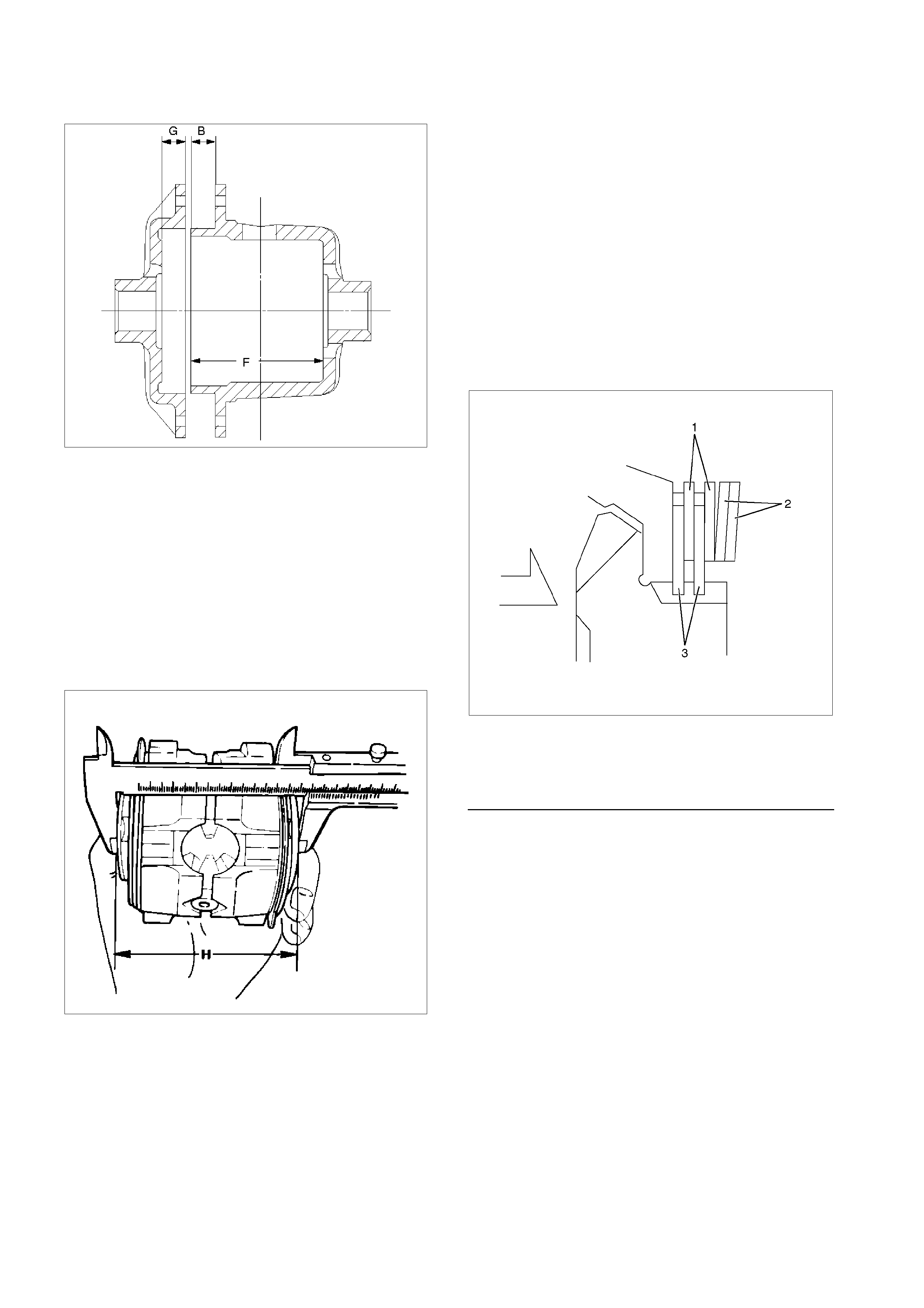
425RS066
2. Measuring dimension bet ween thrust washers at
both ends.
Assemble side gear, pinion, pinion shaft pressure
ring and thrust washer.
• Eli minate clearance by pushing pressure ring
against the pini on sha ft in axial direction.
• Eliminate backlash by con necting side gear to
the pinion.
• Measure dimension between thrust washe rs at
both ends. (H)
425RS067
3. After each dimension is measured, perform
adjustment with the following procedure.
Adjust so that ((F-B) + G-H) = 0.05 to 0.2 mm
(0.002 to 0.008 in). Also, sele ct a proper thrust
washer so that the dimension difference from
back face of the pressure ring to thrust wash er
(left/right side) does not exceed 0.05 mm (0.002
in).
Thickness : 1.5, 1.6, 1.7 mm (0.059, 0.063,
0.067 in)
Note :
When reassembling, sufficiently apply gear oil on
every part, especially on sliding surface.
1. Inst all t hrust washer in differential cag e A a nd
B.
2. Assemble spring plate, friction plate and
friction disc as following illustration.
•
••
• Install spri ng plate with dished side turned
to the differential cage side.
425R300009
Legend
1. Friction Plate
2. Spring Plate
3. Friction Disc
4. Install pressure ring and side gear.
• Fit two side gears in tw o pressure rings, one
from under a ring and the other from above a
ring.
• Fit two pairs of a friction disc and a friction
plate under it on and under these two pressure
rings.
5. Set pinion and pinion shaft on differential cage A
assembly.
6. Assemble differential cage A and B.
7. Align the setting marks on differential cage A and
B and tighten screw s in di agonal order evenly.
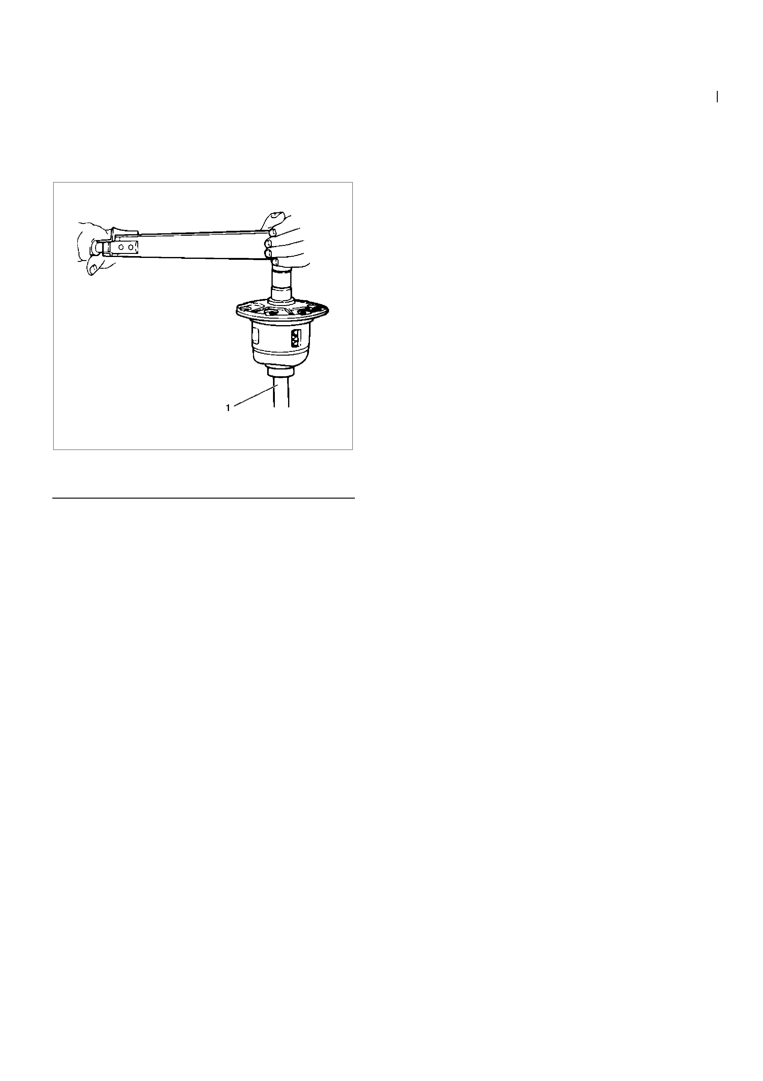
Confirmation of Operation
• Using the side gear holder : 5-8840-2682-0,
measure the starting to rque of the side gear.
Starting torque : 29-45 N⋅m (3.0-4.6 kg⋅m/22-33 lb
ft)
425RW065
Legend
1. Side Gear Holder : 5-8840-2682-0

Troubleshooting
Refer to this Section to quickly diagnose and repair
rear axle problems.
Each troubleshooting chart has three headin gs
arranged from left to right.
(1) Checkpoint
(2) Trouble Cause
(3) Countermeasure
This Section is divided into five sub-sections:
1. Abnormal Rear Axle Noise
1) Noise when th e engine is drivi ng th e v ehicle
2) Noise when the ve hicl e is coasting
3) Intermittent noise
4) Noise when the ve hicl e is turning
5) Constant noise
2. Vibration
3. Oil Leakage
1) Differential carrier leakage
2) Axle case leakage
3) Axle case to inside hub le akage
4) Axle case to inside brake drum leakage
4. Power Not Being Transmitted to the Wheels
(Propeller Shaft Operation is Normal)
Techline
Techline

1. ABNORMAL REAR AXLE NOISE
1) Noise when the Engine is Driving the Vehicle
Checkpoint Trouble Cause Countermeasure
Replenish the gear oilInsufficient gear oil
NG
Differential side bearing Adjust the differential side
bearing pr eload
Replace the drive pinion
bearings
Adjust the drive pinion bearing
preload
Replace the gear oil
Loose differential side
bearings
Worn drive pinion bearings
Loose drive pinion bearings
Wrong or poor grade gear oil
Drive pinion to ring gear
backlash
Drive pini on end play
Adjust the bac k las hToo m uch or too lit tle backlash
Continued on the next page
OK
OK
NG
NG
NG
NG
NG
OK
OK
Rear axle gear oil
Replace the differential side
bearings
Worn differential side bearings
NG
Checkpoint Trouble Cause Countermeasure
Replace the drive pinion and
the ring gear as a set
Excessive ring gear run-out
Replace the drive pinion and
the ring gear as a set
Drive pinion and/or ring gear
damage
NG
NG
Drive pini on and ring gear
Continued from the previous page
Replace the drive pinion and
the ring gear as a set
Worn drive pinion and ring
gear
NG
2) Noise when the Vehicle is Coasting
Checkpoint Trouble Cause Countermeasure
Replace the ring gear and th e
pini on as a set
Ring gear damaged
Adjust the bac k las hInsufficient backlash
OK
Ring gear NG
NG
Drive pini on and ring gear
backlash

3) Intermittent Noise
Checkpoint Trouble Cause Countermeasure
Axle case inside
Ring gear
Remove the foreign material
Replace the drive pinion and
the ring gear as a set
Foreign material in the axle
case
Warped ring gear
Differential cage Tighten the differential cage
bolts
Replace the shaf t
Loose differential cage bolts
Too m uch spline play
OK
NG
NG
NG
NO
OK
OK
Axl e shaf t
4) Noise when the Vehicle is Turning
Checkpoint Trouble Cause Countermeasure
Differential cross pin
Side gear
Replace the differential cross
pin
Replace the side gear
Worn differential cross pin
Worn side gear
Differential pinion Replace the differential pinion
Replace the rear axle shaft
Worn differential pinion
Worn rear axle shaft splines
OK
NG
NG
NG
NO
OK
OK
Rear axle shaft
5) Constant Noise
Checkpoint Trouble Cause Countermeasure
Replace the rear axle shaftBent rear ax le shaft
NG
Replace the side bearin g
Replace the drive pinion
bearing
Replace the drive pinion and
the ring gear as a set
Replace the drive pinion and
the ring gear as a set
Flat spot on the side bearin g
oil seal
Bearing Flat spot on the drive pinion
Flat spot on the gear teeth
pilot bearing wear
Drive pinion Flat spot on the drive pinion
gear teeth
Ring gear
Replace the drive pinion and
the ring gear as a set
Worn pinion splines oil seal
NG
NG
NG
NG
NG
OK
OK
OK
Rear axle shaft
2. VIBRATION
Checkpoint Trouble Cause Countermeasure
Replace the rear axle shaftBent rear ax le shaft
Replace the rear hub bearingWorn rear hub bearing
OK
Rear axle shaft NG
NG
Rear hub bearing
3. OIL LEAK AGE
1) Differential Carrier Leakage
Checkpoint Trouble Cause Countermeasure
Correct the oil levelToo much gear oil
NG
Reapply the liquid gasket
and/or tig hte n the lock nut to
the specified torque
Reapply the liquid gasket
Tighten the bolts to the
specified torque
Replace the oil seal
Ring gear thrust bolt Loose lock nut and/or liquid
Liquid gasket seal bed
Loose bolts
Oil seal Worn or defective oil seal
Differential carrier
Clean the air breatherAir breather Clogged air breather
NG
NG
NG
NG
NG
OK
OK
OK
OK
Gear oil level
2) Axle Case Leakage
Checkpoint Trouble Cause Countermeasure
Tighten the drain plug and/or
replace the gask et( s )
Loose drain plug and/or
defective gask et(s)
NG
Reapply the liquid gasket
Tighten the bolts to the
specified torque
Clean the air breather
Liquid gasket seal bad
Loose bolts
Air breather Clogged air breather
Differential carrier
Replace the axle caseAxle case Cracked axle case
NG
NG
NG
NG
OK
OK
OK
Oil filler and drain plug

3) Axle C ase to Inside Brake Drum Leakage
Checkpoint Trouble Cause Countermeasure
Replace the oil sealWorn or defective oi l seal
NG
Oil seal
4. POWER NOT BEING TRANSMITTED TO THE WHEELS
(PROPELLER SHAFT OPERATION IS NORMAL)
Checkpoint Trouble Cause Countermeasure
Replace the rear axle shaftBroken rear axle shaft
NG
Replace the drive pinion and
the ring gear as a set
Drive pini on and ring gear Broken drive pinion and/or ring
gear
Replace the differential gears
and/or the spider
Differential cage gears Broken differential cage gears
and/or spider
NG
NG
OK
OK
Rear axle shaft
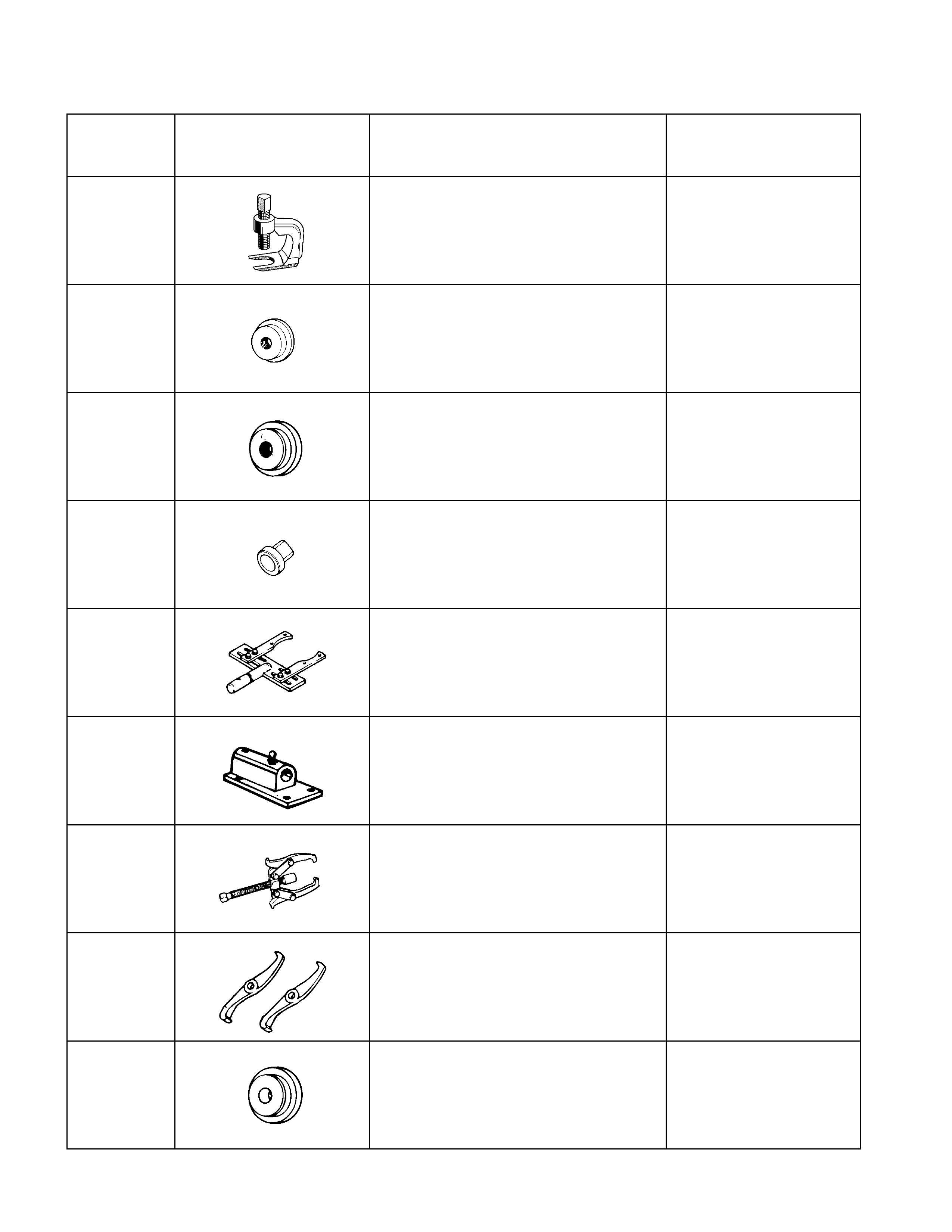
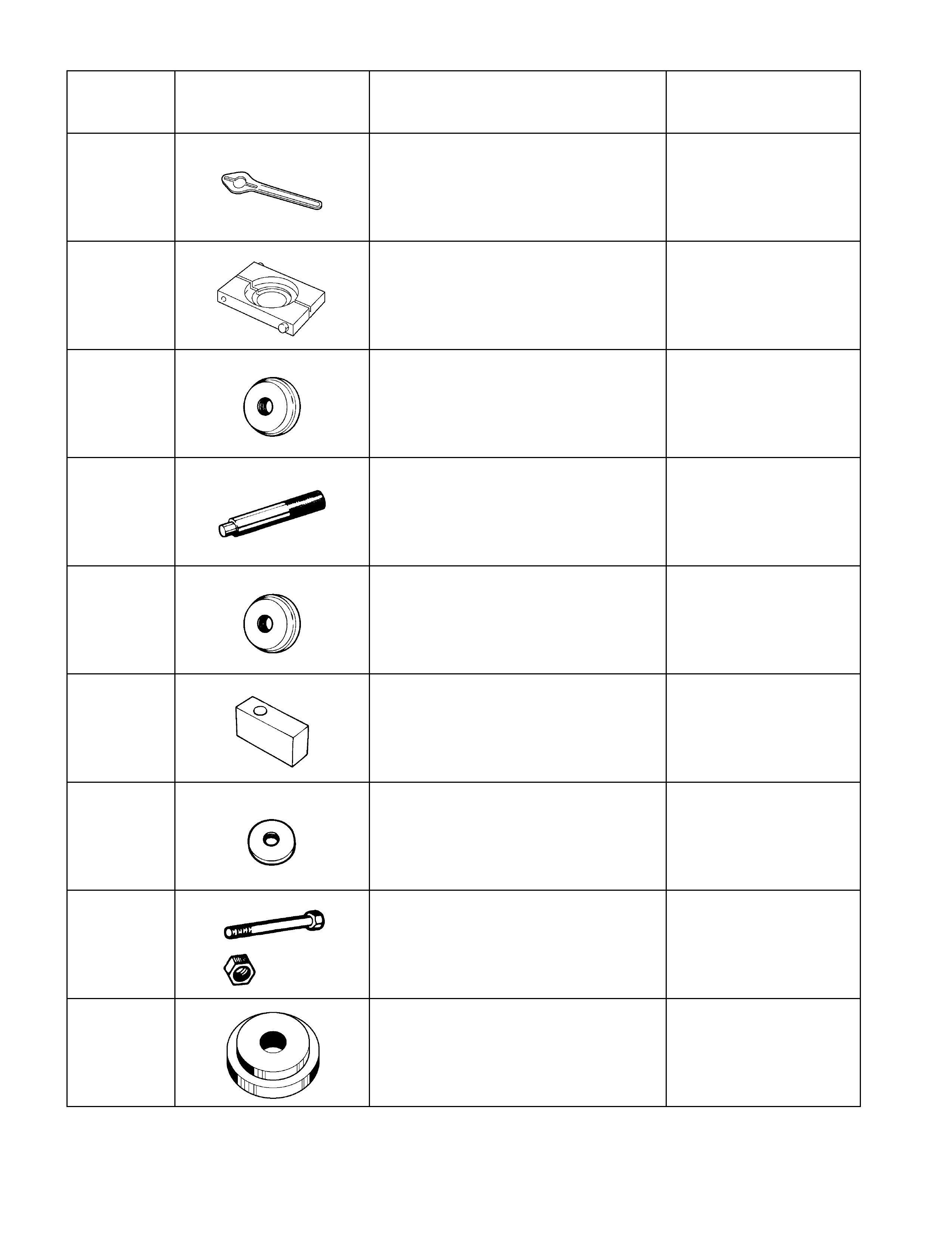
Special Service Tool
ITEM NO. ILLUSTRATION PART NO. PART NAME
5-8840-0079-0
Wheel Pin Remover
9-8522-1269-0
Oil Seal Installer
5-8840-2202-0
Oil Seal Installer
9-8522-1271-0
Support Stand
5-8840-0275-0
Holding Fixture
5-8840-0003-0
Holding Fixture Base
5-8840-0013-0
Remover
5-8840-0014-0
Remover
5-8840-2196-0
Adapter
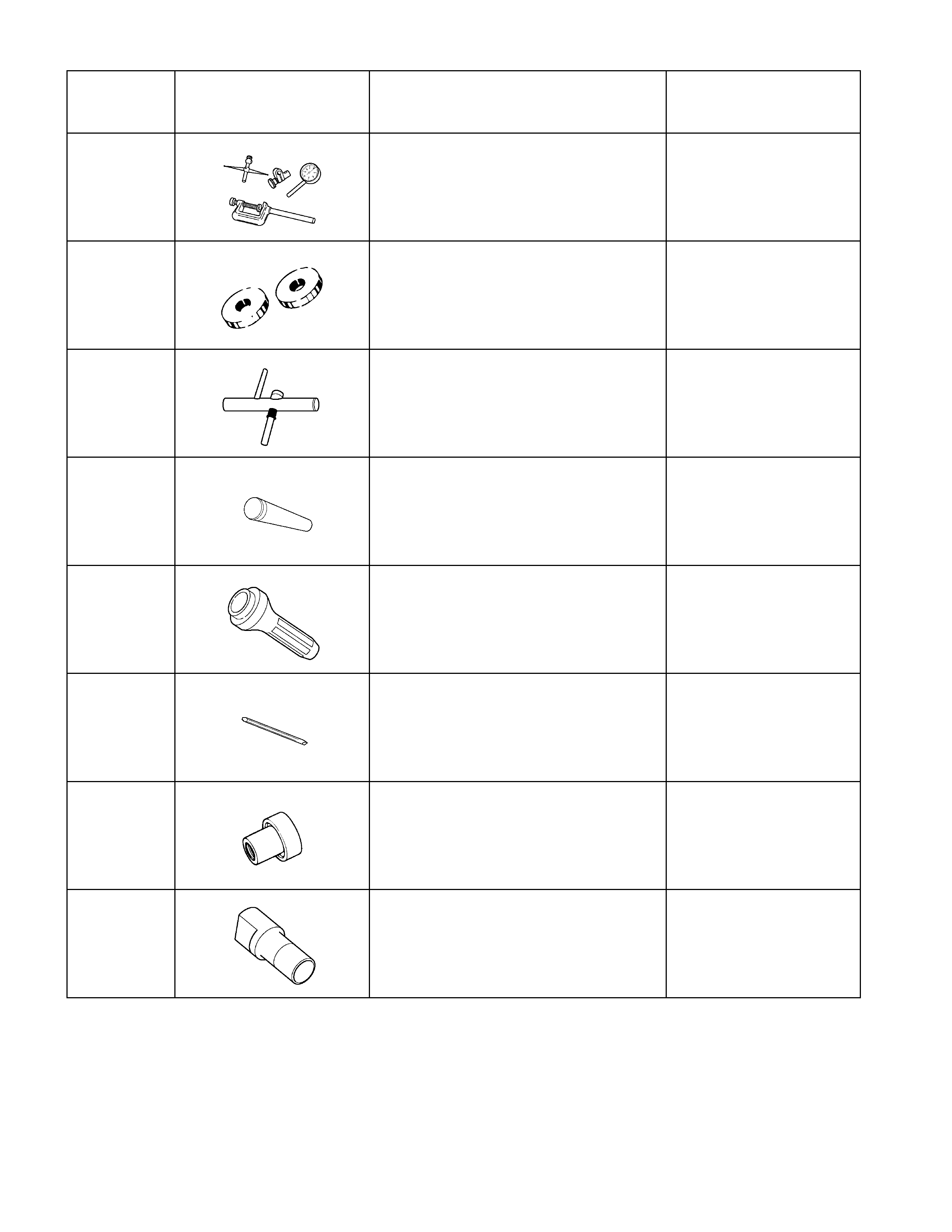
ITEM NO. ILLUSTRATION PART NO. PART NAME
5-8840-0133-0
Flange Holder
5-8840-2197-0
Separator
5-8840-2164-0
Installer
5-8840-0007-0
Grip
5-8840-2163-0
Installer
5-8840-2166-0
Gauge Plate
5-8840-0129-0
Inner Pilot
5-8840-0127-0
Stud and Nut
5-8840-2085-0
Outer Pilot
ITEM NO. ILLUSTRATION PART NO. PART NAME
5-8840-0126-0
Dial Indicator
5-8840-2167-0
Disc
5-8840-0128-0
Arbor
9-8522-1165-0
Installer
5-8840-2165-0
Installer
5-8840-2293-0
Punch
5-8840-2162-0
Installer
5-8840-2682-0
Sid Gear Holder