
SECTION 4C1 - FRONT WHEEL DRIVE
Main Data and Specifications
Special Parts Fixing Nuts and Bolts
Recommended Liquid Gasket
Reco mmended Thread Locki ng Agents
Servicing
General Description
Front Drive Axle Assembly
Front Drive Axle Assembly and Associated Parts
Removal
Installation
Front Axle Drive Shaft
Front Axle Drive Shaft and Associated Parts
Disassembly
Inspection and Repair
Bushing Replacement
Reassembly
Standard caulk Measure
Differential
Disassembly
Major Components
Minor Components
Inspection and Repair
Reassembly
Minor Components
Major Components
Front Hub and Disc (4×
××
×2 Except High Ride Suspension Model)
Disassembly
Inspection and Repair
Reassembly
Front Hub and Disc (4×
××
×4, 4×
××
×2 High Ride Suspension Model)
Disassembly
Inspection and Repair
Reassembly
Front Propeller Shaft
Removal and Installation
Troubleshooting
Special Service Tool
Techline
Main Data and Specifications
FRONT AXLE AND DIFFERENTIAL
Ring gear size mm (in) 194 (7.6)
Axle tube
Type It consists of the duce, a cast iron housing and the Axle tube.
Gear type Hypoid
Gear ratio (to 1) 4.300, 4.777
Differential type Two pinion
Specified gear oil (APL grade) GL-5
Oil capacity liter 1.4
(US/UK gal.) (0.4/0.33)
Axle shaft type Constant velocity joint (Birfield joint type and double offset joint).
FRONT PROPELLER SHAFT mm (in)
4×4 Model
Engine Model 4JH1-TC 6VE1
Transmission Type 5M/T (MUA) 4A/T 5M/T (MUA) 4A/T
Front Axle 194 mm ← ← ←
Outside Diameter mm 40 40 40 40
(in) (1.57) (1.57) (1.57) (1.57)
Inside Diameter mm 36 36 36 36
(in) (1.42) (1.42) (1.42) (1.42)
Length (L) mm 645 712 586 607
(in) (25.39) (28.03) (23.07) (23.90)
Fix Bolt Size T/F M8 M8 M10 M10
Axle M10 M10 M10 M10
Special Parts Fixing Nuts And Bolts
Front Drive Axle And Propeller Shaft N⋅m (kgf⋅m/lb⋅ft)
RTW440LF000101
Front Differential N⋅m (kgf⋅m/lb⋅ft)
RTW440LF000901
Recommended Liquid Gasket
Type Brand Name Manufacture Remarks
RTV*
Silicon Base
ThreeBond 1207B
ThreeBond 1207C
ThreeBond 1215
Three Bond
Three Bond
Three Bond
For Engine Repairs
For Axle Case
Repairs, T/M
Water Base ThreeBond 1141E Three Bond For Engine Repairs
Solvent
ThreeBond 1104
BelcoBond 4
BelcoBond 401
BelcoBond 402
Three bond
Isuzu
Isuzu
Isuzu
For Engine Repairs
Anerobic LOCTITE 515
LOCTITE 518 Loctite
Loctite All
* RTV: Room Temperature Vulcaniser
Note:
1. It is very important that the liquid gaskets listed above or their exact equivalent be used on the vehicle.
2. Be careful to use the specified amount of liquid gasket.
Follow the manufacture's instructions at all times.
3. Be absolutely sure to remo ve all lubricants and mo isture from the conn ecting surfaces before ap plying the
liquid gasket.
The connecting surfaces must be perfectly dry.
4. LOCTITE 515 and LOCTITE 518 harden upon contact with a metal surface.
Do not apply LOCTITE 515 or LOCTIT E 518 between tw o metal surfaces having a clearance of greater than
0.25 mm (0.01 in). Poor adhesion will result.
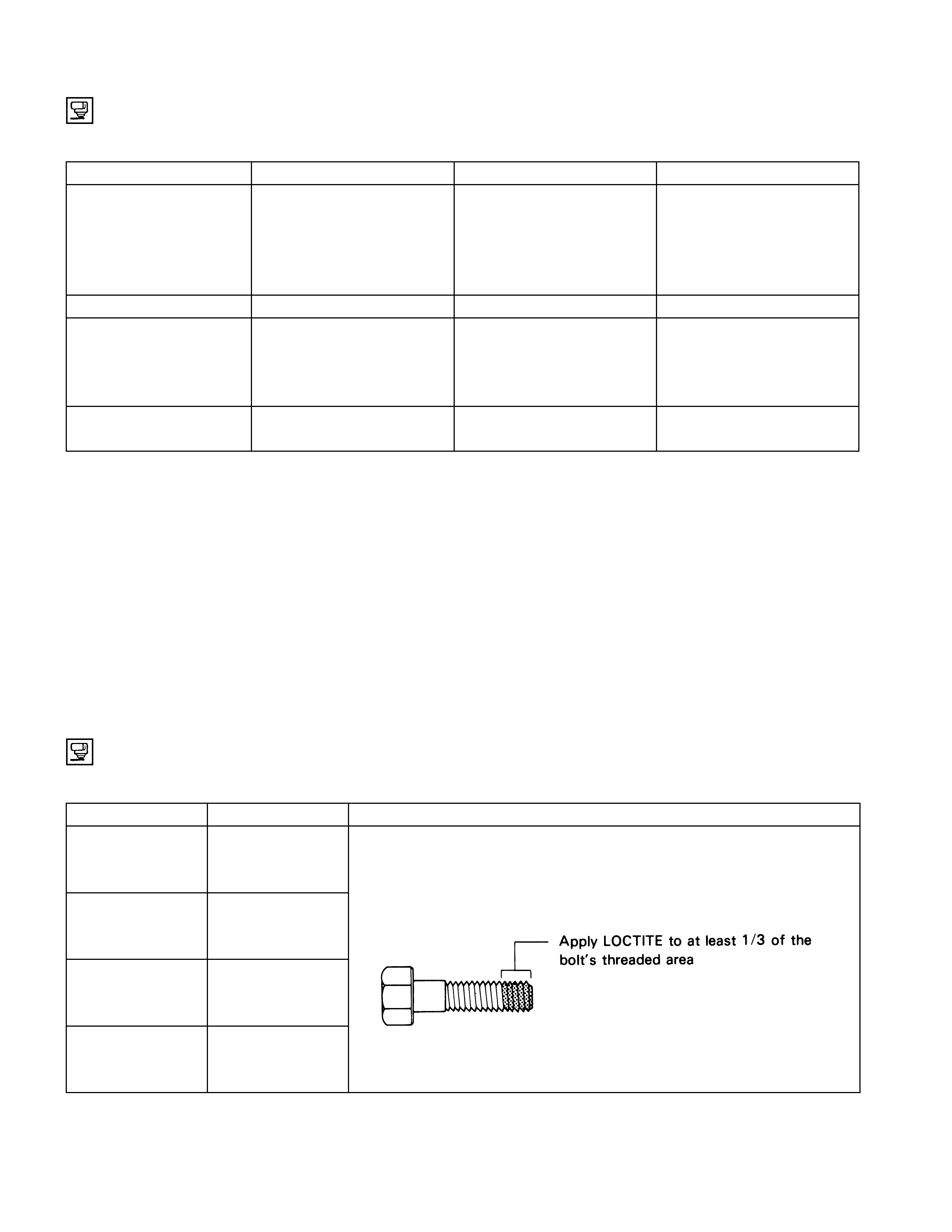
Recommended Thread Locking Agents
LOCTITE Type LOCTITE Color Application Steps
LOCTITE 242
Blue 1. Completely remove all lubricant and moisture from the bolts and
the female threaded surfaces of the parts to be joined.
The surfaces must be perfectly dry.
LOCTITE 262
Red 2. Apply LOCTITE to the bolts.
LOCTITE 270
Green
LOCTITE 271
Red
3. Tighten the bolts to the specified torque.
4. Wait at least on hour before continuing the installation procedure.
Servicing
Hub Bearing Preload at the Wheel Stud
4×4, 4×2 (High Ride Suspension) Model N (lb
)
New bearing and New oil seal 20 - 25 (4.4 - 5.5)
Reuse bearing and New oil seal 12 - 18 (2.6 - 4.0)
4×2 (Except High Ride Suspension) Model N (lb)
New bearing and New oil seal 8 - 12 (1.8 - 2.2)
Reuse bearing and New oil seal 8 - 12 (1.8 - 2.2)
General Description
Front Drive Axle
412R300015
Front Hub and Disc (4×
××
×2 Except High Ride Suspension Model)
412R300010
(4×
××
×2 High Ride Suspension Model)
RTW34CLF000701
Front Hub and Disc (4×
××
×4 Model)
412R300009
Front Propeller Shaft
4JH1-TC
401R300026
6VE1
RTW34ASF000101
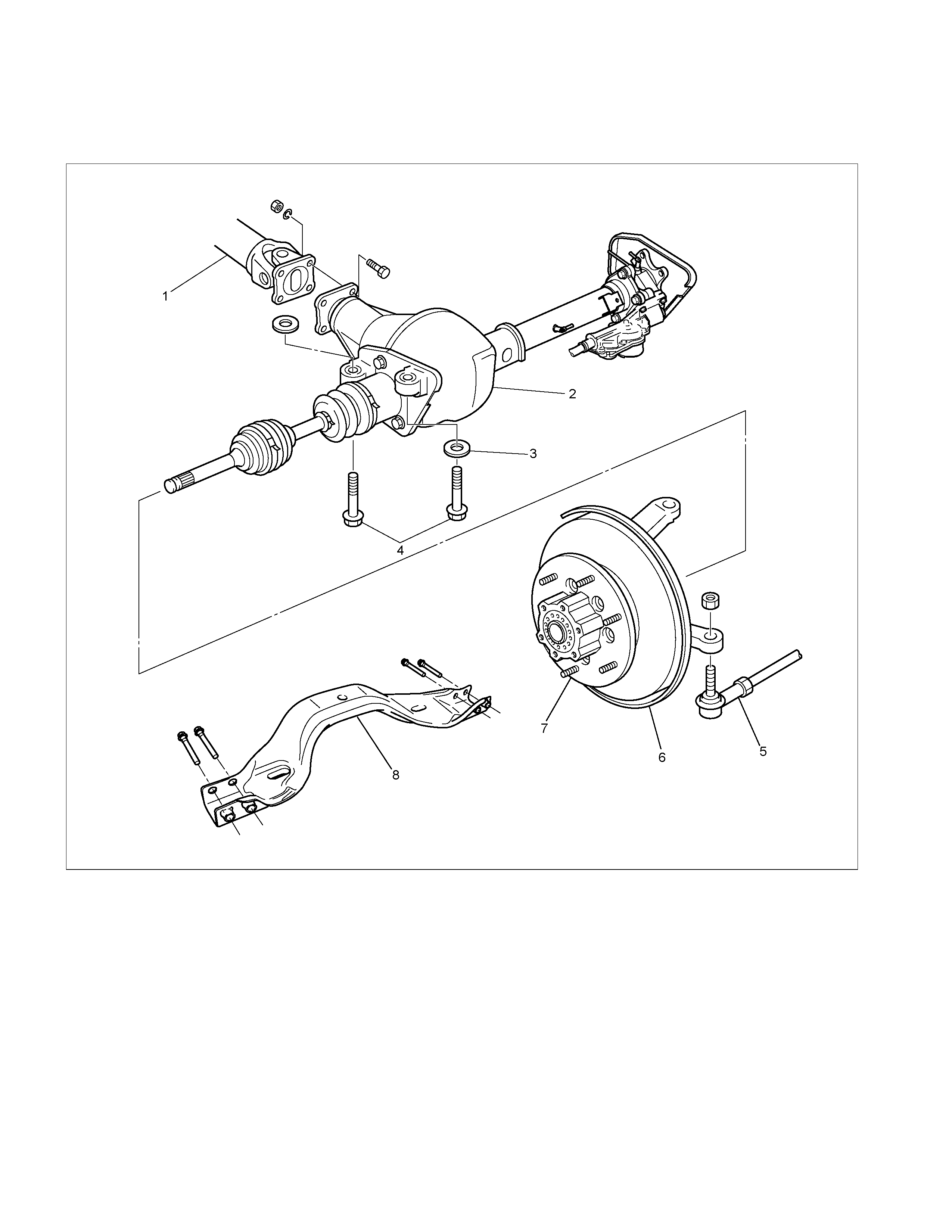
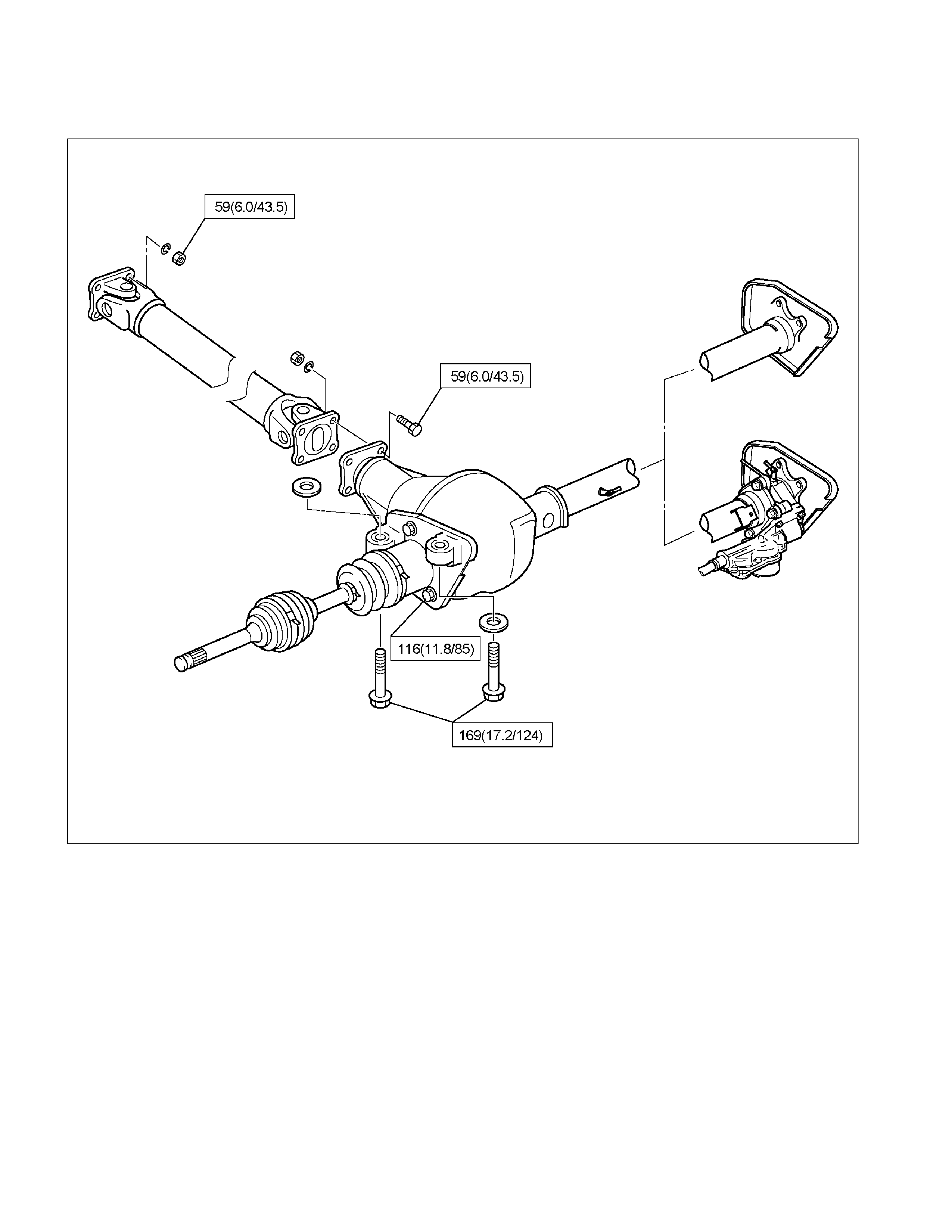
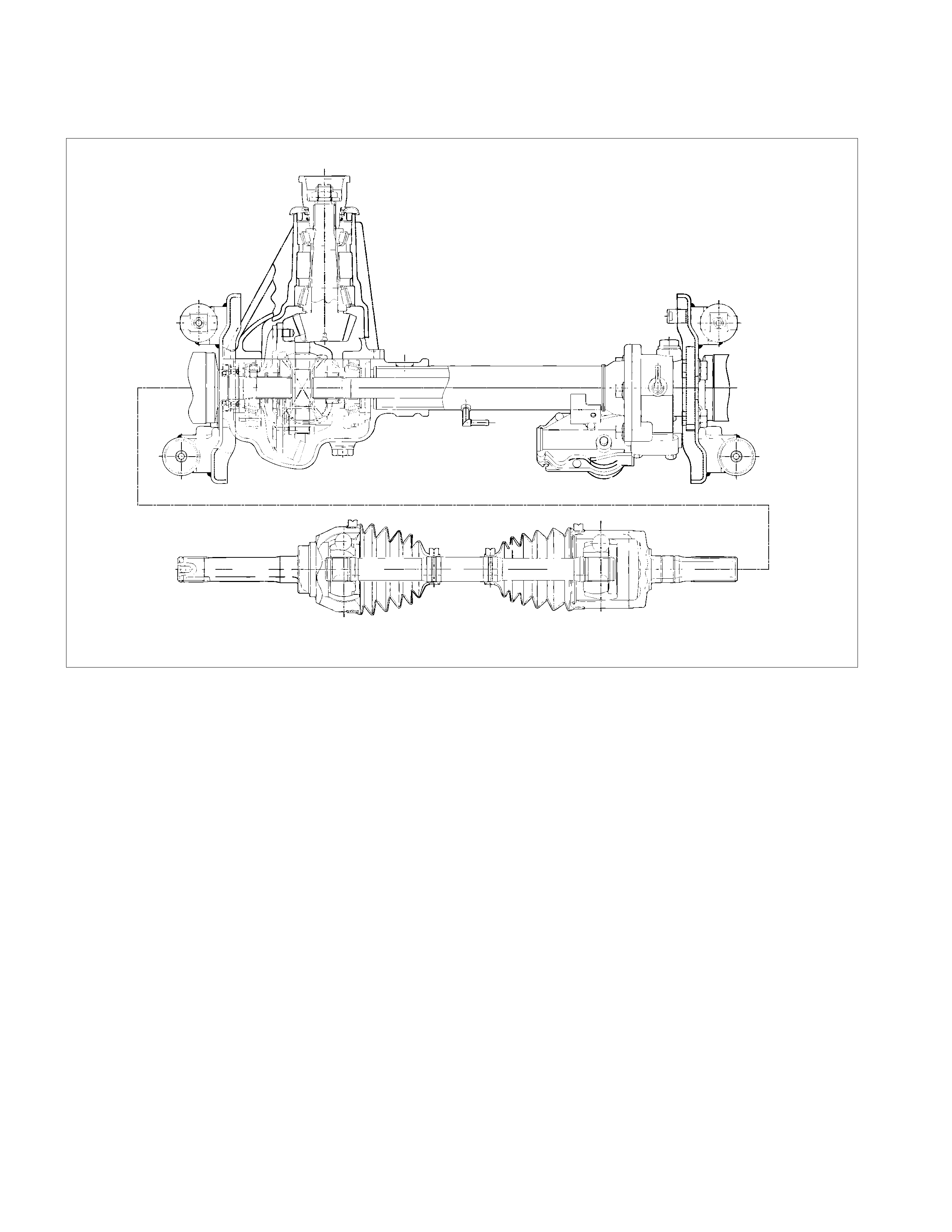
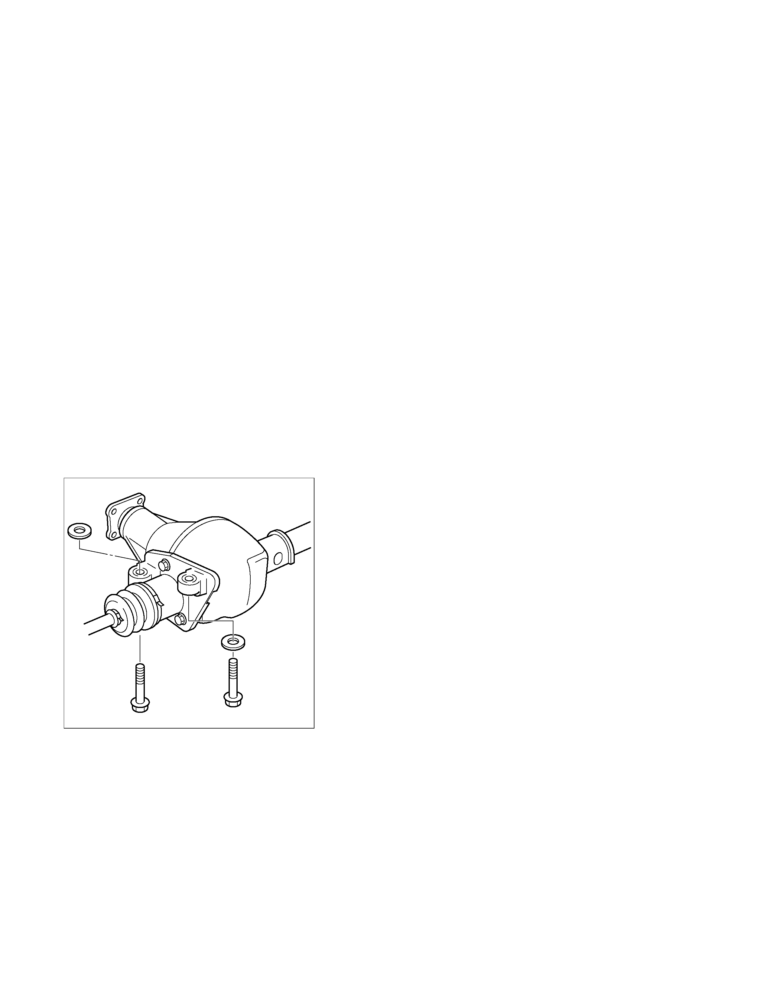
Front Drive Axle Assembly
Front Drive Ax le Assembly and Associated Parts
RTW34CLF000101
Legend
1. Propeller Shaft
2. Front Axle Case Assembly and Front Drive
Shaft Assembly
3. Washer
4. Mounting Bolt
5. Tie-rod End ; Steering Unit
6. Knuckle and Back Plate
7. Hub and Disc Assembly
8. Suspension Crossmember
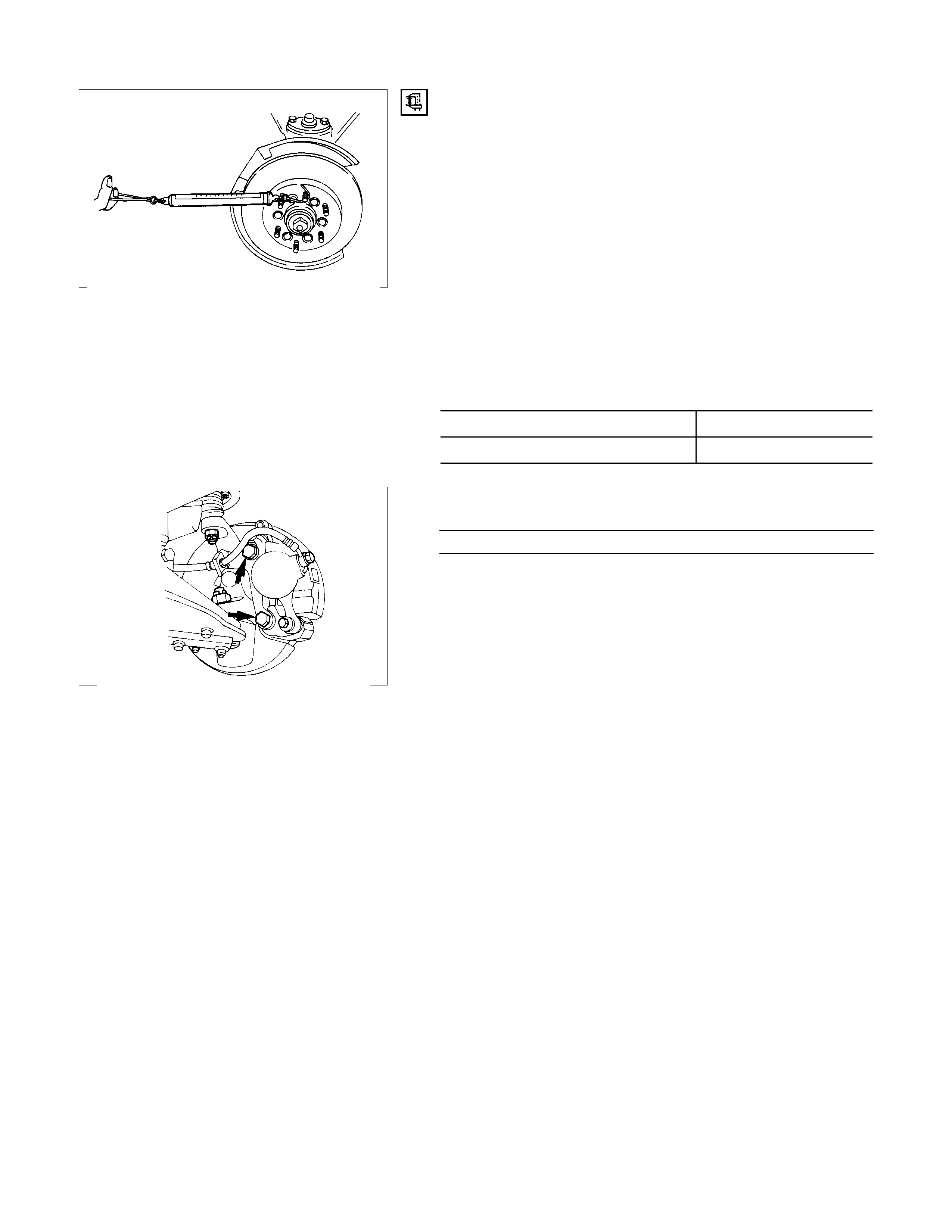
Removal
1. Jack up the vehicle and support it using jack stand.
2. Remove the tire and wheel.
3. Remove the stone guard.
4. Remove the brake caliper fixing bolt and hang the caliper.
Refer to Disc Brakes in Brake section.
5. Remove the antilock brake system speed sensor.
Refer to Front Wheel Speed Sensor in Brake section.
6. Remove the hub and disc assembly.
Refer to Front Hub and Disc in this section.
7. Remove the propeller shaft, refer to Front Propeller Shaft
in this section.
8. Loosen the height control arm of the torsion bar, then
remove the torsion bar from lower control arm.
Refer to Torsion Bar in Suspension section.
9. Remove the suspension crossmember.
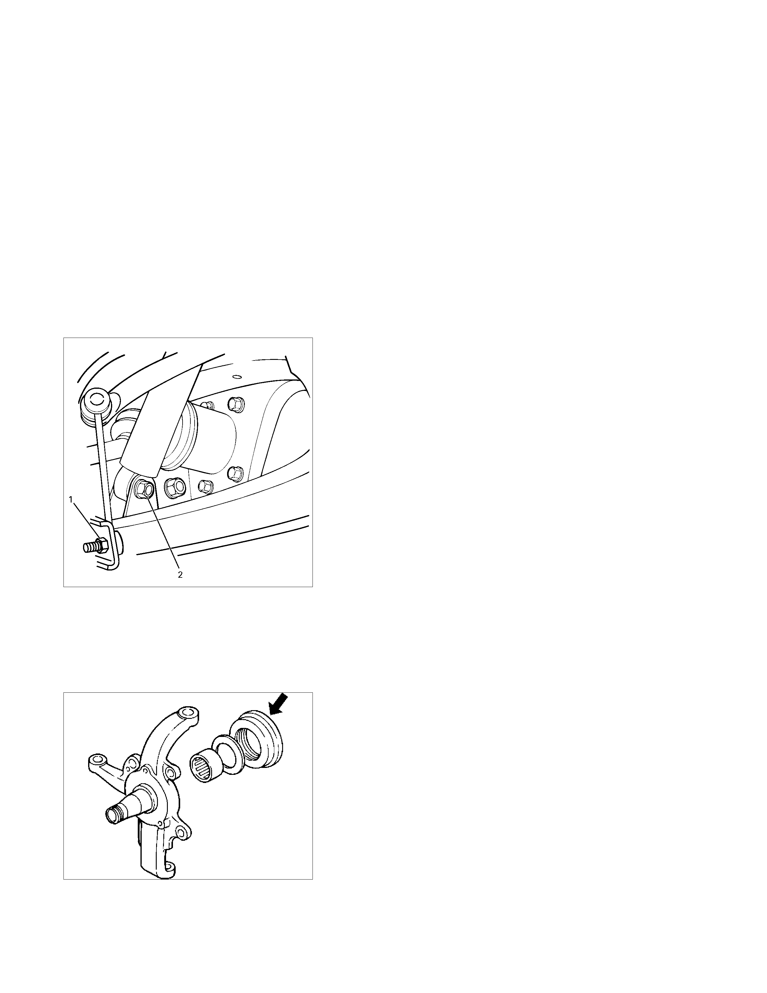
10. Remove the lower nut (1) of the stabilizer link.
11. Remove the lower bolt and nut (2) of the shock absorber.
12. Remove the tie-rod end from the knuckle.
Refer to Power Steering Unit in Steering Section.
13. Disconnect the hose of the shift on the fly, at the hose clip
portion.
14. Disconnect the shift switch connector.
15. Remove the bolts and nuts of the lower control arm (Frame
side), then disconnect the lower control arm from frame.
16. Disconnect between the right side upper control arm and
the knuckle, then remove the knuckle with lower control
arm.
CAUTION:
When removing the knuckle, be careful not to damage the
oil seal inside of the knuckle.
17. Support the differential case by the jack.
18. Remove the front axle mounting bolts and nuts, lower the
jack slowly. Remove the left side drive shaft end from the
knuckle, and then lower the axle assembly from the
vehicle.
CAUTION:
1. During the work, be sure that the axle assembly is
supported securely.
2. Be careful not to damage the bellows of the power
steering unit by interference.
3. Be careful not to damage the hose bracket of the shift
on the fly by interference.
Installation
1. Support the differential case by the jack.
2. Jack up the front drive axle assembly, install the left side
drive shaft to the knuckle, then install the mount bolts and
nuts.
CAUTION:
1. Be careful not to damage the bellows of the power
steering unit by interference.
2. Be careful not to damage the hose bracket of the shift
on the fly by interference.
3. When installing the drive shaft to the knuckle, be
careful not to damage the oil seal inside of the knuckle.
RTW34CSH000101
3. Tighten the mounting bolts and nuts to the specified torque.
Torque : 168 N·m (17.2kg·m/124 lb ft)
4. Install the right side knuckle with lower control arm to the
upper control arm.
Refer to Knuckle in Suspension section.
CAUTION:
When insert the drive shaft to the knuckle, be careful not
to damage the oil seal inside of the knuckle.
5.
A
lign the bolthole of the lower control arm; install the bolts
and nuts.

NOTE :
A
djust the buffer clearance before tighten the bolts and nuts of
the lower control arm.
6. Install the breather hose of the front axle.
7. Install the actuator connector of the shift on the fly. (With
shift on the fly)
8. Install the tie-rod end of the power steering unit to the
knuckle, tighten the nut to the specified torque.
Torque : 98 N·m (10.0kg·m/73 lb ft)
9. Install lower bolts and nuts of the shock absorber, tighten it
to the specified torque.
Torque : 93 N·m (9.5kg·m/69 lb ft)
10. Install lower nuts of the stabilizer link, tighten it to the
specified torque.
Torque : 50 N·m (5.1kg·m/37 lb ft)
11. Install the suspension crossmember.
12. Install the torsion bar.
Refer to Torsion Bar in Suspension section.
13. Install the front propeller shaft.
Refer to Front Propeller Shaft in this section.
14. Install the hub and disc assembly and adjust the bearing
preload.
Refer to Front Hub and Disc in this section.
15. Install the wheel speed sensor of the antilock brake
system.
16. Install the brake caliper. Tighten the bolt of the caliper
bracket to the specified torque.
Torque : 155 N·m (15.8kg·m/115 lb ft)
17. Install the stone guard.
18. Install the tire and wheel.
19. Lower the vehicle, adjust the trim height.
Refer to Trim Height Adjustment in Steering section.
20. Tighten the bolts and nuts of the lower control arm to the
specified torque.
Refer to Lower Control Arm in Suspension section.
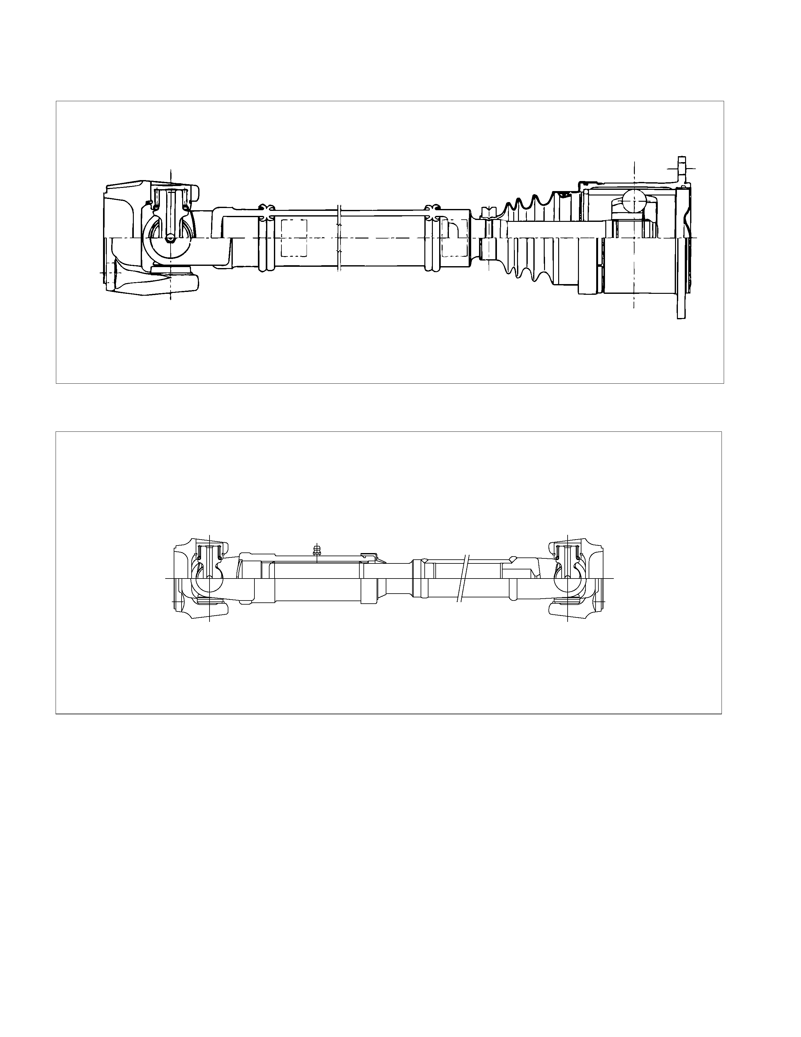
Front Axle Drive Shaft
Front Axle Drive Shaft and Associated Parts
RTW34CLF000401
Legend
1. Axle Case and Differential
2. Snap Ring
3. Bearing
4. Snap Ring
5. Oil Seal
6. Bracket
7. DOJ Case
8. Circlip
9. Bolt
10. Drive shaft Joint Assembly
11. Ball
12. Snap Ring
13. Ball Retainer
14. Ball Guide
15. Band
16. Bellows
17. Band
18. Band
19. Bellows
20. Band
21. UJ Shaft
22. Dust Seal
Disassembly
NOTE:
For the left side, follow the same steps as right side.
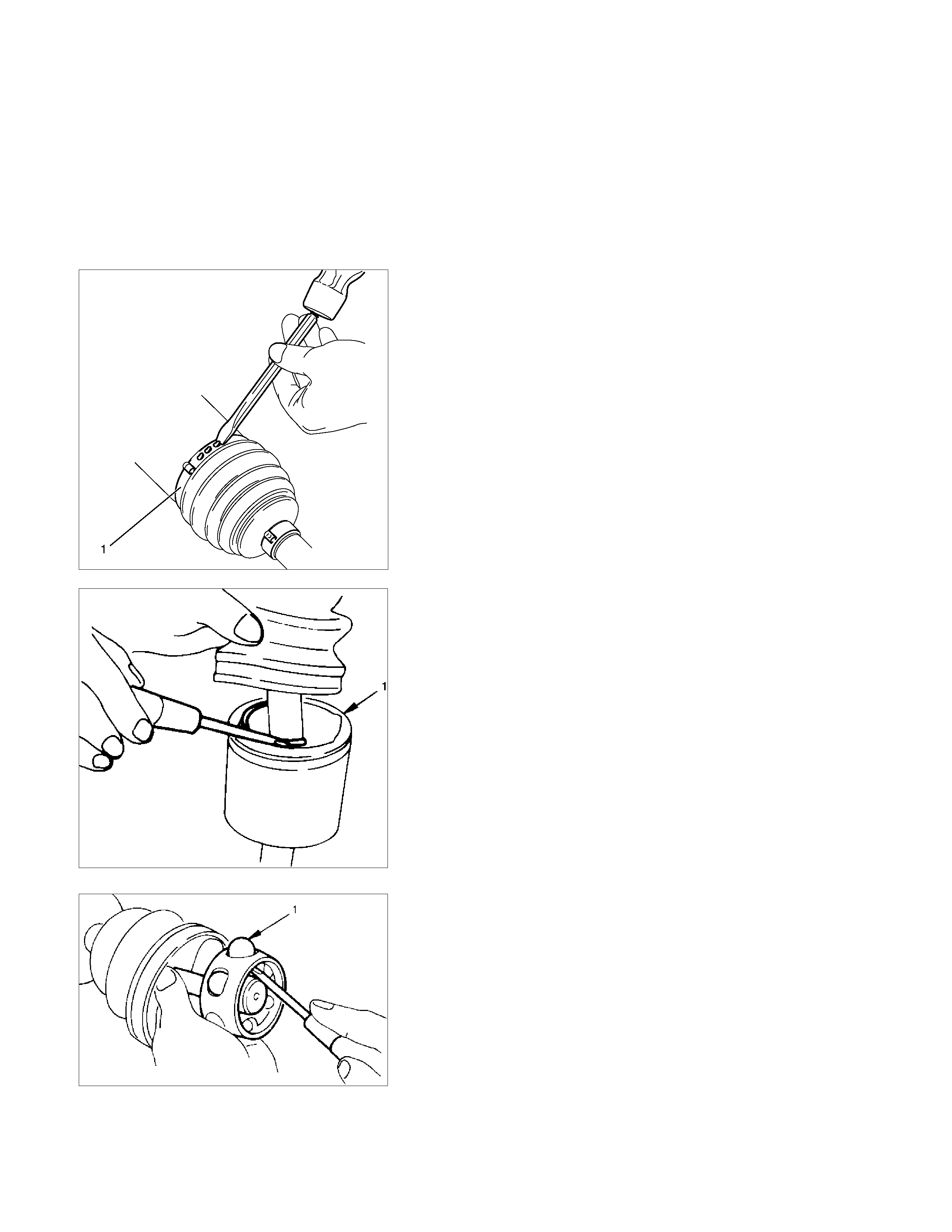
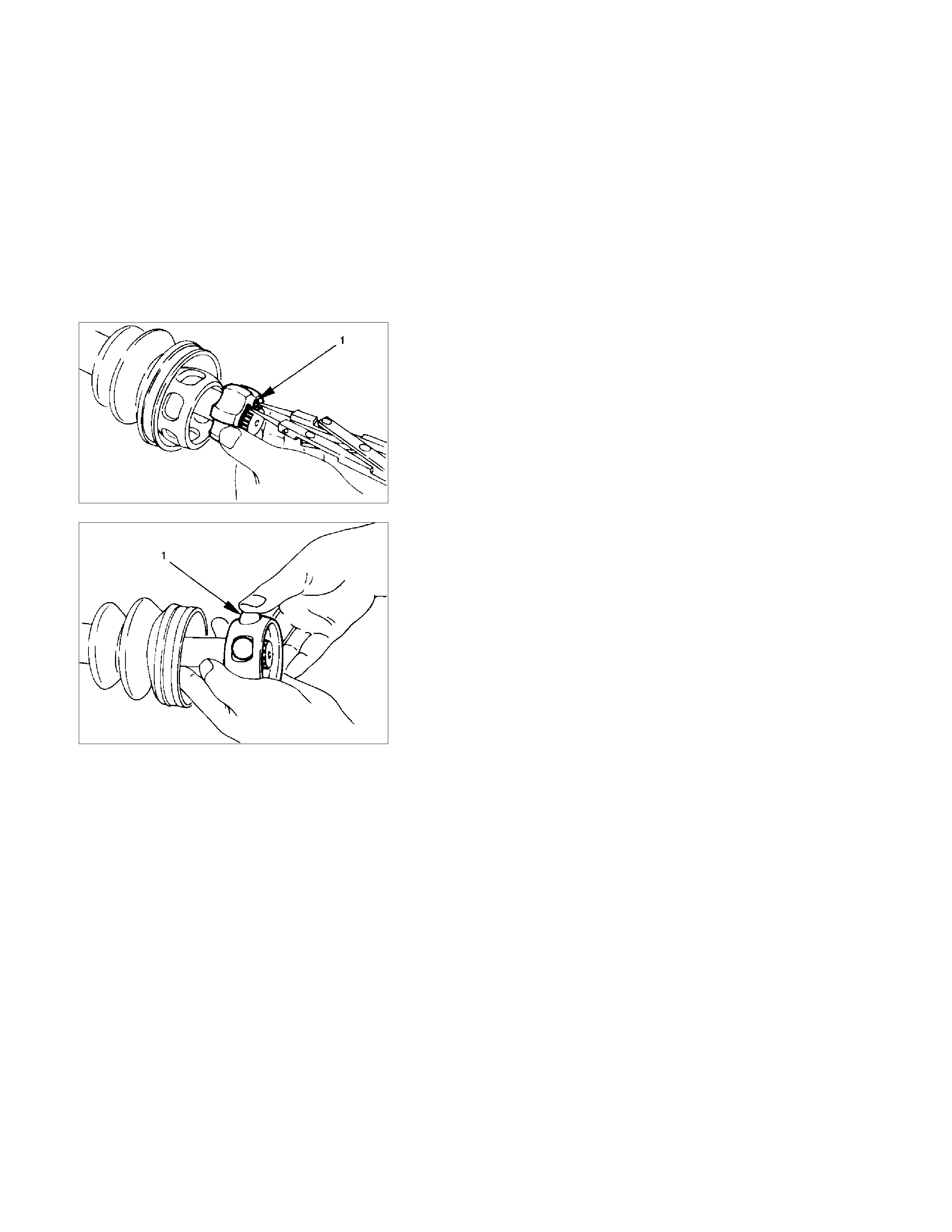
1. Use a hammer and chisel to remove the 3 pawls (above
the large and small boot bands on the DOJ side).
CAUTION:
Take care not to damage the bellows during band removal.
2. Remove band (1).
3. Pry off circlip (1) with a screwdriver or equivalent.
4. Remove drive shaft joint assembly .
5. Remove the six balls (1) with a screwdriver or equivalent.

6. Using snap ring pliers, remove the snap ring (1) fastening
the ball retainer to the center shaft.
7. Remove ball retainer, ball guide and bellows.
8. Use a hammer and chisel to remove the 3 pawls (above
the large and small boot bands on the UJ side).
CAUTION:
Take care not to damage the bellows during band removal.
9. Remove band (1).
10. Remove bellows.
11. Remove dust seal from UJ.
12. Remove UJ shaft assembly.
13. Remove the mounting bracket fixing bolts, and then
remove DOJ case assembly from the axle case.
14. Remove snap ring and bearing.
15. Remove snap ring and oil seal.
16. Remove bracket.
Inspection and Repair
Make necessary correction or parts replacement if wear,
damage, corrosion or any other abnormal condition is found
through inspection.
Check the following parts.
1. Drive shaft joint assembly
2. DOJ case, ball, ball guide, ball retainer
3. Bellows
4. Bearing
5. Dust seal, oil seal
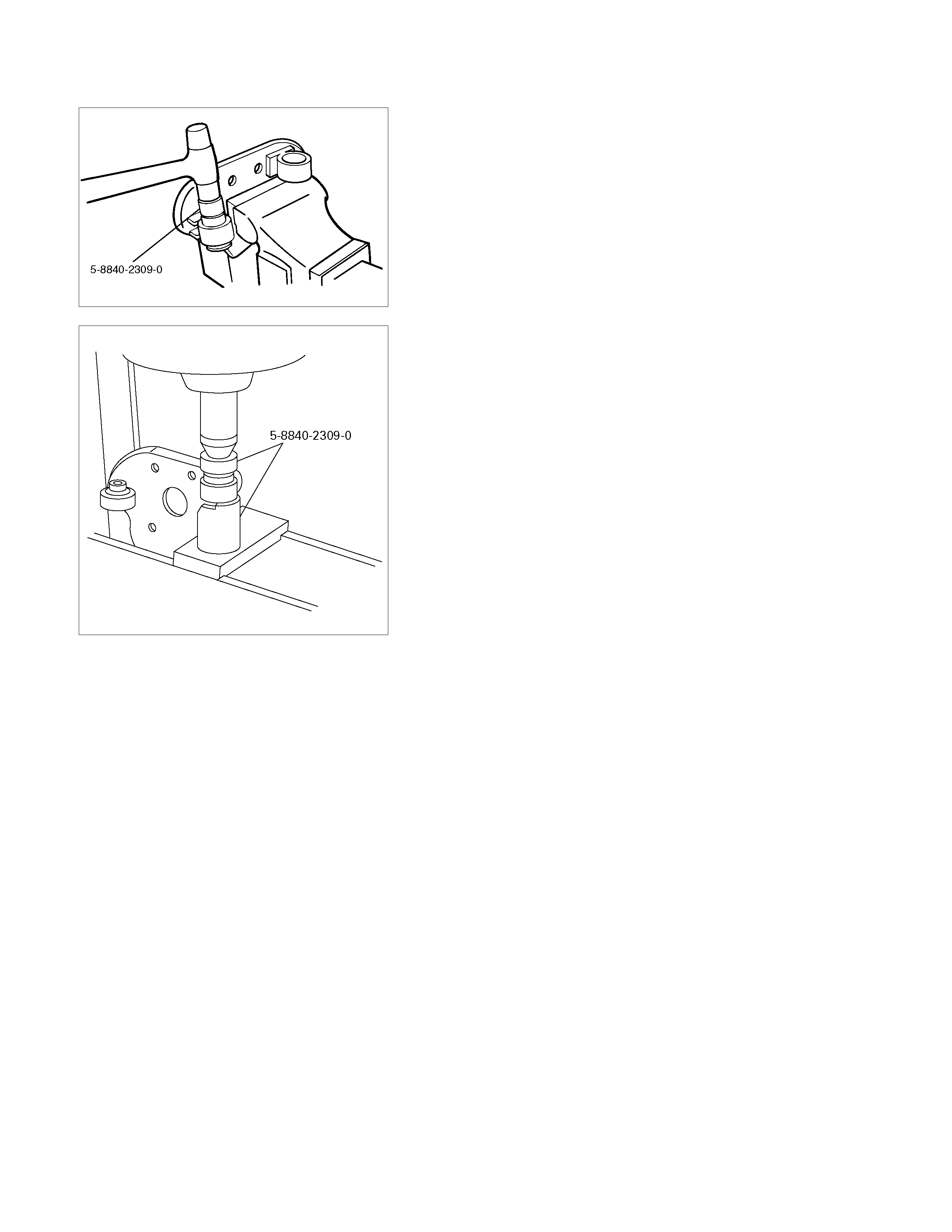
Bushing Replacement
• Remove the bushings using a remover 5-8840-2309-0 and
hammer.
• By using installer and base 5-8840-2309-0, press fit the
bushings into the bracket.
Reassembly
1. Install DOJ case to bracket.
2. Install oil seal and fix snap ring.
Discard the used oil seal, snap ring and install a new one.
3. Install bearing and fix snap ring.
Discard the used snap ring and install a new one.
4. Install bracket to axle case. Tighten the bracket bolt to the
specified torque.
Torque : 116 N·m (11.8kg·m/85 lb ft)
5. Apply 135g of the specified grease in UJ.
6. Install dust seal for UJ.
Discard the used dust seal and install a new one.
Legend
1. Bellows
2. Shaft
7. Apply a thin coat of grease to the shaft for smooth
installation then install bellows.
CAUTION:
During bellows assembly, be sure to insert both ends of
the bellows into the case and shaft grooves.
Legend
1. DOJ Case
2. Bellows
8. Install band. Note the setting direction. After installation,
check Standard Caulk Measure.
Discard the used band and install a new one.
Use the special tool pliers 5-8840-2745-0 to caulk the
bands to the specified value.
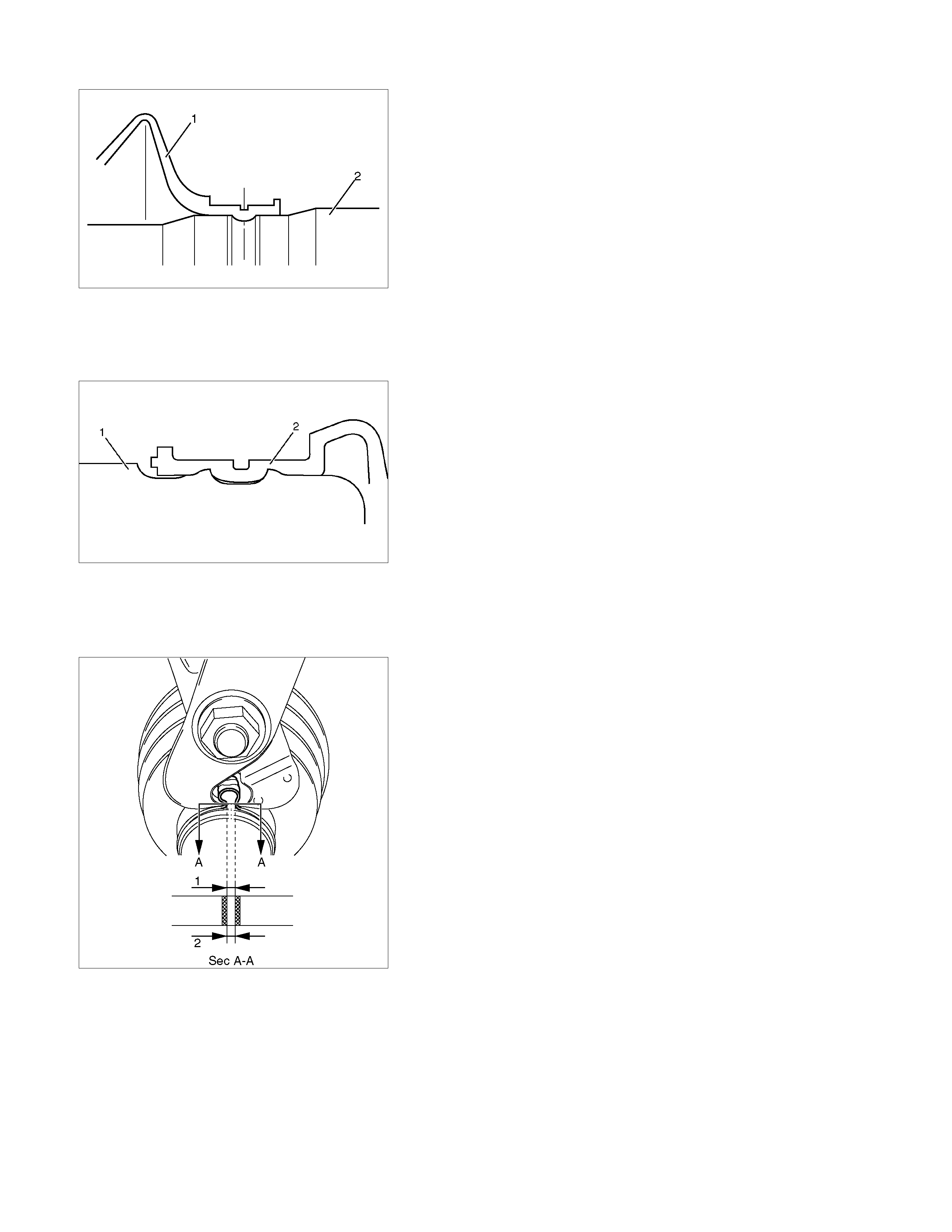
Standard Caulk Measure
• 1.2mm (0.05in) <= (1) and (2) <= 4.0mm (0.16in)
• (1) - (2) or (2) - (1) <= 0.4mm (0.016in)
9. Install another bellows and fix band.
Discard the used band and install a new one.
10. Install the ball guide with the smaller diameter side ahead
onto the shaft.
11. Install ball retainer.
12. Using snap ring pliers, install the snap ring (1) securing the
ball retainer to the shaft.
Discard the used snap ring and install a new one.
13. Align the track on the ball (1) retainer with the window in
the cage, and install the six balls into position.
14. Pack 150g of the specified grease in DOJ case, then install
drive shaft joint assembly. After reassembly, move the DOJ
longitudinally several times to get to fit.
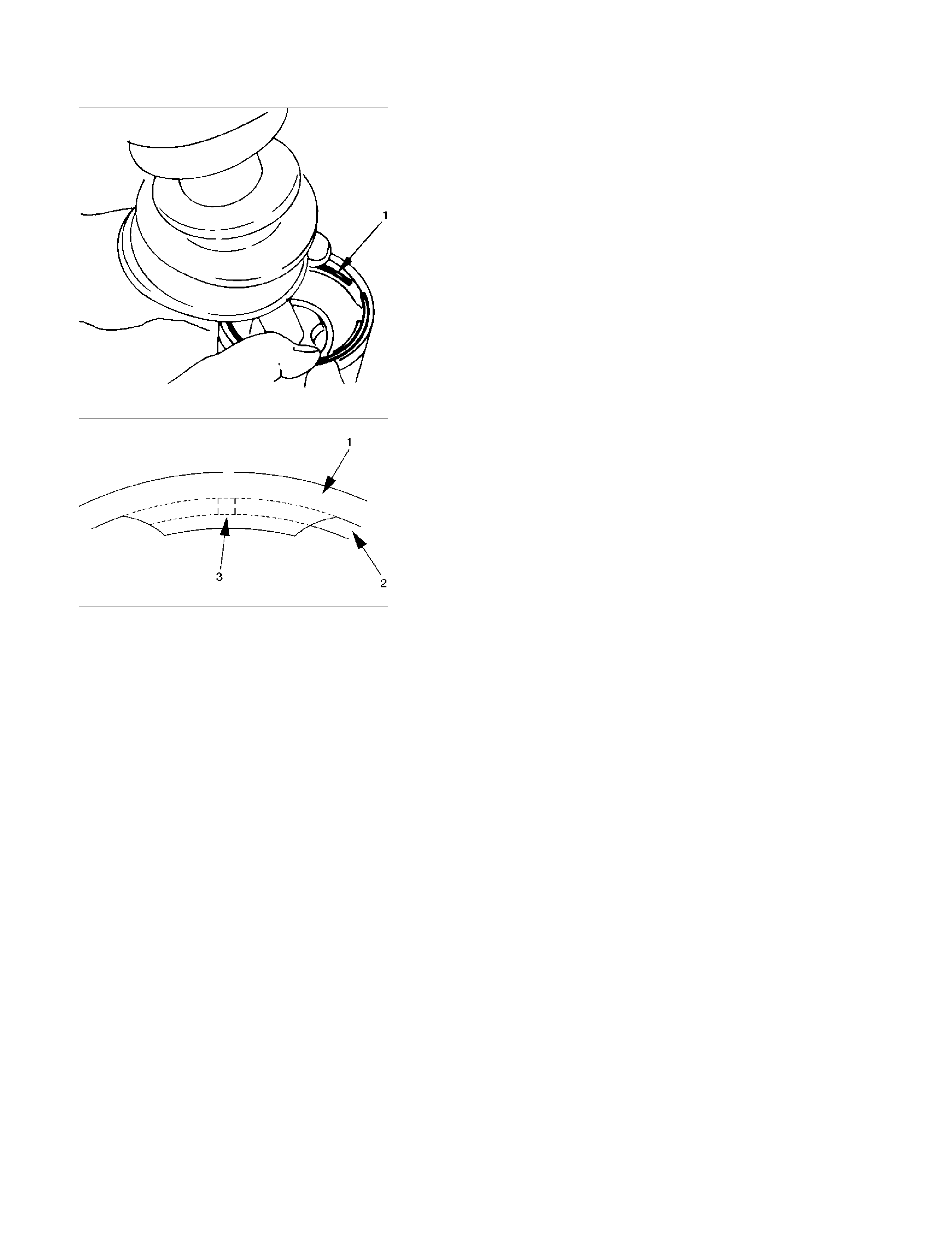
15. Install the circlip (1) so that open ends are positioned away
from the ball groove.
Discard the used circlip and install a new one.
Legend
1. Outer Case
2. Circlip
3. Open Ends
16. Install band. After installation, check that the bellows is free
from distortion.
Discard the used band and install a new one.
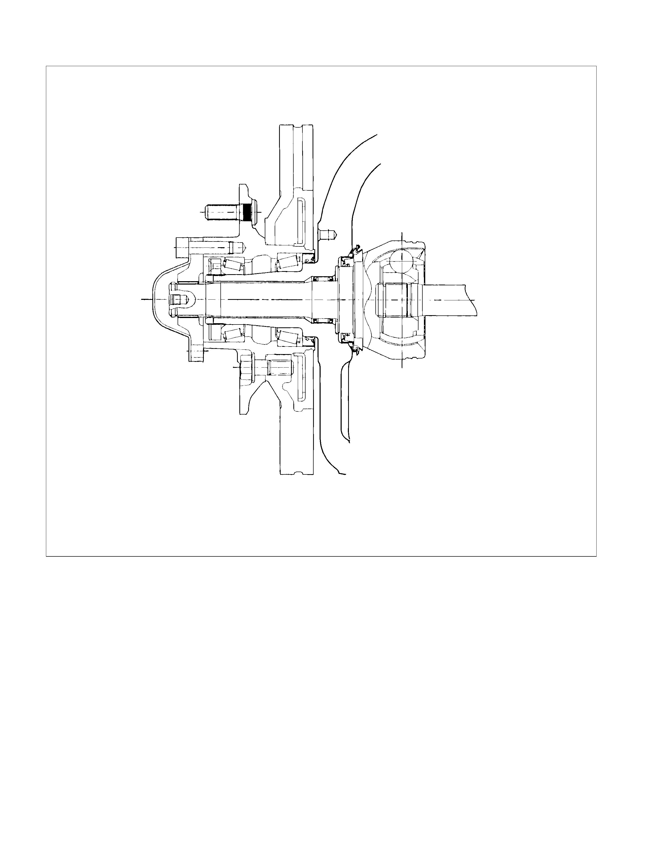
Differential
Disassembly
Major Components
RTW34CLF000501
Disassembly Steps
1. Bolt
2. Differential assembly
3. Axle case
4. Bolt
5. Bearing cap
6. Diff. cage assembly
7. Side bearing outer race
8. Side bearing
9. Adjust shims
10. Flange nut
11. Flange
12. Dust cover
13. Pinion gear
14. Inner bearing
15. Adjust shim
16. Collapsible spacer
17. Inner bearing outer race
18. Oil seal
19. Outer bearing
20. Outer bearing outer race
21. Diff. carrier
Important Operations
5. Bearing Cap
A
pply a setting mark to the side bearing cap and the differential
carrier.
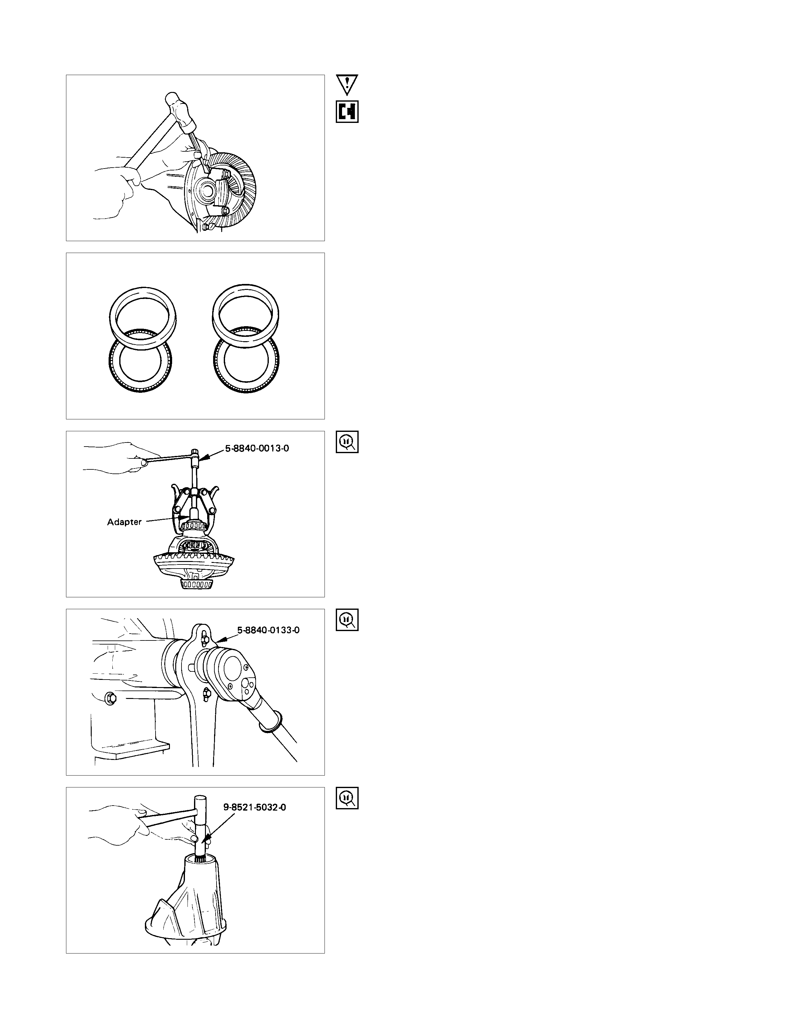
7. Side Bearing Outer Race
After removal, keep the right and left hand side bearing
assemblies separate to maintain inner and outer race
combinations.
8. Side Bearing
Remover : 5-8840-0013-0
(J-22888)
Adapter : 9-8521-1743-0
(J-8107-2)
9. Adjust Shims
Note the thickness and position of the shims removed.
10. Flange Nut
Holding wrench : 5-8840-0133-0
(J-8614-01)
13. Pinion Gear
Remove the drive pinion assembly using a soft metal rod and a
hammer.
Spindle : 9-8521-5032-0
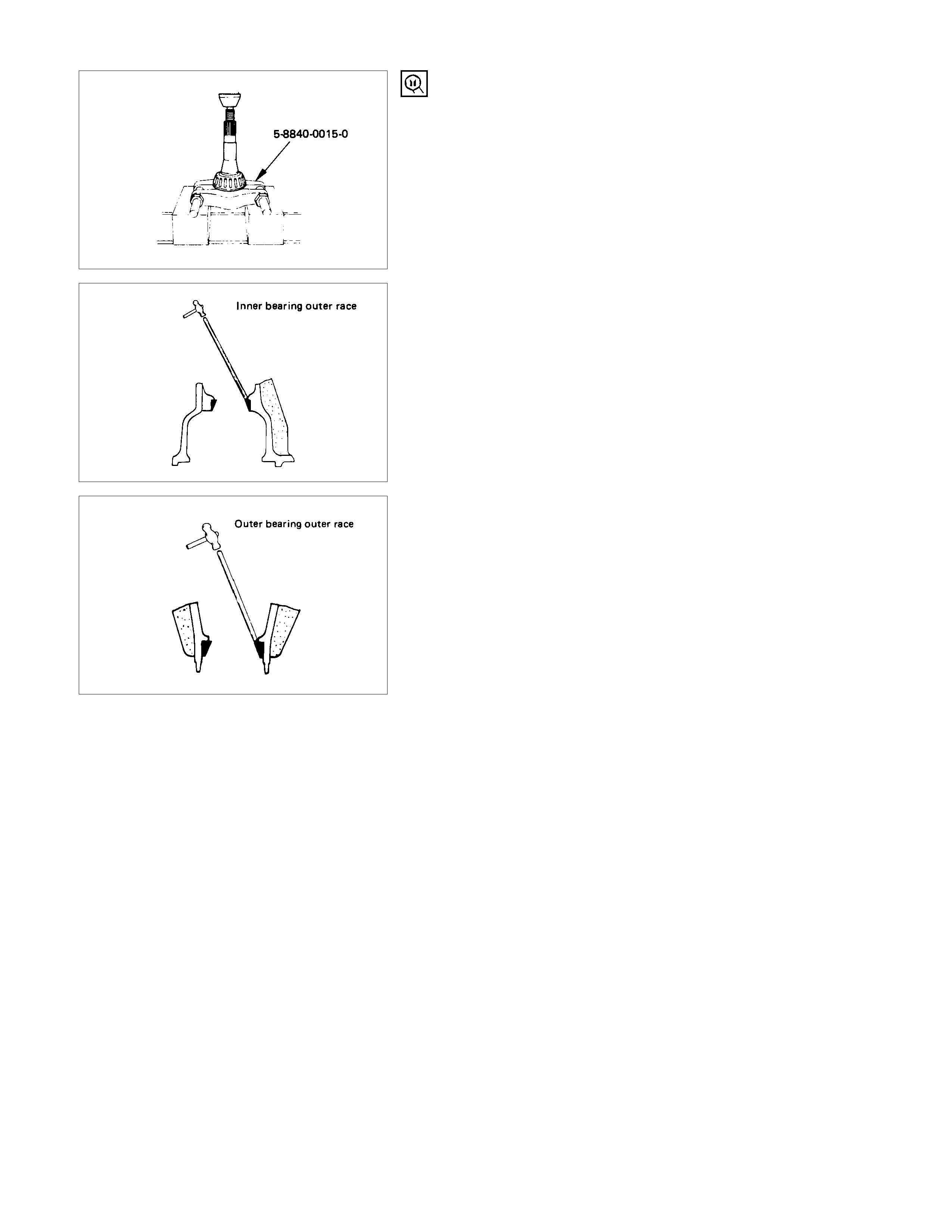
14. Inner Bearing
Remove the inner bearing using a separator and a press.
Separator : 5-8840-0015-0
(J-22912-01)
17. Inner Bearing Outer Race
20. Outer Bearing Outer Race
Remove the inner bearing outer race and the outer bearing
outer race by using a brass bar and a hammer.
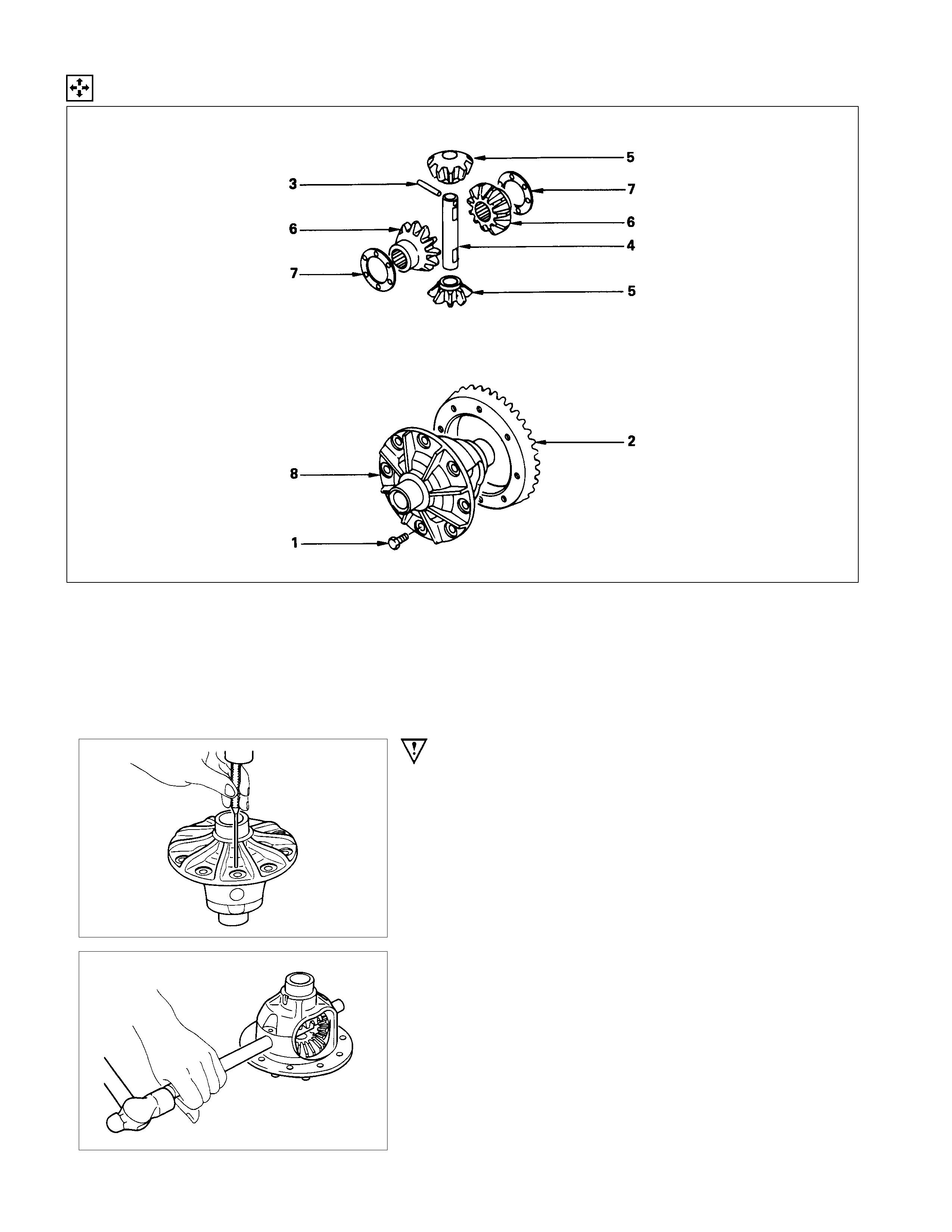
Minor Components
Disassembly Steps
1. Bolt
2. Ring gear
3. Lock pin
4. Cross pin
5. Pinion gear
6. Side gear
7. Thrust washer
8. Differential cage
Important Operations
3. Lock Pin
Break staking on the lock pin using a 5 mm (0.20 in.) diameter
drill.
4. Cross Pin
Remove the cross pin using a soft metal rod and a hammer.
Inspection and Repair
Make all necessary adjustments, repairs, and part replacements if wear, damage, or other problems are discovered
during inspection.
• Ring gear, pinion gear
• Bearing
• Side gear, pinion gear, cross pin
• Differential cage, carrier
• Thrust washer
• Oil seal
Visual Check
Inspect the following parts for wear, damage, or other
abnormal conditions.
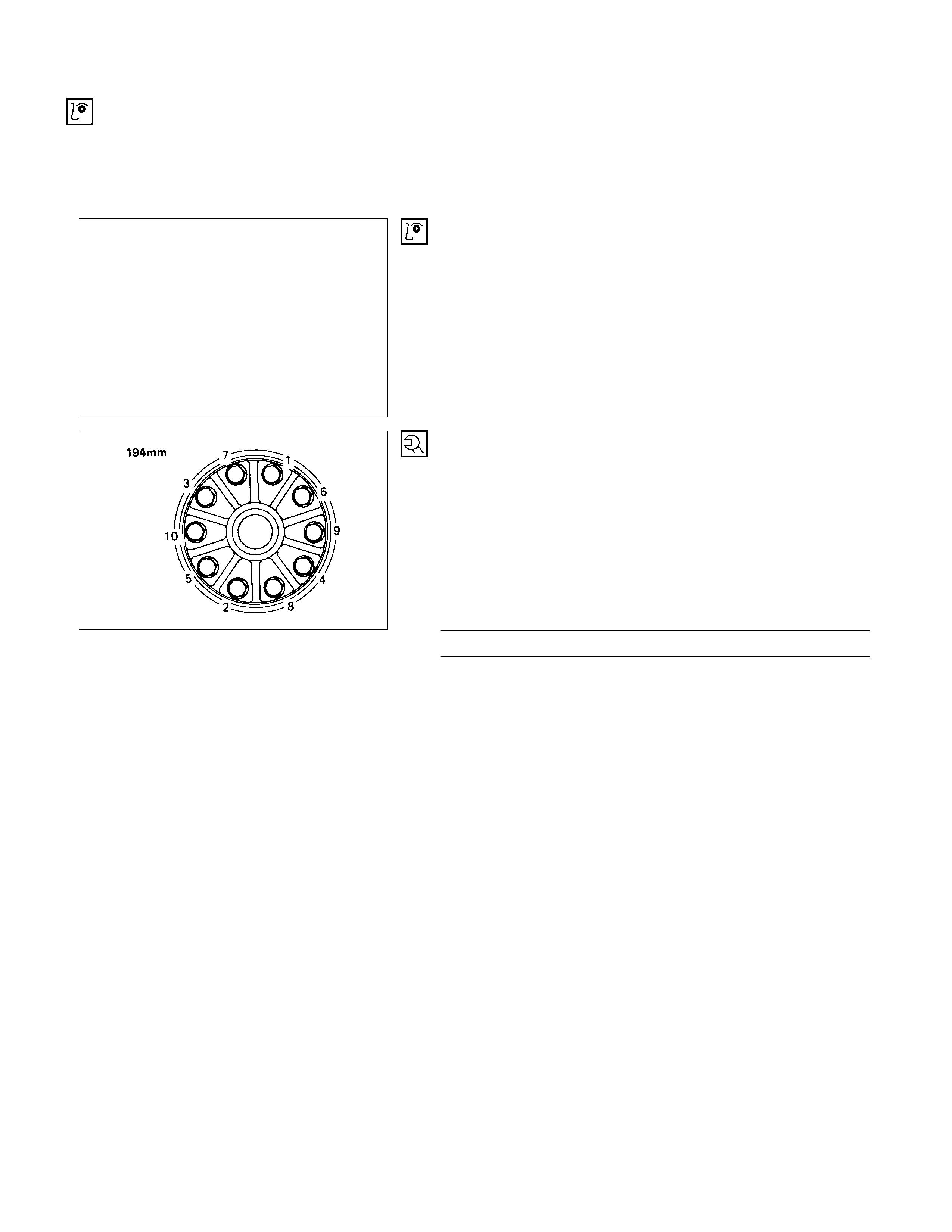
Ring Gear Replacement
(1) The ring gear should always be replaced with the drive
pinion as a set.
(2) When installing the ring gear, apply LOCTITE 271 o
r
equivalent to the threaded hole and bolt.
(3) Tighten the fixing bolts in a diagonal sequence as
illustrated.
(4) Discard used bolts and install new ones.
Bolt Torque N⋅m (kgf⋅m/lb⋅ft)
107.9 ± 9.8 (11 ± 1/79.6 ± 7.2)
Clearance Between the Differential Pinion and the Cross
Pin
mm(in)
Standard Limit
0.05 - 0.10 (0.002 - 0.004) 0.2 (0.008)
Clearance Between the Side Gear and the Differential Box
mm(in)
Standard Limit
0.03 - 0.10 (0.001 - 0.004) 0.15 (0.006)
Play in Splines Between the Side Gear and the Axle Shaft
mm(in)
Standard Limit
0.07 - 0.36 (0.003 - 0.014) 0.25 (0.010)
Reassembly
Minor Components
Reassembly Steps
1. Differential cage
2. Thrust washer
3. Side gear
▲ 4. Pinion gear
▲ 5. Cross pin
▲ 6. Lock pin
▲ 7. Ring gear
▲ 8. Bolt
Important Operations
4. Pinion Gear
Install the pinion gear by engaging it with the side gears while
turning both pinion gears simultaneously in the same direction.
5. Cross Pin
(1) Be sure to ins tall the cross pin so that it is in alignm ent with
the lock pin hole in the differential cage.
(2)
A
djust the backlash between the side gear and the pinion
gear. mm(in)
Backlash 0.10 - 0.20 (0.004 - 0.008)
Thickness of thrust washers available mm(in)
1.00, 1.05, 1.10 (0.039, 0.041, 0.043)
6. Lock Pin
After lock pin installation, stake the cage to prevent discharge
of the lock pin.
7. Ring Gear
When installing the ring gear, apply LOCTITE 271 or
equivalent to the threaded hole and bolt.
8. Bolt
Tighten the bolts in diagonal sequence as illustrated.
Bolt Torque N⋅m (kgf⋅m/lb⋅ft)
107.9 ± 9.8 (11 ± 1/79.6 ± 7.2)
Note :
Discard used bolts and install new ones.
Note that all bolts have a left hand thread.
Major Components
Reassembly Steps
1. Diff. carrier
▲ 2. Outer bearing outer race
▲ 3. Inner bearing outer race
▲ 4. Adjust shim
▲ 5. Inner bearing
▲ 6. Collapsible spacer
7. Pinion gear
8. Outer bearing
▲ 9. Oil seal
10. Dust cover
11. Flange
▲12. Flange nut and washer
▲13. Adjust shim
▲14. Side bearing
15. Bearing outer race
16. Diff. cage assembly
▲17. Bearing cap
▲18. Bolt
19. Axle case
▲20. Differential assembly
21. Bolt
Important Operations
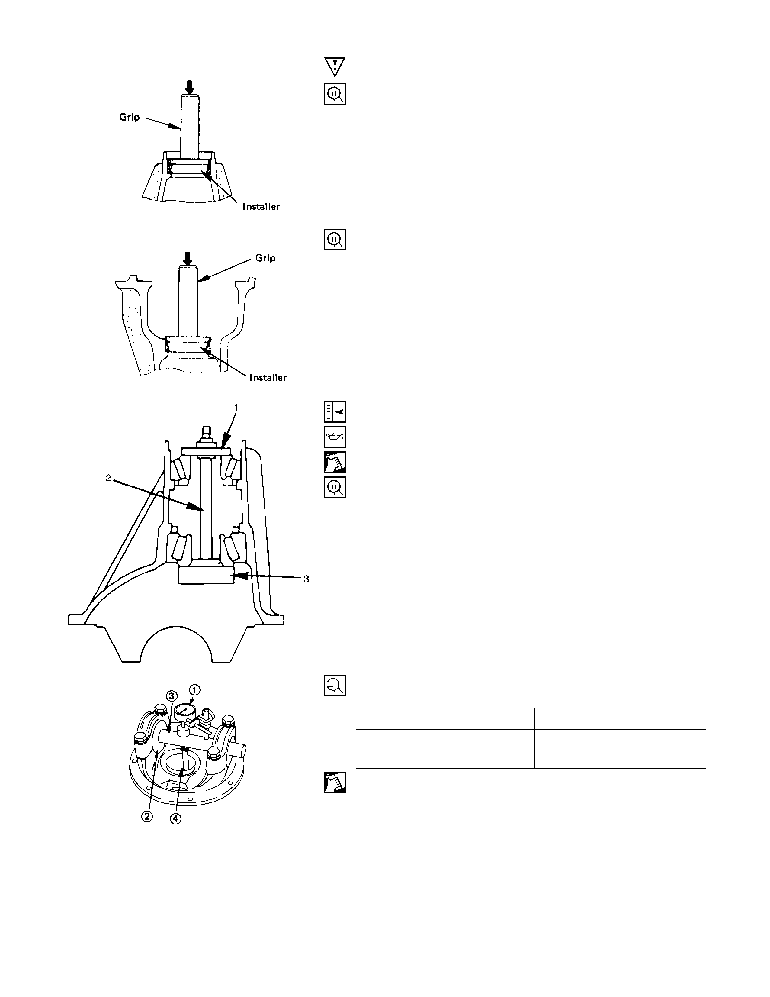
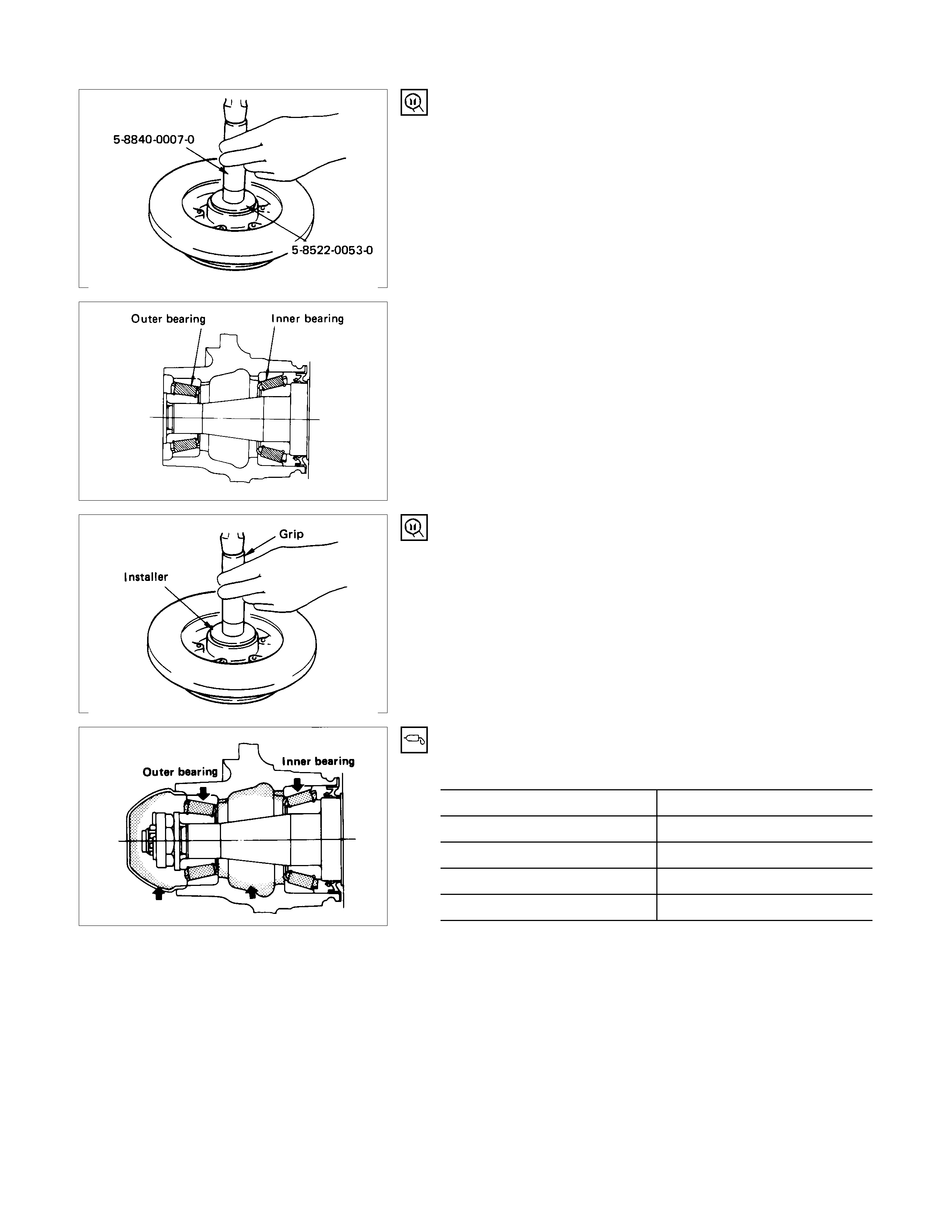
2. Outer Bearing Outer Race
Installer : 9-8522-1141-0
(J-24256)
Grip : 5-8840-0007-0
(J-8092)
3. Inner Bearing Outer Race
Installer : 9-8522-1274-0
Grip : 5-8840-0007-0
(J-8092)
4. Adjust Shim
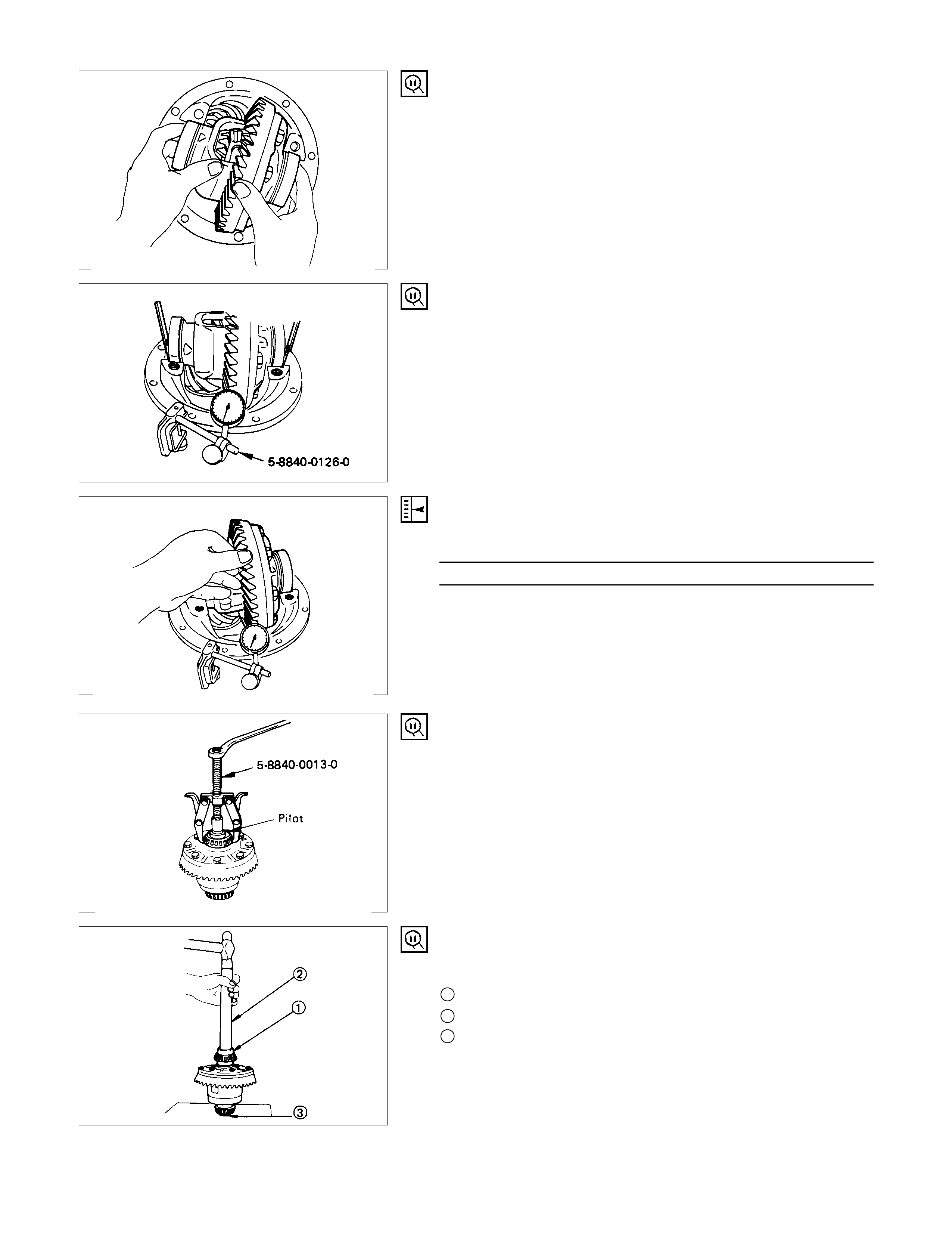
Adjustment of drive pinion mounting distance
(1) Apply gear oil to the inner and outer drive pinion bearing.
Clean the pinion setting gage set.
Then install the gage set together with the inner and oute
r
bearings.
1. Pilot : 5-8840-2085-0
(J-21777-42)
2. Nut and bolt : 5-8840-2089-0
(J-23597-9)
3. Gage plate : 5-8840-2087-0
(J-23597-7)
Tighten the nut to the specified torque. N⋅m (kgf⋅m/lb⋅ft)
New bearing 2.26 (23/20)
Used bearing 0.98 - 1.18
(10 - 12/8.7 - 10.4)
(2) Clean the side bearing bores. Install the dial indicator with
the discs and Arbor. Install and tighten the bearing caps to
the specified torque.
Torque N⋅m ( kgf⋅m/lb⋅ft)
98.1 ± 9.8 (10.0 ± 1.0/72.3 ± 7.2)
1 Dial indicator : 5-8840-0126-0
(J-8001)
2 Disc (2 pcs.) : 5-8840-2088-0
(J-23597-8)
3 Arbor : 5-8840-0128-0
(J-23597-1)
4 Gage plate : 5-8840-2087-0
(J-23597-7)
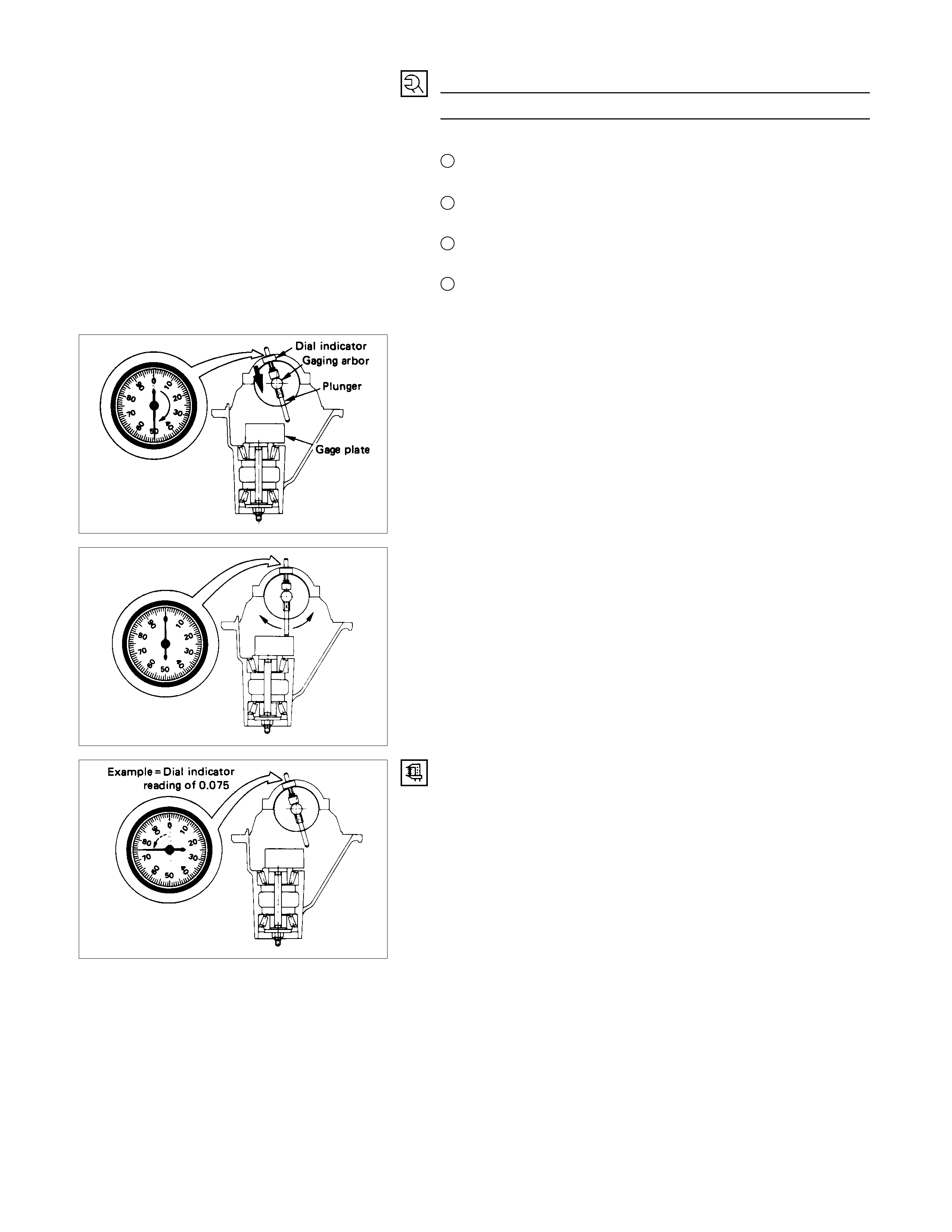
(3) Set the dial indicator to “0”. Place it on the mounting post o
f
the gauging arbor with the contact button touching the
indicator pad. Force the dial indicator downward until the
needle has made a half turn clockwise. Tighten down the
dial indicator in this position.
(4) Position the plunger on the gage plate. Move the gauging
arbor slowly back and forth and locate the pos ition at which
the dial indicator shows the greatest deflection. At this
point, once again set the dial indicator to “0”.
Repeat the procedure to verify the “0” setting.
(5)
A
fter the ZERO setting is obtained, rotate the gauging arbo
r
until the dial indicator rod does not touch the gauging plate.
Record the number the dial indicator needle points to.
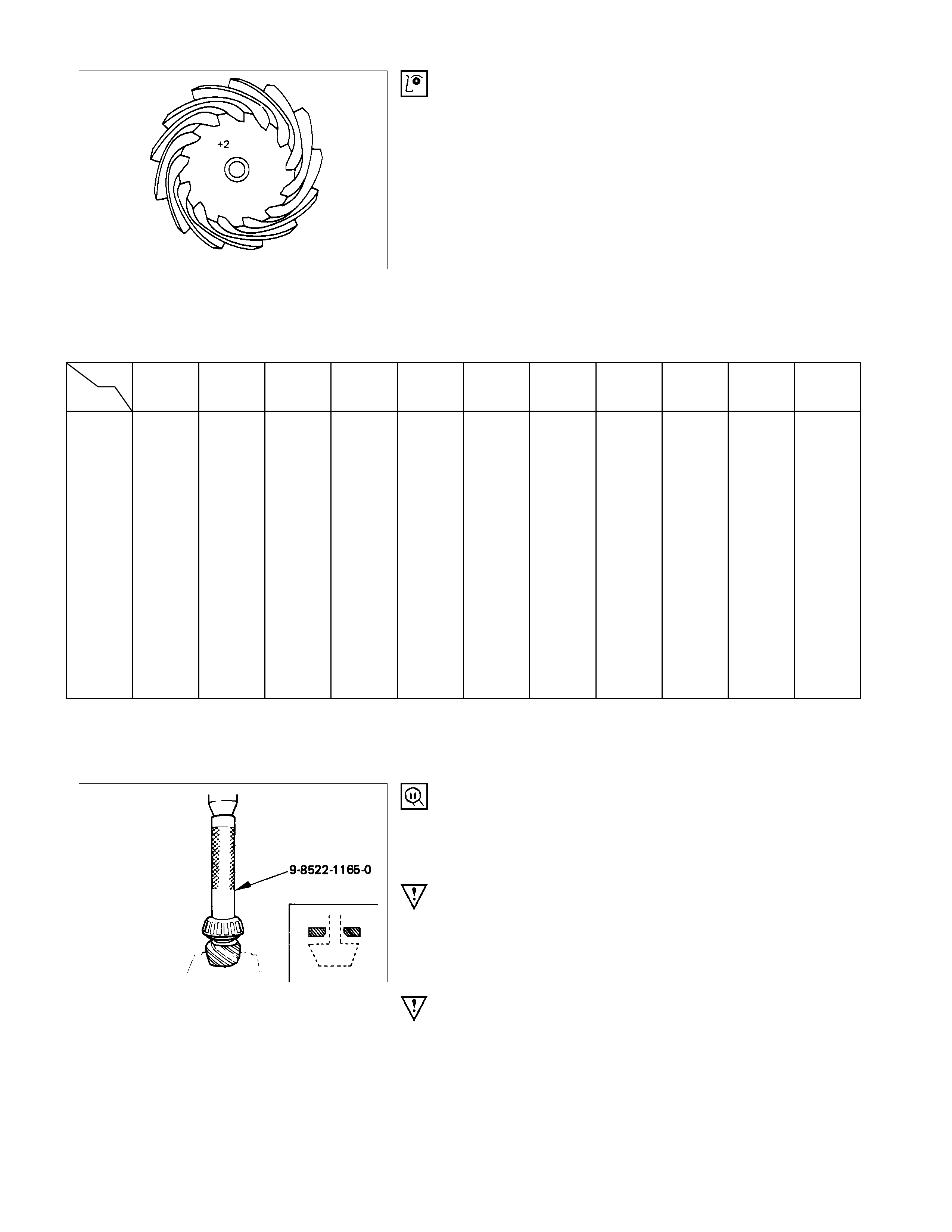
(6) Record the pinion depth code on the head of the drive
pinion.
The number indicates a necessary change in the pinion
mounting distanc e. A plus number indic ates the need for a
greater mounting distance (which can be achieved b
y
decreasing the s him thick ness). A m inus num ber indicates
the need for a smaller mounting distance (which can be
achieved by increasing the shim thickness). If examination
reveals pinion depth code “0”, the pinion is “nominal”.
(7) Select the shim using the chart;
mm(in)
Pinion
marking
+10 +8 +6 +4 +2 0 -2 -4 -6 -8 -10
Dial indica tor
reading (inches)
0.081 2.18 (0.0858)
0.082 2.18 (0.0858) 2.20 (0.0866)
0.083 2.18 (0.0858) 2.20 (0.0866) 2.24 (0.0882)
0.084 2.18 (0.0858) 2.20 (0.0866) 2.24 (0.0882) 2.26 (0.0890)
0.085 2.18 (0.0858) 2.20 (0.0866) 2.24 (0.0882) 2.26 (0.0890) 2.28 (0.0898)
0.086 2.18 (0.0858) 2.20 (0.0866) 2.24 (0.0882) 2.26 (0.0890) 2.28 (0.0898) 2.32 (0.0914)
0.087 2.18 (0.0858) 2.20 (0.0866) 2.24 (0.0882) 2.26 (0.0890) 2.28 (0.0898) 2.32 (0.0914) 2.34 (0.0921)
0.088 2.18 (0.0858) 2.20 (0.0866) 2.24 (0.0882) 2.26 (0.0890) 2.28 (0.0898) 2.32 (0.0914) 2.34 (0.0921) 2.36 (0.0929)
0.089 2.18 (0.0858) 2.20 (0.0866) 2.24 (0.0882) 2.26 (0.0890) 2.28 (0.0898) 2.32 (0.0914) 2.34 (0.0921) 2.36 (0.0929) 2.38 (0.0937)
0.090 2.18 (0.0858) 2.20 (0.0866) 2.24 (0.0882) 2.26 (0.0890) 2.28 (0.0898) 2.32 (0.0914) 2.34 (0.0921) 2.36 (0.0929) 2.38 (0.0937) 2.42 (0.0953)
0.091 2.18 (0.0858) 2.20 (0.0866) 2.24 (0.0882) 2.26 (0.0890) 2.28 (0.0898) 2.32 (0.0914) 2.34 (0.0921) 2.36 (0.0929) 2.38 (0.0937) 2.42 (0.0953) 2.44 (0.0961)
0.092 2.20 (0.0866) 2.24 (0.0882) 2.26 (0.0890) 2.28 (0.0898) 2.32 (0.0914) 2.34 (0.0921) 2.36 (0.0929) 2.38 (0.0937) 2.42 (0.0953) 2.44 (0.0961) 2.46 (0.0969)
0.093 2.24 (0.0882) 2.26 (0.0890) 2.28 (0.0898) 2.32 (0.0914) 2.34 (0.0921) 2.36 (0.0929) 2.38 (0.0937) 2.42 (0.0953) 2.44 (0.0961) 2.46 (0.0969) 2.48 (0.0977)
0.094 2.26 (0.0890) 2.28 (0.0898) 2.32 (0.0914) 2.34 (0.0921) 2.36 (0.0929) 2.38 (0.0937) 2.42 (0.0953) 2.44 (0.0961) 2.46 (0.0969) 2.48 (0.0977) 2.52 (0.0992)
0.095 2.28 (0.0898) 2.32 (0.0914) 2.34 (0.0921) 2.36 (0.0929) 2.38 (0.0937) 2.42 (0.0953) 2.44 (0.0961) 2.46 (0.0969) 2.48 (0.0977) 2.52 (0.0992) 2.54 (0.1000)
0.096 2.32 (0.0914) 2.34 (0.0921) 2.36 (0.0929) 2.38 (0.0937) 2.42 (0.0953) 2.44 (0.0961) 2.46 (0.0969) 2.48 (0.0977) 2.52 (0.0992) 2.54 (0.1000) 2.56 (0.1008)
0.097 2.34 (0.0921) 2.36 (0.0929) 2.38 (0.0937) 2.42 (0.0953) 2.44 (0.0961) 2.46 (0.0969) 2.48 (0.0977) 2.52 (0.0992) 2.54 (0.1000) 2.56 (0.1008)
0.098 2.36 (0.0929) 2.38 (0.0937) 2.42 (0.0953) 2.44 (0.0961) 2.46 (0.0969) 2.48 (0.0977) 2.52 (0.0992) 2.54 (0.1000) 2.56 (0.1008)
0.099 2.38 (0.0937) 2.42 (0.0953) 2.44 (0.0961) 2.46 (0.0969) 2.48 (0.0977) 2.52 (0.0992) 2.54 (0.1000) 2.56 (0.1008)
0 2.42 (0.0953) 2.44 (0.0961) 2.46 (0.0969) 2.48 (0.0977) 2.52 (0.0992) 2.54 (0.1000) 2.56 (0.1008)
0.001 2.44 (0.0961) 2.46 (0.0969) 2.48 (0.0977) 2.52 (0.0992) 2.54 (0.1000) 2.56 (0.1008)
0.002 2.46 (0.0969) 2.48 (0.0977) 2.52 (0.0992) 2.54 (0.1000) 2.56 (0.1008)
0.003 2.48 (0.0977) 2.52 (0.0992) 2.54 (0.1000) 2.56 (0.1008)
0.004 2.52 (0.0992) 2.54 (0.1000) 2.56 (0.1008)
0.005 2.54 (0.1000) 2.56 (0.1008)
0.006 2.56 (0.1008)
Note:
When ordering shims, find the part number in the Parts Catalog by using the thickness of the shims listed in
the above table.
5. Inner Bearing
Place the shim on the drive pinion, with the chamfered side
turned towards the pinion head then install the inner bearing on
to the pinion using an installer and a press.
Installer : 9-8522-1165-0 (J-6133-01)
Note:
Do not apply pressure to the roller cage.
Apply pressure only to the inner race.
6. Collapsible Spacer
Discard the used collapsible spacer and install a new one.
9. Oil Seal
Use oil seal installer to install a new oil seal that has been
soaked in rear axle lubricant.
Installer : 9-8522-1275-0 (J-24250)
Note :
Take care not to use a rear differential oil seal instead of
the front differential oil seal.
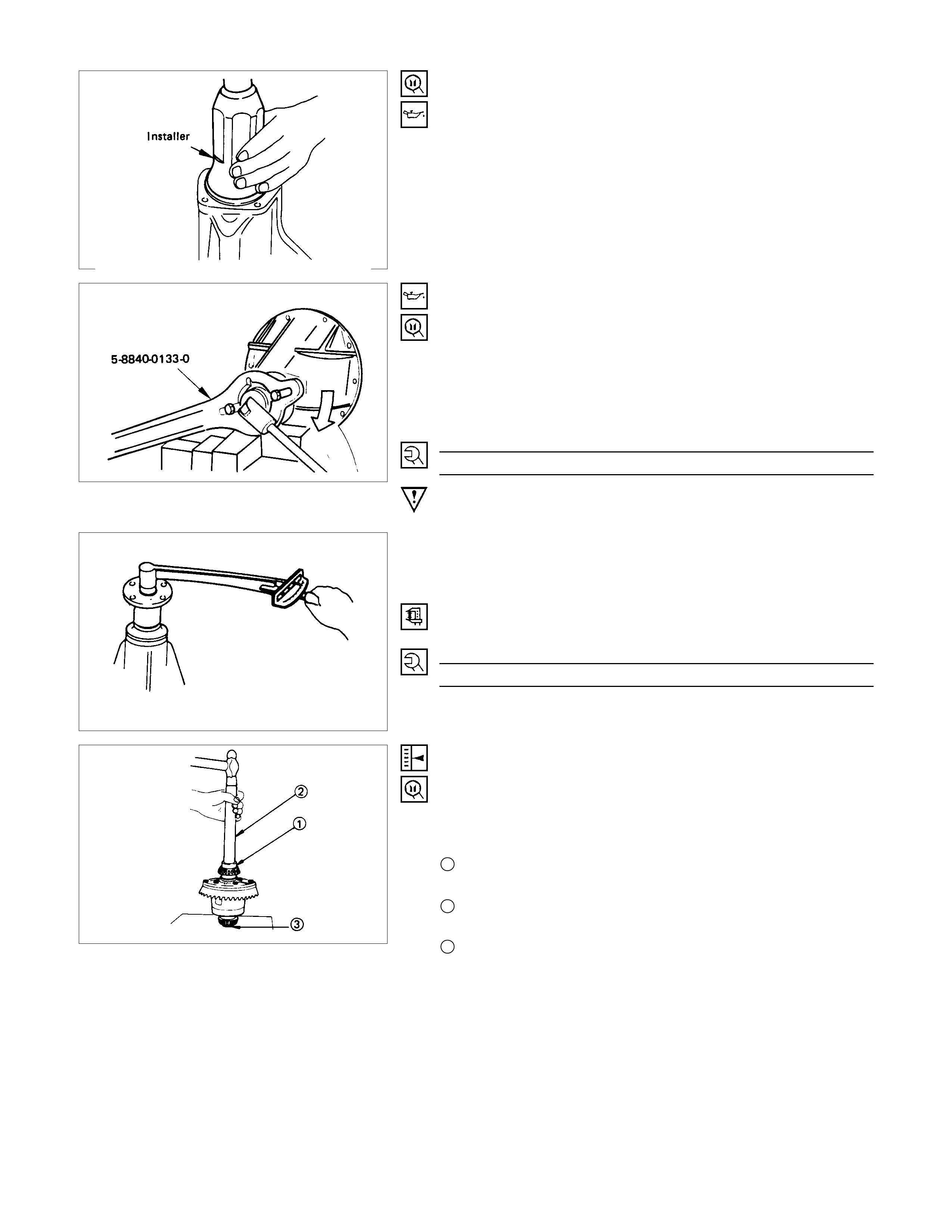
12. Flange Nut and Washer
(1) Apply lubricant to the pinion threads.
(2) Tighten the nut to the specified torque using the pinion
flange holder.
Pinion flange holder : 5-8840-0133-0
(J-8614-01)
Torque N⋅m ( kgf⋅m/lb⋅ft
)
176.6 - 274.7 (18 - 28/130 - 202)
Discard used flange nut and install new one.
(3) Pinion bearing preload
(a) Meas ure the bearing preload by using a torque meter. Note
the scale reading required to rotate the flange.
(b) Continue tightening until the specified starting torque is
obtained.
Starting Torque N⋅m (kgf⋅cm/lb⋅in
)
0.63 - 1.13 (6.5 - 11.5/5.7 - 9.9)
13. Adjust Shim
(1)
A
ttach the side bearing to the differential assembly without
shims. Support the opposite side using a pilot to prevent
bearing damage.
1 Installer : 9-8521-1164-0
(J-24244)
2 Drive handle : 5-8840-0007-0
(J-8092)
3 Pilot : 9-8521-1743-0
(J-8107-2)
(2) Insert the differential cage assembly with bearing oute
r
races into the side bearing bores of the carrier.
(3) Using two sets of feeler gauges, insert a feeler stock o
f
sufficient thickness between each bearing outer race and
the carrier to remove all end plat. Make certain the feele
r
stock is pushed to the bottom of the bearing bores.
Mount the dial indicator on the carrier so that the indicato
r
stem is at right angles to a tooth on the ring gear.
Dial indicator : 5884-0126-0
(J-8001)
(4)
A
djust feeler gauge thickness from side to side until ring
gear backlash is in the specified range.
Backlash mm(in)
0.13 - 0.18 (0.005 - 0.007)
With zero end play and correct backlash established,
remove the feeler gauge pack s, determine the thick ness o
f
the shims required and add 0.05 mm (0.002 in) to each
shim pack to provide side bearing preload. Always use ne
w
shims.
(5) Remove side bearing
Remover : 5-8840-0013-0
(J-22888)
Pilot : 9-8521-1743-0
(J-8107-2)
14. Side Bearing
Install the side bearings together with the selected shims.
1 Installer : 9-8521-1164-0 (J-24244)
2 Drive handle : 5-8840-0007-0 (J-8092)
3 Pilot : 9-8521-1743-0 (J-8107-2)
17. Bearing Cap
Align the setting marks applied at disassembly.
18. Bolt
Bolt Torque N⋅m (kgf⋅m/lb⋅ft
)
98.1 ± 9.8 (10.0 ± 1.0/72.3 ± 7.2)
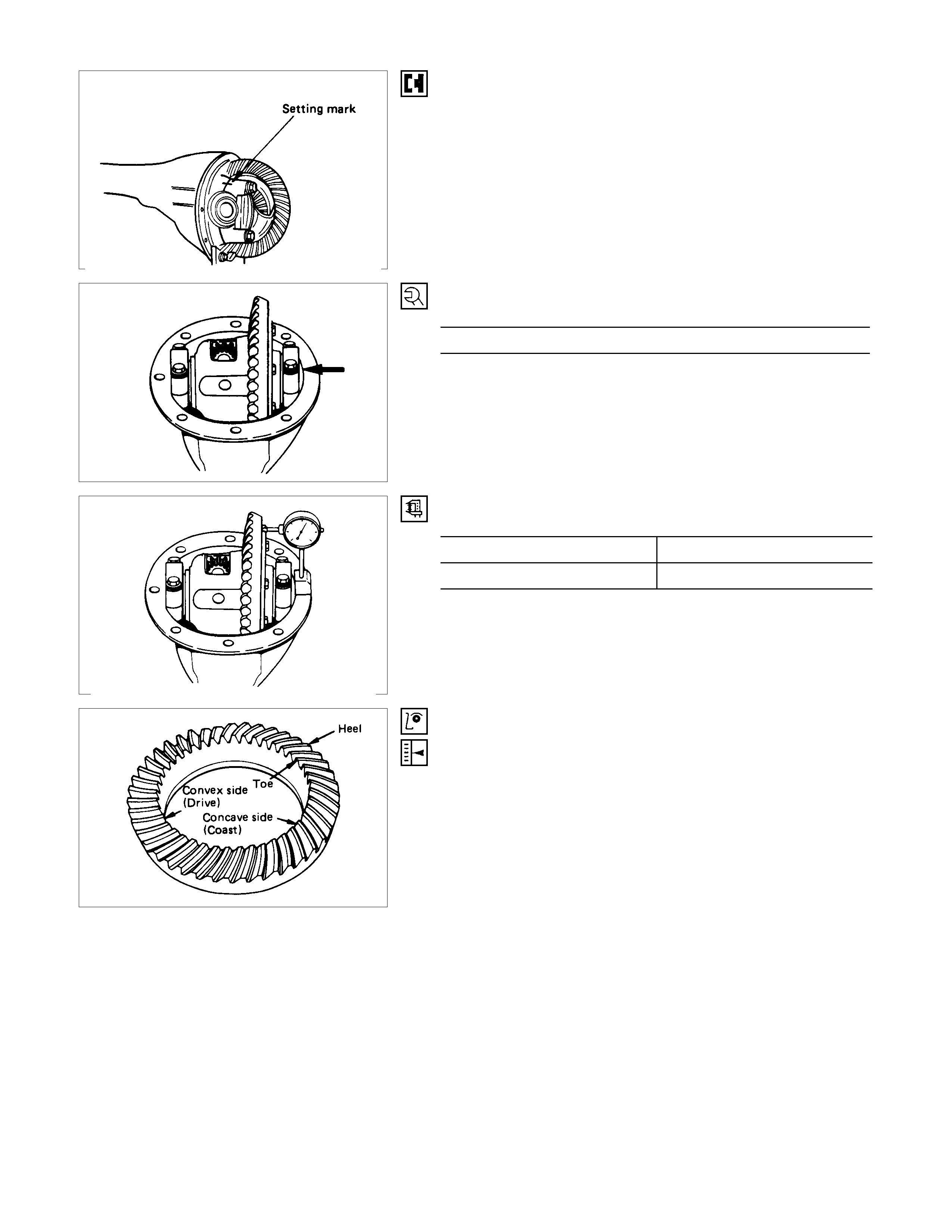
Measure the amount of run-out of the ring gear at its rear face.
mm(in)
Standard Limit
0.02 (0.001) 0.05 (0.002)
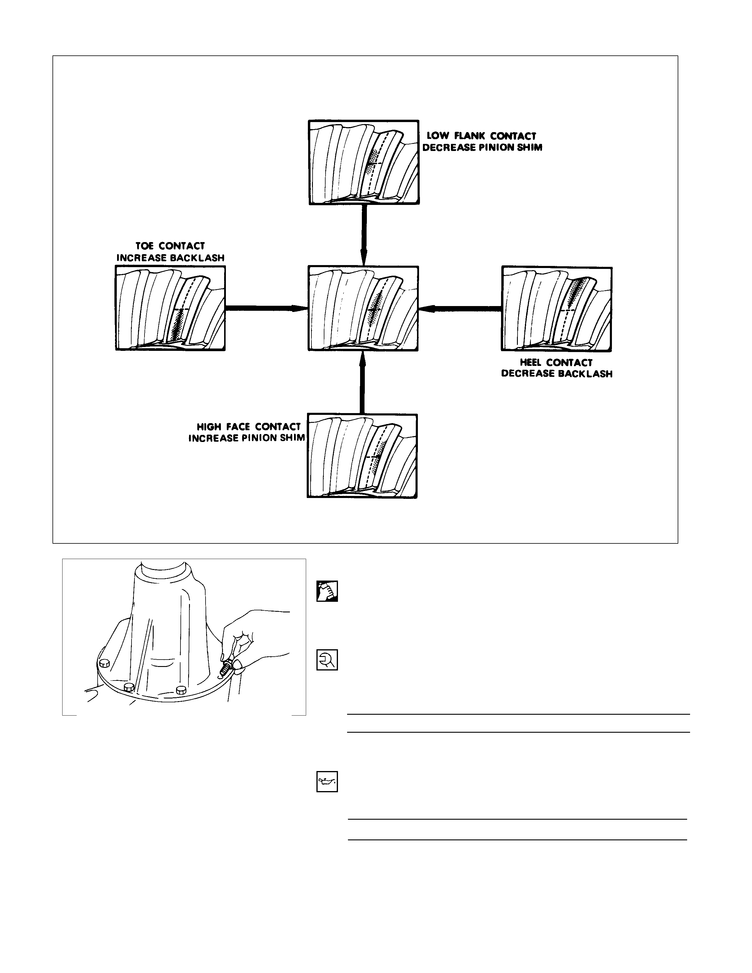
Gear Tooth Contact Pattern Check and Adjustment
Apply a thin coat of Prussian blue or equivalent to the faces of
the 7 - 8 teeth of the ring gear. Check the impression of
contact on the ring gear teeth and make necessary adjustment
as described below if the contact is abnormal.
20. Differential Assembly
(1) Clean the faces of the front axle case and differential
carrier.
A
pply the recommended liquid gasket or its equivalent to
the sealing side of the axle case and the carrier.
(2) Attach the differential case and the carrier assembly to the
front axle case and tighten the nuts and bolts. The axle
case bolt is used for drainage.
Torque N⋅m ( kgf⋅m/lb⋅ft)
25.5 ± 5 (2.6 ± 0.5/18.8 ± 3.6)
(3) Install the axle shaft assem blies as instructed earlier in this
section under “Axle Shaft Replacement”.
(4) Fill the axle case with hypoid gear lubricant, to just belo
w
the filler hole.
Lubricant capacity liter (US/UK gal)
1.4 (0.37/0.31)
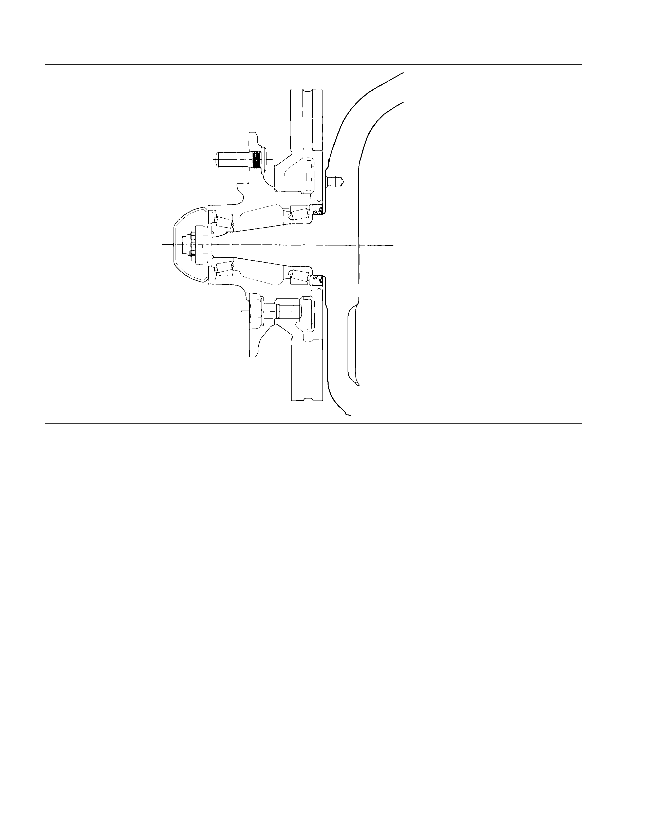
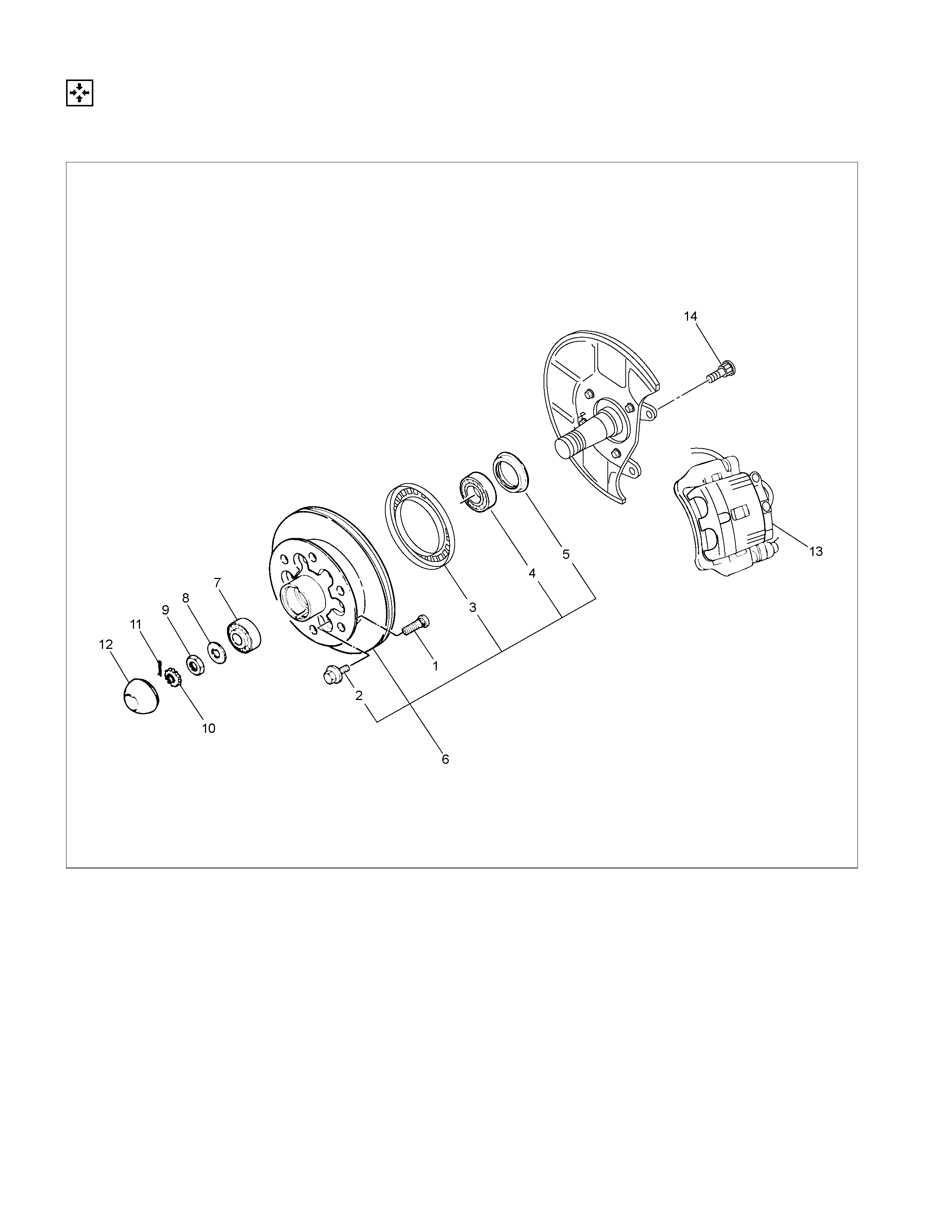
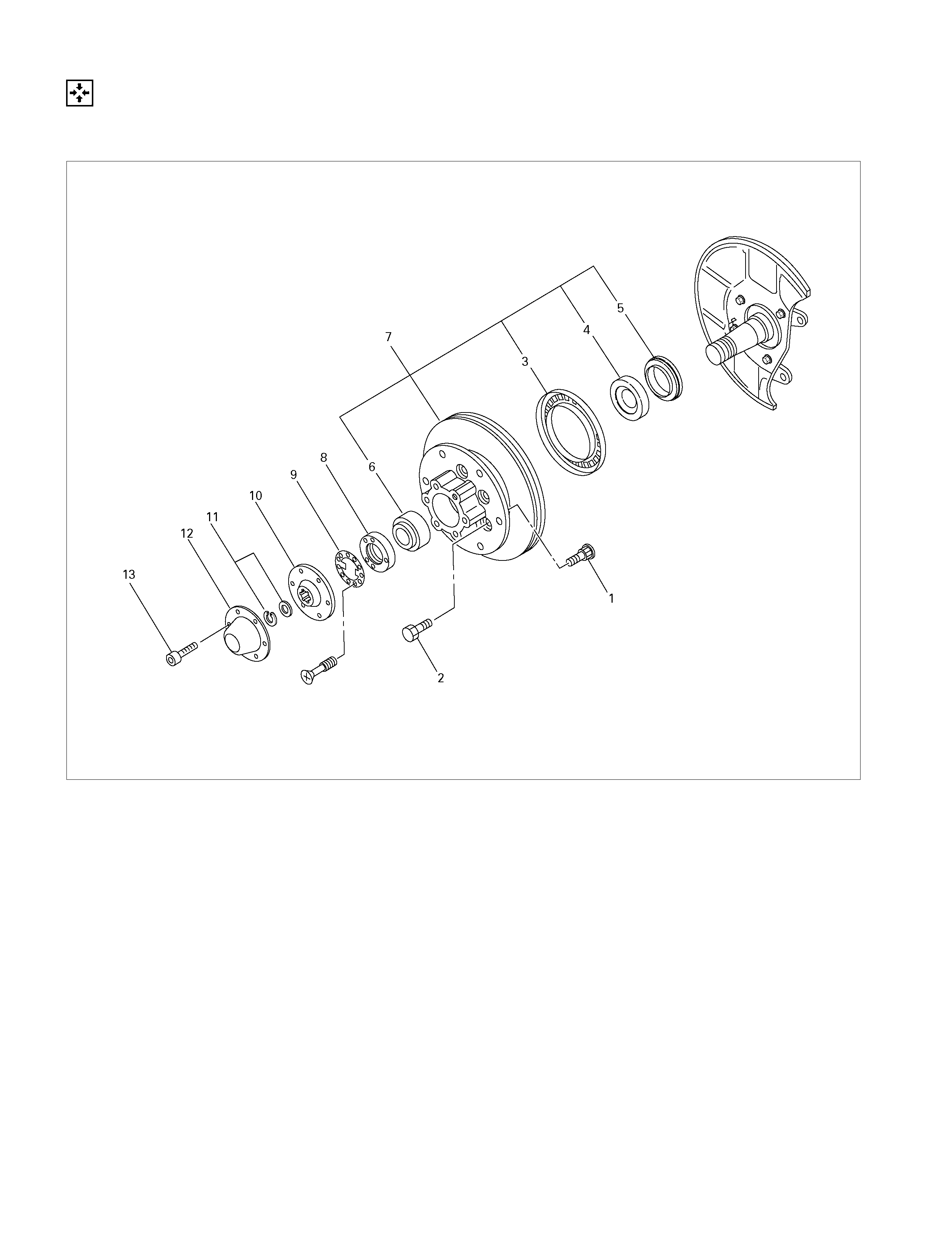
Front Hub and Disc (4×
××
×2 Except High Ride Suspension Model)
Disassembly
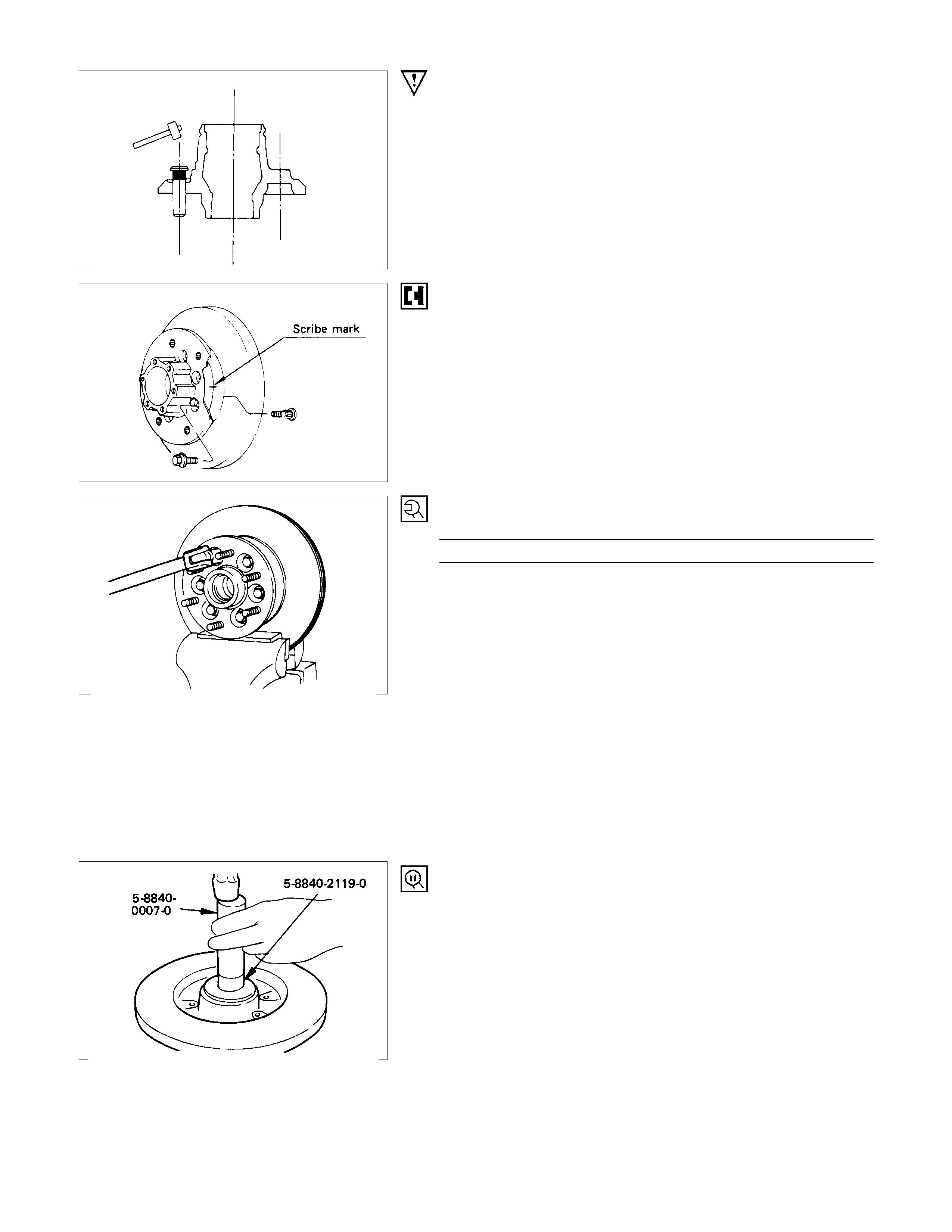
Refer to “WHEEL AND TYRE” SECTION for wheel removal procedure.
RTW34CLF000801
Disassembly Steps
1. Bolt
▲ 2. Brake caliper
▲ 3. Hub cap
4. Split pin
5. Nut retainer
6. Hub nut
7. Lock washer
8. Outer bearing
▲ 9. Hub and disc assembly
10. Oil seal
11. Inner bearing and outer race
▲12. ABS sensor rotor
▲13. Bolt
▲14. Wheel pin
Important Operations
Before removal, jack up the front of vehicle and support frame
with jack stands.
2. Brake Caliper
(1) Remove the two bolts from the rear side of the knuckle arm,
and then remove the brake caliper, with the brake hose
attached.
(2) Use a wire etc., for attaching the brake caliper to the uppe
r
link.
Refer to the section Brake.
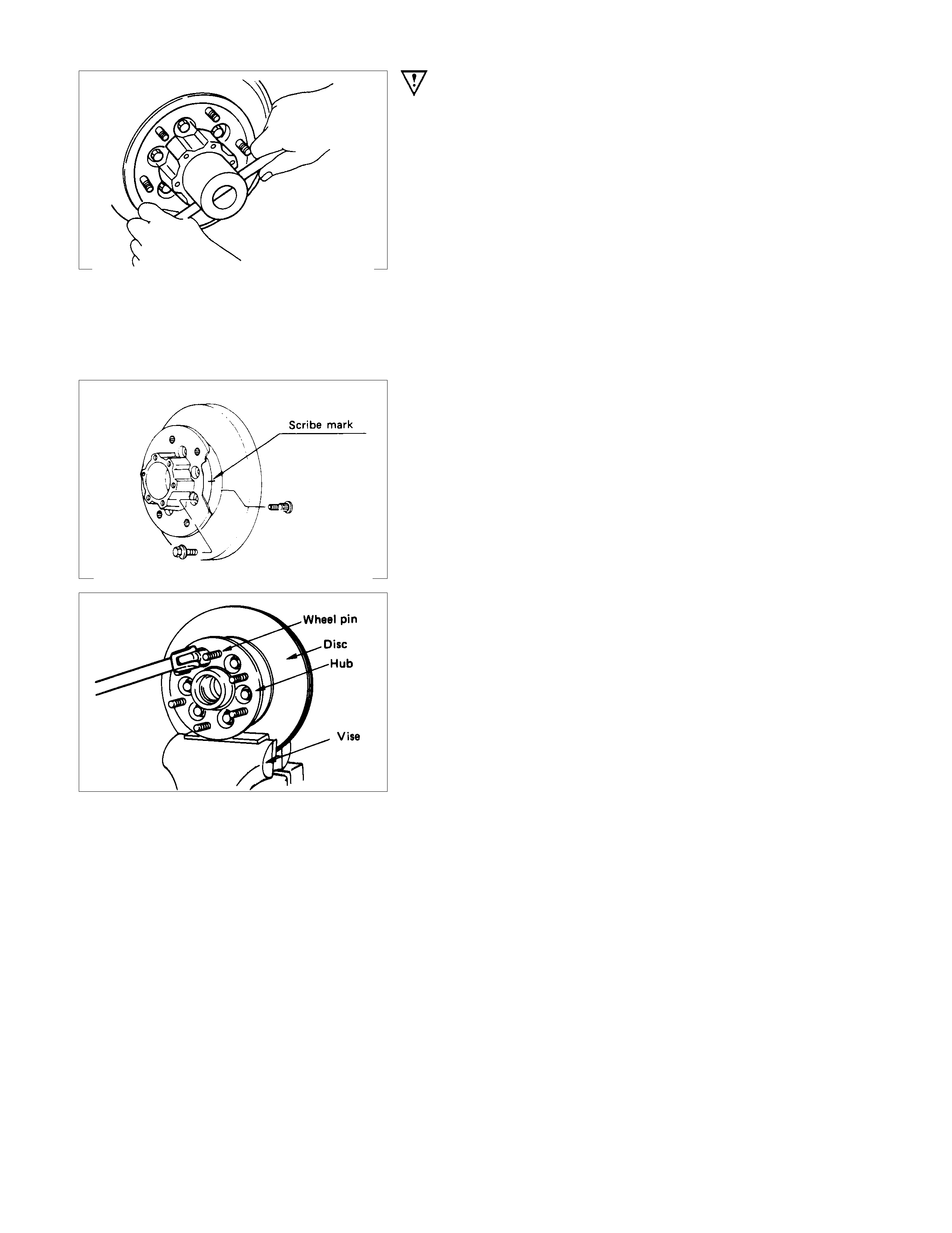
3. Hub Cap
When removing hubcap, exercise care so as not to scratch or
distort hub fitting face.
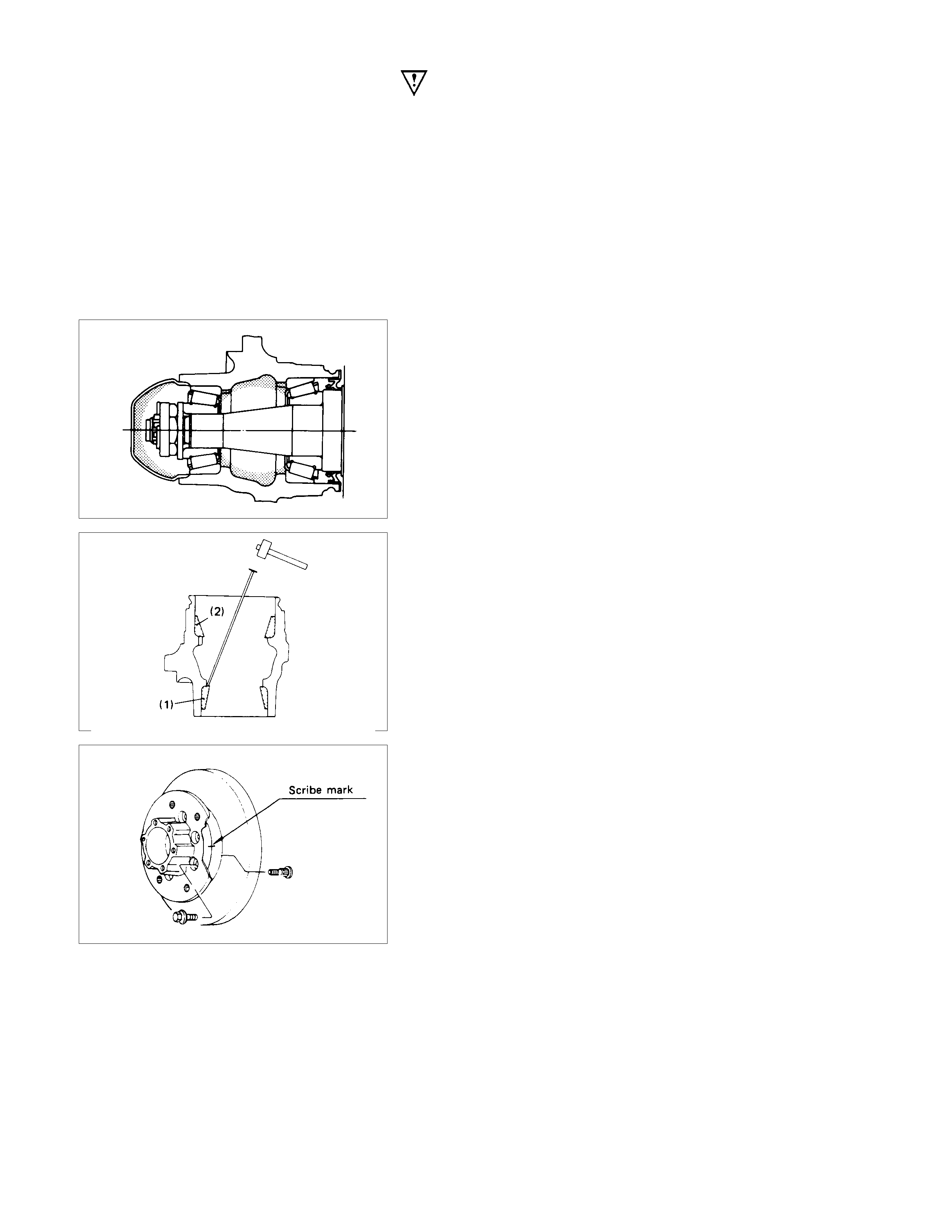
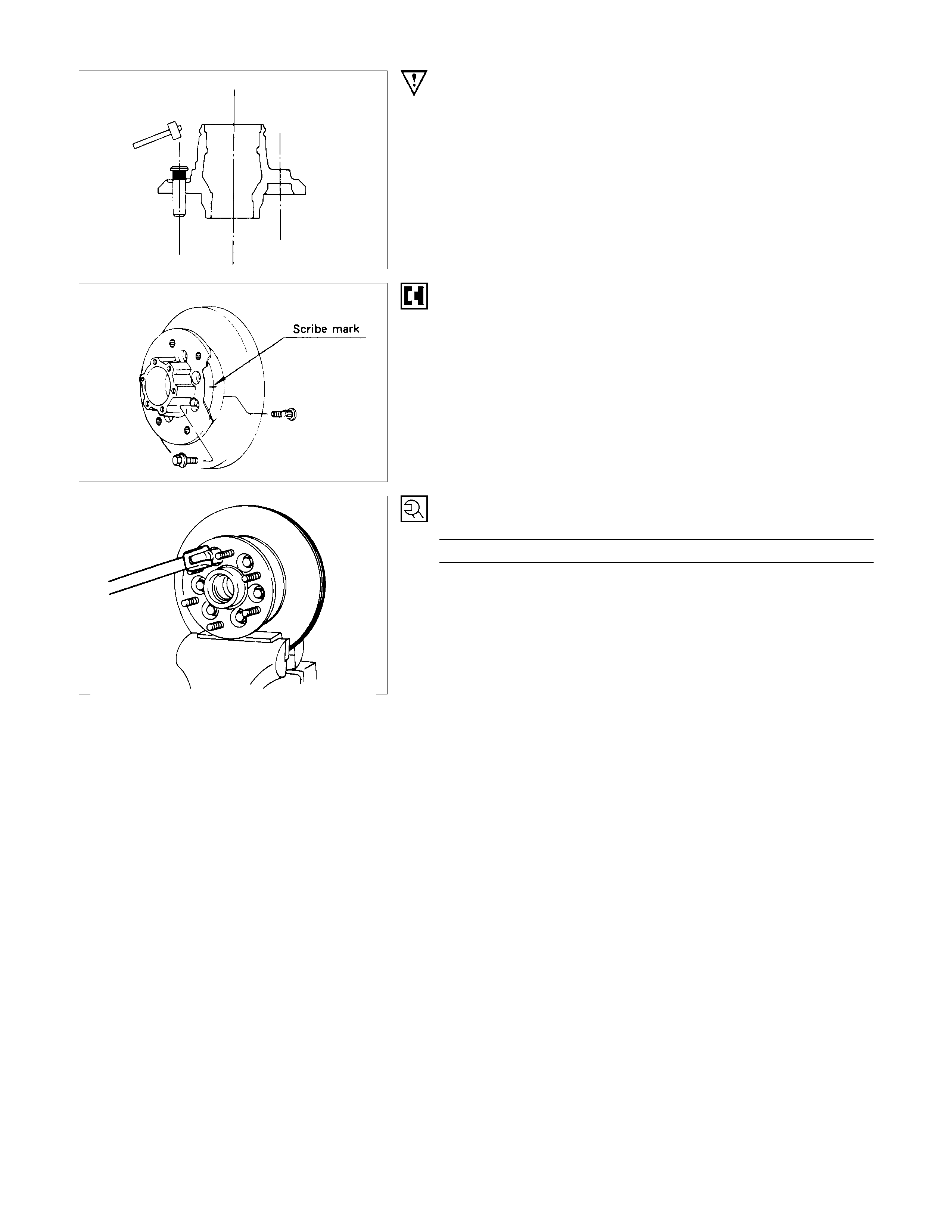
9. Hub and Disc Assembly
Using a brass bar to remove the outer bearing outer race (1),
oil seal, inner bearing and inner bearing outer race (2) from the
hug.
If necessary, replace the wheel pin in the following manner.
13. Bolt
14. Wheel Pin ; Front Hub
(1) Scribe mark on hub to disc before disassembly to insure
proper assembly.
(2) Drive out the ABS sensor rotor using a metal bar and
hammer through the two bolt holes.
• Discard the used ABS sensor rotor
Refer to the section Brake.
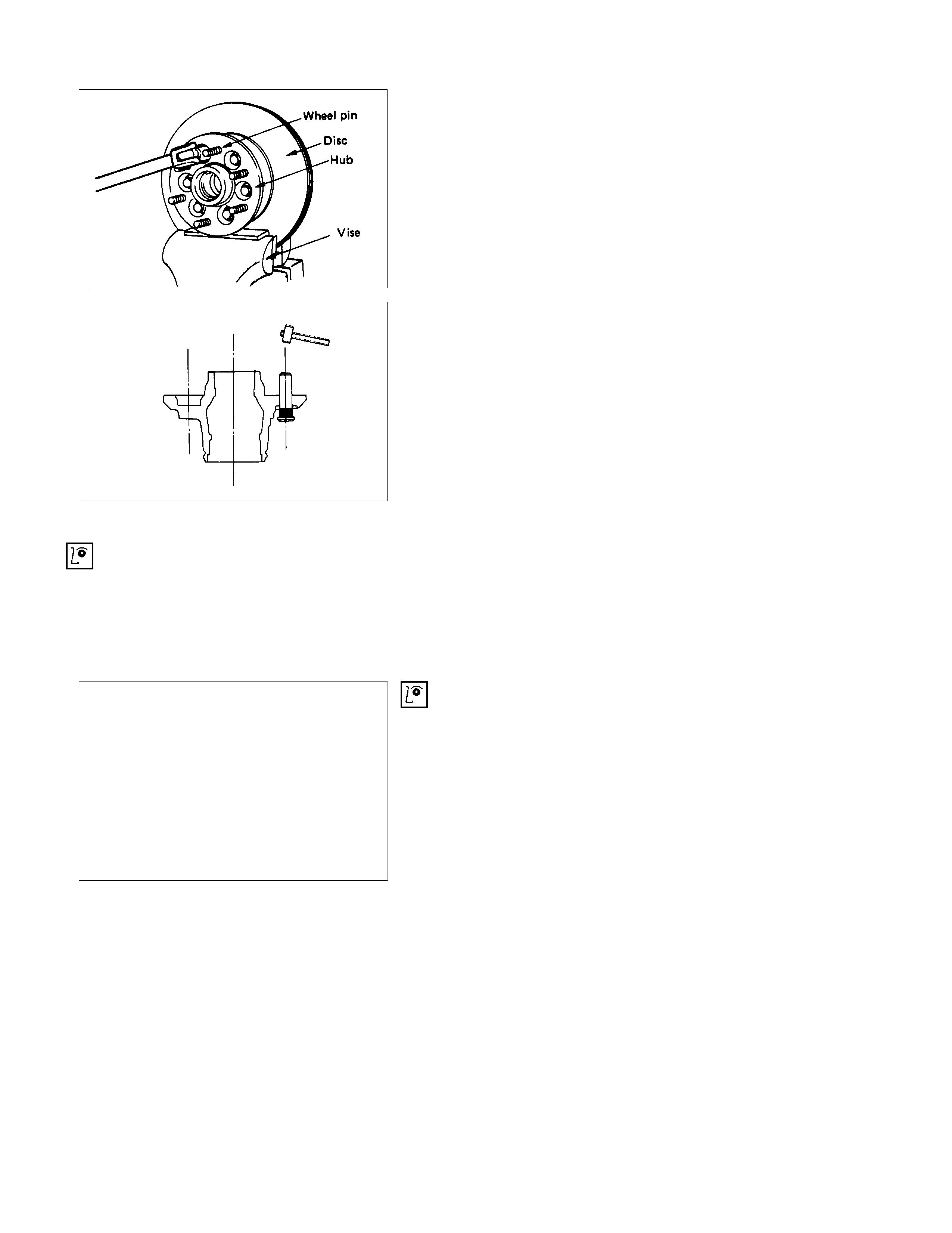
(3) Clam p hub and disc assem bly in vise using pr otective pads
and remove six (6) disc to hub retaining bolts.
(4) Place hub on a suitable work surface and remove wheel
studs, as required, using a hammer.
Inspection and Repair
Make necessary correction or parts replacement if wear, damage or any other abnormal conditions are found through
inspection.
For inspection and servicing of disc caliper, and relative parts, and ABS parts, refer to Section 5 Brakes.
• Hub
• Hub bearing
• Bearing outer race
• Disc
• Oil seal
• Knuckle spindle
• ABS sensor rotor
• Caliper
Visual Check
Check the following parts for wear, damage or other abnormal
conditions.
Reassembly
Refer to SECTION 3E “WHEEL AND TIRE” for wheel removal procedure.
RTW34CLF000901
Reassembly Steps
▲ 1. Wheel pin
▲ 2. Bolt
▲ 3. ABS sensor rotor
▲ 4. Inner bearing and outer race
▲ 5. Oil seal
▲ 6. Hub and disc assembly
7. Outer bearing
8. Lock washer
▲ 9. Hub nut
10. Nut retainer
11. Split pin
▲12. Hub cap
13. Brake caliper
▲14. Bolt
Important Operations
1. Wheel Pin
(1) Place hub on a wood workbench or a block of wood,
approx. 6” by 6” to protect the wheel stud ends and threads.
(2) Install wheel stud using a hammer.
Be sure wheel stud is started squarely and seats
completely .
(3) Align index marks and install hub to disc.
2. Bolt
Torque N⋅m ( kgf⋅m/lb⋅ft)
103 ± 5 (10.5 ± 1/75.9 ± 7.2)
3. ABS sensor rotor
(1) Set a new ABS sensor rotor, if replacement is required.
(2) Install the ABS sensor rotor in the hub, using special tools.
Installer : 5-8840-2789-0
Grip : 5-8840-0007-0
Refer to the section Brake.
4. Inner Bearing and Outer Race
5. Oil Seal
• Outer Bearing Outer Race
(1) Install the bearing outer race by driving into the hub.
Installer (Outer) : 5-8822-0053-0 (J-29016)
Installer (Inner) : 5-8822-0054-0 (J-29015)
Drive handle : 5-8840-0007-0 (J-8092)
(2) Install the outer and inner bearing into the hub with fingers.
(3) Install oil seal using special tools.
Discard the used oil seal and install a new one.
Installer : 5-8522-0051-0
(J-33161)
Grip : 5-8840-0007-0
(J-8092)
6. Hub and Disc Assembly
12. Hub Cap
Apply grease in the hub and hub cap.
Description Amount g(oz)
Hub 50 (1.76)
Hub cap 20 (0.70)
Outer bearing 6.5 (0.23)
Inner bearing 12 (0.42)
9. Hub nut
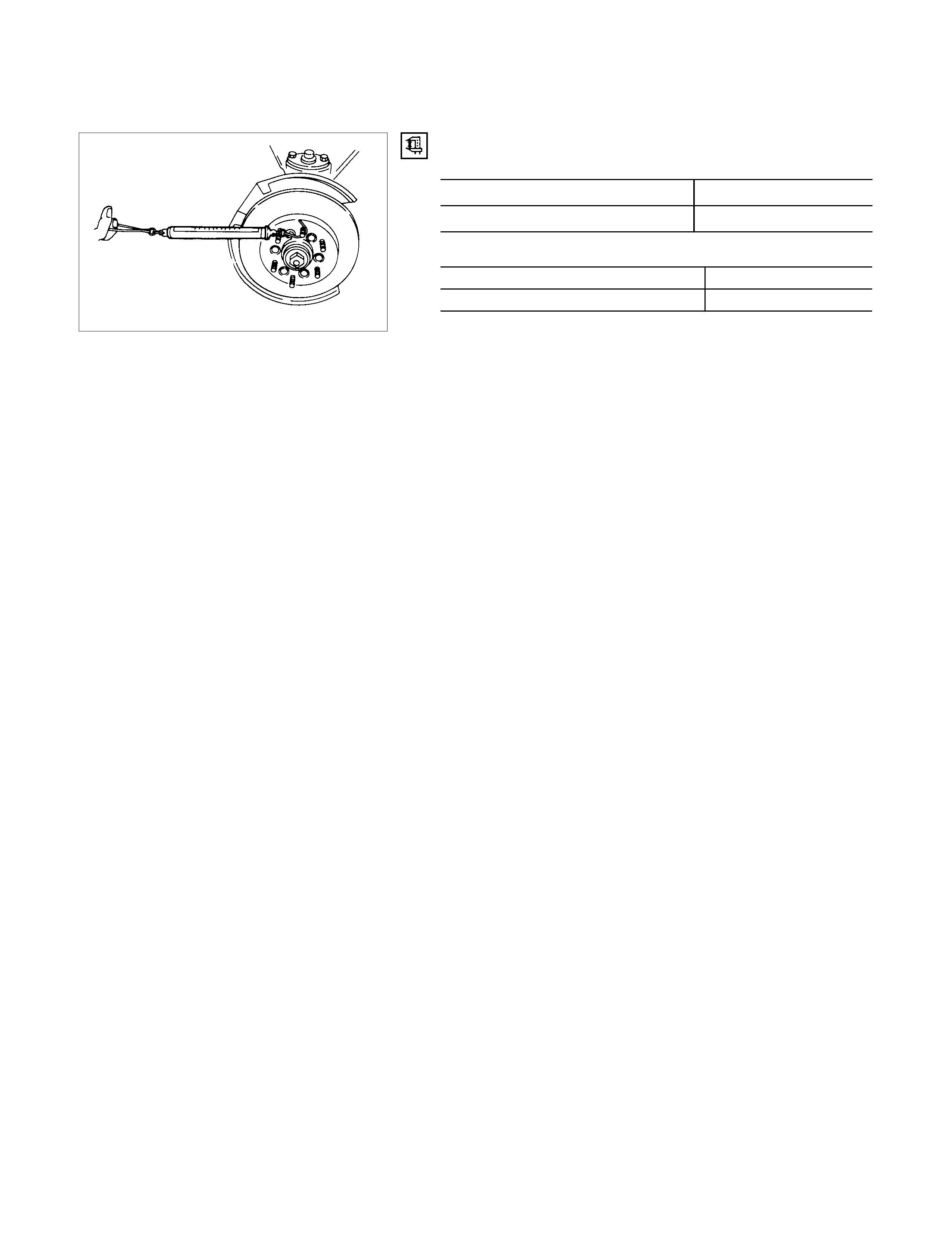
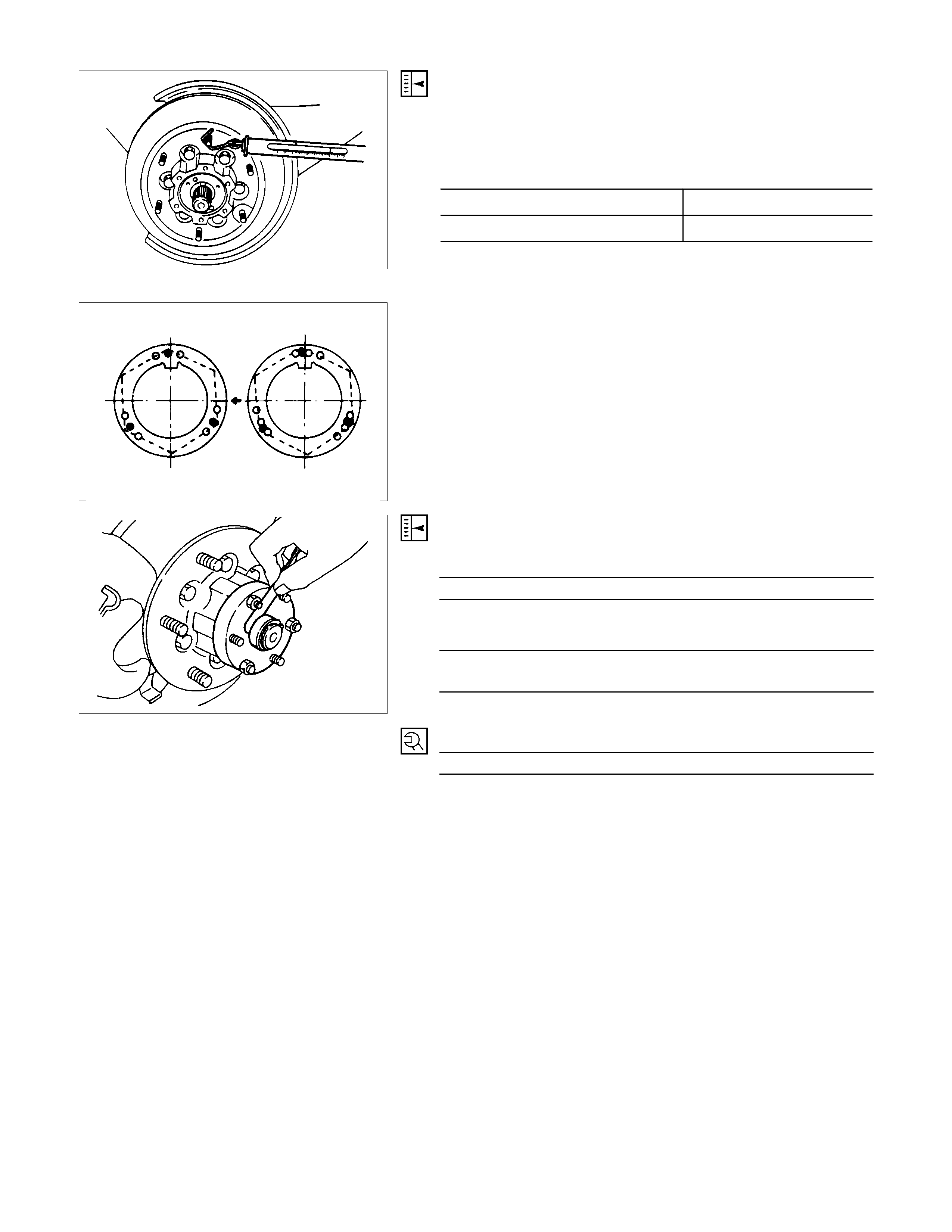
Adjustment of front wheel hub bearing preload
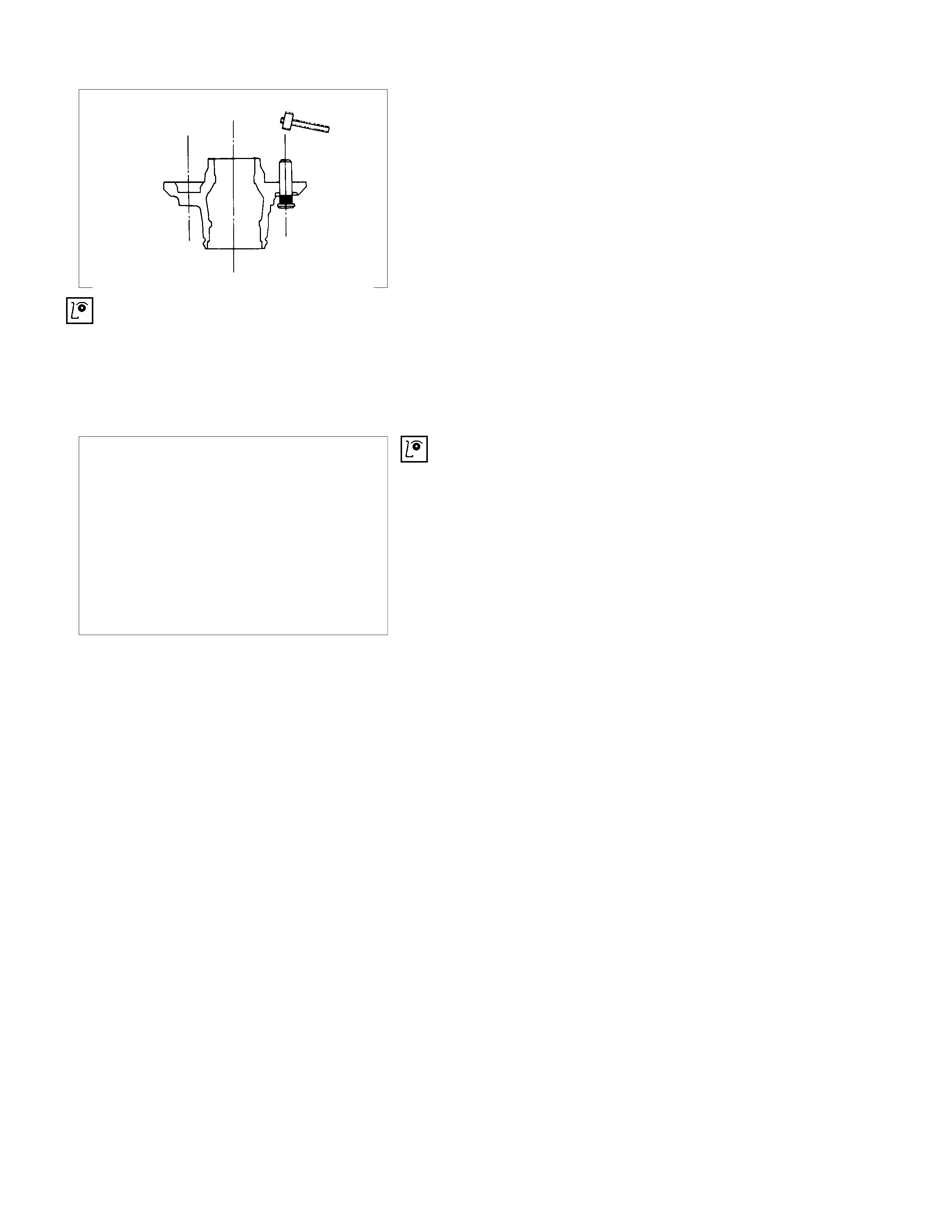
1. Tighten spindle nut to 3.0 kg⋅m (21.7 lb.ft/29.4 N⋅m) torque.
2. Turn the hub 2-3 turns and loosen the nut just enough so
that it can be turned with the fingers.
3. Turn the nut all the way in with the fingers and check to be
sure the hub has no free play.
4. Measure the bearing preload by pulling one of the wheel
hub studs with a spring scale.
5. Tighten the spindle nut until specified bearing preload Is
obtained.
6. Install the split pin in the nut retainer.
Discard the used split pin and install a new one.
After reassembling, install the disc brake caliper assembly.
Bearing Preload N⋅m (kgf⋅m/lb⋅ft)
New bearing and New oil seal 8-12 (0.8-1.2 / 69-104)
Reuse bearing and New oil seal 8-12 (0.8-1.2 / 69-104)
14.Bolt
Torque N⋅m ( kgf⋅m/lb⋅ft)
155 ± 15.7 (15.8 ± 1.6/114.3 ± 11.6)
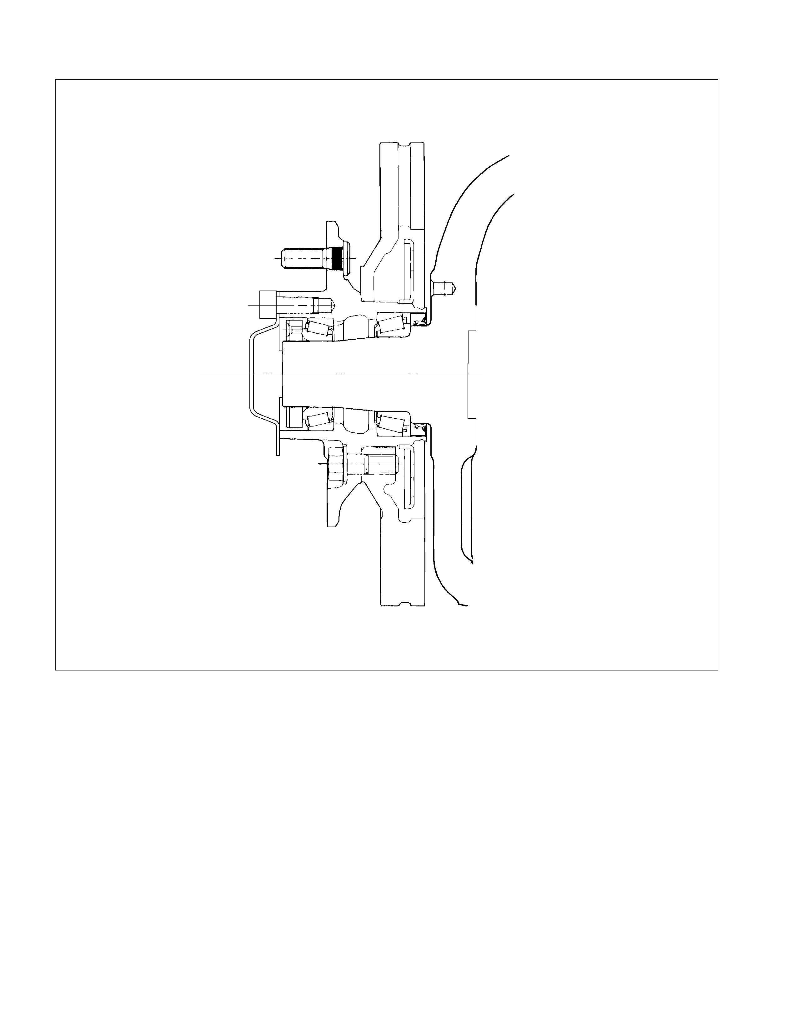
Front Hub and Disc (4×
××
×4, 4×
××
×2 High Ride Suspension Model)
Disassembly
Refer to “WHEEL AND TYRE” SECTION for wheel removal procedure
Disassembly Steps
1. Bolt
2. Hub cap
3. Snap ring and shim (4×4 model only)
4. Flange (4×4 model only)
5. Lock washer
▲ 6. Hub nut
▲ 7. Hub and disc assembly
8. Outer bearing
9. Oil seal
10. Inner bearing
▲ 11. ABS sensor rotor
▲ 12. Bolt
▲ 13. Wheel pin
Important Operations
6. Hub nut
Wrench : 5-8840-2117-0
(J-36827)
7. Hub and disc assembly
Before disassembly, remove the disc brake caliper assembly
and hang it on the frame with wires.
Refer to Section “Brake” for disc brake caliper removal
procedure.
12. Bolt
13. Wheel Pin ; Front Hub
(1) Scribe mark on hub to disc before disassembly to insure
proper assembly.
(2) Drive out the ABS sensor rotor using a metal bar and
hammer through the two bolt holes.
• Discard the used ABS sensor rotor
Refer to the section Brake.
(3) Clam p hub and disc assem bly in vise using pr otective pads
and remove six (6) disc to hub retaining bolts.
(4) Place hub on a suitable work surface and remove wheel
studs, as required, using a hammer.
Inspection and Repair
Make necessary correction or parts replacement if wear, damage or any other abnormal conditions are found through
inspection.
For inspection and servicing of disc caliper, and relative parts, and ABS parts, refer to Section Brakes.
• Hub
• Hub bearing, oil seal
• Knuckle spindle
• Disc
• Caliper
• ABS sensor rotor
• Cap, Hub flange, Shim, Snap ring
Visual Check
Check the following parts for wear, damage or other abnormal
conditions.
Reassembly
Refer to “WHEEL AND TYRE” SECTION for wheel removal procedure.
Reassembly Steps
▲ 1. Wheel pin
▲ 2. Bolt
▲ 3. ABS sensor rotor
▲ 4. Inner bearing
▲ 5. Oil seal
▲ 6. Outer bearing
▲ 7. Hub and disc assembly
▲ 8. Hub nut
▲ 9. Lock washer
10. Flange (4×4 model only)
▲ 11. Snap ring and shim (4×4 model only)
12. Hub cap
▲ 13. Bolt
Important Operations
1. Wheel Pin
(1) Place hub on a wood workbench or a block of wood,
approx. 6” by 6” to protect the wheel stud ends and threads.
(2) Install wheel stud using a hammer.
Be sure wheel stud is started squarely and seats
completely .
(3) Align index marks and install hub to disc.
2. Bolt
Torque N⋅m ( kgf⋅m/lb⋅ft)
103 ± 5 (10.5 ± 1/75.9 ± 7.2)
3. ABS sensor rotor
(1) Set a new ABS sensor rotor, if replacement is required.
(2) Install the ABS sensor rotor in the hub, using special tools.
Installer : 5-8840-2789-0
Grip : 5-8840-0007-0
Refer to the section Brake.
4. Inner Bearing
Outer race ; outer bearing
Install the outer race by driving it into the hub.
Installer : 5-8840-2119-0
(J-36829)
Grip : 5-8840-0007-0
(J-8092)
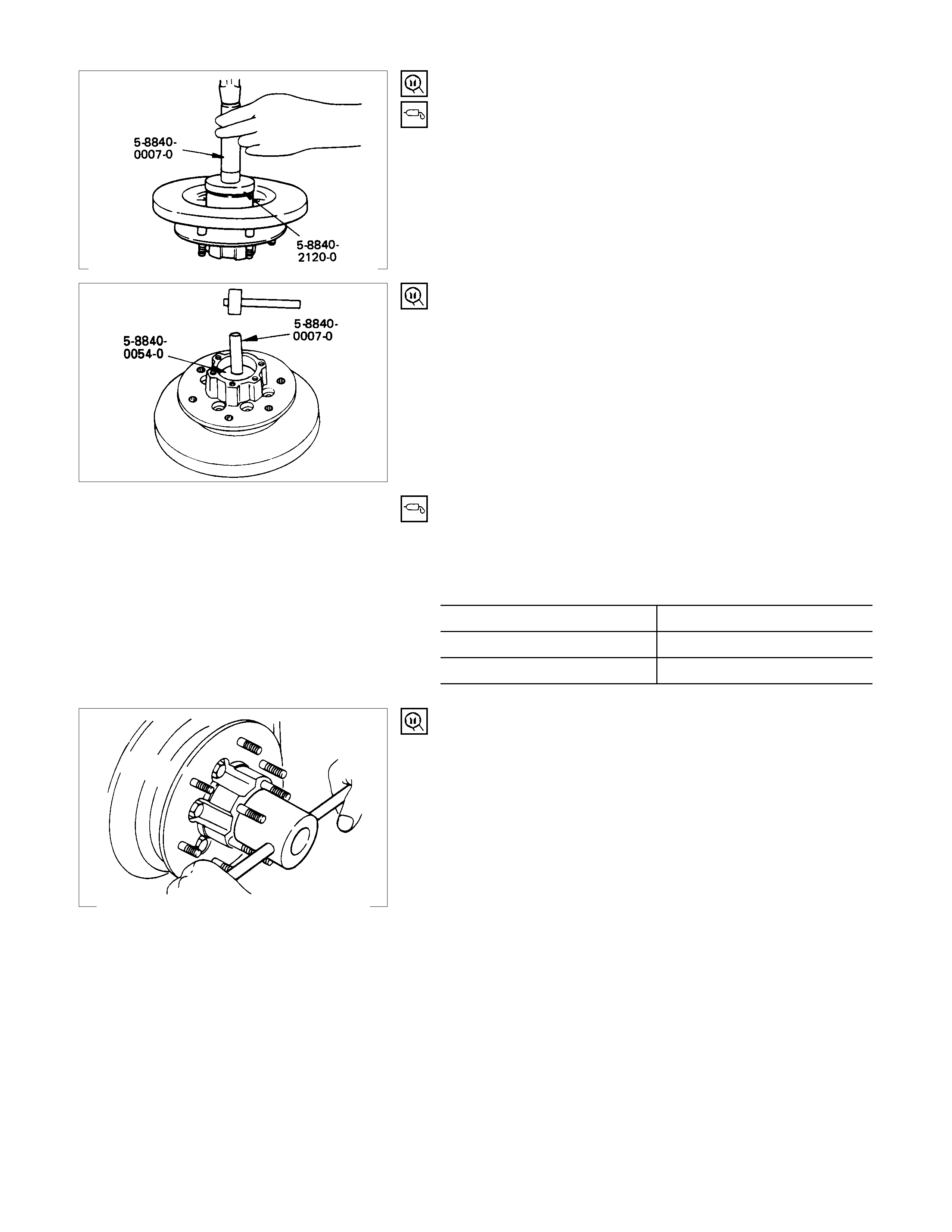
5. Oil Seal
Installer : 5-8840-2120-0
(J-36830)
Grip : 5-8840-0007-0
(J-8092)
Apply grease (Besco L-2 or equivalent) to the lip portion.
Discard the used oil seal and install a new one.
6. Outer bearing
Outer race ; outer bearing
Install the outer race by driving it into the hub.
Installer : 5-8840-0054-0
(J-29015)
Grip : 5-8840-0007-0
(J-8092)
7. Hub and Disc Assembly
(1) Apply grease in the hub.
(2) Apply grease (Besco L-2 or equivalent) to the outer and
inner bearing. g(oz)
Hub 35 (1.23)
Outer bearing 10 (0.35)
Inner bearing 15 (0.53)
8. Hub Nut
(1) Turn the place where there is a chamfer in the tapped hole
to the outer side, and attach the nut.
Wrench : 5-8840-2117-0
(J-36827)
Preload Adjustment
Tighten the hub nut at 29.4 N⋅m (3 kgf⋅m / 21.716 lb.ft), then
loosen the nut to the full.
Tighten the hub nut at the value given below, using a spring
scale on the wheel stud.
Bearing Preload N(lb)
New bearing and New oil seal 20 - 25 (4.4 - 5.5)
Used bearing and New oil seal 12 - 18 (2.68 - 4.0)
If the measured bearing preload is outside the specifications,
adjust it by loosening or tightening the bearing nut.
9. Lock Washer
Turn the side with larger diameter of the tapered bore to the
vehicle outer side, and attach the washer.
If the bolt holes in the lock plate are not aligned with the
corresponding holes in the nut, reverse the lock plate.
If the bolt holes are still out of alignment, turn in the nut just
enough to obtain alignment. Screw is to be fastened tightly so
its head may come lower than the surface of the washer.
11. Snap ring, shims (4×
××
×4 model only)
Adjust the clearance between the flange and the snap ring.
Clearance mm(in)
0 - 0.3 (0 - 0.01)
Adjust shims av ailable mm(in)
0.2, 0.3, 0.5, 1.0
(0.008, 0.011, 0.020, 0.039)
13. Bolt
Torque N⋅m ( kgf⋅m/lb⋅ft
)
59 (6.0 / 43)
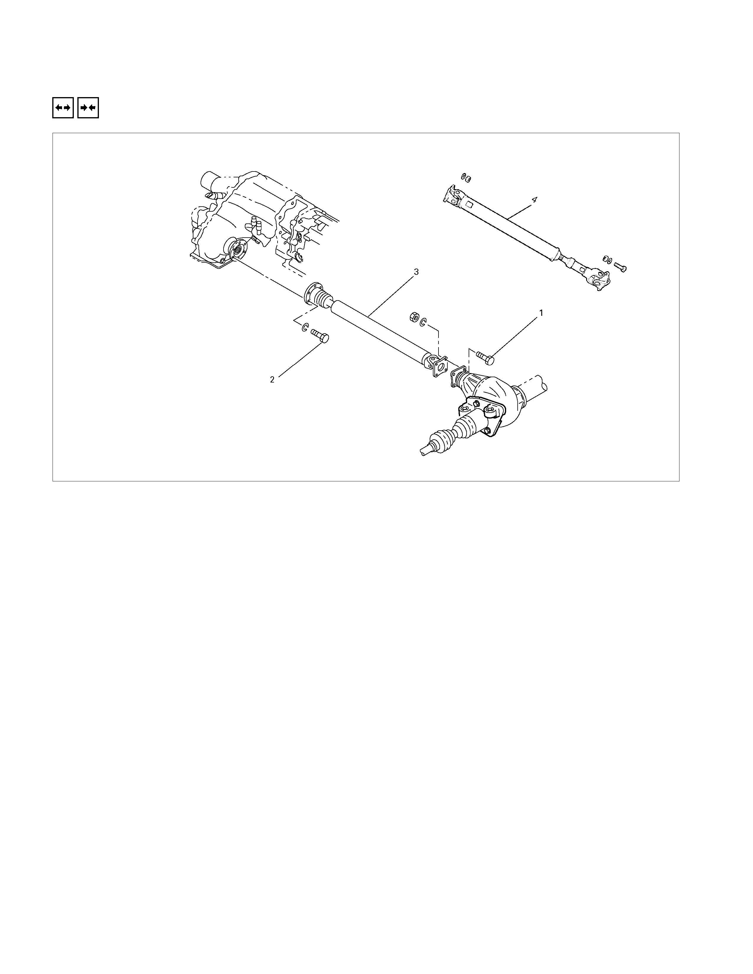
Front Propeller Shaft
Removal and Installation
Since the propeller shaft assembly is carefully balanced, a setting mark should be applied to the flange before removal
to indicate correct position.
Install the parts by aligning the setting marks made at removal.
Removal Steps
1. Nut ; differential side
2. Bolt ; transfer side
3. Propeller shaft assembly (4JH1-TC)
4. Propeller shaft assembly (6VE1)
Installation Steps
4. Propeller shaft assembly (6VE1)
▲ 3. Propeller shaft assembly (4JH1-TC)
▲ 2. Bolt ; transfer side
▲ 1. Nut ; differential side
Important Opera tion - Installation
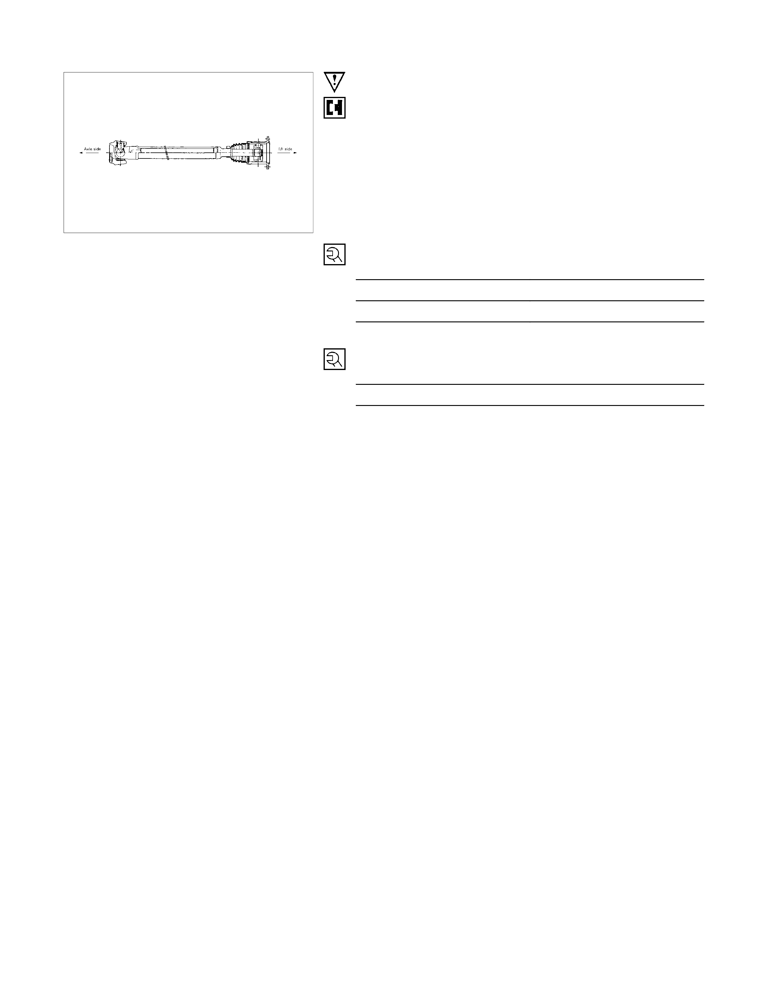
3. Propeller Shaft Assembly ; Rear Side
Align the indexing marks (about 3 mm dia. punched mark) on
the propeller shaft end and the splined yoke.
2. Bolt or Nut ; Transfer Side
Torque N⋅m ( kgf⋅m/lb⋅ft)
Bolt (4JH1-TC) 35 (3.6 / 25.8)
Nut (6VE1) 59 (6.0 / 43.5)
1. Bolt ; Differenti al Side
Torque N⋅m ( kgf⋅m/lb⋅ft)
59 (6.0 / 43.5)

Troubleshooting
Refer to this Section to quickly diagnose and repair front axle problems. Each troubleshooting chart has three headings
arranged from left to right.
(1) Checkpoint (2) Trouble Cause (3) Countermeasure
This Section is divided into ten sub-sections:
4×
××
×2 Model
1. Wanders and pulls
2. Front wheel shimmy
4×
××
×4 Model
1. Oil leak at front axle
2. Oil leak at pinion shaft
3. Noises in front axle drive shaft joint
4. Noises in front axle
5. Wanders and pulls
6. Front wheel shimmy
Propeller shaft
1. Noise
2. Vibration
Techline
4×
××
×2 Model
1. WANDERS AND PULLS
Checkpoint Possible Cause Countermeasure
Adjust the wheel bearing
preload
Too tight
NG
Adjust the front alignment
Front alignment
Incorrect
Steering unit
Tighten or replace
Loose or worn
NG
NG
Suspension
Tighten or replace
Replace or adjust the inflation
Front or rear suspension parts
loose or broken
Tire
Worn or improperly inflated
OK
NG
NG
OK
OK
OK
Wheel bearing preload
2. FRONT WHEEL SHIMMY
Checkpoint Possible Cause Countermeasure
Ba ll j oint or b ush
Replace the ball joint or bush
Worn
Front alignment
Adjust the front alignment
Adjust or replace
Incorrect
Worn or improperly adjusted
OK
OK
NG
NG
NG
OK
Wheel bearing
Tighten or replace
Loose or worn
NO
Shock abs orber
Replace the shock absorber
Worn
Tire
Replace or adjust the inflation
Worn or improperly inflated
OK
NG
NG
OK
Steering unit
4×
××
×4 Model
1. OIL LEAK AT FRONT AXLE
Checkpoint Possible Cause Countermeasure
Front axle housing Repair or replaceCracked
Replace the oil sealWorn or defective oil seal
NG
NG
OK
Oil seal
2. OIL LEAK AT PINION SHAFT
Oil seal Replace the oil sealWorn or defective
Correct the oil levelToo much gear oil
NG
NG
OK
Gear oil level
Pinion flange Tighten or replaceLoose or damaged
NG
OK
3. NOISES IN FRONT AXLE DRIVE SHAFT JOINT
Replace the drive shaft joints
and bellows
Broken or worn
NG
Drive shaft joints and bellows
(UJ and DOJ)
4. NOISES IN FRONT AXLE
Checkpoint Possible Cause Countermeasure
Replenish the gear oilInsufficient gear oil
NG
Replace the wheel bearing
Replace the pinion shaft
bearing
Replace the ring gear pinion
gear or side gear
Replace the gear oil
Wheel bearing Worn
Pinion shaft bearing Worn
Worn or chipped
Wrong or poor grade gear oil
Ring gear, pinion gear or side
gear
Adjust the backlash
Drive pinion to ring gear
backlash Too much or too little backlash
NG
NG
NG
NG
NG
OK
OK
OK
OK
Oil level
Tighten or replaceDifferential bearing Loose or worn
NG
OK
5. WANDERS AND PULLS
Checkpoint Possible Cause Countermeasure
Adjust the wheel bearing
preload
Too tight
NG
Adjust the front alignment
Front alignment
Incorrect
Tighten or replace
Steering unit
Loose or worn
NG
NG
OK
OK
Tighten or replace
Replace or adjust the inflation
Suspension
Front or rear suspension parts
loose or broken
Tab
Worn or improperly inflated
NG
NG
OK
OK
Wheel bearing preload
6. FRONT WHEEL SHIMMY
Checkpoint Possible Cause Countermeasure
Ball j o int or bu sh
Replace the ball joint or bush
Worn
Front alignment
Adjust the front alignment
Adjust or replace
Inco rre ct
Worn or improperly adjusted
OK
OK
NG
NG
NG
OK
Wheel bearing
Tighten or repl ace
Loose or worn
NO
Shock absorber
Replace the shock absorber
Worn
Tire
Replace or adjust the inflation
Worn or im properly inflated
OK
NG
NG
OK
Steering unit
Propeller Shaft
1. NOISE
Checkpoint Possible Cause Countermeasure
Spider bearing ReplaceWorn or jammed
ReplaceDamaged or worn
NG
NG
OK
Yoke spline
2. VIBRATION
Shaft balance AdjustUnbalance
ReplaceIncorrect
NG
NG
OK
Shaft runout
Transmission rear housing
bushing, transfer case
housing bushing ReplaceWorn
NG
OK
Yoke spline ReplaceJammed
NG
OK
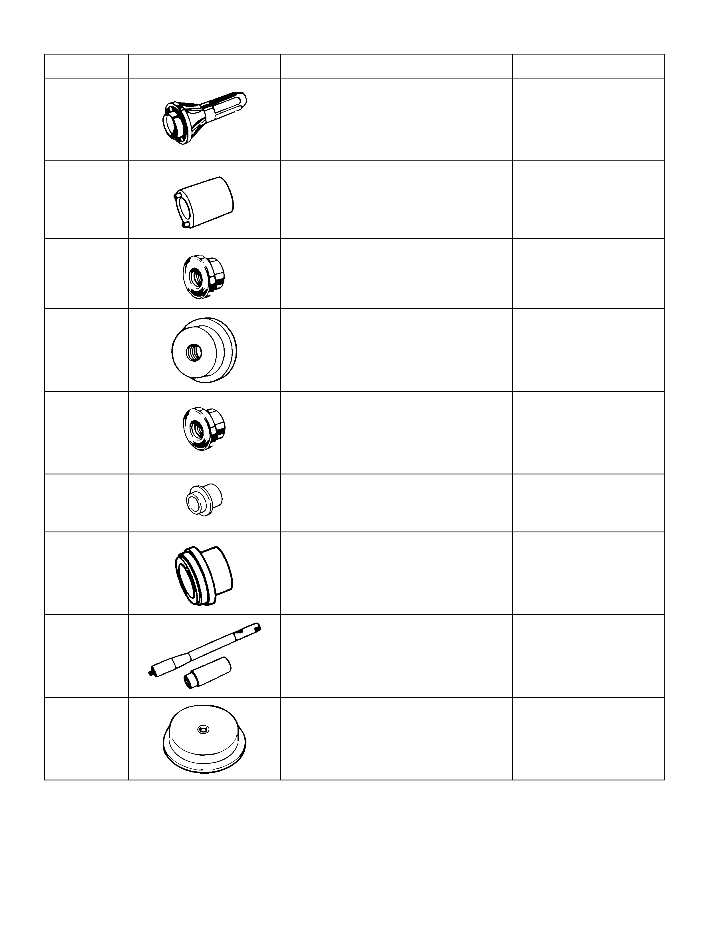
Special Service Tool
ITEM NO. ILLUSTRATION PART NO. PART NAME
FAL-1
5-8840-0013-0
(J-22888)
Side bearing puller
FAL-14
9-8521-1743-0
(J-8107-2)
Side bearing plug adapter
FAL-3
5-8840-0133-0
(J-8614-01)
Pinion flange holder
FAL-8
9-8521-5032-0
Final pinion spindle
FAL-10
5-8840-0015-0
(J-22912-01)
Separator
FAL12
9-8522-1141-0
(J-24256)
Outer bearing outer race
installer
OTL-1
5-8840-0007-0
(J-8092)
Driver handle
FAL-16
9-8522-1274-0
(J-24252)
Inner bearing outer race
installer
FAL-34
5-8840-2085-0
(J-21777-42)
Pilot
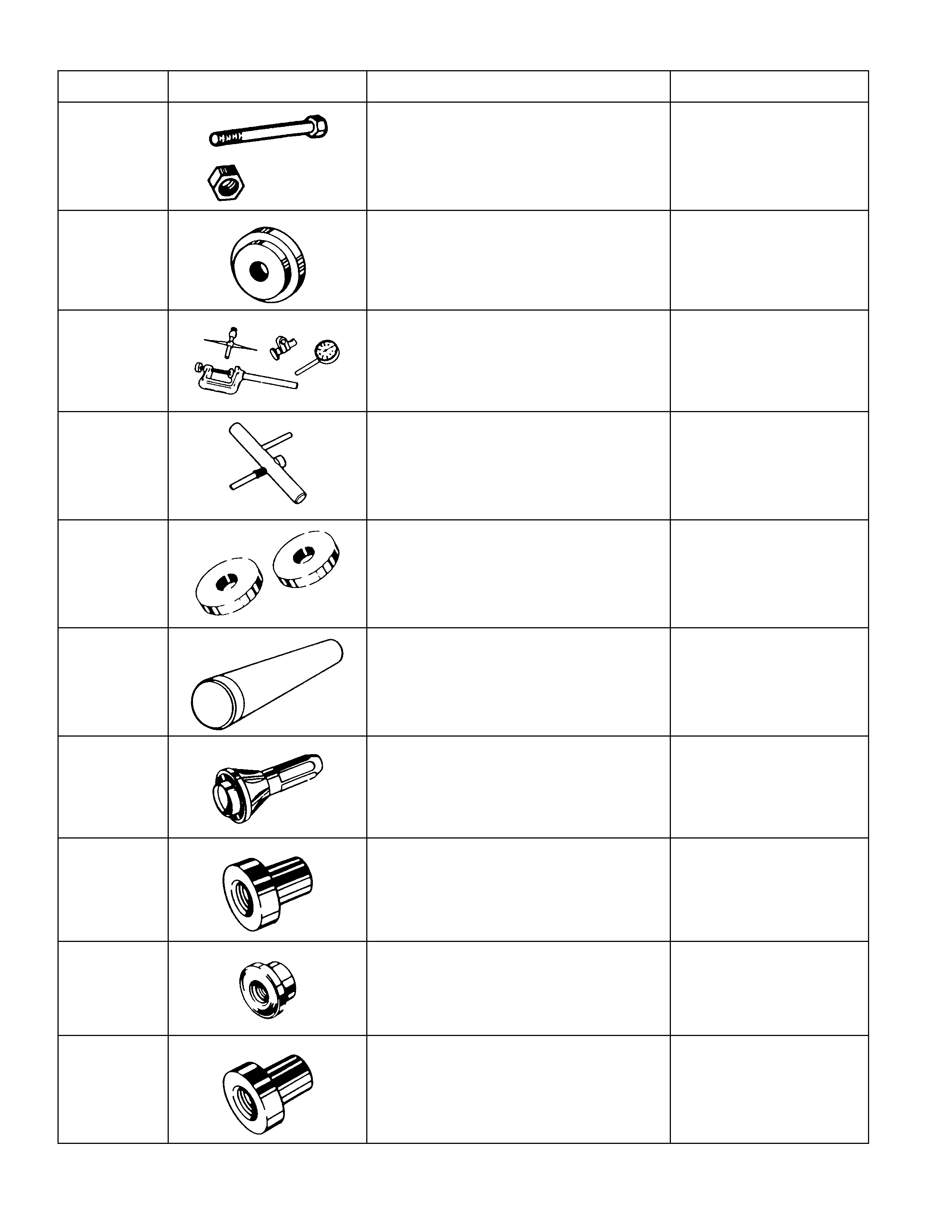
ITEM NO. ILLUSTRATION PART NO. PART NAME
FAL-41
5-8840-2089-0
(J-23597-9)
Nut & bolt
FAL-36
5-8840-2087-0
(J-23597-7)
Gauge plate
FAL-42
5-8840-0126-0
(J-8001)
Dial indicator
FAL-43
5-8840-0128-0
(J-23597-1)
Arbor
FAL-38
5-8840-2088-0
(J-23597-8)
Disc (2 pcs. required)
FAL-59
9-8522-1165-0
(J-6133-01)
Pinion bearing installer
(for 4WD)
FAL-52
9-8522-1275-0
(J-24250)
Pinion oil seal installer
FAL-56
9-8521-1164-0
(J-24244)
Side bearing installer
FAL-57
5-8522-0053-0
(J-29016)
Outer bearing installer
(for 2WD)
FAL-58
5-8522-0054-0
(J-29015)
Inner bearing installer
(for 2WD)
ITEM NO. ILLUSTRATION PART NO. PART NAME
FAL-54
5-8522-0051-0
(J-33161)
Hub oil seal installer
(for 2WD)
FAL-62
5-8840-2117-0
(J-36827)
Hub nut wrench
FAL-17
5-8840-2119-0
(J-36829)
Outer bearing inner race
installer (for 4WD)
FAL-19
5-8840-2120-0
(J-36830)
Oil seal installer (for 4WD)
FAL-18
5-8840-0054-0
(J-29015)
Outer bearing outer race
installer (for 4WD)
FAL-61
5-8840-2137-0
(J-38194)
Inner cam installer
FAL-39
5-8840-2126-0
Auto locking shim gauge
(for 4WD)
FAL-60
5-8840-2125-0
Snap ring installer
(for 4WD)
5-8840-2789-0
ABS sensor rotor installer