
SECTION 4C2 - DRIVELINE CONTROL SYSTEM
Service Precaution
Shift On The Fly System
Outline of Shift on The Fly System
System Diagrams
Shift On The Fly Electrical Equipment
Axle Shaft Connection and Disconnection
Actuator Assembly
Shift On The Fly System and Association Parts
Disassembly
Inspection and Repair
Reassembly
Torque Specifications
Special Service Tool

Service Precaution
WARNING: THIS VEHICLE HAS A SUPPLEMENTAL RESTRAINT SYSTEM (SRS). REFER TO THE SRS
COMPONENT AND WIRING LOCATION VIEW IN ORDER TO DETERMINE WHETHER YOU ARE PERFORMING
SERVICE ON OR NEAR THE SRS COMPONENTS OR THE SRS WIRING. WHEN YOU ARE PERFORMING
SERVICE ON OR NEAR THE SRS COMPONENTS OR THE SRS WIRING, REFER TO THE SRS SERVICE
INFORMATION. FAILURE TO FOLLOW WARNINGS COULD RESULT IN POSSIBLE AIR BAG DEPLOYMENT,
PERSONAL INJURY, OR OTHERWISE UNNEEDED SRS SYSTEM REPAIRS.
CAUTION: Always use the correct fastener in the proper location. When you replace a fastener, use ONLY the
exact part number for that application. HOLDEN will call out those fasteners that require a replacement after
removal. HOLDEN will also call out the fasteners that require thread lockers or thread sealant. UNLESS
OTHERWISE SPECIFIED, do not use supplemental coatings (Paints, greases, or other corrosion inhibitors) on
threaded fasteners or fastener joint interfaces. Generally, such coatings adversely affect the fastener torque
and the joint clamping force, and may damage the fastener. When you install fasteners, use the correct
tightening sequence and specifications. Following these instructions can help you avoid damage to parts and
systems.
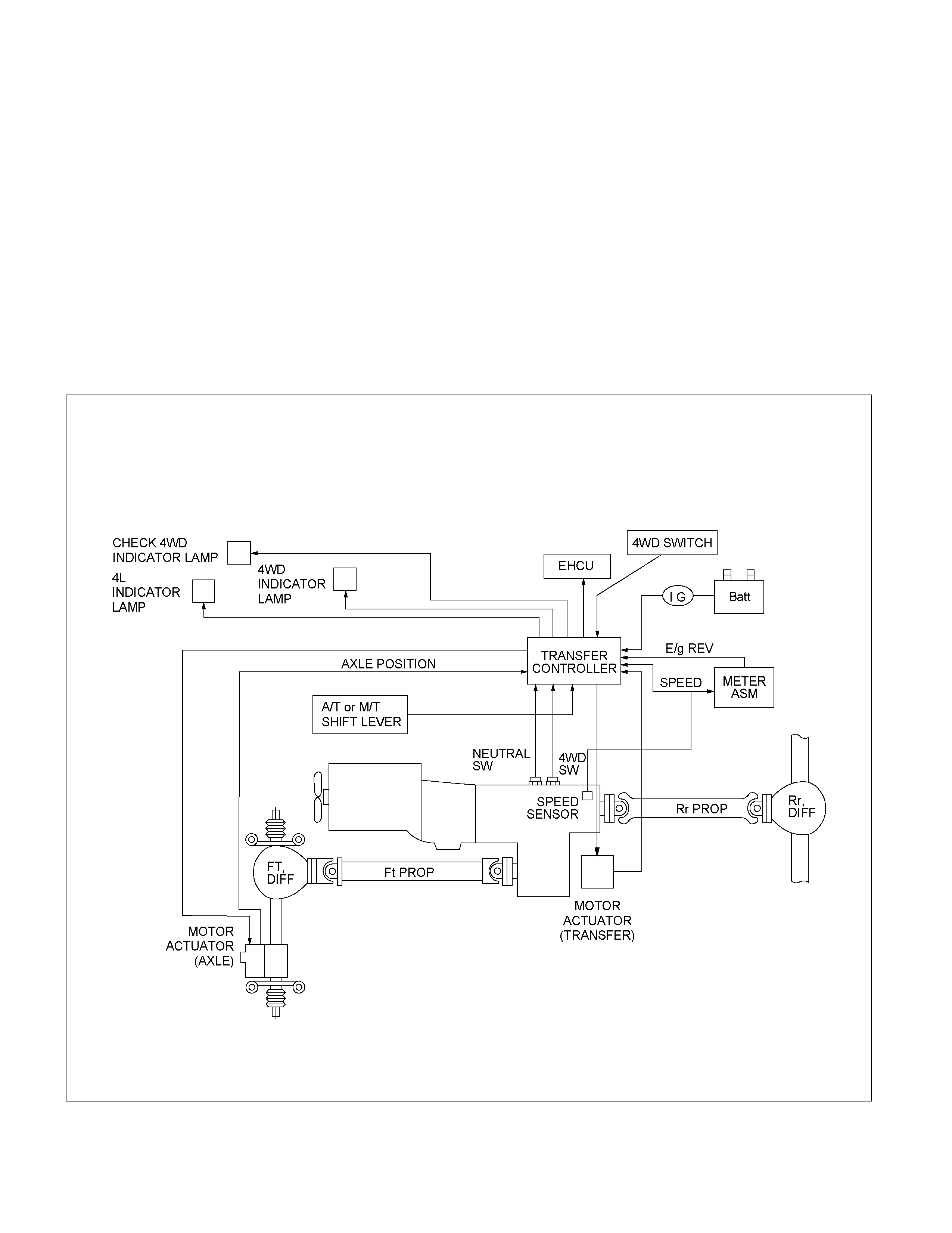
Shift On The Fly System (SOF)
Outline of Shift on The Fly System
The Shift On The Fly system electronically switches between 2 wheel drive (2WD) and 4 wheel drive (4WD) in
response to the driver operating the 4WD switch on instrument panel.
This system controls the following operations.
1. Shifting the transfer case front output gear (Connecting to, and disconnecting from, front propeller shaft by motor
actuator).
2. Retrial of shifting the transfer case front output gear.
3. Connecting front wheels to, and disconnecting them from, the front axles (by axle motor actuator).
4. Illumination of the Indicator on instrument panel.
5. “4WD out” signal to the Electronic Hydraulic Control Unit.(ABS Controller)
System Diagrams
RUW34BLF000201
Shift On The Fly Electrical Equipment
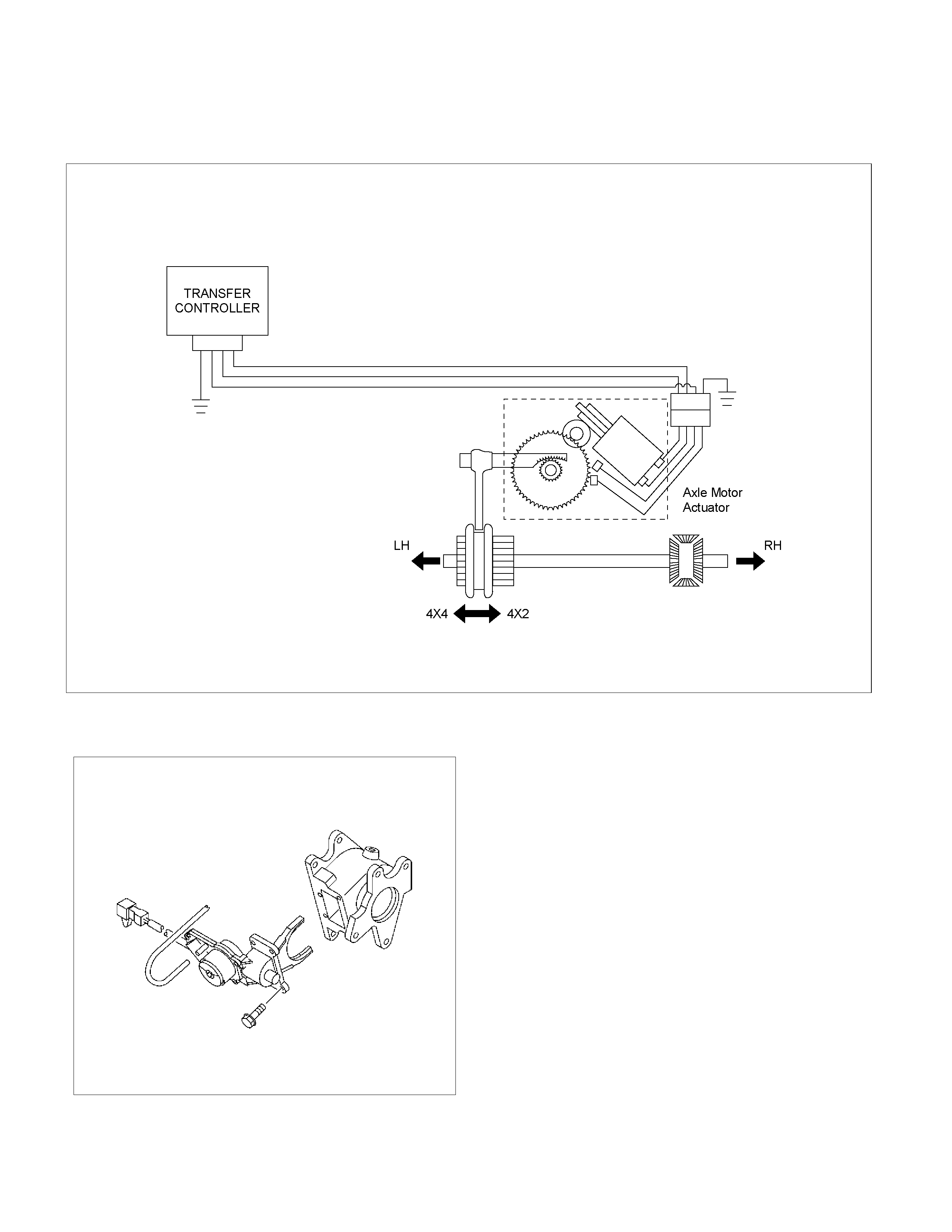
Axle Shaft Connection and Disconnection
RUW34BMF000101
Actuator Assembly
412RY00004
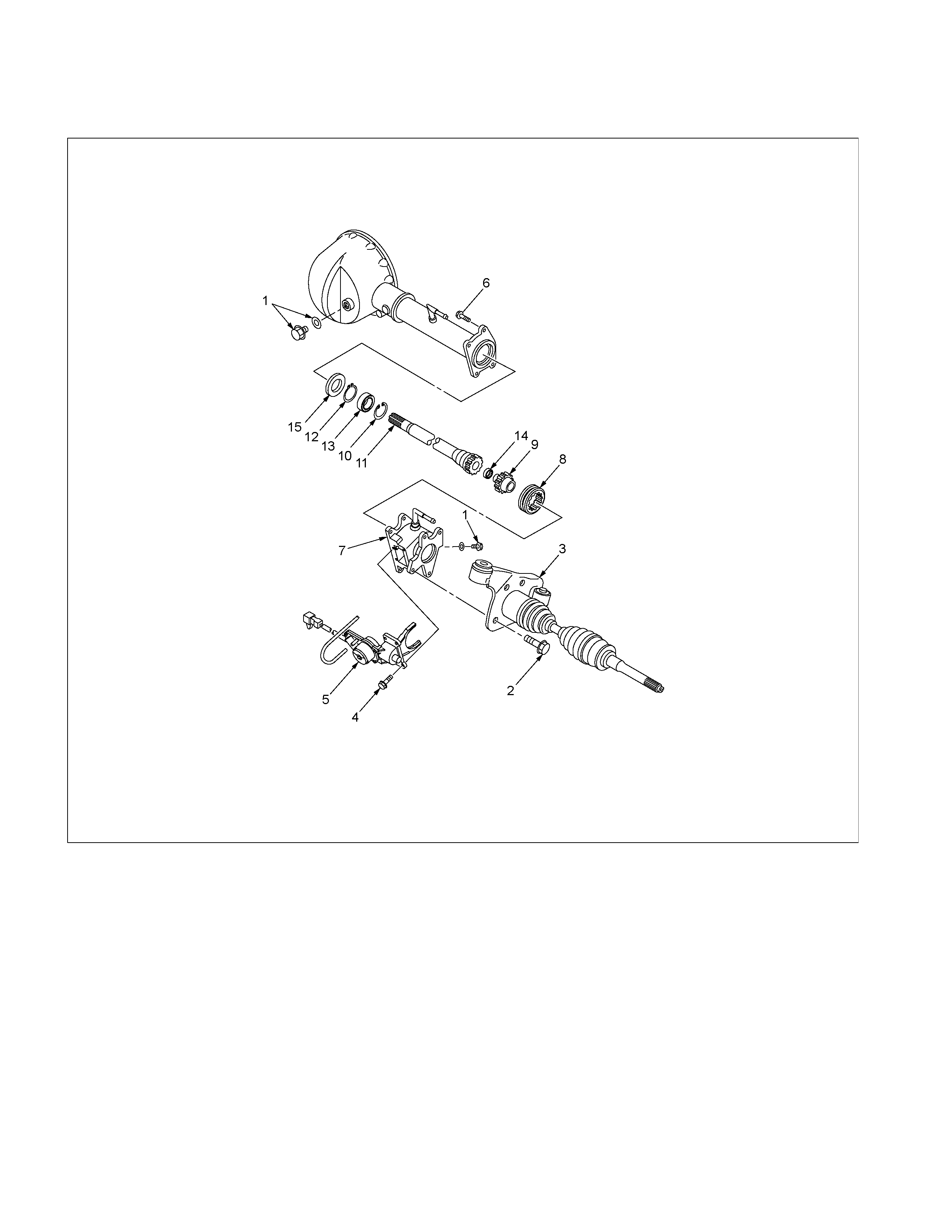
Shift On The Fly System and Association Parts
RTW440LF000701
Disassembly steps
1. Filler plug
2. Bolt
3. Front axle drive shaft (LH side)
4. Bolt
5. Actuator assembly
6. Bolt
7. Housing
8. Sleeve
9. Clutch gear
10. Snap ring
11. Inner shaft
12. Snap ring
13. Inner shaft bearing
14. Needing bearing
15. Oil seal
Reassembly steps
To reassemble, follow the disassembly steps in
the reverse order.
Disassembly
1. Filler Plug
Remove filler plug and packing and drain oil.
2. Bolt
Loosen mounting bracket fitting bolts and remove front axle
drive shaft from front axle case.
3. Front Axle Drive Shaft (LH side)
4. Bolt
Loosen actuator ASM fitting bolts.
5. Actuator Assembly
Draw out actuator ASM.
6. Bolt
Remove hosing fitting bolts.
7. Housing
8. Sleeve
9. Clutch Gear
412RW017
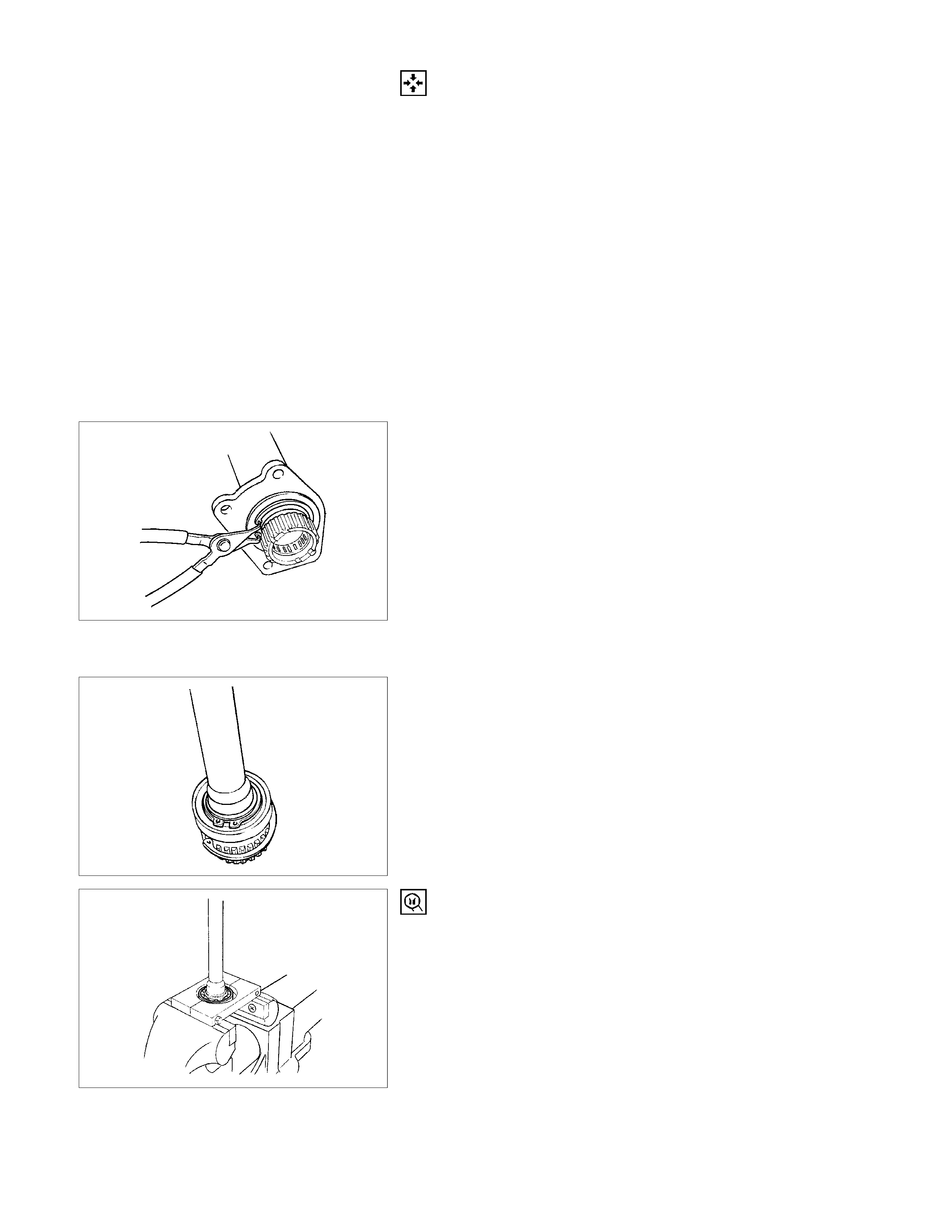
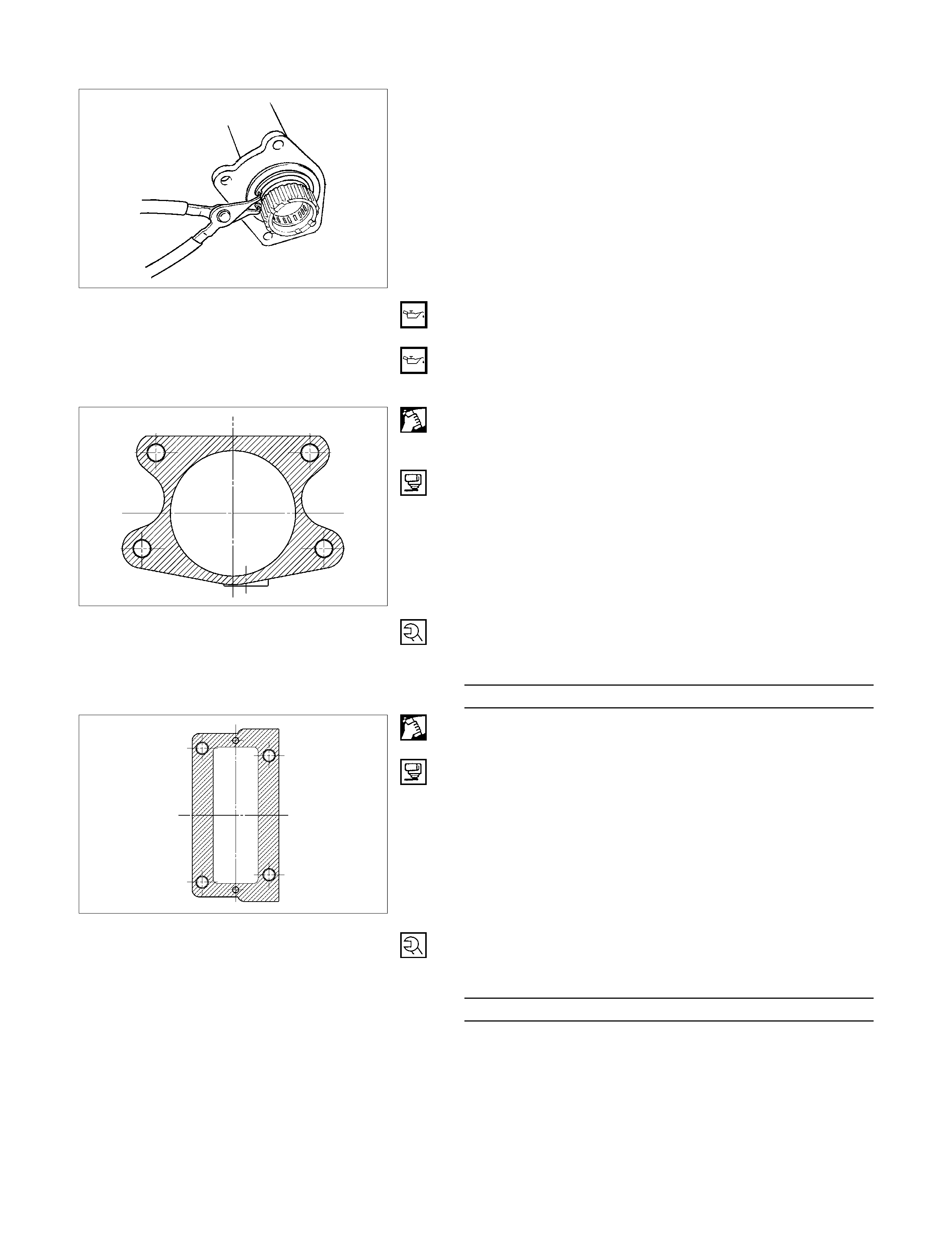
10. Snap Ring
Remove snap ring from the front axle case with the use o
f
snap ring pliers.
11.Inner Shaft
Take out inner shaft from front axle case.
412RW016
12.Snap Ring
Remove snap ring from inner shaft with the use of snap
ring pliers.
412RW015
13.Inner Shaft Bearing
Remove inner shaft bearing by using a special tool and
press.
Remover : 5-8840-2197-0 (J-37452)
NOTE:
Be careful not to damage the shaft.
412RS045
14.Needle Bearing
Remove needle bearing from inner shaft by using a special
tool.
Remover : 5-8840-0027-0 (J-26941)
Sliding hammer : 5-8840-0084-0 (J-2619-01)
NOTE:
Be careful not to damage the shaft.
15.Oil Seal
Remove oil seal from front axle case.
NOTE:
Be careful not to damage the front axle case.
Inspection and Repair
Inspect the removed parts. If there are abnormalities such as
wear and damage, take corrective action or replace.
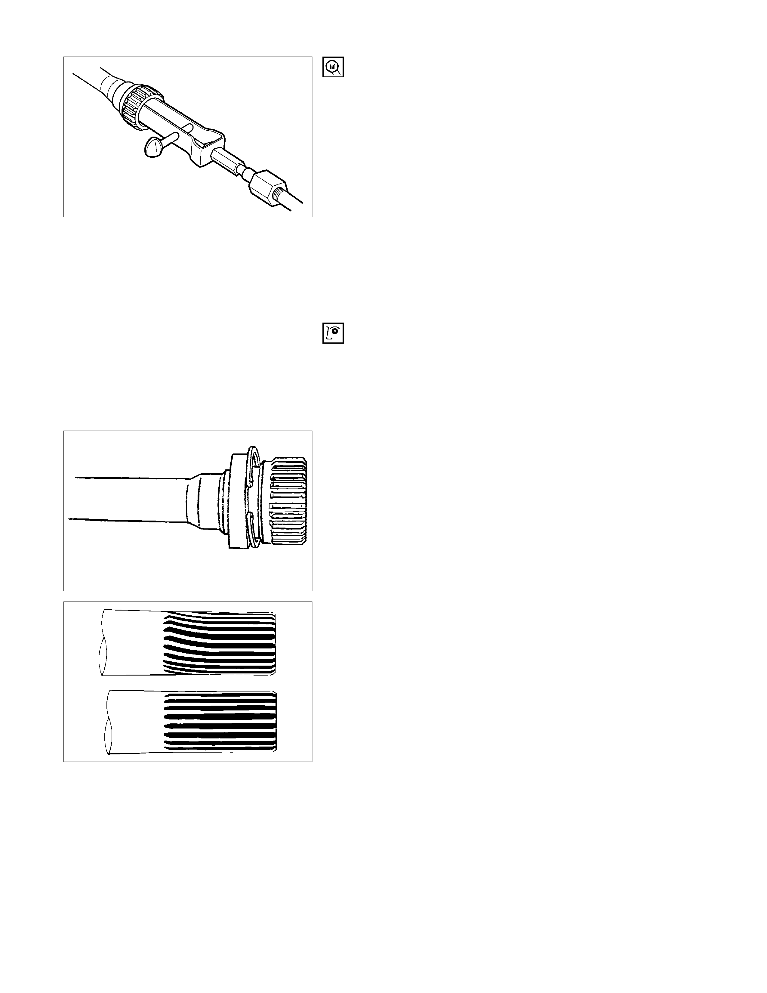
Visual Check
• Check and see if the inner shaft has such
abnormalities as wear and damage.
412RW014
412RS008
• When inspecting the inner shaft, be sure to check
and see if its splined part is twisted, worn, or cracked.
If so, replace with a new shaft. In case such an
abnormality in its gear part (a slide with sleeve),
replace the shaft.
412RS026
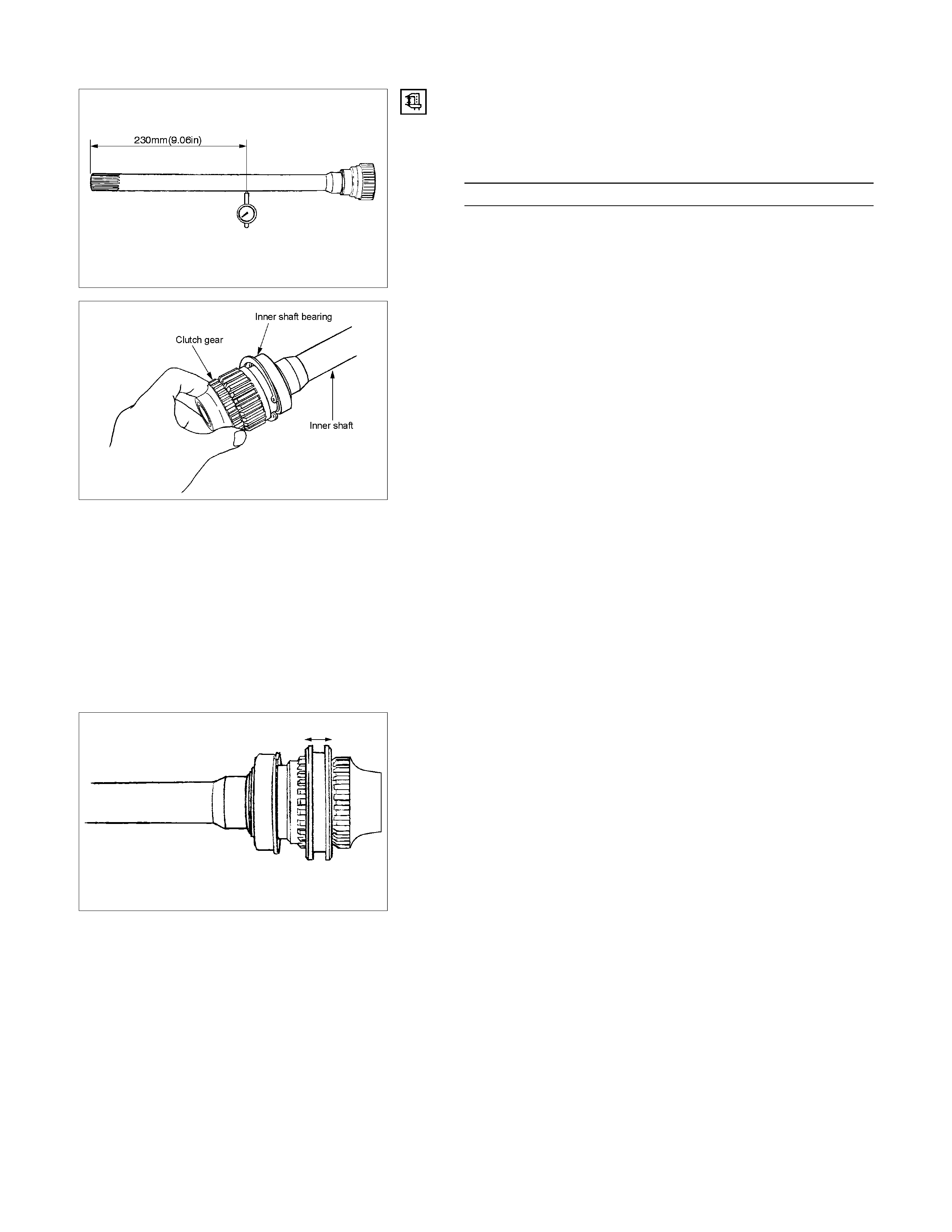
Inner Shaft Run-Out
With both end centers supported, rotate the shaft slowly
and measure deflection with a dial gauge.
Inner Shaft Run-Out (Limit) mm (in)
0.5 (0.02)
NOTE:
Do not heat the shaft to correct its bend.
RTW440SH000101
Inner Shaft Bearing
Inspect the state of inner shaft bearing. If any abnormality
such as roughness is found, replace with a new inner shaft
bearing.
Insert the clutch gear and check the state of needle
bearing.
If there is an abnormality such as roughness, replace the
needle bearing.
Sleeve
Visual Check
Check and see that there is no wear, damage, or cracking
in the sleeve.
NOTE:
Close inspection of the groove and inner gear are
required as any abnormalities to these parts will have
adverse effect to their operation.
412RW011
Functional Check
Operate the sleeve with the inner shaft combined with the
clutch gear.
If any roughness is felt, replace the sleeve.
NOTE:
Gear oil should be applied to the contact surface of gear.
412RW022
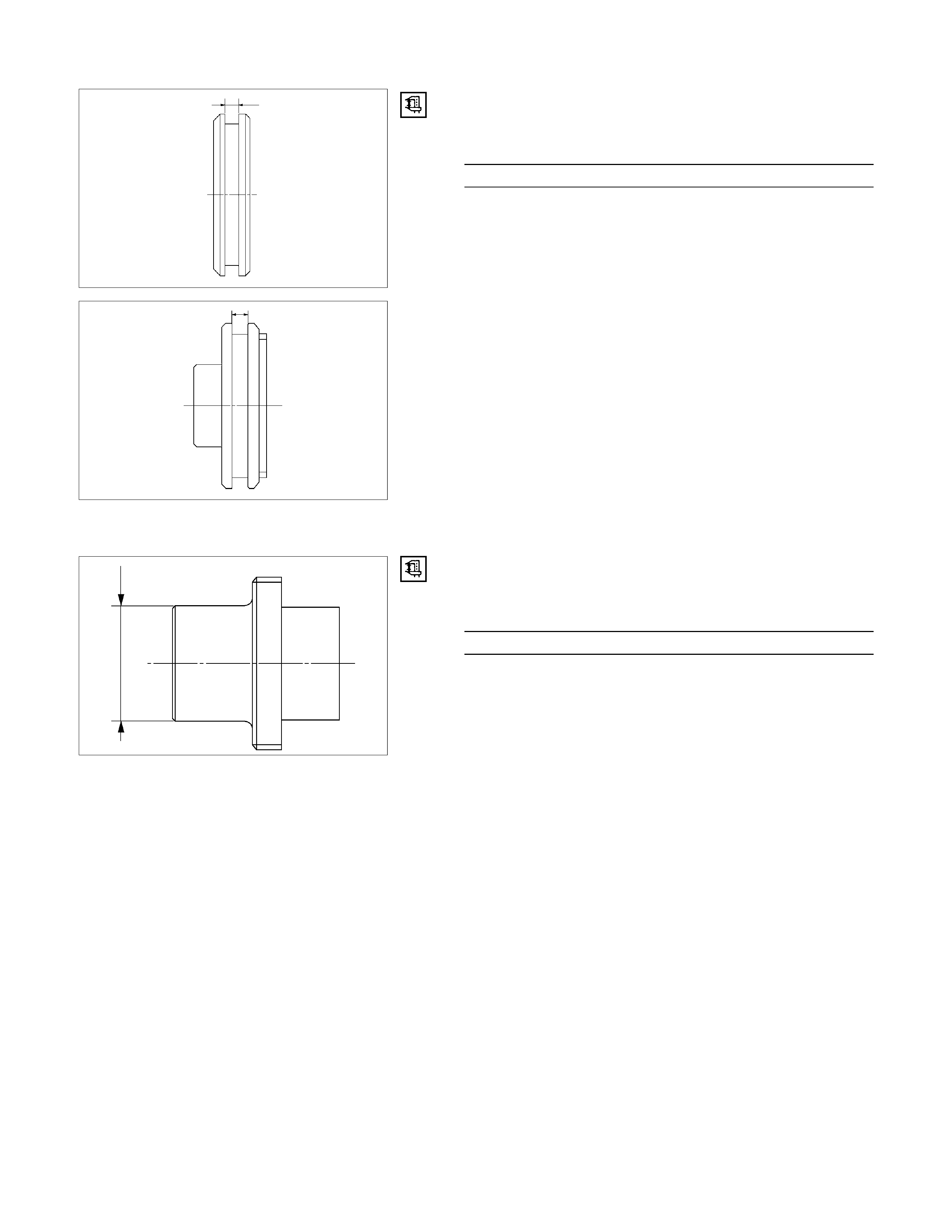
Dimensional Check
Check the width of sleeve center groove.
Sleeve Center Groove (Limit) mm (in)
7.1 (0.28)
RTW440SH000201
Clutch Gear
Visual Check
Check and see that there is no wear, damage, crack, or
any other abnormality in the clutch gear.
Functional Check
If there is an abnormality such as roughness when
operated in combination with sleeve, replace the clutch
gear.
NOTE:
When inspection, gear oil should be applied to the contact
surface of gear.
RTW440SH000301
Dimensional Check
Confirm dimensions shown in the illustration.
Clutch Gear Out Side Diameter (Limit) mm (in)
36.98 (1.46)
RTW440SH000501
RTW440SH000401
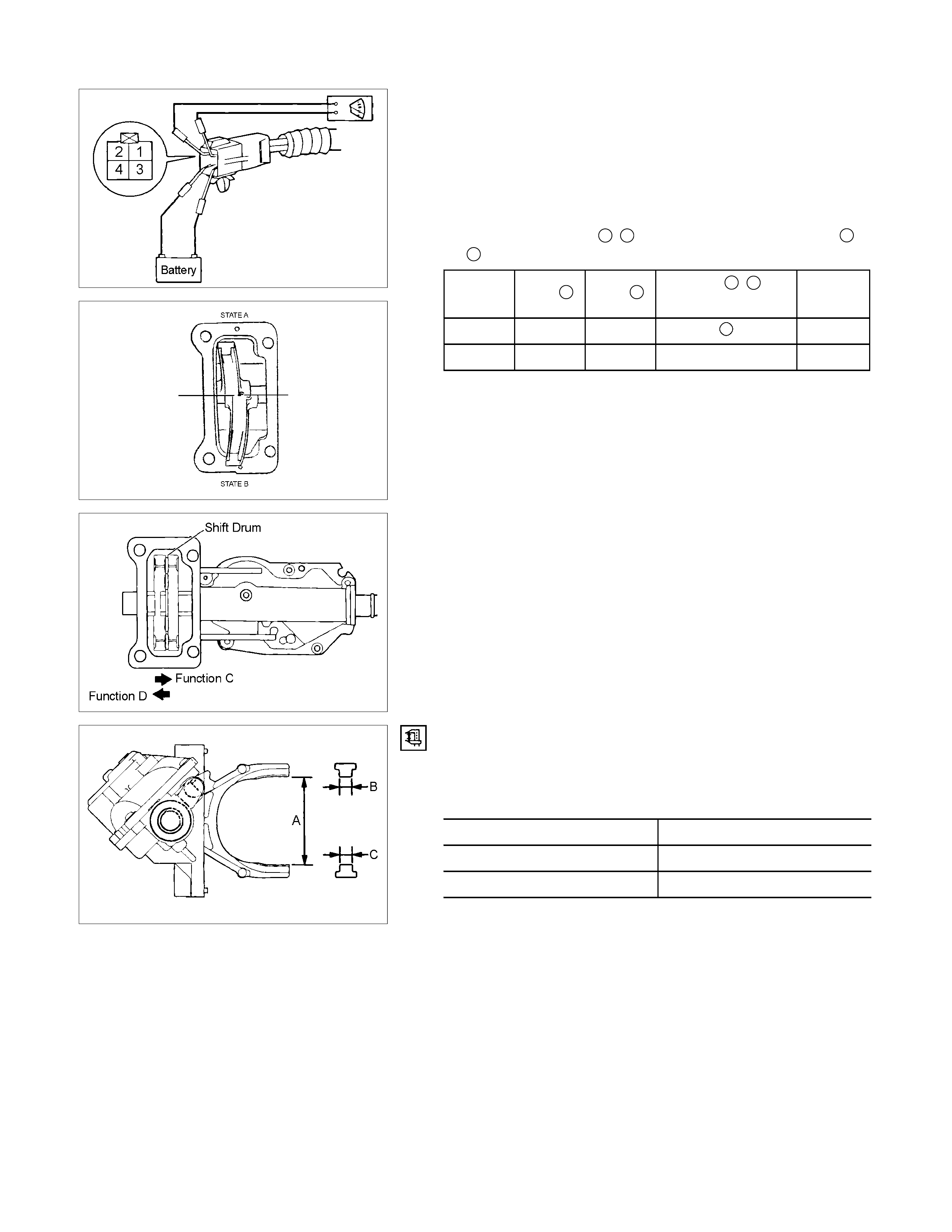
Actuator
Visual Check
Check and see that there is no damage, cracking, or other
abnormality.
Functional Check
Confirm correct operation of actuator with voltage (12V)
applied to terminal 3, 4 and set the tester to terminal 1,
2 in accordance with the table below.
State Port
3Port 4Port 1, 2
Conducting Function
A + − C
B − + × D
If there is an abnormality, replace the actuator as an
assembly.
NOTE:
Be careful not to permit the entry of water or dust into the ports
of the actuator.
Do not open the actuator cover, if the actuator is to be reused.
RTW440SH000601
RTW440SH000801
Dimension Check
Confirm correct measurements for dimensions A, B, and C
as shown in illustration.
Limit mm (in)
A 64.3 (2.53)
B 6.7 (0.26)
C 6.7 (0.26)

RTW440SH000701
Reassembly
15. Oil seal
Install the new oil sea, which has been immersed in
differential gear oil, by using an oil seal installer.
Installer 5-8840-2407-0 (J-41693)
Grip 5-8840-0007-0 (J-8092)
412RS051
14. Needle Bearing
Force a new needle bearing into inner shaft by using the
special tools.
Installer : 5-8840-2408-0 (J-41694)
Grip : 5-8840-0007-0 (J-8092)
412RS044
13. Inner Shaft Bearing
• Place a new snap ring in inner shaft.
• Force a new inner shaft bearing into the inner shaft.
Installer : 5-8840-2197-0 (J-37452)
12. Snap Ring
NOTE;
Be careful not to damage the inner shaft.
11.inner Shaft
• Clean the housing contact surface of the front axle
case.
• Insert inner shaft assembly into the front axle case.
NOTE:
Be careful not to damage oil seal.
412RW017
10. Snap Ring
Install snap ring in the groove of front axle case.
NOTE:
Be sure to install the snap ring properly.
9. Clutch Gear
Apply differential gear oil to clutch gear.
8. Sleeve
Apply differential gear oil to sleeve.
412RW023
7. Housing
• Clean contact surface with the front axle and actuator
mounting surface.
• Apply liquid gasket to the contact surface on the front
axle case and install in the housing.
6. Bolt
Tighten bolts to specified tightening torque.
Housing Bolt Torque N m (kg m/lb ft)
75 (7.6/55)
5. Actuator
• Clean the actuator contact surface of the housing.
• Apply liquid gasket to the contact surface on the
actuator side.
• Align shift arm with the groove of sleeve and install
the actuator.
4. Bolt
Tighten bolts to specified torque.
Actuator Bolt Torque N m (kg m/lb ft)
9 (0.95/78)

3. Front Axle Drive Shaft (LH side)
2. Bolt
• Install front axle drive shaft and mounting bracket.
• Tighten fitting bolts to specified tightening torque.
Bolt Torque N m (kg m/lb ft)
116 (11.8/85)
1. Filler Plug
• Pour specified amount of differential gear oil.
Front Differential Oil Capacity liter (US/UK gal)
1.4 (0.37/0.31)
Actuator Housing Oil Capacity liter (US/UK gal)
0.12 (0.03/0.03)
• Install filler plug through packing and tighten to
specified torque.
Filler Plug Torque N⋅m (kg⋅m/lb⋅ft)
78 (8.0/58)
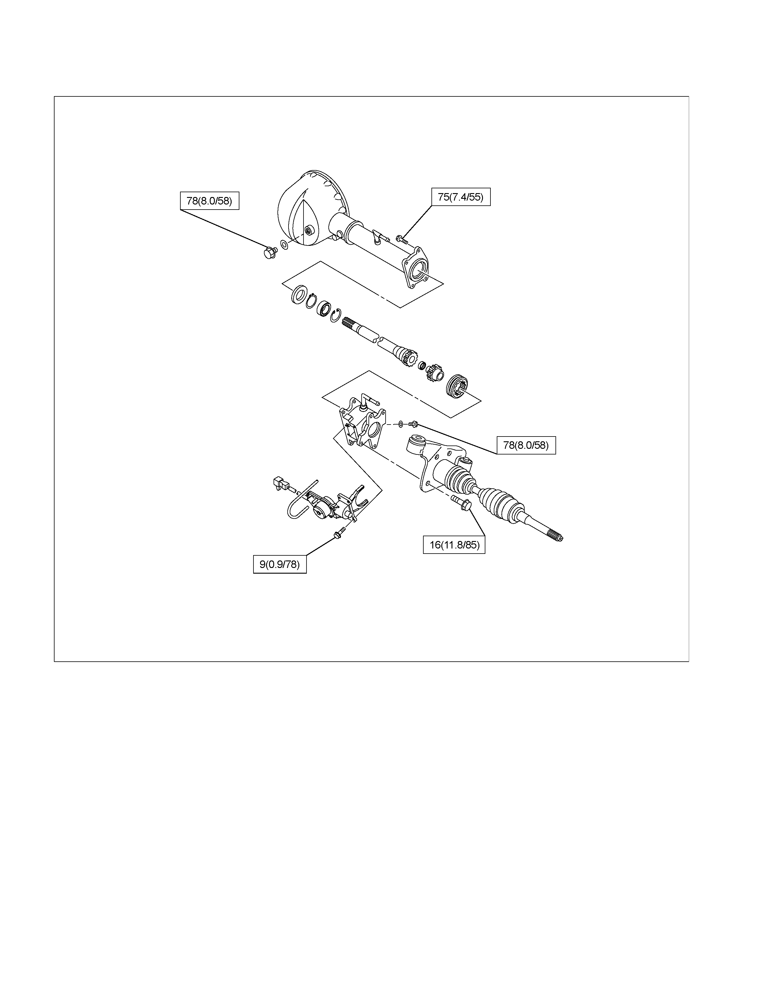
Torque Specifications
N⋅m (kgf⋅m / lb ft)
RTW440LF000801
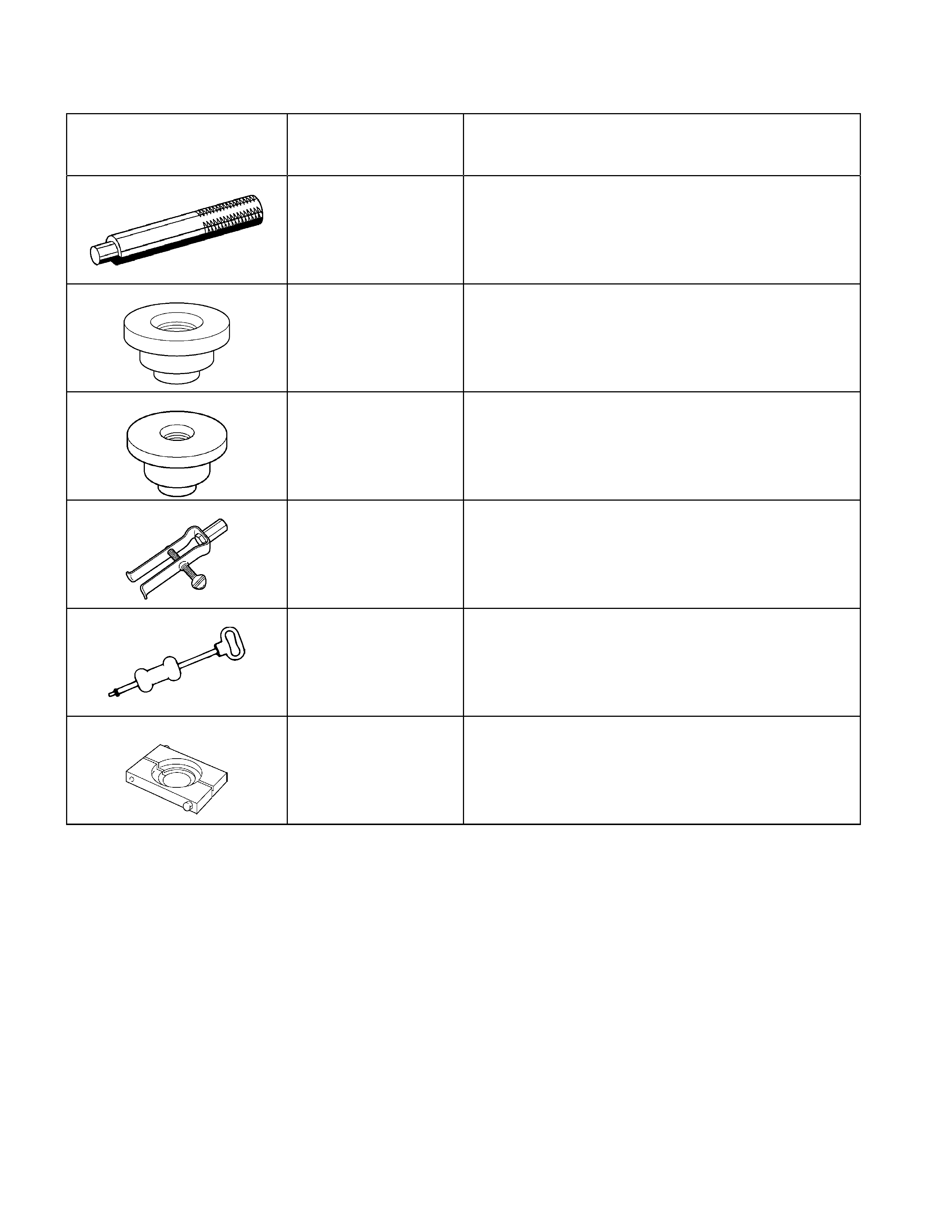
Special Service Tool
ILLUSTRATION PART NO. PART NAME
5-8840-0007-0
(J-8092)
Grip
5-8840-2407-0
(J-41693)
Installer: Oil seal
5-8840-2408-0
(J-41694)
Installer: Bearing needle
5-8840-0027-0
(J-26941)
Remover: Bearing needle
5-8840-0084-0
(J-2619-01)
Hammer: Sliding
5-8840-2197-0
(J-37452)
Remover: Bearing inner shaft