
SECTION 5A - ANTI-LOCK BRAKE
CONTROL SYSTEM
Service Precaution
General Description
EHCU, Brake Pipe Diagram
Hydraulic Unit (H/U)
Normal Braking
Pressure Isolation (Pressure Maintain)
Pressure Reduction
Brake Release
Circuit Diagram
Connector List
Part Location
EHCU Pin-outs
System Components
Electronic Hydraulic Control Unit (EHCU)
ABS Warning Lamp
Wheel Speed Sensor (WSS)
G-Sensor
Normal and Anti-lock Braking
Electronic Brake-force Distribution (EBD)
System
Brake Pedal Travel
Acronyms and Abbreviations
General Diagnosis
General Information
ABS Service Precautions
Computer System Service Precautions
General Service Precautions
If The Battery Has Been Discharged
Note on Intermittent Failures
Test Driving ABS Complaint Vehicles
"ABS and Brake" Warning Lamp
Brake (EBD) Warning Lamp
Tech 2 Scan Tool
DATA LIST (Tech 2)
Actuator Test (Tech 2)
Diagnostic Trouble Codes
Diagnosis By "ABS" Warning Lamp
Illumination Pattern
Basic Diagnostic Flow Chart
Basic Inspection Procedure
1. Basic Inspection of Service Brake
2. Ground Inspection
Wheel Speed Sensor Inspection Procedure
Symptom Diagnosis
ABS Works Frequently But Vehicle Does Not
Decelerate
Uneven Braking Occurs During ABS Operation
The Wheels Are Locked
Abnormal Brake Pedal Feel
Operating Sound Is Heard From EHCU When
Brakes Are Not Applied
No ABS Warning Lamp
DTC C0221 (Flash Code 21) Front Right Wheel
Speed Sensor Short Circuit or Circuit Open
DTC C0222 (Flash Code 22) Front Right Wheel
Speed Sensor Incorrect Signal
DTC C0223 (Flash Code 23) Front Right Wheel
Speed Sensor Signal - Tooth Chipping
DTC C0225 (Flash Code 25) Front Left Wheel
Speed Sensor Short Circuit or Circuit Open
DTC C0226 (Flash Code 26) Front Left Wheel
Speed Sensor Incorrect Signal
DTC C0227 (Flash Code 27) Front Left Wheel
Speed Sensor Signal - Tooth Chipping
DTC C0231 (Flash Code 31) Rear Right Wheel
Speed Sensor Short Circuit or Circuit Open
DTC C0232 (Flash Code 32) Rear Right
Wheel Speed Sensor Incorrect Signal
DTC C0233 (Flash Code 33) Rear Right Wheel
Speed Sensor Signal - Tooth Chipping
DTC C0235 (Flash Code 35) Rear Left Wheel
Speed Sensor Short Circuit or Circuit Open
DTC C0236 (Flash Code 36) Rear Left Wheel
Speed Sensor Incorrect Signal
DTC C0237 (Flash Code 37) Rear Left Wheel
Speed Sensor Signal - Tooth Chipping
DTC C0238 (Flash Code 38) Tire Diameter Error

DTC C0241 (Flash Code 41) Front Right Isolation
Solenoid Circuit Open or Shorted to Ground
DTC C0242 (Flash Code 42) Front Right Dump
Solenoid Circuit Open or Shorted to Ground
DTC C0243 (Flash Code 43) Front Right Isolation
Solenoid Circuit Shorted to Battery
DTC C0244 (Flash Code 44) Front Right Dump
Solenoid Circuit Shorted to Battery
DTC C0245 (Flash Code 45) Front Left Isolation
Solenoid Circuit Open or Shorted to Ground
DTC C0246 (Flash Code 46) Front Left Dump
Solenoid Circuit Open or Shorted to Ground
DTC C0247 (Flash Code 47) Front Left Isolation
Solenoid Circuit Shorted to Battery
DTC C0248 (Flash Code 48) Front Left Dump
Solenoid Circuit Shorted to Battery
DTC C0251 (Flash Code 51) Rear Isolation
Solenoid Circuit Open or Shorted to Ground
DTC C0252 (Flash Code 52) Rear Dump
Solenoid Circuit Open or Shorted to Ground
DTC C0253 (Flash Code 53) Rear Isolation
Solenoid Circuit Shorted to Battery
DTC C0254 (Flash Code 54) Rear Dump
Solenoid Circuit Shorted to Battery
DTC C0265 (Flash Code 65) Fail Safe Relay
(FSR) shorted to Ground
DTC C0266 (Flash Code 66) Fail Safe Relay
(FSR) shorted to Battery
DTC C0267 (Flash Code 67) ABS Motor
shorted to Ground
DTC C0268 (Flash Code 68) ABS Motor
shorted to Battery
DTC C0271 (Flash Code 71) ECU Failure or
Valve +B Circuit Open
DTC C0274 (Flash Code 74) ABS Operation
Long Time
DTC C0276 (Flash Code 76) G-Sensor Malfunction
DTC C0277 (Flash Code 77) Power Supply
Low Input
DTC C0278 (Flash Code 78) Power Supply
High Input
DTC C0282 (Flash Code 82) 4 Wheel Drive
State Input Signal Failure
DTC C0285 (Flash Code 85) Assembly
Error (G-sensor)
Special Tools

Service Precaution
WARNING: THIS VEHICLE HAS A SUPPLEMENTAL
RESTRAINT SYSTEM (SRS). REFER TO THE SRS
COMPONENT AND WIRING LOCATION VIEW IN
ORDER TO DETERMINE WHETHER YOU ARE
PERFORMING SERVICE ON OR NEAR THE SRS
COMPONENTS OR THE SRS WIRING. WHEN YOU
ARE PERFORMING SERVICE ON OR NEAR THE
SRS COMPONENTS OR THE SRS WIRING, REFER
TO THE SRS SERVICE INFORMATION. FAILURE TO
FOLLOW WARNINGS COULD RESULT IN
POSSIBLE AIR BAG DEPLOYMENT, PERSONAL
INJURY, OR OTHERWISE UNNEEDED SRS SYSTEM
REPAIRS.
CAUTION: Always use the correct fastener in the
proper location. When you replace a fastener, use
ONLY the exact part number for that application.
HOLDEN will call out those fasteners that require a
replacement after removal. HOLDEN will also call
out the fasteners that require thread lockers or
thread sealant. UNLESS OTHERWISE SPECIFIED,
do not use supplemental coatings (Paints, greases,
or other corrosion inhibitors) on threaded fasteners
or fastener joint interfaces. Generally, such
coatings adversely affect the fastener torque and
the joint clamping force, and may damage the
fastener. When you install fasteners, use the
correct tightening sequence and specifications.
Following these instructions can help you avoid
damage to parts and systems.
General Description
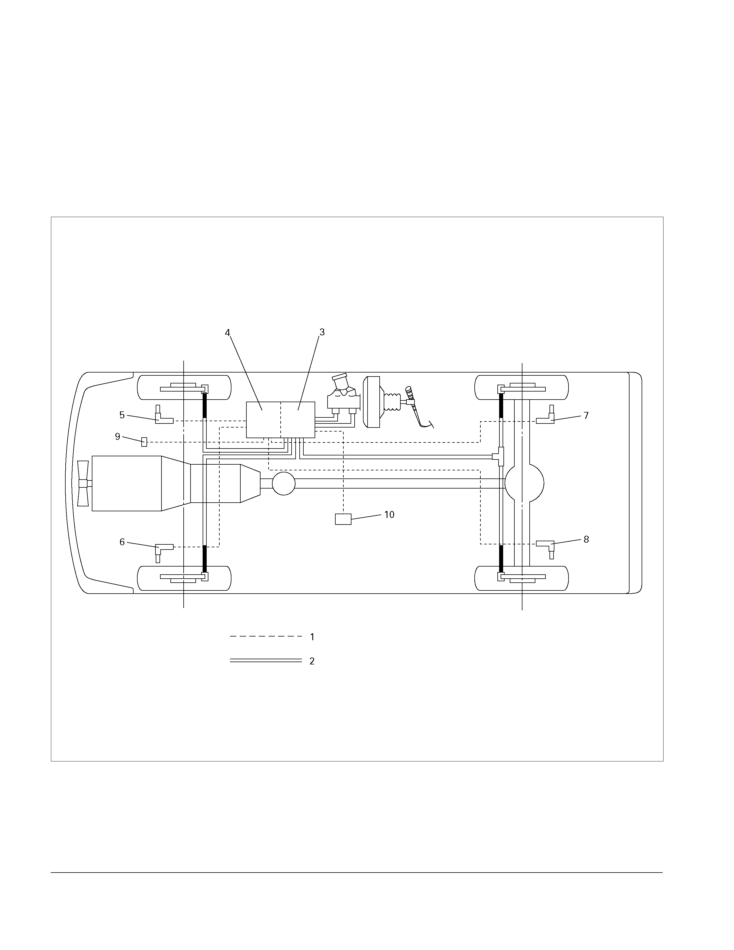
A 3-Channel Sumitomo Anti-lock Brake System (ABS) is available for selected MY2003 TF Rodeo Models.
An Electronic Hydraulic Control Unit (EHCU) controls the ABS (Anti-lock Brake System) and the EBD (Electronic
Brake-force Distribution System). The ABS works on all four wheels, where as the EBD system works on only the two
rear wheels.
By continuously monitoring wheel speed sensor input signals and brake pedal application, the EHCU can determine
when a wheel is about to stop turning and adjust brake pressure to maintain both vehicle stability and braking
efficiency.
Important: Ensure the correct EHCU type (2WD Model or 4WD Model) is fitted, whenever the EHCU is replaced.
C05L300010
Legend
(1) Electronic (6) Front Left Wheel Speed Sensor
(2) Hydraulic (7) Rear Right Wheel Speed Sensor
(3) Hydraulic Unit (H/U) (8) Rear Left Wheel Speed Sensor
(4) Control Unit (9) G-sensor (4WD only)
(5) Front Right Wheel Speed Sensor (10) 2-4WD Control Unit (4WD only)
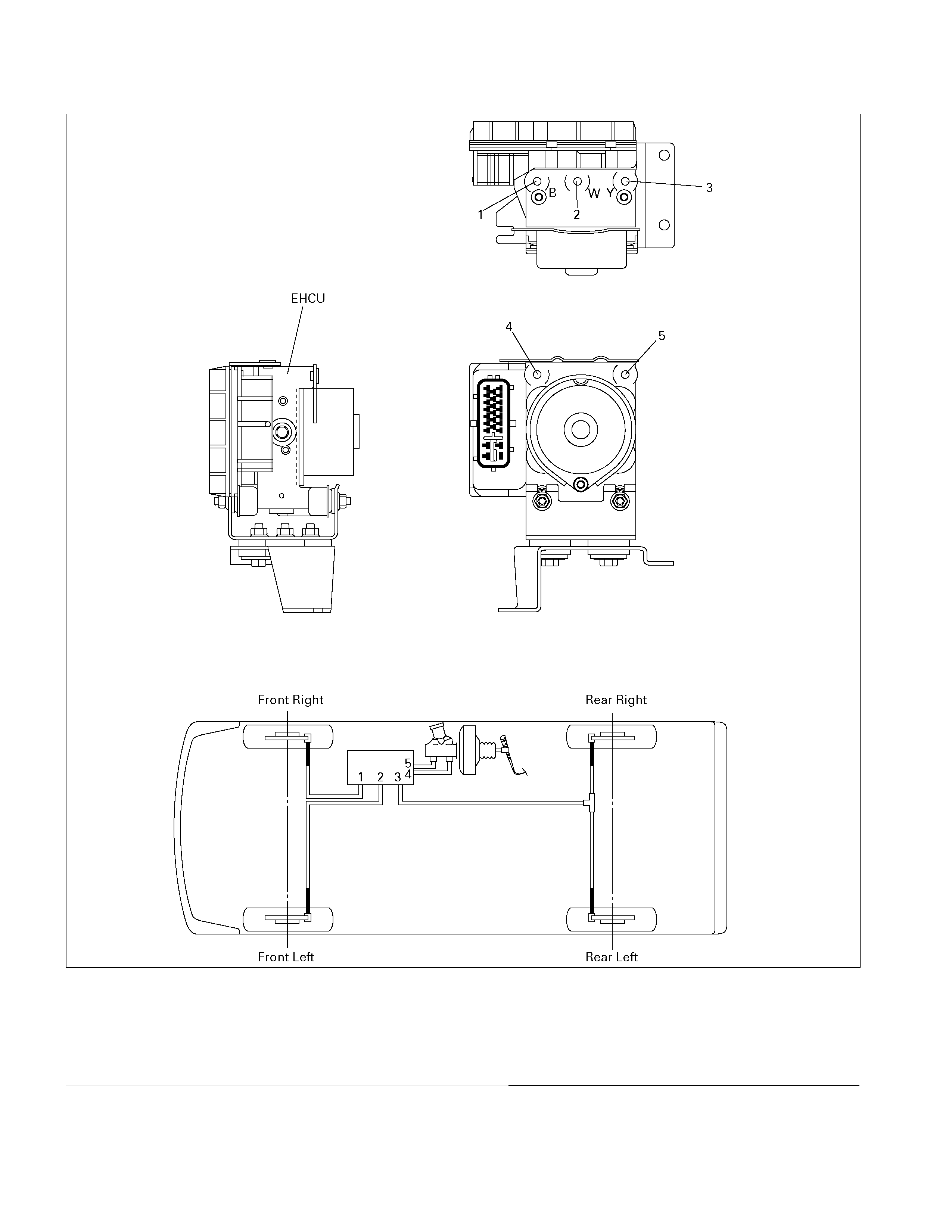
EHCU, Brake Pipe Diagram
C05L300011
Legend
(1) Front Right Brake Port (out) (4) Front Brake Port (in)
(2) Front Left Brake Port (out) (5) Rear Brake Port (in)
(3) Rear Brake Port (out)
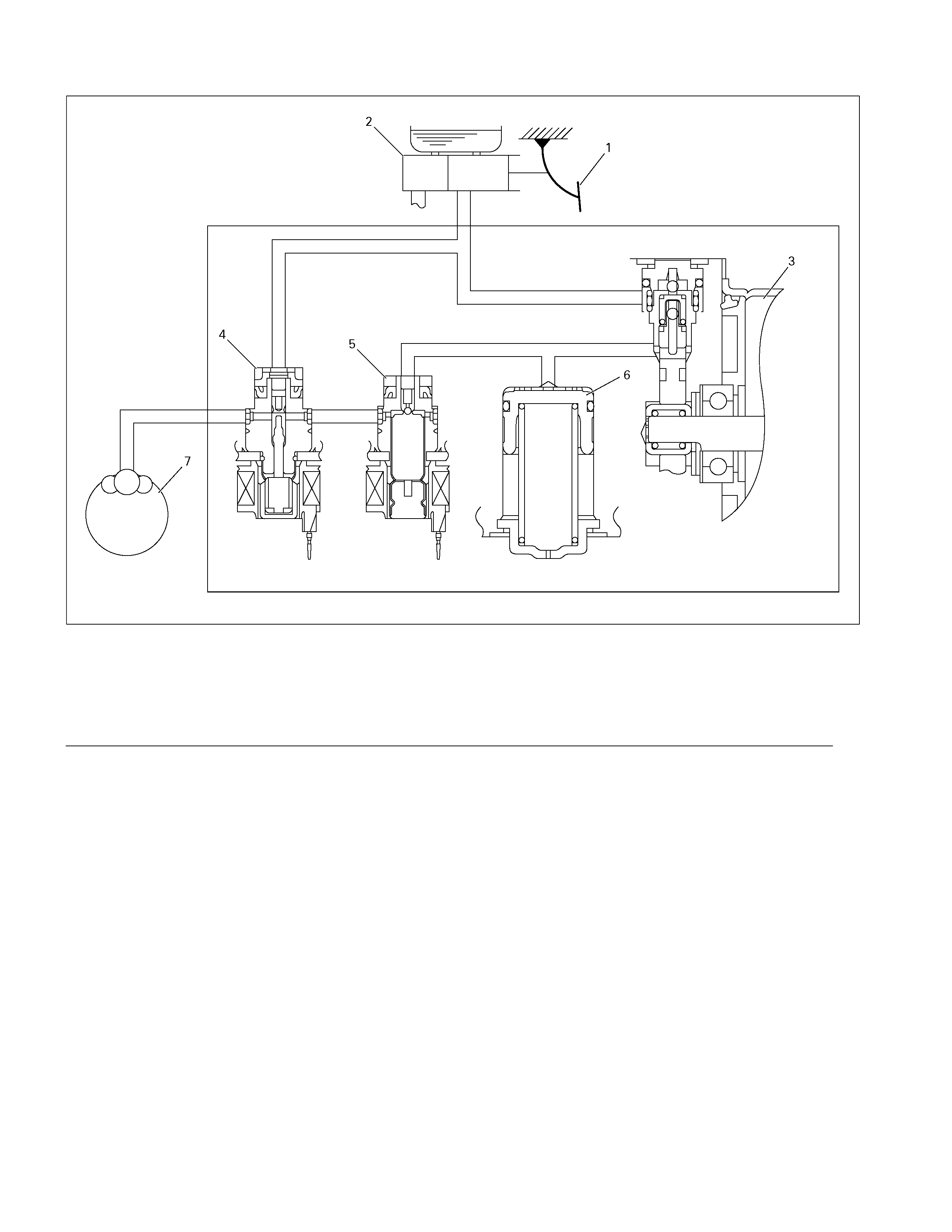
Hydraulic Unit (H/U)
C05L300004
Legend
(1) Brake Pedal (5) Dump Valve
(2) Master Cylinder (6) Buffer Chamber
(3) Motor and Pump (7) Brake Caliper
(4) Isolation Valve
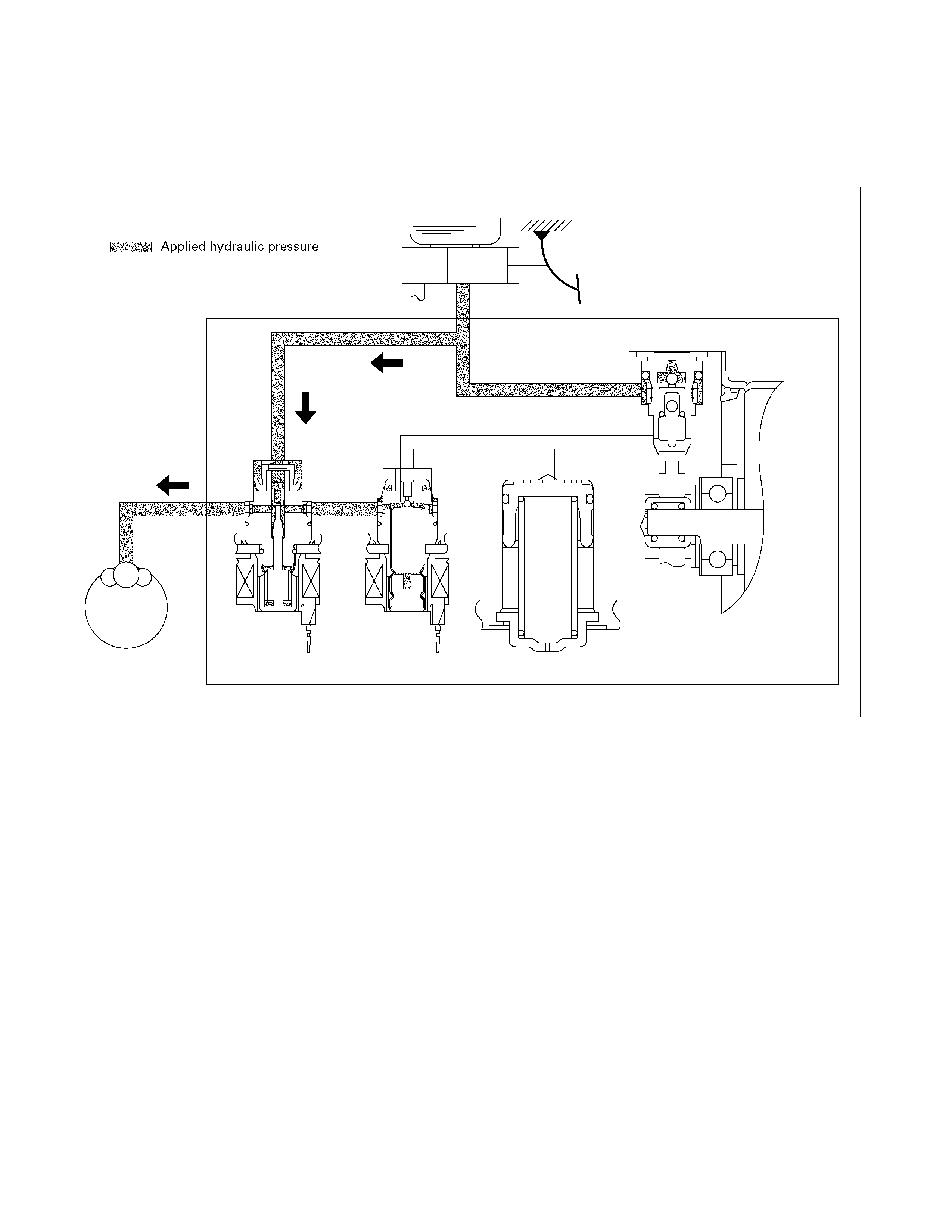
Normal Braking
During normal (non anti-lock) braking, the solenoid valves are de-energised. Spring force keeps the dump valve closed
and the isolation valve open.
Brake fluid travels through the center of the isolation valve (normally open) around the dump valve (normally closed)
then to the brake pistons.
C05L300012
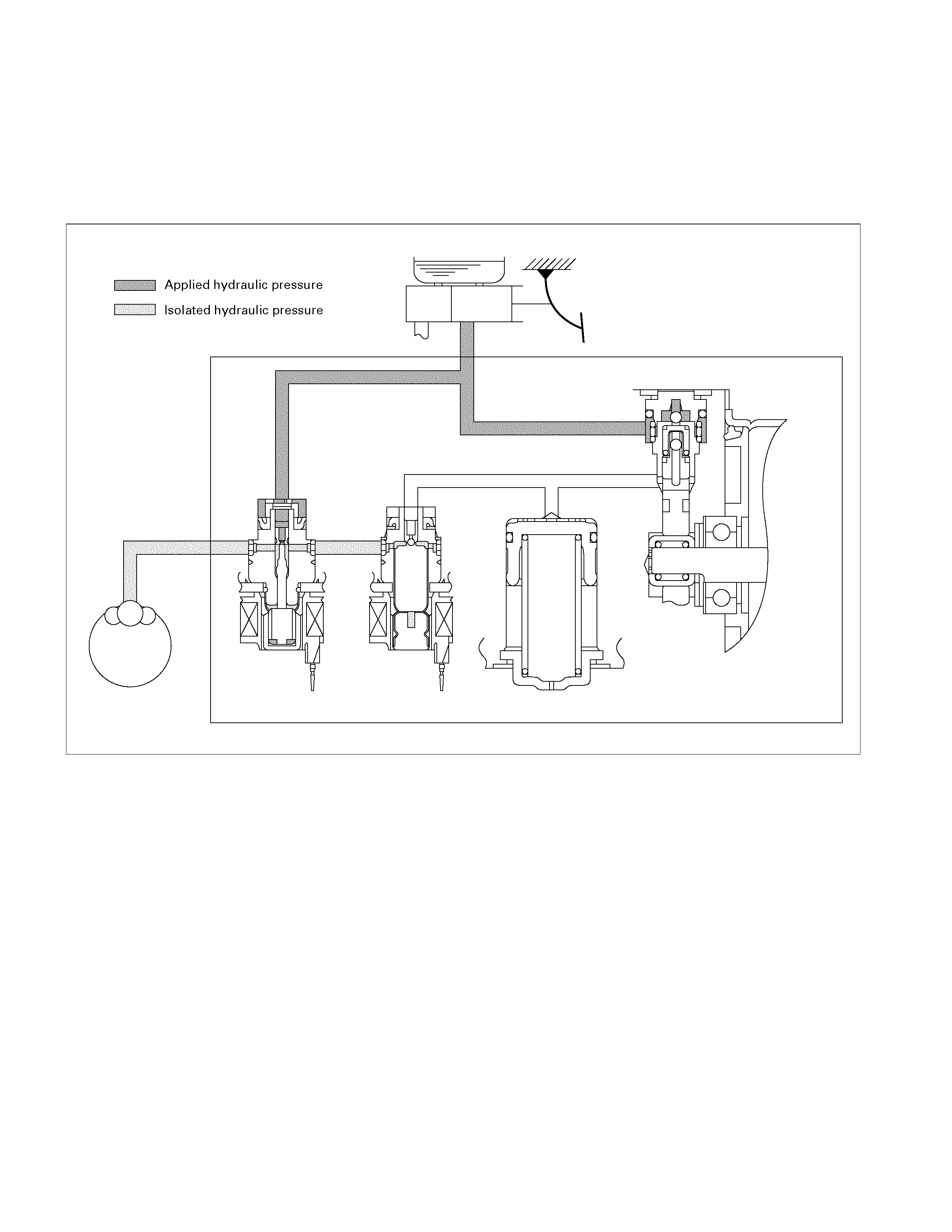
Pressure Isolation (Maintain Pressure)
The electronic-hydraulic control unit is activated when the brakes are applied.
If the information from the wheel speed sensors indicates excessive wheel deceleration (imminent lockup), the first
step in the anti-lock sequence is to isolate the brake pressure being applied by the brake pedal.
The microprocessor in the Control Unit sends a voltage signal to the coil to energise and close the isolation valve. This
effectively isolates the wheel brake unit from the rest of the brake system, preventing any increase in brake application
force.
C05L300013
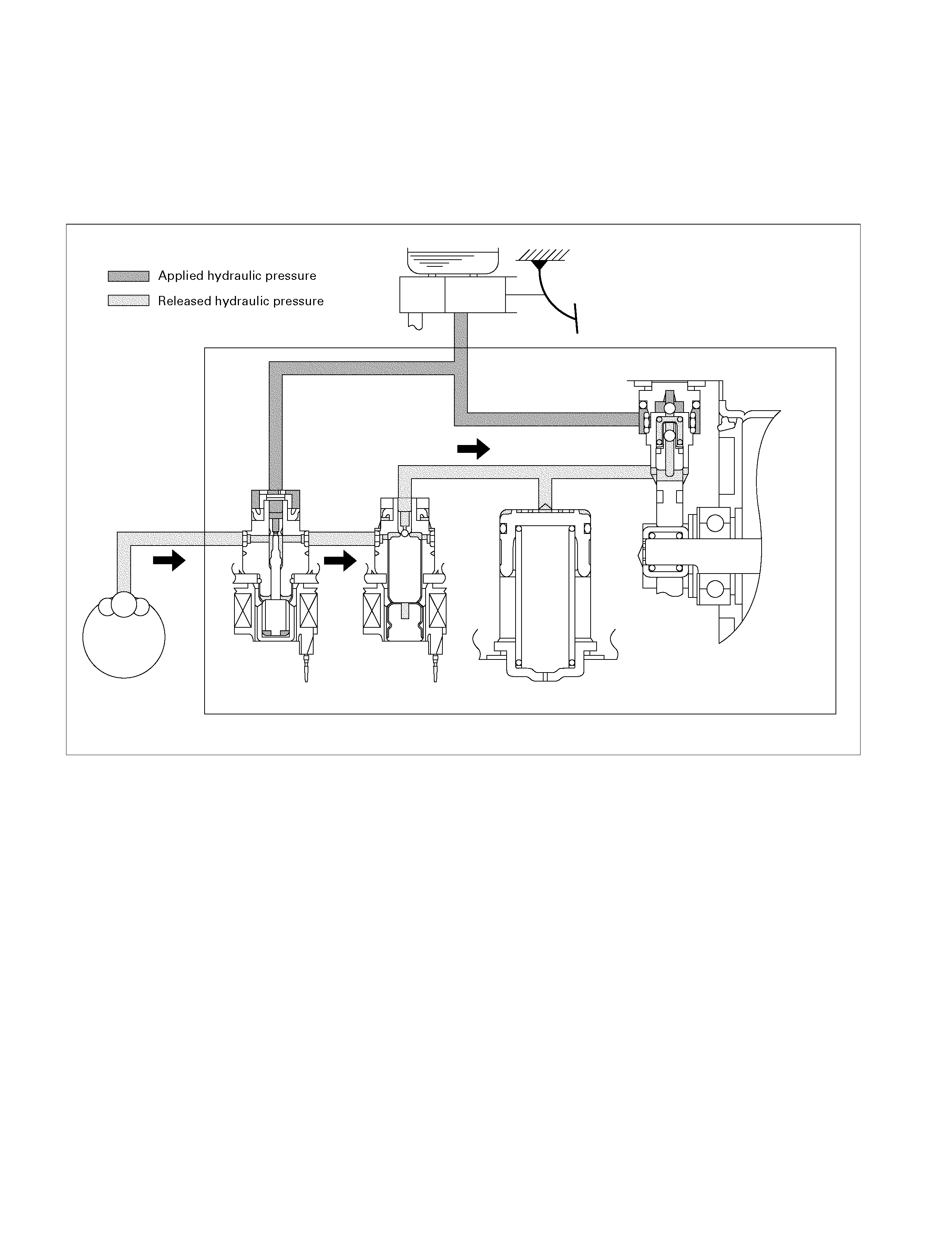
Pressure Reduction
Once the wheel brake unit is isolated, the brake pressure is reduced to allow the wheel speed to increase. This is
accomplished by dumping a portion of the brake fluid pressure into a “buffer” chamber.
The microprocessor energises the normally closed dump valve solenoid, allowing fluid from the wheel to be dumped
into the buffer chamber. This is done with very short activation pulses opening and closing the dump valve
passageway. Brake pressure is reduced at the wheel and allows the wheel to begin rotating again. The fluid from the
brake piston is stored in the buffer chamber against spring pressure and a portion of this fluid also primes the pump.
C05L300014
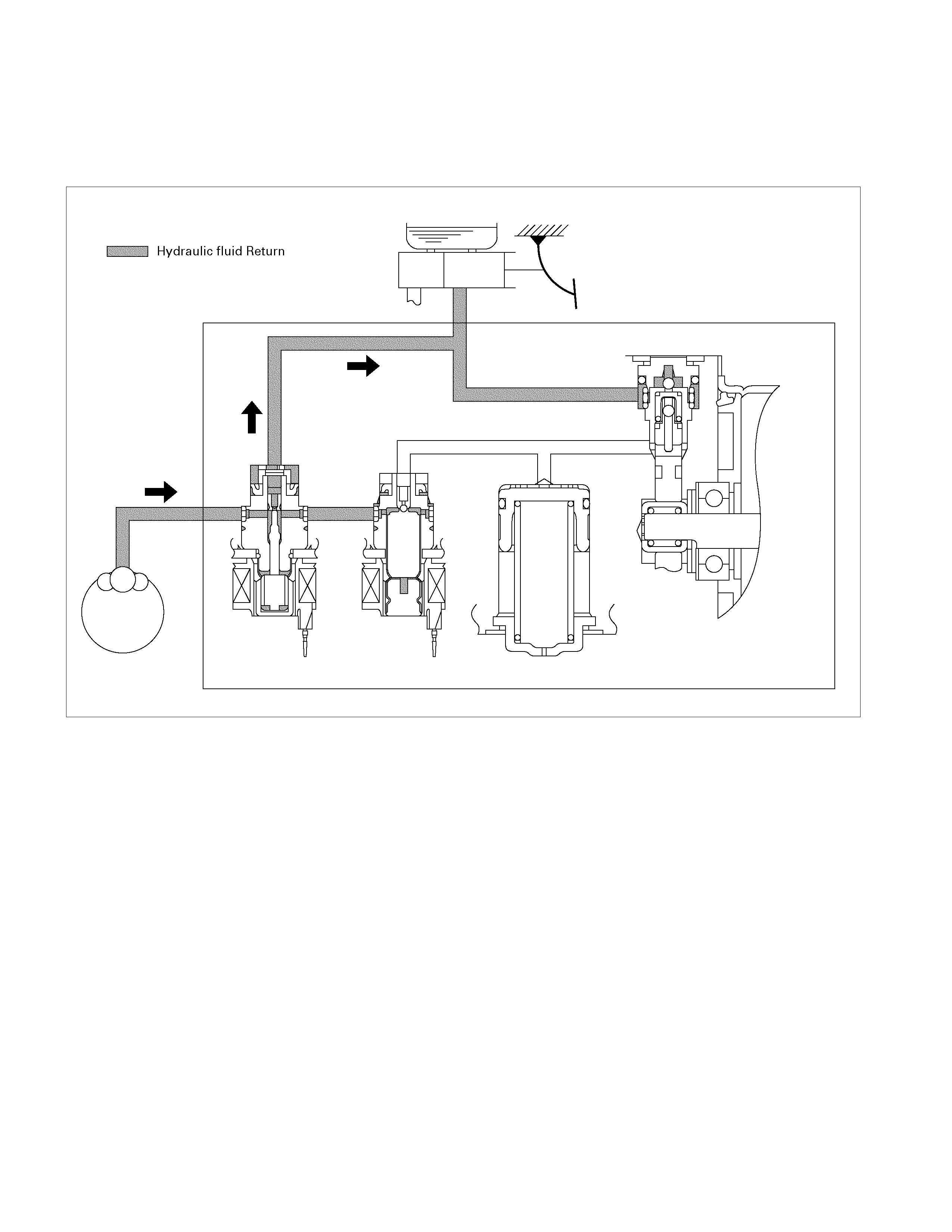
Brake Release
At the end of the anti-lock stop, when the brake pedal is released, the pump will remain running for a short time to help
drain any fluid from the buffer chamber. As this fluid returns into the system, the buffer spring forces the piston back to
its original position.
The isolation valve opens and fluid may return to the master cylinder. Conventional braking is then resumed.
C05L300015
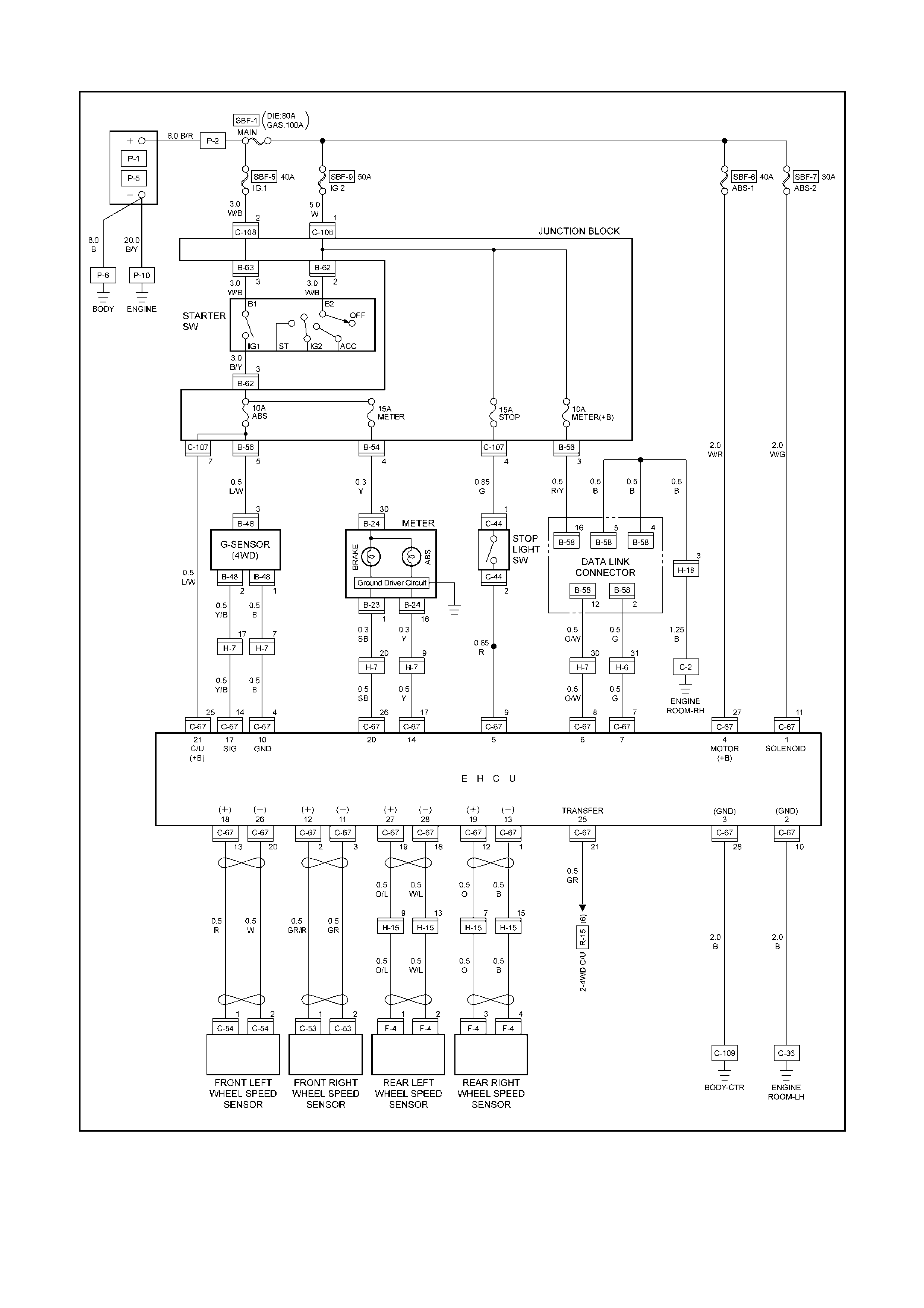
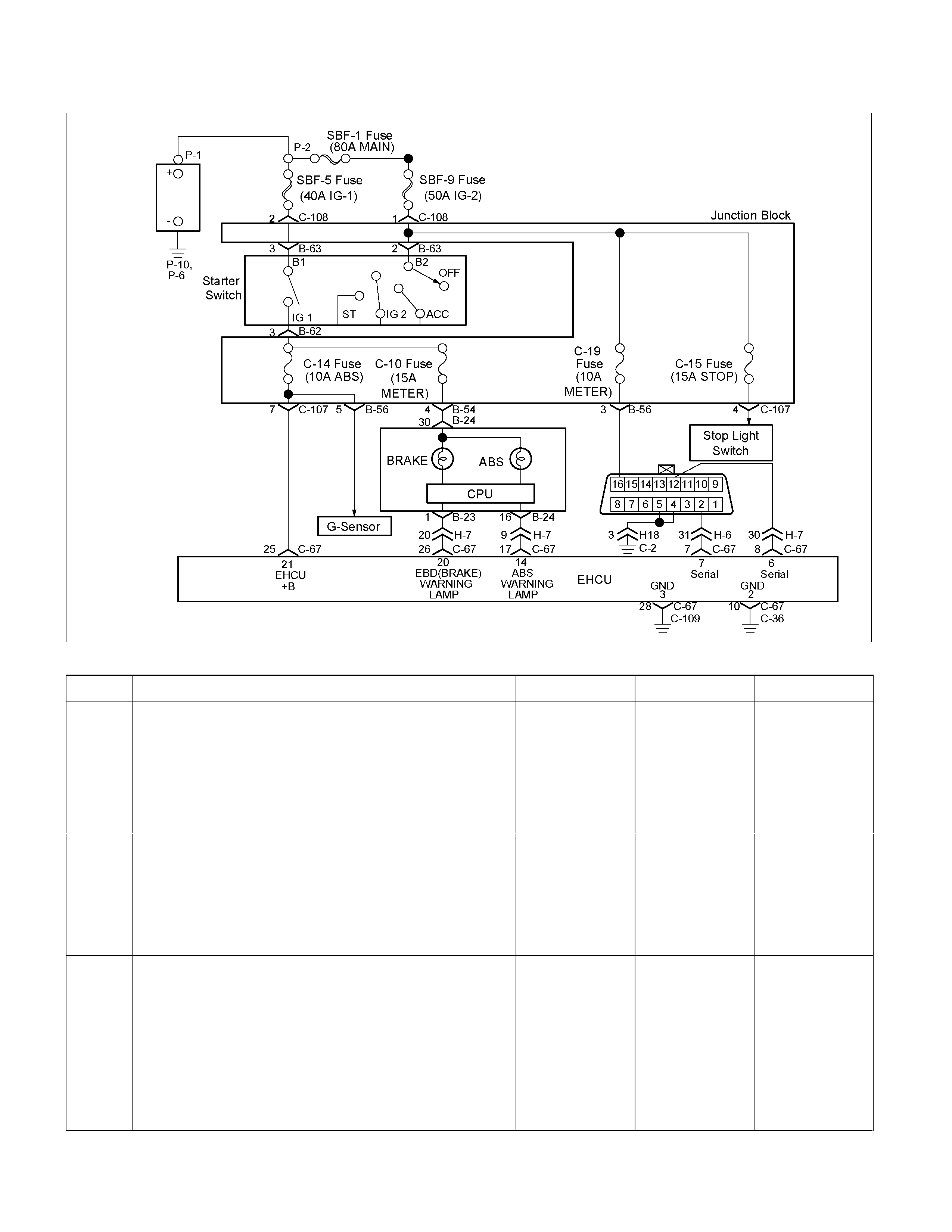
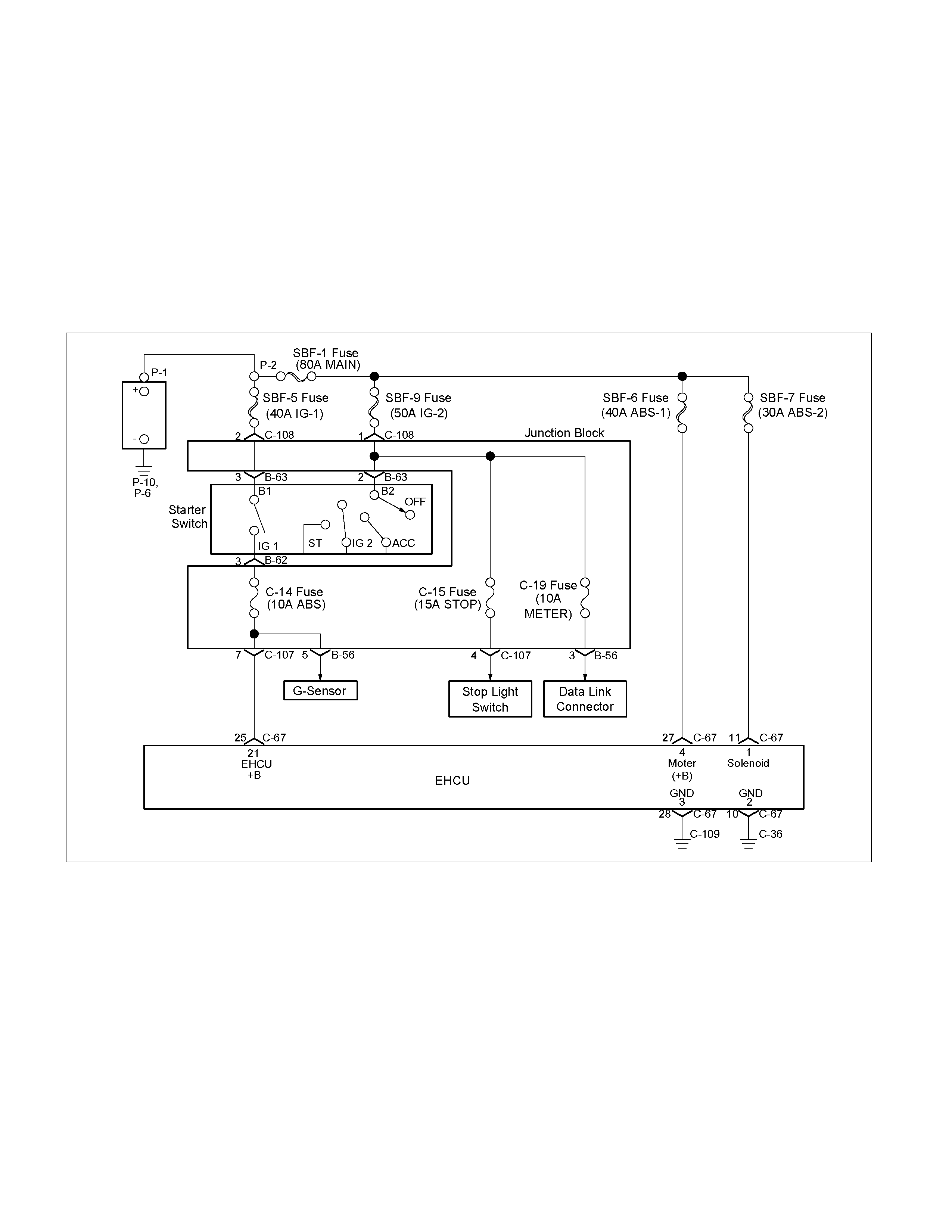
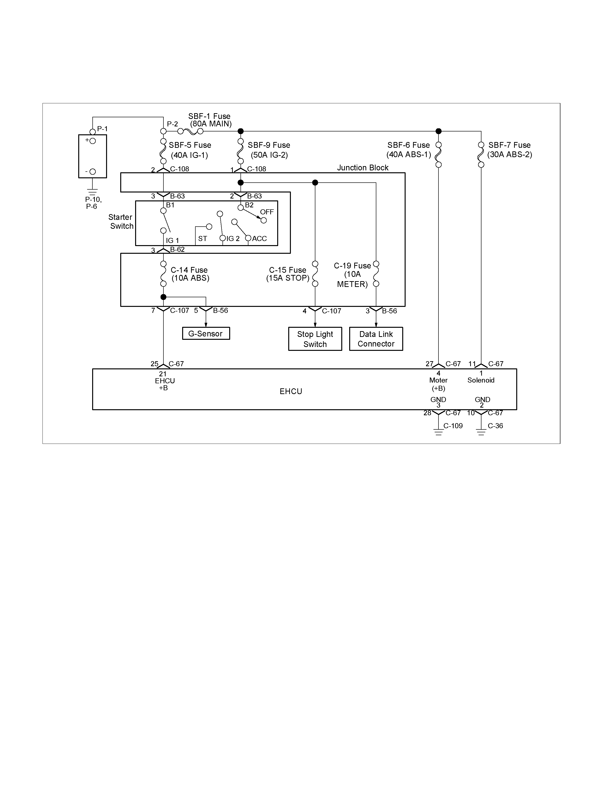
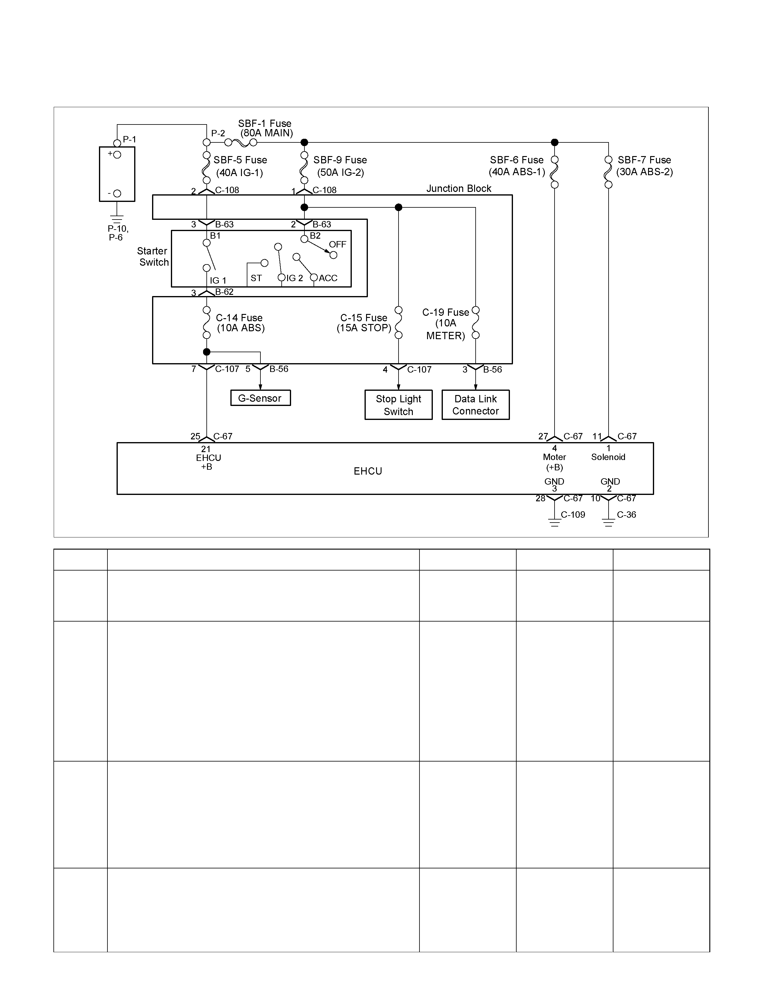
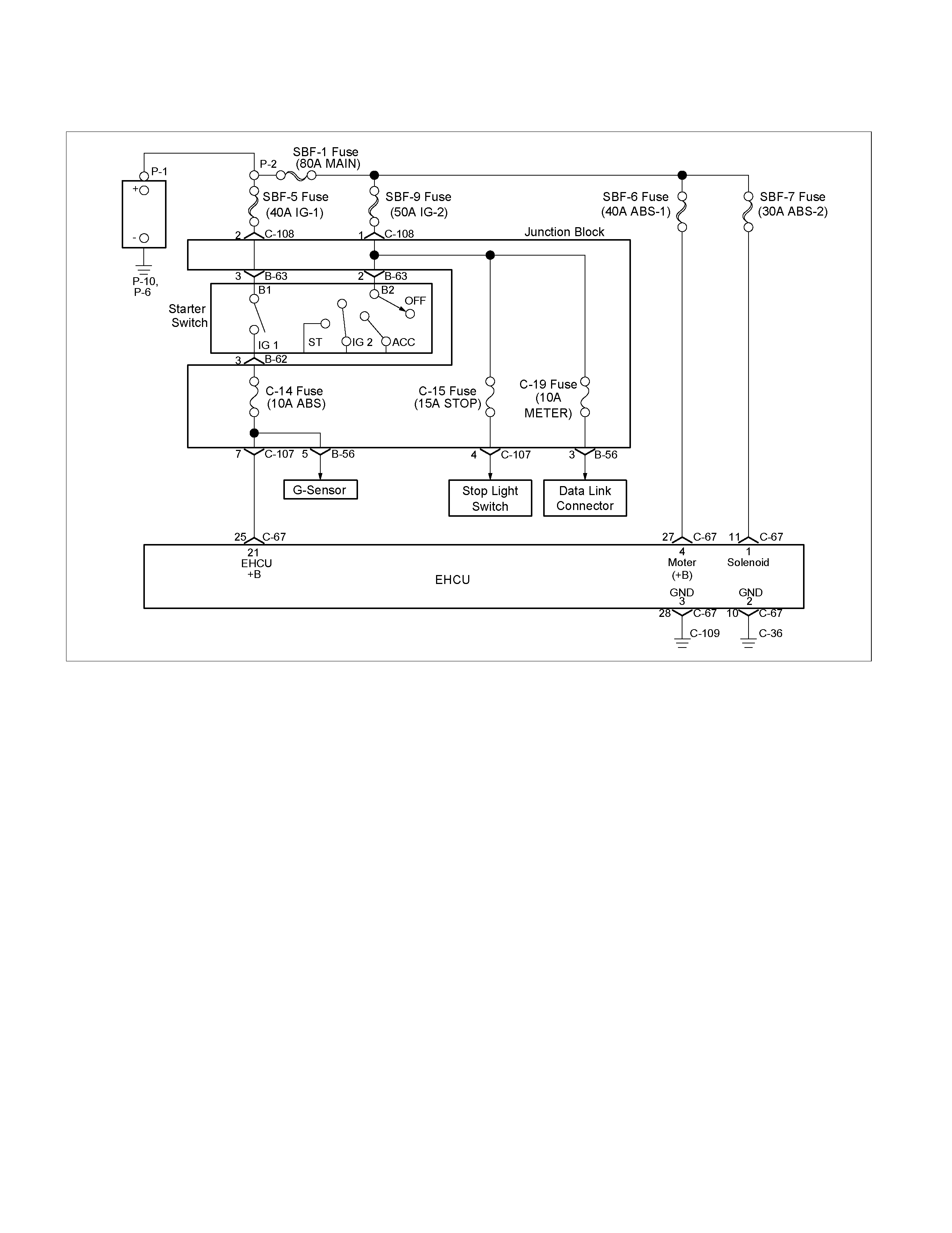
Circuit Diagram
RTW45AXF000101-a
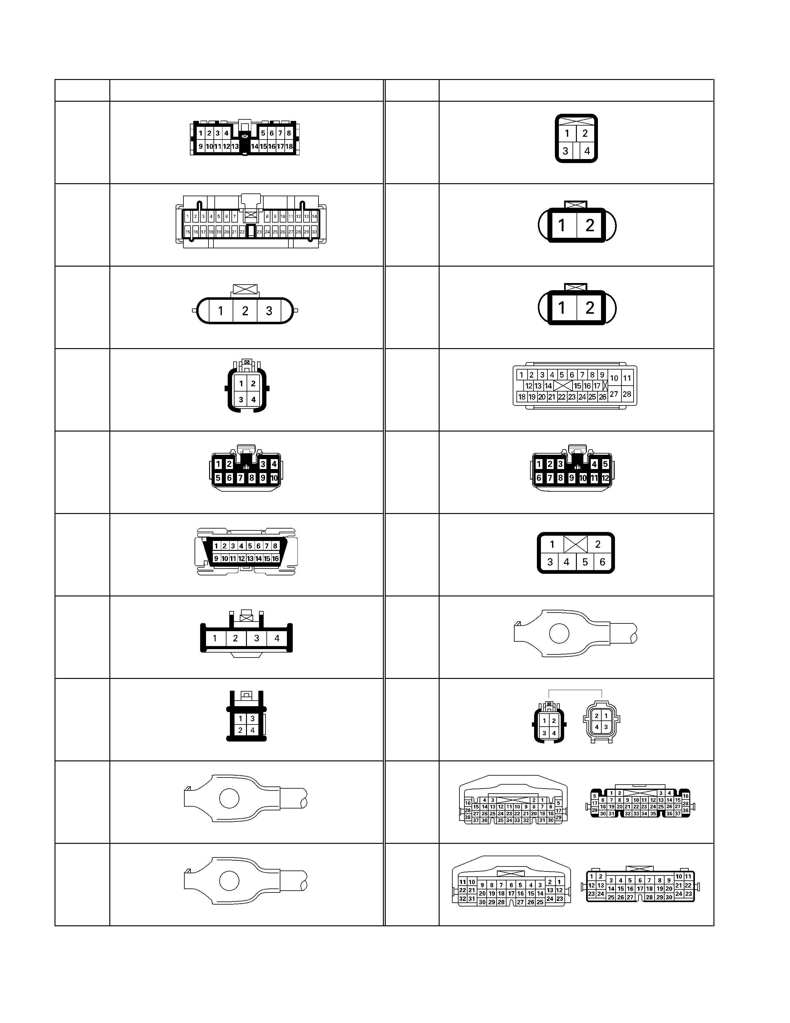
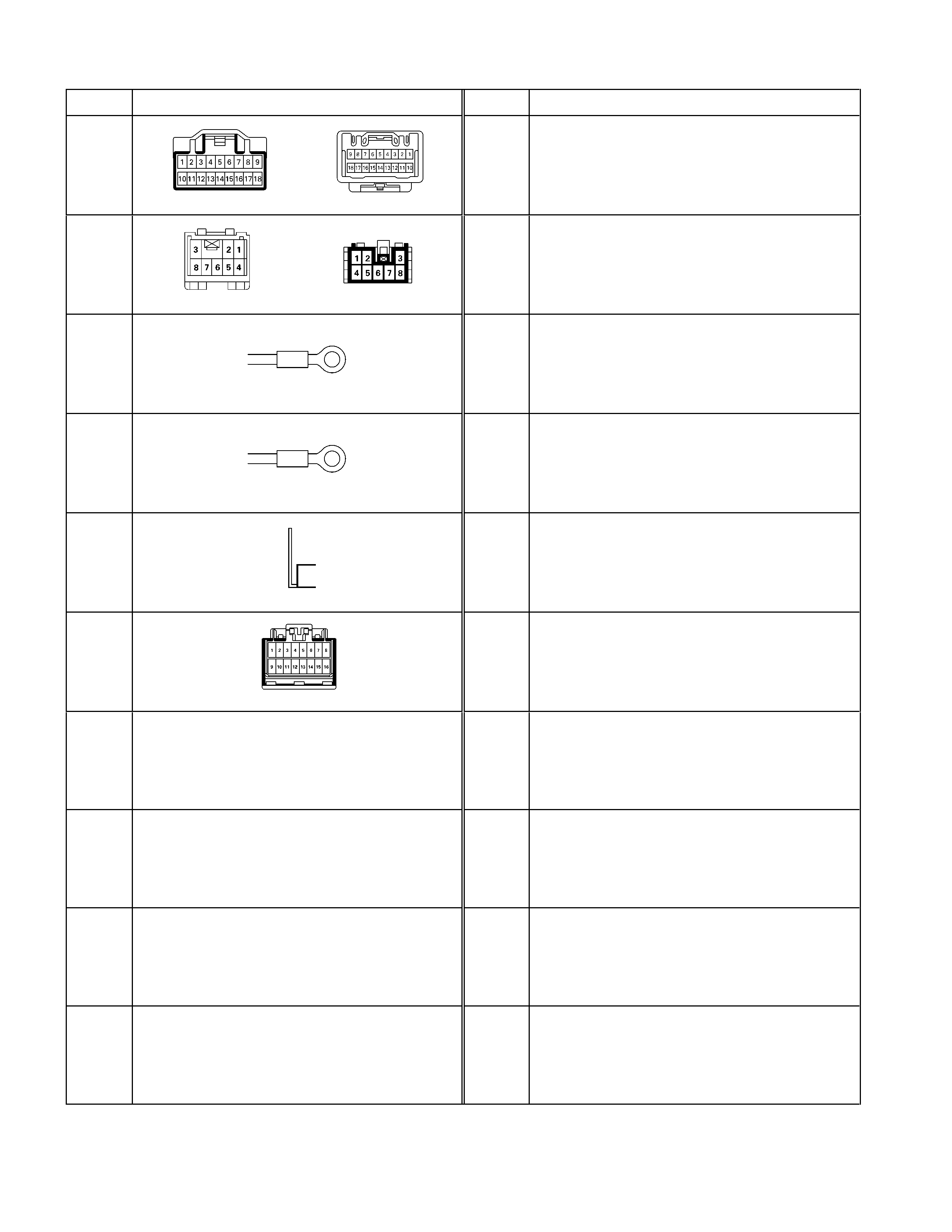
Connector List
No. Connector face No. Connector face
B-23
Green
Meter-A
C-44
White
Stop Light Switch
B-24
Green
Meter-B
C-53
Orange
ABS Sensor Front-RH
B-48
Black
G-sensor
C-54
Orange
ABS Sensor Front-LH
B-54
White
I2
C-67
Black
EHCU
B-56
White
J/B I4
C-107
White
J/B E2
B-58
Black
Data Link Connector
C-108
White
J/B E1
B-62
White
Ignition Switch (IGSUB : G1)
C-109
Silver
Body-LH ; Ground
B-63
White
Ignition Switch (IGSUB : G2)
F-4
Gray
ABS Sensor Rear
C-2
Silver
Engine Room-RH ; ground
H-6
White
Engine Room ~ INST
C-36
Silver
Engine Room-LH ; Ground
H-7
White
Engine Room ~ INST
No. Connector face No. Connector face
H-15
White
Engine Room ~ Chassis
H-18
White
Engine Room ~ INST
P-2
Silver
Relay & Fuse Box
P-6
Silver
Body Earth (Ground)
P-10
Silver
Engine Ground
R-15
Black
2-4WD Control Unit
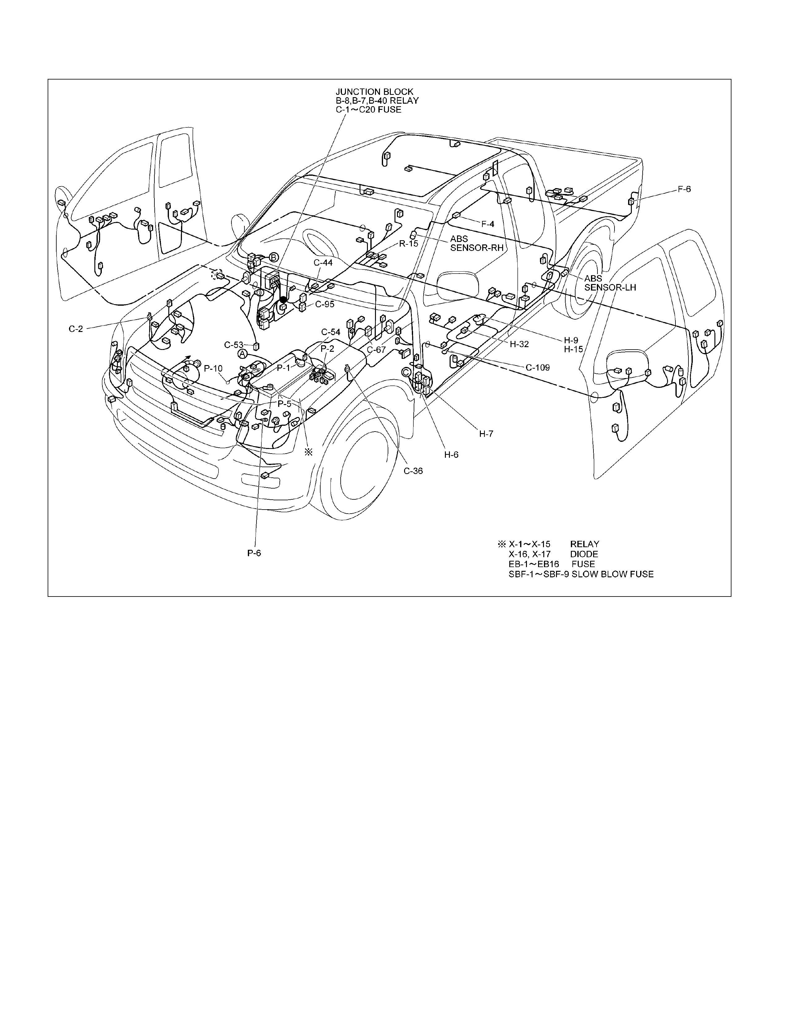
Part Location
RTW48AXF022101A
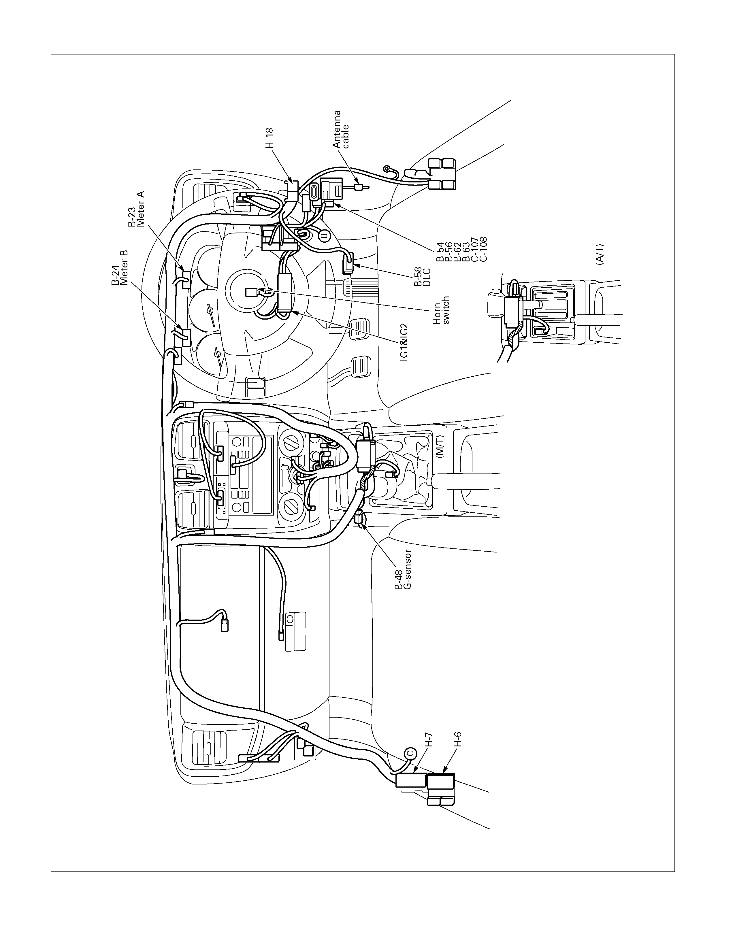
810L300006
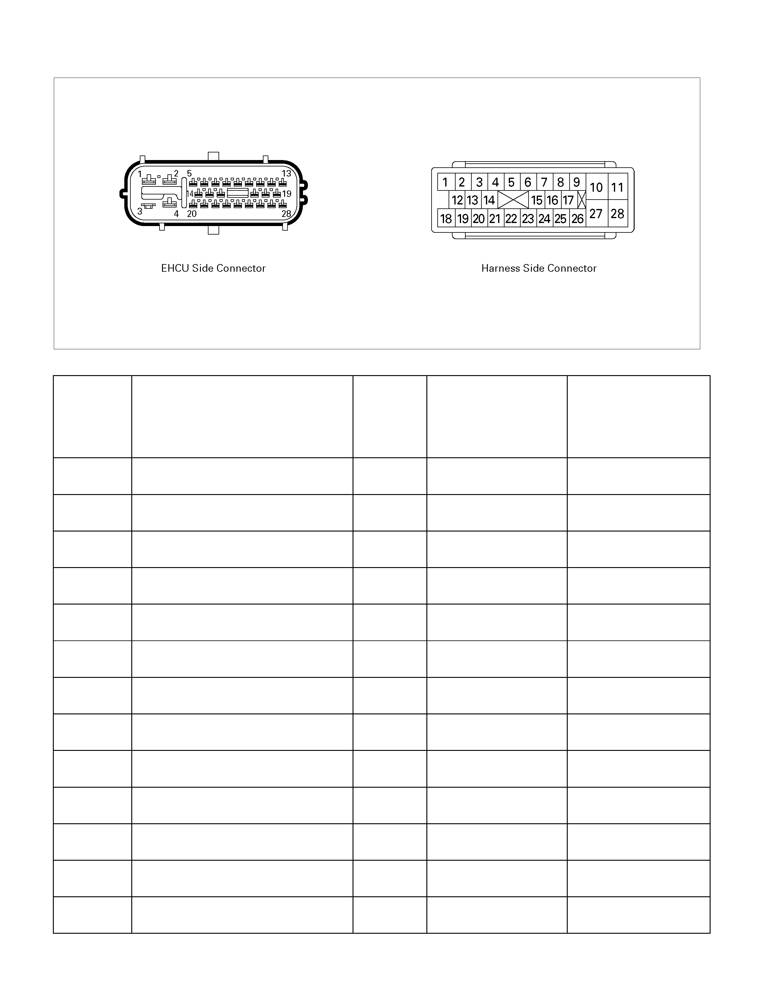
EHCU Pin-outs
C05L300005
EHCU Side
Pin No.
(Harness
side
Pin No.)
Pin Function Wire
Color Typical Value Note
1
(C67-11) Power Supply WHT/GRN Battery Voltage Solenoid
2
(C67-10) Ground 1 BLK 0V
(Less than 0.1V) Solenoid, Control Unit
3
(C67-28) Ground 2 BLK 0V
(Less than 0.1V) Motor
4
(C67-27) Power Supply WHT/RED Battery Voltage Motor
5
(C67-9) Stop Light Switch RED Open : 0V
Close : Battery Voltage Close Condition :
Step on the Brake Pedal
6
(C67-8) Serial ORN/WHT - J1850 Class 2
Communication
7
(C67-7) Serial GRN - J1850 Class 2
Communication
8
(C67-6) Not Used - -
9
(C67-5) Not Used - -
10
(C67-4) G-Sensor Ground BLK 0V
(Less than 0.1V) 4WD Only
DTC C0276, C0285
11
(C67-3) Front Right Wheel Speed Sensor (-) GRY High Level: 1.28~2.28V
Low Level: 0.5~0.86V DTC C0221,C0222,
C0223
12
(C67-2) Front Right Wheel Speed Sensor (+) GRY/RED 12±1.5V DTC C0221,C0222,
C0223
13
(C67-1) Rear Right Wheel Speed Sensor (-) BLK High Level: 1.28~2.28V
Low Level: 0.5~0.86V DTC C0231,C0232,
C0233

EHCU Side
Pin No.
(Harness
side
Pin No.)
Pin Function Wire
Color Typical Value Note
14
(C67-17) ABS Warning Lamp YEL More than 10V
15
(C67-16) Not Used - -
16
(C67-15) Not Used - -
17
(C67-14) G-Sensor Signal YEL/BLK 2.0~3.0V
(MAX4.0V,MIN1.0V) 4WD Only - Check value
with vehicle on level
ground (0G:2.5V)
DTC C0276, C0285
18
(C67-13) Front Left Wheel Speed Sensor (+) RED 12±1.5V DTC C0225, C0226,
C0227
19
(C67-12) Rear Right Wheel Speed Sensor (+) ORN 12±1.5V DTC C0231,C0232,
C0233
20
(C67-26) EBD (Brake) Warning Lamp LT BLU More than 10V
21
(C67-25) Starter Switch ON
(Power Supply and Switch Position) BLU/WHT Battery Voltage Control Unit
DTC C0277,C0278
22
(C67-22) Not Used - -
23
(C67-23) Not Used - -
24
(C67-22) Not Used - -
25
(C67-21) Transfer (2-4WD Control Unit) GRY Pulse Signal
(High 4.5V, Low 1.5V) 4WD Only
DTC C0282
26
(C67-20) Front Left Wheel Speed Sensor (-) WHT High Level: 1.28~2.28V
Low Level: 0.5~0.86V DTC C0225, C0226,
C0227
27
(C67-19) Rear Left Wheel Speed Sensor (+) GRY/BLU 12±1.5V DTC C0235, C0236,
C0237
28
(C67-18) Rear Left Wheel Speed Sensor (-) WHT/BLU High Level: 1.28~2.28V
Low Level: 0.5~0.86V DTC C0235, C0236,
C0237
System Components
Electronic Hydraulic Control Unit (EHCU), four Wheel Speed Sensors, two Warning Lamps, and G-sensor.
Electronic Hydraulic Control Unit (EHCU)
The EHCU consists of ABS control circuits, fault detector, and a fail-safe system. The EHCU controls the motor that
drives the hydraulic unit according to the signal from each wheel speed sensor, cancelling ABS to return to normal
braking when a malfunction has occurred in the ABS.
The EHCU has a self-diagnostic function to aid the Technician during fault diagnosis.
The EHCU is mounted on the engine compartment rear left side. It consists of a motor, solenoid valves and a fail-safe
relay.
Solenoid Valves: Reduce or hold the caliper fluid pressure for each front brake or both rear brakes according to the
signal sent from the EHCU.
Buffer chamber: Temporarily holds the brake fluid that returns from the front and rear brake so that pressure of front
brake can be reduced smoothly.
Motor: Drives the pump according to the signal from EHCU.
Fail-safe Relay: When failure occurs in ABS, the relay will cut the power to the solenoid valves.
NOTE:
THE ELECTRONIC HYDRAULIC CONTROL UNIT (EHCU) IS SERVICED AS A COMPLETE UNIT. NO ATTEMPT
SHOULD BE MADE TO SEPARATE THE CONTROL UNIT FROM THE HYDRAULIC UNIT
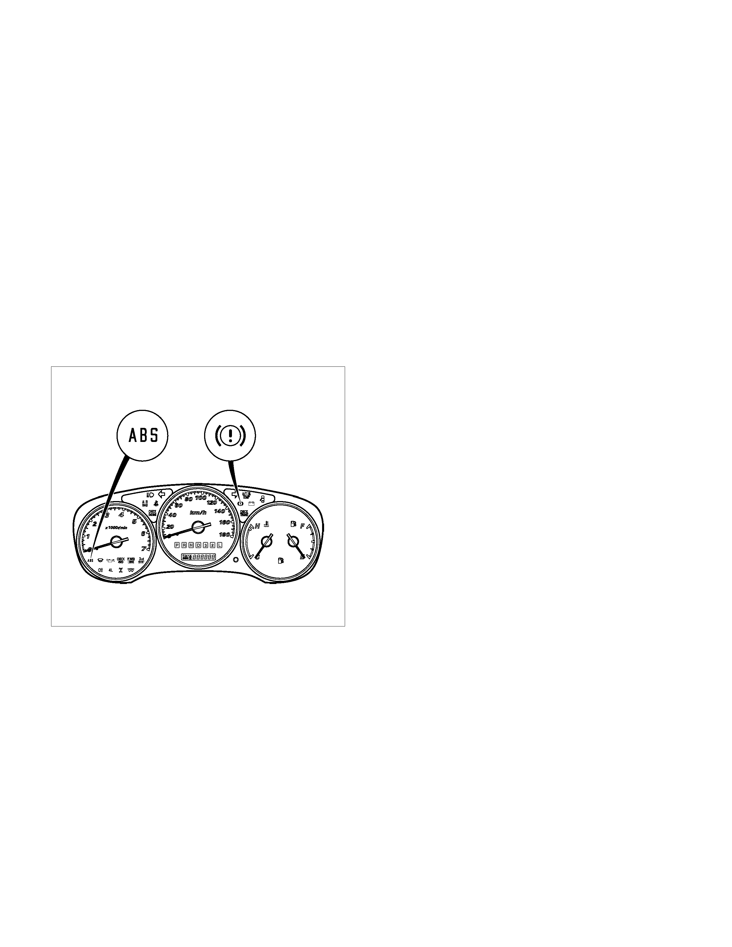
ABS Warning Lamp
825L300001
Vehicles equipped with the Anti-lock Brake System have an amber “ABS” warning lamp in the instrument panel. The
“ABS” warning lamp will illuminate if a malfunction in the Anti-lock Brake System is detected
by the Electronic Hydraulic Control Unit (EHCU).
In case of an electronic malfunction, the EHCU will turn “ON” the “ABS” warning lamp and disable the anti-lock braking
function.
The “ABS” warning lamp will turn “ON” for approximately three seconds after the ignition switch is turned to the “ON”
position.
If the “ABS” warning lamp stays “ON” for longer than three seconds after the ignition switch is turned to the “ON”
position, or comes “ON” and stays “ON” while driving, the Anti-lock Brake System should be inspected for a
malfunction according to the diagnosis procedure.
Wheel Speed Sensor (WSS)
It consists of a sensor and a rotor. The sensor is attached to the knuckle on the front wheels and to the rear wheels.
The rotor is press-fit in the axle shaft.
G-Sensor
The G-sensor detects the vehicle deceleration speed and sends a signal to the EHCU. In 4WD operation, all four
wheels may be decelerated in almost the same phase, since all wheels are connected mechanically.
This tendency is noticeable particularly on roads with low friction coefficient, and the ABS control is adversely affected.
The G-sensor judges whether the friction coefficient of road surface is low or high, and changes the EHCU's operating
system to ensure ABS and EBD control.
Normal and Anti-lock Braking
Under normal driving conditions, the Anti-lock Brake System functions the same as a standard power assisted brake
system. However, with the detection of wheel lock-up, a slight bump or kick-back will be felt in the brake pedal. This
pedal “bump” will be followed by a series of short pedal pulsations which occurs in rapid succession. The brake pedal
pulsation will continue until there is no longer a need for the anti-lock function or until the vehicle is stopped. A slight
ticking or popping noise may be heard during brake applications when the anti-lock feature is being used.
When the anti-lock feature is being used, the brake pedal may rise even as the brakes are being applied. This is also
normal. Maintaining a constant force on the pedal will provide the shortest stopping distance.
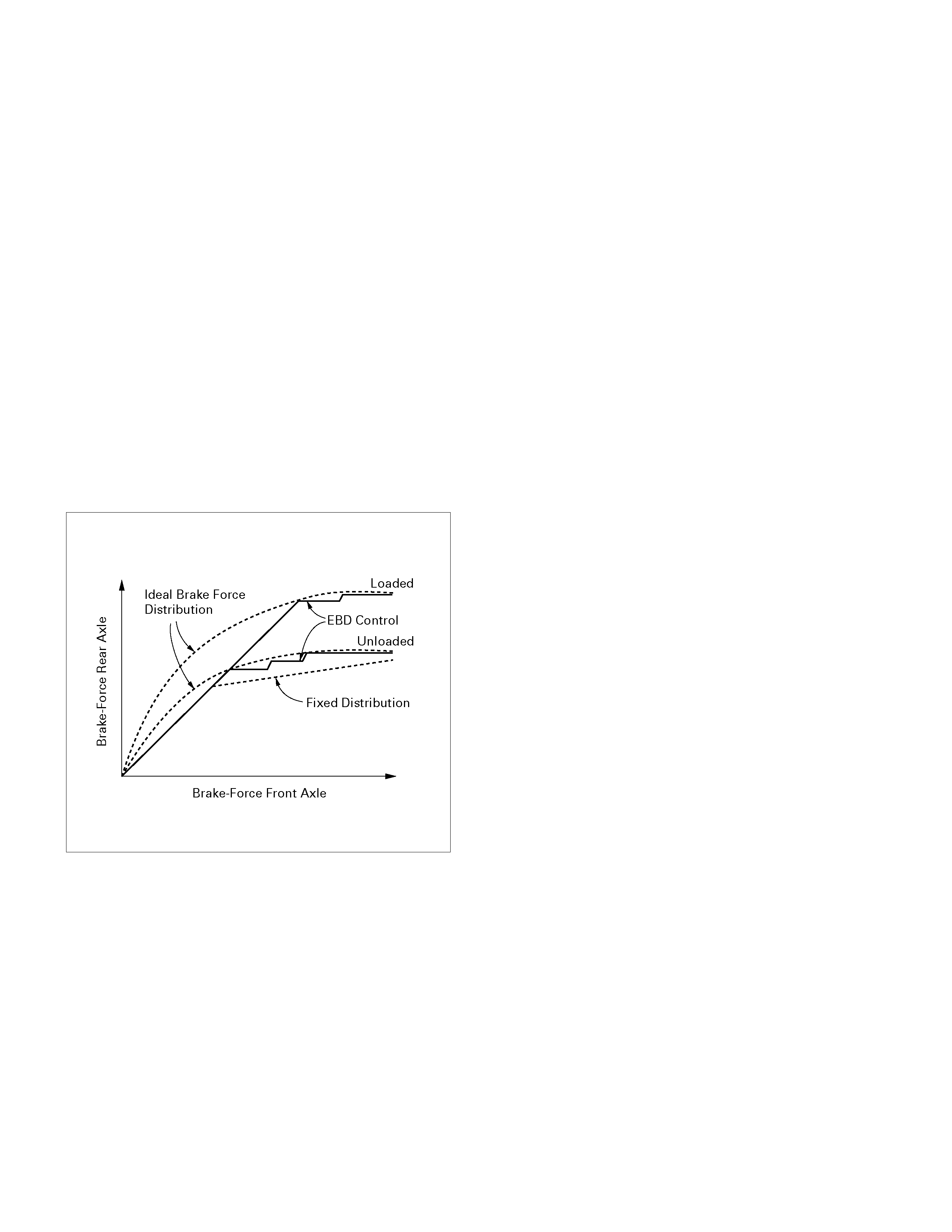
Electronic Brake-force Distribution (EBD) System
ABS has the EBD function. EBD is a function, which controls braking force distribution of a front wheel and a rear
wheel, and makes brake fluid pressure of a rear wheel the optimal. If the rate of a slip of a rear wheel becomes large
more than fixed compared with a front wheel about the rate of a slip in order to perform braking force distribution of a
front wheel and a rear wheel, the brake fluid pressure of a rear wheel will be controlled. EBD enables it to always
utilize the braking power of a rear wheel for the maximum according to the load change concerning the back axis by
vehicles loading states (No luggage, loading, etc.), deceleration, etc. Brake fluid pressure control to a rear wheel is
performed by the EBD function, which uses the ABS function without the mechanical proportioning valve.
C05L300016
Brake Pedal Travel
Vehicles equipped with the Anti-lock Brake System may be stopped by applying normal force to the brake pedal.
Although there is no need to push the pedal beyond the point where it stops or holds the vehicle, by applying more
force the pedal will continue to travel toward the floor.
This extra brake pedal travel is normal.
Acronyms and Abbreviations
Several acronyms and abbreviations are commonly used throughout this section:
ABS
Anti-lock Brake System
CKT
Circuit
DLC
Data Link Connector
EBD
Electronic Brake-force Distribution

EHCU
Electronic Hydraulic Control Unit
FL
Front Left
FR
Front Right
GEN
Generator
H/U
Hydraulic Unit
MV
Millivolts
RR
Rear
RPS
Revolution per Second
VDC
DC Volts
VAC
AC Volts
W/L
Warning Lamp
WSS
Wheel Speed Sensor

General Diagnosis
General Information
ABS failures can be classified into two types, those which can be detected by the ABS warning lamp and those which
can be detected as a vehicle abnormality by the driver.
In either case, locate the fault in accordance with the “BASIC DIAGNOSTIC FLOWCHART” and repair.
Please refer to Section 5C for the diagnosis of mechanical troubles such as brake noise, brake judder (brake pedal or
vehicle vibration felt when braking), uneven braking, and parking brake trouble.
ABS Service Precautions
Required Tools and Items:
• Box Wrench
• Brake Fluid
• Special Tool (Some diagnosis procedures in this section require the installation of a special tool)
• 5-8840-0366-0 High Impedance Multimeter -When circuit measurements are requested, use a circuit tester with
high impedance.
Computer System Service Precautions
The Anti-lock Brake System and Electronic Brake-force Distribution interfaces directly with the Electronic Hydraulic
Control Unit (EHCU) which is a control computer that is similar in some regards to the Engine Control Module. These
modules are designed to withstand normal current draws associated with vehicle operation. However, care must be
taken to avoid overloading any of the EHCU circuits. In testing for opens or shorts, do not ground or apply voltage to
any of the circuits unless instructed to do so by the appropriate diagnostic procedure. These circuits should only be
tested with a high impedance multimeter 5-8840-0366-0 or special tools as described in this section. Power should
never be removed or applied to any control module with the ignition in the “ON” position. Before removing or
connecting battery cables, fuses or connectors, always turn the ignition switch to the “OFF” position.
General Service Precautions
The following are general precautions that should be observed when servicing and diagnosing the Anti-lock Brake
System and/or other vehicle systems. Failure to observe these precautions may result in Anti-lock Brake System and
Electronic Brake-force Distribution damage.
• If welding work is to be performed on the vehicle using an electric arc welder, the EHCU and valve block
connectors should be disconnected before the welding operation begins.
• The EHCU and valve block connectors should never be connected or disconnected with the ignition “ON”.
Note:
• If only rear wheels are rotated using jacks or drum tester, the system will diagnose a speed sensor malfunction
and the “ABS and Brake” warning lamp will illuminate. But actually no fault exists. When the DTC is not detected
and the ABS and BRAKE warning lamp is on, “Erase DTC procedure” is performed and ABS and BRAKE
warning lamps will then be extinguished.
If The Battery Has Been Discharged
The engine may stall if the battery has been completely discharged and the engine is started via jumper cables. This
is because the Anti-lock Brake System (ABS) and Electronic Brake-force Distribution (EBD) System requires a large
quantity of electricity. In this case, wait until the battery is recharged, or set the ABS and EBD to a non-operative state
by removing the fuse for the ABS. After the battery has been recharged, stop the engine and install the ABS fuse. Start
the engine again, and confirm that the ABS warning Lamp does not light.

Note on Intermittent Faults
As with virtually any electronic system, it is difficult to identify an intermittent failure. In such a case duplicating the
system malfunction during a test drive or a good description of vehicle behavior from the customer may be helpful in
locating a “most likely” failed component or circuit. The symptom diagnosis chart may also be useful in isolating the
failure. Most intermittent problems are caused by faulty electrical connections or wiring. When an intermittent failure is
encountered, check suspect circuits for:
• Suspected harness damage.
• Poor mating of connector halves or terminals not fully seated in the connector body (backed out).
• Improperly formed or damaged terminals.
Test Driving ABS Complaint Vehicles
In case that there has been an abnormality in the lighting pattern of the “ABS” warning lamp, the fault can be located in
accordance with the “DIAGNOSIS BY “ABS” WARNING LAMP ILLUMINATION PATTERN”. It is necessary to test
drive the vehicle following the test procedure mentioned below, in order to reproduce the symptom for fault diagnosis:
1. Start the engine and make sure that the “ABS” warning lamp goes OFF. If the warning lamp remains ON, it
means that the Diagnostic Trouble Code (DTC) is stored. Therefore, read the code and locate the fault.
Note: After initiating the DTC clearing procedure with Tech 2, the vehicle must be driven in excess of 6km/h (4mph) to
finally clear the DTC and extinguish the “ABS” warning lamp.
2. Start the vehicle and accelerate to about 30 km/h (19 mph) or more.
3. Slowly brake and stop the vehicle completely.
4. Then restart the vehicle and accelerate to about 40 km/h (25 mph) or more.
5. Brake with sufficient pedal force so as to actuate the ABS and stop the vehicle.
6. Be cautious of abnormality during the road test. If the warning lamp is actuated while driving, read the DTC and
locate the fault.
7. If the abnormality cannot be reproduced by the test drive, endeavour to reproduce the situation reported by the
customer.
8. If the abnormality has been detected, repair in accordance with the “SYMPTOM DIAGNOSIS” .
Note:
• Be sure to carryout the test drive on a wide, even road with little or no other traffic.
• If an abnormality is detected, immediately suspend the road test and commence fault diagnosis as soon as
practicable.
“ABS” Warning Lamp
Normal operation:
The “ABS” warning lamp will illuminate for about three seconds when the ignition is first turned ON, while the system
performs a self test.
Upon satisfactory completion of the self test, the “ABS” warning lamp will be extinguished. The “ABS” warning lamp
should remain OFF at all other times.
Fault detected:
Should a fault be detected during a self test, or an “ABS” failure occur whilst driving, the EHCU will illuminate the “ABS”
warning lamp and log the appropriate Diagnostic Trouble Code (DTC).
While the “ABS” lamp is illuminated, the anti-lock braking system is disabled, although power assisted braking is still
available.
Should on the next ignition cycle, the EHCU determine the fault is no longer present, the “ABS” warning lamp will
extinguish after the self test, but the DTC will remain in the EHCU memory until cleared by Tech 2.
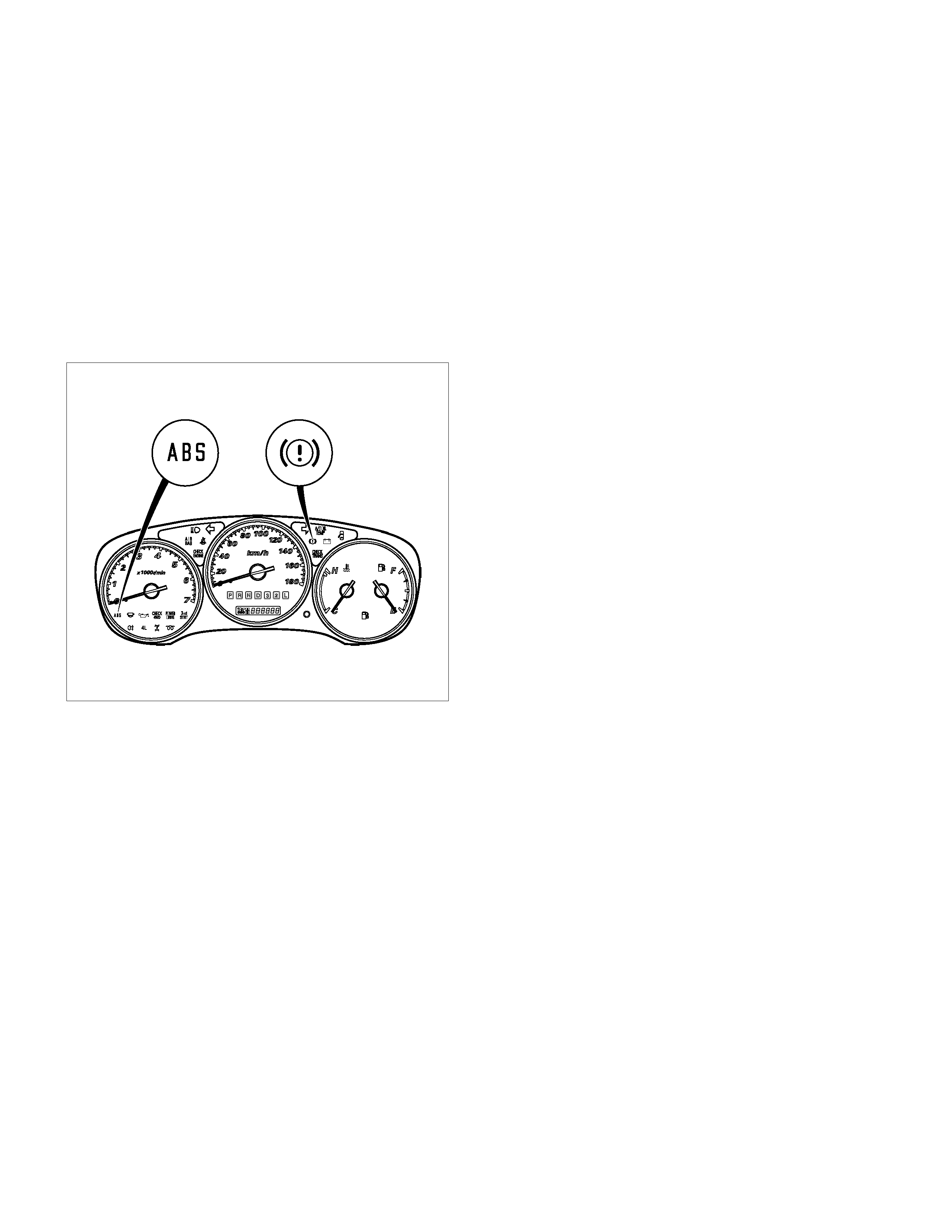
Brake (EBD) Warning Lamp
825L300001
Vehicles equipped with the EBD (Electronic Brake-force Distribution) System have a “Brake” warning lamp in the
instrument panel.
If both the ABS warning lamp and Brake warning lamp are illuminated during normal driving, then EBD system has
failed. (Parking brake switch is "OFF")
Under the following conditions, EBD warning lamp is "ON".
• Starter switch is "ON", engine "OFF".
( Parking brake switch is "OFF")
If engine is started, then EBD warning lamp is "OFF". ( Parking brake switch is "OFF")
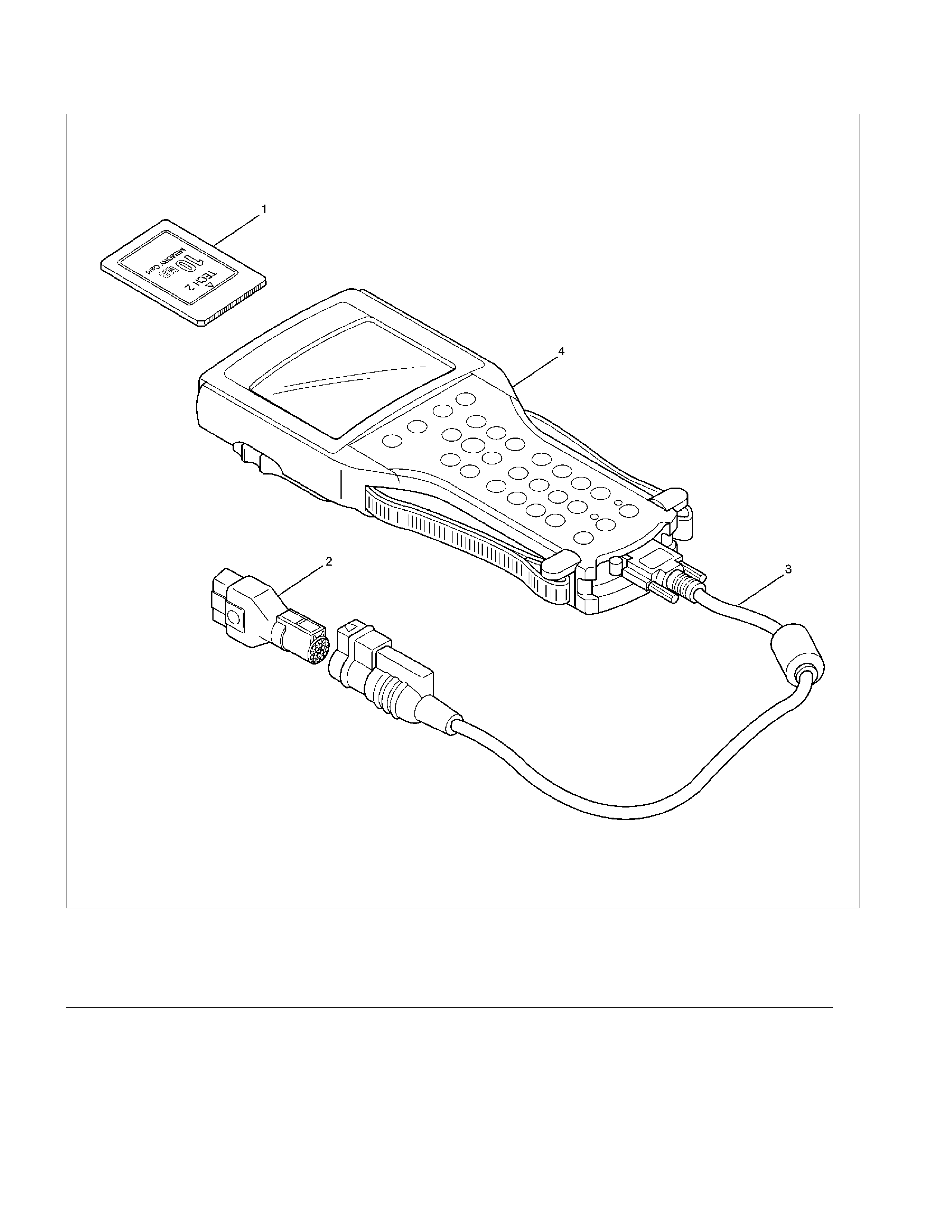
Tech 2 Scan Tool
901RW257
Legend
(1) PCMCIA Card (4) Tech–2
(2) SAE 16/19 Adaptor
(3) DLC Cable
Getting Started
• Before operating the Tech 2, the following steps
must be performed:
1. Insert the Holden LCV PCMCIA card into the
Tech 2.
2. Connect the SAE 16/19 adapter to the DLC
cable.
3. Connect the DLC cable to the Tech 2.
4. Ensure the vehicle ignition is ‘OFF’.
5. Connect the Tech 2 SAE 16/19 adapter to the
vehicle DLC.
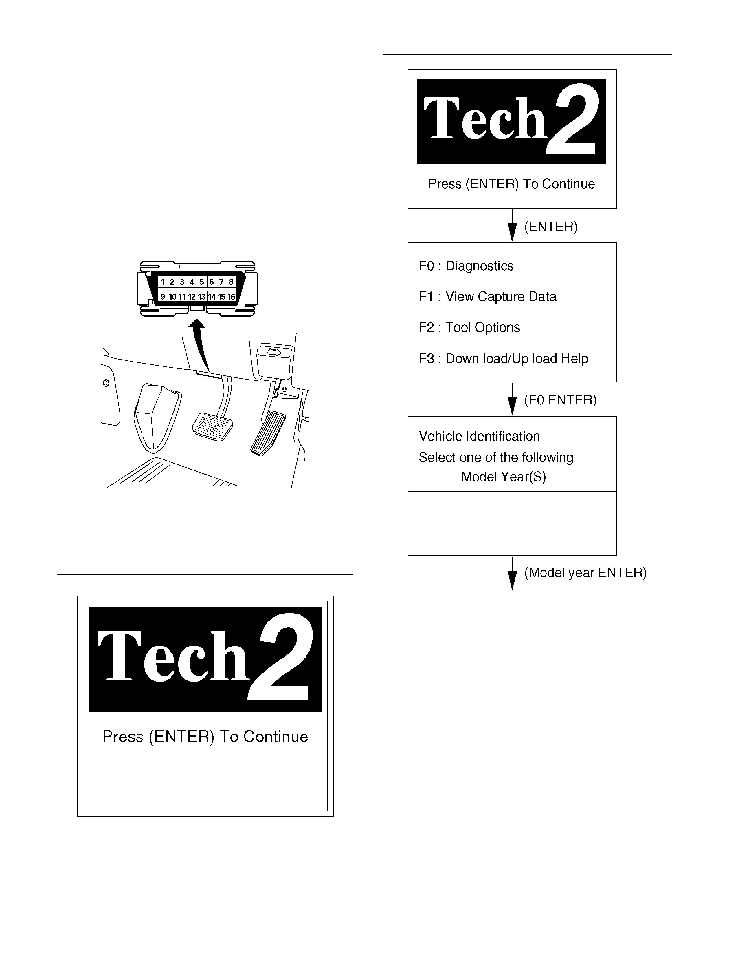
060R300015
6. Turn the ignition ‘ON’.
7. Power up the Tech 2.
8. Verify the Tech 2 Power-up display.
060RW0009
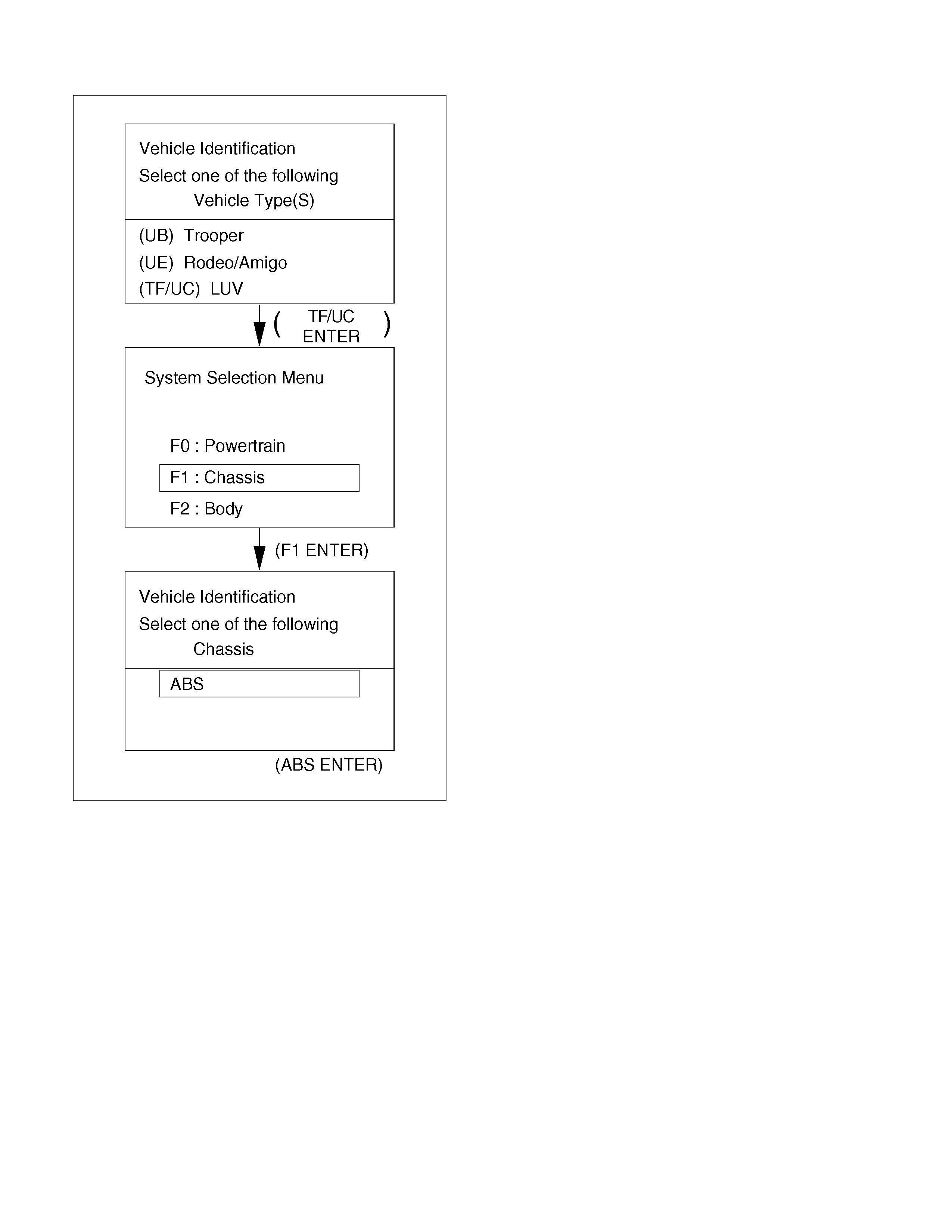
Operating Procedure
The Power-up screen is displayed when you power
up the tester with the Holden LCV PCMCIA card.
Follow the operating procedure below.
060R100102
060L300001
DATA LIST (Tech 2)
The data displayed by DATA LIST are as follows:
Strings Units Description 2WD 4WD
Front Left Wheel Speed km/h (MPH)
Front Right Wheel Speed km/h (MPH)
Rear Left Wheel Speed km/h (MPH)
Rear Right Wheel Speed km/h (MPH)
Start the vehicle and make sure of linear
change in each wheel speed
Brake Switch Open/Closed Brake switch is “closed” when foot brake is
applied.
ABS Warning Lamp On/Off Normally “Off”
EBD Warning Lamp On/Off Normally “Off”
ABS Stop State On/Off Normally “Off”
ABS Relay Active/Inactive Normally “Active”
Return Pump Active/Inactive Normally “Inactive”
DTC Status No DTC Normally “No DTC”
4 Wheel Drive Status Yes/No Normally “Yes” -
FL Dump Valve Commanded
(Front Left) Active/Inactive
FL Isolation Valve Commanded
(Front Left) Active/Inactive
FR Dump Valve Commanded
(Front Right) Active/Inactive
FR Isolation Valve Commanded
(Front Right) Active/Inactive
Rear Dump Valve Commanded Active/Inactive
Rear Isolation Valve Commanded Active/Inactive
FL Dump Valve Feedback
(Front Left) Active/Inactive
FL Isolation Valve Feedback
(Front Left) Active/Inactive
FR Dump Valve Feedback
(Front Right) Active/Inactive
FR Isolation Valve Feedback
(Front Right) Active/Inactive
Rear Dump Valve Feedback Active/Inactive
Rear Isolation Valve Feedback Active/Inactive
Each valve is “Active” when valve is operated.
G-Sensor Output V 2.0~3.0V when vehicle speed is 0 km/h and
vehicle is on a level surface. -
Battery Voltage V EHCU supply voltage value
Diagnostics Connector Open/Closed Diagnostics connector is “Open” when
diagnostics connector is connected.
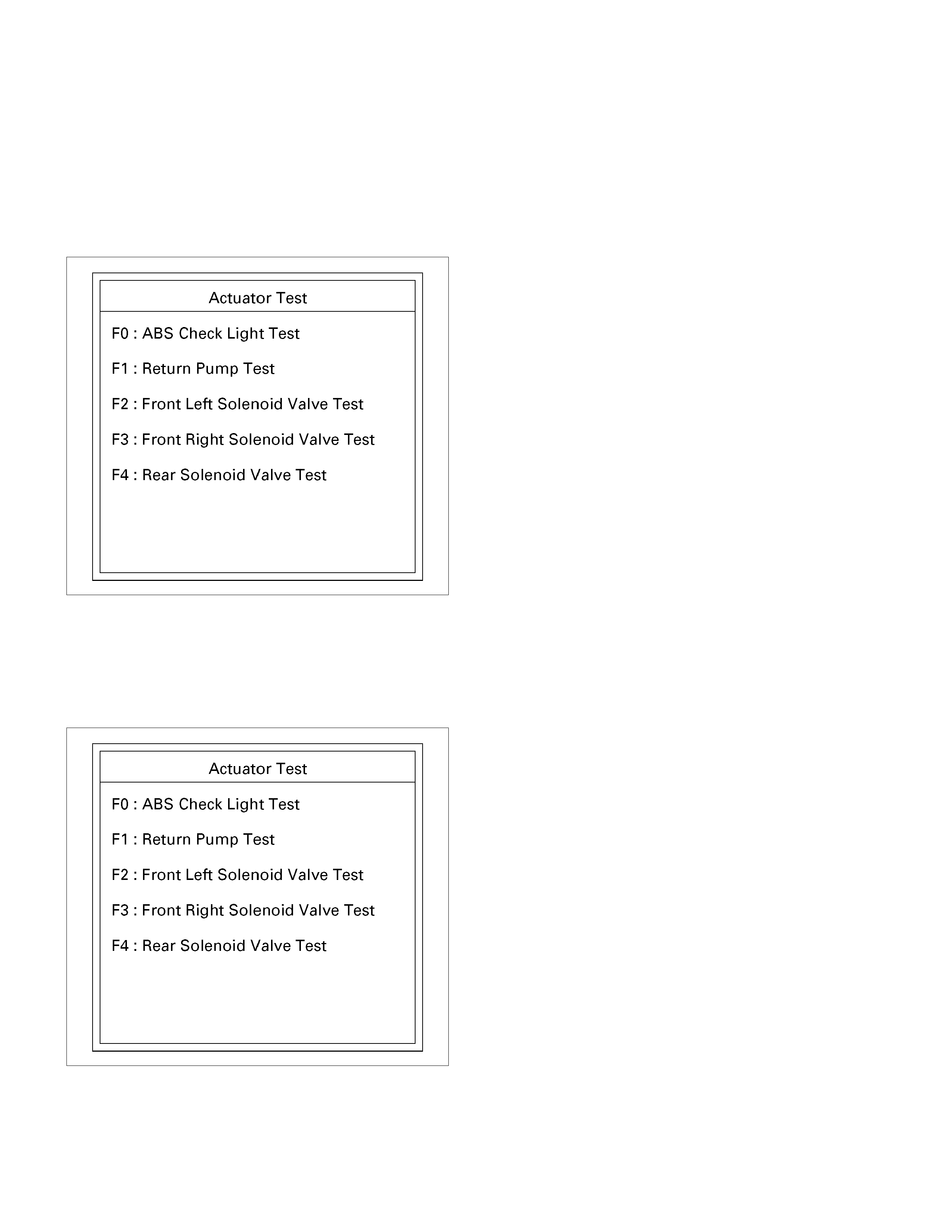
Actuator Test (Tech 2)
There are 5 different menus available for this test. Using these menus can test the state of each circuit. Especially
when DTC cannot be detected, a faulty circuit can be diagnosed by testing each circuit by means of these menus.
Even when DTC has been detected, the circuit tests using these menus could help discriminate between a mechanical
trouble and an electrical trouble.
In all cases follow these test conditions; Engine off with the key turned to the “ON” position, and the brake pedal
depressed after one depress and release.
• Engine: Off
• Ignition SW: ON
060L300002
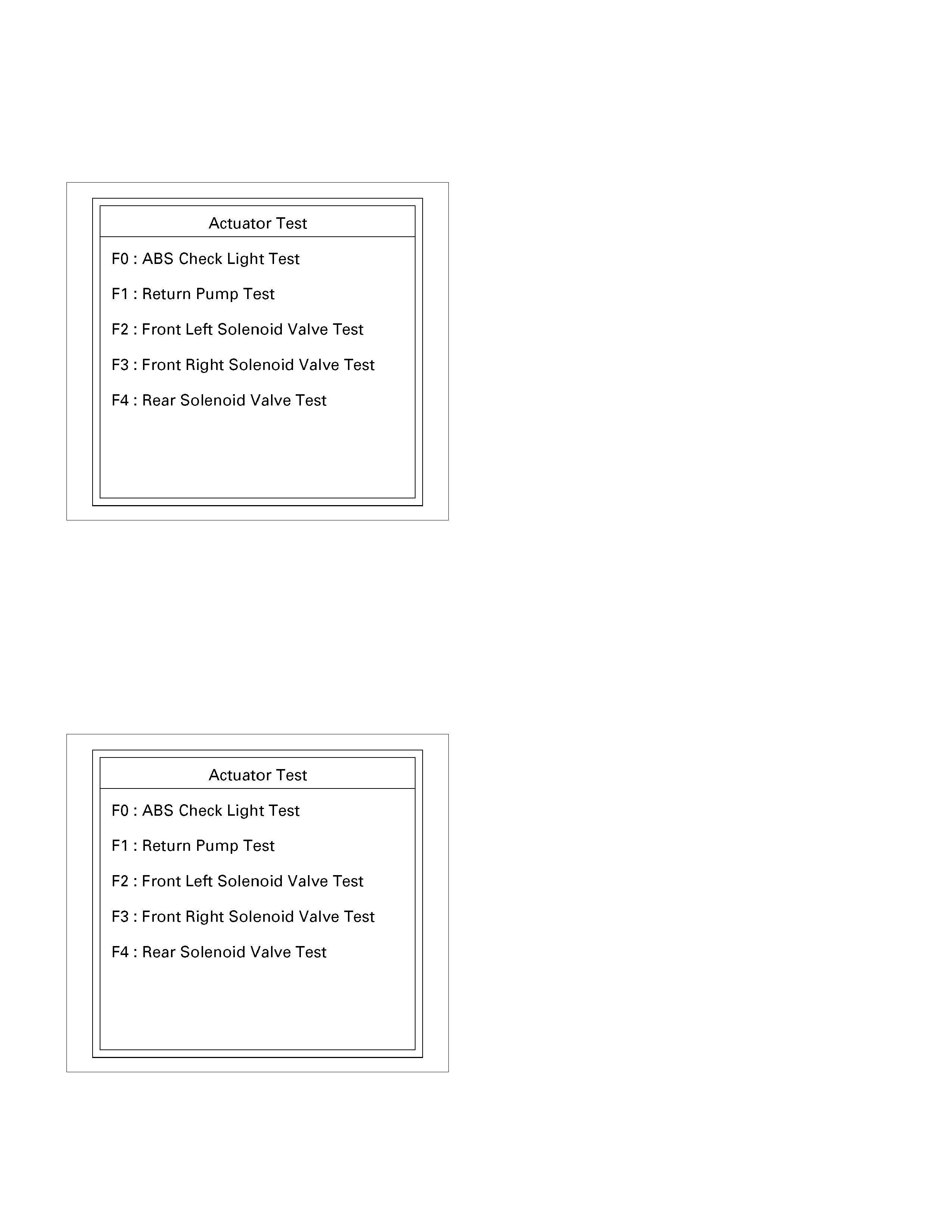
ABS Check Light Test
Test condition: Engine off with the key turned to the “ON” position, and the brake pedal depressed after one depress
and release.
• The circuit is normal if the warning light (lamp) in the meter panel comes on and goes out in accordance with
Tech2’s instruction.
060L300002
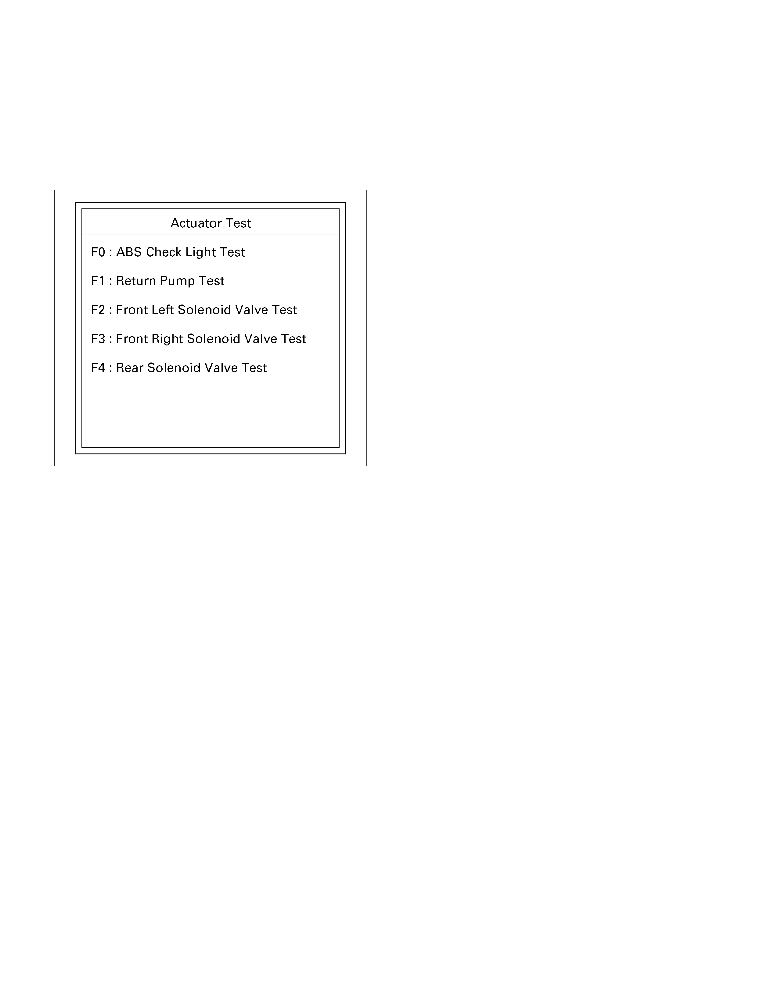
Return Pump Test
Test condition: Engine off with the key turned to the “ON” position, and the brake pedal depressed after one depress
and release.
Confirm operation of return pump relay and return pump by listening for their working sound.
The circuit is normal if the working sound of the return pump relay and return pump are made in accordance with
Tech2’s instruction.
060L300002
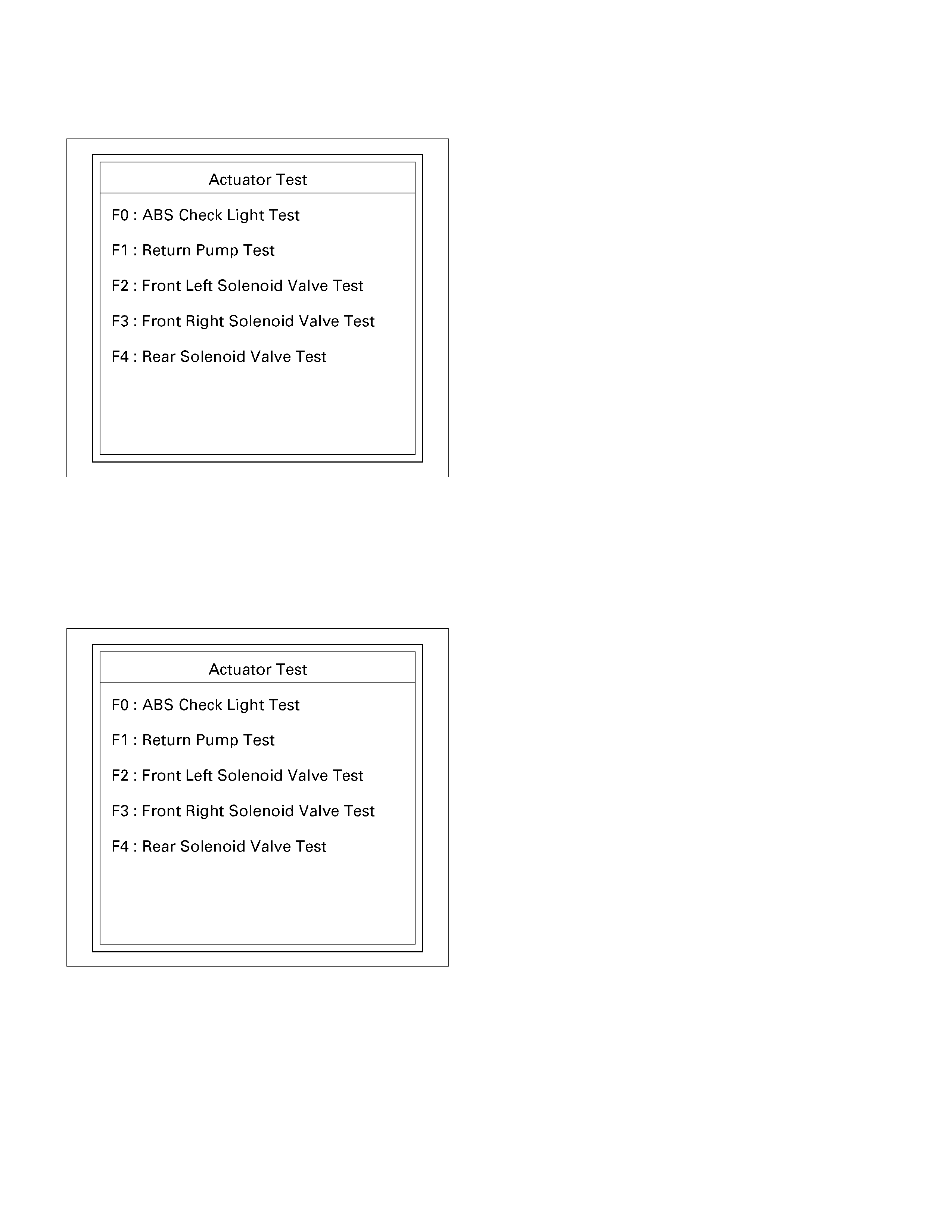
Isolation Valve Test
Purpose: The purpose of this test is to detect brake pipe and valve line harness wire for incorrect connections and
valve trouble.
This test will help you confirm the result of your service repair, including the removal/reinstallation of brake pipe, valve
line harness and valve.
Test conditions: Engine off with the key turned to the “ON” position, and the brake pedal depressed after one depress
and release.
Test procedure:
1. Connect Tech 2 to the vehicle, and select Actuator Test from the menus.
2. Select a Solenoid Valve Test Menu from the Actuator Test Menus.
060L300002
3. Select Isolation Valve from the Valve Select Menus.
4. Step on the brake pedal.
5. Release the brake pedal.
6. Make sure that the Isolation Valve “ON” that has been selected with Tech 2, and the actual wheel locked position
are the same. If different, check brake pipe, valve line harness wiring and H/UNIT. Repair is needed if
abnormality is found.
7. Conduct Step 2 through Step 5 above on all the four wheels.
060L300002
CAUTION: When conducting this test, please observe the following cautions.
1. Do not start the engine.
2. Lift up the vehicle on a level floor.
• Secure a enough clearance from the floor surface to allow the lifted tire to rotate.
3. Maintain the lift up.
4. Wipe the floor surface to remove water and oil to prevent accidents.
5. Do not load the vehicle.
• When lifting up the vehicle, be sure to observe the lifting up points. Refer to vehicle lifting points in Section 0A.
Dump Valve Test
Purpose: The purpose of this test is to detect brake pipe and valve line harness wire for incorrect connections and
valve trouble.
This test will help you confirm the result of your service repair including the removal/reinstallation of brake pipe, valve
line harness and valve.
Test conditions: The ignition key is in the “ON” position with all four wheels lifted up. The brake pedal is depressed,
released and depressed again with the parking brake released.
Test procedure:
1. Connect Tech 2 to the vehicle, and select Actuator Test Function from the menus.
2. Select a Solenoid Valve Test Menu from the Actuator Test Menus.
060L300002
3. Select Dump Valve from the Valve Select Menus.
4. depress the brake pedal.
5. Make sure that the Dump Valve “ON” that has been selected with Tech 2, and the actual wheel released position
are the same. If different, check brake pipe, valve line harness wiring and H/UNIT. Repair is needed if
abnormality is found.
6. Conduct Step 2 through Step 5 above on all the four wheels.
060L300002
CAUTION: When conducting this test, please observe the following cautions.
1. Do not start the engine.
2. Lift up the vehicle at a level floor.
• Secure a clearance from the floor surface enough to allow the lifted tire to rotate.
3. Maintain the lift up.
4. Wipe the floor surface to remove water and oil so that the surface may become unslippery.
5. Do not load the vehicle.
• When lifting up the vehicle, be sure to observe the lifting up points. Refer to vehicle lifting points in Section 0A
Diagnostic Trouble Codes
Choose and follow the appropriate diagnostic flowchart by the numbers listed below to find fault and repair.
Note: DTC cannot be erased when the fault is present.
Warning Lamp System Control Main Items
DTC
(Flash
Code) Description ABS Brake
(EBD) ABS EBD
-
(12) Normal Condition × × -
C0221
(21) Front Right Wheel Speed Sensor Short
Circuit or Circuit Open ×*A × Sensor or Wiring
C0222
(22) Front Right Wheel Speed Sensor
Incorrect Signal *B ×A × Sensor or install condition
C0223
(23) Front Right Wheel Speed Sensor Signal
- Tooth Chipping ×*A × Sensor Rotor or install
condition
C0225
(25) Front Left Wheel Speed Sensor Short
Circuit or Circuit Open ×*A × Sensor or Wiring
C0226
(26) Front Left Wheel Speed Sensor
Incorrect Signal *B ×*A × Sensor or install condition
C0227
(27) Front Left Wheel Speed Sensor Signal -
Tooth Chipping ×*A × Sensor Rotor or install
condition
C0231
(31) Rear Right Wheel Speed Sensor Short
Circuit or Circuit Open ×*A × Sensor or Wiring
C0232
(32) Rear Right Wheel Speed Sensor
Incorrect Signal *B ×*A × Sensor or install condition
C0233
(33) Rear Right Wheel Speed Sensor Signal
- Tooth Chipping ×*A × Sensor Rotor or install
condition
C0235
(35) Rear Left Wheel Speed Sensor Short
Circuit or Circuit Open ×*A × Sensor or Wiring
C0236
(36) Rear Left Wheel Speed Sensor
Incorrect Signal *B ×*A × Sensor or install condition
C0237
(37) Rear Left Wheel Speed Sensor Signal -
Tooth Chipping ×*A × Sensor Rotor or install
condition
C0238
(38) Tire Diameter Error × × Vehicle , Sensor or Tyre
C0241
(41) Front Right Isolation Solenoid Circuit
Open or Shorted to Ground × × Solenoid (EHCU)
C0242
(42) Front Right Dump Solenoid Circuit
Open or Shorted to Ground × × Solenoid (EHCU)
C0243
(43) Front Right Isolation Solenoid Circuit
Shorted to Battery × × Solenoid (EHCU)
C0244
(44) Front Right Dump Solenoid Circuit
Shorted to Battery × × Solenoid (EHCU)
C0245
(45) Front Left Isolation Solenoid Open Or
Shorted to Ground × × Solenoid (EHCU)
C0246
(46) Front Left Dump Solenoid Circuit Open
Or Shorted to Ground × × Solenoid (EHCU)
C0247
(47) Front Left Isolation Solenoid Circuit
Shorted to Battery × × Solenoid (EHCU)

Warning Lamp System Control Main Items
DTC
(Flash
Code) Description ABS Brake
(EBD) ABS EBD
C0248
(48) Front Left Dump Solenoid Circuit
Shorted to Battery × × Solenoid (EHCU)
C0251
(51) Rear Isolation Solenoid Circuit Open or
Shorted to Ground × × Solenoid (EHCU)
C0252
(52) Rear Dump Solenoid Circuit Open or
Shorted to Ground × × Solenoid (EHCU)
C0253
(53) Rear Isolation Solenoid Circuit Shorted
to Battery × × Solenoid (EHCU)
C0254
(54) Rear Dump Solenoid Circuit Shorted to
Battery × × Solenoid (EHCU)
C0265
(65) Fail Safe Relay (FSR) Shorted to
Ground × × Motor (EHCU)
C0266
(66) Fail Safe Relay (FSR) Shorted to
Battery × × Relay (EHCU)
C0267
(67) ABS Motor Shorted to Ground × × Motor (EHCU)
C0268
(68) ABS Motor Shorted to Battery × × Motor (EHCU)
C0271
(71) ECU Failure or Valve +B Circuit Open × × EHCU
C0274
(74) ABS Operation Long Time × × EHCU
C0276
(76) G-Sensor Malfunction × × Sensor or Wiring
× × Battery, Wiring or EHCU
(less than 9V)
C0277
(77) Power Supply Low Input
× × Battery or Wiring
(less than 10V)
C0278
(78) Power Supply High Input × × Battery or Wiring EHCU
C0282
(82) 4 Wheel Drive State Input Signal Failure × × Wiring
C0285
(85) Assembly Error (G-sensor) × × Vehicle (Sensor or EHCU)
*A : When three or more faults are detected, or when faults containing both front wheels and each rear wheels are
detected, EBD warning lamp is "ON" and control is cancelled.
*B : IMPORTANT : The ABS lamp will remain “ON” after a repair until vehicle exceeds 6km/h in the next ignition cycle
and a fault is not detected.
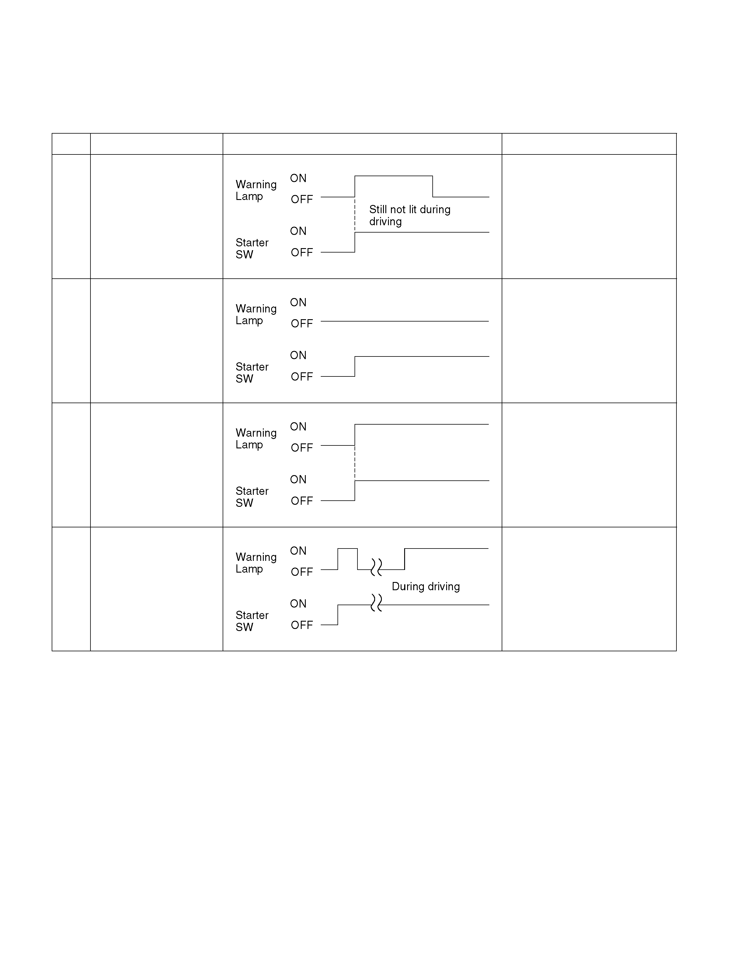
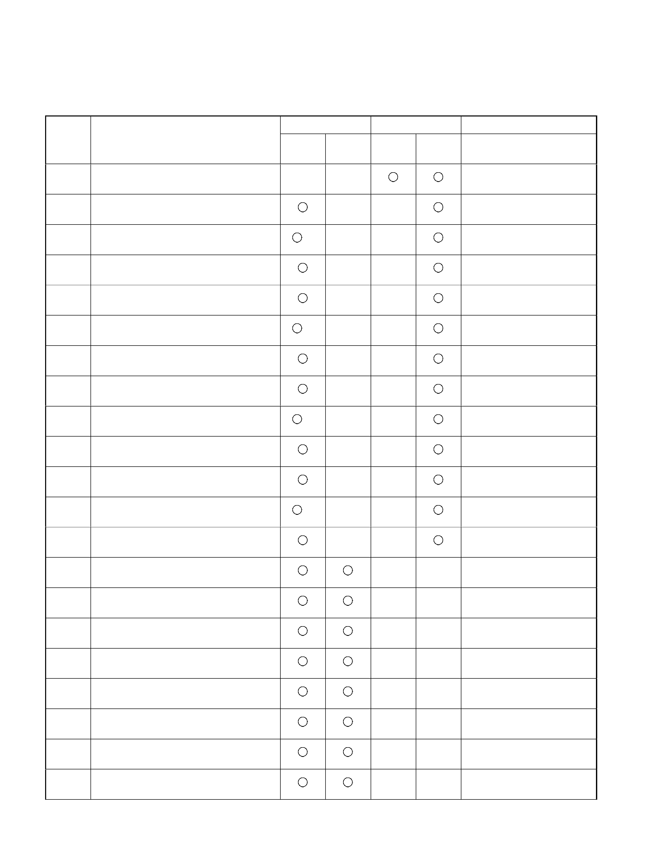
Diagnosis By “ABS” Warning Lamp Illumination Pattern
In the event that there is abnormality in the “ABS” warning Lamp illumination pattern while the key is in the ON position
or if the warning Lamp is actuated during driving, faults should be diagnosed on a illumination pattern basis as follows:
No. Condition “ABS” Warning Lamp Illumination Pattern Diagnostic
1 Warning Lamp is
actuated normally
Normal
2 Warning Lamp is not
lit
Warning Lamp lighting circuit
trouble. Go to No ABS
Warning Lamp.
3 Warning Lamp
remains ON
Diagnostic trouble codes are
stored.
Display diagnostic trouble
codes and diagnose on a
code basis according to
the flow charts.
4 Warning Lamp is
actuated while driving
Diagnostic trouble codes are
stored.
Display diagnostic trouble
codes and diagnose on a
code basis according to
the flow charts.
Diagnostic Trouble Codes (DTCs)
When the warning lamp in the meter remains ON, the EHCU stores the fault identification number (Diagnostic
Trouble Code) and disables the ABS.
Displaying and Erasing DTCs:
TECH 2 is the preferred method of displaying DTCs. Should TECH 2 be unavailable, the following method may be
used to display '‘Flash Codes" via the ABS warning lamp.
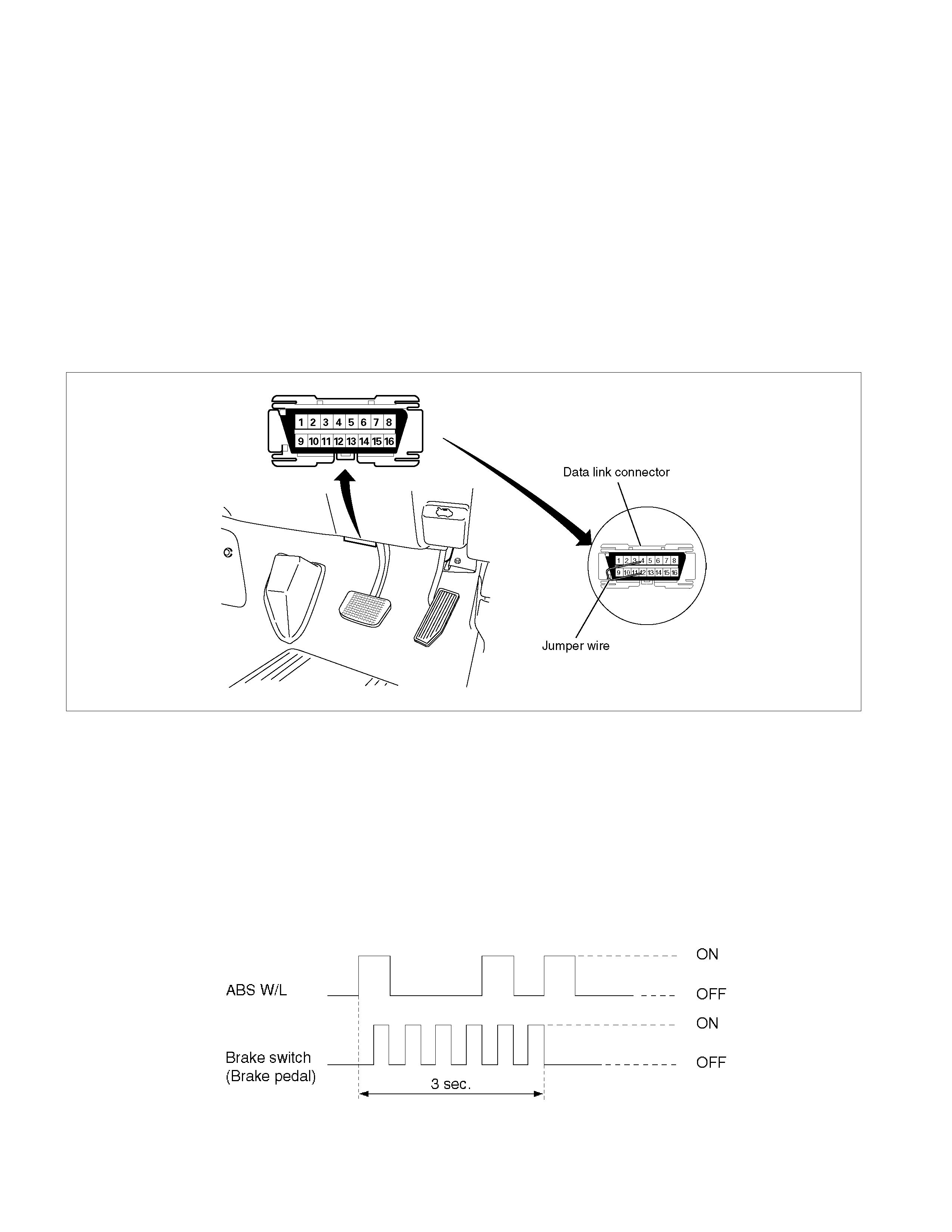
1. Initiating DTC Flash Code display:
• Confirm that the vehicle is at a complete stop (wheels stationary) and that the brake pedal is not depressed.
(Unless these two conditions are met, Flash Codes cannot be displayed.)
• With IGN OFF, connect DLC #12 terminal with #4 terminal or # 5 terminal (GND). Then turn IGN ON.
350L300005
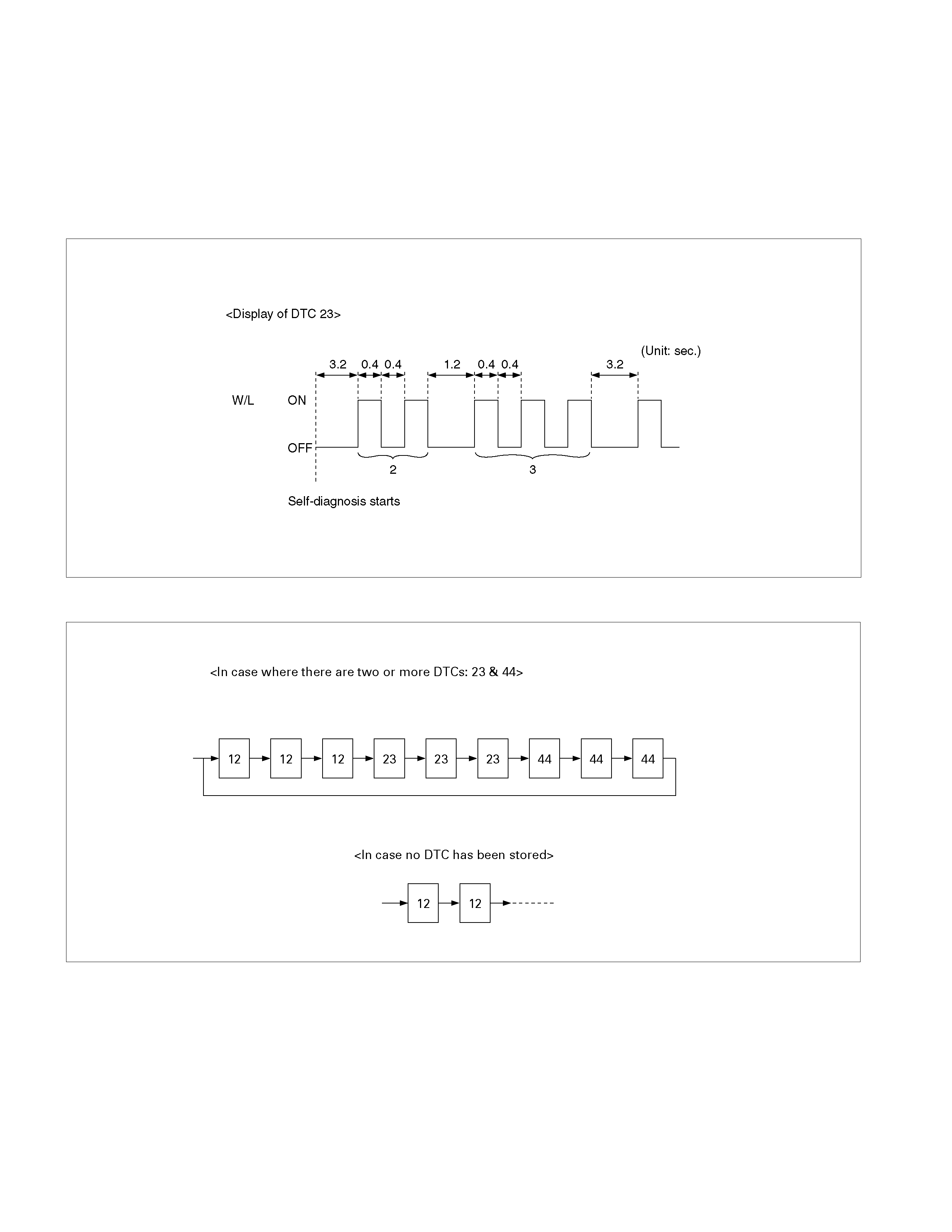
2.Reading the DTC Flash Code display:
• DTCs are displayed on the ABS warning lamp.
• All DTCs are a Double-digit display.
• First, normal DTC 12 is displayed three times and then any other DTCs are displayed three times. (If no
other DTCs have been stored, the display of DTC 12 will be repeated.)
3.Erasing DTC Flash Codes:
• Activate brake switch ON/OFF operation 6 or more times within 3 seconds of self-diagnosis startup.
• The code cannot be erased if more than 3 seconds have passed since self-diagnosis startup or if
self-diagnosis has started with brake switch on (brake depressed).
B05RW0005
Note:
• If, during Diagnostic Trouble Code (DTC) display, either a road wheel turns or the brake pedal is depressed,
the display will be discontinued and ABS control resumed.
• Up to 3 different codes can be stored.
• If the ABS should be disabled due to an intermittent fault, the system will be restored at the next key cycle,
providing the failure is not present during the initial self-check.
Example Flash Code Display - DTC 23
B05R100001
After displaying DTC 12 three times, one DTC after another is displayed. DTC’s are displayed in numerical order.
C05L300017
The DTC 12 is displayed repeatedly.
Basic Diagnostic Flow Chart
LTW35AMF000401
Step Action Value(s) Yes No
1 1. Ignition “ON,”engine “OFF.”
2. Observe the ABS warning lamp.
Note: When the starter switch is turned to the “ON”
position, the ABS warning lamp will turn on for 3
seconds then turn off.
Is the ABS warning lamp “ON”? - Go to Step 2
Go to “No
ABS
warning
lamp”
2 1. Ignition “OFF.”
2. Install Tech2.
3. Ignition “ON.”
4. Attempt to display ABS data with the Tech 2.
Does the Tech 2 display ABS data? - Go to Step 5 Go to Step 3
3 1. Ignition “OFF,” disconnect the EHCU.
2. Check the DLC (Data Link Connector) circuit for
an open, short to ground, or short to voltage.
Also, check the DLC ignition feed circuit for an
open or short to ground and the DLC ground
circuit for an open.
3. If a problem is found, repair as necessary.
W
as a problem found? - Go to Step 2 Go to Step 4

Step Action Value(s) Yes No
4 1. Check the EHCU circuit for an open, short to
ground, or short to voltage. Also, check the
EHCU ignition feed circuit for an open or short to
ground and the EHCU ground circuit for an open.
2. If a problem is found, repair as necessary.
Was a problem found? - Go to Step 2 Go to Step
11
5 Select “Display DTCs” with the Tech 2.
Are any DTCs stored? - Go to Step 6 Go to Step
10
6 Review and record for Tech 2 Failure Records data
and DTCs.
Is the action complete? - Go to Step 7 -
7 Following the DTC is stored.
Is this DTC C0271 stored?
-
Go to
applicable
DTC table
after Go to
step 8 Go to Step 8
8 Clear the DTCs by “Clear the Information“ with
Tech 2.
Did the DTCs cleared? - Go to Step 9 -
9 Select “Display DTCs” with the Tech 2.
Are any DTCs stored? -
Go to
applicable
DTC table Go to Step
10
10 Review and record for Tech 2 data.
Is the action complete?
-
Go to
Symptom
Diagnosis
and Go to
Basic
Inspection
Procedure -
11 Replace the EHCU.
Note: Check the EHCU type for specification, when
the EHCU is replaced.
(Specification; 2WD Model or 4WD Model)
Is the action complete? - Verify repair -

Basic Inspection Procedure
1. Basic Inspection of Service Brake
Step Action Value(s) Yes No
1 Is the fluid level normal?
- Go to Step 2
Replenish
with fluid
Go to Step 2
2 Does fluid leak? - Repair
Go to Step 3 Go to Step 3
3 Is the booster function normal? - Go to Step 4 Repair
Go to Step 4
4 Is the pad and rotor normal? - Go to Step 5 Repair
Go to Step 5
5 Reconnect all components. Ensure all component
are properly mounted.
Was this step completed? - Finished Go to Step 5
2. Ground Inspection
Step Action Value(s) Yes No
1 Are the ABS related ground points OK? - Go to Step 2 Repair
Go to Step 2
2 Reconnect all components. Ensure all components
are properly mounted.
Was this step completed? - Finished Go to Step 2
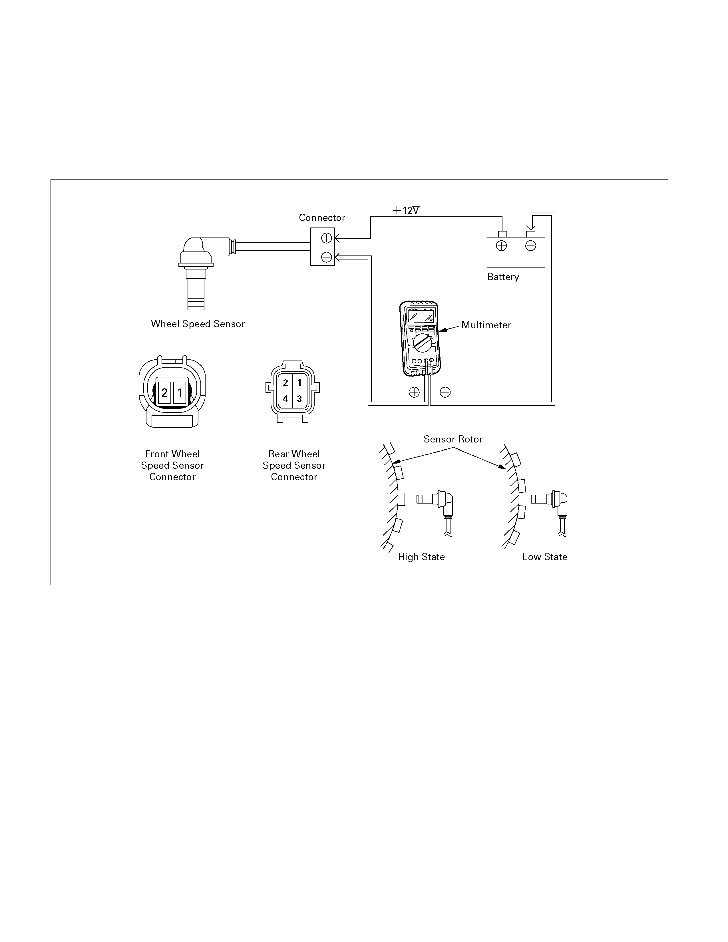
Wheel Speed Sensor Inspection Procedure
PROCEDURE
1. Ignition "OFF".
2. Disconnect the each wheel speed sensor.
3. Check the voltage at sensor harness connector.
Note : Voltage measurement is performed with the wheel speed sensor installed in the vehicle.
C05L300019
Connector Pin-outs
Front Wheel Speed Sensor
Pin 1(+) (+12V supply)
Pin 2 (-) (signal to EHCU)
Rear Wheel Speed Sensor
Pin 1 LH (+) (+12V supply)
Pin 2 LH (-) (signal to EHCU)
Pin 3 RH (+) (+12V supply)
Pin 4 RH (-) (signal to EHCU)
Expected Output Values
High State
1.28~2.2V
Low State
0.5~0.86V
High-Low
Difference
more than 0.8V

Symptom Diagnosis
The symptoms that cannot be indicated by warning lamp can be divided in the following five categories:
1. ABS works frequently but vehicle does not decelerate.
2. Uneven braking occurs while ABS works.
3. The wheels are locked.
4. Brake pedal feel is abnormal.
5. Braking sound (from EHCU) is heard while not braking.
6. No ABS Warning lamp
These are all attributable to problems that cannot be detected by EHCU self-diagnosis. Use the customer complaint
and a road test to determine which symptom is present.
ABS Works Frequently But Vehicle Does Not Decelerate
Step Action Value(s) Yes No
1 Is braking force distribution normal between front
and rear of vehicle?
- Go to Step 2
Repair or
Replace
brake
components.
Go to Step 7
2 Are the wheel speed sensors installed correctly?
- Go to Step 3
Repair axle
parts.
Go to Step 7
3 Is there play in each or any wheel speed sensor?
-
Repair wheel
speed
sensor.
Go to Step 7 Go to Step 4
4 Is there damage, or foreign material sticking to
each or any wheel speed sensor/sensor rotor?
-
Replace
wheel speed
sensor or
sensor rotor.
Go to Step 8 Go to Step 5
5 Is each wheel speed sensor output normal?
- Go to Step 6
Replace
wheel speed
sensor or
repair
harness.
Go to Step 7
6 Is the 4WD control system function normal?
-
2-4WD
Repair or Go
to Step 7
Repair or
replace 2-
4WD control
System.
Go to Step 7
7 Reconnect all components, ensure all components
are properly mounted.
Was this step finished? -
Repeat the
“Basic
diagnostic
flow chart” Go to Step 7

Uneven Braking Occurs During ABS Operation
Step Action Value(s) Yes No
1 Is there play in each or any wheel speed sensor? - Repair.
Go to Step 5 Go to Step 2
2 Is there damage or foreign material sticking to each
or any wheel speed sensor/sensor rotor? - Repair.
Go to Step 5 Go to Step 3
3 Is each sensor output normal?
-
Go to Step 4 Replace
sensor or
repair
harness.
Go to Step 5
4 Is brake pipe connecting order correct?
Important: Ensure the correct EHCU type (2WD
Model or 4WD Model) is fitted, when the EHCU is
replaced. -
Replace
EHCU.
Go to Step 5
Reconnect
brake pipe
correctly.
Go to Step 5
5 Reconnect all components, ensure all components
are properly mounted.
Was this step finished? -
Repeat the
“Basic
diagnostic
flow chart”
Go to Step 5
The Wheels Are Locked During Braking
Step Action Value(s) Yes No
1 Is ABS working? - Go to Step 2 Go to Step 4
2 Is vehicle speed under 5 km/h? - Normal. Go to Step 3
3 Is each wheel speed sensor output correct?
- Go to Step 4
Replace
sensor or
repair
harness.
Go to Step 6
4 Is 2-4WD system functioning correctly?
- Go to Step 5
Replace 2-
4WD control
unit or repair
harness.
Go to Step 6
5 Is EHCU grounded properly?
Important: Ensure the correct EHCU type (2WD
Model or 4WD Model) is fitted, when the EHCU is
replaced.
-
Replace
EHCU.
Go to Step 6 Repair.
Go to Step 6
6 Reconnect all components, ensure all components
are properly mounted.
Was this step finished? -
Repeat the
“Basic
diagnostic
flow chart” Go to Step 6

Abnormal Brake Pedal Feel
Step Action Value(s) Yes No
1 Is the stop light actuated when the brake pedal is
depressed? - Go to Step 2 Go to Step 3
2 1. Turn the ignition switch off.
2. Disconnected EHCU connector.
Measure voltage between the EHCU connector
terminals 10 and 9 when brake pedal is depressed.
Is the voltage equal to battery voltage? - Go to Step 4
Harness NG
between
stop light SW
and EHCU.
Go to Step 6
3 Is stop light fuse normal?
- Go to Step 5
Replace stop
light fuse.
Go to Step 6
4 Is there continuity between EHCU connector
terminals, 10 and 28 to body ground?
- Go to Step 6
Repair body
grounded
harness.
Go to Step 6
5 Is stop light switch operation normal?
-
Repair stop
light
harness.
Go to Step 6
Replace stop
light switch.
Go to Step 6
6 Reconnect all components, ensure all components
are properly mounted.
Was this step finished? -
Repeat the
“Basic
diagnostic
flow chart” Go to Step 6

Operating Sound Is Heard From EHCU When Brakes Are Not Applied
Step Action Value(s) Yes No
1 Is this the first vehicle time the vehicle is being
driven after engine start?
-
Self-check
sound.
Normal Go to Step 2
2 Is vehicle speed under 10 km/h?
-
Self-check
sound.
Normal Go to Step 3
3 Does the sound occur under any of the following
conditions?
• During transmission gear shifting.
• Driving on slippery surfaces (gravel, ice or snow)
• On high-speed turns.
• Driving over speed-humps or curbs.
• While operating electrical equipment.
• ‘Racing’ the engine with the vehicle stationary.
-
ABS may
sometimes
be actuated
even when
brake pedal
is not
applied. Go to Step 4
4 Is there play in each or any sensor/wheel speed
sensor/sensor rotor? - Repair.
Go to Step 7 Go to Step 5
5 Damage or powdered iron sticking to each or any
wheel speed sensor/sensor rotor? - Repair.
Go to Step 7 Go to Step 6
6 Is each sensor output normal?
Important: Ensure the correct EHCU type (2WD
Model or 4WD Model) is fitted, when the EHCU is
replaced.
-
Check
harness/
connector for
open circuits
If no open
circuit is
found,
replace
EHCU
Go to Step 7 Repair.
Go to Step 7
7 Reconnect all components, ensure all components
are properly mounted.
Was this step finished? -
Repeat the
“Basic
diagnostic
flow chart” Go to Step 7

No ABS Warning Lamp
Step Action Value(s) Yes No
1 Check the meter fuse for the instrument cluster
ignition feed circuit.
Is the fuse OK? - Go to Step 3 Go to Step 2
2 Replace the fuse.
Is the action complete? - Verify repair
Go to Step 3 -
3 1. Ignition “OFF,” disconnect the EHCU.
2. Ignition “ON,” engine “OFF.”
3. Observe the ABS warning lamp.
Is the ABS warning lamp “ON”? - Go to Step 5 Go to Step 4
4 Repair or replace the meter circuit or meter.
Is the action complete? - Verify repair -
5 1. Check the EHCU circuit for an open, short to
ground, or short to voltage. Also, check the
EHCU ignition feed circuit for an open or short to
ground and the EHCU ground circuit for an open.
2. If a problem is found, repair as necessary.
Was a problem found? - Verify repair Go to Step 6
6 1. Ignition “OFF,” reconnect the EHCU.
2. Ignition “ON,”engine “OFF.”
3. Observe the ABS warning lamp.
Is the ABS warning lamp “ON”? - Verify repair Go to Step 7
7 Replace EHCU.
Important: Ensure the correct EHCU type (2WD
Model or 4WD Model) is fitted, when the EHCU is
replaced.
Is the action complete? - Verify repair -
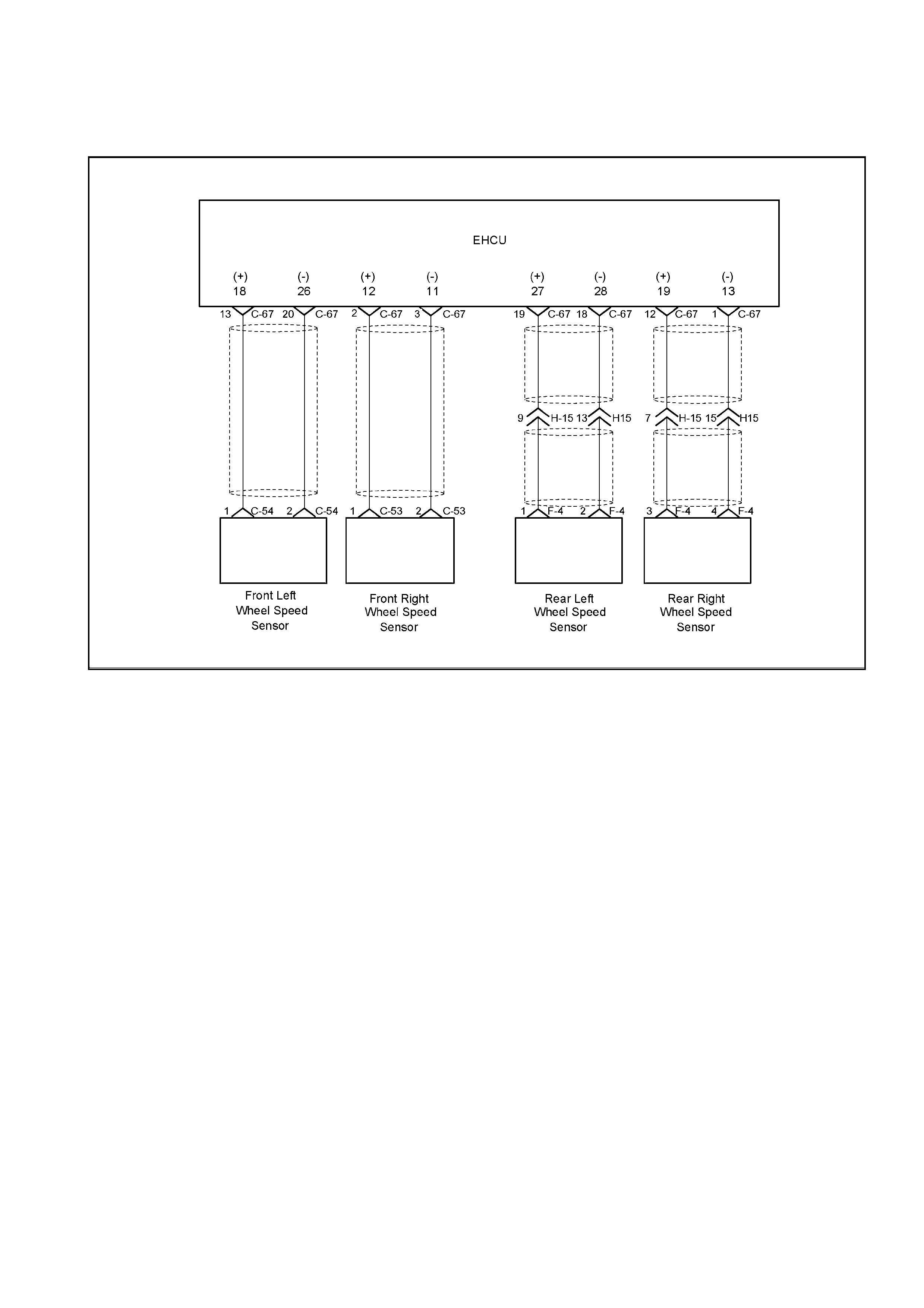
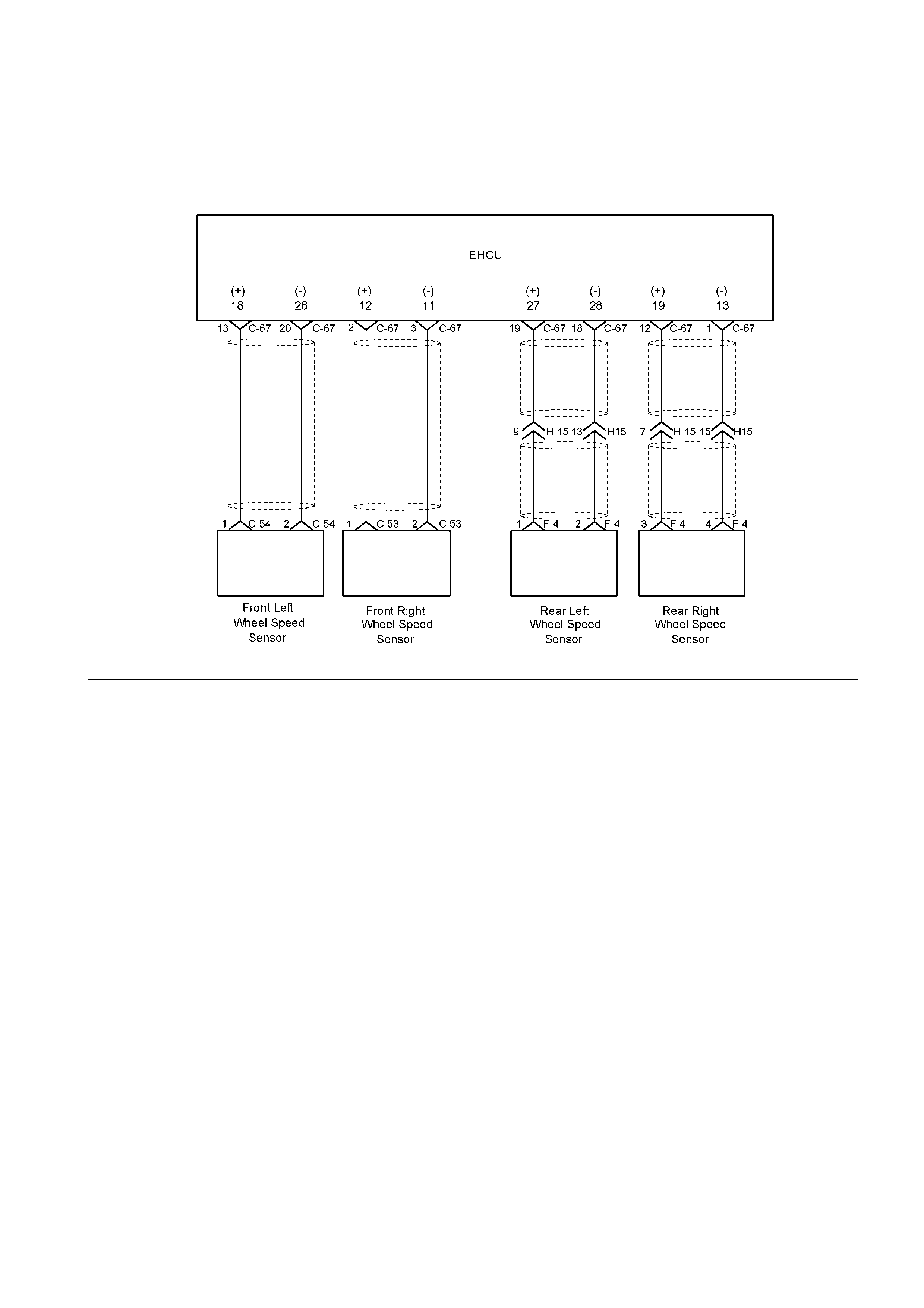
DTC C0221 (Flash Code 21) Front Right Wheel Speed Sensor Short
Circuit or Circuit Open
LTW35AMF000101-a

Step Action Value(s) Yes No
1 Was the “Basic Diagnostic Flow Chart” performed?
- Go to Step 2
Go to Basic
Diagnostic
Flow Chart
2 1. Check for a poor connectio n at the front right wheel
speed sensor harness connector.
2. Check installation condition for front rig ht wheel
speed sensor.
3. If a problem is found, repair as necessary.
Was a problem found? - Verify repair Go to Step 3
3 1. Ignition “OFF,” disconnect the EHCU and front right
wheel speed sensor.
2. Check the circuit between EHCU and front right
wheel speed sensor. (Circuit for an open, short to
ground, or short to voltage.)
3. If a problem is found, repair as necessary.
Was a problem found? - Verify repair Go to Step 4

DTC C0222 (Flash Code 22) Front Right Wheel Speed Sensor
Incorrect Signal
LTW35AMF000101-a

Step Action Value(s) Yes No
1 Was the “Basic Diagnostic Flow Chart” performed?
- Go to Step 2
Go to Basic
Diagnostic
Flow Chart
2 1. Check for a poor connectio n at the front right wheel
speed sensor harness connector.
2. Check installation condition for front rig ht wheel
speed sensor.
3. If a problem is found, repair as necessary.
Was a problem found? - Verify repair Go to Step 3
3 1. Ignition “OFF,” disconnect the EHCU and front right
wheel speed sensor.
2. Check the circuit between EHCU and front right
wheel speed sensor. (short to ground, or short to
voltage.)
3. If a problem is found, repair as necessary.
Was a problem found? - Verify repair Go to Step 4
4 1. Replace front right wheel speed sensor.
2. Select “Display DTCs” with the Tech 2.
Note : Perform the various tests (actuator test, test
run, brake test, etc.) then observe the DTC with a
Tech2.
Are any DTCs stored? - Go to Step 5 Verify repair

DTC C0223 (Flash Code 23) Front Right Wheel Speed Sensor Signal -
Tooth Chipping
LTW35AMF000101-a

Step Action Value(s) Yes No
1 Was the “Basic Diagnostic Flow Chart” performed?
- Go to Step 2
Go to Basic
Diagnostic
Flow Chart
2 1. Check for a poor connectio n at the front right wheel
speed sensor harness connector.
2. Check installation condition for front rig ht wheel
speed sensor.
3. If a problem is found, repair as necessary.
Was a problem found? - Verify repair Go to Step 3
3 1. Check condition for sensor rotor at front hub.
2. If a problem is found, repair as necessary.
Was a problem found? - Verify repair Go to Step 4
4 1. Ignition “OFF,” disconnect the EHCU and front right
wheel speed sensor.
2. Check the circuit between EHCU and front right
wheel speed sensor. (short to ground, or short to
voltage.)
3. If a problem is found, repair as necessary.
Was a problem found? - Verify repair Go to Step 5

DTC C0225 (Flash Code 25) Front Left Wheel Speed Sensor Short
Circuit or Circuit Open
LTW35AMF000101

Step Action Value(s) Yes No
1 Was the “Basic Diagnostic Flow Chart” performed?
- Go to Step 2
Go to Basic
Diagnostic
Flow Chart
2 1. Check for a poor connectio n at the front left wheel
speed sensor harness connector.
2. Check installation condition for front left wheel
speed sensor.
3. If a problem is found, repair as necessary.
Was a problem found? - Verify repair Go to Step 3
3 1. Ignition “OFF,” disconnect the EHCU and front left
wheel speed sensor.
2. Check the circuit between EHCU and front left
wheel speed sensor. (Circuit for an open, short to
ground, or short to voltage.)
3. If a problem is found, repair as necessary.
Was a problem found? - Verify repair Go to Step 4

DTC C0226 (Flash Code 26) Front Left Wheel Speed Sensor
Incorrect Signal
LTW35AMF000101-a

Step Action Value(s) Yes No
1 Was the “Basic Diagnostic Flow Chart” performed?
- Go to Step 2
Go to Basic
Diagnostic
Flow Chart
2 1. Check for a poor connectio n at the front left wheel
speed sensor harness connector.
2. Check installation condition for front left wheel
speed sensor.
3. If a problem is found, repair as necessary.
Was a problem found? - Verify repair Go to Step 3
3 1. Ignition “OFF,” disconnect the EHCU and front left
wheel speed sensor.
2. Check the circuit between EHCU and front left
wheel speed sensor. (short to ground, or short to
voltage.)
3. If a problem is found, repair as necessary.
Was a problem found? - Verify repair Go to Step 4
4 1. Replace front left wheel speed sen sor.
2. Select “Display DTCs” with the Tech 2.
Are any DTCs stored? - Go to Step 5 Verify repair
5 Repair or replace the front left sensor rotor at front
hub.
Was the action complete? - Verify repair
Go to Step 6 -

DTC C0227 (Flash Code 27) Front Left Wheel Speed Sensor Signal -
Tooth Chipping
LTW35AMF000101-a

Step Action Value(s) Yes No
1 Was the “Basic Diagnostic Flow Chart” performed?
- Go to Step 2
Go to Basic
Diagnostic
Flow Chart
2 1. Check for a poor connectio n at the front left wheel
speed sensor harness connector.
2. Check installation condition for front left wheel
speed sensor.
3. If a problem is found, repair as necessary.
Was a problem found? - Verify repair Go to Step 3
3 1. Check condition for sensor rotor at front hub.
2. If a problem is found, repair as necessary.
Was a problem found? - Verify repair Go to Step 4
4 1. Ignition “OFF,” disconnect the EHCU and front left
wheel speed sensor.
2. Check the circuit between EHCU and front left
wheel speed sensor. (short to ground, or short to
voltage.)
3. If a problem is found, repair as necessary.
Was a problem found? - Verify repair Go to Step 5

DTC C0231 (Flash Code 31) Rear Right Wheel Speed Sensor Short
Circuit or Circuit Open
LTW35AMF000101-a

Step Action Value(s) Yes No
1 Was the “Basic Diagnostic Flow Chart” performed?
- Go to Step 2
Go to Basic
Diagnostic
Flow Chart
2 1. Check for a poor connectio n at the rear right wheel
speed sensor harness connector.
2. Check installation condition for rear right wheel
speed sensor.
3. If a problem is found, repair as necessary.
Was a problem found? - Verify repair Go to Step 3
3 1. Ignition “OFF,” disconnect the EHCU and rear right
wheel speed sensor.
2. Check the circuit between EHCU and rear rig ht
wheel speed sensor. (Circuit for an open, short to
ground, or short to voltage.)
3. If a problem is found, repair as necessary.
Was a problem found? - Verify repair Go to Step 4

DTC C0232 (Flash Code 32) Rear Right Wheel Speed Sensor
Incorrect Signal
LTW35AMF000101-a

Step Action Value(s) Yes No
1 Was the “Basic Diagnostic Flow Chart” performed?
- Go to Step 2
Go to Basic
Diagnostic
Flow Chart
2 1. Check for a poor connectio n at the rear right wheel
speed sensor harness connector.
2. Check installation condition for rear right wheel
speed sensor.
3. If a problem is found, repair as necessary.
Was a problem found? - Verify repair Go to Step 3
3 1. Ignition “OFF,” disconnect the EHCU and rear right
wheel speed sensor.
2. Check the circuit between EHCU and rear rig ht
wheel speed sensor. (short to ground, or short to
voltage.)
3. If a problem is found, repair as necessary.
Was a problem found? - Verify repair Go to Step 4
4 1. Replace rear right wheel speed sensor.
2. Select “Display DTCs” with the Tech 2.
Note : Perform the various tests (actuator test, test
run, brake test, etc.) then observe the DTC with a
Tech2.
Are any DTCs stored? - Go to Step 5 Verify repair
DTC C0233 (Flash Code 33) Rear Right Wheel Speed Sensor Signal -
Tooth Chipping
LTW35AMF000101-a

Step Action Value(s) Yes No
1 Was the “Basic Diagnostic Flow Chart” performed?
- Go to Step 2
Go to Basic
Diagnostic
Flow Chart
2 1. Check for a poor connectio n at the rear right wheel
speed sensor harness connector.
2. Check installation condition for rear right wheel
speed sensor.
3. If a problem is found, repair as necessary.
Was a problem found? - Verify repair Go to Step 3
3 1. Check condition for sensor rotor at rear axle.
2. If a problem is found, repair as necessary.
Was a problem found? - Verify repair Go to Step 4
4 1. Ignition “OFF,” disconnect the EHCU and rear right
wheel speed sensor.
2. Check the circuit between EHCU and rear rig ht
wheel speed sensor. (short to ground, or short to
voltage.)
3. If a problem is found, repair as necessary.
Was a problem found? - Verify repair Go to Step 5

DTC C0235 (Flash Code 35) Rear Left Wheel Speed Sensor Short
Circuit or Circuit Open
LTW35AMF000101

Step Action Value(s) Yes No
1 Was the “Basic Diagnostic Flow Chart” performed?
- Go to Step 2
Go to Basic
Diagnostic
Flow Chart
2 1. Check for a poor connectio n at the rear left wheel
speed sensor harness connector.
2. Check installation condition for rear left wheel
speed sensor.
3. If a problem is found, repair as necessary.
Was a problem found? - Verify repair Go to Step 3
3 1. Ignition “OFF,” disconnect the EHCU and rear left
wheel speed sensor.
2. Check the circuit between EHCU and rear left
wheel speed sensor. (Circuit for an open, short to
ground, or short to voltage.)
3. If a problem is found, repair as necessary.
Was a problem found? - Verify repair Go to Step 4

DTC C0236 (Flash Code 36) Rear Left Wheel Speed Sensor
Incorrect Signal
LTW35AMF000101

Step Action Value(s) Yes No
1 Was the “Basic Diagnostic Flow Chart” performed?
- Go to Step 2
Go to Basic
Diagnostic
Flow Chart
2 1. Check for a poor connectio n at the rear left wheel
speed sensor harness connector.
2. Check installation condition for rear left wheel
speed sensor.
3. If a problem is found, repair as necessary.
Was a problem found? - Verify repair Go to Step 3
3 1. Ignition “OFF,” disconnect the EHCU and rear left
wheel speed sensor.
2. Check the circuit between EHCU and rear left
wheel speed sensor. (short to ground, or short to
voltage.)
3. If a problem is found, repair as necessary.
Was a problem found? - Verify repair Go to Step 4
4 1. Replace rear left wheel speed sensor.
2. Select “Display DTCs” with the Tech 2.
Note : Perform the various tests (actuator test, test
run, brake test, etc.) then observe the DTC with a
Tech 2.
Are any DTCs stored? - Go to Step 5 Verify repair

DTC C0237 (Flash Code 37) Rear Left Wheel Speed Sensor Signal -
Tooth Chipping
LTW35AMF000101-a

Step Action Value(s) Yes No
1 Was the “Basic Diagnostic Flow Chart” performed?
- Go to Step 2
Go to Basic
Diagnostic
Flow Chart
2 1. Check for a poor connectio n at the rear left wheel
speed sensor harness connector.
2. Check installation condition for rear left wheel
speed sensor.
3. If a problem is found, repair as necessary.
Was a problem found? - Verify repair Go to Step 3
3 1. Check condition for sensor rotor at rear axle.
2. If a problem is found, repair as necessary.
Was a problem found? - Verify repair Go to Step 4
4 1. Ignition “OFF,” disconnect the EHCU and rear left
wheel speed sensor.
2. Check the circuit between EHCU and rear left
wheel speed sensor. (short to ground, or short to
voltage.)
3. If a problem is found, repair as necessary.
Was a problem found? - Verify repair Go to Step 5

DTC C0238 (Flash Code 38) Tire Diameter Error
Step Action Value(s) Yes No
1 Was the “Basic Diagnostic Flow Chart” performed?
- Go to Step 2
Go to Basic
Diagnostic
Flow Chart
2 1. Check for the tire size of each wheels.
2. If the tire size is different, replace the tire.
3. If a problem is found, repair as necessary.
Was a problem found? - Verify repair Go to Step 3
3 1. Check for the gear ratio of a front axle differential
gear and a rear axle differential gear.
2. If the gear ratio is different, repair the gear ratio.
3. If a problem is found, repair as necessary.
Was a problem found? - Verify repair Go to Step 4
4 Select “Display DTCs” with the Tech 2.
Note : Perform the various tests (actuator test, test
run, brake test, etc.) then observe the DTC with a
Tech2.
Are any DTCs stored? - Go to Step 5 Verify repair
5 Replace EHCU.
Important: Ensure the correct EHCU type (2WD
Model or 4WD Model) is fitted, when the EHCU is
replaced.
Was the action complete? - Verify repair -
DTC C0241 (Flash Code 41) Front Right Isolation Solenoid Circuit
Open or Shorted to Ground
DTC C0242 (Flash Code 42) Front Right Dump Solenoid Circuit Open
or Shorted to Ground
DTC C0243 (Flash Code 43) Front Right Isolation Solenoid Circuit
Shorted to Battery
DTC C0244 (Flash Code 44) Front Right Dump Solenoid Circuit
Shorted to Battery
LTW35AMF000301

Step Action Value(s) Yes No
1 Was the “Basic Diagnostic Flow Chart” performed?
- Go to Step 2
Go to Basic
Diagnostic
Flow Chart
2 1. Ignition “OFF”.
2. Check the EHCU circuit for an open, short to
ground, or short to voltage. Also, check the
EHCU ignition feed circuit for an open or short to
ground and the EHCU ground circuit for an open
or short to voltage.
3. If a problem is found, repair as necessary.
Was a problem found? - Verify repair Go to Step 3
3 1. Ignition “ON,” engine “OFF.”
2. Select “Display DTCs” with the Tech 2.
Note: Perform the various tests (actuator test, test
run, brake test, etc.) then observe the DTC with a
Tech2.
Are any DTCs stored? - Go to Step 4 Verify repair
4 Replace EHCU.
Important: Ensure the correct EHCU type (2WD
Model or 4WD Model) is fitted, when the EHCU is
replaced.
Was the action complete? - Verify repair -

DTC C0245 (Flash Code 45) Front Left Isolation Solenoid Circuit
Open or Shorted to Ground
DTC C0246 (Flash Code 46) Front Left Dump Solenoid Circuit Open
or Shorted to Ground
DTC C0247 (Flash Code 47) Front Left Isolation Solenoid Circuit
Shorted to Battery
DTC C0248 (Flash Code 48) Front Left Dump Solenoid Circuit
Shorted to Battery
LTW35AMF000301

Step Action Value(s) Yes No
1 Was the “Basic Diagnostic Flow Chart” performed?
- Go to Step 2
Go to Basic
Diagnostic
Flow Chart
2 1. Ignition “OFF”.
2. Check the EHCU circuit for an open, short to
ground, or short to voltage. Also, check the
EHCU ignition feed circuit for an open or short to
ground and the EHCU ground circuit for an open
or short to voltage.
3. If a problem is found, repair as necessary.
Was a problem found? - Verify repair Go to Step 3
3 1. Ignition “ON,” engine “OFF.”
2. Select “Display DTCs” with the Tech 2.
Note: Perform the various tests (actuator test, test
run, brake test, etc.) then observe the DTC with a
Tech2.
Are any DTCs stored? - Go to Step 4 Verify repair
4 Replace EHCU.
Important: Ensure the correct EHCU type (2WD
Model or 4WD Model) is fitted, when the EHCU is
replaced.
Was the action complete? - Verify repair -

DTC C0251 (Flash Code 51) Rear Isolation Solenoid Circuit Open or
Shorted to Ground
DTC C0252 (Flash Code 52) Rear Dump Solenoid Circuit Open or
Shorted to Ground
DTC C0253 (Flash Code 53) Rear Isolation Solenoid Circuit Shorted
to Battery
DTC C0254 (Flash Code 54) Rear Dump Solenoid Circuit Shorted to
Battery
LTW35AMF000301

Step Action Value(s) Yes No
1 Was the “Basic Diagnostic Flow Chart” performed?
- Go to Step 2
Go to Basic
Diagnostic
Flow Chart
2 1. Ignition “OFF”.
2. Check the EHCU circuit for an open, short to
ground, or short to voltage. Also, check the
EHCU ignition feed circuit for an open or short to
ground and the EHCU ground circuit for an open
or short to voltage.
3. If a problem is found, repair as necessary.
Was a problem found? - Verify repair Go to Step 3
3 1. Ignition “ON,” engine “OFF.”
2. Select “Display DTCs” with the Tech 2.
Note: Perform the various tests (actuator test, test
run, brake test, etc.) then observe the DTC with a
Tech2.
Are any DTCs stored? - Go to Step 4 Verify repair
4 Replace EHCU.
Important: Ensure the correct EHCU type (2WD
Model or 4WD Model) is fitted, when the EHCU is
replaced.
Was the action complete? - Verify repair -

DTC C0265 (Flash Code 65) Fail Safe Relay (FSR) shorted to Ground
DTC C0266 (Flash Code 66) Fail Safe Relay (FSR) shorted to Battery
LTW35AMF000301

Step Action Value(s) Yes No
1 Was the “Basic Diagnostic Flow Chart” performed?
- Go to Step 2
Go to Basic
Diagnostic
Flow Chart
2 1. Ignition “OFF”.
2. Check the EHCU circuit for an open, short to
ground, or short to voltage. Also, check the
EHCU ignition feed circuit for an open or short to
ground and the EHCU ground circuit for an open
or short to voltage.
3. If a problem is found, repair as necessary.
Was a problem found? - Verify repair Go to Step 3
3 1. Ignition “ON,” engine “OFF.”
2. Select “Display DTCs” with the Tech 2.
Note: Perform the various tests (actuator test, test
run, brake test, etc.) then observe the DTC with a
Tech2.
Are any DTCs stored? - Go to Step 4 Verify repair
4 Replace EHCU.
Important: Ensure the correct EHCU type (2WD
Model or 4WD Model) is fitted, when the EHCU is
replaced.
Was the action complete? - Verify repair -
DTC C0267 (Flash Code 67) ABS Motor shorted to Ground
DTC C0268 (Flash Code 68) ABS Motor shorted to Battery
LTW35AMF000301

Step Action Value(s) Yes No
1 Was the “Basic Diagnostic Flow Chart” performed?
- Go to Step 2
Go to Basic
Diagnostic
Flow Chart
2 1. Ignition “OFF”.
2. Check the EHCU circuit for an open, short to
ground, or short to voltage. Also, check the
EHCU ignition feed circuit for an open or short to
ground and the EHCU ground circuit for an open
or short to voltage.
3. If a problem is found, repair as necessary.
Was a problem found? - Verify repair Go to Step 3
3 1. Ignition “ON,” engine “OFF.”
2. Select “Display DTCs” with the Tech 2.
Note: Perform the various tests (actuator test, test
run, brake test, etc.) then observe the DTC with a
Tech2.
Are any DTCs stored? - Go to Step 4 Verify repair
4 Replace EHCU.
Important: Ensure the correct EHCU type (2WD
Model or 4WD Model) is fitted, when the EHCU is
replaced.
Was the action complete? - Verify repair -
DTC C0271 (Flash Code 71) ECU Failure or Valve +B Circuit Open
LTW35AMF000301
Step Action Value(s) Yes No
1 Was the “Basic Diagnostic Flow Chart” performed?
- Go to Step 2
Go to Basic
Diagnostic
Flow Chart
2 1. Ignition “OFF”.
2. Check the EHCU circuit for an open, short to
ground, or short to voltage. Also, check the
EHCU ignition feed circuit for an open or short to
ground and the EHCU ground circuit for an open
or short to voltage.
3. If a problem is found, repair as necessary.
Was a problem found? - Verify repair Go to Step 3
3 1. Ignition “ON,” engine “OFF.”
2. Select “Display DTCs” with the Tech 2.
Note: Perform the various tests (actuator test, test
run, brake test, etc.) then observe the DTC with a
Tech2.
Are any DTCs stored? - Go to Step 4 Verify repair
4 Replace EHCU.
Important: Ensure the correct EHCU type (2WD
Model or 4WD Model) is fitted, when the EHCU is
replaced.
Was the action complete? - Verify repair -
DTC C0274 (Flash Code 74) ABS Operation Long Time
LTW35AMF000301

Step Action Value(s) Yes No
1 Was the “Basic Diagnostic Flow Chart” performed?
- Go to Step 2
Go to Basic
Diagnostic
Flow Chart
2 Was the “Basic Inspection Procedure” performed?
- Go to Step 3
Go to Basic
Inspection
Procedure
3 1. Check for a poor connection at the wheel speed
sensor harness connector.
2. Check installation condition for wheel speed
sensor.
3. If a problem is found, repair as necessary.
Was a problem found? - Verify repair Go to Step 4
4 1. Check condition for sensor rotor.
2. If a problem is found, repair as necessary.
Was a problem found? - Verify repair Go to Step 5
5 1. Ignition “OFF,” disconnect the EHCU and wheel
speed sensor.
2. Check the circuit between EHCU and wheel
speed sensor.(short ground, or short to voltage.)
3. If a problem is found, repair as necessary.
Was a problem found? - Verify repair Go to Step 6
6 1. Ignition “OFF”.
2. Check the EHCU circuit for an open, short to
ground, or short to voltage. Also, check the
EHCU ignition feed circuit for an open or short to
ground and the EHCU ground circuit for an open
or short to voltage.
3. If a problem is found, repair as necessary.
Was a problem found? - Verify repair Go to Step 7
7 1. Ignition “ON,” engine “OFF.”
2. Select “Display DTCs” with the Tech 2.
Note: Perform the various tests (actuator test, test
run, brake test, etc.) then observe the DTC with a
Tech2.
Are any DTCs stored? - Go to Step 8 Verify repair
8 Replace EHCU.
Important: Ensure the correct EHCU type (2WD
Model or 4WD Model) is fitted, when the EHCU is
replaced.
Was the action complete? - Verify repair -

DTC C0276 (Flash Code 76) G-Sensor Malfunction
RTW35AMF000301-a

Step Action Value(s) Yes No
1 Was the “Basic Diagnostic Flow Chart” performed?
- Go to Step 2
Go to Basic
Diagnostic
Flow Chart
2 1. Check for a poor connectio n at the G-sensor
harness connector.
2. If a problem is found, repair as necessary.
Was a problem found? - Verify repair Go to Step 3
3 1. Ignition “OFF”, disconnect the G-sensor and EHCU.
2. Ignition “ON”, engine “OFF”.
3. Check the supply voltage to G-sensor.
Was the value normal? Battery
Voltage Go to Step 5 Go to Step 4
4 Repair or replace the power supply circuit.
Was the action complete? - Verify repair -
5 1. Check the circuit between EHCU and G-sensor.
(Circuit for an open, short to ground, or short to
voltage.)
2. If a problem is found, repair as necessary.
Was a problem found? - Verify repair Go to Step 6

DTC C0277 (Flash Code 77) Power Supply Low Input
DTC C0278 (Flash Code 78) Power Supply High Input
LTW35AMF000301

Step Action Value(s) Yes No
1 Was the “Basic Diagnostic Flow Chart” performed?
- Go to Step 2
Go to Basic
Diagnostic
Flow Chart
2 1. Check for a poor connection at EHCU
2. If a problem is found, repair as necessary.
Was a problem found? - Verify repair Go to Step 3
3 1. Ignition “OFF”, disconnect EHCU.
2. Ignition “ON”, engine “OFF”.
3. Check the supply voltage to EHCU.
Was the value normal? Battery
Voltage Go to Step 5 Go to Step 4
4 Repair or replace the power supply circuit.
Was the action complete? - Verify repair -
5 1. Check the power supply circuit.
(Circuit for an open, short to ground, or short to
voltage.)
2. If a problem is found, repair as necessary.
Was a problem found? - Verify repair Go to Step 6
6 1. Ignition “ON,” engine “OFF.”
2. Select “Display DTCs” with the Tech 2.
Note: Perform the various tests (actuator test,
test run, brake test, etc.) then observe the DTC
with a Tech2.
Are any DTCs stored? - Go to Step 7 Verify repair
7 Replace EHCU.
Important: Ensure the correct EHCU type (2WD
Model or 4WD Model) is fitted, when the EHCU is
replaced.
Was the action complete? - Verify repair -
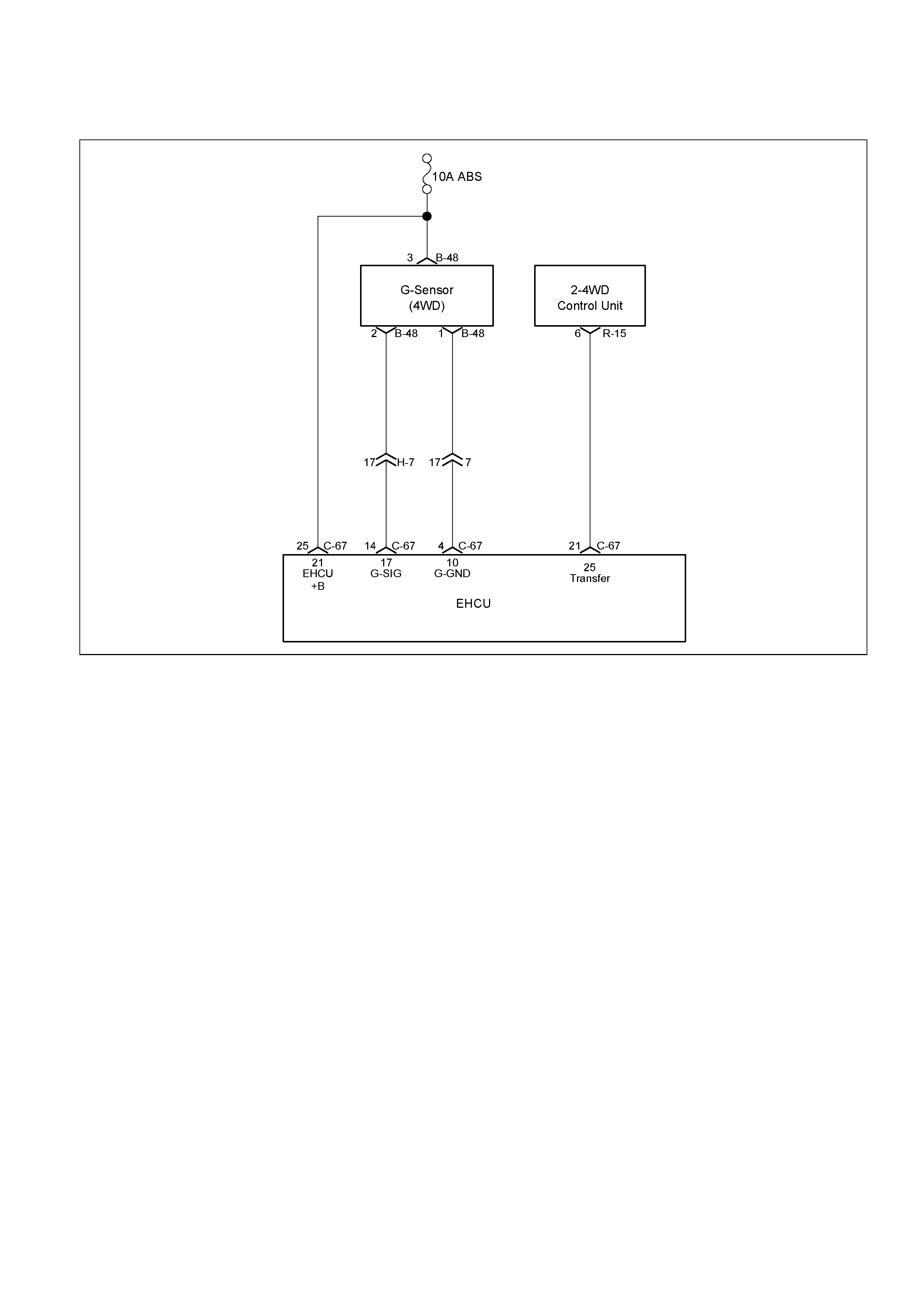
DTC C0282 (Flash Code 82) 4 Wheel Drive State Input Signal Failure
RTW35AMF000301-a

Step Action Value(s) Yes No
1 Was the “Basic Diagnostic Flow Chart” performed?
- Go to Step 2
Go to Basic
Diagnostic
Flow Chart
2 1. Check for a poor conn ection at EHCU and 2-4WD
control unit.
2. If a problem is found, repair as necessary.
Was a problem found? - Verify repair Go to Step 3
3 1. Ignition “OFF,” disconnect the EHCU and 2-4WD
control unit.
2. Check the circuit between EHCU and 2-4WD
control unit. (Circuit for an open, short to ground, or
short to voltage.)
3. If a problem is found, repair as necessary.
Was a problem found? - Verify repair Go to Step 4
4 1. Check the 2-4WD Control system.
2. If a problem is found, repair as necessary.
Was a problem found? - Verify repair Go to Step 5
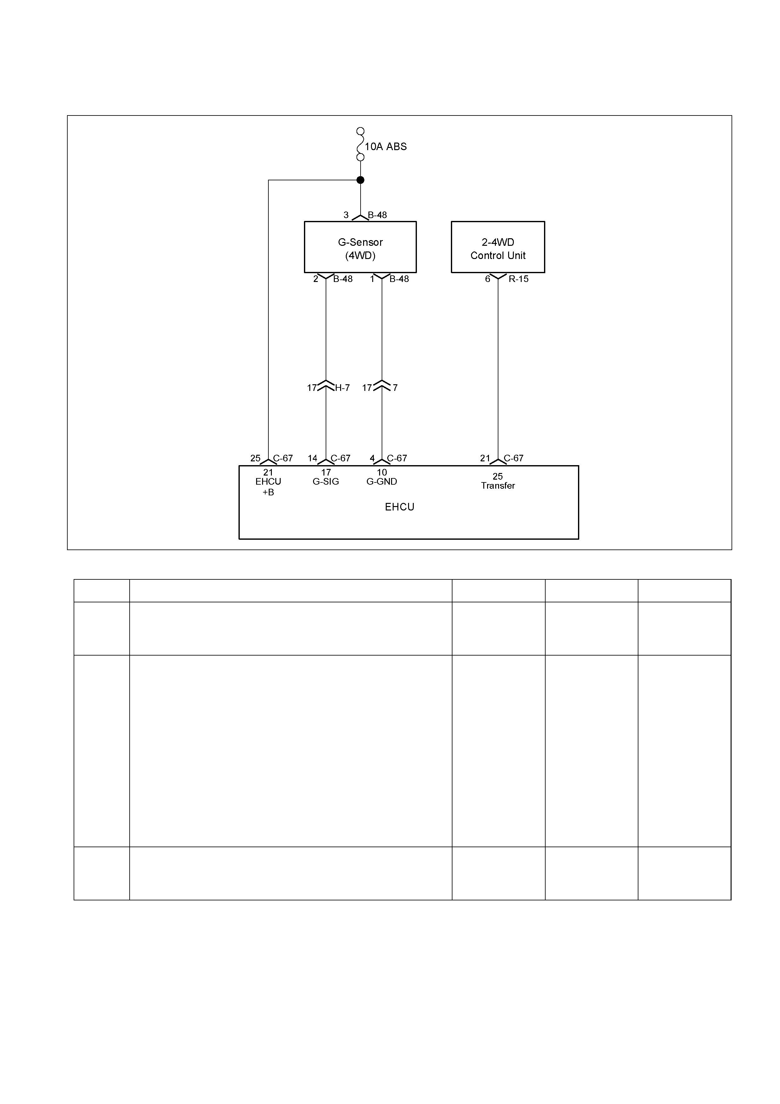
DTC C0285 (Flash Code 85) Assembly Error (G-sensor)
RTW35AMF000301-a
Step Action Value(s) Yes No
1 Was the “Basic Diagnostic Flow Chart” performed?
- Go to Step 2
Go to Basic
Diagnostic
Flow Chart
2 1. Ignition “OFF”.
2. Check for vehicle type and EHCU type.
(Vehicle type : 2WD or 4WD)
3. Checks the EHCU type is the same as a vehicles
type.
If the EHCU type differs from the vehicle s type,
EHCU is replaced.
Note: Check the EHCU type for specification, when the
EHCU is replaced.
(Specification ; 2WD model or 4WD model)
Was the action complete? - Go to Step 3 -
3 1. Check for vehicle type. (Vehicl e type : 2WD or
4WD)
Was vehicle type 2WD? - Go to Step 4 Go to Step 6

Step Action Value(s) Yes No
4 1. Ignition "OFF".
2. Check for a poor condition at the EHCU harness
connector.
3. Check the EHCU circuit for an open, short to
ground, or short to voltage. Also, check the
EHCU ignition feed circuit for an open or short to
ground and the EHCU ground circuit for an open
or short to voltage.
4. If a problem is found, repair as necessary.
Was a problem found? - Verify repair Go to Step 9
5 1. Ignition "OFF," disconnect the EHCU and G-
sensor.
2. Check the circuit between EHCU and G-sensor.
(short to ground, or short to voltage.)
3. If a problem is found, repair as necessary.
Was a problem found? - Verify repair
Go to Step 6 Go to Step 6
6 1. Remove the G-sensor.
2. Reconnect G-sensor and EHCU
3. Install the Tech 2.
4. Ignition "ON", engine "OFF".
5. Observe the G-sensor reading on Tech 2.
If G-sensor inclines, reading voltage will change.
Is the reading voltage between specified value? 1.0 – 4.0 V Go to Step 7 Go to Step 8
7 1. Ignition "OFF".
2. Install the G-sensor.
3. Install the Tech 2.
4. Ignition "ON", engine "OFF".
5. Select "Display DTCs" with the Tech 2.
Are any DTCs stored? - Go to Step 8 Verify repair
8 1. Replace G-sensor.
2. Select "Display DTCs" with the Tech 2.
Note: Perform the various tests (actuator test, test
run, brake test, etc.) then observe the DTC with a
Tech2.
Are any DTCs stored? - Go to Step 9 Verify repair
9 Replace EHCU.
Important: Ensure the correct EHCU type (2WD
Model or 4WD Model) is fitted, when the EHCU is
replaced.
Was the action complete? - Verify repair -
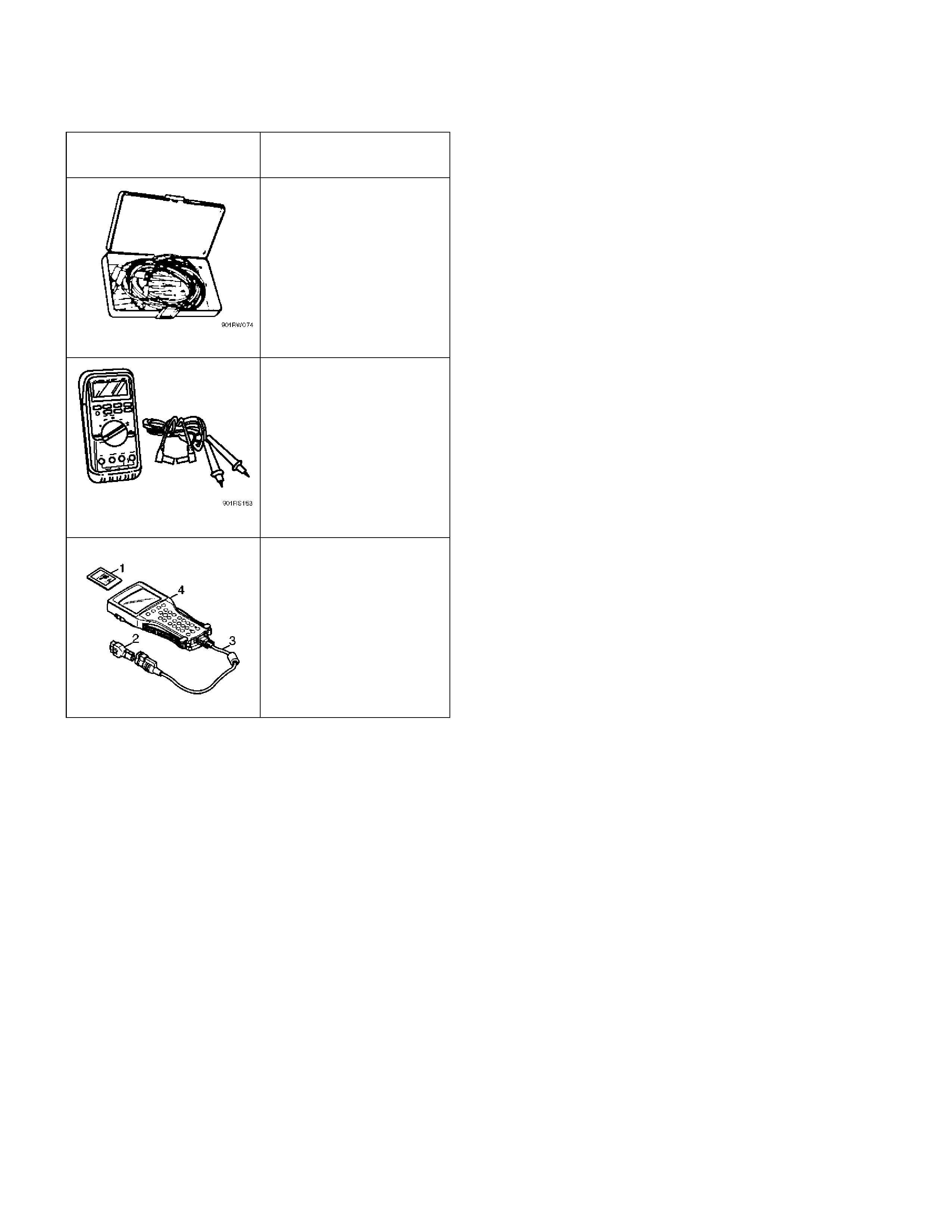
Special Tools
ILLUSTRATION TOOL NO.
TOOL NAME
5–8840–0385–0
(J–35616)
Connector test adaptor
kit
5–8840–0366–0
(J–39200)
High impedance
multimeter
Tech 2 Set
(1) PCMCIA Card
(2) SAE 16/19 Adapter
(3) DLC Cable
(4) Tech 2