
SECTION 5B - ANTI-LOCK BRAKE SYSTEM
COMPONENT SERVICING
Service Precaution
Torque Specifications
Electronic Hydraulic Control Unit
Front Speed Sensor
Rear Speed Sensor
Electronic Hydraulic Control Unit
Electronic Hydraulic Control Unit and Associated Parts
Removal
Installation
Front Wheel Speed Sensor
Front Wheel Speed Sensor and Associated Parts
Removal
Inspection and Repair
Installation
Rear Wheel Speed Sensor
Rear Wheel Sensor and Associated Parts
Removal
Inspection and Repair
Installation
Front Speed Sensor Rotor
Front Sensor Rotor and Associated Parts
Removal
Inspection and Repair
Installation
Rear Speed Sensor Rotor
Rear Sensor Rotor and Associated Parts
Removal
Inspection and Repair
Installation
G-Sensor
G-Sensor and Associated Parts
Removal
Installation
Special Tools

Service Precaution
WARNING: THIS VEHICLE HAS A SUPPLEMENTAL RESTRAINT SYSTEM (SRS). REFER TO THE SRS
COMPONENT AND WIRING LOCATION VIEW IN ORDER TO DETERMINE WHETHER YOU ARE PERFORMING
SERVICE ON OR NEAR THE SRS COMPONENTS OR THE SRS WIRING. WHEN YOU ARE PERFORMING
SERVICE ON OR NEAR THE SRS COMPONENTS OR THE SRS WIRING, REFER TO THE SRS SERVICE
INFORMATION. FAILURE TO FOLLOW WARNINGS COULD RESULT IN POSSIBLE AIR BAG DEPLOYMENT,
PERSONAL INJURY, OR OTHERWISE UNNEEDED SRS SYSTEM REPAIRS.
CAUTION: Always use the correct fastener in the proper location. When you replace a fastener, use ONLY the
exact part number for that application. HOLDEN will call out those fasteners that require a replacement after
removal. HOLDEN will also call out the fasteners that require thread lockers or thread sealant. UNLESS
OTHERWISE SPECIFIED, do not use supplemental coatings (Paints, greases, or other corrosion inhibitors) on
threaded fasteners or fastener joint interfaces. Generally, such coatings adversely affect the fastener torque
and the joint clamping force, and may damage the fastener. When you install fasteners, use the correct
tightening sequence and specifications. Following these instructions can help you avoid damage to parts and
systems.
Torque Specifications
Electronic Hydraulic Control Unit
E05R300007
Front Speed Sensor
E05R300003
Rear Speed Sensor
E05R300008
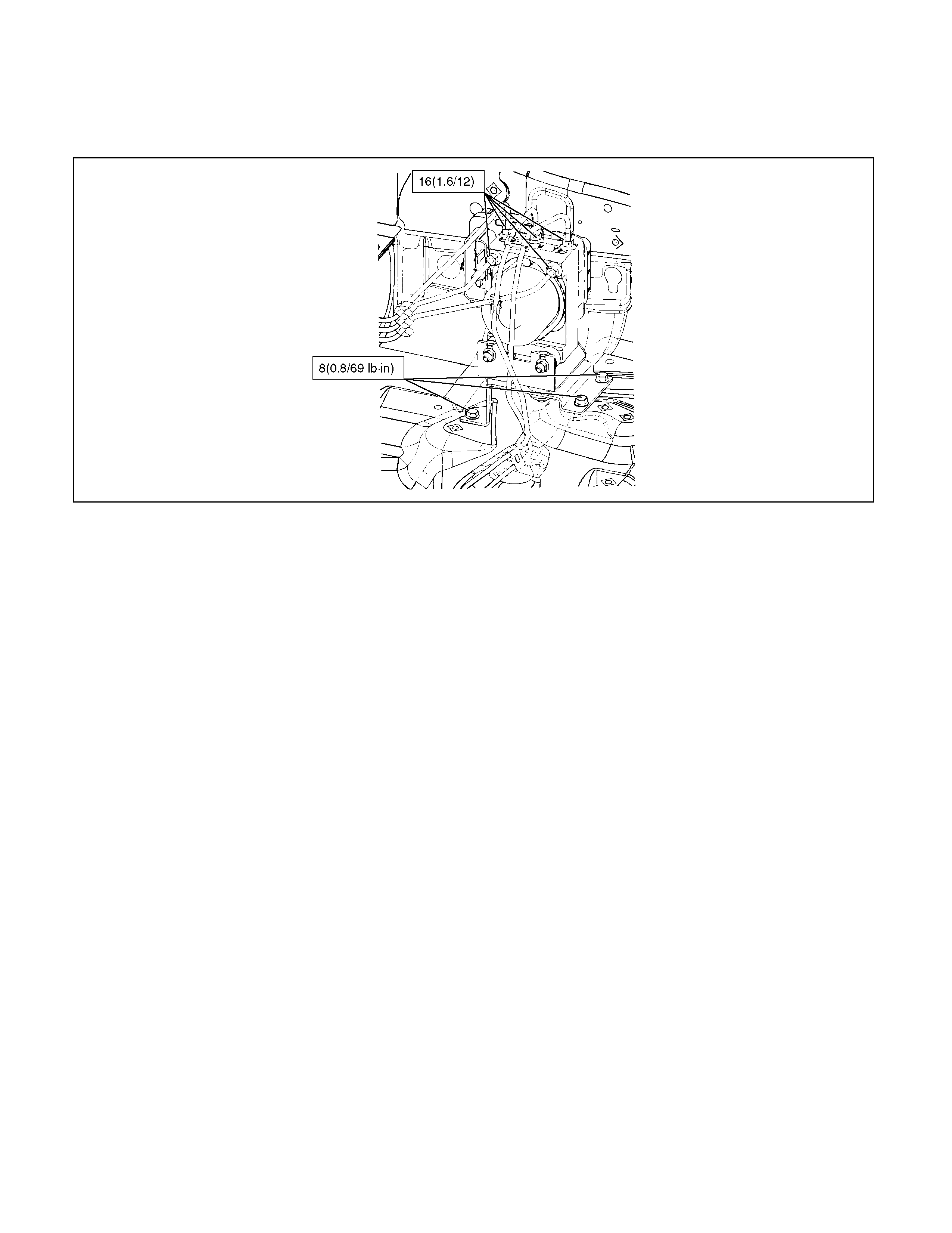
Electronic Hydraulic Control Unit
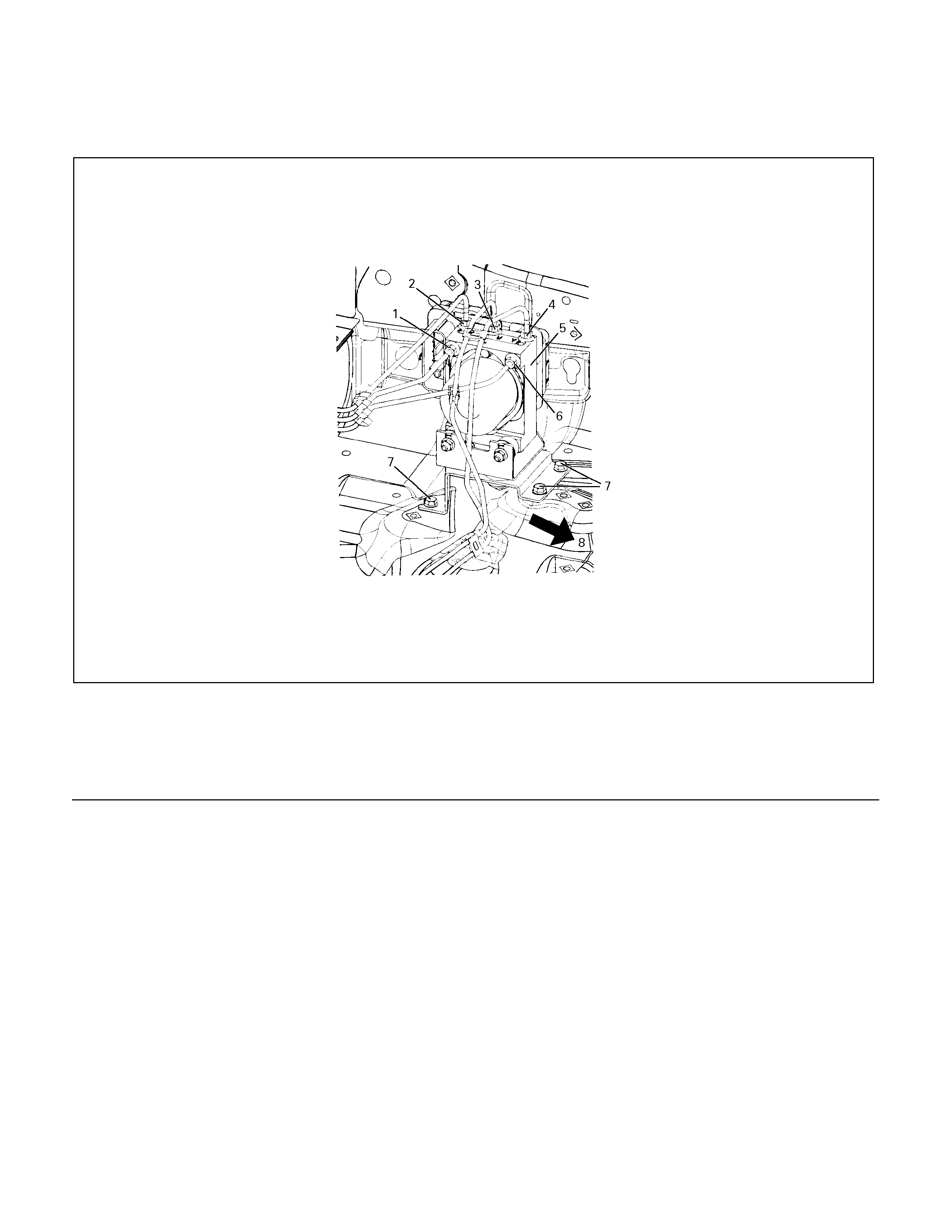
Electronic Hydraulic Control Unit and Associated Parts
360R300001
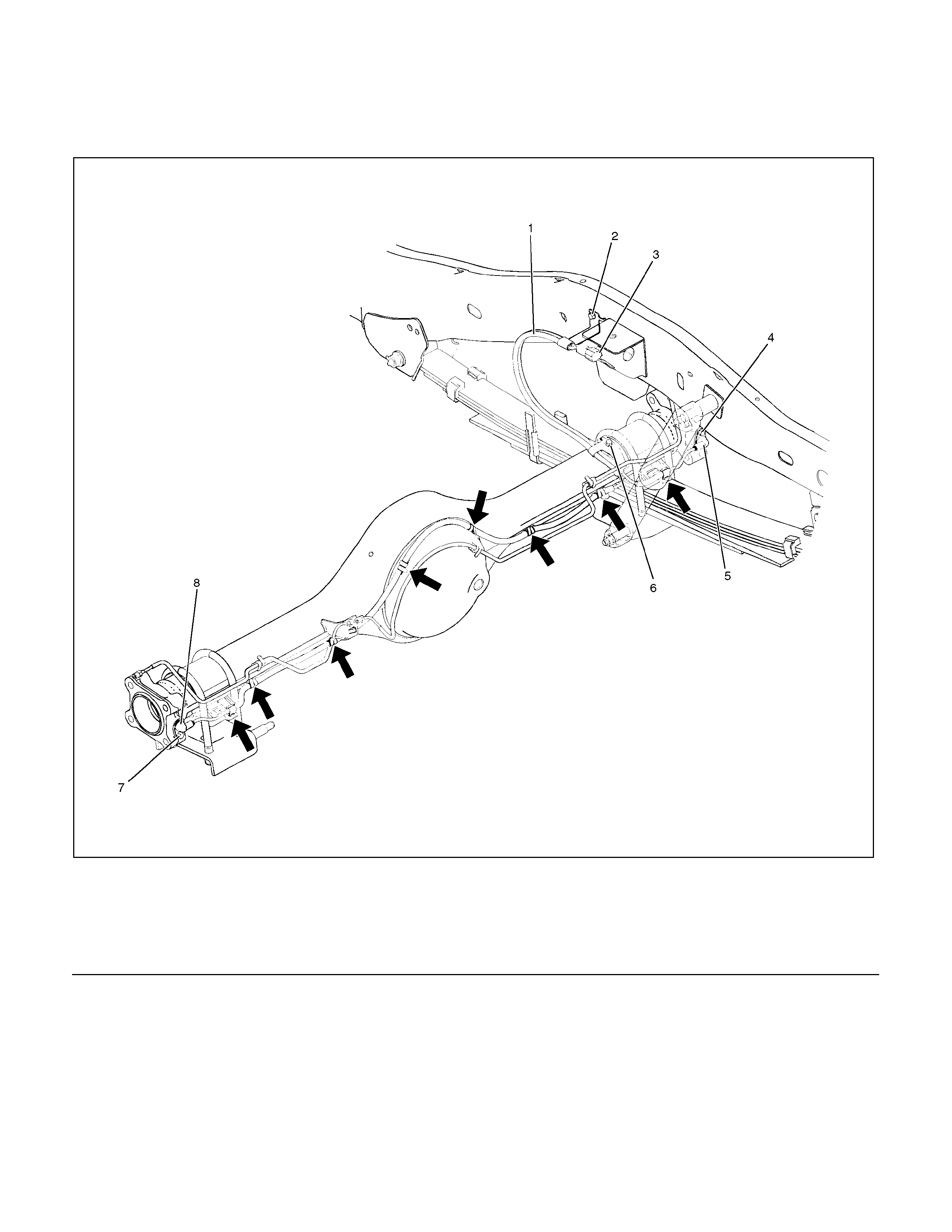
Legend
1. Flare Nut from master cylinder front
2. Flare Nut to front right wheel cylinder
3. Flare Nut to front left wheel cylinder
4. Flare Nut to rear wheel cylinder
5. Electronic Hydraulic Control Unit (EHCU)
6. Flare Nut from master cylinder rear
7. Bolt
8. Front
Removal
1. Disconnect the harness connector.
2. Loosen five flare nuts and remove brake pipes.
• After disconnecting brake pipe, cap or tape the openings of the brake pipe to prevent the entry of foreign matter.
3. Remove three bracket fixing bolts.
Installation
1. Install EHCU and tighten the bolt to the specified torque.
Torque : 8 N⋅m (0.8 kg⋅m /69 lb in)
2. Tighten the flare nuts to the specified torque.
Torque : 16 N⋅m (1.6 kg⋅m /12 lb ft)
3. Connect the harness connector.

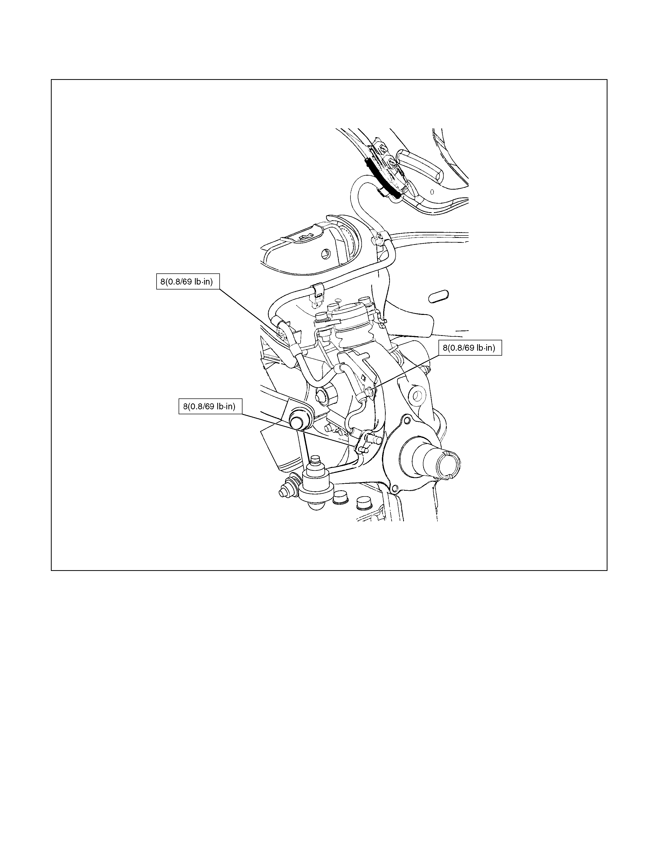
Front Wheel Speed Sensor
Front Wheel Speed Sensor and Associated Parts
350R300006
Legend
1. Connector Portion
2. Front Speed Sensor Assembly
3. Bolt : cable to knuckle
4. Bolt : sensor to knuckle
5. Nut: cable to upper link (4×2)
Bolt: cable to upper link (4×4)

Removal
1. Remove speed sensor connector at connector portion.
2. Remove sensor fixing bolt (4).
3. Remove cable fixing bolts and nut (4×2).
4. Disconnect the arrow mark locks of the cable clips.
5. Remove the speed sensor assembly.
Inspection and Repair
1. Check the speed sensor head for presence of Foreign
materials; remove any dirt, etc.
2. Check the head for damage; replace speed sensor if necessary.
3. Check the speed sensor cable for short or open circuit, and replace with a new one if necessary.
To check for cable short or open, bend or stretch the cable while checking for continuity.
Installation
1. Install the speed sensor in the knuckle and take care not to hit the speed sensor head during installation.
2. Install speed sensor fixing bolt and tighten the fixing bolt to the specified torque.
Torque: 8 N⋅m (0.8 kg⋅m /69 lb in)
3. Connect the cable clips at the arrow mark places.
4. Install the cable fixing bolt and nut (4×2) and tighten the fixing bolt and nut to the specified torque.
Torque :
Bolt 8 N⋅m (0.8 kg⋅m /69 lb in)
Nut 20 N⋅m (2.0 kg⋅m /14 lb ft)
NOTE: Confirm that the cable is not twisted when connecting the speed sensor cable.
5. Connect the speed sensor connector.
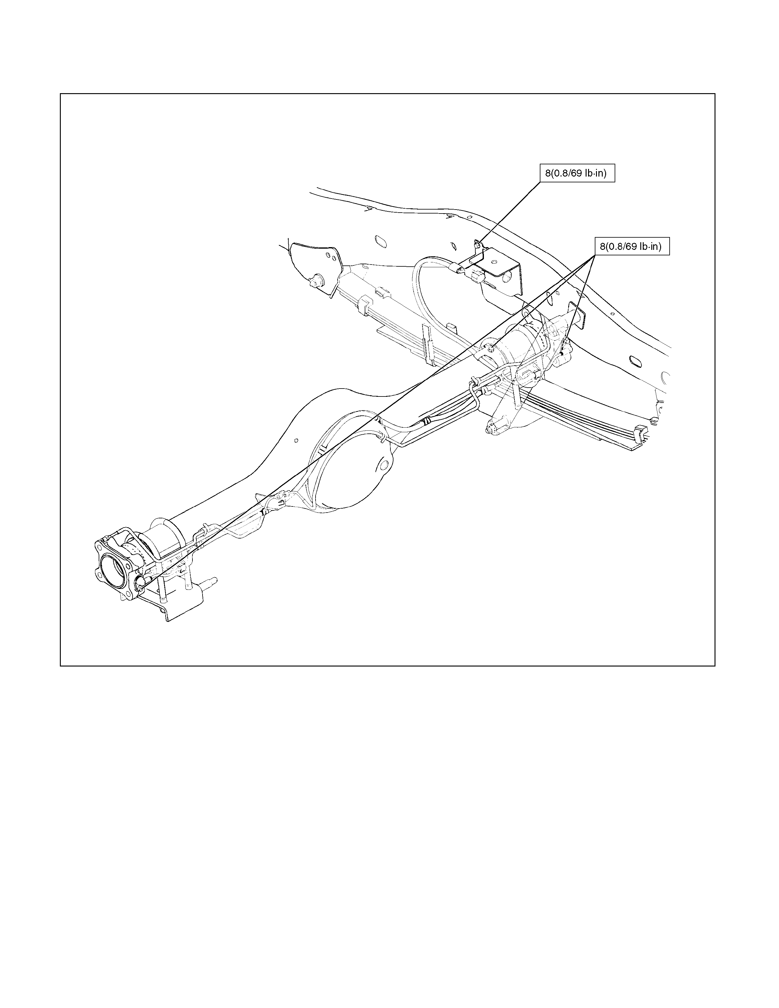
Rear Wheel Speed Sensor
Rear Wheel Sensor and Associated Parts
420R300008
Legend
1. Rear Speed Sensor Assembly
2. Bolt : cable to frame
3. Connector
4. Bolt : sensor to rear axle
5. Speed Sensor
6. Bolt : cable to axle
7. Bolt : sensor to rear axle
8. Speed Sensor

Removal
1. Disconnect the harness connector (3).
2. Remove the cable fixing bolt (2)(6).
3. Disconnect the cable fixing clips (arrow marked).
4. Remove the speed sensor fixing bolts (4)(7) and speed sensor (5)(8).
Inspection and Repair
1. Check speed sensor head for presence of foreign materials; remove any dirt, etc.
2. Check the head for damage, and replace speed sensor if necessary.
3. Check speed sensor cable for short or open, and replace with a new one if necessary. To check for cable short or
open, bend or stretch the cable while checking for continuity.
Installation
1. Install the speed sensor (5)(8).
2. Tighten the sensor fixing bolts (4)(7) to the specified torque.
Torque : 8 N⋅m (0.8 kg⋅m /69 lb in)
3. Connect the cable fixing clips (arrow marked).
4. Install the cable fixing bolts (2)(6) and tighten it to the specified torque.
Torque : 8 N⋅m (0.8 kg⋅m /69 lb in)
5. Connect the harness connector (3).
Front Speed Sensor Rotor
Front Sensor Rotor and Associated Parts
411R300010
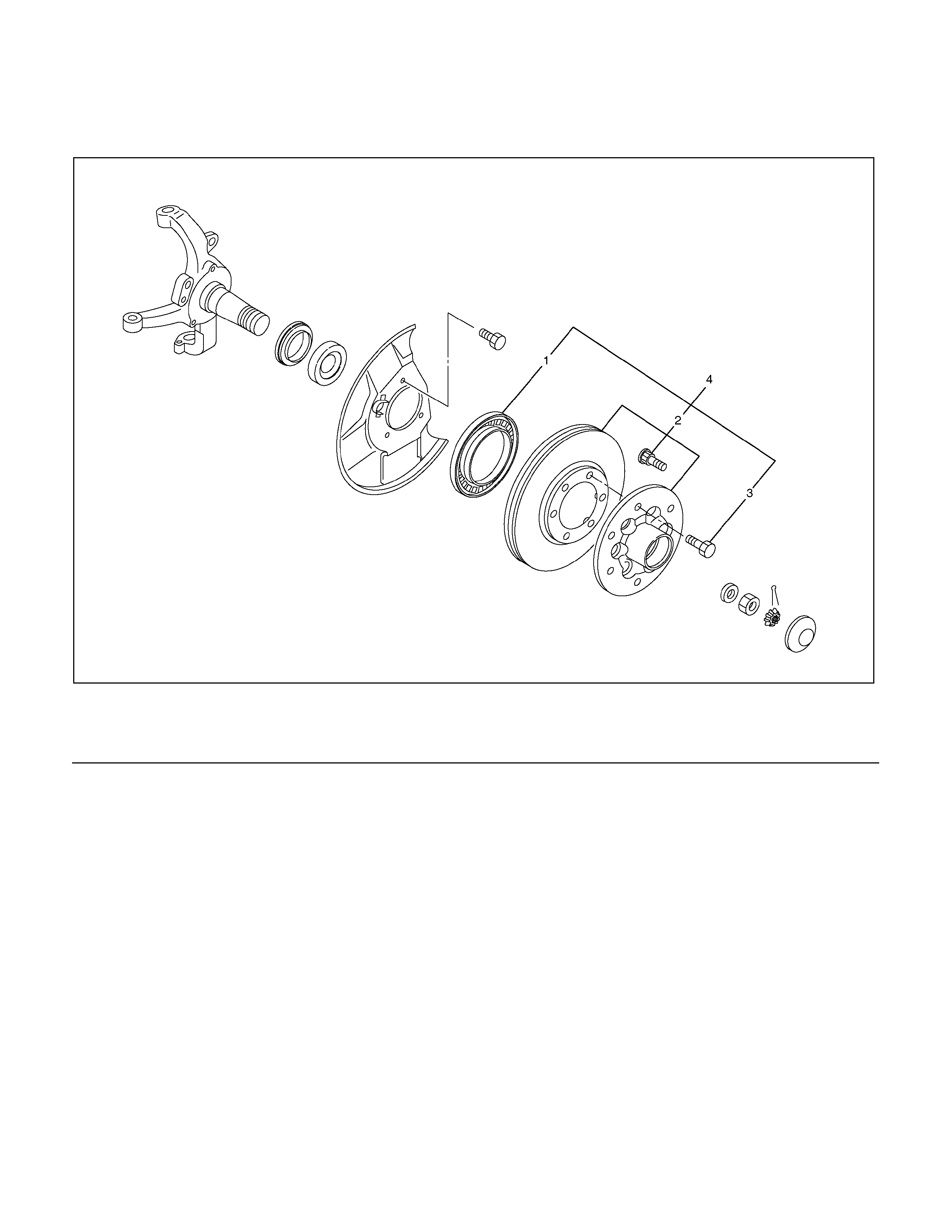
Legend
1. Sensor Rotor
2. Hub and Disc
3. Disc Rotor fixing Bolt
4. Hub and Disc Assembly
Removal
1. Remove the hub and disc assembly (4). (Refer to the section Front wheel Drive).
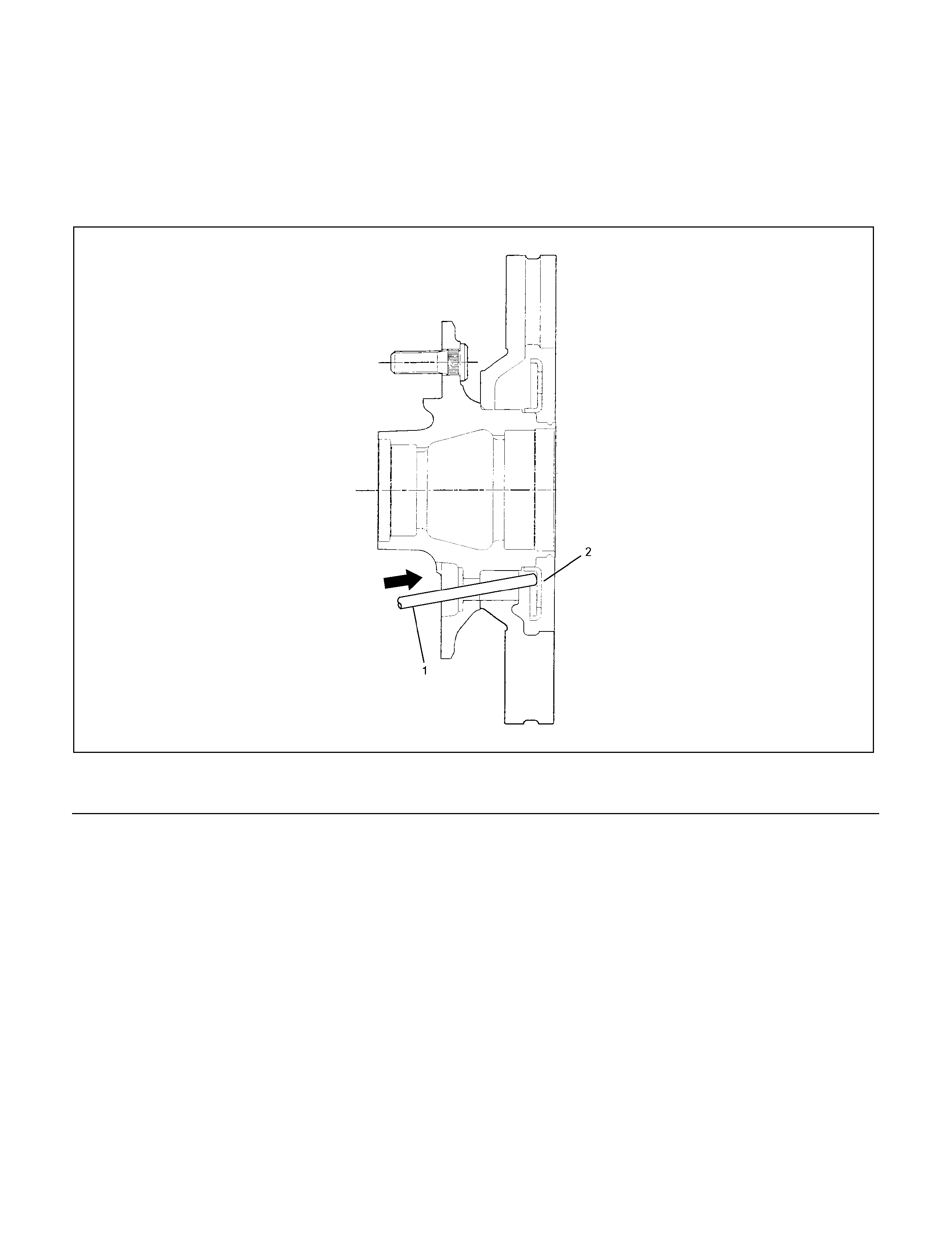
2. Remove two disc rotor fixing bolts (3) on a diagonal.
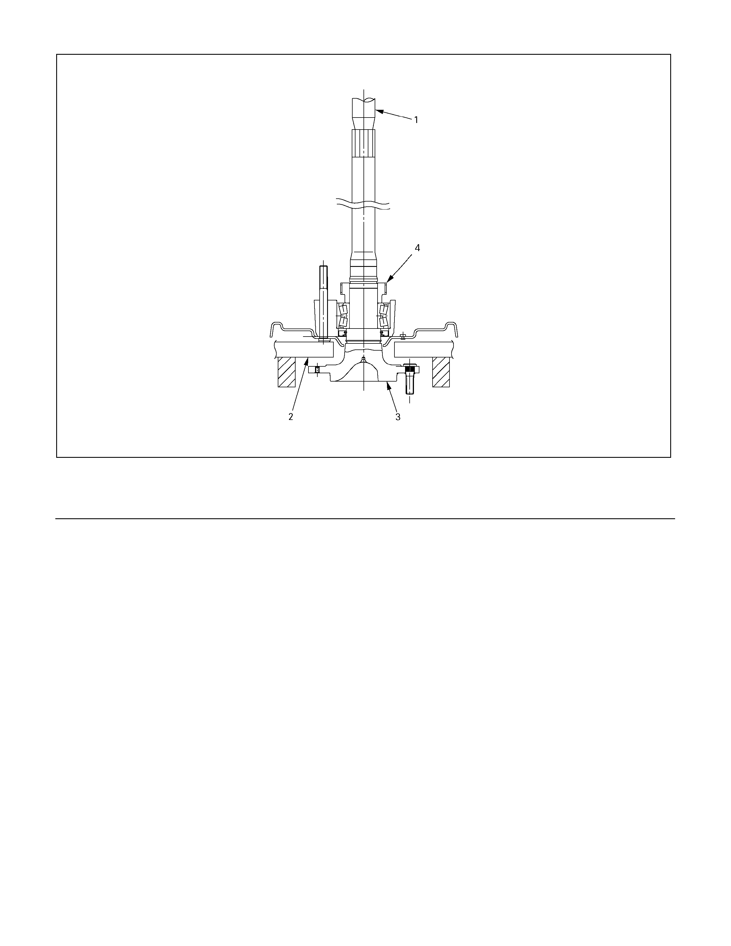
3. Drive out the sensor rotor using a metal bar and hammer through the two bolt holes.
• Discard the used sensor rotor.
4. Install disc rotot fixing bolts and tighten them to the specified torque.
Torque : 103 N⋅m (10.5 kg⋅m /76 lb ft)
411R300007
Legend
1. Metal Bar
2. Sensor Rotor
Inspection and Repair
Make all necessary adjustments, repairs or part replacement.
• Check damage or powdered iron sticking to the sensor rotor.
• Check play in the sensor rotor.
• Check a broken tooth or indentation in the sensor rotor.
NOTE: SENSOR ROTOR MUST BE REPLACED IF REMOVED FROM THE ROTOR.
Installation
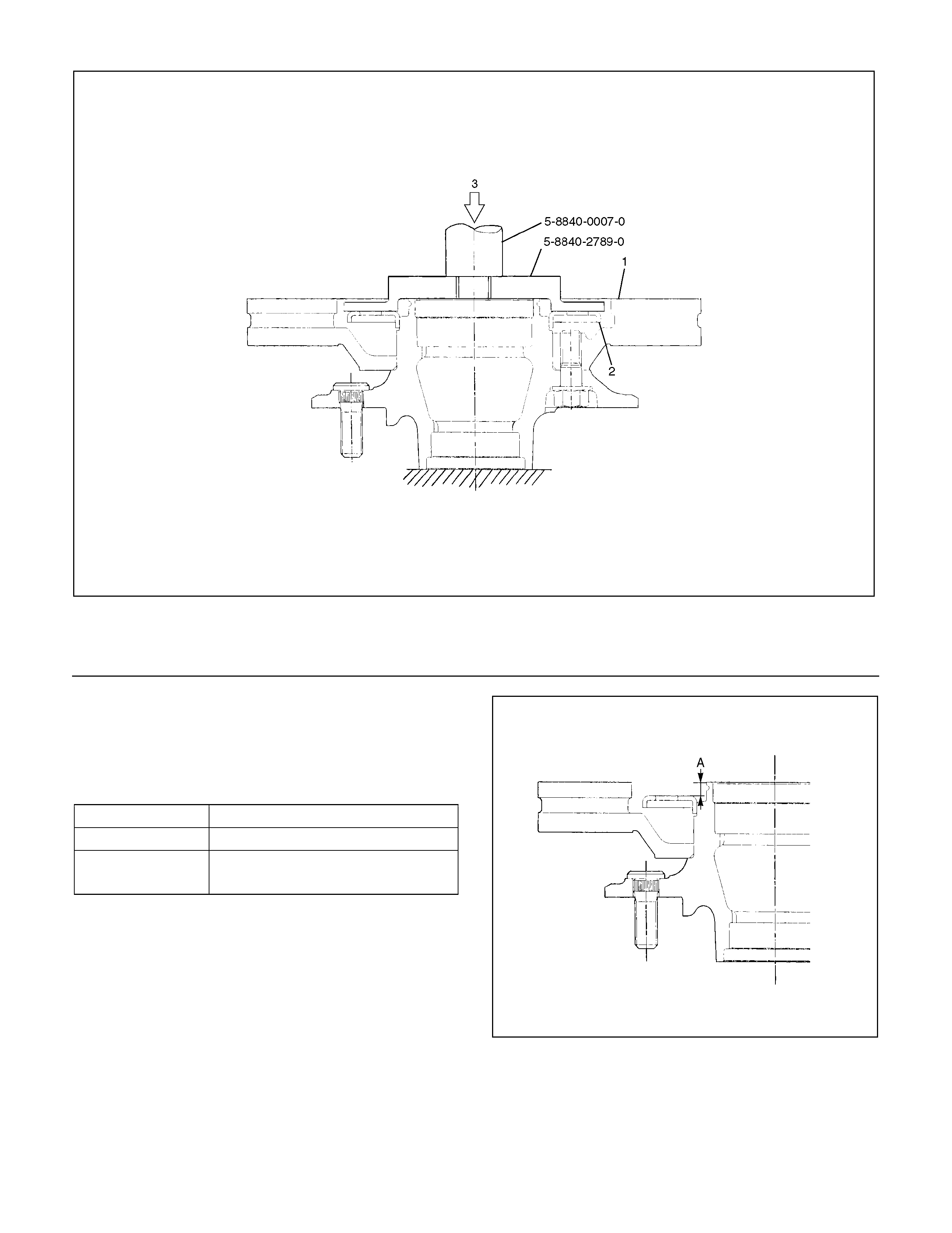
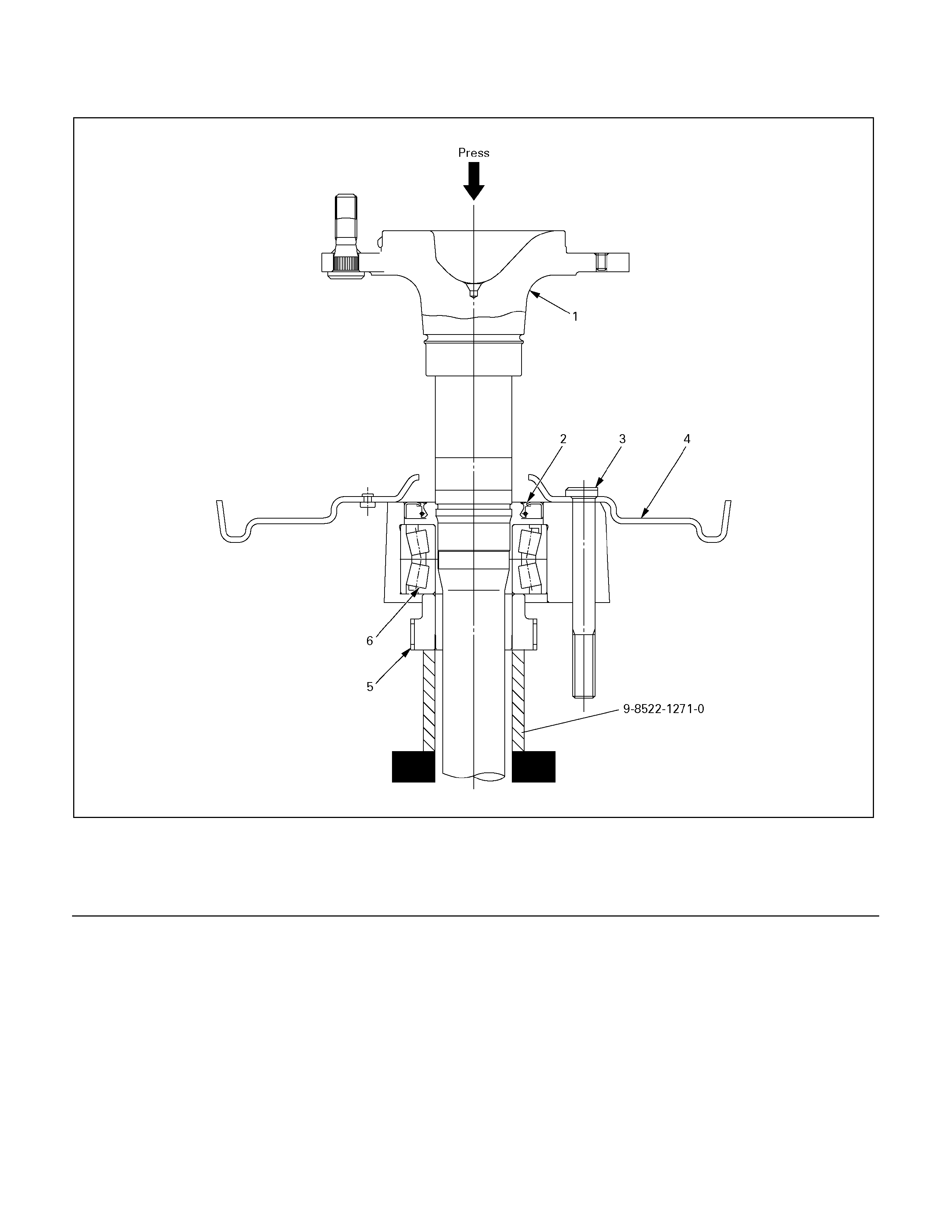
Install the new sensor rotor in the hub, using installer 5-8840-2789-0 and grip 5-8840-0007-0.
411R300006
Legend
1. Hub and Disc
2. Sensor Rotor
3. Press
3. Measure the gap “A” at 4 points at intervals of 90°
(degrees).
Confirm that the gap “A” should be within the
specified range.
Range
Type A
4 × 2 7.0
− 7.4 mm ( 0. 276 − 0.291 in)
4 × 4,
4 × 2 High Ride 7.2 − 7.6 m m ( 0.283 − 0.299 in)
411R300016
4. Install the hub and disc assembly. (Refer to the
section Front Wheel Drive).

A03R300003
Legend
1. Bench Press Fitting
2. Steel Plate (25-30 mm thickness)
3. Axle Shaft
4. Sensor Rotor
Inspection and Repair
Make all necessary adjustments, repairs or part replacement.
• Check damage or powdered iron sticking to the sensor rotor.
• Check play in the sensor rotor.
• Check a broken tooth or indentation in the sensor rotor.
NOTE: If replacement is required remove the sensor rotor from the axle shaft assembly with brake. (Refer to the
section Rear Axle).
• Discard the used sensor rotor.
(Smapring, Oil seal and Bearing)
Installation
1. Install the sensor rotor and assemble it into the axle shaft assembly with back plate. (Refer to Rear Axle)
420R300005
Legend
1. Axle Shaft
2. Oil Seal
3. Bolt
4. Back Plate
5. Sensor Rotor
6. Double Taper Roller Bearing
2. Install the axle shaft assembly with brake in the rear axle. (Refer to the section Rear Axle ).
G-Sensor
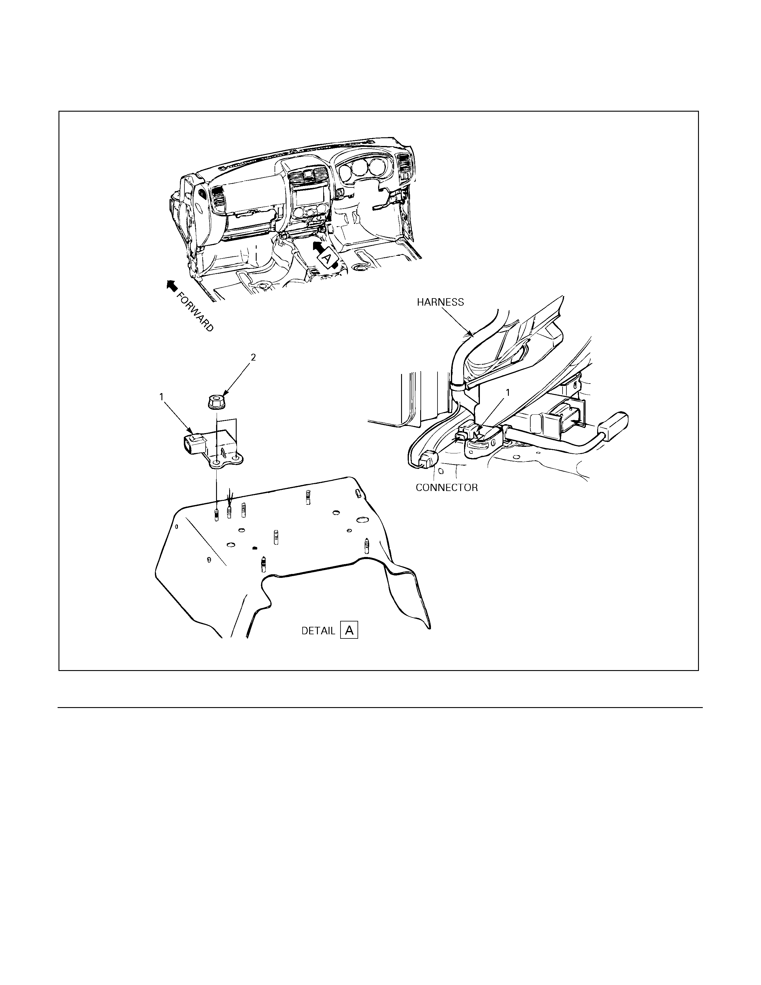
G-Sensor and Associated Parts
350R300007
Legend
1. G-Sensor
2. Nut
Removal
1. Remove the front floor console. (Refer to the section Floor Console)
2. Disconnect the connector.
3. Remove the nuts.
4. Take out the G-sensor.
Installation
1. Set the G-sensor.
2. Install the nut and tighten it to specified torque.
Torque : 8.0 N·m (0.8 kg·m /69 lb in)
3. Connect the connector.
4. Install the front floor console. (Refer to “Floor Console”)
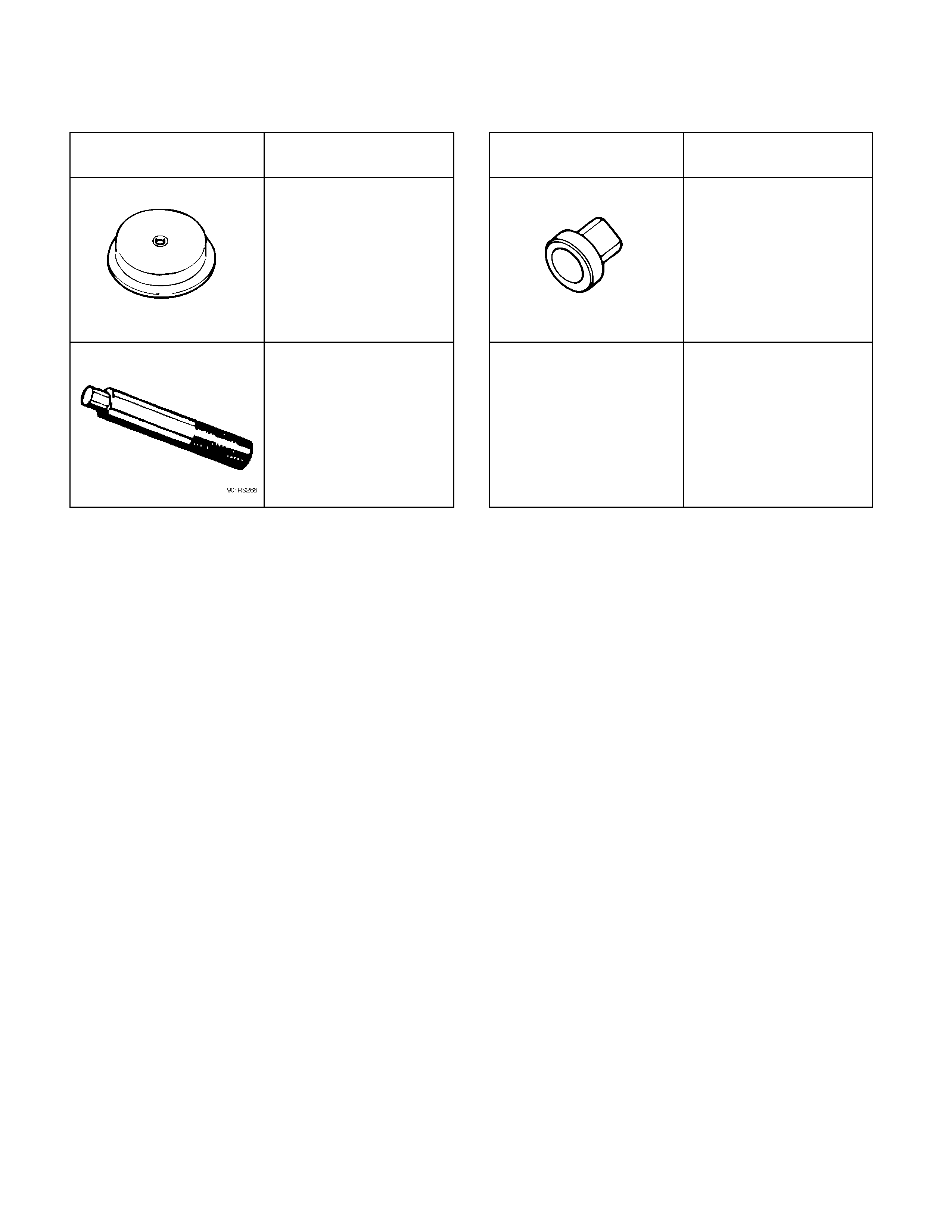
Special Tools
ILLUSTRATION PART NO.
PART NAME ILLUSTRATION PART NO.
PART NAME
5–8840–2789–0
Installer ; Sensor rotor,
front hub
9-8522-1271-0
Setting Tool
5-8840-0007-0
Grip