
SECTION 5C - BRAKES
General Description
Main Data and Speci fications
Torque Specifications
Servicing
Front Brake Assembly
Removal and Installati on
Removal and installation of Disc Pad
Disassembly
Inspection and Repair
Reassembly
Rear Drum Brake Assembly
Disassembly
Inspection and Repair
Reassembly
Brake Control
Removal and Installation
Master Cylinder
Removal and Installation
Disassembly
Inspection and Repair
Reassembly
Vacuum Booster
Removal and Installation
Adjustment Procedure Of Brake Pedal
Techline
GENERAL DESCRIPTION
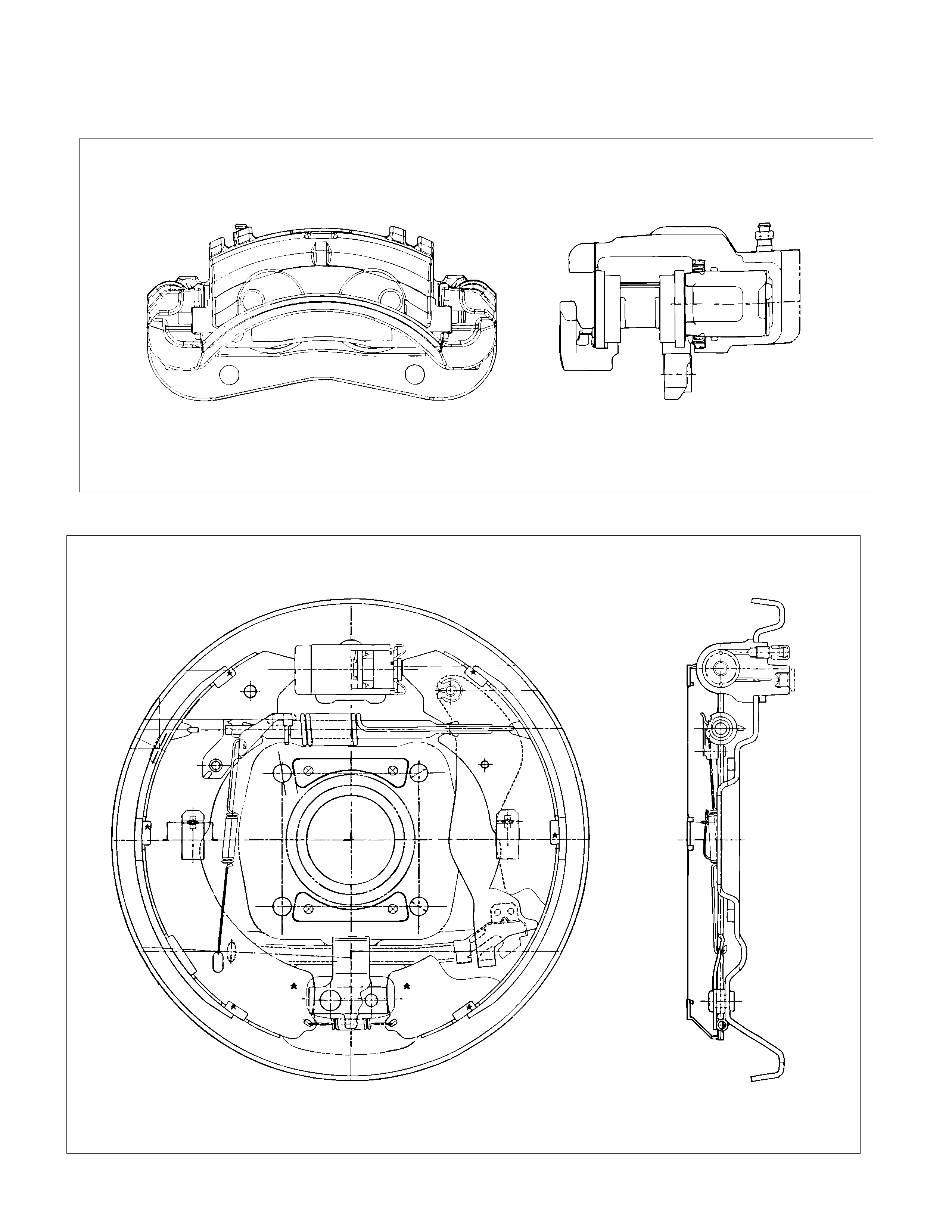
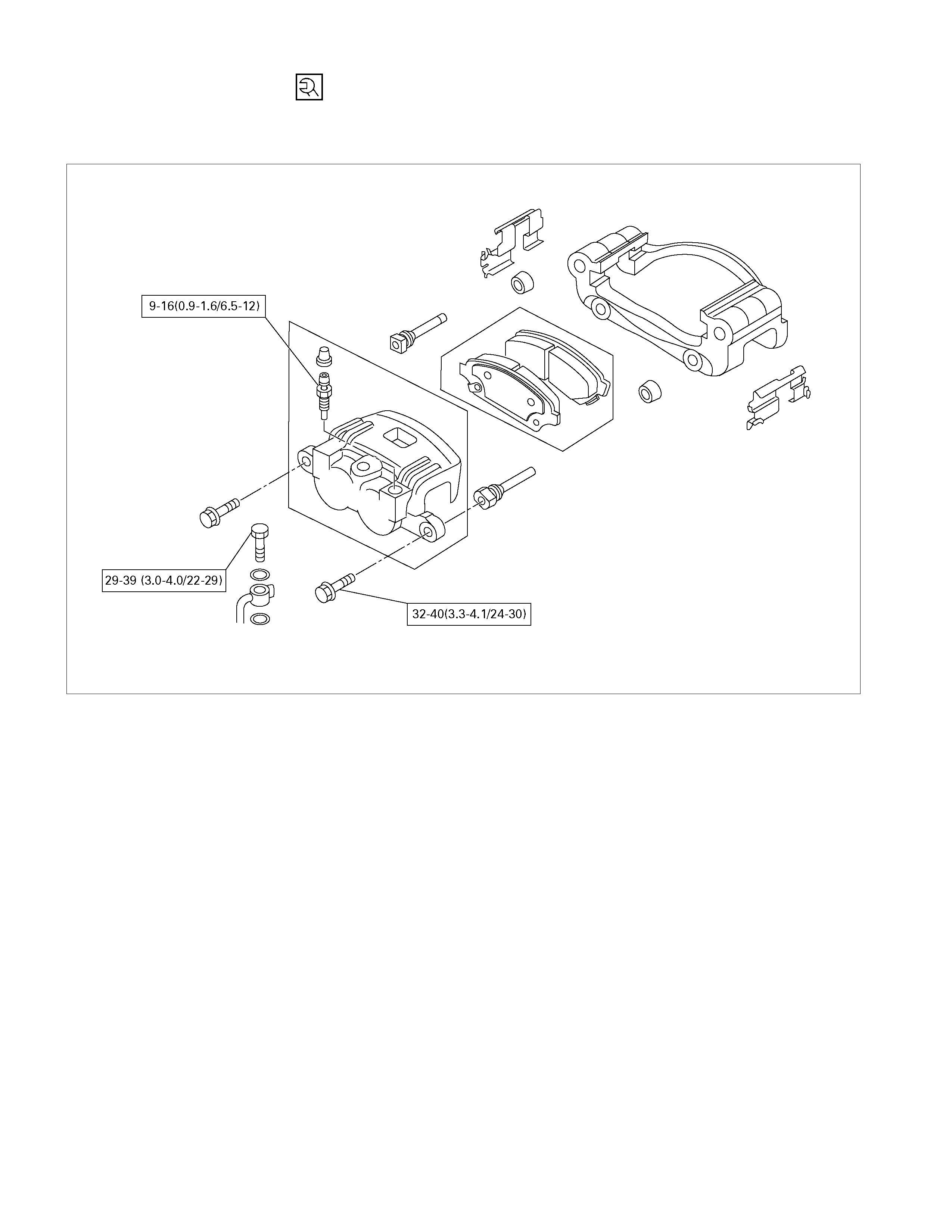
FRONT DISC BRAKE
REAR DRUM BRAKE
REAR WHEEL CYLINDER
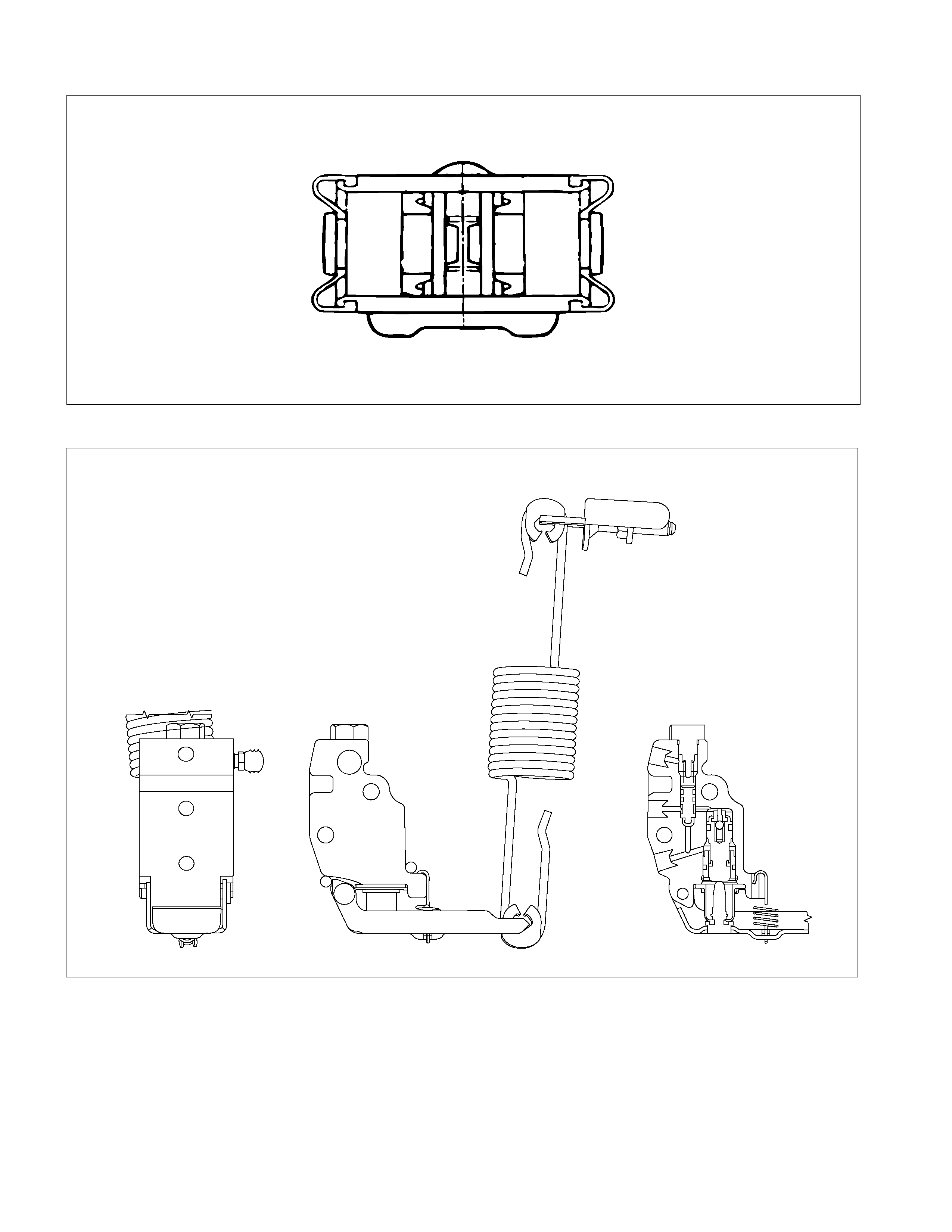
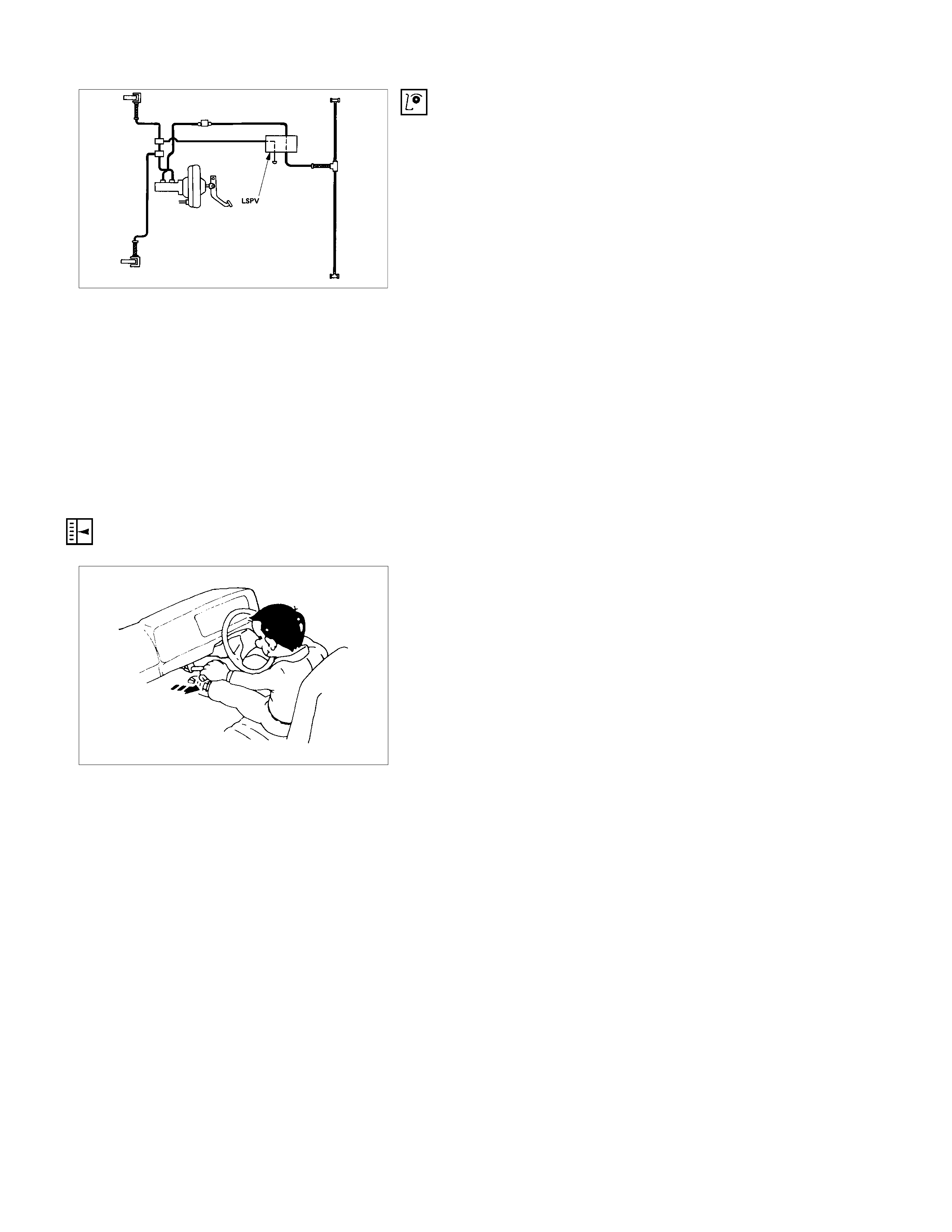
LOAD SENSING PROPORTIONING VALVE (LSPV)
RTW35CMF000101
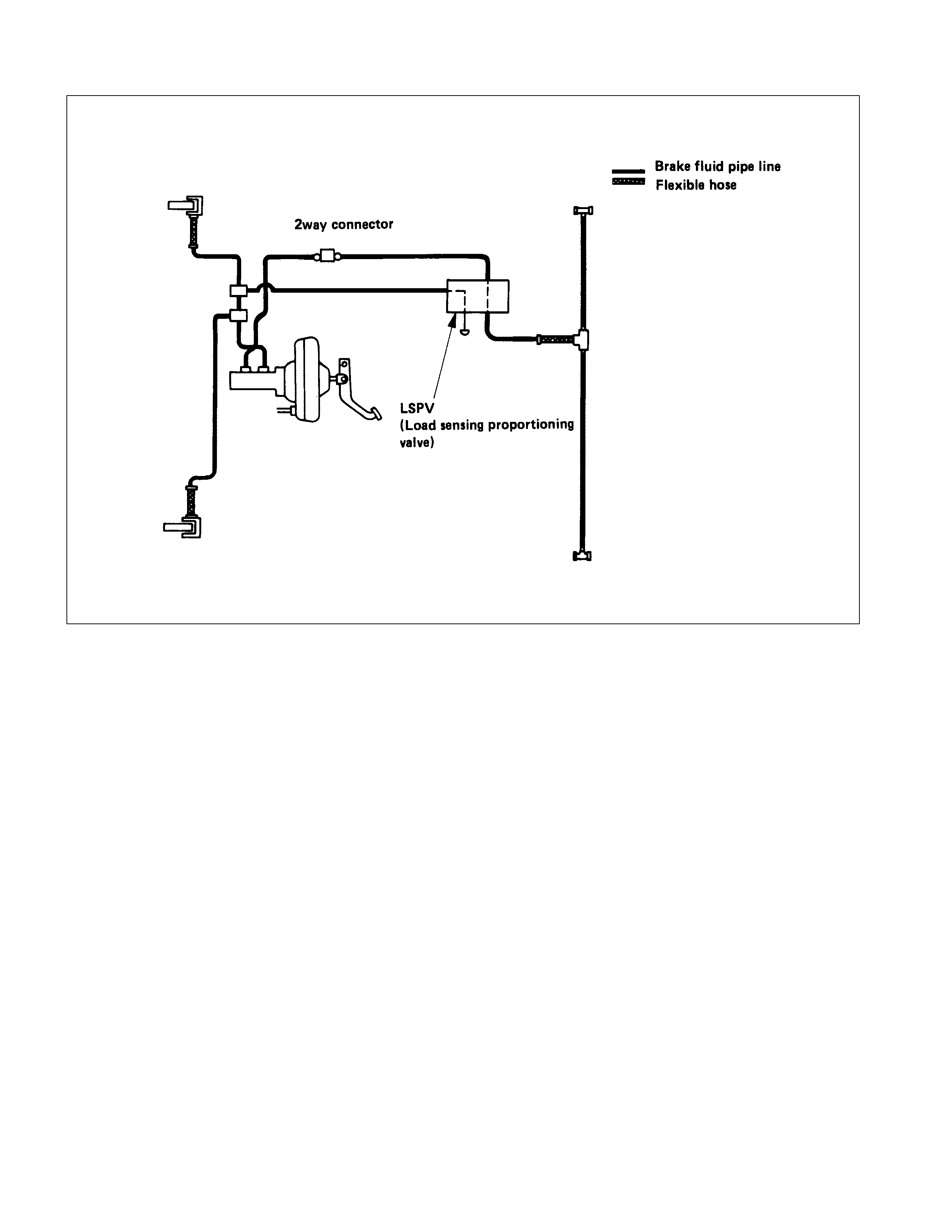
HYDRAULIC LINE DIAGRAM (MODEL WITH LOA D SENSING PROPORTIONING VALVE)
05007-2
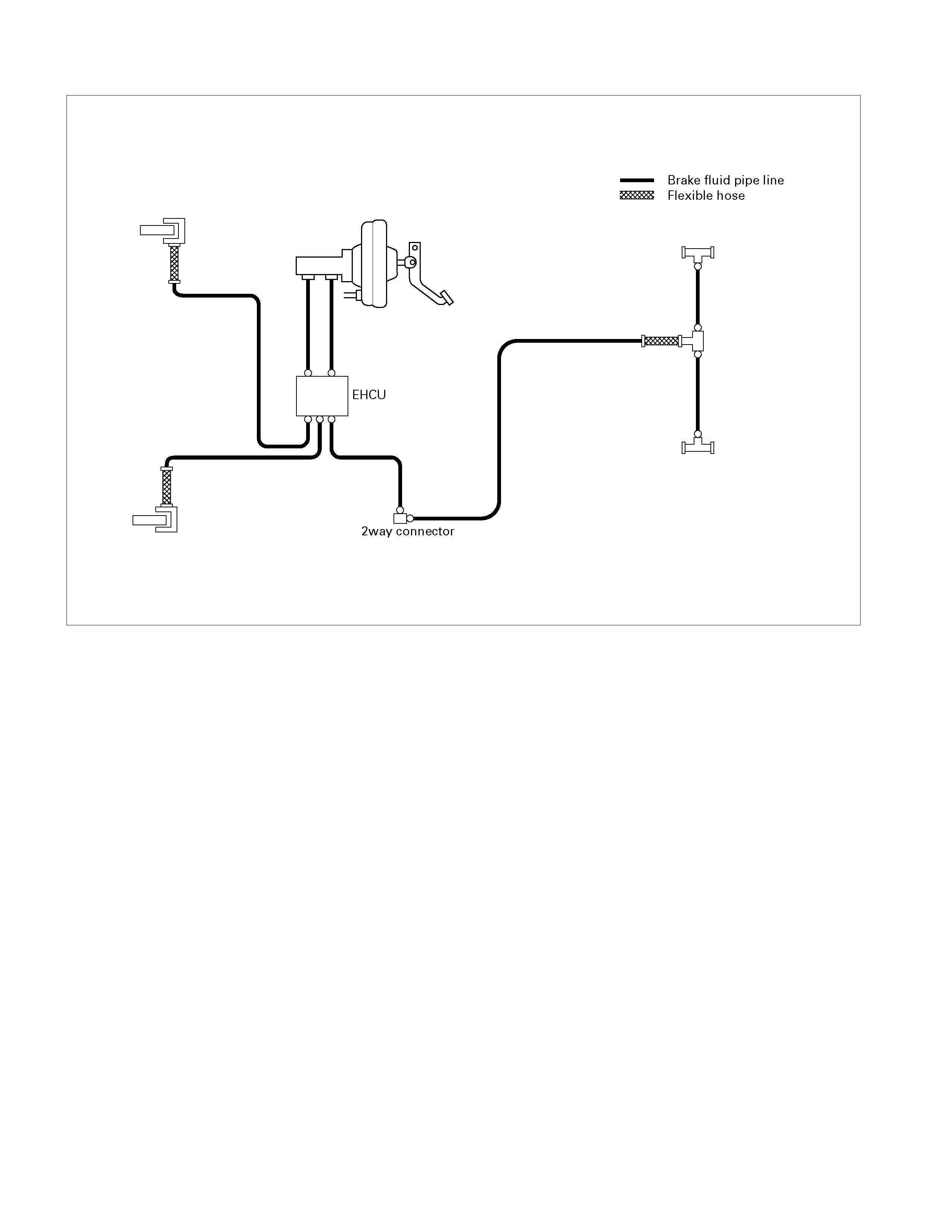
HYDRAULIC LINE DIAGRAM (MODEL WITH A BS)
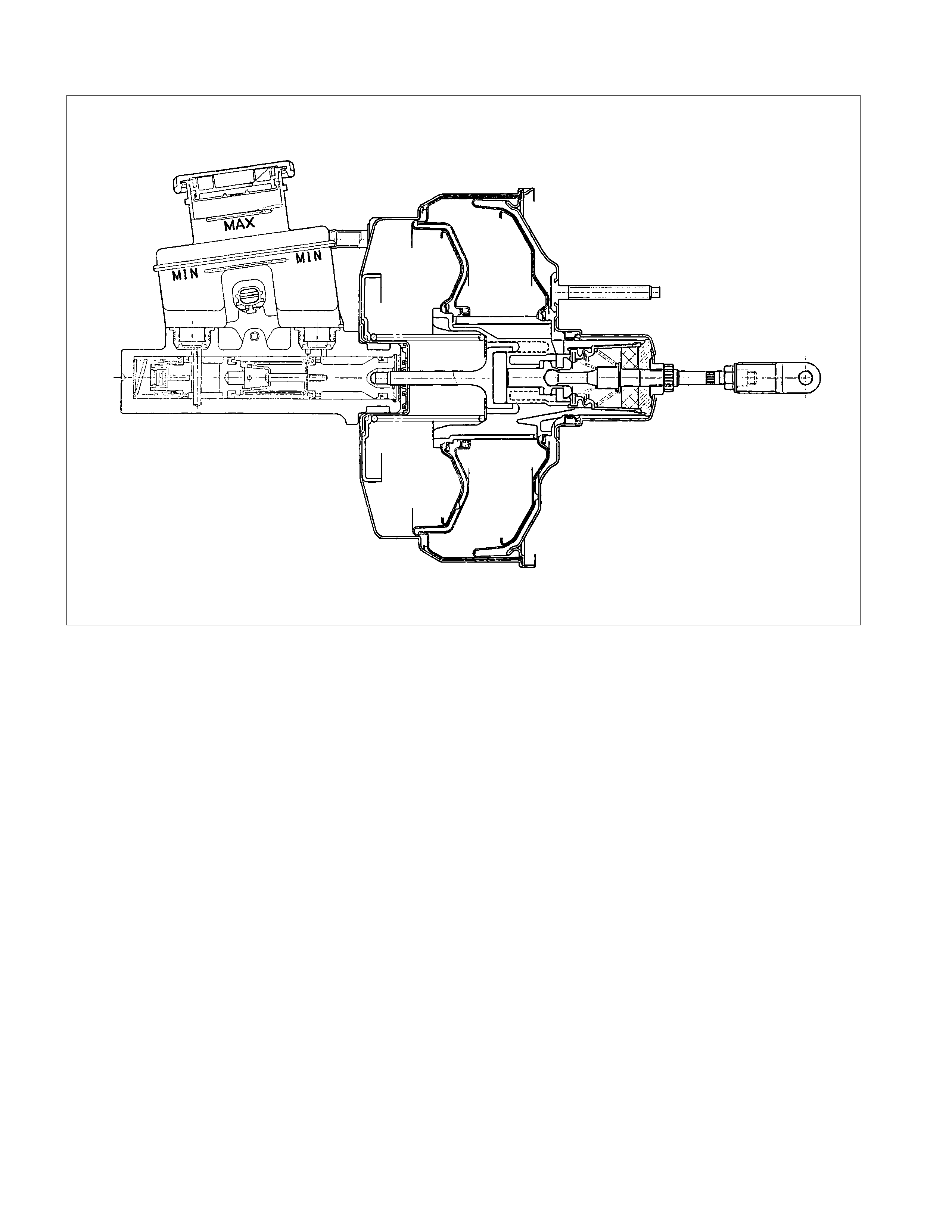
VACUUM SERVO WITH MASTER CYLINDER

MAIN DATA AND SPECIFICATIONS
FRONT DISC BRAKE mm(in.) 4 × 2 4 × 4, 4 × 2 HIGH RIDE
Caliper type Pin slide
Disc outside diameter 256(10.079) 280 (11.023)
Disc thickness 26(1.024) 27 (1.063)
Piston diameter 42.8 (1.685) × 2 45.5 (1.79)
Adjustment method Self-adjusting
REAR DRUM BRAKE mm(in.) 4 × 2 4 × 4
Type Leading and Trailing
Drum inside diameter 254(10.008) 295 (11.614)
Brake lining dimension 244 × 50 × 5 283 × 45 × 5
(Length × Width × Thickness) (9.57 × 1.97 × 0.20) (11.14 × 1.77 × 0.20)
Adjustment method Self-adjusting
WHEEL CYLINDER mm(in.)
Inside diameter : rear 25.4 (1.000) 23.8 (0.937)
MASTER CYLINDER mm(in.)
Type Split
Bore diameter 25.4 (1.000)
Piston stroke (Primary + Secondary) 21.8 + 12 (0.86 + 0.47)
VACUUM SERVO mm(in.) 6VE1/C24NE 4JH1-TC
Diaphragm diameter 205(8.077) + 230(9.055) 180(7.087) + 205(8.077)
Power cylinder stroke 35 (1.378)
PEDAL RATIO 3.7
BALANCE
Type Blend proportioning valve/EBD (with ABS)
TORQUE SPECIFICATIONS
FRONT WHEEL BRAKE
N⋅m(kgf⋅m/lb⋅ft)
E05R300016
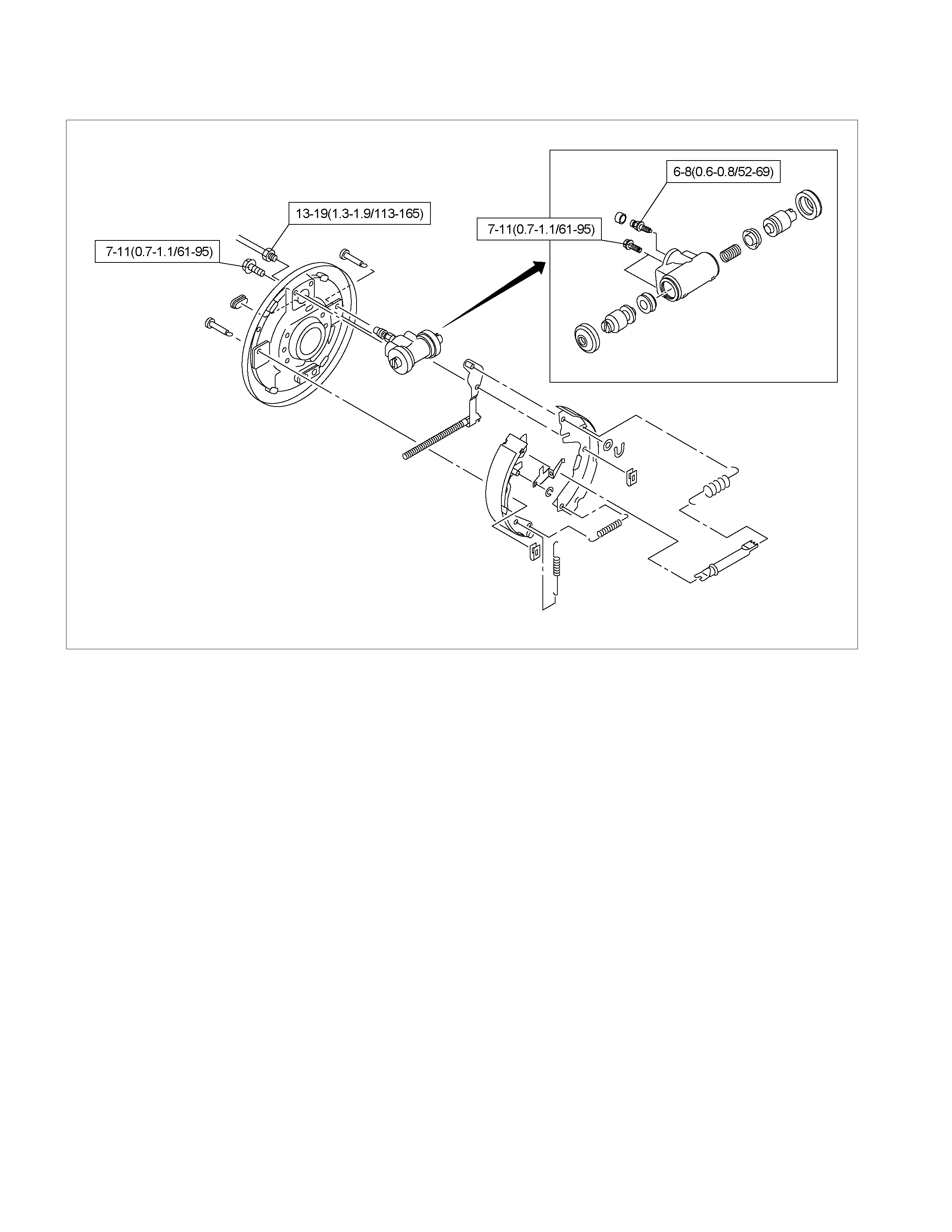
REAR WHEEL DRUM BRAKE
N⋅m(kgf⋅m/lb⋅in)
E05R300014-1
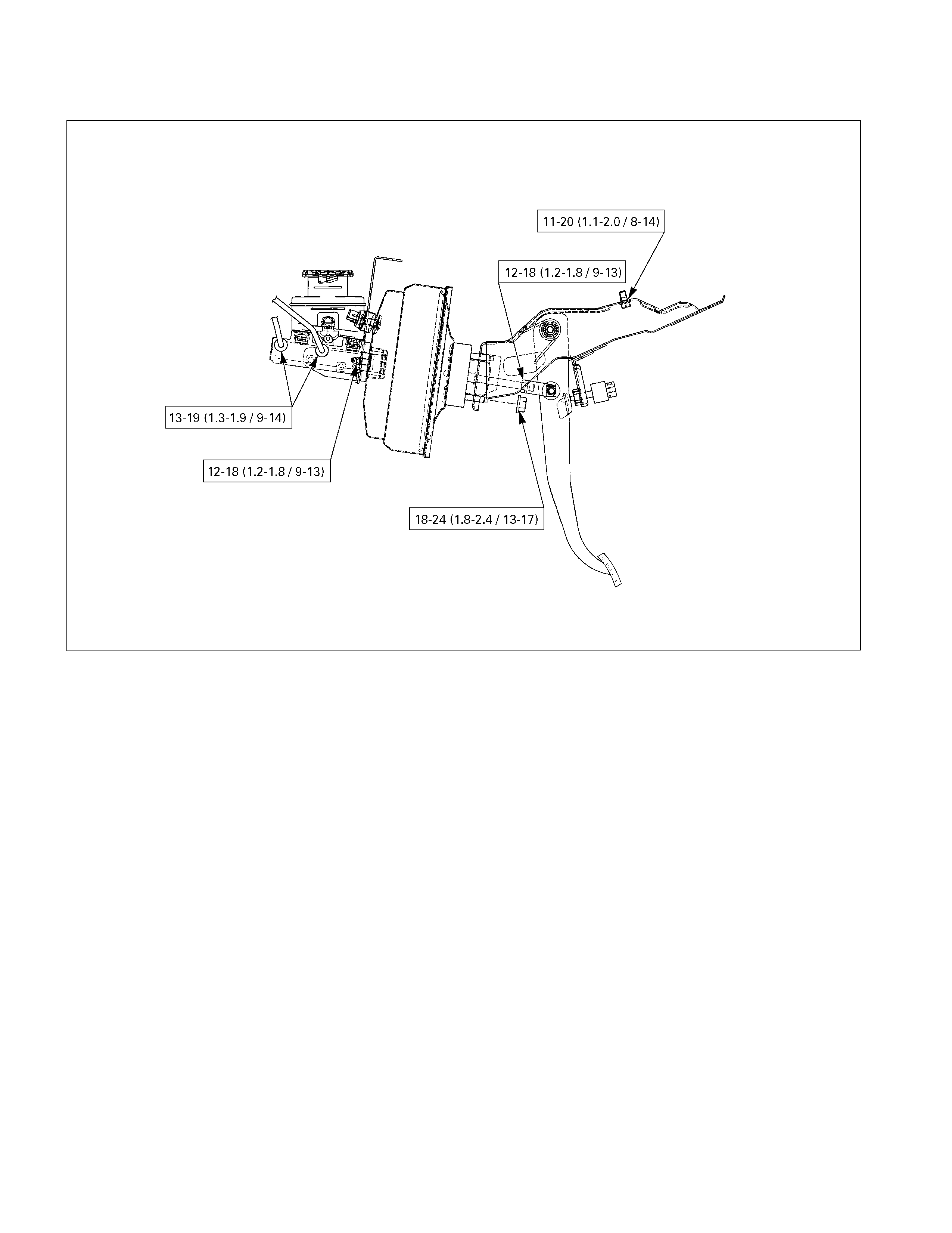
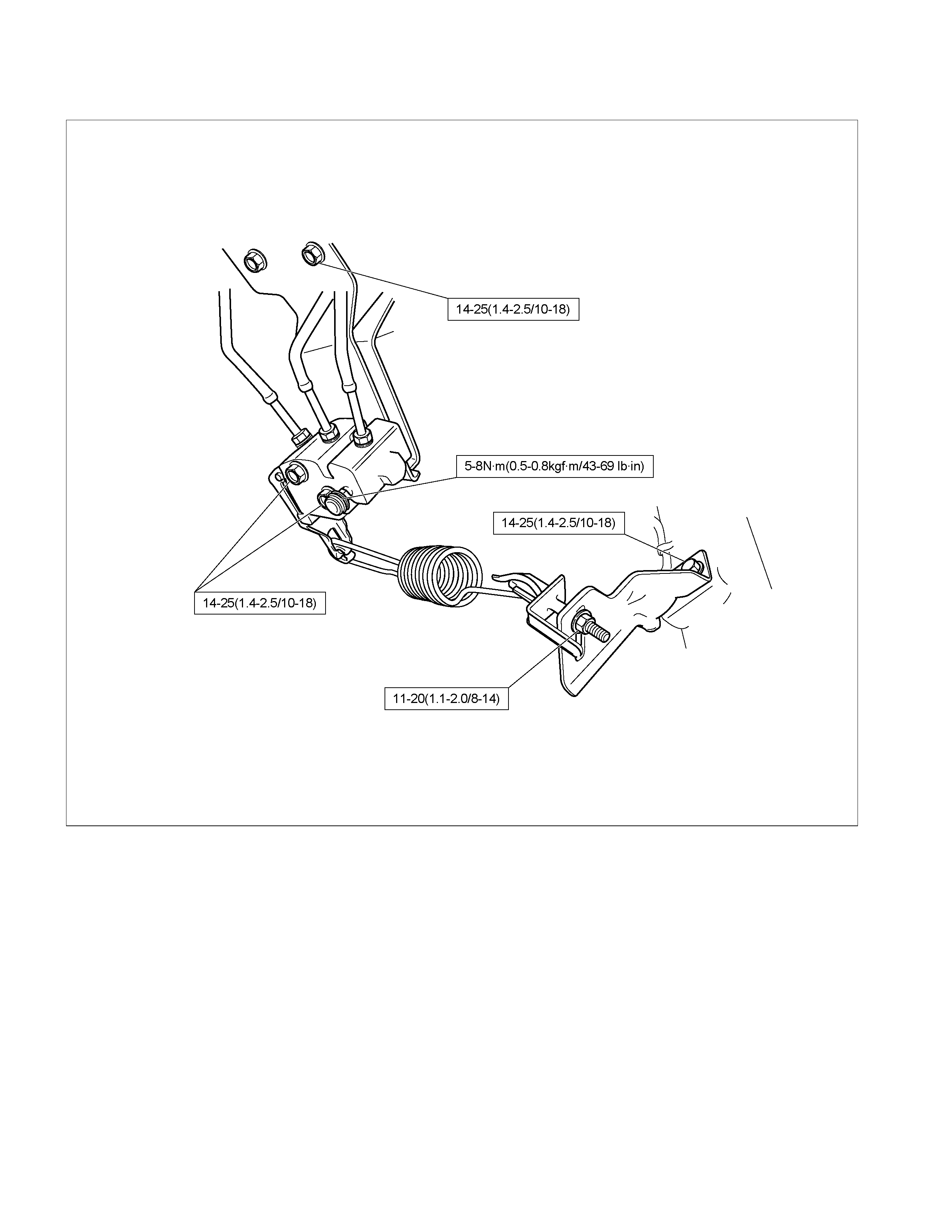
VACUUM SERVO WITH MASTER CYLINDER AND BRAKE PEDAL
N⋅m(kgf⋅m/lb⋅ft)
LOAD SENSING PROPORTIONING VALVE (LSPV)
N⋅m(kgf⋅m/lb⋅ft)
RTW5CLF000101
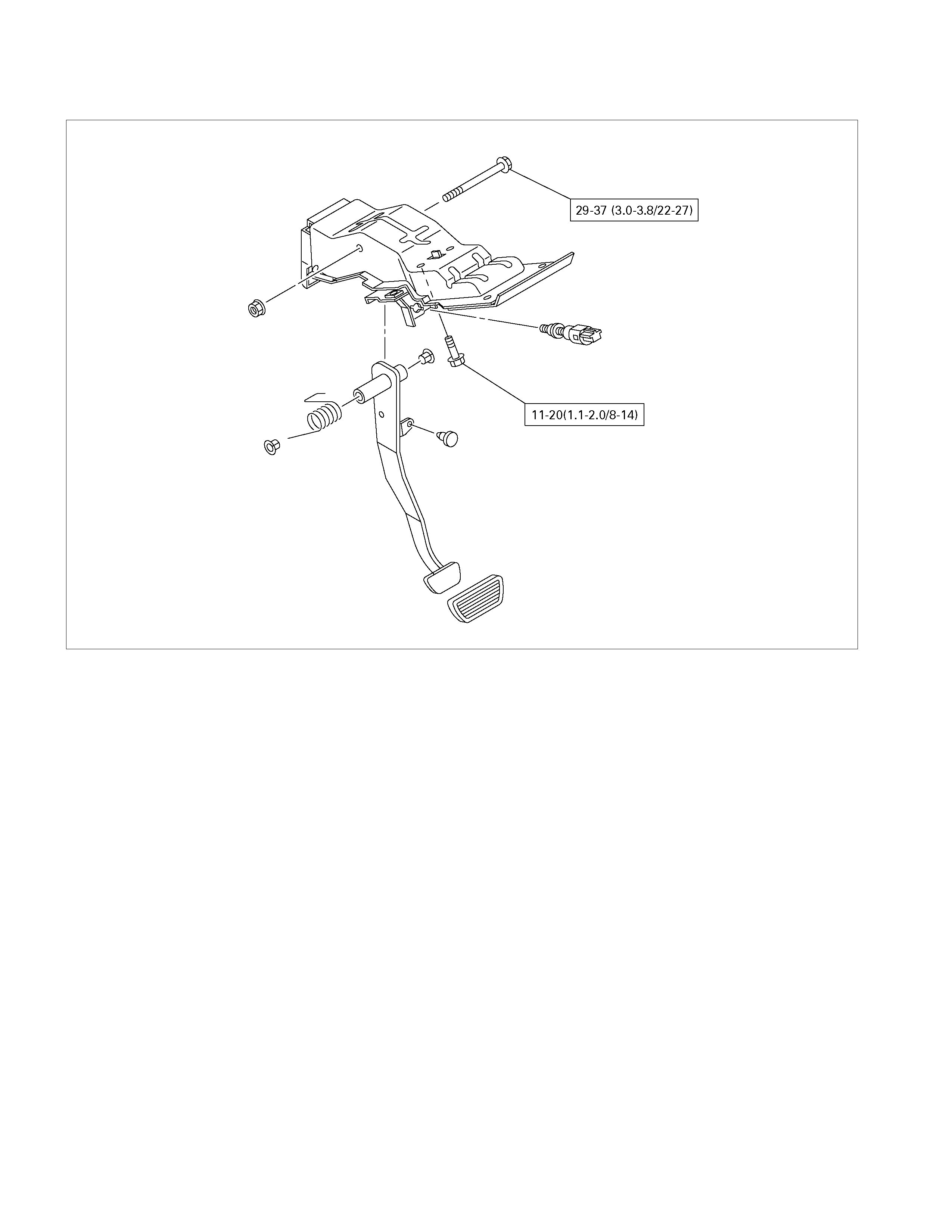
BRAKE PEDAL ASSEMBLY
N⋅m(kgf⋅m/lb⋅ft)
E05R300011-1

BRAKE LINES (HOSES AND PIPES) (MODEL WITH LOAD SENSING PROPORTIONING VALVE)
N⋅m(kgf⋅m/lb⋅ft)
29-39 (3.0-4.0/22-29)
13-19 (1.3-1.9/9.4-14)
11-20 (1.1-2.0/8-14)
13-19 (1.3-1.9/9.4-14)
7.8-18 (0.8-1.8/5.8-13)
13-19 (1.3-1.9/9.4-14)
Eye Bolt Tightening
05020
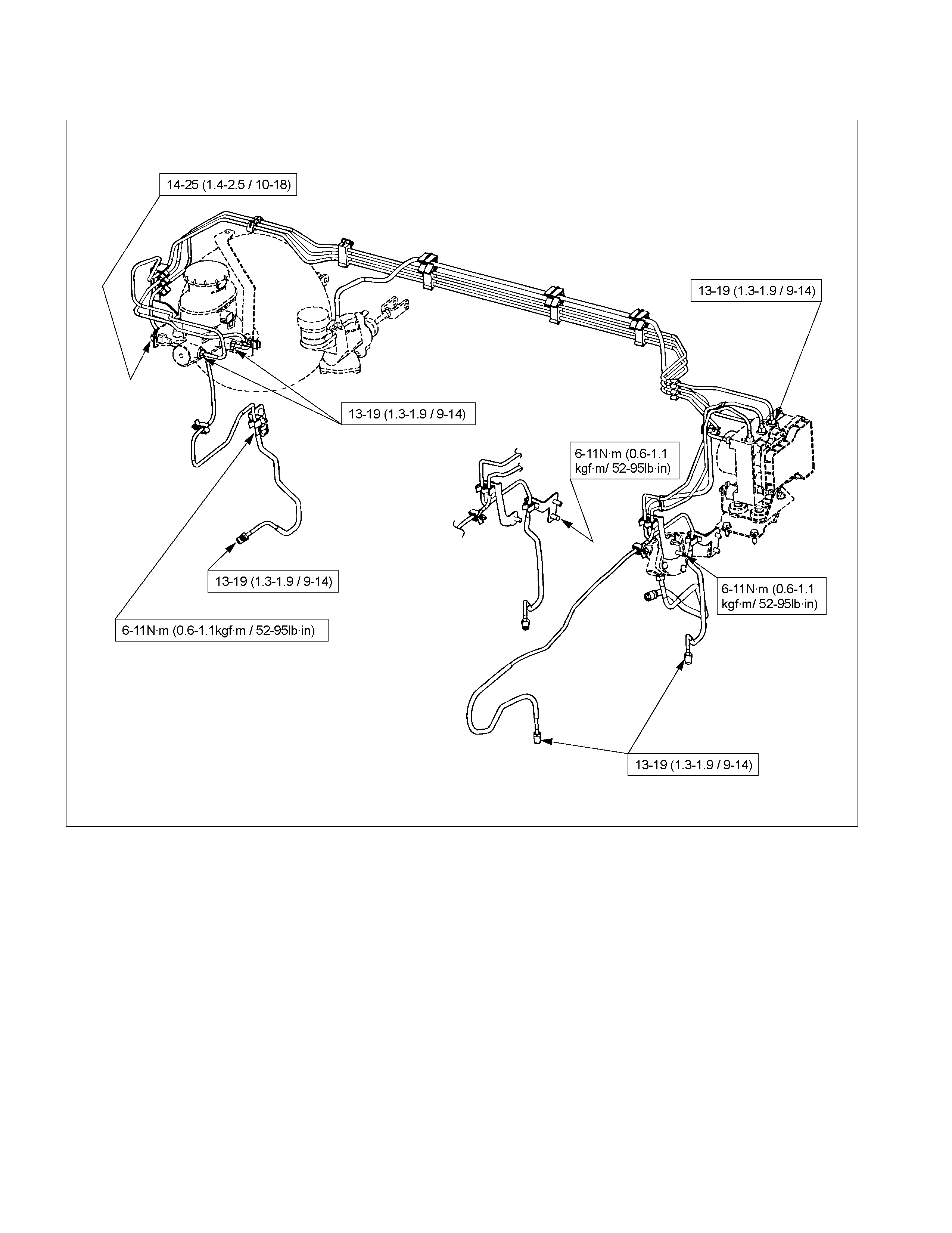
BRAKE LINES (HOSES AND PIPES) (MODEL WITH ABS)
N⋅m(kgf⋅m/lb⋅ft)
RTW35CLF0002
SERVICING
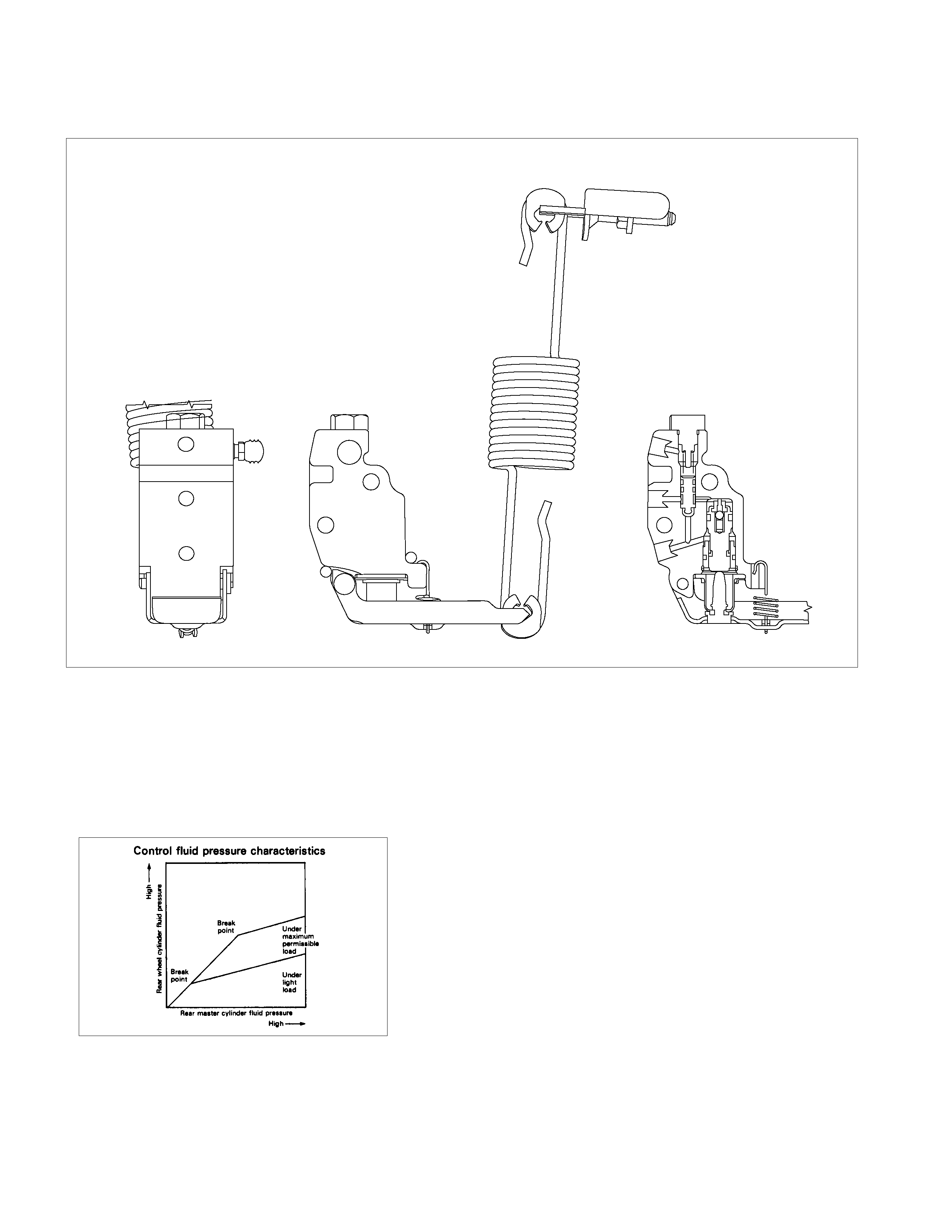
LOAD SENSING PROPORTIONING VALVE (LSPV)
RTW35CMF000101
Structure and Operation
The following is an explanation of the structure and operation
of the spring type load sensing device.
This device controls the fluid pressure to the rear brakes in
accordance with changes in rear axle load (vertical
displacements of the rear axle springs).
•
••
• Structure
This device consists of a load sensing spring and a valve.
The valve is mounted through a bracket to the frame.
One end of the load sensing spring is fixed to the valve at
the frame and the other end to the rear axle housing
through a bracket.
RTW35CSH001001
•
••
• Operation
1) Outline
When the LSPV (Load Sensing Proportioning Valve)
detects a change in load weight, the load sensing spring
stretches.
Its reaction force is transmitted to the bottom of the load
sensing valve to secure an optimum rear wheel cylinde
r
fluid pressure break point in proportion to the actual load
weight.
Besides, if the front brake system should fail, the device is
designed to prevent the master cylinder fluid pressure from
decreasing and to apply it directly to the rear wheel cylinde
r
to obtain a sufficient braking performance.
RTW35CSH001101
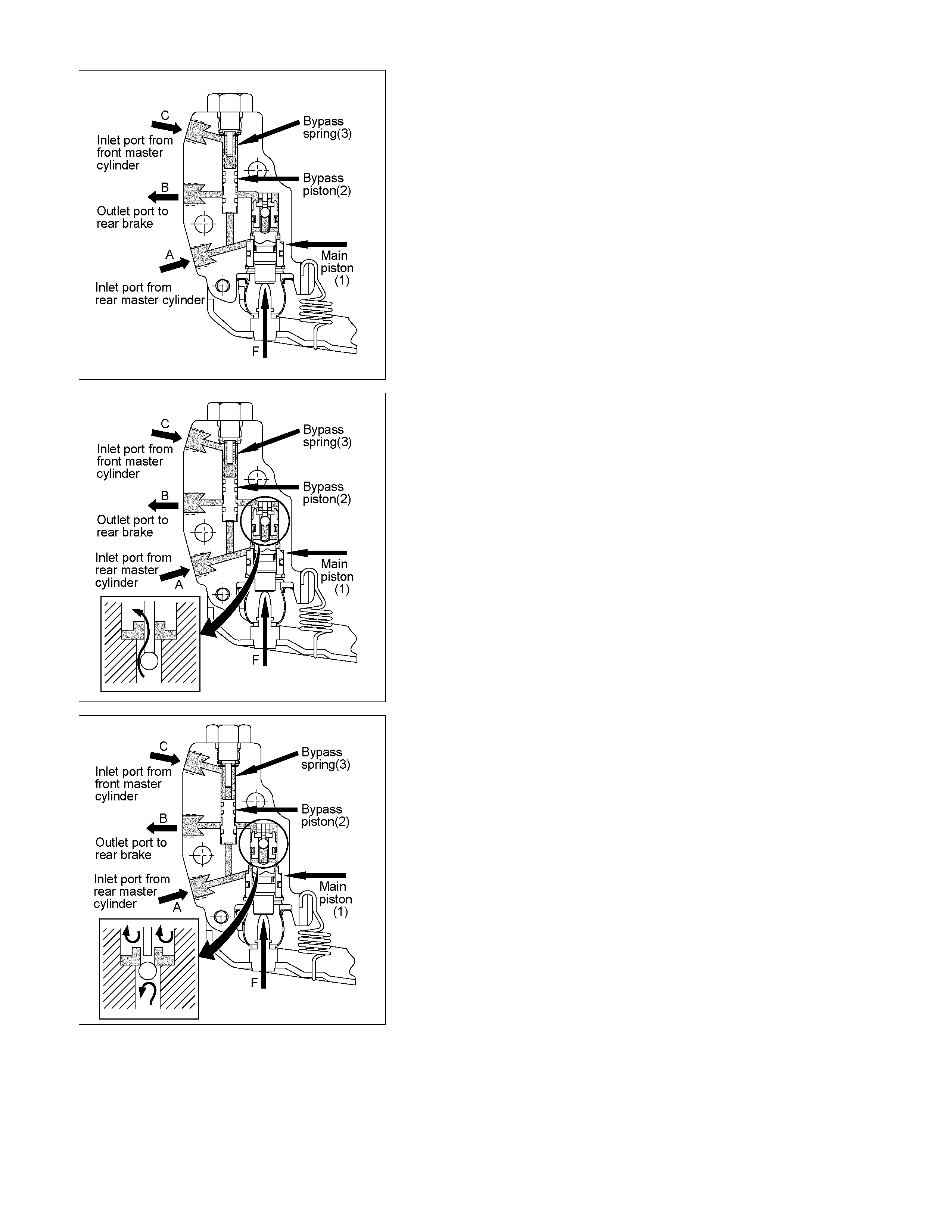
2) Bellow cutting point.
The Force (F) keeps the main piston (1) the rest position.
The inlet pressure ( A) and outlet pressure ( B) are the sam e
as well as the inlet pressure (C) f rom front m aster cylinder.
The bypass piston (2) is k ept on res t pos ition by equilibrium
of the pressures (A) and (C) and the bypass spring load (3).
RTW35CSH001201
3) Cutting point.
The cutting point is given by r elation between force (F ), that
is the load applied by suspension of the vehicle and the
main pis ton ar ea ( 1). The cutting point is achieved when the
force generated by hydraulic pressure is upper than the
forc e ( F) given by the load suspension. T he main piston (1)
moves from the rest position closing the valve. In this
moment the inlet pressure (A) is upper than the outlet
pressure (B). The bypass piston (2) continues on the rest
position by equilibrium of (A) and (C) pressure.
RTW35CSH001301
4) Failure on front master cylinder.
In case of failure on front master cylinder the pressure on
the inlet port (C) drop to zero. The pressure from inlet port
(A) acts on the bypass pist on (2) and m ove it by compr ising
of bypass spring (3). It makes possible the communication
between the inlet port (A) to outlet port (B) through the
bypass system. The outlet pressure (B) reaches the inlet
pressure (A) and the LSPV is bypassed.
Valve Maintenance
In the case to fluid lead or other a abnormalities, faulty valve
should be replaced.
Note:
The load sensing proportioning valve is not repairable and
must be replaced as a completed assembly.
LOAD SENSING PROPORTIONING VALVE (LSPV)
ADJUSTMENT
RTW35CSH000301
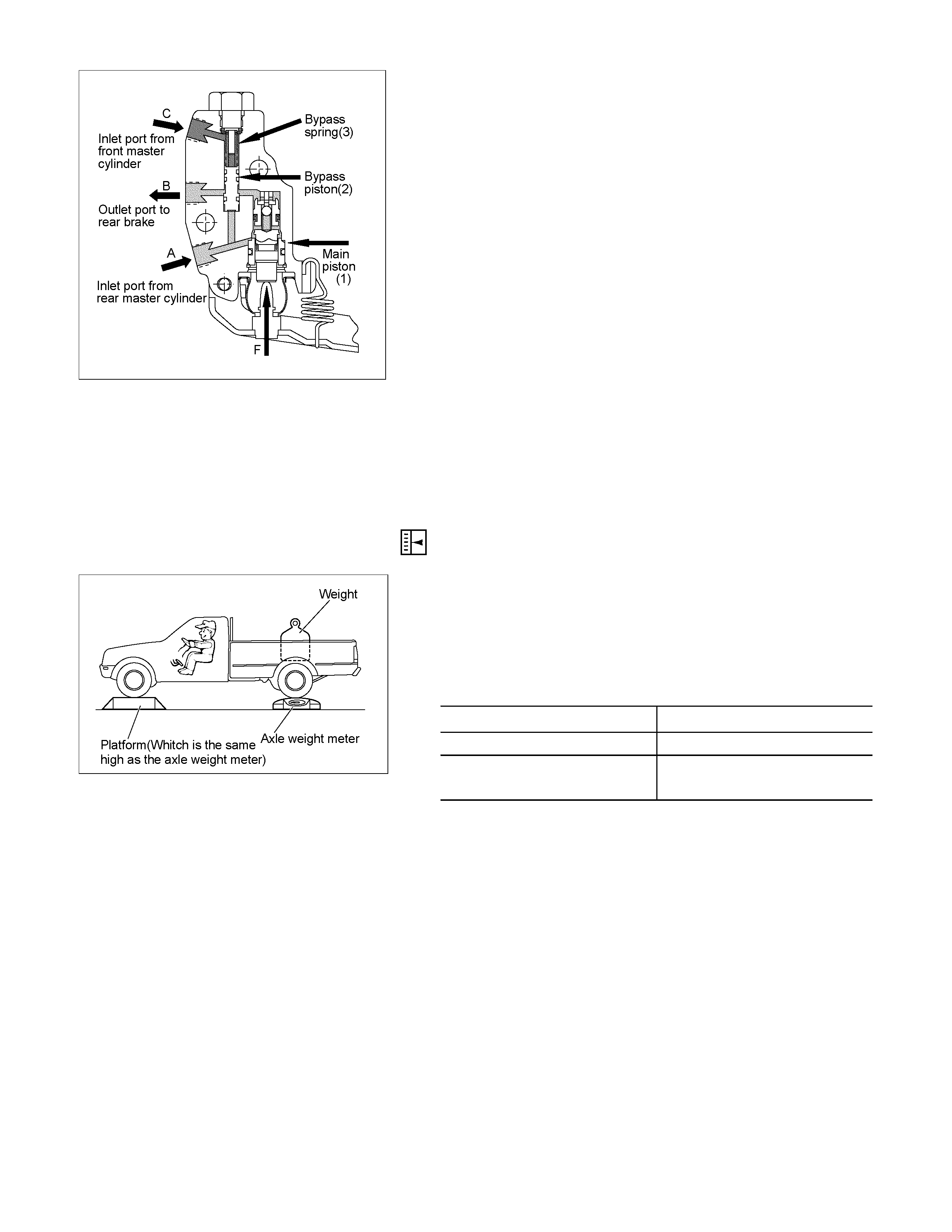
1. Fluid Pressure Measurement
1) Rear axle weight adjustment
With an axle eight meter, adjust the rear axle weight with
a person sitting in the driver’s seat and a weight loaded
in the rear body. N (kg/lb)
MODEL Adjustment value
4 × 2 7845 (800/1764)
4 × 2 HIGH RIDE
4 × 4 9316 (950/2095)
RTW35CSH000101
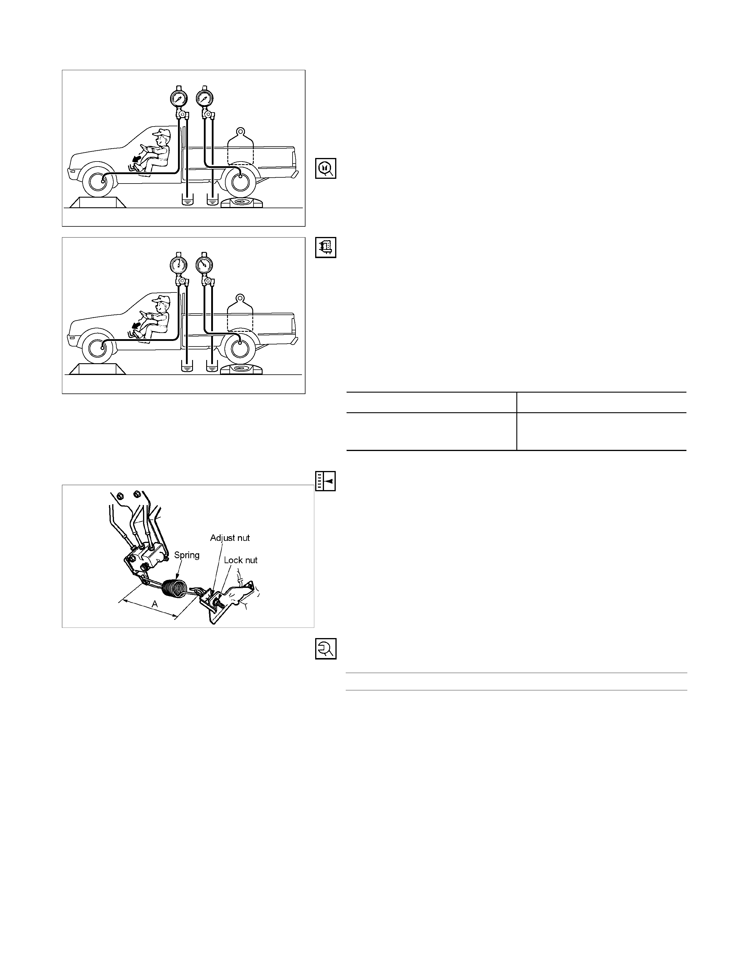
2) Installation of a fluid pressure gauge
Remove the air bleeder of the left hand wheel front and
rear brakes. Bleed air out of the fluid pressure gauge
with the measurement hose of the fluid pressure gauge
installed.
Pressure Tester: Brake oil (Fluid pressure gauge)
5-8840-2190-0
RTW35CSH000201
3) Rear wheel cylinder fluid pressure measurement
Step on the brake pedal until the fluid pressure of the
front wheel cylinder gets to 9.8Mpa (100kg/cm2), and
check the rear wheel cylinder fluid pressure. (Read the
value of the front wheel cylinder fluid pressure 2
seconds after the measurement. When measuring the
L.S.V fluid pressure, keep the brake pedal pressed
down without stepping it down twice or releasing it.)
Rear Wheel Cylinder Fluid Pressure MPa (kg/cm2)
2WD 6.77±0.83 (69.0±8.5)
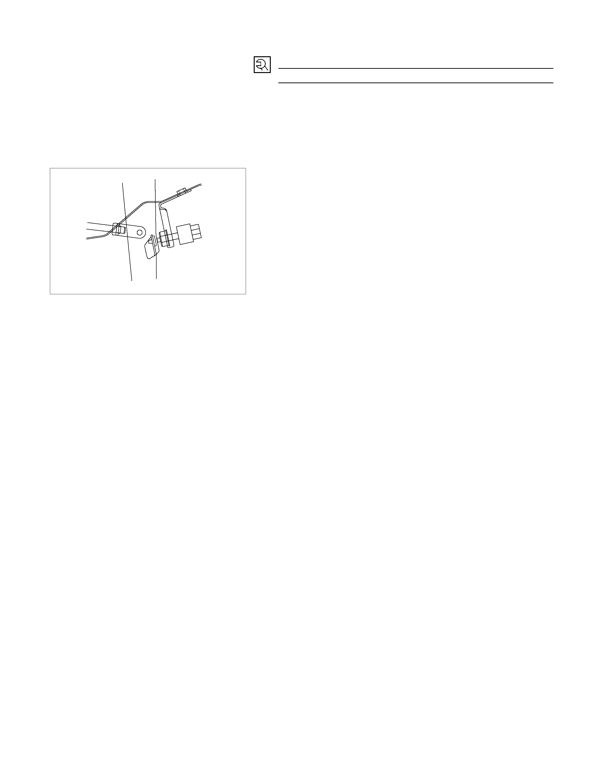
2WD (With High Ride
Suspension), 4WD 6.77±0.83 (69.0±8.5)
RTW35CSH000401
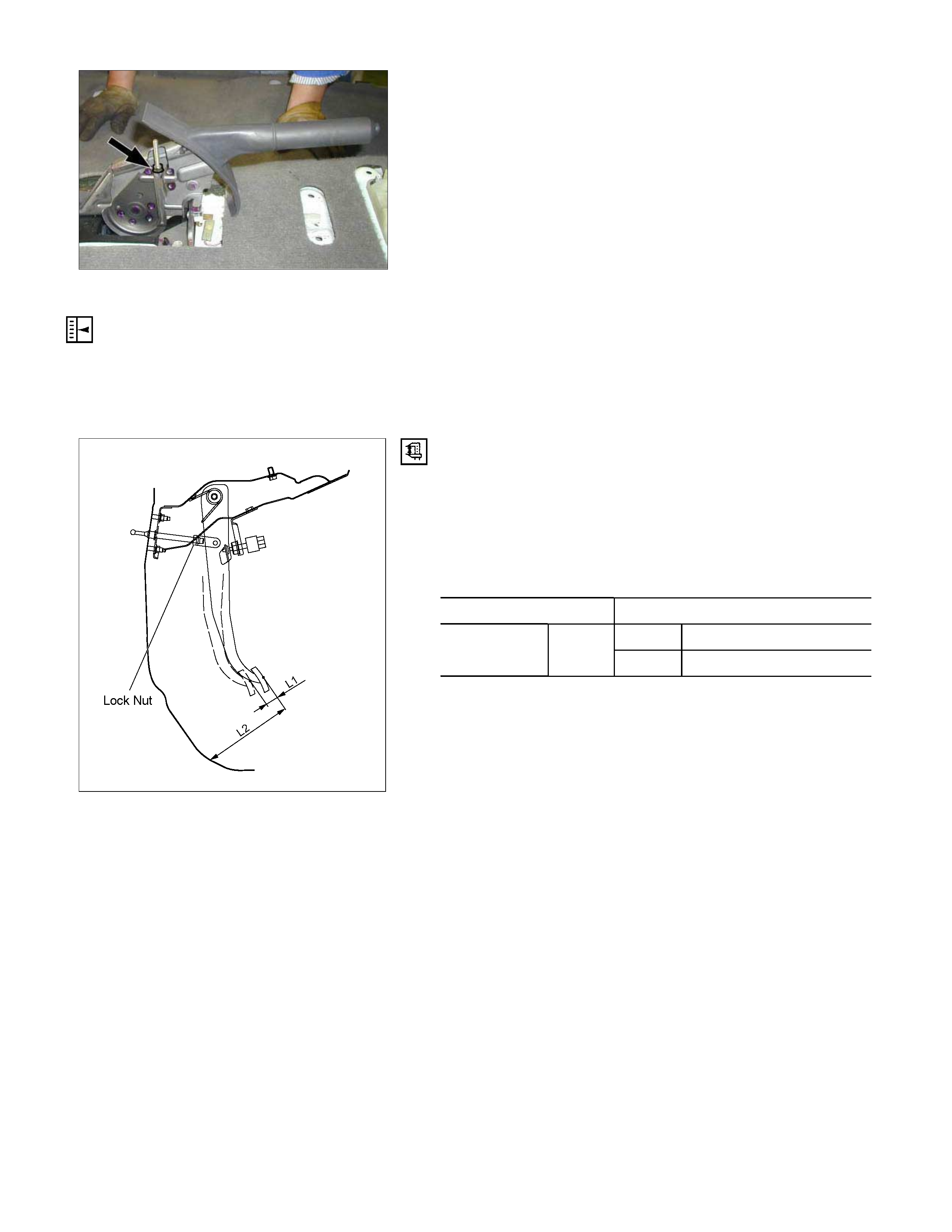
2. Oil Pressure Adjustment
1) LSPV spring length adjustment
Loosen the adjust nut of the LSPV spring joint, and
adjust the length of the LSPV spring.
W hen the oil pressure is insufficient, turn the adjust nut
clock wise to extend the s pan “A”. W hen the oil press ure
is too high, turn the adjust nut counterclockwise to
reduce the span “A”.
2) After adjustment, tighten the lock nut securely.
Lock Nut Torque N⋅m (kg⋅m/lb in)
11-20 (1.1-2.0/95-174)

Filling Master Cylinder Reservoir
CAUTION:
Use only specified brake fluid. Do not use any fluid which
contains a petroleum base. Do not use a container which
has been used for petroleum based fluids or a container
which is wet with water. Petroleum based fluid will cause
swelling and distortion of rubber parts in the hydraulic
brake system. Water mixed with brake fluid lowers the
fluid boiling point. Keep all fluid containers capped to
prevent contamination.
Always fill the master cylinder reservoir when the engine
is cold.
Never allow the brake fluid to come in contact with the
painted surfaces.
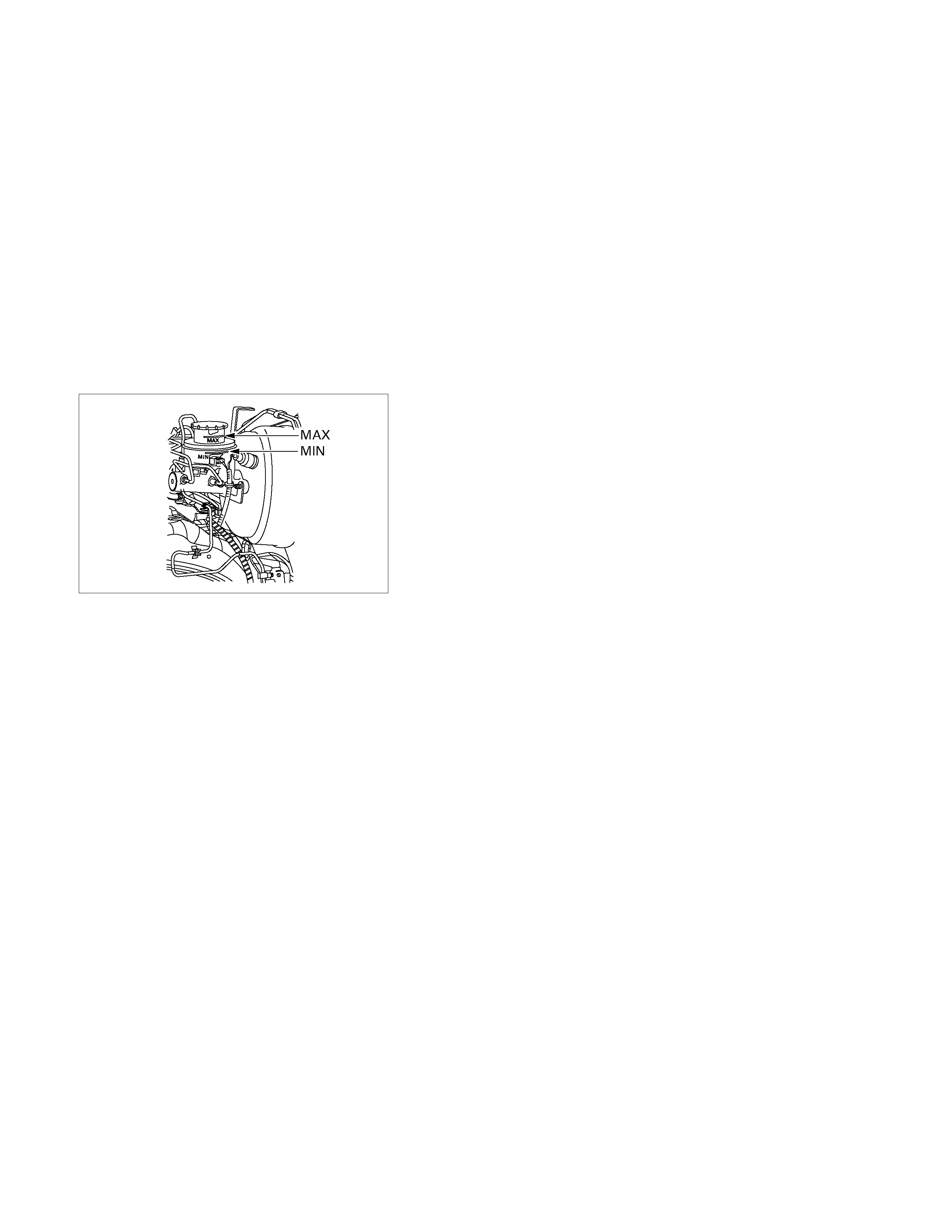
The master cylinder reservoir must be kept properly filled
to ensure adequate reserve and to prevent air and
moisture from entering the hydraulic system. However,
because of expansion due to heat absorbed from the
brakes and the engine, the reservoir must not be
overfilled. Thoroughly clean reservoir cap before removal
to avoid getting dirt into reservoir. Add fluid as required to
bring level to the “MAX” mark on the reservoir tank. Use
“DOT 3” Hydraulic Brake Fluid.
Leakage of Brake Fluid
With engine idling, set shift lever in the neutral position and
continue to depress brake pedal at a constant pedal
application force.
Should the pedal stroke become deeper gradually, leakage
from the hydraulic pressure system is possible.
Make sure by visual check that there is no leak.
BLEEDING OF THE BRAKE HYDRAULIC CIRCUIT
If air enters the bake lines, it will cause poor brake action.
Therefore, bleeding should be performed if the brakes have
been used with the level of brake fluid in the reservoir
excessively low or if brake pipes have been disconnected in
the course of brake servicing.
Bleeding operation calls for co-operative action of 2 persons.
• Set the parking brake firmly while bleeding.
• Perform bleeding operation with ENGINE RUNNING, to
prevent damage to push rod seal.
Make sure exhaust is suitably ventilated.
• Bleed the hydraulic system with the fluid reservoir filled to
the specified level.
• Bleed the system starting with the rear wheel cylinde
r
farthest from the master cylinder.
A bleeding operation is necessary to remove air from the
hydraulic brake system whenever air is introduced into the
hydraulic system. It may be necessary to bleed the hydraulic
system at all four brakes if air has been introduced through a
low fluid level or by disconnecting brake pipes at the master
cylinder. If a brake pipe is disconnected at one wheel, only that
wheel cylinder/caliper needs to be bled. If the pipes are
disconnected at any fitting located between the master cylinder
and brakes, then the brake system served by the disconnected
pipe must be bled.
1. Set the parking brake completely, then start the engine.
NOTE:
The vacuum booster will be damaged if the bleeding operation
is performed with the engine off.
2. Remove the master cylinder reservoir cap.
3. Fill the master cylinder reservoir with brake fluid. Keep the
reservoir at least half full during the air bleeding operation
4. Always use new brake fluid for replenishment.
5. In replenishing rake fluid, take care that air bubbles do not
enter the brake fluid.
When the master cylinder is replaced or overhauled, first
bleed the air from the master cylinder, then from each
wheel cylinder and caliper following the procedures
described below.
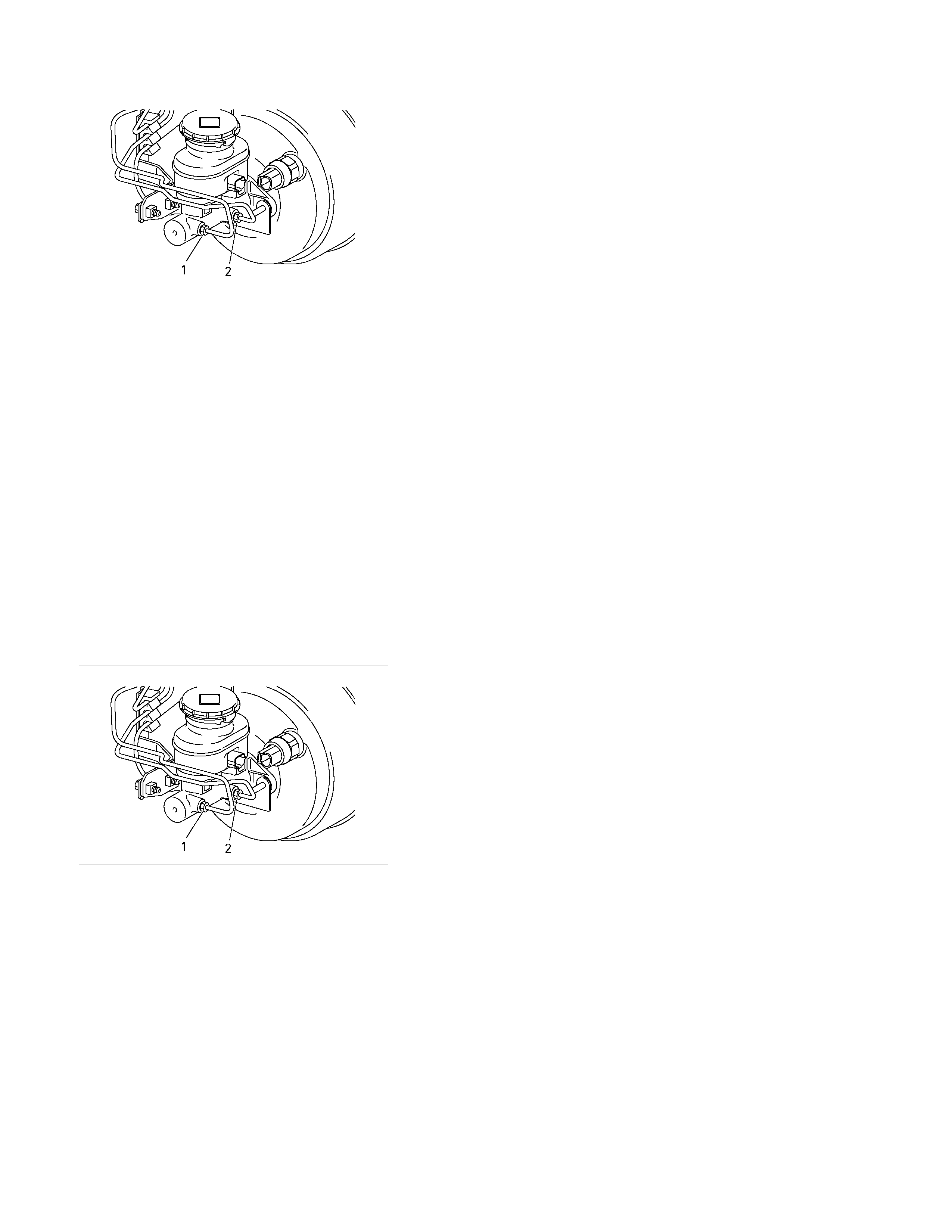
Bleeding the Master Cylinder
6. Disconnect the rear wheel brake pipe (1) from the maste
r
cylinder.
Check the fluid level and replenish as necessary. If
replenished, leave the system for at least one minute.
7. Depress the brake pedal slowly once and hold it depressed.
8. Completely seal the delivery port of the m as ter cylinder with
your finger, where the pipe was disconnected then release
the brake pedal slowly.
9. Release your finger from the delivery port when the brake
pedal returns completely.
10. Repeat steps 7 through 9 until the brake fluid comes out o
f
the delivery port during step 7.
NOTE: Do not allow the fluid level in the reservoir to go below
the half-way mark.
11. Reconnect the brake pipe (1) to the master cylinder and
tighten the pipe.
12. Depress the brake pedal slowly once and hold it depressed.
13. Loosen the rear wheel brake pipe (1) at the master cylinder.
14. Retighten the brake pipe, then release the brake pedal
slowly.
15. Repeat steps 12 through 14 until no air comes out of the
port when the brake pipe is loosened
NOTE: Be very careful not to allow the brake fluid to come in
contact with painted surfaces.
16. Bleed the air from the fr ont wheel brake pipe c onnection (2)
by repeating steps 6 through 15.
Bleeding the Caliper
17. Bleed the air from each wheel in the order listed below:
• Right rear wheel cylinder
• Left rear wheel cylinder
• Left front caliper
• Right front caliper
Conduct air bleeding from the wheels in the above order. I
f
no brake f luid com es out, it s uggests that air is m ixed in the
master cylinder. In this case, bleed air from the maste
r
cylinder. In this case, bleed air from the master cylinder in
accordance with steps 6 through 16, and then bleed ai
r
from the caliper or wheel cylinder.
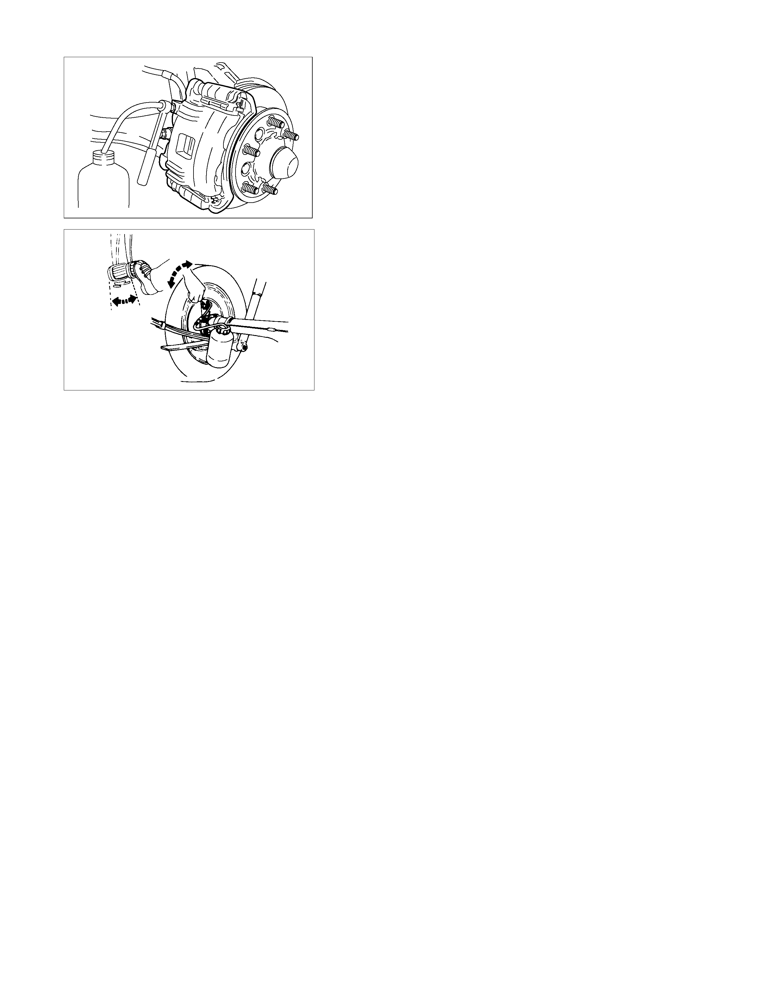
RTW35CSH000501
18. Place the proper size box end wrench over the bleede
r
screw.
19. Cover the bleeder screw with a transparent tube, and
submerge the free end of the transparent tube in a
transparent container containing brake fluid.
5042
20. Pump the brake pedal slowly three (3) times (once/sec),
then hold it depressed.
21. Loosen the bleeder screw until fluid flows through the tube.
22. Retighten the bleeder screw.
23. Release the brake pedal slowly.
24. Repeat steps 21 through 24 until the air is completel
y
removed.
It may be necessar y to repeat the bleeding pr ocedure 10 o
r
more times for front wheels and 15 or more times for rea
r
wheels.
25. Go to the next wheel in the sequence after each wheel is
bled.
Be sure to monitor reservoir fluid level.
26. Depress the brake pedal to check if you feel “sponginess"
after the air has been rem oved fr om all wheel cylinders and
calipers.
If the pedal feels “spongy", the entire bleeding procedure
must be repeated.
27.
A
fter the bleeding operation is completed on the each
individual wheel, check the level of the brake fluid in the
reservoir and replenish up to the “MAX" level as necessary.
28. Attach the reservoir cap.
29. Stop the engine.
05007-1
BRAKE LINE (HOSES AND PIPES)
• Inspect all hoses and pipes for wear, bending, chafing,
cracks, dents, or any other damage.
Make necessary correction or parts replacement if these
abnormal conditions are found through inspection.
• All hoses, pipes and joints can be damaged easily.
Do not allow the hose to become excessively twisted and
bent when working with then, and pay special attention to all
the brake lines not to damage them when repairing o
r
replacing other parts (axle, suspension, etc).
• Inspection for leakage should be performed by depressing
the brake pedal fully.
If leakage is apparent at the circumference of joints,
retighten or replace these parts.
This procedure must be performed whenever brake lines
are installed.
•
A
fter disconnecting the hoses and pipes, cap or tape the
openings to prevent entry of foreign material.
ADJUSTMENT PROCEDURE OF SERVICE AND PARKING BRAKE
Stem type
All brakes are self-adjusting.
Brakes are adjusted by repeated stepping on the brake pedal.
(After stepping on the pedal and releasing it, the rear auto-
adjuster, in the rear brake, produces a clicking sound.
the same operation should be repeated until the sound
disappears.)
Take the following steps after overhauling the rear brake
assembly.
1. Move the parking brake lever to its fully released position.
311R300007
2. Parking cable must be loosened sufficiently.
(Loosen the adjust nut and the lock nut.)
3. Repeat stepping on the brake pedal firmly, and releasing it
until the clicking sound can no longer be heard.
If the dif ference between the brak e drum ins ide diameter o
f
the brake shoes is adjusted to be 0.5 mm, the number o
f
times for depressing the brake pedal can be reduced.
4. Remove the drum.
Measure the brake drum inside diameter and diameter o
f
the brake shoes.
Shoe Clearance mm(in)
0.25 - 0.40 (0.0098 - 0.0157)
If incorrect, check the brake auto-adjusting system.
5. T urn the adjuster nut s o that the parking brak e lever travels
8 to 14 notches when pulled up with a force 30 kg (66 lbs.).
6. Make sure there is not brake dragging.
Floor mount type
All brakes are self-adjusting.
Brakes are adjusted by repeated stepping on the brake pedal.
(After stepping on the pedal and releasing it, the rear auto-
adjuster, in the rear brake, produces a clicking sound.
the same operation should be repeated until the sound
disappears.)
Take the following steps after overhauling the rear brake
assembly.
1. Move the parking brake lever to its fully released position.
2. Parking cable must be loosened sufficiently.
(Loosen the adjust nut and the lock nut.)
3. Repeat stepping on the brake pedal firmly, and releasing it
until the clicking sound can no longer be heard.
If the dif ference between the brak e drum ins ide diameter o
f
the brake shoes is adjusted to be 0.5 mm, the number o
f
times for depressing the brake pedal can be reduced.
4. Remove the drum.
Measure the brake drum inside diameter and diameter o
f
the brake shoes.
Shoe Clearance mm(in)
0.25 - 0.40 (0.0098 - 0.0157)
If incorrect, check the brake auto-adjusting system.
5. T urn the adjuster nut s o that the parking brak e lever travels
6 to 8 notches when pulled up with a force 30 kg (66 lbs.).
6. Make sure there is not brake dragging.
ADJUSTMENT PROCEDURE OF BRAKE PEDAL
The push rod serves as the brake pedal stopper when the
pedal is fully released.
Brake pedal height adjustment should be performed as follows.
RTW35CSH000601
Brake Pedal - Height
Measure the brake pedal height after making sure the pedal is
fully returned by the pedal return spring.
Note:
Pedal height (L2) must be measured after starting the
engine and increasing the revolution several times by
stepping on the accelerator pedal. mm(in)
Pedal free play (L1) 6-10 (0.23 - 0.39)
M/T 174-186 (6.85-7.32)
RHD A/T 176-188 (6.93-7.40)
Height (L2)
Note:
Pedal free play must be measured after turning off the
engine and stepping on the brake pedal firmly five times
or more.
If the measured value deviates from the above range, adjust
the brake pedal as follows:
a) Disconnect the stop lamp switch.
b) Loosen the lock nut on the push rod.
c)
A
djust the brake pedal to the specified height by rotating the
push rod in the appropriate direction.
Lock Nut Torque N⋅m(kgf⋅m/lb⋅
⋅⋅⋅ft)
12 - 18 (1.2 – 1.8 / 9 - 13)
d) Install the stop lamp switch.
Note:
Pedal height (L2) must be 80 mm (3.14 in.) or more when
applying about 50 kg (110.25 lbs.) of stepping force.
331R300005
How to connect the CLEVICE of BOOSTER ROD with PEDAL
ARM. and how to adjust the PEDAL SW.
After connecting the CLEVIS of BOOSTER ROD with PEDAL
ARM, adjust the PEDAL SW mounted (PDA) to PEDAL
BRACKET by the procedure explained still more bellow.
1. Set the hole of the CLEVIS of BOOSTER&M/CYL ROD
with the hole of the PEDAL ARM.
2. Enter the PIN; PUSH ROD to PEDAL to these holes
from left side of the PEDAL.
3. Enter and fix the PIN; SANP PIN FIX to the DITCH o
f
the PIN; PUSH ROD to PEDAL from right side of the
PEDAL.
4. Release the LOCK by turning the SWITCH counter-
clock-wise.
5. After doing so, pull PEDAL ARM to yourself a little so
that PEDAL ARM is not pushed in.
6. Making PEDAL ARM not movable with one hand, push
in the whole SWITCH with the other hand until the
PLUNGER of SWTCH is pushed in and SWITCH itself
hits the RUBBER of PEDAL ARM.
In the condition, turn SWITCH clock-wise until “click”
sound is made and lock it.
By doing this the SWITCH is adjusted at 0.7±0.5mm
clearance.
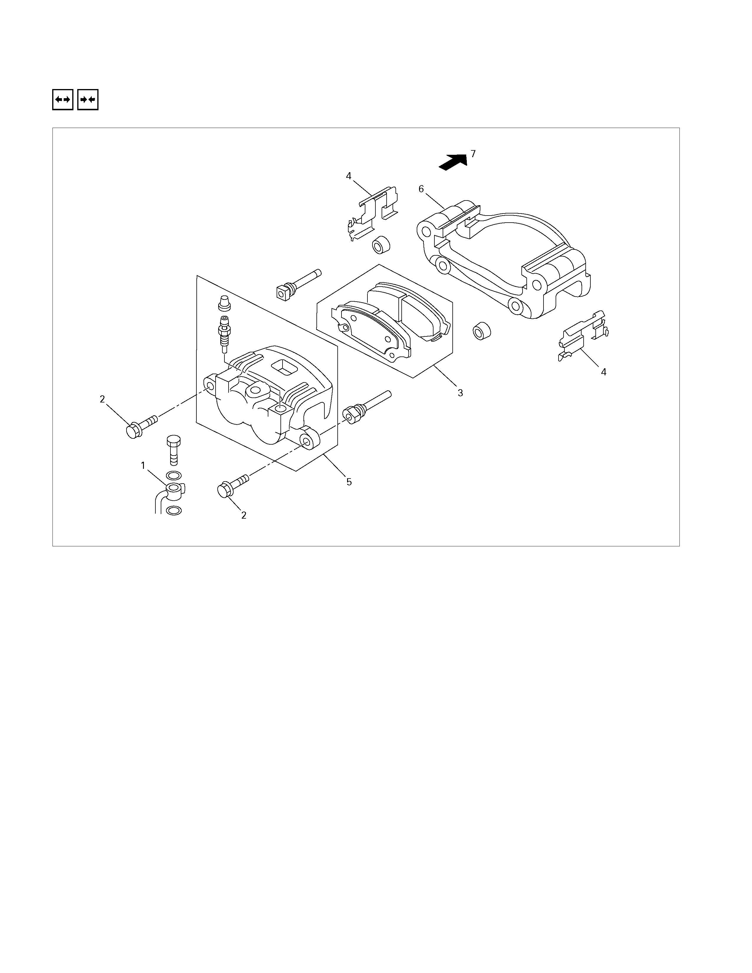
FRONT BRAKE ASSEMBLY
REMOVAL AND INSTALLATION
Removal Steps
▲ 1. Brake flexible hose
▲ 2. Lock bolt
▲ 3. Pad assembly
4. Clip; pad
5. Caliper assembly
▲ 6. Support bracket
▲ 7. Front hub and disc assembly
Installation Steps
▲ 7. Front hub and disc assembly
▲ 6. Support bracket
5. Caliper assembly
▲ 4. Clip; pad
3. Pad assembly with shim
▲ 2. Lock bolt
▲ 1. Brake flexible hose
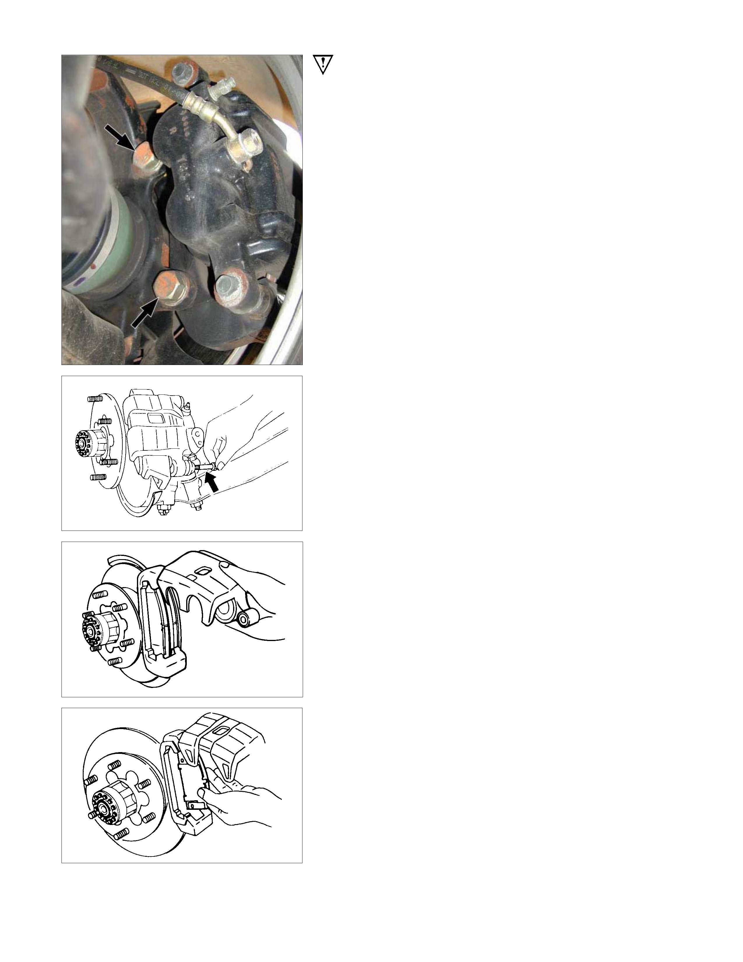
Important Operations - Removal
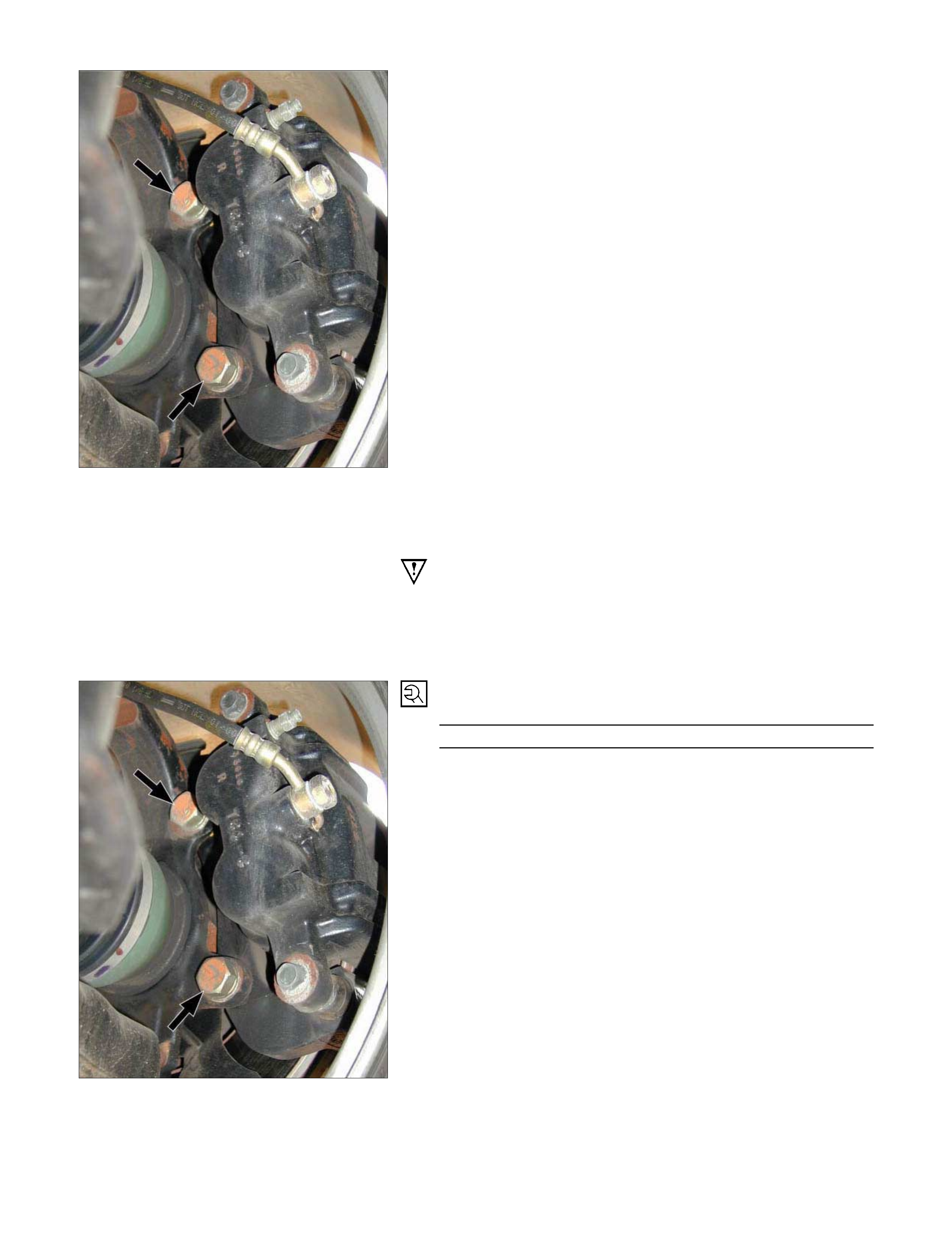
1. Brake Flexible hose
Remove the bolt and gasket and disconnect the brake flexible
hose from the caliper.
After disconnecting the flexible hose, cap or tape the openings
to prevent entry of foreign material.
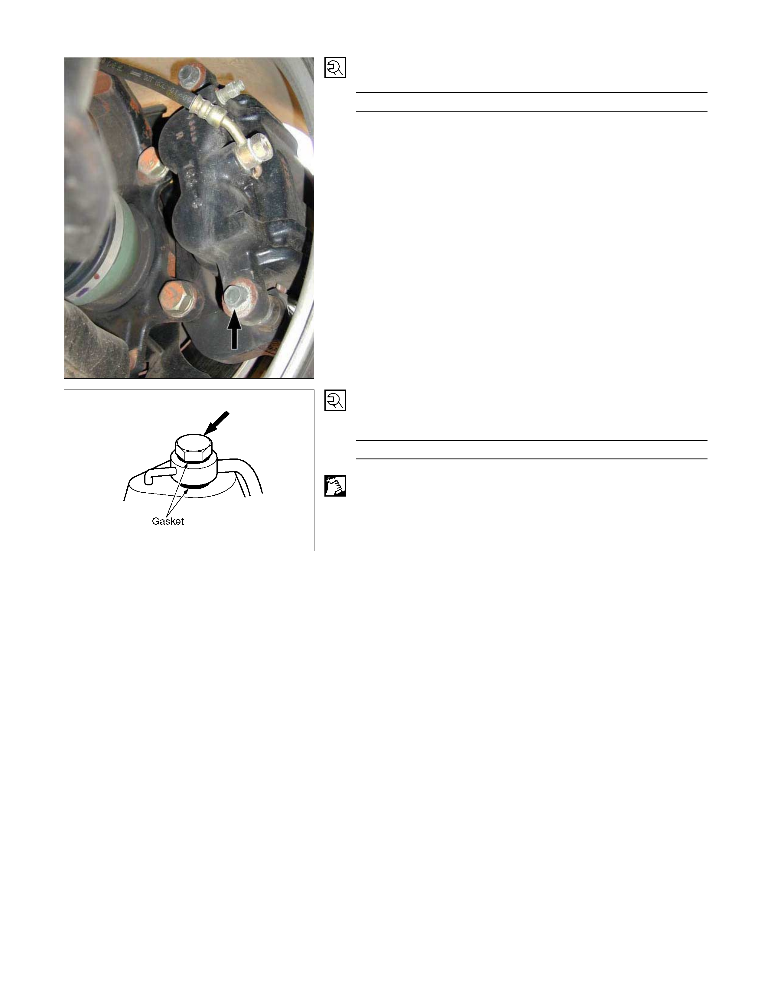
2. Lock Bolt
Remove the lock bolt from the caliper.
3. Pad Assembly with Shim
Rotate the caliper upward.
Mark the lining locations if they are to be reinstalled.
6. Support Bracket
Take care not to damage the flexible brake hose when
removing the support bracket.
7. Front Hub and Disc Assembly
For the removal procedure, refer to
Section 4C "FRONT WHEEL DRIVE".
Important Operations - Installation
7. Front Hub and Disc Assembly
For the installation procedure, refer to the front hub and disc
reassembly procedure in
Section 4C "FRONT WHEEL DRIVE".
6. Support Bracket
Torque N⋅m(kgf⋅m/lb⋅ft)
196 - 235 (20.0 – 24.0 / 145 - 174)
Set up the clip and pad before installation of the support
racket.
4. Clip ; Pad
Install new parts if necessary.
2. Lock Bolt
Torque N⋅m(kgf⋅m/lb⋅ft)
32 - 40 (3.3 – 4.1 / 24 - 30)
1. Brake Flexible Hose
Attach the bolt and new gasket
Torque N⋅m(kgf⋅m/lb⋅ft)
29 -39 (3.0 - 4.0 / 22 - 29)
After installation, bleeding and replenishing procedure must be
performed.
Wipe the circumference of the hose clean.
Note:
•
••
• Always use new gaskets.
• Be sure to put the hooked edge of the flexible hose end into
the anti-rotation cavity.
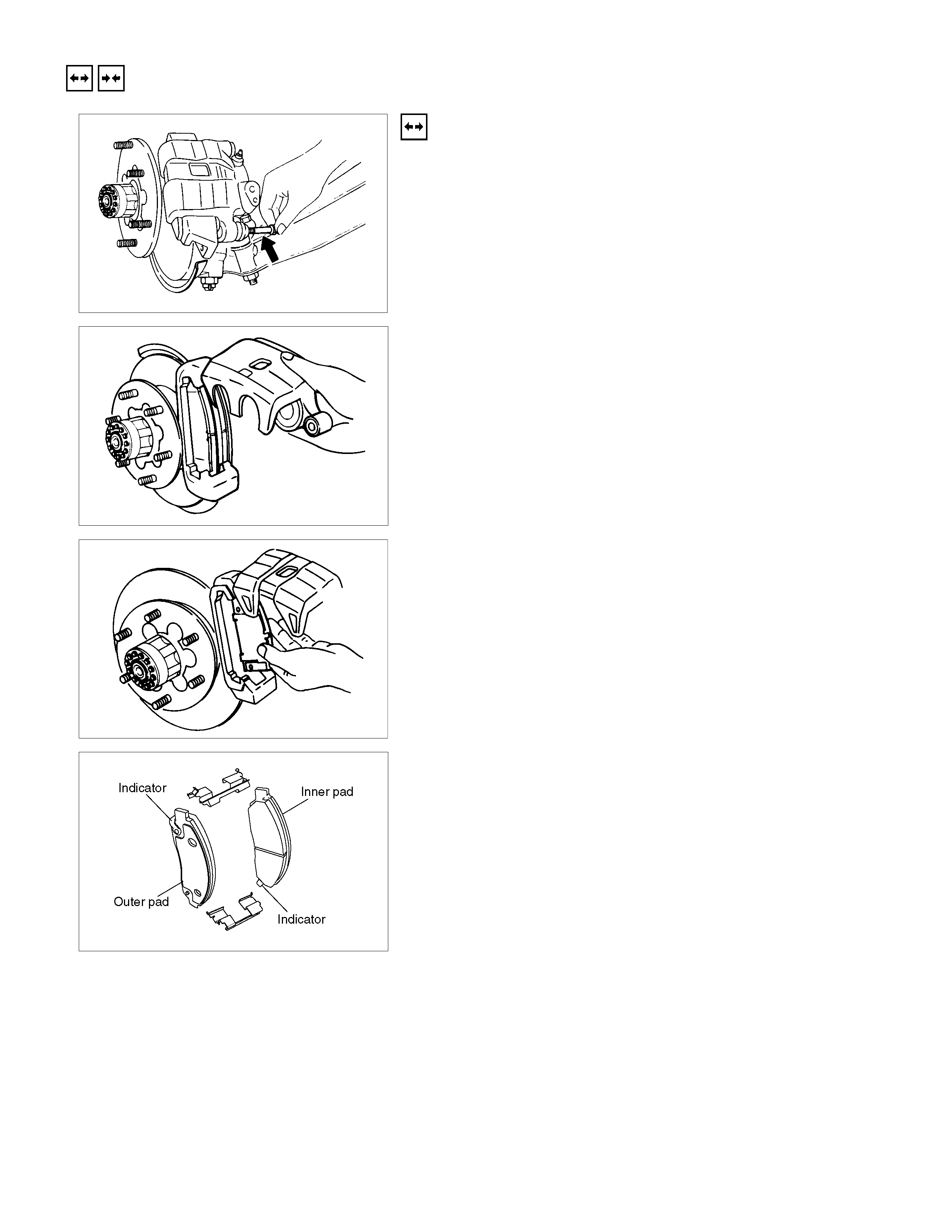
REMOVAL AND INSTALLATION OF DISC PAD
Removal Steps
1. Lock Bolt
Remove the lock bolt from the caliper.
Note:
Don't remove the brake hose from caliper when replacing
pads.
2. Rotate the Caliper Upward
Remove the caliper from the support bracket and ire the
caliper to the upper link or the frame.
Note:
While caliper is removed from support bracket, never step
on the brake pedal or the piston will protrude rapidly.
3. Pad Assembly with Shim
Remove the pad assembly with the shim.
Mark the pad locations if they are to be reinstalled.
4. Clip ; Pad
Discard the used clip and install a new one.
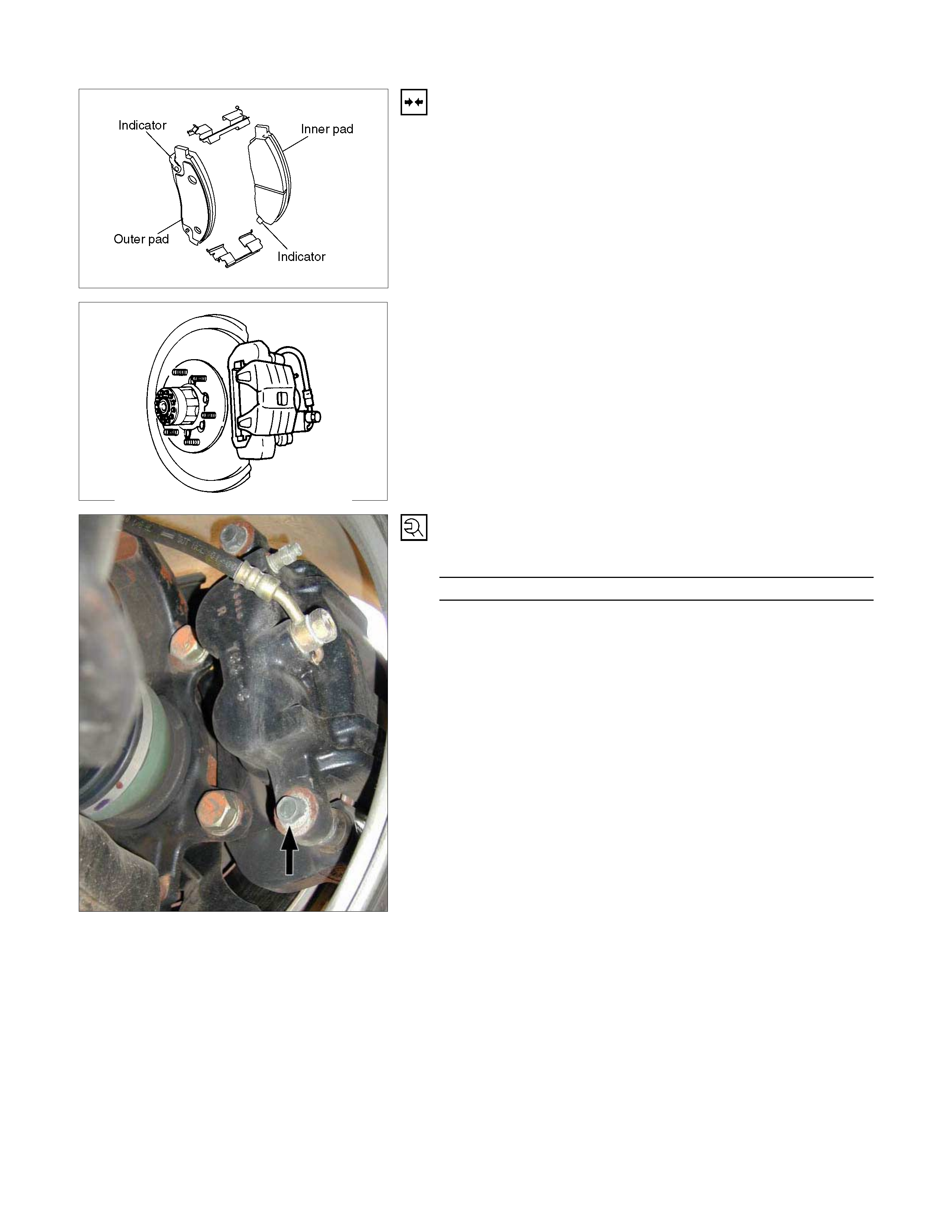
Installation Steps
1. Clip ; Pad
2. Pad Assembly with Shim
After attaching the pad assembly with the shim to the support
bracket, position the wear indicator to the lower side of the
inner pad and position the wear indicator to the upper side of
the outer pad.
3. Caliper Assembly
Lower the caliper into its original position.
Do not damage the flexible hose by twisting or pulling it.
4. Lock Bolt
Attach the lock bolt to the caliper.
Torque N⋅m(kgf⋅m/lb⋅ft)
32 - 40 (3.3 – 4.1 / 24 - 30)
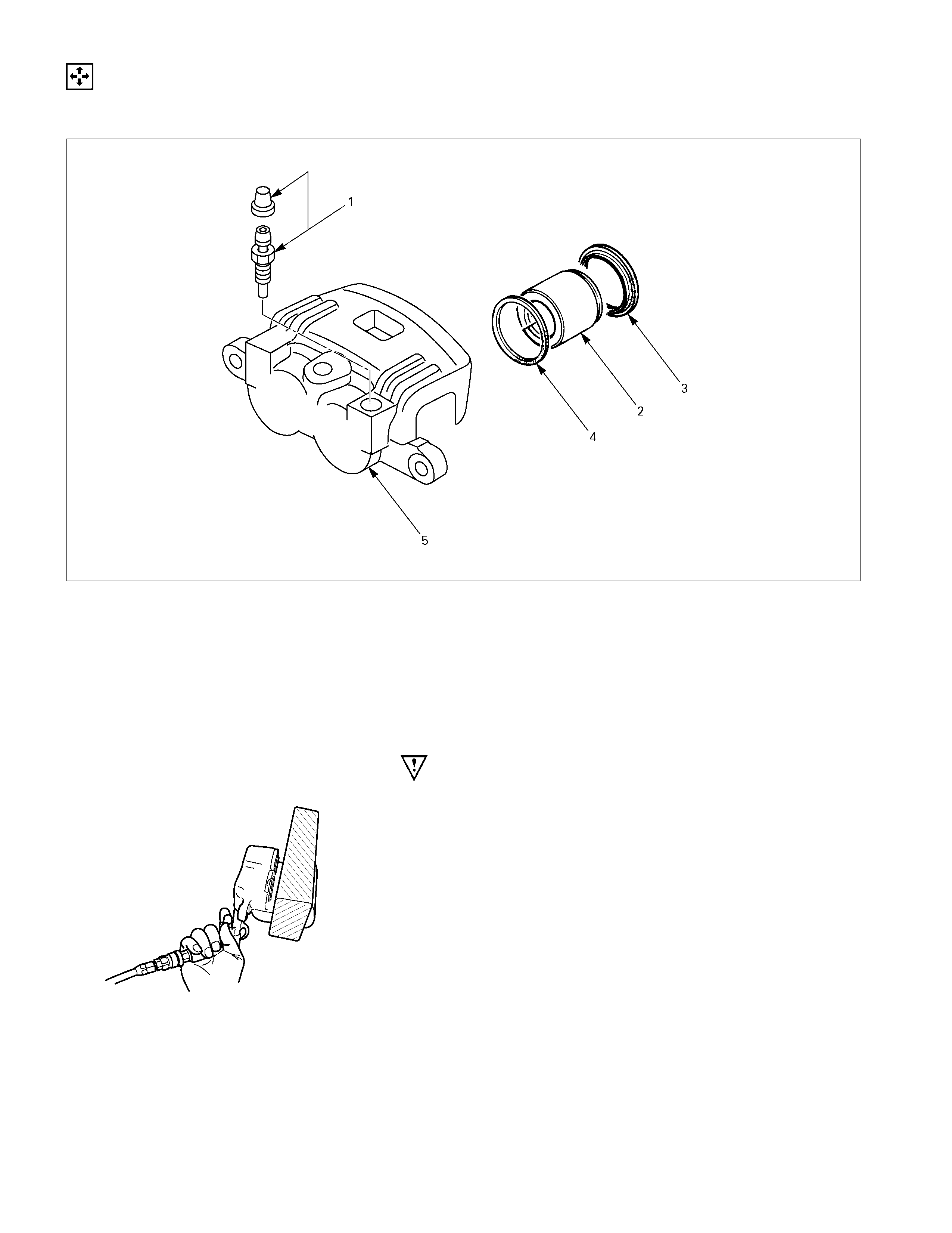
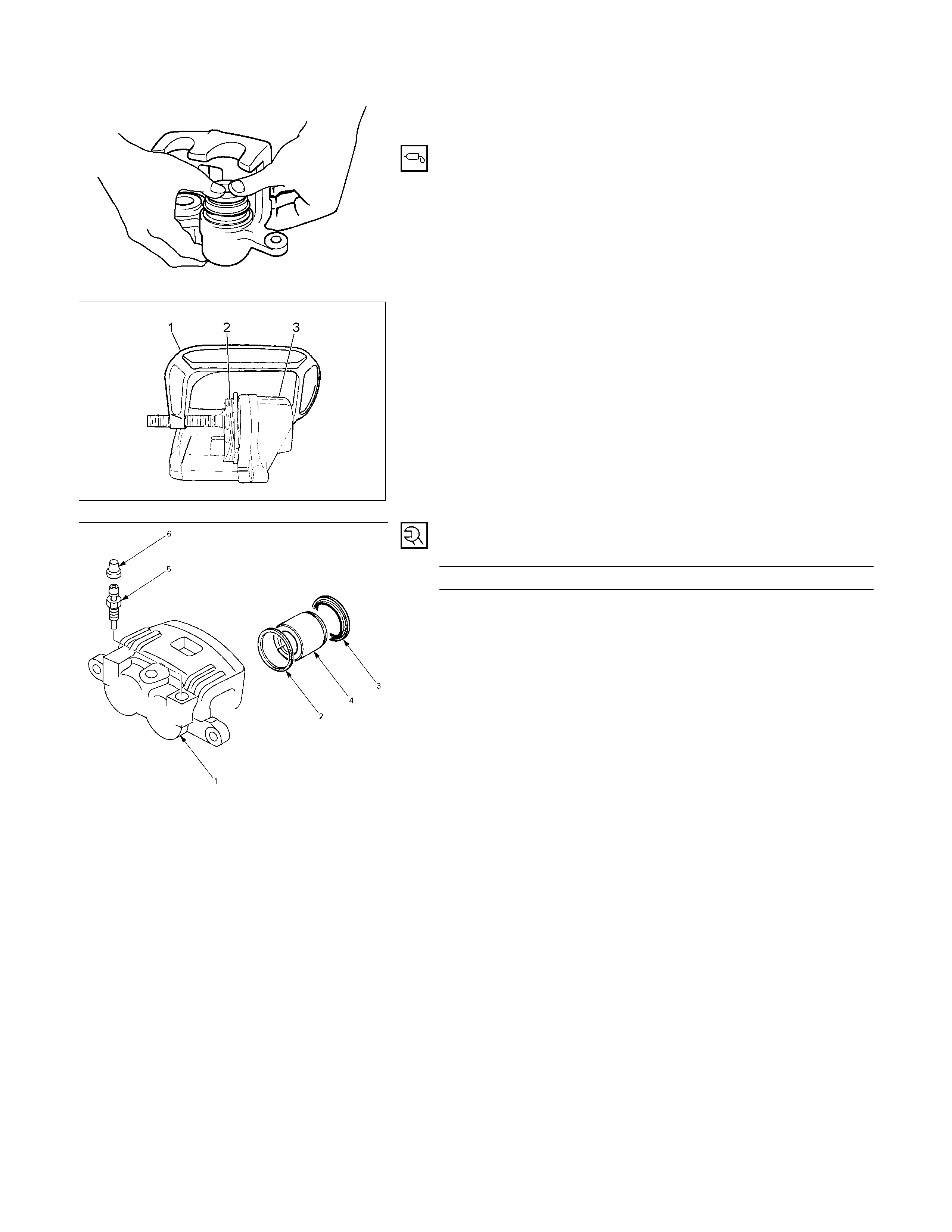
DISASSEMBLY
CALIPER ASSEMBLY
Disassembly Steps
1. Bleeder with cap
▲ 2. Piston
3. Dust seal; piston
4. Ring seal
5. Body; caliper
Important Operations
2. Piston (with Ring Seal)
Insert a block of wood into the caliper and force out the piston
by blowing compressed air into the caliper at the flexible hose
attachment.
This procedure must be done prior to removal of dust seal.
CAUTION:
Do not place your fingers in front of the piston in an
attempt to catch or protect it when applying compressed
air.
INSPECTION AND REPAIR
Make necessary correction or parts replacement if wear damage or any other abnormal conditions are found through
inspection.
• Rotor
• Caliper body
• Cylinder bore
• Piston
• Support bracket
• Lock bolt
• Guide pin
Visual Check
Inspect the following parts for wear, bending, distortion,
cracking, corrosion, or other abnormal conditions.
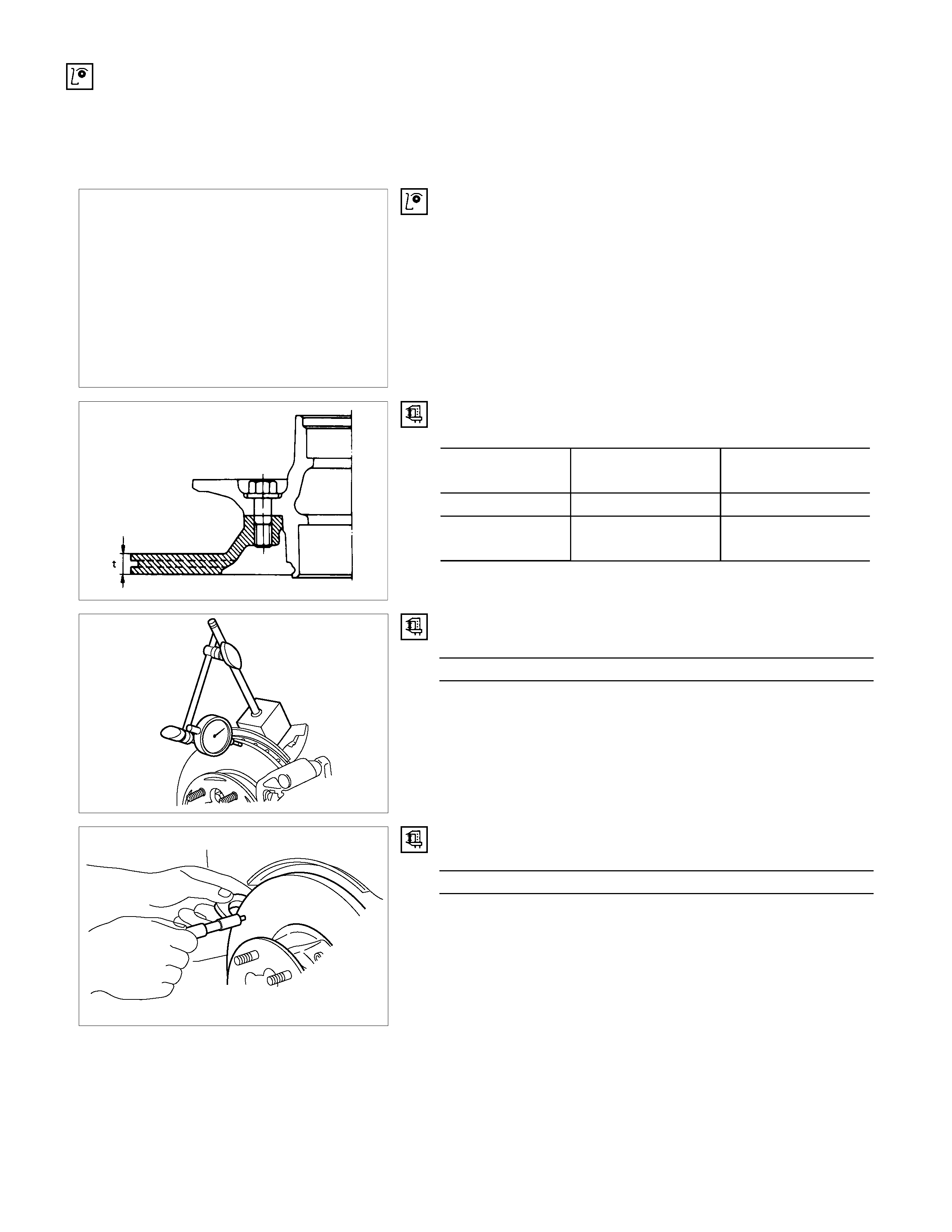
Rotor
• Thickness (t) mm(in)
Standard Replacement
thickness (Discard)
4×2 26.0 (1.024) 24.6 (0.969)
4×2 HIGH RIDE
4×4 27.0 (1.063) 25.6 (1.008)
• Run out
Limit mm(in)
0.075 (0.0029)
Before inspection, adjust the wheel bearing correctly.
Using a dial gauge, measure the run out at the 10mm inside
position from rotor out side edge of disc pad contact surface.
• Parallelism (Total circumferential thickness variation)
Limit mm(in)
0.023 (0.0009)
Contact surface must be within 0.023mm at the 10mm inside
position from rotor out side edge.
(Measurement; shall be measure more than 8 position at
circumferential direction.)
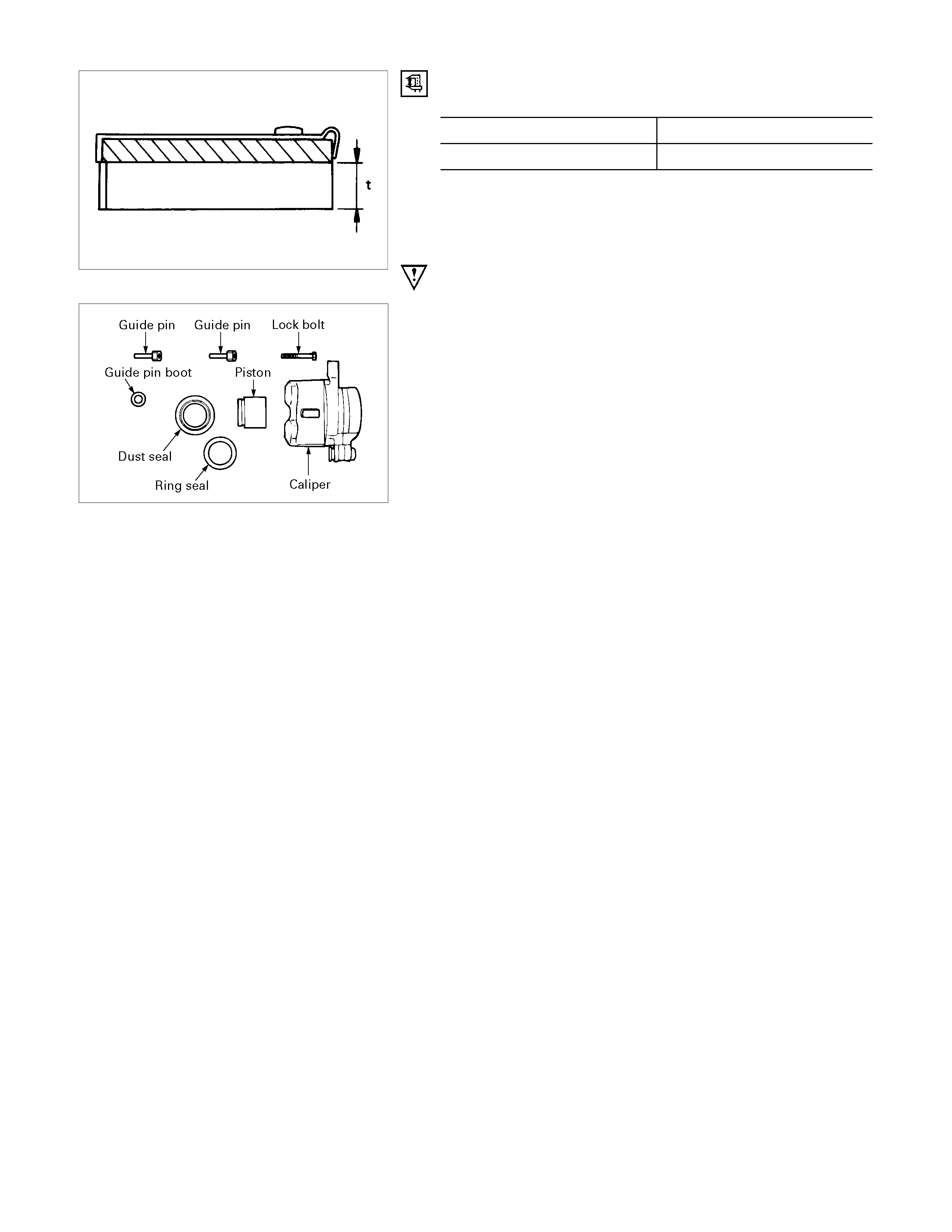
Thickness of Disc Pad
Thickness (t) mm(in)
Standard Limit
10.0 (0.394) 1.8 (0.071)
Replace the front disc pad whenever the pad wear indicator
makes a squeaking noise or when the pad is worn to within 1.8
mm of the shoe table.
All four brake pads should be replaced together.
302R300019
Seal and Boot
The dust seal, dust boot and ring seal are to be replaced each
time the caliper is overhauled.
Discard thee used rubber parts.
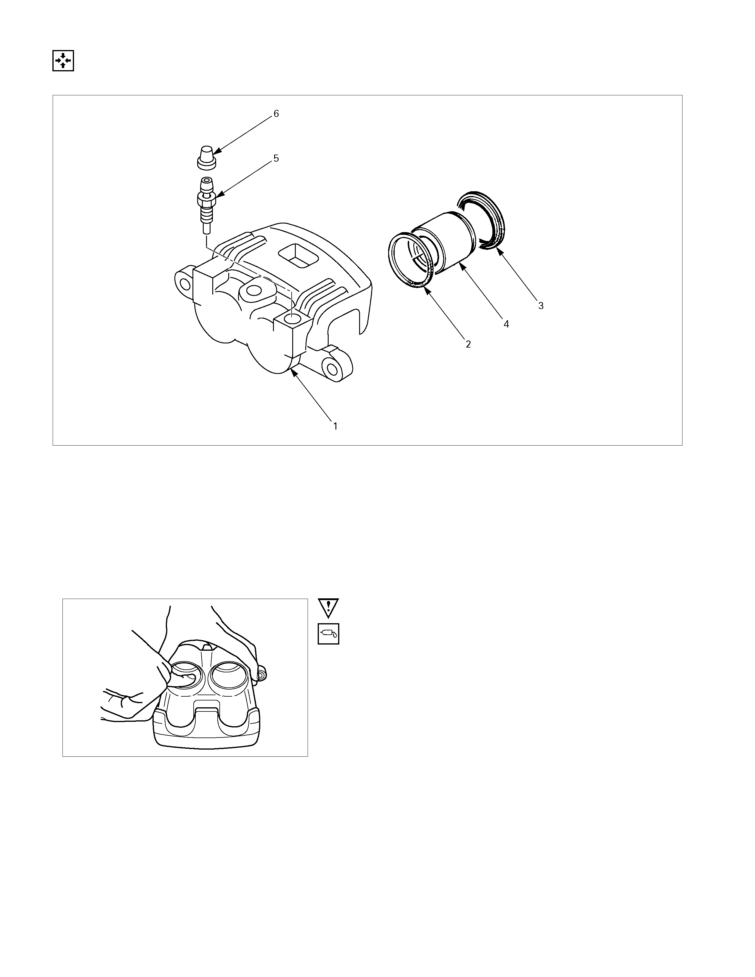
REASSEMBLY
CALIPER ASSEMBLY
Disassembly Steps
1. Body ; caliper
2. Ring seal
3. Dust seal ; piston
4. Piston
5. Bleeder
6. Cap
Important Operations
1. Body ; Caliper
2. Ring Seal
Apply clean brake fluid to the ring seal and cylinder wall, then
insert the ring seal into the cylinder.
Ensure that the piston ring seal are not twisted in the caliper
bore grooves.
3. Dust seal ; Piston
Install the dust seal on the pistons.
4. Piston
Apply clean brake fluid to the piston and attach the dust seal to
the piston and caliper.
When inserting the piston into the cylinder, use finger pressure
only. Do not use a mallet or other impact tools, since damage
to the cylinder wall or ring seal can result.
The movement of a caliper piston into a caliper bore should be
smooth and even. If a caliper piston is frozen or difficult to
bottom, the caliper requires overhaul or replacement.
RTW35CSH000701
For dual piston caliper applications, insert a discarded inner
brake pad (2) or block of wood in front of the pistons. Using 2
large C-clamps (1) installed over the body of the caliper (3) and
against the brake pad or block of wood, slowly bottom the
pistons evenly into the bores.
Insert the dust seal ring into the dust seal.
CAUTION:
Piston made by plastic material.
Don’t must be hit on the piston by hammer etc. and don’t
grasp to face of piston by pliers.
5. Bleeder
Torque N⋅m(kgf⋅m/Ib⋅in)
9 – 16 (0.9 – 1.6 / 78 - 139)
6. Cap
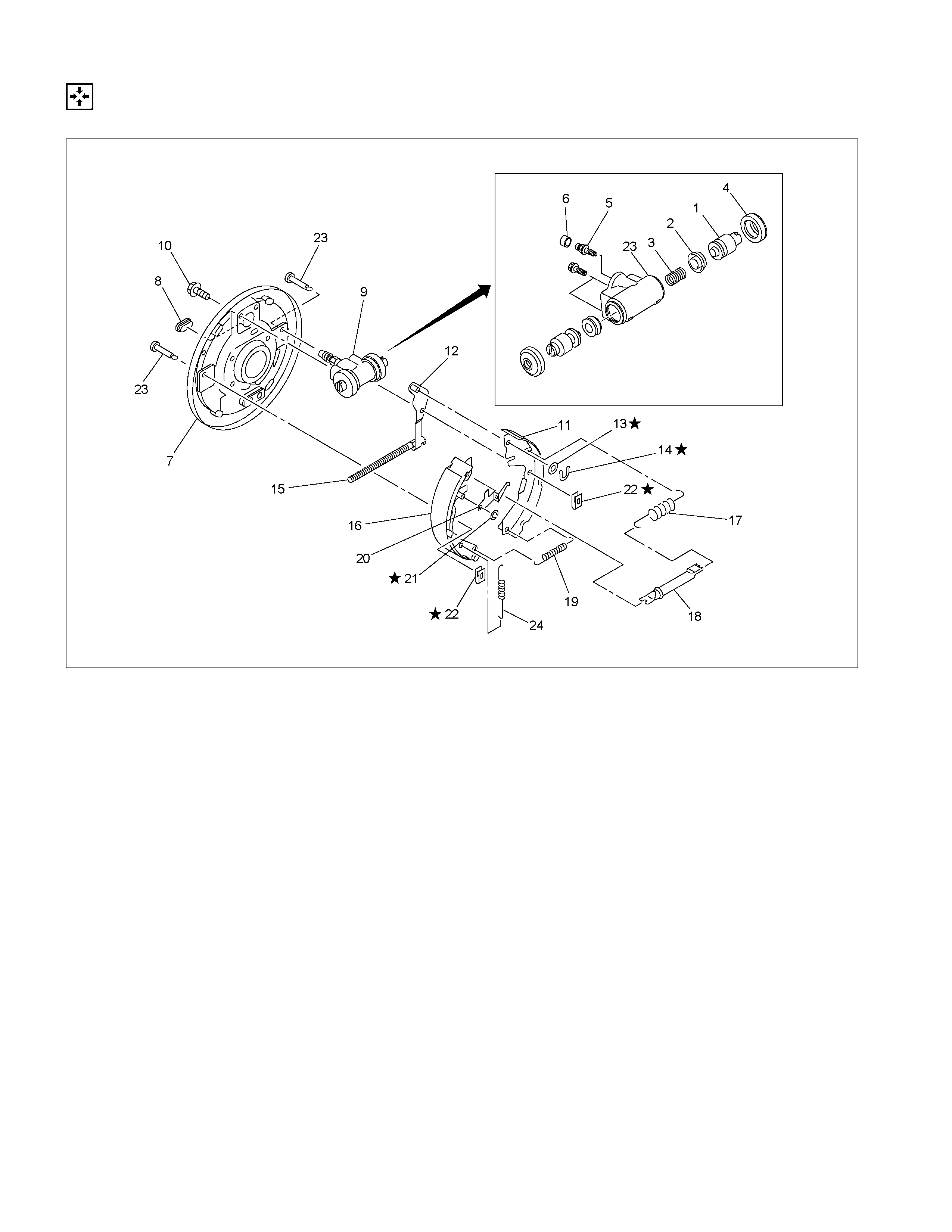
REAR DRUM BRAKE ASSEMBLY
DISASSEMBLY
First, disassemble the brake drum. Then disassemble the rear brake assembly.
Refer to the “REAR AXLE” section for the brake drum disassembly procedure.
RTW35CMF000201
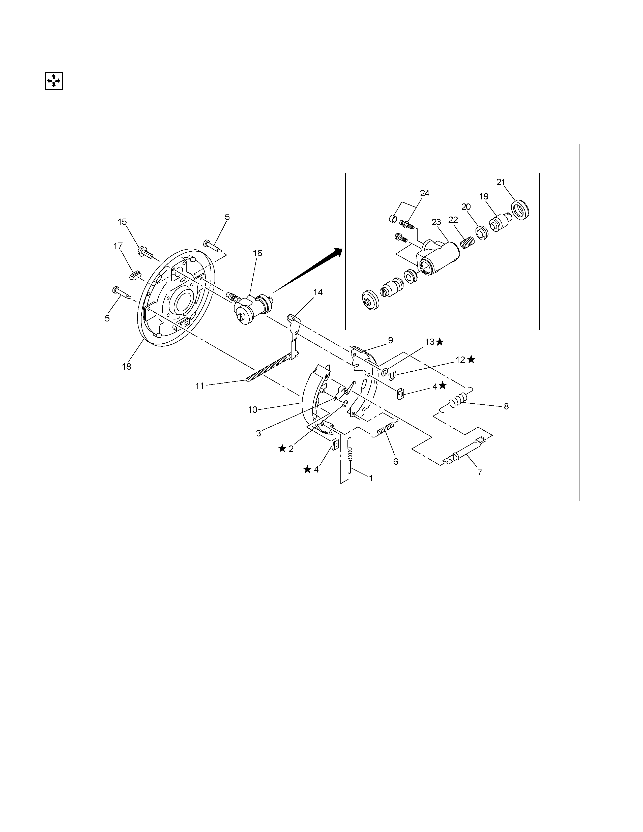
MAJOR COMPONENTS
Disassembly Steps
1. Spring ; adjuster
2. Ring ; Adjuster lever
3. Lever ; adjuster
▲ 4. Spring ; Shoe hold
5. Pin ; Shoe hold
▲ 6. Spring ; Shoe to shoe, lower
7. Adjuster assembly
8. Spring ; shoe to shoe, upper
9. Shoe ; leading
10. Shoe ; trailing
11. Spring ; lever return
12. Retainer
13. Washer ; lever
14. Lever ; parking
15. Bolt ; wheel cylinder
16. Wheel cylinder assembly
17. Cover
18. Back plate
MINOR COMPONENTS
Disassembly Steps
Wheel Cylinder Assembly (14)
19. Piston
20. Cup
21. Boot ; piston
22. Return spring
23. Bleeder
24. Cap ; bleeder
P1010008
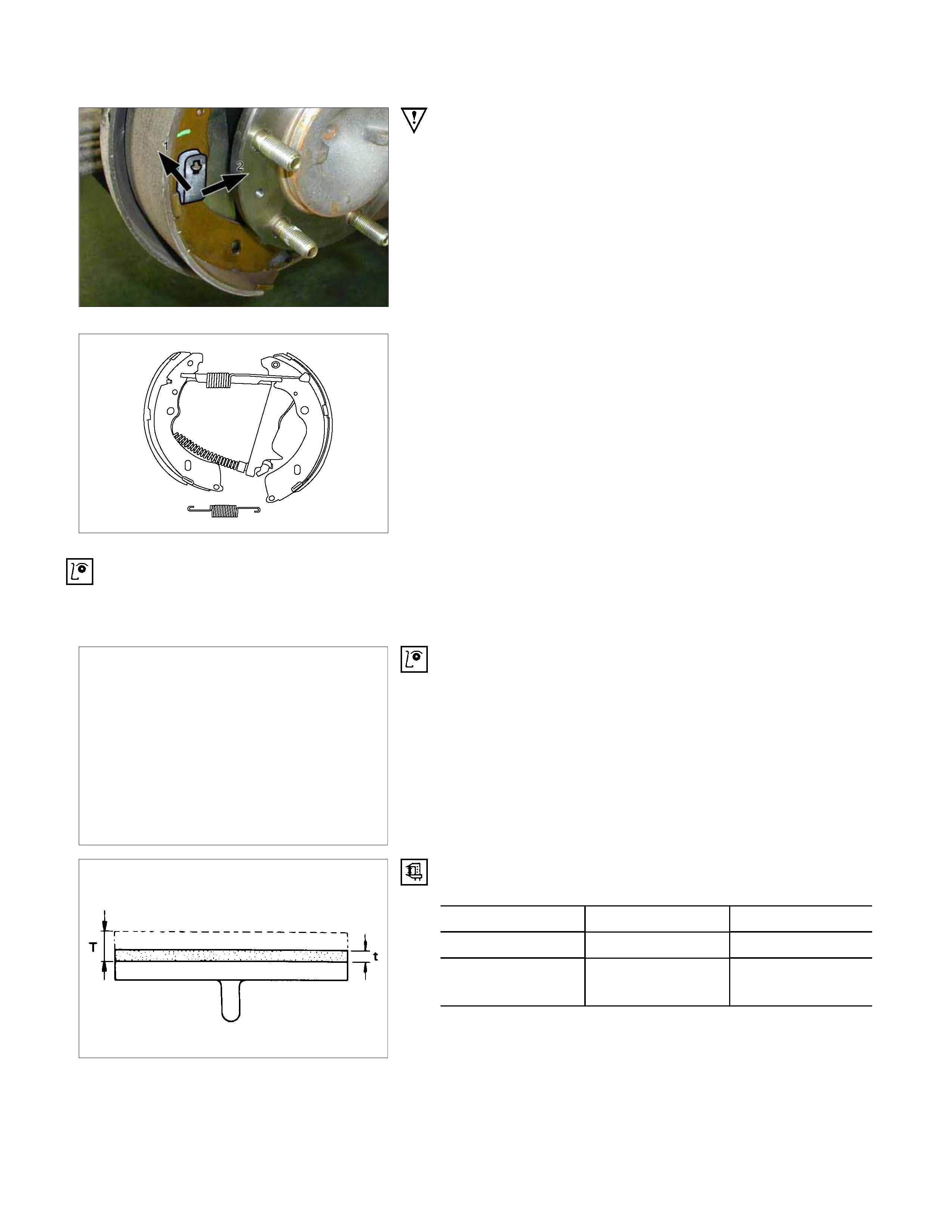
Important Operations
4. Spring ; shoe hold
Push the shoe hold spring toward the brake shoe and hold it.
Rotate the spring to remove it from the shoe hold pin.
6. Spring ; shoe to shoe, lower
Slide the brake shoes and lower spring toward the ground.
Remove the lower spring.
INSPECTION AND REPAIR
Make necessary correction or parts replacement if wear damage or any other abnormal conditions are found through
inspection.
• Brake drum
• Back plate
• Brake lining
• Wheel cylinder body
• Piston
• Piston cup
• Return spring
Visual check
Inspect the following parts for wear scuffs, scratches,
corrosion, stains, deterioration, or other abnormal conditions.
Thickness of the Brake Lining
Thickness mm(in
)
standard (T) Limit (t)
4×2 5.0 (0.197) 1.0 (0.039)
4×2 HIGH RIDE
4×4 5.0 (0.197) 1.0 (0.039)
Clean wheel Cylinder Parts
Always use clean brake fluid to clean wheel cylinder parts.
Note:
Do not use mineral-vase cleaning solvents such as
gasoline, kerosene, acetone, paint thinner, or carbon
tetrachloride.
Piston Cups
Inspect the piston cups for wear, distortion, fatigue, fatigue or
other abnormal conditions.
Measuring the Brake Drum
mm(in)
Standard Limit
Inside diameter 254 (10.000) 255.5 (10.059)
Run out 0.08 (0.003) 0.15 (0.006)
Inside diameter 295 (11.614) 296.5 (11.673)
TFR
(HIGH RIDE)
TFS Run out 0.08 (0.003) 0.15(0.006)
TFR
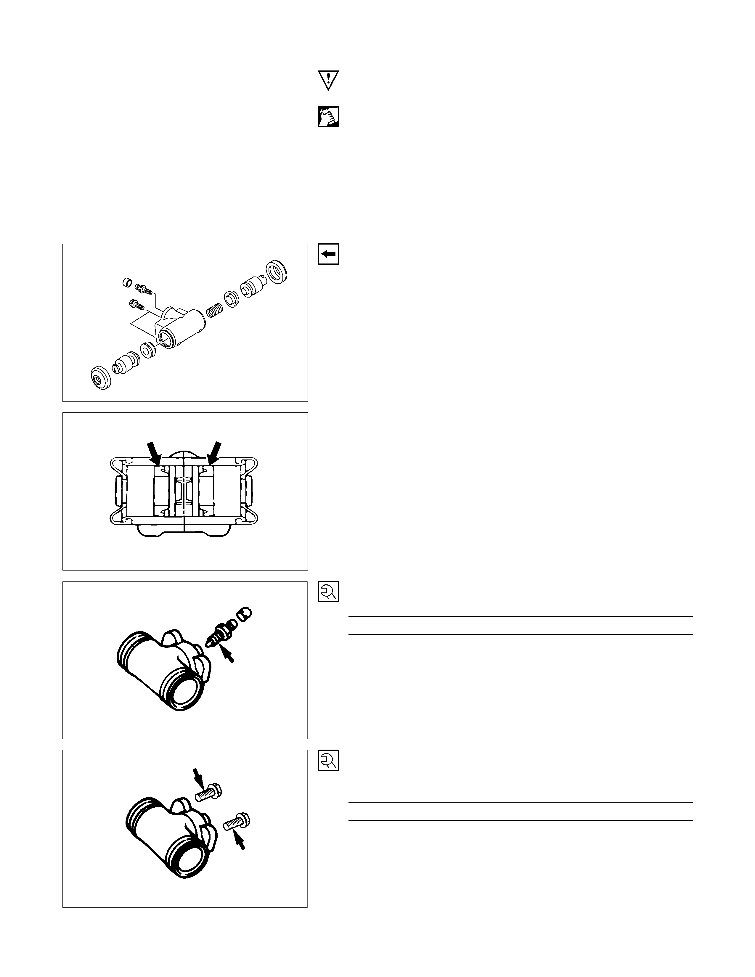
REASSEMBLY
RTW35CMF000301
MINOR COMPONENTS
Reassembly Steps
Wheel cylinder Assembly (7)
1. Piston assembly
2. Cup ; piston
3. Return spring
▲ 4. Boot ; piston
▲ 5. Bleeder
6. Cap ; bleeder
MAJOR COMPONENTS
Reassembly Steps
7. Back plate
8. Cover
▲ 9. Wheel cylinder assembly
▲ 10. Bolt ; wheel cylinder
▲ 11. Shoe ; leading
▲ 12. Lever ; parking
▲ 13. Washer ; lever
▲ 14. Retainer
15. Spring ; lever return
▲ 16. Shoe ; trailing
▲ 17. Spring ; shoe to shoe, upper
▲ 18. Adjust assembly
19. Spring ; shoe to shoe ; lower
▲ 20. Lever ; adjuster
▲ 21. Ring ; Adjuster lever
22. Spring ; shoe hold
▲ 23. Pin ; shoe hold
▲ 24. spring ; adjuster
Important Operations
Note:
• Wash the disassembled parts in clean brake fluid.
• Use compressed air to clean the ports.
• Protect the disassem bled part s urfac es from dust and othe
r
foreign material contamination.
• Before reassembly, check the part surfaces for dust and
other foreign material contamination.
• Be sure to replace the designated parts with new ones.
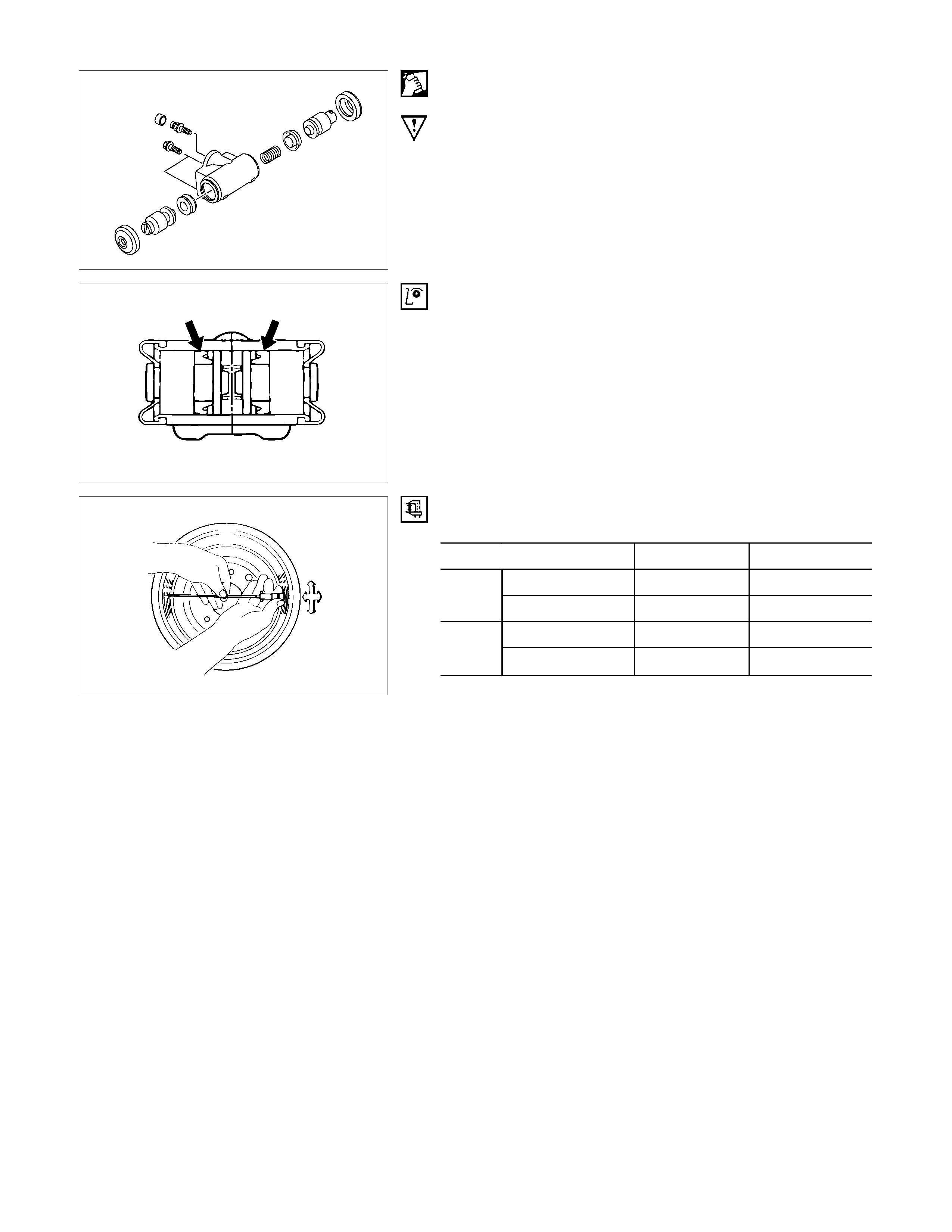
4. Piston Assembly
Install new piston cups on each piston so that the flared end of
the cups are turned to the inboard side of the pistons.
Attach the return spring and the boot to the piston.
Be sure to use new piston cup and boot.
• Apply brake fluid to the piston and the inner face of the
boots.
• Note the direction of piston cup.
5. Bleeder ; Wheel Cylinder
Torque N⋅m(kgf⋅m/Ib⋅in)
6 - 8 (0.6 – 0.8 / 52 - 69)
9. Wheel Cylinder Assembly
10. Bolt ; Wheel cylinder
Torque N⋅m(kgf⋅m/Ib⋅ft)
14 - 18 (1.4 – 1.8 / 10 - 13)
308R300008
11. Shoe ; leading
• Be sure to use new spring; shoe hold.
12. Lever ; parking
13. Washer ; lever
14. Retainer
Install the lever, the washer and the retainer to the leading
brake shoe.
•
A
pply grease to the sliding surfaces of the lever and
brake shoe.
• Be sure to use new retainer and washer.
305R300009
16. Shoe ; trailing
• Be sure to use new spring; shoe hold.
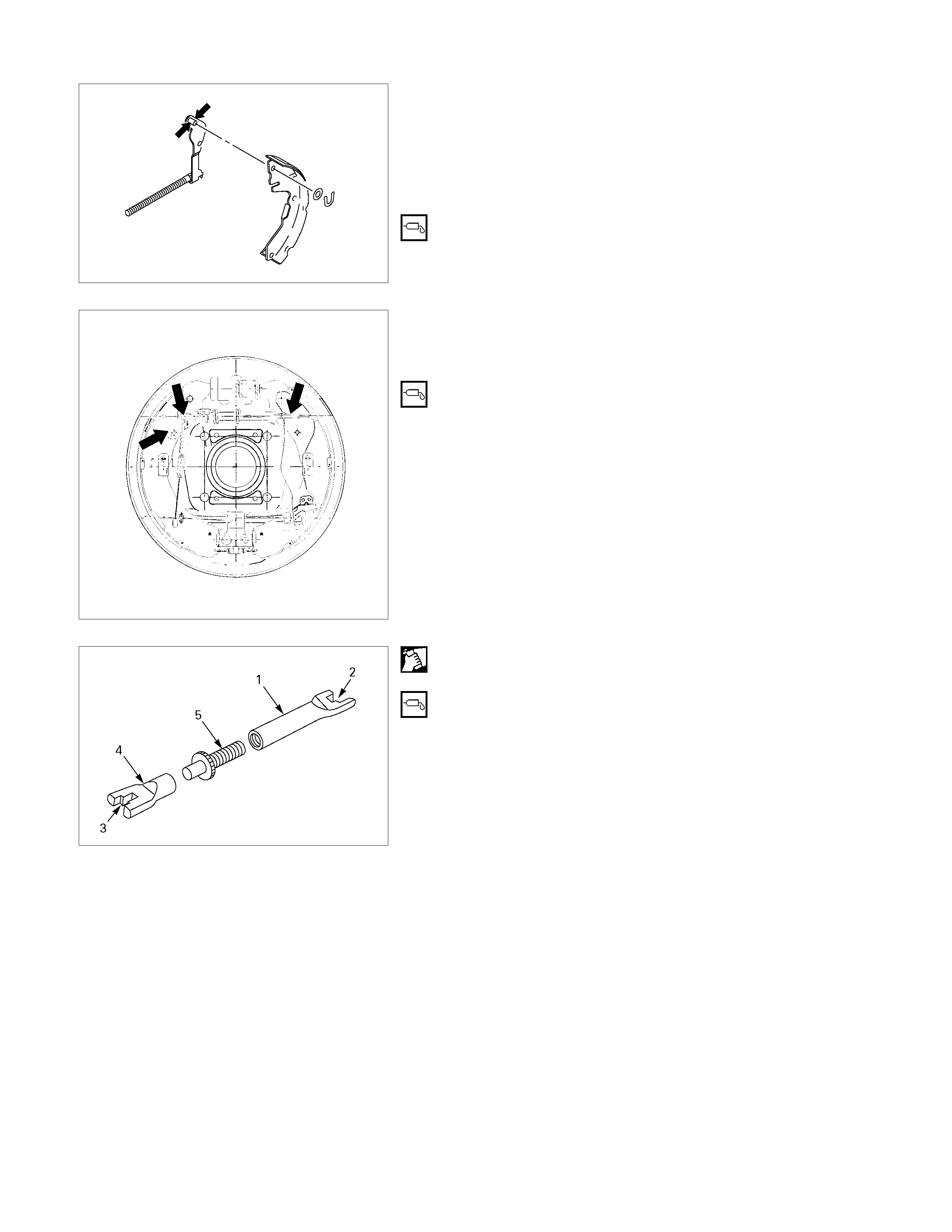
17. Spring ; shoe to shoe, upper
18. Adjuster assembly
1. Apply grease to each of the parts shown in the
illustration before installing the brake shoe.
• Lever; adjuster-shoe
• Adjuster-shoe
2. Clean the adjuster bolt (5) and the adjuster rods (1) (4).
Apply grease to the threaded portion of the adjuster bolt.
3. Install the adjuster rod to the adjuster bolt.
4.
A
pply grease to the adjuster asm ends (2) (3). Set the
spring ; upper to the adjuster asm, then install them to
the brake shoe.
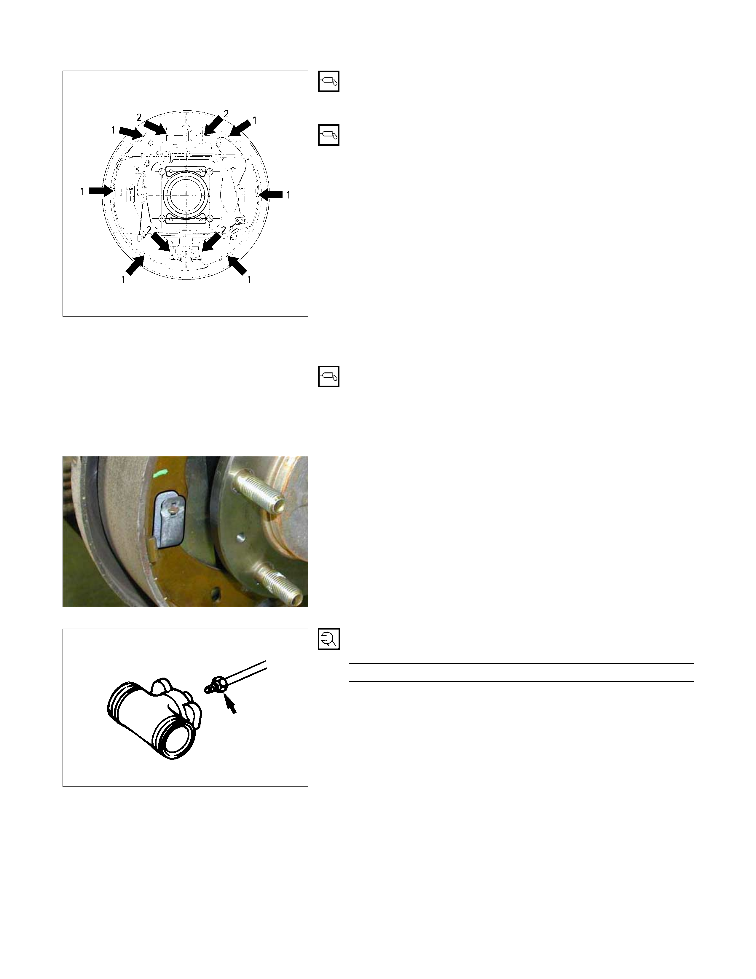
305R300010
5. Before s etting the brake shoes , apply grease to the back
plate portions (1) contacting the brake shoe edge as
shown in the illustration.
6.
A
pply grease to the wheel cylinder parts contacting the
brake shoe (2).
7. Install the brake shoe.
Note:
• Be careful not to damage the wheel cylinder dust cover.
• Do not allow the wheel cylinder piston to fly free.
20. Lever ; adjuster
21. Ring ; Adjuster lever
• Apply grease to the lever ; adjuster sliding surface.
Install the lever ; adjuster and the ring to the shoe ;
trailing.
• Be sure to use new ring.
P1010008B
23. Pin ; shoe hold
24. Spring ; shoe hold
• Install the brake drum.
• Install the rear wheel.
• If the wheel cylinder has been removed, the brake
system must be bled.
• Pump the brake pedal 10 times. Check that there is little
or no stroke length variation as the pedal is pumped.
• Adjust the lining clearance.
• Brake Line
Torque N⋅m(kgf⋅m/Ib⋅ft)
13 - 19 (1.3 - 1.9 / 9 - 14)
BRAKE CONTROL
REMOVAL AND INSTALLATION
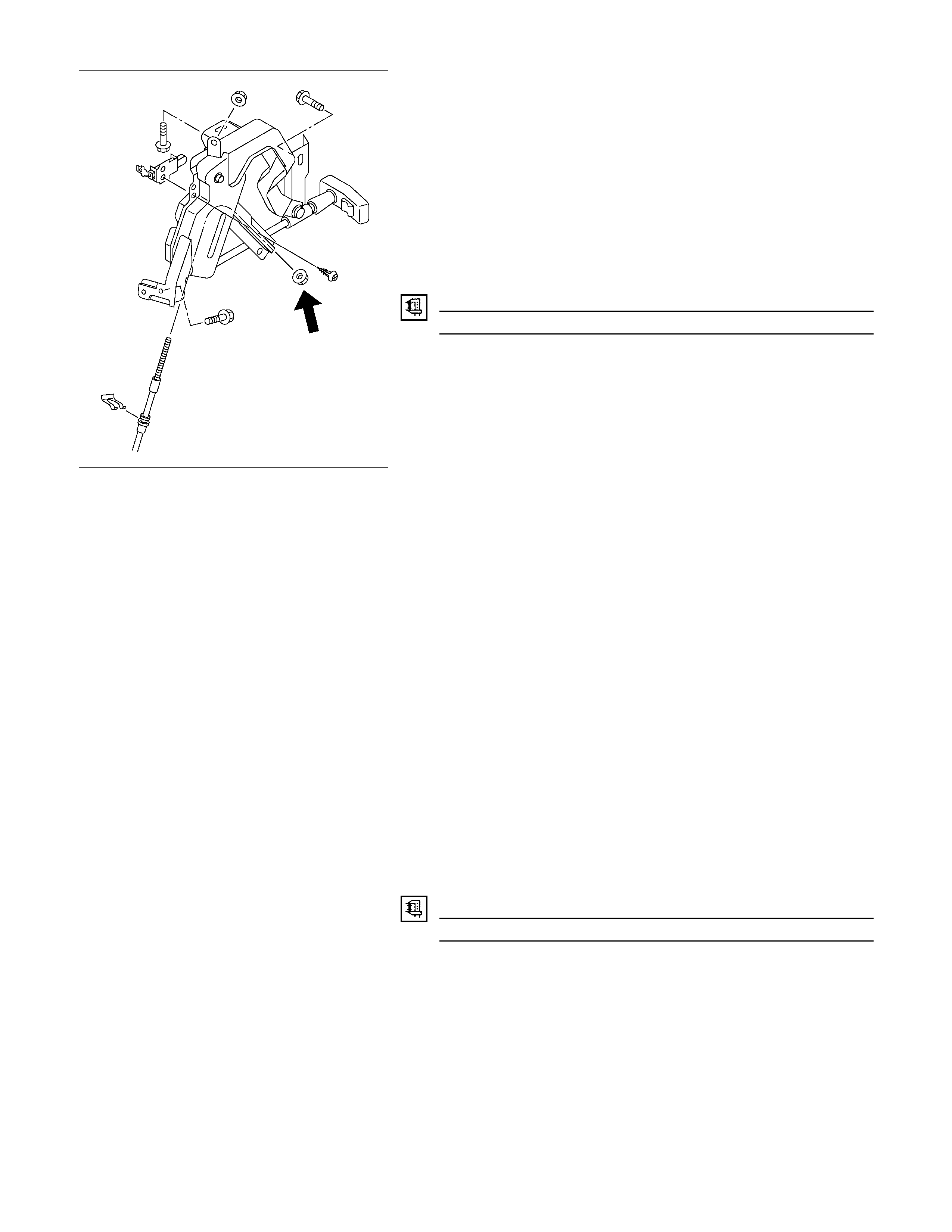
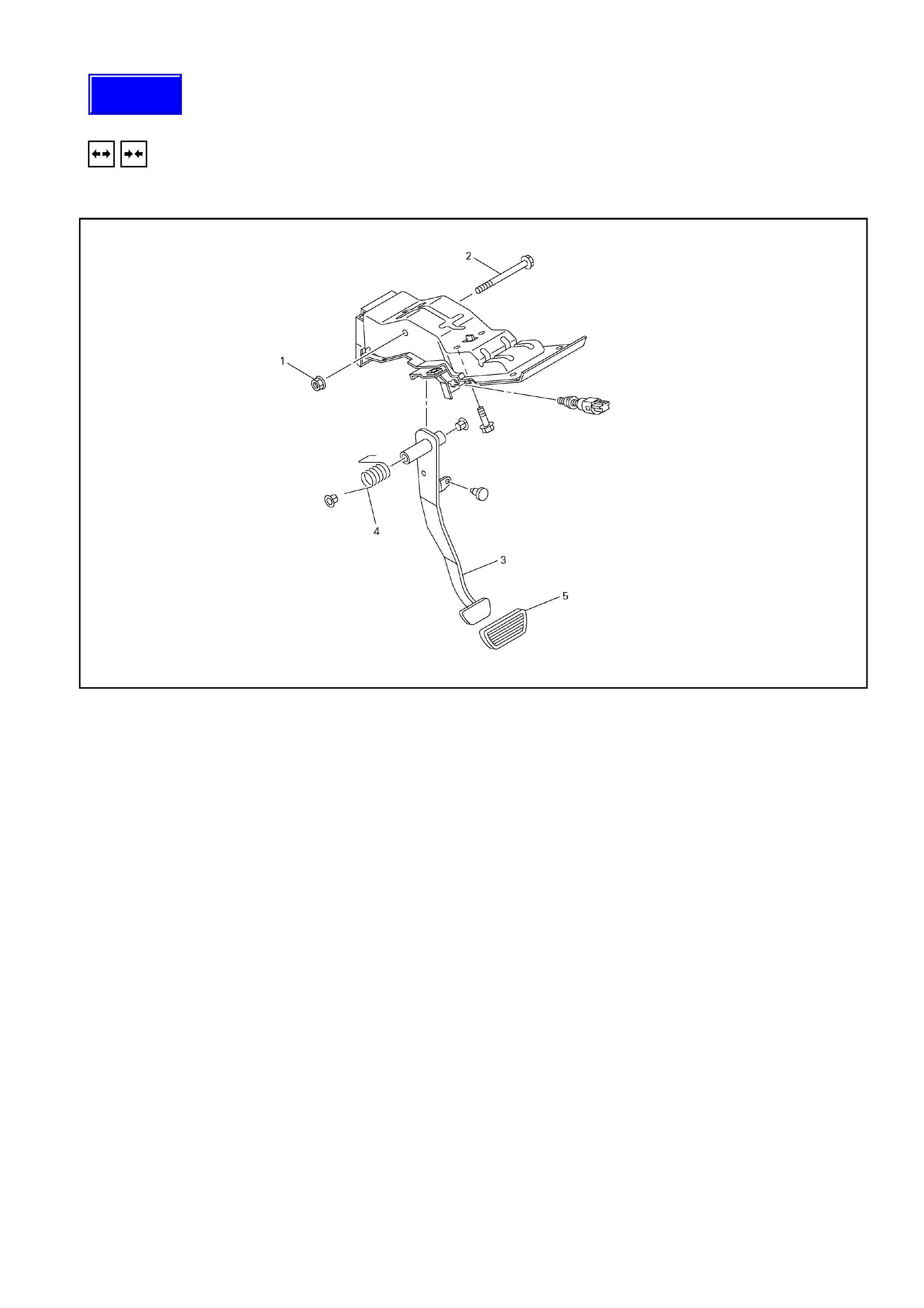
BRAKE PEDAL ASSEMBLY
310R300001
Removal Steps
1. Nut ; fulcrum pin
2. Pin ; fulcrum, pedal to bracket
3. Pedal arm
4. Return spring
5. Pedal pad
Installation Steps
Before installation, apply grease to the entire
circumference of the fulcrum pin (2).
Refer to “Adjustment Procedure of Brake Pedal”,
in this Section.
Techline
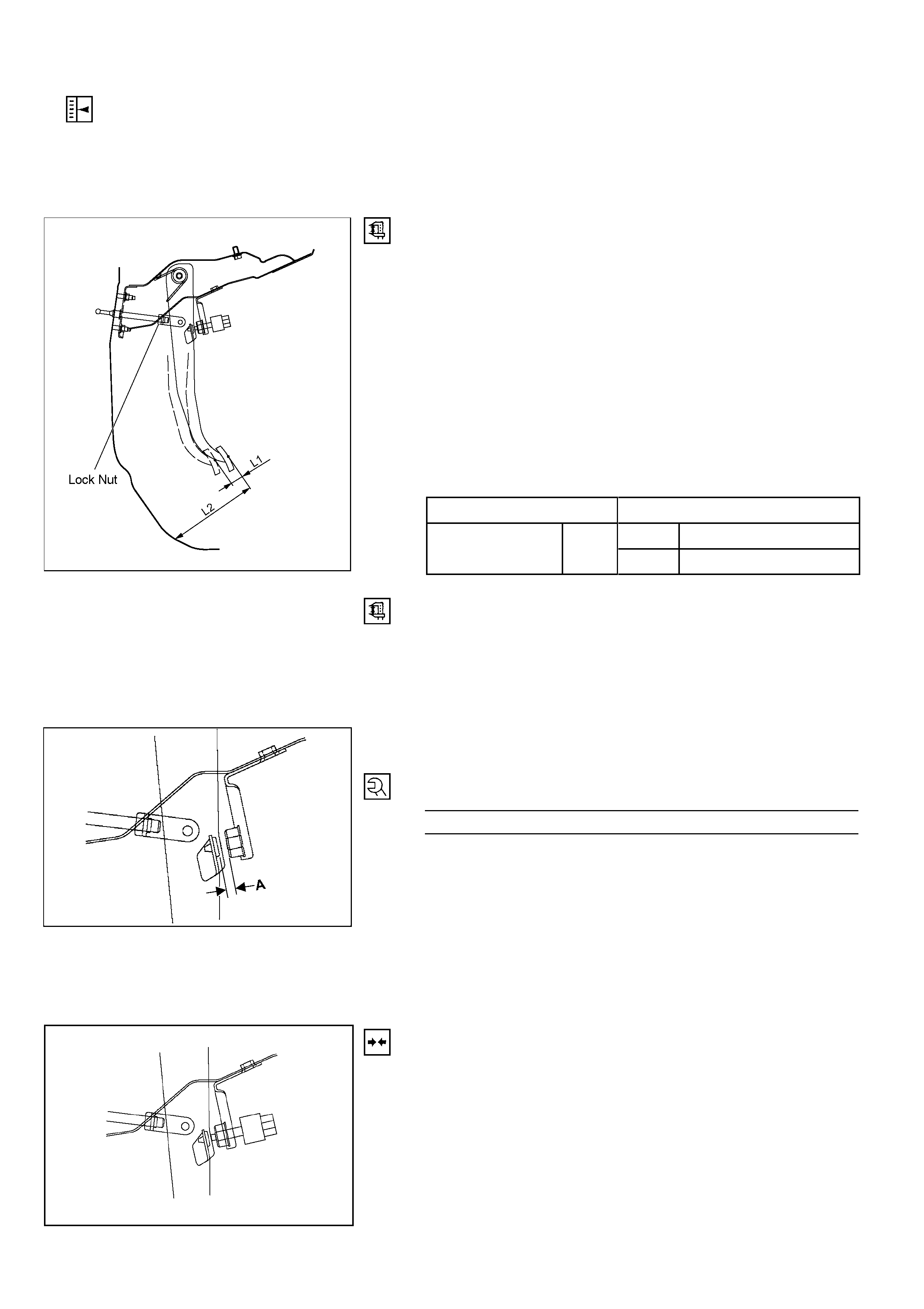
ADJUSTMENT PROCEDURE OF BRAKE PEDAL
The push rod serves to stop the brake p edal when released.
Brake pedal height adjustment should be performed as
follows:
RTW35CSH000601
Brake Pedal – Height
1. Rotate the brake light swit ch counter-clockwise to release,
then remove from the mounting bracket.
2. Check that the pedal is fully released an d not binding, by
lightly lifting the pedal, assisting the pedal return spring.
3. Measure the brake pedal height (L2) with the pedal in the
fully released position.
Notes:
• Pedal height (L2) must be measured after starting the
engine and providing full vacuum to the booste r.
• Pedal free play (L1) must be measured after turni ng off
the engine, then applying/releasing the brake pedal at
least five times to exhaust stored vacuum. mm(in)
Pedal free play (L1) 6 – 10 (0.23 – 0.39)
M/T 174 – 186 (6.85 – 7.32)
Pedal Height (L2) RHD A/T 176 – 188 (6.93 – 7.40)
331R300005b
4. If the pedal height (L2) is not within the above range,
adjust as follows:
a) Check that the stop lamp switch has been removed.
b) Loosen the lock nut on the push rod clevis yoke.
c) Adjust the brake pedal to the specified height (L2)
by rotating the push rod in the appropriate direction.
d) The gap between the stoplight swit ch mount and the
pedal bracket (A) sh ould then be from 5 – 8 mm.
e) Tighten the push rod lock nut to the specified torque.
Lock Nut Torque N⋅m(kgf⋅m/lb⋅ft)
12 – 18 (1.2 – 1.8 / 9 - 13)
f) Reinstall the stop lamp swit ch, using the following
procedure.
NOTE:
Pedal height (L2) must be 80 mm (3.14 in.) or more when
applying about 50 kg (110.25 lbs. ) of stepping force.
331R300005
Connecting Pedal and Fitting Stop Lamp Switch.
1.
A
lign the hole in the booster & master cylinder rod clevis
yoke with the hole in the brake pedal.
2. Insert the clevis pin into these holes from left side of the
pedal and secure with snap clip.
3. Pull the brake pedal upwards to take up all slack and hold
in this position.
4. With your other hand, install the brake light switch until the
switch plunger is completely depressed.
5. Turn the switch clock-wise until a “click” sound is made,
locking the switch into position.
6. The pedal when released should now have a small
amount of free-play

MASTER CYLINDER
REMOVAL AND INSTALLATION
MASTER CYLINDER ASSEMBLY
Removal Steps
▲ 1. Brake line
2. Nut ; master cylinder to vacuum booster
3. Master cylinder assembly
Installation Steps
3. Master cylinder assembly
▲ 2. Nut ; master cylinder to vacuum booster
▲ 1. Brake line
Important Operation - Removal
1. Brake Line
Be very careful not to spill brake fluid on the painted surface.
Damage to the painted surface will result.
Important Operation - Installation
2. Nut ; Master Cylinder to Vacuum Booster
Torque N⋅m (kg f⋅m/lb⋅ft)
12 – 18 (1.2 – 1.8 / 9 – 13)
1. Brake Line
Torque N⋅m (kg f⋅m/lb⋅ft)
13 – 19 (1.3 – 1.9 / 9 – 14)
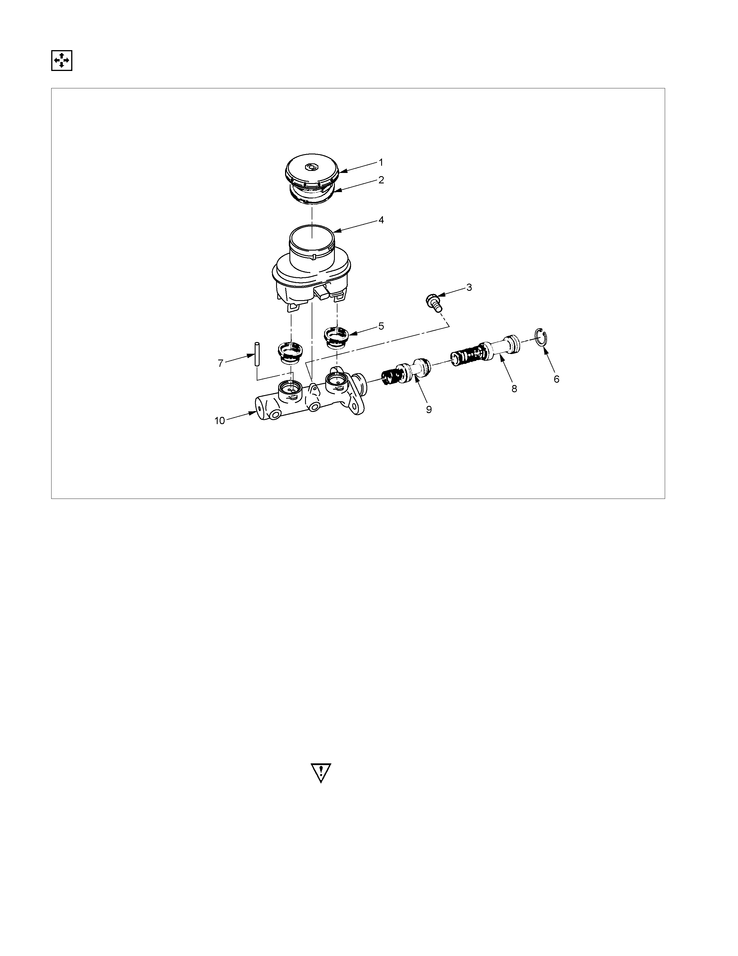
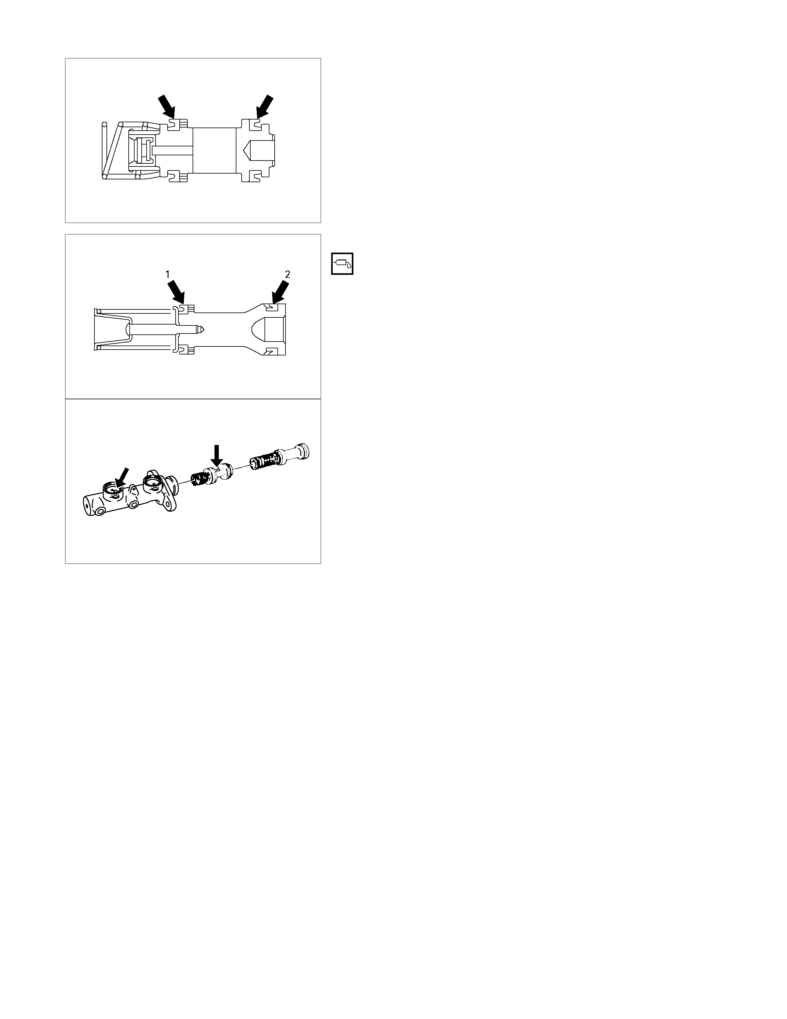
DISASSEMBLY
RTW35CMF000401
Disassembly Steps
1. Cap
2. Diaphragm
3. Bolt
4. Resever tank
5. Grommet
▲ 6. Snap ring
▲ 7. Stop pin
▲ 8. Primary piston
▲ 9. Secondary piston
10. Cylinder body
Note:
• Be sure to replace the designated with new ones.
• Wash the disassembled parts in clean brake fluid.
• Use compressed air to clean the ports.
• Do not allow dirt and dust to contaminate the dis assembled
parts.
Important Operations
When disassembling, inspecting or reassembling the master
cylinder assembly, take care not to bring the parts into contact
with mineral oil or dust. Wash the piston cups only with brake
fluid. Do not use gasoline or other mineral-base cleaning
solvents.
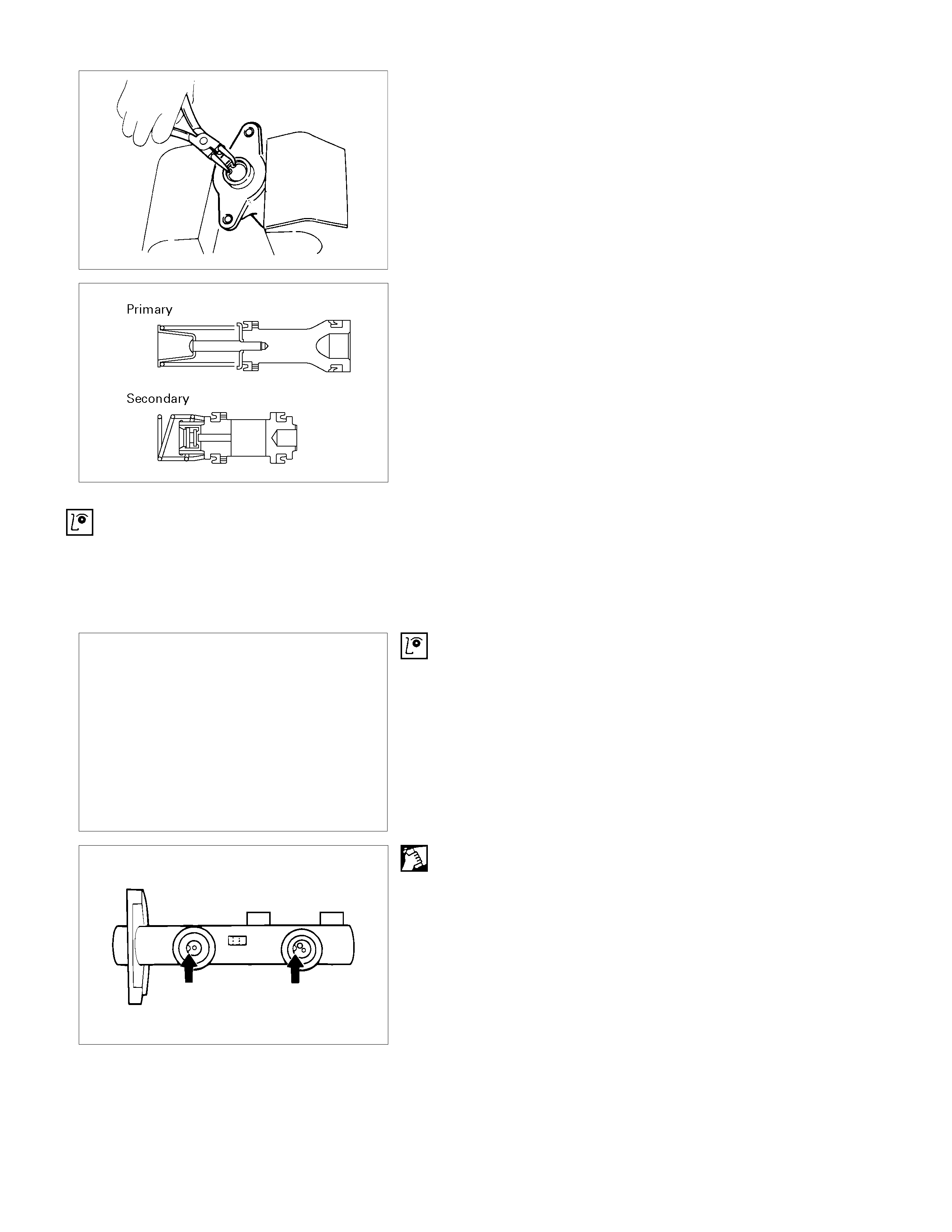
6. Ring ; Snap
Remove the snap ring from the cylinder body with pushing in
the primary and secondary pistons.
7. Stop Pin
Remove the stop pin from the cylinder body with pushing in the
primary and secondary pistons.
8. Piston Assembly ; Primary and Spring
9. Piston Assembly ; Secondary and Spring
Don’t remove the spring from the piston.
INSPECTION AND REPAIR
Make necessary correction or parts replacement if wear damage or any other abnormal conditions are found through
inspection.
• Cylinder inside face
• Piston
• Piston cap
• Piston cap spacer
• Return port
• Return spring
Visual Check
Inspect the following parts for wear, distortion, cuts, nicks,
corrosion, or other abnormal conditions.
Return Port
Check the return port for obstructions and if necessary, clean
with a tag wire.
Blow away foreign matter with compressed air.

Primary Piston
A
fter reassembly, push in the primary piston to see that returns
smoothly .
Repeat the test two or three times to see that brake fluid is
forced out from the front and rear outlets.
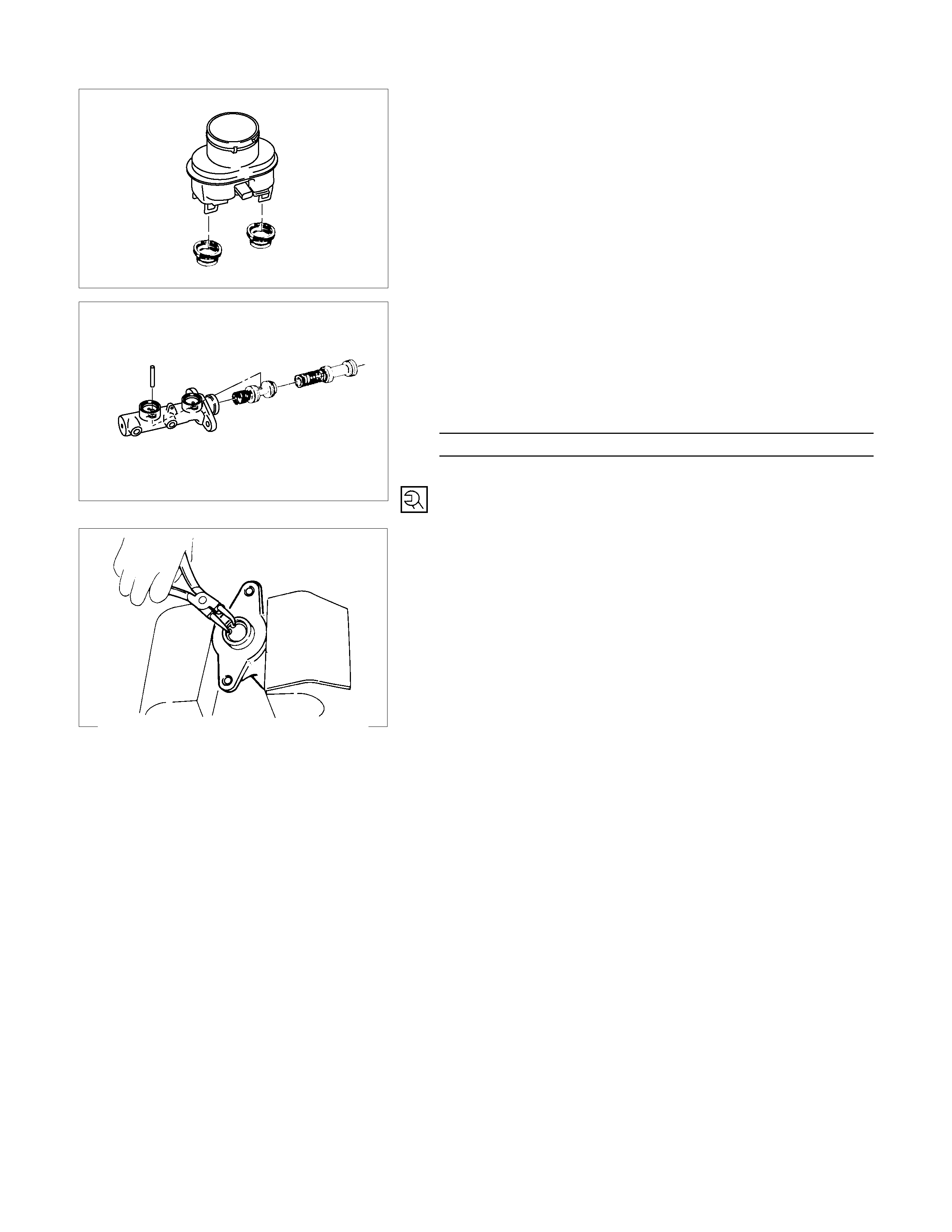
REASSEMBLY
Reassembly Steps
1. Secondary piston
2. Primary piston
3. Cylinder body
4. Grommet
5. Reservoir tank
6. Stop pin
7. Bolt
8. Snap ring
9. Diaphragm
10. Cap
1. Secondary piston
Lubricate the piston cups on the secondary piston assemblies
with brake fluid.
Note:
Be sure to use a new piston.
2. Primary piston
Lubricate the piston cups on the primary piston assemblies
with brake fluid (1) and the rubber grease (2).
Note:
Be sure to use a new piston.
3. Cylinder body
Install the secondary piston and the primary piston to the
cylinder body.
Note:
The secondary piston long hole and the cylinder body stop pin
hole must be aligned at installation.
4. Grommet
5. Reservoir tank
6. Stop pin
7. Bolt
1. Install the grommets to the reservoir tank.
Note:
Be sure to use are new grommets.
330R300018
2. Press down on the prim ar y piston and install the stop pin
to the cylinder body (the piston long hole must be
aligned with the cylinder body installation hole).
3. Install the reservoir tank to the cylinder body.
4. Tighten the bolts to the specified torque.
Torque N⋅m (kg f⋅m/lb⋅in)
2 - 3 (0.2 - 0.3 / 17 - 26)
8. Snap pin
Press down on the primary piston and install the snap ring to
the cylinder body groove.
Note:
Be sure to use new snap ring.
9. Diaphragm
10. Cap
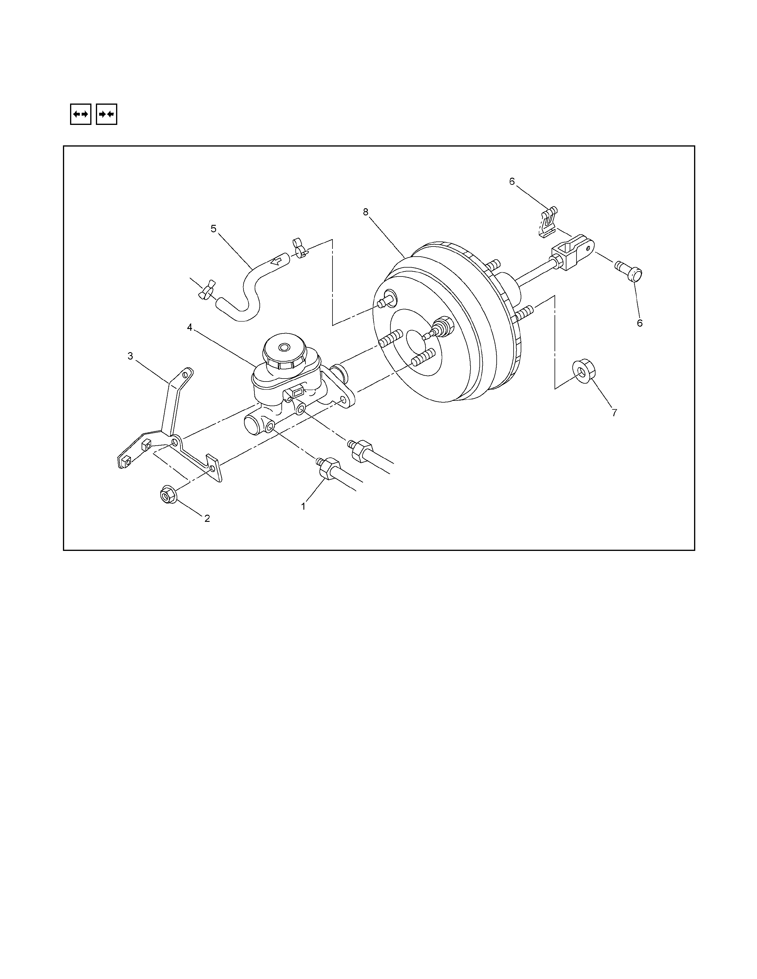
VACUUM BOOSTER
REMOVAL AND INSTALLATION
RTW35CMF000501
Removal Steps
▲ 1. Brake pipe
▲ 2. Master cylinder fixing nut
▲ 3. Bracket (only RHD model)
▲ 4. Master cylinder assembly
▲ 5. Vacuum hose
6. Spring retaining clip and clevis pin
7. Vacuum booster fixing nut
8. Vacuum booster assembly
Installation Steps
▲ 8. Vacuum booster assembly
▲ 7. Vacuum booster fixing nut
▲ 6. Clevis pin and spring retaining clip
▲ 5. Vacuum hose
4. Master cylinder assembly
3. Bracket
2. Master cylinder fixing nut
1. Brake pipe
330R300002
Removal
1. Brake pipe
Important Operation
When removing brake pipes and master cylinder, be careful
not to spill brake fluid over the painted surfaces, as damage to
the paint finish will result.
2. Master Cylinder Fixing Nut
3. Bracket
4. Master Cylinder Assembly
NOTE:
Before removing the master cylinder from the vacuum booster,
depress and release the brake pedal approximately five times
to exhaust any stored vacuum in the booster.
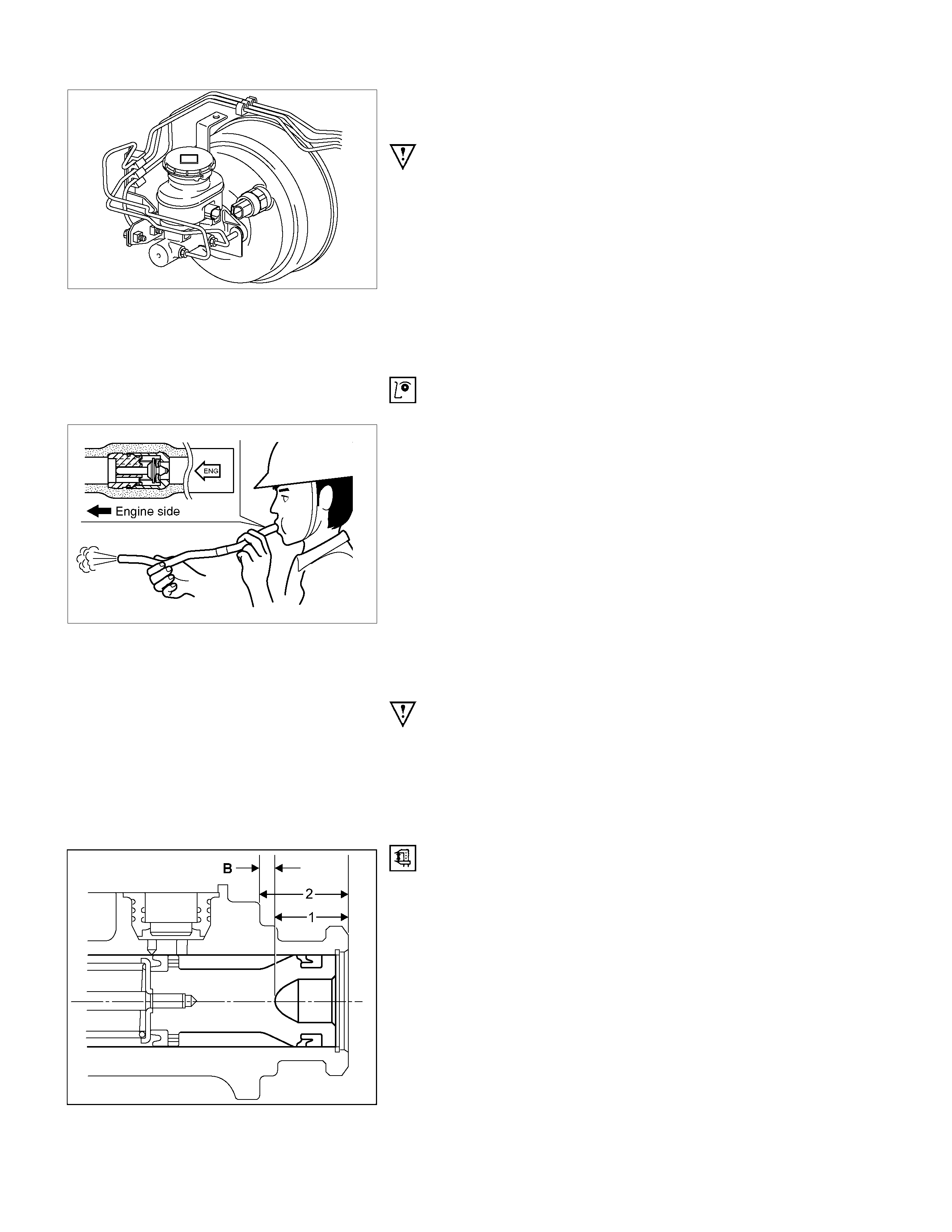
Inspection and Repair
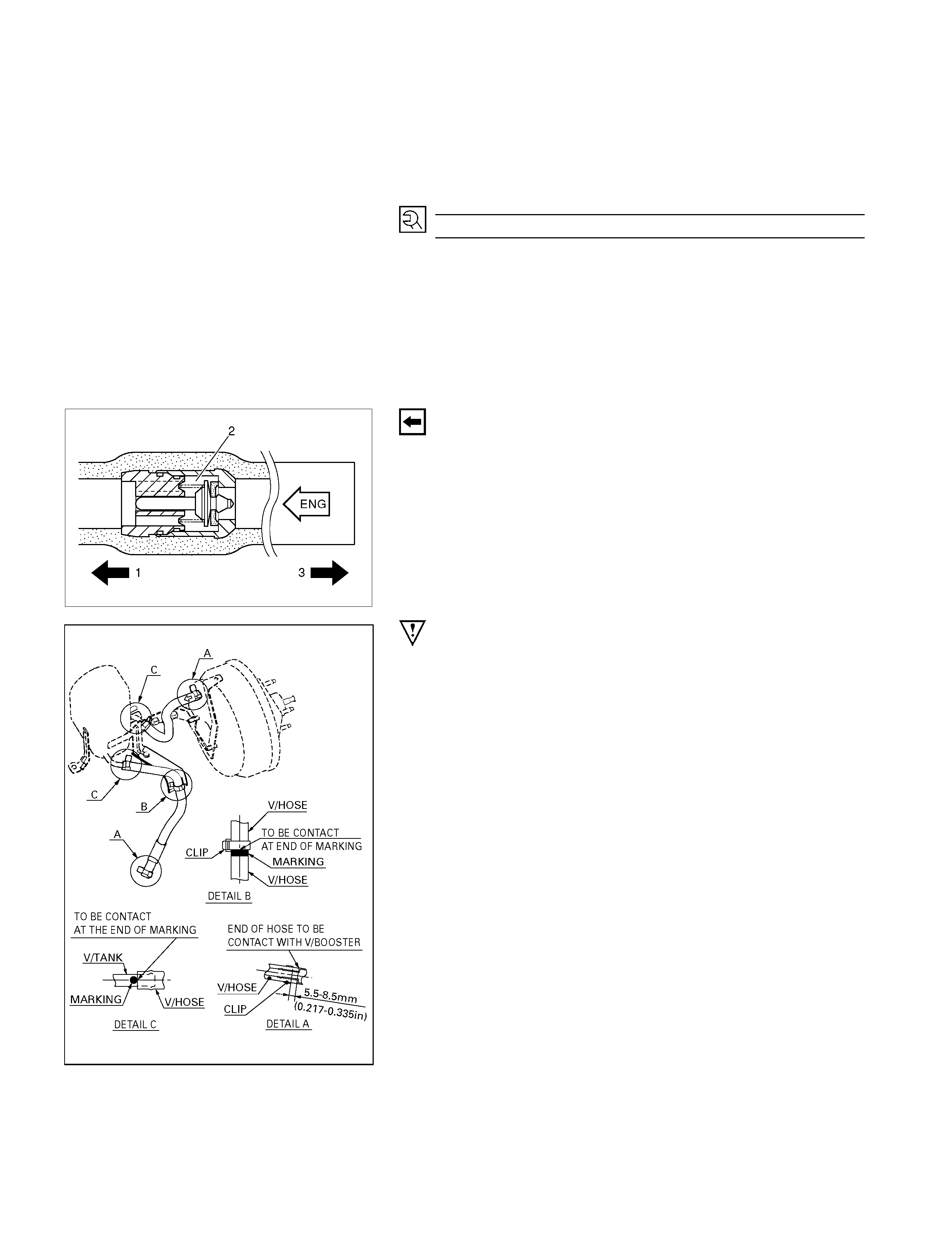
5. Vacuum Hose (The built in check valve)
360R300002
Inspect the check valve, installed inside the vacuum hose, as
follows:
1. Blow air into the hose from the booster side as
shown in the illustration. The air should pass freely
through the hose.
2. Blow air into the hose from the engine side. The
check valve should close to block the passage of air.
The vacuum hose and built-in check valve must be replaced
as an assembly, if either is found to be defective.
Installation
8. Vacuum Booster Assembly
Important Operation
Perform vacuum booster and vacuum booster push rod
adjustment.
NOTE:
When replacing either the master cylinder or vacuum booster,
it is vital that the push rod to piston clearance is measured and
adjusted, as detailed here:
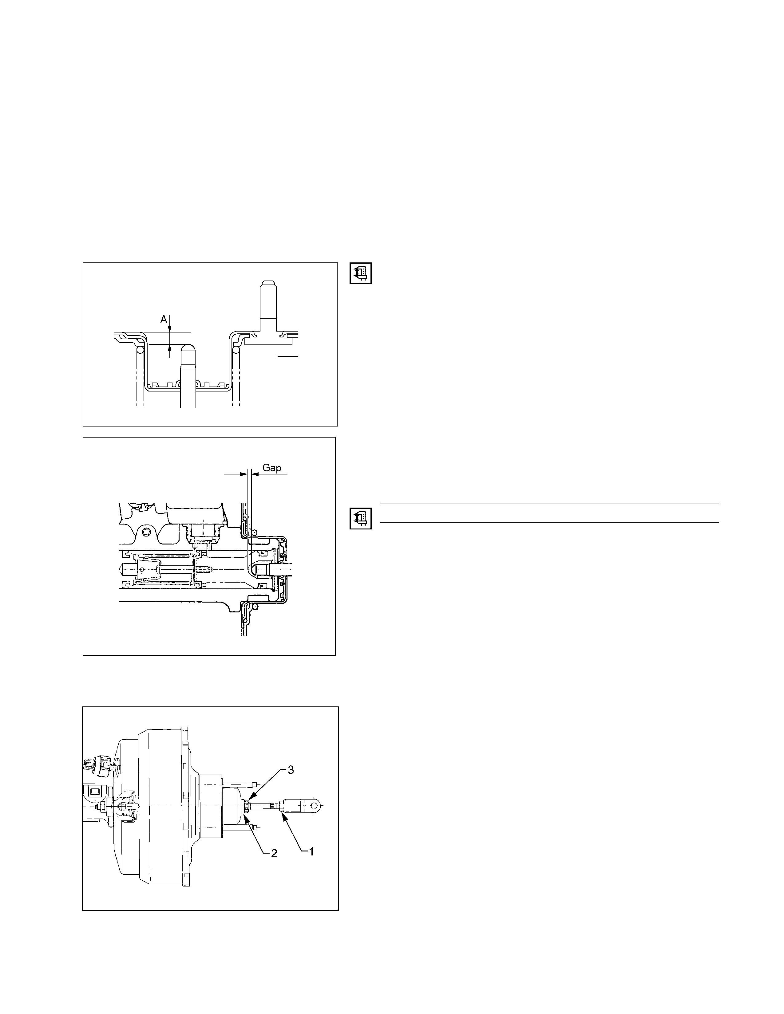
RTW35CSH000901
1. Measure dimension (B) at the master cylinder, as
follows:
a Using a depth micrometer or vernier calipers,
measure the distance from the end of the maste
r
cylinder to the end of the counter-bore in the
piston (1).
b Using the same technique, measure from the end
of the master cylinder to the larger stepped flange
(2).
c Subtract (1) from (2) to achieve dimension ‘B’.
d Record dimension ‘B’.
2.
A
pply a negative pressure (vacuum) to the vacuum
booster to achieve the specified vacuum reading;
Gasoline Engine: 66.7 kPa (500 mm Hg) or Diesel
Engine 93.3 kPa (700 mm Hg).
NOTE:
To achieve the required vacuum reading, it will be
necessary to use the engine as the vacuum source. As it is
recommended that the following booster push rod
measurement is taken with the booster removed from the
vehicle, a suitable length and wall thickness hose will be
needed to connect the engine to the booster.
3. Push the booster push rod inward to ensure that it is
fully seated.
4. With vacuum applied to the booster (refer Step 2),
measure the distance from the booster shell to the
end of the push rod, using a depth micrometer o
r
vernier calipers. Thi s be comes dimension ‘A’.
5. Record the measure d dimension ‘A’.
RTW35CSH000801
6. Calculate the clearance between the end of the
booster push rod and the master cylinder piston by
subtracting dimension ‘A’ from ‘B’.
Gap mm
0 − 0.4 (0 − 0.0157)
7. If the gap dimension (A-B) is not as specified, adjus
t
the push rod as follows:
a Check that the clevis yoke lock nut (1) is tight.
b While holding the 17 mm nut (2) with a se
t
spanner, loosen the push rod lock nut (3) at the
vacuum booster.
NOTE:
A
s lock nut (3) is a double hexagon, the use of a
suitable size pipe spanner will be required to loosen
/ tighten the lock nut.
c Use the adjuster (2) to adjust the length of the
protruding portion of the push rod to achieve the
dimension specified in Step 6.
NOTE:
When repeating Steps 3 to 5 inclusive, ensure that
the specified vacuum is applied to the booste
r
(Applied vacuum should be; Gasoline Engine:– 66.7
kPa (500mm Hg) or Diesel Engine:– 93.3 kPa
(700mm Hg) after adjustment).
7. Vacuum Booster Fixing Nut
1. Install the vacuum booster assembly to the dash panel
and pedal mounting bracket.
2. Install the booster retaining nuts and tighten to the
specified torque.
Torque N⋅m(kgf⋅m/lb⋅f
t
18 – 24 (1.8 – 2.4 / 13 – 17)
6. Clevis Pin and Spring Retaining Clip
1. Reinstall the brake pedal clevis pin through the clevis
yoke and brake pedal, from left to right.
2. Secure the clevis pin, usi ng the spring retaining clip.
3. Check and adjust the brake pedal height, as required.
Refer to “Adjustment Procedure of Brake Pedal”, in
Servicing, in this Section.
360r300003
5. Vacuum Hose
The check valve (2) is built-in to the vacuum hose.
When installing the vacuum hose make sure that the arrow on
the hose is facing the engine (1 ).
NOTE:
Do not apply oil to the vacuum hose.
331R300008
Important Operation
The vacuum hose installation direction is very important. The
booster will not operate if the vacuum hose is installed in the
wrong direction.