
SECTION 5D - PARKING BRAKE SYSTEM
Service Precaution
General Description
Parking Brake Lever
Parking Brake Lever Assembly and Associated Parts (Bench Seat)
Removal
Installation
Front Parking Brake Cable
Front Parking Brake Cable and Associated Parts (Bench Seat)
Removal
Installation
Parking Brake Lever
Parking Brake Lever Assembly and Associated Parts (Buckle Seat)
Removal
Installation
Parking Brake Rear Cable
Parking Brake Rear Cable and Associated Parts
Removal
Installation
Inspection and Repair
Parking Brake Adjustment
Main Data and Specifica tions
General Specifications
Torque Specifications

Service Precaution
WARNING: THIS VEHICLE HAS A SUPPLEMENTAL RESTRAINT SYSTEM (SRS). REFER TO THE SRS
COMPONENT AND WIRING LOCATION VIEW IN ORDER TO DETERMINE WHETHER YOU ARE PERFORMING
SERVICE ON OR NEAR THE SRS COMPONENTS OR THE SRS WIRING. WHEN YOU ARE PERFORMING
SERVICE ON OR NEAR THE SRS COMPONENTS OR THE SRS WIRING, REFER TO THE SRS SERVICE
INFORMATION. FAILURE TO FOLLOW WARNINGS COULD RESULT IN POSSIBLE AIR BAG DEPLOYMENT,
PERSONAL INJURY, OR OTHERWISE UNNEEDED SRS SYSTEM REPAIRS.
CAUTION: Always use the correct fastener in the proper location. When you replace a fastener, use ONLY the
exact part number for that application. HOLDEN will call out those fasteners that require a replacement after
removal. HOLDEN will also call out the fasteners that require thread lockers or thread sealant. UNLESS
OTHERWISE SPECIFIED, do not use supplemental coatings (Paints, greases, or other corrosion inhibitors) on
threaded fasteners or fastener joint interfaces. Generally, such coatings adversely affect the fastener torque
and the joint clamping force, and may damage the fastener. When you install fasteners, use the correct
tightening sequence and specifications. Following these instructions can help you avoid damage to parts and
systems.

General Description
Pulling up the parking brake lever by hand will set the parking brake. By means of a ratchet type lock, the lever can be
held in that position until it is released. The position of the lever is transmitted through cable/lever systems to the rear
wheels. These parts are designed to obtain sufficient braking force even when parking on slopes. When the parking
brake is set, or when the ignition SW is in the "ON" position, the brake warning light illuminates. The rear wheel parking
brake is a leading-trailing brake (mechanical inside expansion type) built in the rear drum brake. Parking brake
adjustment is made through the adjusting hole (bored through back plate). Parking brake lever stroke should be
adjusted to 8−14 notches with 30kg (bench seat) or 6−8 notches with 30kg (bucket seat). Refer to
“Parking Brake Adjustment" in this section.
Parking Brake Lever
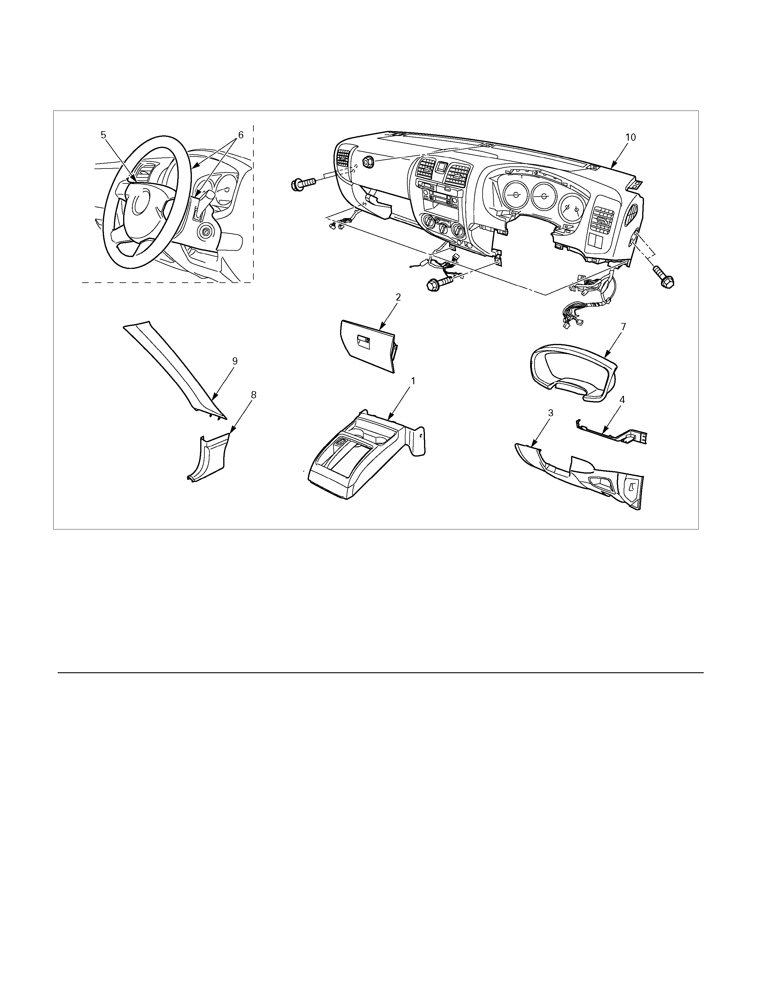
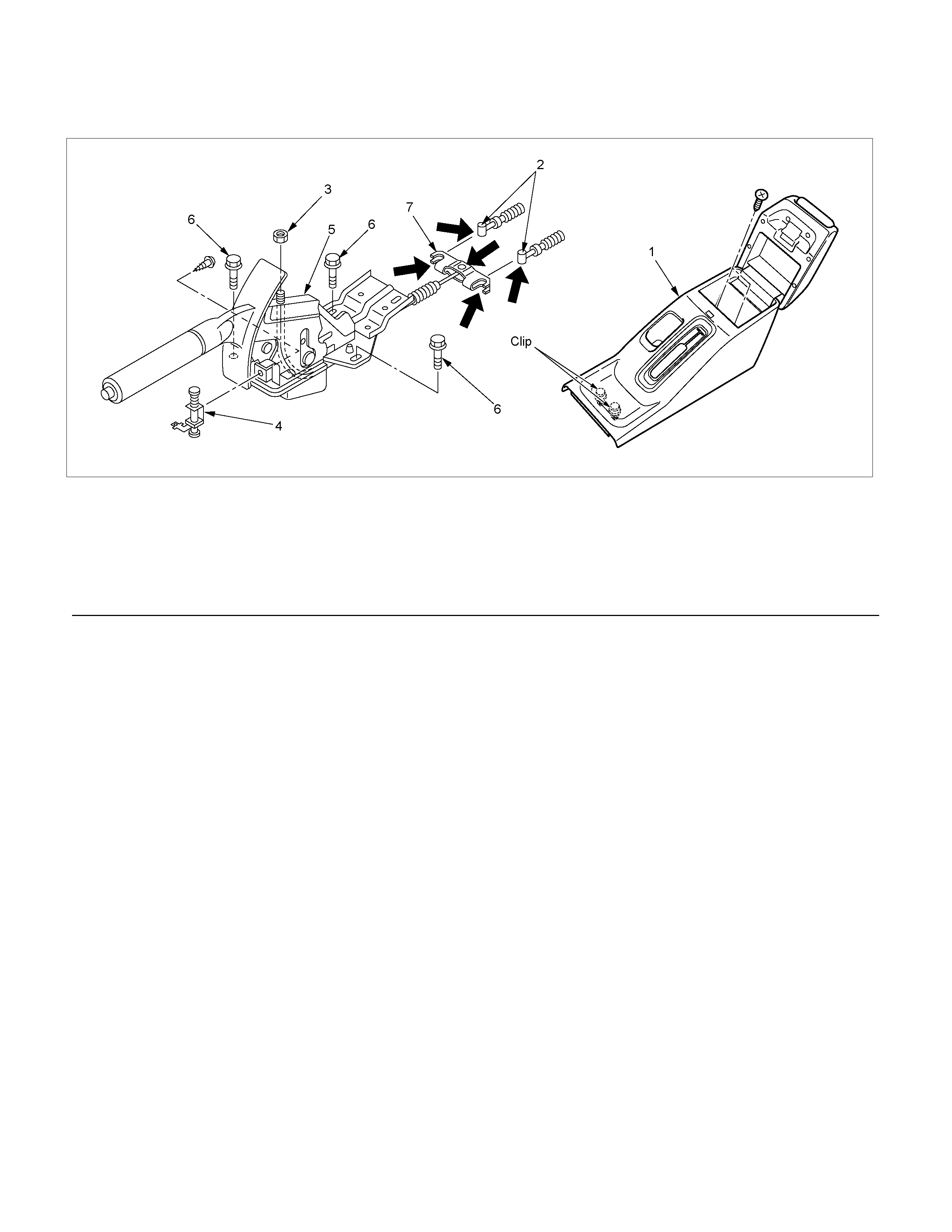
Parking Brake Lever Assembly and Associated Parts (Bench Seat)
740R300010
Legend
(1) Front Console Assembly
(2) Glove Box
(3) Instrument Panel Driver Lower Cover Assembly
(4) Driver Knee Bolster Assembly
(5) Driver Air Bag
(6) Steering Wheel/Steering Cowl
(7) Meter Cluster Assembly
(8) Dash Side Trim Cover
(9) Front Piller Trim Cover
(10) Instrument Panel Assembly & Cross Beam
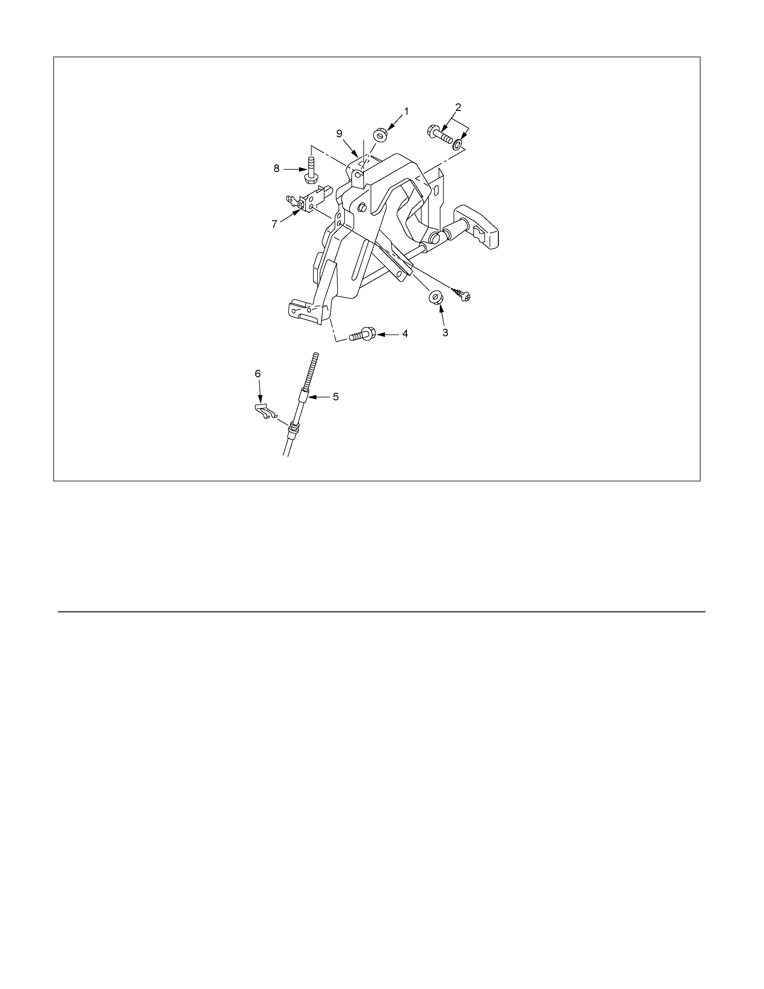
RTW35DLH000101
Legend
(1) Nut
(2) Bolt and Washer
(3) Adjust Nut
(4) Bolt
(5) Front Parking Brake Cable
(6) Clip
(7) Switch
(8) Bolt
(9) Parking Lever Assembly

Removal
1. Remove instrument panel assembly & cross beam in legend numbers order.
Refer to the Section 2C.
2. Bolts (2)(8) are already removed in step 1.
3. Remove adjust nut (3).
4. Pull out clip (6) and take out front parking brake cable (5) from parking lever assembly (9).
5. Remove bolts (4) and nut (1) and take out parking lever assembly (9).
6. Remov e switch (7).
Installation
1. Install switch (7).
Torque: 1.5 N⋅
⋅⋅⋅m (0.15 kg⋅
⋅⋅⋅m/13 lb in)
2. Set parking lever assembly (9).
3. Install bolts (4) and nut (1) and tighten them to the specified torque.
Torque: 15 N⋅
⋅⋅⋅m (1.5 kg⋅
⋅⋅⋅m/11 lb ft)
4. Set front parking brake cable (5) in parking lever assembly (9).
5. Drive clip (6) into the outer cable groove of front parking brake cable (5) at the outside of
parking lever assembly (9).
6. Drive adjust nut (3) on the f ront end of fr ont park ing brak e cable (5) so that fr ont ends of rear park ing brak e f it into
the rear end (equalizer) of front cable (5).
7. Install instrument panel assembly & cross beam.
Refer to Section 2C.
8. Install bolts (2) (8) and tighten them to the specified torque.
Torque: 15 N⋅
⋅⋅⋅m (1.5 kg⋅
⋅⋅⋅m/11 lb ft)
9. Install all parts removed when removal steps.
Refer to the section "Instrument Pane l" in Section 2C.
10. When a parking cable is replaced, pull parking brake lever with a force equivalent to
operating force: 490N (50 kg/110 lb), 10 times for conditioning.
11. Adjust nut (3) so that lever (9) goes through 8−14 notches, when pulled with a operation
force of 294N (30 kg/66 lb) and check brake for no drag.
Front Parking Brake Cable
Front Parking Brake Cable and Associated Parts (Bench Seat)
750R300003
Legend
(1) Shift Knob (manual transmission)
(2) Front Floor Console
(3) Rear Cov er
(4) Bolt
(5) Seat Assembly
(6) Buckle: side seat and Center Seat Belt
(7) Seat Adjuster
RTW35DMF000101
Legend
(1) Adjust Nut
(2) Clip
(3) Bolt
(4) Bolt
(5) Parking Brake Cable T-end
(6) Front Parking Brake Cable

Removal
1. Remove seat assembly and seat adjuster.
Refer to Section 2C.
2. Turn over the carpet so that front parking brake cable (6) appears.
3. Remove adjust nut (1).
4. Pull out clip (2) and take out front parking brake cable (6).
5. Remove bolt (3) (4).
6. Disconect parking brake cable T-ends (5) from front parking brake cable (6).
7. Take out front parking brake cable through the floor hole.
Installation
1. Apply grease (MULTI-PURPOSE GREASE or equivalent) to the connecting portion of parking brake cable T-end
(5) and front parking brake equalizer. (arrow mark)
2. Let rear end (equalizer) of front park ing brake cable (6) enter the floor hole and connect it with parking brake rear
cable T-end (5).
3. Set front parking brake cable (6) in the parking lever assembly.
4. Drive clip (2) into the outer cable groove of front parking brake cable (6) at the outside of the parking lever
assembly.
5. Install bolt (3)(4) on the floor and tighten them to the specified torque.
Torque: 15 N⋅
⋅⋅⋅m (1.5 kg⋅
⋅⋅⋅m/11 lb ft)
6. Drive adj ust nut (1) on the fr ont end of fr ont parking brak e cable (6) so that park ing brake cable T -end fits into the
rear end (equalizer) of front cable (6).
7. Fit the carpet on the floor.
8. Install seat adjuster and seat assembly.
Refer to Section 2C.
9. Pull parking brake lever with a force equivalent to operating force: 490N (50 kg/110 lb), 10 times for conditioning.
10. Adjust nut (1) so that parking brak e lever goes through 8−14 notches , when pulled with a operation force of 294N
(30 kg/66 lb).
11. Check brake for no drag.
Parking Brake Lever
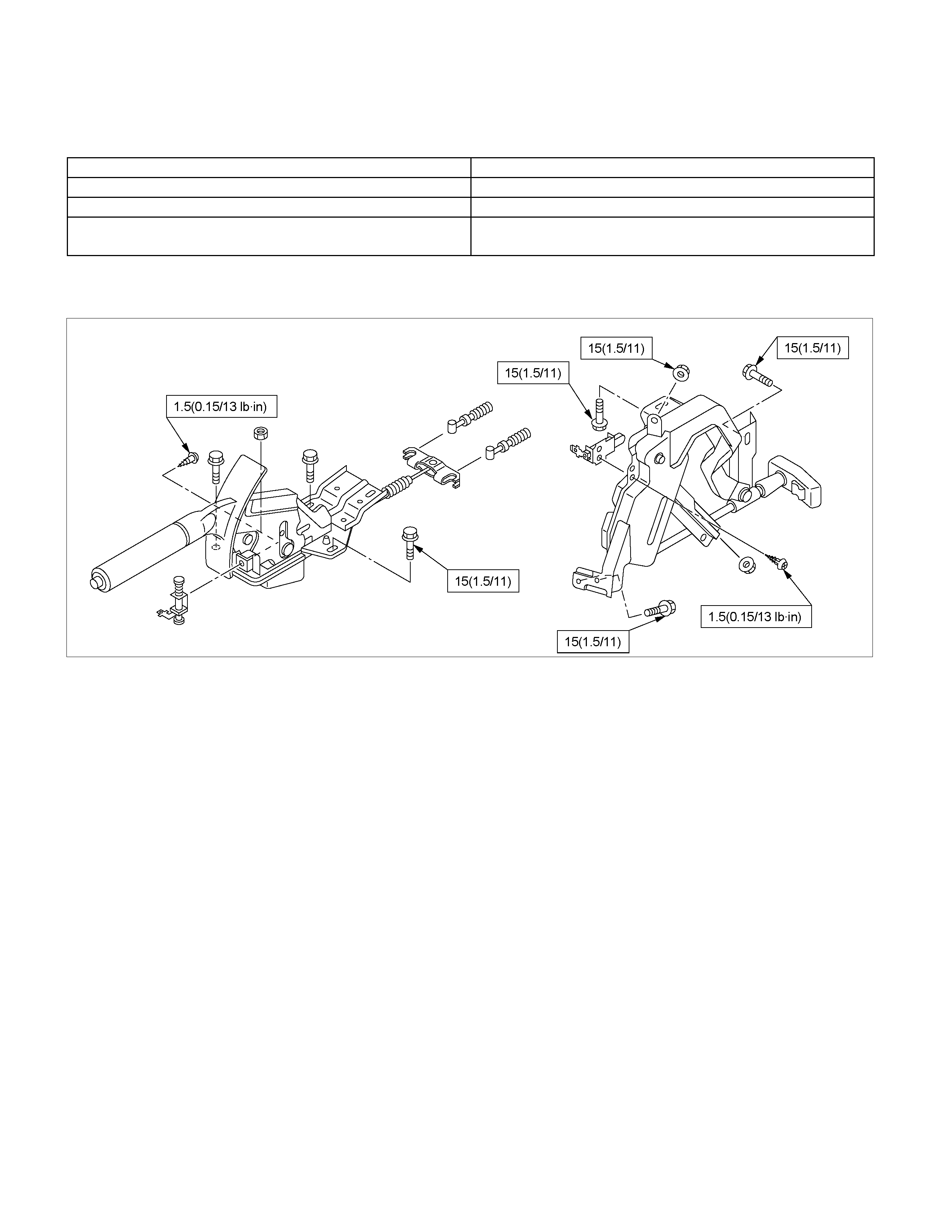
Parking Brake Lever Assembly and Associated Parts (Bucket Seat)
RTW35DSF000101
Legend
(1) Rear Floor Console
(2) Parking Brake Cable T-end
(3) Adjust Nut
(4) Switch
(5) Parking Brake Lever Assembly
(6) Bolt
(7) Equalizer
Removal
1. Remove rear floor console (1).
Refer to Section 2C.
2. Loosen adjust nut (3).
3. Remove bolt (6).
4. Remov e switch (4).
5. Disconnect parking brake cable T-end (2) from
parking brake lever assembly (5).
6. Take out parking brake lever assembly (5).
Installation
1. Apply grease (MULTI-PURPOSE GREASE o
r
equivalent) to the connecting portion of parking
brak e rear cable T - end (2) and park ing brak e leve
r
equalizer (7). (arrow mark)
2. Connect parking brake rear cable T-end (2) to
equalizer (7).
3. Install switch (4).
4. Tighten the parking brake lever fixing bolt (6) to
the specified torque.
Torque: 15 N⋅
⋅⋅⋅m (1.5 kg⋅
⋅⋅⋅m/11 lb ft)
5. Drive adjust nut (3) on parking brake assembly so
that parking brake cable T-end fits into equalizer
(7).
6. Install rear floor console (1).
Refer to the section Floor Console.
7. Pull parking brake lever with a force equivalent to
operating f orce: 490 N (50 k g/110 lb), 10 times for
conditioning.
8. Adjust nut (3) so that parking brake lever goes
through 6−8 notc hes, when pulled with a operation
force of 294 N (30 kg/66 lb).
9. Check brake for no drag.
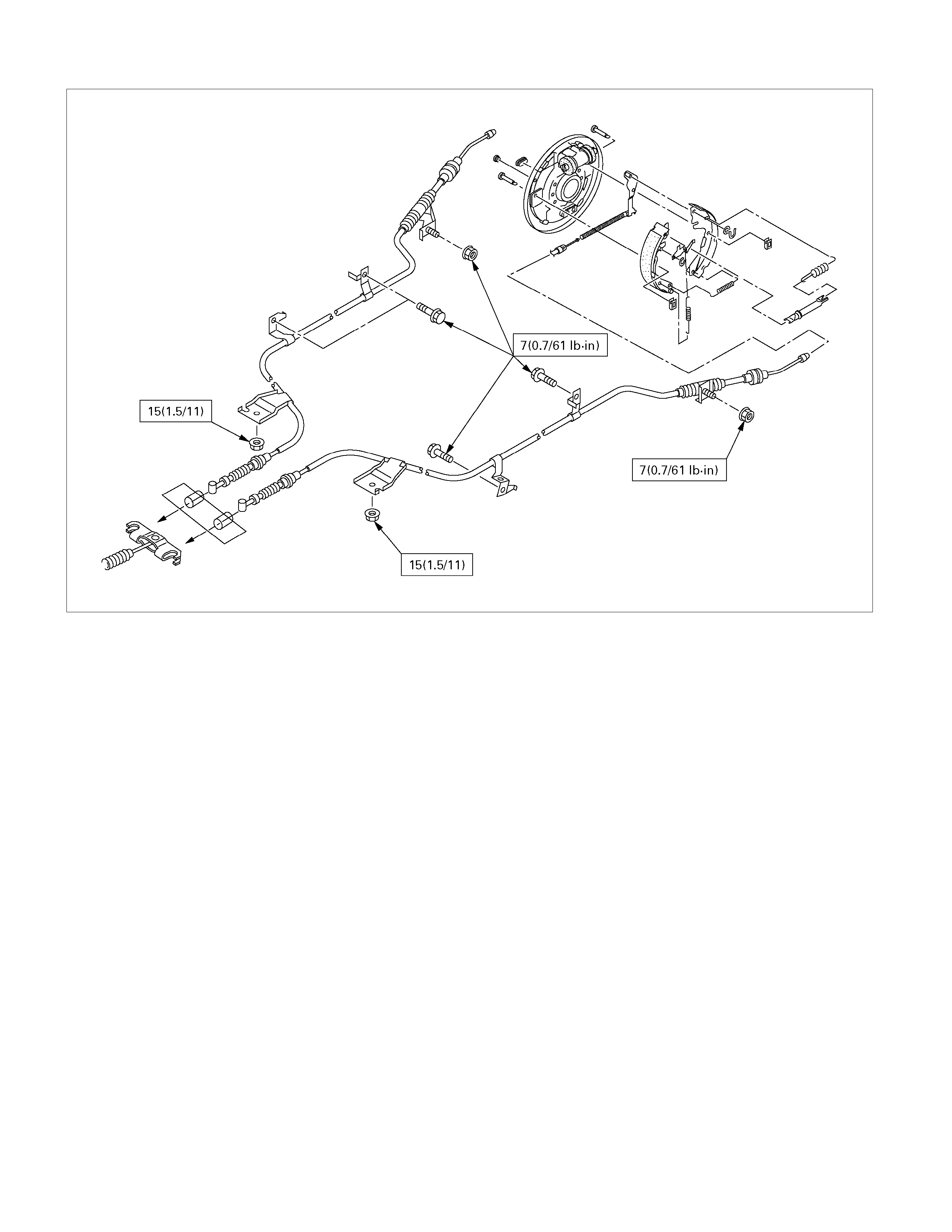
Parking Brake Rear Cable
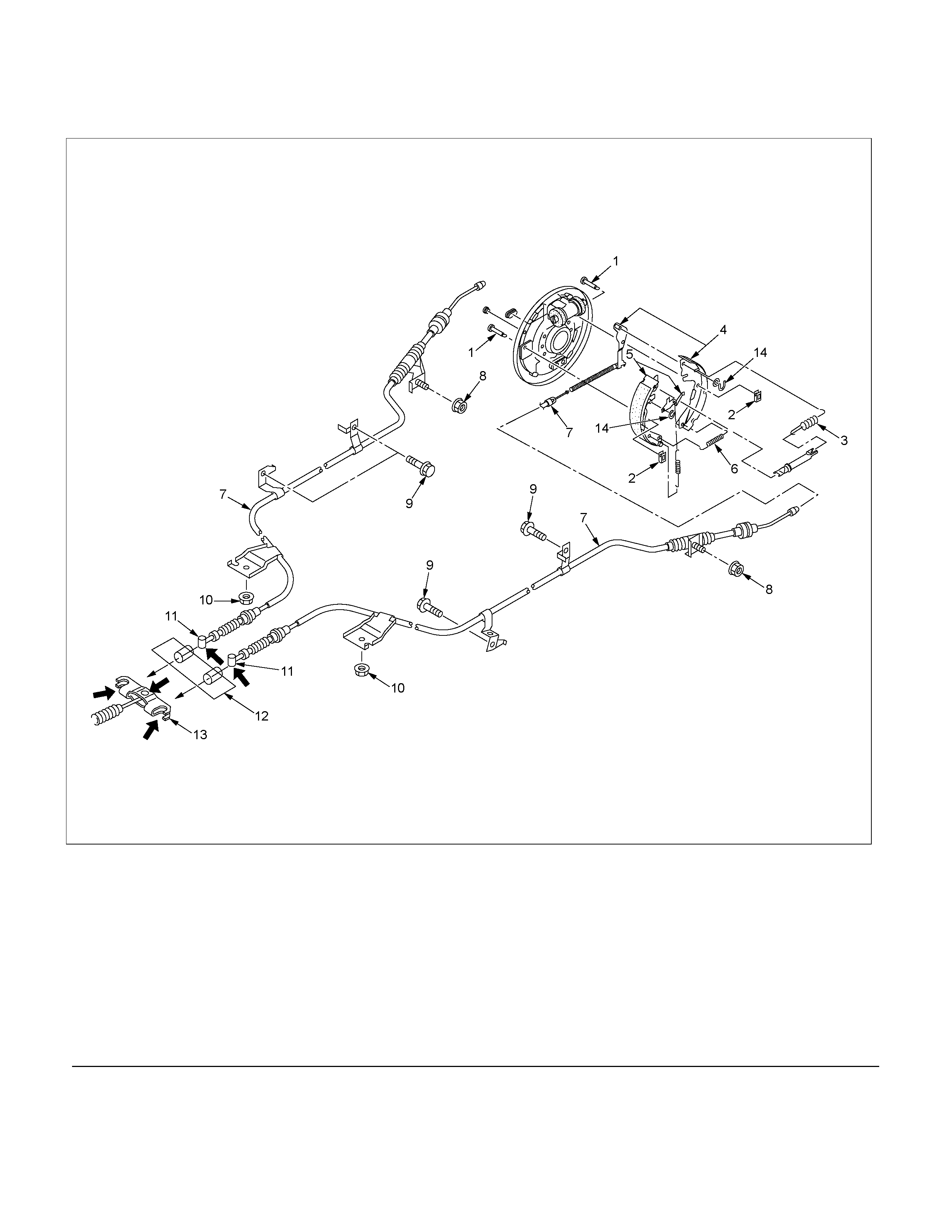
Parking Brake Rear Cable and Associated Parts
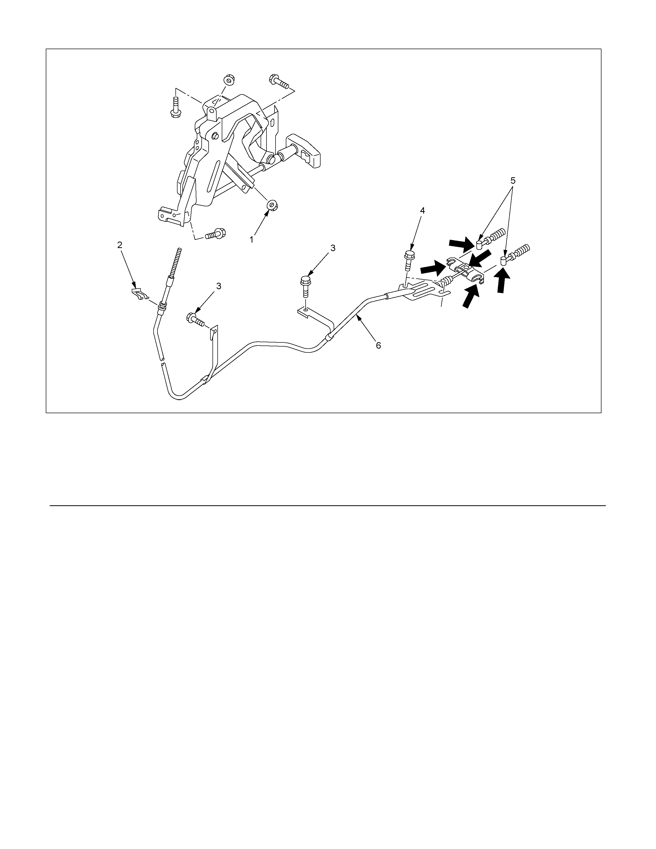
RTW35DLF000101
Legend
(1) Tension Pin
(2) Shoe Clamp Spring
(3) Return Spring
(4) Shoe Assembly with Parking Brake Lever
(5) Shoe Assembly with Adjuster Lever
(6) Spring
(7) Parking Brake Rear Cable
(8) Nut
(9) Bolt
(10) Nut
(11) T-end
(12) Outer Cable Retainer
(13) Equalizer
(14) Adjuster Lever Clip
Removal
1. Remove wheel and tire.
2. Remove brake drum.
3. Remove tension pin (1) and shoe clamp spring (2).
4. Remove return spring (3).
5. Remove shoe assemblly with parking brake leve
r
(4).
6. Remove shoe as s embly with adjuster lever (5) and
spring (6).
7. Remove parking brake inner cable from parking
brake lever (4).
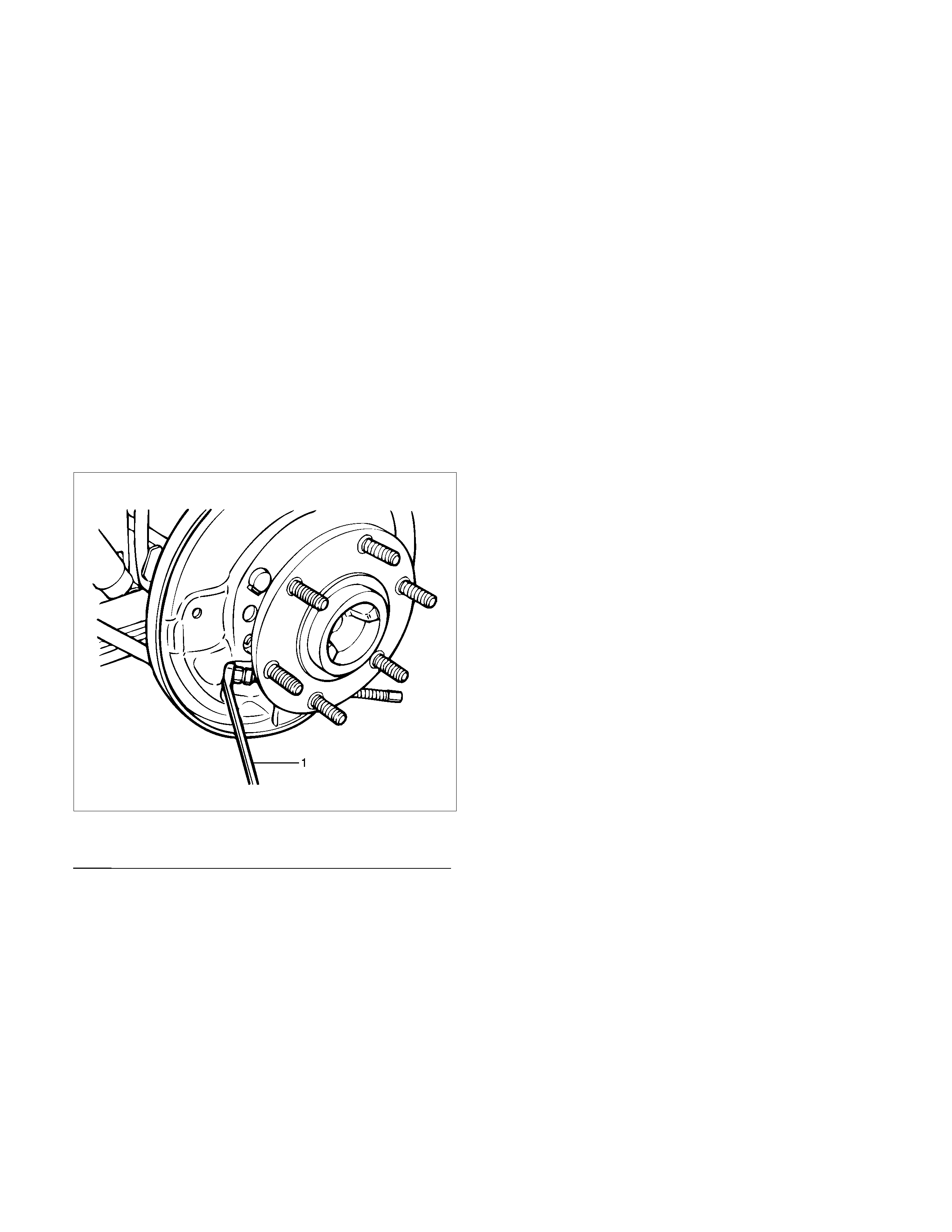
8. Use offset box wrench (12mm hex.) to compress
locking lugs on the cable, then remove parking
brake outer cable from back plate.
NOTE: Do not twist or bend the cable too much.
A damatged cable will cause poor operation or a cable
brakdown.
311RS012
Legend
(1) Offset Box Wrench (12mm hex)
9. Remove nut (8) to fix the cable (7) on the lea
f
spring.
10. Take out parking brake rear cable (7) from the
back plate.
11. Remove bolt (9) and nut (10).
12. Disconnect T-end (11) from the equalizer of front
cable.
Installation
NOTE: Be sure to use the new shoe clamp spring (2)
and the new adjuster lever clip (14).
1. Apply grease (MULTI-PURPOSE GREASE or
equivalent) to the connecting portion of the rear
cable (11) and equalizer (13). (aroow mark).
2. Install parking brake outer cable in back plate and
inner cable in parking brake lever (4).
3. Install return spring (3).
4. Install shoe clamp spring (2) and tension pin (1)
5. Install shoe assembly with adjuster lever, shoe
assembly with parking brake lever (4) and spring
(6). ---- snap action
6. Install nut (8) and tighten it to the specified torque.
Torque: 7N⋅
⋅⋅⋅m (0.7 kg⋅
⋅⋅⋅m/61 lb in)
7. Connect T-end (11) with equalizer (13) through
outer cable retainer (12).
8. Install nut (10) and tighten it to the specifed torque.
Torque: 15 N⋅
⋅⋅⋅m (1.5 kg⋅
⋅⋅⋅m/11 lb ft)
9. Install bolt (9) and tighten it to the specified torque.
Torque: 7 N⋅
⋅⋅⋅m (0.7 kg⋅
⋅⋅⋅m/61 lb in)
10. Install brake drum.
11. Install wheel and tire.
12. Pull parking brake lever with a force equivalent to
poerating f orce: 490 N (50 k g/110 lb), 10 times for
conditioning.
13.
A
djust parking brake lever adjusting nut so that
parking brake lever goes through 8−14 (bench
seat) or 6−8 (bucket seat) notches, when pulled
with a operation force of 294N (30 kg/66 lb).
14. Check brake for no drag.
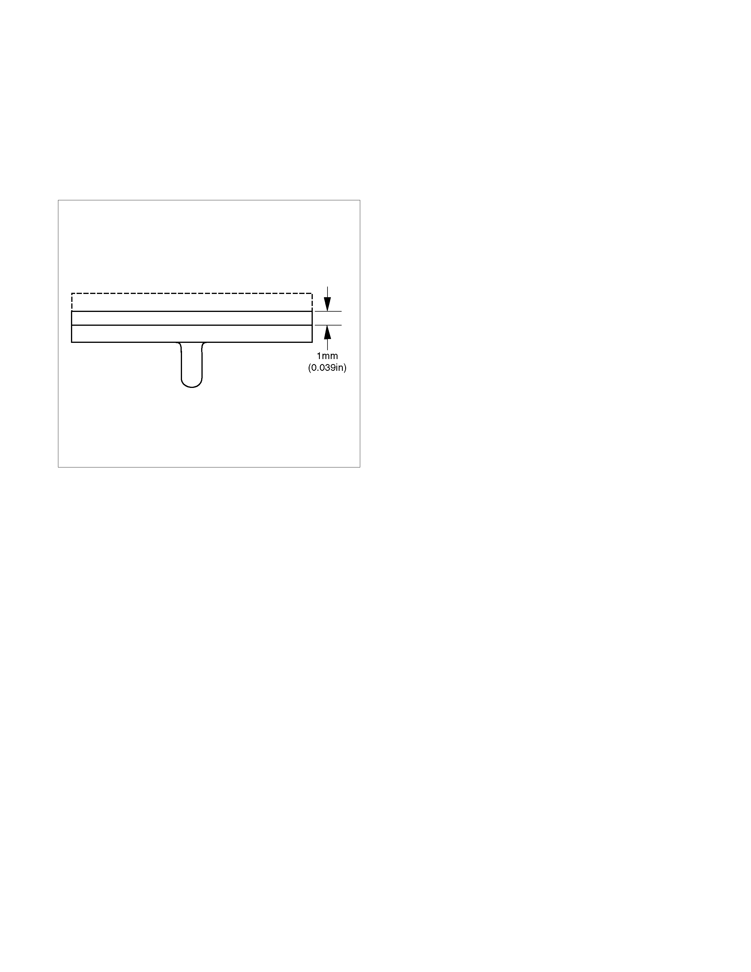
Inspection and Repair
Brake Lining Inspection
Check the shoe assemblies for wear by removing the
brake drum.
Replace the shoe assemblies if the lining thickness is
less than 1.0 mm (0.039 in).
Minimum limit: 1.0 m (0.039 in)
308RS004
Parking Brake Adjustment
NOTE: All brake are self-adjusting. Brakes are adjusted
by repeated stepping on the brake pedal. (After
stepping on the pedal and releasing it, the rear
autoadjuster, in th rear brake, produces aclicking
sound. The same operation should be repeated unitl the
sound disappears.)
Take the follwing steps after overhaulling the rear brake
assembly.
1. Move the parking brake lever to its fully released
position.
2. Parking cable must be loosened sufficiently.
(Loosen the adjust nut.)
3. Repeat stepping on the brake pedal firmly, and
releasing it nutil the clicking sound can no longe
r
be heard.
If the difference between the brake drum inside
diameter and diameter of he brake shoes is
adjusted to be 0.4mm, the number of times fo
r
depressing the brake pedal can be reduced.
4. Remove the dr um. Meas ure the brake drum inside
diameter and diameter of the brake shoes.
Total shoe clearance: 0.4 mm
If incorrect, readjust the brake shoe clearance.
5. Rotate the adjust nut of hand brake lever until all
slack disappears from the cable. Set the adjust
nut.
6.
A
fter the rear brake shoe/drum gap has been
adjusted, perform parking brake cable adjustment.
7. Turn the adjusting nut so that the parking brake
lever travels 6−8 (bucket seat) or 8−14 (bench
seat) notches when pulled up with a force of 294 N
(30 kg/66 lb).
8. Make sure there is no brake dragging.
Main Data and Specifications
General Specifications
Model
Type Leading-Trailing
Drum inside diameter 254 mm (10 in) or 295 mm (11.6 in)
Parking brake lever stroke 6−8 notches (bucket seat) or 8−14 notches (bench seat)
When pulled with a force of 294 N (30 kg/66 lb)
Torque Specifications N⋅
⋅⋅⋅m (kg⋅
⋅⋅⋅m/lb ft)
RTW35DSF000201
N⋅
⋅⋅⋅m (kg⋅
⋅⋅⋅m/lb ft)
E05R300006