

Service Precaution
WARNING:
THIS VEHICLE HAS A SUPPLEMENTAL RESTRAINT
SYSTEM (SRS). REFER TO THE SRS COMPONENT AND
WIRING LOCATION VIEW IN ORDER TO DETERMINE
WHETHER YOU ARE PERFORMING SERVICE ON OR
NEAR THE SRS COMPONENTS OR THE SRS WIRING.
WHEN YOU ARE PERFORMING SERVICE ON OR NEAR
THE SRS COMPONENTS OR THE SRS WIRING, REFER TO
THE SRS SERVICE INFORMATION. FAILURE TO FOLLOW
WARNINGS COULD RESULT IN POSSIBLE AIR BAG
DEPLOYMENT, PERSONAL INJURY, OR OTHERWISE
UNNEEDED SRS SYSTEM REPAIRS.
CAUTION:
Always use the correct fastener in the proper location.
When you replace a fastener, use ONLY the exact part
number for that application. ISUZU will call out those
fasteners that require a replacement after removal. ISUZU
will also call out the fasteners that require thread lockers
or thread sealant. UNLESS OTHERWISE SPECIFIED, do
not use supplemental coatings (Paints, greases, or other
corrosion inhibitors) on threaded fasteners or fastener
joint interfaces. Generally, such coatings adversely affect
the fastener torque and the joint clamping force, and may
damage the fastener. When you install fasteners, use the
correct tightening sequence and specifications. Following
these instructions can help you avoid damage to parts
and systems.
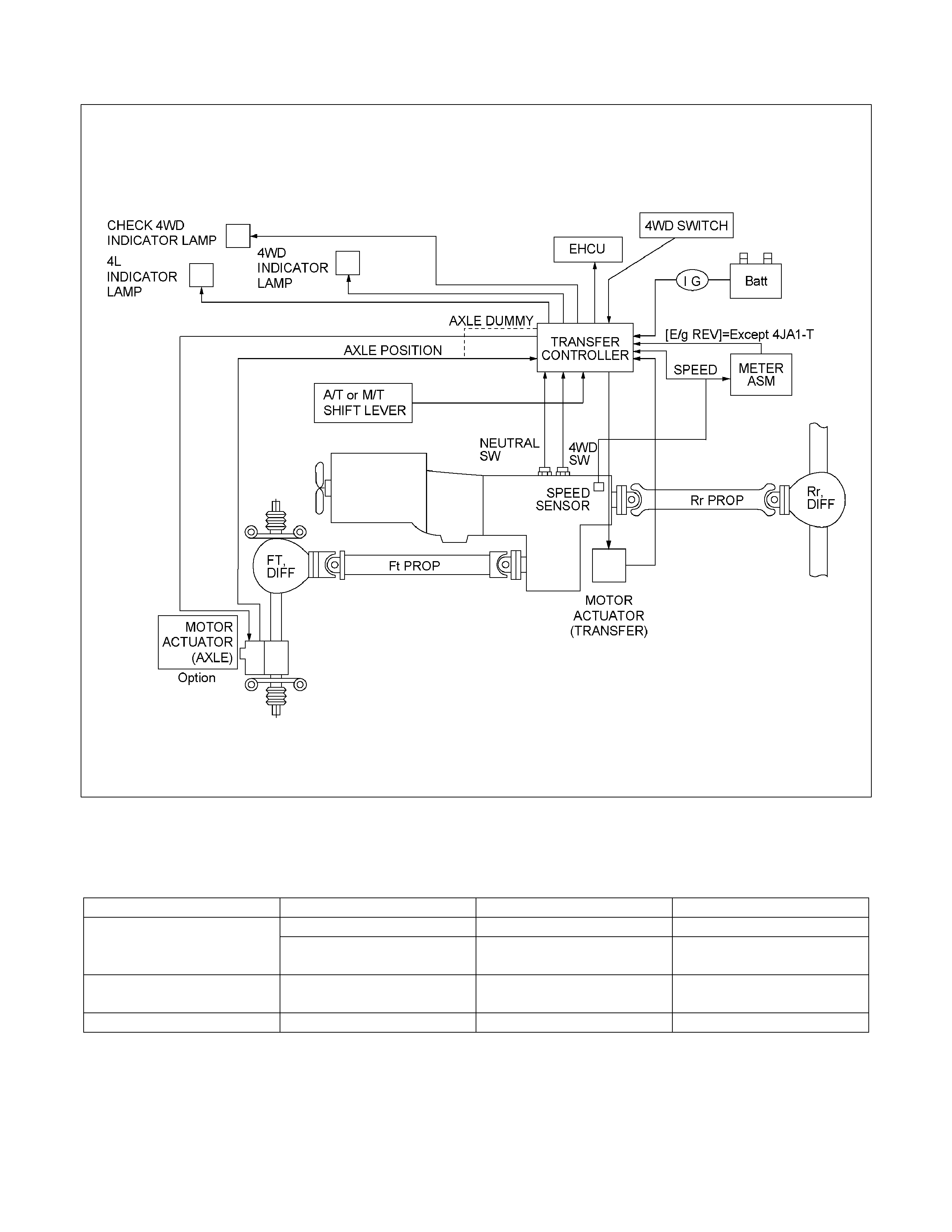
General Description
RTW47DLF000701
Transfer Position and Drive Mode
Three drive modes can be selected through operation of 4WD switch.
Transfer Position 4WD SWITCH Mode Drive mode
2H RWD Rear wheel drive
HIGH 4H 4WD (HIGH)
High-speed mechanical
lock-up four wheel drive
LOW 4L 4WD (LOW)
Low-speed mechanical
lock-up four wheel drive
NEUTRAL 2H & 4L (10 Sec) NEUTRAL Towed by other vehicle

Summary of transfer control system
The transfer control system switches between the 2-wheel
drive (2H), 4-wheel drive high-speed (4H), 4-wheel drive low-
speed (4L), and neutral positions electrically when the driver
operate the switches.
This system has following functions.
1. Connection or disconnection of drive force distribution to
the front wheel front shaft (axle shaft) (The drive force
distribution to the front propeller is connected o
r
disconnected with the motor actuator.)
2. Try to repeat the connection or disconnection of the front
wheel drive function as described above.
3. Option: Shift on the fly type only.
Instruction of connection or disconnection of the drive force
transmission between the front wheel axle (axle shaft) and
front wheel (The motor actuator connects or disconnects
the left front wheel and front wheel axle (axle shaft).).
4. Shifting of auxiliary transmission gears, connection o
r
disconnection of wheel and engine drive force (4H, 4L,
neutral).
5. Operation of indicator on the instrument panel.
6. Transmission of position signal to other controllers.
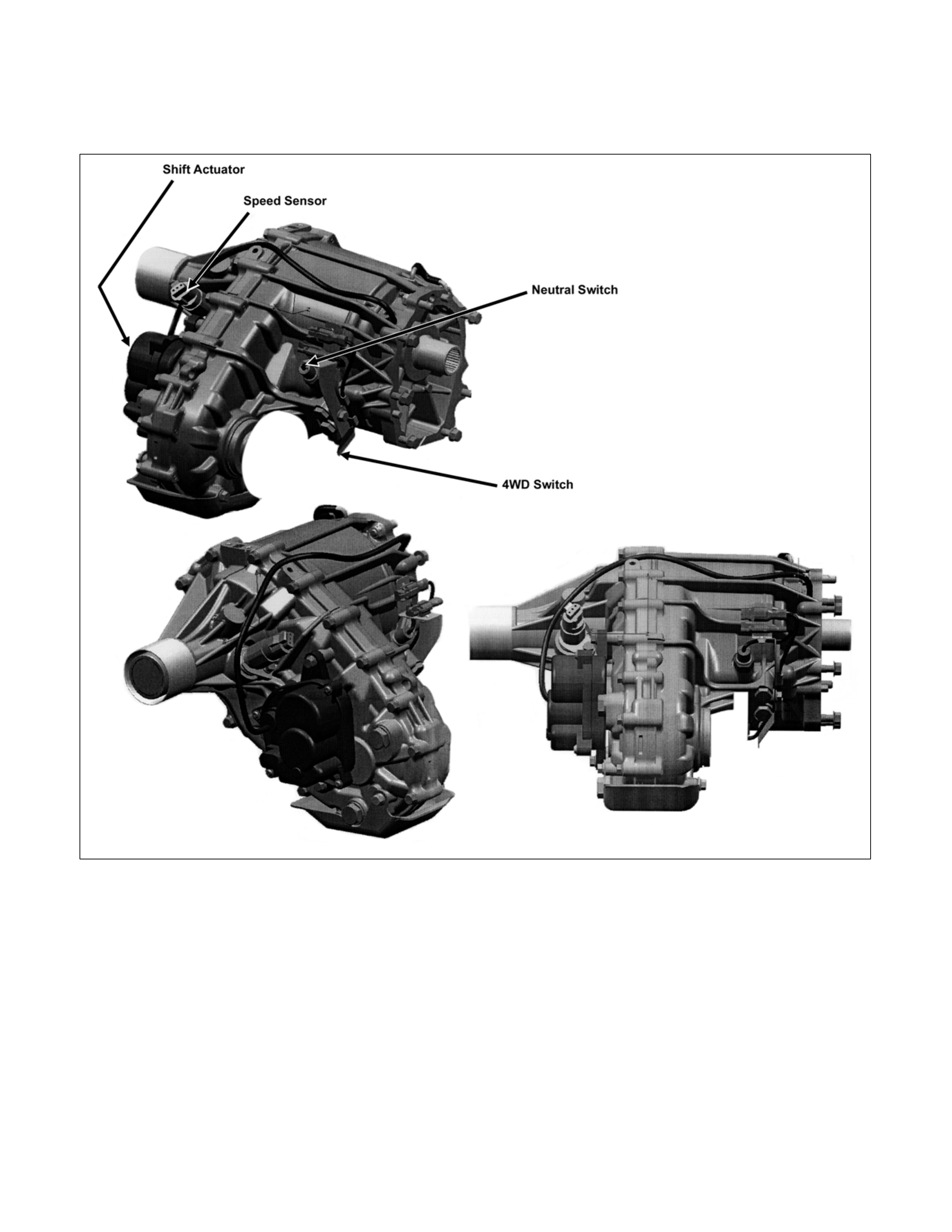
System Components
Parts Location
Speed sensor
Revolutions of the rear output shaft are decreased and taken
out by the speed/drive/driven gears installed in the transfer
case and the number of revolutions is detected with a speed
sensor.
About 4/3 pulses per revolution of the shaft is output.
4WD switch
The 4WD switch detects the movement of the shift rod driving
the 4×2 - 4×4 sleeve.
PUSH open is achieved with the PUSH open switch when the
shift rod is at the 4×2 position.
4×2 - 4×4 sleeve & Arm
The 4×2 - 4×4 sleeve moves directly in the 4×4 direction with
the 4×2 - 4×4 shift rod, but, when moving in 4×2 direction, a
spring standby mechanism is provided between the rod and

sleeve so that the rod is positioned at the 4×2 position, while
the sleeve is at the 4×4 position in sometime.
This mechanism is provided to protect the shift mechanism
from the force to prevent the movement of the sleeve
(torsional torque etc. of the drive system). By releasing the
preventive force, the sleeve can move to 4×2 state by the
spring force.
Neutral switch
The neutral switch detects the movement of the shift rod
driving the high-low sleeve.
PUSH close is achieved with the PUSH close switch when the
shift rod is positioned between the High and the Low, that is, at
the neutral state.
High-Low Sleeve & Arm
The spring standby mechanism is provided for the high-low
sleeve in both directions of the high-low shift rod. For this
reason, the rod position and the actual sleeve position may be
offset in some cases.
This system is provided to protect the shift mechanism from
the collision due to coincidence of the high and low phases of
the engaged splines. By giving rotational force to the
preventing phase coincidence, the splines are moved to the
proper engagement position by the spring force.
Shift actuator
The output shaft is rotated by the built-in motor and the
transfer position is switched.
Detection (limit) switches to detect the rotating angle of the
output shaft is provided to the actuator at 4 positions, which
are connected to the transfer controller through the vehicle
harness to constantly transmit the actuator operating angle
and changes in its transfer status.
7B4-PDF2
4WD indicator (in meter panel)
This lamp indicates the following items
Valve check
Drive condition (2WD-4WD)
Operating condition (2Hz: Actuator in operation, mechanism
standby)
Restrictions on operation (4Hz, including indication of
interrupted operation due
to excessive load)
7B4-PDF3
4L indicator (in meter panel)
This lamp indicates following items.
Valve check
Driving status (High-Low)
Operating status (2Hz: Actuator in operation, mechanism
standby)
Restrictions on operation (4Hz)
7B4-PDF4
Neutral indicator (in operation switch panel)
This LED indicates following items.
LED check
Driving status (Neutral)
Operating status (2Hz: Actuator in operation, mechanism
standby)
Restrictions on operation (4Hz)
7B4-PDF5
Check 4WD warning light (in meter panel)
This light indicates following items.
Valve check
Faulty actuator limit SW, and fault of circuit related with the
limit switch
825R300018
4WD switch
Switch to transmit a switching command to the 2H, 4H,
Neutral, or 4L position.
It comprises 3 PUSH momentary switches. By keeping to push
the 2H and 4L switches for 10 seconds,
operation is instructed to the neutral position.
To shift from the neutral to other position, other required
switches should be pushed for 10 seconds.
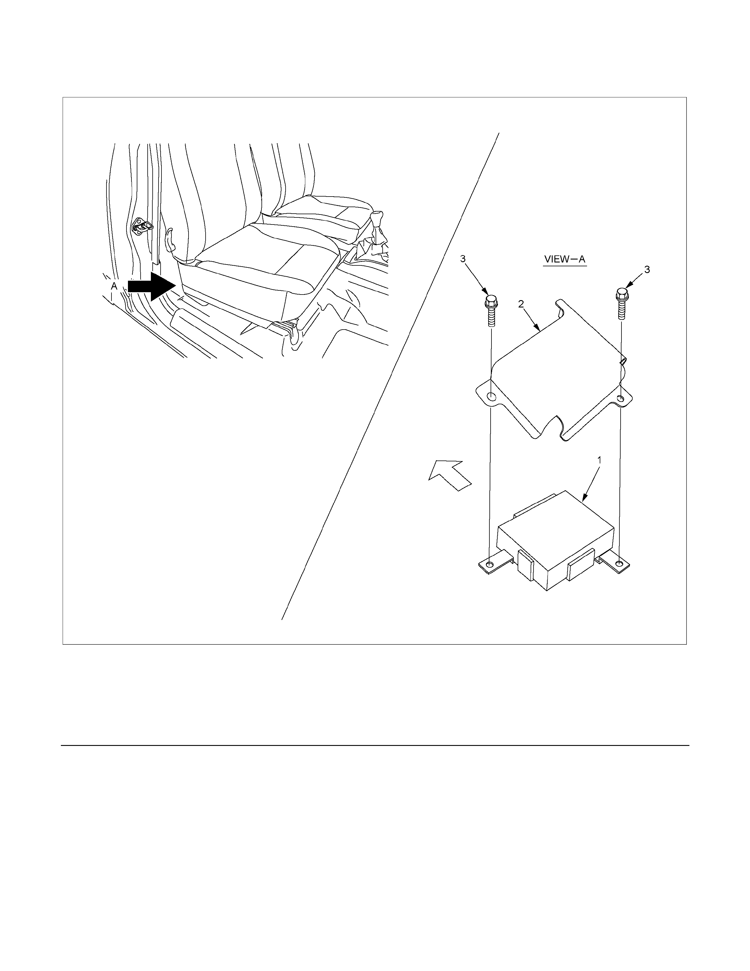
Transfer controller
Located below the right seat.
RTW37DLF000401
Legend
1. Transfer controller
2. Protector
3. Bolt
Transfer Acutuator
Method of confirming the actuator position detection
(limit) switch
The actuator indicates the continuity condition of combinations
as shown in the list below between the 4 detection (limit)
switch pins and GND pin along the direction of the notch of the
output shaft spline. Check that these combinations are as
specified.
The middle condition between these positions (4 patterns in
case of 2H-4H) is either of the combinations shown below
depending upon manufacturing variations of the switch plate.
2H 2H-4H 4H 4H-N N N-L 4L
Direction of output
shaft notch (outline) -54° to -
29° -29° to 74° 74° to
110° 110° to 179° 179° to
215° 215° to
285° 285° to
300°
LS1 Close Close Open Open Open Open Open Open Open Close Close
LS2 Open Close Open Close Close Open Open Close Close Close Close
LS3 Close Close Close Close Close Close Open Open Open Open Open
LS4 Open Open Open Open Close Close Close Close Open Open Close
Continuity between each pin and GND pin. (Continuity also exists between CLOSE pins.)
Transfer Actuator Connector
7B4-PDF6
Method of checking the position detection switch harness
Disconnect the vehicle harness connector on the transfer
controller side and the vehicle harness connector on the
transfer actuator side as shown in the wiring diagram, and
check the continuity between the following connector pins and
that there is no continuity between those pins and GND or
power source.
Check that there is continuity between the GND pin and
vehicle GND on the transfer actuator and there is no continuity
between the GND pin and other power source.
RTW47DSF000301
Vehicle harness connector pin No. (connector of mating parts of the harness is shown in this figure)
Name of pin T/F controller side T/F actuator side Remarks
LS1 R-14, 17 5
LS2 R-14, 6 4
LS3 R-14, 15 7
LS4 R-14, 14 6
GND R-15, 1, 9 8

Function of Switch and indicator Lamp
Transfer-related indicator lamp and switch function
Item 4WD
lamp 4L lamp Neutral
lamp
Check
4WD
warning
light
4WD
switch
Actuator
detection
(limit)
switches
LS1, LS2,
LS3. and
LS4
1 = on
2 = off
Transfer
4WD
switch
Transfer
neutral
switch
SOF
actuator
switch
Or
Axle
dummy
Remarks
2H Off Off Off Off No
operation 1,0,1,0 Open Open Open -----
4H start
of
operation Off Off Off Off
4H position
for 0.1
second 1,0,1,0 Open Open Open
Switch
operation
sensor
Start of
operation Blinking
(2HZ) Off Off Off No
operation
1,1,1,0
0,0,1,0
0,1,1,0
0,1,1,1
Open Open Open
2H to 4H
while
driving
During
operation
(Synchro)
Blinking
(2HZ) Off Off Off No
operation
1,1,1,0
0,0,1,0
0,1,1,0
0,1,1,1
Open Open Open
2H to 4H
using
synchro
and
retrial
During
operation
(Axle
drive)
Blinking
(2HZ) Off Off Off No
operation 0,0,1,1 Closed Open Open Axle drive
Axle
waiting Blinking
(2HZ) Off Off Off No
operation 0,0,1,1 Closed Open Open Axle drive
4H On Off Off Off No
operation 0,0,1,1 Closed Open Closed -----
4L start
of
operation On Off Off Off
4L position
for 0.1
second 0,0,1,1 Closed Open Closed
Switch
operation
sensor
Start of
operation On Blinking
(2HZ) Off Off No
operation 0,0,0,1
0,1,0,1 Closed Open Closed
4H to 4L
while
driving
During
operation
(N) Off Blinking
(2HZ) Off Off No
operation 0,0,0,1
0,1,0,1 Closed Closed Closed
4H to 4L
through
neutral
During
operation
(N) Off Blinking
(2HZ) Off Off No
operation 0,1,0,0 Closed Closed Closed
4H to 4L
through
neutral
During
operation
(N) Off Blinking
(2HZ) Off Off No
operation 1,1,0,0 Closed Closed Closed
4H to 4L
through
neutral
4L
waiting On Blinking
(2HZ) Off Off No
operation 1,1,0,1 Closed Closed Closed
4H to 4L
while
waiting
4L On On Off Off No
operation 1,1,0,1 Closed Open Closed -----
4H start
of
operation On Off Off Off
4H position
for 0.1
second 1,1,0,1 Closed Open Closed
Switch
operation
sensor

Item 4WD
lamp 4L lamp Neutral
lamp
Check
4WD
warning
light
4WD
switch
Actuator
detection
(limit)
switches
LS1, LS2,
LS3. and
LS4
1 = on
2 = off
Transfer
4WD
switch
Transfer
neutral
switch
SOF
actuator
switch
Or
Axle
dummy
Remarks
During
operation On Blinking
(2HZ) Off Off No
operation 1,1,0,1 Closed Open Closed
4L to 4H
while
driving
During
operation
(N) Off Blinking
(2HZ) Off Off No
operation 1,1,0,0 Closed Closed Closed
4L to 4H
through
neutral
During
operation Off Blinking
(2HZ) Off Off No
operation 0,1,0,1
0,0,0,1 Closed Closed Closed
4L to 4H
while
driving
4H
waiting Off Blinking
(2HZ) Off Off No
operation 0,0,1,1 Closed Closed Closed 4L to 4H
while
waiting
4H On Off Off Off No
operation 0,0,1,1 Closed Open Closed -----
2H start
of
operation On Off Off Off
2H position
for 0.1
second 0,0,1,1 Closed Open Closed
Switch
operation
sensor
Start of
operation Blinking
(2HZ) Off Off Off No
operation
0,1,1,1
0,1,1,0
0,0,1,0
1,1,1,0
Closed Open Closed
2H to 4H
while
driving
During
operation
(Axle)
Blinking
(2HZ) Off Off Off No
operation
0,1,1,1
0,1,1,0
0,0,1,0
1,1,1,0
Open Open Closed Axle drive
Axle
waiting Blinking
(2HZ) Off Off Off No
operation 1,0,1,0 Open Open Closed Axle
waiting
2H Off Off Off Off No
operation 1,0,1,0 Open Open Open -----

2H to 4H retrial
Item 4WD
lamp 4L lamp Neutral
lamp
Check
4WD
warning
light
4WD
switch
Actuator
detection
(limit)
switches
LS1, LS2,
LS3. and
LS4
1 = on
2 = off
Transfer
4WD
switch
Transfer
neutral
switch
SOF
actuator
switch
Or
Axle
dummy
Remarks
2H Off Off Off Off No
operation 1,0,1,0 Open Open Open -----
4H start
of
operation Off Off Off Off
4H
position
for 0.1
second
1,0,1,0 Open Open Open -----
Start of
operation Blinking
(2HZ) Off Off Off No
operation
1,1,1,0
0,0,1,0
0,1,1,0
0,1,1,1
Open Open Open
2H to 4H
while
driving
During
operation
(Synchro)
(Go to 4H
if synchro
complete)
Blinking
(2HZ) Off Off Off No
operation
1,1,1,0
0,0,1,0
0,1,1,0
0,1,1,1
Open Open Open
2H to 4H
using
synchro
and retrial
X 2
Abandon
ed
operation
(2H)
Blinking
(4HZ) Off Off Off No
operation 1,0,1,0 Open Open Open
Return to
2H
2H
indication
after
10second
s
Off Off Off Off No
operation 1,0,1,0 Open Open Open -----
• Completion of transfer case H-L area and axle shift timing may cause some variation in 2Hz blinking pattern.

Operational limits (4H4L) (Vehicle speed, engine speed, and transmission position not specified)
Item 4WD
lamp 4L lamp Neutral
lamp
Check
4WD
warning
light
4WD
switch
Actuator
detection
(limit)
switches
LS1, LS2,
LS3. and
LS4
1 = on
2 = off
Transfer
4WD
switch
Transfer
neutral
switch
SOF
actuator
switch
Or
Axle
dummy
Remarks
4H On Off Off Off Open 0,0,1,1 Closed Open Closed -----
4H start
of
operation On Off Off Off
4L
position
for 0.1
second
0,0,1,1 Closed Open Closed -----
10
second
display
during
limitation
On Blinking
(4HZ) Off Off Open 0,0,1,1 Closed Open Closed
No
operation
during
limitation
Go to 4H
after 10
seconds On Off Off Off Open 0,0,1,1 Closed Open Closed -----
Operational limits (4L4H) (Vehicle speed, engine speed, and transmission position not specified)
Item 4WD
lamp 4L lamp Neutral
lamp
Check
4WD
warning
light
4WD
switch
Actuator
detection
(limit)
switches
LS1, LS2,
LS3. and
LS4
1 = on
2 = off
Transfer
4WD
switch
Transfer
neutral
switch
SOF
actuator
switch
Or
Axle
dummy
Remarks
4L On On Off Off No
operation 1,1,0,1 Closed Open Closed -----
4L start of
operation On On Off Off
4H
position
for 0.1
second
1,1,0,1 Closed Open Closed -----
10
second
display
during
limitation
On Blinking
(4HZ) Off Off Open 1,1,0,1 Closed Open Closed
No
operation
during
limitation
Go to 4L
after 10
seconds On On Off Off No
operation 1,1,0,1 Closed Open Closed -----
• Under some conditions, a secondary operational indication may be received when the 4Hz operational
indication is present.

Transfer-related indicator lamp and switch function
Skip operation
Item 4WD
lamp 4L lamp Neutral
lamp
Check
4WD
warning
light
4WD
switch
Actuator
detection
(limit)
switches
LS1,
LS2,
LS3. and
LS4
1 = on
2 = off
Transfer
4WD
switch
Transfer
neutral
switch
SOF
actuator
switch
Or
Axle
dummy
Remarks
2H Off Off Off Off No
operation 1,0,1,0 Open Open Open -----
4L start of
operation Off Off Off Off
4L
position
for 0.1
second
1,0,1,0 Open Open Open Switch
operation
sensor
Start of
operation Blinking
(2HZ) Blinking
(2HZ) Off Off No
operation
1,1,1,0
0,0,1,0
0,1,1,0
0,1,1,1
Open Open Open
2H to 4H
while
driving
During
operation
(Synchro)
Blinking
(2HZ) Blinking
(2HZ) Off Off No
operation
1,1,1,0
0,0,1,0
0,1,1,0
0,1,1,1
Open Open Open
2H to 4H
using
synchro
and retrial
During
operation
(Passing
through
4H)
Off Blinking
(2HZ) Off Off No
operation 0,0,1,1 Closed Open Open -----
During
operation
(Passing
through
4H)
Off Blinking
(2HZ) Off Off No
operation 0,0,1,1
0,1,0,1 Closed Open Open -----
During
operation
(N) On Blinking
(2HZ) Off Off No
operation 0,0,1,1
0,1,0,1 Closed Open Closed -----
During
operation
(N) On Blinking
(2HZ) Off Off No
operation 0,1,0,0 Closed Open Closed Switch
operation
sensor
During
operation
(N) On Blinking
(2HZ) Off Off No
operation 0,0,1,1 Closed Open Closed
4H to 4L
while
driving
During
operation
(Axle
drive)
Blinking
(2HZ) Blinking
(2HZ) Off Off No
operation 0,0,1,1 Closed Open Open -----
Axle
waiting Blinking
(2HZ) Blinking
(2HZ) Off Off No
operation 0,0,1,1 Closed Open Open -----
4L waiting On Blinking
(2HZ) Off Off No
operation 1,1,0,1 Closed Closed Closed
4H to 4L
while
waiting
4L On On Off Off No
operation 1,1,0,1 Closed Open Closed -----

Item 4WD
lamp 4L lamp Neutral
lamp
Check
4WD
lamp
4WD
switch
Actuator
detection
(limit)
switches
LS1,
LS2,
LS3. and
LS4
1 = on
2 = off
Transfer
4WD
switch
Transfer
neutral
switch
SOF
actuator
switch
Or
Axle
dummy
Remarks
2H start
of
operation On On Off Off
2H
position
for 0.1
second
1,1,0,1 Closed Open Closed Switch
operation
sensor
During
operation Blinking
(2HZ) Blinking
(2HZ) Off Off No
operation 1,1,0,1 Closed Open Closed
4L to 4H
while
driving
During
operation
(Passing
through
N)
On Blinking
(2HZ) Off Off No
operation 1,1,0,0 Closed Closed Closed
4L to 4H
through
neutral
During
operation
(Passing
through
N)
Off Blinking
(2HZ) Off Off No
operation 0,1,0,0 Closed Closed Closed
4L to 4H
through
neutral
During
operation
(4H
waiting)
Off Blinking
(2HZ) Off Off No
operation 0,0,1,1 Closed Closed Closed
4L to 4H
while
waiting
During
operation
(Axle)
Off while
waiting for
start of H
shift
Blinking
(2HZ)
while
waiting for
start of H
shift
Off Off No
operation
0,1,1,1
0,1,1,0
0,0,1,0
1,1,1,0
Closed Open Closed
2H to 4H
while
driving
During
operation
(Axle)
Blinking
(2HZ) at
end of H
shift
Off at end
of H shift Off Off No
operation
0,1,1,1
0,1,1,0
0,0,1,0
1,1,1,0
Closed Open Closed Axle
driving
Axle
waiting Blinking
(2HZ) Off Off Off No
operation 1,0,1,0 Open Open Closed -----
2H Off Off Off Off No
operation 1,0,1,0 Open Open Open -----
• Completion of transfer case H-L area and axle shift timing may cause some variation in 2Hz blinking pattern.

Skip operation limitations (4L2H) (Vehicle speed, engine speed, and transmission position not
specified)
Item 4WD
lamp 4L lamp Neutral
lamp
Check
4WD
warning
light
4WD
switch
Actuator
detection
(limit)
switches
LS1, LS2,
LS3. and
LS4
1 = on
2 = off
Transfer
4WD
switch
Transfer
neutral
switch
SOF
actuator
switch
Or
Axle
dummy
Remarks
4L Off On Off Off Open 1,1,0,1 Closed Open Closed -----
4L start of
operation Off On Off Off
2H
position
for 0.1
second
1,1,0,1 Closed Open Closed -----
10
second
display
during
limitation
Blinking
(4HZ) Off Off Off Open 1,1,0,1 Closed Open Closed
No
operation
during
limitation
Go to 4L
after 10
seconds Off ON Off Off Open 1,1,0,1 Closed Open Closed -----
Skip operation limitations (2H4L) (Vehicle speed, engine speed, and transmission position not
specified)
Item 4WD
lamp 4L lamp Neutral
lamp
Check
4WD
warning
light
4WD
switch
Actuator
detection
(limit)
switches
LS1, LS2,
LS3. and
LS4
1 = on
2 = off
Transfer
4WD
switch
Transfer
neutral
switch
SOF
actuator
switch
Or
Axle
dummy
Remarks
2HL Off Off Off Off Open 1,0,1,0 Open Open Open -----
4L start of
operation Off Off Off Off
2H
position
for 0.1
second
1,0,1,0 Open Open Open -----
10
second
display
during
limitation
Blinking
(4HZ) Blinking
(4HZ) Off Off Open 1,0,1,0 Open Open Open
No
operation
during
limitation
Go to 2H
after 10
seconds Off Off Off Off Open 1,0,1,0 Open Open Open -----
Under some conditions, a secondary operational indication may be received when the 4Hz operational
indication is present.

Transfer-related indicator lamp and switch function
2H→Neutral→2H
Item 4WD
lamp 4L lamp Neutral
lamp
Check
4WD
warning
light
4WD
switch
Actuator
detection
(limit)
switches
LS1,
LS2,
LS3. and
LS4
1 = on
2 = off
Transfer
4WD
switch
Transfer
neutral
switch
SOF
actuator
switch
Or
Axle
dummy
Remarks
2H Off Off Off Off No
operation 1,0,1,0 Open Open Open -----
Neutral
start of
operation Off Off Off Off
Neutral
position
for 10
seconds
1,0,1,0 Open Open Open Switch
operation
sensor
Start of
operation Off Off
Blinking
(2HZ) Off No
operation
1,1,1,0
0,0,1,0
0,1,1,0
0,1,1,1
Open Open Open
2H to 4H
while
driving
During
operation
(Synchro) Off Off
Blinking
(2HZ) Off No
operation
1,1,1,0
0,0,1,0
0,1,1,0
0,1,1,1
Open Open Open
2H to 4H
using
synchro
and retrial
During
operation
(Passing
through
4H)
Off Off
Blinking
(2HZ) Off No
operation 0,0,1,1 Closed Open Closed -----
During
operation
(Passing
through
4H)
Off Off
Blinking
(2HZ) Off No
operation 0,0,0,1
0,1,0,1 Closed Open Closed
4H to 4L
while
driving
During
operation
(N) Off Off Blinking
(2HZ) Off No
operation 0,0,0,1
0,1,0,1 Closed Closed Closed 4H to 4L
through
neutral
During
operation
(N) Off Off
Blinking
(2HZ) Off No
operation 0,1,0,0 Closed Closed Closed Switch
operation
sensor
Neutral Off Off On Off No
operation 0,1,0,0 Closed Closed Open -----
2H start
of
operation Off Off On Off
2H
position
for 10
seconds
0,1,0,0 Closed Open Closed Switch
operation
sensor
During
operation
(Passing
through
N)
Off Blinking
(2HZ) Off Off No
operation 0,1,0,0 Closed Closed Closed
4L to 4H
through
neutral
During
operation Off Blinking
(2HZ) Off Off No
operation 0,1,0,1
0,0,0,1 Closed Closed Closed
4L to 4H
while
driving

Item 4WD
lamp 4L lamp Neutral
lamp
Check
4WD
warning
light
4WD
switch
Actuator
detection
(limit)
switches
LS1,
LS2,
LS3. and
LS4
1 = on
2 = off
Transfer
4WD
switch
Transfer
neutral
switch
SOF
actuator
switch
Or
Axle
dummy
Remarks
During
operation
(4H
waiting)
Off Blinking
(2HZ) Off Off No
operation 0,0,1,1 Closed Closed Closed
4L to 4H
while
waiting
During
operation
(Axle)
Blinking
(2HZ) Off Off Off No
operation
0,1,1,1
0,1,1,0
0,0,1,0
1,1,1,0
Closed Open Closed
2H to 4H
while
driving
During
operation
(Axle)
Blinking
(2HZ) Off Off Off No
operation
0,1,1,1
0,1,1,0
0,0,1,0
1,1,1,0
Open Open Closed Axle
driving
Axle
waiting Blinking
(2HZ) Off Off Off No
operation 1,0,1,0 Open Open Closed -----
2H Off Off Off Off No
operation 1,0,1,0 Open Open Open -----
• Operational restrictions (vehicle speed, engine speed, and transmission position) are applicable to transfer
shifts in both directions (H←→Neutral←→L).

4HNeutral4H
Item 4WD
lamp 4L lamp Neutral
lamp
Check
4WD
warning
light
4WD
switch
Actuator
detection
(limit)
switches
LS1, LS2,
LS3. and
LS4
1 = on
2 = off
Transfer
4WD
switch
Transfer
neutral
switch
SOF
actuator
switch
Or
Axle
dummy
Remarks
4H On Off Off Off No
operation 0,0,1,1 Closed Open Closed -----
Neutral
start of
operation On On Off Off
Neutral
position
for 10
seconds
1,1,0,1 Closed Open Closed -----
Start of
operation Off Off
Blinking
(2HZ) Off No
operation 1,1,0,0 Closed Open Closed
4L to N
while
driving
During
operation
(N) Off Off
Blinking
(2HZ) Off No
operation 1,1,0,0 Closed Closed Closed
4L to N
with axle
driving
During
operation
(N) Off Off
Blinking
(2HZ) Off No
operation 0,1,0,0 Closed Closed Closed
4L to 4N
with axle
removed
During
operation
(Axle)
Blinking
(2HZ) Off Off Off No
operation
0,1,1,1
0,1,1,0
0,0,1,0
1,1,1,0
Open Open Closed Axle
driving
Axle
waiting Blinking
(2HZ) Off Off Off No
operation 1,0,1,0 Open Open Closed -----
Neutral Off Off On Off No
operation 0,1,0,0 Closed Closed Open -----
4H start
of
operation Off Off Off Off
2H
position
for 10
seconds
0,1,0,0 Open Open Open Switch
operation
sensor
During
operation
(N) Off Blinking
(2HZ) Off Off No
operation 1,1,0,0 Closed Closed Open 4L to 4H
through
neutral
During
operation
(N) Off Blinking
(2HZ) Off Off No
operation 0,1,0,0 Closed Closed Open 4L to 4H
through
neutral
During
operation Off Blinking
(2HZ) Off Off No
operation 0,1,0,1
0,0,0,1 Closed Closed Open 4L to 4H
while
driving
4H
waiting Blinking
(2HZ) Off) Off Off No
operation 0,0,1,1 Closed Closed Open 4L to 4H
while
waiting
During
operation
(Axle)
Blinking
(2HZ) Off Off Off No
operation 0,0,1,1 Closed Open Open Axle
driving
Axle
waiting Blinking
(2HZ) Off Off Off No
operation 0,0,1,1 Closed Open Open -----
4H On Off Off Off No
operation 0,0,1,1 Closed Open Closed -----
• Operational restrictions (vehicle speed, engine speed, and transmission position) are applicable to transfer
shifts in both directions (H←→Neutral←→L).

4LNeutral4L
Item 4WD
lamp 4L lamp Neutral
lamp
Check
4WD
warning
light
4WD
switch
Actuator
detection
(limit)
switches
LS1, LS2,
LS3. and
LS4
1 = on
2 = off
Transfer
4WD
switch
Transfer
neutral
switch
SOF
actuator
switch
Or
Axle
dummy
Remarks
4L On On Off Off No
operation 1,1,0,1 Closed Open Closed -----
Neutral
start of
operation On On Off Off
Neutral
position
for 10
seconds
1,1,0,1 Closed Open Closed -----
Start of
operation Off Off
Blinking
(2HZ) Off No
operation 1,1,0,0 Closed Open Closed
4L to N
while
driving
During
operation
(N) Off Off
Blinking
(2HZ) Off No
operation 1,1,0,0 Closed Closed Closed
4L to N
with axle
driving
During
operation
(N) Off Off
Blinking
(2HZ) Off No
operation 0,1,0,0 Closed Closed Closed
4L to 4N
with axle
removed
During
operation
(Axle)
Blinking
(2HZ) Off Off Off No
operation 0,1,0,0 Closed Closed Closed Axle
driving
Axle
waiting Blinking
(2HZ) Off Off Off No
operation 0,1,0,0 Closed Closed Closed -----
Neutral Off Off On Off No
operation 0,1,0,0 Closed Closed Open -----
4L start of
operation Off Off On Off
4L
position
for 10
seconds
0,1,0,0 Open Open Open Switch
operation
sensor
During
operation
(N) Off Blinking
(2HZ) Off Off No
operation 1,1,0,0 Closed Closed Open 4H to 4L
through
neutral
During
operation
(N) Off Blinking
(2HZ) Off Off No
operation 1,1,0,0 Closed Closed Open 4H to 4L
through
neutral
During
operation
(N) Off Blinking
(2HZ) Off Off No
operation 1,1,0,0 Closed Closed Open 4H to 4L
through
neutral
4H
waiting On Blinking
(2HZ) Off Off No
operation 1,1,0,1 Closed Closed Open 4L while
waiting
During
operation
(Axle)
Blinking
(2HZ) Off Off Off No
operation 1,1,0,1 Closed Open Open Axle
driving
Axle
waiting Blinking
(2HZ) Off Off Off No
operation 1,1,0,1 Closed Open Open -----
4H On On Off Off No
operation 1,1,0,1 Closed Open Closed -----
• Operational restrictions (vehicle speed, engine speed, and transmission position) are applicable to transfer
shifts in both directions (H←→Neutral←→L).
Parts Location (RHD)
RTW48AXF021701&RTW48AXF021801
Parts Location (LHD)
RTW48AXF021901&RTW48AXF022001
RTW48AXF021601
PARTS LOCATION
RTW68AXF018501
CIRCUIT DIAGRAMS - (6VE1)
RTW680XF014101
Circuit Diagram (HFV6)
RTW68AXF012601
Circuit Diagram (C24SE)
RTW680XF014201
Circuit Diagram (4JA1-TC/4JH1-TC)
RTW680XF014301
Circuit Diagram (4JA1-T)
RTW680XF014401
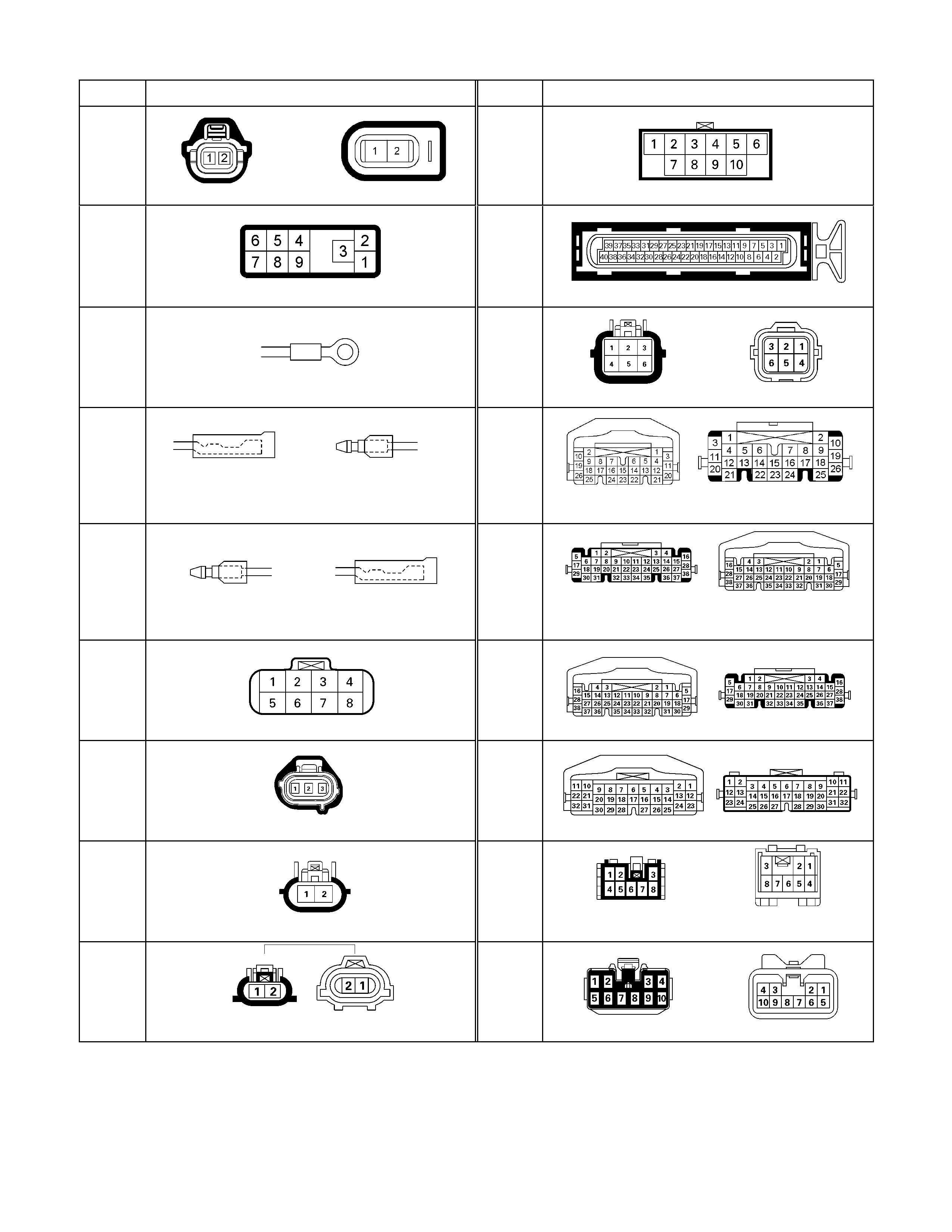
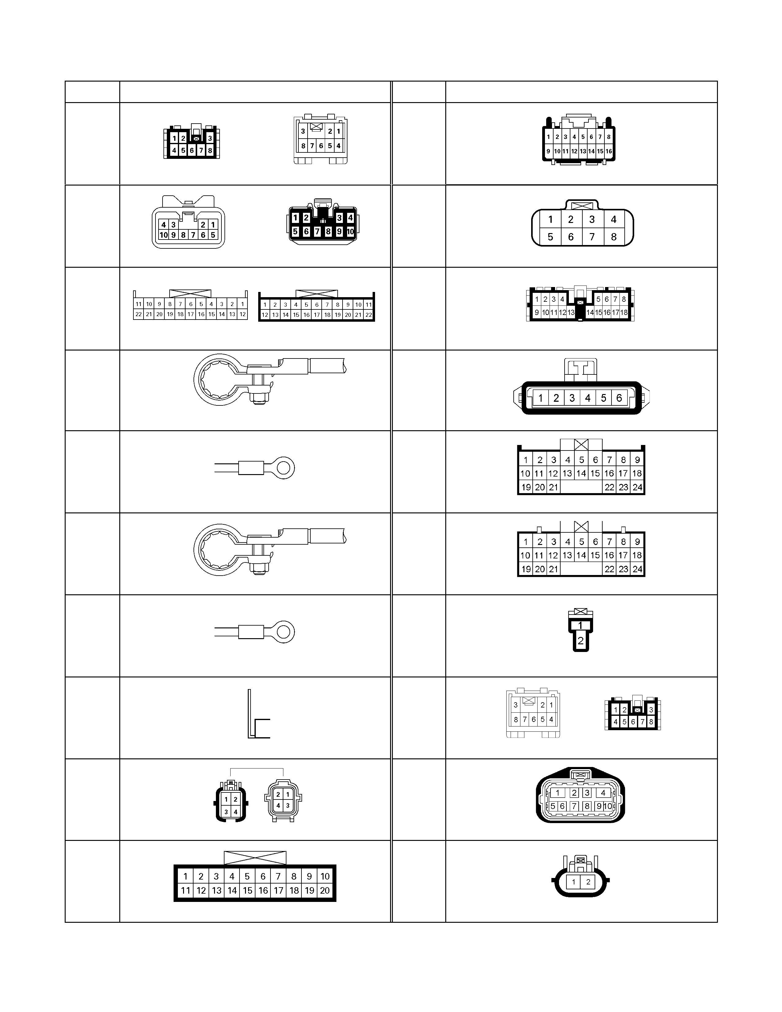
CONNECTOR LIST
No. Connector face No. Connector face
B-24
Green
Meter-B
C-56
(C24SE
/
HFV6)
ECM
B-54
White
J/B I2
C-57
(4JA1-
TC /
4JH1-
TC)
ECM-B
B-62
White
Ignition switch (IGSUB : G1)
C-67
(6VE1/4
JH1-TC)
Black
EHCU
B-63
White
Ignition switch (IGSUB : G2)
C-94
(4JA1-
TC /
4JH1-
TC)
White
TCM
B-64
Silver
Weld splice 1(Illumination)
C-95
(6VE1)
White
TCM-(B)
B-65
Silver
Weld splice 2 (Ground)
C-107
White
J/B E2
B-66
White
4WD switch
C-108
White
J/B E1
C-2
Silver
Engine room-RH ; Ground
C-109
Silver
Body-LH ; ground
C-36
Silver
Engine room-LH ; Ground
C-118
(4JH1-
TC)
White
A/C Resister & Neutral switch
C-56
(4JA1-TC
/ 4JH1-
TC)
ECM-A
C-119
(6VE1)
Auto cruise actuator
No. Connector face No. Connector face
E-6
(C24SE/
6VE1)
(6VE1) Fuel injector (C24SE)
E-51
(4JH1-
TC)
Black
Inhibiter switch
E-6
(4JH1-
TC)
Injector pump
E-61
(6VE1)
ECM
E-10
Silver
Engine ground
H-3
(6VE1/4
JH1-TC /
HFV6)
White
Battery (+) ∼ Engine room
E-11
(4JA1-TC/
4JH1-TC/
C24SE)
Natural
Green
Neutral switch
H-4
(C24SE)
White
Engine room ∼ Mission
E-12
(4JA1-TC/
4JH1-TC/
C24SE)
Natural
Green
Neutral switch
H-4
(6VE1/
4JA1-TC/
4JH1-TC)
White
Engine ∼ Engine room
E-35
(4JH1-
TC
C24SE)
Black
Motor actuator
H-6
White
Engine room ∼ INST
E-44
Gray
Vehicle speed sensor
H-7
White
Engine room ∼ INST
E-45
(4JH1-
TC)
Gray
4WD switch
H-22
(6VE1/4
JH1-TC /
HFV6)
White
Engine ∼ Engine room C
E-46
(4JH1-
TC)
H-L neutral switch
H-23
(4JA1-T
/ HFV6)
Engine room B ∼ T/mission
No. Connector face No. Connector face
H-29
(C24SE)
Battery (+) ∼ Engine room C
R-15
2-4WD Control unit
H-31
(6VE1)
White
Engine room ∼ T/mission
M-28
(6VE1 /
HFV6)
Motor actuator
H-32
(C24SE /
6VE1 /
HFV6)
Engine room ∼ Rear body
B-23
Green
Meter-A
P-1
Silver
Battery (+)
M-28
(6VE1 /
HFV6)
Black
Cruise main
P-2
Silver
Relay & Fuse box
B-96
P-5
Silver
Battery (-)
B-97
P-6
Silver
Body earth (Ground)
C-77
Clutch switch
P-10
Silver
Engine ground
H-27
Black
INST ~ Rear body
P-13
Gray
Shift on the fly actuator
E-79
(6VE1)
Neutral start switch
R-14
2-4WD Control unit
M-26

No. Connector face No. Connector face
M-27
(6VE1)
H-L Neutral Switch

Diagnosis
Before determining a trouble (Non-trouble mode)
1. When shifting from 2H to 4H:
1-1-1 When the flashing frequency of the 4WD indicator is changed from 2Hz to 4Hz (Shft on the fly)
If the load is too large to shift the gears synchronously, the operation is repeated up to 3 times. If the shifting
is not effected after being repeated 3 times, the indicator frequency is changed from 2Hz to 4Hz and, at the
same time, the actuator condition is changed to 2H, indicator flashes at 4Hz for 10 seconds, and then goes
out.
Cause of excessive synchronous shifting load
• Extremely low temperature (the oil viscosity of the front differential increases requiring a large load for
synchronization)
• High speed (since the difference of relative revolutions of gears to be shifted synchronously is too large,
required work load per unit time becomes larger).
Step 1-1-1:
Stop the vehicle or decrease the speed and operate as required again.
1-1-2 When the flashing frequency of the 4WD indicator is changed from 2Hz to 4Hz (Rigid and free
wheel Hub) / Block out of meshing spline.
Step 1-1-2:
Run the vehicle forward and backward several meters and operate as required again.
1-2 When the flashing of 4WD indicator at 2Hz continues more than 11.5 seconds (repetition of 3 times of
above No.1 is counted) (Shift on the fly)
If there is difference of revolutions and phases between the front wheel and axle, connecting the front wheel
and axle is difficult.
Until shifting in the transfer and connection of the front wheel and axle are completed∗, the indicator flashes
at a frequency of 2Hz. In the above case, the indicator continues flashing at a frequency of 2Hz until the
connection of the front axle is completed. (If the shifting in the transfer is not completed, the flashing
frequency is changed to 4Hz (above No.1).)
By correcting the difference of relative revolutions and deviation of phases, the shifting can be completed.
Step 1-2:
While the vehicle is running, make sure of safety around the vehicle and accelerate or decelerate the
vehicle while going straight.
When the vehicle is at a stop, run the vehicle forward and backward several meters.
2. When shifting from 4H to 2H
2-1 When 4WD indicator continues flashing at 2Hz
When shifting from 4H to 2H, the 4WD indicator continues flashing at 2Hz until separation in the transfer and
the separation of the front wheel axle are completed∗. When torsional torque is accumulated in the drive
system, separation in the transfer and separation of the front axle∗ is difficult. In such a case, they can be
separated by removing the torsional torque of the drive system.
Step 2-1:
While the vehicle is running, make sure of safety around the vehicle and accelerate or decelerate the
vehicle while going straight.
When the vehicle is in stop, run the vehicle several meters forward and backward.
∗: Shift on the fly only.

3. Shifting from 4H to 4L
3-1 When the 4L indicator flashes at 2Hz
When shifting from 4H to 4L, the 4L indicator continues flashing at 2Hz until shifting in the transfer case is
completed. The phases of the engaged splines may sometimes deviated preventing completion of shifting.
By correcting the deviation of phases, shifting is completed.
Step 3-1:
(In case of AT): Set the select bar of the transmission to the D position.
(In case of MT): Set the lever of the transmission to a position allow ing running and engage the clutch
gently.
At this time, some rotating force acts on the engaged splines, phase is corrected and the engagement
is completed.
3-2 When the 4L indicator flashes at 2Hz for 10 seconds and then keeps ON again (AT vehicle)
This condition occurs when torsional torque has been generated between the transmission and road surface
and the transfer standby mechanism cannot absorb it completely.
Step 3-2:
Set the select lever of the transmission to the N position. (Stepping on the brake pedal is effective at
this time.)
3-3 When the 4L indicator flashes at a frequency of 4Hz
Shifting from 4H to 4L is restricted.
When the vehicle is running, the transmission lever is at the running range and the engine speed is high (L4:
3000rpm or more V6: 2000rpm), the transfer cannot be shifted from 4H to 4L (restriction on operation).
Restriction on operation (Except 4JA1-T)
The 4H, neutral and 4L shifting mechanism has no synchronization function. Therefore, if relative rotations in the
mechanism become excessive, shifting exerts adverse influence on the internal mechanism of the transfer. To
avoid such a trouble, vehicle condition is detected to restrict the operation (vehicle speed, engine speed and TM
position).
Requirement to restrict the speed: Vehicle should be in stop.
For the reason of the detection logic, time to wait for start of operation may be required.
A/T: If the vehicle is in stop for a long time at the TM running range (D, 1, 2) before operating the AT, waiting
time becomes longer (from 1 second to 3 minutes at the maximum).
M/T: If the vehicle is at stop with the clutch stepped on at the T/M running position (1 – R), the time to wait
becomes longer.
Waiting time means the time commencing from when other requirements (engine speed and T/M position) are
met to permission of the speed restriction. Operation during the waiting time is not permissible.
The waiting time is 1 second at the minimum and increases up to 5 seconds if the above condition continues 3
minutes. After that, the waiting time increases up to 3 minutes in 2 minutes.
When it is clear that the above condition has continued and reduction of waiting time is desirable, turn on or off
the ignition or start and stop the vehicle several meters.
Requirements for permission of restriction on engine speed: Engine speed should be decreased.
The engine speed of 3000rpm (V6: 2000rpm) or below is advisable.
Requirements for permission of restriction on T/M position restriction:
(AT) N range is recommendable
(MT) should be at the neutral.
These requirements for permission should be all met before the switch is operated. If the requirements are met
after operation, operation is not automatically effected but re-operation is required after permission is given.
Restriction on operation (4JA1-T)

The 4H, neutral and 4L shifting mechanism has no synchronization function. Therefore, if relative rotations in the
mechanism become excessive, shifting exerts adverse influence on the internal mechanism of the transfer. To
avoid such a trouble, vehicle condition is detected to restrict the operation (vehicle speed, and TM position).
Requirement to restrict the speed: Vehicle should be in stop.
Requirements for permission of restriction on engine speed: Engine speed should be decreased.
The engine speed of 3000rpm (V6: 2000rpm) or below is advisable.
Requirements for permission of restriction on T/M position restriction:
should be at the neutral.
These requirements for permission should be all met before the switch is operated. If the requirements are met
after operation, operation is not automatically effected but re-operation is required after permission is given.
Note: Don’t’ accelerate engine speed a the time of this operation.
Step 3-3:
Stop the vehicle. (Close the accelerator and decrease the engine speed to below L4: 3000rpm, V6:
2000rpm.)
(In case of AT): Set the transmission select lever to the N position.
(In case of MT): Set the transmission lever to the neutral position. (Stepping on the clutch is
recommendable.) Push the 4L button.
If shifting operation is not completed (the lamp flashes at 2Hz), perform the step 3-1.
4. Shifting from 4L to 4H
4-1 When 4L indicator continues flashing at 2HZ
When shifting from 4L to 4H, the 4L indicator continues flashing at 2Hz until the shifting in the transfer case is
completed. Phases of engaged splines may deviate and the operation may not completed in some cases.
Shifting is completed by correcting the deviation of the splines.
Step 4-1: (same as step 3-1)
(In case of AT): Set the transmission select lever to the D position.
(In case of MT): Shift the transmission lever to a position allowing running and engage the clutch
gently.
4-2 When the indicator continues flashing at 2Hz for 10 seconds and then keeps on at 4L again (AT
vehicle)
This condition occurs when torsional torque has generated between the transmission and the road surface
(use of the parking position on a slope) and resistance against the separation of the driving force cannot be
fully by the waiting mechanism of the transfer.
Shifting is possible by using the brake also at the neutral position of the transmission
Step 4-2: (Same procedure as the step 3-2)
Set the transmission select lever to the N position.
(Leaving the brake lever and stepping it again is recommendable.)
4-3 When the 4L indicator flashes at 4HZ
Shifting from 4L to 4H is restricted.
When the vehicle is running, transmission lever is at the running range, and the engine speed is high, the
transfer 4L cannot be shifted to 4H.

Step 4-3: (Same procedure as the step 3-3)
Stop the vehicle (close the accelerator and decrease the engine speed to L4: 3000rpm V6: 2000rpm or
below).
(In case of AT): Set the transmission select lever to the N position.
(In case of MT): Set the transmission lever to the neutral position (stepping on the clutch lever is
recommendable).
Push the 4H button.
If the shifting is not completed (indicator flashes at 2Hz), go to the step 4-1.
5. When shifting from 4H or 4L to neutral
(Same procedure is required when shifting from 2H but in such a case, requirements for shifting from
2H to 4H are also applied.)
5-1 Neutral indicator continues flashing at 2Hz
The neutral indicator continues flashing at 2Hz until 4H (4L) is completely separated in the transfer. If
torsional torque has accumulated between the transmission and road surface, separation may be difficult.
Step 5-1:
If the operation is not completed, execute the step 7 for confirmation.
(In case of AT): Set the transmission select lever to the D position.
After confirming that the gears are at the neutral position, return the lever to the N
position.
(In case of MT): Set the transmission lever to a vehicle running position and engage the clutch
gently. After confirming that the gears are at the neutral position, return the lever to
the neutral position
5-2 When the neutral indicator flashes at 4Hz
As in the case of shifting from 4L to 4H, restriction is imposed to the operation from 4L or 4H (including 2H).
If the transmission lever is at a running range and engine speed is high (L4: 3000rpm, V6: 2000rpm or more)
while the vehicle is running, operation from the 4L or 4H (including 2H) of the transfer to the neutral is
impossible (restriction on operation).
Step 5-2:
Stop the vehicle.
(In case of AT): Set the transmission select lever to the N (or P) position.
(In case of MT): Set the transmission lever to the neutral position (at this time, stepping on the clutch
is recommended).
Keep pushing the 2H and 4L button for 10 second.
Follow the start procedure for confirmation. (Confirmation of drive force not transferred; same as in the
step 5-1)
After the confirmation, set the transmission to the neutral position in case of MT or to the neutral
position in case of AT.

6. When shifting from neutral to 2H, 4H or 4L
6-1 When the 4L indicator or 4WD indicator flashes at 2Hz
Indicator flashing at 2Hz indicates that the engagement of the splines has not completed because of
deviation of the spline phases. By eliminating such a deviation, shifting is completed (same as in the step 3-1
and 4-1).
6-2 When the 4L indicator or 4WD indicator flashes at 4Hz
As in the case of shifting from 4L to 4H, restriction is imposed to the operation to 4L or 4H (including 2H). If
the transmission lever is at a running range and engine speed is high (3000rpm or more) while the vehicle is
running, operation from neutral of the transfer to the 4L or 4H (including 2H) is impossible (restriction on
operation).
Step 6-2:
Stop the vehicle.
(In case of AT): Set the transmission select lever to the N (or P) position.
(In case of MT): Set the transmission lever to the neutral position (at this time, stepping on the clutch
is recommended).
Keep pushing the4H or 4L or 2H button for 10 second.

Trouble diagnosis based on the operation switch, transfer indicator lamp and operating
sound “Check 4WD” indicator ON (operation guard based on the transfer actuator
position detection error)
This condition indicates a faulty circuit related with the detection (limit) switches of the system actuator.
Detection (limit) switches detect the actuator operating angle based on their combinations.
The controller monitors transition of the actuator based on the combination of the detection (limit) switch output.
If the transition based on the combinations indicates some trouble, it is memorized, shifting operation is stopped
when the trouble is counted 5 times, and the “Check 4WD” indicator lights up. At this time, the system permits
operation to 2H only.
When such a condition results, inspection of the transfer shift actuator, check of harness related with the
detection (limit) switch, and erasure of the memory of the controller are required.
(Refer to the memory erasure procedure for the erasure of the memory.)
At this time, the position indicator may flash at 4Hz. It means that a detection (limit) switch trouble wad
detected in the operation process shown by that position indicator (example: 4WD indicator when shifting from
2H to 4H).
Caution:
In the course of trouble diagnosis and correction, do not turn ON the ignition with the harness connector
of the transfer actuator disconnected. (Do not disconnect the harness connector of the transfer actuator
when the ignition is ON.)
If the controller is connected at this condition, a limit SW trouble is judged and the above-described
“Check 4WD” condition is brought about.
This can be reset by clearing the memory.
When it is required to disconnect the harness connector of the actuator and turning the ignition ON,
remove the controller at the same time or remove the IG power fuse of the transfer controller.
Memory Erasing Procedure
1-1 Memory erasing with operation button
1. Turn on the ignition.
2. Shift to “N” position with the vehicle stopped.
RTW67DSH000101
3. Simultaneous pushing the 3 buttons (2H/4H/4L) and keep
the 20 seconds with the button pushed.
4. Confirm the “Check 4WD” indicator in the meter panel is
OFF.
5. Before erasing the memory, check that the circuit of the T/F
actuator position detection harness, etc. for it are all
normal.
1-2 Memory erasing with short harness (Other procedure)
1. Prepare two pieces of short harness with the end sharped
like a needle (bout 20 cm(7.9 in) long).
2. Turn OFF the ignition.
3. Remove the front left seat ASM.
4. Make the controller under the front left seat ASM (spread
the cut of the floor carpet).
5. Keeping the connector of the transfer controller connected,
set the short harness from the back of the connector as
illustrated.
6. Turn ON the ignition, wait for 2 seconds, and turn OFF the
ignition after confirming the relay sound.
7. Disconnect the short harness, turn ON the ignition again,
and confirm the “Check 4WD” lamp in the meter panel is
OFF.
8. Before erasing the memory, check that the circuit of the T/F
actuator position detection harness, etc. for it are normal.
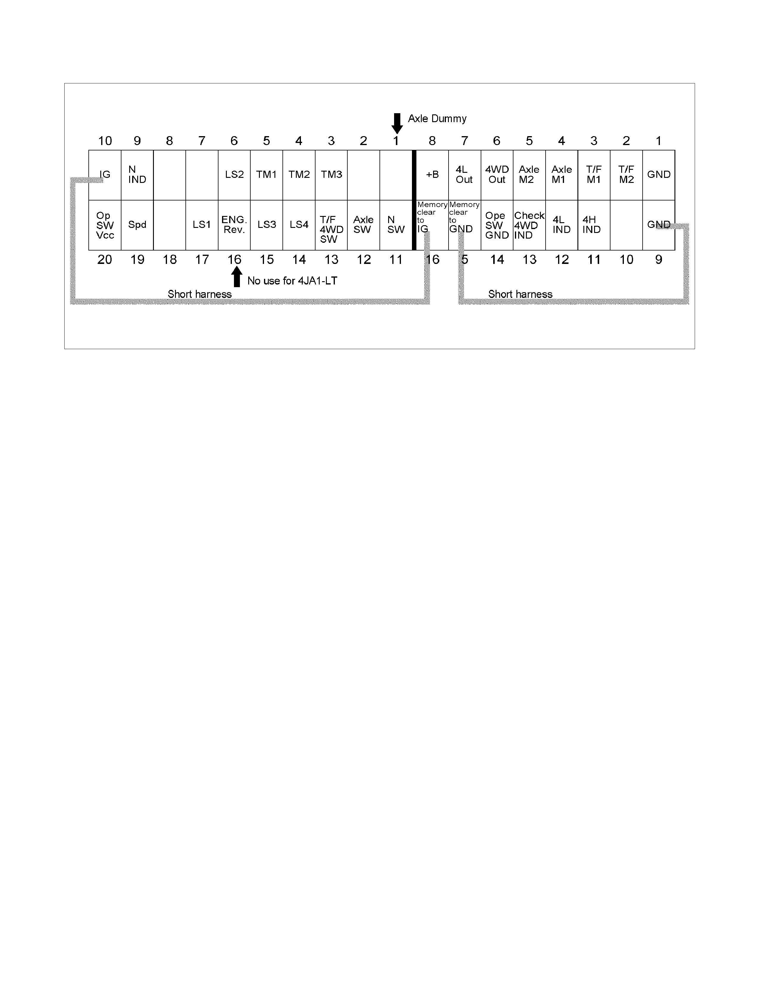
Transfer Controller Pin Assignment
RTW47DSF000101

Diagnosis From Symptom
Check4WD lighting up
Step Action Yes No
1 Check what was done before
the trouble occurred.
Was the harness between the
transfer controller and actuator
disconnected with the ignition
kept ON for the purpose of
servicing the vehicle, etc.?
Or, was the ignition turned ON
(power supplied to the transfer
controller) with the harness of
the actuator removed?
If the power is supplied with the
actuator not connected, faulty
position detection switch is
considered.
Clear the memory and trace this
chart from the beginning.
Go to step 2.
2 Is the ignition switch ON? Go to step 3. Turn the ignition switch ON and
trace this chart from the
beginning.
3 Does the transfer-related
indicators (4WD, 4Lo, Check
4WD, neutral) light up for 2
seconds when the ignition
switch is turned ON?
Go to step 4. Indicator lamp burnt out.
Disconnected harness wire .
After repairing, trace this chart
from the beginning.
4 Isn’t the harness between the
Check4WD indicator and
transfer controller GND
shorted?
GND (body) short of the indicator
harness.
After repairing, trace this chart
from the beginning.
Go to step 5.
5 Check the continuity of harness
between the transfer controller
and transfer actuator. Check
the power short and GND short.
Check the GND harness of the
transfer actuator.
Is a trouble noticed?
Repair the harness, clear the
memory and trace this chart from
the beginning.
Go to step 6.
6 Check the limit switch of the
actuator.
Is a trouble noticed?
Failed actuator. Replace the
actuator, clear the memory and
trace this chart from the
beginning.
Clear the memory and trace this
chart from the beginning.
Failed controller.
Replace the controller, clear the
memory and trace this chart from
the beginning.
To check the operation after completing the repair and clearing the memory, shift between 2H and 4L 5 times at
least.
To judge the condition more quickly, ask the customer the situation when the Check4WD lamp lighted up.
When the position indicator blinks at a frequency of 4Hz immediately after occurrence of a trouble, position of
failure which the indicator shows may be limited.
(Since it indicates the situation immediately before detection of failure whether the vehicle is running or standstill so
that possibility of failure around that point is high.)
Status of the transfer when the Check4WD lights up is not always the same. Immediately after occurrence of the
failure, 2H can be operated.

Cannot shift from 2WD to 4H or 4L.
When shifting from 2H to other position, the indicator (4WD, 4Lo, Check4WD, neutral)
does not respond.
Step Action Yes No
1 Is the ignition switch ON? Go to step 2. Turn the ignition switch ON and
trace this chart from the
beginning.
2 Does the transfer-related
indicators (4WD, 4Lo, Check
4WD, neutral) light up for 2
seconds when the ignition
switch is turned ON?
Failed operation switch. Only 2H
is stuck at ON condition and 4H-
4L position is internally
disconnected. Or,
Failed controller
Indicator lamp burnt out.
Disconnected harness wire .
After repairing, trace this chart
from the beginning.
Even after correction step 1-1(*), 4WD indicator blinks at 4Hz and changes to 2H after 10
seconds.
Step Action Yes No
1 Is the ignition switch ON? Go to step 2. Turn the ignition switch ON and
trace this chart from the
beginning.
2 Does the transfer-related
indicators (4WD, 4Lo, Check
4WD, neutral) light up for 2
seconds when the ignition
switch is turned ON?
Go to step 3. Indicator lamp burnt out.
Disconnected harness wire.
After repairing, trace this chart
from the beginning.
3 After 2 seconds, check that the
Check4WD lamp is ON or OFF.
Is the Check4WD lamp OFF?
Go to step 4. Failed actuator position detection
switch (LS1, LS2, LS3, LS4,
GND).
Short or disconnection of harness
of this detection switch.
After repairing, trace this chart
from the beginning.
4 Press the 4H button.
Is sound of relay heard from the
transfer control?
Go to step 5. Failed controller.
Replace the controller and trace
this chart from the beginning.
5 Is the sound of running motor
heard? Failed control system of the
transfer mechanism. Check and
repair and trace this chart from
the beginning.
Failed actuator motor.
Disconnected controller motor
drive output circuit, GND short
circuit. +B fuse blown out.
Disconnection of that harness.
After repairing, trace this chart
from the beginning.
*Before determining a trouble (Non-trouble mode)

Even after the correction step 1-2(*), the 4WD indicator still blinks at 2Hz when shifting
from 2H to 4H.
Step Action Yes No
1 Check the air pressure and
wear of all the tires. Is any
trouble noticed?
After adjusting the air pressure
and repairing the tire worn away,
try the correction step 1-2(*).
Go to step 2.
2 Check the 4WD detection switch
on the transfer case, neutral
detection switch and each
harness. Is a trouble noticed?
4WD detection switch is open or
the harness failed.
The neutral detection switch is
closed or the harness GND is
shorted.
Replace or repair and then trace
this chart from the beginning.
Go to step 3.
3 Is there continuity in the harness
between the transfer controller
and front axle actuator? Isn’t a
body short or disconnection
noticed?
Go to step 4. Body short or disconnection of
the harness between the transfer
controller and front axle actuator.
After repairing, trace this chart
from the beginning.
4 Is a trouble noticed in the axle
detection harness between the
axle actuator and transfer
controller?
Disconnected harness.
After repairing trace this chart
from the beginning.
Malfunction of axle actuator.
Refer to the paragraph of the
axle disconnect.
After repairing, trace this chart
from the beginning.
*Before determining a trouble (Non-trouble mode)
Note:
The vehicle of manual hub and rigid hub don’t have axle actuator.
When the above-mentioned procedure is followed, check the harness between the axle dummy output terminal
and the axle switch input terminal of transfer controller instead of axle actuator.

After operation, indicator of target position blinks for 1.5 sec. at 2Hz, return to 2H
condition (4WD indicator going out)
Step Action Yes No
1 Keep to press the 4H button
(about 10 seconds).
Does the 4WD indicator blink at
2Hz for 15 seconds and then
blink at 4Hz?
Failed actuator motor.
Disconnection of controller motor
drive output circuit, or GND short.
+B fuse blown out.
Disconnection of that harness.
After repairing, trace this chart
from the beginning.
Go to step 2.
2 Press the 4H button.
Is the sound of relay heard from
the transfer controller?
Go to step 3. Failed controller.
Replace the controller and trace
this chart from the beginning.
3 Is the sound of running motor
heart? Failed control system of the
transfer mechanism. Check and
repair and trace this chart from
the beginning.
Failed actuator motor.
Disconnection or GND short of
controller motor drive output
circuit.
After repairing, trace this chart
from the beginning.

Transfer cannot shift to a position other than 4H.
When shifting from 4H to other position, indicator (4WD, 4Lo, Check4WD, neutral) does
not respond (Only 4WD keeps lighting).
Step Action Yes No
1 Is the ignition switch ON? Go to step 2. Failed 4WD indicator and
harness.
After repairing, trace this chart
from the beginning.
2 Does the transfer-related
indicators (4WD, 4Lo, Check
4WD, neutral) light up for 2
seconds when the ignition
switch is turned ON?
Then, only 4H lights up.
Go to step 3. Indicator lamps other than the
4WD indicator are burnt out.
(Check for GND short circuit
between the 4WD indicator and
transfer controller.)
Disconnected harness wire.
After repairing, trace this chart
from the beginning.
3 Press the 2H button.
Is the sound of relay heard from
under the seat, and the sound of
running motor heard?
Failed controller.
After replacing the controller,
trace this chart from the
beginning.
*Failed operation switch. Or
disconnected or shorted of the
harness for the operation switch.
* The operation switch is an analog type switch which reads the internal composite resistance value at the time of
operation. If an abnormal value is detected, it is judged to be an instruction to 4H.

Even after the correction step 2-1(*), the 4WD indicator still blinks at 2Hz when shifting
from 4H to 2H.
Step Action Yes No
1 Check all the tires for air
pressure and wear. Is any
trouble noticed?
After adjusting the air pressure
and repairing the tire worn away,
try the correction step 2-1(*).
Go to step 2.
2 Check the 4WD detection switch
on the transfer case and neutral
detection switch and each
harness. Is a trouble noticed?
4WD detection switch is closed
or the GND short of harness.
The neutral detection switch is
closed or the harness GND is
shorted.
Replace or repair and then trace
this chart from the beginning.
Go to step 3.
3 Is there continuity in the harness
between the transfer controller
and axle actuator?
Isn’t short or disconnection
noticed?
Isn’t the connection mistaken?
Go to step 4. Body short, disconnection or
incorrect connection of the
harness between the transfer
controller and actuator.
After repairing, trace this chart
from the beginning.
4 Is a trouble noticed in the axle
detection harness between the
axle actuator and transfer
controller?
GND short of harness Malfunction of axle actuator.
Refer to the paragraph of axle
disconnect.
After repairing, trace this chart
from the beginning.
*Before determining a trouble (Non-trouble mode)
Note:
The vehicle of manual hub and rigid hub don’t have axle actuator.
When the above-mentioned procedure is followed, check the harness between the axle dummy output terminal
and the axle switch input terminal of transfer controller instead of axle actuator.

Though the indicator responds when shifting from 4H to 2H(or other position), it returns
to 4H.
Step Action Yes No
1 Is the ignition switch ON? Go to step 2. Turn the ignition switch ON and
trace this chart from the
beginning.
2 Does the transfer-related
indicators (4WD, 4Lo, Check
4WD, neutral) light up for 2
seconds when the ignition
switch is turned ON?
Go to step 3. Indicator lamp burnt out.
Disconnected harness wire.
After repairing, trace this chart
from the beginning.
3 After 2 seconds, check if the
Check4WD lamp lights up.
Is the Check4WD lamp OFF?
Go to step 4. Failed actuator position detection
(limit) switch (LS1, LS2, LS3,
LS4, GND).
Short or disconnection of
harness of this detection switch.
Refer to paragraph of
Check4WD.
After repairing, trace this chart
from the beginning.
4 Press the 2H button.
Is the sound of relay heard from
the transfer controller?
Go to step 5. Failed controller.
Replace the controller and trace
this chart from the beginning.
5 Is the sound of running motor
heart? Failed control system of the
transfer mechanism. Check and
repair and trace this chart from
the beginning.
Failed actuator motor.
Disconnection of controller motor
drive output circuit or GND short.
After repairing, trace this chart
from the beginning.
If the motor does not or cannot run at all (stuck transfer mechanism, disconnected motor, failed drive circuit), the
lamp blinks at 4Hz when the position is shifted to other position by pressing the button for more 10 seconds (20
seconds in case of neutral position).

From 4H to 4L; Even after the correction step 3-3(*), 4Lo indicator blinks at 4Hz
Step Action Yes No
1 Is the ignition switch ON? Turn it OFF once. Go to step 2.
2 Turn ON the ignition switch and
check the valve. Do not start
the engine.
Has the valve check for 2
seconds been completed
normally?
Go to step 3. Refer to the paragraph about the
indicator when it does not react
when shifted from 2H to 4H.
After taking the remedy, trace
this chart from the beginning.
3 Shift to 2H.
Can be shifted to 2H and then to
4H?
Go to step 4. Refer to the paragraph about
shifting from 2H to 4H.
In particular, check if not at the
Check4WD condition, return to
this chart and trace it from the
beginning.
4 Set to N position in case of AT
and set to the neutral position in
case of MT and check if the
lamp blinks at 4Hz after
operation.
Failed T/M position switch and
harness (failure of TM1 and TM2
harness and their related
switches shown in the figure).
Incorrect wiring.
Repair as required and trace this
chart from the beginning.
Shift back to 4H and go to step 5.
5 Start the engine and travel the
vehicle.
Does the speedometer run at
this time?
Go to step 6. Failure of speed sensor or
disconnection or short of harness
(for the meter).
After repairing, trace this chart
from the beginning.
6 Check the harness between the
transfer controller and speed
sensor.
(Check the engine rotation
detection harness at the same
time.)
Is any trouble noticed?
Failed harness between the
transfer controller and speed
sensor.
After repairing, trace this chart
from the beginning.
(Repair the engine rotation
detection unit, if required.)
Go to step 7.
7 Travel the vehicle several
meters, stop it, meet the
permission requirements for
operation limits.
Did you wait for several seconds
after the requirements were
met?
Failed controller.
Replace the controller and trace
this chart from the beginning.
You did not wait for enough time.
Optimum waiting time is 1
second or maximum 3 minutes
depending on the previous
conditions.
Refer to the paragraph about
operation without failure.
*Before determining a trouble (Non-trouble mode)

From 4L to 4H: After the correction step 4-3(*), 4Lo indicator blinks at 4H.
Step Action Yes No
1 Is the ignition switch ON? Turn it OFF once. Go to step 2.
2 Turn ON the ignition switch and
check the valve. Do not start
the engine.
Has the valve check for 2
seconds been completed
normally?
Go to step 3. Refer to the paragraph about the
indicator when it does not react
when shifted from 2H to 4H.
After taking the remedy, trace
this chart from the beginning.
3 Can be shifted to 2H and then to
4L? Go to step 4.
(Impossible usually.)
Failed controller
In case of Check 4WD, shifting to
2H is possible.
Returning to 4L is impossible.
Refer to the paragraph about
Check4WD.
4 Set to N position in case of AT
and set to the neutral position in
case of MT and check if the
lamp blinks at 4Hz after
operation.
Failed T/M position switch and
harness (failure of TM1 and TM2
harness and their related
switches shown in the figure).
Incorrect wiring.
Repair as required and trace this
chart from the beginning.
Press the operation switch of 4L
and go to step 5.
5 Start the engine and travel the
vehicle.
Does the speedometer run at
this time?
Go to step 6. Failure of speed sensor or
disconnection or short of harness
(for the meter).
After repairing, trace this chart
from the beginning.
6 Check the harness between the
transfer controller and speed
sensor.
(Check the engine rotation
detection harness at the same
time.)
Is any trouble noticed?
Failed harness between the
transfer controller and speed
sensor.
After repairing, trace this chart
from the beginning.
(Repair the engine rotation
detection unit, if required.)
Go to step 7.
7 Travel the vehicle several
meters, stop it, meet the
permission requirements for
operation limits.
Did you wait for several seconds
after the requirements were
met?
Failed transfer controller.
Replace the controller and trace
this chart from the beginning.
You did not wait for enough time.
Optimum waiting time is 1
second or maximum 3 minutes
depending on the previous
conditions.
Refer to the paragraph about
operation without failure.
*Before determining a trouble (Non-trouble mode)

To neutral: After the correction step 5-2(*), neutral indicator blinks at 4Hz.
Check the function between H and L according to the chart for 4L to 4H instead of check
for the requirements of neutral.
Step Action Yes No
1 Is the ignition switch ON? Turn it OFF once. Go to step 2.
2 Turn ON the ignition switch and
check the valve. Do not start the
engine.
Has the valve check for 2
seconds been completed
normally?
Go to step 3. Refer to the paragraph about the
indicator when it does not react
when shifted from 2H to 4H
(7D1-37).
After taking the remedy, trace
this chart from the beginning.
3 Can be shifted to 2H and then to
4L? Go to step 4.
(Impossible usually.)
Failed controller
Refer to the paragraph about
shifting from 2H to 4H.
In particular, check if not at the
Check4WD condition, return to
this chart and trace it from the
beginning.
In case of Check4WD, shifting to
2H is possible.
Returning to 4H is impossible.
Refer to the paragraph about
Check4WD.
4 Set to N position in case of AT
and set to the neutral position in
case of MT and check if the lamp
blinks at 4Hz after operation.
Failed T/M position switch and
harness (failure of TM1 and TM2
harness and their related
switches shown in the figure).
Incorrect wiring.
Repair as required and trace this
chart from the beginning.
Shift back to 4H and go to step 5.
5 Start the engine and travel the
vehicle.
Does the speedometer run at this
time?
Go to step 6. Failure of speed sensor or
disconnection or short of harness
(for the meter).
After repairing, trace this chart
from the beginning.
6 Check the harness between the
transfer controller and speed
sensor.
(Check the engine rotation
detection harness at the same
time.)
Is any trouble noticed?
Failed harness between the
transfer controller and speed
sensor.
After repairing, trace this chart
from the beginning.
(Repair the engine rotation
detection unit, if required.)
Go to step 7.
7 Travel the vehicle several
meters, stop it, meet the
permission requirements for
operation limits.
Did you wait for several seconds
after the requirements were met?
Failed controller.
Replace the controller and trace
this chart from the beginning.
You did not wait for enough time.
Optimum waiting time is 1
second or maximum 3 minutes
depending on the previous
conditions.
Refer to the paragraph about
operation without failure.
*Before determining a trouble (Non-trouble mode)
For shifting to neutral, 2H and 4L switches should be kept pressed at the same time for 10 seconds.
For shifting from neutral to other position, 2H, 4H or 4L switch should be kept pressed for 10 seconds.
When shifting from neutral to other position, the lamp blinking at 2Hz indicates active condition.
When the lamp keeps blinking at 2Hz, follow the step for the case when the lamp keeps blinking at 2Hz when
shifting between positions.