
SECTION 7A1 - CONSTRUCTION & FUNCTION (JR405E)
Description
Construction
Main Data And Specificat i o n
Number Plate Locat ion
Electronic Control Components Location
Transmission Control Unit (TCM) Peripheral
Circuit
Structure And Function Of Component
Torque Converter (With Lock-Up Function)
Oil Pump
Input Shaft
Output Shaft
Gear Shiftin g M ech anism
Clutch And Brake
Control Valve
Oil Passage
Parking Function
Inhibitor Switch
Turbine Sensor
Speed Sensor
Throttle Position Sensor (TPS)
Engine Speed Sensor (=TDC Sensor)
Brake Switch
Mode Select Switch
Transmission Control Module (TCM)
Control Mechanism
Content Of Function And Control
Control Item, Input And Output
Line Pressure Control
Lock-Up Control
Direct Electric Shift Control (Desc)
Learning Control
Major Input/Output Component And Their
Functions
Control Circuit Block Diagram
Gear Train (Transmission Mechanism) Operation
And Hydraulic Circuit
Construction And Operation
Component Name And Function
Component And Their Operating Condition
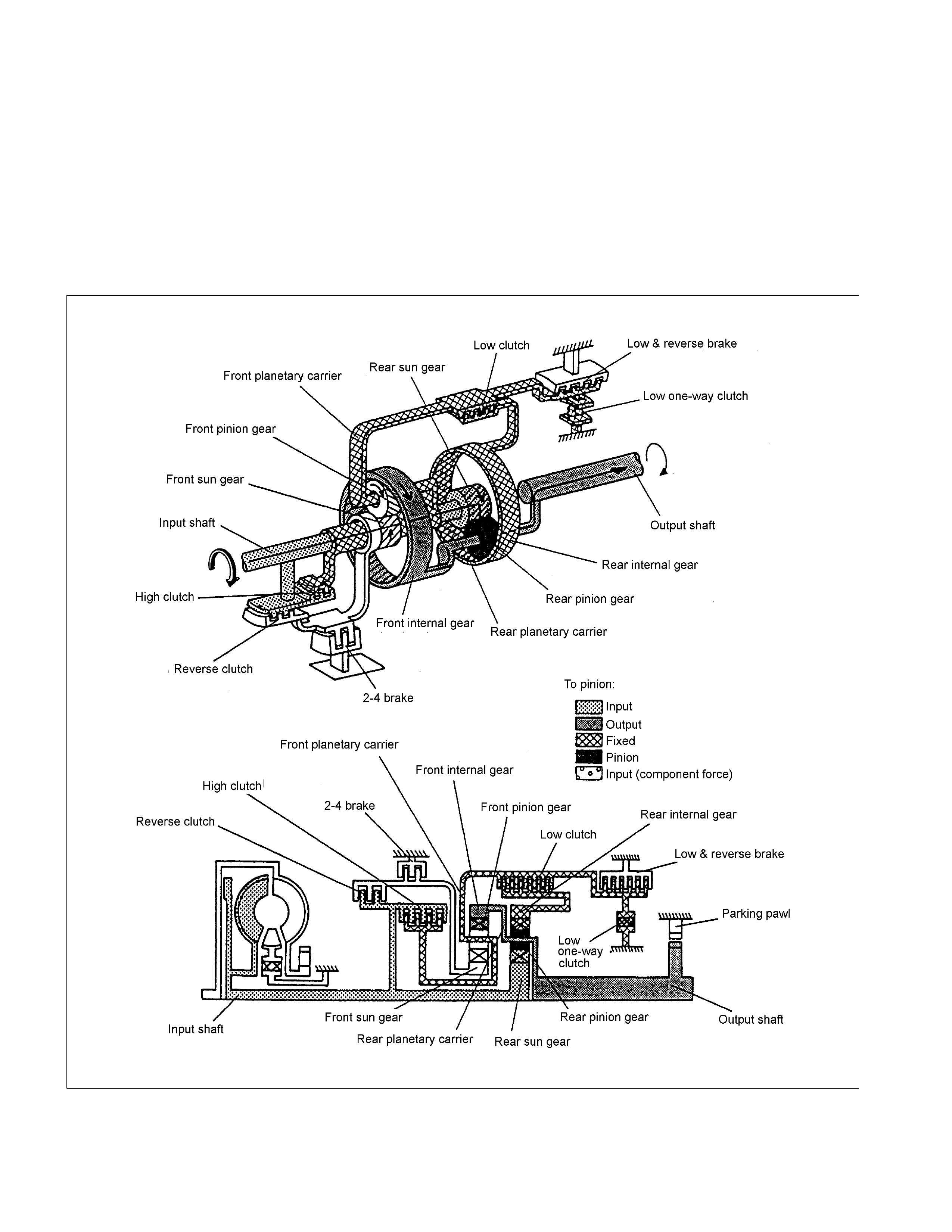
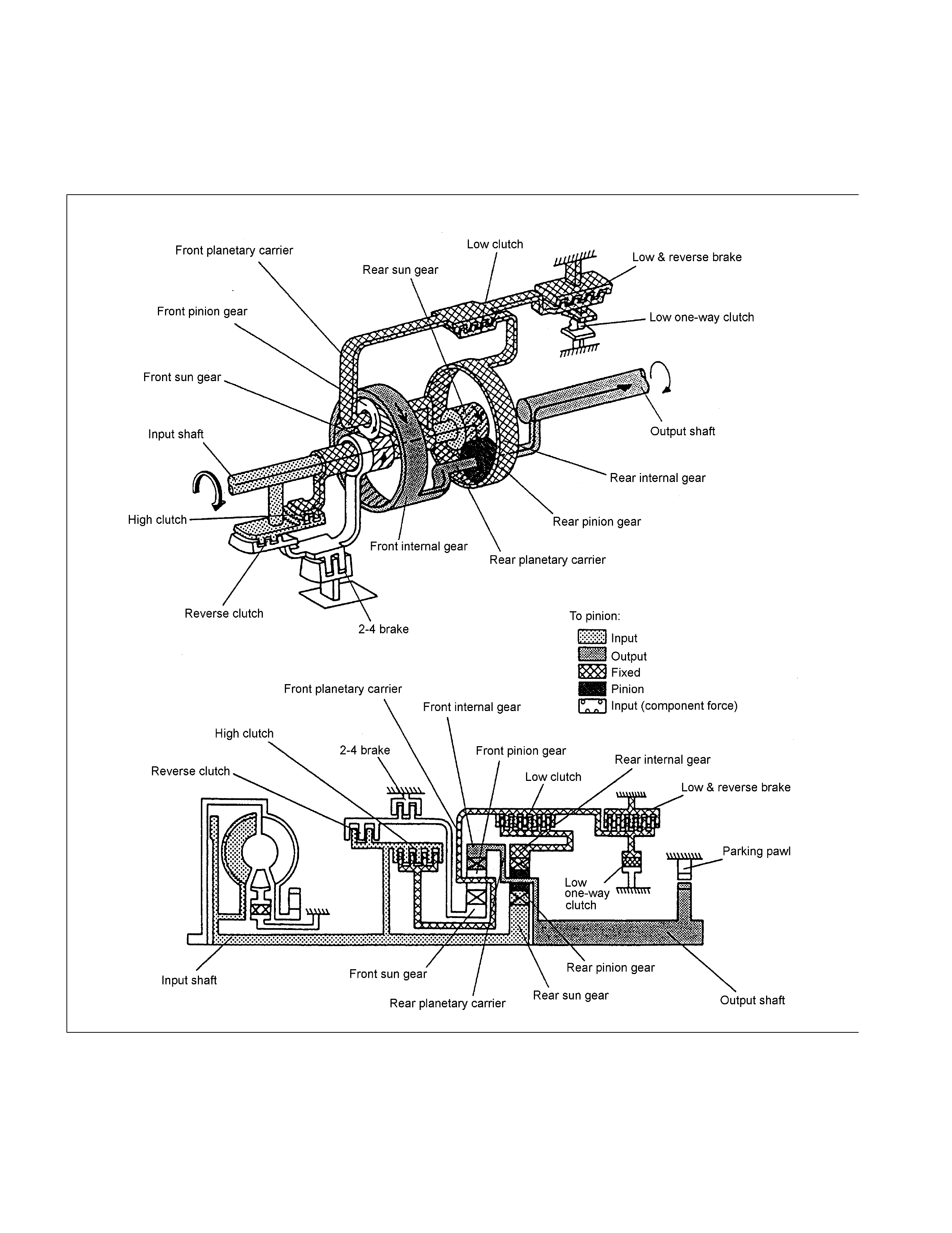
Description
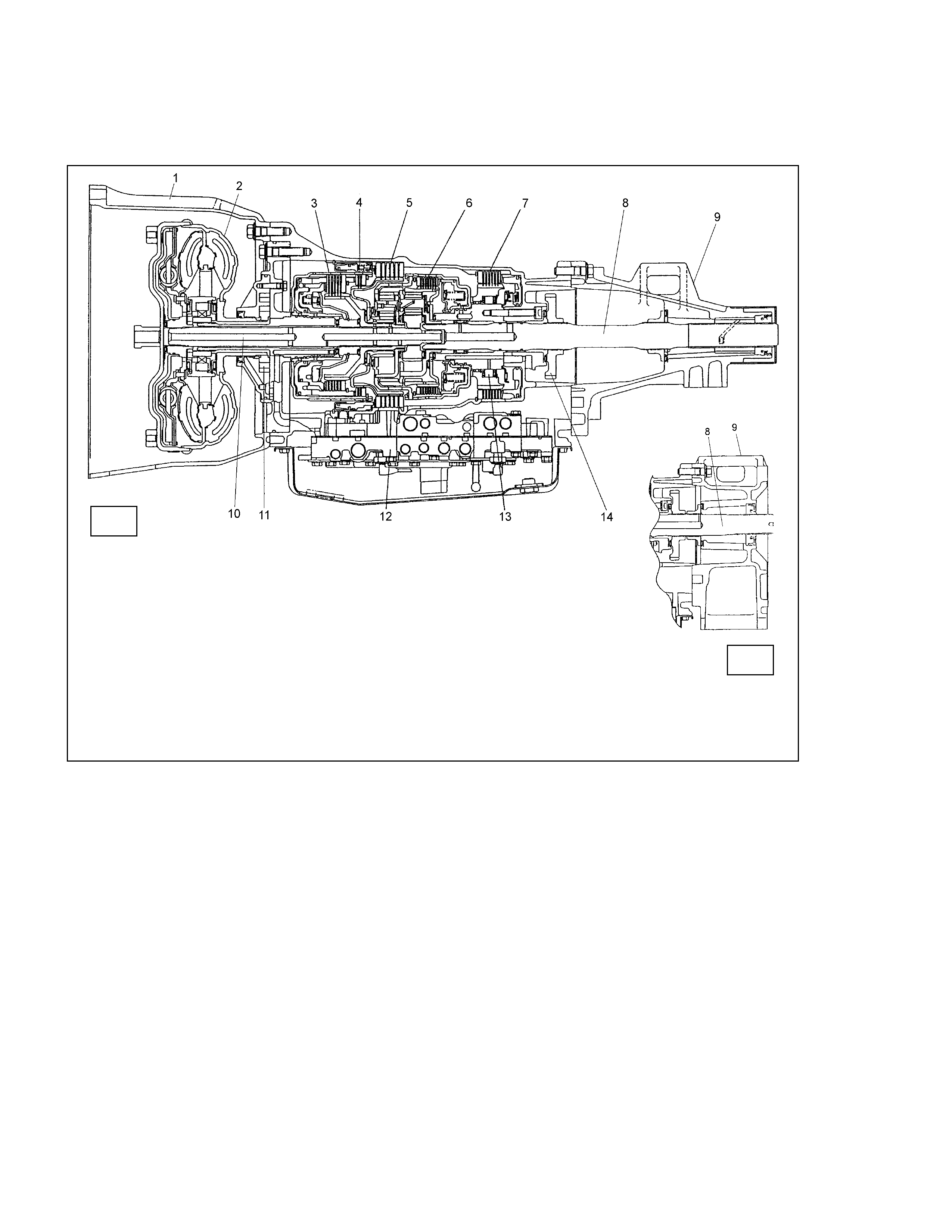
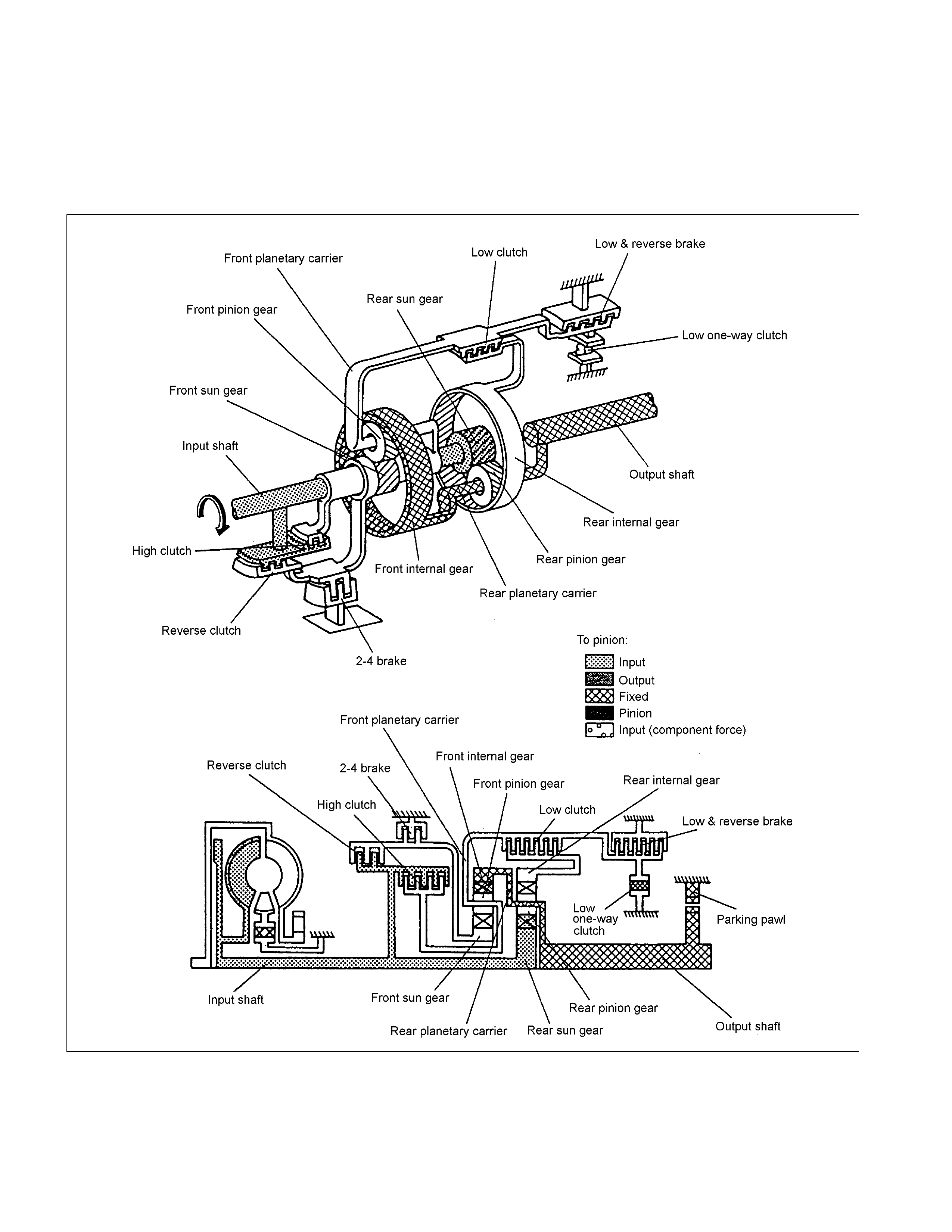
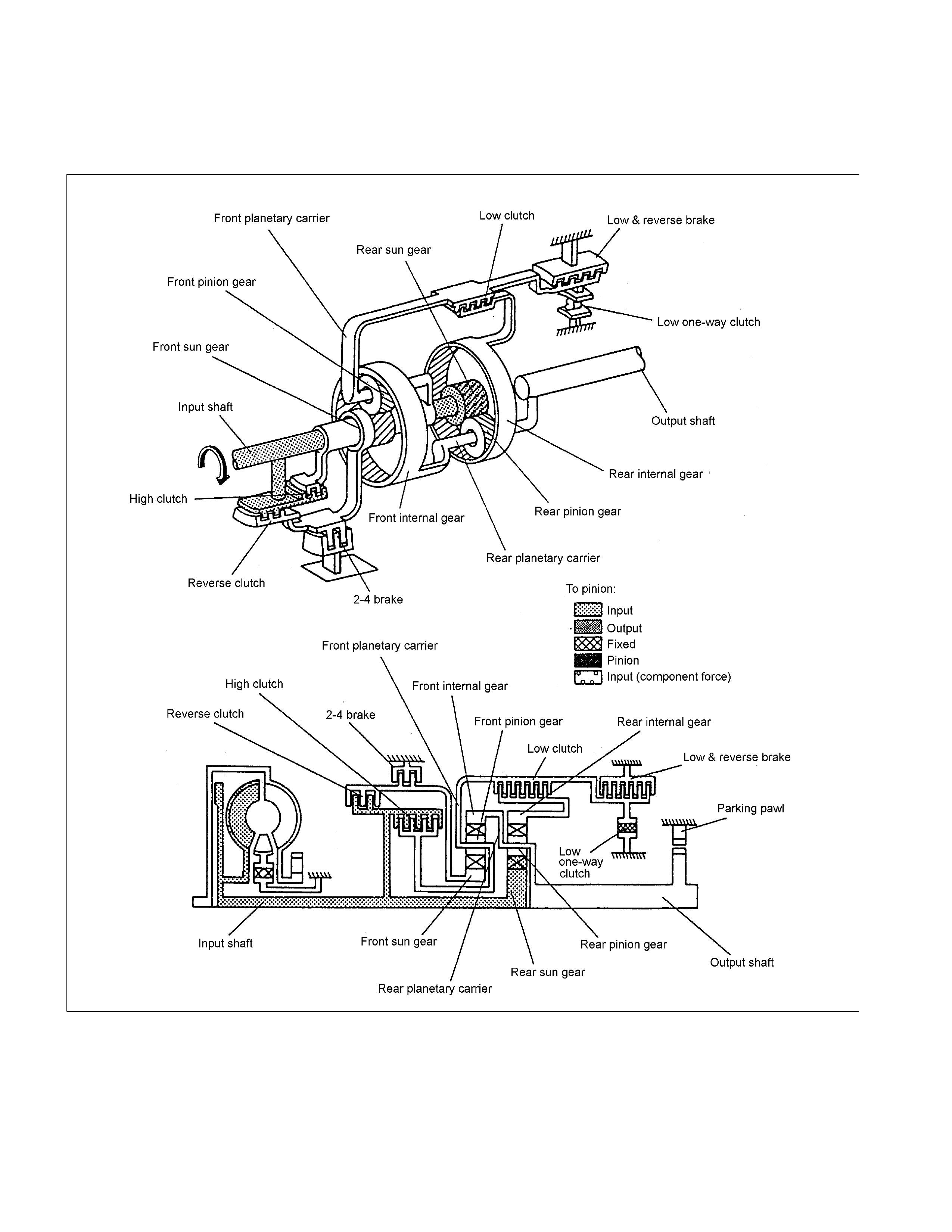
Construction
1 Converter Housing 6 Low Clutch 11 Oil Pump
2 Torque Converter 7 Low & Reverse Brake 12 Control Valve
3 High Clutch 8 Output Shaft 13 Low One-way Clutch
4 Reverse Clutch 9 Extension Housing 14 Parking Gear
5 2-4 Brake 10 Input Shaft
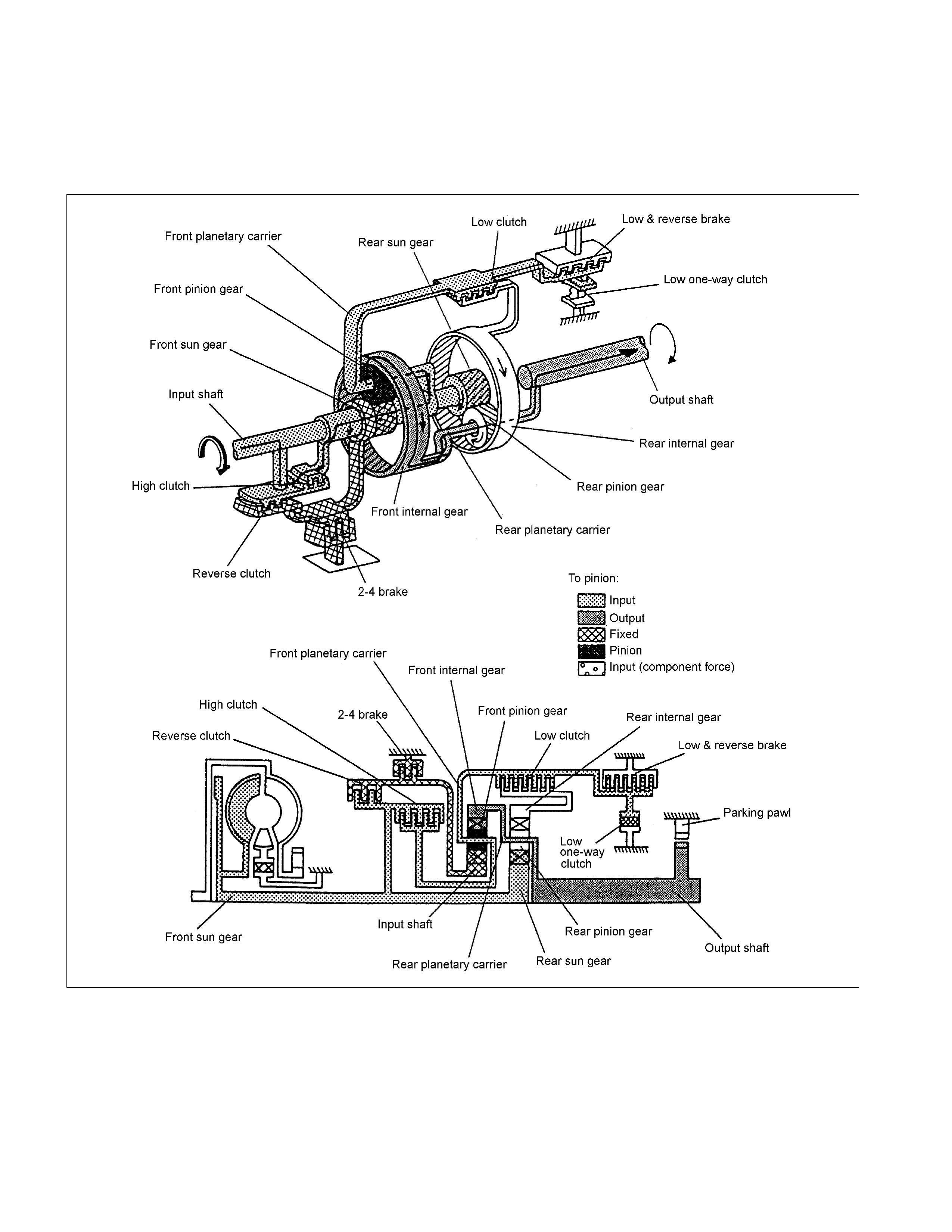
Figure 1. Construction of Automatic Transmission
A microcomputer transmission control module (TCM) electrically controls the JR405E automatic transmission. There are
four forward speeds and one reverse speed.
This JR405E automatic transmission employs a clutch pressure direct control sy stem (Direct Electronic Shift Control:
DESC) using a duty cycle type solenoid, which ensures high shift quality.
This transmission also controls learning and constantly checks the time of each clutch and brake required for the speed
change to match this time with the target value for the optimum speed change.
The TCM will automatically select the most appropriate shift points and lock-up points depending on the throttle opening
angle, the vehicle speed and the vehicle load.
If any trouble arises in the vehicle sensor, throttle sensor, solenoid, etc., the fail-safe control function is activated to keep
the running performance.
Problems with the sensors, the solenoids can be quickly detected with the self-diagnosis procedure described in this
manual.
The JR405E automatic transmission consists of the torque converter, the oil pump, the input shaft, the out put shaft, the
planetary gears and the control valve.
The gear train consists of two planetary gear sets and three multiple plate clutches in combination with two multiple plate
brakes and a one-way clutch.
2WD
4WD

Main Data And Specification
Model JR405E
Torque Converter Type Three Elements, One Stage & Two Phase Type
With Lock-up Function
Torque Converter Stall Torque Ratio 1.8
Name ATF DEXRON III
Quantity 9.2L-9.6L
ATF
Cooling System Water Cooled Type (Radiator)
1st 2.786
2nd 1.546
3rd 1.000
4th (Over Drive) 0.694
Gear Ratio
Reverse 2.273
Low Clutch L/C 7
High Clutch H/C 5
Reverse Clutch R/C 2
Number of Disc
Clutch
Low One-way Clutch L/O.C 1 Set
Low & Reverse Brake L&R/B 6
Brake 2-4 Brake 2-4/B 5 Number of Disc
Sun Gear 33
Pinion Gear 21
Front Planetary
Ring Gear 75
Sun Gear 42
Pinion Gea r 17
Planetary Gear Unit
Rear Planetary
Ring Gear 75
Number of Teeth
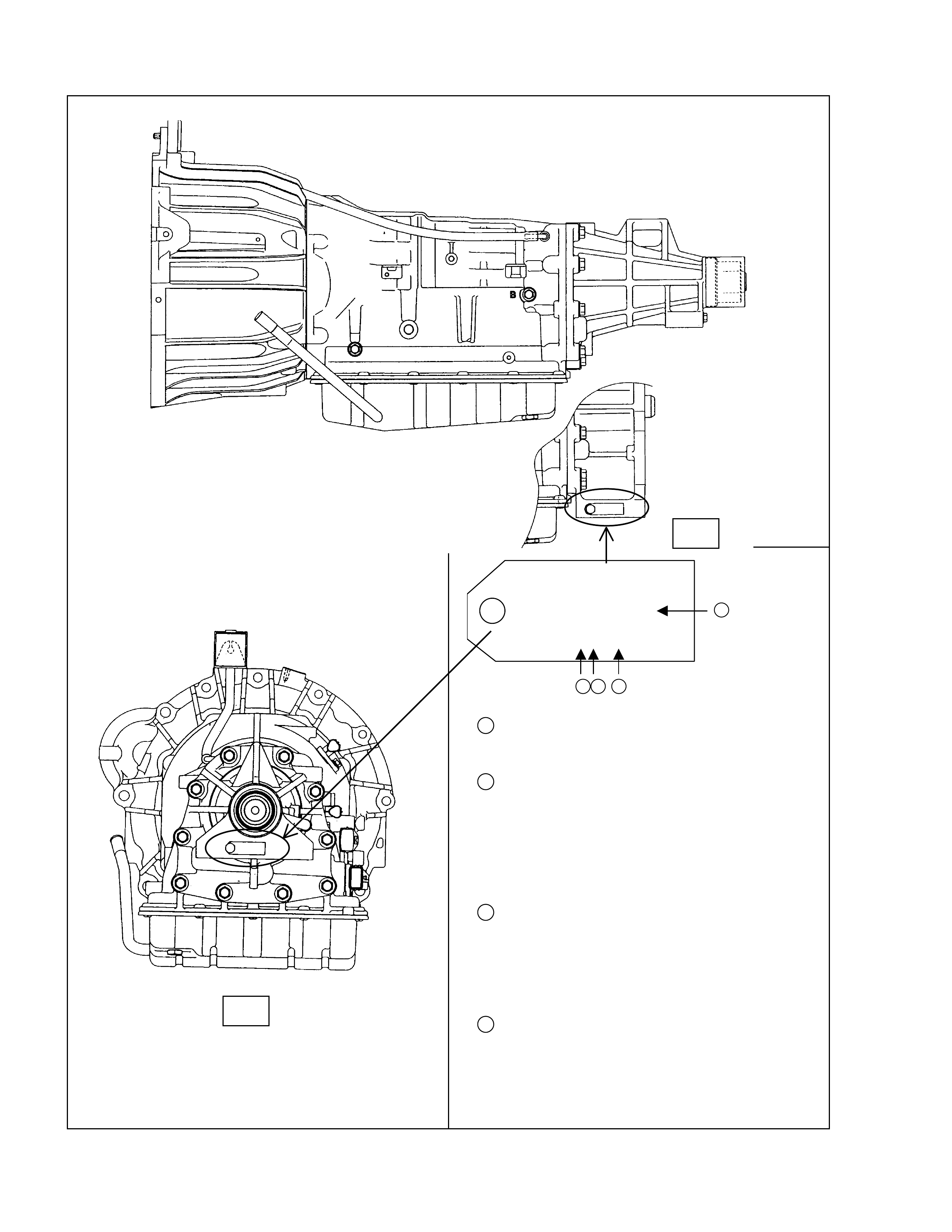
Number Plate Location
JATCO CORP
UK000 1
No. 1X80652
2 3 4
1→UK000 UK000 = 2WD
UK001 = 4WD
2→1 Production Year
1=2001
2=2002
3=2003
4=2004
5=2005
3→X Product Month
19=JanuarySeptember
X=October
Y=November
Z=December
4→80652 Production Sequence Number
Serial Number Locat ion
2WD:Back of the transmis sion rear mount ing
4WD:Left side of the tr ansmission rear mounting
Figure 2. Number Plate Location
4WD
2WD
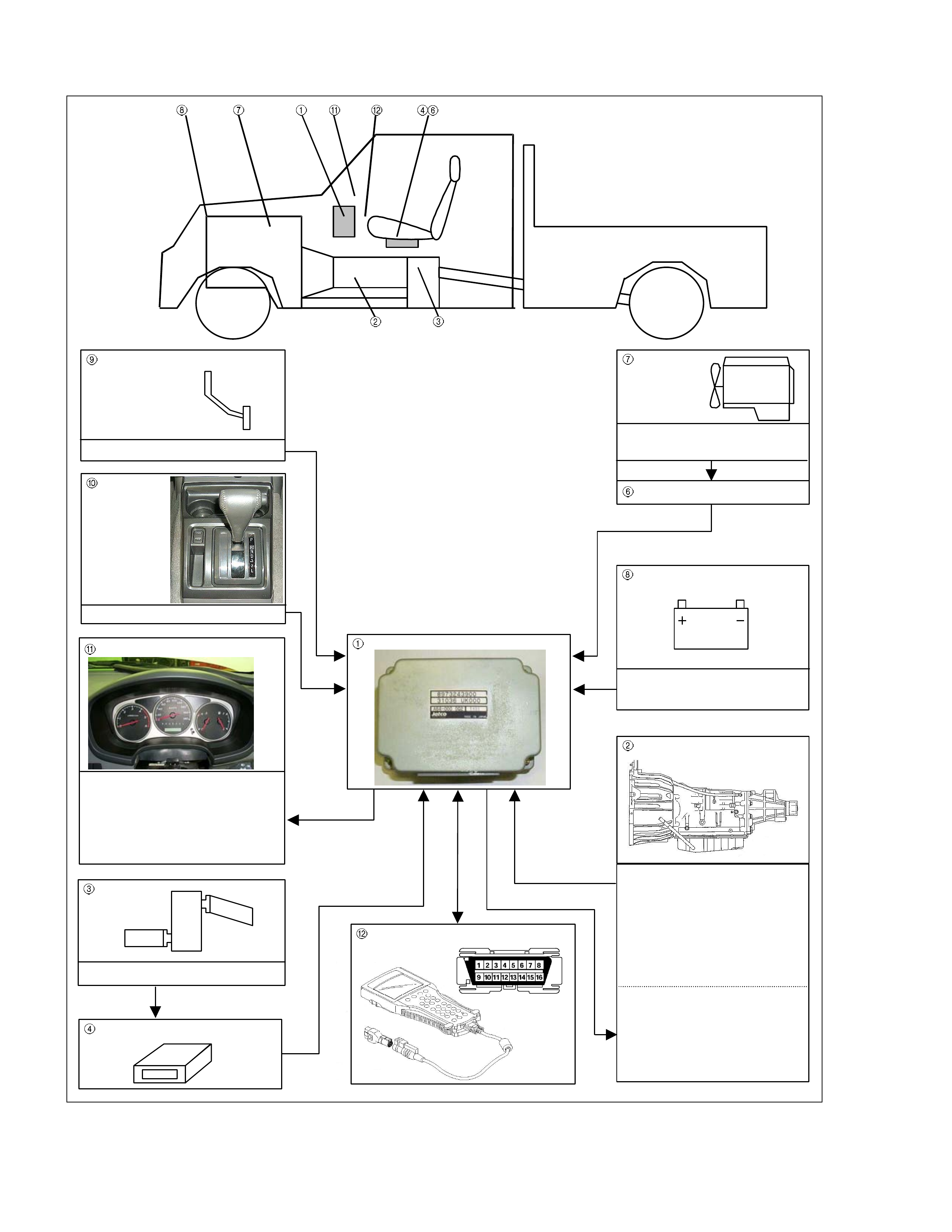
Electronic Control Components Location
4W D Only
4WD Only
Instrument panel (Meter)
Speed meter (2WD Only)
Shift position indicator la mp
POWER DRIVE, 3rd START
indicator lamp
A/T OIL TEMP indicat or lamp
CHECK TRANS indicator lam
p
Brake pedal
Brake S witc h
Select lever
Power Drive
,
3rd Start select switch
Transmis s ion Control Modu le (TCM)
Electrical source
Ignition
Batt ery voltage
Speed sensor
Turbine sensor
Inhibitor switch
ATF therm o sensor
High cl utch oil pressure switch
2-4 brake o il pressure s witc h
Low & Reverse brake oi l pressure
switch
Line pres sure solenoid
Low clutc h solenoid
High c lutch solenoid
2-4 brake solenoid
Low & Reverse brake solenoid
Lock- up solenoid
Tr ansmission
Transf er C ontrol Module
Transfer
4L mode switch
Engi ne
Engine speed sens or
Throttle Posit ion Sensor
Engi ne C ontrol Module (ECM)
Data link connector

Transmission Control Unit (TCM) Peripheral Circuit
Figure 4. TCM Peripheral Circuit
Structure And Function Of Component
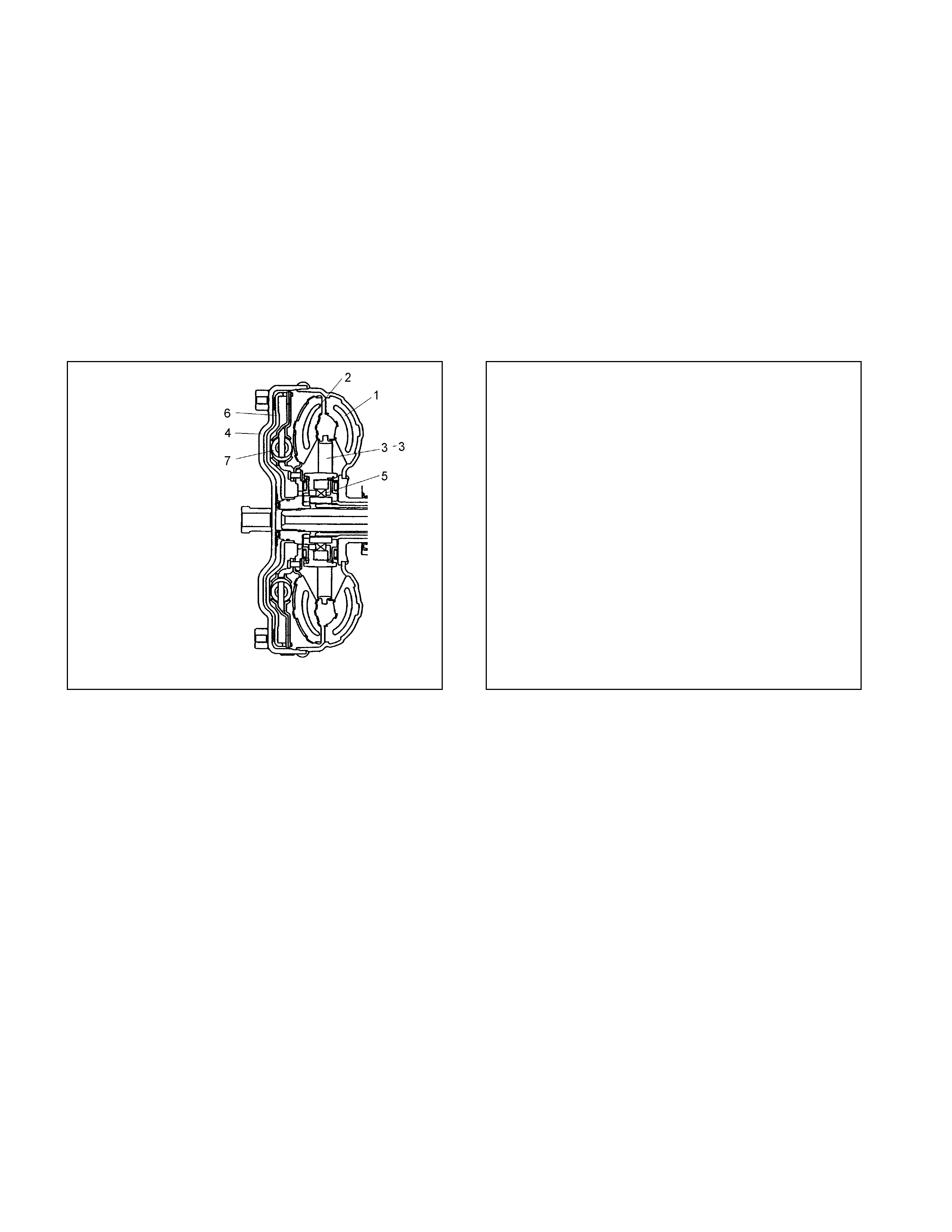
Torque Converter (With Lock-Up Function)
• The torqu e converter is a device for transmitting the engi ne t orque to the tr ansmission. It t r ansmit s pow er by
means of o il w hen the lo ck-up is dise ngaged and by means of a loc k-up pist on when it is engag ed.
• The torqu e converter is of t he symmetrical, t hree-element , single-stage, two-phase type.
• As show n in t he drawin g, t he symmetrica l t hree-elements refer to three elem ent s (component s) consist ing o f
impeller (1), turbine (2) an d st at or (3) t hat are arranged symmetr ica lly (figure 5).
• "Singl e-st age" means that t here is only one t urbine as an output element; "t w o-phase" means that the p ump
impeller acts as a t orque conv ert er when the turbin e speed is comparatively low, and as a fluid coupling when
the speed is high.
1. Pump Impeller
2. Turbine Runner
3. Stator
1. Pump Impeller
2. Turbine Runner
3. Stator
4. Converter Cover
5. One-way Clutch
6. Lock-up Piston
7. Torsion Damper
Figure 5. Torque Converter Figure 6. Construction of Torque Converter
Lock-up mechanism
• "Lock-up" ref ers t o a fixed state of the lo ck-up piston inside the torque converter and t hus connects t he engine
directly to the tr ansmi ssion.
• The hydraulic pressure f or the loc k-up cont rol is sup plied from tw o circuits.
When the lock-up is disengaged (Figure 7)
• When the loc k-up is disengaged, the torque converter operati ng pressure is supplie d from the o il passage (A) to
between the cover and the lock-up piston, and sepa r at es t he lock-up piston clutch facing and converter cover.
• As a result , the engine driv e power is transmit ted from the convert er cover to the pump impel ler, the ATF and to
the turbine. The torque converter functi on as a fluid conn ect or in t his condition.
• The torqu e converter oper at ing pressur e is supplied from the o il passage (A), passes throug h t he oi l passage
(B).
When the lock-up is engaged (Figure 8)
• When the lock-up is engaged, the torque convert er operatin g pressure is supplied fro m oil pa ssage (B) to the oil
pump impe ll er, turbine, then to the stat or side. The oil bet ween the lock-up pi ston and conv ert er cover is
drained.
• Since the force acting on t he right s ide of t he lock- up pisto n is greater t han forc e on the left s ide, it conne cts the
lock-up p iston clutch fac in g with the convert er cover, thereby increasing the transmission efficiency.
Figure 7. Lock-up Control (Dise ngaged) Figure 8. Lock-up Control (Engaged)
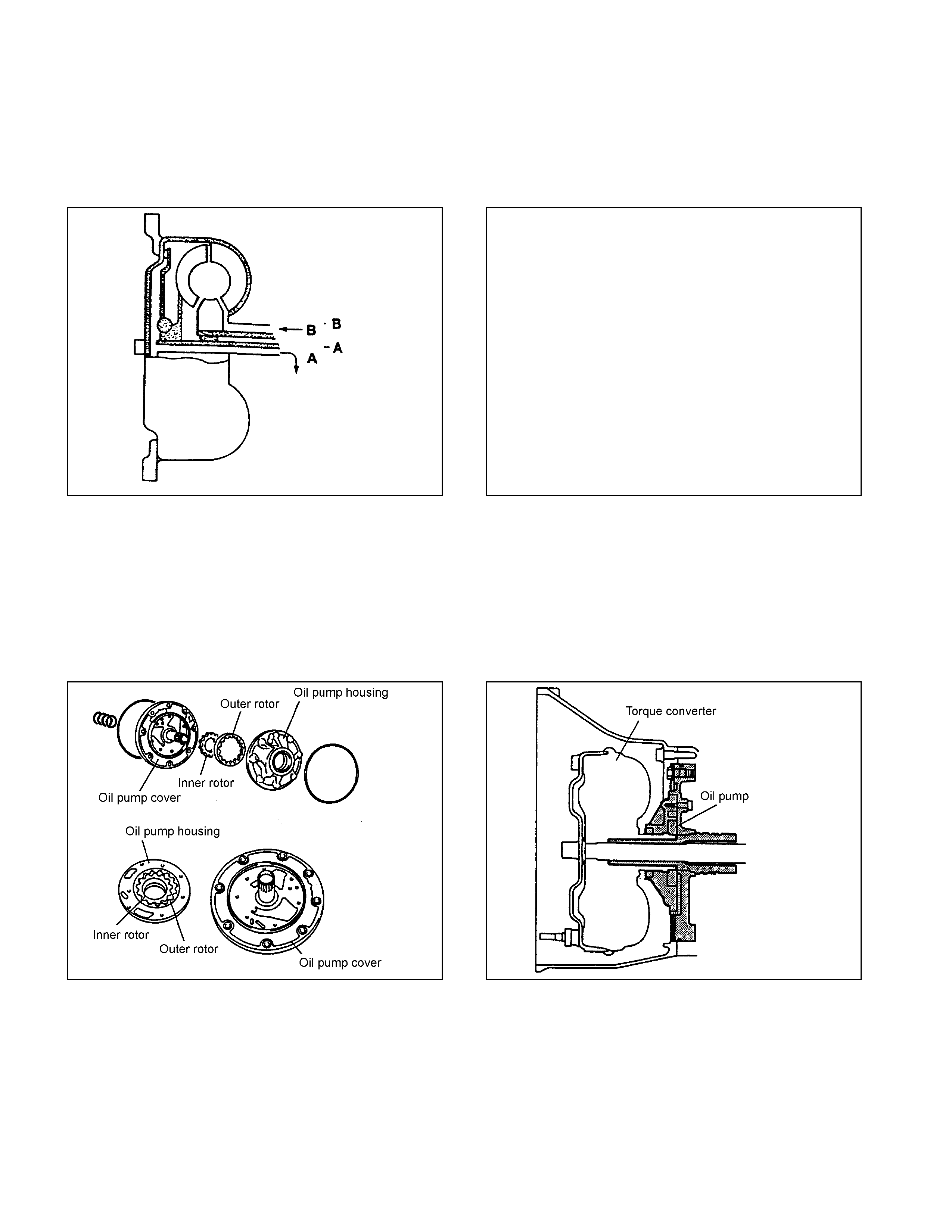
Oil Pump
• The oil pump generating o il pressure is a s ma ll-size t r ochoid gear type oil pump. I t feeds o i l t o the torque
converter, lubri cat es t he power tr ain mechanism, and feeds t he oil pressure t o the oil pressure contro l unit
under pressur e.
• The oil pump is located behind t he t orque convert er. Sine the in ner rot o r in t he oil pump is fitted with the driv e
sleeve of the torque conv ert er, it works by the powe r from the engin e.
Figure 9. Construction of Oil Pump Figure 10. Location of Oil Pump
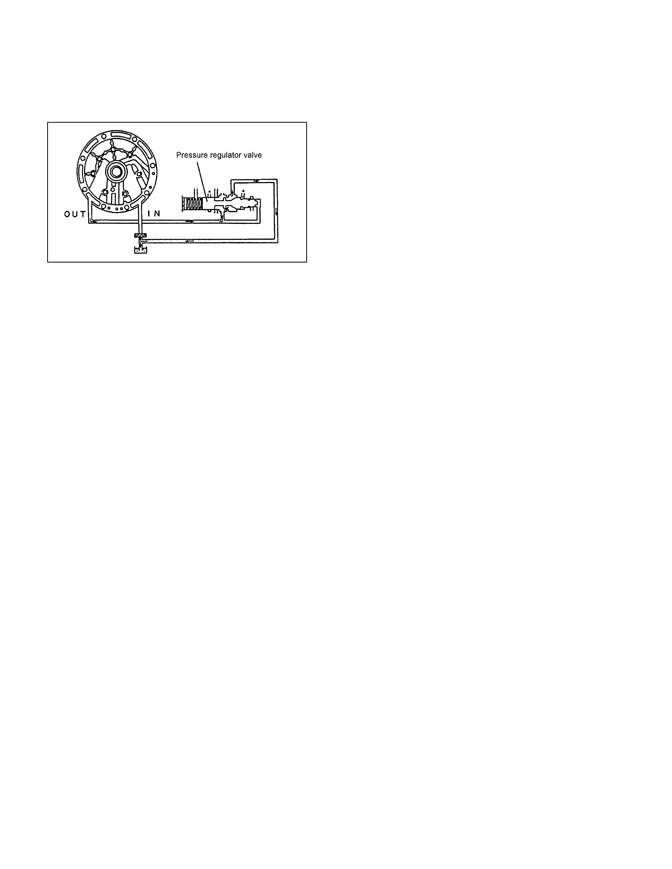
• When t he inner rotor in t he oil pump rotates, ATF is sucked in fro m the oil pan, passed betwee n the inner rot or,
outer rotor and cres cent and discharge d. This pressure disch arged is sent to t he pressure regulator valve in the
control valve and adjust ed as required f or operating the A/T. The flow rat e under pressure increases or
decreases in proportion of t he number of rotations.
Figure 11. Operation of Oil Pump
Input Shaft
• The input sha ft has some oil hol es, throug h which lu bricating ATF is s upplied t o the torque conv erter, bearing s,
etc.
• The input sh aft is fitted the t urbine runner in the torqu e converter, reverse & high clut ch dru m and rear sun ge ar
by means of the s pline. There fore, t he engine driving force received by t he t orque co nverter is transmitted to
the reverse & high cl ut ch drum and rear sun gear.
Output Shaft
• The out put shaft has some oil hol es, t h rough whic h t he lubricat ing ATF is su pplied to the bearin gs, planetary
gear unit, et c.
• The out put shaft trans mits t he engi ne driving force fr om the planetary gear to the propeller shaft.
• The front internal gear i s fitted wit h the rear carrier asse mbly by spline. The parking gear is also fitt ed by spline.
By fixing th is gear mechanically , t he out put shaft is fixed as required whe n parking the vehicle.
Gear Shifting Mechanism
• The JR 405E cons ists of tw o sets of planet ary gears, three multiple p late clutche s, two multi ple plate br akes and
a one-way clut ch. T hey are activat ed in different co mb inations i n any of four forward and one reverse g ear
positions.
Principle of gear shifting (Figure 12)
• Planet ary gears have t he advantage of a compact c onfiguration be cause of th e way they are constructed wit h a
single central sha ft .
• Also, unl ike the manual t ransmission gears that require chang ing of gear mes h, t he gear rat io o f the planetary
gears can be changed more easily by locking, releasing or rot at ing o nly some of their parts.
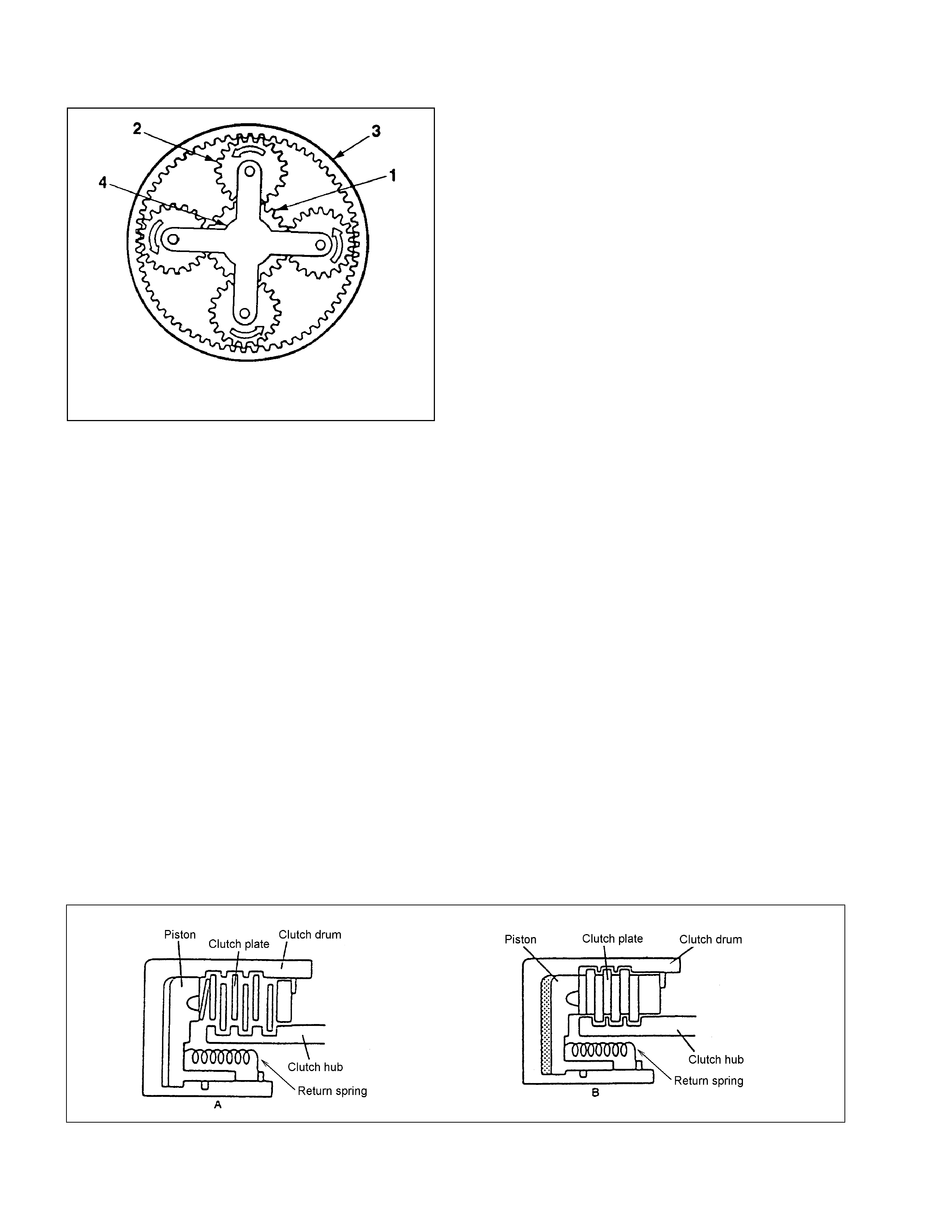
• A planetary gear is made up of a s un gear (1) at its cent er and pinion gears (2) each of which rotates ab out it s
own center and also along the sun gear, as sh own. They are al l called in t he i nt ernal gear (3).
• Also, si nce t he pinion g ears are further supported by the planet ary carrier (4), they rotate as a un it in t he same
direction a nd at the same rat e.
• As show n above, each planetary gear is constr uct ed of three eleme nt s; a sun gear, pinion gears, and i nt ernal
gear and a planetary carrier. Gear shifting is achieved by conditi oning two of the three elements na mely the sun
gear, internal gear and the planetary carrier.
• The pla net ary gears are lo cked by the clutc h, brake and one-w ay clutch according t o t he gear shifting.
1. Sun Gear
2. Pinion Gear
3. Internal Gear
4. Planetary Carrier
Figure 12. Planetary Gear
• The JR4 05E consists of two sets of plan et ary gears, which are called front pla net ary gear and rear planet ary
gear.
• The sun gear of front planetary gear is fixed t o t he drive plat es of 2-4 brake and reverse clutch.
• The pla net ary carrier of front planetary gear is fixed to the drum of low clutch, the drive plates of low & reverse
brake and the hub of high clutch.
• The internal gear of fro nt pla netary gear and the pla netary carrier of rear plan etary gear are connecte d as one,
and they are fixed to outp ut shaft.
• The sun gear of rear planetary gear is fixed to input shaft.
• The internal gear of rear planet ary gear is fixed to t he hub of low clutch.
Clutch and Brake
• Basic struct ure of the clutch and brake is shown in the f igures below .
• In the figure A, t he clutch plates (driv e plate and driv en plate) are in the fluid so t hat they slip against each other
transmitting no power.
• Figure B shows the con dition w here the oil pressure i s acting on the pist on. The clut ch plates ar e fitted to eac h
other under press ure t r ansmitting t he rotations of th e clut ch drum to the clut ch hub.
• When the oil pressure is removed from the piston, the clutch returns to the condition in the figure A by the return
spring.
Figure 13. Basic Construction of Clutch and Brake
Low Clutch, High Clutch and Reverse Clutch (Multi-Plate Clutch)
• The multi-p late clut ch is c omposed o f drive plat es a nd driven pl ates. By apply ing the oi l pressure ont o the en d
surface of the pl at es, t he clut ch is engaged or disengaged. The oil pressure i s adj ust ed with the cont rol valv e
according t o t he signal from the T CM.
• All clut ches use dish p lates to prev ent uncont rolled operation of the clut ches when en gaged, caus ing a shock.
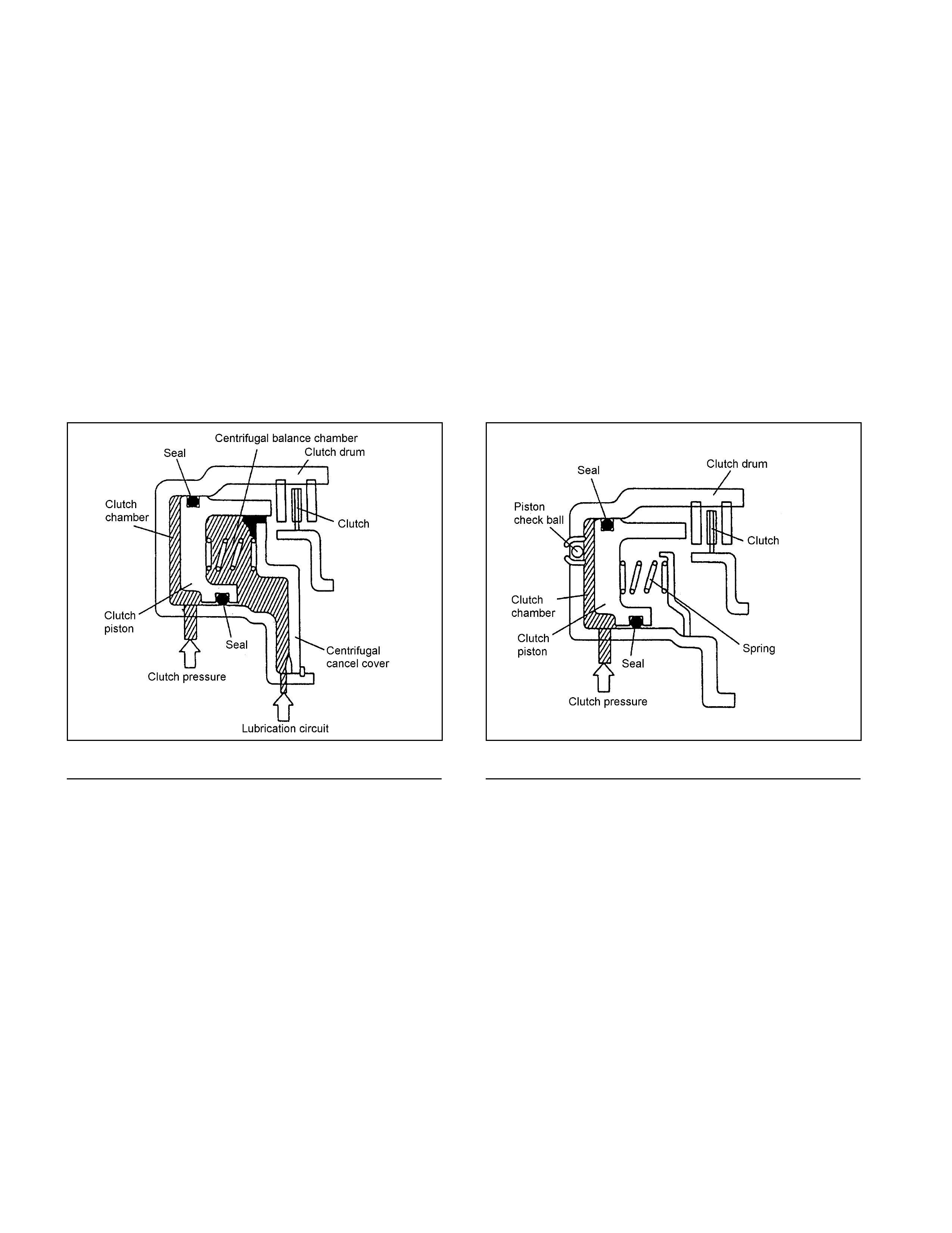
• For the rev erse cl ut ch, a piston check ball is used to release t he oil pressure for the purpose o f preventing the
clutch drag due to oil pressure generated by residua l ATF becau se of the cent rifu gal force w hi le t he clutch is
racing (under no oi l pressure).
• For the low clutch and high clutch, a centrifug al balance chamber always full o f A TF i s provided to offset the
excessiv e oi l pressure, for the purpos e of prev enting the clutch drag due t o oil pressure generated by residu al
ATF because of the centrifugal force while the cl ut ch is racing (under no oil pressure).
• The solenoid in the control valve is driven based o n the speed cha nge signal f r om TCM and moves t he shift
valv e, t hereby engaging the drive plate and driven plate through the piston of each clutch.
• Result antly, elements of the planetary gear unit are combined.
• When the o i l pressure is removed, the pist on returns t o t he origi nal position by t he force of the return spring.
Figure 14. Basic Construction of Low Clutch and
High Clutch Figure 15. Basic Construction of Reverse Clutch
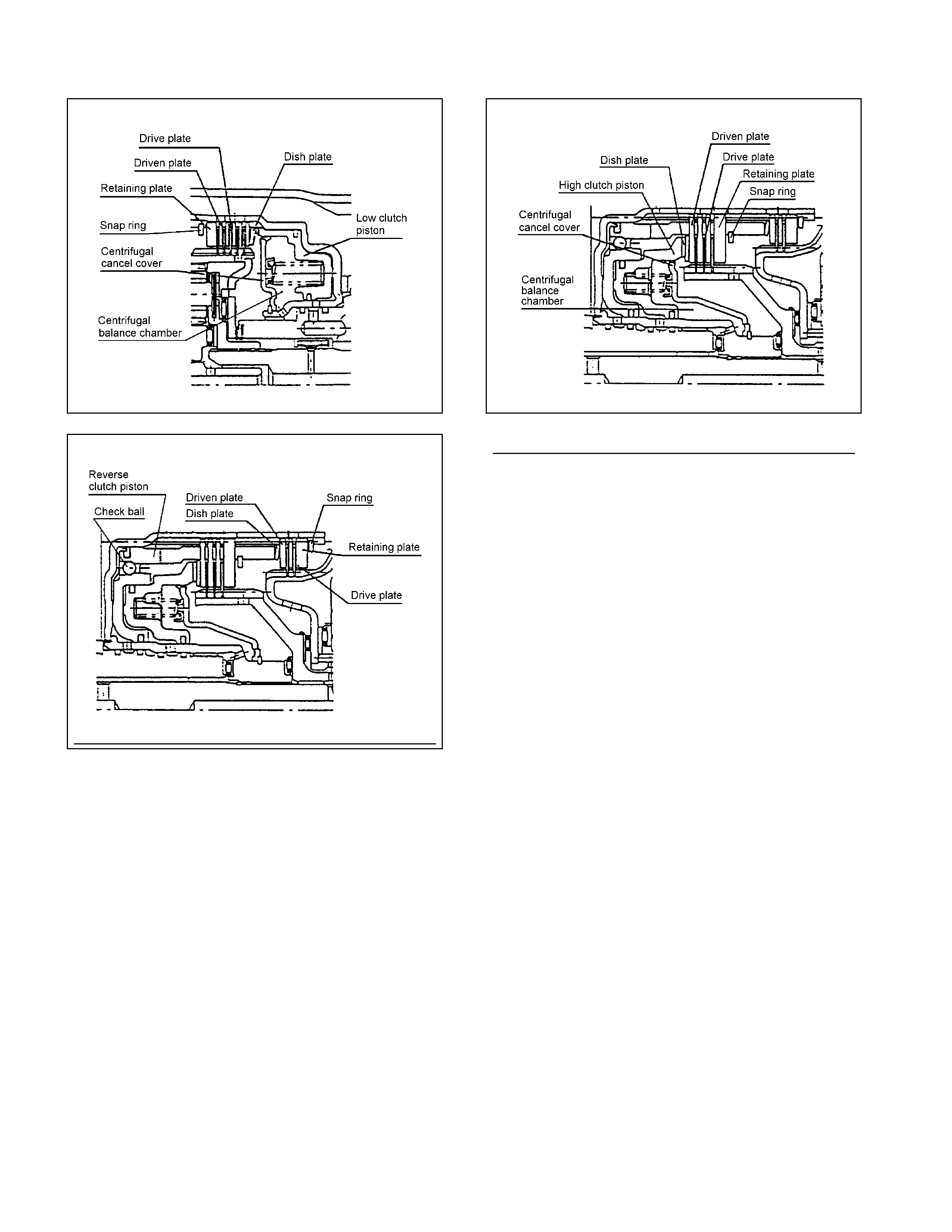
Figure 16. Construction of Low Clutch Figure 17. Construction of High Clutch
Figure 18. Construction of Reverse Clutch
2-4 Brake and Low & Reverse Brake (Multi-Plate Brake)
• The mult i-plate brake is composed o f drive pl at es and driven plates. By appl ying the o il pressure o nto the end
surface of the pl at es, t he clut ch is engaged or disengaged. The oil pressure i s adj ust ed with the cont rol valv e
according t o t he signal from the T CM.
• All bra kes use dish plat es to prev ent uncont rolled op erat ion of the clutches when engaged, causing a shock.
• The solenoid in the control valve is driven based o n the speed cha nge signal f r om TCM and moves t he shift
valv e, t hereby engaging the drive plate and driven plate through the piston of each clutch.
• Result antly, rot ation of each el ement of the planet ary gear unit is f ixe d.
• When the o i l pressure is removed, the pist on returns t o t he origi nal position by t he force of the return spring.
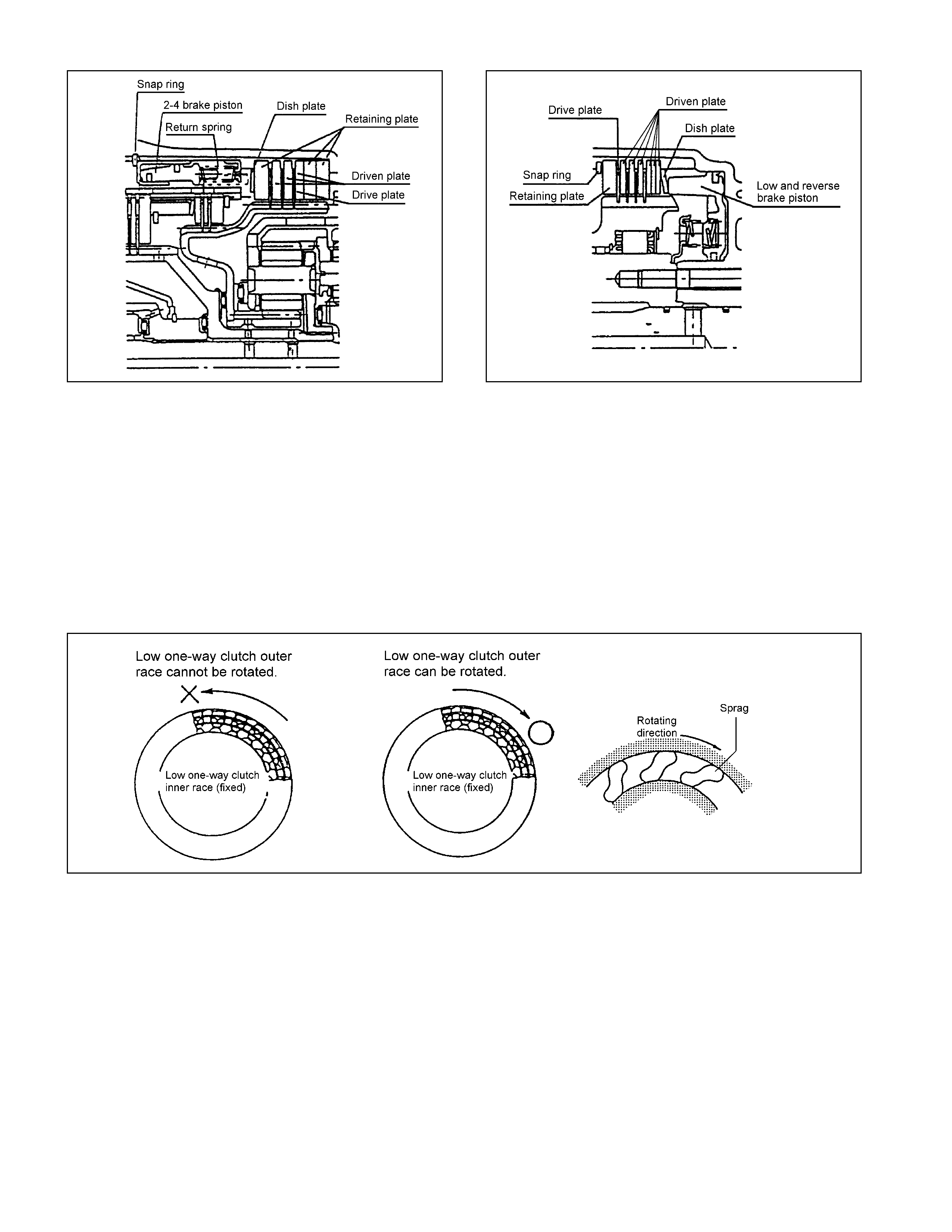
Figure 19. Construction of 2-4 Brake Figure 20. Construction of Low & Reverse Brake
Low One-Way Clutch
• The low one-w ay clutc h employs the sprag, which locks the count erclockwise rotat ion o f the front planetary
carrier and rear interna l g ear.
• The one-w ay clutch out er race is fitted with the low clutch drum and the inner race with the t r ansmissio n case.
• The out er race rot at es freely clockwise but when it at t empts t o rot ate counterclockw ise, the sprag functions t o
lock the outer race.
• When the v ehicle is traveling in 1st gear in the D, 3 or 2range, t he low one-wa y clutch loc ks t he rear int ernal
gear via the low clutch. It is left free in the 2nd, 3rd or 4th gear position.
Figure 21. Construction of Low One-way Clutch

Control Valve
• Employing the direct elect r onic control (Direct El ect ronic Shift Control: DES C) for the clutch pressure has
simplified t he oil pressure circuit, reduced the number of functiona l components and made the c ont rol valve
compact.
• The cont rol valve body is div ided into the upper bod y and lower body . All solenoids, oil pressure switch and
ATF thermo sensor are installed t o t he lower body.
• Three-way valve t ype solenoi ds providing high responsibility are employed. Some of the so lenoids are
switche d bet w e en ON and OFF and oth ers repeat ON an d O FF at 50Hz (dut y cycle syst em). Functional ly,
some supp ly output pressure when pow er is not suppli ed and others dr ai n t he out put pressure.
• When the s o l enoid is driven based on the signa l fro m the TCM, the oil pressure is changed. The valve i s
operated by the difference of the oi l pressure.
Figure 22. Construction of Valve Body

Line Pressure Solenoid
• The line pressure solenoid is turned ON or OFF according to t he si gnal from t he TCM. It sw it ches the line
pressure betw een high an d low pressure.
• While no power is suppl ied, the sole noid supplie s hi gh pressure.
Shift Solenoid
• The shi ft solenoid is o f the dut y cycle type whic h are turned ON or OFF at 50H z. The ratio of the O N an d O FF
time can be freely controlled in t he range of 0 - 100%.
• While no power is supplied, the solenoid sup plies out put pressure.
• The low clut ch solenoid a djusts the low cl ut ch pressure, t he high clutc h soleno id t he high clutch pressure, the
2-4 brake solenoid the 2-4 brake pressure and the low & reverse brake solenoid t he low & reverse bra ke
pressure respect iv ely .
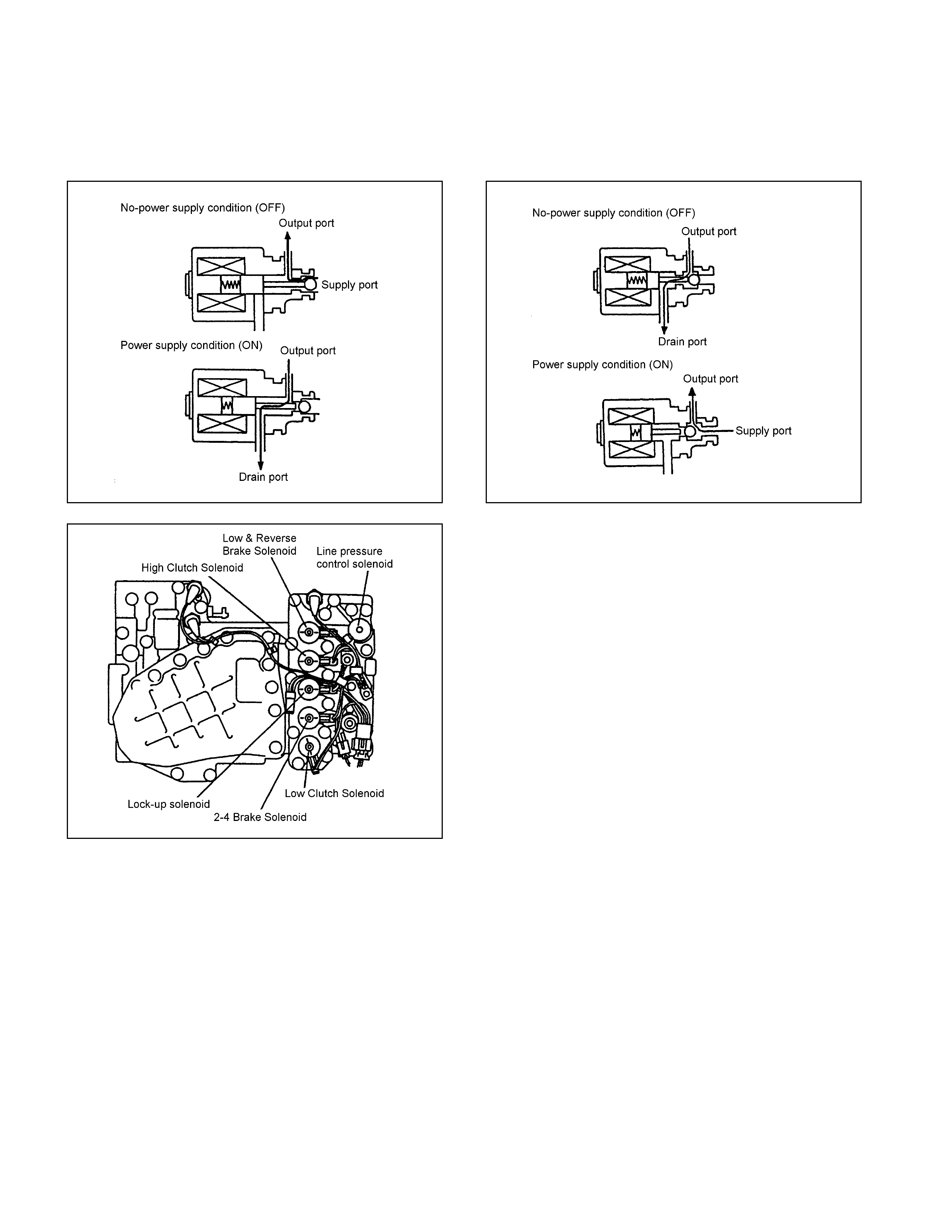
Lock-up Solenoid
• The lock-up solenoid is of the duty cycle type which is turned ON or OFF at 50Hz. The ratio of ON and OFF time
can be freely controlled in the range of 0-1 00%.
• While no pow er is supplie d, t he solenoid drains the output pressure.
Figure 23. Shift Solenoid Figure 24. Lock-up Solenoid
Figure 25. Location of Solenoid
Control Valve Fail-safe Function
• To prevent int erlocking due to engagement of more than three clutches and brakes at the same ti me, t he 2-4
brake fail-safe valve A a nd B, and the l ow & reverse brake fail-safe valve A and B are provi ded.
• When oi l pressure is generated in the h igh clutch and the low cl ut ch, t he 2-4 brake solenoid is turned ON to
drain the oi l pressure applied t o t he 2-4 brake.
• When oil pressure is g enerated in the h igh clutch or 2-4 brake, the low & reverse brake solen oid is turne d ON to
drain the oi l pressure applied t o t he low & reverse brake.

Figure 26. Fail-safe Function
Oil Pressure Switch
• The oil pressure switch detects the oil pressure supply condition to the clutch and brake and sends the detection
result to the TCM.
• The oil pressure switch is t urned O N w hen the oil pressure reaches the swit ch working pre ssure and tur ned
OFF whe n t he pressure decreases below t he specif ied value.
• The hig h clut ch oil pres sure swit ch det ects the high clutch oil pressure, 2-4 brake oil pressure sw it ch t he 2-4
brake oil pr essure, and t he low & reverse brake oil pressure switch the low & reverse brake oil pressure
respectively.
Figure 27. Oil Pressure Switch Figure 28. Location of Oil Pressure Switch
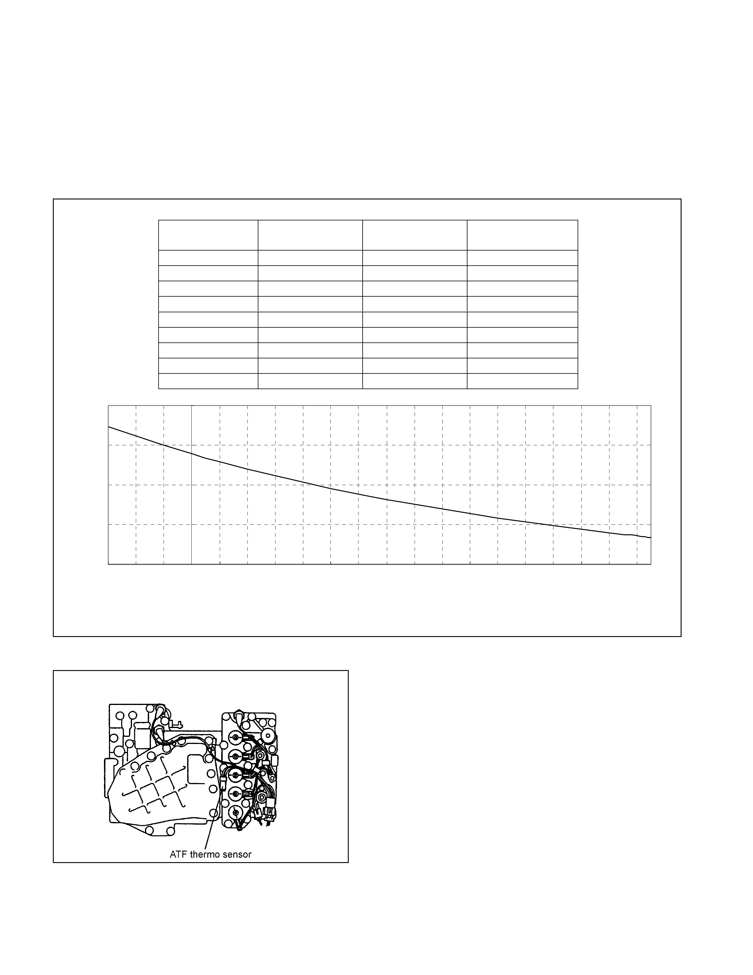
ATF Thermo Sensor
• The ATF thermo sensor detects the ATF temperature in the oil pan and sends signal to the TCM.
• The ATF thermo sensor is of the thermister type that the resistance value changes according to the ATF oil
temperature.
• The lower is the ATF temperature, the larger is the resistance, and vice versa.
• When the ATF temperature exceeds 135°C, the TCM lights up the ATF temperature warning lamp in the
meter. When the ATF temperature decreases below 128°C, the ATF temperature warning lamp goes out.
• The ATF thermo sensor is installed to the lower control valve body and integrated with the harness assembly.
10.0
100.0
1,000.0
10,000.0
100,000.0
-30 -20 -10 0 10 20 30 40 50 60 70 80 90 100 110 120 130 140 150 160
ATF Temperature (°C)
Resistance (Ħ
)
ATF Temperature
(deg. C) Resistance (Ohm)
(Approximately) ATF Temperature
(deg. C) Resistance (Ohm)
(Approximately)
-30 29,614 100 190
-20 16,705 110 149
-10 9,842 120 118
0 6,028 128 98
20 2,500 130 94
40 1,160 135 84
50 819 140 76
60 591 145 68
80 324 150 62
Figure 29. Characteristic of Thermo Sensor
Figure 30. Location of Thermo Sensor
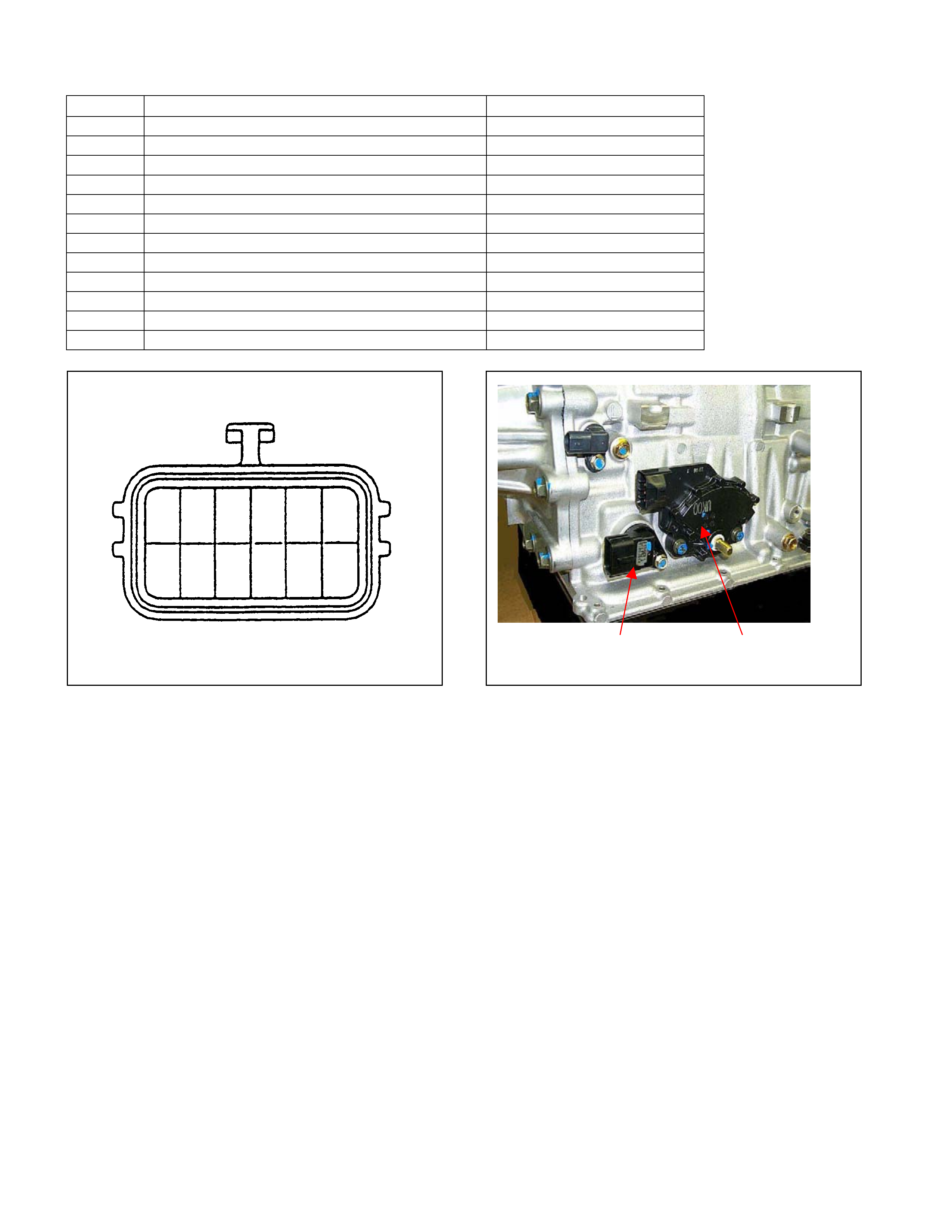
Terminal Assembly
Pin No. Connected to Connecte d TCM Pin No.
6 Line Pres sure S olenoid B23
12 Low & Reverse Br ake Oil Press ur e Switch B12
5 Low & Reverse Brake Duty Solenoid B6
11 Ground Return B22
4 Lock-up Duty Solenoid B17
10 High Clutch Duty Solenoid B8
3 Low Clutch Duty Solenoid B9
9 2-4 Brake Duty Solenoid B7
2 Oil Thermo Sensor B4
8 Oil Thermo Sensor Ground B14
1 High Clutch Oil Pressure Switch B20
7 2-4 Brake Oil Pressure Switch B1
123456
89101112 7
Terminal Assembly Inhibitor Switch
Figure 31. Pin Assignment Figure 32. Location of Terminal Assembly
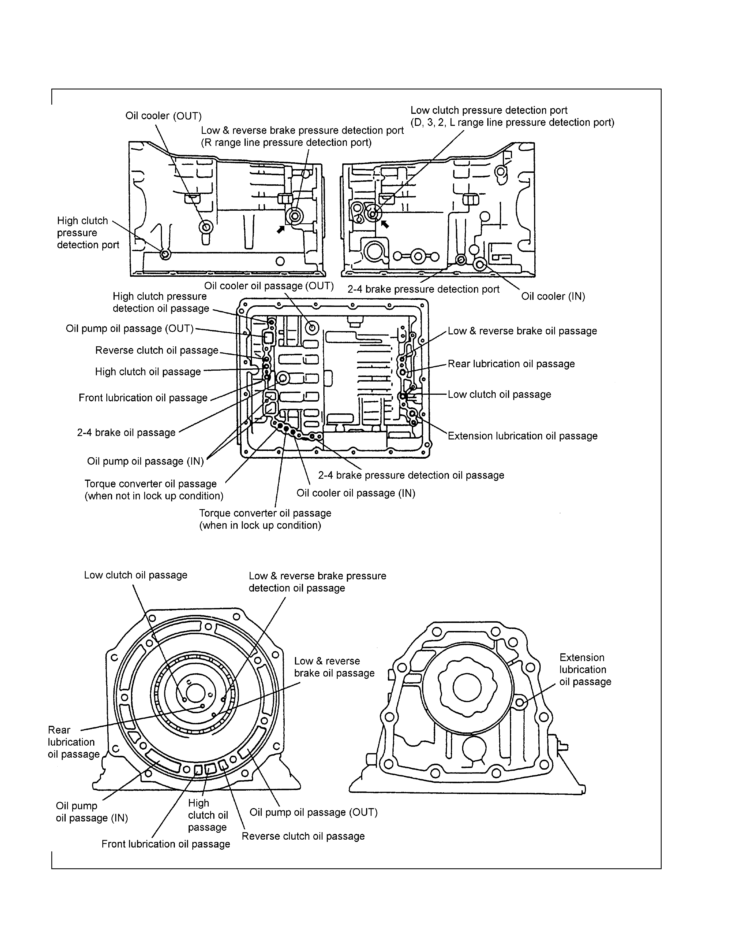
Oil Passage
Figure 33. Oil Passage of Transmission Case
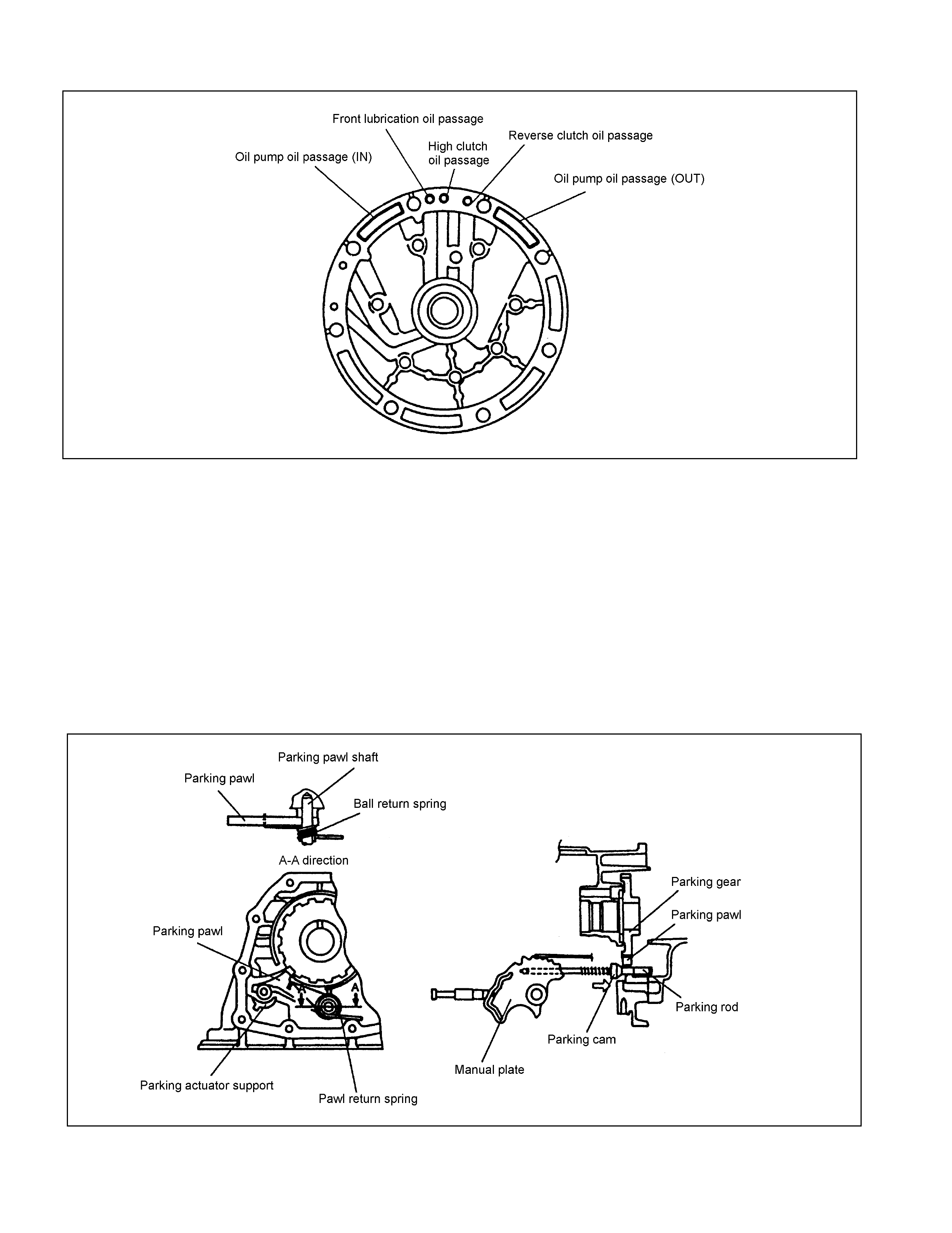
Figure 34. Oil Passage of Oil Pump
Parking Function
• By setting the select lev er to the P range, the par king pawl is enga ged with the parking gear and fixes the output
shaft.
• The mov ement of the sele ct lever moves the manua l shaft on the side surf ace of the AT. The manua l plate and
parking rod i n the AT are interlocked w ith the manua l shaft. When th e manual shaft moves, t he parking r od end
pushes up the p arking paw l.
• The parking pawl is engaged with the parking gear when pushed up, and fixes the output shaft.
• When the c lut ch is disengaged, it ret urns t o t he original p osition by t he force of the return spring fixed t o t he
parking pawl.
Figure 35. Parking Function
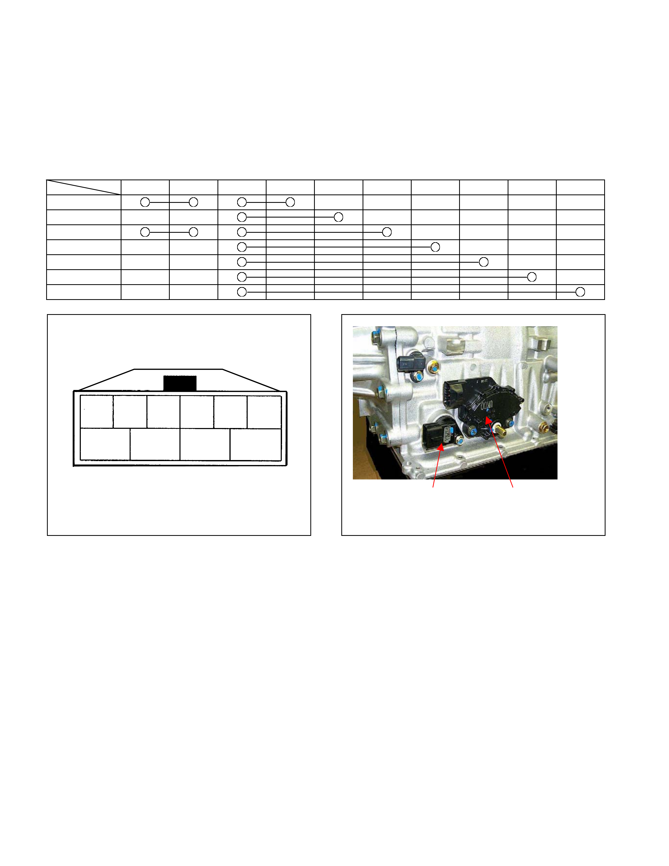
Inhibitor Sw itch
• The inhibitor switch is installed on the right side of the transmission main unit to detect the select lever
position.
• The inhibitor switch is connected with the starter SW circuit. The engine cannot be started when the select
lever is at any position other than t he P or N range.
• By mov ing the select lever, the combination of the inhibitor sw it ch pins is changed. The current range of TCM
is detected based on the combination of the pins.
10 7 3 2 4 8 5 1 9 6
P
R
N
D
3
2
L
6 345
10 98 7
2 1
Terminal A ssembly Inhibitor Swit ch
Figure 36. Pin Assignment Figure 37. Loc ation of Inhibitor Switch
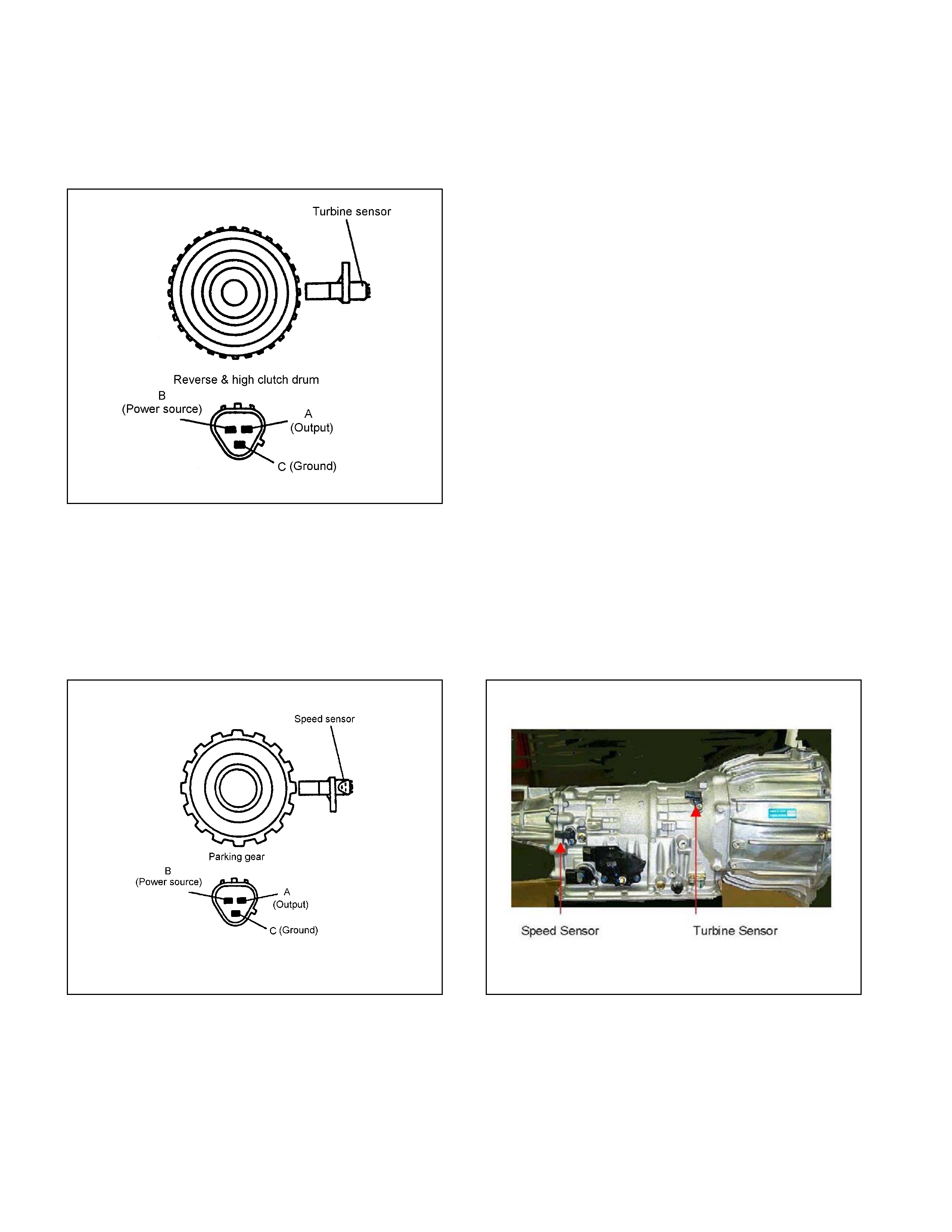
Turbine Sensor
• The turbine sensor is a hall element. It is installed to the front of the transmission case. The turbine sensor
converts the rot at ions of the reverse & high clutch drum fitted with the input shaf t by spline to pulse signal and
sends the signal to TCM.
• One t urn of the reverse & high clutch drum generates 32-pulse signal, which is sent t o the TCM.
Figure 38. Turbine Sensor
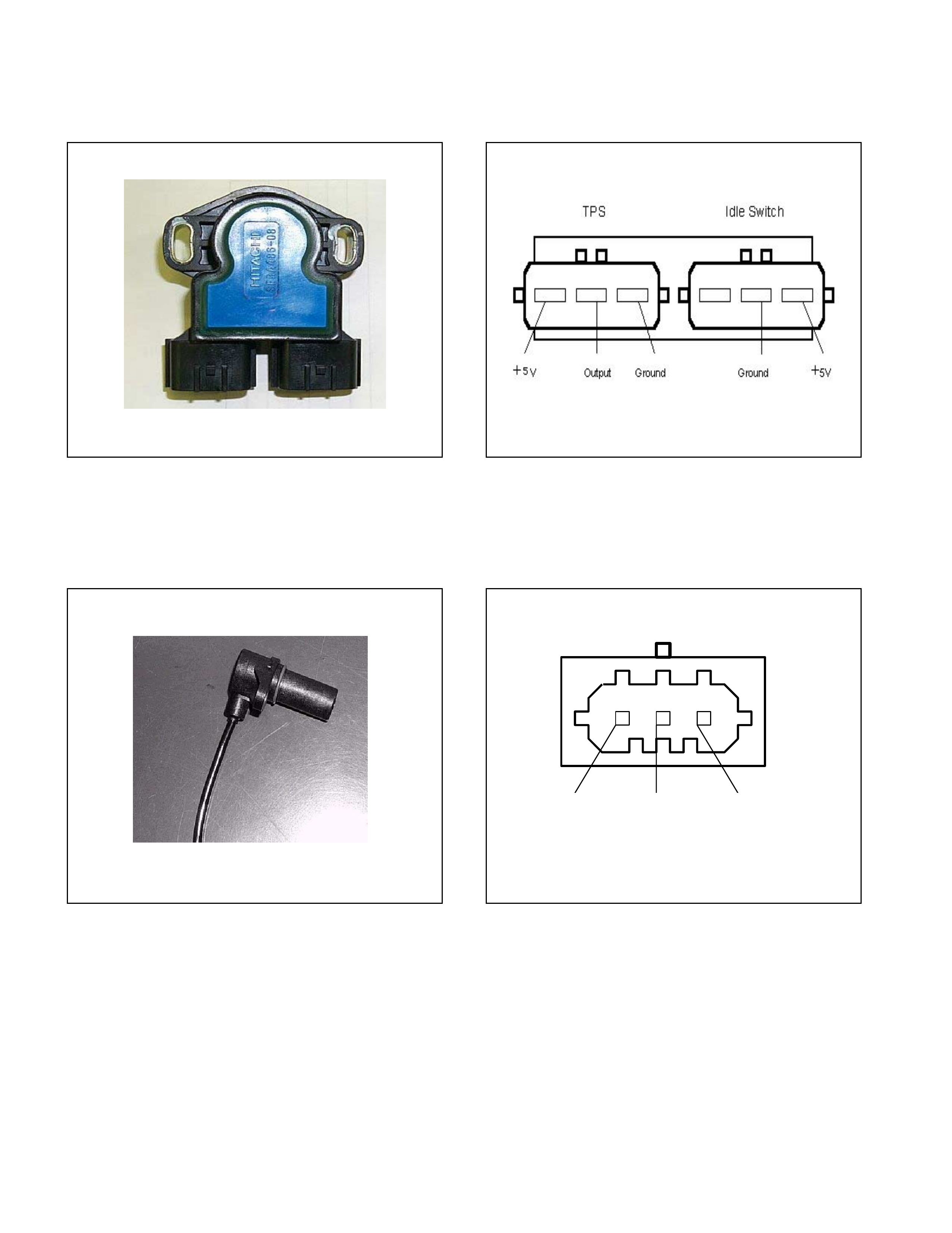
Speed Sensor
• The speed sensor is a hall element. It is installed to the rear of the transmission case. The speed sensor
converts the rotations of the parking gear fitted with the output shaft by spline to a pulse signal, which is sent
to the TCM.
• One t urn of the parking gear generates a 16-pulse signal to be sent to the TCM.
Figure 39. Speed Sensor Figure 40. Location of Turbine & Speed Sensor
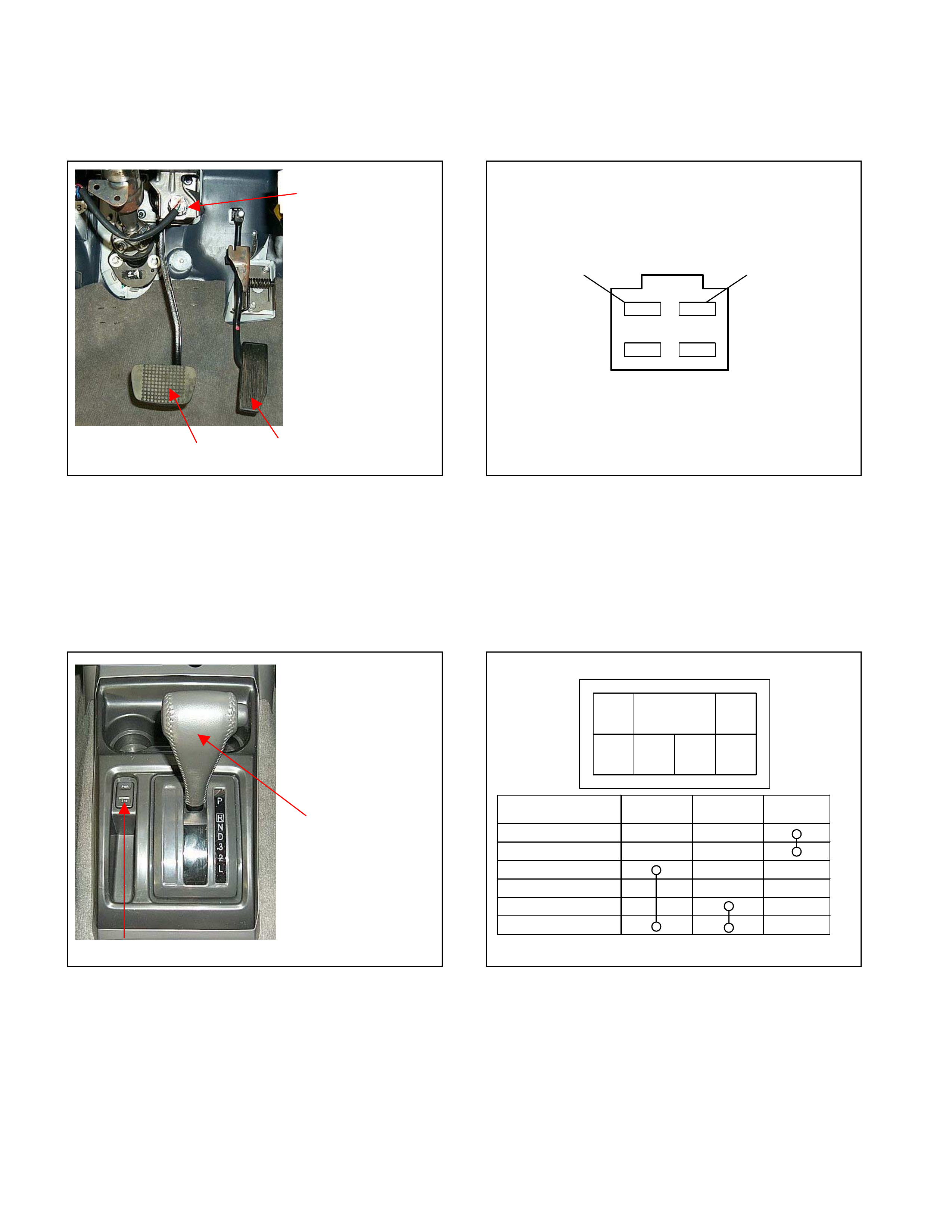
Throttle Position Sensor (TPS)
• Opening of the accelerat or pedal is converted to an elect r ic signal, w hich is t r ansmitted from ECM to TCM.
Figure 41. Throttle Position Sensor Figure 42. Pin Assignment
Engine Speed Sensor (=TDC Sensor)
• The engine speed sensor converts the crankshaft from the TDC (Top Dead Center) sensor rotation to a pulse
signal, which is tr ansmitted from ECM to TCM.
Ground Signal Shield Line
Figure 43. TDC Sensor Figure 44. Pin Assignment
Brake Switch
• The brake switch is installed to the brake pedal. W hen the driver steps on the brake pedal, an electric signal
is sent to the TCM.
Brake Switch
A
ccelerator Pe dal
Brake Pedal
TCM A3 +12 V
Figure 45. Brake Switch Figure 46. Pin Assignment
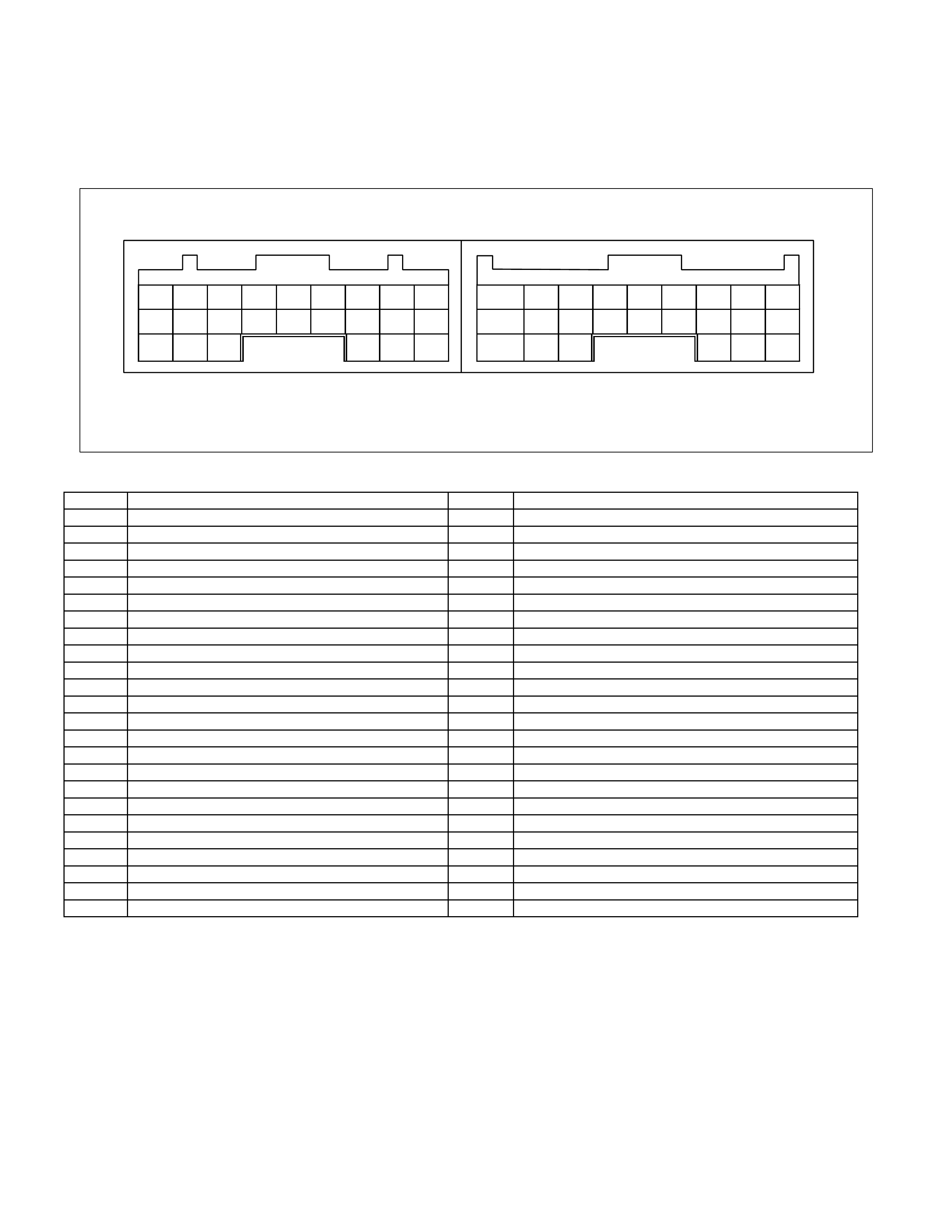
Mode Select Switch
• The mode select switch is installed beside the select lever. When the driver selects the PWR or 3rd, an
electric signal is sent to t he respect ively. It turns O N the indicator lamp in the meter.
• The 3rd START mode can be used only in the D range.
Mode Sele c t Switch
Gear Sele ct Lever
Power 3rd
Illumination
Lamp
1 (Illum inat ion)
2 (Ground)
3 (TCM A24)
4 (No Connection)
5 (TCM A11)
6 (Ground)
2 1
6 5 4 3
Figure 47. Mode Select Switch Figure 48. Pin Assignment
Transmission Control Module (TCM)
• The TCM is fitted side of brake pedal by means of two stud bolts.
• The TCM judges necessary line pressure, gear shifting point and lock-up operation based on electrical
signals from switches and sensors and sends appropriate signals to solenoids.
B9 B
8
B7 B6 B5 B
4
B3 B2 B1 A9 A8 A
7
A6 A5 A4 A3 A2 A1
B18B17B16B15B14B13B12B11B10 A1
8
A17A16A15A1
4
A13A12A11A10
B24B23B22 B21B20B19 A2
4
A23A22 A21A20A19
Connect to White Connector Connect to Grey Connector
Figure 49. Pin Assignment
Pin No. Pin Assignment Pin No. Pin Assignment
B1 2-4 Brake Oil Pressure Switch A1 V BATT (Battery Back-up Power Supply)
B2 2 Range Switch A2 P Range Switch
B3 Turbine Sensor A3 Brake Switch
B4 ATF T hermo Sensor A4 3rd Start Indicator Lamp
B5 Ground A5 K-Line Signal (Tech 2 Serial Communication)
B6 Low & Reverse Brake Duty Solenoid A6 No Connection
B7 2-4 Brake Duty Solenoid A7 Engine Speed Sensor
B8 High Clutch Duty Solenoid A8 No Connection
B9 Low Clutch Duty Solenoid A9 No Connection
B10 N Range Switch A10 Vehicle Speed Sensor Out (2WD Only)
B11 D Range Switch A11 3rd START Select Switch
B12 Low & Reverse Brake Oil Pressure Switch A12 4L Mode Switch (4WD Only)
B13 Vehicle Speed Sensor A13 No Connection
B14 ATF Thermo Sensor Ground A14 No Connection
B15 Ground A15 No Connection
B16 No Connection A16 Throttle Position Sensor
B17 Lock-up Duty Solenoid A17 3 Range Switch
B18 V ign (Ignition Power Supply) A18 DIAG Switch (Tes t Switch)
B19 R Range Switch A19 A/T OIL TEMP Indicator Lamp
B20 High Clutch Oil Pressure Switch A20 CHECK TRANS Indicator Lamp
B21 L Range Switch A21 POWER DRIVE Indicator Lamp
B22 Ground (Shift Solenoid) A22 No Connection
B23 Line Pressure Solenoid A23 No Connection
B24 V ign (Ignition Power Supply) A24 POWER DRIVE Select Switch
Control Mechanism
Content Of Function And Control
Item Description
Line pressure control TCM issues a signal according to the vehicle traveling, engine load and other conditions to
TCM and the ON/OFF type line pressure solenoid is driven to switch the line pressure to
high or low pressure.
The line pressure solenoid is switc hed to the low pressure s ide when the solenoid is turned
ON (power supplied) and to the high pressure side when turned OFF (no power supplied).
In the forward travel range (D, 3, 2, L range), the line pres sure dec reases lower than that in
the P, N, and R range through the oil pressure circuit for the forward travel range.
Gear shift control The TCM issues a shift solenoid drive signal based on the traveling mode switch, inhibitor
switch, vehicle speed, throttle opening and other input signal to control the optimum gear
position automatically.
Speed change features have been set up to the TCM; the normal mode is suited to usual
traveling and the power mode is appropriate when the vehicle is loaded or acc elerates the
speed.
In addition, speed change features used only for high oil temperature, hill climbing, and
down have been set up to the TCM, which are automatically switched depending on the
traveling conditions.
When the oil temperature is low (below 10°C), speed change from the third to the fourth
speed is prohibited by the gear shift control.
Shift pattern selection
control According to a vehicle condition, the TCM selects the following shift pattern.
Selection
Priority Shift Pattern 3rd Start
Lamp Power Drive
Lamp
High High Temperature OFF OFF
3rd Start ON
4L
Power SW Off
OFF
Down Slop Power SW On
Power ON
Up Slope
Low Normal
OFF
OFF
- High temperature mode -
High temperature mode setting condition
ATF temperature: More than 123°C
Above condition is met for more than 10 seconds.
High temperature mode cancel condition
ATF temperature: Less than 116°C
Above condition is met for more than 10 seconds.
- 3rd start mode -
3rd start mode setting condition
3rd start switch: On → Off (Pushed)
Vehicle speed: Less than 11km/h
ATF temperature: Less than 115°C
Throttle position: Less than 8%
Select lever position: D range
Above conditions are met at the same time.
3rd start mode reset condition
3rd start switch: On → Off again(Pushed again)
Vehicle speed: More than 34km/h
Select lever position: Other than D range

Item Description
At least, one of above conditions is met.
- 4L mode -
4L mode setting condition
‚SL switch: On
Vehicle speed: More than 5km/h
Above conditions are met at the same time.
4L mode reset condition
4L switch: Off
Vehicle speed: Less than 4km/h
Above conditions are met at the same time.
- Down slope mode -
Down slope mode setting condition
Brake switch: On
Engine idle condition: More than 2.5 seconds
Select lever position: D or 3 range
Vehicle speed: More than 55km/h
Vehicle speed change: +1km/h
Above conditions are met at the same time.
Down slope mode reset condition
Engine idle condition: Not idle condition
Select lever position: Other than D or 3 range
At least, one of above conditions is met.
- Power Mode -
W hen power drive switch is On at only D range, 3 range and 2 range, the shift change is
performed by 1 – 4 speed based on shift diagram set as power pattern.
- Up slope mode -
TCM compares up slope reasoning value calculated from average throttle angle with one
calculated from average acceleration, regards smaller value as up slope.
And up slope reasoning value is calculated from present vehicle speed.
TCM compares the former with the latter judges as up slope mode, when the former is
bigger than latter.
Lock-up control The lock-up solenoid adjusts the pressure based on the signal from the TCM according to
the vehicle speed, throttle opening and other input signals based on the pre-set lock-up
point to control the lock-up.
Smooth lock-up control engages and disengages the clutch smoothly at the time of lock-up.
W hen the oil temperature is low (below 20°C) or high (above 128°C), lock-up is prohibited
even when the vehicle is at a lock-up speed.
The lock-up is disengaged also when the throttle is closed.
Direct electronic shift
control (DESC ) The duty cycle type solenoid is used for each clutch and brake. The solenoid adjusts the
clutch pressure to be s uited to the engine load and vehicle traveling c ondition based on the
signal from the TCM. The pressure switch provided in the control valve oil passage sends
the oil pressure condition to the TCM to control the dis engagement and engagement of the
clutch and brake directly and finely.

Item Description
Learning control Learning is controlled to correct the oil press ure control timing to engage or disengage the
clutch optimally in order to compensate changes of the engine performance and changes
of the transmission with time. It is controlled to bring the speed-change time closer to the
value pre-set to the TCM.
Fail-safe function In case of malfunction of the vehicle speed sensor, throttle position sensor, all solenoids or
inhibitor switch, TCM automatically begins fail-safe control to minimize effects on driving.
The gear is fix ed at the 3rd-speed position and power supply to the solenoid is shut off so
that the solenoid does not work nor lock up.
Self-diagnosis function Parts required for controlling the automatic transmission are provided with a self-diagnosis
function. When any trouble occurs, the check trans indicator lamp blinks to warn the driver.
The trouble code is memorized in the TCM.
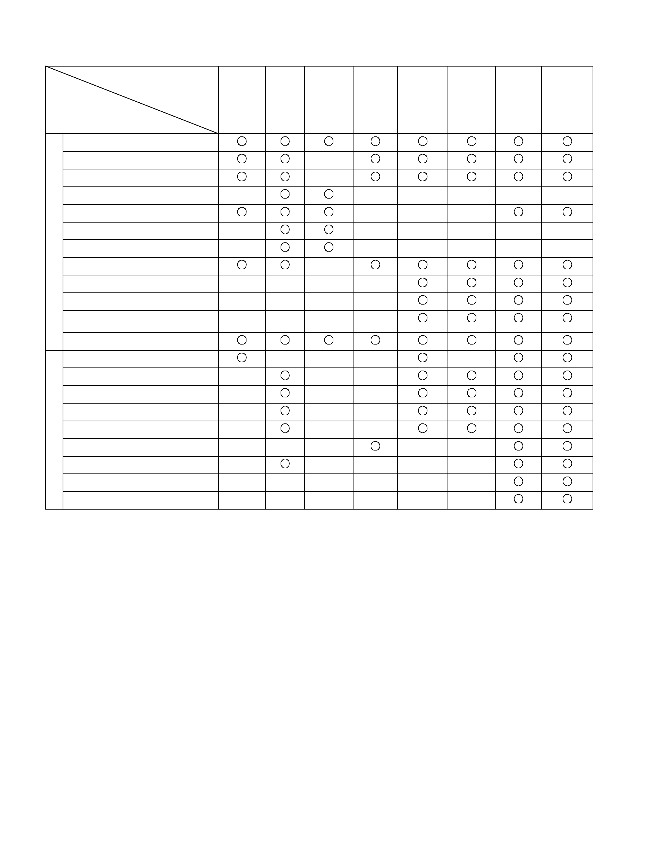
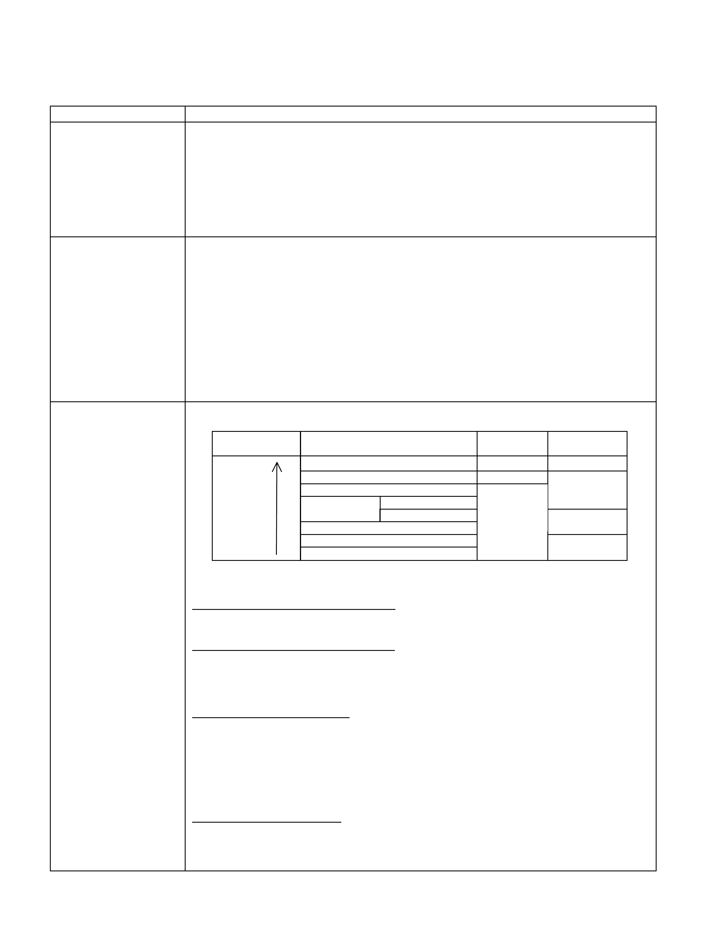
Control Item, Input And Output
Control item
Item
Line
pressure
control
Gear
shift
control
Shift
pattern
selection
Lock-up
control
Direct
electronic
shift
control
(DECS)
Learning
control
Fail-safe
function
Self-
diagnosis
function
Speed sensor
Turbine sensor
Engine speed sensor
Brake switch
Inhibitor switch
Mode select switch
4L switch (4WD Only)
ATF thermo sensor
High clutch oil pressure switch
2-4 brake oil pressure switch
Low & Reverse brake oil pressure
switch
Input
Throttle position sensor
Line pressure solenoid
Low clutch solenoid
High clutch solenoid
2-4 brake solenoid
Low & Reverse brake solenoid
Lock-up solenoid
Shift pattern indicator lamp
ATF temperature indicator lamp
Output
Check trans indicator lamp
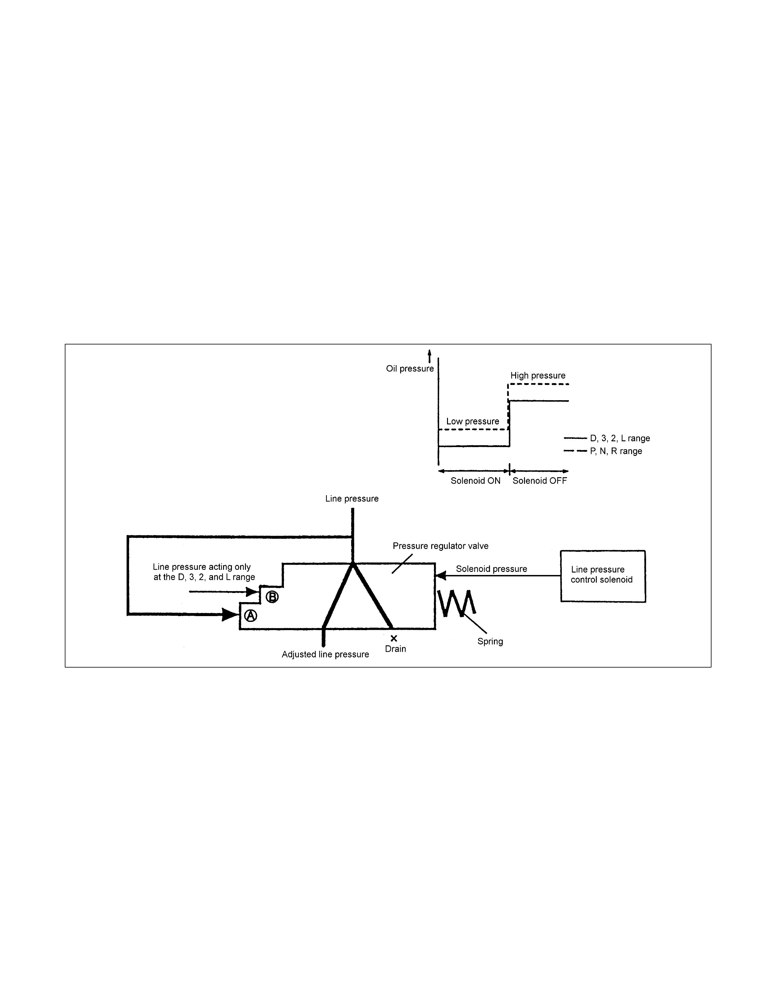
Line Pressure Control
• Either the throttle opening, vehicle speed, turbine rotational speed, ATF temperature or speed-change range
signal appropriate under the situation is issued from the TCM. The ON/OFF type line pressure solenoid is
actuated and swit ches t he line pressure t o high or low pressure.
• The line pressure generated by the oil pump acts on the point A of the pressure regulator valve. W hen the
pressure control solenoid is turned ON by the signal from the TCM, the solenoid pressure does not act. The
line pressure is adjusted to match the spring force acting on the right side of the pressure regulat or valve.
• When the pressure control solenoid is turned OFF, the solenoid pressure acts so that the line pressure is
adjusted to match the spring force acting on the right side of the pressure regulat or valve.
• As a result, the line pressure is adjusted to be low when the pressure control solenoid is ON and to be high
when the pressure control solenoid is O FF.
• In the D, 3, 2 and L range, the line pressure through the oil pressure circuit acts onto the point B of the
pressure regulator valve and the pressure regulator valve moves so as to increase the pressure to be
drained, so that the line pressure is adjusted to be lower than the P, N, and R range by the difference of area
at the point B.
Figure 50. Line Pressure Control
Lock-Up Control
• The lock-up solenoid adjusts the pressure and controls the lock-up based on the pre-set lock-up point,
according to the vehicle speed, throttle opening, engine rotations, turbine rotations and ATF temperature
input signal, based on the signal from the TCM.
• Smooth lock-up control is employed to engage or disengage t he clut ch smoothly at the time of lock-up.
• W hen the oil temperature is low (below 20°C) or high (over 128°C), lock-up is disengaged even though the
vehicle is at t he lock-up speed.
• The lock-up is disengaged also when the throttle is closed.
• W hen the TCM determines the lock-up engagement, the DUTY ratio to supply power to the lock-up solenoid
is gradually increased (5% to 95%) and the oil between the lock-up piston and converter cover is gradually
drained.
As a result, the lock-up piston is fitted slowly under pressure to the converter cover securing smooth lock-up
engagement.
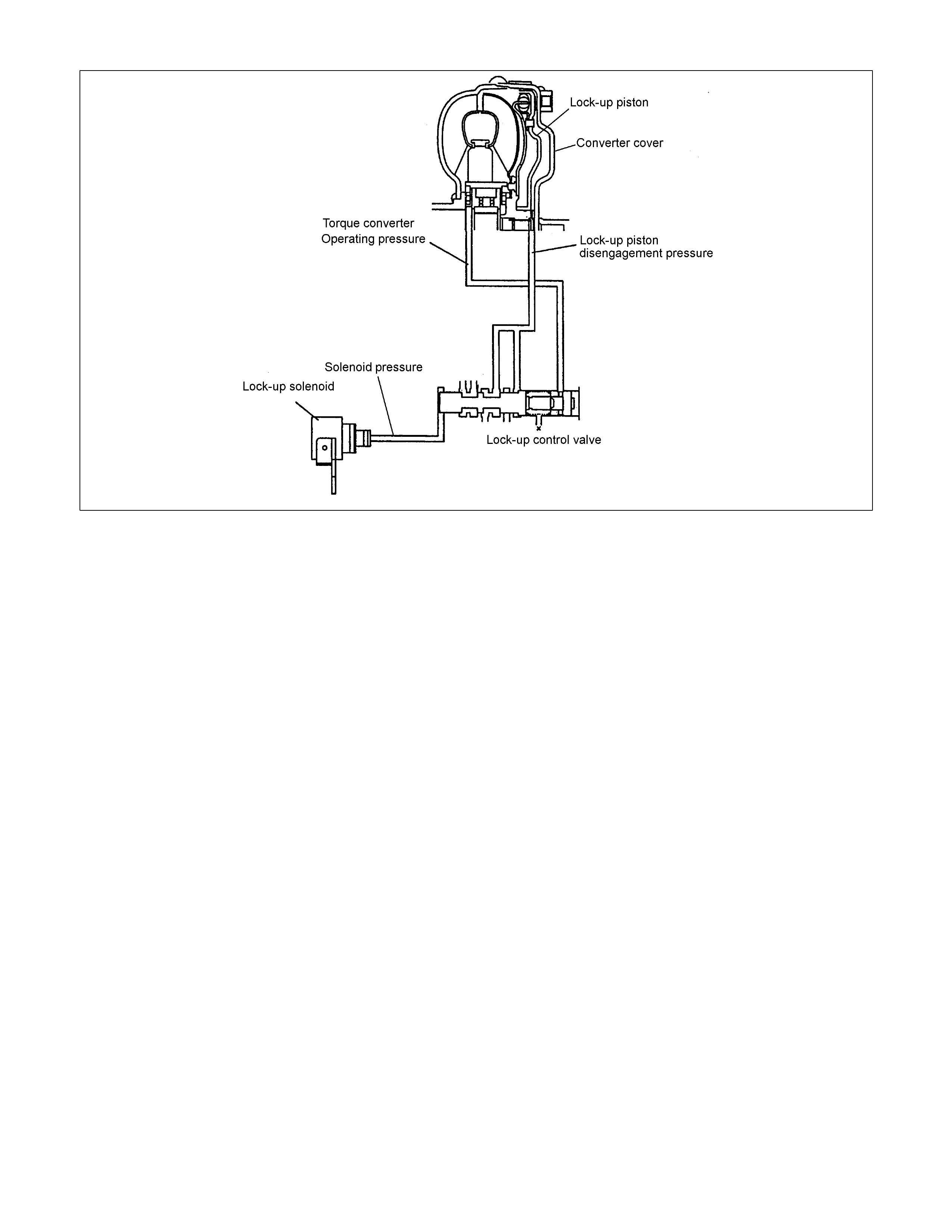
Figure 51. Lock-up Control
Direct Electric Shift Control (DESC)
Feature
• Based on the each switch signals (low & reverse brake pressure, 2-4 brake pressure & high clutch pressure)
and sensors signals (turbine sensor, speed sensor, engine speed signal & throttle position signal), duty cycle
type solenoid adjusts the clutch pressure to match the engine load and vehicle traveling condition. By this
result, controlling the engagement and disengagement of the clutch and brake pressure is directly and
accurately cont rolled via TCM, which is not realiz ed in previous accumulator ty pe.
Operation
• Instead of the previous system (on/off type of shift solenoid and shift valve), the combination of duty cycle
type solenoid and amplifier (Amp) valve are used to adjust the clutch pressure to match the engine load and
vehicle traveling condition based on the signal from the TCM, and the pressure switch provided in the oil
passage of the control valve transmits the oil pressure condition at that time to TCM, thus controlling the
engagement and disengagement of the clutch and brake directly and finely.
• When the gear is shifted from the 2nd to 3rd, 3rd to 4th (O/D), 4th (O/D) to 3rd and 3rd to 2nd, the clutch
pressure on the engagement side and that on the disengagement side are simultaneously controlled.
As a result, engine racing or clutch drag is prevented securing smooth and quick speed change response
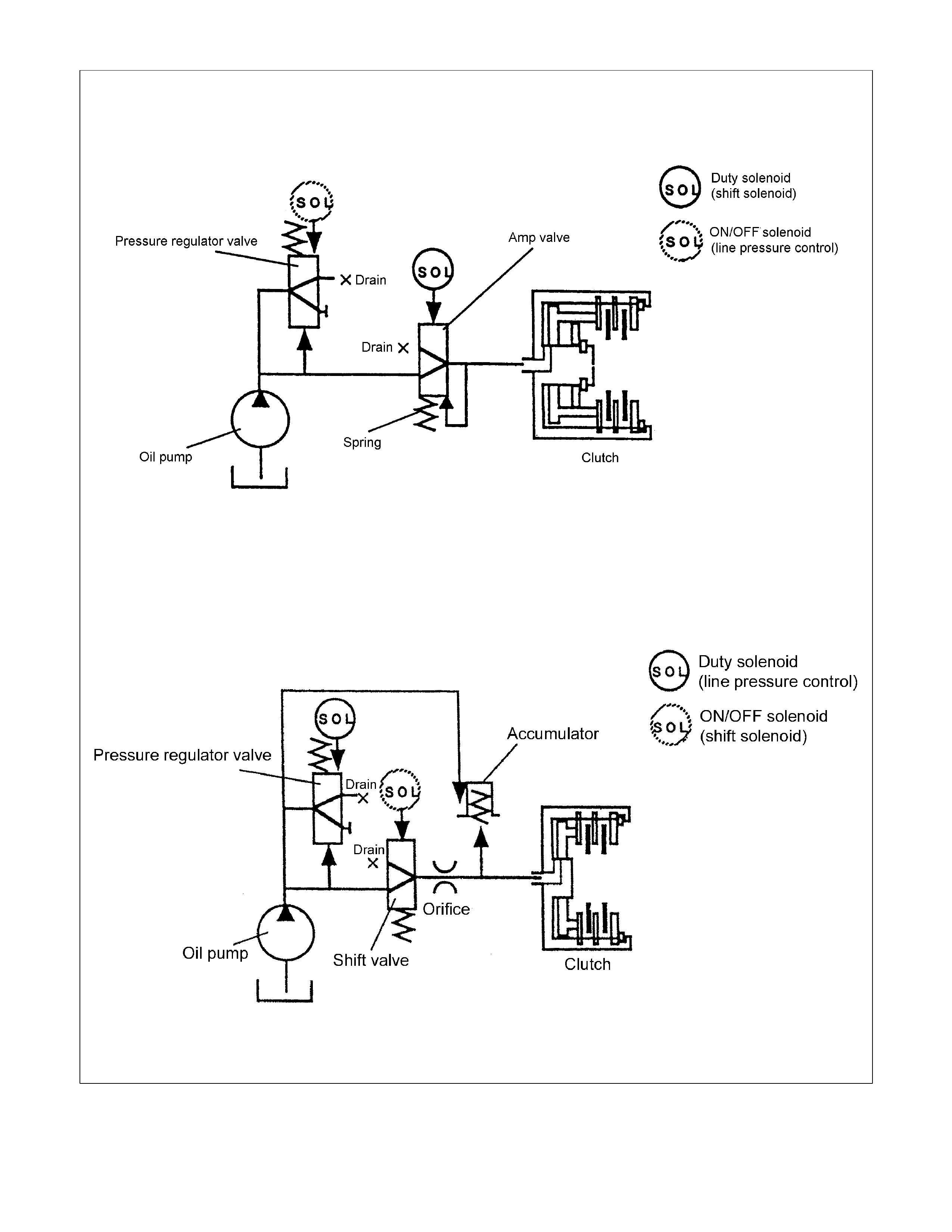
Direct Electric Shift Control
Previous Model
Figure 52. Direct Electric Shift Control (DESC)
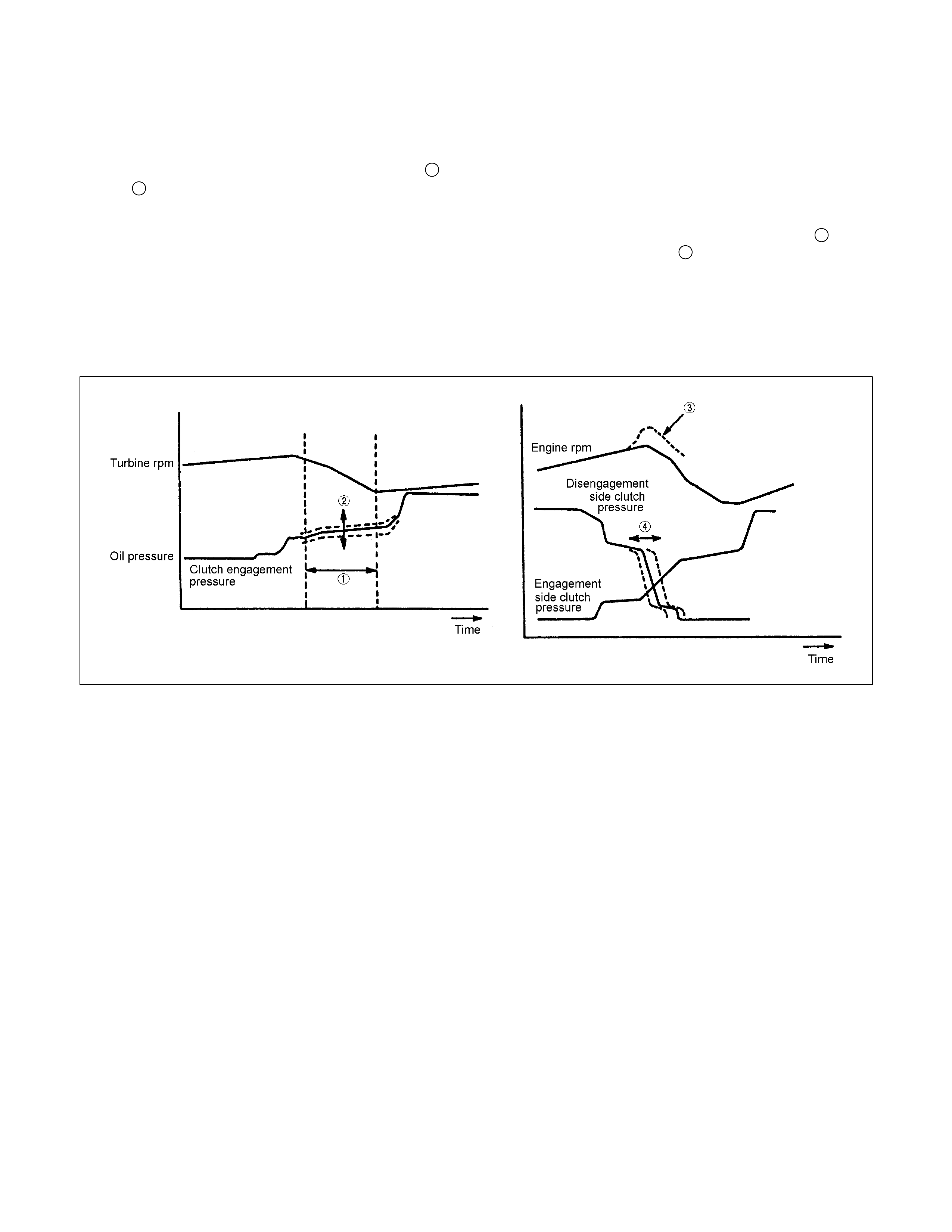
Learning Control
• Oil pressure control timing is optimally corrected at the time of clutch engagement and disengagement and
controlled to bring the speed-change time to the value preset to t he TCM and compensate the changes of the
engine performance and changes of the transmission with time.
• W hen the gear is shifted, the clutch pressure 2 is corrected so that the shift speed is as near as the target
value 1 preset to the TCM and the changes in the engine perform ance and the changes of the transmission
with time can be compensated for based on the last shift speed results.
• When the clutch is operated to shift the gear, the time of the clutch oil pressure release timing 4 on the
disengagement side is optimally corrected so that the changes of the engine rpm 3 are optimised.
Note:
• W hen the battery terminal is disconnected, contents of learning are cleared and resultantly the speed change
shock may increase. After the vehicle has tr aveled, learning is repeated and t he shock decreases gradually.
Figure 53. Learning Control

Major Input/Output Component And Their Functions
Speed sensor Detects output shaft revolution and sends rpm signal to TCM.
Turbine sensor Detects input shaft revolution and sends rpm signal to TCM.
Engine speed sensor Inputs engine revolution from engine control computer.
Brake switch Detects brake pedal operated by the driver and sends signal to
TCM.
Inhibitor switch Detects select lever position and sends signal to TCM.
Mode select switch Detects "Power Drive" or "3rd Start" selected by the driver and
sends signal to TCM.
4L switch (4WD Only) Inputs 4L mode from transfer control computer.
ATF thermo sensor Detects ATF temperature and sends signal to TCM.
High clutch oil pressure switch Detects high clutch supply oil pressure and sends signal to
TCM.
2-4 brake oil pressure switch Detects 2-4 brake supply oil pressure and sends signal to
TCM.
Low & Reverse brake oil pressure switch Detects low & reverse brake supply oil pressure and signal to
TCM.
Throttle position sensor Inputs throttle opening angle from engine control computer.
Input
TCM Judges necessary line pressure, gear shifting point and lock-up
operation based on electrical signals from switches and
sensors and sends appropriate signals to solenoids.
Line pressure solenoid Regulates oil pump delivery pressure to the appropriate line
pressure for current driving condition based on signal from
TCM.
Low clutch solenoid Selects appropriate gear shifting position for current driving
condition and regulates low clutch supply oil pressure based on
signal from TCM.
High clutch solenoid Selects appropriate gear shifting position for current driving
condition and regulates high clutch supply oil pressure based
on signal from TCM.
2-4 brake solenoid Selects appropriate gear shifting position for current driving
condition and regulates 2-4 brake supply oil pressure based on
signal from TCM.
Low & Reverse brake solenoid Selects appropriate gear shifting position for current driving
condition and regulates low & reverse brake supply oil
pressure based on signal from TCM.
Lock-up solenoid Regulates lock-up pressure to appropriate level for current
driving conditions based on signal from TCM.
Mode indicator lamp Indicates POWER DRIVE or 3rd START switch position.
Speed meter signal (2WD Only) Outputs vehicle speed to speed meter.
A/T OIL TEMP indicator lamp Indicates A/T OIL TEMP indicator lamp in case of high
temperature.
Output
CHECK TRANS indicator lamp Indicate s CHECK TRANS indicator lamp in case of
malfunction.
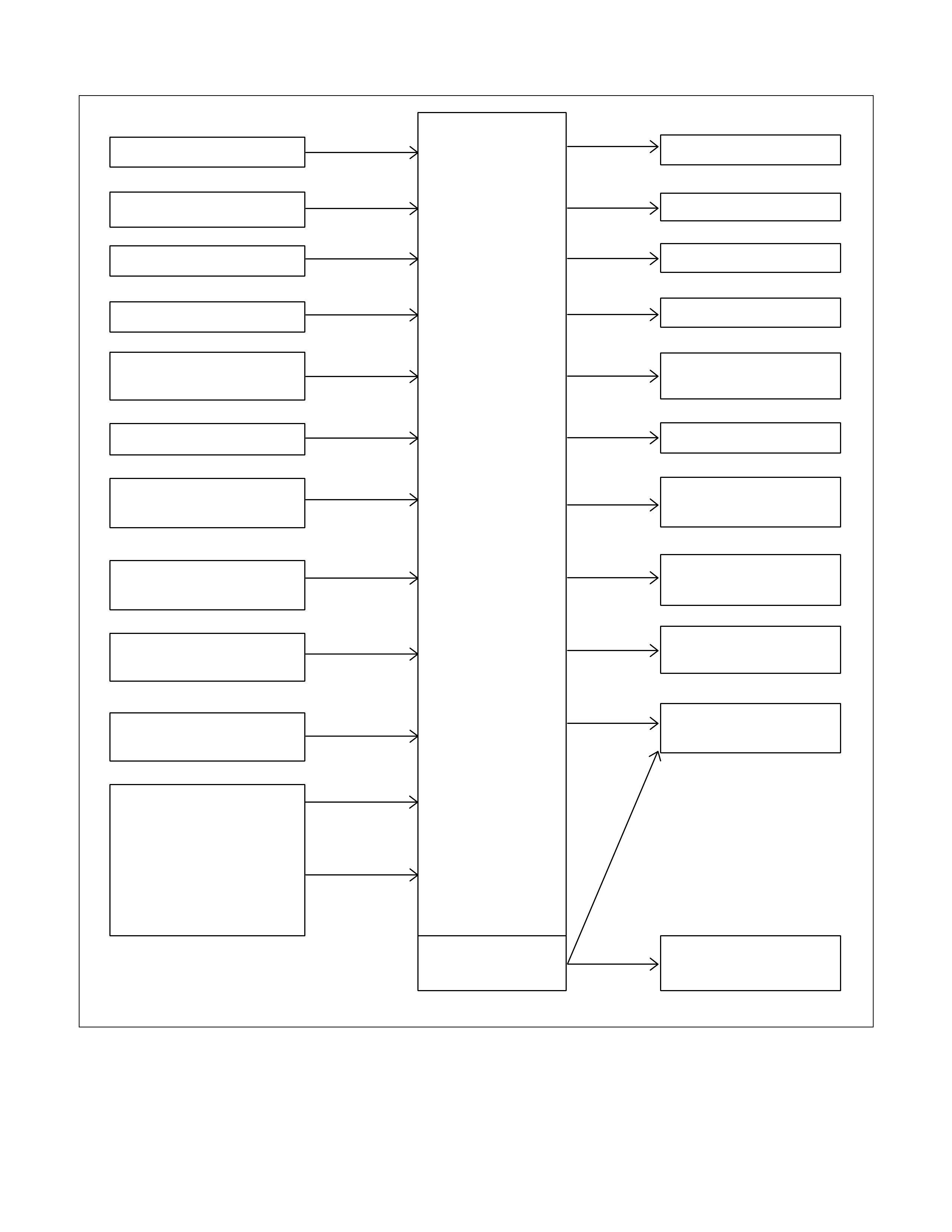
Control Circuit Block Diagram
Speed sensor
Turbine sensor
Brake switch
Inhibitor switch
Power drive, 3rd start
switch
ATF oil thermo sensor
High clutch oil pressure
switch
2-4 brake oil pressure
switch
Low & reverse brake oil
pressure switch
Transfer control module
(4WD Only)
Engine Control Module
(ECM)
Line pressure solenoid
Low clutch solenoid
High clutch solenoid
2-4 brake solenoid
Low & reverse brake
solenoid
Lock-up solenoid
ATF temperature
indicator lamp
Speed meter (2WD
Only)
Power, 3rd start indicator
lamp
Check trans indicator
lamp
Data link connector
Self-diagnosis
function
Transmission
Control
Module
(TCM)
4L mode
Engine
speed
Throttle
angle
Figure 54. Control Circuit Block Diagram
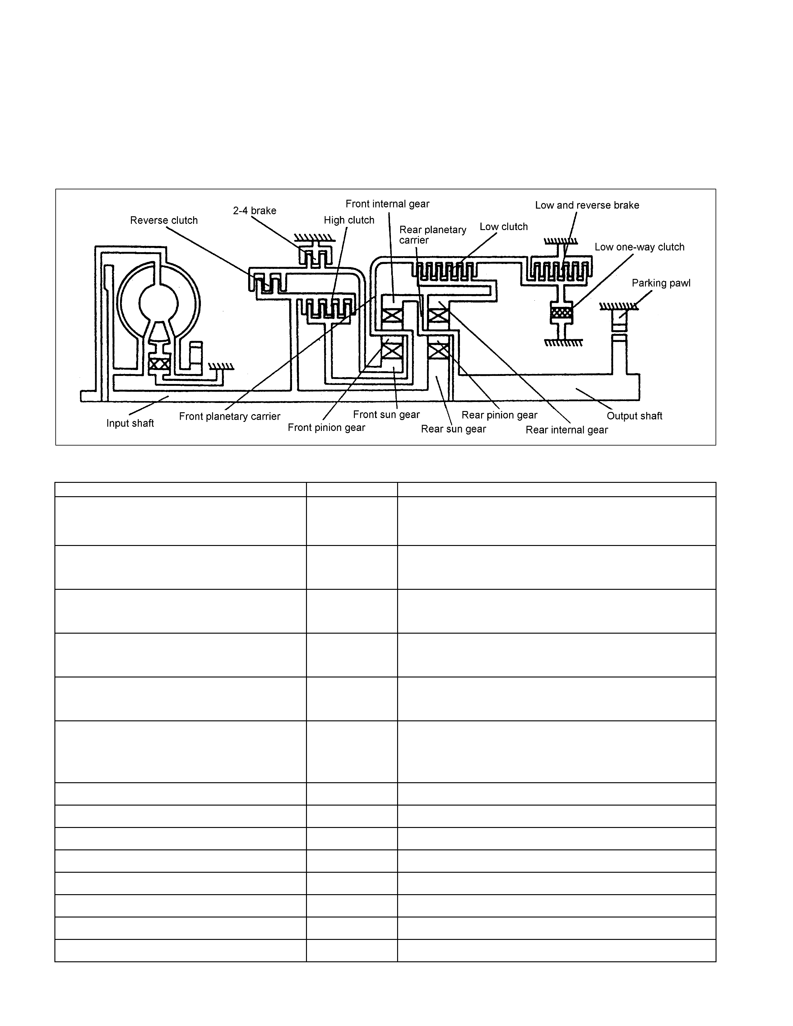
Gear Train (Transmission Mechanism)
Operation And Hydraulic Circuit
Construction And Operation
The JR405E consists of two sets of planetary gears, three multiple plate clutches, two multiple plate brakes and
one one-way clut ch.
Component Name And Function
Component Name Symbol Function
Low Clutch L/C Connects the front planetary carrier to the rear internal
gear.
Engaged at 1st, 2nd and 3rd gear.
High Clutch H/C Connects the input shaft to the front planetary carrier.
Engaged at 3rd and 4th (O/D) gear.
Reverse Clutch R/C Connects the input shaft to the front sun gear.
Engaged at Reverse gear.
Low & Reverse Brake L&R/B Locks the front planetary carrier.
Engaged at L range and Reverse gear.
2-4 Brake 2-4/B Locks the front sun gear.
Engaged at 2nd and 4th (O/D) gear.
Low One-way Clutch L/O.C Allows the front planetary carrier to turn forward
(clockwise) but locks to opposite direction
(counterclockwise).
Operative when accelerating.
Low Clutch Solenoid L/C.S Regulates low clutch pressure.
High Clutch Solenoid H/C.S Regulates high clutch pressure.
Low & Reverse Brake Solenoid L&R/B.S Regulates low & reverse brake pressure.
2-4 Brake Solenoid 2-4/B.S Regulates 2-4 brake pressure.
Lock-up Solenoid L/U.S Regulates lock-up clutch pressure.
High Clutch Oil Pressure SW H/C.P/SW Detects high clutch supply oil pressure.
Low & Reverse Brake Oil Pressure SW L&R/B.P/SW Detects low & reverse brake supply oil pressure.
2-4 Brake Oil Pressure SW 2-4/B.P/SW Detects 2-4 brake supply oil pressure.
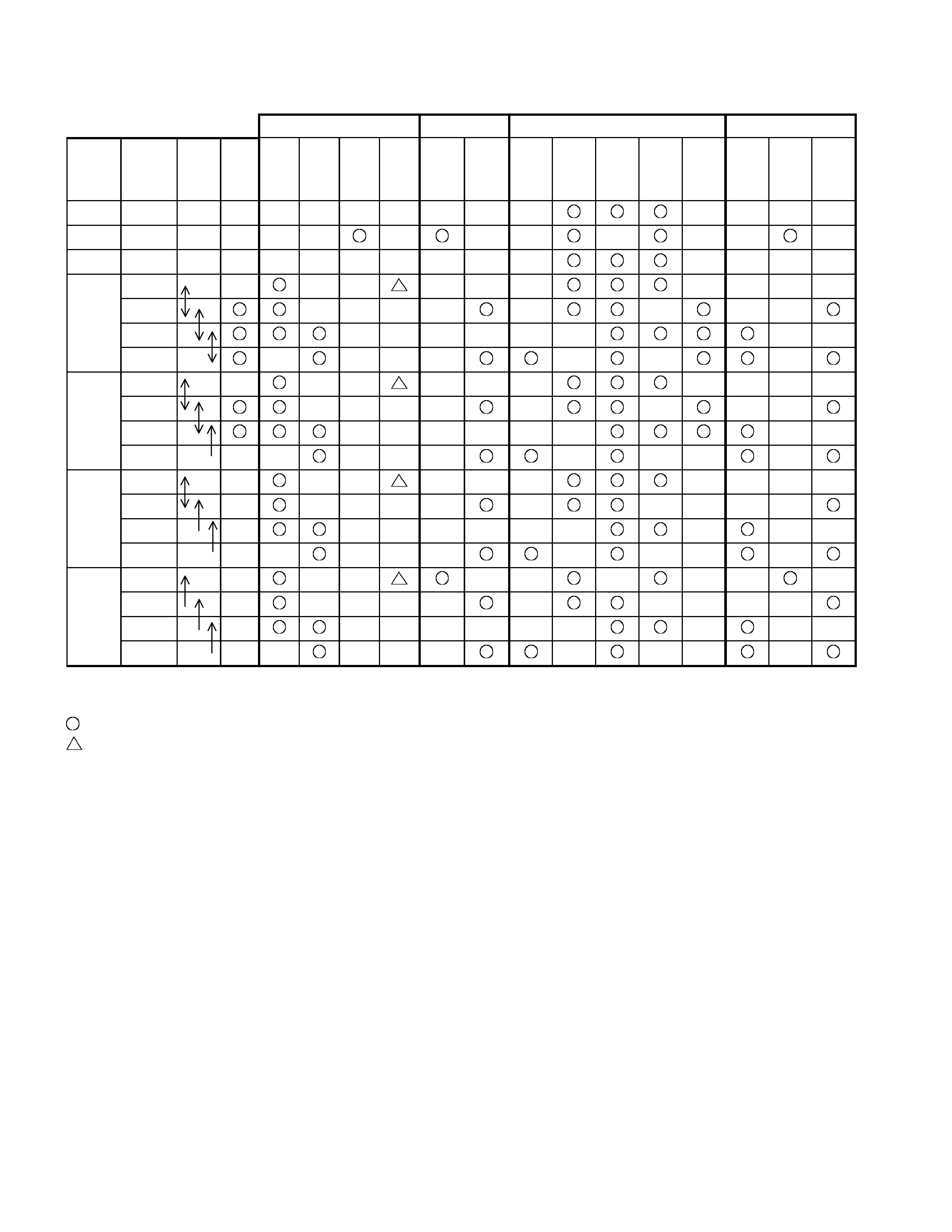
Component And Their Operating Condition
Clutch Brake S olenoid Pressure Switch
Select
lever
position
Gear
position
Gear
Shift
Lock-
up
L/C
H/C
R/C
L/O.C
L&R/B
2-4/B
L/C.S
H/C.S
L&R/
B.S
2-4/
B.S
L/U.S H/
C.P/
SW
L&R/
B.P/
SW
2-4
B.P/
SW
P - -
R Reverse -
N - -
1st
2nd
3rd
D
4th
1st
2nd
3rd
3
4th(*1)
1st
2nd
3rd(*1)
2
4th(*1)
1st
2nd(*1)
3rd(*1)
L
4th(*1)
*1:Transmission is shifted at high speed to prevent engine ov er-run.
- Engaged or operated
- Operative when accelerating
P Range
Though the driving force of the input shaft is transmitted to the rear sun gear and reverse & high clutch drum , the
driving force is not transmitted to the output shaft since all of the clutches and brakes are not engaged.
Therefore, the vehicle can move at this condition. However, since the output shaft is mechanically locked with
the parking pawl, the rear planetary carrier and front internal gear are locked. For this reason, the vehicle does
not move.
N Range
Though the driving force of the input shaft is transmitted to the rear sun gear and reverse & high clutch drum , the
driving force is not transmitted to the output shaft, since all of the clutches and brakes are not engaged.
Therefore, the vehicle can mov e at t his condit ion.
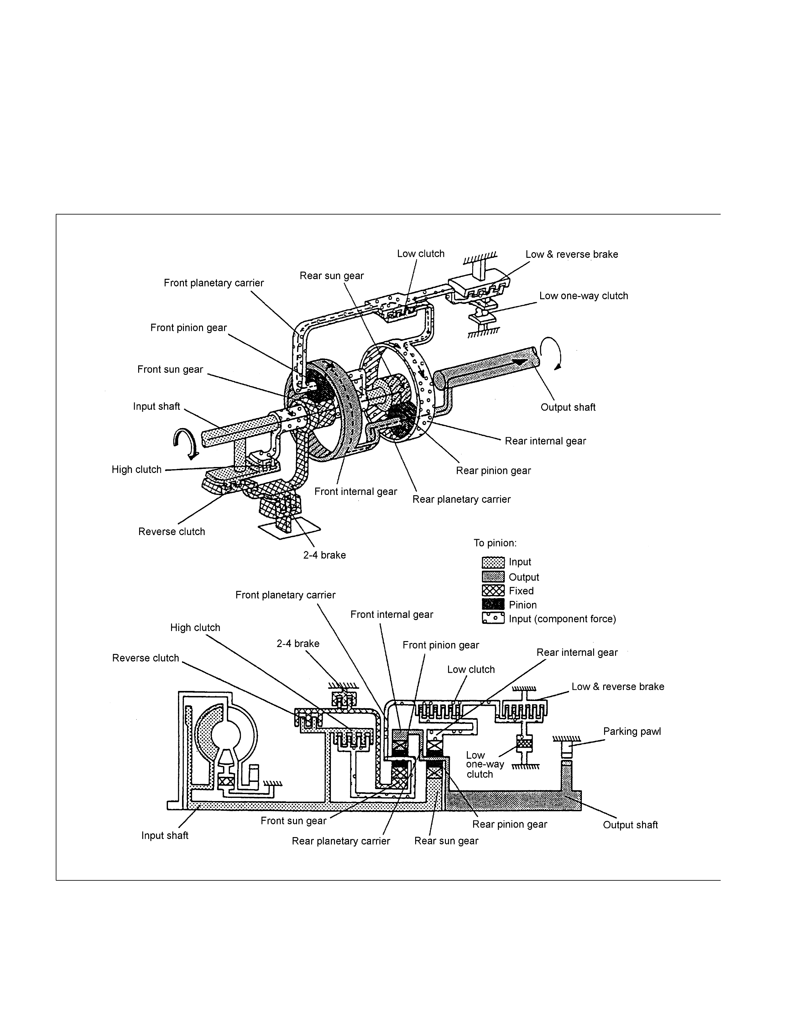
Reverse Gear in Range
The driving force from the input shaft is transmitted to the rear sun gear and reverse & high clutch drum. In the R
range, the reverse clutch is engaged and the driving force is transmitted to the front sun gear and rotates it clockwise.
The low & reverse brake is also engaged and the front planetary carrier is fixed so that the front pinion gear does not
rotate clockwise but can rotate counterclockwise. As a result, the output shaft rotates counterclockwise and the vehicle
goes back.
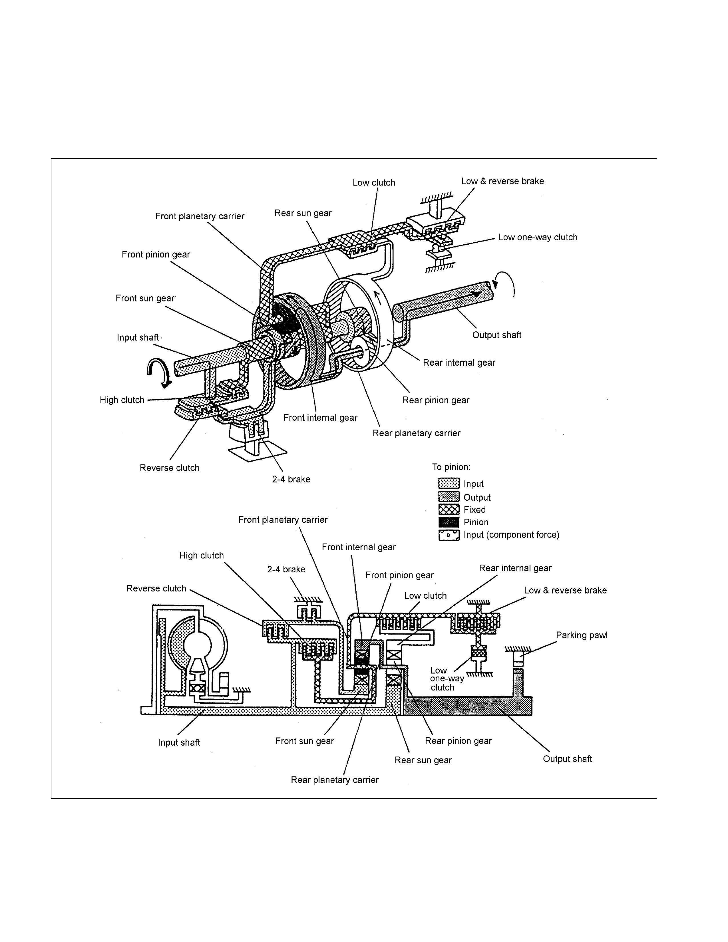
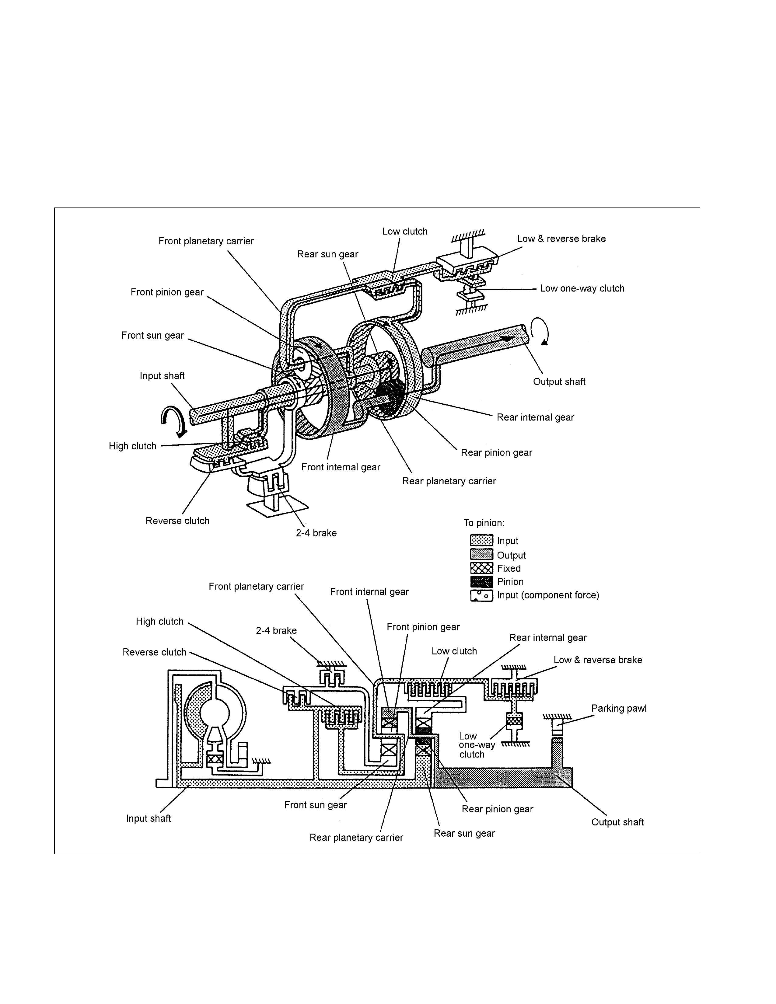
1st Gear in D, 3, 2 Range
The driving force from the input shaft is transmitted to the rear sun gear and reverse & high clutch drum. Since
the low clutch is engaged, the movement of the rear internal gear is restricted and, since the low one-way clutch
acts at the same time, counterclockwise rotations of the rear internal gear are locked. As a result, the driving
force transmitted to the rear sun gear rotates the rear planetary carrier clockwise, is decreased in speed and
transmitted to the out put shaf t .
W hen decelerating, since the rotating speed of the rear planetary carrier (rear pinion gear) is higher than that of
the rear sun gear and therefore, the rear internal gear attempts to rotate clockwise. At this time, the low one-way
clutch does not act but races and therefore the rear internal gear rotates clockwise. That is, the reverse torque
from the driving shaft is not t r ansmitted t o t he engine side and t herefore, t he engine brake does not act.
1st Gear in L Range
The basic mechanism is the same as in the D, 3, and 2 Range. To apply the engine brake, the low & reverse
brake is engaged to restrict the movement of the low one-w ay clutch.
W hen decelerating, since the rear internal gear is fixed, reverse torque from the drive shaft is transmitted to the
engine side so that the engine brake is applied.
2nd Gear in D, 3, 2 Range
The driving force from the input shaft is transmitted to the rear sun gear and reverse & high clutch drum. As in
the case of the 1st gear, since the low clutch is engaged, the movement of the rear internal gear is restricted.
Since the 2-4 brake is engaged, the front sun gear is fixed. As a result, movement of the rear internal gear is
restricted, and the driving force transmitted to the rear sun gear rotates the rear planetary carrier clockwise, and
is decreased and output. The rotating speed of the rear planetary carrier is increased as the rear internal gear
rotates.
When decelerating, the engine brake is applied.
3rd Gear in D, 3 Range
The driving force from the input shaft is transmitted to the rear sun gear and reverse & high clutch drum. As in
the case of the 1st gear and 2nd gear, since the low clutch is engaged, the movement of the rear internal gear is
restricted. Since the high clutch is engaged, the driving force from the input shaft is directly transmitted to the
rear internal gear. As a result, the rpm of the rear sun gear and the rear internal gear becomes the same as that
of the input shaft so that the rear pinion gear rotates not independently but together with the rear sun gear and
rear internal gear.
When decelerating, the engine brake is applied.
4th Gear (O/D) in D Range
The driving force from the input shaft is transmitted to the rear sun gear and reverse & high clutch drum. Since
the 2-4 brake is engaged, the front sun gear is fixed. As a result, the front pinion gear rotates both itself and
together with other gears clockwise. This rotation increases the speed of rotation of the front internal gear and is
transmitted to the out put shaf t .