
SECTION 7A2 - TRANSMISSION CONTROL
SYSTEM (AW30–40LE) (V6 3.5L)
Service Precaution
General Description
Electronic Control Diagram
Transmission Control Module (TCM) (1/2)
Transmission Control Module (TCM) (2/2)
TCM Point Table
TCM Voltage & Resistance Check Sheet
Control System Diagram
Control and Functions
Gear Shift Control 3rd start
Mode Type
Mode Selection
Comparison of mode
3rd start Mode
Backup Mode
Functions of Input / Output Components
CAN bus systems in automatic
transmission control (AW30-40LE)
High speed CAN bus
Diagnosis
Electronic Diagnosis
Check Trans Indicator
On Board Diagnostic Check
"Check Trans" Check
Tech 2 OBD Connection
OBD Diagnostic Management System
16 - Terminal Data Link Connector (DLC)
Clear DTC
DTC Check
TCM Precaution
Information On TCM
TCM Diagnostic Trouble Codes
DTC P0560 (FLASH CODE 25) System
Voltage Error
DTC P0602 (FLASH CODE 63) Transmission
Control Module (TCM) Programming Err or
DTC P0705 (FLASH CODE 17) Transmission
Range Sensor Circuit Malfunction
DTC P0712 (FLASH CODE 15) Transmission Oil
Temperature Sensor Circuit Low Input
DTC P0713 (FLASH CODE 16) Transmission Oil
Temperature Sensor Circuit Hight Input
DTC P0717 (FLASH CODE 14) Input
Speed Sensor Signal Error
DTC P0722 (FLASH CODE 11) Output
Speed Sensor Signal Error
DTC P0743 (FLASH CODE 33) Torque
Converter Clutch Electrical
DTC P0748 (FLASH CODE 35) Pressure
Control Solenoid Electrical
DTC P0753 (FLASH CODE 31) Shift
Solenoid S1 Electrical
DTC P0758 (FLASH CODE 32) Shift
Solenoid S2 Electrical
DTC P1767 (FLASH CODE 67) ECM CAN Invalid
DTC P1790 (FLASH CODE 61) Transmission
Control Module ROM Checksum Error
DTC P1791 (FLASH CODE 62) Transmission
Control Module RAM Error
DTC U2104 (FLASH CODE 65) CAN BUSS OFF

Service Precaution
WARNING: THIS VEHICLE HAS A SUPPLEMENTAL RESTRAINT SYSTEM (SRS). REFER TO THE SRS
COMPONENT AND WIRING LOCATION VIEW IN ORDER TO DETERMINE WHETHER YOU ARE PERFORMING
SERVICE ON OR NEAR THE SRS COMPONENTS OR THE SRS WIRING. WHEN YOU A RE PERFORMING
SERVICE ON OR NEAR THE SRS COMPONENTS OR THE SRS WIRING, REFER TO THE SRS SERVICE
INFORMATION. FAILURE TO FOLLOW WARNINGS COULD RESULT IN POSSIBLE AIR BAG DEPLOYMENT,
PERSONAL INJURY, OR OTHERWISE UNNEEDED SRS SYSTEM REPAIRS.
CAUTION: Always use the correct fastener in the proper location. When you replace a fastener, use ONLY the
exact part number for that application. HOLDEN will call out those fasteners that require a replacement after
removal. HOLDEN will also call out the fasteners that require thread lockers or thread sealant. UNLESS
OTHERWISE SPECIFIED, do not use supplemental coatings (Paints, greases, or other corrosion inhibitors) on
threaded fasteners or fastener joint interfaces. Generally, such coatings adversely affect the fastener torque
and the joint clamping force, and may damage the fastener. When you install fasteners, use the correct
tightening sequence and specifications. Following these instructions can help you avoid damage to parts and
systems.

General Description
The AW30-40LE is a 4–speed fully automatic transmission. It uses a microcomputer as a control unit to judge running
conditions including throttle opening rate and vehicle speed, then it sets the shifting point in the optimum timing so that
best driving performance can be achieved.
In addition, the built–in shift mode select function can select three shift modes according to the driver's preference:
• Normal mode –Normal shift pattern.
• 3rd Start mode –Starts in 3rd gear to reduce slippage on ice or snow.
• Power mode has a delayed up shift when more powerful acceleration is required.
Also, the built–in fail–safe function (“backup mode") assures driving performance even if the vehicle speed sensor,
throttle signal or any solenoid fails.
Further, the self–diagnostic function conducts diagnosis in a short time when the control system fails, thus improving
serviceability.
The major features of AW30-40LE are as follows:
• A compact structure consisting of 2 sets of planetary gears and flat torque converter.
• Electronic control selects the optimum shift mode according to the driving conditions.
• Electronic control maintains the optimum hydraulic pressure for clutch, band brake as well as transmission so that
shift feeling is improved.
• Two sets of planetary gears reduce friction of power train.
Also, a lockup mechanism in the torque converter reduces fuel consumption.
• Wide gear ratio and high torque rate of torque converter provide excellent starting performance.
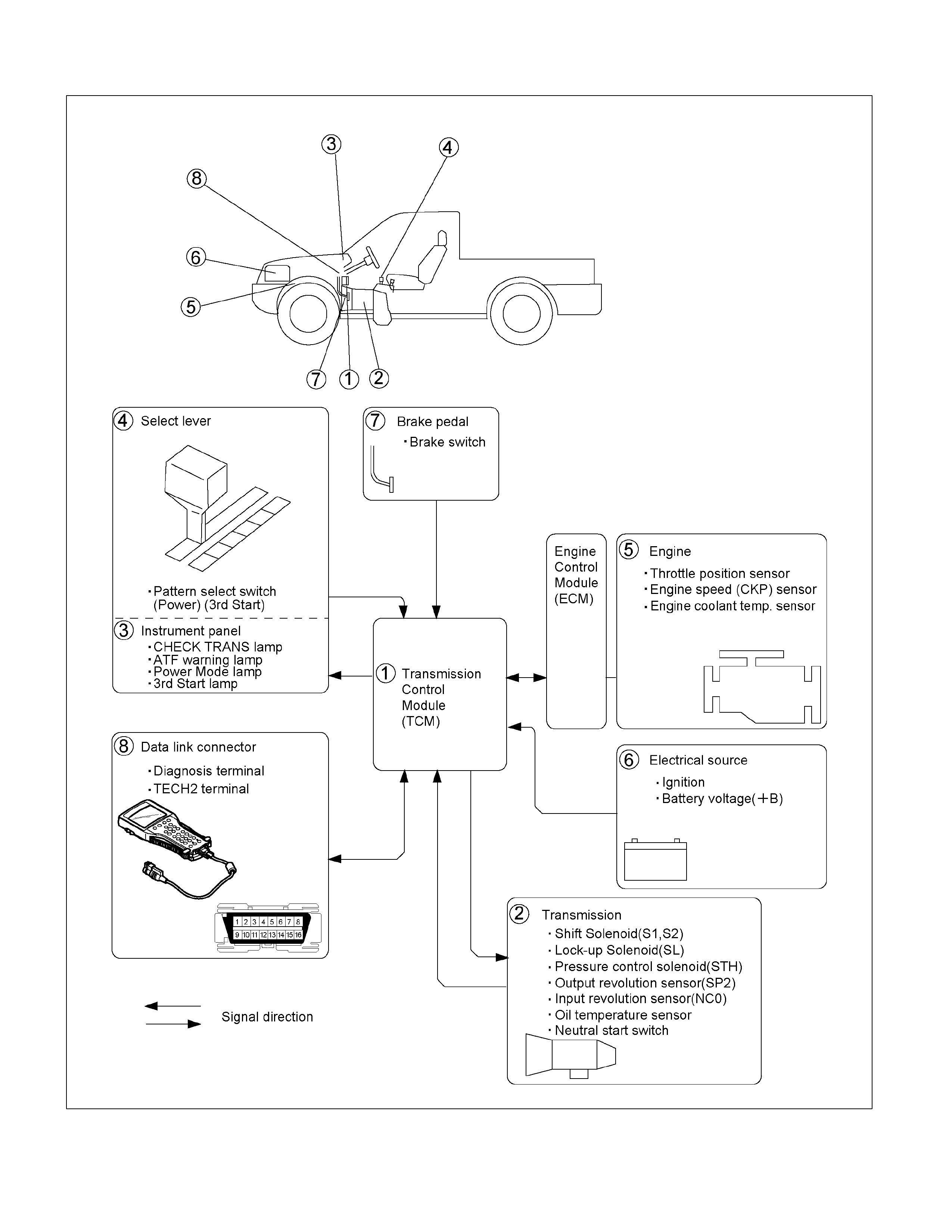
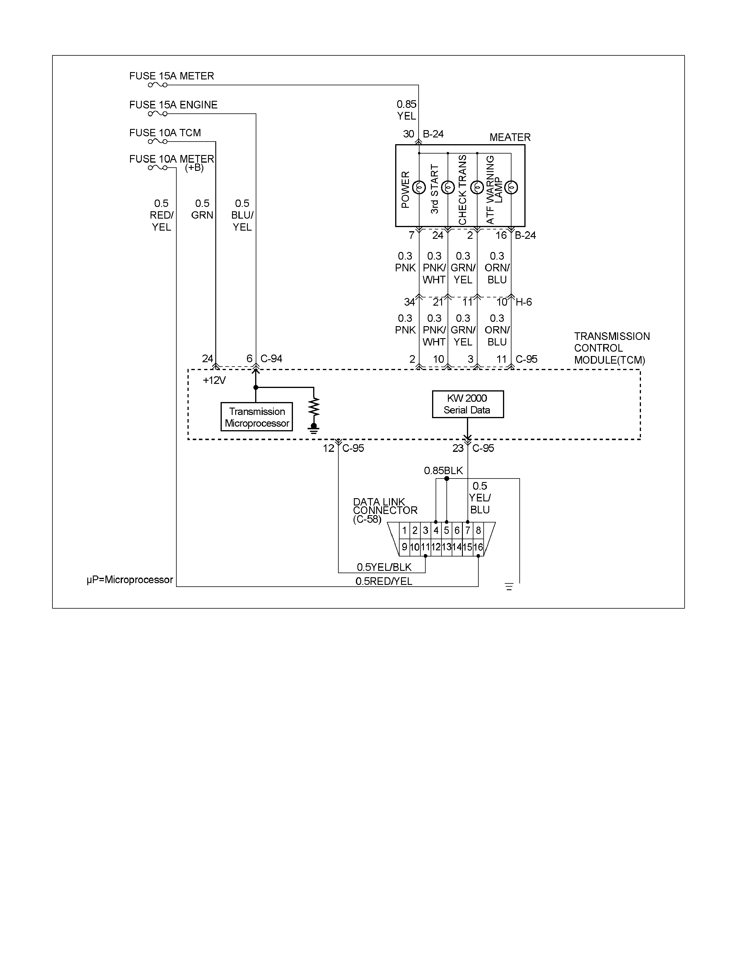
Electronic Control Diagram
RTW37AXF000101
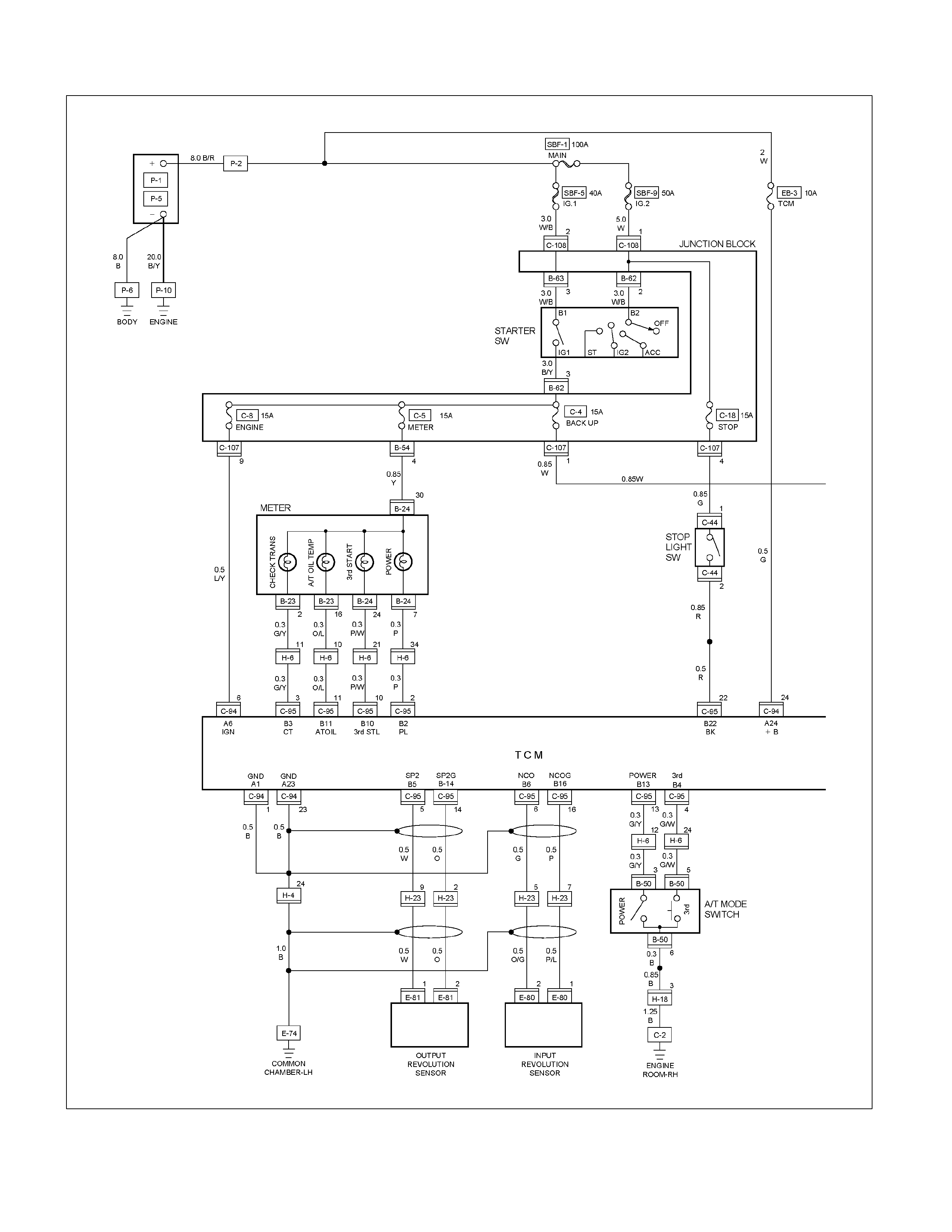
Transmission Control Module (TCM) (1/2)
RTW38DXF000401-1
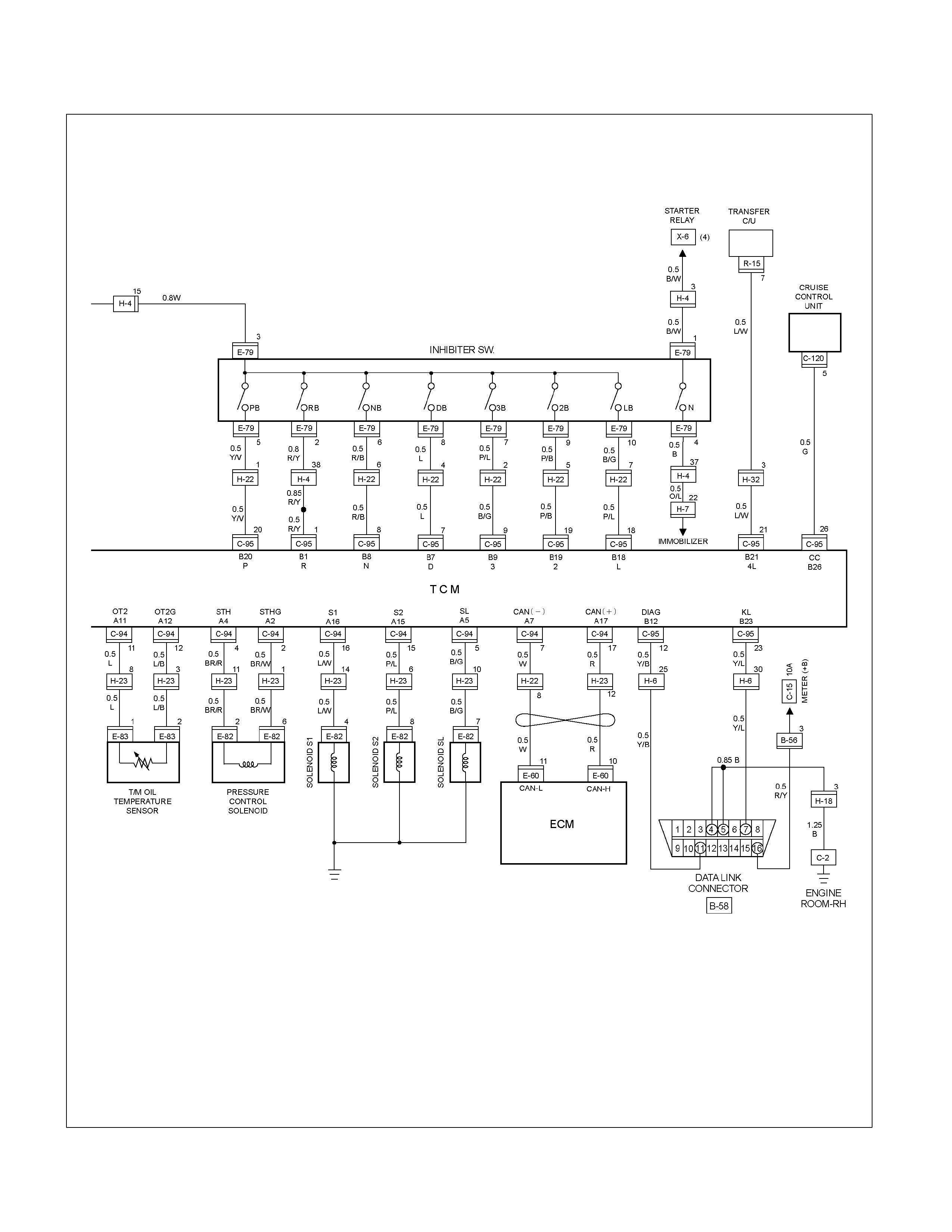
Transmission Control Module (TCM) (2/2)
RTW38DXF000501
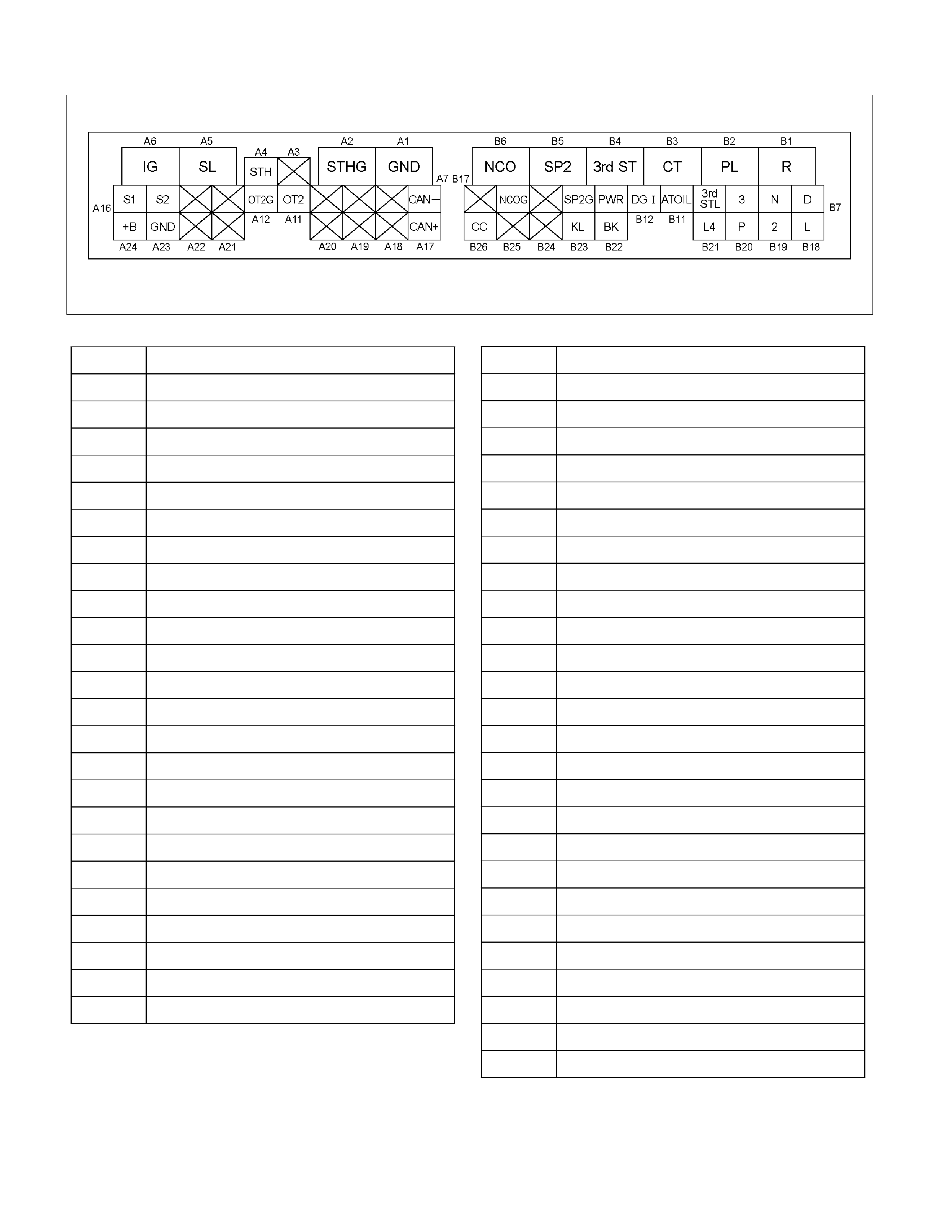
TCM Point Table
RTW37ASF000101-1
PIN No. SIGNAL NAME
A1 GND
A2 PRESSURE CONTROL SOLENOID GND
A3 —
A4 PRESSURE CONTROL SOLENOID
A5 L-up SOLENOID
A6 STARTER SW(IG1)
A7 CAN COMMUNICATION (-)
A8 —
A9 —
A10 —
A11 T/M OIL TEMPERATURE SENSOR
A12 T/M OIL TEMPERATURE SENSOR GND
A13 —
A14 —
A15 SHIFT SOLENOID (S2)
A16 SHIFT SOLENOID (S1)
A17 CAN COMMUNICATION (+)
A18 —
A19 —
A20 —
A21 —
A22 —
A23 GND
A24 BATTERY
PIN No. SIGNAL NAME
B1 NEUTRAL START SW (R)
B2 POWER LAMP
B3 CHECK TRANS LAMP
B4 PATTERN SELECT SW (3rd START)
B5 SPEED SENSOR (+)
B6 INPUT REVOLUTION SENSOR (+)
B7 NEUTRAL START SW (D)
B8 NEUTRAL START SW (N)
B9 NEUTRAL START SW (3)
B10 3rd START LAMP
B11 OIL TEMPERATURE WARNING LAMP
B12 DIAGNOSIS TERMINAL
B13 PATTERN SELECT SW (POWER)
B14 SPEED SENSOR (-)
B15 —
B16 INPUT REVOLUTION SENSOR (+)
B17 —
B18 NEUTRAL START SW (L)
B19 NEUTRAL START SW (2)
B20 NEUTRAL START SW (P)
B21 TRANSMISFER LOW 4 SW
B22 BRAKE LAMP SW
B23 DIAGNOSIS OUT PUT
B24 —
B25 —
B26 CRUISE CONTROL UNIT

TCM Voltage & Resistance Check Sheet
CHECK ITEM PIN No. VALUE NOTE
VIGN A6–A1 VIGN Key “ON”
A6–A23 VIGN Key “ON”
Backup Power Supply A24–A1 +B (Always) Key “ON”
Inhibitor (Select) SW P B20–A1 “P” Range VIGN Key “ON”
Except “P” 0V
Inhibitor (Select) SW R B1–A1 “R” Range VIGN Key “ON”
Except “R” 0V
Inhibitor (Select) SW N B8–A1 “N” Range VIGN Key “ON”
Except “N” 0V
Inhibitor (Select) SW D B7–A1 “D” Range VIGN Key “ON”
Except “D” 0V
Inhibitor (Select) SW 2 B19–A1 “2” Range VIGN Key “ON”
Except “2” 0V
Inhibitor (Select)SW 1 B18–A1 “1” Range VIGN Key “ON”
Except “1” 0V
Inhibitor (Select) SW 3 B9–A1 “3” Range VIGN Key “ON”
Except “3” 0V
Power SW B13–A1 ON 0V Key “ON”
OFF VIGN
3rd Start SW B4–A1 ON 0V Key “ON”
OFF VIGN
Brake SW B22–A1 ON VIGN Key “ON”
OFF 0V
AT Oil Temperature
Sensor A11–A12 20°C 4.6V Engine run.
155°C 1.1V
4L Signal B21–A1 4L 0V Key “ON”
2H/4H VIGN
Diag SW B12–A1 ON VIGN Key “ON”
OFF 0V
Shift Solenoid A (S1) A16–A1 P VIGN Engine run.
R VIGN
N VIGN
D–1 VIGN
D–2 VIGN
D–3 0V
D–4 0V
Shift Solenoid B (S2) A15–A1 P 0V Engine run.

CHECK ITEM PIN No. VALUE NOTE
R 0V Engine run. (Without the
Reverse range lock out)
N 0V Engine run.
D–1 0V
D–2 VIGN
D–3 VIGN
D–4 0V
Lock-up Solenoid A5–A1 ON VIGN (ex.) It is “ON” when the
vehicle speed is more than
65km/h.
OFF 0V
Check Trans Lamp B3–A1 ON 0V Key “ON”
(The lamp is “ON” for 3
second after key “ON”)
OFF VIGN
AT Oil Temperature Lamp B11–A1 ON 0V Key “ON”
(The lamp is “ON” for 3
second after key “ON”)
OFF VIGN
Power Lamp B2–A1 ON 0V Key “ON”
(The lamp is “ON” when the
Power switch is “ON”)
OFF VIGN
3 rd Start Lamp B10–A1 ON 0V Key “ON”
(The lamp is “ON” when the
3rd Start switch is “ON”)
OFF VIGN
AT Oil Temp Sensor
Resistance A11–A12 20°C 12k Key “OFF”
50°C 1.5k
155°C 293
Pressure Control Solenoid
Resistance A4–A2 About
4–7(20°C) Key “OFF”
Speed Sensor Resistance B5–B14 About
560–120(20°C) Key “OFF”
Input Revolution Sensor
Resistance B6–B16 About
560–120(20°C) Key “OFF”
Lock-up Solenoid
Resistance A5–A1 About
10–15(20°C) Key “OFF”
Shift Solenoid A (S1)
Resistance A16–A1 About
10–15(20°C) Key “OFF”
Shift Solenoid B (S2)
Resistance A15–A1 About
10–15(20°C) Key “OFF”

Control System Diagram
RTW37AXF000201

Control and Functions
Shift Control
The transmission gear is shifted according to the shift
pattern selected by the driver. In shifting gears, the gear
ratio is controlled by the ON/ OFF signal using the shift
solenoid S1 and the shift solenoid S2.
Band Apply Control
The band apply is controlled when in the 3–2 downshift
(engine overrun prevention) and the garage shift (shock
control).
The band apply solenoid is controlled by the signal from
the Pulse Width Modulation (PWM) to regulate the flow
of the oil.
Torque Converter Clutch Control
The clutch application is controlled by the TCM via the
Torque Converter Clutch (TCC) solenoid.
Line Pressure Control
The throttle signal allows the current signal to be sent to
the force motor. After receiving the current signal, the
force motor activates the pressure regulator valve to
regulate the line pressure.
On–Board Diagnostic System
Several malfunction displays can be stored in the
Transmission Control Module (TCM) memory , and read
out of it afterward.
The serial data lines, which are required for the testing
of the final assembly and the coupling to other
electronic modules, can be regulated by this function.
Fail–Safe Mechanism
If there is a problem in the transmission system, the
TCM will go into a “backup" mode.
The vehicle can still be driven, but the driver must use
the select lever to shift gears.
Torque Management Control
The transmission control side sends the absolute spark
advance signal to the engine control side while the
transmission is being shifted. This controls the engine
spark timing in compliance with the vehicle running
condition to reduce the shocks caused by the change of
speed.
ATF Warning Control
The oil temperature sensor detects the ATF oil
temperature to control the oil temperature warning,
TCC, and the 3rd start mode.
Reverse Lock Out Control
With the selector lever in reverse position, the TCM will
not close the PWM solenoid until the vehicle is below 15
km/h (9.3 mph), thus preventing reverse engagement
above this speed.
Downhill Control
This mode is automatically activated from NORMAL
mode only when downhill conditions are recognised.
The shift pattern is identical to NORMAL mode except
3-4 and 4-3 shift lines at low throttle modified to get
engine braking on a larger speed range.
Uphill Control
When uphill condition are recognised the 2-3 and 3-4
shift and TCC apply are down only when the engine
torque is sufficient in order to avoid shift hunting.
Gear Shift Control 3rd start
SELECT LEVER
RANGE SHIFT PATTERN
D(Drive) 1⇔2TCC⇔3TCC⇔4TCC
3(Third) 1⇔2TCC⇔3TCC
2(Second) 1⇔2(←3)
L(First) 1(←2)
TCC: Torque Converter Clutch
(Notice1): “( )" means over-revving prevention control .
Mode Type
Mode Type Select lever position
Normal drive mode
(NOR) Entire range (excluding “R")
Power drive mode
(PWR) Entire range (excluding “R")
Mode Selection
SWITCH(SW) LAMP
Mode Type PWR/N
OR.S 3RD
START
SW
POWER
DRIVE
LAMP
3RD
START
LAMP
Normal
drive mode
(NOR)
OFF OFF OFF OFF
Power
drive mod
(PWR)
ON OFF ON OFF
3rd Start
mode OFF ON OFF ON
However, the 3rd start switch prevails over the
PWR/NOR switch.
The mode become normal drive mode when the 3rd
start switch is operated from ON to OFF.

Comparison of mode
1. The normal drive mode is set at the normal shift
points.
2. The shift points of the power drive mode are shifted
to the higher speed side, compared to the normal
drive mode.
3. The 3rd start mode is a special mode used
exclusively for starting in third gear.
3rd start Mode
1. The 3rd start switch will operate when switched on
after all of the following conditions are present:
a. The gear select position is “D" range only.
b. Vehicle speed is 11 km/h (7 mph) or less.
c. Transmission oil temperature is 120°C (248°F)
or less.
d. Accelerator opening is at 8% or less.
2. Cancel Release
1. Cancellation by driver
a. Turning off the 3rd start mode switch
b. Shifting select position to “3", “2", or “L" (3rd
start mode is not cancelled by selecting “N",
“R", or “P" )
c. Ignition key is turned off.
2. Automatic cancellation
a. When vehicle runs at 34 km/h (21mph) or
more for 1 second or more
b. When transmission oil temperature reaches
120°C (284°F) or above
NOTE: The mode returns to normal drive mode or
power drive mode after the 3rd start mode is cancelled.
Backup Mode
If a major system failure occurs which could affect
safety or damage the transmission under normal
vehicle operation, the diagnostic system detects the
fault and overrides the Transmission Control Module
(TCM).
The “CHECK TRANS" light flashes to alert the driver,
and the transmission must be manually shifted as
follows:
Shifts are firmer to prevent clutch slip and consequent
wear. The fault should be corrected as soon as
possible.
Select lever position Gear Ratio Selected
D 4 (Fourth)
Manual 3 4 (Fourth)
Manual 2 3 (Third)
Manual L 3 (Third)
R Reverse

Functions of Input / Output Components
Component Function
Trans fer low signal Detects the transfer High/ Low position.
OD Cancel signal Detects whether the cruise control unit is judged OD cancel mode.
Output revoluti o n sensor
(Transmission) Det e cts the vehicle speed.
Input revolution sensor
(Transmission) Det ects the in put r evolution (O D direct clutch drum revolution) .
Engine r evolution sensor Det ects the eng ine revolut i on with CAN.
Throttle position signal Detects the throttle opening rate with CAN.
Neutral start switch Detects the select lever position.
Pattern select switch Det ects whether the driver has select ed "NORMAL" or "POWER" mode.
Brake lamp switch Det ects whether the driver has pressed the brake pedal or not.
Oil temperature sensor Detects the oil temperature.
I
n
p
u
t
Diagnostic star t switc h Start s self-diagnosis and displays a code for faulty part if any.
I
n
p
u
t
/
O
u
t
p
u
t
Data link connector When connected with Tech2 or tester, can communicate the data for function
check, etc.
Shift solenoid S1, S2 Selects s hift point and gea r position s uited to th e vehicle running condition on the
basis of T C M output .
Lock-up co ntrol s olenoid SL Cont rol the lock-up c l utch suited to th e vehicle running condition on the basis of
TCM output.
Pressure control solenoid
STH Adjusts throttle pres sure by ener gizin g current o f linear pressu re con trol so lenoid
to prevent the shift shock and to obtain shift smoothly.
"CHECK TRANS" lamp When trouble has occur red to throttle position sensor, vehicle s peed sensor, or
solenoid, "C HECK TRANS" lamp is blinked to warn the driver. If also displays the
trouble co de.
A/T OIL TEMP warning
lamp Lights when ATF oil temperature rises. (Turned on at greater than 146°C
(295°F). Turned off at less than 132°C (270°F).
POWER lamp Lights when POWER MODE detected.
O
u
t
p
u
t
3rd Sta rt lamp Ligh ts w he n 3r d St art MODE dete ct ed .
C
o
m
p
u
t
e
r
Transmission C ontrol
Module (TCM) Based on the signal fr om each switch and sensors, judg es necessar y shift point
and lo ck-up oper ation, an d send signal to ea ch sol en oid.

CAN bus systems in automatic
transmission control (AW30-40LE)
The automatic transmission control system in AW30-
40LE uses high speed CAN bus system .The individual
CAN bus systems are connected via two interfaces and
can exchange information and data. This allows control
modules that are connected to different CAN bus
systems to communicate.
High speed CAN bus
Transmission control modules in the vehicle that require
continuous, rapid communication are connected to the
high speed CAN bus. For example, the automatic
transmission is continuously notified of the current
engine load status. Since the automatic transmission
control module has to react immediately to load status
changes, rapid communication is required between the
engine control module and the automatic transmission
control module. The high speed CAN bus in the AW30-
40LE is designed as a two-wire CAN bus (twisted pair).
The wires are shielded and twisted. The transfer rate is
500 K baud.
RUW37ASF000401
Diagnosis
Electronic Diagnosis
How To Diagnose The Problem
1. To avoid incorrect diagnostics, this book needs to
be followed accurately . Unless stated, do not jump
directly to a section that could contain the
solution. Some important information may be
missed.
2. The sections in CAPITALS and bold are the main
sections that can be found in the contents.
3. The go to “SECTION" means to continue to check
going to the “section".
4. The go through “SECTION" means to go through
the “section" and then to go back to the place the go
through was written.
5. BASIC ELECTRIC CIRCUITS:
You should understand the basic theory of
electricity. This includes the meaning of voltage,
amps, ohms, and what happens in a circuit with an
open or shorted wire. You should also be able to
read and understand wiring diagrams.
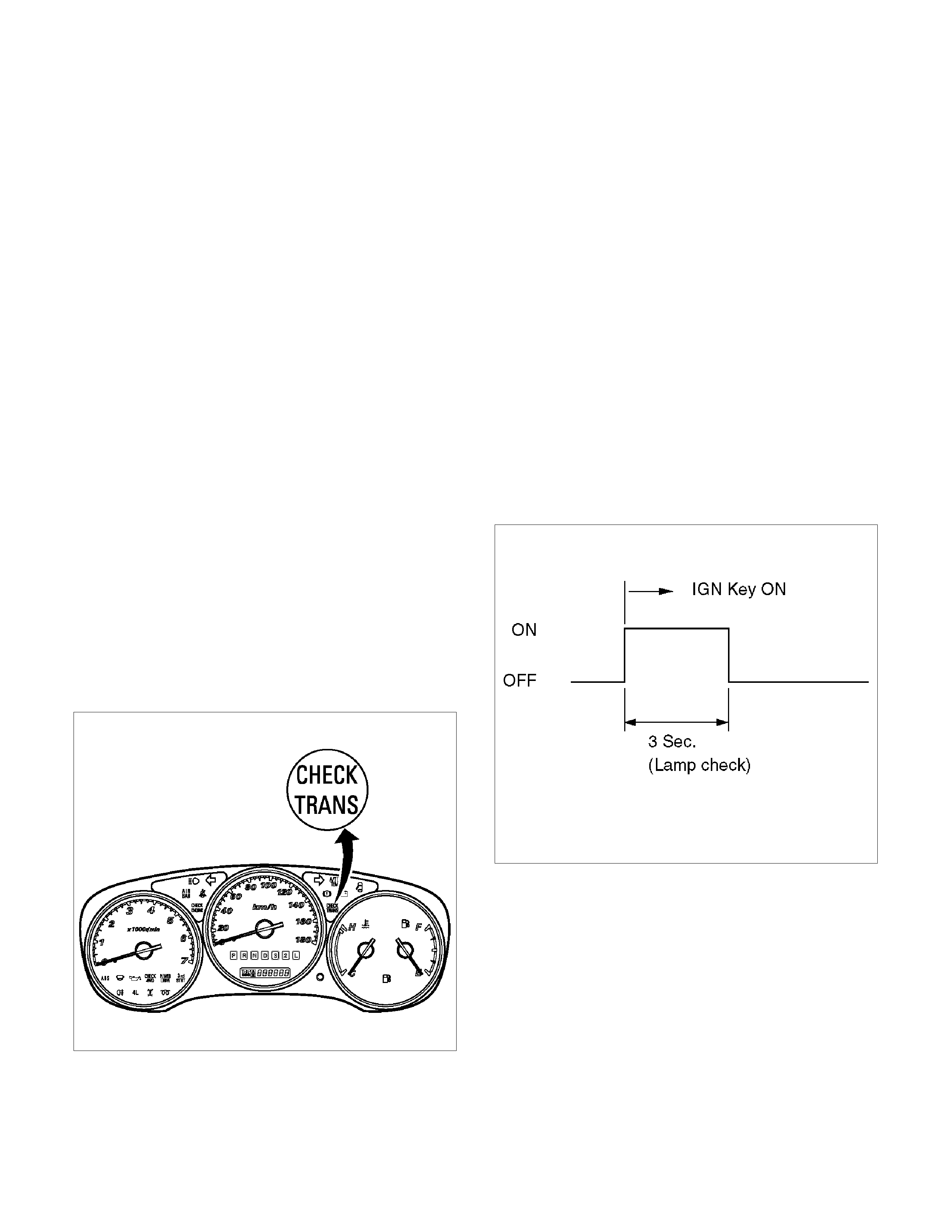
Check Trans Indicator
Find CHECK TRANS indicator and verify if it is
A. FLASH: Go to DIAGNOSTIC CHECK.
B. Staying on: Go through CHECK TRANS CHECK.
C. Is never ON when the ignition key is turned on: Go
through CHECK TRANS CHECK
D. Is ON during 3 seconds at ignition but OFF after:
Normal operation. No DTC or malfunction.
RTW37ASH000401
On Board Diagnostic Check
This test determines if the transmission or its input or
output connections or sensors are failing.
1. Connect the Tech 2: Go through Tech 2 OBD
CONNECTION.
2. Turn on the ignition but not the engine.
3. Push “F0" on Tech 2 to see the Diagnostic
Trouble Code (DTC):
4. Do you have a DTC?
YES: write dow n all code numbers and do the DTC
CHECK
NO: the DTC can not help you find the problem.
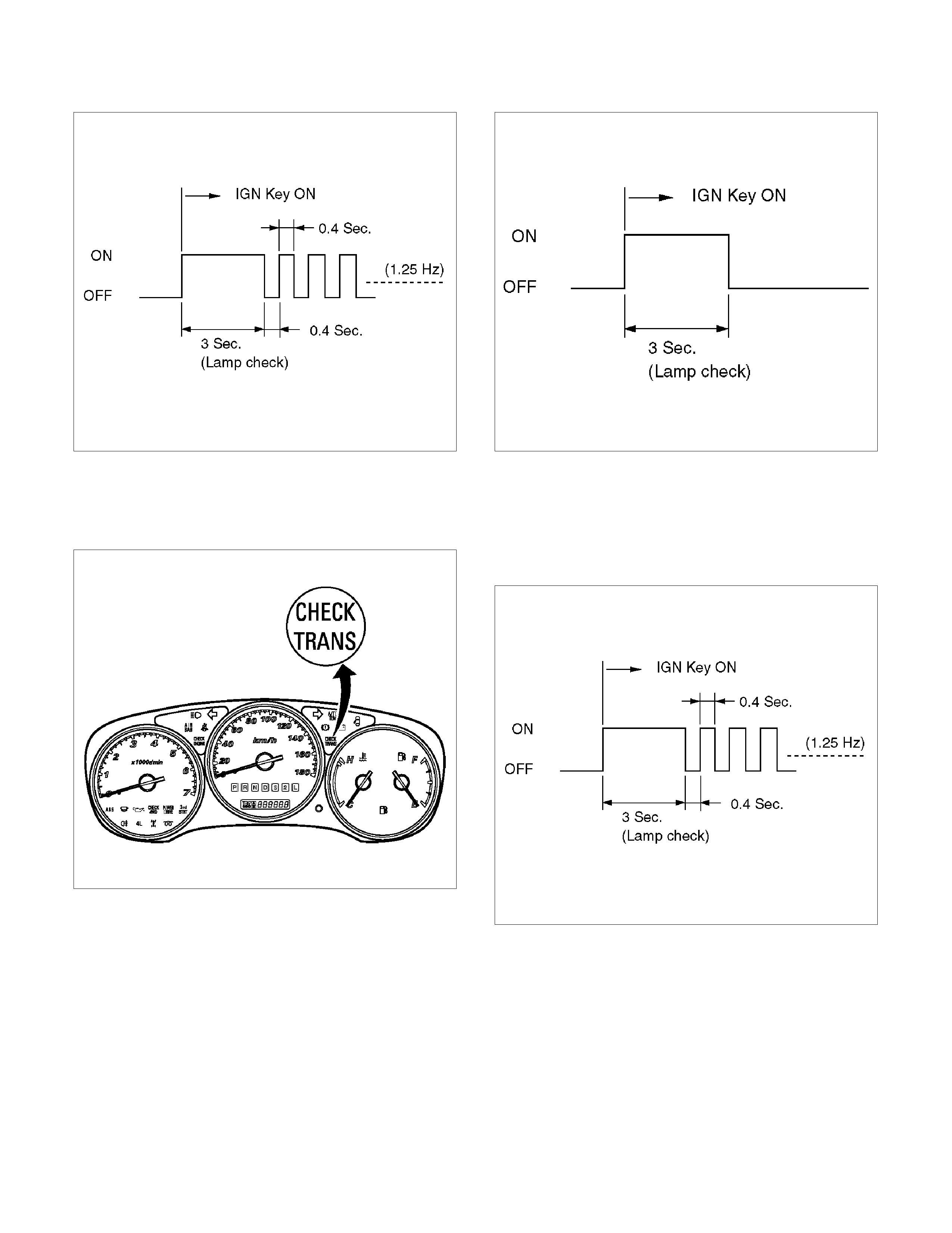
1. Go through “CHECK TRANS" CHECK
2. If it is FLASH and the flash is 0.4 seconds ON
and 0.4 seconds OFF, this means that you
should have a DTC stored. Please recheck go
to DIAGNOSTIC CHECK and if you find the
same problem, replace the Powertrain Control
Module (TCM).
Normal
C07RY005-1
Abnormal
C07RY00042-1
“Check Trans" Check
1. Indicator is ON during 3 seconds at ignition but it is
OFF after the engine starts. The indicator is working
normally go to DIAGNOSTIC CHECK.
RTW37ASH000401
Normal
C07RY005-1
2. Indicator is FLASH and the flash is 0.4 seconds ON
and 0.4 seconds OFF always when ignition is on
(engine cranked or not). This means that there is a
malfunction. Go to DIAGNOSTIC CHECK.
Abnormal
C07RY00042-1

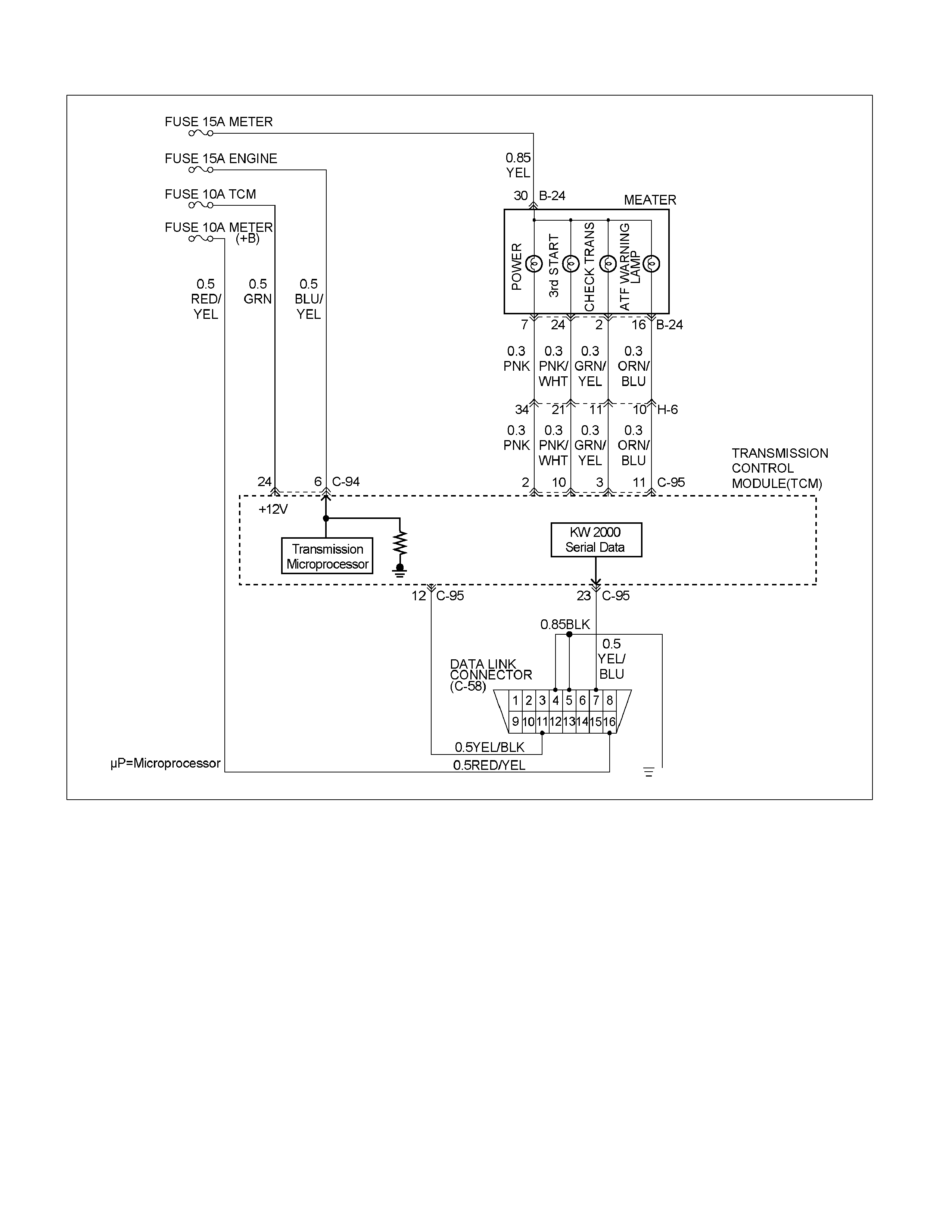
3. Indicator is staying ON always when Ignition is ON.
1. This means that connection between the lamp
and the indicator control unit is shorted to
ground.
2. Verify if instrument panel terminal 2 of
connector B–23 is shorted to ground.
3. Verify if the indicator control unit connector
C–95 terminal 3 is shorted to ground.
4. Verify that the instrument panel terminal 30 of
connector B–24 is connected to battery.
5. If problem solved: Go to CHECK TRANS
INDICATOR.
NO: Replace Transmission Control Module
(TCM).
4. Indicator is staying OFF with the ignition ON (engine
OFF).
1. This means that connection between the lamp
and the indicator control unit is shorted to
battery or opened.
2. Verify if instrument panel terminal 2 of
connector B–23 is shorted to battery or open.
3. Verify if the indicator control unit connector
C–95 terminal 3 is shorted to battery or open.
4. Verify that the instrument panel terminal 2of
connector B–23 is connected to battery. If not,
check the fuses and the connections (terminal
11 of connector H–6) voltage.
5. If problem solved: Go to CHECK TRANS
INDICATOR.
NO: Replace Transmission Control Module
(TCM).
RTW37LF000701
Tech 2 OBD Connection
In order to access OBD Transmission Control Module
(TCM) data, use of the Tech 2 scan tool kit is required.
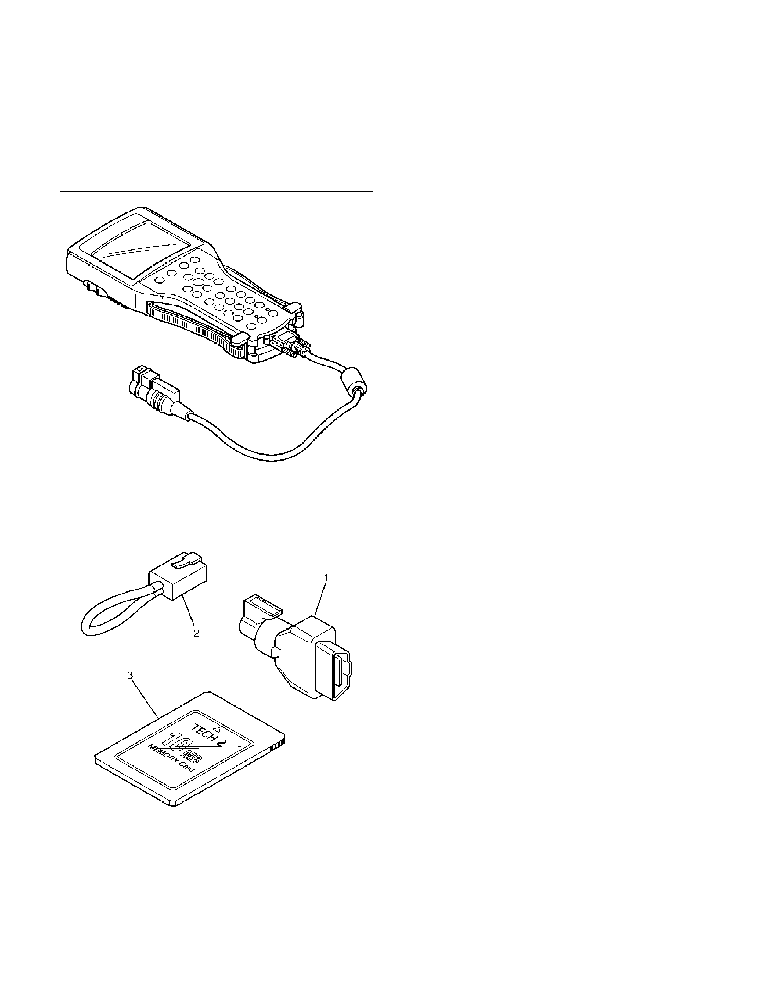
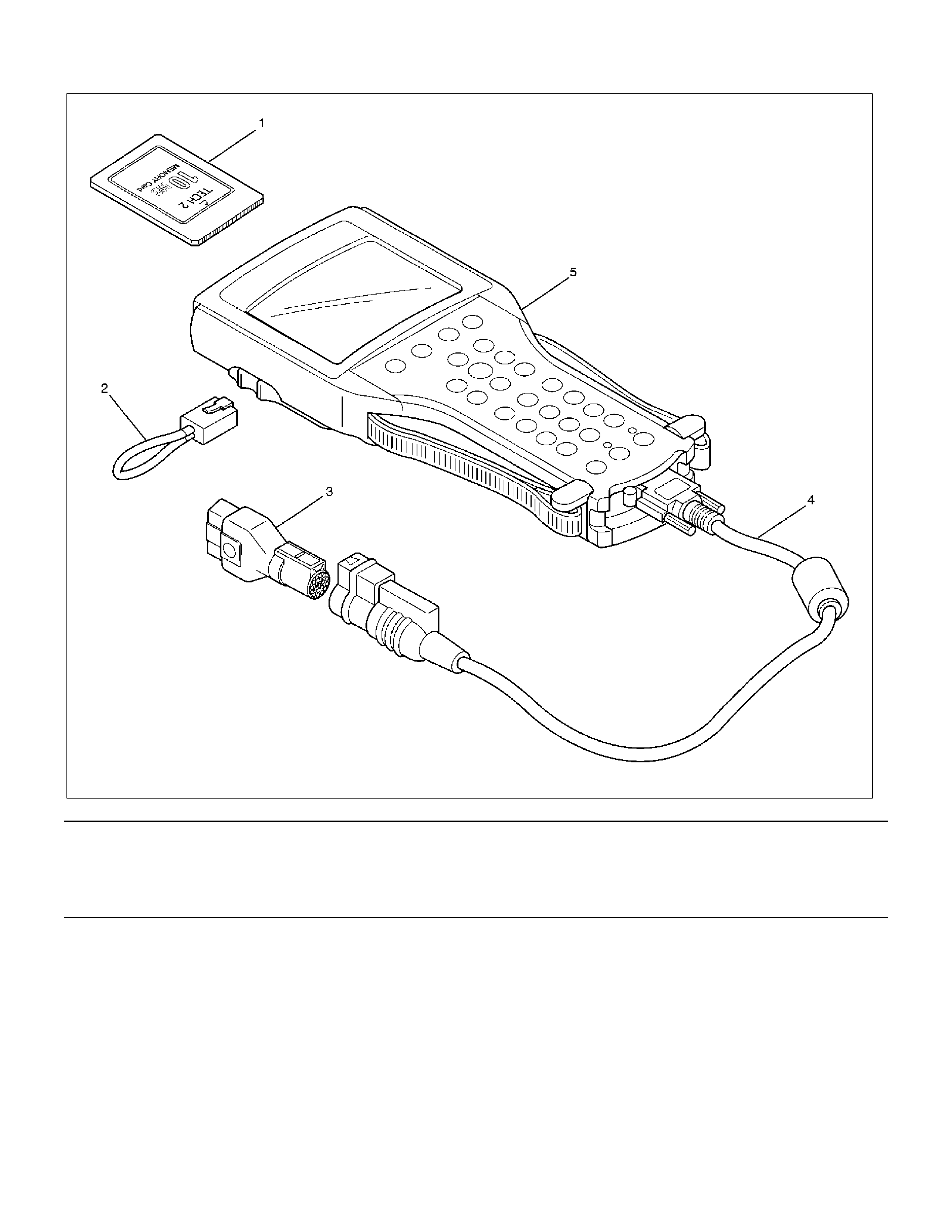
1. The electronic diagnosis equipment is composed of:
1. Tech 2 hand held scan tool unit (7000057) and
DLC cable (3000095).
901RW176
2. SAE 16/19 Pin Adaptor (3000098)(1), RS232
Loop Back Connector (3000112)(2), and
PCMCIA Card (3000117)(3).
F07RW033
2. Connecting the Tech 2
901RW180
Legend (3) SAE 16/19 Adaptor
(1) PCMCIA Card (4) DLC Cable
(2) RS 232 Loop Back Connector (5) Tech 2
• Before operating the Isuzu PCMCIA card with the
Tech 2, the following steps must be performed:
1. The Isuzu System PCMCIA card (1) inserts into
the Tech 2 (5).
2. Connect the SAE 16/19 adaptor (3) to the DLC
cable (4).
3. Connect the DLC cable to the Tech 2 (5)
4. Mark sure the vehicle ignition is off.
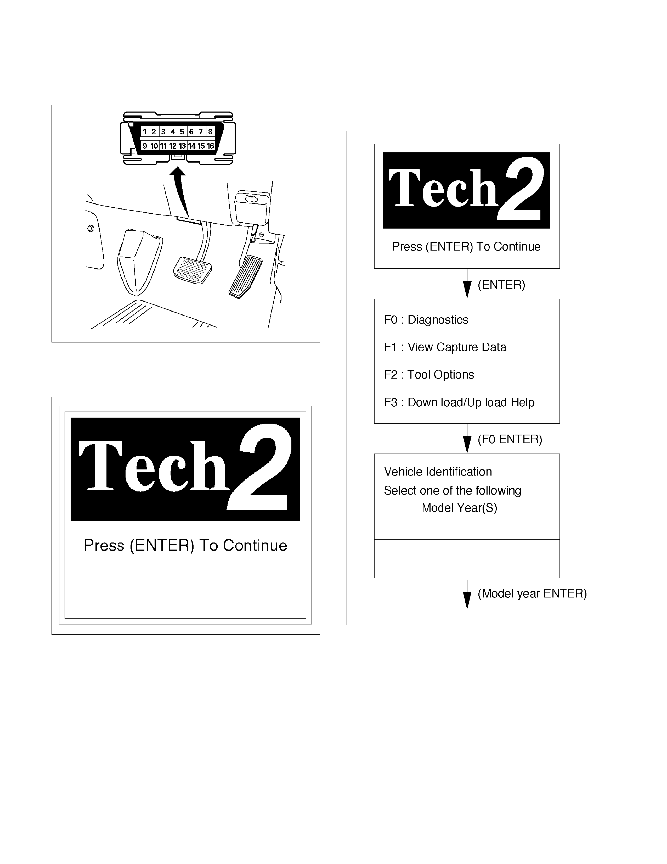
5. Connect the Tech 2 SAE 16/19 adaptor to the
vehicle DLC (1).
060r300015
6. The vehicle ignition turns on.
7. Verify the Tech 2 power up display.
060RW009
NOTE: The RS232 Loop back connector is only to use
for diagnosis of Tech 2 and refer to user guide of the
Tech 2.
8. The power up screen is displayed when you
power up the tester with the Isuzu systems
PCMCIA card. Follow the operating procedure
below.
060R100102
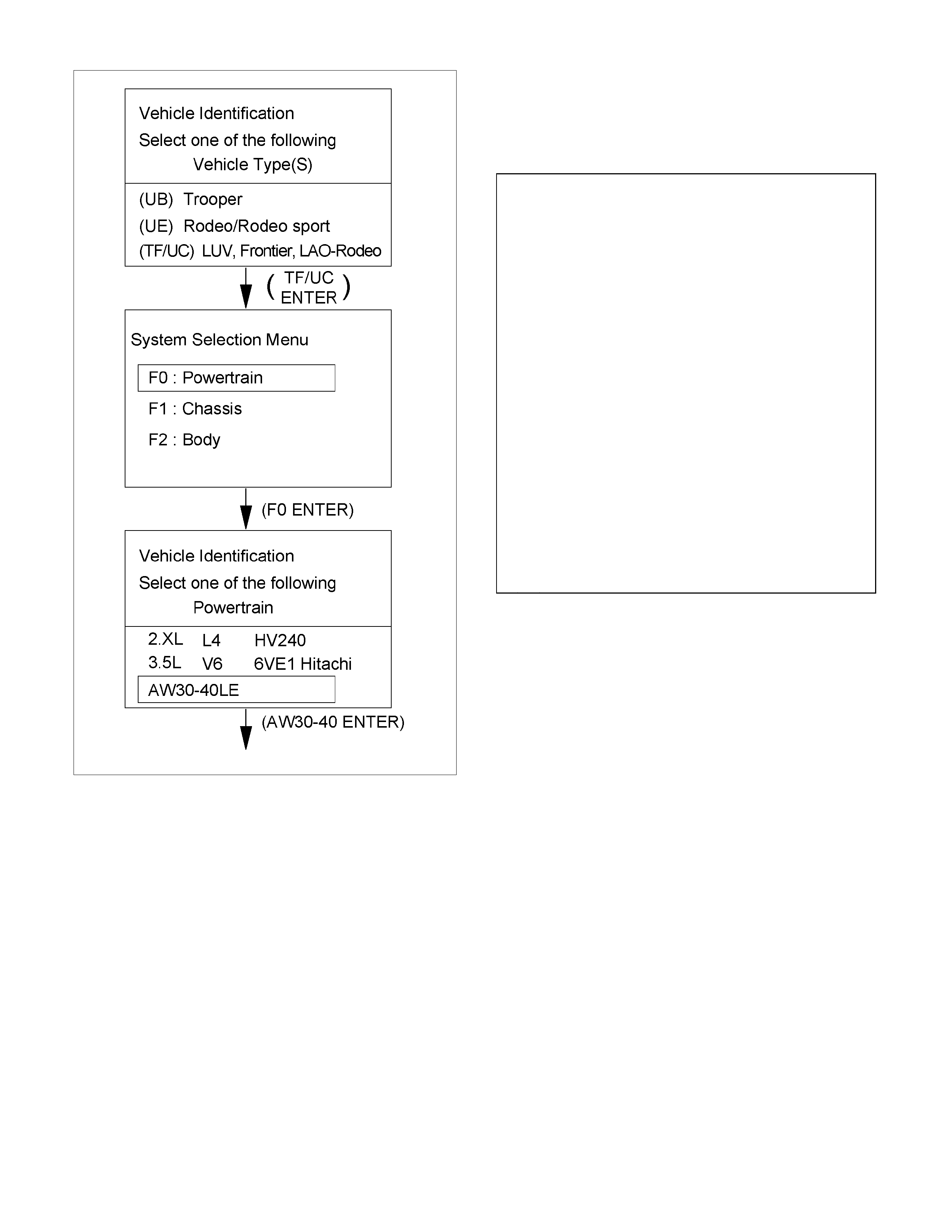
RTW37ALH000101
Once the test vehicle has been identified an
“Application (Powertrain) Menu" screen appears. Please
select the appropriate application.
The following table shows, which functions are used for
the available equipment versions.
F0: Diagnostic Trouble Codes
F0: Read DTC Info As stored By ECU
F1: Clear DTC Information
F2: DTC Information
F1: Data Display
F2: Snap Shot
F3: Miscllaneous Tests
F0: Lamps
F0: Power Lamp Test
F1: 3rd start Lamp Test
F2: AT Oil Temperature Lamp
F3: Check Light
F1: Solenoids
F0: Shift solenoid A (S1)
F1: Shift Solenoid B (S2)
F2: Pressure Control Solenoid (PCS)

Diagnostic Trouble Codes
The purpose of the “Diagnostic Trouble Codes" mode is
to display stored TCM trouble codes.
When “Diagnostic Trouble Codes" is selected an
“Application Menu" screen appears.
Clear DTC Information
The purpose of the “Clear DTC Information" mode is to
command the clearing of stored TCM trouble codes.
When “Clear DTC Information" is selected, a “Clear
DTC Information", warning screen appears. This screen
informs you that by cleaning DTC's, “all stored DTC
information in controller will be erased".
Do you want to clear DTC's (Yes/No).
Press either the Yes or No key when answering.
After clearing codes, confirm system operation by test
driving the vehicle.
Allow the vehicle to shift through all four forward gears
in a manner that attempts to repeat the failure condition.
NOTE: When the trouble has not been repaired and
the trouble code cannot be erased, check the vehicle
again.
DTC Information
When “DTC Information" is selected, an “Application
Menu" appears with a list of DTC information function
keys addressing DTC specifics and their origins.
Function key selections may vary for particular vehicle
and/or system.
Data Display
The purpose of the “Data Display" mode is to
continuously monitor data parameters.
The current actual values of all important sensors and
signals in the system are display through F1 mode.
When “Data Display " is selected an “Application Menu"
appears. Please select either “Engine" or “Transmission
Data Display".
See “Transmission Data" on next page.
Snapshot
When “Snapshot" is selected an “Application Menu"
appears.
When “Transmission Snapshot" application is selected
from the “Application Menu", a “Snapshot Menu"
appears, displaying several options. “Snapshot" options
may vary from one system to another.
“Snapshot" allows a recording of all vehicle parameters.
The parameters may then be replayed at a future point
in time.
This action allows you to focus on making the condition
occur, rather than trying to view all of the data in
anticipation of the fault. The snapshot will collect
parameter information around a trigger point that you
select.
When a snapshot is taken. It is recorded onto the
PCMCIA memory card. When the Tech 2 is powered
down. Snapshots are not lost.
Actuator Tests
The purpose of “Actuator Tests" mode is to check for
correct operation of electronic system actuators.
Lamps
You can operate the lamps by pressing the “ON" and
“OFF" buttons.
Preconditions: none
Solenoid
Solenoid A(S1), Solenoid B(S2)
You can operate the solenoids by pressing the “ON"
and “OFF" buttons.
Preconditions: P–N position, no vehicle speed, no
engine speed
Pressure Control Solenoid (PCS)
You can set desired PCS Current using the “ON" (+20)
and “OFF" (-20) button. The PC Solenoid Data informs
about PCS Current, Pressure and Duty Cycle.
Preconditions: P–N position, no engine speed, no
vehicle speed
NOTE:
Freeze Frame
Freeze Frame is an element of the Diagnostic
Management System which stores various vehicle
information at the moment an emission-related fault
is stored in memory and when the Check Trans
Lamp is commanded on. These data can help to
identity the cause of a fault. Refer to Storing And
Erasing Freeze Frame Data for more detailed
information.

Transmission Data
ITEM UNIT ENGIN RUNNING AT IDLE
Current Gear 1st/2nd/3rd/4th 1st
Target Gear 1st/2nd/3rd/4th 1st
Vehicle Speed km/h 0 km/h
AT Output Speed (Automatic Transmission) RPM 0 RPM
AT Input Speed (Automatic Transmission) RPM 675725 RPM
Engine Speed RPM 675725 RPM
Throttle Position Sensor Signal % 0.007.00%
AT Oil Temperature (Automatic Transmission) °C Depends on conditions
TCM Status Transfer Low /Transfer High Transfer HI
Desired PC Solenoid Pressure (STH) kPa 34.397.0 kPa
Desired PC Solenoid Current (STH) mA 8351020 mA
PC Solenoid Actual Current (STH) mA 8351020 mA
Gear Ratio : 1 Depends on upper hood
TCC Slip Speed RPM 0 RPM
Shift Position Actual P/R/N/L/2/3 P
Inhibitor Switch P/R/N/L/2/3 P
Transmission Check Light On/Off Off
AT Oil Temperature Lamp (Automatic
Transmission) On/Off Off
3 rd Start Lamp On/Off Off
Power Lamp On/Off Off
Shift Solenoid S1 On/Off On
Shift Solenoid S2 On/Off On
Shift Solenoid S3 On/Off Off
Diag Switch Condition On/Off Off
Power Switch On/Off Off
Brake Switch On/Off Off
Cruise Switch On/Off Off
4L Signal On/Off Off
3 rd Start S witch On/Off Off
Coolant Temperature °C Depends on conditions
Torque Request (timing Retard) °CA 0 °CA
Garage Shift Mode On/Off Off
CAN TPS % 0.00%
CAN Signal Valid Counter (ECM) — 0 255
CAN Signal Valid Counter (TCM) — 0 255
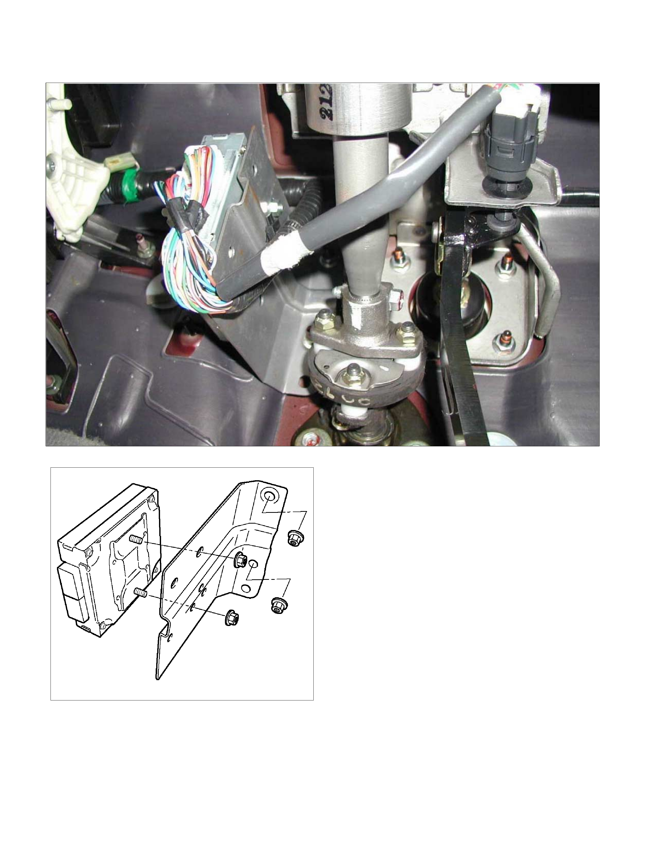
OBD Diagnostic Management System
Transmission Control Module (TCM) Location
P1010052
RTW37ASH000301

16 – Terminal Data Link Connector (DLC)
OBD standardises Data Link Connector (DLC)
configurations. The DLC, formerly referred to as the
ALDL, will be a 16–terminal connector found on the
lower right side of the driver's side instrument panel. All
manufacturers must conform to this 16–terminal
standard.
060R300015
810RT022
PIN 1 – uart
PIN 2 – J1850 Bus + L line on 2–wire systems, or
single wire (ECM)
PIN 3 – (Not used)
PIN 4 – Chassis ground pin
PIN 5 – Chassis ground pin
PIN 6 – ECM diagnostic enable
PIN 7 – KW2000
PIN 8 – (Not used)
PIN 9 – Primary UART
PIN 10 – (Not used)
PIN 11 – TCM diagnostic enable
PIN 12 – ABS diagnostic or CCM diagnostic enable
PIN 13 – SIR diagnostic enable
PIN 14 – (Not used)
PIN 15 – (Not used)
PIN 16 – Battery power from vehicle unswitched (4
AMP MAX.)

Clear DTC
NOTE: If you clear the DTC (Diagnostic Trouble
Codes) you will not be able to read any codes recorded
during the last occurrence.
NOTE: To use the DTC again to identify a problem,
you will need to reproduce the fault or the problem.
This may require a new test drive or just turning the
ignition on (this depends on the nature of the fault).
1. IF you have a Tech 2:
1. Connect the Tech 2 if it is still not connected go
through Tech 2 OBD CONNECTION.
2. Push “F1: Clear DTC Information" in the
Application Menu and answer “Yes" to the
question “Do you want to clear DTC's?"
a. When a malfunction still exists and the Tech
2 displays “AW30-40 CODES NOT
CLEARED". This means that the problem is
still there or that the recovery was not done.
Please go to DTC CHECK.
b. When a malfunction has been repaired and
the recovery is done the Tech 2 displays
“AW30-40LE CODES CLEARED".
2.When you have no Tech 2, the stored trouble codes
can be cleared by shorting the terminals No.11 and
No.4 or 5 (ground) of data link connector with a lead
wire for 1 6 seconds.
DTC Check
1. Diagnostic Trouble Codes (DTC) have been
identified by Tech 2.
2. You have written the list of the DTCs. The order of
the malfunctions has no meanings for this TCM.
Usually only one or two malfunctions should be set
for a given problem.
3. Check directly the DTCs you identified. The DTCs
are sorted by number. Refer to Diagnostic Trouble
Code (DTC) Identification in this section.
TCM Precaution
The TCM can be damaged by:
1. The electrostatic discharge
2. The short circuit of some terminals to voltage or to
ground.
Electrostatic Discharge Damage Description:
1. Electronic components used to control systems
are often designed to carry very low voltage, and
are very susceptible to damage caused b
y
electrostatic discharge. It is possible for less than
100 volts of static electricity to cause damage to
some electronic components. By comparison, it
takes as much as 4,000 volts for a pers on to even
feel the zap of a static discharge.
2. There are several ways for a person to become
statically charged. The most common methods o
f
charging are by friction and induction. An exam ple
of charging by friction is a person sliding across a
car seat, in which a charge of as much as 25,000
volts can build up. Charging by induction occurs
when a person with well insulated shoes stands
near a highly charged object and momentaril
y
touches ground. Charges f or the sam e polarity are
drained of f, leaving the person highly charged with
the opposite polarity. Static charges of either type
can cause damage, therefore, it is important to use
care when handling and testing electronic
components.
NOTE: To prevent possible electrostatic discharge
damage:
1. Do not touch the TCM connector pins or soldered
components on the TCM circuit board.
2. Be sure to follow the guidelines listed below if
servicing any of these electronic components:
3. Do not open the replacement part package until it is
time to install the part.
4. Avoid touching electrical terminals of the part.
5. Before removing the part from its package, ground
the package to a known good ground on the
vehicle.
6.
A
lways touch a known good ground before handling
the part. This step should be repeated before
installing the part if the part has been handled while
sliding across the seat, while sitting down from a
standing position or while walking some distance.
Information On TCM
1. The Transmission Control Module (TCM) is located
in the place of a clutch pedal and is the control
centre of the electronic transmission control system.
2. The TCM must be maintained at a temperature
below 85°C (185°F) at all times. This is most
essential if the vehicle is put through a paint baking
process. The TCM will become inoperative if its
temperature exceeds 85°C (185°F). Therefore, it is
recommended that the TCM be removed or that
temporary insulation be placed around the TCM
during the time the vehicle is in a paint oven or other
high temperature process.
3. The TCM is designed to process the various inputs
and then respond by sending the appropriate
electrical signals to control transmission upshift,
downshift, shift feel and torque converter clutch
engagement.
4. The TCM constantly interprets information from the
various sensors, and controls the systems that
affect transmission and vehicle performance. By
analysing operational problems, the TCM is able to
perform a diagnostic function by displaying DTC(s)
and aid the technician in making repairs.

TCM Diagnostic Trouble Codes
The following table lists the diagnostic trouble codes supported by this vehicle application. If any a scan tool displays
DTCs not listed here, the scan tool data may by faulty; notify the scan tool manufacture of any DTCs displayed that are
not included in the following table.
DTC
NUMBER FLASH
CODE DTC NAME “CHECK
TRANS"
P0560 25 System Voltage Error —
P0602 63 Transmission Control Module (TCM) Programming Error —
P0705 17 Transmission Range Sensor Circuit Malfunction ON
P0712 15 Transmission Oil Temperature Sensor Circuit Low Input ON
P0713 16 Transmission Oil Temperature Sensor Circuit Hight Input ON
P0717 14 Input Speed Sensor Signal Error ON
P0722 11 Output Speed Sensor Signal Error ON
P0743 33 Torque Converter Clutch Electrical ON
P0748 35 Pressure Control Solenoid Electrical ON
P0753 31 Shift Solenoid S1 Electrical ON
P0758 32 Shift Solenoid S2 Electrical ON
P1767 67 ECM CAN (Control Area Network) Invalid ON
P1790 61 Transmission Control Module ROM Checksum Error ON
P1791 62 Transmission Control Module RAM Error ON
U2104 65 CAN (Control Area Network) BUSS OFF ON
DTC P0560 (FLASH CODE 25) System Voltage Error
RTW37ALF000701
Circuit Description
The Transmission Control Module (TCM) monitors the
system voltage on the ignition feed terminal to the TCM.
A system voltage DTC will set whenever the voltage is
below or above a calibrated value.
Condition for setting the DTC
When the TCM detects following conditions.
• Ignition voltage is less than 9V or more than 18V.
• Engine speed is more than 600 rpm.
Action Taken When The DTC Sets
• DTC stored.
Conditions For Clearing The DTC
• The DTC can be cleared from the TCM history by
using a scan tool.
• The DTC will be cleared from history when the
vehicle has achieved 40 warm-up cycles without a
failure reported.
• After more than 1 second has elapsed after the
ignition key has been turned “ON", short between
No.11 and No.4 (ground) of DLC (Data Link
Connector). Then, after 1 second, but within 6
seconds, discontinue shorting.
Diagnostic Aids
• Inspect the wiring for poor electrical connection at the
TCM. Look for possible bent, backed out, deformed
or damaged terminals. Check for weak terminal
tension as well. Also check for a chafed wire that
could short to bare metal or other wiring.
Inspect for a broken wire inside the insulation.
• When diagnosing for a possible intermittent short or
open condition, move the wiring harness while
observing test equipment for a change.

DTC P0560 – System Voltage Error
Step Action Value(s) YES NO
1 Was the powertrain On-Board Diagnostic (OBD)
System Check performed?
— Go to Step 2 Go to OBD
System Check
2 Using a DVM, measure the battery voltage at the
battery.
Is the battery voltage greater than the specified value?
11.5 V Go to Step 3 Charge battery,
then go to Step
3
3 1. Install a Tech 2.
2. Select “Ignition Volts" on the Tech 2.
3. Start the engine and raise the engine speed to the
specified value.
4. Load the electrical system by turning on the
headlights, high blower, etc.
Is the ignition voltage approximately equal to the
specified value?
2000 RPM
12.8-14.1 V
Go to Step 4 Go to
Starting/Chargi
ng
4 1. Ignition “OFF".
2. Disconnect the TCM connector at the TCM.
3. Using a DVM, measure the battery voltage at the
TCM connector C-94.
Is it approximately equal to battery voltage?
— Check for
excessive
current draw
with ignition
“OFF" engine
“OFF".
Go to Step 5
5 1. Check for faulty connections at the TCM harness
terminals.
2. Repair as necessary.
Was a repair necessary?
— Verify repair Go to Step 6
6 Check for an open battery feed circuit to the TCM.
Is the action complete?
— Verify repair Go to Step 7
7 Replace the TCM.
Important: The replacement TCM must be
programmed. (Refer to SPS for procedure.)
Is the action complete?
— Verify repair —

DTC P0602 (FLASH CODE 63) Transmission Control Module (TCM) Programming Error
Circuit Description
The Service Programming System (SPS) updates the
flash calibration files that are stored in a Transmission
Control Module (TCM). The calibration file
custom-tailors a module to a certain vehicle. The
calibration file contains data for things such as spark
curves and fuel control. When troubleshooting a
driveability problem, diagnosis may call for
reprogramming the controller with newer calibration
information to correct a customer concern and Vehicle
Identification Number (VIN).
Condition for setting the DTC
When the VIN is not written to the TCM.
Action Taken When The DTC Sets
• DTC stored.
Conditions For Clearing The DTC
• The DTC can be cleared from the TCM history by
using a scan tool.
• The DTC will be cleared from history when the
vehicle has achieved 40 warm-up cycles without a
failure reported.
• After more than 1 second has elapsed after the
ignition key has been turned “ON", short between
No.11 and No.4 (ground) of DLC (Data Link
Connector). Then, after 1 second, but within 6
seconds, discontinue shorting.
Diagnostic Aids
DTC P0602 indicates that the VIN has not been written
to the TCM.
Do not replace the TCM – reprogram with the SPS to
write the VIN to the TCM and disable the security lock.
DTC P0602 (FLASH CODE 63) Transmission Control Module (TCM) Programming Error
Step Action Value(s) YES NO
1 Was the “On-Board Diagnostic (OBD) System Check"
performed?
— Go to Step 2 Go to OBD
System Check
2 1. Install the scan tool.
2. Key “ON".
3. Check the Vehicle Identification Number (VIN) by the
scan tool.
Is VIN on the scan tool same as vehicle VIN?
— Go to Step 4 Go to Step 3
3 Write the VIN by the scan tool. (Refer to SPS for
procedure.)
Is the action complete?
— Go to Step 4 —
4 Clear the DTC P0602 by the scan tool.
Is the action complete?
— Go to Step 5 —
5 Perform the SPS and perform security lock. (Refer to SPS
for procedure)
Is the action complete?
— Go to Step 6 —
6 Recheck the DTC by the scan tool.
1. Key “OFF".
2. Wait a few seconds.
3. Key “ON".
4. Review and record scan tool data.
5. Operate the vehicle with in scan tool data.
Is the action complete?
— Go to Step 7 Verify repair
7 Replace the TCM.
Important: The replacement TCM must be programmed.
(Refer to SPS for procedure.)
Is the action complete?
— Verify repair —
DTC P0705 (FLASH CODE 17) Transmission Range Sensor Circuit Malfunction
RTW37ALF000501
Circuit Description
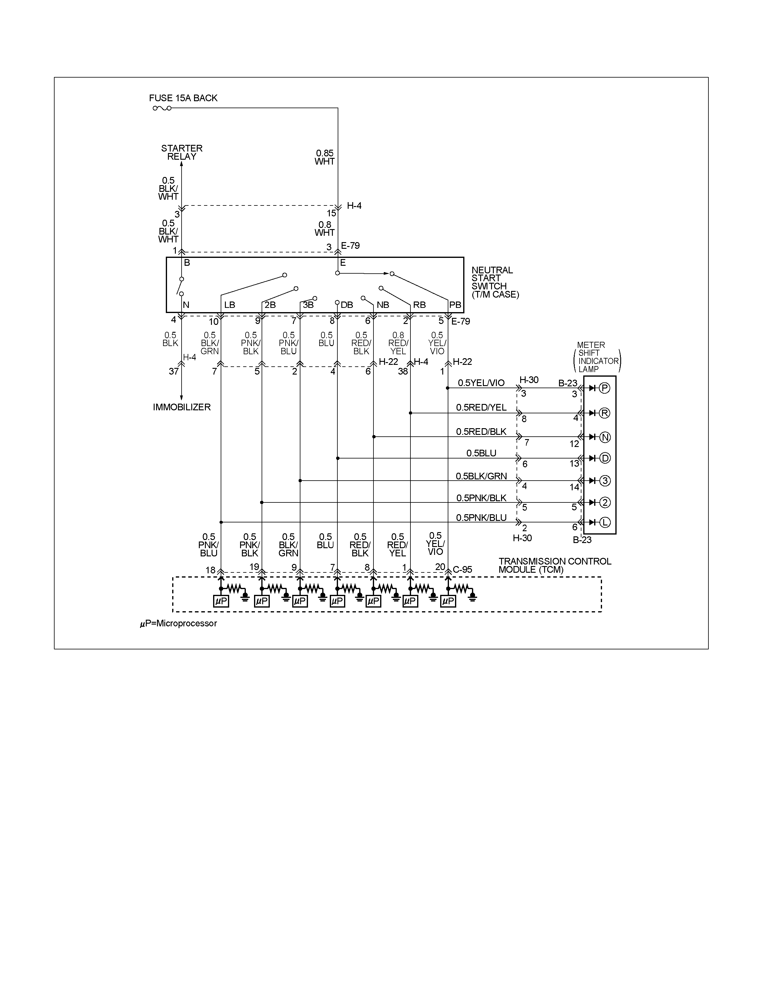
The neutral start switch gives the signals related to the
selector lever position (PRND32L) to the Transmission
Control Module (TCM). The neutral start switch turns on
when the select lever is shifted to the P, R, N, D, 3, 2 or
L range. The neutral start switch, which is connected to
the starter switch circuit, is available only when the
select lever is in the P or N range (Engine run).
The neutral start switch is connected to the
transmission manual shaft and installed in the
transmission case.
Condition for setting the DTC
• The TCM detects following "Condition 1" for 30 sec
continuously.
• The TCM detects following "Condition 2" for 10 sec
continuously.
Condition 1("Open"):
When the TCM detects no signal of range sensor
more than 2.0 sec at following conditions.

Condition 2 ("Short"):
When the TCM detects 2 times or more signals of
range sensor more than 0.025 sec at following
conditions.
• Vehicle speed is more than 19 mph.
• Engine speed is more than 1500 rpm.
Action Taken When The DTC Sets
• No 3rd start mode.
• No slope control.
• The TCM judges always D range position of range
sensor at "Condition 1".
• The TCM judges the position of range sensor with
following priority at "Condition 2".
• There is a priority in order of D, 3, 2, L, R, N, and P.
• Check Trans ON.
• DTC stored.
Conditions For Clearing The DTC
• The DTC can be cleared from the TCM history by
using a scan tool.
• The DTC will be cleared from history when the
vehicle has achieved 40 warm-up cycles without a
failure reported.
• After more than 1 second has elapsed after the
ignition key has been turned “ON", short between
No.11 and No.4 (ground) of DLC (Data Link
Connector). Then, after 1 second, but within 6
seconds, discontinue shorting.
Diagnostic Aids
• Inspect the wiring for poor electrical connection at the
TCM. Look for possible bent, backed out, deformed
or damaged terminals. Check for weak terminal
tension as well. Also check for a chafed wire that
could short to bare metal or other wiring.
Inspect for a broken wire inside the insulation.
• When diagnosing for a possible intermittent short or
open condition, move the wiring harness while
observing test equipment for a change.
• Check range sensor for proper mounting and
adjustment.

DTC P0705 (FLASH CODE 17) Transmission Range Sensor Circuit Malfunction
Step Action Value(s) YES NO
1 Was the powertrain On-Board Diagnostics (OBD) System
check performed ?
— Go to Step 2 Go to OBD
System Check
2 1. Install the scan tool.
2. Key “ON"
3. Review and record scan tool data.
4. Operate the vehicle with in scan tool data.
Does the scan tool indicate DTC P0705 ?
— Go to Step 3 Refer to
Diagnostic Aids
3 Measure the voltage between TCM connector terminals
and ground, with the selector lever in each gear position.
1. Key “OFF"
2. Disconnect the TCM connector.
3. Key “ON"
4. Connect the DMM to the TCM connector terminal and
ground.
Is the displayed voltage at every position normal ?
7—16V Go to Step 7 Go to Step 4
4 Measure the voltage between terminal the neutral start
switch and ground.
1.Key “OFF"
2. Disconnect the neutral start switch connector.
3.Key “ON"
4. Connect the J39200 DMM to the each terminal of the
neutral start switch connector E79-3 and ground.
If the problem found repair as necessary.
Was the problem found?
7—16V Verify repair Go to Step 5
5 Measure the resistance shifting the select lever to every
position, between terminal neutral start switch connector
E79-3 and E79other terminal.
1.Key “OFF"
2. Disconnect the neutral start switch connector.
3.Key “ON"
4. Connect the DMM to the each terminal of the neutral
start switch connector E79-3 and E79-5 or E79-2 or
E79-6 E79-8 or E79-7 or E79-9 or E79-10.
If the problem found repair as necessary.
Was the problem found?
Less than 1 Verify repair Go to Step 6
6 Check the wire between terminal C-95 and E-79 for open.
1. Connect the J39200 DMM to the each terminal of the
TCM connector and neutral start switch.
If the problem found repair as necessary.
Was the problem found?
∞ Verify repair —
7 Replace the TCM.
IMPORTANT; The replacement TCM must be
programmed. (Refer to SPS for procedure.)
Is the action complete?
— Verify repair —
DTC P0712 (FLASH CODE 15) Transmission Oil Temperature Sensor Circuit Low Input
RTW37AMF000201
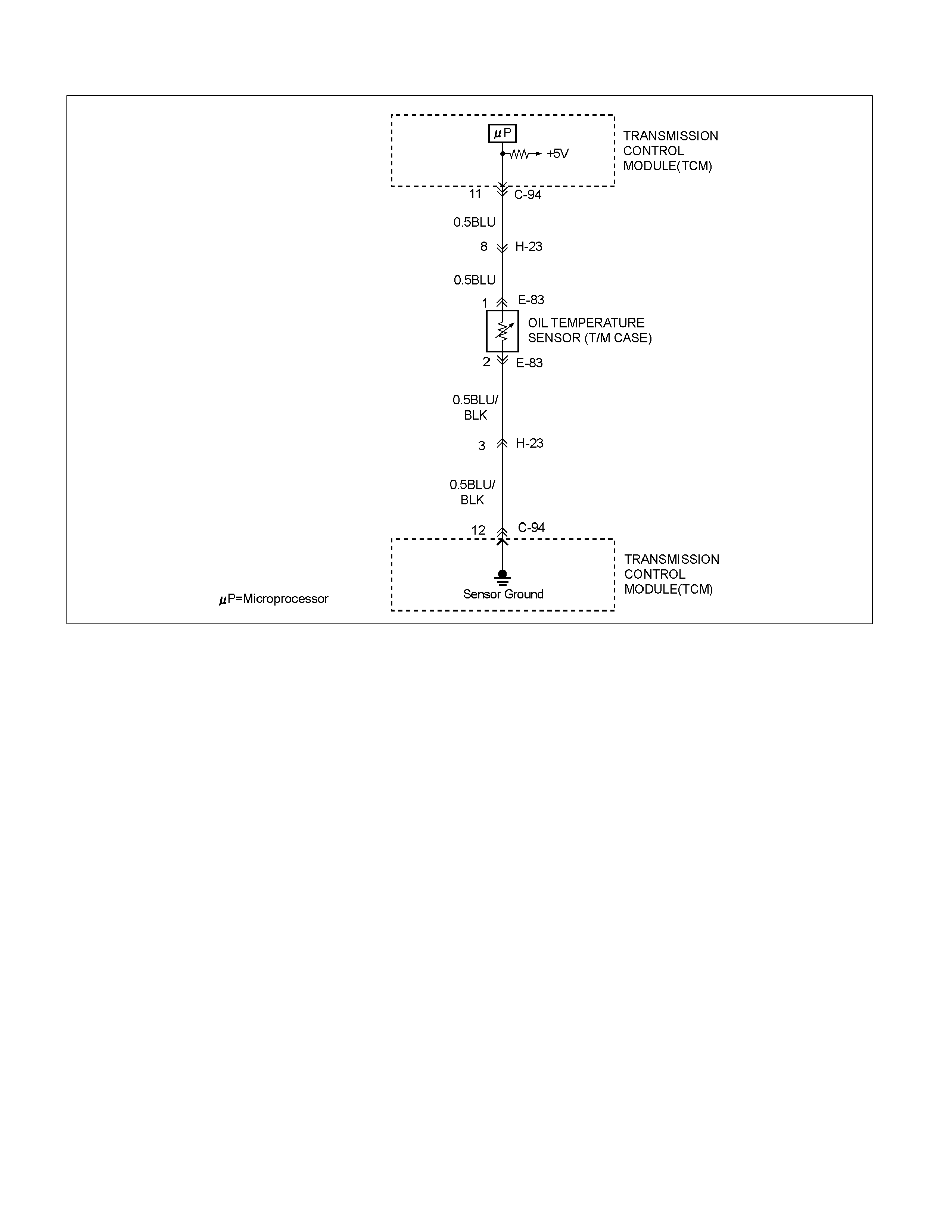
Circuit Description
The oil temperature sensor is a thermistor sensor that is
installed in the transmission case and converts
temperature changes into continuous electric signals,
then outputs them to the Transmission Control Module
(TCM). When the ATF temperature is low, the
resistance of the sensor (thermistor) goes up, so that
the voltage of the TCM signal becomes high.
As the ATF is gradually warmed, the resistance of the
sensor goes down and the voltage becomes low. At the
normal operating ATF temperature (80°C/176°F) of the
transmission, the voltage of the TCM is about 3.7V.
Condition for setting the DTC
• The TCM detects following "Condition" for 5 min
continuously.
Condition ("Short"):
• Oil temperature is more than 220°C (428°F).
Action Taken When The DTC Sets
• The TCM judges oil temperature is 100°C (212°F).
• Check Trans ON.
• DTC stored.
Conditions For Clearing The DTC
• The DTC can be cleared from the TCM history by
using a scan tool.
• The DTC will be cleared from history when the
vehicle has achieved 40 warm-up cycles without a
failure reported.
• After more than 1 second has elapsed after the
ignition key has been turned “ON", short between
No.11 and No.4 (ground) of DLC (Data Link
Connector). Then, after 1 second, but within 6
seconds, discontinue shorting.
Diagnostic Aids
• Inspect the wiring for poor electrical connection at the
TCM. Look for possible bent, backed out, deformed
or damaged terminals. Check for weak terminal
tension as well. Also check for a chafed wire that
could short to bare metal or other wiring. Inspect for a
broken wire inside the insulation.
• When diagnosing for a possible intermittent short or
open condition, move the wiring harness while
observing test equipment for a change.
• Check oil temperature sensor for proper mounting
and adjustment.

DTC P0712 (FLASH CODE 15) Transmission Oil Temperature Sensor Circuit Low Input
Step Action Value(s) YES NO
1 Was the powertrain On-Board Diagnostic (OBD)
System Check performed?
— Go to Step 2 Go to OBD
System Check
2 Perform the transmission fluid checking procedure.
Refer to checking Transmission Fluid level and
Condition in Automatic Transmission 7A section.
Was the fluid checking procedure performed ?
— Go to Step 3 Refer to
Checking
Transmission
Fluid level and
Condition in
Automatic
Transmission
(AW30-40LE)
section
3 1. Install the scan tool.
2. Key “ON"
3. Review and record scan tool data.
4. Operate the vehicle with in scan tool data.
Does the scan tool indicate DTC P0712 ?
— Go to Step 4 Refer to
Diagnostic Aids
4 Measure the voltage of the transmission fluid
temperature sensor by the J39200 DMM.
1. Key “OFF".
2. Disconnect the oil temperature sensor connector.
3. Key “ON".
4. Connect the J39200 DMM to the each terminal of
the oil temperature sensor connector E83-2 and
E83-1.
Does the scan tool indicate less than specified value ?
5V Go to Step 5 Go to Step 6
5 Replace the transmission fluid temperature sensor.
Is the action complete ?
— Verify repair —
6 Measure the resistance of the wire by the J39200
DMM.
1. Key “OFF".
2. Disconnect the TCM connector.
3. Install a jumper wire from terminal E83-1 and E83-
2 on the mission harness.
4. Connect the j39200 DMM to the each terminal of
the TCM connector C94-11 and C94-12.
If a problem is found, repair as necessary.
Was the problem found ?
less than 1 Verify repair Go to Step 7
7 Replace the TCM.
Important: The replacement TCM must be
programmed.
(Refer to SPS for procedure.)
Is the action complete ?
— Verify repair —

DTC P0713 (FLASH CODE 16) Transmission Oil Temperature Sensor Circuit Hight Input
RTW37AMF000201
Circuit Description
The oil temperature sensor is a thermistor sensor that is
installed in the transmission case and converts
temperature changes into continuous electric signals,
then outputs them to the Transmission Control Module
(TCM). When the ATF temperature is low, the
resistance of the sensor (thermistor) goes up, so that
the voltage of the TCM signal becomes high.
As the ATF is gradually warmed, the resistance of the
sensor goes down and the voltage becomes low. At the
normal operating ATF temperature (80°C/176°F) of the
transmission, the voltage of the TCM is about 3.7V.
Condition for setting the DTC
• The TCM detects following "Condition" for 15 min
from ignition ON.
Condition ("Open"):
• Fluctuation of high temperature fixed value is
2.3°C (36°F).
• Fluctuation of low temperature fixed value is -10°C
(14°F).
Action Taken When The DTC Sets
• The TCM judges oil temperature is 100°C (212°F).
• Check Trans ON.
• DTC stored.
Conditions For Clearing The DTC
• The DTC can be cleared from the TCM history by
using a scan tool.
• The DTC will be cleared from history when the
vehicle has achieved 40 warm-up cycles without a
failure reported.
• After more than 1 second has elapsed after the
ignition key has been turned “ON", short between
No.11 and No.4 • (ground) of DLC (Data Link
Connector). Then, after 1 second, but within 6
seconds, discontinue shorting.
Diagnostic Aids
• Inspect the wiring for poor electrical connection at the
TCM. Look for possible bent, backed out, deformed
or damaged terminals. Check for weak terminal
tension as well. Also check for a chafed wire that
could short to bare metal or other wiring. Inspect for a
broken wire inside the insulation.
• When diagnosing for a possible intermittent short or
open condition, move the wiring harness while
observing test equipment for a change.
• Check oil temperature sensor for proper mounting
and adjustment.

DTC P0713 (FLASH CODE 16) Transmission Oil Temperature Sensor Circuit Hight Input
Step Action Value(s) YES NO
1 Was the powertrain On-Board Diagnostic (OBD)
System Check performed ?
— Go to Step 2 Go to OBD
System check
2 Perform the transmission fluid checking procedure.
Refer to Checking Transmission Fluid Level and
condition Automatic Transmission7A section.
Was the fluid checking procedure performed ?
— Go to Step 3 Refer to
checking
Transmission
Fluid Level and
Condition
Automatic
Transmission
(AW30-40LE)
section
3 1. Install the scan tool ?
2. Key “ON"
3. Review and record scan tool date.
4. Operate the vehicle with in scan tool data.
Does the scan tool indicator DTC P0713 ?
— Go to Step 4 Go to
Diagnostic Aids
4 Observe the voltage of the transmission fluid
temperature sensor on the TECH2 data.
1. Key “OFF".
2. Disconnect the transmission fluid temperature
sensor connector E-83
3. Install a fused jumper wire from terminal E83-2 to
E83-1 on the mission harness.
4. Key “ON".
Does the scan tool indicate more than specified
value ?
0.4V Go to Step 5 Go to Step 6
5 Replace the transmission fluid temperature sensor .
If the action complete ?
— Verify repair —
6 Measure the resistance of wire by the J39200 DMM.
1. Key “OFF".
2. Disconnect the TCM connector
3. Install a fused jumper wire from terminal E83-1 and
E83-2 on the mission harness.
Does the scan tool indicate less than specified value ?
less than 1Go to Step 8 Go to Step 7
7 Repair an open circuit.
Was the problem found ?
— Verify repair —
8 Replace the TCM
IMPORTANT; The replacement TCM must be
programmed. (Refer to SPS for procedure.)
Is the action complete ?
— Verify repair —
DTC P0717 (FLASH CODE 14) Input Speed Sensor Signal Error
MAW060MF001501
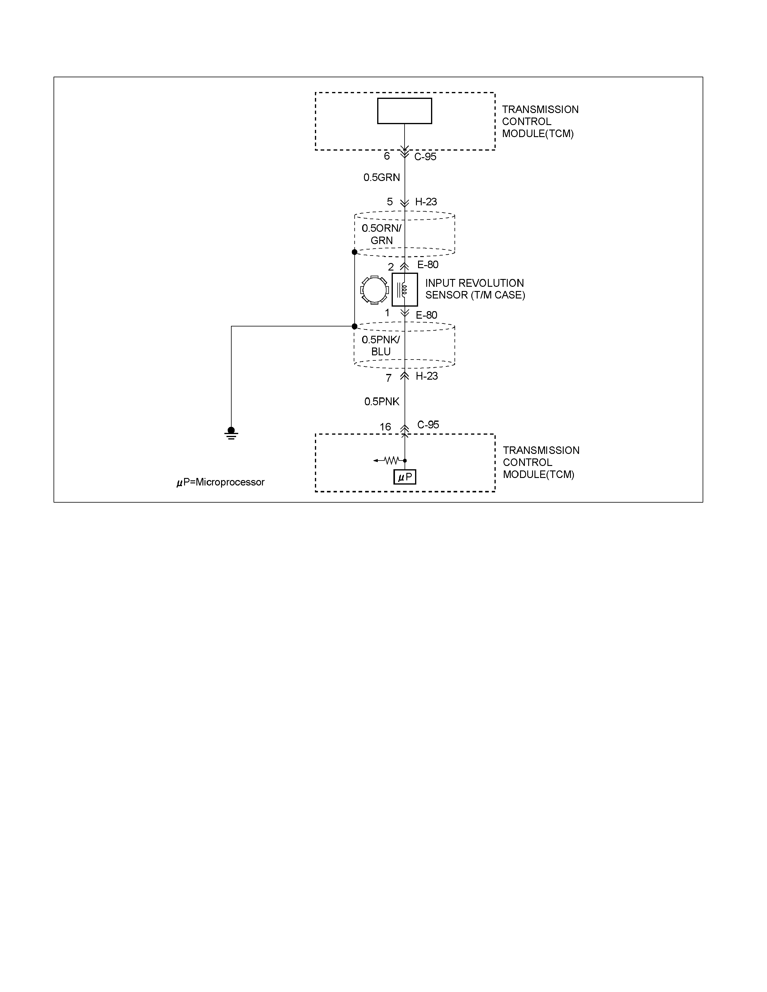
Circuit Description
Input revolution information is provided to TCM by the
input revolution sensor. This sensor is located in the
transmission case.
The input revolution sensor is an electromagnetic pulse
pickup type that generates a speed signal according to
the revolution of the transmission OD direct clutch
drum. As a result, the sensor sends a sine wave signal
(AC) to the TCM, which converts this sine wave signal
(pulse voltage) to a RPM signal.
Condition for setting the DTC
The TCM detects following conditions at 1000
times continuously.
• When the TCM detects following conditions at the
same time.
• When output speed is over 775 rpm (16 mph) at gear
position is 1st or 2nd or 3rd.
• Input speed signal is no pulse while output speed
signal are 12 pulses.
OR
• When the TCM output 2nd gear.
• The TCM detects no pulse of input speed sensor
circuit signal after 3.5 sec.
(detection time: 0.03 sec at vehicle speed is 36 mph)
Action Taken When The DTC Sets
• No engine torque control.
• No line pressure control.
• No lock-up control.
• No slope control.
• Check Trans ON.
• DTC stored.
• No detect DTC P0722.

Conditions For Clearing The DTC
• The DTC can be cleared from the TCM history by
using a scan tool.
• The DTC will be cleared from history when the
vehicle has achieved 40 warm-up cycles without a
failure reported.
• After more than 1 second has elapsed after the
ignition key has been turned “ON", short between
No.11 and No.4 (ground) of DLC (Data Link
Connector). Then, after 1 second, but within 6
seconds, discontinue shorting.
Diagnostic Aids
• Inspect the wiring for poor electrical connection at the
TCM. Look for possible bent, backed out, deformed
or damaged terminals. Check for weak terminal
tension as well. Also check for a chafed wire that
could short to bare metal or other wiring.
Inspect for a broken wire inside the insulation.
• When diagnosing for a possible intermittent short or
open condition, move the wiring harness while
observing test equipment for a change.
• Check input speed sensor for proper mounting and
adjustment.

DTC P0717 (FLA SH CODE 14) Input Speed Sensor Signal Error
Step Action Value(s) YES NO
1 Was the powertrain On-Board Diagnostic (OBD) System
check performed ?
— Go to Step 2 Go to OBD
system check
2 1. Install the scan tool.
2. Key “ON".
3. Review and record scan tool data
4. Operate the vehicle with in scan tool data.
Does the scan tool indicator DTC0717 ?
— Go to Step 3 Refer to
Diagnostic Aids
3 Measure voltage of the input revolution sensor by the
J39200 DMM.
1. Key “ON".
2. Engine run.
3. Disconnect the input revolution sensor connector .
4. Measure the voltage between terminal the input
revolution sensor connector E80-1 and E80-2.
Does the scan tool indicate less than specified value ?
3V Refer to
Diagnostic Aids Go to Step 4
4 Measure the resistance of wire by the J39200 DMM.
1. Key “OFF".
2. Disconnect the TCM connector.
3. Connect the input revolution sensor connector.
4. Measure the resistance between the TCM connector
terminal C95-6 and C95-16.
Does the scan tool indicate specified value ?
560680
(20°C)
Go to Step 5 Go to Step 6
5 1. Replace the TCM.
2. Install the scan tool(TECH2).
3. Make a road running test for the vehicle.
Important: The replacement TCM must be programmed.
(Refer to SPS for procedure.)
Dose the scan tool indicate DTC P0717 ?
— Go to Step 7 Go to Step 8
6 Measure the resistance of input revolution sensor by the
J39200 DMM.
1. Key “OFF".
2. Disconnect the input revolution sensor connector.
3. Measure the resistance between terminal input
revolution sensor side connector E80-1 and E80-2.
Does the scan tool indicate specified ?
560680
(20°C)
Go to Step 9 Go to Step 7
7 Replace the input revolution sensor.
Is the action complete ?
— Verify repair —
8 Replace the TCM.
IMPORTANT; The replacement TCM must be
programmed. (Refer to SPS for procedure.)
Is the action complete ?
— Verify repair —
9 Check the wire between terminal C95-6 and E80-2 or C95-
16 and E80-1.
1. 1.Connect the J39200 DMM to the each of the TCM
connector and input revolution sensor.
If the problem found repair as necessary.
Was the found problem ?
— Verify repair —
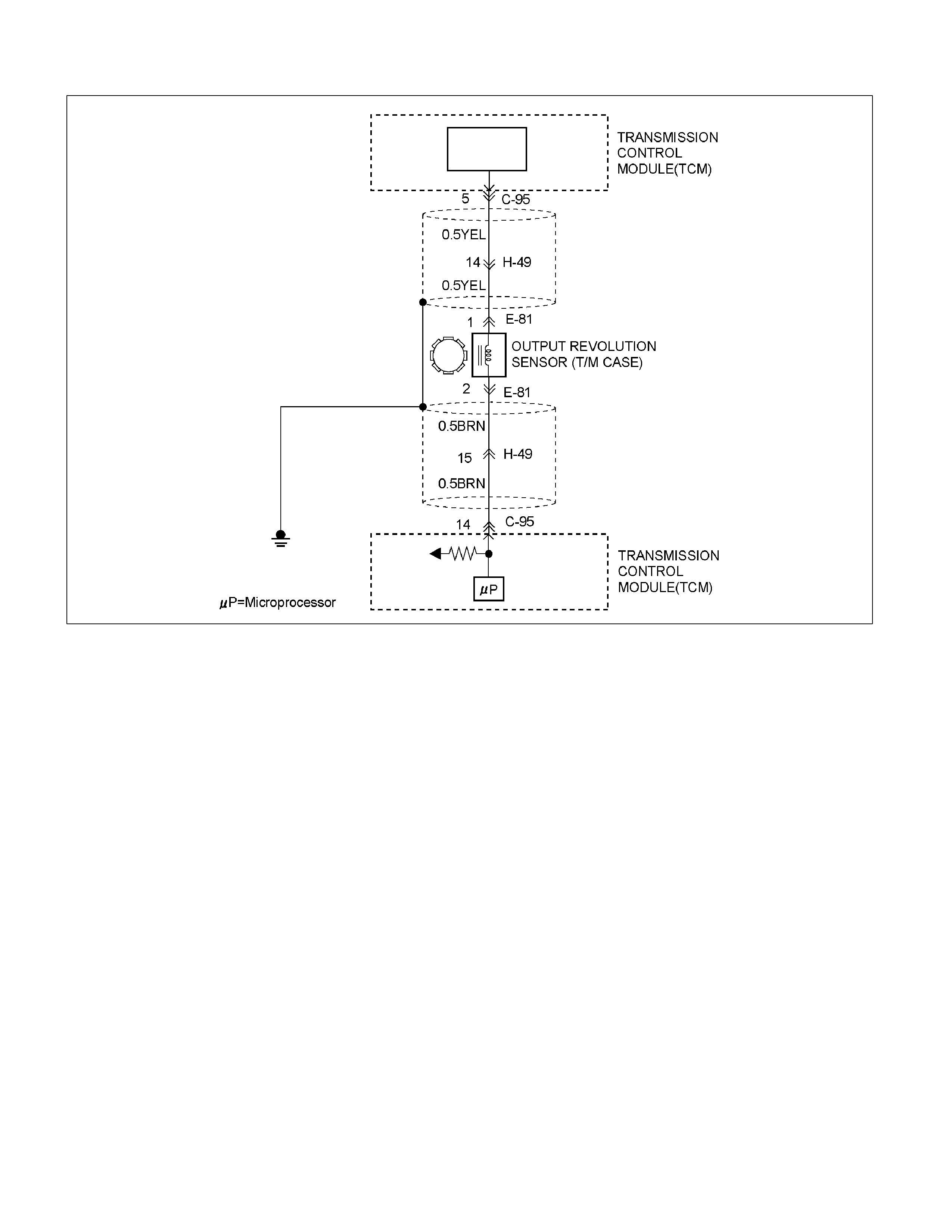
DTC P0722 (FLASH CODE 11) Output Speed Sensor Signal Error
RTW37AMF000501
Circuit Description
Vehicle speed information is provided to the TCM by the
output revolution sensor. This sensor is located in the
transmission adapter housing.
The output revolution sensor is an electromagnetic
pulse pickup type that generates a speed signal
according to the revolution of the transmission output
shaft. As a result, the sensor sends a sine wave signal
(AC) to the TCM, which converts this sine wave signal
(pulse voltage) to a RPM signal.
Condition for setting the DTC
The TCM detects following conditions at 500 times
continuously.
(When gear positions are 1st, 2nd and 3rd.)
When the TCM detects following conditions at the same
time.
• Output speed signal is no pulse while input speed
signal are 45 pulses.
(Detection time, 1st: 0.031 sec, 2nd: 0.057 sec, 3rd:
0.087 sec, at vehicle speed is 38 mph.)
Action Taken When The DTC Sets
• The TCM uses input speed sensor as a vehicle
speed.
• No squat control.
• No engine torque control.
• No line pressure control.
• No use 4th gear.
• No lock-up control.
• No slope control.
• Check Trans ON.
• DTC stored.
• No reverse lockout control.

Conditions For Clearing The DTC
• The DTC can be cleared from the TCM history by
using a scan tool.
• The DTC will be cleared from history when the
vehicle has achieved 40 warm-up cycles without a
failure reported.
• After more than 1 second has elapsed after the
ignition key has been turned “ON", short between
No.11 and No.4 (ground) of DLC (Data Link
Connector). Then, after 1 second, but within 6
seconds, discontinue shorting.
Diagnostic Aids
• Inspect the wiring for poor electrical connection at the
TCM. Look for possible bent, backed out, deformed
or damaged terminals. Check for weak terminal
tension as well. Also check for a chafed wire that
could short to bare metal or other wiring.
Inspect for a broken wire inside the insulation.
• When diagnosing for a possible intermittent short or
open condition, move the wiring harness while
observing test equipment for a change.
• Check output speed sensor for proper mounting and
adjustment.

DTC P0722 (FLASH CODE 11) Output Speed Sensor Signal Error
Step Action Value(s) YES NO
1 Was the powertrain On-Board Diagnostic (OBD) System
check performed ?
— Go to Step 2 Go to OBD
system check
2 1. Install the scan tool.
2. Key “ON".
3. Review and record scan tool data
4. Operate the vehicle with in scan tool data.
Does the scan tool indicator DTC 0722 ?
— Go to Step 3 Refer to
Diagnostic Aids
3 Measure the voltage of the output revolution sensor by the
J39200 DMM.
1. Key “OFF"
2. Lift the driving wheels.
3. Disconnect the output revolution sensor connector.
4. With engine idling in gear.
5. Measure the voltage between the output revolution
sensor connector terminal E81-1 and E81-2.
Does the scan tool indicate less than specified value ?
3V Refer to
Diagnostic Aids Go to Step 4
4 Measure the resistance of wire by the J39200 DMM.
1. Key “OFF".
2. Disconnect the TCM connector.
3. Connect the output revolution sensor connector.
4. Measure the resistance between the TCM terminal C95-
5 and C95-14
Does the scan tool indicate specified value ?
560680(20°
C)
Go to Step 5 Go to Step 6
5 1. Replace the TCM
2. Install the scan tool (TECH2).
3. Make a road running test for the vehicle.
Important: The replacement TCM must be programmed.
(Refer to SPS for procedure.)
Does the scan tool indicate DTC P0722 ?
— Go to Step 7 Go to Step 8
6 Measure the resistance of output revolution sensor by the
J39200 DMM.
1. Key “OFF"
2. Disconnect the output revolution sensor connector.
3. Measure the resistance between terminal output
revolution sensor side connector E81-1 and E81-2.
Does the scan tool indicate specified ?
560680(20°
C)
Go to Step 9 Go to Step 7
7 Replace the output revolution sensor.
Is the action complete ?
— Verify repair —
8 Replace the TCM.
Important: The replacement TCM must be programmed.
(Refer to SPS for procedure.)
Is the action complete ?
— Verify repair —
9 Check the wire between terminal C95-5 and E81-1 or C95-
14 and E81-2.
1. Connect the J39200 DMM to the each the TCM
connector and output revolution sensor.
If the problem found repair as necessary.
Was the found problem ?
— Verify repair —

DTC P0743 (FLASH CODE 33) Torque Converter Clutch Electrical
RUW37ALF000601
Circuit Description
The lock-up solenoid SL of the torque converter clutch
(TCC) controls the lock-up clutch by a signal according
to the lock-up range judgment of the TCM when the
vehicle runs.
This function can improve the fuel consumption to
almost the same extent as the manual transmission.
The lock-up solenoid SL is put into B+ by the TCM, so
that the solenoid is actuated with the result of lock-up.
Condition for setting the DTC
The TCM detects following conditions both "Condition
1" and "Condition 2" occur 2 times or more than it.
Condition 1 ("GND short"):
• Voltage at connector pin is 0V for 0.3 sec
continuously when solenoid is “ON".
Condition 2 ("Open or IG short"):
• Voltage at connector pin is ignition voltage for 0.5 sec
continuously when solenoid is “OFF".
Action Taken When The DTC Sets
• No lock-up control.
• The TCM fixes to 1st gear when the vehicle speed is
less than 6 mph.
• Check Trans ON.
• DTC stored.

Conditions For Clearing The DTC
• The DTC can be cleared from the TCM history by
using a scan tool.
• The DTC will be cleared from history when the
vehicle has achieved 40 warm-up cycles without a
failure reported.
• After more than 1 second has elapsed after the
ignition key has been turned “ON", short between
No.11 and No.5 (ground) of DLC (Data Link
Connector). Then, after 1 second, but within 6
seconds, discontinue shorting.
Diagnostic Aids
• Inspect the wiring for poor electrical connection at the
TCM. Look for possible bent, backed out, deformed
or damaged terminals. Check for weak terminal
tension as well. Also check for a chafed wire that
could short to bare metal or other wiring.
Inspect for a broken wire inside the insulation.
• When diagnosing for a possible intermittent short or
open condition, move the wiring harness while
observing test equipment for a change.
DTC P0743 (FLASH CODE 33) Torque Converter Clutch Electrical
Step Action Value(s) YES NO
1 Was the Powertrain On-Board Diagnostic (OBD) System
Check performed?
— Go to Step 2 Go to OBD
System Check
2 1. Install the scan tool.
2. Key “ON".
3. Review and record scan tool data.
4. Operate the vehicle within scan tool data.
Does the scan tool indicate DTC P0743?
— Go to Step 3 Refer to
Diagnostic Aids
3 1. Key “ON", engine run.
2. Place the selector lever in the "P" range.
3. Measure the voltage between terminal C94-5 and
terminal C94-1 on the TCM pigtail connector by J39200
DMM.
Is the voltage specified value?
816V Go to Step 4 Go to Step 10
4 1. Key "OFF".
2. Disconnect the TCM connector (C-94).
3. Key "ON".
4. Measure the voltage between terminal C94-5 and
terminal C94-1 by J39200 DMM.
Is the voltage specified value?
0V Go to Step 5 Go to Step 7
5 1. Key “OFF".
2. Measure the resistance between terminal C94-5 and
body ground by J39200 DMM.
Is the resistance specified value?
Go to Step 9 Go to Step 6
6 1. Disconnect the automatic transmission connector (E-
82).
2. Measure the resistance between terminal E82-7 and
body ground by J39200 DMM.
Is the resistance specified value?
Go to Step 7 Go to Step 8
7 1. Check for open or short in the wire between terminal
C94-5 and terminal E82-7.
2. Repair or replace the wire between terminal C94-5 and
terminal E82-7.
Is the action complete?
— Verify repair —
8 Replace the SL solenoid.
Is the action complete?
— Verify repair —
9 1. Clear the DTC.
2. Perform the test-driving.
3. Check the DTC.
Was DTC P0743 stored?
— Go to Step 10 Refer to
Diagnostic Aids
10 Replace the TCM.
Is the action complete?
— Verify repair —

DTC P0748 (FLASH CODE 35) Pressure Control Solenoid Electrical
RTW37ALF000601
Circuit Description
The pressure control solenoid is a PWM duty control
solenoid located in the valve body.
The pressure control solenoid is a TCM-controlled
device used to regulate transmission throttle pressure
by energizing current from the TCM.
Condition for setting the DTC
The TCM detects following "Condition 1" and "Condition
2".
Condition 1("Ignition short"):
• When the TCM detects following condition for 0.5 sec
continuously.
• Monitor A/D value is more than 1000 (1.36A).
Condition 2("Open or GND short"):
• When the TCM detects following condition for 70ms
continuously.
• Monitor A/D value is less than 15 (20mA).
Action Taken When The DTC Sets
• No squat control.
• No line pressure control.
• No lock-up control.
• No slope control.
• Check Trans ON.
• DTC stored.

Conditions For Clearing The DTC
• The DTC can be cleared from the TCM history by
using a scan tool.
• The DTC will be cleared from history when the
vehicle has achieved 40 warm-up cycles without a
failure reported.
• After more than 1 second has elapsed after the
ignition key has been turned “ON", short between
No.11 and No.4 (ground) of DLC (Data Link
Connector). Then, after 1 second, but within 6
seconds, discontinue shorting.
Diagnostic Aids
• Inspect the wiring for poor electrical connection at the
TCM. Look for possible bent, backed out, deformed
or damaged terminals. Check for weak terminal
tension as well. Also check for a chafed wire that
could short to bare metal or other wiring.
Inspect for a broken wire inside the insulation.
• When diagnosing for a possible intermittent short or
open condition, move the wiring harness while
observing test equipment for a change.
DTC P0748 (FLA SH CODE 35) Pressure Control Solenoid Malfunction
Step Action Value(s) YES NO
1 Was the Powertrain On-Board Diagnostic (OBD) System
Check performed?
— Go to Step 2 Go to OBD
System Check
2 1. Install the scan tool.
2. Key “ON".
3. Review and record scan tool data.
4. Operate the vehicle within scan tool data.
Does the scan tool indicate DTC P0748?
— Go to Step 3 Refer to
Diagnostic Aids
3 Perform the transmission fluid checking procedure.
Refer to checking Transmission Fluid level and Condition in
Automatic Transmission 7A section.
Was the fluid checking procedure performed?
— Go to Step 4 Refer to checking
Transmission
Fluid level and
Condition in
Automatic
Transmission
(AW30-40LE)
section
4 Measure the resistance of pressure control solenoid.
1. Key “OFF".
2. Disconnect the automatic transmission connector and
TCM connector.
3. Measure the resistance between automatic
transmission terminal E82-2 and automatic
transmission terminal E82-6.
Is the resistance specified value?
5 to 5.6 at
68°F (20°C)
Go to Step 5 Go to Step 8
5 Measure the resistance of wire between terminal C94-2
and terminal C94-4
1. Key “OFF".
2. Connect the automatic transmission connector.
3. Disconnect the TCM connector.
4. Measure the resistance between terminal C94-2 and
terminal C94-4.
Is the resistance specified value?
5 to 5.6 at
68°F (20°C)
Go to Step 7 Go to Step 6
6 Repair or Replace the wire between terminals C94-2,4 and
terminals E82-6,2.
Is the action complete?
— Verify repair —
7 Observe the pressure control solenoid valve data on the
scan tool data.
1. Key “ON".
Does the scan tool indicate is specified value?
1.0- Verify repair Go to Step 9
8 Replace the pressure control solenoid.
Is the action complete?
— Verify repair —
9 Replace the TCM.
Important: The replacement TCM must be programmed
(Refer to SPS for procedure).
Is the action complete?
— Verify repair —

DTC P0753 (FLASH CODE 31) Shift Solenoid S1 Electrical
RTW37ALF000601
Circuit Description
The shift solenoid S1 changes the hydraulic route with
the signals from the TCM according to the vehicle
speed and the throttle opening to control shifting. When
the solenoid S1 or S2 fails, the hydraulic circuit is
mechanically operated as a backup.
Condition for setting the DTC
The TCM detects following "Condition 1" and "
Condition 2" for 2 times continuously at shifting.
Condition 1("GND short" ):
• Voltage at connector pin is 0V for 0.3 sec
continuously when solenoid is “ON".
Condition 2("Open or Ignition short"):
• Voltage at connector pin is ignition voltage for 0.5 sec
continuously when solenoid is “OFF".

Action Taken When The DTC Sets
• The TCM operates shifting as following pattern.
Normal Fail S1 S2
1 3 - on
2 3 - on
3 3 - on
4 4 - off
• No squat control.
• No engine torque control.
• No line pressure control.
• No lock-up control.
• No slope control.
• Check Trans ON.
• DTC stored.
• No detect DTC P0722
• No detect DTC P0717
Conditions For Clearing The DTC
• The DTC can be cleared from the TCM history by
using a scan tool.
• The DTC will be cleared from history when the
vehicle has achieved 40 warm-up cycles without a
failure reported.
• After more than 1 second has elapsed after the
ignition key has been turned “ON", short between
No.11 and No.4 (ground) of DLC (Data Link
Connector). Then, after 1 second, but within 6
seconds, discontinue shorting.
Diagnostic Aids
• Inspect the wiring for poor electrical connection at the
TCM. Look for possible bent, backed out, deformed
or damaged terminals. Check for weak terminal
tension as well. Also check for a chafed wire that
could short to bare metal or other wiring.
Inspect for a broken wire inside the insulation.
• When diagnosing for a possible intermittent short or
open condition, move the wiring harness while
observing test equipment for a change.

DTC P0753 (FLA SH CODE 31) Shift Solenoid S1 Electrical
Step Action Value(s) YES NO
1 Was the Powertrain On-Board Diagnostic (OBD)
System Check performed?
— Go to Step 2 Go to OBD
System Check
2 1. Install the scan tool.
2. Key “ON".
3. Review and record scan tool data.
4. Operate the vehicle within scan tool data.
Does the scan tool indicate DTC P0753?
— Go to Step 3 Refer to
Diagnostic Aids
3 1. Key “ON", engine run.
2. Place the selector lever in the "P" range.
3. Measure the voltage between terminal C94-16 and
terminal C94-1 on the TCM pigtail connector by
J39200 DMM.
Is the voltage specified value?
816V Go to Step 4 Go to Step 10
4 1. Key "OFF".
2. Disconnect the TCM connector (C-94).
3. Key "ON".
4. Measure the voltage between terminal C94-16 and
terminal C94-1 by J39200 DMM.
Is the voltage specified value?
0V Go to Step 5 Go to Step 7
5 1. Key “OFF".
2. Measure the resistance between terminal C94-5
and body ground by J39200 DMM.
Is the resistance specified value?
Go to Step 9 Go to Step 6
6 1. Disconnect the automatic transmission connector
(E-82).
2. Measure the resistance between terminal E82-4
and body ground by J39200 DMM.
Is the resistance specified value?
Go to Step 7 Go to Step 8
7 1. Check for open or short in the wire between
terminal C94-16 and terminal E82-4.
2. Repair or replace the wire between terminal C94-
16 and terminal E82-4.
Is the action complete?
— Verify repair —
8 Replace the SL solenoid.
Is the action complete?
— Verify repair —
9 1. Clear the DTC.
2. Perform the test-driving.
3. Check the DTC.
Was DTC P0753 stored?
— Go to Step 10 Refer to
Diagnostic Aids
10 Replace the TCM.
Is the action complete?
— Verify repair —
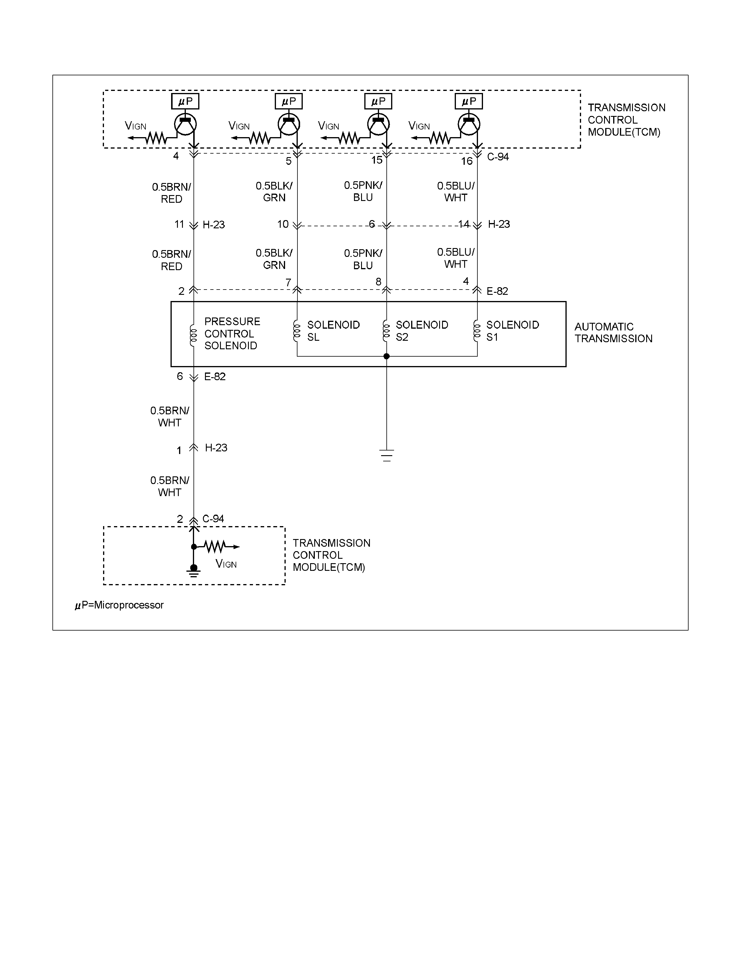
DTC P0758 (FLASH CODE 32) Shift Solenoid S2 Electrical
RTW37ALF000601
Circuit Description
The solenoid S2 changes the hydraulic route with the
signals from the TCM according to the vehicle speed
and the throttle opening to control shifting. When the
solenoid S1 or S2 fails, the hydraulic circuit is
mechanically operated as a backup.
Condition for setting the DTC
The TCM detects following "Condition 1" and "Condition
2" for 2 times continuously at shifting.
Condition 1 ("GND short"):
• Voltage at connector pin is 0V for 0.3 sec
continuously when solenoid is “ON".
Condition 2 ("Open or Ignition short"):
• Voltage at connector pin is ignition voltage for 0.5 sec
continuously when solenoid is “OFF".

Action Taken When The DTC Sets
The TCM operates shifting as following patterns.
Normal Fail S1 S2
1 3 - on
2 3 - on
3 3 - on
4 4 - off
• No squat control.
• No engine torque control.
• No line pressure control.
• No lock-up control.
• No slope control.
• No torque reduction.
• Check Trans ON.
• DTC stored.
• No detect DTC P0722.
• No detect DTC P0717.
Conditions For Clearing The DTC
• The DTC can be cleared from the TCM history by
using a scan tool.
• The DTC will be cleared from history when the
vehicle has achieved 40 warm-up cycles without a
failure reported.
• After more than 1 second has elapsed after the
ignition key has been turned “ON", short between
No.11 and No.4 (ground) of DLC (Data Link
Connector). Then, after 1 second, but within 6
seconds, discontinue shorting.
Diagnostic Aids
• Inspect the wiring for poor electrical connection at the
TCM. Look for possible bent, backed out, deformed
or damaged terminals. Check for weak terminal
tension as well. Also check for a chafed wire that
could short to bare metal or other wiring .
Inspect for a broken wire inside the insulation.
• When diagnosing for a possible intermittent short or
open condition, move the wiring harness while
observing test equipment for a change.

DTC P0758 (FLA SH CODE 32) Shift Solenoid S2 Electrical
Step Action Value(s) YES NO
1 Was the Powertrain On-Board Diagnostic (OBD)
System Check performed?
— Go to Step 2 Go to OBD
System Check
2 1. Install the scan tool.
2. Key “ON".
3. Review and record scan tool data.
4. Operate the vehicle within scan tool data.
Does the scan tool indicate DTC P0758?
— Go to Step 3 Refer to
Diagnostic Aids
3 1. Key “ON", engine run.
2. Place the selector lever in the "P" range.
3. Measure the voltage between terminal C94-15 and
terminal C94-1 on the TCM pigtail connector by
J39200 DMM.
Is the voltage specified value?
816V Go to Step 4 Go to Step 10
4 1. Key "OFF".
2. Disconnect the TCM connector (C-94).
3. Key "ON".
4. Measure the voltage between terminal C94-15 and
terminal C94-1 by J39200 DMM.
Is the voltage specified value?
0V Go to Step 5 Go to Step 7
5 1. Key “OFF".
2. Measure the resistance between terminal C94-15
and body ground by J39200 DMM.
Is the resistance specified value?
Go to Step 9 Go to Step 6
6 1. Disconnect the automatic transmission connector
(E-82).
2. Measure the resistance between terminal E82-8
and body ground by J39200 DMM.
Is the resistance specified value?
Go to Step 7 Go to Step 8
7 1. Check for open or short in the wire between
terminal C94-15 and terminal E82-8.
2. Repair or replace the wire between terminal C94-
15 and terminal E82-8.
Is the action complete?
— Verify repair —
8 Replace the SL solenoid.
Is the action complete?
— Verify repair —
9 1. Clear the DTC.
2. Perform the test-driving.
3. Check the DTC.
Was DTC P0758 stored?
— Go to Step 10 Refer to
Diagnostic Aids
10 Replace the TCM.
Is the action complete?
— Verify repair —
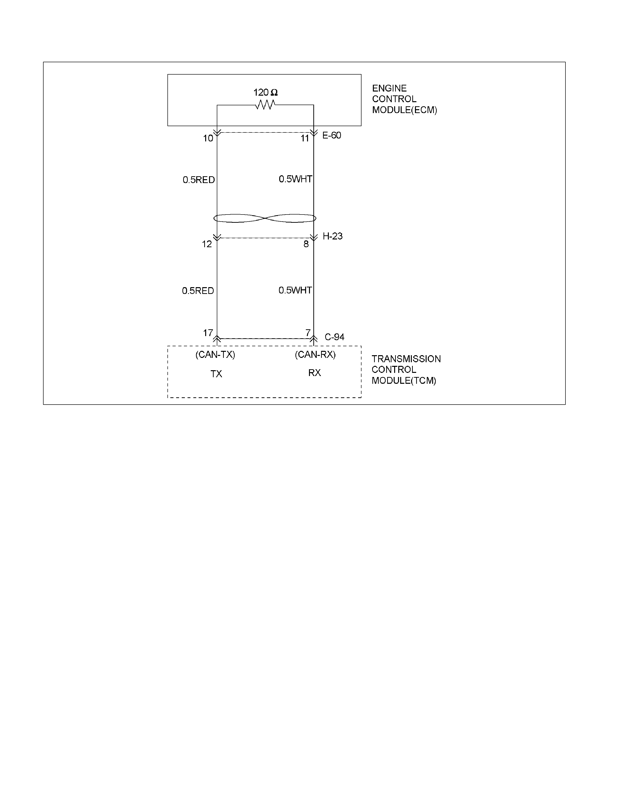
DTC P1767 (FLASH CODE 67) ECM CAN Invalid
RTW37AMF000401
Circuit Description
The automatic transmission control system in AW30-
40LE uses high speed CAN bus system. The individual
CAN bus systems are connected via two interfaces and
can exchange information and data. This allows control
modules that are connected to different CAN bus
systems to communicate. Transmission control
modules in the vehicle that require continuous, rapid
communication are connected to the high speed CAN
bus. The automatic transmission is continuously notified
of the current engine load status. Since the automatic
transmission control module has to react immediately to
load status changes, rapid communication is required
between the engine control module and the automatic
transmission control module. The high speed CAN bus
in the AW30-40LE is designed as a two-wire CAN bus
(twisted pair). The wires are shielded and twisted. The
transmission rate is 500K band.
Condition for setting the DTC
The TCM detects invalid signal for 0.18 sec. (After the
TCM leaves a communication start with the ECM for
0.64 sec)
The TCM detects above condition for 2.0 sec
continuously.
Action Taken When The DTC Sets
• The line pressure is max.
• The TCM judges APS(Accelerator Position Sensor)
angle is 0% at the time of shift operation.
• No line pressure control.
• No engine torque control.
• No lock-up control.
• No slope control.
• Check Trans ON.
• DTC stored.
• No squat control.
• Engine REV is 7000 rpm.
• Coolant temperature is 80°C.
• No detect DTC P0712, 0713.
• No detect DTC P0560.

Conditions For Clearing The DTC
• The DTC can be cleared from the TCM history by
using a scan tool.
• The DTC will be cleared from history when the
vehicle has achieved 40 warm-up cycles without a
failure reported.
• After more than 1 second has elapsed after the
ignition key has been turned “ON", short between
No.11 and No.4 (ground) of DLC (Data Link
Connector). Then, after 1 second, but within 6
seconds, discontinue shorting.
Diagnostic Aids
• Inspect the wiring for poor electrical connection at the
TCM. Look for possible bent, backed out, deformed
or damaged terminals. Check for weak terminal
tension as well. Also check for a chafed wire that
could short to bare metal or other wiring. Inspect for a
broken wire inside the insulation.
• When diagnosing for a possible intermittent short or
open condition, move the wiring harness while
observing test equipment for a change.
• Inspect the wiring for EMI (Electro-Magnetic
Interference). Check that all wires are properly routed
away from coil, and generator. Also check for
improperly installed electrical options. When this test
is performed, turn “OFF" all electronic accessory
switches to prevent electronic noise.
DTC P1767 (FLASH CODE 67) ECM CAN Invalid
Step Action Value(s) YES NO
1 Was the Powertrain On-Board Diagnostic (OBD) System
Check performed?
— Go to Step 2 Go to OBD
System Check
2 1. Install the scan tool.
2. Key “ON".
3. Review and record scan tool data.
4. Operate the vehicle within scan tool data.
Does the scan tool indicate DTC P1767?
— Go to Step 3 Refer to
Diagnostic Aids
3 Observe the valid data of the ECM on the scan tool.
Was the valid data of the ECM fixed or did not
synchronized?
— Go to Step 4 Refer to
Diagnostic Aids
4 Check the wire between the TCM connector and the ECM
connector by J39200 DMM.
1. Key “OFF".
2. Disconnect the TCM connector.
3. Measure the resistance between terminal C94-7 and
terminal C94-17.
Is the resistance specified value?
About 120 Go to Step 5 Go to Step 7
5 Check the resistance of the ECM..
1. Key “OFF".
2. Disconnect the ECM connector.
3. Measure the resistance between the ECM terminal E60-
70 and the ECM terminal E60-71.
Is the resistance specified value?
About 120 Go to Step 6 Go to Step 8
6 Replace or Repair the wire between the TCM connector
C94-7,17 and the ECM connector E60-70,71.
Is the action complete?
— Verify repair —
7 Replace the TCM.
Important: The replacement TCM must be programmed
(Refer to SPS for procedure).
Is the action complete?
— Verify repair —
8 Replace the ECM.
Important: The replacement ECM must be programmed
(Refer to SPS for procedure).
Is the action complete?
— Verify repair —

DTC P1790 (FLASH CODE 61) Transmission Control Module ROM Checksum Error
Circuit Description
The electrically erasable programmable read only
memory (EEPROM) is a permanent memory chip that is
physically solenoid within the TCM. The EEPROM
contains the program and the calibration information
that the TCM needs to control powertrain operation.
Unlike the PROM used in past applications, the
EEPROM is not replace able. If the TCM is replaced,
the new TCM will need to be programmed. Equipment
containing the correct program and calibration for the
vehicle is required to program the TCM.
Condition for setting the DTC
The TCM detects incorrect value of ROM checksum.
Action Taken When The DTC Sets
• Check Trans ON.
• DTC stored.
Conditions For Clearing The DTC
• The DTC can be cleared from the TCM history by
using a scan tool.
• The DTC will be cleared from history when the
vehicle has achieved 40 warm-up cycles without a
failure reported.
• After more than 1 second has elapsed after the
ignition key has been turned “ON", short between
No.11 and No.5 (ground) of DLC (Data Link
Connector). Then, after 1 second, but within 6
seconds, discontinue shorting.
Diagnostic Aids
• Inspect the wiring for poor electrical connection at the
TCM. Look for possible bent, backed out, deformed
or damaged terminals. Check for weak terminal
tension as well. Also check for a chafed wire that
could short to bare metal or other wiring. Inspect for a
broken wire inside the insulation.
• When diagnosing for a possible intermittent short or
open condition, move the wiring harness while
observing test equipment for a change.
DTC P1790 (FLA SH CODE 61) Transmission Control Module ROM Checksum Error
Step Action Value(s) YES NO
1 Was the Powertrain ON-Board Diagnostic (OBD)
System Check performed?
— Go to Step 2 Go to OBD
System Check
2 1. Install the scan tool.
2. Key “OFF" and keep the position for more than 30
seconds.
3. Key “ON".
4. Check the DTC on the scan tool.
Does the scan tool indicate DTC P1791?
— Go to Step 3 Refer to
Diagnostic Aids
3 Perform the SPS for the TCM.
Is the action complete?
— Go to Step 4 —
4 Recheck the DTC on the scan tool.
Does the scan tool indicate DTC P1790?
— Go to Step 5 Verify repair
5 Replace the TCM.
Important: The replacement TCM must be
programmed (Refer to SPS for procedure).
Is the action complete?
— Verify repair —

DTC P1791 (FLASH CODE 62) Transmission Control Module RAM Error
Circuit Description
DTC P1791 is recorded by TCM when there is
malfunction in the RAM.
Condition for setting the DTC
When the TCM can not detect all RAM from following
steps in initialising routine.
Action Taken The DTC Sets
• Check Trans ON.
• DTC stored.
Conditions For Clearing The DTC
• The DTC can be cleared from the TCM history by
using a scan tool.
• The DTC will be cleared from history when the
vehicle has achieved 40 warm-up cycles without a
failure reported.
• After more than 1 second has elapsed after the
ignition key has been turned “ON", short between
No.11 and No.4 (ground) of DLC (Data Link
Connector). Then, after 1 second, but within 6
seconds, discontinue shorting.
Diagnostic Aids
• Inspect the wiring for poor electrical connection at the
TCM. Look for possible bent, backed out, deformed
or damaged terminals. Check for weak terminal
tension as well. Also check for a chafed wire that
could short to bare metal or other wiring. Inspect for a
broken wire inside the insulation.
• When diagnosing for a possible intermittent short or
open condition, move the wiring harness while
observing test equipment for a change.
DTC P1791 (FLA SH CODE 62) Transmission Control Module RAM Error
Step Action Value(s) YES NO
1 Was the Powertrain On-Board Diagnostic (OBD)
System Check performed?
— Go to Step 2 Go to OBD
System Check
2 1. Install the scan tool.
2. Key “OFF" and keep the position for more than 30
seconds.
3. Key “ON"
4. Check the DTC on the scan tool.
Does the scan tool indicate DTC P1791?
— Go to Step 3 Refer to
Diagnostic Aids
3 Replace the TCM.
Important: The replacement TCM must be
programmed (Refer to SPS for procedure).
Is the action complete?
— Verify repair —

DTC U2104 (FLASH CODE 65) CAN BUS OFF
RTW37AMF000401
Circuit Description
The automatic transmission control system in AW30-
40LE uses high speed CAN bus system. The individual
CAN bus systems are connected via two interfaces and
can exchange information and data. This allows control
modules that are connected to different CAN bus
systems to communicate. Transmission control
modules in the vehicle that require continuous, rapid
communication are connected to the high speed CAN
bus. The automatic transmission is continuously notified
of the current engine load status. Since the automatic
transmission control module has to react immediately to
load status changes, rapid communication is required
between the engine control module and the automatic
transmission control module. The high speed CAN bus
in the AW30-40LE is designed as a two-wire CAN bus
(twisted pair). The wires are shielded and twisted. The
transmission rate is 500K band.
Condition for setting the DTC
The TCM detects CAN BUS OFF for 0.18 sec (After the
TCM leaves a communication start with the ECM for
0.64 sec) continuously..
Action Taken When The DTC Sets
• The throttle pressure is max.
• The TCM judges APS(Accelerator Position Sensor)
angle is 0% at the time of shift operation.
• No throttle pressure reduction.
• No torque reduction.
• No lock-up control.
• No slope control.
• No squat control.
• Check Trans ON.
• DTC stored.
• Engine REV is 7000 rpm.
• Coolant temperature is 80°C.
• No detect DTC P1767.
• No detect DTC P0560.
• No detect DTC P0712, 0713.

Conditions For Clearing The DTC
• The DTC can be cleared from the TCM history by
using a scan tool.
• The DTC will be cleared from history when the
vehicle has achieved 40 warm-up cycles without a
failure reported.
• After more than 1 second has elapsed after the
ignition key has been turned “ON", short between
No.11 and No.4 (ground) of DLC (Data Link
Connector). Then, after 1 second, but within 6
seconds, discontinue shorting.
Diagnostic Aids
• Inspect the wiring for poor electrical connection at the
TCM. Look for possible bent, backed out, deformed
or damaged terminals. Check for weak terminal
tension as well. Also check for a chafed wire that
could short to bare metal or other wiring. Inspect for a
broken wire inside the insulation.
• When diagnosing for a possible intermittent short or
open condition, move the wiring harness while
observing test equipment for a change.
• Inspect the wiring for EMI (Electro-Magnetic
Interference). Check that all wires are properly routed
away from coil, and generator. Also check for
improperly installed electrical options. When this test
is performed, turn “OFF" on electronic auto parts
switches to improperly for a noise preventing.
DTC U2104 (FLASH CODE 65) CAN BUS OFF
Step Action Value(s) YES NO
1 Was the Powertrain On-Board Diagnostic (OBD) System
Check performed?
— Go to Step 2 Go to OBD
System Check
2 1. Install the scan tool.
2. Key “ON".
3. Review and record scan tool data.
4. Operate the vehicle within scan tool data.
Does the scan tool indicate DTC U2104?
— Go to Step 3 Refer to
Diagnostic Aids
3 Observe the valid data of the ECM on the scan tool.
Was the valid data of the ECM fixed or did not
synchronized?
— Go to step 4 Refer to
Diagnostic Aids
4 Check the wire between the TCM connector and the ECM
connector by J39200 DMM.
1. Key “OFF".
2. Disconnect the TCM connector.
3. Measure the resistance between terminal C94-7 and
terminal C94-17.
Is the resistance specified value?
About 120 Go to Step 7 Go to Step 5
5 Check the resistance of the ECM..
1. Key "OFF".
2. Disconnect the ECM connector.
3. Measure the resistance between the ECM terminal E60-
70 and the ECM terminal E60-71.
Is the resistance specified value?
About 120 Go to step 6 Go to step 8
6 Replace or Repair the wire between the TCM connector
C94-7,17 and the ECM connector E60-70,71.
Is the action complete?
— Verify repair —
7 Replace the TCM.
Important: The replacement TCM must be programmed
(Refer to SPS for procedure).
Is the action complete?
— Verify repair —
8 Replace the ECM.
Important: The replacement ECM must be programmed
(Refer to SPS for procedure).
Is the action complete?
— Verify repair —