
SECTION 7A2 - DIAGNOSIS (JR405E)
Basic Trouble Shooting
Check Trans Indicator & Self Diagnosis
Diagnosis With Tech 2
Tech 2 Operating Flow Chart (Start Up)
Miscellaneous Test
Intermittent Diagnosis
Snapshot Display With TIS 2000
Circuit Diagram
Part Location
Connector List
Diagnosis Trouble Code Table
Fail-Safe Function
DTC P0722 (Flash Code 11) Output Shaft Sensor
No Signal
DTC P0727 (Flash Code 13) Engine Revolution
Sensor No Signal
DTC P0717 (Flash Code 14) Turbine Speed Sensor
No Signal
DTC P0710 (Flash Code 15) Atf Temperature Sensor
Failure
DTC P0560 (Flash Code 16) System Voltage Failure
DTC P0705 (Flash Code 17) Inhibitor Switch Failure
DTC P1120 (Flash Code 22) Throttle Signal Failure
DTC P1875 (Flash Code 25) Gnd Return Circuit
Failure
DTC P0753 (Flash Code 31) Low & Reverse Brake
Duty Solenoid Failure
DTC P0758 (Flash Code 32) 2-4 Brake Duty
Solenoid Failure
DTC P0763 (Flash Code 33) High Clutch Duty
Solenoid Failure
DTC P0768 (Flash Code 34) Low Clutch Duty
Solenoid Failure
DTC P0748 (Flash Code 35) Line Pressure Solenoid
Failure
DTC P1860 (Flash Code 36) Lock-Up Duty Solenoid
Failure
DTC P1853 (Flash Code 26) Low & Reverse Brake
Pressure Switch Failure
DTC P1858 (Flash Code 27) 2-4 Brake Pressure
Switch Failure
DTC P1863 (Flash Code 28) High Clutch Pressure
Switch Failure
DTC P0731 (Flash Code 41) 1st Gear Ratio Error
DTC P0732 (Flash Code 42) 2nd Gear Ratio Error
DTC P0733 (Flash Code 43) 3rd Gear Ratio Error
DTC P0734 (Flash Code 44) 4th Gear Ratio Error
DTC P1750 (Flash Code 51) Low & Reverse Brake
Fail-Safe Valve Failure
DTC P1755 (Flash Code 52) 2-4 Brake Fail-Safe
Valve Failure
DTC P0602 Programming Error
Symptom Diagnosis
No. A1: Vehicle Does Not Run In D, 3, 2, L And
Range
No. A2: Vehicle Does Not Run In R Range
No. A3: Vehicle Does Not Run In D, 3, 2 And Range
No. B1: Vehicle Runs In N Range
No. B2: Poor Acceleration At Starting
No. B3: Engine Race Up During Starting (Slip)
No. B4: Large Shock When Shift Lever Is Changed
To N To D Range Or N To R Range
No. B5: Engine Stalls When Selecting From N
Range To R, D, 3, 2 Or L Range
No. B6: Engine Starter Does Not Run In P Or N
Range
No. B7: Engine Starter Runs Except In P Or N
Range
No. B8: Extended Time Lag When Shift Lever Is
Changed To N To D
No. B9: Extended Time Lag When Shift Lever Is
Changed To N To R
No. B10: Brake Is Applied In R Range
No. B11: Insufficient Starting Or Shaking In D
Range
No. B12: Noise Or Vibration Is Generated At
Starting
No. C1: Engine Race Up (Slip) When Gear Is Shifted
Up To 1st To 2
nd
No. C2: Engine Race Up (Slip) When Gear Is
Shifted Up To 2nd To 3
rd
No. C3: Engine Race Up (Slip) When Gear Is
Shifted Up To 3rd To 4
th
No. C4: Engine Race Up (Slip) When Gear Is Shift
Down Or Kick-Down To 4th To 3
rd
No. C5: Engine Race Up (Slip) When Gear Is Shift
Down Or Kick-Down To 4th To 2
nd
No. C6: Engine Race Up (Slip) When Gear Is Shift
Down Or Kick-Down To 3rd To 2
nd
No. C7: Engine Race Up (Slip) When Gear Is Shift
Down To 4th Or 3
rd
To 1
st
No. C8: Engine Race Up (Slip) Others

No. C9: Barking Feel When Gear Is Shifted Up To
1st To 2
nd
No. C10: Barking Feel When Gear Is Shifted Up To
2nd To 3
rd
No. C11: Barking Feel When Gear Is Shifted Up To
3rd To 4
th
No. C12: Large Shock When Gear Is Shifted To 1st
To 2
nd
Or 2nd To 1
st
No. C13: Large Shock When Gear Is Shifted To
2nd To 3
rd
Or 3rd To 2
nd
No. C14: Large Shock When Gear Is Shifted To
3rd To 4th To 3
rd
No. C15: Large Shock When Kick-Down
No. C16: Large Shock When No Acceleration
No. C17: Large Shock When Gear Is Shifted Down
To 2nd To 1st In L Range
No. C18: Large Shock (Other)
No. C19: Large Shock When Vehicle Speed Is
Downed By No Accelerator Panel Or Vehicle Is
Stopped
No. C20: Large Lock-Up Shock
No. C21: Shift Down Or Engine Over-Run When The
Acceleration Pane Is Stepped On In 4th Gear
No. D1: Faulty Gear Shifting (Different From Shift
Pattern)
No. D2: Gear Is Shifted Frequently
No. D3: Gear Shift Point Is Low Or High At All Point
No. D4: Gear Shift Point Is Low Or High At Limited
Point
No. D5: No Kick-Down
No. E1: No Gear Shift
No. E2: Only 4th Gear (O/D) Is Not Selectable
No. E3: Gear Is Shifted 2nd To 3rd In 2 Range
No. E4: Gear Is Shifted 1st To 2nd In L Range
No. E5: Gear Is Shifted 3rd To 4th In 3 Range
No. F1: Low Maximum Speed Or Poor Acceleration
No. F2: Engine Races Up During Acceleration (Slip)
No. F3: Noise Or Vibration During The Running In
R, D, 3, 2 Or L Range
No. F4: Engine Brake Does Not Apply In L Range
No. F5: Engine Stalls Before Vehicle Stops From
Running
No. G1: Vehicle Moves In P Range Or Parking Gear
Is Not Disengaged Other Than P Range
No. G2: Creep Force Is Large
No. G3: Creep Force Is Small
No. G4: Large Noise During Idling With The Vehicle
In Stop State
No. H1: Judder Occurs At The Lock-Up
No. H2: Large Lock-Up Shock
No. H3: Lock-Up Point Is High Or Low
No. I1: No Lock-Up
No. J1: Oil Leaks From Breather
No. J2: Oil Leaks Between Engine And Converter
Housing
No. J3: Oil Leaks Between Main Case And
Converter Housing
No. J4: Oil Leaks Between Main Case And Rear
Housing
No. J5: Oil Leaks From Oil Pan
No. J6: Oil Leaks From Manual Shaft Oil Seal
No. J7: Oil Leaks From Oil Cooler Pipe Joint
No. Z1: Transmission Overheat
No. Z2: Mode Lamp (Power Drive Or 3rd Start) Does
Not Light Up When The Power Mode Or 3rd Start
Mode Is Turned On
No. Z3: Mode Lamp (Power Drive Or 3rd Start)
Lights Up When The Power Mode Or 3rd Start
Mode Is Turned Off
No. Z4: Oil Temperature Warning Lamp Lights Up
No. Z5: Select Lever Feeling Is Faulty
No. Z6: Poor Fuel Consumption
No. Z7: Pattern Select Switch Is Faulty
No. Z8: Oil Is Splashed During The Running
No. Z9: Abnormal Smell
No. Z10: Atf Quantity Is Low Or High
No. Z11: Abnormal Oil Pressure
No. Z12: Reverse Buzzer Does Not Ring
Stall Test
Line Pressure Test
Time Lag Test
Test Drive
Shift Point Chart
Shift Point Diagram
TCM Voltage Check
Basic Trouble Shooting
Transmission fluid pressure together with clutch and brake friction and other important transmission functions are
controlled by electrical signal from the Transmission Control Module (TCM).
Random diagnosis can produce inaccurate and misleading indications. It is important that diagnosing procedure be
carried out systematically.
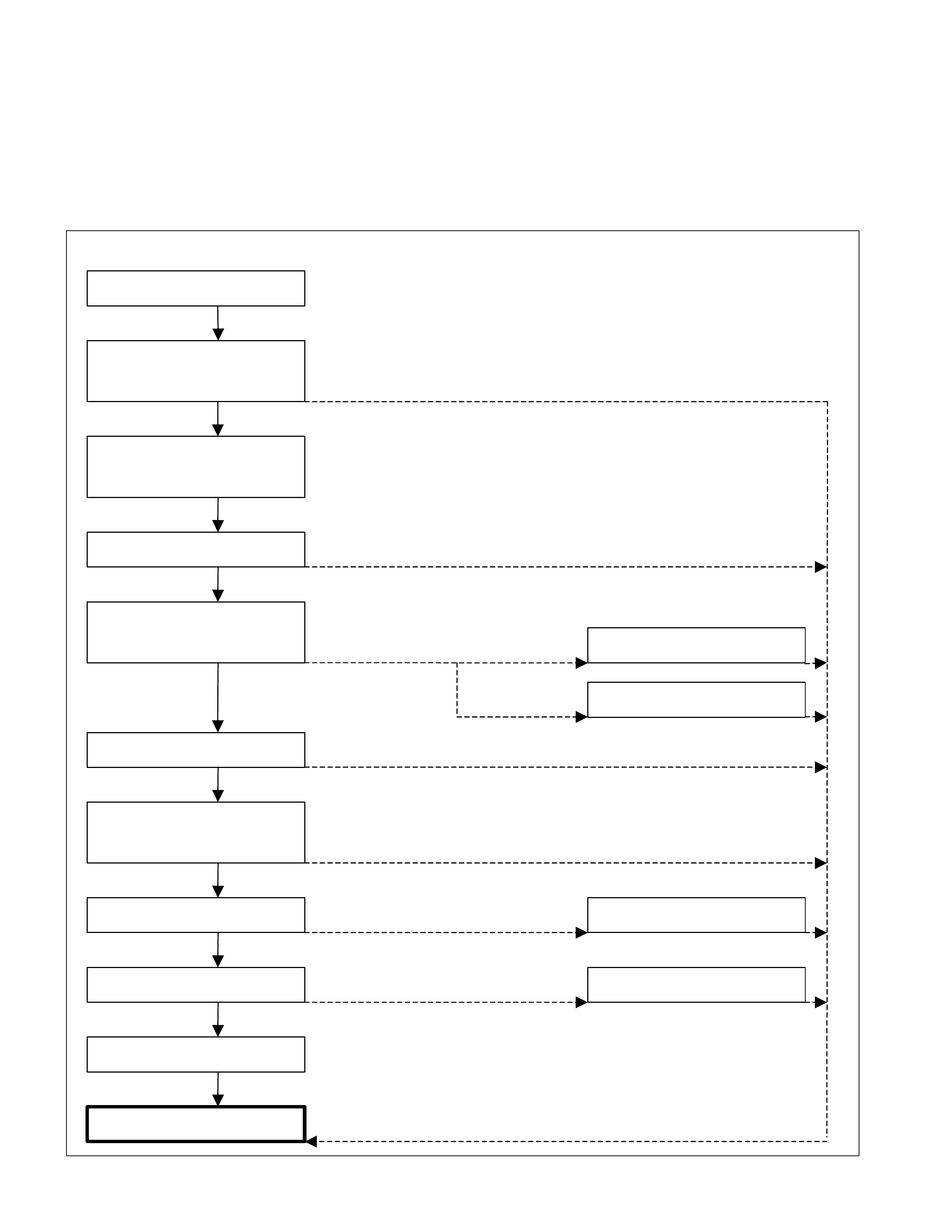
Carefully follow the sequence outlined below to diagnose automatic transmission assembly.
Verify Cus to mer Complain
Prel imin ar y Ch e ck
(V is ua l Ch eck/ Test Dr ive)
Compare to Same Model
(If Av ailable)
Check Service Bulletin
DTC Check
(Self-diagnosis/Tech 2)
Go to Symptom Diagnosis
Sta ll Test
Line Pressure Test
T ransmission Overhaul
Repair & Verify Fix
Transmission Overhaul
Transmission Overhaul
Go to DTC Chart
Go to Intermittent Diagnosis
NG
Follow the instructions
NG
No Inst r u cti on
NG
OK
NO DTC
Not Solved
OK
OK
Follow the Bulletin
(Once Clear Memory) Restored
Not Stored
Use Service Programming
System (SPS)
Not Solved
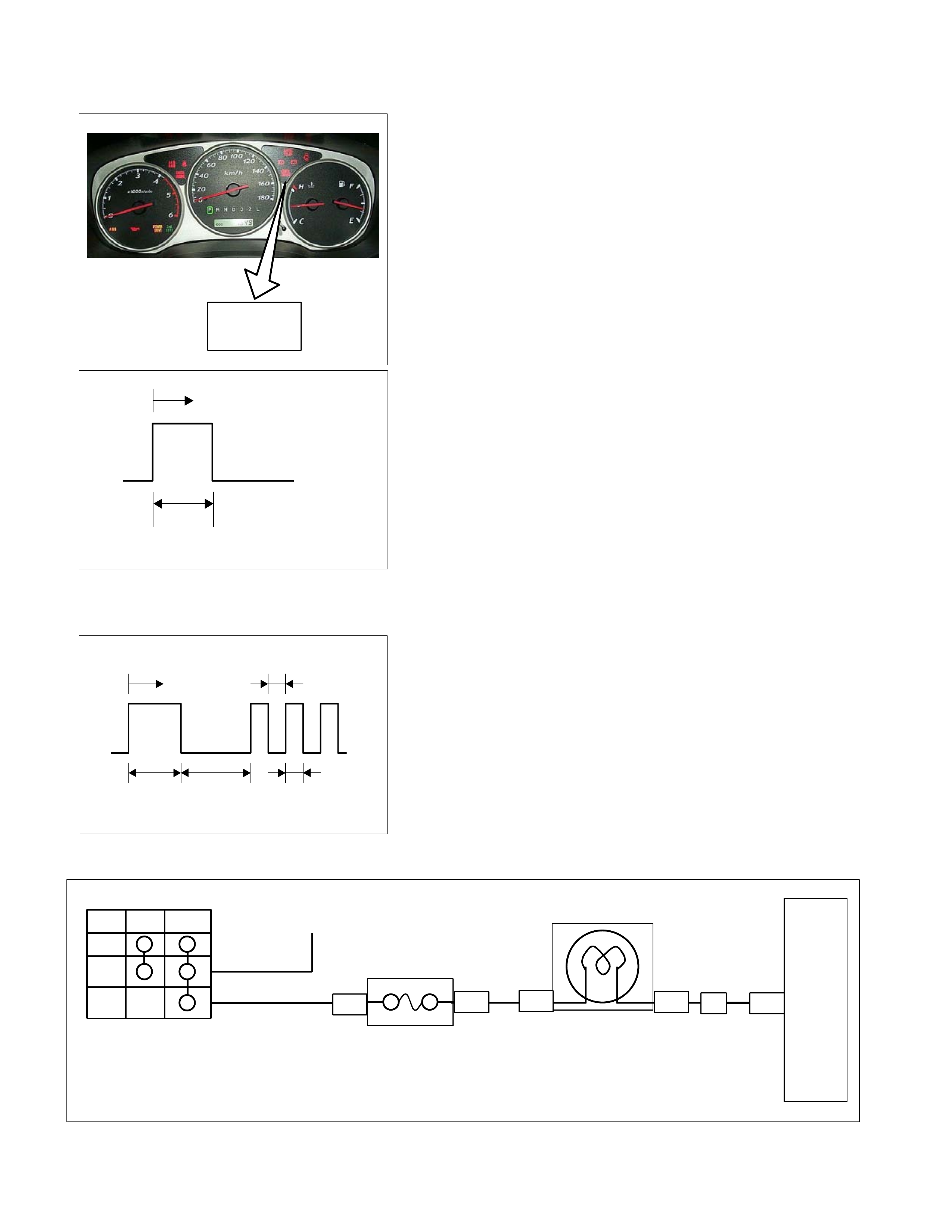
Check Trans Indicator & Self Diagnosis
CHECK
TRANS
Warning to the driver
• "CHECK TRANS" illuminates for 3 seconds when the
ignition is switched ON.
• When a failure occurs, the “CHECK TRANS" lamp flashes
to alert the driver.
• The failure is recorded by the TCM as a diagnostic trouble
code. When the trouble code is canceled, the "CHEC
K
TRANS" lamp will stop flashing. This flashing can be
stopped turning the ignition OFF. But the DTC remains
memorised by TCM.
Key S W O N
ON
OFF
3 Sec.
(Lamp Check)
Illumination Pattern at Normal Condition
Note:
1. If the "CHECK TRANS" lamp is staying ON at key switch
ON position, this means that connection between the lamp
and TCM is shorted to ground.
Verify connection and wire between the TCM A20 terminal
and lamp short to ground.
2. If the "CHECK TRANS" lamp is staying OFF at key switch
ON position (Engine off), this means that connection
between the lamp and TCM is opened or meter fuse C5
(15A) is burnt out.
Verify connection and wire between the TCM A20 terminal
and lamp open circuit and meter fuse C5 (15A).
@@@@@@@@
Key SW ON 0.4 Sec.
ON
OFF
3 Sec.@@@@
3.2 Sec.@@@@
@
0.4 Sec.
(Lamp Check)
Illumination Pattern at Trouble Condition
Off Acc On V Acc
CHECK TRANS
Meter
Meter Fuse C5 (15A)
Fuse Box & Relay Box
(Cabin)
TCM
A20
B54 B23
B24 C94
B62 H6
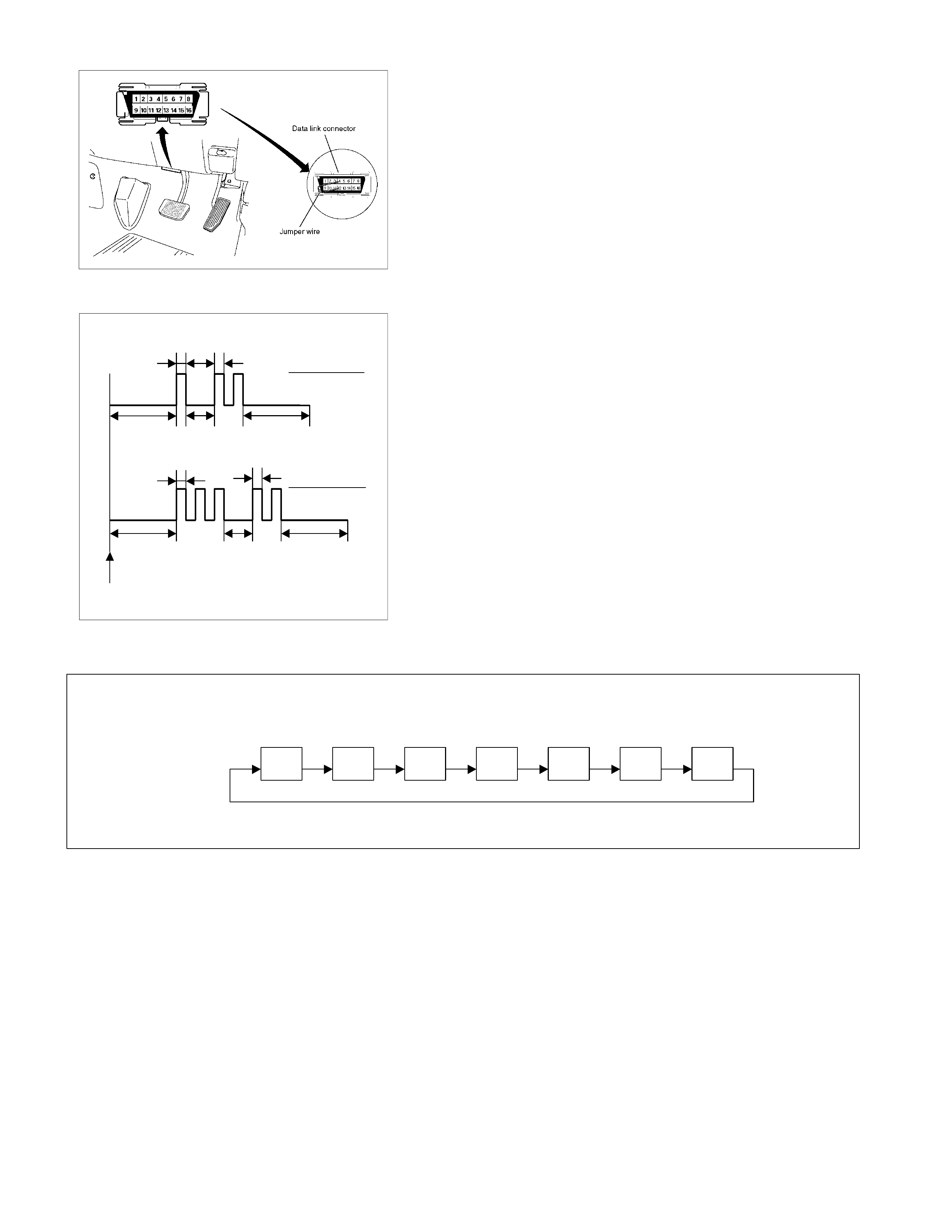
Data Link Connector Short Circuit
Self-diagnosis c ode (Flash code) display
• The stored trouble codes can be identified by shorting the
terminal No. 11 and No. 4 or 5 (ground) of data link
connector with a lead wire.
Indication Method:
1. Terminal No. 11 and No. 4 or 5 (ground) of data link
connector are short circuited.
2. Turn the key switch to the ON position.
3. In case no trouble code existence, normal code (12) is
indicated repeatedly.
0.4 Sec 0.4 Sec
.
ON
OFF
3.2 Sec. 1.2 Sec. 3.2 Sec.
0.4 Sec 0.4 Sec
.
ON
OFF
3.2 Sec. 1.2 Sec. 3.2 Sec.
Self-diagnosis Start
Normal Code (12)
Trouble Code (32)
Flash Code Illumination Pattern
4. In case the plural trouble codes have occurred at a time,
each codes are indicated three rimes in numerical order.
Trouble Code Clear Method:
If you have Tech 2:
Follow the procedure "DIAGNOSIS WITH TECH 2" in this
manual.
If you have no Tech 2:
Remove ECM (B) fuse SBF-4 (30A) for at least 10 seconds.
NOTE:
If you clear the DTC you will not be able to read any codes
recorded during the last occurrence.
To use the DTC again to identify a problem, you will need
to reproduce the fault or the problem. This may require a
new test drive or just turning the key switch on (this
depends on the na ture of the fault).
12 14 14 14 32 32 32
In case DTC 14 & 32 are stored
Diagnosis With Tech 2
In this JR405E transmission, troubleshooting can be performed for electrical faults using the Tech 2 scan tool.
If the "CHECK TRANS" lamp blinks, or if an electrical fault in the transmission may probably exit, check trouble codes
using the Tech 2 scan tool.
In the diagnostic procedures described in this manual, first repair the faulty positions indicated by trouble code in order
of numbers and then perform troubleshooting for the faulty positions that are not indicated by trouble code. For correct
troubleshooting, it is necessary to first repair the trouble codes of lower order numbers, then to repair the trouble codes
of higher order numbers in sequence.
If no codes are set:
• Refer to F1: Data Display and identify the electrical faults that are not indicated by trouble code.
• Refer to "SYMPTOM DIAGNOSIS".
If codes are set:
1. Record all trouble codes displayed by Tech 2 and check id the codes are intermittent.
2. Clear the codes.
3. Drive the vehicle for a test to reproduce the faulty status.
4. Check trouble codes again using the Tech 2.
5. If no codes are displayed by test driving, the fault is intermittent. In this case, refer to "INTERMITTENT
DIAGNOSIS".
6. If a code is present, refer to DTC Chart for diagnosis.
7. Check trouble codes again using the Tech 2.
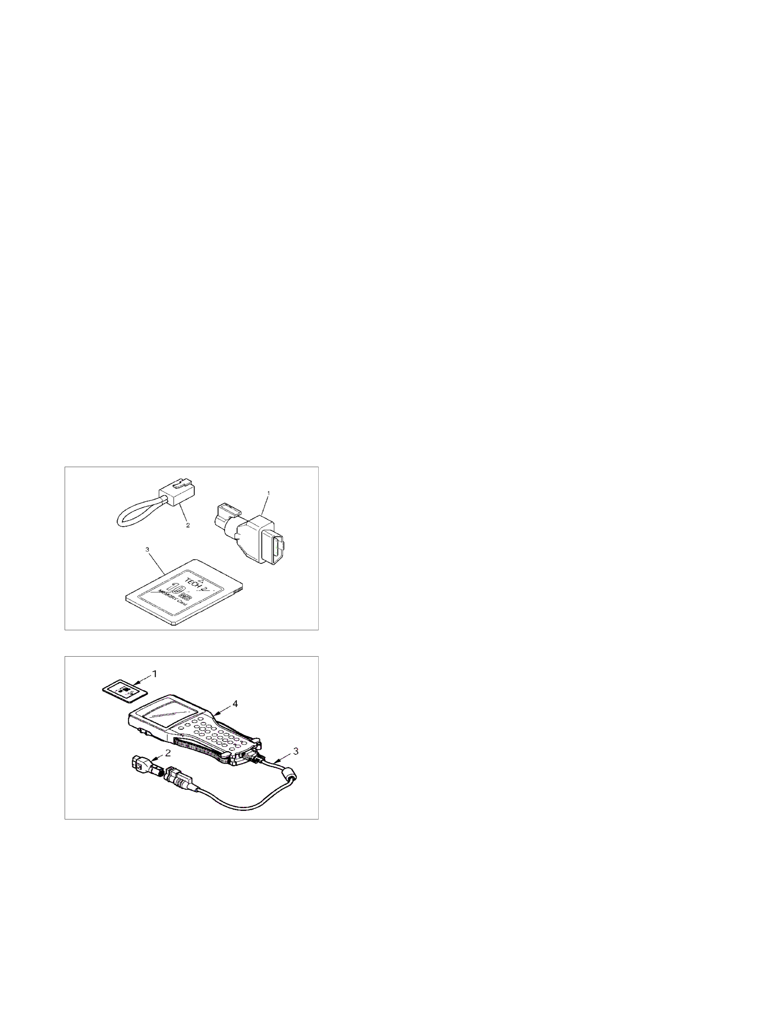
Tech 2 Connection
Tech 2 scan tool is used to electrically diagnose the automatic
transmission system and to check the system. The Tech 2
enhances the diagnosis efficiency though all the
troubleshooting can be done without the Tech 2.
1. Configuration of Tech 2
• Tech 2 scan tool kit (No. 7000086), Tech 2 scan tool
(No. 7000057) and DLC cable (No. 3000095).
• SAE 16/19 adapter (No. 3000098) (1) , RS232 loop back
connector (No. 3000112) (2) and PCMCIA card (No.
3000117) (3).
2. Tech 2 Connection
• Check the key switch is turn OFF.
• Insert the PCMCIA card (1) into the Tech 2 (4).
• Connect the SAE 16/19 adapter (2) to the DLC cable (3).
• Connect the DLC cable (3) to the Tech 2 (4).
• Connect the SAE 16/19 adapter (2) to the data link
connector of the vehicle.
• Turn the key switch of the vehicle ON and press the
"PWR" key of the Tech 2.
• Check the display of the Tech 2.

Note:
Be sure to check that the power is not supplied to the
Tech 2 when attaching or removing the PCMCIA card.
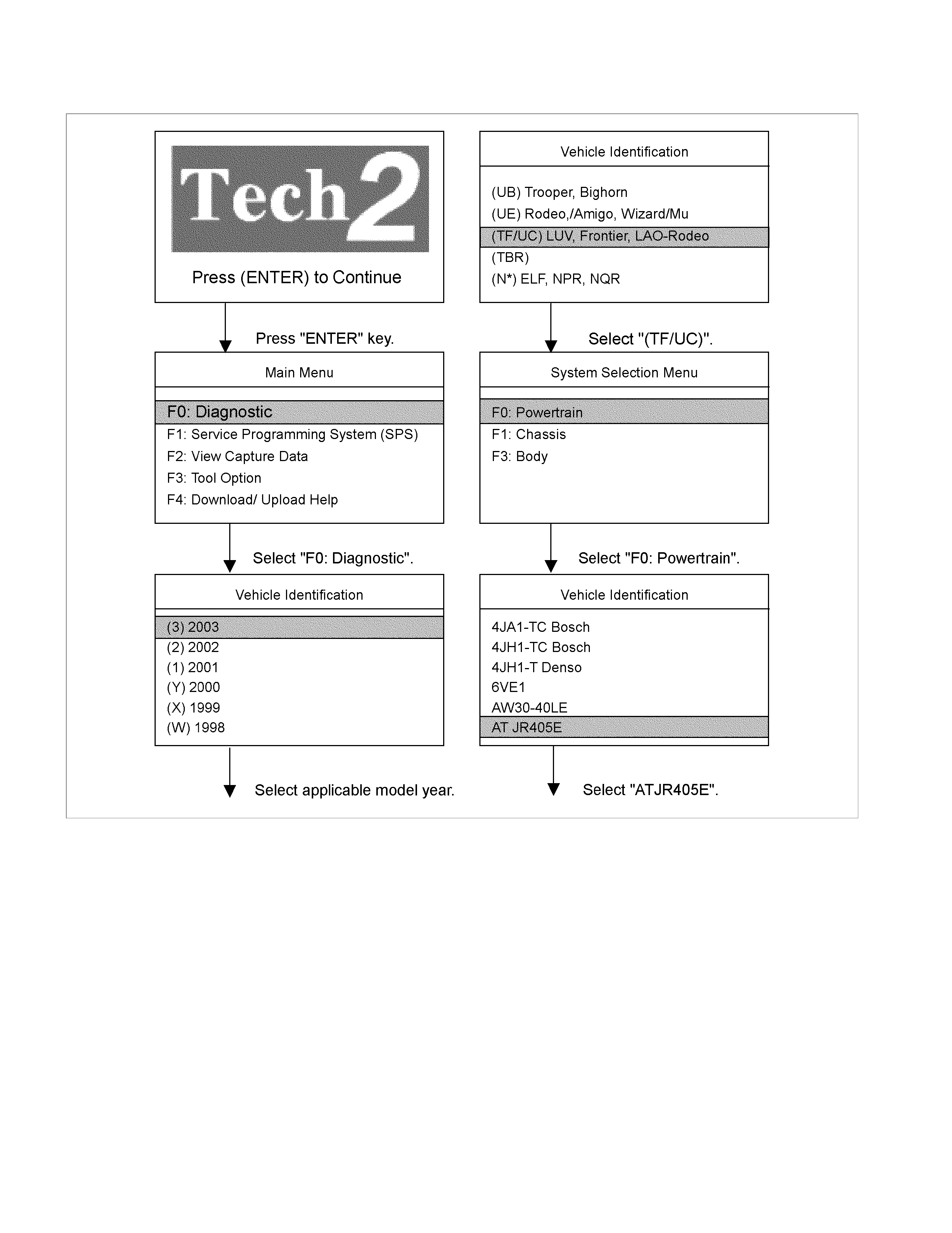
Tech 2 Operating Flow Chart (Start Up)
Select "AT JR405E" in Vehicle Identification menu and the following table is shown in the Tech 2 screen.

F0: Diagnostic Trouble Code
F0: Read DTC Infor As Stored By ECU
F1: Clear DTC Information
F1: Data Display
F2: Snapshot
F3: Miscellaneous Test
F0: Lamp
F0: Power Lamp Test
F1: 3rd Start Lamp Test
F2: AT Oil Temperature Lamp Test
F3: Transmission Check Light Test
F1: Solenoids
F0: Low & Reverse Brake Solenoid
F1: 2-4 Brake Solenoid
F2: High Clutch Solenoid
F3: Low Clutch Solenoid
F4: Line Pressure Solenoid
F5: Lock Up Duty Solenoid
F0: Diagnostic Trouble Code
The purpose of the "Diagnostic Trouble Codes" mode is
to display stored trouble code in the TCM.
When "Clear DTC Information" is selected, a "Clear DTC
Information", warning screen appears. This screen
informs you that by cleaning DTC's "all stored DTC
information in the TCM will be erased".
After clearing codes, confirm system operation by test
driving the vehicle.
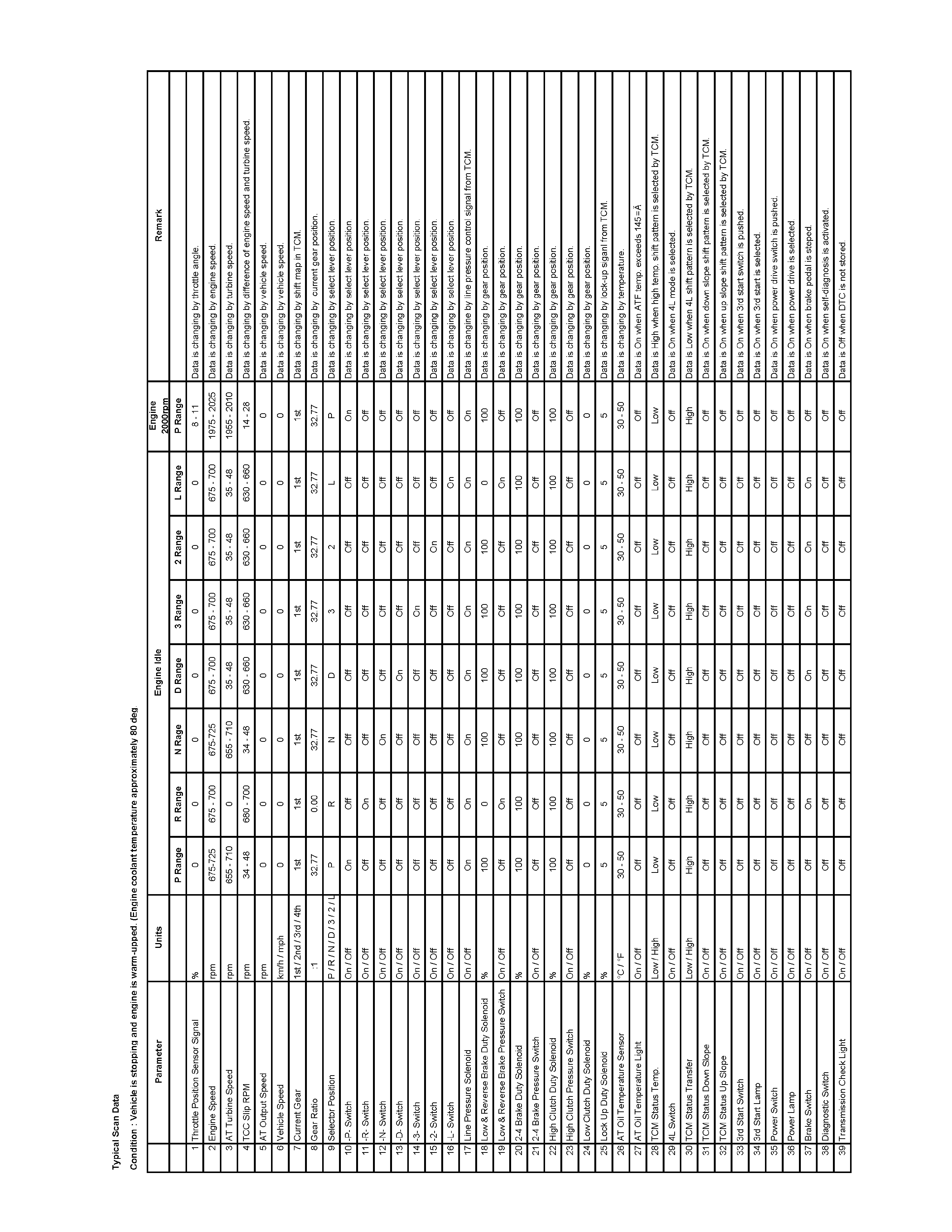
F1: Data Display
The purpose of the "Data Display" mode is to continuously
monitor data parameters.
The current actual values of all important sensors and
signals in the system are display through F1mode.
See the "Typical Scan Data" section.
F2: Snapshot
"Snapshot" allows you to focus on making the condition
occur, rather than trying to view all of the data in
anticipation of the fault. The snapshot will collect
parameter information around a trigger point that you
select.
F3: Miscellaneous Test:
The purpose of "Miscellaneous Test" mode is to check for
correct operation of electronic system actuators.

Miscellaneous Test
Using miscellaneous test menus can test the state of each circuit. Especially when DTC cannot be detected, a faulty
circuit can be diagnosed by testing each circuit by means of these menus.
Even DTC has been detected, the circuit tests using these menus could help discriminate between a mechanical
trouble and an electrical trouble.
Connect Tech 2 and select "Powertrain", "JR 405E" & "Miscellaneous Test".
F0: Lamps
The circuit is normal if the warning light in the meter panel comes on and goes out in accordance with Tech 2
instruction.
Lamps
F0: Power Lamp Test
F1: 3rd Start Lamp Test
F2: AT Oil Tempeature Lamp Test
F3: Transmission Check Light Test
F0: Power Lamp Test
Power Lamp Test
Power Lamp Off
− Press "Active" key.
Then, "POWER DRIVE" indicator lamp is turned on in the
meter panel.
− Press "Inactive" key.
Then, "POWER DRIVE" indicator lamp is turned off in the
meter panel.
− Press "Quit" Key to cancel the test.
F1: 3rd Start Lamp Test
F2: AT Oil Temperature Lamp Test
F3: Transmisstion Check Light Test
Test procedure is same as "F0: Power Lamp Test".
The circuit is normal if the warning light in the meter panel
comes on and goes out in accordance with Tech 2 instruction.
F1: Solenoids
The circuit is normal if clicking sound is generated in accordance with Tech 2 instruction.
Solenoids
F0: Low & Reverse Brake Solenoid
F1: 2-4 Brake Solenoid
F2: High Clutch Solenoid
F3: Low Clutch Solenoid
F4: Line Pressure Solenoid
F5: Lock Up Duty Solenoid

F0: Low & Reverse Brake Solenoid
Low & Reverse Brake Solenoid
Low & Reverse Brake Duty 0%
− Press "Active" key.
Then, duty ratio is indicated 100 % and "clicking sound" is
generated from the transmission control valve.
− Press "Inactive" key.
Then, duty ratio is indicated 0 % and "clicking sound" is
generated from the transmission control valve.
− Press "Quit" Key to cancel the test.
F0: Low & Reverse Brake Solenoid
F1: 2-4 Brake Solenoid
F2: High Clutch Brake Solenoid
F3: Low Clutch Solenoid
F4: Line Pressure Solenoid
F5: Lock Up Duty Solenoid
Test procedure is same as "F0: Low & Reverse Brake
Solenoid"
The circuit is normal if clicking sound is generated in
accordance with Tech 2 instruction.

Intermittent Diagnosis
If the Tech 2 displays any codes as intermittent, or if after a test drive any codes does not reappear, the problem is
most likely a faulty electrical connection or loose wiring.
Terminals should always be the prime suspects.
Intermittent rarely occur in sophisticated electronic components such as the TCM.
When an intermittent problem is encountered, check suspect circuits for:
• Poor terminal to wire connection.
• Terminals not fully seated in the connector body.
• Improperly formed or damaged terminals.
• Loose, dirty or damaged terminals.
Any time you have an intermittent in more than one circuit, check whether the circuits share a common ground
connection.
• Pinched or damaged wires.
• Electric interference.
Check for improperly installed electrical options, such as light, radios, etc.
Use the F2: Snapshot mode of the Tech 2 to help isolate the cause of an intermittent fault. The snapshot mode will
record information before and after the problem occurs. Set the snapshot to "Trigger" on the suspected code or, if you
notice the reported symptom during test drive, trigger the snapshot manually.
After the snapshot has been triggered, command the Tech 2 to play back the flow of data recorded from each of the
various sensors. Sings of intermittent fault in a sensor circuit are a sudden unexplainable jump in data values out of the
normal range.
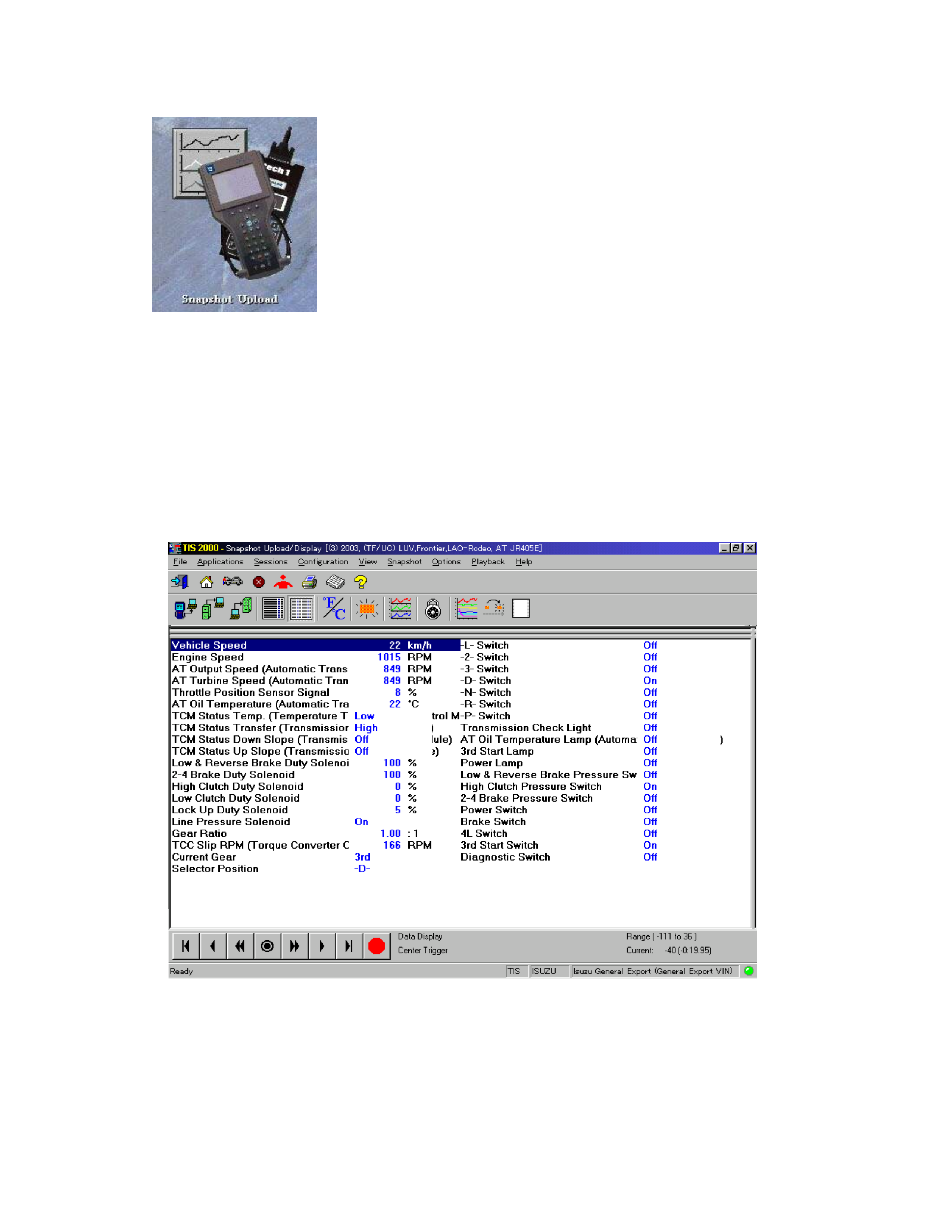
Snapshot Display With TIS2000 (For Snapshot Data Analysis)
Procedures for transferring and displaying Tech2 snapshot
data by using TIS2000 [Snapshot Upload] function is described
below.
Snapshot data can be displayed with [Snapshot Upload]
function included in TIS2000.
By analyzing these data in various methods, trouble conditions
can be checked.
Snapshot data is displayed by executing the three steps below
shown:
1. Record the snapshot data, in Tech2.
2. Transfer the snapshot data to PC.
After recording the snapshot in Tech2, transfer the data from Tech2 to PC by the below procedures.
1. Start TIS2000.
2. Select [Snapshot Upload] on the TIS2000 start screen.
3. Select [Upload from trouble diagnosis tool ( transfer f rom diagnosis tester)] or clic k the corr esponding icon of the
tool bar.
4. Select Tech2, and transfer the recorded snapshot information.
5. Select the transferred snapshot.
6. After ending transfer of the snapshot, data parameter list is display ed on the screen.
3. Snapshot data is displayed with TIS2000 [Snapshot Upload] function.
Snapshot is stored in the PC hard disk or floppy disk, and can be displayed any time.
Stored snapshot can be displayed by the below procedures.
1. Start TIS2000.
2. Select [Snapshot Upload] on the TIS2000 start screen.
3. Select [Open the existing files] or click the corresponding icon of the tool bar.
4. Select the transferred snapshot.
5. Open the snapshot, to display the data parameter list on the screen.
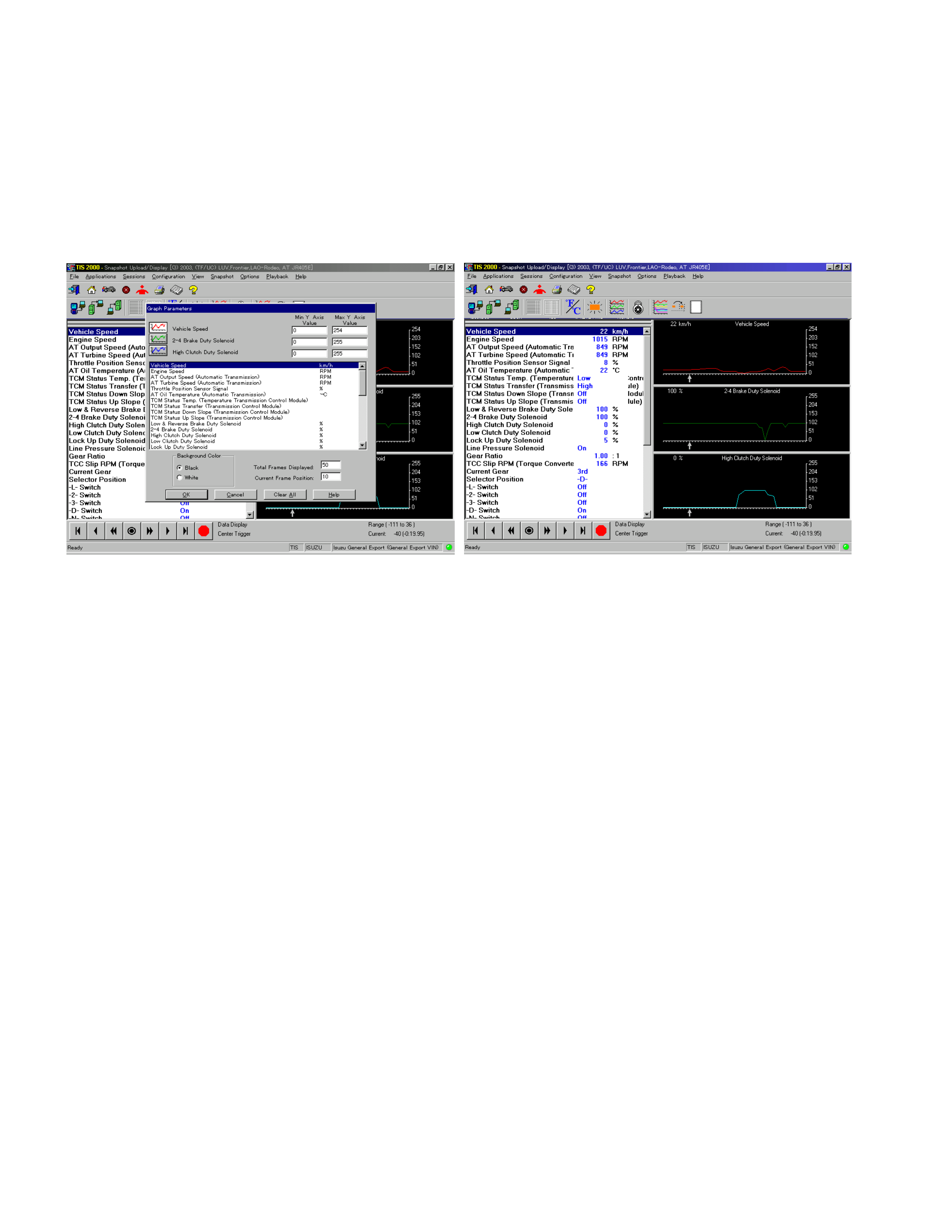
Graph display
Values and graphs (Max. 3 graphs):
1. Click the icon for graph display. [Graph Parameter] window opens.
2. Click the first graph icon of the window upper part, and select one par ameter f rom the list of the window lower part.
Selected param eter is displayed nest to the graph icon. Gr aph division can be s elected in the f ield on the param eter
right side.
3. Repeat the same procedures with the 2nd and 3rd icons.
4. After selecting all parameters to be displayed (Max. 3 parameters), click [OK] button.
5. Parameter selected is displayed in graph form on the right of the data parameter on the screen.
6. Graph display can be moved with the navigation icon.
7. For displaying another parameter by graph, click the parameter of the list, drug the mouse to the display screen
while pressing the mouse button and release the mouse button. New parameter is displayed at the position of the
previous parameter. For displaying the graph display screen in full size, move the cursor upward on the screen.
When the cursor is changed to the m agnif ying glass f orm , c lick the sc reen. Graph s creen is displayed on the whole
screen.
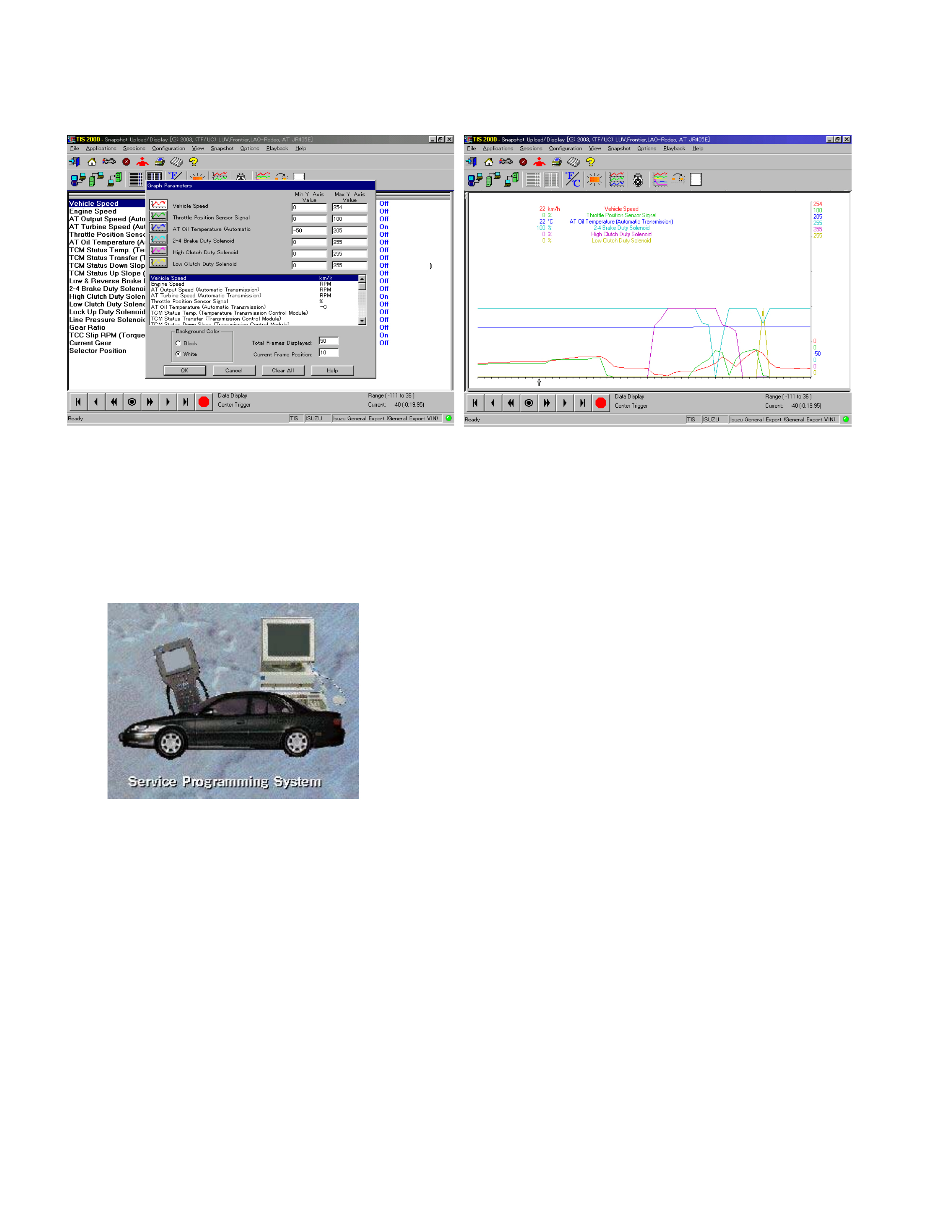
Display of graphs on one screen (Max. 6 graphs):
1. Click the 6 graph icon. [Graph Parameter] window opens.
2. Click the graph icon, select the parameter to be displayed from the list and change divisions according to necessity.
3. Repeat the same procedures with the graph icons, from the 2nd to 6th.
4. Click the [OK] button to display.
5. In this case, parameters are displayed only in graph form. All parameters are displayed in one graph.
6. The graph display screen can be moved with the navigation icon.
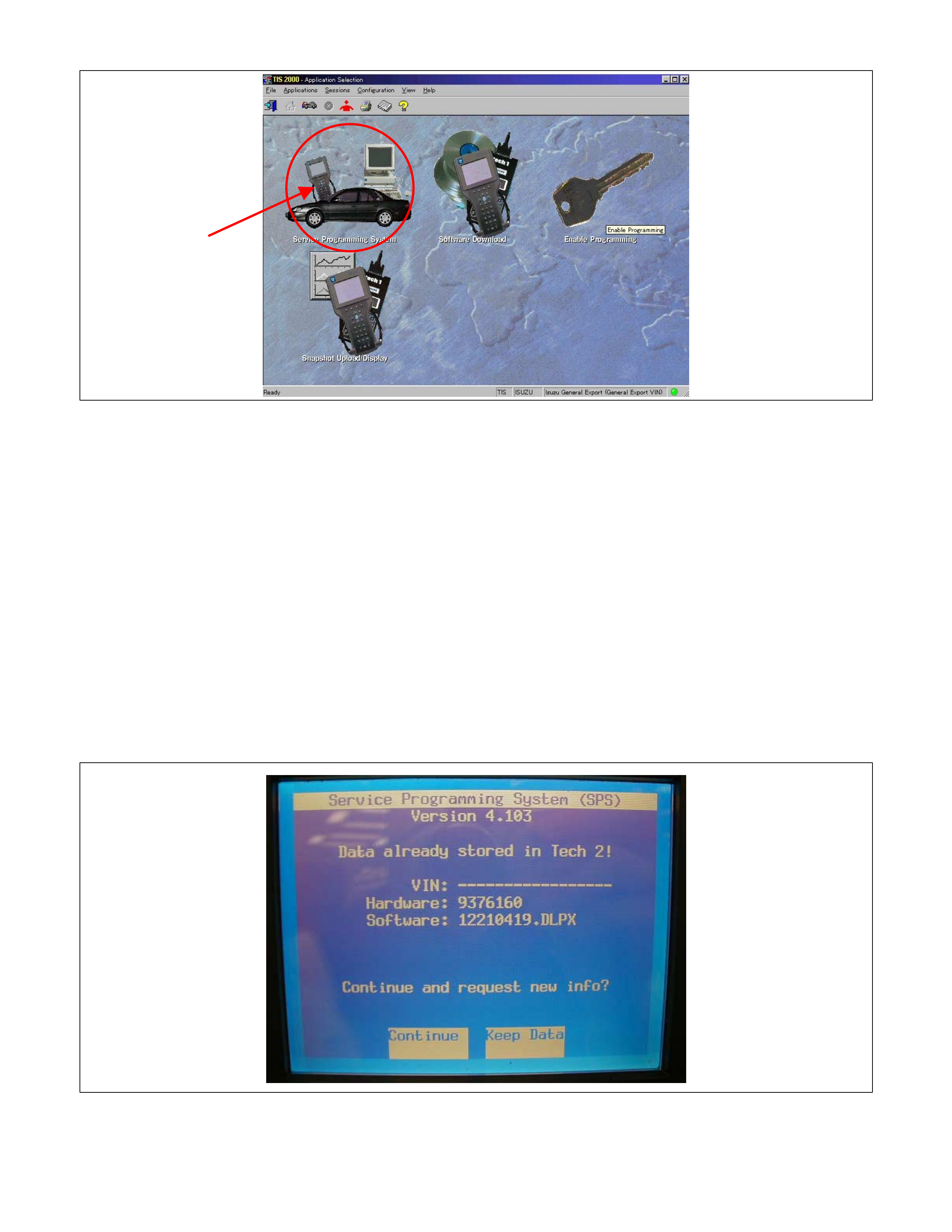
Service Programming System (SPS)
The procedure to program the control unit by using SPS
software contained in TIS 2000 is explained in steps below.
Important: Please checks the following before SPS is used.
• Latest software shall be used on Tech 2 and PC.
• Batteries of the vehicle shall be fully charged.
1. Preparations of TIS 2000
1. Connect Tech 2 to P/C.
2. Check to see if Hardware Key is plugged into Port.
3. Activate TIS 2000 by P/C.
4. On the activating screen of TIS2000, choose "Service Programming System"
5. On the screen of "Diagnostic Tester and Processing Program Selection", choose the one that will comply with the
following.
• Diagnostic tester in use
• New programming by the existing module or new programming by the replaced/new module.
• Fixing position of the control unit.
6. Upon completion of the selection, push the button of "Continue".
2. Demand of Data
1. Connect Tech-2 to the vehicle. When activated by turning on the power of Tech-2, push the "Enter" switch.
2. Turn on the ignition switch (without starting the engine)
3. In the main menu of Diagnostic Tester, push "F1: Service Programming System (SPS)".
4. Push "F0: Request Info" of Tech-2.
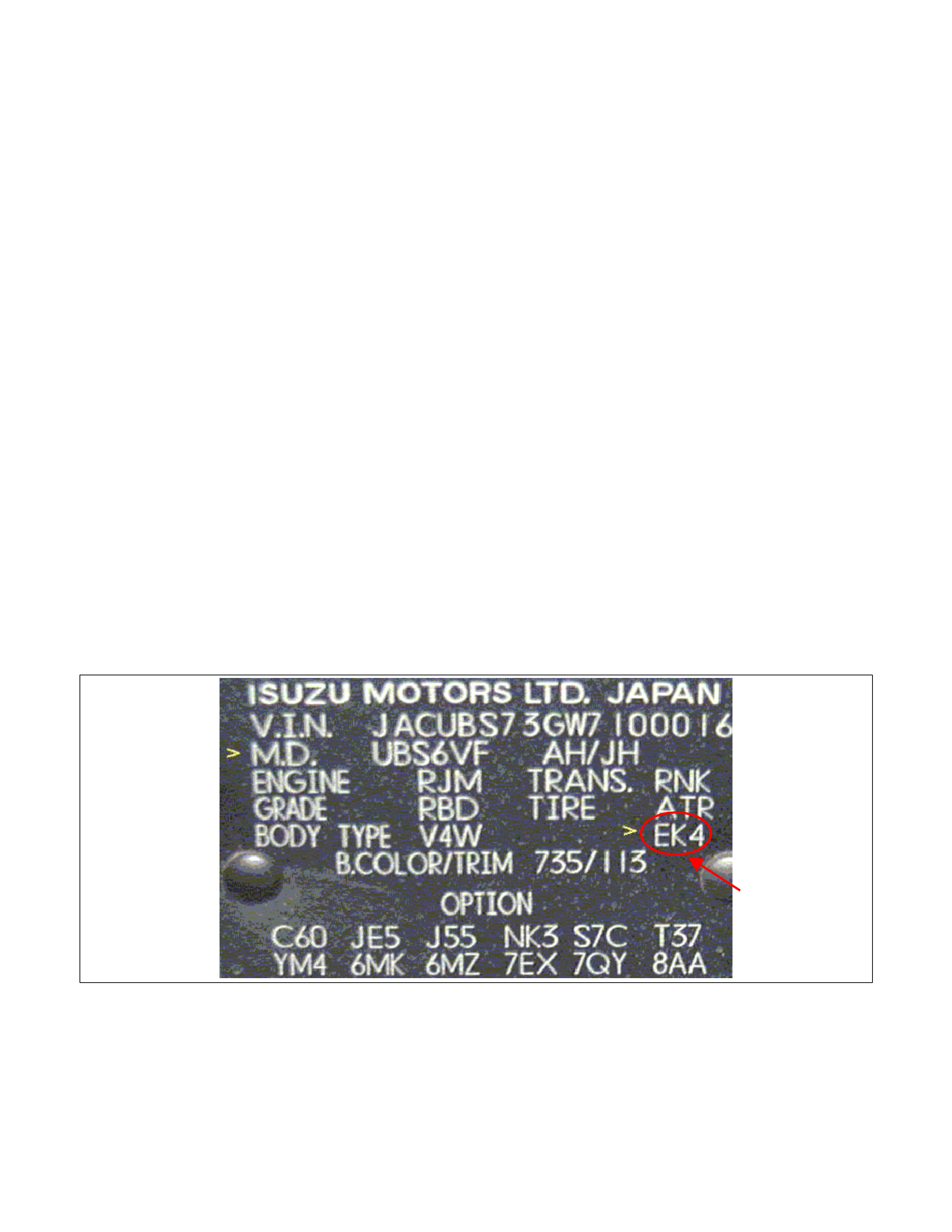
5. Where vehicle data has been already saved in Tech 2, the existing data come on display. In this instance, as
Tech-2 starts asking whether to keep the data or to continue obtaining anew data from the control unit, choose
either of them.
6. If you select “continue”, you have to select “Model Year”, “Vehicle Type”, “Controller Type(Transmission)”.
7. After that. then push button and turn Ignition switch on, off, on following Tech-2 display. Tech-2 will read
information from controller after this procedure.
8. During obtaining information, Tech-2 is receiving information from the control unit chosen. In replacing the control
unit, please be sure to under take "Obtaining Inf ormation" f r om the new unit. With VIN not being programmed into
the new c ontrol unit at the tim e of shipm ent, "obtaining inform ation" is not com plete (because the vehic le model,
engine model and model year are specified f rom VIN). For the procedure get additional information on vehicles,
instruction will be provided in dialog form, when TIS2000 is in operation.
9. Following instructions by T ech-2, push the "Exit" switch of Tech-2, tur n off the ignition of the vehic le and turn off
the power of Tech-2, thereby removing from the vehicle.
3. Data Exchange
1. Connect Tech-2 to P/C, turn on the power and click the "Next" button of P/C.
2. Check VIN of the vehicle and choose "Next".
3. When a lack of data is asked from among the following menu, enter accordingly.
* With VIN information
There is no necessary to select option menu.
The select menu is appeared automatically.
Some case, it is necessary to select “Destination code”.
* Without VIN information
Select following Menu
• Model Year
• Model
• Engine type
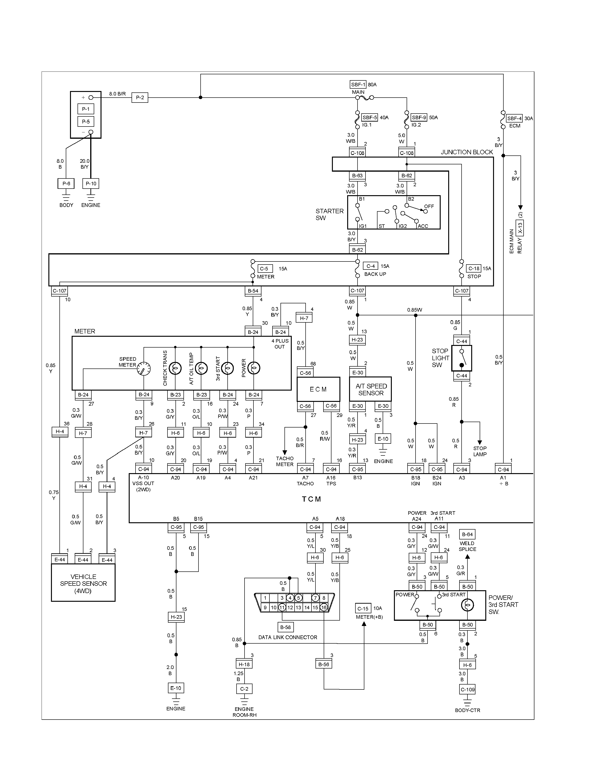
• Destination code (vehicles for general export)*1
* 1: How to read the destination code
Destination code can be read from ID Plate affixed on vehicles, while on VIN plate the destination code is described at
the right-hand edge of Body Type line. In Fig.-3, the destination code can be read as ""EK4"".
4. After choosing the data, click the "Next" button.
5. When all the necessary information is entered, the "details" of software within the database that match the
entered data will appear for confirm ation. Click the "Program" switch and then download the new software onto
Tech-2.
6. "Data Transfer" comes on display. The progress of downloading will be displayed on the screen in the form of bar
graph.

7. Upon finishing the data transfer, turn off the power of Tech-2, removing from P/C.
4. Programming of TCM
1. Check to see if batteries are fully charged, while ABS connectors shall be removed from the vehicle.
2. Connect Tech-2 to Vehicle Diagnostic Connectors.
3. Turn on the power of Tech-2 and the title screen comes on display.
4. Turn on the ignition (without allowing the engine to start)
5. On the title screen of Tech-2, push the "Enter" button.
6. Choose "F: Service Programming System" on the main screen and then choose "Fl: Programming".
7. While data is being transferred, "Downloading" will be displayed on the Tech-2 screen.
8. Upon f inishing the data tr ansf er, T ech-2 will display "Reprogram m ing Succe ssf ul". Push the "Ex it" button to bring
program to completion.
9. Following "Procedure 2: Demand of Data", tr y over again "Information Obtaining" and c hec k to c onf ir m if the data
has been correctly re-loaded.
10. Upon finishing confirmation, turn off the ignition of the vehicle and then turn off the power of Tech-2, removing
from the vehicle.
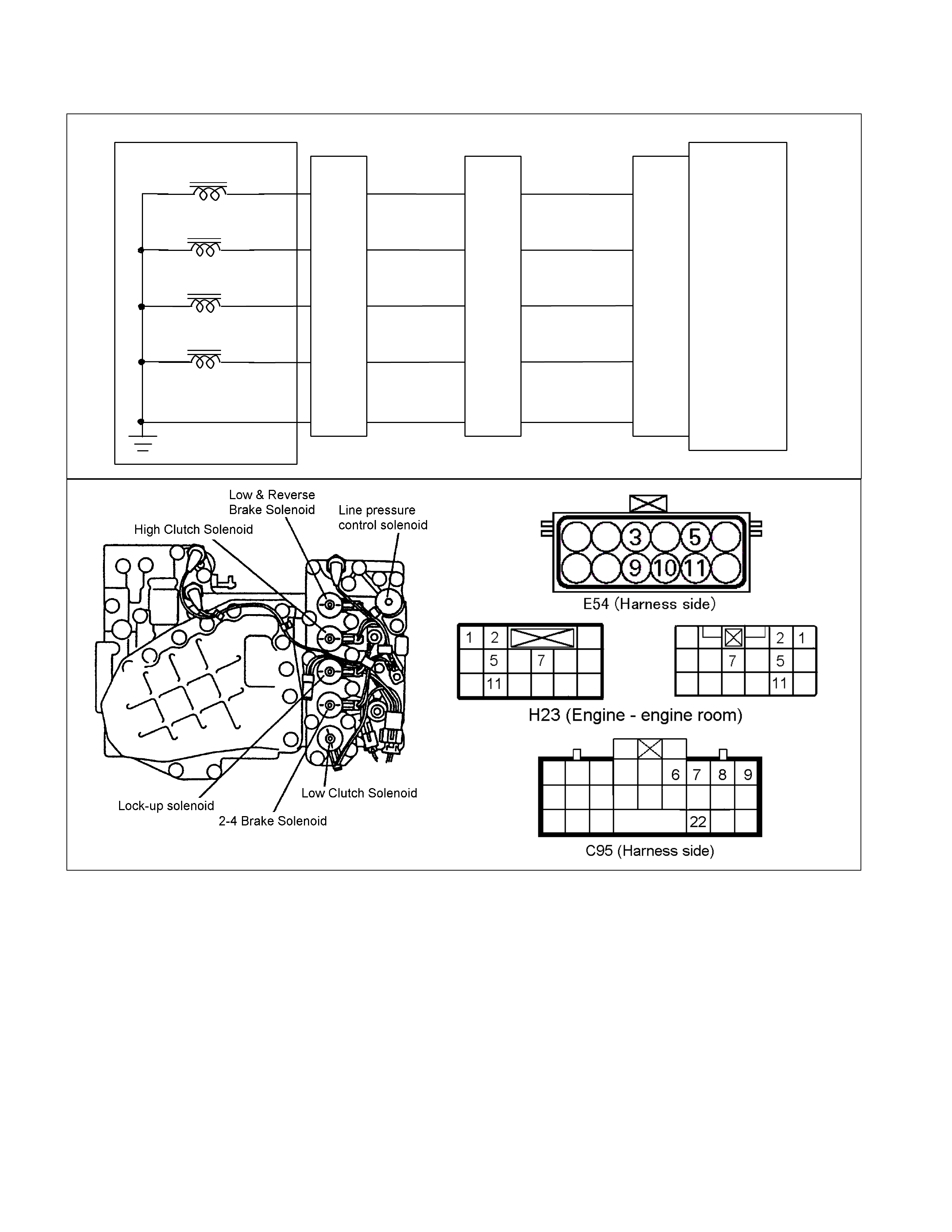
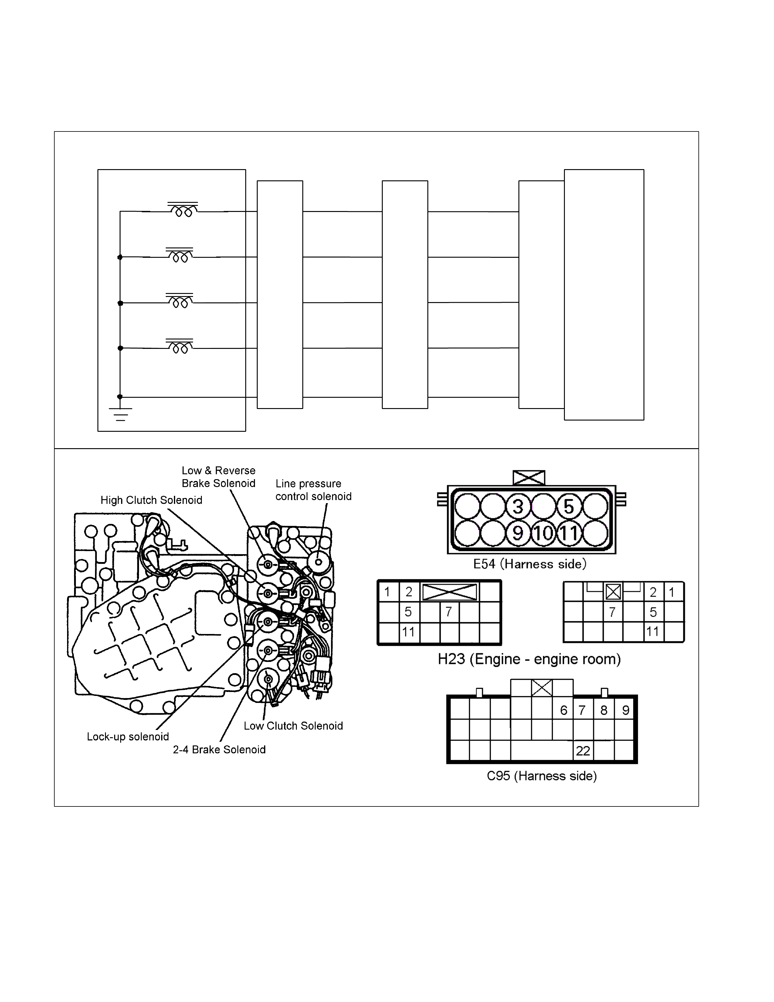
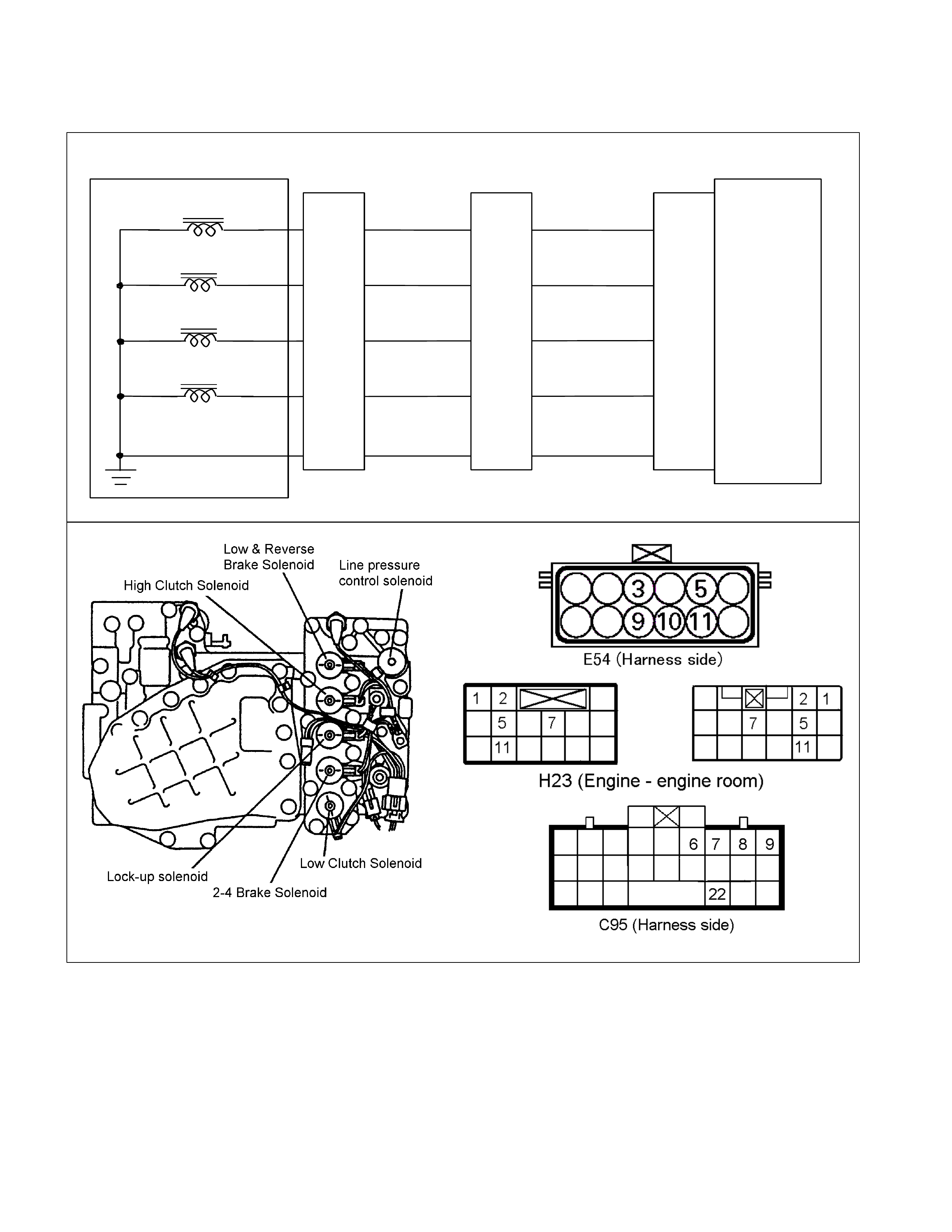
Circuit Diagram
RTW38DXF001001
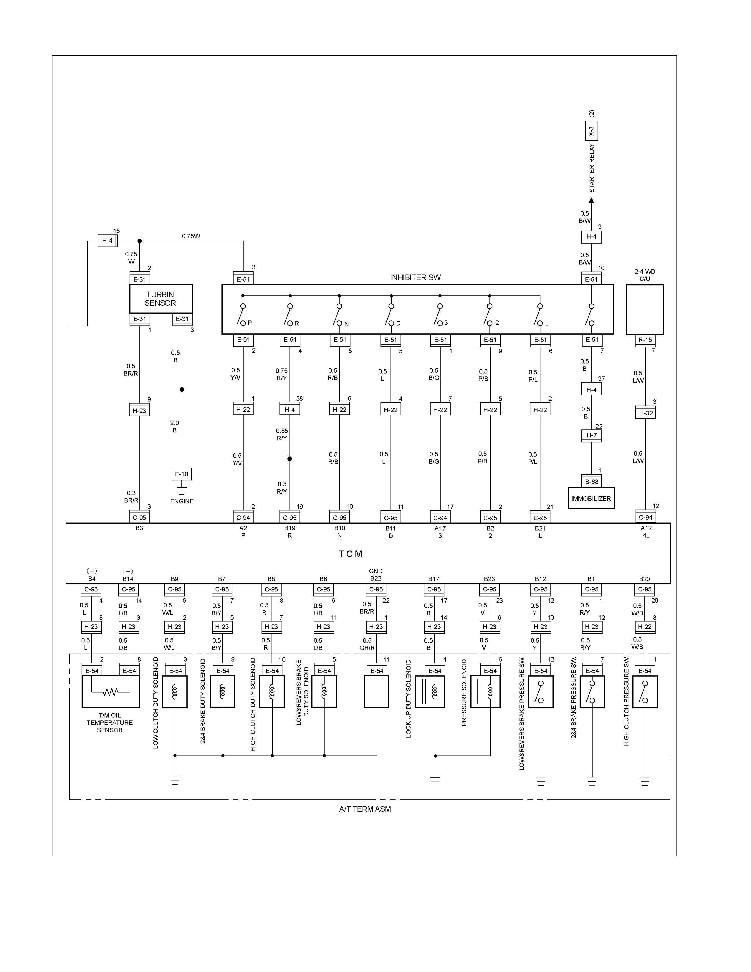
RTW38DXF001101
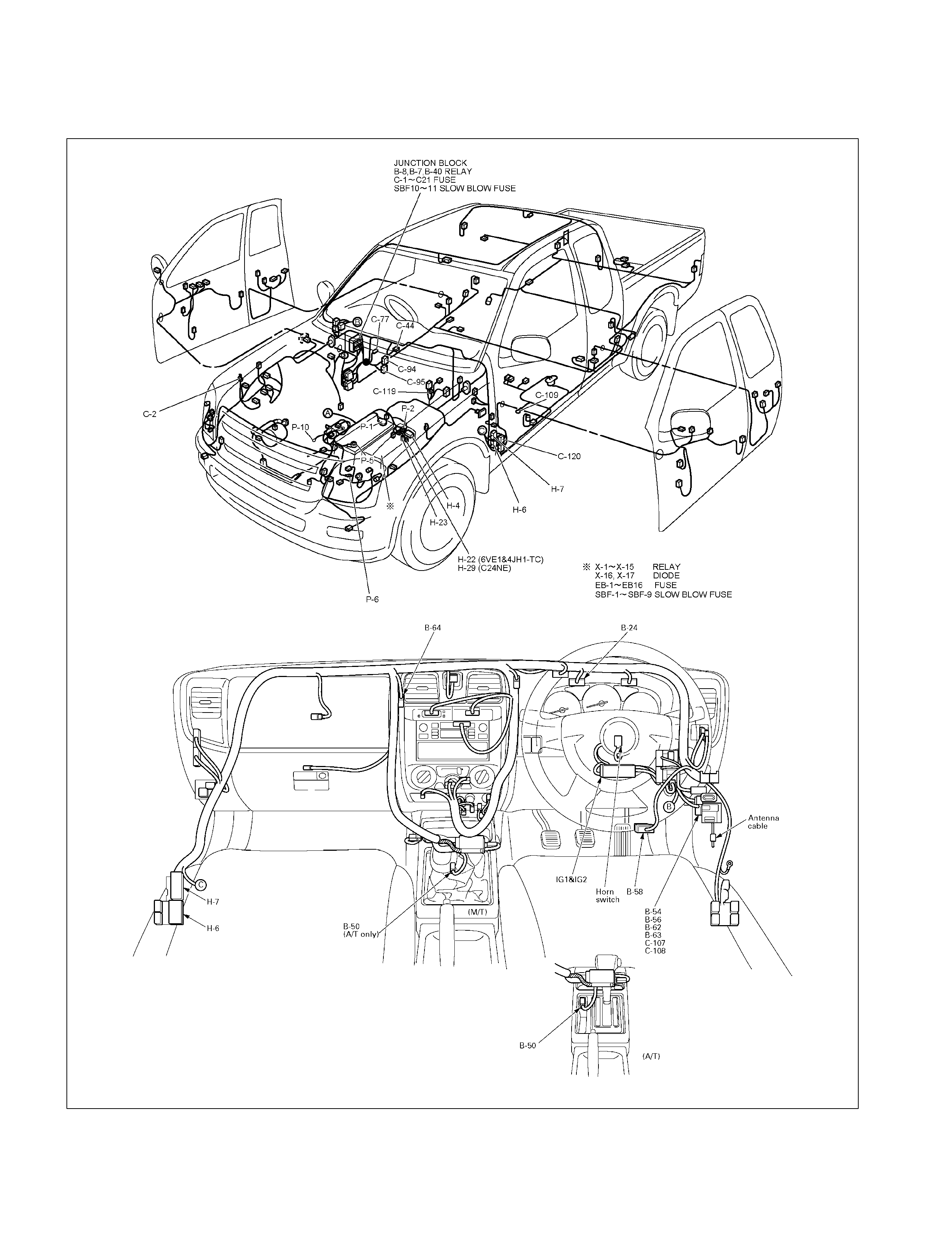
Parts Location
Parts Location (1)
RTW38DMF001001&810R300082
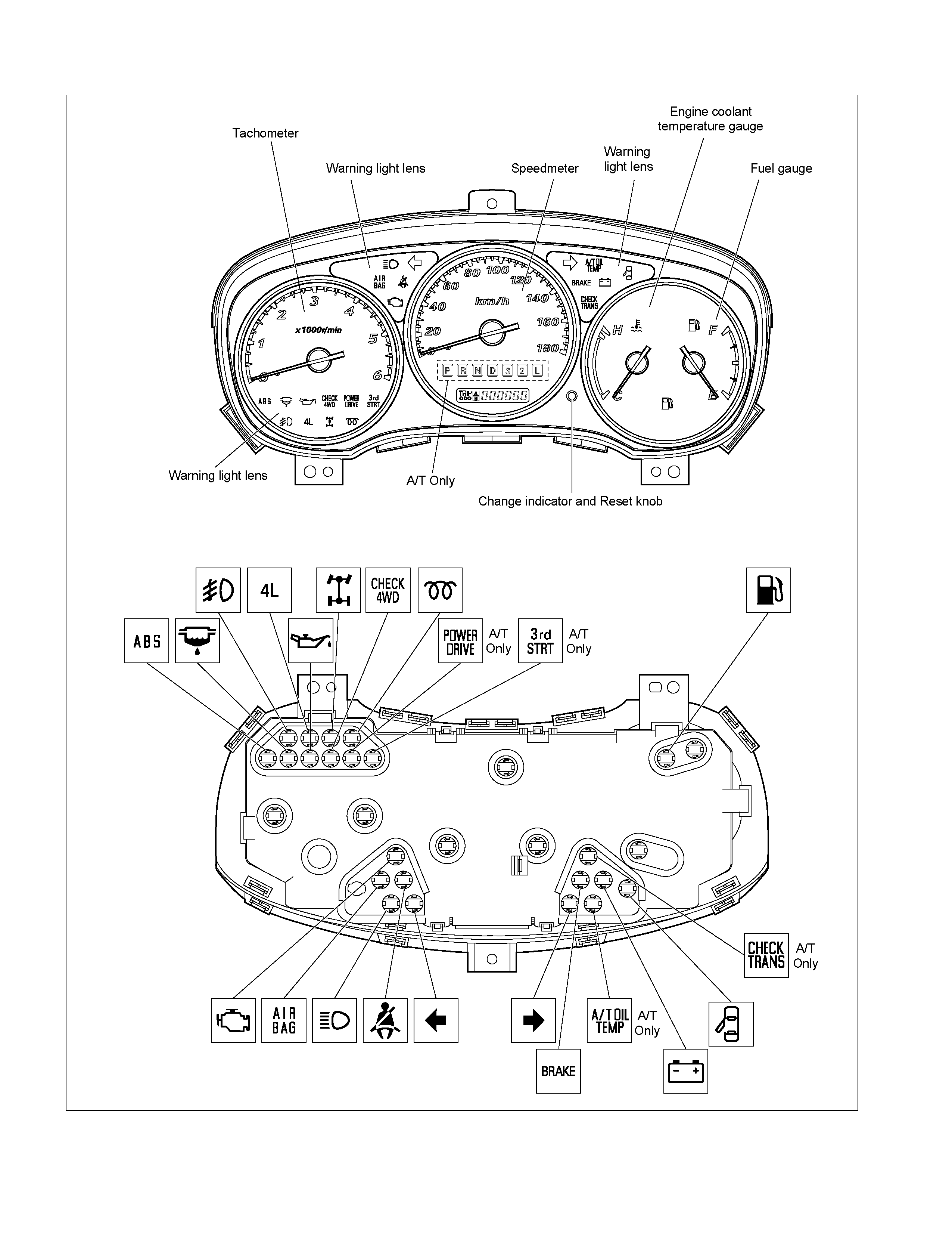
Parts Location (2)
RTW38DXF005601
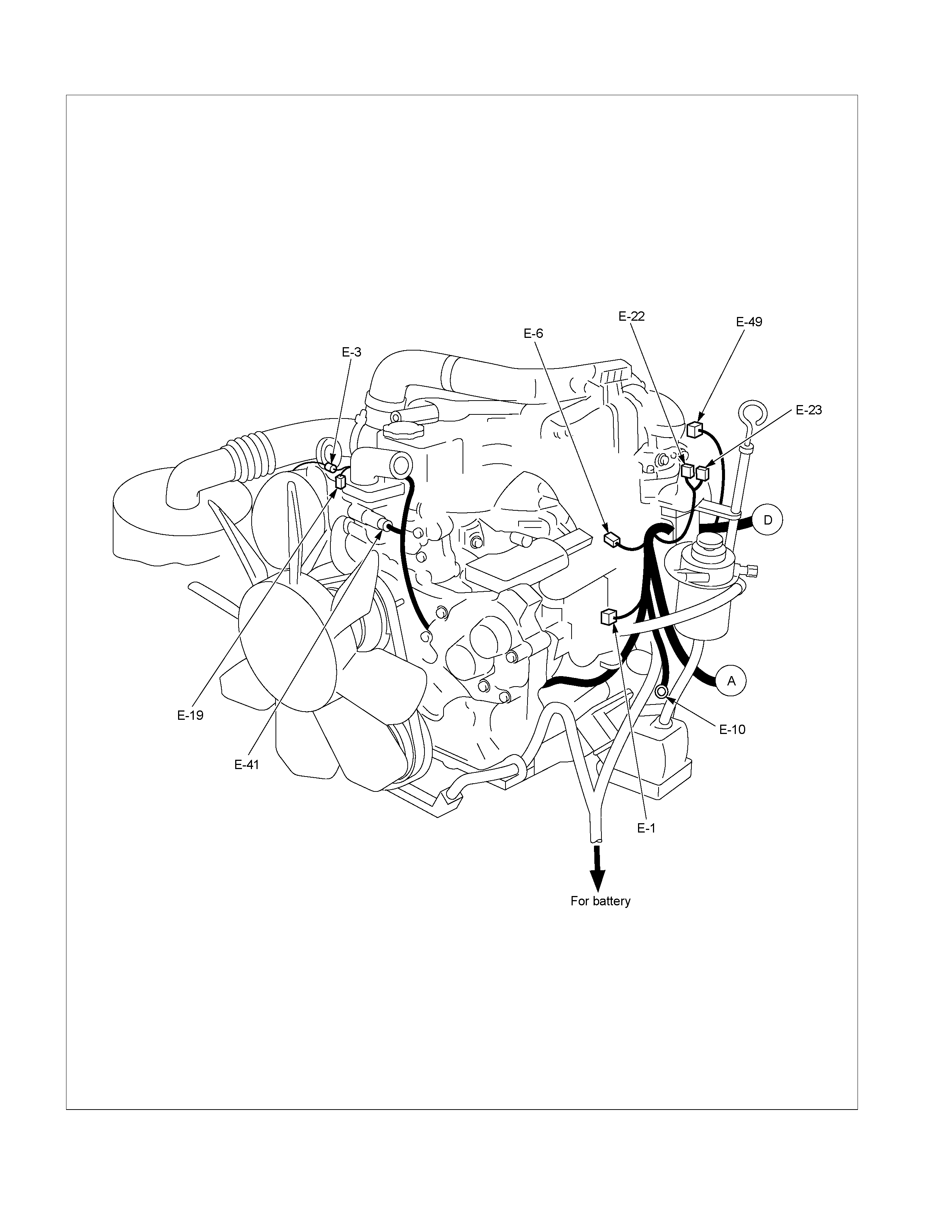
Parts Location (3)
RTW38DXF007601
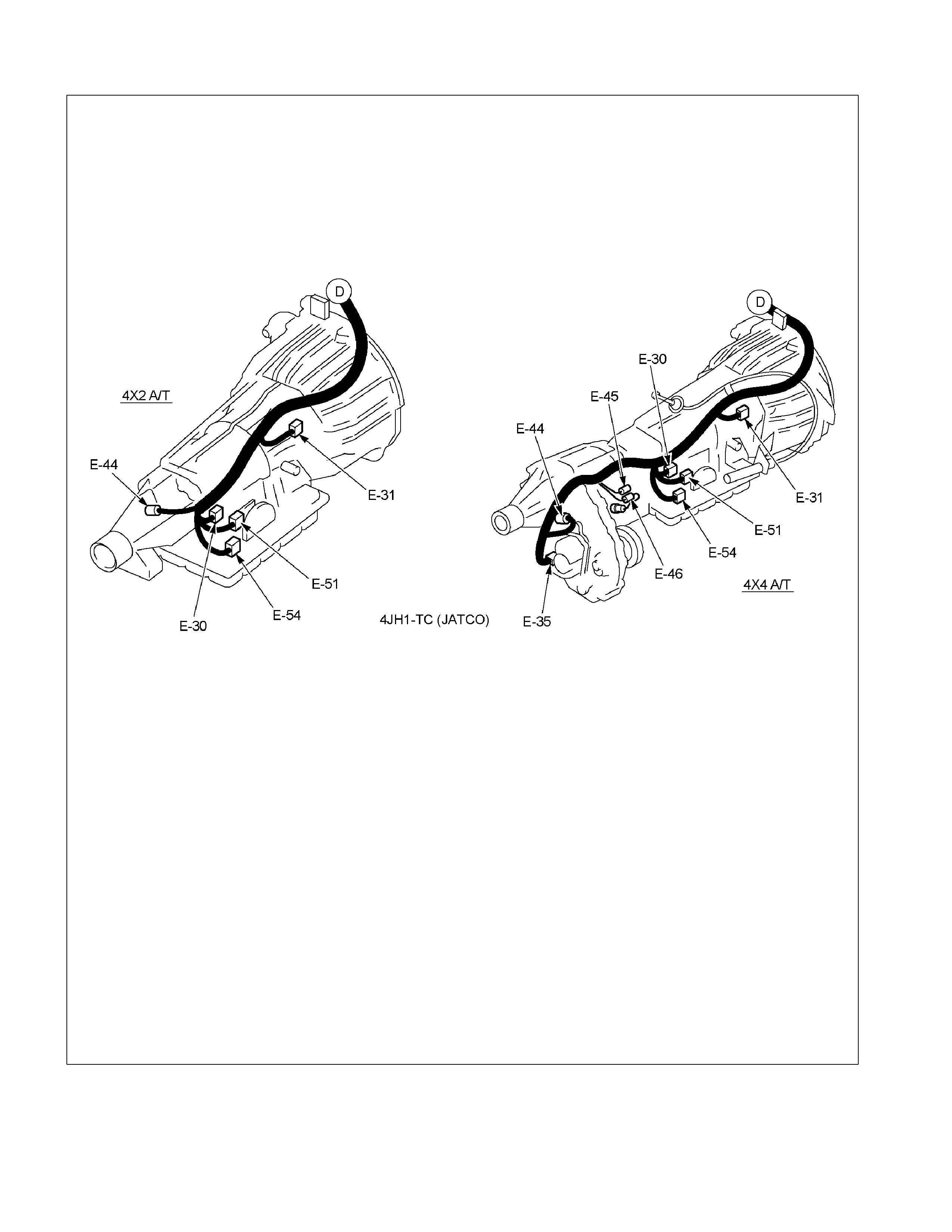
Parts Location (4)
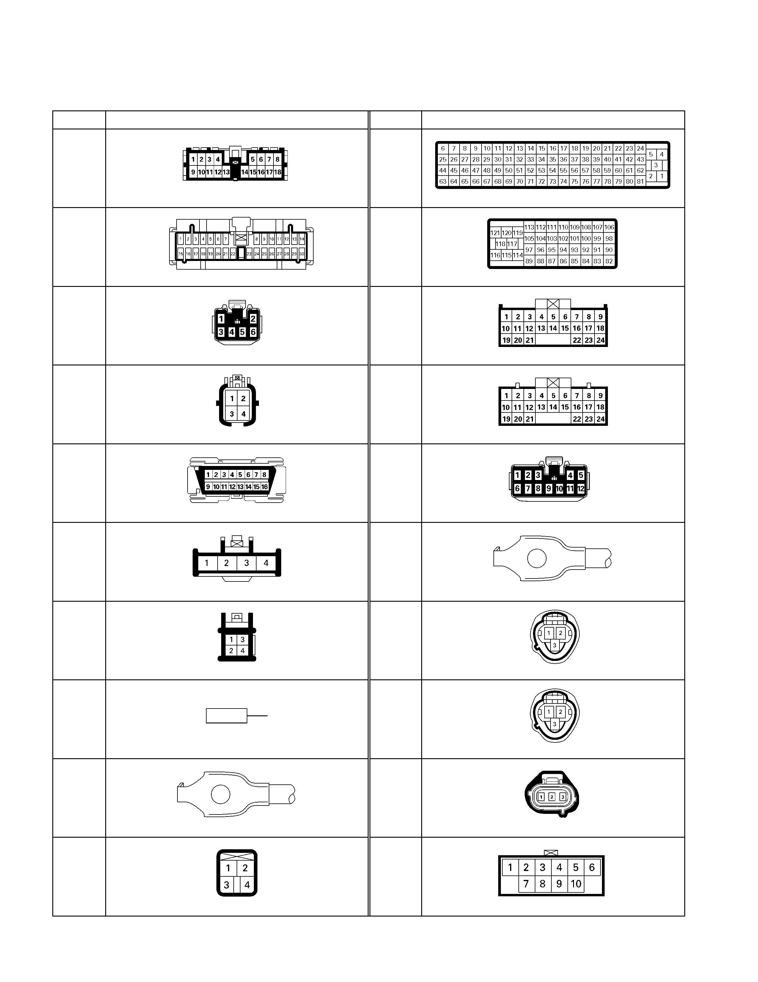
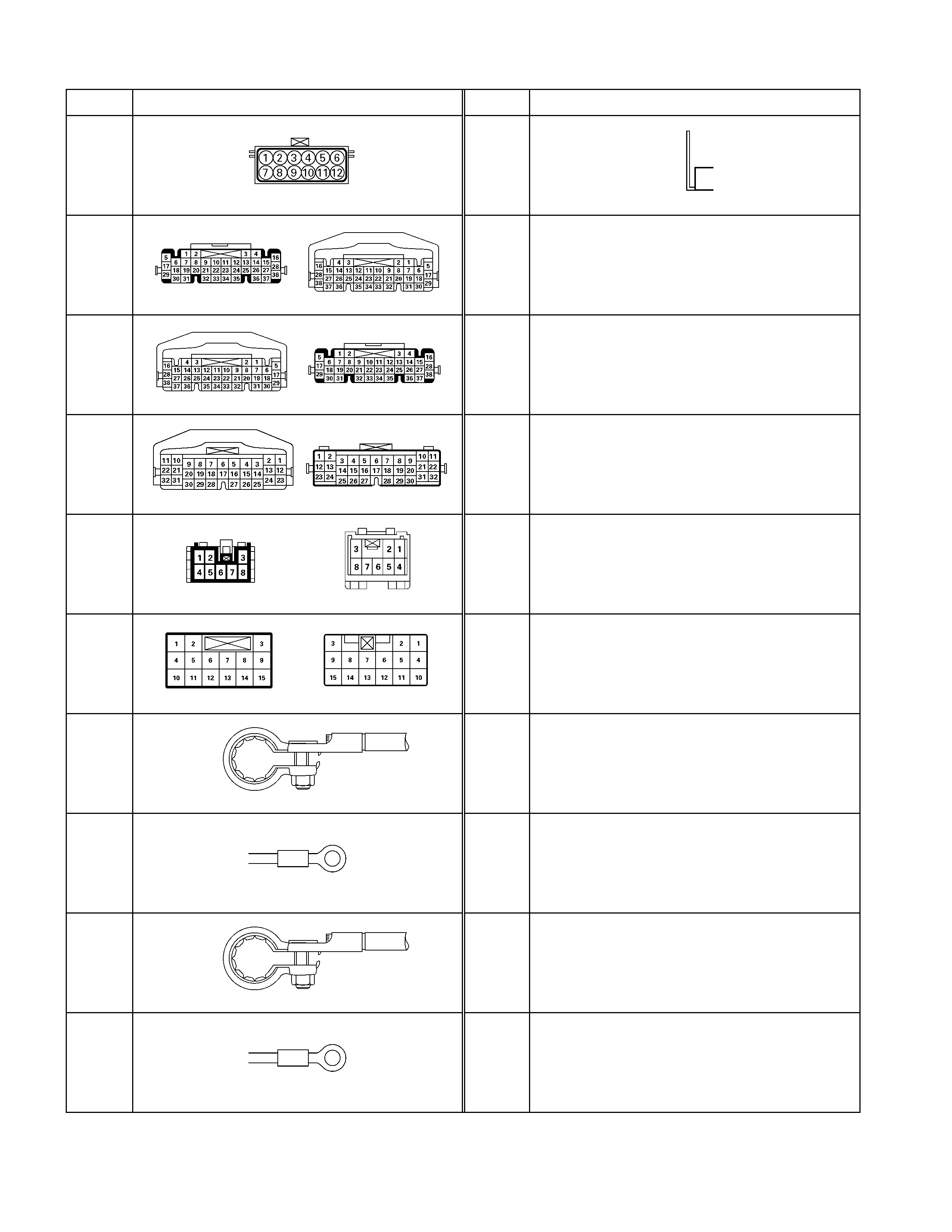
Connector List
TCM
No. Connector face No. Connector face
B-23
Green
Meter-A
C-56
(4JH1-TC)
ECM-A
B-24
Green
Meter-B
C-57
(4JH1-TC)
ECM-B
B-50
White
Power/3rd start switch
C-94
(6VE1)
(4JH1-TC)
Gray
TCM
B-54
White
J/B I2
C-95
(6VE1)
(4JH1-TC)
White
TCM
B-58
Black
Check connector
C-107
White
J/B E2
B-62
White
Ignition switch (IGSUB : G1)
C-109
Silver
Body-LH ; ground
B-63
White
Ignition switch (IGSUB : G2)
E-30
(4JH1-TC)
Gray
A/T speed sensor
B-64
Silver
Weld splice 1 (Illumination)
E-31
(4JH1-TC)
Gray
Turbine sensor
C-2
Silver
Engine room-RH ground
E-44
Gray
Vehicle speed sensor
C-44
White
Stop lamp switch
E-51
(4JH1-TC)
Black
Inhibiter switch
No. Connector face No. Connector face
E-54
(4JH1-TC)
Black
A/T term ASM
P-10
Silver
Engine ground
H-4
(6VE1)
(4JH1-TC)
White
Engine ~ Engine room
H-6
White
Engine room ~ INST
H-7
White
Engine room ~ INST
H-22
(6VE1)
(4JH1-TC)
White
Engine ~ Engine room C
H-23
(6VE1)
(4JH1-TC)
White
Engine ~ Engine room B
P-1
Silver
Battery (+)
P-2
Silver
Relay & Fuse box
P-5
Silver
Battery (-)
P-6
Silver
Body earth (Ground)
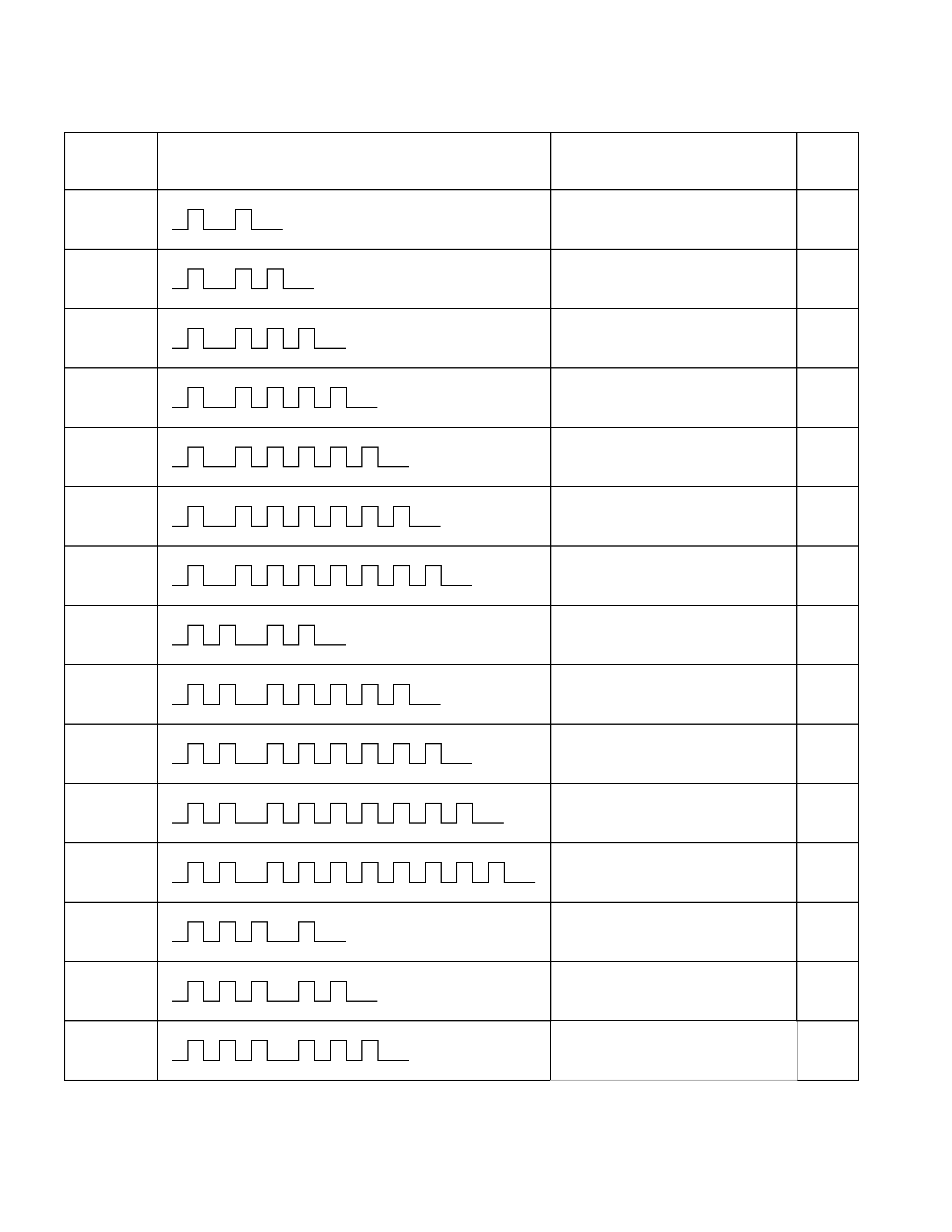
Diagnosis Trouble Code Table
Flash Code
(P-Code)
CHECK TRANS Flash Pattern
Description CHECK
TRANS
Warning
11 (P0722) Output Shaft Sensor - No Signal ON
12 (-) Normal -
13 (P0727) ON
Engine Revolution Sensor No
Signal
14 (P0717) Turbine Speed Sensor No Signal ON
15 (P0710) ATF Temperature Sensor Failure OFF
16 (P0560) System Voltage Failure ON
17 (P0705) Inhibitor Switch Failure ON
22 (P1120) Throttle Signal Failure ON
25 (P1875) GND Return Circuit Failure ON
26 (P1853) ON
Low & Reverse Brake Pressure
Switch Failure
27 (P1858) 2-4 Brake Pressure Switch Failure ON
28 (P1863) ON
High Clutch Pressure Switch
Failure
31 (P0753) ON
Low & Reverse Brake Dut
y
Solenoid Failure
32 (P0758) 2-4BrakeDutySolenoidFailure ON
33 (P0763) ON
High Clutch Duty Solenoid Failure

Flash Code
(P-Code)
CHECK TRANS Flash Pattern
Description CHECK
TRANS
Warning
34 (P0768) Low Clutch Duty Solenoid Failure ON
35 (P0748) Line Pressure Solenoid Failure ON
36 (P1860) Lock-up Duty Solenoid Failure ON
41 (P0731) 1stGearRatioError ON
42 (P0732) 2ndGearRatioError ON
43 (P0733) 3rdGearRatioError ON
44 (P0734) 4thGearRatioError ON
51 (P1750) ON
Low & Reverse Brake Fail-safe
Valve Failure
52 (P1755) 2-4BrakeFail-safeValveFailure ON
- (P0602) No Flash Code Programming Error ON

Fail-Safe Function
Fail-Safe Condition
Flash Code
(P-Code)
Description CHECK
TRANS
Warning
Gear Shift
Solenoid
Line
Pressure
Solenoid
Lock-up
Remark
11
(P0722) Output Shaft Sensor
No Signal ON 3rdFix All Stop - Inhibited
13
(P0727) Engine Revolution Sensor
No Signal ON - - - Inhibited
14
(P0717) Turbine Speed Sensor No
Signal ON 3rdFix All Stop - Inhibited
15
(P0710) ATF Temperature Sensor
Failure OFF 3,2,L - - Inhibited *1
16
(P0560) System Voltage Failure ON 3rdFix All Stop - Inhibited *2
17
(P0705) Inhibitor Switch Failure ON 3rdFix All Stop - Inhibited
22
(P1120) Throttle Signal Failure ON 3rdFix All Stop - Inhibited
25
(P1875) GND Return Circuit
Failure ON 3rdFix All Stop - Inhibited *2
26
(P1853) Low & Reverse Brake
Pressure Switch Failure ON No Fail-safe Function
27
(P1858) 2-4 Brake Pressure
Switch Failure ON No Fail-safe Function
28
(P1863) High Clutch Pressure
Switch Failure ON No Fail-safe Function
31
(P0753) Low & Reverse Brake
Duty Solenoid Failure ON 3rdFix All Stop - Inhibited
32
(P0758) 2-4 Brake Duty Solenoid
Failure ON 3rdFix All Stop - Inhibited
33
(P0763) High Clutch Duty Solenoid
Failure ON 3rdFix All Stop - Inhibited
34
(P0768) Low Clutch Duty Solenoid
Failure ON 3rdFix All Stop - Inhibited
35
(P0748) Line Pressure Solenoid
Failure ON - - Stop -
36
(P1860) Lock-up Duty Solenoid
Failure ON - - - Inhibited
41
(P0731) 1stGearRatioError ON No Fail-safe Function
42
(P0732) 2ndGearRatioError ON No Fail-safe Function
43
(P0733) 3rdGearRatioError ON No Fail-safe Function
44
(P0734) 4thGearRatioError ON No Fail-safe Function
51
(P1750) Low & Reverse Brake
Fail-safe Valve Failure ON 3rdFix All Stop - Inhibited
52
(P1755) 2-4 Brake Fail-safe Valve
Failure ON 3rdFix All Stop - Inhibited
-
(P0602) Programming Error ON No Fail-safe Function
*1: When the engine speed is more than 470 rpm for 10 minuets, the lock-up and gear shift to 4th (over-drive) are
allowed.
*2: In case of fail-safe valve failure, gear shift to 4th (over-drive) is inhibited.
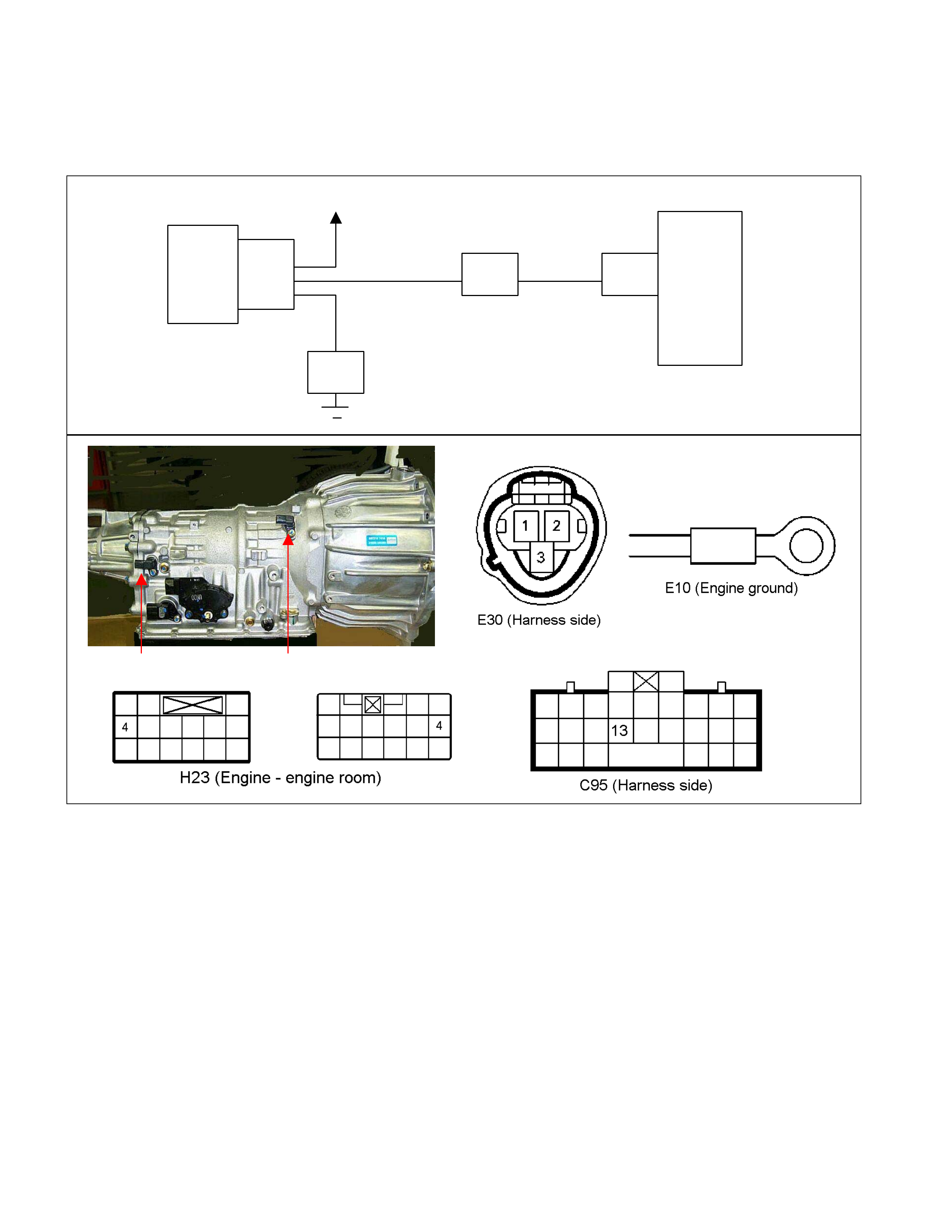
DTC P0722 (Flash Code 11) Output Shaft Speed Sensor No Signal
Speed
Sensor
TCM
B13
H23
(4) C95
(13)
E30
(2)
(1)
(3)
E10
Key SW
YEL/RED
BLK
YEL/RED
Output Shaft Speed Sensor Turbine Sensor
Setting Condition:
• W hen the vehicle speed exceeds 5 km/h with the turbine speed over 1000 rpm for 5 seconds, after 25.5 seconds
elapsed in D, 3, 2 or L range.
Fail Safe:
• When the vehicle is running, the gear position selected at the trouble detection is held and the lock-up is inhibited.
• After the vehicle stopped, all solenoid operations stop (OFF) and the gear is fixed to the 3rd.
Possible Cause:
• Speed sensor malfunction.
• Sensor wheel (parking gear) malfunction.
• Large sensing gap between speed sensor and sensor wheel (parking gear).
• Sens or wire open circ uit, s hort c irc uit to battery or short cir cuit to gr ound between s peed s ensor terminal 1 and TCM
terminal B13 (C95).
• Sensor wire open circuit or short circuit to ground of the harness between speed sensor terminal 2 and power supply
circuit.

• Sensor wire open circuit or short circuit to battery between speed sensor terminal 3 and ground circuit.
• Poor connection of each connector.
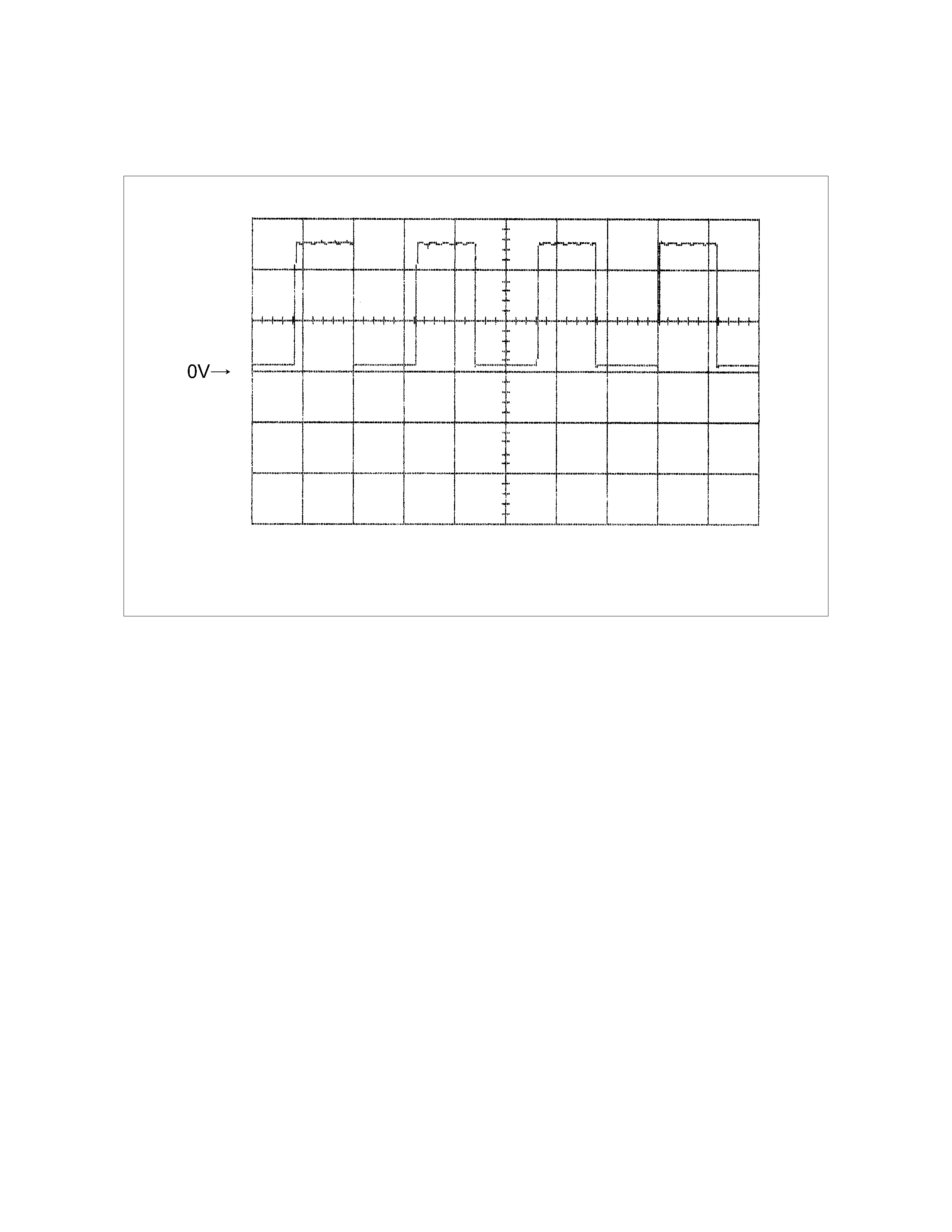
Reference:
When the vehicle speed 20km/h at L range in 1st gear, following signal is outputted.
Measurement terminal: B13 (C95) and B5 (C95)
-AC range by circuit tester: Approximately 6.2 V
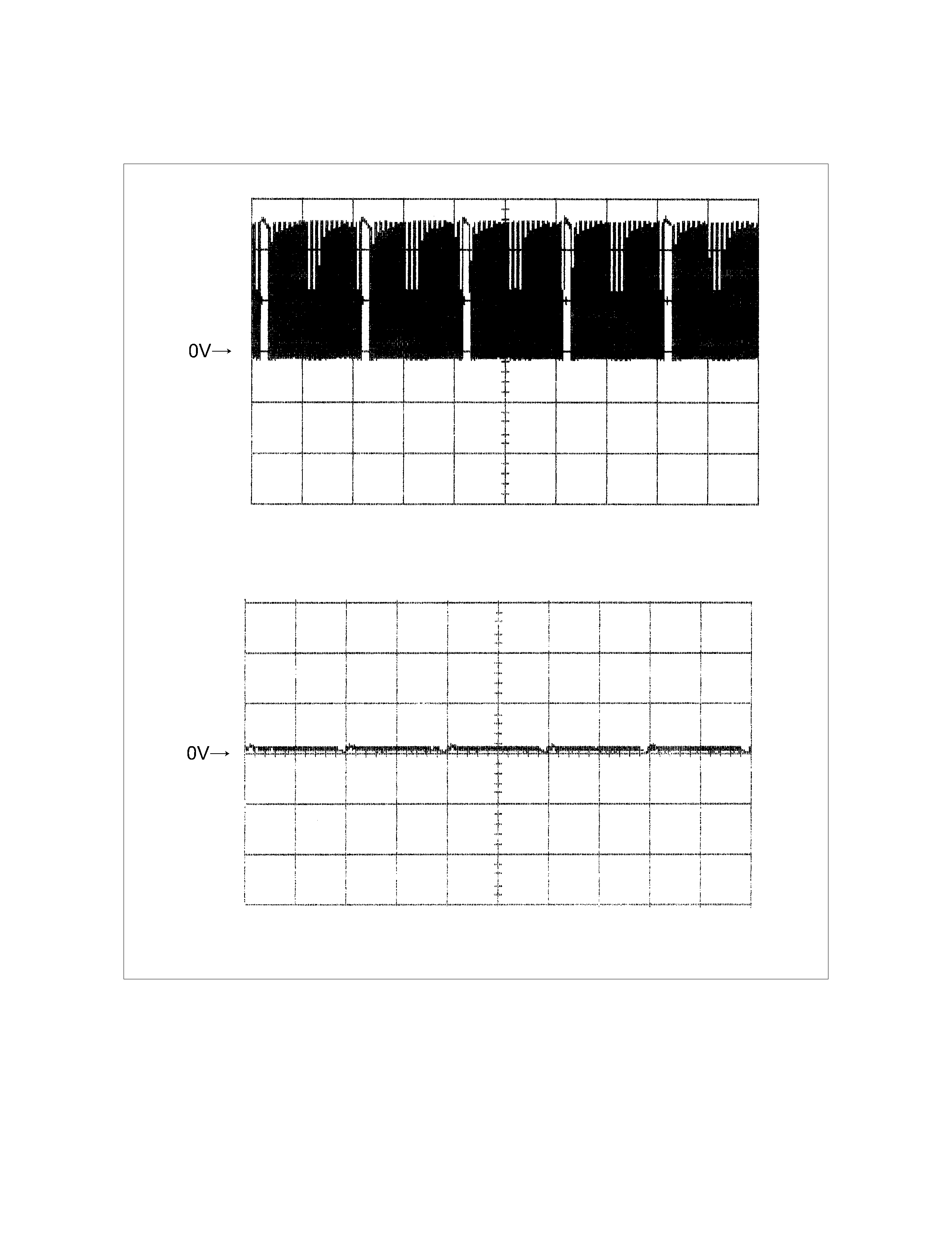
Vehicle Speed Sensor Reference Wave Form
Measurement Terminal: B13 (+) B5 (-)
Measurement Scale: 5V/div 2ms/div
Measurement Condition: Vehicle speed 20km/h at L range in 1st gear
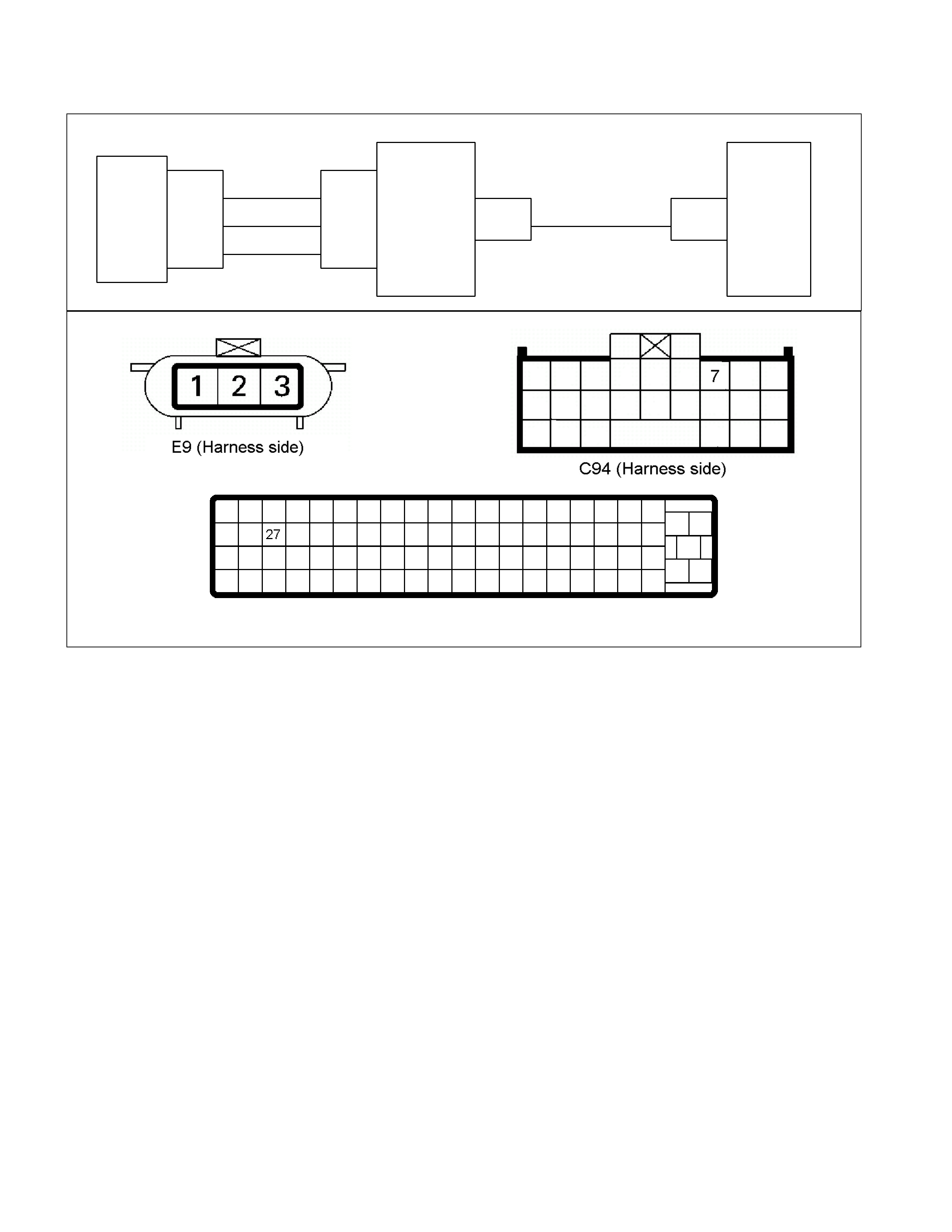
DTC P0727 (Flash Code 13) Engine Revolution Sensor No Signal
RED
TDC
Sensor
TCM
A
7
C94
(7)
BLK/RED
WHT
C56
(27)
E9
(1)
(2)
(
3
)
C57
(98)
(90)
(
101
)
ECM
C56 (ECM-A)
Setting Condition:
• The engine speed becomes 0 rpm for 2 seconds while the vehicle is running at the over 40 km/h.
Fail Safe:
• Lock-up is inhibited.
Possible Cause:
• Crank position sensor malfunction.
• Sensor wheel (flywheel) malfunction.
• Large sensing gap between speed sensor and sensor wheel (flywheel).
• Faulty input signal from crank position sensor to ECM.
• Signal wire open circuit or short circuit to battery between ECM A24 and TCM terminal A7 (C94).
• Poor connection of each connector.
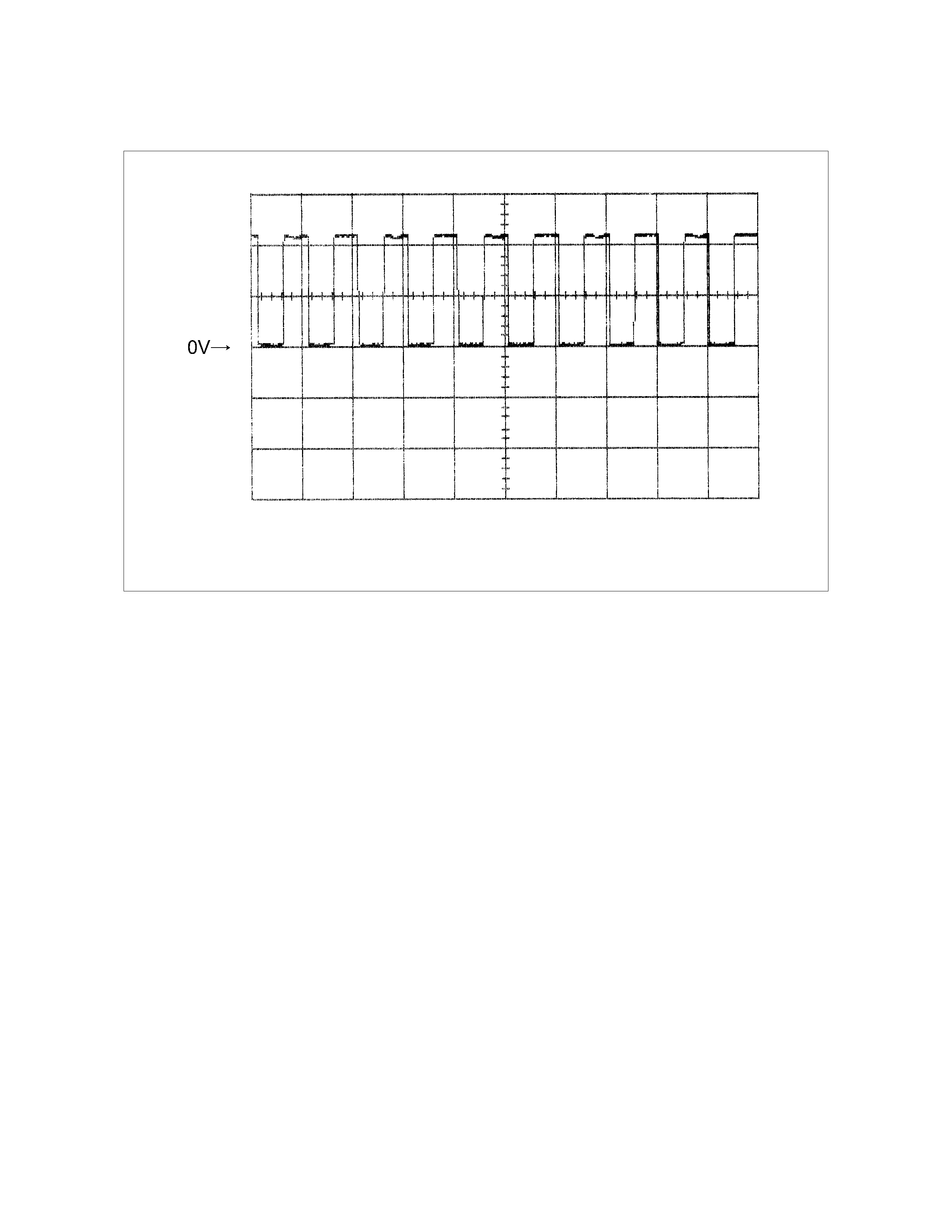
Reference:
When the engine speed 1500rpm, following signal is outputted.
Measurement terminal: A7 (C94) and B5 (C95)
Engine Speed Sensor Reference Wave Form
Measurement Terminal: A7 (+) B5(-)
Measurement Scale: 5V/div 20ms/div
Measurement Condition: At engine speed 1500rpm
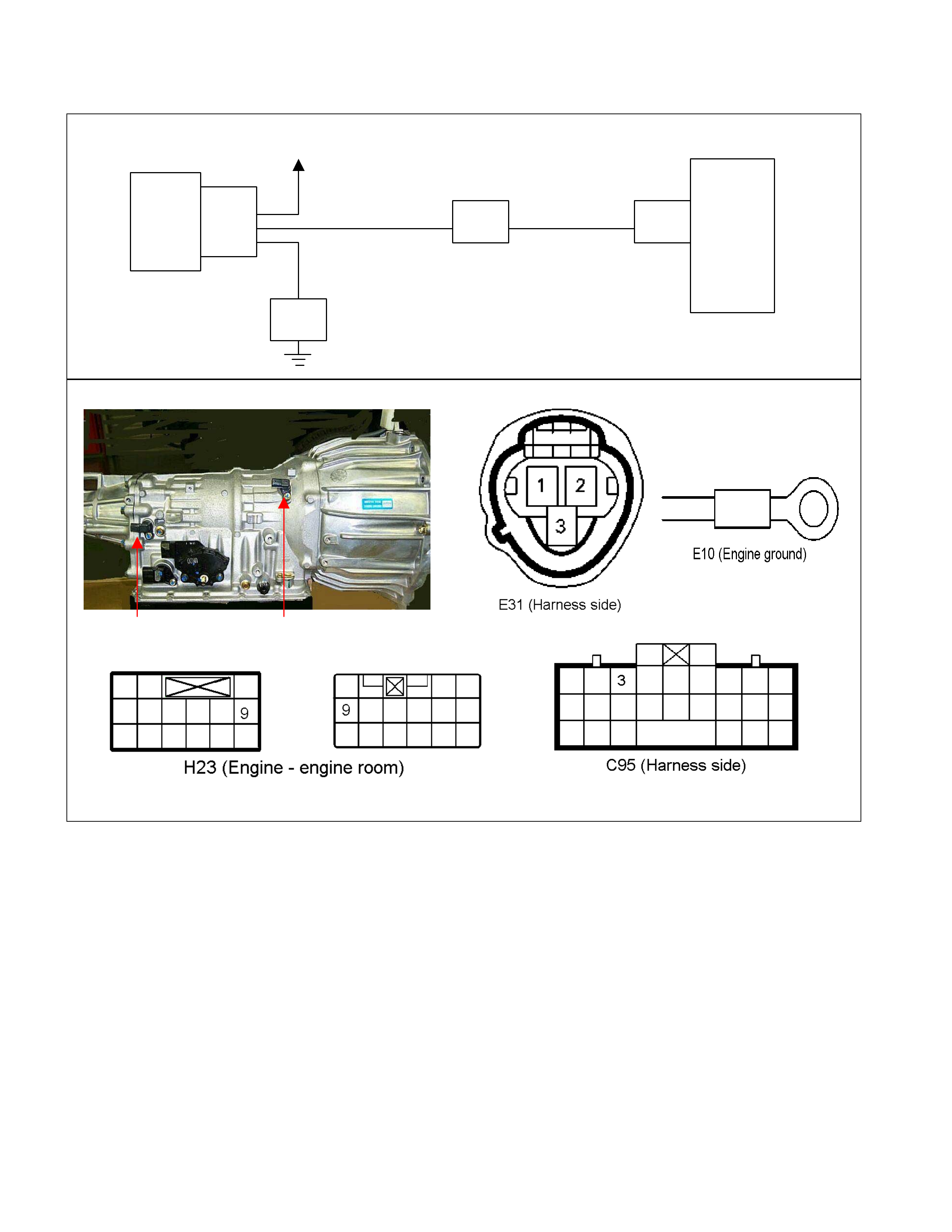
DTC P0717 (Flash Code 14) Turbine Speed Sensor No Signal
Turbine
Sensor
TCM
B3
H23
(9) C95
(3)
E31
(2)
(1)
(3)
E10
Key SW
BRN/RED
WHT
BLK
BRN/RED
Speed Sensor Turbine Sensor
Setting Condition:
• The turbine speed below 300 rpm for 2 seconds while the vehicle is running at the speed over 40 km/h with the
engine speed over 1500 rpm in the D, 3, 2, or L range.
Fail Safe:
• When the vehicle is running, the gear position selected at the trouble detection is held and the lock-up is inhibited.
• After the vehicle stopped, all solenoid operations stop (OFF) and the gear is fixed to the 3rd.
Possible Cause:
• Turbine speed sensor malfunction.
• Sensor wheel (reverse & high clutch drum) malfunction.
• Large sensing gap between speed sensor and sensor wheel (reverse & high clutch drum).
• Sensor wire open circuit, short circuit to battery or short circuit to ground between turbine speed sensor terminal 1
and TCM terminal B3 (C95).
• Sensor wire open circuit or short circuit to ground between turbine speed sensor terminal 2 and power supply circuit.
• Sensor wire open circuit or short circuit to battery between turbine speed sensor terminal 3 and ground circuit.
• Poor connection of each connector.
Reference:
When the vehicle speed 20km/h at L range in 1st gear, following signal is outputted.
Measurement terminal: B3 (C95) and B5 (C95)
-AC range by circuit tester: Approximately 6.2 V
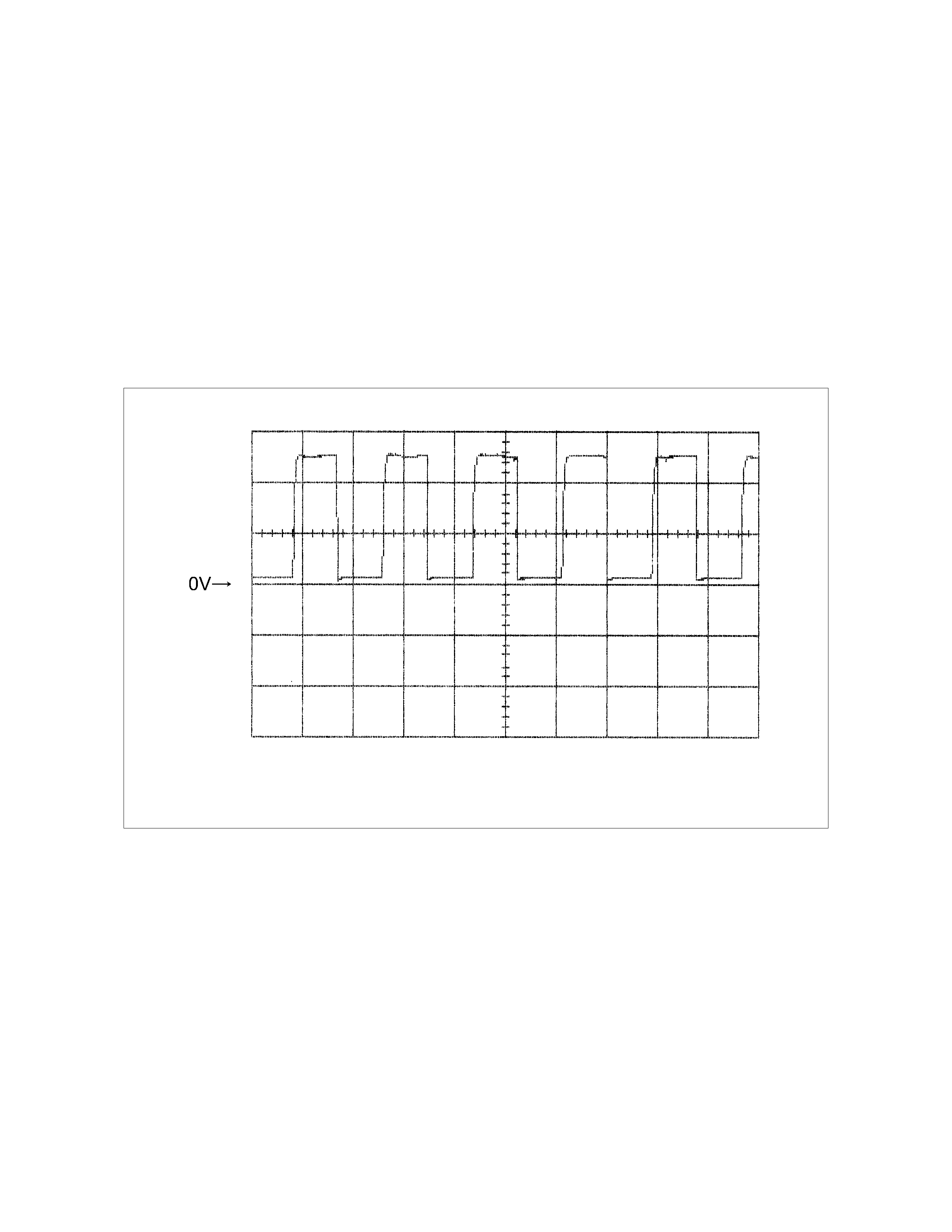
Turbine Sensor Reference Wave Form
Measurement Terminal: B3 (+) B5 (-)
Measurement Scale: 5V/div 500ms/div
Measurement Condition: Vehicle speed 20km/h at L range in 1st gear
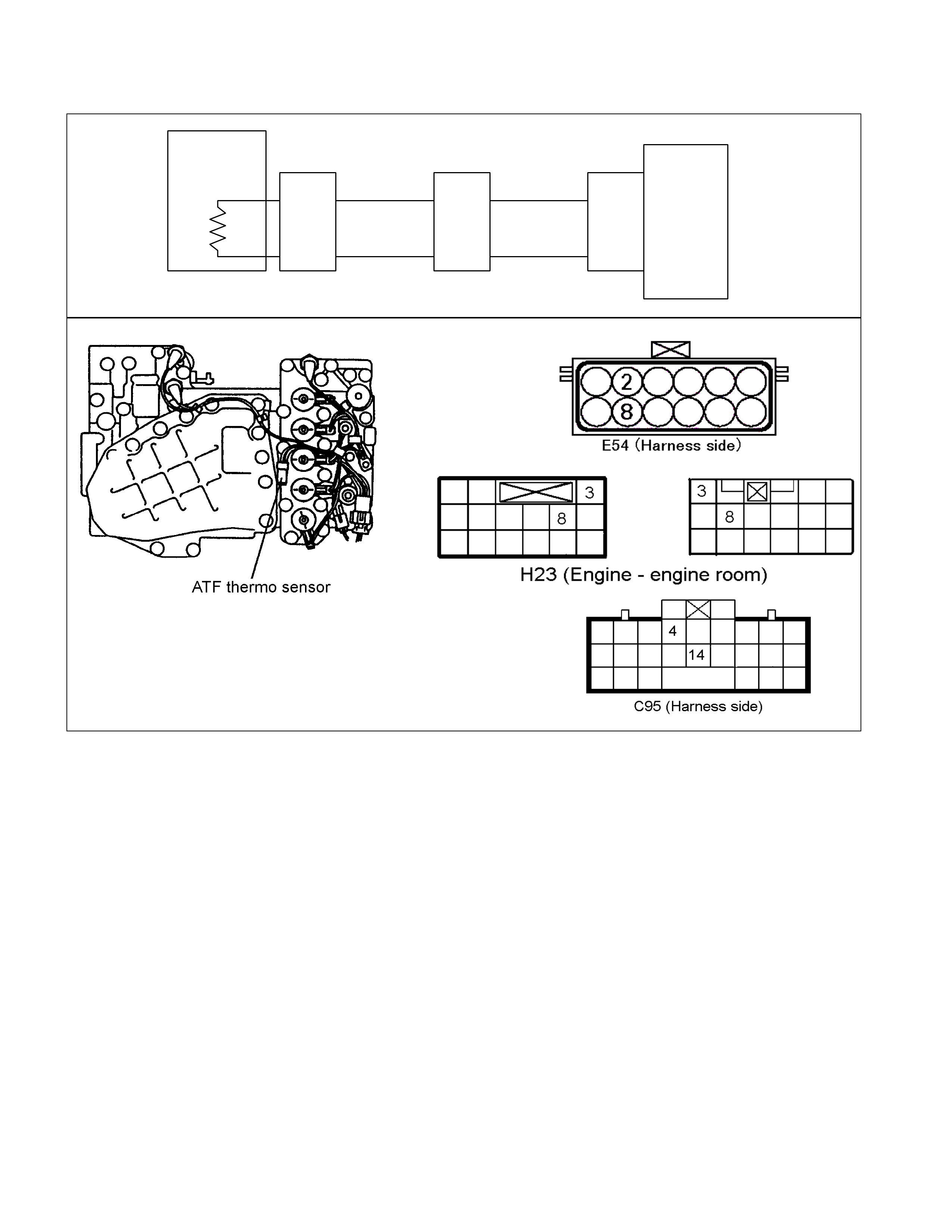
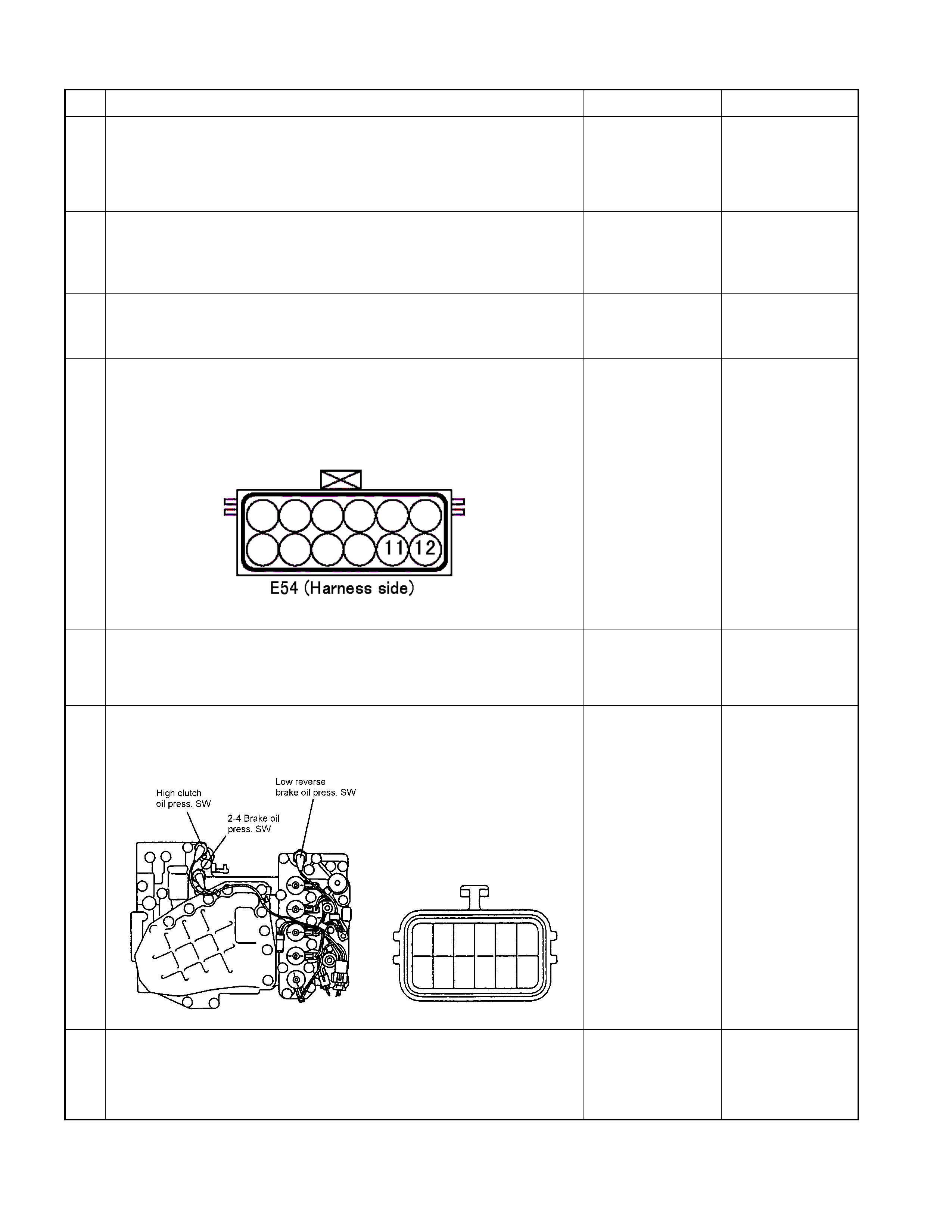
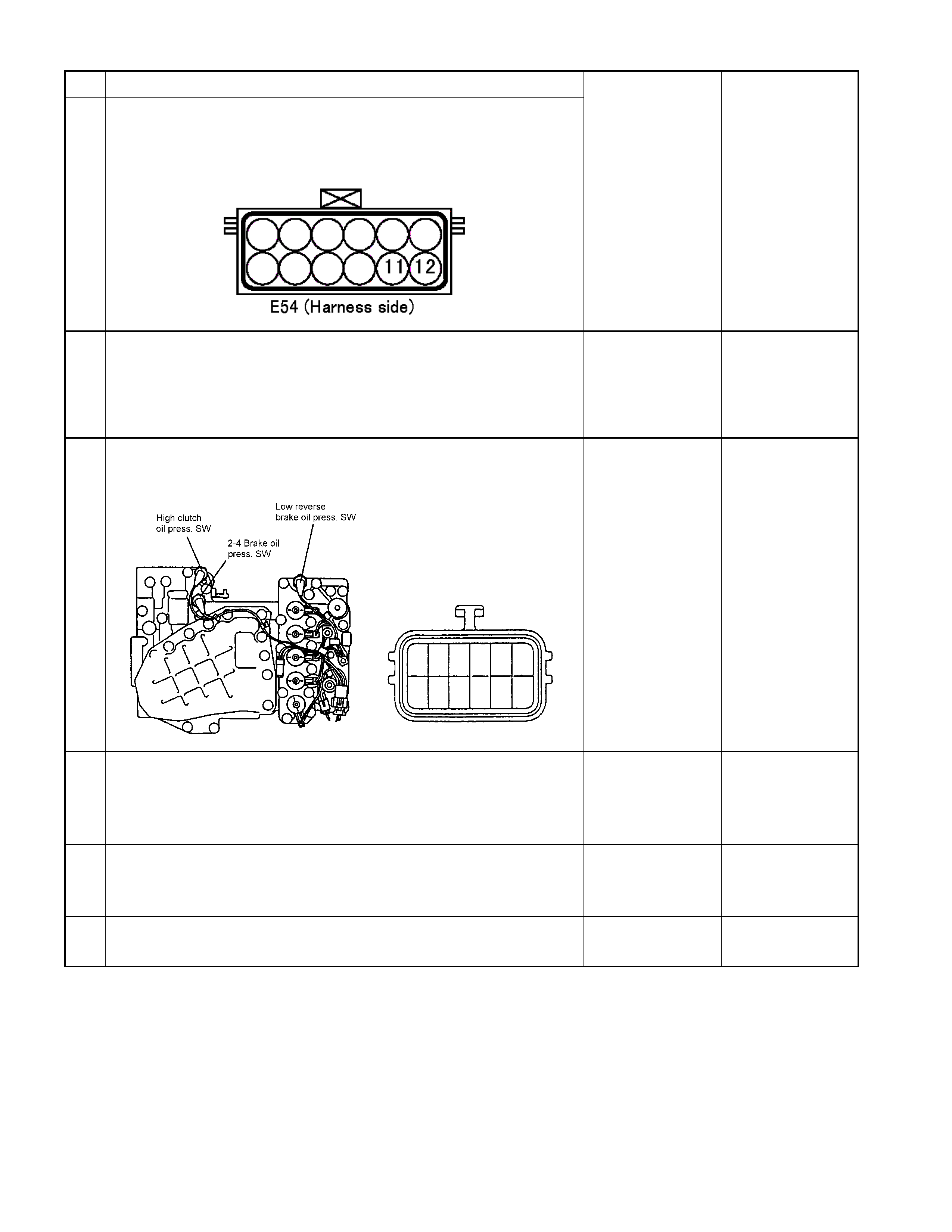
DTC P0710 (Flash Code 15) ATF Temperature Sensor Failure
ATF
Temp.
Sensor TCM
B4 (+)
B14 (-)
H23
(8)
(
3
)
C95
(4)
(
14
)
BLU
Terminal
Assembly
BLU/BLK
E54
(2)
(
8
)
BLU
BLU/BLK
Setting Condition:
• The condition in which the voltage of oil temperature sensor is below 0.1V (146°C) and ATF temperature warning
lamp ON in the P or N range lasts for more than 5 minutes.
Or
• T he vehicle speed exceeds 20 k m /h and the voltage of oil tem per ature sens or exc eeds 2.43V (-40 °C) for m or e than
10 seconds.
Fail Safe:
• The lock-up is inhibited, and TCM is controlled ATF temperature 80°C condition as substitute.
• When the engine speed is more than 470 rpm for 10 minuets, the lock-up and gear shift to 4th (over-drive) are
allowed.

Possible Cause:
• Oil temperature sensor wire open circuit or short circuit.
• Oil temperature sensor malfunction.
• Power supply wire open circuit, s hort circuit to battery or short cir cuit to ground between oil tem perature sensor and
TCM terminal B4 (C95).
• Ground wire open circuit or short circuit to battery between oil temperature sensor terminal and TCM terminal B14
(C95).
• Poor connection of each connector.
Reference:
Following output voltage and resistance can be measured by circuit tester.
Measurement terminal: B4 (C95) and B14 (C95)
Temperature Output Voltage (V) Resistance
20 °C 1.55 2,500Ω
40 °C 1.08 1,160Ω
60 °C 0.7 590Ω
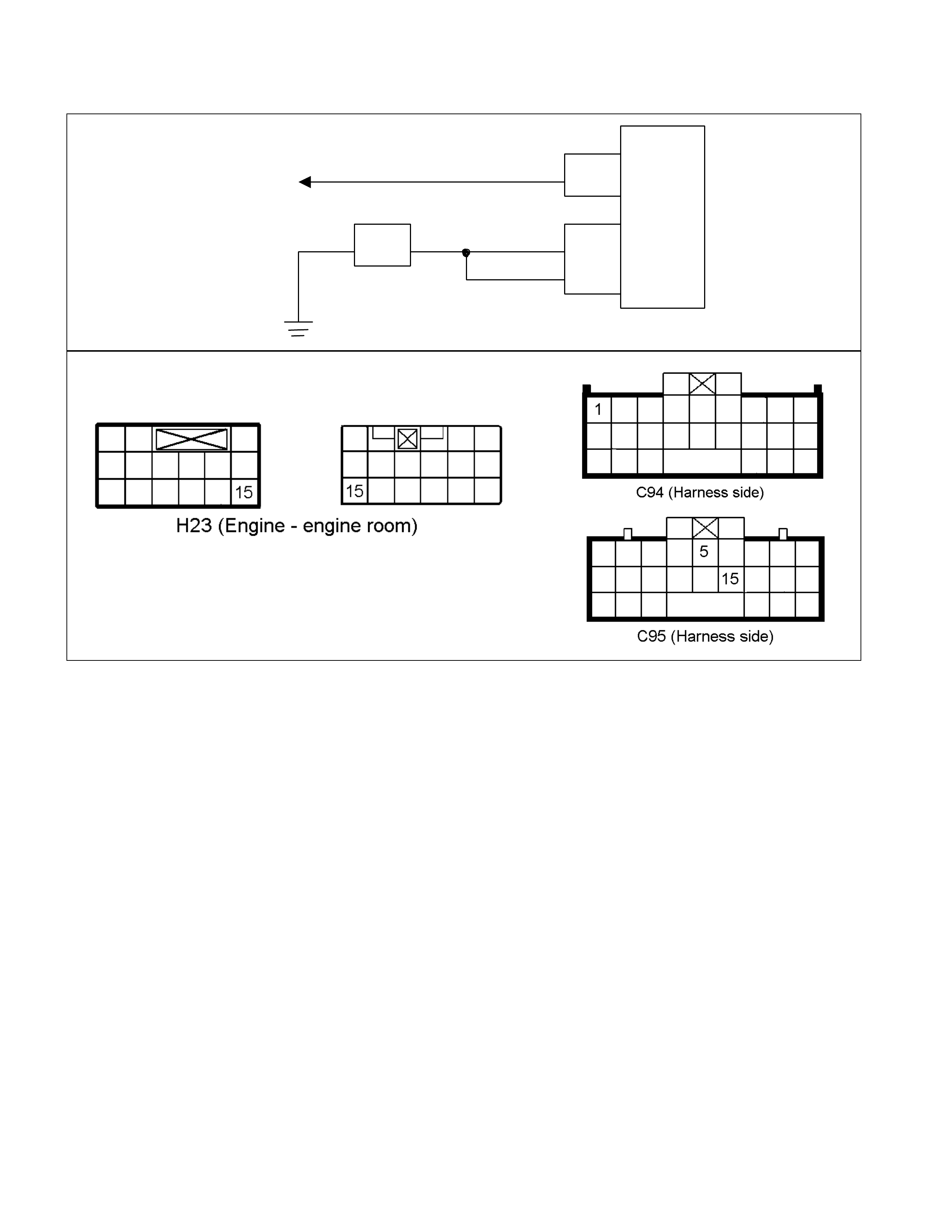
DTC P0560 (Flash Code 16) System Voltage Failure
TCM
A
1 (+B)
B5
B15
H23
(15) C95
(5)
(15)
BLK/YEL
BLK
BLK
Battery C94
(1)
BLK
Setting Condition:
• The supply voltage is below 10V and the engine speed exceeds 1000 rpm for more than 1 second.
Fail Safe:
• When the vehicle is running, the gear position selected at the trouble detection is held and the lock-up is inhibited.
• After the vehicle stopped, all solenoid operations stop (OFF) and the gear is fixed to the 3rd. (In case of fail-safe
valve failure, gear shift to 4th (over-drive) is inhibited.)
Possible Cause:
• Alternator or battery malfunction.
• Power supply wire open circuit or short circuit to ground between power supply and TCM terminal A1 (C94).
• Ground wire open circuit or short circuit to battery between ground location and TCM terminal B5 (C95) or B15
(C95).
• Poor connection of each connector.
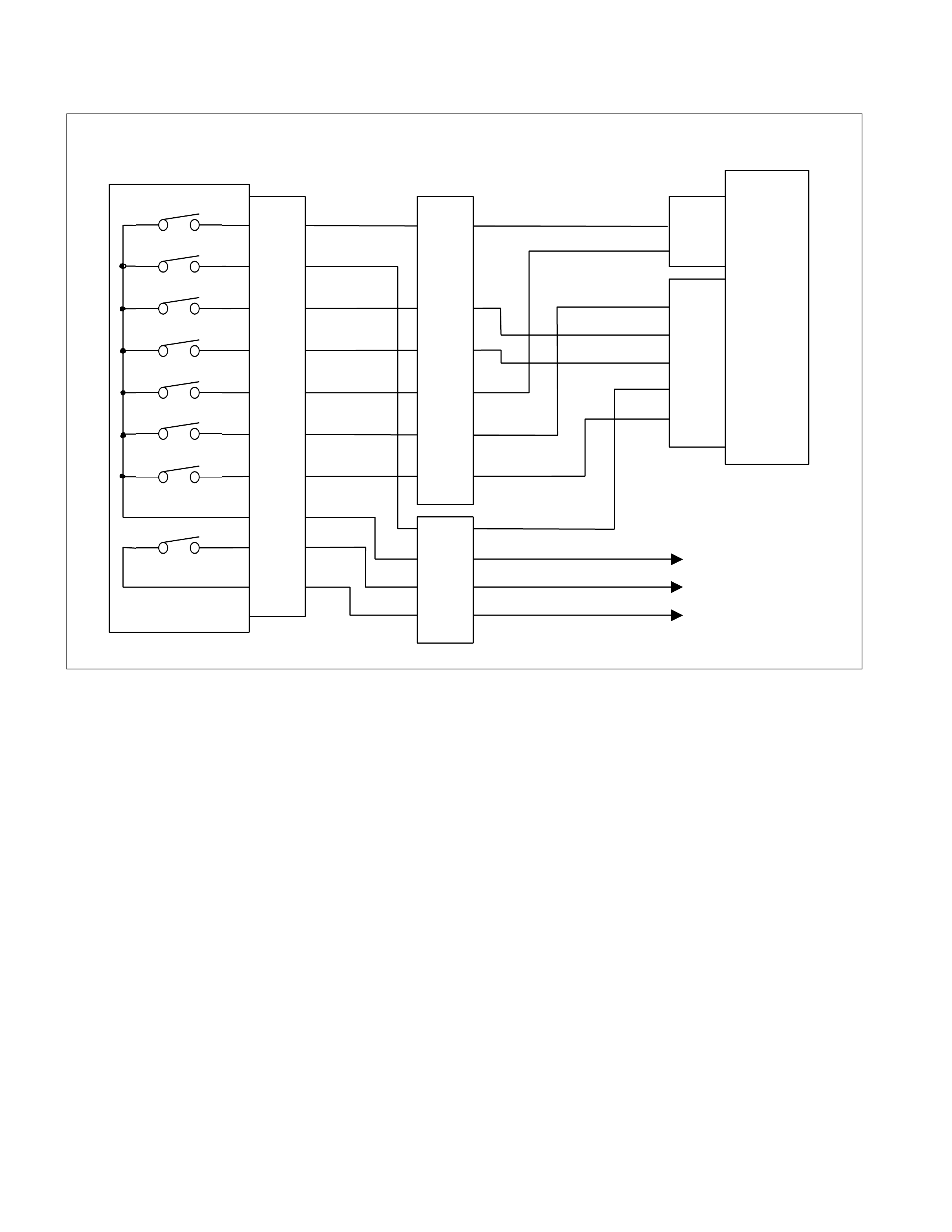
DTC P0705 (Flash Code 17) Inhibitor Switch Failure
Inhibitor SW
TCM
A
2 (P)
A
17 (3)
B2 (2)
B10 (N)
B11 (D)
B19 (R)
B21 (L)
C95
(2)
(10)
(11)
(19)
(21)
YEL/VIO
RED/BLK
BLU
BLK/GRN
Starter Relay
C94
(2)
(3)
B
H22
(1)
(6)
(4)
(7)
(5)
(2)
P
2
R
N
D
3
L
Start SW
PNK/BLU
E51
(2)
(4)
(8)
(5)
(1)
(9)
(6)
(3)
(10)
(7)
(38)
(15)
(3)
(37)
H4
PNK/BLK
RED/Y EL
YEL/VIO
BLK/GRN
PNK/BLK
RED/BLK
BLU
RED/YEL
PNK/BLU
BLK/WHT
BLK
BLK
BLK/WHT Key Switch
WHT
WHT
Immobiliser Control Unit

Terminal Assembly Inhibitor Switch
Setting Condition:
• No range signal is entered from the inhibitor switch with the engine speed over 500 rpm for 2 seconds.
Or
• Multiple signals are entered from the inhibitor switch for 1 second.
Fail Safe:
• When the vehicle is running, the gear position selected at the trouble detection is held and the lock-up is inhibited.
• After the vehicle stopped, all solenoid operations stop (OFF) and the gear is fixed to the 3rd.
Possible Cause:
• Inhibitor switch incorrect adjustment.
• Inhibitor switch malfunction.
• O pen c irc uit or s hor t cir cuit to batter y between inhibitor switch term inal 2 and T C M terminal A2 (C94) , ter minal 4 and
TCM ter m inal B19 (C95), ter m inal 8 and TC M term inal B10 (C95) , term inal 5 and T CM term inal B11 (C 95), ter m inal
1 and TCM ter minal A17 (C94), ter minal 9 and TCM ter minal B2 (B95), or terminal 6 and T CM terminal B21 (C95),
or short between respective harness.
• Power supply wire open circuit or short circuit to ground between inhibitor switch terminal 3 and power supply circuit.
• Poor connection of each connector.
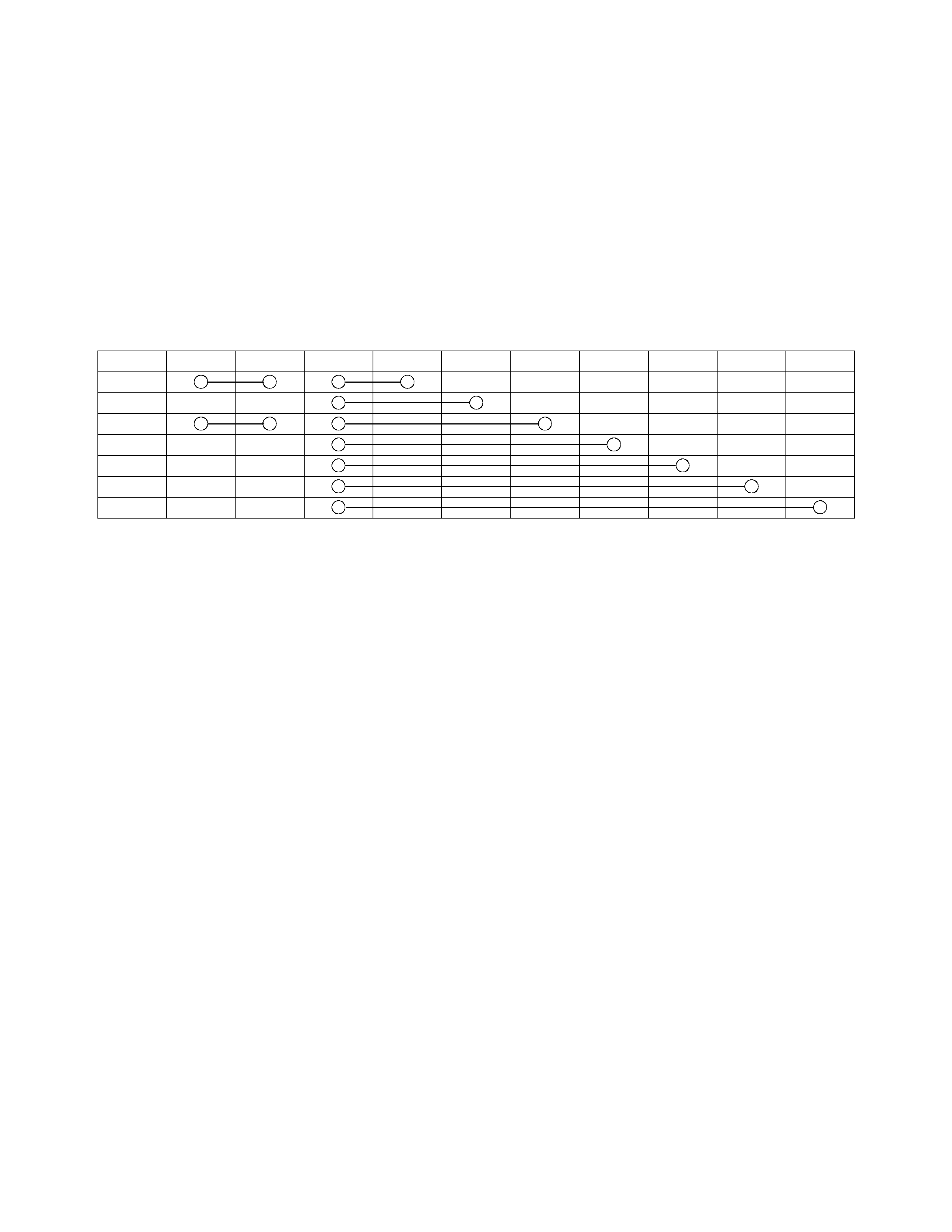
Reference:
Following continuity can be measured by circuit tester.
10 7 3 2 4 8 5 1 9 6
P
R
N
D
3
2
L
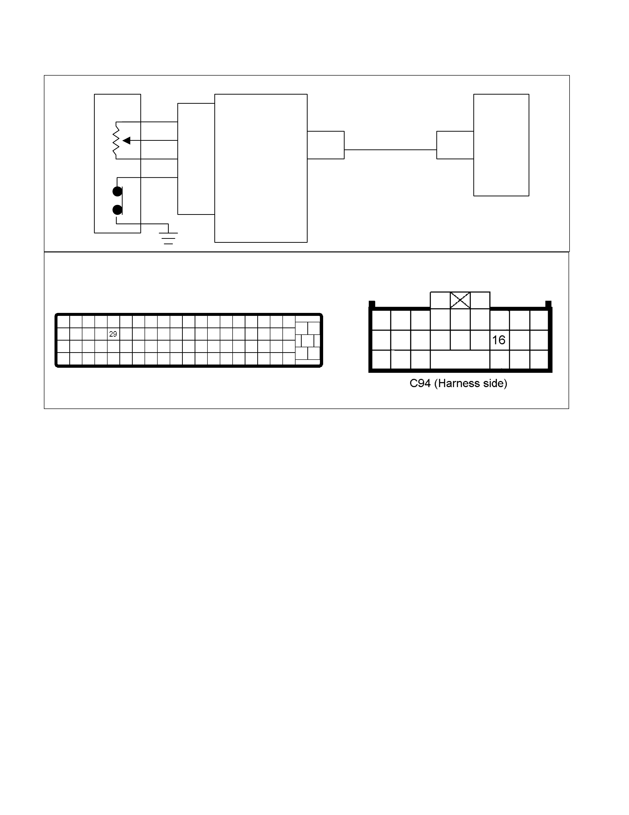
DTC P1120 (Flash Code 22) Throttle Signal Failure
TPS TCM
A
16
C56
(29) C94
(16)
RED/WHT
C56
(49)
(38)
(57)
(69)
ECM
C56 (ECM-A)
Setting Condition:
• No throttle signal is sent from the ECM for 0.4 seconds.
Fail Safe:
• When the vehicle is running, the gear position selected at the trouble detection is held and the lock-up is inhibited.
• After the vehicle stopped, all solenoid operations stop (OFF) and the gear is fixed to the 3rd.
Possible Cause:
• Throttle position sensor malfunction.
• Signal wire open circuit or short circuit to battery of the harness between ECM A26 (C56) and TCM terminal A16
(C94).
• Poor connection of each connector.
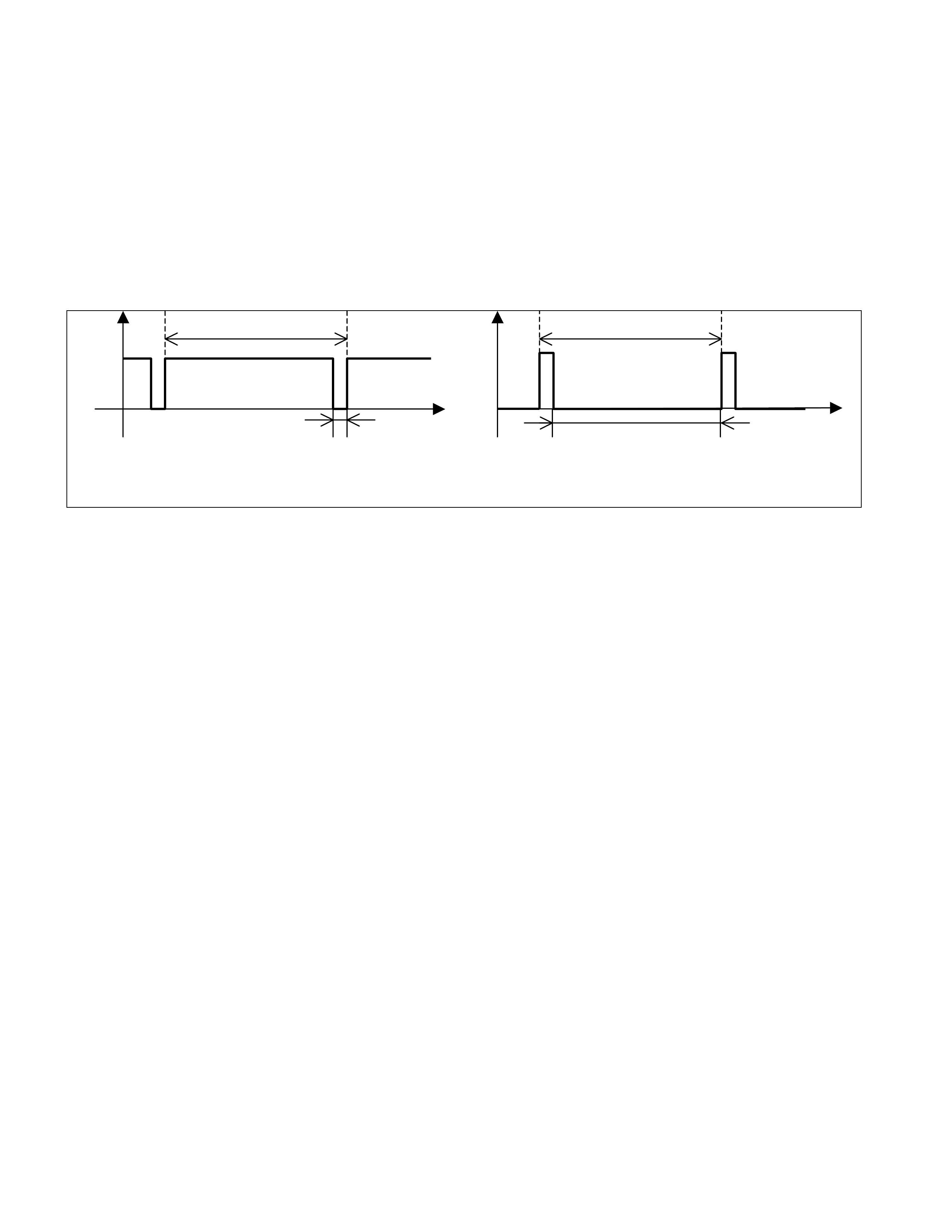
Reference:
• At throttle position 0%, OFF duty signal 10% is sent from ECM terminal A26 (C56) to TCM terminal A16 (C94).
• At throttle position 100% (W OT), OFF duty signal 90% is sent from ECM terminal A26 (C56) to TCM terminal A16
(C94).
7.14ms 7.14ms
Time Time
0.714ms 6.426ms
Voltage
Off duty 10% =Throttle Position 0%
Voltage
Off duty 90% =Throttle Position 100%
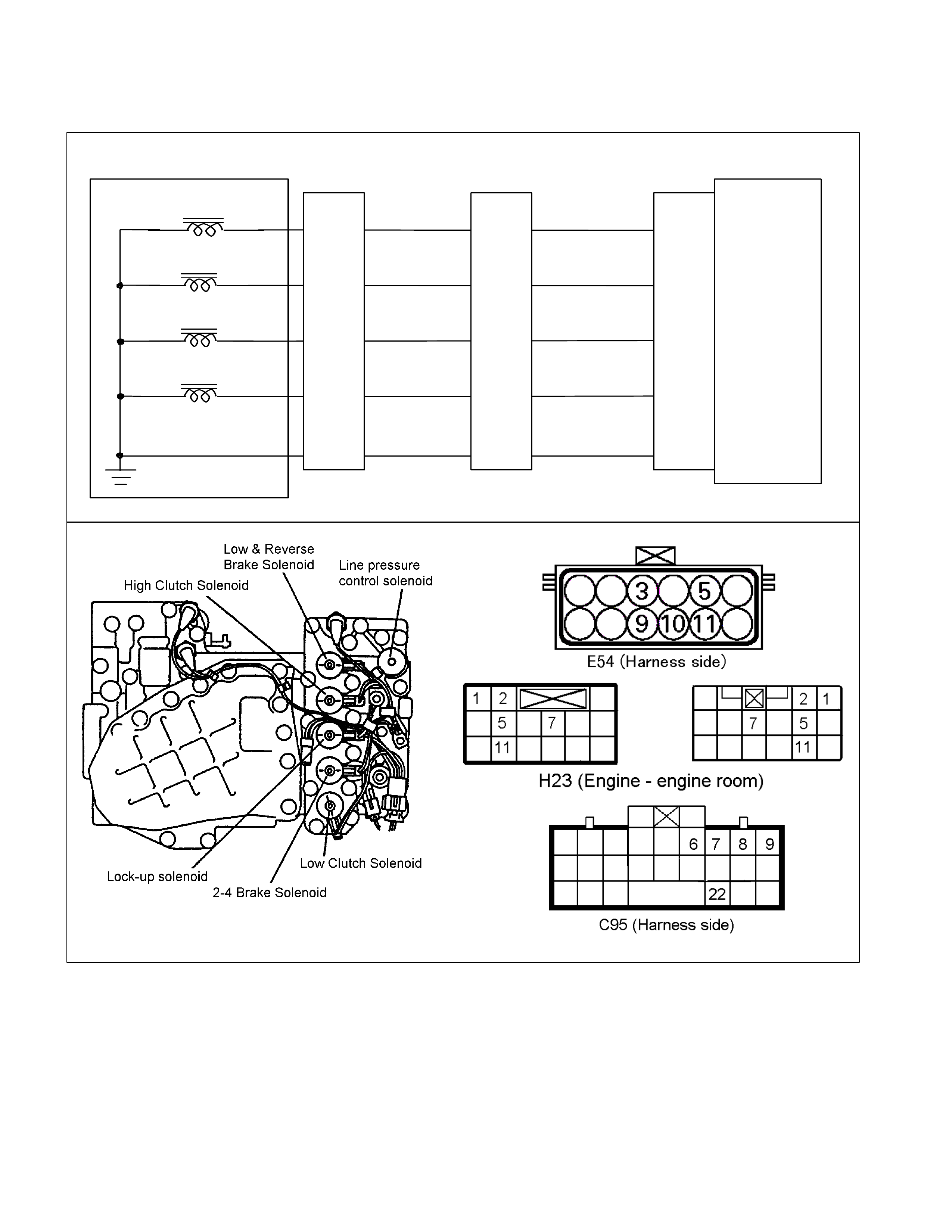
DTC P1875 (Flash Code 25) GND Return Circuit Failure
Control Valve
TCM
B6
B7
B8
B9
B22 (GND)
BLU/BLK
W HT/BLU
L&R Brake Solenoid
Terminal
Assembly
BLK/YEL
RED
2-4 Brake Sol enoi d
High Clutc h Solenoid
Low Clutch Solenoi d
E54
(5)
(9)
(10)
(3)
(11)
H23
(11)
(5)
(7)
(2)
(1)
GRY/RED
C95
(6)
(7)
(8)
(9)
(22)
BLU/BLK
BLK/YEL
RED
WHT/BLU
GRY/RED
Setting Condition:
• Ground return circuit is failed 7 times continuously after the low & reverse brake duty solenoid output signal turn on.
Fail Safe:
• All solenoid operations are stopped (OFF), the gear is fixed to the 3rd, and the lock-up is inhibited. (In case of fail-
safe valve failure, gear shift to 4th (over-drive) and lock-up are inhibited.)
Possible Cause:
• Ground return wire open circuit between terminal assembly terminal 11 and TCM terminal B22 (C95).
• Poor connection of each connector.
DTC P0753 (Flash Code 31) Low & Reverse Brake Duty Solenoid
Failure
Control Valve
TCM
B6
B7
B8
B9
B22 (GND)
BLU/BLK
WHT/BLU
L&R Brake Solenoid
Terminal
Assembly
BLK/YEL
RED
2-4 Brake Sol enoi d
High Clutc h Solenoid
Low Clutch Solenoi d
E54
(5)
(9)
(10)
(3)
(11)
H23
(11)
(5)
(7)
(2)
(1)
GRY/RED
C95
(6)
(7)
(8)
(9)
(22)
BLU/BLK
BLK/YEL
RED
WHT/BLU
GRY/RED

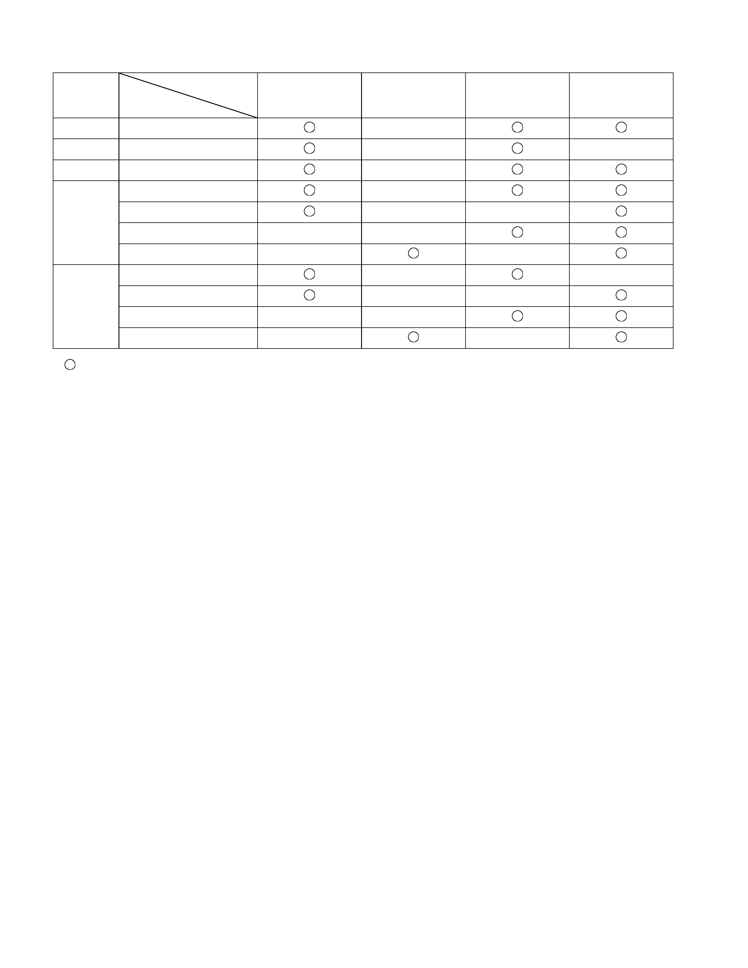
Gear Position & Shift Solenoid Operation
Range
TCM terminal
Gear
B8
(High clutch
solenoid)
B9
(Low clutch
solenoid)
B7
(2-4 brake
solenoid)
B6
(Low & reverse
brake solenoid)
P ×
R Reverse × ×
N ×
D, 3, 2 1st ×
2nd × ×
3rd × ×
4th × ×
L 1st × ×
2nd × ×
3rd × ×
4th × ×
: On (Operated)
× : Off (Not operated)
Setting Condition:
• The low & reverse brake duty solenoid signal is open circuit or short circuit.
(The voltage different from the output ON/OFF signals was detected while the TCM monitors the solenoid output
voltage.)
Fail Safe:
• When the vehicle is running, the operation of the low & reverse brake duty solenoid and the lock-up solenoid is
stopped (OFF), the gear position selected at the trouble detection is held, and the lock-up is inhibited.
• After the vehicle stopped, all solenoid operations stop (OFF) and the gear is fixed to the 3rd.
Possible Cause:
• Low & reverse brake duty solenoid malfunction.
• Open (Off) circuit or short (On) circuit harness of the low & reverse brake duty solenoid.
• Open circuit, short circuit to battery or short circuit to ground between low & reverse brak e duty solenoid terminal 5
and TCM terminal B6 (C96).
• Insufficient ground condition of the low & reverse brake duty solenoid.
• Poor connection of each connector.
Reference:
When the low & reverse brake solenoid is operated, following signal is outputted.
Measurement terminal: B6 (C95) and B22 (C95)
-AC range by circuit tester: Approximately 6.8V
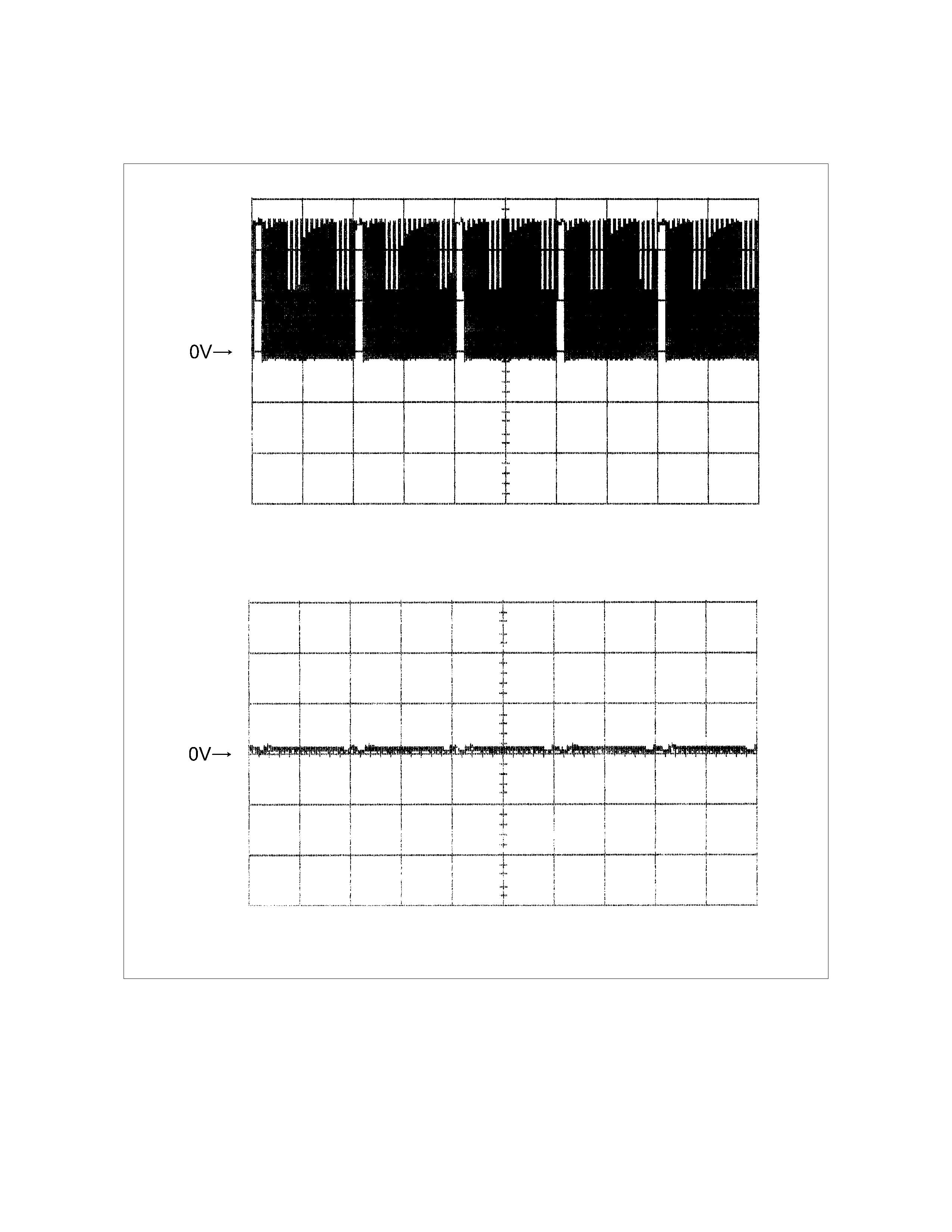
Low & Reverse Brake Duty Solenoid Reference Wave Form
Measurement Terminal: B6 (+) B22 (-)
Measurement Scale: 5V/div 20ms/div
Measurement Condition: P, N range in idle
Measurement Terminal: B6 (+) B22 (-)
Measurement Scale: 5V/div 20ms/div
Measurement Condition: R range in idle
DTC P0758 (Flash Code 32) 2-4 Brake Duty Solenoid Failure
Co nt ro l Valv e
TCM
B6
B7
B8
B9
B22 (GN D )
BLU/BLK
WHT/BLU
L&R Brake Solenoid
Terminal
Assembly
BLK/YEL
RED
2-4 Brake Solenoid
High Clutch Solenoid
Low Clutch Solenoid
E54
(5)
(9)
(10)
(3)
(11)
H23
(11)
(5)
(7)
(2)
(1)
GRY/RED
C95
(6)
(7)
(8)
(9)
(22)
BLU/BLK
BLK/YEL
RED
WHT/BLU
GRY/RED

Gear Position & Shift Solenoid Operation
Range
TCM terminal
Gear
B8
(High clutch
solenoid)
B9
(Low clutch
solenoid)
B7
(2-4 brake
solenoid)
B6
(Low & reverse
brake solenoid)
P ×
R Reverse × ×
N ×
D, 3, 2 1st ×
2nd × ×
3rd × ×
4th × ×
L 1st × ×
2nd × ×
3rd × ×
4th × ×
: On (Operated)
× : Off (Not operated)
Setting Condition:
• The 2-4 brake duty solenoid signal is open circuit or short circuit.
(The voltage different from the output ON/OFF signals was detected while the TCM monitors the solenoid output
voltage.)
Fail Safe:
• When the vehicle is running, the oper ation of the 2- 4 brake duty solenoid and the lock- up solenoid is s topped ( OF F) ,
the gear position selected at the trouble detection is held, and the lock-up is inhibited.
• After the vehicle stopped, all solenoid operations stop (OFF) and the gear is fixed to the 3rd.
Possible Cause:
• 2-4 brake duty solenoid malfunction.
• Open (Off) circuit or short (On) circuit of the 2-4 brake duty solenoid.
• Open circuit, short circuit to battery or short circuit to ground of the harness between 2-4 brake duty solenoid
terminal 9 and TCM terminal B7 (C95).
• Insufficient ground condition of the 2-4 brake duty solenoid.
• Poor connection of each connector.
Reference:
When the 2-4 brake duty solenoid is operated, following signal is outputted.
Measurement terminal: B7 (C95) and B22 (C95)
-AC range by circuit tester: Approximately 6.8V
2-4 Brake Duty Solenoid Reference Wave Form
Measurement Terminal: B7 (+) B22 (-)
Measurement Scale: 5V/div 20ms/div
Measurement Condition: P, N range in idle
Measurement Terminal: B7 (+) B22 (-)
Measurement Scale: 5V/div 20ms/div
Measurement Condition: D range 4th gear
DTC P0763 (Flash Code 33) High Clutch Duty Solenoid Failure
Co nt ro l Valv e
TCM
B6
B7
B8
B9
B22 (GN D )
BLU/BLK
WHT/BLU
L&R Brake Solenoid
Terminal
Assembly
BLK/YEL
RED
2-4 Brake Solenoid
High Clutch Solenoid
Low Clutch Solenoid
E54
(5)
(9)
(10)
(3)
(11)
H23
(11)
(5)
(7)
(2)
(1)
GRY/RED
C95
(6)
(7)
(8)
(9)
(22)
BLU/BLK
BLK/YEL
RED
WHT/BLU
GRY/RED

Gear Position & Shift Solenoid Operation
Range
TCM terminal
Gear
B8
(High clutch
solenoid)
B9
(Low clutch
solenoid)
B7
(2-4 brake
solenoid)
B6
(Low & reverse
brake solenoid)
P ×
R Reverse × ×
N ×
D, 3, 2 1st ×
2nd × ×
3rd × ×
4th × ×
L 1st × ×
2nd × ×
3rd × ×
4th × ×
: On (Operated)
× : Off (Not operated)
Setting Condition:
• The high clutch duty solenoid signal is open circuit or short circuit.
(The voltage different from the output ON/OFF signals was detected while the TCM monitors the solenoid output
voltage.)
Fail Safe:
• When the vehicle is running, the operation of the high clutch duty solenoid and the lock-up solenoid is stopped
(OFF), the gear position selected at the trouble detection is held, and the lock-up is inhibited.
• After the vehicle stopped, all solenoid operations stop (OFF) and the gear is fixed to the 3rd.
Possible Cause:
• High clutch duty solenoid malfunction.
• Open (Off) circuit or short (On) circuit of the high clutch duty solenoid.
• O pen circ uit, short circuit to battery or short circ uit to gr ound between high clutch duty solenoid term inal 10 and T C M
terminal B8 (C95).
• Insufficient ground condition of the high clutch duty solenoid.
• Poor connection of each connector.

Reference:
When the high clutch duty solenoid is operated, following signal is outputted.
Measurement terminal: B8 (C95) and B22 (C95)
-AC range by circuit tester: Approximately 6.2V
High Clutch Duty Solenoid Reference Wave Form
Measurement Terminal: B8 (+) B22 (-)
Measurement Scale: 5V/div 20ms/div
Measurement Condition: P, N range in idle
Measurement Terminal: B8 (+) B22 (-)
Measurement Scale: 5V/div 20ms/div
Measurement Condition: D range 3rd, 4th gear

DTC P0768 (Flash Code 34) Low Clutch Duty Solenoid Failure
Co nt ro l Valv e
TCM
B6
B7
B8
B9
B22 (GN D )
BLU/BLK
WHT/BLU
L&R Brake Solenoid
Terminal
Assembly
BLK/YEL
RED
2-4 Brake Solenoid
High Clutch Solenoid
Low Clutch Solenoid
E54
(5)
(9)
(10)
(3)
(11)
H23
(11)
(5)
(7)
(2)
(1)
GRY/RED
C95
(6)
(7)
(8)
(9)
(22)
BLU/BLK
BLK/YEL
RED
WHT/BLU
GRY/RED
Gear Position & Shift Solenoid Operation
Range
TCM terminal
Gear
B8
(High clutch
solenoid)
B9
(Low clutch
solenoid)
B7
(2-4 brake
solenoid)
B6
(Low & reverse
brake solenoid)
P ×
R Reverse × ×
N ×
D, 3, 2 1st ×
2nd × ×
3rd × ×
4th × ×
L 1st × ×
2nd × ×
3rd × ×
4th × ×
: On (Operated)
× : Off (Not operated)
Setting Condition:
• The low clutch duty solenoid signal is open circuit or short circuit.
(The voltage different from the output ON/OFF signals was detected while the TCM monitors the solenoid output
voltage.)
Fail Safe:
• When the vehicle is running, the operation of the low clutch duty solenoid and the lock-up solenoid is stopped (OFF),
the gear position selected at the trouble detection is held, and the lock-up is inhibited.
• After the vehicle stopped, all solenoid operations stop (OFF) and the gear is fixed to the 3rd.
Possible Cause:
• Low clutch duty solenoid malfunction.
• Open (Off) circuit or short (On) circuit harness of the low clutch duty solenoid.
• Open circuit, short circuit to battery or short circuit to ground between low clutch duty solenoid terminal 3 and T CM
terminal B9 (C95).
• Insufficient ground condition of the low clutch duty solenoid.
• Poor connection of each connector.
Reference:
When the low clutch duty solenoid is operated, following signal is outputs.
Measurement terminal: B9 (C95) and B22 (C95)
-AC range by circuit tester: Approximately 6.8V
Low Clutch Duty Solenoid Reference Wave Form
Measurement Terminal: B9 (+) B22 (-)
Measurement Scale: 5V/div 20ms/div
Measurement Condition: D range 4th gear
Measurement Terminal: B9 (+) B22 (-)
Measurement Scale: 5V/div 20ms/div
Measurement Condition: P, N range in idle
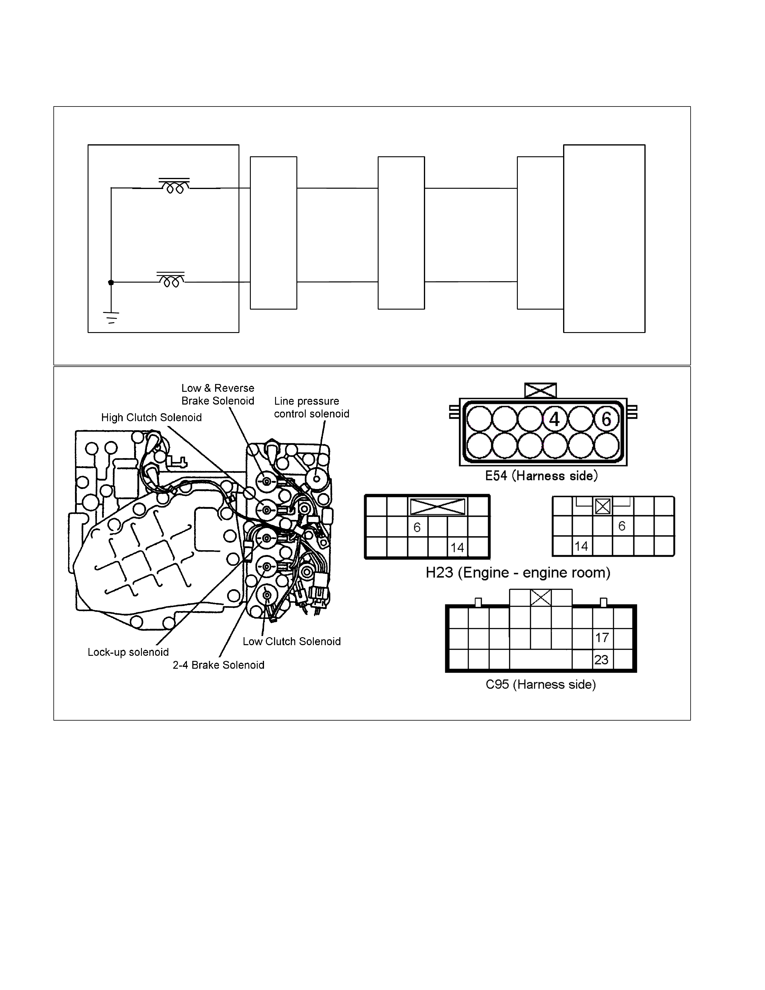
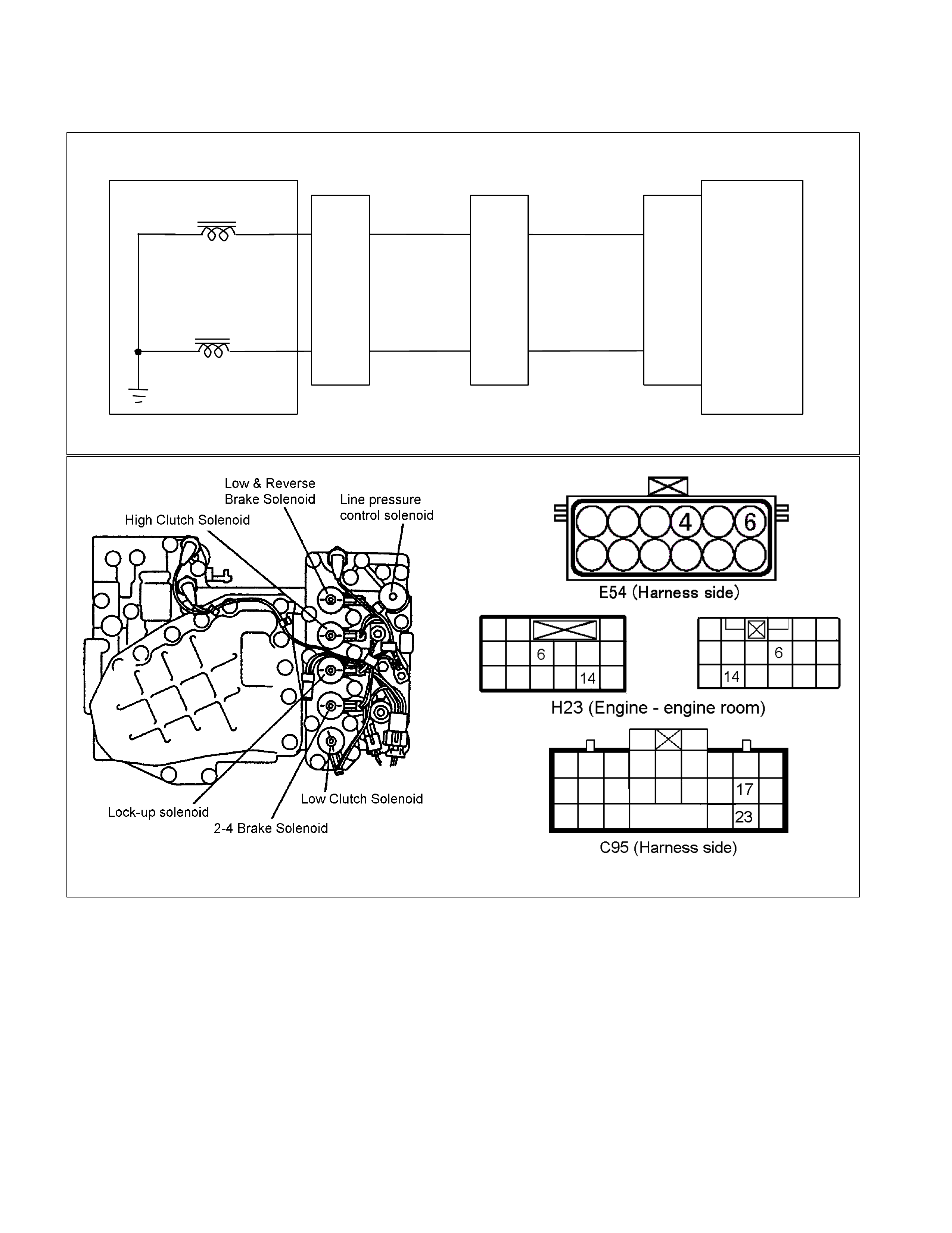
DTC P0748 (Flash Code 35) Line Pressure Solenoid Failure
Control Valve
TCM
B17
B23
BLK
Lock-up Solenoid
Terminal
Assembly
VIO
Line Press ur e Sol enoid
E54
(4)
(6)
H23
(14)
(6)
C95
(17)
(23)
BLK
VIO

Setting Condition:
• The line pressure solenoid signal is open circuit or short circuit.
(The voltage different from the output ON/OFF signals was detected while the TCM monitors the solenoid output
voltage.)
Fail Safe:
• The operation of the line pressure solenoid is stopped (OFF).
Possible Cause:
• Line pressure solenoid malfunction.
• Line pressure solenoid harness open (Off) circuit or short (On) circuit.
• Open circuit, short circuit to battery or short circuit to ground between line pressure solenoid terminal 6 and TCM
terminal B23 (C95).
• Insufficient ground condition of the line pressure solenoid.
• Poor connection of each connector.
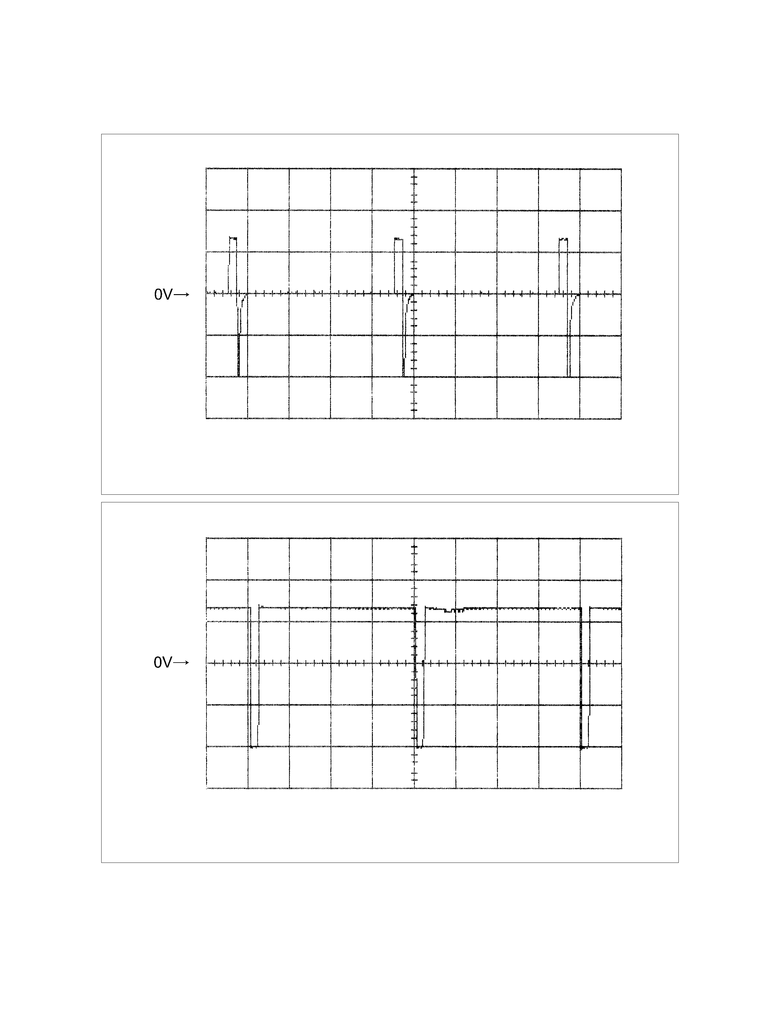
Reference:
When the line pressure solenoid is operated, following signal is outputted.
Measurement terminal: B23 (C95) and B22 (C95)
-At N rage: Battery voltage
-At D range: Less than 1V
DTC P1860 (Flash Code 36) Lock-up Duty Solenoid Failure
Control Valve
TCM
B17
B23
B
Lock-up Solenoid
Terminal
Assembly
V
Line Press ur e Sol enoid
E54
(4)
(6)
H23
(14)
(6)
C95
(17)
(23)
B
V

Setting Condition:
• The lock-up duty solenoid signal is open circuit or short circuit.
(The voltage different from the output ON/OFF signals was detected while the TCM monitors the solenoid output
voltage.)
Fail Safe:
• The lock-up is inhibited.
Possible Cause:
• Lock-up duty solenoid malfunction.
• Open (Off) circuit or short (On) circuit of the lock-up duty solenoid.
• Open circuit, short circuit to battery or short circuit to ground between lock-up duty solenoid terminal 4 and TCM
terminal B17 (C95).
• Insufficient ground condition of the lock-up duty solenoid.
• Poor connection of each connector.
Reference:
When the lock-up duty solenoid is operated, following signal is outputted.
Measurement terminal: B17 (C95) and B5 (C95)
-AC range by circuit tester: Approximately 7.2V
Lock-up Duty Solenoid Reference Wave Form
Measurement Terminal: B17 (+) B5 (-)
Measurement Scale: 10V/div 5ms/div
Measurement Condition: Unlock-up condition
Lock-up Duty Solenoid Reference Wave Form
Measurement Terminal: B17 (+) B5 (-)
Measurement Scale: 10V/div 5ms/div
Measurement Condition: Lock-up condition
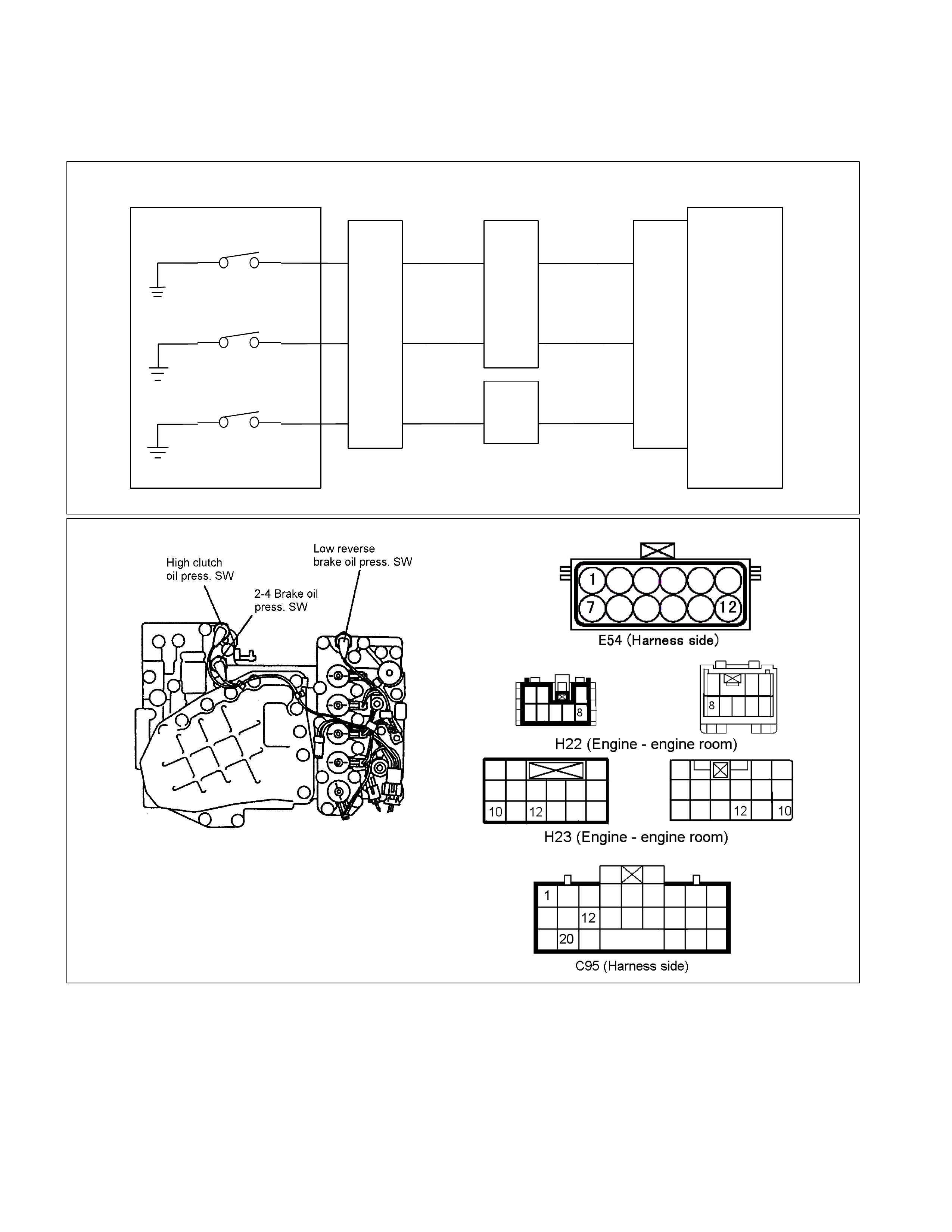
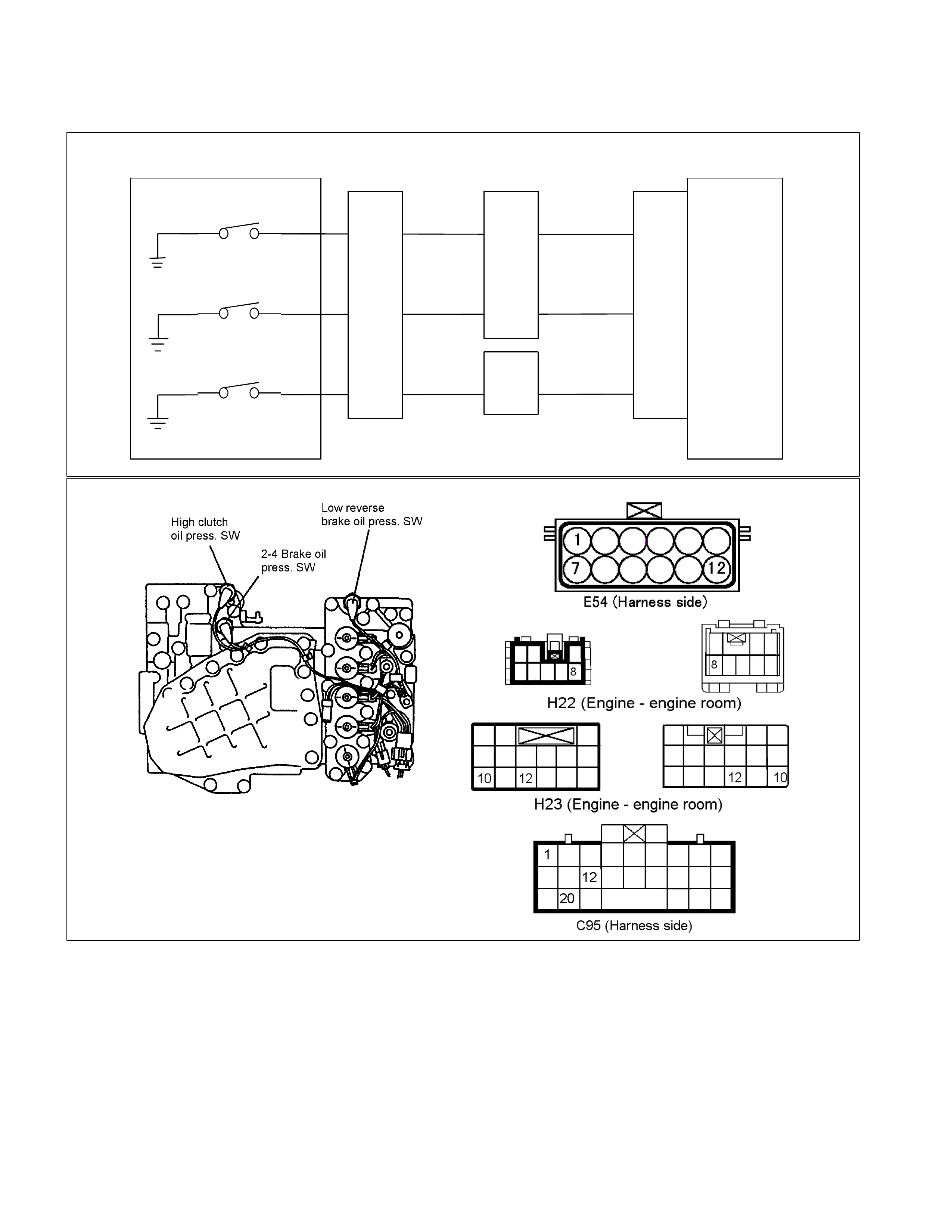
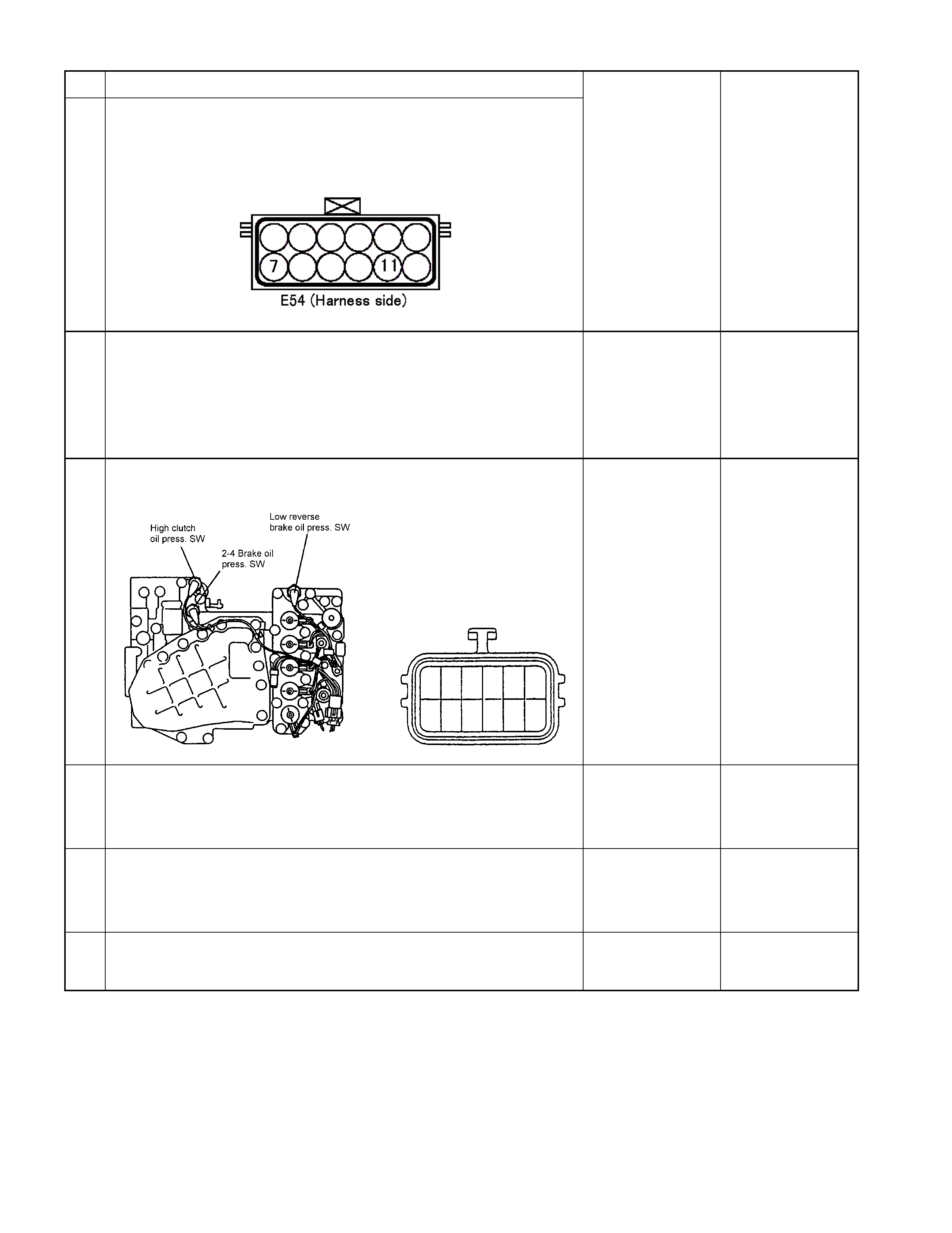
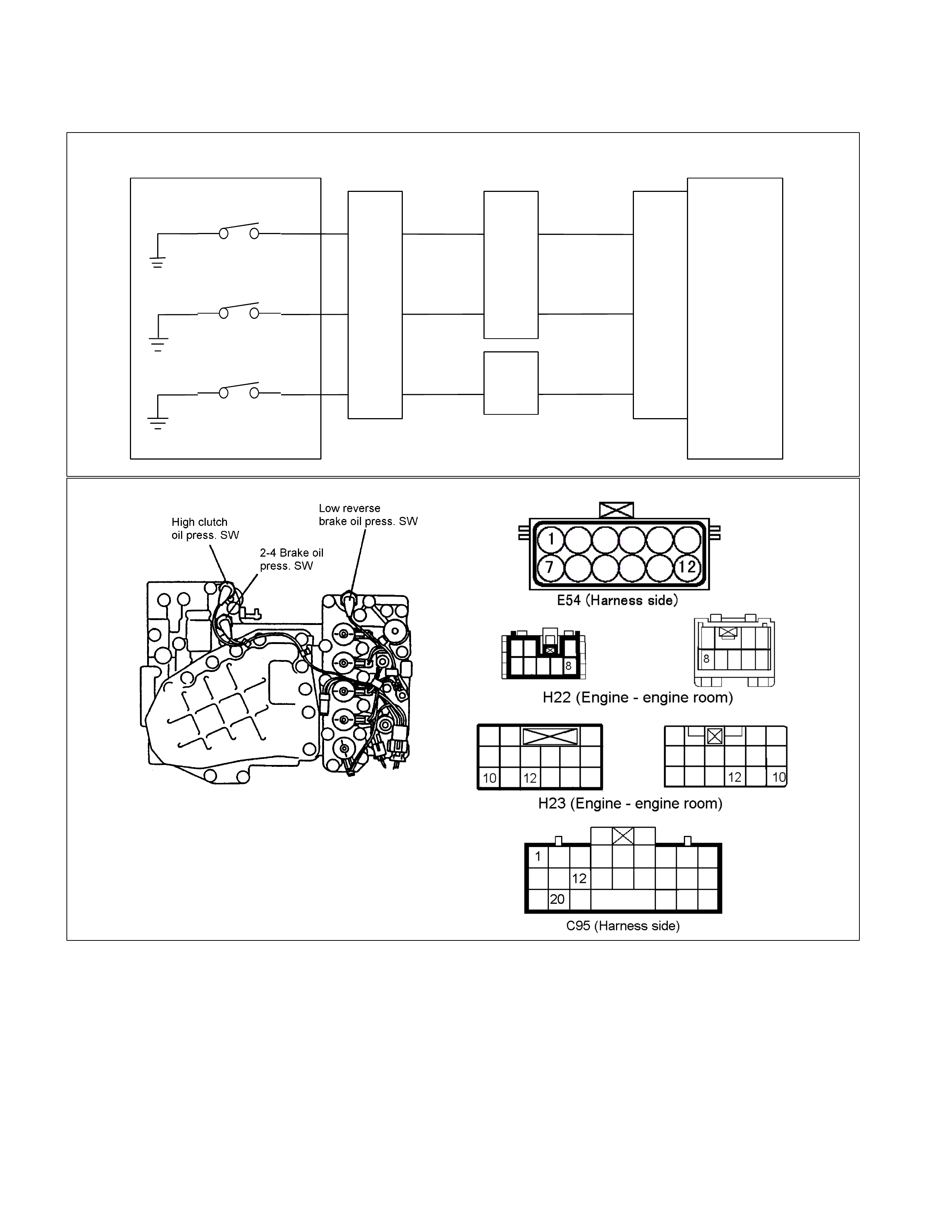
DTC P1853 (Flash Code 26) Low & Reverse Brake
Pressure Switch Failure
Control Valve
TCM
B1
B12
B20
RED/YEL
WHT/BLK
2-4 Brake Pressure SW
Terminal
Assembly
YEL
E54
(7)
(12)
(1)
H23
(12)
(10)
C95
(1)
(12)
(20)
RED/YEL
YEL
WHT/BLK
L&R Brake Pressure SW
High Clutch Pressure SW H22
(8)

Pre-setting Condition:
• No gear shifting.
• No Check Trans indicator lamp.
• No system voltage failure.
• No inhibitor switch failure.
• Low & reverse brake duty solenoid 0 or 100 %.
• ATF temperature more than 60°C.
• ATF input voltage more than 0.1V.
• Engine speed more than 500 rpm.
Setting Condition:
• Dur ing the running, the low & reverse brak e pr ess ur e switch does not tur n on though hydraulic press ure is s upposed
to be generated in the low & reverse brake.
(All pre-s etting c onditions are met for 2.5 sec onds, Low & reverse brak e duty solenoid 0% and low & revers e brake
pressure switch off in R range)
Or
• During the running, the low & reverse brak e s witch does not turn of f though no hydraulic press ure is s upposed to be
generated in the low & reverse brake.
(All pre-setting conditions are m et for 2.5 seconds , 4th gear, all pres sure s witch on and gear ratio 0.652 - 0.735 in D
range.)
Fail Safe:
• No fail safe function
Possible Cause:
• Low & reverse brake duty solenoid malfunction.
• Low & reverse brake pressure switch wire open circuit or short circuit.
• Open circuit, short circuit to battery or s hort circuit to ground between low & reverse brak e pressure s witch term inal
12 and TCM terminal B12 (C95).
• Low & reverse brake hydraulic circuit malfunction in the control valve.
• Poor connection of each connector.
Reference:
When the low & reverse brake pressure switch is operated, following signal is outputted.
Measurement terminal: B12 (C95) and B22 (C95)
-At other than R rage or L range in 1st gear: More than 10V
-At R range or L range in 1st gear: Less than 1V
Step Action Yes No
1 Clear the DTC from the memory once.
Was the action complete?
Go to Step 2
Refer DTC clear
method in this
manual.
2 Turn the ignition switch off once, then restart the engine and shift to
4th gear in the D range. When about 10 seconds elapsed, does the
CHECK TRANS lamp blink? Go to Step 3 Go to Step 7
3 Is the DTC P0753 (31) Low & Reverse Brake Duty Solenoid Failure
stored? Go to P0753 (31)
Section Go to Step 4
4 Connect the Tech 2 and select the item for low & reverse brake
pressure switch. Is the indication of low & reverse brake pressure
switch turned off when the terminal assembly connector is
disconnected?
Go to Step 5
Repair the harness
or connector.
Go to Step 12
5 Turn the key switch off and disconnect the terminal assembly
connector. Are the pins correct?
Go to Step 6
Repair the
connector or pin.
Go to Step 12
6 Remove the oil pan. Is the continuity correct between terminal
assembly terminal 12 and low & reverse brake pressure switch
connector?
12
Repair the harness
or connector.
Go to Step 12
Replace pressure
switch.
Go to Step 12
7 Start the engine and select the R range. When about 10 seconds
elapsed, does the CHECK TRANS lamp blink?
Go to Step 8 Go to P0753 (31)
Section
Step Action Yes No
8 Connect the Tech 2, and with the key switch in OFF position, short
the terminals 11 and 12 on the vehicle harness side. Does the
indication of the low & reverse brake pressure switch on the Tech 2
becomes on when the key switch is turned on?
Go to Step 9
Repair the harness
or connector.
Go to Step 12
9 Check if the trouble is caused by a poor connection of terminal
assembly connector.
With the key switch in OFF position, is the connection condition of
the connector and harness correct?
Go to Step 10
Repair the harness
or connector.
Go to Step 12
10 Remove the oil pan. Is the continuity correct between terminal
assembly terminal 12 and low & reverse brake pressure switch
connector?
12
Go to Step 11
Repair the harness
or connector.
Go to Step 12
11 Is the result OK when the oil pan is removed and the low & reverse
brake pressure switch is checked? Refer the ON VEHICLE
SERVICE SECTION in this manual for the procedure. Repair the control
valve.
Go to Step 12
Replace pressure
switch.
Go to Step 12
12 Clear the DTC from the memory and perform the work after repair. Is
the same DTC code outputted again in the subsequent DTC check?
Replace the TCM Go to Step 13
13 Are the other DTCs outputted? Go to Other DTC
Section Action is completed
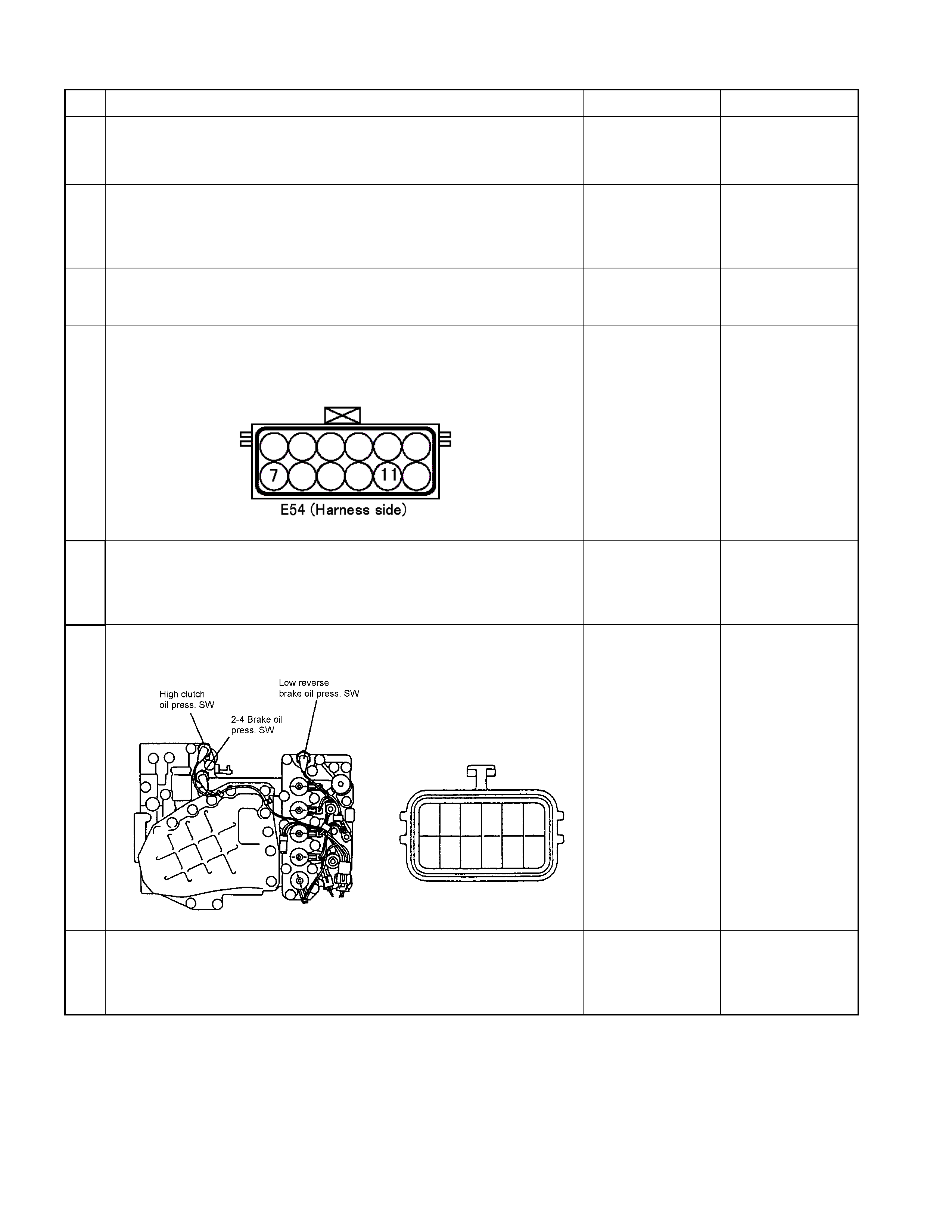
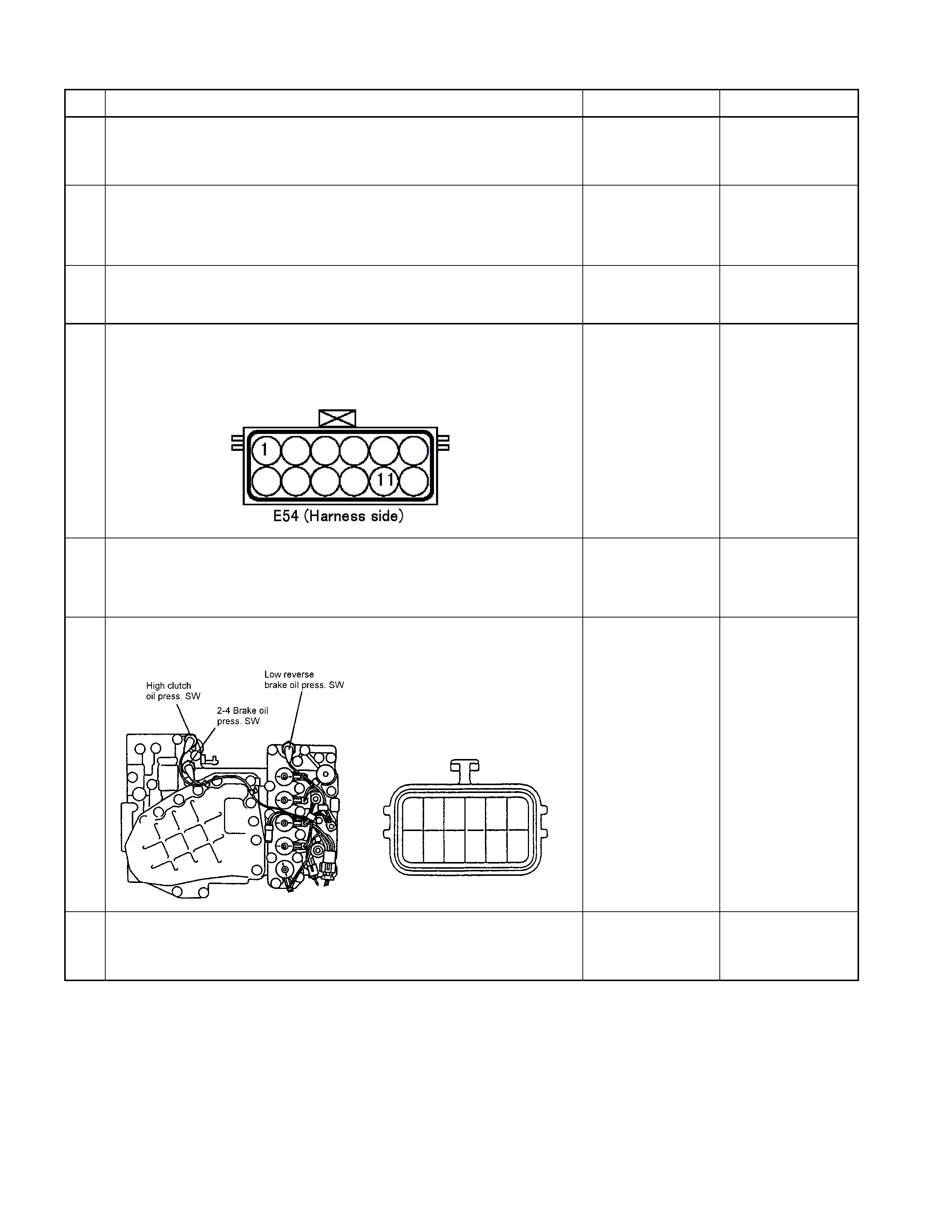
DTC P1858 (Flash Code 27) 2-4 Brake Pressure Switch Failure
Control Valve
TCM
B1
B12
B20
RED/YEL
WHT/BLK
2-4 Brake Pressure SW
Terminal
Assembly
YEL
E54
(7)
(12)
(1)
H23
(12)
(10)
C95
(1)
(12)
(20)
RED/YEL
YEL
WHT/BLK
L&R Brake Pressure SW
High Clutch Pressure SW H22
(8)

Pre-setting Condition:
• No gear shifting.
• No Check Trans indicator lamp.
• No system voltage failure.
• No inhibitor switch failure.
• 2-4 brake duty solenoid 0 or 100 %.
• ATF temperature more than 60°C.
• ATF input voltage more than 0.1V.
• Engine speed more than 500 rpm.
Setting Condition:
• During the running, the 2-4 brake pressure switch does not turn on though hydraulic pressure is supposed to be
generated in 2-4 brake.
(All pre-setting conditions are met for 2.5 s ec onds, 2- 4 brake pres sur e s witch of f , high c lutch pr es sur e s witch on and
gear ratio more than 0.65 or less than 0.74 with 4th gear in D range.)
Or
• Dur ing the running, the 2- 4 brake switch does not turn of f though no hydraulic pressure is s upposed to be gener ated
in the 2-4 brake.
(All pre-setting conditions are met for 2.5 seconds, 2-4 brake pressure switch on in D or N range.)
Fail Safe:
• No fail safe function
Possible Cause:
• 2-4 brake duty solenoid malfunction.
• 2-4 brake pressure switch wire open circuit or short circuit.
• O pen circ uit, short circuit to battery or s hort c irc uit to ground between 2-4 br ak e pr es sur e s witch terminal 7 and T CM
terminal B1 (C95).
• 2-4 brake hydraulic circuit malfunction in the control valve.
• Poor connection of each connector.
Reference:
When the 2-4 brake pressure switch is operated, following signal is outputted.
Measurement terminal: B1 (C95) and B22 (C95)
-At other than 2nd or 4th gear: More than 10V
-At 2nd or 4th gear: Less than 1V
Step Action Yes No
1 Clear the DTC from the memory once.
Was the action complete?
Go to Step 2
Refer DTC clear
method in this
manual.
2 Turn the ignition switch off once, then restart the engine and in D
range. When about 10 seconds elapsed, does the CHECK TRANS
lamp blink?
Go to Step 3 Go to Step 7
3 Is the DTC P0758 (32) 2-4 Brake Duty Solenoid Failure stored? Go to P0758 (32)
Section Go to Step 4
4 Connect the Tech 2 and select the item for 2-4 brake pressure
switch. Is the indication of 2-4 brake pressure switch turned off when
the terminal assembly connector is disconnected?
Go to Step 5
Repair the harness
or connector.
Go to Step 12
5 Turn the key switch off and disconnect the terminal assembly
connector. Are the pins correct?
Go to Step 6
Repair the
connector or pin.
Go to Step 12
6 Remove the oil pan. Is the continuity correct between terminal
assembly terminal 7 and 2-4 brake pressure switch connector?
7
Repair the harness
or connector.
Go to Step 12
Replace pressure
switch.
Go to Step 12
7 Start the engine and shift to 4th gear in the D range. When about 10
seconds elapsed, does the CHECK TRANS lamp blink?
Go to Step 8 Go to P0758 (32)
Section
Step Action Yes No
8 Connect the Tech 2, and with the key switch in OFF position, short
the terminals 11 and 7 on the vehicle harness side. Does the
indication of the 2-4 brake pressure switch on the Tech 2 becomes
on when the key switch is turned on?
Go to Step 9
Repair the harness
or connector.
Go to Step 12
9 Check if the trouble is caused by a poor connection of terminal
assembly connector.
With the key switch in OFF position, is the connection condition of
the connector and harness correct?
Go to Step 10
Repair the harness
or connector.
Go to Step 12
10 Remove the oil pan. Is the continuity correct between terminal
assembly terminal 7 and 2-4 brake pressure switch connector?
7
Go to Step 11
Repair the harness
or connector.
Go to Step 12
11 Is the result OK when the oil pan is removed and the 2-4 brake
pressure switch is checked? Repair the control
valve.
Go to Step 12
Replace pressure
switch.
Go to Step 12
12 Clear the DTC from the memory and perform the work after repair. Is
the same DTC code outputted again in the subsequent DTC check?
Replace the TCM Go to Step 13
13 Are the other DTCs outputted? Go to Other DTC
Section Action is completed
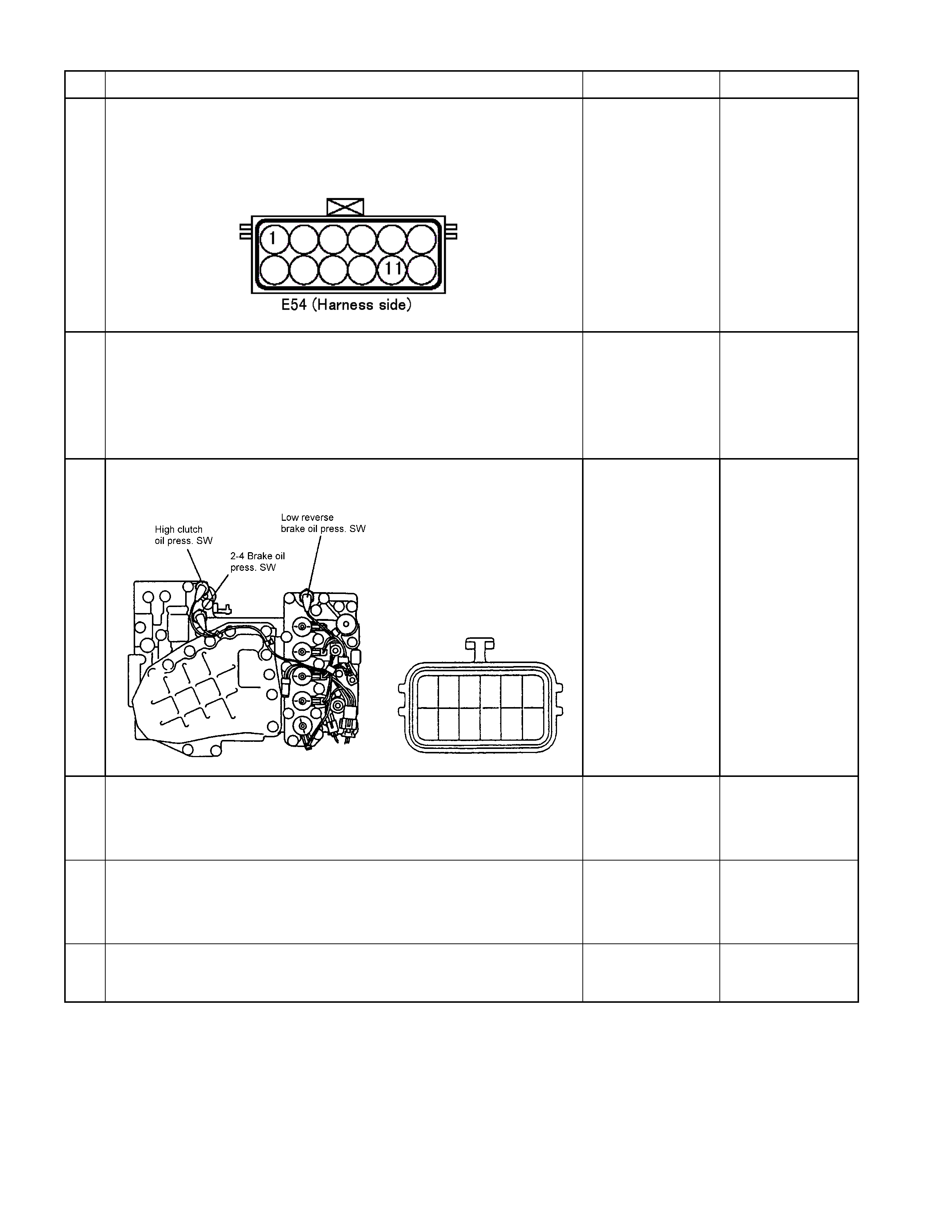
DTC P1863 (Flash Code 28) High Clutch Pressure Switch Failure
Control Valve
TCM
B1
B12
B20
RED/YEL
WHT/BLK
2-4 Brake Pressure SW
Terminal
Assembly
YEL
E54
(7)
(12)
(1)
H23
(12)
(10)
C95
(1)
(12)
(20)
RED/YEL
YEL
WHT/BLK
L&R Brake Pressure SW
High Clutch Pressure SW H22
(8)

Pre-setting Condition:
• No gear shifting.
• No Check Trans indicator lamp.
• No system voltage failure.
• No inhibitor switch failure.
• 2-4 brake duty solenoid 0 or 100 %.
• ATF temperature more than 60°C.
• ATF input voltage more than 0.1V.
• Engine speed more than 500 rpm.
Setting Condition:
• During the running, the high clutch pressure switch does not turn on though hydraulic pressure is supposed to be
generated in high clutch.
(All pre-setting conditions are met for 2.5 s ec onds, high c lutch pr es sur e s witch of f , 2- 4 brake pres sur e s witch on and
gear ratio more than 0.65 or less than 0.74 with 4th gear in D range.)
Or
• Dur ing the running, the high c lutch pr es sur e s witch does not tur n of f though no hydraulic pr es sur e is s upposed to be
generated in the high clutch.
(All pre-setting conditions are met for 2.5 seconds, high clutch pressure switch on in P, R or N range.)
Fail Safe:
• No fail safe function
Possible Cause:
• High clutch duty solenoid malfunction.
• High clutch pressure switch open circuit or short circuit.
• Open circuit, short circuit to battery or short circuit to ground of the harness between high clutch pressure switch
terminal 1 and TCM terminal B20 (C95).
• High clutch hydraulic circuit malfunction in the control valve.
• Poor connection of each connector.
Reference:
When the high clutch pressure switch is operated, following signal is outputted.
Measurement terminal: B20 (C95) and B22 (C95)
-At other than 3rd or 4th gear: More than 10V
-At 3rd or 4th gear: Less than 1V
Step Action Yes No
1 Clear the DTC from the memory once.
Was the action complete?
Go to Step 2
Refer DTC clear
method in this
manual.
2 Turn the ignition switch off once, then restart the engine and in R
range. When about 10 seconds elapsed, does the CHECK TRANS
lamp blink? Go to Step 3 Go to Step 7
3 Is the DTC P0763 (33) High Clutch Duty Solenoid Failure stored? Go to P0763 (33)
Section Go to Step 4
4 Connect the Tech 2 and select the item for high clutch pressure
switch. Is the indication of high clutch pressure switch turned off
when the terminal assembly connector is disconnected?
Go to Step 5
Repair the harness
or connector.
Go to Step 12
5 Turn the key switch off and disconnect the terminal assembly
connector. Are the pins correct?
Go to Step 6
Repair the
connector or pin.
Go to Step 12
6 Remove the oil pan. Is the continuity correct between terminal
assembly terminal 1 and high clutch pressure switch connector?
1
Repair the harness
or connector.
Go to Step 12
Replace pressure
switch.
Go to Step 12
7 Start the engine and shift to 4th gear in the D range. When about 10
seconds elapsed, does the CHECK TRANS lamp blink?
Go to Step 8 Go to P0763 (33)
Section
Step Action Yes No
8 Connect the Tech 2, and with the key switch in OFF position, short
the terminals 11 and 1 on the vehicle harness side. Does the
indication of the high clutch pressure switch on the Tech 2 turn on
when the key switch is turned on?
Go to Step 9
Repair the harness
or connector.
Go to Step 12
9 Check if the trouble is caused by a poor connection of terminal
assembly connector.
With the key switch in OFF position, is the connection condition of
the connector and harness correct?
Go to Step 10
Repair the harness
or connector. Go to
Step 12
10 Remove the oil pan. Is the continuity correct between terminal
assembly terminal 1 and high clutch pressure switch connector?
1
Go to Step 11
Repair the harness
or connector.
Go to Step 12
11 Is the result OK when the oil pan is removed and the high clutch
pressure switch is checked? Repair the control
valve.
Go to Step 12
Replace pressure
switch.
Go to Step 12
12 Clear the DTC from the memory and perform the work after repair.
Is the same DTC code outputted again in the subsequent DTC
check?
Replace the TCM Go to Step 13
13 Are the other DTCs outputted? Go to Other DTC
Section Action is completed

DTC P0731 (Flash Code 41) 1st Gear Ratio Error
DTC P0732 (Flash Code 42) 2nd Gear Ratio Error
DTC P0733 (Flash Code 43) 3rd Gear Ratio Error
DTC P0734 (Flash Code 44) 4th Gear Ratio Error
Pre-setting Condition:
• No other DTCs.
• 2 seconds elapsed after D, 3, 2, or 1 range was selected.
• Vehicle is running at the vehicle speed over 10 km/h with the turbine speed over 1000 rpm.
• Except at the gear shifting.
• ATF temperature more than 60°C.
• No fail safe valve malfunction.
Setting Condition:
In the case pre-setting conditions are met, the TCM calculates the turbine speed that corresponds to the gear ratio of
the outputted solenoid pattern in about 7 seconds after each gear shift has completed, and when the output shaft speed
against the turbine speed exceeds 500 rpm.
Fail Safe:
• No fail safe function
Possible Cause:
• Turbine sensor or speed sensor malfunction.
• Shift solenoid malfunction.
• Clutch slipping.
Step Action Yes No
1 Turn the key switch on and check the DTC. Are the DTC other
than gear ratio error outputted? Go to Other DTC
Section Go to Step 2
2 Clear the DTC from the memory. Turn the key switch off once,
and then start the engine. Does the CHECK TRANS blink
when the gear shift is repeated 3 times from 1st to 4th in the D
range? Go to Other DTC
Section Go to Step 3
3 Check again the DTC. Are all codes indicating gear ratio error
outputted? Even if one of DTC
indicating gear ratio
error is outputted
Go to step 5
Go to Step 4
DTC indicating gear
ratio error are not
outputted at all.
Go to step 9
4 Check the turbine sensor and the speed sensor for function. Is
the result OK?
Go to Step 9
Replace turbine speed
sensor.
Go to Step 9

Step Action Yes No
5 Are the color and smell of ATF normal? Go to Step 6 Go to Step 9
6 Is the quantity of ATF correct?
Go to Step 7
Correct the quantity of
ATF.
Go to Step 9
7 Connect the Tech 2 and test the solenoids of respective
solenoids for low & reverse brake, 2-4 brake, high clutch and
low clutch. Is operation sound heard from each solenoid?
Go to Step 8
Replace the solenoid
that does not generate
the operation sound.
Go to Step 9
8 Check the line pressure during the idling and at the engine stall
speed. Is the line pressure correct?
Go to Step 10
Either control valve, oil
pump or power train
parts (clutch, brake)
will be faulty. Replace
or overhaul the
transmission unit.
Go to step 10
9 Run the vehicle, and is the gear shifted from 1st to 4th
correctly?
Go to Step 10
Either control valve, oil
pump or power train
parts (clutch, brake)
will be faulty. Replace
or overhaul the
transmission unit.
Go to step 10
10 Clear the DTC from the memory and perform the work after
repair. Is the same DTC code outputted again in the
subsequent DTC check?
Replace the TCM Go to Step 11
11 Are the other DTCs outputted? Go to Other DTC
Section Action is completed

DTC P1750 (Flash Code 51) Low & Reverse Brake Fail-safe Valve
Failure
Low & Reverse Brake Fail Valve (B)
Control Valve Upper Body
Low & Revers e Brake Fail Valve (A)
Control Valve Lower Body
Setting Condition:
• W hen the oil pr essure generated and low & rever se brak e pressure s witch operates off /on twice, the TCM detected
an operation failure of the low & reverse brake fail-safe valve in D, 3, 2, L range.
Fail Safe:
• When the vehicle is running, the gear position selected at the trouble detection is held and the lock-up is inhibited.
• After the vehicle stopped, all solenoid operations stop (OFF) and the gear is fixed to the 3rd.
Possible Cause:
• Stick of low & reverse brake fail-safe valve.
• Low & reverse brake pressure switch does not turn on.
• Short circuit to ground of harness low & reverse brake pressure switch.
• Poor connection of each connector of harness in low & reverse brake pressure switch.

Step Action Yes No
1 Turn the key switch on and check the DTC. Is only the DTC for
low & reverse brake fail-safe valve failure outputted? Go to Step 2 Go to Other DTC
Section
2 Clear the DTC from the memory. Turn the key switch off once,
and then start the engine. Does the CHECK TRANS blink
when the D range is selected and about 10 seconds elapsed?
Go to Other DTC
Section Go to Step 3
3 Run the vehicle, shift the gear from 1st to 4th, stop the vehicle,
and again shift the gear from 1st to 4th. Does the CHECK
TRANS blink at this time?
Go to Step 4
The low & reverse
brake fail-safe valve
may be faulty
temporarily.
Go to step 5
4 Turn the key switch on and check the DTC. Is only the DTC for
the low & reverse brake fail-safe valve failure outputted? Repair or replace the
control valve.
Go to Step 5 Go to Other DTC
Section
5 Clear the DTC from the memory and perform the work after
repair. Is the same DTC code outputted again in the
subsequent DTC check?
Replace the TCM Go to Step 6
6 Are the other DTCs outputted? Go to Other DTC
Section Action is completed
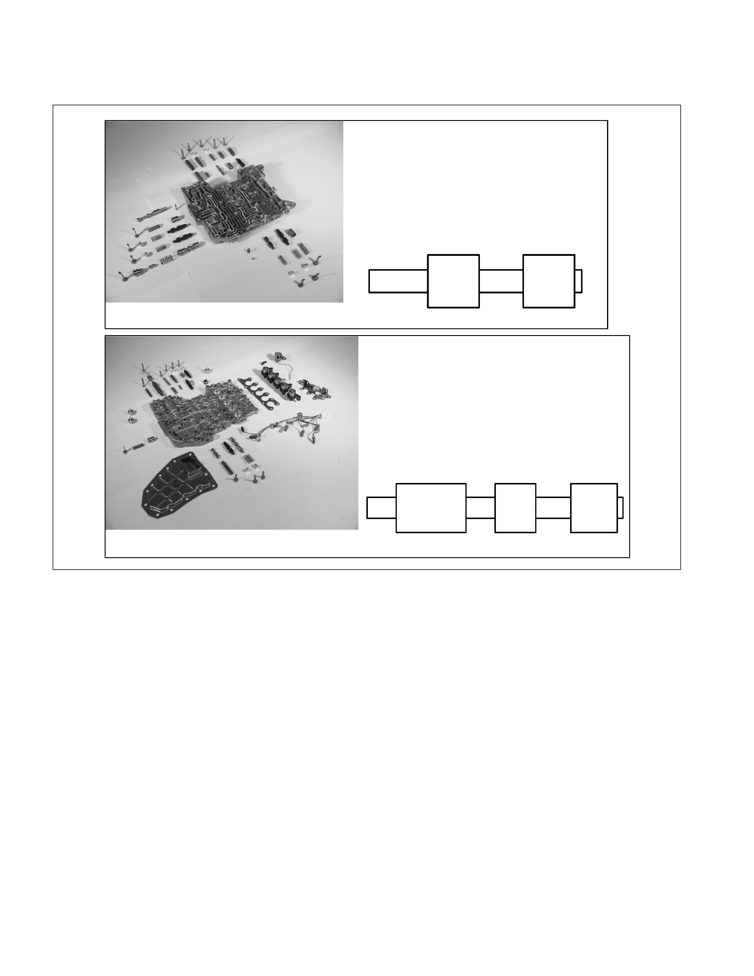
DTC P1755 (Flash Code 52) 2-4 Brake Fail-safe Valve Failure
Control Valve Upper Body 2-4 Brake Fail Valve (B)
Control Valve Lower Body 2-4 Brake Fail Valve (A)
Setting Condition:
• When the oil pressure generated and 2-4 brake pressure switch operates off/on twice, the TCM detected an
operation failure of the low & reverse brake fail-safe valve in D, 3, 2, L range.
Fail Safe:
• When the vehicle is running, the gear position selected at the trouble detection is held and the lock-up is inhibited.
• After the vehicle stopped, all solenoid operations stop (OFF) and the gear is fixed to the 3rd.
Possible Cause:
• Stick of 2-4 brake fail-safe valve.
• 2-4 brake pressure switch does not turn on.
• Short to ground of harness 2-4 brake pressure switch.
• Faulty fitting of each connector of harness in 2-4 brake pressure switch.

Step Action Yes No
1 Turn the key switch on and check the DTC. Is only the DTC for
2-4 brake fail-safe valve failure outputted? Go to Step 2 Go to Other DTC
Section
2 Clear the DTC from the memory. Turn the key switch off once,
and then start the engine. Does the CHECK TRANS blink when
the D range is selected and about 10 seconds elapsed?
Go to Other DTC
Section Go to Step 3
3 Run the vehicle, shift the gear from 1st to 4th, stop the vehicle,
and again shift the gear from 1st to 4th. Does the CHECK
TRANS blink at this time?
Go to Step 4
The 2-4 brake fail-safe
valve may be faulty
temporarily.
Go to step 5
4 Turn the key switch on and check the DTC. Is only the DTC for
the 2-4 brake fail-safe valve failure outputted? Repair or replace the
control valve.
Go to Step 5 Go to Other DTC
Section
5 Clear the DTC from the memory and perform the work after
repair. Is the same DTC code outputted again in the
subsequent DTC check?
Replace the TCM Go to Step 6
6 Are the other DTCs outputted? Go to Other DTC
Section Action is completed

DTC P0602 Programming Error
Setting Condition:
• When reprogramming operation is stopped under Service Programming System (SPS).
• When non programmed TCM (blank TCM) is used without Service Programming System (SPS).
Fail Safe:
• Lock-up is inhibited.
• All solenoid operations stop (OFF) and the gear is fixed to the 3rd.
Possible Cause:
• Low battery voltage while Service Programming System (SPS) is operated.
• No programmed TCM (blank TCM) is used.
Recover DTC:
Reprogram the TCM using with Service Programming Sy stem (SPS).

Symptom Diagnosis
Symptom Condition Description
Vehicle does not
run In D, 3, 2, L, and R ranges Vehicle does not run though the accelerator
pedal is stepped on. A1
In R range Vehicle does not run in R range only. A2
It runs normally in D, 3, 2, and L ranges.
In D, 3, 2, and L ranges Vehicle does not run in D, 3, 2, and L
ranges only. A3
It runs normally in R range.
Trouble at
starting Vehicle runs in N range Creep appears in N range. B1
Vehicle moves unless the brake pedal is
stepped on in N range.
Poor acceptation Starting acceleration is poor. B2
Engine races up during starting (slip) The engine speeds up but vehicle speed
does not increase when the accelerator
pedal is stepped on at the starting. B3
Large shock when shift lever is changed to
N to D range or N to R range
Large shock is felt when selecting D or R
range from N range during the idling after
warming up. B4
Engine stalls when selecting from N range
to R, D, 3, 2, or L range
The engine stalls when selecting from N or
P range to a run range during the engine
idling. B5
Engine starter does not run in P or N range The engine starter does not run though the
P or N range is selected. B6
Engine starter runs except in P or N range The engine starter runs though the R or D,
3, 2or L range is selected. B7
Extended time lag when shift lever is
changed to N to D The shift time lag is longer than standard
value when shift lever is changed to N to D. B8
Extended time lag when shift lever is
changed to N to R The shift time lag is longer than standard
value when shift lever is changed to N to R. B9
Brake is applied in R range Brake is applied suddenly in R range. B10
Insufficient starting or shaking in D range Insufficient starting or shaking in D range. B11
Noise or vibration Noise or vibration is generated in the vicinity
of AT at starting. B12
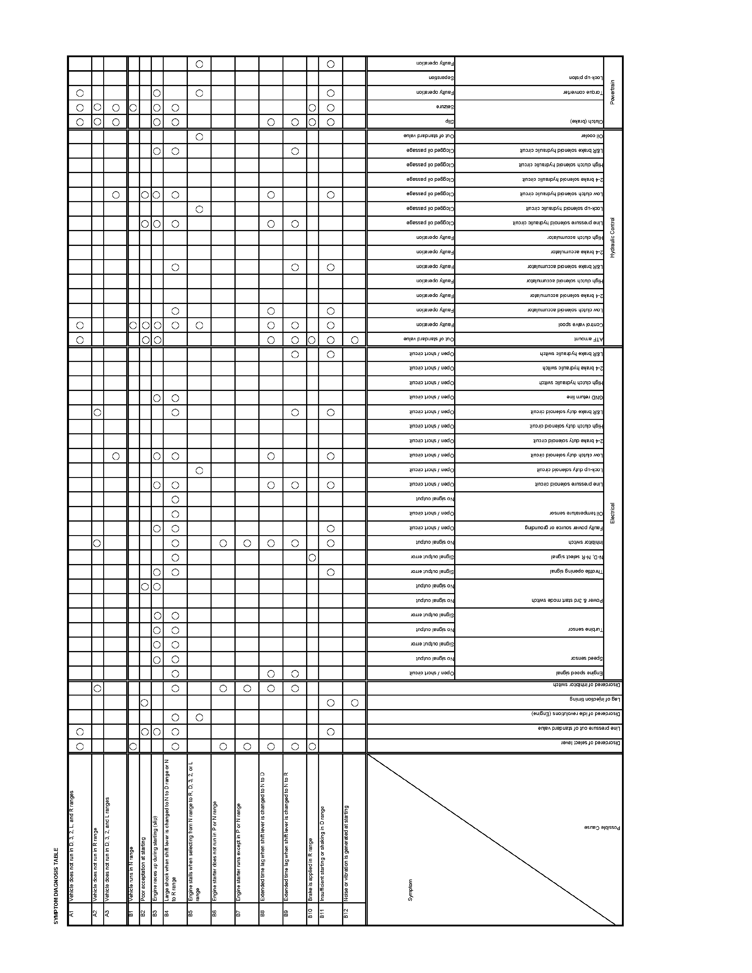

Symptom Diagnosis
Symptom Condition Description
Faulty shifting Engine race up (slip) when gear is shifted up
to 1st to 2nd
The engine speed up when the accelerator
pedal is stepped on for acceleration and the
gear is shifted up. C1
Engine race up (slip) when gear is shifted up
to 2nd to 3rd
The engine speed up when the accelerator
pedal is stepped on for acceleration and the
gear is shifted up. C2
Engine race up (slip) when gear is shifted up
to 3rd to 4th
The engine speed up when the accelerator
pedal is stepped on for acceleration and the
gear is shifted down or for kick-down during
steady run.
C3
Engine race up (slip) when gear is shift
down or kick-down to 4th to 3rd
The engine speed up when the accelerator
pedal is stepped on for acceleration and the
gear is shifted down or for kick-down. C4
Engine race up (slip) when gear is shift
down or kick-down to 4th to 2nd
The engine speed up when the accelerator
pedal is stepped on for acceleration and the
gear is shifted down or for kick-down. C5
Engine race up (slip) when gear is shift
down or kick-down to3rd to 2nd
The engine speed up when the accelerator
pedal is stepped on for acceleration and the
gear is shifted down or for kick-down. C6
Engine race up (slip) when gear is shift
down or kick-down to4th or 3rd to 1st
The engine speed up when the accelerator
pedal is stepped on for acceleration and the
gear is shifted down or for kick-down. C7
Engine race up (slip) others
The engine speed up when the accelerator
pedal is stepped on for acceleration and the
gear is shifted down or for kick-down during
steady run.
C8
Barking feel when gear is shifted up to 1st to
2nd
Brake feeling appears when the accelerator
pedal is stepped on for acceleration and the
gear is shifted up. C9
Barking feel when gear is shifted up to 2nd
to 3rd
Brake feeling appears when the accelerator
pedal is stepped on for acceleration and the
gear is shifted up. C10
Barking feel when gear is shifted up to 3rd
to 4th
Brake feeling appears when the accelerator
pedal is stepped on for acceleration and the
gear is shifted up. C11
Large shock when gear is shifted to 1st to
2nd or 2nd to 1st
Large shock is felt when the accelerator
pedal is stepped on for acceleration and the
gear is shifted up or down. C12
Large shock when gear is shifted to 2nd to
3rd or 3rd to 2nd
Large shock is felt when the accelerator
pedal is stepped on for acceleration and the
gear is shifted up or down. C13

Symptom Condition Description
Large shock when gear is shifted to 3rd to
4th or 4th to 3rd
Large shock is felt when the accelerator
pedal is stepped on for acceleration and the
gear is shifted up or down. C14
Large shock when kick-down Large shock is felt when the accelerator
pedal is stepped on for kick-down. C15
Large shock when no acceleration Large shock is felt when the accelerator
pedal is not stepped on. C16
Large shock when gear is shifted down to
2nd to 1st in L range Large shock is felt when the shift lever is
selected in L range. C17
Large shock (other) Large shock is felt when the accelerator
pedal is stepped on for acceleration and the
gear is shifted up or down. C18
Large shock when vehicle speed is downed
by no accelerator pedal or vehicle is
stopped.
Large shock is felt when the accelerator
pedal is not stepped on. C19
Large lock-up shock Large shock is felt at lock-up. C20
Shift down or engine over-run when the
accelerator pedal is stepped on in 4th gear Shift down or engine over-run above the
kick-down area. C21
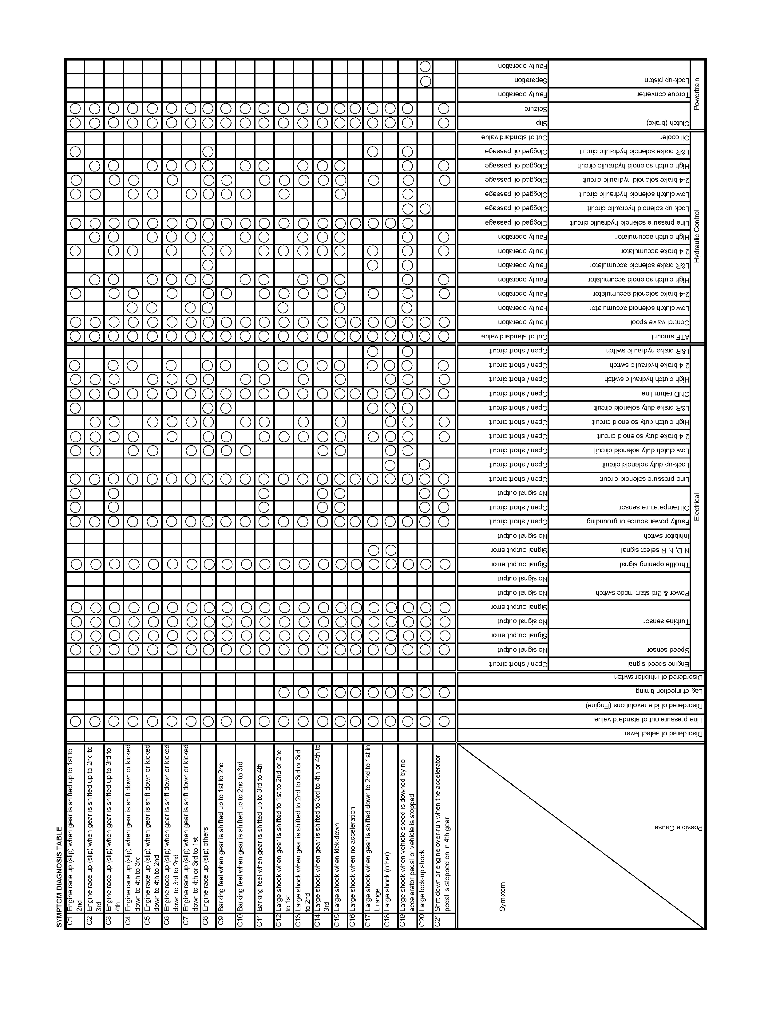

Symptom Diagnosis
Symptom Condition Description
Faulty shift point Faulty gear shifting (different from shift
pattern) Gear is shifted, different from the specified
shift pattern. D1
Gear is shifted frequently Gear is shifted down immediately though the
accelerator pedal is stepped on a little in D,
3, 2, or L range. D2
Gear shift point is low or high at all point Gear shift point is deviated from the shift
diagram. D3
Gear is not shifted up properly though the
vehicle is accelerated.
Gear is not shifted immediately and enough
acceleration cannot be obtained though the
accelerator pedal is stepped on.
Gear shift point is low or high at limited area Gear shift point is deviated from the shift
diagram. D4
Gear is not shifted up properly though the
vehicle is accelerated.
Gear is not shifted immediately and enough
acceleration cannot be obtained though the
accelerator pedal is stepped on.
No kick-down Kick-down (shift down) is not performed
though the accelerator pedal is fully stepped
on in the kick-down speed range. D5
No gear shift No gear shift Range is fixed without shifting the gear of
1st to 2nd, 2nd to 3rd, and 3rd to 4th. E1
Gear may be shifted or may not be shifted.
Only 4th gear is not selectable Gear is not shifted up from 3rd to 4th though
the vehicle is accelerated. E2
Gear is shifted 2nd to 3rd in 2 range Gear is shifted 2nd to 3rd in 2 range. E3
Gear is shifted 1st to 2nd in L range Gear is shifted 1st to 2nd in L range. E4
Gear is shifted 3rd to 4th in 3 range Gear is shifted 3rd to 4th in 3 range. E5
Faulty during the
running Low maximum speed or poor acceleration Starting acceleration is poor. F1
Acceleration is slow though the accelerator
pedal is stepped on during the running.
Engine races up during acceleration (slip) The engine speeds up but vehicle speed
does not increase when the accelerator
pedal is stepped on at the starting. F2
Only the engine speeds up but vehicle
speed does not increase when the
accelerator pedal is stepped on for
acceleration during the running.
Noise or vibration during the running in R, D,
3, 2, or L range Noise or vibration is generated in the vicinity
of AT during the running. F3
Symptom Condition Description
Engine brake does not in apply L range
The engine brake does not apply, allowing
the vehicle to run freely when the
accelerator pedal is released at low speed in
L range.
F4
Engine stalls before vehicle stops from
running
The engine stalls simultaneously wi th the
vehicle stop when the brake pedal is
stepped on to stop the vehicle during the
running.
F5
Faulty in the
stopping Vehicle moves in P range, or parking gear is
not disengaged other than P range Vehicle moves though it stops at a slope
and P range is selected. G1
The engine stalls and vehicle does not move
though other than P range is selected and
the accelerator pedal is stepped on.
Creep force is large Vehicle accelerates in D, 3, 2, L, and R
ranges though the accelerator pedal is not
stepped on. G2
Creep force is small Vehicle does not move though a run range
is selected on a flat road during the idling. G3
Large noise during idling with the vehicle in
stop state The transmission is noisy during the idling
speed in all ranges. G4
Faulty lock-up Judder occurs at the lock-up The vehicle body judders at lock-up. H1
Large lock-up shock Large shock is felt at lock-up. H2
Lock-up point is high or low Lock-up point is excessive high or low. H3
No lock-up No lock-up Lockup is not performed in spite of the lock-
up area. I1


Symptom Diagnosis
Symptom Condition Description
Oil Leak Breather Oil leaks from breather. J1
Between engine and converter housing Oil leaks between engine and converter
housing. J2
Between converter housing and main case Oil leaks between converter housing and
main case. J3
Between main case and rear housing Oil leaks between main case and rear
housing. J4
Oil pan Oil leaks from oil pan. J5
Manual shaft oil seal Oil leaks from manual shaft oil seal. J6
Oil cooler pipe Oil leaks from oil cooler pipe joint. J7
Other Transmission overheat You smell the transmission burning. Z1
The transmission smokes.
Mode lamp does not light up when the
power mode or 3rd start mode is turned on
The mode lamp on the instrument panel
does not light up though the power mode or
3rd start mode is turned on with the ignition
switch in ON position.
Z2
Mode lamp lights up when the power mode
or 3rd start mode is turned off
The mode lamp on the instrument panel
lights up though the power mode or 3rd start
mode is turned off with the ignition switch in
ON position.
Z3
Oil temperature warning lamp lights up Sometimes, the oil temperature warning
lamp lights up. Z4
Select lever feeling is faulty Select lever feeling is faulty. Z5
Poor fuel consumption Poor fuel consumption. Z6
Pattern select switch is faulty Shift pattern does not change though the
pattern select switch is turned on. Z7
Oil is splashed during the running Oil is splashed during the running. Z8
Abnormal smell Abnormal smell. Z9
Oil quantity is low or high Oil quantity is low or high. Z10
Abnormal oil pressure Oil pressure is low or high. Z11
Reverse buzzer does not ring Reverse buzzer does not ring in R range. Z12
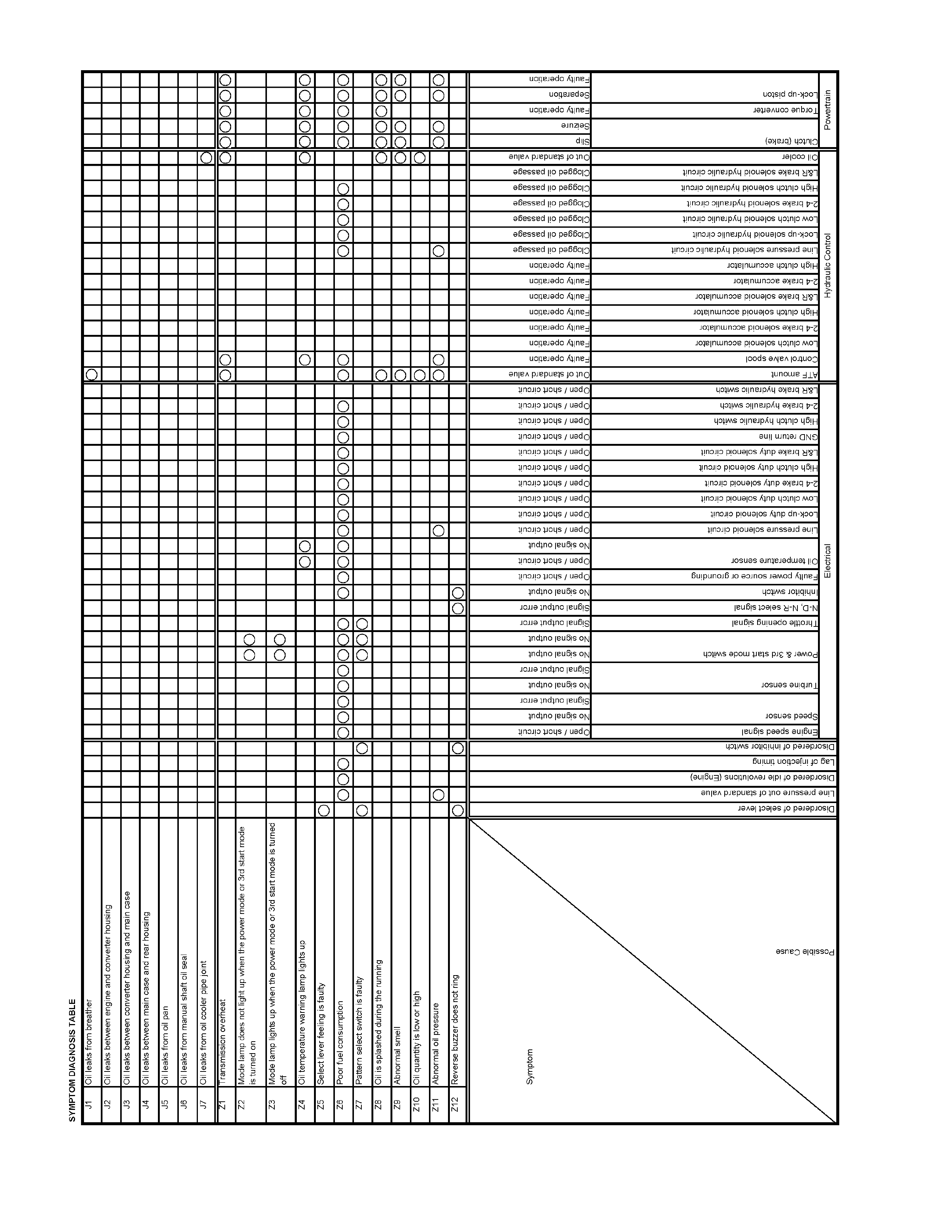

No. A1: Vehicle Does Not Run in D, 3, 2, L and R Range
Description:
• Vehicle does not run though the accelerator pedal is stepped on.
Diagnosis Hints:
• Some trouble in the AT main unit is supposed (since the vehicle can run even if the TCM is defective). However,
since the trouble of the main unit may be originated from the s ensor s ystem or output s ystem, thes e s ystems s hould
be also checked to prevent reproduce of the trouble.
Possible Cause:
• Slip of clutch (low clutch, low one-way clutch, reverse clutch, low & reverse brake).
If slip of clutch is caused, a DTC (gear ratio error) is stored.
• Shortage or faulty quality of ATF.
• Dropped line pressure.
• Trouble in control valve body (faulty operation, sticking, clogged oil passage).
• Disordered select cable (s elect indicator light indicates D, 3, 2, L or R but the hydraulic system is not in the D, 3, 2,
L, or R range).
• Faulty torque generated.
• Trouble in the torque converter (faulty operation, sticking), insufficient engine output.
• Malfunction of parking mechanism.
Step Action Yes No
1 Dislocation or disordered of select lever.
Does the vehicle move when the brake is released in a
position other than the P range and the vehicle is pushed? Go to Step 2 Adjust the select cable.
2 Are any DTCs stored? Go to DTC Chart Go to Step 3
3 Are the quantity, contamination and smell normal? If the ATF level is low,
replenish up to the
specified level.
Go to Step 4
If ATF is extremely
black and
contaminated and
smells burnt, slip of the
clutch is supposed.
Overhaul the AT unit.
4 Is the stall revolution correct in all range? Refer the STALL
TEST section in this manual. Go to Step 5 Repair the defect or
replace.
5 Is the line pressure correct? Refer the LINE PRESSURE
TEST section in this manual. Trouble in the AT
assembly or control
valve. Repair the defect or
replace.

No. A2: Vehicle Does Not Run in R Range
Description:
• Vehicle does not run in R range only.
• It runs correctly in D, 3, 2, and L ranges.
Diagnosis Hints:
• Some trouble in the AT main unit is supposed (since the vehicle can run even if the TCM is defective). However,
since the trouble of the main unit may be originated from the s ensor s ystem or output s ystem, thes e s ystems s hould
be also checked to prevent reproduce of the trouble.
Possible Cause:
• Slip of clutch (reverse clutch, low & reverse brake).
If slip of clutch is caused, a DTC (gear ratio error) is stored.
• Shortage or faulty quality of ATF.
• Dropped line pressure.
• Trouble in control valve body (faulty operation, sticking, clogged oil passage).
• Disordered select cable (select indicator light indicates R but the hydraulic system is not in the R range).
• Faulty torque generated.
• Trouble in the torque converter (faulty operation, sticking), insufficient engine output.
• Malfunction of parking mechanism.
Step Action Yes No
1 Dislocation or disordered of select lever.
Does the vehicle move when the brake is released in a
position other than the P range and the vehicle is pushed?
Go to Step 2
Adjust the select cable.
2 Are any DTCs stored? Go to DTC Chart Go to Step 3
3 Are the quantity, contamination and smell normal? If the ATF level is low,
replenish up to the
specified level.
Go to Step 4
If ATF is extremely
black and
contaminated and
smells burnt, slip of the
clutch is supposed.
Overhaul the AT unit.
4 Is the stall revolution correct in R range? Refer the STALL
TEST section in this manual. Go to Step 5 Repair the defect or
replace.
5 Is the line pressure correct? Refer the LINE PRESSURE
TEST section in this manual. Trouble in the AT
assembly or control
valve. Repair the defect or
replace.

No. A3: Vehicle Does Not Run in D, 3, 2 and L Range
Description:
• Vehicle does not run in D, 3, 2 and L range only.
• It runs correctly in R ranges.
Diagnosis Hints:
• Some trouble in the AT main unit is supposed (since the vehicle can run even if the TCM is defective). However,
since the trouble of the main unit may be originated from the s ensor s ystem or output s ystem, thes e s ystems s hould
be also checked to prevent reproduce of the trouble.
Possible Cause:
• Slip of clutch (low clutch and low one-way clutch).
If slip of clutch is caused, a DTC (gear ratio error) is stored.
• Shortage or faulty quality of ATF.
• Dropped line pressure.
• Trouble in control valve body (faulty operation, sticking, clogged oil passage).
• Disordered select cable (select indicator light indicates D, 3, 2 and L but the hydraulic system is not in the D, 3, 2
and L range).
• Faulty torque generated.
• Trouble in the torque converter (faulty operation, sticking), insufficient engine output.
• Malfunction of parking mechanism.
Step Action Yes No
1 Dislocation or disordered of select lever.
Does the vehicle move when the brake is released in a
position other than the P range and the vehicle is pushed?
Go to Step 2
Adjust the select cable.
2 Are any DTCs stored? Go to DTC Chart Go to Step 3
3 Are the quantity, contamination and smell normal? If the ATF level is low,
replenish up to the
specified level.
Go to Step 4
If ATF is extremely
black and
contaminated and
smells burnt, slip of the
clutch is supposed.
Overhaul the AT unit.
4 Is the stall revolution correct in D, 3, 2 and L range? Refer
the STALL TEST section in this manual. Go to Step 5 Repair the defect or
replace.
5 Is the line pressure correct? Refer the LINE PRESSURE
TEST section in this manual. Trouble in the AT
assembly or control
valve. Repair the defect or
replace.

No. B1: Vehicle Runs in N Range
Description:
• Creep appears in N range.
• Vehicle moves unless the brake pedal is stepped on in N range.
Diagnosis Hints:
• Basically a trouble in the AT main unit. However, some trouble in the sensor system or output system may have
some influence on the trouble in the main unit and therefore these systems should be also checked to prevent
reproduce of the trouble.
Possible Cause:
• Seized clutch (low clutch, low one-way clutch, reverse clutch, low & reverse brake).
• Trouble in the control valve (faulty operation, sticking, clogged oil passage).
• Dislocated selec t lever (the selec t indicator light indicates the N range but the hydraulic system is in the D, 3, 2 or L
range).
Step Action Yes No
1 Dislocation or disordered of select lever.
Does the vehicle move when the brake is released in a
position other than the P range and the vehicle is pushed?
Go to Step 2
Adjust the select cable.
2 Are any DTCs stored?
Go to DTC Chart Go to Step 3
3 Are the quantity, contamination and smell normal?
If the ATF level is low,
replenish up to the
specified level.
Trouble in the AT
assembly or control
valve.
If ATF is extremely
black and
contaminated and
smells burnt, slip of the
clutch is supposed.
Overhaul the AT unit.

No. B2: Poor Acceleration at Starting
Description:
• Starting acceleration is poor.
Diagnosis Hints:
• In addition to the low engine output, faulty gear shifting of AT or fixing at the 3rd position may be possible.
Theref ore, in case of suc h a trouble that "maxim um s peed is low, and acceleration is poor ", it should be cleared up
whether the trouble is originated from the engine system of AT system by a running test, inspection of stall
revolution, etc.
Possible Cause:
• Clogged air cleaner, out of injection timing, dropped compression pressure, etc.
• Fixing at 3rd position (fail-safe activated).
Since the gear is fixed at the 3rd position because of the fail-safe function, a trouble that "Maximum speed is low,
and acceleration is poor" is resulted. In this case, the DTC is memorized.
When TCM stops operation because of faulty TCM ground, the gear is fixed at the 3rd position because of a
mechanical reason. In this case, no DTC is memorized.
• Disordered inhibitor switch.
• Incorrect properties of throttle opening signal (serial communication) of throttle position sensor.
Throttle opening signal (serial communication) of the throttle position sensor does not change in proportion to the
throttle opening. In this case, fixing at the high or low gear results in such a trouble that "Maximum Speed is Low
and Acceleration is Poor".
• Slip of clutch (low clutch, high clutch).
• If slip of clutch is caused, a DTC (gear ratio error) is stored.
• Dropped line pressure.
• Trouble in the torque converter system (faulty operation).
Step Action Yes No
1 Test Drive.
Is the gear smoothly shifted in the order of 1st to 2nd, 2nd to 3rd,
3rd to 4th gear and lock up?
Clogged air cleaner,
out of injection
timing, dropped
compression
pressure, etc.
Go to Step 2
2 Gear ratio trouble diagnosis.
Travel in the following sequence for about 7 seconds or more in
each range: Start in the L range (1st) to 2 range (2nd) to 3 range
(3rd) to D range (4th) (to detect the gear ratio trouble exactly, this
process should be carried out)
Go to Step 3 Go to Step 3
3 Are any DTCs stored?
Go to DTC Chart Go to Step 4
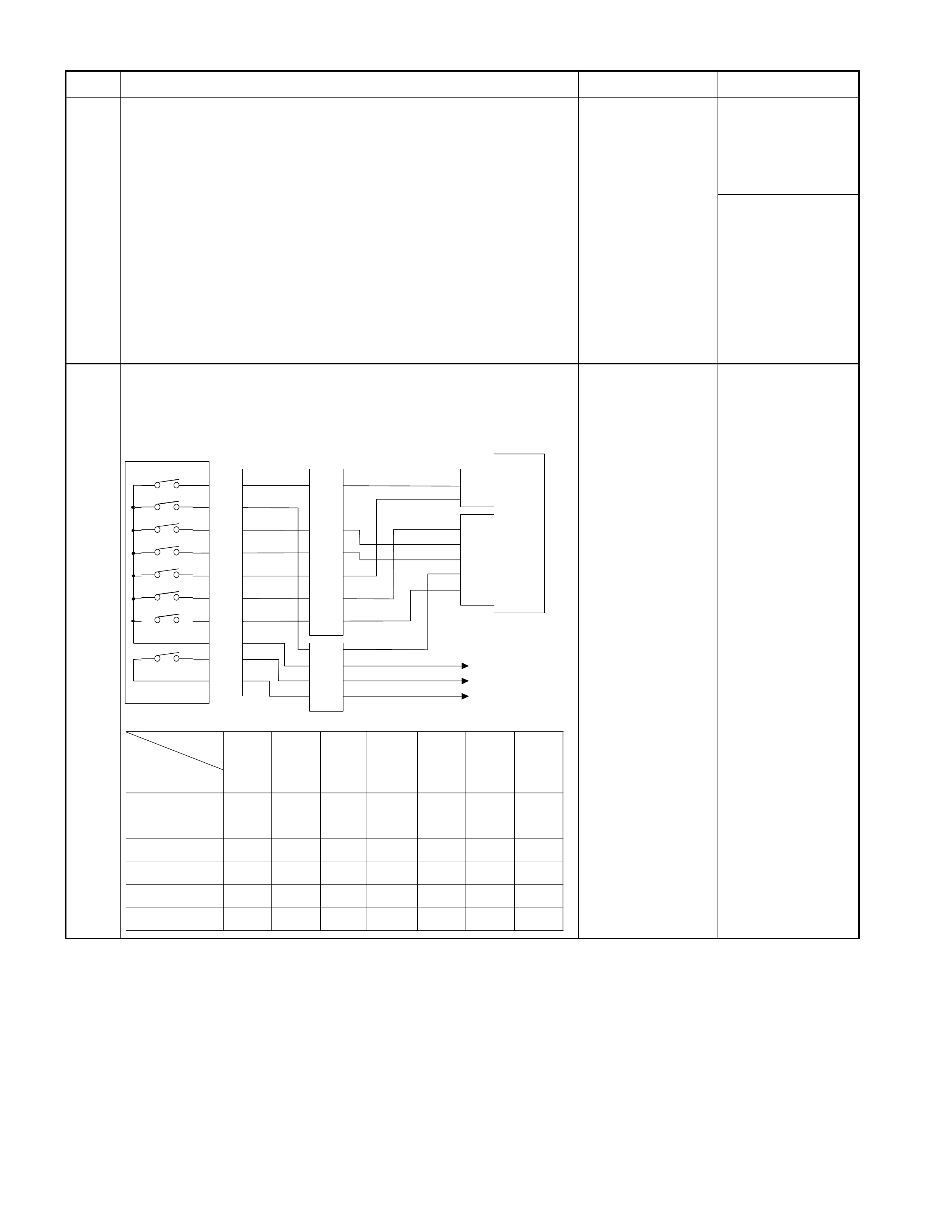
Step Action Yes No
4 Are the quantity, contamination and smell normal?
If the ATF level is
low, replenish up to
the specified level.
Go to Step 5
If ATF is extremely
black and
contaminated and
smells burnt, slip of
the clutch is
supposed.
Overhaul the AT
unit.
5 Inspection of inhibitor switch using a Tech 2 or circuit tester.
When the select lever is operated, is the data display in the Tech 2
correct or voltage at each range correct?
Inhibitor SW
TCM
A2 (P)
A17 (3)
B2 (2)
B10 (N)
B11 (D)
B19 (R)
B21 (L)
C95
(2)
(10)
(11)
(19)
(21)
YEL/VIO
RED/BLK
BLU
BLK/GRN
Starter Relay
C94
(2)
(3)
B
H22
(1)
(6)
(4)
(7)
(5)
(2)
P
2
R
N
D
3
L
St a rt S W
PNK/BLU
E51
(2)
(4)
(8)
(5)
(1)
(9)
(6)
(3)
(10)
(7)
(38)
(15)
(3)
(37)
H4
PNK/BLK
RED/YEL
YEL/VIO
BLK/GRN
PNK/BLK
RED/BLK
BLU
RED/YEL
PNK/BLU
BLK/WHT
BLK
BLK
BLK/WHT Key Switch
WHT
WHT
Im mobilis e r Con t ro l Unit
TCM terminal
Range
A2 B19 B10 B11 B17 B2 B21
P Battery
volta
g
e------
R-Battery
volta
g
e-----
N--Battery
volta
g
e----
D - - - Battery
volta
g
e---
3----Battery
volta
g
e--
2 - - - - - Battery
volta
g
e-
L------Battery
volta
g
e Go to Step 6 Adjust the inhibitor
switch.
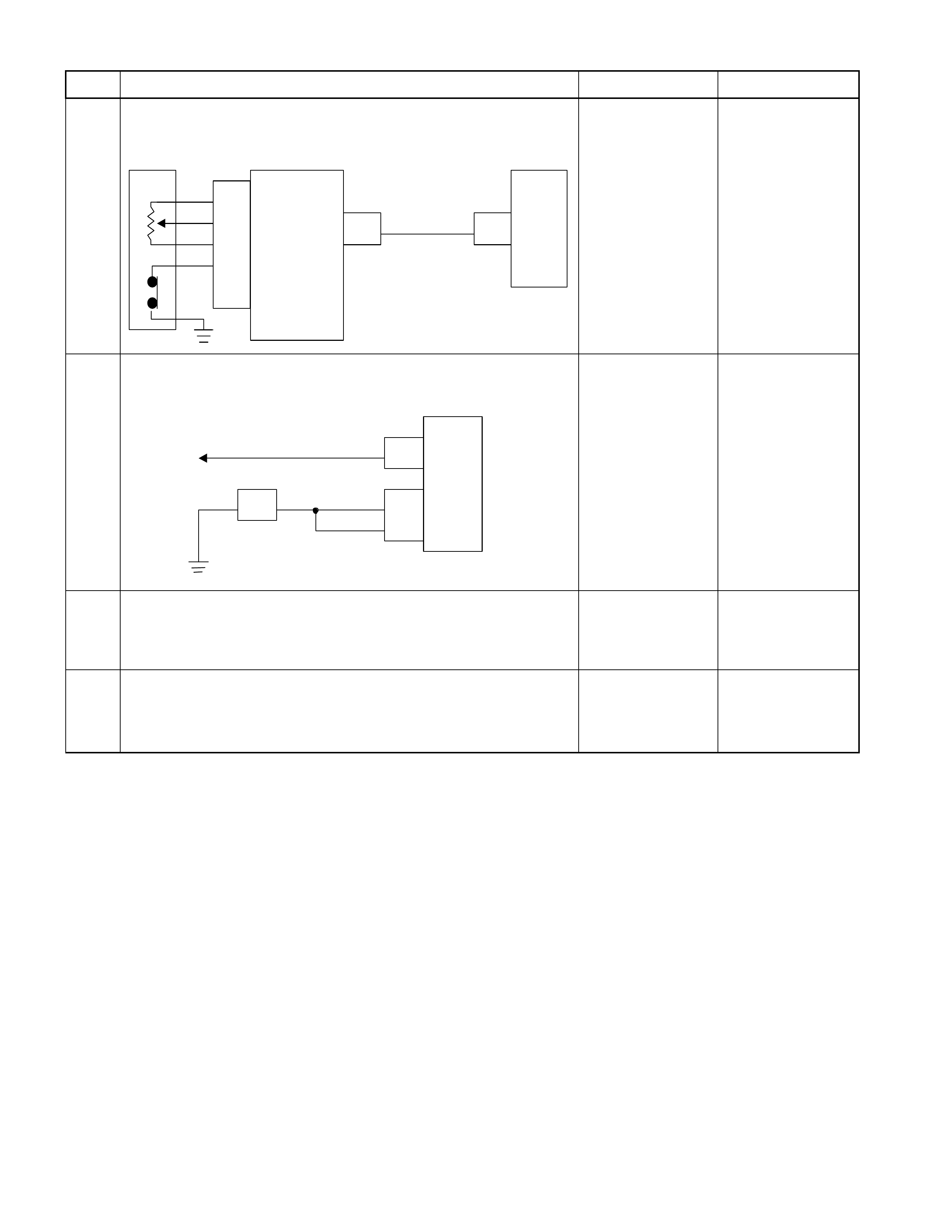
Step Action Yes No
6 Inspect the output voltage and throttle opening signal of the throttle
position sensor using a Tech 2 or circuit tester.
Is a voltage value in proportion to the throttle opening output?
TPS TCM
A16
C56
(28) C94
(16)
RED/WHT
C56
(49)
(38)
(57)
(69)
ECM
A47 (GN D )
A35 (Ou tput)
A26
A55 (+5V)
A69 (Idle SW)
Go to Step 7 Repair the defect or
replace.
7 Check of power supply to and earth of TCM.
Are the power supply and earth proper?
TCM
A1 (+B)
B5
B15
H23
(15) C95
(5)
(15)
BLK/YEL
BLK
BLK
Battery C94
(1)
BLK
Go to Step 8
Check the power
source harness and
earth harness (bolt
tightening to the
body).
8 Is the stall revolution correct in D, 3, 2 and L range? Refer the
STALL TEST section in this manual.
Go to Step 6 Repair the defect or
replace.
9 Is the line pressure correct? Refer the LINE PRESSURE TEST
section in this manual. Trouble in the AT
assembly or control
valve. Repair the defect or
replace.

No. B3: Engine Race Up During Starting (Slip)
Description:
• The engine speeds up but vehicle speed does not increase when the accelerator pedal is stepped on at the starting.
Diagnosis Hints:
• Possibility of slip of clutch is supposed. If slip of clutch has occurred, a DTC of "Gear ratio error" is stored.
Possible Cause:
• Slip of clutch.
If slip of clutch is caused, a DTC (gear ratio error) is stored.
• Dropped line pressure.
• Trouble in control valve body (faulty operation, sticking, clogged oil passage).
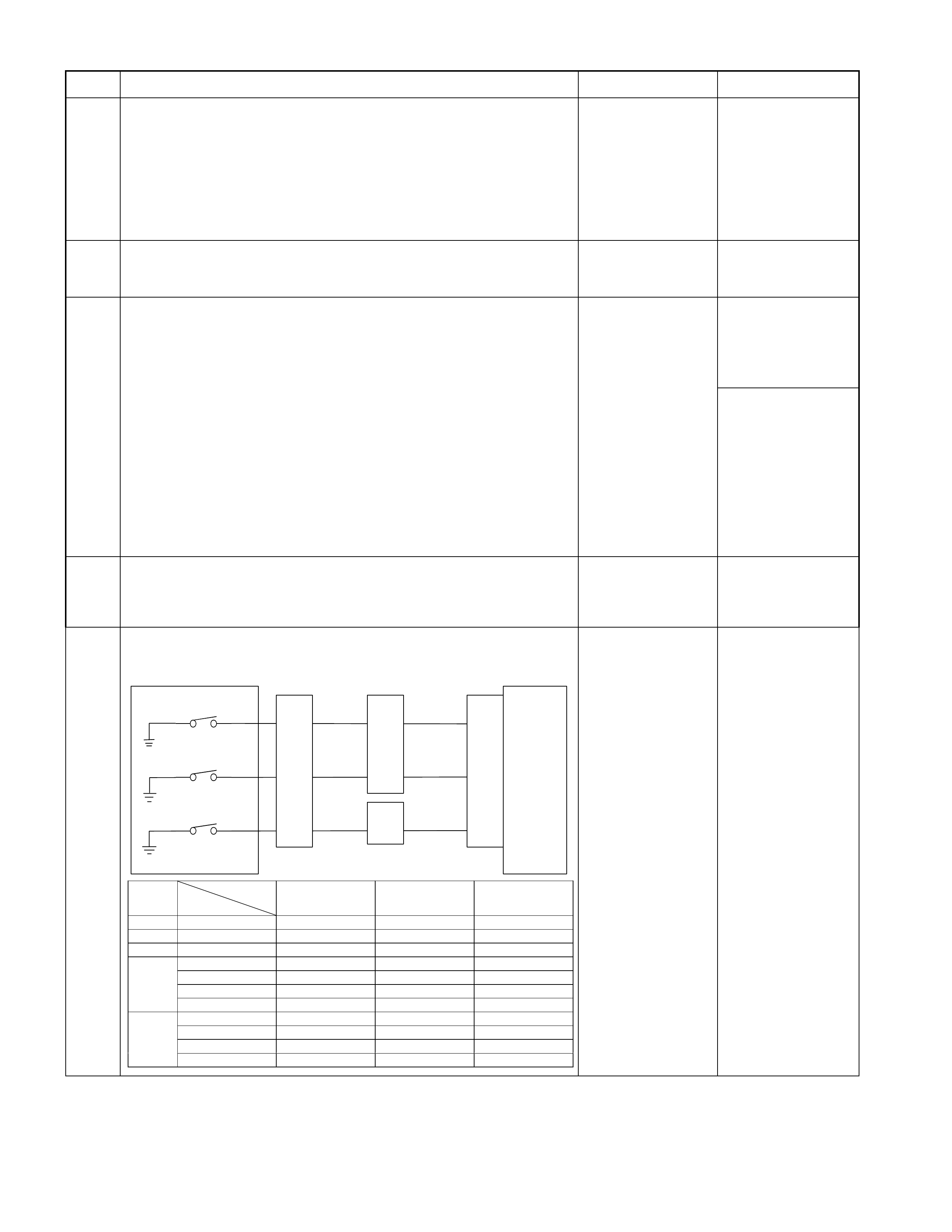
Step Action Yes No
1 Gear ratio trouble diagnosis.
Travel in the following sequence for about 7 seconds or more in
each range: Start in the L range (1st) to 2 range (2nd) to 3 range
(3rd) to D range (4th) (to detect the gear ratio trouble exactly, this
process should be carried out)
Go to Step 2 Go to Step 2
2 Are any DTCs stored?
Go to DTC Chart Go to Step 3
3 Are the quantity, contamination and smell normal?
If the ATF level is
low, replenish up to
the specified level.
Go to Step 4
If ATF is extremely
black and
contaminated and
smells burnt, slip of
the clutch is
supposed.
Overhaul the AT
unit.
4 Are the engine speed and other engine system correct?
Go to Step 5 Repair the defect or
replace.
5 Inspection of electrical or mechanical fault
Is the signal from each pressure switch changed synchronously?
Control Valve
TCM
B1
B12
B20
RED/YEL
WHT/BLK
2-4 Brake Pressure SW
Terminal
Assembly
YEL
E54
(7)
(12)
(1)
H23
(12)
(10)
C95
(1)
(12)
(20)
RED/YEL
YEL
WHT/BLK
L&R Brake Pressure SW
High Clutch Pressure SW H22
(8)
Range
TCM terminal
Gear
B20
(High clutch
pressure SW)
B1
(2-4 brake pressure
SW)
B12 (Low & reverse
brake
p
ress ure SW
)
P - More than 10V More than 10V More than 10V
R Reverse More than 10V More than 10 V -
N - More than 10V More than 10V More than 10V
D, 3, 2 1st More than 10V More than 10V More than 10V
2nd More than 10V - More than 10V
3rd - More than 10V More than 10V
4th - - More than 10V
L 1st More than 10V More than 10V -
2nd More than 10V - More than 10V
3rd - More than 10V More than 10V
4th - - More than 10V Go to Step 6 Repair the defect or
replace.
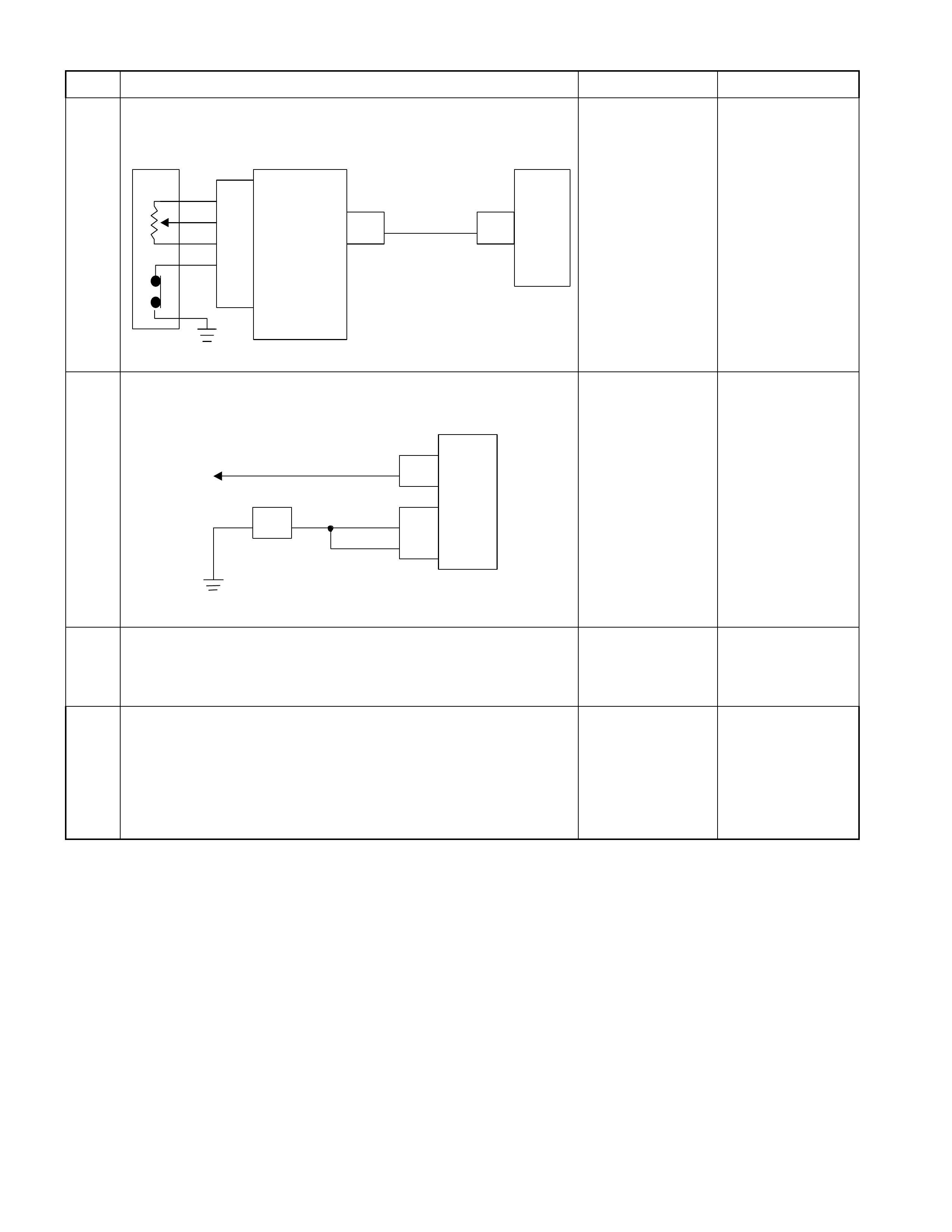
Step Action Yes No
6 Inspect the output voltage and throttle opening signal of the
throttle position sensor using a Tech 2 or circuit tester.
Is a voltage value in proportion to the throttle opening output?
TPS TCM
A16
C56
(28) C94
(16)
RED/WHT
C56
(49)
(38)
(57)
(69)
ECM
A47 (GND)
A35 (Output)
A26
A55 (+5V)
A69 (Idle SW )
Go to Step 7 Repair the defect or
replace.
7 Check of power supply to and earth of TCM.
Are the power supply and earth proper?
TCM
A1 (+B)
B5
B15
H23
(15) C95
(5)
(15)
BLK/YEL
BLK
BLK
Battery C94
(1)
BLK
Go to Step 8
Check the power
source harness and
earth harness (bolt
tightening to the
body).
8 Is the stall revolution correct in D, 3, 2 and L range? Refer the
STALL TEST section in this manual.
Go to Step 9 Repair the defect or
replace.
9 Is the line pressure correct? Refer the LINE PRESSURE TEST
section in this manual.
Trouble in the AT
assembly or control
valve. Repair the defect or
replace.

No. B4: Large Shock When Shift Lever is Moved from N to D Range
or N to R Range
Description:
• Large shock is felt when selecting D or R range from N range during the idling after warming up.
Diagnosis Hints:
• Check the entire condition of the vehicle for unusual other than AT including faulty engine mount, exhaust hanger,
etc.
• When the fail-safe operation, select shock may grow worse. In such a case, check for the DTC. If no DTC is issued,
shock due to faulty operation of the control valve or burnt clutch is considered.
Possible Cause:
• High engine idling.
• Dislocated select lever, improper inhibitor switch adjusting point.
• Faulty or insufficient tightening of engine mount, exhaust mount.
• Play of suspension.
• Burnt clutch.
• Too low or high line pressure.
• Faulty input signal system.
• Faulty control valve. (faulty operation or sticking of accumulator)

No. B5: Engine Stalls When Selecting From N Range to R, D, 3, 2 or L
Range
Description:
• The engine stalls when selecting from N or P range to a run range during the engine idling.
Diagnosis Hints:
• As causes attributable to the engine, faulty idle up, insufficient engine output, etc. are considered.
• As a cause of the AT system, faulty lockup piston system (lockup engine stall) is considered.
• If the oil thr ough resistanc e increases r em ark ably due to clogged oil cooler or som e other reason, or if the AT F level
decreases, the lock-up piston works causing the engine stall.
Possible Cause:
• Disordered idling speed, faulty idle up, faulty engine output, and low output.
• Insufficient ATF quantity (dropped level).
• Clogged oil cooler (foreign substance mixed in).
• Faulty lock-up piston (clogged oil passage of solenoid drive circuit, faulty operation).
Step Action Yes No
1 Gear ratio trouble diagnosis.
Travel in the following sequence for about 7 seconds or more in
each range: Start in the L range (1st) to 2 range (2nd) to 3 range
(3rd) to D range (4th) (to detect the gear ratio trouble exactly, this
process should be carried out)
Go to Step 2 Go to Step 2
2 Are any DTCs stored?
Go to DTC Chart Go to Step 3
3 Are the quantity, contamination and smell normal?
If the ATF level is
low, replenish up to
the specified level.
Go to Step 4
If ATF is extremely
black and
contaminated and
smells burnt, slip of
the clutch is
supposed.
Overhaul the AT
unit.
4 Check of engine idle up speed
Does the idle speed increase when the air conditioning or other
electric load is turned on?
Go to Step 5 Repair the defect or
replace.
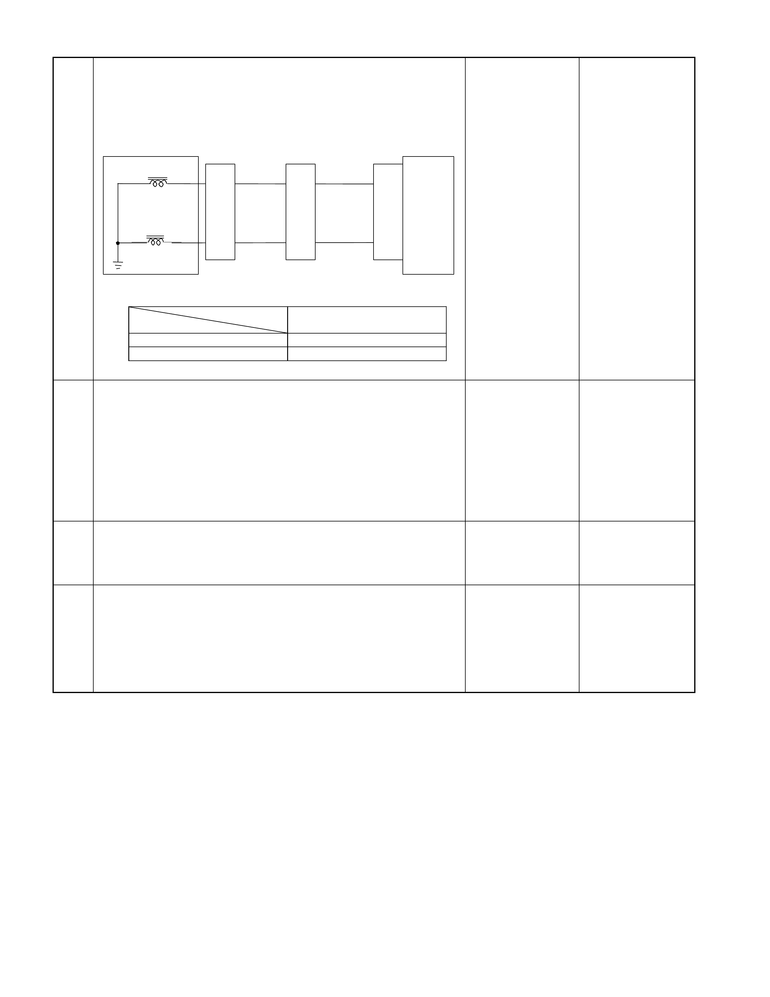
Step Action Yes No
5 Inspection of electrical or mechanical fault
When the D range is selected from D at idling speed, is the signal
to the lock-up solenoid turned off using the Tech 2 or circuit
tester?
Control Valve
TCM
B17
B23
BLK
Lock-up Solenoid
Terminal
Assembly
VIO
Line Pressure Solenoid
E54
(4)
(6)
H23
(14)
(6)
C95
(17)
(23)
BLK
VIO
TCM terminal
Lock-up B17
At lock-up Approx. 7.2 V (AC range)
At unlock-up Approx. 4.0V (AC range)
Go to Step 6
Find a cause to turn
on the lockup
solenoid
6 Check of clogging of oil cooler
When blowing the oil cooler outlet with air, does some foreign
substance come out?
Clean or replace the
oil cooler.
Go to Step 7
Clogged lock-up
solenoid oil
passage. Faulty
operation of lock-up
piston.
Faulty control valve.
7 Is the stall revolution correct in D, 3, 2 and L range? Refer the
STALL TEST section in this manual.
Go to Step 8 Repair the defect or
replace.
8 Is the line pressure correct? Refer the LINE PRESSURE TEST
section in this manual.
Trouble in the AT
assembly or control
valve. Repair the defect or
replace.

No. B6: Engine Starter Does Not Run in P or N Range
No. B7: Engine Starter Runs Except in P or N Range
Description:
• The engine starter does not run though the P or N range is selected.
• The engine starter runs though the R or D, 3, 2or L range is selected.
Possible Cause:
• Disordered select cable.
• Disordered Inhibitor switch, disconnection or short-circuit of inhibitor switch.

No. B8: Extended Time Lag When Shift Lever is Changed to N to D
Description:
• The shift time lag is longer than standard value when shift lever is changed to N to D.
Possible Cause:
• Forward range line pressure is low.
• Slip of low & reverse clutch.
• Slip of low one-way clutch.
• Trouble in control valve body (faulty operation, sticking, clogged oil passage).
• Faulty low clutch duty solenoid operation.
• Shortage or faulty quality of ATF.

No. B9: Extended Time Lag When Shift Lever is Changed to N to R
Description:
• The shift time lag is longer than standard value when shift lever is changed to N to R.
Possible Cause:
• Reverse range line pressure is low.
• Slip of low & reverse brake.
• Slip of reverse clutch.
• Trouble in control valve body (faulty operation, sticking, clogged oil passage).
• Faulty low & reverse brake duty solenoid operation.
• Shortage or faulty quality of ATF.

No. B10: Brake is Applied in R Range
Description:
• Brake is applied suddenly in R range.
Diagnosis Hints:
• Basically a trouble in the AT main unit. However, some trouble in the sensor system or output system may have
some influence on the trouble in the main unit and therefore these systems should be also checked to prevent
reproduce of the trouble.
Possible Cause:
• Seized clutch (low clutch, high clutch, 2-4 brake).
• Shortage or faulty quality of ATF.
• Trouble in control valve body (faulty operation, sticking, clogged oil passage).
• Disordered select cable (select indicator light indicates R but the hydraulic system is not in the R range).
• Malfunction of parking mechanism.

No. B11: Insufficient Starting or Shaking in D Range
Description:
• Insufficient starting or shaking in D range.
Possible Cause:
• Slip of clutch (low clutch, low one-way clutch, reverse clutch, low & reverse brake).
If slip of clutch is caused, a DTC (gear ratio error) is stored.
• Shortage or faulty quality of ATF.
• Dropped line pressure.
• Trouble in control valve body (faulty operation, sticking, clogged oil passage).

No. B12: Noise or Vibration is Generated at Starting
Description:
• Noise or vibration is generated in the vicinity of AT at starting.
Diagnosis Hints:
• Cause other than AT can be also cons idered. It is eff ective means to r eproduce a running condition using a lif t up,
chassis dynamo, etc. to investigate the origin (generating condition) of noise and vibration.
Caution:
Lifting up some unit to test it accompanies danger. Provide safety measures as far as possible and carry
out the test with sufficient care.
Possible Cause:
Following sources of noise or vibration other than the AT can be considered.
• Noise from differential gears.
• Noise from propeller shaft.
• The bearing support in the m iddle of the propeller shaft has f atigued, and the bend angle of the propeller shaft has
changed, causing vibration at the time of start.
• Unbalanced and poor uniformity of tires cause vibration.

No. C1: Engine Race Up (Slip) When Gear is Shifted Up to 1st to 2nd
No. C2: Engine Race Up (Slip) When Gear is Shifted Up to 2nd to 3rd
No. C3: Engine Race Up (slip) When Gear is Shifted Up to 3rd to 4th
No. C4: Engine Race Up (Slip) When Gear is Shift
Down or Kick-down to 4th to 3rd
No. C5: Engine Race Up (Slip) When Gear is Shift
Down or Kick-down to 4th to 2nd
No. C6: Engine Race Up (Slip) When Gear is Shift
Down or Kick-down to 3rd to 2nd
No. C7: Engine Race Up (Slip) When Gear is Shift
Down or Kick-down to 4th or 3rd to 1st
No. C8: Engine Race Up (Slip) Others
Description:
• The engine speed up when the accelerator pedal is stepped on for acceleration and the gear is shifted up.
• The engine speed up when the accelerator pedal is stepped on for acceleration and the gear is shifted down or for
kick-down during steady run.
• The engine speed up when the accelerator pedal is stepped on for acceleration and the gear is shifted down or for
kick-down during steady run.
Diagnosis Hints:
• Possibility of slip of clutch is supposed. If slip of clutch has occurred, a DTC of "Gear ratio error" is stored.
Possible Cause:
• Slip of clutch.
If slip of clutch is caused, a DTC (gear ratio error) is stored.
• Dropped line pressure.
• Trouble in control valve body (faulty operation, sticking, clogged oil passage).

Step Action Yes No
1 Gear ratio trouble diagnosis.
Travel in the following sequence for about 7 seconds or more in
each range: Start in the L range (1st) to 2 range (2nd) to 3 range
(3rd) to D range (4th) (to detect the gear ratio trouble exactly, this
process should be carried out)
Go to Step 2 Go to Step 2
2 Are any DTCs stored?
Go to DTC Chart Go to Step 3
3 Are the quantity, contamination and smell normal?
If the ATF level is
low, replenish up to
the specified level.
Go to Step 4
If ATF is extremely
black and
contaminated and
smells burnt, slip of
the clutch is
supposed.
Overhaul the AT
unit.
4 Are the engine speed and other engine system correct?
Go to Step 5 Repair the defect or
replace.
5 Inspection of electrical or mechanical fault
Is the signal from each pressure switch changed synchronously?
Control Valve
TCM
B1
B12
B20
RED/YEL
WHT/BLK
2-4 Bra ke Press ure SW
Terminal
Assembly
YEL
E54
(7)
(12)
(1)
H23
(12)
(10)
C95
(1)
(12)
(20)
RED/YEL
YEL
WHT/BLK
L&R Brake Pressure SW
High Clutch Pressure SW H22
(8)
Range
TCM terminal
Gear
B20
(High clutch
pressure SW)
B1
(2-4 brake pressure
SW)
B12 (Low & reverse
brake
p
ress ure SW
)
P - More than 10V More than 10V More than 10V
R Reverse More than 10V More than 10V -
N - More than 10V More than 10V More than 10V
D, 3, 2 1st More than 10V More than 10V More than 10V
2nd More than 10V - More than 10V
3rd - More than 10V More than 10V
4th - - More than 10V
L 1st More than 10V More than 10V -
2nd More than 10V - More than 10V
3rd - More than 10V More than 10V
4th - - More than 10V
Go to Step 6 Repair the defect or
replace.
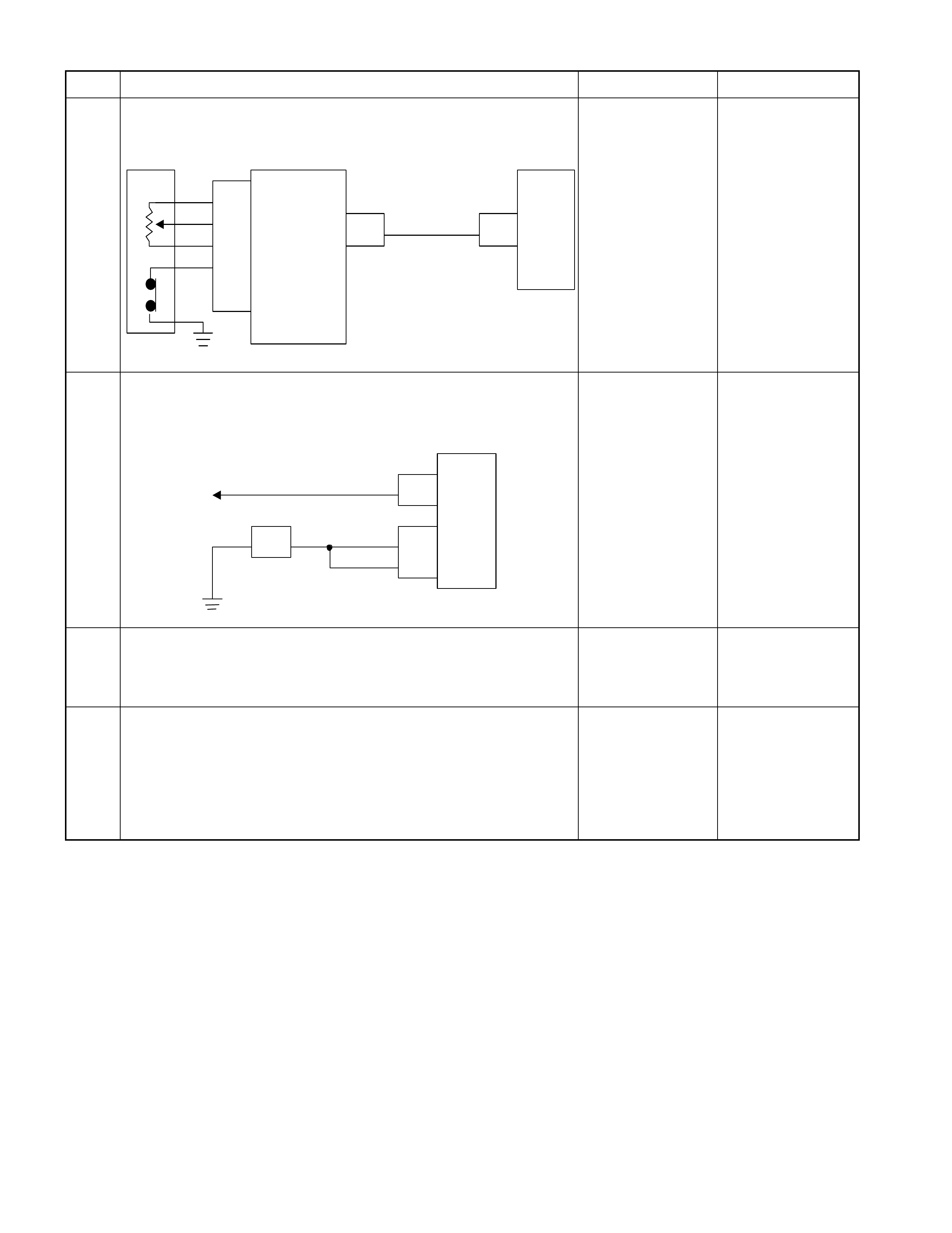
Step Action Yes No
6 Inspect the output voltage and throttle opening signal of the
throttle position sensor using a Tech 2 or circuit tester.
Is a voltage value in proportion to the throttle opening output?
TPS TCM
A16
C56
(28) C94
(16)
RED/WHT
C56
(49)
(38)
(57)
(69)
ECM
A47 (GND)
A35 (Output)
A26
A55 (+5V)
A69 (Idle SW)
Go to Step 7 Repair the defect or
replace.
7 Check of power supply to and earth of TCM.
Are the power supply and earth proper?
TCM
A1 (+B)
B5
B15
H23
(15) C95
(5)
(15)
BLK/YEL
BLK
BLK
Battery C94
(1)
BLK
Go to Step 8
Check the power
source harness and
earth harness (bolt
tightening to the
body).
8 Is the stall revolution correct in D, 3, 2 and L range? Refer the
STALL TEST section in this manual.
Go to Step 9 Repair the defect or
replace.
9 Is the line pressure correct? Refer the LINE PRESSURE TEST
section in this manual.
Trouble in the AT
assembly or control
valve. Repair the defect or
replace.

No. C9: Braking Feel When Gear is Shifted Up to 1st to 2nd
No. C10: Braking Feel When Gear is Shifted Up to 2nd to 3rd
No. C11: Braking Feel When Gear is Shifted Up to 3rd to 4th
Description:
• Brake feeling appears when the accelerator pedal is stepped on for acceleration and the gear is shifted up.
Diagnosis Hints:
• Possibility of slip of clutch is supposed. If slip of clutch has occurred, a DTC of "Gear ratio error" is stored.
Possible Cause:
• Slip of clutch.
If slip of clutch is caused, a DTC (gear ratio error) is stored.
• Dropped line pressure.
• Trouble in control valve body (faulty operation, sticking, clogged oil passage).
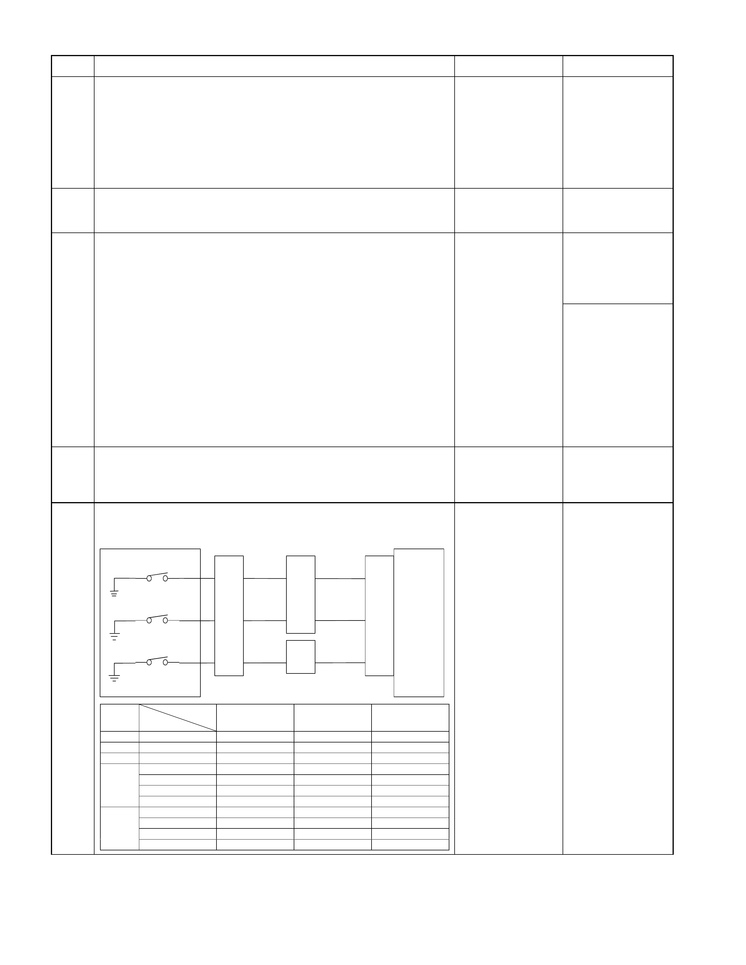
Step Action Yes No
1
Gear ratio trouble diagnosis.
Travel in the following sequence for about 7 seconds or more in
each range: Start in the L range (1st) to 2 range (2nd) to 3 range
(3rd) to D range (4th) (to detect the gear ratio trouble exactly, this
process should be carried out)
Go to Step 2 Go to Step 2
2 Are any DTCs stored?
Go to DTC Chart Go to Step 3
3 Are the quantity, contamination and smell normal?
If the ATF level is
low, replenish up to
the specified level.
Go to Step 4
If ATF is extremely
black and
contaminated and
smells burnt, slip of
the clutch is
supposed.
Overhaul the AT
unit.
4 Are the engine speed and other engine system correct?
Go to Step 5 Repair the defect or
replace.
5 Inspection of electrical or mechanical fault
Is the signal from each pressure switch changed synchronously?
Control Valve
TCM
B1
B12
B20
RED/YEL
WHT/BLK
2-4 Br ake Press ure SW
Terminal
Assembly
YEL
E54
(7)
(12)
(1)
H23
(12)
(10)
C95
(1)
(12)
(20)
RED/YEL
YEL
WHT/BLK
L&R Brake Pressure SW
High Clutch Pressure SW H22
(8)
Range
TCM terminal
Gear
B20
(High clutch
pressure SW)
B1
(2-4 brake pressure
SW)
B12 (Low & reverse
brake pres sure SW
)
P - More than 10V More than 10V More than 10V
R Reverse More than 10V More than 10V -
N - More than 10V More than 10V More than 10V
D, 3, 2 1st More than 10V More than 10V More than 10V
2nd More than 10V - More than 10V
3rd - More than 10V More than 10V
4th - - More than 10V
L 1st More than 10V More than 10V -
2nd More than 10V - More than 10V
3rd - More than 10V More than 10V
4th - - More than 10V Go to Step 6 Repair the defect or
replace.
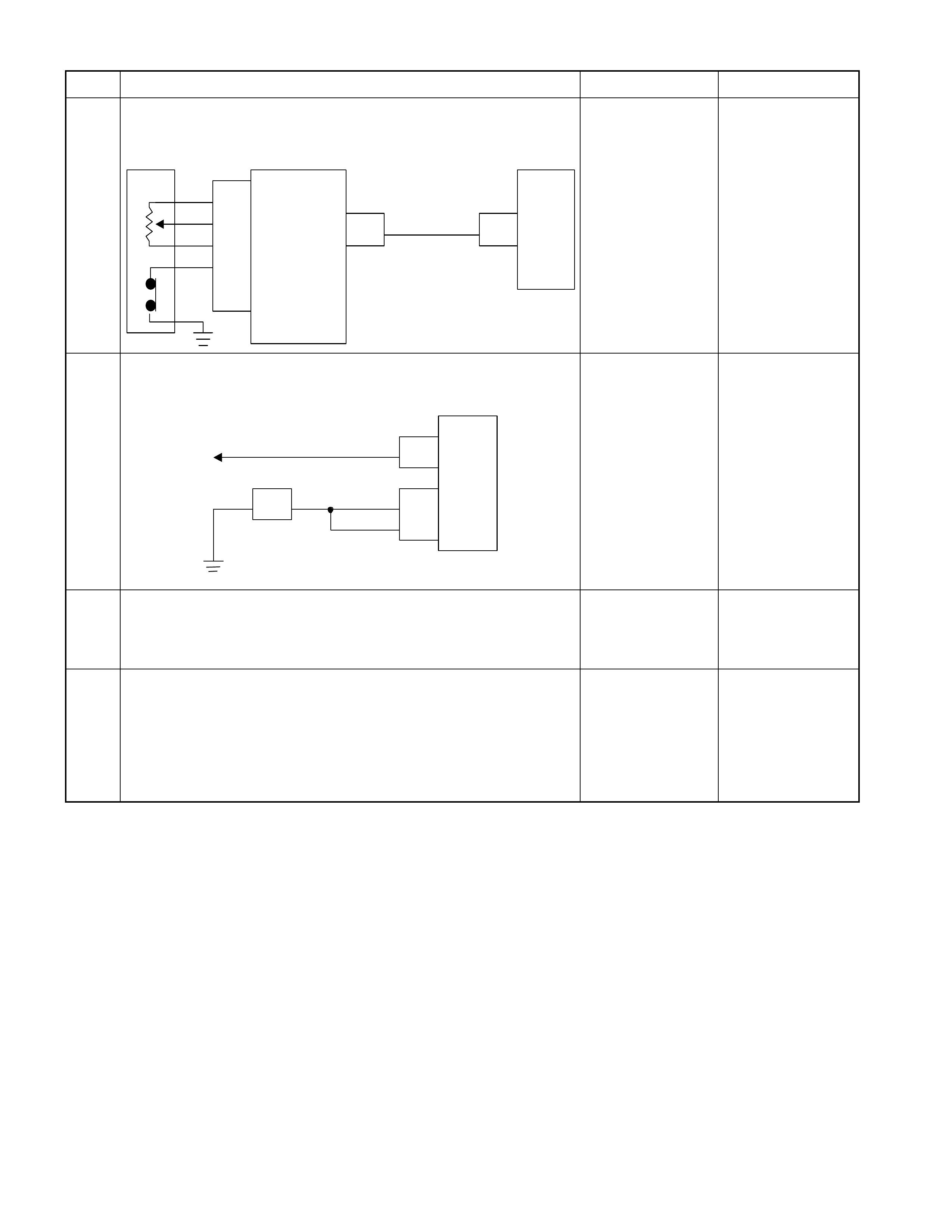
Step Action Yes No
6 Inspect the output voltage and throttle opening signal of the
throttle position sensor using a Tech 2 or circuit tester.
Is a voltage value in proportion to the throttle opening output?
TPS TCM
A16
C56
(28) C94
(16)
RED/WHT
C56
(49)
(38)
(57)
(69)
ECM
A47 (GND)
A35 (Output)
A26
A55 (+5V)
A69 (Idle SW)
Go to Step 7 Repair the defect or
replace.
8 Check of power supply to and earth of TCM.
Are the power supply and earth proper?
TCM
A1 (+B)
B5
B15
H23
(15) C95
(5)
(15)
BLK/YEL
BLK
BLK
Battery C94
(1)
BLK
Go to Step 9
Check the power
source harness and
earth harness (bolt
tightening to the
body).
9 Is the stall revolution correct in D, 3, 2 and L range? Refer the
STALL TEST section in this manual.
Go to Step 10 Repair the defect or
replace.
10 Is the line pressure correct? Refer the LINE PRESSURE TEST
section in this manual.
Trouble in the AT
assembly or control
valve. Repair the defect or
replace.

No. C12: Large Shock When Gear is Shifted to 1st to 2nd or 2nd to 1st
No. C13: Large Shock When Gear is Shifted to 2nd to 3rd or 3rd to 2nd
No. C14: Large Shock When Gear is Shifted to 3rd to 4th or 4th to 3rd
No. C15: Large Shock When Kick-down
No. C16: Large Shock When No Acceleration
No. C17: Large Shock When Gear is Shifted Down to
2nd to 1st in L Range
No. C18: Large Shock (Other)
No. C19: Large Shock When Vehicle Speed is Reduced
at Closed Throttle or Vehicle is Stationary
Description:
• Large shock is felt when the accelerator pedal is stepped on for acceleration and the gear is shifted up or down.
• Large shock is felt when the accelerator pedal is stepped on for kick-down.
• Large shock is felt when the accelerator pedal is not stepped on.
• Large shock is felt when the shift lever is selected in L range.
Diagnosis Hints:
• Basically same causes as "No. C1 - C8: Engine races up (slip)" are considered.

No. C20: Large lock-up shock
Description:
• Large shock is felt at lock-up.
Diagnosis Hints:
• Out of properties of input sensor or faulty lock-up piston pressure system are considered.
• Trouble diagnosis flow is basically the same as "No. I1: No lock-up".

No. C21: Shift Down or Engine Over-run When The Accelerator Pedal
is Stepped on in 4th Gear
Description:
• Shift down or engine over-run above the kick-down area.
Diagnosis Hints:
• Basically same causes as "No. C1 - C8: Engine races up (slip)" are considered.
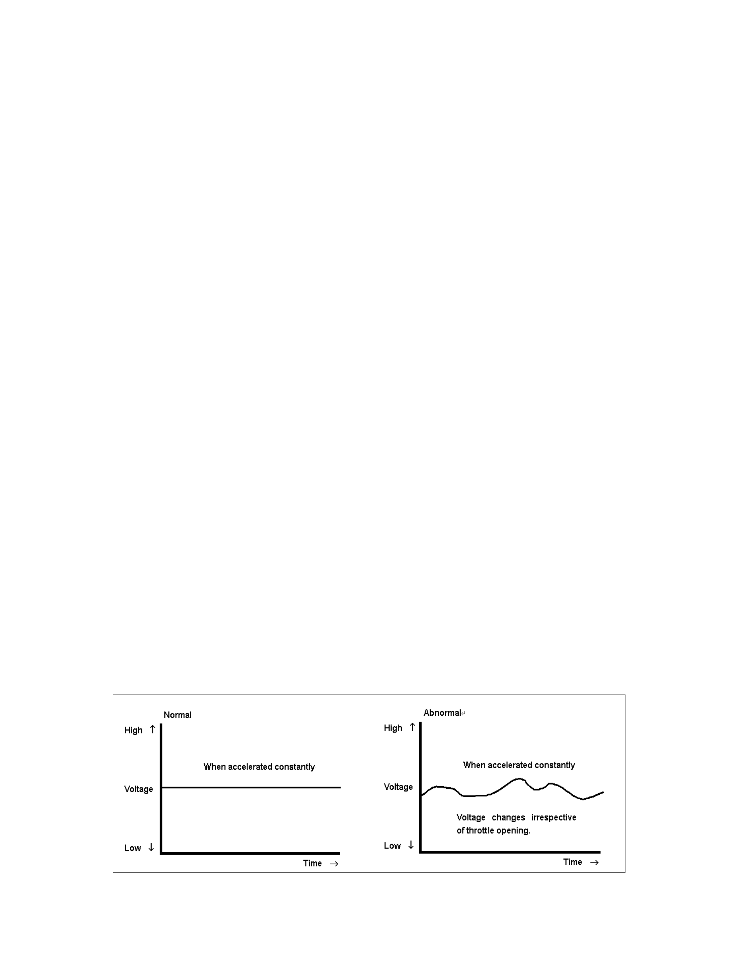
No. D1: Faulty Gear Shifting (Different from Shift Pattern)
Description:
• Gear is shifted, different from the specified shift pattern.
Diagnosis Hints:
• When inspecting faulty gear shifting, it is important to distinguish between the fault of electric system and
mechanical system (AT main unit).
• Fault of electric system.
Monitor the output signal (each solenoid driving s ignal) using with Tech 2. If a tr ouble signal is sent to the solenoid
synchronously with the faulty gear shifting, the fault is originated in the electric system.
Monitor the input signal (signal from each sensor) using with Tech 2 and find an input signal by which the output
signal (each solenoid driving signal) is subjected to fault.
Fault of the electric system may be derived from temperature or vibration. For instance, though the engine is normal
while it is cold, fault may occur when the engine is warmed up or vehicle is running.
• Fault of mechanical system.
If the gear is incorrectly shifted irrespective of operating signal (ON-OFF) of each solenoid, the faulty is originated
from the machine system (AT).
If the clutch slips, ATF smells burnt, contaminated to be black or the stall speed increases.
Possible Cause:
• Disordered select cable.
• Disordered inhibitor switch.
• Slip of clutch.
If slip of clutch is caused, a DTC (gear ratio error) is stored.
• Fixing at 3rd position (fail-safe activated)
Since the gear is fixed at the 3rd position because of the fail-safe function, a trouble that "Faulty gear shifting" is
resulted. In this case, the DTC is memorized.
When TCM stops operation because of faulty TCM ground, the gear is fixed at the 3rd position because of a
mechanical reason. In this case, no DTC is memorized.
• Incorrect properties of throttle opening signal (serial communication) of throttle position sensor.
The throttle opening signal, which is sent by serial communication from ECM and TCM, is an important signal for
gear shifting. In case of ECM fault or when the throttle position sensor does not issue voltage signal according to
the throttle opening, stepping on the accelerator does not shift the gear.
If the output voltage of the throttle position sensor changes freely even though the throttle opening is constant, the
gear is shifted incorrectly.
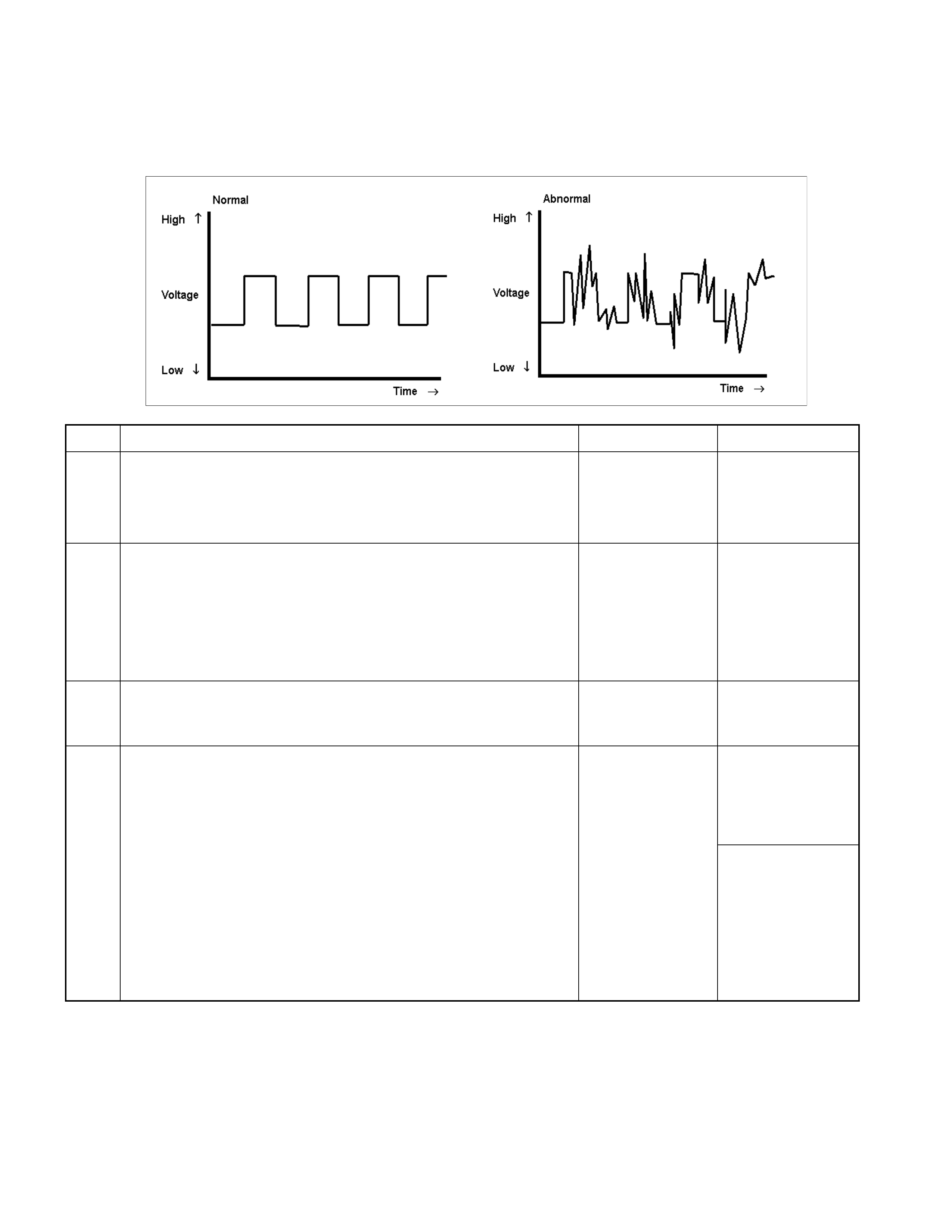
• Faulty speed sensor.
W hen s ignal from the s peed sensor becom es out of order , it may be judged a res ult of changed vehicle speed and
faulty gear shifting may be the causes.
• Trouble in control valve body (faulty operation, sticking, clogged oil passage)
Step Action Yes No
1 Dislocation or disordered of select lever.
Does the vehicle move when the brake is released in a position
other than the P range and the vehicle is pushed?
Go to Step 2 Adjust the select
cable.
2 Gear ratio trouble diagnosis.
Travel in the following sequence for about 7 seconds or more in
each range: Start in the L range (1st) to 2 range (2nd) to 3 range
(3rd) to D range (4th) (to detect the gear ratio trouble exactly, this
process should be carried out)
Go to Step 3 Go to Step 3
3 Are any DTCs stored?
Go to DTC Chart Go to Step 4
4 Are the quantity, contamination and smell normal?
If the ATF level is
low, replenish up to
the specified level.
Go to Step 5
If ATF is extremely
black and
contaminated and
smells burnt, slip of
the clutch is
supposed.
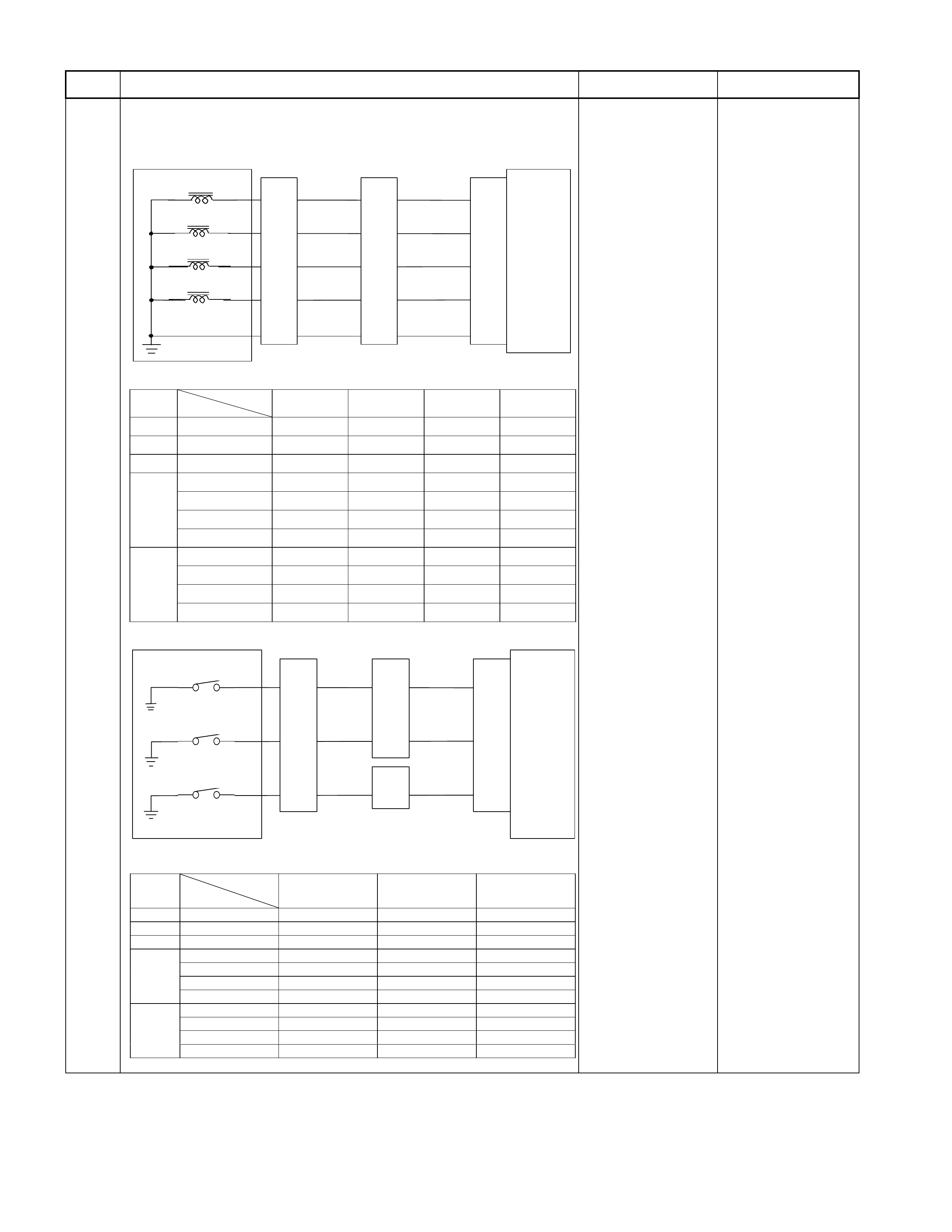
Step Action Yes No
5 Inspection of electrical or mechanical fault
Is signal to each solenoid and pressure switch changed
synchronously to the faulty gear shift?
C ont ro l Valve
TCM
B1
B12
B20
RED/YEL
WHT/BLK
2-4 Brake Pressure SW
Terminal
Assembly
YEL
E54
(7)
(12)
(1)
H23
(12)
(10)
C95
(1)
(12)
(20)
RED/YEL
YEL
WHT/BLK
L&R Brake Pressure SW
High Clutch Pressure SW
H22
(8)
Co nt ro l Valve
TCM
B6
B7
B8
B9
B22 (GN D)
BLU/BLK
WHT/BLU
L&R Brake Solenoid
Terminal
Assembly
BLK/YEL
RED
2-4 Brake Solenoid
High Clutch Solenoid
Low Clutch Solenoid
E54
(5)
(9)
(10)
(3)
(11)
H23
(11)
(5)
(7)
(2)
(1)
GRY/RED
C95
(6)
(7)
(8)
(9)
(22)
BLU/BLK
BLK/YEL
RED
WHT/BLU
GRY/RED
Range
TCM terminal
Gear
B20
(High clutch
pressure SW)
B1
(2-4 brake pressure
SW)
B12 (Low & reverse
brake pressure SW
)
P - More than 10V More than 10V More than 10V
R Reverse More than 10V More than 10V -
N - More than 10V More than 10V More than 10V
D, 3, 2 1st More than 10V More than 10V More than 10V
2nd More than 10V - More than 10V
3rd - More than 10V More than 10V
4th - - More than 10V
L 1st More than 10V More than 10V -
2nd More than 10V - More than 10V
3rd - More than 10V More than 10V
4th - - More than 10V
Range
TCM terminal
Gear
B8
(High clutch
solenoid)
B9
(Low clutch
solenoid)
B7
(2 -4 bra k e
solenoid)
B6
(Lo w & rev e rs e
brake solenoid)
P - A pprox. 6.8V
(A C ran ge ) - A pprox. 6.8V
(A C ran ge ) Ap prox. 6.2V
(AC ra n g e)
R Re verse A pprox. 6.8V
(A C ran ge ) - A pprox. 6.8V
(A C ran ge ) -
N - Approx. 6.8V
(A C ran ge ) - A pprox. 6.8V
(A C ran ge ) Ap prox. 6.8V
(AC ra n g e)
D, 3, 2 1s t A pprox. 6.8V
(A C ran ge ) - A pprox. 6.8V
(A C ran ge ) Ap prox. 6.8V
(AC ra n g e)
2nd Approx. 6.8V
(A C ran ge ) - - Approx. 6 .8V
(AC ra n g e)
3rd - - A pprox. 6.8V
(A C ran ge ) Ap prox. 6.8V
(AC ra n g e)
4th - Ap prox. 6.8V
(AC range) - Approx. 6.8V
(AC ra n g e)
L 1st A pprox. 6.8V
(A C ran ge ) - A pprox. 6.8V
(A C ran ge ) -
2nd Approx. 6.8V
(A C ran ge ) - - Approx. 6 .8V
(AC ra n g e)
3rd - - A pprox. 6.8V
(A C ran ge ) Ap prox. 6.8V
(AC ra n g e)
4th - Ap prox. 6.8V
(AC range) - Approx. 6.8V
(AC ra n g e)
Go to Step 6
In case of fault in
the machine
system, repair that
portion or replace
the unit.
Slip of clutch or fault
of control valve.
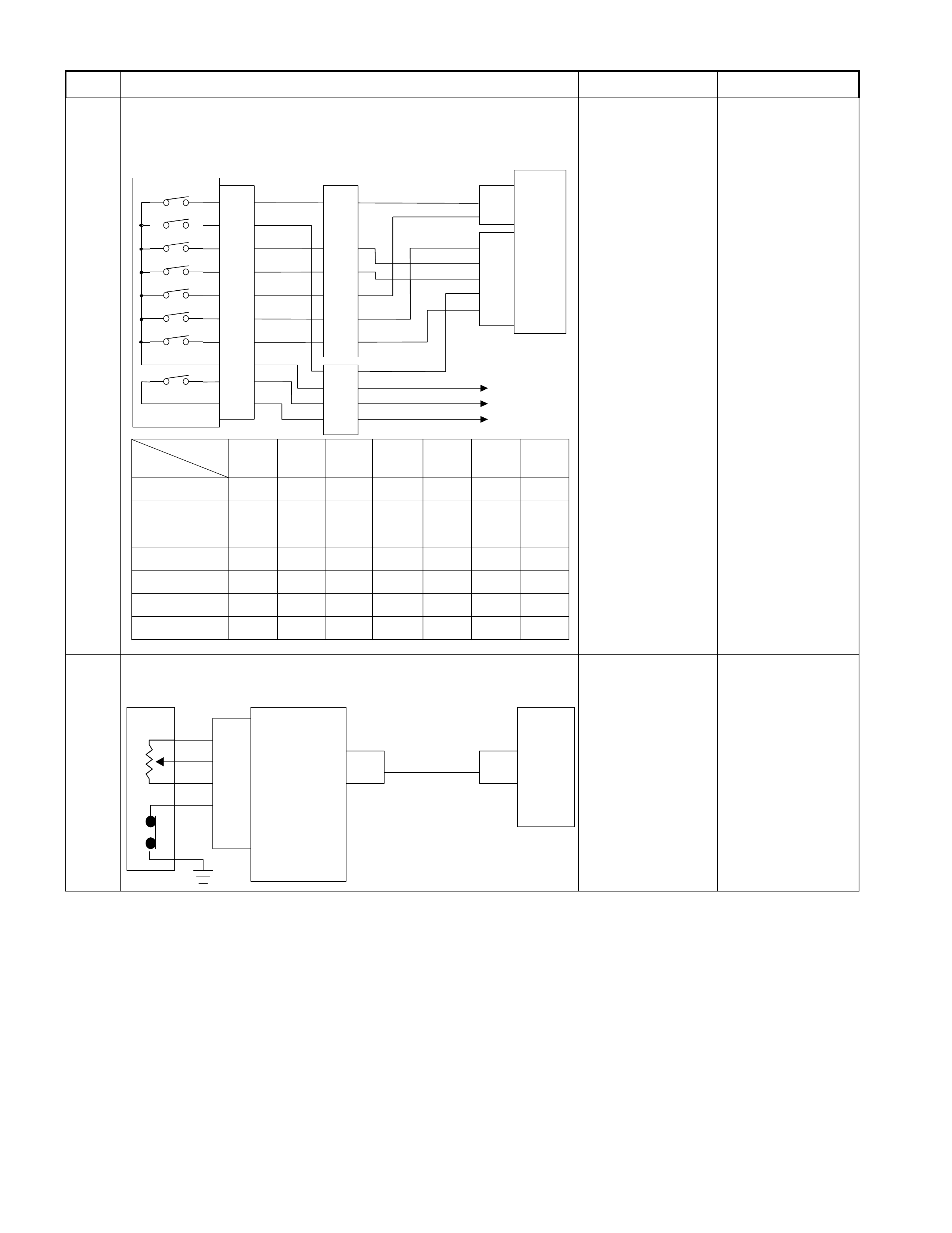
Step Action Yes No
6 Inspection of inhibitor switch using a Tech 2 or circuit tester.
Inspect the output voltage and throttle opening signal of the
throttle position sensor using a Tech 2 or circuit tester.
Inhibitor SW
TCM
A2 (P)
A17 (3)
B2 (2)
B10 (N)
B11 (D)
B19 (R)
B21 (L)
C95
(2)
(10)
(11)
(19)
(21)
YEL/VIO
RED/BLK
BLU
BLK/GRN
Starter Relay
C94
(2)
(3)
B
H22
(1)
(6)
(4)
(7)
(5)
(2)
P
2
R
N
D
3
L
Start SW
PNK/BLU
E51
(2)
(4)
(8)
(5)
(1)
(9)
(6)
(3)
(10)
(7)
(38)
(15)
(3)
(37)
H4
PNK/BLK
RED/YEL
YEL/VIO
BLK/GRN
PNK/BLK
RED/BLK
BLU
RED/YEL
PNK/BLU
BLK/WHT
BLK
BLK
BLK/WHT Key Switch
WHT
WHT
Immobiliser Control Unit
TCM terminal
Range
A2 B19 B10 B11 B17 B2 B21
PBattery
volta
g
e------
R-Battery
volta
g
e-----
N - - Battery
volta
g
e----
D---Battery
volta
g
e---
3 - - - - Battery
volta
g
e--
2-----Battery
volta
g
e-
L------Battery
volta
g
e Go to Step 7 Adjust the inhibitor
switch.
7 Is a voltage value in proportion to the throttle opening output?
TPS TCM
A16
C56
(28) C94
(16)
RED/WHT
C56
(49)
(38)
(57)
(69)
ECM
A47 (GND)
A35 (Output)
A26
A55 (+5V)
A69 (Idle SW)
Go to Step 8 Repair the defect or
replace.
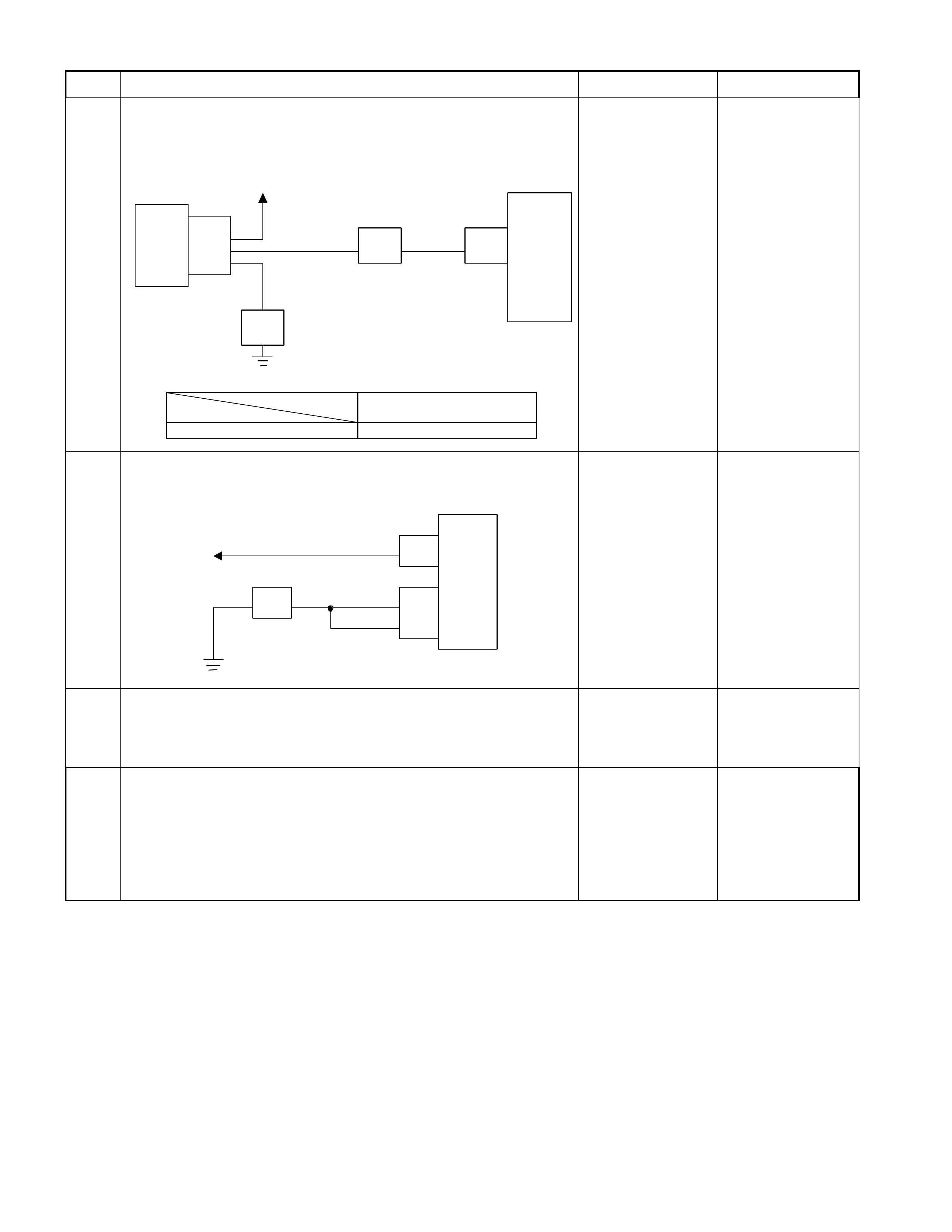
Step Action Yes No
8 Inspect the output signal of the speed sensor using a Tech 2 o
r
circuit tester.
Is the data display in the Tech 2 correct or output voltage correc
t
in the circuit tester?
Speed
Sensor
TCM
B13
H23
(4) C95
(13)
E30
(2)
(1)
(3)
E10
Key SW
YEL/RED
WHT
BLK
YEL/RED
TCM terminal
Condition B13
20km/h at L range in 1st gear Approx. 6.2V (AC range) Go to Step 9 Repair the defect or
replace.
9 Check of power supply to and earth of TCM.
Are the power supply and earth proper?
TCM
A1 (+B)
B5
B15
H23
(15) C95
(5)
(15)
BLK/YEL
BLK
BLK
Battery C94
(1)
BLK
Go to Step 10
Check the power
source harness and
earth harness (bolt
tightening to the
body).
10 Is the stall revolution correct in D, 3, 2 and L range? Refer the
STALL TEST section in this manual.
Go to Step 11 Repair the defect or
replace.
11 Is the line pressure correct? Refer the LINE PRESSURE TEST
section in this manual.
Trouble in the AT
assembly or control
valve. Repair the defect or
replace.

No. D2: Gear is Shifted Frequently
Description:
• Gear is shifted down immediately though the accelerator pedal is stepped on a little in D, 3, 2, or L range.
Diagnosis Hints:
• Basically, the same cause as "No. D1: Faulty gear shifting" is considered. However, as possible cause, fault input
signal of throttle pos ition sens or or speed s ensor, f ault input signal of inhibitor switch, or fault of T CM power sourc e,
earth, ground return wire are considered first.
• Then, slip of the clutch, fault of the control valve are considered.

No. D3: Gear Shift Point is Low or High at All Point
No. D4: Gear Shift Point is Low or High at Limited Point
Description:
• Gear shift point is deviated from the shift diagram.
• Gear is not shifted up properly though the vehicle is accelerated.
• Gear is not shifted immediately and enough acceleration cannot be obtained though the accelerator pedal is stepped
on.
Diagnosis Hints:
• If the cause is not faulty gear shift, throttle position sensor disordered or fault input of speed sensor is considered.
Output signal of the throttle position sensor is changed to linear one.
(Refer the paragraph about the faulty throttle position sensor of "No. D1: Faulty gear shifting".)

No. D5: No Kick-down
Description:
• The engine speeds up but vehicle speed does not increase when the accelerator pedal is stepped on at the starting.
Diagnosis Hints:
• W hen the gear shift is normal only without kick-down, possibility of fault of the throttle position sensor. Check that
the throttle voltage increases linearly in proportion to the throttle opening.
(Refer the paragraph about the faulty throttle position sensor of "No. D1: Faulty gear shifting".)

No. E1: No Gear Shift
Description:
• Range is fixed without shifting the gear of 1st to 2nd, 2nd to 3rd, and 3rd to 4th.
• Gear may be shifted or may not be shifted.
Diagnosis Hints:
• Fixing at some gear speed, signal error from throttle position sensor or trouble in the AT main unit are supposed.
Possible Cause:
• Slip of clutch (low clutch, high clutch and 2-4 brake).
If slip of clutch is caused, a DTC (gear ratio error) is stored.
• Dropped line pressure.
• Fixing at 3rd position (fail-safe activated).
Since the gear is fixed at the 3rd position because of the fail- safe func tion, a trouble that "No gear shift" is r esulted.
In this case, the DTC is memorized.
When TCM stops operation because of faulty TCM ground, the gear is fixed at the 3rd position because of a
mechanical reason. In this case, no DTC is memorized.
• Incorrect properties of throttle opening signal (serial communication) of throttle position sensor.
Throttle opening signal (serial communication) of the throttle position sensor does not change in proportion to the
throttle opening. In this case, fixing at the high or low gear results in such a trouble that "No Gear Shift".
• Trouble in control valve body (faulty operation, sticking, clogged oil passage)
Step Action Yes No
1 Gear ratio trouble diagnosis.
Travel in the following sequence for about 7 seconds or more in
each range: Start in the L range (1st) to 2 range (2nd) to 3 range
(3rd) to D range (4th) (to detect the gear ratio trouble exactly, this
process should be carried out).
Go to Step 2 Go to Step 2
2 Are any DTCs stored?
Go to DTC Chart Go to Step 3
3 Are the quantity, contamination and smell normal?
If the ATF level is
low, replenish up to
the specified level.
Go to Step 4
If ATF is extremely
black and
contaminated and
smells burnt, slip of
the clutch is
supposed.
Overhaul the AT
unit.
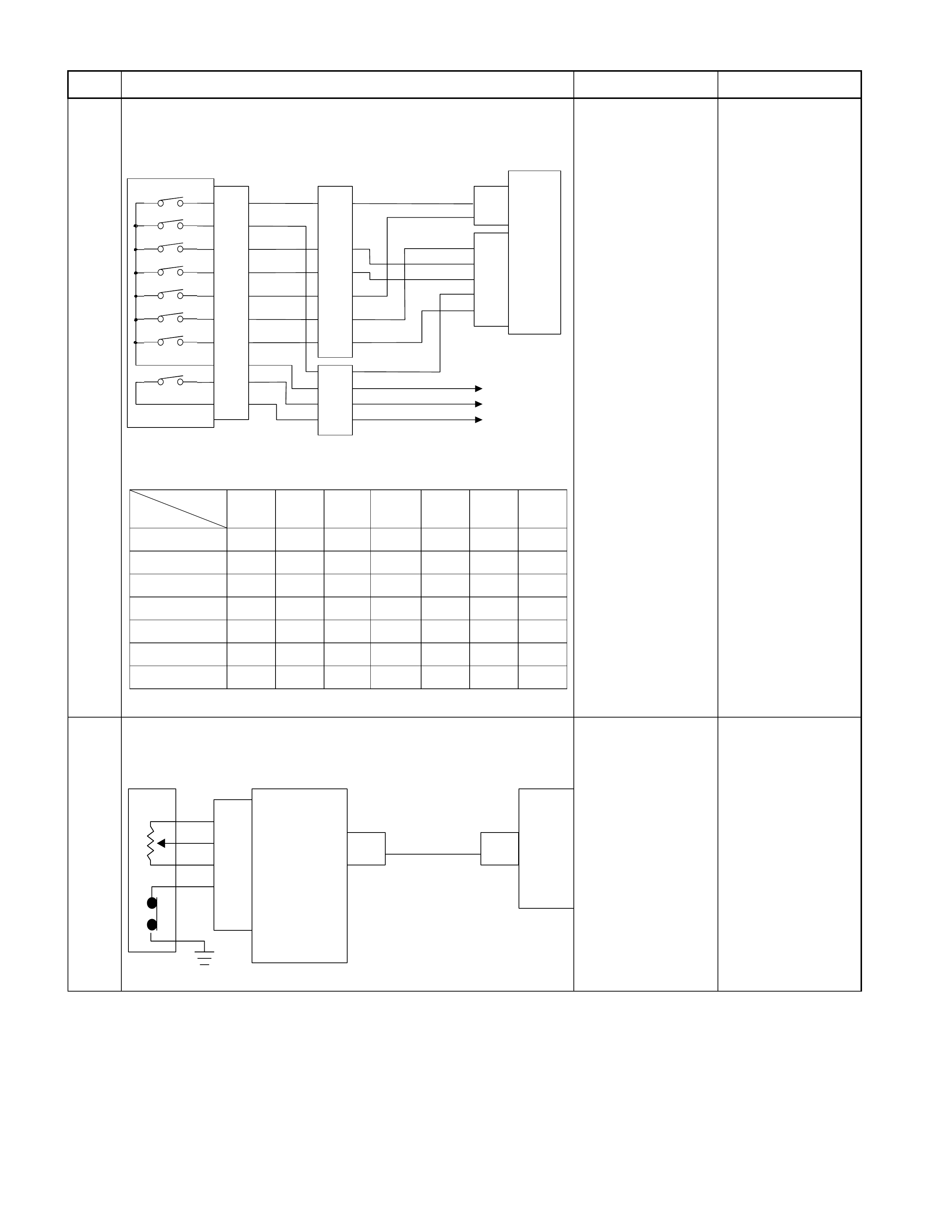
Step Action Yes No
4 Inspection of inhibitor switch using a Tech 2 or circuit tester.
When the select lever is operated, is the data display in the Tech
2 correct or voltage at each range correct?
Inhibitor SW
TCM
A2 (P)
A17 (3)
B2 (2)
B10 (N)
B11 (D)
B19 (R)
B21 (L)
C95
(2)
(10)
(11)
(19)
(21)
YEL/VIO
RED/BLK
BLU
BLK/GRN
Starter Relay
C94
(2)
(3)
B
H22
(1)
(6)
(4)
(7)
(5)
(2)
P
2
R
N
D
3
L
Start SW
PNK/BLU
E51
(2)
(4)
(8)
(5)
(1)
(9)
(6)
(3)
(10)
(7)
(38)
(15)
(3)
(37)
H4
PNK/BLK
RED/YEL
YEL/VIO
BLK/GRN
PNK/BLK
RED/BLK
BLU
RED/YEL
PNK/BLU
BLK/WHT
BLK
BLK
BLK/WHT Key Switch
WHT
WHT
Immobiliser Control Unit
TCM terminal
Range
A2 B19 B10 B11 B17 B2 B21
PBattery
volta
g
e------
R-Battery
volta
g
e-----
N - - Battery
volta
g
e----
D---Battery
volta
g
e---
3 - - - - Battery
volta
g
e--
2-----Battery
volta
g
e-
L------Battery
volta
g
e
Go to Step 5 Adjust the inhibitor
switch.
5 Inspect the output voltage and throttle opening signal of the
throttle position sensor using a Tech 2 or circuit tester.
Is a voltage value in proportion to the throttle opening output?
TPS TCM
A16
C56
(28) C94
(16)
RED/WHT
C56
(49)
(38)
(57)
(69)
ECM
A47 (GND)
A35 (Output)
A26
A55 (+5V)
A69 (Idle SW)
Go to Step 6 Repair the defect or
replace.
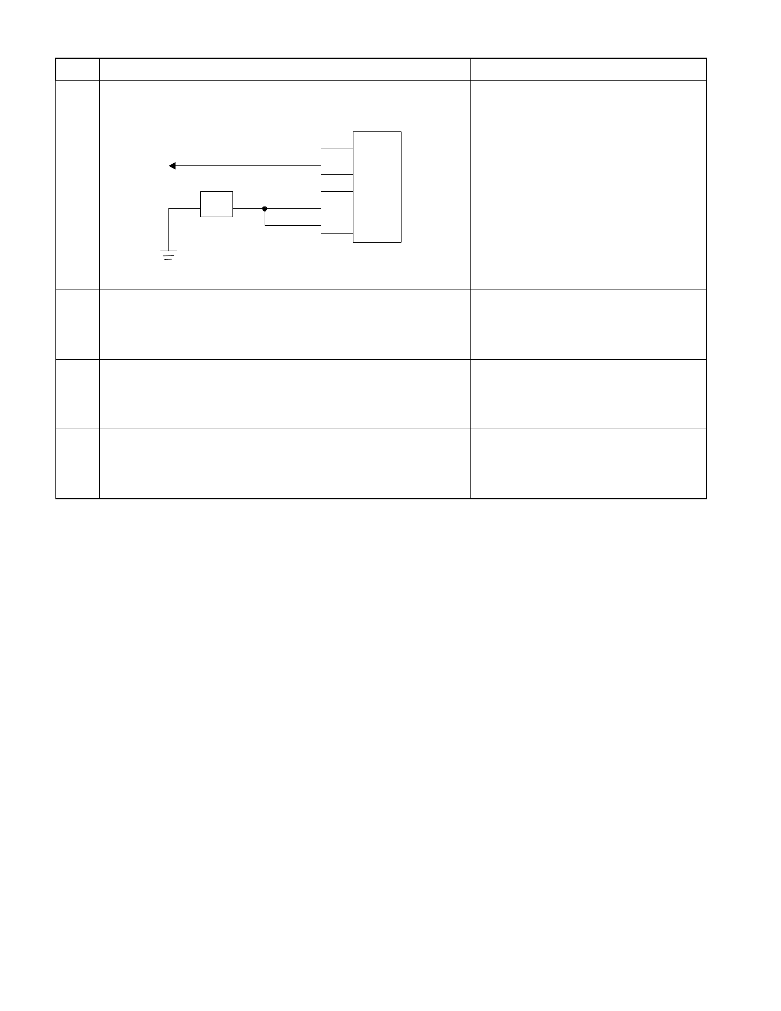
Step Action Yes No
6 Check of power supply to and earth of TCM.
Are the power supply and earth proper?
TCM
A1 (+B)
B5
B15
H23
(15) C95
(5)
(15)
BLK/YEL
BLK
BLK
Battery C94
(1)
BLK
Go to Step 7
Check the power
source harness and
earth harness (bolt
tightening to the
body).
7 Inspection of speed sensor and turbine sensor
Have the speed sensor and turbine sensor failed at the same
time? (No DTC is stored at the time of trouble) Repair the defect or
replace. Go to Step 8
8 Is the stall revolution correct in D, 3, 2 and L range? Refer the
STALL TEST section in this manual.
Go to Step 9 Repair the defect or
replace.
9 Is the line pressure correct? Refer the LINE PRESSURE TEST
section in this manual. Trouble in the AT
assembly or control
valve. Repair the defect or
replace.

No. E2: Only 4th gear (O/D) is Not Selectable
Description:
• Gear is not shifted up from 3rd to 4th though the vehicle is accelerated.
Possible Cause:
• Disordered select cable.
• Disordered inhibitor switch.
• ATF thermo sensor detects low oil temperature (4th gear is prohibited temperature less than 10°C.).
• Clogged oil passage of low clutch duty solenoid.
• Trouble in control valve body (faulty operation, sticking, clogged oil passage).
Step Action Yes No
1 Dislocation or disordered of select lever.
Does the vehicle move when the brake is released in a position
other than the P range and the vehicle is pushed?
Go to Step 2 Adjust the select
cable.
2 Gear ratio trouble diagnosis.
Travel in the following sequence for about 7 seconds or more in
each range: Start in the L range (1st) to 2 range (2nd) to 3 range
(3rd) to D range (4th) (to detect the gear ratio trouble exactly, this
process should be carried out)
Go to Step 3 Go to Step 3
3 Are any DTCs stored?
Go to DTC Chart Go to Step 4
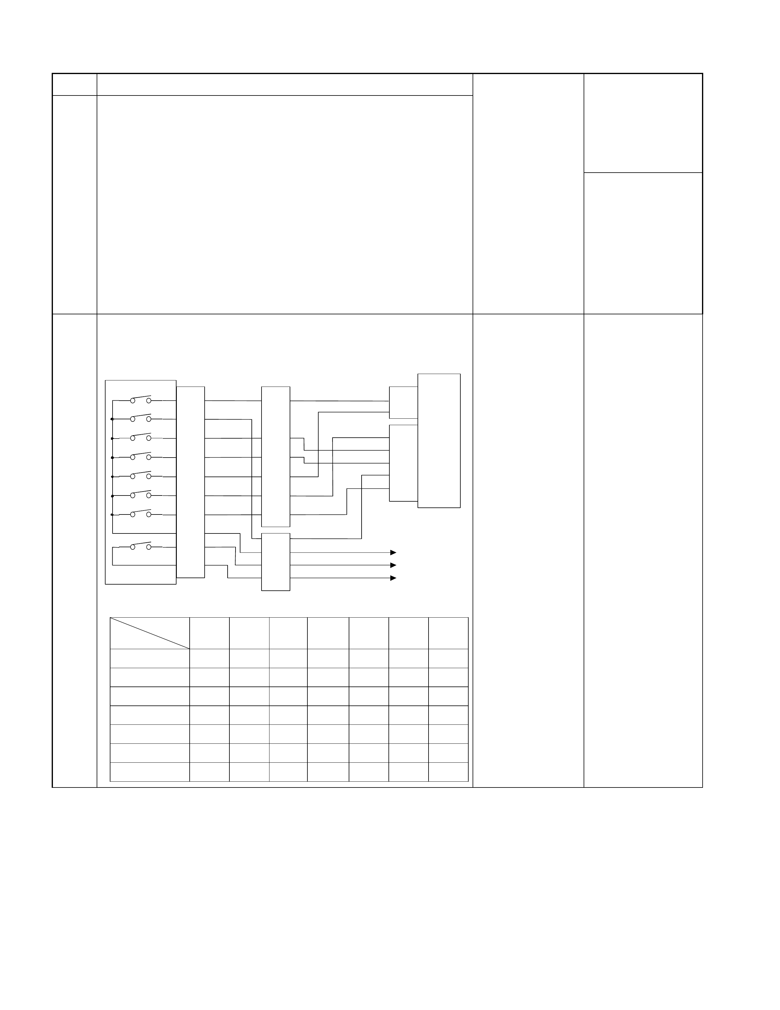
Step Action Yes No
4 Are the quantity, contamination and smell normal?
If the ATF level is
low, replenish up to
the specified level.
Go to Step 5
If ATF is extremely
black and
contaminated and
smells burnt, slip of
the clutch is
supposed.
Overhaul the AT
unit.
5 Inspection of inhibitor switch using a Tech 2 or circuit tester.
W hen the select lever is operated, is the data display in the Tech
2 correct or voltage at each range correct?
Inhibitor SW
TCM
A2 (P)
A17 (3)
B2 (2)
B10 (N)
B11 (D)
B19 (R)
B21 (L)
C95
(2)
(10)
(11)
(19)
(21)
YEL/VIO
RED/BLK
BLU
BLK/GRN
Starter Relay
C94
(2)
(3)
B
H22
(1)
(6)
(4)
(7)
(5)
(2)
P
2
R
N
D
3
L
Start SW
PNK/BLU
E51
(2)
(4)
(8)
(5)
(1)
(9)
(6)
(3)
(10)
(7)
(38)
(15)
(3)
(37)
H4
PNK/BLK
RED/YEL
YEL/VIO
BLK/GRN
PNK/BLK
RED/BLK
BLU
RED/YEL
PNK/BLU
BLK/WHT
BLK
BLK
BLK/WHT Key Switch
WHT
WHT
Immobiliser Control Unit
TCM terminal
Range
A2 B19 B10 B11 B17 B2 B21
PBattery
volta
g
e------
R-Battery
volta
g
e-----
N - - Battery
volta
g
e----
D---Battery
volta
g
e---
3 - - - - Battery
volta
g
e--
2-----Battery
volta
g
e-
L------Battery
volta
g
e Go to Step 6 Adjust the inhibitor
switch.
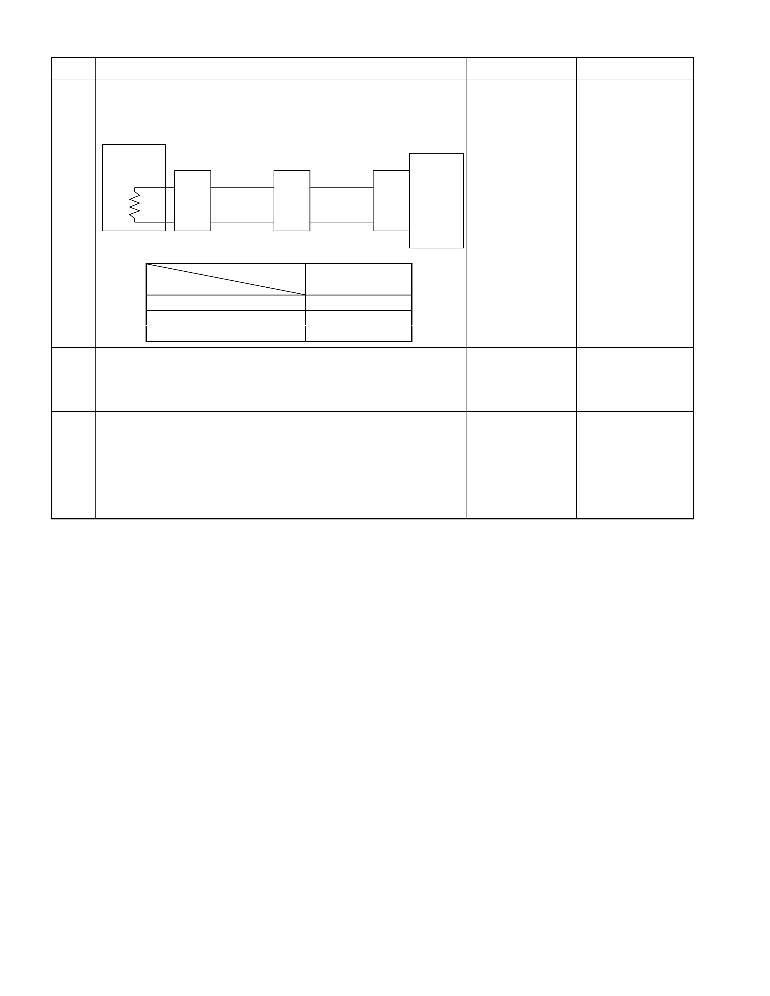
Step Action Yes No
6 Inspection of ATF oil thermo sensor.
Is the ATF oil temperature sensor terminal voltage correct?
A
fter running using the Tech 2 data display function, is the ATF
temperature higher than 10C?
ATF
Temp.
Sensor TCM
B4 (+)
B14 (-)
H23
(8)
(
3
)
C95
(4)
(
14
)
BLU
Terminal
Assembly
BLU/BLK
E54
(2)
(
8
)
BLU
BLU/BLK
TCM terminal
Temperature
B4
(
Ou tp u t vo lta
g
e
)
20 Ž 1.55
40 Ž 1.08
60 Ž 0.7 Go to Step 7 Repair the defect or
replace.
7 Is the stall revolution correct in D, 3, 2 and L range? Refer the
STALL TEST section in this manual.
Go to Step 8 Repair the defect or
replace.
8 Is the line pressure correct? Refer the LINE PRESSURE TEST
section in this manual.
Trouble in the AT
assembly or control
valve. Repair the defect or
replace.

No. E3: Gear is Shifted 2nd to 3rd in 2 Range
No. E4: Gear is Shifted 1st to 2nd in L Range
No. E5: Gear is Shifted 3rd to 4th in 3 Range
Description:
• Gear is shifted 2nd to 3rd in 2 range
• Gear is shifted 1st to 2nd in L range
• Gear is shifted 3rd to 4th in 3 range
Possible Cause:
• Disordered select cable.
• Disordered inhibitor switch.
• Trouble in control valve body (faulty operation, sticking, clogged oil passage).

No. F1: Low Maximum Speed or Poor Acceleration
Description:
• Starting acceleration is poor.
• Acceleration is slow though the accelerator pedal is stepped on during the running.
Diagnosis Hints:
• In addition to the low engine output, faulty gear shifting of AT or fixing at the 3rd position may be possible.
Theref ore, in case of suc h a trouble that "maxim um s peed is low, and acceleration is poor", it s hould be cleared up
whether the trouble is originated from the engine system of AT system by a running test, inspection of stall
revolution, etc.
Possible Cause:
• Clogged air cleaner, out of injection timing, dropped compression pressure, etc.
• Fixing at 3rd position (fail-safe activated).
Since the gear is fixed at the 3rd position because of the fail-safe function, a trouble that "Maximum speed is low,
and acceleration is poor" is resulted. In this case, the DTC is memorized.
When TCM stops operation because of faulty TCM ground, the gear is fixed at the 3rd position because of a
mechanical reason. In this case, no DTC is memorized.
• Disordered inhibitor switch .
• Incorrect properties of throttle opening signal (serial communication) of throttle position sensor.
Throttle opening signal (serial communication) of the throttle position sensor does not change in proportion to the
throttle opening. In this case, fixing at the high or low gear results in such a trouble that "Maximum Speed is Low
and Acceleration is Poor".
• Slip of clutch (low clutch, high clutch).
• If slip of clutch is caused, a DTC (gear ratio error) is stored.
• Dropped line pressure.
• Trouble in the torque converter system (faulty operation).
Step Action Yes No
1 Test Drive.
Is the gear smoothly shifted in the order of 1st to 2nd, 2nd to 3rd,
3rd to 4th gear and lock up?
Clogged air
cleaner, out of
injection timing,
dropped
compression
pressure, etc. Go to Step 2
2 Gear ratio trouble diagnosis.
Travel in the following sequence for about 7 seconds or more in
each range: Start in the L range (1st) to 2 range (2nd) to 3 range
(3rd) to D range (4th) (to detect the gear ratio trouble exactly, this
process should be carried out)
Go to Step 3 Go to Step 3
3 Are any DTCs stored?
Go to DTC Chart Go to Step 4
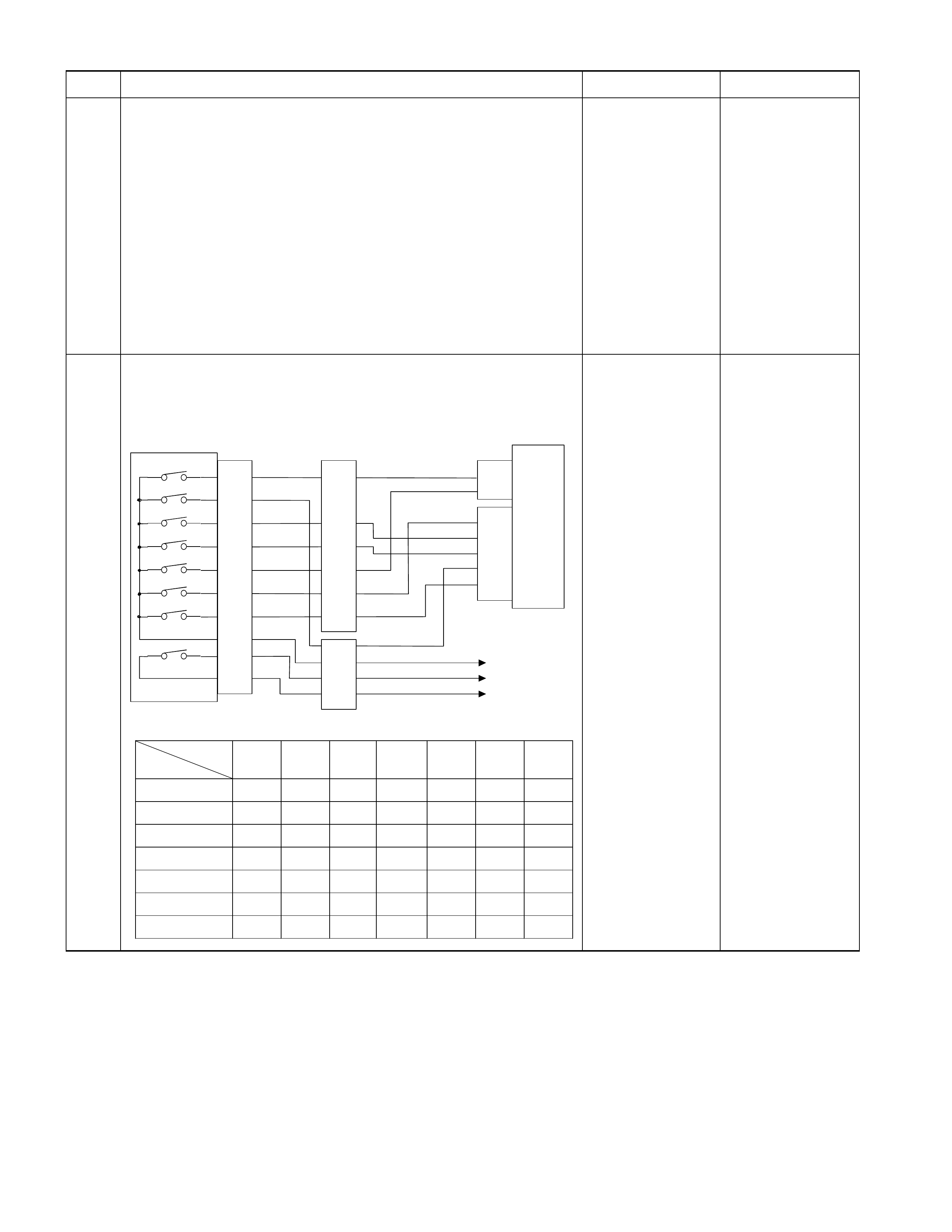
Step Action Yes No
4 Are the quantity, contamination and smell normal?
If the ATF level is
low, replenish up to
the specified level.
Go to Step 5
If ATF is extremely
black and
contaminated and
smells burnt, slip of
the clutch is
supposed.
Overhaul the AT
unit.
5 Inspection of inhibitor switch using a Tech 2 or circuit tester.
W hen the selec t lever is operated, is the data display in the T ech
2 correct or voltage at each range correct?
Inhibitor SW
TCM
A2 (P)
A17 (3)
B2 (2)
B10 (N)
B11 (D)
B19 (R)
B21 (L)
C95
(2)
(10)
(11)
(19)
(21)
YEL/VIO
RED/BLK
BLU
BLK/GRN
Starter Relay
C94
(2)
(3)
B
H22
(1)
(6)
(4)
(7)
(5)
(2)
P
2
R
N
D
3
L
Start SW
PNK/BLU
E51
(2)
(4)
(8)
(5)
(1)
(9)
(6)
(3)
(10)
(7)
(38)
(15)
(3)
(37)
H4
PNK/BLK
RED/YEL
YEL/VIO
BLK/GRN
PNK/BLK
RED/BLK
BLU
RED/YEL
PNK/BLU
BLK/WHT
BLK
BLK
BLK/WHT Key Switch
WHT
WHT
Immobiliser Control Unit
TCM terminal
Range
A2 B19 B10 B11 B17 B2 B21
PBattery
volta
g
e------
R - Battery
volta
g
e-----
N--Battery
volta
g
e----
D - - - Battery
volta
g
e---
3----Battery
volta
g
e--
2 - - - - - Battery
volta
g
e-
L------Battery
volta
g
e Go to Step 6 Adjust the inhibitor
switch.
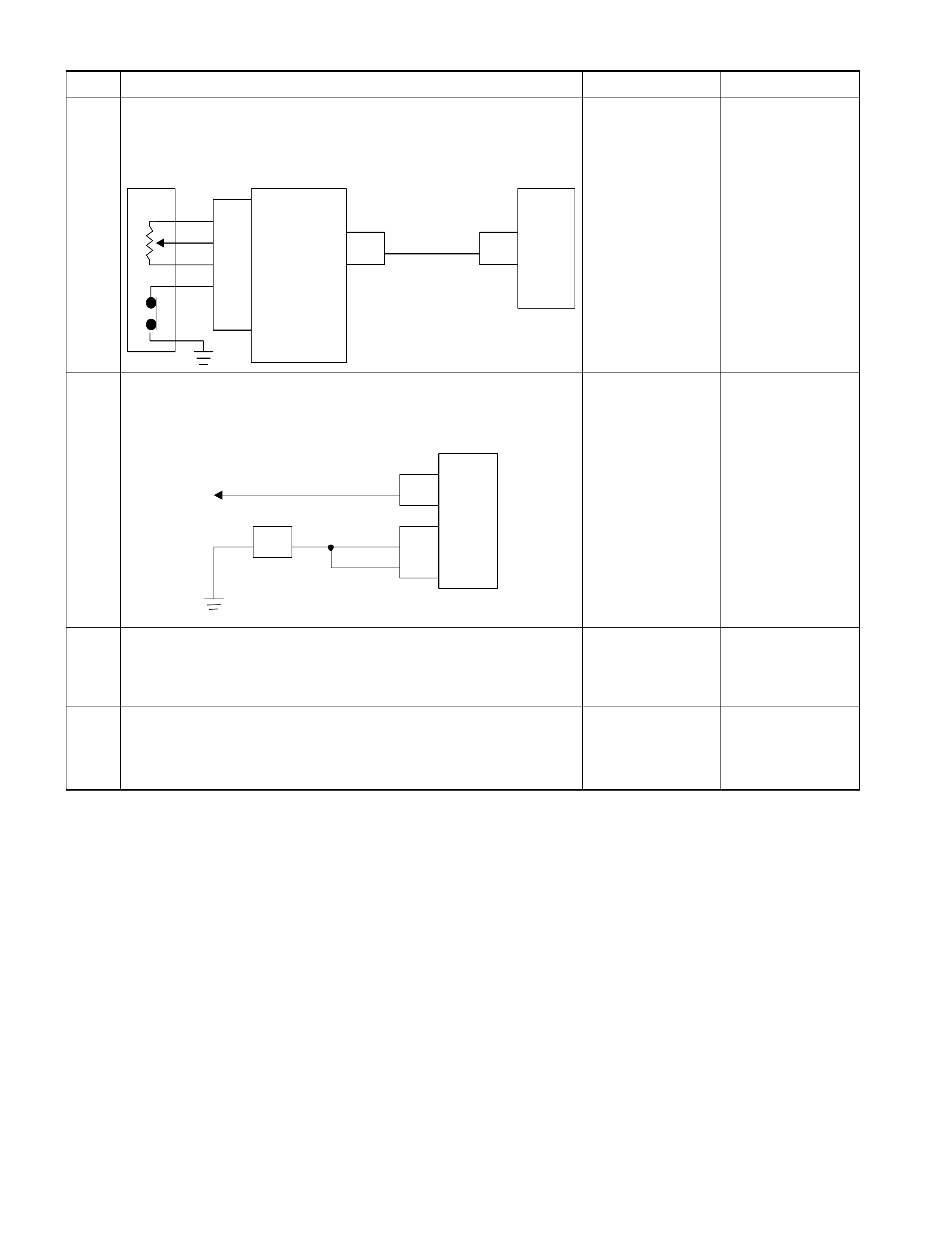
Step Action Yes No
6 Inspect the output voltage and throttle opening signal of the
throttle position sensor using a Tech 2 or circuit tester.
Is a voltage value in proportion to the throttle opening output?
TPS TCM
A16
C56
(28) C94
(16)
RED/WHT
C56
(49)
(38)
(57)
(69)
ECM
A47 (GND)
A35 (Output)
A26
A55 (+5V)
A69 (Idle SW)
Go to Step 7 Repair the defect or
replace.
7 Check of power supply to and earth of TCM.
Are the power supply and earth proper?
TCM
A1 (+B)
B5
B15
H23
(15) C95
(5)
(15)
BLK/YEL
BLK
BLK
Battery C94
(1)
BLK
Go to Step 8
Check the power
source harness and
earth harness (bolt
tightening to the
body).
8 Is the stall revolution correct in D, 3, 2 and L range? Refer the
STALL TEST section in this manual.
Go to Step 6 Repair the defect or
replace.
9 Is the line pressure correct? Refer the LINE PRESSURE TEST
section in this manual. Trouble in the AT
assembly or control
valve. Repair the defect or
replace.

No. F2: Engine Races Up During Acceleration (Slip)
Description:
• The engine speed up when the accelerator pedal is stepped on for acceleration and the gear is shifted up or down.
• Only the engine speeds up but vehicle speed does not increase when the accelerator pedal is stepped on for
acceleration during the running.
Diagnosis Hints:
• Basically same causes as "No. C1 - C8: Engine races up (slip) by shift up or shift down" are considered.
When the condition of No. C1-C8 grows worse, symptom of No. F2 results.

No. F3: Noise or Vibration During the Running in R, D, 3, 2 or L
Range
Description:
• Noise or vibration is generated in the vicinity of AT during the running.
Diagnosis Hints:
• Cause other than AT can be also cons idered. It is effe ctive means to r eproduce a running condition using a lif t up,
chassis dynamo, etc. to investigate the origin (generating condition) of noise and vibration.
Caution:
Lifting up some unit to test it accompanies danger. Provide safety measures as far as possible and carry
out the test with sufficient care.
Possible Cause:
Following sources of noise or vibration other than the AT can be considered.
• Noise from differential gears.
• Noise from propeller shaft.
• The bearing support in the m iddle of the propeller shaft has f atigued, and the bend angle of the propeller shaft has
changed, causing vibration at the time of start.
• Unbalanced and poor uniformity of tires cause vibration.

No. F4: Engine Brake Does Not Apply in L Range
Description:
• The engine brake does not apply, allowing the vehicle to run freely when the accelerator pedal is released at low
speed in L range.
Possible Cause:
• Slip of clutch (low & reverse brake)
If slip of clutch is caused, a DTC (gear ratio error) is stored.
• Faulty input/output signal system.
Low & reverse brake duty solenoid
• Faulty control valve (faulty operation, sticking).

No. F5: Engine Stalls Before Vehicle Stops from Running
Description:
• T he engine stalls sim ultaneously with the vehicle stop when the brake pedal is s tepped on to stop the vehicle dur ing
the running.
Possible Cause:
• Trouble on the engine system side (fuel injection control, engine speed control, etc.) is considered.
• Refer to "No. B5: Engine stalls when selecting from N range to R, D, 3, 2 or L range".

No. G1: Vehicle Moves in P Range or Parking Gear is Not Disengaged
other than P Range
Description:
• Vehicle moves though it stops at a slope and P range is selected.
• The engine stalls and vehicle does not move though other than P range is selected and the accelerator pedal is
stepped on.
Possible Cause:
• Trouble of the parking mechanism (noise or shock may result).
• Disordered selector cable (only when traveling in the P range).
• If the vehicle moves in the N range, follow the procedure of "No. B1: Vehicle r uns in N range".

No. G2: Creep Force is Large
Description:
• Vehicle accelerates in D, 3, 2, L, and R ranges though the accelerator pedal is not stepped on.
Possible Cause:
• Too high engine idling speed (not attributable to AT).

No. G3: Creep Force is small
Description:
• Vehicle does not move though a run range is selected on a flat road during the idling.
Diagnosis Hints:
• When the creep force is small in all ranges, low engine output is considered. Another possible cause is slip of
clutch. If the creep is norm al only in the R range, operation of the fail- safe f unction due to a trouble in the electric al
system is considered.
Possible Cause:
• Slip of clutch (low clutch).
If slip of clutch is caused, a DTC (gear ratio error) is stored.
• Low engine output (low idling speed, out of injection timing, lowered compression pressure, etc.).
• Shortage or faulty quality of ATF.
• Disconnection or short circuit of solenoid valve output.
• Clogged oil passage of solenoid valve output.
• Faulty ground return line in AT assembly.
If the ground return line earth is faulty, clutch pressure may decrease causing slip of the clutch.
• Trouble in the torque converter system (faulty operation).
Step Action Yes No
1 Gear ratio trouble diagnosis.
Travel in the following sequence for about 7 seconds or
more in each range: Start in the L range (1st) to 2 range
(2nd) to 3 range (3rd) to D range (4th) (to detect the gear
ratio trouble exactly, this process should be carried out) Go to Step 2 Go to Step 2
2 Are any DTCs stored? Go to DTC Chart Go to Step 3
3 Are the quantity, contamination and smell normal? If the ATF level is low,
replenish up to the
specified level.
Go to Step 4
If ATF is extremely
black and
contaminated and
smells burnt, slip of the
clutch is supposed.
Overhaul the AT unit.
4 Are the idling speed and other engine system normal?
Go to Step 5 Repair the defect or
replace.
5 Is the stall revolution normal in D, 3, 2 and L range? Refer
the STALL TEST section in this manual.
Go to Step 6 Repair the defect or
replace.
6 Is the line pressure normal? Refer the LINE PRESSURE
TEST section in this manual. Trouble in the AT
assembly or control
valve. Repair the defect or
replace.

No. G4: Large Noise During Idling with the Vehicle in Stop State
Description:
• The transmission is noisy during the idling speed in all ranges.
Diagnosis Hints:
• Causes such as solenoid operating sound or faulty oil pump are considered.
• Distinguis hing to some extent is possible by stopping the solenoid operation tem porar ily, checking the cor relation f or
the former case and, changing the line pressure and confirming the correlation with noise.
• As a matter of course, noise may be generated around the engine, for instance, other than the AT and should be
checked carefully.
Note:
When the noise is generated only at the time of gear shift, it may be the sound of flowing ATF or gear noise.
If the sound varies depending on the gear speed to be shifted, it may be the gear noise generated from the
planetary gear and its related components. If the sound varies depending on the vehicle speed, it may be
the gear noise of the output system, and if varying depending on the engine speed, it may be the gear noise
of the input system or faulty torque converter.
In either case, sound may be "noise" depending on the origin and resonance object. When the object
generating the sound (resonance object) and the sound source (vibration source) are different,
investigation of the cause may be difficult.

No. H1: Judder Occurs at the Lock-up
Diagnosis Hints:
• The vehicle body judders at lock-up.
Diagnosis Hints:
• Slip due to burning of the lockup piston or insufficient fastening due to dropped working pressure are considered.
Trouble diagnosis flow is basically the same as "No. I1: No lock-up".
Note:
When the lock-up piston has burnt, foreign material mixed in the oil cooler is considered. In such a case,
inspect the oil cooler circuit for clogging of the oil cooler.

No. H2: Large Lock-up Shock
No. H3: Lock-up Point is High or Low
Description:
• Large shock is felt at lock-up.
• Lock-up point is excessive high or low.
Diagnosis Hints:
• Out of properties of input sensor or faulty lock-up piston pressure system are considered.
• Trouble diagnosis flow is basically the same as "No. I1: No lock-up".

No. I1: No Lock-up
Description:
• Lockup is not performed in spite of the lock-up area.
Diagnosis:
• Lockup is not performed in spite of the lock-up area.
• Monitor the signal to the lock-up solenoid while carrying out a running test.
• When the output signal to the lock-up solenoid is correctly sent causing no lock-up, clogged lock-up solenoid oil
passage or malfunction of the lock-up piston may be considered.
• Even the lock-up area, the output signal to the lock-up solenoid is not sent, fault of the ATF thermo sensor
controlling the lockup is considered. (Lock-up is not operated at ATF temperature less than 11°C or more than
128°C.)
Note:
When the lock-up piston has burnt, foreign material mixed in the oil cooler is considered. In such a case,
inspect the oil cooler circuit for clogging of the oil cooler
Possible Cause:
• ATF thermo sensor detects low oil temperature (Lock-up is prohibited temperature less than 10°C.).
• Clogged oil passage of lock-up duty solenoid.
• Trouble in control valve body (faulty operation, sticking, clogged oil passage).
Step Action Yes No
1 Are any DTCs stored?
Go to DTC Chart Go to Step 2
2 Are the quantity, contamination and smell normal?
If the ATF level is
low, replenish up to
the specified level.
Go to Step 3
If ATF is extremely
black and
contaminated and
smells burnt, slip of
the clutch is
supposed.
Overhaul the AT
unit.
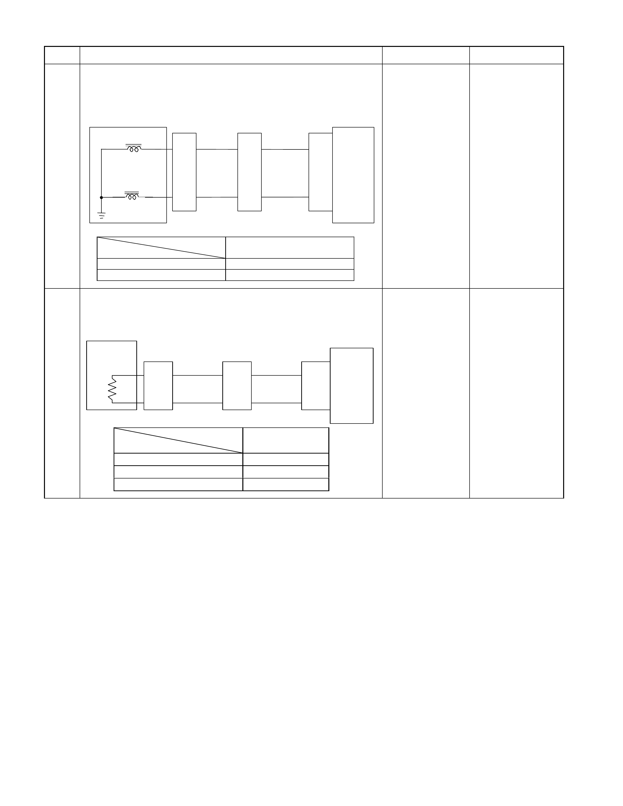
Step Action Yes No
3 Inspection of electrical or mechanical fault
When the ATF oil temperature is above 20C and the vehicle
speed is 80km/h, is ON signal issued to the lock-up solenoid
using the Tech 2 or circuit tester?
Control Valve
TCM
B17
B23
BLK
Lock-up Solenoid
Terminal
Assembly
VIO
Line Pressure Solenoid
E54
(4)
(6)
H23
(14)
(6)
C95
(17)
(23)
BLK
VIO
TCM terminal
Lock-up B17
At lock-up Approx. 7.2 V (AC range)
At unlock-up Approx. 4.0 V (AC range)
Clogged oil
passage of lock-up
solenoid or faulty
operation of lock-
up piston. Go to Step 4
4 Inspection of ATF oil thermo sensor.
Is the ATF oil temperature sensor terminal voltage correct?
After running using the Tech 2 data display function, is the ATF
temperature higher than 10C?
ATF
Temp.
Sensor TCM
B4 (+)
B14 (-)
H23
(8)
(
3
)
C95
(4)
(
14
)
BLU
Terminal
Assembly
BLU/BLK
E54
(2)
(
8
)
BLU
BLU/BLK
TCM terminal
Temperature
B4
(
Ou tp u t vo lta
g
e
)
20 Ž 1.55
40 Ž 1.08
60 Ž 0.7
Monitor the electric
system input
sensor signal and
find a signal
causing no lockup. Repair the defect or
replace.

No. J1: Oil Leaks from Breather
Description:
• Oil leaks from breather.
Possible Cause:
• ATF quantity is excessively.

No. J2: Oil Leaks Between Engine and Converter Housing
No. J3: Oil Leaks Between Main Case and Converter Housing
No. J4: Oil Leaks Between Main Case and Rear Housing
No. J5: Oil Leaks from Oil Pan
No. J6: Oil Leaks from Manual Shaft Oil Seal
No. J7: Oil Leaks from Oil Cooler Pipe Joint
Description:
• Oil leaks between engine and converter housing.
• Oil leaks between converter housing and main case.
• Oil leaks between main case and rear housing.
• Oil leaks from oil pan.
• Oil leaks from manual shaft oil seal.
• Oil leaks from oil cooler pipe joint.
Possible Cause:
• Faulty oil seal or sealing of contact surface is considered.

No. Z1: Transmission Overheat
Description:
• You smell the transmission burning.
• The transmission smokes.
Possible Cause:
• Slip of clutch.
If slip of clutch is caused, a DTC (gear ratio error) is stored.
• Clogged oil cooler (foreign substance mixed)
• ATF stirred excessively (too much ATF).
• Faulty torque converter operating pressure.
• Faulty lock-up piston.

No. Z2: Mode Lamp (Power Drive or 3rd Start) Does Not Light Up
When The Power Mode or 3rd Start Mode is Turned On
Description:
• The mode lamp on the instrument panel does not light up though the power mode or 3rd start mode is turned on
with the ignition switch in ON position.
Possible Cause:
• Faulty mode select switch is considered.
• Bulb burn out.

No. Z3: Mode Lamp (Power Drive or 3rd Start) Lights Up When The
Power Mode or 3rd Start Mode is Turned Off
Description:
• The mode lamp on the instrument panel lights up though the power mode or 3rd start mode is turned off with the
ignition switch in ON position.
Possible Cause:
• Faulty mode select switch is considered.

No. Z4: Oil Temperature Warning Lamp Lights up
Description:
• Sometimes, the oil temperature warning lamp lights up.
Possible Cause:
• When the vehicle is stuck in the m ud or c ontinues to ac celerate under over load, and AT F tem per ature ex ceeds 145
°C, the oil temperature warning lamp lights up.
• If the oil temperature warning lamp lights up under usual service condition, following causes are considered.
• ATF level has increased for some fault.
Refer to "No. Z1: Transmission Overheat".
• Lights up due to error of the ATF oil thermo sensor.

No. Z5: Select Lever Feeling is Faulty.
Description:
• Select lever feeling is faulty.
Possible Cause:
• Disordered select cable.
• Disordered select lever.
• Faulty Manual plate.

No. Z6: Poor Fuel Consumption
Description:
• Poor fuel consumption.
Diagnosis Hints:
• Basically same causes as "No. C1 - C8: Engine races up (slip) by shift up or shift down" are considered.

No. Z7: Pattern Select Switch is Faulty
Description:
• Shift pattern does not change though the pattern select switch is turned on.
Possible Cause:
• Faulty mode select switch is considered.

No. Z8: Oil is Splashed During the Running
Description:
• Oil is splashed during the running
Possible Cause:
• ATF quantity is too high.

No. Z9: Abnormal Smell
Description:
• Abnormal smell.
Diagnosis Hints:
• Basically a trouble in the AT main unit.

No. Z10: ATF Quantity is Low or High
Description:
• Oil quantity is low or high.
Possible Cause:
• In case of oil level is high.
ATF temperature is low when ATF quantity is checked.
• In case of oil level is low.
ATF leaks is considered. Check the AT main unit and cooler circuit.

No. Z11: Abnormal Oil Pressure
Description:
• Oil pressure is low or high.
Possible Cause:
• Basically, the same cause as "No. C1 - C8: Engine races up (slip) by shift up or shift down" is considered.
• In case of oil pressure is low, faulty oil pump is considered.

No. Z12: Reverse Buzzer Does Not Ring
Description:
• Reverse buzzer does not ring in R range.
Possible Cause:
• Disordered select cable.
• Disordered select lever.
• Disordered inhibitor switch.
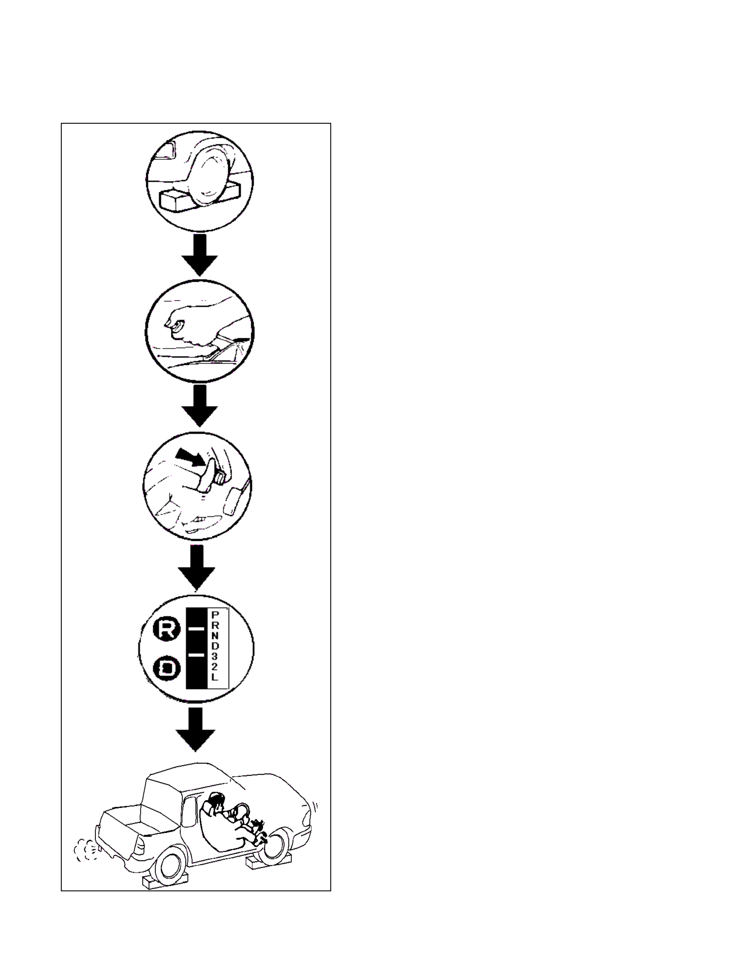
Stall Test
CAUTION:
Because A/T may break down, do not perform the stall test continuously.
Procedure
1. Chock the four wheels.
2. Warm up the engine.
3. Apply the parking brake.
4. Step on the foot brake fully.
5. Set the select lever to either D, 3, 2, L or R range.
6. Step on the accelerator pedal fully.
7. When the engine speed becomes constant, record that
value quickly.
Stall Speed
Standard: 2600±150 rpm
Evaluation
1. If the stall speed is higher than standard value in all
ranges.
• Low line pressure.
• Abraded oil pump.
• Faulty operation of low clutch.
• Adjustment error of or faulty inhibitor switch.
•
A
TF leaking from oil pump, control valve, o
r
transmission case.
• Fixed pressure regulator valve and pilot valve.
2. If the stall speed is high er th an stan dard v alue in D, 3, 2
and L ranges.
• Slip of low clutch.
• Slip of low one-way clutch.
3. If the stall speed is higher than standard value in R
range.
• Slip of low & reverse brake.
• Slip of reverse clutch.
4. If the stall speed is lower than standard value in all
ranges.
• Slip of one-way clutch (in torque converter).
• Faulty engine.
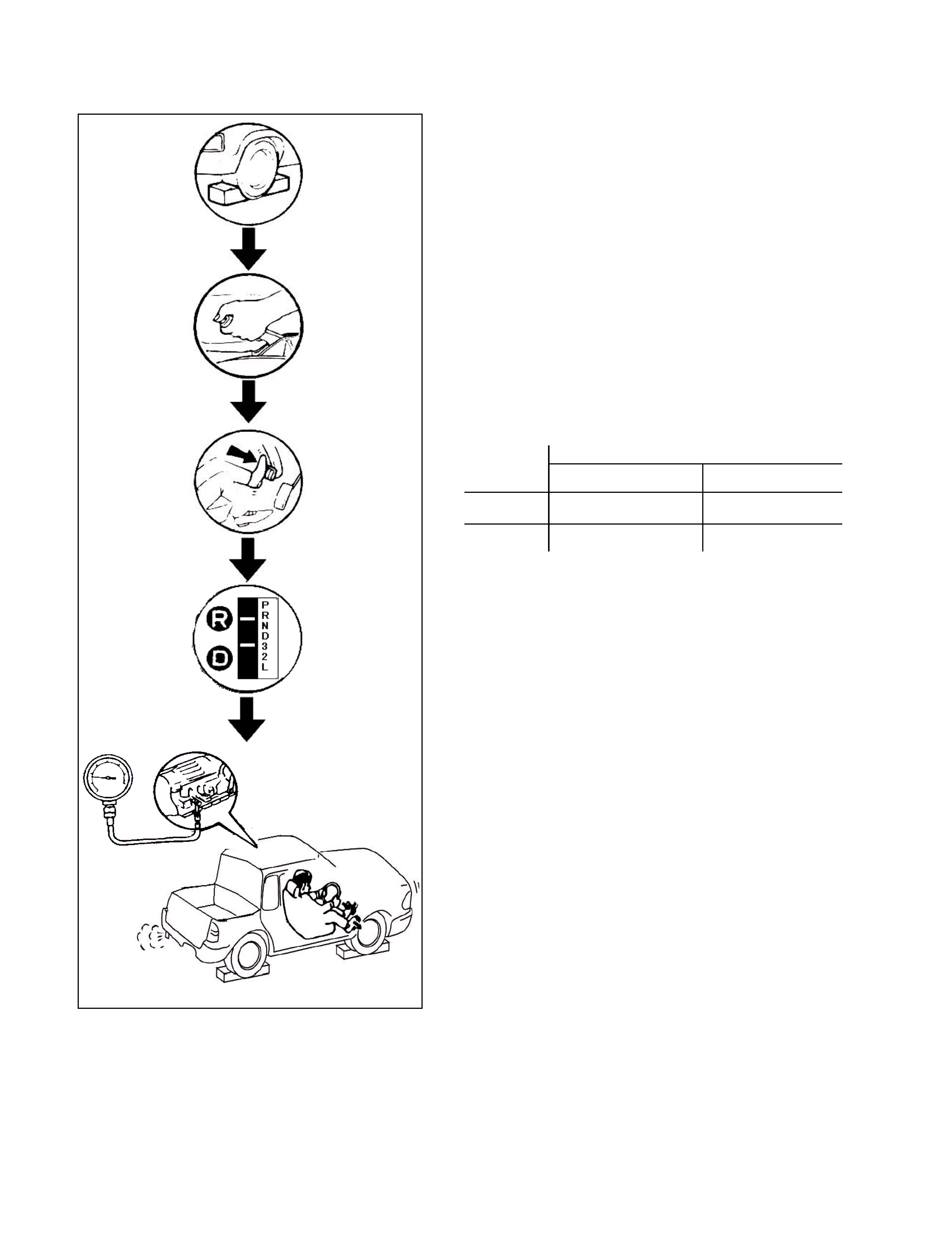
Line Pressure Test
Procedure
1. Chock the four wheels.
2. Remove the test plug of the transmiss ion cas e and f it the oil
pressure gauge.
3. Warm up the engine.
4. Apply the parking brake.
5. Step on the foot brake fully.
6.Set the select lever to either D, 3, 2, L or R range.
7. Record the oil pressure at idling.
8. When stepping over the accelerator pedal fully and the
engine speed becomes constant, record the oil pressure
quickly .
Line Pressure
Standard:
Engine Line Pressure (Kpa)
Speed D, 3, 2 or L Range R Range
Idling 350 - 480 450 - 650
Stall 1,050 - 1,250 1.400 - 1,630
Evaluation
1. If the line pressure is lower than standard value at
idling in all ranges.
• Abraded oil pump.
• Faulty operation of each solenoid.
• Sticking of pressure regulator valve or pilot valve.
• Fatigued pressure regulator valve or pilot valve spring.
•
A
TF leaking from oil strainer, oil pump, pressure
regulator valve, torque c onverter relief valve or press ure
relief valve.
2. If the line pressure is lower than standard value at
idling in D, 3, 2 and L ranges.
• ATF leaking from low clutch hydraulic circuit.
3. If the line pressure is lower than standard value at
idling in R range.
• ATF leaking from reverse hydraulic circuit.
• ATF leaking from low and reverse brake hydraulic
circuit.

4. If the line pressure is lower than standard value at
idling in L and R ranges.
•
A
TF leaking from low and reverse brake hydraulic
circuit.
5. If the line pressure is higher than standard value at
idling in all ranges.
• Throttle opening signal reception error.
• Faulty oil temperature sensor.
• Faulty operation of low clutch solenoid.
• Sticking pilot valve.
• Sticking pressure regulator valve or plug.
6. If the line pressure is low er than standard v alue at stall
speed in all ranges.
• Throttle opening signal reception error.
• Faulty operation of line pressure solenoid.
• Faulty operation of low clutch solenoid.
• Sticking pilot valve.
• Sticking pressure regulator valve or plug.
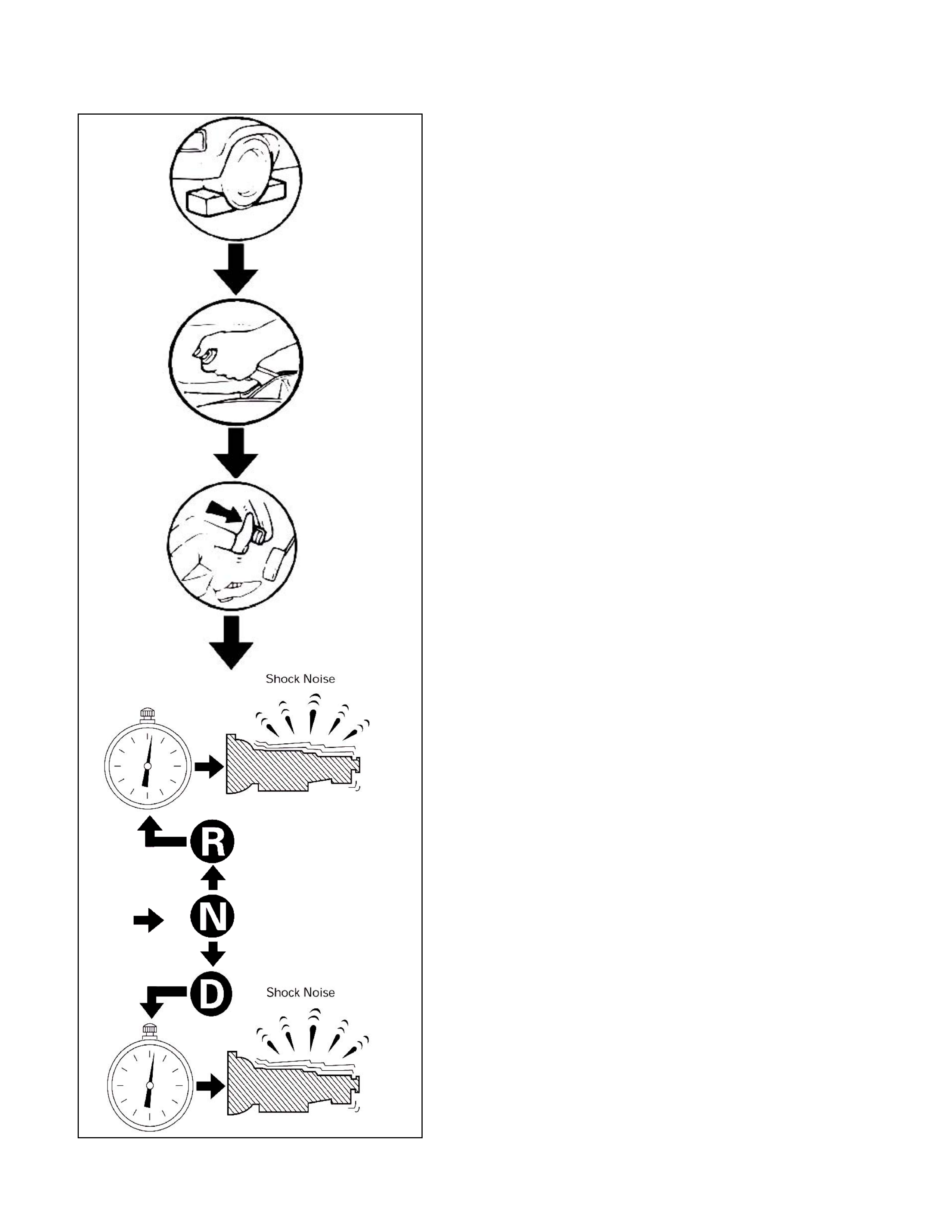
Time Lag Test
Procedure
1. Chock the four wheels.
2. Warm up the engine.
3. Apply the parking brake.
4. Step on the foot brake fully.
5. Set the select lever from N to D or N to R range.
6. Record the time from when moving the select button until
feeling shock.
Time Lag
Standard:
N to D Range: Below 0.7 Seconds
N to R Range: Below 1.2 Seconds
Evaluation
1. If the time lag is out of standard value when shifting N
to D range.
• Forward range line pressure is low.
• Slip of low clutch.
• Slip of low one-way clutch.
• Trouble in control valve body (faulty operation, sticking,
clogged oil passage).
• Faulty low clutch duty solenoid operation.
• Shortage or faulty quality of ATF.
2. If the time lag is out of standard value when shifting N
to R range.
• Reverse range line pressure is low.
• Slip of low & reverse brake.
• Slip of reverse clutch.
• Trouble in control valve body (faulty operation, sticking,
clogged oil passage).
• Faulty low & reverse brake duty solenoid operation.
• Shortage or faulty quality of ATF.
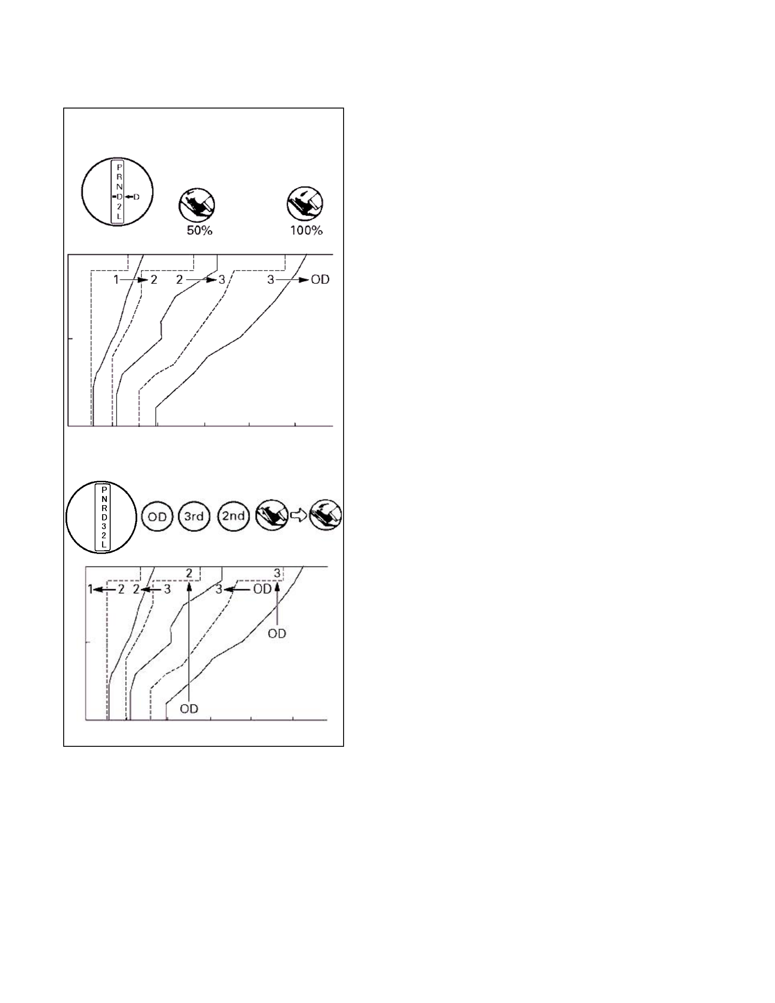
Test Drive
NOTE:
Perform the test at normal operation A TF temperature 50 -
80°
°°
°C.
Drive the vehicle on level ground s o as not to change to
up and down hill control.
1. D range test in Normal and Power shift pattern.
1) Shift into the D range and hold the accelerator pedal
constant at the 50% and 100% throttle angle.
2) 1-2, 2-3, 3-4 and lock - up, up-s hif t s hould take place, and
shift points should confirm to those shown in the
diagram.
3) Also check to see that downshift is made from 4-3, 3-2
and 2-1 down-shift point is within the limits shown in the
diagram.
2. 3 range test in Normal and Power shift pattern.
1) Shift into the 3 range and hold the accelerator pedal
constant at the 50% and 100% throttle angle.
2) 1-2, 2-3 and lock-up, up-shift should take place, and
shift points should confirm to those shown in the
diagram.
3) While running in the 3 rages, does not up-shift 3-4.
4) Also check to see that down-shift is made from 4-3, 3-2
and 2-1 down-shift point is within the limits shown in the
diagram.
3. 2 range test in Normal shift pattern.
1) Shift into the 2 range and hold the accelerator pedal
constant at the 50% and 100% throttle angle.
2) 1-2 and up-shift should take place, and shift points
should confirm to those shown in the diagram.
3) W hile running in the 2 rages, does not up-shift 2-3 or 3-
4, and lock-up does not operate.
4) Also check to see that down-shift is made from 4-3, 3-2
and 2-1 down-shift point is within the limits shown in the
diagram.
4. L range test in Normal shift pattern.
1) While running in the L rages, does not up-shift 1-2, 2-3
or 3-4, and lock-up does not operate.
2) Also check to see that down-shift is made from 4-3, 3-2
and 2-1 down-shift point is within the limits shown in the
diagram.
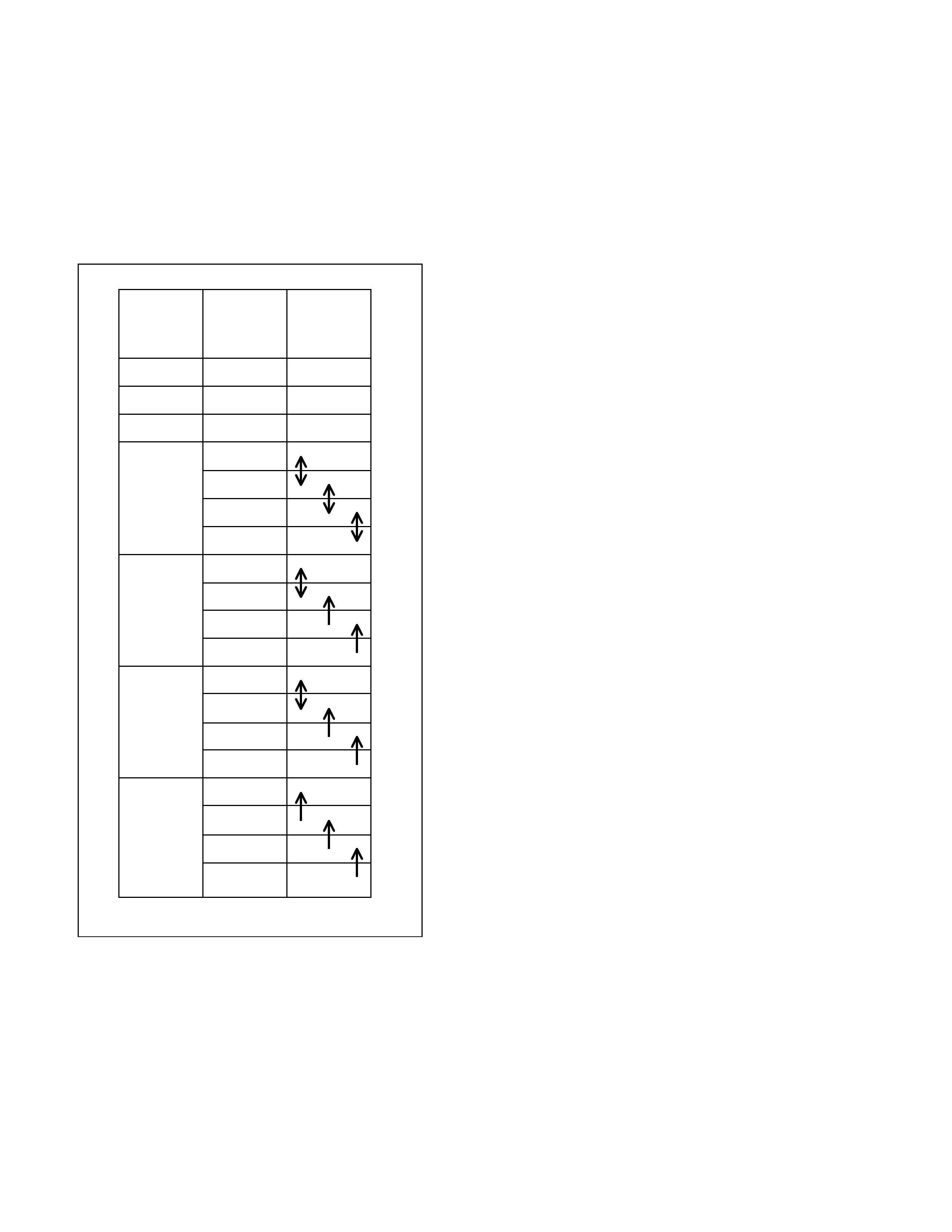
5. R range test.
1) Shift into the R range and while starting at full throttle,
check for slipping.
6.P range test.
1) Stop the vehicle on a grade and after shifting into the P
range, release the parking brake. Then check to see that
the parking lock pawl holds the vehicle in place.
Select
Lever
Position
Gear
Position Gear
Shift
P |
|
R Reverse |
N |
|
D 1st
2nd
3rd
4th
3 1st
2nd
3rd
4th(*1)
2 1st
2nd
3rd(*1)
4th(*1)
L 1st
2nd(*1)
3rd(*1)
4th(*1)
Evaluation
1. If there is no 1 to 2 up-shift.
• 2-4 brake malfunction.
• 2-4 brake hydraulic circuit failed.
• 2-4 brake duty solenoid stick.
Refer to symptom diagnosis "No. D1: Faulty Gea
r
Shifting" or DTC section "Gear Ratio Error".
2. If there is no 2 to 3 up-shift.
• High clutch malfunction.
• High clutch hydraulic circuit failed.
• High clutch duty solenoid stick.
Refer to symptom diagnosis "No. D1: Faulty Gea
r
Shifting" or DTC section "Gear Ratio Error".
3. If there is no 2 to 4 (O/D) up-shift.
• 2-4 brake malfunction.
• 2-4 brake hydraulic circuit failed.
• 2-4 brake duty solenoid stick.
Refer to symptom diagnosis "No. D1: Faulty Gea
r
Shifting" or DTC section "Gear Ratio Error".
4. If there is no lock-up in 2, 3 and 4.
• Lock-up piston malfunction.
• Lock-up hydraulic circuit failed.
• Lock-up duty solenoid stick.
Refer to symptom diagnosis "No. I1: No Lock-up" o
r
DTC section "Lock-up Duty Solenoid Failure".
*1: Transmission is shifted at high speed to
prevent engine over-run.

5. If there is no reverse.
• Reverse clutch malfunction.
• Reverse clutch hydraulic circuit failed.
• Low & reverse brake hydraulic circuit failed.
• Low & reverse brake duty solenoid stick.
Refer to symptom diagnosis "No. A2: Vehicle Dose Not
Run in R Range" or DTC section "Low & Reverse
Brake Duty Solenoid Failure".
6. If there is no parking.
• Parking pawl malfunction.
Refer to symptom diagnosis "No. G 1: Vehicle M oves in
P Range or Parking Gear in Not Disengaged othe
r
than P Range".
NOTE:
The check for the cause of abnormal noise and vibration
must be made with extreme care as it could also be due to
loss of balance in propeller shaft, diffe rential, the torque
converter, etc. Or insufficient bending, rigidity, etc. in the
powertrain.
Shift Point Chart
D Range
Normal Mode Power Mode 4L Mode
Gear Throttle
Position Velocity (km/h) Output Shaft
Speed (rpm) Velocity (km/h) Output Shaft
Speed (rpm) Velocity (km/h) Output Shaft
Speed (rpm)
1→2 50% 25-31 27 -33 930 29 -35 31 -37 1054 28 -34 30 -36 1023
100% 36-42 37 -43 1271 36 -42 38 -44 1271 32 -38 34 -40 1147
2→3 50% 46-52 49 -55 1612 55 -61 58 -64 1891 52 -58 55 -61 1798
100% 75-81 79 -85 2542 75 -81 79 -85 2542 67 -73 71 -77 2294
3→4 50% 80-86 84 -90 2697 83 -89 88 -94 2821 80 -86 84 -90 2697
100% 118-124 125 -131 3967 118 -124 125 -131 3967 107 -113 113 -119 3595
4→3 0% 27-33 29 -35 992 27 -33 29 -35 992 27 -33 29 -35 992
50% 52-58 55 -61 1798 70 -76 74 -80 2387 67 -73 71 -77 2294
100% 102-108 108 -114 3440 102 -108 108 -114 3440 93 -99 98 -104 3130
3→2 0% 6- 12 6 - 12 279 6 - 12 6 -12 279 6 - 12 6 - 12 279
50% 28-34 30 -36 1023 44 -50 47 -53 1550 43 -49 46 -52 1488
100% 61-67 64 -70 2077 61 -67 64 -70 2077 56 -62 59 -65 1922
2→1 0% 6- 12 6 - 12 279 6 - 12 6 -12 279 6 - 12 6 - 12 279
50% 9- 15 10 -16 403 18 -24 19 -25 682 17 -23 18 -24 651
100% 27-33 29 -35 992 27-33 29 -35 992 25 -31 27 -36 930
Axle Gear Ratio 4.300 4.300 4.300 4.300 4.300 4.300
Tire Radius 0.349 0.368 0.349 0.368 0.349 0.368
3 Range
Normal Mode Power Mode 4L Mode
Gear Throttle
Position Velocity (km/h) Output Shaft
Speed (rpm) Velocity (km/h) Output Shaft
Speed (rpm) Velocity (km/h) Output Shaft
Speed (rpm)
1→2 50% 25-31 27 -33 930 29 -35 31 -37 1054 28 -34 30 -36 1023
100% 36-42 38 -44 1271 36 -42 38 -44 1271 32 -38 34 -40 1147
2→3 50% 46-52 49 -55 1612 55 -61 58 -64 1891 52 -58 55 -61 1798
100% 75-81 79 -85 2542 75 -81 79 -85 2542 67 -73 71 -77 2294
4→3 0% 118-124 125 -131 3967 118 -124 125 -131 3967 107 -113 113 -119 3595
50% 118-124 125 -131 3967 118 -124 125 -131 3967 107 -113 113 -119 3595
100% 118-124 125 -131 3967 118 -124 125 -131 3967 107 -113 113 -119 3595
3→2 0% 6- 12 6 - 12 279 6 - 12 6 -12 279 6 - 12 6 - 12 279
50% 28-34 30 -36 1023 44 -50 47 -53 1550 43 -49 45 -51 1488
100% 61-67 64 -70 2077 61 -67 64 -70 2077 57 -63 59 -65 1922
2→1 0% 6- 12 6 - 12 279 6 - 12 6 -12 279 6 - 12 6 - 12 279
50% 9- 15 10 -16 403 18 -24 19 -25 682 17 -23 18 -24 651
100% 27-33 29 -35 992 27-33 29 -35 992 25 -31 27 -33 930
Axle Gear Ratio 4.300 4.300 4.300 4.300 4.300 4.300
Tire Radius 0.349 0.368 0.349 0.368 0.349 0.368
2 Range
Normal Mode 4L Mode
Gear Throttle
Position Velocity (km/h) Output Shaf t
Speed (rpm) Velocity (km/h) Output Shaft
Speed (rpm)
1→2 50% 25 -31 27 -33 930 28 - 34 30 -36 1023
100% 36 -42 38 -44 1271 32 - 38 34 -40 1147
4→3 0% 119 -125 125 -131 3967 107 - 113 113 -119 3595
50% 119 -125 125 -131 3967 107 - 113 113 -119 3595
100% 119 -125 125 -131 3967 107 - 113 113 -119 3595
3→2 0% 75 -81 79 -85 2542 67 - 73 71 -77 2294
50% 75 -81 79 -85 2542 67 - 73 71 -77 2294
100% 75 -81 79 -85 2542 67 - 73 71 -77 2294
2→1 0% 6 -12 6 -12 279 6- 12 6 - 12 279
50% 9 -15 10 -16 403 17 - 23 18 -24 651
100% 27 -33 29 -35 992 25 - 31 27 -33 930
Axle Gear Ratio 4.300 4.300 4.300 4.300
Tire Radius 0.349 0.368 0.349 0.368
L Range
Normal Mode 4L Mode
Gear Throttle
Position Velocity (km/h) Output Shaft
Speed (rpm) Velocity (km/h) Output S haft
Speed (rpm)
4→3 0% 118 -124 125 -131 3967 107 -113 113 -119 3595
50% 118 -124 125 -131 3967 107 -113 113 -119 3595
100% 118 -124 125 -131 3967 107 -113 113 -119 3595
3→2 0% 75 -81 79 -85 2542 67 -73 71 -77 2294
50% 75 -81 79 -85 2542 67 -73 71 -77 2294
100% 75 -81 79 -85 2542 67 -73 71 -77 2294
2→1 0% 36 -42 38 -44 1271 32 -38 34 -40 1147
50% 36 -42 38 -44 1271 32 -38 34 -40 1147
100% 36 -42 38 -44 1271 32 -38 34 -40 1147
Axle Gear Ratio 4.300 4.300 4.300 4.300
Tire Radius 0.349 0.368 0.349 0.368
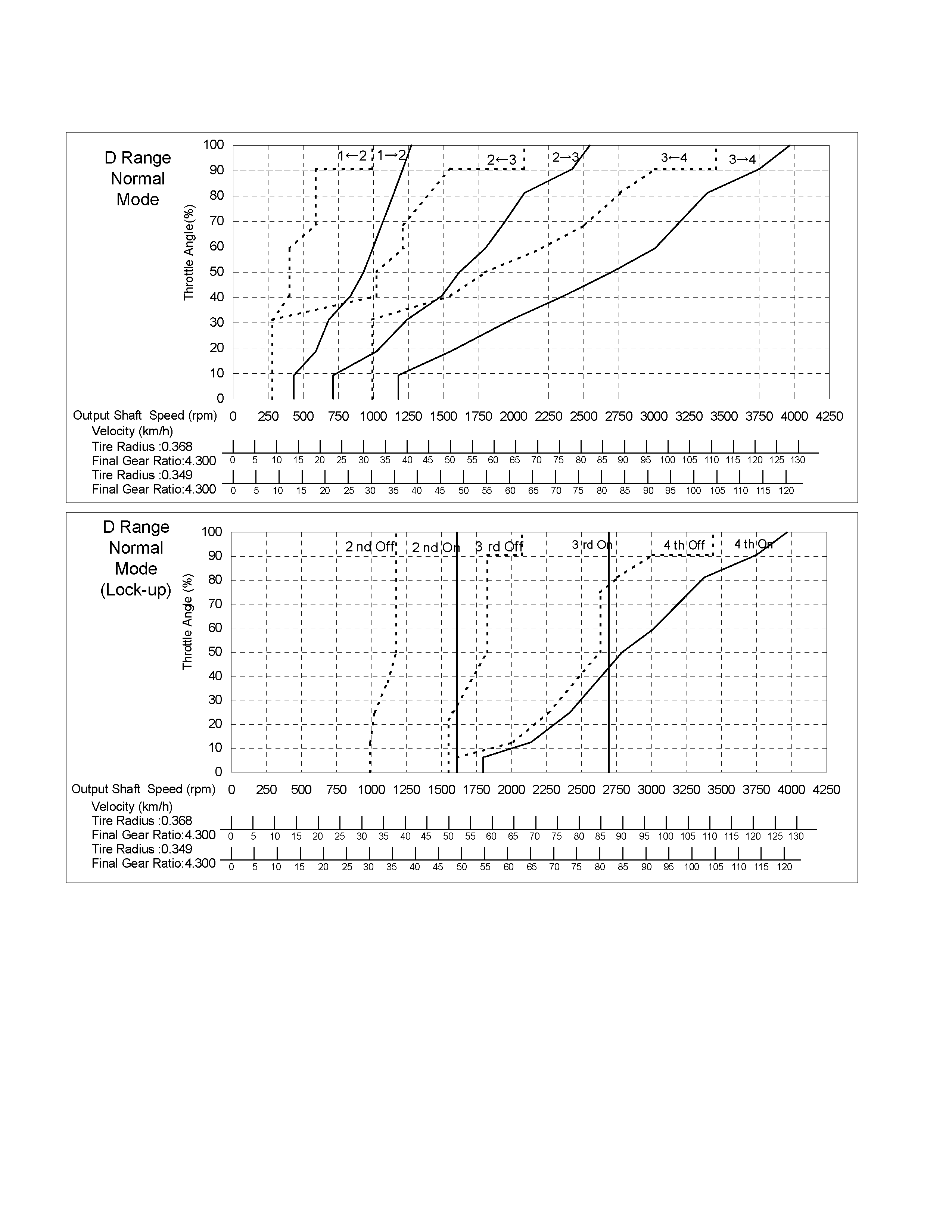
Shift Point Diagram
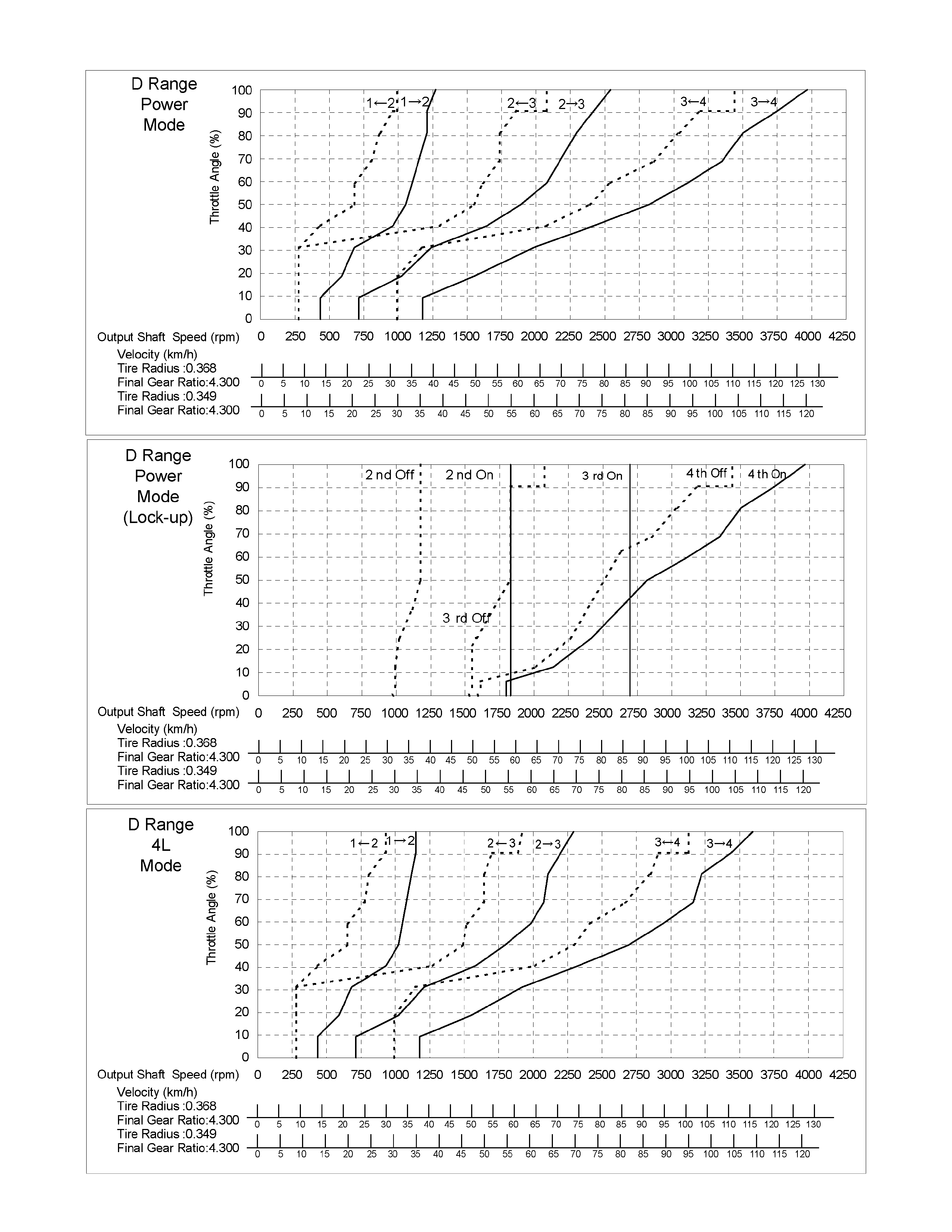
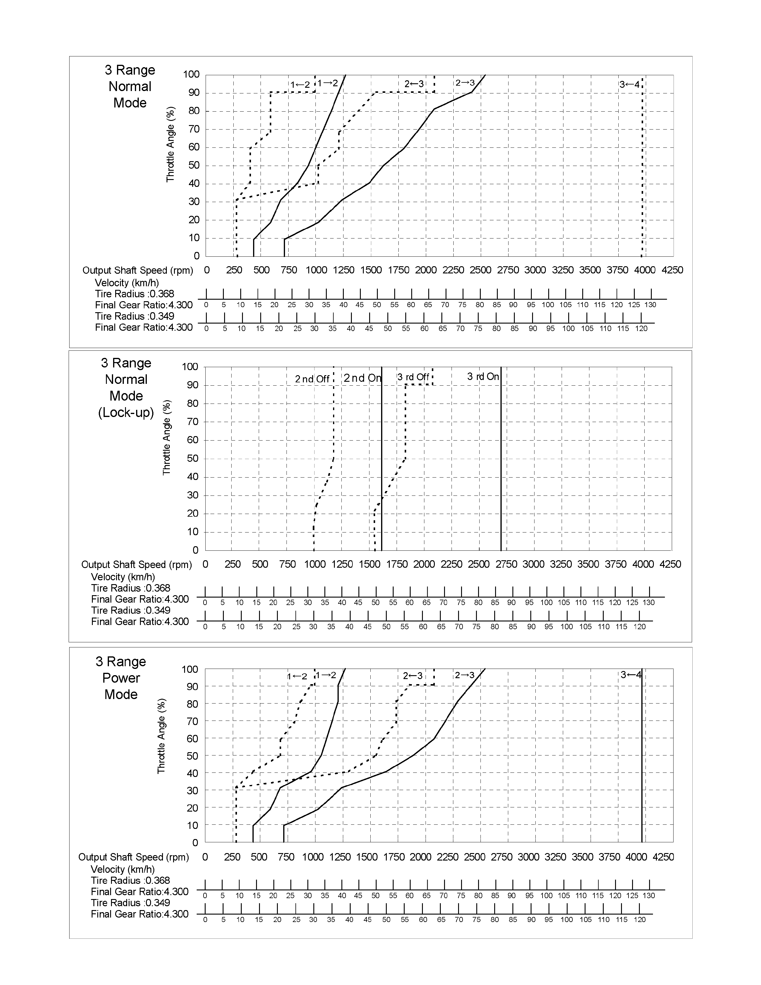
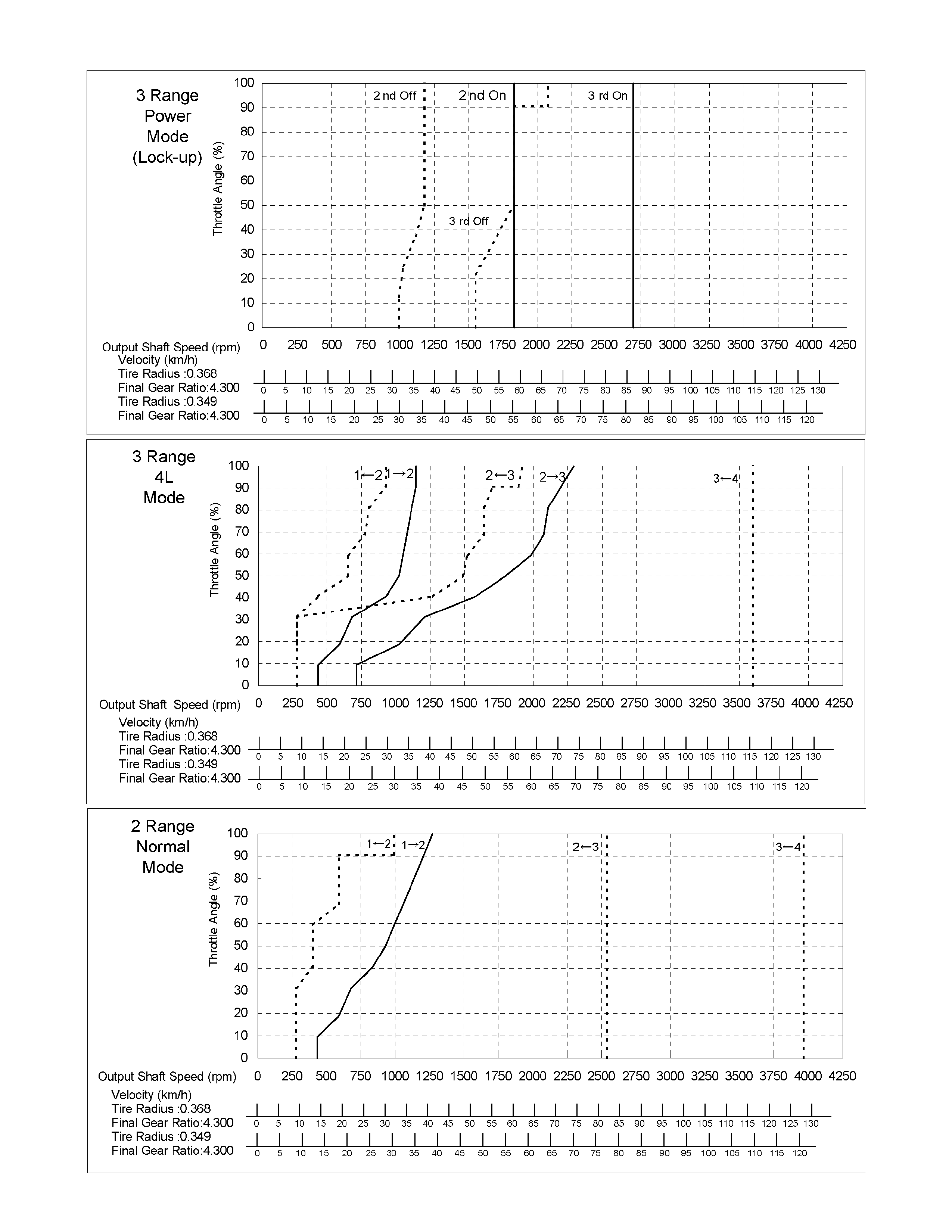
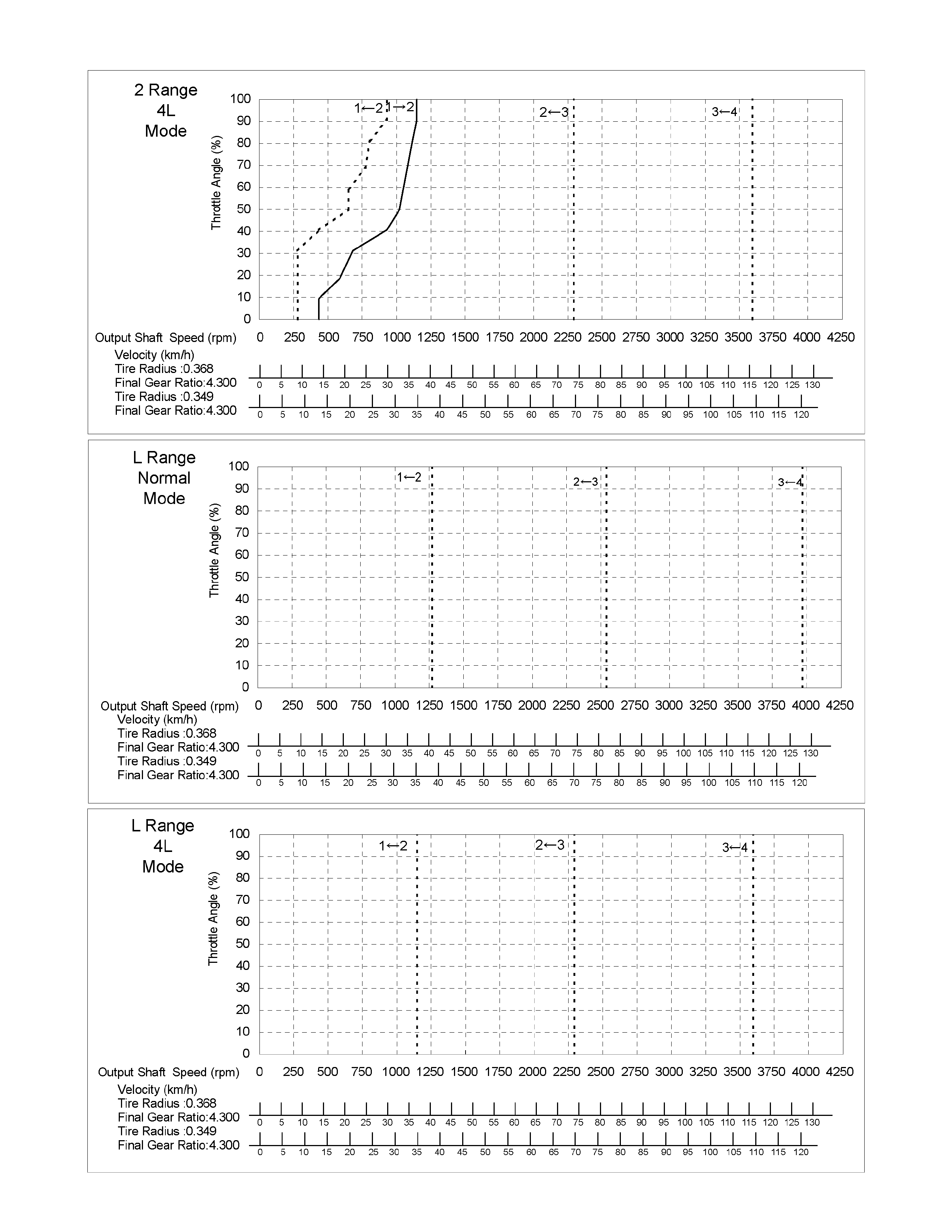
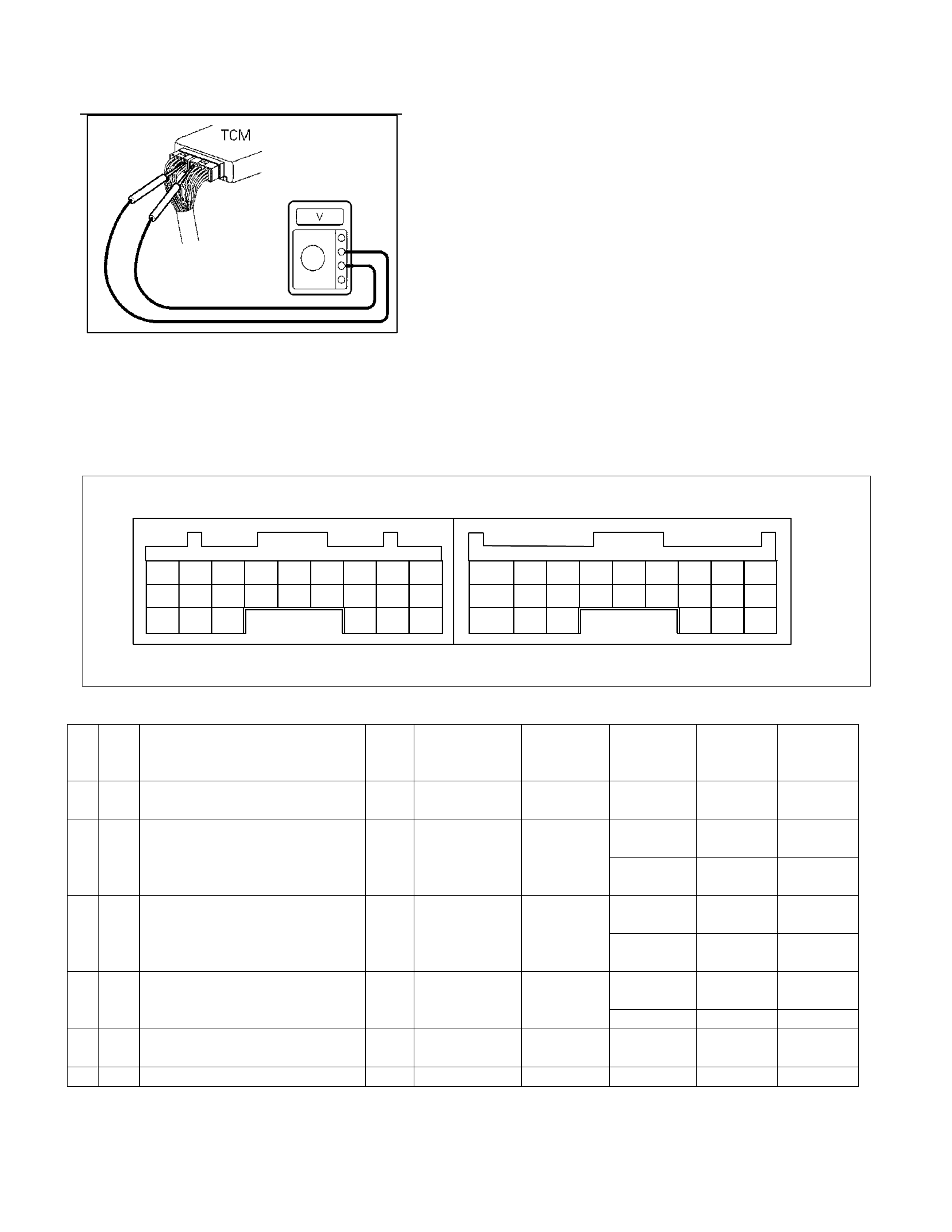
TCM Voltage Check
TCM voltage check is done to check for transmission and TCM
problems, which cannot be detected by self-diagnosis.
Additionally, it severs as a back-up check for self-diagnosis.
Measure the voltage drop and make a continuity test for each of
sensors, solenoids and switches.
If the voltage is within the specified range and continuity exists,
that particular area of the TCM and transmission assembly is
normal.
If voltage deviation or lack of continuity is discovered, disconnect
the applicable parts and check of them individually.
Inspection Tool
Use a circuit tester and an oscilloscope to measure voltage and
circuit continuity.
Insert the test probes from the connector wiring side. TCM
terminals are extremely small.
Wrap a piece of thin wire around the probe of tester.
This will make measurement easier.
TCM Pin Assignment
B9 B8 B7 B6 B5 B4 B3 B2 B1 A9 A8 A7 A6 A5 A4 A3 A2 A1
B18 B17 B16 B15 B14 B13 B12 B11 B10 A18 A17 A16 A15 A14 A13 A12 A11 A10
B24 B23 B22 B21 B20 B19 A24 A23 A22 A21 A20 A19
Connect to White Connector Connect to Grey Connector
No. Wire
Color Pin Name Input /
Output Connected to Measurement
Item Measurement
Condition Standard Inspection
Point at
Trouble
A1 RED V BATT (Battery Back-up Powe
r
Supply) Input Battery Voltage - Battery
voltage Related
harness
At P range Battery
voltage Related
harness
A2 YEL/
VIO P Range Switch Input Inhibitor switc h Voltage At other than
P range Less than 2V Inhibitor
switch
At brake
stepped Battery
voltage Related
harness
A3 RED Brake Switch Input Brake s witc h Volt age At brake no
stepped Less than 2V Brake switch
At lamp OFF Battery
voltage Related
harness
A4 PNK/
WHT 3rd Start Indicator Lamp Output 3rd start lamp V ol tage At lamp ON Less t han 2V Lamp
A5 GRN K-line signal (Tech 2 serial
communication) Input/
Output Tech 2 - - - Related
harness
A6 - - - - - - - -

No. Wire
Color Pin Name Input /
Output Connected to Measurement
Item Measurement
Condition Standard Inspection
Point at
Trouble
Related
harness
Engine
Speed
Sensor
A7 BLK/
RED Engine S peed S ensor Input ECM Voltage (Wave
form)
At 1500rpm.
Circuit tester
(+) to A7 pin,
(-) to B5 pin.
Pulse
generated (At
AC range
approx. 5.5
V) ECM
A8 - - - - - - - -
A9 - - - - - - - -
Related
harness
Speed
sensor
Speed meter
A10 BLK/
YEL Vehic l e Speed Sensor Out (2WD Only) Output Speed m et er Voltage (Wave
form)
At run in L
range in 1st
gear 20 km /h.
Circuit tester
(+) to A10 pin,
(-) to B5 pin.
Pulse
generated (At
AC range
approx. 6.5
V) TCM
At switch
pushed Less t han 2V Related
harness
A11 GRN/
WHT 3rd Start Selec t Switch Input 3rd start switch Voltage At switch off Battery
voltage 3rd st art
switch
At 4L Less than 2V Related
harness
A12 BLU/
WHT 4L Mode Switch (4WD Only) Input Transfer control
unit Voltage At other t han
4L Battery
voltage 4L switch
A13 - - - - - - - -
A14 - - - - - - - -
A15 - - - - - - - -
At ful l y close Off duty 10% Related
harness
ECM
A16 RED/
WHT Throttle Position Sensor Input ECM Wave form
(140Hz Duty
signal) *1 At fully open Off duty 90% Throttle
position
sensor
At 3 range Battery
voltage Related
harness
A17 BLK/
GRN 3 Range Switch I nput Inhi bi tor switch V ol tage At other than
3 range Less than 2V Inhibitor
switch
At key switch
ON Battery
voltage Related
harness
A18 YEL/
BLK DIAG S witch Input Data link
connector Voltage At short circuit
of DIAG
switch Less than 2V
At lamp OFF Battery
voltage Related
harness
A19 ORG/
BLU A/T OIL TE MP I ndi cator Lamp Output AT OIL TEMP
indicat or l amp Voltage At lamp ON Less than 2V Lam p
At lamp OFF Battery
voltage Related
harness
A20 GRN/
YEL CHECK TRA NS Indicat o r Lamp Output CHECK TRA NS
indicat or Lamp Voltage A t l amp ON Less than 2V Lamp
At lamp OFF Battery
voltage Related
harness
A21 PNK POWE R DRIVE Indi cator Lam p Out put POWER DRIVE
indicat or l amp Voltage At lamp ON Less than 2V Lam p
A22 - - - - - - - -
A23 - - - - - - - -

No. Wire
Color Pin Name Input /
Output Connected to Measurement
Item Measurement
Condition Standard Inspection
Point at
Trouble
At lamp OFF Battery
voltage Related
harness
A24 GRN/
YEL Power Drive Selec t Switch Input Power drive
switch Voltage At lamp ON Less than 2V Lamp
At other than
2nd or 4th
gear
More than 10
V Related
harness
B1 RED/
YEL 2-4 Brake Pressure Switch Input 2-4 brake
pressure switch Voltage At 2nd or 4th
gear Less than 2V Pressure
switch
At 2 range Battery
voltage Related
harness
B2 PNK/
BLK 2 Range Switch Input Inhibitor switch V ol tage At other than
2 range Less than 2V Inhibitor
switch
Input Related
harness
B3 BRN/
RED Turbine Sens or Turbi ne sensor Voltage (Wave
form)
At run in L
range in 1st
gear 20 km /h.
Circuit tester
(+) to B3 pin,
(-) to B5 pin.
Pulse
generated (At
AC range
approx. 6.2
V)
Turbine
sensor
ATF temp.
20C Approx. 1.55
V Related
harness
B4 BLU ATF Thermo Sensor Input ATF thermo
sensor Voltage ATF tem p.
60C Approx. 0,7V Thermo
sensor
B5 BLK Ground - Ground Voltage Normally Less than 2V
Related
harness
Related
harness
B6 BLU/
BLK Low & Reverse Brak e Duty Solenoid Output Low & reverse
brake duty
solenoid
Voltage (Wave
form)
P, N range.
Circuit tester
(+) to B6 pin,
(-) to B22 pin.
Pulse
generated (At
AC range
approx. 6.8V) Dut y solenoid
Related
harness
B7 BLK/
YEL 2-4 Brake Duty Solenoid Output 2-4 brake duty
solenoid Volt age (Wave
form)
P, N range.
Circuit tester
(+) to B7 pin,
(-) to B22 pin.
Pulse
generated (At
AC range
approx. 6.8V) Dut y solenoid
Related
harness
B8 RED High Clutch Duty Solenoid Output High clutch duty
solenoid Volt age (Wave
form)
P, N range.
Circuit tester
(+) to B8 pin,
(-) to B22 pin.
Pulse
generated (At
AC range
approx. 6.8V) Dut y solenoid
Related
harness
B9 WHT/
RED Low Clutch Duty S ol enoi d Output Low clut ch duty
solenoid Volt age (Wave
form)
4th gear in D
range. Circui t
tester (+) to
B9 pin, (-) t o
B22 pin.
Pulse
generated (At
AC range
approx. 6.8V) Dut y solenoid
At N range Battery
voltage Related
harness
B10 RED/
BLK N Range Switch Input Inhibitor switch Voltage At other than
N range Less than 2V Inhibitor
switch
At D range Battery
voltage Related
harness
B11 BLU D Range Switch Input Inhibitor switch Vol tage At other than
D range Less than 2V Inhibitor
switch
At other than
R range, L
range 1st gear
More than 10
V Related
harness
B12 YE L Low & Reverse Brake Pressure Switch Input Low & reverse
brake press ure
switch Voltage At R range, L
range 1st gear Less than 2V Pressure
switch

No. Wire
Color Pin Name Input /
Output Connected to Measurement
Item Measurement
Condition Standard Inspection
Point at
Trouble
Related
harness
B13 YEL/
RED Vehic l e Speed Sensor Input Vehic l e speed
sensor Voltage (Wave
form)
At run in L
range in 1st
gear 20 km /h.
Circuit tester
(+) to B13 pin,
(-) to B5 pin.
Pulse
generated (At
AC range
approx. 6.2
V)
Vehicle
speed sens or
B14 BLU/
BLK ATF Thermo Sensor Ground - ATF thermo
sensor Continuity Normally Continuity Related
harness
B15 BLK Ground - Ground Voltage Normally Less than 2V
Related
harness
B16 - - - - - - - -
At loc k-up.
Circuit tester
(+) to B17 pin,
(-) to B5 pin.
Pulse
generated (At
AC range
approx. 7.2
V)
Related
harness
B17 BLK Lock-up Duty Solenoi d Output Loc k-up duty
solenoid Volt age (Wave
form) At unl ock-up.
Circuit tester
(+) to B17 pin,
(-) to B5 pin.
Pulse
generated (At
AC range
approx. 4.0
V)
Duty solenoid
At key switch
ON Battery
voltage Related
harness
B18 W HT V ign (I gni tion Power Supply) Input Key switch Voltage At key switch
OFF Less than 2V Fuse
At R range Battery
voltage Related
harness
B19 RED/
YEL R Range Switch Input Inhibitor switch Voltage At other than
R range Less than 2V Inhibitor
switch
At other than
3rd or 4th
gear
More than 10
V Related
harness
B20 WHT/
BLK High Clut ch Oil Pres sure Switch Input High clutch
pressure switch Voltage At 3rd or 4th
gear Less than 2V Pressure
switch
At L range Battery
voltage Related
harness
B21 PNK/
BLK L Range Switch Input Inhibitor switch V ol tage At other than
L range Less than 2V Inhibitor
switch
B22 GRY /
RED Ground Return Output Shift solenoid Cont i nui ty Normally Cont i nuity Related
harness
At N range Battery
voltage Related
harness
B23 VIO Line P res sure Solenoid Output Line pressure
solenoid Voltage At D range
stall Less than 2V Solenoid
At key switch
ON Battery
voltage Related
harness
B24 W HT V ign (I gni tion Power Supply) Input Key switch Voltage At Key switch
OFF Less than 2V Fuse
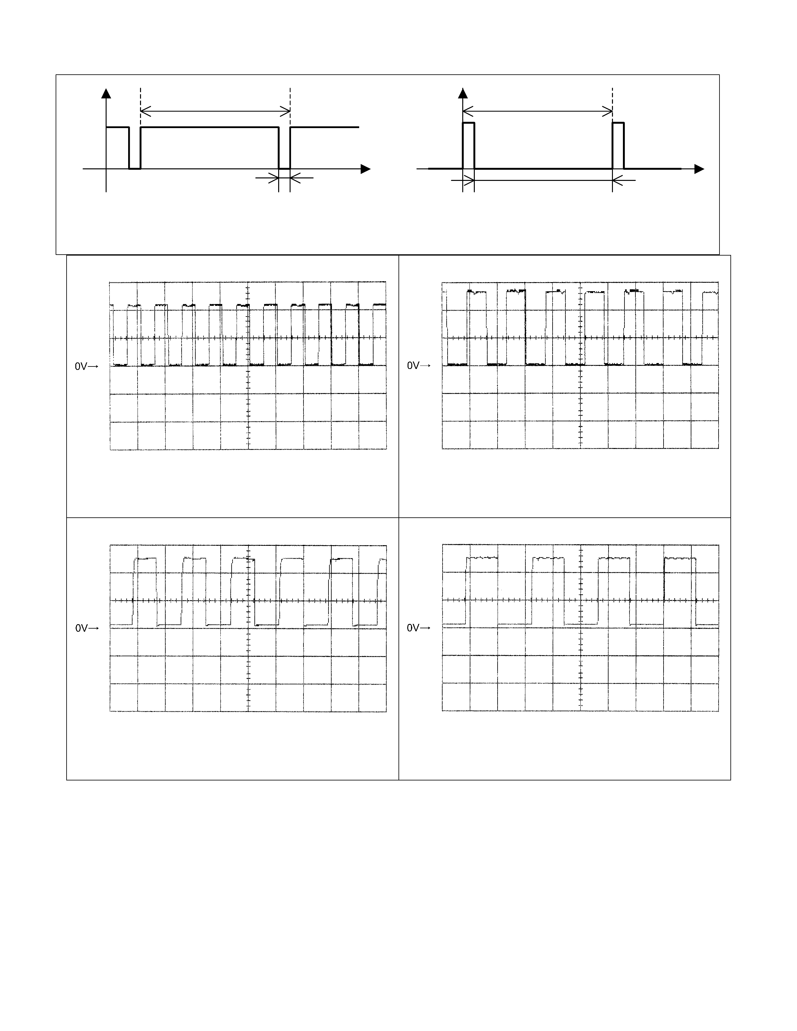
7.14ms 7.14ms
Time Time
0.714ms 6.426ms
Voltage
Off duty 10% =Throttle Position 0%
Voltage
Off duty 90% =Throttle Position 100%
Engine Speed Sensor Reference Wave Form
Measurement Terminal: A7 (+) B5 (-)
Measurement Scale: 5V/div 20ms/div
Measurement Condition: At engine speed 1500rpm
Vehicle Speed Sensor Out Reference Wave Form
Measurement Terminal: A10 (+) B5 (-)
Measurement Scale: 5V/div 50ms/div
Measurement Condition: Vehicle speed 20km/h at L
range in 1st gear
Turbine Sensor Re ference Wa ve Form
Measurement Terminal: B3 (+) B5 (-)
Measurement Scale: 5V/div 500ms/div
Measurement Condition: Vehicle speed 20km/h at L
range in 1st gear
Vehicle Speed Sensor Reference Wave Form
Measurement Terminal: B13 (+) B5 (-)
Measurement Scale: 5V/div 2ms/div
Measurement Condition: Vehicle speed 20km/h at L
range in 1st gear
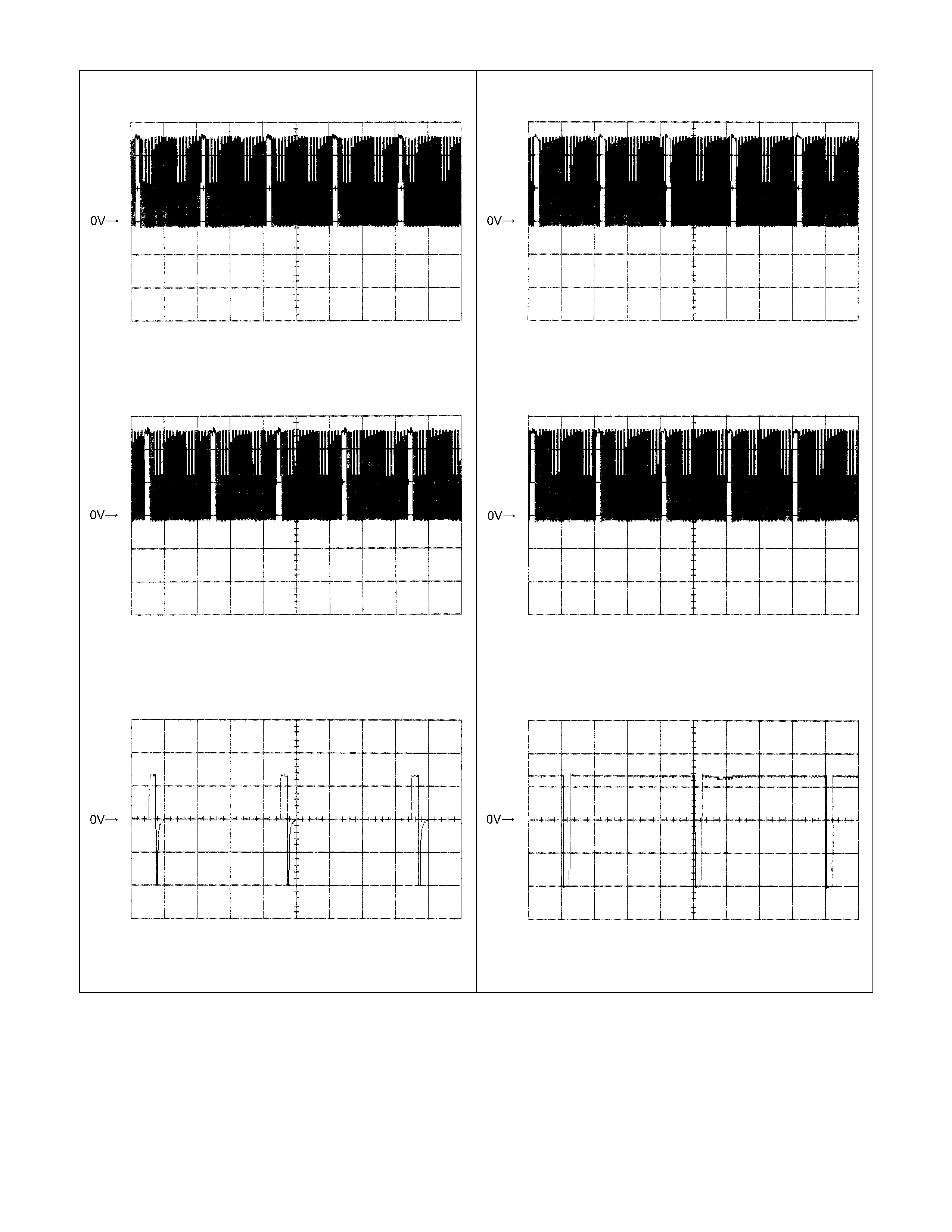
Low & Reverse Brake Duty Solenoid Reference
Wave Form
Measurement Terminal: B6 (+) B22 (-)
Measurement Scale: 5V/div 10ms/div
Measurement Condition: P, N range in idle
2-4 Brake Duty Solenoid Reference Wave Form
Measurement Terminal: B7 (+) B22 (-)
Measurement Scale: 5V/div 20ms/div
Measurement Condition: P, N range in idle
High Clutch Duty Solenoid Reference Wave Form
Measurement Terminal: B8 (+) B22 (-)
Measurement Scale: 5V/div 20ms/div
Measurement Condition: P, N range in idle
Low Clutch Duty Solenoid Reference Wave Form
Measurement Terminal: B9 (+) B22 (-)
Measurement Scale: 5V/div 20ms/div
Measurement Condition: D range 4th gear
Lock-up Duty Solenoid Reference Wave Form
Measurement Terminal: B17 (+) B5 (-)
Measurement Scale: 10V/div 5ms/div
Measurement Condition: Unlock-up condition
Lock-up Duty Solenoid Reference Wave Form
Measurement Terminal: B17 (+) B5 (-)
Measurement Scale: 10V/div 5ms/div
Measurement Condition: Lock-up condition