
SECTION 7A3 - ON-VEHICLE SERVICE
(AW30–40LE)
Service Precaution
Location of Clutch, Brake, One-Way
Clutch and Solenoid
Operation of Clutch, Brake and One-Way Clutch
Trnasmission Indentification
Speed Change and Lock-Up Pattern
Overdrive and Lock-Up Operating Conditions
Diagnosis
Basic Troubleshooting
Manual Shifting Test
Stall Test
Time Lag Test
Hydraulic Test
Road Test
Shift Pont Chart and Lock-Up Point Chart
Shift Pont Char t
Lock-Up Point Chart
Transmission Fluid Level and Condition
Inspection
ATF Replacement
Inspection
Neutral Start Switch (Mode Switch)
Inspection
Removal
Installation
Brake Signal
Inspection
Input and Output Revolution Sensor
Inspection
Pattern Select Switch
Inspection
Solenoid
Inspection
ATF Temperature Sensor
Inspection
Select Lever
Remove or Disconnect
Install or Connect
Shift Cable
Remove or Disconnect
Install or Connect
Torque Specifications
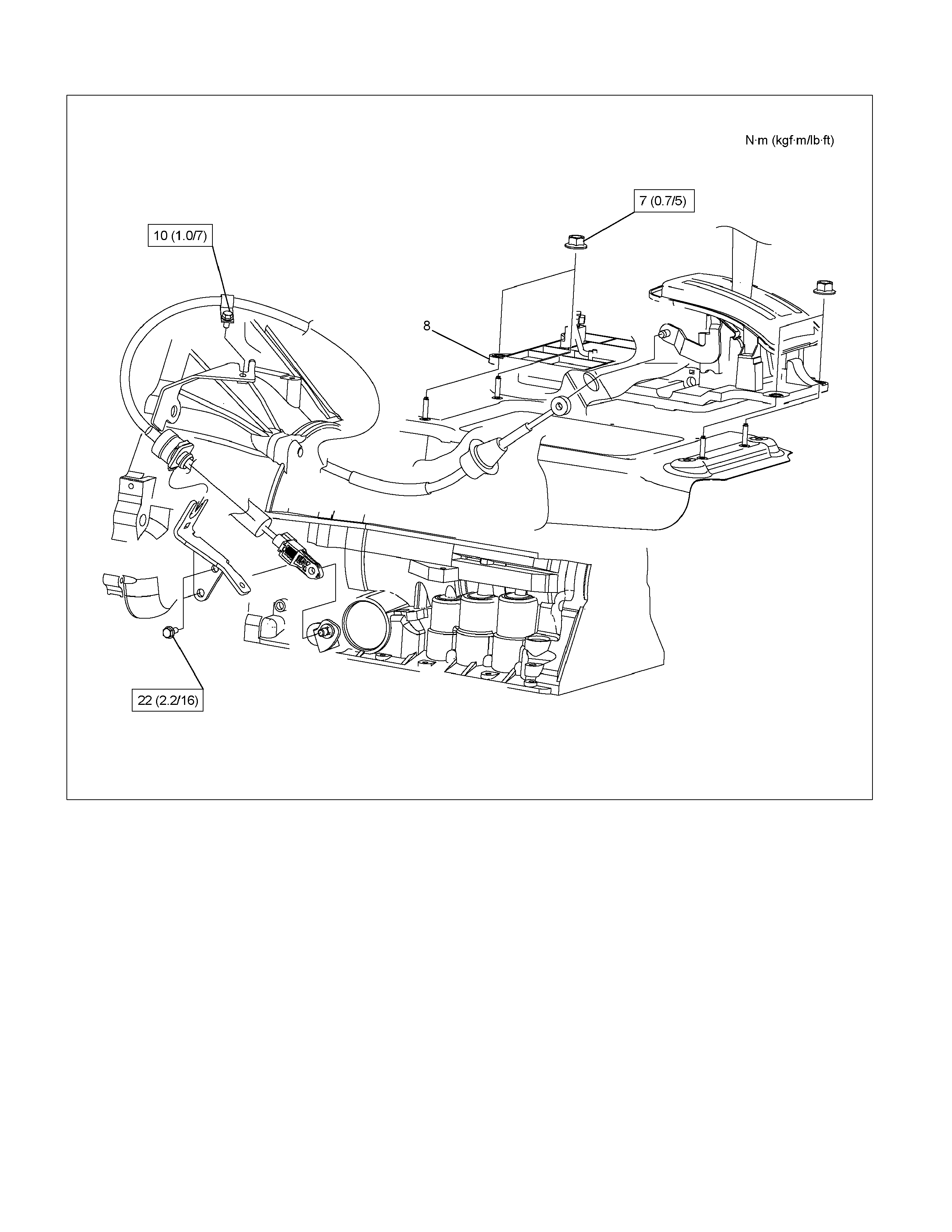
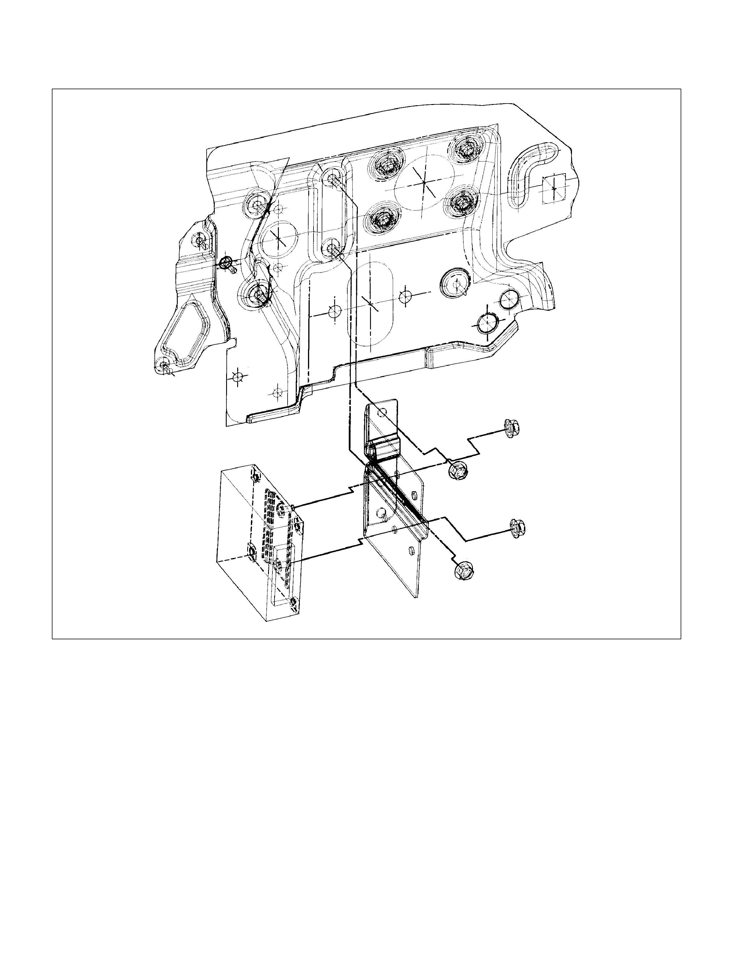
Transmission Control Module (TCM)
Removal
Installation
Shift Solenoid and Lock-Up Solenoid
Removal
Installation
Valve Body Assembly and Pressure
Control Solenoid
Removal
Installation
Rear Oil Seal (Adapter Housing, 4×
××
×4)
Removal
Installation
Real Oil Seal (Extension Housing, 4×
××
×2)
Removal
Installation
Transmission Assembly
Transmission and Associated Parts
Removal
Installation
Major Components
Techline

Service Precaution
WARNING: THIS VEHICLE HAS A SUPPLEMENTAL
RESTRAINT SYSTEM (SRS). REFER TO THE SRS
COMPONENT AND WIRING LOCATION VIEW IN
ORDER TO DETERMINE WHETHER YOU ARE
PERFORMING SERVICE ON OR NEAR THE SRS
COMPONENTS OR THE SRS WIRING. WHEN YOU
ARE PERFORMING SERVICE ON OR NEAR THE
SRS COMPONENTS OR THE SRS WIRING, REFER
TO THE SRS SERVICE INFORMATION. FAILURE TO
FOLLOW WARNINGS COULD RESULT IN
POSSIBLE AIR BAG DEPLOYMENT, PERSONAL
INJURY, OR OTHERWISE UNNEEDED SRS SYSTEM
REPAIRS.
CAUTION: Always use the correct fastener in the
proper location. When you replace a fastener, use
ONLY the exact part number for that application.
HOLDEN will call out those fasteners that require a
replacement after removal. HOLDEN will also call
out the fasteners that require thread lockers or
thread sealant. UNLESS OTHERWISE SPECIFIED,
do not use supplemental coatings (Paints, greases,
or other corrosion inhibitors) on threaded fasteners
or fastener joint interfaces. Generally, such
coatings adversely affect the fastener torque and
the joint clamping force, and may damage the
fastener. When you install fasteners, use the
correct tightening sequence and specifications.
Following these instructions can help you avoid
damage to parts and systems.
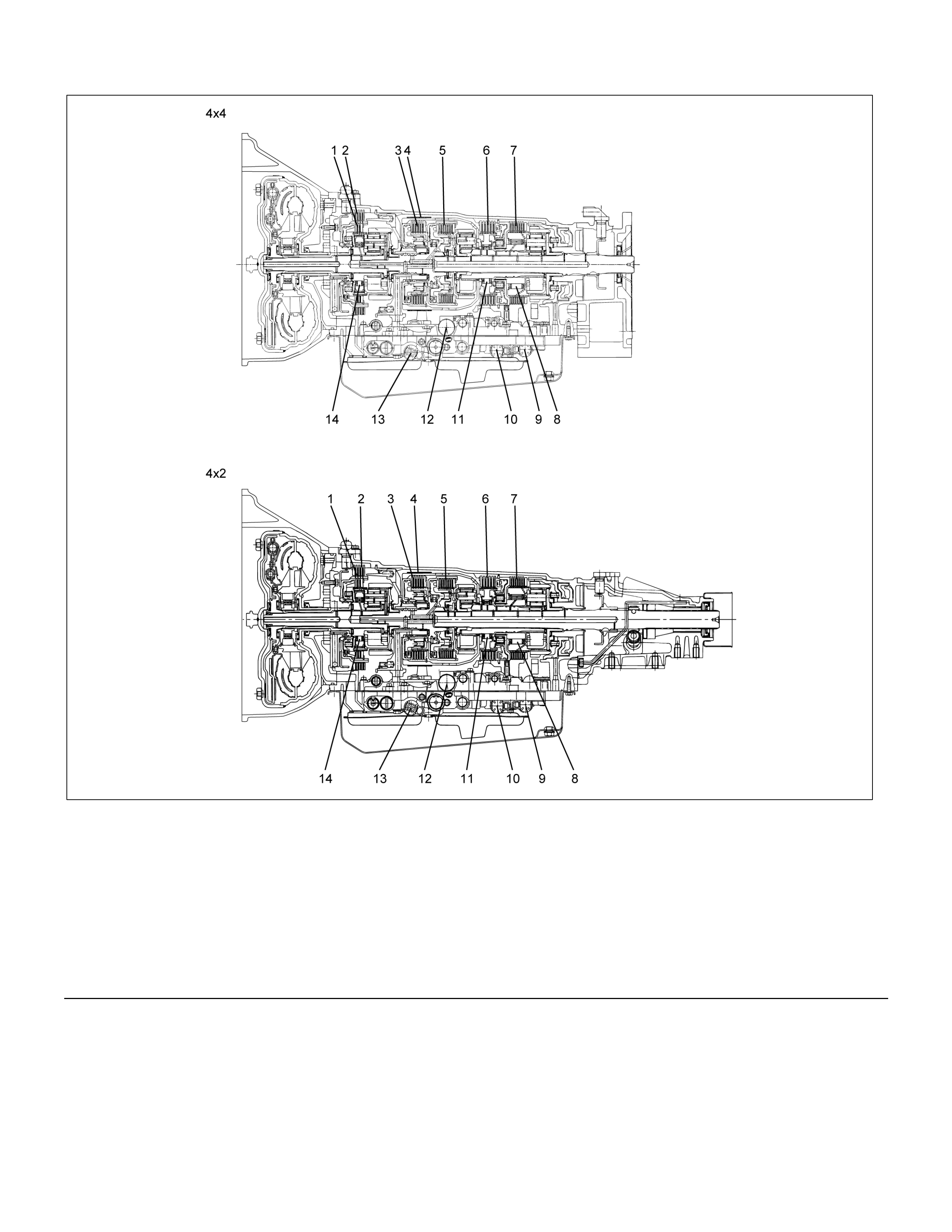
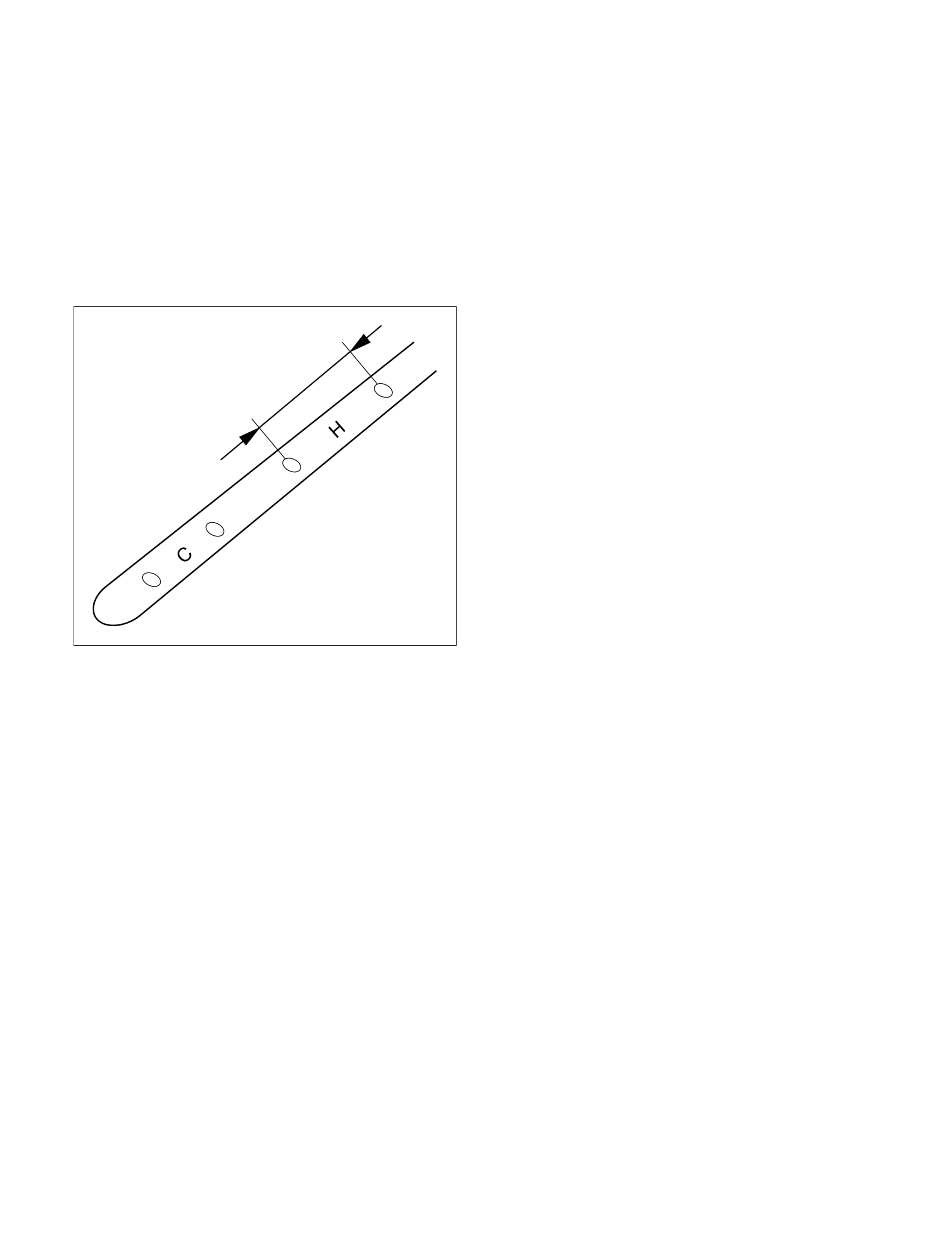
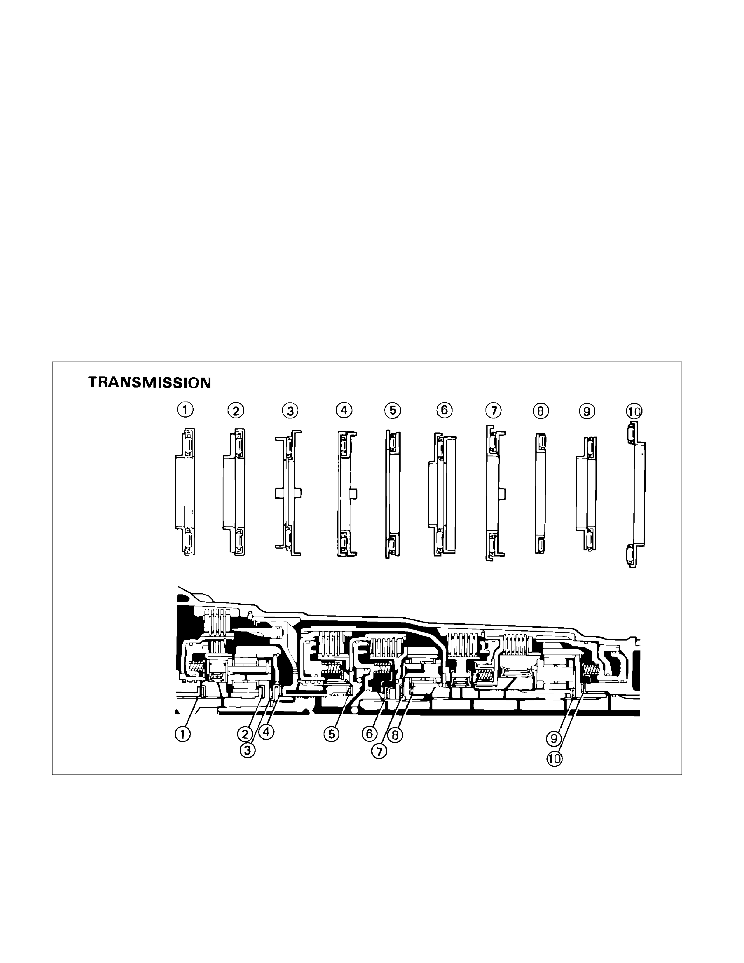
Location of Clutch, Brake, One-Way Clutch and Solenoid
RUW37ALF000201
Legend (8) One-way clutch (No.2) (F–2)
(1) Overdrive direct clutch (C–0) (9) Shift solenoid (S–1)
(2) Overdrive brake (B–0) (10) Shift solenoid (S–2)
(3) Direct clutch (C–2) (11) One-way clutch (No.1) (F–1)
(4) Second coast brake (B–1) (12) Pressure control solenoid (STH)
(5) Forward clutch (C–1) (13) Lock-up solenoid (SL)
(6) Second brake (B–2) (14) Overdrive one-way clutch (F–0)
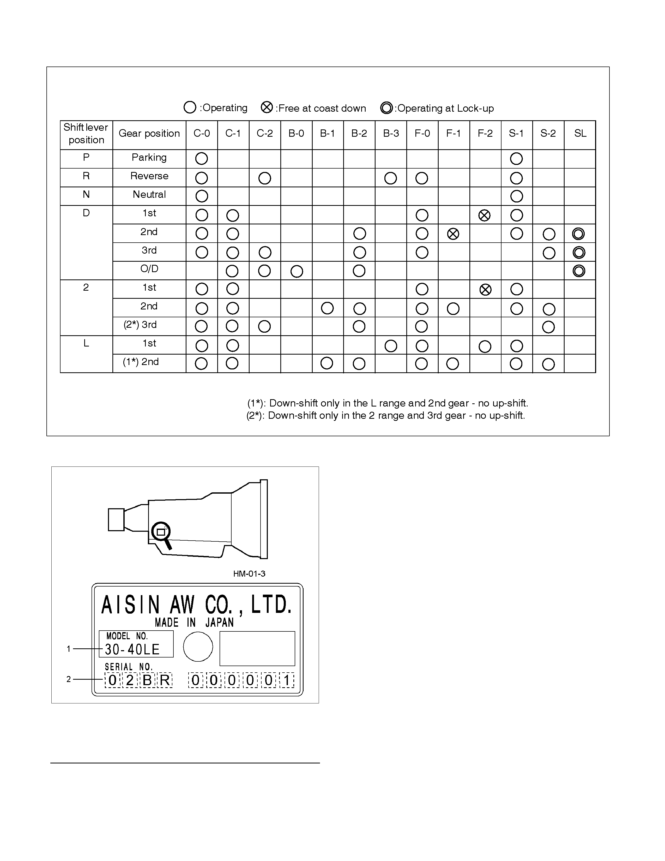
Operation of Clutch, Brake and One-Way Clutch
Transmission Identification
RUW37ASH004301
Legend
(1) Transmission Model Number
(2) Production Serial Number
The identification plate is located on the right rear side
of the transmission.

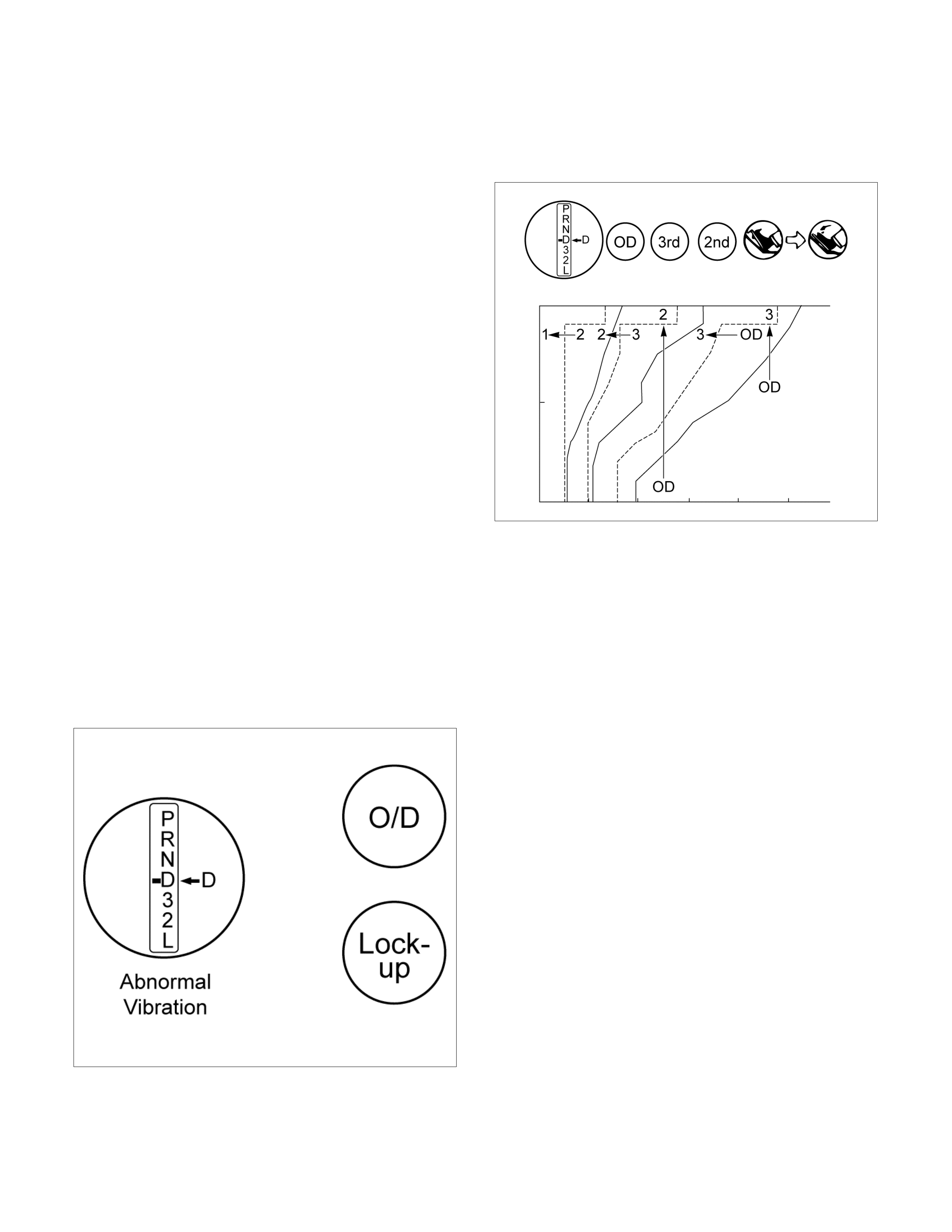
Speed Change and Lock-Up Pattern
If you select a speed as shown below by specifying
respective positions of transmission shift lever, transfer
switch and pattern select switch, the transmission
control computer controls speed change and lock-up
operations based on the specified pattern in accordance
with the degree of throttle opening and vehicle speed.
Pattern select sw.
position Transmission shift position
D 3 2 L
NORMAL, POWER 1st⇔[2nd]⇔[3rd]⇔[O/D] 1st⇔[2nd]⇔[3rd] 1st⇔2nd⇐(3rd) 1st⇐(2nd)
3rd START 3rd fixing — —
[ ]: The lock-up operation is available.
( ): Transmission is shifted at high speed to prevent overrun.
Overdrive and Lock-Up Operating Conditions
The overdrive and lock-up clutch operate if the following
conditions are satisfied.
Overdrive Lock-up clutch
Shift pattern position NORMAL NORMAL
Transmission shift position D range ←
Brake lamp switch — OFF
Throttle opening Fully closed Except fully closed
Accelerator About 52 km/h (32 mph) or more 2nd: About 76 km/h (47 mph) or
more
Vehicle speed Deceleration About 42 km/h (26 mph) or more 3rd: About 56 km/h (35 mph) or
more
O/D: About 67 km/h (42 mph) or
more
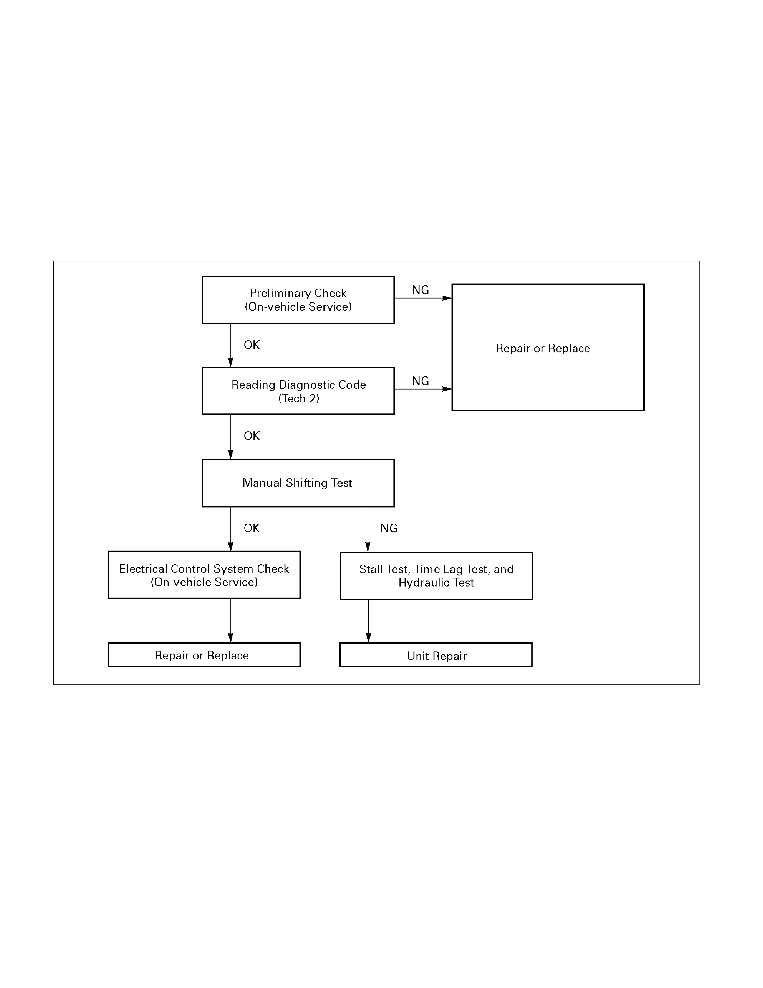
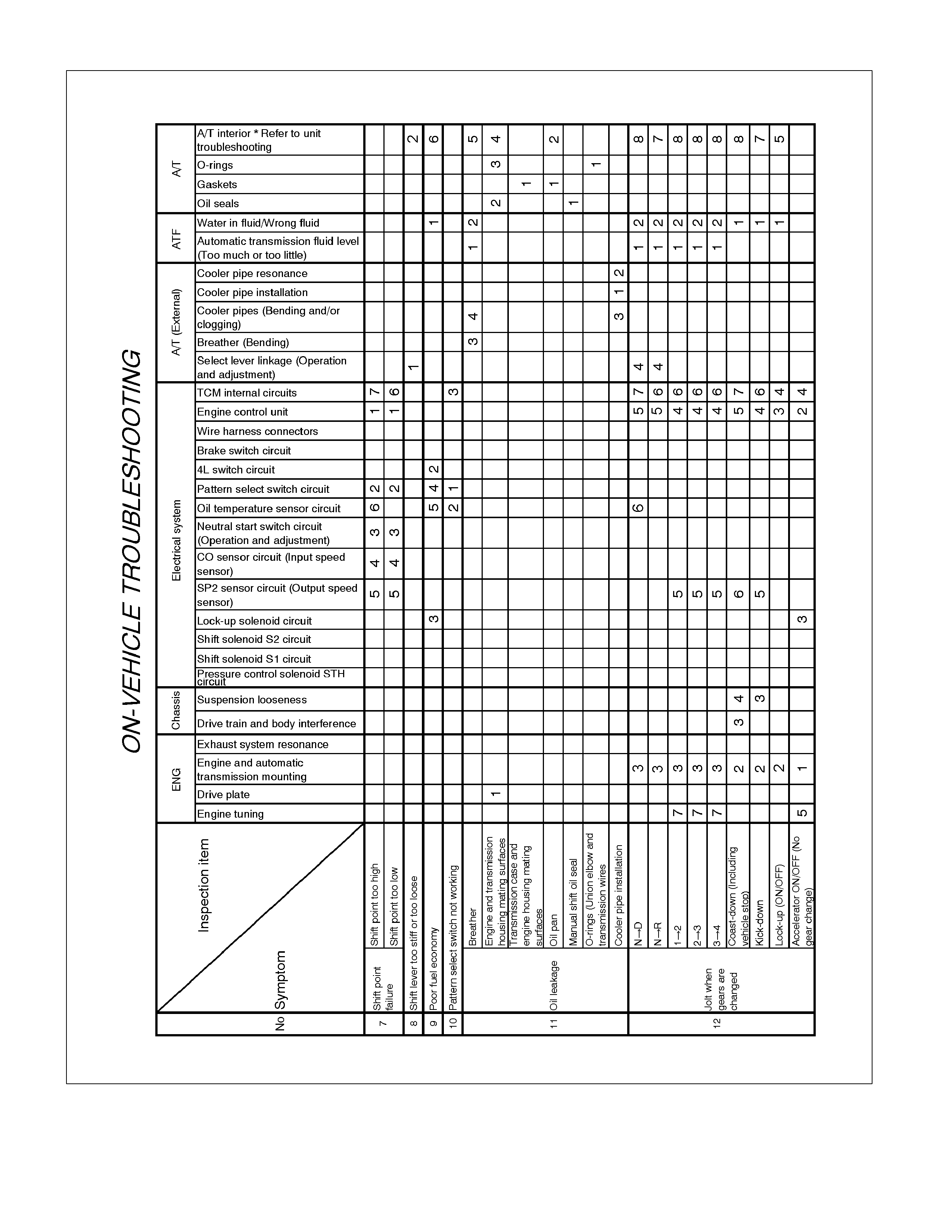
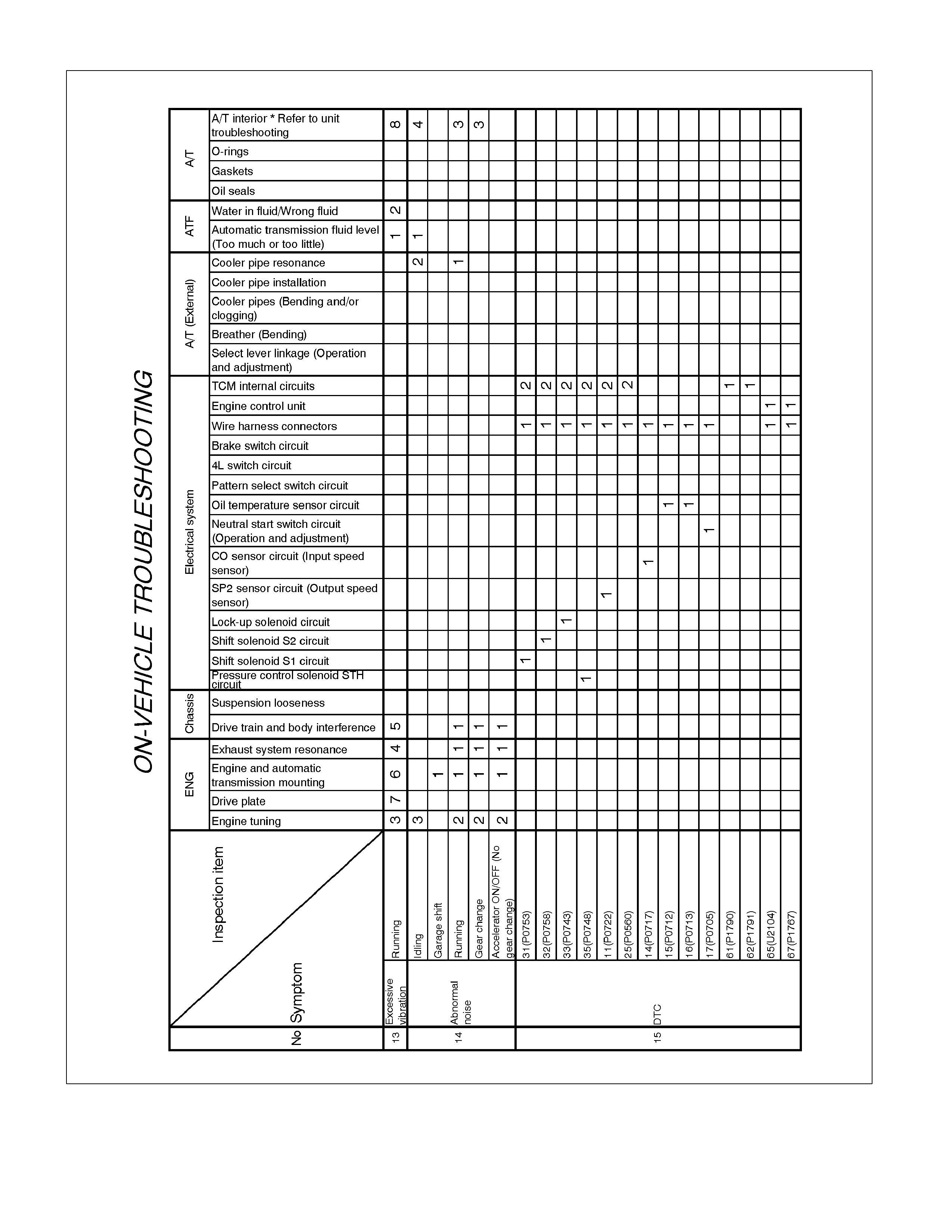
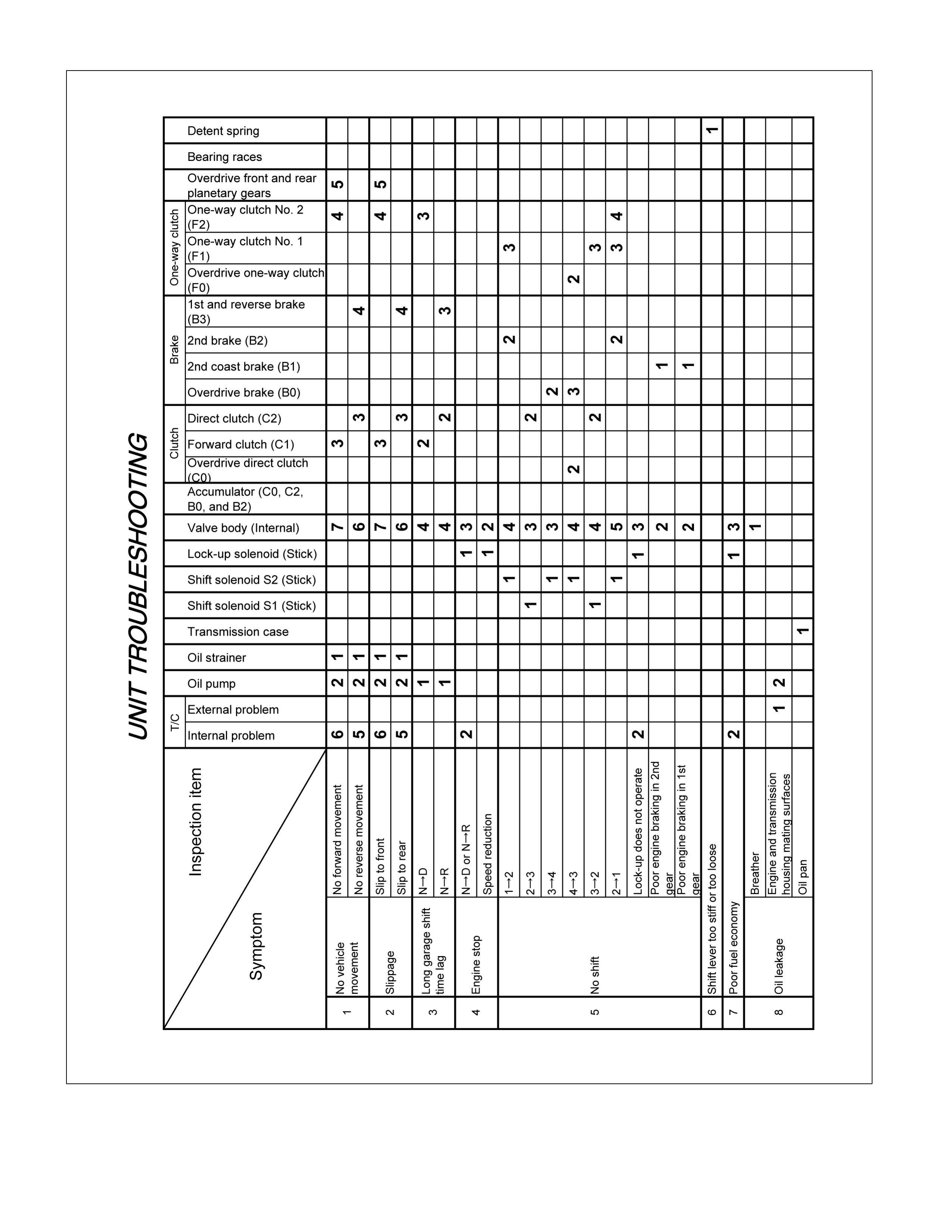
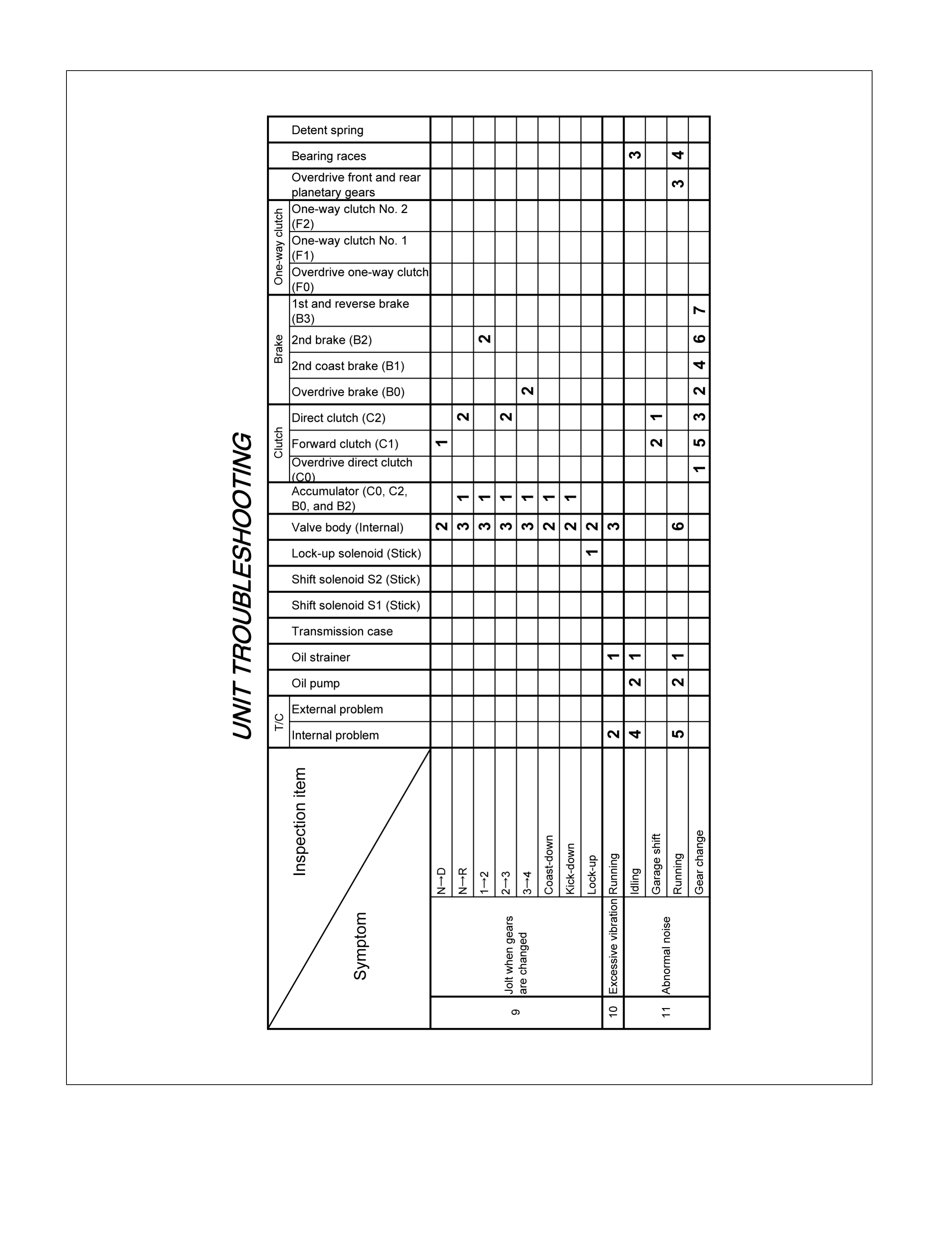
Diagnosis
Basic Troubleshooting
AW30–40LE transmission, with Transmission Control
Module (TCM), differs from the Mechanical – Hydraulic
control type transmissions. Accordingly, its
troubleshooting procedure differs also.
Before troubleshooting a TCM, first determine whether
the problem is electrical or mechanical. To do this, just
refer to the basic troubleshooting flowchart provided
below.
If the cause is already known, using the basic
troubleshooting chart below along with the
troubleshooting chart should speed the procedure.
F07R200005-X
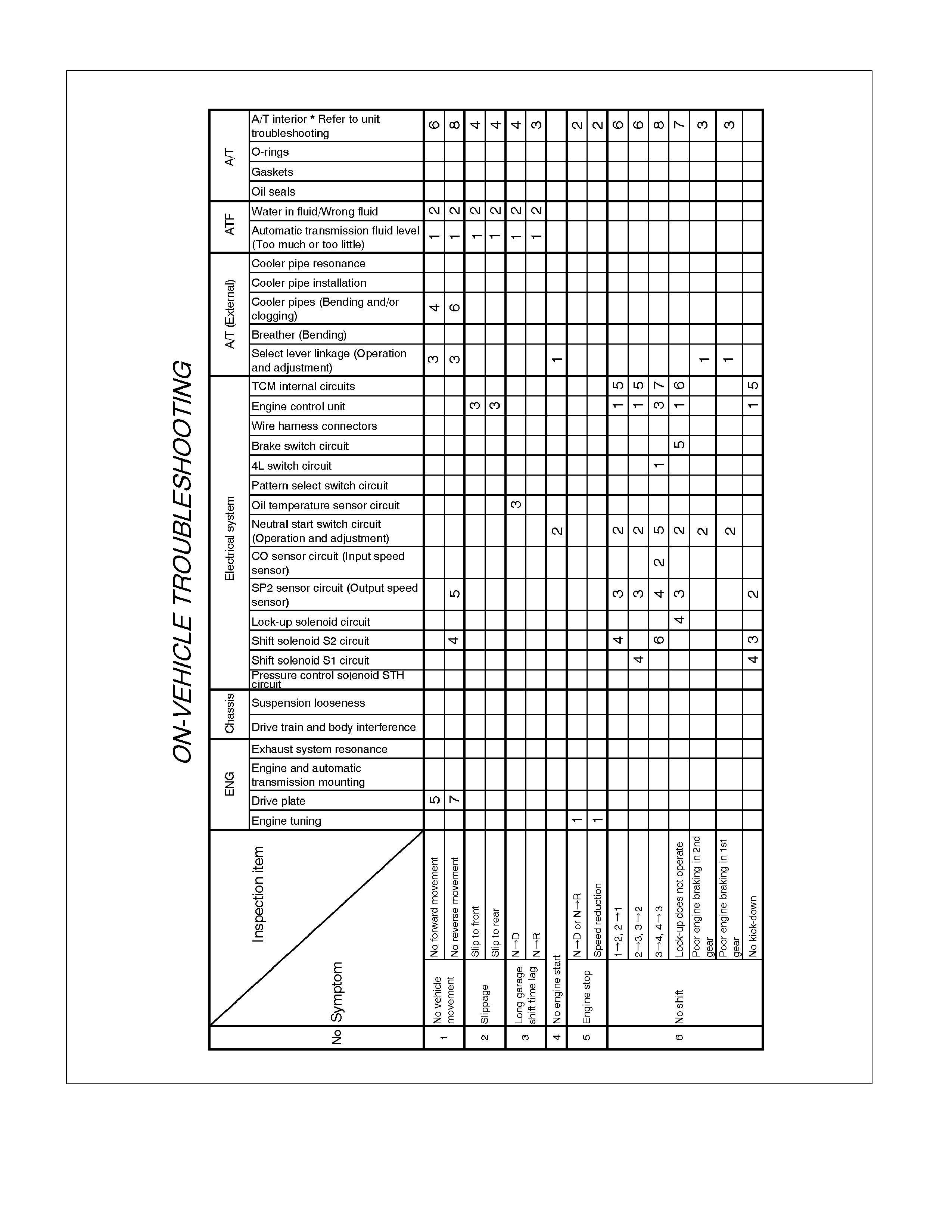
Troubleshooting Chart
Numbers are arranged in order of probability. Perform inspections starting with number one and
working up.
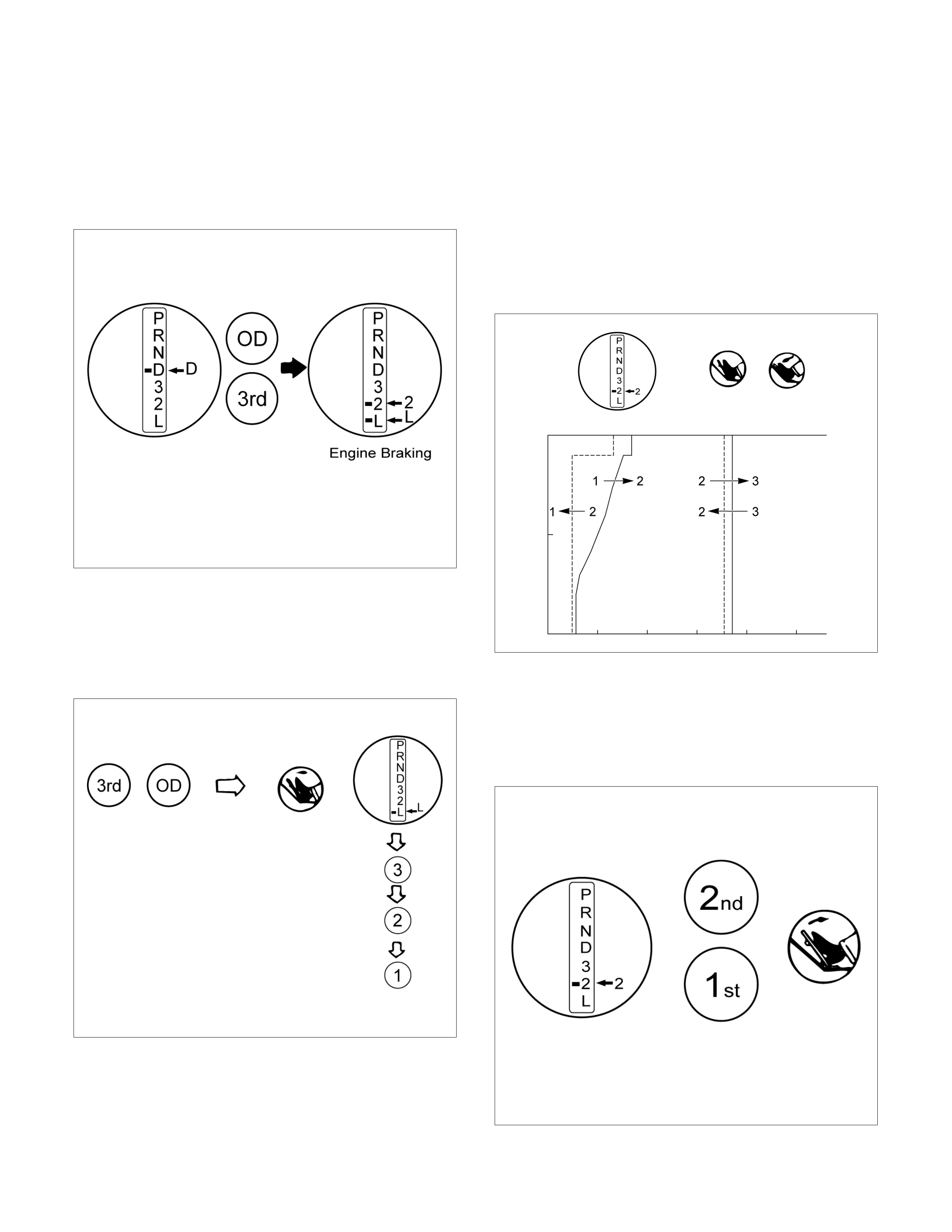
Manual Shifting Test
NOTE: With this test, it can be determined whether the
trouble lies within the electrical circuit or is a mechanical
problem in the transmission.
1. Disconnect TCM connector
Inspect manual driving operation
2. Inspect manual driving operation
Check that the shift and gear positions correspond
with the table.
If the “L", “2" “3" and “D" range gear positions are
difficult to distinguish, do perform the following road
test.
While driving, shift through the “L", “2" “3" and “D"
ranges. Check that the gear change corresponds to
the gear position.
If any abnormality is found in the above test, do
perform the stall, time lag or gear change tests.
RUW37ASH004101
3. Connect TCM connector
With the engine off, connect the TCM connector.
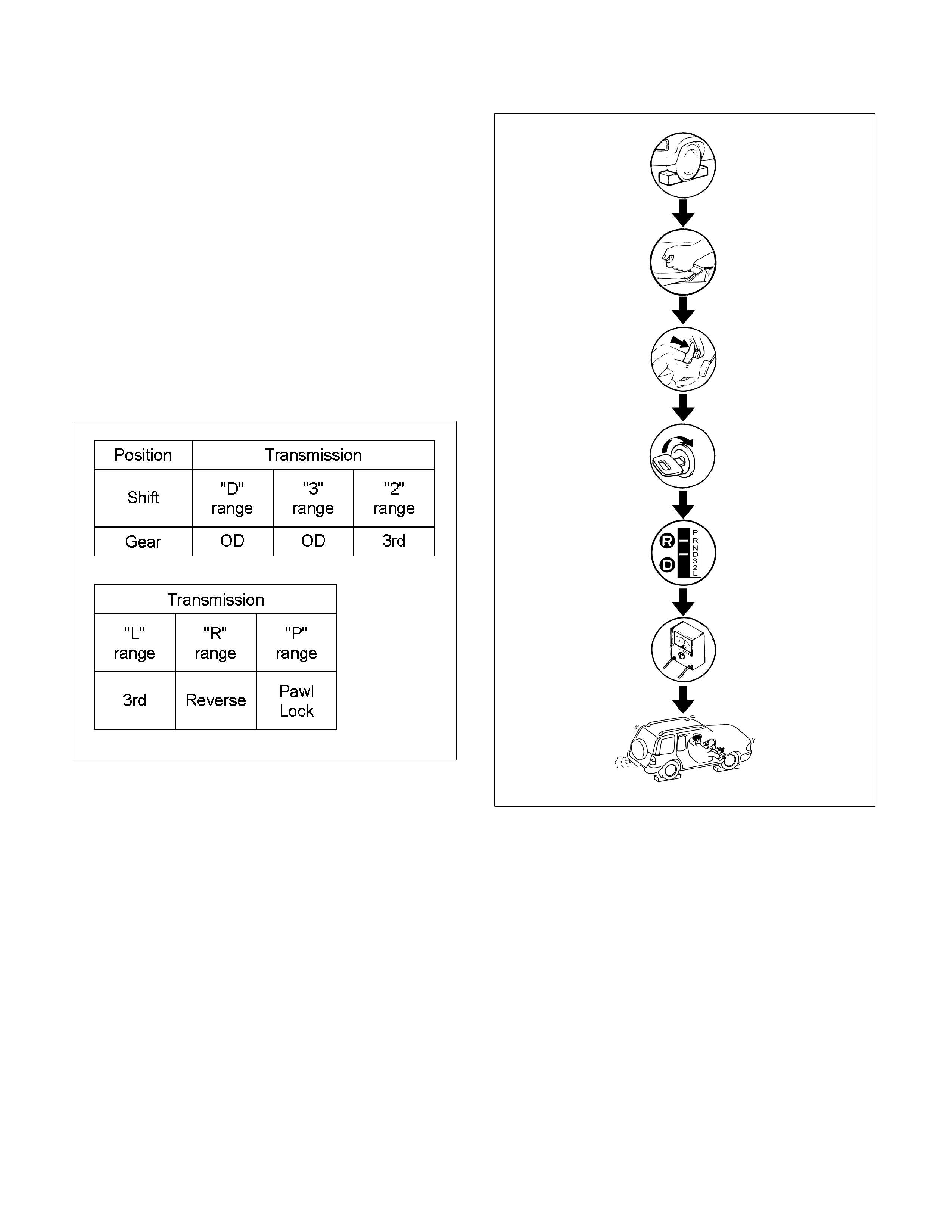
Stall Test
RUW37ALH000101
The object of this test is to check the overall
performance of the transmission and engine by
measuring the maximum engine speeds at the “D" and
“R" ranges.
NOTE:
1. Perform the test at normal operation fluid
temperature (50 – 80°C or 122 – 176°F).
2. Do not continuously run this test longer than 5
seconds.
Measure Stall Speed
1. Chock the four wheels.
2. Mount an engine tachometer.
3. Fully apply the parking brake.
4. Step down strongly on the brake pedal with your left
foot.
5. Start the engine.
6. Turn off the A/C.
7. Shift into the “D" range. Step all the way down on
the accelerator pedal with your right foot. Quickly
read the highest engine rpm.
Stall speed: 2200±
±±
±150 rpm
8. Perform the same test in the “R" range.
Evaluation
1. If the engine speed is the same for both ranges but
lower than the specified value:
• Engine output is insufficient.
• Stator one-way clutch is not operating properly.
NOTE: If more than 600 rpm below the specified value,
the torque converter could be faulty.
2. If the stall speed in “D" range is higher than
specified:
• Line pressure too low
• Forward clutch slipping
• No.2 one-way clutch not operating properly
3. If the stall speed in “R" range is higher than
specified:
• Line pressure too low
• Direct clutch sl ipping
• No.3 brake slipping
4. If the stall speed in the “R" and “D" ranges are
higher than specified:
• Line pressure too low
• Improper fluid level
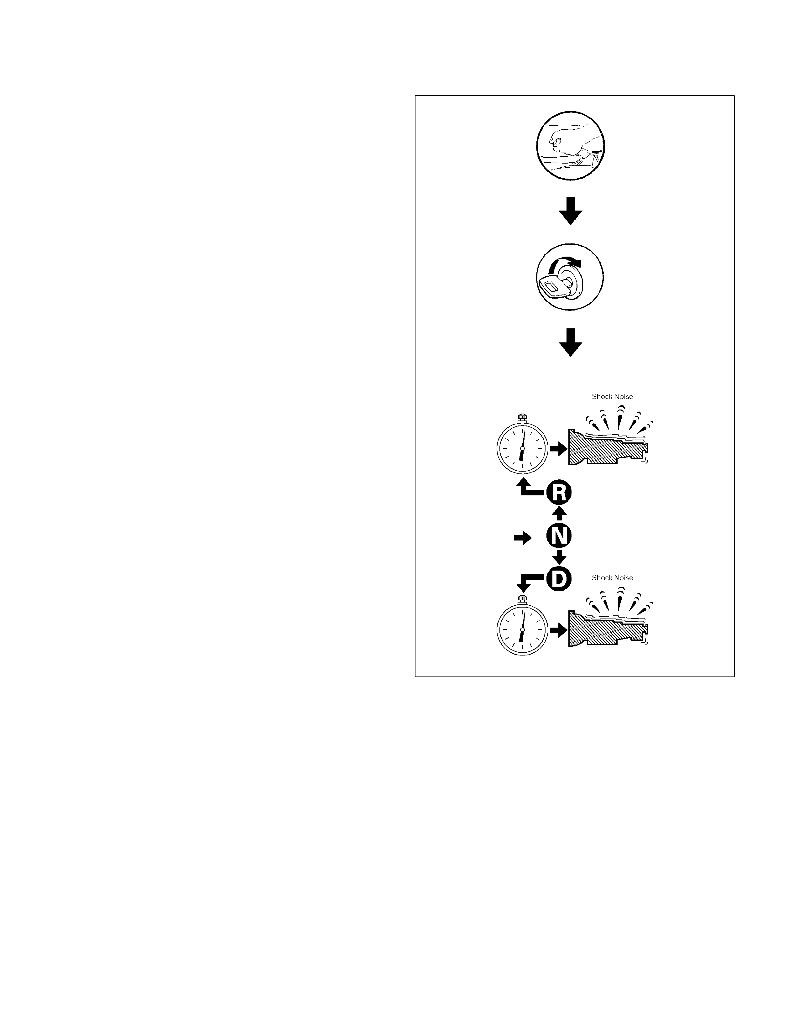
Time Lag Test
F07RY00003
If the shift lever is shifted while the engine is idling,
there will be a certain time elapse or lag before the
shock can be felt. This is used for checking the
condition of the forward clutch, direct clutch, No.3
brake, and No.2 one-way clutch.
NOTE:
1. Perform the test at normal operation fluid
temperature (50 – 80°C or 122 – 176°F)
2. Be sure to allow one minute interval between tests.
3. Make three measurements and take the average
value.
Measure Time Lag
1. Fully apply the parking brake.
2. Start the engine.
Check idling speed (A/C OFF).
3. Shift the shift lever from “N" to “D" range. Using a
stopwatch, measure the time it takes from shifting
the lever until the shock is felt.
Time lag: Less than 0.7 seconds
4. In same manner, measure the time lag for “N"
“R".
Time lag: Less than 1.2 seconds
Evaluation
1. If “N"
“D" time lag is longer than specified:
• Line pressure too low
• Forward clutch malfunction
• No.2 one-way clutch not operating properly
2. If “N"
“R" time lag is longer than specified:
• Line pressure too low
• Direct clutch malfunction
• No.3 brake malfunction
3. If both time lag is longer than specified:
• Line pressure too low
Hydraulic Test
RUW37ALH000201
Preparation
1. Warm up the transmission fluid.
2. Remove the transmission case test plug and mount
the hydraulic pressure gauge.
Oil pressure gauge: J–29770–A
NOTE: Perform the test at normal operation fluid
temperature (50 – 80°C or 122 – 176°F).
Measure Line Pressure
1. Fully apply the parking brake and chock the four
wheels.
2. Start the engine and check idling rpm.
3. Shift into “D" range, step down strongly on the brake
pedal with your left foot and, while manipulating the
accelerator pedal with the right foot, measure the
line pressures at the engine speeds specified in the
table.
4. In the same manner, perform the test in “R" range.
Line pressure kPa (kg/cm2/psi)
Engine
speed “D" range “R" range
Idling 323 – 382
(3.3 – 3.9/47 – 55) 500 – 598
(5.1 – 6.1/73 – 87)
Stall 1,137 – 1,274
(11.6–13.0/165–185) 1,499 – 1,833
(15.3–18.7/218–266)
Evaluation
1. If the measured values at all ranges are higher than
specified:
• Pressure control solenoid defective
• Primary regulator valve defective
2. If the measured values at all ranges are lower than
specified:
• Primary regulator valve defective
• Oil pump defective
• Pressure control solenoid defective
3. If pressure is low in “D" range only:
• “D" range circuit fluid leakage
4. If pressure is low in “R" range only:
• “R" range circuit fluid leakage
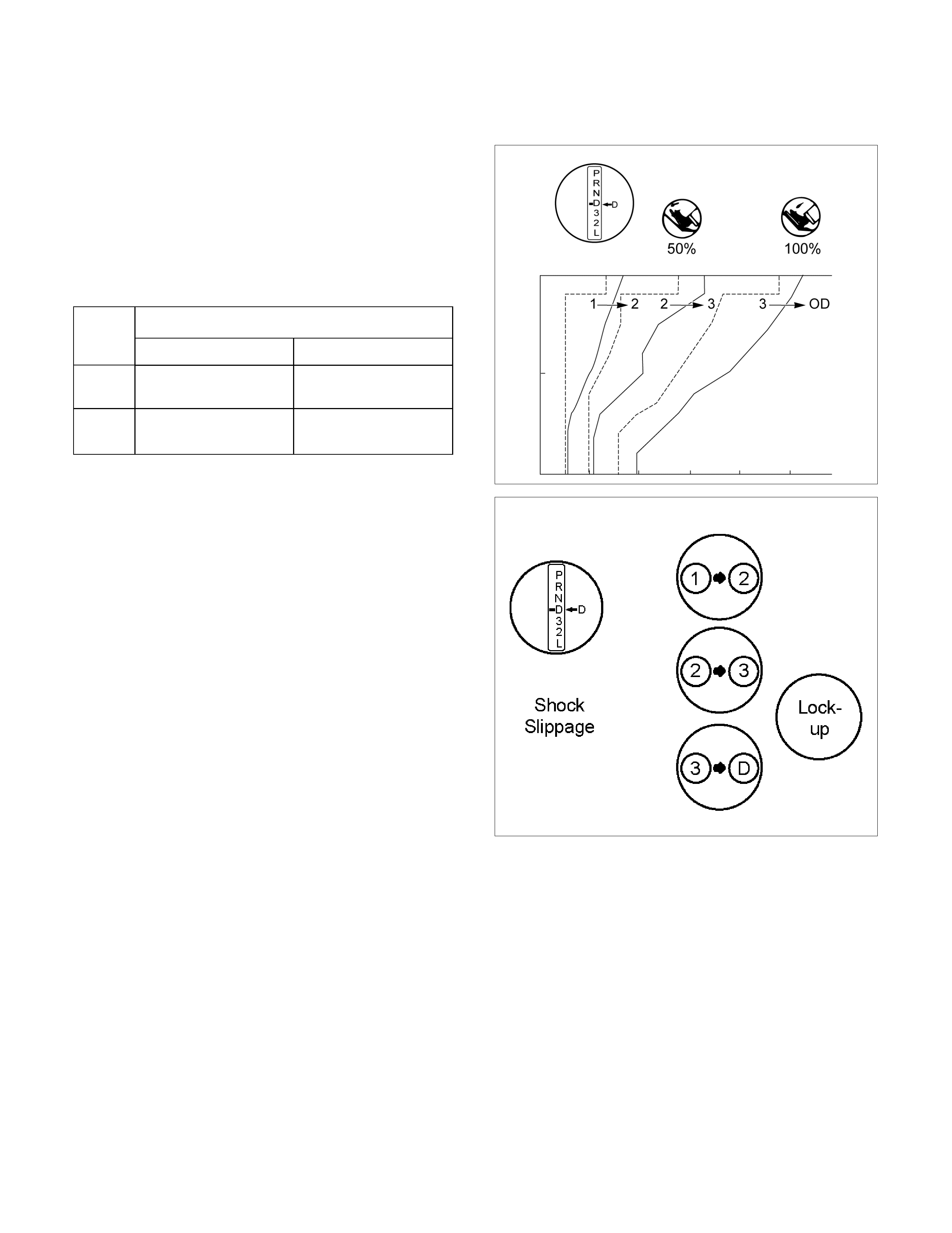
Road Test
NOTE: Perform the test at normal operation fluid
temperature (50 – 80°C or 122 – 176°F).
“D" Range Test in “NORMAL", and “POWER"
Pattern Ranges
Shift into the “D" range and hold the accelerator pedal
constant at the 50% and 100% throttle valve opening
positions.
Push in one of the pattern selector buttons and check
the following:
1. 1–2, 2–3, 3–OD and lock-up, up-shifts should take
place, and shift points should conform to those
shown in the automatic shift diagram.
RUA370MH000101
RUA37ASH000101
Evaluation
i. If there is no 1→2 up-shift:
• Solenoid S2 is stuck
• 1–2 shift valve is stuck
ii. If there is no 2→3 up-shift:
• Solenoid S1 is stuck
• 2–3 shift valve is stuck
iii. If there is no 3→OD up-shift (throttle valve opening
1/2):
• Solenoid S2 is stuck
• 3–OD shift valve is stuck
iv. If the shift point is defective:
Refer to TROUBLESHOOTING CHART in this
section.
v. If the lock-up is defective:
Refer to TROUBLESHOOTING CHART in this
section.
2. In the same manner, check the shock and slip at the
1→2, 2→3 and 3→OD up-shifts.
NOTE: Drive the vehicle on level ground.
Evaluation
If the shock is excessive:
Refer to TROUBLESHOOTING CHART in this section.
3. Run at “D" range lock-up or OD gear and check for
abnormal noise and vibration.
NOTE: The check for the cause of abnormal noise and
vibration must be made with extreme care as it could
also be due to loss of balance in the propeller shaft,
differential, the torque converter, etc. or insufficient
bending, rigidity , etc. in the power train.
RUW37ASH000201
4. While running in “D" range, 2nd, 3rd gears and OD,
check to see that the possible kick-down vehicle
speed limits for 2→1, 3→1, 3→2, OD→3 and
OD→2 kick-downs conform to those indicated on
the automatic shift diagram.
RUW37AMH000101
5. Check for abnormal shock and slip at kick-down.
6. While running in “D" range, OD gear or “lock-up",
shift to “2" and “L" ranges and check the engine
braking effect at each of these ranges.
7. Also check to see that downshift is made from 3→2
or from OD to 3 and then to 2 immediately and that
2→1 downshift point is within the limits shown in the
diagram when tested by releasing the accelerator
pedal and shifting into position of “L" while driving in
the third gear or in overdrive.
Evaluation
i. If there is no engine braking effect in the “2" range:
• Second coast (No.1) brake is defective.
ii. If there is no engine braking effect in the “L" range:
• First and reverse (No.3) brake is defective.
RUW37ASH000301
iii. Also check to see that downshift is made from 3→2
or from OD to 3 and then to 2 immediately and that
2→1 downshift point is within the limits shown in the
diagram when tested by releasing the accelerator
pedal and shifting into “L" position while driving in
the third gear or in overdrive.
RUW37ASH000401
“2" Range Test
Shift into “2" range and, while driving with the
accelerator pedal held constantly at the specified point
(throttle valve opening 50% and 100%), push in one of
the pattern selectors (only for 44) and check on the
following points.
1.
A
t each of the above throttle openings, check to see
that the 1→2 up-shift takes place and that the shift
points conform to those shown on the automatic
shift diagram.
NOTE: There is no OD and no lock-up in the “2" range.
RUW37AMH000201
2. While running in the “2" range and 2nd gear,
release the accelerator pedal and check the
engine's braking effect.
3. Check for 2→1 down-shift and abnormal noise at
acceleration and deceleration, and for shock at
upshift and down-shift.
RUW37ASH000501
“L" Range Test
1. While running above 80 km/h (50 mph) in the “D"
range, release your foot from the accelerator pedal
and shift into the “L" range.
Then check to see that the 2→1 down-shift occurs
at the specified point shown on the automatic shift
diagram.
RUW37ASH000601
2. While running in the “L" range, check to see that
there is no up-shift to 2nd gear.
3. While running in the “L" range, release the
accelerator pedal and check the engine braking
effect.
4. Check for abnormal noise during acceleration and
deceleration.
RUW37ASH000701
“R" Range Test
Shift into the “R" range and, while starting at full throttle,
check for slipping.
RUW37ASH000801
“P" Range Test
Stop the vehicle on a grade (more than 9%) and after
shifting into the “P" range, release the parking brake.
Then check to see that the parking lock pawl holds the
vehicle in place.

Shift and Lock-Up Point Chart
Shift Pont Cha rt
(H2, H4)
(REAR AXLE RATIO: 4.300)
(RADIUS OF TYRE: 0.361m)
“NORMAL" mode
Upshift km/h (mph)
Range Throttle Opening 1→
→→
→2 2→
→→
→3 3→
→→
→4
Fully opened 48 – 54 (30 – 34) 104 – 110 (65 – 68) 177 – 183 (110 – 114)
D Half throttle 32 – 38 (20 – 24) 59 – 65 (37 – 40) 114 – 120 (71 – 75)
Fully opened 48 – 54 (30 – 34) 104 – 110 (65 – 68) —
3 Half throttle 32 – 38 (20 – 24) 59 – 65 (37 – 40) —
Fully opened 48 – 54 (30 – 34) — —
2 Half throttle 32 – 38 (20 – 24) — —
Downshift km/h (mph)
Range Throttle Opening 1→
→→
→2 2→
→→
→3 3→
→→
→4
Fully opened 37 – 43 (23 – 27) 94 – 100 (58 – 62) 155 – 161(96 – 100)
Half throttle 15 – 21 (9 – 13) 33 – 39 (21 – 24) 65 – 71 (40 – 44)
D
Fully closed 9 – 15 (6 – 9) 20 – 26 (12 – 16) 39 – 45 (24 – 28)
Fully opened 37 – 43 (23 – 27) 94 – 100 (58 – 62) —
Half throttle 15 – 21 (9 – 13) 33 – 39 (21 – 24) —
3
Fully closed 9 – 15 (6 – 9) 20 – 26 (12 – 16) —
Fully opened 37 – 43 (23 – 27) 94 – 100 (58 – 62) —
Half throttle 15 – 21 (9 – 13) 94 – 100 (58 – 62) —
2
Fully closed 9 – 15 (6 – 9) 94 – 100 (58 – 62) —
L — 37 – 43 (23 – 27) — —
“POWER" mode
Upshift km/h (mph)
Range Throttle Opening 1→
→→
→2 2→
→→
→3 3→
→→
→4
Fully opened 48 – 54 (30 – 34) 104 – 110 (65 – 68) 177 – 183 (110 – 114)
D Half throttle 38 – 44 (24 – 27) 74 – 80 (46 – 50) 128 – 134 (80 – 83)
Fully opened 48 – 54 (30 – 34) 104 – 110 (65 – 68) —
3 Half throttle 38 – 44 (24 – 27) 74 – 80 (46 – 50) —
Fully opened 48 – 54 (30 – 34) — —
2 Half throttle 38 – 44 (24 – 27) — —
Downshift km/h (mph)
Range Throttle Opening 1→
→→
→2 2→
→→
→3 3→
→→
→4
Fully opened 39 – 45 (24 – 28) 94 – 100 (58 – 62) 155 – 161(96 – 100)
Half throttle 21 – 27 (13 – 17) 50 – 56 (31 – 35) 95 – 101 (59 – 63)
D
Fully closed 13 – 19 (8 – 12) 24 – 30 (15 – 19) 47 – 53 (29 – 33)
Fully opened 39 – 45 (24 – 28) 94 – 100 (58 – 62) —
Half throttle 21 – 27 (13 – 17) 50 – 56 (31 – 35) —
3
Fully closed 13 – 19 (8 – 12) 24 – 30 (15 – 19) —
Fully opened 39 – 45 (24 – 28) 94 – 100 (58 – 62) —
Half throttle 21 – 27 (13 – 17) 94 – 100 (58 – 62) —
2
Fully closed 13 – 19 (8 – 12) 94 – 100 (58 – 62) —
L — 39 – 45 (24 – 28) — —
“3rd START" mode km/h (mph)
‘D’ Range, Winter mode ON→OFF 32 – 38 (20 – 24)

Lock-Up Point Chart
(H2, H4)
(REAR AXLE RATIO: 4.300)
(RADIUS OF TYRE: 0.361m) km/h (mph)
Throttle Opening: 20 %
Lock-up ON Lock-up OFF
Range
A/T Mode
3rd 4th 3rd 4th
NORMAL 53 – 59 (33 – 37) 64 – 70 (40 – 43) 45 – 51 (28 – 32) 60 – 66 (37 – 41)
D POWER 78 – 84 (49 – 52) 81 – 87(50 – 54) 68 – 74 (42 – 46) 73 – 79 (45 – 49)
Lock-up points in 2nd are following figures regardless
of throttle opening, whether NORMAL or POWER
mode.
Lock-up ON: 73 – 79 km/h (45 – 49 mph)
Lock-up OFF: 68 – 74 km/h (42 – 46 mph)
Transmission Fluid Level and Condition
Inspection
Park vehicle on level ground and set parking brake.
With the engine idling, move the shift lever through all
positions from “P" to “L", then return to position “P".
Check to see if the level of fluid comes to “HOT" range
of about 80°
°°
°C (176°
°°
°F) on the dipstick gauge.
If the level of fluid is too low, replenish to bring it to
maximum level in “HOT" range.
Inspection of fluid condition. If the ATF is black or
smells burnt, replace it.
RUW37ASH002501
ATF Replacement
Inspection
NOTE: Do not overfill.
1. Remove the drain plug from oil pan and drain the
fluid.
RUW17ASH013401
2. Reinstall the drain plug securely.
Torque: 19 N⋅
⋅⋅⋅m (14 Ib ft)
3. With the engine OFF, add new fluid through the fille
r
tube.
Drain and refill 5.2 liter
Dry fill 8.7 liter
Fluid BESCO ATF III
4. Start the engine and shift the selector into all
position from “P" through “L", and then shift into “P".
5. With the engine idling, check the fluid level. Add
fluid up to the “COLD" level on the dipstick.
6. The ATF level must be checked again for correct
level with the “HOT" level.
NOTE: To prevent fluid leaks, the drain plug gasket
must be replaced each time this plug is removed.
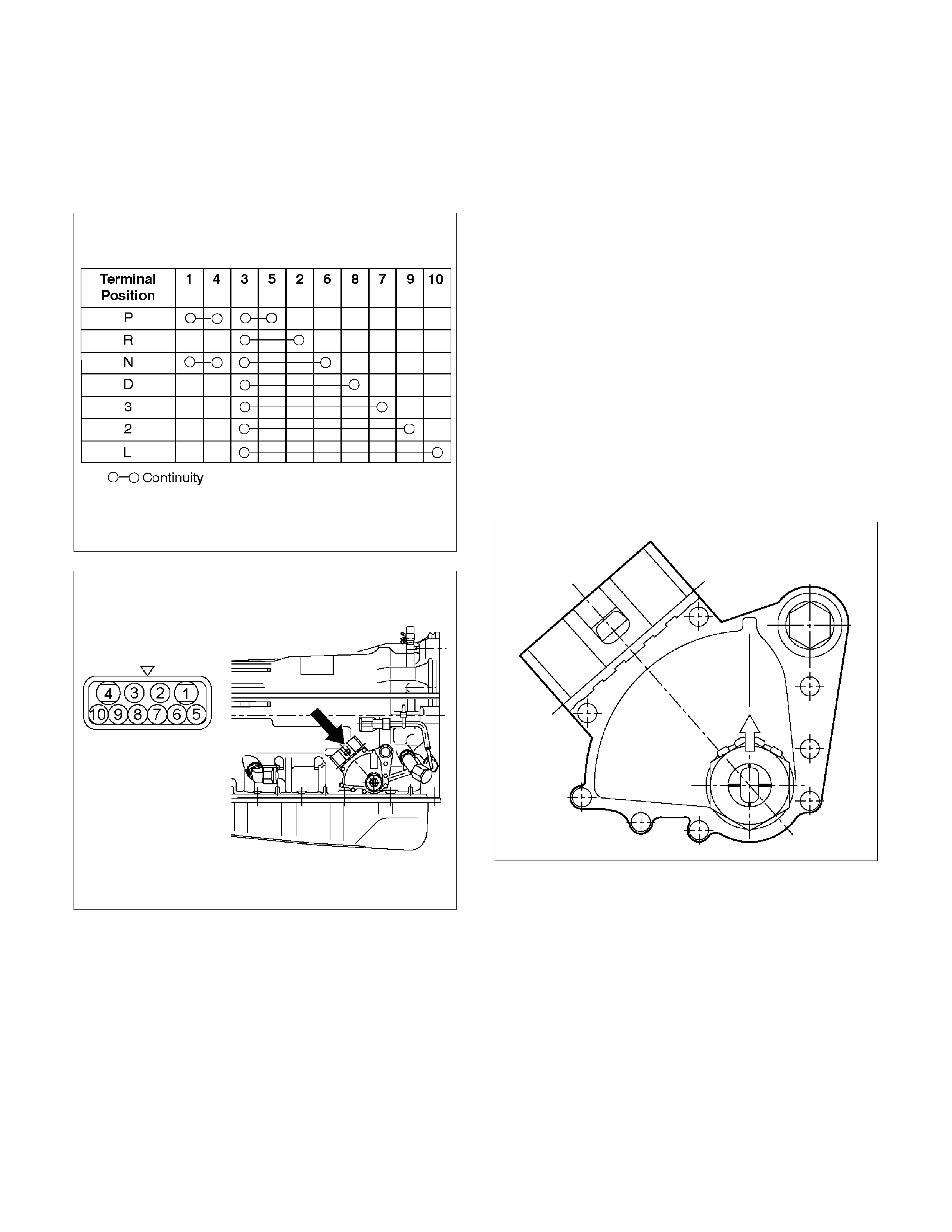
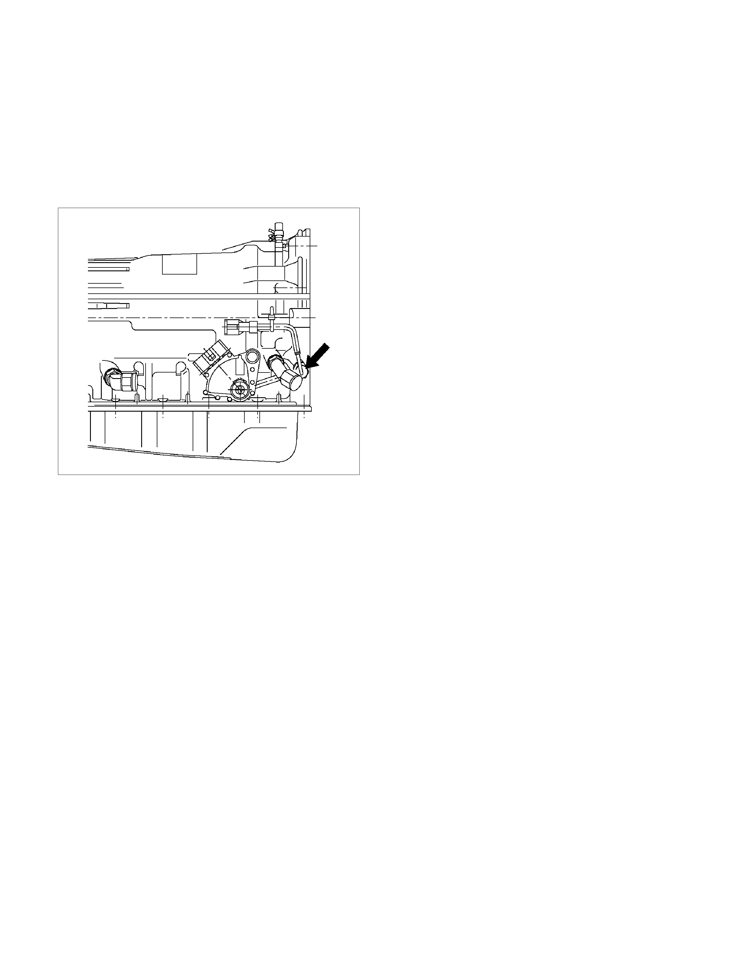
Neutral Start Switch (Mode Switch)
Inspection
With a circuit tester, make a continuity test on the
neutral start switch with the moving piece set in each
position.
RTW37BSH000101
Removal
Preparation:
Disconnect negative (–) battery cable.
1. Remove the rear side ATF cooler pipe from the
transmission elbow.
2. Disconnect neutral start switch connector.
3. Unstake the lock washer, and then remove the shaft
nut.
4. Remove the neutral start switch.
Installation
To install, follow the removal steps in the reverse order,
noting the following points;
If an engine starts at any selector position except “N” or
“P”, the neutral start switch (mode switch) should be
adjusted.
1. Loosen the neutral start switch bolt and set the shift
selector to the “N" range.
2. Align the groove and neutral basic line.
3. Hold in position and tighten the bolt and nut.
Torque:
Nut – 7 N⋅
⋅⋅⋅m (61 Ib in)
Bolt – 13 N⋅
⋅⋅⋅m (113 Ib in)
4. Lock the nut with the lock washer tubs at two points.
RUW17ASH013601
Brake Signal
Inspection
Check that the brake light comes on when the brake
pedal is depressed.
310RW020
Input and Output Revolution Sensor
Inspection
1. Disconnect the input and output revolution sensor
connector.
2. Use an ohmmeter to measure the resistance
between terminals 1 and 2.
Standard resistance
Input revolution sensor: 387 – 473 (at 20°
°°
°C,
42), 560 – 680 (at 20°
°°
°C, 44)
Output revolution sensor: 560 – 680 (at 20°
°°
°C)
F07RY00018
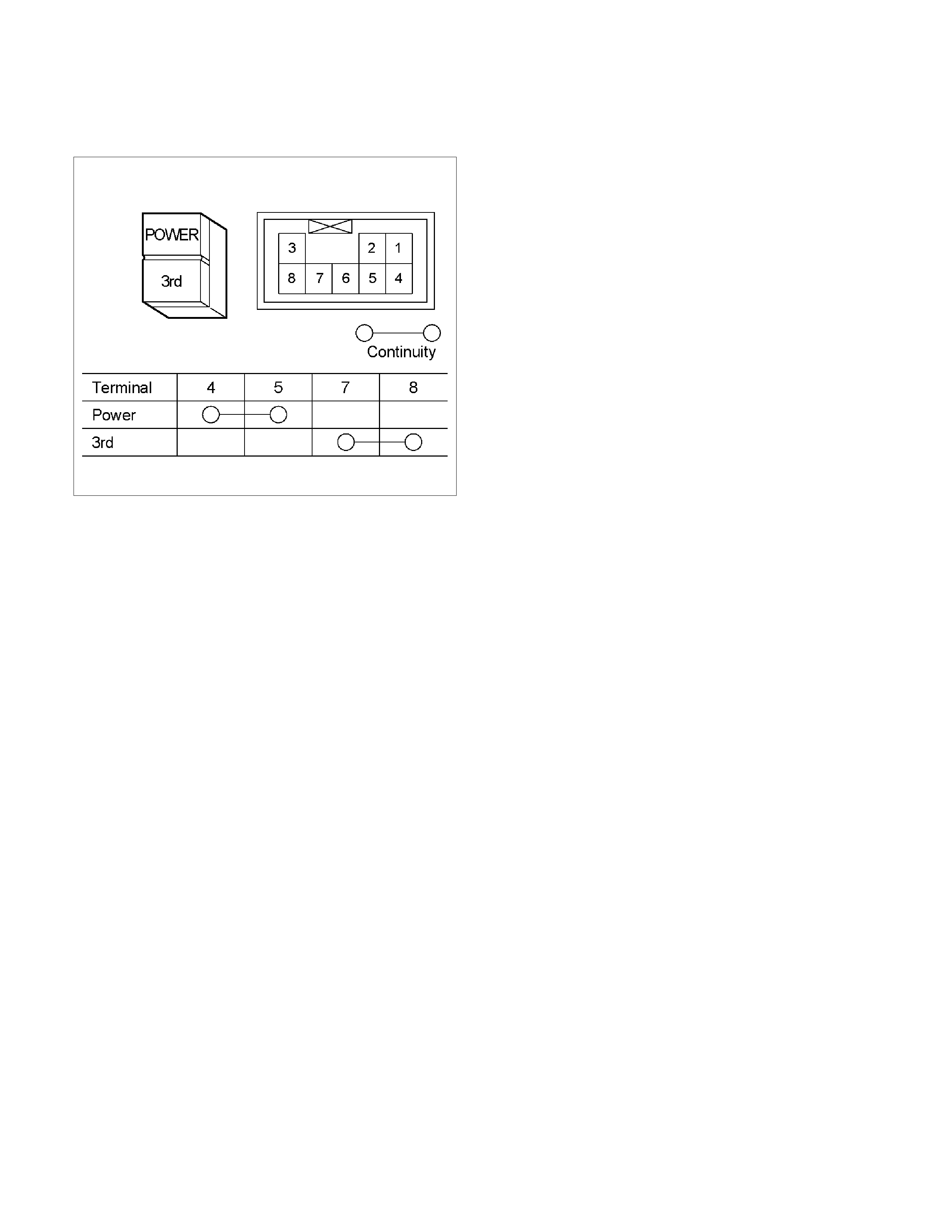
Pattern Select Switch
Inspection
Inspect that there is continuity between each terminals.
RTW37ASH000501

Solenoid
Inspection
1. Resistance check
• Using an ohmmeter, check the resistance
between each terminals (S1/S2/SL) and body.
Solenoid S1, S2 and lock-up solenoid SL
resistance:
11 – 15 (at 20°
°°
°C)
(Reference) 12 – 16 (at 40°
°°
°C)
• Using an ohmmeter, check the resistance
between each terminals (STH) and (STHG).
Pressure control solenoid resistance:
5 – 5.6 (at 20°
°°
°C)
(Reference) 5.4– 6.1 (at 40°
°°
°C)
220L100001
NOTE: If the pressure control solenoid resistance is
not within speciation, replace the valve body assembly.
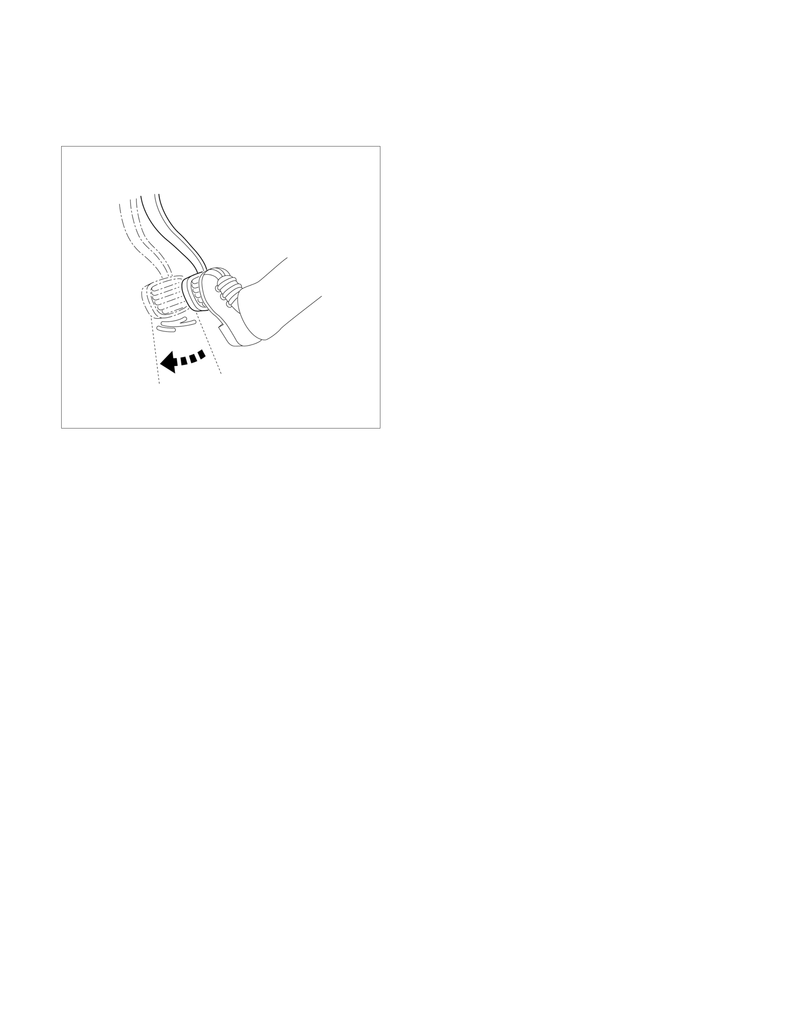
2. Operation check
Check the solenoid operation by blowing into an oil
hole as shown in the figure.
Solenoid S1 and S2 (Normal close ty pe)
When battery terminal is
disconnected No air leaks
When battery terminal is
connected Air passes through
Lock-up solenoid SL (Normal open type)
When battery terminal is
disconnected Air passes through
When battery terminal is
connected No air leaks
244RX00001
244RY00005
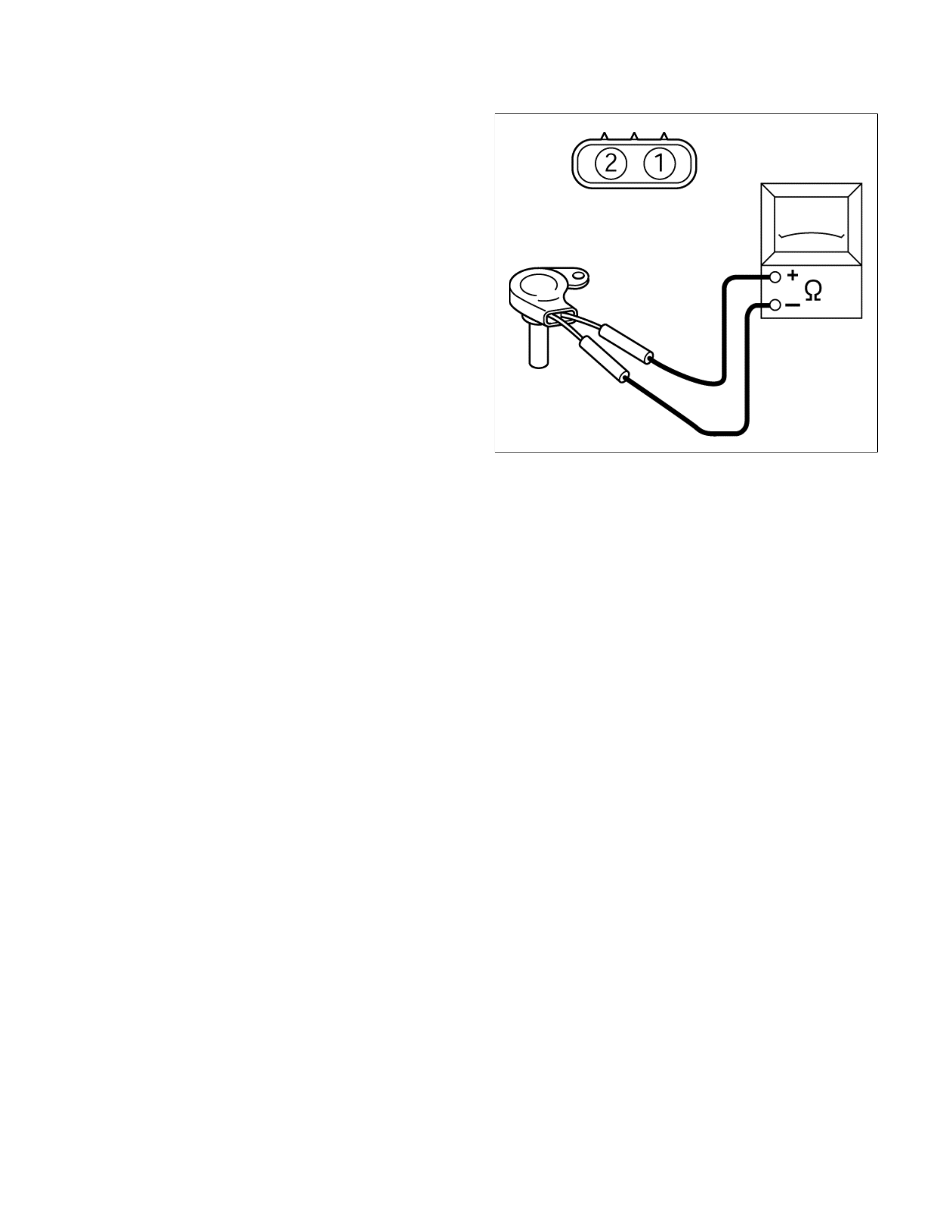
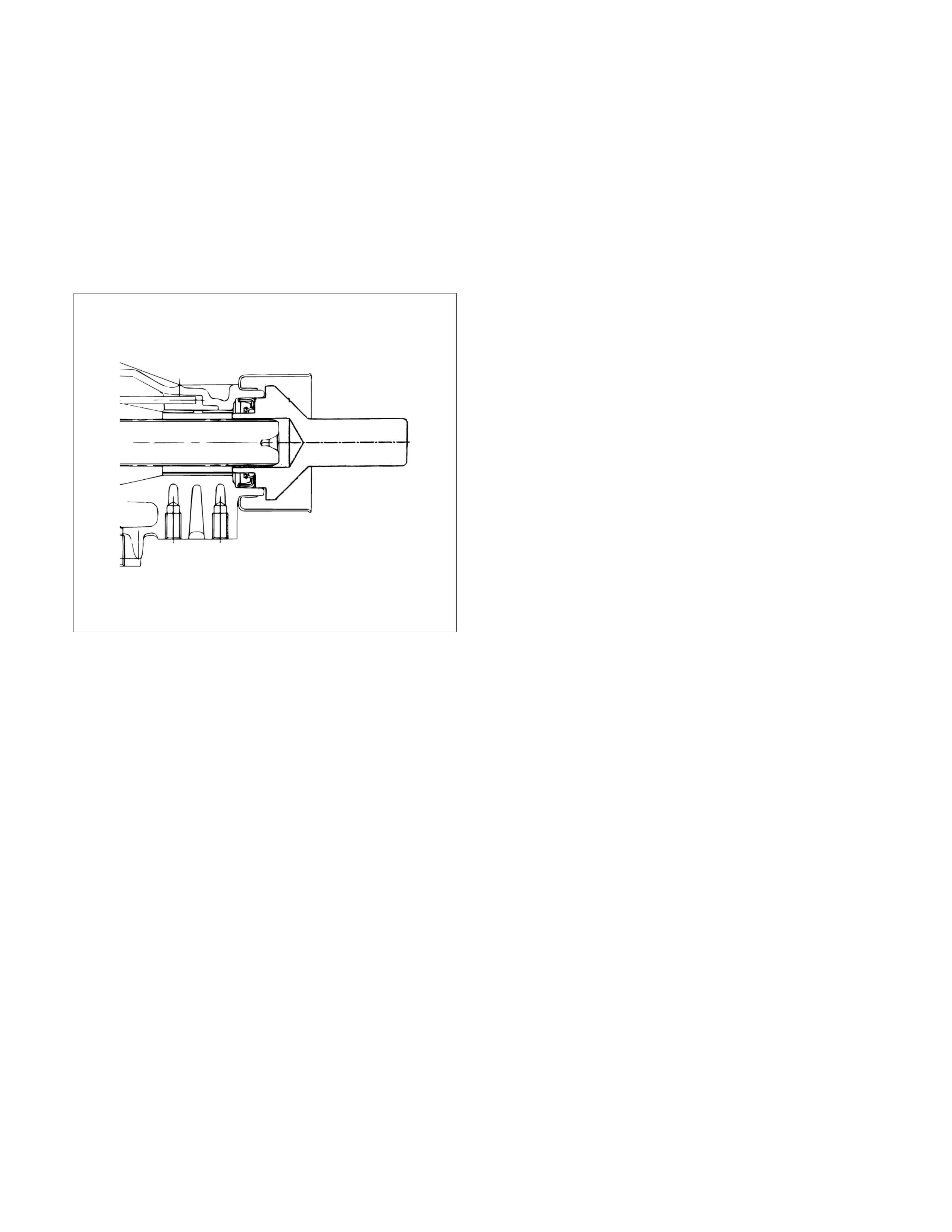
ATF Temperature Sensor
Inspection
1. Disconnect the front side ATF cooler pipe from the
elbow and remove the elbow.
2. Remove the ATF temperature sensor from the
transmission case.
3. Place the ATF temperature sensor in a container of
ATF.
RUW37ASH004001
4. Measure the resistance between each terminal,
while warming ATF.
Resistance: 0.5 – 30 k (at 0°
°°
°C – 120°
°°
°C)
5. If either of the measured values exceeds the
specified value, replace the ATF temperature
sensor.
Torque: 15 N⋅
⋅⋅⋅m (11 Ib ft)
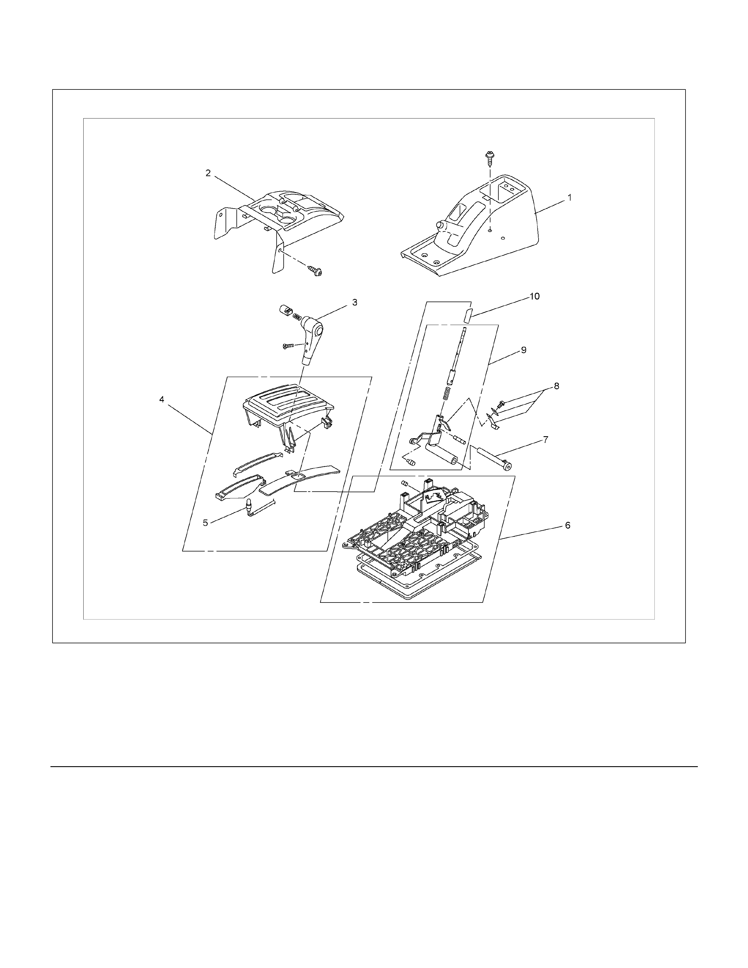
Select Lever
RTW37ALF001101
Legend (6) Base plate
(1) Rear console (7) Grooved pin
(2) Front console (8) Spring plate
(3) Select lever knob (9) Lever assembly
(4) Upper housing (10) Sleeve
(5) Lamp assembly
Remove or Disconnect
1. Block the wheels.
2. Disconnect the negative battery cable.
3. Remove the rear console and the front console.
4. Remove the 2 screws fixing the select lever knob.
5. Remove the knob together with the knob button and
spring from the lever.
6. Tu rn the sleeve counterclock wise to rem ove it. Make
a note of the number of turns required to free the
sleeve.
7. Remove the harness connectors from the base plate.
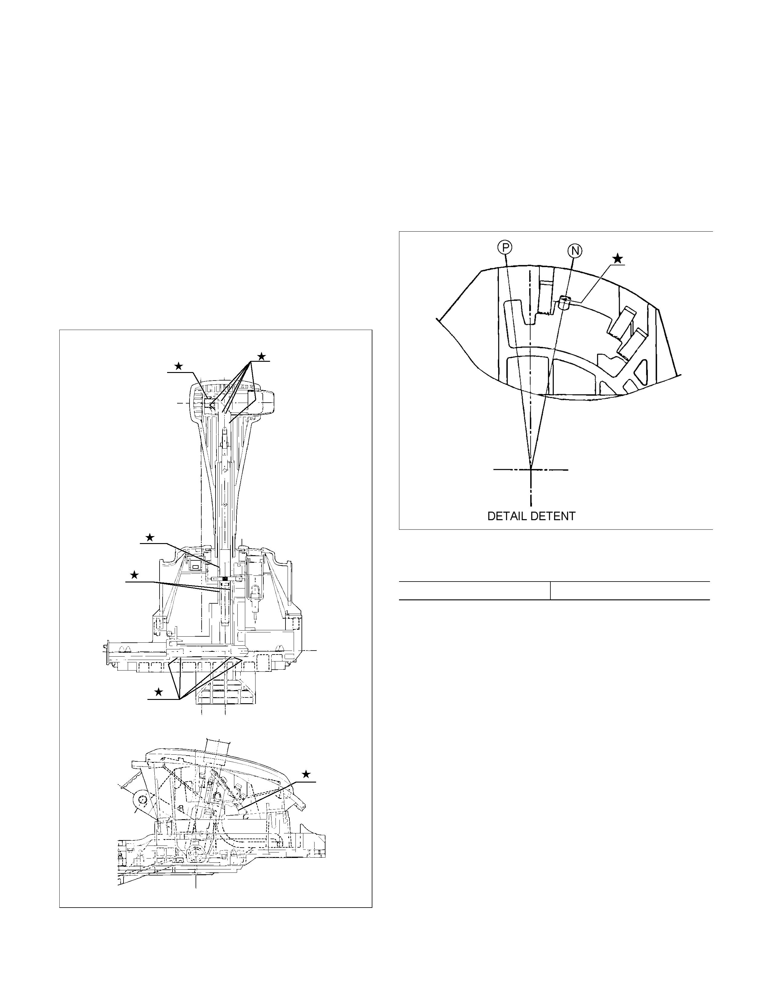
8. Remove the upper housing (held in place by 4
latched fasteners).
9. Remove the spring plate.
10. Remove the grooved pin.
11. Remove the lever assembly by pressing the rod
down (lever in N position).
12. If lamp replacement is required, remove the lamp
assembly from the lamp socket (align the socket
grooved portion and the lamp assembly protruding
portion).
Install or Connect
NOTE:
Apply MULTEMP No. 2 grease (or equivalent) to the
select lever. Refer to the illustration.
RTW37ALH000201
1. Install the lever assembly to the base plate.
a. Insert and secure shaft.
b. Insert paw led end of shaft into base plate hole.
c. Insert grooved pin of shaft into detente aperture
(lever assembly in N position).
2.Install the spring plate.
a. Insert the grooved pin into the base plate detente
groove until it touches the front wall (lever
assembly in N position).
RTW37ASH001001
b. Install the spring plate tighten the screws to the
specified torque.
Screw torque 2 N⋅m (0.2 kg⋅m/17 lb in)
c. Check that the grooved pin moves smoothly in
the detente groove (shift knob temporaril
y
installed).
3. Temporarily install the sleeve.
4. Install the lamp assembly to the lamp socket (i
f
removed at disassembly).
a. Align the recess ed por tion of the lamp s ocket with
the protruding portion of the lamp assembly.
b. Insert the lamp assembly into the lamp socket
and rotate it 90 degrees clockwise.
5. Attach the harness connectors to the base plate.
6. Move the lever to the “P” position.
7. Install the sleeve (rotate the sleeve clockwise the
same number of turns it was rotated
counterclockwise at disassembly).
8. Install the knob, the knob button, and the knob
spring.
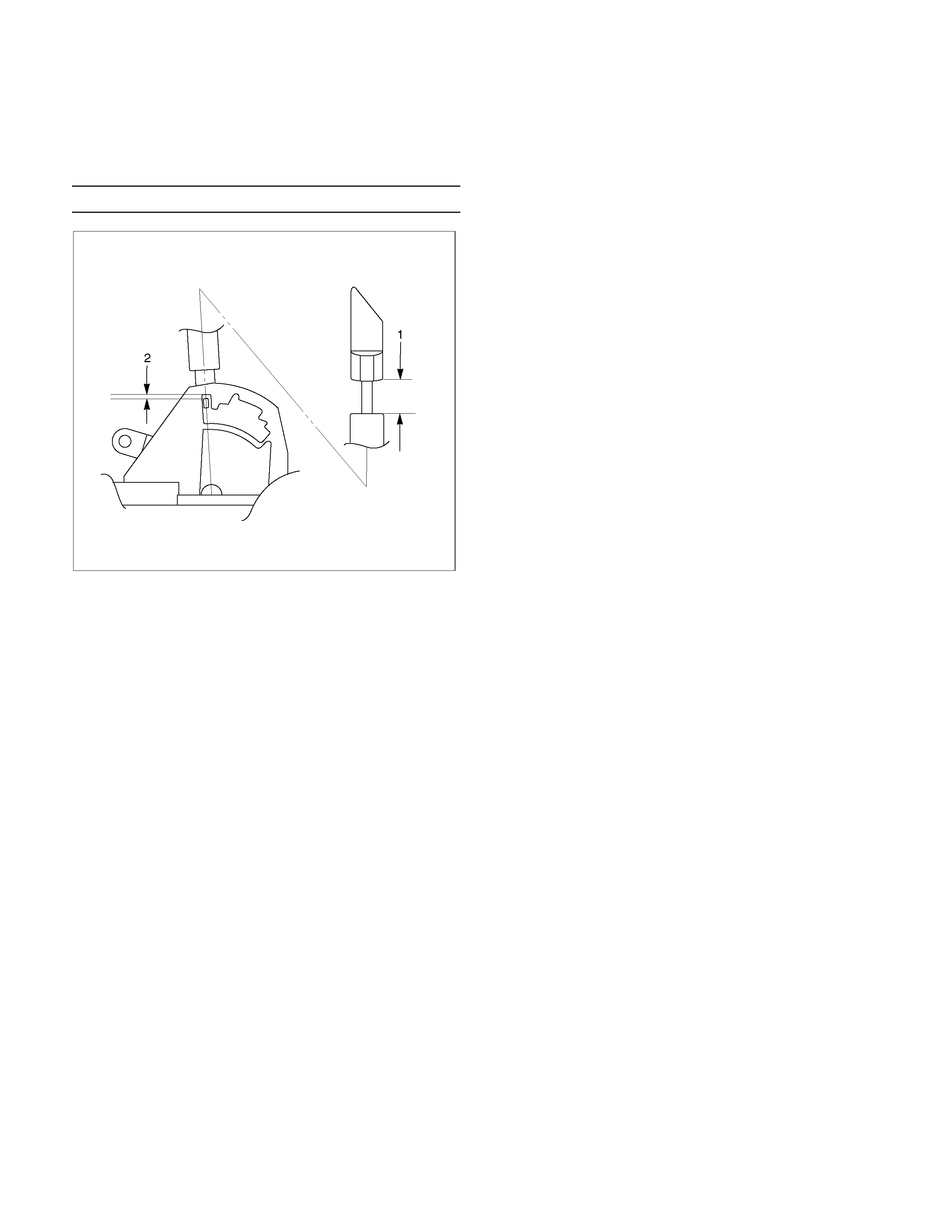
9. Adjust the clearance (2) between the detente plate
and the pin by moving the select lever knob sleeve
(1).
Detente plate and pin clearance mm(in
)
0.2 - 1.0 (0.01 - 0.04)
255R300002
10. Install the 2 screws securing the knob and tighten
them to the specified torque.
Screw torque: 2 N⋅m (0.2kg⋅m/17 lb in)
11. Install the upper housing. Make sure that the 4
latched fasteners are securely closed.
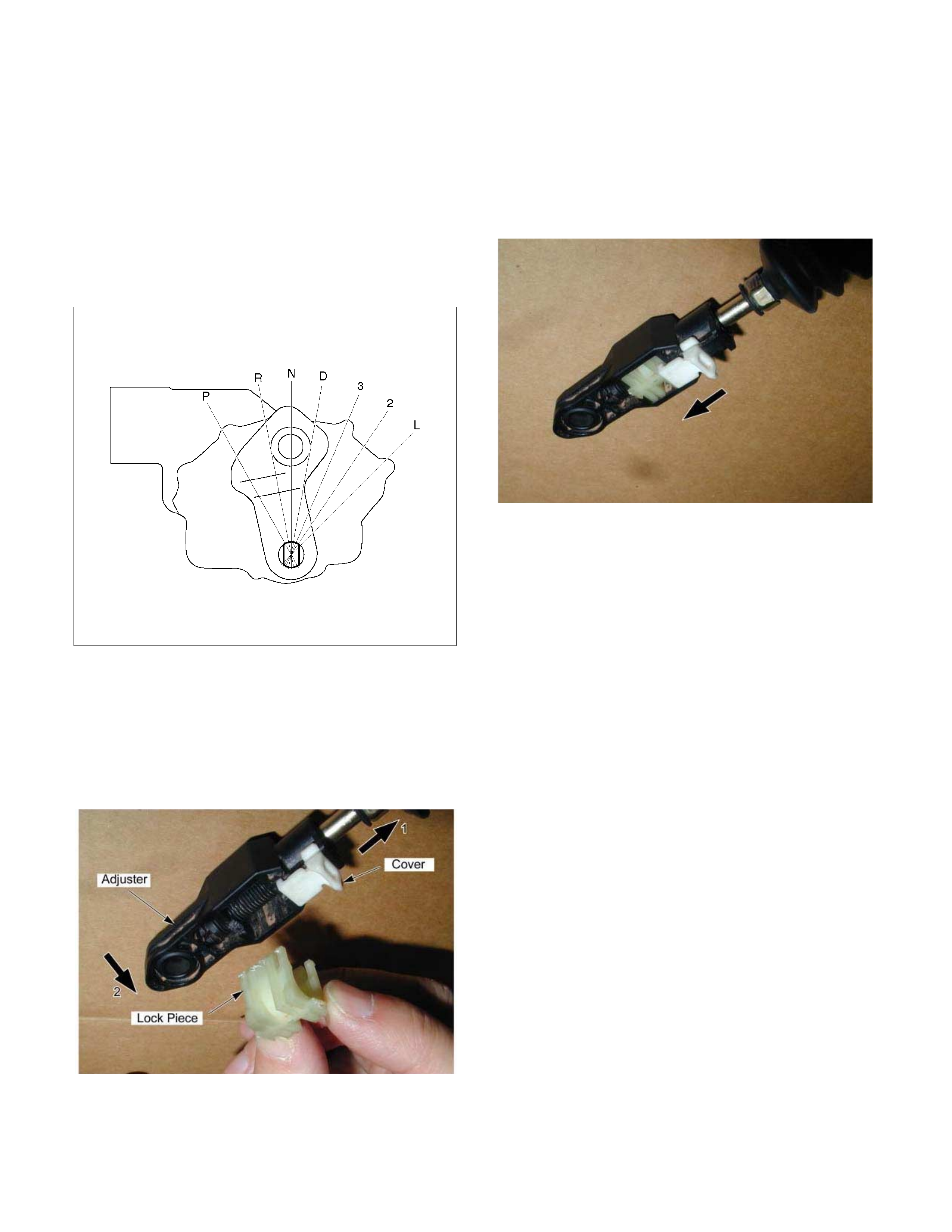
Shift Cable
RTW37ALF001601
Legend (5) Bracket
(1) Select lever (6) Clip
(2) Shift cable retaining pawl (7) Shift cable
(3) Manual shaft select lever (8) Select lever base
(4) Adjuster
Remove or Disconnect
1. Block the wheels.
2. Disconnect the negative battery cable.
3. Move the select lever to the “N” position.
4. Remove the rear console and front console.
5. Disconnect the shift cable from the select lever.
6. Press on the shift c able retaining pawl to rem ove the
cable from the select lever base.
7. Disconnect the shift cable from the transmission
side.
8. Remove the shift cable from the bracket.
9. Pull the shift cable free from the bottom of the
vehicle.
Install or Connect
1. Install the shift cable toward the inside of the cabin
from the bottom of the vehicle.
2. Push the shift cable into the select lever base.
3. Connect the shift cable to the select lever.
4. Fix the shift cable to the bracket.
Install the clip on the marking of shift cable.
5. Check that the select lever is in the “N” position.
6. Check that the transmission is in the “N” position.
249R300002
7. Slide the cover in the direction shown by the arro
w
(1).
8. Use an ordinary screwdriver to move the lock piece
from the pos ition indicated by the arrow (2). Continue
to move the lock piece until the adjuster position
begins to change.
P1010012
9. Connect the shift cable to the manual shaft select
lever at the transmission side.
10. Insert the lock piece to the adjuster (cable length
adjustment).
11. Slide the cover on the adjuster and secure lock
piece.
P1010016-2
11. Press the select lever knob button 5 times.
Then check that the select lever moves smoothly to
each of its positions.
13. Check that the shift position indicated by the select
lever and the actual shift position are the same.
14. Install the front console and rear console.
15. Connect the negative battery cable.
16. Remove the wheel blocks.
Torque Specifications
RTW37ALF001701
Transmission Control Module (TCM)
RTW37ALF001801
Removal
Preparation:
Disconnect negative (–) battery cable.
1. Disconnect the TCM harness connectors.
2. Remove fixing nuts (2 pieces) and TCM with
bracket from the car.
NOTE: The TCM is fitted under instrument panel of the
driver's compartment by means of two stud bolts.
3. Remove fixing nuts (2 pieces) and remove TCM
from bracket.
Installation
To install, follow the removal steps in reverse order.
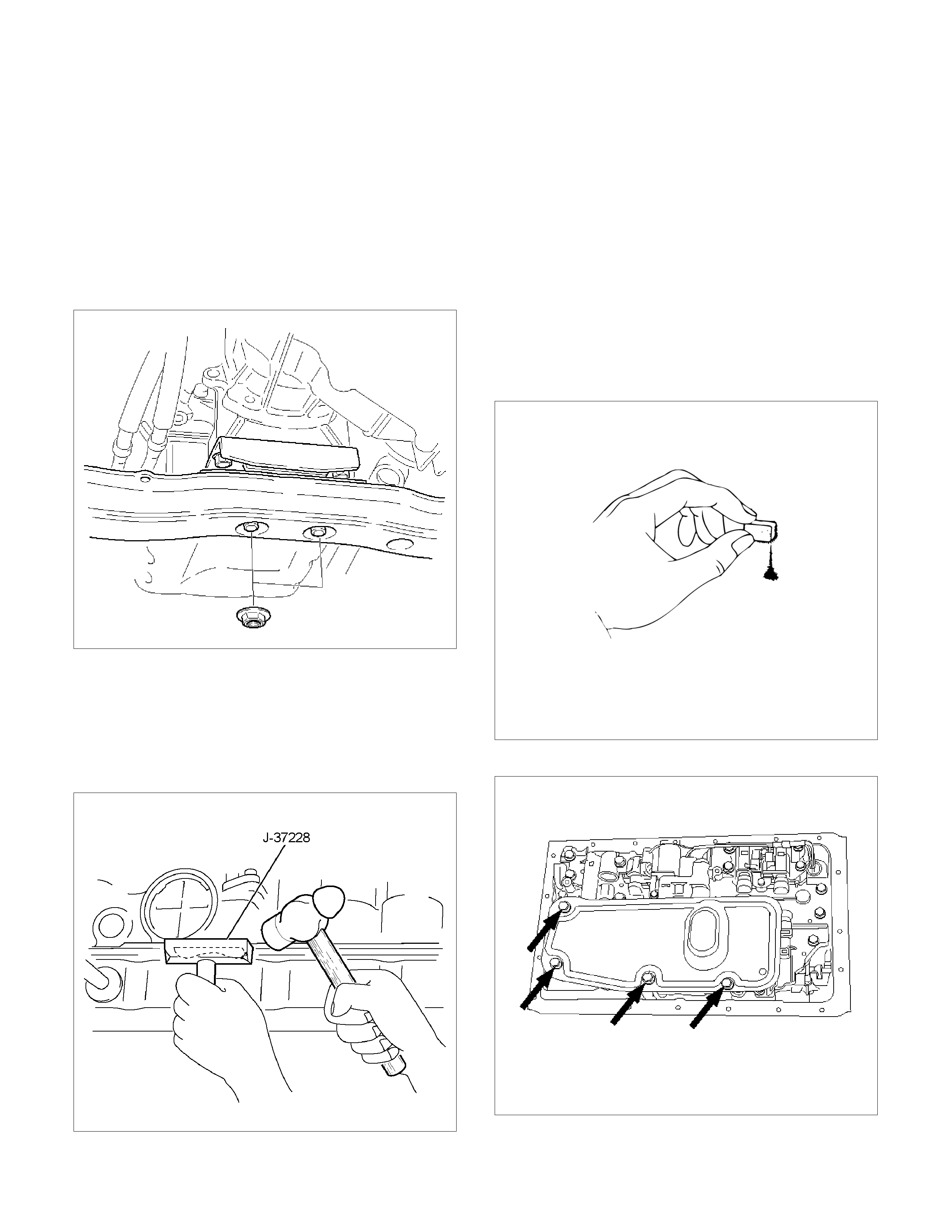
Shift Solenoid and Lock-Up Solenoid
Removal
Preparation:
• Disconnect negative (–) battery cable.
• Drain the fluid.
Refer to ATF REPLACEMENT in this section.
1. Remove oil lever gage and oil filler tube.
2. Support transfer case (4x4) or rear cover (4x2)
with a transmission jack.
3. Remove engine rear mounting nuts.
F07RW008
4. Remove fuel pipe heat protector on transmission
crossmember.
5. Remove fuel pipe from the crossmember.
6. Remove transmission crossmember.
7. Remove the nineteen bolts.
8. Remove oil pan, using seal cutter J–37228.
RUW37ASH002901
NOTE: Do not turn over the transmission as this will
contaminate the valve body with foreign materials in the
bottom of the oil pan.
Remove oil pan by lifting the transmission case.
Oil pan seal cutter: J–37228
Examine particles in oil pan
Remove the magnet and use it to collect any steel
chips.
Look carefully at the chips and particles in the oil
pan and on the magnet to anticipate what type of
wear you will find in the transmission:
Steel (magnetic) ..................bearing, gear and
clutch plate wear
Brass (non-magnetic)..........bushing wear
240RY00008
9. Remove the oil strainer assembly.
244RY00003
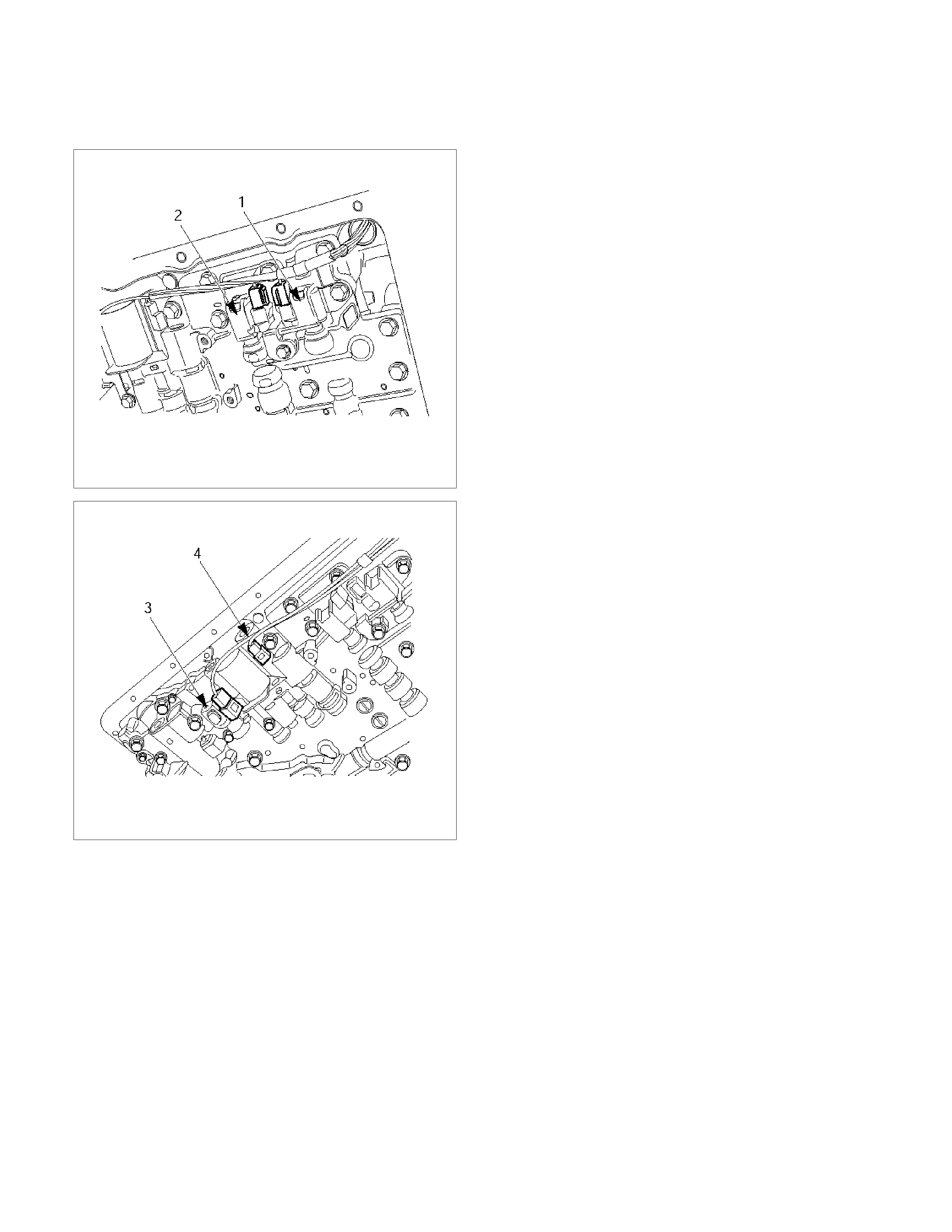
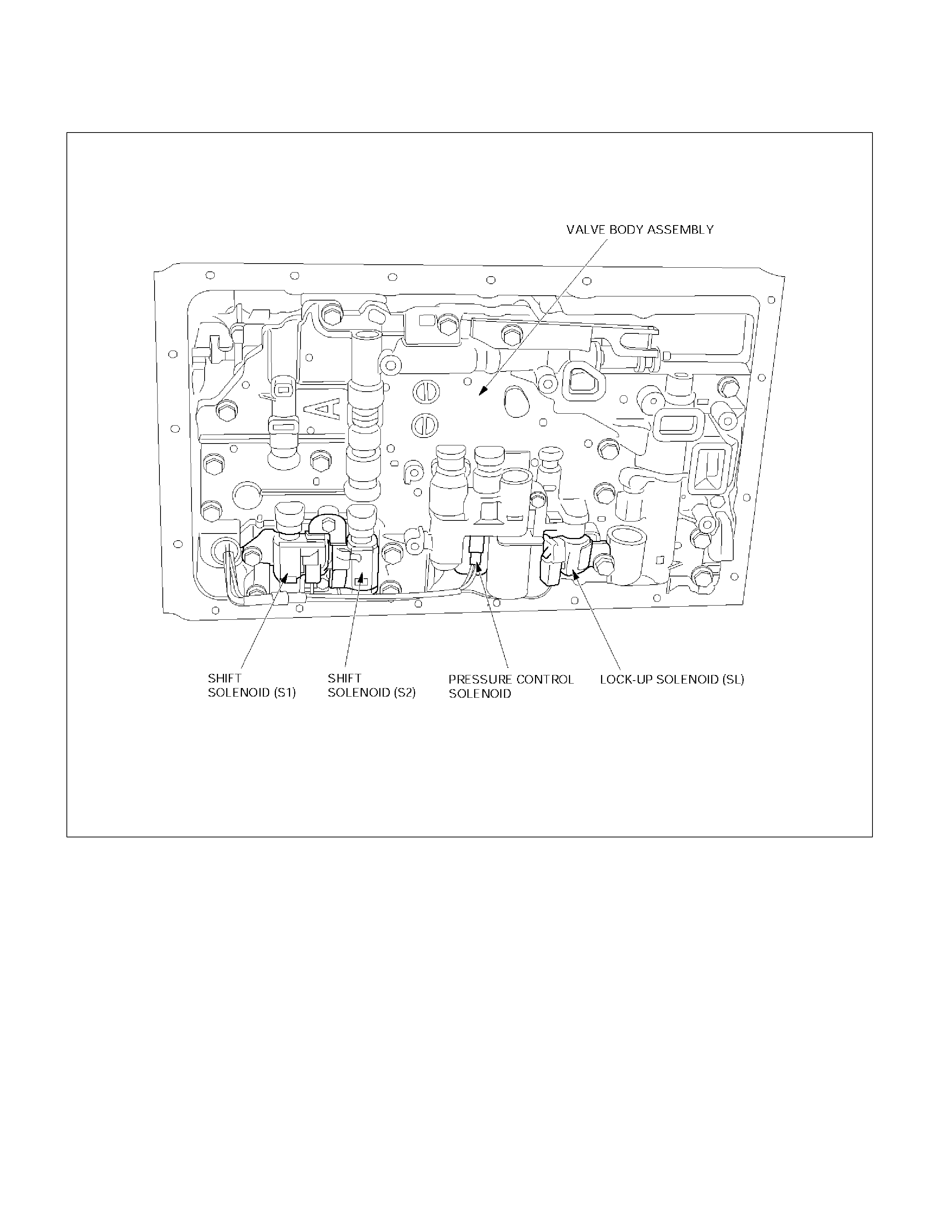
10.Disconnect the solenoid wiring connectors from the
shift solenoid S1(1), S2(2), lock-up solenoid(3) and
pressure control solenoid(4).
249RY00011
249RY00012
11. Remove each retaining bolts and solenoids. (Except
pressure control solenoid:)
Pressure control solenoid cannot be removed.
Installation
To install, follow the removal steps in reverse order
noting the following point;
Refer to the section Reassembly of Major
Components(2) and Transmission Removal and
Installation.
Torque:
Solenoid S1, S2 bolt – 7 N⋅m (61 Ib in)
Lock-up solenoid bolt – 10 N⋅m (87 Ib in)
2. Remove the oil strainer assembly.
244RY00003
3. Disconnect the solenoid wiring connectors from the
solenoids.
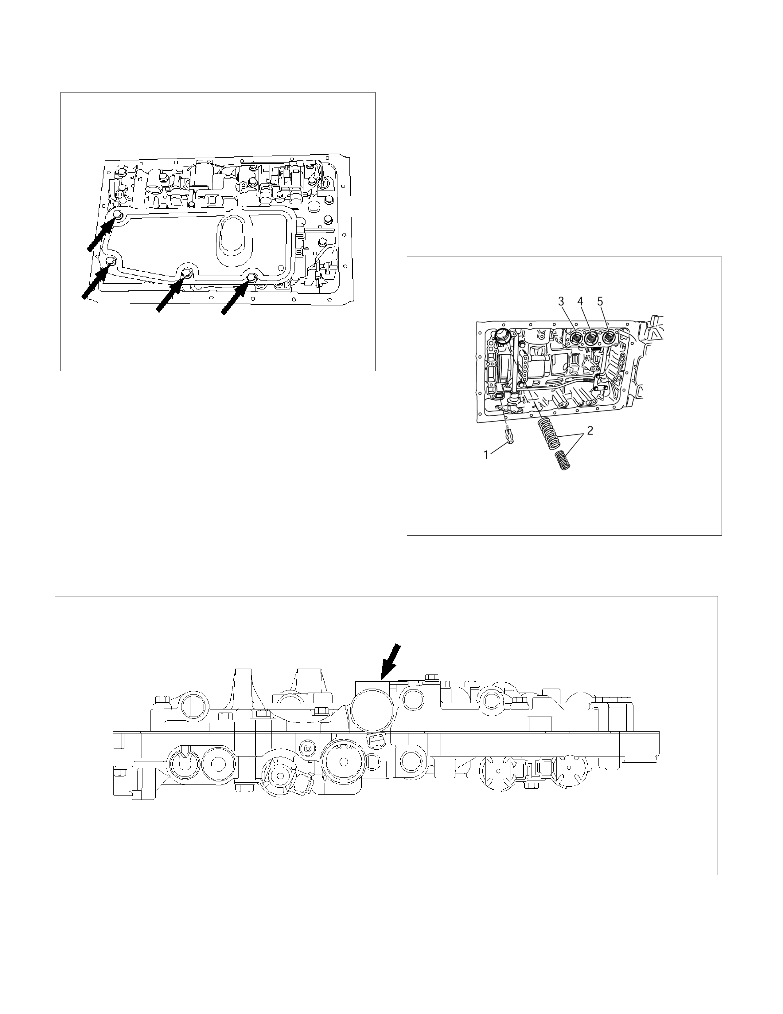
4. Remove the twenty bolts from the valve body.
5. Remove the valve body assembly and pressure
control solenoid.
• After removing valve body assembly from the
transmission case, loosen the solenoid clamp
bolt and remove the pressure control solenoid
from the upper valve body assembly.
Also disconnect the harness connector from the
pressure control solenoid.
NOTE:
• Two or more persons are required for removal and
installation of the valve body assembly and pressure
control solenoid.
• The check valve assembly (1) and the C0
accumulator piston springs (2) will fall from the
transmission case during removal of valve body
assembly.
Protect these parts from damage. The B0 (3), C2 (4),
and B2 (5) accumulator piston and springs may also
fall free and must be protected.
244RY00018
244RY00006
Installation
To install, follow the removal steps in reverse order
noting the following point;
1. Reinstall the parts removed with the valve body
assembly to their assigned positions in the
transmission case (check valve assembly, C0
accumulator pistons, etc). Install the valve body
assembly to the transmission case.
Refer to REASSEMBLY OF MAJOR
COMPONENTS (2).
2. Solenoid clamp bolt
Torque : 7 N⋅
⋅⋅⋅m (61 Ib in)
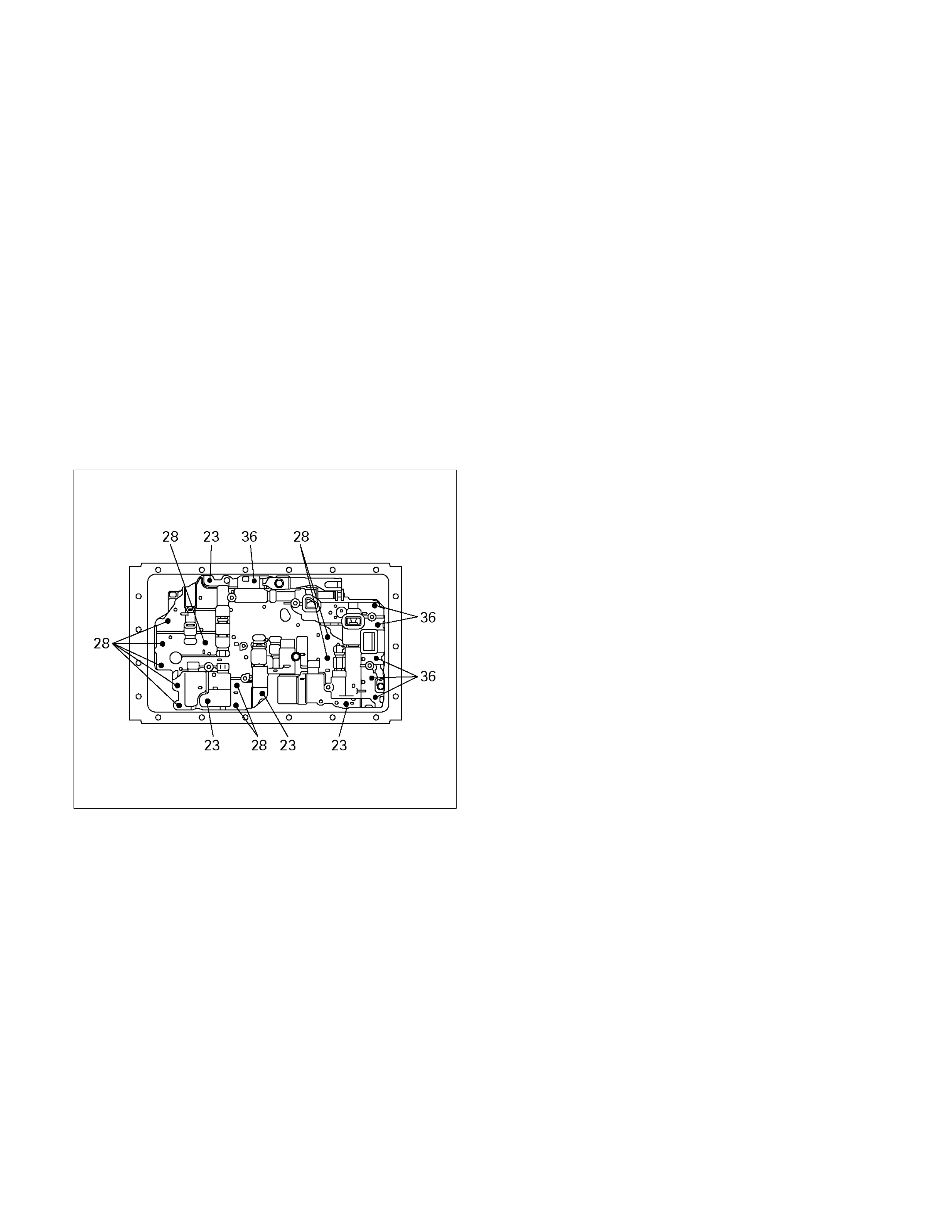
3. Valve body fixing bolts
Each bolt location and length (mm) is indicated in
the figure.
Torque : 10 N⋅
⋅⋅⋅m (87 Ib in)
NOTE: Tighten the bolts toward outside equally.
244R200078
4. Oil strainer fixing bolts
Torque : 10 N⋅
⋅⋅⋅m (87 Ib in)
5. Oil pan fixing bolts
Torque : 8 N⋅
⋅⋅⋅m (69 Ib in)
Rear Oil Seal (Adapter Housing, 4×
××
×4)
Removal
1. Remove the front and rear propeller shaft assembly
from the transfer case.
2. Remove the transfer case assembly from the
transmission case.
Refer to Section 4 DRIVELINE/AXLE.
3. Using a screwdriver, remove the rear oil seal.
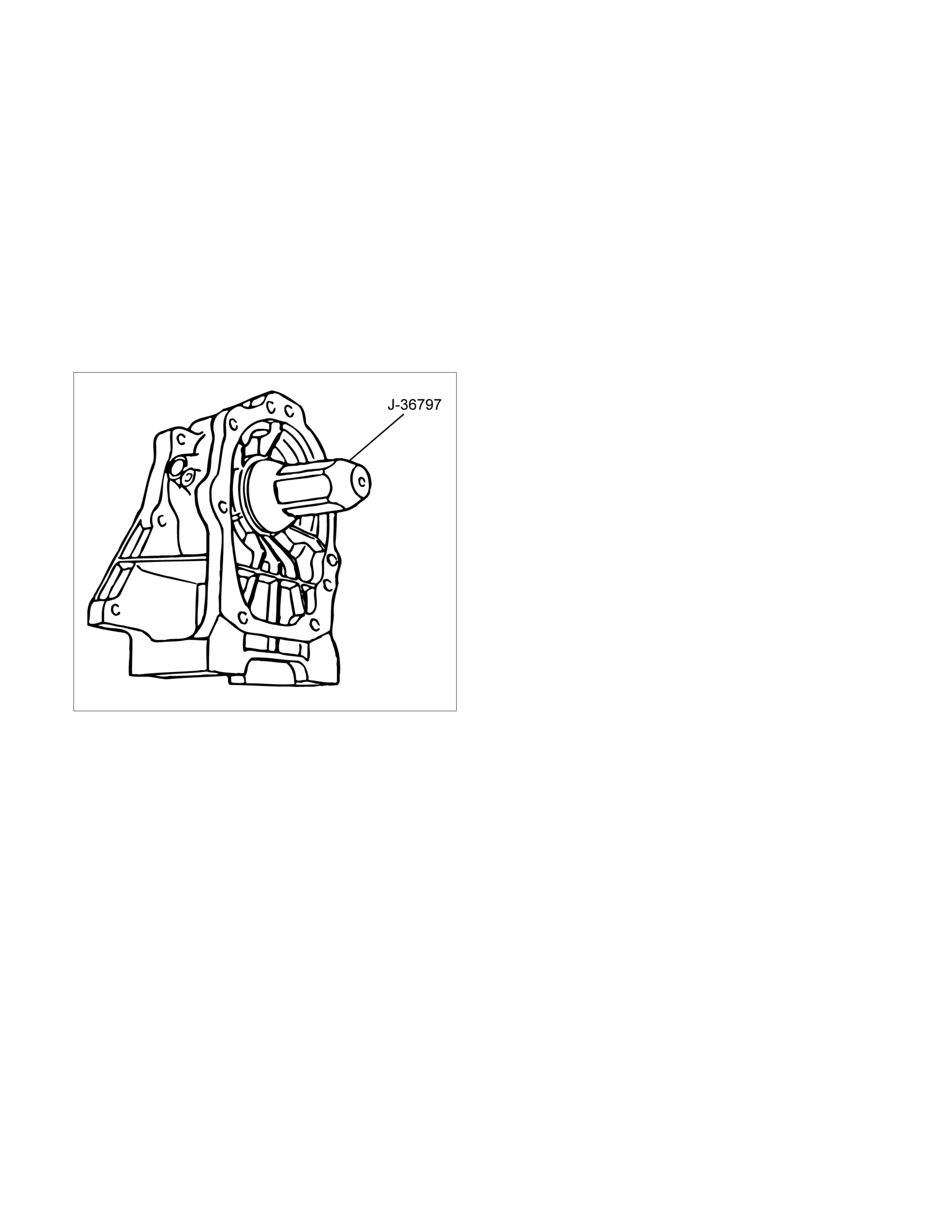
Installation
1. Apply ATF to a new rear oil seal lip.
2. Using oil seal installer, install the rear oil seal to the
adapter housing.
Oil seal installer : J–36797
RUW37ASH002401
3. Install the transfer case assembly.
Refer to Section 4 DRIVE/AXLE.
4. Install the front and rear propeller shaft assembly.
Torque (Propeller shaft flange bolt) : 63 N⋅
⋅⋅⋅m (46
Ib ft)
Real Oil Seal (Extension Housing, 4×
××
×2)
Removal
1. Remove the rear propeller shaft assembly.
2. Using a screwdriver, remove the rear oil seal.
Installation
1. Apply ATF to a new rear oil seal lip.
2. Using oil seal installer, install the rear oil seal to the
extension housing.
Oil seal installer : J–46197
249L100005
3. Install the rear propeller shaft.
Torque (Flange bolt) : 63 N⋅
⋅⋅⋅m (46 Ib ft)
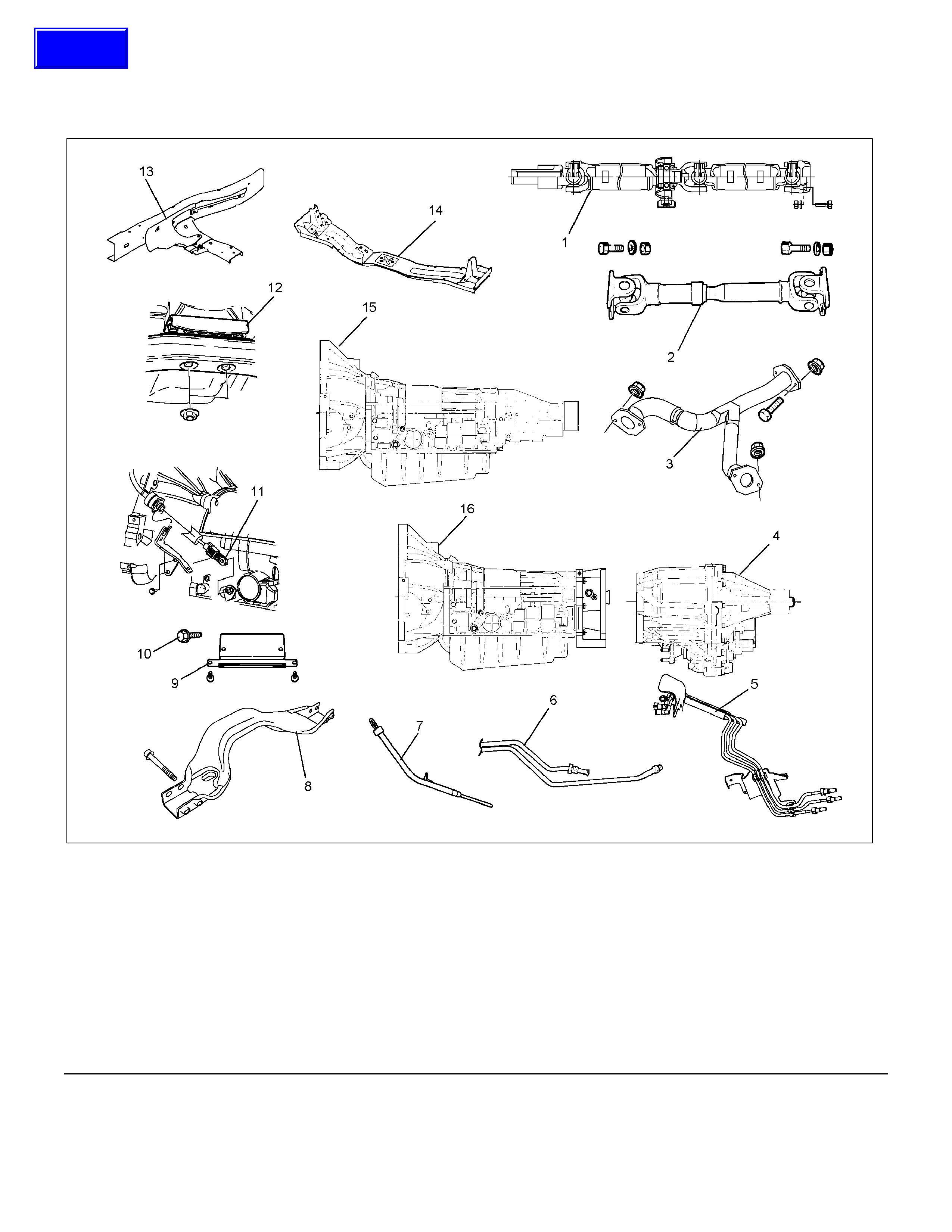
Transmission Assembly
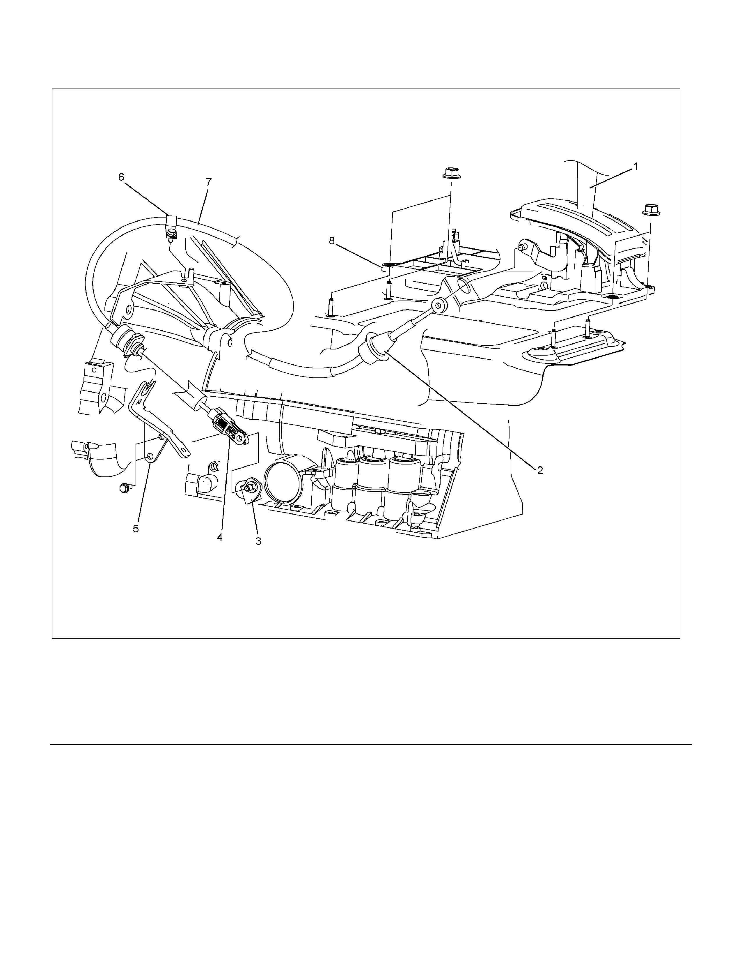
Transmission and Associated Parts
Legend (9) Under Cover
(1) Rear Propeller Shaft (10) Flex Plate Torque Converter bolt
(2) Front Propeller Shaft (4WD only) (11) Shift Cable
(3) Middle Exhaust Pipe (12) Rear Mount Rubber
(4) Transfer Case Assembly (4WD only) (13) Heat Protector
(5) Fuel Pipe Clip and Bracket (14) Transmission Crossmember
(6) ATF Pipe and Clip (15) Transmission Assembly (2WD)
(7) Oil Level Gauge and Guide Tube (16) Transmission Assembly (4WD)
(8) Suspension Crossmember
Techline
Removal
NOTE: Before removing transmission and transfer
assembly from vehicle, change the transfer mode to
2WD using the 4WD push button switch on dash panel.
1. Disconnect battery ground cable.
2. Raise and support vehicle with suitable stands.
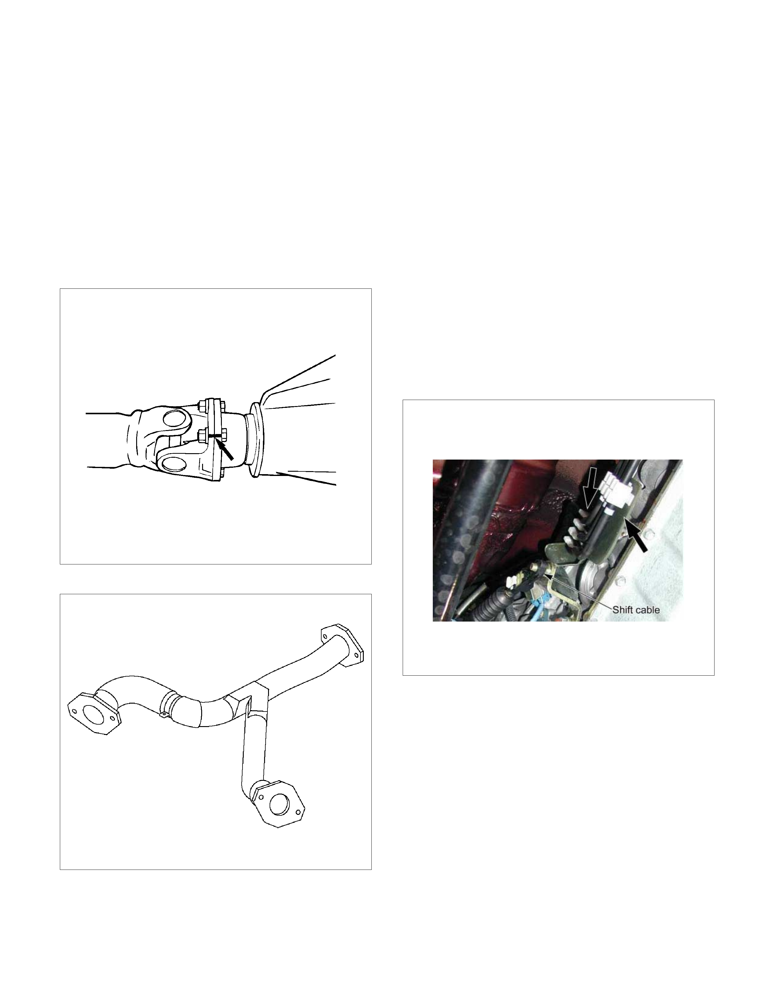
3. Remove front propeller shaft.(4WD only)
NOTE: Apply alignment marks on the flange at both
front and rear sides.
4. Remove rear propeller shaft.
NOTE: Apply alignment marks on the flange at the
differential side.
401RS023
5. Remove the middle exhaust pipe.
RTW37ASH0001
6. Disconnect the transfer harness connectors and the
clips.(4WD only)
• Speed sensor
• 2W-4W shift actuator
NOTE: Avoid turning the vehicle ignition switch to the
ON position when the 2WD-4WD connector is removed
(battery connected).
If the ignition switch must be turned to the ON position,
the controller must first be removed (memory must be
cleared because the CHECK 4WD INDICATOR will
light).
7. Support transfer case with a transmission
jack.(4WD only)
8. Remove the transfer case assembly from the
transmission.(4WD only)
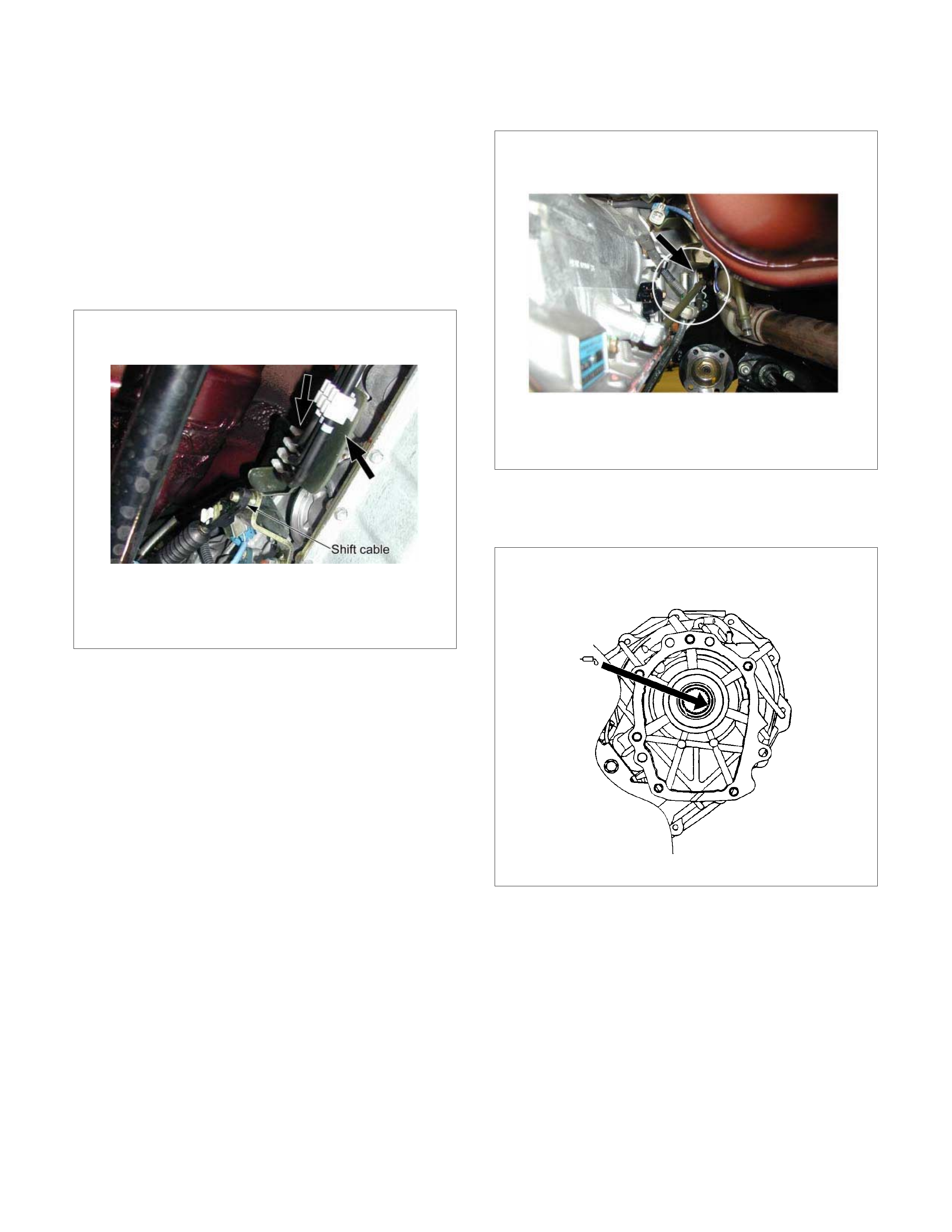
9. Disconnect the shift cable.
10. Remove the fuel pipe clips with the f uel pipes f rom
the brackets and put aside it. Remove the fuel pipe
brackets from the transmission.
P1010010
11. Disconnect the transmission harness connectors
and clips.
12. Remove the oil level gauge and the guide tube.
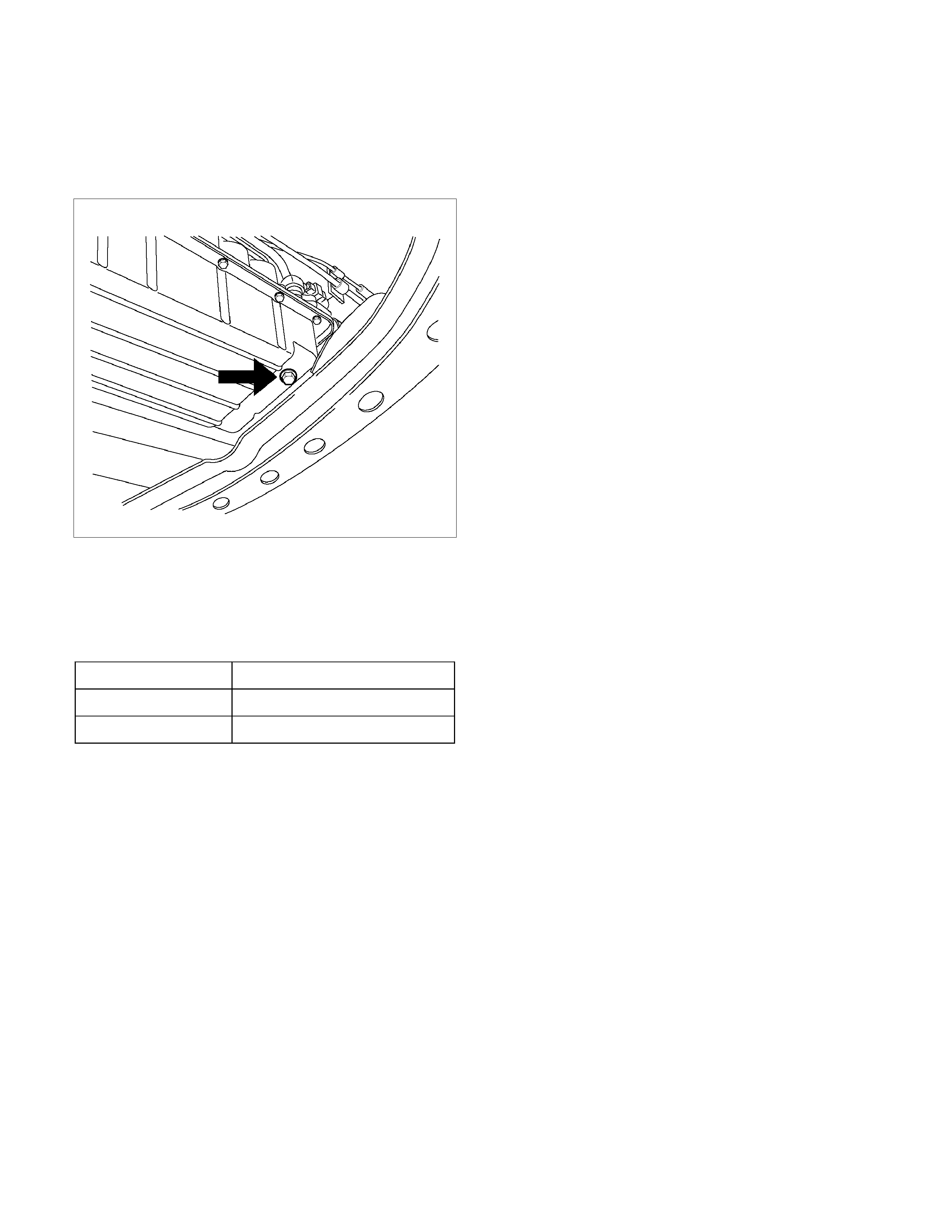
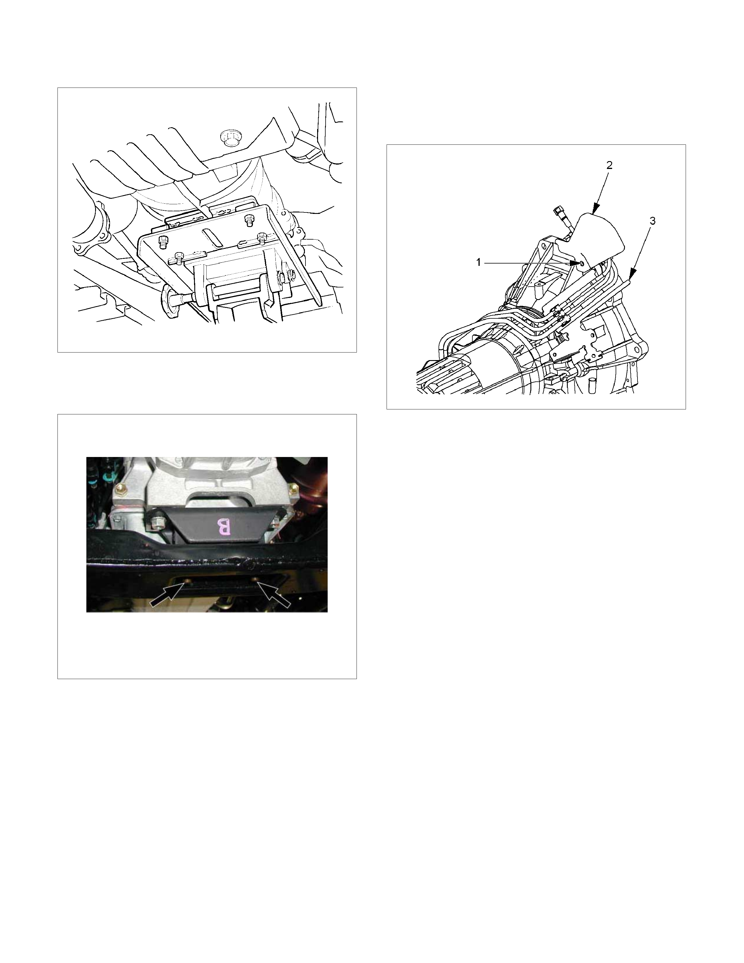
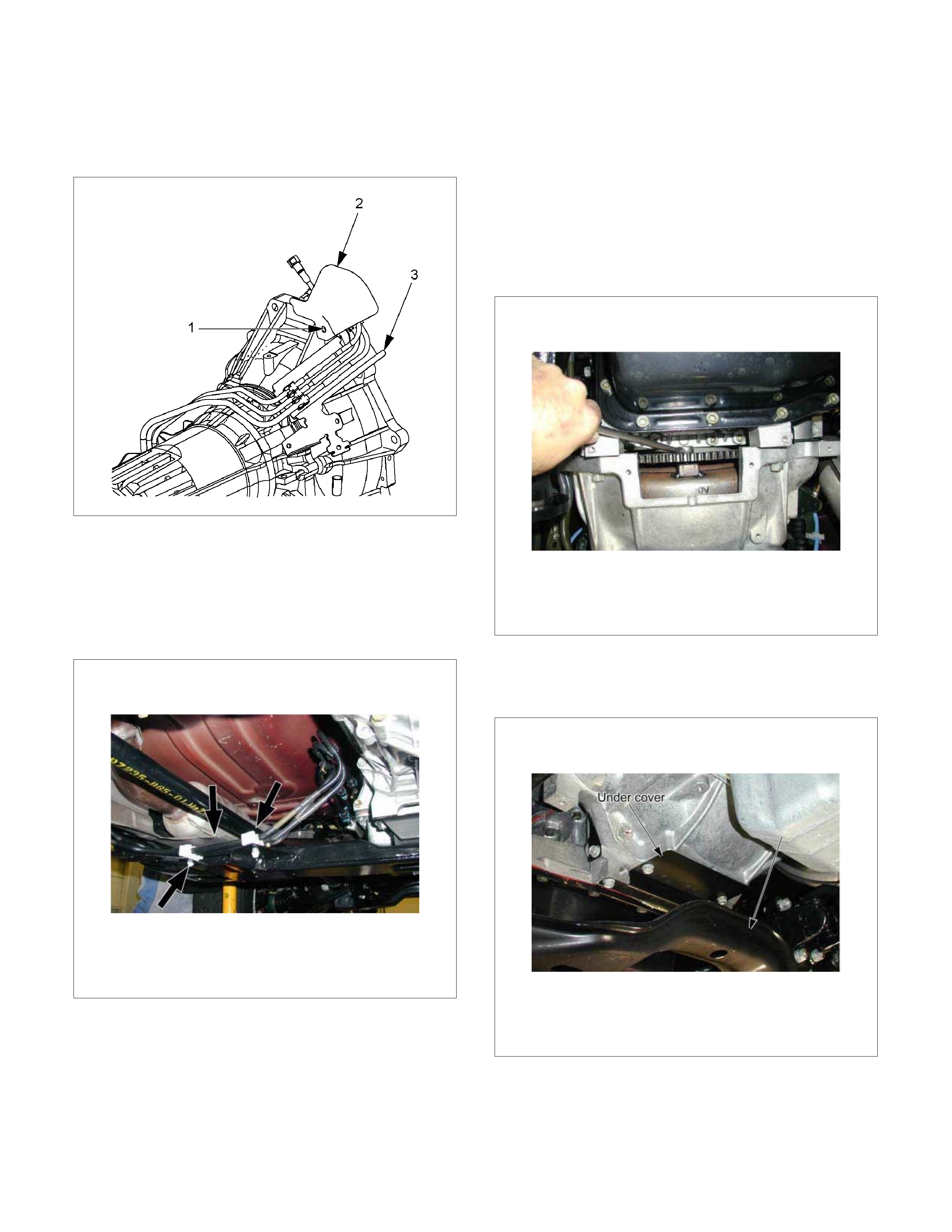
13. Remove the suspension crossmember.
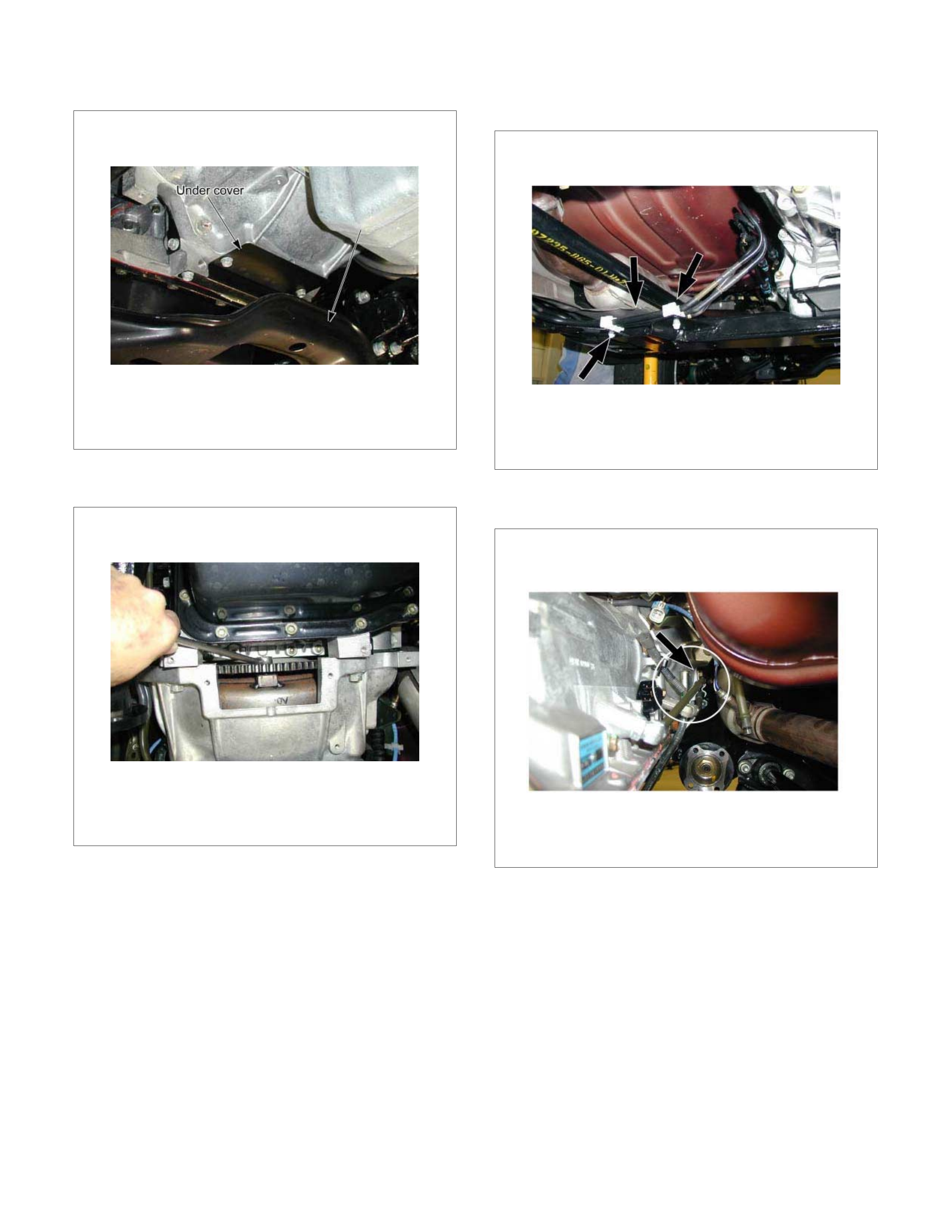
14. Remove the under covers.
P1010012
15. Remove the flex plate torque converter bolts b
y
turning the crank shaft.
P1010005
16. Remove the heat protector and the fuel pipe clips
with fuel pipes on the transmission crossmember.
P1010005B
17.Disconnect the ATF pipes.
18. Remove the ATF pipe clips.
P1010024
19.Support the transmission with a transmission jack.
220RS0001
20.Remove the transmission crossmember.
• Remove engine rear mount nuts fixing on
transmission crossmember.
P1010018
• Remove the transmission crossmember by
removing four fixing bolts.
• If necessary, remove the rear mount rubber from
the transmission.
21. Disconnect the air bleeder hose at the transmission.
22.Remove the protector and fuel pipe bracket.
• Loosen the nut (1) and remove the protector (2).
• Remove the bracket with the fuel pipes (3) and
put aside it.
RTW37ASH001201
23.Remove the transmission assembly.
• Remove transmission retaining nuts and bolts.
• Remove transmission assembly from the vehicle.
Installation
1. Install the rear mounting rubber on the
transmission.
Torque: 50 N⋅m (5.1 kg⋅m/36 lb ft)
2. Attach the transmission to the engine.
• Slowly raise transmission jack until front of the
transmission is aligned with rear of the engine.
• Attach the transmission to the engine.
• Tighten engine transmission bolts as shown in
the figure.
RTW37ALF000301
3. Install the protector and fuel pipe bracket.
• Install the bracket with the fuel pipes (3) to the
transmission.
• Install the protector (2) and tighten nuts (1).
RTW37ASH001201
4. Connect the air bleeder hose on the transmission.
5. Install the transmission crossmember.
Torque: 67 N⋅
⋅⋅⋅m (6.8 kg⋅
⋅⋅⋅m/49 lb ft)
6. Install the heat protector and the fuel pipe clips with
fuel pipes on the transmission crossmember.
P1010005B
7. Install rear mount nuts.
Torque: 50 N⋅
⋅⋅⋅m (5.3 kg⋅
⋅⋅⋅m/37 lb ft)
8. Remove a transmission jack.
9. Install flex plate torque converter bolts.
• Align the flex plate torque converter bolt boss
with flex plate hole by turning the torque
converter.
• Install flex plate torque converter bolts (6 pieces)
by turning the crankshaft.
Torque: 54 N⋅
⋅⋅⋅m (54 kg⋅
⋅⋅⋅m/40 lb ft)
NOTE: Do not reuse the flex plate torque converter
bolt.
P1010005
10.Install the under covers to the transmission and
engine.
Torque: 8 N⋅
⋅⋅⋅m (0.8 kg⋅
⋅⋅⋅m/69 lb in)
P1010012
11. Install the suspension crossmember.
Torque: 65 N⋅
⋅⋅⋅m (6.6 kg⋅
⋅⋅⋅m/48 lb ft)
12. Install filler tube and insert oil level gage.
Torque: 22 N⋅
⋅⋅⋅m (2.2 kg⋅
⋅⋅⋅m/16 lb ft)
13. Install select cable by connecting inner cable to
select lever and installing outer cable with bracket.
14. Install the fuel pipe brackets to the transmission.
Install the fuel pipe clips with the pipes to the
bracket.
P1010010
15. Connect the transmission harness connectors and
clips.
16. Connect transmission oil cooler pipes to A/T.
Torque: 44 N⋅
⋅⋅⋅m (4.5 kg⋅
⋅⋅⋅m/33 lb ft)
17. Install oil cooler pipe clamp and bracket to the
converter housing.
18.Tighten oil cooler pipe clamp bolt at the engine
mount side.
P1010024
19. Install the transfer case assembly.(4WD only)
•
A
pply a thin coat of molybdenum disulfide grease
to the input shaft spline as shown in the figure.
260R300001
• Install the transfer case assembly.
• Tighten transmission transfer bolts as shown in
the figure.(4WD only)
261R300002
20. Connect transfer harness connectors and
clips.(4WD only)
• Speed sensor
• 2W-4W shift actuator
21. Install the middle exhaust pipe.
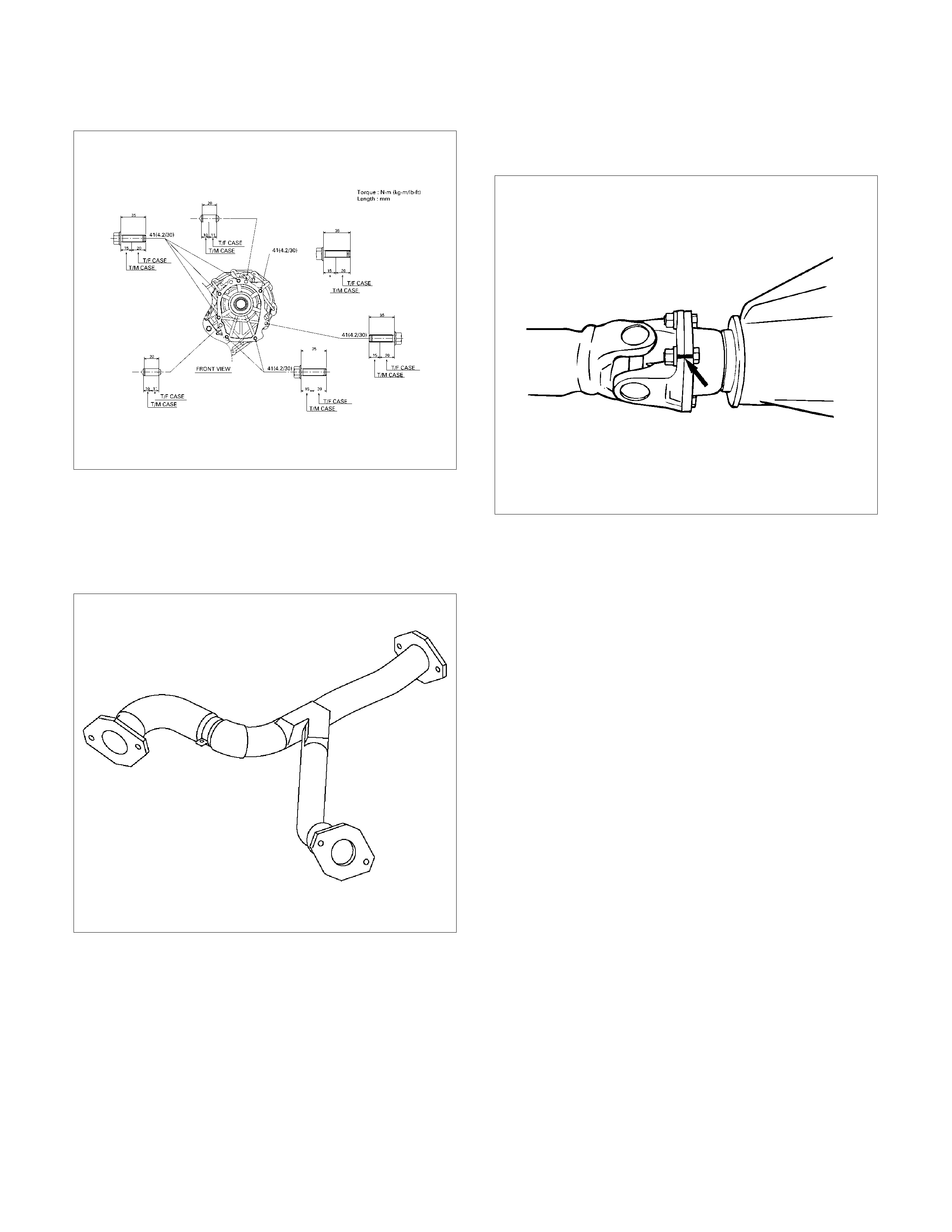
RTW37ASH0001
22. Install the rear propeller shaft.
Torque: 63 N⋅
⋅⋅⋅m (6.4 kg⋅
⋅⋅⋅m/46 lb ft)
NOTE: Align alignment marks on the flange.
23. Install the center bearing on crossmember.
Torque: 69 N⋅
⋅⋅⋅m (7.0 kg⋅
⋅⋅⋅m/51 lb ft)
24.Install the front propeller shaft.(4WD only)
Torque: 63 N⋅
⋅⋅⋅m (6.4 kg⋅
⋅⋅⋅m/46 lb ft)
NOTE: Align alignment marks on the flange.
401RS023
25. Connect battery ground cable.
Major Components
Disassembly, inspection and reassembly of each
component group is indicated in the following chapter.
Before reassembly, make sure, again, that all
component groups are assembled correctly.
If something wrong is found in a certain component
group during assembly, inspect and repair this group
immediately .
General Assembly Notes:
1. The automatic transmission is composed of highly
precision-finished parts, necessitating careful
inspection before assembly because even a small
nick could cause fluid leakage or affect
performance.
2. Before assembling new clutch discs and brake
bands, soak them in automatic transmission fluid for
at least thirty minutes.
3. Apply automatic transmission fluid on the sliding or
rotating surfaces of parts before assembly.
4.Use petroleum jelly to keep small parts in place.
5. Do not use adhesive cement on gaskets and similar
parts.
6. When assembling the transmission, be sure to use
new gaskets and O-rings.
7. Dry all parts with compressed air - never use shop
rags.
8. Be sure to install the thrust bearings and races in
the correct direction and position.
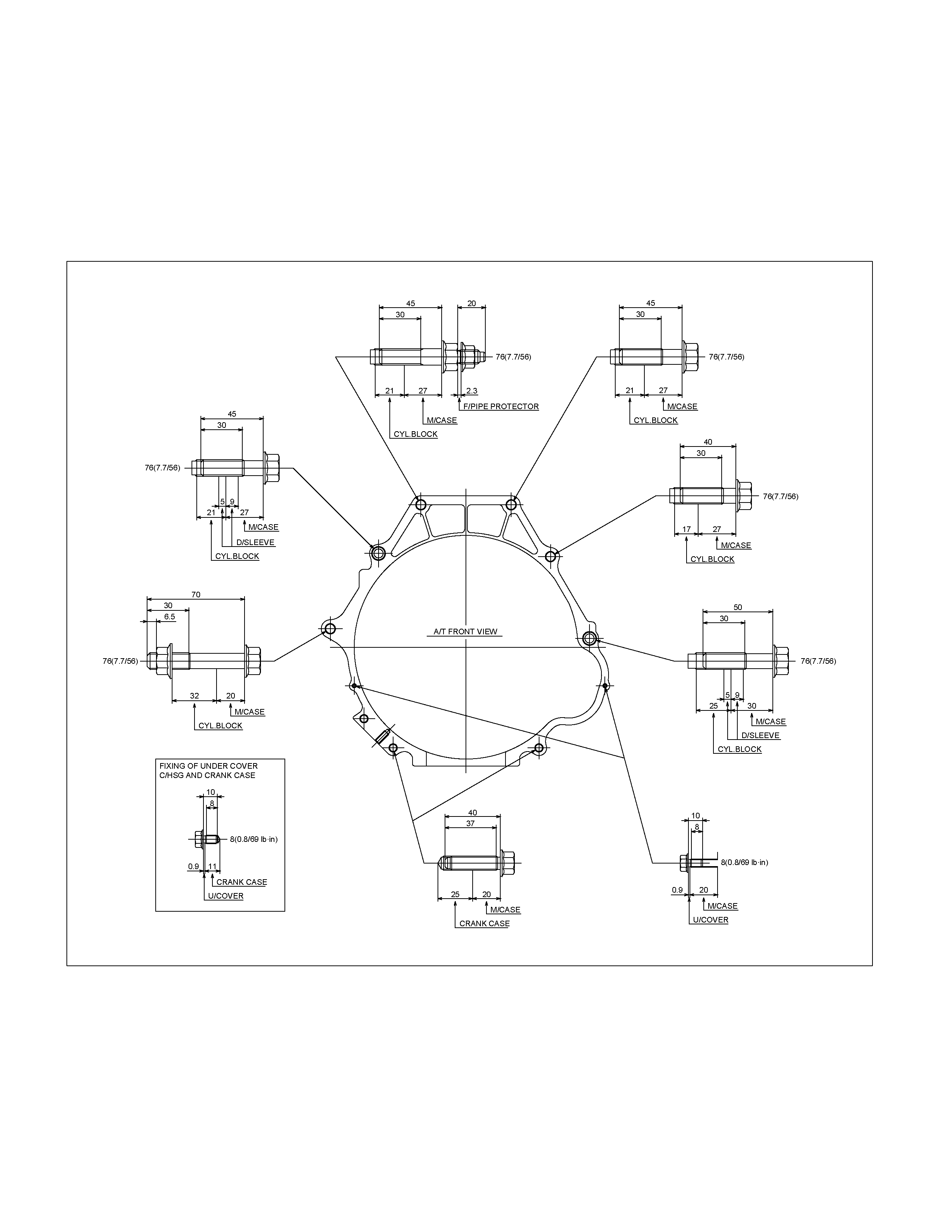
Bearing and Race
RUW36AMF000201

Mark Front Race Diameter
Inside/Outside Thrust Bearing Diameter
Inside/Outside Rear Race Diameter
Inside/Outside
1 28.6 (1.13) / 46.5 (1.83) 28.9 (1.14) / 50.2 (1.98) —
2 28.45 (1.12) / 47.23 (1.86) 29.1 (1.15) / 50.2 (1.98) —
3 24.7 (0.97) / 41.8 (1.65) 24.2 (0.95) / 47.8 (1.88) —
4 37.2 (1.46) / 58.8 (2.31) 33.7 (1.33) / 50.1 (1.97) —
5 36.7 (1.44) / 50.85 (2.00) 33.7 (1.33) / 47.8 (1.88) —
6 26.0 (1.02) / 48.9 (1.93) 26.0 (1.02) / 46.7 (1.84) 26.8 (1.06) / 47.0 (1.85)
7 — 35.15 (1.38) / 53.65 (2.11) 34.3 (1.35) / 47.8 (1.88)
8 33.7 (1.33) / 47.6 (1.87) 35.6 (1.40) / 47.7 (1.88) —
9 28.5 (1.12) / 44.2 (1.74) 27.7 (1.09) / 44.2 (1.74) —
10 — 39.38 (1.55) / 58.15 (2.29) —