
SECTION 7A3 - ON-VEHICLE SERVICE (JR405E)
Description
Automatic Transmission Fluid (ATF)
Inspect
ATF Level
Inspect
ATF Change
Inspect
Transmission Control Module (TCM)
Remove and Disconnect
Install or Connect
Throttle Position Sensor
Adjust
Inhibitor Switch
Inspect
Adjust
Remove or Disconnect
Install or Connect
Speed Sensor
Inspect
Turbine Sensor
Inspect
Power and 3rd Start Switch
Inspect
Select Lever
Remove or Disconnect
Install or Connect
Shift Cable
Remove or Disconnect
Install or Connect
Torque Specifications
Solenoids, Oil Pressure Switch and Oil
Temperature Sensor
Remove or Disconnect
Inspect
Install or Connect
Control Valve Assembly
Remove or Disconnect
Install or Connect
Flushing the Transmission Fluid Cooler and Line
Procedures
Transmission Assembly
Remove or Disconnect
Install or Connect
Torque Specifications

Description
Before performing on-vehicle service on the automatic transmission, check that the engine idling speed and general
engine condition are normal.

Automatic Transmission Fluid (ATF)
Inspect
Remove the transmission dipstick to check the condition of the ATF.
Clean the dipstick and look for gum or varnish.
Gum or varnish indicates scorching of the clutch band and other parts.
The transmission control module, the transmission unit, and the vehicle must be carefully checked if gum or varnish is
present.
ATF Level
Inspect
Hot Level
1. W arm up the engine and the transmission by driving
the vehicle on the road so that the temperature
reaches around 80°C (176°F).
Do not turn the engine off.
2. Park the vehicle on a level surface.
3. Apply the parking brake firmly.
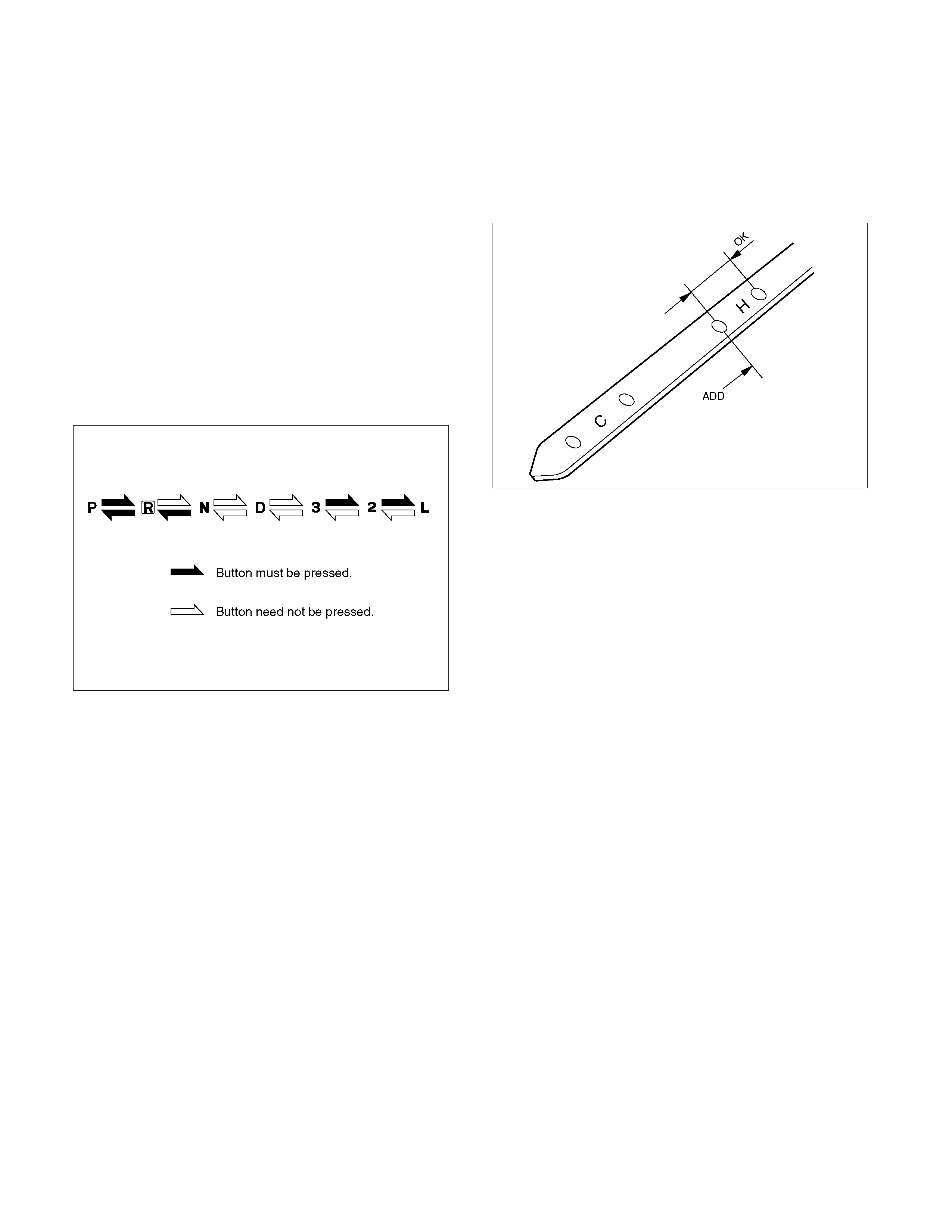
4. Let the engine run at idle.
Move the select lever slowly through all the gea
r
ranges.
Stop in each gear range just long enough for the
transmission to engage.
5. Return the select lever to either “P” or “N”.
C07RW009
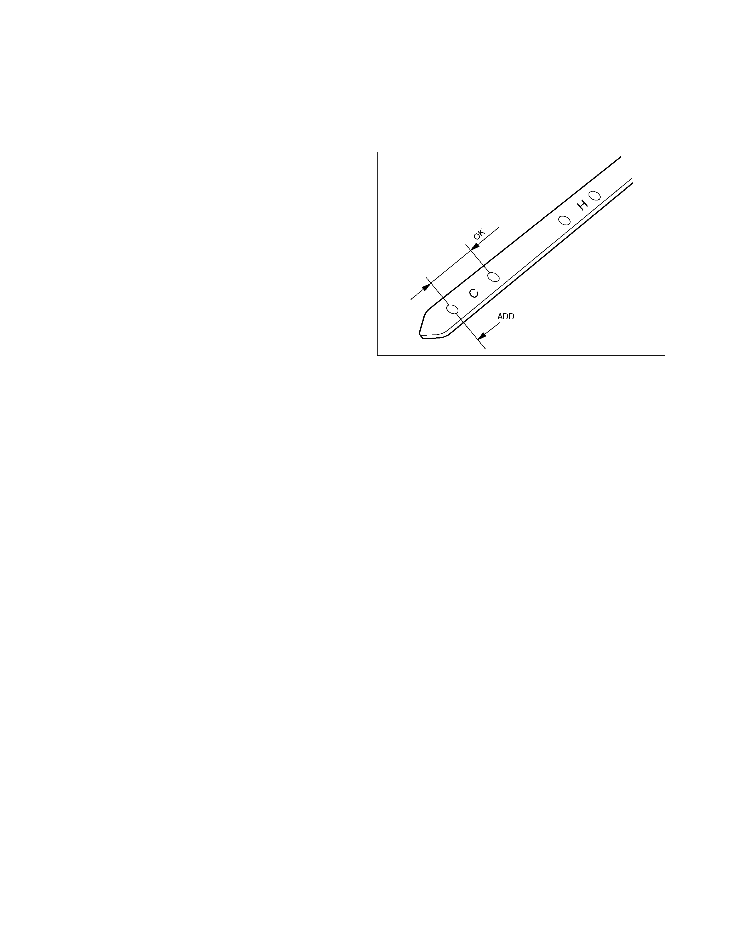
6. Remove the ATF level dipstick.
7. Wipe the dipstick clean with a paper towel.
8. Reinsert the dipstick and wait several seconds.
9. Remove the dipstick.
The AT F level should be inside the “H” range on the
dipstick.
242R300001
If the ATF level is below the “H” range, AT F mus t be
added.
Cold Level
The vehicle must not have been driven so that the
temperature reaches around 20°C (68°F) before the
cold level check is made.
1. Park the vehicle on a level surface.
2. Apply the parking brake firmly.
3. Start the engine and allow it to warm up.
The engine coolant temperature gauge needle
should be midway between the “C” mark and “H”
mark.
4. Let the engine run at idle.
Move the select lever slowly through all the gea
r
ranges.
Stop in each range just long enough for the
transmission to engage.
5. Return the select lever either “P” or “N”.
6. Remove the ATF level dipstick.
7. Wipe the dipstick clean with a paper towel.
8. Reinsert the dipstick and wait several seconds.
9. Remove the dipstick.
The AT F level should be inside the “C” range on the
dipstick.
If the ATF level is below the “C” range, AT F mus t be
added.
242R300002

ATF Change
1. Start the engine and allow it to idle until the ATF
reaches a temperature of 40-50°C
2. Park the vehicle on level ground and block the
wheels.
3. Stop the engine.
4. Raise vehicle and support with suitable safet
y
stands.
5. Remove the drain plug from the oil pan and dr ain the
ATF (approximately 6 liters).
6. Remove the oil pan.
7. Inspect the oil pan (details written below).
8. Install the oil pan.
Note:
Use new gasket. Clean the oil pan and magnet.
Oil pan bolt torque : 8 N⋅m (69 lb⋅in)
9. Replace the gasket and install the drain plug.
Drain plug torque : 35 N⋅m (26 lb⋅ft)
Note:
Do not reuse old washer (gasket).
Clean the drain plug (especially the threaded section).
10. Pour about 5 liters of new AT F. T hen, add m ore AT F
carefully as necessary using the dipstick.
Refer to “ATF LEVEL” previously in this section.
Note:
Keep the engine idle (do not stop it) during the oil level
adjustment.
Inspect
1. Check the drain plug tip for adhesion of foreign
substances.
2. Check the drained ATF f or color, sm ell and inclusion
of foreign substances.
3. Check the oil pan bottom and magnet for adhesion o
f
foreign substances.
If a problem is discovered during those checks, the
Automatic transmission must be overhauled.
Note:
The torque converter and the oil strainer need replaced
with new ones if the drained ATF contains large
amounts of metallic or facing flakes.
In addition, flush the ATF cooler circuit
RTW07ASH000101
11. Remove the safety stands and wheel blocks.
Transmission Control Module (TCM)
RTW37ALF001901
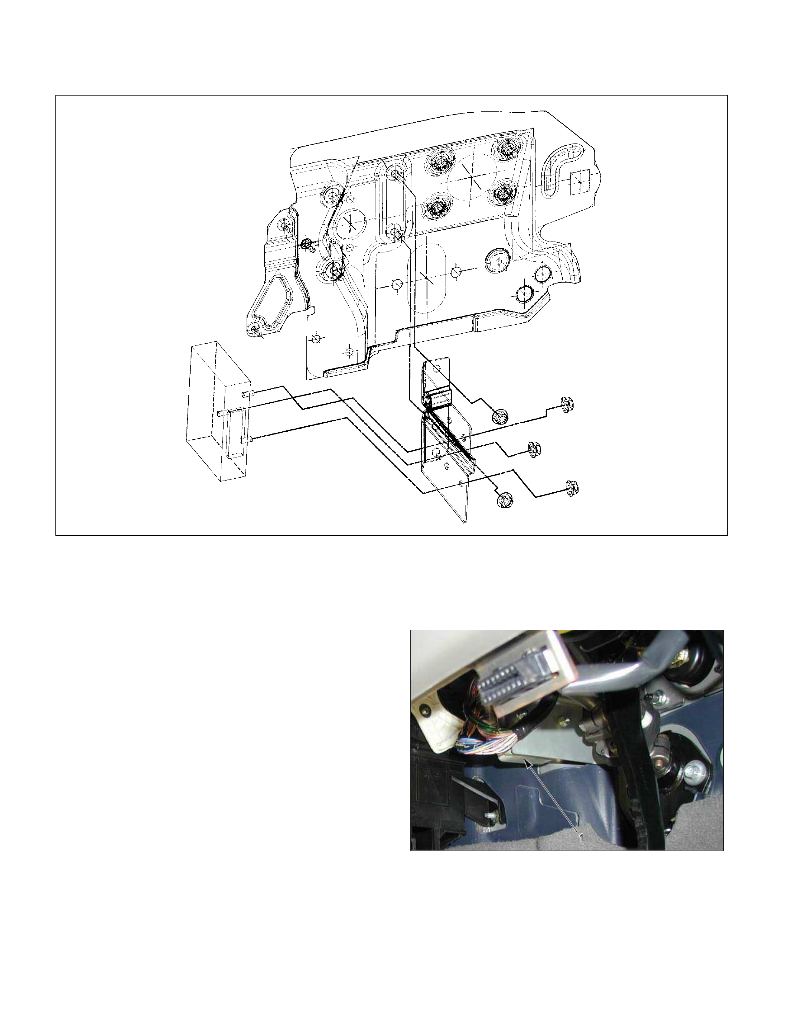
Remove and Disconnect
1. Disconnect the negative battery cable.
2. Remove the connectors.
3. Remove the fixing nuts and remove the TCM (1)
from the bracket.
Note:
The TCM is fitted under instrument panel of the driver’s
compartment by means of three stud bolts.
Install or Connect
Follow the removal steps in the reverse order. Be
absolutely sure that the connectors are securely
fastened.
AT CONT
Throttle Position Sensor
1
P1010052
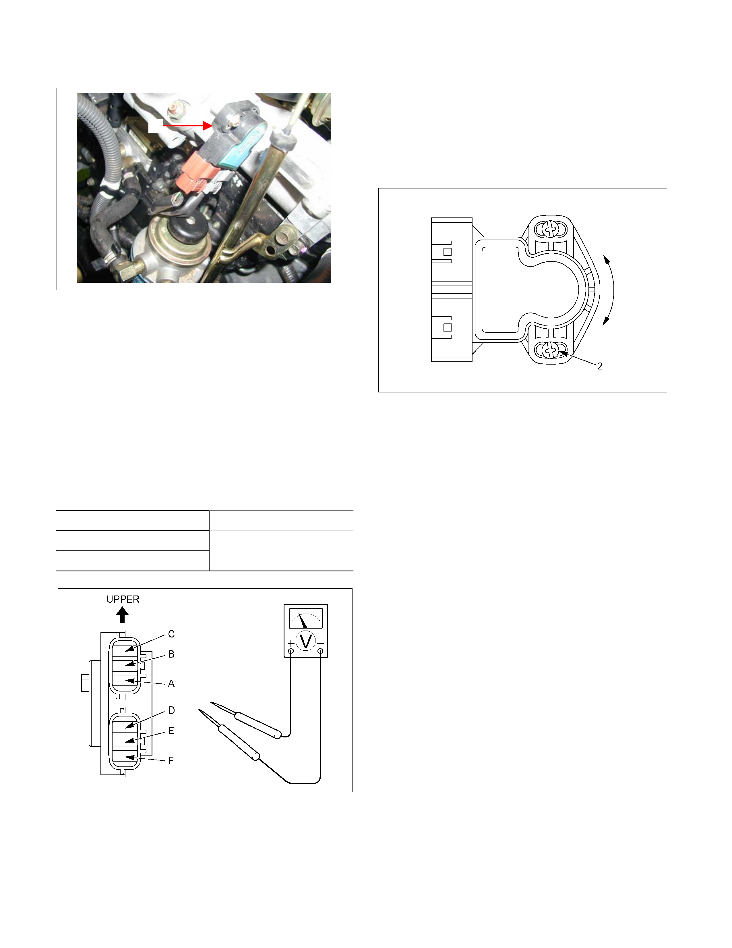
The throttle position sensor (1) is fitted on the throttle
valve body.
Adjust
1. Turn the starter switch to the “ON” position.
2. Measure the voltage between TPS connecto
r
terminals (B) (output) and (A) (ground).
Note:
• Do not remove the sensor connector.
• Make sure that power source (5.0 ± 0.01 V) is
meas ured between TPS c onnector term inals (C ) and
(A) before measurement at step 2.
Standard voltage :
Throttle Angle TPS
Idling (0%) 0.2 - 0.3 V
WOT (100%) 3.4 – 4.1 V
RTW37ASH0013
3. If the reading is beyond the specified value, loosen
the throttle position sensor fixing bolts, and turn it
right or left, so that the specified output voltage be
obtained.
A
fter adjusting, tighten the throttle position sensor
fixing screws (2 ).
826R300013
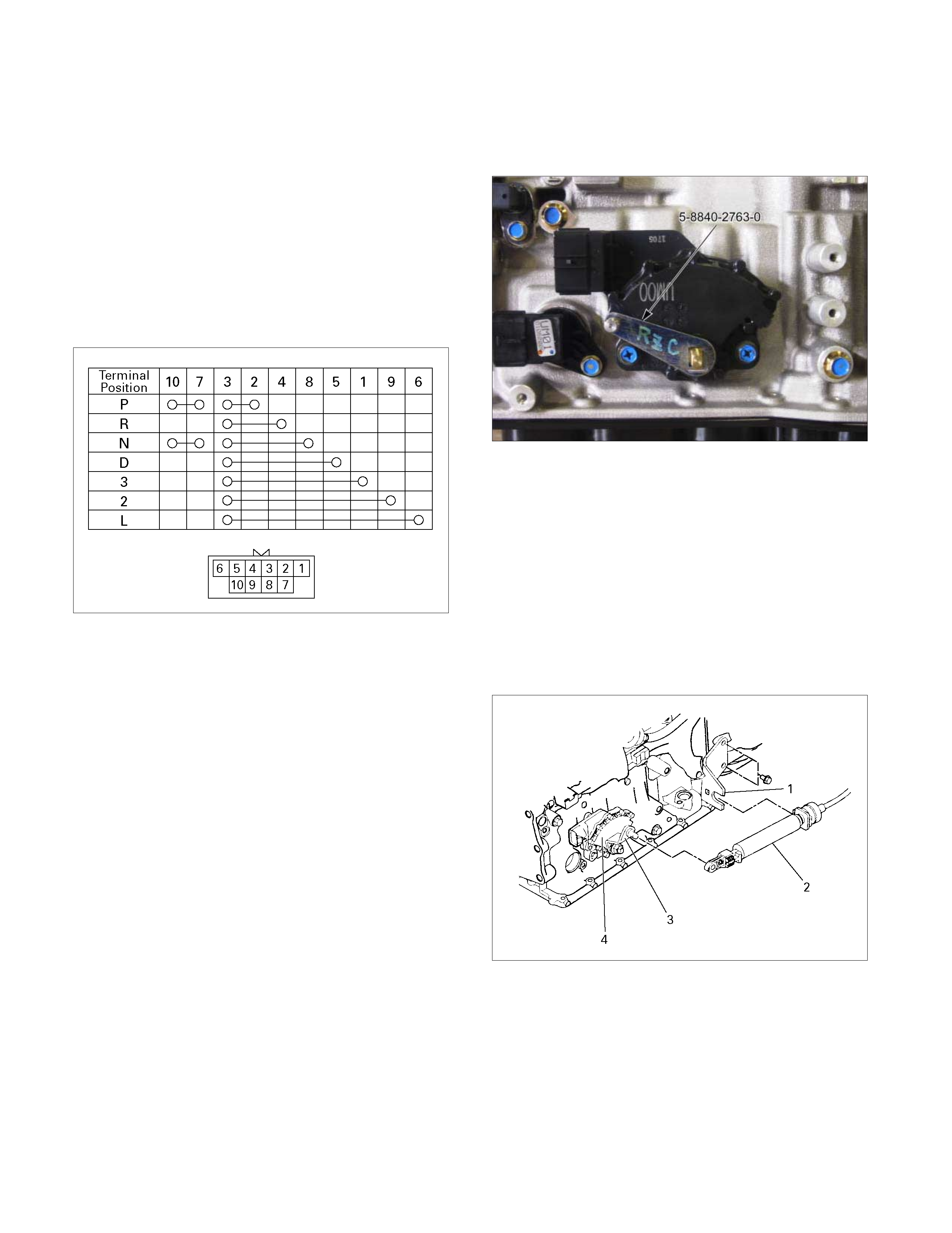
Inhibitor Switch
The inhibitor switch is attached to the right side of the
transmission.
Inspect
1. Block the wheels.
2. Disconnect the negative battery cable.
3. Disconnect the harness connectors.
4. Use an ohmmeter to check the inhibitor switch
continuity between the following terminals as shown
in figure.
5. Place the select lever in the “N” range.
249R300001
6. Move the select lever to either side.
Check the inhibitor switch continuity between the
terminals shown in Step (4).
The continuity readings should remain fairly stead
y
as the select lever is moved.
If there is no continuity or the continuity is
intermittent, the inhibitor switch must be adjusted.
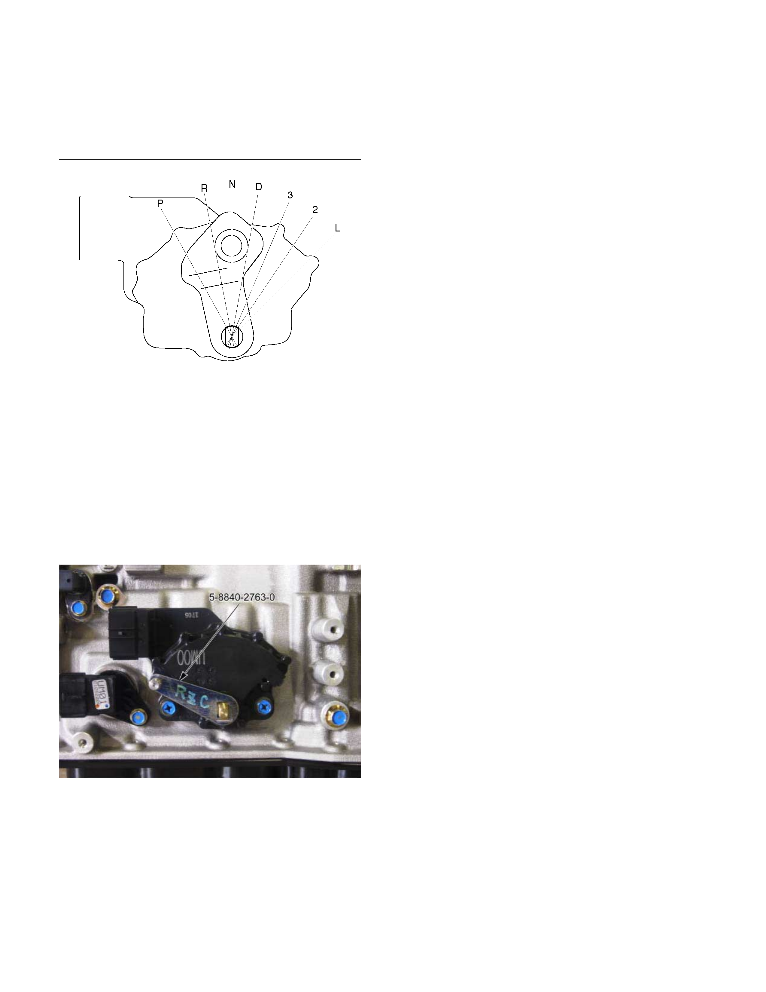
Adjust
1. Disconnect the shift calbe from the lever.
2. Loosen the inhibitor switch bolts.
3. Use the inhibitor switch set plate to align the neutral
holes (manual shaft and inhibitor switch).
Turn the inhibitor switch to adjust it.
Inibitor switch set plate: 5-8840-2763-0
Note:
Inhibitor switch adjustment is very important.
If the inibitor switch is not correctly adjusted, the
automatic transmission will not function normally.
4. Tighten the 2 inhibitor switch bolts to the specified
touque.
Torque: 5.5 N·m (48 lb·in)
47INH-SW01
5. Connect the shift cable to the lever.
6. Connect the harness connector.
Remove or Disconnect
1. Remove the cable bracket (1) from the transmission.
2. Disconnect the shift cable (2) from the lever (3).
3. Disconnect the harness connectors.
4. Remove the inhibitor switch bolts.
5. Remove the inhibitor switch (4) from the
transmission.
238R300001
Install or Connect
1. Install the inhibitor switch (4) to the transmission.
Temporarily tighten the inhibitor switch bolts.
2. Move the manual shaft select lever to the “N” range.
249R300002
3. Use the inhibitor switch set plate to align the neutral
holes (manual shaft and inhibitor switch).
Turn the inhibitor switch to adjust it.
Inhibitor switch set plate: 5-8840-2763-0
Note:
Inhibitor switch adjustment is very important.
If the inhibitor switch is not correctly adjusted, the
automatic transmission will not function normally.
4. Tighten the 2 inhibitor switch bolts to the specified
torque.
Torque: 5.5 N·m (48 lb·in)
47INH-SW01
5. Install the cable bracket (1) to the transmission.
6. Connect the shift cable (2) to the lever (3).
7. Connect the harness connector.
8. Connect the negative battery cable.
9. Remove the wheel blocks.
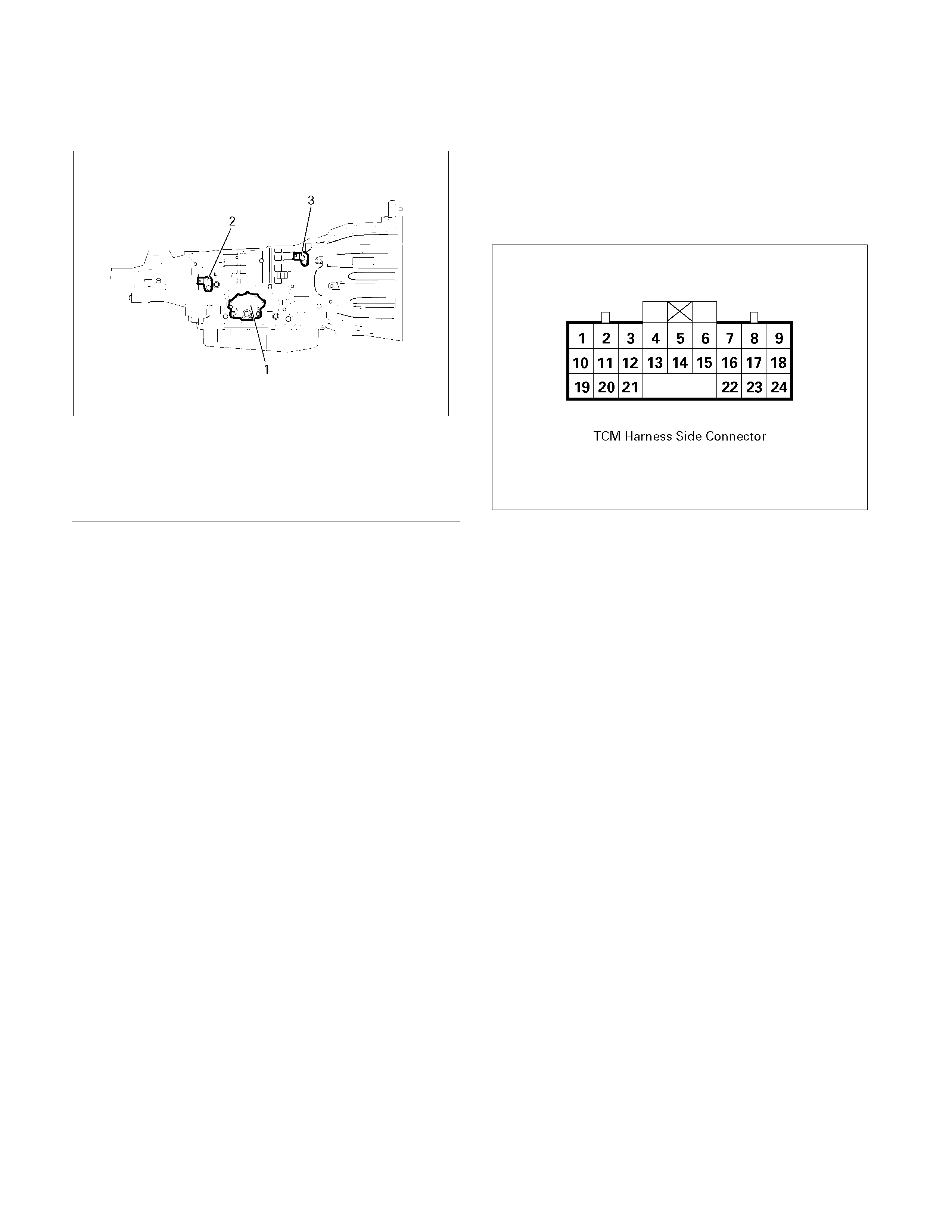
Speed Sensor
The speed sensor is attached to the right side of the
transmission.
240L300001
Legend
1. Inhibitor switch
2. Speed sensor
3. Turbine sensor
Inspect
1. During the driving at speed of 20km/h (12mph) with
“L” range in low gear, measure the voltage between
the TCM connector terminals (B13) and (B5) with a
digital voltmeter.
Standard voltage : approx. 7V (AC range)
826R300014
2. If the voltage is out of the standard value, check the
speed sensor pole piece for presence of foreign
meterials and the speeed sensor cable for short or
open circuit.
Res ult of the inspec tion is norm al, replace the speed
sensor.
Torque: 6 N·m (52 lb·in)

Turbine Sensor
The turbine sensor is attached to the right side of the
transmission.
Inspect
1. During the driving at speed of 20km/h (12mph) with
“L” range in low gear, measure the voltage between
the TCM connector terminals (B3) and (B5) with a
digital voltmeter.
Standard voltage : approx. 7V (AC range)
2. If the voltage is out of the standard value, check the
turbine sensor pole piece for presence of foreign
materials and the turbine sensor cable for short o
r
open circuit.
Result of the inspection is normal, replace the
turbine sensor.
Torque: 6 N·m (52 lb·in)
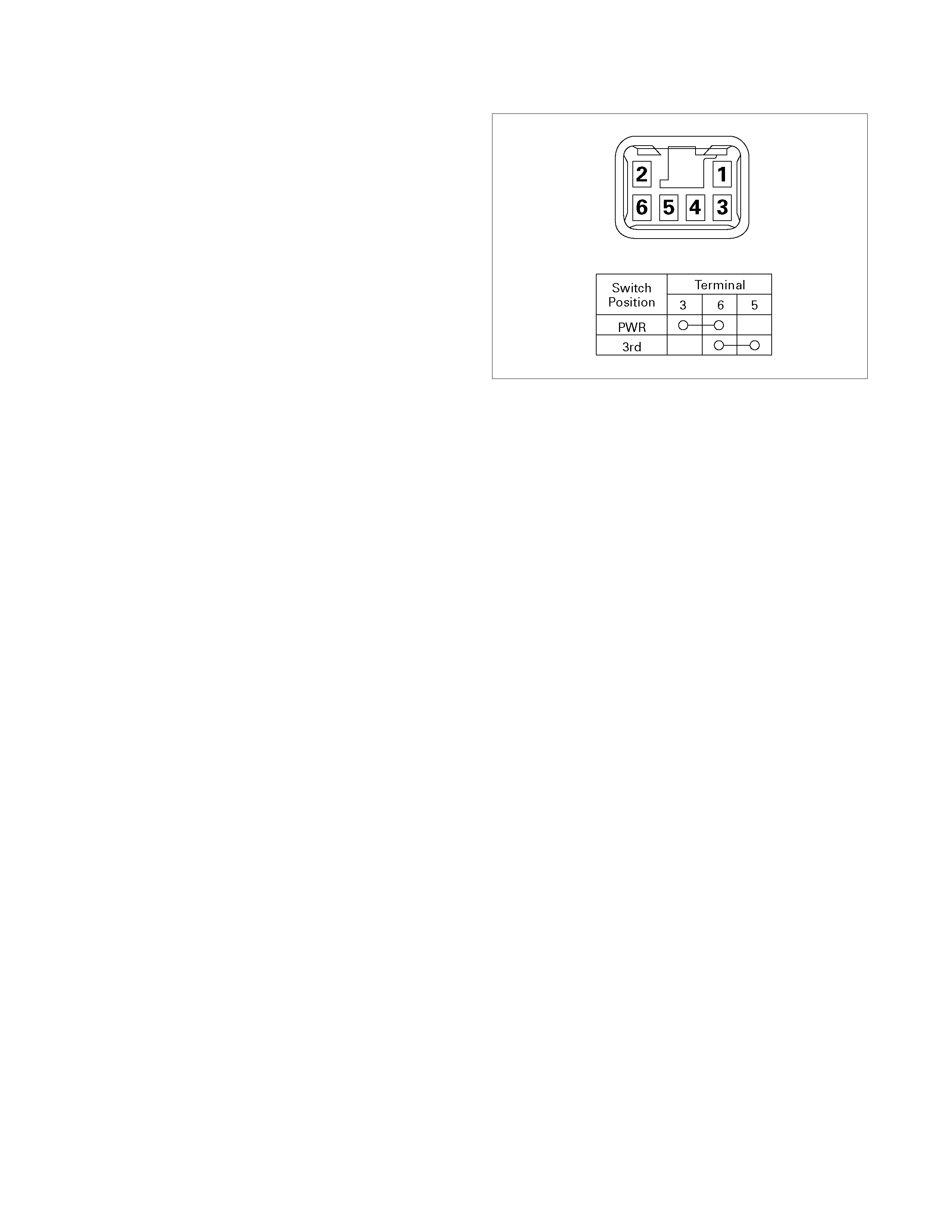
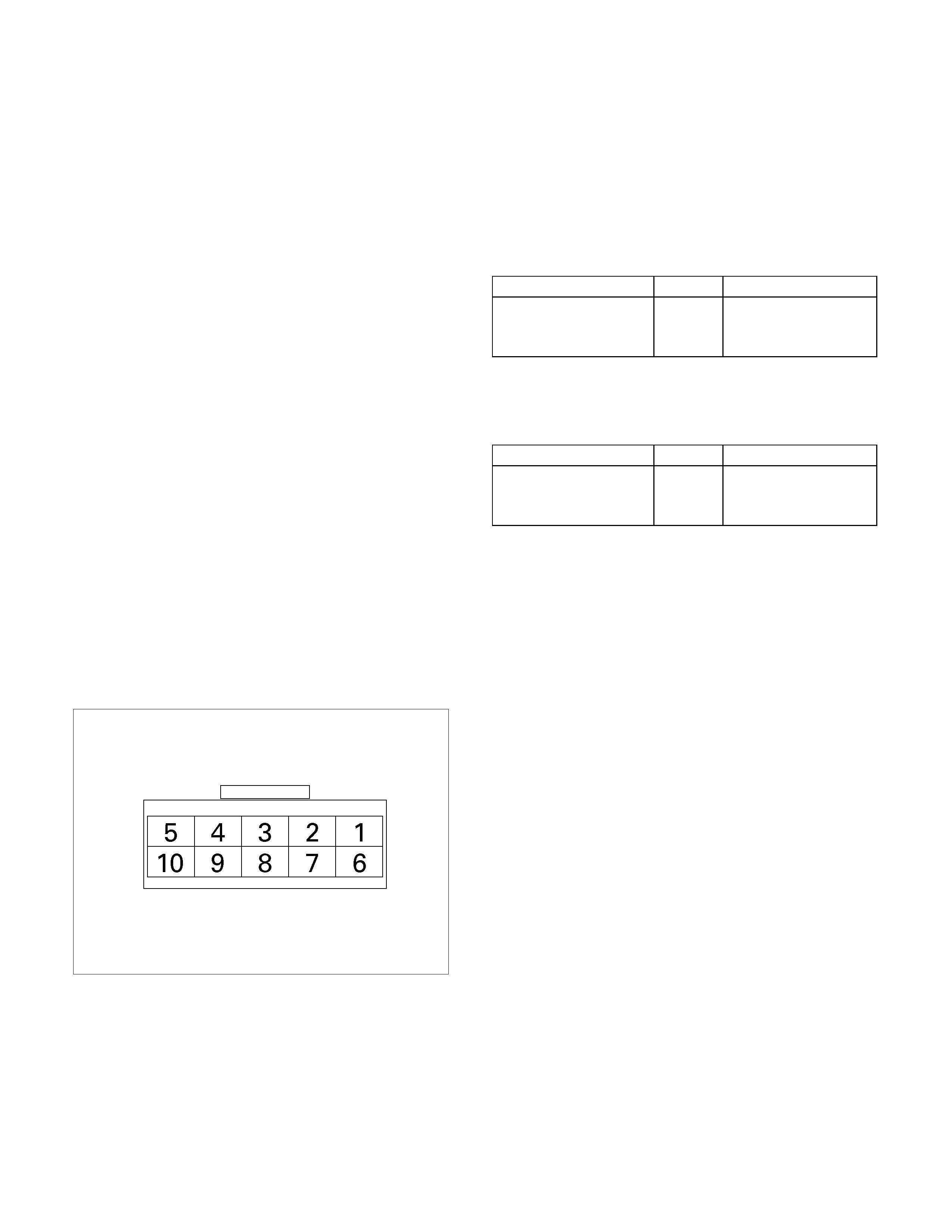
Power And 3rd Start Switch
Inspect
1. Block the wheels.
2. Disconnect the negative battery cable.
3. Pry out the switch from the floor console.
4. Disconnect the harness connector.
5. Check continuity between terminal (5) and ( 6) at thir d
(3rd) position .
6. Check continuity between terminals (3) and (6) at
power (PWR) position.
7. Replace the power and 3rd start switch when the
result of inspection is found abnormal.
8. Connect the harness connector.
9. Connect the negative battery cable.
10. Remove the wheel blocks.
238R300003
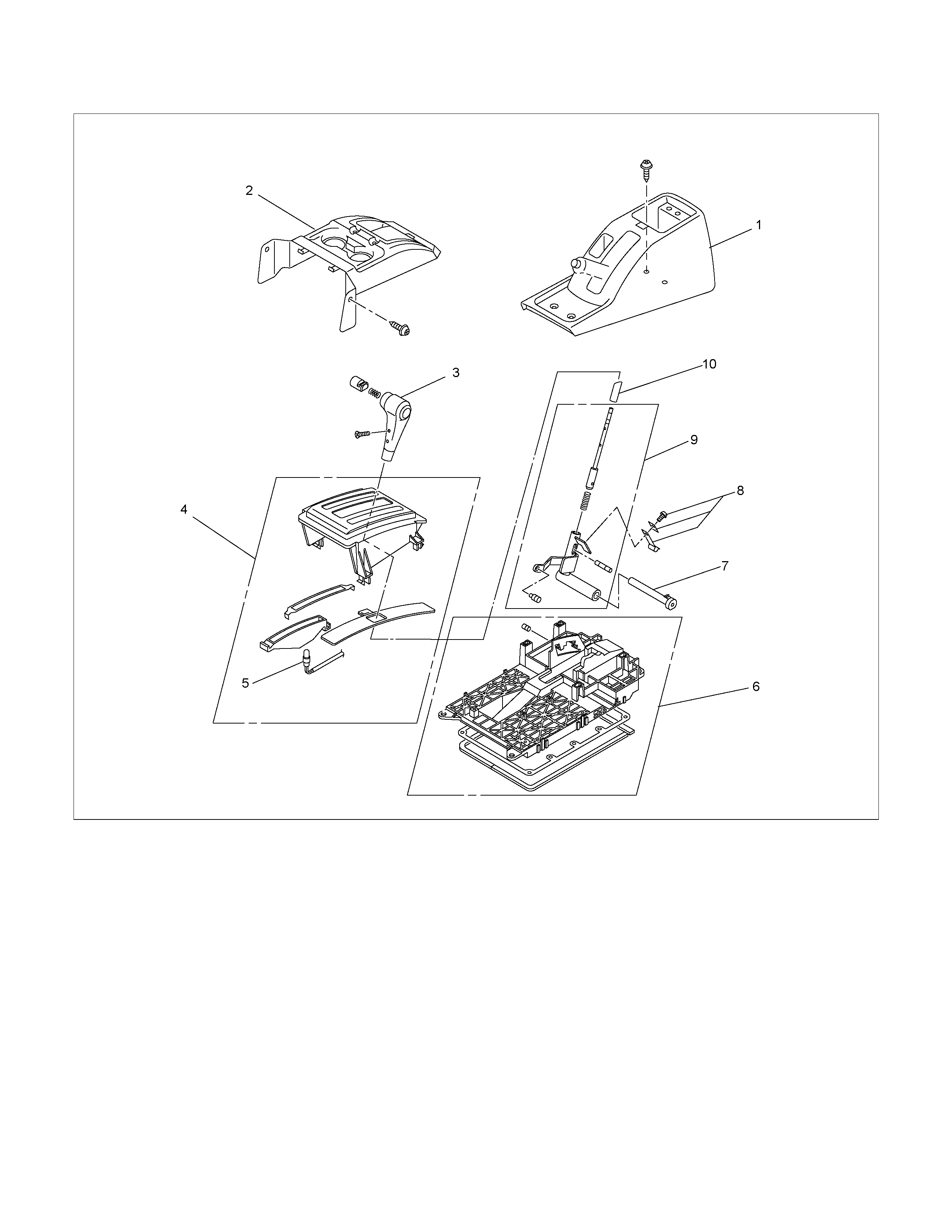
Select Lever
RTW37ALF001101
Legend
1. Rear console
2. Front console
3. Select lever knob
4. Upper housing
5 Lamp assembly
6 Base plate
7 Grooved pin
8 Spring plate
9 Lever assembly
10 Sleeve
Remove or Disconnect
1. Block the wheels.
2. Disconnect the negative battery cable.
3. Remove the rear console and the front console.
4. Remove the 2 screws fixing the select lever knob.
5. Remove the knob together with the knob button and
spring from the lever.
6. T urn the sleeve counterc lockwise to r emove it. Mak e
a note of the number of turns required to free the
sleeve.
7. Remove the harness connectors from the base plate.
8. Remove the upper housing (held in place by 4
latched fasteners).
9. Remove the spring plate.
10. Remove the grooved pin.
11. Remove the lever assembly by pressing the rod
down (lever in N position).
12. If lamp replacement is required, remove the lamp
assembly from the lamp socket (align the socket
grooved portion and the lamp assembly protruding
portion).
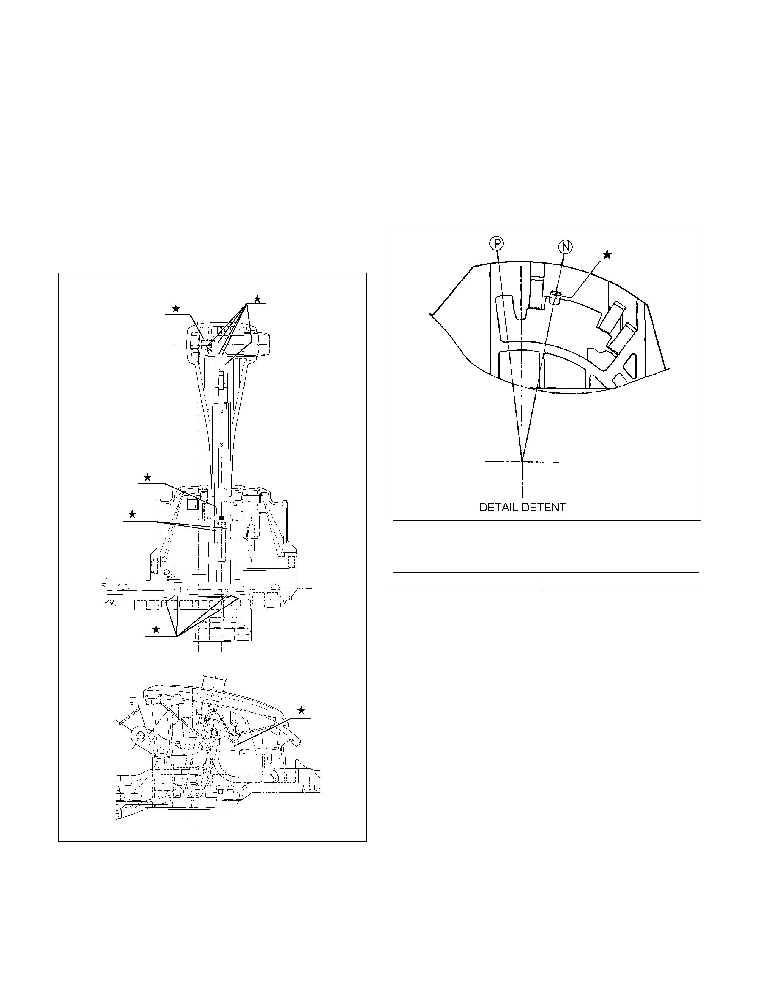
Install or Connect
NOTE:
Apply MULTEMP No. 2 grease (or equivalent) to the
select lever. Refer to the illustration.
RTW37ALH000201
1. Install the lever assembly to the base plate.
a. Insert and secure shaft.
b. Insert pawled end of shaft into base plate hole.
c. Insert grooved pin of shaft into detente aperture
(lever assembly in N position).
2.Install the spring plate.
a. Insert the grooved pin into the base plate detente
groove until it touches the front wall (lever
assembly in N position).
RTW37ASH001001
b. Install the short spring plate tighten the screws to
the specified torque.
Screw torque 2 N⋅m (0.2kg⋅m/17 lb ft)
c. Check that the grooved pin moves smoothly in
the detente groove (shift knob temporaril
y
installed).
3. Temporarily install the sleeve.
4. Install the lamp assembly to the lamp socket (i
f
removed at disassembly).
a.
A
lign the recess ed por tion of the lamp socket with
the protruding portion of the lamp assembly.
b. Insert the lamp assembly into the lamp socket
and rotate it 90 degrees clockwise.
5. Attach the harness connectors to the base plate.
6. Move the lever to the “P” position.
7. Install the sleeve (rotate the sleeve clockwise the
same number of turns it was rotated
counterclockwise at disassembly).
8. Install the knob, the knob button, and the knob
spring.
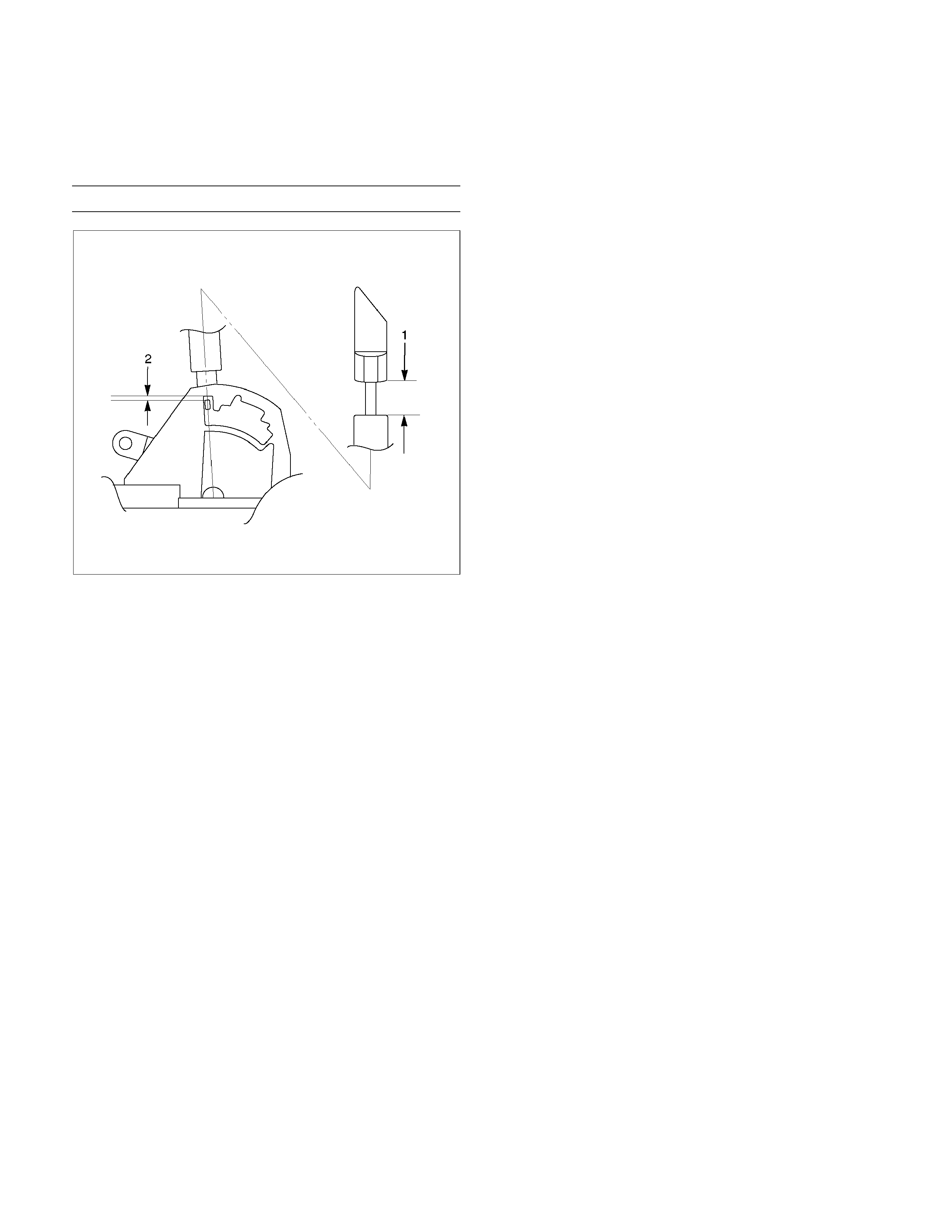
9. Adjust the clearance (2) between the detente plate
and the pin by moving the select lever knob sleeve
(1).
Detente plate and pin clearance mm(in
)
0.2 - 1.0 (0.01 - 0.04)
255R300002
10. Install the 2 screws securing the knob and tighten
them to the specified torque.
Screw torque: 2 N⋅m (0.2kg ⋅m/17 lb in)
11. Install the upper housing. Make sure that the 4
latched fasteners are securely closed.
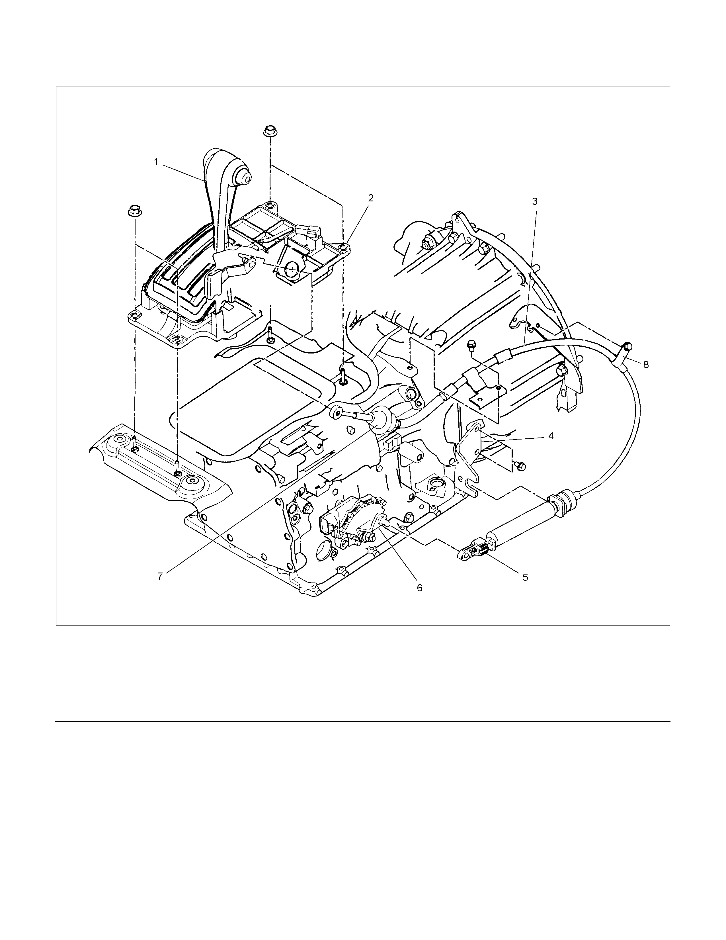
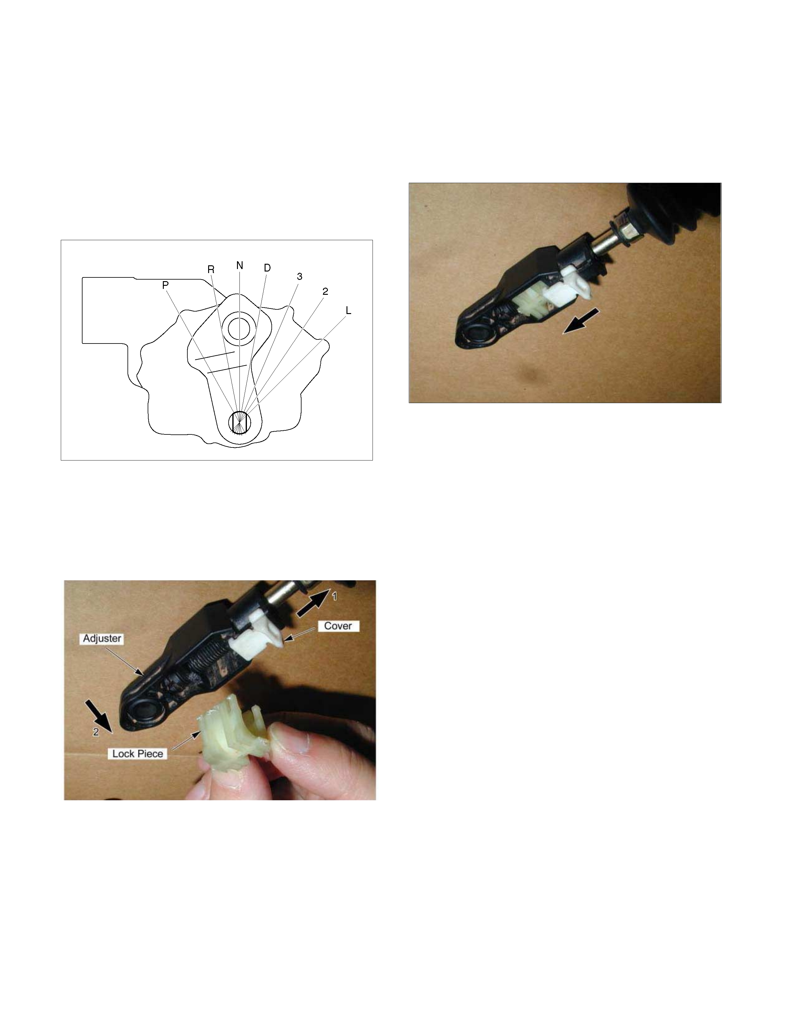
Shift Cable
RTW37ALF001201
Legend
1. Select lever
2. Select lever base
3. Shift cable
4. Bracket
5. Adjuster
6. Manual shaft select lever
7. Shift cable retaining pawl
8. Clip
Remove or Disconnect
1. Block the wheels.
2. Disconnect the negative battery cable.
3. Move the select lever to the “N” position.
4. Remove the rear console and front console.
5. Disconnect the shift cable from the select lever.
6. Pr ess on the shif t cable retaining pawl to rem ove the
cable from the select lever base.
7. Disconnect the shift cable from the transmission
side.
8. Remove the shift cable from the bracket.
9. Pull the shift cable free from the bottom of the
vehicle.
Install or Connect
1. Install the shift cable toward the inside of the cabin
from the bottom of the vehicle.
2. Push the shift cable into the select lever base.
3. Connect the shift cable to the select lever.
4. Fix the shift cable to the bracket.
Install the clip on the marking of shift cable.
5. Check that the select lever is in the “N” position.
6. Check that the transmission is in the “N” position.
249R300002
7. Slide the cover in the direction shown by the arro
w
(1).
8. Use an ordinary screwdriver to move the lock piece
from the position indicated by the arrow (2). Continue
to move the lock piece until the adjuster position
begins to change.
P1010012
9. Connect the shift cable to the manual shaft select
lever at the transmission side.
10. Insert the lock piece to the adjuster (cable length
adjustment).
11. Slide the cover on the adjuster and secure lock
piece.
P1010016-2
11. Press the select lever knob button 5 times.
Then check that the select lever moves smoothly to
each of its positions.
13. Check that the shift position indicated by the select
lever and the actual shift position are the same.
14. Install the front console and rear console.
15. Connect the negative battery cable.
16. Remove the wheel blocks.
Torque Specifications
E07R300015
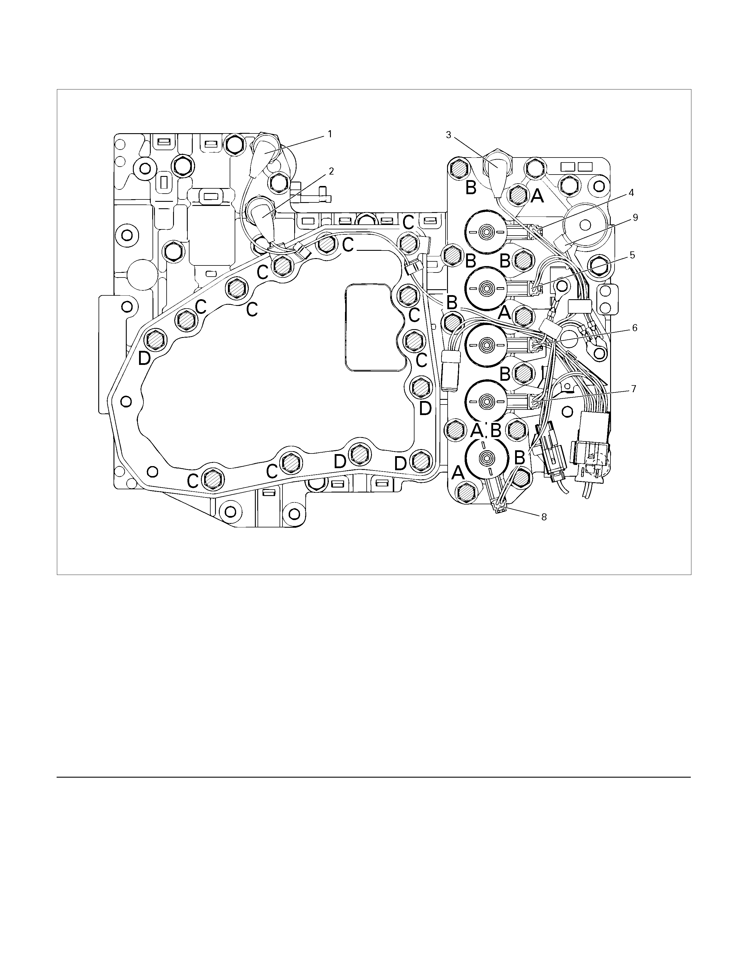
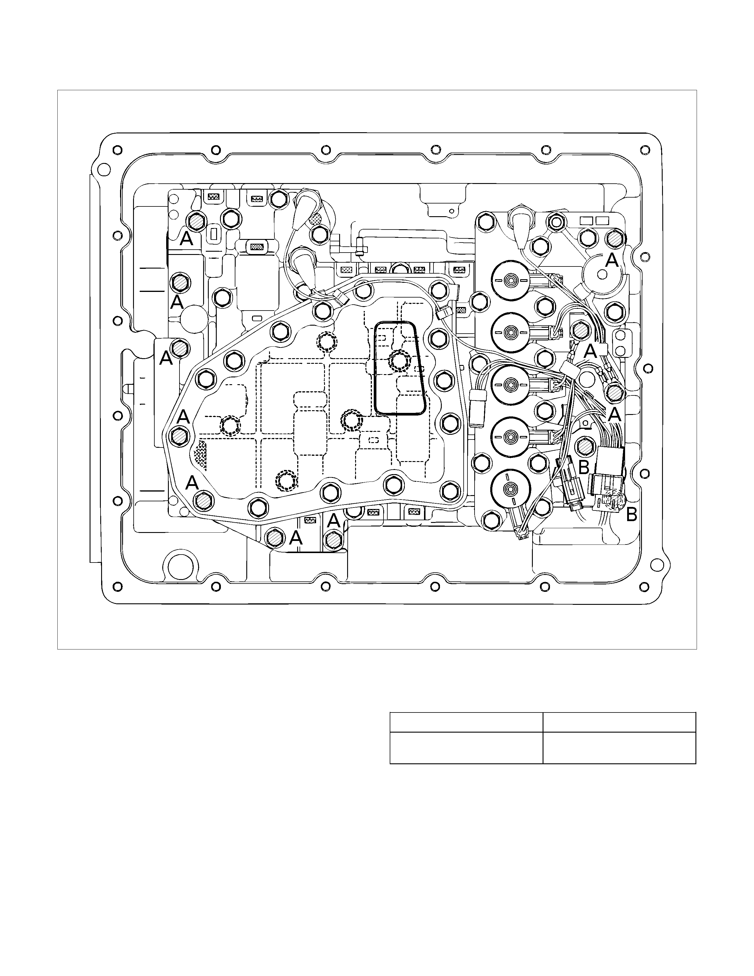
Solenoids, Oil Pressure Switch And Oil Temperature Sensor
244L300003
Legend
1. High clutch oil pressure switch connector
(wire color: Gray)
2. 2-4 brake oil pressure switch connector
(wire color: Brown)
3. Low and reverse brake oil pressure switch connector
(wire color: White)
4. Low and reverse brake duty solenoid connector
(wire color: Pink and White)
5. High clutch duty solenoid connector
(wire color: Green and Gray)
6. Lock-up duty solenoid connector
(wire color: Yellow and Black)
7. 2-4 brake duty solenoid connector
(wire color: Blue and Brown)
8. Low clutch duty solenoid connector
(wire color: Orange and Black)
9. Line pressure solenoid connector
(wire color: Pink)
Remove or Disconnect
1. Block the wheels.
2. Disconnect the negative battery cable.
3. Drain the fluid.
Refer to “ATF CHANGE” in this section.
4. Remove the 19 bolts and oil pan.
5. Inspect the bottom of the oil pan and strainer netting
for foreign material (clutch facing and metal
shavings).
If there is an excessive accumulation of foreign
material, the oil strainer must be replaced.
Further inspection is required to determine the
source of the foreign material.
6. Remove the harness assembly (including oil
temperature sensor).
7. Remove the 11 bolts and the solenoid fixing plate.
8. Remove the 6 solenoids and 3 oil pressure switches.
Inspect
Oil pressure switch
Apply compressed air (392 kPa/4.0 kg/cm2) to the oil
pressure switch to ch eck the oil pressure swi tch
continuity between the connector and screw.
Oil temperature sensor (harness assembly)
Check the oil temperature sensor resistance between
harness terminals 7 and 6 (ground).
Oil temperature sensor resistance:
2,400~2,600 ohms (20°
°°
°C)
244L300011
Solenoid
Measure the resistance of each solenoid.
Resistance:
Brown connector – 3.0~3.4 ohms (20°
°°
°C)
Gray connector – 12.0~13.2 ohms (20°
°°
°C)
White connector – 12.2~13.4 ohms (20°
°°
°C)
Install or Connect
1. Install the O-rings to each of the solenoids.
2. Install the 6 solenoids and 3 oil pressure switches.
Line pressure solenoid bolt torque:
8 N·m (69 lb·in)
Oil pressure switch bolt torque:
4.4 N·m (39 lb·in)
3. Install the solenoid fixing plate together with the
harness brackets.
Number Length (Color)
Solenoid fixing plate bolt
(A)
(B)
4
7
16 mm (0.63 in) (Gold)
45 mm (1.77 in) (Silver)
Bolt torque : 8 N·m (69 lb·in)
4. Install the harness assembly.
5. If removed, install the oil strainer.
Number Length (Color)
Oil strainer bolt (C)
(D)
9
4
13 mm (0.51 in) (Silver)
45 mm (1.77 in) (Silver)
Bolt torque : 8 N·m (69 lb·in)
6. Install the new gasket and oil pan.
Bolt torque : 8 N·m (69 lb·in)
7. Fill the fluid.
Refer to “ATF CHANGE” in this section.
8. Connect the negative battery cable.
9. Remove the wheel blocks.
Control Valve Assembly
244L300001
Remove or Disconnect
1. Block the wheels.
2. Disconnect the negative battery cable.
3. Drain the fluid.
Refer to “ATF CHANGE” in this section.
4. Remove the 19 bolts and oil pan.
5. Inspect the bottom of the oil pan and strainer netting
for foreign material (clutch facing and metal
shavings).
If there is an excessive accumulation of foreign
material, the oil strainer must be replaced.
Further inspection is required to determine the
source of the foreign material.
6. Disconnect the 2 harness connectors leading to the
control valve.
7. Remove the 12 bolts and the control valve assembly.
Number of bolts Length
10 (A)
2 (B) 40 mm (1.57 in)
30 mm (1.18 in)
Note:
Take care not to disturb the manual valve (inside the
control valve assembly).
Do not allow the pin to fall free (the pin prevents the
valve from turning).
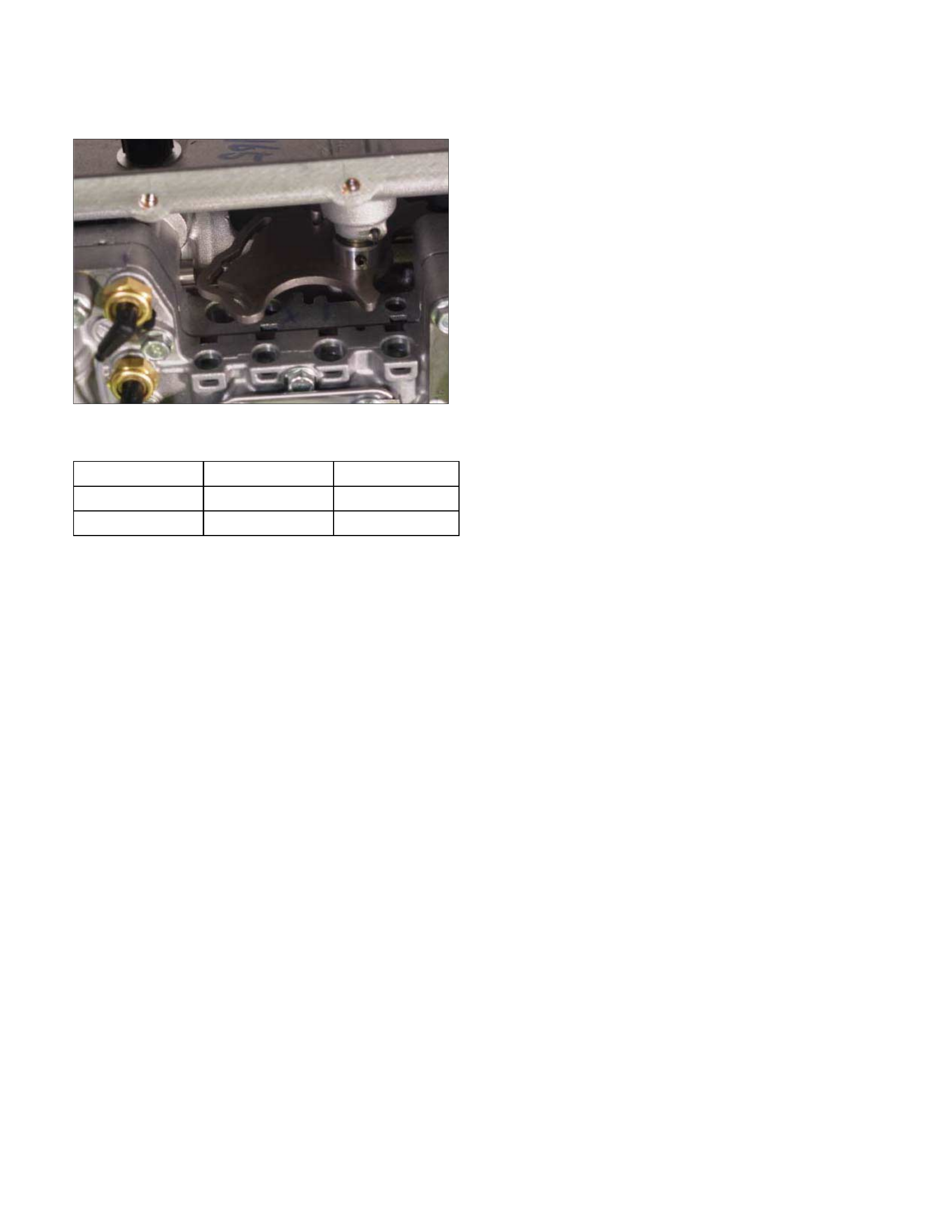
Install or Connect
1.
A
lign the manual valve and the manual plate of the
transmission case.
43ASSY119
2. Install the control valve assembly and tighten the 12
fixing bolts to the specified torque.
Number of bolts Length Color
10 (A) 40 mm (1.57 in) Gold
2 (B) 30 mm (1.18 in ) Gold
Bolt torque : 8 N·m (69 lb·in)
3. Connect the 2 harness connectors.
4. If removed, install the oil strainer.
Refer to “Solenoids, Oil Pressure Switch and Oil
Temperature Sensor” previously in this section.
5. Install the new gasket and oil pan.
Bolt torque : 8 N·m (69 lb·in)
6. Fill the fluid.
Refer to “ATF CHANGE” in this section.
7. Connect the negative battery cable.
8. Remove the wheel blocks.

Flushing The Transmission Fluid Cooler And Line
The fluid cooler and lines may be flushed under the
following condition. This will help prevent more trouble
after the transmission is repaired.
1. When the abnormal amount of debris are found.
2. When the abnormal wear or chips on gears and
shafts are found while overhauling.
3. When the abnormal clutch facing wear and oil
contamination are found.
Procedures
1. Block the wheels.
2. Disconnect negative battery cable.
3. Raise vehicle and support with suitable safet
y
stands.
4. Disconnect fluid cooler lines at transmission case
and fluid cooler.
5. Flush and back-flush the fluid cooler and lines using
solvent and compressed air.
Note:
DO NOT exceed 197 kPa (29 psi) air pressure or
damage may result to oil cooler.
6. Remove all remaining solvent from the system with
compressed air.
7. Flush the cooling system again with Automatic
Transmission Fluid (ATF).
After the final flush, connect all lines.
Cooler line joint connector torque :
44 N·m (33 lb·ft)
8. Replenish ATF
9. Start engine to test the system for the free flow o
f
fluid. If the f low is restricted, the cooler assembly or
lines must be replaced.
Repeated cleaning and flushing may not remove all
debris from the fluid cooler circuit.
Move the select lever through the various ranges and
return to neutral.
Check for fluid level.
If the fluid level is below the specified range, ATF
must be added.
10. Connect negative battery cable.
11. Remove safety stands.
12. Remove wheel blocks.
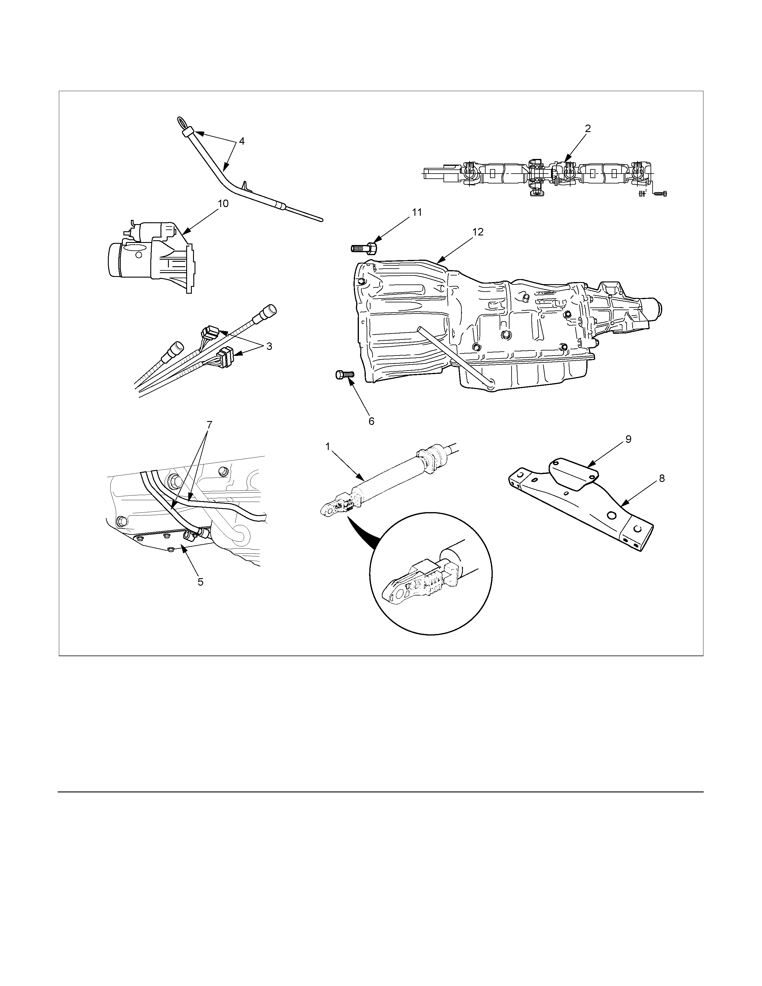
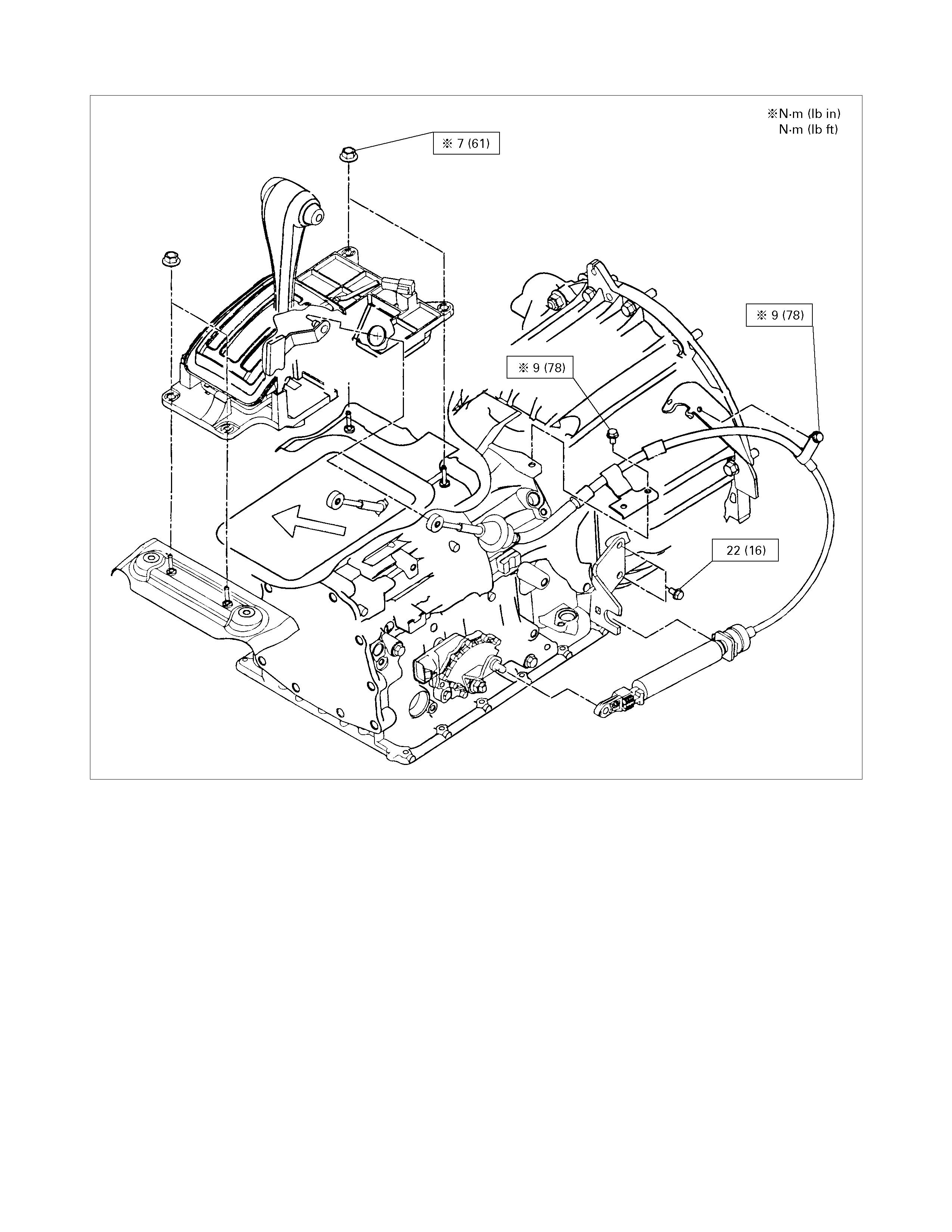
Transmission Assembly
RTW37ALF001401
Legend
1. Shift Cable
2. Propeller Shaft
3. Engine Harness
4. ATF Level Dipstick
5. Under Cover
6. Bolt
7. ATF Pipe
8. Crossmember
9. Bracket
10. Starter Motor
11. Bolt
12. Automatic Transmission
Remove or Disconnect
1. Block the wheels.
2. Disconnect the negative battery cable.
3. Raise the vehicle and suppor t with the suitable saf et
y
stands.
4. Remove the shift cable from the transmission.
P1010068
5. Remove the rear propeller shaft assembly .
6. Loosen (do not remove) the nuts securing the
exhaust manifold and the exhaust pipe.
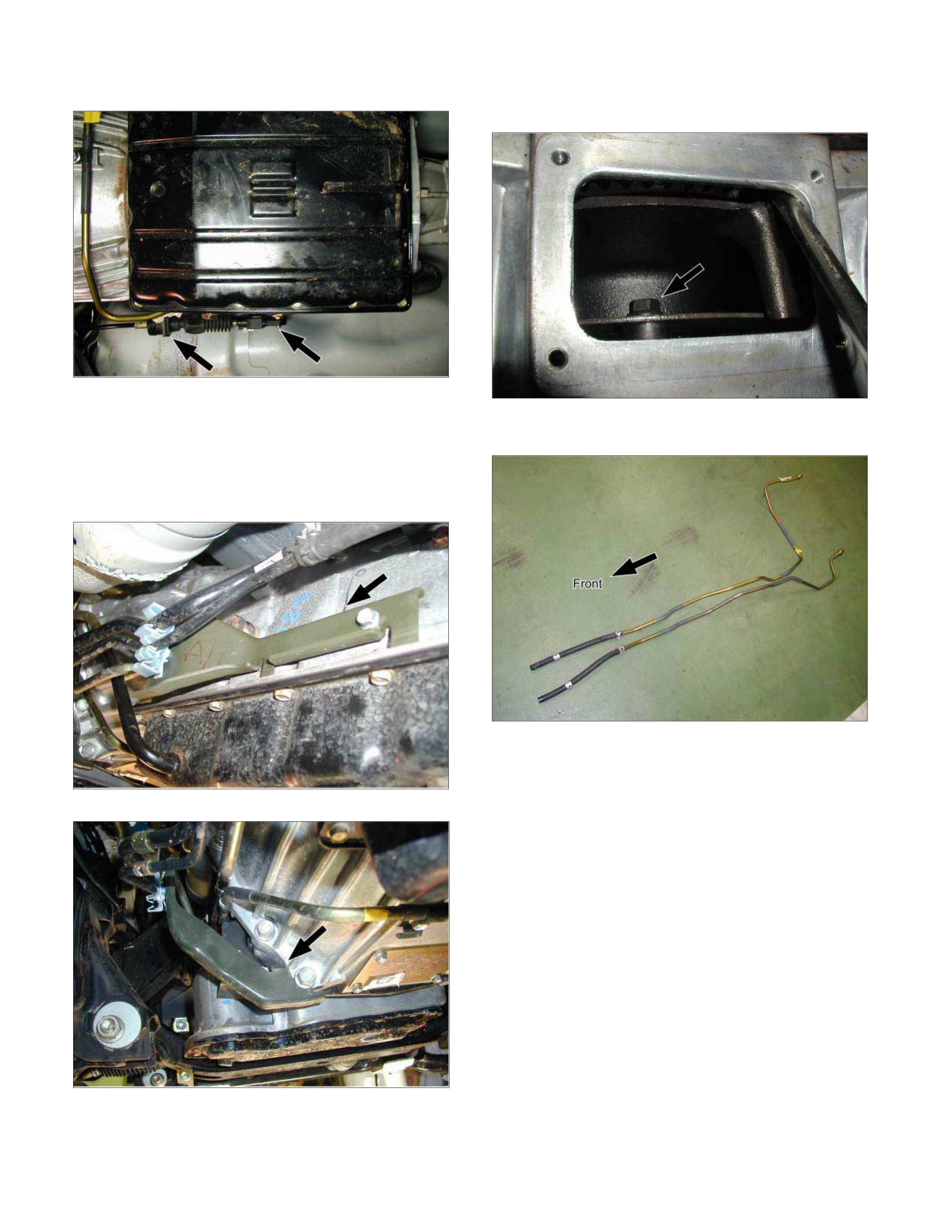
7. Disconnect the harness connectors from the
transmission.
8. Remove the fuel pipe bracket.
P1010013
P1010014
9. Remove the ATF level dipstick and tube.
10. Remove the undercover.
11. Rotate the ring gear and remove the 6 torque
converter bolts.
P1010016
12. Remove the automatic transmission fluid cooling
pipe.
P1010060
13. Place a jack beneath the engine to support it.
14. Remove the 3rd crossmember.
15. Remove the transmission mount.
16. Lower the jack beneath the engine slightly to tilt the
engine and transmission. Do not allow the radiator
and air conditioner hoses to stretch.
17. Remove the bolts attaching the transmission to the
engine.
18. Lower the transmission from beneath the vehicle.
Take care not to damage the breathers.
Install or Connect
1. Install the transm ission to the engine and tighten the
bolts.
Bolt torque : M10 40 N·m (30 lb·ft)
M12 76 N·m (56 lb·ft)
2. Install the cable bracket to the transmission.
3. Connect the engine harness connectors.

4. Install the 3rd crossmember.
Bolt and Nut torque : 67 N·m (49 lb·ft)
Bolt torque : 50 N·m (37 lb·ft)
5. Install the automatic transmission fluid cooling pipe.
6. Install the torque converter bolts.
Bolt torque : 29 N·m (22 lb·ft)
7. Install the undercover.
Bolt torque : 9 N·m (78 lb·in)
8. Install the ATF level dipstick and tube.
9. Install the fuel hose bracket.
Bolt torque : 6 N·m (52 lb·in)
10. Tighten the nuts securing the exhaust manifold and
the exhaust pipe.
Bolt torque : 43 N·m (32 lb·ft)
11. Install the rear propeller shaft assembly.
Flange bolt torque : 63 N·m (46 lb·ft)
Center bearing bracket bolt torque :
69 N·m (51 lb·ft)
12. Install the shift cable.
13. Connect the negative battery cable.
14. Remove the safety stands.
15. Remove the wheels blocks.
Torque Specifications
RTW37ALF001501