
SECTION 7A4 - UNIT REPAIR (JR405E)
Automatic Transmission Disassembly
Cleaning The Automatic Transmission
Automatic Transmission Disassembly Cautions
Disassembly Steps
Control Valve Assembly
Disassembly Steps
Inspection
Reassembly Steps
Control Valve Upper Body
Disassembly Steps
Inspection
Valve Specifications
Spring Specifications
Reassembly Steps
Control Valve Lower Body
Disassembly Steps
Inspection
Valve Specifications
Spring Specifications
Oil Pressure Switch
Oil Temperature Sensor (Harness Assembly)
Solenoid
Reassembly Steps
Oil Pump Assembly
Disassembly Steps
Inspection
Reassembly Steps
Clutch Pack (Reverse and High Clutch Assembly)
Disassembly Steps
Inspection
Reassembly Steps
Carrier and Low Clutch Assembly
Disassembly Steps
Inspection
Reassembly Steps
Inspection
Transmission Case
Disassembly Steps
Inspection
Reassembly Steps
Bearing and Bearing Race Installation Position
Automatic Transmission Reassembly
Assembly Cautions
Power Train
Reassembly Steps
Service Standard
Special Service Tool

Automatic Transmission Disassembly
Cleaning The Automatic Transmission
1. Use compressed steam and /or cleaning oil to thoroughly
clean the outside of the transmission before disassembly.
CAUTION:
Steam under high pressure may cause dirt particles
adhering to the transmission to fly through the air at great
speed. These particles can cause serious eye injury. Wear
protective goggles when steam-c leaning the outside of
the transmission.
2. During disassembly, clean the removed parts with cleaning
oil. Dry the parts with compressed air.
Use Compressed air to clean the transmission oil holes
and oil passages.
Automatic Transmission Disassembly Cautions
• Perform the disassembly procedure in a dust-free
environment to prevent the entry of foreign material into
the transmission.
• Inspect each transmission part as you remove it.
• Carefully check the oil pan and the magnet for foreign
material. This is a good way to estimate transmission
condition.
• Use your bare hands or vinyl gloves to disassemble the
transmission. Do not use ordinary work gloves (loose
threads from the gloves may fall into the transmission and
cause problems).
• Use a plastic hammer to loosen the transmission case
and other aluminum parts during disassembly. Strike
around the parts lightly with the hammer. Do not pry
aluminum parts away from each other with a screwdriver
or similar object.
• Arrange the disassembled parts neatly in the order they
were removed. Cover the parts with a plastic sheet or
similar object to protect them from dust.
Disassembly Steps
1. Torque converter
• Pull the torque converter free.
NOTE:
Place a pan beneath the torque converter to catch
automatic transmission fluid (ATF) spillage.
• Draining the ATF from the torque converter.
01ASSY101
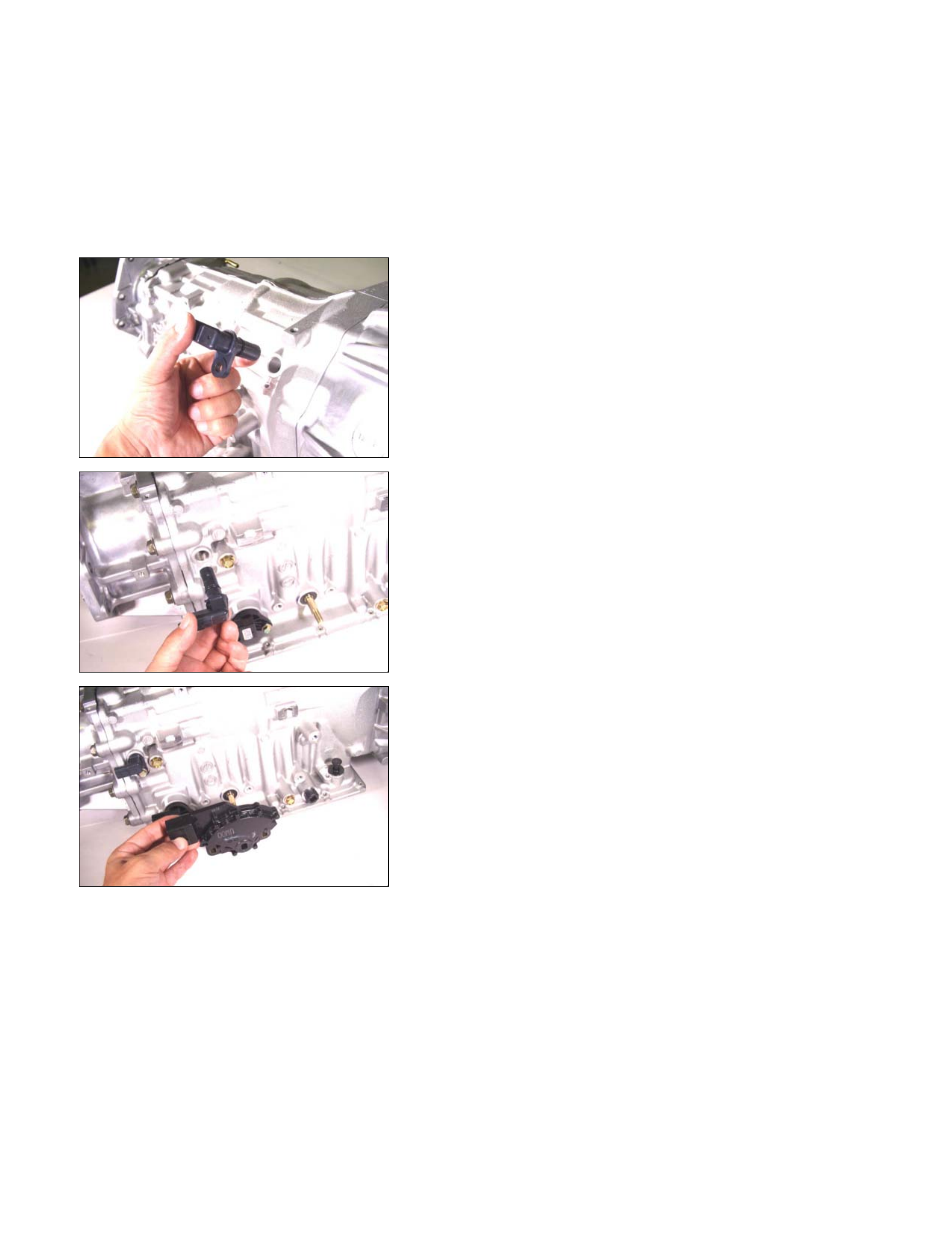
2. Turbine sensor and speed sensor
• Remove the turbine sensor from the transmission case.
02ASSY103
• Remove the speed sensor from the transmission case.
03ASSY106
3. Inhibitor switch
Remove the 2 bolts and the inhibitor switch from the
transmission case.
240L300002
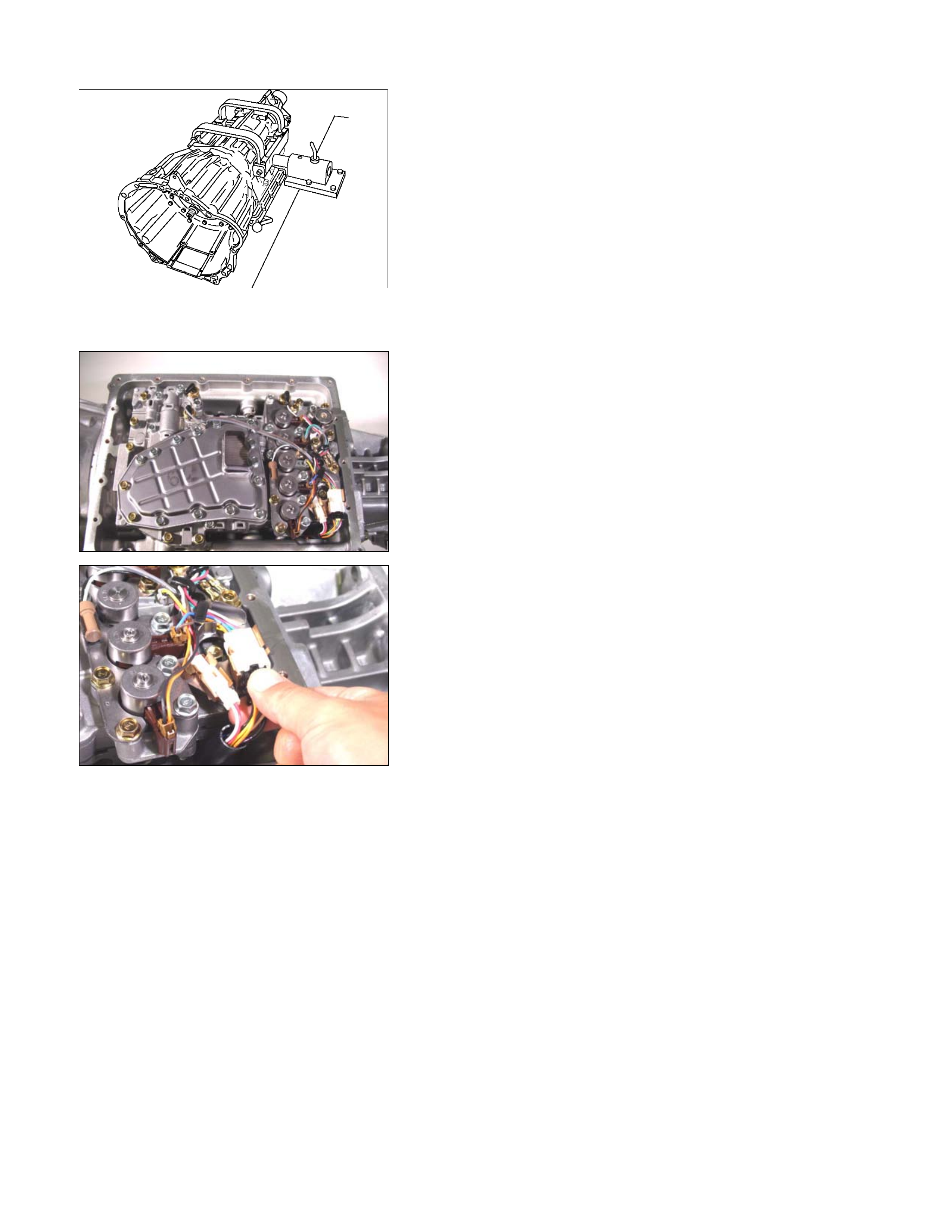
4. Oil pan
• Lift and support the transmission with the holding fixture
and holding fixture base.
Holding fixture: 5-8841-0841-0
Holding fixture base: 5-8840-0003-0
• Remove the drain plug from the oil pan and drain the
ATF from the oil pan.
• Rotate the automatic transmission so that the converte
r
housing is facing up and drain the ATF.
• Rotate the automatic transmission so that the oil pan is
facing up.
• Remove the 19 bolts and the oil pan.
04CV37
• Inspect the bottom of the oil pan and strainer netting fo
r
foreign material (clutch facing and metal shavings).
If there is an exc ess ive accum ulation of fo reign m aterial,
the oil strainer must be replaced.
Further inspection is r equired to determ ine the source o
f
the foreign material.
45CV29
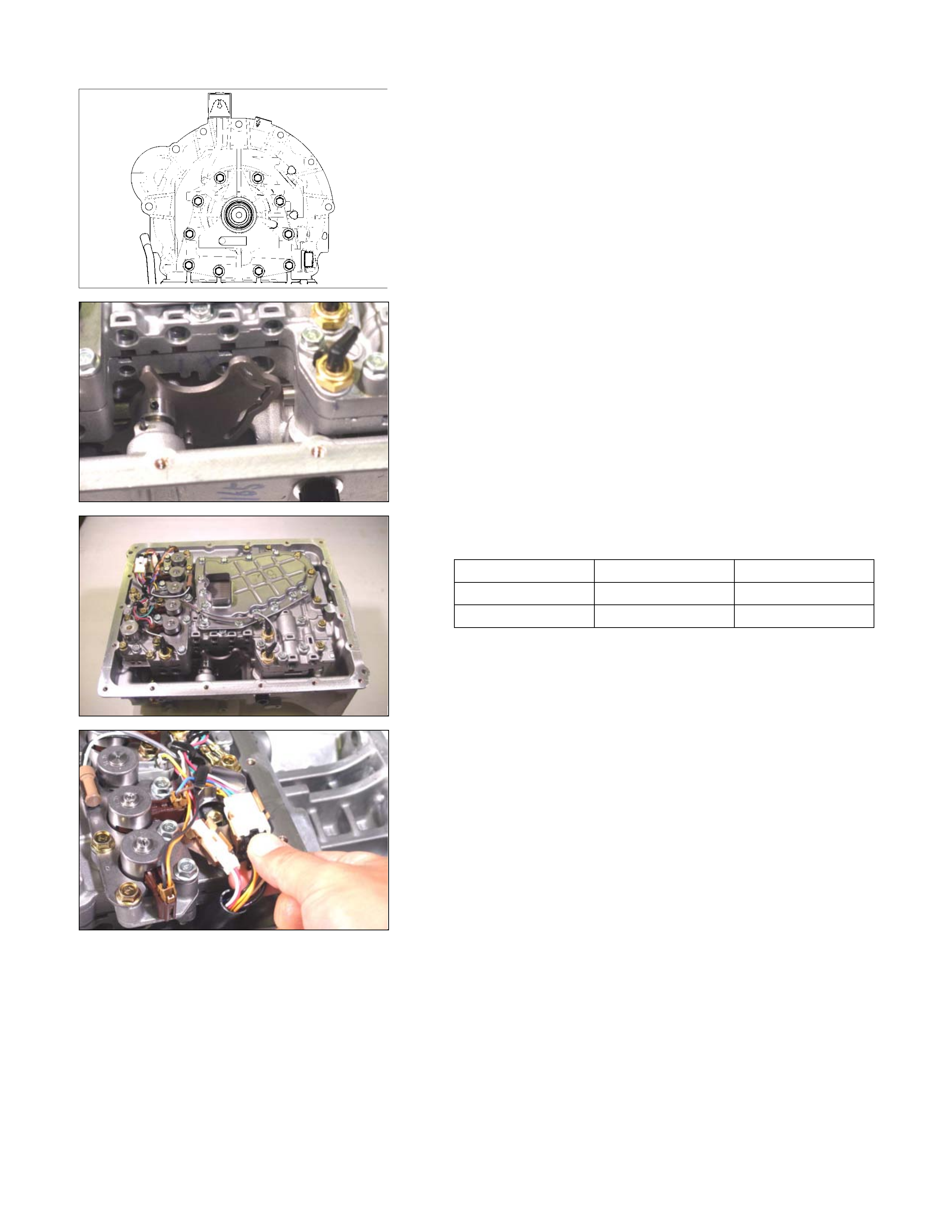
5. Control valve assembly
• Disconnect the 2 harness connectors leading to the
control valve.
244L300001
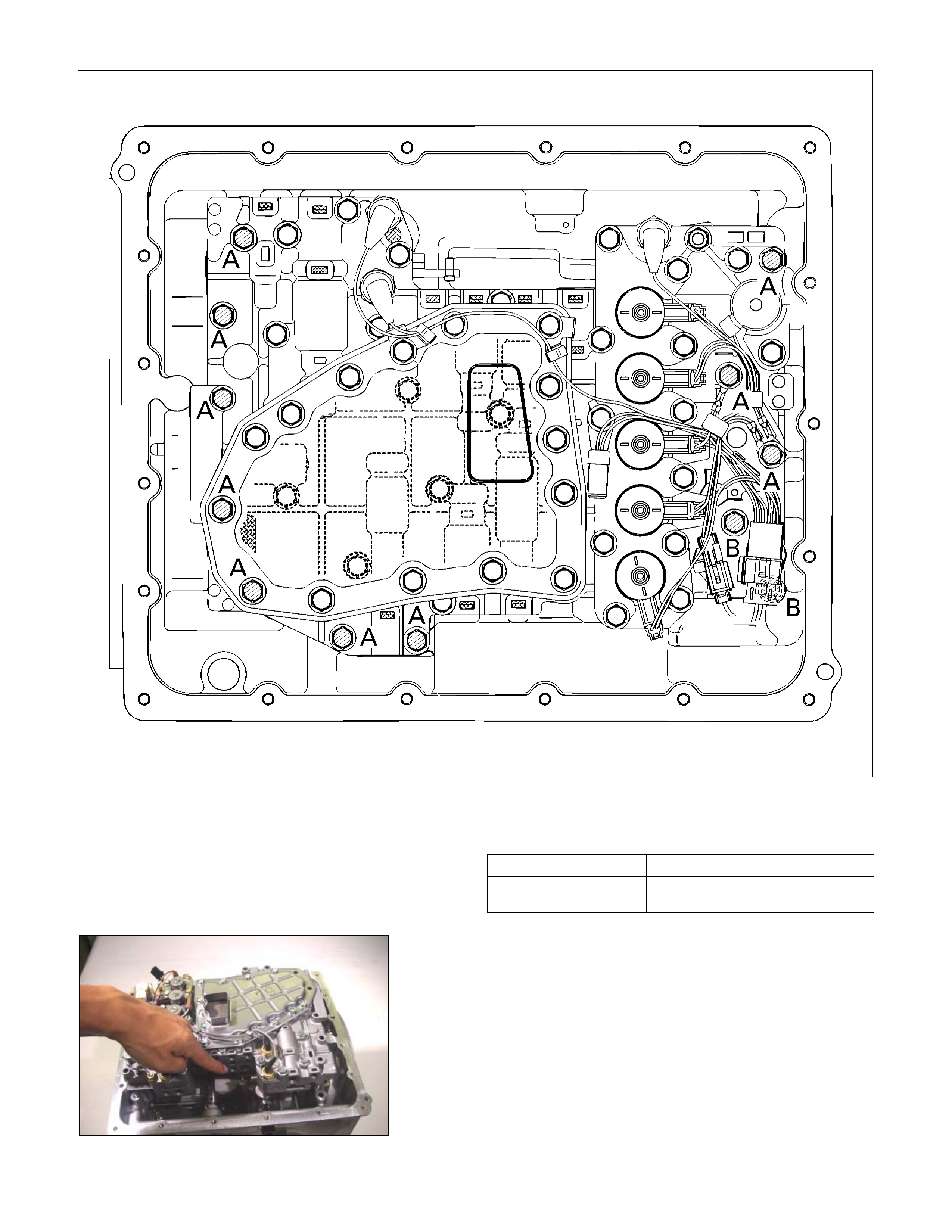
• Remove the 12 bolts and the control valve assembly.
Number of bolts Length
10 (A)
2 (B) 40 mm (1.57 in)
30 mm (1.18 in)
42ASSY118
NOTE:
Take care not to disturb the manual valve (inside the
control valve assembly).
Do not allow the pin to fall free (the pin prevents the valve
from turning).
10ASSY116
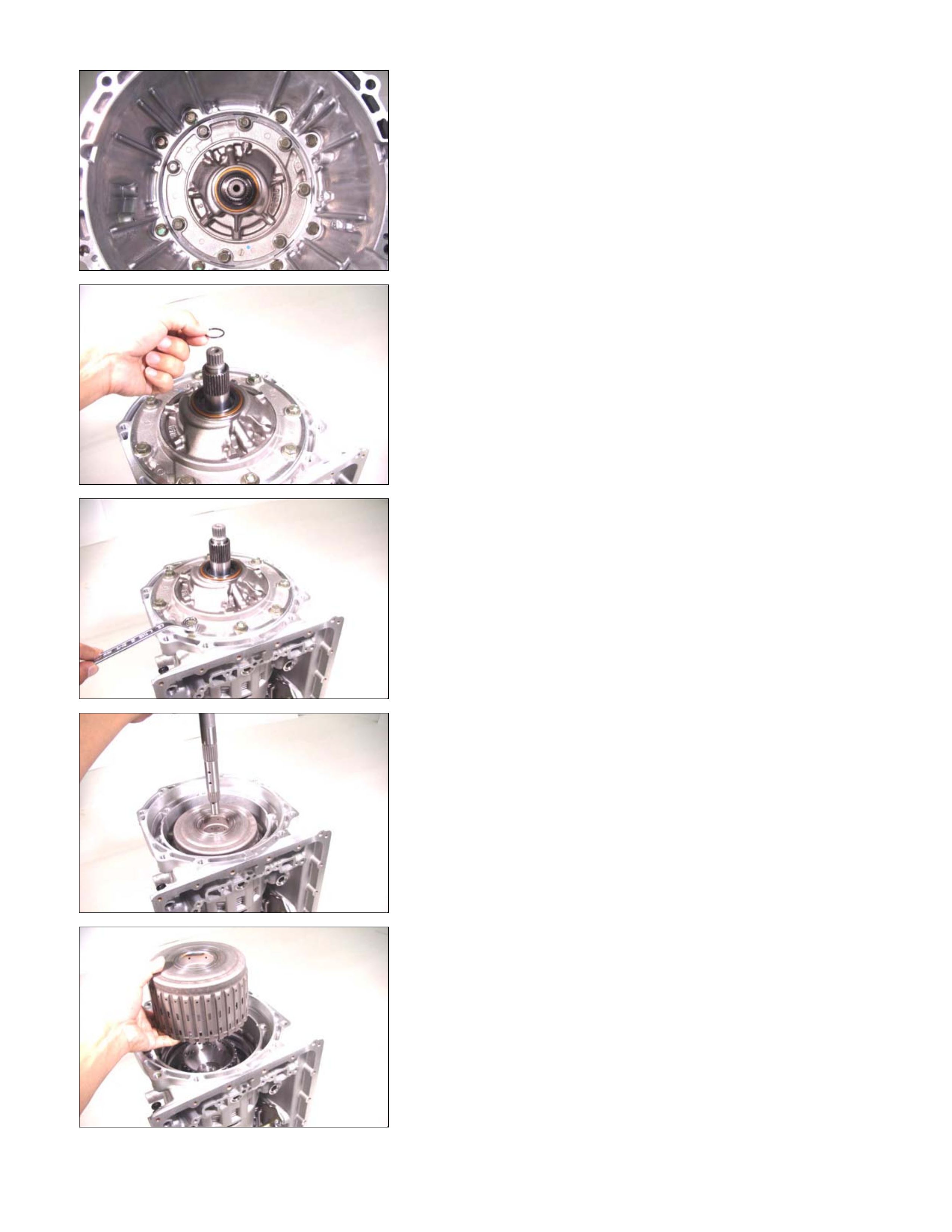
6. Converter housing
• Position the automatic transmission so that the
converter housing is facing up.
• Remove the 8 bolts and the converter housing.
11ASSY068
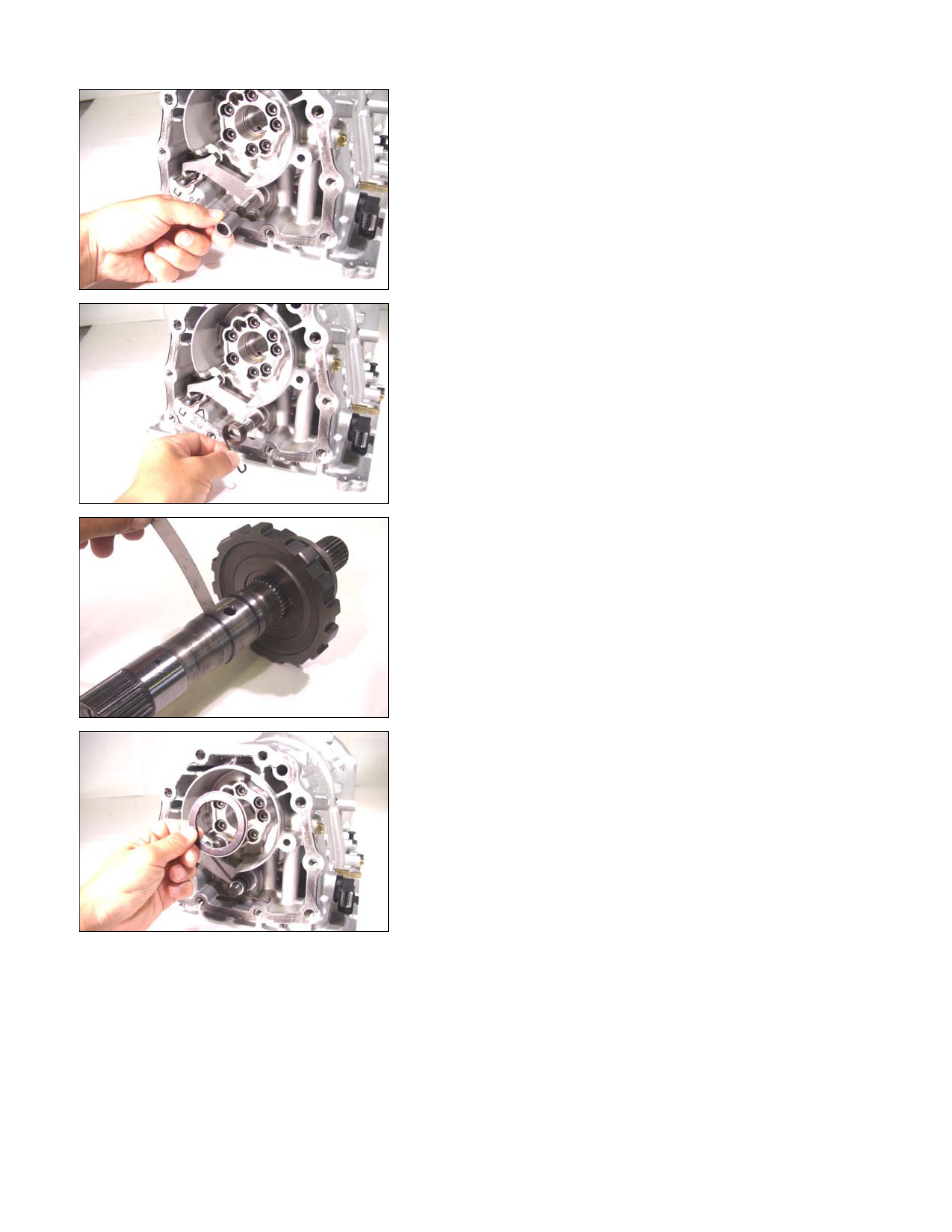
7. O-ring
Remove the O-ring from the input shaft.
12ASSY067
8. Oil pump assembly and bearing race
• Remove the 8 bolts.
• Use a slide hammer to remove the oil pump assembl
y
from the transmission case.
NOTE:
To prevent damage to the oil pump bolt hole threads,
hand-tighten the slide hammer as far as possible.
• Remove the bearing race from the oil pump assembly.
• Inspect the bearing race surfaces for damage.
14ASSY057
9. Input shaft
Pull the input shaft free.
15ASSY049
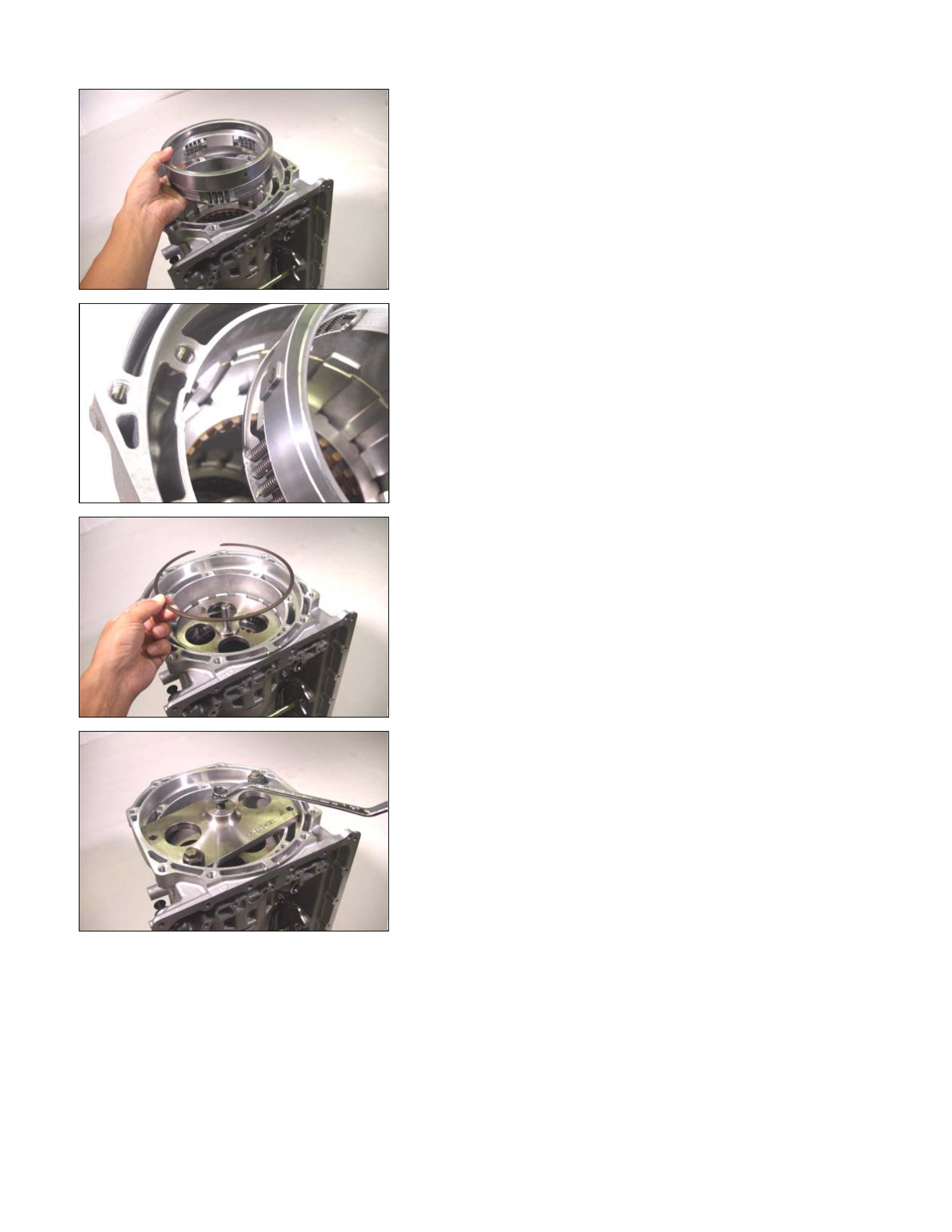
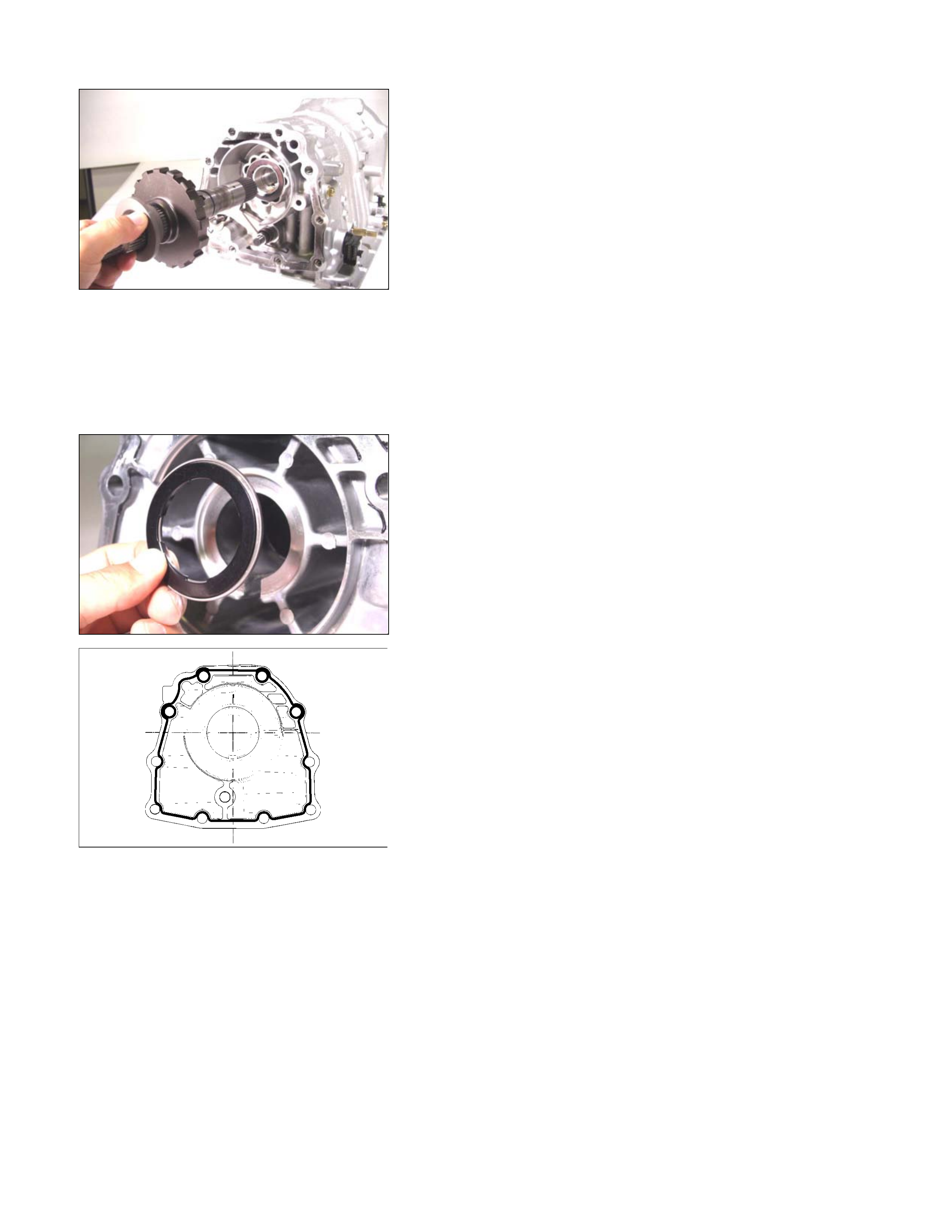
10.Clutch pack (Reverse and high clutch assembly) and
bearing
• Pull the clutch pack free.
• Remove the bearing from the clutch pack.
16ASSY047
11.High clutch hub, bearing, and bearing race
• Rem ove the clutch hub, bearing (with bearing race), and
the bearing race.
• Rem ove the bearing (with bearing race ) and the bearing
race from the high clutch hub.
• Inspect the bearing race surfaces for damage.
17ASSY040
12.Front sun gear, bearing, and bearing race
• Remove the bear ing, the fr ont sun gear, and the bearing
race.
• Rem ove the bearing and the bearing rac e from the f ront
sun gear.
• Inspect the bearing race surfaces for damage.
19ASSY113
13.2-4 brake retainer
• Remove the brake seal ring and the sleeve.
23ASSY030
• Attach the spring compressor to the transmission case.
Spring compressor: 5-8840-2764-0
24ASSY029
• Force out the 2-4 brake retainer and remove the snap
ring.
NOTE:
Overturning the spring compressor will damage the 2-4
brake retainer.
• Remove the spring compressor.
25ASSY019
• Remove the 2-4 brake retainer and return spring.
26ASSY026
14.Carrier assembly (Carrier and low clutch assembly),
bearing, bearing race, and 2 – 4 brake assembly
• Pull the carrier assembly, the bearing, the bearing race
and the 2-4 brake assembly (Dish plate, retaining plate,
drive plate, and driven plate) f rom the transm ission case
at the same time.
• Remove the bearing, the bearing race, and the 2-4
brake assembly from the carrier assembly.
27U-SPG02
• Remove the 3 brake springs from the transmission case.
28L&R06
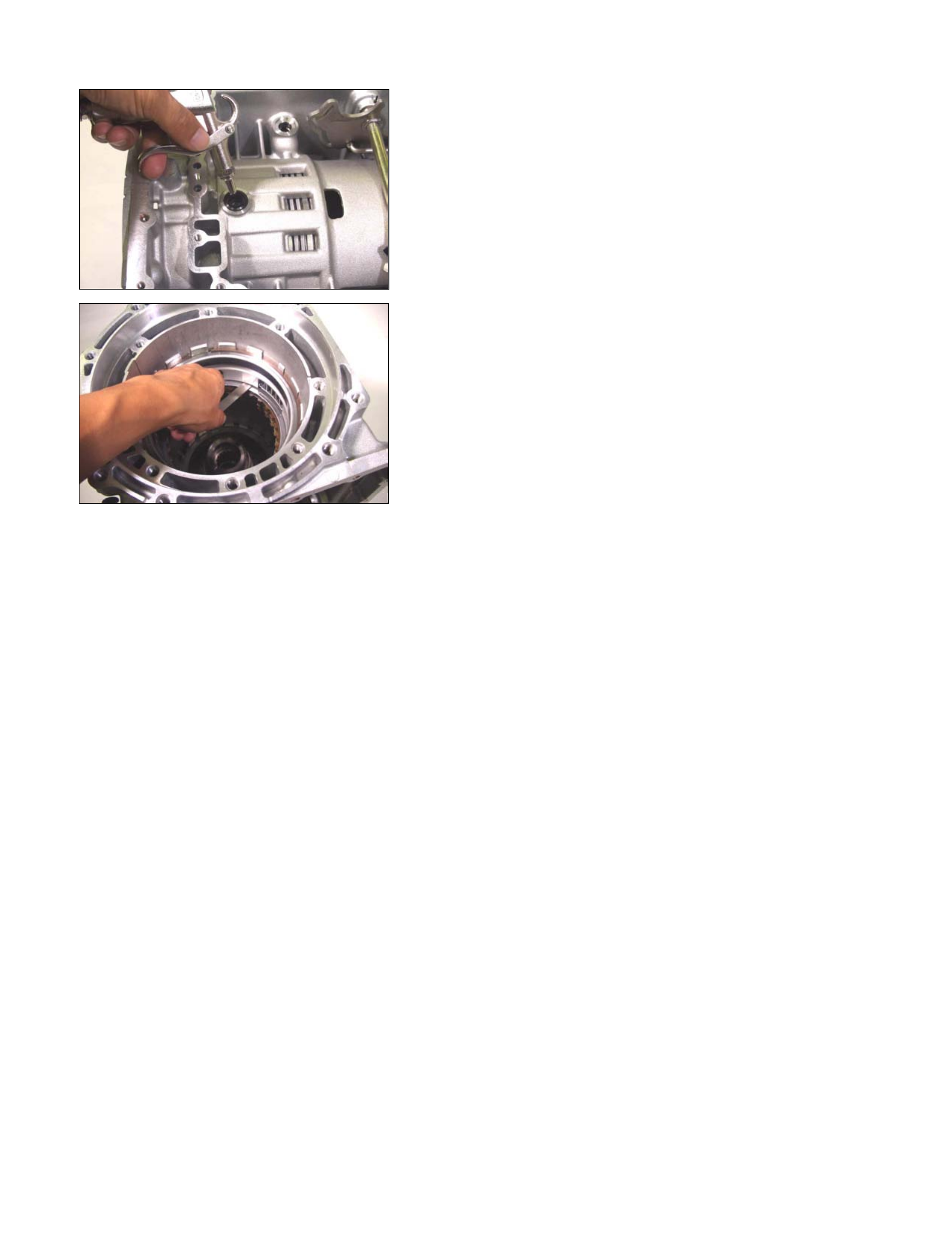
15.Low and reverse brake
• Remove the snap ring.
• Pull the low and reverse brake free.
16.Rear extension (2WD) or Adapter case (4WD)
• Rotate the transm iss ion case so that the oil pan opening
is facing up.
• Remove the 10 bolts and the rear extension (2WD) o
r
the adapter case (4WD).
29ASSY091
17.Output shaft
• Pull the output shaft from the transmission case.
30ASSY089
• Remove the bearing (with bearing race) from the
transmission case.
31ASSY124
18.Parking pawl, shaft, spring, and spacer
Remove the parking pawl, shaft, spring and spacer from the
transmission case.
36ASSY075
19.Actuator support
Remove the actuator support from the transmission case.
37ASSY074
20.Low one-way clutch inne r race and bearing
• Loosen the 7 bolts securing the low one-way clutch inne
r
race.
NOTE:
Loosen the bolts a little at a time as uniformly as possible
to prevent the inner race from tilting and becoming
jammed.
• Remove the 6 bolts. Support the low one-way clutch
inner race with your hand and remove the final bolt.
39ASSY006
• Remove the bearing and the low one-way clutch inne
r
race from the transmission case.
• Remove the bearing from the low one-way clutch inne
r
race.
40ASSY005
21.Low and reverse brake return spring
Remove the low and reverse brake return spring from the
transmission case.
41L&R02
22.Low and reverse brake piston
• Force compressed air (329kPa/4.0kg/cm2) through the
transmission case oil passages.
42ASSY004
• Remove the low and reverse brake piston from the
transmission case.
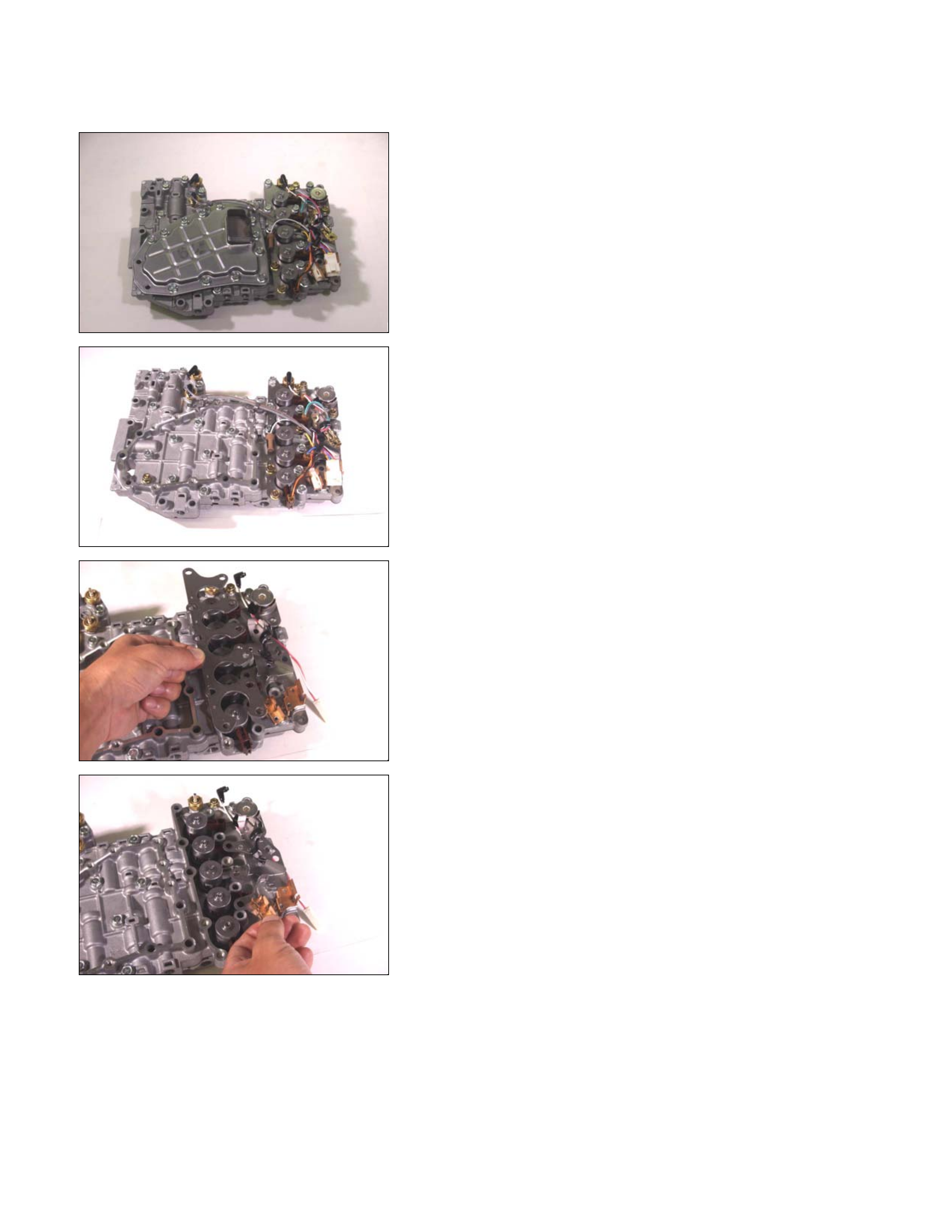
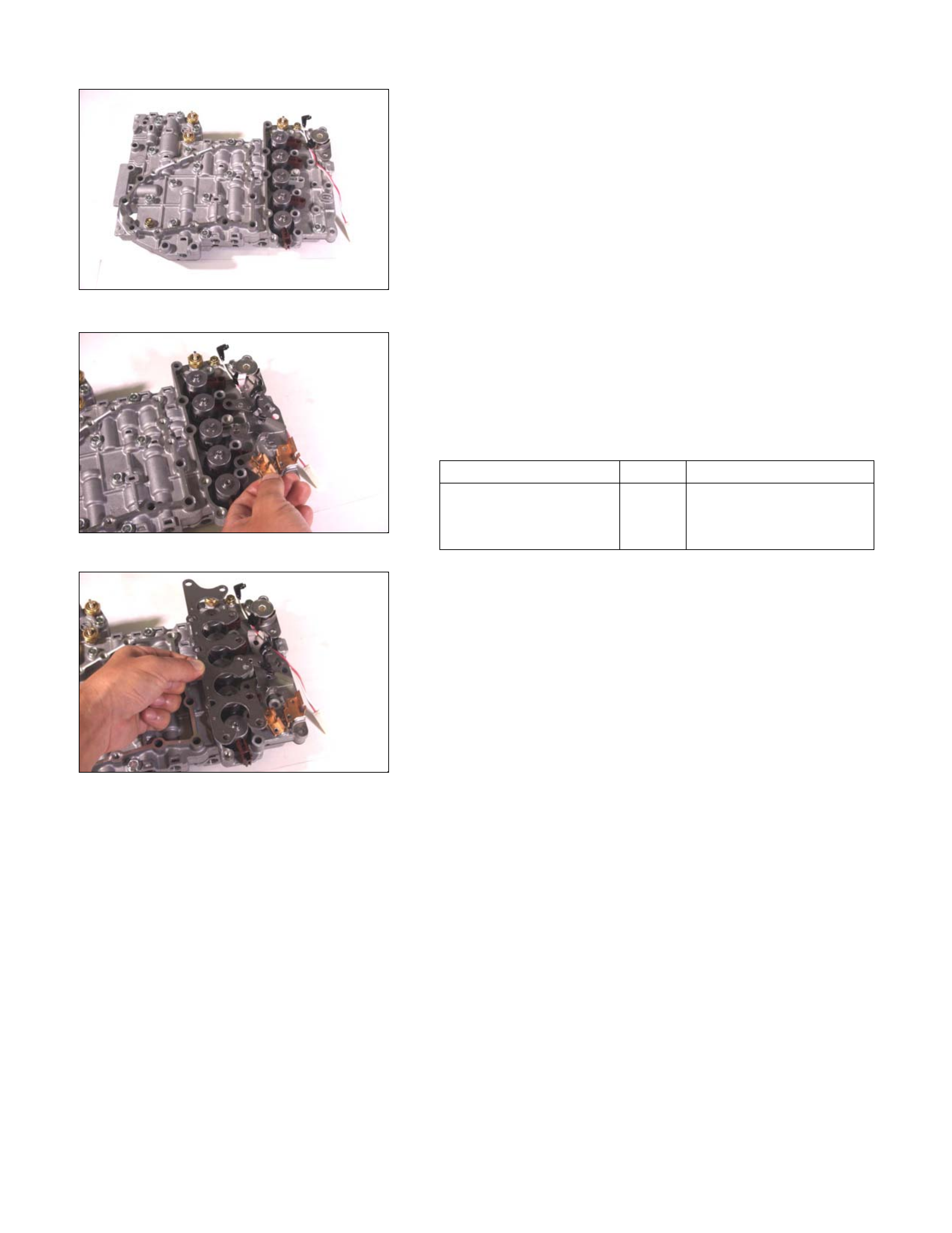
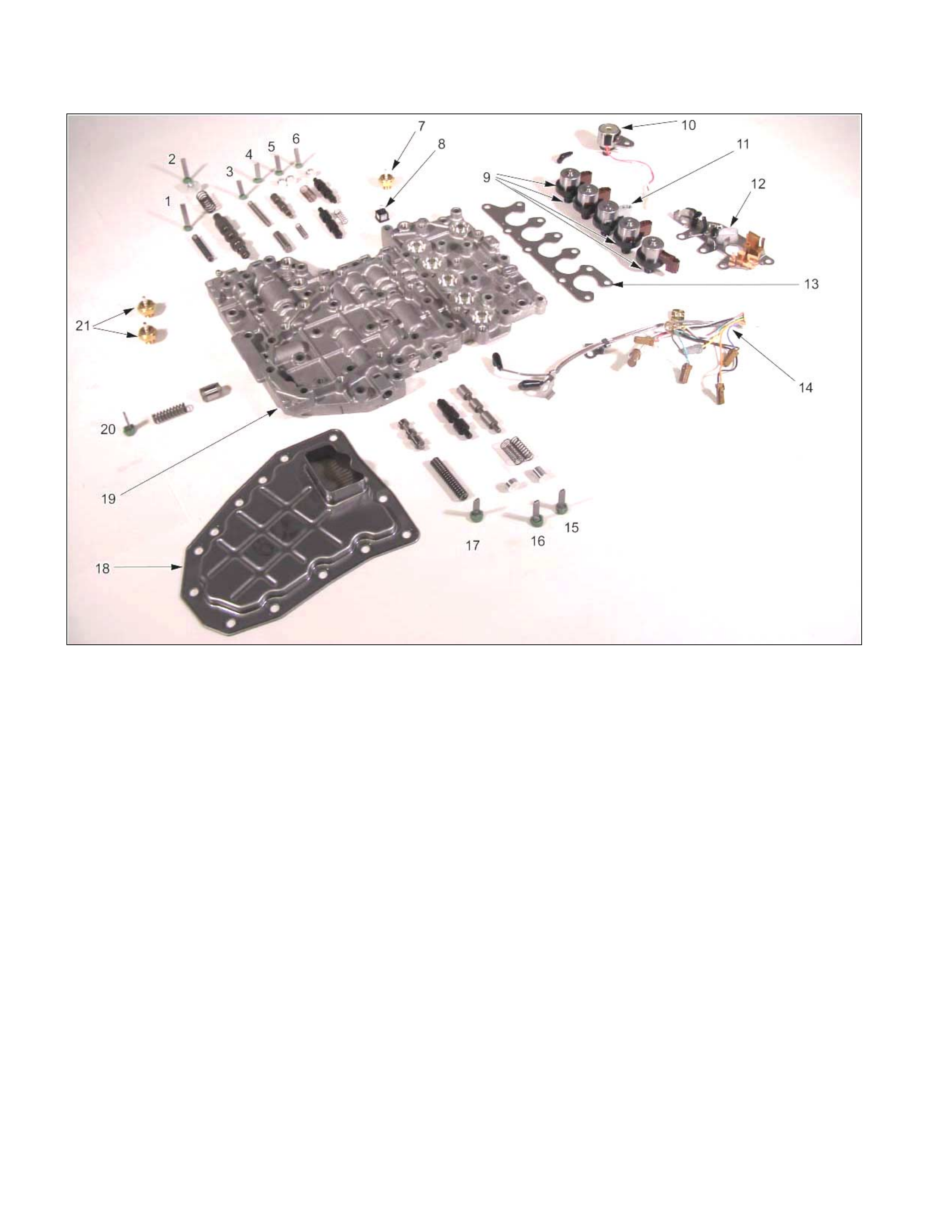
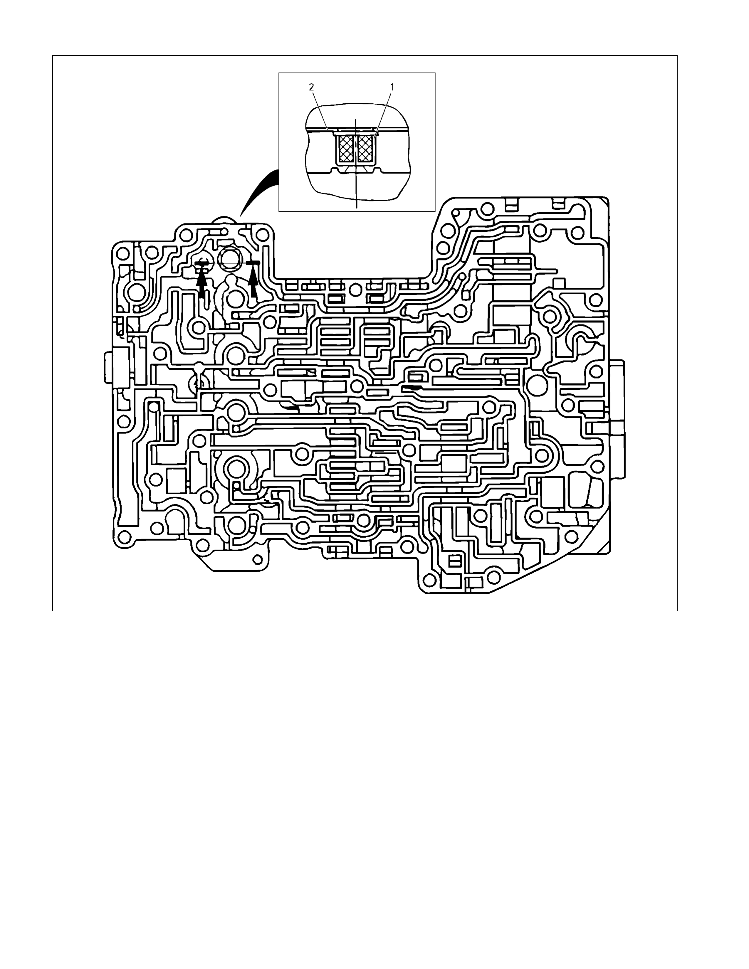
Control Valve Assembly
01CV40
Disassembly Steps
1. Oil strainer
Remove the 13 bolts and the oil strainer from the control
valve assembly.
02CV26
2. Harness assembly
Remove the harness assembly.
04CV21
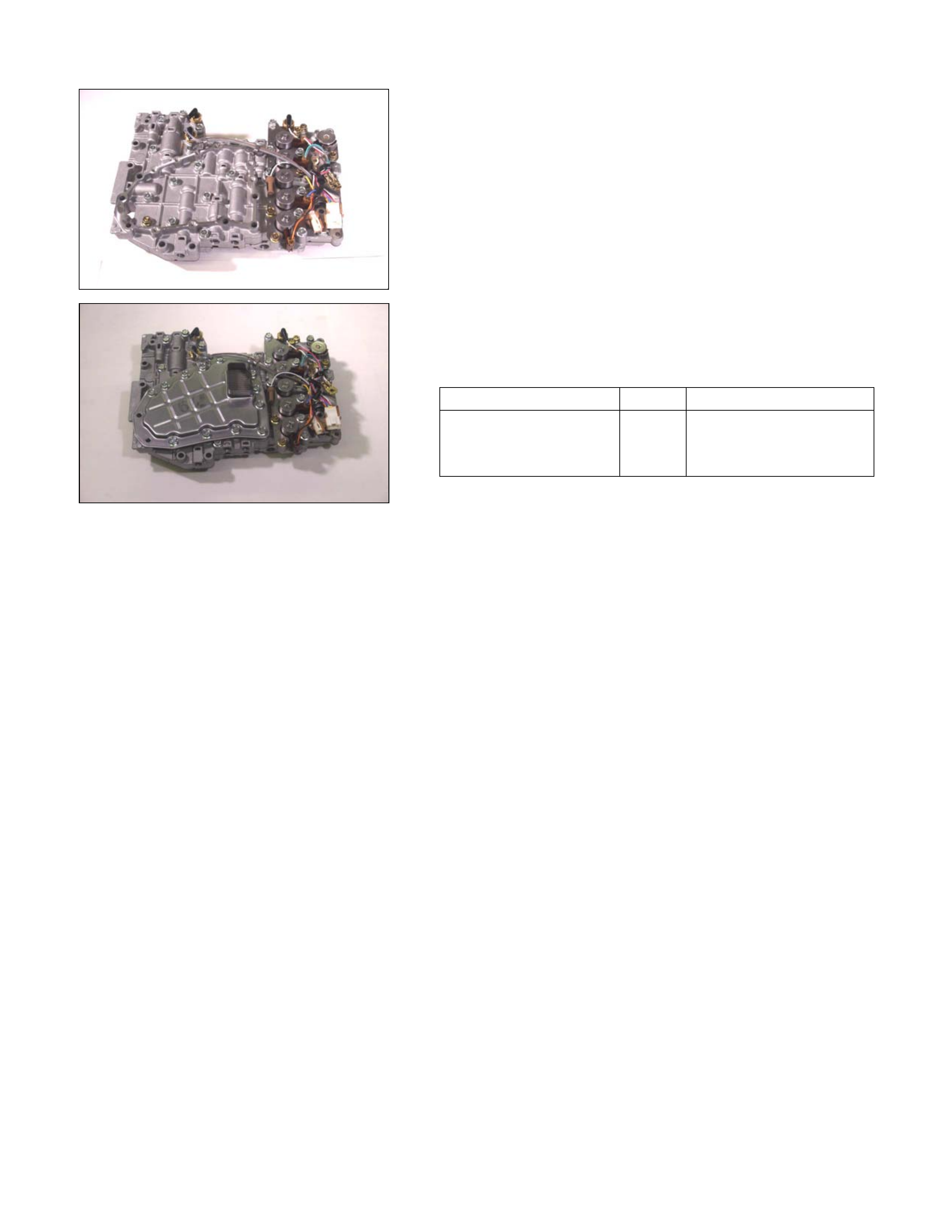
3. Solenoid fixing plate
4. Harness bracket
• Remove the 11 bolts and the solenoid fixing plate
together with the harness bracket.
05CV20
06CV19
5. Solenoid
6. Oil pressure switch
Remove the 6 solenoids together and the 3 oil pressure
switches.
07CV17
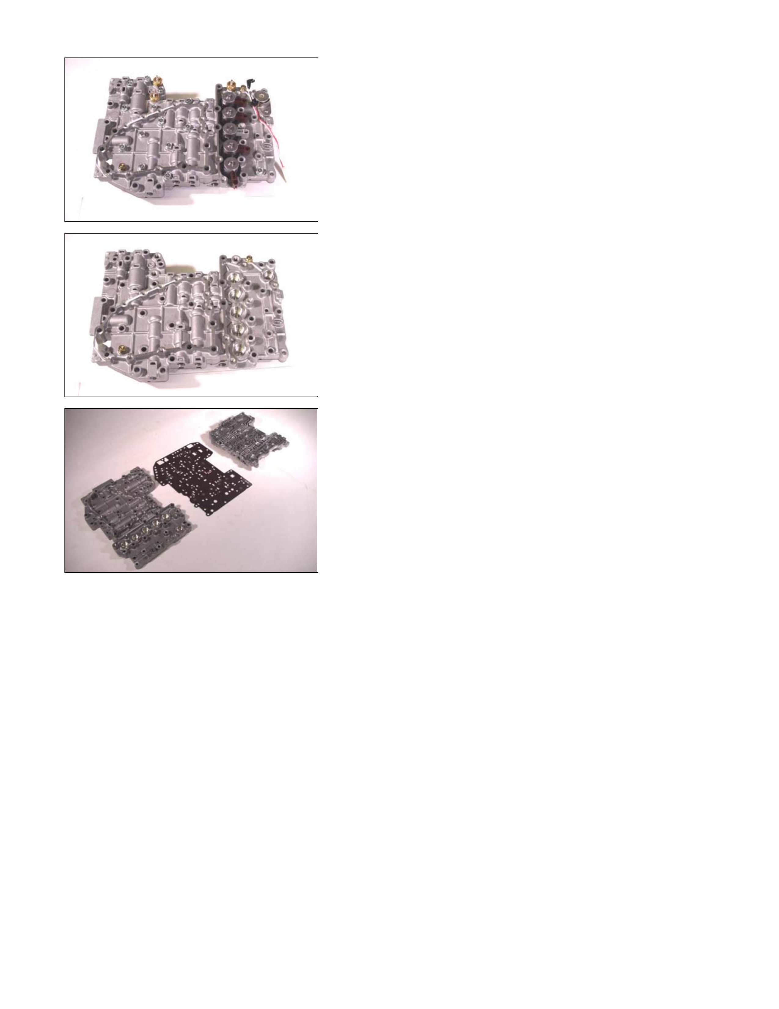
7. Control valve upper body
8. Control valve lower body
9. Separation plate
• Remove the 17 bolts securing the control valve uppe
r
body, the control valve lower body, and the separation
plate.
08CV16
• Separate the upper body, the lower body, and the
separation plate.
NOTE:
Take care not to drop or lose the parts at the inside of the
control valve.
Inspection
• Inspect the separation plate for wear and other damage.
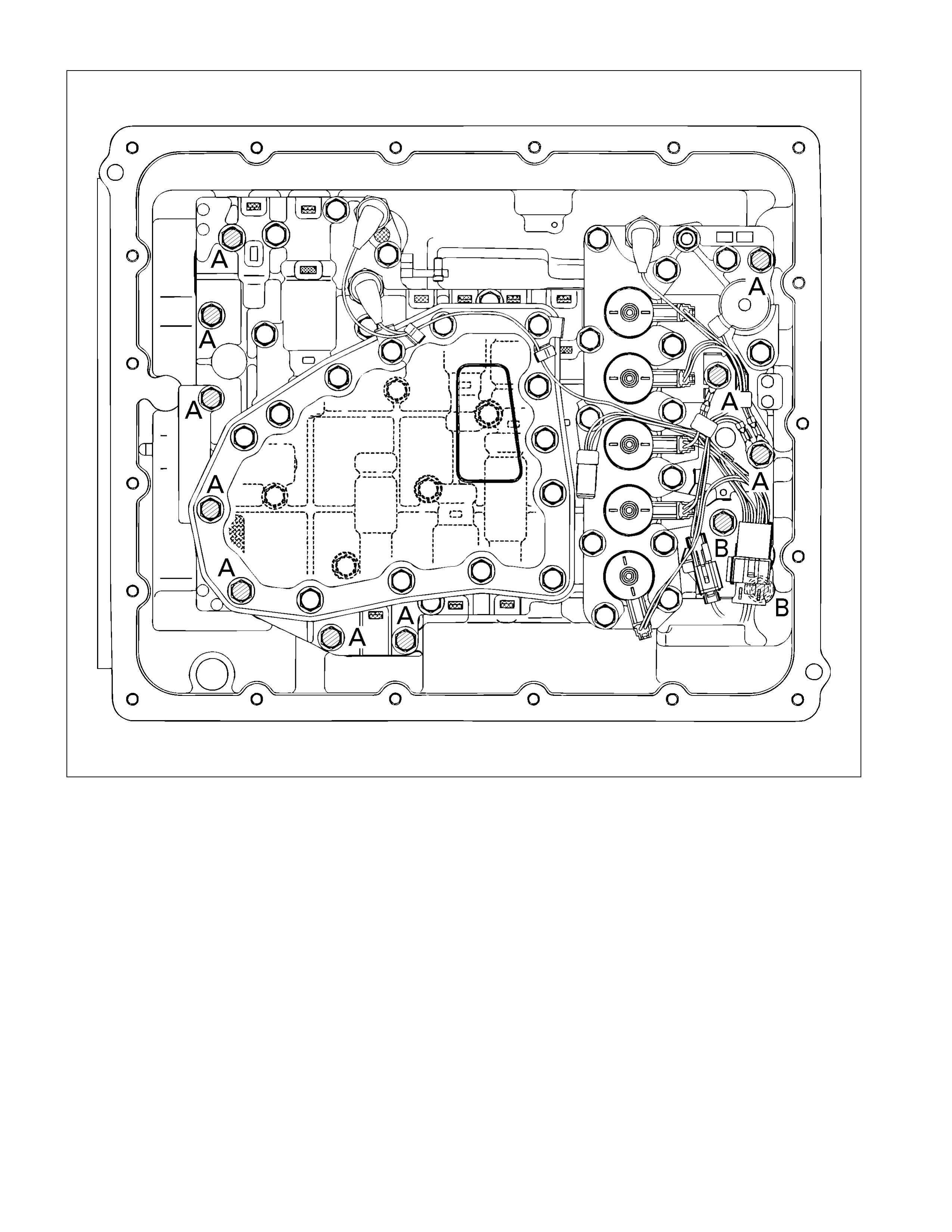
Reassembly Steps
Coat the parts with ATF before installing them.
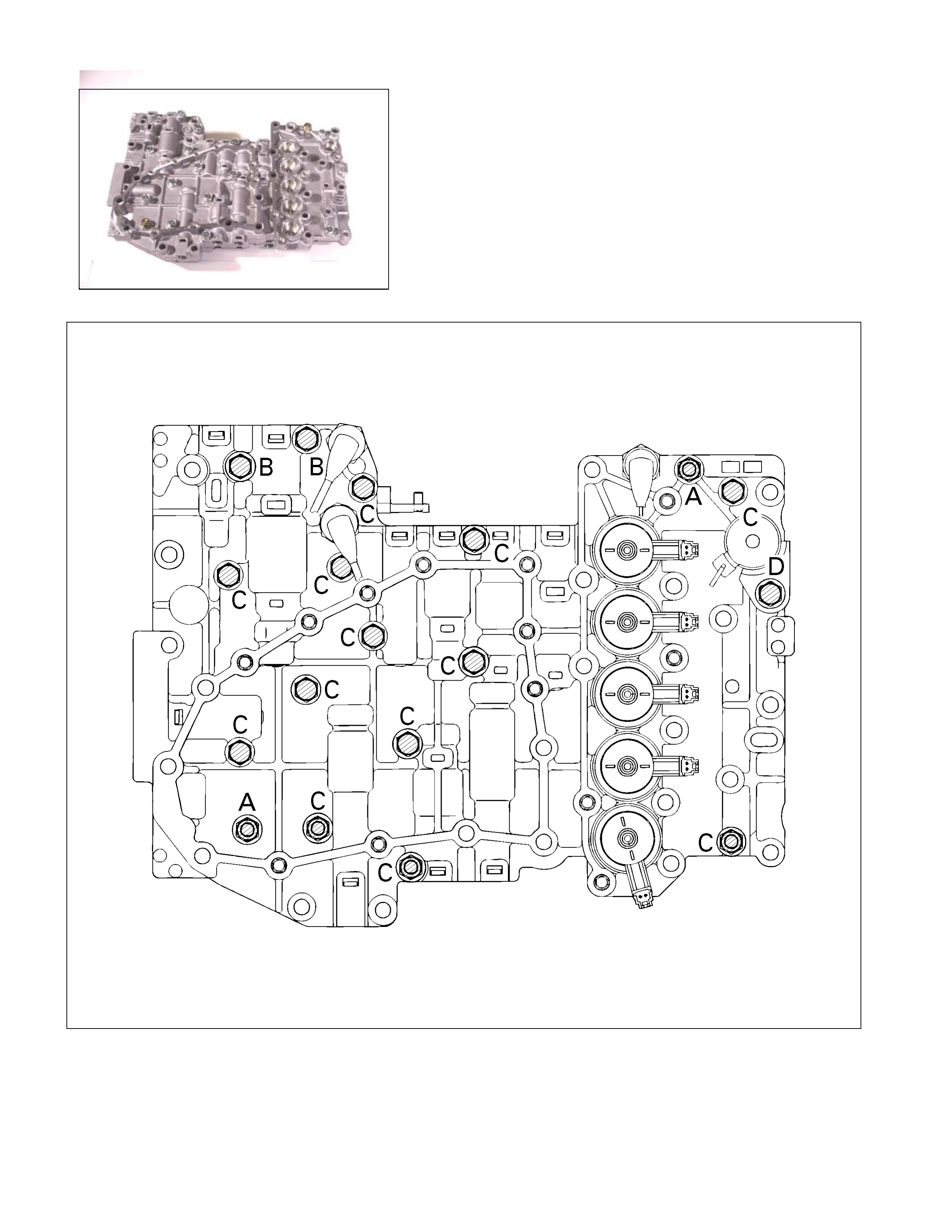
11CV18
1. Control valve upper body
2. Control valve lower body
3. Separation plate
Assem bly the control valve upper body, the lower body, and
the separation plate.
Tighten the bolts to the specified torque.
244L300002

Number Length (Color)
Control valve rocket
bolts and nuts (A) 2 (Plus 2 nuts) 50 mm (1.97 in) (Gold)
Upper body and
lower body fixing
bolts
(B) 2 45 mm (1.77 in) (Silver)
(C) 13 35 mm (1.38 in) (Silver)
Line pressure
solenoid fixing bolt
(D)
1 16 mm (0.63 in) (Gold)
Torque: 8 N⋅
⋅⋅⋅m (69 Ib⋅
⋅⋅⋅in)
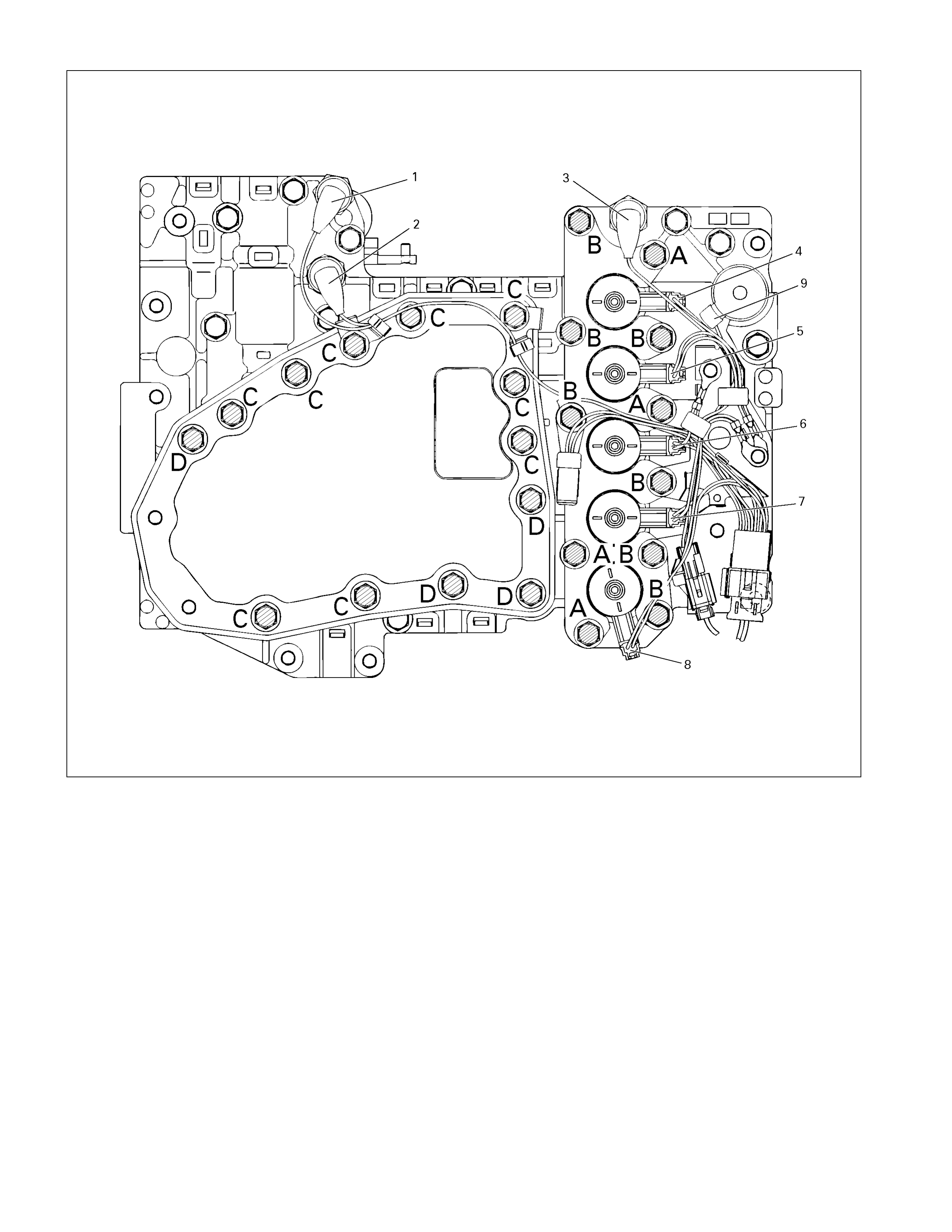
244L300003
Legend
1. High clutch oil pressure switch connector
(wire color: Gray)
2. 2-4 brake oil pressure switch connector
(wire color: Brown)
3. Low and reverse brake oil pressure
switch connector (wire color: White)
4. Low and reverse brake duty solenoid
connector (wire color: Pink and White)
5. High clutch duty solenoid connector
(wire color: Green and Gray)
6. Lock-up duty solenoid connector (wire
color: Yellow and Black)
7. 2-4 brake duty solenoid connector (wire
color: Blue and Brown)
8. Low clutch duty solenoid connector (wire
color: Orange and Black)
9. Line pressure solenoid connector (wire
color: Pink)
12CV19
4. Solenoid
5. Oil pressure switch
• Install the O-rings to each of the solenoids.
• Install the 6 solenoids together and the 3 oil pressure
switches.
NOTE:
Be sure the high clutch oil pressure switch is marked.
• Tighten the bolts to the specified torque.
Torque:
Oil pressure switch bolts – 4.4 N⋅
⋅⋅⋅m (39 Ib⋅
⋅⋅⋅in)
Line pressure solenoid bolt (Single gold-colored bolt 16
mm) – 8 N⋅
⋅⋅⋅m (69 Ib⋅
⋅⋅⋅in)
6. Solenoid fixing plate
7. Harness bracket
Install the solenoid fixing plate together with the harness
bracket.
Tighten the bolts to the specified torque.
Number Length (Color)
Solenoid fixing plate bolt
(A) 4 16 mm (0.63 in) (Gold)
(B) 7 45 mm (1.77 in) (Silver)
13CV20
Torque: 8 N⋅
⋅⋅⋅m (69 Ib⋅
⋅⋅⋅in)
14CV21
15CV26
8. Harness assembly
Install the harness assembly.
9. Oil strainer
Install the oil strainer.
Tighten the bolts to the specified torque.
Number Length (Color)
Oil strainer bolt
(C) 9 13 mm (0.51 in) (Silver)
(D) 4 45 mm (1.77 in) (Silver)
16CV40
Torque: 8 N⋅
⋅⋅⋅m (69 Ib⋅
⋅⋅⋅in)
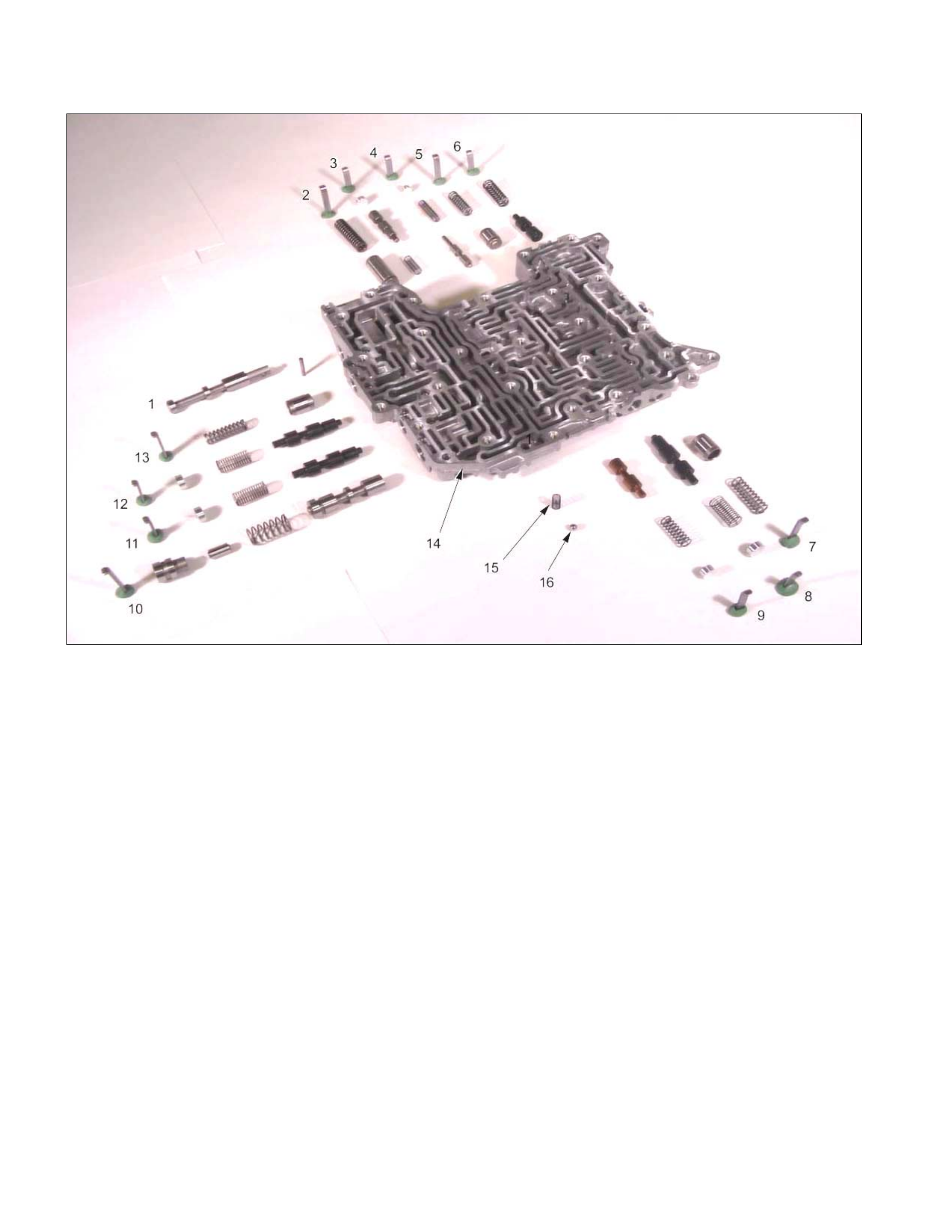
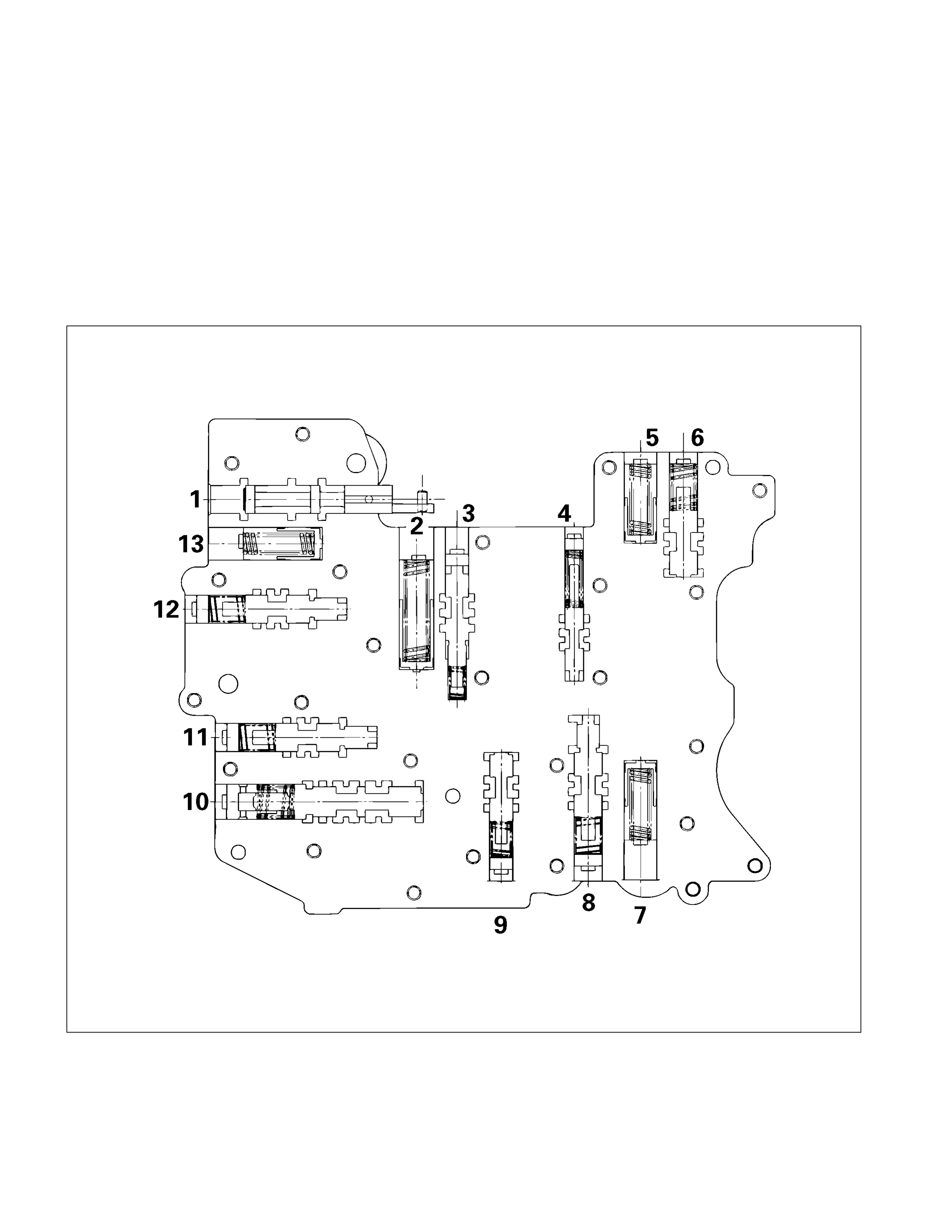
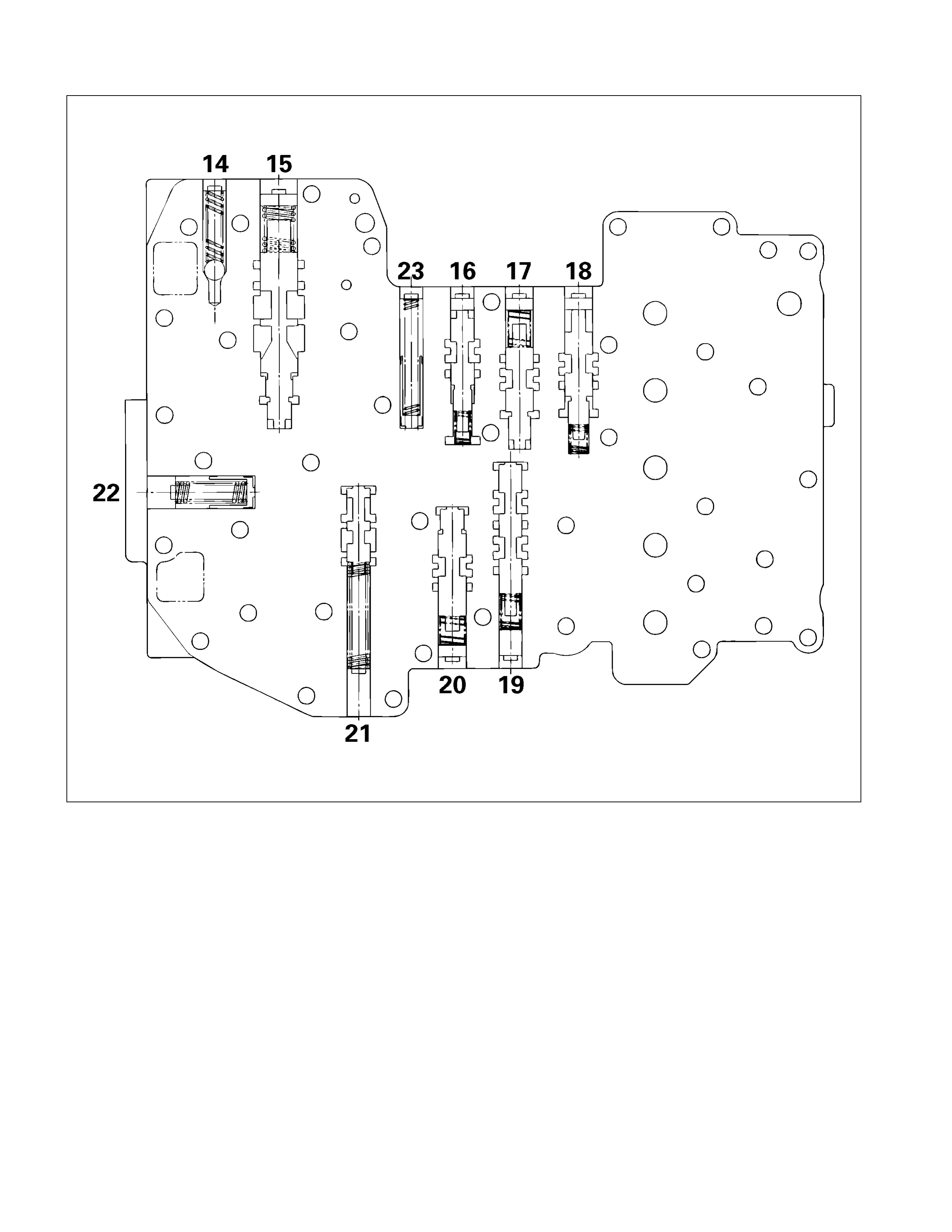
Control Valve Upper Body
09CV02
Legend
1. Manual valve, and pin
2. Retainer plate, spring, and 2-4 brake
accumulator
3. Retainer plate, plug, and low and
reverse brake fail valve B
4. Retainer plate, plug, spring, and reverse
stall valve
5. Retainer plate, spring, and low and
reverse brake solenoid accumulator
6. Retainer plate, spring, and pilot valve
7. Retainer plate, spring, and low clutch
solenoid accumulator
8. Retainer plate, plug, spring, and low
clutch amp valve A
9. Retainer plate, plug, spring, and 2-4
brake fail valve B
10. Retainer plate, sleeve, plug, spring, and
lock-up control valve
11. Retainer plate, plug, spring, and 2-4
brake amp valve
12. Retainer plate, plug, spring, and high
clutch amp valve
13. Retainer plate, spring, and high clutch
solenoid accumulator
14. Control valve upper body
15. Spring
16. Steel ball
Disassembly Steps
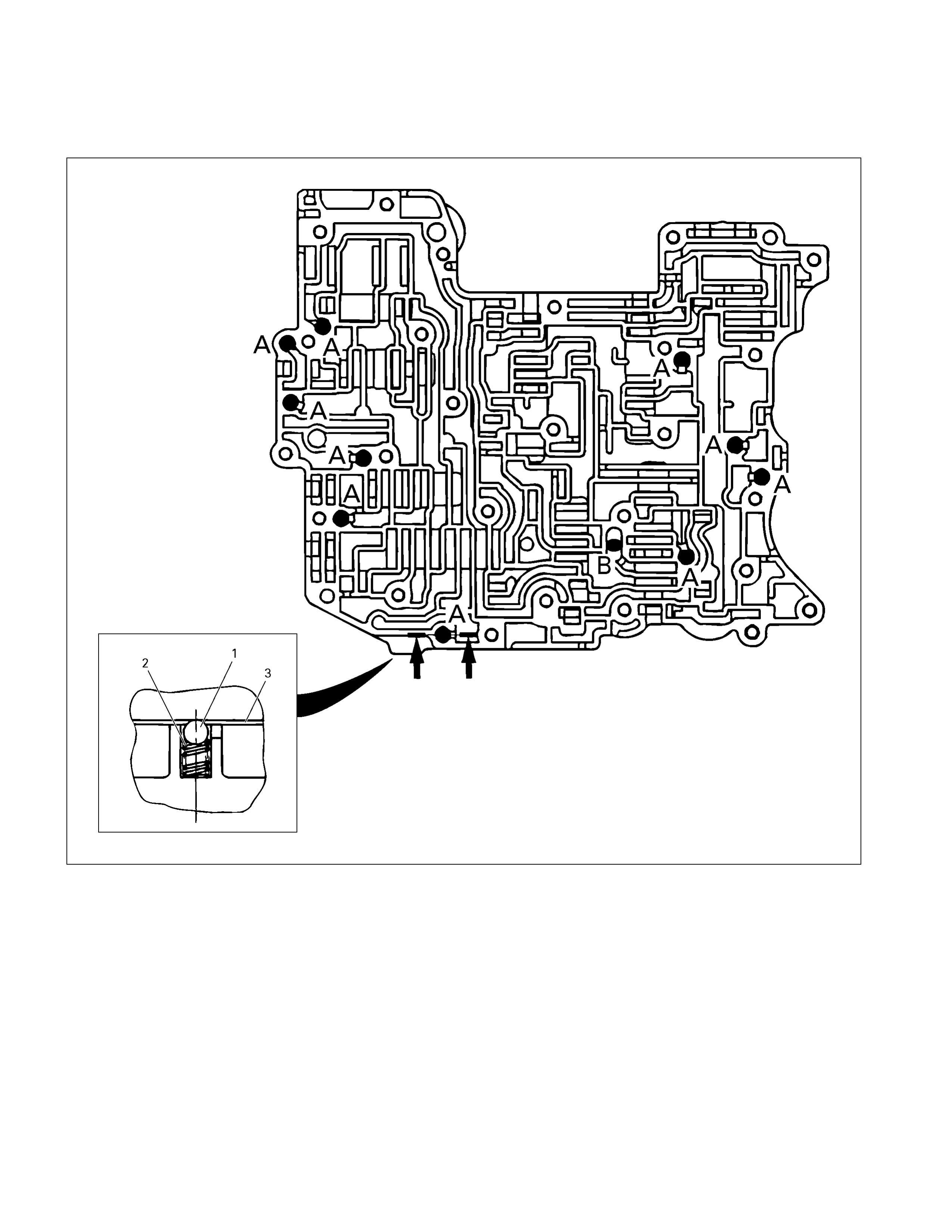
• Remove the 11 steel balls and spring from the control
valve upper body.
244L300005
Legend
1. Steel ball: A – 10 (Silver)
B – 1 (Black)
2. Spring
3. Separation plate
• Remove the control valves from the control valve uppe
r
body.
NOTE:
Place the control valve where it will not get mixed up with
the other parts.
Inspection
Valve
Inspect each of the valves for denting and other damage.
Spring
Inspect each of the springs for wear and fatigue.
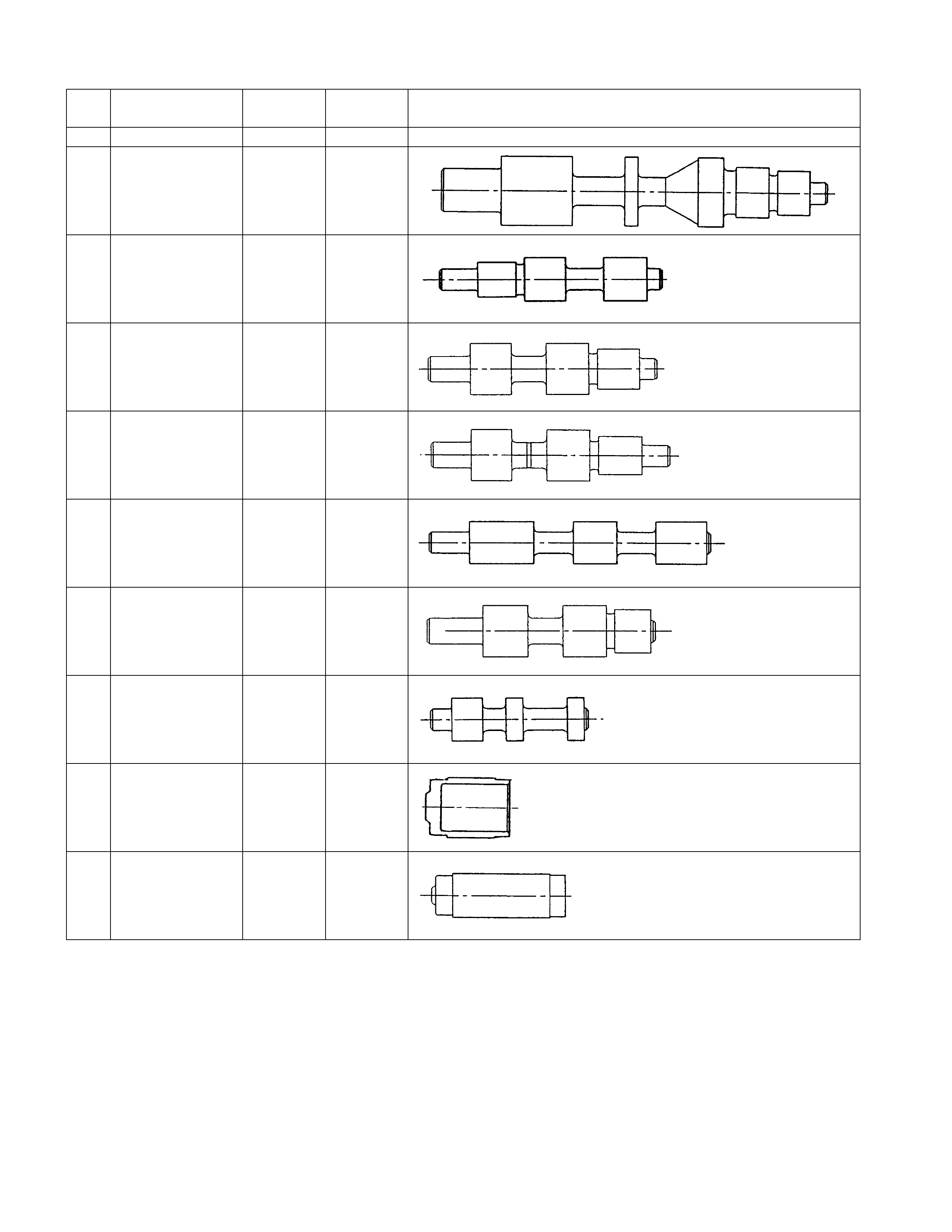
Valve Specifications
244L300006
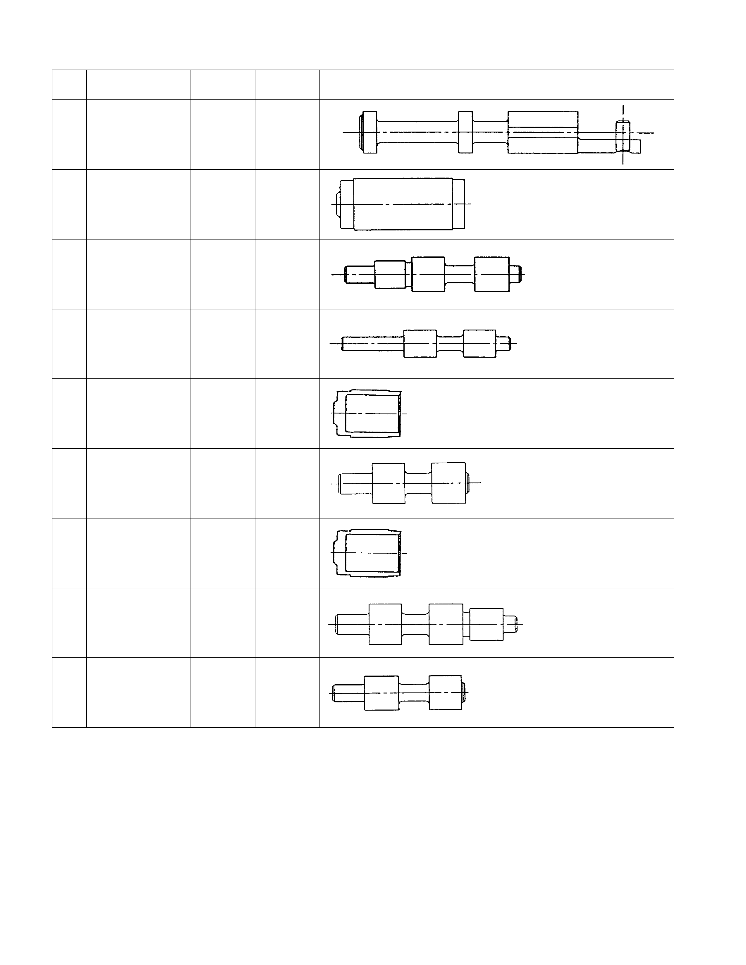
No. Valve
nomenclature Diameter
(mm / in) Length
(mm / in) Configuration
1 Manual 12.0 /
0.472 82.0 /
3.228
2 2 – 4 brake
accumulator 15.0 /
0.591 37.5 /
1.476
3 Low and reverse
brake fail (B) 10.0 /
0.394 52.0 /
2.047
4 Reverse stall 8.0 /
0.315 50.0 /
1.969
5 Low and reverse
brake solenoid
accumulator
14.0 /
0.551 19.5 /
0.768
6 Pilot 12.0 /
0.472 38.5 /
1.516
7 Low clutch
solenoid
accumulator
14.0 /
0.551 19.5 /
0.768
8 Low clutch amp
(A) 12.0 /
0.472 53.5 /
2.106
9 2 – 4 brake fail
(B) 10.0 /
0.394 39.0 /
1.535
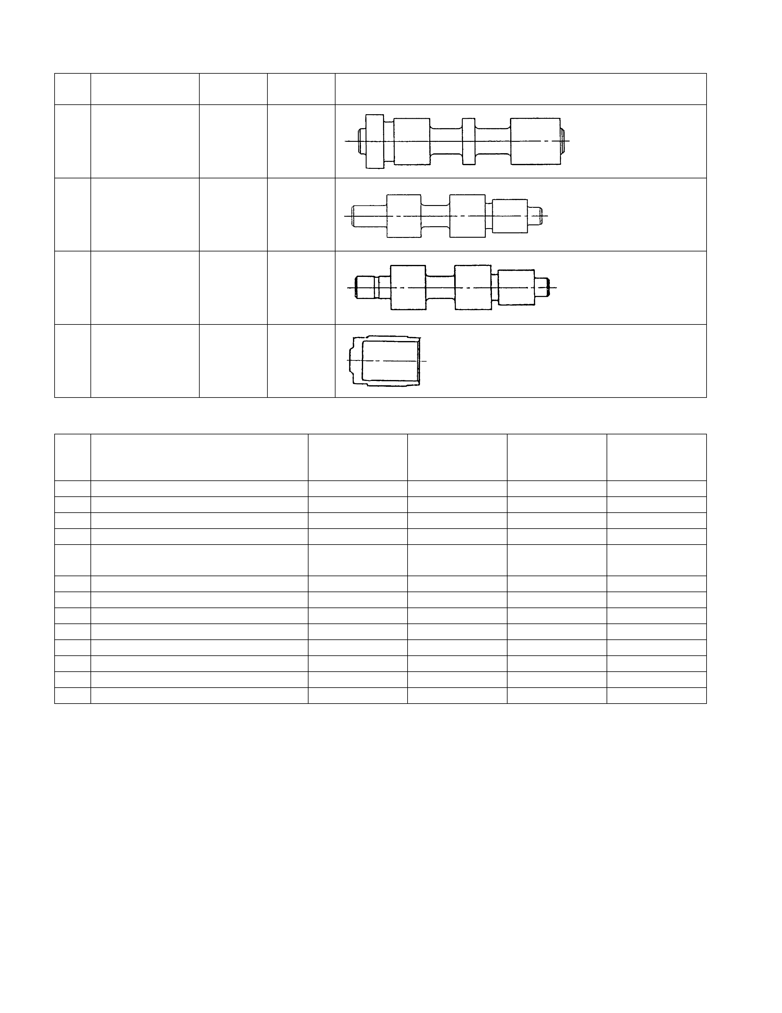
No. Valve
nomenclature Diameter
(mm / in) Length
(mm / in) Configuration
10 Lock-up control 12.9 /
0.508 57.5 /
2.264
11 2 – 4 brake amp 12.0 /
0.472 53.5 /
2.106
12 High clutch amp 12.0 /
0.472 53.5 /
2.106
13 High clutch
solenoid
accumulator
14.0 /
0.551 19.5 /
0.768
Spring Specifications
No. Valve nomenclature Free length
(mm / in)
Outside
diameter (mm
/ in)
Linear
diameter (mm
/ in)
Number of
coils
1 Manual ---- ---- ---- ----
2 2 – 4 brake accumulator 43.9 / 1.728 11.0 / 0.433 2.0 / 0.079 13.1
3 Low and reverse brake fail (B) 22.0 / 0.866 7.0 / 0.276 0.6 / 0.024 10.0
4 Reverse stall 31.5 / 1.240 7.0 / 0.276 1.0 / 0.039 12.8
5 Low and reverse solenoid brake
accumulator 31.4 / 1.236 9.8 / 0.386 1.3 / 0.051 9.3
6 Pilot 32.0 / 1.260 11.0 / 0.433 1.3 / 0.051 9.2
7 Low clutch solenoid accumulator 31.4 / 1.236 9.8 / 0.386 1.3 / 0.051 9.3
8 Low clutch amp (A) 23.0 / 0.906 11.0 / 0.433 0.5 / 0.020 13.2
9 2 – 4 brake fail (B) 24.8 / 0.976 8.5 / 0.335 0.9 / 0.035 7.8
10 Lock-up control 27.0 / 1.063 14.0 / 0.551 1.1 / 0.043 5.7
11 2 – 4 brake amp 23.0 / 0.906 11.0 / 0.433 0.5 / 0.020 13.2
12 High clutch amp 23.0 / 0.906 11.0 / 0.433 0.5 / 0.020 13.2
13 High clutch solenoid accumulator 31.4 / 1.236 9.8 / 0.386 1.3 / 0.051 9.3
Reassembly Steps
• Coat the parts with ATF before installing them.
• Install the control valve to the upper body.
• Install the 11 steel balls and spring to the upper body.
Control Valve Lower Body
10CV11
Legend
1. Retainer plate, spring, and steel ball
2. Retainer plate, plug, spring, and
pressure regulator valve
3. Retainer plate, spring, and high clutch
accumulator
4. Retainer plate, plug, low and reverse
brake fail valve A, and spring
5. Retainer plate, plug, spring, and fail
valve
6. Retainer plate, plug, low and reverse
brake amp valve, and spring
7. Oil pressure swi tch
8. Oil filter
9. Solenoid
10. Line pressure solenoid
11. Lock-up solenoid
12. Harness bracket
13. Solenoid fixing plate
14. Harness assembly
15. Retainer plate, plug, spring, and 2-4
brake fail valve A
16. Retainer plate, plug, spring, and low
clutch amp valve B
17. Retainer plate, spring, and torque
converter relief valve
18. Oil strainer
19. Control valve lower body
20. Retainer plate, spring, and 2-4 brake
solenoid accumulator
21. Oil pressure switch
Disassembly Steps
• Remove the oil filter from the control valve lower body.
244L300009
Legend
1. Oil filter
2. Separation plate
• Remove the control valve from the control valve lowe
r
body.
NOTE:
Place the control valve where it will not get mixed up with
the other parts.
Inspection
Valve
Inspect each of the valves for denting and other damage.
Spring
Inspect each of the springs for wear and fatigue.
Valve Specifications
244L300008
No. Valve
nomenclature Diameter
(mm / in) Length
(mm / in) Configuration
14 Pressure relief ---- ----
15 Pressure
regulator 16.0 /
0.630 89.5 /
3.524
16 Low and reverse
brake fail (A) 10.0 /
0.394 52.0 /
2.047
17 Fail 12.0 /
0.472 53.5 /
2.106
18 Low and reverse
brake amp 12.0 /
0.472 55.5 /
2.185
19 2 – 4 brake fail
(A) 10.0 /
0.394 65.5 /
2.579
20 Low clutch amp
(B) 12.0 /
0.472 53.0 /
2.087
21 Torque
converter relief 10.0 /
0.394 37.4 /
1.472
22 2 – 4 brake
solenoid
accumulator
14.0 /
0.551 19.5 /
0.768
23 High clutch
accumulator 10.0 /
0.394 31.0 /
1.220
Spring Specifications
No. Valve nomenclature Free length
(mm / in)
Outside
diameter (mm
/ in)
Linear
diameter (mm
/ in)
Number of
coils
14 Pressure relief 49.0 / 1.929 7.6 / 0.299 1.1 / 0.043 17.3
15 Pressure regulator 30.5 / 1.201 14.0 / 0.551 1.4 / 0.055 5.7
16 Low and reverse brake fail (A) 22.0 / 0.866 7.0 / 0.276 0.6 / 0.024 10.0
17 Fail 23.0 / 0.906 11.0 / 0.433 0.5 / 0.020 13.2
18 Low and reverse brake amp 19.5 / 0.768 7.9 / 0.311 0.5 / 0.020 6.9
19 2 – 4 brake fail (A) 24.8 / 0.976 8.5 / 0.335 0.9 / 0.035 7.8
20 Low clutch amp (B) 26.0 / 1.024 11.0 / 0.433 0.5 / 0.020 6.9
21 Torque converter relief More than 47.2
/ 1.858 9.2 / 0.362 1.6 / 0.063 20.2
22 2 – 4 brake solenoid accumulator 31.4 / 1.236 9.8 / 0.386 1.3 / 0.051 9.3
23 High clutch accumulator 51.0 / 2.008 6.5 / 0.256 0.8 / 0.031 23.5
Oil Pressure Switch
Apply compressed air (392 kPa/4.0 kg/cm2) to the oil pressure
switch to check the oil pressure switch continuity between the
connector and screw.
244L300011
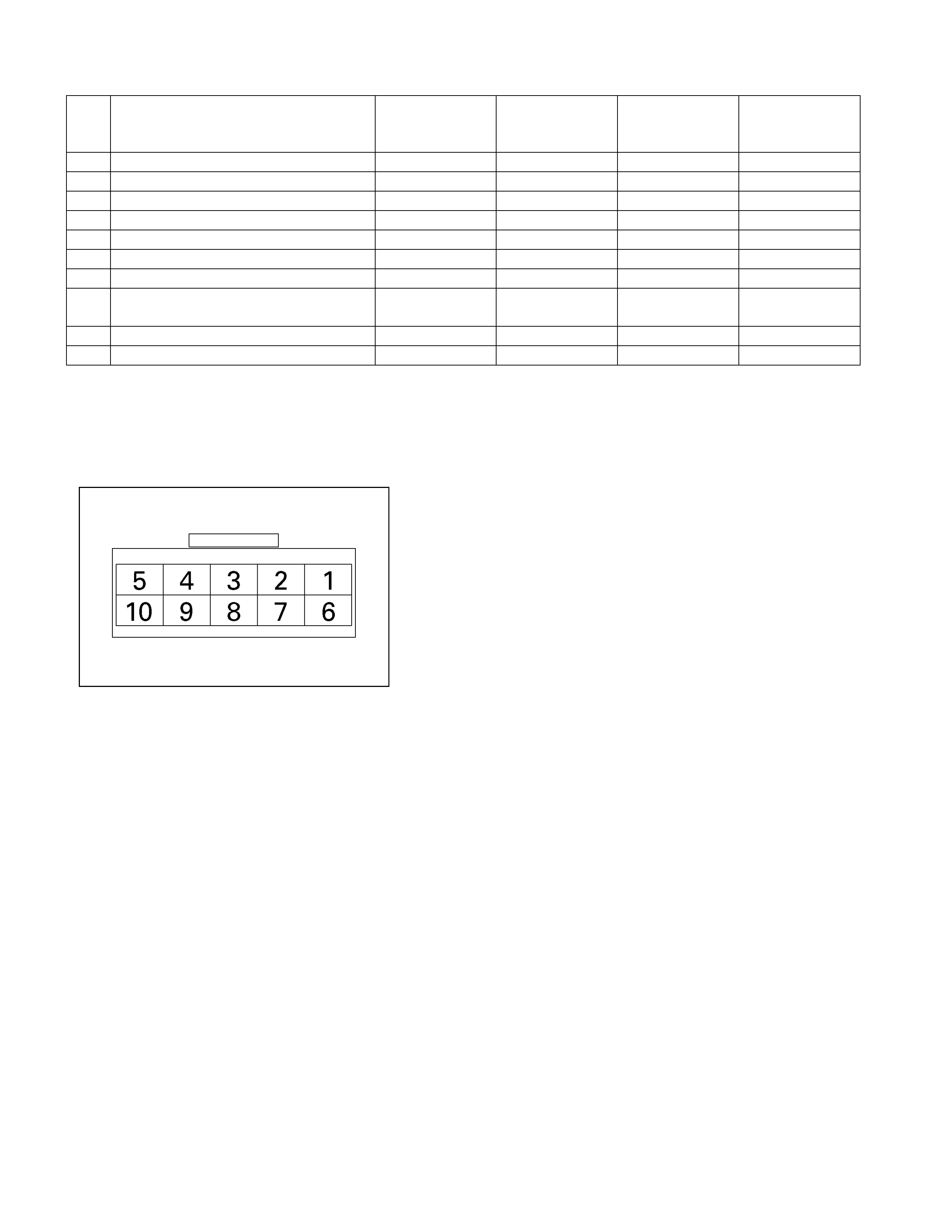
Oil Temperature Sensor (Harness Assembly)
Check the oil temperature sensor resistance between harness
terminals 7 and 6 (ground).
Oil temperature sensor resistance: 2,4002,600 ohms
(20)
Solenoid
Measure the resistance of each solenoid.
Resistance:
Brown connector – 3.0∼
∼∼
∼3.4 ohms (20°
°°
°C)
Gray connector – 12.0∼
∼∼
∼13.2 ohms (20°
°°
°C)
White connector – 12.2∼
∼∼
∼13.4 ohms (20°
°°
°C)
Reassembly Steps
• Coat the parts with ATF before installing them.
• Install the control valve to the control valve lower body.
• Install the oil filter to the control valve lower body.
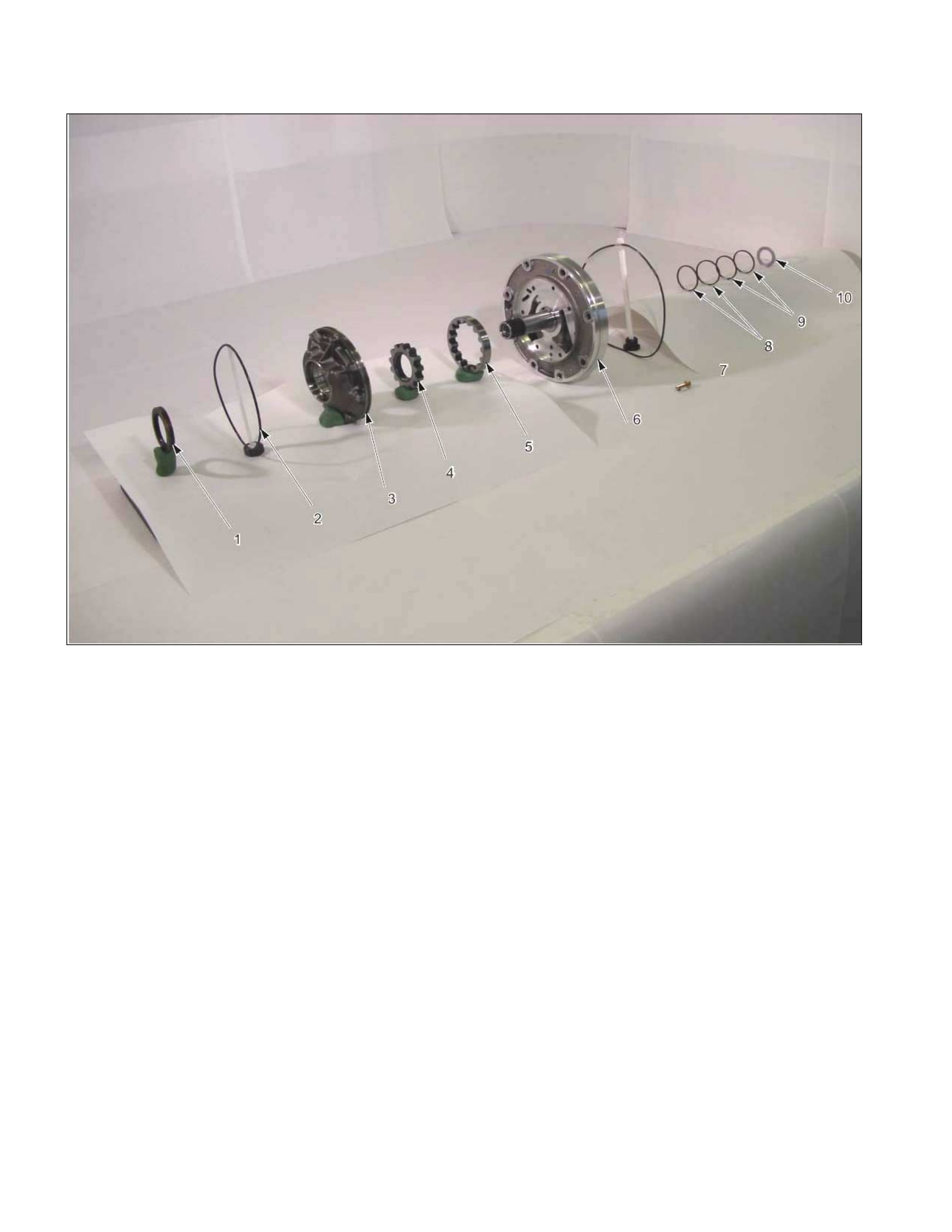
Oil Pump Assembly
01PUMP32
Legend
1. Oil seal
2. O-ring (small)
3. Oil pump housing
4. Inner rotor
5. Outer roto r
6. Oil pump cover
7. O-ring (large)
8. Seal ring (large)
9. Seal ring (small)
10. Bearing race
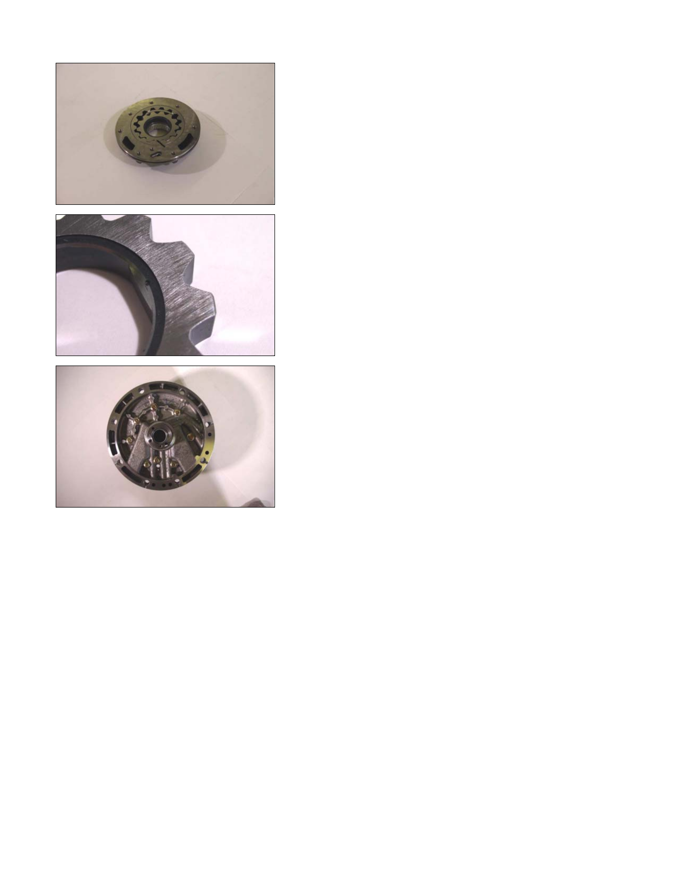
02PUMP07
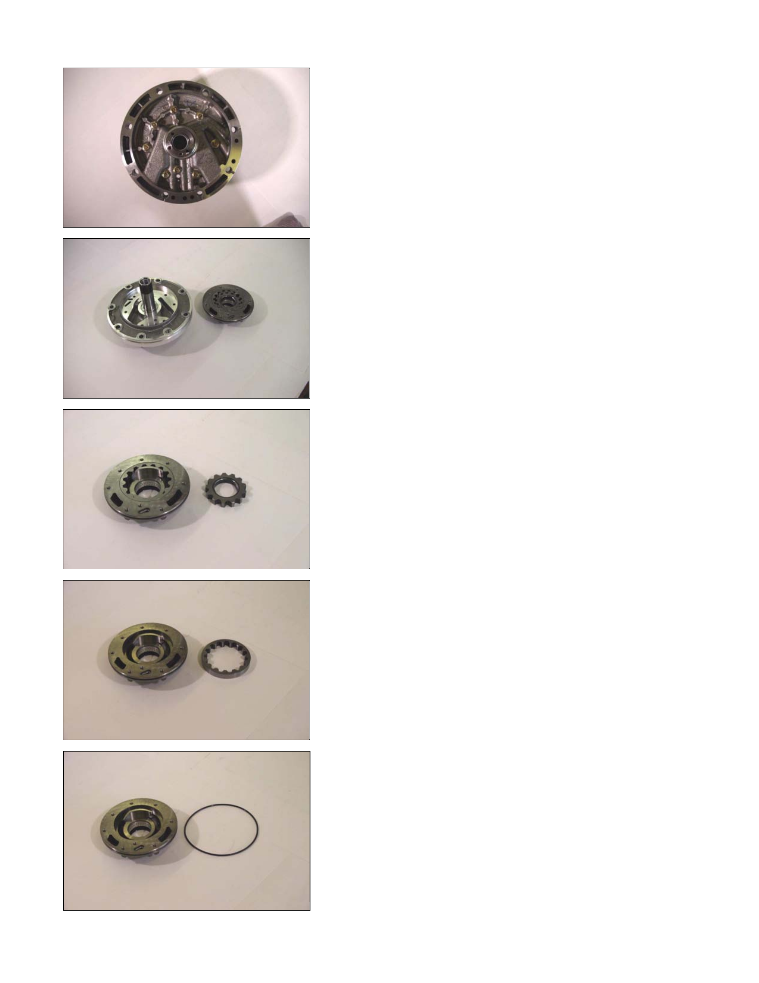
Disassembly Steps
1. Oil pump cover
2. Oil pump housing
• Loosen the 8 bolts evenly a little at a time.
04PUMP10
• Separate the oil pump cover from the oil pump housing
by tapping on each of the bolts with a plastic hammer.
06PUMP13
3. Inner rotor
Remove the inner rotor from the oil pump housing.
07PUMP14
4. Outer rotor
Remove the outer rotor form the oil pump housing.
15PUMP18
5. O-ring (small)
Remove the O-ring (small) from the oil pump housing.
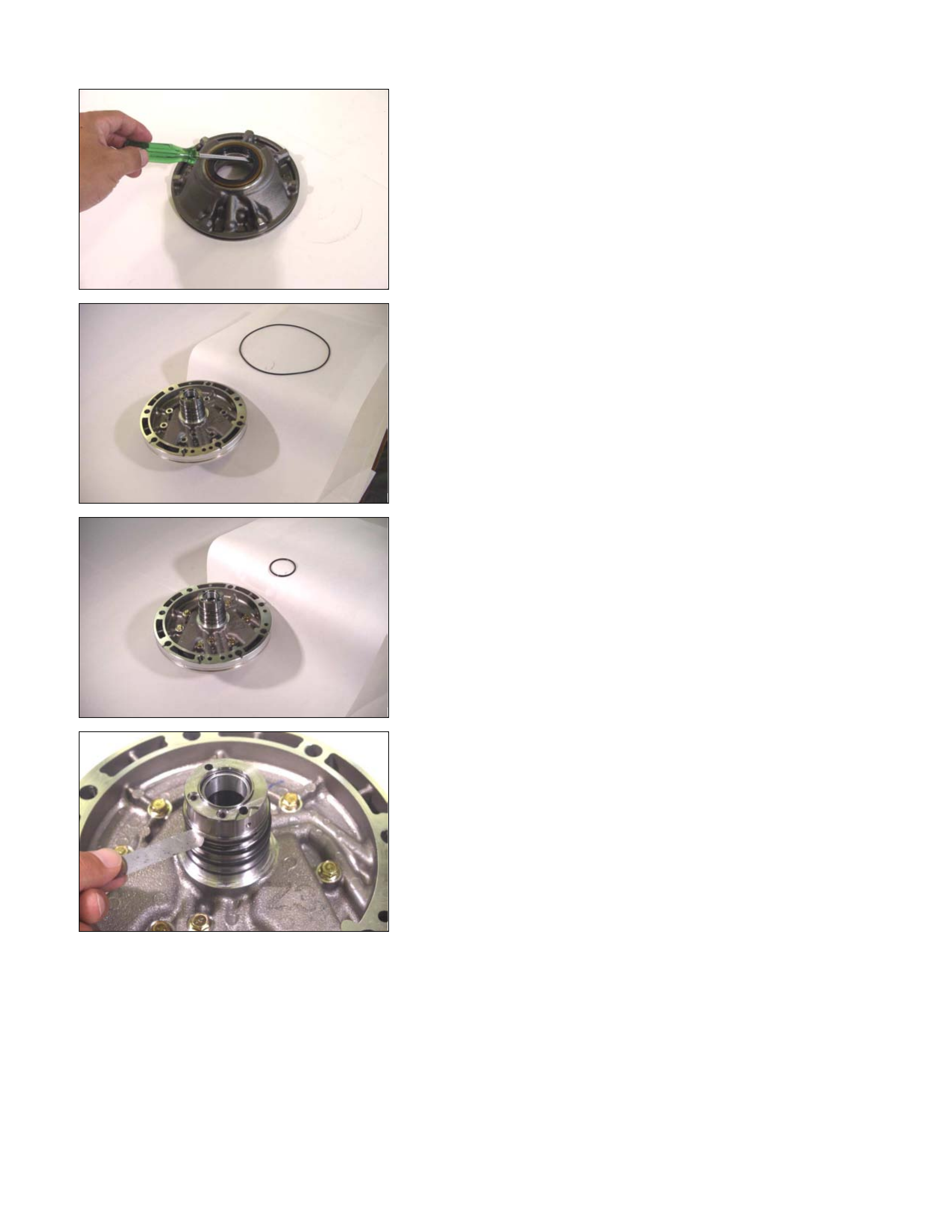
10PUMP19
6. Oil seal
Remove the oil seal from the oil pump housing.
08PUMP09
7. O-ring (large)
Remove the O-ring (large) from the oil pump cover.
09PUMP05
8. Seal ring
Remove the 4 seal rings from the oil pump cover.
11PUMP43
Inspection
Oil pump cover
• Install new seal rings to the oil pump cover.
NOTE:
The seal ring with the large inside diameter fits into the
primary mating surface of the cover.
• Measure the gap between the seal ring and the seal ring
groove.
If the measured gap is outside the specified range, the
oil pump cover must be replaced.
Seal ring and seal ring groove gap: 0.10∼
∼∼
∼0.25 mm
(0.0039∼
∼∼
∼0.0098 in)
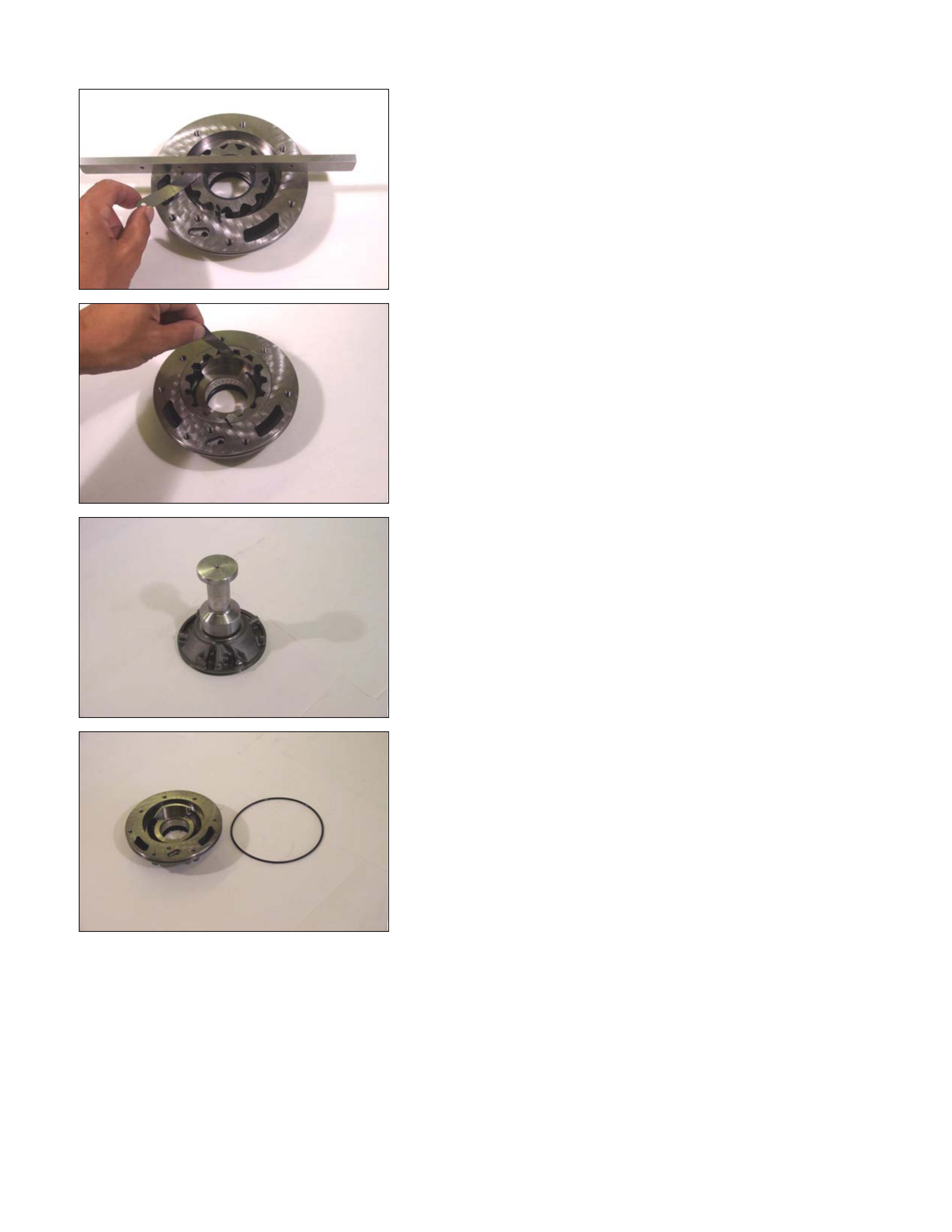
12PUMP45
Inner rotor
• Install the inner rotor to the oil pump housing.
• Use a straight edge to measure the side clearance
between the oil pump housing and the inner rotor.
If the measured clearance is outside the specified range,
the inner rotor must be replaced.
Oil pump housing and inner rotor side clea rance:
0.02~0.04 mm (0.0008~0.0016 in)
13PUMP46
Outer rotor
• Install the outer rotor to the oil pump housing.
• Measure the gap between the outer rotor and the
crescent.
If the measured gap is outside the specified range, the
outer rotor must be replaced.
Outer rotor and crescent gap:
0.02~0.15 mm (0.0008~0.0059 in)
14PUMP28
Reassembly Steps
Coat the parts with ATF before installing them.
1. Oil seal
• Use the oil seal installer to install new oil seal to the oil
pump housing.
Oil seal installer: 5-8840-2761-0
15PUMP18
2. O-ring (small)
Install new O-ring (small) to the oil pump housing.
16PUMP29
3. Outer rotor
4. Inner rotor
Install the outer rotor and the inner rotor to the oil pump
housing.
17PUMP42
NOTE:
The identification mark on the inner rotor must be facing
the inside of the oil pump housing.
18PUMP07
5. Oil pump cover
6. Oil pump housing
Install the oil pump cover to the oil pump housing.
Tighten the 8 bolts to the specified torque.
Torque: 9 N⋅
⋅⋅⋅m (78 Ib⋅
⋅⋅⋅in)
7. O-ring (large)
Install the O-ring (large) to the oil pump cover.
8. Seal ring
Install the 4 seal rings to the oil pump cover.
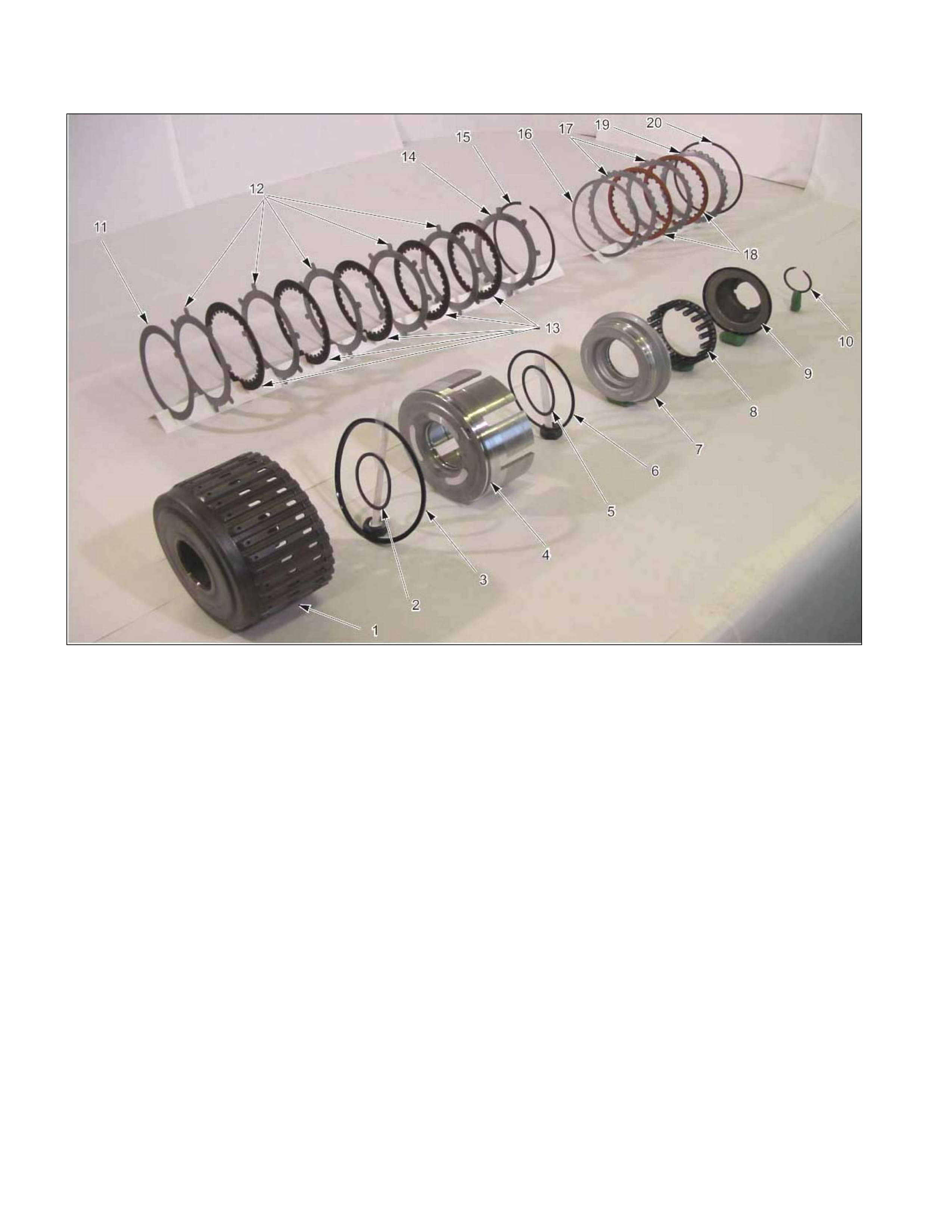
Clutch Pack (Reverse And High Clutch Assembly)
01R&H17
Legend
1. Reverse and high clutch drum
2. Seal ring (reverse clutch)
3. Lip seal (reverse clutch)
4. Reverse clutch piston
5. Seal ring (small, high clutch)
6. Seal ring (large, high clutch)
7. High clutch piston
8. Return spring
9. High clutch cover
10. Snap ring
11. Dish plate (high clutch)
12. Driven plates (5, high clutch)
13. Drive plates (5, high clutch)
14. Retaining plate (high clutch)
15. Snap ring (high clutch)
16. Dish plate (reverse clutch)
17. Driven plates (2, reverse clutch)
18. Drive plates (2, reverse clutch)
19. Retaining plate (reverse clutch)
20. Snap ring (reverse clutch)
02R&H18
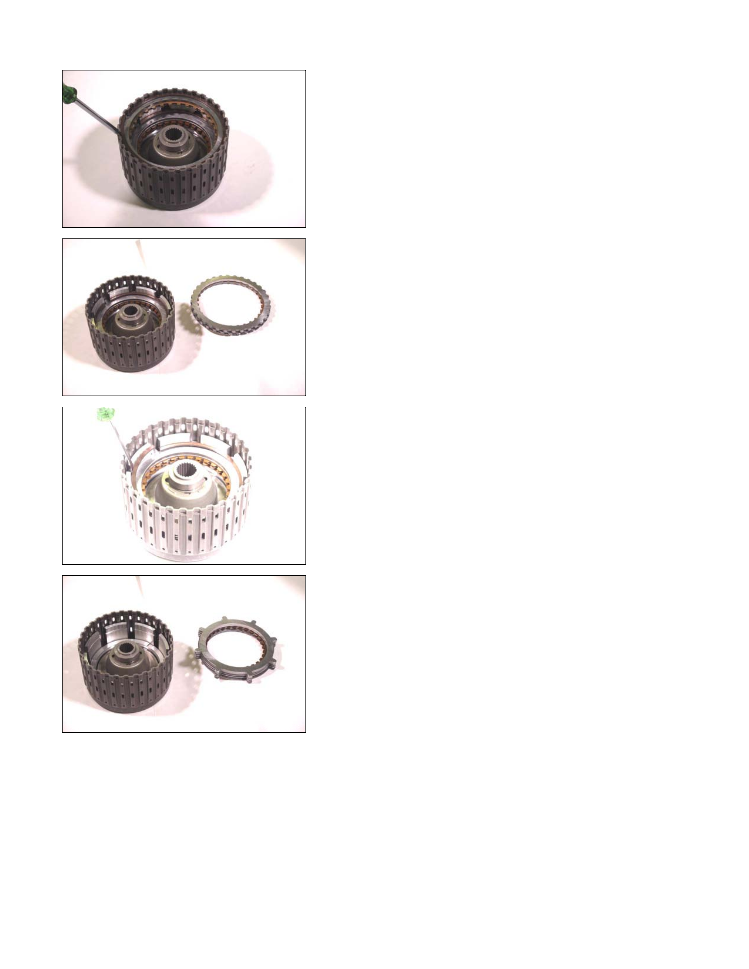
Disassembly Steps
1. Snap ring
Remove the reverse clutch snap ring.
03R&H21
2. Retaining plate, drive plate, driven plate and dish plate
Remove the reverse clutch retaining plate, the 2 drive
plates, the 2 driven plates, and the dish plate.
04R&H22
3. Snap ring
Remove the high clutch snap ring.
05R&H25
4. Retaining plate, drive plate, driven plate and dish plate
Remove the high clutch retaining plate, the 5 drive plates,
the 5 driven plates, and the dish plate.
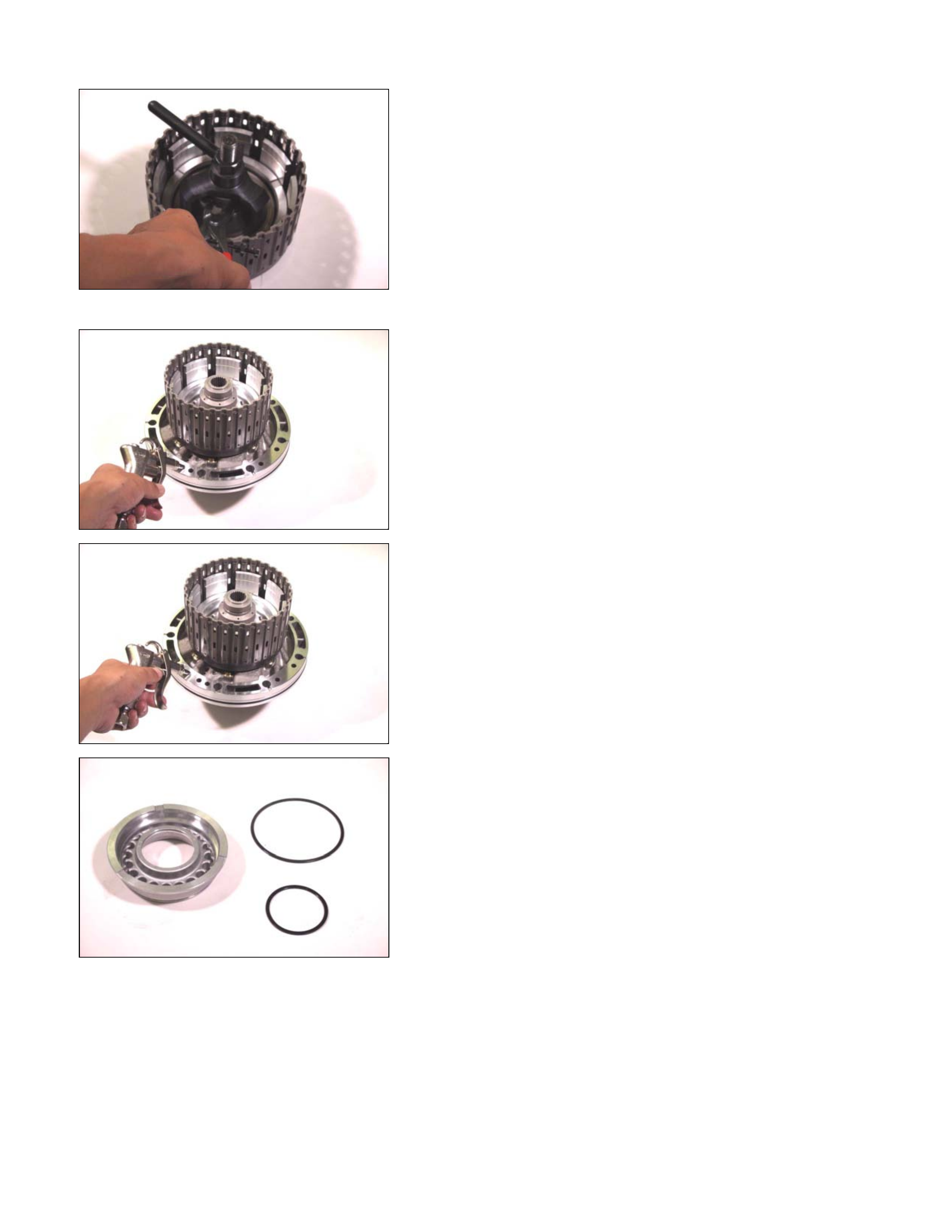
07R&H28
5. Snap ring
6. High clutch cover
7. Return spring
• Install the spring compressor to the reverse and high
clutch drum.
Spring compressor: 5-8840-2767-0
• Carefully press the high clutch cover down.
Take care not to damage the return spring.
• Remove the snap ring.
• Remove the high clutch cover and the return spring.
08R&H36
8. High clutch piston
9. Reverse clutch piston
• Install the reverse and high clutch drum to the oil pump.
• Force compressed air into the oil pump oil channels.
• Remove the high clutch piston and the reverse clutch
piston.
09R&H37
12R&H39
10.Seal ring (high clutch)
Remove the 2 seal rings from the high clutch piston.
13R&H38
11.Seal ring (reverse clutch)
Remove the 2 seal rings from the reverse clutch piston.
Inspection
Drive plate
• Measure the drive plate facing thickness at 3 points.
• Calculate the average value.
If the average value is less than the specified limit, the
drive plate must be replaced.
Drive plate facing thickness:
Standard – 2.0 mm (0.079 in)
Limit – 1.8 mm (0.071 in)
Return spring
• Check the number of effective return spring coils.
If the number is less than the specified minimum, the
return spring must be replaced.
Effective return spring coils (standard): 10.2
• Measure the return spring outside diameter, free length,
and linear diameter.
If any of the measur ed values exceed the spec ified lim it,
the return spring must be replaced.
Return spring measurements (standard):
Outside diameter – 8.0 mm (0.315 in)
Free length – 27.1 mm (1.067 in)
Linear diameter – 1.1 mm (0.043 in)
10R&H40
Reverse clutch piston
• Apply compressed air (392 kPa/4.0 kg/cm2) to the
reverse clutch piston from the outside to the inside.
The flow of air should be blocked.
11R&H44
• Apply compressed air (392 kPa/4.0 kg/cm2) to the
reverse clutch piston from inside to the outside.
The flow of air should be unrestricted.
12R&H39
Reassembly Steps
Coat the parts with ATF before installing them.
1. Seal ring (high clutch)
Install new seal rings to the high clutch piston.
13R&H38
2. Seal ring (reverse clutch)
Install new seal rings to the reverse clutch piston.

14R&H32
3. Reverse clutch piston
Install the reverse clutch piston to the reverse and high
clutch drum.
15R&H31
4. High clutch piston
Install the high clutch piston to the reverse clutch piston.
16R&H33
5. Return spring
Install the return spring to the high clutch piston.
17R&H30
6. High clutch cover
• Carefully center the high clutch cover and install it.
NOTE:
If the clutch cover is not centered, the cover outside seal
gum will be forced into the piston area where it will be
damaged.
18R&H27
7. Snap ring
• Install the spring compressor to the reverse and high
clutch drum.
• Use the spring compressor to carefully force the high
clutch cover down.
Spring compressor: 5-8840-2767-0
NOTE:
To avoid damage to return springs, use only as much
force as is required to press the high clutch cover into
place.
19R&H28
• Install the new snap ring to the reverse and high clutch
drum.
20R&H25
8. Dish plate, drive plates, driven plates, and retaining
plate
Install the high clutch dish plate (1), the 5 driven plates (2),
the 5 drive plates (3), and retaining plate (4).
248L300002
9. Snap ring
Install the snap ring.
21R&H21
10.Dish plate, drive plates, driven plates, and retaining
plate
Install the reverse clutch dish plate (1) the 2 driven plates
(2), the 2 drive plates (3), and retaining plate (4).
248L300003
11.Snap ring
Install the snap ring.
22R&H35
• Install the reverse and high clutch drum to the oil pump
assembly.
• Force compressed air (392 kPa/4.0 kg/cm 2) through the
oil pump oil passages to check high clutch operation.
If the clutch does not operate, the seal ring may be
damaged or the parts may have been installed in the
wrong order.
23CLEAR02
• Measur e the c learanc e between the high clutch r etaining
plate and the snap ring.
If the clearance is outside the specified range, replace
the existing retaining plate with a new plate of the prope
r
size (thickness).
High clutch retaining plate and snap ring clearance
(A): 1.2~1.6 mm (0.047~0.063 in)
Available high clutch retaining plate thicknesses
4.6 mm (0.181 in)
248L300004
4.8 mm (0.189 in)
5.0 mm (0.197 in)
5.2 mm (0.205 in)
5.4 mm (0.213 in)
24R&H34
• Force compressed air (392 kPa/4.0 kg/cm 2) through the
oil pump oil passages to check reverse clutch operation.
If the clutch does not operate, the seal ring may be
damaged or the parts may have been installed in the
wrong order.
25CLEAR04
• Measure the clearance between the reverse clutch
retaining plate and the snap ring.
If the clearance is outside the specified range, replace
the existing retaining plate with a new plate of the prope
r
size (thickness).
Reverse clutch retaining plate and snap ring
clearance (B):
0.6~0.9 mm (0.024~0.035 in)
Available reverse clutch retaining plate thicknesses
4.8 mm (0.189 in)
5.0 mm (0.197 in)
5.2 mm (0.205 in)
5.4 mm (0.213 in)
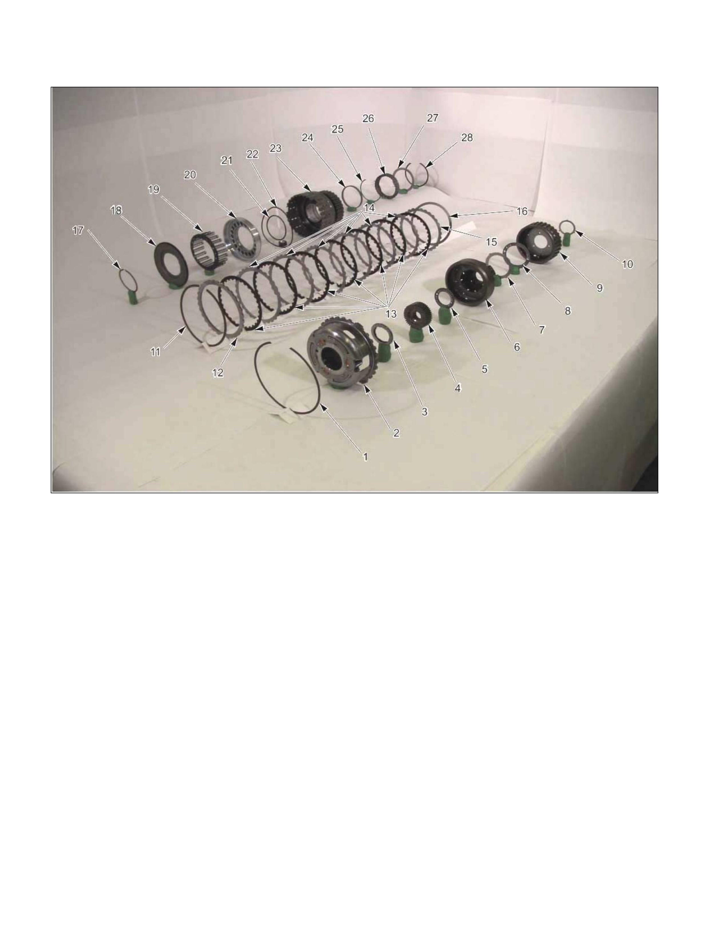
Carrier And Low Clutch Assembly
01C&L12
Legend
1. Snap ring
2. Front carrier
3. Bearing (with bearing race)
4. Rear sun gear
5. Bearing
6. Rear carrier
7. Bearing race
8. Bearing
9. Rear internal gear
10. Bearing race
11. Snap ring
12. Retaining plate
13. Drive plates (7, low clutch)
14. Driven plates (6, low clutch)
15. Driven plate (1, 2 mm thick, low clutch)
16. Dish plate
17. Snap ring
18. Cancel cover
19. Return spring
20. Low clutch piston
21. Seal ring (small)
22. Seal ring (large)
23. Low clutch drum
24. Bearing
25. Snap ring
26. Low one-way clutch
27. Side plate
28. Snap ring
02C&L-SUB03
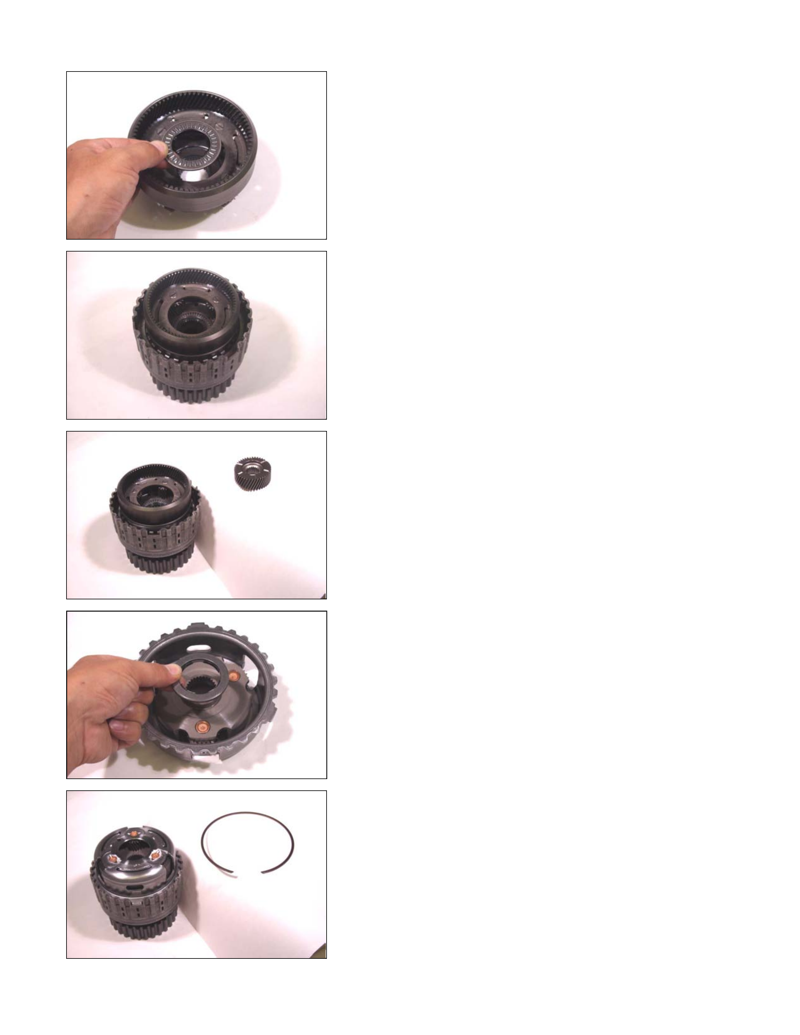
Disassembly Steps
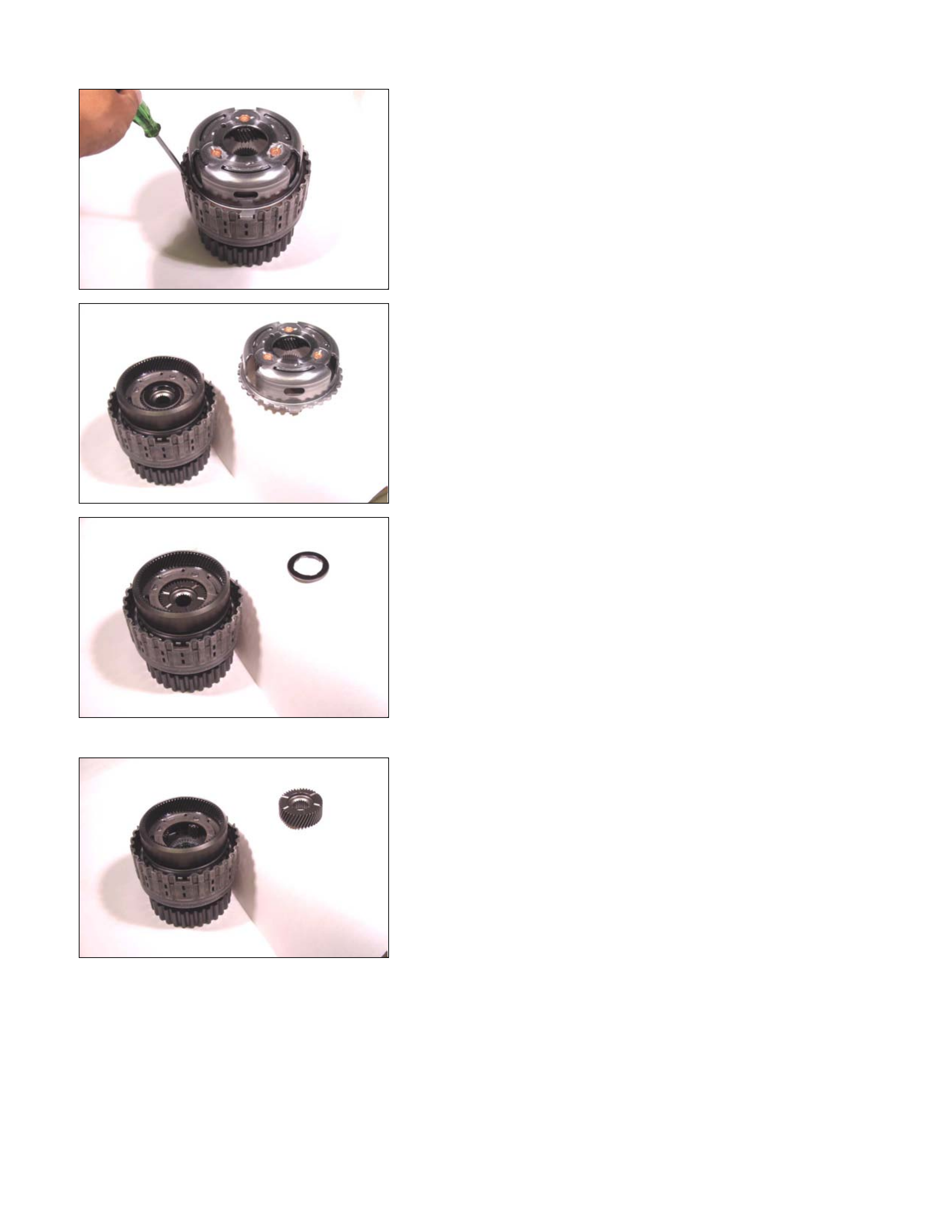
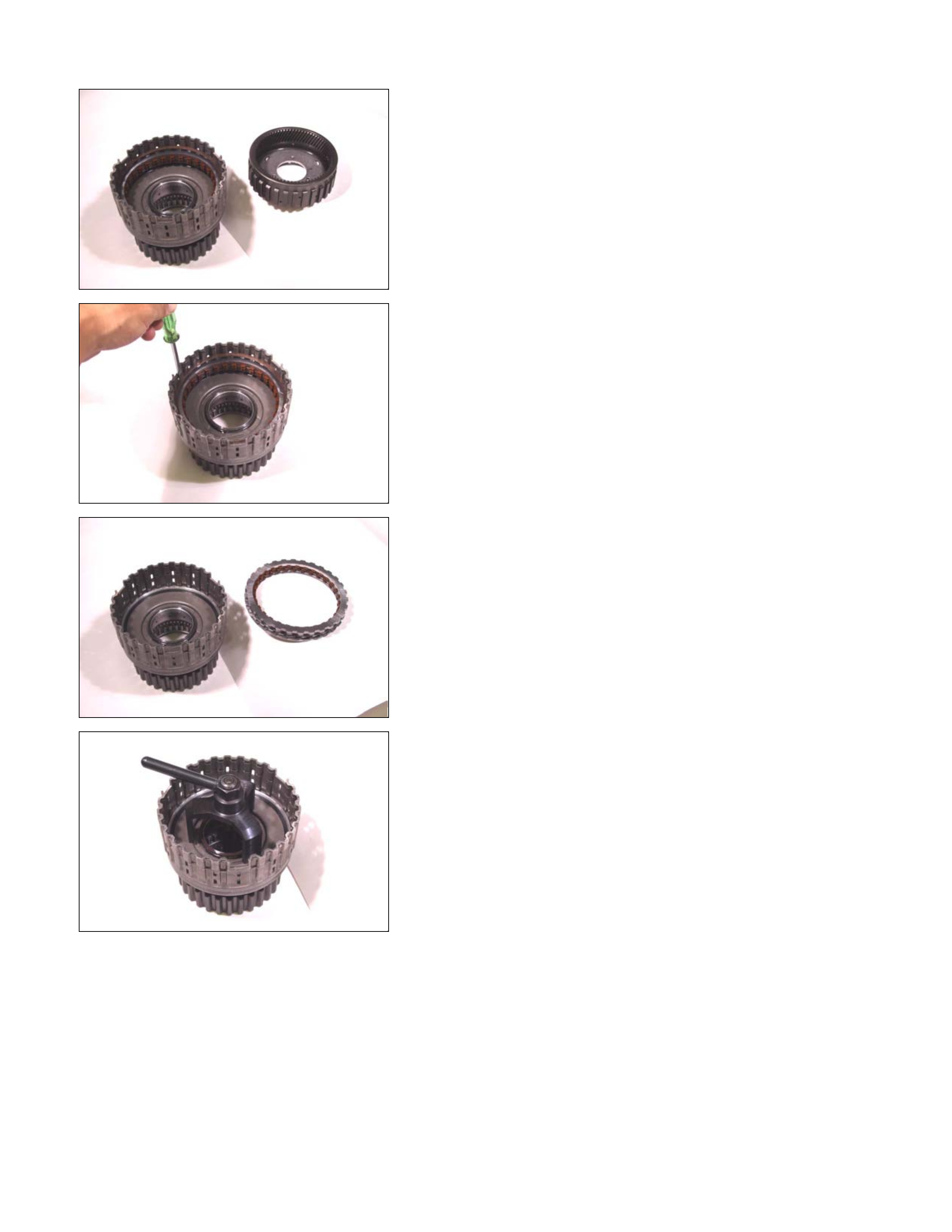
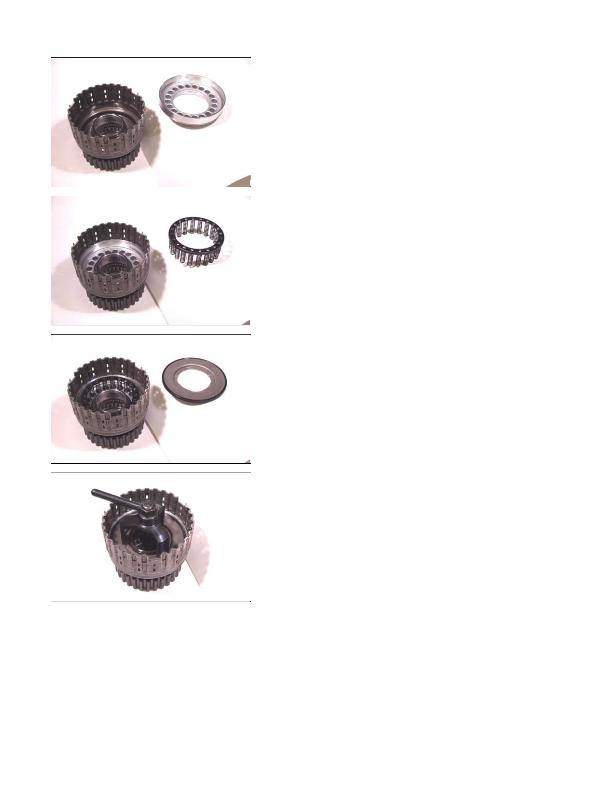
1. Snap ring
Remove the snap ring from the low clutch drum.
03C&L-SUB05
2. Front carrier
Remove the front carrier from the low clutch assembly.
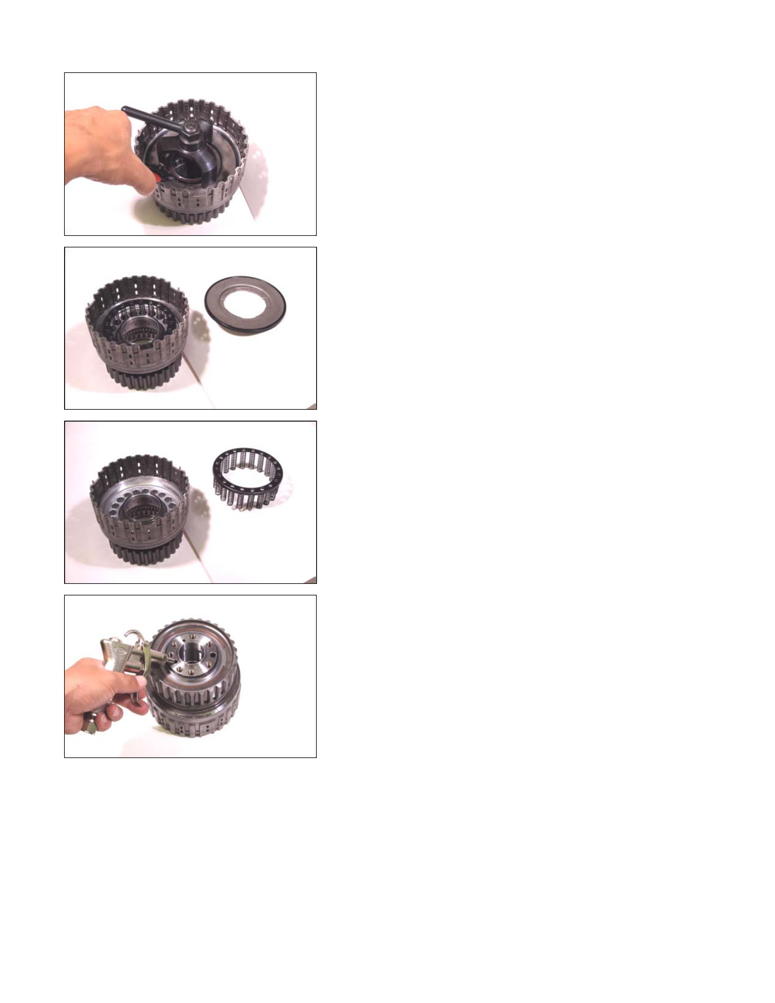
04C&L-SUB06
3. Bearing (with bearing race)
4. Rear sun gear
5. Bearing
6. Rear carrier
7. Bearing race
8. Bearing
9. Rear internal gear
10.Bearing race
Remove the bearing (with bearing race), the rear sun gear,
the bearing, the rear carrier, the bearing race, the bearing,
and rear internal gear.
05C&L-SUB07
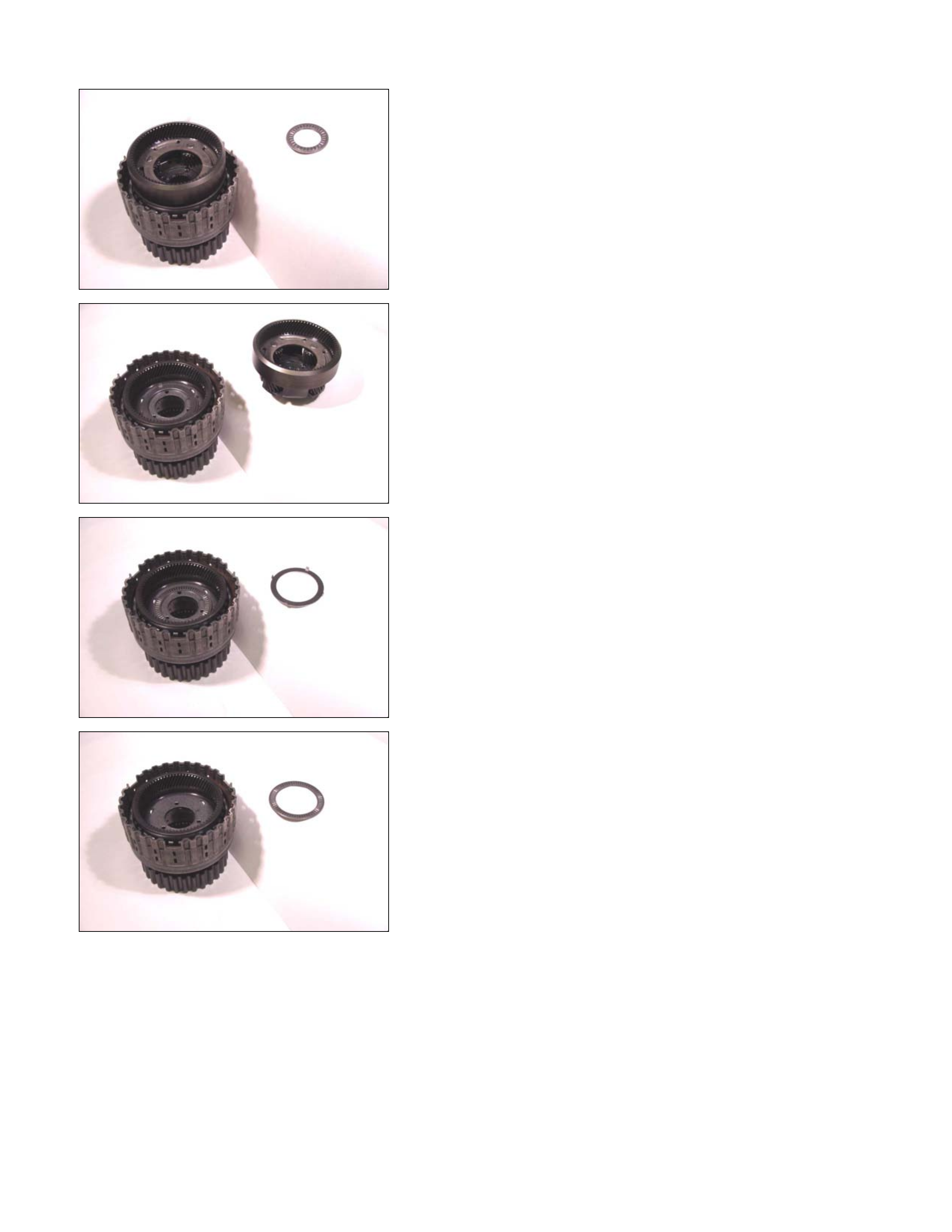
06C&L-SUB08
07C&L-SUB09
08C&L-SUB10
09C&L-SUB11
10C&L-SUB12
• Remove the bearing race from the rear internal gear.
11C&L-SUB13
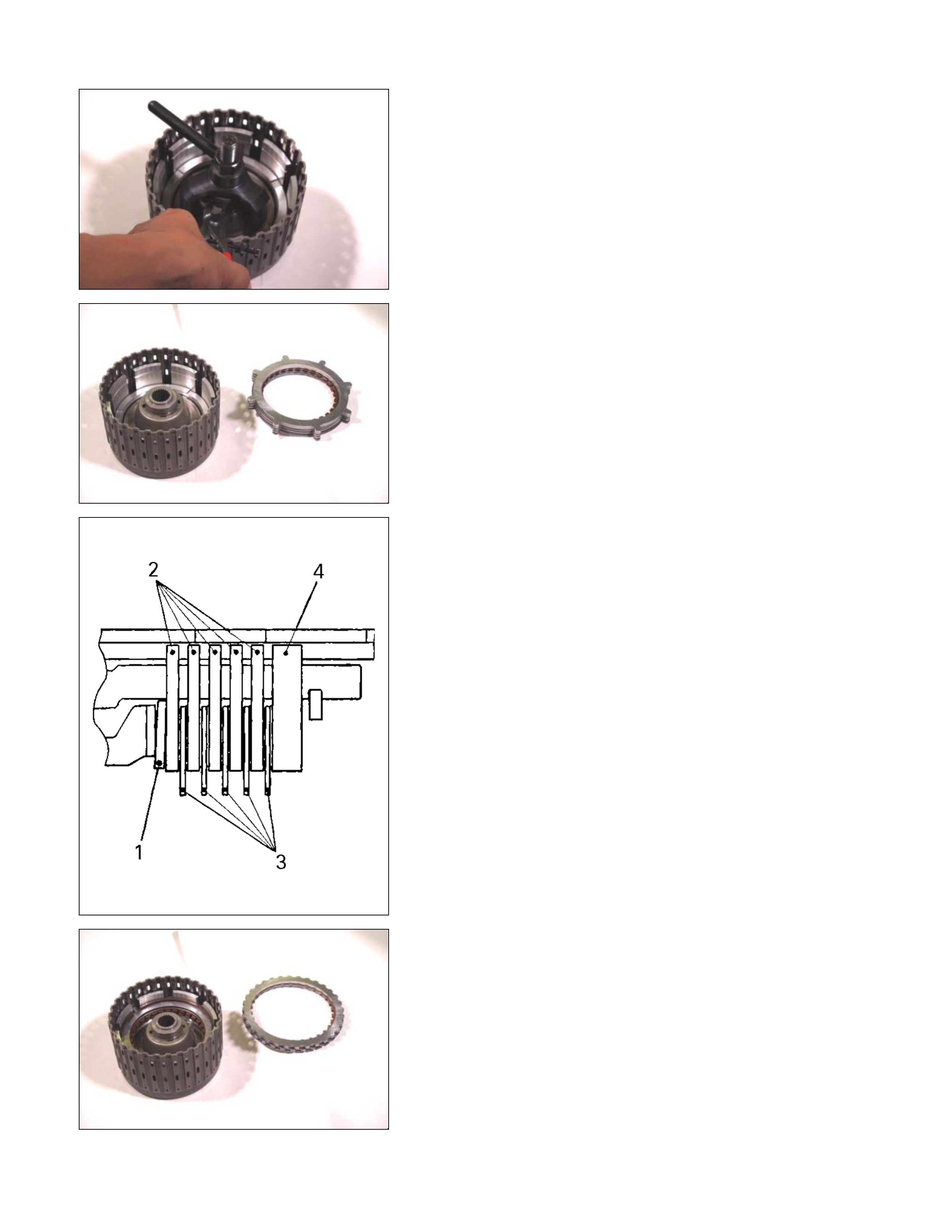
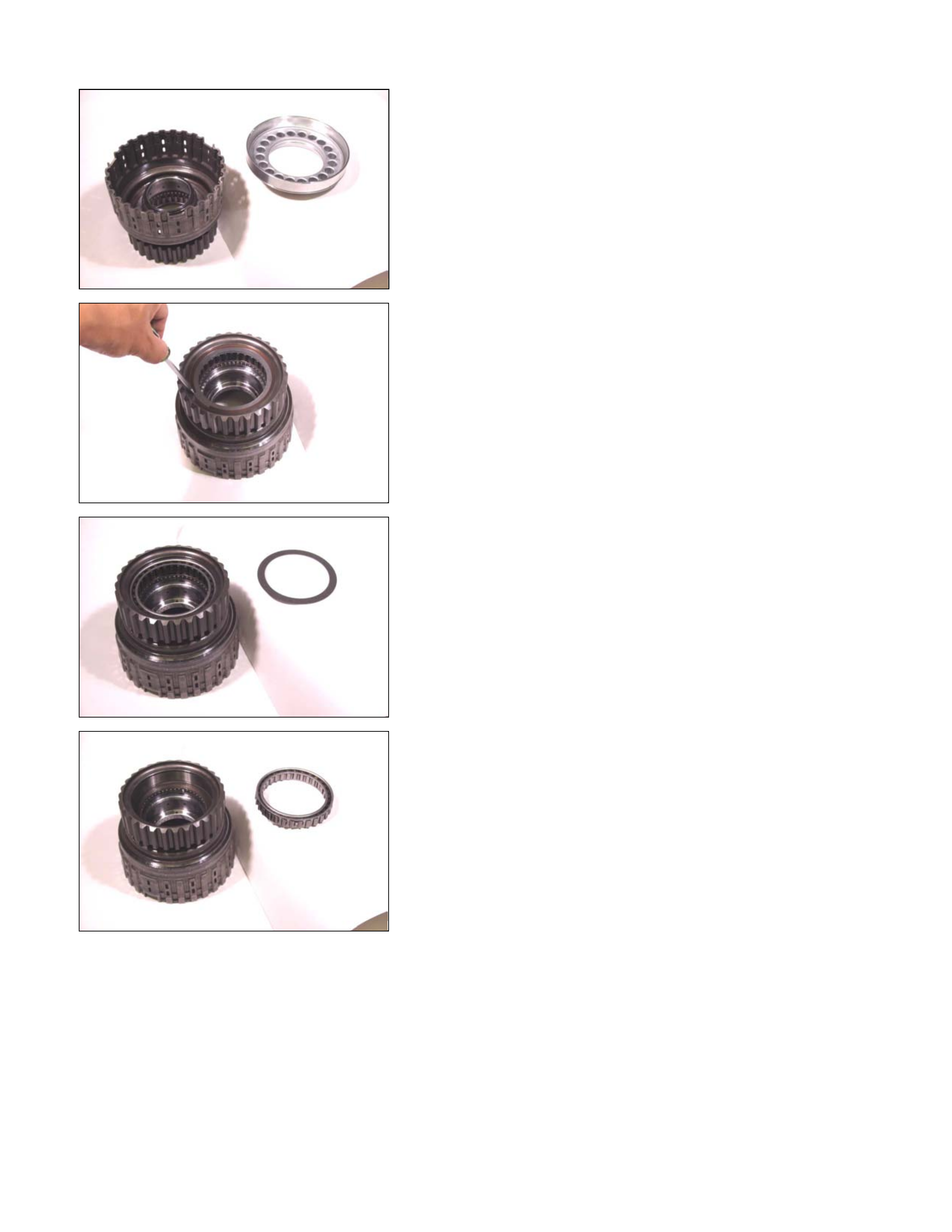
11.Snap ring
Remove the low clutch snap ring.
12C&L-SUB15
12.Retaining plate, drive plate, driven plate, and dish plate
Remove the low clutch retaining plate, the 7 drive plates,
the 7 driven plates, and the dish plate.
13C&L-SUB18
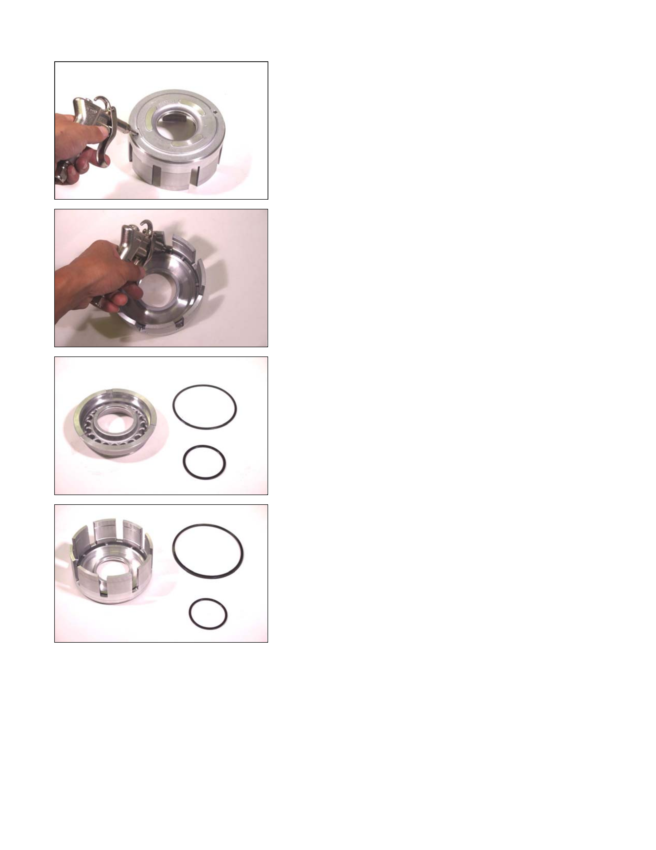
13.Snap ring
• Install the spring compressor to the low clutch drum.
Spring compressor: 5-8840-2759-0
• Carefully press the cancel cover down.
Take care not to damage the return spring.
14C&L-SUB19
• Remove the snap ring.
31C&L-SUB20
14.Cancel cover
Remove the cancel cover.
30C&L-SUB21
15.Return spring
Remove the return spring.
15C&L-SUB38
16.Low clutch piston
• Inser t the low one-way clutch inner race to the low clutc h
drum.
• Force compressed air through the oil passages of the
low one-way clutch inner race to remove the low clutch
piston.
29C&L-SUB22
16C&L-SUB25
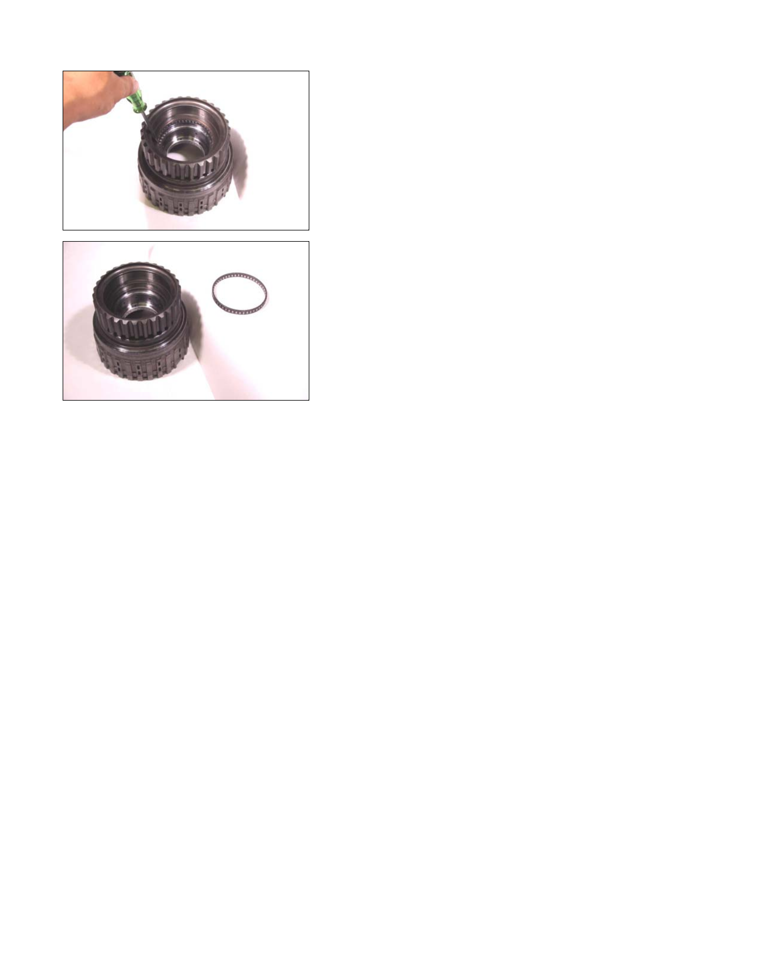
17.Snap ring
• Raise the low one-way clutch side.
• Remove the low one-way clutch snap ring.
17C&L-SUB27
18.Side plate
Remove the side plate.
18C&L-SUB28
19.Low one-way clutch
Remove the low one-way clutch.
19C&L-SUB29
20.Snap ring
Remove the snap ring from the low clutch drum.
20C&L-SUB31
21.Bearing
Remove the bearing.
Inspection
Drive plate
• Measure the drive plate facing thickness at 3 points.
• Calculate the average value.
If the average value is less than the specified limit, the
drive plate must be replaced.
Drive plate facing thickness:
Standard – 2.0 mm (0.079 in)
Limit – 1.8 mm (0.071 in)
Return spring
• Check the number of effective return spring coils.
If the number is less than the specified minimum, the
return spring must be replaced.
Effective return spring coils (standard): 9.9
• Measure the return spring outside diameter, free length,
and linear diameter.
If any of the measur ed values exceed the spec ified lim it,
the return spring must be replaced.
Return spring measurements (standard):
Outside diameter – 9.7 mm (0.382 in)
Free length – 36.4 mm (1.433 in)
Linear diameter – 1.2 mm (0.047 in)

21C&L-SUB31
Reassembly Steps
Coat the parts with ATF before installing them.
1. Bearing
Install the bearing into the low clutch drum.
22C&L-SUB30
2. Snap ring
Install the snap ring to the low clutch drum.
23C&L-SUB28
3. Low one-way clutch
Install the low one-way clutch to the low clutch drum.
24C&L-SUB33
NOTE:
The flanged side of the low one-way clutch must face the
outside.

25C&L-SUB27
4. Side plate
Install the side plate.
26C&L-SUB26
5. Snap ring
Install the snap ring to the low clutch drum.
27C&L-SUB58
• Attach the low one-way clutch inner race to the lo
w
clutch drum in the opposite direction of normal position.
• Rotate the one-way clutch inner race clockwise. It
should turn smoothly w ith little resistance.
• Rotate the low one-way clutch inner race
counterclockwise.
It should immediately lock (rotation is impossible).
If it does not, check the low one-way clutch installation
direction.
Inspect and replace the low one-way clutch if required.
• Remove the low one-way clutch inner race.
• Reverse the low clutch drum.
28C&L-SUB32
6. Low clutch piston
• Install new seal rings to the low clutch piston.
29C&L-SUB22
• Install the low clutch piston to the low clutch drum.
30C&L-SUB21
7. Return spring
Install the return spring to the low clutch piston.
31C&L-SUB20
8. Cancel cover
• Carefully center the cancel cover and install it.
NOTE:
If the cancel cover is not centered, the cover outside seal
ring gum will be forced into the low clutch piston area
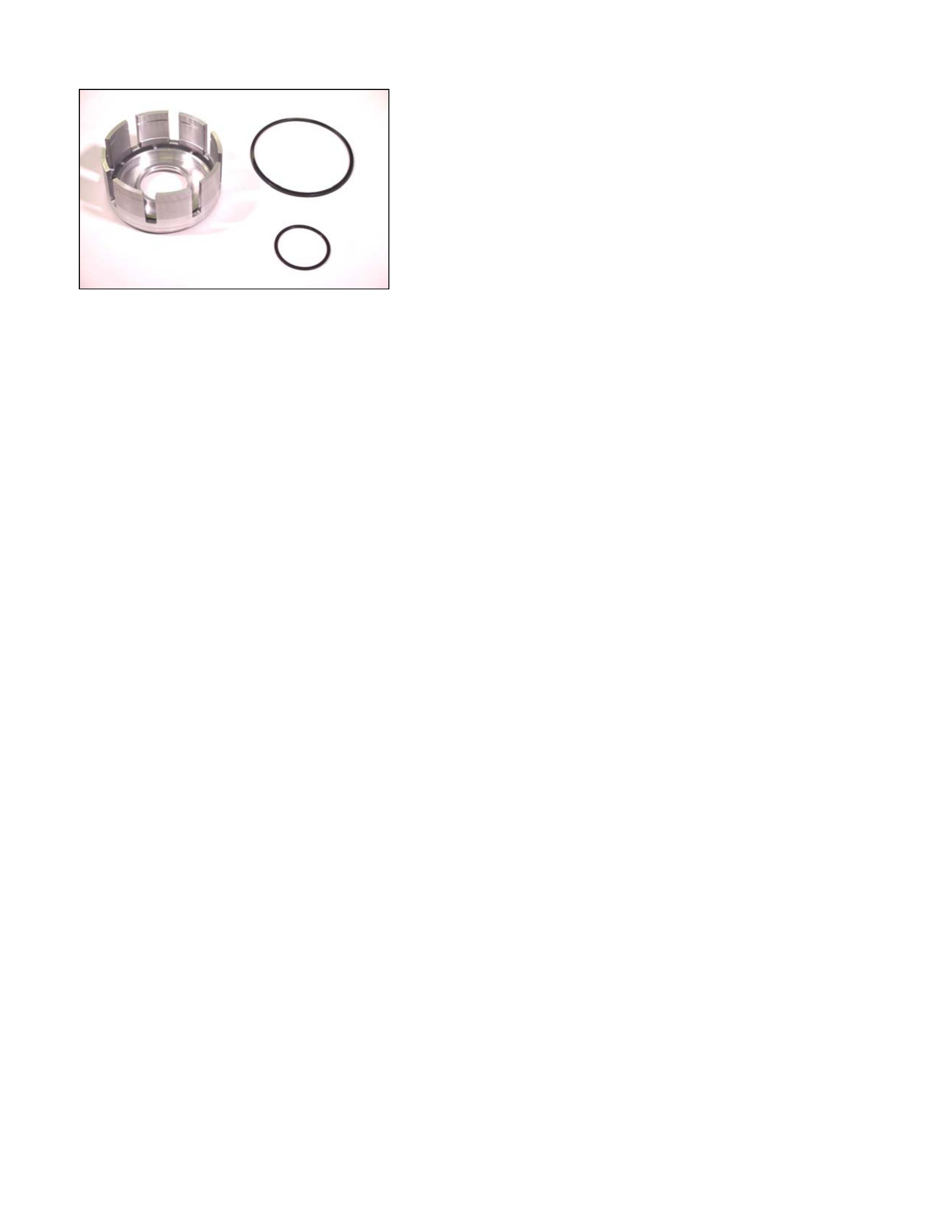
where it will be damaged.
32C&L-SUB18
• Install the spring compressor to the low clutch.
Spring compressor: 5-8840-2759-0
33C&L-SUB19
9. Snap ring
• Use the spring compressor to carefully force the cancel
cover down.
NOTE:
To avoid damage to the return spring, use only as much
force as is required to press the cancel cover into place.
• Install new snap ring to the low clutch drum.
34C&L-SUB15
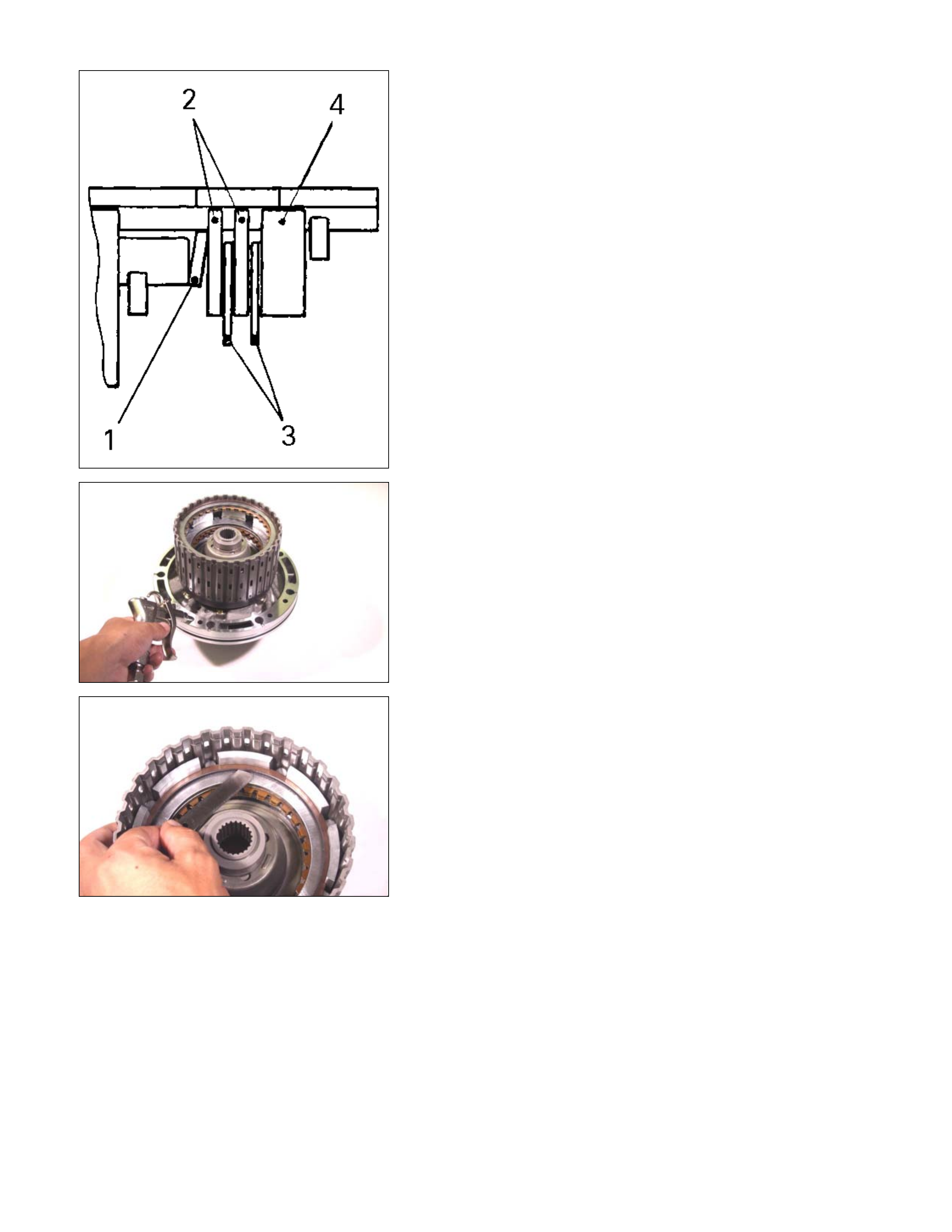
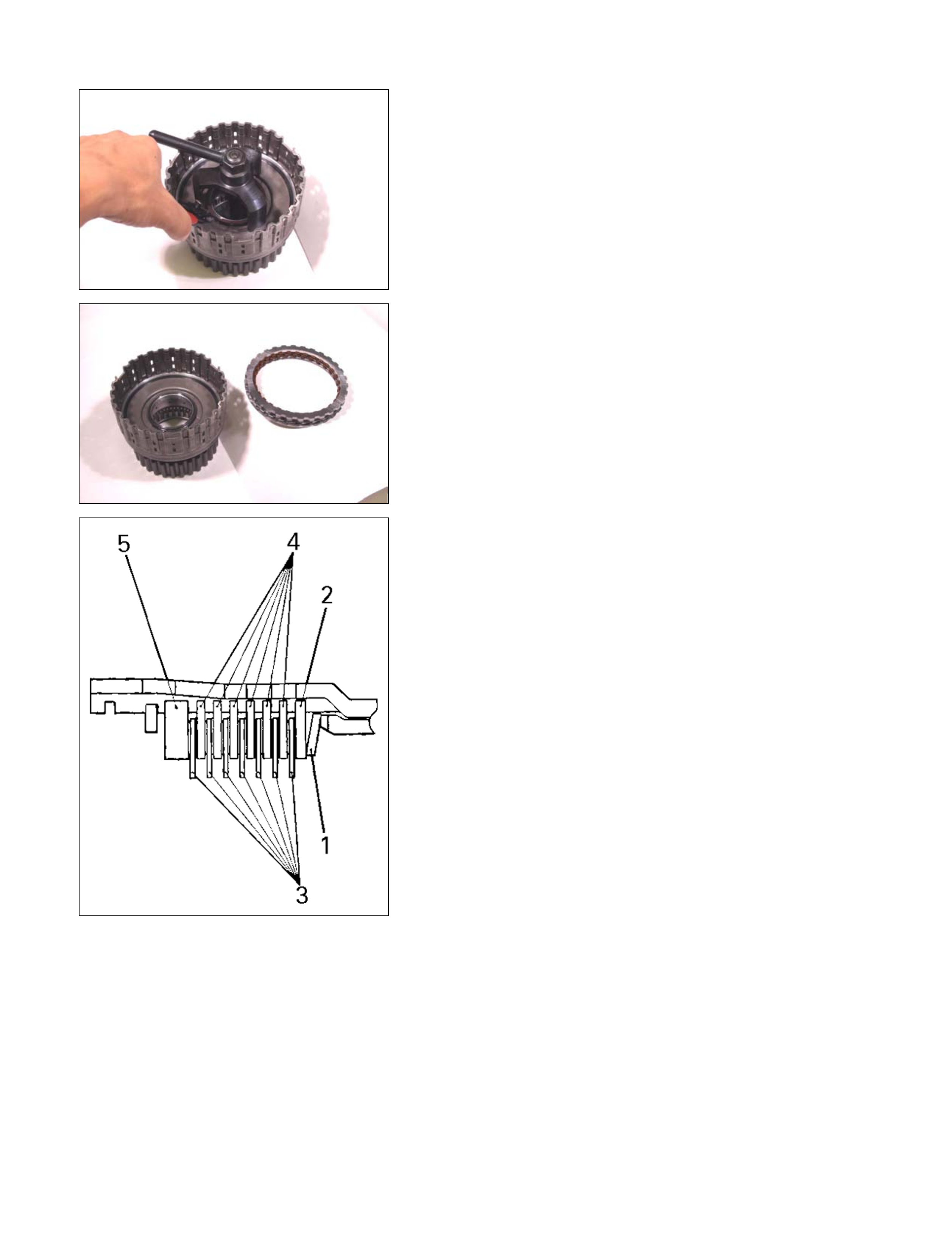
10.Dish plate, drive plate, driven plate, and retaining plate
Install the low clutch dish plate (1), the 2 mm thick driven
plate (2), the 7 drive plate (3), the other 6 driven plates (4),
and the retaining plate (5).
NOTE:
Dish plate side with the identification mark must face the
driven plate.
248L300006
11.Snap ring
Install the snap ring to the low clutch drum.
35C&L-SUB38
36CLEAR06
248L300007
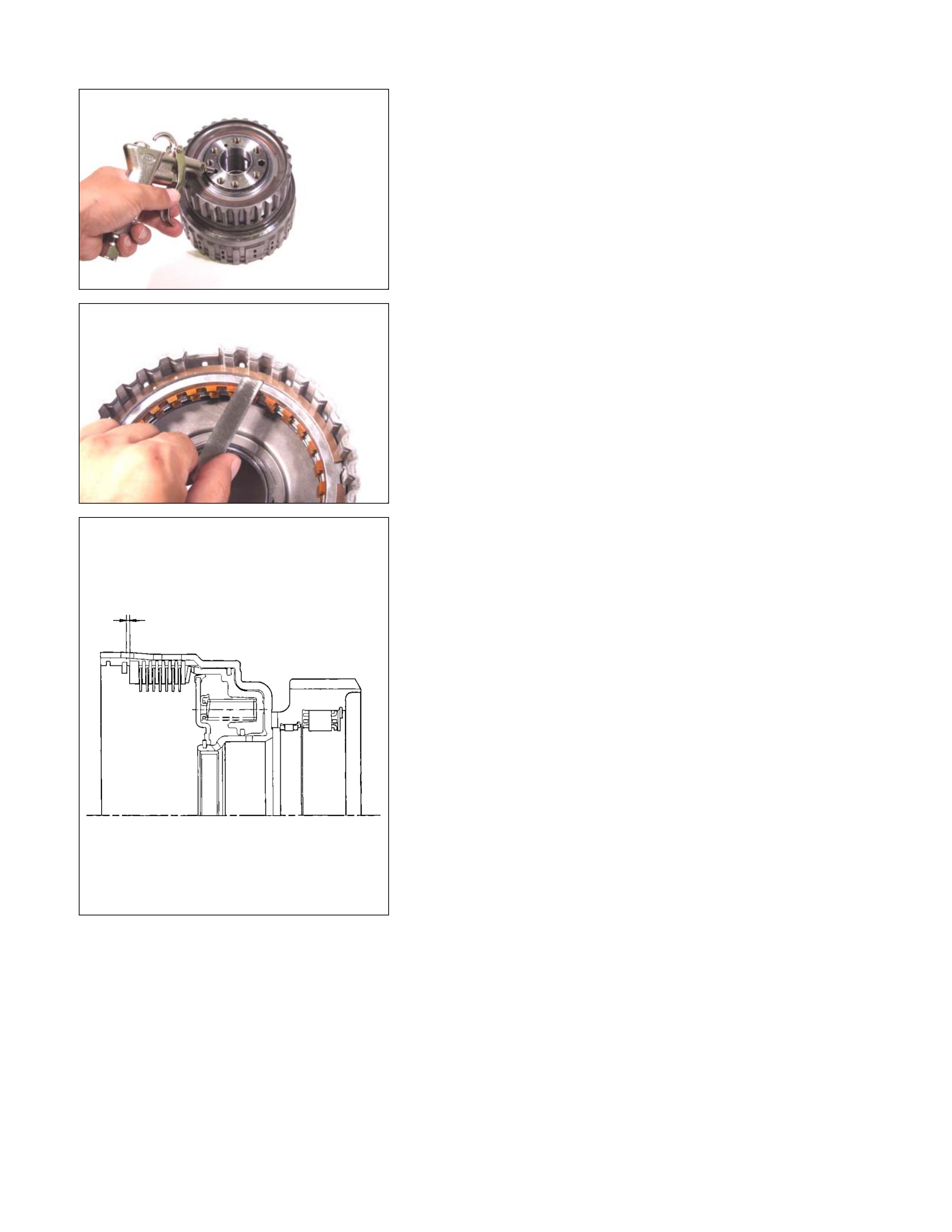
Inspection
• Inser t the low one-way clutch inner race to the low clutch
drum.
• Force compressed air (392 kPa/4.0 kg/cm 2) through the
oil passages of the low one-way clutch inner race to
check low clutch operation.
If the low clutch does not oper ate, the seal rings m ay be
damaged or the parts may have been installed in the
wrong order.
• Measure the clearance between the low clutch retaining
plate and the snap ring.
If the clearance is outside the specified range, replace
the existing plate with a new plate of the proper size
(thickness).
Low clutch retaining plate and snap ring clearance:
0.9~1.3 mm (0.035~0.051 in)
Available low clutch retaining plate thicknesses
3.8 mm (0.150 in)
4.0 mm (0.157 in)
4.2 mm (0.165 in)
4.4 mm (0.173 in)
4.6 mm (0.181 in)
4.8 mm (0.189 in)
37C&L-SUB40
12.Bearing race
13.Rear internal gear
14.Bearing
Install the bearing race and the bearing to the rear internal
gear.
NOTE:
Apply Vaseline to the fitting surfaces of the rear internal
gear to prevent the bearing race and the bearing from
falling during the installation process.
38C&L-SUB43
39C&L-SUB60
• Install the rear internal gear to the low clutch drum.
40C&L-SUB46
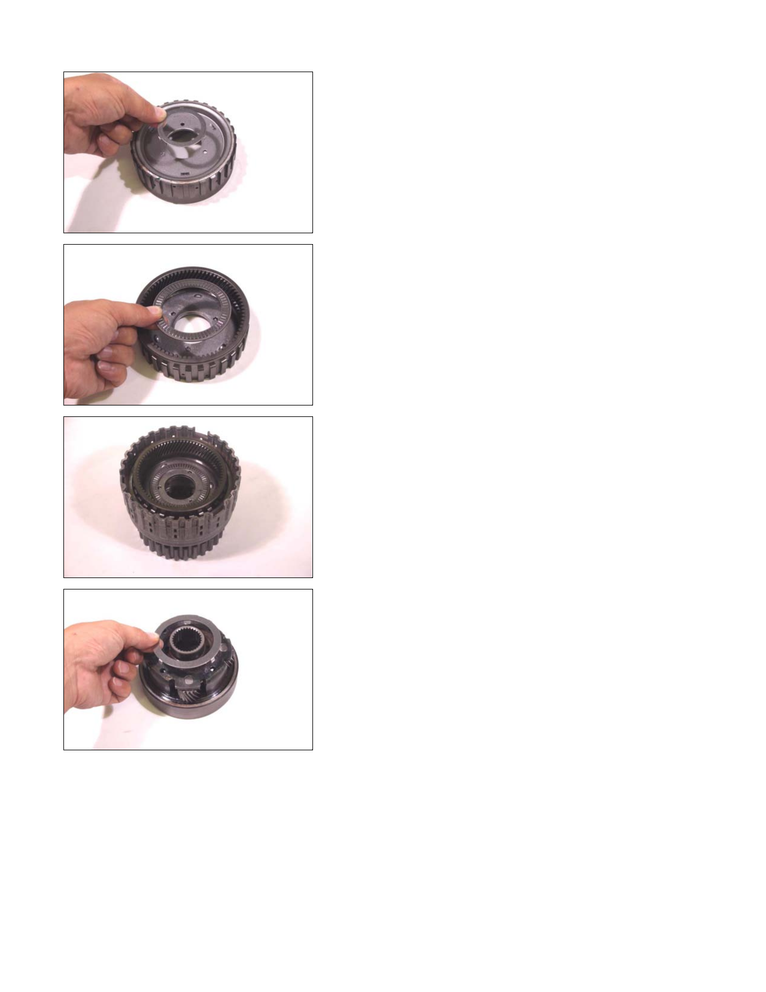
15.Bearing race
16.Rear carrier
17.Bearing
Install the bearing race and the bearing to the rear carrier.
NOTE:
Apply Vaseline to the fitting surfaces of the rear carrier to
prevent the bearing race and the bearing from falling
during the installation process.
41C&L-SUB49
42C&L-SUB61
• Install the rear carrier to the low clutch drum.
43C&L-SUB07
18.Rear sun gear
Install the rear sun gear to the low clutch drum.
44C&L-SUB52
19.Bearing (with bearing race)
20.Front carrier
Install the bearing (with bearing race) to the front carrier.
NOTE:
Apply Vaseline to the fitting surfaces of the front carrier to
prevent the bearing from falling during the installation
process.
45C&L-SUB04
21.Snap ring
• Install the front carrier to the low clutch drum.
• Install the snap ring to the low clutch drum.
Transmission Case
02CASE-BK06
Legend
1. Transmission case
2. Spring pin (slender)
3. Spring pin (fat)
4. Manual plate
5. Detent spring
6. Parking rod
7. Manual shaft
8. Oil seal
9. Inhibitor switch
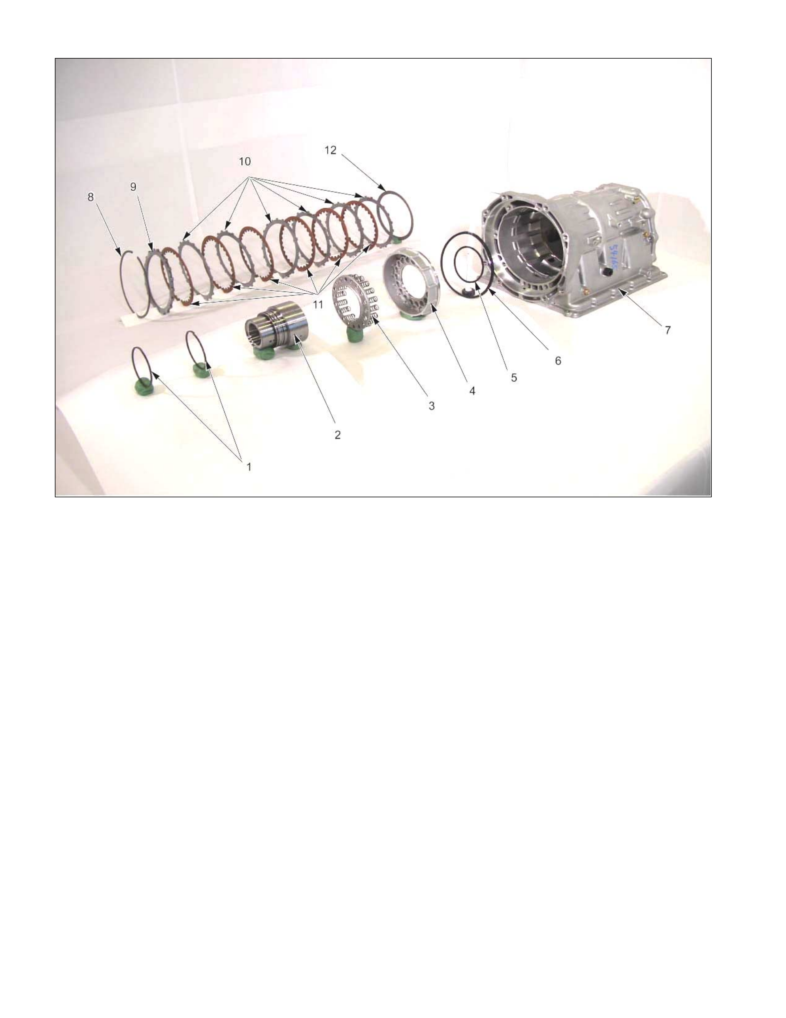
01L&R-CS05
Legend
1. Seal ring
2. Low one-way clutch inner race
3. Return spring
4. Low and reverse brake piston
5. Seal ring
6. Lip seal
7. Transmission case
8. Snap ring
9. Retaining plate
10. Driven plate
11. Drive plate
12. Dish plate
04CASE-AY52
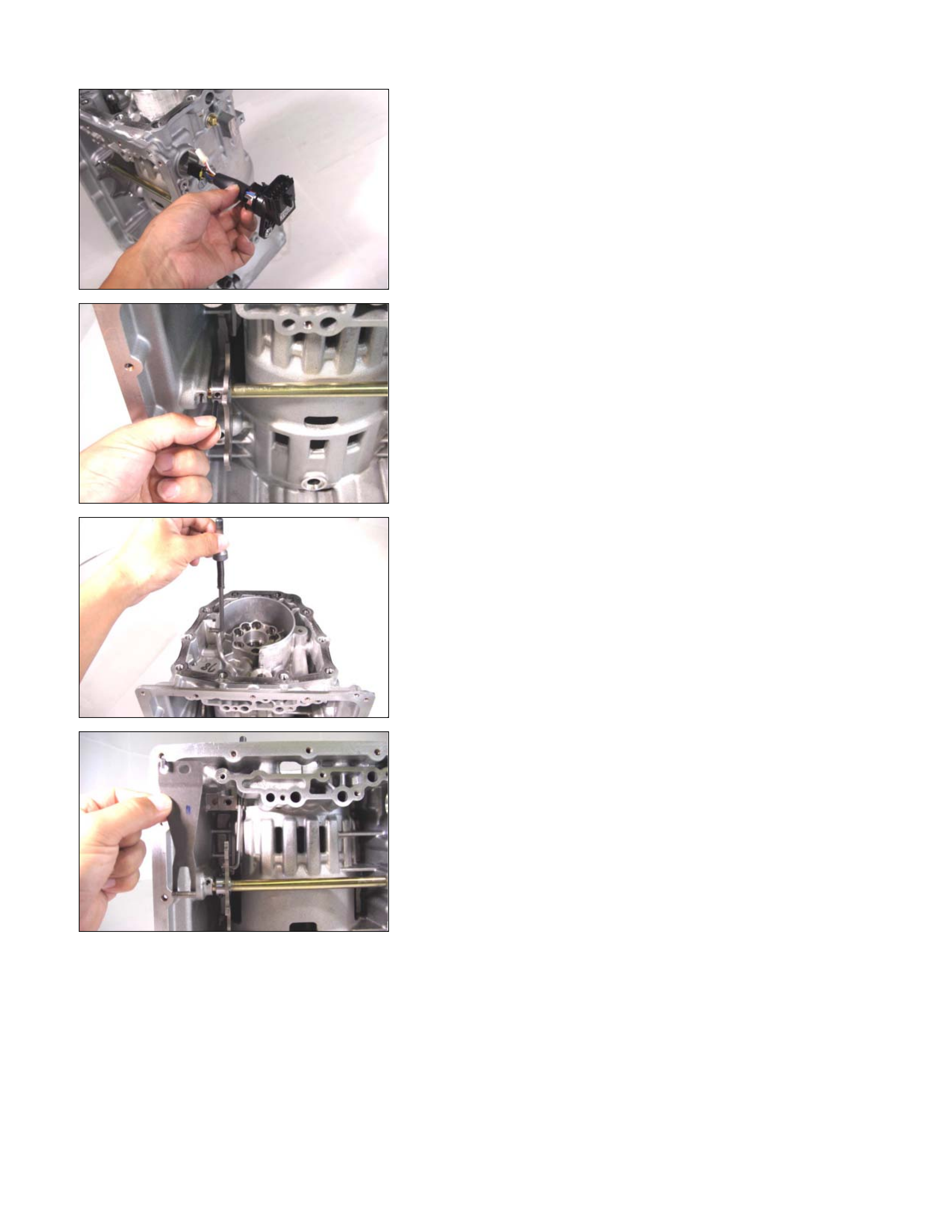
Disassembly Steps
1. Harness assembly
Remove the fixing bolt and the harness assembly.
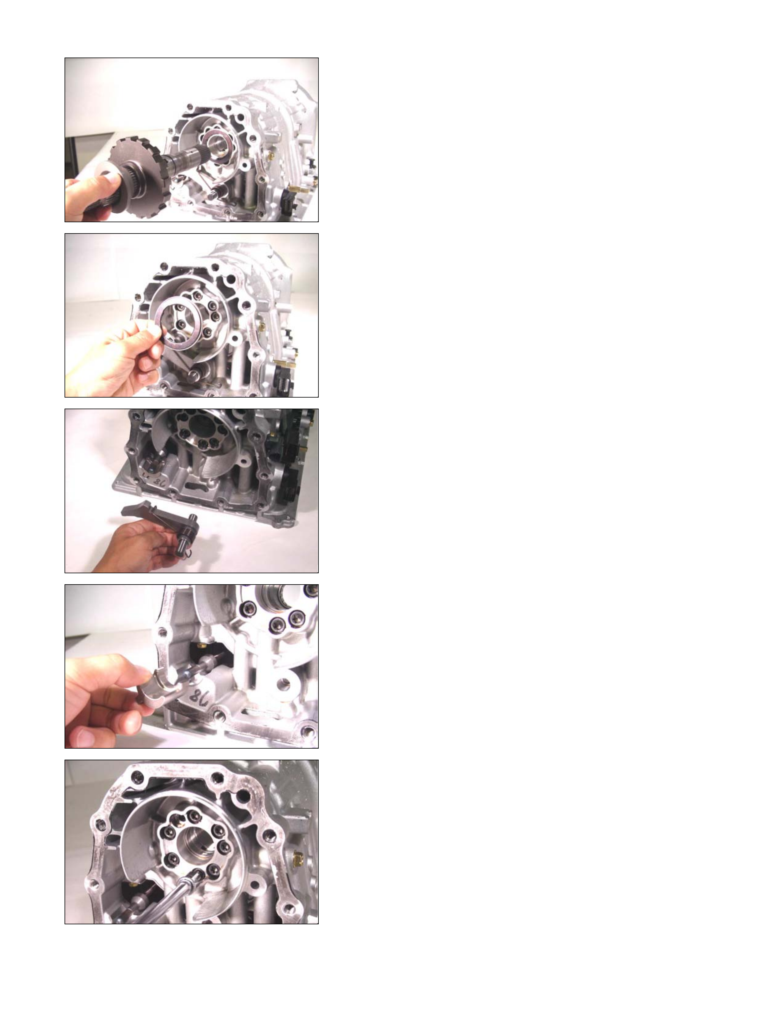
05CASE-AY30
2. Parking rod
• Use a pin punch to force out the parking rod spring pin.
06CASE-AY37
• Rotate the manual plate as you pull the parking rod free.
08CASE-AY45
3. Detent spring
Remove the fixing bolt and the detent spring.
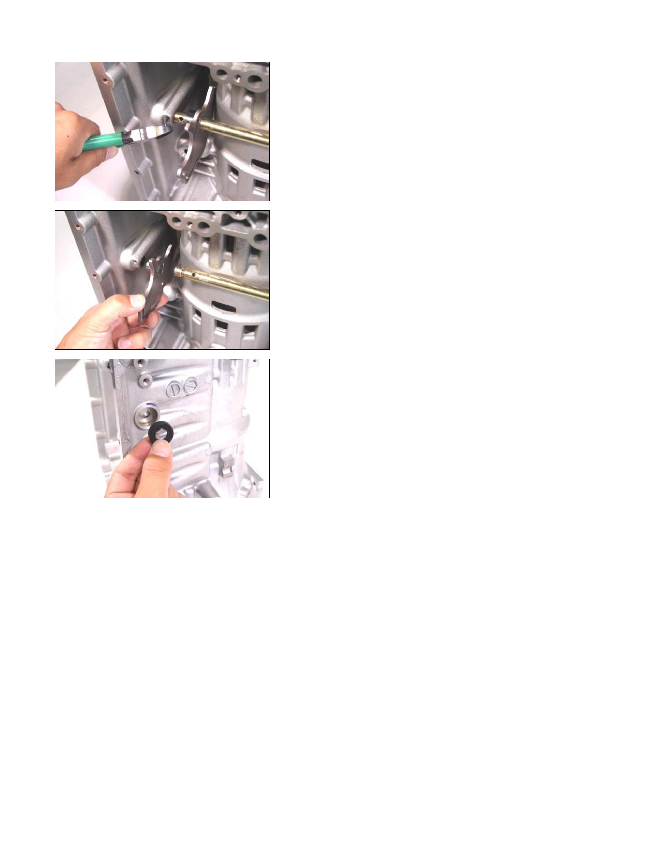
09CASE-AY28
4. Manual shaft and manual plate
• Remove the manual shaft spring pin.
10CASE-AY21
• Remove the manual shaft together with the manual
plate.
11CASE-AY01
5. Oil seal
Using a screwdriver, remove the oil seal from the
transmission case.

Inspection
2 – 4 brake drive plate
Measure the 2-4 brake drive plate facing thickness at 3
points and calculate the average value.
If the average value is less than the specified limit, the 2-4
brake drive plate must be replaced.
2 – 4 brake drive plate facing thickness:
Standard = 2.0 mm (0.079 in)
Limit = 1.8 mm (0.071 in)
Low and reverse brake drive plate
Measure the low and reverse brake drive plate facing
thickness at 3 points and calculate the average value.
If the average value is less than the specified limit, the lo
w
and reverse drive plate must be replaced.
Low and reverse brake drive plate facing thickness:
Standard = 2.0 mm (0.079 in)
Limit = 1.8 mm (0.071 in)
2 – 4 brake return spring
• Check the number of effective 2-4 brake return spring
coils.
Effective return spring coils (Standard): 10.2
• Measure the 2-4 brake return spring outside diameter,
free length, and linear diameter.
If any of the measur ed values exceed the spec ified lim it,
the 2-4 brake return spring must be replaced.
2 – 4 brake return spring measurements (Standard):
Outside diameter = 6.9 mm (0.272 in)
Free length = 22.5 mm (0.886 in)
Linear diameter = 1.1 mm (0.043 in)
Low and reverse brake return spring
• Check the number of effective low and reverse brake
return spring coils.
Effective return spring coils (standard): 4.8
• Measur e the low and reverse br ake return spr ing outside
diameter, free length, and linear diameter.
If any of the measur ed values exceed the spec ified lim it,
the low and reverse return spring must be replaced.
Low and reverse brake return spring measurements
(Standard):
Outside diameter = 11.2 mm (0.441 in)
Free length = 22.3 mm (0.878 in)
Linear diameter = 1.1 mm (0.043 in)
12CASE-AY06
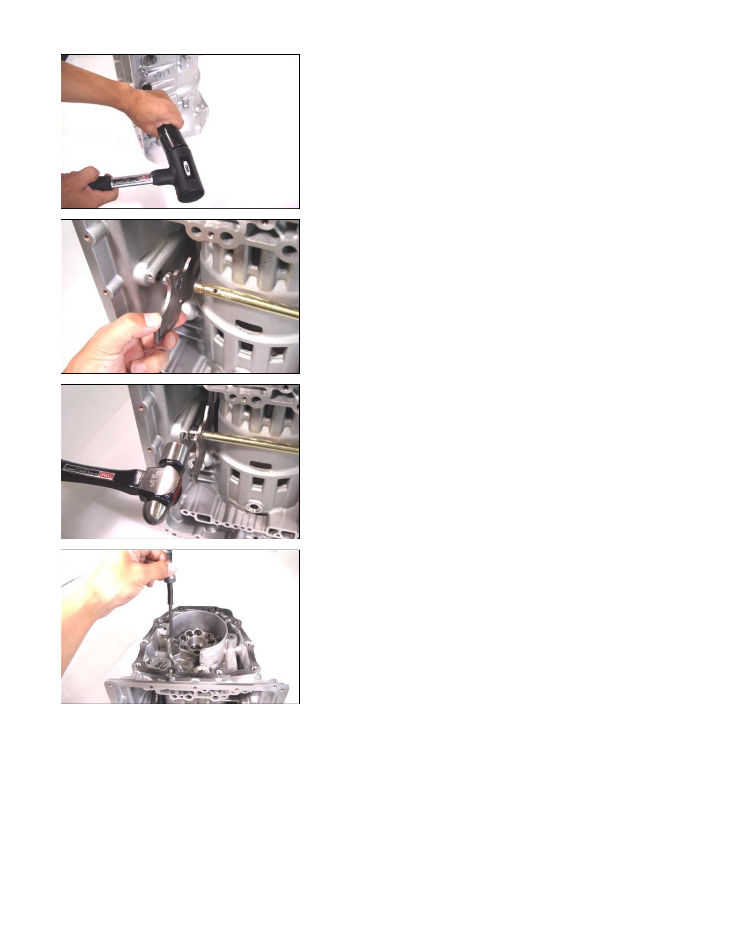
Reassembly Steps
1. Oil seal, manual shaft, and manual plate
• Use the oil seal installer to force the manual plate oil
seal into place.
Oil seal installer: 5-8840-2758-0
14CASE-AY21
• Install the manual shaft together with the manual plate.
15CASE-AY26
• Drive the spring pin into the transmission case.
16CASE-AY37
2. Parking rod
• Rotate the manual plate while installing the parking rod.

18CASE-AY43
• Use a pin punch to drive the m anual plate spr ing pin into
place.
21CASE-AY48
3. Detent spring
• Install the detent spring and tighten the fixing bolt to the
specified torque.
Torque: 7 N⋅
⋅⋅⋅m (61 Ib⋅
⋅⋅⋅in)
23CASE-AY53
4. Harness assembly
• Apply automatic trans mission f luid to the new O -r ing and
install them to the harness assembly.
• Install the harness assembly to the transmission case.
Tighten the fixing bolt to the specified torque.
Torque: 6 N⋅
⋅⋅⋅m (52 Ib⋅
⋅⋅⋅in)
24ASSY003
5. Low one-way clutch inner race
• Install new seal rings to the low one-way clutch inne
r
race.
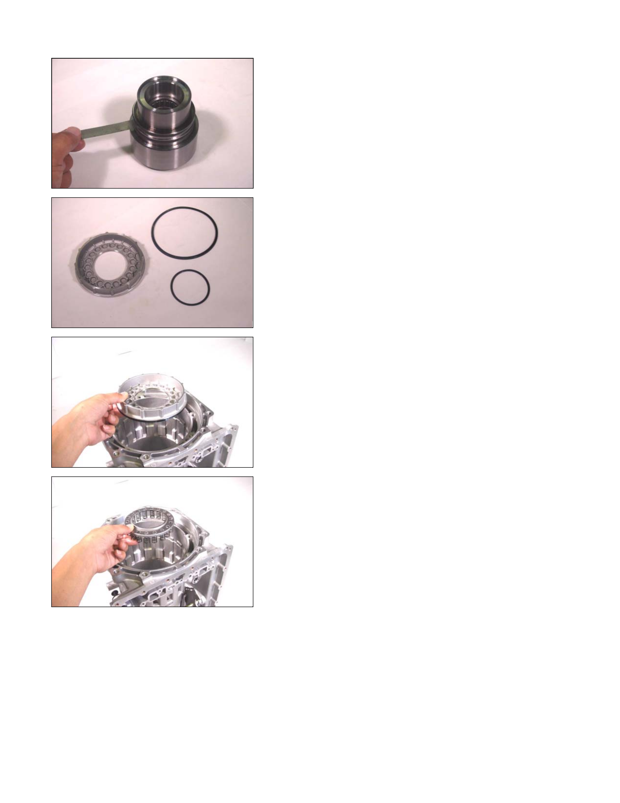
25ASSY126
• Measure the gap between the seal ring and the ring
groove.
If the measured valve is outside the specified range the
low one-way clutch inner race must be replaced.
Sealing ring and ring groove gap:
0.10~0.25 mm (0.0004~0.001 in)
26L&R01
6. Low and reverse brake piston
• Install new seal rings to the low and reverse piston.
27ASSY004
• Install the low and reverse brake piston to the
transmission case.
28ASSY005
7. Return spring
• Install the return spring to the low and reverse brake
piston.
29ASSY006
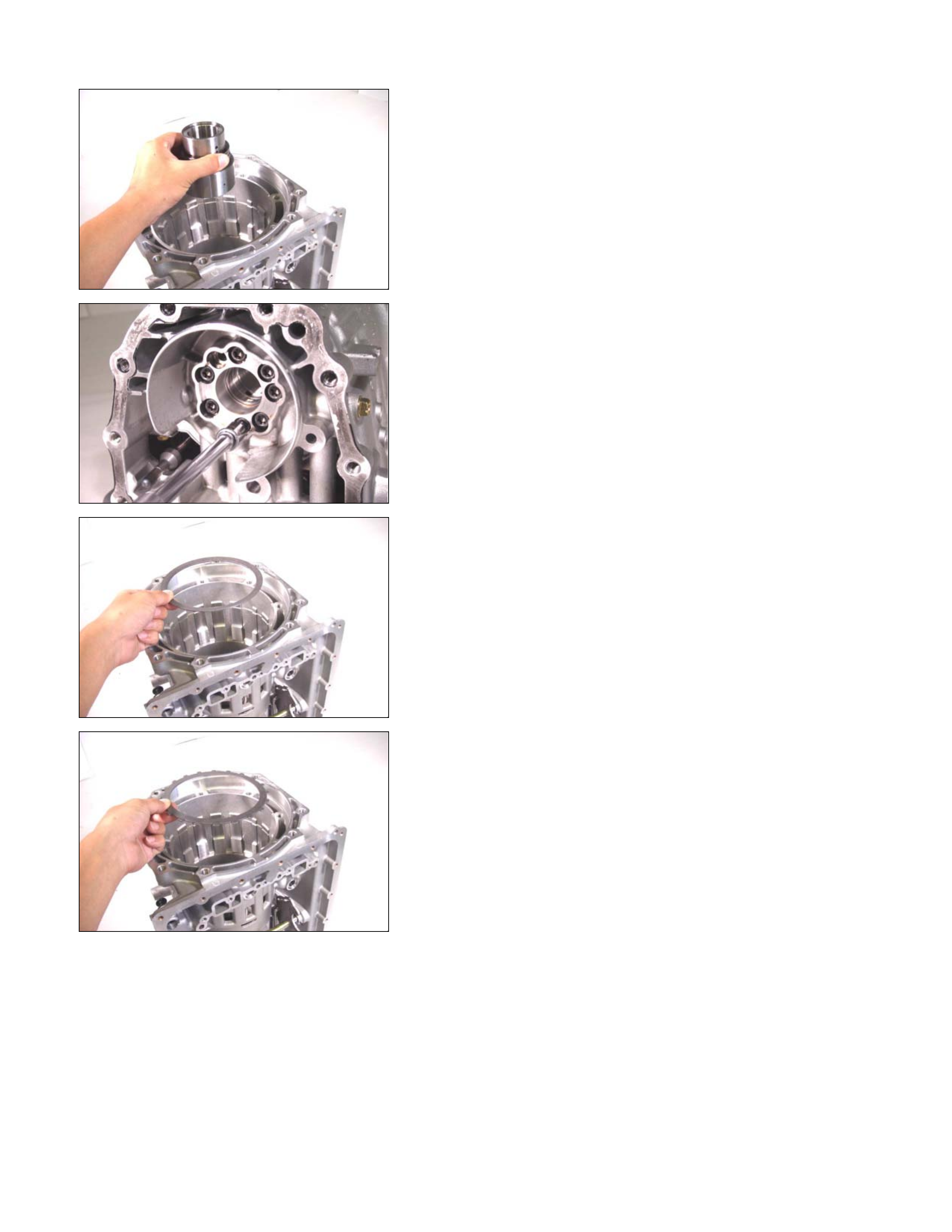
8. Low one-way clutch inner race
• Install the low one-way clutch inner race to the
transmission case.
• Temporarily tighten the 7 fixing bolts.
31ASSY074
• T ighten each of the bolts a little at a tim e to the s pec if ied
torque.
Be sure that the return spring and the low one-wa
y
clutch inner race installation position do not change as
you tighten the bolts.
Torque: 24 N⋅
⋅⋅⋅m (17 Ib⋅
⋅⋅⋅ft)
32ASSY007
9. Dish plate, driven plate, drive plate, and retaining plate
(low and reverse brake)
• Install the dish plate (1) followed by the 6 driven plates
(2) and drive plates (3) sets.
33ASSY008
34ASSY009
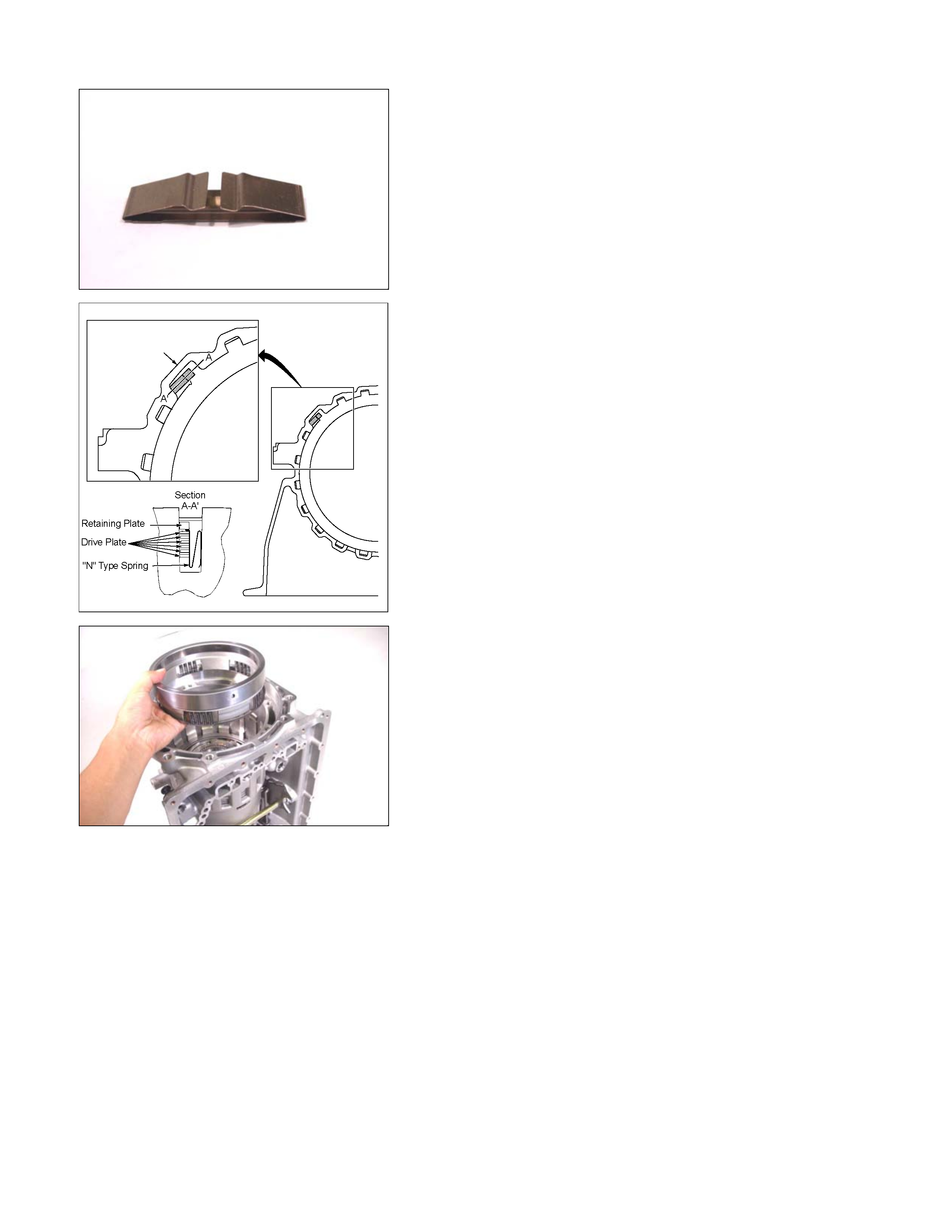
35N-SPG02
• Install the N-type spring.
249L300004
36ASSY10
• Install the retaining plate (4).
37ASSY011
• Install the snap ring.
38L&R03
• Force compressed air (392 kPa/4.0 kg/cm 2) through the
oil passages of the transmission case to check low and
reverse brake operation.
If the low and reverse br ake does not oper ate, c heck the
seal rings for damage and replace if necessary. Also
check that no parts have been installed out of place.
39L&R04
249L300003
• Measure the clearance between the low and reverse
retaining plate and the snap ring.
If the clearance is out side the specified range, replace
the existing retaining plate with a new plate of the prope
r
size (thickness).
Low and reverse retaining and snap ring clearance:
0.7~1.1 mm (0.028~0.043 in)
A
vailable low and reverse brake retaining plate
thicknesses
5.2 mm (0.205 in)
5.4 mm (0.213 in)
5.6 mm (0.220 in)
5.8 mm (0.228 in)
6.0 mm (0.236 in)
10.Dish plate, drive plate, driven plate, and retaining plate
(2-4 brake)
NOTE:
If 2-4 brake clearance measurement is required, it must be
done now.
Brake clearance cannot be measured after the carrier
assembly has been installed.
402-4B08
• Install the 2-4 brake dish plate to the transmission case
(plate contact surface).
412-4B09
• Install the drive plate, driven plate, and the retaining
plate.
422-4B10
432-4B11
442-4B12
11.2 – 4 brake piston and 2 – 4 brake retainer
• Install new seal ring to the 2-4 brake piston.
• Install the 2-4 brake piston to the 2-4 brake retainer.
452-4B15
• Install the 2- 4 brake piston and the 2-4 br ake retainer to
the transmission case.
Pay close attention to the retainer projection from the
case groove.
472-4B17
• Install the spring compressor to the transmission case.
Spring compressor: 5-8840-2764-0
NOTE:
Be sure that the spring compressor is perfectly centered
(an off-center special tool will damage the return spring).
• Use the spring compressor to force the 2-4 brake
retainer.
482-4B18
NOTE:
To avoid damaging the return spring, apply as little force
as possible to the 2-4 brake retainer.
• Install the snap ring.
492-4B22
• Force compressed air (392 kPa/4.0 kg/cm 2) through the
oil passages of the transmission case to operate and
break-in the 2-4 brake.
502-4B19
• Measure the clearance between the 2-4 brake retaine
r
and the retaining plate.
If the clearance is outside the specified range, replace
the existing brake retainer with a new one of the prope
r
size (thickness).
2 – 4 brake retainer and retaining plate clearance:
1.0~1.4 mm (0.039~0.055 in)
Available 2-4 brake retaining plate thicknesses
5.4 mm (0.213 in)
5.6 mm (0.220 in)
5.8 mm (0.228 in)
6.0 mm (0.236 in)
6.2 mm (0.244 in)
6.4 mm (0.252 in)
• Use the spring compressor to release the 2-4 brake.
Bearing And Bearing Race Installation Position
A07L300001
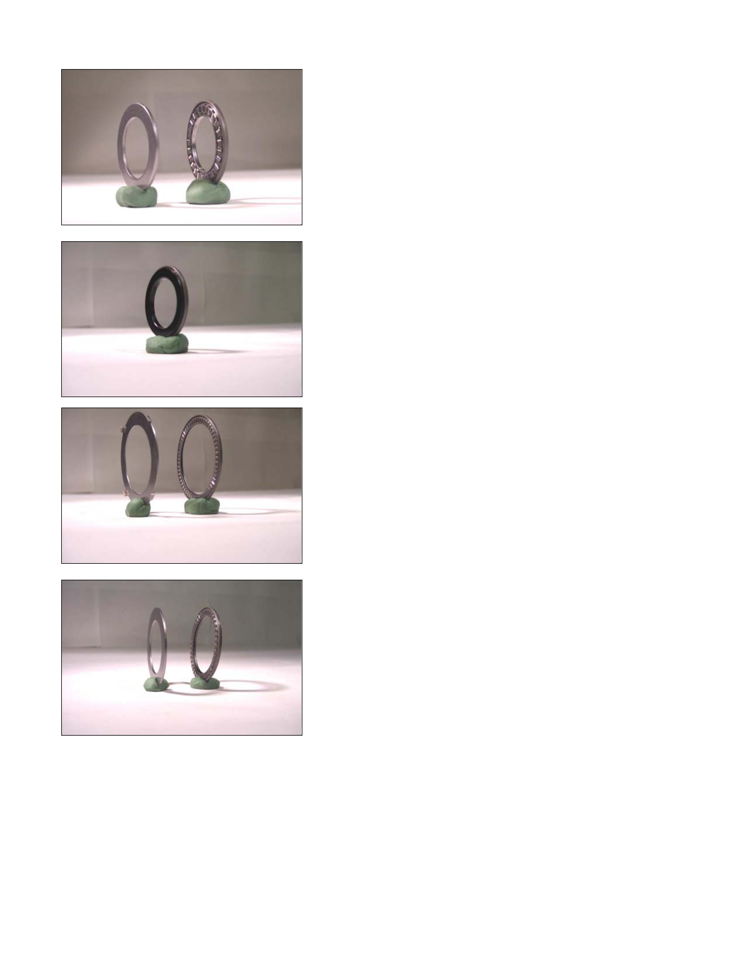
1. Bearing and bearing race
Outside diameter
Bearing – 46 mm (1.811 in)
Bearing race – 45 mm (1.772 in)
01BRG16
2. Bearing (with bearing race)
Outside diameter
Bearing – 46 mm (1.811 in)
02BRG02
Bearing race ( black color) inst allation direction – Fac ing the
front of the transmission.
3. Bearing and bearing race
Outside diameter
Bearing – 65 mm (2.559 in)
Bearing race – 64 mm (2.520 in)
03BRG04
4. Bearing and bearing race
Outside diameter
Bearing – 73 mm (2.874 in)
Bearing race – 72 mm (2.835 in)
04BRG05
5. Bearing (with bearing race)
Outside diameter
Bearing – 53 mm (2.087 in)
05BRG06
Bearing race ( black color) inst allation direction – Fac ing the
front of the transmission.
6. Bearing
Outside diameter
Bearing – 53 mm (2.087 in)
06BRG07
7. Bearing and bearing race
Outside diameter
Bearing – 78 mm (3.071 in)
Bearing race – 76 mm (2.992 in)
07BRG08
8. Bearing and bearing race
Outside diameter
Bearing – 53.4 mm (2.102 in)
Bearing race – 51 mm (2.008 in)
08BRG09
9. Bearing (with bearing race)
Outside diameter
Bearing – 64 mm (2.520 in)
09BRG18
Bearing race ( black color) inst allation direction – Fac ing the
rear of the transmission.
10.Bearing (with bearing race)
Outside diameter
Bearing – 64 mm (2.520 in)
10BRG17
Bearing race ( black color) inst allation direction – Fac ing the
front of the transmission.

Automatic Transmission Reassembly
Assembly Cautions
• Use your bare hands or vinyl gloves to reassemble the
transmission. Do not use ordinary work gloves (loosen
threads from the gloves may fall into the transmission
and cause problems).
• Before installing the drive plates, immerse them in the
recommended automatic transmission fluid (BESCO
ATF II or ATF III). If the drive plate is new, it must be
immers ed f or at least two hours to ens ure oil penetr ation
and saturation of the facing.
•
A
pply ATF to all sliding and contact surfaces before
assembly. Also apply ATF to seal rings and O-rings.
Assemble the parts carefully to avoid damaging them.
• Replace any snap ring that appears worn, bent out o
f
shape, or otherwise damaged.
• If any part contacting the tr ansmission c ase is damaged,
it must be replaced with a new part.
• Be careful not to damage the plates during reassembl
y
(oil leakage from the plate will result).
• If you are reusing a seal, rem ove the old adhesive agent
and clean the surface with cleaning oil before applying
the new adhesive agent.
• Wait at least two hours after installing the oil seals
before installing the plates.
• Do not replace O-rings, snap rings, bearings, and/o
r
bearing races with inferior substitutes.
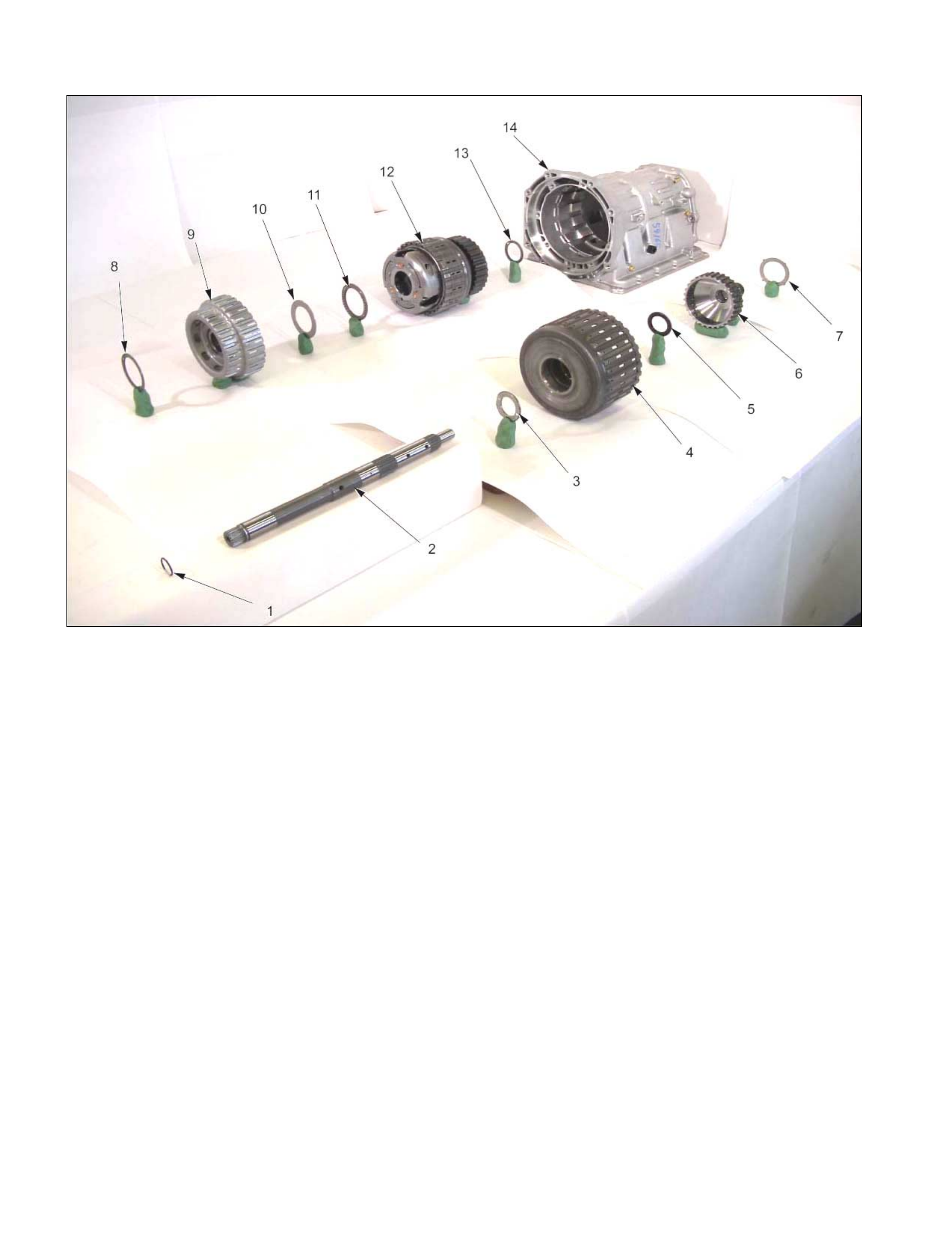
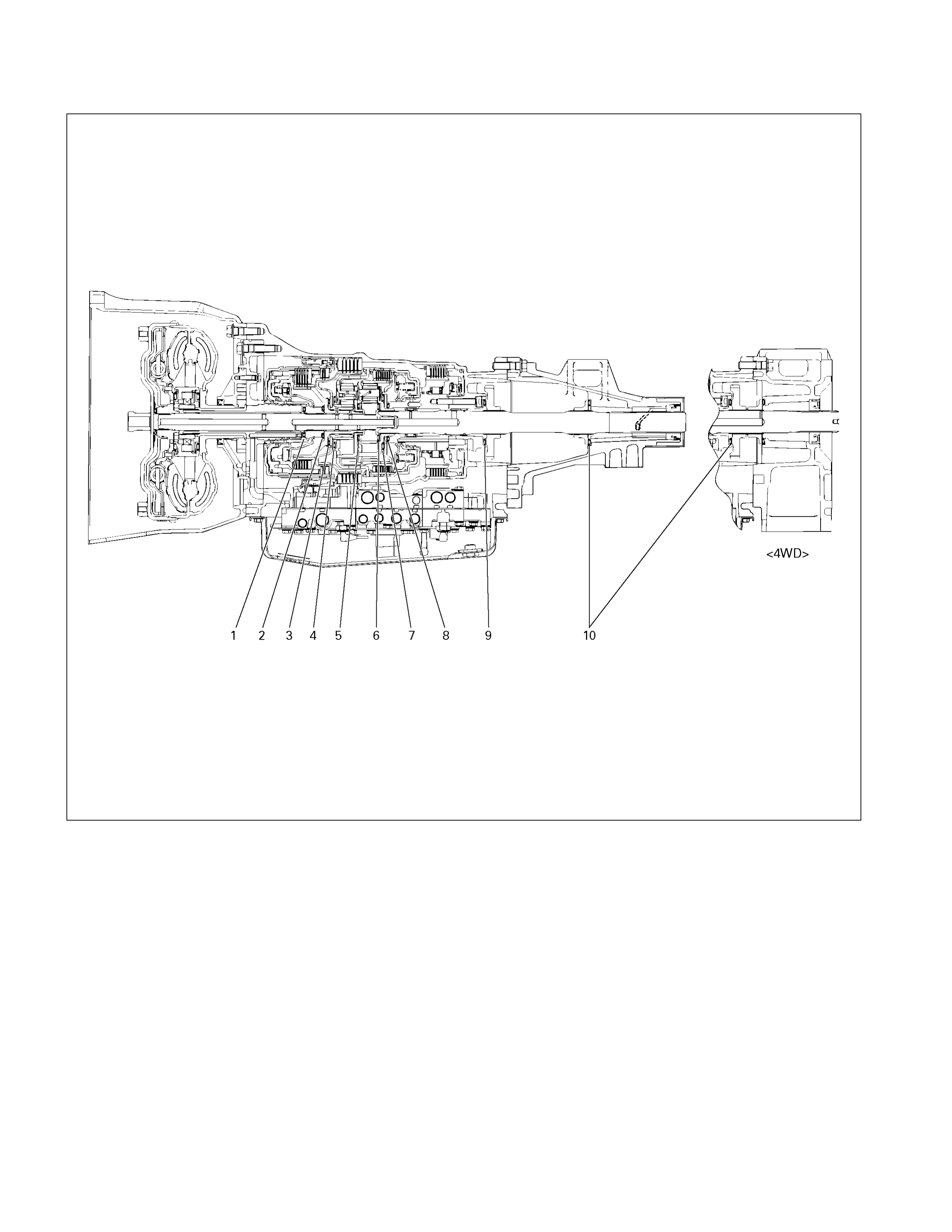
Pow e r Train
01HUB-H04
Legend
1. O-ring
2. Input shaft
3. Bearing
4. Reverse and high clutch assembly
5. Bearing
6. High clutch hub
7. Bearing race
8. Bearing
9. Front sun gear
10. Bearing race
11. Bearing
12. Carrier and low clutch assembly
13. Bearing
14. Transmission case
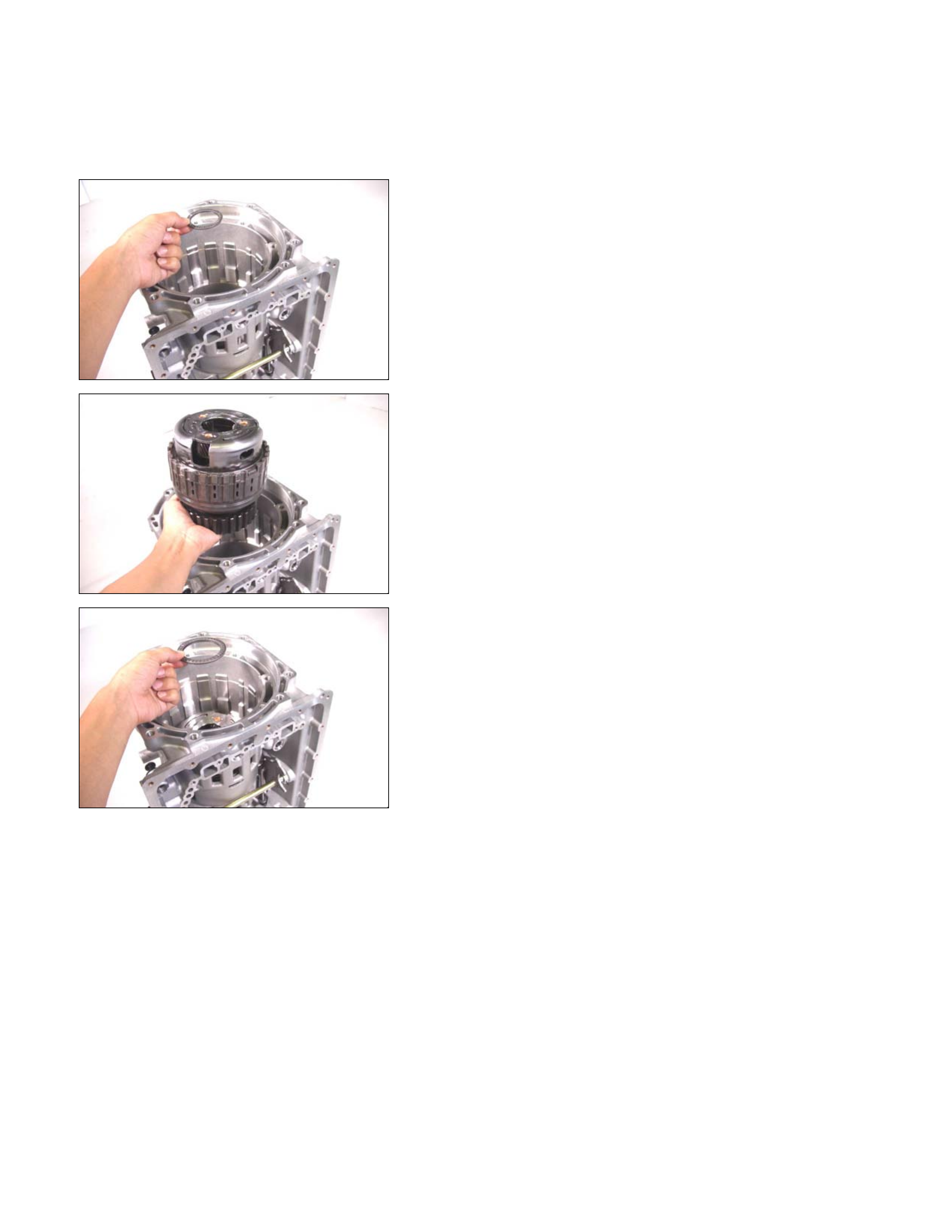
Reassembly Steps
1. Transmission case
Rotate the transmission case so that the converter housing
installation surfaces are facing up.
02ASSY012
2. Bearing
Install the bearing to the low and one-way clutch inner race.
Refer to the item “Transmission Case” for more detailed
information.
NOTE:
Apply Vaseline to the bearing to prevent them from failing
during the installation procedure.
03ASSY013
3. Carrier and low clutch assembly
Install the carrier and low clutch assembly to the
transmission case.
NOTE:
Do not allow the low clutch drum end to protrude beyond
the 2-4 brake plate contact surface (transmission case).
04ASSY014
4. Bearing
Install the bearing to the carrier and low clutch assembly.
05ASSY015
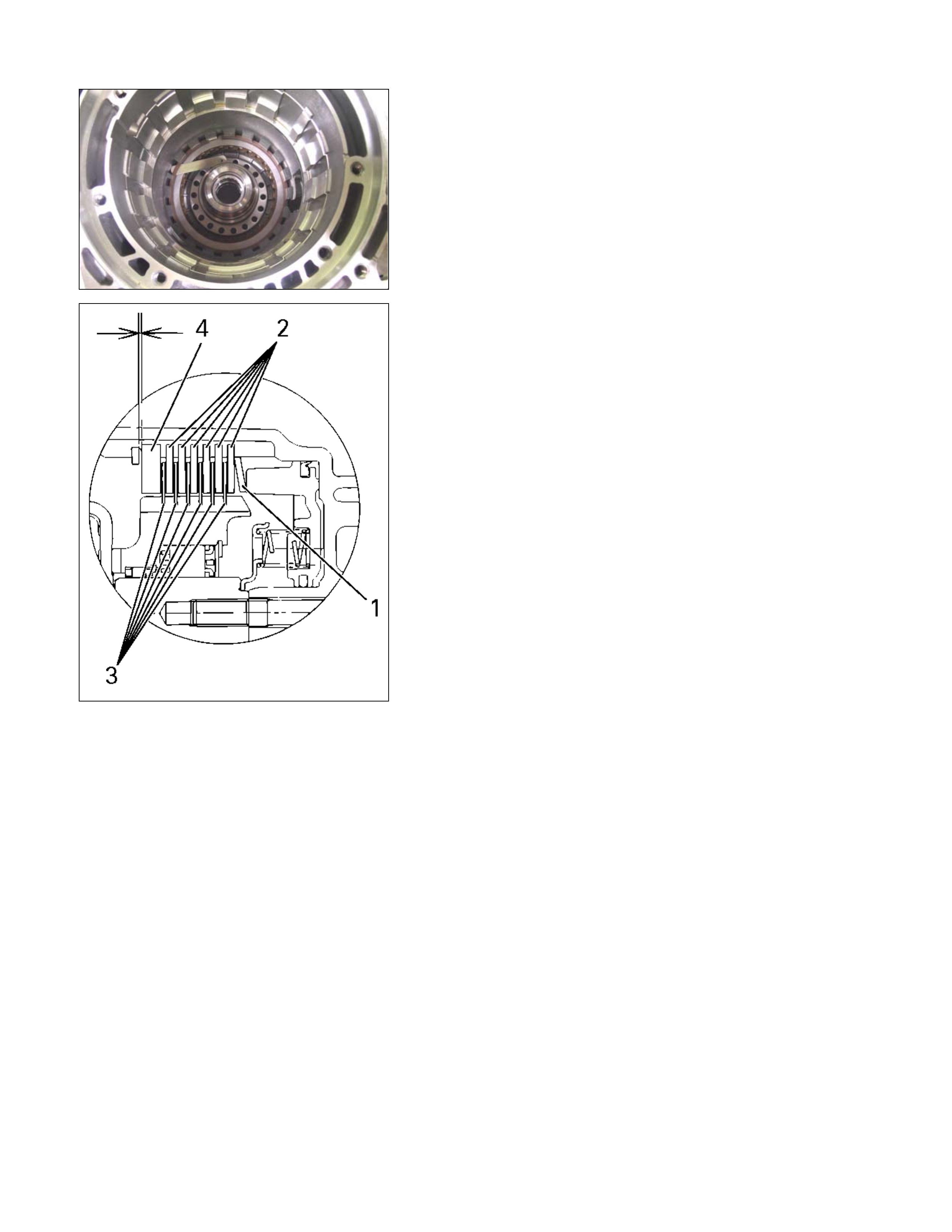
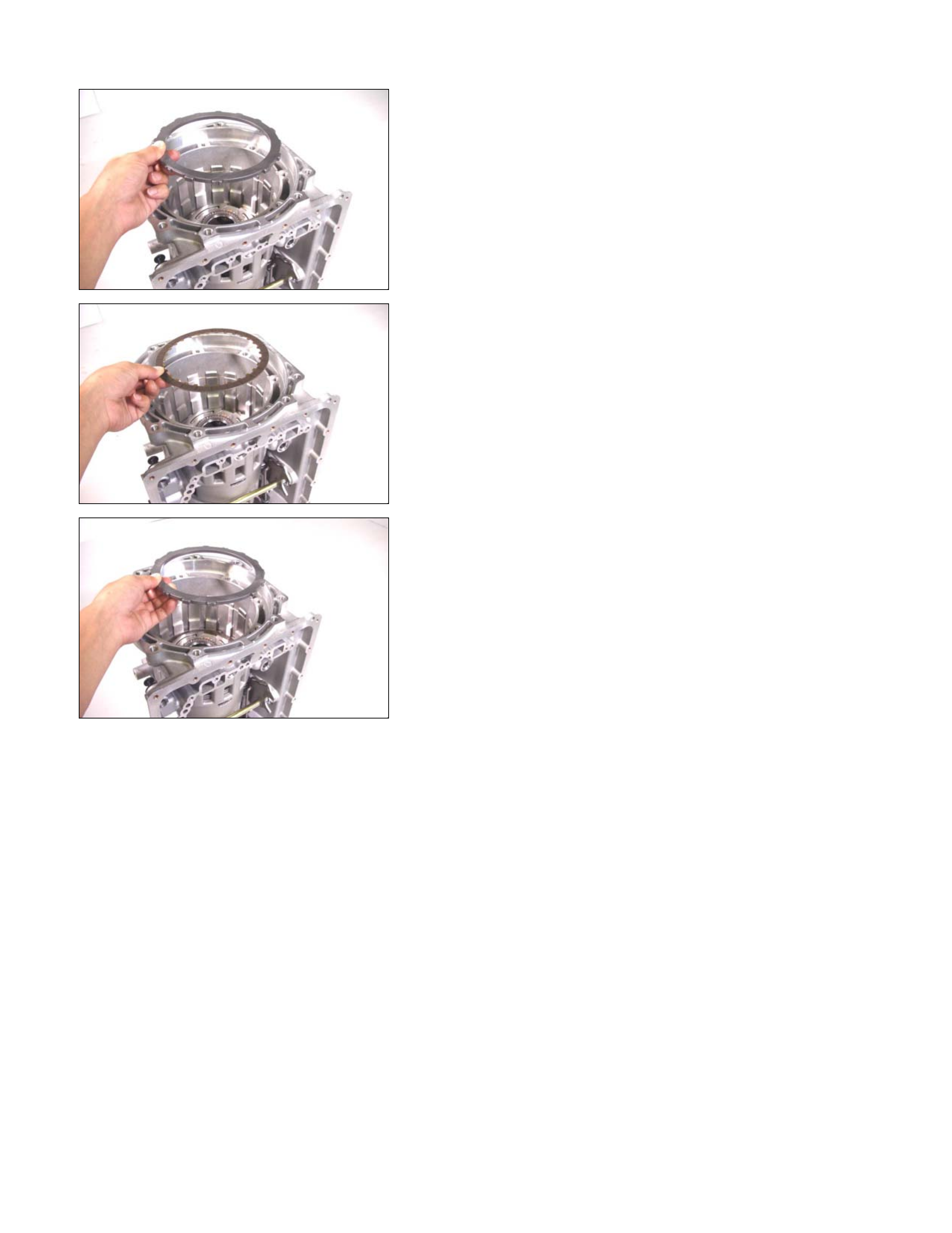
5. Driven plate, drive plate, retaining plate, and dish plate
(2 – 4 brake)
Install the 2-4 brake 5 driven plate (1), 5 drive plates (2),
retaining plate (3), and dish plate (4) in that order.
NOTE:
•
••
• The thickest driven plate (5.6 mm) must be installed
at the bottom (transmission case plate surface).
•
••
• Dish plate side with the identification mark must
face the retaining plate.
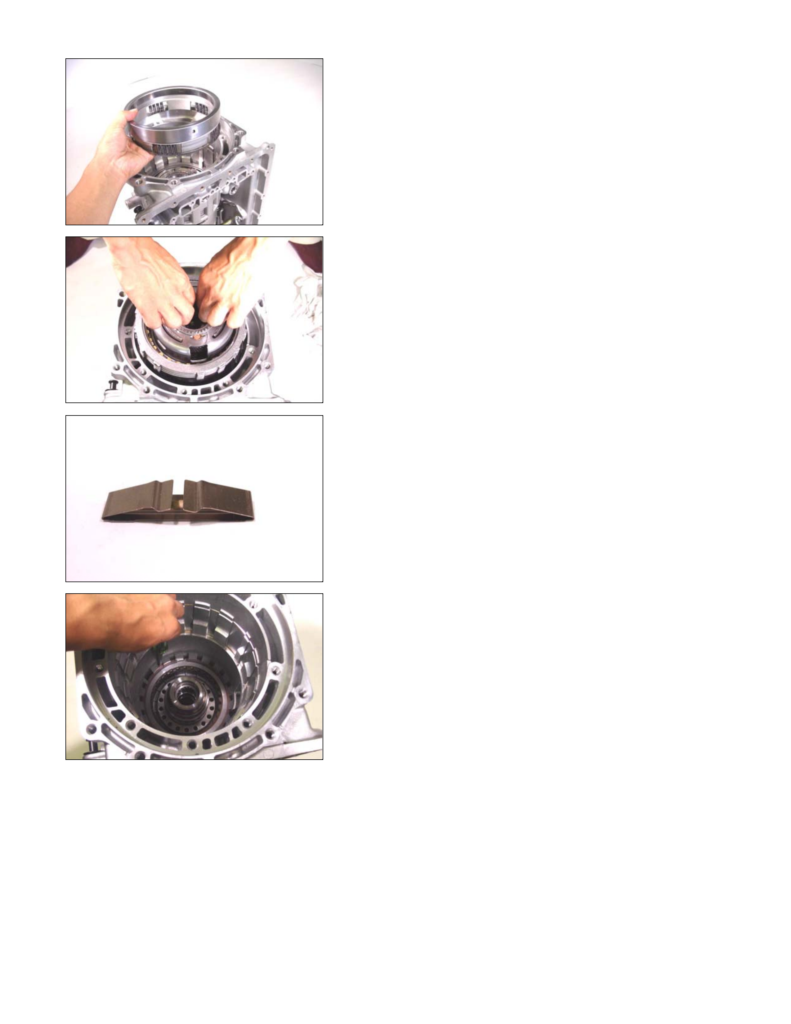
06ASSY016
07ASSY017
08ASSY018
248L300008
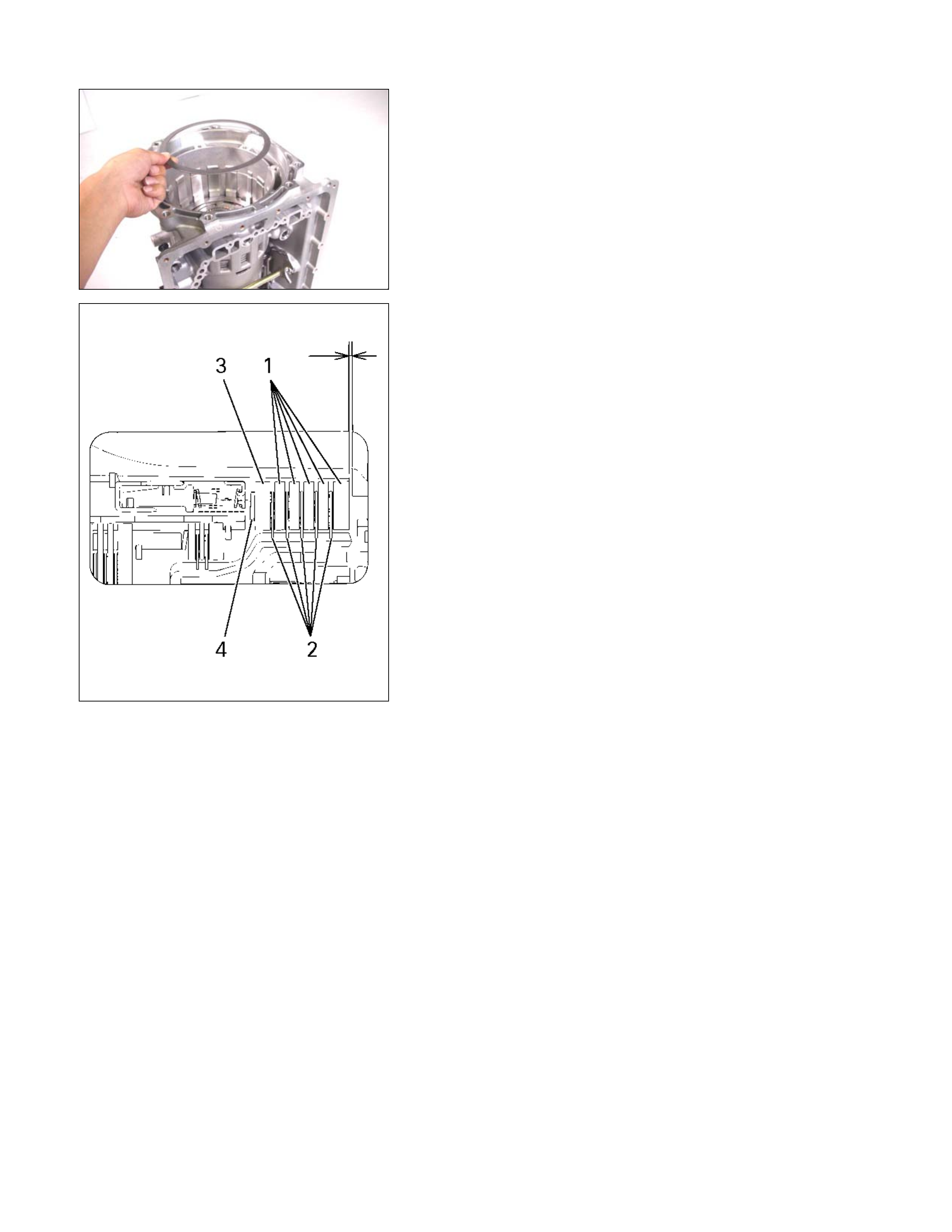
09U-SPG2
6. 2 – 4 brake spring
Install the 2-4 brake springs (3) to the transmission case.
RTW37AMF0001-X
10ASSY019
7. Return spring and 2 – 4 brake retainer
• Align the transmission case groove and the 2-4 brake
retainer projection.
• Install the return spring and the 2-4 brake retainer.
11ASSY028
12ASSY029
• Install the spring compressor to the transmission case.
Spring compressor: 5-8840-2764-0
NOTE:
Carefully center the spring compressor to prevent damage
to the return spring.
• Push the 2-4 brake retainer into place.
NOTE:
Do not push the brake retainer too far.
Damage to the return spring will result.
• Install the snap ring.
14ASSY031
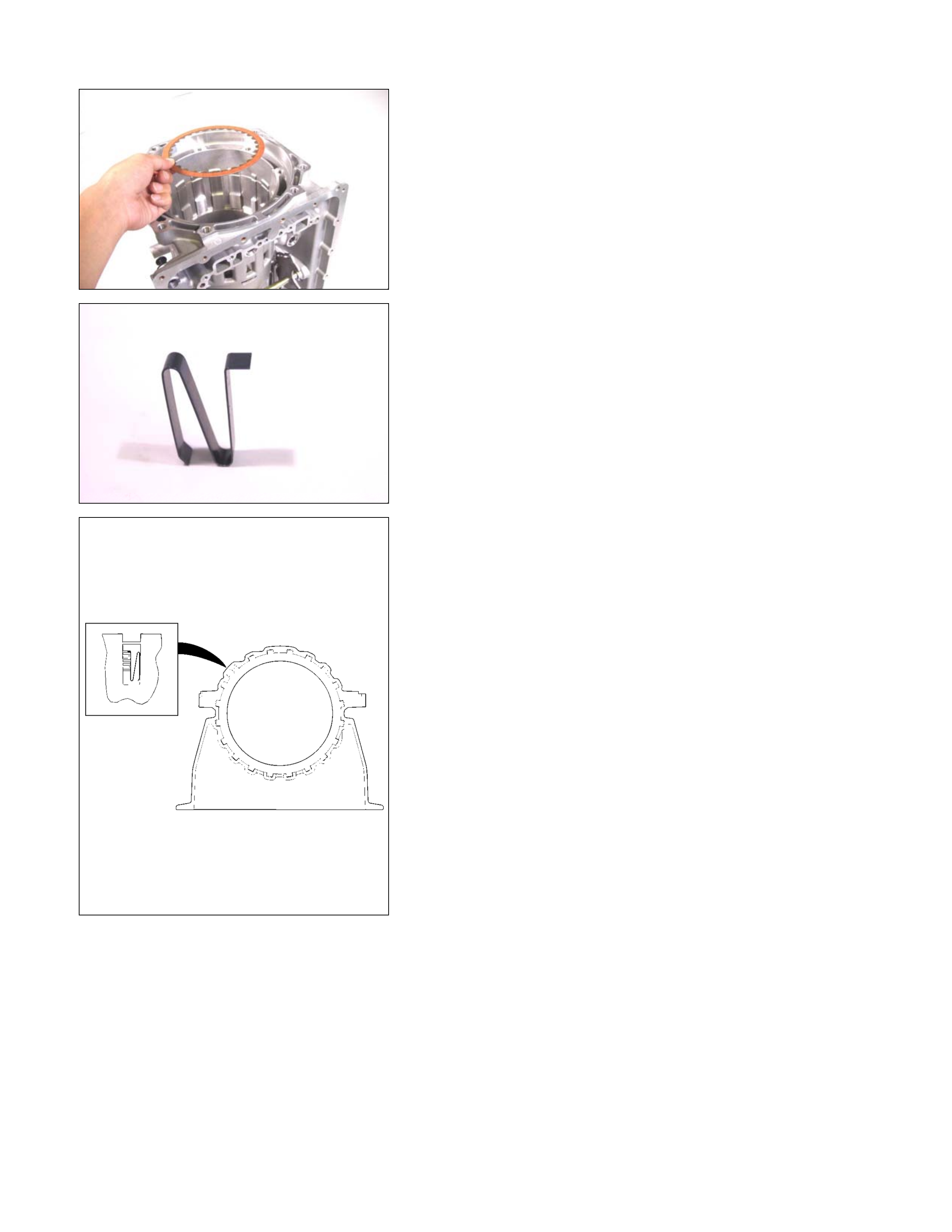
17ASSY113
8. Sleeve and seal ring
• Install the new sleeve and seal ring to the transmission
case.
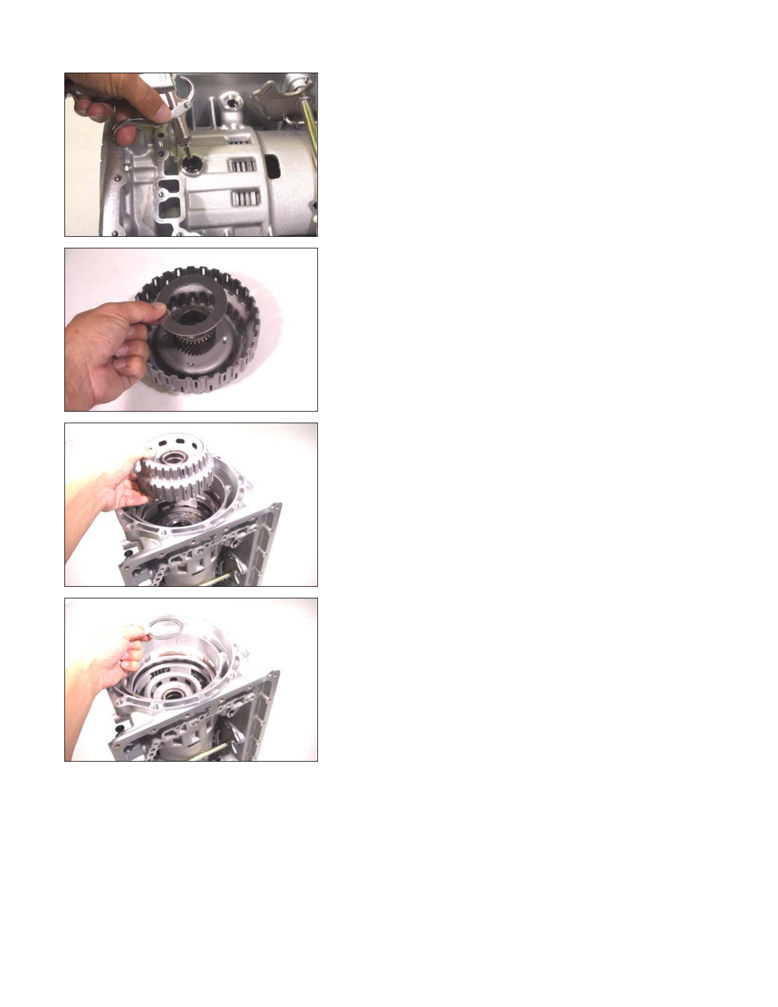
192-4B22
• Force compressed air (392 kPa/4.0 kg/cm 2) through the
transmission case oil passage to 2-4 brake operation.
If the 2-4 brake does not operate, the seal ring may be
damaged or the parts may have been installed in the
wrong order.
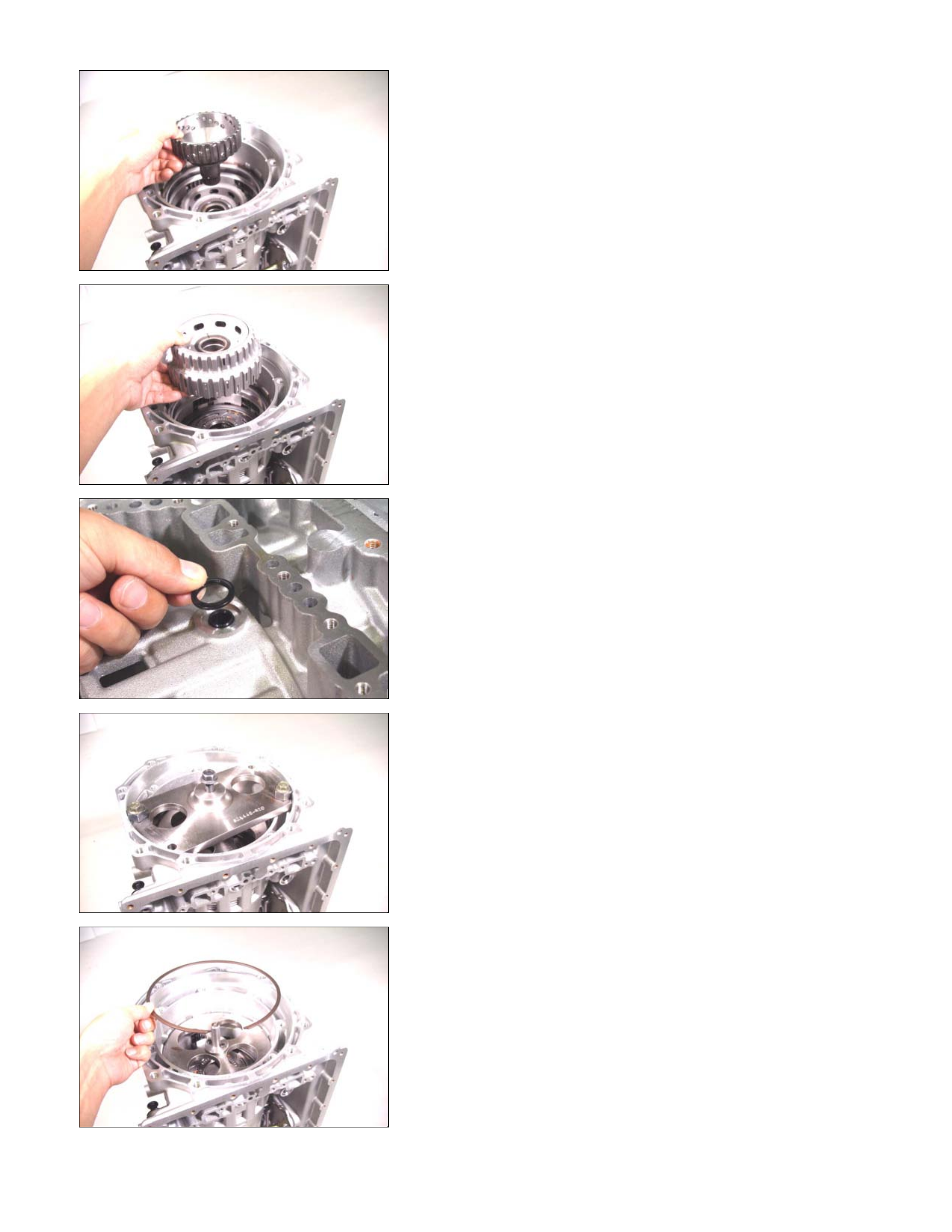
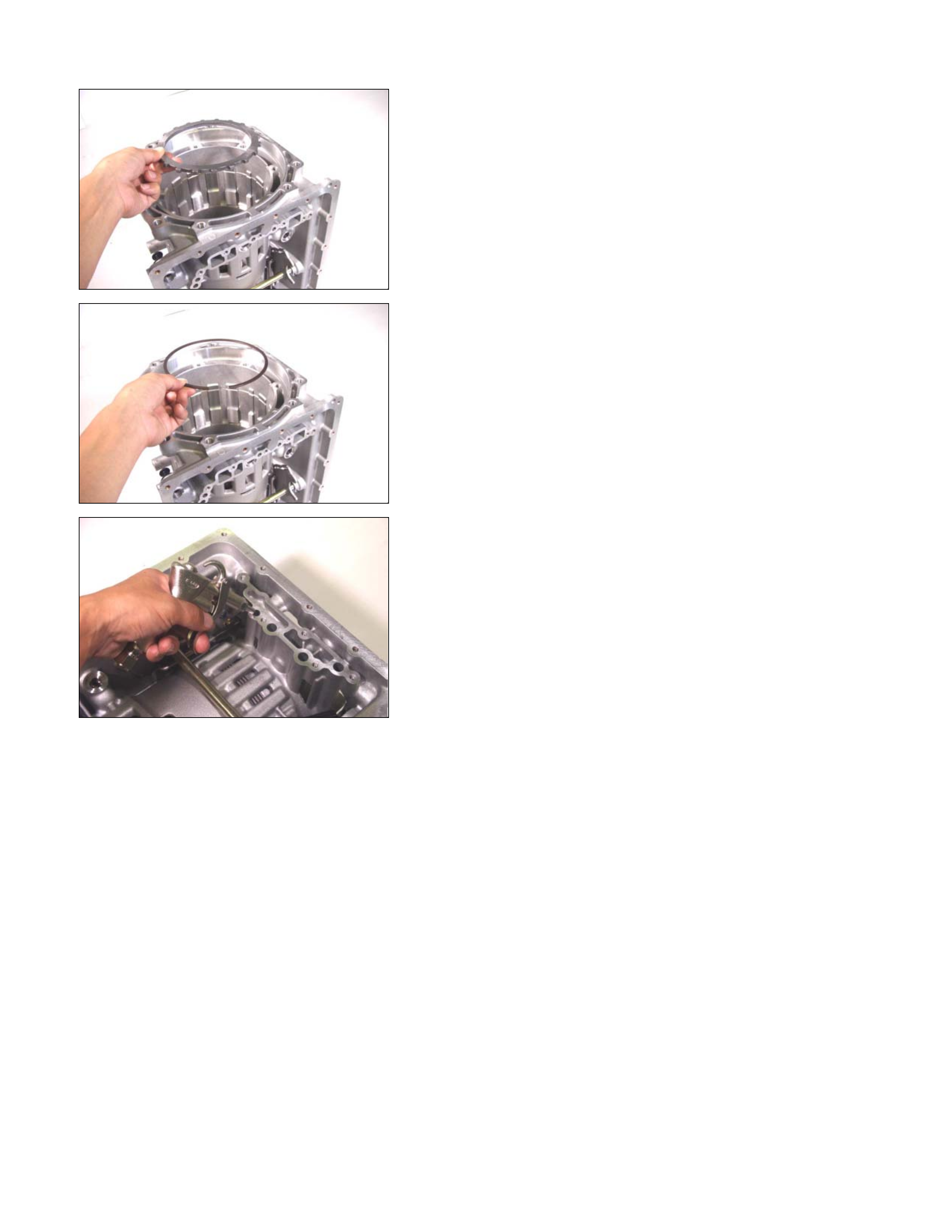
20ASSY037
9. Bearing race, front sun gear, and bearing
• Install the bearing race to the front sun gear.
NOTE:
Apply Vaseline to the bearing race and bearing to prevent
them from falling during the installation procedure.
21ASSY040
• Install the front sun gear to the transmission case.
22ASSY042
• Install the bearing to the front sun gear.
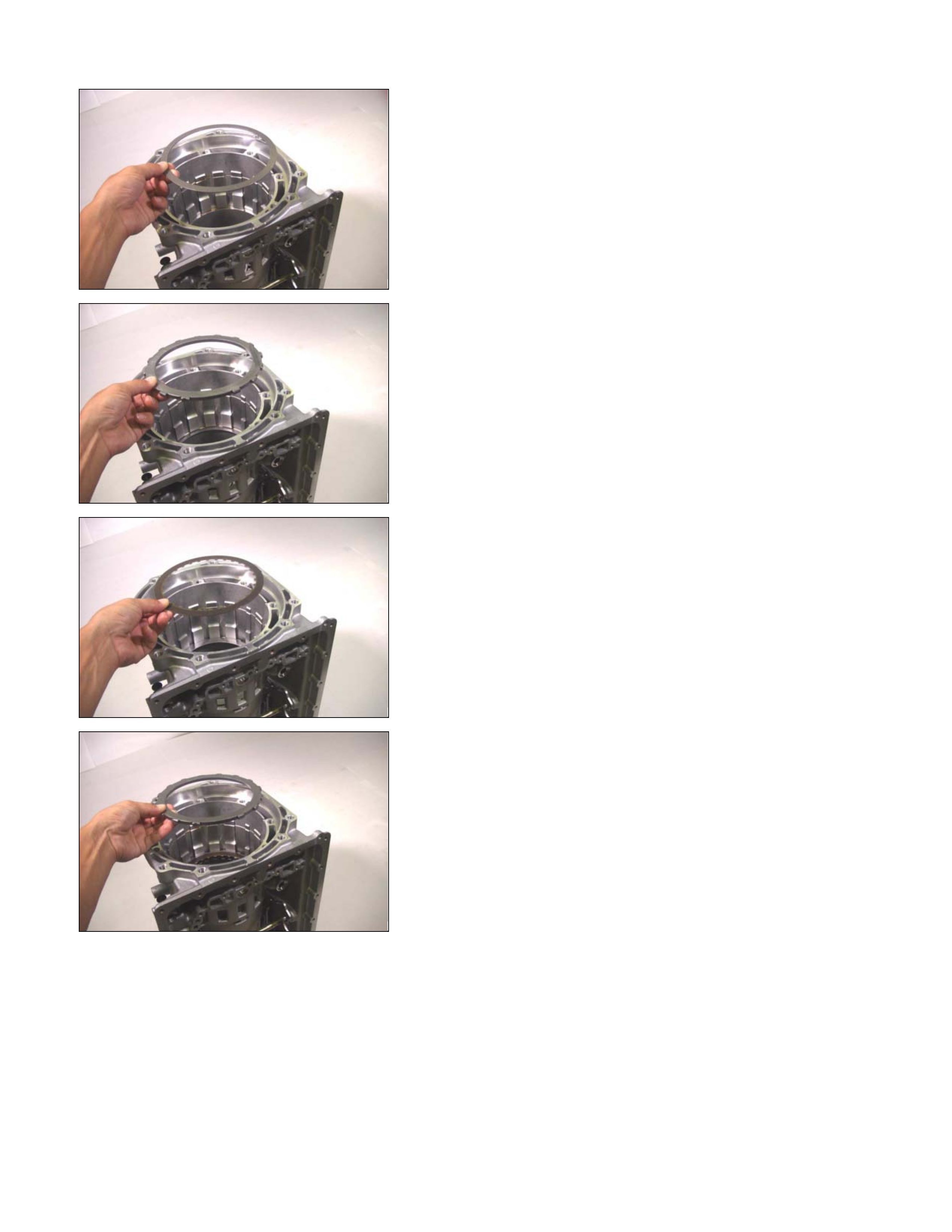
23ASSY045
10.High clutc h hub and bearing race
Install the bearing race to the high clutch hub.
NOTE:
Apply Vaseline to the bearing race.
24ASSY047
• Install the high clutch hub and the bearing race to the
transmission case.
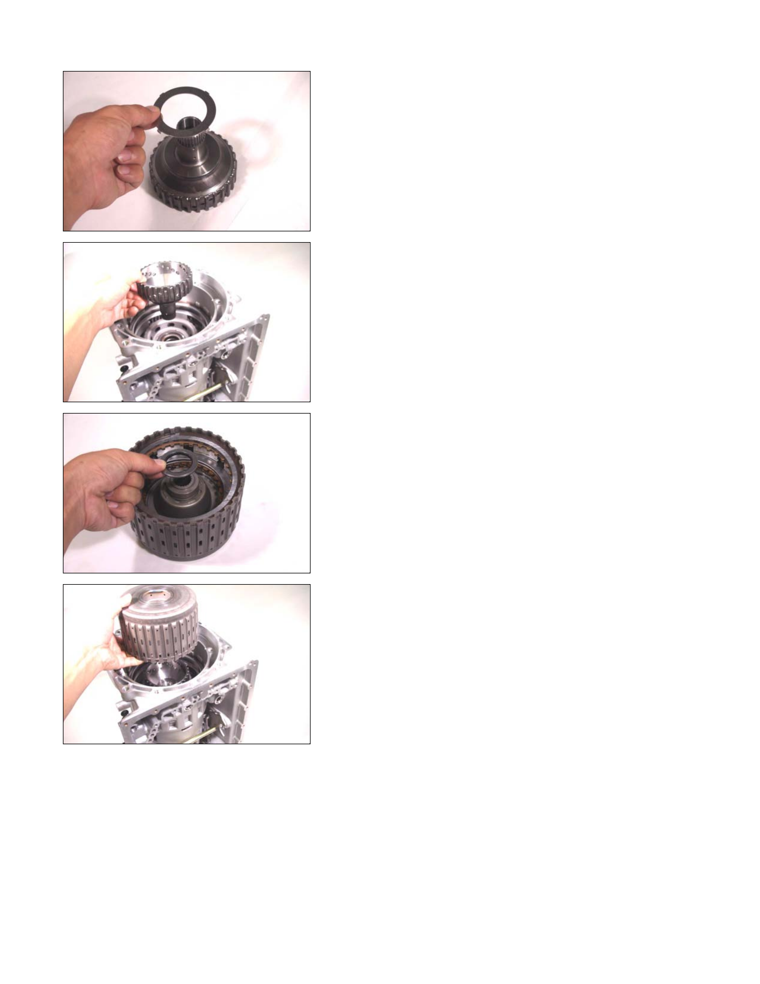
25R&H42
11.Clutch pack (reverse and high clutch assembly)
• Install the bearing (with bearing race) to the clutch pack.
NOTE:
•
••
• The black side (bearing race) of the bearing must
contact the clutch pack.
•
••
• Apply Vaseline to the bearing.
26ASSY049
• Install the clutch pack and bearing to the transmission
case.

27ASSY051
• Install the bearing to the clutch pack.
NOTE:
Apply Vaseline to the bearing.
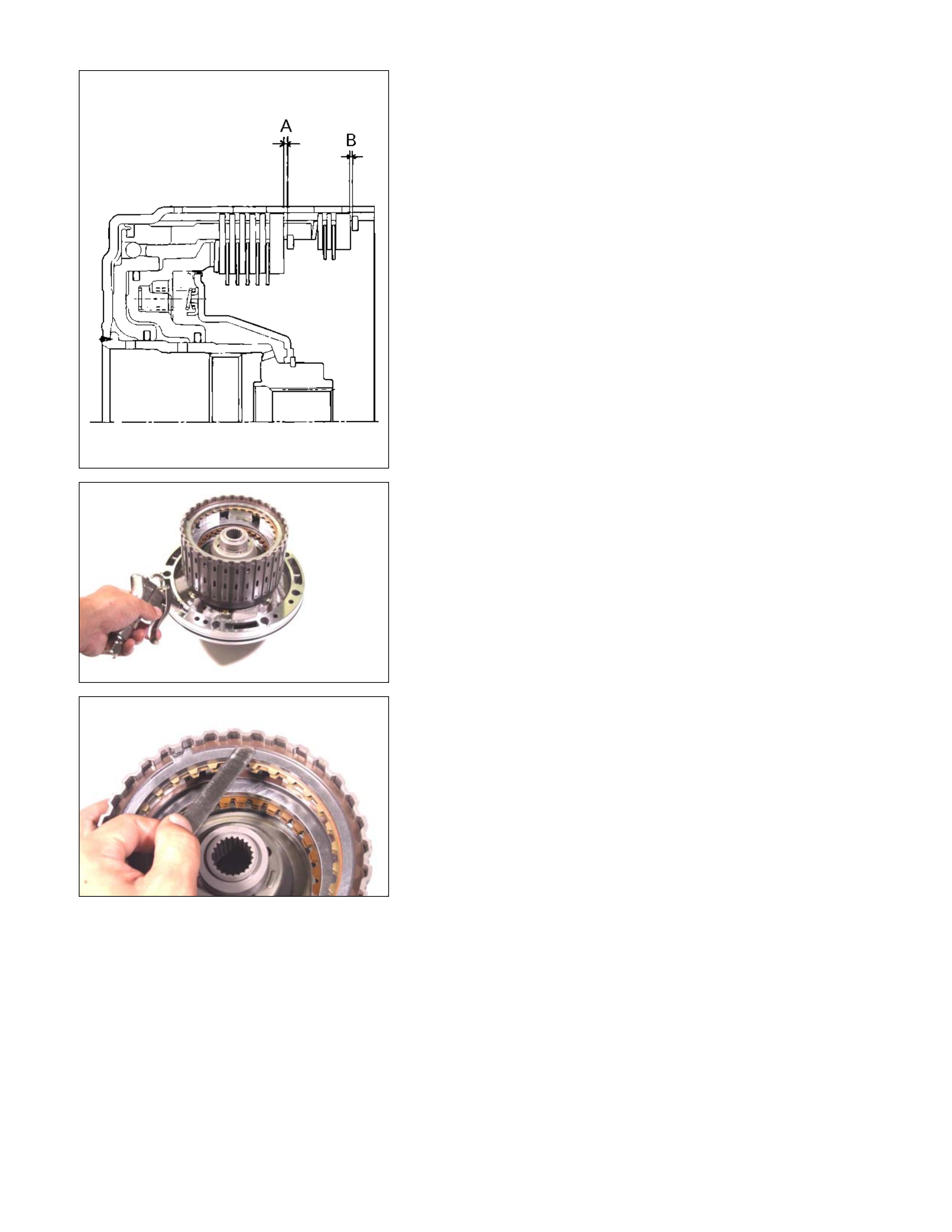
A07L300002
Total end play measurement
• Install the bearing race (oil pump) to the clutch pack.
• Measure the distance (A) between the oil pump
installation surface and the bearing race.
241L300003
• Measure the distance (B) between the bearing race
installation surface and the machined surface.
• Calculate the total end play using the following formula.
Total end play = distance (A) – distance (B)
If the measured and calculated end play is outside the
specified range, replace the existing bearing race with a
bearing race of the proper size (thickness).
Total end play = 0.25~0.55 mm (0.0098~0.0217 in)
Available oil pump bearing race thicknesses
1.4 mm (0.055 in)
1.6 mm (0.063 in)
1.8 mm (0.071 in)
2.0 mm (0.079 in)
2.2 mm (0.087 in)
2.4 mm (0.094 in)
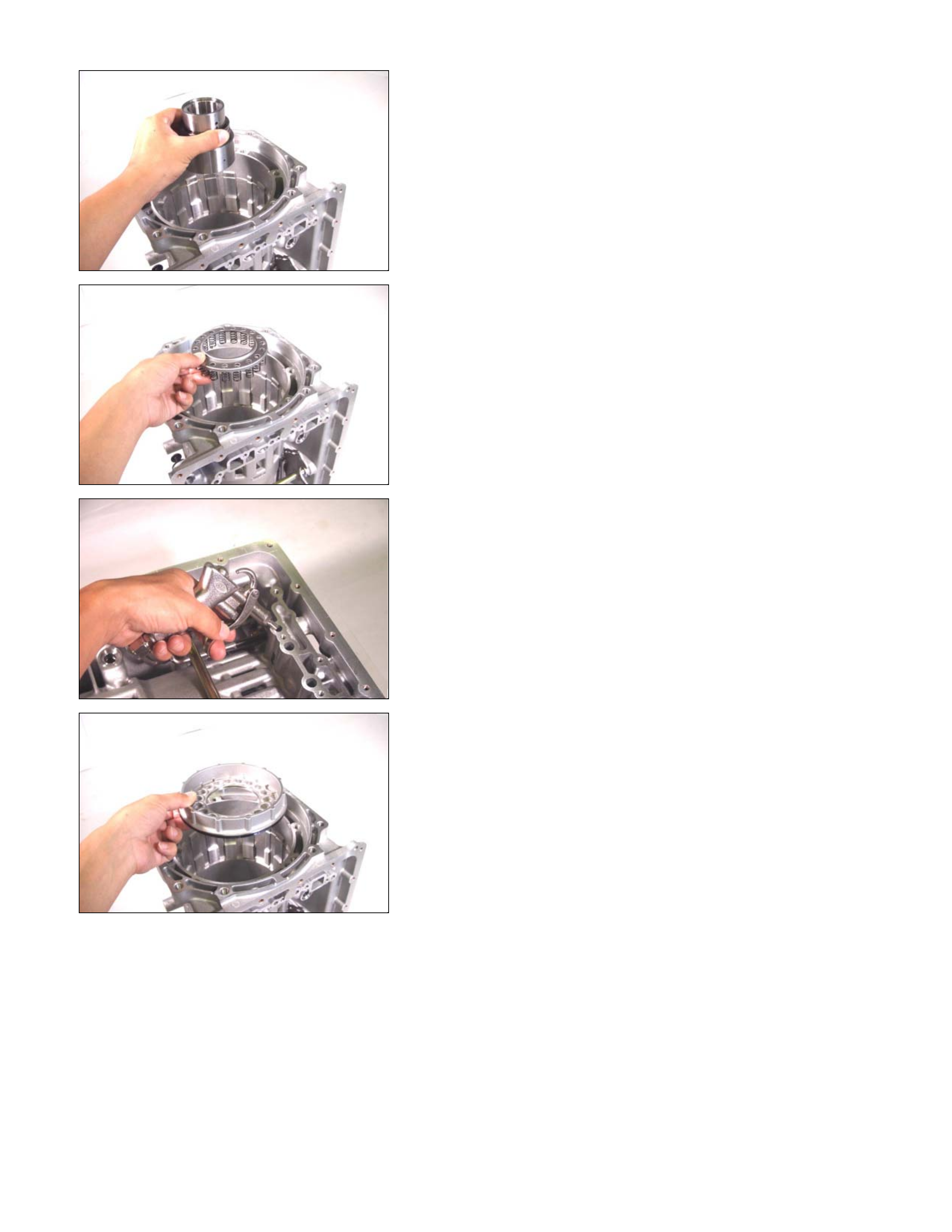
28ASSY058
12.Input shaft
Install the input shaft.
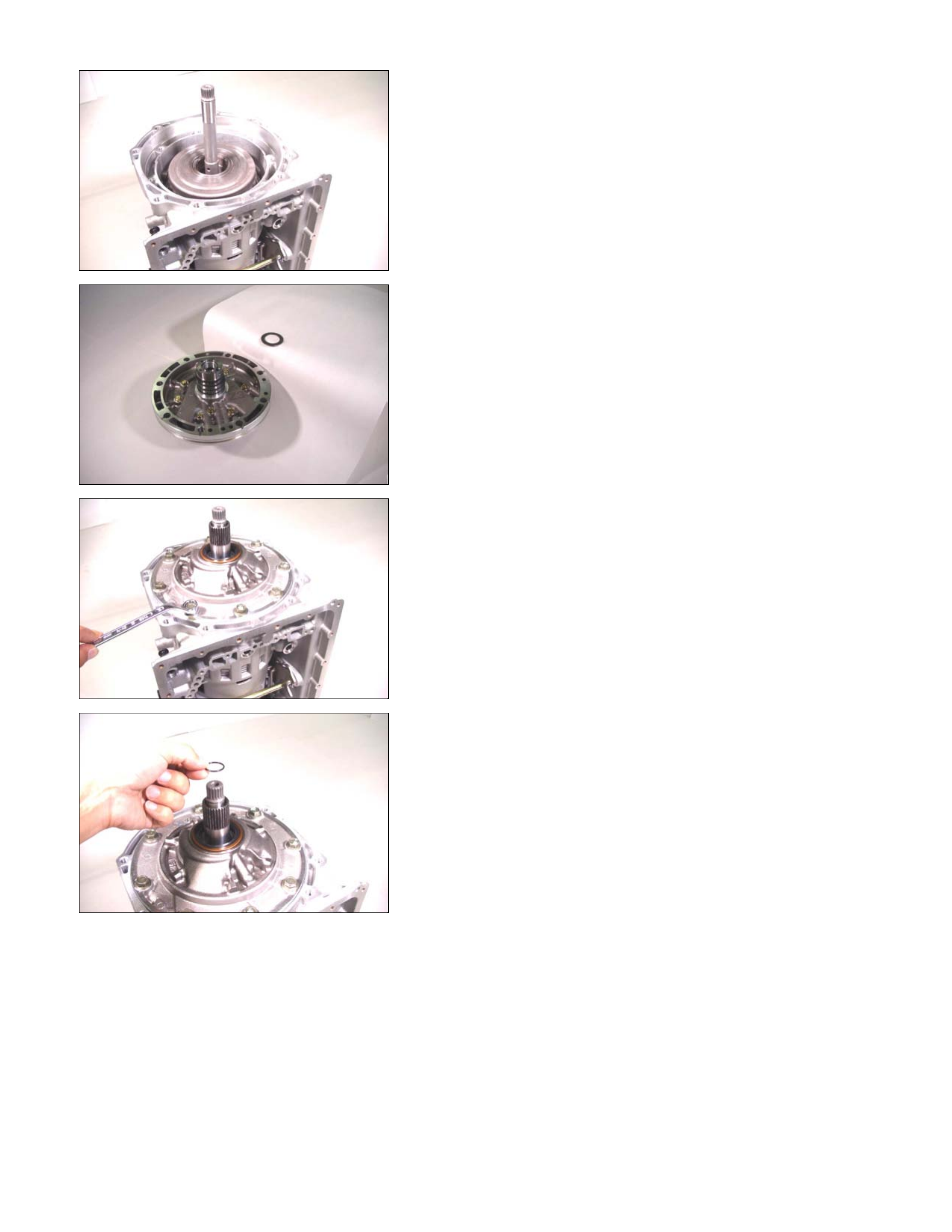
29PUMP02
13.Oil pump assembly
• Install a new O-ring to the outside of the oil pump.
• Install the bearing race to the oil pump.
NOTE:
Apply Vaseline to the bearing race.
30ASSY067
• Apply ATF to the O-ring at the outside of the oil pump.
• Install the oil pump assembly to the transmission case.
•
A
pply sealing agent (TB1215) to the threaded surfaces
of the 8 fixing bolts and tighten to the specified torque.
Torque: 58 N⋅
⋅⋅⋅m (43 Ib⋅
⋅⋅⋅ft)
31ASSY068
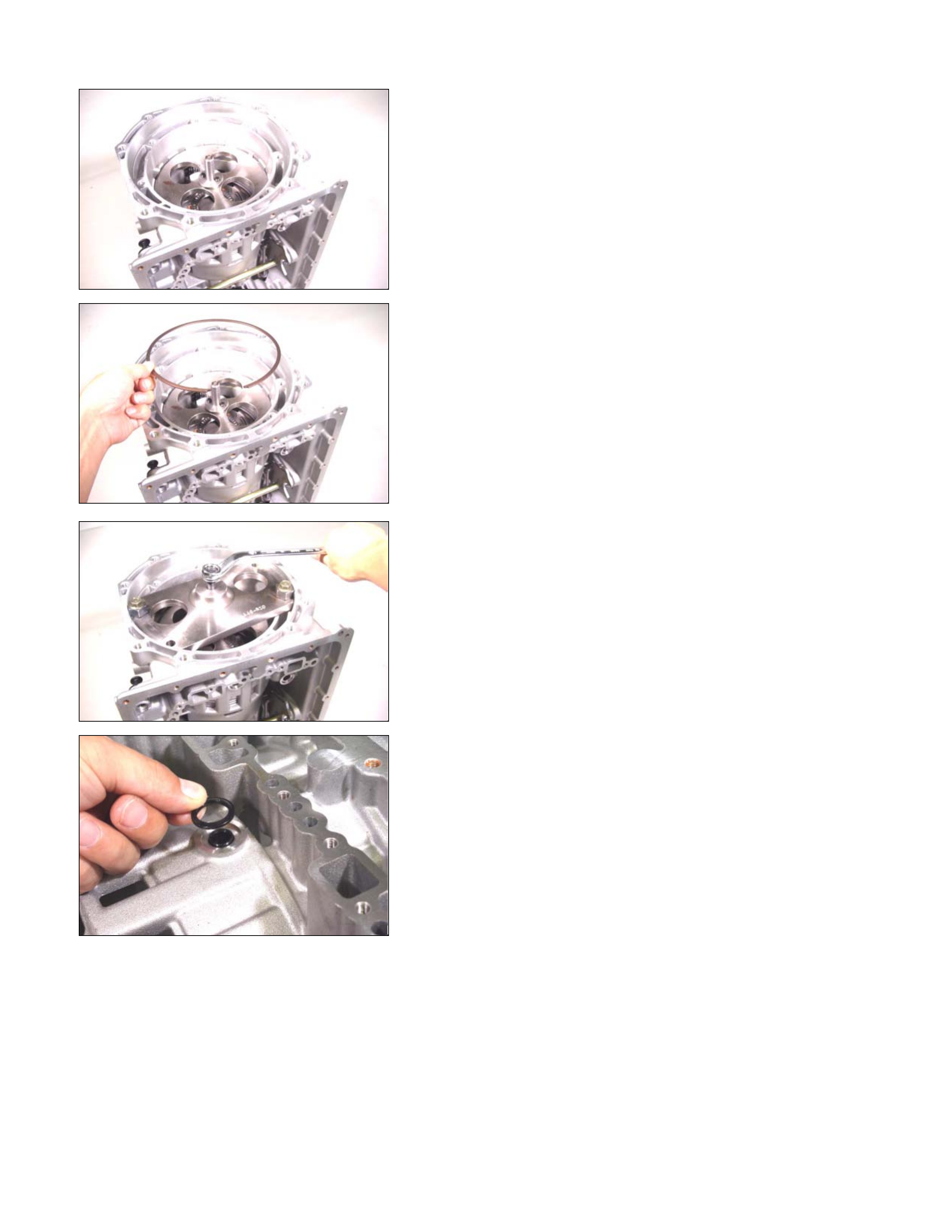
14.O-ring
Install a new O-ring to the input shaft.
32ASSY116
15.Converter housing
Install the converter housing and tighten the bolts to the
specified torque.
Torque: 53 N⋅
⋅⋅⋅m (39 Ib⋅
⋅⋅⋅ft)
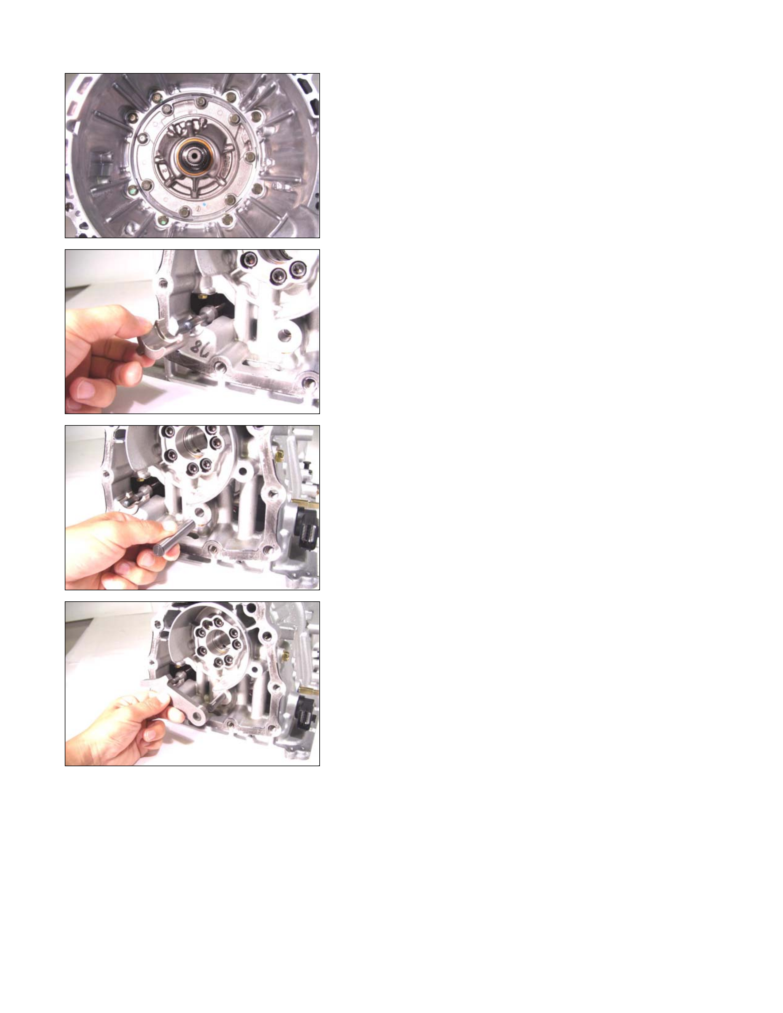
33ASSY075
16.Actuator support
Install the actuator support.
34ASSY077
17.Parking pawl, shaft, spring, and spacer
Install the parking pawl, the shaft, the spring, and the
spacer.
35ASSY082
36ASSY084
37ASSY086
38OUTPUT25
29ASSY089
18.Output shaft
• Install a new seal ring to the output shaft assembly.
• Measure the gap between the seal ring and the ring
groove.
If the gap is outs ide the specif ied r ange, the output shaf t
must be replaced.
Seal ring and ring groove gap:
0.10~0.25 mm (0.0039~0.0098 in)
• Install the bearing to the case.
NOTE:
•
••
• Apply Vaseline to the bearing (with bearing race).
•
••
• T he black side (bearing race) of th e bearin g must be
visible.
40ASSY091
• Push the output shaft into place.
19.Rear extension (2WD) or adapter case (4WD)
• Use the oil seal installer to install the oil seal to the rea
r
extension (2WD) or adapter case (4WD).
Oil seal installer:
5-8840-2769-0 (2WD)
5-8840-2770-0 (4WD)
41ASSY096
• Install the bearing (with bearing race) to the rea
r
extension (2WD) or adapter case (4WD).
NOTE:
•
••
• T he black side (bearing race) of th e bearing must be
visible.
•
••
• Apply Vaseline to the bearing.
249L300005
•
A
pply sealing agent (TB1216B) to the rear extension
(2WD) or adapter case (4WD) contact surfaces.
249L300006
• Install the rear extension (2W D) or adapter case (4W D)
to the transmission case and tighten the 10 bolts to the
specified torque.
Torque: 53 N⋅
⋅⋅⋅m (39 Ib⋅
⋅⋅⋅ft)
43ASSY119
20.Control valve assembly
• Align the manual valve and the manual plate of the
transmission case.
• Install the control valve assembly and tighten the 12
fixing bolts to the specified torque.
Number of bolts Length Color
10 (A) 40 mm (1.57 in) Gold
2 (B) 30 mm (1.18 in) Gold
44ASSY121
Torque: 8 N⋅
⋅⋅⋅m (69 Ib⋅
⋅⋅⋅in)
45CV29
• Connect the harness assembly and control valve
assembly connectors.
244L300001
21.Oil pan
• Install a new gasket and the oil pan.
• Tighten the bolts to the specified torque.
Torque: 8 N⋅
⋅⋅⋅m (69 Ib⋅
⋅⋅⋅in)
47INH-SW01
22.Inhibitor switch
• Secure the inhibitor switch (1) by hand-tightening the 2
bolts.
• Use the inhibitor switch set plate to align the neutral
holes (manual shaft and inhibitor switch).
Turn the inhibitor switch to adjust it.
Inhibitor switch set plate: 5-8840-2763-0
NOTE:
Inhibitor switch adjustment is very important.
If the inhibitor switch is not correctly adjusted, the
automatic transmission will not function normally.
• Tighten the 2 inhibitor switch bolts to the specified
torque.
Torque: 5.5 N⋅
⋅⋅⋅m (48 Ib⋅
⋅⋅⋅in)
• Remove the holding fixture from the transmission case.
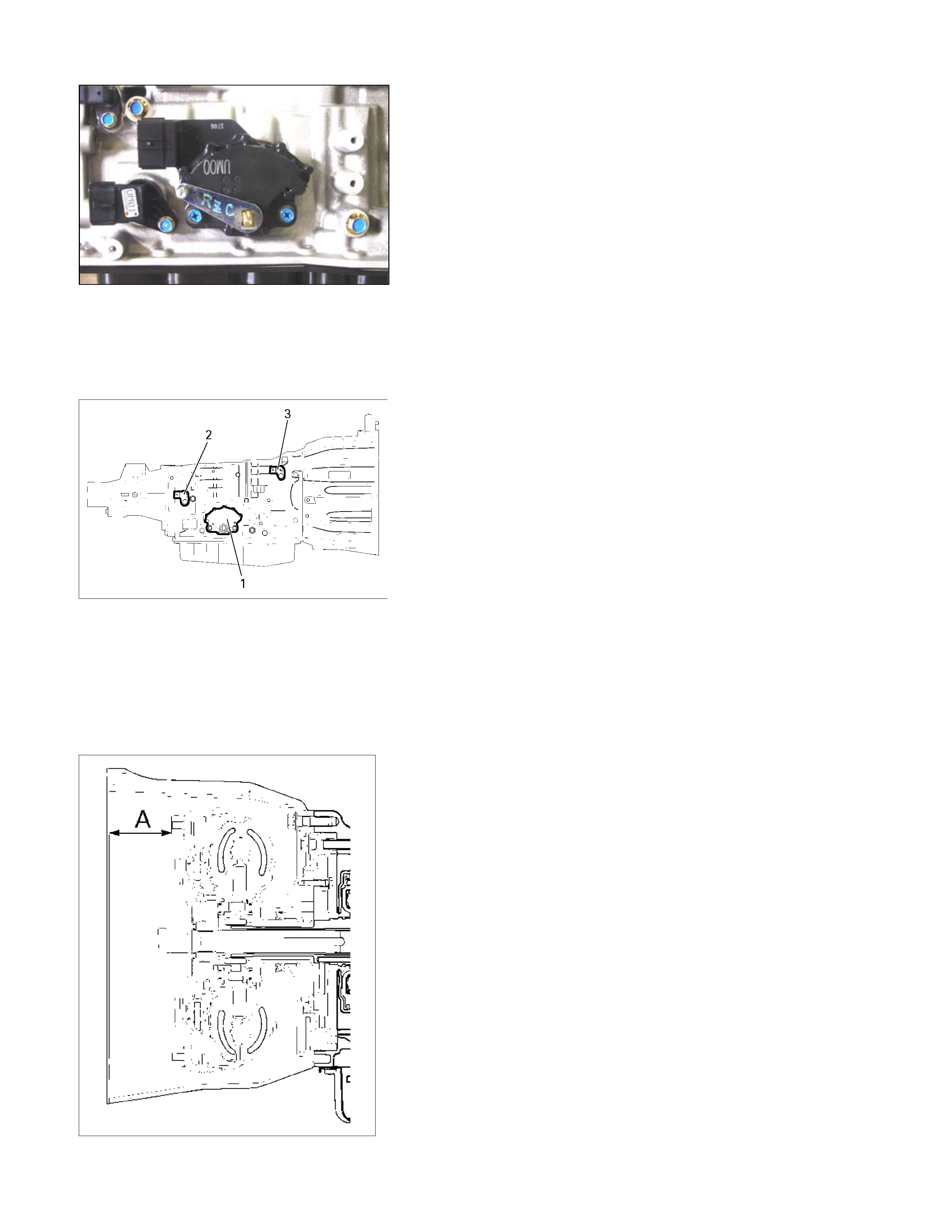
240L300001
23.Speed sensor and turbine sensor
• Apply ATF to the new O-rings and install them the speed
sensor (2) and the turbine sensor (3).
• Install the speed sensor and the turbine sensor. Tighten
the bolt to the specified torque.
Torque: 6 N⋅
⋅⋅⋅m (52 Ib⋅
⋅⋅⋅in)
24.Torque converter
• Pour the new ATF into the torque converter.
• Shake the torque converter to thoroughly clean the
inside.
• Drain the ATF from the torque converter.
• Pour the new ATF into the torque converter.
NOTE:
If significant amounts of foreign material (clutch facing,
metallic fragments, etc.) are found in the automatic
transmission at time of disassembly, the existing torque
converter must be replaced with a new one.
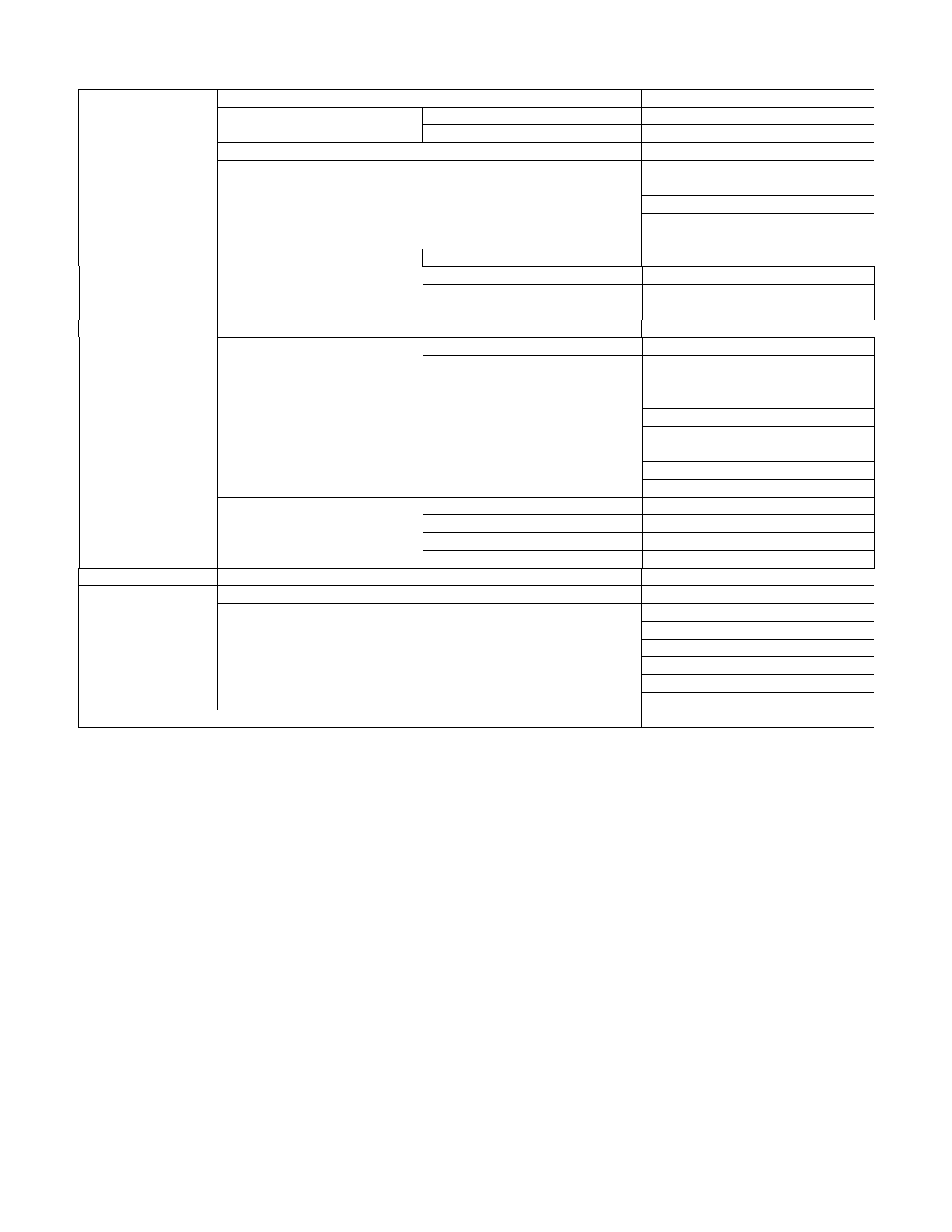
A07L300003
• Install the torque converter.
• Measure the torque converter end play (A).
If the measured value is greater than the specified
minimum, the torque converter is correctly installed.
Torque converter end pay (Minimum): 67 mm (2.64
in)

Service Standard
Name ATF DEXRON
ATF Quantity L 9.2 – 9.6
Seal ring clearance mm (in) 0.10 – 0.25 (0.0039 – 0.0098)
Housing and inner rotor side clearance mm (in) 0.02 – 0.04 (0.0008 – 0.0016)
Oil pump
Outer rotor and crescent clearance mm (in) 0.02 – 0.15 (0.0008 – 0.0059)
Number of drive plate / driven plate 7/7
Standard mm (in) 2.0 (0.079) Drive plate facing thickness Limit mm (in) 1.8 (0.071)
Retaining plate and snap ring clearance mm (in) 0.9 – 1.3 (0.035 – 0.051)
3.8 (0.150)
4.0 (0.157)
4.2 (0.165)
4.4 (0.173)
4.6 (0.181)
Available low clutch retaining plate thickness mm (in)
4.8 (0.189)
Number of coil 9.9
Outside diameter mm (in) 9.7 (0.382)
Free length mm (in) 36.4 (1.433)
Low clutch
Return spring
Linear diameter mm (in) 1.2 (0.047)
Number of drive plate / driven plate 5/5
Standard mm (in) 2.0 (0.079) Drive plate facing thickness Limit mm (in) 1.8 (0.071)
Retaining plate and snap ring clearance mm (in) 1.2 – 1.6 (0.047 – 0.063)
4.6 (0.181)
4.8 (0.189)
5.0 (0.197)
5.2 (0.205)
Available high clutch retaining plate thickness mm (in)
5.4 (0.213)
Number of coil 10.2
Outside diameter mm (in) 8.0 (0.315)
Free length mm (in) 27.1 (1.067)
High clutch
Return spring
Linear diameter mm (in) 1.1 (0.043)
Number of drive plate / driven plate 2/2
Standard mm (in) 2.0 (0.079) Drive plate facing thickness Limit mm (in) 1.8 (0.071)
Retaining plate and snap ring clearance mm (in) 0.6 – 0.9 (0.0236 – 0.035)
4.8 (0.189)
5.0 (0.197)
5.2 (0.205)
Reverse clutch
Available reverse clutch retaining plate thickness mm (in)
5.4 (0.213)
Low one-way clutch Seal ring clearance mm (in) 0.10 – 0.25 (0.0039 – 0.0098)
Number of drive plate / driven plate 6/6
Standard mm (in) 2.0 (0.079) Drive plate facing thickness Limit mm (in) 1.8 (0.071)
Retaining plate and snap ring clearance mm (in) 0.7 – 1.1 (0.028 – 0.043)
5.2 (0.205)
5.4 (0.213)
5.6 (0.220)
5.8 (0.228)
Low & reverse brake
Available low & reverse brake retaining plate thickness mm (in)
6.0 (0.236)
Number of coil 4.8
Outside diameter mm (in) 11.2 (0.441)
Free length mm (in) 22.3 (0.878)
Return spring
Linear diameter mm (in) 1.1 (0.043)
Number of drive / driven plate 5/5
Standard mm (in) 2.0 (0.079)Drive plate facing thickness Limit mm (in) 1.8 (0.071)
Retaining plate and retaining plate clearance mm (in) 1.0 – 1.4 (0.039 – 0.055)
5.4 (0.213)
5.6 (0.220)
5.8 (0.228)
6.0 (0.236)
6.2 (0.244)
Available 2-4 brake retaining plate thickness mm (in)
6.4 (0.252)
Number of coil 10.2
Outside diameter mm (in) 6.9 (0.272)
Free length mm (in) 22.5 (0.886)
2-4 brake
Return spring
Linear diameter mm (in) 1.1 (0.043)
Output shaft Seal ring clearance mm (in) 0.10 – 0.25 (0.0039 – 0.0098)
Total end play mm (in) 0.25 – 0.55 (0.0098 – 0.0217)
1.4 (0.055)
1.6 (0.063)
1.8 (0.071)
2.0 (0.079)
2.2 (0.087)
Total end play Available oil pump bearing race thickness mm (in)
2.4 (0.094)
Torque converter end play mm (in) 67.0 (2.638)
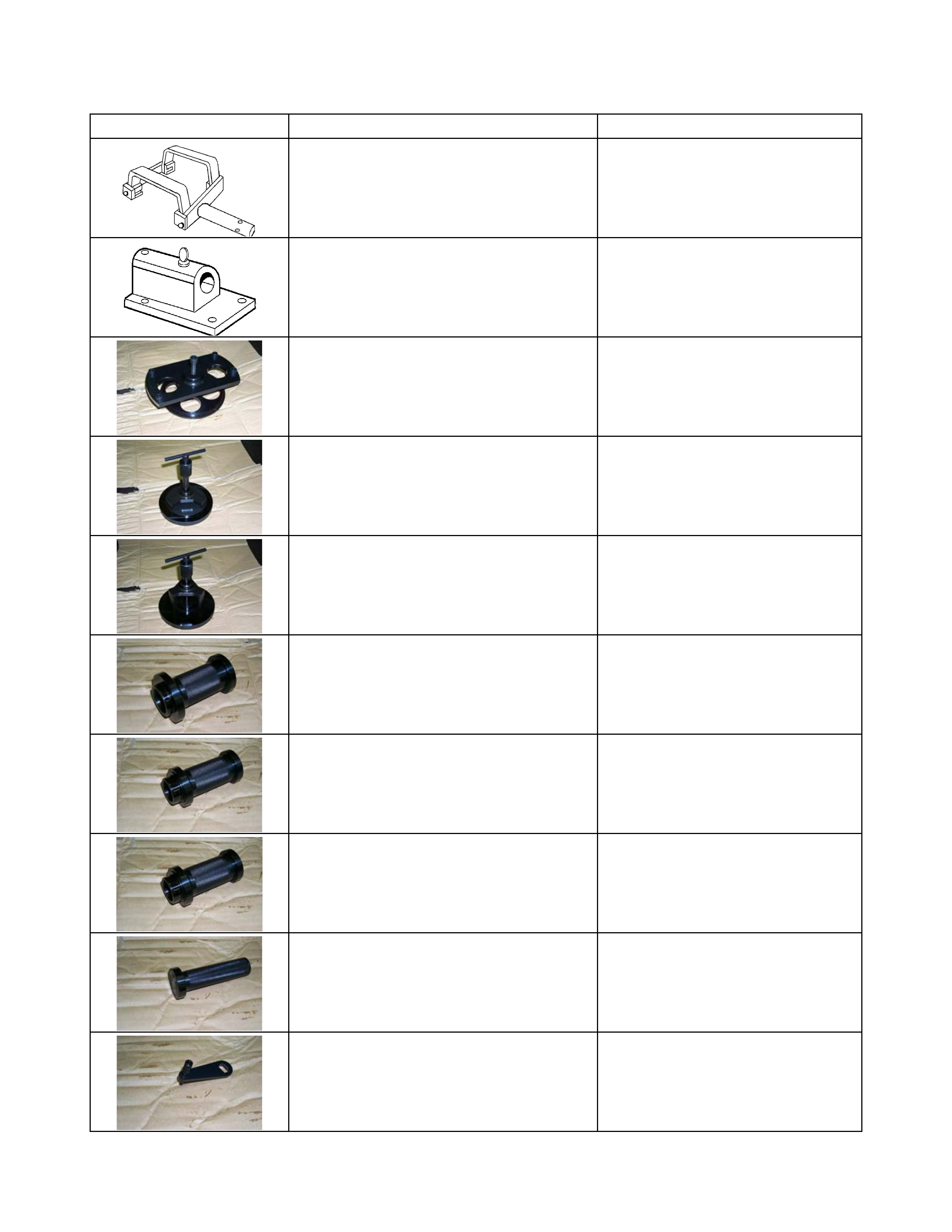
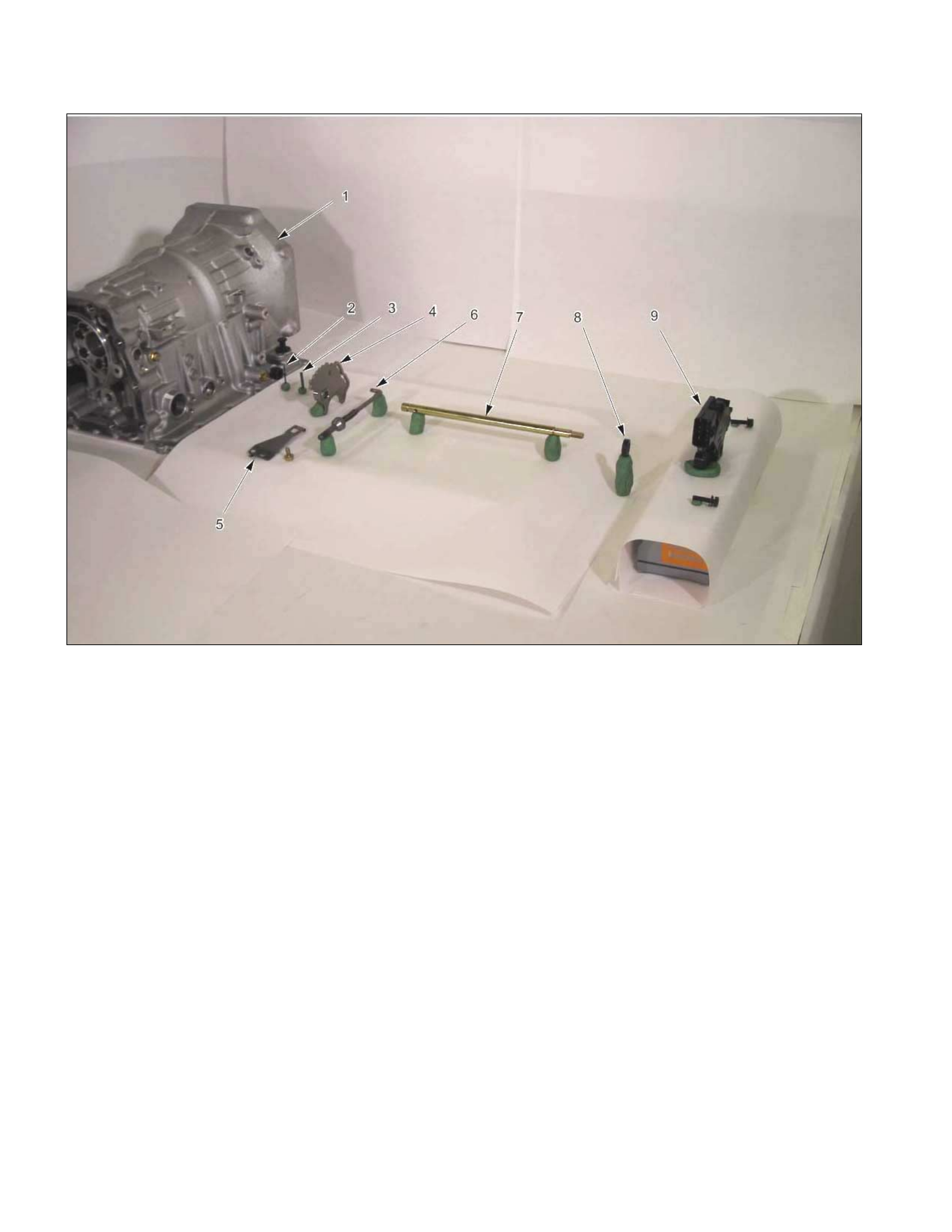
Special Service Tool
ILLUSTRATION PART NO. PART NAME
5-8841-0841-0
Holding Fixture
5-8840-0003-0
Holding Fixture Base
5-8840-2764-0
2-4 Brake Spring Compressor
5-8840-2767-0
High Clutch Spring Compressor
5-8840-2759-0
Low Clutch Spring Compressor
5-8840-2761-0
Oil Pump Oil Seal Installer
5-8840-2769-0
Rear Extension Oil Seal Installer
5-8840-2770-0
Rear Adapter Oil Seal Installer
5-8840-2758-0
Manual Shaft Oil Seal Installer
5-8840-2763-0
Inhibitor Switch Set Plate