
SECTION 7B1 – MANUAL
TRANSMISSION MUA5G
MUA 5G/5S ( 4×
××
×2)
Service Precaution
Gen era l De scriptio n
Rear Oil Seal (4×
××
×2)
Transmission (4×
××
×2)
Disassembled View
Removal
Installation
Transmission Case
Major Component
Disassembly
Reassembly
Intermediate Plate w ith Gear Assembly, Detent,
Shift A rm, Shift Rod, and Interlock Pin
Disassembled View
Disassembly
Inspection and Repair
Reassembly
Reverse Gear and 5th Gear
Disassembled View
Disassembly
Inspection and Repair
Reassembly
Top Gear Shaft, Main Gear Shaft,
and Counter Gear Shaft
Disassembled View
Disassembly
Inspection and Repair
Reassembly
Main Data and Specifications
Troubleshooting
Special Tools (MUA)
MUA5G (4×
××
×4)
Service Precaution
General Description
Transmission (4×
××
×4)
Disassembled View
Removal
Installation
Transmission Case
Maj or Compon ent
Disassembly
Reassembly
Intermediate Plate with Gear Assembly, Detent,
Shift A rm, Shift Rod, and Interlock Pin
Disassembled View
Disassembly
Inspection and Repair
Reassembly
Reverse Gear and 5th Gear
Disassembled View
Disassembly
Inspection and Repair
Reassembly
Top Gear Shaft, Main Gear Sh aft,
and Counter Gear Shaft
Disassembled View
Disassembly
Inspection and Repair
Reassembly
Main Data and Specifications
Troubleshooting
Special Tools (MUA)
Techline
Techline

MUA 5G/5S (4×
××
×2)
Service Precaution
WARNING: THIS VEHICLE HAS A SUPPLEMENTAL
RESTRAINT SYSTEM (SRS). REFER TO THE SRS
COMPONENT AND WIRING LOCATION VIEW IN
ORDER TO DETERMINE WHETHER YOU ARE
PERFORMING SERVICE ON OR NEAR THE SRS
COMPONENTS OR THE SRS WIRING. WHEN YOU
ARE PERFORMING SERVICE ON OR NEAR THE
SRS COMPONENTS OR THE SRS WIRING, REFER
TO THE SRS SERVICE INFORMATION. FAILURE TO
FOLLOW WARNINGS COULD RESULT IN POSSIBLE
AIR BAG DEPLOYMENT, PERSONAL INJURY, OR
OTHERWISE UNNEEDED SRS SYSTEM REPAIRS.
CAUTION: Always use the correct fastener in the
proper location. When you replace a fastener, use
ONLY the exact part number for that application.
HOLDEN will call out those fasteners that require a
replacement after removal. HOLDEN will also call
out the fasteners that require thread lockers or
thread sealant. UNLESS OTHERWISE SPECIFIED,
do not use supplemental coatings (Paints, greases,
or other corrosion inhibitors) on threaded fasteners
or fastener joint interfaces. Generally, such coatings
adversely affect the fastener torque and the joint
clamping force, and may damage the fastener.
When you install fasteners, use the correct
tightening sequence and specifications. Following
these instructions can help you avoid damage to
parts and systems.
General Description
MUA 5G/5S Transmission (4×
××
×2)
A07R300006
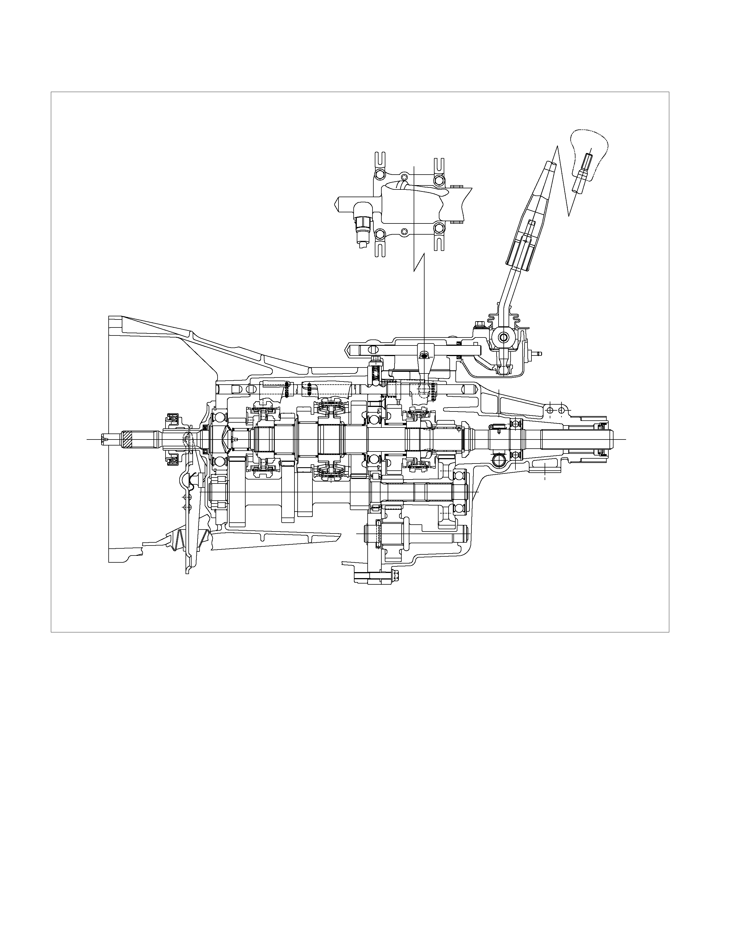
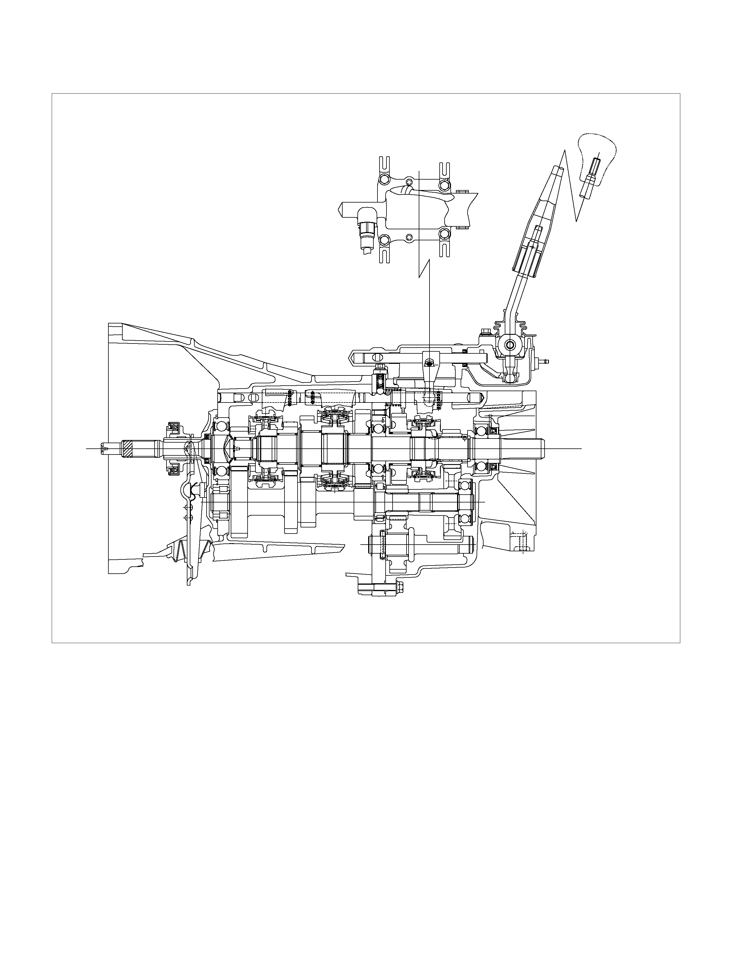
The MUA5G is a constant mesh transmission,
synchronised in all speeds. The transmission has been
designed to provide both low shift-effort and low gea
r
noise.
Principle parts of the transmission are the integral clutch
housing, the intermediate plate, the rear cover, and the
gears.
The transmission control box is built into the
transmission.
Rear Oil Seal (4×
××
×2)
Disassembled View
220R300030
Legend
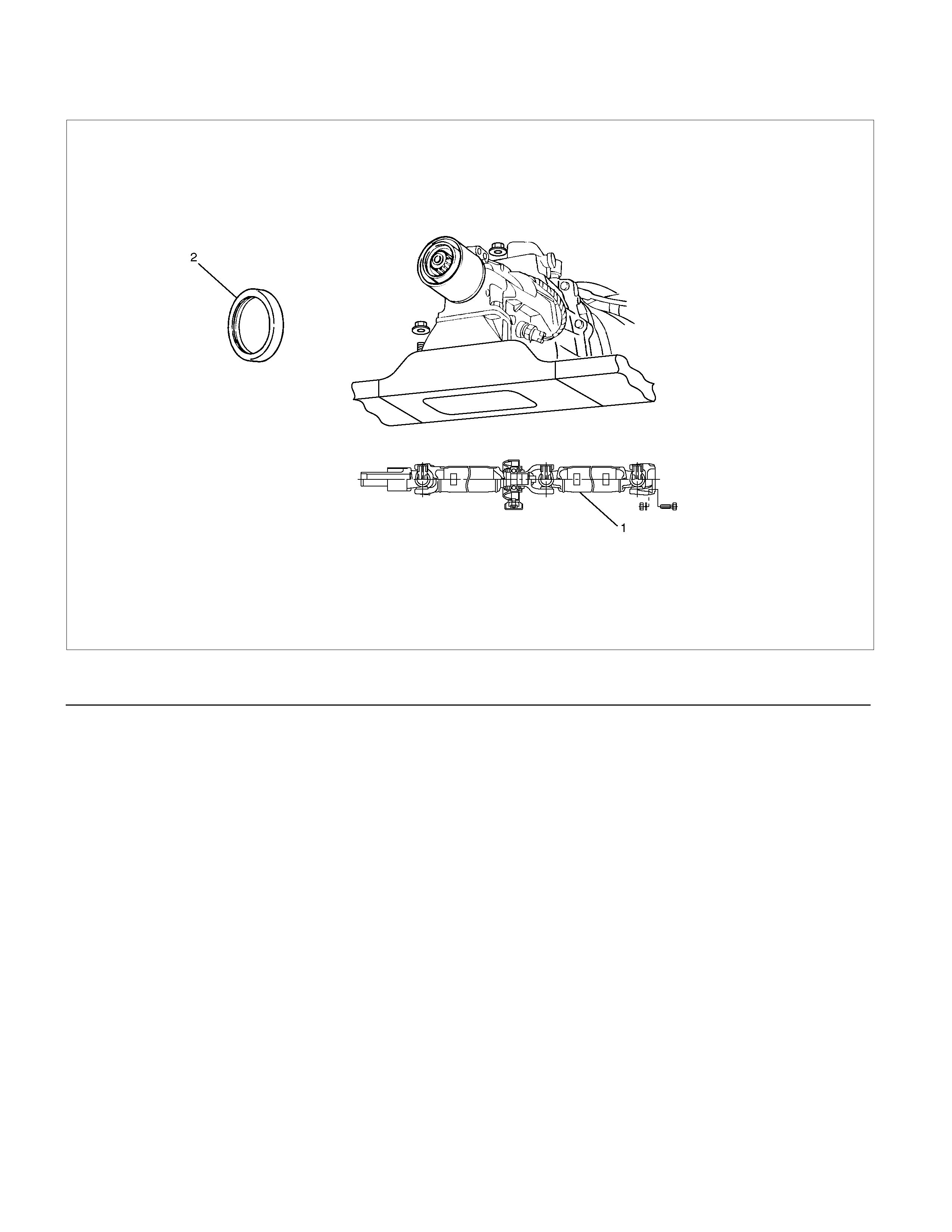
(1) Rear Propeller Shaft (2) Rear Oil Seal
Removal
1. Raise and support vehicle with suitable jack
stands.
2. Remove propeller shaft flange yoke bolts and nuts
at the differential side.
3. Remove center bearing from crossmenber.
4. Remove prepeller shaft from the transmission
main shaft spline.
Refre to the section “Rear Propeller Shaft”.
5. Use a screwdriver to pry the rear oil seal from the
rear cover.
Installation
1. Install a new oil seal (2) using the installer 5-8522-
0050-0.
220RS044
2. Insert the splined yoke into the transimission
mainshaft spline.
3. Install the propeller shaft flange yoke to the drive
pinion flange.
Torque : 63 N·m (6.4 kg·m/46 lb·ft)
4. Install center bearing on crossmember.
Torque : 69 N·m (7.0 kg·m/51 lb·ft)
5. Check transmission fluid level.
6. Lower vehicle.
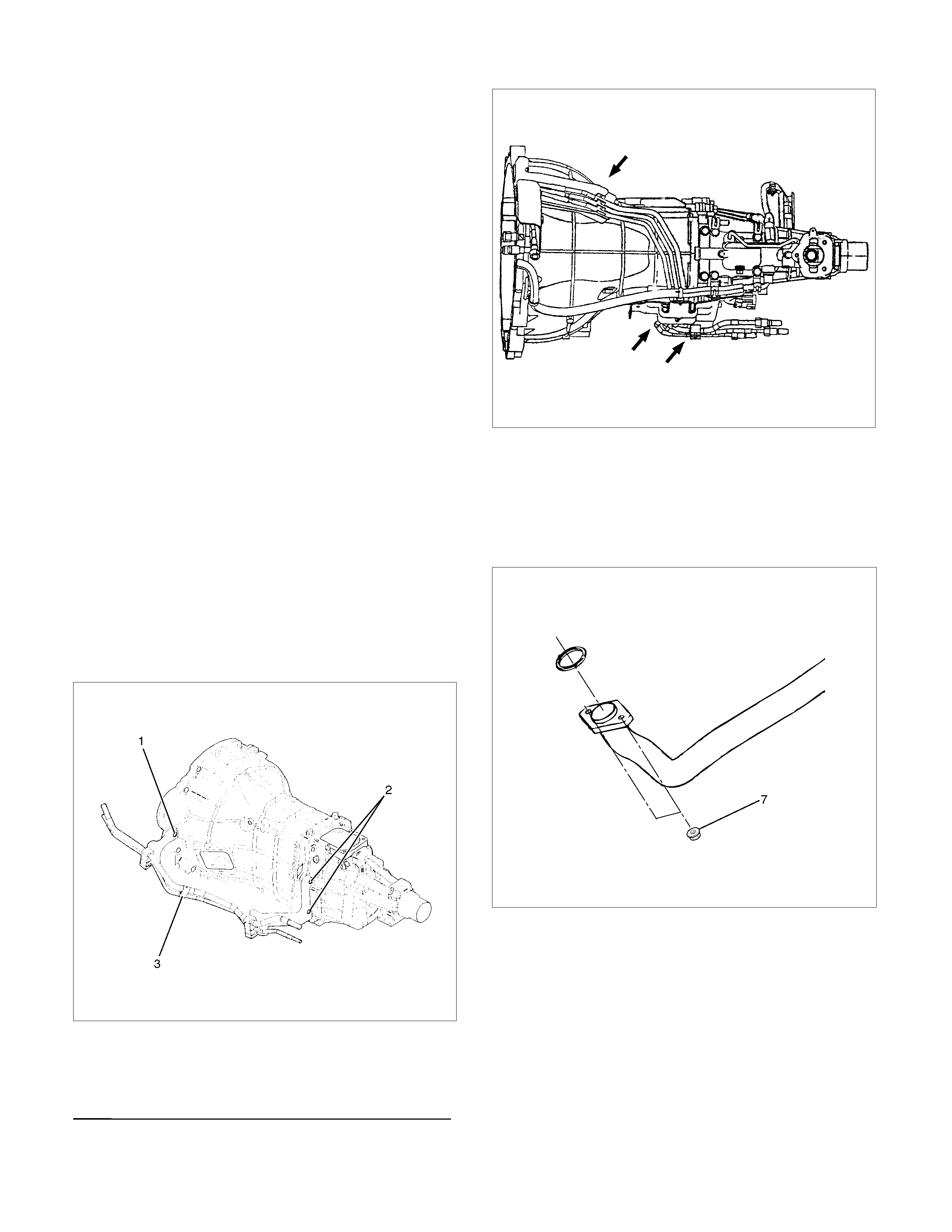
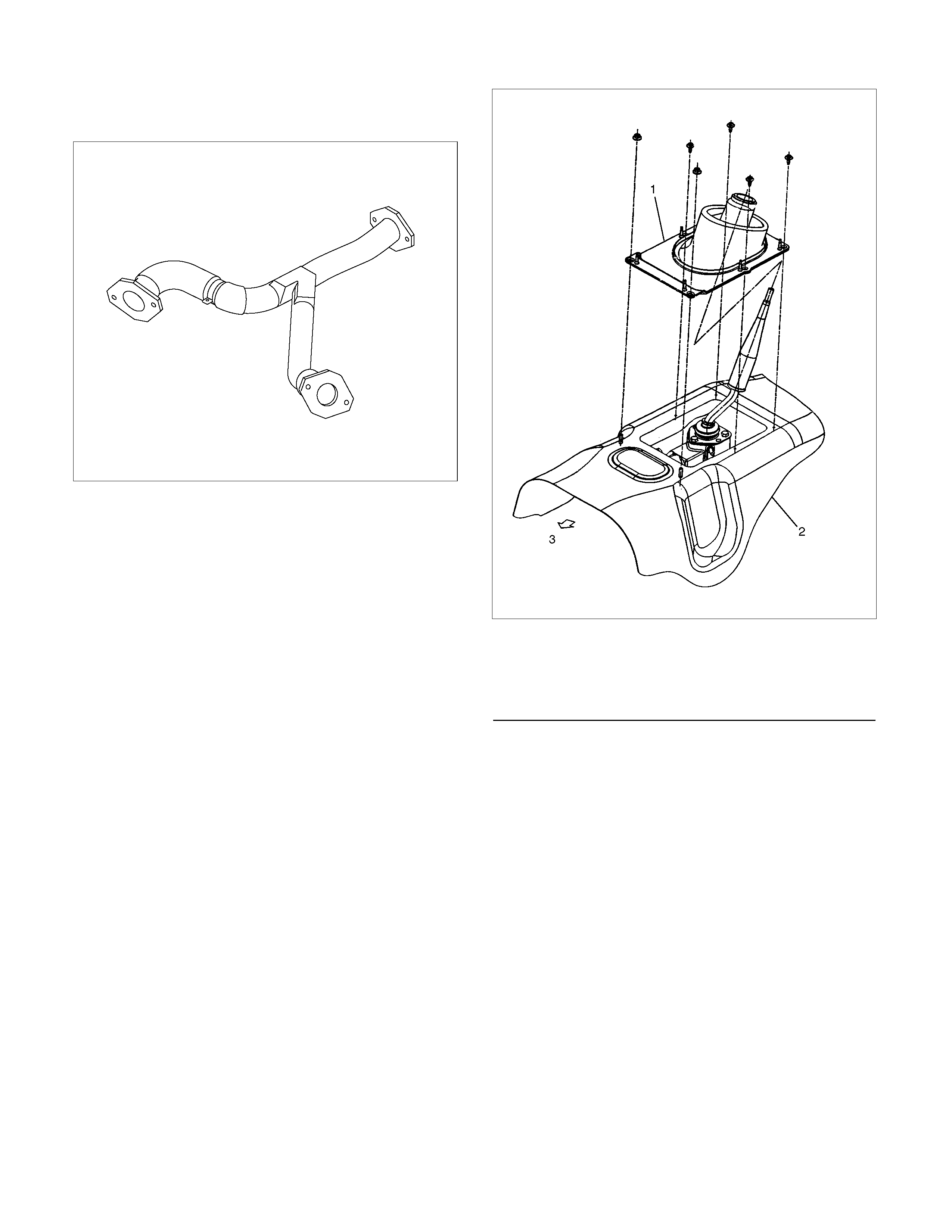
Transmission (4×
××
×2)
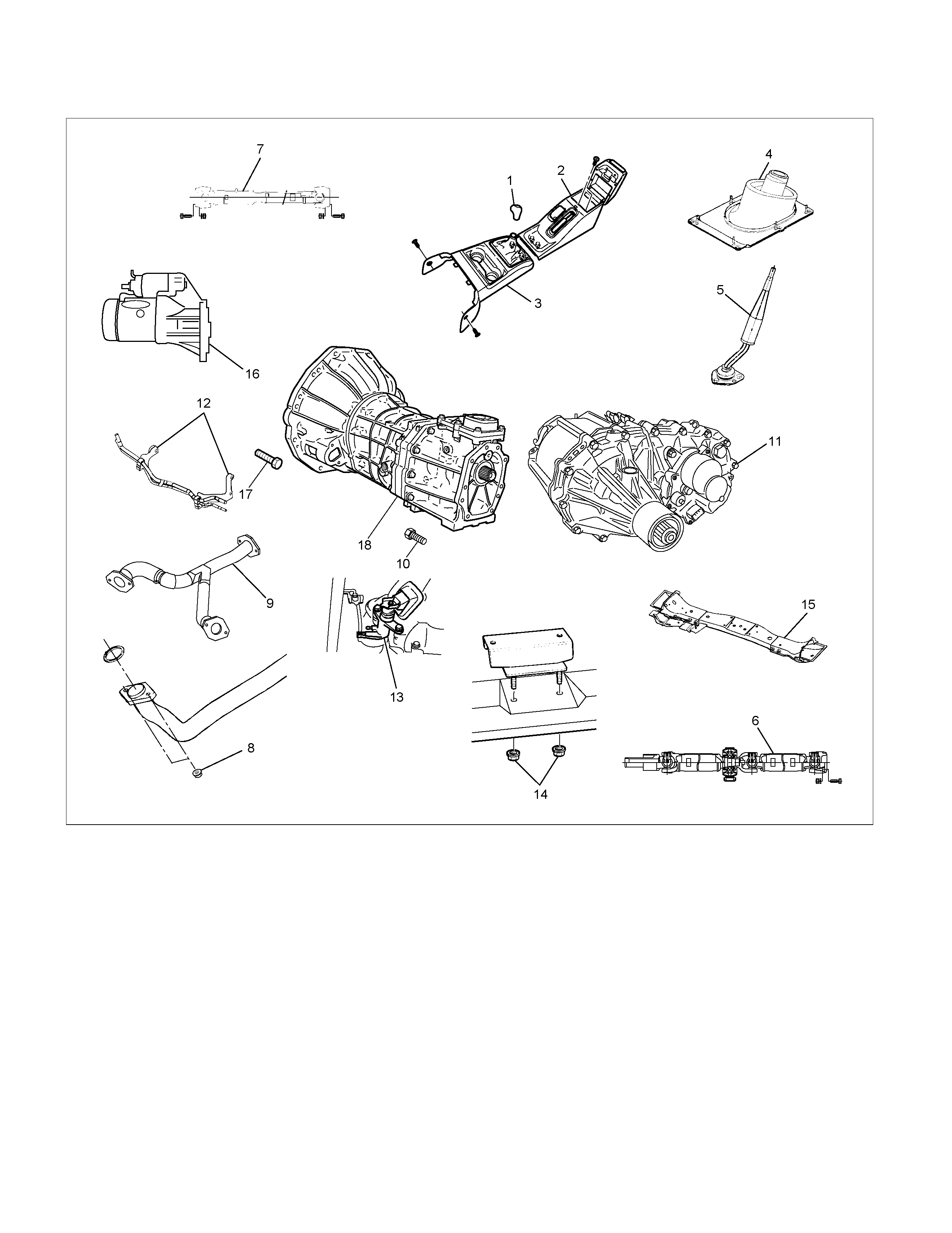
Disassembled View
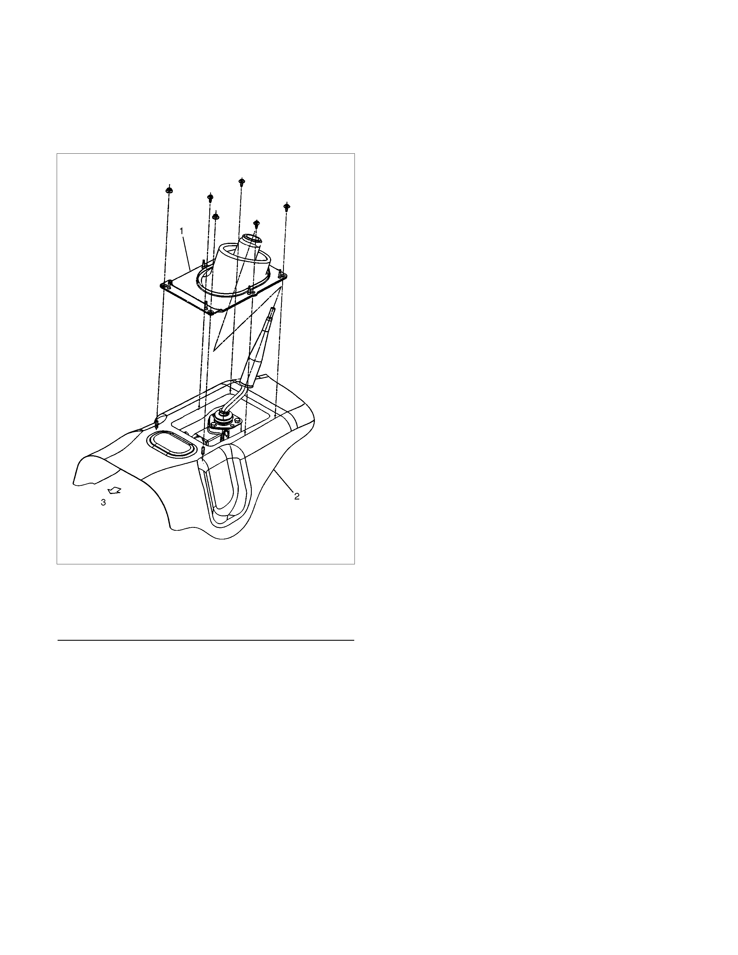
RTW37ALF0001
Legend
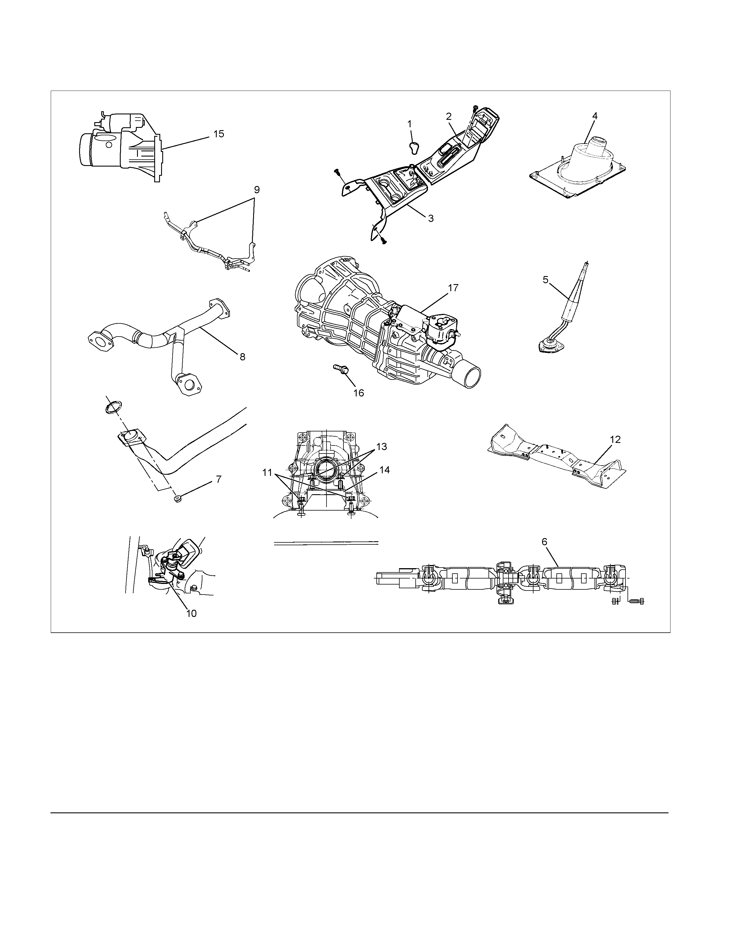
(1) Gear Control Lever Knob (10) Slave Cylinder
(2) Rear Floor Console (bucket seat) (11) Nut : rear mount to Crossmember
(3) Front Floor Console (12) Transmission Crossmember
(4) Grommet Assembly (13) Nut : rear mount to transmission
(5) Gear Control Lever (14) Rear Mount Rubber
(6) Rear Propeller Shaft (15) Starter (4JH1-TC only)
(7) Exhaust Pipe Nut (4JH1-TC only) (16) Transmission Retaining Nut and Bolt
(8) Exhaust Pipe (6VE1 only) (17) Transmission Assembly
(9) Fuel Pipe Bracket
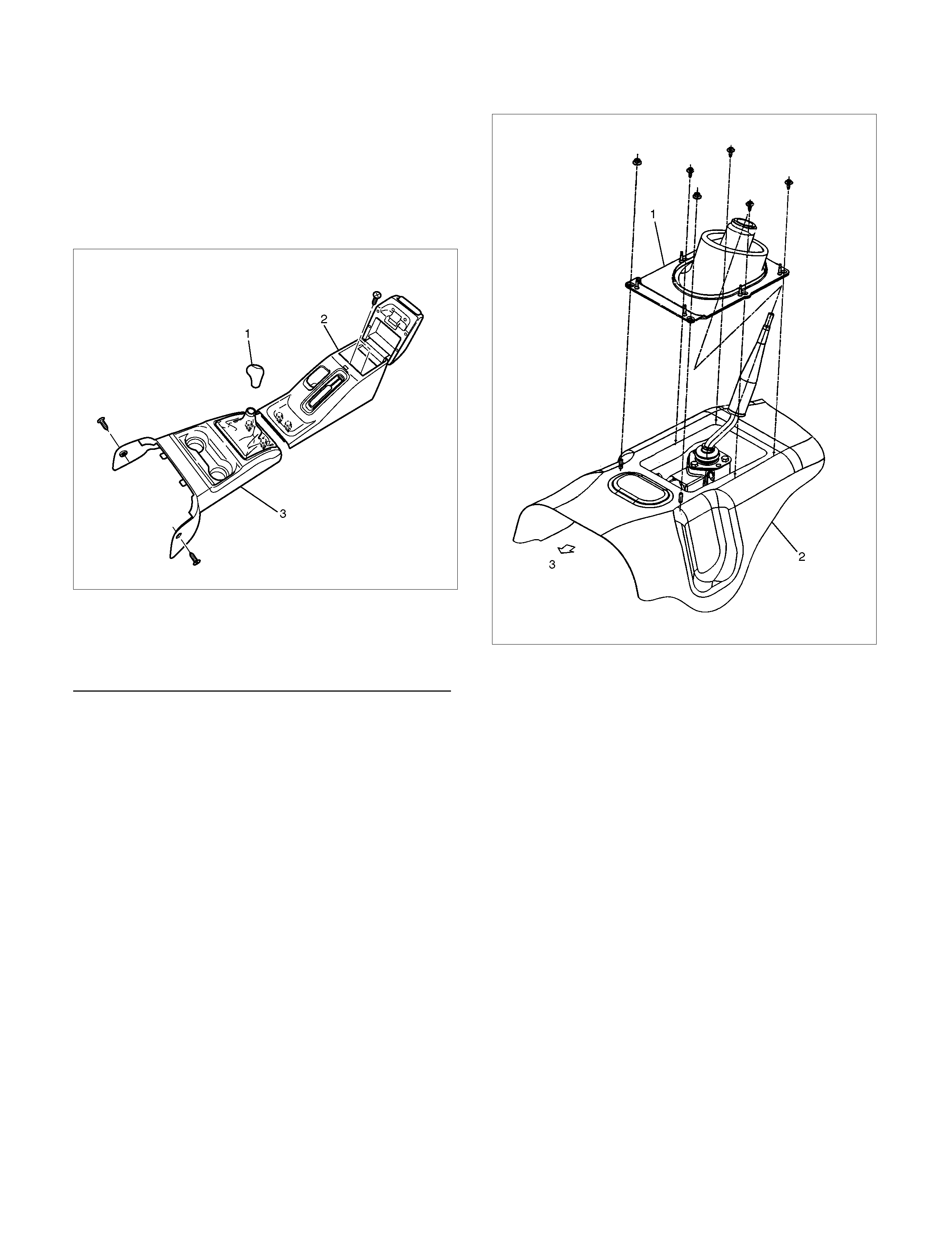
Removal
1. Disconnect battery ground cable.
2. Remove gear control lever knob (1).
3. Remove rear floor console (2). (Bucket seat)
Refer to the section “Floor Console”.
4. Remove front floor console (3).
Refer to the section “Floor Console”.
745R300006
Legend
(1) Knob
(2) Rear Floor Console
(3) Front Floor Console
5. Remove grommet assembly (4).
235R300001
6. Remove gear control lever (5).
7. Raise and support vehicle with suitable stands.
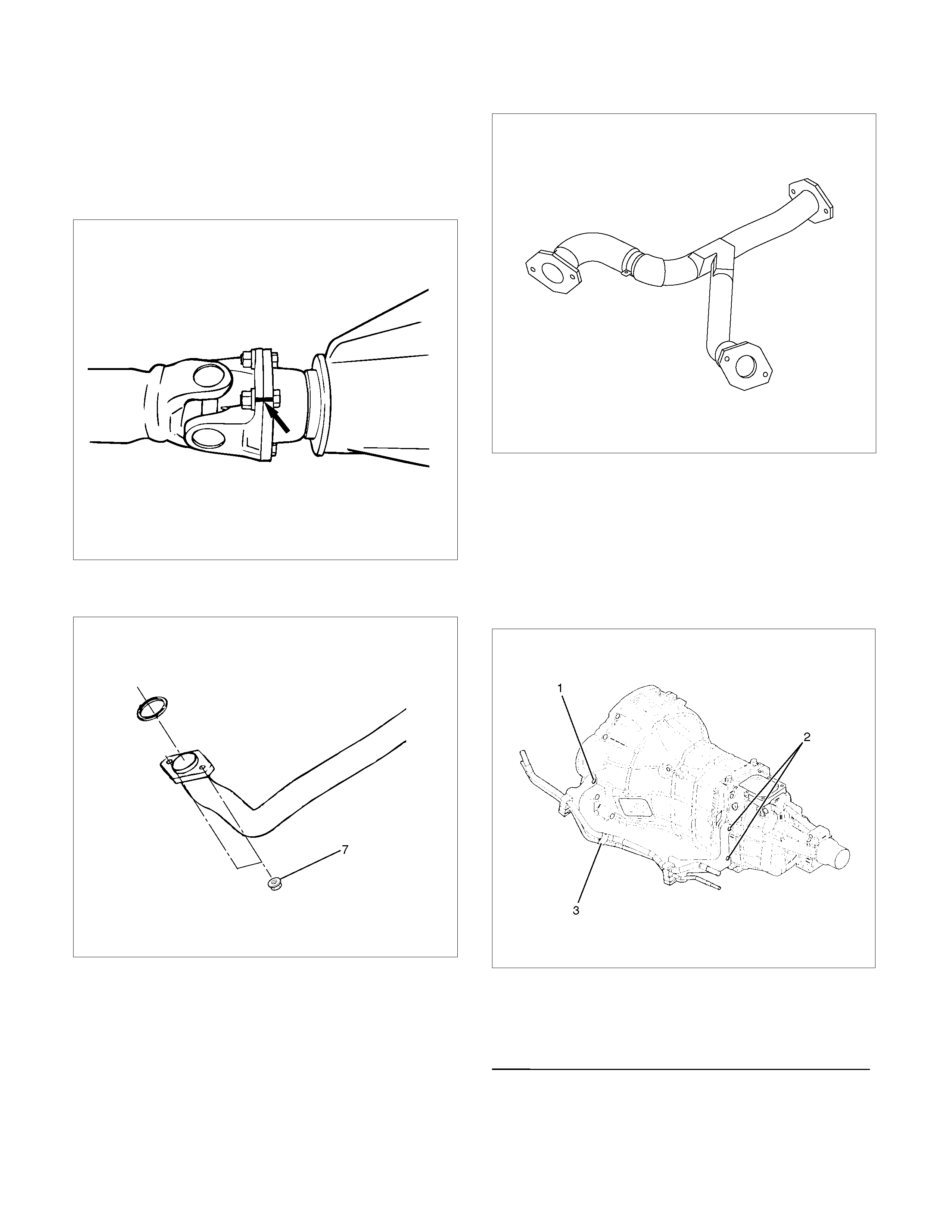
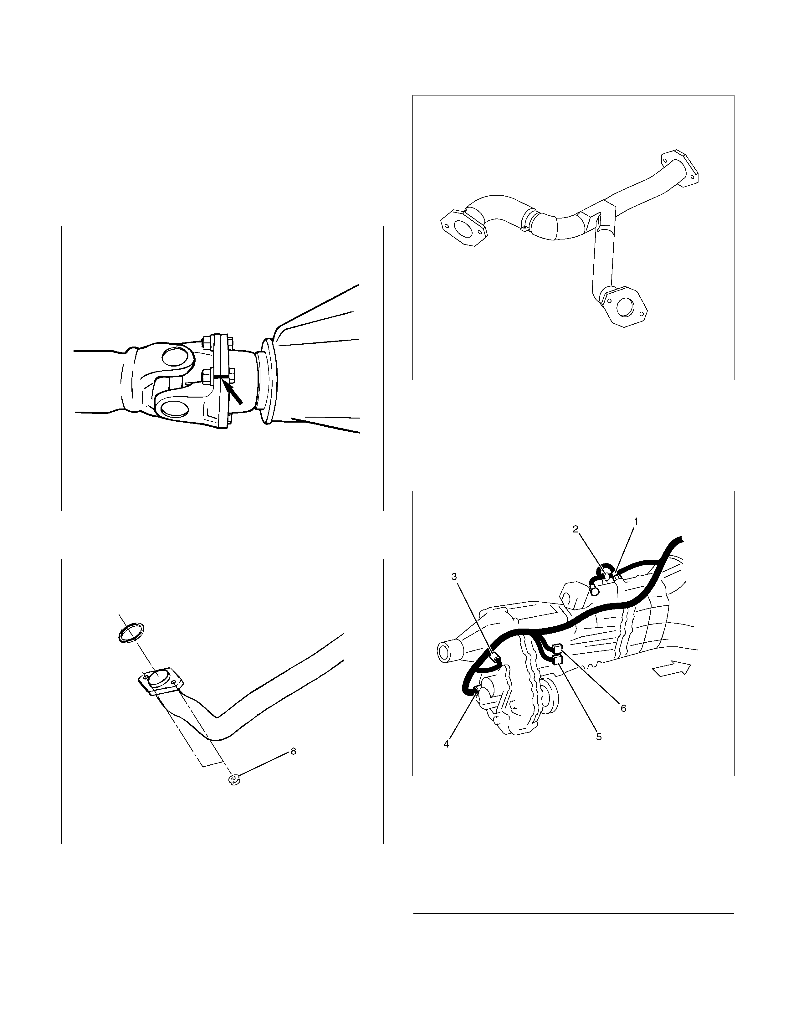
8. Remove rear propeller shaft (6).
NOTE: Apply alignment marks on the flange at the
differential side.
401RS023
9. Loosen the front exhaust pipe fixing nuts (7) at the
engine side but not remove them. (4JH1-TC only)
150R300003
10. Remove the exhaust pipe (8). (6VE1 only)
RTW37ASH0001
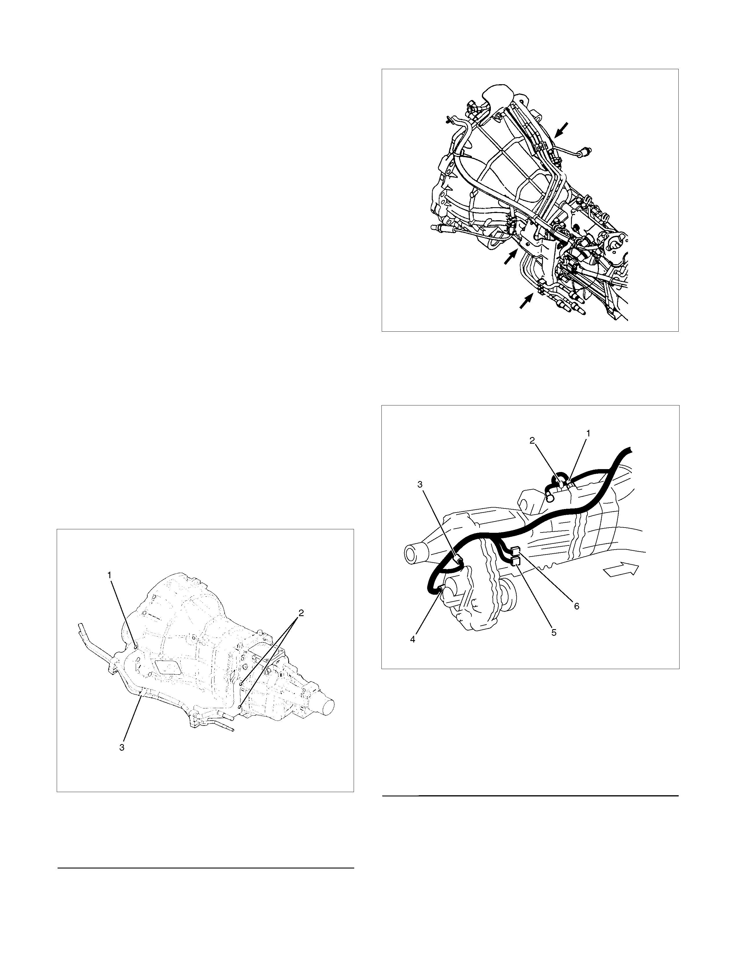
11. Disconnect harness connectors and clips on the
transmission.
• Neutral Switch
• Back up Switch
• Car Speed Sensor
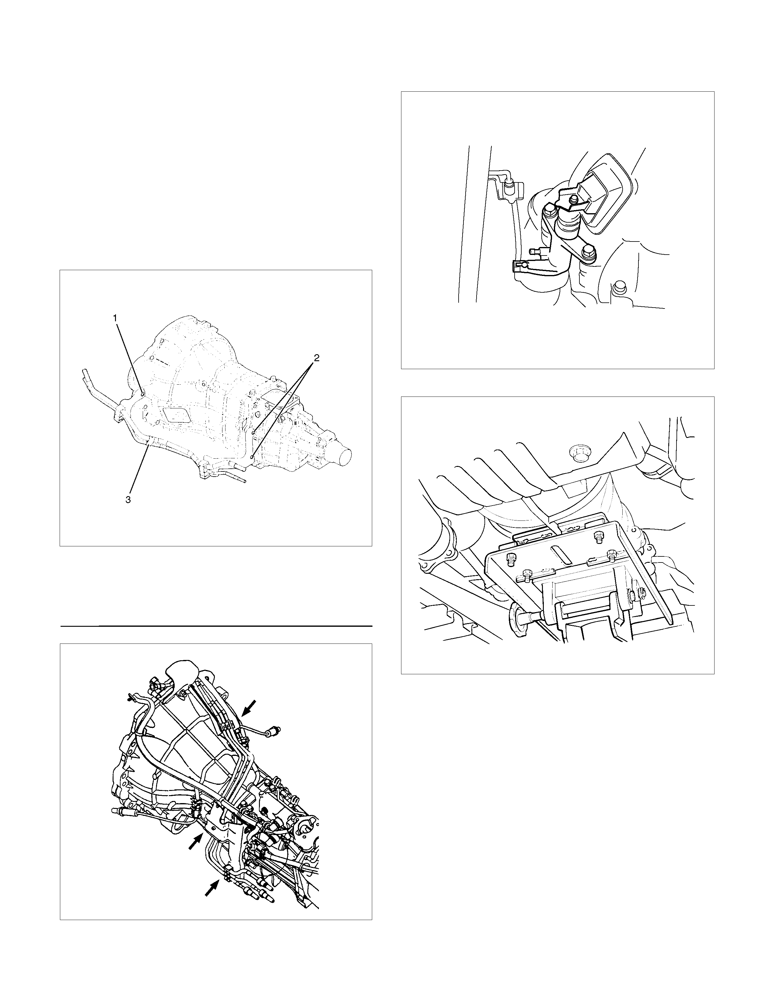
12. Remove the fuel pipe bracket (9) with pipes from
the transmission (17).
4JH1-TC
220R300012
Legend
(1) Bolt
(2) Nut
(3) Fuel Pipe Assembly
6VE1, C24NE
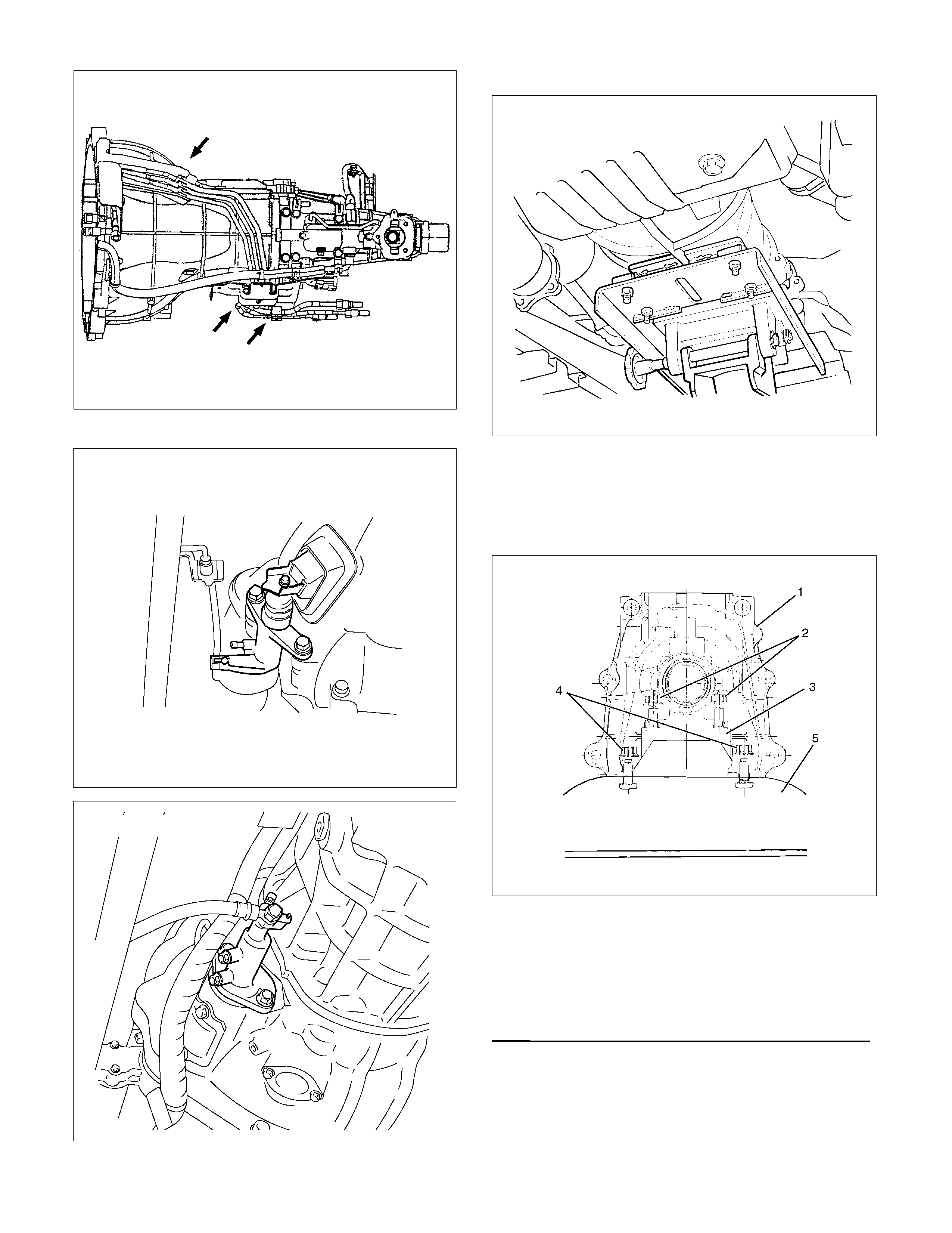
Scan-1
13. Remove slave cylinder (10) and put aside it.
4JH1-TC
220LV019
6VE1
206RW002
14. Support transmission with a transmission jack.
220RS001
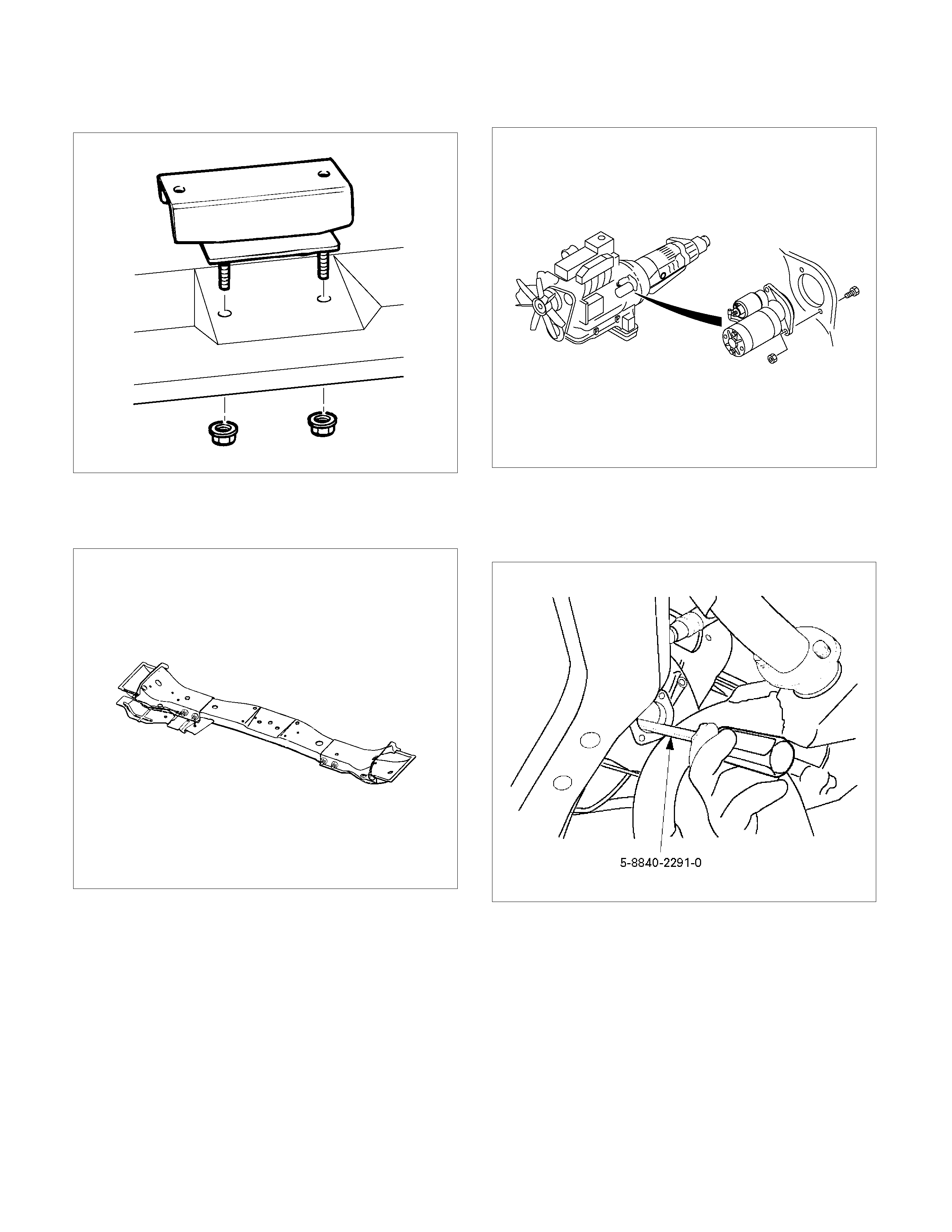
15. Remove engine rear mount nuts (11) fixing on
cross member from transmission crossmember
(12).
16. Remove engine rear mount nuts (13) fixing on
transmission.
220R300029
Legend
(1) Transmission
(2) Nut : rear mount to transmission
(3) Rear Mount Rubber
(4) Nut : rear mount to crossmember
(5) Transmission Crossmember
17. Remove the middle part of transmission
crossmember (12) by removing four fixing bolts
and nuts.
501R300008
18. Take out the rear mount rubber (14).
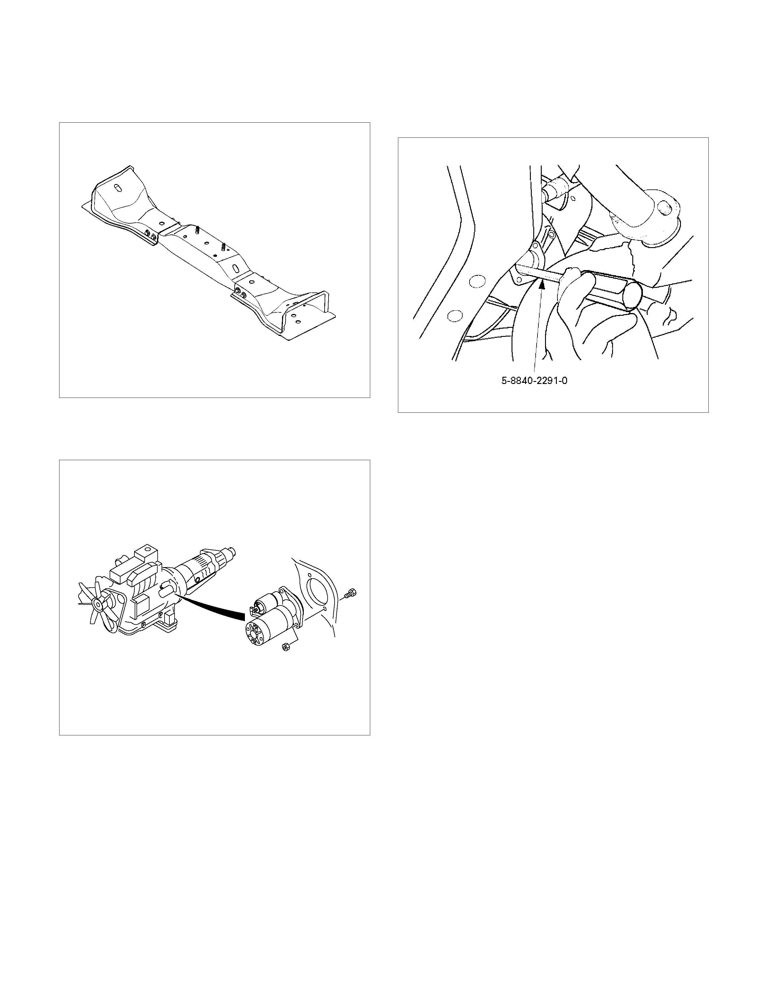
19. Remove starter (15) (4JH1-TC only).
060L100070
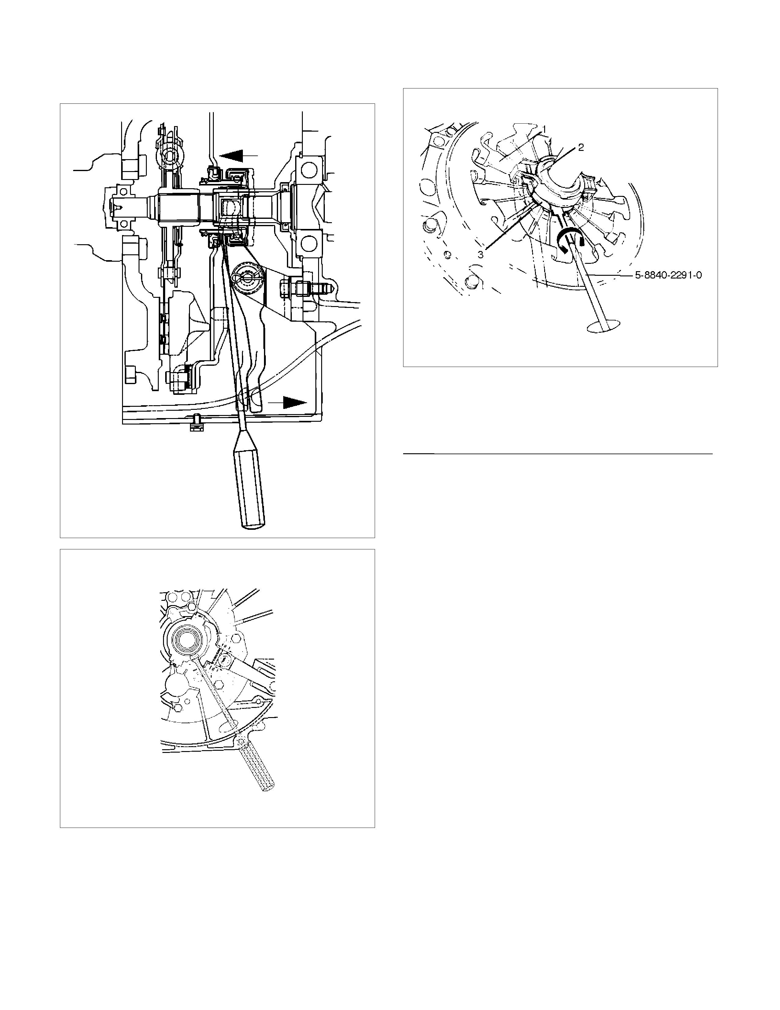
20. Use the clutch release bearing remover 5-8840-
2291-0 (J-39207) to disconnect the clutch release
bearing from the clutch pressure plate. (6VE1
only )
220RW109
Release bearing disconnection
1. Pull the shift fork toward the transmission to
press the clutch release bearing against the
clutch.
2. Insert the clutch release bearing remover
between the wedge collar and the release
bearing.
3. Turn the remover to separate the release
bearing.
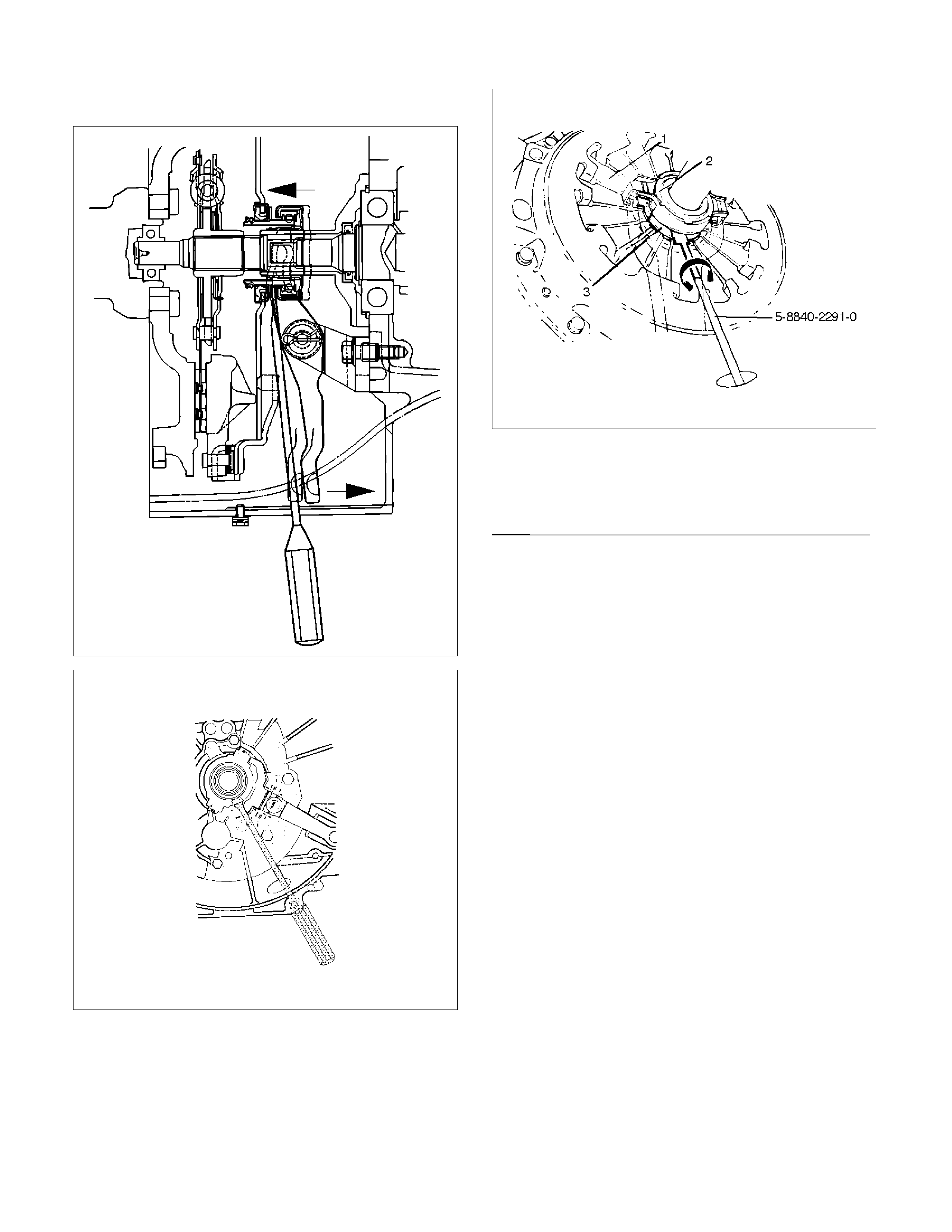
NOTE: Be sure not to insert the remover between the
wedge collar and the clutch.
220RW063
220RW064
220RW019
Legend
(1) Pressure Plate Assembly
(2) Release Bearing
(3) Wedge Collar
21. Remove transmission retaining nuts and bolts(16).
Remove transmission assembly (17) from the
vehicle.
Installation
1. Apply a thin coat of molybdenum disulfide grease
to the top gear shaft spline.
2. Slowly operate the transmission jack until the front
of transmission is aligned with the rear of the
engine.
The slope of the engine and the transmission
must be the same.
3. Align the top gear shaft spline with the clutch
driven plate spline.
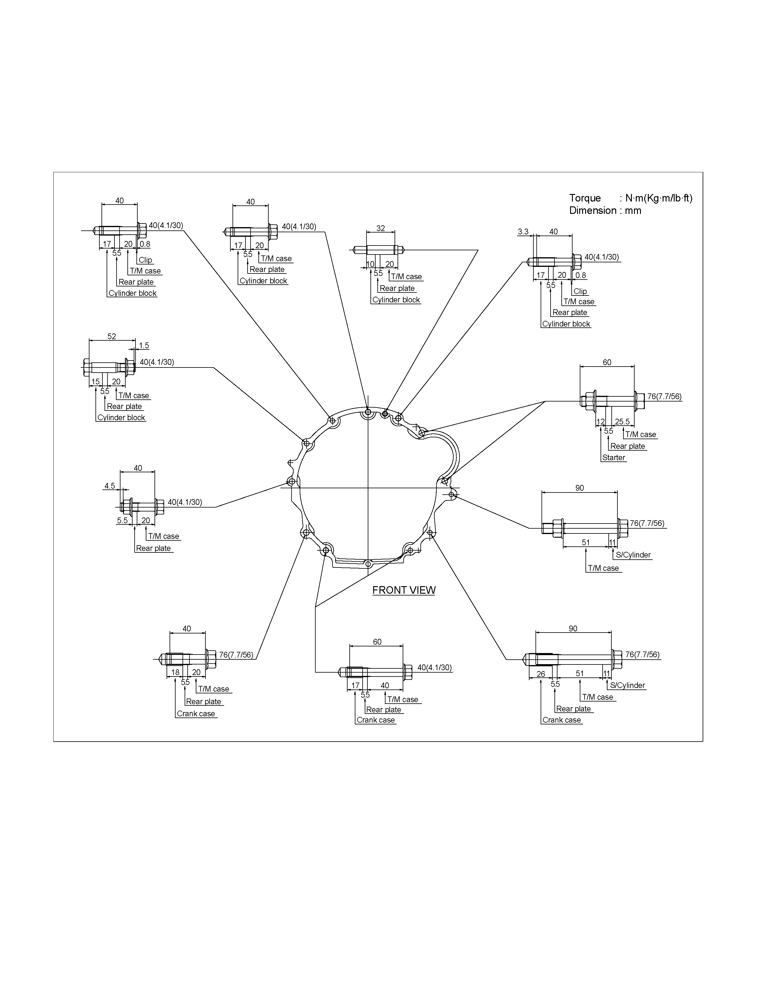
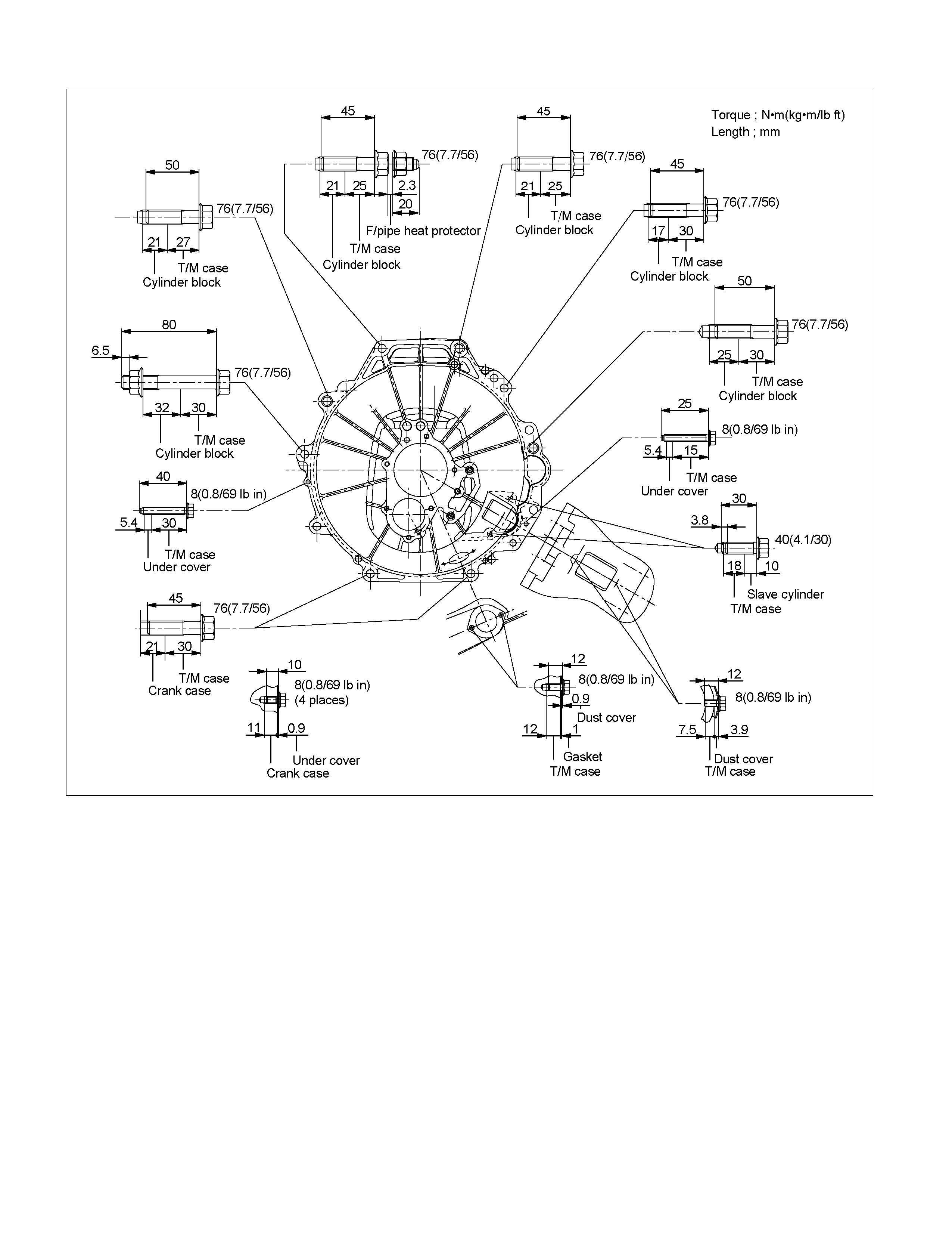
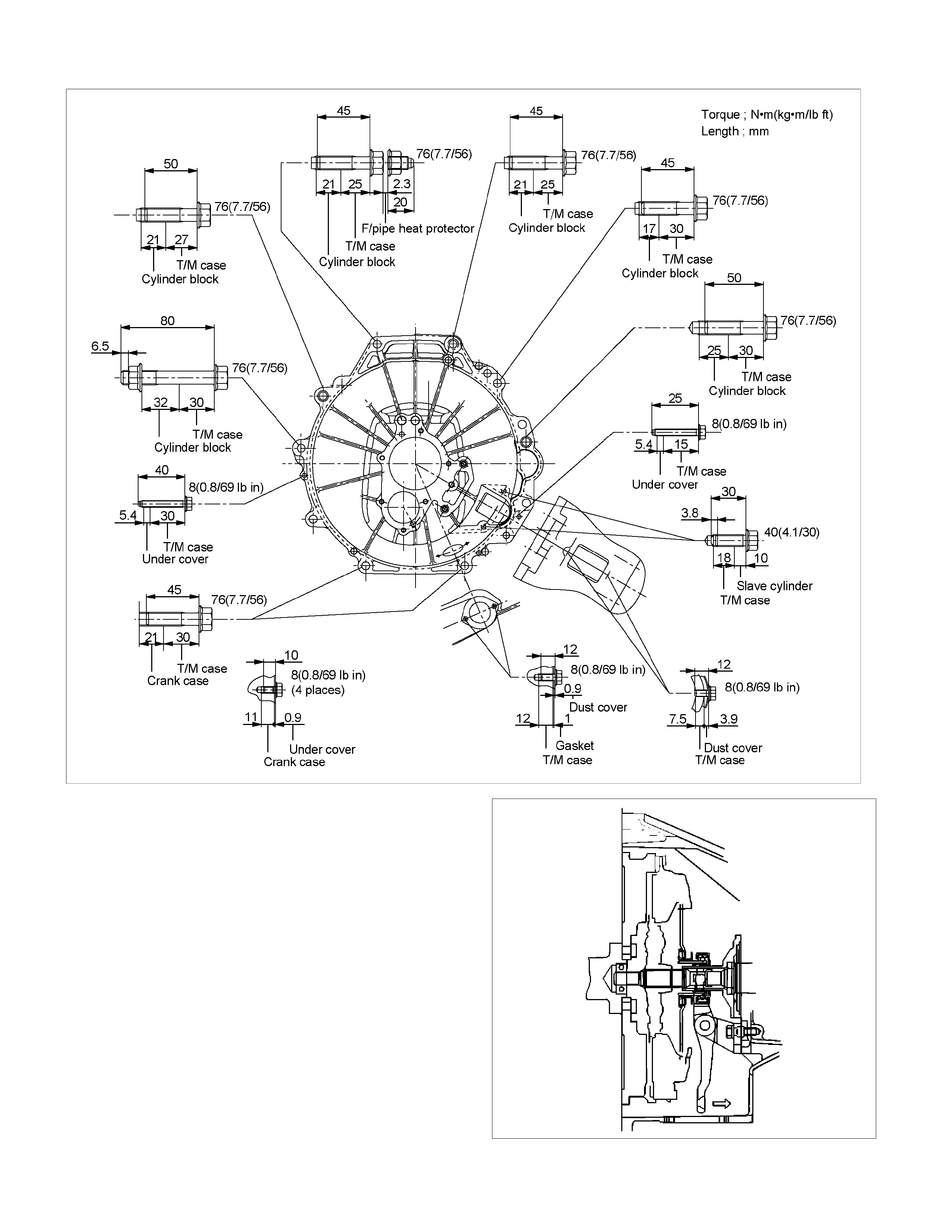
4. Install the transmission assembly (17) to the
engine.
Tighten the transmission nuts and bolts (16) as
shown in the figure.
4JH1-TC
RTW37BLF000901
6VE1
RTW37BLF0001
C24NE
RTW37BLF0002
220RS006
5.
A
pply a force of about 113N (26 Ib) to the tip of the
shift fork in the direction of the transmission to
engage the clutch pressure plate and release
bearing. (6VE1 only)
NOTE: A clicking sound is heard when the release
bearing and the tip of the diaphragm spring engage
each other.
Check to see if they are securely engaged by pushing
the tip of the shift fork toward the engine while applying
a force of about 25 N (5.5 lb). If the shift fork will not
move, then they are securely engaged.
6. Install starter(15). (4JH1-TC only)
NOTE: Tighten the lower bolt temporarily.
After installing the fuel pipe assembly, tighten the bolt to
the specified torque.
Torque: 76 N·m (7.7 kg·m/56 lb·ft)
7. Install the rear support rubber (14) on the
transmission and tighten the nuts to the specified
torque.
Torque: 52 N·m (5.3 kg·m/38 lb·ft)
8. Install the middle part of transmission
crossmember (12) and bolts.
Tighten the nuts to the specified torque.
Torque: 67 N·m (6.8 kg·m/49 lb·ft)
9. Install engine rear mount nuts (11) fixing on
transmission crossmember (12).
Torque: 52 N·m (5.3 kg·m/38 lb·ft)
Remove the transmission jack from transmission
side.
10. Apply grease to top hole portion of the shift fork.
Install slave cylinder (10) and tighten the bolts to the
specified torque.
Torque: 76 N·m (7.7 kg·m/56 lb·ft)
11. Install the fuel pipe brackets (9) on the
transmission.
Install the fuel pipe assembly to the fuel brackets.
Torque: Bolt & Nut 76 N·m (7.7 kg·m/56 lb·ft)
Nut 37 N·m (3.8 kg·m/28 lb·ft)
4JH1-TC
220R300012
Legend
(1) Bolt
(2) Nut
(3) Fuel Pipe Assembly
6VE1, C24NE
Scan-1
12. Connect transmission harness connectors and
clip. Connector: neutral switch, car speed sensor,
and backup switch.
13. Tighten exhaust pipe fixing nuts (7) to the
specified torque. (4JH1-TC)
Torque: 67 N·m (6.8 kg·m/49 lb·ft)
150R300003
14. Install the exhaust pipe (8). (6VE1)
Torque: 67 N·m (6.8 kg·m/49 lb·ft)
RTW37ASH000101
15. Install rear propeller shaft (6).
Torque: 63 N·m (6.4 kg·m/46 lb·ft)
16. Install center bearing on crossmember.
Torque: 69 N·m (7.0 kg·m/51 lb·ft)
17. Install gear control lever (5).
Torque: 19 N·m (1.9 kg·m/14 lb·ft)
18. Install grommet assembly (4).
Torque: Screw 1.4 N·m (0.14 kg·m/12 lb·in)
Nut 7 N·m (0.7 kg·m/61 lb·in)
235R300001
Legend
(1) Grommet Assembly
(2) Floor Panel
(3) Front
19. Install front floor console (3) and rear floor console
(2).
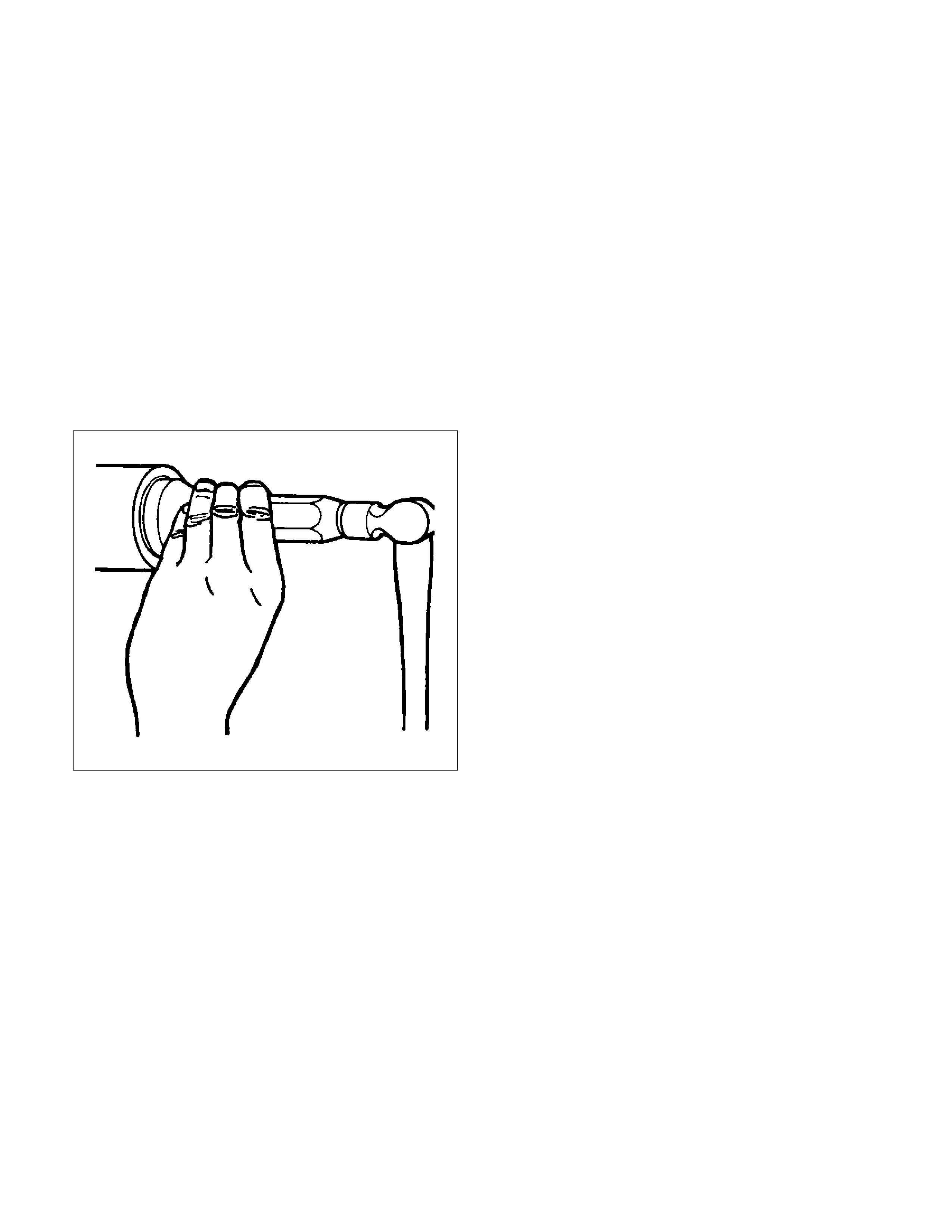
20. Install gear control lever knob (1).
To the female thread portion, adhesive (TB1344 or
LOCTITE 222 or equiv.) of 3 - 4 drops to be
applied and transmission knob tightened.
Torque: 9 N·m (0.9 kg·m/78 lb·in)
After tightening to specified torque, the knob should
be correctly orientated.
21. Connect battery ground cable.
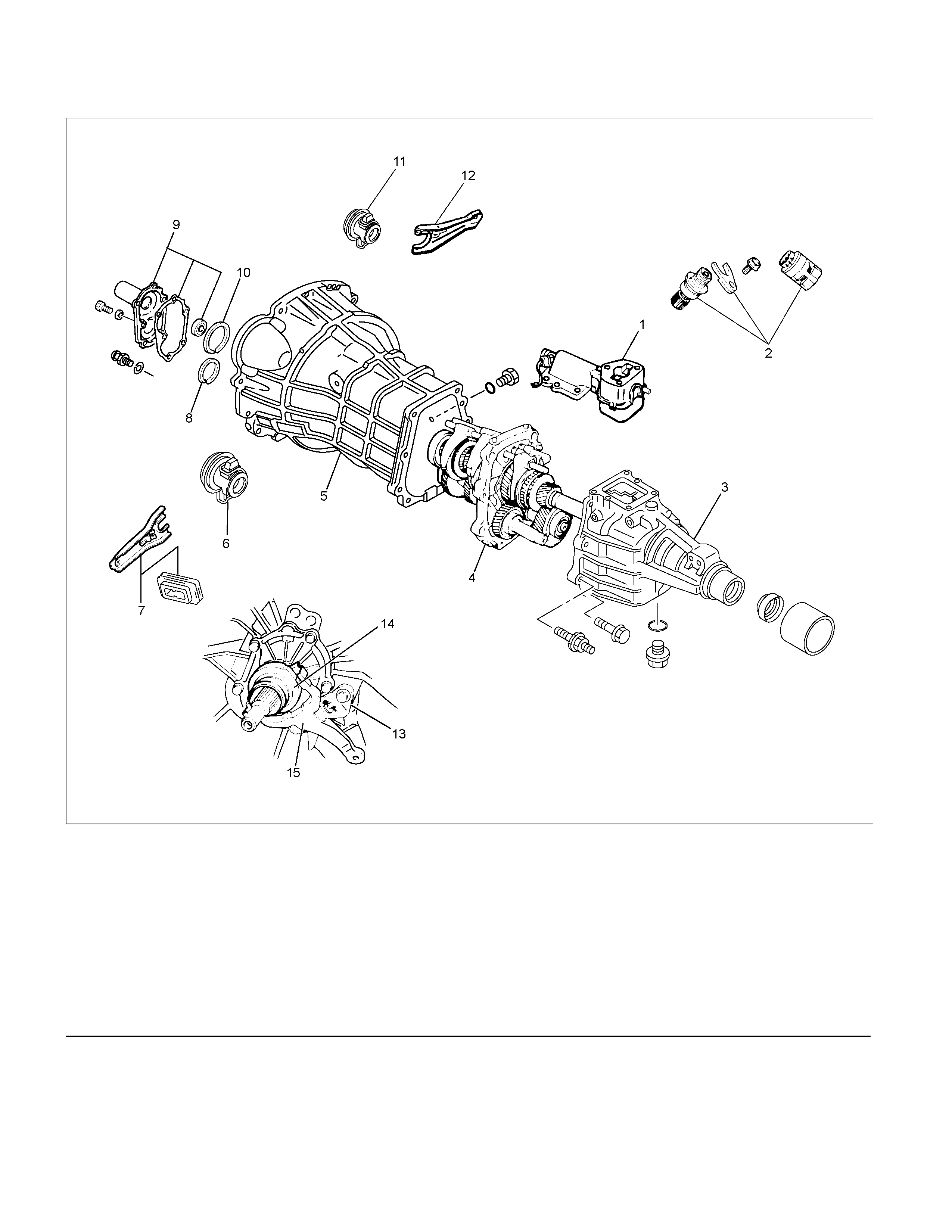
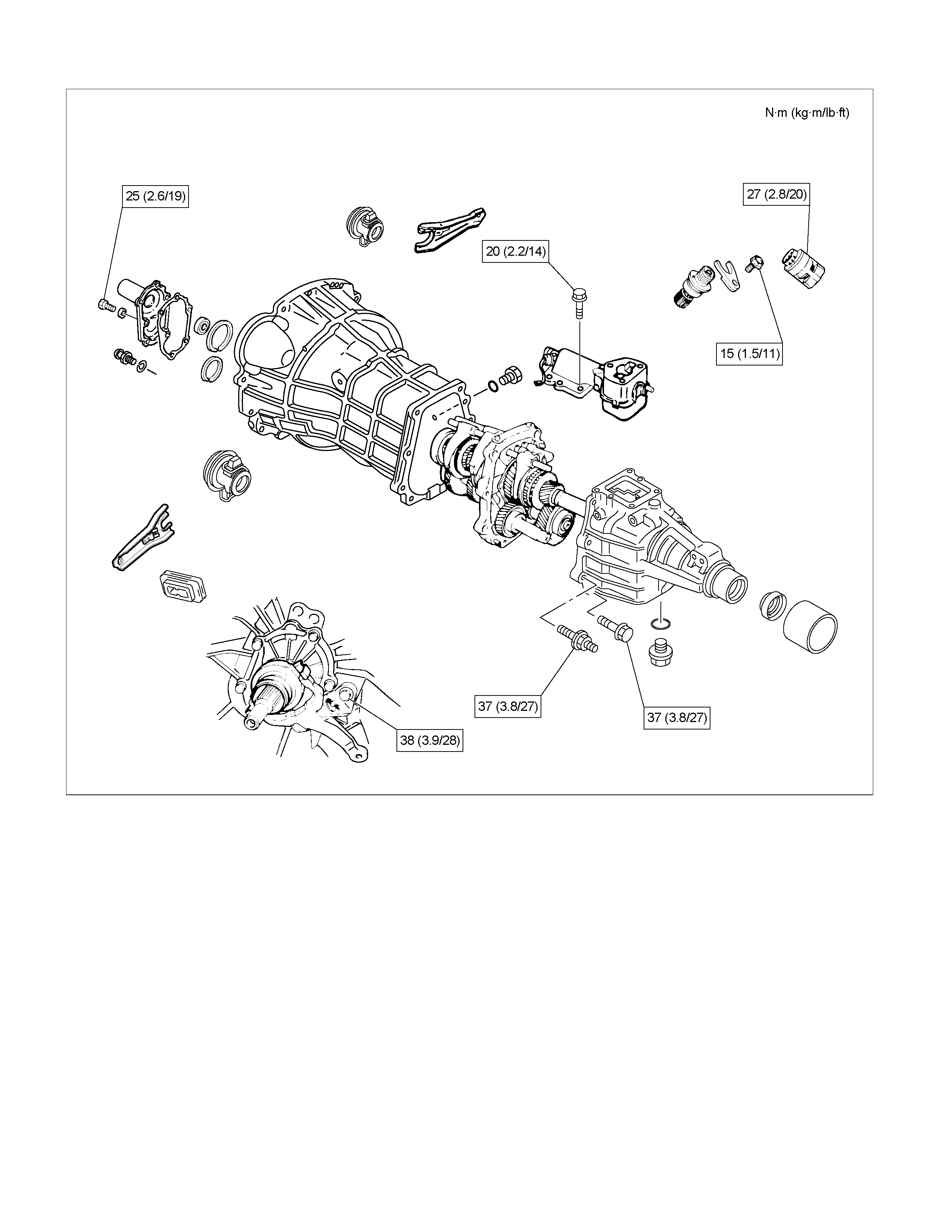
Transmission Case
Major Component
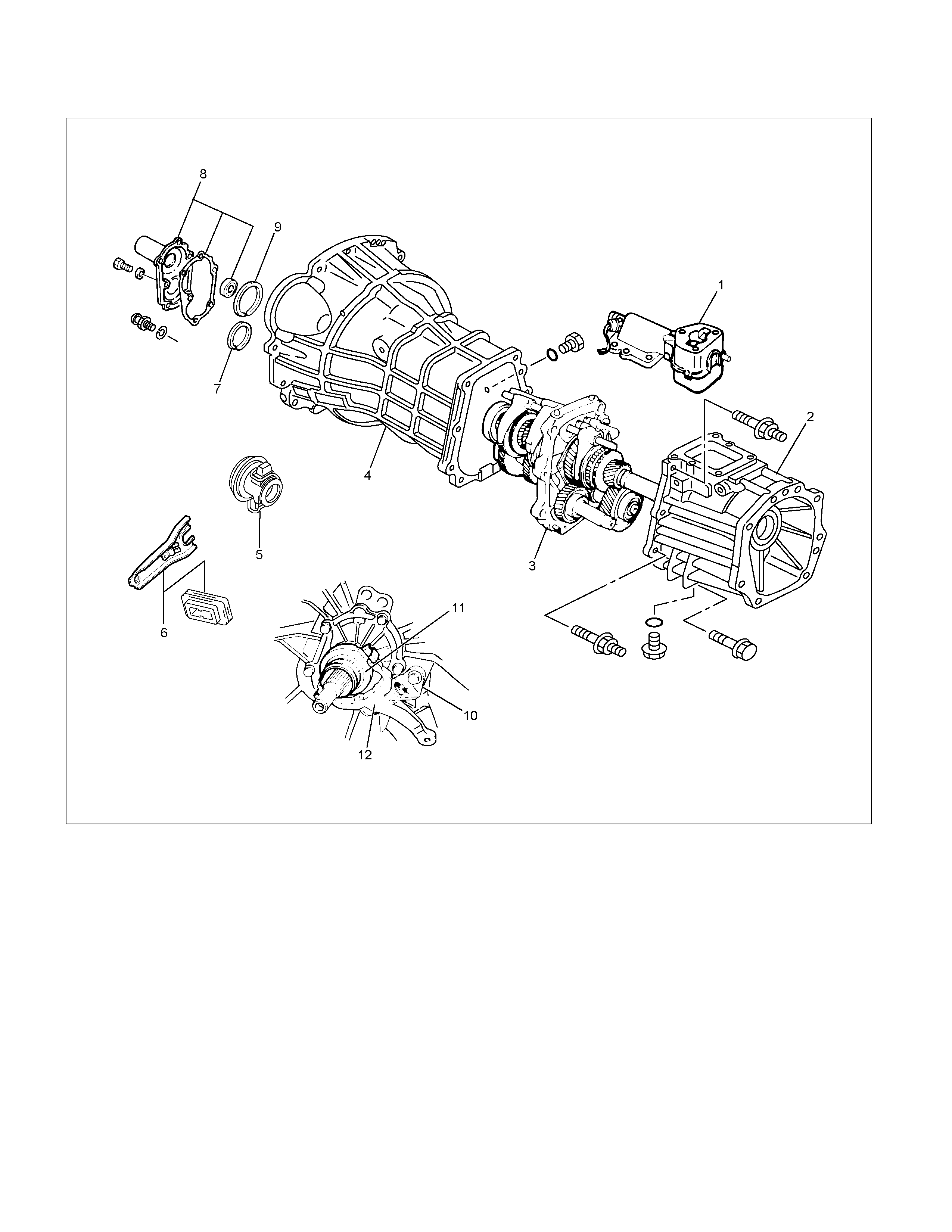
RTW37BLF0005
Legend
(1) Gear Control Box Assembly and Gasket (9) Front Cover (with Oil Seal)
(2) Speedometer Sensor and Driven Gear (10) Top Gear Bearing Snap Ring
(3) Rear Cover Assembly (11) Release Bearing : C24NE
(4) Intermediate Plate with Gear Assembly (12) Shift Fork : C24NE
(5) Transmission Case (13) Fulcrum Bridge : 6VE1
(6) Release Bearing (with Spring) : 4JH1-TC (14) Release Bearing : 6VE1
(7) Shift Fork : 4JH1-TC (15) Shift Fork : 6VE1
(8) Counter Front Bearing Snap Ring
Disassembly
1. Clean the exterior of the unit with solvent.
2. Remove the drain plug from the transmission case
and drain the lubricant.
3. Remove the clutch release bearing with spring
(6)(11) from the transmission case.
4. Remove the shift fork (7)(12), and boot. (4JH1-TC,
C24NE)
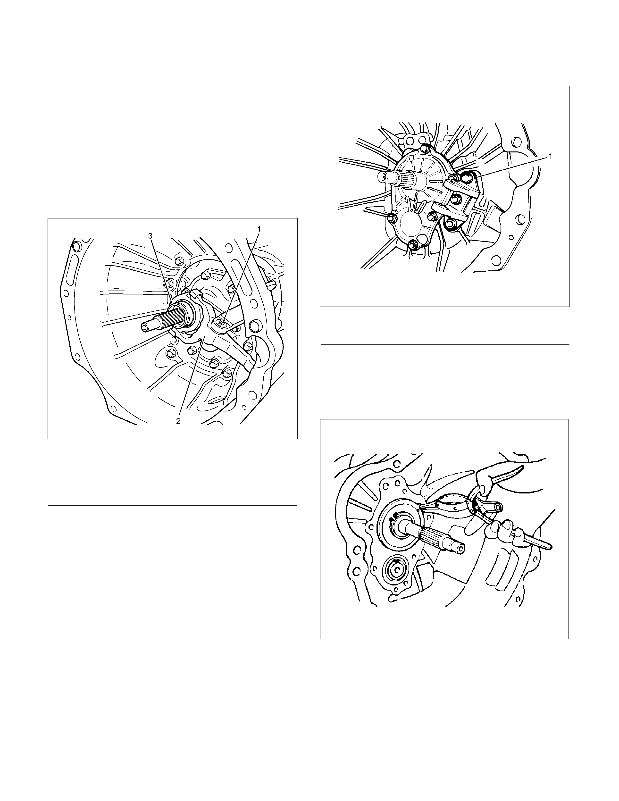
5. Remove the shift fork snap pin. (6VE1)
6. Remove the shift fork pin and shift fork from the
fulcrum bridge. (6VE1)
220RW088-X
Legend
(1) Shift fork pin
(2) Shift fork
(3) Release bearing
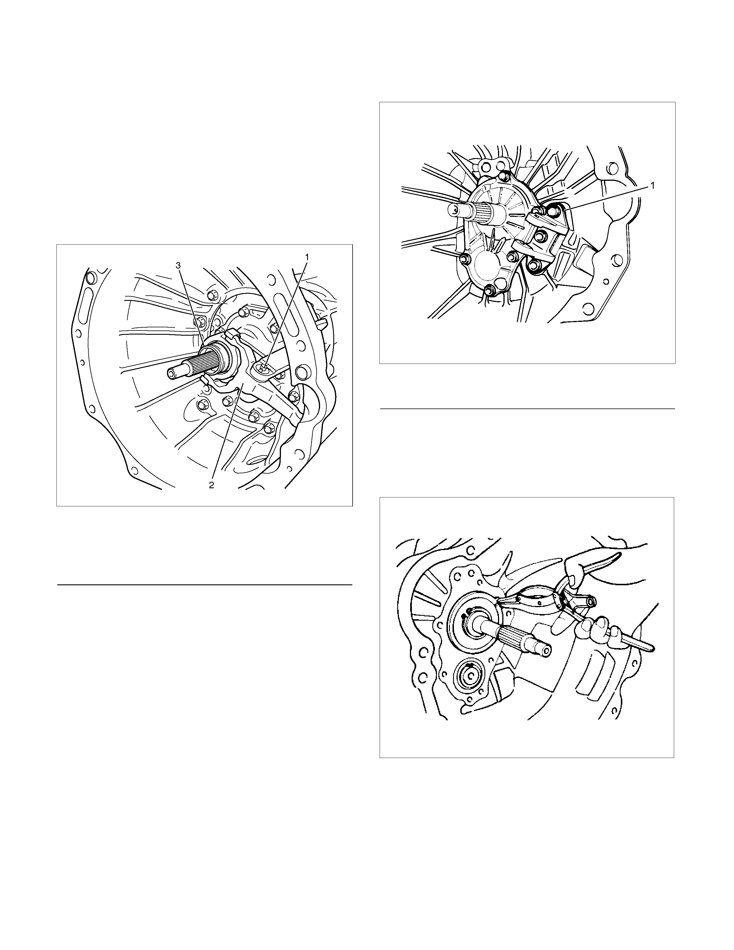
7. Remove the fulcrum bridge from the transmission
case. (6VE1)
RTW37ASH0002
Legend
(1) Fulcrum bridge
8. Remove the front cover (9) and gasket from the
transmission case.
9. Remove snap ring (8) fixing counter front bearing.
10. Use a pair of snap ring pliers to remove the snap
ring (10) fixing top gear bearing.
226RS001
11. Remove the speedometer sensor (2).
Remove the plate (2).
Remove the driven gear bushing and driven gear
(2).
NOTE: Apply a reference mark to the driven gear
bushing before removal.
12. Remove gear control box assembly (1).
13. Remove the rear cover assembly (3) from the
transmission case (5) and intermediate plate (4).
14. Remove intermediate plate with gear assembly (4)
from transmission case (5).
Reassembly
1. Apply recommended liquid gasket (LOCTITE
17430) or its equivalent to the transmission case
(5), intermediate plate (4) and rear cover (3) fitting
surfaces.
2. Install the intermediate plate with gear assembly
(4) to the transmission case (5).
Pull out the top gear shaft until the ball bearing snap
ring groove protrudes from the transmission case
front cover fitting face.
Avoid subjecting the main shaft to sudden shock or
stress.
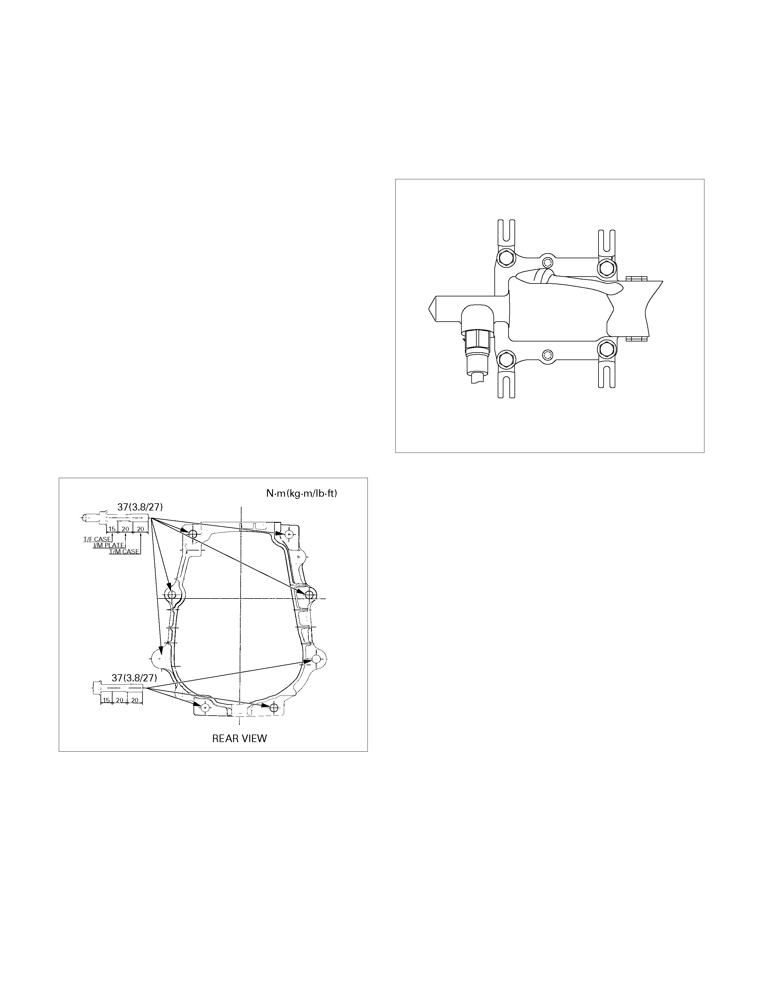
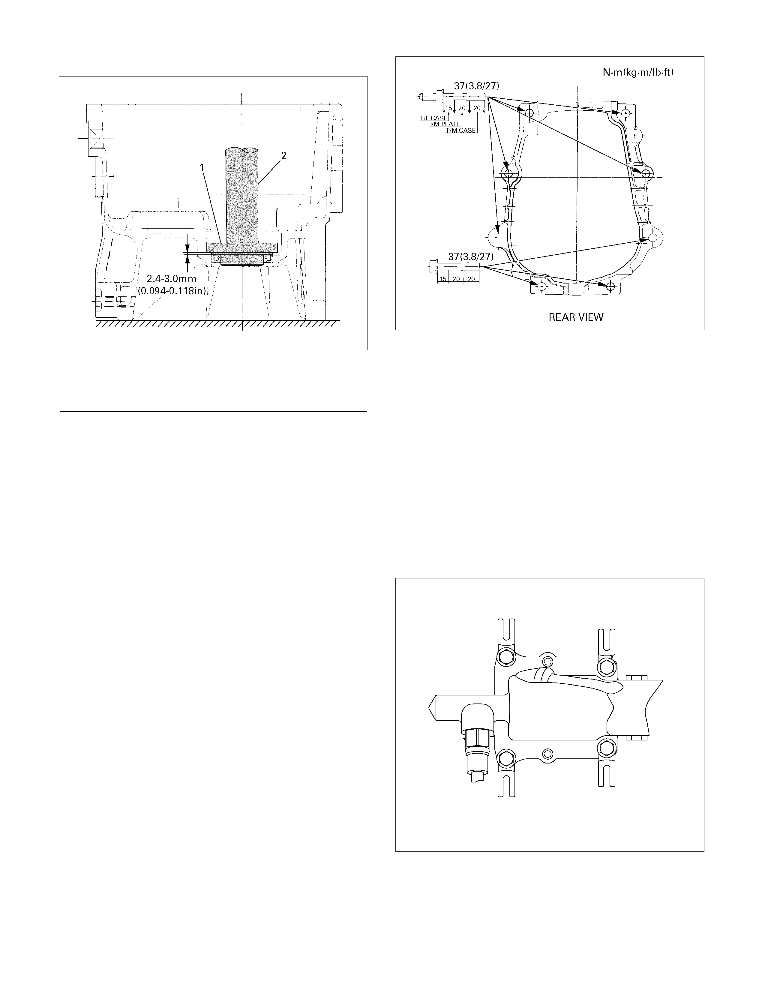
3. Install the rear cover with oil seal (3) on the
intermediate plate with gear (4) by performing the
following steps.
• Cover the shaft splines with adhesive tape.
This will prevent damage to the oil seal lip.
• Tighten the transmission rear case bolts and
nuts to the specified torque.
Torque: 37 N·m (3.8 kg·m/27 lb·ft)
220R300026
Notes When Tightening the Bolt:
• After cleaning the bolt hole, dry it thoroughly with
air.
• After cleaning the screw face of a removed bolt or
new one, dry it thoroughly. Apply recommended
liquid gasket (LOCTITE 242) or its equivalent on
them before tightening it.
4. Install a new gasket and gear control box
assembly (1).
Install the harness clips and brackets and then
tighten four new gear control box bolts to the
specified torque.
Torque: 20 N·m (2.0 kg·m/14 lb·ft)
261R300004
5. Install the O-ring (4) to the speedometer driven
gear bushing (3).
Install the driven gear to the speedometer driven
gear bushing (3).
6. Install the speedometer driven gear assembly (2)
to the transmission rear cover (3).
Install the plate (1) to the transmission rear cover
(3).
Torque: 15 N·m (1.5 kg·m/11 lb·ft)
7. Install the speedometer sensor (2).
Torque: 27 N·m (2.8 kg·m/20 lb·ft)
225R300001
8. Install top gear bearing snap ring (10) and counter
front bearing snap ring (8).
• Use a pair of snap ring pliers to install the snap
rings to the mainshaft and countershaft.
• The snap rings must be fully inserted into the
bearing snap ring groove.
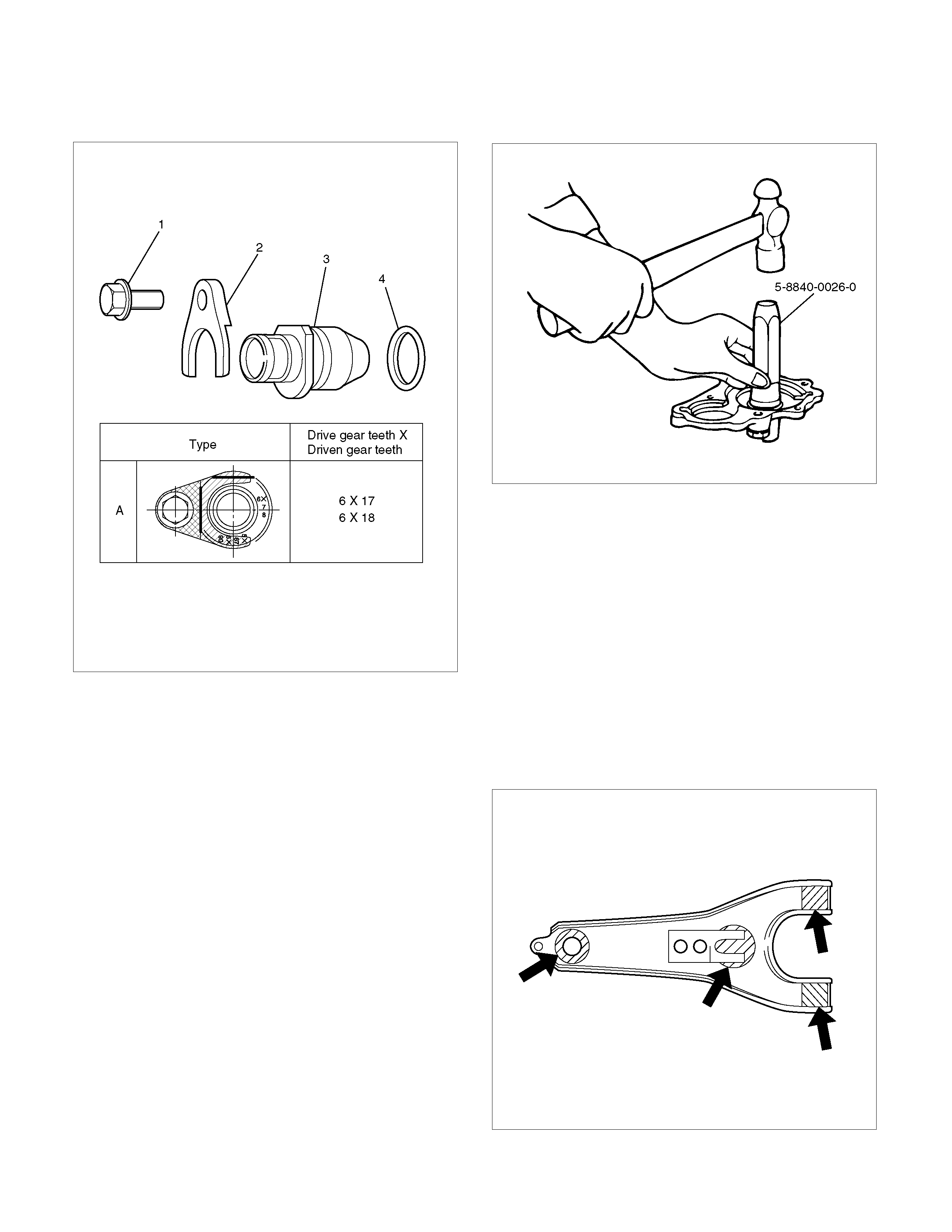
9. Front cover with oil seal (9).
Front Cover Oil Seal Replacement
• Remove the oil seal from the front cover.
• Apply engine oil to a new oil seal outer
circumference.
• Apply recommended grease to the oil seal lip.
• Use the oil seal installer 5-8840-0026-0 to
install the oil seal to the front cover.
220R3000020
10. Install a new gasket and front cover (9) to the
transmission case.
NOTE: Take care not to damage the oil seal.
Notes When Tightening the Bolt:
• After cleaning the bolt hole, dry it thoroughly with
air.
• After cleaning the screw face of a removed bolt or
new one, dry it thoroughly. Apply recommended
liquid gasket (LOCTITE 242) or its equivalent
before tightening it.
Tighten six front cover bolts to the specified torque.
Torque: 25 N·m (2.6 kg·m/19 lb·ft)
11. Apply molybdenum disulfide type grease to the
areas as shown in the figure and install shift fork
(7). (4JH1-TC, C24NE)
F07L100026
12. Install the fulcrum bridge to the transmission case.
(6VE1)
Torque: 38 N·m (3.9 kg·m/28 lb·ft)
RTW37ASH0002
Legend
(1) Fulcrum bridge
13. Apply molybdenum disulfide type grease to the pin
hole inner circumferences and thrust surfaces.
(6VE1)
14. Attach the shift fork to the fulcrum bridge and
insert the pin from below of the fulcrum bridge.
(6VE1)
15. Install the washer and snap pin. (6VE1)
201RW019
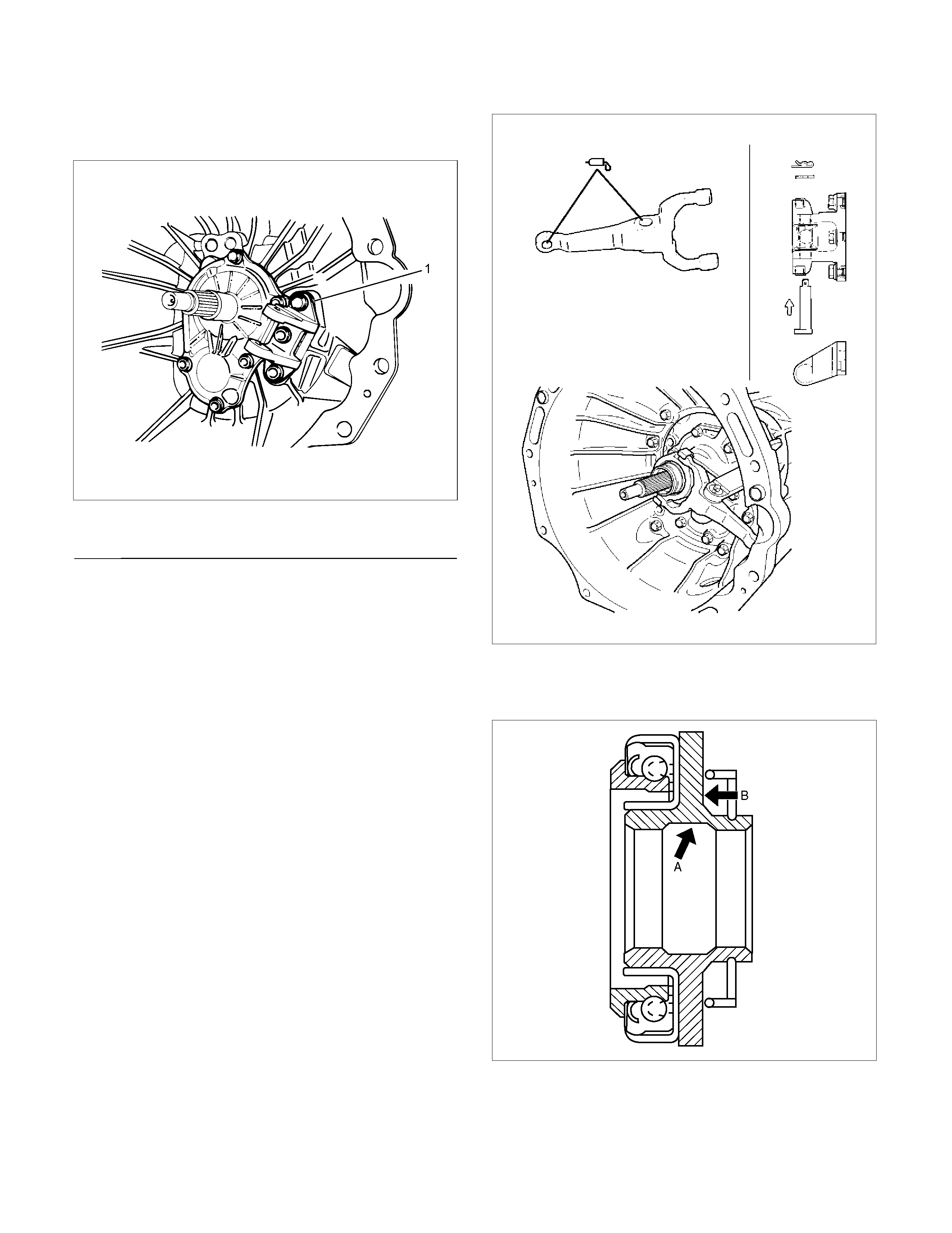
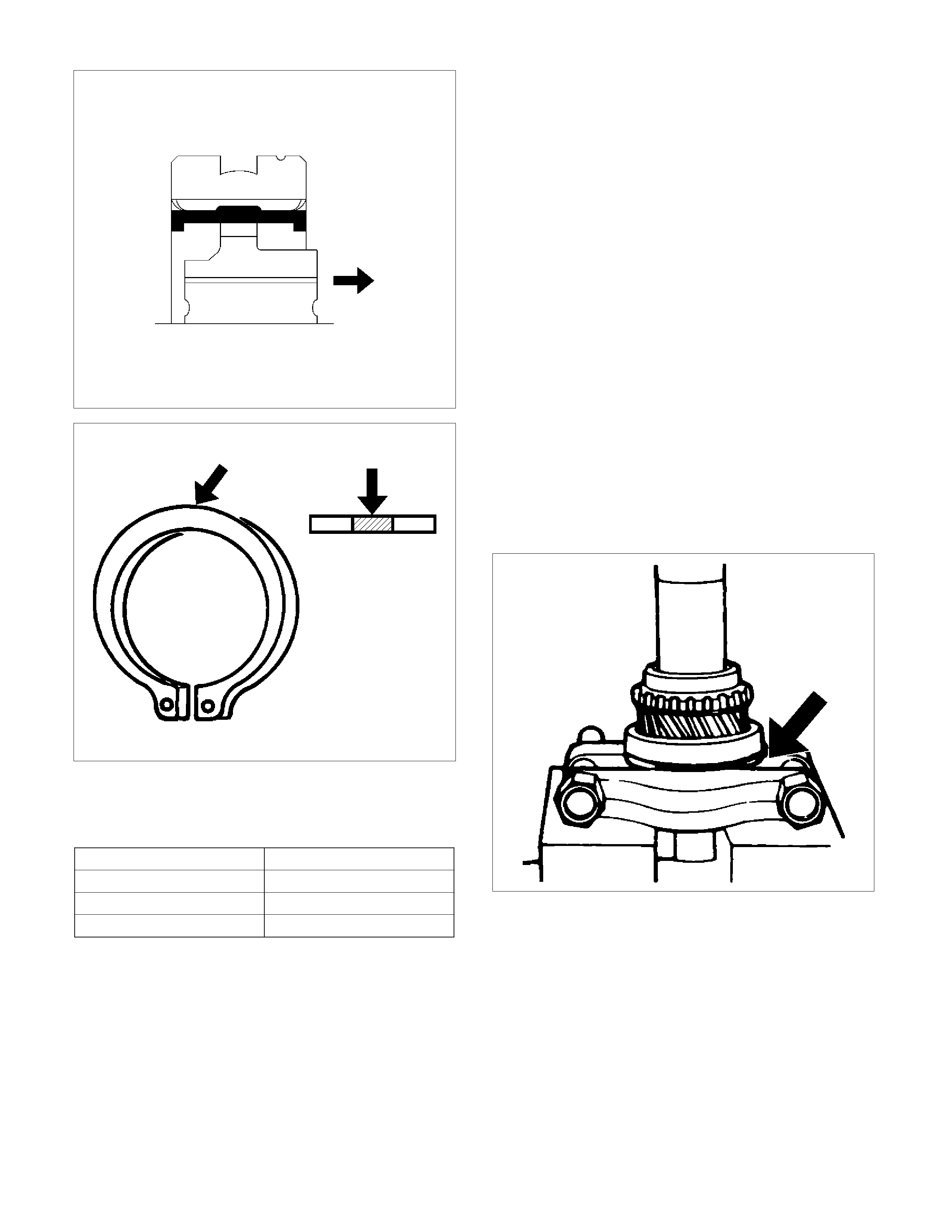
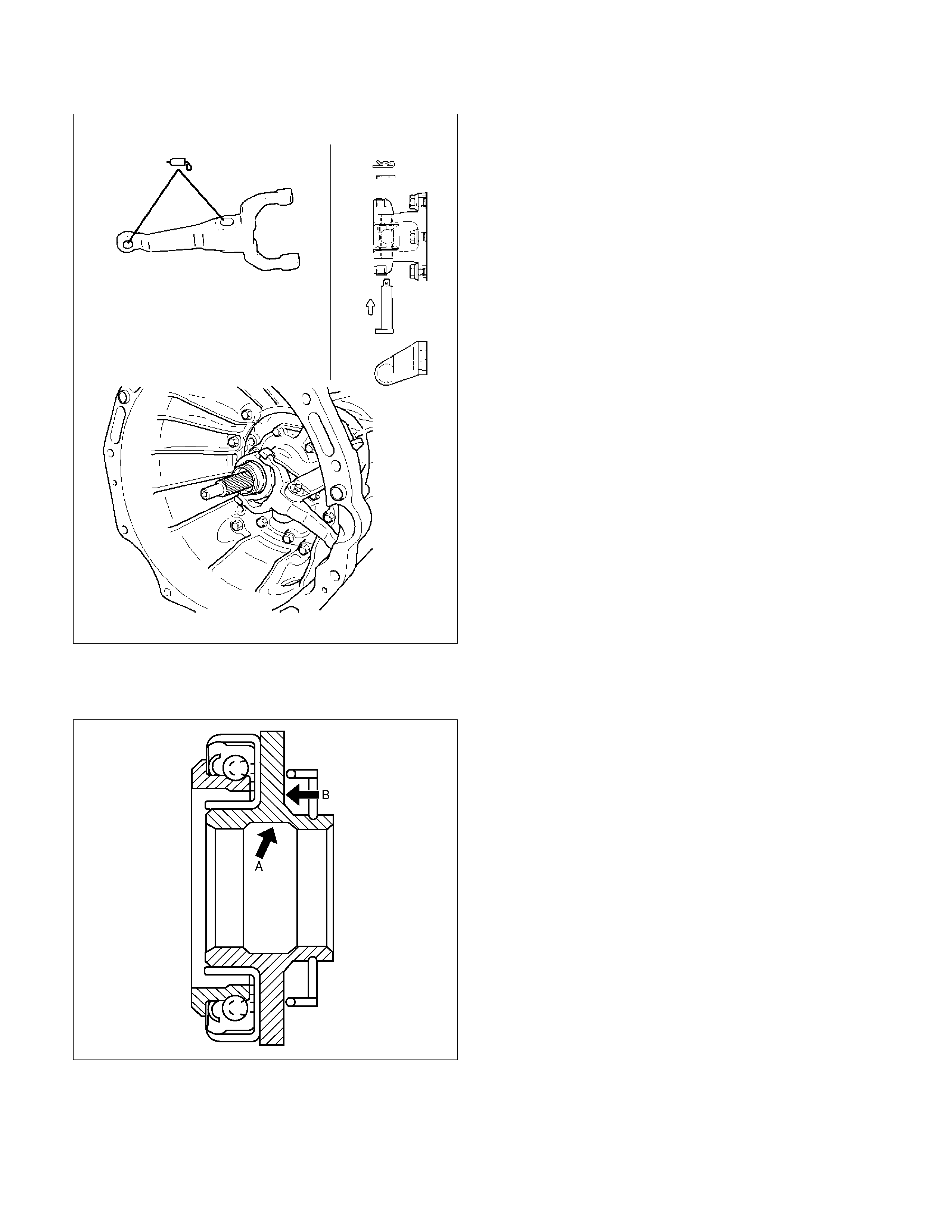
16. Pack the inside recess (A) and coat the back (B)
of the release bearing with molybdenum disulfide
type grease as shown in the figure.
A07RW075
17. Install the release bearing (6) on the front cover,
joining it to the shift fork.

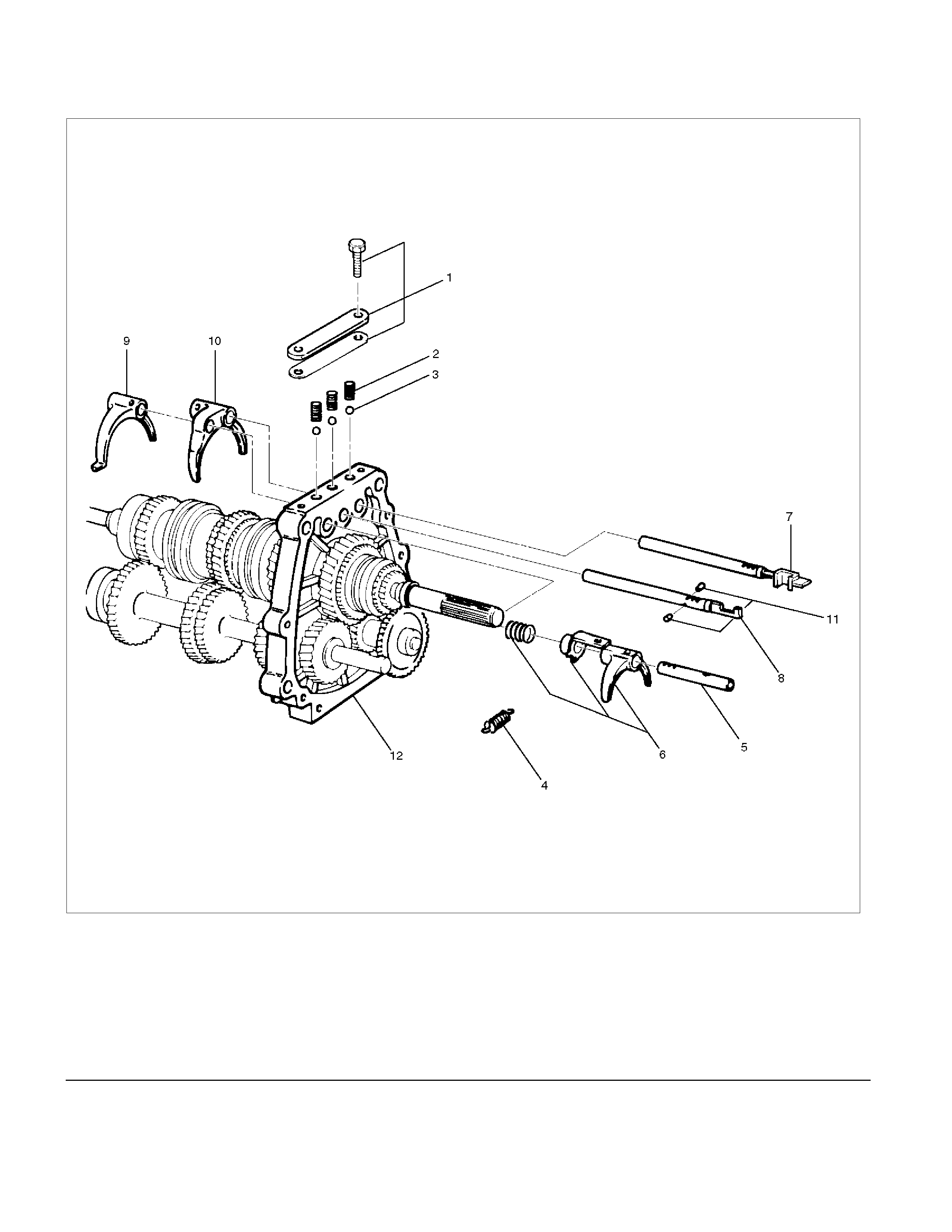
Intermediate Plate with Gear Assembly, Detent, Shift Arm, Shift Rod, and Interlock Pin
Disassembled View
220RS010
Legend
(1) Detent Spring Plate and Gasket (7) 1st-2nd Shift Rod
(2) Detent Spring (8) 3rd-4th Shift Rod
(3) Detent Ball (9) 3rd-4th Shift Arm
(4) Spring (10) 1st-2nd Shift Arm
(5) Rev-5th Shift Rod (11) Interlock Pin
(6) Rev-5th Shift Arm and Reverse Inhibitor (12) Intermediate Plate and Gear Assembly
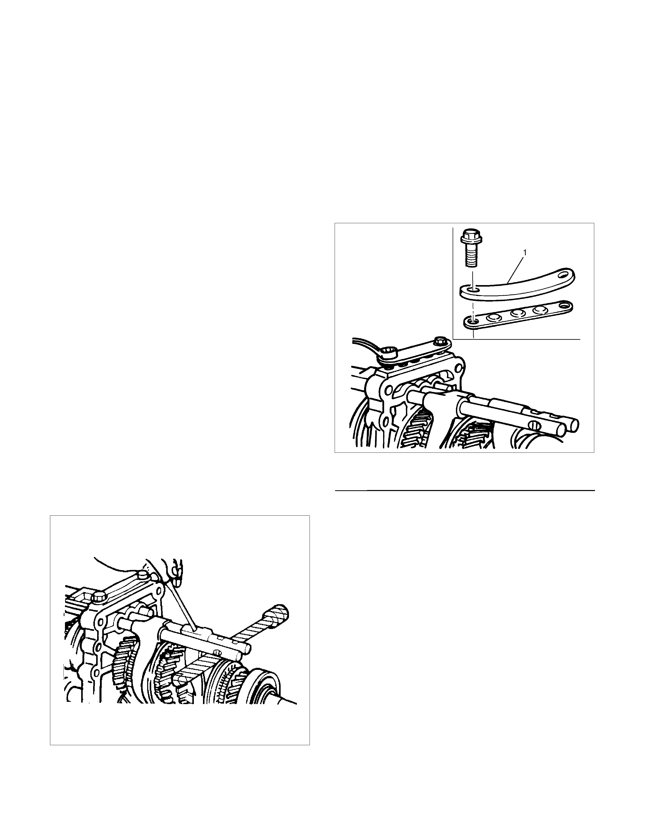
Disassembly
1. Remove detent spring plate and gasket (1), detent
spring (2) and detent ball (3).
Use a magnetic hand to remove the detent balls
from the intermediate plate.
220RS011
2. Remove spring (4).
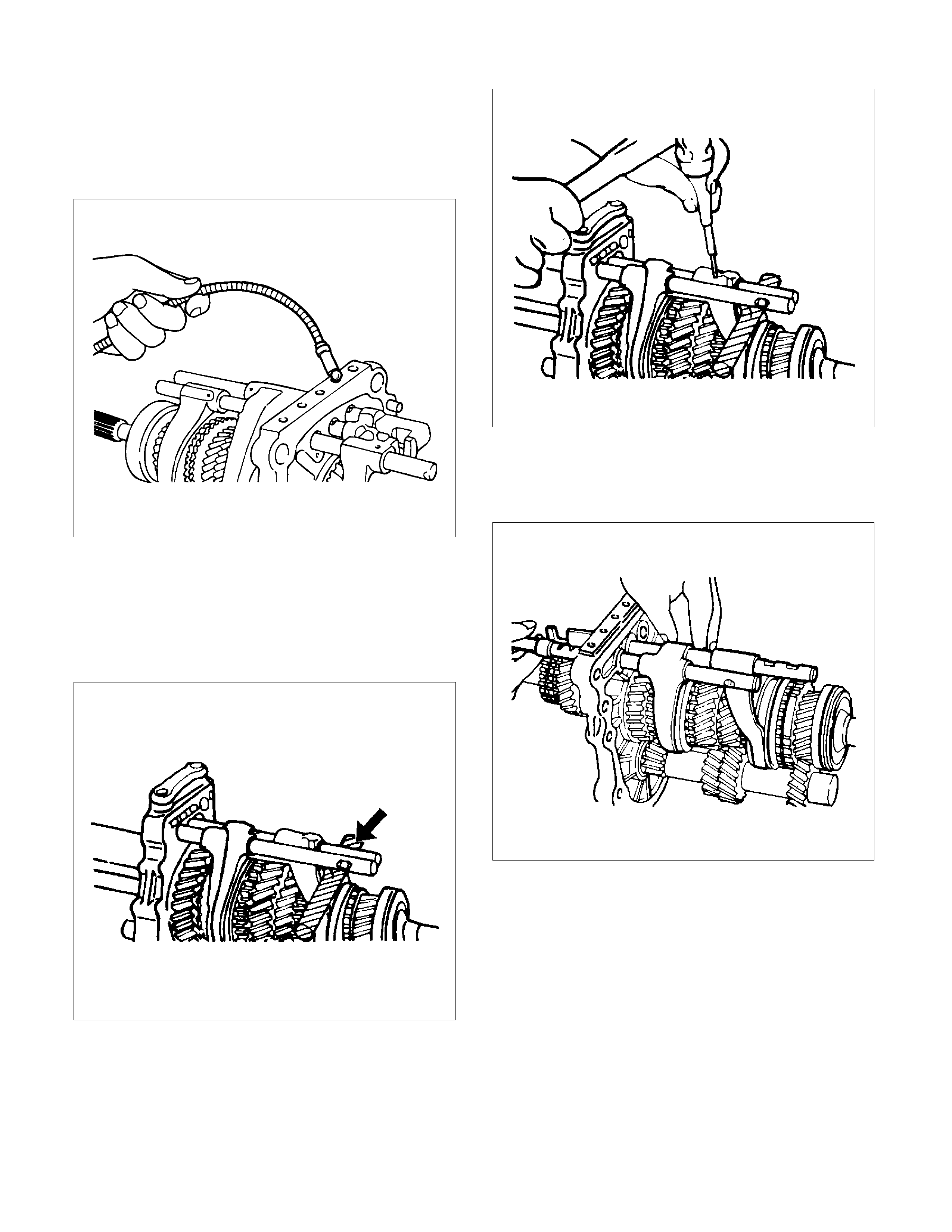
3. Remove rev-5th shift rod (5), and rev-5th shift arm
and reverse inhibitor (6).
Remove 1st-2nd shift rod (7), 3rd-4th shift rod (8),
3rd-4th shift arm (9), and 1st-2nd shift arm (10).
• Hold a round bar against the shift rod end.
230RS003
• Use a spring pin remover to remove the shift
arm spring pins from the shift arms and the
shift rods.
230RS0004
• Be careful not to lose the interlock pins, when
pulling out the shift rod rearward.
Interlock pins are located between the shifter
rods in the intermediate plate.
230RS0005
• Remove the rev-5th, 1st-2nd and 3rd-4th shift
rods carefully.
4. Remove interlock pin (11) from intermediate plate
and gear assembly (12).

Inspection and Repair
Make the necessary adjustments, and part
replacements if excessive wear or damage is
discovered during inspection.
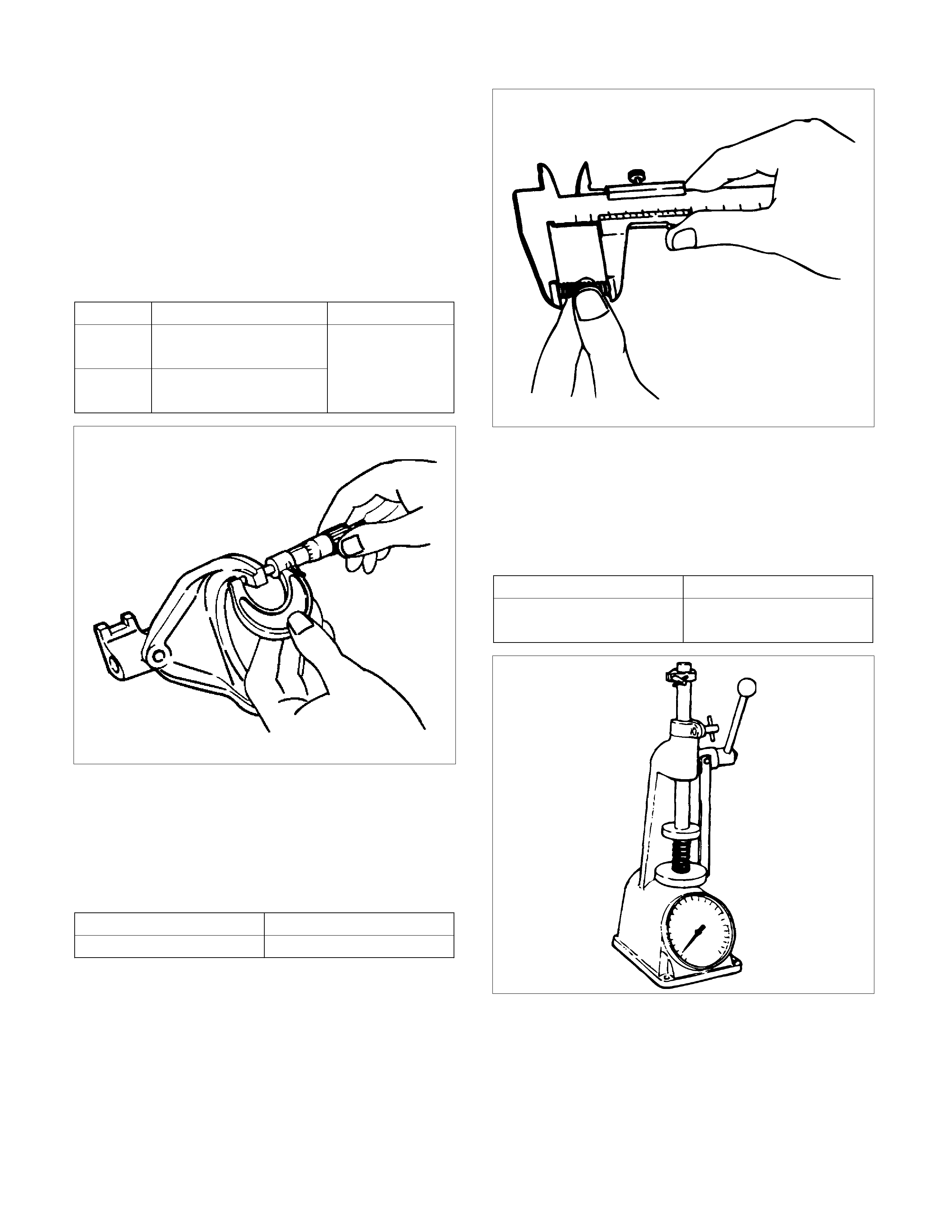
Shift Arm Thickness
• Use a micrometer to measure the shift arm
thickness.
If the measured value is less than the specified limit,
the shift arm must be replaced.
Shift Arm Thickness
Standard Limit
1st-2nd 9.60 - 9.85 mm
(0.378 - 0.388 in)
3rd-4th
Rev.5th 9.60 - 9.80 mm
(0.378 - 0.386 in)
9.0 mm
(0.354 in)
230RS006
Detent Spring Free Length
• Use a vernier caliper to measure the detent spring
free length.
If the measured value is less than the specified limit,
the detent spring must be replaced.
Detent Spring Free Length
Standard Limit
26.8 mm (1.06 in) 26.2 mm (1.03 in)
220RS012
Detent Spri ng Tension
• Use a spring tester to measure the detent spring
tension.
If the measured value is less than the specified limit,
the detent spring must be replaced.
Detent Spri ng Tension
Compressed height Standard
20 mm (0.787 in) 87.2 - 97.1 N
(19.6 - 21.8 lb)
220RS013
Reassembly
1. Install rev-5th shift arm and reverse inhibitor (6)
and rev-5th shift rod (5).
• Apply oil to the reverse inhibitor inner surface.
• Install the shift rod in the intermediate plate
(12).
• Hold a round bar against the shift rod end
lower face to protect it against damage.
• Install a new spring pin.
Never reinstall the used spring pin.
• Install the interlock pin (11) in the intermediate
plate (12).
Do not allow the interlock pin to fall from the
intermediate plate (12).
2. Install 1st-2nd shift arm (10) and 3rd-4th shift arm
(9) to intermediate plate and gear assembly (12).
3. Install 3rd-4th shift rod (8) and 1st-2nd shift rod
(7).
• Install the interlock pin (11) in the intermediate
plate and gear assembly (12).
• Install the 3rd-4th shift rod (8) in the
intermediate plate (12).
Do not allow the interlock pin to fall from the
intermediate plate.
• Install the interlock pin (11) and then 1st-2nd
shift rod (7) in the intermediate plate (12).
Do not allow the interlock pin to fall from the
intermediate plate.
• Hold a round bar against the shift rod end
lower face to protect it against damage.
• Install a new spring pin.
Never reinstall the used spring pin.
230RS007
4. Install spring (4).
5. Put detent balls (3) in the intermediate plate holes.
• Apply oil to the detent balls.
6. Install detent springs (2) and detent spring plate
and gasket (1).
• Install a new gasket and the detent spring
plate.
• Tighten the detent spring plate bolts to the
specified torque.
Torque: 25 N·m (2.5 kg·m/18 lb·ft)
220RS030
Legend
(1) Warped
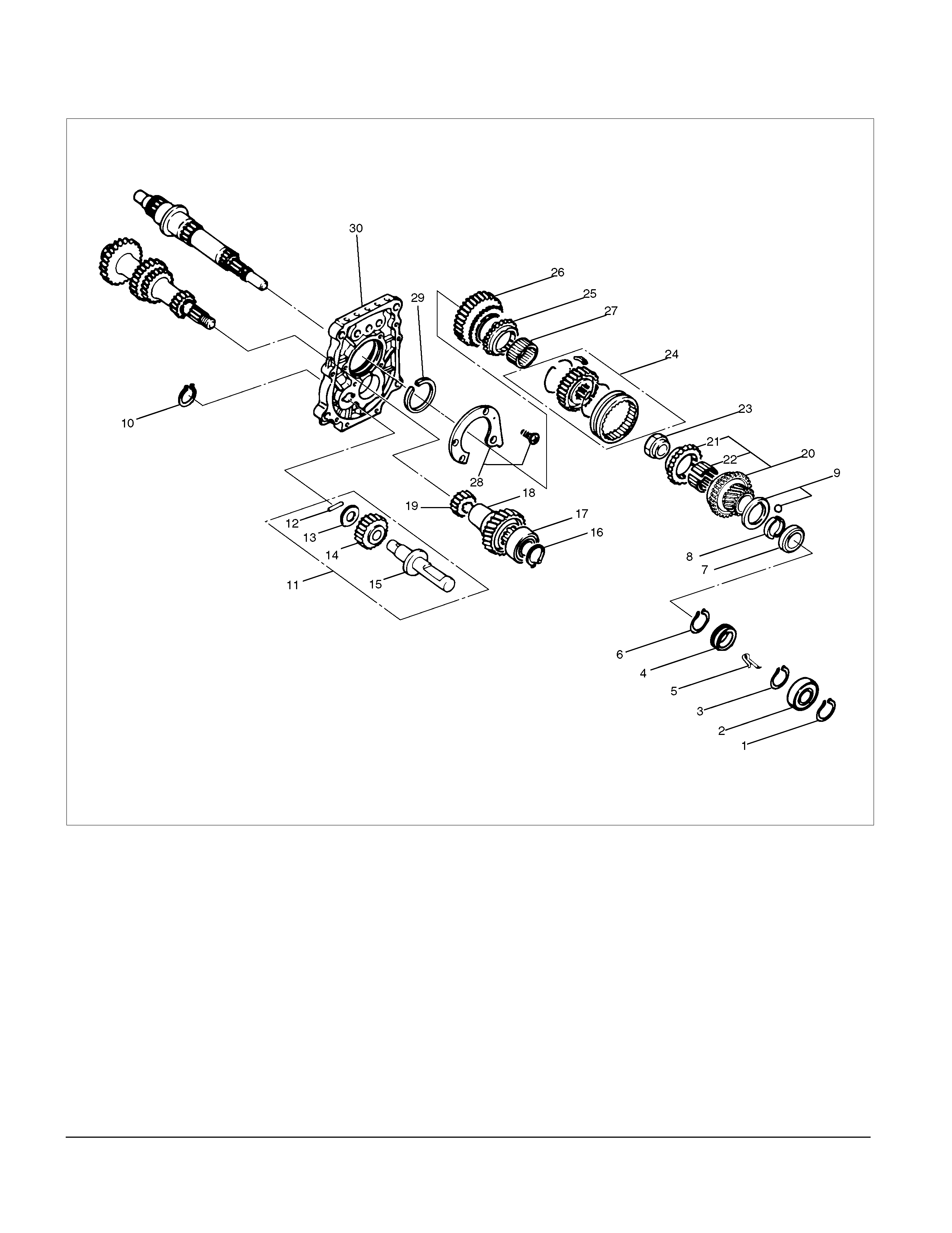
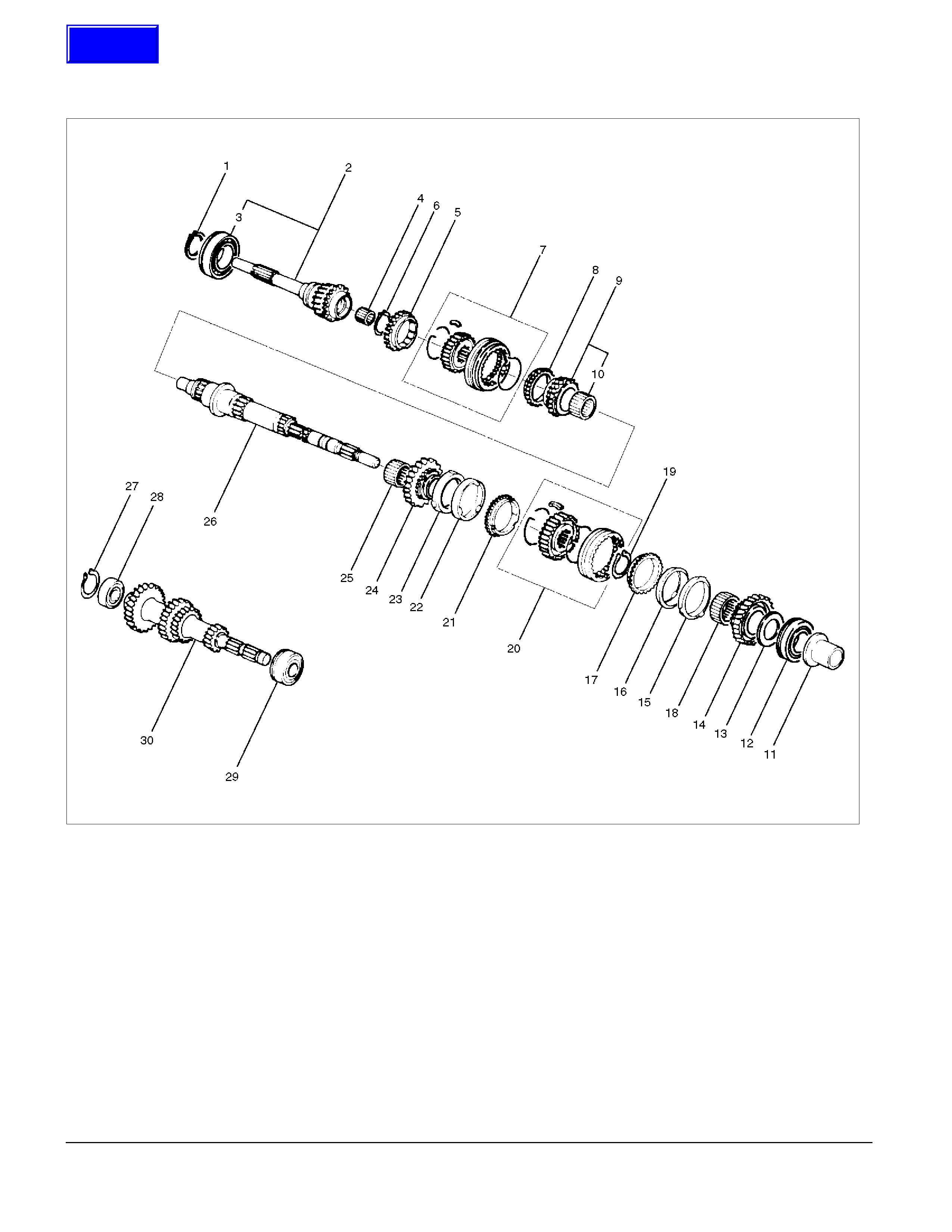
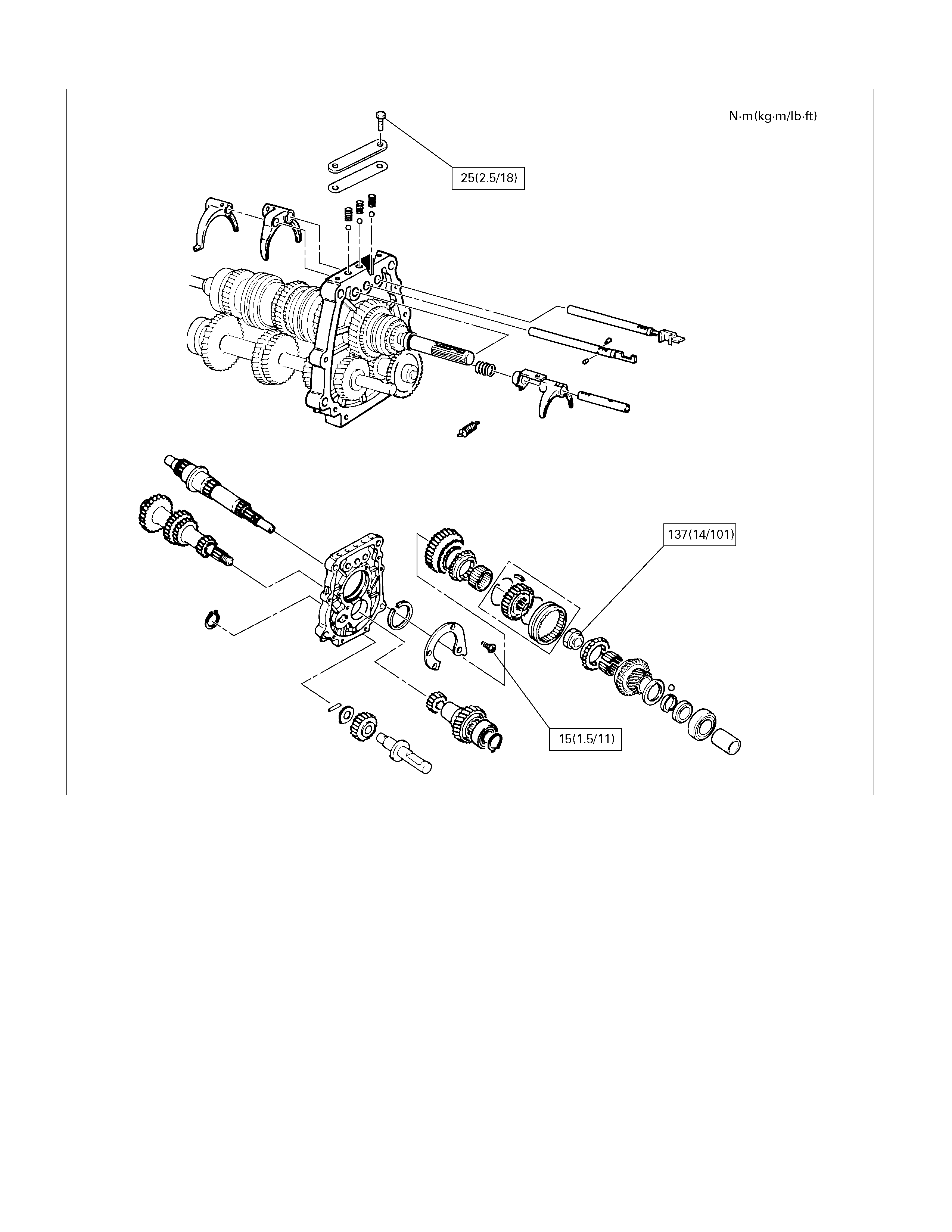
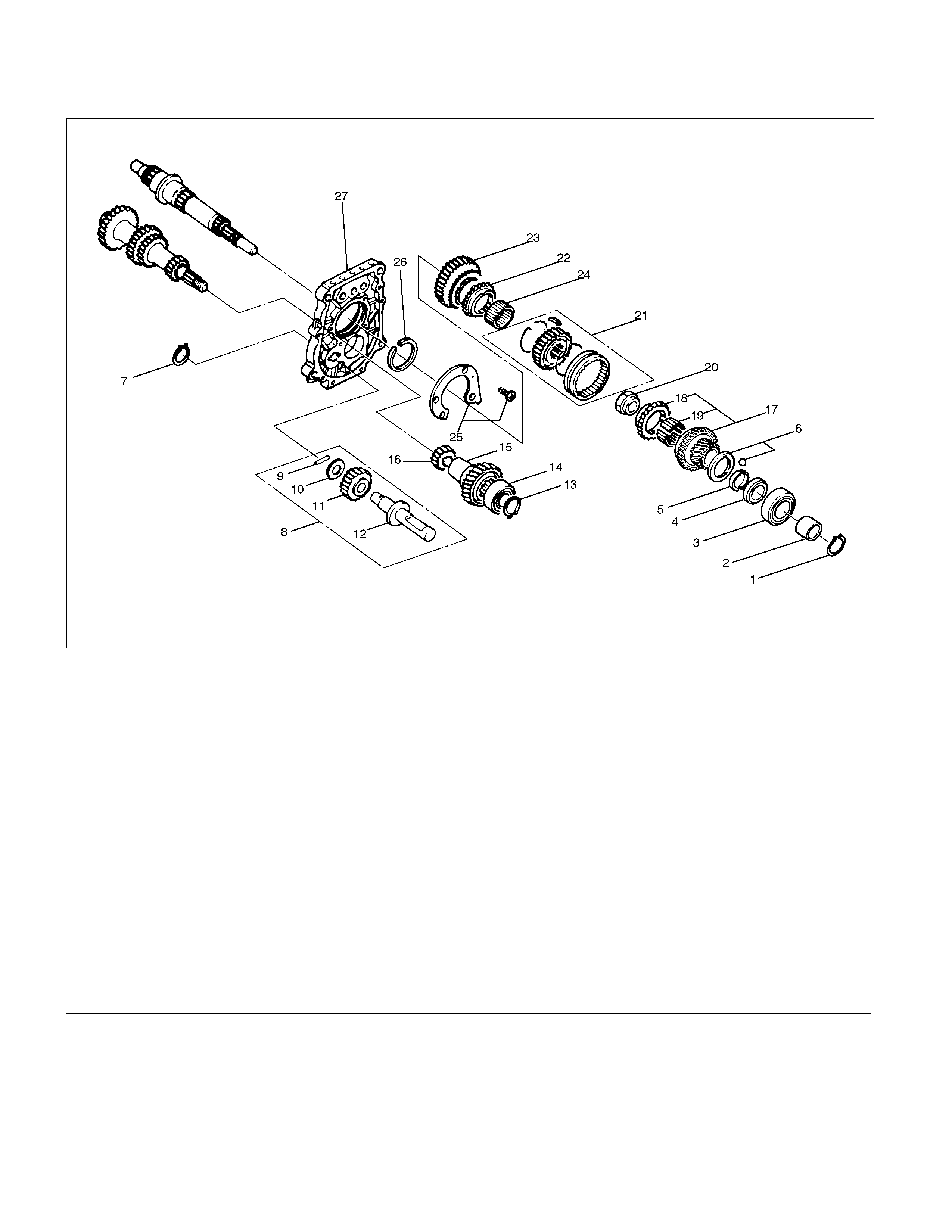
Reverse Gear and 5th Gear
Disassembled View
226R300027
Legend
(1) Bearing Snap Ring (11) Reverse Idler Gear Assembly
(2) Ball Bearing (12) Idle Shaft Pin
(3) Bearing Snap Ring (13) Thrust Washer
(4) Speedometer Drive Gear (14) Reverse Idler Gear
(5) Clip (15) Reverse Idler Shaft
(6) Retainer Snap Ring (16) Bearing Snap Ring
(7) Retainer (17) Ball Bearing
(8) Thrust Plate (18) Counter 5th Gear
(9) Thrust Washer and Lock Ball (19) Counter Reverse Gear
(10) Reverse Idler Gear Snap Ring (20) 5th Gear
(21) 5th Block Ring (26) Reverse Gear
(22) Needle Bearing (27) Needle Baring
(23) Mainshaft Nut (28) Bearing Plate and Screw
(24) Rev-5th Synchronizer Assembly (29) Bearing Snap Ring
(25) Reverse Block Ring (30) Intermediate Plate
Disassembly
1. Use a pair of snap ring pliers to remove the
bearing snap ring (1).
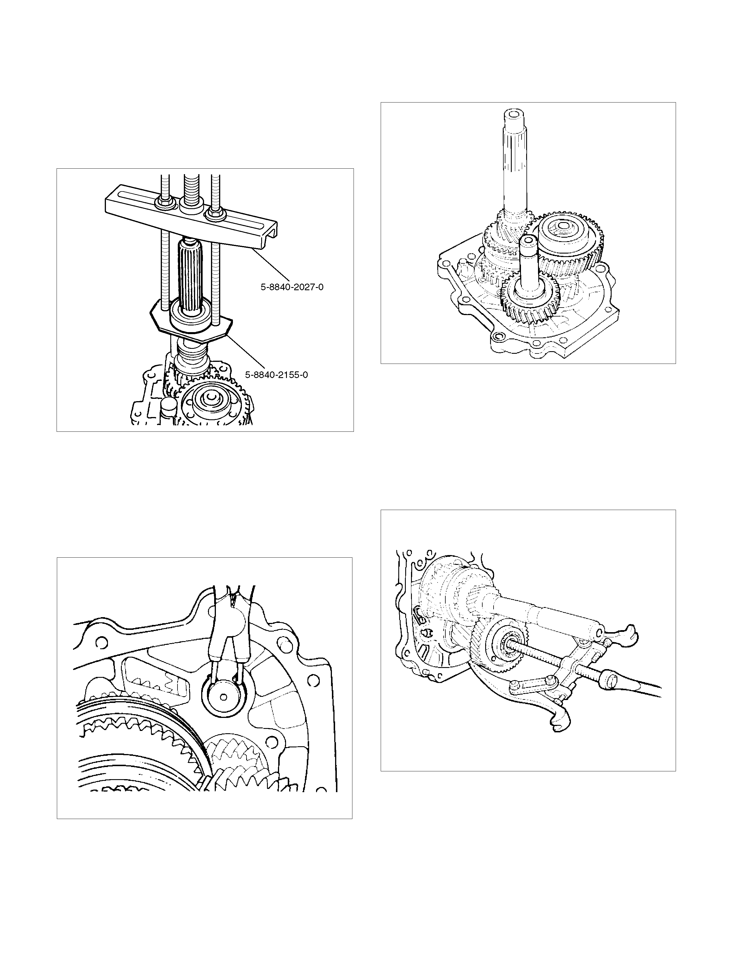
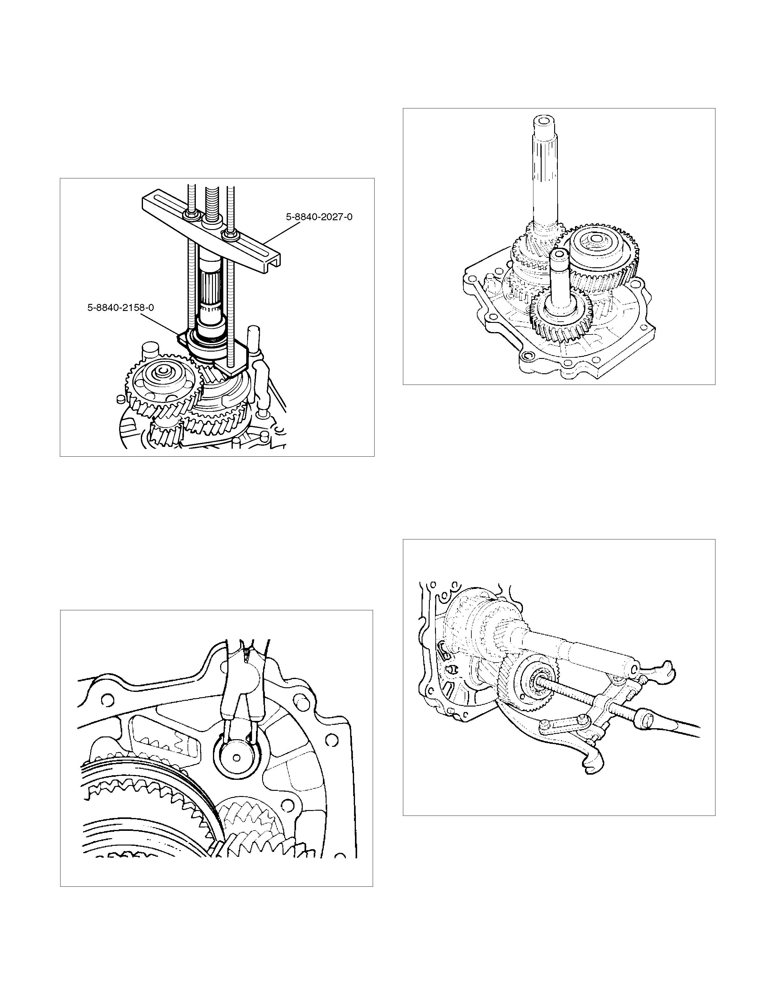
2. Set the bearing remover 5-8840-2155-0 and puller
5-8840-2027-0 to the bearing (2) and the
mainshaft end to remove the ball bearing (2).
262L100001
3. Remove the bearing snap ring (3), clip (5),
speedometer drive gear (4), retainer snap ring (6)
and retainer (7).
4. Remove thrust plate (8) and thrust washer and
lock ball (9).
5. Use a pair of snap ring pliers to remove reverse
idler gear snap ring (10).
226RS004
6. Remove the reverse idler gear assembly (11) from
the intermediate plate (30).
226RS005
7. Remove idle shaft pin (12), thrust washer (13),
reverse idler gear (14), and reverse idler shaft
(15).
8. Use a pair of snap ring pliers to remove the snap
ring (16).
9. Attach a universal puller to the counter gear shaft.
Use a universal puller to remove the ball bearing
(17) and the counter 5th gear (18).
226RS006
10. Remove counter reverse gear (19).

11. Remove 5th gear (20), 5th block ring (21), and
needle bearing (2 piece type) (22).
226RS007
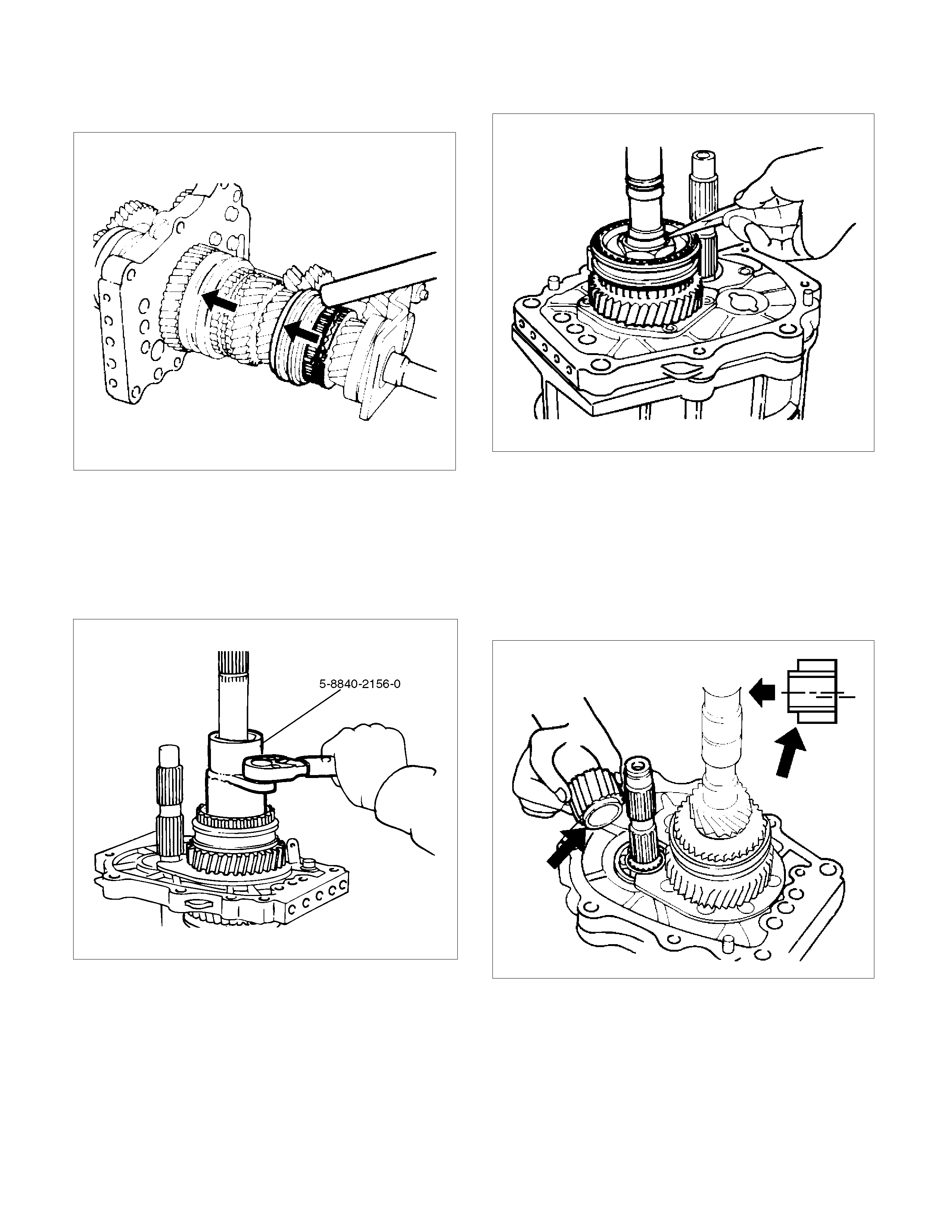
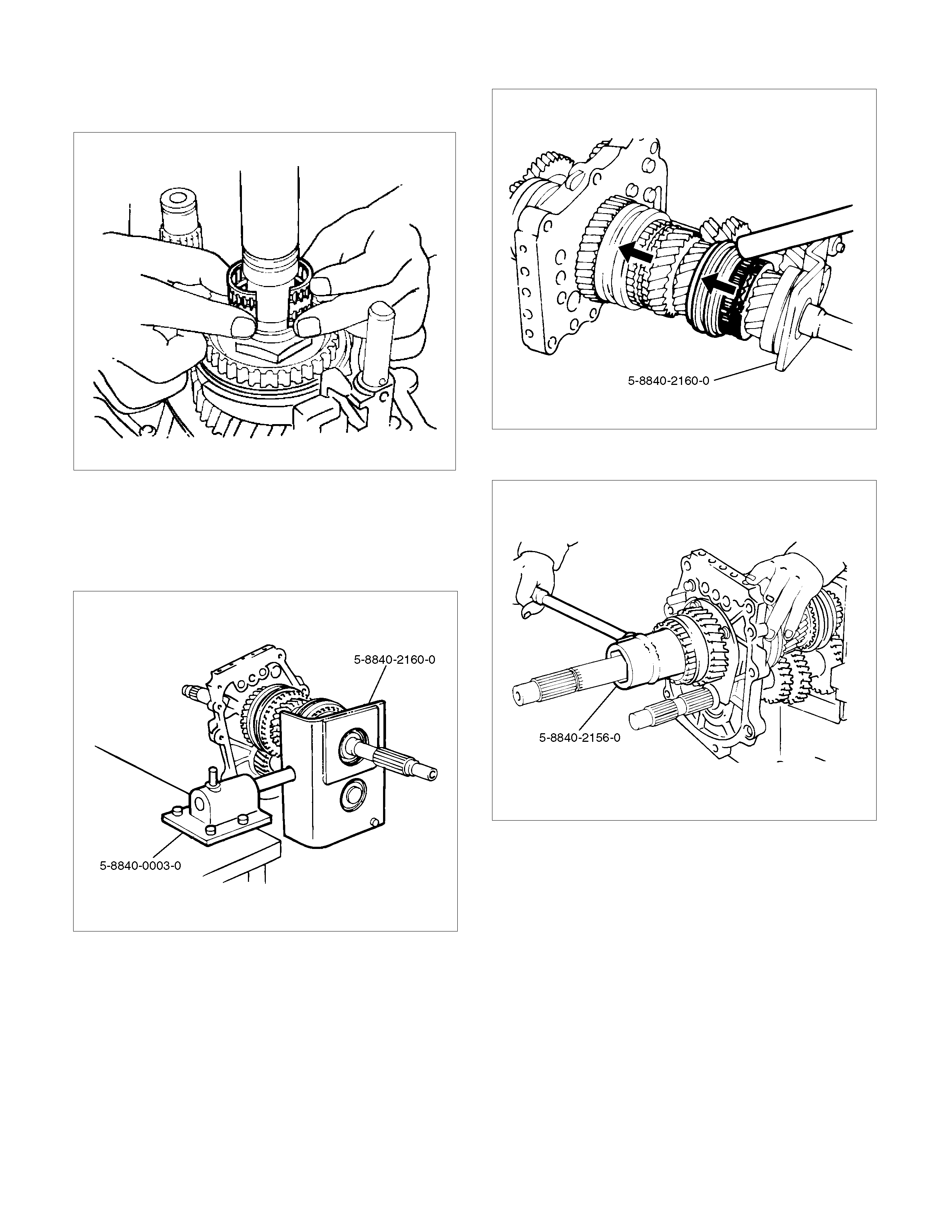
12. Remove the mainshaft nut (23) according to
following steps.
Attach the holding fixture 5-8840-2160-0 and base
5-8840-0003-0 to the mainshaft and the counter
gear.
226RW212
• Engage the 3rd-4th synchronizer with the 3rd
gear.
• Engage the 1st-2nd synchronizer with the 1st
gear.
226RW210
• Use the mainshaft nut wrench 5-8840-2156-0
to remove the mainshaft nut (23).
226RW211

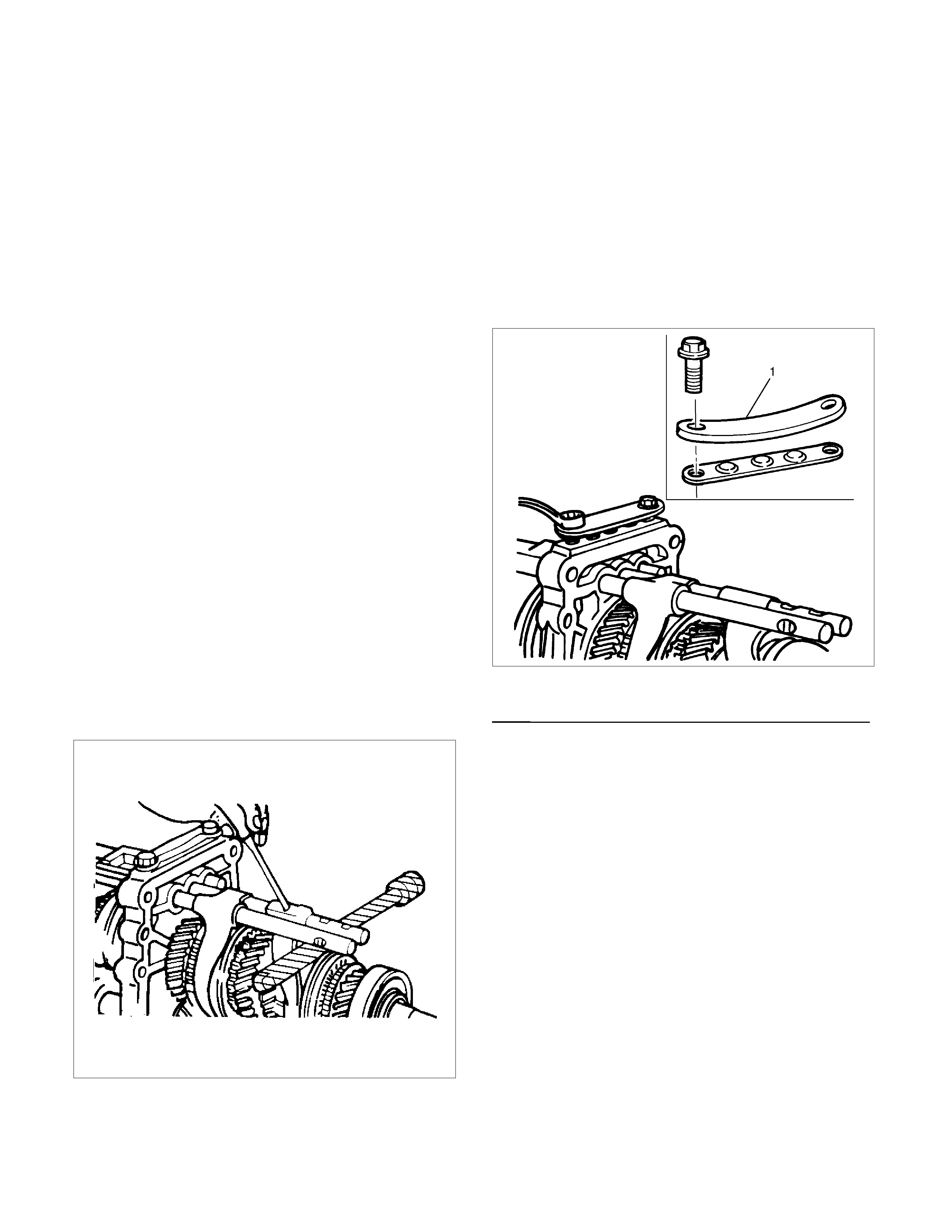
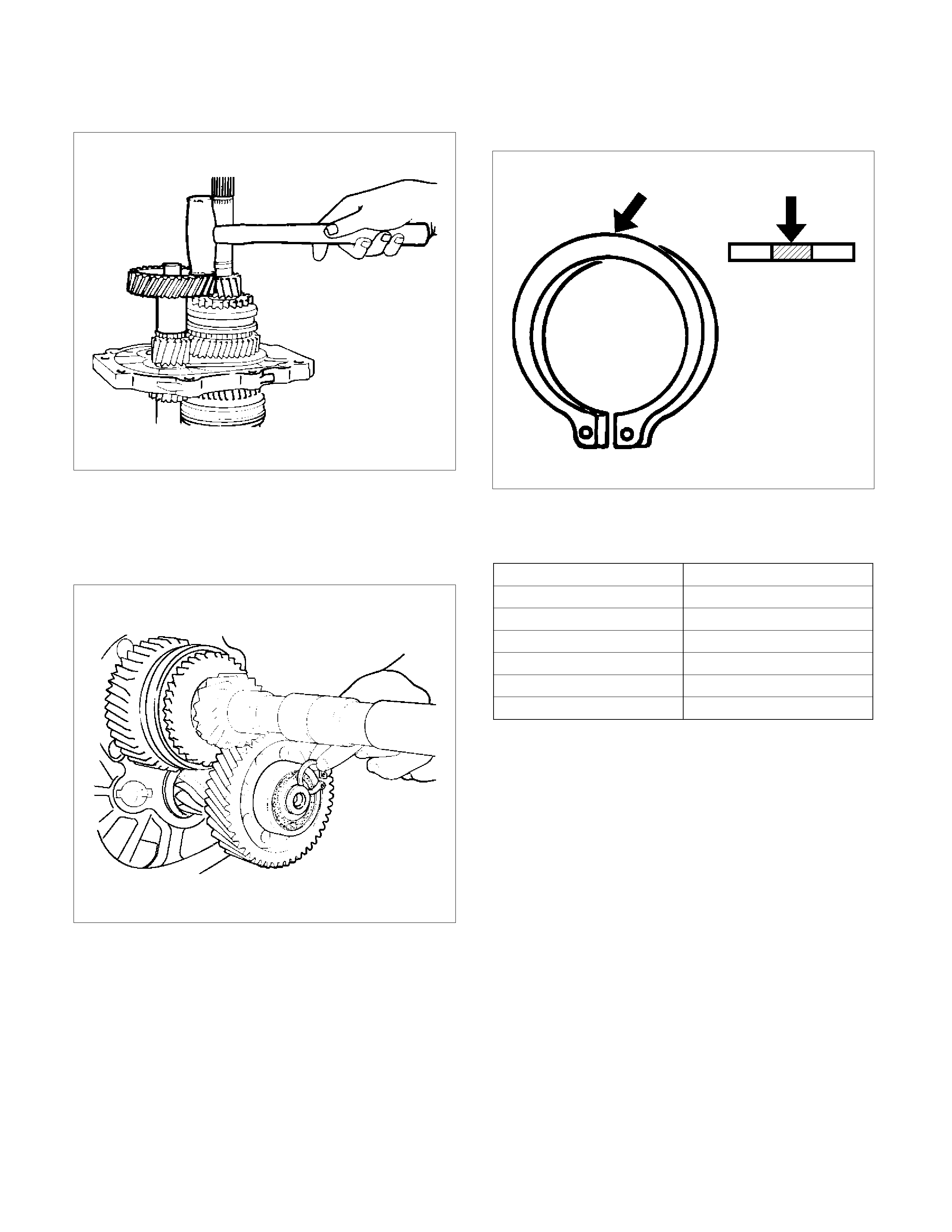
13. Use screw drivers between the reverse gear (26)
and bearing plate (28) to remove the Rev-5th
synchronizer assembly (24) together with reverse
block ring (25) and reverse gear (26).
226RS010
14. Remove needle bearing (27).
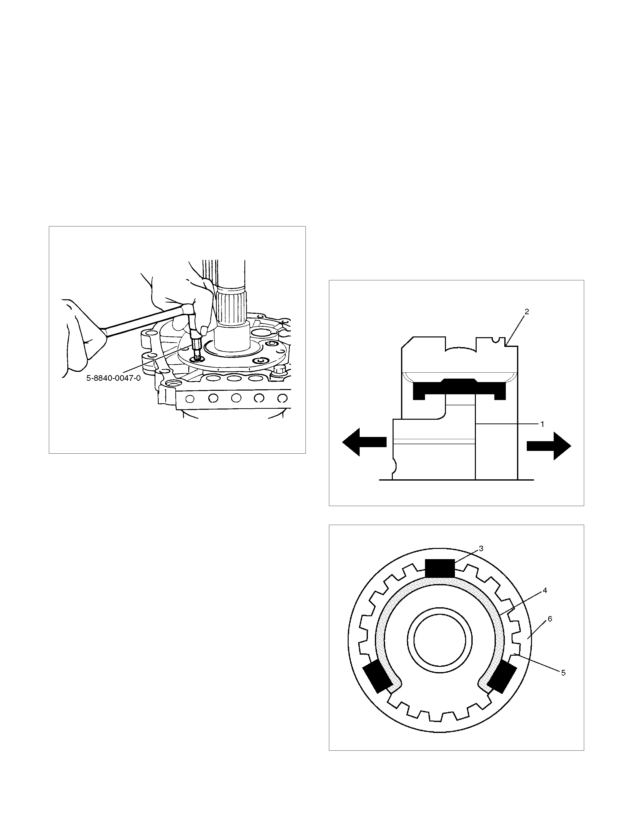
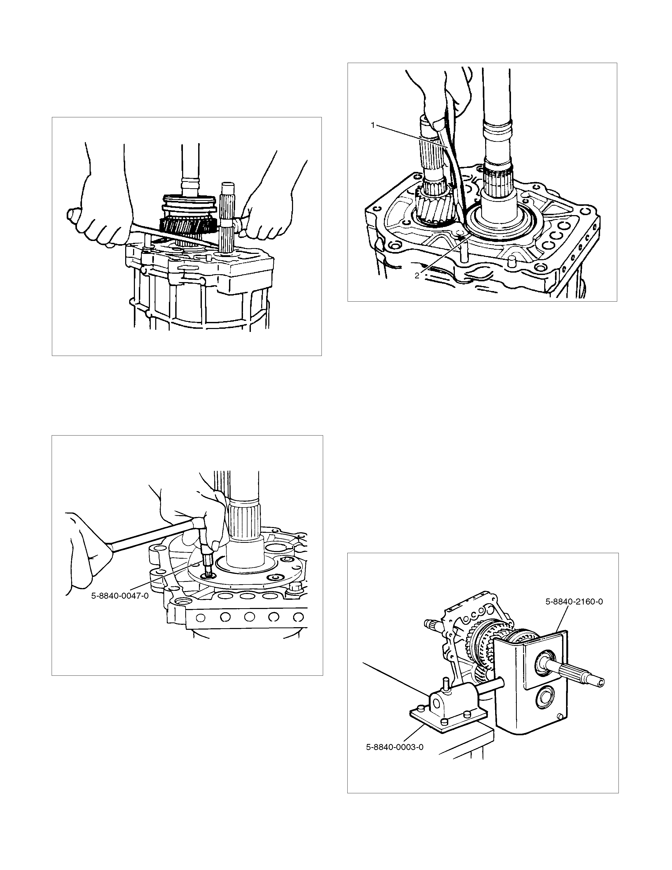
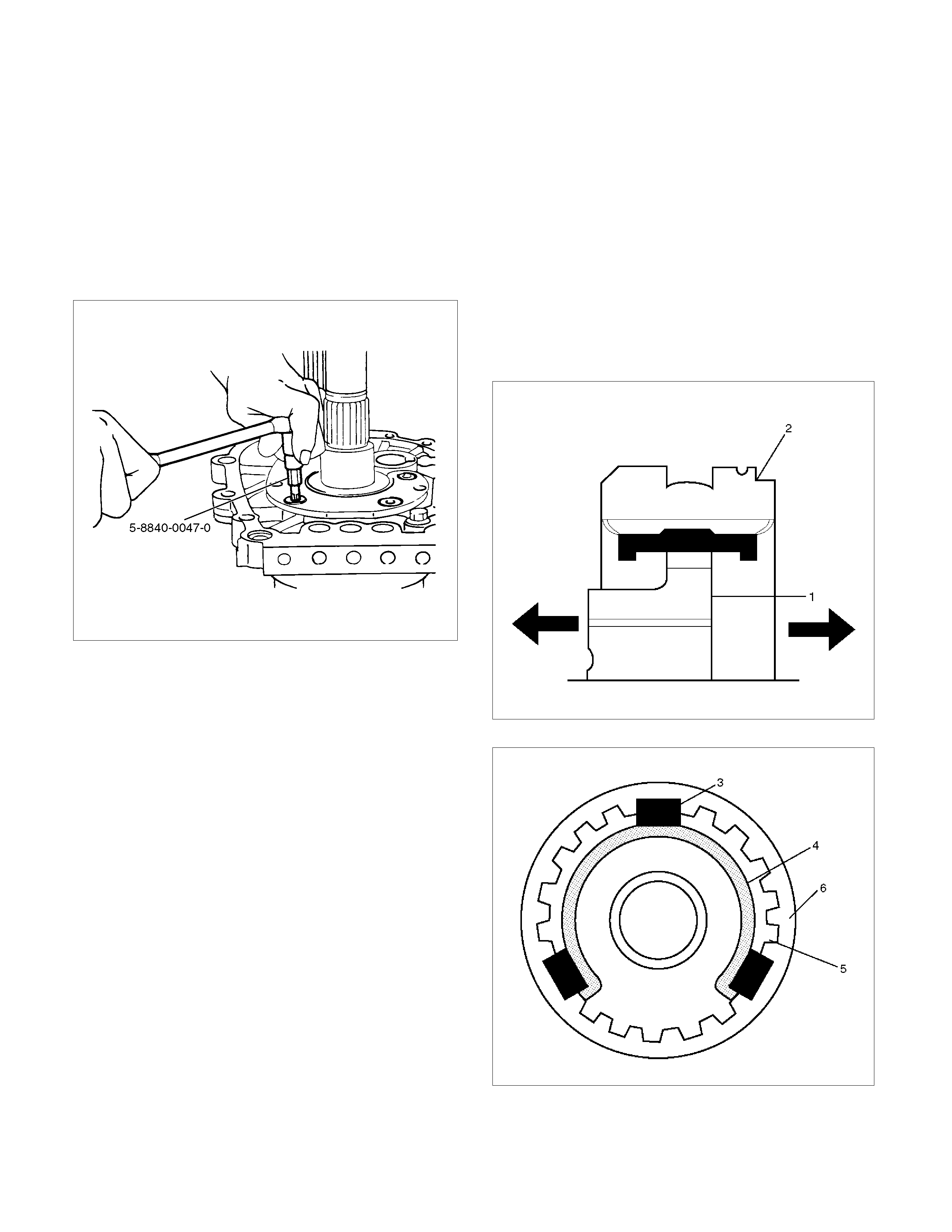
15. Use the torx bit wrench (T45) 5-8840-0047-0 to
remove the bearing plate and screw (28) from the
intermediate plate.
220RW137
16. Use the snap ring pliers (1) to remove the
mainshaft bearing snap ring (2) (29).
226RS011
17. Hold the snap ring open with the pliers.
Push the intermediate plate (30) toward the rear of
the transmission to remove it.
The bearing snap ring (29) will come free.
Inspection and Repair
Refer to Top Gear Shaft, Main Gear Shaft, and
Counter Gear in this section for inspection and repair.
Reassembly
1. Mesh the counter gear with the mainshaft
assembly.
Set the holding fixture 5-8840-2160-0 to the
mainshaft and the counter gear and then install it on
the base 5-8840-0003-0.
Install the intermediate plate (30) on the gear
assembly.
226RW212
2. Install bearing snap ring (29).
3. Apply recommended thread locking agents
(LOCTITE 242) or its equivalent to each of the
bearing plate screw threads.
Install bearing plate and screw (28).
Tighten the screws to the specified torque by using
torx bit wrench 5-8840-0047-0.
Torque: 15 N·m (1.5 kg·m/11 lb·ft)
220RW137
4. Install needle bearing (27), reverse gear (26), and
reverse block ring (25).
5. Assemble rev-5th synchronizer assembly (24) by
performing the following steps.
1. Turn the clutch hub face (1) toward the sleeve
groove (2) (rear side) on the outer
circumference.
2. Check that the inserts (3) fit snugly into the
clutch hub (5) ring insert grooves.
3. Check that the inserts springs (4) are fitted to
the inserts as shown in the illustration.
4. Check that the clutch hub (5) and the sleeve
(6) slide smoothly.
5. Install the synchronizer assembly (24) to the
mainshaft.
The clutch hub face with the heavy boss must be
facing the reverse gear side.
226RS013
226RS049
6. Mesh the 1st-2nd and 3rd-4th synchronizers with
both the 1st and 3rd gears (double engagement).
226RS015
This will prevent the mainshaft from turning.
7. Install the new mainshaft hub nut.
Use the mainshaft nut wrench 5-8840-2156-0 to
tighten the mainshaft nut (23) to the specified
torque.
Torque: 137 N·m (14 kg·m/101 lb·ft)
226RW214
8. Use a punch to stake the mainshaft nut (23).
226RW153
9. Install needle bearing (22), 5th block ring (21), and
5th gear (20).
10. Apply engine oil to the counter reverse gear (19)
and the reverse gear (26).
Install the counter reverse gear (19) to the counter
shaft.
The reverse gear projection must be facing the
intermediate plate.
226RW151
11. Install the counter 5th gear (18) to the counter
shaft.
226RS019
12. Install ball bearing (17) and bearing snap ring (16)
by performing the following steps:
• Select the snap ring, which will provide the
minimum clearance between the ball bearing
and the snap ring.
226RS020
• There are six snap ring sizes available.
The snap rings are color‐coded to indicate
their thickness.
226RS021
Ball Bearing and Snap Ring Clearance
Standard: 0 - 0.15 mm (0 - 0.0059 in)
Snap Ring Availability
Thickness Color Coding
1.1 mm (0.043 in) White
1.2 mm (0.047 in) Yellow
1.3 mm (0.051 in) Blue
1.4 mm (0.055 in) Pink
1.5 mm (0.059 in) Green
1.6 mm (0.063 in) Brow n
• Use a pair of snap ring pliers to install the snap
ring(13) to the counter gear shaft.
The snap ring must be fully inserted into the
counter gear shaft snap ring groove.
13. Assemble reverse idler shaft (15), reverse idler
gear (14), thrust washer (13), and idle shaft pin
(12) into reverse idler gear assembly (11).
The trust washer should be assembled as oil groove
faces to gear side.

14. Select reverse idler gear snap ring (10), which will
provide the minimum clearance between the
intermediate plate (30) and the snap ring (10).
226RS022
• There are three snap ring sizes available.
The snap rings are color-coded to indicate their
thickness.
Intermediate Plate and Snap Ring Clearance
Standard: 0 - 0.15 mm (0 - 0.0059 in)
Snap Ring Availability
Thickness Color Coding
1.2 mm (0.047 in) White
1.3 mm (0.051 in) Yellow
1.4 mm (0.055 in) Blue
226RS021
• Use a pair of snap ring pliers to install the snap
ring to the reverse idler shaft.
The snap ring must be fully inserted into the
reverse idler shaft snap ring groove.
15. Install thrust washer and lock ball (9) by
performing the following steps:
• Use a thickness gauge to measure the
clearance between the 5th gear and the thrust
washer.
5th Gear and Thrust Washer Clearance
Standard: 0.10 - 0.25 mm (0.004 - 0.010 in))
• Measure clearance "A" as shown in the figure.
226RS023
• Select appropriate thrust washer from chart.
• There are four thrust washer sizes available.
Thrust Washer Availability
Thickness
mm (in) Color
Coding A mm (in) Clearance
mm (in)
7.9 (0.311) White 8.05 - 8.1
(0.317-0.319) 0.15 - 0.25
(0.006-0.010)
8.0 (0.315) Yellow 8.1 - 8.2
(0.319-0.323) 0.1 - 0.25
(0.004-0.010)
8.1 (0.319) Green 8.2 - 8.3
(0.323-0.327) 0.1 - 0.25
(0.004-0.010)
8.2 (0.323) Blue 8.3 - 8.36
(0.327-0.329) 0.1 - 0.21
(0.004-0.008)
• The thrust washers are color coded to indicate
their thickness as shown in the figure.
226RS024
• Apply grease to the thrust washer and the lock
ball.
• Install the thrust washer and the lock ball.
16. Install thrust plate (8) and retainer (7).
17. Install the retainer snap ring (6), clip (5),
speedometer drive gear (4) and bearing snap ring
(3).
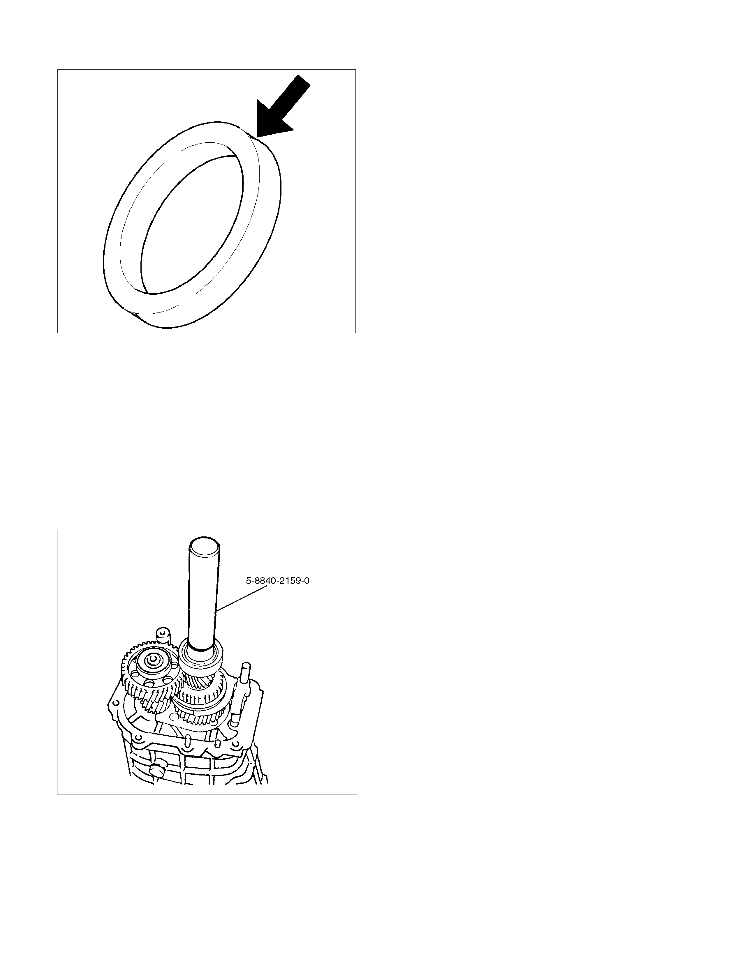
18. Apply engine oil to the bearing (2) inner and outer
circumference.
Use the installer 5-8840-2159-0 to install the ball
bearing (2) to the mainshaft.
226L100002
19. Install the bearing snap ring (1).
Top Gear Shaft, Main Gear Shaft, and Counter Gear Shaft
Disassembled View
226RS026
Legend
(1) Top Gear Shaft Snap Ring (16) 1st Outside Ring
(2) Top Gear Shaft (17) 1st Block Ring
(3) Ball Bearing (18) Needle Bearing
(4) Needle Bearing (19) Clutch Hub Snap Ring
(5) Top Block Ring (20) 1st-2nd Synchronizer Assembly
(6) Mainshaft Snap Ring (21) 2nd Block Ring
(7) 3rd-4th Synchronizer Assembly (22) 2nd Outside Ring
(8) 3rd Block Ring (23) 2nd Inside Ring
(9) 3rd Gear (24) 2nd Gear
(10) Needle Bearing (25) Needle Bearing
(11) Needle Bearing Collar (26) Mainshaft
(12) Mainshaft Ball Bearing (27) Bearing Snap Ring
(13) 1st Gear Thrust Bearing (28) Front Roller Bearing
(14) 1st Gear (29) Center Roller Bearing
(15) 1st Inside Ring (30) Counter Gear Shaft
Techline
Disassembly
1. Use a pair of snap ring pliers to remove the top
gear shaft snap ring(1).
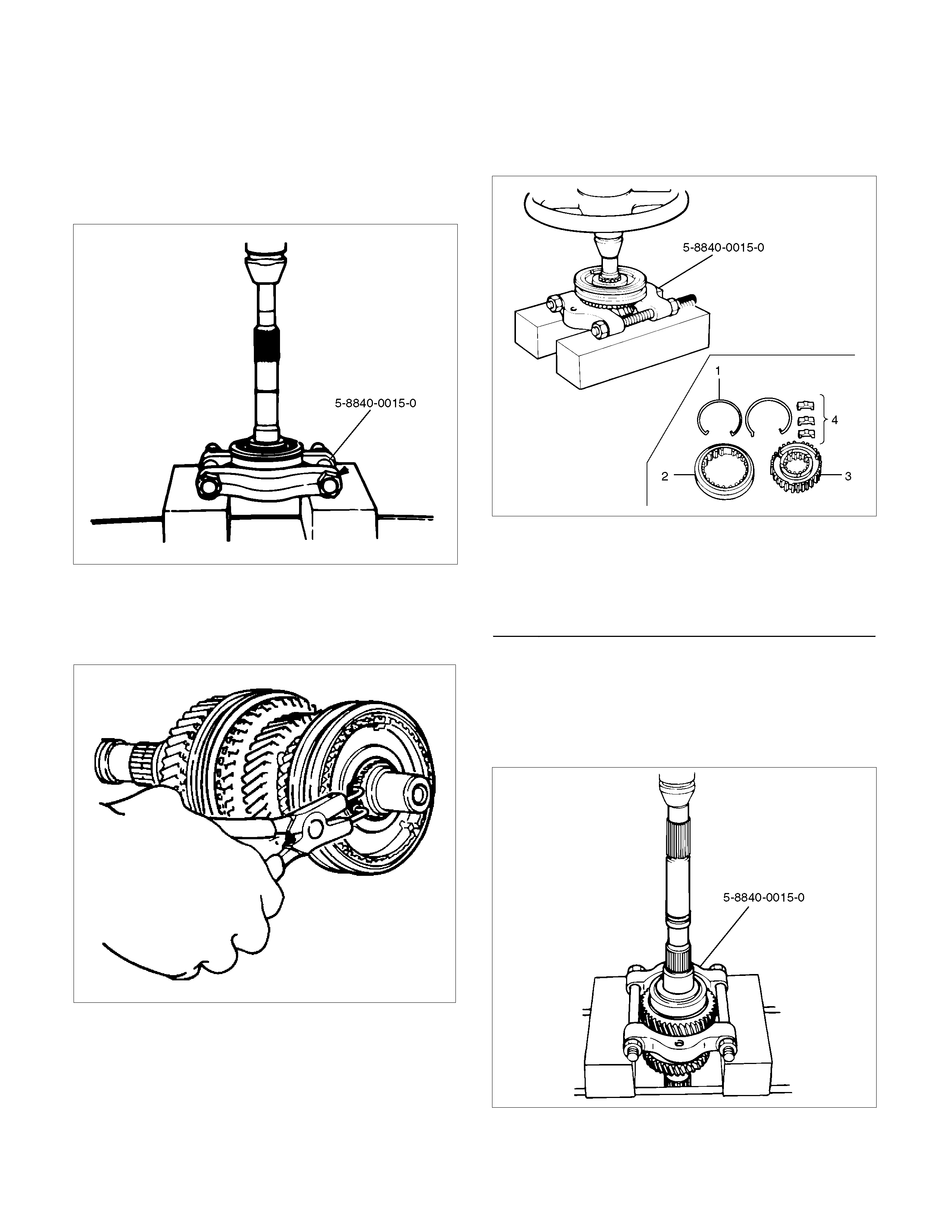
2. Remove top gear shaft(2) with ball bearing(3).
3. Use a bench press and the bearing remover 5-
8840-0015-0 to remove the ball bearing(3).
226RW216
4. Remove needle bearing (4) and top block ring (5),
mainshaft snap ring.
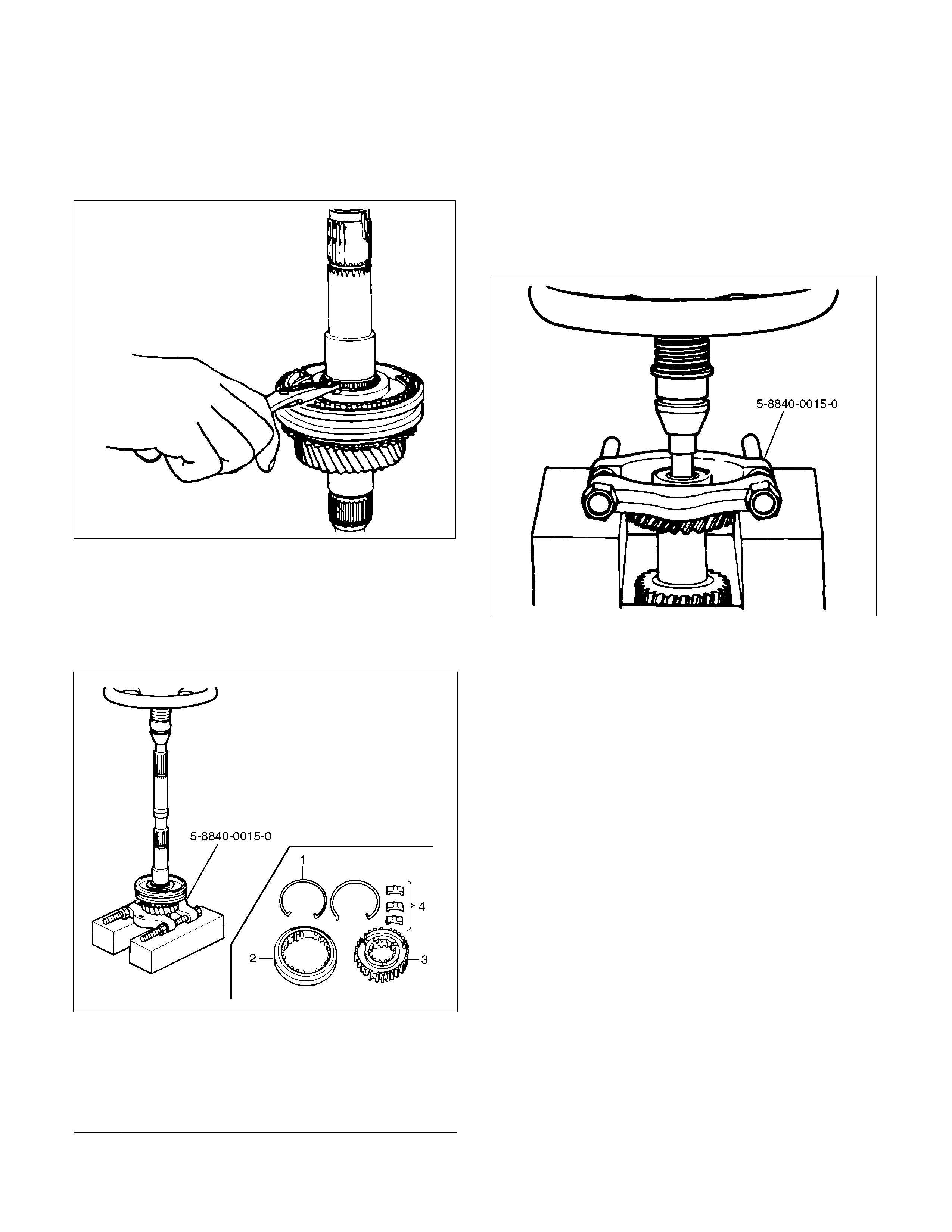
5. Use a pair of snap ring pliers to remove the
mainshaft snap ring (6).
226RS008
6. Use a bench press and the bearing remover 5-
8840-0015-0 to remove the 3rd-4th synchronizer
assembly (7) as a set.
Disassemble the synchronizer assembly.
226RW217
Legend
(1) Springs
(2) Sleeve
(3) Clutch Hub
(4) Inserts
7. Remove 3rd block ring (8), 3rd gear (9), and
needle bearing (10).
8. Use a bench press and the bearing remover 5-
8840-0015-0 to remove the 1st gear(14) together
with the mainshaft ball bearing(12), 1st gear thrust
bearing (13), and needle bearing collar (11).
226RW218
9. Disassemble 1st inside ring (15), 1st outside ring
(16), and 1st block ring (17).
10. Remove needle bearing (18).
11. Use a pair of snap ring pliers to remove the clutch
hub snap ring (19).
226RS031
12. Use bench press and the bearing remover 5-8840-
0015-0 to remove the 2nd gear (24) together with
1st-2nd synchronizer assembly (20), 2nd block
ring (21), 2nd outside ring (22), and inside ring
(23).
Disassemble the synchronizer assembly.
226RW220
Legend
(1) Springs
(2) Sleeve
(3) Clutch Hub
(4) Inserts
13. Remove needle bearing (25) from mainshaft (26).
14. Remove bearing snap ring (27).
15. Remove the front roller bearing (28) by performing
the following steps.
• Remove the ring, outer race and bearing
assembly by using a bench press and remover
5-8840-0015-0.
• Remove the inner race by using a bench press
and remover 5-8840-0015-0.
226RW219
16. Remove center roller bearing (29) from counter
gear shaft (30).
Inspection and Repair
Make the necessary adjustments, repairs, and part
replacements if excessive wear or damage is
discovered during inspection.
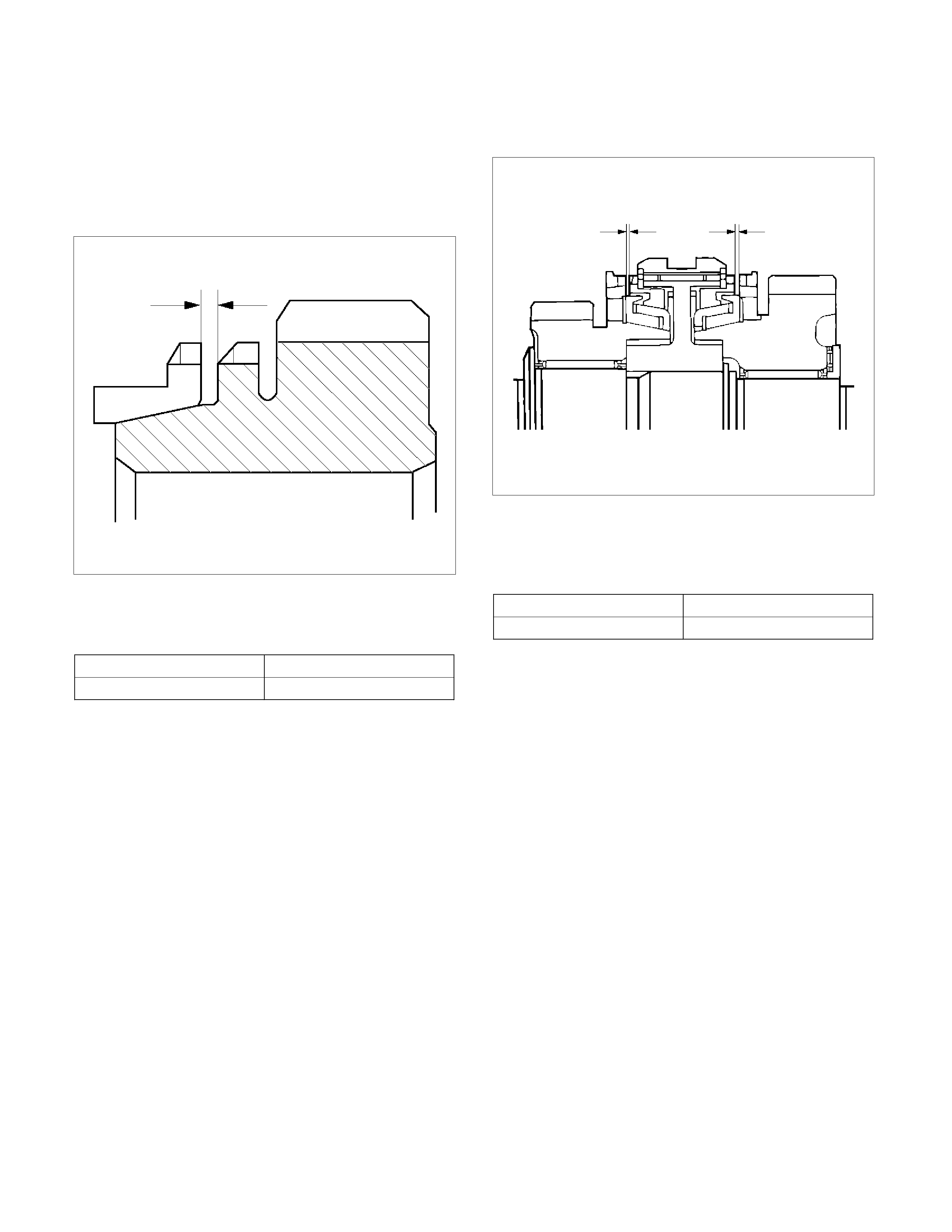
Block Ring and Dog Teeth Clearance
• Use a thickness gauge to measure the clearance
between the block ring and the dog teeth.
226RS035
If the measured value exceeds the specified limit,
the block ring must be replaced.
Block Ring and Dog Teeth Clearance
Standard Limit
1.5 mm (0.059 in) 0.8 mm (0.032 in)
1st-2nd Synchronizer (3-CONE)
• Use a thickness gauge to measure the clearance
between the block ring and the dog teeth.
226RS036
If the measured value exceeds the specified limit,
the 1st-2nd synchronizer assembly must be
replaced.
Block Ring and Dog Teeth Clearance
Standard Limit
1.5 mm (0.059 in) 0.8 mm (0.032 in)
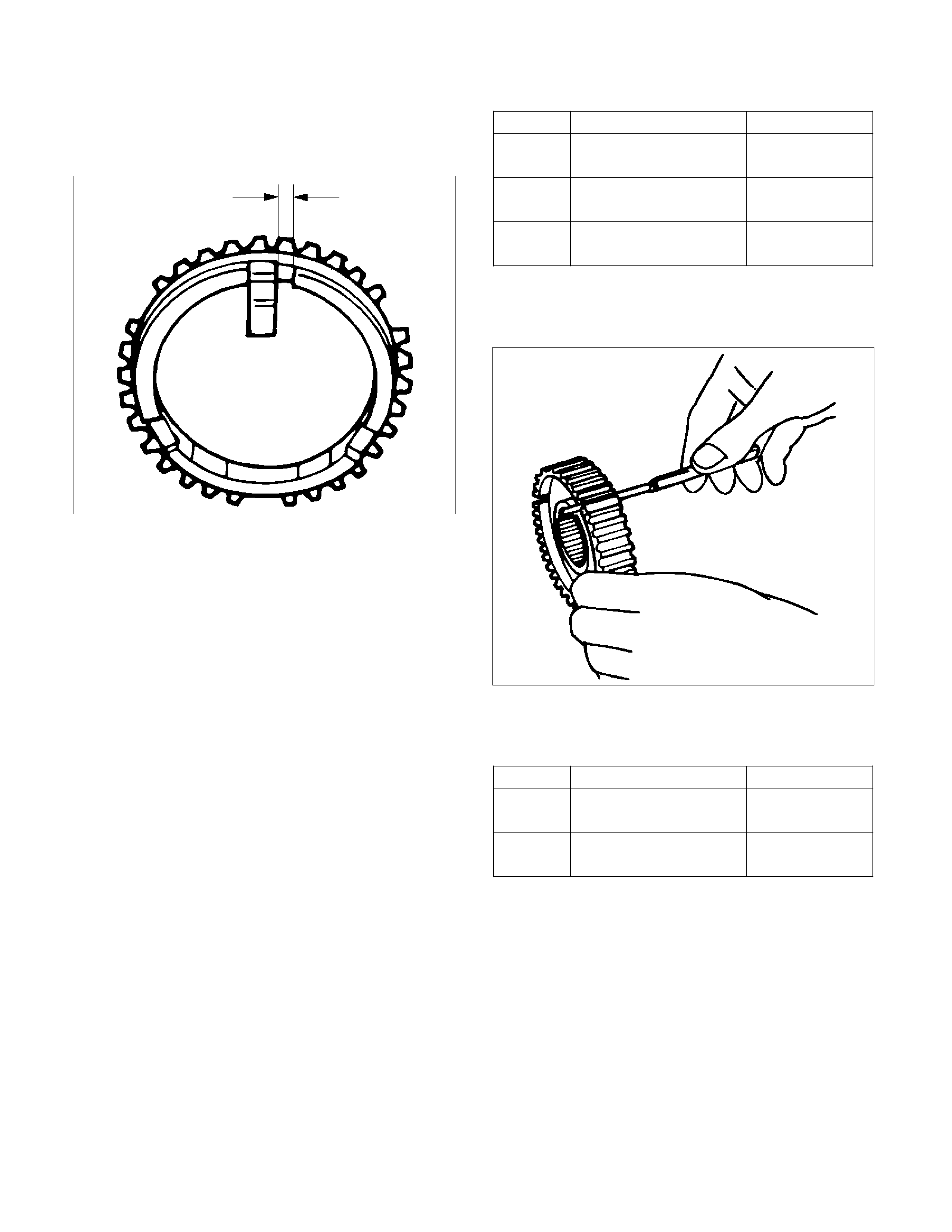
Block Ring and Insert Clearance
• Use a vernier caliper or thickness gauge to
measure the clearance between the block ring and
the insert.
226RS037
If the measured value exceeds the specified limit,
the block ring and the insert must be replaced.
Block and Insert Clearance
Standard Limit
3rd-4th 3.46 - 3.76 mm
(0.136 - 0.148 in) 4.0 mm
(0.158 in)
1st-2nd 3.86 – 4.16 mm
(0.152 - 0.164 in) 4.9 mm
(0.193 in)
Rev.5th 3.59 - 3.91 mm
(0.141 - 0.154 in) 4.1 mm
(0.161 in)
Clutch Hub and Insert Clearance
• Use a thickness gauge to measure the clearance
between the clutch hub and the insert.
226RS038
If the measured value exceeds the specified limit,
the clutch hub and the insert must be replaced.
Clutch Hub and Insert Clearance
Standard Limit
1st-2nd
3rd-4th 0.01 – 0.21 mm
(0.004 - 0.0083 in) 0.3 mm
(0.012 in)
Rev-5th 0.09 – 0.31 mm
(0.0035 - 0.0122 in) 0.4 mm
(0.016 in)
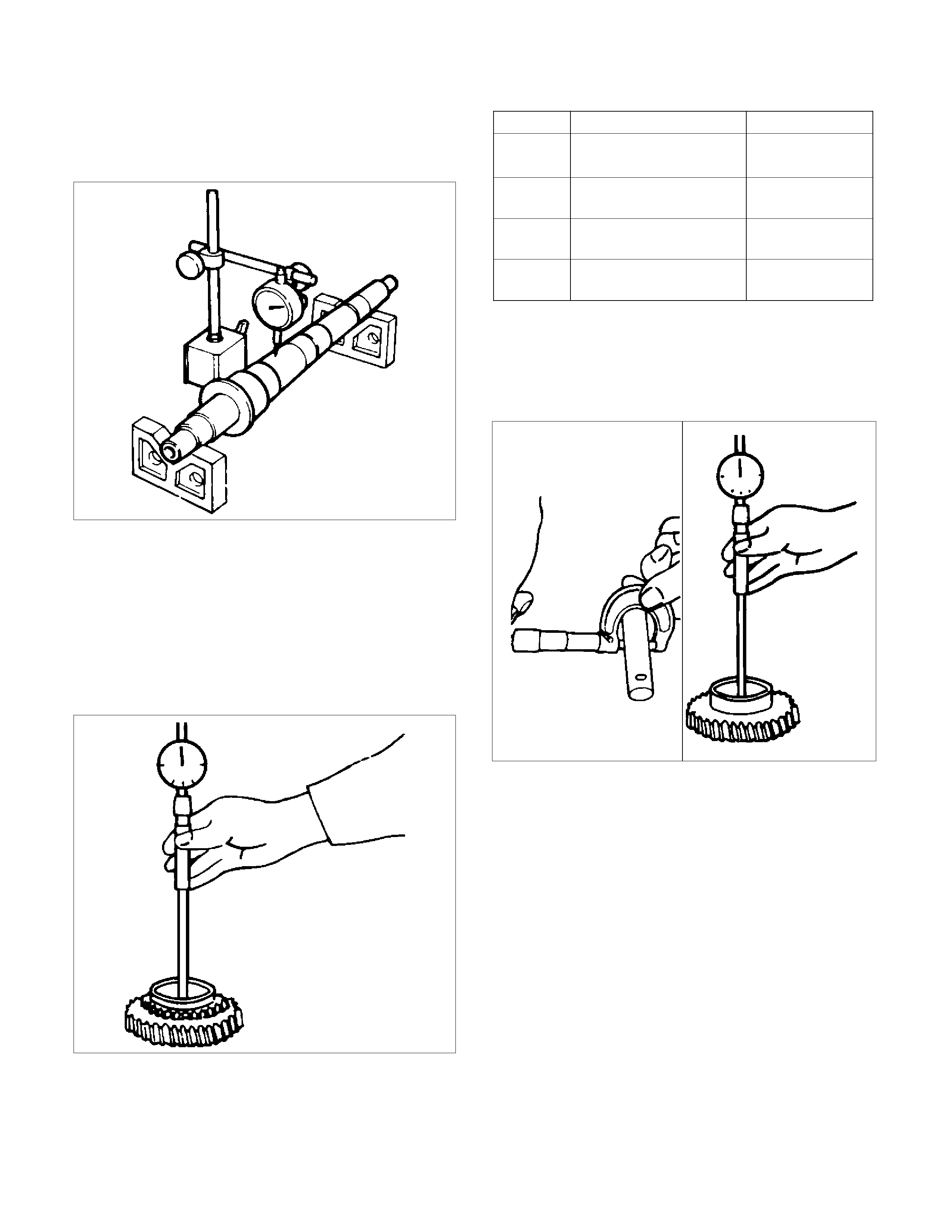
Mainshaft Run-out
• Install the mainshaft to V-blocks.
• Use a dial indicator to measure the mainshaft
central portion run-out.
226RS039
If the measured mainshaft run-out exceeds the
specified limit, the mainshaft must be replaced.
Mainshaft Run-out
Limit: 0.05 mm (0.0020 in)
Gear Inside Diameter
• Use an inside dial indicator to measure the gear
inside diameter.
226RS040
If the measured value is less than the specified limit,
the gear must be replace.
Gear Inside Diameter
Standard Limit
1st
3rd 45.000 - 45.013 mm
(1.771 - 1.772 in) 45.100 mm
(1.776 in)
2nd 52.000 - 52.013 mm
(2.047 - 2.048 in) 52.100 mm
(2.051 in)
Rev. 48.000 - 48.013 mm
(1.889 - 1.890 in) 48.100 mm
(1.894 in)
5th 32.000 - 32.013 mm
(1.259 - 1.260 in) 32.100 mm
(1.246 in)
Reverse Idler Gear and Idler Gear Shaft Clearance
• Use a micrometer to measure the idler gear shaft
diameter.
• Use an inside dial indicator to measure the idler
gear inside diameter.
226RS041
• Calculate the idler gear and idler gear shaft
clearance.
Idler gear inside diameter-idler gear shaft diameter =
idle gear and idler gear shaft clearance.
If the measured value exceeds the specified limit,
the idle gear and/or the idler gear shaft must be
replaced
Idler Gear and Idler Gear Shaft Clearance
Standard: 0.041 - 0.074 mm (0.0016 -0.0029 in)
Limit: 0.150 mm (0.0059 in)

Clutch Hub Spline Play
• Set a dial indicator to the clutch hub to be
measured.
226RS042
• Move the clutch hub as far as possible to both the
right and the left.
Note the dial indicator reading.
If the measured value exceeds the specified limit,
the clutch hub must be replaced.
Clutch Hub Spline Play
Standard Limit
1st-2nd
3rd-4th 0 - 0.1 mm
(0 - 0.004 in) 0.2 mm
(0.008 in)
Rev. 5th 0 - 0.2 mm
(0 - 0.008 in) 0.3 mm
(0.012 in)
Ball Bearing Play
• Use a dial indicator to measure the ball bearing
play.
Ball Bearing Play
Limit: 0.2 mm (0.008 in)
226RS043
Reassembly
1. Install center roller bearing (29) to counter gear
shaft (30).
• Apply engine oil to the bearing inner and outer
circumferences.
• Install the roller bearing in the proper direction.
NOTE: Check that outer race moves only in the
direction of arrow.
226RS044
2. Install front roller bearing (28) by performing the
following steps.
• Use bearing installer 5-8840-2194-0 to install
the front roller bearing inner race to the counter
gear shaft (30).
• Install the outer race and roller assembly.
The snap ring groove must be facing the
transmission front side.
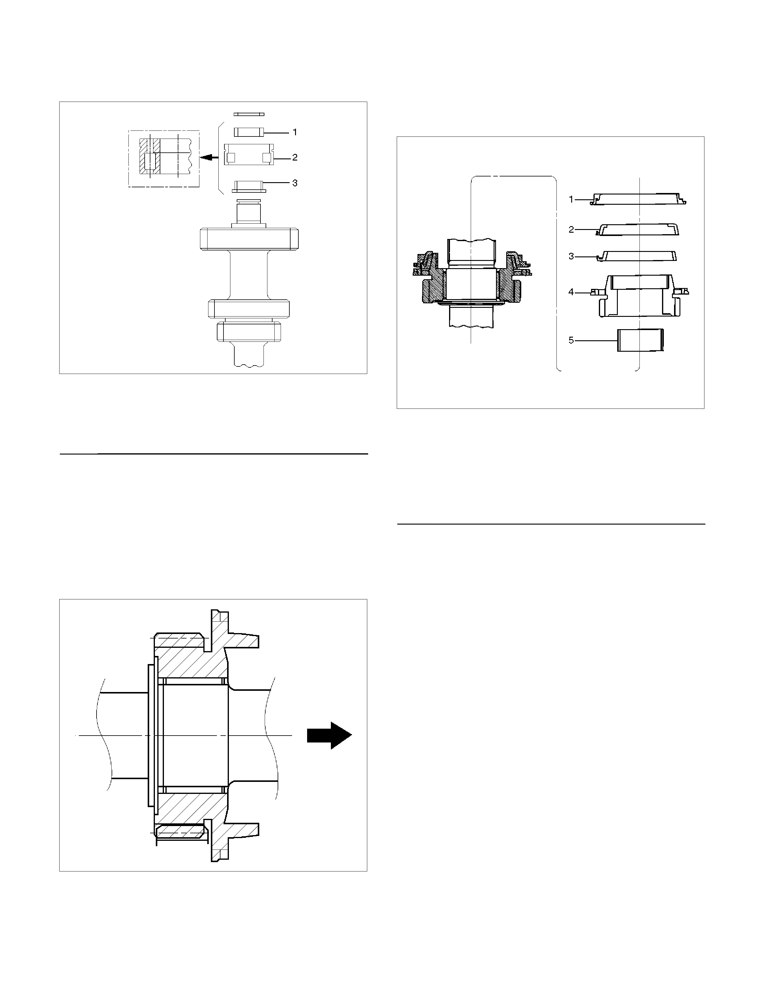
• Use bearing installer 5-8840-2194-0 to install
the ring.
226RS045
Legend
(1) Ring
(2) Outer Race and Roller Assembly
(3) Inner Race
3. Install bearing snap ring (27) to counter gear shaft
(30).
4. Apply engine oil to the needle bearing (25) and the
2nd gear (24) thrust surfaces.
Install the needle bearing (25) and the 2nd gear (24)
to the mainshaft (26).
The 2nd gear (24) dog teeth must be facing the
transmission rear side.
226RS046
5. Assemble 2nd inside ring (23), 2nd outside ring
(22), and 2nd block ring (21) on 2nd gear (24).
•
A
pply engine oil to the synchronizer ring friction
surfaces.
226RS047
Legend
(1) Block Ring
(2) Outside Ring
(3) Inside Ring
(4) 2nd Gear
(5) Needle Bearing
6. Assemble 1st-2nd synchronizer assembly (20) by
performing the following steps:
1. Check that the inserts (3) fit snugly into the
clutch hub (5) insert grooves.
2. Check that the inserts springs (4) are fitted to
the inserts as shown in the illustration.
3. Check that the clutch hub (5) and the sleeve
(6) slide smoothly.
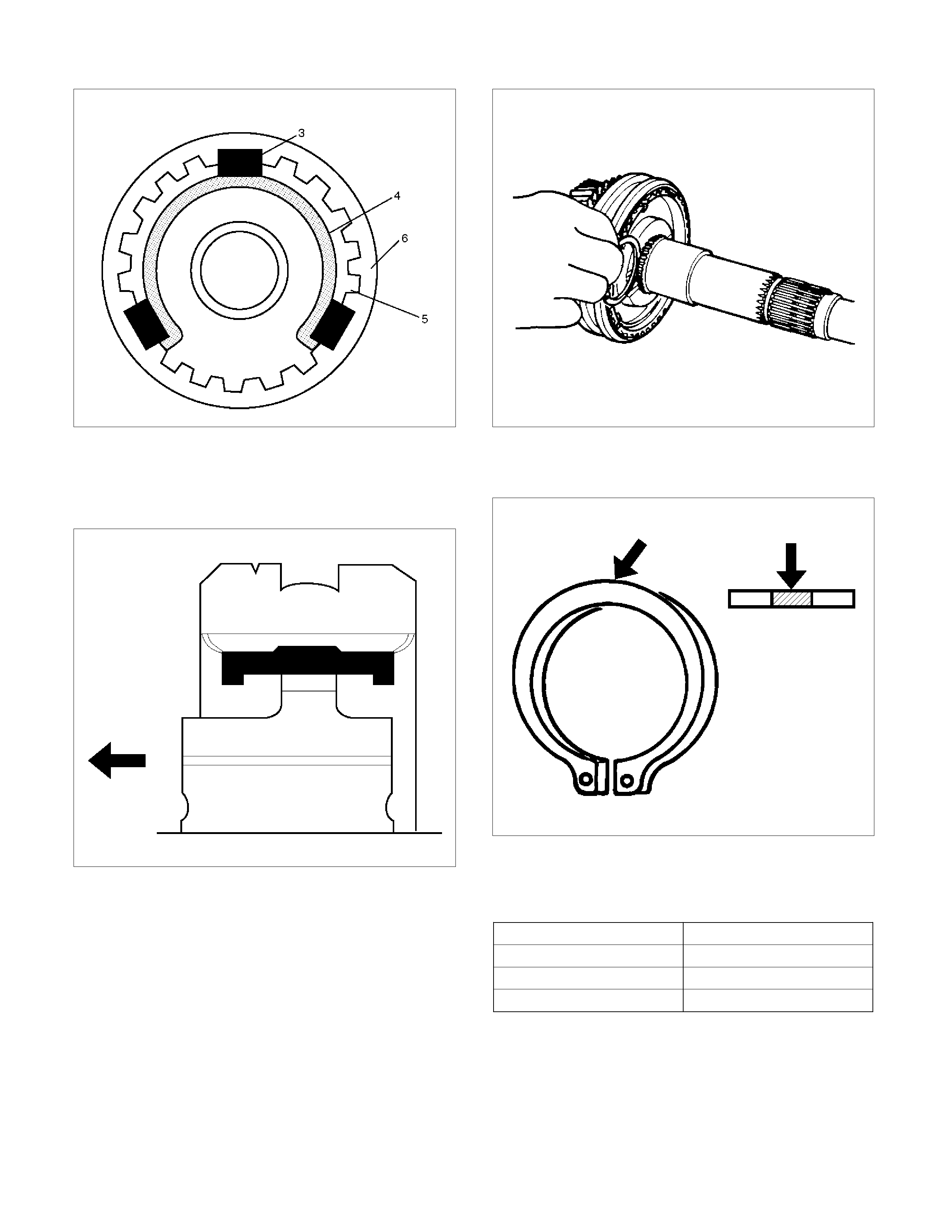
266RS049
7. Install the synchronizer assembly (20) to the
mainshaft (26).
The clutch hub face with the heavy boss must be
facing the 2nd gear side.
226RS048
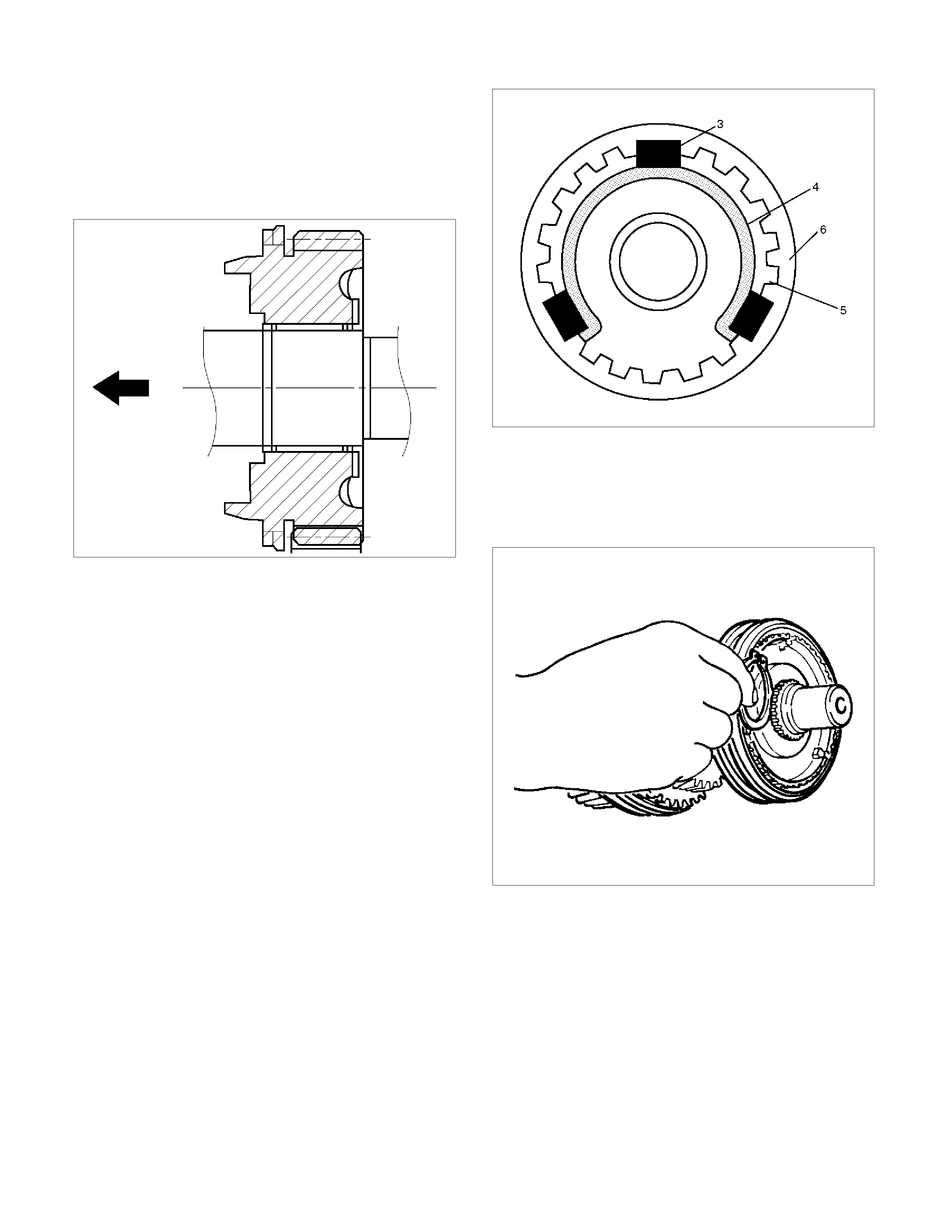
8. Install clutch hub snap ring(19) by performing the
following steps:
• Select the snap ring, which will provide the
minimum clearance between the 1st-2nd clutch
hub and the snap ring.
226RS050
• There are three snap ring sizes available.
• The snap rings are color coded to indicate their
thickness as shown in the figure.
226RS021
Clutch Hub and Snap Ring Clearance
Standard: 0 - 0.1 mm (0 - 0.004 in)
Snap Ring Availability
Thickness Color Coding
1.80 mm (0.071 in) White
1.85 mm (0.073 in) Yellow
1.90 mm (0.075 in) Blue
• Use a pair of snap ring pliers to install the snap
ring (19) to the mainshaft (26).
The snap ring must be fully inserted into the
mainshaft snap ring groove.

226RS031
9. Install needle bearing (18), 1st block ring (17), 1st
outside ring (16), 1st inside ring (15), and 1st gear
(14).
• Apply engine oil to the needle bearing, 1st gear
thrust surfaces and synchronizer ring friction
surfaces.
• The 1st gear dog teeth must be facing the
transmission front side.
226RS053
Legend
(1) 1st Gear
(2) Needle Bearing
(3) Inside Ring
(4) Outside Ring
(5) Block Ring
10. Install the 1st gear thrust bearing and the race(13)
to the main shaft.
The thrust bearing side must be facing the
transmission front side.
226RS054
11. Apply engine oil to the mainshaft ball bearing (12)
and the mainshaft (26).
Install the ball bearing (12) and needle bearing collar
(11) to the mainshaft (26).
The ball bearing snap ring groove must be facing
the transmission rear side.
Use a bench press and installer 9-8522-1165-0 to
slowly force the collar into place.
226RS055
12. Apply engine oil to the needle bearing (10) and the
3rd gear (9) thrust surfaces.
Install the needle bearing (10) and the 3rd gear (9)
to the mainshaft.
The 3rd gear dog teeth must be facing the
transmission front side.
226RS056
13. Install 3rd block ring (8).
14. Check and install 3rd-4th synchronizer assembly
(7) by the following steps:
1. Check that the inserts (3) fit snugly into the
clutch hub insert grooves.
2. Check that the insert springs (4) are fitted to
the inserts as shown in the illustration.
3. Check that the clutch hub (5) and the sleeve
(6) slide smoothly.
4. Install the synchronizer assembly to the
mainshaft.
The clutch hub face with the heavy boss must be
facing the 3rd gear side.
226RS049
15. Select and install mainshaft snap ring(6) in the
following way:
Select the snap ring, which will provide the minimum
clearance between the 3rd-4th clutch hub and the
snap ring.
226RS058
There are three snap ring sizes available.
The snap rings are color coded to indicate their
thickness as shown in the figure.
226RW221
226RS021
Clutch Hub and Snap Ring Clearance
Standard: 0 - 0.1 mm (0 - 0.004 in)
Snap Ring Availability
Thickness Color Coding
1.80 mm (0.071 in) White
1.85 mm (0.073 in) Yellow
1.90 mm (0.075 in) Blue
• Use a pair of snap ring pliers to install the snap
ring to the mainshaft.
The snap ring must be fully inserted into the
mainshaft snap ring groove.
16. Install top block ring (5).
Apply grease to the needle bearing (4) inner and
outer circumferences and install needle bearing (4)
in the top gear shaft (2).
17. Use a bench press to install the top gear shaft ball
bearing (3) to the top gear shaft (2).
226RS059
The snap ring groove of the ball bearing (3) must be
facing the transmission front side.
18. Use a pair of snap ring pliers to install the top gear
shaft snap ring (1) to the top gear shaft (2).

Main Data and Spec ifications
General Specifications
(MUA 5G)
MUA 5G (6VE1, 4JH1-TC) MUA 5S (C24NE)
Transmission type Fully synchronized forward and reverse gears
Control method Remote control with the gear shift lever on the floor.
Gear ratio: Transmission 1st 4.008 4.357
2nd 2.301 2.502
3rd 1.427 1.501
4th 1.000 1.000
5th 0.828 0.809
Rev. 3.651 3.970
Transmission oil capacity 2.95 lit. (3.12 US qt)
Type of lubricant Engine oil: Refer to the chart in "SECTION 0"

RTW37BLF0006
E07R300014

Troubleshooting
1. ABNORMAL NOISE
1) NOISY IN NEUTRAL
Checkpoint Fault Action
Replenish or replace the gear
oil
Insufficient or improper gear
oil
NG
Mainshaft splines
Synchronizer clutch hub
splines
Replace the main shaft and
the synchronizer clutch hub
Replace the gear(s)
Replace the flywheel pilot
Worn splines
Worn or scuffed gear tooth
contact surfaces
Flywheel pilot bearing Worn flywheel pilot bearing
Bearings (Mainshaft,
countershaft, and transfer
shaft)
Gears (Mainshaft,
countershaft, reverse idler
gear and transfer gears)
Replace the bearing(s)Worn or broken bearing(s)
OK
NG
NG
NG
NG
OK
OK
OK
Gear oil
Transmission Realign the transmissionTransmission misalignment
OK
NG

2) NOISY OPERATION
Checkpoint Fault Action
Replenish or replace the gear
oil
Insufficient or improper engine
oil
NG
Replace the gear(s)
Replace the gear(s)
Replace the bearing(s)
Gears (Gear whining) Lack of backlash between
meshing gears
Free running gears seizing on
the thrust face or the inner
face
Bearings (Hissing, thumping
or bumping) Worn or broken bearing(s)
Gears (Squealing at high
speeds)
Replace the gear(s)
Gears (Growling, humming, or
grinding) Worn, chipped, or cracked
gear(s)
NG
NG
NG
NG
OK
OK
OK
OK
Gear oil (Metallic rattling)

2. HARD SHIFTING
Checkpoint Fault Action
Change lever play
Clutch pedal free play
Repair or replace the
applicable parts and regrease
Readjust the clutch pedal free
play
Worn change lever sliding
portions
Improper clutch pedal free
play
Change lever operation Repair or regrease the change
lever assembly
Replenish or replace the
engine oil
Hard operating change lever
caused insufficient grease
Insufficient or improper gear
oil
OK
OK
NG
NG
NG
NG
OK
OK
Gear oil
Continued on the next page
Shift rod and quadrant box
sliding faces, and other parts Replace the shidt rod and/or
the quadrant box
Worn shift rod and/or sliding
faces
Repair or replace the sleeveSleeve movement failure
NG
NG
OK
Shift block sleeve movement

Checkpoint Fault Action
Synchronizer assembly
Shift arm and synchronizer
sleeve
Replace the worn parts
Replace the worn parts
Worn synchronizer parts
Worn shift arm and/or
synchronizer sleeve groove
Mainshaft and countershaft
thrust play Replace the worn parts
Worn thrust washer, collar,
and/or gear thrust faces
OK
NG
NG
NG
OK
OK
Continued from the previous

3. WALKING OR JUMPING OUT OF GEAR
Checkpoint Fault Action
Shift rod and quadrant box
sliding faces
Detent ball
Replace the shift rod and/or
the quadrant box
Replace the detent ball
Worn shift rod and/or sliding
faces
Worn detent ball
Detent spring Repair or replace the detent
spring
Replace the worn parts
Detent spring weak or broken
Insufficient stroke caused by
sliding position wear and
excessive play
OK
OK
NG
NG
NG
NG
OK
OK
Change lever play
Continued on the next page
Mainshaft and countershaft
thrust play Replace the worn parts
Worn thrust washer, collar,
and/or gear thrust faces
Replace the worn parts
Worn shift arm and/or
synchronizer sleeve groove
NG
NG
OK
Shift arm and synchronizer
sleeve

Checkpoint Fault Action
Synchronizer assembly
Bearings (Mainshaft,
countershaft, and individual
gears)
Replace the spring
Replace the bearing(s)
Weak or broken spring
Worn or broken bearings(s)
Mainshaft splines
Synchronizer clutch hub
splines
Replace the main shaft and
the synchronizer clutch hub
Worn splines
OK
NG
NG
NG
OK
OK
Continued from the previous page

4. OIL LEAKAGE
Checkpoint Fault Action
Gear oil Replace the gear oilImproper gear oil
Drain plug and/or filler plug Tighten the plug(s) and
replenish the oil
Drain the oil to the correct
level
Loose plug(s)
Oil level too high
OK
NG
NG
NG
OK
OK
Oil level
Rear cover oil seal
Air breather
Replace the oil seal
Install the air breather
Replace the air breather
Worn or scratched oil seal
Air breather not installed
Air breather clogged
Front cover oil seal Replace the oil seal
Replace the gasket(s)
Worn or scratched oil seal
Defective or improperly
installed gasket(s)
OK
NG
NG
NG
NG
OK
OK
Gaskets
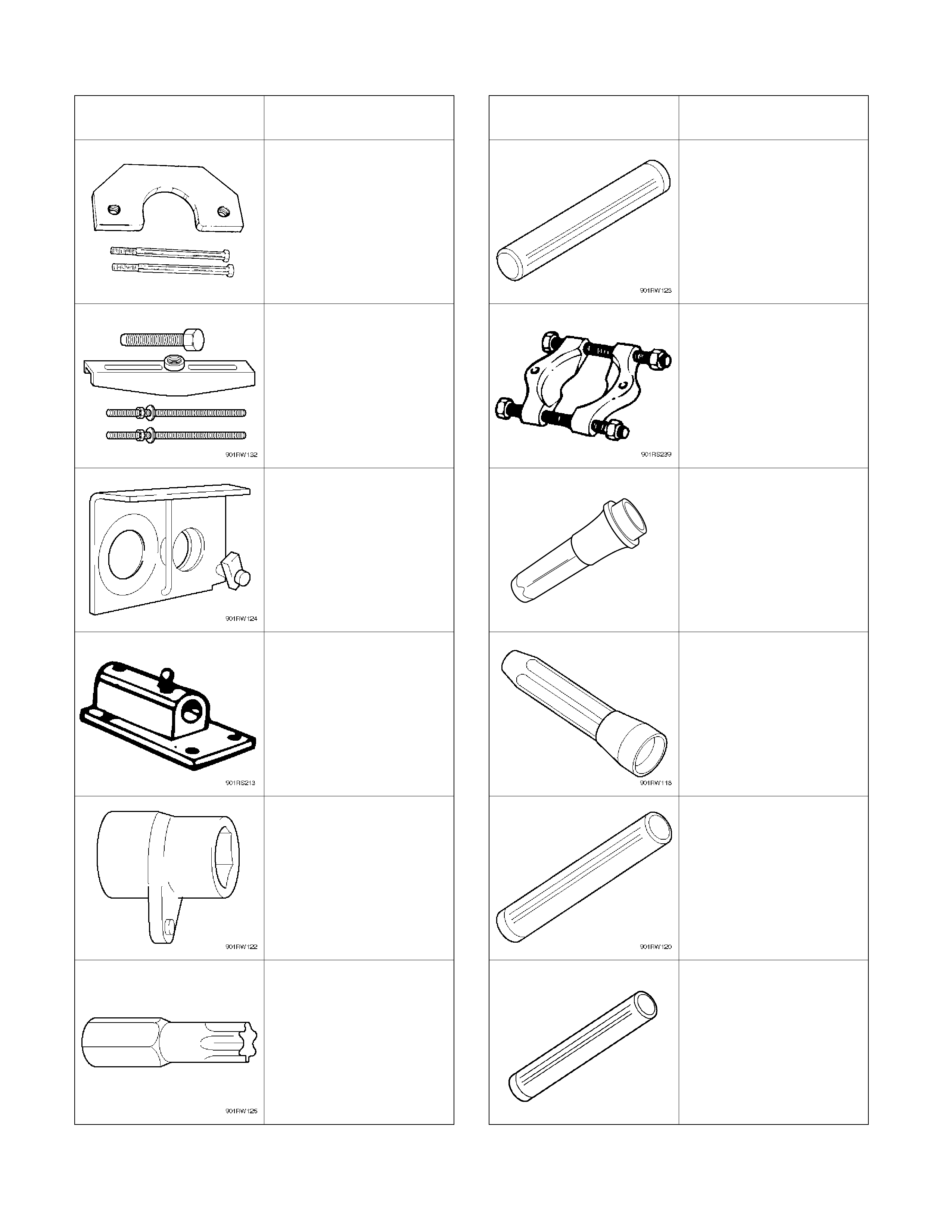
Special Tools (MUA)
ILLUSTRATION TOOL NO.
TOOL NAME ILLUSTRATION TOOL NO.
TOOL NAME
5-8840-2155-0
Bearing remover
5-8840-2159-0
Mainshaft end bearing
installer
5-8840-2027-0
Puller 5-8840-0015-0
Bearing
remover/installer
5-8840-2160-0
Holding fixture
5-8522-0050-0
Rear case oil seal
installer
5-8840-0003-0
Holding fixture base
5-8840-0026-0
Front cover oil seal
installer
5-8840-2156-0
Wrench
9-8522-1165-0
Mainshaft collar remover
5-8840-0047-0
Torx bit wrench
(T–45)
5-8840-2194-0
Bearing installer

MUA5G (4×4)
Service Precaution
WARNING: THIS VEHICLE HAS A SUPPLEMENTAL
RESTRAINT SYSTEM (SRS). REFER TO THE SRS
COMPONENT AND WIRING LOCATION VIEW IN
ORDER TO DETERMINE WHETHER YOU ARE
PERFORMING SERVICE ON OR NEAR THE SRS
COMPONENTS OR THE SRS WIRING. WHEN YOU
ARE PERFORMING SERVICE ON OR NEAR THE
SRS COMPONENTS OR THE SRS WIRING, REFER
TO THE SRS SERVICE INFORMATION. FAILURE TO
FOLLOW WARNINGS COULD RESULT IN POSSIBLE
AIR BAG DEPLOYMENT, PERSONAL INJURY, OR
OTHERWISE UNNEEDED SRS SYSTEM REPAIRS.
CAUTION: Always use the correct fastener in the
proper location. When you replace a fastener, use
ONLY the exact part number for that application.
HOLDEN will call out those fasteners that require a
replacement after removal. HOLDEN will also call
out the fasteners that require thread lockers or
thread sealant. UNLESS OTHERWISE SPECIFIED,
do not use supplemental coatings (Paints, greases,
or other corrosion inhibitors) on threaded fasteners
orfastener joint interfaces. Generally, such coatings
adversely affect the fastener torque and the joint
clamping force, and may damage the fastener.
When you install fasteners, use the correct
tightening sequence and specifications. Following
these instructions can help you avoid damage to
parts and systems.
General Description
MUA5G Transmission (4×
××
×4)
A07R300003
The MUA5C is a constant mesh transmission,
synchronized in all speeds. The transmission is
designed for a great reduction of the shift effort and the
quietest possible operation.
Principle parts of the transmission are the integral clutch
housing, the intermediate plate, the rear case, and the
gears.
The transmission control box is built into the
transmission.
Transmission (4×
××
×4)
Disassembled View
RTW37ALF000201
Legend
(1) Gear Control Lever Knob (10) Transmission-Transfer Fixing Bolt
(2) Rear Floor Console (bucket) (11) Transfer Assembly
(3) Front Floor Console (12) Fuel Pipe Bracket
(4) Grommet Assembly (13) Slave Cylinder
(5) Gear Control Lever (14) Rear Mount Nut
(6) Rear Propeller Shaft (15) Transmission Crossmember
(7) Front Propeller Shaft (16) Starter (4JH1-TC only)
(8) Exhaust Pipe Nut (4JH1-TC) (17) Transmission Retaining Nut and Bolt
(9) Exhaust Pipe Assembly (6VE1) (18) Transmission Assembly

Removal
1. Disconnect battery ground cable.
2. Remove gear control lever knob (1).
3. Remove rear floor console (2). (Bucket seat)
Refer to the section “Floor Console”.
4. Remove front floor console (3).
Refer to the section “Floor Console”.
745R300006
Legend
(1) Knob
(2) Rear Floor Console
(3) Front Floor Console
5. Remove grommet assembly (4).
235R300001
6. Remove gear control lever (5).
7. Raise and support vehicle with suitable stands.
8. Remove rear propeller shaft (6).
NOTE: Apply alignment marks on the flange at the
differential side.
9. Remove front propeller shaft (7).
NOTE: Apply alignment marks on the flange at both
front and rear sides.
401RS023
10. Loosen the front exhaust pipe fixing nuts (8) at the
engine side but not remove them. (4JH1-TC only)
150R300004
11. Remove the exhaust pipe (9). (6VE1 only)
RTW37ASH000101
12. Disconnect harness connectors and clips on the
transfer.
• Actuator connector
• Car Speed Sensor
810R300069
Legend
(1) Neutral Switch Connector: Transmission
(2) Back up Switch Connector
(3) Speed Sensor Connector
(4) Actuator Connector
(5) 2W - 4W Switch Connector
(6) Neutral Switch Connector: Transfer
13. Remove transmission-transfer fixing bolts (10),
and remove the transfer assembly (11) from the
transmission.
14. Disconnect harness connectors and clips on the
transmission.
• Neutral switch; Transmission
• Back up Switch
• 2W-4W Switch
• Neutral Switch; Transfer
15. Remove the fuel pipe brackets (12) with pipes
from the transmission (18).
4JH1-TC
220R300012
Legend
(1) Bolt
(2) Nut
(3) Fuel Pipe Assembly
6VE1
Scan-2
16. Remove slave cylinder (13) and put aside it.
220LV019
17. Support transmission with a transmission jack.
220RS0001
18. Remove engine rear mount nuts (14) from
transmission crossmember (15).
19. Remove engine rear mount bolts fixing
transmission.
220R300009
20. Remove the middle part of transmission
crossmember (15) by removing four fixing bolts
and nuts.
501R30007
21. Take out the rear support rubber.
22. Remove starter (16). (4JH1-TC only)
060L100070
23. Use the clutch release bearing remover 5-8840-
2291-0 (J-39207) to disconnect the clutch release
bearing from the clutch pressure plate. (6VE1
only )
220RW109
Release bearing disconnection
1. Pull the shift fork toward the transmission to
press the clutch release bearing against the
clutch.
2. Insert the clutch release bearing remover
between the wedge collar and the release
bearing.
3. Turn the remover to separate the release
bearing.
NOTE: Be sure not to insert the remover between the
wedge collar and the clutch.
220RW063
220RW064
220RW019
Legend
(1) Pressure Plate Assembly
(2) Release Bearing
(3) Wedge Collar
24. Remove transmission retaining nuts and bolts(17).
Remove transmission assembly (18) from the
vehicle.
Installation
1. Apply a thin coat of molybdenum disulfide grease
to the top gear shaft spline.
2. Slowly operate the transmission jack until the front
of transmission is aligned with the rear of the
engine.
The slope of the engine and the transmission
must be the same.
3.
A
lign the top gear shaft with the clutch driven plate
spline.

4. Install the transmission assembly (18) to the
engine.
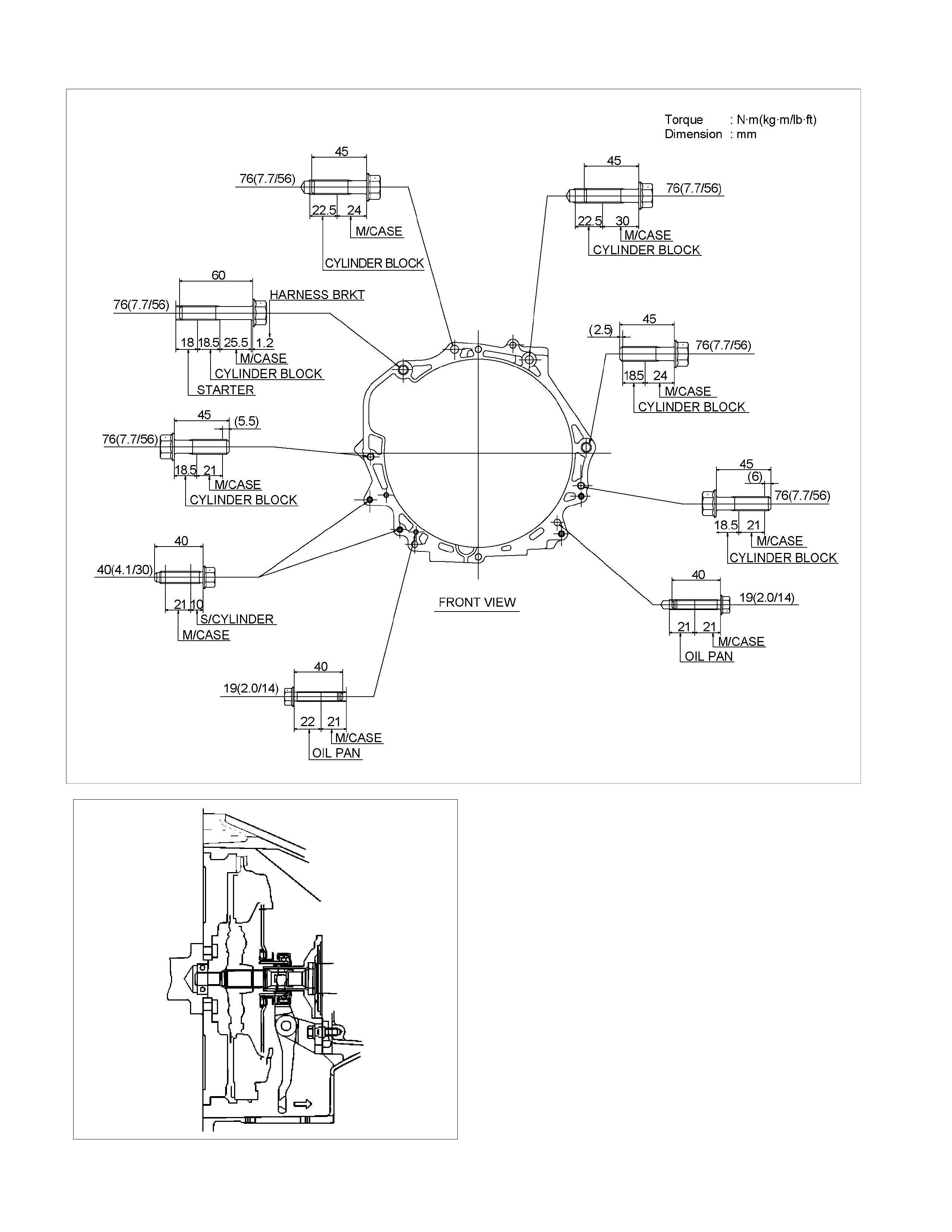
Tighten the transmission nuts and bolts as shown in
the figure.
4JH1-TC
RTW37BLF000901
6VE1
RTW37BLF0001
5. Apply a force of about 113N (26 Ib) to the tip of the
shift fork in the direction of the transmission to
engage the clutch pressure plate and release
bearing. (6VE1 only)
NOTE: A clicking sound is heard when the release
bearing and the tip of the diaphragm spring engage
each other.
Check to see if they are securely engaged by pushing
the tip of the shift fork toward the engine while applying
a force of about 25 N (5.5 lb). If the shift fork will not
move, then they are securely engaged.
220RS006
6. Install starter(16).(4JH1-TC)
NOTE: Tighten the lower bolt temporarily.
After installing the fuel pipe assembly, tighten the bolt to
the specified torque.
Torque: 76 N·m (7.7 kg·m/56 lb·ft)
7. Install the rear support rubber on the transmission
and tighten the bolts to the specified torque.
Torque: 50 N·m (5.1 kg·m/37 lb·ft)
8. Install the middle part of transmission
crossmember (15) and bolts.
Tighten the nuts to the specified torque.
Torque: 67 N·m (6.8 kg·m/49 lb·ft)
9. Install engine rear mount nuts (14).
Torque: 52 N·m (5.3 kg·m/38 lb·ft)
Remove the transmission jack from transmission
side.
10. Apply grease to top hole portion of the shift fork.
Install slave cylinder (13) and tighten the bolts to the
specified torque.
Torque: 76 N·m (7.7 kg·m/56 lb·ft)
11. Install the fuel pipe brackets on the transmission.
Install the fuel pipe assembly to the fuel pipe
brackets
Torque: Bolt & Nut 76 N·m (7.7 kg·m/56 lb·ft)
Nut 37 N·m (3.8 kg·m/28 lb·ft)
4JH1-TC
220R300012
Legend
(1) Bolt
(2) Nut
(3) Fuel Pipe Assembly
6VE1
Scan-2
12. Connect transmission harness connectors and
clips. Connector: transfer neutral switch, 2W - 4W
switch, backup switch, and transmission neutral
switch.
810R300069
Legend
(1) Neutral Switch Connector: Transmission
(2) Backup Switch Connector
(3) Speed Sensor Connector
(4) Actuator Connector
(5) 2W - 4W Switch connector
(6) Neutral Switch Connector: Transfer
13. Apply grease (BESCO L2 or equivalent) on the
splined portion of the output shaft.
14. Connect the transfer to the transmission.

15. Install the transmission-transfer bolts and nut and
tighten them to the specified torque.
Torque: 41 N·m (4.2 kg·m/30 lb·ft)
261R300005
16. Connect transfer harness connectors and clips.
Connector: actuator, car speed sensor.
17. Tighten exhaust pipe fixing nuts (8) to the
specified torque. (4JH1-TC)
Torque: 67 N·m (6.8 kg·m/49 lb·ft)
150R300004
18. Install the exhaust pipe (9). (6VE1)
Torque: 67 N·m (6.8 kg·m/49 lb·ft)
RTW37ASH000101
19. Install front propeller shaft (7).
Refer to the section “Front Propeller Shaft”.
20. Install rear propeller shaft (6).
Torque: 63 N·m (6.4 kg·m/46 lb·ft)
21. Install the centre bearing on crossmember.
Torque: 69 N·m (7.0 kg·m/51 lb·ft)
22. Install gear control lever (5).
Torque: 19 N·m (1.9 kg·m/14 lb·ft)
21. Install grommet assembly (4).
Torque: Screw 1.4 N·m (0.14 kg·m/12 lb·in)
Nut 7 N·m (0.7 kg·m/61 lb·in)
235R300001
Legend
(1) Grommet Assembly
(2) Floor Panel
(3) Front
24. Install front floor console (3) and rear floor console
(2).
25. Install gear control lever knob (1).
To the female thread portion, adhesive (TB1344 or
LOCTITE 222 or equiv.) of 3 - 4 drops to be applied
and transmission knob tightened.
Torque: 9 N·m (0.9 kg·m/78 lb·in)
After tightening to specified torque, ensure shift
knob is correctly aligned.
26. Connect battery ground cable.
Transmission Case
Major Component
RTW37BLF0007
Legend
(1) Gear Control Box Assembly and Gasket (7) Counter Front Bearing Snap Ring
(2) Re ar Case Assembly (8) Front Cover (with Oil Seal)
(3) Intermediate Plate with Gear Assembly (9) Top Gear Bearing Snap Ring
(4) Transmission Case (10) Fulcrum Bridge : 6VE1
(5) Release Bearing (with Spring): 4JH1-TC (11) Release Bearing : 6VE1
(6) S hift Fork: 4JH1-TC (12) Shift Fork : 6VE1
Disassembly
1. Clean the exterior of the unit with solvent.
2. Remove the drain plug from the transmission case
and drain the lubricant.
3. Remove the clutch release bearing with spring (5)
from the transmission case.
4. Remove the shift fork, and boot. (4JH1-TC)
5. Remove the shift fork snap pin. (6VE1)
6. Remove the shift fork pin and shift fork from the
fulcrum bridge. (6VE1)
220RW088-X
Legend
(1) Shift fork pin
(2) Shift fork
(3) Release bearing
7. Remove the fulcrum bridge from the transmission
case. (6VE1)
RTW37ASH0002
Legend
(1) Fulcrum bridge
8. Remove the front cover (8) and gasket from the
transmission case.
9. Remove snap ring (7) fixing counter front bearing.
10. Use a pair of snap ring pliers to remove the snap
ring (9) fixing top gear bearing.
226RS001
11. Remove gear control box assembly (1).
12. Remove the rear case assembly (2) from the
transmission case (4) and intermediate plate (3).
13. Remove intermediate plate with gear assembly (3)
from transmission case (4).
Rear Oil Seal Replacement
220R300025
Legend
(1) Installer 5-8840-2797-0
(2) Grip 5-8840-0007-0
1. Remove the oil seal from the rear case and
discard the used oil seal.
2. Apply engine oil to new oil seal outer surfaces.
3. Apply recommended grease (BESCO L2) or
equivalent to the oil seal lip.
4. Use the oil seal installer 5-8840-2797-0 and grip 5-
8840-0007-0 to install the oil seal to the rear case.
Reassembly
1. Apply recommended liquid gasket (LOCTITE
17430) or its equivalent to the transmission case
(4), intermediate plate (3) and rear case (2) fitting
surfaces.
2. Install the intermediate plate with gear assembly
(3) to the transmission case (4).
Pull out the top gear shaft until the ball bearing snap
ring groove protrudes from the transmission case
front cover fitting face.
Avoid subjecting the mainshaft to sudden shock or
stress.
3. Install the rear case with oil seal (2) on the
intermediate plate with gear (3) by performing the
following steps.
• Cover the shaft splines with adhesive tape.
This will prevent damage to the oil seal lip.
• Tighten the transmission rear case bolts and
nuts to the specified torque.
Torque: 37 N·m (3.8 kg·m/27 lb·ft)
220R300026
Notes When Tightening the Bolt:
• After cleaning the bolt hole, dry it thoroughly with
air.
• After cleaning the screw face of a removed bolt or
new one, dry it thoroughly. Apply recommended
liquid gasket (LOCTITE 242) or its equivalent on
them before tightening it.
4. Install a new gasket and gear control box
assembly (1).
Install the harness clips and brackets and then
tighten four new gear control box bolts to the
specified torque.
Torque: 20 N·m (2.0 kg·m/14 lb·ft)
261R300004

5. Install top gear bearing snap ring (9) and counter
front bearing snap ring (7).
• Use a pair of snap ring pliers to install the snap
rings to the mainshaft and countershaft.
• The snap rings must be fully inserted into the
bearing snap ring groove.
6. Front cover with oil seal (8).
Front Cover Oil Seal Replacement
• Remove the oil seal from the front cover.
• Apply engine oil to a new oil seal outer
circumference.
• Apply recommended grease to the oil seal lip.
• Use the oil seal installer 5-8840-0026-0 to
install the oil seal to the front cover.
220R3000020
7. Install a new gasket and front cover (8) to the
transmission case.
NOTE: Take care not to damage the oil seal.
Notes When Tightening the Bolt:
• After cleaning the bolt hole, dry it thoroughly with
air.
• After cleaning the screw face of a removed bolt or
new one, dry it thoroughly. Apply recommended
liquid gasket (LOCTITE 242) or its equivalent
before tightening it.
Tighten six front cover bolts to the specified torque.
Torque: 25 N·m (2.6 kg·m/19 lb·ft)
8. Apply molybdenum disulfide type grease to the
areas as shown in the figure and install shift fork
(6). (4JH1-TC)
F07L100026
9. Install the fulcrum bridge to the transmission case.
(6VE1)
Torque: 38 N·m (3.9 kg·m/28 lb·ft)
RTW37ASH0002
Legend
(1) Fulcrum bridge
10. Apply molybdenum disulfide type grease to the pin
hole inner circumferences and thrust surfaces.
(6VE1)
11. Attach the shift fork to the fulcrum bridge and
insert the pin from below of the fulcrum bridge.
(6VE1)
12. Install the washer and snap pin. (6VE1)
201RW019
13. Pack the inside recess (A) and coat the back (B)
of the release bearing with molybdenum disulfide
type grease as shown in the figure.
A07RW075
14. Install the release bearing (5) on the front cover,
joining it to the shift fork.
Intermediate Plate with Gear Assembly, Detent, Shift Arm, Shift Rod, and Interlock Pin
Disassembled View
220RS010
Legend
(1) Detent Spring Plate and Gasket (7) 1st-2nd Shift Rod
(2) Detent Spring (8) 3rd-4th Shift Rod
(3) Detent Ball (9) 3rd-4th Shift Arm
(4) Spring (10) 1st-2nd Shift Arm
(5) Rev-5th Shift Rod (11) Interlock Pin
(6) Rev-5th Shift Arm and Reverse Inhibitor (12) Intermediate Plate and Gear Assembly

Disassembly
1. Remove detent spring plate and gasket (1), detent
spring (2) and detent ball (3).
Use a magnetic hand to remove the detent balls
from the intermediate plate.
220RS011
2. Remove spring (4).
3. Remove rev-5th shift rod (5), and rev-5th shift arm
and reverse inhibitor (6).
Remove 1st-2nd shift rod (7), 3rd-4th shift rod (8),
3rd-4th shift arm (9), and 1st-2nd shift arm (10).
• Hold a round bar against the shift rod end.
230RS003
• Use a spring pin remover to remove the shift
arm spring pins from the shift arms and the
shift rods.
230RS0004
• Be careful not to lose the interlock pins, when
pulling out the shift rod rearward.
Interlock pins are located between the shifter
rods in the intermediate plate.
230RS0005
• Remove the rev-5th, 1st-2nd and 3rd-4th shift
rods carefully.
4. Remove interlock pin (11) from intermediate plate
and gear assembly (12).
Inspection and Repair
Make the necessary adjustments, and part
replacements if excessive wear or damage is
discovered during inspection.
Shift Arm Thickness
• Use a micrometer to measure the shift arm
thickness.
If the measured value is less than the specified limit,
the shift arm must be replaced.
Shift Arm Thickness
Standard Limit
1st-2nd 9.60 - 9.85 mm
(0.378 - 0.388 in)
3rd-4th
Rev.5th 9.60 - 9.80 mm
(0.378 - 0.386 in)
9.0 mm
(0.354 in)
230RS006
Detent Spring Free Length
• Use a vernier caliper to measure the detent spring
free length.
If the measured value is less than the specified limit,
the detent spring must be replaced.
Detent Spring Free Length
Standard Limit
26.8 mm (1.06 in) 26.2 mm (1.03 in)
220RS012
Detent Spri ng Tension
• Use a spring tester to measure the detent spring
tension.
If the measured value is less than the specified limit,
the detent spring must be replaced.
Detent Spri ng Tension
Compressed height Standard
20 mm (0.787 in) 87.2 - 97.1 N
(19.6 - 21.8 lb)
220RS013
Reassembly
1. Install rev-5th shift arm and reverse inhibitor (6)
and rev-5th shift rod (5).
• Apply oil to the reverse inhibitor inner surface.
• Install the shift rod in the intermediate plate
(12).
• Hold a round bar against the shift rod end
lower face to protect it against damage.
• Install a new spring pin.
Never reinstall the used spring pin.
• Install the interlock pin (11) in the intermediate
plate (12).
Do not allow the interlock pin to fall from the
intermediate plate (12).
2. Install 1st-2nd shift arm (10) and 3rd-4th shift
arm(9) to intermediate plate and gear assembly
(12).
3. Install 3rd-4th shift rod (8) and 1st-2nd shift rod
(7).
• Install the interlock pin (11) in the intermediate
plate and gear assembly (12).
• Install the 3rd-4th shift rod (8) in the
intermediate plate (12).
Do not allow the interlock pin to fall from the
intermediate plate.
• Install the interlock pin (11) and then 1st-2nd
shift rod (7) in the intermediate plate (12).
Do not allow the interlock pin to fall from the
intermediate plate.
• Hold a round bar against the shift rod end
lower face to protect it against damage.
• Install a new spring pin.
Never reinstall the used spring pin.
230RS007
4. Install spring (4).
5. Put detent balls (3) in the intermediate plate holes.
• Apply oil to the detent balls.
6. Install detent springs (2) and detent spring plate
and gasket (1).
• Install a new gasket and the detent spring
plate.
• Tighten the detent spring plate bolts to the
specified torque.
Torque: 25 N·m (2.5 kg·m/18 lb·ft)
220RS030
Legend
(1) Warped
Reverse Gear and 5th Gear
Disassembled View
226R300024
Legend
(1) Collar Snap Ring (15) Counter 5th Gear
(2) Oil Seal Collar (16) Counter Reverse Gear
(3) Ball Bearing (17) 5th Gear
(4) Retainer (18) 5th Block Ring
(5) Thrust Plate (19) Needle Bearing
(6) Thrust Washer and Lock Ball (20) Mainshaft Nut
(7) Reverse Idler Gear Snap Ring (21) Rev-5th Synchronizer Assembly
(8) Reverse Idler Gear Assembly (22) Reverse Block Ring
(9) Idle Shaft Pin (23) Reverse Gear
(10) Thrust Washer (24) Needle Baring
(11) Reverse Idler Gear (25) Bearing Plate and Screw
(12) Reverse Idler Shaft (26) Bearing Snap Ring
(13) Bearing Snap Ring (27) Intermediate Plate
(14) Ball Bearing
Disassembly
1. Use a pair of snap ring pliers to remove the collar
snap ring (1).
2. Set the retaining ring remover 5-8840-2158-0 and
puller 5-8840-2027-0 to the retainer (4) and the
mainshaft end.
262RW079
3. Remove the retainer (4) together with the bearing
(3) and the oil seal collar (2).
The universal puller may be used in place of the
retaining ring remover.
4. Remove thrust plate (5) and thrust washer and
lock ball (6).
5. Use a pair of snap ring pliers to remove reverse
idler gear snap ring (7).
226RS004
6. Remove the reverse idler gear assembly (8) from
the intermediate plate (27).
226RS005
7. Remove idle shaft pin (9), thrust washer (10),
reverse idler gear (11), and reverse idler shaft
(12).
8. Use a pair of snap ring pliers to remove the snap
ring (13).
9. Attach a universal puller to the counter gear shaft.
Use a universal puller to remove the ball bearing
(14) and the counter 5th gear (15).
226RS006
10. Remove counter reverse gear (16).
11. Remove 5th gear (17), 5th block ring (18), and
needle bearing (2 piece type) (19).
226RS007
12. Remove the mainshaft nut (20) according to
following steps.
Attach the holding fixture 5-8840-2160-0 and base
5-8840-0003-0 to the mainshaft and the counter
gear.
226RW212
• Engage the 3rd-4th synchronizer with the 3rd
gear.
• Engage the 1st-2nd synchronizer with the 1st
gear.
226RW210
• Use the mainshaft nut wrench 5-8840-2156-0
to remove the mainshaft nut (20).
226RW211
13. Use screw drivers between the reverse gear (23)
and bearing plate (25) to remove the Rev-5th
synchronizer assembly (21) together with reverse
block ring (22) and reverse gear (23).
226RS010
14. Remove needle bearing (24).
15. Use the torx bit wrench (T45) 5-8840-0047-0 to
remove the bearing plate and screw(25) from the
intermediate plate.
220RW137
16. Use the snap ring pliers (1) to remove the
mainshaft bearing snap ring (2) (26).
226RS011
17. Hold the snap ring open with the pliers.
Push the intermediate plate (27) toward the rear of
the transmission to remove it.
The bearing snap ring will come free.
Inspection and Repair
Refer to Top Gear Shaft, Main Gear Shaft, and
Counter Gear in this section for inspection and repair.
Reassembly
1. Mesh the counter gear with the mainshaft
assembly.
Set the holding fixture 5-8840-2160-0 to the
mainshaft and the counter gear and then install it on
the base 5-8840-0003-0.
Install the intermediate plate (27) on the gear
assembly.
226RW212
2. Install bearing snap ring (26).
3. Apply recommended thread locking agents
(LOCTITE 242) or its equivalent to each of the
bearing plate screw threads.
Install bearing plate and screw (25).
Tighten the screws to the specified torque by using
torx bit wrench 5-8840-0047-0.
Torque: 15 N·m (1.5 kg·m/11 lb·ft)
220RW137
4. Install needle bearing (24), reverse gear (23), and
reverse block ring (22).
5. Assemble rev-5th synchronizer assembly (21) by
performing the following steps.
1. Turn the clutch hub face (1) toward the sleeve
groove (2) (rear side) on the outer
circumference.
2. Check that the inserts (3) fit snugly into the
clutch hub (5) ring insert grooves.
3. Check that the inserts springs (4) are fitted to
the inserts as shown in the illustration.
4. Check that the clutch hub (5) and the sleeve
(6) slide smoothly.
5. Install the synchronizer assembly (21) to the
mainshaft.
The clutch hub face with the heavy boss must be
facing the reverse gear side.
226RS013
226RS049

6. Mesh the 1st-2nd and 3rd-4th synchronizers with
both the 1st and 3rd gears (double engagement).
226RS015
This will prevent the mainshaft from turning.
7. Install the new mainshaft hub nut.
Use the mainshaft nut wrench 5-8840-2156-0 to
tighten the mainshaft nut (20) to the specified
torque.
Torque: 137 N·m (14 kg·m/101 lb·ft)
226RW214
8. Use a punch to stake the mainshaft nut (20).
226RW153
9. Install needle bearing (19), 5th block ring (18), and
5th gear (17).
10. Apply engine oil to the counter reverse gear (16)
and the reverse gear (23).
Install the counter reverse gear (16) to the counter
shaft.
The reverse gear projection must be facing the
intermediate plate.
226RW151

11. Install the counter 5th gear (15) to the counter
shaft.
226RS019
12. Install ball bearing (14) and bearing snap ring (13)
by performing the following steps:
• Select the snap ring which will provide the
minimum clearance between the ball bearing
and the snap ring.
226RS020
• There are six snap ring sizes available.
The snap rings are color‐coded to indicate
their thickness.
226RS021
Ball Bearing and Snap Ring Clearance
Standard: 0 - 0.15 mm (0 - 0.0059 in)
Snap Ring Availability
Thickness Color Coding
1.1 mm (0.043 in) White
1.2 mm (0.047 in) Yellow
1.3 mm (0.051 in) Blue
1.4 mm (0.055 in) Pink
1.5 mm (0.059 in) Green
1.6 mm (0.063 in) Brow n
• Use a pair of snap ring pliers to install the snap
ring(13) to the counter gear shaft.
The snap ring must be fully inserted into the
counter gear shaft snap ring groove.
13. Assemble reverse idler shaft (12), reverse idler
gear (11), thrust washer (10), and idle shaft pin (9)
into reverse idler gear assembly (8).
The trust washer should be assembled as oil groove
faces to gear side.
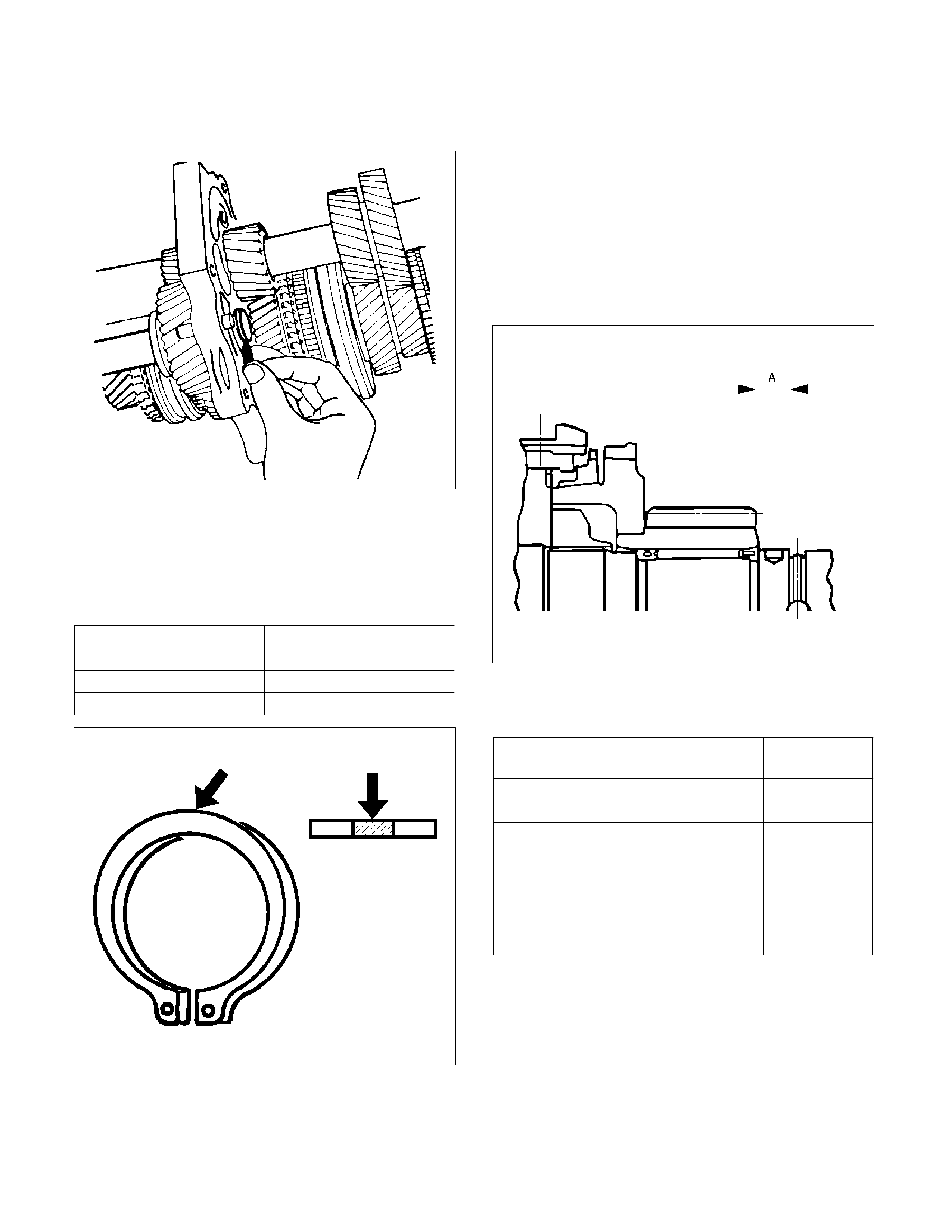
14. Select reverse idler gear snap ring (7) which will
provide the minimum clearance between the
intermediate plate (27) and the snap ring (7).
226RS022
• There are three snap ring sizes available.
The snap rings are color-coded to indicate their
thickness.
Intermediate Plate and Snap Ring Clearance
Standard: 0 - 0.15 mm (0 - 0.0059 in)
Snap Ring Availability
Thickness Color Coding
1.2 mm (0.047 in) White
1.3 mm (0.051 in) Yellow
1.4 mm (0.055 in) Blue
226RS021
• Use a pair of snap ring pliers to install the snap
ring to the reverse idler shaft.
The snap ring must be fully inserted into the
reverse idler shaft snap ring groove.
15. Install thrust washer and lock ball (6) by
performing the following steps:
• Use a thickness gauge to measure the
clearance between the 5th gear and the thrust
washer.
5th Gear and Thrust Washer Clearance
Standard: 0.10 - 0.25 mm (0.004 - 0.010 in))
• Measure clearance "A" as shown in the figure.
226RS023
• Select appropriate thrust washer from chart.
• There are four thrust washer sizes available.
Thrust Washer Availability
Thickness
mm (in) Color
Coding A mm (in) Clearance
mm (in)
7.9 (0.311) White 8.05 - 8.1
(0.317-0.319) 0.15 - 0.25
(0.006-0.010)
8.0 (0.315) Yellow 8.1 - 8.2
(0.319-0.323) 0.1 - 0.25
(0.004-0.010)
8.1 (0.319) Green 8.2 - 8.3
(0.323-0.327) 0.1 - 0.25
(0.004-0.010)
8.2 (0.323) Blue 8.3 - 8.36
(0.327-0.329) 0.1 - 0.21
(0.004-0.008)
• The thrust washers are color coded to indicate
their thickness as shown in the figure.
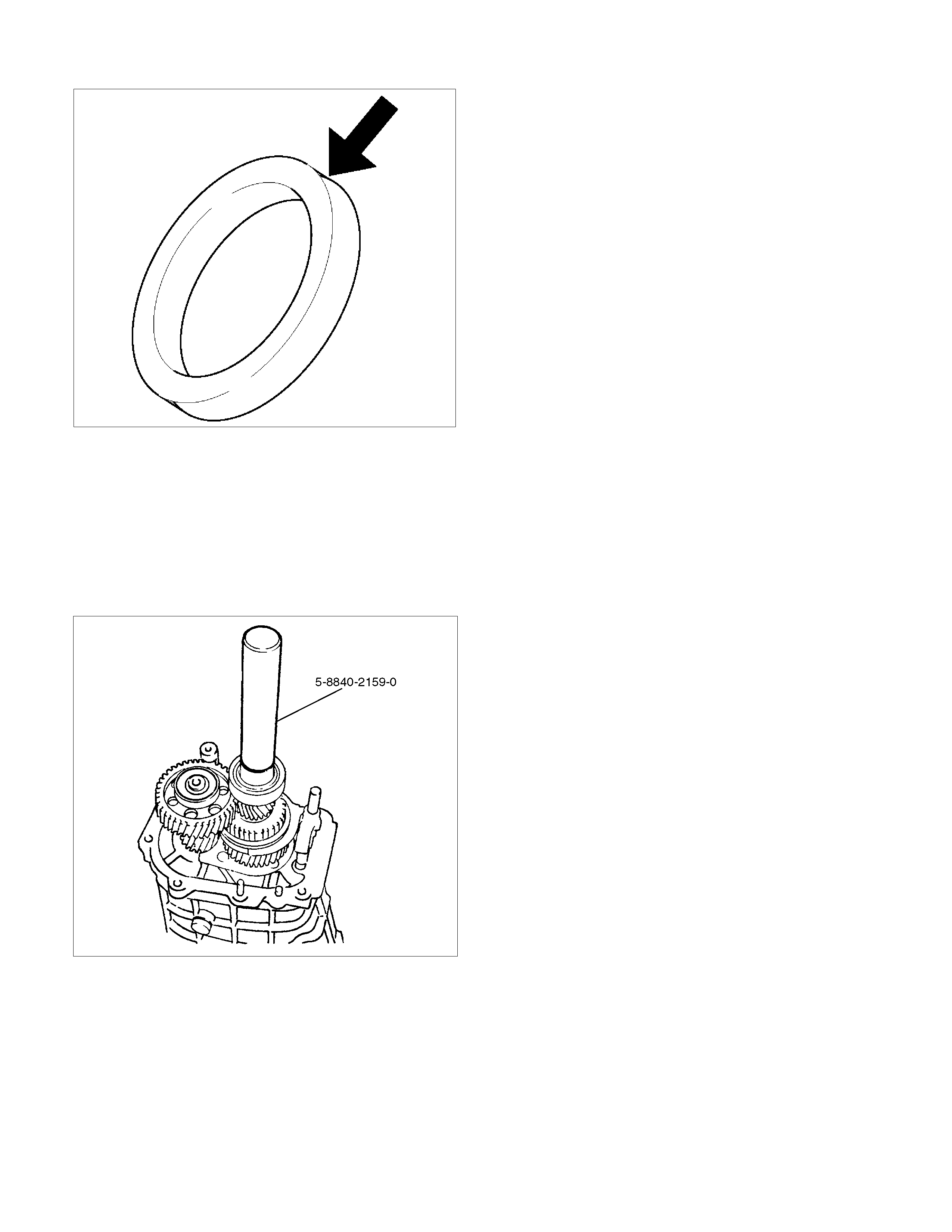
226RS024
• Apply grease to the thrust washer and the lock
ball.
• Install the thrust washer and the lock ball.
16. Install thrust plate (5) and retainer (4).
17. Apply engine oil to the bearing inner and outer
circumference.
Use the installer 5-8840-2159-0 to install the ball
bearing (3) to the mainshaft.
226L100002
18. Apply engine oil to the oil seal collar inner
circumference.
Install the oil seal collar (2) to the mainshaft by using
the installer 5-8840-2159-0.
19. Install the oil seal collar snap ring (1).

Top Gear Shaft, Main Gear Shaft, and Counter Gear Shaft
Disassembled View
226RS026
Legend
(1) Top Gear Shaft Snap Ring (16) 1st Outside Ring
(2) Top Gear Shaft (17) 1st Block Ring
(3) Ball Bearing (18) Needle Bearing
(4) Needle Bearing (19) Clutch Hub Snap Ring
(5) Top Block Ring (20) 1st-2nd Synchronizer Assembly
(6) Mainshaft Snap Ring (21) 2nd Block Ring
(7) 3rd-4th Synchronizer Assembly (22) 2nd Outside Ring
(8) 3rd Block Ring (23) 2nd Inside Ring
(9) 3rd Gear (24) 2nd Gear
(10) Needle Bearing (25) Needle Bearing
(11) Needle Bearing Collar (26) Mainshaft
(12) Mainshaft Ball Bearing (27) Bearing Snap Ring
(13) 1st Gear Thrust Bearing (28) Front Roller Bearing
(14) 1st Gear (29) Center Roller Bearing
(15) 1st Inside Ring (30) Counter Gear Shaft
Techline

Disassembly
1. Use a pair of snap ring pliers to remove the top
gear shaft snap ring(1).
2. Remove top gear shaft(2) with ball bearing(3).
3. Use a bench press and the bearing remover 5-
8840-0015-0 to remove the ball bearing(3).
226RW216
4. Remove needle bearing (4) and top block ring (5),
mainshaft snap ring.
5. Use a pair of snap ring pliers to remove the
mainshaft snap ring (6).
226RS008
6. Use a bench press and the bearing remover 5-
8840-0015-0 to remove the 3rd-4th synchronizer
assembly (7) as a set.
Disassemble the synchronizer assembly.
226RW217
Legend
(1) Springs
(2) Sleeve
(3) Clutch Hub
(4) Inserts
7. Remove 3rd block ring (8), 3rd gear (9), and
needle bearing (10).
8. Use a bench press and the bearing remover 5-
8840-0015-0 to remove the 1st gear (14) together
with the mainshaft ball bearing (12), 1st gear
thrust bearing (13), and needle bearing collar (11).
226RW218
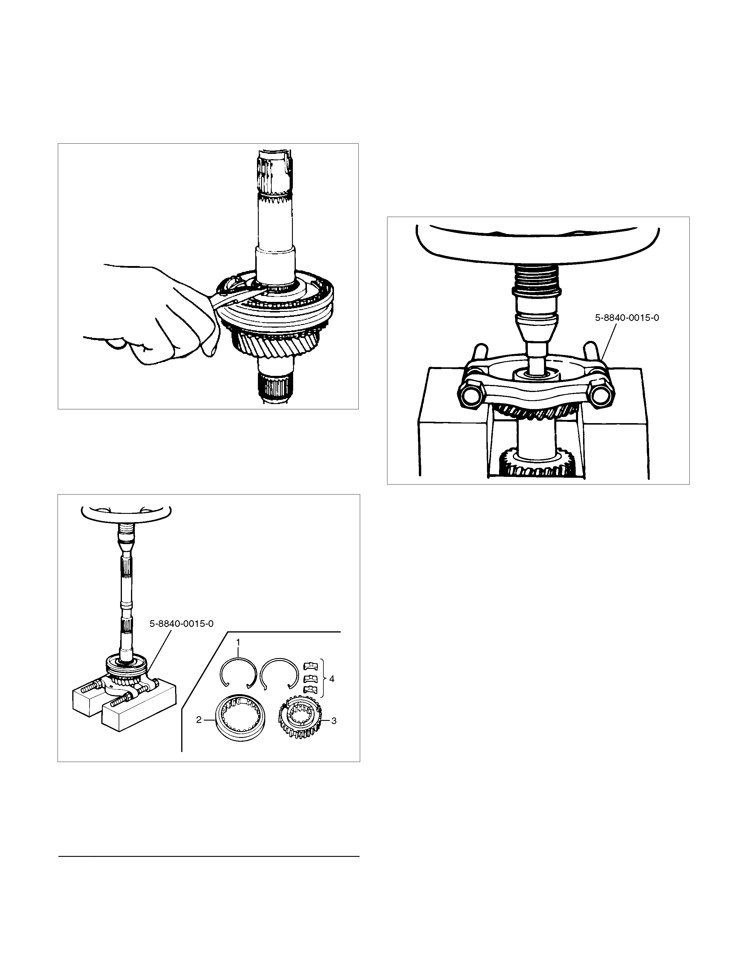
9.Disassemble 1st inside ring (15), 1st outside ring (16),
and 1st block ring (17).
10.Remove needle bearing (18).
11.Use a pair of snap ring pliers to remove the clutch
hub snap ring (19).
226RS031
12.Use bench press and the bearing remover 5-8840-
0015-0 to remove the 2nd gear (24) together with
1st-2nd synchronizer assembly (20), 2nd block ring
(21), 2nd outside ring (22), and inside ring (23).
Disassemble the synchronizer assembly.
226RW220
Legend
(1) Springs
(2) Sleeve
(3) Clutch Hub
(4) Inserts
13. Remove needle bearing (25) from mainshaft (26).
14. Remove bearing snap ring (27).
15. Remove the front roller bearing (28) by performing
the following steps.
• Remove the ring, outer race and bearing
assembly by using a bench press and remover
5-8840-0015-0.
• Remove the inner race by using a bench press
and remover 5-8840-0015-0.
226RW219
16. Remove center roller bearing (29) from counter
gear shaft (30).
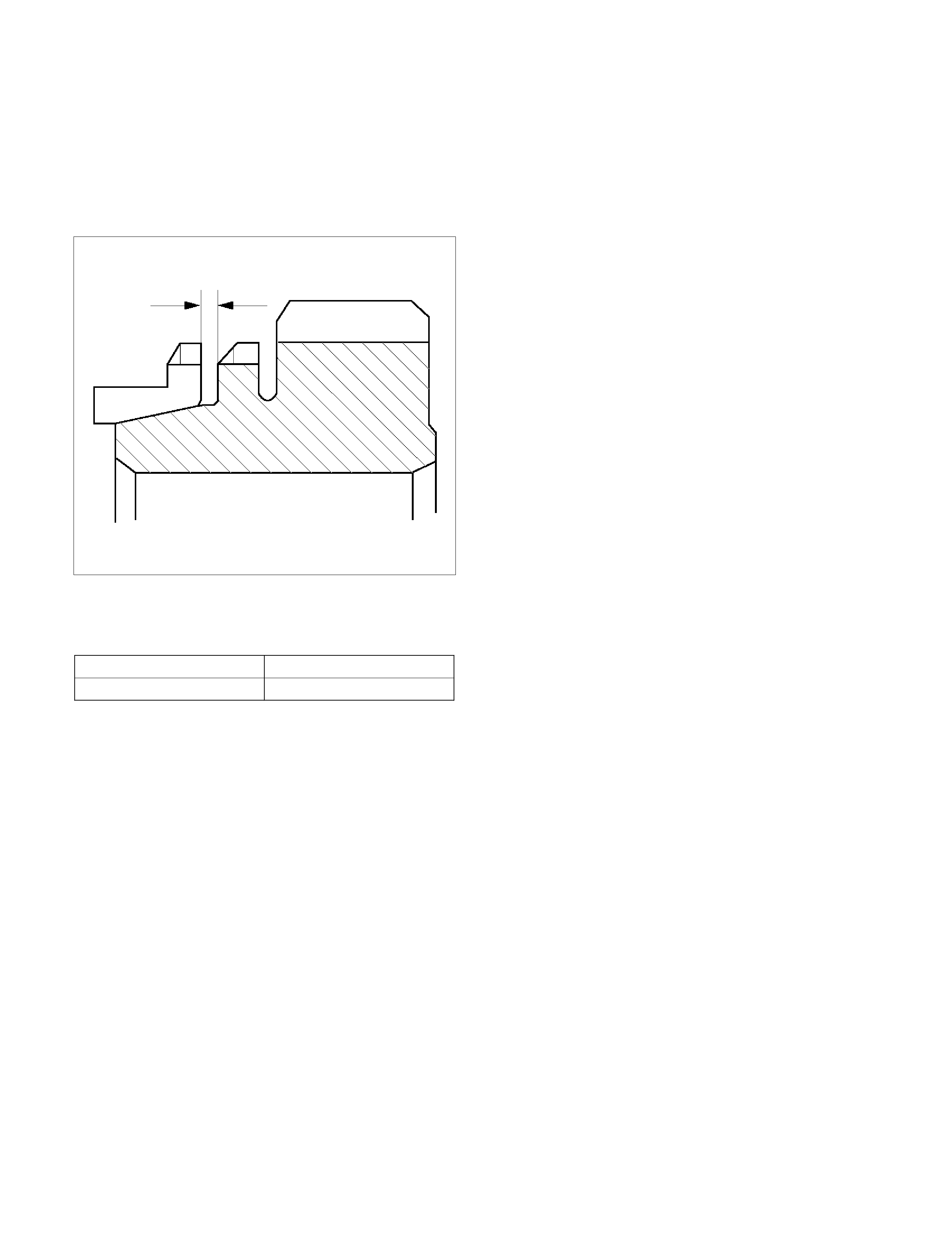
Inspection and Repair
Make the necessary adjustments, repairs, and part
replacements if excessive wear or damage is
discovered during inspection.
Block Ring and Dog Teeth Clearance
• Use a thickness gauge to measure the clearance
between the block ring and the dogteeth.
226RS035
If the measured value exceeds the specified limit,
the block ring must be replaced.
Block Ring and Dog Teeth Clearance
Standard Limit
1.5 mm (0.059 in) 0.8 mm (0.032 in)
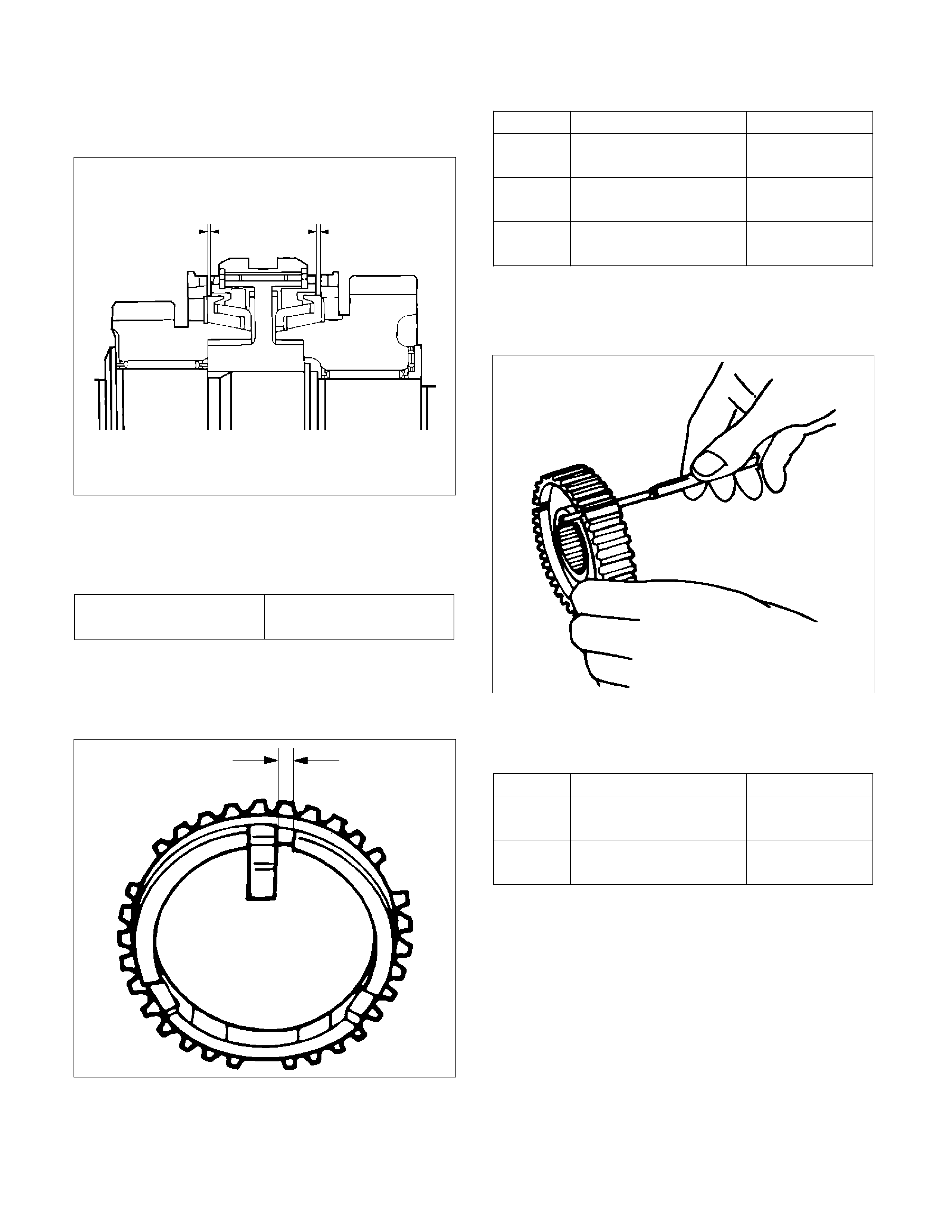
1st-2nd Synchronizer (3-CONE)
• Use a thickness gauge to measure the clearance
between the block ring and the dogteeth.
226RS036
If the measured value exceeds the specified limit,
the 1st-2nd synchronizer assembly must be
replaced.
Block Ring and Dog Teeth Clearance
Standard Limit
1.5 mm (0.059 in) 0.8 mm (0.032 in)
Block Ring and Insert Clearance
• Use a vernier caliper or thickness gauge to
measure the clearance between the block ring and
the insert.
226RS037
If the measured value exceeds the specified limit,
the block ring and the insert must be replaced.
Block and Insert Clearance
Standard Limit
3rd-4th 3.46 - 3.76 mm
(0.136 - 0.148 in) 4.0 mm
(0.158 in)
1st-2nd 3.86 – 4.16 mm
(0.152 - 0.164 in) 4.9 mm
(0.193 in)
Rev.5th 3.59 - 3.91 mm
(0.141 - 0.154 in) 4.1 mm
(0.161 in)
Clutch Hub and Insert Clearance
• Use a thickness gauge to measure the clearance
between the clutch hub and the insert.
226RS038
If the measured value exceeds the specified limit,
the clutch hub and the insert must be replaced.
Clutch Hub and Insert Clearance
Standard Limit
1st-2nd
3rd-4th 0.01 – 0.21 mm
(0.004 - 0.0083 in) 0.3 mm
(0.012 in)
Rev-5th 0.09 – 0.31 mm
(0.0035 - 0.0122 in) 0.4 mm
(0.016 in)

Mainshaft Run-out
• Install the mainshaft to V-blocks.
• Use a dial indicator to measure the mainshaft
central portion run-out.
226RS039
If the measured mainshaft run-out exceeds the
specified limit, the mainshaft must be replaced.
Mainshaft Run-out
Limit: 0.05 mm (0.0020 in)
Gear Inside Diameter
• Use an inside dial indicator to measure the gear
inside diameter.
226RS040
If the measured value is less than the specified limit,
the gear must be replace.
Gear Inside Diameter
Standard Limit
1st
3rd 45.000 - 45.013 mm
(1.771 - 1.772 in) 45.100 mm
(1.776 in)
2nd 52.000 - 52.013 mm
(2.047 - 2.048 in) 52.100 mm
(2.051 in)
Rev. 48.000 - 48.013 mm
(1.889 - 1.890 in) 48.100 mm
(1.894 in)
5th 32.000 - 32.013 mm
(1.259 - 1.260 in) 32.100 mm
(1.246 in)
Reverse Idler Gear and Idler Gear Shaft Clearance
• Use a micrometer to measure the idler gear shaft
diameter.
• Use an inside dial indicator to measure the idler
gear inside diameter.
226RS041
• Calculate the idler gear and idler gear shaft
clearance.
Idler gear inside diameter-idler gear shaft diameter =
idle gear and idler gear shaft clearance.
If the measured value exceeds the specified limit,
the idle gear and/or the idler gear shaft must be
replaced
Idler Gear and Idler Gear Shaft Clearance
Standard: 0.041 - 0.074 mm (0.0016 -0.0029 in)
Limit: 0.150 mm (0.0059 in)
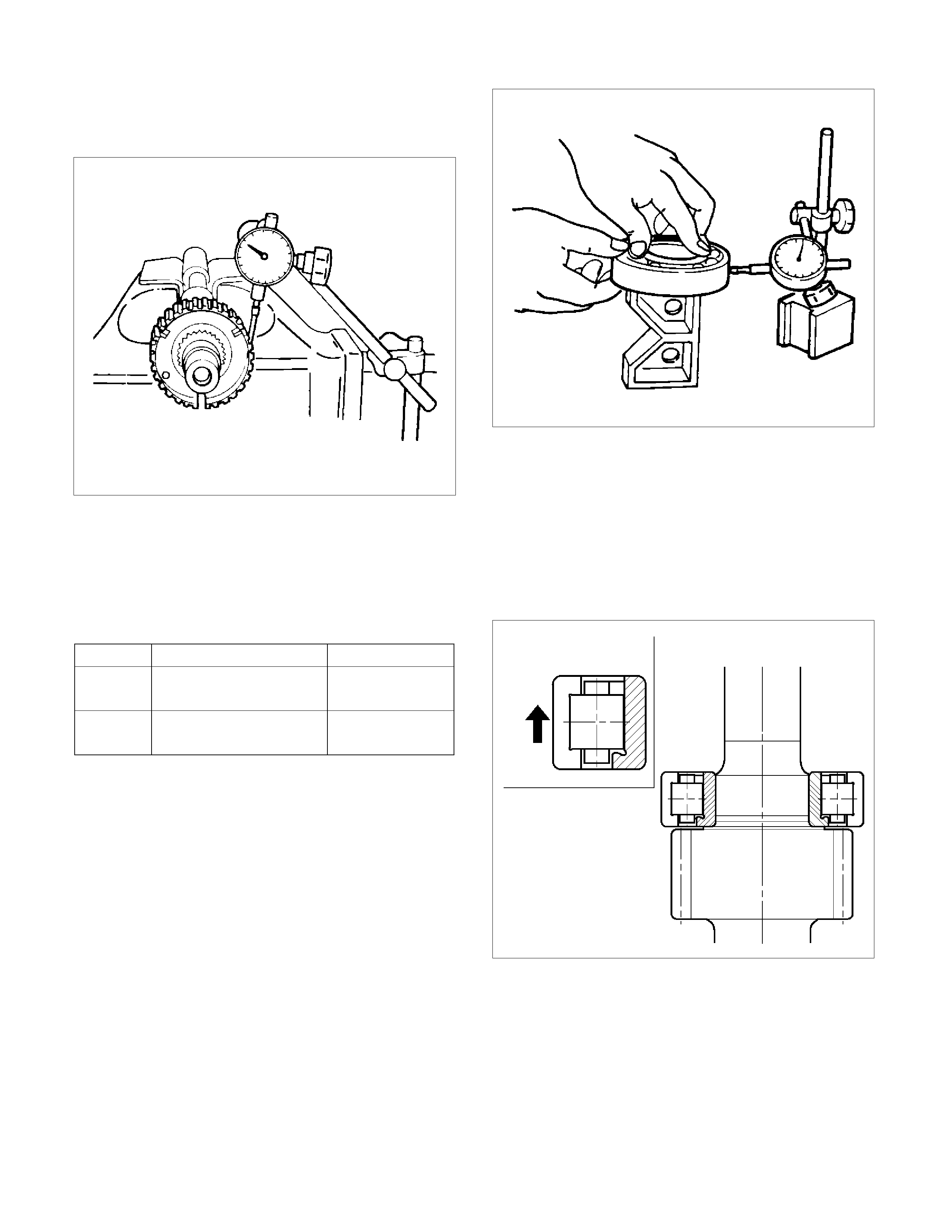
Clutch Hub Spline Play
• Set a dial indicator to the clutch hub to be
measured.
226RS042
• Move the clutch hub as far as possible to both the
right and the left.
Note the dial indicator reading.
If the measured value exceeds the specified limit,
the clutch hub must be replaced.
Clutch Hub Spline Play
Standard Limit
1st-2nd
3rd-4th 0 - 0.1 mm
(0 - 0.004 in) 0.2 mm
(0.008 in)
Rev. 5th 0 - 0.2 mm
(0 - 0.008 in) 0.3 mm
(0.012 in)
Ball Bearing Play
• Use a dial indicator to measure the ball bearing
play.
Ball Bearing Play
Limit: 0.2 mm (0.008 in)
226RS043
Reassembly
1. Install center roller bearing (29) to counter gear
shaft (30).
• Apply engine oil to the bearing inner and outer
circumferences.
• Install the roller bearing in the proper direction.
NOTE: Check that outer race moves only in the
direction of arrow.
226RS044
2. Install front roller bearing (28) by performing the
following steps.
• Use bearing installer 5-8840-2194-0 to install
the front roller bearing inner race to the counter
gear shaft (30).
• Install the outer race and roller assembly.
The snap ring groove must be facing the
transmission front side.

• Use bearing installer 5-8840-2194-0 to install
the ring.
226RS045
Legend
(1) Ring
(2) Outer Race and Roller Assembly
(3) Inner Race
3. Install bearing snap ring (27) to counter gear shaft
(30).
4. Apply engine oil to the needle bearing (25) and the
2nd gear (24) thrust surfaces.
Install the needle bearing (25) and the 2nd gear (24)
to the mainshaft (26).
The 2nd gear (24) dog teeth must be facing the
transmission rear side.
226RS046
5. Assemble 2nd inside ring (23), 2nd outside ring
(22), and 2nd block ring (21).
•
A
pply engine oil to the synchronizer ring friction
surfaces.
226RS047
Legend
(1) Block Ring
(2) Outside Ring
(3) Inside Ring
(4) 2nd Gear
(5) Needle Bearing
6. Assemble 1st-2nd synchronizer assembly (20) by
performing the following steps:
1. Check that the inserts (3) fit snugly into the
clutch hub (5) insert grooves.
2. Check that the inserts springs (4) are fitted to
the inserts as shown in the illustration.
3. Check that the clutch hub (5) and the sleeve
(6) slide smoothly.

266RS049
7. Install the synchronizer assembly (20) to the
mainshaft (26).
The clutch hub face (with the heavy boss) must be
facing the 2nd gear side.
226RS048
8. Install clutch hub snap ring(19) by performing the
following steps:
• Select the snap ring, which will provide the
minimum clearance between the 1st-2nd clutch
hub and the snap ring.
226RS050
• There are three snap ring sizes available.
• The snap rings are color coded to indicate their
thickness as shown in the figure.
226RS021
Clutch Hub and Snap Ring Clearance
Standard: 0 - 0.1 mm (0 - 0.004 in)
Snap Ring Availability
Thickness Color Coding
1.80 mm (0.071 in) White
1.85 mm (0.073 in) Yellow
1.90 mm (0.075 in) Blue
• Use a pair of snap ring pliers to install the snap
ring (19) to the mainshaft (26).
The snap ring must be fully inserted into the
mainshaft snap ring groove.
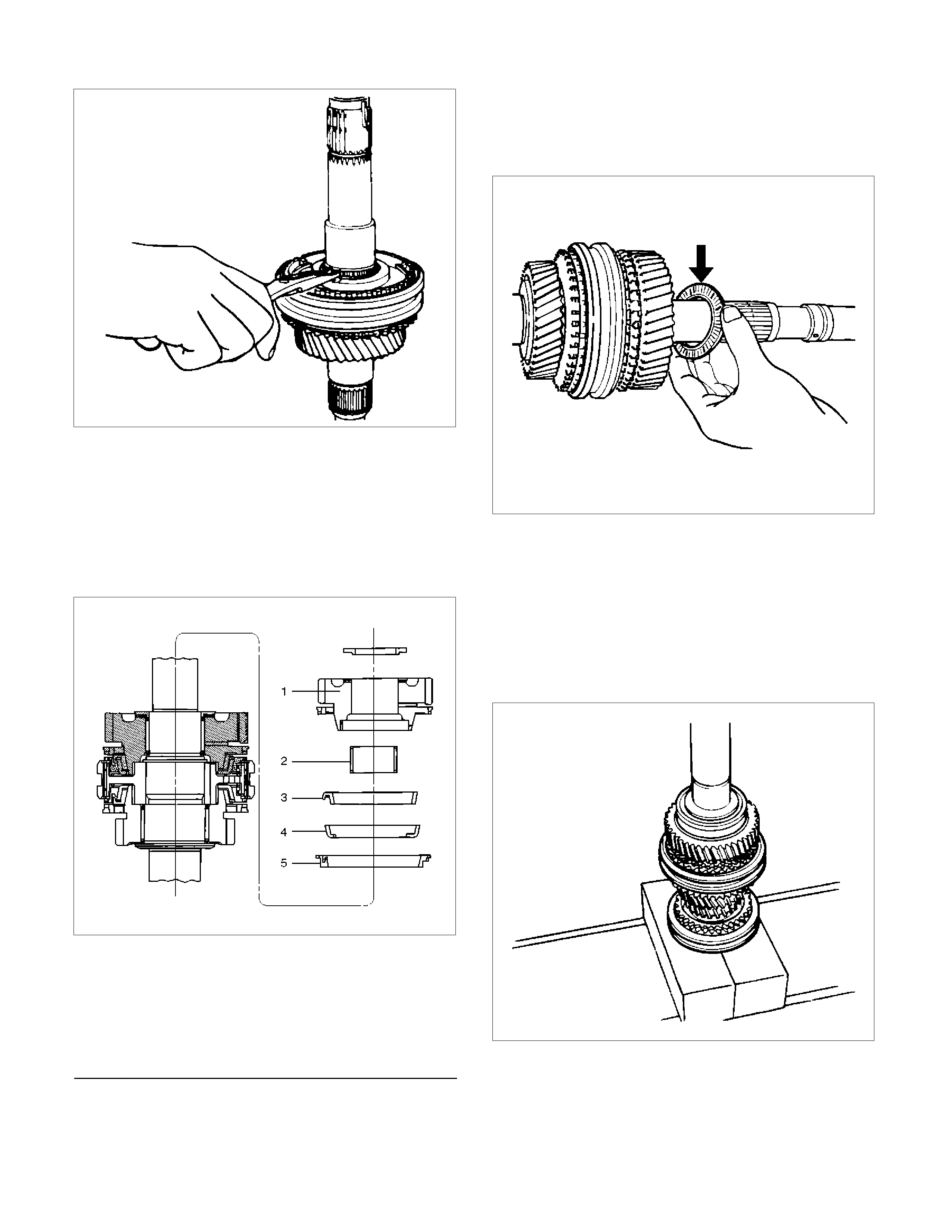
226RS031
9. Install needle bearing (18), 1st block ring (17), 1st
outside ring (16), 1st inside ring (15), and 1st gear
(14).
• Apply engine oil to the needle bearing, 1st gear
thrust surfaces and synchronizer ring friction
surfaces.
• The 1st gear dog teeth must be facing the
transmission front side.
226RS053
Legend
(1) 1st Gear
(2) Needle Bearing
(3) Inside Ring
(4) Outside Ring
(5) Block Ring
10. Install the 1st gear thrust bearing and the race
(13) to the main shaft.
The thrust bearing side must be facing the
transmission front side.
226RS054
11. Apply engine oil to the mainshaft ball bearing (12)
and the mainshaft (26).
Install the ball bearing (12) and needle bearing collar
(11) to the mainshaft (26).
The ball bearing snap ring groove must be facing
the transmission rear side.
Use a bench press and installer 9-8522-1165-0 to
slowly force the collar into place.
226RS055
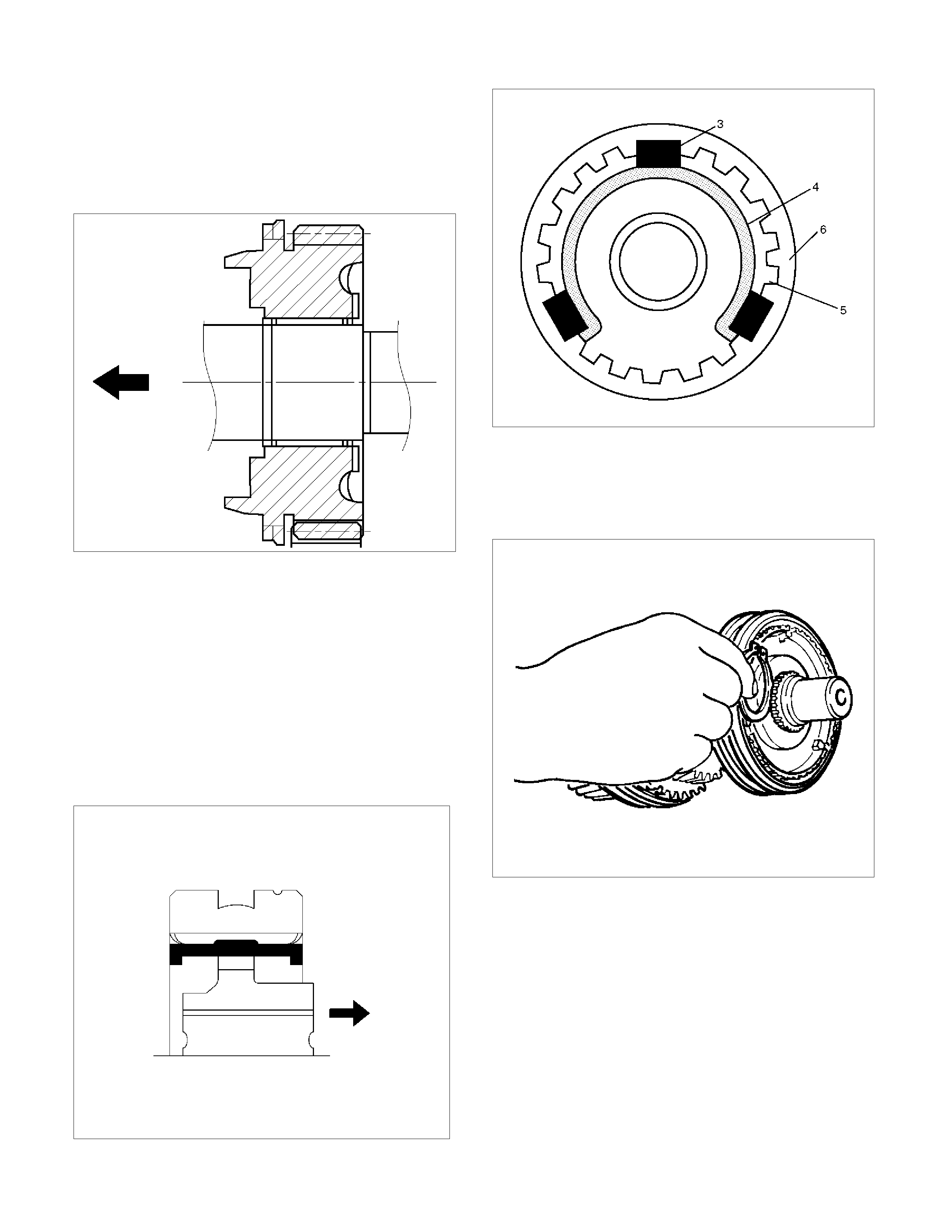
12. Apply engine oil to the needle bearing (10) and the
3rd gear (9) thrust surfaces.
Install the needle bearing (10) and the 3rd gear (9)
to the mainshaft.
The 3rd gear dogteeth must be facing the
transmission front side.
226RS056
13. Install 3rd block ring (8).
14. Check and install 3rd-4th synchronizer assembly
(7) by the following steps:
1. Check that the inserts (3) fit snugly into the
clutch hub insert grooves.
2. Check that the insert springs (4) are fitted to
the inserts as shown in the illustration.
3. Check that the clutch hub (5) and the sleeve
(6) slide smoothly.
4. Install the synchronizer assembly to the
mainshaft.
The clutch hub face with the heavy boss must be
facing the 3rd gear side.
226RW221
226RS049
15. Select and install mainshaft snap ring(6) in the
following way:
Select the snap ring, which will provide the minimum
clearance between the 3rd-4th clutch hub and the
snap ring.
226RS058
There are three snap ring siz es available.
The snap rings are color coded to indicate their
thickness as shown in the figure.
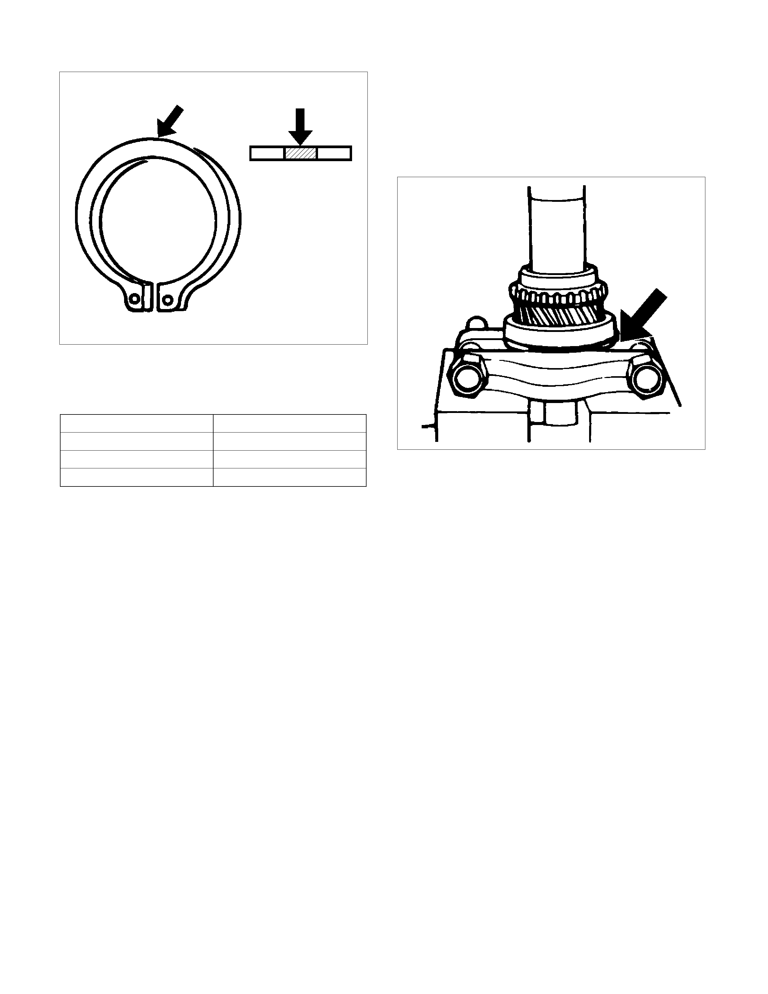
226RS021
Clutch Hub and Snap Ring Clearance
Standard: 0 - 0.1 mm (0 - 0.004 in)
Snap Ring Availability
Thickness Color Coding
1.80 mm (0.071 in) White
1.85 mm (0.073 in) Yellow
1.90 mm (0.075 in) Blue
• Use a pair of snap ring pliers to install the snap
ring to the mainshaft.
The snap ring must be fully inserted into the
mainshaft snap ring groove.
16. Install top block ring (5).
Apply grease to the needle bearing (4) inner and
outer circumferences and install needle bearing (4)
in the top gear shaft (2).
17. Use a bench press to install the top gear shaft ball
bearing (3) to the top gear shaft (2).
226RS059
The snap ring groove of the ball bearing (3) must be
facing the transmission front side.
18. Use a pair of snap ring pliers to install the top gear
shaft snap ring (1) to the top gear shaft (2).
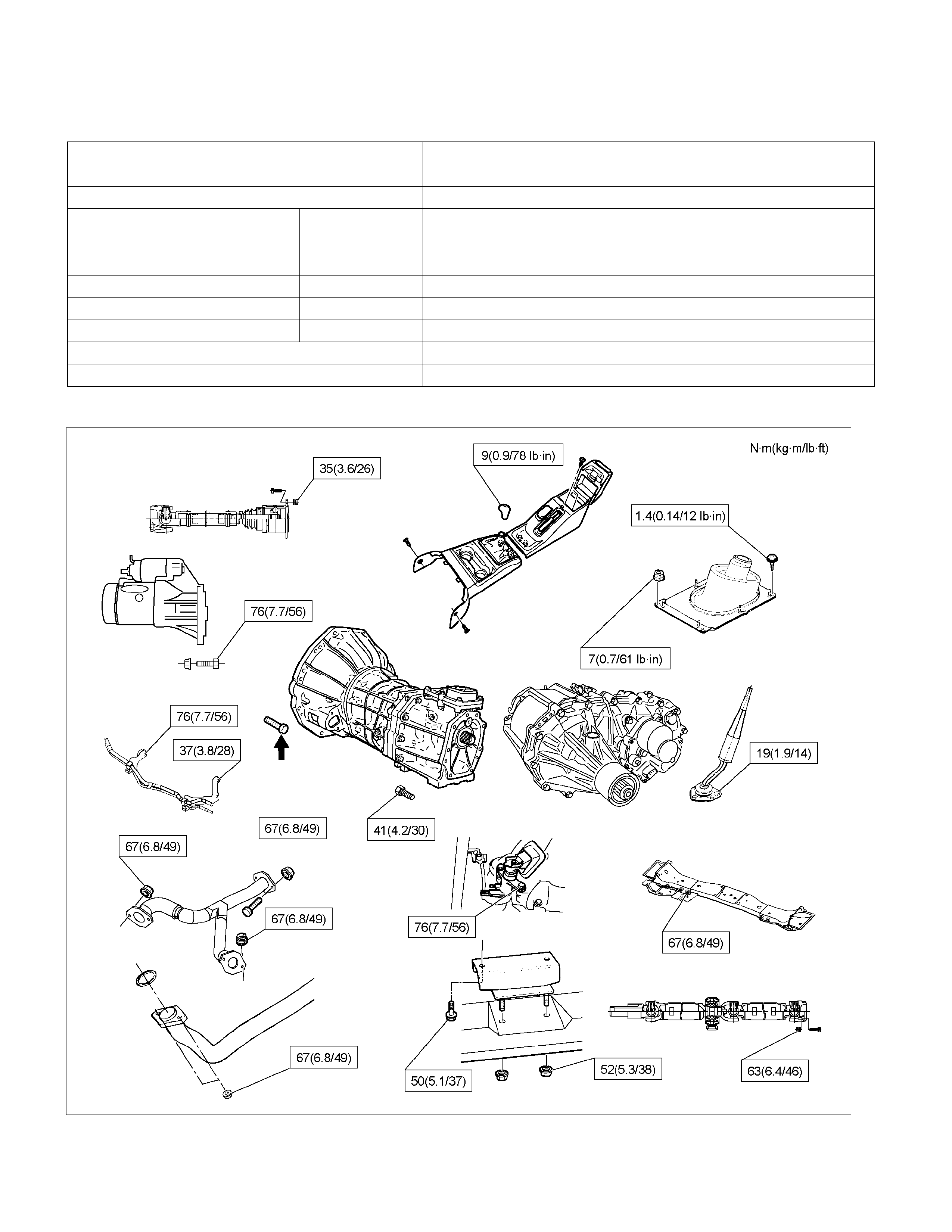
Main Data and Spec ifications
General Specifications
(MUA 5G) 4 ×
××
× 4
Transmission type Fully synchronized forward and reverse gears
Control method Remote control with the gear shift lever on the floor.
Gear ratio: Transmission 1st 4.008
2nd 2.301
3rd 1.427
4th 1.000
5th 0.828
Rev. 3.651
Transmission oil capacity 2.95 lit. (3.12 US qt)
Type of lubricant Engine oil: Refer to the chart in "SECTION 0"
Torque Specifications
RTW37BLF0004
About arrow mark, refer to Transmission (MUA) Installation in this section.
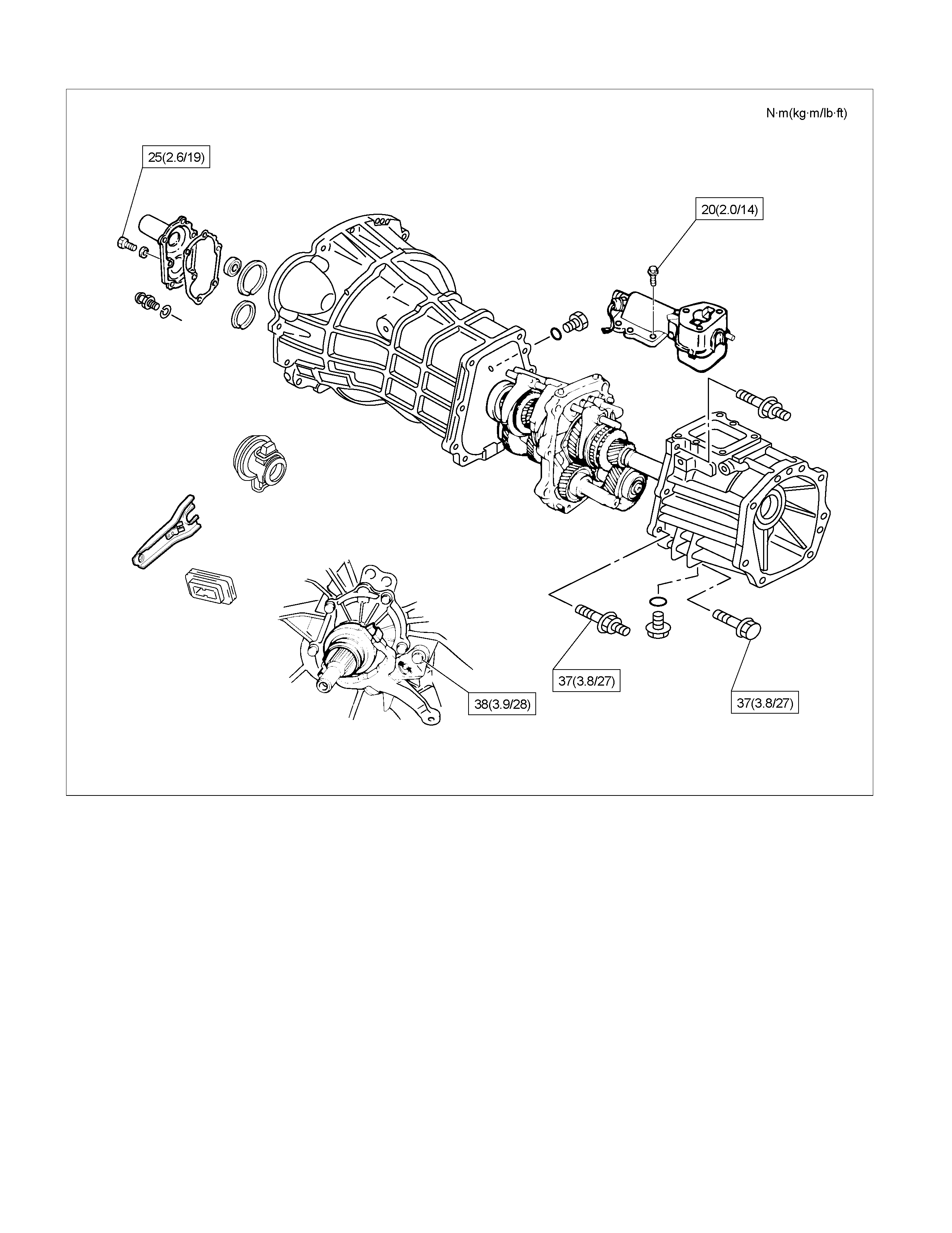
RTW37BLF0008

E07R300014

Troubleshooting
1. ABNORMAL NOISE
1) NOISY IN NEUTRAL
Checkpoint Fault Action
Replenish or replace the gear
oil
Insufficient or improper gear
oil
NG
Mainshaft splines
Synchronizer clutch hub
splines
Replace the main shaft and
the synchronizer clutch hub
Replace the gear(s)
Replace the flywheel pilot
Worn splines
Worn or scuffed gear tooth
contact surfaces
Flywheel pilot bearing Worn flywheel pilot bearing
Bearings (Mainshaft,
countershaft, and transfer
shaft)
Gears (Mainshaft,
countershaft, reverse idler
gear and transfer gears)
Replace the bearing(s)Worn or broken bearing(s)
OK
NG
NG
NG
NG
OK
OK
OK
Gear oil
Transmission Realign the transmissionTransmission misalignment
OK
NG

2) NOISY OPERATION
Checkpoint Fault Action
Replenish or replace the gear
oil
Insufficient or improper engine
oil
NG
Replace the gear(s)
Replace the gear(s)
Replace the bearing(s)
Gears (Gear whining) Lack of backlash between
meshing gears
Free running gears seizing on
the thrust face or the inner
face
Bearings (Hissing, thumping
or bumping) Worn or broken bearing(s)
Gears (Squealing at high
speeds)
Replace the gear(s)
Gears (Growling, humming, or
grinding) Worn, chipped, or cracked
gear(s)
NG
NG
NG
NG
OK
OK
OK
OK
Gear oil (Metallic rattling)
2. HARD SHIFTING
Checkpoint Fault Action
Change lever play
Clutch pedal free play
Repair or replace the
applicable parts and regrease
Readjust the clutch pedal free
play
Worn change lever sliding
portions
Improper clutch pedal free
play
Change lever operation Repair or regrease the change
lever assembly
Replenish or replace the
engine oil
Hard operating change lever
caused insufficient grease
Insufficient or improper gear
oil
OK
OK
NG
NG
NG
NG
OK
OK
Gear oil
Continued on the next page
Shift rod and quadrant box
sliding faces, and other parts Replace the shidt rod and/or
the quadrant box
Worn shift rod and/or sliding
faces
Repair or replace the sleeveSleeve movement failure
NG
NG
OK
Shift block sleeve movement

Checkpoint Fault Action
Synchronizer assembly
Shift arm and synchronizer
sleeve
Replace the worn parts
Replace the worn parts
Worn synchronizer parts
Worn shift arm and/or
synchronizer sleeve groove
Mainshaft and countershaft
thrust play Replace the worn parts
Worn thrust washer, collar,
and/or gear thrust faces
OK
NG
NG
NG
OK
OK
Continued from the previous
3. WALKING OR JUMPING OUT OF GEAR
Checkpoint Fault Action
Shift rod and quadrant box
sliding faces
Detent ball
Replace the shift rod and/or
the quadrant box
Replace the detent ball
Worn shift rod and/or sliding
faces
Worn detent ball
Detent spring Repair or replace the detent
spring
Replace the worn parts
Detent spring weak or broken
Insufficient stroke caused by
sliding position wear and
excessive play
OK
OK
NG
NG
NG
NG
OK
OK
Change lever play
Continued on the next page
Mainshaft and countershaft
thrust play Replace the worn parts
Worn thrust washer, collar,
and/or gear thrust faces
Replace the worn parts
Worn shift arm and/or
synchronizer sleeve groove
NG
NG
OK
Shift arm and synchronizer
sleeve
Checkpoint Fault Action
Synchronizer assembly
Bearings (Mainshaft,
countershaft, and individual
gears)
Replace the spring
Replace the bearing(s)
Weak or broken spring
Worn or broken bearings(s)
Mainshaft splines
Synchronizer clutch hub
splines
Replace the main shaft and
the synchronizer clutch hub
Worn splines
OK
NG
NG
NG
OK
OK
Continued from the previous page
4. OIL LEAKAGE
Checkpoint Fault Action
Gear oil Replace the gear oilImproper gear oil
Drain plug and/or filler plug Tighten the plug(s) and
replenish the oil
Drain the oil to the correct
level
Loose plug(s)
Oil level too high
OK
NG
NG
NG
OK
OK
Oil level
Rear cover oil seal
Air breather
Replace the oil seal
Install the air breather
Replace the air breather
Worn or scratched oil seal
Air breather not installed
Air breather clogged
Front cover oil seal Replace the oil seal
Replace the gasket(s)
Worn or scratched oil seal
Defective or improperly
installed gasket(s)
OK
NG
NG
NG
NG
OK
OK
Gaskets
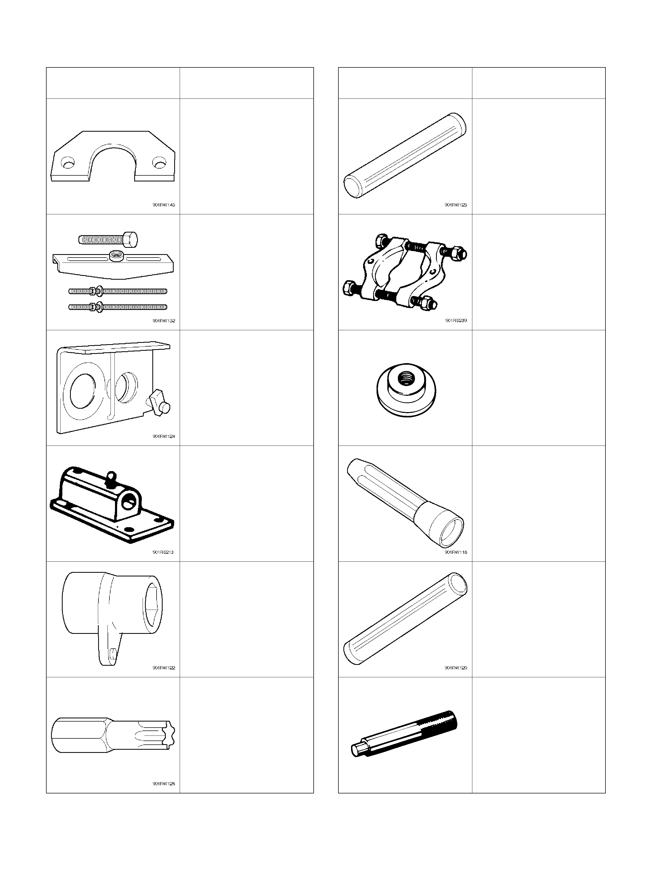
Special Tools (MUA)
ILLUSTRATION TOOL NO.
TOOL NAME ILLUSTRATION TOOL NO.
TOOL NAME
5-8840-2158-0
Mainshaft collar remover
5-8840-2159-0
Mainshaft end bearing
installer
5-8840-2027-0
Puller
5-8840-0015-0
Bearing
remover/installer
5-8840-2160-0
Holding fixture
5-8840-2797-0
Rear case oil seal
installer
5-8840-0003-0
Holding fixture base
5-8840-0026-0
Front cover oil seal
installer
5-8840-2156-0
Wrench
9-8522-1165-0
Mainshaft collar remover
5-8840-0047-0
Torx bit wrench
(T–45)
5-8840-0007-0
Driver handle