
Manual Transmission – V6 Page 7B1–1
Page 7B1–1
Section 7B1
Manual Transmission – HFV6
ATTENTION
Before performing any service operation or other procedure described in this Section, refer to General
Information Warnings, Cautions and Notes for correct workshop practices with regard to safety and/or
property damage.
1 General Information ...............................................................................................................................2
1.1 General Description............................................................................................................................................... 2
Synchroniser Assemblies.....................................................................................................................................2
Synchroniser Action ........................................................................................................................................... 2
Lubrication ............................................................................................................................................................. 2
Selector Mechanism .............................................................................................................................................. 2
1.2 Transmission Cross-section................................................................................................................................. 3
Shift Pattern............................................................................................................................................................ 3
1.3 Transmission Identification .................................................................................................................................. 4
1.4 WARNINGS, CAUTIONS and NOTES.................................................................................................................... 5
Definition of WARNING, CAUTION and NOTE Statements................................................................................. 5
WARNING Defined............................................................................................................................................. 5
CAUTION Defined.............................................................................................................................................. 5
NOTE Defined.................................................................................................................................................... 5
1.5 Diagnosis................................................................................................................................................................ 6
2 Servicing Information ............................................................................................................................7
2.1 Recommended Lubricant and Quantity............................................................................................................... 7
2.2 Checking Transmission Lubricant Level............................................................................................................. 8
2.3 Draining and Refilling Transmission.................................................................................................................... 9
3 Minor Service Operations....................................................................................................................10
3.1 Back-Up Lamp Switch ......................................................................................................................................... 10
Remove................................................................................................................................................................. 10
Reinstall................................................................................................................................................................ 10
3.2 Speed Sensor (RWD)........................................................................................................................................... 11
Remove................................................................................................................................................................. 11
Reinstall................................................................................................................................................................ 11
3.3 Transmission Support and Mount...................................................................................................................... 12
Remove................................................................................................................................................................. 12
Reinstall................................................................................................................................................................ 13
3.4 Extension Housing Oil Seal (RWD) .................................................................................................................... 14
Replace................................................................................................................................................................. 14
3.5 Gearshift Lever Knob, Boot Assembly and Lever............................................................................................. 15
Remove................................................................................................................................................................. 15
Reinstall................................................................................................................................................................ 16
3.6 Transmission Assembly...................................................................................................................................... 17
Remove................................................................................................................................................................. 17
Reinstall................................................................................................................................................................ 19
4 Specifications.......................................................................................................................................20
5 Torque Wrench Specifications............................................................................................................21

Manual Transmission – V6 Page 7B1–2
Page 7B1–2
1 General Information
This Section describes the removal and rei nstallation procedures of the Ai sin AR5 five speed manual transmission as
well as the service operations which can be performed with the transmission still fitted to the vehicle.
1.1 General Description
The Aisin AR5 manual shift transmission is a 5-speed assembly, fully synchronised with single overdrive. All gear
positions (including Reverse) are synchronised. The transmission has a reluctor wheel on the output shaft for the vehicle
speed sensor.
Plain roller, tapered roller, and ball bearings are used to support the input shaft, countershaft, and output shaft. All
constant mesh speed gears are supported on needle roller b earings.
Synchroniser Assemblies
The Warner type speed synchronisers are as follows:
• first, second and third gears – triple type synchroniser,
• fourth and fifth gears – single type synchroniser,
• reverse gear – brake type synchroniser.
Synchroniser Action
During synchroniser operation , the synchroniser ring is moved into engagement by the appropriate fork, carrying with it,
three spring loaded synchr oniser inserts and balls, loc ated i n slots in the synchroniser hub.
The outer synchroniser ring, together with the inserts, is moved along the hub, placing a load on the three lugs of the
blocking ring.
This initial force is sufficient to seat the blocking ring and start pre-synchronisation b eca use of the friction between the
cone on the constant mesh gear and the blocking ring/s.
At this stage, gear engagement is prevented as long as there is a difference in spe ed between the mating surfaces of the
blocking ring and cone of the constant mesh gear. As the speeds between the blocking ring and the gear cone become
synchronised, the teeth on the blocking rin g a nd gear cone line up with the internal spli nes of the ring, allowing the outer
synchroniser ring to engage the teeth o n the gear being engaged, completing gear selection.
Lubrication
Lubrication of all internal components is by splash feed, provided by the rotating cou ntershaft gear and constant mesh
gears of reverse, first and second gears. Lubricatio n splash is controlled by an oil separator arou nd the countershaft gear
and the oil distribution channels mounted through out the transmission.
This manual transmission is oil fill ed for life and uses lubricant SAE 75 –90 GL3 or alternatively Mobilube XHP GL4.
Selector Mechanism
The gearshift assembly is mounted to the floor panel and the control lever is directly attached to the top of the
transmission housing. The control lever is linked to a four shift rails mechanism, the control lever mechanism rotates and
connects with one of the four shift rails, as a gear is selected.
Manual Transmission – V6 Page 7B1–3
Page 7B1–3
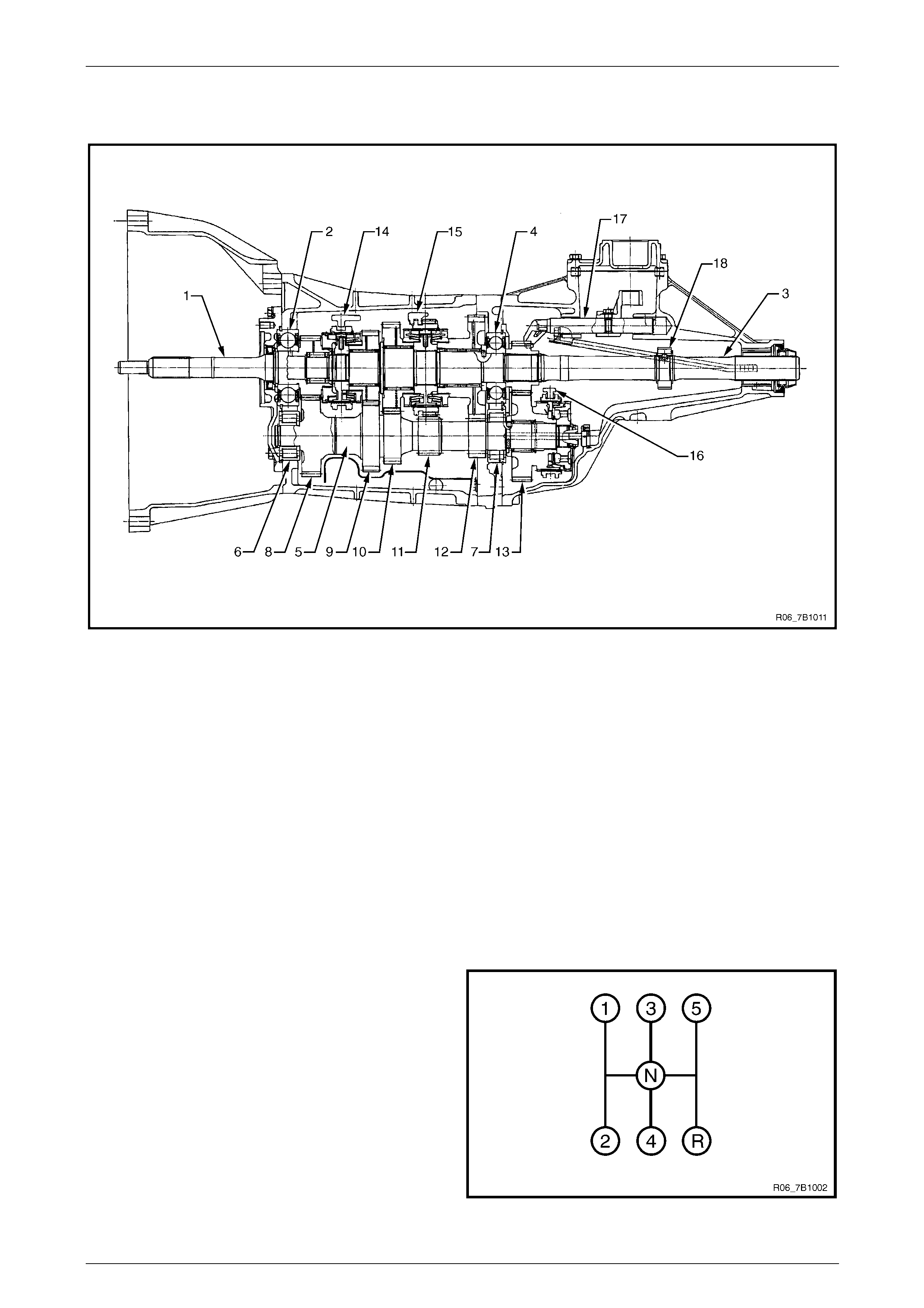
1.2 Transmission Cross-section
Figure 7B1 – 1
Legend
1 Input Shaft
2 Ball Bearing – Input Shaft
3 Output Shaft
4 Ball Bearing – Output Shaft
5 Counter Gear Shaft
6 Front Roller Bearing – Counter
Gear Shaft
7 Centre Roller Bearing – Counter Gear
Shaft
8 Headset Reduction
9 3rd Gear
10 2nd Gear
11 Reverse gear and Idler
12 1st Gear
13 5th Gear
14 3–4 Synchro
15 1–2 Synchro
16 5th Synchro
17 Select Mechanism
18 Reluctor Wheel – Speed Sensor
NOTE
When 4th speed is selected, the input and o utput
shafts are directly coupled (ratio 1:1), there is no
4th gear fitted to the shafts.
Shift Pattern
The shift pattern is as shown, with reverse gear (R) in line
with the fifth gear and neutral (N) in a central position.
Figure 7B1 – 2
Manual Transmission – V6 Page 7B1–4
Page 7B1–4
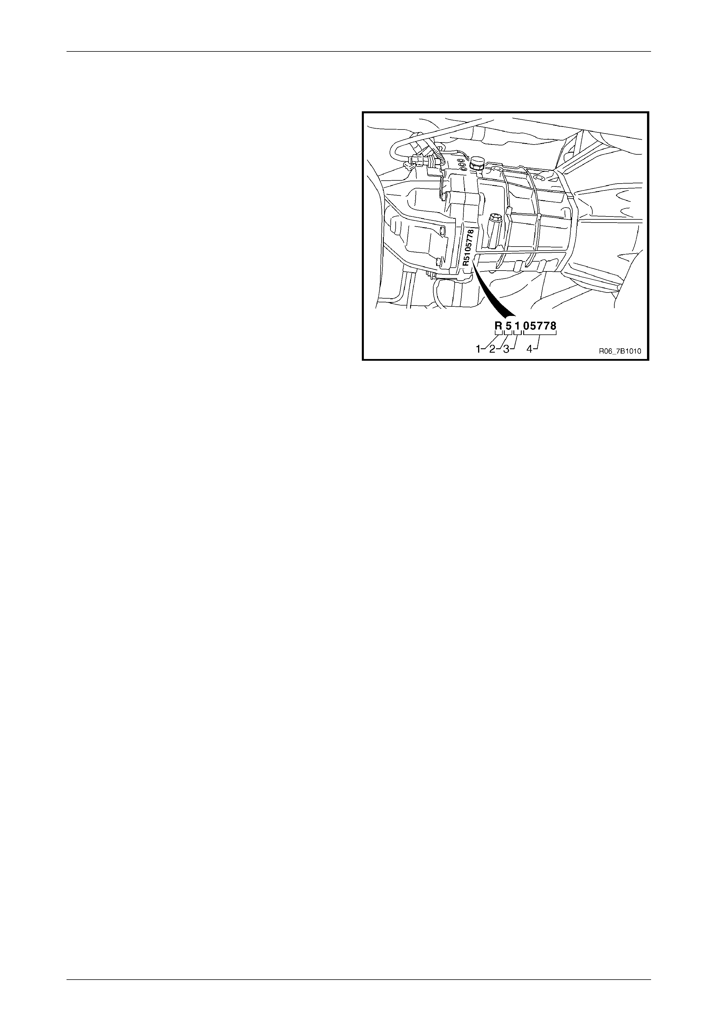
1.3 Transmission Identification
The transmission identificatio n can be determined from the
stamping onto the lower part of the transmission
intermediate case at the interface between the intermediate
case and the transmission rear case.
Legend
1 (R): transmission type (AR5)
2 (5): year of manufacture (2005)
3 (1): month of manufacture (January)
4 (05778): individual transmission S/N built that Month.
NOTE
The first nine months of the year are id entif ied b y
a number 1 to 9, the last three months b y a letter
as follows:
• X for October,
• Y for November, and
• Z for December.
Figure 7B1 – 3

Manual Transmission – V6 Page 7B1–5
Page 7B1–5
1.4 WARNINGS, CAUTIONS and NOTES
This Section contains various W A RNINGS, CAUTIONS and NOTE statements that you must observe carefull y to reduce
the risk of death or injury during service, repair procedures or vehicle op eration. Incorrect service or repair procedures
may damage the vehicle or cause operational faults. WARNINGS, CAUTION and NOTE statements are not exhaustive .
GM HOLDEN LTD can not possibly warn of all the potentially hazardous consequences of failure to follow these
instructions.
Definition of WARNING, CAUTION and NOTE Statements
Diagnosis and repair proce dures in this Section contain both general and specific WARNING, CAUTION and NOT E
statements. GM HOLDEN LTD is dedicated to the presentation of service information that helps the technician to
diagnose and repair the systems necessary for proper operation of the vehicle. Certain procedures may present a hazard
to the technician if they are not followed in the recommended manner. WA RNING, CAUTION and NOTE statements are
designed to help prevent thes e hazards from occurring, but not all hazards can be foresee n.
WARNING Defined
A WARNING statement immediately precedes an operatin g procedure or maintenance practice which, if not correctly
followed, could result in death or injury. A WARNING statement alerts yo u to take necessary action or not to take a
prohibited action. If a WARNING statement is ignored, the following consequences may occur:
• Death or injury to the technician or other personnel working on the vehicle,
• Death or injury to other people in or near the workplace area, and / or
• Death or injury to the driver / or passenger(s) of the vehicle or other people, if the vehicle has been improperly
repaired.
CAUTION Defined
A CAUTION statement immediately precedes an operating procedure or maintenance practice which, if not correctly
followed, could result in damage to or destru c tion of equipment, or corruption of data. If a CAUTION statement is
ignored, the following consequences may occur:
• Damage to the vehicle,
• Unnecessary vehicle repairs or component replacement,
• Faulty operation or performance of any system or component being repaired,
• Damage to any system or components which depend on the proper operation of the system or component being
repaired,
• Faulty operation or performance of any systems or components which depend on the pro per operation or
performance of the system or component under repair,
• Damage to fasteners, basic tools or special tools and / or
• Leakage of coolant, lubricant or other vital fluids.
NOTE Defined
A NOTE statement immediately precedes or follows an operating proc edure, maintenance practice or condition that
requires highlighting. A NOTE statement also emphasises necessary characteristics of a diagnostic or repair procedure.
A NOTE statement is designed to:
• Clarify a procedure,
• Present additional information for accomplishing a procedure,
• Give insight into the reasons for performing a procedure in the recommended manner, and / or
• Present information that gives the technician the ben efit of past experience in accomplishi ng a procedure with
greater ease.

Manual Transmission – V6 Page 7B1–6
Page 7B1–6
1.5 Diagnosis
Condition Probable Cause Corrective Action
Abnormal Noise Flywheel pilot bearing worn
Bearing worn or broken (mainshaft,
counter shaft and transfer shaft)
Gear tooth contact surfaces worn or
scuffed (mainshaft, counter shaft
reverse idler gear and transfer gears)
Splines worn (mainshaft synchronizer
clutch hub)
Gear or bearing thrust face seized
Replace
Repair/replace transmission
Repair/replace transmission
Repair/replace transmission
Repair/replace transmission
Hard Shifting Improper clutch pedal free play
Change lever sliding p ortions worn
Shift block, shift rod and/or control box
sliding faces worn
Shift arm and synchronizer sleeve
groove worn
Thrust washer, collar and/or gear
thrust faces worn (mainshaft and
counter shaft thrust play)
Synchronizer parts worn
Readjust
Repair or replace, regrease
Repair/replace transmission
Repair/replace transmission
Repair/replace transmission
Repair/replace transmission
Walking or Jumping out of Gear Détente ball worn
Détente spring weakened or b r oken
Shift rod and/or control box sli ding
faces worn
Shift arm and synchronizer sleeve
groove worn
Thrust washer, collar and/or gear
thrust faces worn (mainshaft and
counter shaft thrust play)
Bearings worn or broken
Splines worn or broken
Synchronizer spring weakened or
broken
Repair/replace transmission
Repair/replace transmission
Repair/replace transmission
Repair/replace transmission
Repair/replace transmission
Repair/replace transmission
Repair/replace transmission
Repair/replace transmission
Oil Leakage Loose drain plug and/or filler plug
Defective or improperly installed
gasket(s)
Oil seal worn or scratched
Tighten, replenish oil
Repair/replace transmission
Repair/replace transmission

Manual Transmission – V6 Page 7B1–7
Page 7B1–7
2 Servicing Information
2.1 Recommended Lubricant and Quantity
This transmission assembly is oil filled for life (no service interval), with a lubricant capacity as follows:
• RWD vehicles: 2.2 litres
• 4WD vehicles: 2.3 litres.
The lubricant is rated as GL-3 with a viscosity rating of 75W-90 (alternative Mobilube XHP GL4).
Manual Transmission – V6 Page 7B1–8
Page 7B1–8
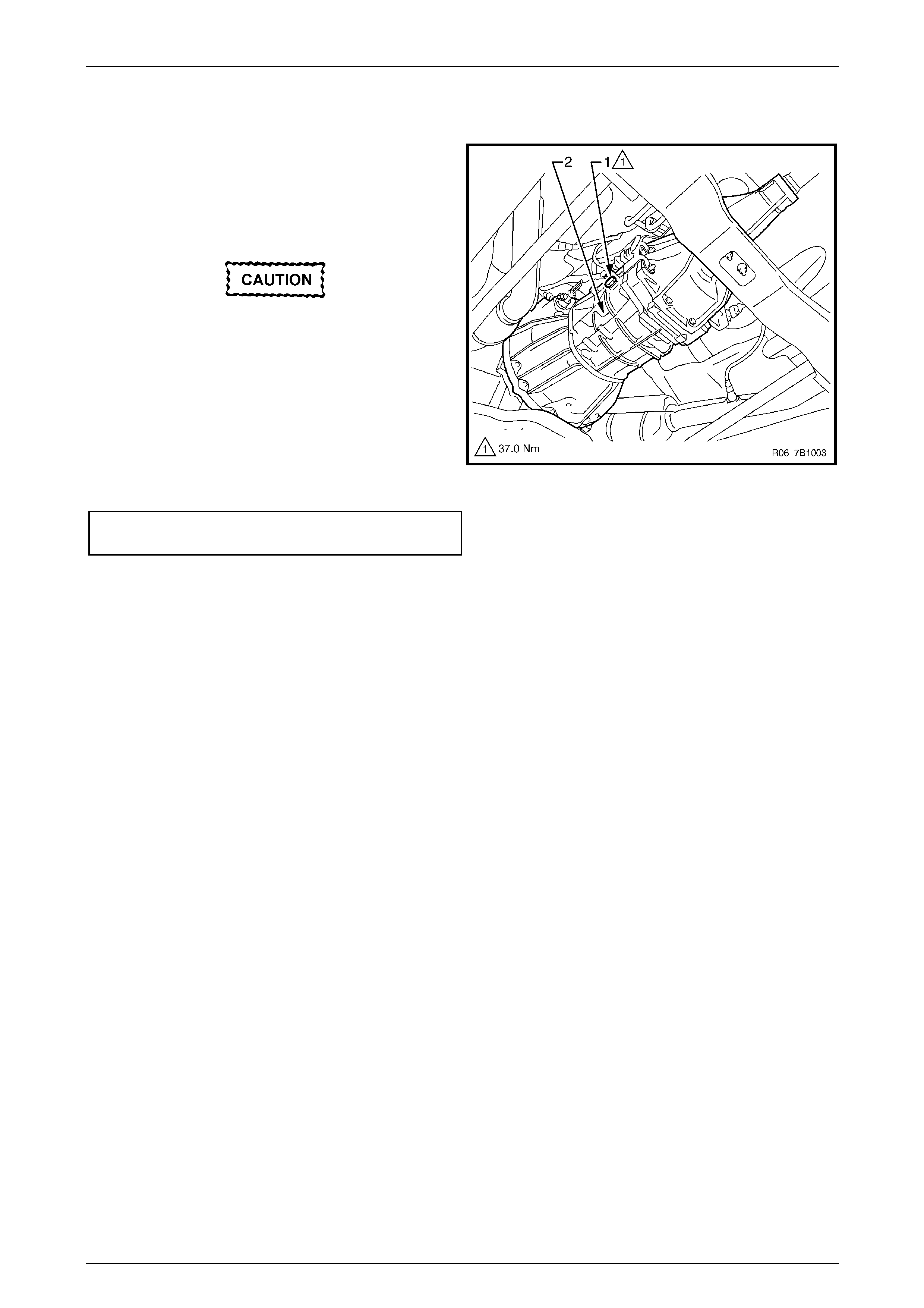
2.2 Checking Transmission Lubricant Level
1 Raise the vehicle and suppor t in a safe manner,
ensure the vehicle is level, ref er to Section 0A General
Information.
2 Clean the area around the fill er plug (1) on the
transmission case (2).
Ensure the transmission lubricant is at
ambient temperature.
3 Remove the filler plug and gasket using a suitable size
ring spanner.
4 Check if the lubricant level is correct with the lubric ant
just reaching the filler plug threads in the tra nsmissio n
case.
5 Replace the filler plug gasket, then reinstall the filler
plug tightening it to the correct torque specification.
Transmission filler plug
torque specification............................................37.0 Nm
6 If the lubricant level is low, then the reason must be
investigated and corrected. After correction of the
leakage condition, drain and refill the transmi ssion,
refer to 2.3 Draining and Refilling Transmission.
Figure 7B1 – 4
Manual Transmission – V6 Page 7B1–9
Page 7B1–9
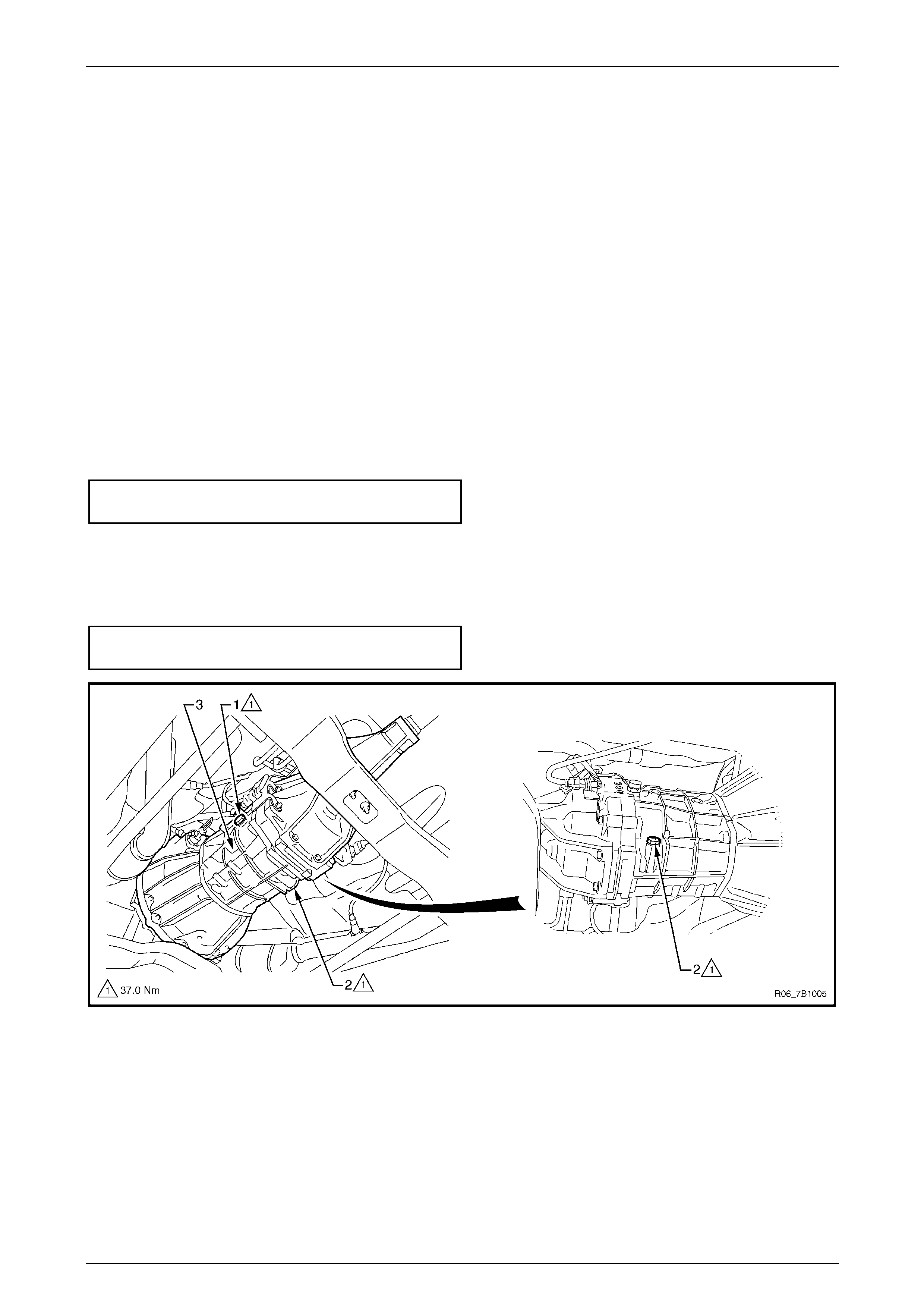
2.3 Draining and Refilling Transmission
1 Raise the vehicle and suppor t in a safe manner, ensure the vehicle is level, refer to Section 0A General Information.
2 Clean the area around the fill er plug (1) and the drain plug (2) on the transmission case (3), refer to
Figure 7B1 – 5.
3 Remove the filler plug, using a suitable size ring spanner.
4 Remove the drain plug using a suitable size ring spanner, draining the lubricant into a suitable container of a
minimum 2.5 litre capac ity.
NOTE
• The lubricant will drain quicker and completely
if it is warm.
• Carefully inspect the drain plug magnet and
the drained lubricant for foreign matter such
as metal particles, etc.
5 Replace the drain plug gasket, then reinstall the drain plug in the transmission case, tightening it to the correct
torque specification.
Transmission drain plug
torque specification............................................37.0 Nm
6 Refill the transmission with the recomme nded lubricant, refer to 2.1 Recommended Lubricant and Quantity, until
the lubricant (cold) just reaches the filler plug threads in th e transmission case.
7 Replace the filler plug gask et, then reinsta ll the filler plug in the transmission case, tightening it to the correct torque
specification.
Transmission filler plug
torque specification............................................37.0 Nm
Figure 7B1 – 5
Manual Transmission – V6 Page 7B1–10
Page 7B1–10
3 Minor Service Operations
3.1 Back-Up Lamp Switch
Remove
Disconnection of the battery affects
certain vehicle electronic systems. Refer
to Sectio n 6D1-3 Battery, before removing the
ground lead.
1 Disconnect the battery ground cable.
2 Raise the vehicle and suppor t in a safe manner, refer to Section 0A General Information.
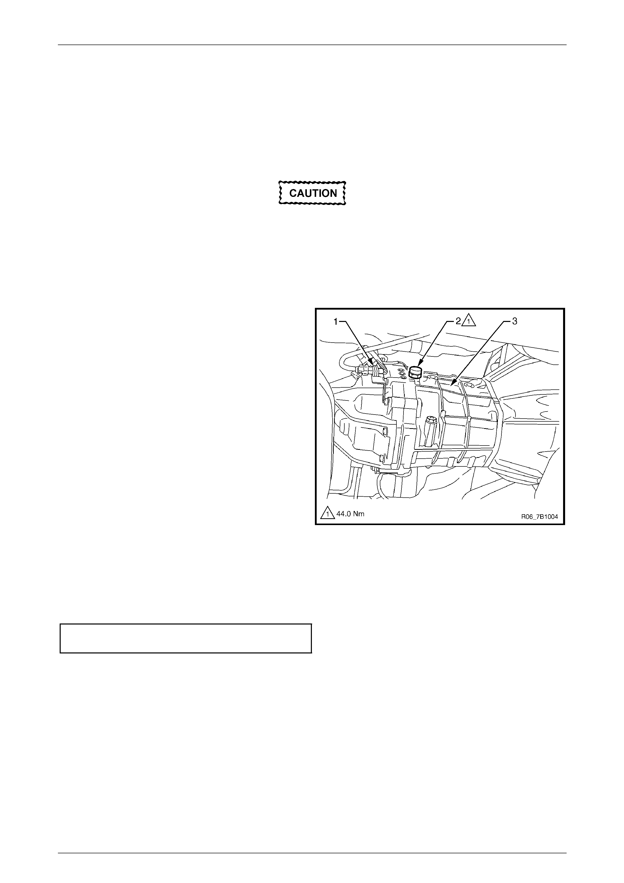
3 Disconnect the back-up lamp s witch harness
connector (1).
4 Using a suitable sized set spanner, remove the back-
up lamp switch (2) and sealing washer from the right
side of the front transmission case (3). Discard the
removed washer.
Figure 7B1 – 6
Reinstall
1 Install the back-up lamp switch, with a new sealing washer fitted.
2 Tighten the back-up lamp switch to the correct torque specification.
Back-up lamp switch
torque specification............................................44.0 Nm
3 Connect the harness connector to the back-up lamp switch.
4 Lower the vehicle to the ground.
5 Reconnect the battery ground cable.
Manual Transmission – V6 Page 7B1–11
Page 7B1–11
3.2 Speed Sensor (RWD)
NOTE
For 4WD vehicle s peed s ensor servic e procedure
refer to Section 7D Transfer Case and Adaptor
Housing.
Remove
Disconnection of the battery affects
certain vehicle electronic systems. Refer to
Section 6D1-3 Battery, before removing the
ground lead.
1 Disconnect the battery ground cable.
2 Raise the vehicle and suppor t in a safe manner, refer to Section 0A General Information.
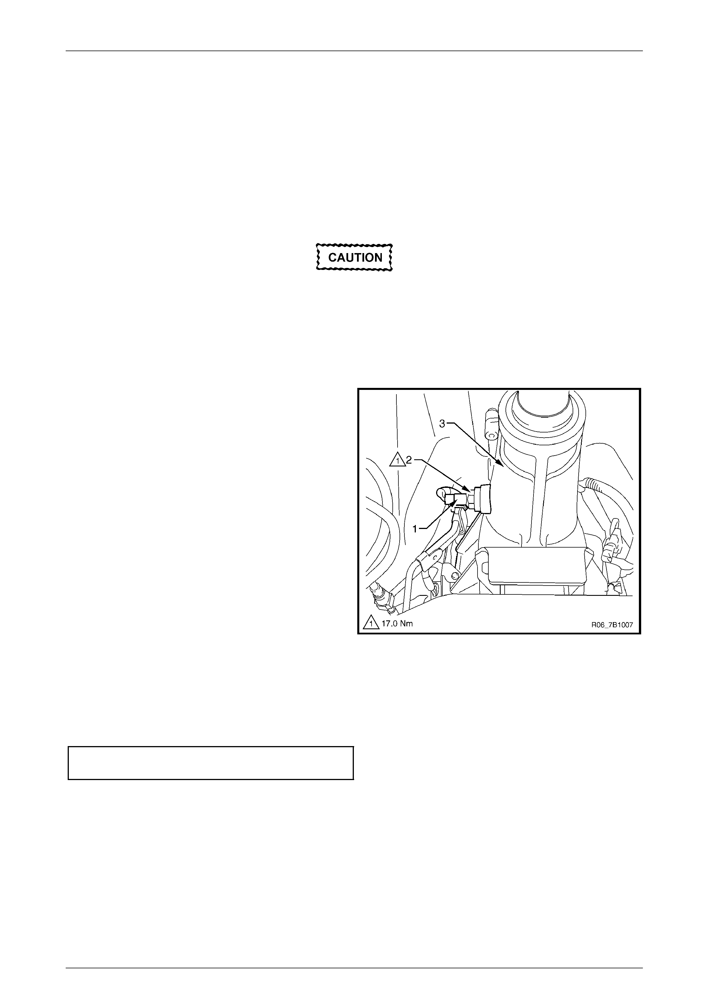
3 Disconnect the speed sensor harness connector (1).
4 Using a suitable sized set spanner, remove the speed
sensor (2) from the extension housing (3).
Figure 7B1 – 7
Reinstall
1 Ensure the O-ring is not damaged, replace as required.
2 Install the speed sensor and tighten to the correct torque specification.
Speed sensor
torque specification............................................17.0 Nm
3 Connect the harness connector to the speed sensor.
4 Lower the vehicle to the ground.
5 Reconnect the battery ground cable.
Manual Transmission – V6 Page 7B1–12
Page 7B1–12
3.3 Transmission Support and Mount
Remove
1 Raise the vehicle and suppor t in a safe manner, refer to Section 0A General Information for the location of support
points.
2 Support the transmission with a Jack, do not plac e the support underneath the e xtensi on housing or the oil pan,
refer to Figure 7B1 – 8.
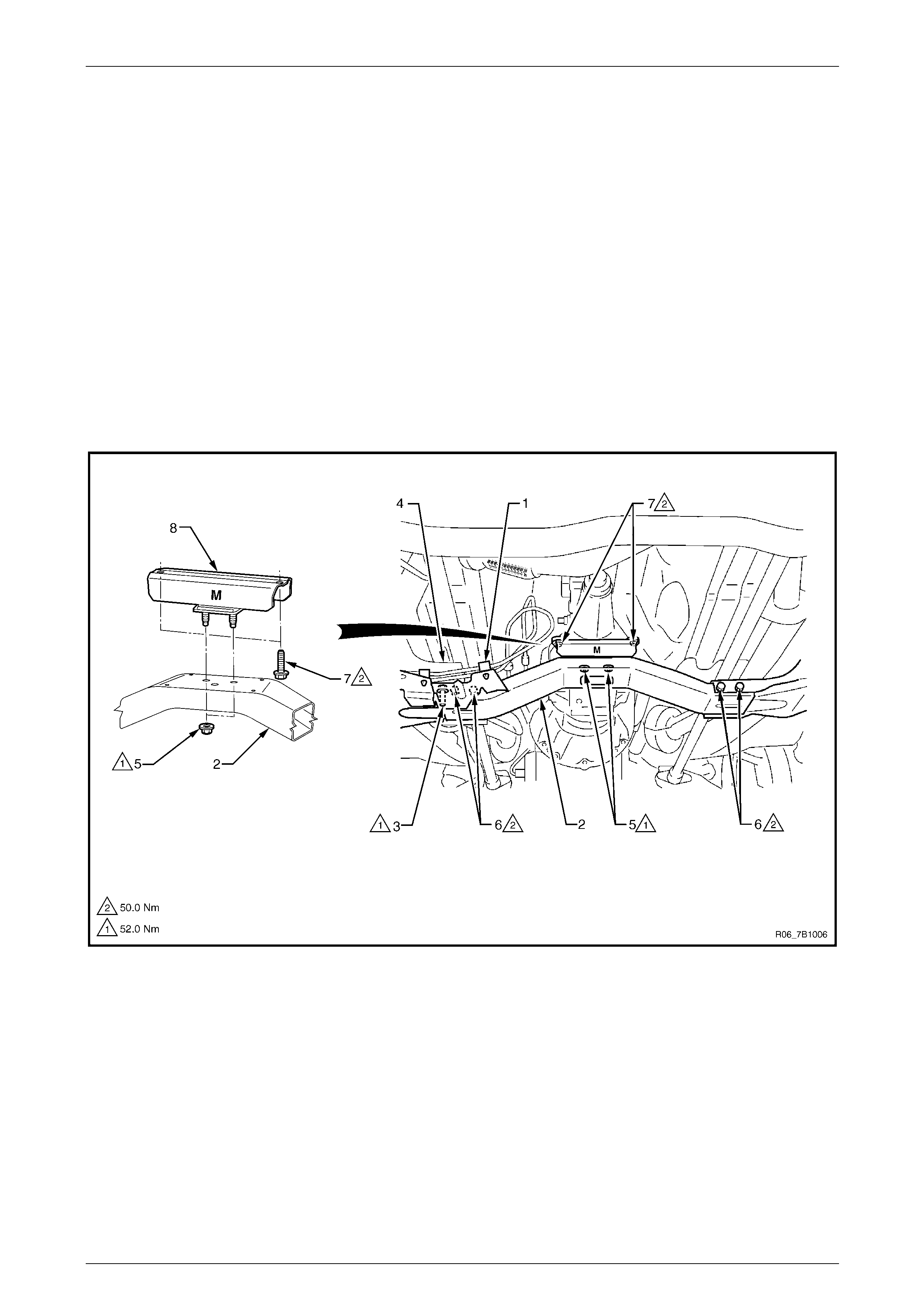
3 Remove the clip (1) holding the fuel feed and fuel vapour lines on the transmission support (2).
4 Remove the bolt (3) attaching the heat shiel d (4) to the transmission support.
5 Remove the two nuts (5) attaching the transmission mount to the support.
6 Remove the four bolts and nuts (6) attaching the transmission support to the under body side rails and remove the
support.
7 If required, remove the two bolts (7) attaching the transmission mount (8) to the extension housing and remove the
mount.
Figure 7B1 – 8
Legend
1 Fuel Feed and Vapour Lines Clip
2 Transmission Support
3 Heat Shield Bolt
4 Heat Shield
5 Transmission Mount Nuts
6 Transmission Support Bolts
7 Transmission Mount Bolts
8 Transmission Mount
Manual Transmission – V6 Page 7B1–13
Page 7B1–13
Reinstall
1 If required, install the transmission mount (8) onto the extension housing, ti ghten the two attaching bolts (7) to the
correct torque specification, refer to Figure 7B1 – 8.
Transmission mount attaching
bolt torque specification.....................................50.0 Nm
2 Install the transmission suppor t (2) to the under body side rails and tighten the four attaching bolts and nuts (6) to
the correct torque specification.
Transmission support attaching
bolt and nut torque specification ........................50.0 Nm
3 Install and tighten the transmission mount two attaching nuts (5) to the correct torque spe c ification.
Transmission mount attaching
nut torque specification......................................52.0 Nm
4 Install the bolt (3) attaching the heat shield (4) to the transmission supp ort, tighten to the correct torque
specification.
Heat shield to transmission support
attaching bolt torque specification......................52.0 Nm
5 Reinstall the clip (1) holding the fuel feed and fuel vapour lin es on the transmission support.
6 Lower the vehicle to the ground.
Manual Transmission – V6 Page 7B1–14
Page 7B1–14
3.4 Extension Housing Oil Seal (RWD)
Replace
1 Raise the vehicle and suppor t in a safe manner, refer to Section 0A General Information for the location of support
points.
2 Remove the rear propeller shaft, refer to Section 4A Propeller Shaft.
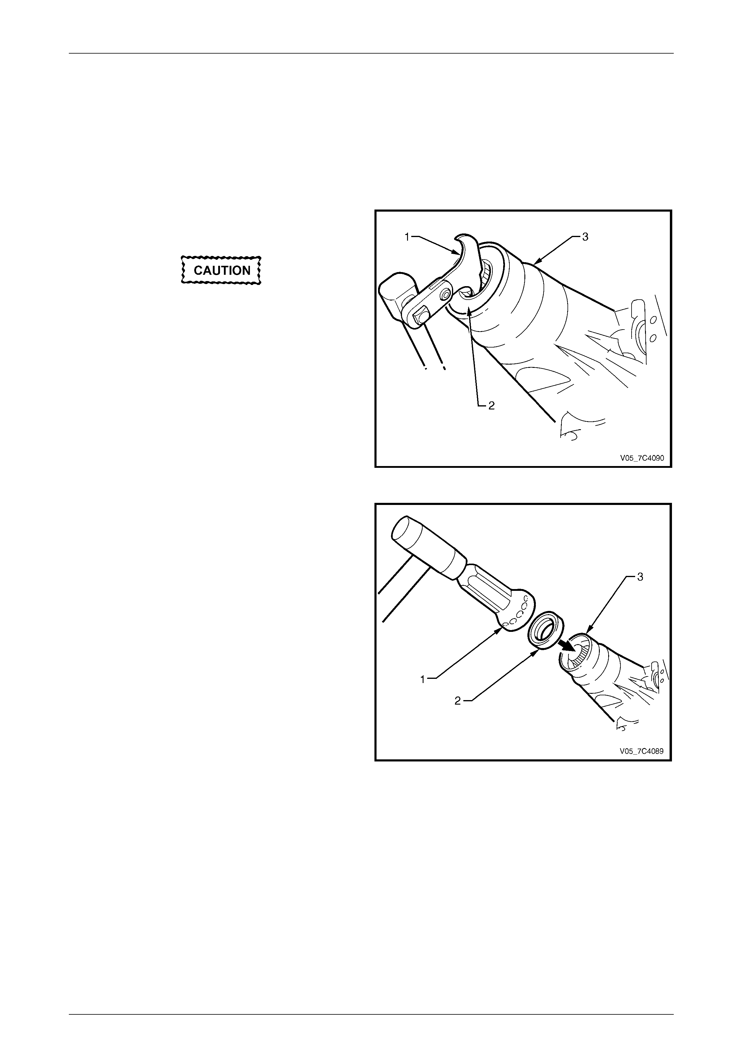
3 Place a suitable size drip tray underne ath rear of
transmission.
Take care not to scratch the machined seal
recess in the extension housing as
transmission fluid may weep past the outer
diameter of the installed seal.
4 Using the seal remover, Tool No. E308 (1) or
equivalent, prise the oil seal (2 ) from rear of the
extension hous ing (3) and discard the seal.
5 Thoroughly cle an around the seal bore in the
extension hous ing and ensure there are no burrs.
Figure 7B1 – 9
6 Using a suitable seal installer (1) and a soft faced
hammer, tap a new oil seal (2) into place in the rear of
the extension housing (3).
7 Install the rear propeller shaft, refer to
Section 4A Propeller Shaft.
8 check the fluid level and lower the vehicle to the
ground, refer to 2.2 Checking Transmission Lubricant
Level.
Figure 7B1 – 10
Manual Transmission – V6 Page 7B1–15
Page 7B1–15
3.5 Gearshift Lever Knob, Boot Assembly
and Lever
Remove
Disconnection of the battery affects
certain vehicle electronic systems. Refer to
Section 6D1-3 Battery, before removing the
ground lead.
1 Disconnect the battery ground cable.
2 Remove the rear centre console from the floor panel, refer to Section 2C Cab and Interior Trim.
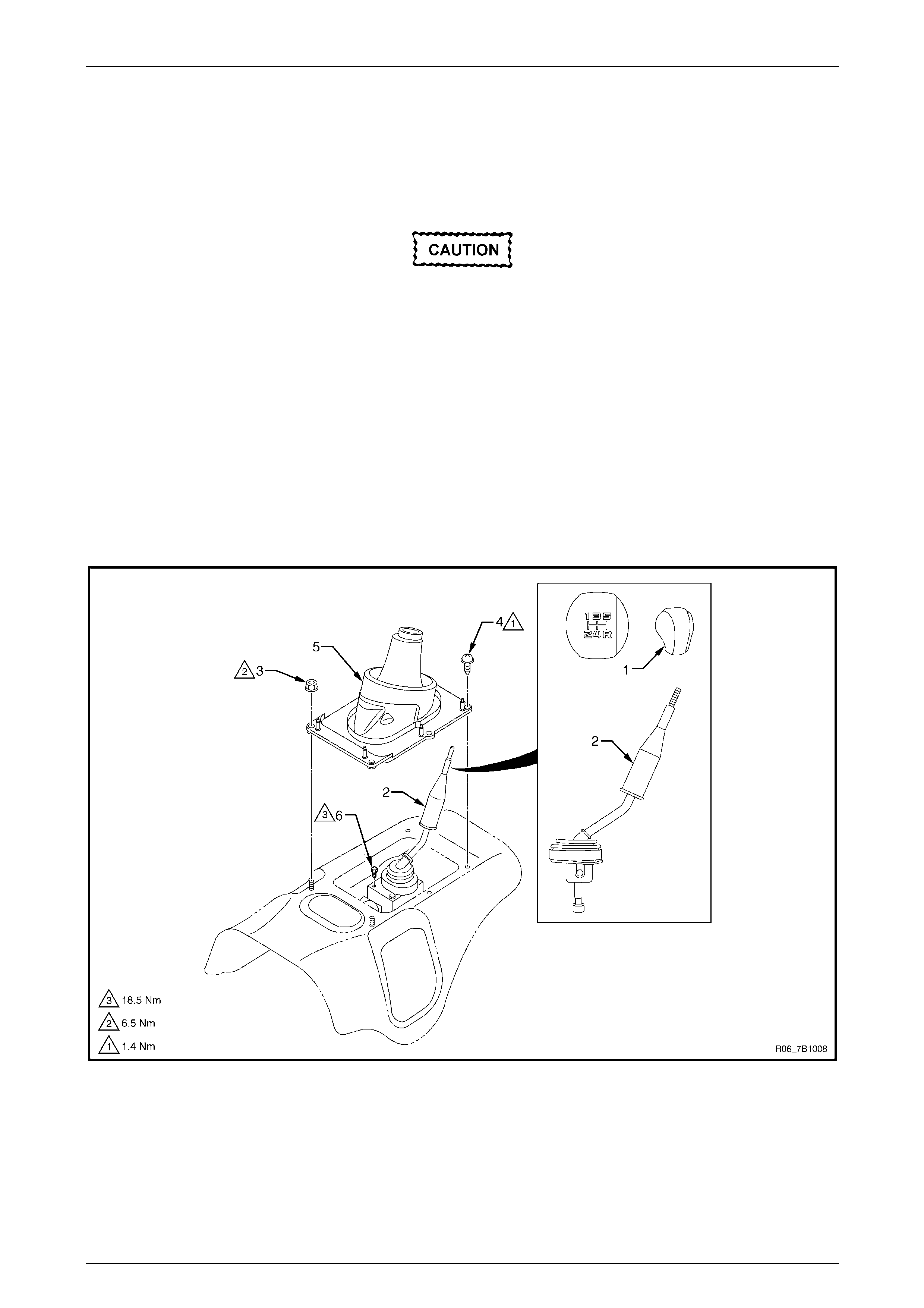
3 Loosen the shift lever knob (1) counter clock wise by hand and remove it from the shift lever (2), refer to
Figure 7B1 – 11.
4 Remove the front centre console from the floor panel, refer to Section 2C Cab and Interior Trim.
5 Remove the attaching nut (3), two places, the scre w (4), four places, then remove the boot assembly (5) from the
floor panel.
6 Remove the attaching bolt (6), four places, and the shift lever from the transmission.
Figure 7B1 – 11

Manual Transmission – V6 Page 7B1–16
Page 7B1–16
Reinstall
1 Install the shift lever (2) to the transmission and tighten the attaching bolt (6), four places, to the correct torque
specification, refer to Figure 7B1 – 11.
Shift lever attaching bolt
torque specification............................................18.5 Nm
2 Attach the boot assembly (5) to the floor panel, tighten the attaching nut ( 3), two places, and the screw (4), four
places, to the correct torque specification.
Boot assembly attaching nut
torque specification..............................................6.5 Nm
Boot assembly attaching screw
torque specification..............................................1.4 Nm
3 Install the front centre console to the floor panel, refer to Section 2C C ab and Interior Trim.
4 Secure the shift lever knob (1) rotating it clockwise onto the shift lever.
5 Install the rear centre console to the floor panel, refer to Section 2C Cab and Interior Trim.
6 Reconnect the battery ground cable.
Manual Transmission – V6 Page 7B1–17
Page 7B1–17
3.6 Transmission Assembly
Remove
Disconnection of the battery affects
certain vehicle electronic systems. Refer to
Section 6D1-3 Battery, before removing the
ground lead.
1 Disconnect the battery ground cable.
2 Raise the vehicle and suppor t in a safe manner, refer to Section 0A General Information.
3 Remove the following components:
a Gearshift lever assembly, refer to 3.5 Gearshift Lever Knob, Boot Assembly and Lever.
Plug the gear control box opening to prevent foreign matter entry.
b Front and centre exhaust assemblies, refer to Section 6F Exhaust System – V6.
b Rear propeller shaft and for 4WD vehicle front propeller shaft, refer to Section 4A Propeller Shaft.
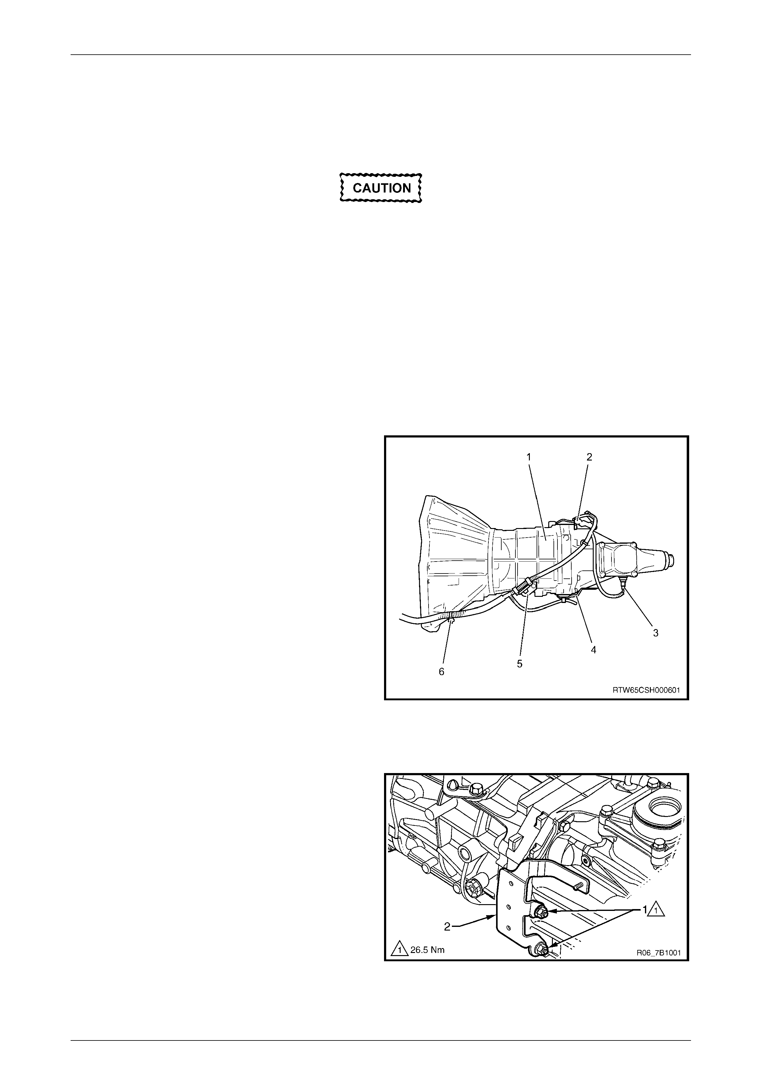
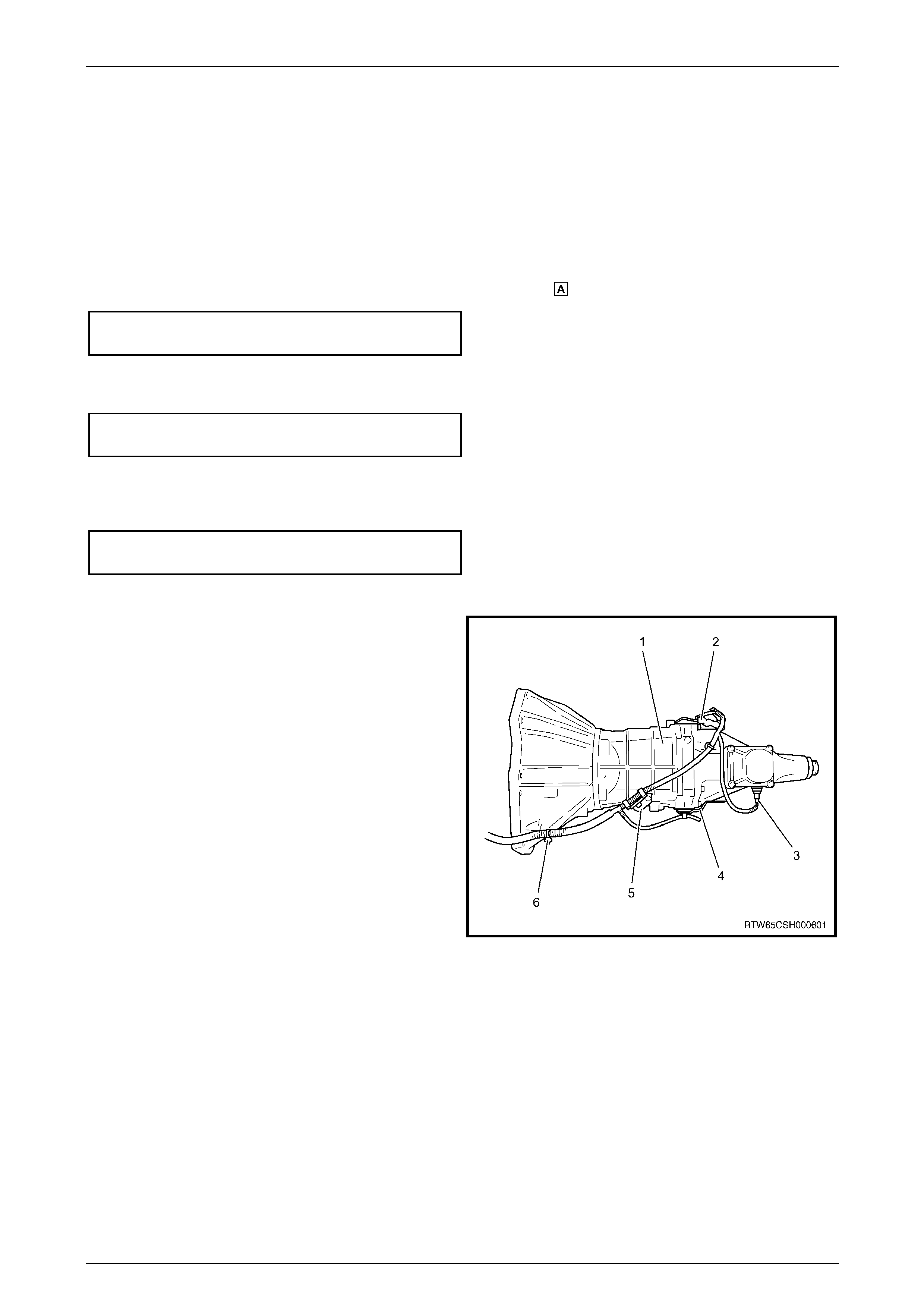
4 Disconnect the following:
• Oxygen sensor and back up lamp harness
connectors (2) from the bracket by sliding the
connectors upward.
• RWD vehicle only, speed sensor harness
connector (3).
• Oxygen sensor harness from the brack et (4).
• Harness clips (5 and 6) from the brackets on top
of the transmission.
5 For 4WD vehicles only, disconnect the transfer
harness connectors:
• 2–4 switch and neutral s witch,
• transfer actuator, and
• vehicle speed sensor. Figure 7B1 – 12
6 Remove the transmission support, refer to
3.3 Transmission Support and Mount .
7 Disconnect the fuel and EVAP pipes three brackets
and clips, refer to Section 6C Fuel S ystem – V6.
If required, remove the two nuts (1) and the bracket (2)
from the transmission housing.
Figure 7B1 – 13
Manual Transmission – V6 Page 7B1–18
Page 7B1–18
8 Disconnect the clutch flexible hose from the actuatin g cylinder adaptor steel pipe, refer to Section 7A1 Clutch –V6.
Immediately plug both open h ose/pipe ends to minimise fluid loss and prevent the entry of foreign matter.
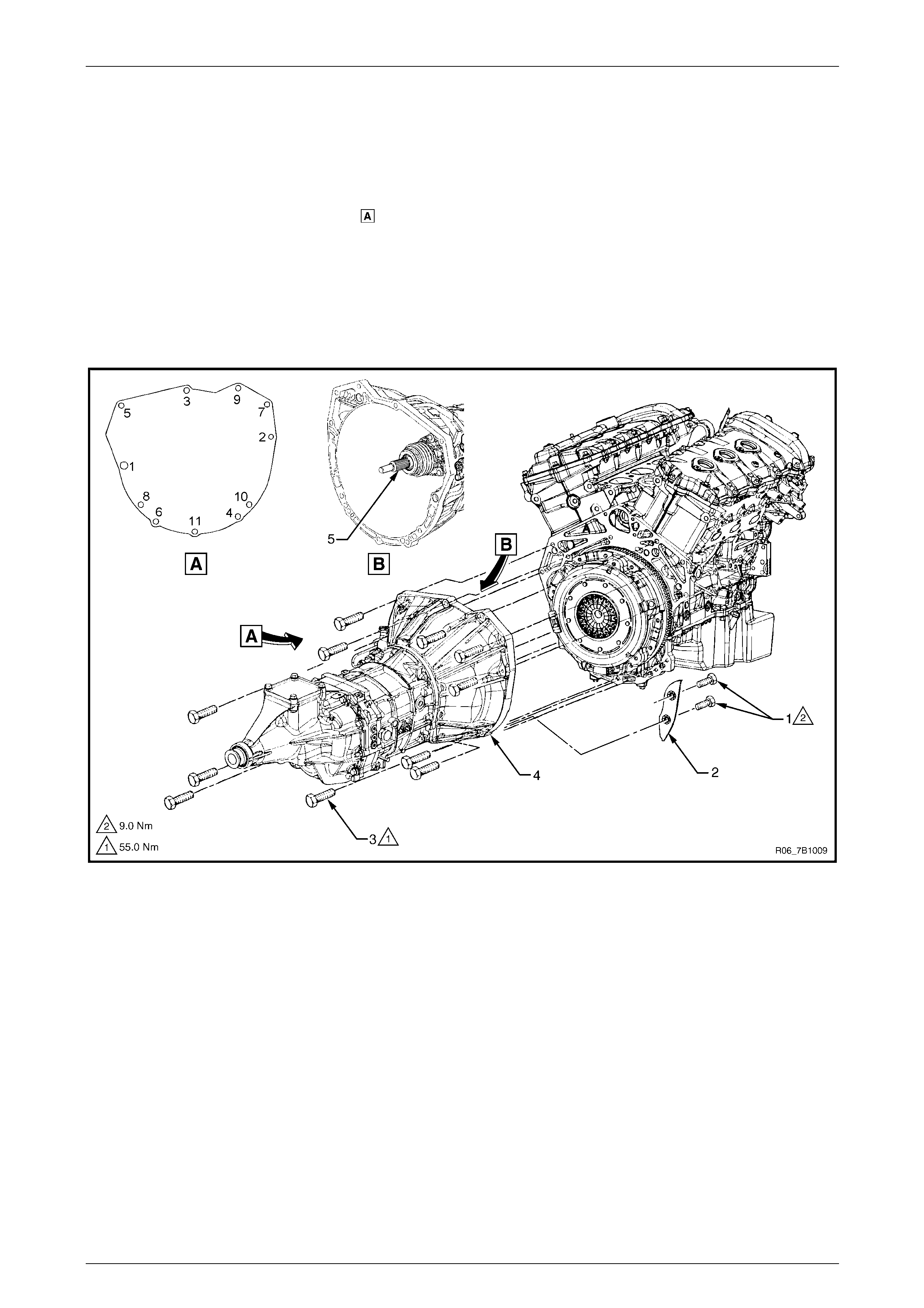
9 Remove the two screws (1) securing the close-out cover (2) to the front of the transmiss ion case, then remove the
cover and set to one side, refer to Figure 7B 1 – 14.
10 With the transmission supported, using a long socket extension, universal joint and suitab le size socket, loosen
then remove the eleven bolts (3) securing the transmission (4) to the rear of the engine block, in the reverse order
of the torque sequence shown in view .
11 Shake the rear of the transmission to separate the front case from the loca ting dowels.
12 Carefully slide the transmission rearward, taking care not to allow the transmission input shaft (5) to drag or hang
on the clutch driven plate.
13 When the input shaft is clear from the clutch pressure plate, lower the transmission and remove it from the vehicle.
14 If required on 4WD vehicle, remove the transfer case, refer to Section 7D Transfer Case and Adaptor Housing.
Figure 7B1 – 14
Manual Transmission – V6 Page 7B1–19
Page 7B1–19
Reinstall
1 If required on 4WD vehicle, reinstall the transfer case, refer to Section 7D Transfer Case and Adaptor Housing.
2 Ensure the transmission and the engine mating surfaces are clean and free of burrs.
3 Apply a thin coat of molybdenum disulfide grease over the full length of the transmission i nput shaft spline (5),
refer to Figure 7B1 – 14.
4 Bring the transmission up to the engine taking care not to allow the input shaft to drag on the clutch driven plate,
and ensuring the locating dowels completely enter the transmission housing.
5 With the transmission supported, install the eleven bolts (3) attaching th e transmission to the engine and tighten to
the correct torque specification following the sequence shown in view .
Transmission housing attach ing
bolt torque specification.....................................55.0 Nm
6 Reinstall the two bolts (1) and the close-out cover (2) to the front of the transmission case, tighten the bolts to the
correct torque specification.
Close-out cover attaching
bolt torque specification.......................................9.0 Nm
7 Reconnect the fuel and EVAP pipes three br ackets and clips, refer to Section 6C Fuel System – V6.
If required, install the fuel and EVAP pipes bracket (2) to the transmission housing, tighten the two nuts (1) to the
correct torque specification, refer to F igure 7B1 – 13.
Fuel and EVAP pipes bracke t
attaching nut torque specification.......................26.5 Nm
8 Reinstall the transmission su pport, refer to 3.3 Transmission Support and Mount.
9 Reconnect the following:
• Oxygen sensor and back up lamp harness
connectors (2) to the bracket by sliding the
connectors upward.
• RWD vehicle only, speed sensor harness
connector (3).
• Oxygen sensor harness to the bracket (4).
• Harness clips (5 and 6) to the brackets on top of
the transmission.
10 For 4WD vehicles only, reconnect the transfer harness
connectors:
• 2–4 switch and neutral s witch,
• transfer actuator, and
• vehicle speed sensor. Figure 7B1 – 15
11 Reconnect the clutch flexible hose to the act uating cylinder adaptor steel pipe, refer to Section 7A1 Clutch –V6.
12 Install the following components:
a Gearshift lever assembly, refer to 3.5 Gearshift Lever Knob, Boot Assembly and Lever.
b Front and centre exhaust assemblies, refer to Section 6F Exhaust System – V6.
b Rear propeller shaft and for 4WD vehicle front propeller shaft, refer to Section 4A Propeller Shaft.
13 Bleed the clutch hydraulic system, refer to Section 7A 1 Clutch –V6.
14 Check the lubricant level, top up as requir ed, refer to 2.2 Checking Transmission Lubricant Level.
15 Lower the vehicle to the ground.
16 Reconnect the battery ground cable.

Manual Transmission – V6 Page 7B1–20
Page 7B1–20
4 Specifications
General
Type................................................................Aisin AR5 5 Speed, Synchromesh on all Gears
Production Option............................................................................................................. MA5
Transmission Ratios
1st...................................................................................................................................3.75:1
2nd..................................................................................................................................2.26:1
3rd ..................................................................................................................................1.37:1
4th...................................................................................................................................1.00:1
5th...................................................................................................................................0.73:1
Reverse..........................................................................................................................3.67:1
Mass
RWD............................................................................................................................ 48.4 Kg
4WD............................................................................................................................. 48.7 Kg
Lubricant
Type..............................................................................................................SAE 75 – 90 GL3
...............................................................................................................or Mobilube XHP GL4
Capacity:
RWD................................................................................................................................2.2 Lt
4WD.................................................................................................................................2.3 Lt
Grease ...........................................................NLGI No. 2 lithium soap based EP grease with
.................................................. molybdenum disulphide, such as Shell Retinax HDX2grease
......................................................................... or BP Energrease LMS-EP 23 (or equivalent).

Manual Transmission – V6 Page 7B1–21
Page 7B1–21
5 Torque Wrench Specifications
Transmission Filler Plug.......................................................................37.0 Nm
Transmission Drain Plug ......................................................................37.0 Nm
Back-up Lamp Switch...........................................................................44.0 Nm
Speed Sensor............................................................................13.6 – 20.4 Nm
Transmission Mount Attaching Bolt...........................................43.0 – 57.0 Nm
Transmission Support Attaching Nut....................................................50.0 Nm
Transmission Mount Attaching Nut............................................44.0 – 60.0 Nm
Heat Shield to Transmission Support Attaching Bolt............................52.0 Nm
Shift Lever Attaching Bolt..........................................................15.0 – 22.0 Nm
Boot Assembly Attaching Nut........................................................4.6 – 8.5 Nm
Boot Assembly Attaching Screw....................................................1.3 – 1.5 Nm
Transmission Housing Attaching Bolt........................................50.0 – 60.0 Nm
Close-out Cover Attaching Bolt ...................................................7.5 – 10.0 Nm
Fuel and EVAP Pipes Bracket Attaching Nut ............................26.0 – 27.0 Nm