
SECTION 7C - CLUTCH
Main Data and Specifica tions
General Description
Torque Specification
Servicing
Clutch
Removal and Installation
Inspection and Repair
Clutch Control
Removal and Installation
Master Cylinder
Disassembly
Reassembly
Slave Cylinder (4JH1-TC, C24SE)
Disassembly
Inspection and Repair
Reassembly
Slave Cylinder (6VE1)
Disassembly
Inspection and Repair
Reassembly
Hydraulic Damper Cylinder
Inspection and Repair
Troubleshooting
Special Service Tool
MAIN DATA AND SPECIFICATIONS
ENGINE 6VE1 4JH1-TC C24SE
Clutch type Dry single plate with diaphragm
Size mm (in) 260 (10.24) 250 (9.84) 240 (9.45)
Clamping force kg(lb) 735 (1621) 640 (1411) 560 (1235)
(N) (7200) (6300) (5500)
Pressure plate
Outside diameter mm(in) 260 (10.24) 250 (9.84) 240 (9.45)
Inside diameter mm(in) 170 (6.69) 160 (6.299) 160 (6.299)
Driven plate
Thickness mm(in)
at free 8.8 (0.346) 8.3 (0.327) 8.7 (0.342)
at compressed 8.2 (0.323) 7.8 (0.307) 8.0 (0.315)
Clutch Cont. type Hydraulic
Pedal free play mm(in) 5.0-15.0 (0.2-0.6)
Master cylinder
Bore×Stroke mm(in) 15.87 × 35 (0.625 × 1.38)
Slave cylinder
Bore × Stroke mm(in) 22.22 × 18.9
(0.875 × 0.744) 20.64 × 23
(0.813 × 0.906) 19.05 × 23
(0.749 × 0.906)
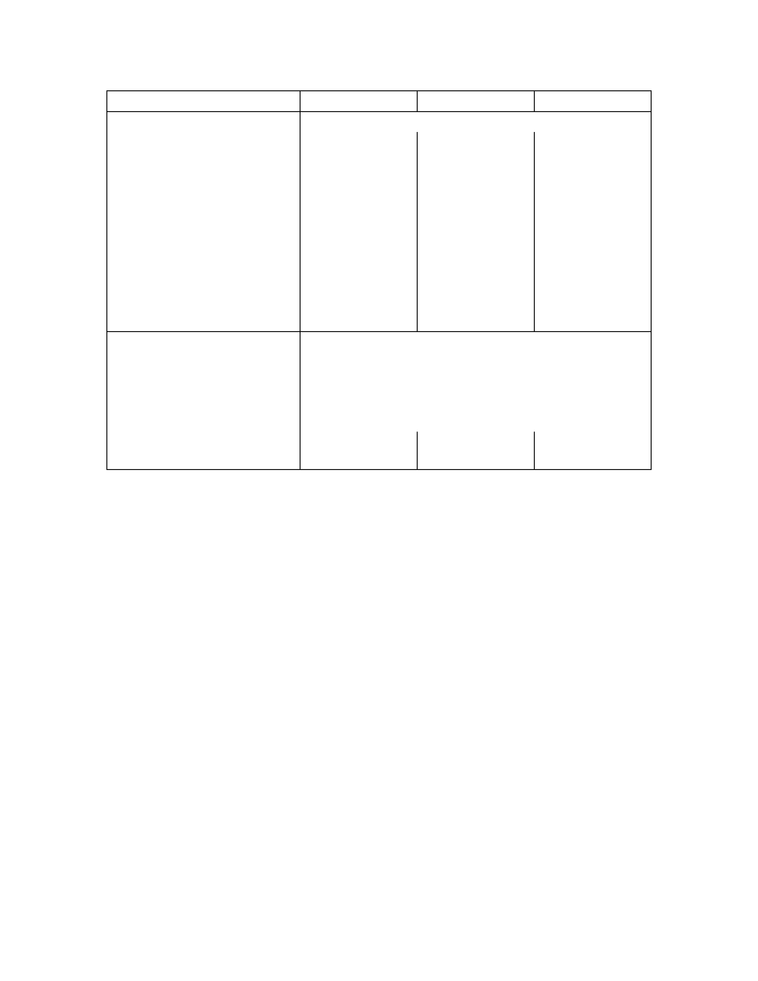
GENERAL DESCRIPTION
HYDRAULIC CONTROL TYPE
PUSH TYPE CLUTCH (4JH1-TC, C24SE)
PULL TYPE CLUTCH (6VE1)
A07RW046
The clutch assembly consists of the pressure plate, the clutch cover, the diaphragm spring pivot pin and the driven
plate assembly.
The clutch pedal is connected to the release bearing through the shift fork.
The driven plate assembly is installed between the flywheel and the pressure plate.
For 4JH1-TC and HEC engine models, the push-type clutch is employed.
Diaphragm spring pressure holds the driven plate against flywheel and the pressure plate to provide the friction
necessary to engage the clutch.
Depressing the clutch pedal moves the shift fork against the release bearing.
The release bearing forces the diaphragm to overcome the force of the diaphragm spring and separate the driven plate
from the flywheel and pressure plate to disengage the clutch.
For 6VE1 engine model, the pull-type clutch is employed. The pull-type clutch is disengaged by pulling the release lever
(release bearing) to disengage the pressure plate.
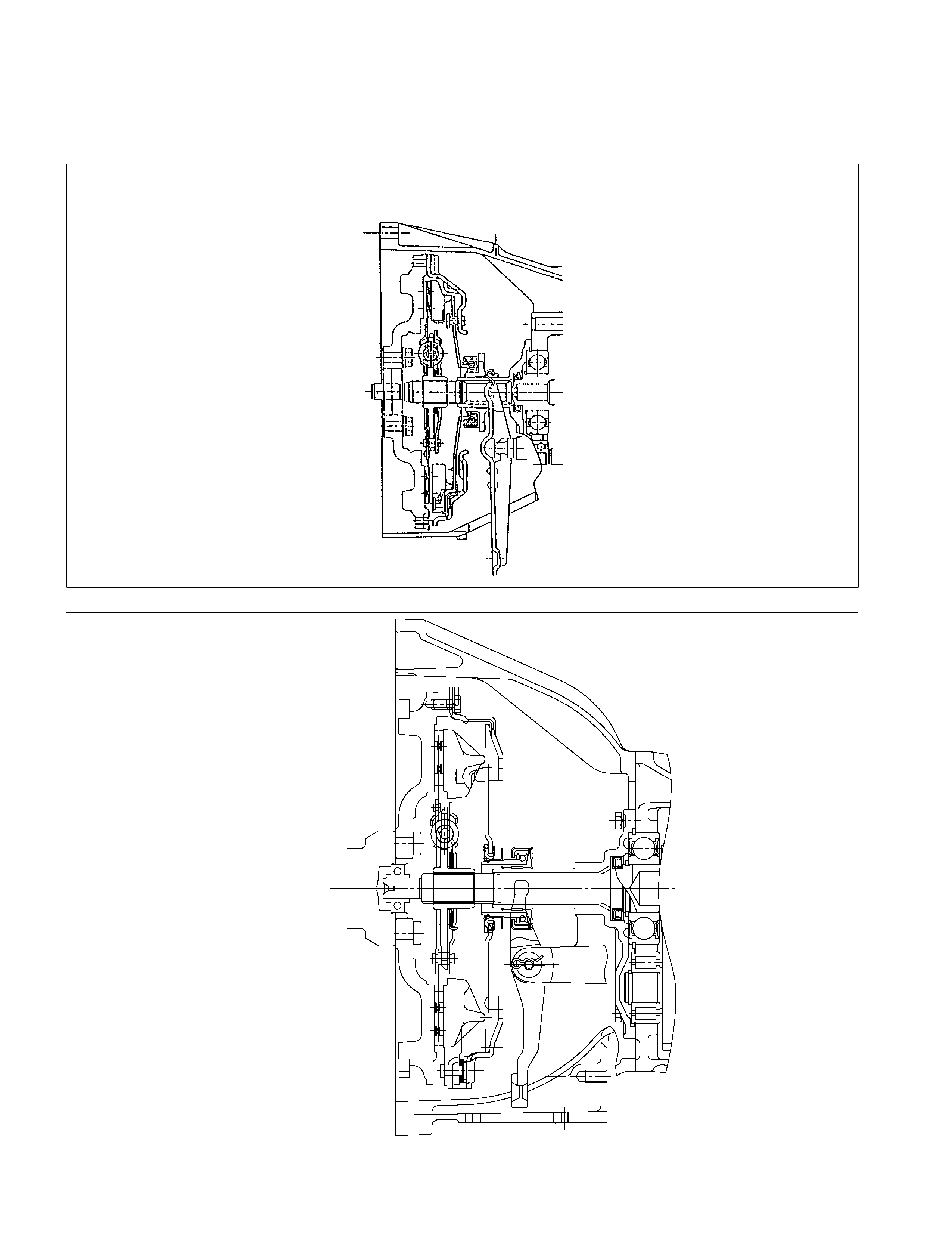
MASTER CYLINDER
6VE1, 4JH1-TC
C24SE
RTW37CSF0001
The master cylinder converts mechanical energy into hydraulic energy.
Depressing the clutch pedal causes the push rod to move against the piston to close the return port.
Clutch fluid is forced out of the master cylinder.
Releasing the clutch pedal causes the return spring to force the piston back to its original position.
The return port is opened and the clutch fluid flows back into the fluid reservoir.
Quickly releasing the clutch pedal will cause the fluid pressure at the return spring side to be lower than the fluid
pressure at the push rod side.
This allows the fluid at the push rod side to quickly flow to the return spring side through a port in the piston head.
This equalizes the pressure at both sides of the piston.

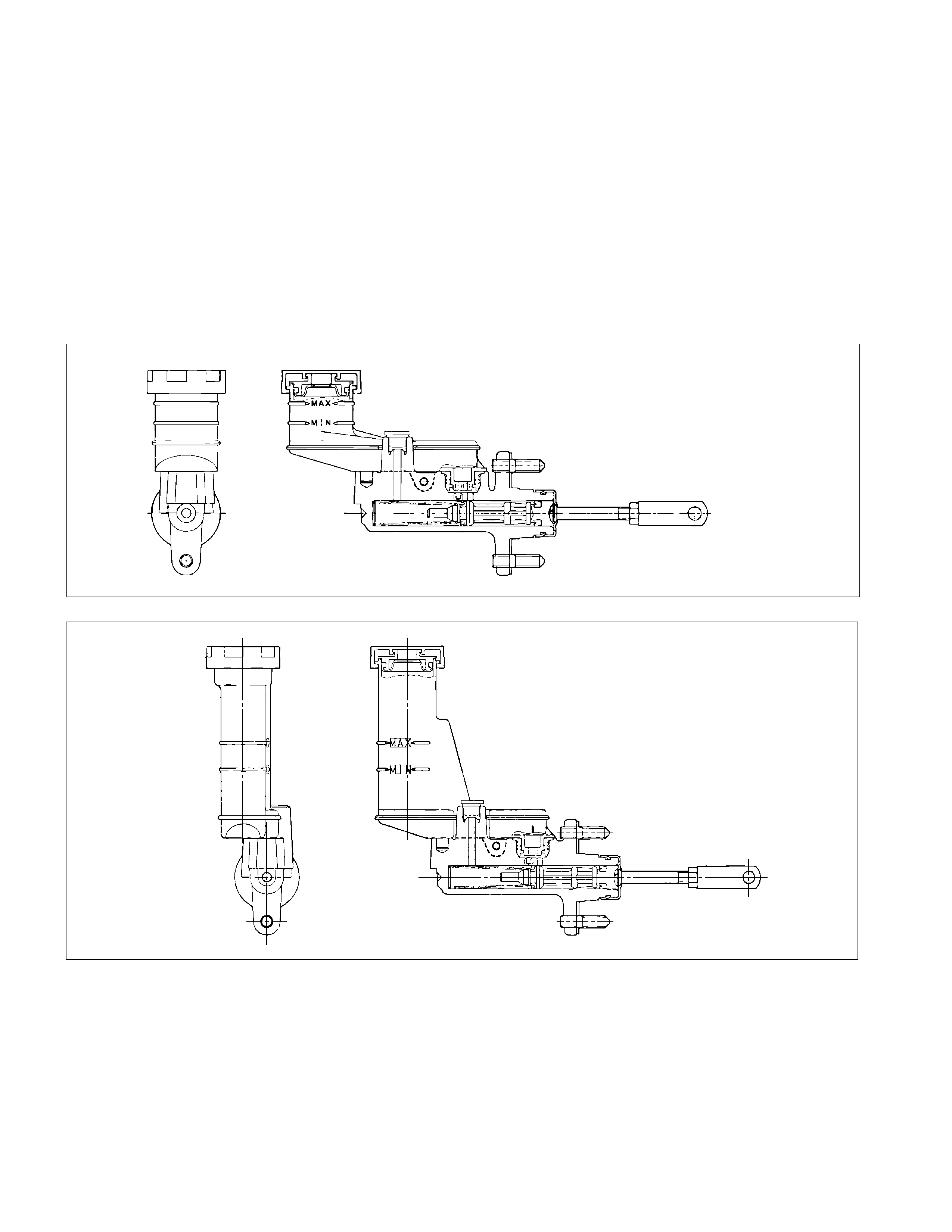
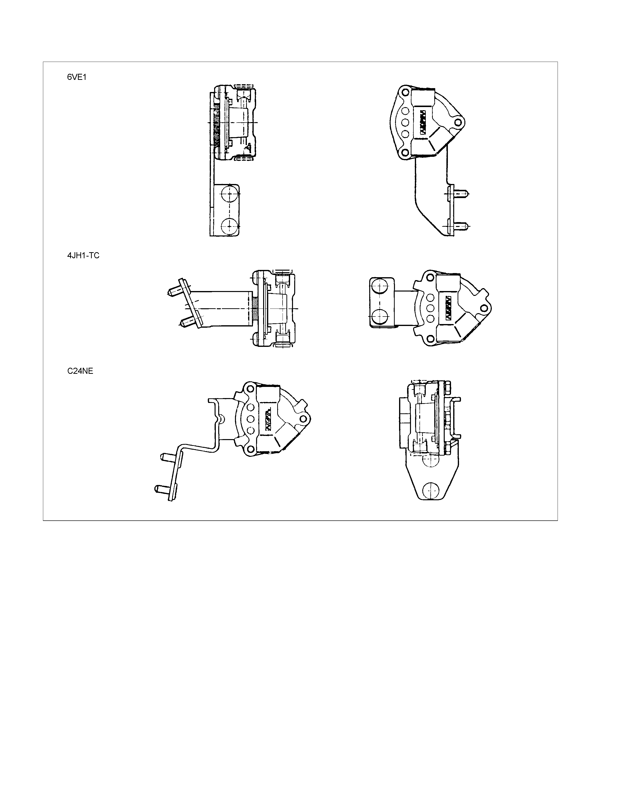
SLAVE CYLINDER
6VE1
A07RS005
4JH1-TC
C24SE
RTW37CSF0002
The slave cylinder converts hydraulic energy into mechanical energy.
Hydraulic fluid supplied by the master cylinder moves the slave cylinder piston to actuate the shift fork.
The mechanical energy produced by the slave cylinder is directly proportional to the diameters of the master cylinder
and the slave cylinder.
A bleeder screw is provided to bleed the slave cylinder.
HYDRAULIC DAMPER CYLINDER
RTW37CLF0001-X
The hydraulic damper cylinder is installed between the master cylinder and the slave cylinder to smooth out variations in
clutch pedal feel.
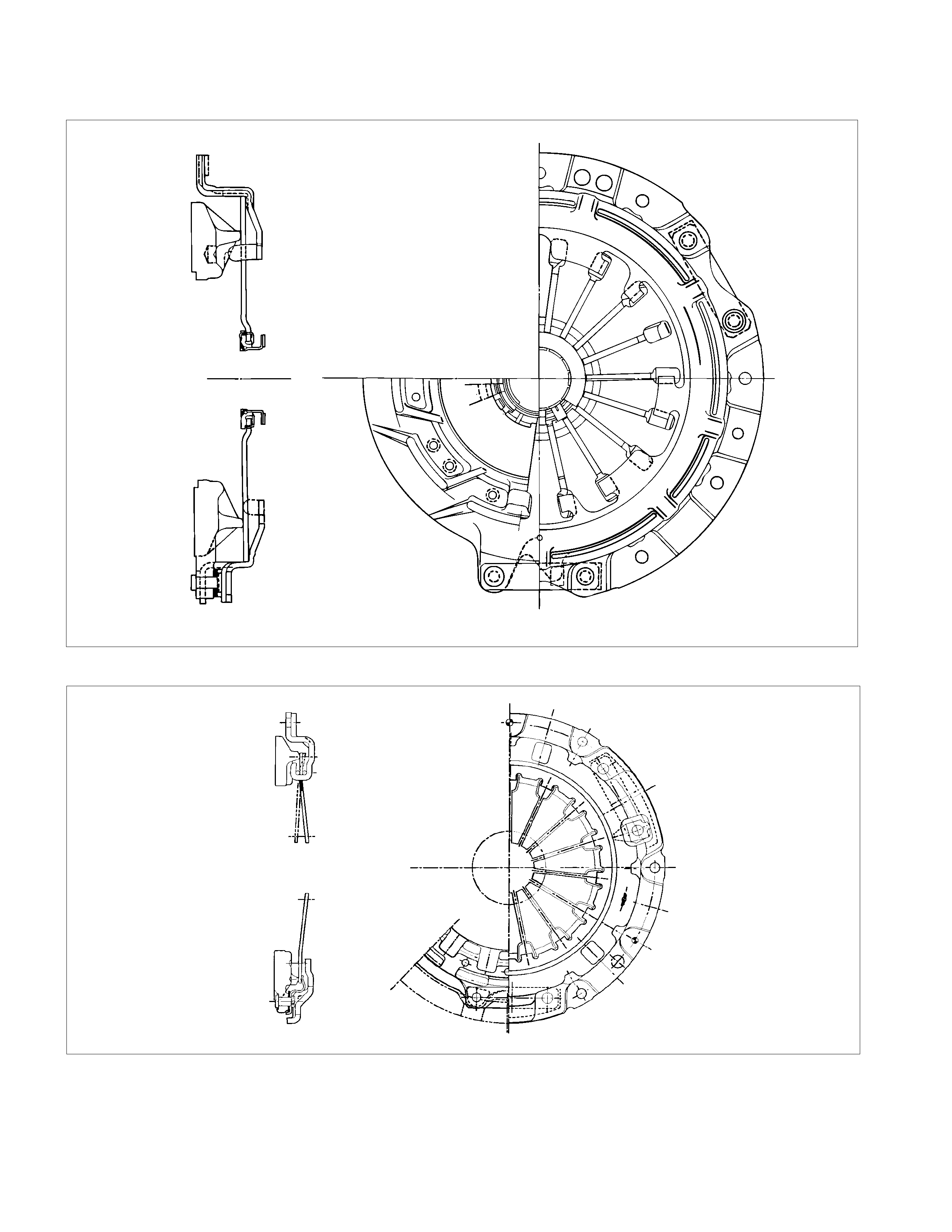
PRESSURE PLATE ASSEMBLY
6VE1
A07RS006
4JH1-TC
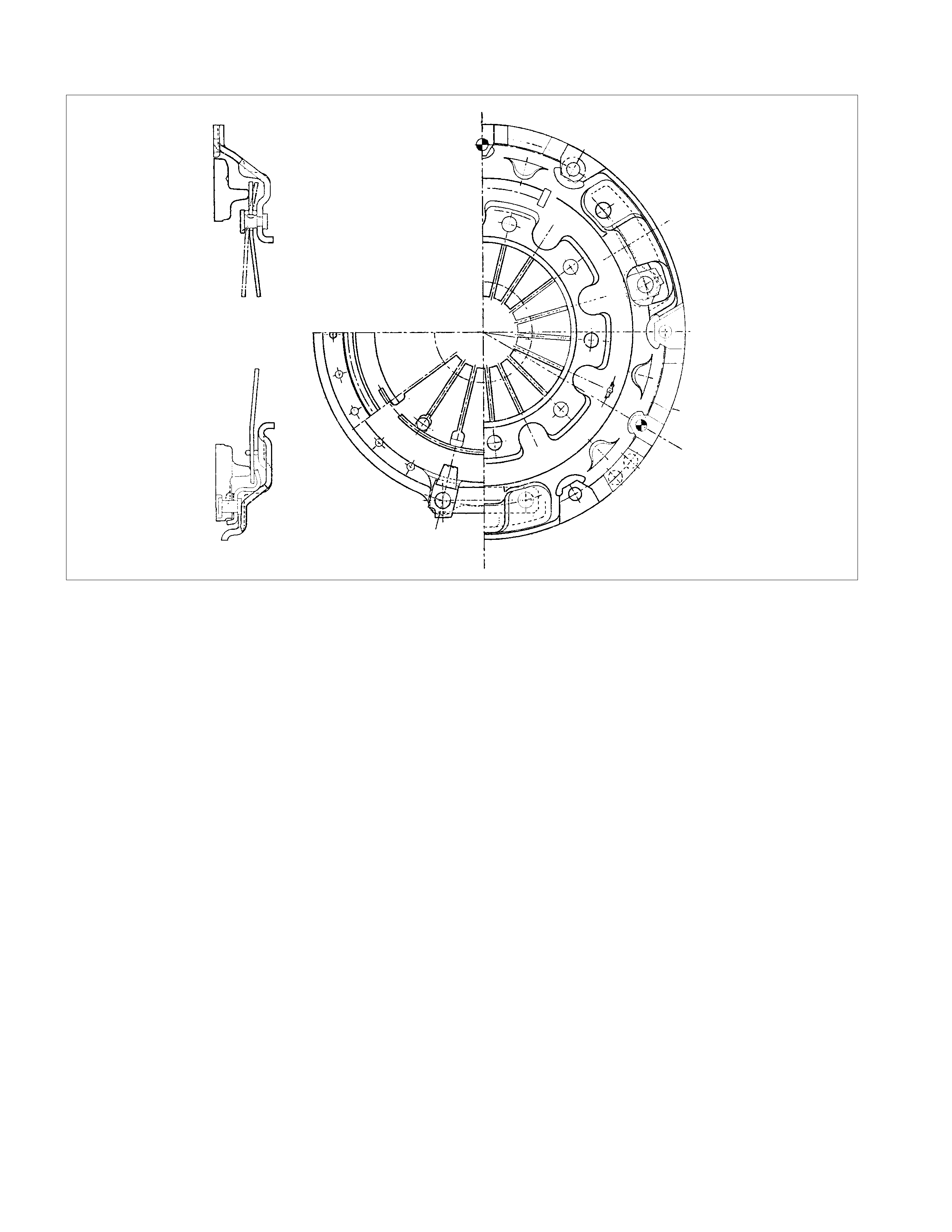
C24SE
RTW37CMF000101
The pressure plate assembly consists of the clutch cover, the pressure plate with diaphragm spring.
Operating the clutch pedal causes the pressure plate to move in an axial direction to engage and disengage the clutch.
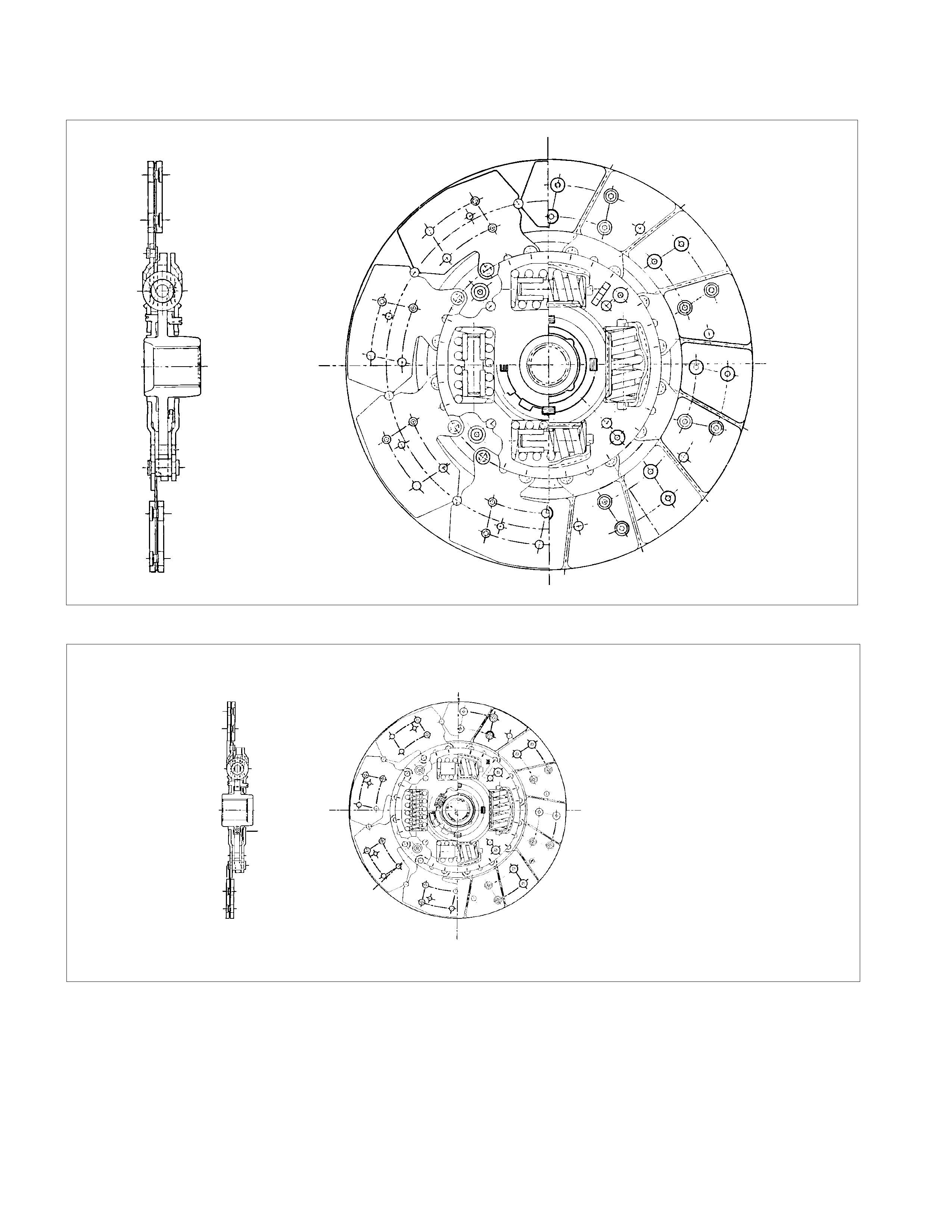
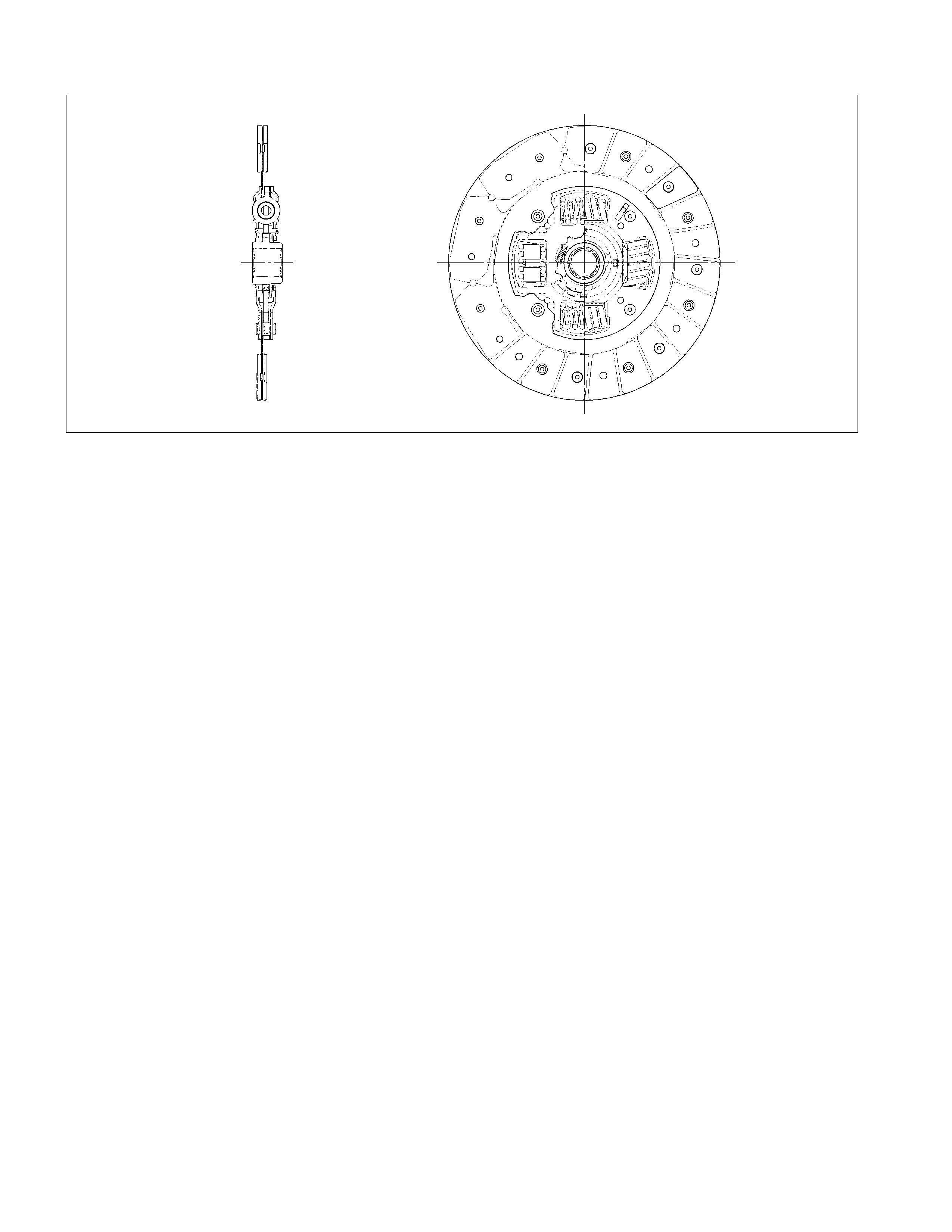
DRIVEN PLATE ASSEMBLY
6VE1
RTW37CMF000201
4JH1-TC
C24SE
RTW37CSF0003
The driven plate assembly consists of the plate and the facing.
The plate consists of the clutch center, the cushioning plate and the torsion springs.
The facing is riveted to both sides of the cushioning plate.
The cushioning plate provides a longer service life by minimizing wear and vibration at the clutch contact surfaces.
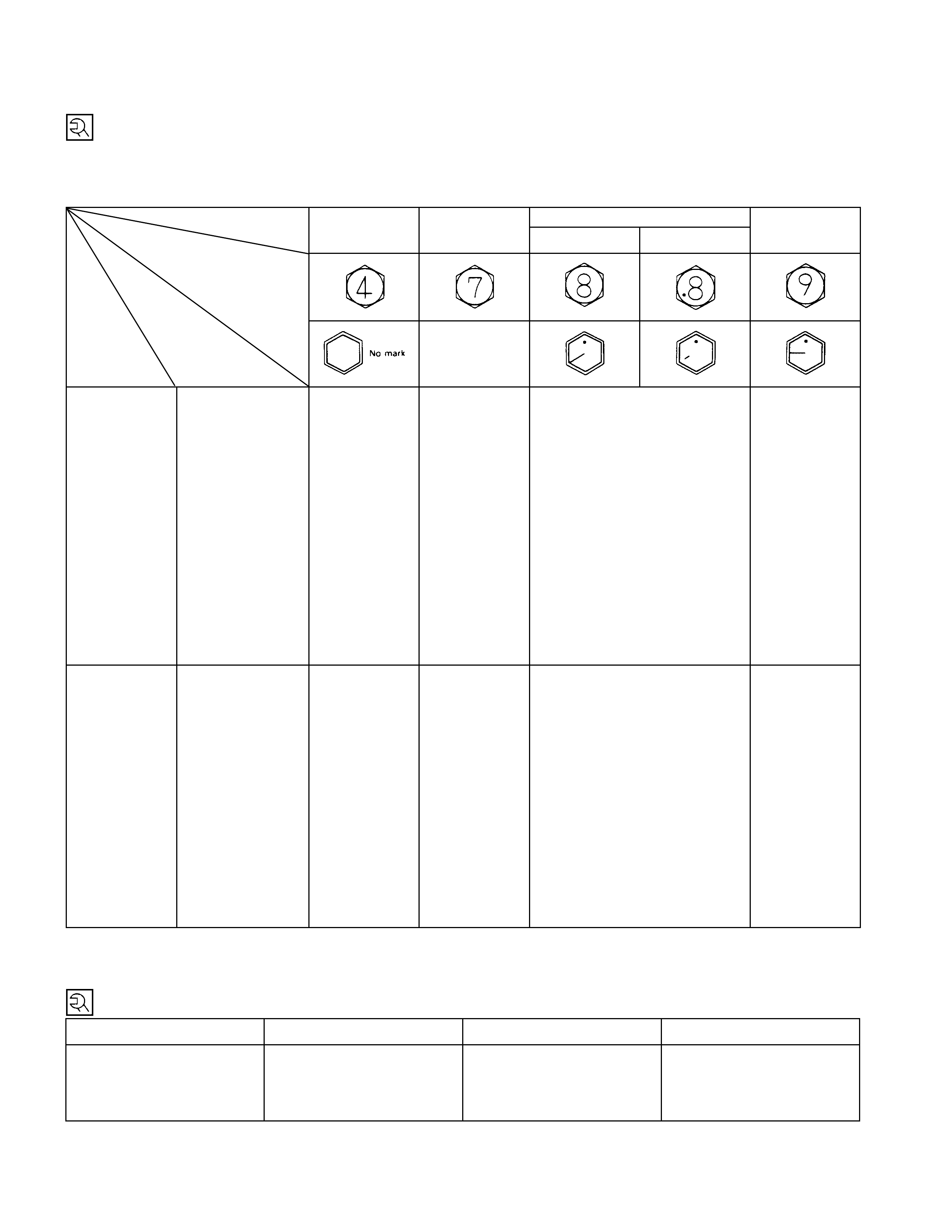
TORQUE SPECIFICATION
STANDARD BOLTS
The torque values given in the following table should be applied where a particular torque is not specified.
N⋅m (kgf⋅m/lb ft)
Strength 4.8/4T 7T 8.8 9.8/9T
Class Refined Non-Refined
Bolt Identifi-
cation
Bolt
Diameter×
××
×
Pitch (m m)
-
M6 × 1.0 6 (0.6 / 52 lb. i n) 7 (0.7 / 61 lb. i n) 8 (0.8 / 69 lb. i n) -
M8 × 1.25 13 (1.3 / 113
lb.in) 17 (1.7 / 12) 20 (2.0 / 14) 24 (2.4 / 17)
M10 × 1.25 27 (2.8 / 20) 37 (3.8 / 27) 42 (4.3 / 31) 50 (5.1 / 37)
M12 × 1.25 61 (6.3 / 45) 76 (7.8 / 56) 87 (8.9 / 64) 95 (9.7 / 70)
M14 ×1.5 96 (9.8 / 71) 116 (11.8 / 85) 133 (13.6 / 98) 142 (14. 5 / 105)
M16 × 1.5 130 (13.3 / 96) 170 (17.3 / 125) 193 (19.7 / 143) 200 (20.4 / 148)
M18 × 1.5 188 (19.2 / 139) 244 (24.9 / 180) 278 (28.3 / 205) 287 (29.3 / 212)
M20 × 1.5 258 (26.3 / 190) 337 (34.4 / 249) 385 (39.3 / 284) 396 (40.4 / 292)
M22 × 1.5 332 (33.9 / 245) 453 (46.3 / 335) 517 (52.7 / 381) 530 (54.1 / 391)
M24 × 2.0 449 (45.8 / 331) 570 (58. 2 / 421) 651 (66.3 / 480) 692 (70.6 / 511)
* M10 × 1.5 26 (2.7 / 20) 36 (3.7 / 27) 41 (4.2 / 30) 48 (4.9 / 35)
* M12 × 1.75 57 (5.8 / 42) 71 (7.2 / 52) 80 (8.2 / 59) 89 (9.1 / 66)
* M14 × 2.0 89 (9.1 / 66) 110 (11.2 / 81) 125 (12.7 / 92) 133 (13.6 / 98)
* M16 × 2.0 124 (12.7 / 92) 162 (16.5 / 119) 185 (18.9 / 137) 191 (19.5 / 141)
Flange Bolt M6 × 1.0 7 (0.7 / 61 lb. i n) 8 (0.8 / 69 lb. i n) 9 (0.9 / 78 lb. i n) -
M8 × 1.25 15 (1.5 / 11) 19 (1.9 / 14) 22 (2.2 / 16) 26 (2.7 / 20)
M10 × 1.25 31 (3.2 / 23) 41 (4.2 / 30) 47 (4.8 / 35) 56 (5.7 / 41)
M12 × 1.25 69 (7.0 / 51) 85 (8.7 / 63) 97 (9.9 / 72) 106 (10.8 / 78)
M14 × 1.5 104 (10.6 / 77) 126 (12.8 / 93) 144 (14.6 / 106) 154 (15. 7 / 114)
M16 × 1.5 145 (14.8 / 127) 188 (19. 2 / 139) 214 (21.8 / 158) 221 (22.5 / 163)
M18 × 1.5 - - - -
M20 × 1.5 - - - -
M22 × 1.5 - - - -
M24 × 2.0 - - - -
* M10 × 1.5 30 (3.1 / 22) 40 (4.1 / 30) 46 (4.7 / 34) 54 (5.5 / 40)
* M12 × 1.75 64 (6.5 / 47) 78 (8.0 / 58) 89 (9.1 / 66) 99 (10.1 / 73)
* M14 × 2.0 97 (9.9 / 72) 119 (12.1 / 88) 135 (13.8 / 99.7) 144 (14.7 / 107)
* M16 × 2.0 137 (14.0 / 101) 178 (18.2 / 132) 203 (20.7 / 132) 210 (21.5 / 155)
The asterisk * indicates that the bolts are used for female-threaded parts that are made of soft materials such as
casting, etc.
FLARE NUTS
Pipe diameter mm (in) Torque N⋅
⋅⋅⋅m (kgf⋅
⋅⋅⋅m / lb ft) Pipe diameter mm (in) Torque N⋅
⋅⋅⋅m (kgf⋅
⋅⋅⋅m / lb ft)
4.76 (0.187) 16 (1.6 / 12) 10.00 (0.394) 54 (5.5 / 40)
6.35 (0.250) 26 (2.7 / 20) 12.00 (0.472) 88 (9.0 / 65)
8.00 (0.315) 44 (4.5 / 33) 15.00 (0.591) 106 (10.8 / 78)
Standard Hex.
Head Bolt
TORQUE SPECIFICATIONS
N⋅m (kgf⋅m/lb ft)
6VE1, 4JH1-TC N⋅m (kgf⋅m/lb ft)
RTW37CLF000401
C24SE N⋅m (kgf⋅m/lb ft)
RTW37CLF000301
SERVICING
Servicing refers to general maintenance procedures to be performed by qualified service personnel.
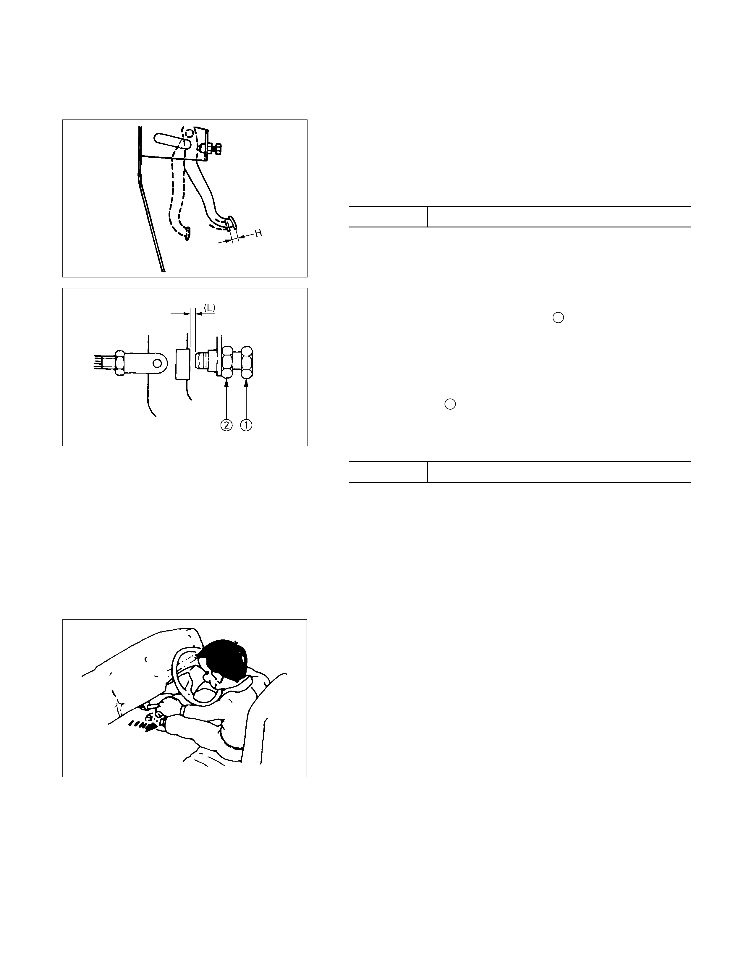
CLUTCH PEDAL PLAY
Inspection
Depress the clutch pedal lightly by hand, and measure to
determine if the free play is within the standard value.
Pedal Free Play mm(in)
H 5.0-15.0 (0.2-0.6)
Adjustment of the c lutch switch (or stopper bolt)
Turn the clutch switch or stopper bolt 1 until the switch bolt or
stopper bolt just touches the clutch pedal arm.
Adjust clutch switch or stopper bolt by backing it out half a turn,
and measure the clearance (L) between the clutch pedal arm
and the clutch switch bolt end or stopper bolt.
Lock the lock nut 2 .
Connect clutch switch connector.
Clutch switch and clutch pedal
Clearance mm(in)
(L) 0.5-1.5 (0.020-0.059)
AIR BLEEDING
Bleed air from clutch operating cylinder according to the
following procedure.
Carefully monitor fluid level at master cylinder during bleeding
operation.
1. Set the parking brake.
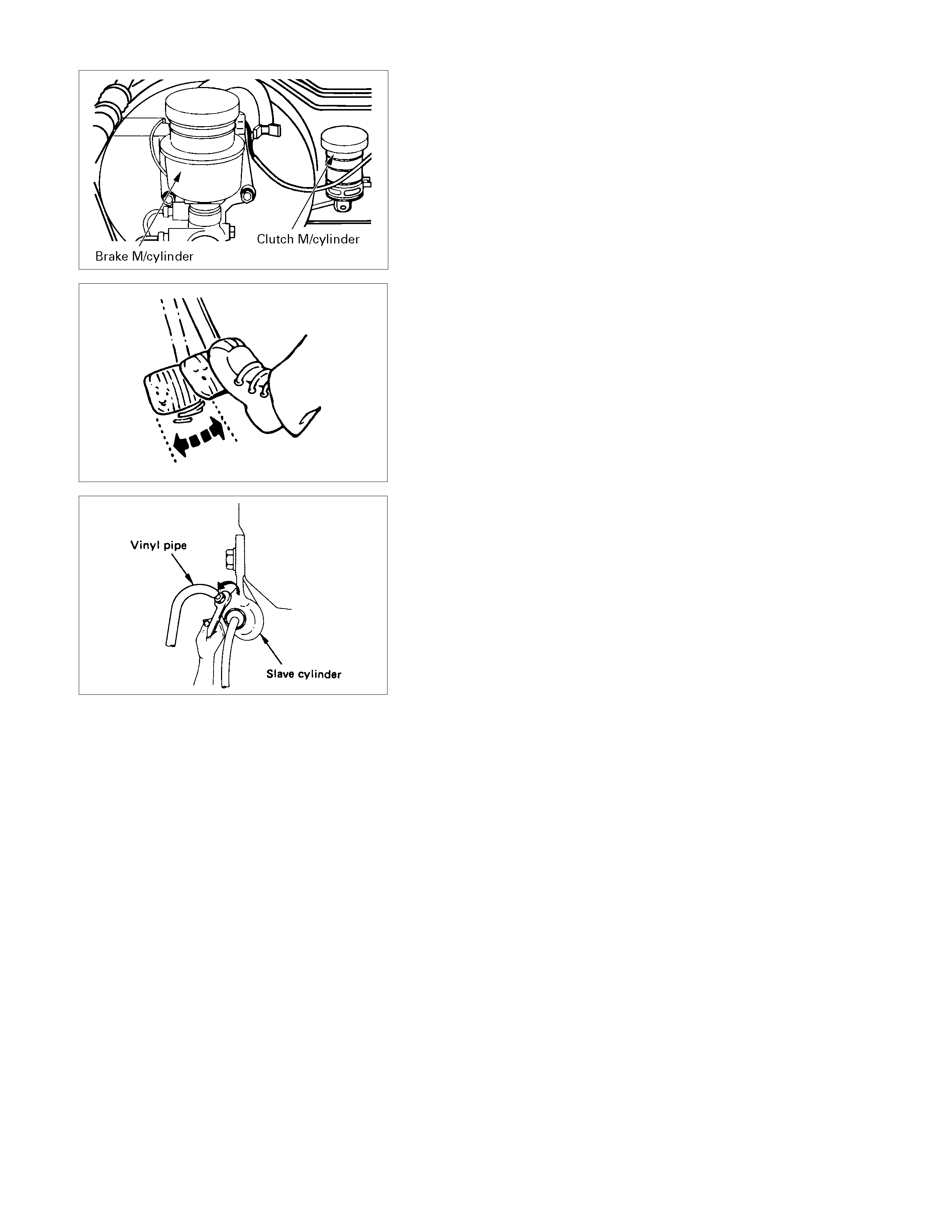
2. Top up reservoir with recommended brake fluid.
3. Connect a transparent vinyl tube to air bleeder valve.
4. Fully depress clutch pedal several times.
5. With clutch pedal depressed, open bleeder valve to release
air.
6. Close bleeder valve.
7. Repeat steps 5 through 6 above until brake fluid flows from
air bleeder valve without air bubbles.
8. Bleed air from clutch damper according to the above
procedure.
9. Repeat the above bleeding procedure until the air
completely removed.
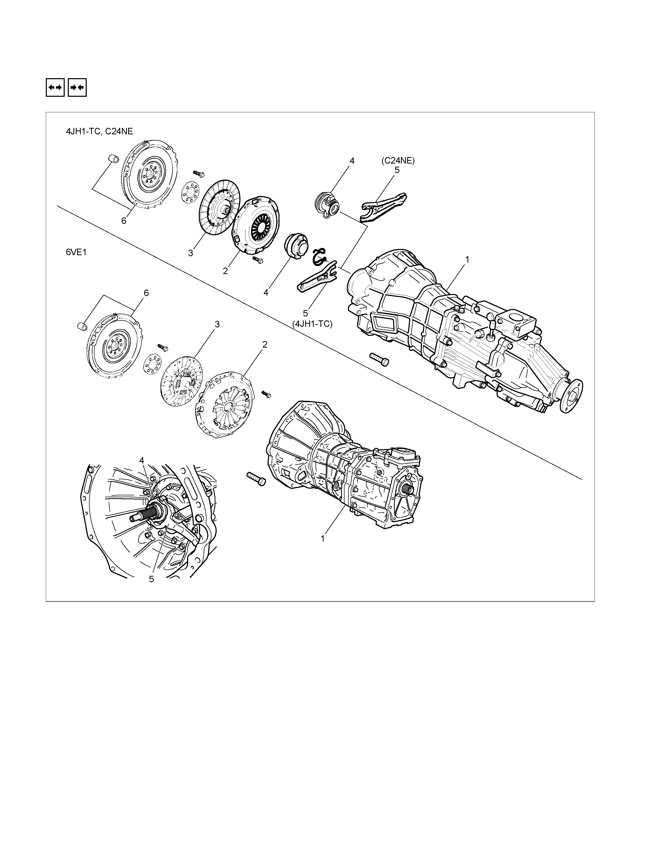
CLUTCH
REMOVAL AND INSTALLATION
RTW37CLF000201-X
Removal Steps
1. Transmission assembly
▲ 2. Pressure Plate assembly
▲ 3. Driven plate assembly
4. Release bearing
5. Shift fork
6. Flywheel assembly and crank bearing
Installation Steps
To install, follow the removal steps in the
reverse order.
Important Operations - Removal
1. Transmission Assembly
Refer to “MANUAL TRANSMISSION” of section 7B1
for “REMOVAL AND INSTALLATION” procedure.
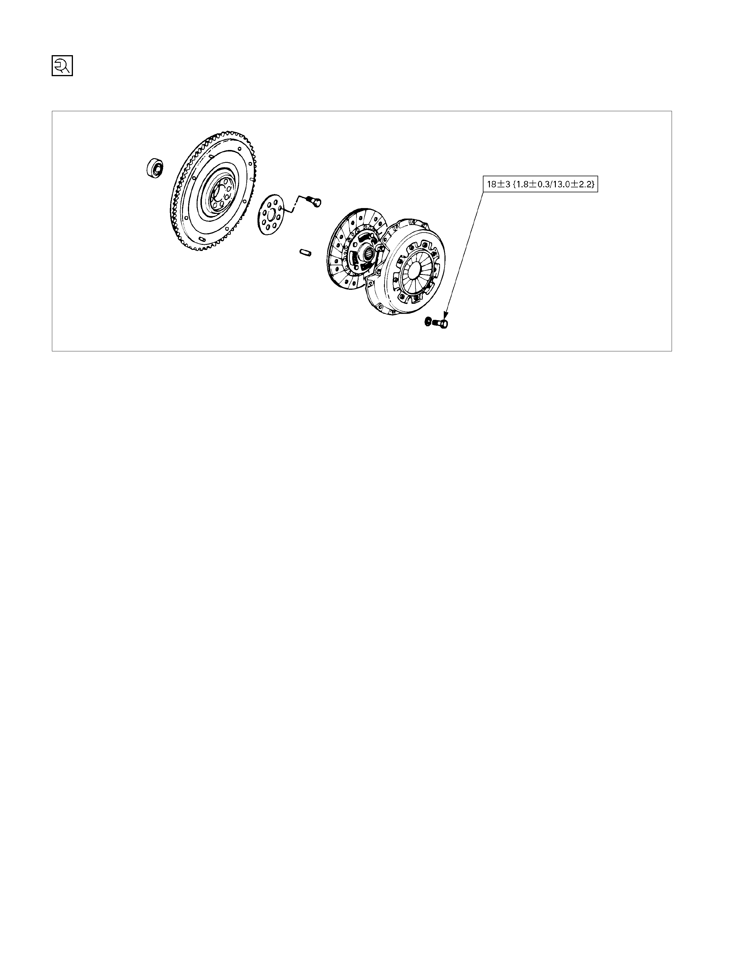
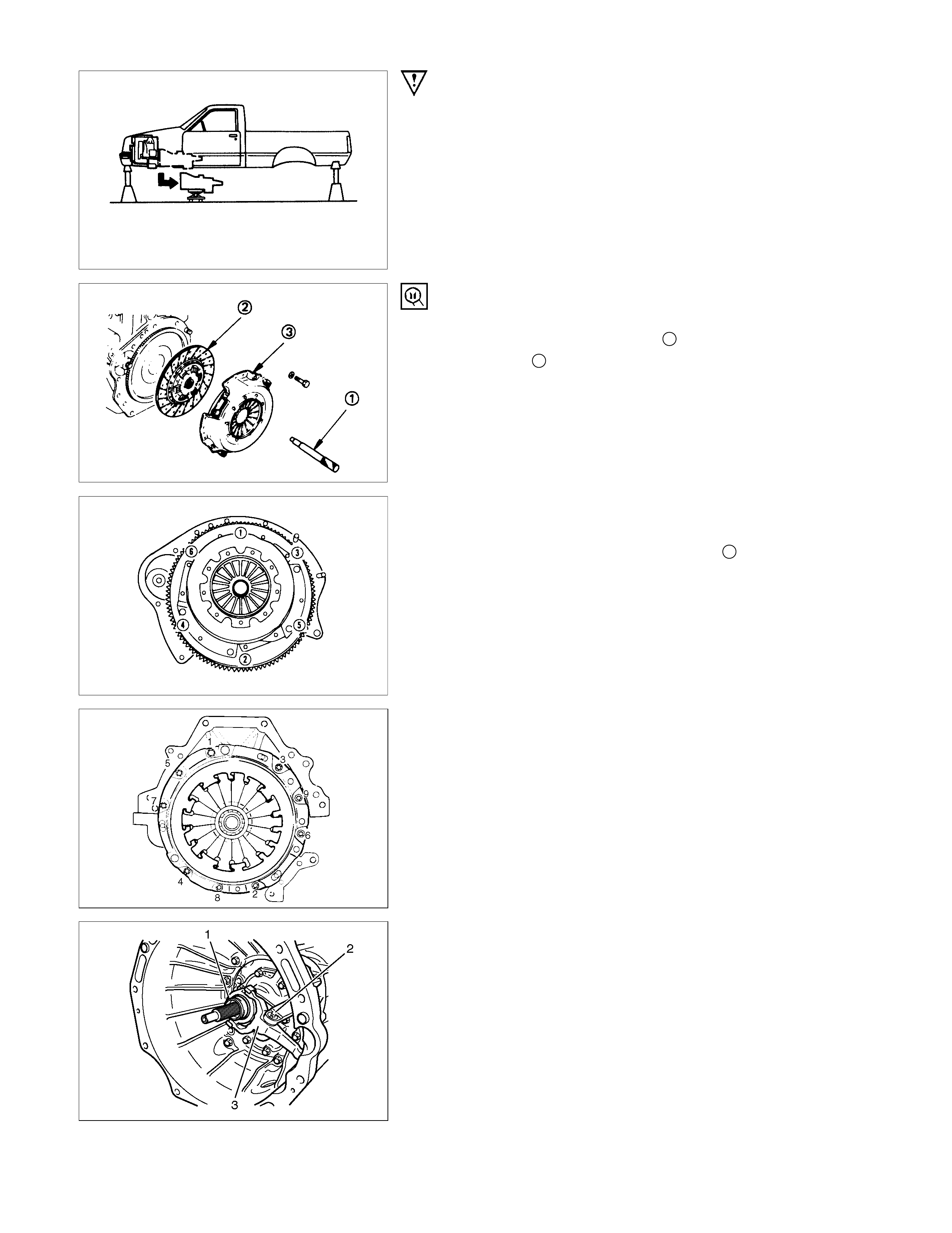
2. Clutch Pressure Plate Assembly
3. Driven Plate Assembly
(1) Use the clutch pilot aligner 1 to prevent the driven plate
assembly 2 from falling free.
Clutch Pilot Aligner : 5-85253-001-0
(2) Loosen the clutch cover bolts in the numerical order shown
in the illustration.
(3) Remove the pressure plate assembly 3 from the flywheel.
(4) Remove the driven plate from the flywheel.
201RS017
220RW088-X
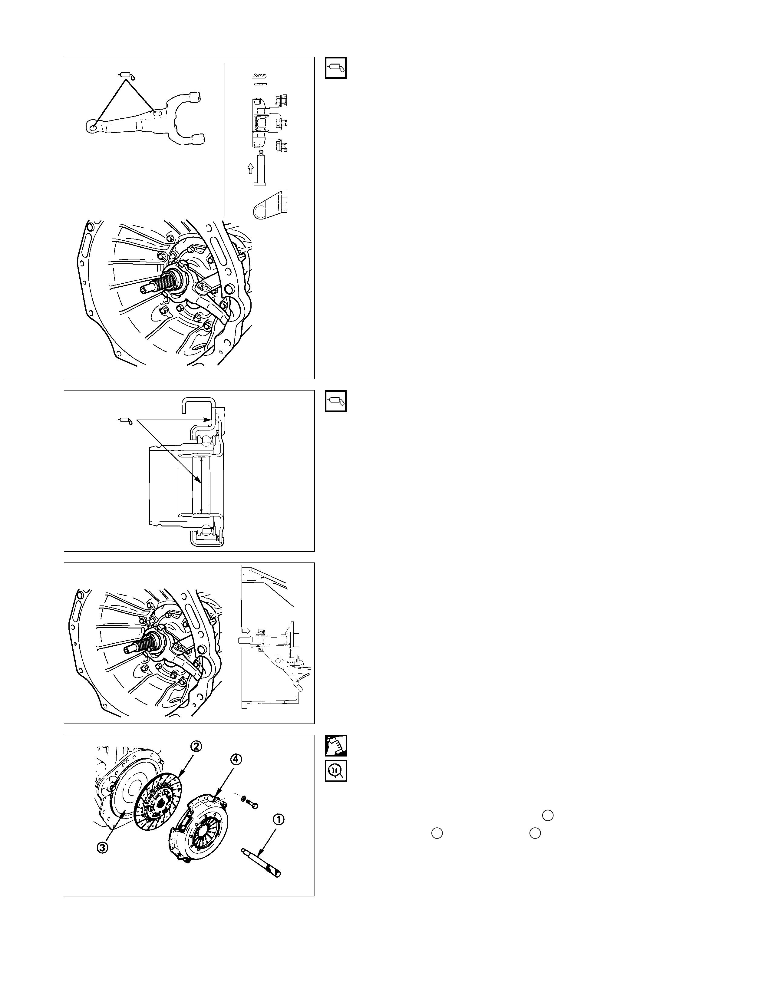
4. Release Bearing (6VE1)
5. Shift Fork (6VE1)
(1) Remove the release bearing (1) from the transmission
case.
(2) Remove the shift fork snap pin (2).
(3) Rem ove the shift fork pin and shift fork (3) f rom the fulcr um
bridge.
6VE1
4JH1-TC, C24SE
015RW053
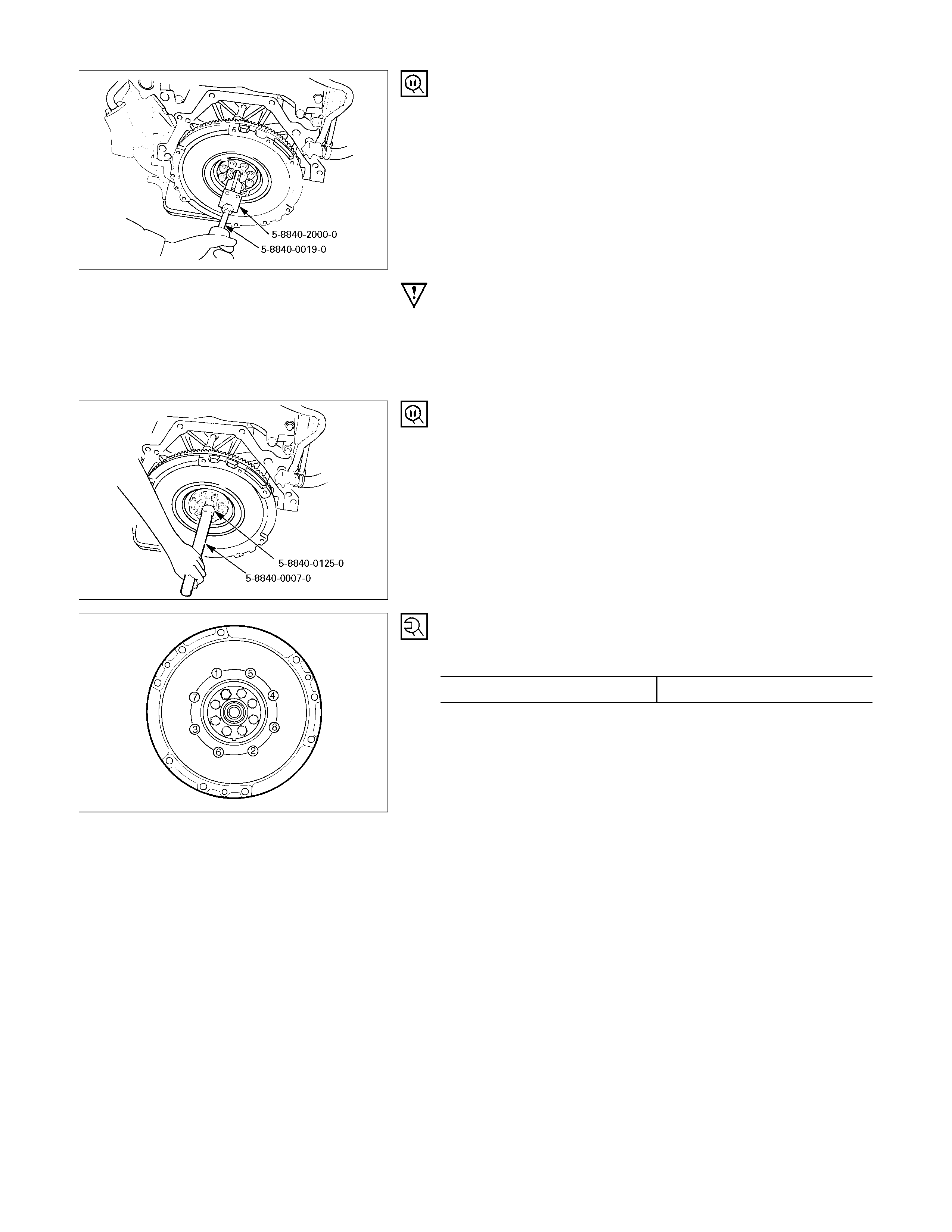
6. Flywheel Assembly and Crank Bearing (6VE1)
(1) Remove flywheel assembly and crankshaft bearing. Do not
remove except for replacement.
(2) Use the remover 5-8840-2000-0 (J-5822) and sliding
hammer 5-8840- 0019-0 ( J -23907) to remove the c rankshaft
bearing
Important Operations - Installation
Follow the removal procedure in reverse order to perform the
installation procedure.
Pay careful attention to the important points during the
installation procedure.
015RW054
6. Flywheel Assembly and Crank Bearing (6VE1)
(1) Install flywheel assembly and crankshaft bearing. Use the
installer 5-8840-0125-0 (J-26516-A) and driver handle 5-
8840-0007-0 (J-8092) to install the crankshaft bearing then
clean and lubricate with grease.
015RS047
(2) Install new flywheel fixing bolts in the order illustrated and
tighten them to the specified torque. N⋅m (kg⋅m/lb ft)
6VE1 54 (5.5/40)
NOTE: Do not reuse the bolt and do not apply oil or thread lock
to the bolt.
201RW019
5. Shift For k (6VE1)
4. Release Bearing (6VE1)
(1)
A
pply molybdenum disulphide type grease to the pin hole
inner circumferences and thrust surfaces.
(2) Attach the shift fork to the front cover and insert the pin
from below of the front cover.
(3) Install the washer and snap pin.
201RW012
(4)
A
pply molybdenum disulphide type grease to the areas
shown in illustration.
201RW020
(5) Install the release bearing in the proper direction.
NOTE: Ensure release bearing is properly positioned during
installation, as shown in illustration.
3. Driven plate Assembly
2. Clutch Pressure Plate Assembly
(1) Clean the flywheel surface.
(2) Clean the facing surface.
(3) Use the clutch pilot aligner 1 to install the driven plate
assembly 2 to the flywheel 3.
Clutch Pilot Aligner : 5-8525-3001-0
(4) Clean the pressure plate surfaces.
(5) Align the pressure plate assembly 4 with the flywheel
knock pin 5.
(6) Install the pressure plate assembly to the flywheel.
(7) Tighten the clutch cover bolts a little at a time in the
numerical order shown in the illustration.
Clutch Cover Bolt Torque N⋅m (kgf⋅m/lb⋅ft)
18 ± 3 (1.8 ± 0.3 / 13.0 ± 2.2)
201RS017
(8) Remove the clutch pilot aligner.
Note:
Do not strike the clutch pilot aligner with a hammer to
remove it.
INSPECTION AND REPAIR
Make the necessary adjustments, repairs, and part replacements if excessive wear or damage is discovered during
inspection.
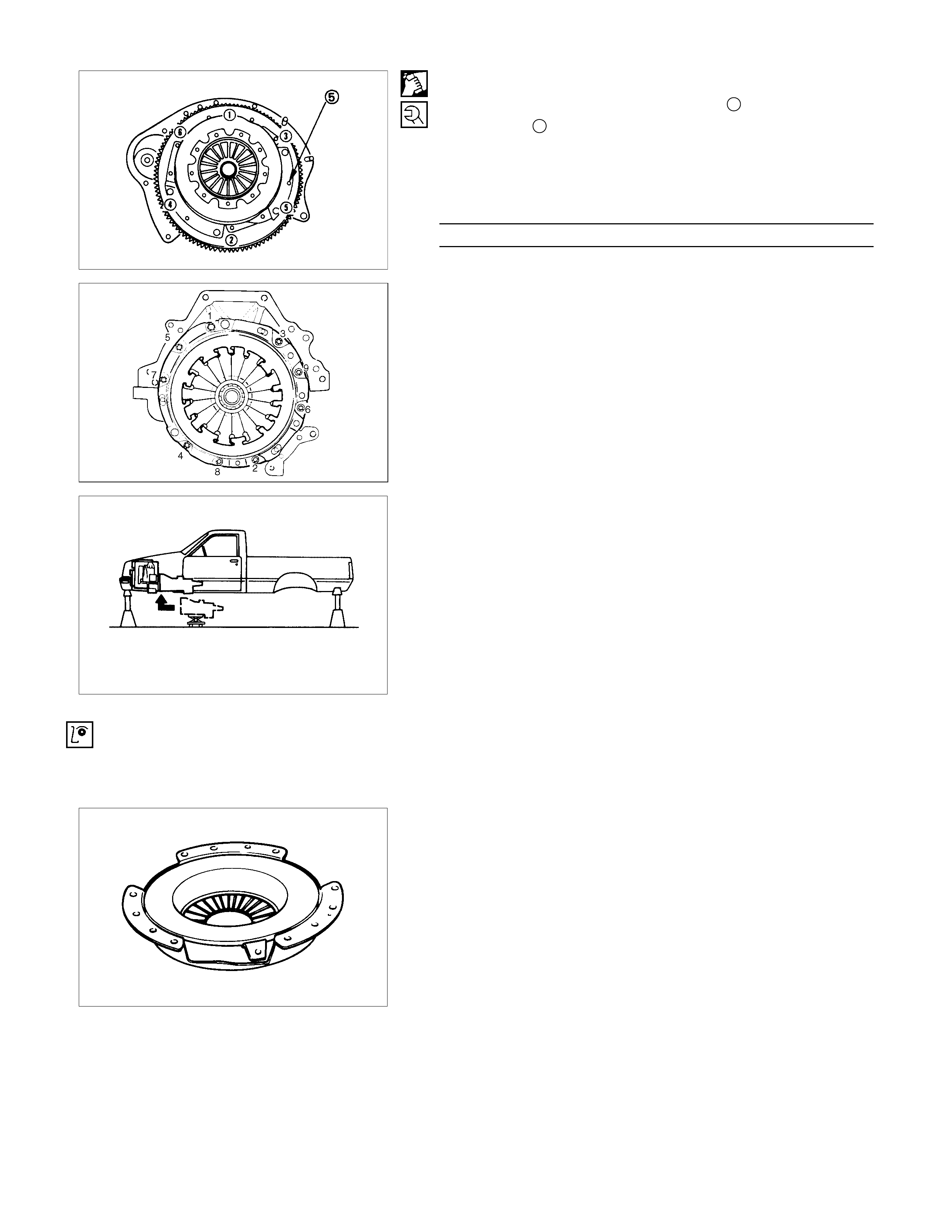
PRESSURE PLATE ASSEMBLY
Visually inspect the pressure plate friction surface for
excessive wear and heat cracks.
If excessive wear or deep heat cracks are present, the
pressure plate must be replaced.
4JH1-TC, C24SE
6VE1
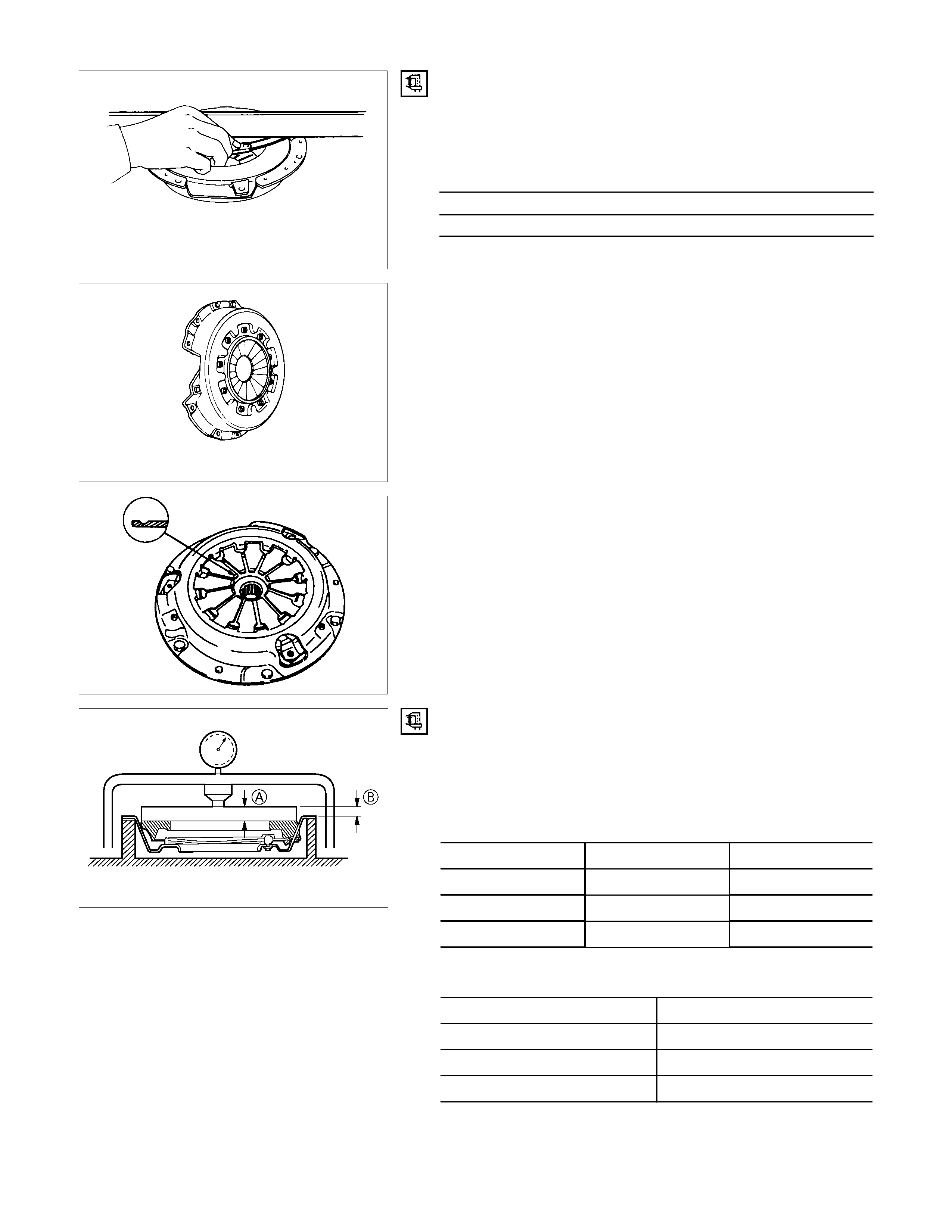
Pressure Plate Warpage
Use a straight edge and a feeler gauge to measure the
pressure plate friction surface flatness in four directions.
If any of the measured values exceed the specified limit, the
pressure plate must be replaced.
Pressure Plate Warpage mm(in)
Limit
0.3 (0.012)
Clutch Cover
Visually inspect the entire clutch cover for excessive wear,
cracking, and other damage.
The clutch cover must be replaced if any of these conditions
are present.
1. Abr as ion, sc ratc hes , c rac ks and def lec tion of f r ic tion f ac e to
the disc, loose rivet and wear of ring
• Grind small scratches, or replace the assembly if extreme
scratches are found.
201R300011
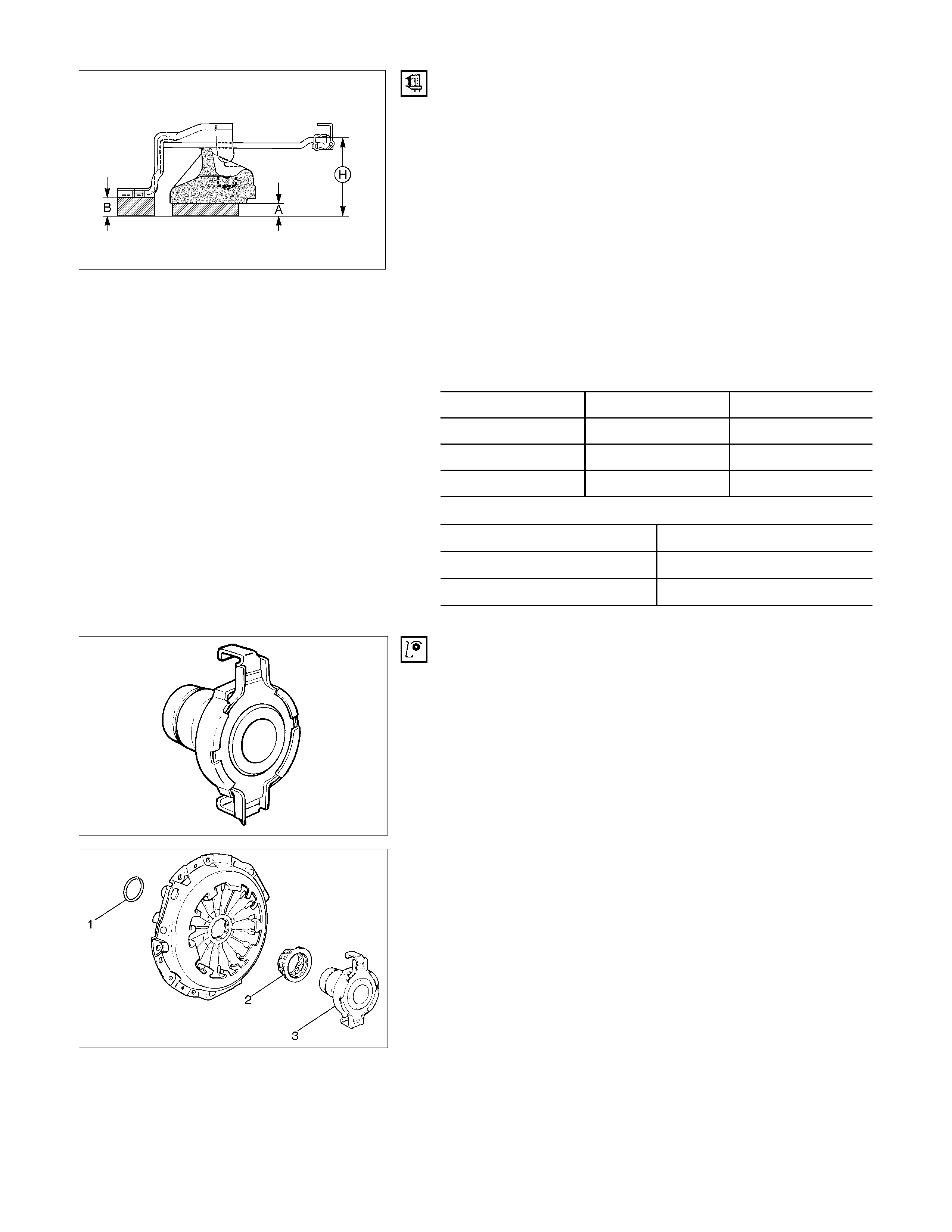
Clutch Set Force
1. Invert the pressure plate assembly.
2. Place a metal sheet “A” on the pressure plate.
3. Compress the pressure plate assembly until the distance
“B” becomes specified.
Thickness and Distance mm(in
)
A B
6VE1 8.2 (0.323) 12 (0.472)
4HJ1-TC 7.8 (0.307) 18 (0.71)
C24NE 8.0 (0.315) 0 (0)
4. Note the pressure plate gauge reading.
Driven Plate Clamping Load N (kg/Ib)
Standard
6VE1 7200 (734/1618)
4JH1-TC 6300 (642/1415)
C24NE 5500 (561/1237)
RTW37CSH000101
Diaphragm Spr ing Finger Height
1. Place a new driven plate or the appropriate spacer beneath
the pressure plate.
2. Fully compress the pressure plate and diaphragm spring.
There are two ways to do this.
• Use a bench pres s to pres s down on the as sembly from the
top.
• Tighten the fixing bolts.
NOTE: Preload on diaphragm spring finger must be 49 - 98 N
(11 - 22 lb) in direction of release, when clutch cover assembly
is bolted to the flywheel.
3. Measur e the spring height f rom base to spring tip "H". If the
measured value exceeds the specified limit, the pressure
plate assembly must be replaced.
Spacer Thickness mm(in)
A B
6VE1 8.2 (0.323) 12 (0.472)
4HJ1-TC 7.8 (0.307) 18 (0.71)
C24NE 8.0 (0.315) 0 (0)
Finger Height
6VE1 49.9-51.9 (1.96-2.04)
4JH1-TC 39-41 (1.54-1.61)
C24NE 39-41 (1.54-1.61)
201RS011
Release Bearing (6VE1)
1. Visually check the release bearing f or excess ive play, noise
and breakage.
2. If any of these conditions are discovered, the release
bearing must be replaced.
201RW010-X
3. When replacing the release bearing (3), replace both the
wedge collar (2) and wire ring (1) at the same time.
201RS013
Wedge Collar
1. Visually check the surfaces of the wedge collar making
contact with the release bearing for excessive wear and
damage.
2. Replace any exhibiting excessive wear or damage.
201RS014
Shift Fork
1. Visually check the surfaces of the shift fork m aking contact
with the release bearing for excessive wear and damage.
2. Remove any minor stepping or abrasion f rom s hift fork with
an oil stone.
3. Replace any exhibiting excessive wear or damage.
Release Bearing (4JH1-TC, C24SE)
Removal
1. Visually inspect the surfaces of the release bearing making
contact with the shift fork for excessive wear and damage.
Replace any exhibiting excessive wear or damage.
2. Apply multi-purpose type grease (NLGI No.2 or No.3) to
contact surface between the release bearing and the shift
fork. (Do not apply grease to the sleeve inner face.)
Shift Fork
1. Visually inspect the surfaces of the shift fork making contact
with the release bearing for excessive wear and damage.
2. Remove any minor stepping or abrasion from the release
bearing with an oil stone.
Replace any exhibiting excessive wear or damage.
3. Apply multi-purpose type grease (NLGI No.2 or No.3) to
area.
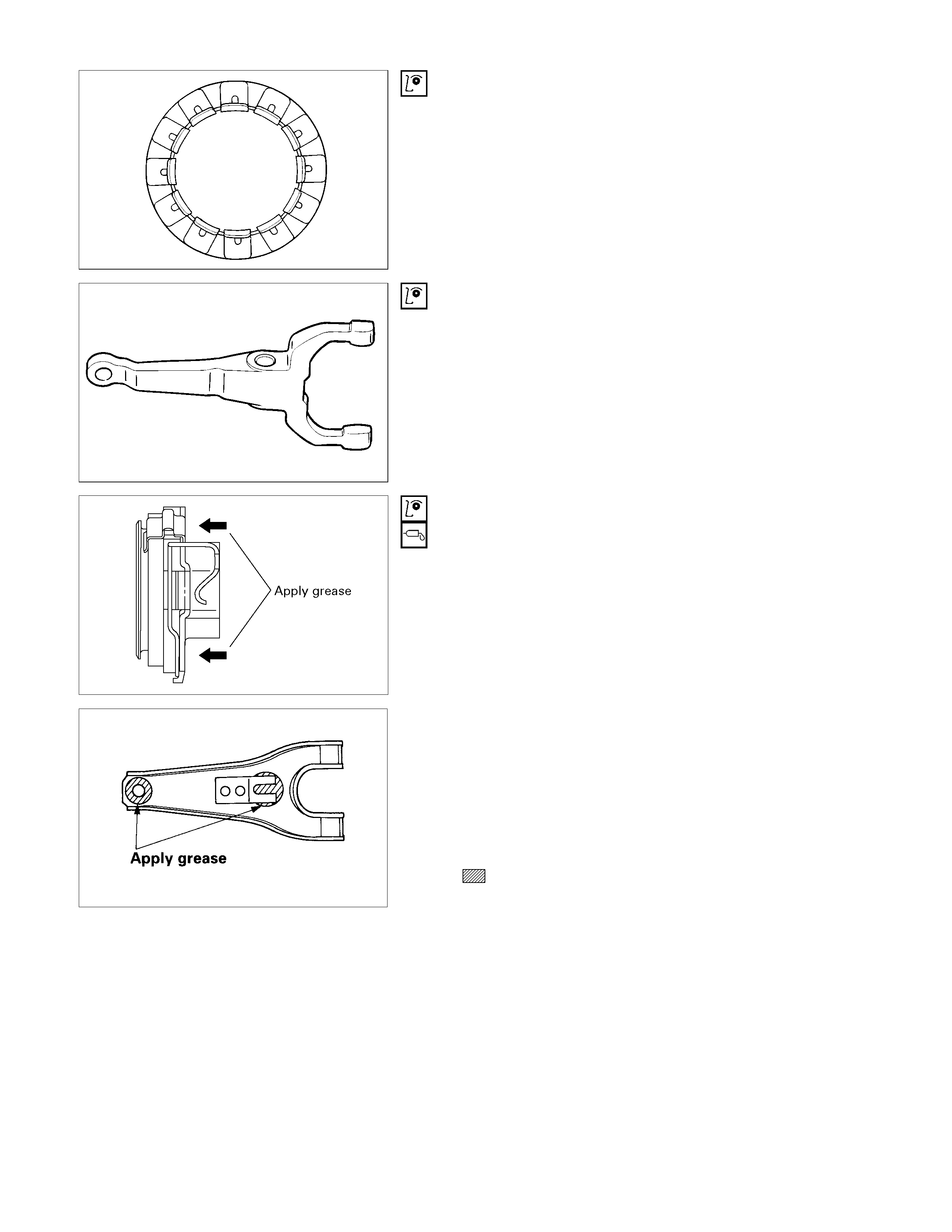
DRIVEN PLATE ASSEMBLY
1. Visually inspect the torsion spring 1 for looseness,
breakage, and weakening.
If any of these conditions are discovered, the driven plate
assembly must be replaced.
2. Visually inspect the facing surfaces 2 for cracking and
excessive scorching.
Visually inspect the facing surfaces for the presence of oil
or grease.
If any of these conditions are discovered, the facing must
be cleaned or replaced.
3. Check that the driven plate moves smoothly on the
transmission top gear shaft spline.
Minor ridges on the top gear shaft spline may be removed
with an oil stone.
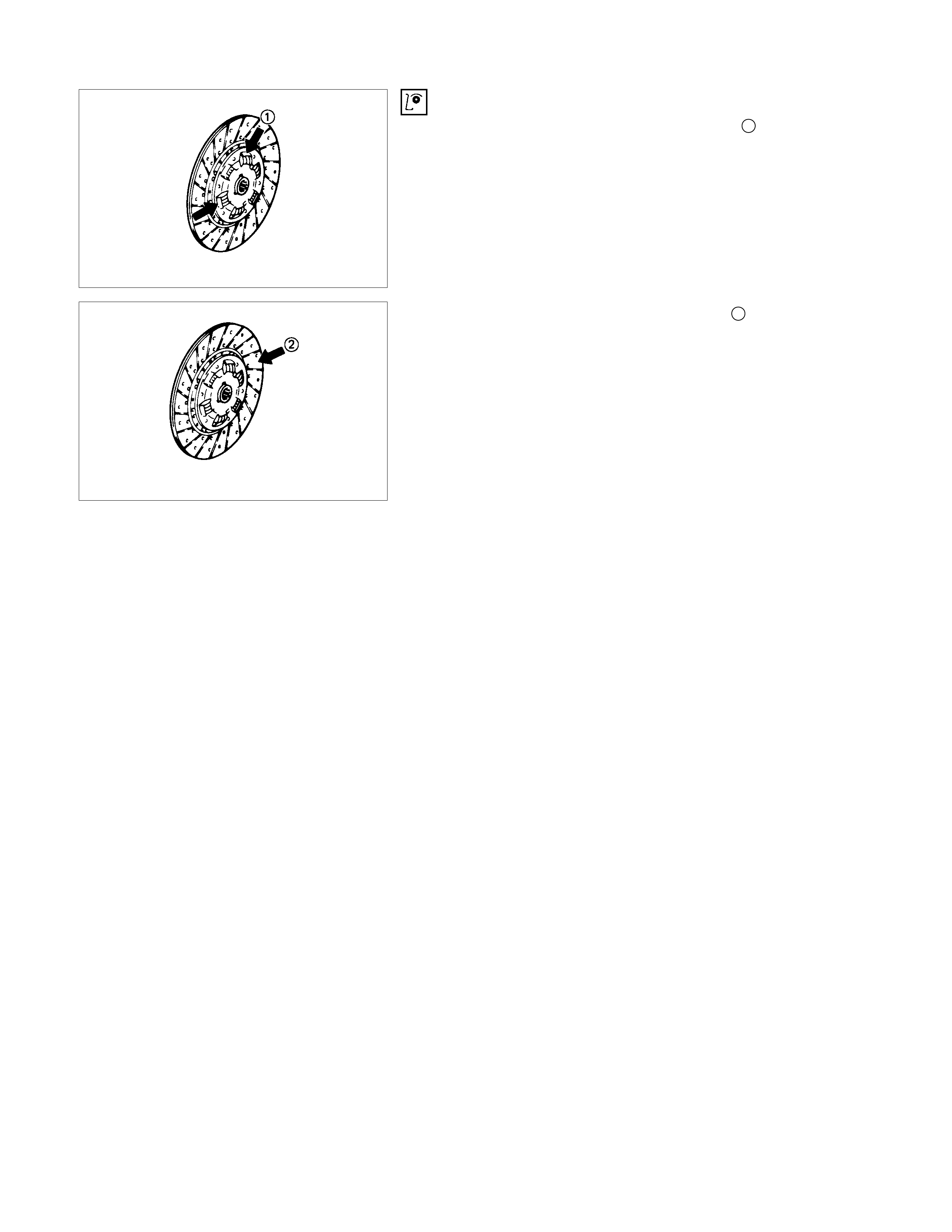
Driven Plate Warpage
1. Insert the clutch pilot aligner into the driven plate splined
hub.
The clutch pilot aligner must be held perfectly horizontal.
Clutch Pilot Aligner : 5-8525-3001-0
2. Set a dial indicator to the driven plate outside
circumference.
3. Slowly turn the driven plate.
Read the dial indicator as you turn the driven plate.
If the measured value exceeds the specified limit, the driven
plate assembly and/or the facing must be replaced.
Driven Plate Warpage mm(in)
Standard Limit
0.7 (0.028) 1.0 (0.039)
Driven Plate Splined Hub Spline Wear
1. Clean the driven plate splined hub.
2. Install the driven plate to the transmission top gear shaft
spline.
3. Set a surface gauge to the driven plate outside
circumference.
4. Slowly turn the driven plate counterclockwise.
Measure the spline rotation play as you turn the driven
plate.
If the measured value exceeds the specified limit, the driven
plate assembly must be replaced.
Driven Plate Splined Hub Spline Wear mm(in)
Standard Limit
0.5 (0.020) 1.0 (0.039)
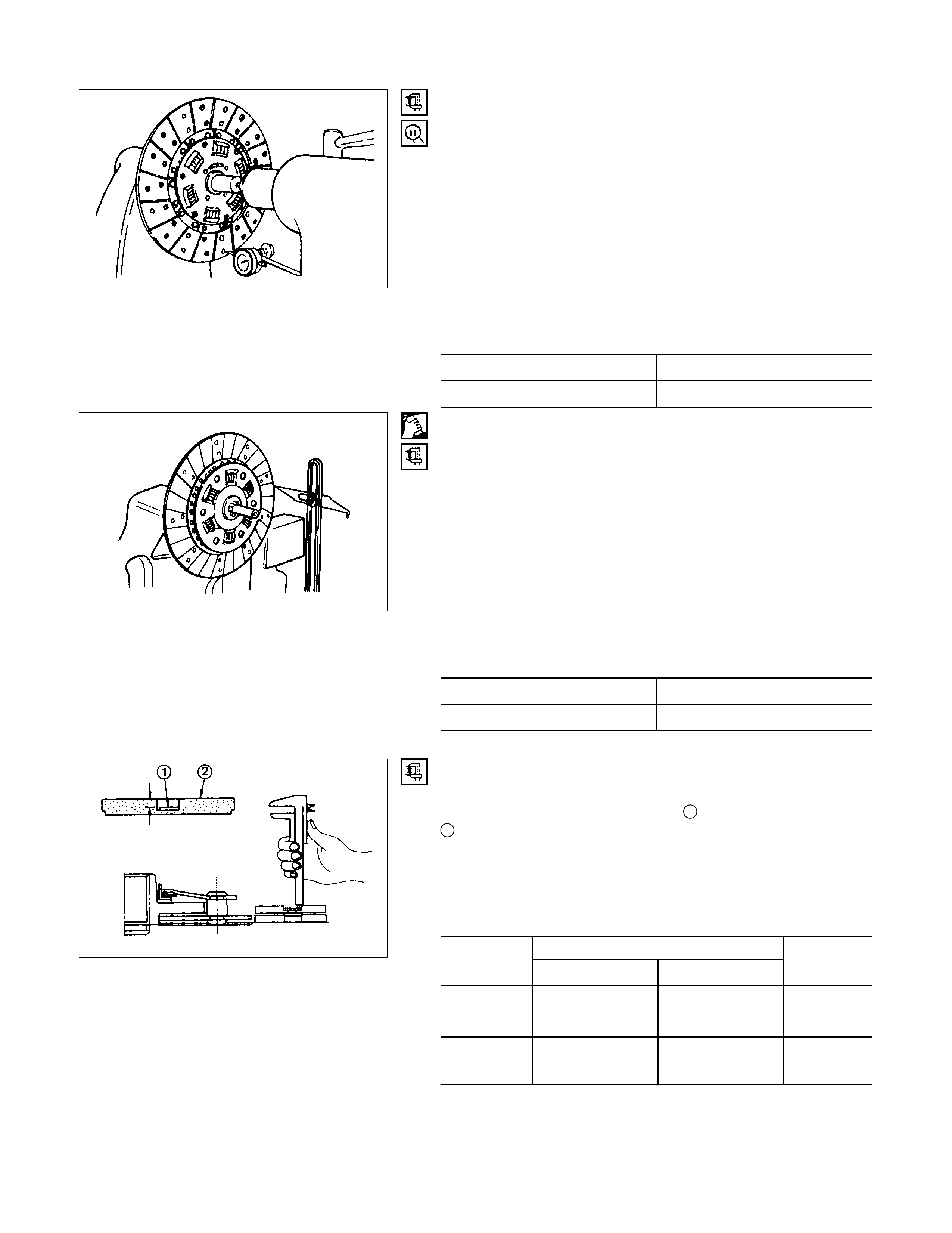
Rivet Head Depression
Use a depth gauge or a straight edge with steel rule to
measure the rivet head depression 1 from the facing surface
2.
Be sure to measure the rivet head depression on both sides of
the driven plate.
If the measured value is less than the specified limit, the facing
must be replaced.
Rivet Head Depression mm(in)
Standard
Fly wheel side P/Plate side Limit
4JH1-TC 1.35-1.95
(0.053-0.077) 1.65-2.25
(0.065-0.089) 0.2
(0.008)
6VE1
C24NE 1.65-2.25
(0.065-0.089) 1.65-2.25
(0.065-0.089) 0.2
(0.008)
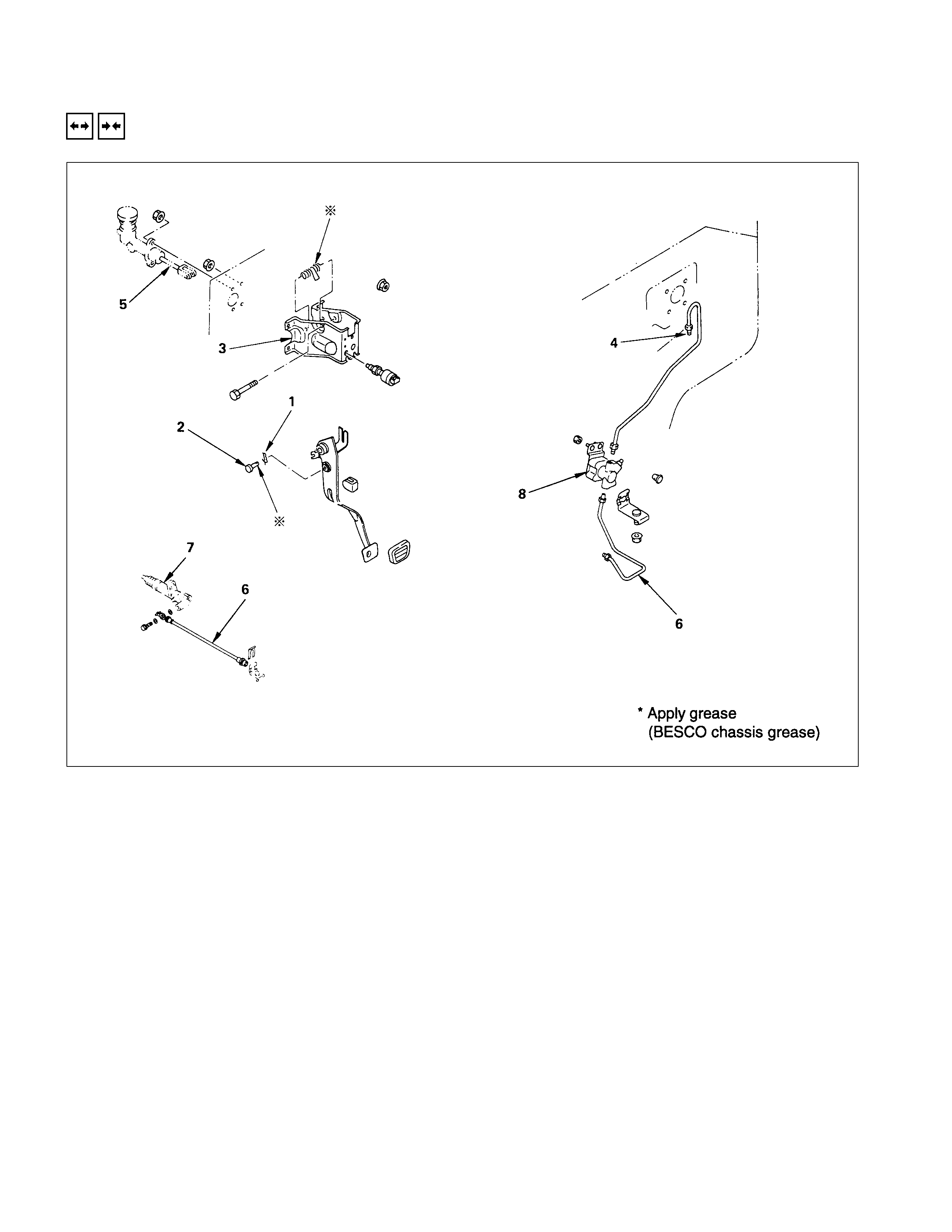
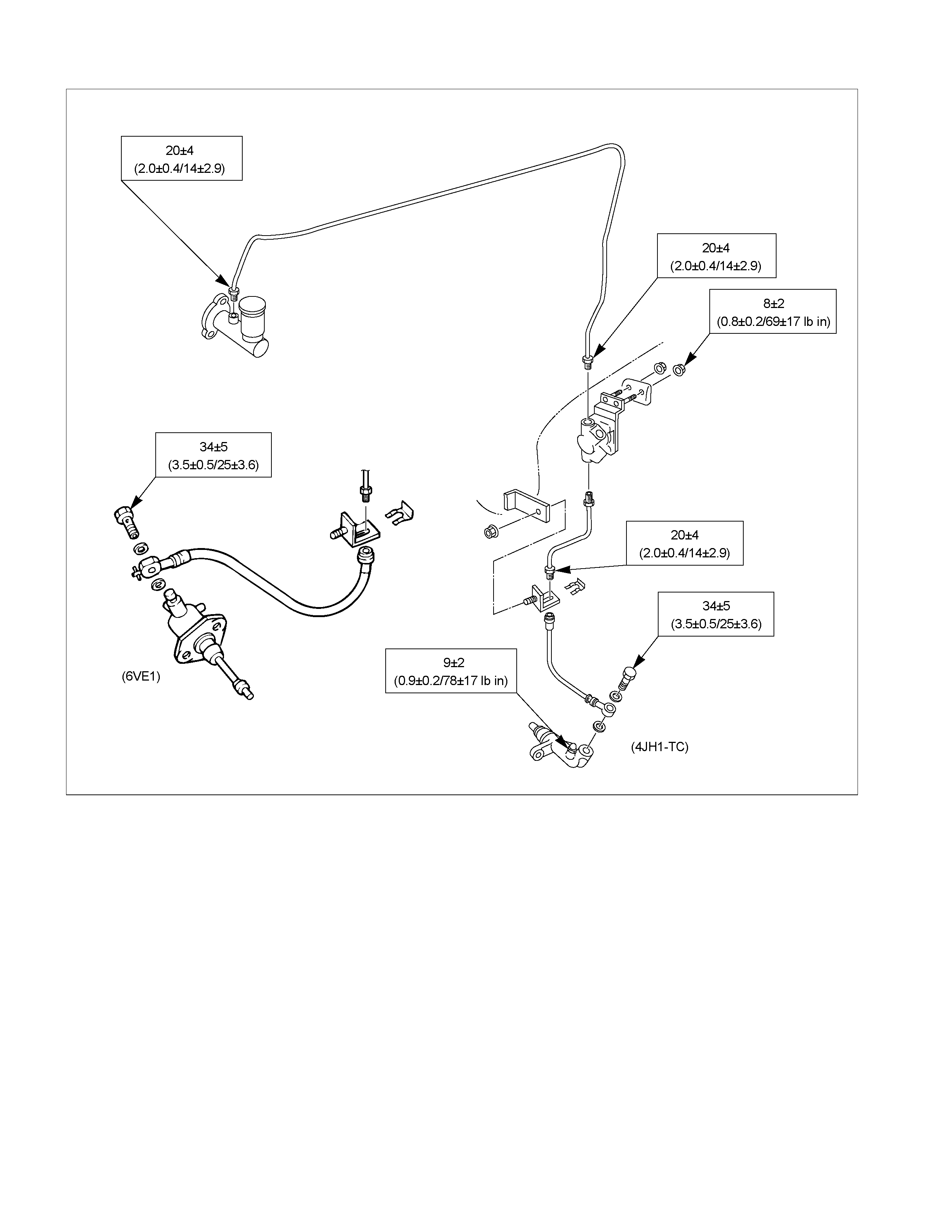
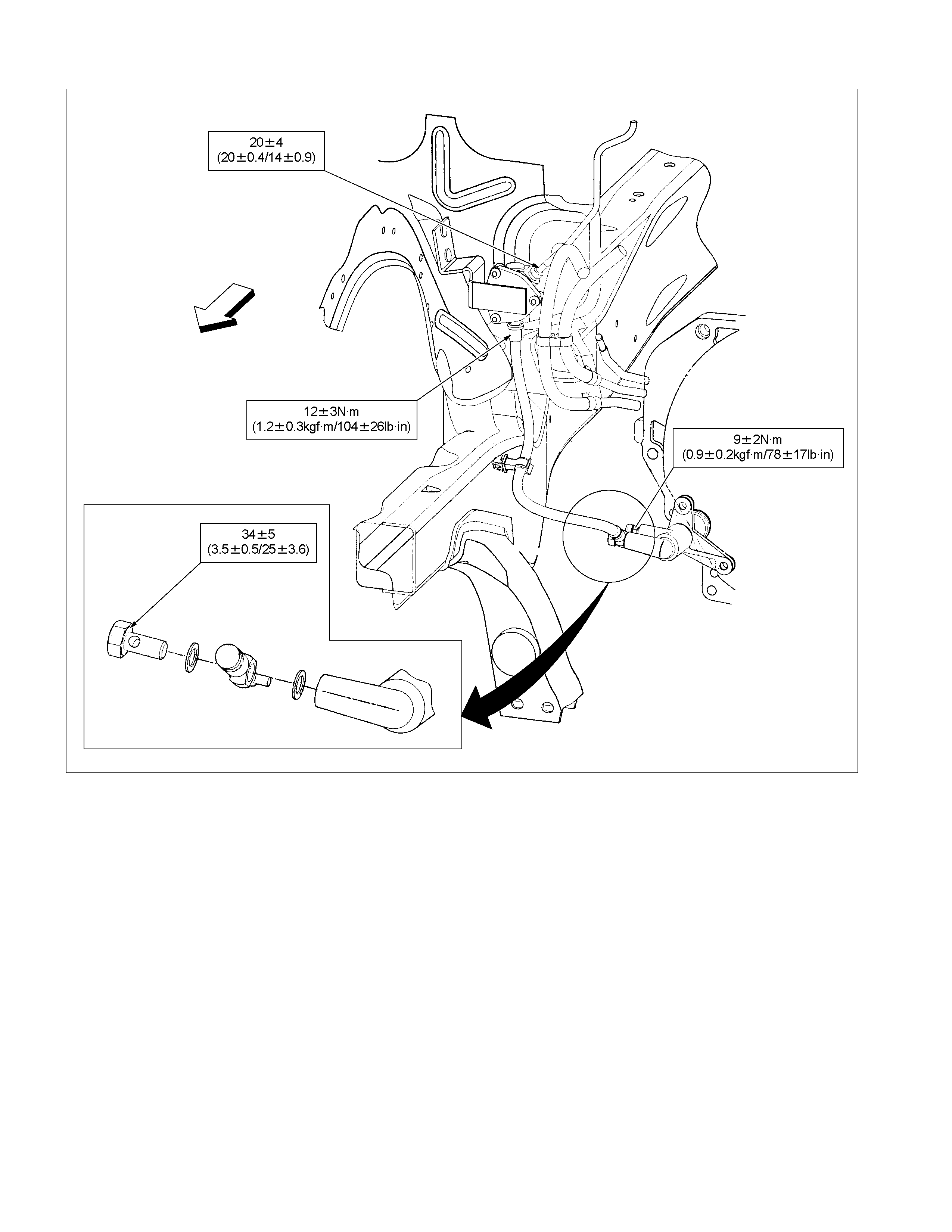
CLUTCH CONTROL
REMOVAL AND INSTALLATION
Removal Steps
1. Pin
2. Jaw joint pin
3. Pedal assembly
4. Oil line
5. Master cylinder assembly
6. Oil line
7. Slave cylinder assembly
8. Damper cylinder assembly
Installation Steps
8. Damper cylinder assembly
7. Slave cylinder assembly
6. Oil line
5. Master cylinder assembly
4. Oil line
3. Pedal assembly
2. Jaw joint pin
1. Pin
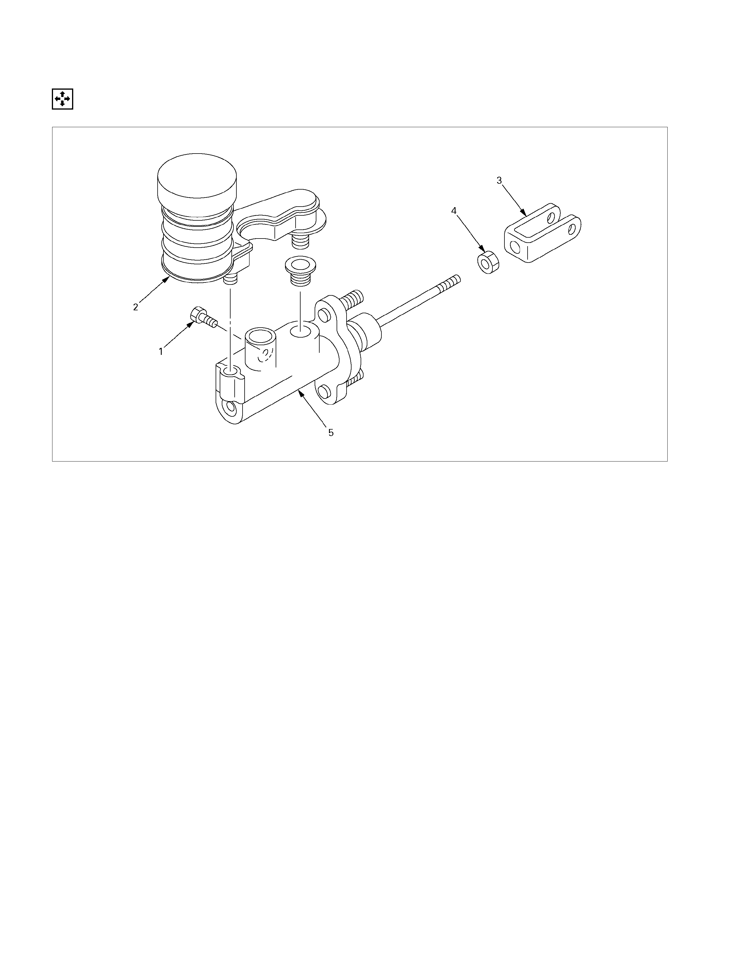
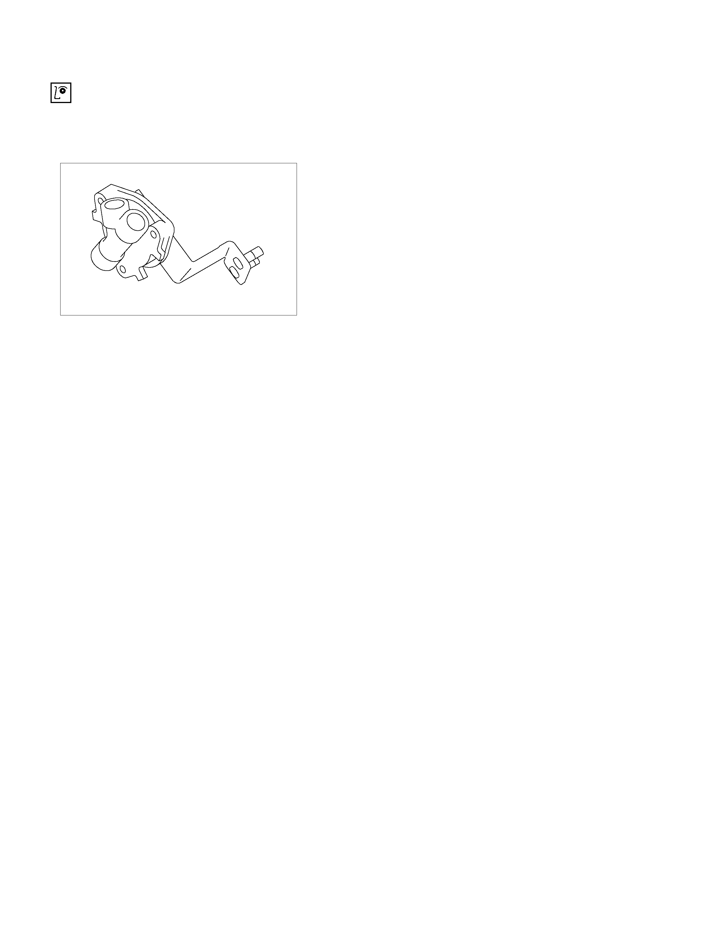
MASTER CYLINDER
DISASSEMBLY
Disassembly Steps
1. Bolt : reservoir tank
2. Reservoir tank Comp
3. Yoke
4. Lock nut
5. Body sub assembly
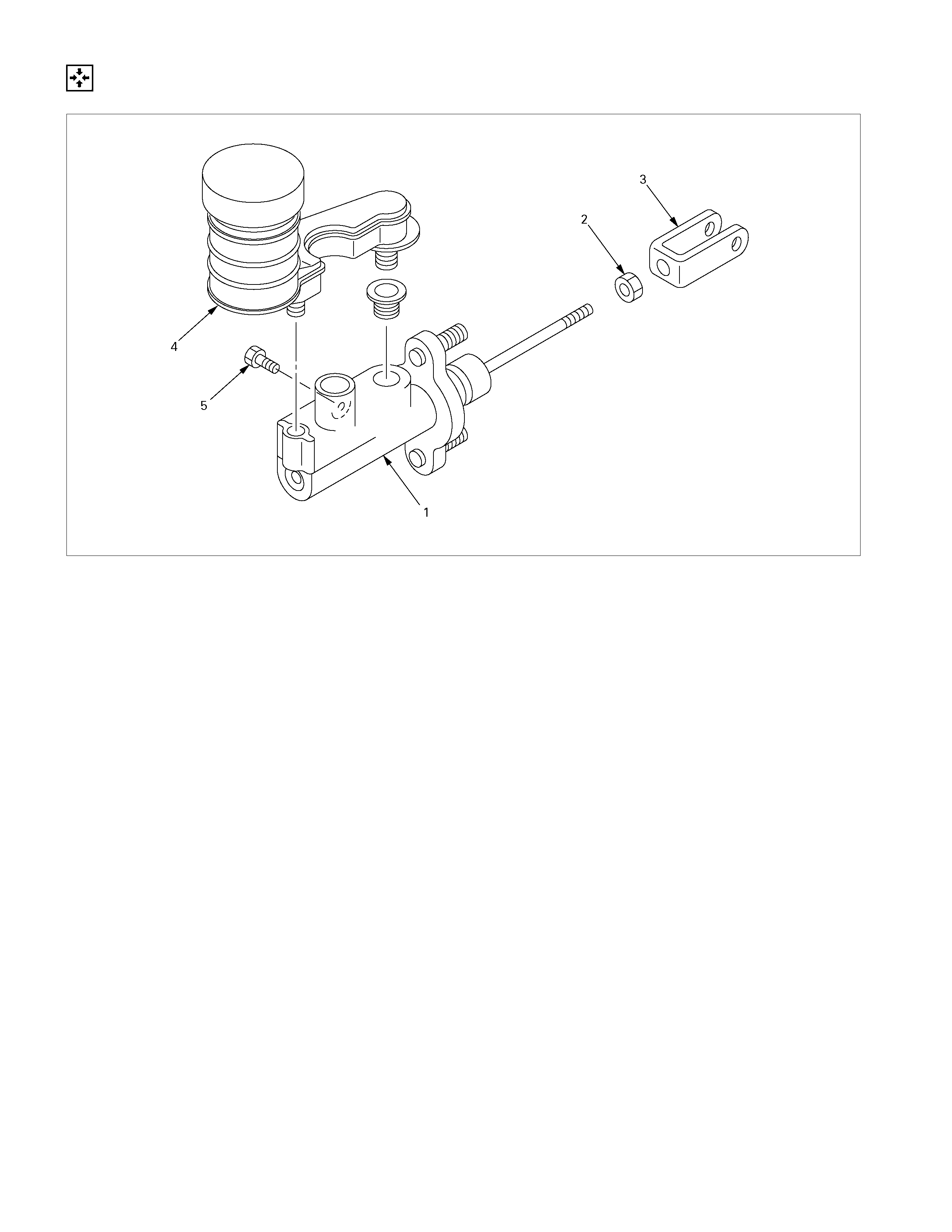
REASSEMBLY
Reassembly Steps
1. Body sub assembly
2. Lock nut
3. Yoke
4. Reservoir tank Comp
5. Bolt : Reservoir Tank
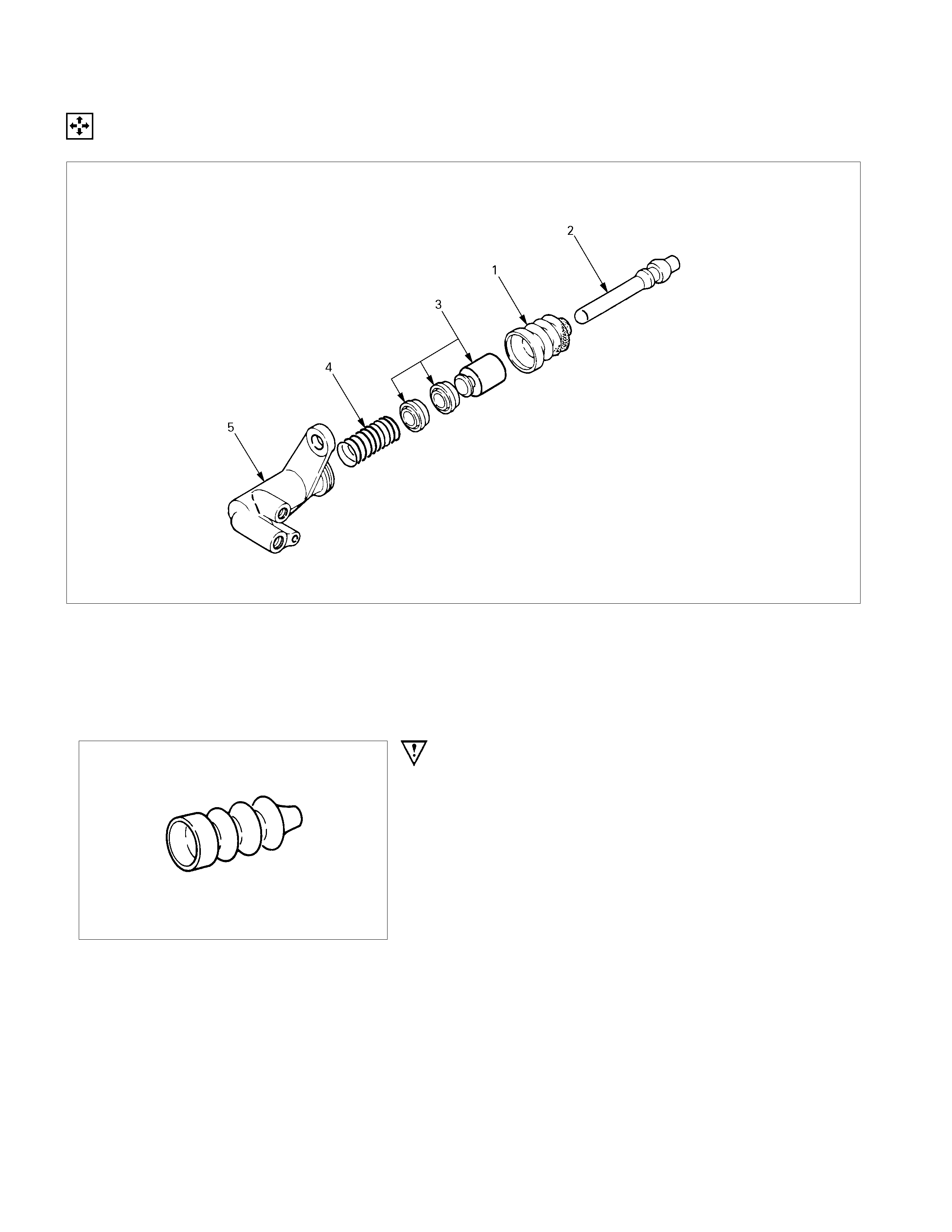
SLAVE CYLINDER (4JH1-TC, C24SE)
DISASSEMBLY
Disassembly Steps
▲ 1. Boot
2. Push rod
3. Piston and piston cup
4. Spring
5. Cylinder body
Important Operations
1. Boot
Brake fluid spilled on painted or plastic surfaces will cause
serious damage.
Take care not to spill brake fluid.
INSPECTION AND REPAIR
Make the necessary adjustments, repairs, and part replacements if excessive wear or damage is discovered during
inspection.
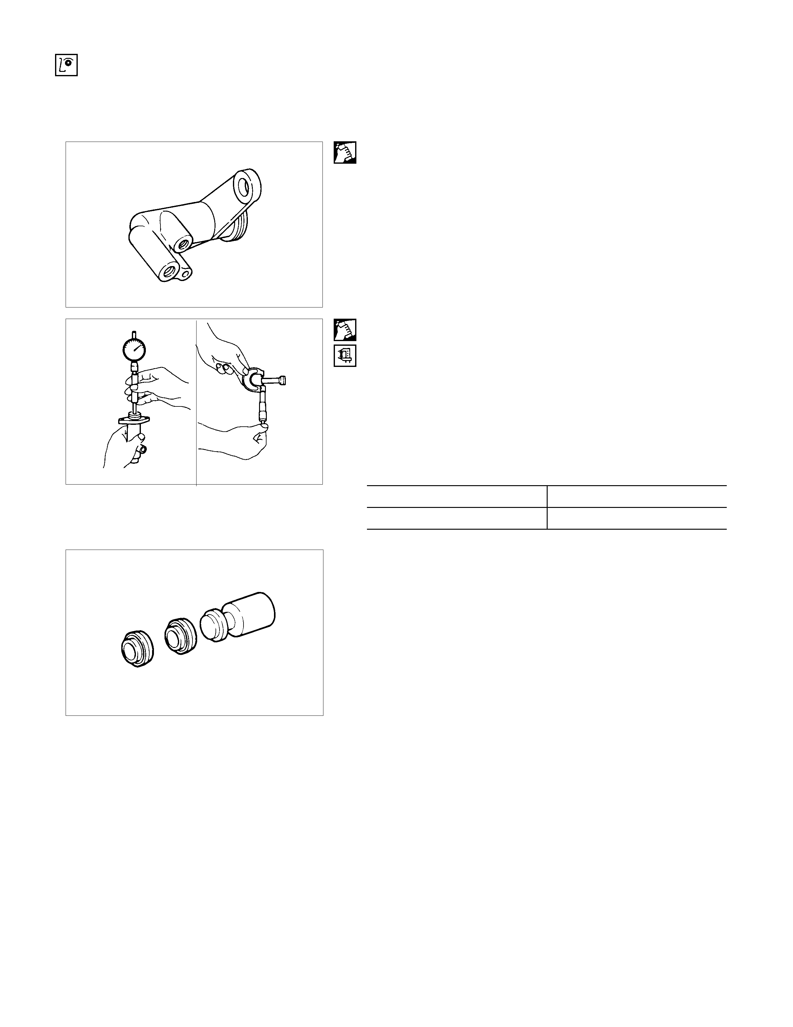
Cylinder Body
1. Clean the cylinder body.
2. Check the fluid return port for restrictions and clean it i
f
necessary.
Cylinder Bore and piston Clearance
1. Clean the cylinder body and the piston.
2. Use an inside dial indicator to measure the cylinder bore.
3. Use a micrometer to measure the piston diameter.
4. Calculate the clearance between the cylinder bore and the
piston diameter.
If the clearance exceeds the limit, the entire slave cylinde
r
assembly must be replaced.
Cylinder Bore and Piston Clearance mm(in)
Standard Limit
0.07 (0.0028) 0.15 (0.006)
Piston and Piston Cup
Visually inspect the disassembled piston and piston cup for
excessive wear and damage.
Replace the inner parts with new parts (Repair kit A) shown in
the illustration.
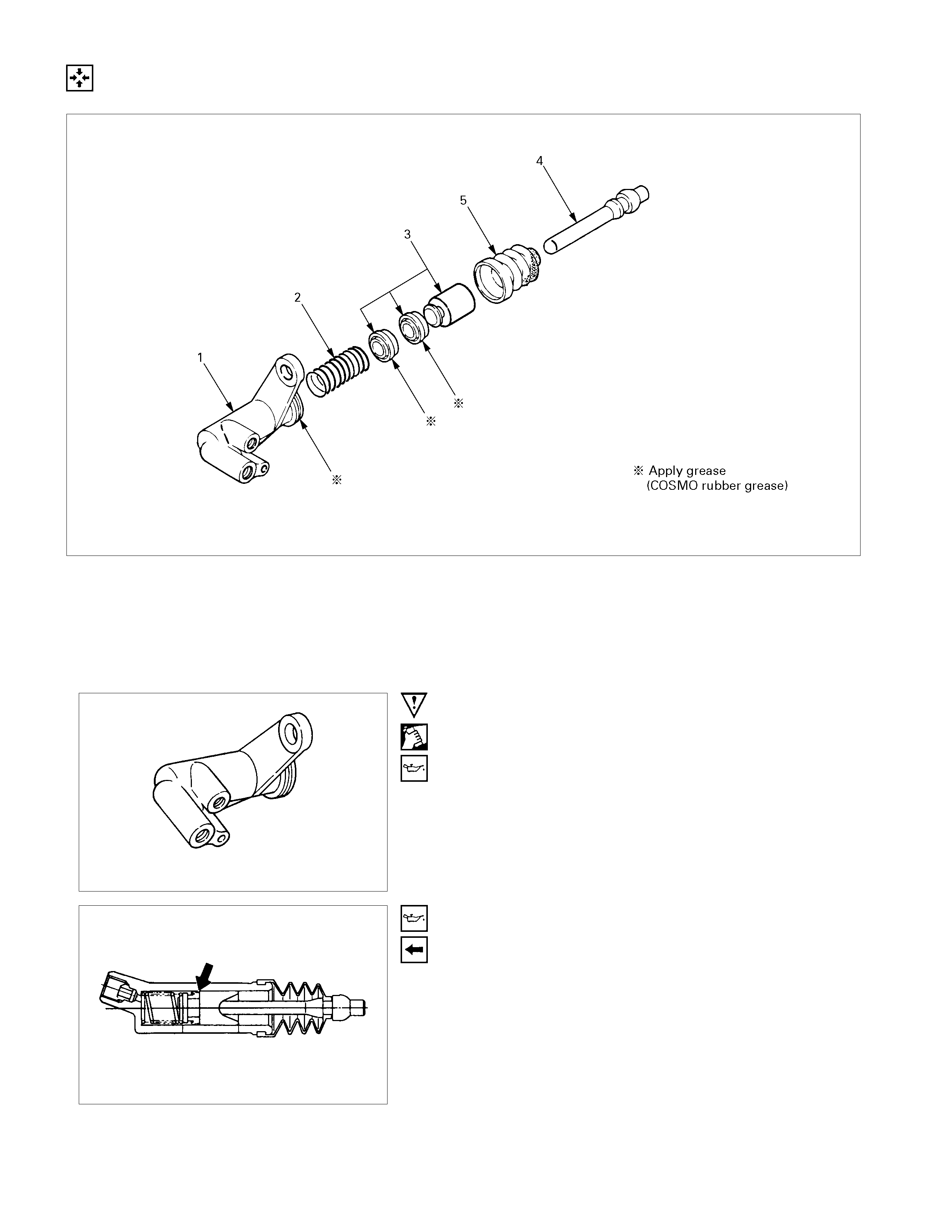
REASSEMBLY
Reassembly Steps
▲ 1. Cylinder body
2. Spring
▲ 3. Piston and piston cup
4. Push rod
5. Boot
Important Operations
1. Cylinder Body
1) Clean the cylinder body.
2) Apply brake fluid to the cylinder bore.
3. Piston and piston Cup
1) Apply brake fluid to the piston and piston cup.
2) Install the cups to the piston.
Note the installation direction of the piston cups in the
illustration.
3) Install the piston and piston cup to the cylinder body .
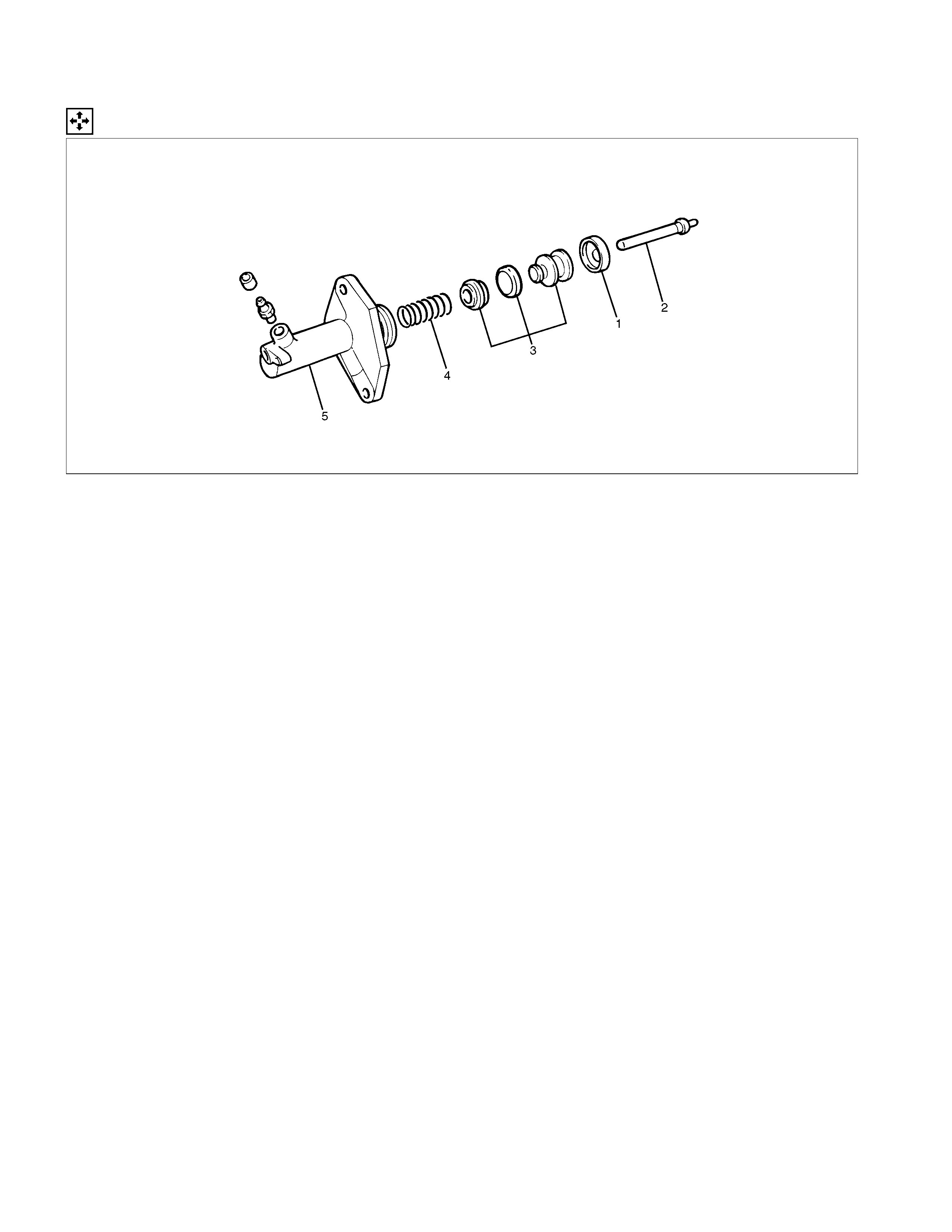
SLAVE CYLINDER (6VE1)
DISASSEMBLY
206RW004-X
Disassembly Steps
1. Boot
2. Push rod
3. Piston and piston cup
4. Spring
5. Cylinder body
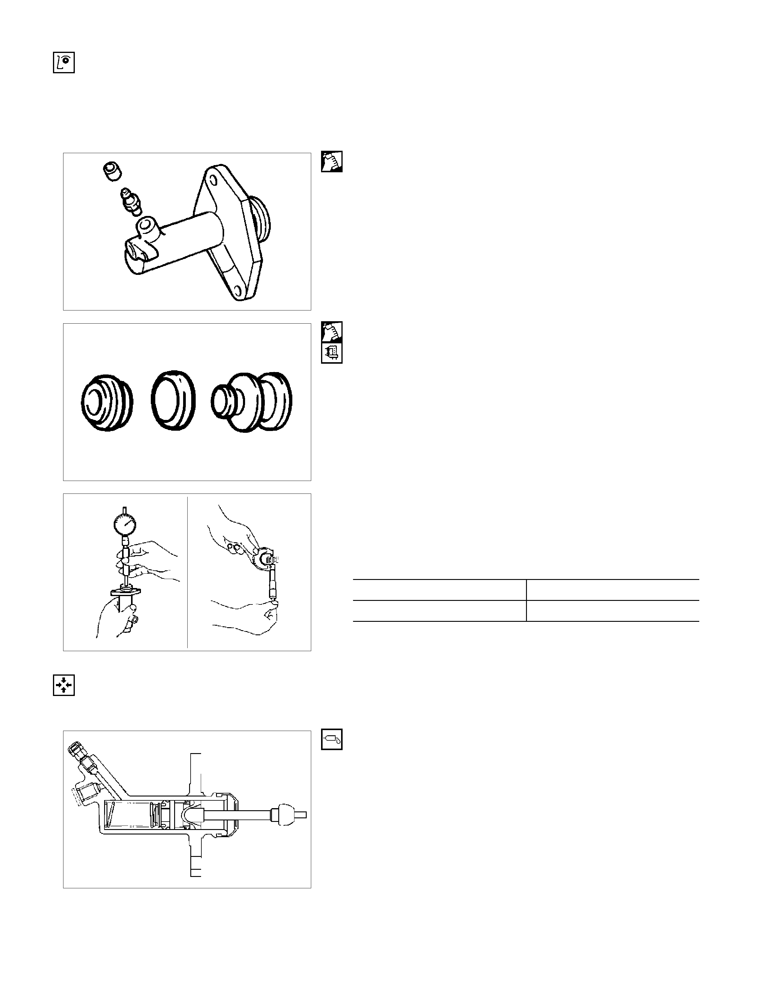
INSPECTION AND REPAIR
Make the necessary adjustments, repairs, and part replacements if excessive wear or damage is discovered during
inspection.
206RS003
Cylinder Body
1. Clean the cylinder body.
2. Check the fluid return port for restrictions and clean it i
f
necessary.
206RS004
Piston and Piston Cup
1. Visually inspect the disassembled piston and piston cup fo
r
excessive wear and damage.
2. Replace the inner parts with new parts shown in the
illustration.
206RS005
3. Measure the clearance between slave cylinder wall and
piston.
4. If the measured value ex ceeds the specif ied limit, the slave
cylinder assembly must be replaced.
mm(in)
Standard Limit
0.07 (0.0028) 0.15 (0.006)
REASSEMBLY
To reassemble, follow the disassembly steps in the reverse order, noting the following points:
206RS006
1. Before installing the parts, apply a thin coat of rubbe
r
grease.
2. Install cup in groove in piston with the lip turned to the front
of cylinder. Use care so as not to scratch the cylinder.
HYDRAULIC DAMPER CYLINDER
INSPECTION AND REPAIR
Make the necessary adjustments, repairs, and part replacements if excessive wear or damage is discovered during
inspection.
Visually check for oil leakage and other damage.
If oil leakage or other damage is discovered during the
inspection; the damper cylinder assembly must be replaced as
a unit.

TROUBLESHOOTING
Refer to this Section to quickly diagnose and repair clutch problems.
Each troubleshooting chart has three headings arranged from left to right.
(1) Checkpoint (2) Fault (3) Action
This Section is divided into five sub-sections:
1. Clutch Slippage
2. Clutch Does Not Release Properly
3. Clutch Shudder
4. Clutch Noise
1) Clutch pedal Depressed (Clutch Disengaged)
2) Clutch pedal Not Depressed (Clutch Engaged)
5. Oil Leakage

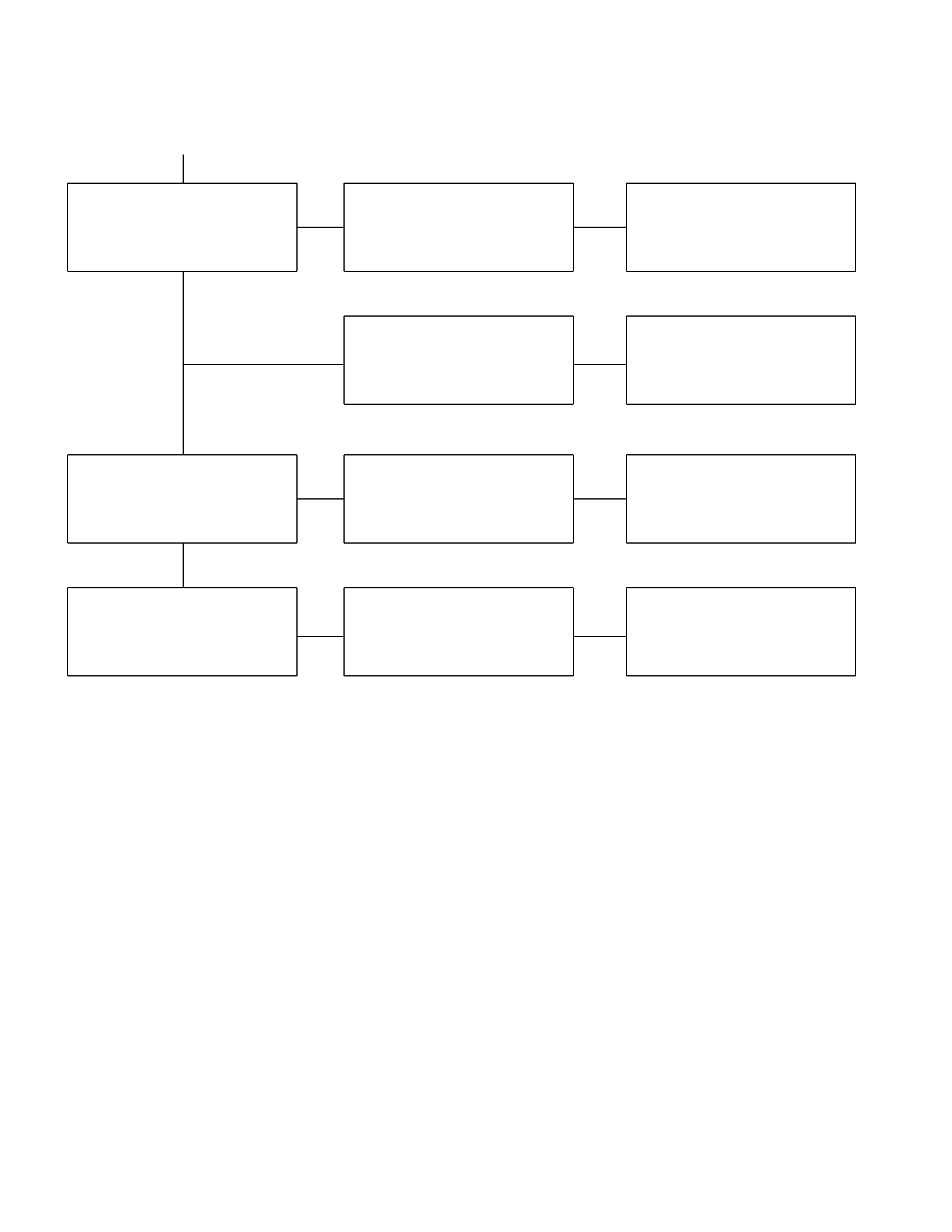
1. CLUTCH SLIPPAGE
Checkpoint Fault Action
Adjust the push rod play
No push rod play in the master
cylinder
NG
Clutch pedal free play
Clean the related parts and/or
replace the facing
Replace the transmission front
cover oil seal
Clean the related parts and/or
replace the facing
Repair or replace the
transmission front cover
Defective transmission front
cover oil seal
Continued on the next page
Grease or oil adhering to the
facing
Too much grease
Transmission front cover
unevenly worn
Clean and grease the release
bearing
Release bearing
Insufficient grease on the front
cover contact surfaces
NG
NG
NG
NG
OK
OK
OK
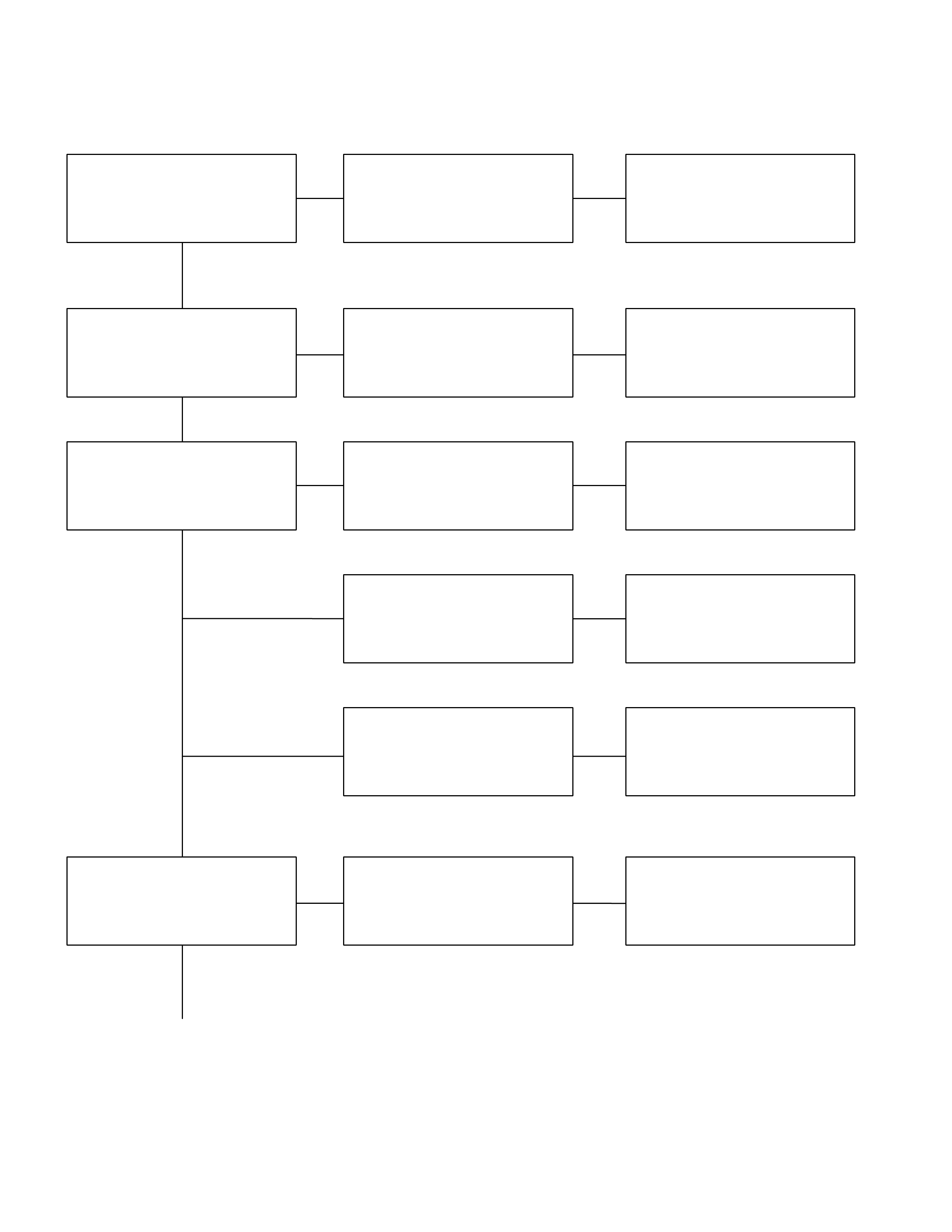
Checkpoint Fault Action
Replace the release bearingRelease bearing broken
Clean the related parts and/or
replace the facing
Replace the crankshaft rear oil
seal
Defective crankshaft rear oil
seal
NG
NG
OK
OK
Grease or oil adhering to the
facing
Clutch diaphragm spring Replace the clutch pressure
plate assembly
Weak or broken clutch
diaphragm spring
Replace the driven plate
assembly
Worn facing
NG
NG
OK
Facing
Continued from the previous page
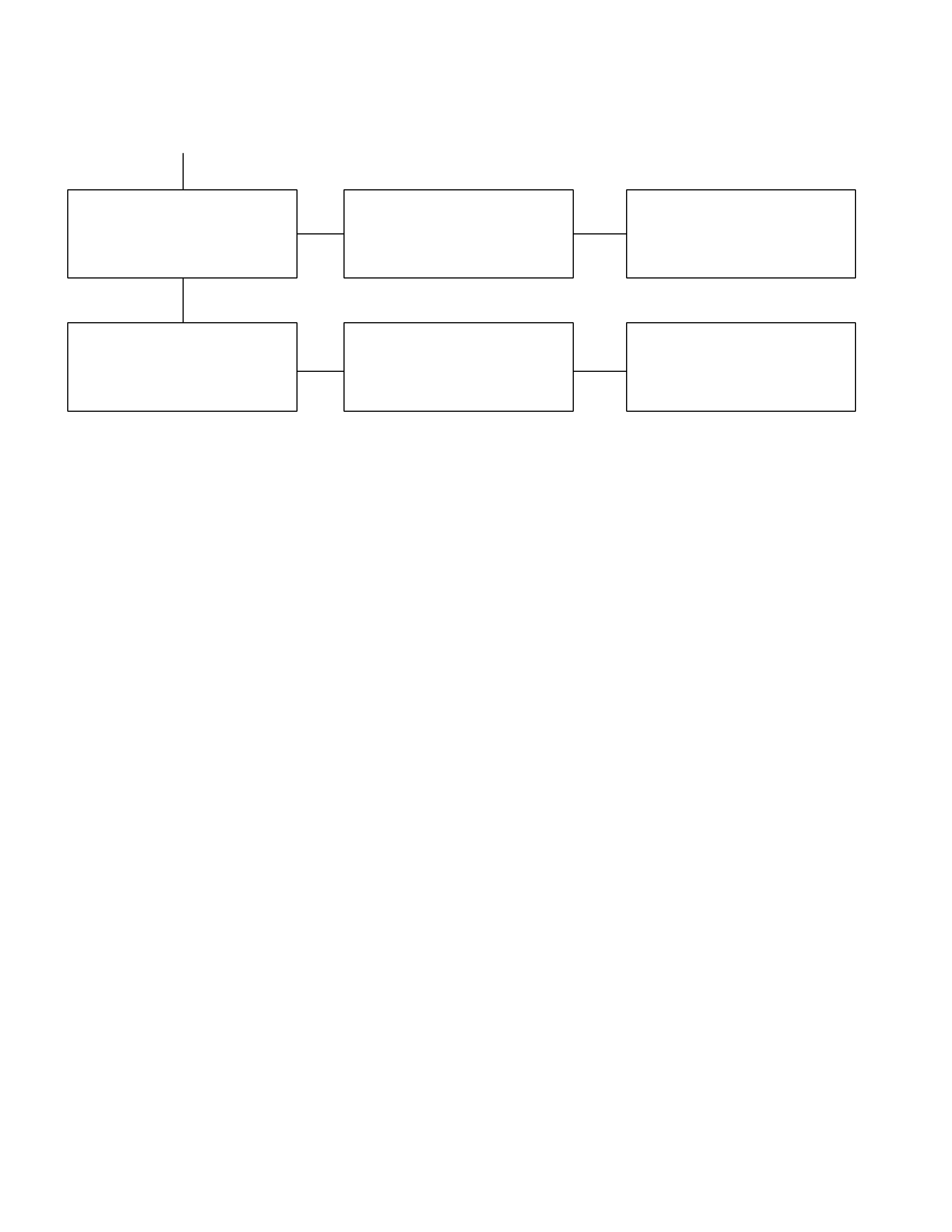
2. CLUTCH DOES NOT RELEASE PROPERLY
Checkpoint Fault Action
Adjust the push rod play
Too much push rod play in the
master cylinder
NG
Clutch pedal free play
Driven plate
Replace the driven plate
Driven plate warped or
unevenly worn
Hydraulic circuit
Bleed the hydraulic circuit
Air in the hydraulic circuit
OK
NG
NG
OK
Clean or repair the top gear
shaft spline
Replace the top gear shaft
Corrosion or step wear on the
top gear shaft spline
Pressure plate
Replace the pressure plate
assembly
Clean and grease the splined
contact surface
Pressure plate unevenly worn
Insufficient grease on the
spline contact surface of the
splined hub
OK
NG
NG
NG
OK
Continued on the next page
Checkpoint Fault Action
Crankshaft pilot bearing Replace the pilot bearing
Top gear shaft wobble is
causing pilot bearing wear
Repair or replace the flywheelFlywheel unevenly worn
NG
NG
OK
OK
Flywheel
Continued from the previous page
3. CLUTCH SHUDDER
Checkpoint Fault Action
Grease or oil adhering to the
facing
Clean the related parts and/or
replace the facing
Replace the transmission front
cover oil seal
Replace the pressure plate
assembly
Defective transmission front
cover oil seal
Pressure plate unevenly worn
Pressure plate
Clean the related parts and/or
replace the facing
Tighten the connections
Repair or replace the
applicable parts
Too much grease
Poorly connected components
causing looseness and
abrasion
OK
NG
NG
NG
NG
OK
Power train
Clean and grease the spline
contact surface
Insufficient grease on the
spline contact surface of the
splined hub
Driven plate
Clean or repair the top gear
shaft spline
Replace the top gear shaft
Clean the related parts and/or
replace the facing
Replace the crankshaft rear oil
seal
Corrosion or step wear on the
top gear shaft spline
Defective crankshaft rear oil
seal
OK
NG
NG
NG
OK
Continued on the next page
Checkpoint Fault Action
Replace the driven plate
assembly
Warpage and/or uneven wear
Replace the driven plate
assembly
Loose facing rivets
NG
NG
OK
Driven plate
Continued from the previous page
Flywheel Repair or replace the flywheelFlywheel uneven wear
NG
OK
4. CLUTCH NOISE
1) Clutch Pedal Depressed (Clutch Disengaged)
Checkpoint Fault Action
Replace the pedal shaft with
the sleeve
Worn pedal shaft and/or
sleeve
Clean and grease the pedal
shaft and sleeve
Insufficient grease at the
pedal shaft and sleeve
NG
NG
Pedal shaft and sleeve
Master cylinder piston and
push rod contact faces
Clean and grease the master
cylinder piston and push rod
contact faces
Insufficient grease at the
maser cylinder piston and
push rod contact faces
NG
OK
Driven plate Replace the driven plate
assembly
Loose or broken damper
spring
NG
OK
Crankshaft pilot bearing Replace the crankshaft pilot
bearing
Insufficient grease at the
crankshaft pilot bearing (pilot
bearing worn)
NG
OK
2) Clutch Pedal Not Depressed (Clutch Engaged)
Replace the driven plate
Weak or broken damper
spring
NG
Driven plate damper spring
Replace the crankshaft pilot
bearing
Insufficient grease at the
crankshaft pilot bearing (pilot
bearing worn)
OK
NG
Crankshaft pilot bearing

5. OIL LEAKAGE
Checkpoint Fault Action
Replace the body sub
assembly
Weak or damaged piston cup
NG
Tighten the oil pipe
Tighten the oil pipe connection
Tighten the fluid pipe and/or
hose connections
Fluid reservoir
Loosely connected oil pipe
Loosely connected oil pipe
Master cylinder fluid pipe and
hose
Loosely connected fluid pipe
and/or hose
Slave cylinder oil pipe
Replace the piston cup
Slave cylinder
Weak or damaged piston cup
NG
NG
NG
NG
OK
OK
OK
OK
Master cylinder

SPECIAL SERVICE TOOL
ITEM NO. ILLUSTRATION PART NO. PART NAME
5-85253-001-0
Clutch pilot aligner