
SECTION 7D - TRANSFER CASE
Service Precaution
General Description
Transfer Rear Oil Seal
Transfer Rear Oil Seal and Associated Parts
Removal
Installation
Transfer Case Assembly
Transfer Case Assembly and Associated Parts
Removal
Installation
Transfer Control Unit
Removal
Installation
Transfer Disassembly
Removal
Internal Component Disassembly and Reassembly
Oil Pump Disassembly
Oil Pump Reassembly
Inspection and Repair
Inspection and Repair (Transfer Case Assembly)
Reassembly
Main Data and Specifica tions
General Specifications
Torque Specifications
Special Tools

Service Precaution
WARNING: THIS VEHICLE HAS A SUPPLEMENTAL RESTRAINT SYSTEM (SRS). REFER TO THE SRS
COMPONENT AND WIRING LOCATION VIEW IN ORDER TO DETERMINE WHETHER YOU ARE PERFORMING
SERVICE ON OR NEAR THE SRS COMPONENTS OR THE SRS WIRING. WHEN YOU ARE PERFORMING
SERVICE ON OR NEAR THE SRS COMPONENTS OR THE SRS WIRING, REFER TO THE SRS SERVICE
INFORMATION. FAILURE TO FOLLOW WARNINGS COULD RESULT IN POSSIBLE AIR BAG DEPLOYMENT,
PERSONAL INJURY, OR OTHERWISE UNNEEDED SRS SYSTEM REPAIRS.
CAUTION: Always use the correct fastener in the proper location. When you replace a fastener, use ONLY the
exact part number for that application. ISUZU will call out those fasteners that require a replacement after
removal. ISUZU will also call out the fasteners that require thread lockers or thread sealant. UNLESS
OTHERWISE SPECIFIED, do not use supplemental coatings (Paints, greases, or other corrosion inhibitors) on
threaded fasteners or fastener joint interfaces. Generally, such coatings adversely affect the fastener torque
and the joint clamping force, and may damage the fastener. When you install fasteners, use the correct
tightening sequence and specifications. Following these instructions can help you avoid damage to parts and
systems.
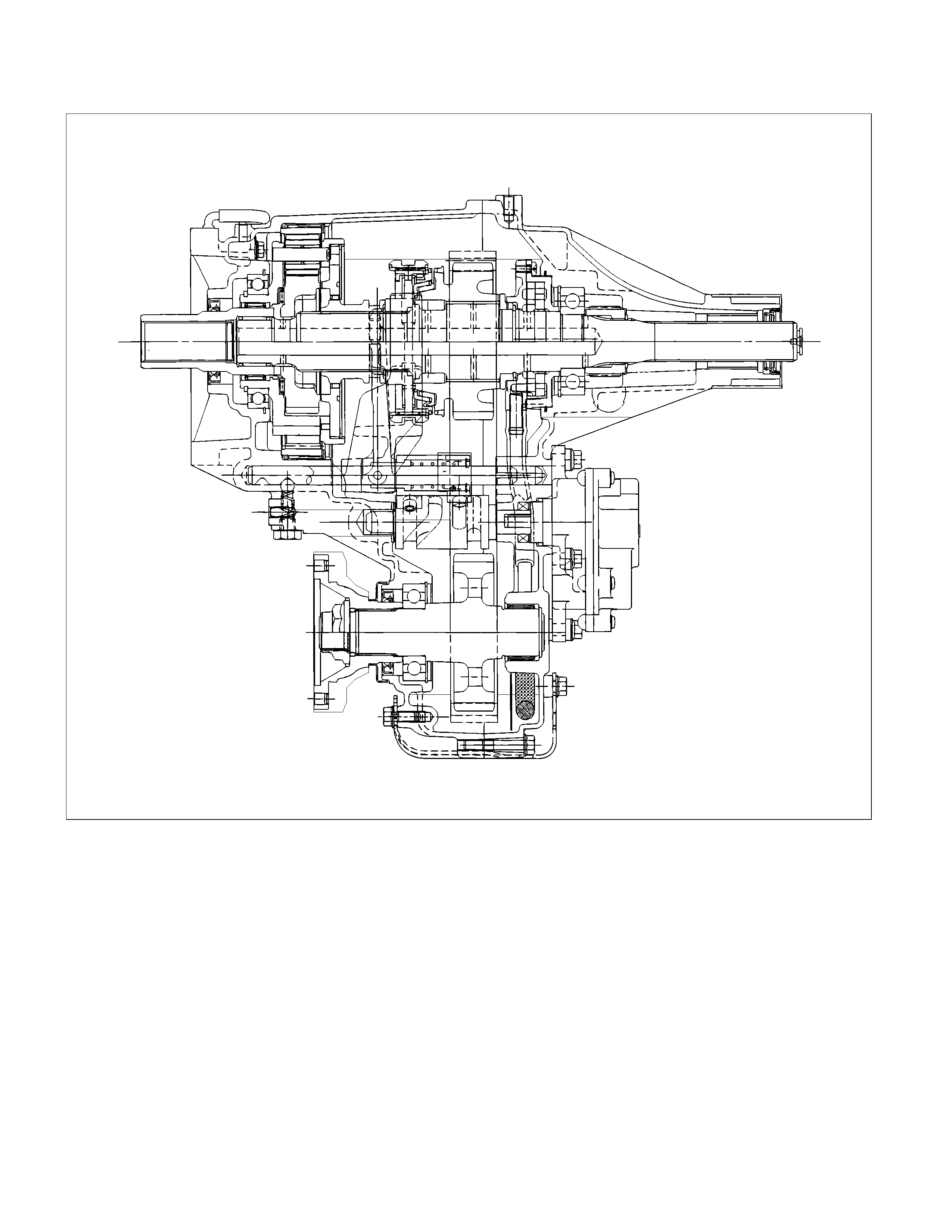
General Description
RUW34DLF000701
The transfer case is used to provide a means of providing power flow to the front axle. The transfer case also provides
a means of disconnecting the front axle, providing better fuel economy and quieter operation when the vehicle is driven
on improved roads where four wheel drive is not required. In addition, the transfer case provides an additional gear
reduction when placed in low range, which is useful when difficult off-road conditions are encountered.
Use the 4WD switch on the center cluster panel to select the drive range. The 4WD indicator lamp is n when 4WD is
selected.
Transfer Rear Oil Seal
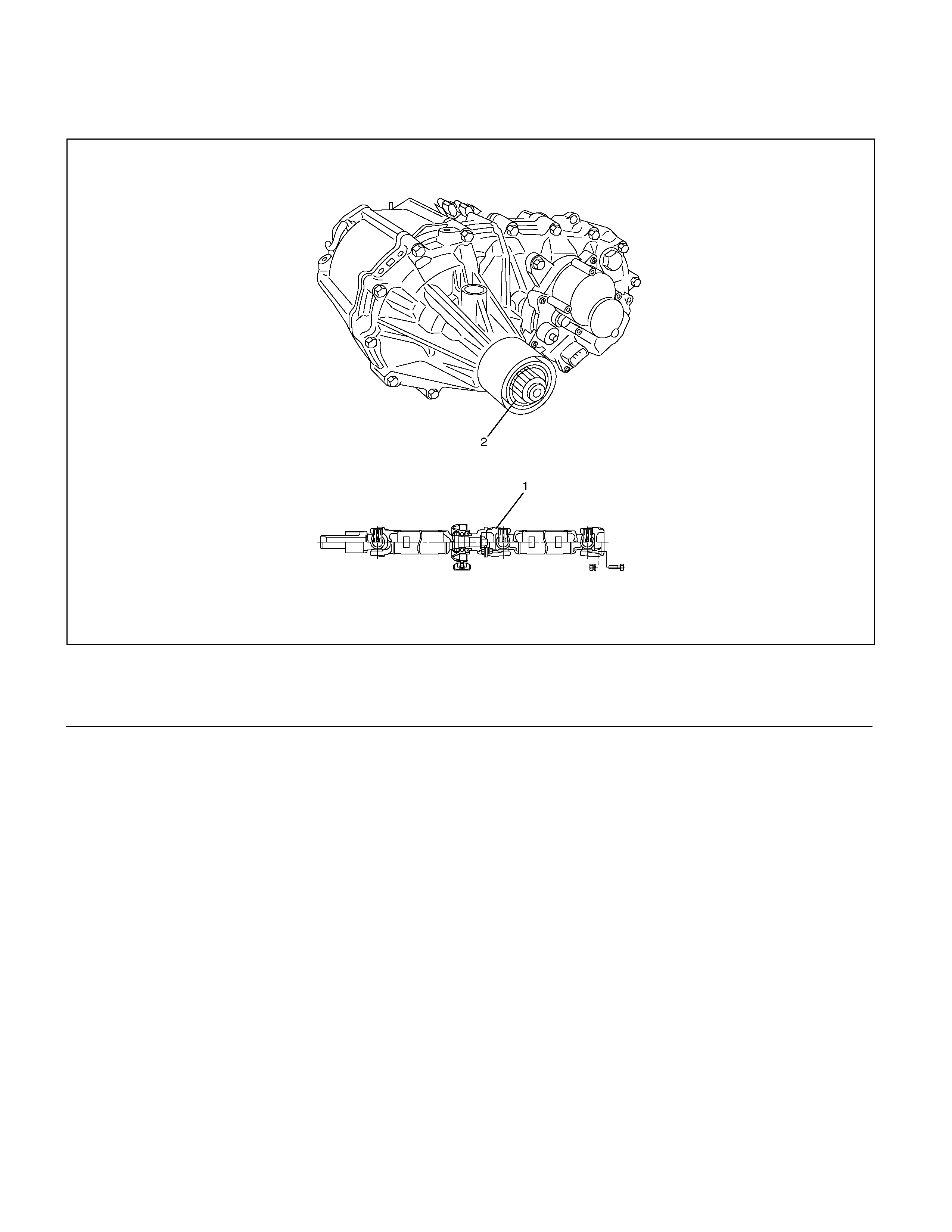
Transfer Rear Oil Seal and Associated Parts
220R300018
Legend
(1)Rear Propeller Shaft
(2)Oil Seal
Removal
1. Disconnect the rear propeller shaft (1) from the
transfer case side.
2. Remove the oil seal from the transfer case.
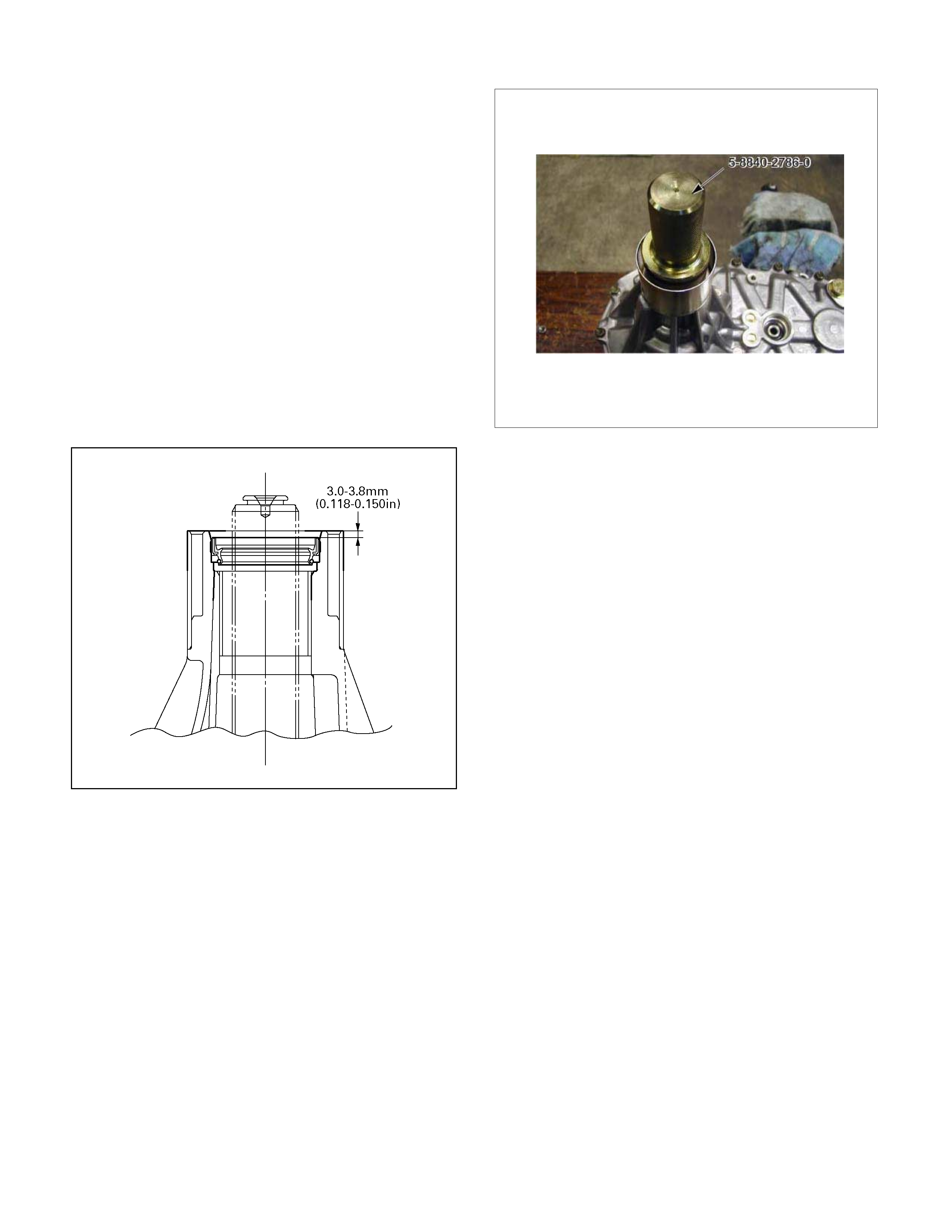
Installation
1. Install oil seal and apply engine oil to the oil seal
outer surfaces.
2.
A
pply the recommended grease (BESCO L2) o
r
equivalent to the oil seal lip.
3. Use the oil seal installer 5-8840-2786-0 to install the
rear seal (2) to the transfer rear case.
220R300021
4. Connect the rear propeller shaft.
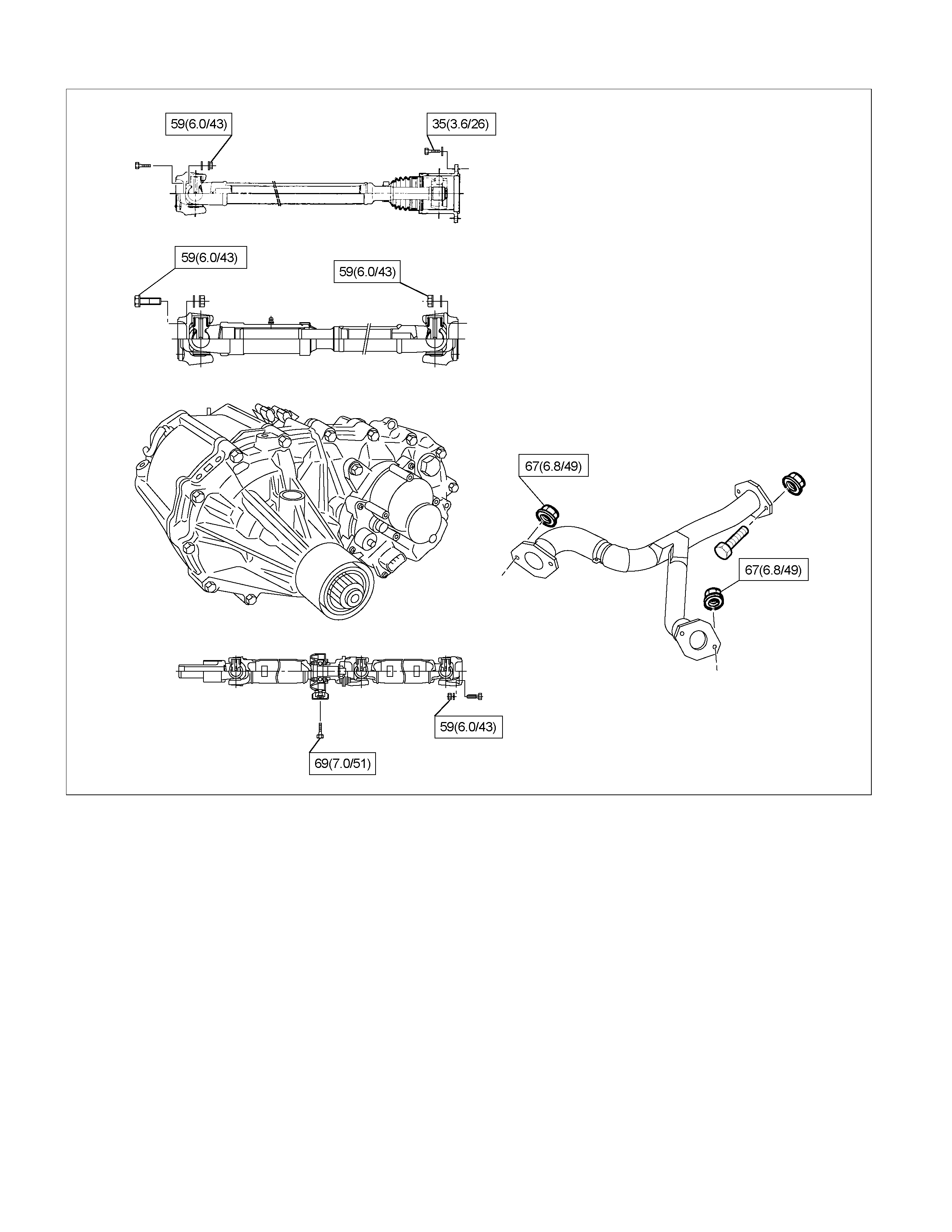
Transfer Case Assembly
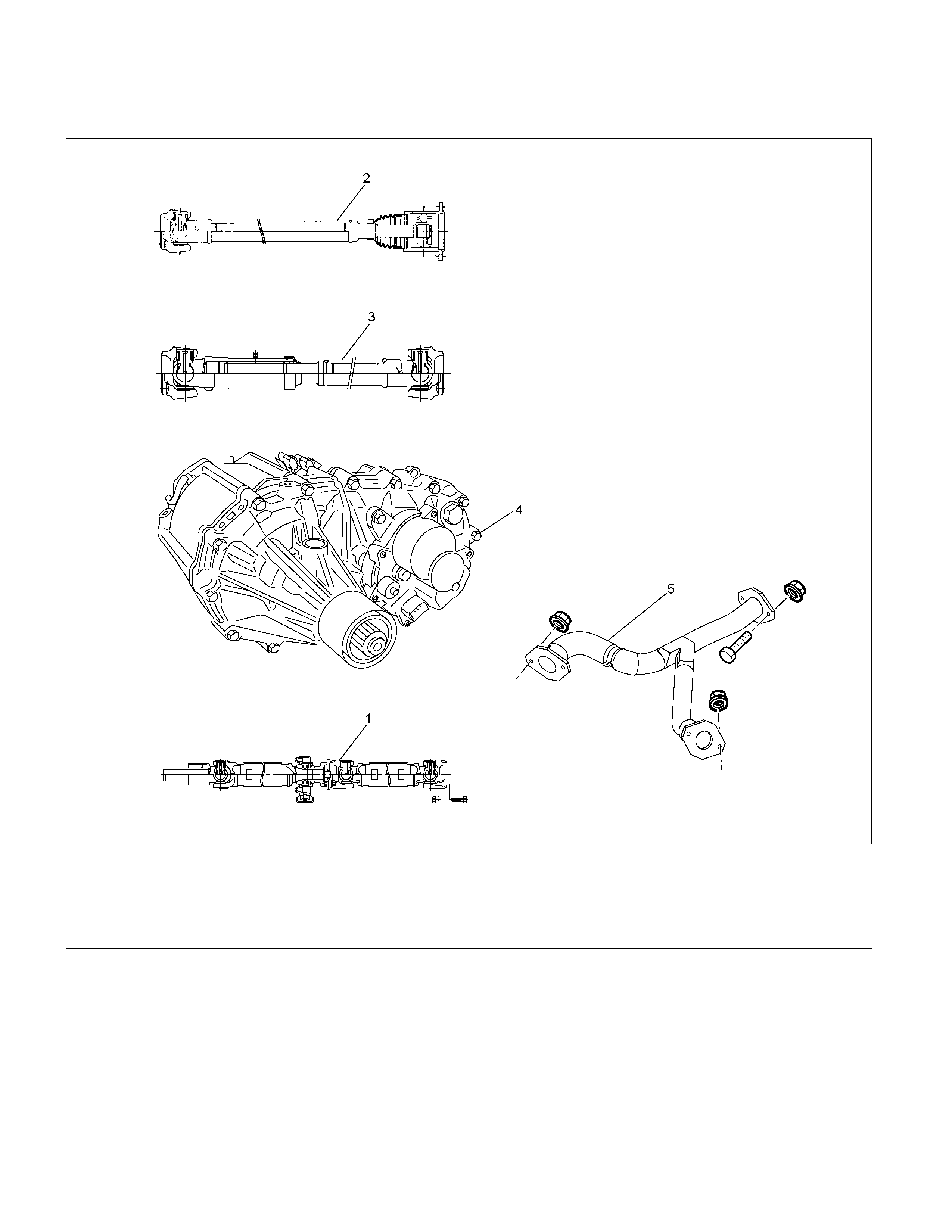
Transfer Case Assembly and Associated Parts
RTW37DLF000201
Legend
(1)Rear Propeller Shaft (4)Transfer Case Assembly
(2)Front Propeller Shaft (4JH1-TC) (5)Center Exhaust Pipe (6VE1 only )
(3)Front Propeller Shaft (6VE1)
Removal
NOTE: Before removing transmission and transfer
assembly from vehicle, change the transfer mode to
2WD using the 4WD push button switch on dash panel.
1. Disconnect battery ground cable.
2. Raise and support vehic le with suitable stands. Drain
transfer case fluid.
3. Remove the center exhaust pipe(5). (6VE1 only)
4. Remove rear propeller shaft (1) and front propelle
r
shaft (2)(3).
NOTE: Apply alignment marks on the flange at both
front and rear sides.
5. Disconnect harness connectors and clip.
Connector: transfer switch, 2WD-4WD actuator,
speed sensor.
NOTE: Avoid turning the vehicle ignition switch to the
ON position when the 2WD-4WD connector is removed
(battery connected).
If the ignition switch must be turned to the ON position,
the controller must first be removed (memory must be
cleared because the CHECK 4WD INDICATOR will
light).
6. Remove transfer case (4) from the vehicle.
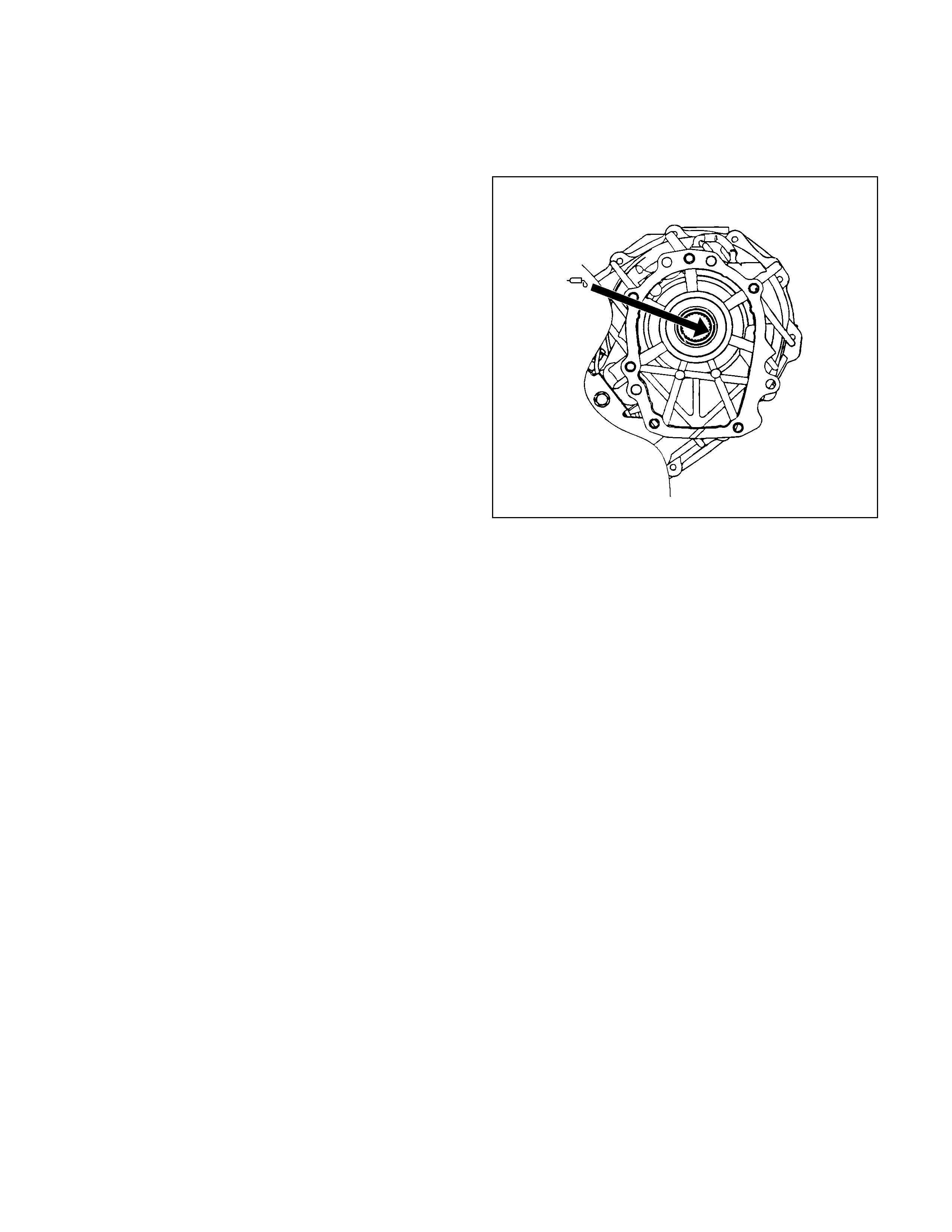
Installation
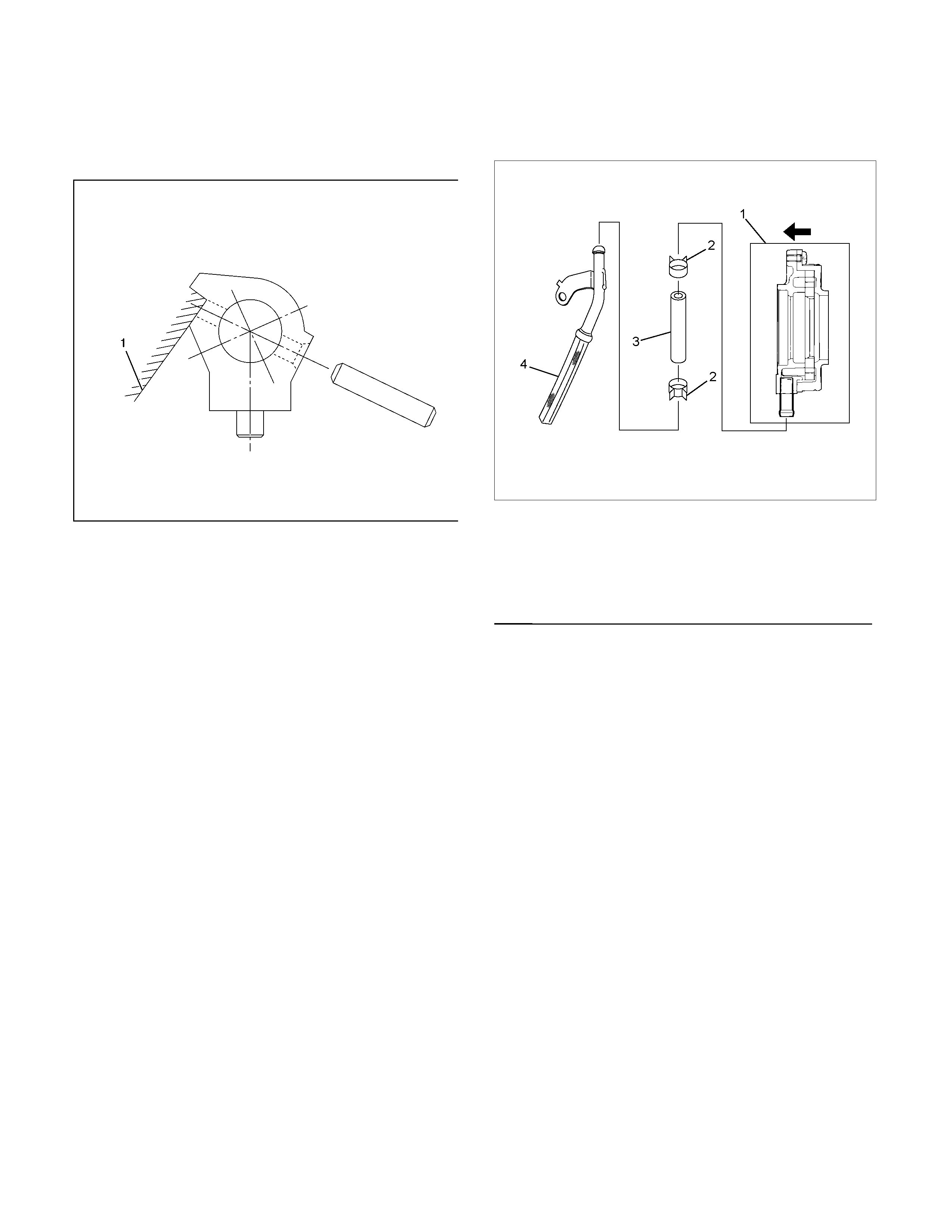
1.
A
pply a thin coat of molybdenum disulfide grease to
the input shaft spline as shown in the figure.
260R300001
2. Install transfer case (4) to the transmission. Tighten
transfer bolts as shown in the figure.
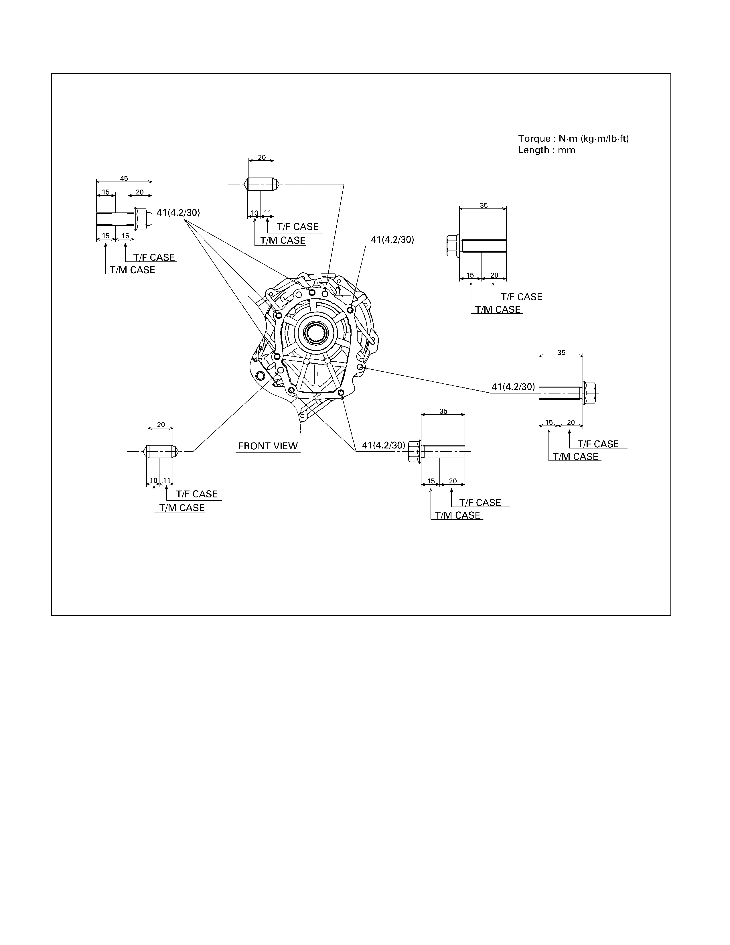
For M/T
261R300001
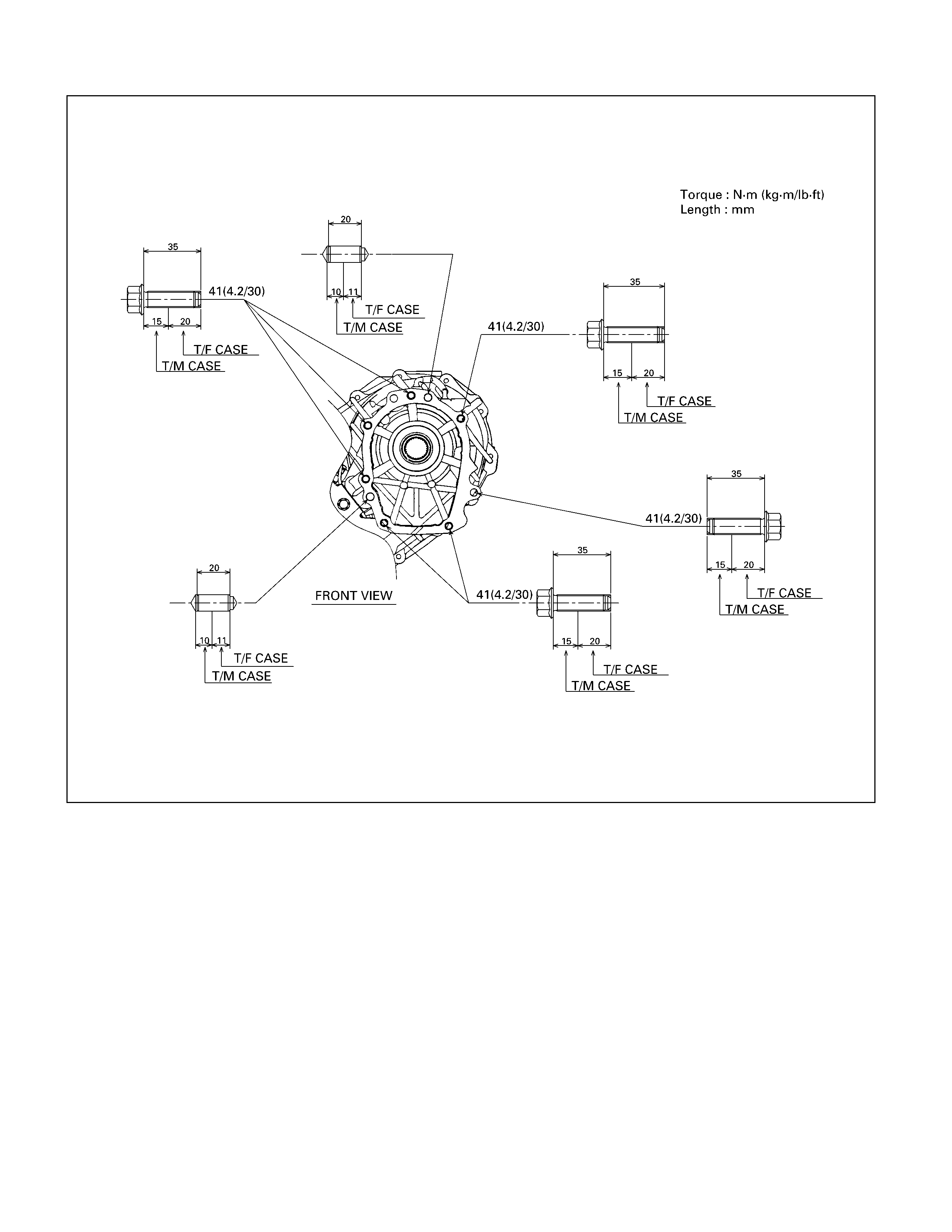
For A/T
261R300002
3. Connect harness connectors and clip.
Connector: transfer switch, 2WD-4WD actuator,
speed sensor.
4. Install center exhaust pipe (5). (6VE1 only)
5. Install rear propeller shaft (1) and front propelle
r
shaft (2)(3).
Torque: 63 N⋅
⋅⋅⋅m (6.4 kg⋅
⋅⋅⋅m/46 lb ft)
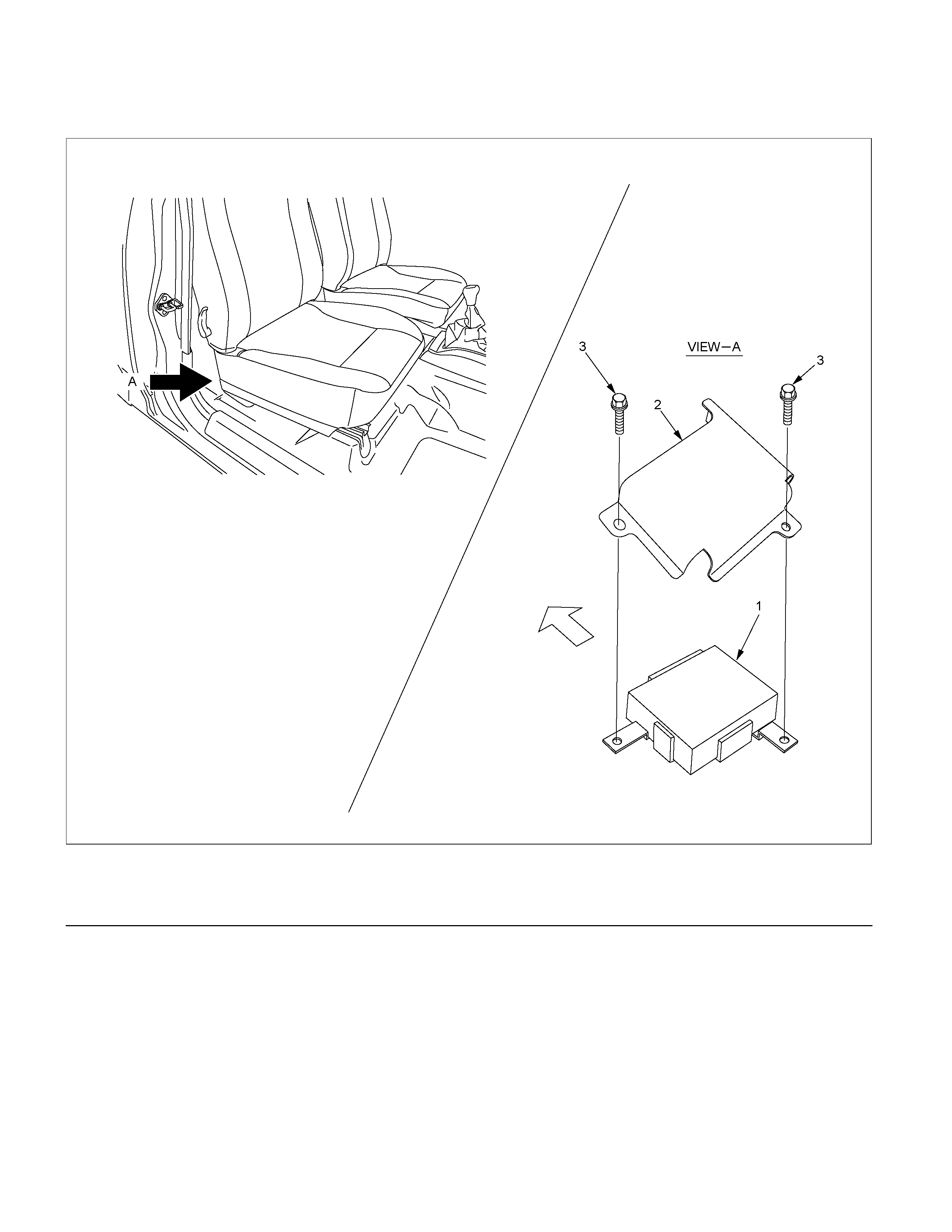
Transfer Control Unit
RTW37DLF000401
Legend
(1)Transfer Control Unit (3) Bolt
(2)Protector
Removal
1. Disconnect the battery ground cable.
Remove the driver’s seat.
2. Peel back the floor carpet on the driver's side of the
vehicle to expose the transfer control unit.
3. Dis connect the harness connector f rom the T ransfe
r
control unit.
4. Remove the Transfer control unit.
Installation
1. Install the Transfer control unit.
2. Connect the harness connector to the Transfer
control unit.
3. Connect the battery ground cable.
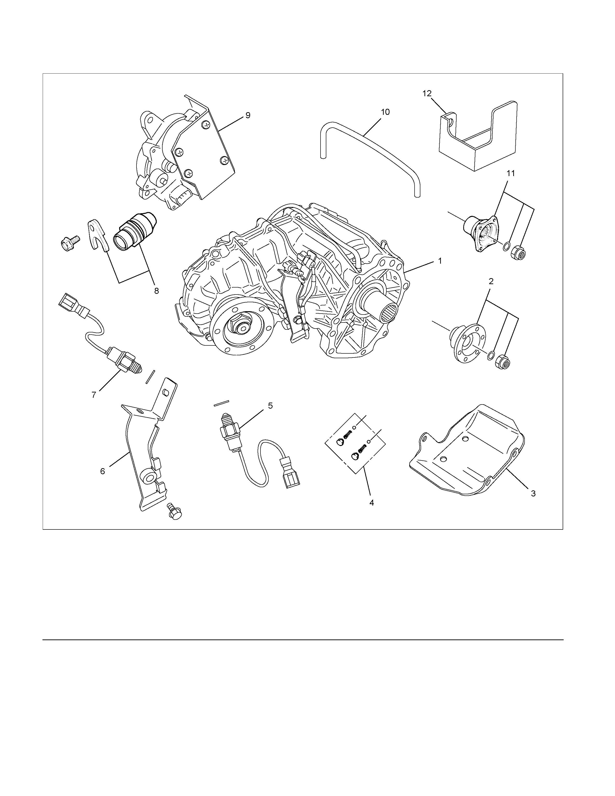
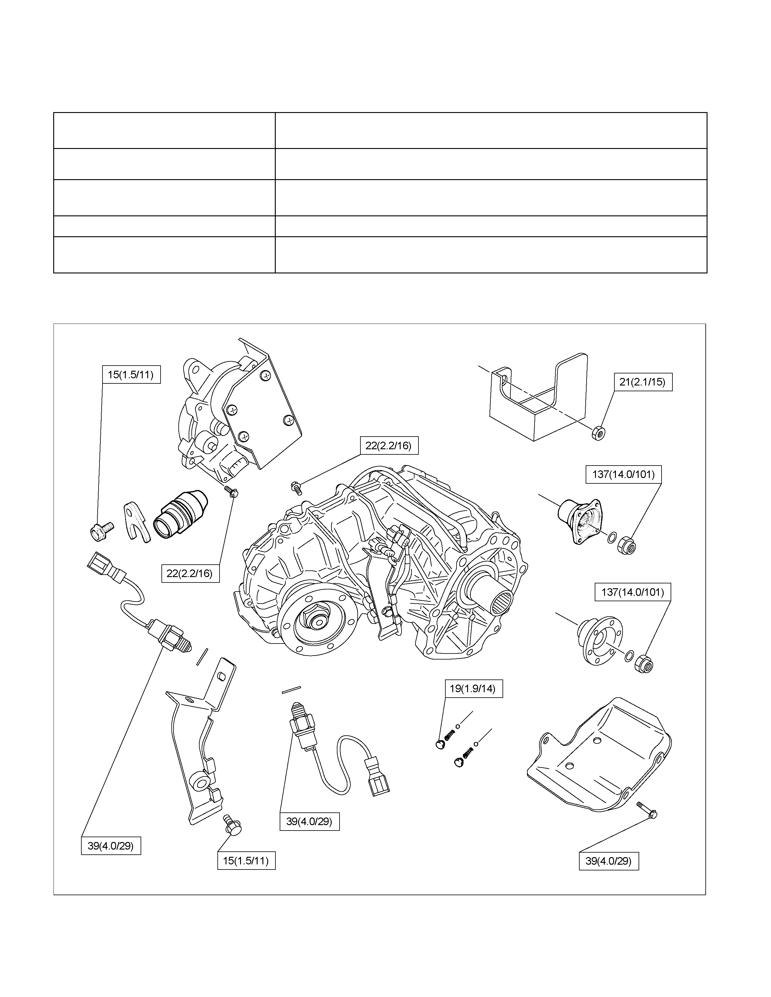
Transfer Disassembly
RTW37DLF000101
Legend (7) Neutral Switch ASM
(1)Transfer Case (8) Speedometer Bush, Plate and Driven Gear
(2)Companion Flange, O-ring and Nut (4JH1-TC) (9) Transfer Actuator
(3)Stoneguard (10) Breather Hose
(4)Detent Plug, Spring and Detent Ball (11) Companion Flange, O-ring and Nut (6VE1)
(5)2-4 Switch ASM (12) Heat Protector
(6)Switch Bracket
Removal
1. Remove the stoneguard.
2. Remove the drain plug from the transfer case to
drain the oil.
3. Remove the parts listed below.
• Speedometer bush, plate, and speedometer
driven gear
• Breather hose (Between the transfer case and
the transfer actuator assembly )
• Transfer actuator assembly
• Switch bracket
• 2-4 switch assembly (Gray harness cover)
• Neut ral switch assembly (Black harness cover)
• Detent plugs, detent springs, and detent balls (2
parts each)
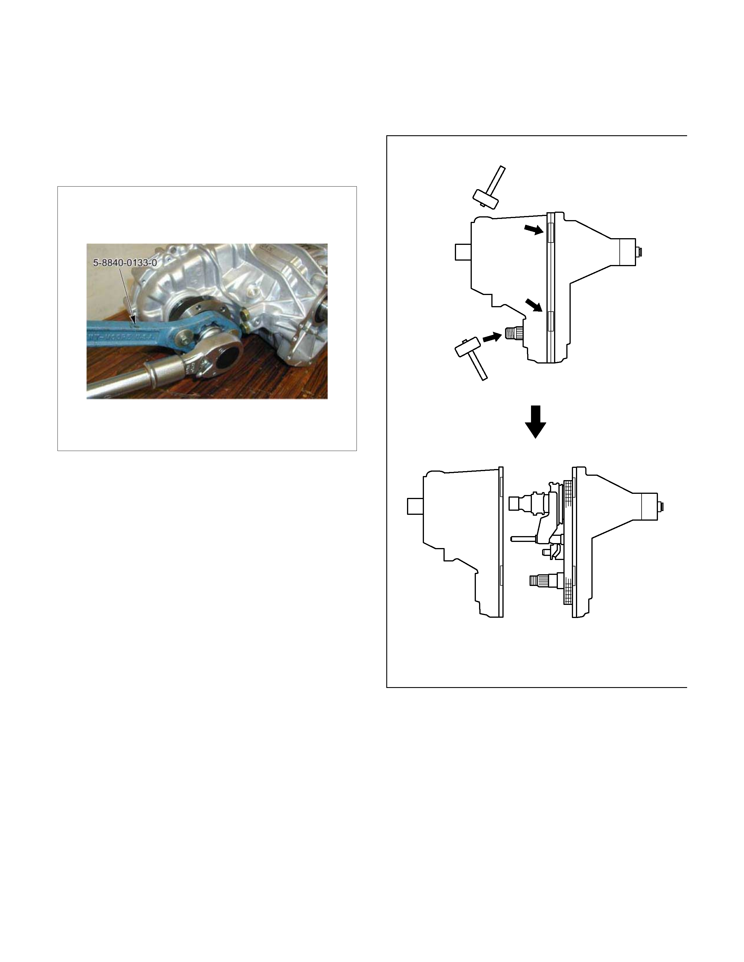
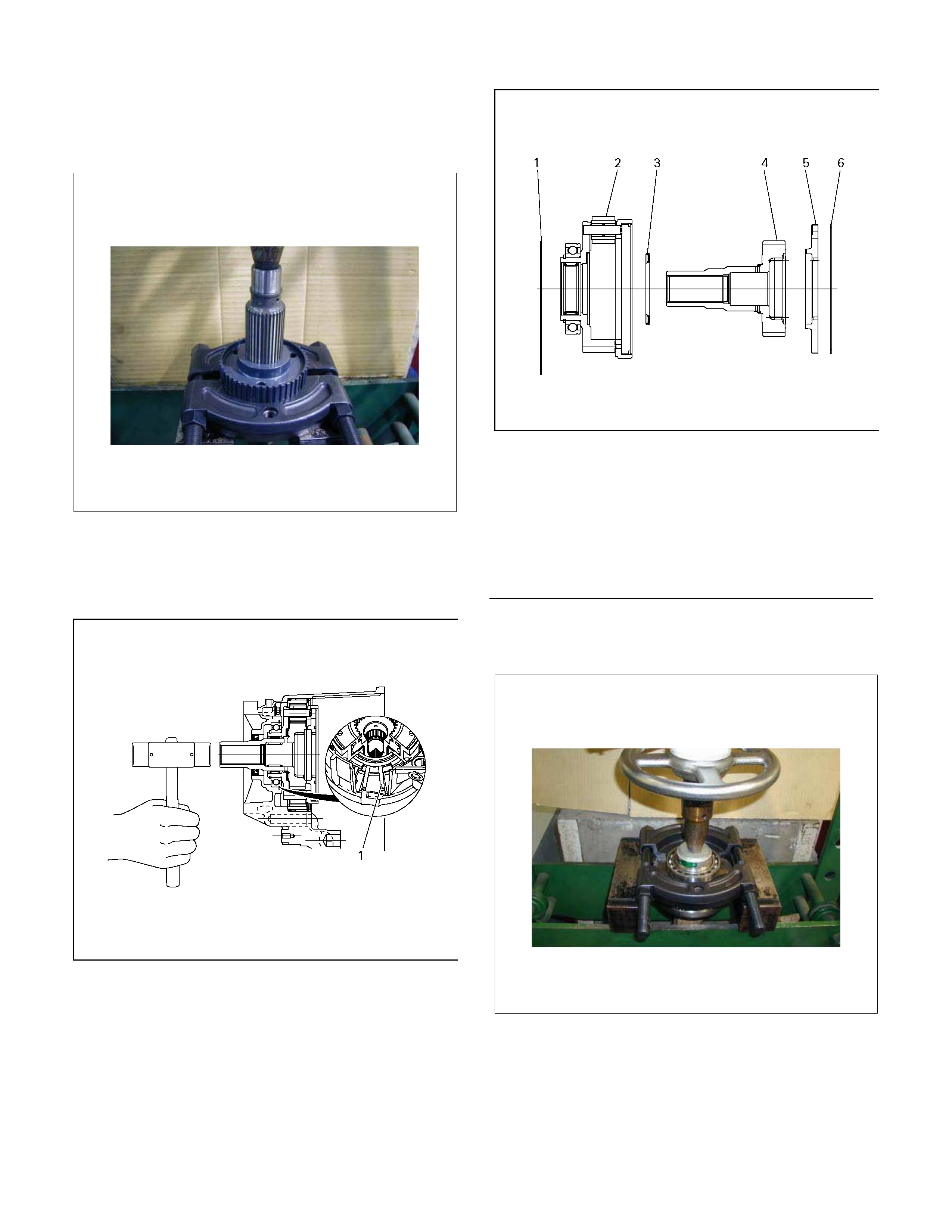
4. Use the com panion flange holder ( 5-8840-0133-0) to
remove the end nut from the front companion flange.
5. Remove the bolts attaching the rear cover to the
transfer case.
6. Strike the area around the front output shaft head
and the rear cover bolt holes with a plastic hammer
to remove the rear cover.
220R300022
7. Remove the parts listed below from the rear cover.
• H-L sleeve
• H-L shift asse mbly
• 2-4 sleeve, synchroniser key, and front
synchroniser spring (do not remove the rear
spring)
• 2-4 shift assembly
• Shift drum and shift shaft
• Sun gear needle bearing
260R300001
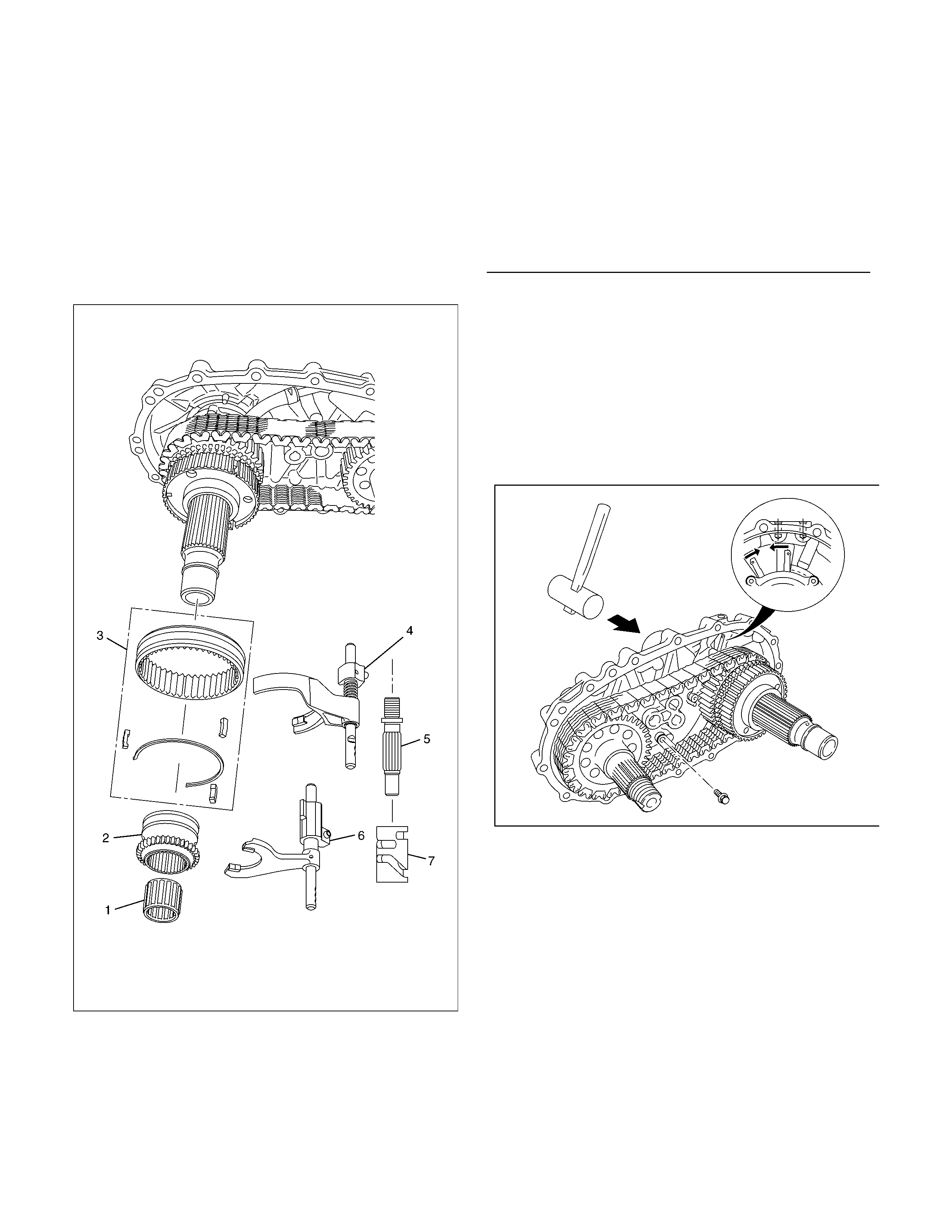
8. Remove the oil pump strainer fixing bolts from the
rear cover.
9. Com press the retaining ring at the rear of the chain.
Strike the rear end of the main shaft with a plastic
hammer to remove the main shaft, transfer chain,
and front output s haft assem bly f rom the rear cover.
Be careful not to damage the oil pump strainer.
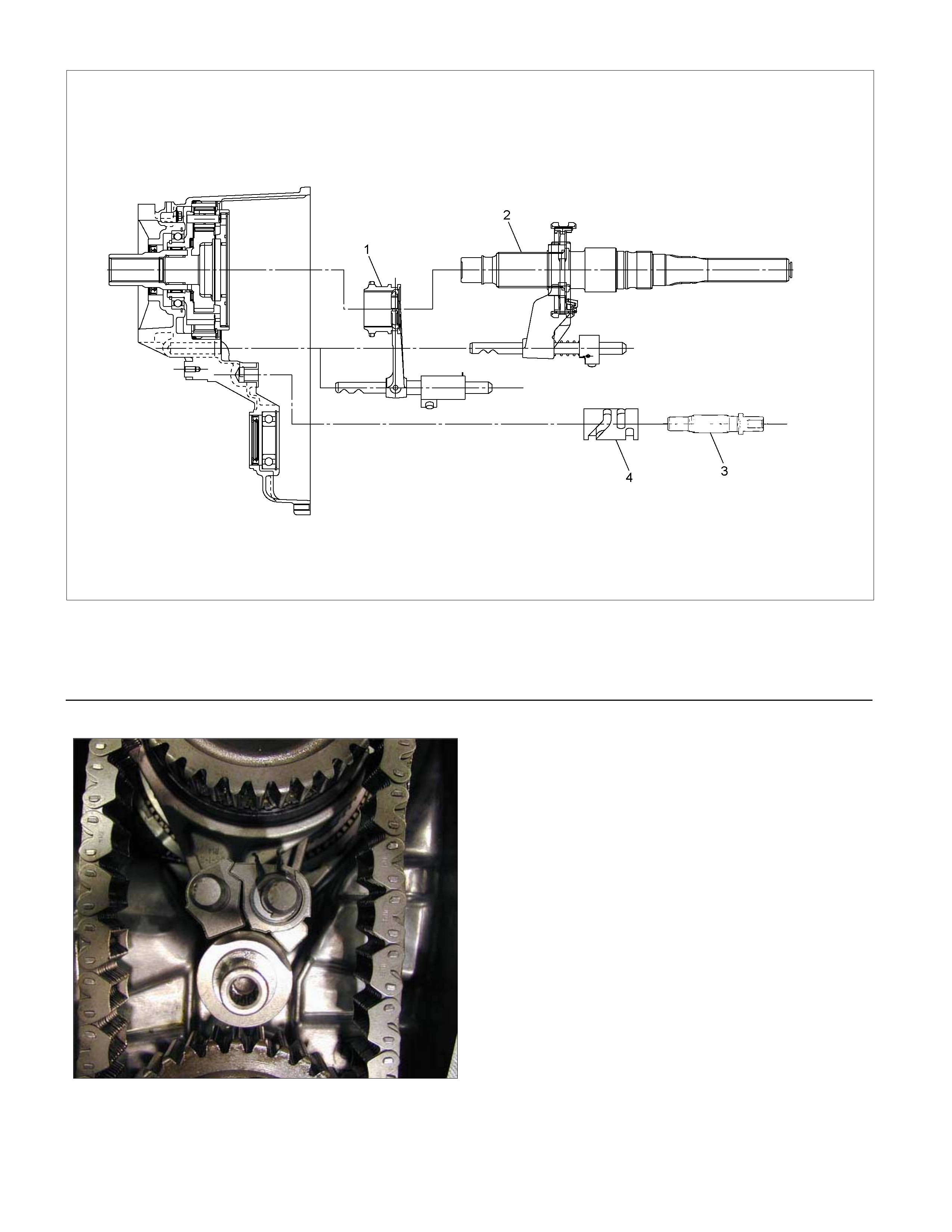
226R30001
Legend
(1)Sun Gear Needle Bearing
(2)H-L Sleeve
(3)2-4sleeve, synchroniser key, and front
synchroniser spring
(4)2-4 Shift ASM
(5)Shift Shaft
(6)H-L Shift ASM
(7)Shift Drum
10. Remove the transfer c hain and the front output shaf t
from the main shaft.
11. Remove the main shaft snap ring.
12. Remove the speedometer drive gear, the ball
bearings, the retaining ring, and the oil pump
assembly.
13. Remove the sprocket snap ring.
14. Remove the thrust washer, the drive sprocket, the
inside ring, the outside ring, the block ring, and the
rear synchroniser spring.
RTW37DMF000101
Legend
(1)Rear synchroniser spring (9)Sprocket Snap Ring
(2)Block Ring (10)Oil Pump ASM
(3)Outside Ring (11)Oil Pump Retaining Ring
(4)Inside Ring (12)Retaining Ring
(5)Drive Sprocket (13)Ball Bearing
(6)Transfer Chain (14)Speedometer Drive Gear
(7)Front Output shaft (15)Main Shaft Snap Ring
(8)Thrust Washer
15. Remove the snap ring from the main shaft.
16 Use a press to remove the 2-4 hub from the main
shaft.
17. Spread the edges of the retaining ring while lightl
y
tapping on the sun gear input shaf t end. Rem ove the
carrier and gear assembly from the transfer case.
226R300020
18 Remove the dogteeth snap r ing from the carr ier and
gear assembly.
19. Remove the planetary dogteeth and the sun gear
input shaft together with the thrust needle bearing.
2260R300021
20. Remove the carrier snap ring.
21. Use a press to remove the ball bearings.
22. Use the sliding hammer (5-8840-0084-0) and the
needle bearing replacer (5-8840-0027-0) to remove
the needle bearing f rom the center of the car rier and
gear assembly.
Legend
(1)Outer Retaining Ring
(2)Carrier and Gear ASM
(3)Thrust needle Bearing
(4)Sun gear Input Shaft
(5)Planetary dogteeth
(6)Dog Teeth Snap Ring

23. Remove the retaining ring (spiral type) together with
the internal gear and the damper ring.
226R300004
24. Remove the snap ring.
25. Use a press to remove the front output shaft ball
bearings.
26. Remove the oil pump wire snap ring from the rear
cover.
27. Use a sliding ham m er (5-8840-0084- 0) and a needle
bearing replacer (5-8840-2788-0) to remove the
needle bearing from the front output shaft.
P1010023
Legend
(1)Dumper Ring
(2)Internal Gear
(3)Retaining Ring
Internal Component Disassembly and
Reassembly
226R300017
H-L Shift Disassembly
1. Remove the guide roller.
2. Use a vise to compress the H-L shift spirng (inside
the assembly.
3. Remove the uter snap ring.
4. Remove the shift block assembly from the shift rod.
5. Use a socket and a vise to com press the shift block
spring (inside the assembly.
6. Remove the inner retaining ring.
7. Remove the collar (rear.
8. Remove the shift block spring.
9. Remove the collar (rear.
10. Remove the shift block assembly
11. Remove the outer snap ring.
12. Remove the shift arm.
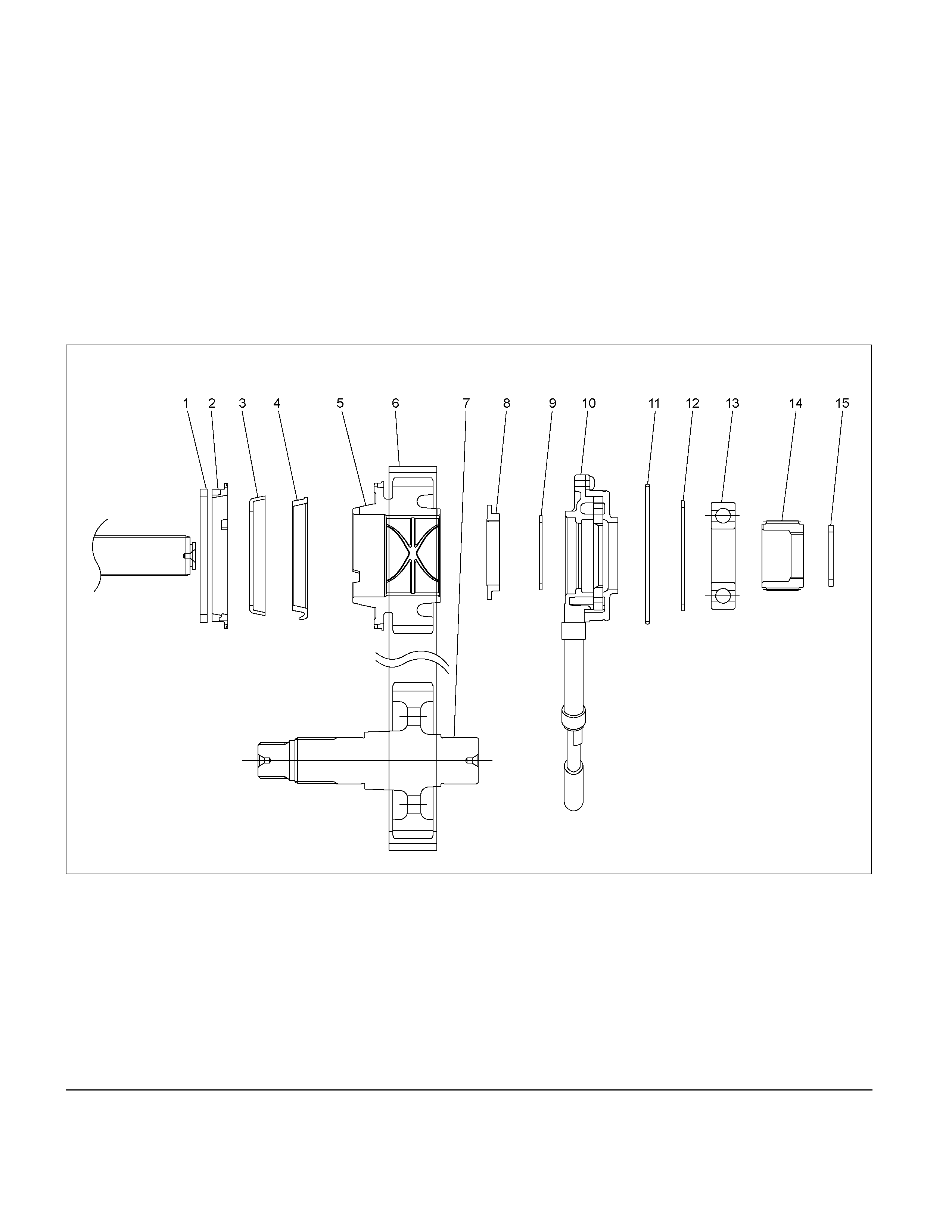
13. Remove the front and rear companion flange.
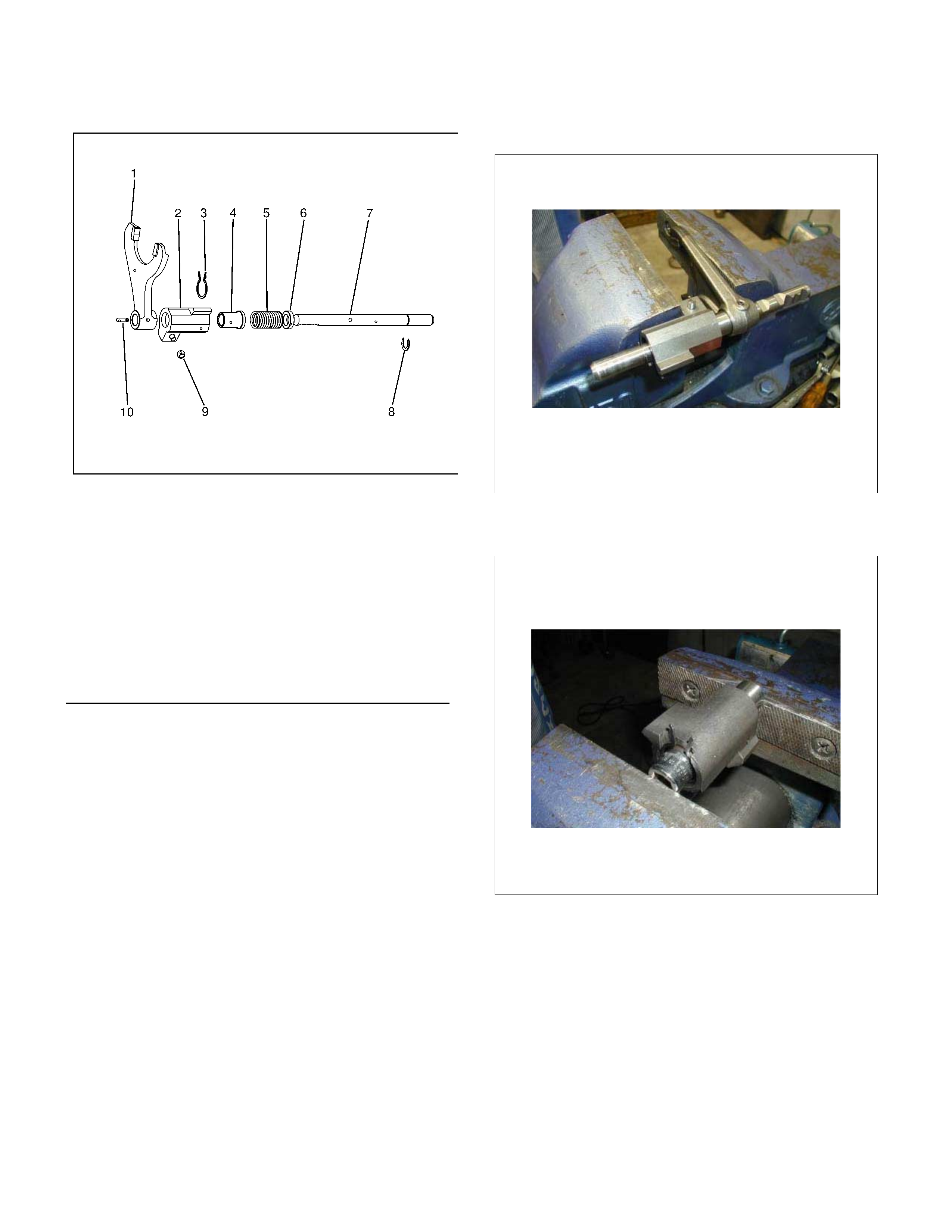
Legend
(1)ARM; SHIFT
(2)BLOCK ASM; SHIFT
(3)RING; RETAINING, INNER
(4)COLLER (FRONT)
(5)SPRING
(6)COLLER (RE AR)
(7)ROD; SHIFT
(8)RING; SNAP, OUTER
(9)ROLLER; GUIDE
(10)PIN ASM; SPRING
H-L shift reassembly
1. Install the shift arm to the shift rod.
2. Install the spring pin. The top of the pin must be
flush with the surrounding surface (no projection).
3. Install the front collar, the spring, and the rear collar
to the shift block in that order.
4. Use a socket and a vise to com press the shift block
spring.
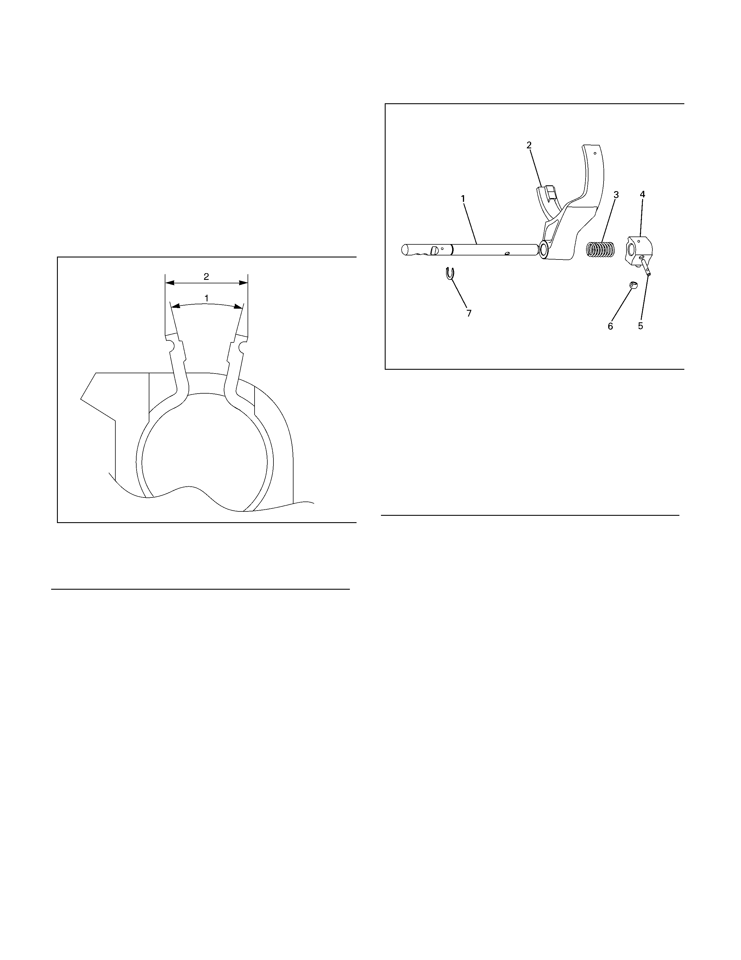
5. Install the inner retaining ring. Be sure that the arm
aperture width is within the specified limit.
226R300014
6. Install the shift lock assembly to the shift rod.
7. Use a socket and a vise to compress the H-L shift
spring.
8. Install the outer snap ring.
9. Install the guide roller.
2-4 shift ASM
226R300016
2-4 shift disassembly
1. Remove the guide roller.
2. Compress the spring and remove the snap ring.
3. Remove the shift arm.
4. Remove the spring.
5. Remove the spring pin.
6. Remove the shift block assembly.
7. Remove the shift rod.
Legend
(1)25.62°
(2)14.1mm
Legend
(1)ROD; SHIFT
(2)ARM; SHIFT
(3)SPRING
(4)BLOCK ARM;SHIFT
(5)PIN ARM; SPRING
(6)ROLLER; GUIDE
(7)RING; SNAP
2-4 shift reassembly
1. Install the shift block assembly to the shift rod.
2. Install the spring pin. The head of the pin must not
project beyond the surface (1) of the shift block.
226R300015
3. Install the spring.
4. Install the shift arm.
5. Compress the spring and install the snap ring.
6. Install the guide roller.
Oil Pump Disassembly
1. Remove the clamps securing the screen.
2. Remove the screen.
3. Remove the clamps securing the hose.
4. Remove the hose.
NOTE: To maintain and protect oil pump function, the
pump is constructed so that it cannot be disassembled.
Under no conditions attempt to disassemble the pump.
Oil Pump Reassembly
1. Tighten the clamps to secure the hose.
2. Tighten the clamps to secure the screen.
NOTE: Be careful in the alignment of the clamps.
RTW37DSH000101
Legend
(1) OIL PUMP ASM
(2) CLAMP
(3) HOSE
(4) SCREEN ASM
Inspection and Repair
1. Make the necessary repair or parts replacement i
f
wear, damage or any other abnormal conditions are
found during inspection.
2. Wash all parts thoroughly in clean solvent. Be sure
all old lubricant, metallic particles, dirt, or foreign
material are removed from the surfaces of ever
y
part. Apply compressed air to each oil feed port and
channel in each case half to remove an
y
obstructions or cleaning solvent residue.
Inspection and Repair (Transfer Case
Assembly)
When wear, damage, or any other defects are observed
during the inspection, the part or parts must be repaired
or replaced. Wash all the parts with clean detergent,
and check that old oil, metallic particles, dirt, or foreign
materials are completely removed. Blow the air into oil
holes and grooves to remove foreign materials or
residual detergent.
Chain
• Check whether the face that contacts the sprock et is
free from excessive wear or damage. If defects are
observed, replace the part.
• If the chain interference mark is found on the inside
wall of the transf er c over or the c hain is so s lack that
a skipped engagement occurs between the chain
and sprocket, replace the chain.
Sprocket
• Check whether the sprocket tooth surface is
exces sively worn or dam aged, and there is evidence
of burrs, chipping, wear, or damage on the gear
spline. Remove minor flaws or scratches with oil
stone. If excessive wear or damage is observed,
replace the part.
• If excessive wear or damage is observed on the
sprocket inside sliding surface, replace the part.
Gear
• Check whether the gear tooth surface is excessivel
y
worn or damaged, and there is evidence of burrs,
chipping, wear, or damage on the gear spline.
• Remove minor flaws or scratches with oil stone. I
f
excessive wear or damage is observed, replace the
part.
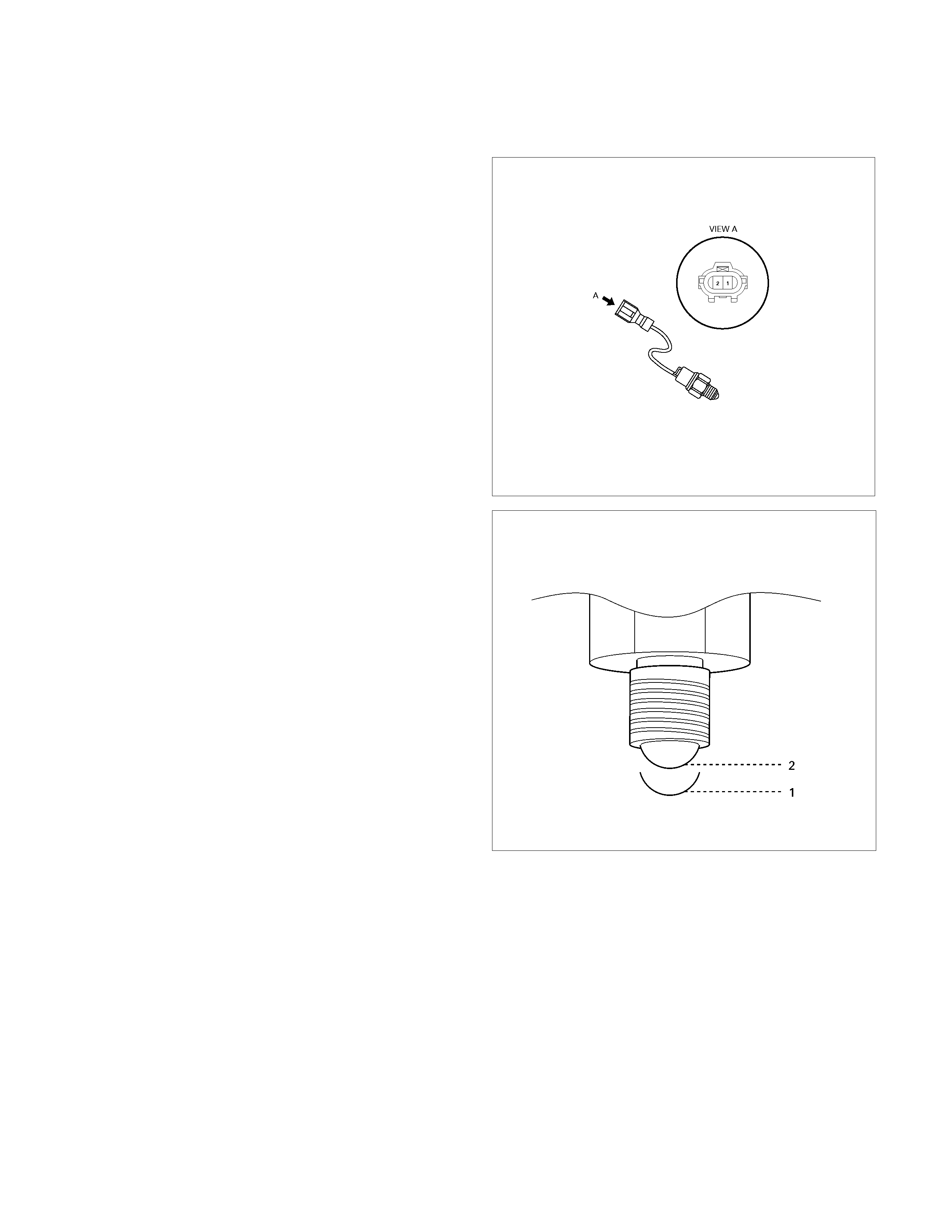
2-4 and Neutral Switch
• Check the continuity of 2-4 and Neutral switch.
If defects are observed, replace the switch.
221R300001
261R300003
Switch Position 1: Terminals 1&2 are open circuit
Switch Position 2: Terminals 1&2 have continuity
Oil Pump
• Remove foreign materials from the strainer. If the
strainer is damaged, replace it.
If the area into which the shaft is inserted is excessively
worn or damaged, replace the oil pump assembly.
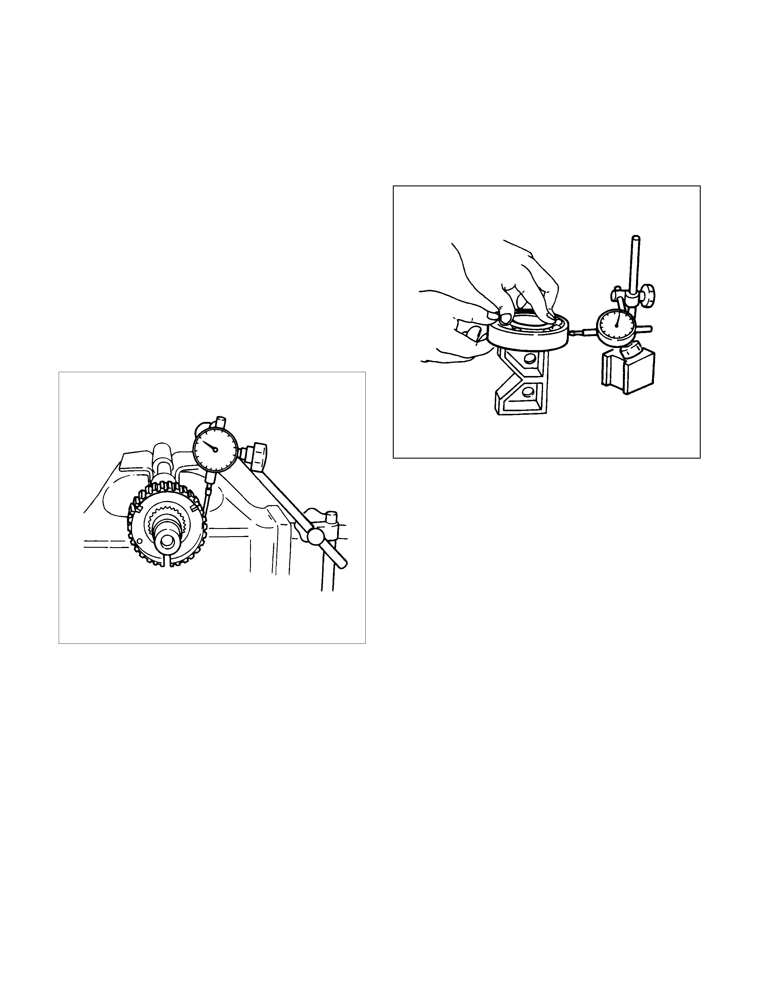
Clutch Hub Spline Play
• Set a dial indicator to the clutch hub to be measured.
• Move the clutch hub as far as possible to both the
right and the left.
Note the dial indicator reading.
• If the measured value exceeds the specified limit,
the clutch hub must be replaced.
Clutch hub spline play
Standard : 0-0.1 mm (0-0.004 in)
Limit : 0.2 mm (0.008 in)
226RS042
Bearings
1. Inspect the condition of all the needles and ball
bearings. Wash bearings thoroughly in a cleaning
solvent. Apply compressed air to the bearings.
NOTE: Do not allow the bearings to spin. Turn them
slowly by hand. Spinning bearings may damage the
rollers.
2. Lubricate the bearings with a light oil and check them
for roughness by slowly turning the race by hand.
Ball Bearing Play
1. Use a dial indicator to measure the ball bearing play.
2. If the measured value exceeds the specified limit, the
ball bearing must be replaced.
Limit : 0.2 mm (0.008 in)
226R3043
Synchronisers
The synchroniser hubs and sliding sleeves are a
selected assembly and should be kept together as
originally assembled.
Clean synchroniser components with clean solvent and
air dry.
Inspect the components for the following:
• Teeth for wear, scuffs, nicks, burrs or breaks.
• Keys and springs for wear, cracks or distortion,
replace if these conditions are present.
• If scuffed, nicked or burred conditions cannot be
corrected with a soft stone or crocus cloth, replace
the component.
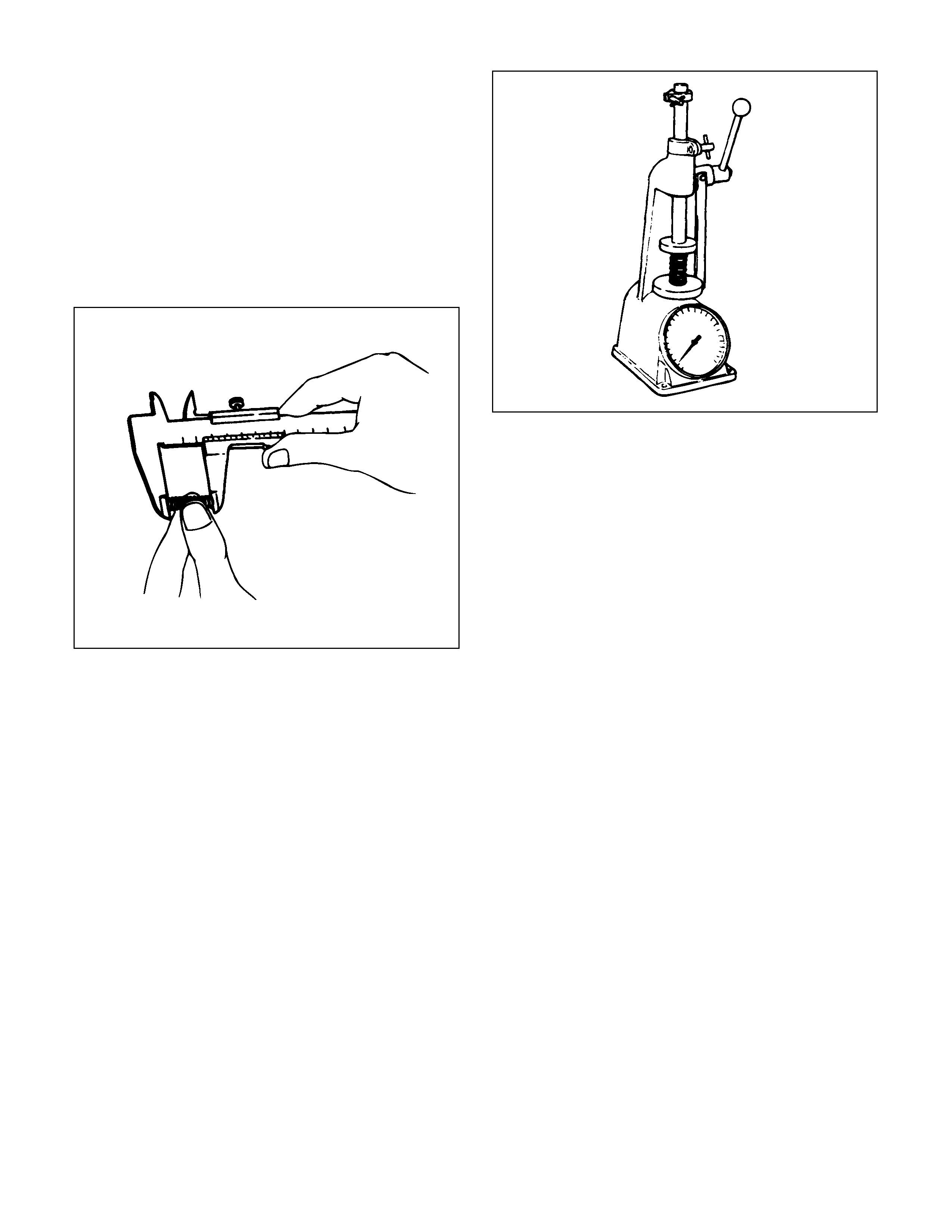
Block Ring and Insert Clearance
1. Use a vernier caliper to measure the clearance
between the block ring and the insert.
2. If the measured value exceeds the specified limit,
the block ring and the insert must be replaced.
Block ring and insert clearance
Standard : 2.46-2.74 mm (0.097-0.108 in)
Limit : 3.0 mm (0.118 in)
226RS037
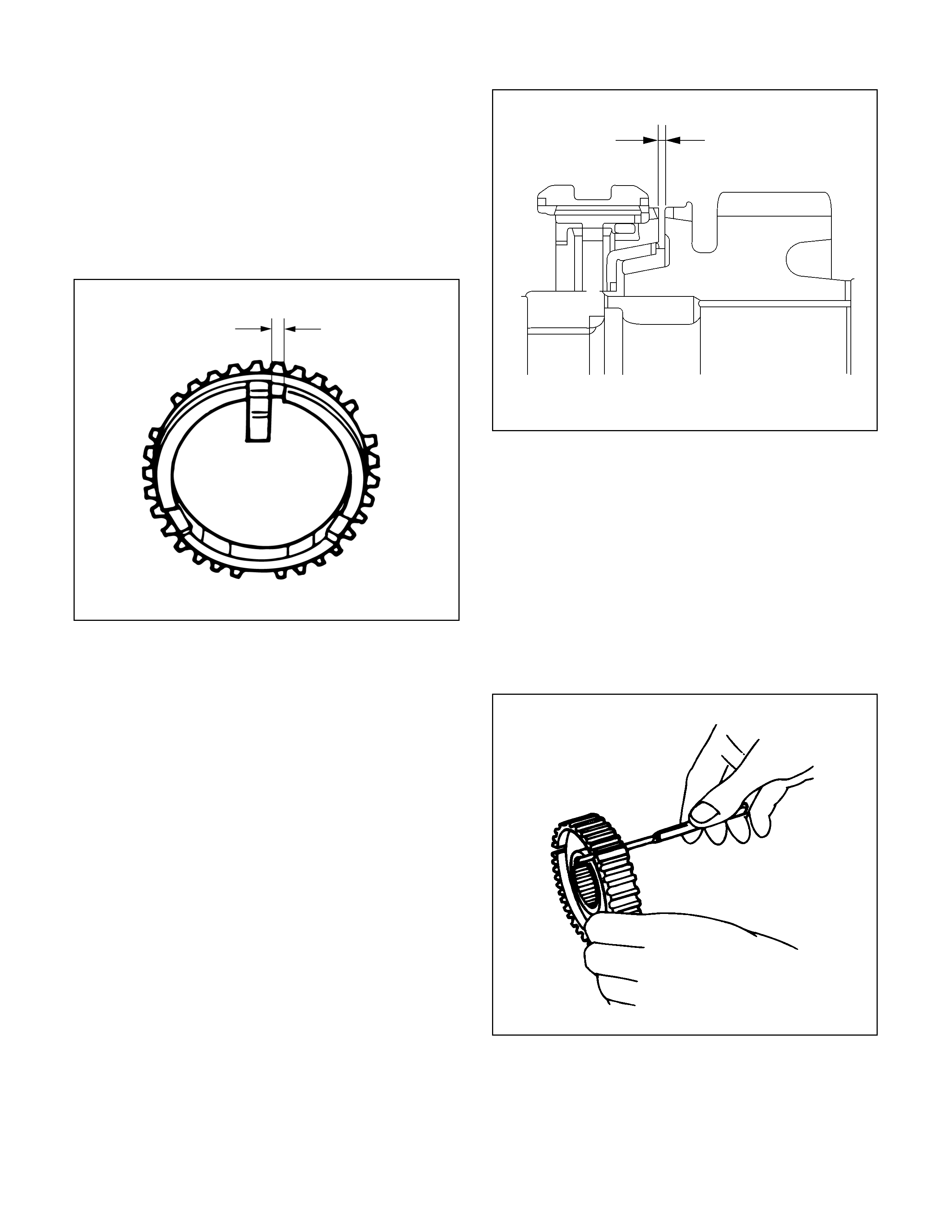
2WD-4WD Synchroniser (3-Cone)
1. Use a thickness gauge to measure the clearance
between the block ring and the dog teeth.
2. If the measured value exceeds the specified limit,
the 2WD-4WD synchroniser assembly must be
replaced.
Block ring and dog teeth clearance
Standard : 1.5 mm (0.059 in)
Limit : 0.8 mm (0.031 in)
226R300019
Clutch Hub and Insert Clearance
1. Clutch Hub and Insert Clearance
2. Use a thickness gauge to measure the clearance
between the clutch hub and the insert.
3. If the measured value exceeds the specified limit, the
clutch hub and the insert must be replaced.
Clutch hub and insert clearance
Standard : 0.01-0.19 mm (0.0004-0.0075 in)
Limit : 0.3 mm (0.012 in)
226RS038
Detent Spri ngs
1. Inspect the springs for distortion, cracks or wear.
Replace if these conditions are present.
Detent Spring Free Length
1. Use a vernier caliper to measure the detent spring
free length.
2. If the m easured value is less than the s pecified limit,
the detent spring must be replaced.
Detent spring free length
Detent ball
Standard :23.4 mm (0.92 in)
Limit :22.8 mm (0.90 in)
220RW035
Detent Spri ng Tension
1. Use a spring tester to measure the detent spring
tension.
2. If the m easured value is less than the spec ified limit,
the detent spring must be replaced.
Detent ball
Compressed height : 18.7 mm (0.736 in)
Standard : 68.6 ~ 88.2 N (7.0 ~ 9.0 kg/ 15.4 ~ 19.8
lb)
220RS013
Shift Arm
1. Inspect the shift arms for wear, distortion or scoring.
Replace if these conditions are present.
Shift Arm Thickness
1. Use a micrometer to measure the shift arm
thickness.
2. If the measured value is less than the specif ied limit,
the shift arm must be replaced.
H-L Shift arm thickness
Standard : 7.6-7.85 mm (0.299-0.309 in)
Limit : 7.0 mm (0.276 in)
2-4 Shift arm thickness
Standard : 9.6-9.85 mm (0.378-0.388 in)
Limit : 9.0 mm (0.354 in)
Reassembly
Transfer Reassembly
The rear cover oil seals and the rear output shaft ball
bearings cannot be reused. They must be replaced with
new ones when the transfer is reassembled.
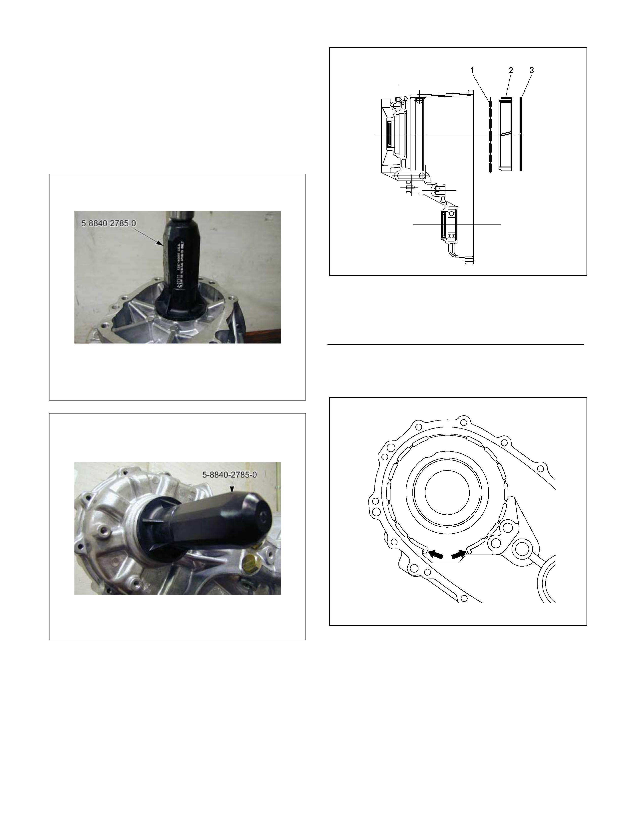
1. Use the oil seal installer (5-8840-2785-0) to press
the new input shaft and/or f ront output shaf t oil s eals
into place (If replacement is required).
2. Use a press to install the ball bearings to the front
output shaft. Be sure that the bearings are full
y
inserted and then install the snap ring.
3. Install the damper ring and the internal gear to the
transfer case. Be sure that the damper ring is
between the internal gear and the case.
226R300004
Note the direction of the dumper ring installation as
figure.
226R300025
Legend
(1)Dumper Ring
(2)Internal Gear
(3)Retaining Ring
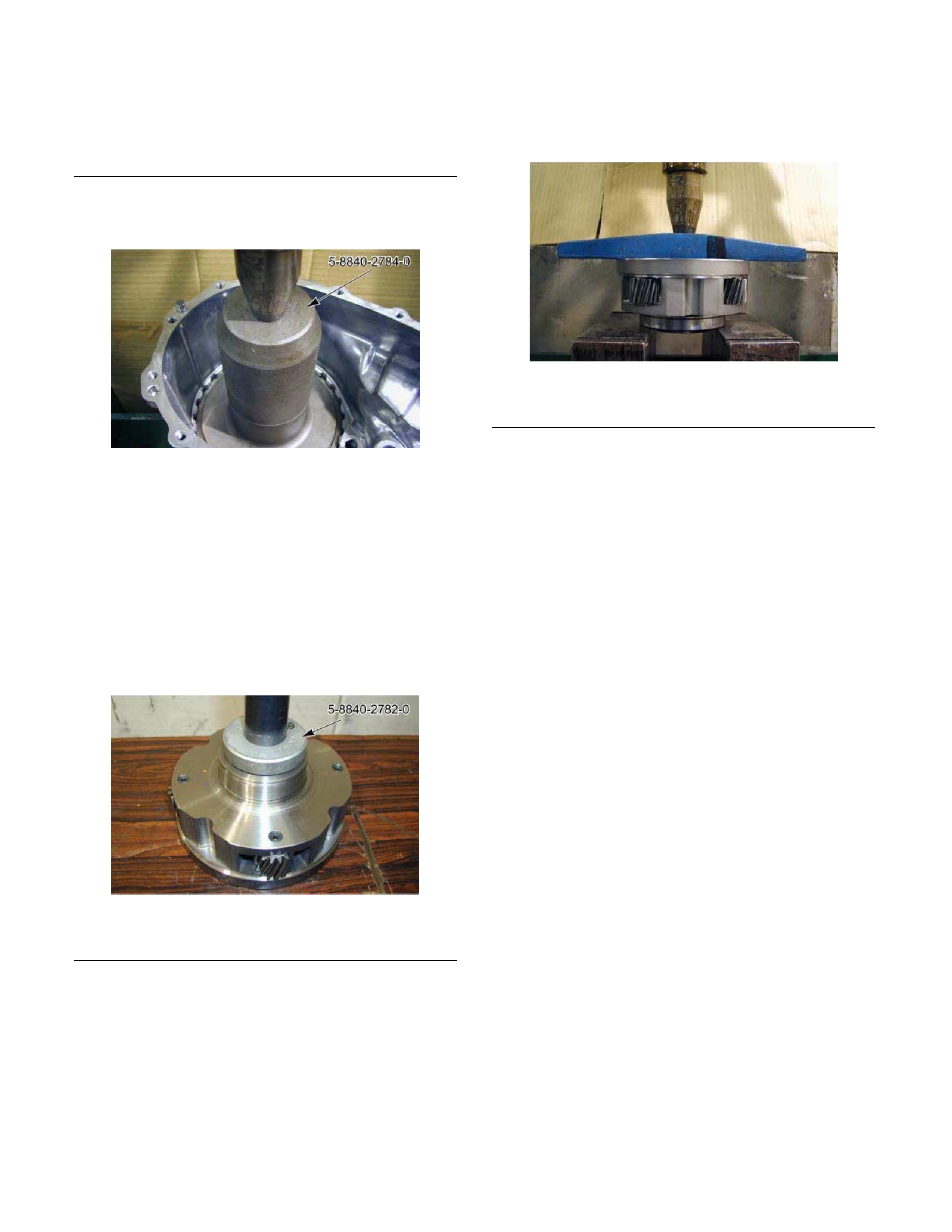
4. Use a press and the special tool (5-8840-2784-0) to
hold the internal gear against the dam per ring. Install
the retaining ring (spiral type).
5. Use a press and the installer (5-8840-2782-0) to
force the needle bearing fully into the carrier and
gear assembly.
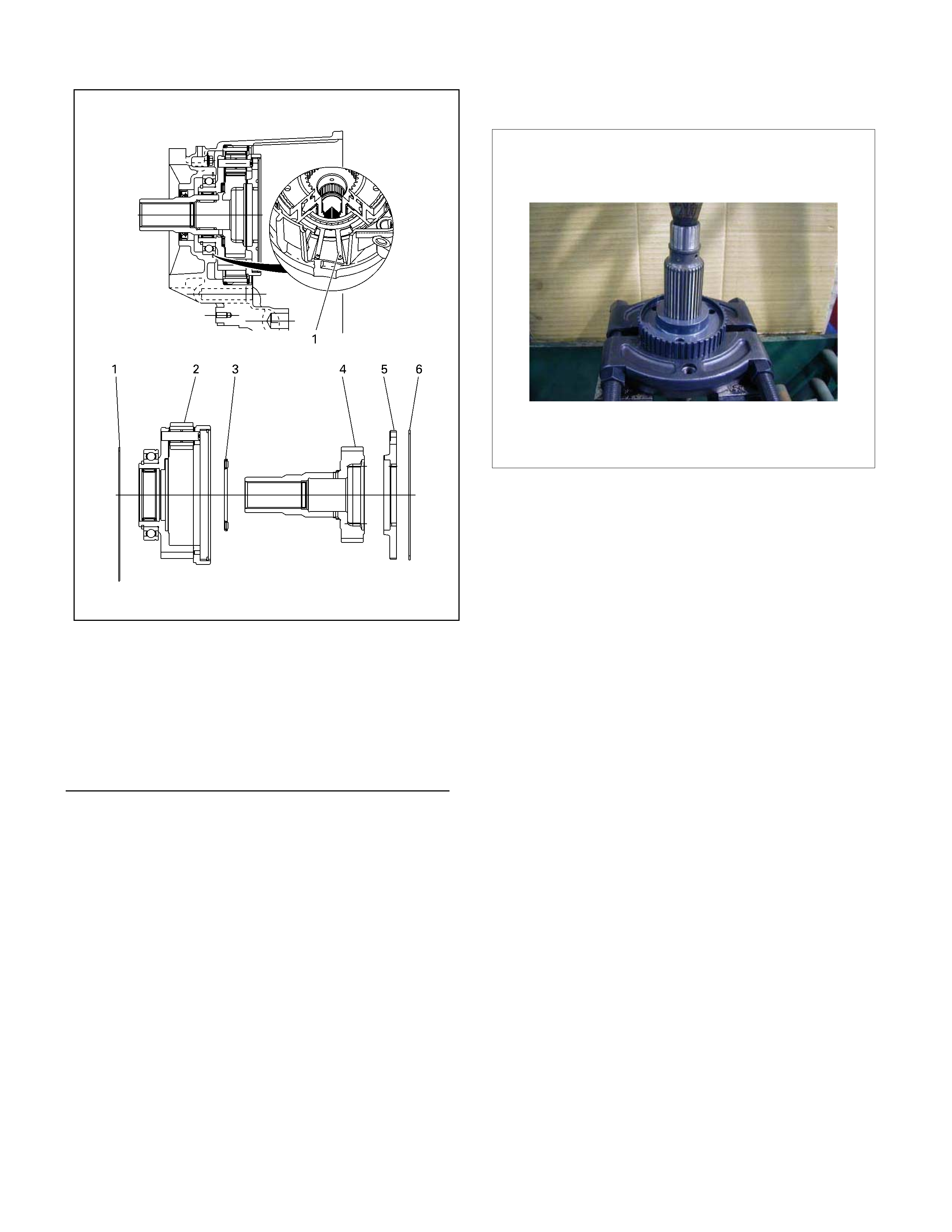
6. Use a press and an appropriate special tool to force
the ball bearings fully into the carrier and gear
assembly.
7. Install the carrier snap ring.
8. Install the thrust needle bearing, the sun gear input
shaft, the needle bearing, the planetary dog teeth,
and the dog teeth snap ring to the carrier and gea
r
assembly in that order.
9. Install the outer retaining ring to the tansfer case
10. Use a pair of s nap ring plier s to ins tall the carr ier and
gear assembly.
NOTE: Be sure that the outer retaining ring fits snugly in
its groove.
226R300003
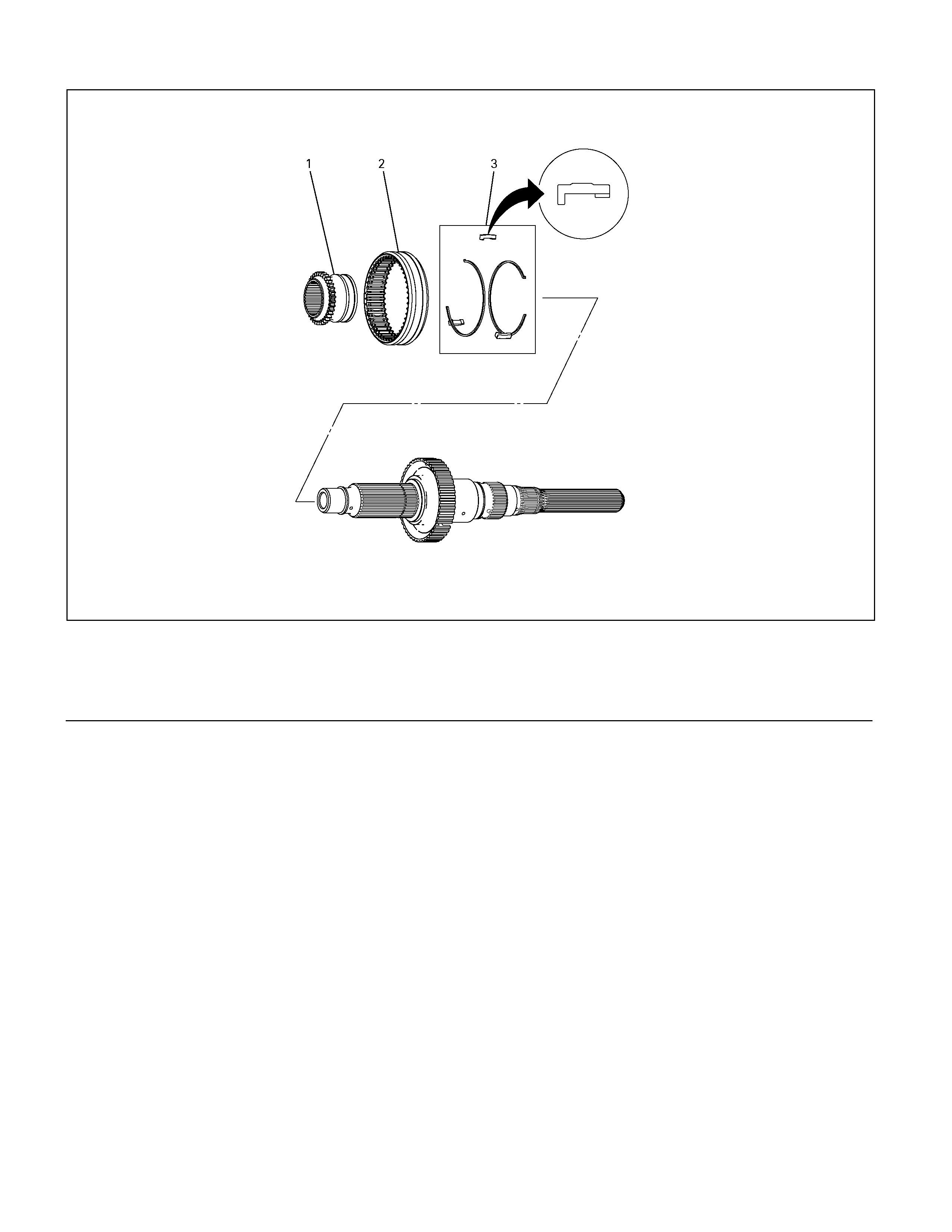
11. Use a press to install the 2-4 hub.
12. Install the hub snap ring.
13. Install the synchroniser key springs (2), the
synchroniser key, and the 2-4 sleeve to the 2-4 hub.
The key and the open end of the springs must be
facing in the opposite direction.
14. Insert the H-L sleeve into the main shaft.
Legend
(1)Retaining Ring
(2)Carrier and Gear ASM
(3)Thrust Needle Bearing
(4)Sun gear Input Shaft
(5)Planetary Dog Teeth
(6)Dog Teeth Snap ring
226R300023
Legend
(1)H-L Sleeve (3)Synchroniser Key and Key Spring
(2)2-4 Sleeve
15. Install the sleeve to the H-L shift assembly.
16. Install the sleeve to the 2-4 shift assembly.
17. Coat the area around each of the shift assembl
y
insertion holes (transfer case) with transfer oil.
18. Install the main shaft together with the H-L shift
assembly and the 2-4 shift assembly to the shift
drum.
19.
A
lign the shift shaft splines with the shift drum and
install the shafts to the drum.
RTW320MF000201
Legend
(1)H-L Sleeve and Shift ASM (3)Shift Shaft
(2)2-4 Sleeve ASM with Main Shaft and Shift ASM (4)Shift Drum
NOTE: Be careful in the direction of an assembly.
P1010041/020124
20. Coat the main shaft with oil.
21. Align the block ring, the outside ring, and the inside
ring with the 2-4 hub assembly and install them.
22.
A
ssemble the sprocket, transfer chain, and front
output shaft.
23. Install the sprocket, transfer chain, and front output
shaft to the main shaft and the transfer case.

24.
A
lign the sprocket thrust washer with the main shaft
groove and install it.
226R300009
25. Select a snap r ing that will allow minim um axial play.
Insert it to the main shaft installation groove.
Identification colour Snap ring thickness -mm (in)
Red 2.15 (0.085)
No colour 2.10 (0.083)
Blue 2.05 (0.081)
White 2.00 (0.079)
226R300008
Legend
(1)Block Ring (5)Chain
(2)Outside Ring (6)Front Output Shaft
(3)Inside Ring (7)Thrust Washer
(4)Sprocket (8)Snap Ring
26. Measure the snap ring external diameter. If the
measured diameter is outside the specified range, a
larger or smaller snap ring must be used.
Snap ring outside diameter (Standard):
53.0 ±
±±
± 0.5 mm
27. Position the rear cover so that its mating surfaces
are facing up.
28. Use a press and the installer (5-8840-2783-0) to
install the front output shaft needle bearing. The
installer must be aligned with the bearing
manufacturer's name (stamped into the bearing).
29. Install the oil pump wire snap ring to the rear cover.
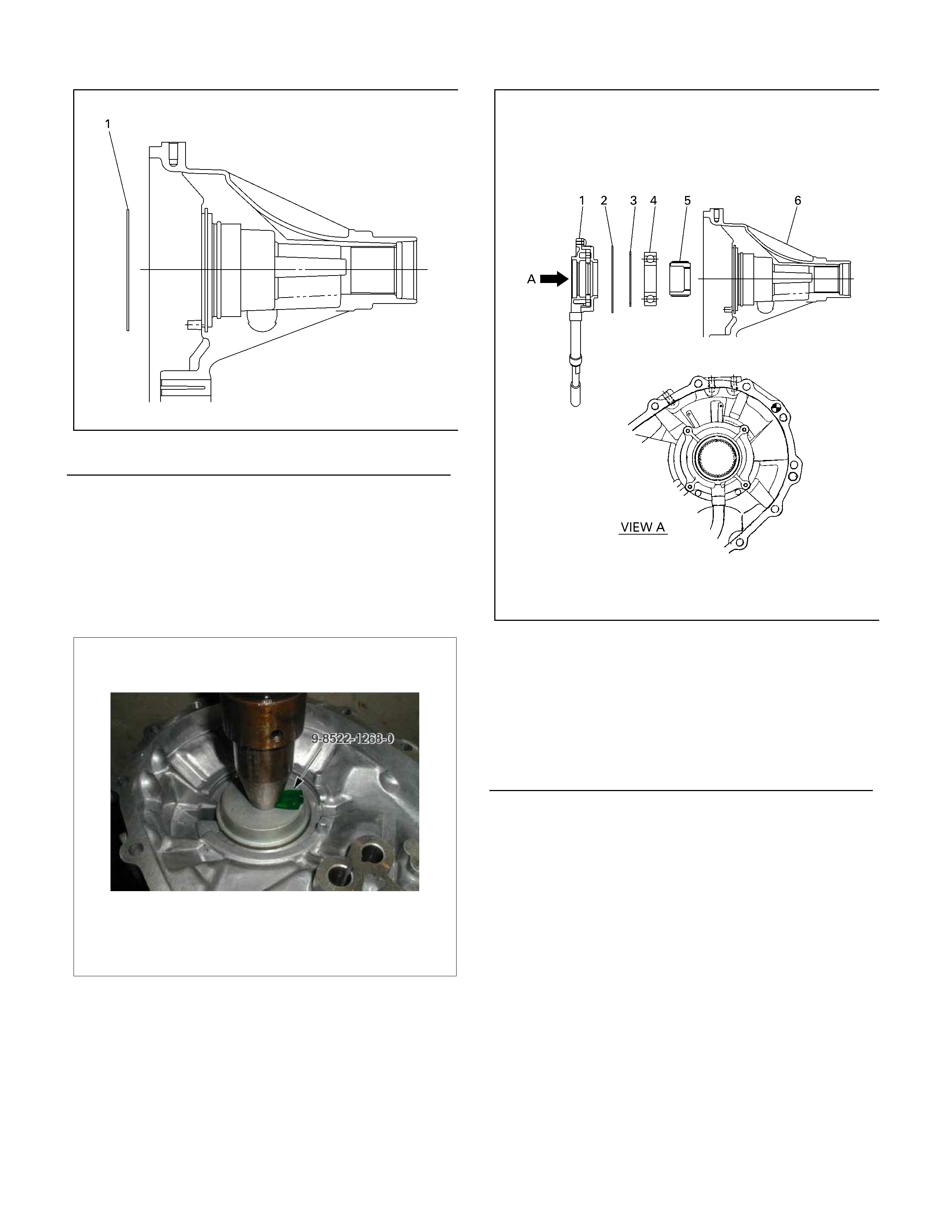
226R300005
30. Temporarily install the speedometer drive gear to the
inside of the rear cover. Pay close attention to
installation direction.
31. Use a press and the installer (9-8522-1268-0) to
install the rear output shaft ball bearings. Do not
drive the ball bearings into place with a hammer.
32. Install the rear output shaft retaining ring.
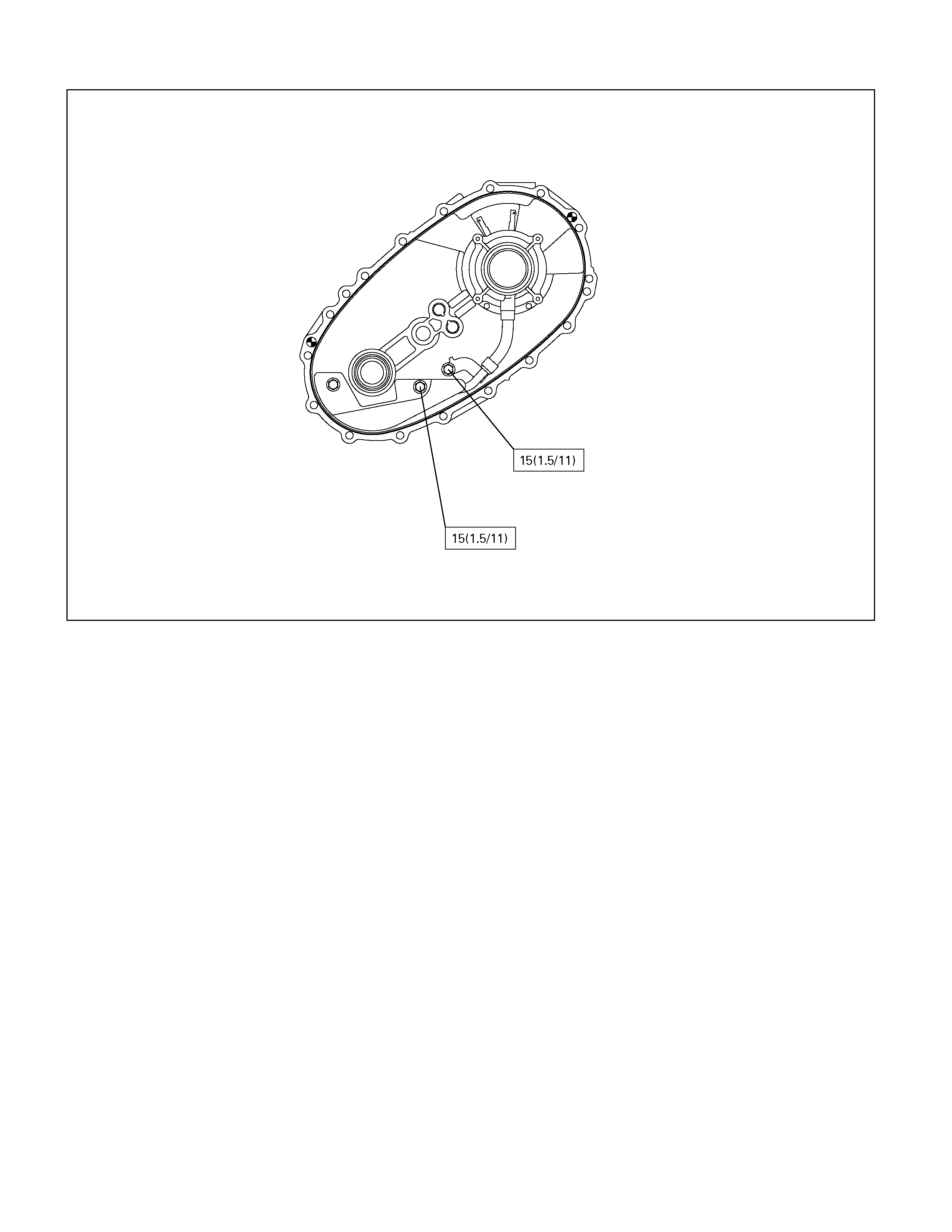
33. Place the oil pump in its specified position.
34. Secure the pump strainer to the rear cover and
tighten the bolts to the specified torque.
Rear cover and transfer case bolt torque:
15 Nm (1.5 kgm/11 lb ft)
226R300010
35.
A
pply Loctite FMD 127 to the m ating surfaces of the
rear cover and the transfer case. Be sure that the
Loctite is evenly applied to the inside surfac es of the
bolt holes with no gaps.
Legend
(1)Oil Pump ASM
(2)Wire Snap ring
(3)Retaining Ring
(4)Ball Bearing
(5)Speedometer Gear Drive Gear
(6)Rear Cover
Legend
(1)Wire Snap ring
226R300011
36. Install the rear cover to the transf er case and tighten
the bolts to the specified torque.
Rear cover and transfer case bolt torque:
22 Nm (2.2 kgm/16 lbft)
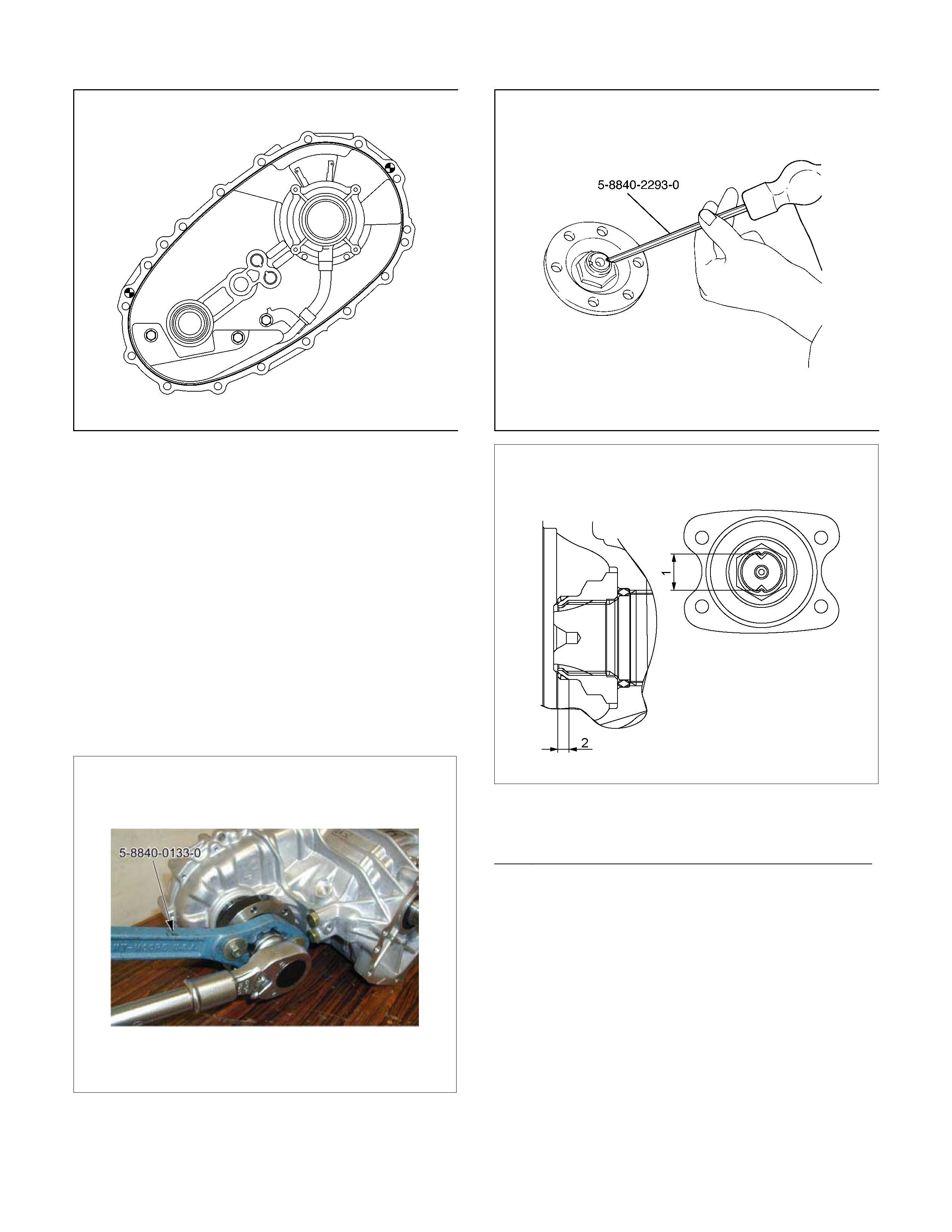
37. Apply engine oil to the companion flange O-ring.
38. Install the O-ring to the front output shaft.
39. Secure the front companion flange with the
companion flange holder (5-8840-0133-0).
40. Install the end nuts and tighten them to the s pecified
torque.
Front companion flange end nut torque:
137 Nm (14 kgm/101 lbft)
41. Use a cold chisel to caulk the front companion
flange end nuts.
226R300012
RUW34DSH000301
Legend
(1) MAX 26mm (1.02 in)
(2) MIN 4mm (0.16 in)
42.
A
pply Loctite 575 to the threaded portion of the
detenteplugs.
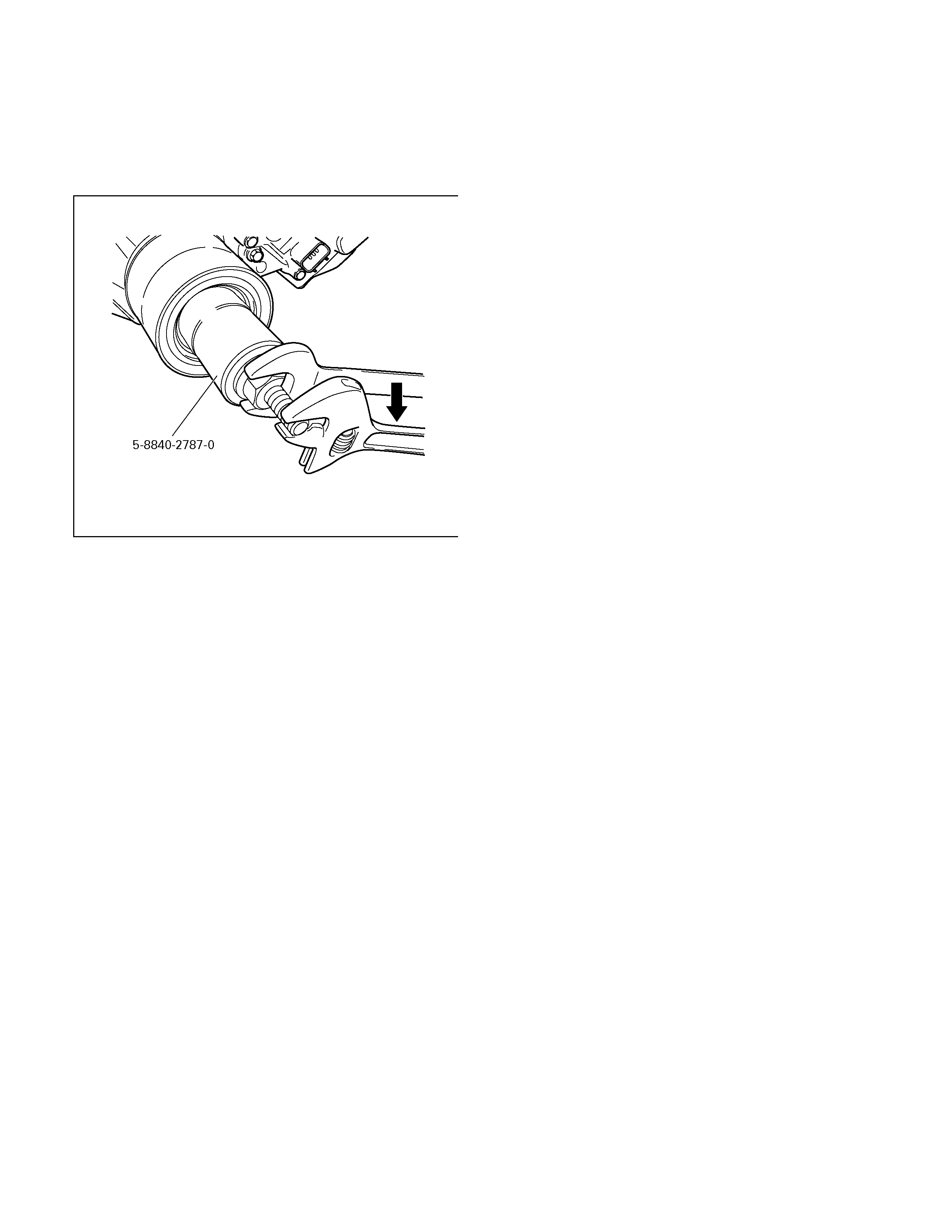
43. Use the installer (5-8840-2787-0) to install the main
shaft end s nap ring to the rear output s haft (f rom the
back end of the shaft). Be absolutely sure that the
snap ring is seated in the groove.
226R300022
44. Use the installer (5-8840-2786-0) to install the rear
output oil seal to the rear case.
45. Install the detent balls, the detent springs, and the
detent plugs (2 parts each) to the transfer case.
Tighten the plugs to the specified torque.
Detent plug torque: 19 Nm (1.9 kgm/14 lbft)
46. Install the neutr al s witch (blac k harnes s cover ) to the
transfer case and tighten the bolts to the specified
torque.
Neutral start switch bolt torque:
39 Nm (4 kgm/29 lbft)
47. Install the 2-4 switch (gray harness cover) to the
transfer case and tighten the bolts to the specified
torque.
2-4 switch bolt torque: 39 Nm (4 kgm/29 lbft)
48. Install the switch bracket to the transfer case and
tighten the bolts to the specified torque.
Switch bracket bolt torque:
15 Nm (1.5 kgm/11 lbft)
49. Install the transfer actuator assembly to the transfer
case and tighten the bolts to the specified torque.
The actuator must be installed in the same direction
as the shaft.
Transfer actuator assembly bolt torque:
22 Nm (2.2 kgm/16 lbft)
50. Install the breather hose between the transfer
actuator and the transfer case.
51. Install the speedometer driven gear, the
speedom eter bush, and the speedom eter stay to the
transfer case. Tighten the bolts to the specified
torque.
Speedometer bolt torque:
15 Nm (1.5 kgm/11 lbft)
52. Ins tall the drain plug to the transfer case and tighten
it to the specified torque.
Drain plug torque : 39 Nm (4 kgm/29 lbft)
53. Loos en and remove the f iller plug. Add the specified
volume of transfer oil (5W-30) or the equivalent to
the transfer through the filler hole.
Transfer oil volume: 1.3 liters
54. Replace the filler plug and tighten it to the specified
torque.
Filler plug torque: 39 Nm (4 kgm/29 lbft)
55. Install the underguard and tighten the bolts to the
specified torque.
Underguard bolt torque: 39 Nm (4 kgm/29 lbft)
Main Data and Specifications
General Specifications
Type Synchronised type gears shifting between the 2 and 4 wheel drive mode.
Planetary type gears shifting between “low" and “high".
Control method Remote control with the button switch on the instrument panel for gears
shifting among “2H”, “4H" and “4L".
Gear ratio High; 1.000
Low; 2.050
Oil capacity 1.3 lit. (1.37 U.S. quart)
Type of lubricant Refer to chart in Section 0B
Torque Specifications N⋅m (kg⋅m/lb ft)
RTW37DLF000501
N⋅m (kg⋅m/lb ft)
RTW37DLF000301
N⋅m (kg⋅m/lb ft)
E07R300008
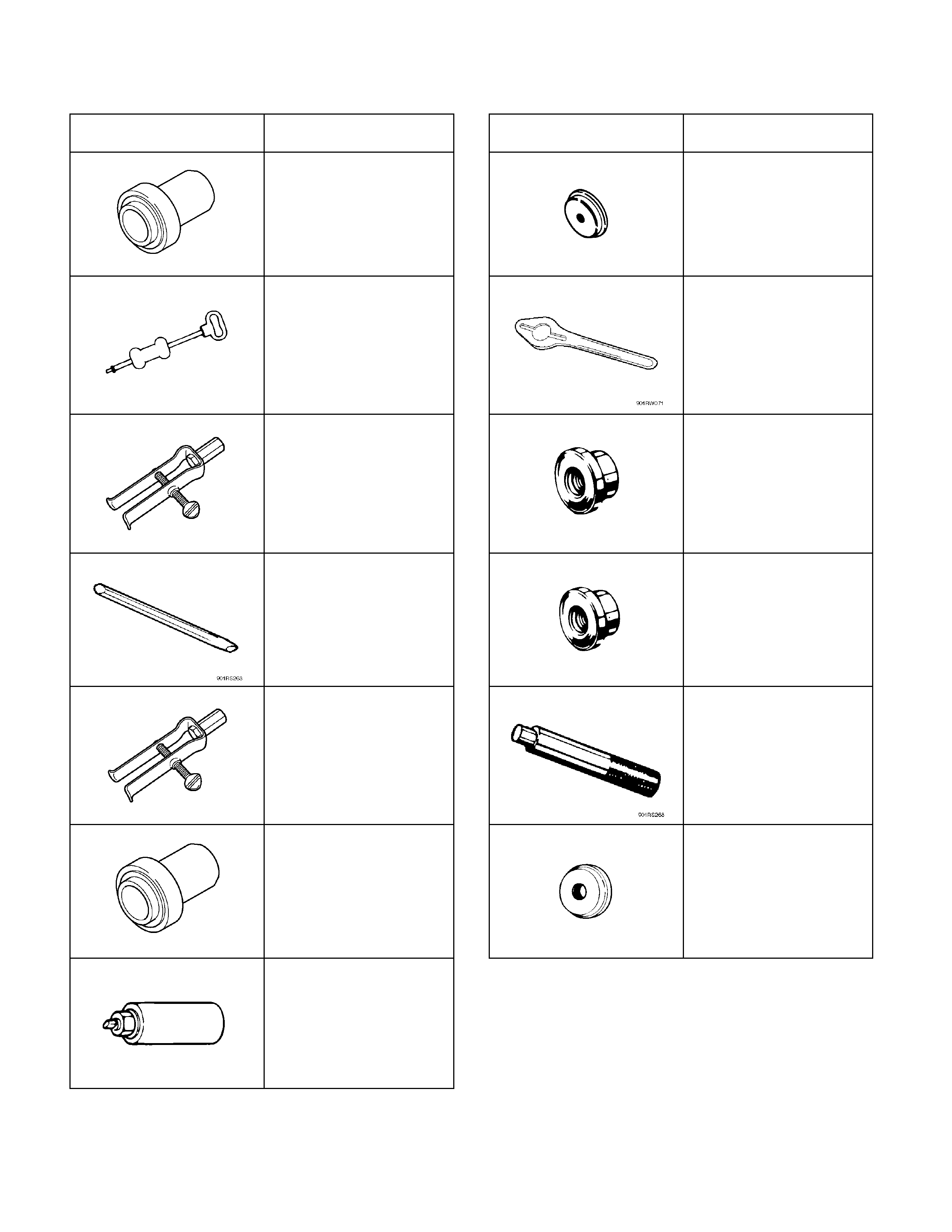
Special Tools
ILLUSTRATION PART NO.
PART NAME ILLUSTRATION PART NO.
PART NAME
5-8840-2786
Transfer case oil seal
installer
5-8840-2784-0
Ring gear installer
5-8840-0084-0
Sliding hammer
5-8840-0133-0
Flange holder
5-8840-0027-0
Rear output shaft needle
bearing replacer
5-8840-2782-0
Needle bearing installer
5-8840-2293-0
Punch; end nut
5-8840-2783-0
Needle bearing installer
5-8840-2788-0
Front output shaft needle
bearing replacer
5-8840-0007-0
Driver handle
5-8840-2785-0
Input shaft and/or front
output shaft oil seal
installer
5-8840-1268-0
Rear output shaft ball
bearing installer
5-8840-2787-0
Snap ring installer