
SECTION 7D1 - TRANSFER CONTROL SYSTEM
Service Precaution
General Description
System Components
Parts Location
Transfer Case Control Module (TCCM)
Shift Actuator Limit Switch Test
Shift Actuator Harness Test
Function Of Switch And Indicator Lamp
Parts Location
Circuit Diagram
Connector List
Diagnosis
Road Testing Prior To Repair
Shifting From 2H To 4H
Shifting From 4H To 2H
Shifting From 4H To 4L
Shifting From 4L To 4H
Shifting From 4L Or 4H To Neutral
Shifting From Neutral To 2H, 4H Or 4L
4WD Indicator Lamp Flashes When Ignition Is Turned On
‘Check 4WD’ Indicator Lamp On When Ignition Is On
TCCM Memory Erase Procedure
Diagnosis From Symptom
Techline
Techline

Service Precaution
WARNING:
THIS VEHICLE HAS A SUPPLEMENTAL RESTRAINT SYSTEM (SRS). REFER TO THE SRS COMPONENT AND
WIRING LOCATION VIEW IN ORDER TO DETERMINE WHETHER YOU ARE PERFORMING SERVICE ON OR
NEAR THE SRS COMPONENTS OR THE SRS WIRING. WHEN YOU ARE PERFORMING SERVICE ON OR NEAR
THE SRS COMPONENTS OR THE SRS WIRING, REFER TO THE SRS SERVICE INFORMATION. FAILURE TO
FOLLOW WARNINGS COULD RESULT IN POSSIBLE AIR BAG DEPLOYMENT, PERSONAL INJURY, OR
OTHERWISE UNNEEDED SRS SYSTEM REPAIRS.
CAUTION:
Always use the correct fastener in the proper location. When you replace a fastener, use ONLY the exact part
number for that application. HOLDEN will call out those fasteners that require a replacement after removal.
HOLDEN will also call out the fasteners that require thread lockers or thread sealant. UNLESS OTHERWISE
SPECIFIED, do not use supplemental coatings (Paints, greases, or other corrosion inhibitors) on threaded
fasteners or fastener joint interfaces. Generally, such coatings adversely affect the fastener torque and the
joint clamping force, and may damage the fastener. When you install fasteners, use the correct tightening
sequence and specifications. Following these instructions can help you av oid damage to parts and systems.
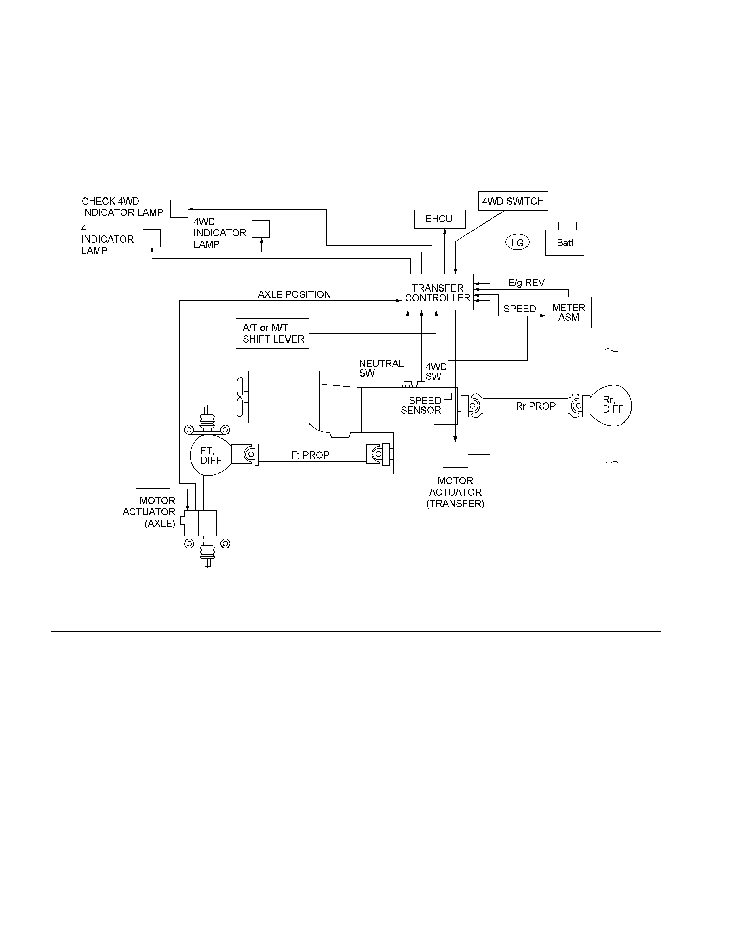
General Description
RTW34BLF000201

Transfer Position and Drive Mode
Three drive modes can be selected through operation of 4WD switch.
Transfer Position 4WD SWITCH Mode Drive mode
2H RWD Rear wheel drive
HIGH 4H 4WD (HIGH)
High-speed mechanical
lock-up four wheel drive
LOW 4L 4WD (LOW)
Low-speed mechanical
lock-up four wheel drive
NEUTRAL 2H & 4L (10 Sec) NEUTRAL Towed by other vehicle
Summary of transfer control system
The transfer control system switches between the 2-wheel
drive (2H), 4-wheel drive high-speed (4H), 4-wheel drive low-
speed (4L), and neutral positions electrically when the driver
operate the switches.
This system has following functions.
1. Connection or disconnection of drive force distribution to
the front wheel front shaft (axle shaft) (The drive force
distribution to the front propeller is connected o
r
disconnected with the motor actuator.)
2. Try to repeat the connection or disconnection of the front
wheel drive function as described above.
3. Instruction (to the axle controller) of connection o
r
disconnection of the drive force transmission between the
front wheel axle (axle shaft) and front wheel
(The motor actuator connects or disconnects the left front
wheel ad front wheel axle (axle shaft).).
4. Shifting of auxiliary transmission gears, connection o
r
disconnection of wheel and engine drive force (4H, 4L,
neutral).
5. Operation of indicator on the instrument panel.
6. Transmission of position signal to other controllers.
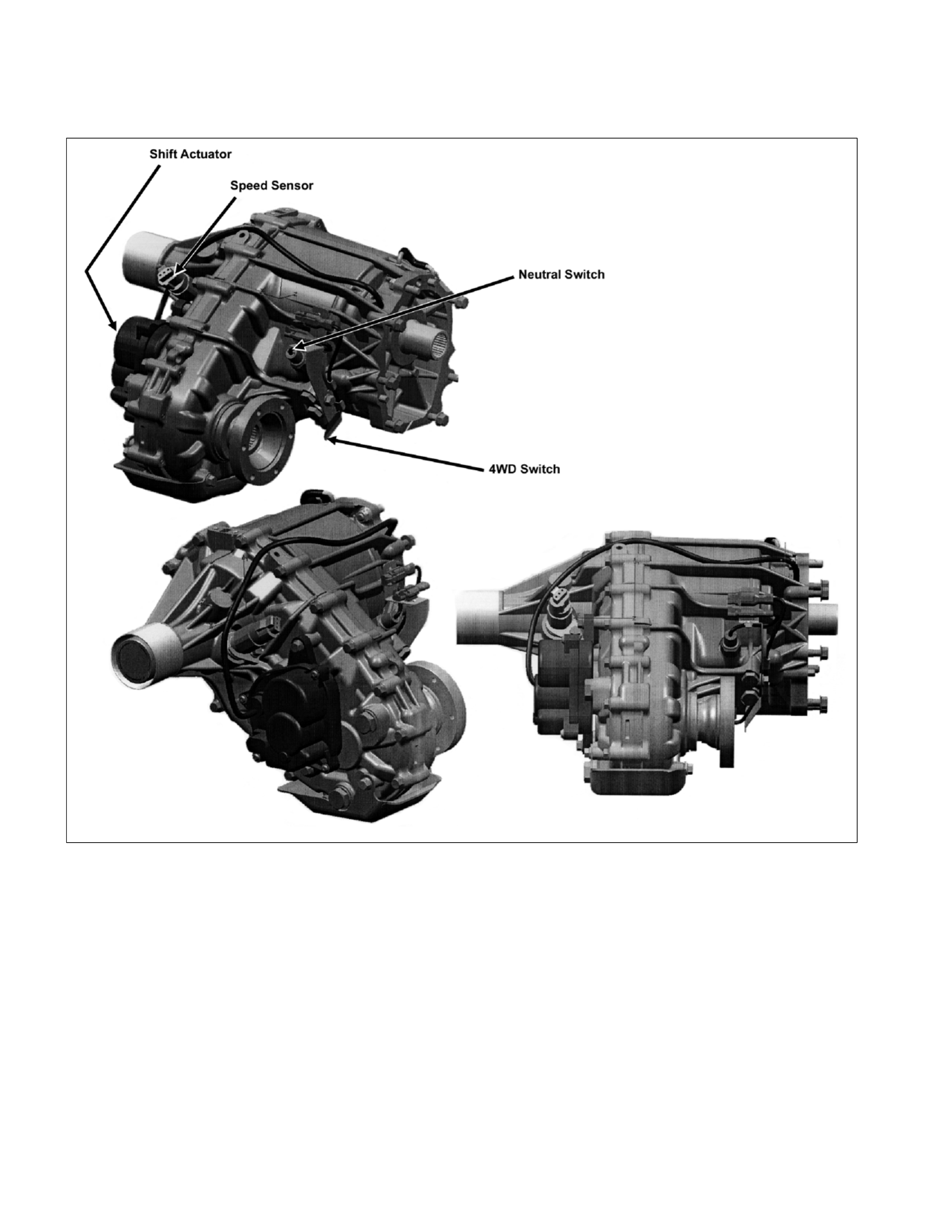
System Components
Parts Location

Speed sensor
Revolutions of the rear output shaft are decreased and taken
out by the speed/drive/driven gears installed in the transfer
case and the number of revolutions is detected with a speed
sensor.
About 4/3 pulses per revolution of the shaft is output.
4WD switch
The 4WD switch detects the movement of the shift rod driving
the 4×2 - 4×4 sleeve.
The contact of the switch are open when the shift rod is at the
4×2 position.
4×2 - 4×4 sleeve & Arm
The 4×2 - 4×4 sleeve moves directly in the 4×4 direction with
the 4×2 - 4×4 shift rod, but, when moving in 4×2 direction, a
spring standby mechanism is provided between the rod and
sleeve so that the rod is positioned at the 4×2 position, while
the sleeve is at the 4×4 position in sometime.
This mechanism is provided to protect the shift mechanism
from the force to prevent the movement of the sleeve
(torsional torque etc. of the drive system). By releasing the
preventive force, the sleeve can move to 4×2 state by the
spring force.
Neutral switch
The neutral switch detects the movement of the shift rod
driving the high-low sleeve.
The contacts of the neutral switch are closed when the shift
rod is positioned between the High and the Low, that is, at the
neutral position.
High-Low Sleeve & Arm
The spring standby mechanism is provided for the high-low
sleeve in both directions of the high-low shift rod. For this
reason, the rod position and the actual sleeve position may be
offset in some cases.
This system is provided to protect the shift mechanism from
the damage due to a phase difference between the engaged
splines. When correctly phased, the splines are moved to the
engaged position by the spring force.
Shift actuator
The built-in motor rotates the output shaft and the transfer
range is changed.
Detection (limit) switches to detect the rotating angle of the
output shaft is provided to the actuator at 4 positions, which
are connected to the transfer controller through the vehicle
harness to constantly transmit the actuator operating angle
and changes in its transfer status.
7B4-PDF2
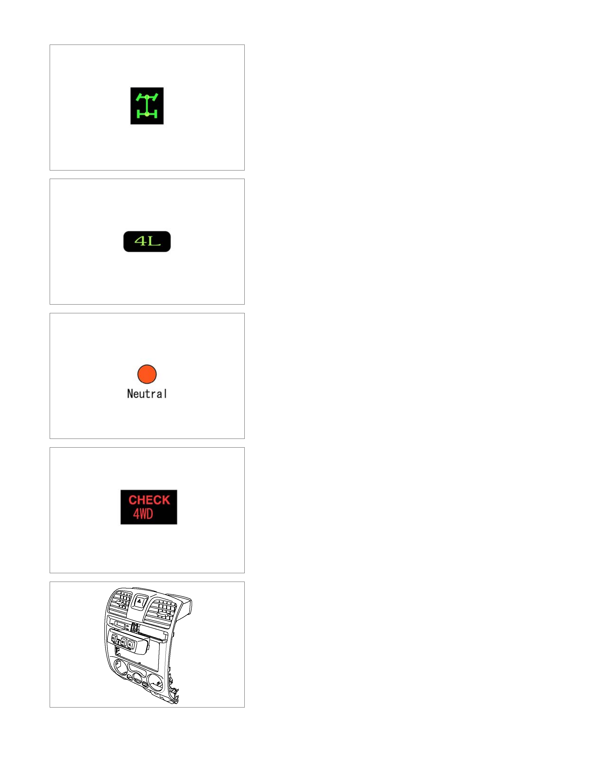
4WD indicator (in meter panel)
This lamp indicates the following items
Valve check
Drive condition (2WD-4WD)
Operating condition (2Hz: Actuator in operation, mechanism
standby)
Restrictions on operation (4Hz, including indication of
interrupted operation due
to excessive load)
7B4-PDF3
4L indicator (in meter panel)
This lamp indicates following items.
Valve check
Driving status (High-Low)
Operating status (2Hz: Actuator in operation, mechanism
standby)
Restrictions on operation (4Hz)
7B4-PDF4
Neutral indicator (in operation switch panel)
This LED indicates following items.
LED check
Driving status (Neutral)
Operating status (2Hz: Actuator in operation, mechanism
standby)
Restrictions on operation (4Hz)
7B4-PDF5
Check 4WD warning light (in meter panel)
This light indicates following items.
Valve check
Faulty actuator limit SW, and fault of circuit related with the
limit switch
825R300018
4WD switch
Switch to transmit a switching command to the 2H, 4H,
Neutral, or 4L position.
It comprises 3 PUSH momentary switches. By keeping to push
the 2H and 4L switches for 10 seconds,
operation is instructed to the neutral position.
To shift from the neutral to other position, other required
switches should be pushed for 10 seconds.
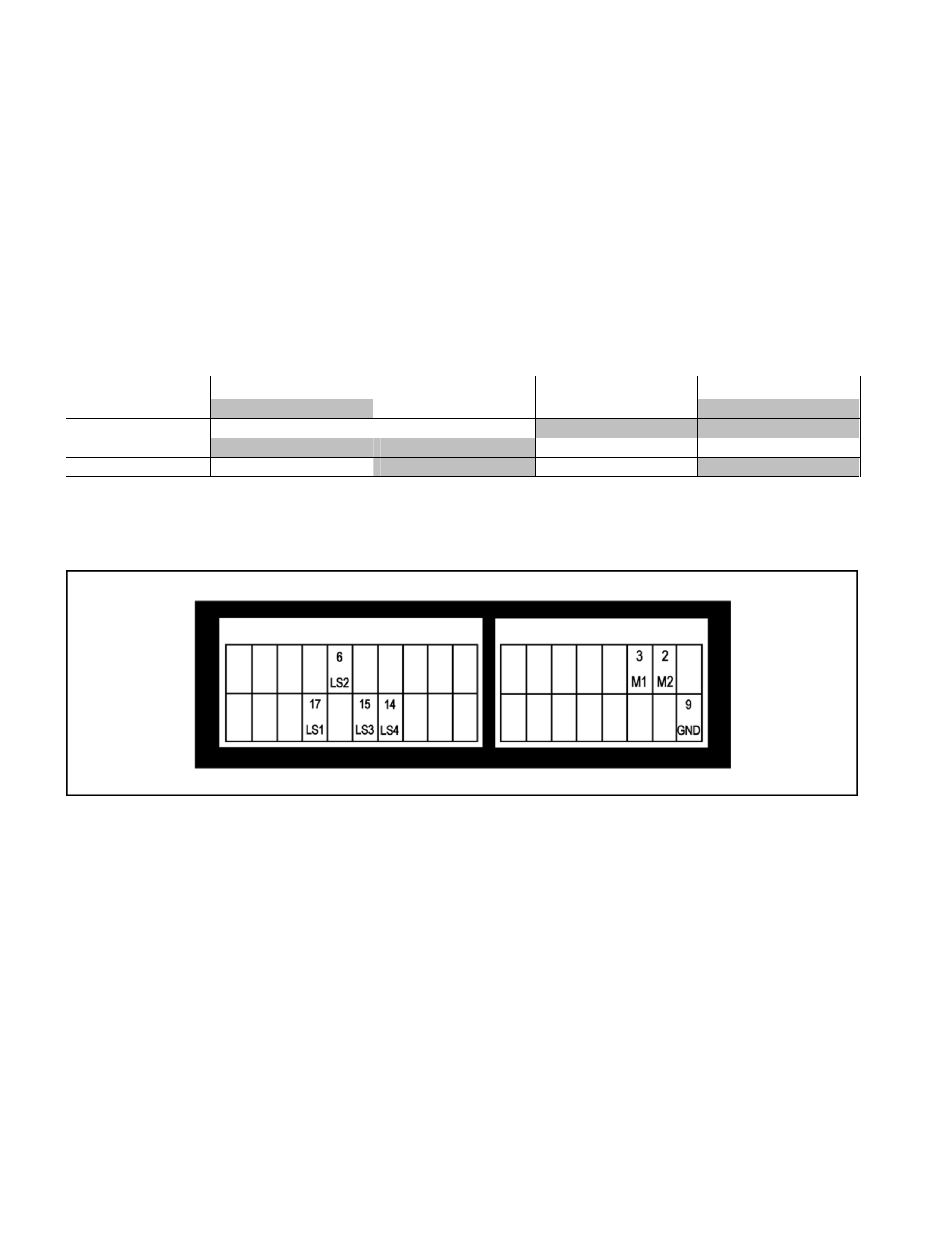
Shift Actuator Limit Switch Test
The initial test is best performed at the TCCM. Refer to the chart for the test conditions and to the TCCM Pin Out
illustration below for the correct harness pin location.
Should the test fail at Step 1, remove the harness connector with the transfer case in each drive range, and conduct
the test on the respective Limit Switch pin.
If the test fails at step 1, but passes at step 2, then a harness/connector fault is the most probable cause of the CHECK
4WD lamp illuminating.
NOTE:
The ignition switch must be in the OFF position whenever removing or replacing the TCCM or Limit Switch harness
connectors.
Under no circumstances should the Transfer Case Actuator harness connector be back-probed. This will damage the
weather-pak seal, leading to possible failure of the system due to contamination of the harness connector and actuator
pins.
2H 4H N 4L
LS1 Closed Open Open Closed
LS2 Open Open Closed Closed
LS3 Closed Closed Open Open
LS4 Open Closed Open Closed
NOTE:
“Closed” indicates continuity between the respective pin and GND pin. (Continuity should also exist between the
“Closed” pins.)
TCCM Pin Locations- Shift Actuator Limit Switch Test
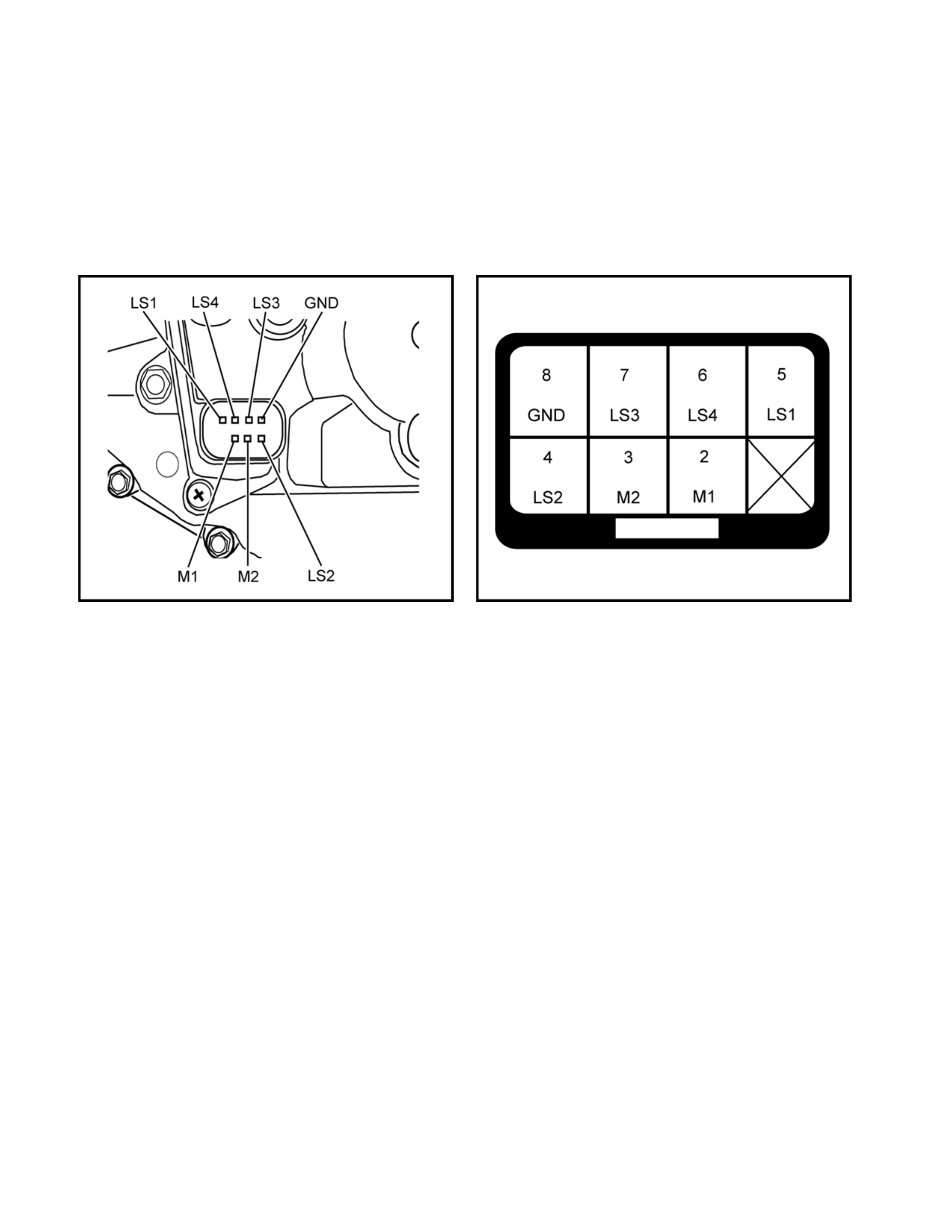
Shift Actuator Harness Test
Disconnect the vehicle harness connector on the transfer controller side and the vehicle harness connector on the
transfer actuator side as shown in the wiring diagram, and check the continuity between the following connector
pins and that there is no continuity between those pins and GND or power source.
Check that there is continuity between the GND pin and vehicle GND on the transfer actuator and pin and power
source.
Shift Actuator Pin Location
Actuator Harness Connector – Face View

Function of Switch and indicator Lamp
Transfer-related indicator lamp and switch function
Item 4WD
lamp 4L lamp Neutral
lamp
Check
4WD
warning
light
4WD
switch
Actuator
detection
(limit)
switches
LS1, LS2,
and LS3.
and LS4
1 = on
2 = off
Transfer
4WD
switch
Transfer
neutral
switch
SOF
actuator
switch Remarks
2H Off Off Off Off No
operation 1,0,1,0 Open Open Open -----
4H start
of
operation Off Off Off Off 4H position
for 0.1
second 1,0,1,0 Open Open Open Switch
operation
sensor
Start of
operation Blinking
(2HZ) Off Off Off No
operation
1,1,1,0
0,0,1,0
0,1,1,0
0,1,1,1
Open Open Open 2H to 4H
while
driving
During
operation
(Synchro)
Blinking
(2HZ) Off Off Off No
operation
1,1,1,0
0,0,1,0
0,1,1,0
0,1,1,1
Open Open Open
2H to 4H
using
synchro
and
retrial
During
operation
(Axle
drive)
Blinking
(2HZ) Off Off Off No
operation 0,0,1,1 Closed Open Open Axle drive
Axle
waiting Blinking
(2HZ) Off Off Off No
operation 0,0,1,1 Closed Open Open Axle drive
4H On Off Off Off No
operation 0,0,1,1 Closed Open Closed -----
4L start
of
operation On Off Off Off 4L position
for 0.1
second 0,0,1,1 Closed Open Closed
Switch
operation
sensor
Start of
operation On Blinking
(2HZ) Off Off No
operation 0,0,0,1
0,1,0,1 Closed Open Closed 4H to 4L
while
driving
During
operation
(N) Off Blinking
(2HZ) Off Off No
operation 0,0,0,1
0,1,0,1 Closed Closed Closed 4H to 4L
through
neutral
During
operation
(N) Off Blinking
(2HZ) Off Off No
operation 0,1,0,0 Closed Closed Closed 4H to 4L
through
neutral
During
operation
(N) Off Blinking
(2HZ) Off Off No
operation 1,1,0,0 Closed Closed Closed 4H to 4L
through
neutral

Item 4WD
lamp 4L lamp Neutral
lamp
Check
4WD
warning
light
4WD
switch
Actuator
detection
(limit)
switches
LS1, LS2,
LS3. and
LS4
1 = on
2 = off
Transfer
4WD
switch
Transfer
neutral
switch
SOF
actuator
switch Remarks
4L
waiting On Blinking
(2HZ) Off Off No
operation 1,1,0,1 Closed Closed Closed 4H to 4L
while
waiting
4L On On Off Off No
operation 1,1,0,1 Closed Open Closed -----
4H start
of
operation On Off Off Off 4H position
for 0.1
second 1,1,0,1 Closed Open Closed
Switch
operation
sensor
During
operation On Blinking
(2HZ) Off Off No
operation 1,1,0,1 Closed Open Closed
4L to 4H
while
driving
During
operation
(N) Off Blinking
(2HZ) Off Off No
operation 1,1,0,0 Closed Closed Closed 4L to 4H
through
neutral
During
operation Off Blinking
(2HZ) Off Off No
operation 0,1,0,1
0,0,0,1 Closed Closed Closed 4L to 4H
while
driving
4H
waiting Off Blinking
(2HZ) Off Off No
operation 0,0,1,1 Closed Closed Closed 4L to 4H
while
waiting
4H On Off Off Off No
operation 0,0,1,1 Closed Open Closed -----
2H start
of
operation On Off Off Off 2H position
for 0.1
second 0,0,1,1 Closed Open Closed
Switch
operation
sensor
Start of
operation Blinking
(2HZ) Off Off Off No
operation
0,1,1,1
0,1,1,0
0,0,1,0
1,1,1,0
Closed Open Closed 2H to 4H
while
driving
During
operation
(Axle)
Blinking
(2HZ) Off Off Off No
operation
0,1,1,1
0,1,1,0
0,0,1,0
1,1,1,0
Open Open Closed Axle drive
Axle
waiting Blinking
(2HZ) Off Off Off No
operation 1,0,1,0 Open Open Closed Axle
waiting
2H Off Off Off Off No
operation 1,0,1,0 Open Open Open -----

2H to 4H retrial
Item 4WD
lamp 4L lamp Neutral
lamp
Check
4WD
warning
light
4WD
switch
Actuator
detection
(limit)
switches
LS1, LS2,
LS3. and
LS4
1 = on
2 = off
Transfer
4WD
switch
Transfer
neutral
switch
SOF
actuator
switch Remarks
2H Off Off Off Off No
operation 1,0,1,0 Open Open Open -----
4H start
of
operation Off Off Off Off
4H
position
for 0.1
second
1,0,1,0 Open Open Open -----
Start of
operation Blinking
(2HZ) Off Off Off No
operation
1,1,1,0
0,0,1,0
0,1,1,0
0,1,1,1
Open Open Open 2H to 4H
while
driving
During
operation
(Synchro)
(Go to 4H
if synchro
complete)
Blinking
(2HZ) Off Off Off No
operation
1,1,1,0
0,0,1,0
0,1,1,0
0,1,1,1
Open Open Open
2H to 4H
using
synchro
and retrial
X 2
Abandon
ed
operation
(2H)
Blinking
(4HZ) Off Off Off No
operation 1,0,1,0 Open Open Open Return to
2H
2H
indication
after
10second
s
Off Off Off Off No
operation 1,0,1,0 Open Open Open -----
• Completion of transfer case H-L area and axle shift timing may cause some variation in 2Hz blinking pattern.
Operational limits (4HÆ4L) (Vehicle speed, engine speed, and transmission position not specified)
Item 4WD
lamp 4L lamp Neutral
lamp
Check
4WD
warning
light
4WD
switch
Actuator
detection
(limit)
switches
LS1, LS2,
LS3. and
LS4
1 = on
2 = off
Transfer
4WD
switch
Transfer
neutral
switch
SOF
actuator
switch Remarks
4H On Off Off Off Open 0,0,1,1 Closed Open Closed -----
4H start
of
operation On Off Off Off
4L
position
for 0.1
second
0,0,1,1 Closed Open Closed -----
10
second
display
during
limitation
On Blinking
(4HZ) Off Off Open 0,0,1,1 Closed Open Closed
No
operation
during
limitation
Go to 4H
after 10
seconds On Off Off Off Open 0,0,1,1 Closed Open Closed -----

Operational limits (4LÆ4H) (Vehicle speed, engine speed, and transmission position not specified)
Item 4WD
lamp 4L lamp Neutral
lamp
Check
4WD
warning
light
4WD
switch
Actuator
detection
(limit)
switches
LS1, LS2,
LS3. and
LS4
1 = on
2 = off
Transfer
4WD
switch
Transfer
neutral
switch
SOF
actuator
switch Remarks
4L On On Off Off No
operation 1,1,0,1 Closed Open Closed -----
4L start of
operation On On Off Off
4H
position
for 0.1
second
1,1,0,1 Closed Open Closed -----
10
second
display
during
limitation
On Blinking
(4HZ) Off Off Open 1,1,0,1 Closed Open Closed
No
operation
during
limitation
Go to 4L
after 10
seconds On On Off Off No
operation 1,1,0,1 Closed Open Closed -----
• Under some conditions, a secondary operational indication may be received when the 4Hz operational indication is
present.
Transfer-related indicator lamp and switch function
Skip operation
Item 4WD
lamp 4L lamp Neutral
lamp
Check
4WD
warning
light
4WD
switch
Actuator
detection
(limit)
switches
LS1, LS2,
LS3. and
LS4
1 = on
2 = off
Transfer
4WD
switch
Transfer
neutral
switch
SOF
actuator
switch Remarks
2H Off Off Off Off No
operation 1,0,1,0 Open Open Open -----
4L start of
operation Off Off Off Off
4L
position
for 0.1
second
1,0,1,0 Open Open Open Switch
operation
sensor
Start of
operation Blinking
(2HZ) Blinking
(2HZ) Off Off No
operation
1,1,1,0
0,0,1,0
0,1,1,0
0,1,1,1
Open Open Open 2H to 4H
while
driving
During
operation
(Synchro)
Blinking
(2HZ) Blinking
(2HZ) Off Off No
operation
1,1,1,0
0,0,1,0
0,1,1,0
0,1,1,1
Open Open Open
2H to 4H
using
synchro
and retrial
During
operation
(Passing
through
4H)
Off Blinking
(2HZ) Off Off No
operation 0,0,1,1 Closed Open Open -----
During
operation
(Passing
through
4H)
Off Blinking
(2HZ) Off Off No
operation 0,0,1,1
0,1,0,1 Closed Open Open -----
During
operation
(N) On Blinking
(2HZ) Off Off No
operation 0,0,1,1
0,1,0,1 Closed Open Closed -----
During
operation
(N) On Blinking
(2HZ) Off Off No
operation 0,1,0,0 Closed Open Closed Switch
operation
sensor

Item 4WD
lamp 4L lamp Neutral
lamp
Check
4WD
lamp
4WD
switch
Actuator
detection
(limit)
switches
LS1, LS2,
LS3. and
LS4
1 = on
2 = off
Transfer
4WD
switch
Transfer
neutral
switch
SOF
actuator
switch Remarks
During
operation
(N) On Blinking
(2HZ) Off Off No
operation 0,0,1,1 Closed Open Closed 4H to 4L
while
driving
During
operation
(Axle
drive)
Blinking
(2HZ) Blinking
(2HZ) Off Off No
operation 0,0,1,1 Closed Open Open -----
Axle
waiting Blinking
(2HZ) Blinking
(2HZ) Off Off No
operation 0,0,1,1 Closed Open Open -----
4L waiting On Blinking
(2HZ) Off Off No
operation 1,1,0,1 Closed Closed Closed 4H to 4L
while
waiting
4L On On Off Off No
operation 1,1,0,1 Closed Open Closed -----
2H start
of
operation On On Off Off
2H
position
for 0.1
second
1,1,0,1 Closed Open Closed Switch
operation
sensor
During
operation Blinking
(2HZ) Blinking
(2HZ) Off Off No
operation 1,1,0,1 Closed Open Closed 4L to 4H
while
driving
During
operation
(Passing
through
N)
On Blinking
(2HZ) Off Off No
operation 1,1,0,0 Closed Closed Closed 4L to 4H
through
neutral
During
operation
(Passing
through
N)
Off Blinking
(2HZ) Off Off No
operation 0,1,0,0 Closed Closed Closed 4L to 4H
through
neutral
During
operation
(4H
waiting)
Off Blinking
(2HZ) Off Off No
operation 0,0,1,1 Closed Closed Closed 4L to 4H
while
waiting
During
operation
(Axle)
Off while
waiting for
start of H
shift
Blinking
(2HZ)
while
waiting for
start of H
shift
Off Off No
operation
0,1,1,1
0,1,1,0
0,0,1,0
1,1,1,0
Closed Open Closed 2H to 4H
while
driving
During
operation
(Axle)
Blinking
(2HZ) at
end of H
shift
Off at end
of H shift Off Off No
operation
0,1,1,1
0,1,1,0
0,0,1,0
1,1,1,0
Closed Open Closed Axle
driving
Axle
waiting Blinking
(2HZ) Off Off Off No
operation 1,0,1,0 Open Open Closed -----
2H Off Off Off Off No
operation 1,0,1,0 Open Open Open -----
• Completion of transfer case H-L area and axle shift timing may cause some variation in 2Hz blinking pattern.

Skip operation limitations (4LÆ2H) (Vehicle speed, engine speed, and transmission position not specified)
Item 4WD
lamp 4L lamp Neutral
lamp
Check
4WD
warning
light
4WD
switch
Actuator
detection
(limit)
switches
LS1, LS2,
LS3. and
LS4
1 = on
2 = off
Transfer
4WD
switch
Transfer
neutral
switch
SOF
actuator
switch Remarks
4L Off On Off Off Open 1,1,0,1 Closed Open Closed -----
4L start of
operation Off On Off Off
2H
position
for 0.1
second
1,1,0,1 Closed Open Closed -----
10
second
display
during
limitation
Blinking
(4HZ) Off Off Off Open 1,1,0,1 Closed Open Closed
No
operation
during
limitation
Go to 4L
after 10
seconds Off ON Off Off Open 1,1,0,1 Closed Open Closed -----
Skip operation limitations (2HÆ4L) (Vehicle speed, engine speed, and transmission position not specified)
Item 4WD
lamp 4L lamp Neutral
lamp
Check
4WD
warning
light
4WD
switch
Actuator
detection
(limit)
switches
LS1, LS2,
LS3. and
LS4
1 = on
2 = off
Transfer
4WD
switch
Transfer
neutral
switch
SOF
actuator
switch Remarks
2HL Off Off Off Off Open 1,0,1,0 Open Open Open -----
4L start of
operation Off Off Off Off
2H
position
for 0.1
second
1,0,1,0 Open Open Open -----
10
second
display
during
limitation
Blinking
(4HZ) Blinking
(4HZ) Off Off Open 1,0,1,0 Open Open Open
No
operation
during
limitation
Go to 2H
after 10
seconds Off Off Off Off Open 1,0,1,0 Open Open Open -----
Under some conditions, a secondary operational indication may be received when the 4Hz operational indication is
present.

Transfer-related indicator lamp and switch function
2H→Neutral→2H
Item 4WD
lamp 4L lamp Neutral
lamp
Check
4WD
warning
light
4WD
switch
Actuator
detection
(limit)
switches
LS1, LS2,
LS3. and
LS4
1 = on
2 = off
Transfer
4WD
switch
Transfer
neutral
switch
SOF
actuator
switch Remarks
2H Off Off Off Off No
operation 1,0,1,0 Open Open Open -----
Neutral
start of
operation Off Off Off Off
Neutral
position
for 10
seconds
1,0,1,0 Open Open Open Switch
operation
sensor
Start of
operation Off Off Blinking
(2HZ) Off No
operation
1,1,1,0
0,0,1,0
0,1,1,0
0,1,1,1
Open Open Open 2H to 4H
while
driving
During
operation
(Synchro) Off Off Blinking
(2HZ) Off No
operation
1,1,1,0
0,0,1,0
0,1,1,0
0,1,1,1
Open Open Open
2H to 4H
using
synchro
and retrial
During
operation
(Passing
through
4H)
Off Off Blinking
(2HZ) Off No
operation 0,0,1,1 Closed Open Closed -----
During
operation
(Passing
through
4H)
Off Off Blinking
(2HZ) Off No
operation 0,0,0,1
0,1,0,1 Closed Open Closed 4H to 4L
while
driving
During
operation
(N) Off Off Blinking
(2HZ) Off No
operation 0,0,0,1
0,1,0,1 Closed Closed Closed 4H to 4L
through
neutral
During
operation
(N) Off Off Blinking
(2HZ) Off No
operation 0,1,0,0 Closed Closed Closed Switch
operation
sensor
Neutral Off Off On Off No
operation 0,1,0,0 Closed Closed Open -----
2H start
of
operation Off Off On Off
2H
position
for 10
seconds
0,1,0,0 Closed Open Closed Switch
operation
sensor
During
operation
(Passing
through
N)
Off Blinking
(2HZ) Off Off No
operation 0,1,0,0 Closed Closed Closed 4L to 4H
through
neutral

Item 4WD
lamp 4L lamp Neutral
lamp
Check
4WD
warning
light
4WD
switch
Actuator
detection
(limit)
switches
LS1, LS2,
LS3. and
LS4
1 = on
2 = off
Transfer
4WD
switch
Transfer
neutral
switch
SOF
actuator
switch Remarks
During
operation Off Blinking
(2HZ) Off Off No
operation 0,1,0,1
0,0,0,1 Closed Closed Closed 4L to 4H
while
driving
During
operation
(4H
waiting)
Off Blinking
(2HZ) Off Off No
operation 0,0,1,1 Closed Closed Closed 4L to 4H
while
waiting
During
operation
(Axle)
Blinking
(2HZ) Off Off Off No
operation
0,1,1,1
0,1,1,0
0,0,1,0
1,1,1,0
Closed Open Closed 2H to 4H
while
driving
During
operation
(Axle)
Blinking
(2HZ) Off Off Off No
operation
0,1,1,1
0,1,1,0
0,0,1,0
1,1,1,0
Open Open Closed
Axle
driving
Axle
waiting Blinking
(2HZ) Off Off Off No
operation 1,0,1,0 Open Open Closed -----
2H Off Off Off Off No
operation 1,0,1,0 Open Open Open -----
• Operational restrictions (vehicle speed, engine speed, and transmission position) are applicable to transfer shifts in
both directions (H←→Neutral←→L).

4HÆNeutralÆ4H
Item 4WD
lamp 4L lamp Neutral
lamp
Check
4WD
warning
light
4WD
switch
Actuator
detection
(limit)
switches
LS1, LS2,
LS3. and
LS4
1 = on
2 = off
Transfer
4WD
switch
Transfer
neutral
switch
SOF
actuator
switch Remarks
4H On Off Off Off No
operation 0,0,1,1 Closed Open Closed -----
Neutral
start of
operation On On Off Off
Neutral
position
for 10
seconds
1,1,0,1 Closed Open Closed -----
Start of
operation Off Off Blinking
(2HZ) Off No
operation 1,1,0,0 Closed Open Closed
4L to N
while
driving
During
operation
(N) Off Off Blinking
(2HZ) Off No
operation 1,1,0,0 Closed Closed Closed
4L to N
with axle
driving
During
operation
(N) Off Off Blinking
(2HZ) Off No
operation 0,1,0,0 Closed Closed Closed
4L to 4N
with axle
removed
During
operation
(Axle)
Blinking
(2HZ) Off Off Off No
operation
0,1,1,1
0,1,1,0
0,0,1,0
1,1,1,0
Open Open Closed
Axle
driving
Axle
waiting Blinking
(2HZ) Off Off Off No
operation 1,0,1,0 Open Open Closed -----
Neutral Off Off On Off No
operation 0,1,0,0 Closed Closed Open -----
4H start
of
operation Off Off Off Off
2H
position
for 10
seconds
0,1,0,0 Open Open Open Switch
operation
sensor
During
operation
(N) Off Blinking
(2HZ) Off Off No
operation 1,1,0,0 Closed Closed Open 4L to 4H
through
neutral
During
operation
(N) Off Blinking
(2HZ) Off Off No
operation 0,1,0,0 Closed Closed Open 4L to 4H
through
neutral
During
operation Off Blinking
(2HZ) Off Off No
operation 0,1,0,1
0,0,0,1 Closed Closed Open 4L to 4H
while
driving
4H
waiting Blinking
(2HZ) Off) Off Off No
operation 0,0,1,1 Closed Closed Open 4L to 4H
while
waiting
During
operation
(Axle)
Blinking
(2HZ) Off Off Off No
operation 0,0,1,1 Closed Open Open Axle
driving
Axle
waiting Blinking
(2HZ) Off Off Off No
operation 0,0,1,1 Closed Open Open -----
4H On Off Off Off No
operation 0,0,1,1 Closed Open Closed -----
• Operational restrictions (vehicle speed, engine speed, and transmission position) are applicable to transfer shifts in
both directions (H←→Neutral←→L).

4LÆNeutralÆ4L
Item 4WD
lamp 4L lamp Neutral
lamp
Check
4WD
warning
light
4WD
switch
Actuator
detection
(limit)
switches
LS1, LS2,
LS3. and
LS4
1 = on
2 = off
Transfer
4WD
switch
Transfer
neutral
switch
SOF
actuator
switch Remarks
4L On On Off Off No
operation 1,1,0,1 Closed Open Closed -----
Neutral
start of
operation On On Off Off
Neutral
position
for 10
seconds
1,1,0,1 Closed Open Closed -----
Start of
operation Off Off Blinking
(2HZ) Off No
operation 1,1,0,0 Closed Open Closed
4L to N
while
driving
During
operation
(N) Off Off Blinking
(2HZ) Off No
operation 1,1,0,0 Closed Closed Closed
4L to N
with axle
driving
During
operation
(N) Off Off Blinking
(2HZ) Off No
operation 0,1,0,0 Closed Closed Closed
4L to 4N
with axle
removed
During
operation
(Axle)
Blinking
(2HZ) Off Off Off No
operation 0,1,0,0 Closed Closed Closed
Axle
driving
Axle
waiting Blinking
(2HZ) Off Off Off No
operation 0,1,0,0 Closed Closed Closed -----
Neutral Off Off On Off No
operation 0,1,0,0 Closed Closed Open -----
4L start of
operation Off Off On Off
4L
position
for 10
seconds
0,1,0,0 Open Open Open Switch
operation
sensor
During
operation
(N) Off Blinking
(2HZ) Off Off No
operation 1,1,0,0 Closed Closed Open 4H to 4L
through
neutral
During
operation
(N) Off Blinking
(2HZ) Off Off No
operation 1,1,0,0 Closed Closed Open 4H to 4L
through
neutral
During
operation
(N) Off Blinking
(2HZ) Off Off No
operation 1,1,0,0 Closed Closed Open 4H to 4L
through
neutral
4H
waiting On Blinking
(2HZ) Off Off No
operation 1,1,0,1 Closed Closed Open 4L while
waiting
During
operation
(Axle)
Blinking
(2HZ) Off Off Off No
operation 1,1,0,1 Closed Open Open Axle
driving
Axle
waiting Blinking
(2HZ) Off Off Off No
operation 1,1,0,1 Closed Open Open -----
4H On On Off Off No
operation 1,1,0,1 Closed Open Closed -----
• Operational restrictions (vehicle speed, engine speed, and transmission position) are applicable to transfer shifts in
both directions (H←→Neutral←→L).
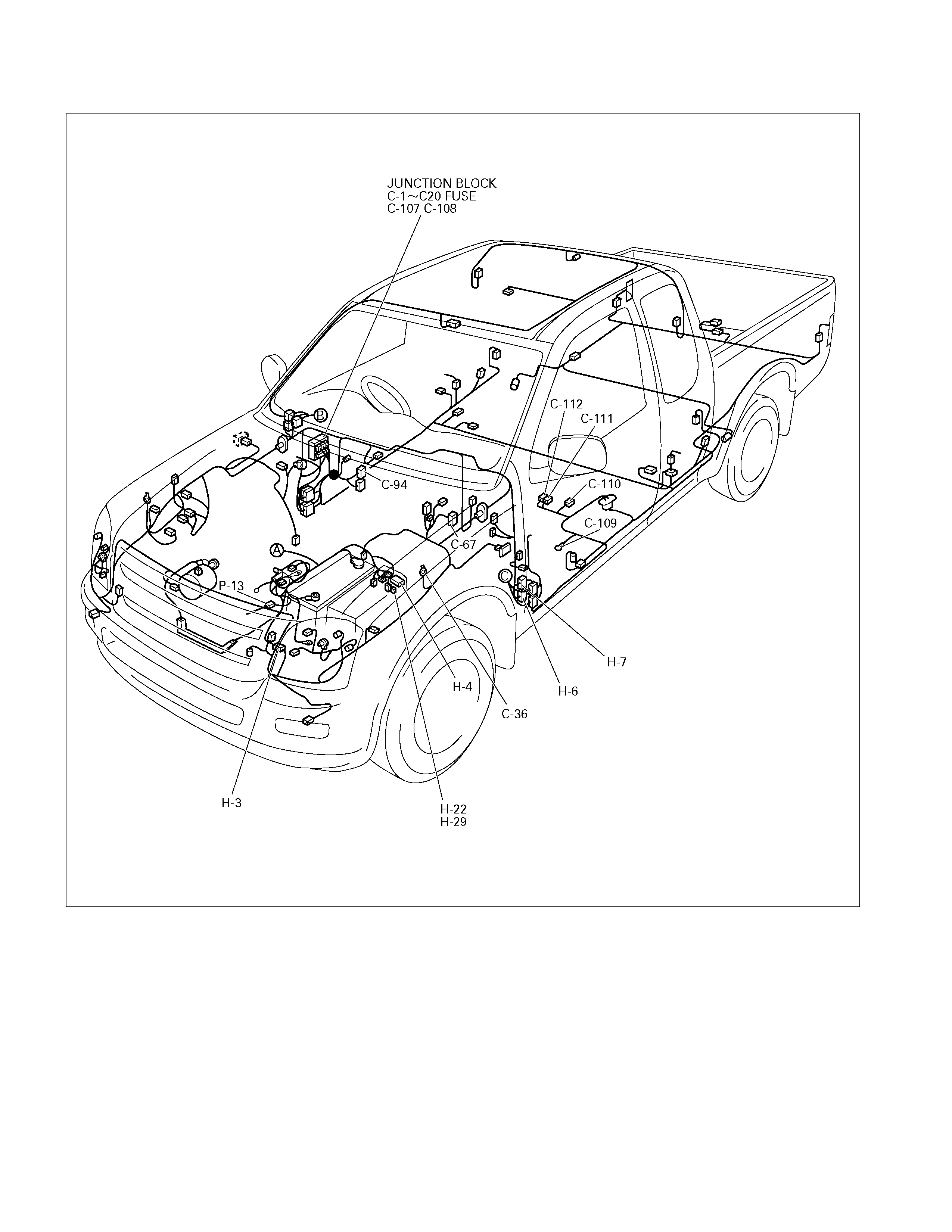
Parts Location
810R300065
810R300066
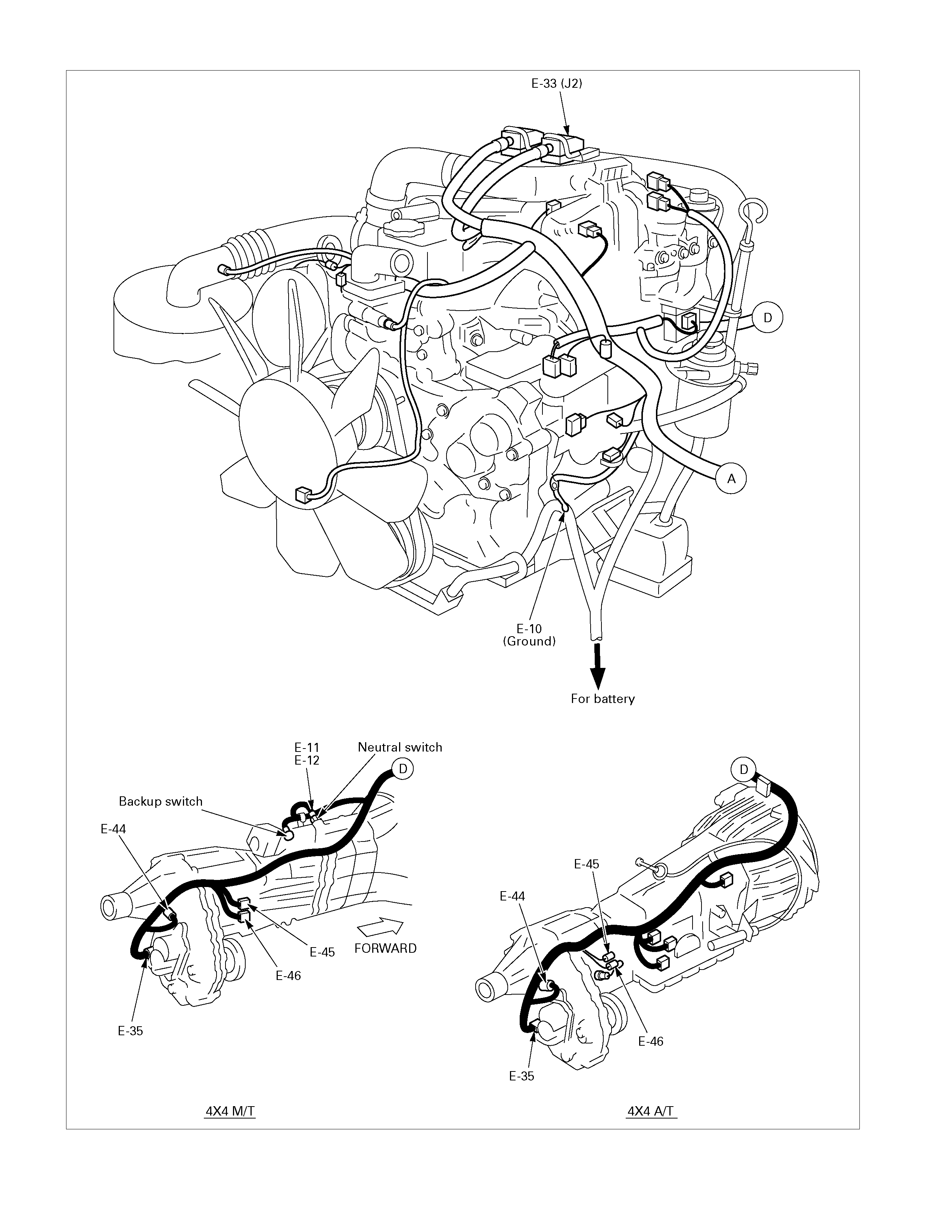
810R300067

Circuit Diagram
6VE1
RTW38DXF001701
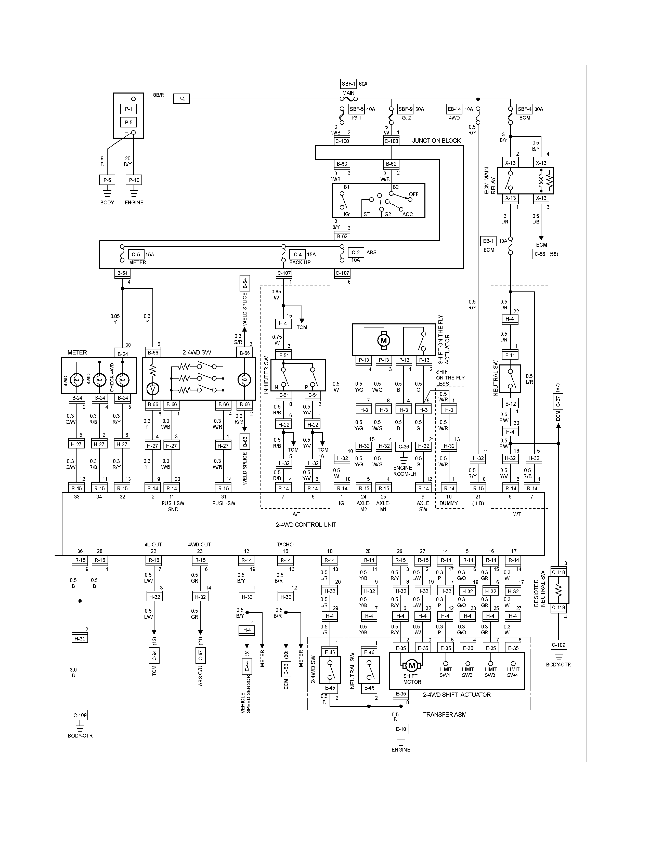
4JH1-TC
RTW38DXF001801
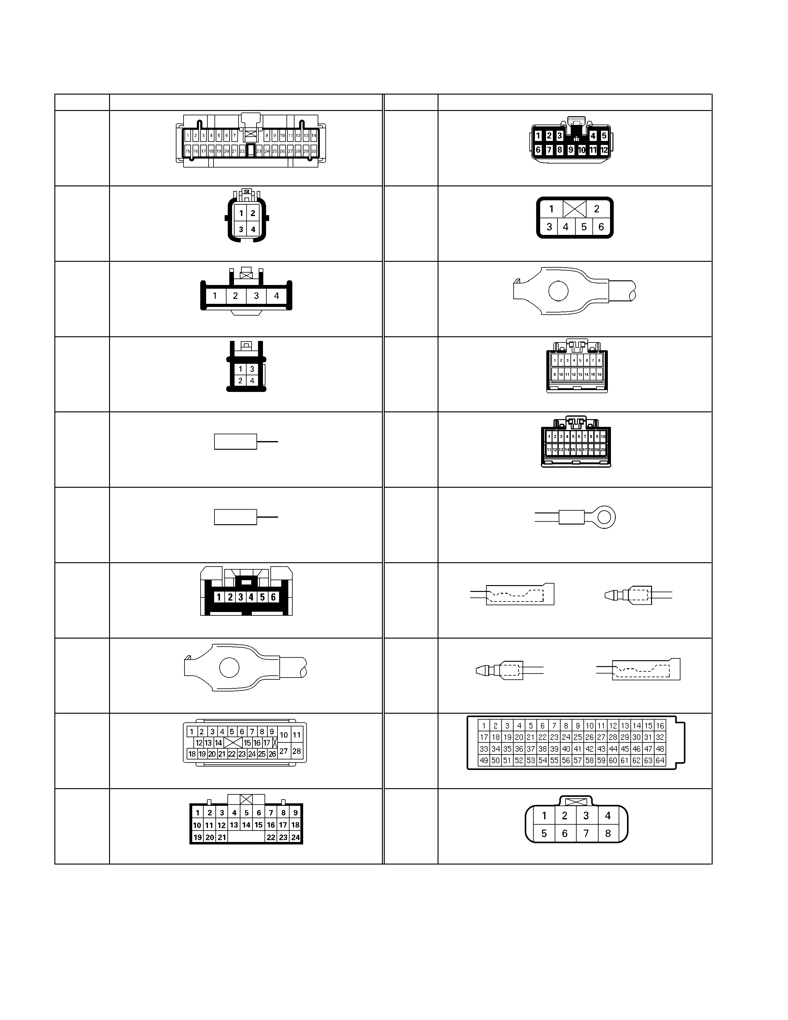
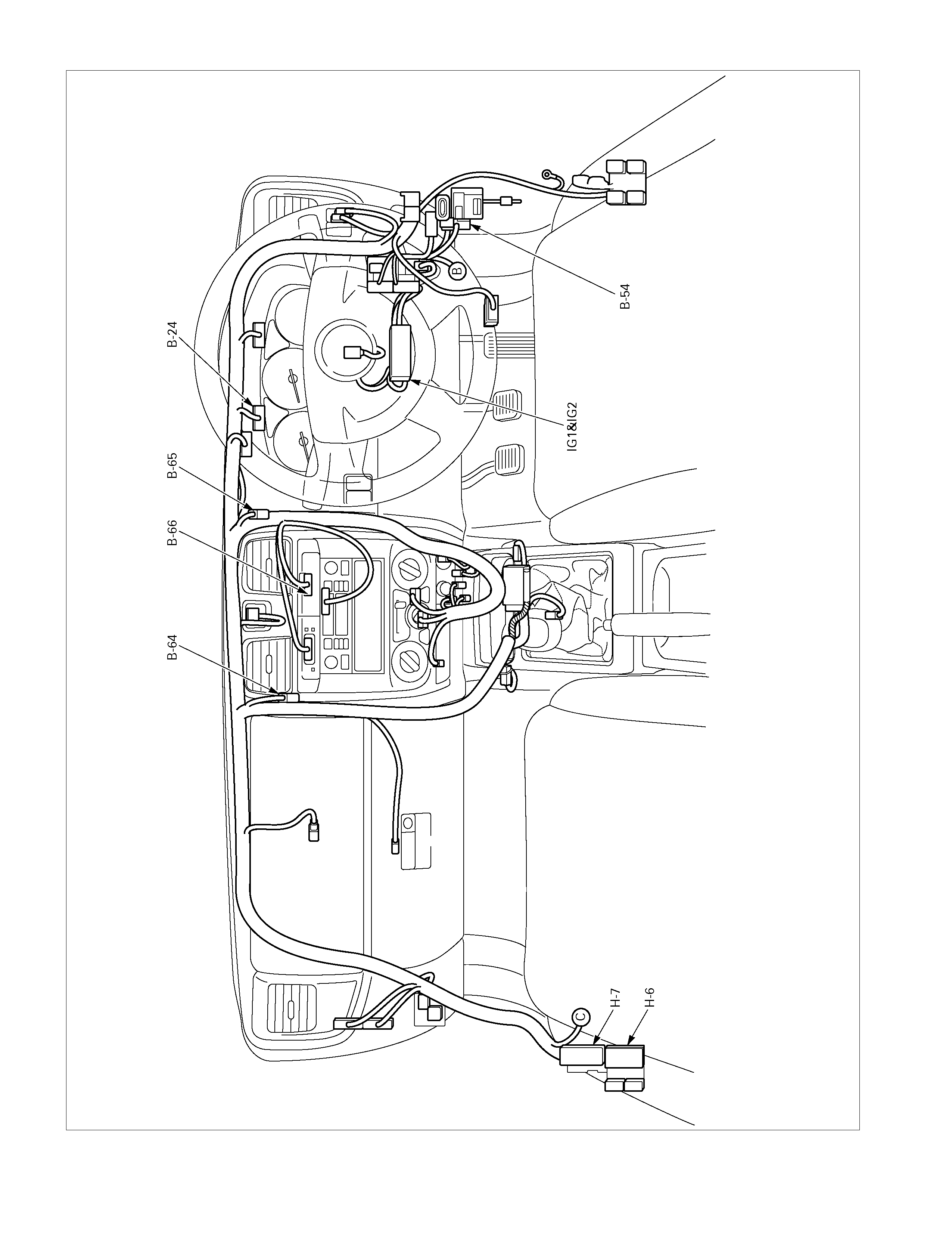
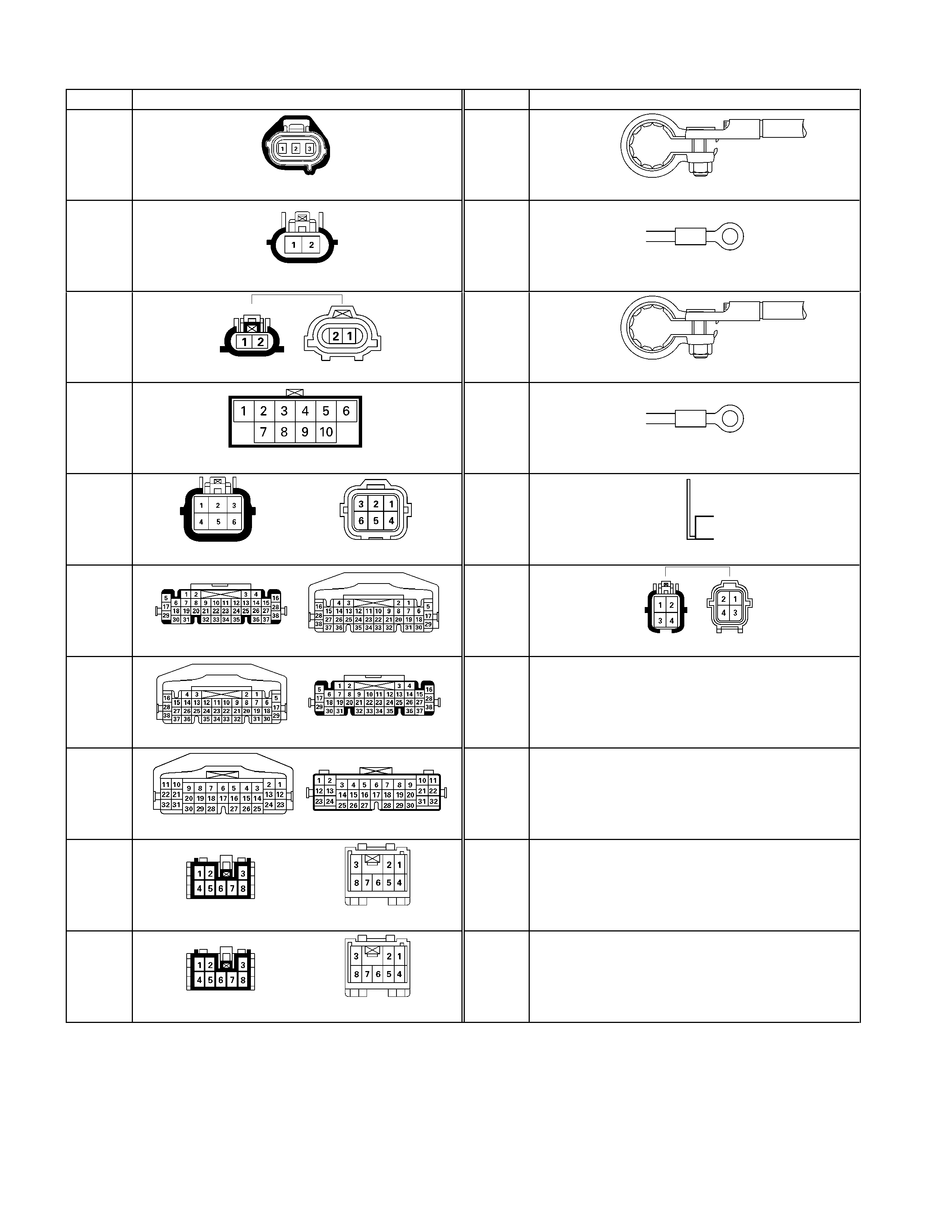
Connector List
No. Connector face No. Connector face
B-24
Green
Meter-B
C-107
White
J/B E2
B-54
White
J/B I2
C-108
White
J/B E1
B-62
White
Ignition switch (IGSUB : G1)
C-109
Silver
Body-LH ; ground
B-63
White
Ignition switch (IGSUB : G2)
R-15
Black
Transfer controller
B-64
Silver
Weld splice 1(Illumination)
R-14
Black
Transfer controller
B-65
Silver
Weld splice 2 (Ground)
E-10
Silver
Engine ground
B-66
White
4WD switch
E-11
(4JH1)
Natural
Green
Neutral switch
C-36
Silver
Engine room-LH ; Ground
E-12
(4JH1)
Natural
Green
Neutral switch
C-67
Black
EHCU
E-33
Black
ECM J2
C-94
Gray
TCM
E-35
Black
Motor actuator
No. Connector face No. Connector face
E44
Gray
Vehicle speed sensor
P-1
Silver
Battery (+)
E-45
White
4WD switch
P-2
Silver
Relay & Fuse box
E-46
Brown
H-L neutral switch
P-5
Silver
Battery (-)
E-51
Black
Inhibiter switch
P-6
Silver
Body earth (Ground)
H-3
(4JH1-
A/T)
White
Battery (+) ∼ Engine room
P-10
Silver
Engine ground
H-4
(4JH1)
White
Engine ∼ Engine room
P-13
(4JH1)
Gray
Shift on the fly actuator
H-6
White
Engine room ∼ INST
H-7
White
Engine room ∼ INST
H-22
(4JA1/H1
-M/T)
Gray
Engine ∼ Engine room C
H-29
(4JH1-
M/T)
White
Battery (+) ∼ Engine room C

Diagnosis
Neither the Transfer Case Control System nor Shift On The Fly (SOF) System can be accessed with the TECH 2 scan
tool. Incorrect diagnosis can be both time-consuming and expensive. Refer to the following for the correct diagnostic
procedures and symptom charts.
ROAD TESTING PRIOR TO REPAIR
Before attempting diagnosis, the vehicle should be road-tested to determine if a mechanical/electrical fault actually
exists. Many reports of incorrect transfer case or S.O.F. system operation can be attributed to the driving conditions at
the time of “failure”.
Noting the operation of the 4WD, 4 Low, Neutral indicator lamps and the CHECK 4WD warning lamp will provide
valuable information when testing the performance of the four wheel drive system. Observe the operating sequence of
the indicator/warning lamps when operating the transfer case controls, then use the information below to determine
whether or not further diagnosis is required.
SHIFTING FROM 2H TO 4H
4WD Indicator Lamp: Flash rate increases from 2Hz to 4Hz.
Probable Cause: High vehicle speed or extremely low operating temperatures.
Corrective Action: Reduce speed or stop the vehicle and perform the required shift.
At high road speed the relative speed difference between the internal components of the transfer case is too high for
the shift to occur. The TCCM will make four attempts to shift from 2H to 4H. If the shift is not achieved on the fourth
attempt, the 4WD indicator lamp frequency will increase to 4Hz for 10 seconds and then go out. The transfer case will
then remain in 2H.
Similarly, extremely low operating temperature (high transfer case oil viscosity) will give rise to excessive component
speed difference.
4WD Indicator Lamp: Flash rate of 2Hz continues for more than 11.5 seconds.
Probable Cause: Speed or phase difference between LH front wheel and front axle.
Corrective Action: If moving, accelerate and decelerate the vehicle in a straight line.
If stationary, move the vehicle backwards and forwards a few metres.
If there is difference of speed and/or phase between the LH front wheel and axle, the S.O.F. system cannot operate
correctly.
Until the both the transfer case and S.O.F. actions are completed, the 4WD Indicator Lamp flashes at a frequency of
2Hz. The indicator continues flashing at a frequency of 2Hz until the S.O.F. internal switch indicates front axle
engagement.
By correcting the difference in relative speeds or axle phase, the S.O.F. action can be completed.
SHIFTING FROM 4H TO 2H
4WD Indicator Lamp: Flash rate of 2Hz continues for more than 11.5 seconds.
Probable Cause: High torque loading on drivetrain components – possible ‘wind-up’ condition.
Corrective Action: If moving, accelerate and decelerate the vehicle in a straight line.
If stationary, move the vehicle backwards and forwards a few metres.
High torque loading of the drivetrain will usually occur if the vehicle is driven in 4WD on hard ground, particularly if
performing turning manoeuvres. The high torque load will prevent the ‘separation’ of the front axle and transfer case
components and the vehicle will remain in 4WD.
Moving the vehicle with the road wheels in the straight ahead position will usually reduce the torque loading
sufficiently to allow the shift from 4H to 2H to complete.
NOTE: In cases of extreme drivetrain ‘wind-up’, it will be necessary to lift the front wheels of the vehicle from the
ground to remove the torque loading. This operation should be performed with extreme caution due to the rapid wheel
movement that occurs when the torque load is released.

SHIFTING FROM 4H TO 4L
4L Indicator Lamp: Flash rate of 2Hz continues for more than 11.5 seconds.
Probable Cause: Spline phase difference between transfer case components.
Corrective Action: A/T – Select [D] range and then [N] range.
M/T – Select 2nd gear and partially engage the clutch, depress the clutch and select
neutral.
Failure to shift due to spline phase difference may occur if the drivetrain is under load. Selecting [D] or [N] (A/T) or
selecting 2nd gear with a gentle application of the clutch (M/T) will generally allow sufficient component movement for
the transfer case shift to complete.
4L Indicator Lamp: Flash rate of 2Hz for 10 seconds, then remains ‘ON’ continuously (A/T only )
Probable Cause: High torque loading on drivetrain components.
Corrective Action: Apply the footbrake and then Select [N] range.
The transfer case H-L Shift Assembly stand-by mechanism cannot overcome the load applied to the H-L shift
components. This condition will usually occur when a high torque loading has been generated between the drivetrain
and the road surface.
Applying the footbrake and then selecting [N] range will allow the components to dissipate the torque loading.
4L Indicator Lamp: Flash rate of 4Hz
Probable Cause: High engine speed.
Transmission not in [N] or [P] – (A/T)
Transmission not in Neutral – (M/T)
Corrective Action: Reduce engine speed to below 2000rpm.
Select correct transmission range.
Push the 4L Transfer Shift switch.
The TCCM will not allow the transfer case to shift from 4H to 4L or from 4L to 4H if the engine speed is above
2000rpm, the transmission is not in neutral (M/T & A/T) or ‘Park ‘ (A/T). Any of these conditions will cause the TCCM to
enter “Restricted Operation” mode.
NOTE:
‘Restricted Operation’ Mode
The 4H, neutral and 4L shifting mechanism has no synchronisation components. Consequently, attempting to shift
with a high relative component speed difference may lead to component failure. To avoid this incidence, the
TCCM will restrict transfer case and S.O.F. operation if any or all of the following conditions are detected:
Vehicle is moving.
Engine Speed above 2000rpm.
Transmission not in neutral (M/T & A/T) or ‘Park ‘ (A/T).
The programming of the TCCM logic circuit includes a Wait-Time function. When certain conditions are detected via
the input signals to the TCCM, a delay (wait time) will be encountered before the transfer case or S.O.F.
system will operate in response to a driver command.
A/T: If the vehicle has been idling in any drive range for up to three minutes, the wait-time will be between one and
five seconds.
M/T: If the vehicle has been idling, with the transmission in any gear and the clutch disengaged, for up to three
minutes, the wait-time will be between one and five seconds.
Should either of the above conditions be continued for longer than three minutes, the wait-time will increase to a
maximum of three minutes.
Wait-time can be reduced to zero by turning the ignition OFF, then ON or driving the vehicle for 5 metres.

SHIFTING FROM 4L TO 4H
4L Indicator Lamp: Flash rate of 2Hz continues for more than 11.5 seconds.
Probable Cause: Spline phase difference between transfer case components.
Corrective Action: A/T – Select [D] range and then [N] range.
M/T – Select 2nd gear and partially engage the clutch, depress the
clutch and select neutral.
Failure to shift due to spline phase difference may occur if the drivetrain is under load. Selecting [D] or [N] (A/T) or
selecting 2nd gear with a gentle application of the clutch (M/T) will generally allow sufficient component movement for
the transfer case shift to complete.
4L Indicator Lamp: Flash rate of 2Hz for 10 seconds, then remains ‘ON’ continuously (A/T only )
Probable Cause: High torque loading on drivetrain components.
Corrective Action: Apply the footbrake and then Select [N] range.
The transfer case H-L Shift Assembly stand-by mechanism cannot overcome the load applied to the H-L shift
components. This condition will usually occur when a high torque loading has been generated between the drivetrain
and the road surface.
Applying the footbrake and then selecting [N] range will allow the components to dissipate the torque loading.
4L Indicator Lamp: Flash rate of 4Hz
Probable Cause: High engine speed.
Transmission not in [N] or [P] – (A/T)
Transmission not in Neutral – (M/T)
Corrective Action: Reduce engine speed to below 2000rpm.
Select correct transmission range.
Push the 4H Transfer Shift switch.
The TCCM will not allow the transfer case to shift from 4H to 4L or from 4L to 4H if the engine speed is above
2000rpm, the transmission is not in neutral (M/T & A/T) or ‘Park ‘ (A/T). Any of these conditions will cause the TCCM
to enter “Restricted Operation” mode.
SHIFTING FROM 4L OR 4H TO NEUTRAL
Neutral Indicator Lamp: Flash rate of 2Hz continues for more than 11.5 seconds.
Probable Cause: Spline phase difference between transfer case components.
Corrective Action: A/T – Select [D] range and then [N] range.
M/T – Select 2nd gear and partially engage the clutch, depress the
clutch and select neutral.
Failure to shift due to spline phase difference may occur if the drivetrain is under load. Selecting [D] or [N] (A/T) or
selecting 2nd gear with a gentle application of the clutch (M/T) will generally allow sufficient component movement for
the transfer case shift to complete.
Neutral Indicator Lamp: Flash rate of 4Hz
Probable Cause: High engine speed.
Transmission not in [N] or [P] – (A/T)
Transmission not in Neutral – (M/T)
Corrective Action: Reduce engine speed to below 2000rpm.
Select correct transmission range.
Push and hold the 2H and 4L Transfer Shift switches for 10 seconds.
The TCCM will not allow the transfer case to shift fr om 2H, 4H or 4L Neutral if the engine speed is above 2000rpm,
the transmission is not in neutral (M/T & A/T) or ‘Park ‘ (A/T). Any of these conditions will cause the TCCM to enter
“Restricted Operation” mode.

SHIFTING FROM NEUTRAL TO 2H, 4H OR 4L
4L or 4WD Indicator Lamp: Flash rate of 2Hz continues for more than 11.5 seconds.
Probable Cause: Spline phase difference between transfer case components.
Corrective Action: A/T – Select [D] range and then [N] range.
M/T – Select 2nd gear and partially engage the clutch, depress the clutch and select
neutral.
Failure to shift due to spline phase difference may occur if the drivetrain is under load. Selecting [D] or [N] (A/T) or
selecting 2nd gear with a gentle application of the clutch (M/T) will generally allow sufficient component movement
for the transfer case shift to complete.
4WD INDICATOR LAMP FLASHES WHEN IGNITION IS TURNED ON
4WD Indicator Lamp: Flash rate of 2Hz.
Probable Cause: Ignition turned OFF with 4H or 4L selected.
Corrective Action: A/T – Select [D] range and then [N] range.
M/T – Select 2nd gear and partially engage the clutch, depress the
clutch and select neutral.
When the ignition is first turned ON, the TCCM initialises and commands the Shift Actuator motor to the 2WD
position. At the completion of initialisation, the TCCM will the command the Shift Actuator motor to the last selected
position. Failure to shift to that position may be due to spline phase difference if the drivetrain is under load.
Selecting [D] or [N] (A/T) or selecting 2nd gear with a gentle application of the clutch (M/T) will generally allow
sufficient component movement for the transfer case shift to complete.
‘CHECK 4WD’ INDICATOR LAMP ON WHEN IGNITION IS ON
‘CHECK 4WD’ Indicator Lamp: ON when ignition is turned ON
Probable Cause: Failure of Shift Actuator motor or harness
Corrective Action: Conduct the test procedure outlined below, replace failed components.
The initial test is best performed at the TCCM. Refer to the chart below for the test conditions and to the TCCM Pin
Out illustration on 7D1-10 for the correct harness pin location.
Should the test fail at Step 1, remove the harness connector with the transfer case in each drive range, and
conduct the test on the respective Limit Switch pin 7D1-9
If the test fails at step 1, but passes at step 2, then a harness/connector fault is the most probable cause of the
CHECK 4WD lamp illuminating.
NOTE:
The ignition switch must be in the OFF position whenever removing or replacing the TCCM or Limit Switch harness
connectors.
Under no circumstances should the Transfer Case Actuator harness connector be back-probed. This will damage the
weather-pak seal, leading to possible failure of the system due to contamination of the harness connector and actuator
pins.
2H 4H N 4L
LS1 Closed Open Open Closed
LS2 Open Open Closed Closed
LS3 Closed Closed Open Open
LS4 Open Closed Open Closed
NOTE:
“Closed” indicates continuity between the respective pin and GND pin. (Continuity should also exist between the
“Closed” pins.)

Trouble diagnosis based on the operation switch, transfer indicator lamp and operating sound “Check 4WD”
indicator ON (operation guard based on the transfer actuator position detection error)
This condition indicates a faulty circuit related with the detection (limit) switches of the system actuator.
The ECU determines the actuator operating angle based on the combined Detection (limit) switches signals.
The controller monitors transition of the actuator based on the combination of the detection (limit) switch output.
If the transition based on the combinations indicates some trouble, it is memorized, shifting operation is stopped
when the trouble is counted 5 times, and the “Check 4WD” indicator lights up. At this time, the system permits
operation to 2H only.
When such a condition results, inspection of the transfer shift actuator, check of harness related with the detection
(limit) switch, and erasure of the memory of the controller are required.
(Refer to the memory erasure procedure for the erasure of the memory.)
At this time, the position indicator may flash at 4Hz. It means that a detection (limit) switch trouble wad detected in
the operation process shown by that position indicator (example: 4WD indicator when shifting from 2H to 4H).
Caution:
In the course of fault diagnosis and correction, do not turn ON the ignition with the harness connector of the
transfer actuator disconnected. (Do not disconnect the harness connector of the transfer actuator when the
ignition is ON.)
If the controller is connected at this condition, a “Limit SW Failure” is set and the above-described “Check
4WD” condition is brought about.
This can be reset by clearing the memory.
When it is required to disconnect the harness connector of the actuator and turning the ignition ON, remove
the controller at the same time or remove the IG power fuse of the transfer controller.
TCCM Memory Erasing Procedure
Circuit Description
The “CHECK 4WD” indicator lamp is ON when the Transfer Case
Control module (TCCM) detects a faulty circuit related to the limit
switches of the shift-actuator.
The limit switches detect the shift-actuator operating angle based on
their combinations. The TCCM monitors the transition of the shift-
actuators based on the combination of the limit switch outputs.
If the transition based on the combinations indicates some trouble, it
is memorised by the TCCM.
NOTE:
1. Do Not Turn the ignition ON with the TCCM harness connector
disconnected.
2. Do Not Turn the ignition ON with the shift actuator harness
connector disconnected.
3. Do Not Turn the ignition ON with the in-line connector
disconnected.
If any of the above conditions occur, the TCCM will assume a limit
switch problem and will activate the “CHECK 4WD” indicator lamp.
When any connectors need to be disconnected, disconnect the
TCCM harness connector with the ignition key tur ned OFF or remove
the “ABS” fuse in the cabin to disable the TCCM.
The TCCM cannot be disabled by removing the “4WD” fuse in the
engine compartment. It will cause the “CHECK 4WD” to be activated.
Once the “CHECK 4WD” is ON, it cannot be turned OFF until the
erasing procedure is completed, even if the problem has been
corrected. The memory is not erased by key cycles.
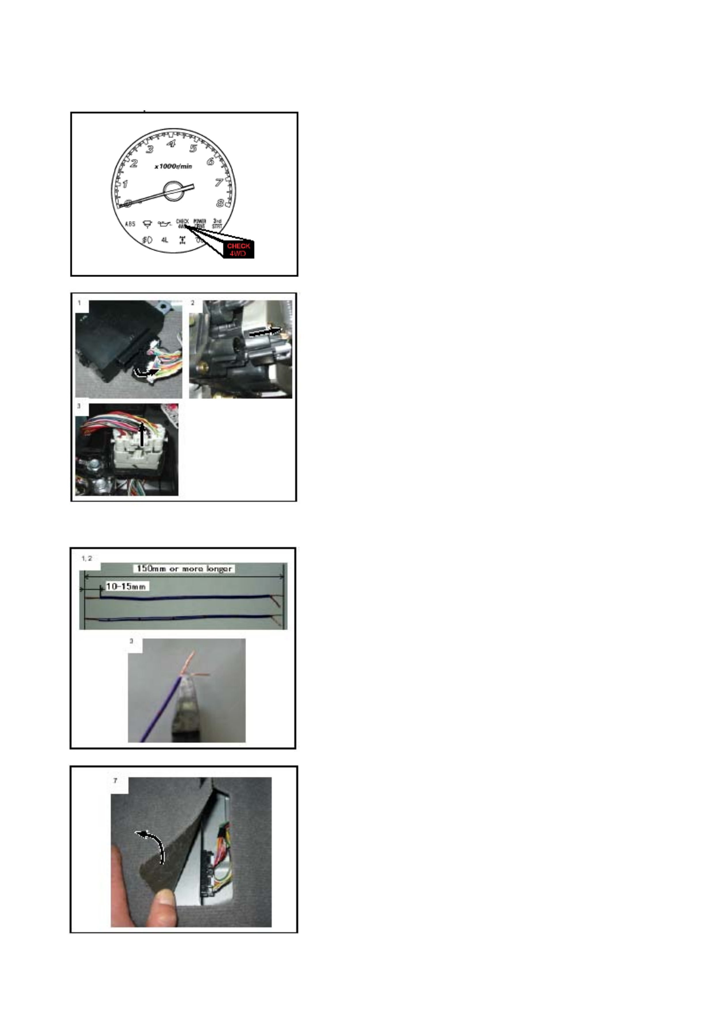
TCCM Memory Erasing Procedure
1. Prepare two pieces of 0.5 mm wiring, approximately 150 mm
long to form two jumper-harnesses.
2. Strip the wire insulation by 10 – 15mm at each end.
3. Cut the stripped wire to reduce the wire size in half, at each , then
twist the exposed wires. Soldering the wires will improve
stiffness.
4. Turn OFF the ignition switch.
5. Disconnect the seat belt s witch and/or SRS pretens ioner harness
connectors, if fitted.
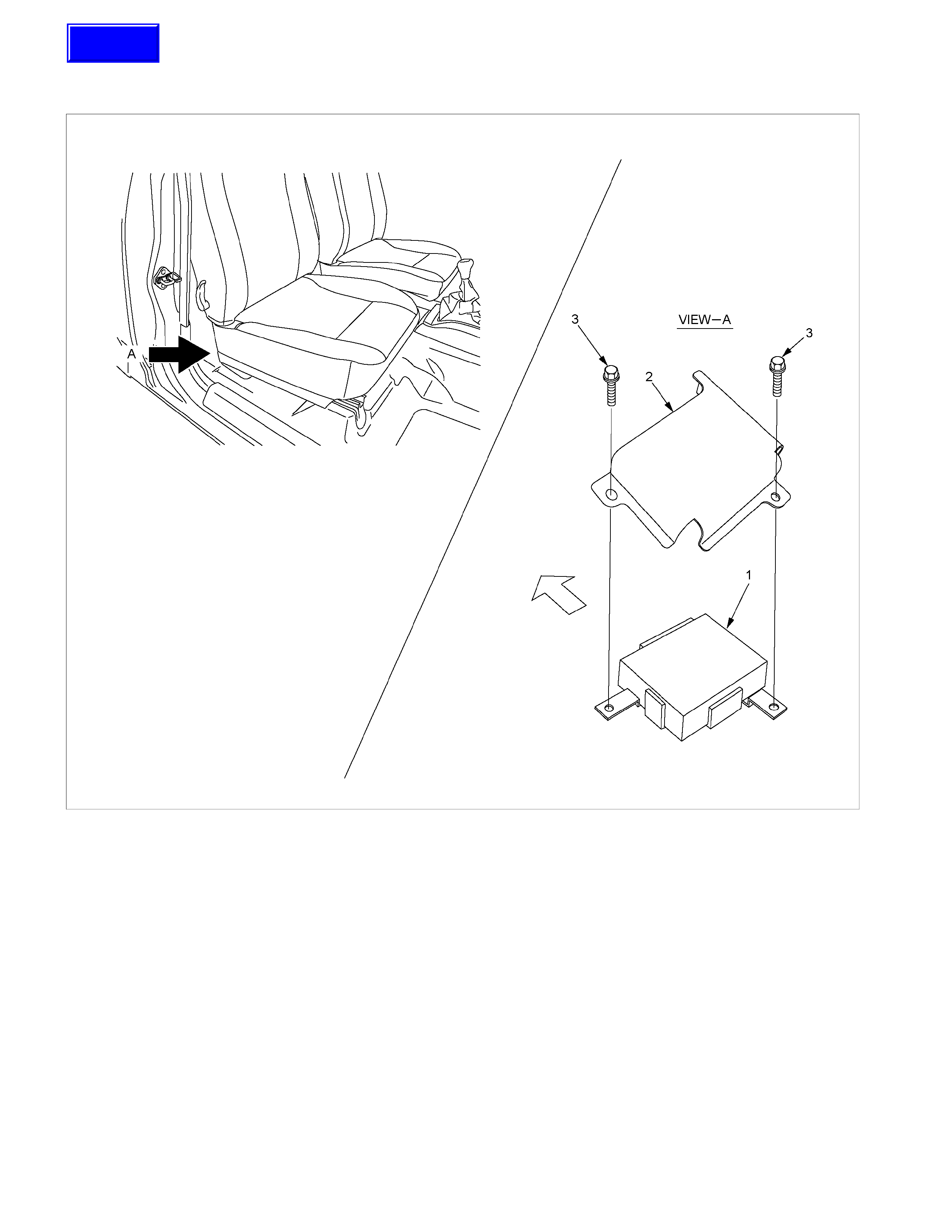
6. Remove the front seat assembly.
7. Spread the cut line of the floor carpet or roll up the floor carpet.
8. Remove two bolts and protective cover. Pull the TCCM out onto
the carpet.
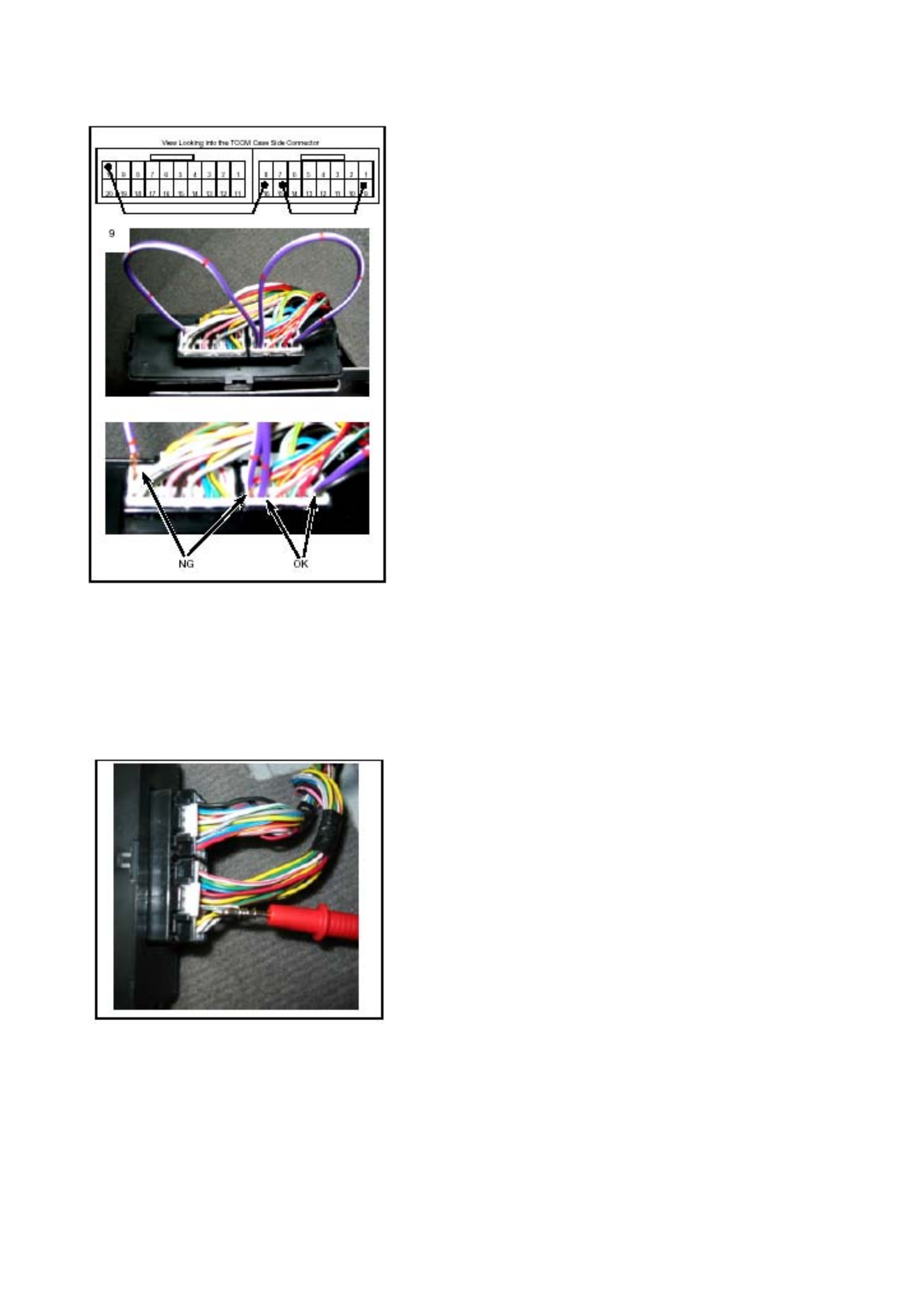
9. With the TCCM harness connector still connected, insert the
jumper-harnesses into the ba ck of the connectors:
One end of jumper wire #1 into cavity 10 of the 20 pin connector
and cavity 16 of the 16 pin connector.
Insert jumper wire #2 into cavities 9 and 15 of the 16 pin
connector.
When fully installed, none of the stripped wire should be visible.
NOTE:
The jumper-harness must be installed in the correct positions as
shown in the picture on the left.
Inadequate installation or installation in the wrong connector cavities
will cause the memory erasing procedure to fail or cause the “ABS”
fuse to fail.
10. Turn the ignition switch ON more than 3 seconds
11. Turn OFF the ignition s witch, then remove the jum per wires from
the TCCM connectors.
12. Turn the ignition switch ON then, after the bulb check process,
verify the “CHECK 4WD” indicator lamp is OFF.
If the “CHECK 4WD” indicator lamp stays ON, repeat the TCCM
memory erasing procedure again as described, or perform the
limit switch circuit test.
13. Reinstall all removed parts and reconnect all disconnected
harness connector(s).
Test 1
Check the TCCM output voltage at the harness conn ector, using a
multi-meter.
Test Condition:
1. Ignition switch is ON.
2. Probe the test-lead from the back of the connector as shown in
the picture on the left.
3. Measure the output voltage at each transfer case position.
NOTE:
Use fine wire around the test lead prob es to prevent damage to the
rear of the connector.
The following causes can be considered when the voltage need ed is
ignition voltage (10-14.5V) and output voltage is less than needed.
• There is a circuit short to ground between the TCCM and the
shift-actuator.
• Faulty limit switch in the shift-actuator.
• Faulty TCCM.
The following causes can be considered when the voltage need ed is
less than 1V and output voltage is more than nee ded.
• Circuit is short to battery or ignition voltage between the TCCM
and the shift actuator.
• Faulty limit switch in the shift actuator.
• Faulty TCCM.
Output Voltage Status at Each Transfer Position Measurement
Terminal
Connector
Terminal
No. Pin Function Wire
Colour 2H 4H
4L
Neutral
(+) (–)
14 Limit Switch 1 PNK Less than 1 V Ignition
voltage
(10–14.5 V) Less than 1 V Ignition voltage
(10–14.5 V) 14 GND
5 Limit Switch 1
GRN/
ORG Ignition voltage
(10–14.5 V) Less than 1 V 5 GND
16 Limit Switch 3 GRY Less than 1 V Ignition voltage
(10–14.5 V) 16 GND
17 Limit Switch 4 WHT
Ignition voltage
(10–14.5 V) Less than 1 V Ignition voltage
(10–14.5 V) 17 GND
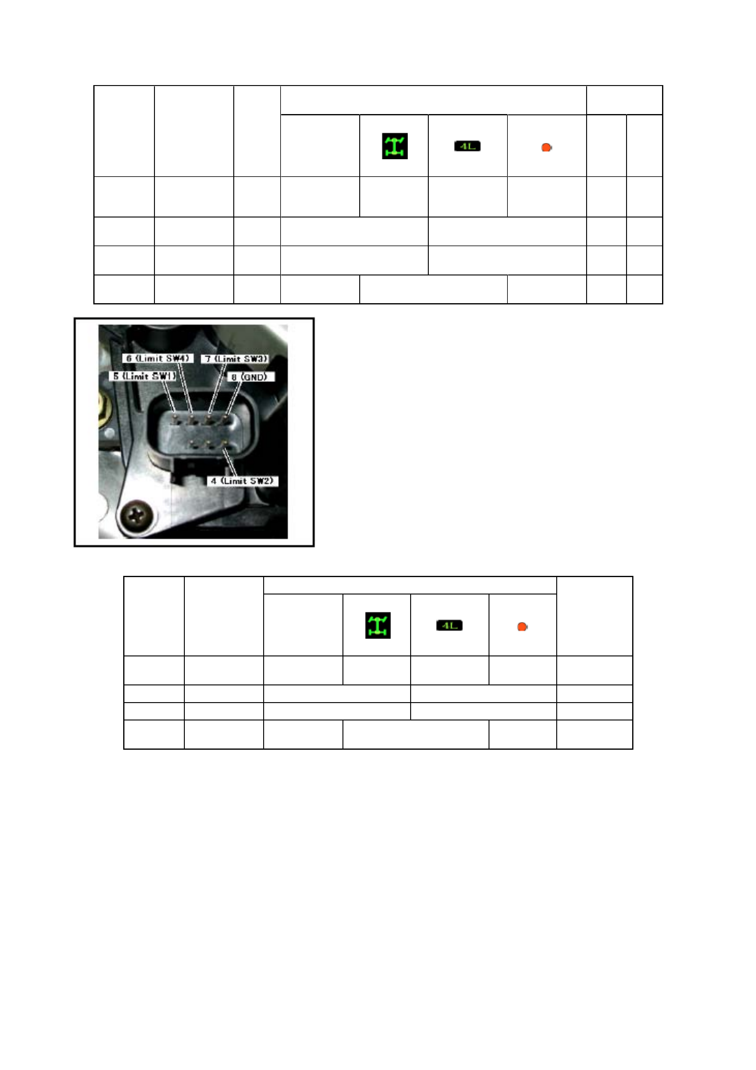
Test 2
Shift-actuator limit switch continuity testing at the shift-actuator
connector with a multimeter.
Test Condition:
• While the harness connector is disconnected, ignition switch
must be in the OFF position.
• Measure the continuity between the limit switch terminal and
ground terminal at each transfer position.
Test Result:
A faulty limit switch in the shift-actuator is indicated, when continuity
is expected and non-continuity results or when non-continuity is
expected and continuity results.
Output Voltage Status at Each Transfer Position
Connector
Terminal
No. Pin Function 2H 4H
4L
Neutral
Measurement
Terminal
14 Limit Switch 1 Continuity Non
Continuity Continuity Non
Continuity 5 & 8
5 Limit Switch 1 Non Continuity Continuity 4 & 8
16 Limit Switch 3 Continuity Non Continuity 7 & 8
17 Limit Switch 4 Non Continuity Continuity Non
Continuity 6 & 8
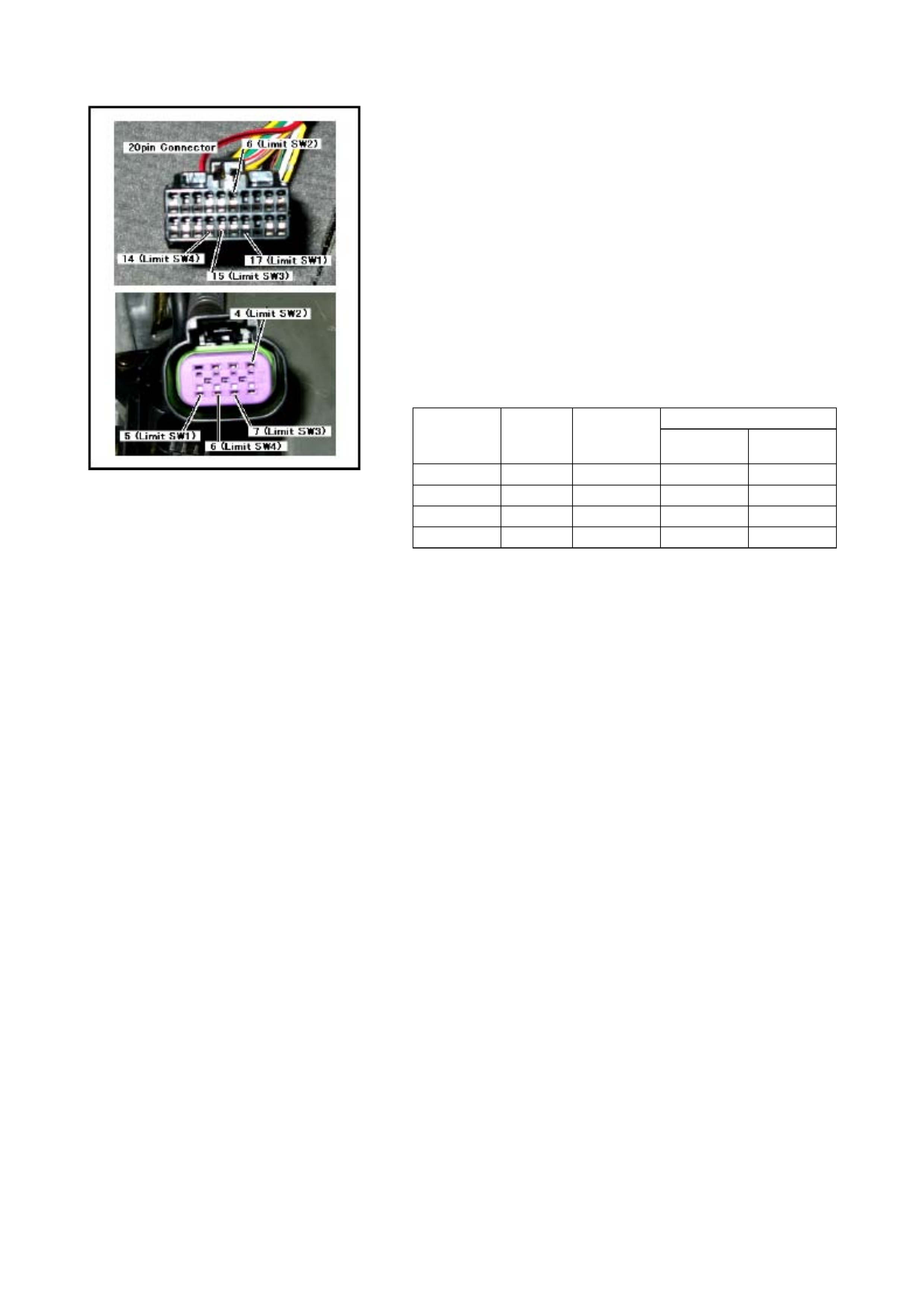
Test 3
Test the TCCM and shift-actuator harness continuity at the harness
connectors, using a multi-meter.
Test Condition:
While the harness connector is disconnected, ignition switch must be
OFF.
• Measure the continuity in each circuit, as detaile d in the following
table. Make sure that the correct cavity numbers are tested.
• Measure the non-continuity in each circuit, as detailed in the
following table. Make sure that the correct cavity numbers are
tested.
Test Result:
A wiring harness problem is expected when:
• An open circuit is found, when continuity is required and non-
continuity is the result.
• When non-continuity is needed and continuity is the result, a
short circuit to other limit switch circuits is probable.
Measurement Terminal
Pin Function Wire
Colour Continuity
Status TCCM
Connector Shift Actuator
Connector
Limit Switch 1 PNK Continuity 17 5
Limit Switch 2 GRN/ORG Continuity 6 4
Limit Switch 3 GRY Continuity 15 7
Limit Switch 4 WHT Continuity 14 6

Diagnosis from symptom
Check4WD lighting up
Step Action Yes No
1 Check what was done before
the trouble occurred.
Was the harness between the
transfer controller and actuator
disconnected with the ignition
kept ON for the purpose of
servicing the vehicle, etc.?
Or, was the ignition turned ON
(power supplied to the transfer
controller) with the harness of
the actuator removed?
If the power is supplied with the
actuator not connected, faulty
position detection switch is
considered.
Clear the memory and trace this
chart from the beginning.
Go to step 2.
2 Is the ignition switch ON? Go to step 3. Turn the ignition switch ON and
trace this chart from the
beginning.
3 Does the transfer-related
indicators (4WD, 4Lo, Check
4WD, neutral) light up for 2
seconds when the ignition
switch is turned ON?
Go to step 4. Indicator lamp burnt out.
Disconnected harness wire .
After repairing, trace this chart
from the beginning.
4 Is the harness between the
Check4WD indicator and
transfer controller GND
shorted?
GND (body) short of the indicator
harness.
After repairing, trace this chart
from the beginning.
Go to step 5.
5 Check the continuity of harness
between the transfer controller
and transfer actuator. Check
the power short and GND short.
Check the GND harness of the
transfer actuator.
Is a trouble noticed?
Repair the harness, clear the
memory and trace this chart from
the beginning.
Go to step 6.
6 Check the limit switch of the
actuator.
Is a trouble noticed?
Failed actuator. Replace the
actuator, clear the memory and
trace this chart from the
beginning.
Clear the memory and trace this
chart from the beginning.
Failed controller.
Replace the controller, clear the
memory and trace this chart from
the beginning.
To check the operation after completing the repair and clearing the memory, shift between 2H and 4L at least 5 times.
To judge the condition more quickly, ask the customer the situation when the Check 4WD lamp illuminated.
(Since it indicates the situation immediately before detection of failure whether the vehicle is running or standstill, that
possibility of failure around that point is high.)

Cannot shift from 2WD to 4H or 4L.
When shifting from 2H to other position, the indicator (4WD, 4Lo, Check 4WD, neutral) does not respond.
Step Action Yes No
1 Is the ignition switch ON? Go to step 2. Turn the ignition switch ON and
trace this chart from the
beginning.
2 Does the transfer-related
indicators (4WD, 4Lo, Check
4WD, neutral) light up for 2
seconds when the ignition
switch is turned ON?
Failed operation switch. Only 2H
is stuck at ON condition and 4H-
4L position is internally
disconnected. Or,
Failed controller
Indicator lamp burnt out.
Disconnected harness wire .
After repairing, trace this chart
from the beginning.
Even after correction step 1-1(*), 4WD indicator blinks at 4Hz and changes to 2H after 10 seconds.
Step Action Yes No
1 Is the ignition switch ON? Go to step 2. Turn the ignition switch ON and
trace this chart from the
beginning.
2 Does the transfer-related
indicators (4WD, 4Lo, Check
4WD, neutral) light up for 2
seconds when the ignition
switch is turned ON?
Go to step 3. Indicator lamp burnt out.
Disconnected harness wire.
After repairing, trace this chart
from the beginning.
3 After 2 seconds, check that the
Check4WD lamp is ON or OFF.
Is the Check4WD lamp OFF?
Go to step 4. Failed actuator position detection
switch (LS1, LS2, LS3, LS4,
GND).
Short or disconnection of harness
of this detection switch.
After repairing, trace this chart
from the beginning.
4 Press the 4H button.
Is sound of relay heard from the
transfer control?
Go to step 5. Failed controller.
Replace the controller and trace
this chart from the beginning.
5 Is the sound of running motor
heard? Failed control system of the
transfer mechanism. Check and
repair and trace this chart from
the beginning.
Failed actuator motor.
Disconnected controller motor
drive output circuit, GND short
circuit. +B fuse blown out.
Disconnection of that harness.
After repairing, trace this chart
from the beginning.
*Before determining cause of a failure (No fault mode)

Even after performing step 1-2(*), the 4WD indicator still blinks at 2Hz when shifting from 2H to 4H.
Step Action Yes No
1 Check the air pressure and
wear of all the tires. Is any
trouble apparent?
After adjusting the air pressure
and repairing the tire worn away,
try the correction step 1-2(*).
Go to step 2.
2 Check the 4WD detection switch
on the transfer case, neutral
detection switch and each
harness. Is a fault apparent?
4WD detection switch is open or
the harness failed.
The neutral detection switch is
closed or the harness GND is
shorted.
Replace or repair and then trace
this chart from the beginning.
Go to step 3.
3 Is there continuity in the harness
between the transfer controller
and front axle controller? Isn’t a
body short or disconnection
noticed?
Go to step 4. Body short or disconnection of
the harness between the transfer
controller and front axle
controller.
After repairing, trace this chart
from the beginning.
4 Is there continuity in the harness
between the axle controller and
actuator?
Isn’t short or disconnection
noticed?
Isn’t the connection mistaken?
Go to step 5. Body short, disconnection or
incorrect connection of the
harness between the axle
controller and actuator.
After repairing, trace this chart
from the beginning.
5 Is a fault present in the axle
detection switch harness
between the axle actuator and
transfer controller?
Disconnected harness.
After repairing trace this chart
from the beginning.
GND disconnection of axle
actuator.
Malfunction of axle actuator.
Malfunction of axle controller.
Refer to the paragraph of the
axle disconnect.
After repairing, trace this chart
from the beginning.
*Before determining cause of a failure(No fault mode)
After operation, 4WD indicator blinks for 1.5 sec. at 2Hz, return to 2H condition (4WD indicator going out)
Step Action Yes No
1 Keep to press the 4H button
(about 10 seconds).
Does the 4WD indicator blink at
2Hz for 15 seconds and then
blink at 4Hz?
Failed actuator motor.
Disconnection of controller motor
drive output circuit, or GND short.
+B fuse blown out.
Disconnection of that harness.
After repairing, trace this chart
from the beginning.
Go to step 2.
2 Press the 4H button.
Is the sound of relay heard from
the transfer controller?
Go to step 3. Failed controller.
Replace the controller and trace
this chart from the beginning.
3 Is the sound of running motor
heard? Failed control system of the
transfer mechanism. Check and
repair and trace this chart from
the beginning.
Failed actuator motor.
Disconnection or GND short of
controller motor drive output
circuit.
After repairing, trace this chart
from the beginning.

Transfer cannot shift to a position other than 4H.
When shifting from 4H to other position, indicator (4WD, 4Lo, Check 4WD, neutral) does not respond (4WD
stays illuminated).
Step Action Yes No
1 Is the ignition switch ON? Go to step 2. Failed 4WD indicator and
harness.
After repairing, trace this chart
from the beginning.
2 Do the transfer-related
indicators (4WD, 4Lo, Check
4WD, neutral) light up for 2
seconds when the ignition
switch is turned ON?
Then, only 4H lights up.
Go to step 3. Indicator lamps other than the
4WD indicator are burnt out.
(Check for GND short circuit
between the 4WD indicator and
transfer controller.)
Disconnected harness wire.
After repairing, trace this chart
from the beginning.
3 Press the 2H button.
Is the sound of relay heard from
under the seat, and the sound of
running motor heard?
Failed controller.
After replacing the controller,
trace this chart from the
beginning.
*Failed operation switch. Or
disconnected or shorted of the
harness for the operation switch.
* The operation switch is an analog type switch that reads the internal composite resistance value at the time of
operation. If an abnormal value is detected, it is judged to be an instruction to shift into 4H.
Even after the correction step 2-1(*), the 4WD indicator still blinks at 2Hz when shifting from 4H to 2H.
Step Action Yes No
1 Check all the tires for air
pressure and wear. Is any
trouble noticed?
After adjusting the air pressure
and repairing the tire worn away,
try the correction step 2-1(*).
Go to step 2.
2 Check the 4WD detection switch
on the transfer case and neutral
detection switch and each
harness. Is a fault apparent?
4WD detection switch is closed
or the GND short of harness.
The neutral detection switch is
closed or the harness GND is
shorted.
Replace or repair and then trace
this chart from the beginning.
Go to step 3.
3 Is there continuity in the harness
between the axle controller and
axle actuator?
Isn’t short or disconnection
noticed?
Isn’t the connection mistaken?
Go to step 4. Body short, disconnection or
incorrect connection of the
harness between the axle
controller and actuator.
After repairing, trace this chart
from the beginning.
4 Is a trouble apparent in the axle
detection harness between the
axle actuator and transfer
controller?
GND short of harness Malfunction of axle actuator.
Malfunction of axle controller.
Refer to the paragraph of axle
disconnect.
After repairing, trace this chart
from the beginning.
*Before determining cause of a failure (No fault mode)

Though the indicator responds when shifting from 4H to 2H(or other position), it returns to 4H.
Step Action Yes No
1 Is the ignition switch ON? Go to step 2. Turn the ignition switch ON and
trace this chart from the
beginning.
2 Does the transfer-related
indicators (4WD, 4Lo, Check
4WD, neutral) light up for 2
seconds when the ignition
switch is turned ON?
Go to step 3. Indicator lamp burnt out.
Disconnected harness wire.
After repairing, trace this chart
from the beginning.
3 After 2 seconds, check if the
Check4WD lamp lights up.
Is the Check4WD lamp OFF?
Go to step 4. Failed actuator position detection
(limit) switch (LS1, LS2, LS3,
LS4, GND).
Short or disconnection of
harness of this detection switch.
Refer to paragraph of
Check4WD.
After repairing, trace this chart
from the beginning.
4 Press the 2H button.
Is the sound of relay heard from
the transfer controller?
Go to step 5. Failed controller.
Replace the controller and trace
this chart from the beginning.
5 Is the sound of running motor
heart? Failed control system of the
transfer mechanism. Check and
repair and trace this chart from
the beginning.
Failed actuator motor.
Disconnection of controller motor
drive output circuit or GND short.
After repairing, trace this chart
from the beginning.
If the motor does not or cannot run at all (stuck transfer mechanism, disconnected motor, failed drive circuit), the lamp
blinks at 4Hz when the position is shifted to other position by pressing the button for more 10 seconds (20 seconds in
case of neutral position).

From 4H to 4L; Even after the correction step 3-3(*), 4Lo indicator blinks at 4Hz
Step Action Yes No
1 Is the ignition switch ON? Turn it OFF once. Go to step 2.
2 Turn ON the ignition switch and
check the valve. Do not start
the engine.
Has the valve check for 2
seconds been completed
normally?
Go to step 3. Refer to the paragraph about the
indicator when it does not react
when shifted from 2H to 4H.
After taking the remedy, trace
this chart from the beginning.
3 Shift to 2H.
Can be shifted to 2H and then to
4H?
Go to step 4. Refer to the paragraph about
shifting from 2H to 4H.
In particular, check if not at the
Check4WD condition, return to
this chart and trace it from the
beginning.
4 Set to N or P position in case of
AT and set to the neutral
position in case of MT and
check if the lamp blinks at 4Hz
after operation.
Failed T/M position switch and
harness (failure of TM1 and TM2
harness and their related
switches shown in the figure).
Incorrect wiring.
Repair as required and trace this
chart from the beginning.
Shift back to 4H and go to step 5.
5 Start the engine and travel the
vehicle.
Does the speedometer run at
this time?
Go to step 6. Failure of speed sensor or
disconnection or short of harness
(for the meter).
After repairing, trace this chart
from the beginning.
6 Check the harness between the
transfer controller and speed
sensor.
(Check the engine rotation
detection harness at the same
time.)
Is any trouble noticed?
Failed harness between the
transfer controller and speed
sensor.
After repairing, trace this chart
from the beginning.
(Repair the engine rotation
detection unit, if required.)
Go to step 7.
7 Drive the vehicle several
metres, stop, and meet the
requirements for operation.
Did you wait for several seconds
after the requirements were
met?
Failed controller.
Replace the controller and trace
this chart from the beginning.
You did not wait for enough time.
Optimum waiting time is 1
second or maximum 3 minutes
depending on the previous
conditions.
Refer to the paragraph about
operation without failure.
*Before determining cause of a failure (No fault mode)

From 4L to 4H: After the correction step 4-3(*), 4Lo indicator blinks at 4H.
Step Action Yes No
1 Is the ignition switch ON? Turn it OFF once. Go to step 2.
2 Turn ON the ignition switch and
check the valve. Do not start
the engine.
Has the valve check for 2
seconds been completed
normally?
Go to step 3. Refer to the paragraph about the
indicator when it does not react
when shifted from 2H to 4H.
After taking the remedy, trace
this chart from the beginning.
3 Can be shifted to 2H and then to
4L? Go to step 4.
(Impossible usually.)
Failed controller
In case of Check 4WD, shifting to
2H is possible.
Returning to 4L is impossible.
Refer to the paragraph about
Check4WD.
4 Set to N or P position in case of
AT and set to the neutral
position in case of MT and
check if the lamp blinks at 4Hz
after operation.
Failed T/M position switch and
harness (failure of TM1 and TM2
harness and their related
switches shown in the figure).
Incorrect wiring.
Repair as required and trace this
chart from the beginning.
Press the operation switch of 4L
and go to step 5.
5 Start the engine and travel the
vehicle.
Does the speedometer run at
this time?
Go to step 6. Failure of speed sensor or
disconnection or short of harness
(for the meter).
After repairing, trace this chart
from the beginning.
6 Check the harness between the
transfer controller and speed
sensor.
(Check the engine rotation
detection harness at the same
time.)
Is any trouble noticed?
Failed harness between the
transfer controller and speed
sensor.
After repairing, trace this chart
from the beginning.
(Repair the engine rotation
detection unit, if required.)
Go to step 7.
7 Drive the vehicle several
metres, stop, and meet the
requirements for operation.
Did you wait for several seconds
after the requirements were
met?
Failed transfer controller.
Replace the controller and trace
this chart from the beginning.
You did not wait for enough time.
Optimum waiting time is 1
second or maximum 3 minutes
depending on the previous
conditions.
Refer to the paragraph about
operation without failure.
*Before determining cause of a failure (No fault mode)

To neutral: After the correction step 5-2(*), neutral indicator blinks at 4Hz.
Check the function between H and L according to the chart for 4L to 4H instead of check for the requirements
of neutral.
Step Action Yes No
1 Is the ignition switch ON? Turn it OFF once. Go to step 2.
2 Turn ON the ignition switch and
check the valve. Do not start the
engine.
Has the valve check for 2
seconds been completed
normally?
Go to step 3. Refer to the paragraph about the
indicator when it does not react
when shifted from 2H to 4H
(7D1-37).
After taking the remedy, trace
this chart from the beginning.
3 Can be shifted to 2H and then to
4L? Go to step 4.
(Impossible usually.)
Failed controller
Refer to the paragraph about
shifting from 2H to 4H.
In particular, check if not at the
Check4WD condition, return to
this chart and trace it from the
beginning.
In case of Check4WD, shifting to
2H is possible.
Returning to 4H is impossible.
Refer to the paragraph about
Check4WD.
4 Set to N or P position in case of
AT and set to the neutral position
in case of MT and check if the
lamp blinks at 4Hz after
operation.
Failed T/M position switch and
harness (failure of TM1 and TM2
harness and their related
switches shown in the figure).
Incorrect wiring.
Repair as required and trace this
chart from the beginning.
Shift back to 4H and go to step 5.
5 Start the engine and travel the
vehicle.
Does the speedometer run at this
time?
Go to step 6. Failure of speed sensor or
disconnection or short of harness
(for the meter).
After repairing, trace this chart
from the beginning.
6 Check the harness between the
transfer controller and speed
sensor.
(Check the engine rotation
detection harness at the same
time.)
Is any trouble noticed?
Failed harness between the
transfer controller and speed
sensor.
After repairing, trace this chart
from the beginning.
(Repair the engine rotation
detection unit, if required.)
Go to step 7.
7 Drive the vehicle several metres,
stop, and meet the requirements
for operation.
Did you wait for several seconds
after the requirements were met?
Failed controller.
Replace the controller and trace
this chart from the beginning.
You did not wait for enough time.
Optimum waiting time is 1
second or maximum 3 minutes
depending on the previous
conditions.
Refer to the paragraph about
operation without failure.
*Before determining cause of a failure (No fault mode)
For shifting to neutral, 2H and 4L switches should be kept pressed at the same time for 10 seconds.
For shifting from neutral to other position, 2H, 4H or 4L switch should be kept pressed for 10 seconds.
When shifting from neutral to other position, the lamp blinking at 2Hz indicates active condition.
When the lamp keeps blinking at 2Hz, follow the step for the case when the lamp keeps blinking at 2Hz when shifting
between positions.