
SECTION 8A
ELECTRICAL-BODY AND CHASSIS
General Information
Notes for Working on Electrical Items
Symbols and Abbreviations
Symbols
Abbreviations
Parts for Electrical Circuit
Wiring
Fuse
Fusible Link
Relay
Diode
Connector
Battery
Reading the Circuit Diagram
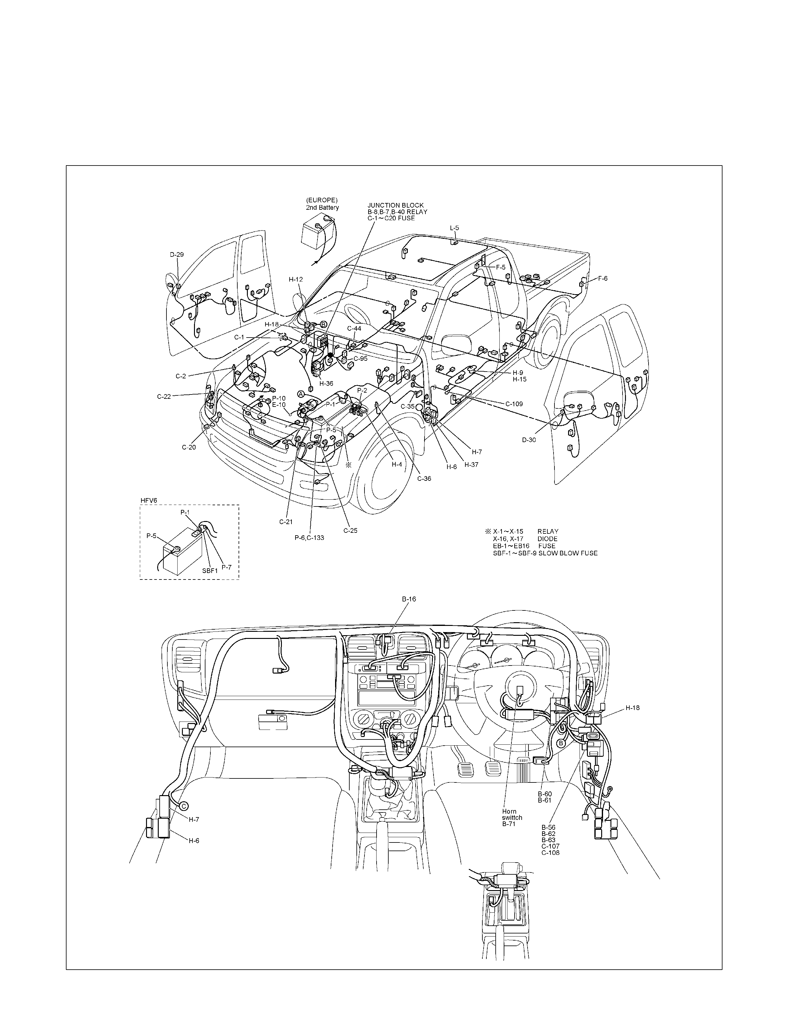
Parts Location
Circuit Diagram
Connector List
Main Data and Specifications
Bulb Specifications
Relay and Fuse
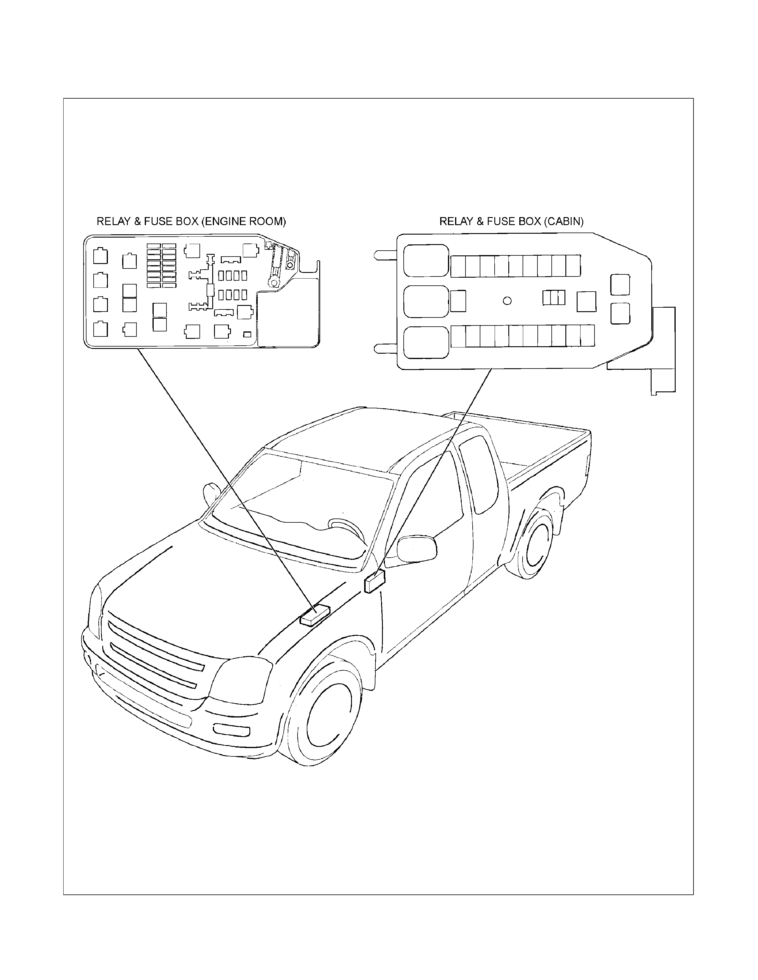
Relay and Fuse Box Location
Relay Location
Fuse and Slow Blow Fuse Location
Fuse Location
Diode Location
Fuse Block Circuit
Fuse Block Circuit (C24SE)
Fuse Block Circuit (6VE1)
Fuse Block Circuit (HFV6)
Fuse Block Circuit (4JA1-TC/4JH1-TC)
- RHD
Fuse Block Circuit (4JA1-TC/4JH1-TC)
- LHD
Fuse Block Circuit (4JH1-L)
Grounding Point
Ground Point
Ground Point Location
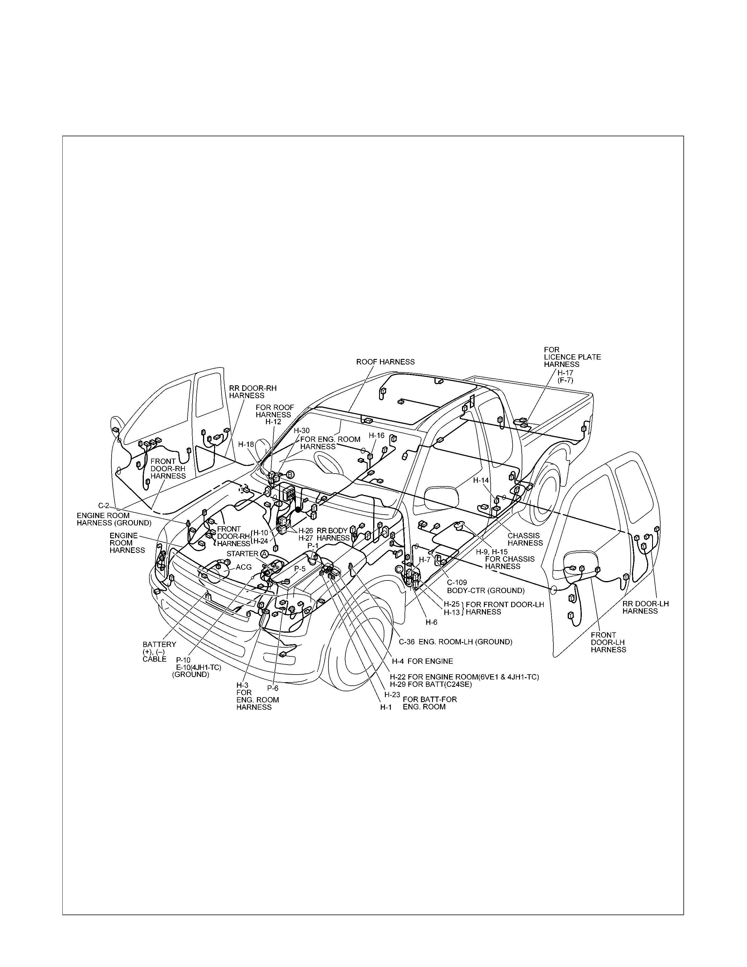
Cable Harness Routing
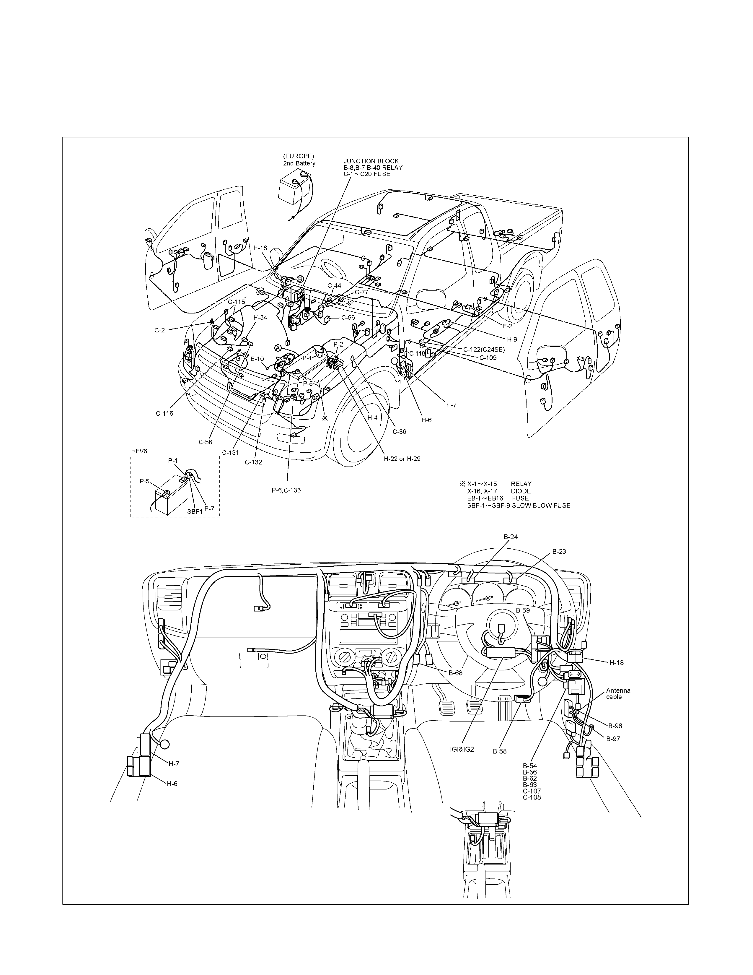
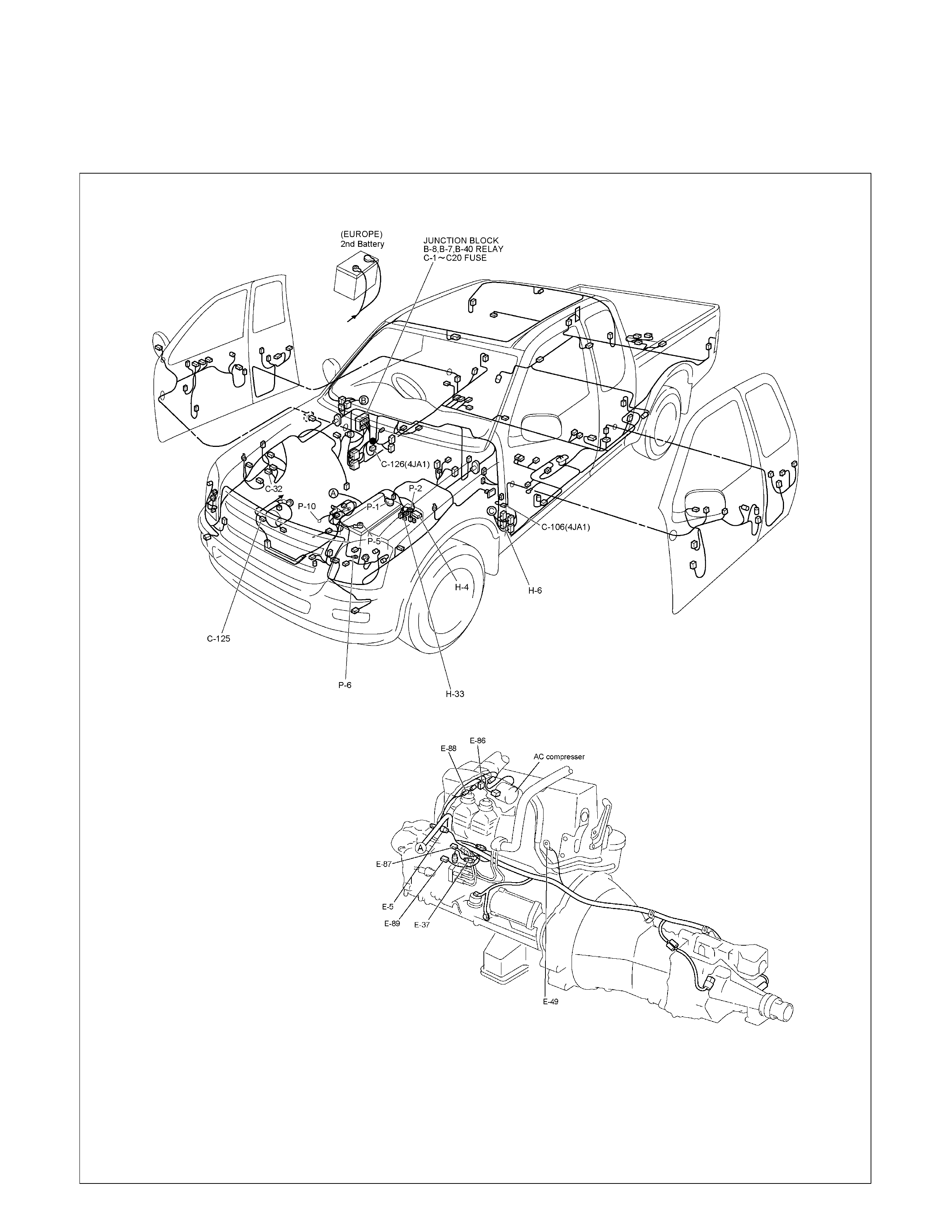
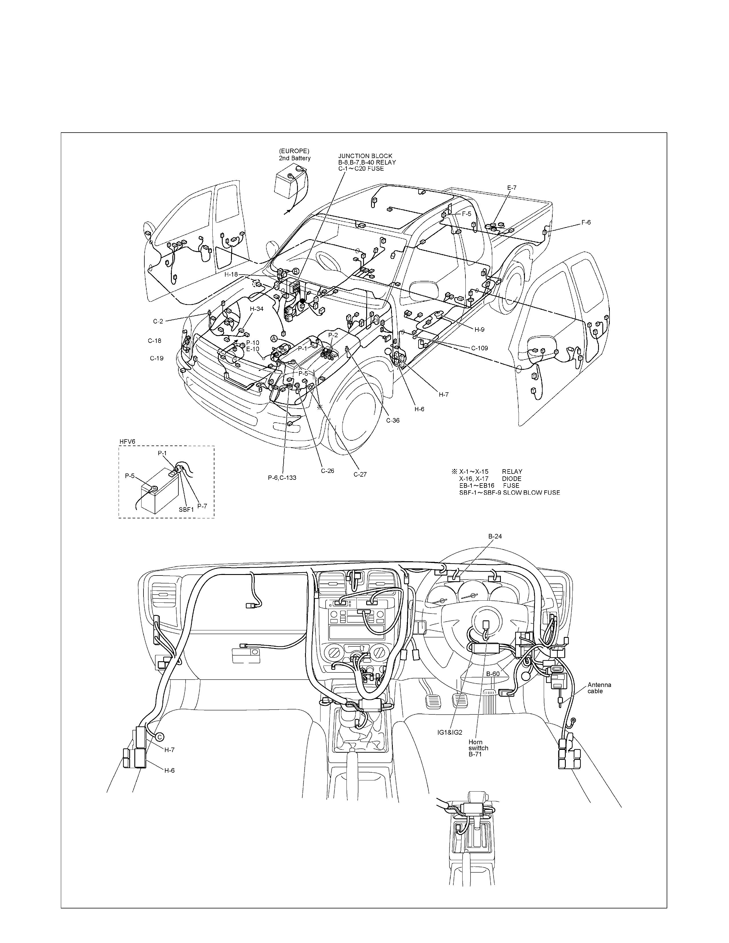
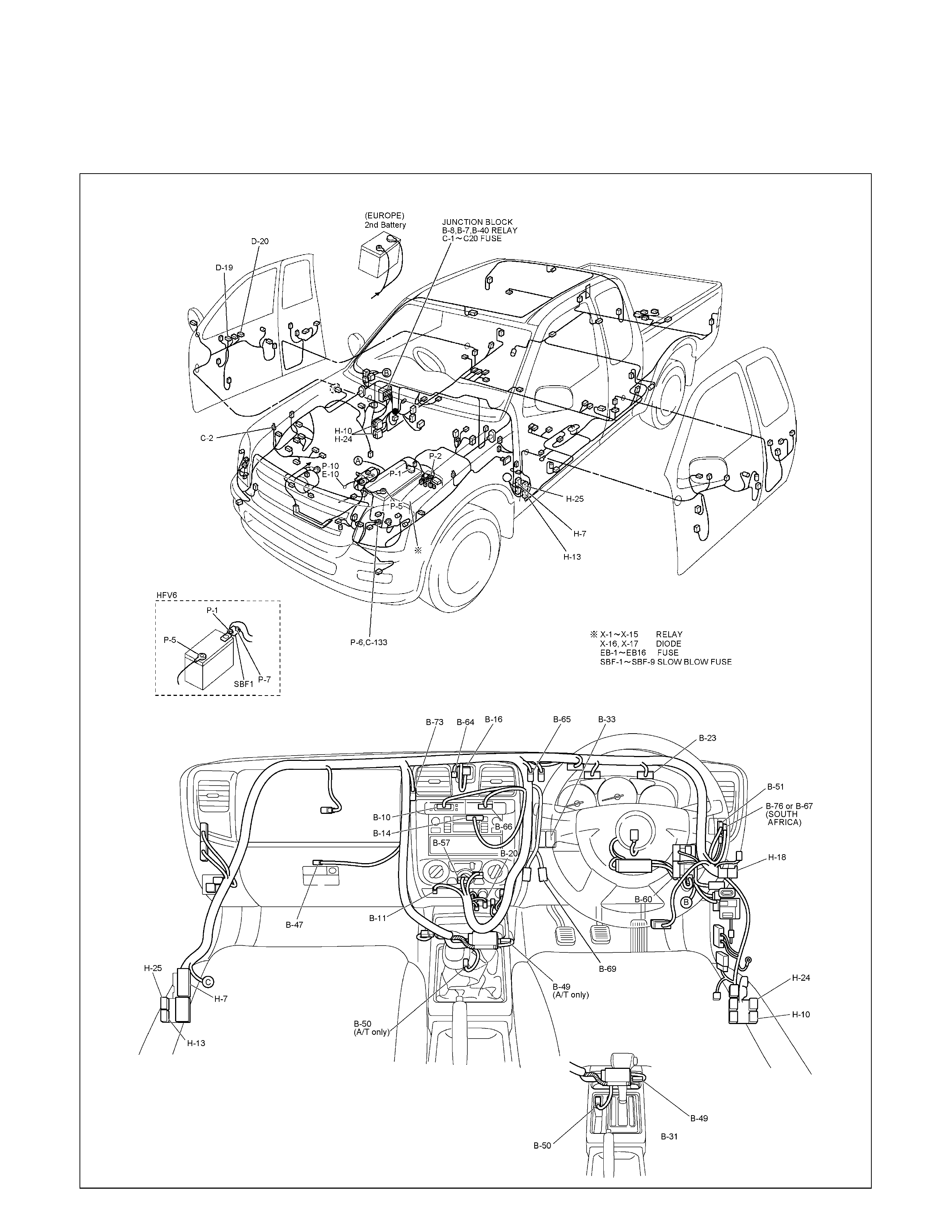
Main Cable Harness (RHD)
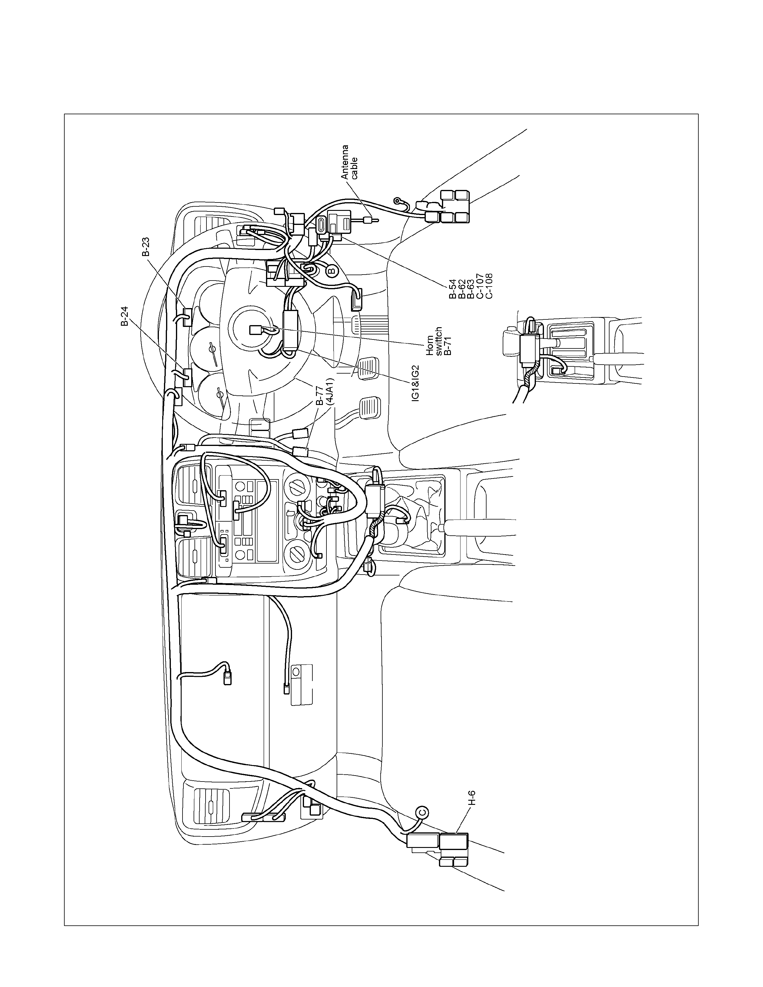
Instrument Harness (RHD)
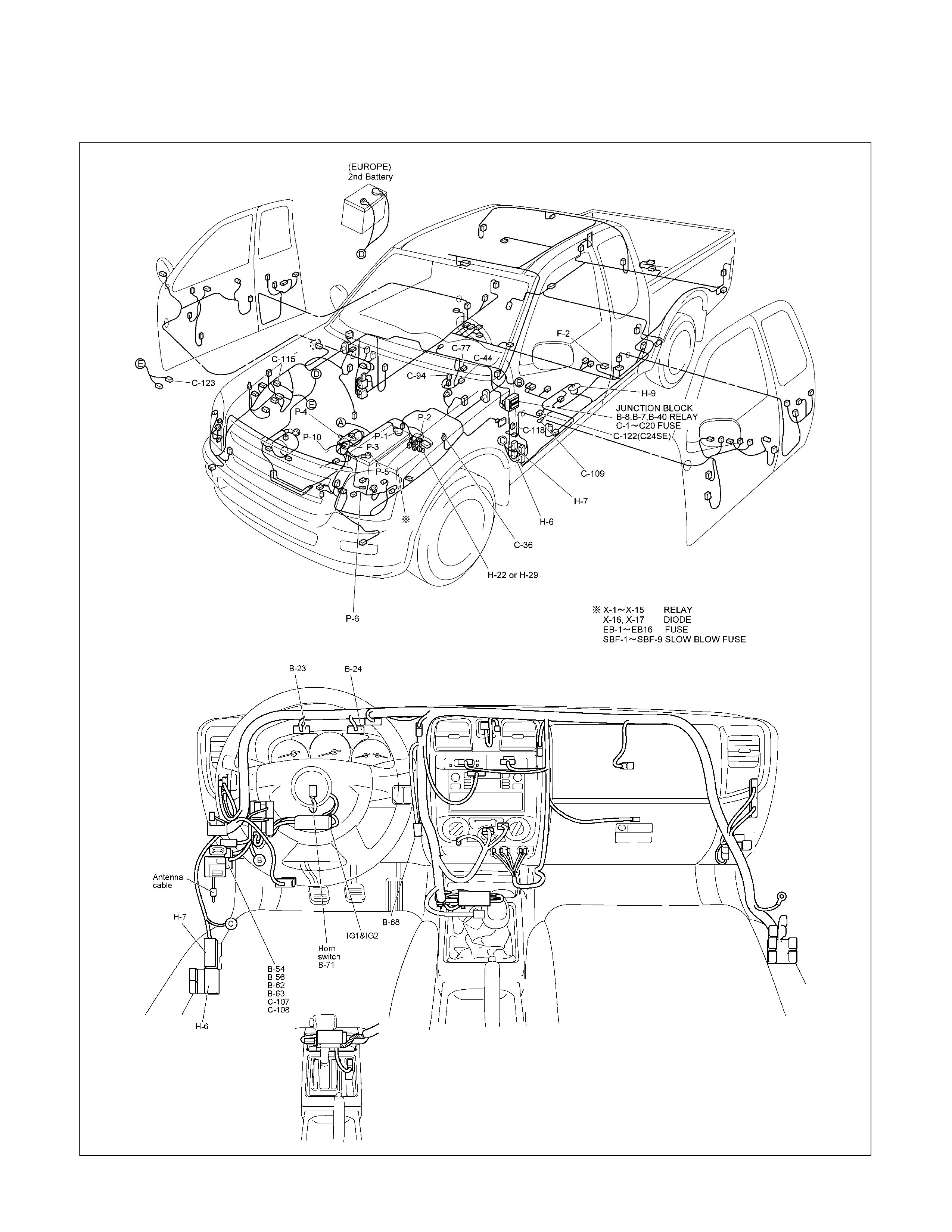
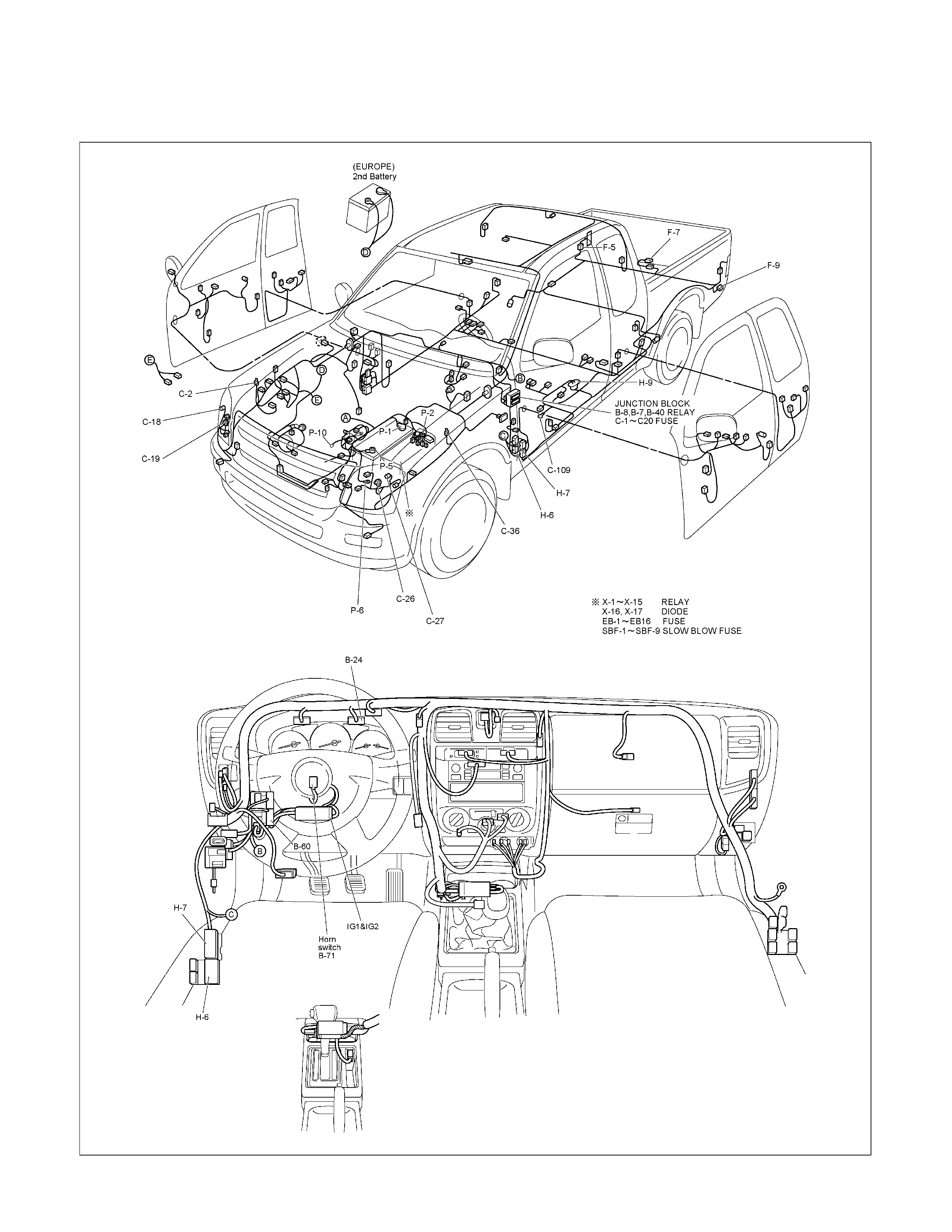
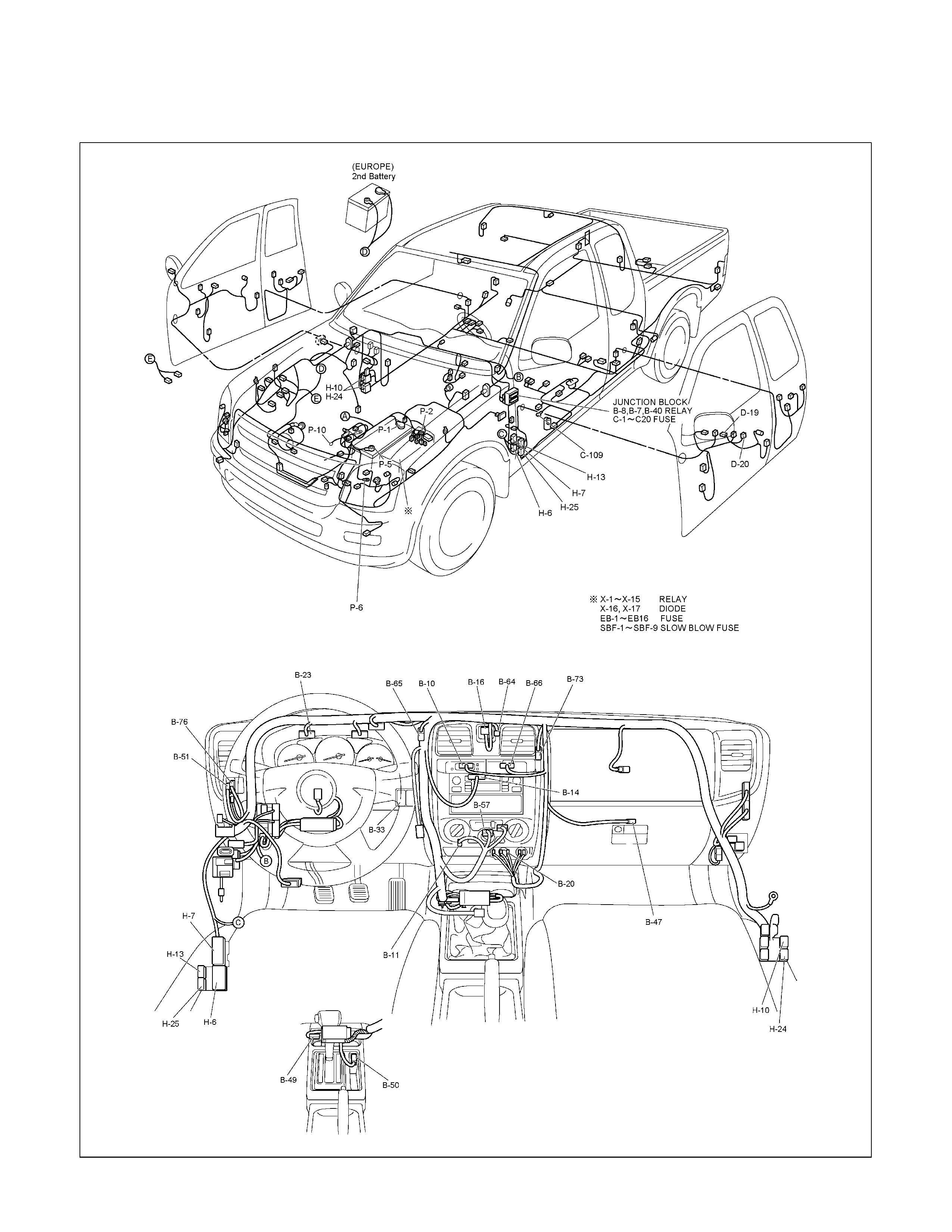
Main Cable Harness (LHD)
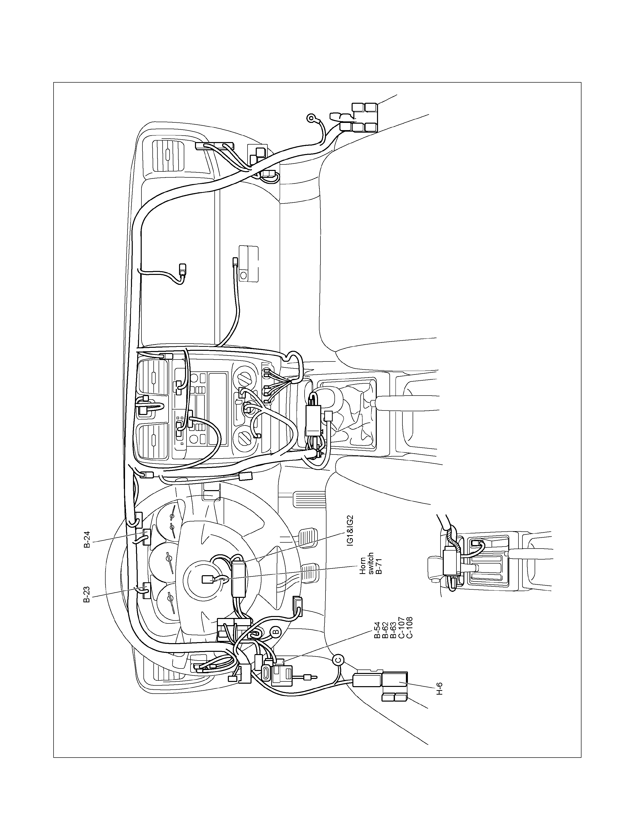
Instrument Harness (LHD)
Engine Harness C24SE
Engine Harness 6EV1
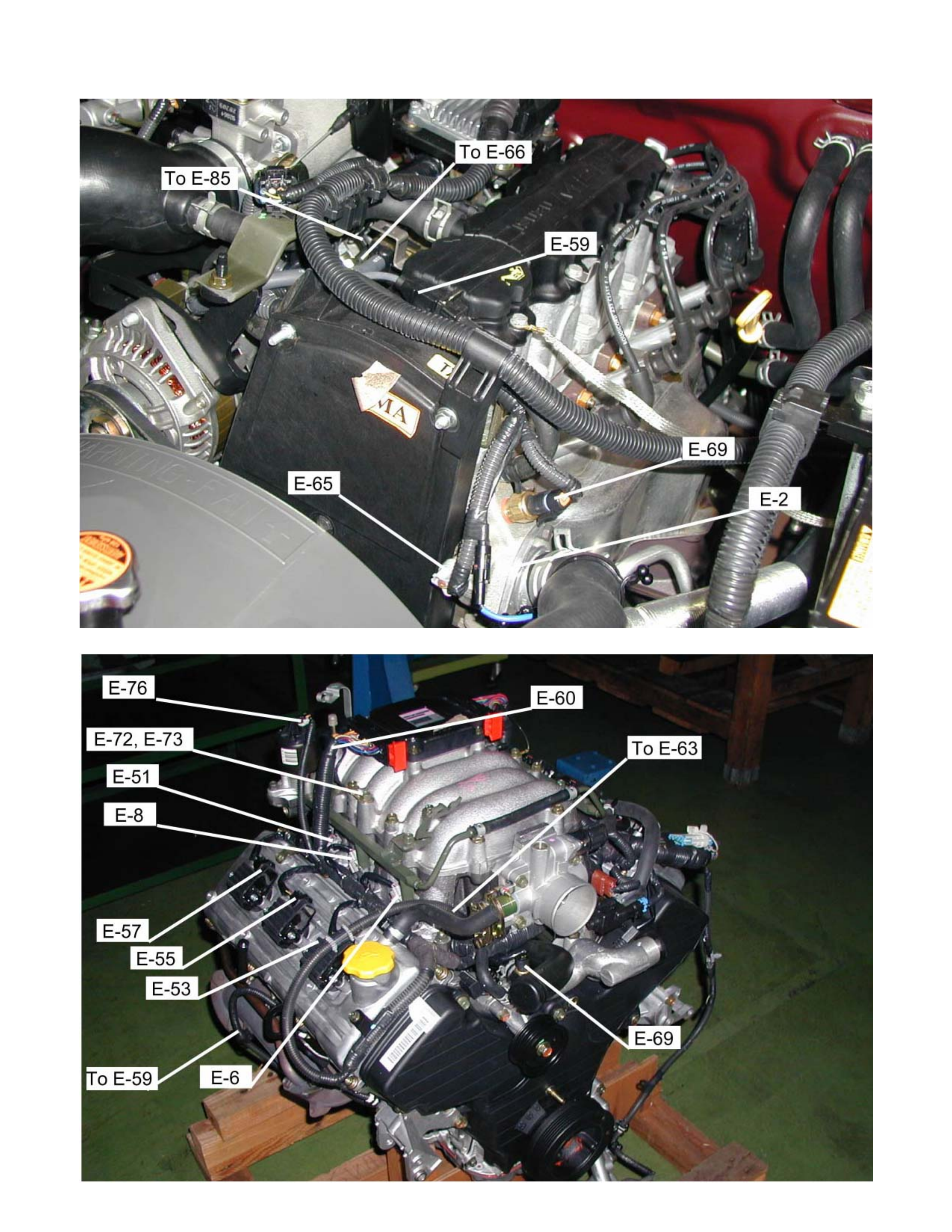
Engine Harness HFV6
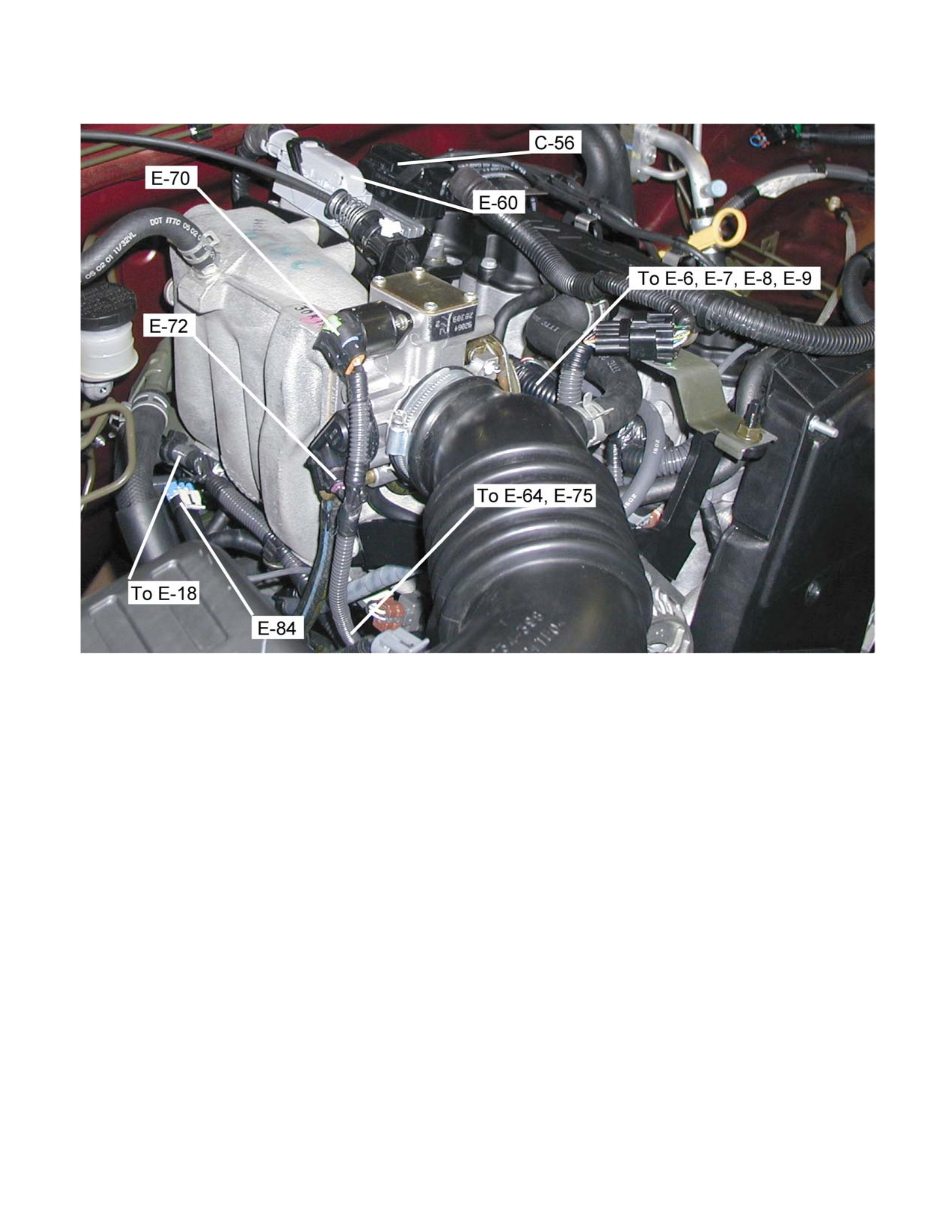
Engine Harness 4JA1-TC/4JH1-
TC/4JA1-L
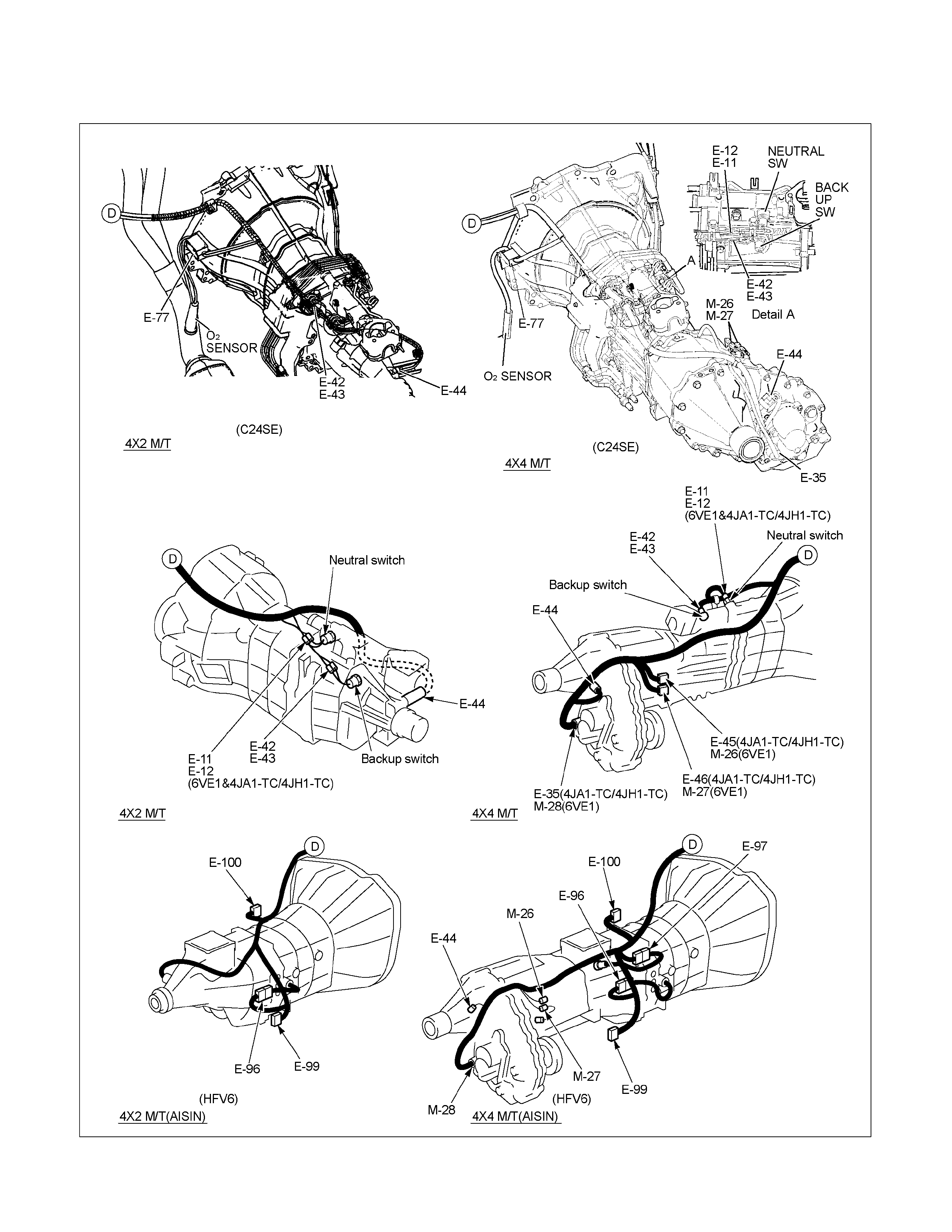
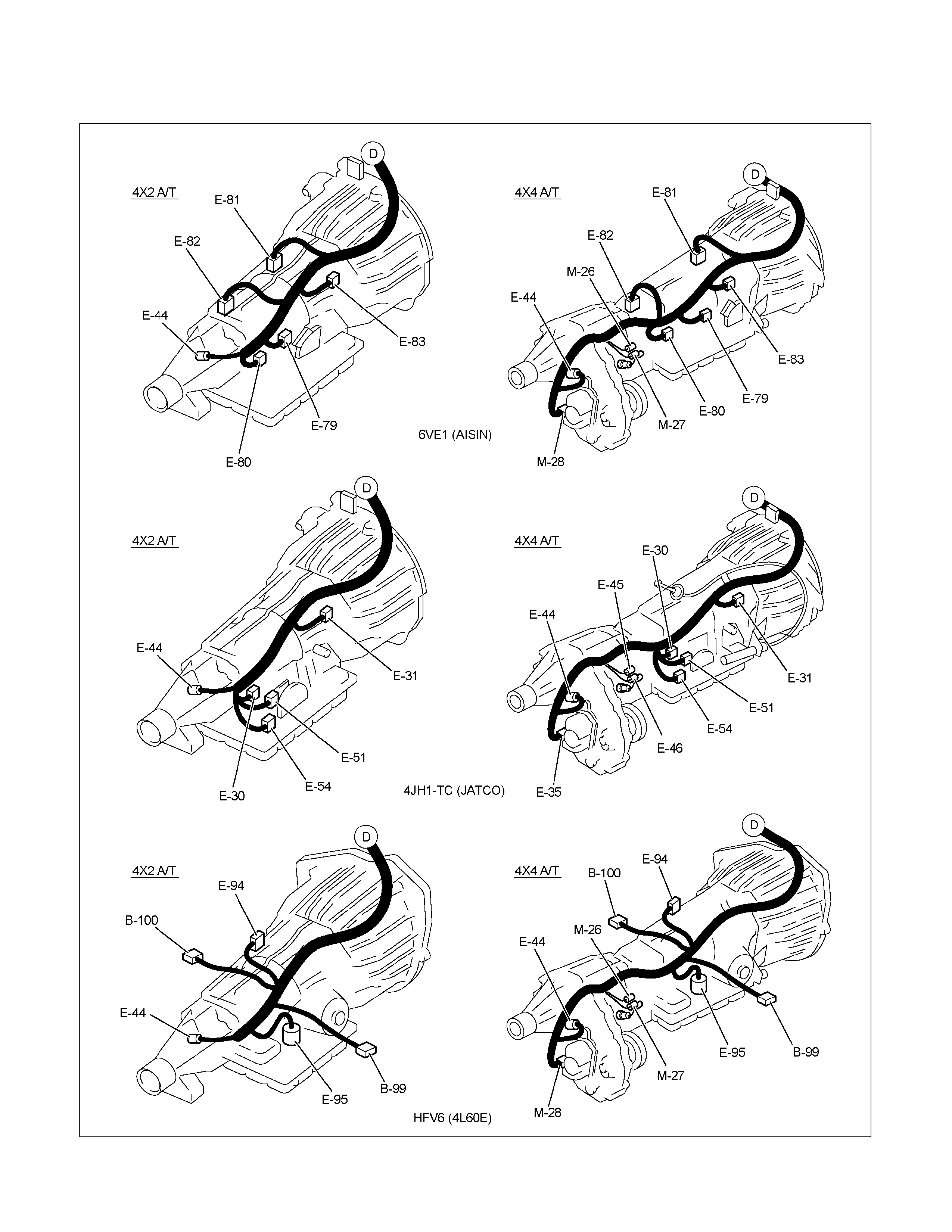
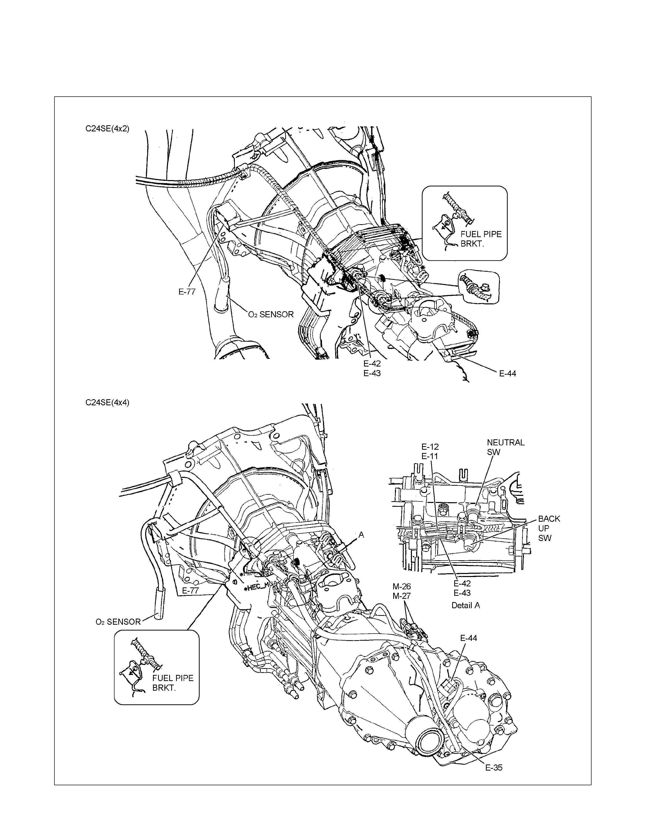
Transmission Harness
System Repair
Start and Charging
Engine Control Module (ECM)
Powertrain Interface Module (PIM):
HFV6 Only
Exhaust Gas Recalculation (EGR):
4JA1-L Only
Lighting
Front Fog Light
Rear Fog Light
Head Light Leveling
Illumination
Hazard Warning Flasher, Turn Signal
Light, Back Up Light, Horn and Stop
Light
Dome Light, Spot Light, Map Light and
Warning Buzzer
Windshield Wiper and Washer
Transmission Control Module (TCM)
Meter Warning Light and Indicator
Light
Techline
Techline


GENERAL INFORMATION
The body and chassis electrical system operates on a twelve volt power supply with negative ground polarity.
The main harness consists of the engine harness, the instrument harness, the body harness, and the chassis
harness.
The harnesses use a split corrugated tube to protect the wires from the elements.
Wire size is determined by current flow, circuit length, and voltage drop.
All wires have color-coded insulation.
Wire color-codes are shown in the circuit diagrams.
This makes it easier to trace circuits and to make the proper connections.
Each circuit consists of the following:
1. Power source - The battery and the alternator
2. Wires - To carry electrical current through the circuit
3. Fuses - To protect the circuit against current overload
4. Relays - To protect voltage drop between the battery and the circuit parts and to protect the switch points
against burning
5. Switches - To open and close the circuit
6. Load - Any device, such as a light or motor, which converts the electrical current into useful work
7. Ground - To allow the current to flow back to the power source
NOTES FOR WORKING ON ELECTRICAL ITEMS
Battery
BATTERY CABLE
Disconnecting the Battery Cable
1. All switches should be "OFF" position.
2. Disconnect the battery ground cable.
3. Disconnect the battery positive cable.
CAUTION:
It is important that the battery ground cable be
disconnected first.
Disconnecting the battery positive cable first can result in
a short circuit.
Connecting the Battery Cable
Follow the disconnecting procedure in the reverse order to
connect the battery cables.
CAUTION:
Clean the battery terminal and apply light coat of grease
to prevent terminal corrosion.
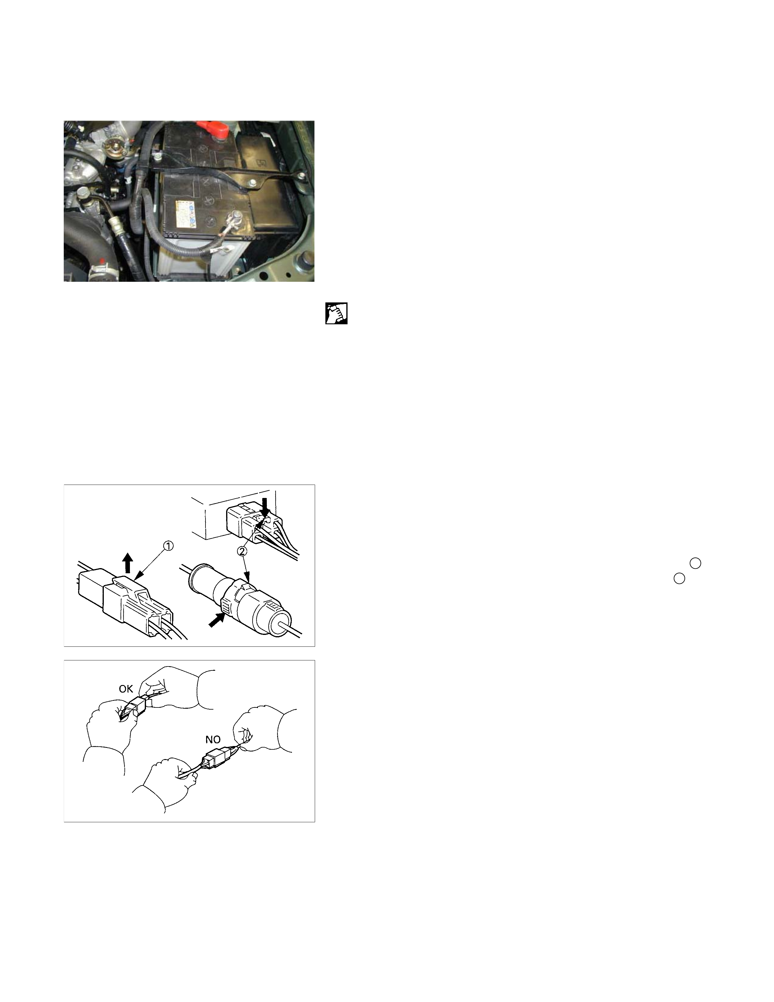
CONNECTOR HANDLING
Disconnecting the Connectors
Some connectors have a tang lock to hold the connectors
together during vehicle operation.
Some tang locks are released by pulling them towards you 1.
Other tang locks are released by pressing them forward 2.
Determine which type of tang lock is on the connector being
handled.
Firmly grasp both sides (male and female) of the connector.
Release the tang lock and carefully pull the two halves of the
connector apart.
Never pull on the wires to separate the connectors.
This will result in wire breakage.
Connecting the Connectors
Firmly grasp both sides (male and female) of the connector.
Be sure that the connector pins and pin holes match.
Be sure that both sides of the connector are aligned with each
other.
Firmly but carefully push the two sides of the connector
together until a distinct click is heard.
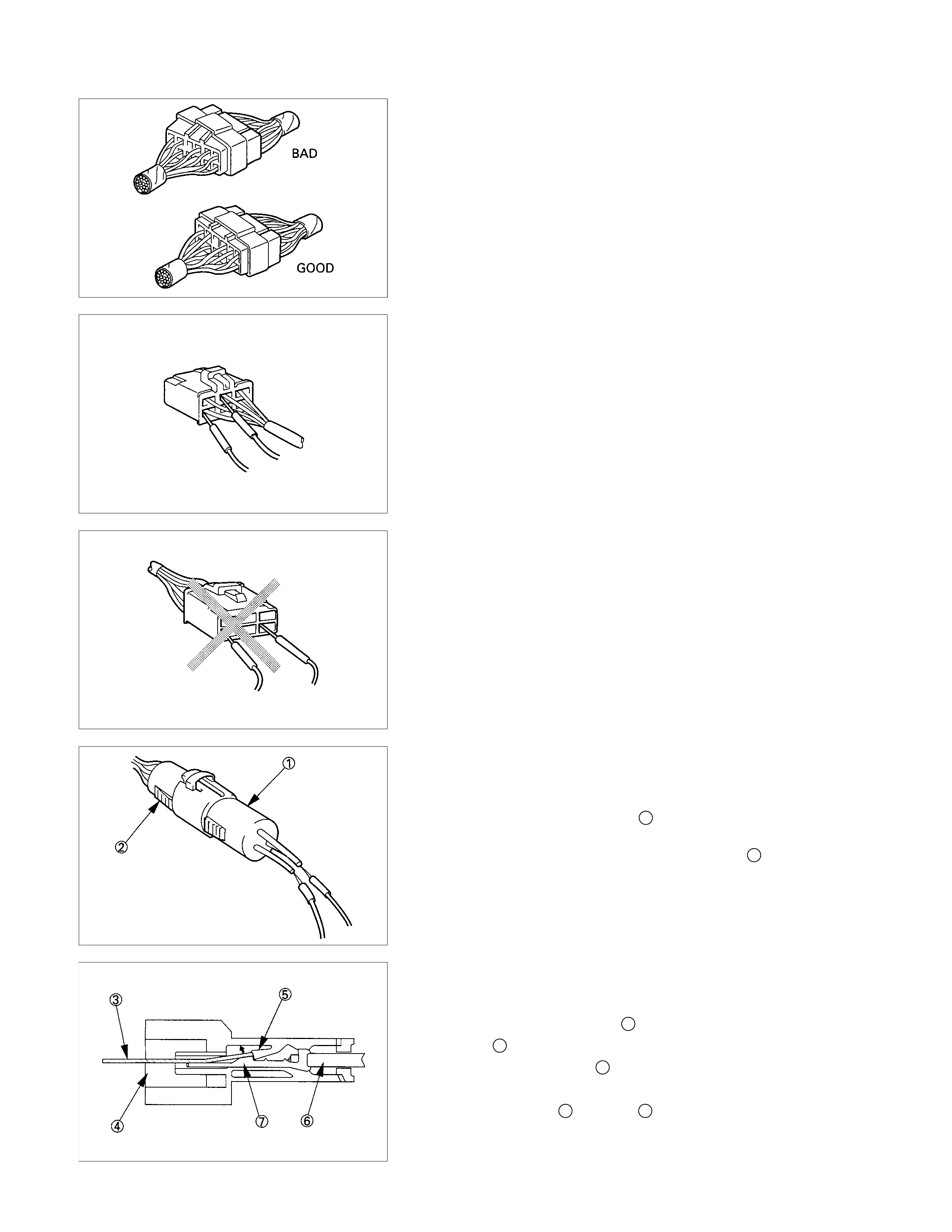
Connector Inspection
Use a circuit tester to check the connector for continuity.
Insert the test probes from the connector wire side.
CAUTION
Never insert the circuit tester test probes into the
connector open side to test the continuity.
Broken or open connector terminals will result.
Waterproof Connector Inspection
It is not possible to insert the test probes into the connector
wire side of a waterproof connector.
Use one side of a connector 1 with its wires cut to make the
test.
Connect the test connector to the connector 2 to be tested.
Connect the test probes to the cut wires to check the
connector continuity.
Connector Pin Removal
Connector Housing Tang Lock Type
1. Insert a slender shaft 3into the connector housing open
end 4.
2. Push the tang lock 5up (in the direction of the arrow in the
illustration).
Pull the wire 6 with pin 7free from the wire side of the
connector.

Pin Tang Lock Type
1. Insert a slender shaft 3into the connector housing open
end 4.
2. Push the tang lock 8flat (toward the wire side of the
connector).
Pull the wire 6 with pin 7free from the wire side of the
connector.
Connector Pin Insertion
1. Check that the tang lock 8 is fully up.
2. Insert the pin 7 from the connector wire side 9.
Push the pin in until the tang lock closes firmly.
3. Gently pull on the wires 6to make sure that connector pin
is firmly set in place.
Fuse Replacement
The replacement fuse must have the same amperage
specification as the original fuse.
Never replace a burn out fuse with a fuse of a different
amperage specification.
Doing so can result in an electrical fire or other serious circuit
damage.
Parts Handling
Be careful for parts handling and any part should not be
dropped or thrown, otherwise short circuit or disorder may
result.
Wiring Harness
1. When assembling the parts, be careful not to bite or wedge
the wiring harness.
2. All electrical connections must be kept clean and tight.
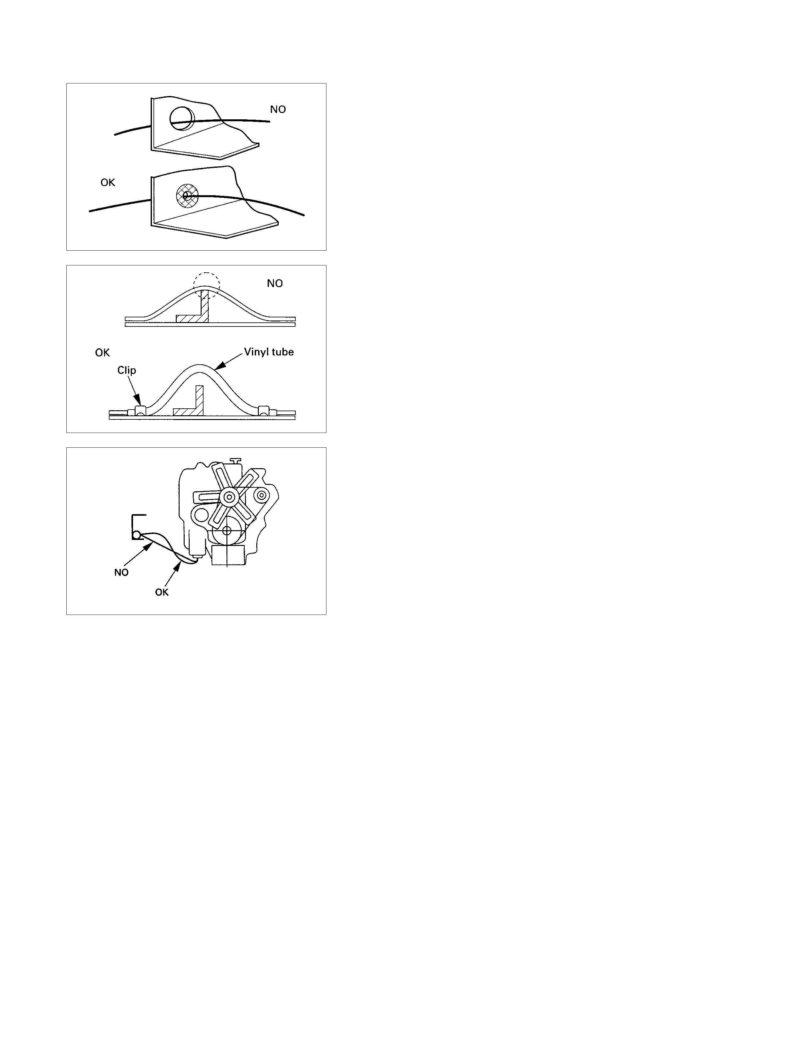
3. Use a grommet or guard tube to protect the wiring harness
from contacting a sharp edge or surface.
4. Position the wiring harness with enough clearance from the
other parts and guard the wiring harness with a vinyl tube
to avoid direct contact.
5. The wiring harness between engine and chassis should be
long enough to prevent chafing or damage due to various
vibrations.
SPLICING WIRE
Open the Harness
If the harness is taped, remove the tape.
To avoid wire insulation damage, use a sewing "seam ripper"
(available from sewing supply stores) to cut open the harness.
If the harness has a black plastic conduit, simply pull out the
desired wire.
Cut the wire
Begin by cutting as little wire off the harness as possible.
You may need the extra length of wire later if you decide to cut
more wire off to change the location of a splice.
You may have to adjust splice locations to make certain that
each splice is at least 1-1/2" (40 mm) away from other splices,
harness branches, or connectors.
Strip the insulation
When replacing a wire, use a wire of the same size as the
original wire.
Check the stripped wire for nicks or cut strands.
If the wire is damaged, repeat the procedure on a new section
of wire.
The two stripped wire ends should be equal in length.
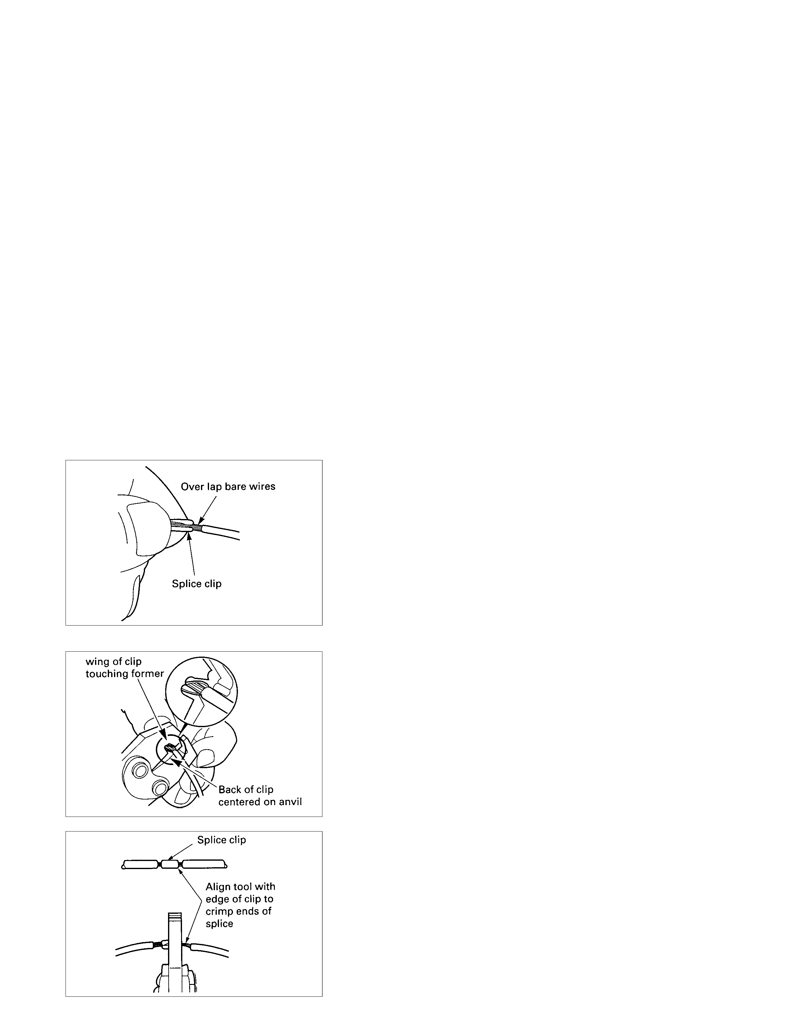
Crimp the Wires
Select the proper clip to secure the splice.
To determine the proper clip size for the wire being spliced,
follow the directions included with your clips.
Select the correct anvil on the crimper.
(On most crimpers your choice is limited to either a small or
large anvil.)
Overlap the two stripped wire ends and hold them between
your thumb and forefinger.
Then, enter the splice clip under the stripped wires and hold it
in place.
• Open the crimping tool to its full width and rest one handle
on a firm flat surface.
• Center the back of the splice clip on the proper anvil and
close the crimping tool to the point where the back of the
splice clip touches the wings of the clip.
• Make sure that the clip and wires are still in the correct
position. Then, apply pressure until the crimping tool
closes.
Before crimping the ends of the clip, be sure that:
• The wires extend beyond the clip in each direction.
• No strands of wire are cut loose.
• No insulation is caught under the clip.
Crimp the splice again, once on each end.
Do not let the crimping tool extend beyond the edge of the clip
or you may damage or nick the wires.
Solder
Apply 60/40 rosin core solder to the opening in the back of the
clip.
Follow the manufacturer's instructions for the solder
equipment you are using.
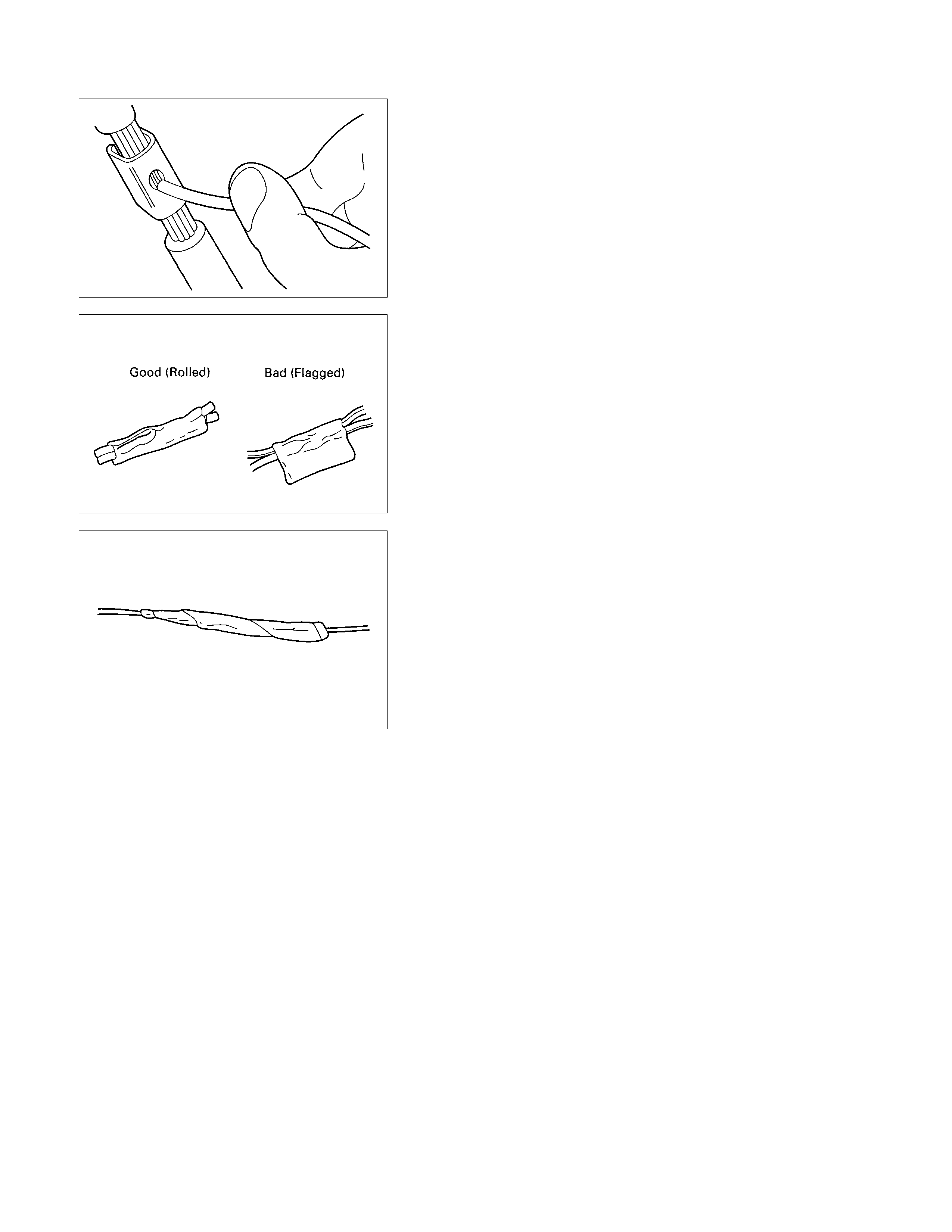
Tape the Splice
Center and roll the splicing tape.
The tape should cover the entire splice.
Roll on enough tape to duplicate the thickness of the insulation
on the existing wires.
Do not flag the tape.
Flagged tape may not provide enough insulation, and the
flagged ends will tangle with the other wires in the harness.
If the wire does not belong in a conduit or other harness
covering, tape the wire again.
Use a winding motion to cover the first piece of tape.
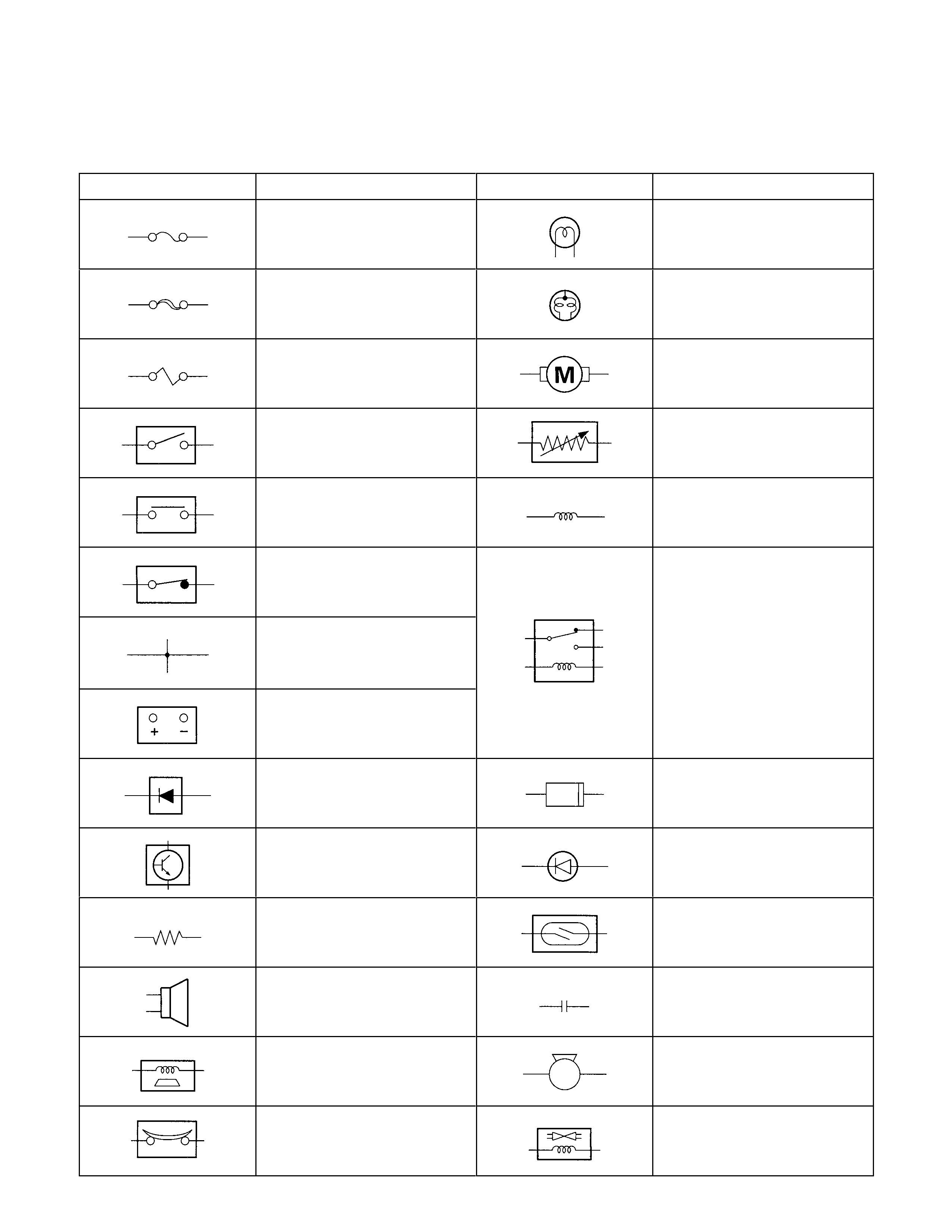
SYMBOLS AND ABBREVIATIONS
SYMBOLS
Symbol Meaning of Symbol Symbol Meaning of Symbol
Fuse
Bulb
Fusible link
Double filament bulb
Fusible link wire
Motor
Switch
Variable resistor Rheostat
Switch
Coil (inductor), solenoid,
magnetic valve
Switch (Normal close type)
Contact wiring
Relay
Battery
Diode
Connector
Electronic Parts
Light emitting diode
Resistor
Reed switch
Speaker
Condenser
Buzzer
Horn
Circuit breaker
Vacuum switching valve

ABBREVIATIONS
Abbreviation Meaning of abbreviation Abbreviation Meaning of abbreviation
4×2 Two-wheel drive HVAC Heater, Ventilation, and Air
Conditioning
4×4 Four-wheel drive IAT Intake Air Temperature
A Ampere (S) IC Integrated circuit
ABS Anti-lock brake system IG Ignition
AC Alternating current KS Knock Sensor
A/C Air conditioner kW Kilowatt
ACC Accessories LH Left hand
APP Accel Pedal Position LWB Long wheel base
ASM Assembly MAF Mass Air Flow
BARO Barometric Pressure MPI Multipart fuel injection
CARB Carburetor M/T Manual transmission
C/B Circuit breaker PIM Powertrain Interface Module
CKP Crankshaft Position QOS Quick On Start system
CMP Camshaft Position RH Right hand
CSD Cold start device RR Rear
DIS Direct ignition system RWAL Rear wheel anti-lock brake system
DLC Data Link Connector SRS Supplemental restraint system
ECGI Electronic control gasoline injection ST Start
ECM Engine control module STD Standard
ECT Engine Coolant Temperature SW Switch
ECU Electronic control unit SWB Short wheel base
EFE Early fuel evaporation TAC Throttle Actuator Control
EHCU Electronic Hydraulic control Unit TCM Transmission control module
EOP Enigne Oil Pressure TP Throttle Position
EVAP Evaporative Emission V Volt
FL Fusible link VSS Vehicle Speed Sensor
FRT Front VSV Vacuum switching valve
H/L Headlight W Watt (S)
HO2S B1S1 Heated Oxygen Sensor Bank 1
Sensor 1 W/ With
HO2S B1S2 Heated Oxygen Sensor Bank 1
Sensor 2 W/O Without
HO2S B2S1 Heated Oxygen Sensor Bank 2
Sensor 1 WOT Wide open throttle
HO2S B2S2 Heated Oxygen Sensor Bank 2
Sensor 2 W/S Weld Splice
PARTS FOR ELECTRICAL CIRCUIT
WIRING
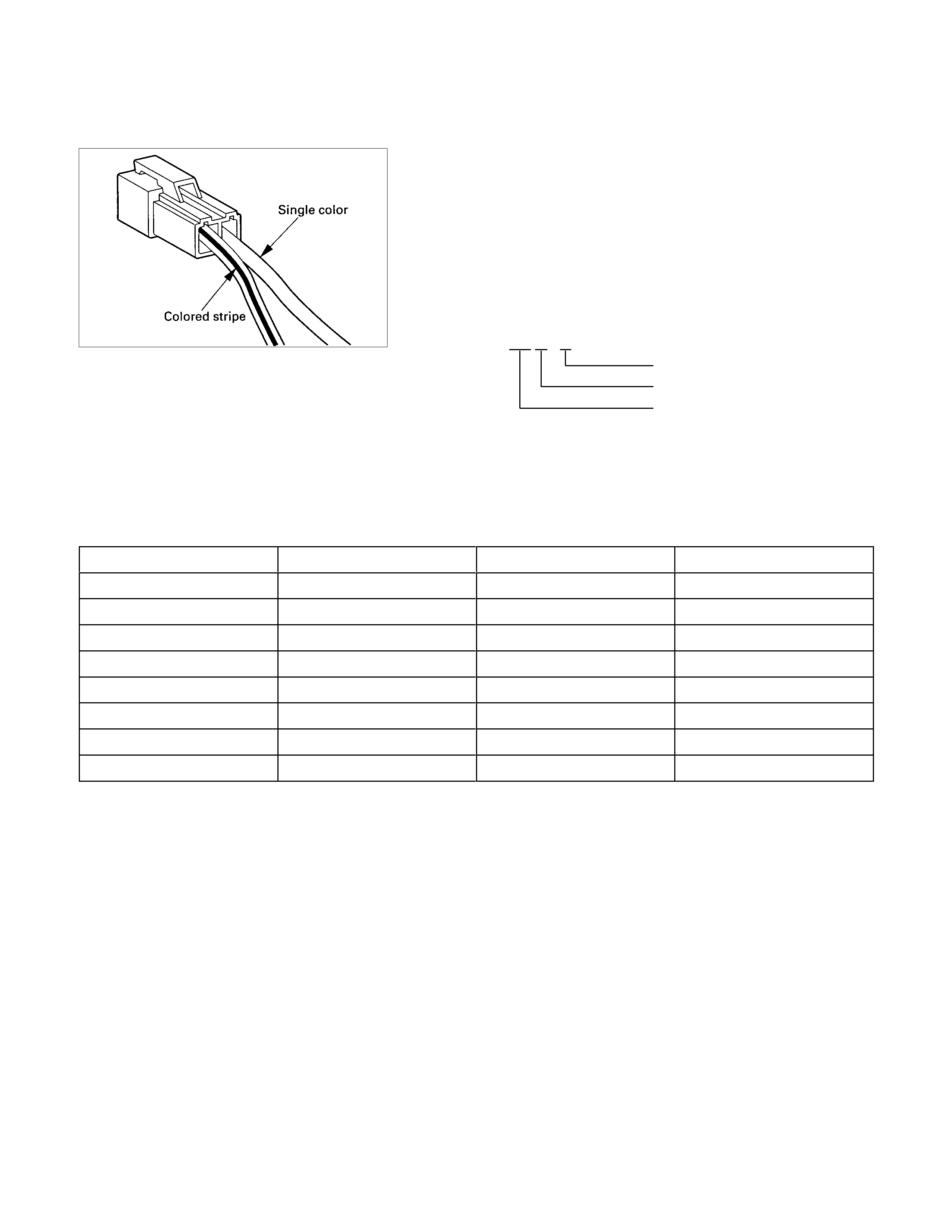
Wire Color
All wires have color-coded insulation.
Wires belonging to system's main harness will have a single
color.
Wires belonging to a system's sub-circuits will have a colored
stripe.
Striped wires use the following code to show wire size and
colors.
Example: 0.5 G / R Red (Stripe color)
Green (Base color)
Wire size (0.5mm2)
Abbreviations are used to indicate wire color within a circuit
diagram.
Refer to the following table.
Wire Color-Coding
Color-Coding Meaning Color-Coding Meaning
B Black BR Brown
W White LG Light green
R Red GR Grey
G Green P Pink
Y Yellow LB Light blue
L Blue V Violet
O Orange T Tan
DB Dark Blue DG Dark Green
Distinction of Circuit by Wire Base Color
Base color Circuits Base color Circuits
B Starter circuit and grounding circuit Y Instrument circuit
W Charging circuit L, O, BR, LG,
R Lighting circuit GR, P, LB, V, Other circuits
G Signal circuit T, DB, DG
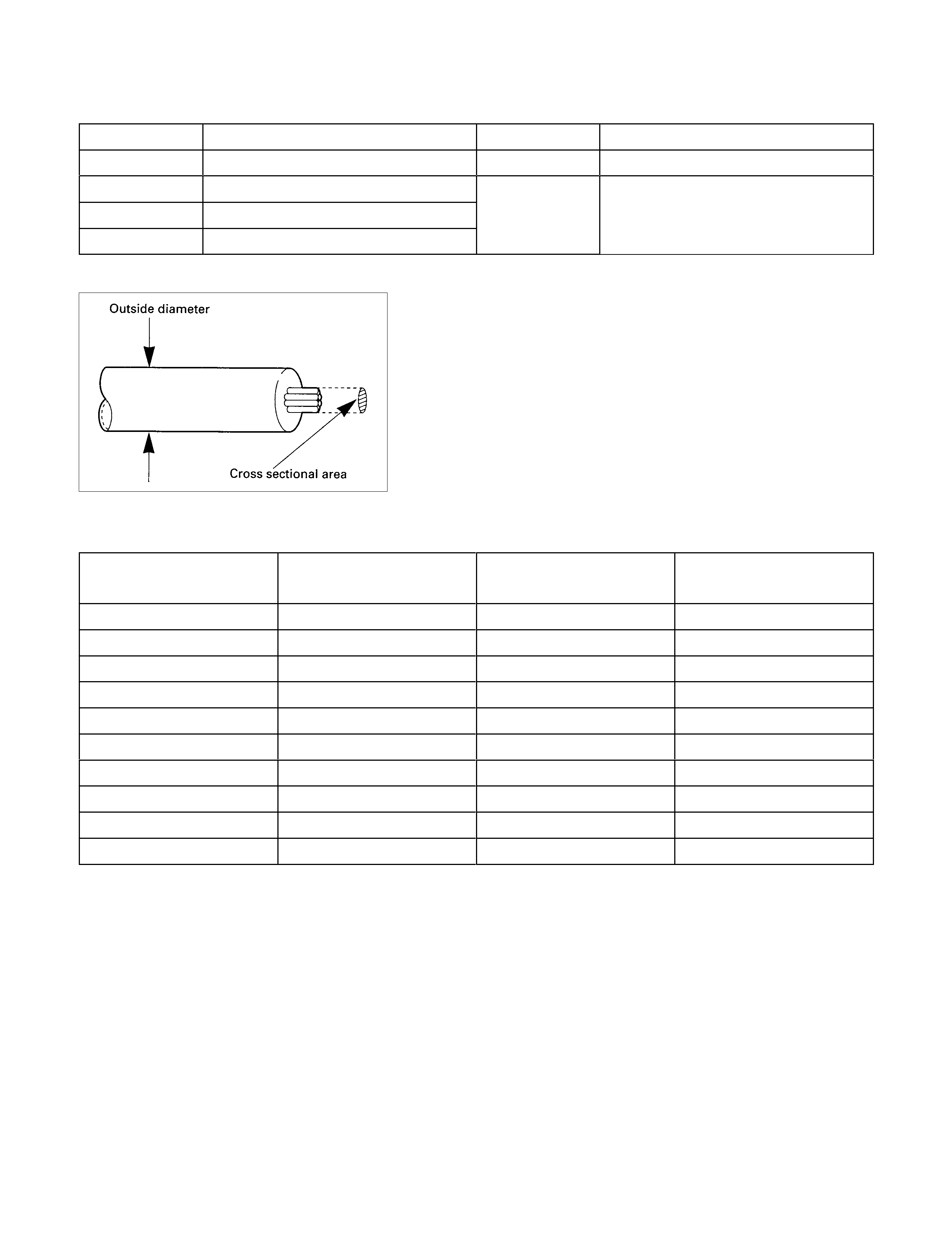
Wire Size
Wire size is specified with the metric gauge system.
The metric gauge system gives the wire size in cross sectional
area measured in square millimeters.
Wire Size Specifications
Normal size Cross sectional area
(mm2) Outside diameter
(mm) Allowable current
(A)
0.3 0.372 1.8 9
0.5 0.563 2.0 12
0.85 0.885 2.2 16
1.25 1.287 2.5 21
2 2.091 2.9 28
3 3.296 3.6 37.5
5 5.227 4.4 53
8 7.952 5.5 67
15 13.36 7.0 75
20 20.61 8.2 97
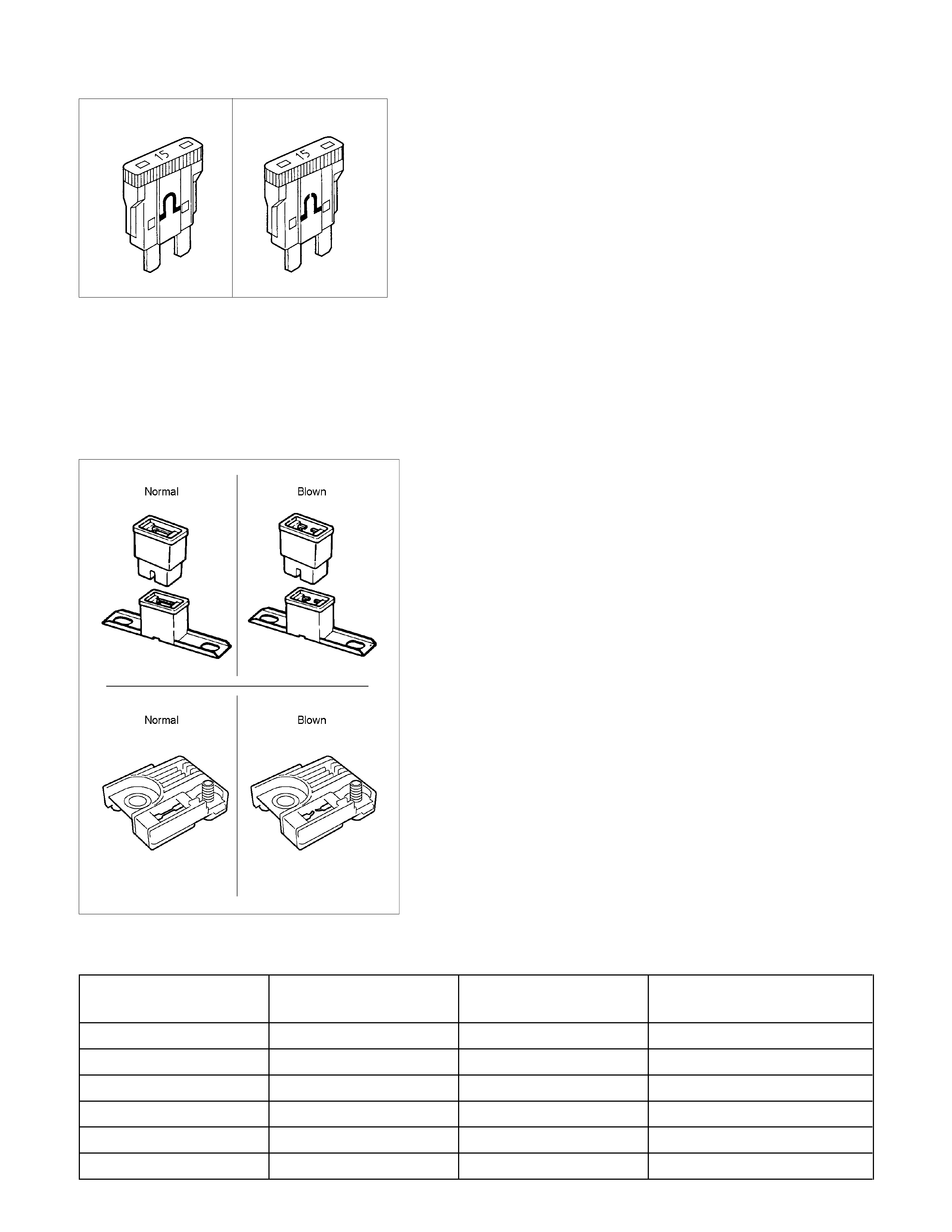
Normal Blown
FUSE
Fuses are the most common form of circuit protection used in
vehicle wiring.
A fuse is a thin piece of wire or strip of metal encased in a
glass or plastic housing.
It is wired in series with the circuit it protects.
When there is an overload of current in a circuit, such as a
short of a ground, the wire or metal strip is designed to burn
out and interrupt the flow of current.
This prevents a surge of high current from reaching and
damaging other components in the circuit.
Determine the cause of the overloaded before replacing the
fuse.
Never replace a blown fuse with a fuse of a different amperage
specification.
Doing so can result in an electrical fire or other serious circuit
damage.
A blown fuse is easily identified.
RTW68AMH000101
FUSIBLE LINK
The fusible link is primarily used to protect circuits where high
amounts of current flow and where is would not be practical to
use a fuse.
For example, the starter circuit.
When a current overload occurs, the fusible link melts open
and interrupts the flow of current so as to prevent the rest of
the wiring harness from burning.
Determine the cause of the overload before replacing the
fusible link.
The replacement fusible link must have the same amperage
specification as the original fusible link.
Never replace a blown fusible link with fusible link of a different
amperage specification.
Doing so can result in an electrical fire or other serious circuit
damage.
A blown fusible link is easily identified.
Fusible Link Specifications
Type Rating Case Color Maximum Circuit Current
(A)
Connector 20A 10
Connector 30A Pink 15
Connector 40A Green 20
Bolted 50A Red 25
Bolted 60A Yellow 30
Bolted 80A Black 40
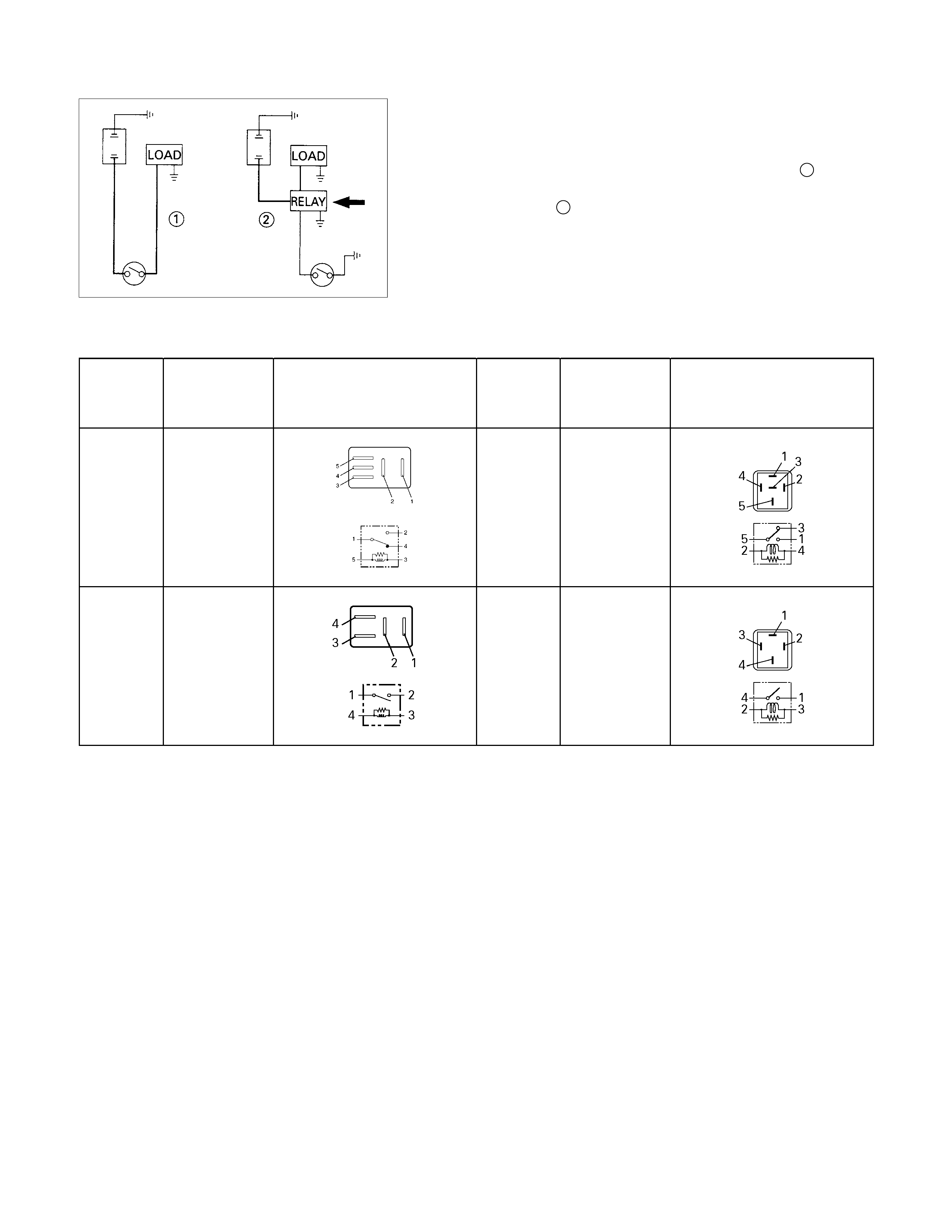
RELAY
Battery and load location may require that a switch be placed
some distance from either component.
This means a longer wire and a higher voltage drop 1. The
installation of a relay between the battery and the load reduces
the voltage drop 2.
Because the switch controls the relay, amperage through the
switch can be reduced.
Relay Specifications and Configurations
Name/
Color
Rated
voltage/ Coil
resistance Internal circuit Name/
color
Rated
Voltage/Coil
resistance Internal circuit
1T
(MICRO
ISO)
/Black
12V
Approx. 92Ω
Minimum
operating
voltage: 7V at
20°C (77°F)
1M (MINI
ISO)
/Black
12V Approx.
94Ω Minimum
operating
voltage: 7V at
20°C (77°F)
1M
(MICRO
ISO)
/Black
12V
Approx. 132-3
Ω Minimum
operating
voltage: 7V at
20°C (77°F)
1M
(power)/
Black
12V Approx.
94Ω Minimum
operating
voltage: 7V at
20°C (77°F)
* Relay contact shown in the wiring diagram indicates condition before actuation.
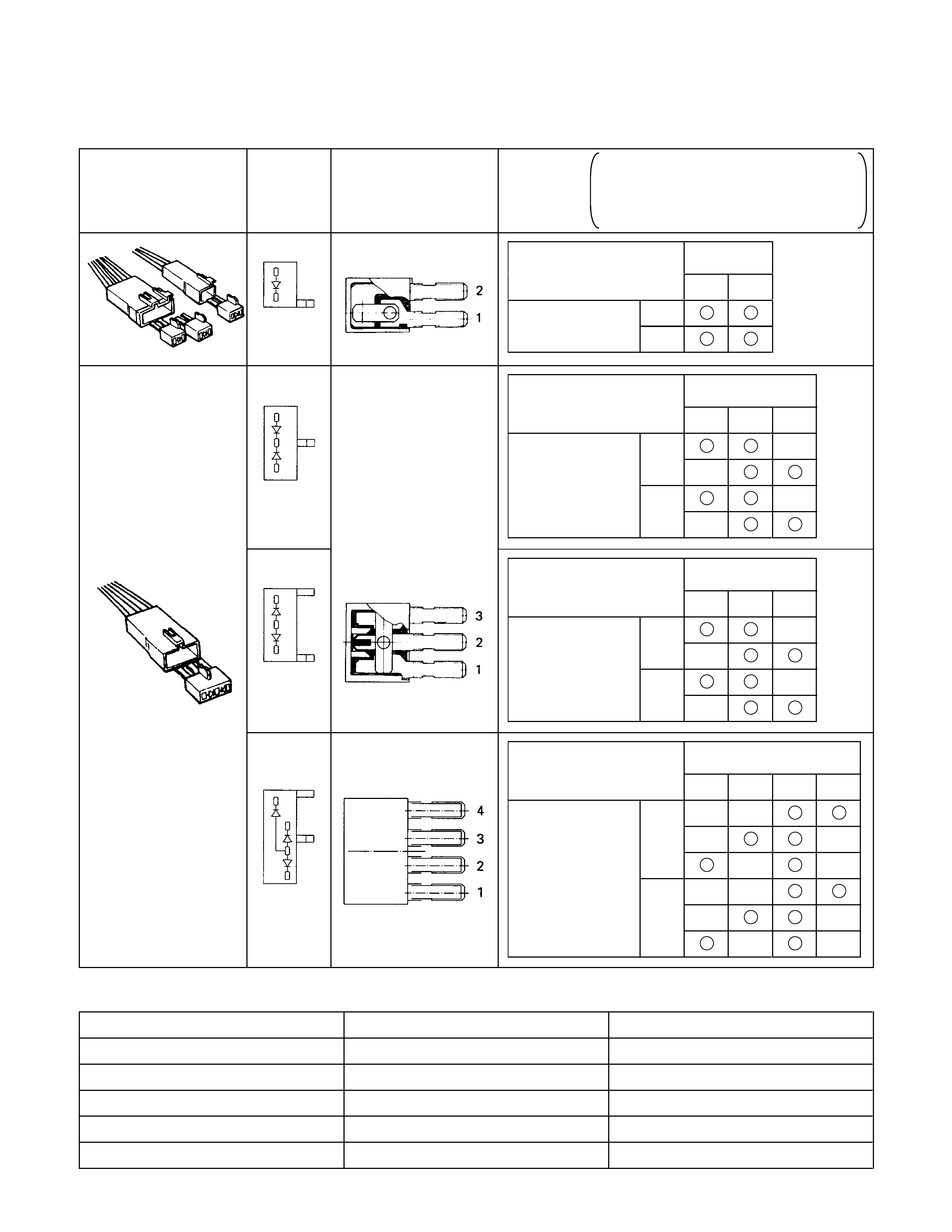
DIODE
Diode Specifications and Configurations
SHAPE
MARK/
COLOR
CONSTRUCTION CHECKING
THERE SHOULD BE CONTINUITY IN
EITHER A OR B WHEN A CIRCUIT
TESTER IS CONNECTED WITH
DIODE TERMINAL
BLACK
21
CONNECTION A + -
PATTERN B - +
TERMINAL NO.
BLACK
321
- +
CONNECTION + -
PATTERN + -
- +
B
A
TERMINAL NO.
BLACK
321
- +
CONNECTION + -
PATTERN + -
- +
B
A
TERMINAL NO.
BLACK
4321
+ -
A- +
CONNECTION - +
PATTERN - +
B+ -
+ -
TERMINAL NO.
Maximum Rating (Temp.=25°C)
Items Rating Remarks
Peak reverse voltage 400V
Transient peak reverse voltage 500V
Average output current 1.5A Temp.=40°C
Working ambient temperature -30°C∼80°C
Storage temperature -40°C∼100ßC

CONNECTOR
The connector pin shape determines whether the connector is
male or female.
The connector housing configuration does not determine
whether a connector is male or female.
The symbol illustrated in the figure is used as connector in the
circuit this section.
Connector is identified with a number.
The applicable terminal number is shown for each connector.
Connector terminal numbers are clearly shown.
Male side connector terminal numbers are in sequence from
upper right to lower left.
Female side connector terminal numbers are in sequence
from upper left to lower right.
NOTE:
For those connectors on which specific terminal numbers
on symbols are shown, the terminal numbers or symbols
are used in the circuit diagram, irrespective of the above
rule.
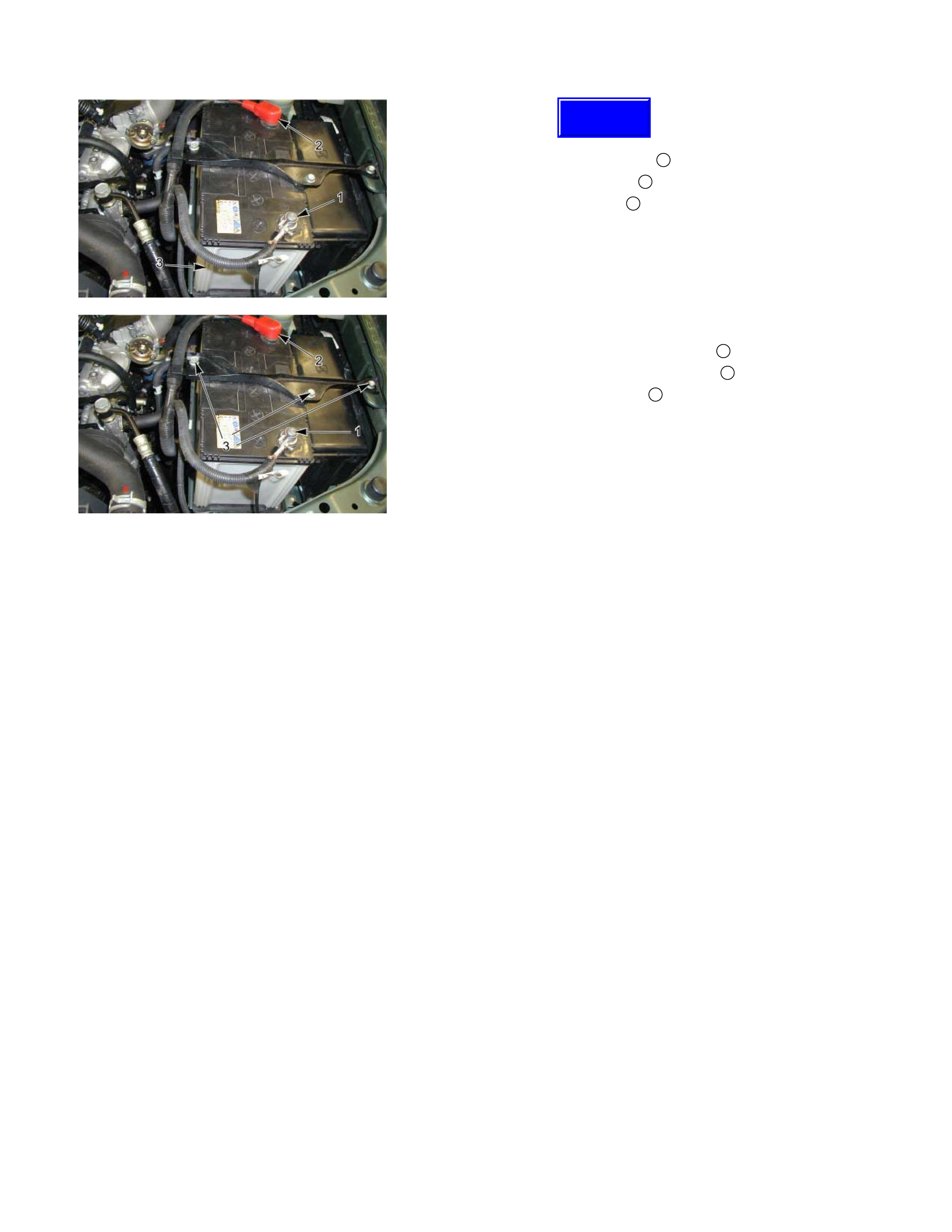
Battery-1
BATTERY
Inspection
1. Check the battery terminals 1 for corrosion.
2. Check the battery cables 2 for looseness.
3. Check the battery case 3 for cracks and other damage.
4. Check the battery electrolyte level.
Battery-2
Battery Replacement
1. Disconnect the battery ground cable 1.
2. Disconnect the battery positive cable 2.
3. Remove the battery clamp 3.
4. Remove the battery
Caution:
It is important that the battery ground cable be removed
first.
Removing the battery positive cable first can result in a
short circuit.
Jump Starting the Engine with a Booster Battery
The following description assumes that you are using a
booster battery mounted on a second vehicle.
The listed steps (with some minor modifications) are also
applicable if you are using a naked booster battery or special
battery charging equipment.
Caution:
Never push or tow the vehicle in an attempt to start it.
Extensive damage to the emission system and other
vehicle parts will result.
(Only catalytic converter vehicle)
Treat both the discharged battery and the booster battery
with great care when using jumper cables.
Carefully follow the procedure outlined below.
Always be aware of the dangers of sparking.
Failure to follow the following procedure can result in:
a. Serious personal injury, specially to your eyes.
b. Extensive property damage from a battery explosion,
battery acid discharge, or electrical file.
c. Extensive damage to the electronic components o
f
both vehicles.
Do not use a 24 volt booster battery.
Serious damage to the vehicle's electrical sy stem and
electronic components will result.
Techline

Jump Starting Procedure
1. Set the parking brake on both vehicles.
2. If one or both vehicles is equipped with a manual
transmission, place the gear shift in the "NEUTRAL"
position.
3. Turn off the ignition on both vehicles.
4. Turn off all vehicle lights and accessories.
5 Be sure that the two vehicles are not touching.
Attach the end of one jumper cable to the booster battery
positive terminal.
6
A
ttach the other end of the same cable to the discharged
battery positive terminal.
7. Once again, check that the booster battery has a 12 volt
rating.
8. Attach one end of the remaining booster cable to the
booster battery negative terminal.
9.
A
ttach the other end of the booster cable to a solid ground
(such as the air conditioner compressor mounting bracket
or the alternator mounting bracket) in the engine room o
f
the vehicle with the discharged battery.
Be sure that the ground connection is at least 500 mm (20
in) from the discharged battery.
Caution:
Do not attach the booster cable to the discharged battery
negative terminal.
11. Start the engine of the vehicle with the booster battery.
Check that all unnecessary electrical accessories are off.
12. Start the engine of the vehicle with the discharged battery.
13. Remove the jumper cables in the reverse order to which
they were attached.
Caution:
Be absolutely sure to remove the negative jumper cable
from the vehicle with the discharged battery first.
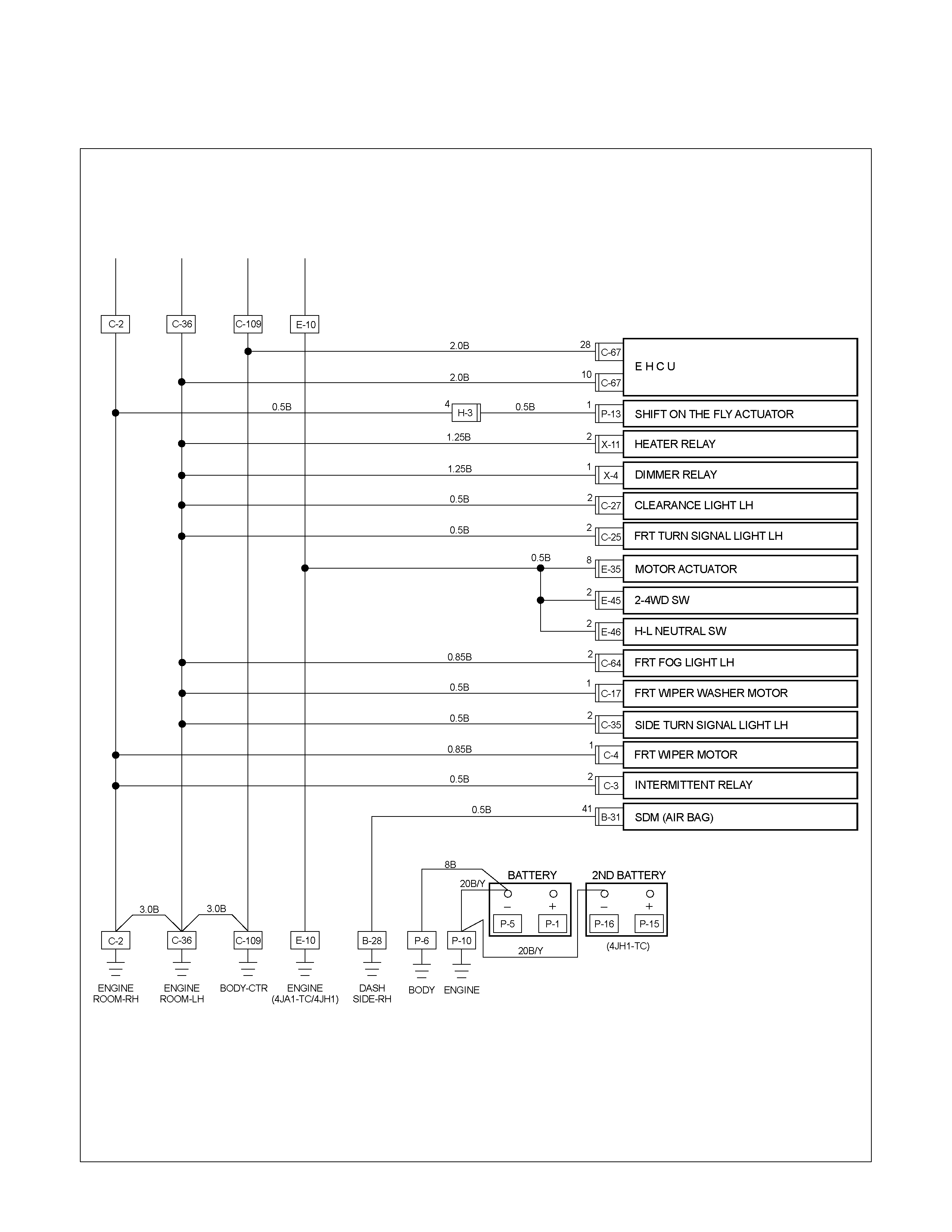
READING THE CIRCUIT DIAGRAM
In this manual, each system has its own parts location illustration and circuit diagram.
And connector configurations used in the circuit diagram are shown at the end of this manual.
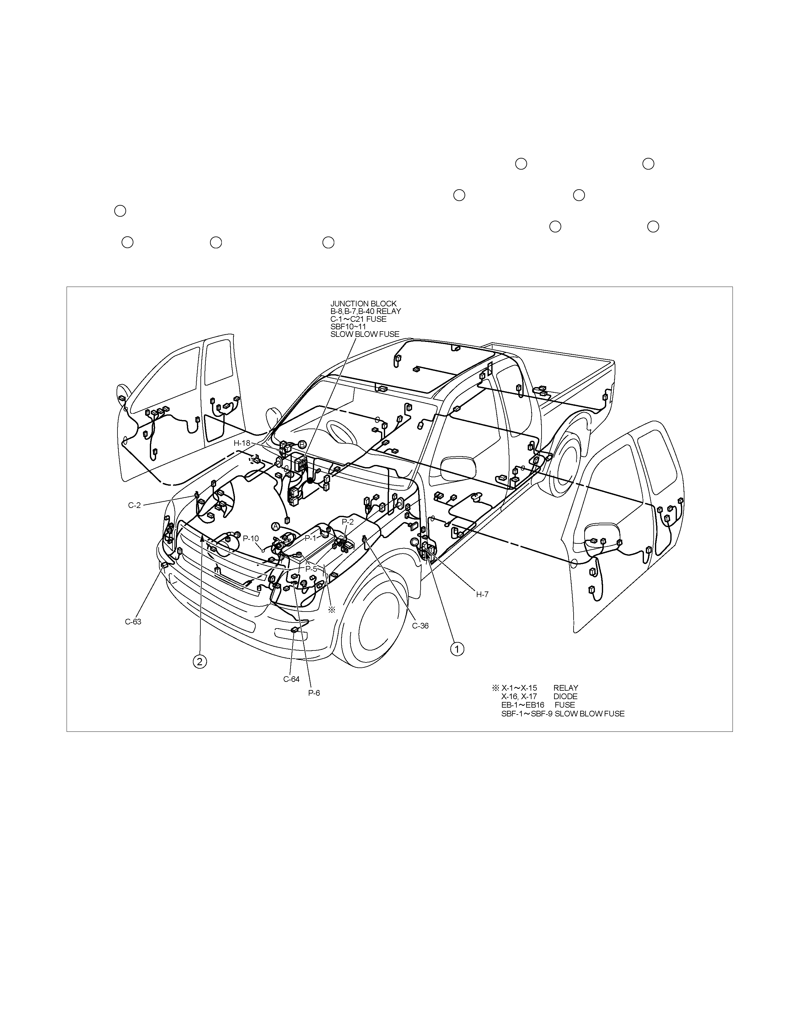
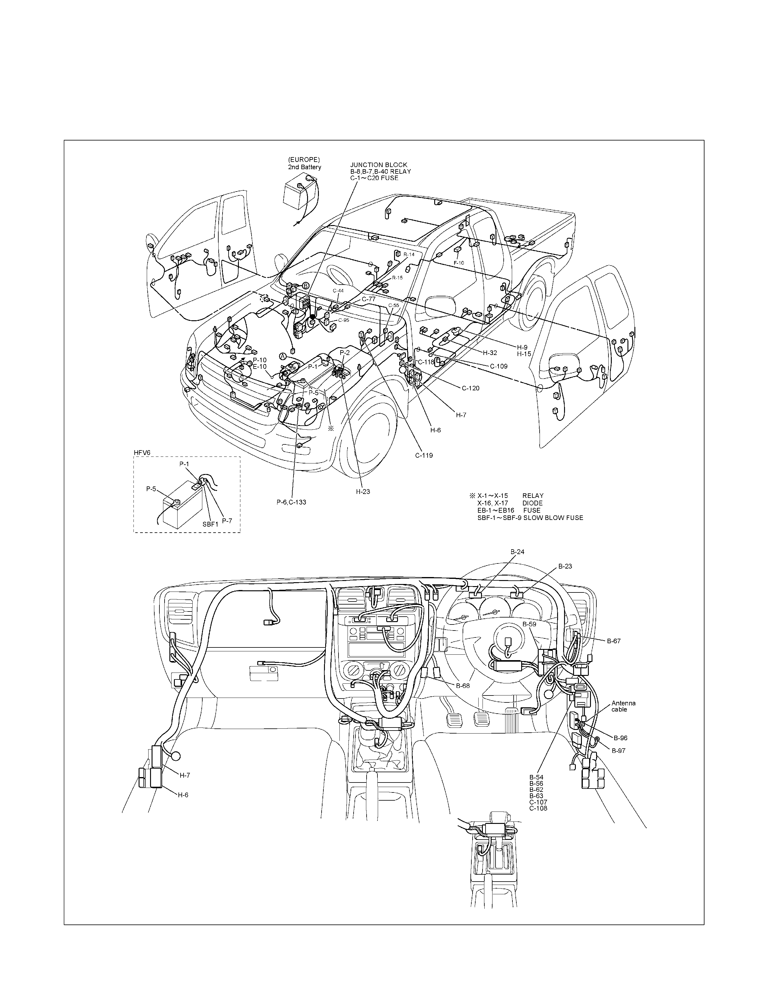
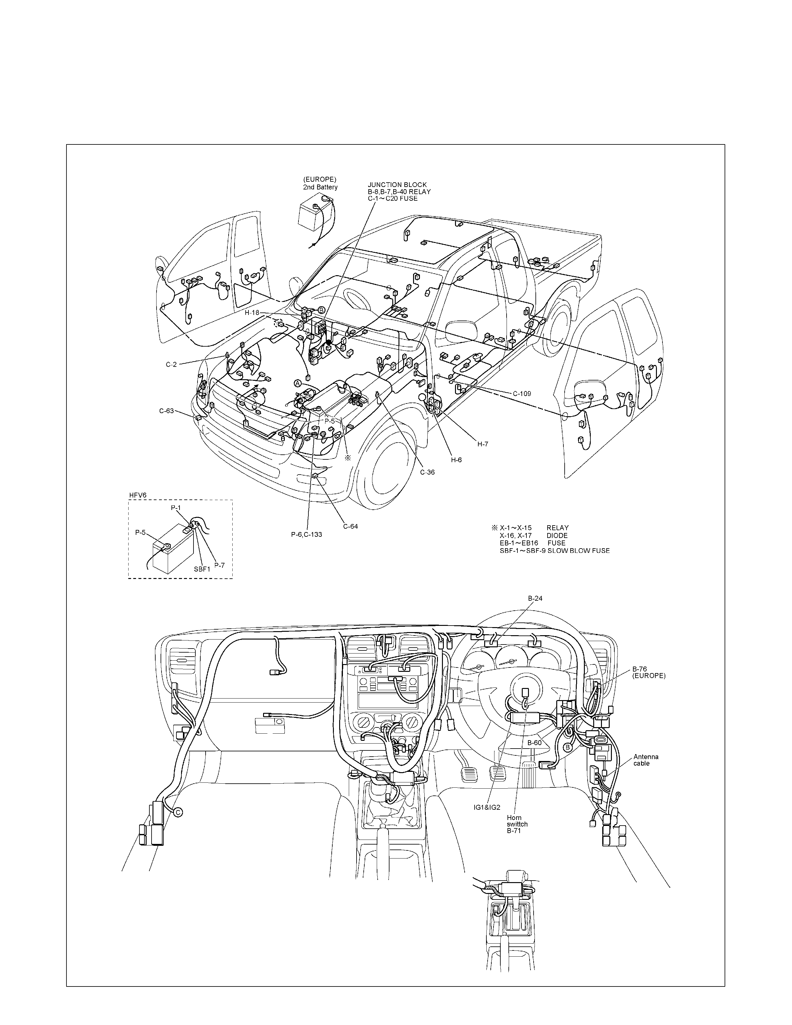
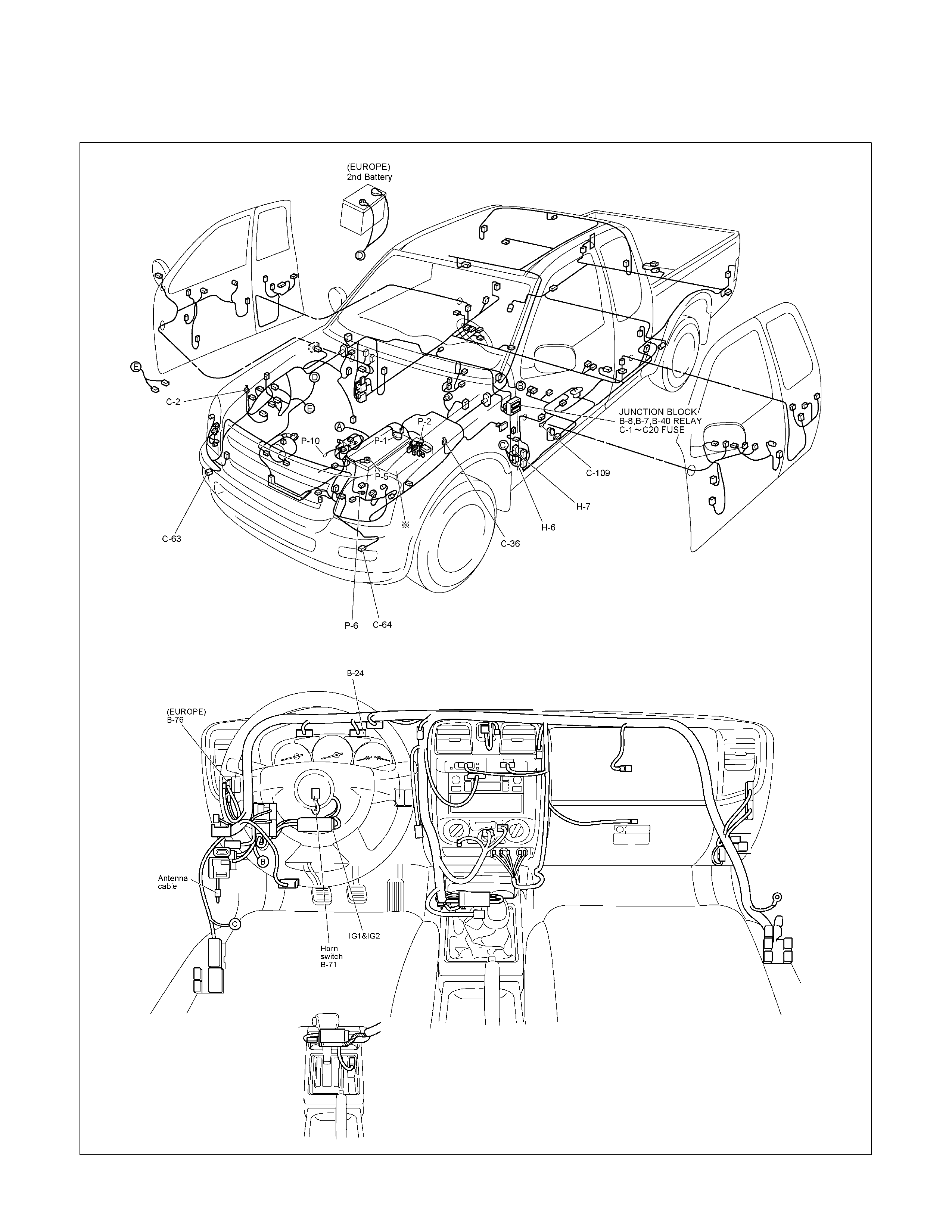
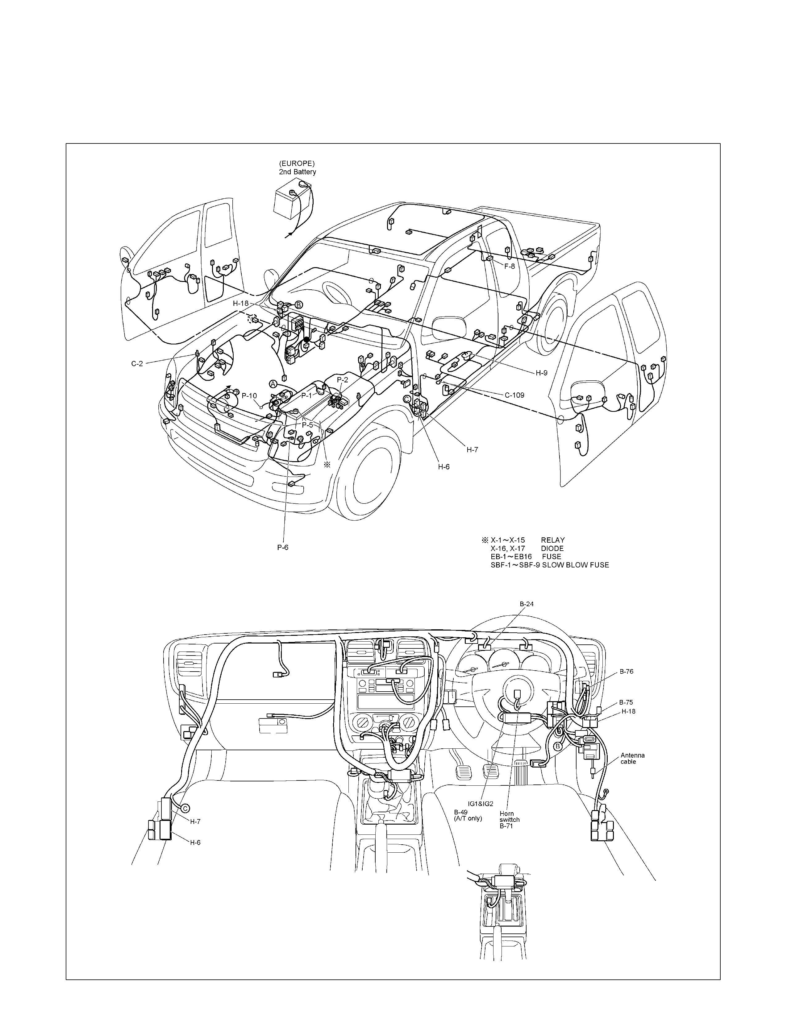
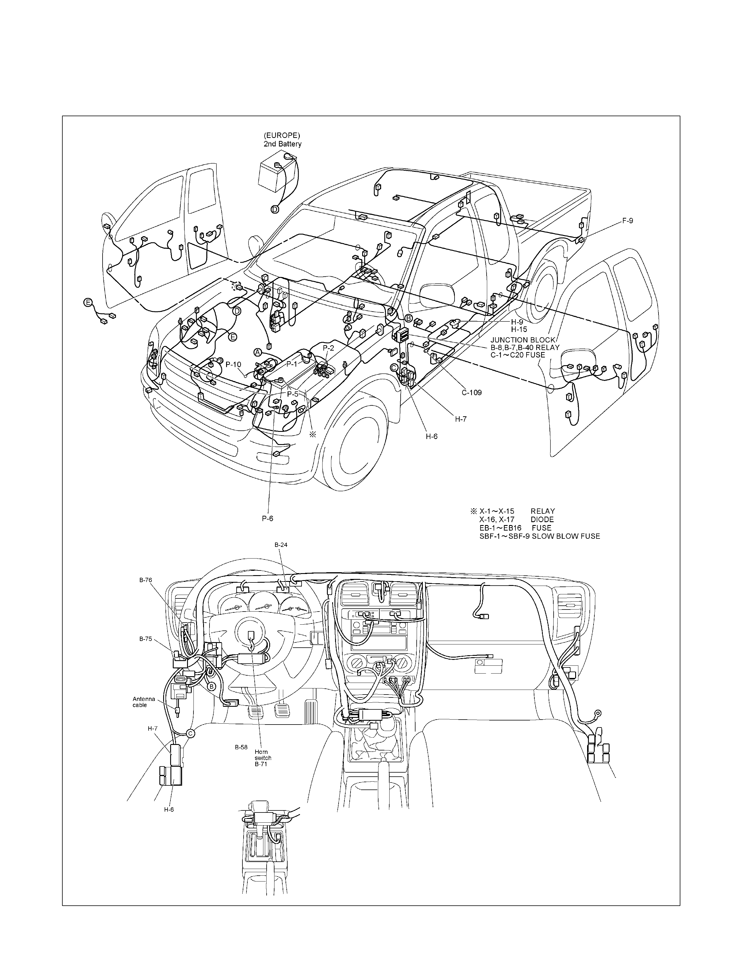
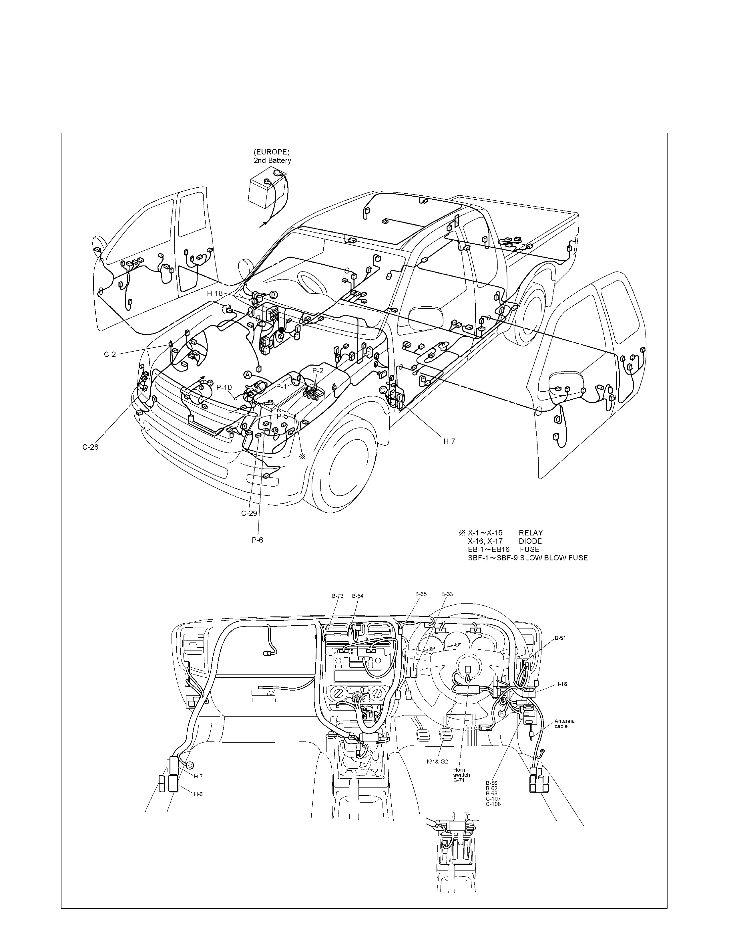
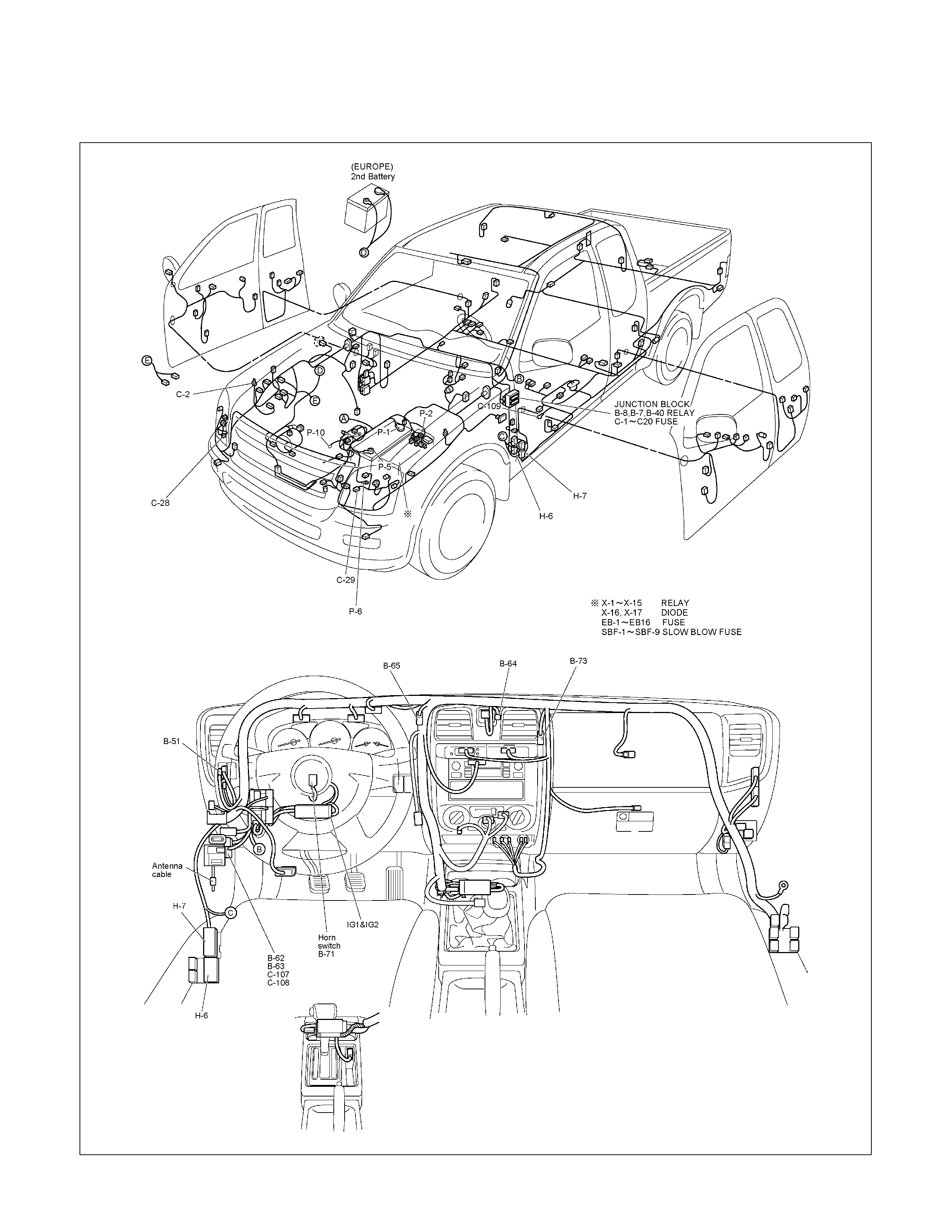
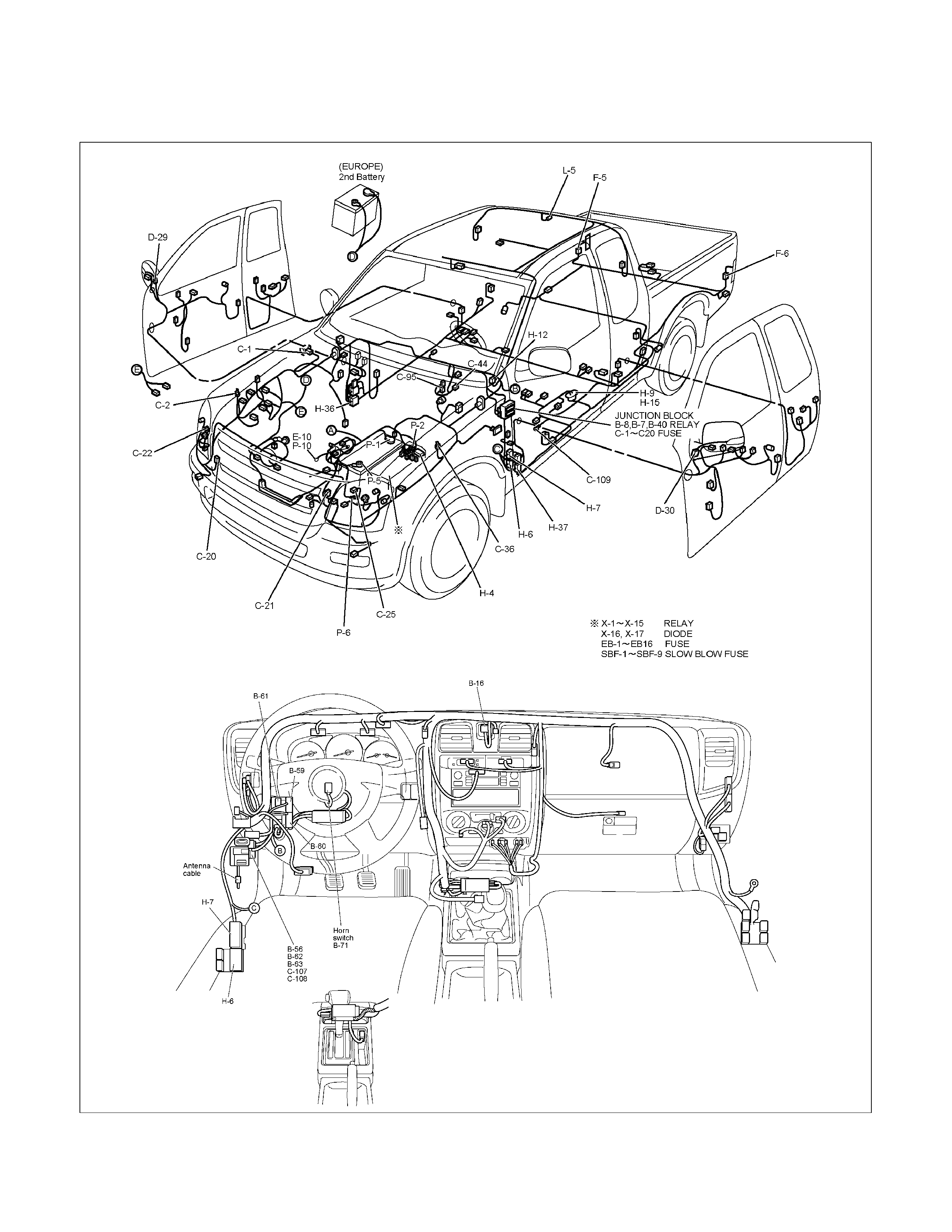
PARTS LOCATION: The parts location shows the location of the connectors 1 and the harnesses 2 used in the
each system.
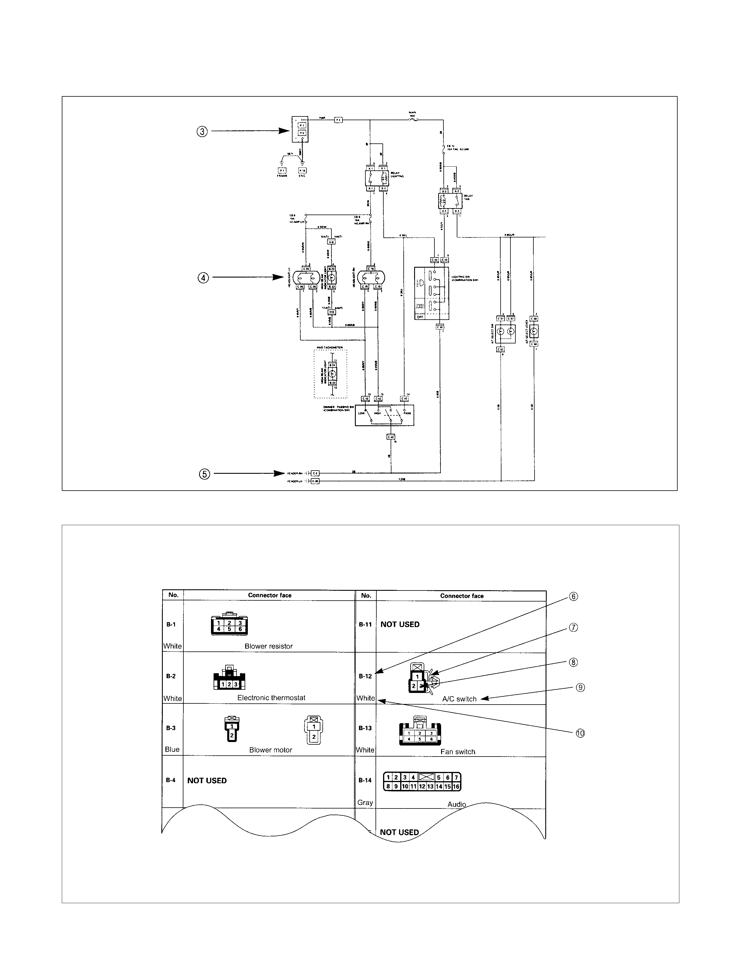
CIRCUIT DIAGRAM: The circuit diagram shows the power supply 3, the load or loads 4 and the grounding
point(s) 5.
CONNECTOR LIST: The connector configuration shows each connector's number 6, configuration 7 and the pin
numbers 8, parts name 9 , connector color 10 .
PARTS LOCATION
RTW38DMF000201
CIRCUIT DIAGRAM
CONNECTOR LIST
MAIN DATA AND SPECIFICATIONS
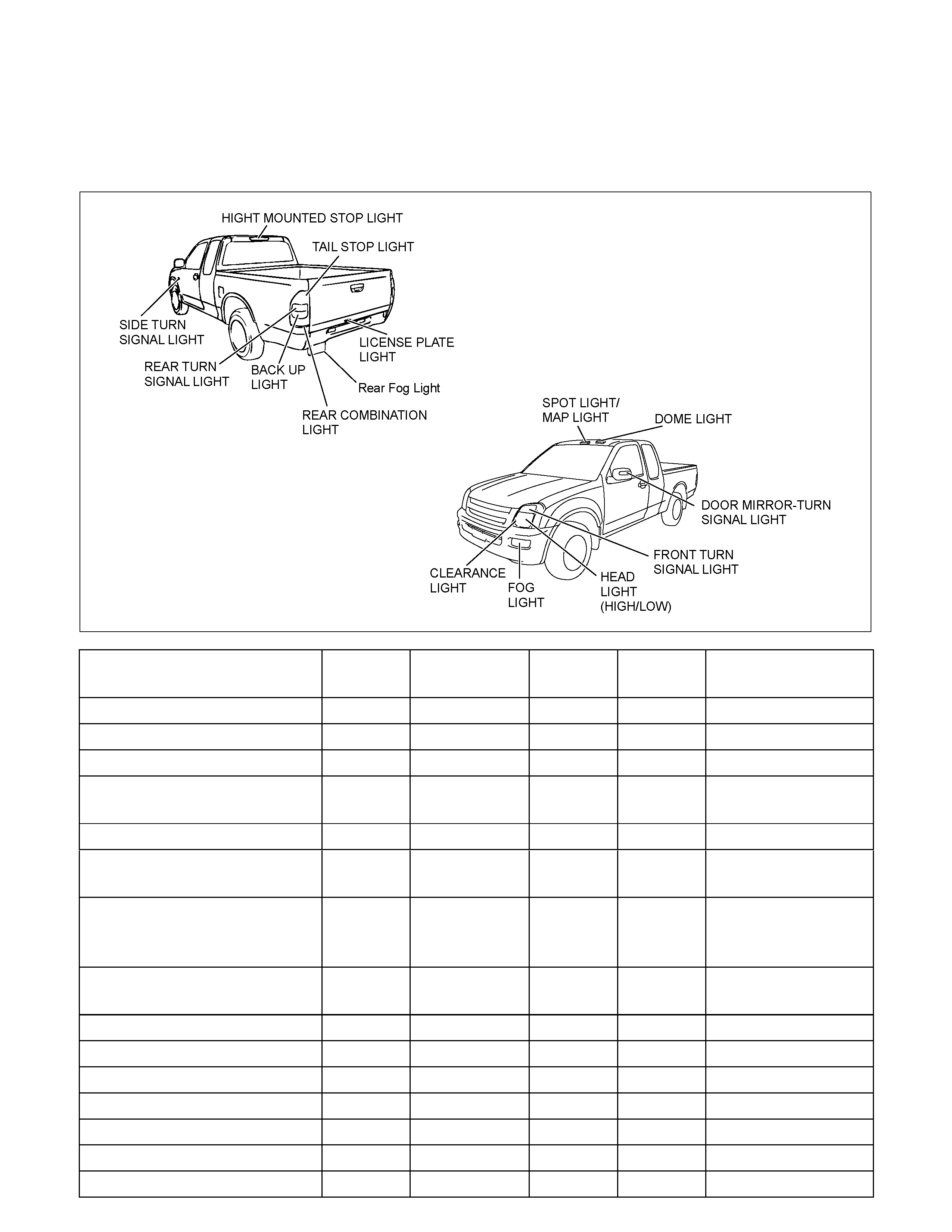
BULB SPECIFICATIONS
This illustration based on LHD
RTW68AMF004901
Light Name Bulb No. Rated Power
V-W Number
of Bulbs Lens
Color Remarks
Headlight H4 12-60/55 2 White Halogen
High mounted stop light W5W 12-5 4 RED
Fog light H3 12-55 2 White
Front turn signal light PY21W 12-21 2 White Bulb Lens color
Amber
Clearance light W5W 12-5 2 White
Door mirror-turn signal light
(out side mirror type) - - 2 White LED (Illuminated
color Amber)
Side turn signal light W5W 12-5 2 White with
amber
inner lens
Rear turn signal light PY21W 12-21 2 White Bulb Lens color
Amber
Rear fog light P21W 12-21 1 Red
Tail and stop light P21/5W 12-21/5 2 Red
Back up light P21W 12-21 2 White
License plate light W5W 12-5 2 White
A/C-Heater control light - 12-0.7 1 -
Dome light - 12-10 1 White
Spot light/ Map light - 12-5 2 White
Light Name Rated Power
V-W Number of
Bulbs Lens
Color Remarks
W/O Tacho 5Illumination light 14-2 W/ Tacho 7 White
Turn Signal 14-1.12 2 Green
High Beam 14-1.12 1 Blue
Low Fuel 14-1.12 1 Amber
A/T Oil Temp 14-1.12 1 Red
Brake system 14-1.12 1 Red
4WD 14-1.12 1 Green
Seat belt 14-1.12 1 Red
Oil pressure 14-1.12 1 Red
ABS 14-1.12 1 Amber
SEDIMENTER 14-1.12 1 Red
AIR BAG 14-1.12 1 Red
Brake 14-1.12 1 Red
Charge 14-1.12 1 Red
Check Trans 14-1.12 1 Red
Check 4WD 14-1.12 1 Red
Power drive 14-1.12 1 Amber
3rd start 14-1.12 1 Green
4L 14-1.12 1 Green
Cruise Set 14-1.12 1 Green
Check Engine 14-1.12 1 Amber
SVS 14-1.12 1 Amber
Front Fog 14-1.12 1 Green
Rear fog light 14-1.12 1 Amber
Glow 14-1.12 1 Amber
P LED 1 Green
R LED 1 Green
N LED 1 Green
D LED 1 Green
3 LED 1 Green
2 LED 1 Green
Indicator/
Warning
light
A/T shift
indicator
L LED 1 Green
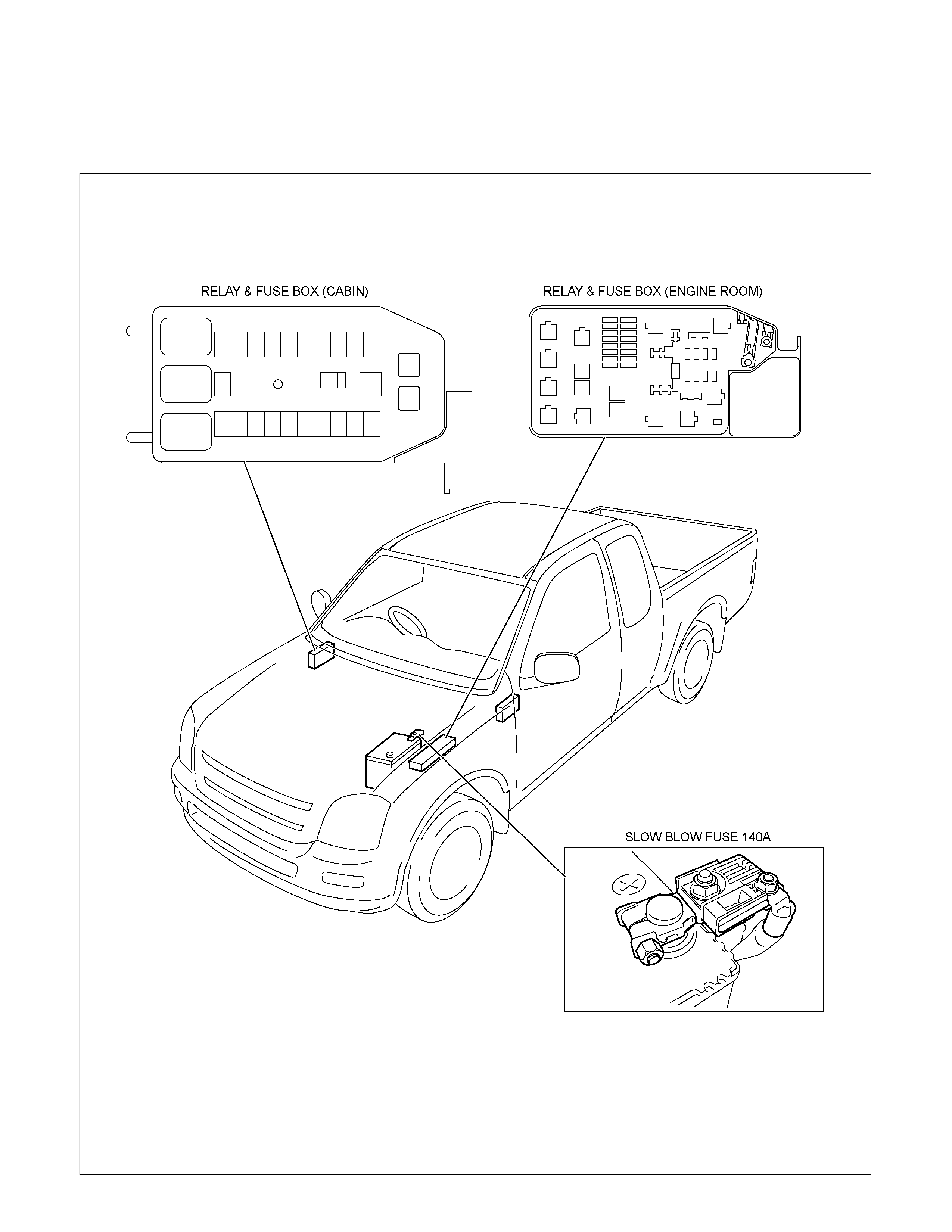
RELAY AND FUSE
RELAY AND FUSE BOX LOCATION (RHD)
RTW68AXF009901
RELAY AND FUSE BOX LOCATION (LHD)
RTW48ALF000201
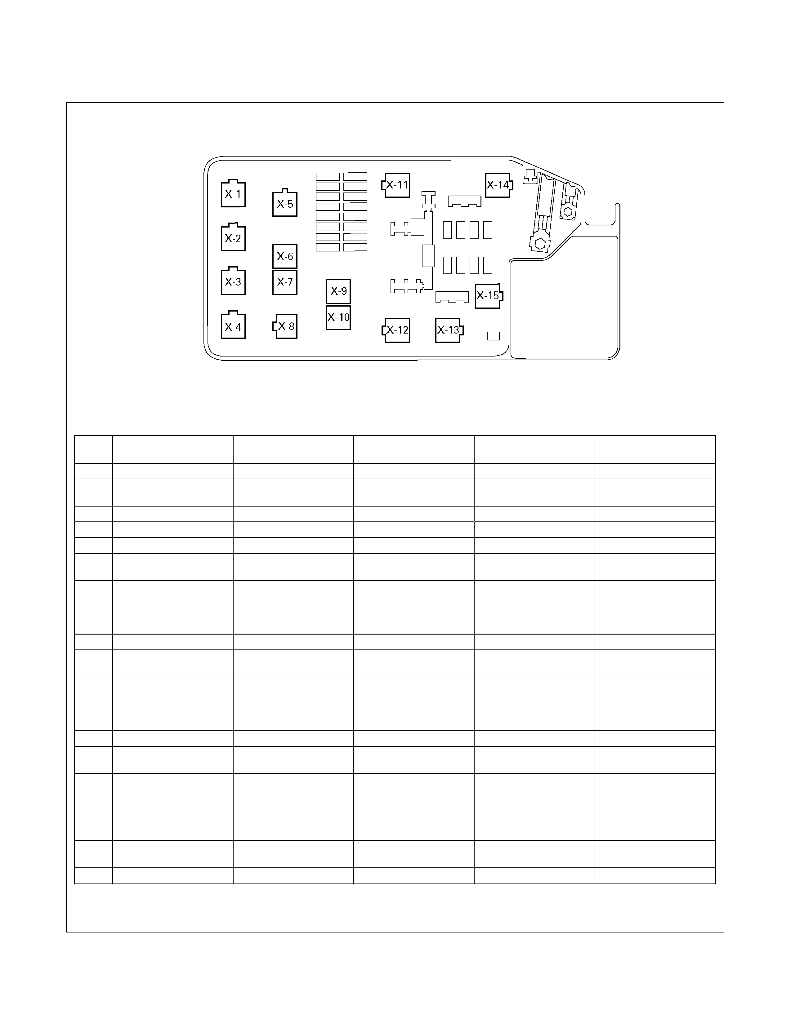
RELAY LOCATION
RELAY & FUSE BOX (ENGINE ROOM)
RHD
NO. RELEY (C24SE) RELAY (6VE1) RELAY
(4JA1-TC 4JH1-TC) RELAY (4JA1-L) RELAY (HFV6)
X-1 RELAY; TAIL LIGHT ← ← ← ←
X-2 RELAY; FUEL PUMP ← RELAY; FRT FOG
LIGHT ← RELAY; FUEL PUMP
X-3 RELAY; HORN ← ← ← ←
X-4 RELAY; DIMMER ← ← ← ←
X-5 ⎯ ⎯ RELAY; GLOW ← ⎯
X-6 RELAY; STARTER ← RELAY; STARTER
CUT (EURO 3) RELAY; CSD ⎯
X-7 RELAY; HEAD LIGHT
(Except AUSTRALIA)
RELAY; COND. FAN
(AUSTRALIA)
RELAY; HEAD LIGHT RELAY; HEAD LIGHT
(EURO 3) RELAY; HEAD LIGHT ⎯
X-8 ⎯ ⎯ RELAY; STARTER ← ⎯
X-9 RELAY; FRT FOG
HEAD LIGHT ← RELAY; COND. FAN ⎯ ⎯
X-10 RELAY; COND. FAN RELAY; COND. FAN RELAY; RR FOG
(EURO 3)
RELAY; HEAD LIGHT
(Except EURO 3)
⎯ RELAY; FRT FOG
LIGHT
X-11 RELAY; HEATER RELAY; HEATER RELAY; HEATER RELAY; HEATER ←
X-12 RELAY; STARTER
CUT (AUSTRALIA) RELAY; STARTER
CUT RELAY; STARTER
CUT (Except EURO 3) ⎯ REL AY; ECM MAIN
X-13 RELAY; STARTER
CUT (Except
AUSTRALIA)
RELAY; HEAD LIGHT
(AUSTRALIA)
RELAY; ECM MAIN RELAY; ECM MAIN RELAY; COND. FAN RELAY; STARTER
X-14 RELAY; A/C COMP RELAY; A/C COMP RELAY; A/C COMP RELAY; STARTER
CUT RELAY; A/C COMP
X-15 RELAY; THERMO RELAY; THERMO RELAY; THERMO RELAY; THERMO RELAY; HEAD LIGHT
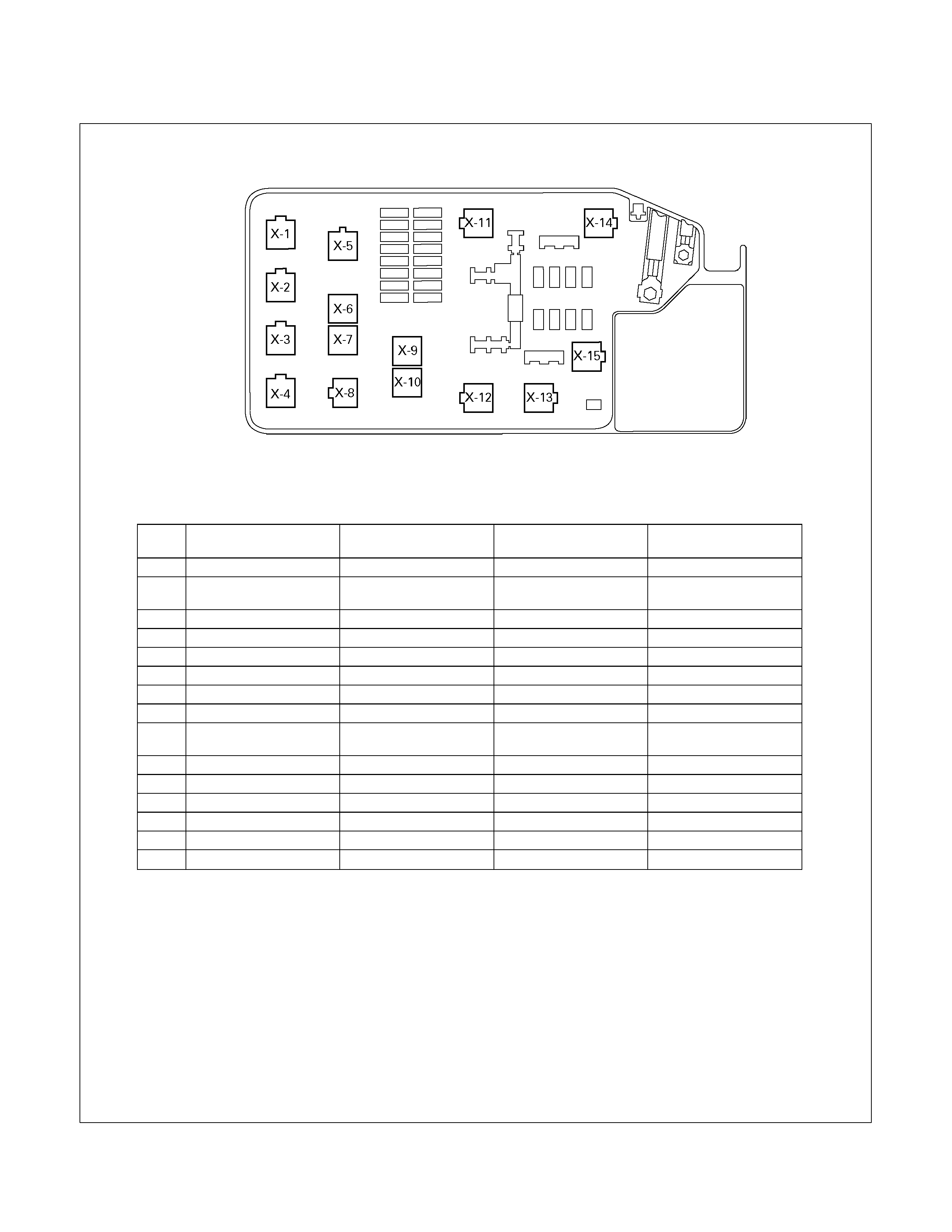
RELAY LOCATION
RELAY & FUSE BOX (ENGINE ROOM)
LHD
NO. RELEY (C24SE) RELAY; (6VE1) RELAY
(4JA1-TC 4JH1-TC) RELAY (4JA1-L)
X-1 RELAY; TAIL LIGHT ← ← ←
X-2 RELAY; FUEL PUMP ← RELAY; FRT FOG
LIGHT ←
X-3 RELAY; HORN ← ← ←
X-4 RELAY; DIMMER ← ← ←
X-5 ⎯ ⎯ RELAY; GLOW ←
X-6 RELAY; STARTER ← RELAY; STARTER CUTRELAY; CSD
X-7 RELAY; HEAD LIGHT ← ← ←
X-8 ⎯ ⎯ RELAY; STARTER ←
X-9 RELAY; FRT FOG
HEAD LIGHT ← RELAY; COND FAN ⎯
X-10 RELAY; COND. FAN RELAY; COND. FAN RELAY; RR FOG ⎯
X-11 RELAY; HEATER ← ← ←
X-12 ⎯ RELAY; STARTER CUTSHORT CONNECTOR ⎯
X-13 RELAY; STARTER CUT RELAY; ECM MAIN ← RELAY; COND. FAN
X-14 RELAY; A/C COMP ← ← REL AY; STARTER CUT
X-15 RELAY; THERMO ← ← ←
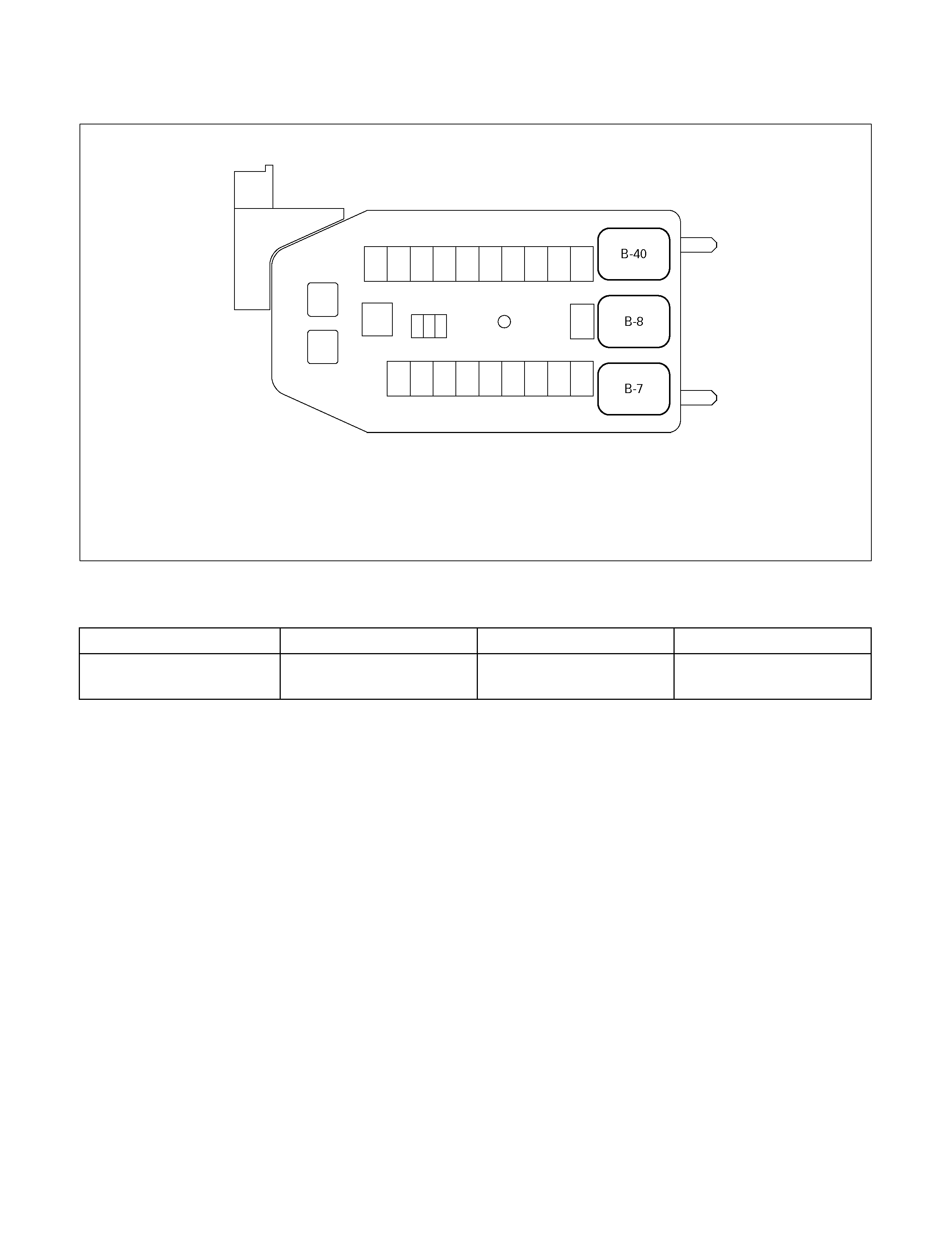
RELAY LOCATION
RELAY & FUSE BOX (CABIN)
RELAY
Connector No. B-7 B-8 B-40
Relay name REAR DEFOGGER POWER WINDOW (NO RELAY)
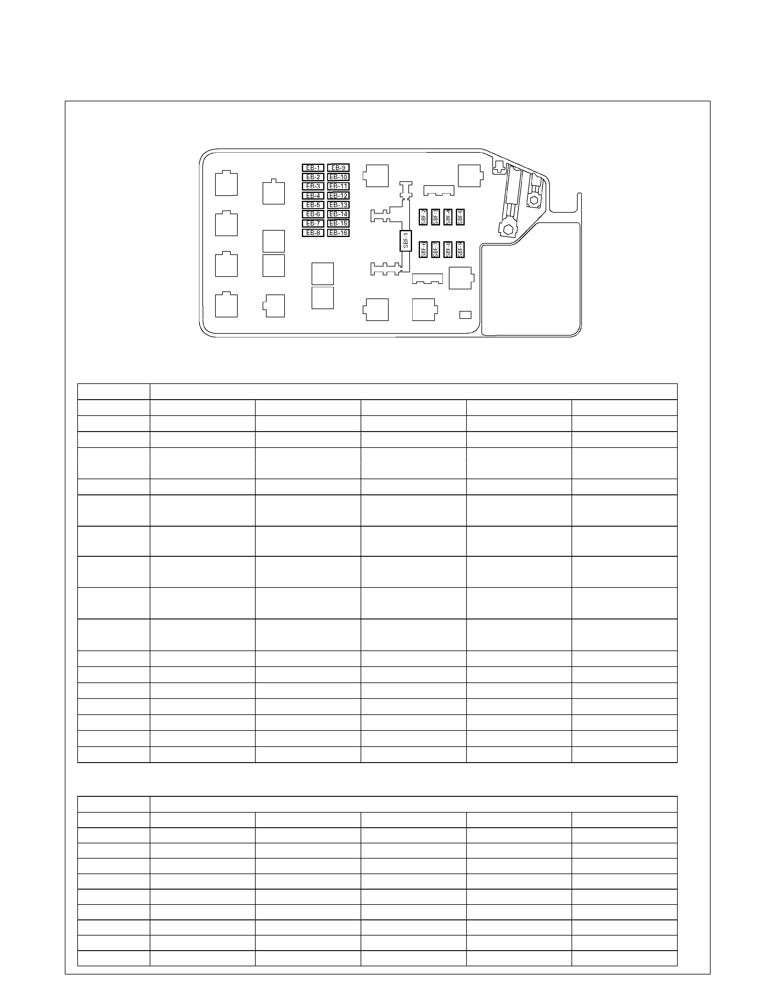
FUSE AND SLOW BLOW FUSE LOCATION
RELAY & FUSE BOX (ENGINE ROOM)
RHD
∗1 AUSTRALIA
FUSE ∗2 EMISSION SYSTEM EURO3
ENGINE MODEL
FUSE NO. C24SE 6VE1 4JH1-TC 4JA1-L HFV6
EB-1 15A ECM 20A ECM 10A ECM ⎯ 15A ECM
EB-2 ⎯ 10A ECM(B) 10A RR FOG ⎯ 15A O2S/PRE
EB-3 15A FRT FOG 10A TCM 15A FRT FOG ← 10A ECM
20A TRAILER ∗1
EB-4 10A ACG(S) 15A FRT FOG ⎯ 10A ACG(S) 10A TCM
EB-5 10A TAIL-RH 10A ILLUMI 10A ILLUMI 10A ILLUMI 10A TAIL-RH
10A TAIL-RH ∗2
EB-6 10A TAIL - LH 10A TAIL 10A TAIL ← 10A TAIL - LH
10A TAIL – LH ∗2
EB-7 10A H/L(RH) ← 10A H/L(RH) 10A H/L(RH) 10A H/L(RH)
10A H/L(RH)LO ∗2
EB-8 10A H/L(LH) ← 10A H/L(LH) 10A H/L(LH) 10A H/L(LH)
10A H/L(LH)LO ∗2
EB-9 20A F/PUMP 20A O2 SENSOR 10A TRAILER ∗2 ⎯ 20A TRAILER
20A TRAILER ∗1
EB-10 10A O2 SENSOR 20A F/PUMP 10A ACG(S) ⎯ 15A O2S POST
EB-11 ⎯ ⎯ 10A H/L(RH)HI ∗2⎯ 15A IG. COIL RH
EB-12 ⎯ ⎯ 10A H/L(LH)HI ∗2 ⎯ 15A IG. COIL LH
EB-13 10A A/C ← ← ← 10A A/C
EB-14 10A 4WD ← ← ← 10A 4WD
EB-15 10A HORN ← ← ← 10A HORN
EB-16 10A HAZARD ← ← ← 10A HAZARD
SLOW BLOW FUSE ∗ BATTERY TERMINAL
ENGINE MODEL
FUSE NO. C24SE 6VE1 4JA1-TC / 4JH1-TC 4JA1-L HFV6
SBF-1 100A MAIN ← 80A MAIN ← 140A MAIN ∗
SBF-2 ⎯ ⎯ 20A COND, FAN ⎯ 20A FRT FOG
SBF-3 ⎯ ⎯ 60A GLOW 20A COND, FAN 60A RAD. FAN
SBF-4 20A COND, FAN ← 30A ECM 50A GLOW 20A F/PUMP
SBF-5 40A IG 1 ← ← ← ←
SBF-6 ⎯ 40A ABS-1 ← ← ←
SBF-7 ⎯ 30A ABS-2 ← ← ←
SBF-8 30A BLOWER ← ← ← ←
SBF-9 50A IG 2 ← ← ← ←
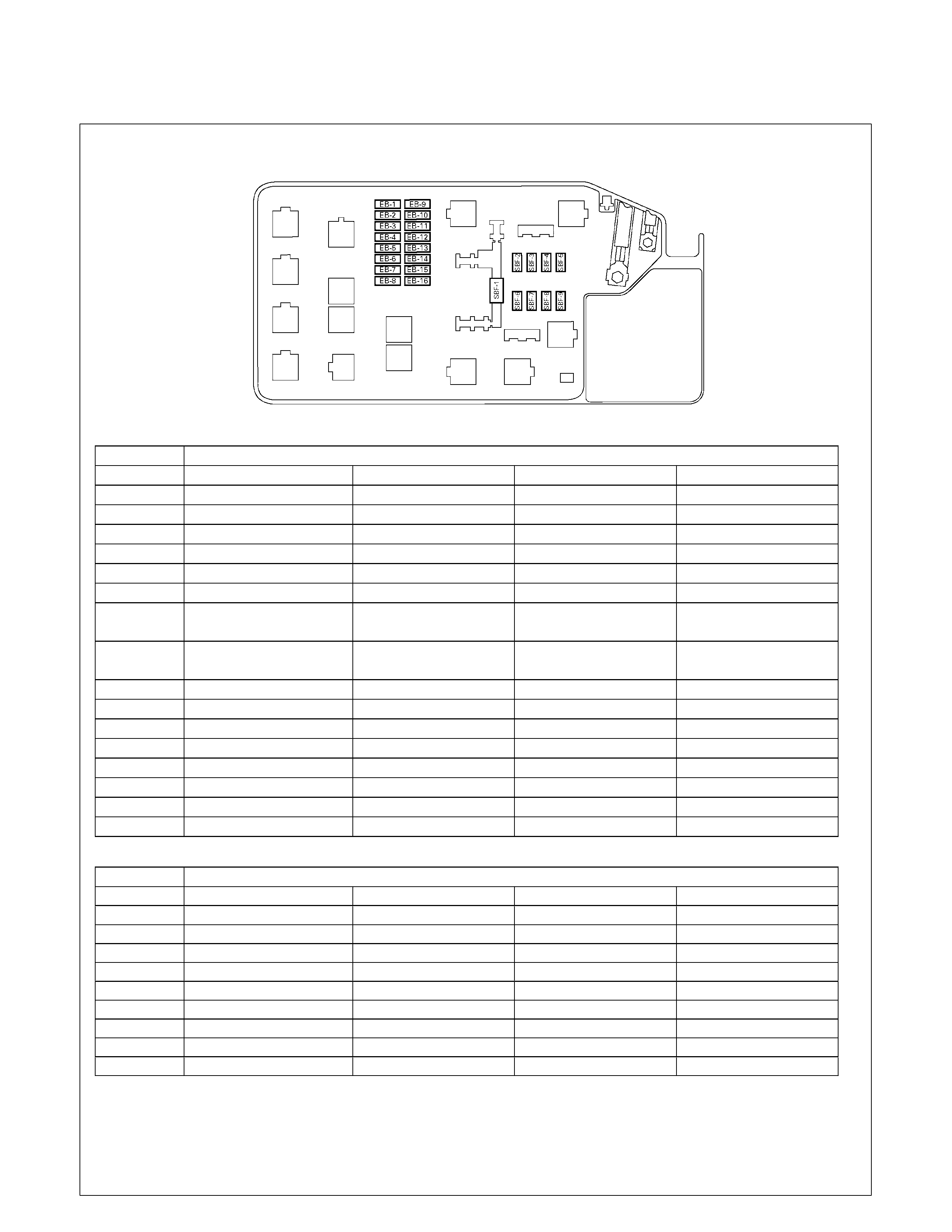
FUSE AND SLOW BLOW FUSE LOCATION
RELAY & FUSE BOX (ENGINE ROOM)
LHD
FUSE ∗3 WITH HEADLIGHTS LEVELING
ENGINE MODEL
FUSE NO. C24SE 6VE1 4JH1-TC 4JA1-L
EB-1 15A ECM 20A ECM 10A ECM ⎯
EB-2 ⎯ 10A ECM(B) 10A RR FOG ⎯
EB-3 15A FRT FOG 10A TCM 15A FRT FOG ←
EB-4 10A ACG(S) 15A FRT FOG ⎯ 10A ACG(S)
EB-5 10A TAIL-RH 10A ILLUMI 10A TAIL-RH ←
EB-6 10A TAIL-LH 10A TAIL 10A TAIL-LH ←
EB-7 10A H/L(RH) 10A H/L(RH) 10A H/L(RH) ←
10A H/L(RH)LO ∗3 10A H/L(RH)LO ∗3
EB-8 10A H/L(LH) 10A H/L(LH) 10A H/L(LH) ←
10A H/L(LH)LO ∗3 10A H/L(LH)LO ∗3
EB-9 20A F/PUMP 20A O2 SENSOR 10A TRAILER ⎯
EB-10 10A O2 SENSOR 20A F/PUMP 10A ACG(S) ⎯
EB-11 10 A H/L(RH)HI ∗3 ⎯ 10A H/L(RH)HI ∗3 ←
EB-12 10A H/L(LH)HI ∗3 ⎯ 10A H/L(LH)HI ∗3 ←
EB-13 10A A/C ← ← ←
EB-14 10A 4WD ← ← ←
EB-15 10A HORN ← ← ←
EB-16 10A HAZARD ← ← ←
SLOW BLOW FUSE
ENGINE MODEL
FUSE NO. C24SE 6VE1 4JA1-TC / 4JH1-TC 4JA1-L
SBF-1 100A MAIN ©
80A MAIN ←
SBF-2 ⎯ ⎯ 20A COND, FAN ⎯
SBF-3 ⎯ ⎯ 60A GL OW 20A COND, FAN
SBF-4 20 A COND, FAN ← 30A ECM 50A GLOW
SBF-5 40A IG 1 ← ← ←
SBF-6 ⎯ 40A ABS-1 ← ←
SBF-7 ⎯ 30A ABS-2 ← ←
SBF-8 30A BLOWER ← ← ←
SBF-9 50A IG 2 ← ← ←
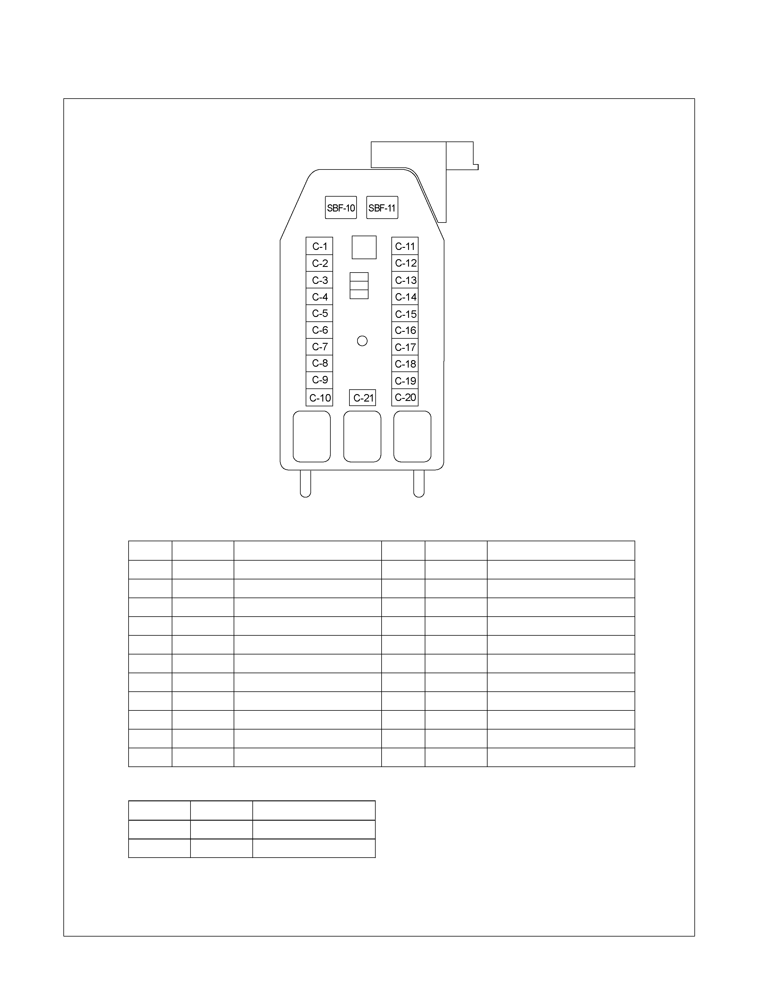
FUSE LOCATION
RHD/LHD
RTW38DMF000101
FUSE
NO. C apacity Indication on label NO. C apacity Indication on label
C -1 ⎯ ⎯ C -12 20A C IGER/ACC SO CKET
C -2 10A A B S/4W D C -13 15A AU D IO (+B )
C -3 10A TR A ILER C -14 20A D O O R LO C K
C -4 15A B A C K LIG H T C -15 10A M ETER (+B )
C -5 15A M ETER C -16 10A D O M E LIGHT
C -6 10A TU R N LIG H T C -17 10A A N TI THEFT
C -7 15A ELEC .IG C -18 15A STO P LIGHT
C -8 15A EC U C -19 ⎯ ⎯
C -9 20A FR T WIPER & W A SH ER C -20 10A STA R TER
C -10 15A EN G IN E C -21 10A SR S
C -11 10A A U D IO
SLOW BLOW FUSE
NO. C apacity Indication on label
SB F-10 20A R R DEF
SB F-11 30A P O W ER WINDOW
FUSE BOX
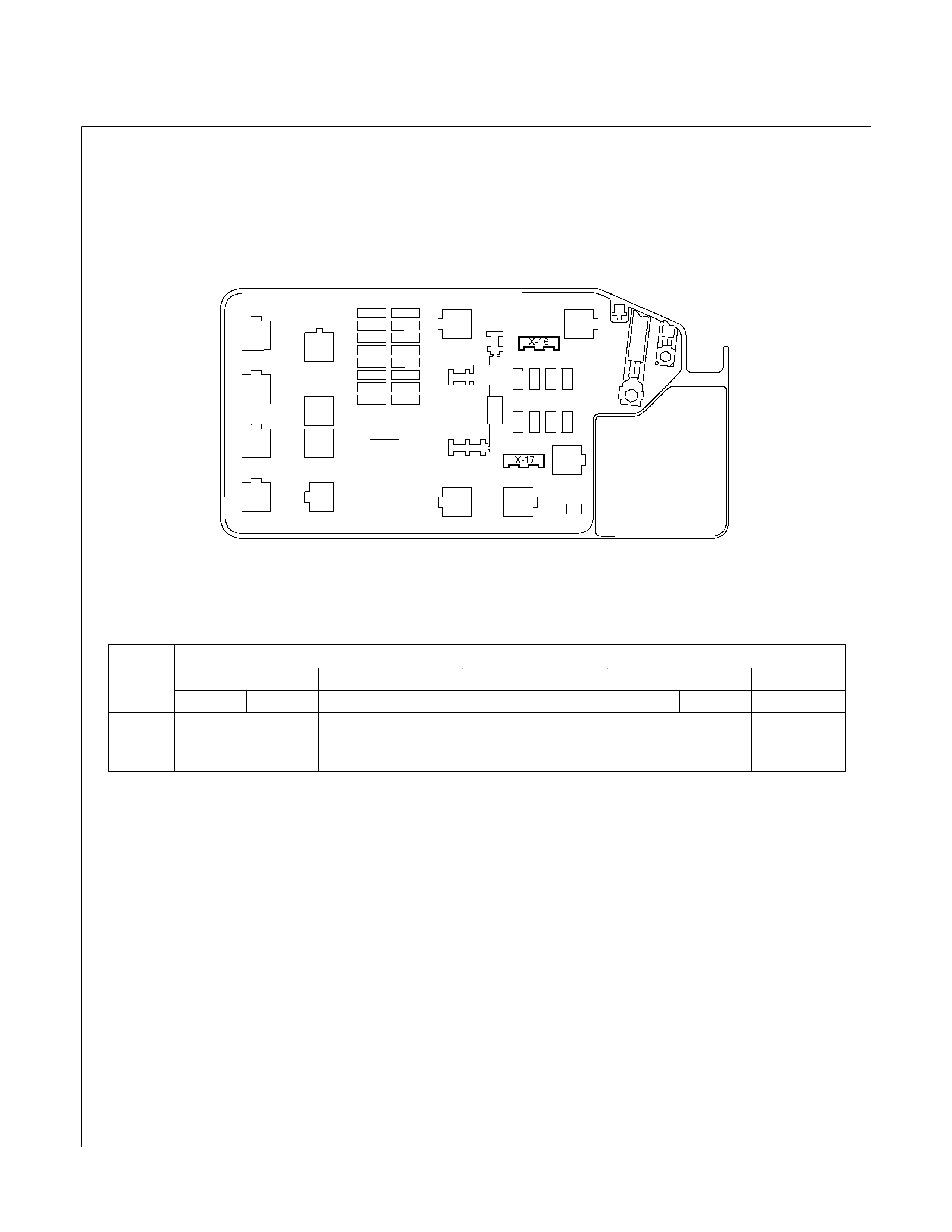
DIODE LOCATION
RELAY & FUSE BOX
DIODE
C24SE 6VE1 4JA1-TC / 4JH1-TC 4JA1-L HFV6
No. RHD LHD RHD LHD RHD LHD RHD LHD RHD
X-16 ⎯ AUTO
CRUISE ⎯ A/T A/C
⎯
X-17 ⎯ A/T A/T ⎯ ⎯ ⎯
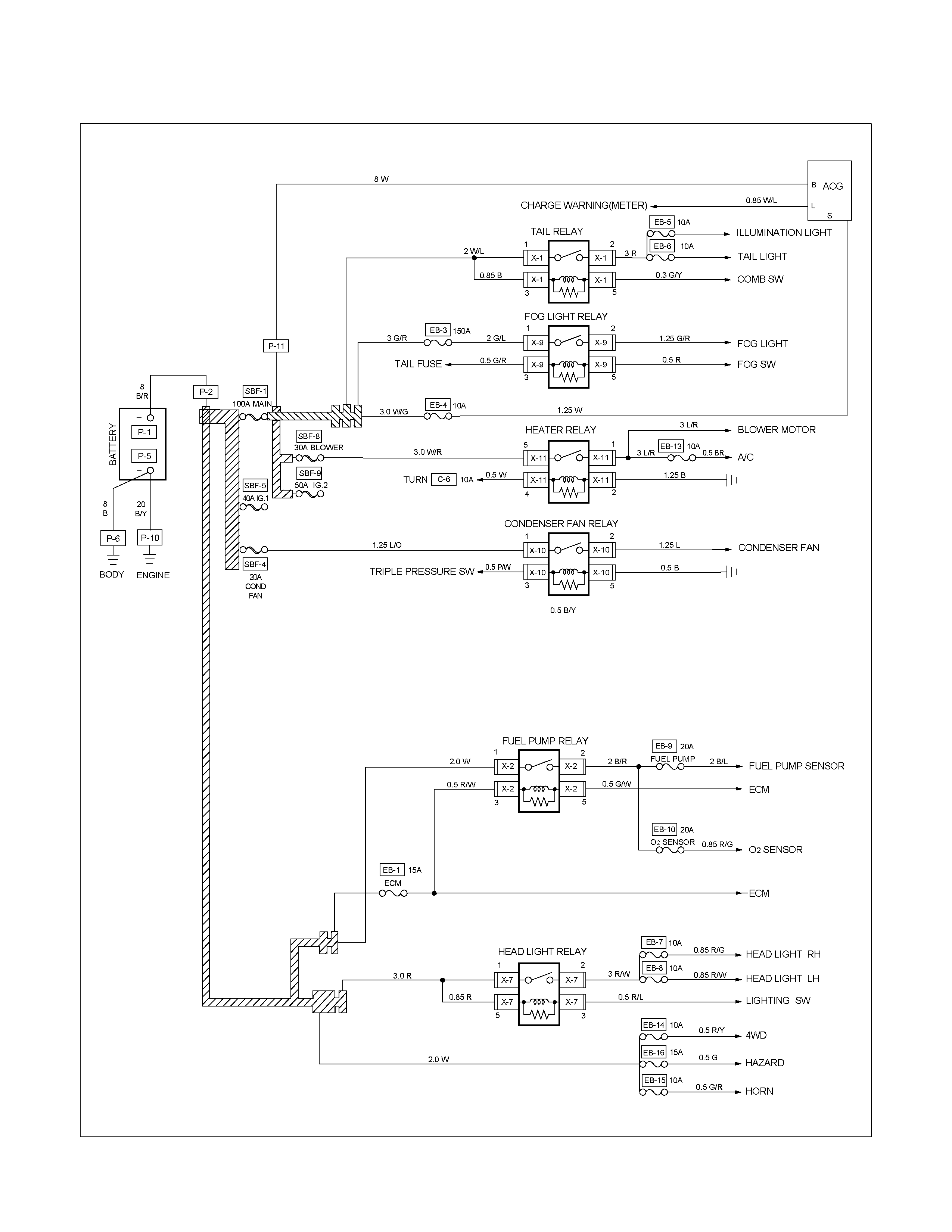
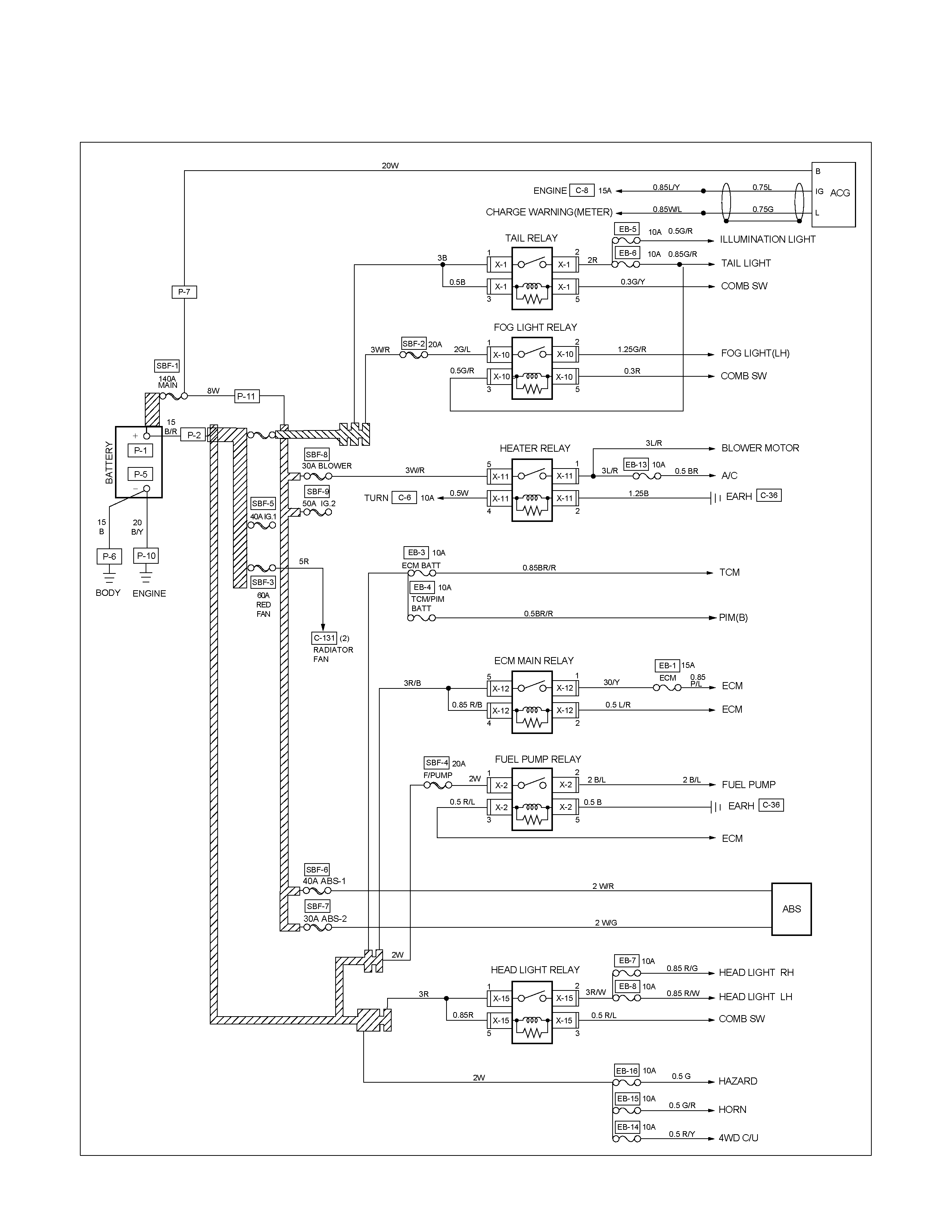
FUSE BLOCK CIRCUIT C24SE Sheet 1/2
RTW68AXF005801
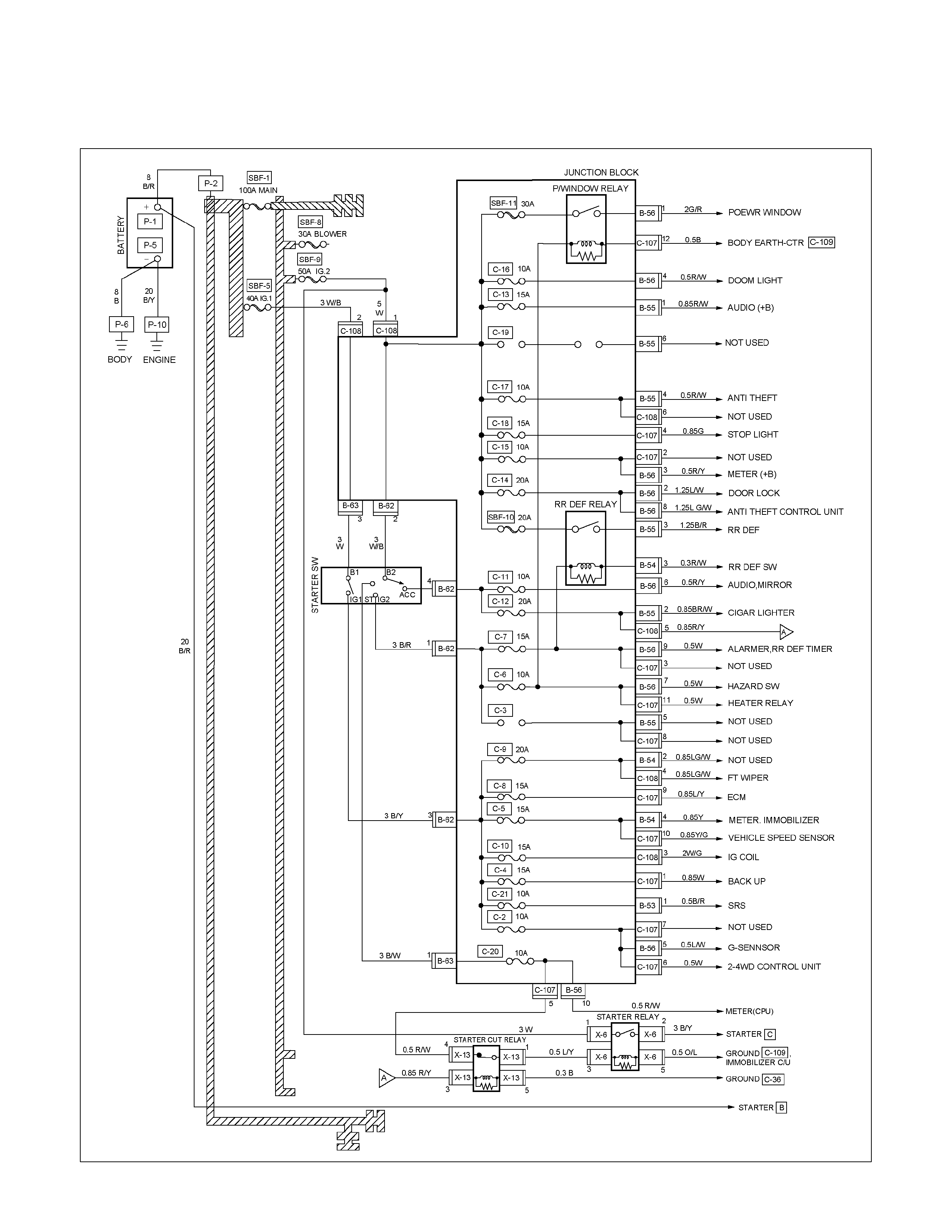
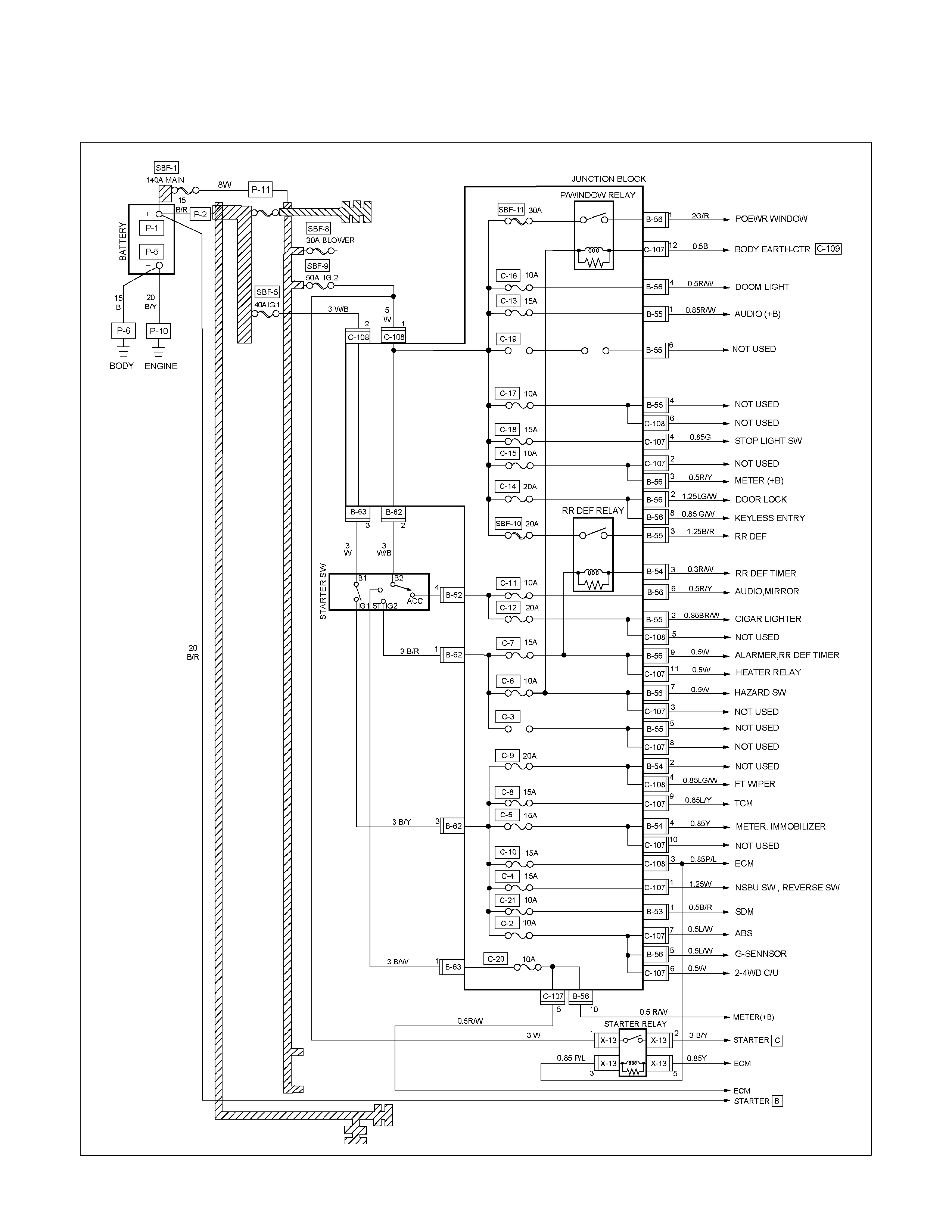
FUSE BLOCK CIRCUIT C24SE Sheet 2/2
RTW68AXF005901
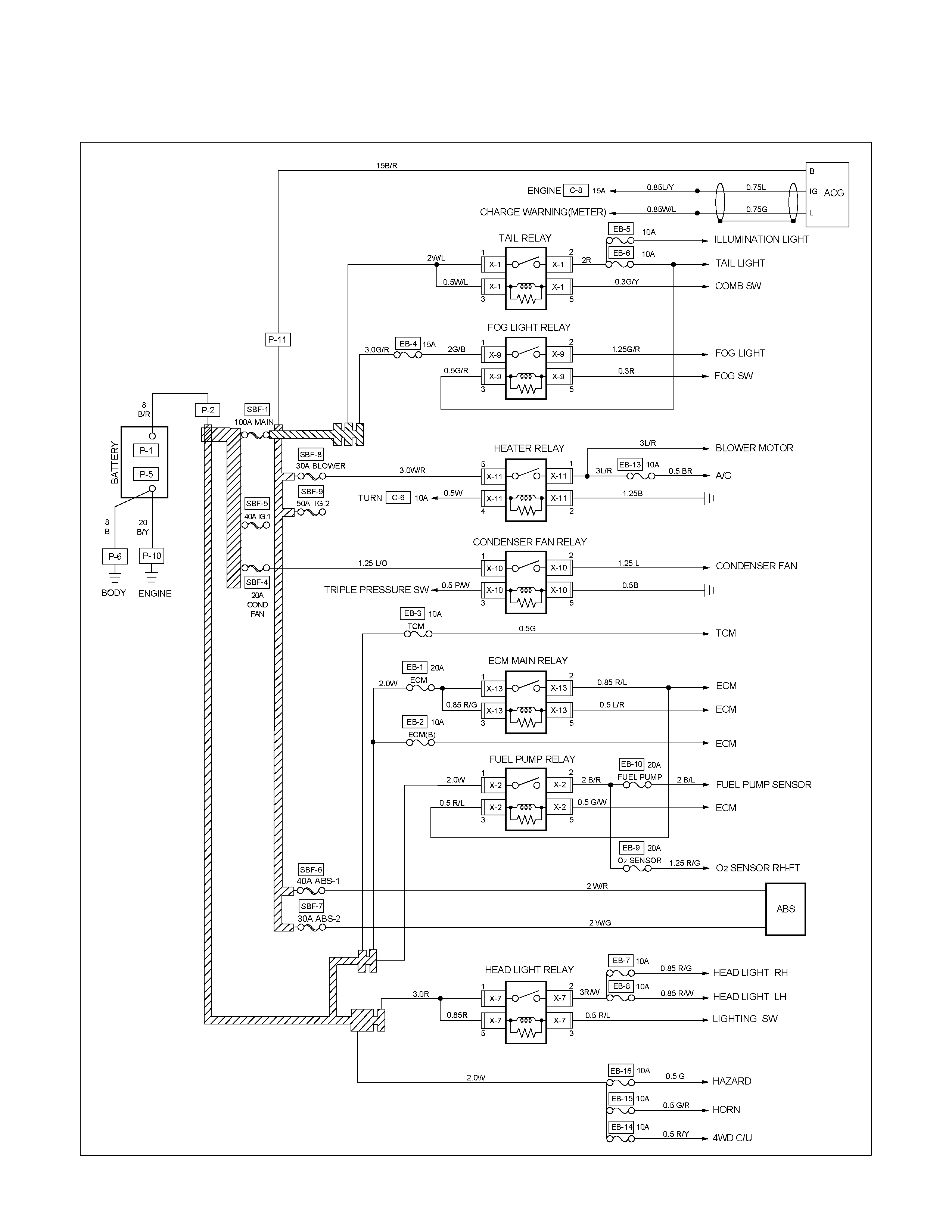
FUSE BLOCK CIRCUIT 6VE1 Sheet 1/2
RTW68AXF006001

FUSE BLOCK CIRCUIT 6VE1 Sheet 2/2
RTW68AXF006101
FUSE BLOCK CIRCUIT HFV6 Sheet 1/2
RTW68AXF010001
FUSE BLOCK CIRCUIT HFV6 Sheet 2/2
RTW68AXF010101
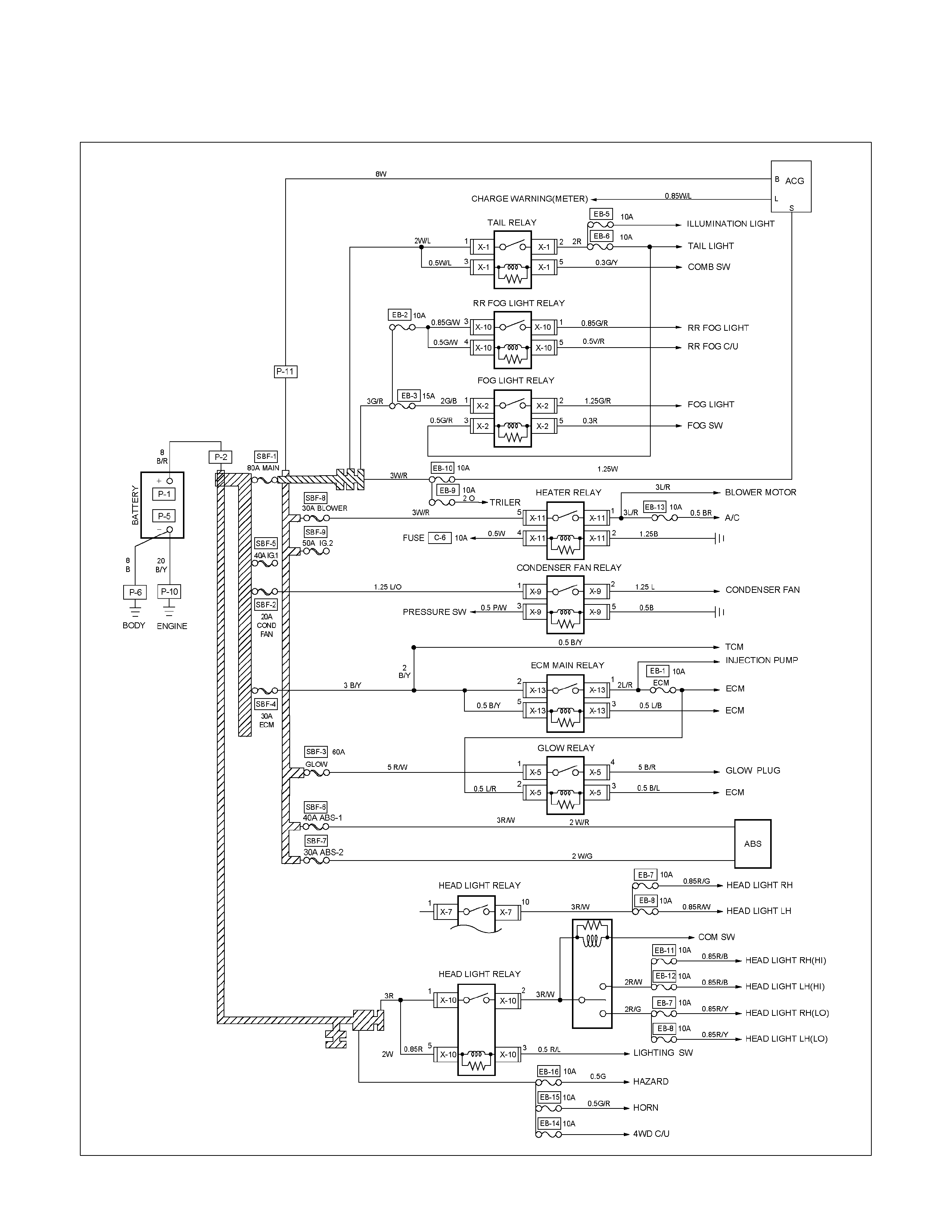
FUSE BLOCK CIRCUIT 4JA1-TC / 4JH1-TC (RHD) Sheet 1/2
RTW68AXF006201
FUSE BLOCK CIRCUIT 4JA1-TC / 4JH1-TC (RHD) Sheet 2/2
RTW68AXF006301
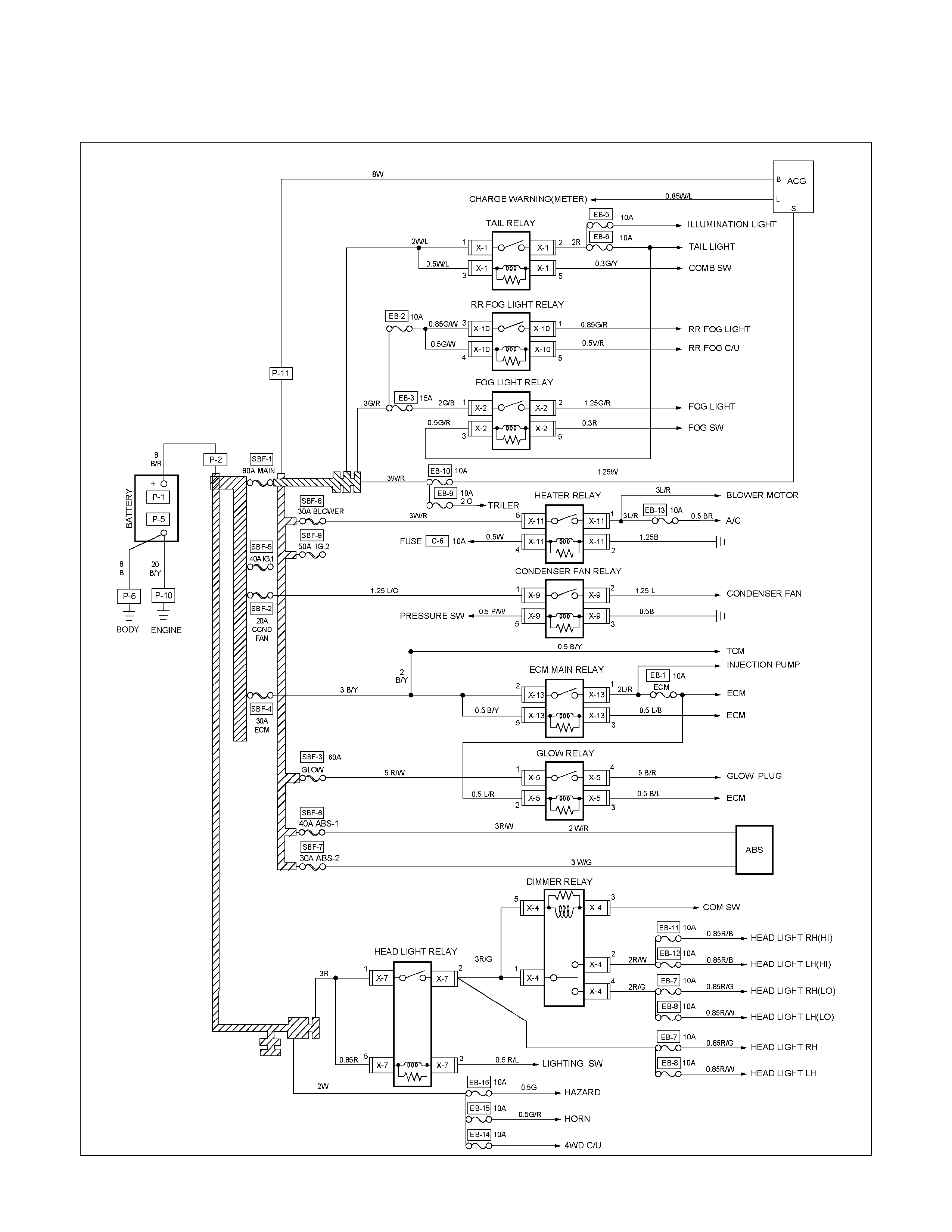
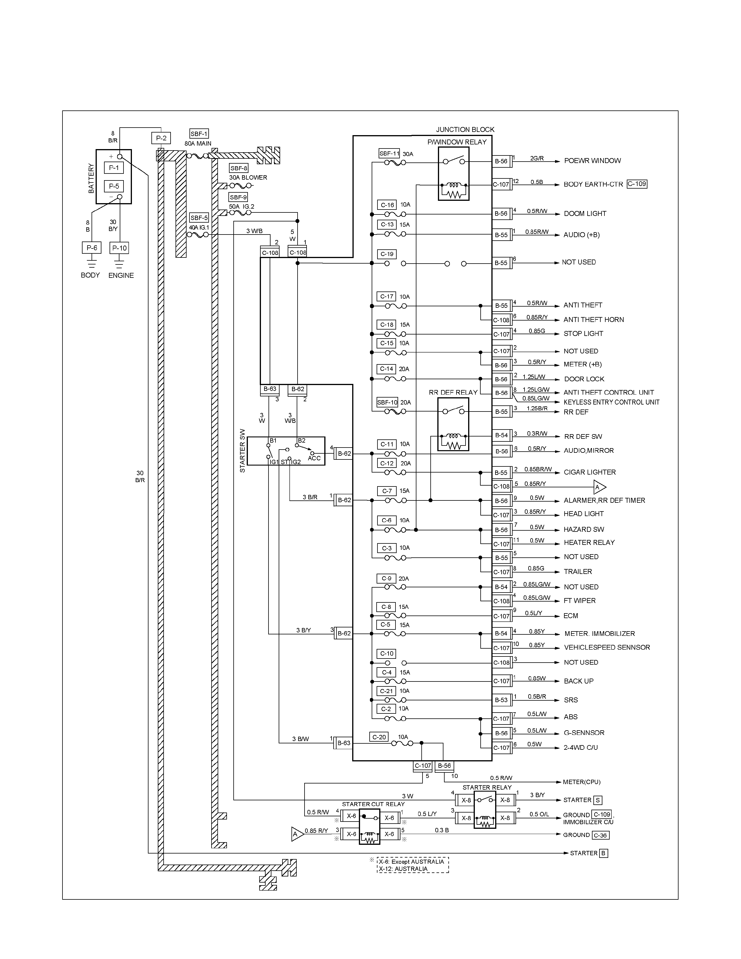
FUSE BLOCK CIRCUIT 4JA1-TC / 4JH1-TC (LHD) Sheet 1/2
RTW68AXF006401
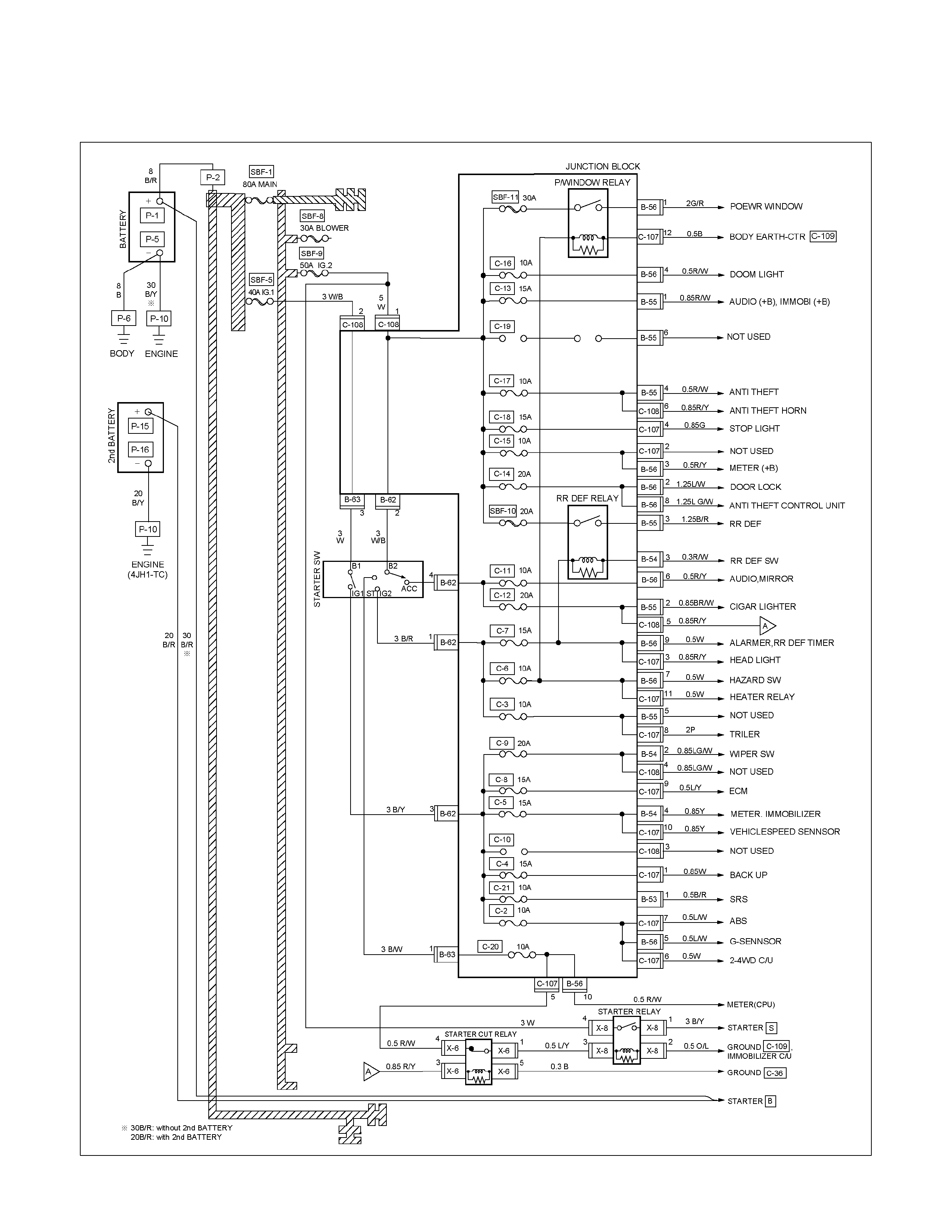
FUSE BLOCK CIRCUIT 4JA1-TC / 4JH1-TC (LHD) Sheet 2/2
RTW68AXF006501
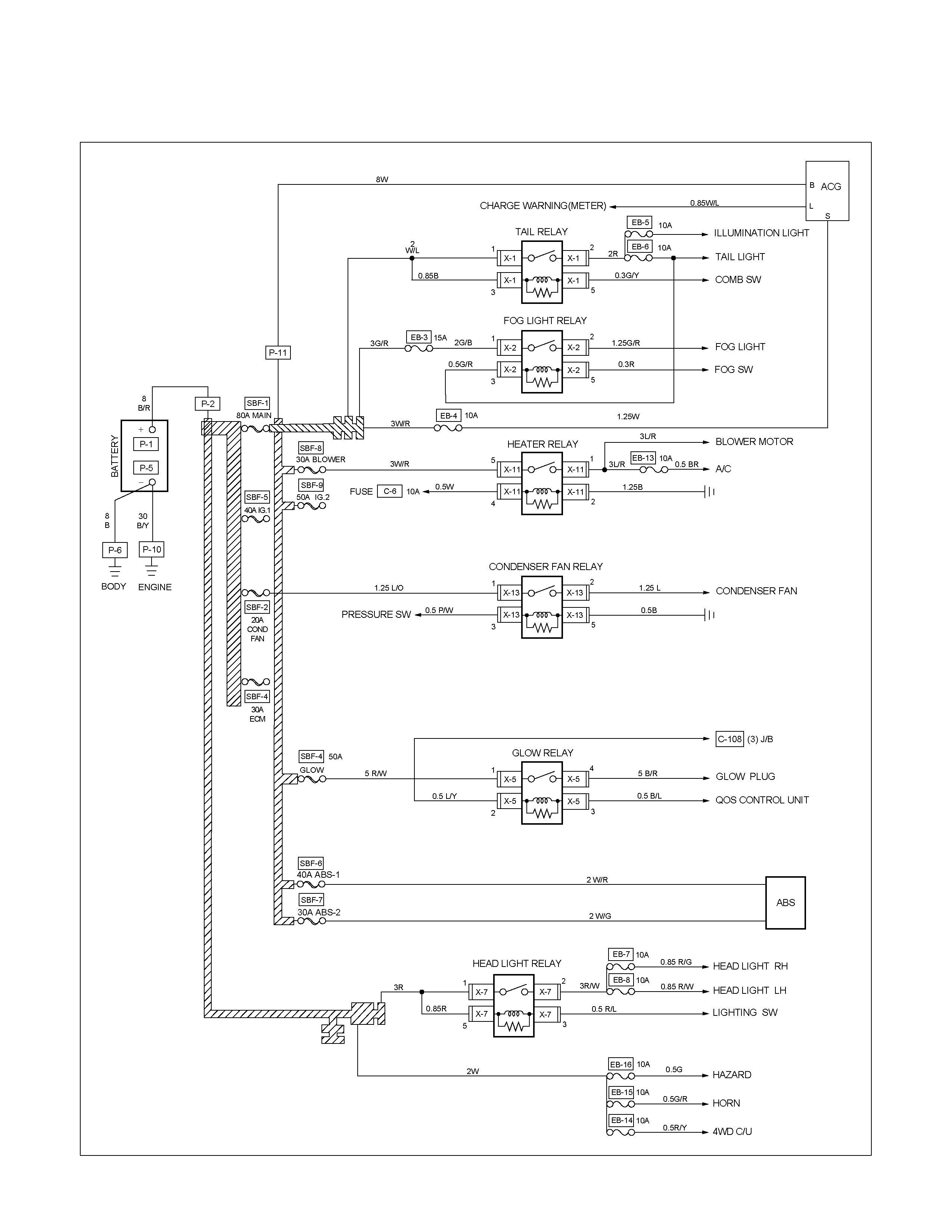
FUSE BLOCK CIRCUIT 4JA1-L Sheet 1/2
RTW68AXF006601

FUSE BLOCK CIRCUIT 4JA1-L Sheet 2/2
RTW68AXF006701
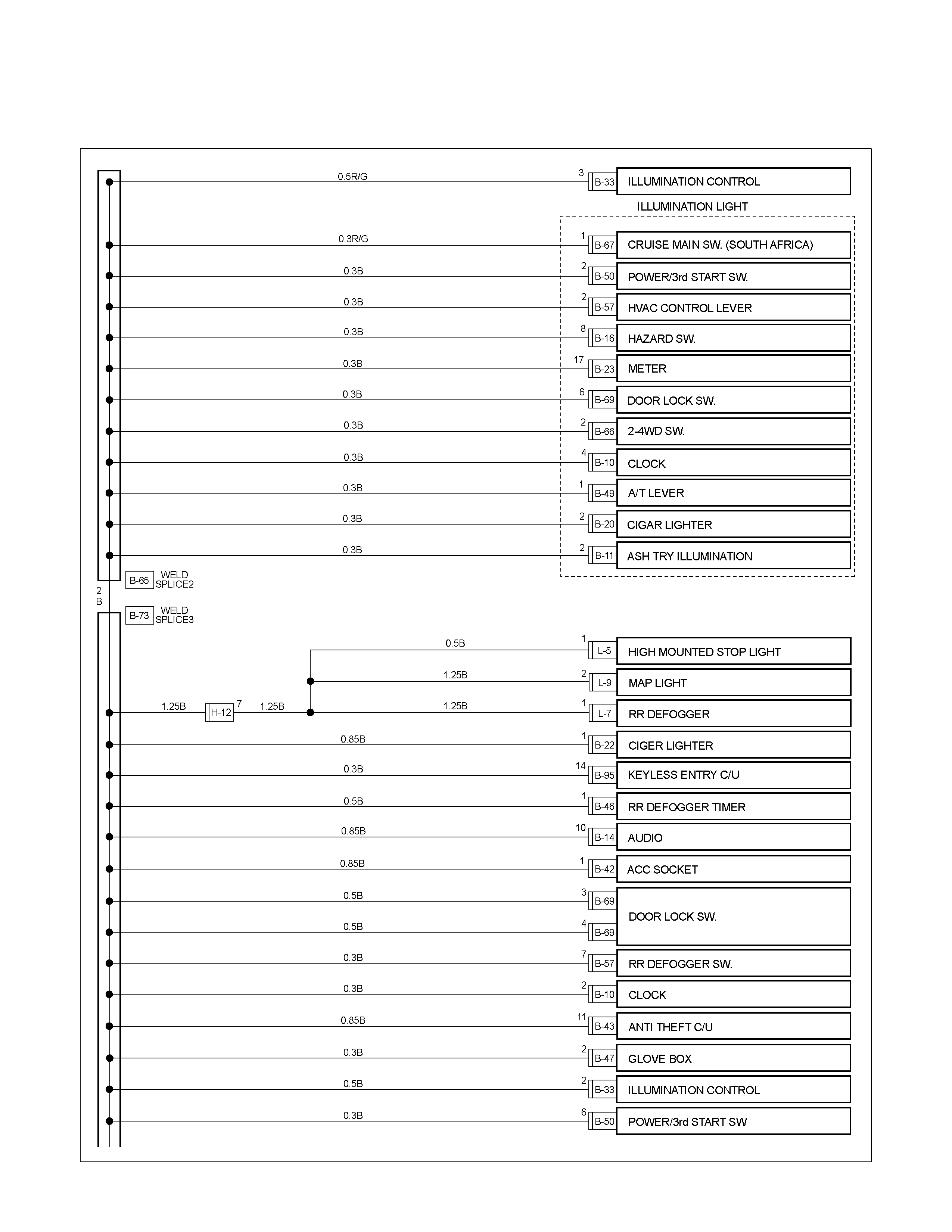
Grounding Point
GROUND POINT (RHD) G.EXP Sheet 1/4
RTW68AXF006801
GROUND POINT (RHD) G.EXP Sheet 2/4
RTW68AXF006901
GROUND POINT (RHD) G.EXP Sheet 3/4
RTW68AXF007001

GROUND POINT (RHD) G.EXP Sheet 4/4
RTW68AXF007101
GROUND POINT (RHD) AUSTRALIA HFV6 Sheet 1/3
RTW68AXF010201
GROUND POINT (RHD) AUSTRALIA HFV6 Sheet 2/3
RTW68AXF010301
GROUND POINT (RHD) AUSTRALIA HFV6 Sheet 3/3
RTW68AXF010401
GROUND POINT (RHD) EUROPE Sheet 1/4
RTW68AXF007201
GROUND POINT (RHD) EUROPE Sheet 2/4
RTW68AXF007301
GROUND POINT (RHD) EUROPE Sheet 3/4
RTW68AXF007401
GROUND POINT (RHD) EUROPE Sheet 4/4
RTW68AXF007501
GROUND POINT (LHD) G.EXP Sheet 1/4
RTW68AXF007601
GROUND POINT (LHD) G.EXP Sheet 2/4
RTW68AXF007701
GROUND POINT (LHD) G.EXP Sheet 3/4
RTW68AXF007801
GROUND POINT (LHD) G.EXP Sheet 4/4
RTW68AXF007901
GROUND POINT (LHD) EUROPE Sheet 1/4
RTW68AXF008001
GROUND POINT (LHD) EUROPE Sheet 2/4
RTW68AXF008101
GROUND POINT (LHD) EUROPE Sheet 3/4
RTW68AXF008201
GROUND POINT (LHD) EUROPE Sheet 4/4
RTW68AXF008301
GROUND POINT LOCATION
P−5
P−6
GROUND POINT LOCATION
C24NE C24NE
6VE1
4JA1-TC/4JH1-TC
GROUND POINT LOCATION
HFV6 HFV6
HFV6
CABLE HARNESS ROUTING
RTW38DXF007401
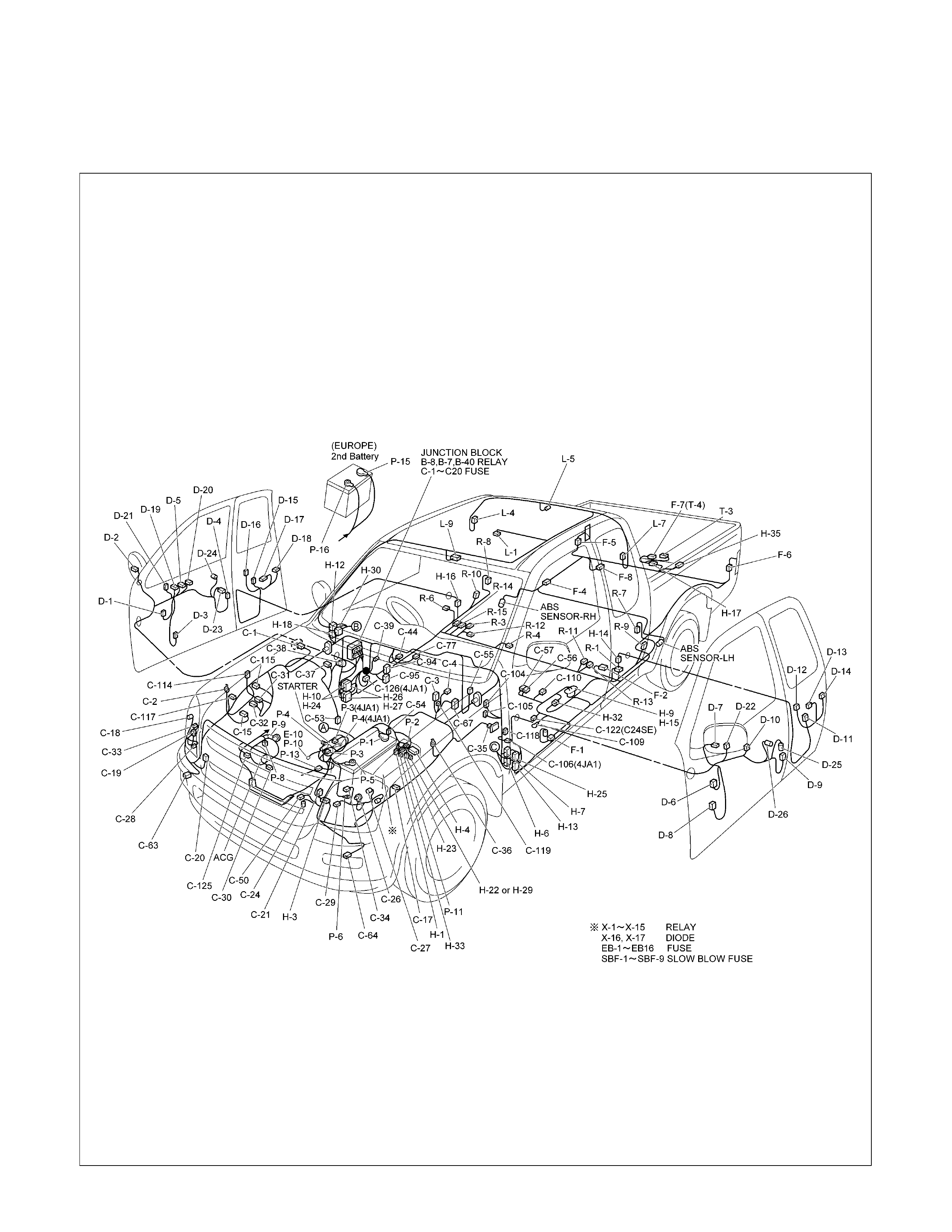
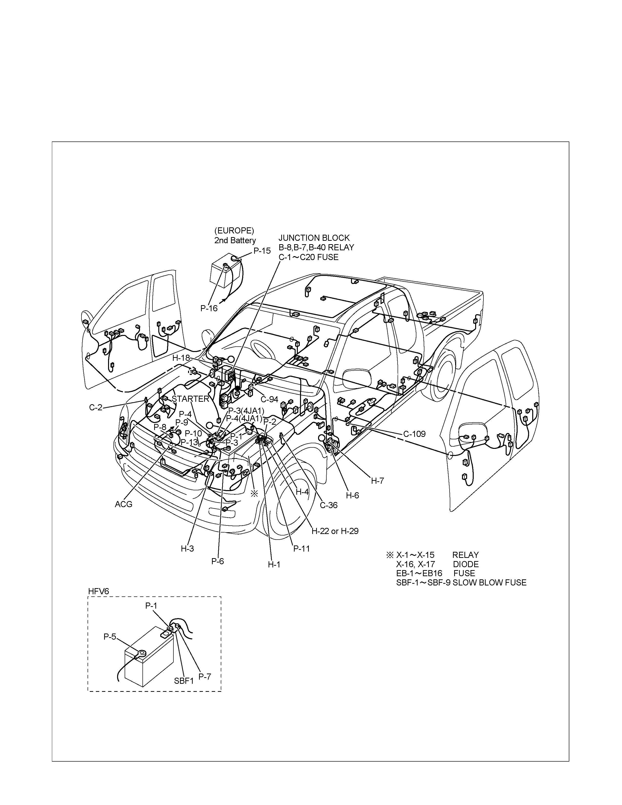
MAIN CABLE HARNESS (RHD)
RTW48AXF004101
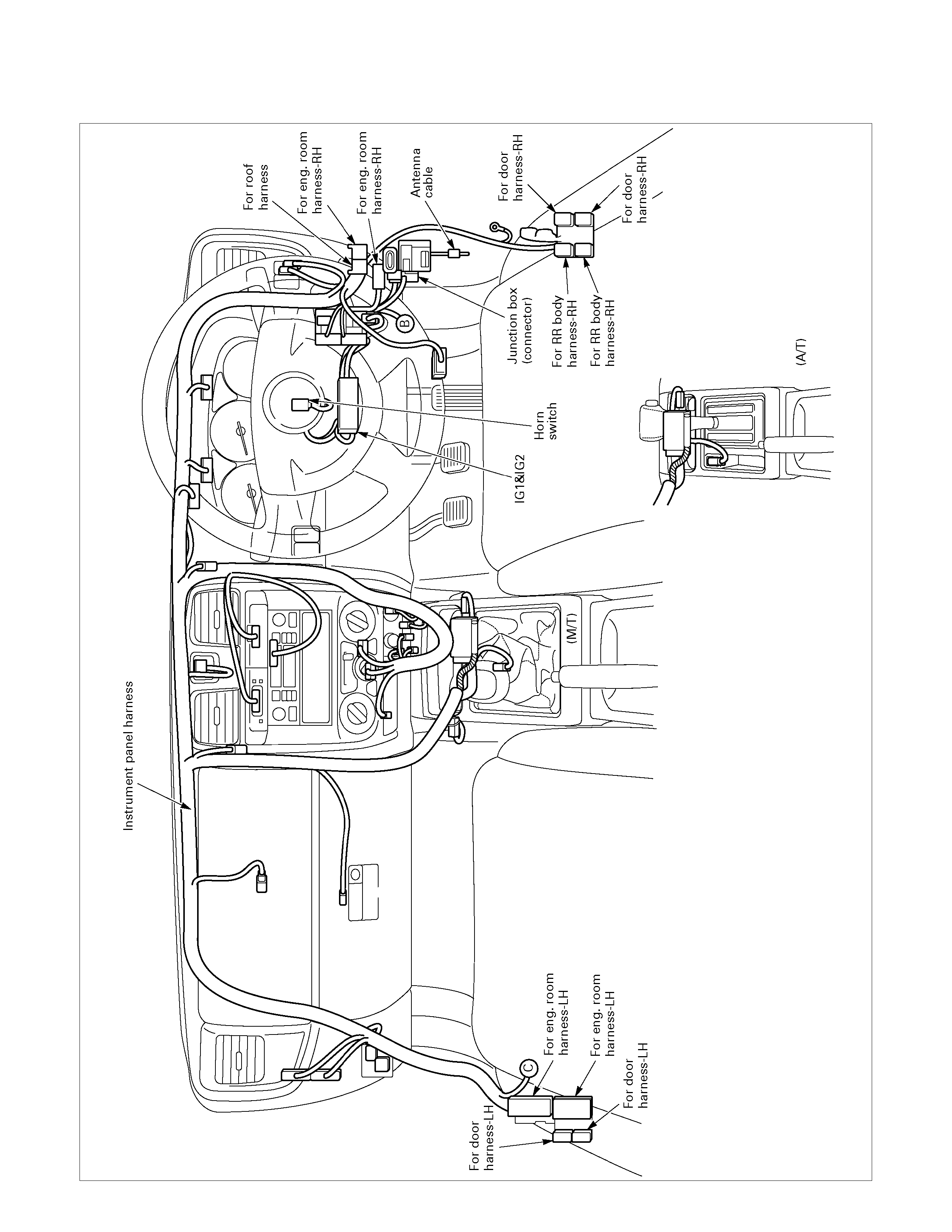
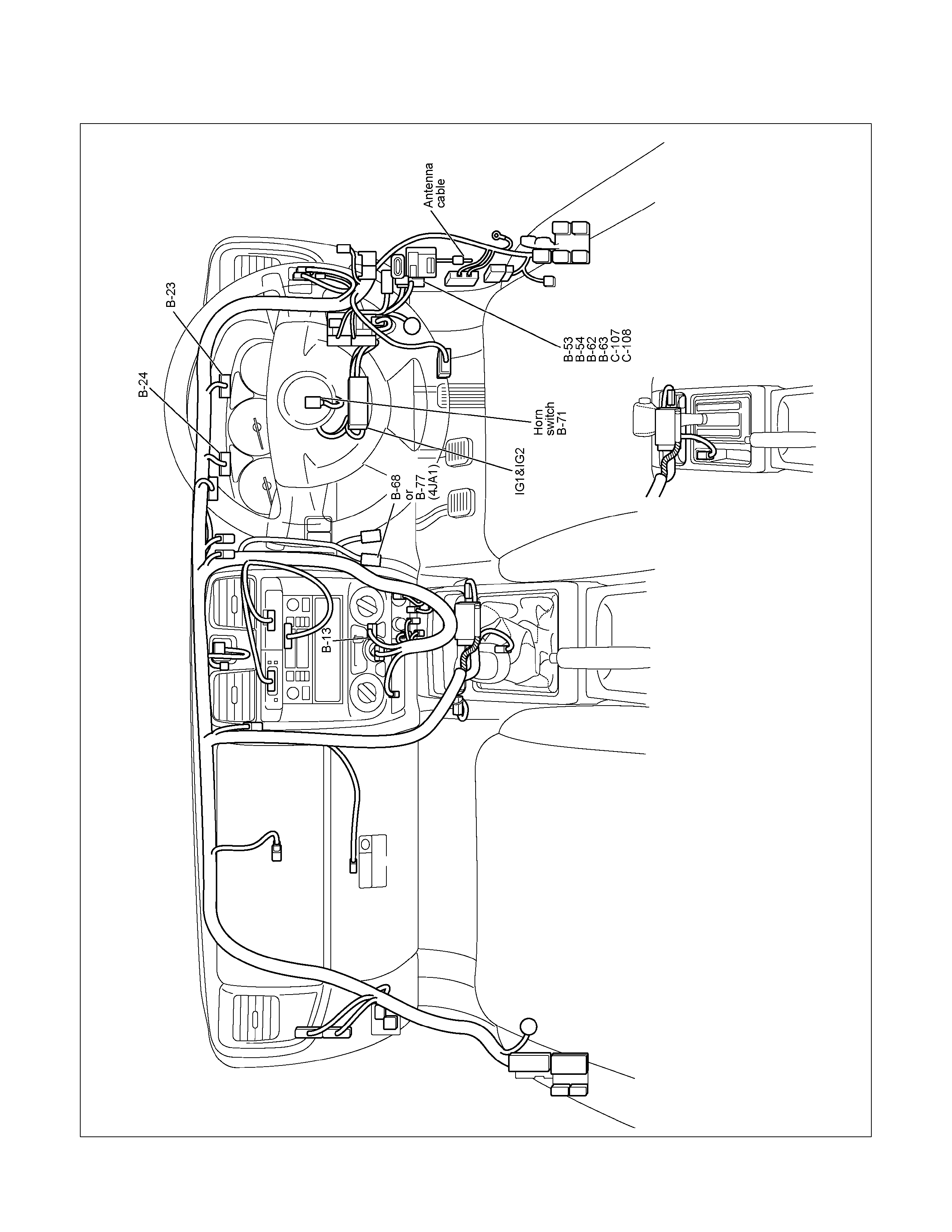
INSTRUMENT HARNESS (RHD)
810R300071
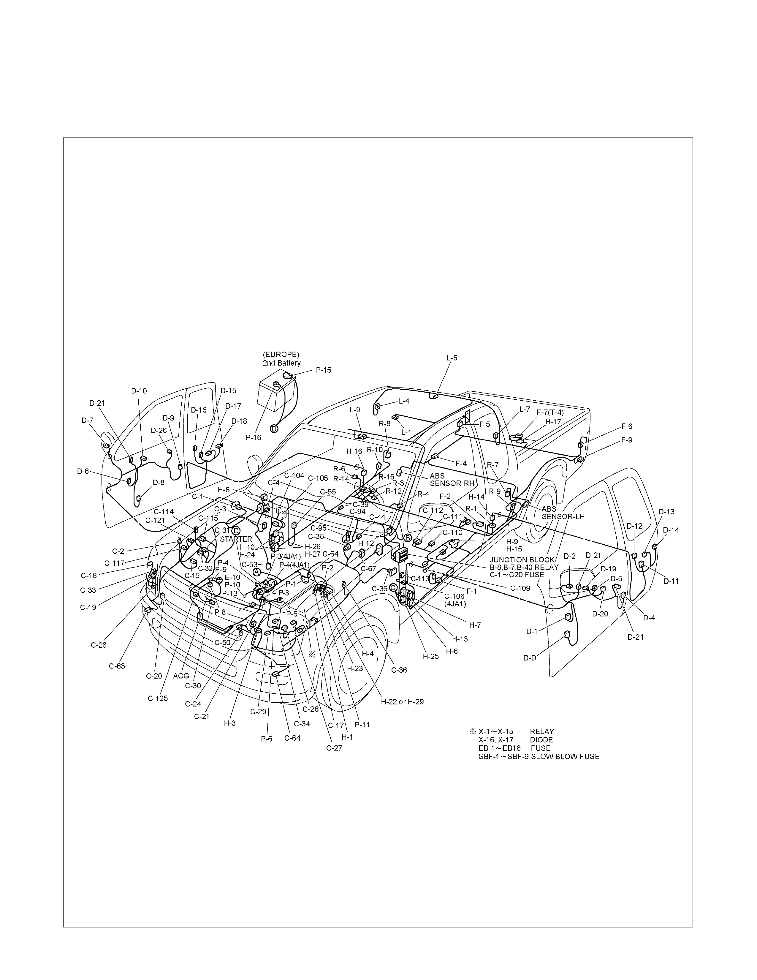
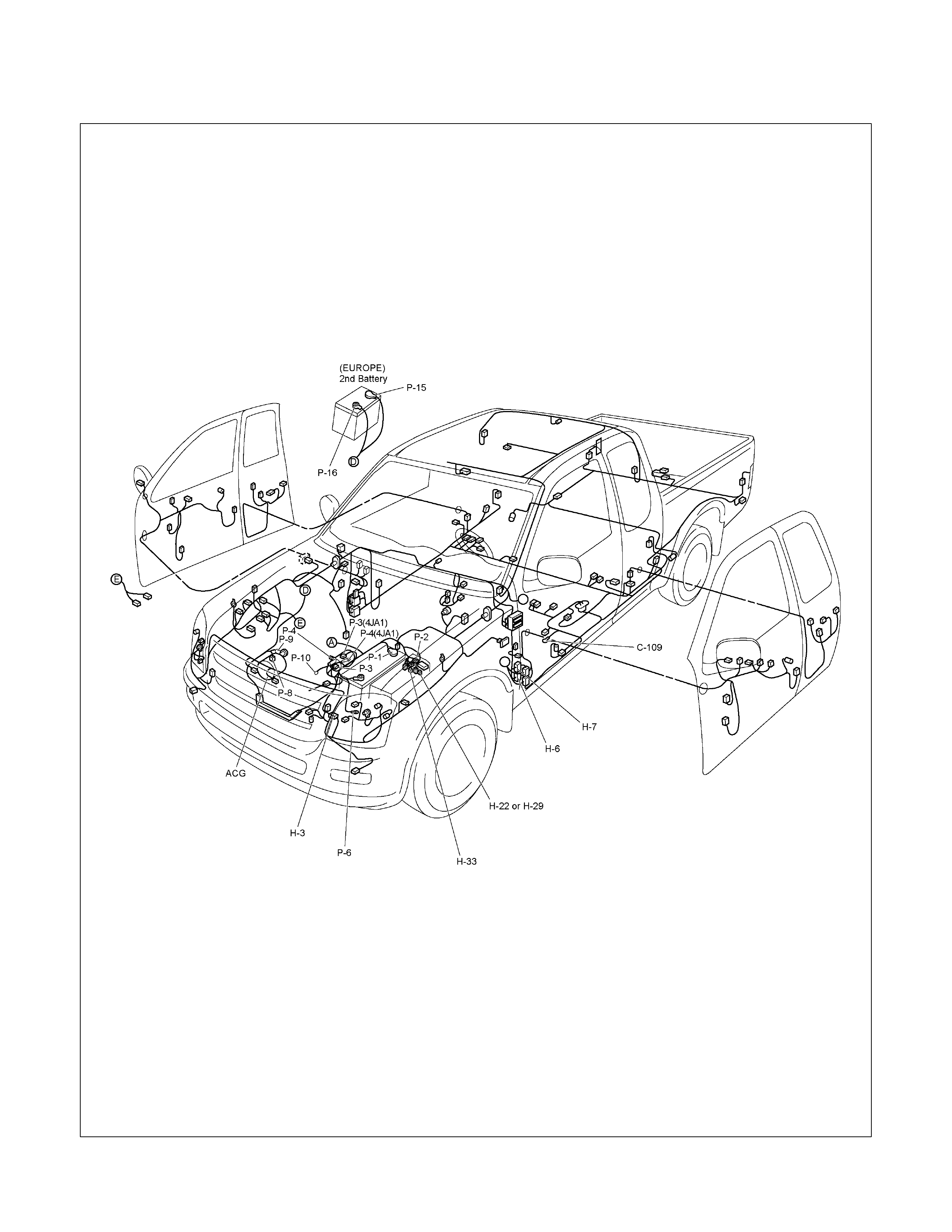
MAIN CABLE HARNESS (LHD)
RTW48AXF004101
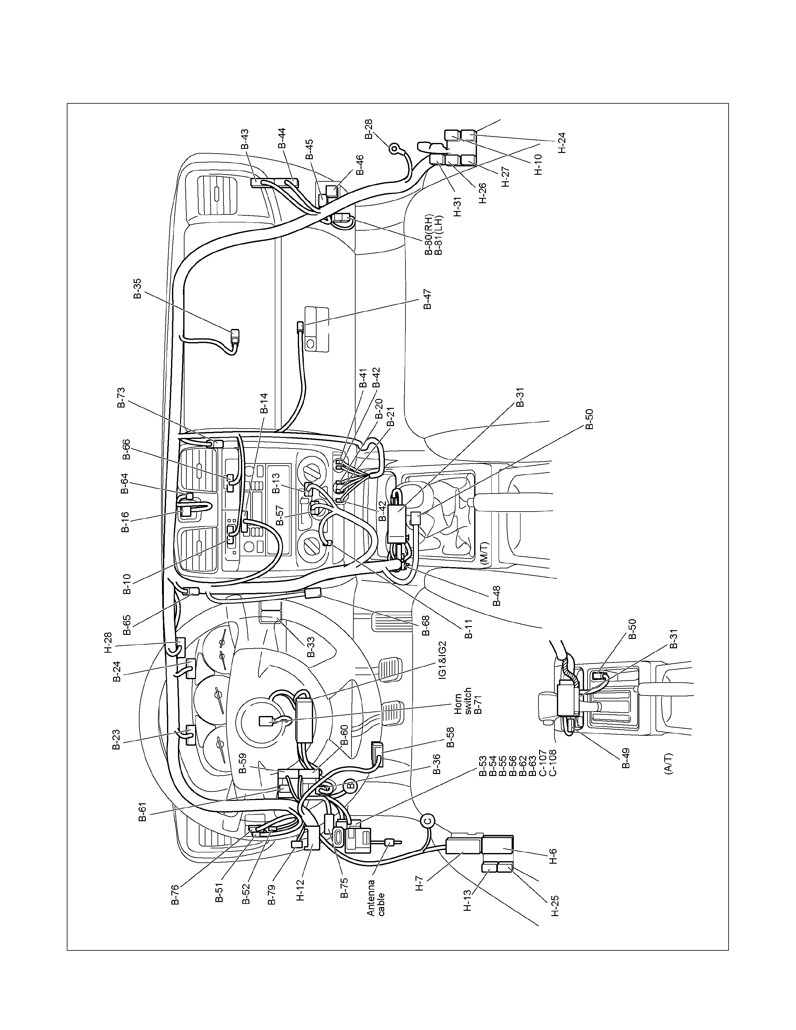
INSTRUMENT HARNESS (LHD)
RTW48AXF004001
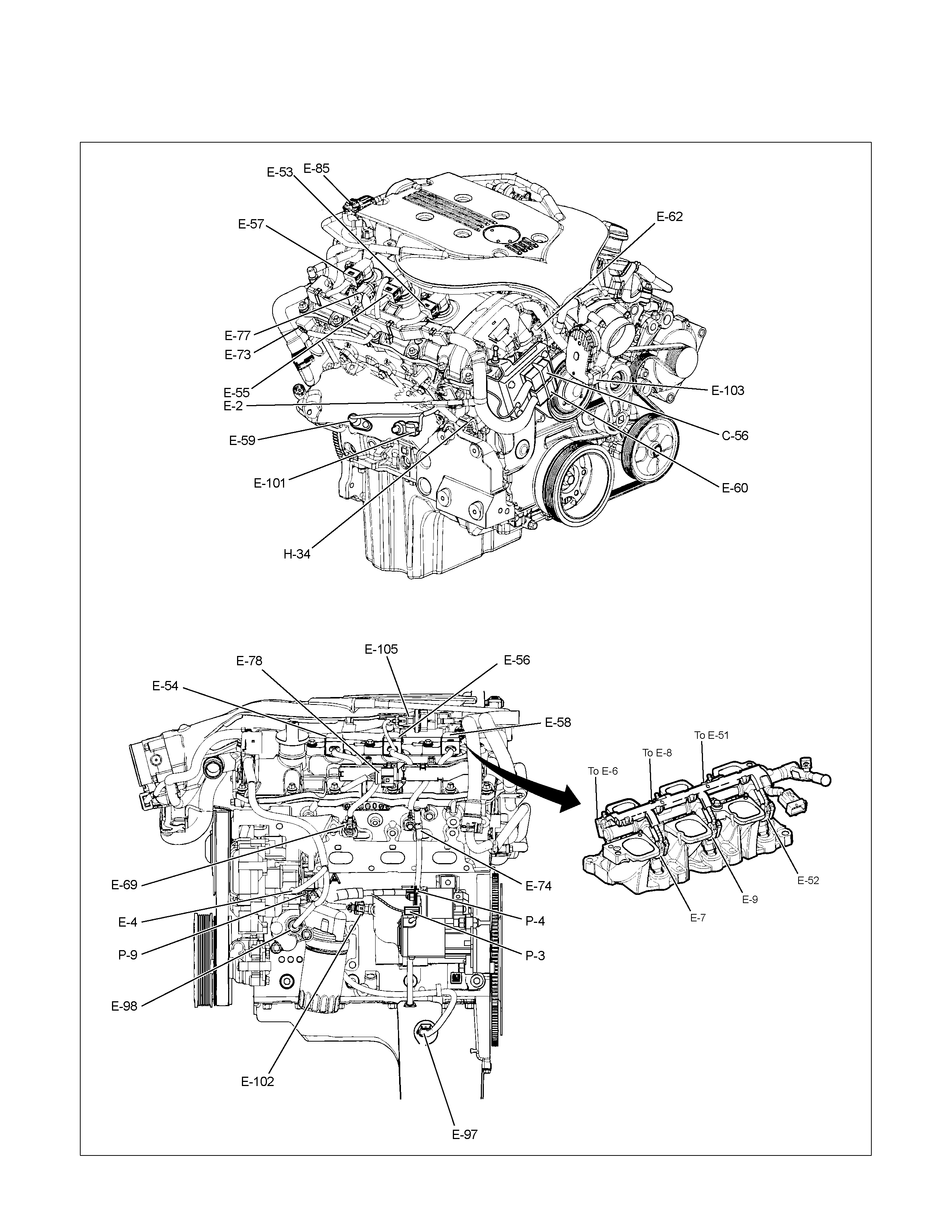
ENGINE HARNESS C24SE
ENGINE HARNESS 6VE1
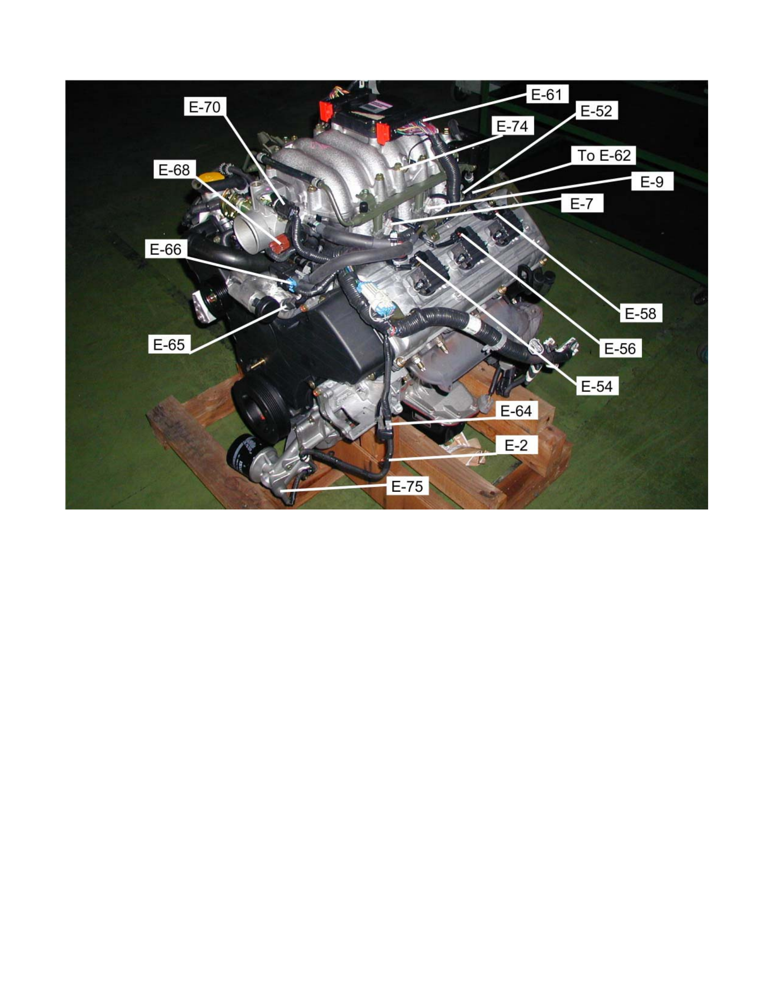

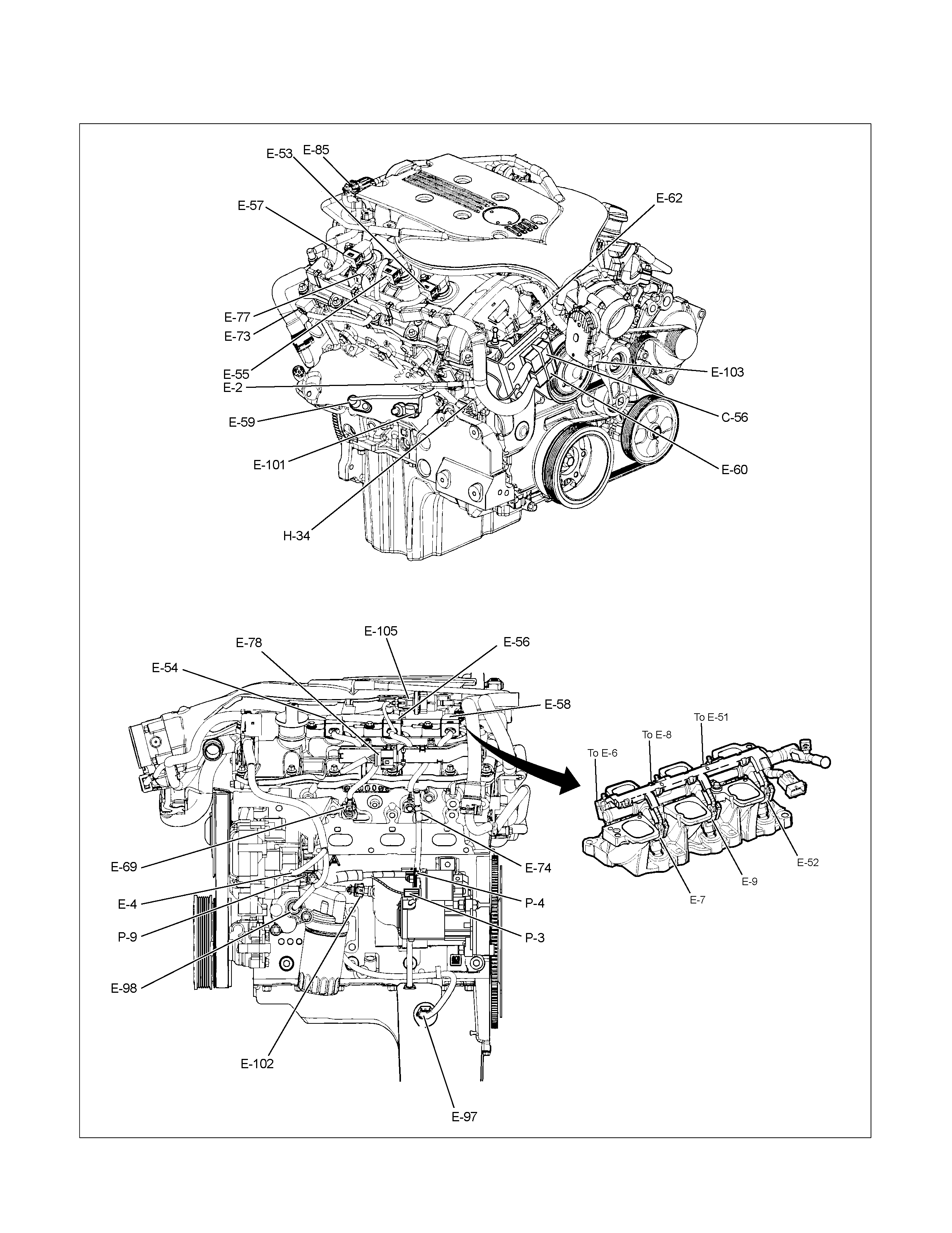
ENGINE HARNESS HFV6
RTW68AXF012201
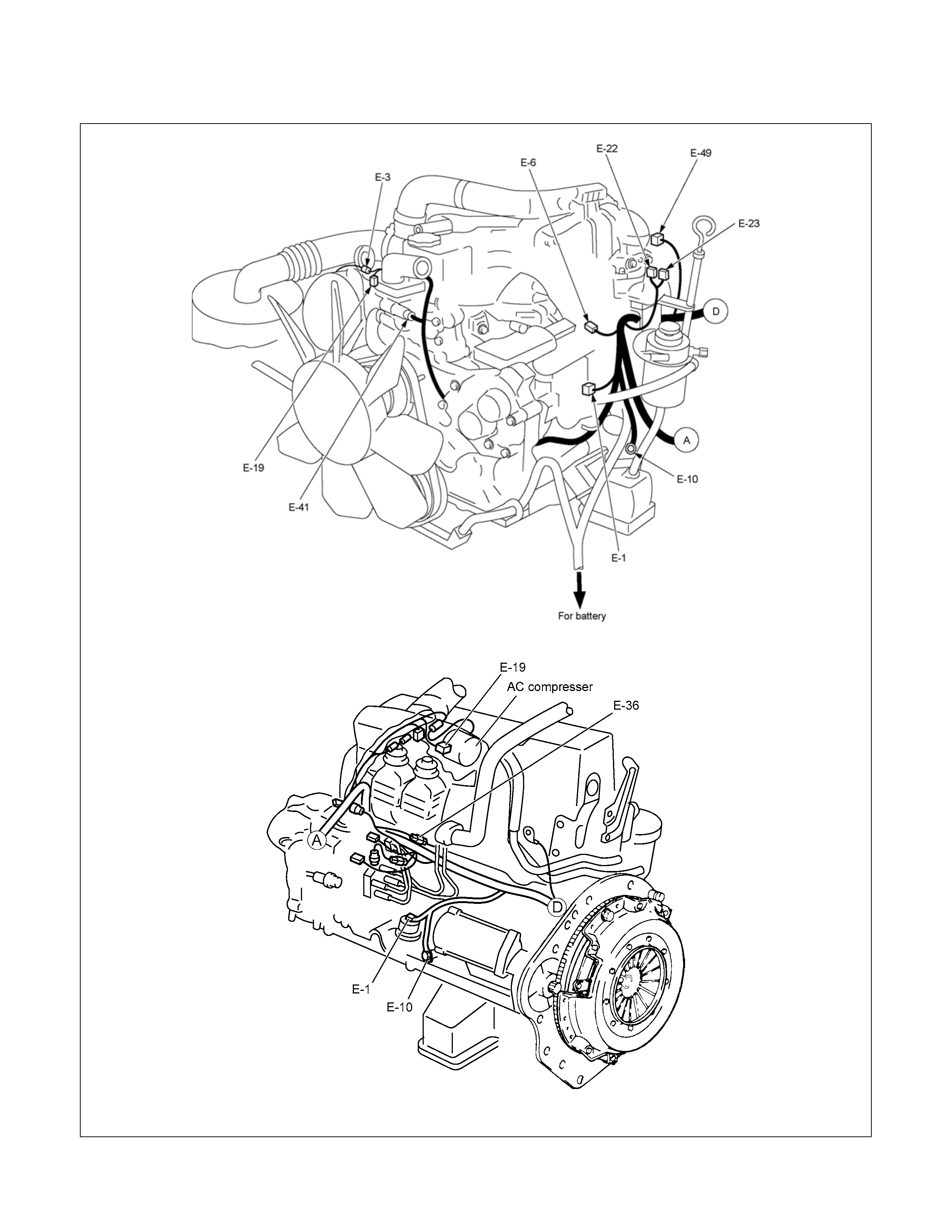
ENGINE HARNESS 4JA1-TC / 4JH1-TC / 4JA1-L
4JA1-TC, 4JH1-TC
4JA1-L
RTW38DX007601 & RTW48AMF001401

TRANSMISSION HARNESS
RTW68AXF014701

TRANSMISSION HARNESS
RTW68AXF012801
SYSTEM REPAIR
START AND CHARGING
PARTS LOCATION (RHD)
RTW68AXF013801
PARTS LOCATION (RHD)
RTW68AXF013901
PARTS LOCATION (LHD)
RTW48AXF012801
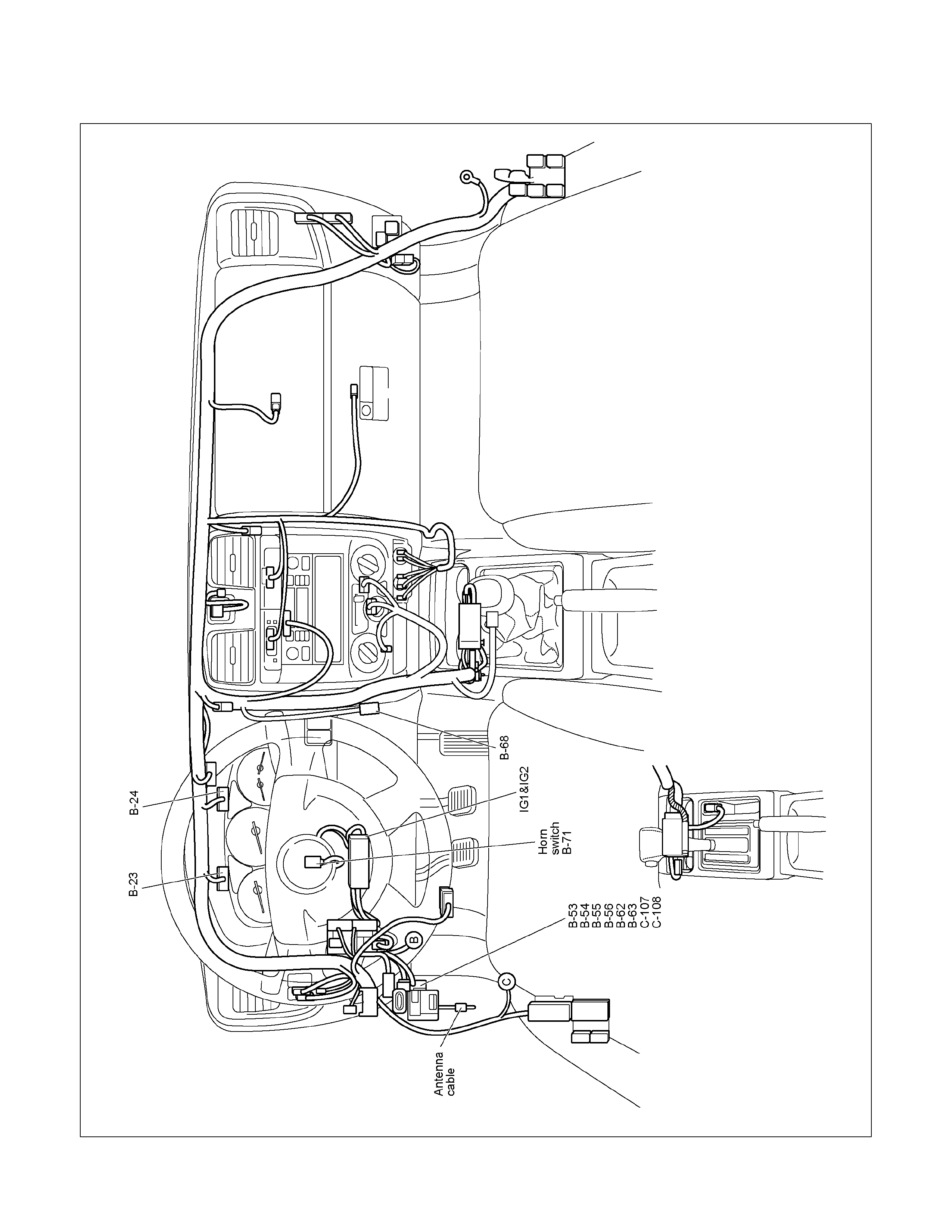
PARTS LOCATION (LHD)
RTW48AXF012901
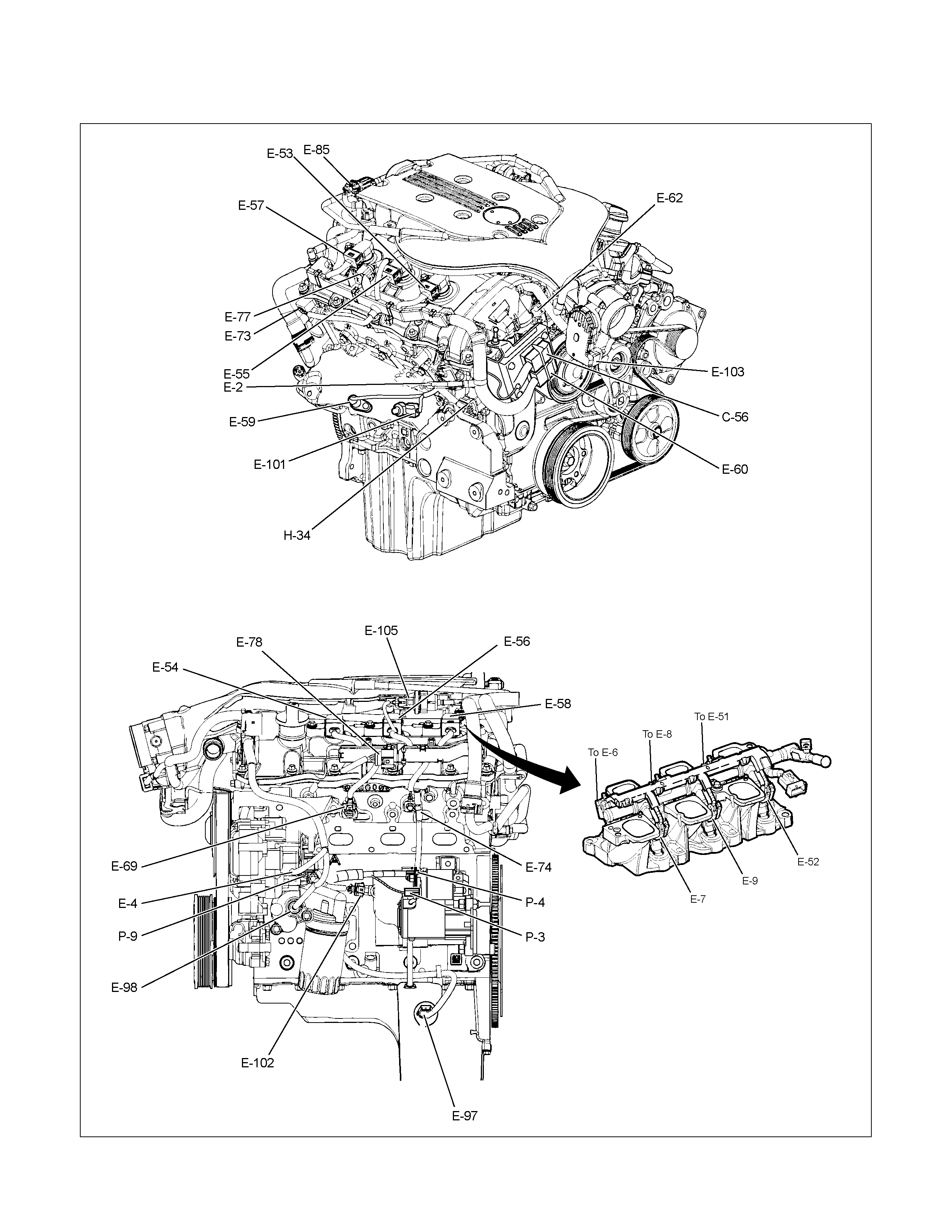
PARTS LOCATION HFV6
RTW68AXF012201

PARTS LOCATION
RTW68AXF012801
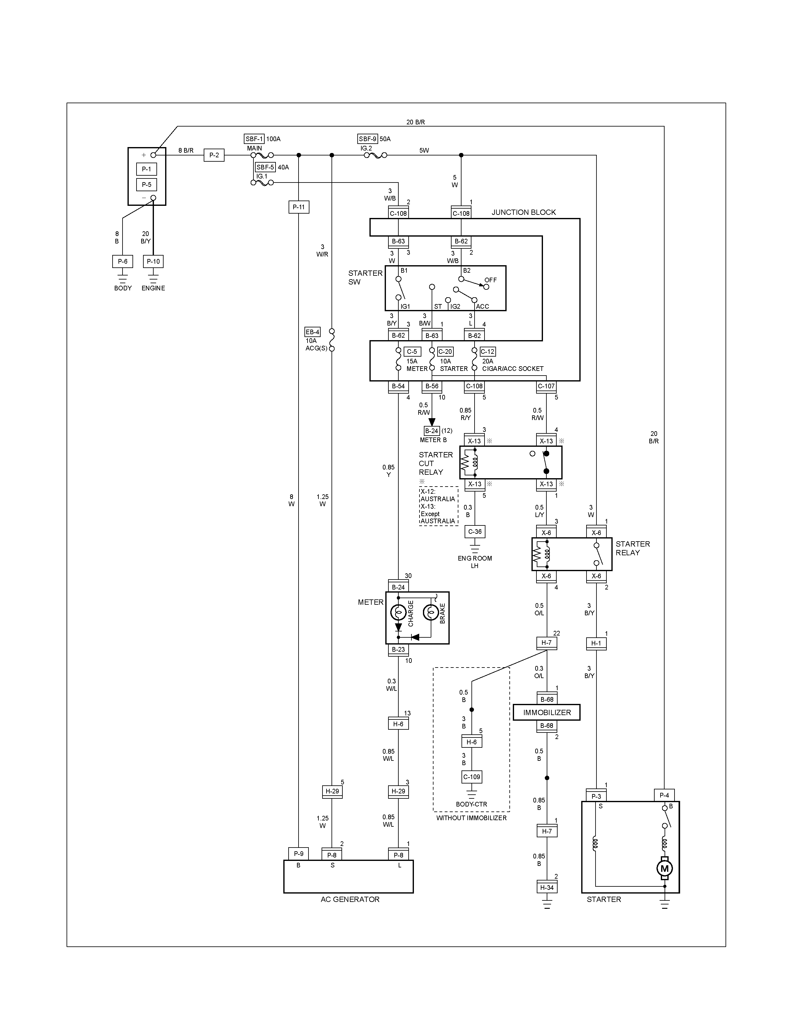
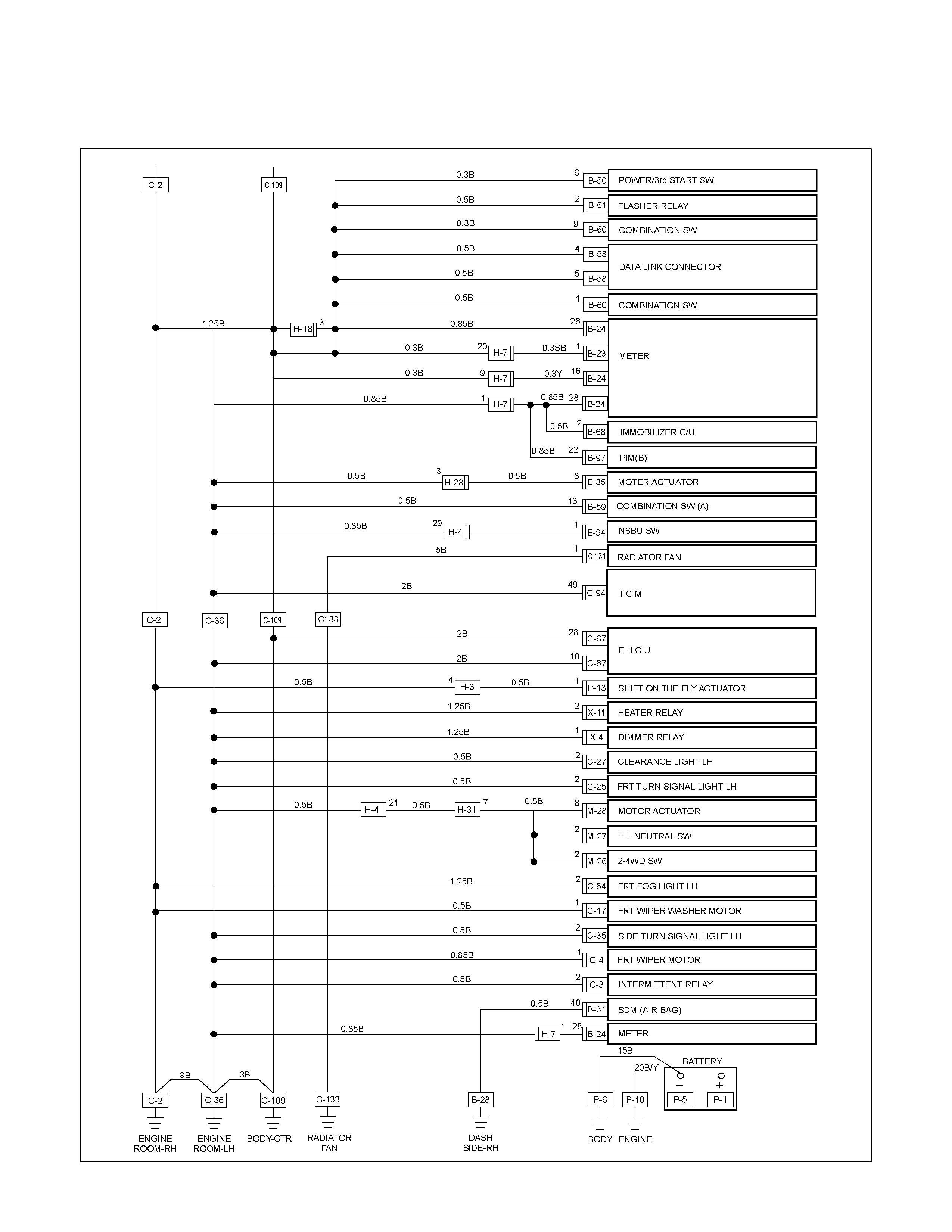
CIRCUIT DIAGRAM C24SE
RTW680XF005001
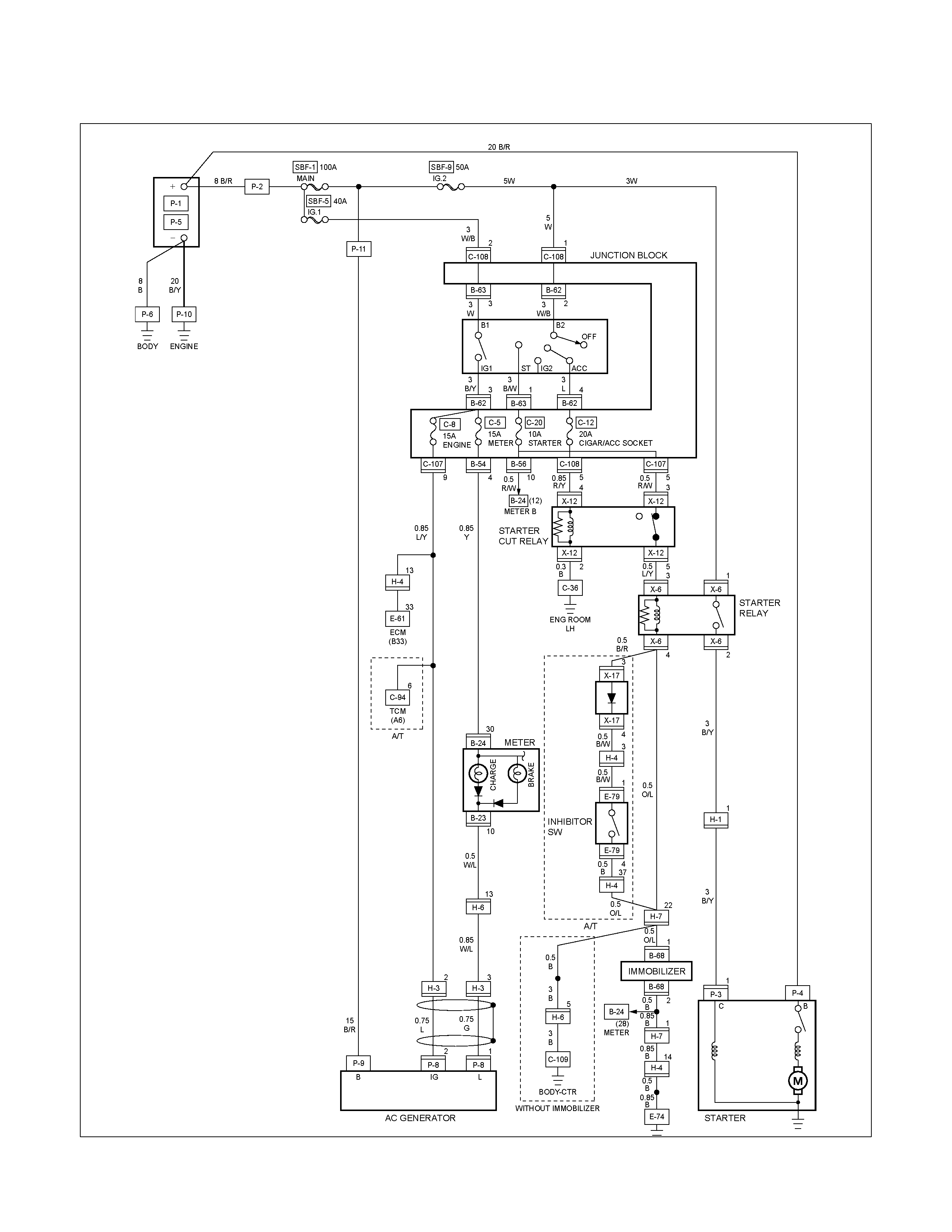
CIRCUIT DIAGRAM 6VE1
RTW680XF005101

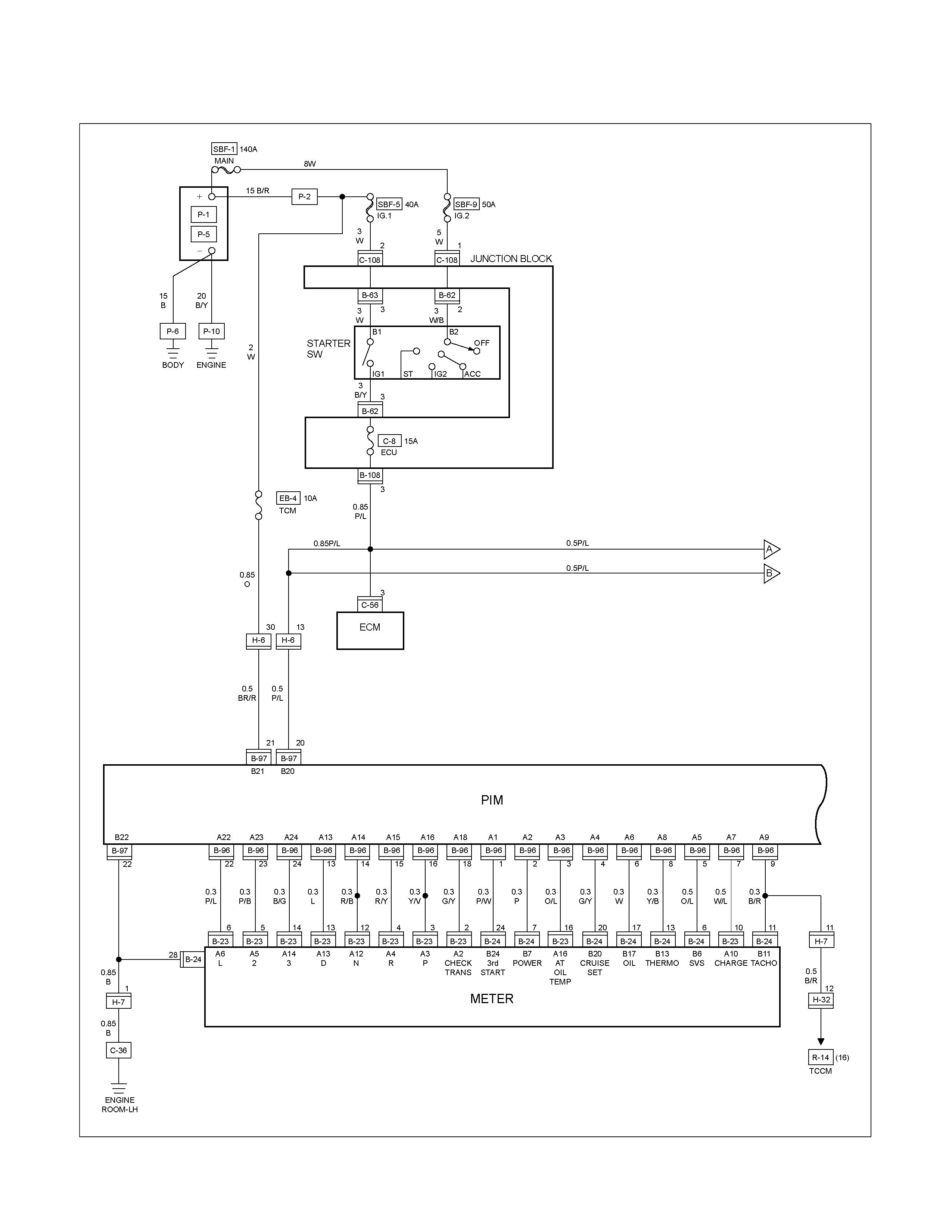
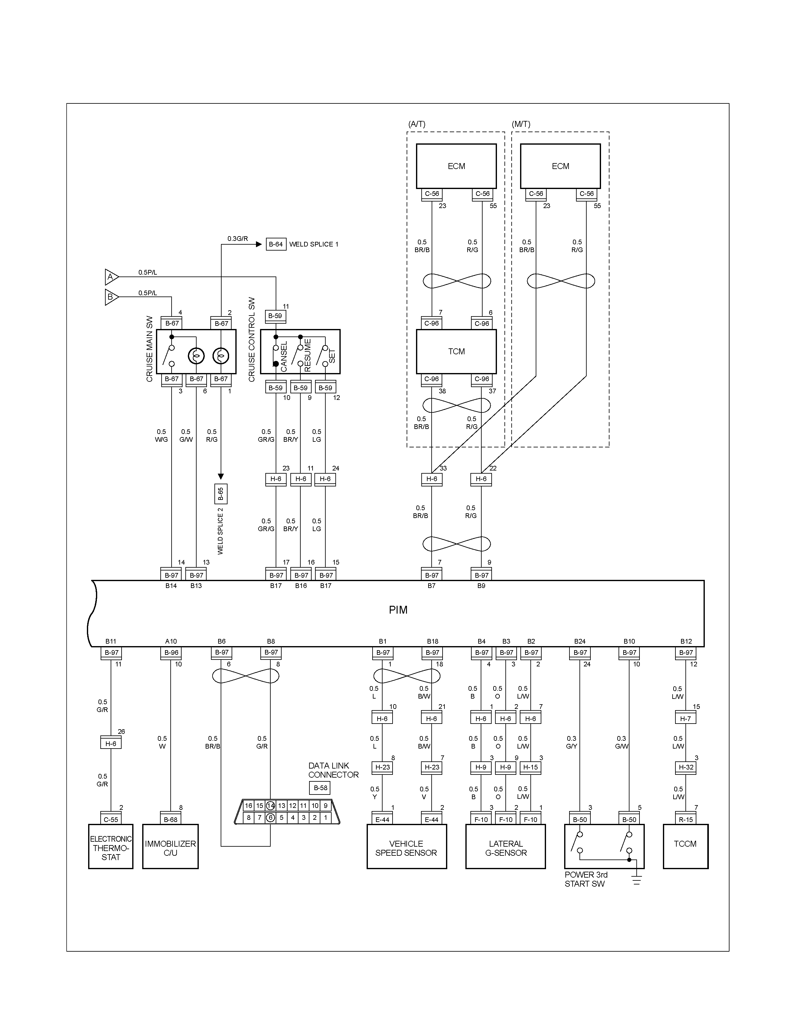
CIRCUIT DIAGRAM HFV6
RTW68AXF010501
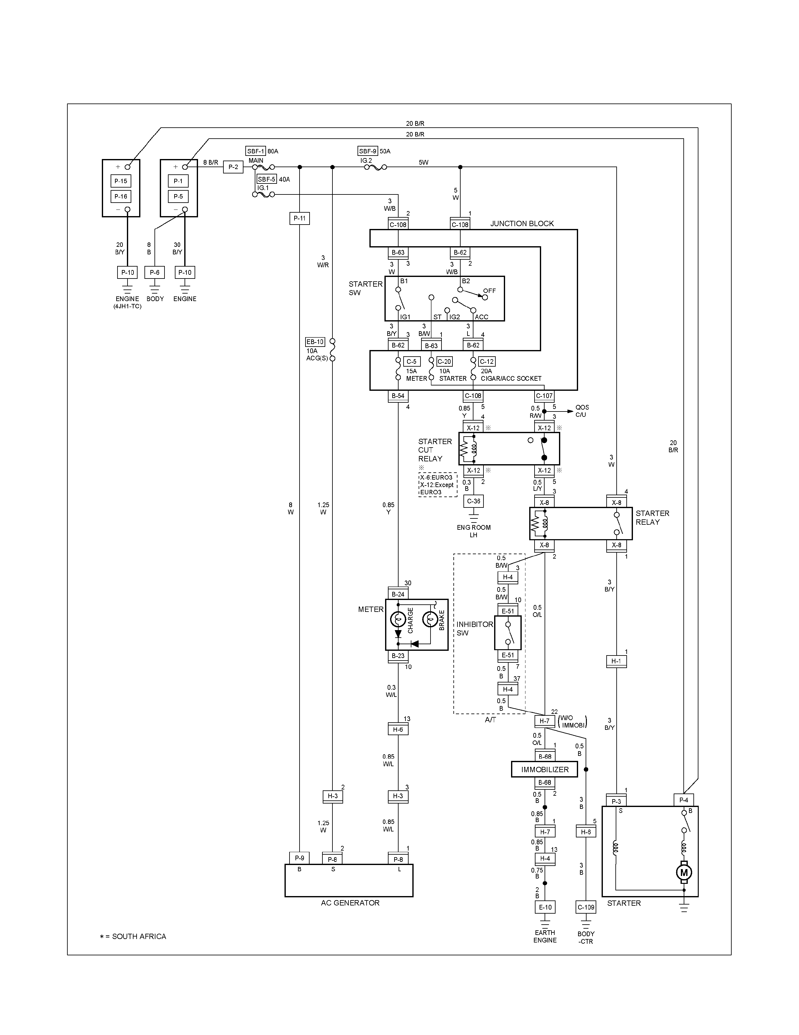
CIRCUIT DIAGRAM 4JA1-TC / 4JH1-TC (RHD)
RTW680XF005201
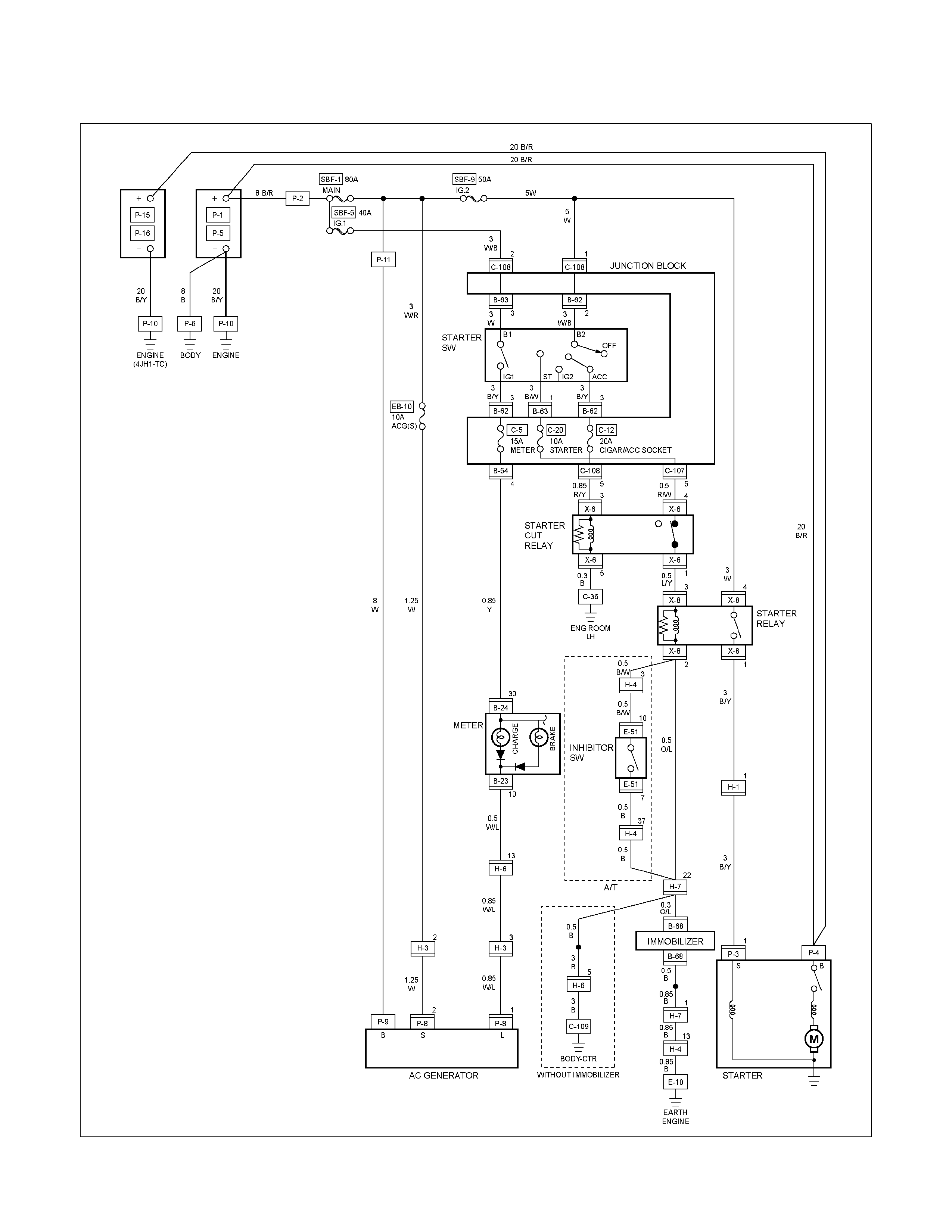
CIRCUIT DIAGRAM 4JA1-TC / 4JH1-TC (LHD)
RTW680XF005301
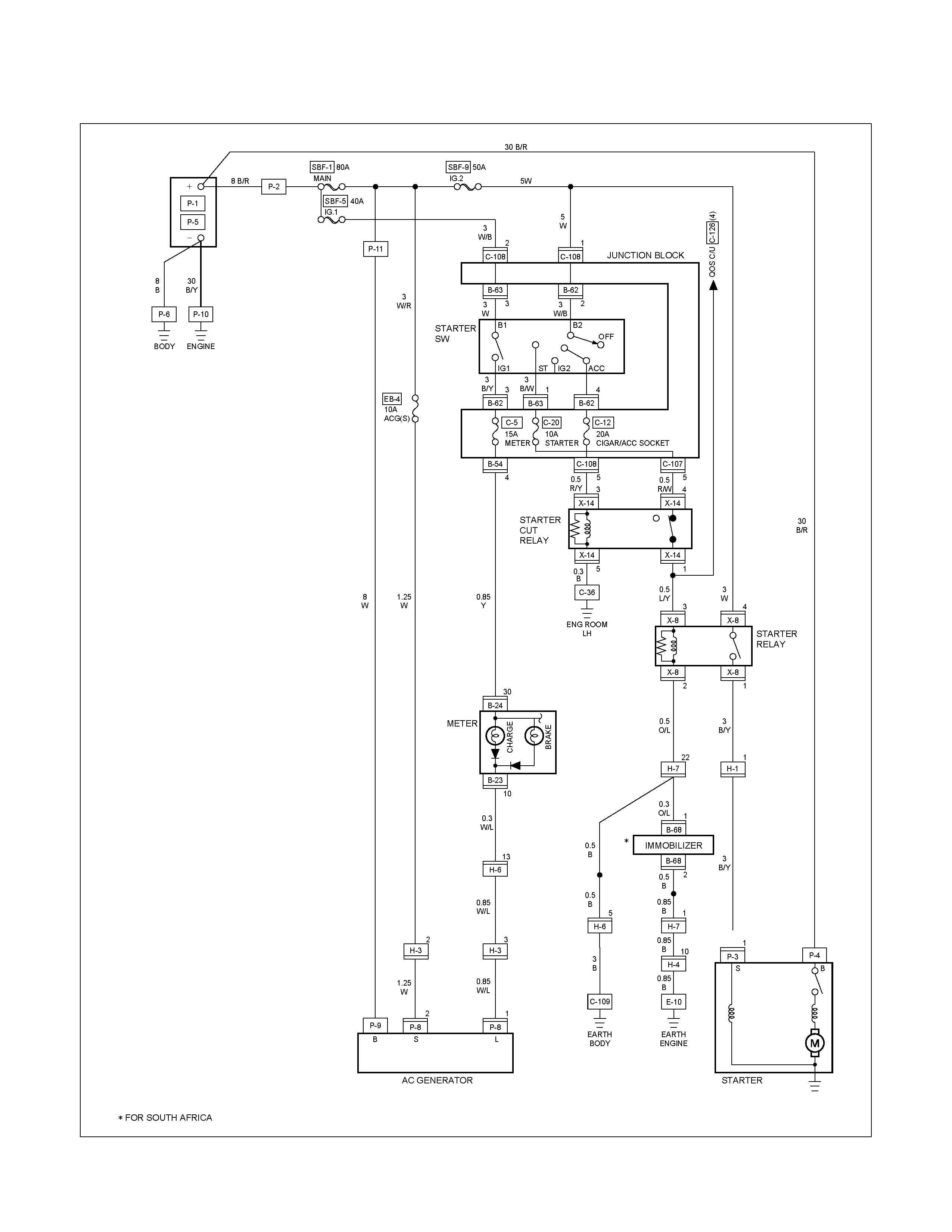
CIRCUIT DIAGRAM 4JA1-L
RTW680XF005401
REMOVAL AND INSTALLATION
This illustration is based on RHD model
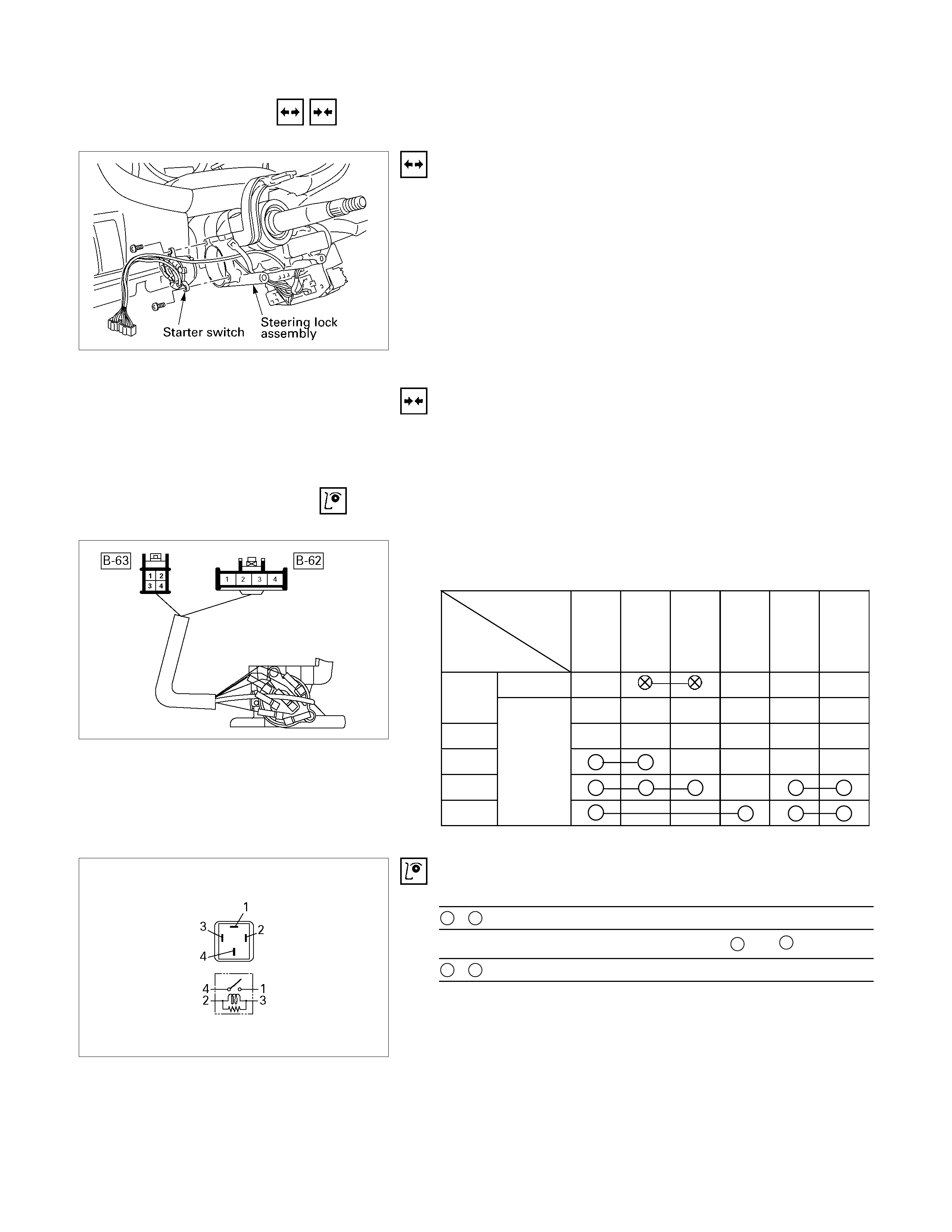
STARTER SWITCH
Removal
1. Steering Lock Assembly
• Refer to Section 3B" STEERING COLUMN" for steering
lock assembly removal steps.
2. Starter Switch
Installation
Follow the removal procedure in the reverse order to install the
starter switch.
INSPECTION AND REPAIR
STARTER SWITCH
Switch Connections
Terminal No.
Starter
switch key
position
B-62
2
(B2)
B-62
4
(ACC)
B-62
1
(IG2)
B-63
1
(ST)
B-63
3
(B1)
B-62
3
(IG1)
Removed
OFF
ACC Inserted
ON
START
LOCK
825R300046
Starter relay
Check continuity between the relay terminals.
1 - 4............................ No continuity
(When battery voltage is applied between 2 and 3)
1 - 4............................ Continuity
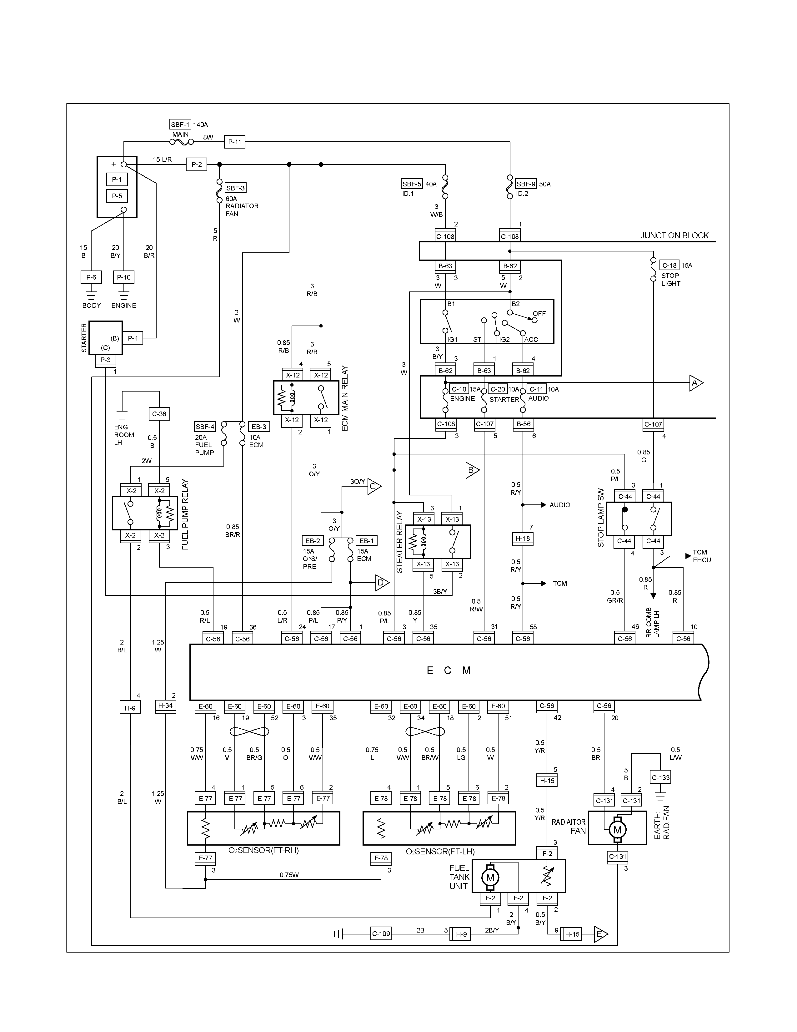
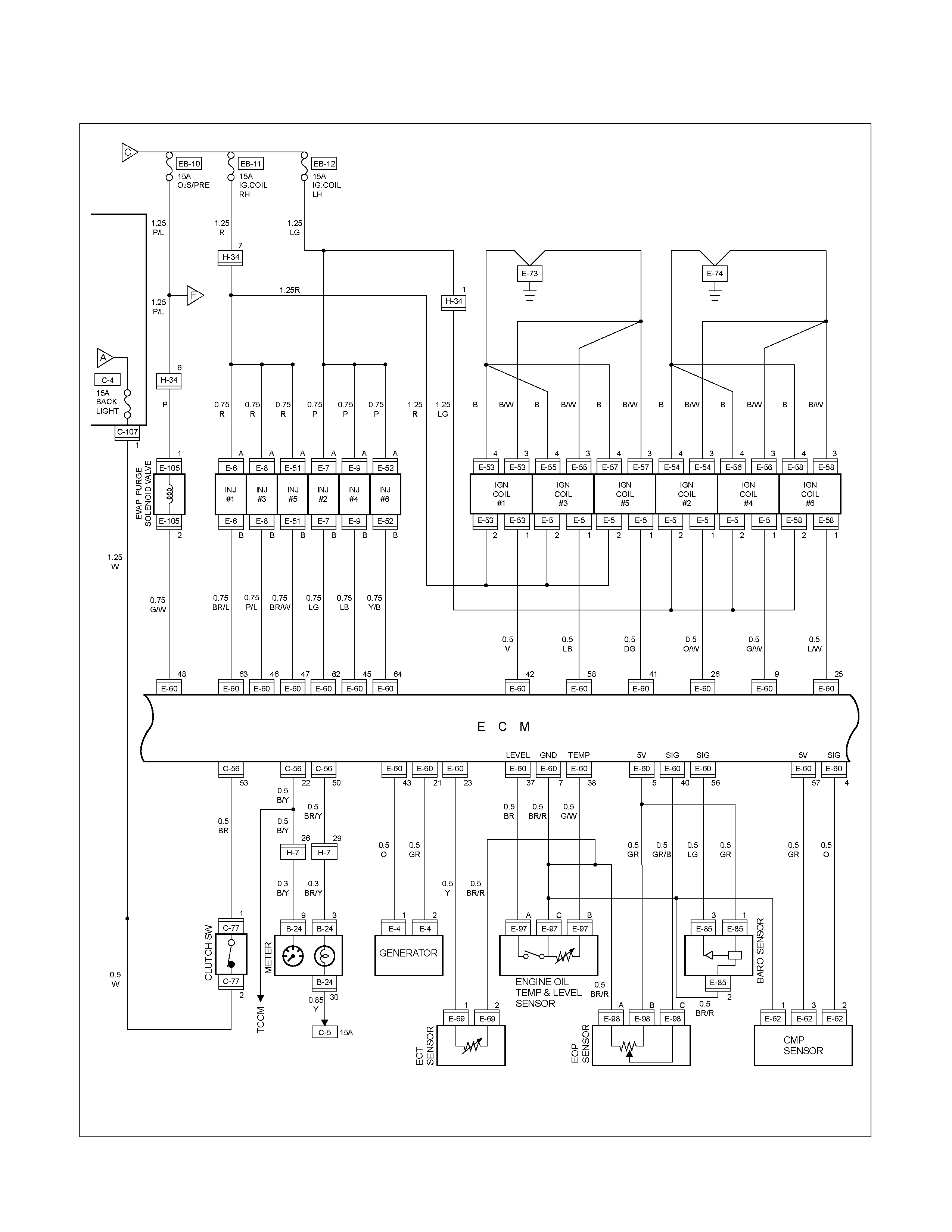
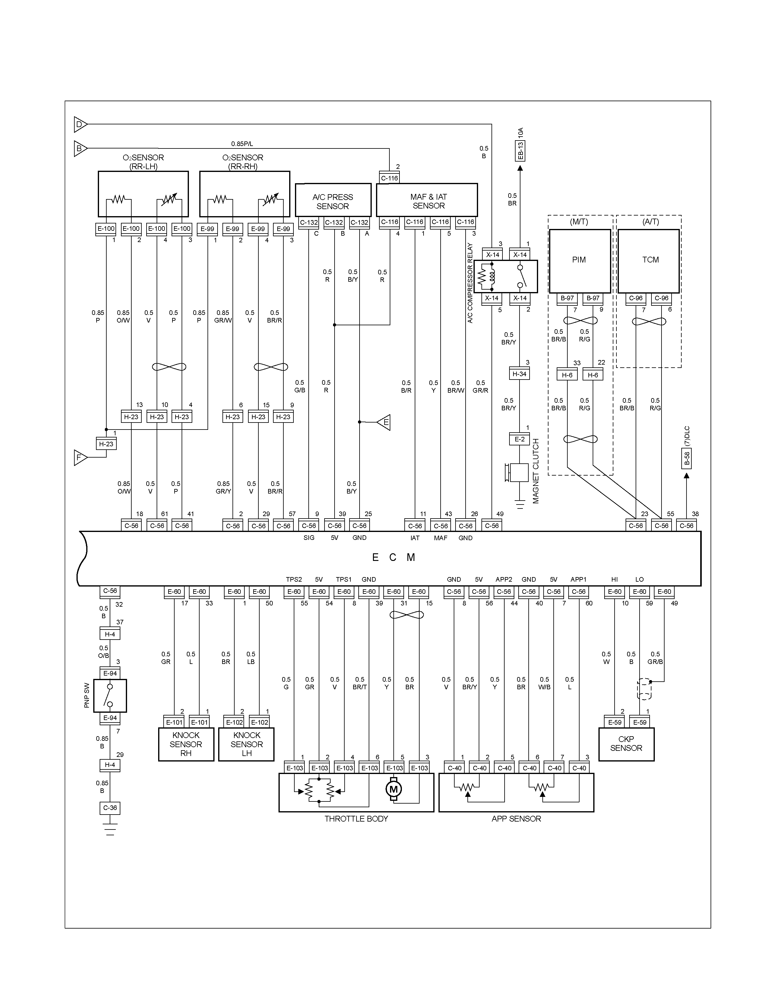
ENGINE CONTROL MODULE (ECM)
PARTS LOCATION (RHD)
RTW68AXF013001 & RTW68AXF018601
PARTS LOCATION (LHD)
RTW48AXF013401 & RTW48AXF013501

PARTS LOCATION C24SE

PARTS LOCATION 6VE1

PARTS LOCATION HFV6
RTW68AXF012201

PARTS LOCATION 4JA1-TC / 4JH1-TC
RTW38DXF007601
PARTS LOCATION
RTW68AXF014701
PARTS LOCATION
RTW68AXF012801
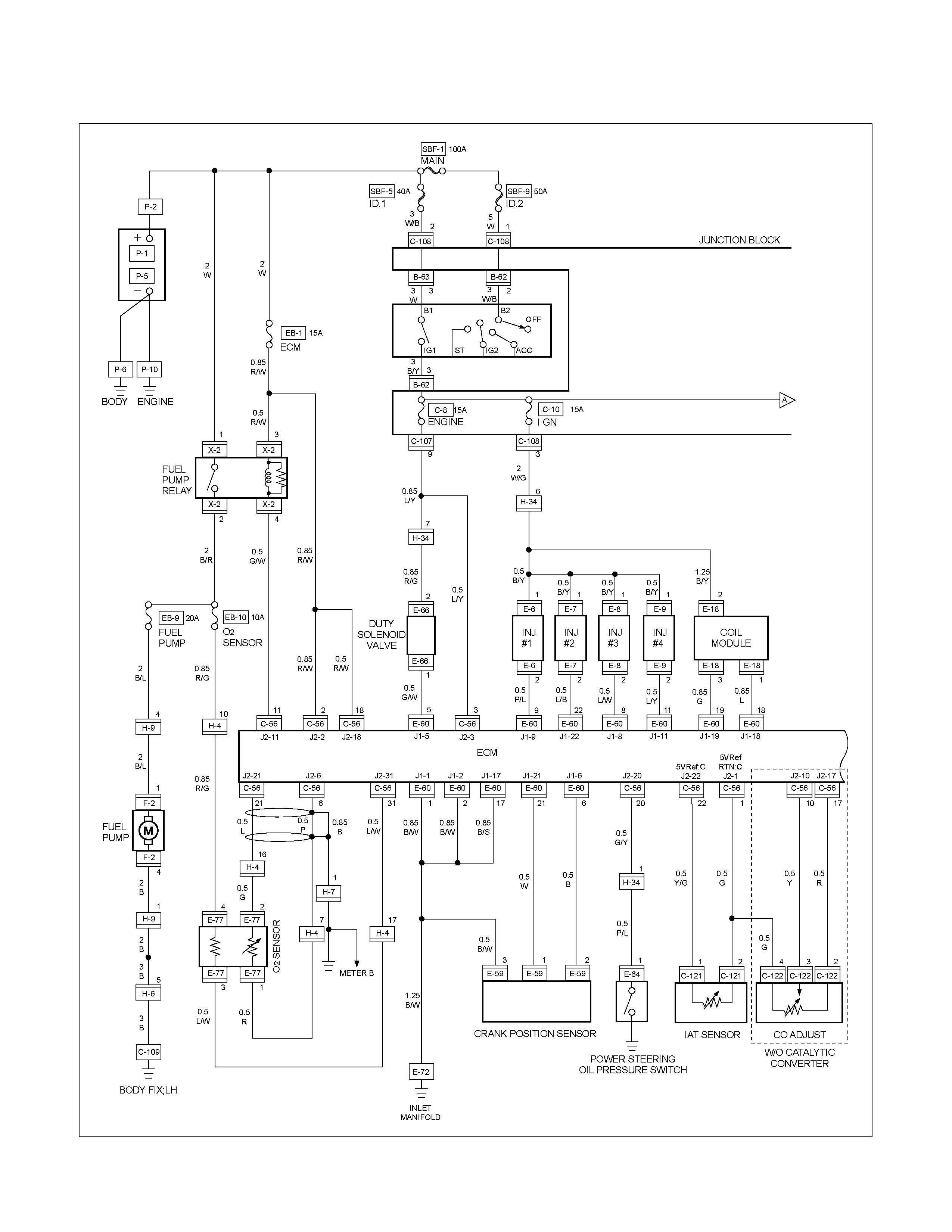
CIRCUIT DIAGRAM C24SE Sheet 1/2
RTW680XF005501
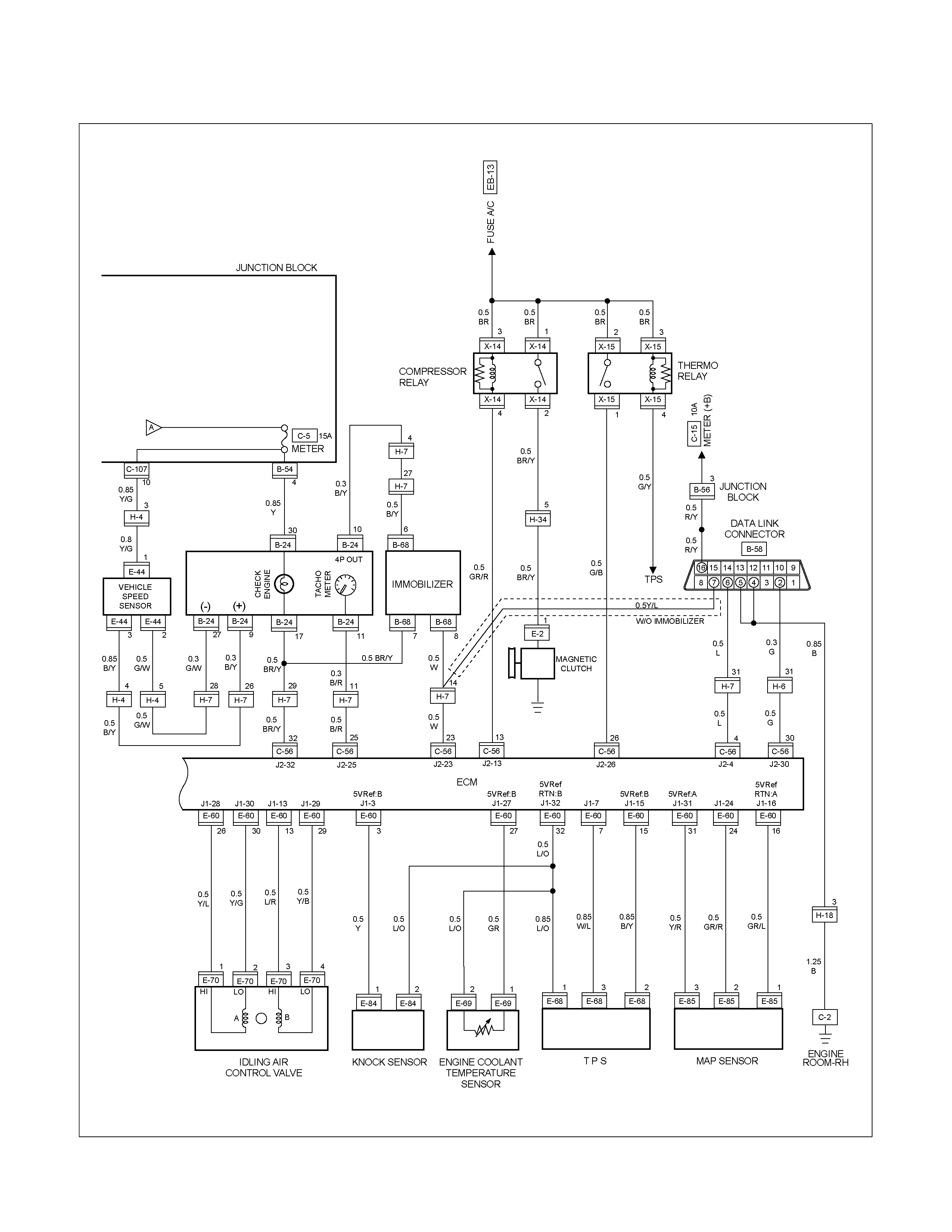
CIRCUIT DIAGRAM C24SE Sheet 2/2
RTW680XF005601

CIRCUIT DIAGRAM 6VE1 Sheet 1/3
RTW680XF005701
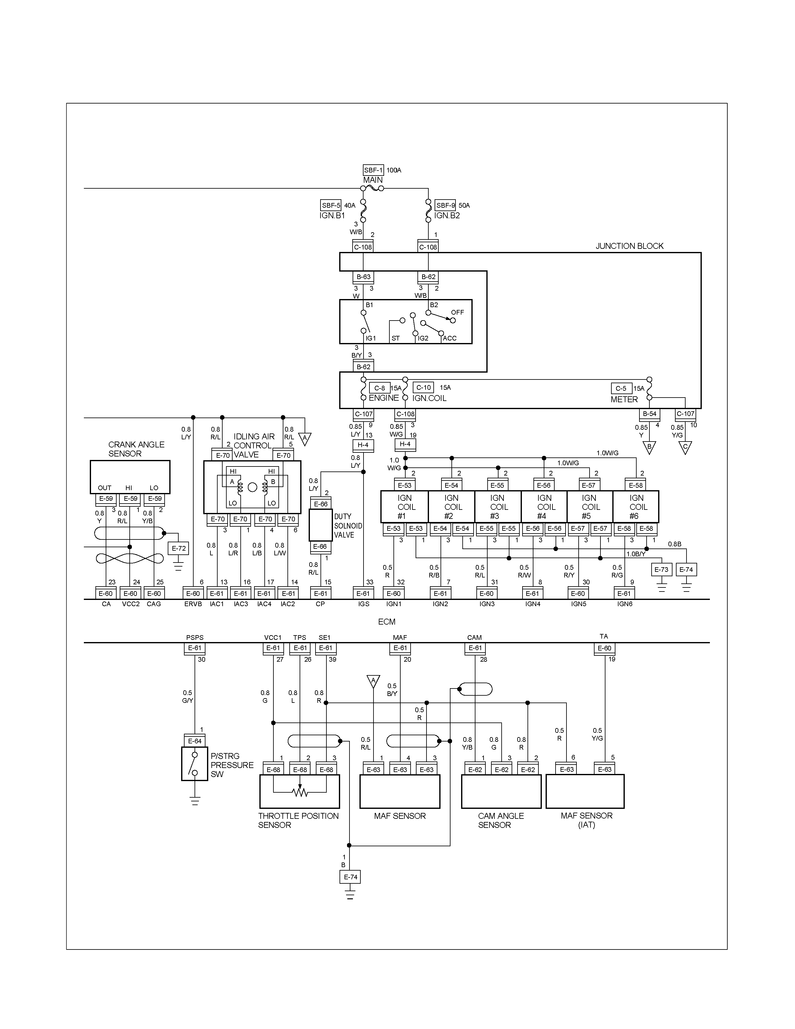
CIRCUIT DIAGRAM 6VE1 Sheet 2/3
RTW680XF005801
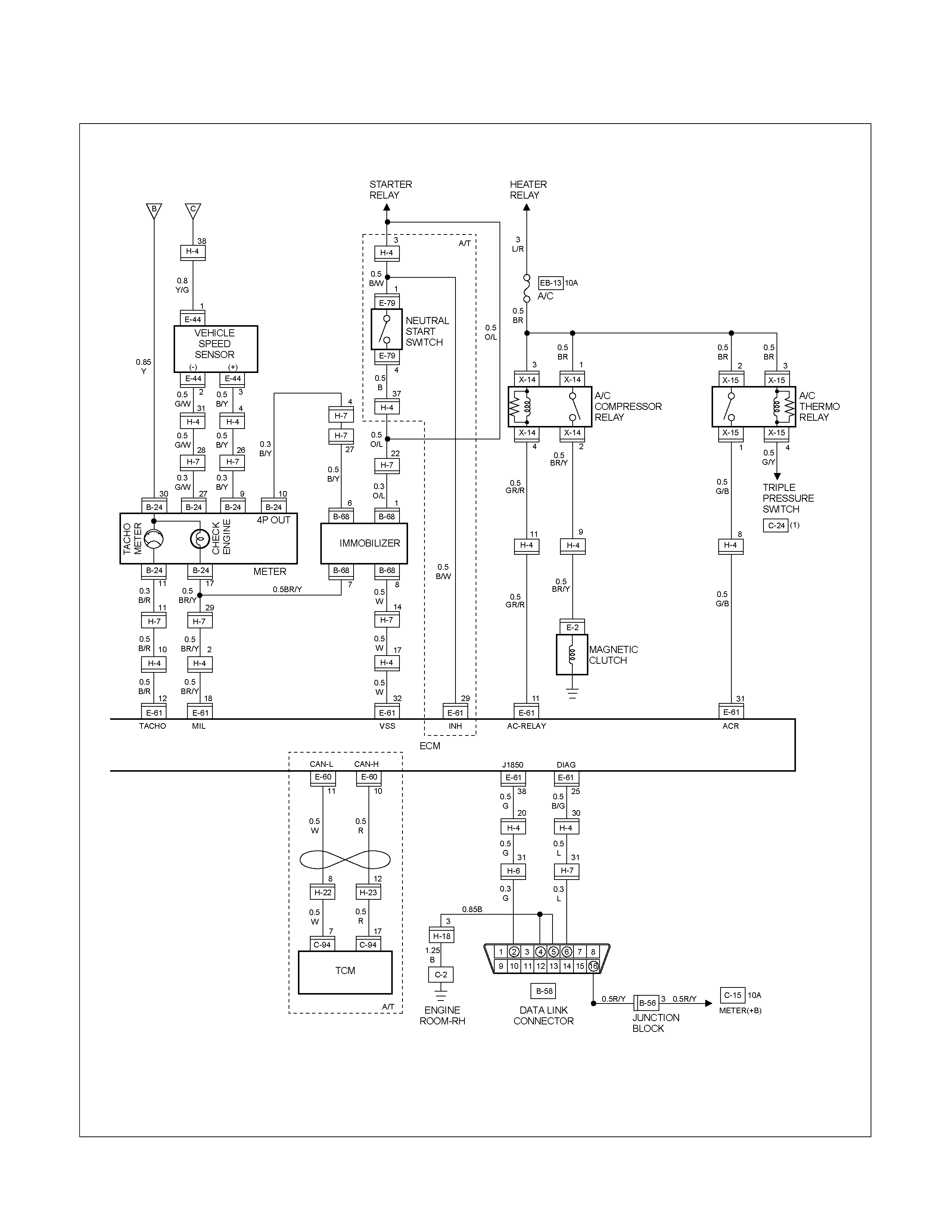
CIRCUIT DIAGRAM 6VE1 Sheet 3/3
RTW680XF005901
CIRCUIT DIAGRAM HFV6 Sheet 1/3
RTW680XF016201
CIRCUIT DIAGRAM HFV6 Sheet 2/3
RTW680XF016301
CIRCUIT DIAGRAM HFV6 Sheet 3/3
RTW680XF016401
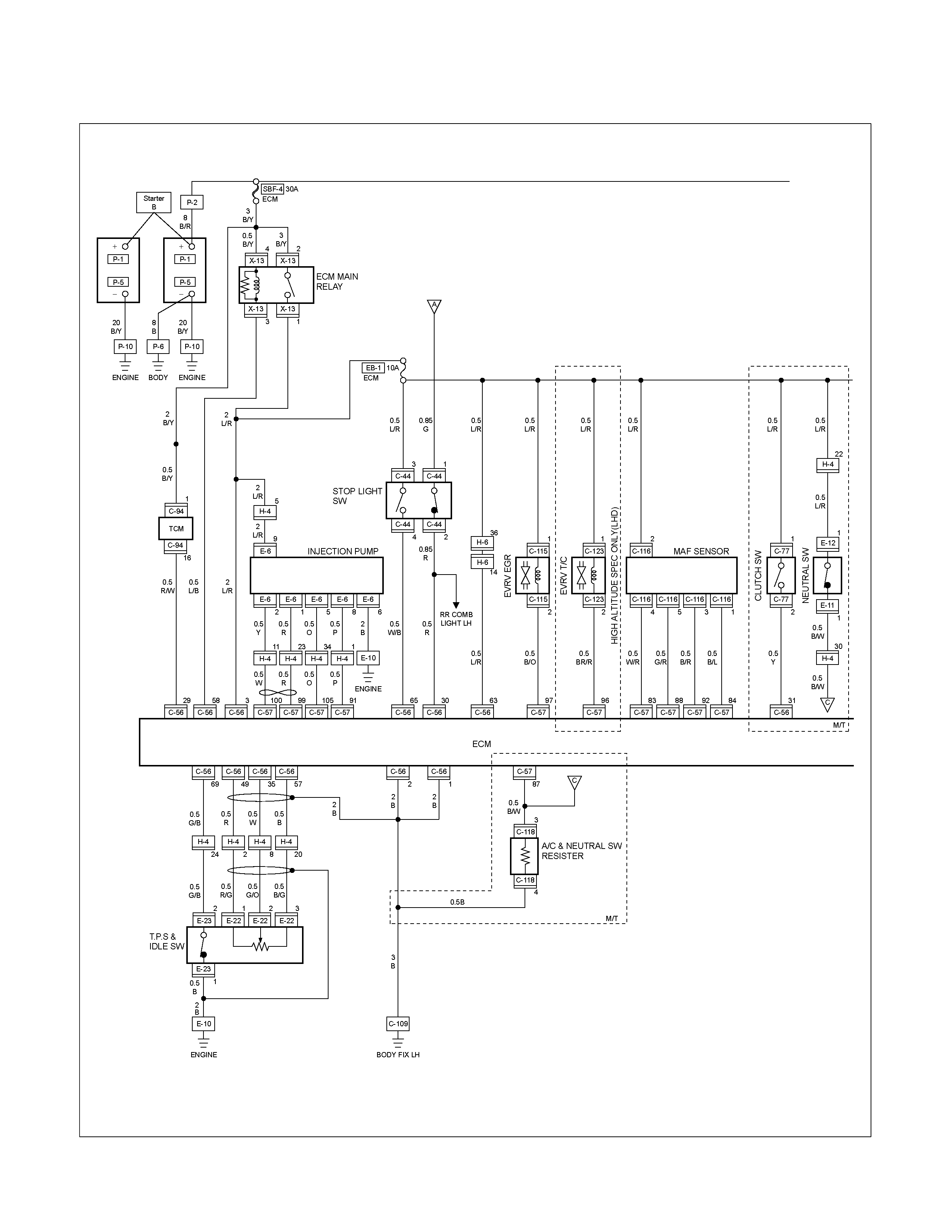
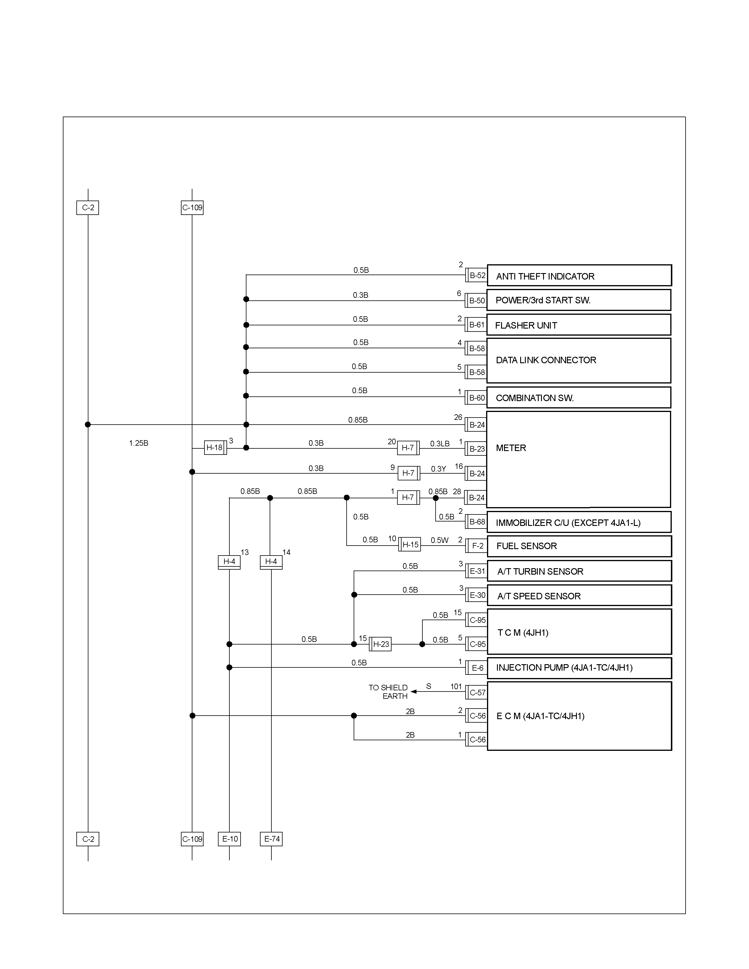
CIRCUIT DIAGRAM 4JH1-TC Sheet 1/2
RTW680XF006001
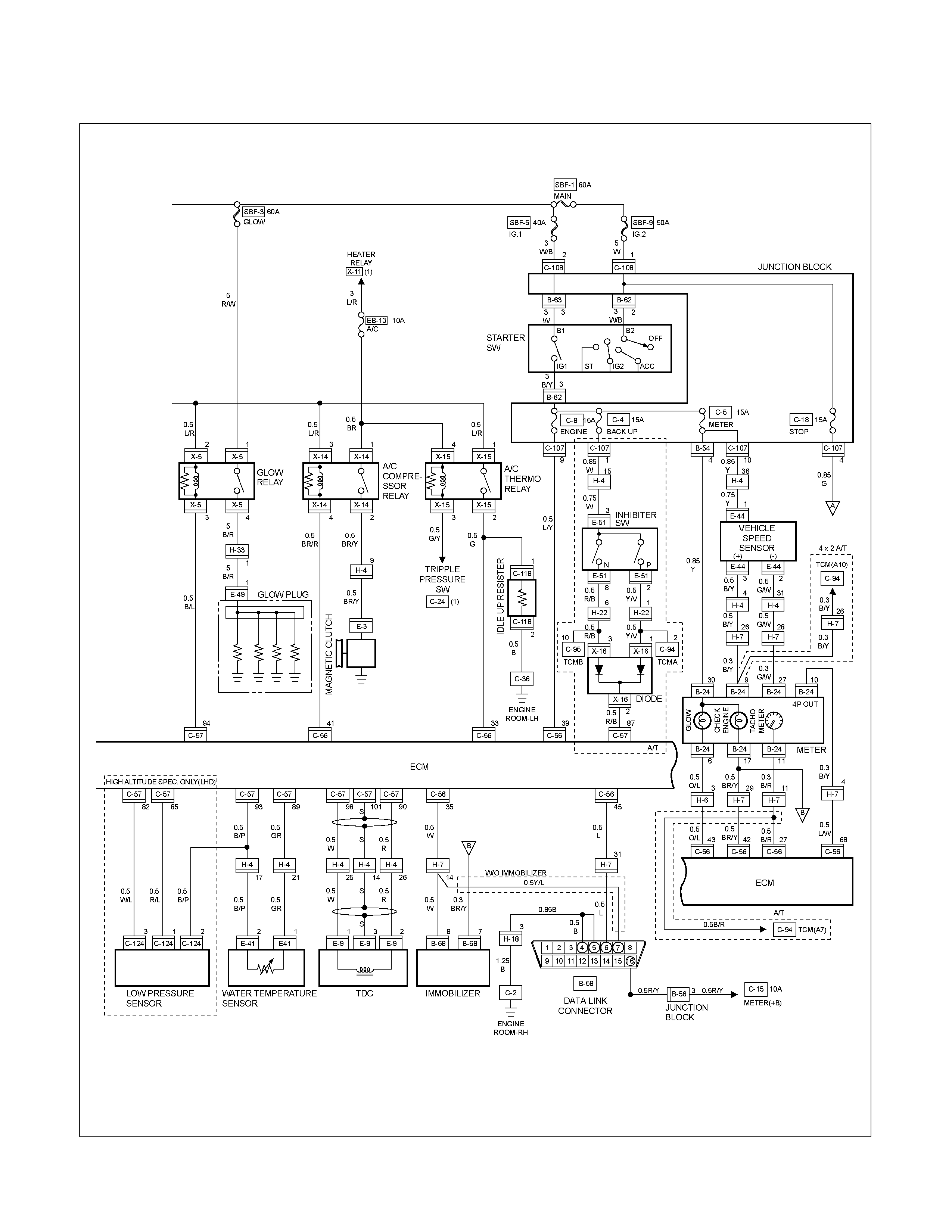
CIRCUIT DIAGRAM 4JH1-TC Sheet 2/2
RTW680XF006101
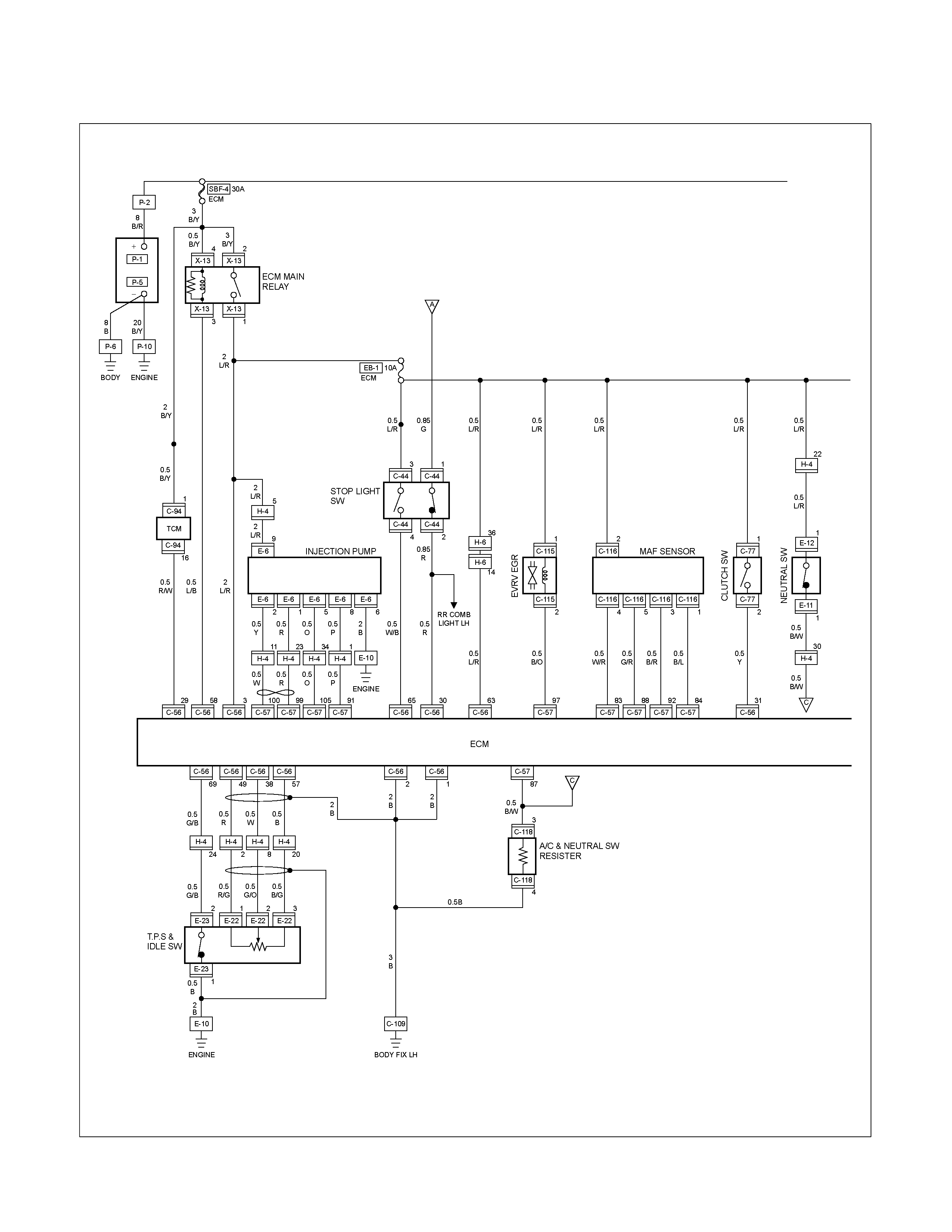
CIRCUIT DIAGRAM 4JA1-TC Sheet 1/2
RTW680XF006201
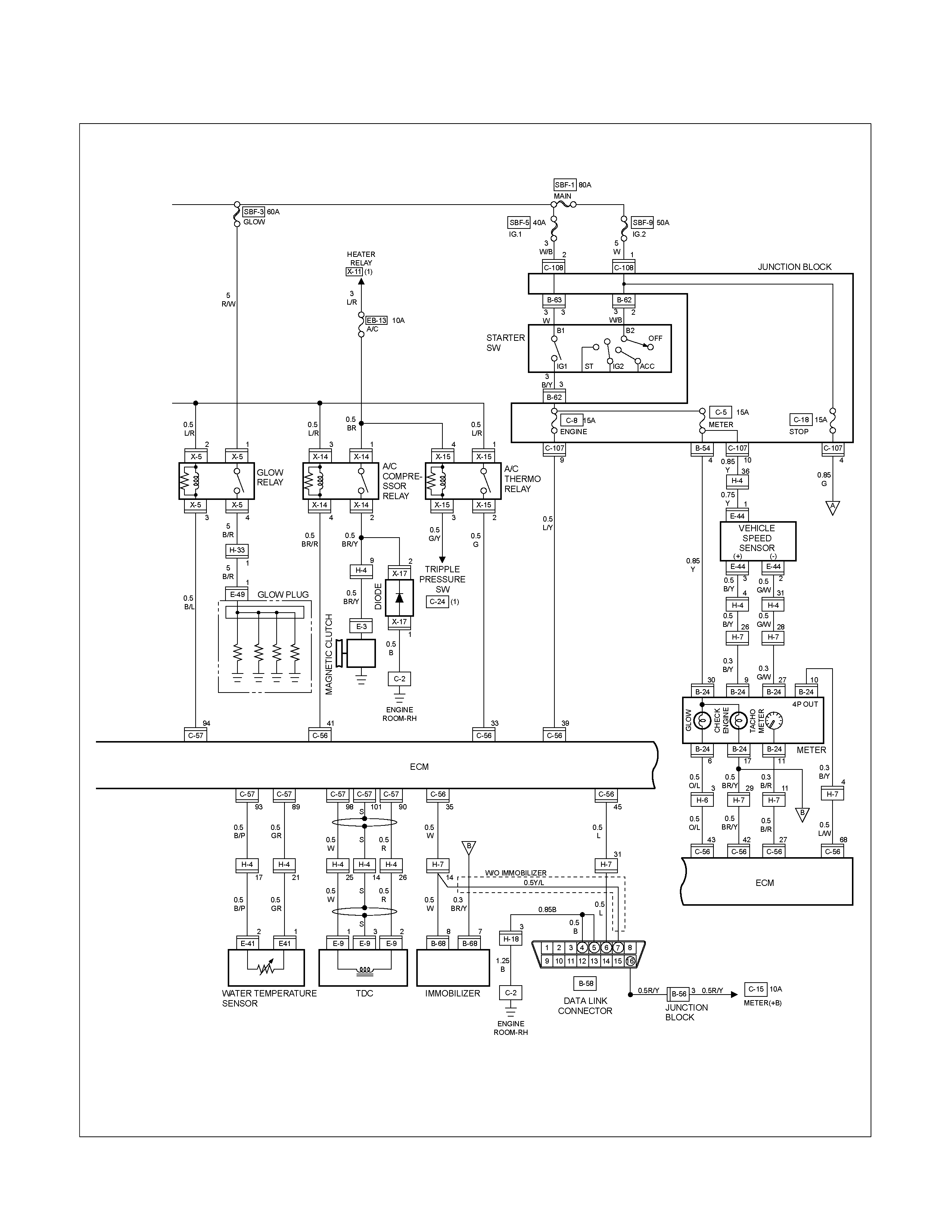
CIRCUIT DIAGRAM 4JA1-TC Sheet 2/2
RTW680XF006301
REMOVAL AND INSTALLATION
ECM (ENGINE CONTROL MODULE):
C24SE
Removal
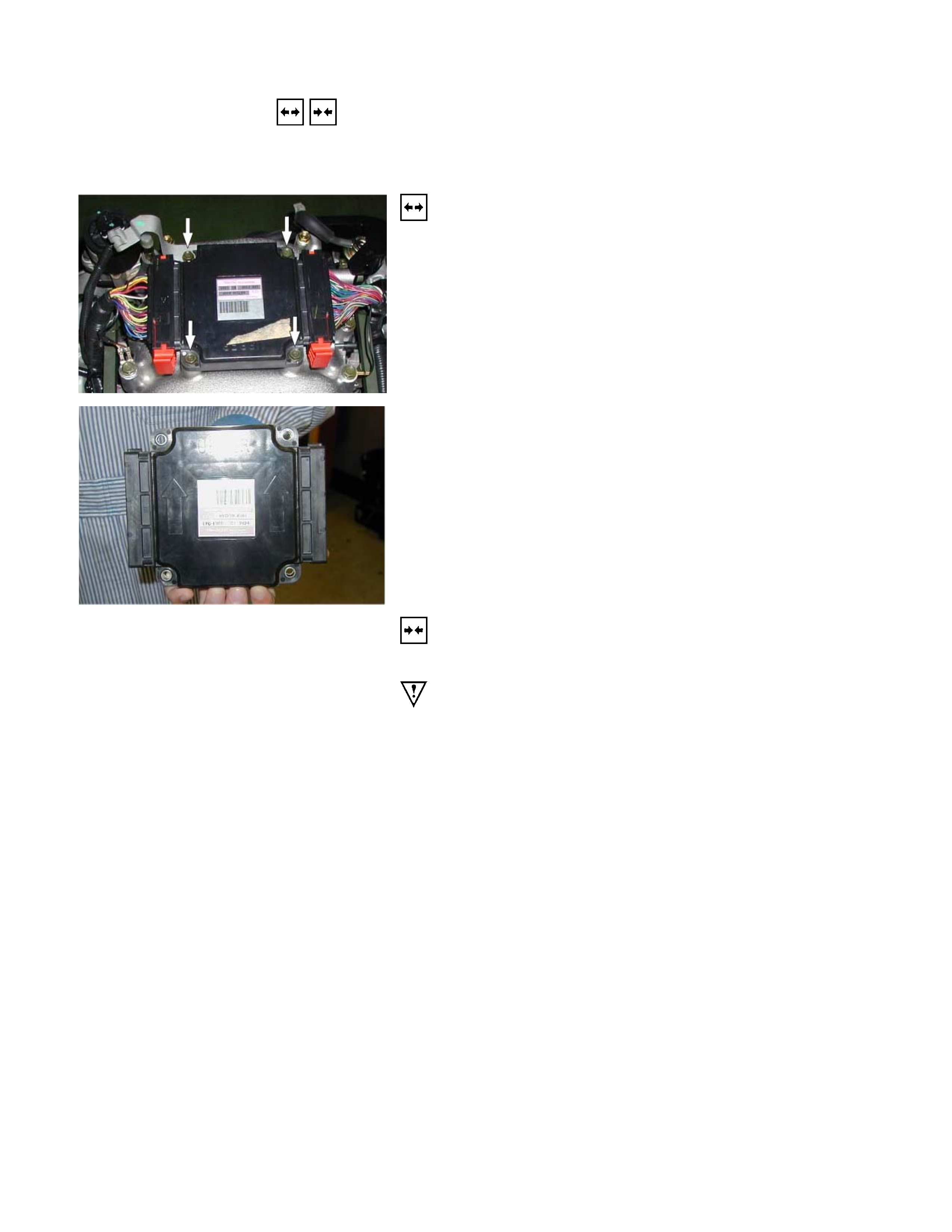
1. Lift both the ECM harness connector locking levers and
remove the two harness connectors form the ECM.
2. Remove the four socket head screws securing the ECM to
the mounting bracket.
3. Remove the ECM from the engine compartment.
4. Pull out the ECM.
5. Disconnect both red and tan connectors.
Refer to the Section 6E-ENGINE of this Manual.
IMPORTANT: The replacement ECM must be programmed.
“SPS (Service Programming System) and immobilizer
programming (if equipped) is/are necessary”
Installation
Follow the removal procedure in the reverse order to install the
ECM.
Pay close attention to the important points mentioned in the
following paragraphs.
Connector
Be absolutely sure that ECM is securely connected.
This will prevent a poor contact and open circuit.
REMOVAL AND INSTALLATION
ECM (ENGINE CONTROL MODULE):
6VE1
Removal
1. Pull both the red ECM harness connector locks toward the
front of the vehicle, and remove the two harness
connectors form the ECM.
2. Remove the four hex-head screws securing the ECM to the
common chamber.
3. Remove the ECM from the engine compartment.
4. Pull out the ECM.
5. Disconnect both red and tan connectors.
Refer to the Section 6E-ENGINE of this Manual.
IMPORTANT: The replacement ECM must be programmed.
“SPS (Service Programming System) and immobilizer
programming (if equipped) is/are necessary”
Installation
Follow the removal procedure in the reverse order to install the
ECM.
Pay close attention to the important points mentioned in the
following paragraphs.
Connector
Be absolutely sure that ECM is securely connected.
This will prevent a poor contact and open circuit.
REMOVAL AND INSTALLATION
ECM (ENGINE CONTROL MODULE):
HFV6
RTW68ASH000601
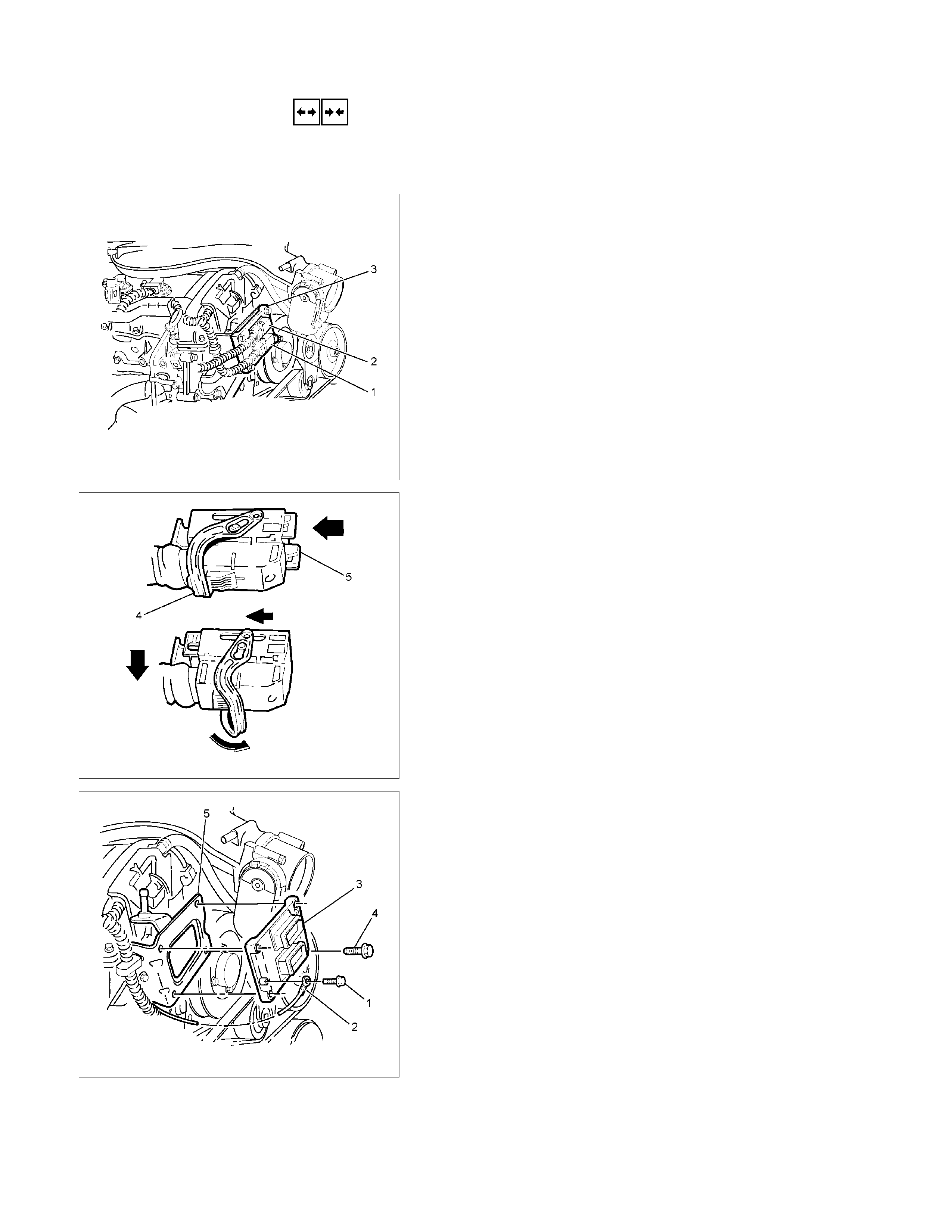
Removal
1. Turn the ignition switch off.
2. Disconnect the battery.
3. Remove the ECM from the engine compartment.
4. Disconnect the engine harness connector (1) and the
engine room harness connector (2) from the ECM (3).
RTW68ASH000701
5. To release each connector, lift the connector locking leve
r
(4) whilst simultaneously pushing the connector locking
slide (5)
RTW68ASH000801
6. Remove the screw (1) attaching the ground
terminal (2) to the ECM (3).
7. Remove the nut (4), four places, attaching the ECM to the
mounting bracket (5) and remove the ECM.
Refer to the Section 6E-ENGINE of this Manual.
IMPORTANT: The replacement ECM must be programmed.
“SPS (Service Programming System) and immobilizer
programming (if equipped) is/are necessary”
RTW68ASH000901
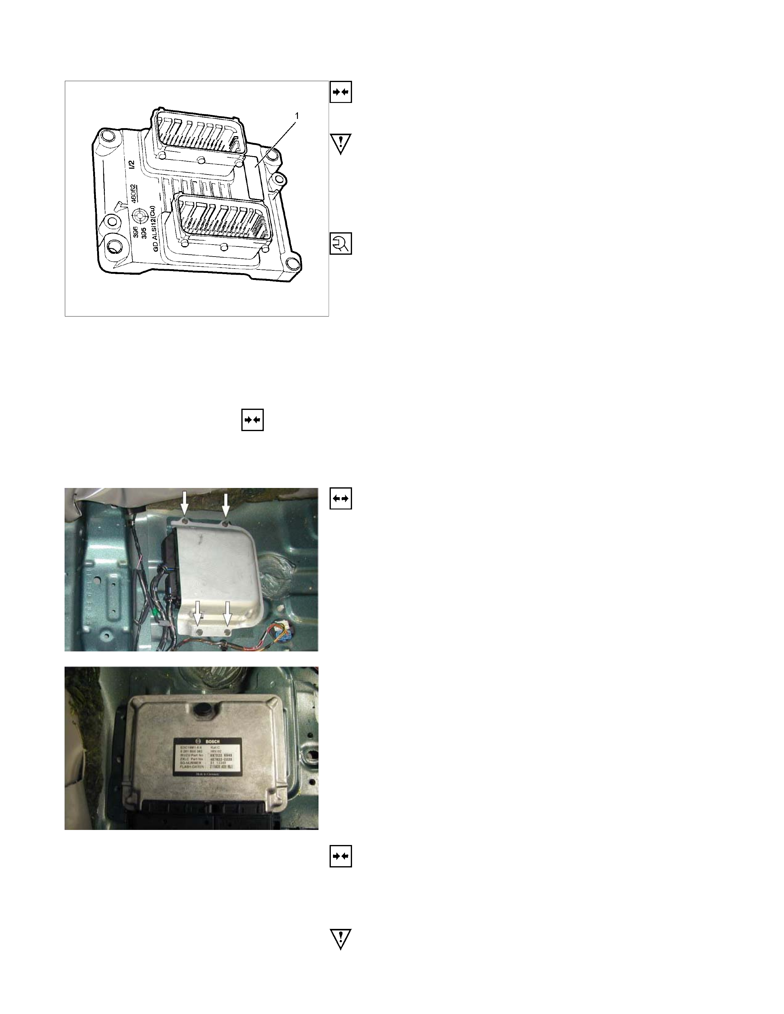
Installation
Follow the removal procedure in the reverse order to install the
ECM.
Pay close attention to the important points mentioned in the
following paragraphs.
During installation of the ECM, the label (1) is positioned at the
top right-hand corner.
ECM attaching bolt
Torque: 10 N⋅m (1.0 kgf⋅m)
Ground terminal attaching screw
Torque: 4.5 N⋅m (0.4 kgf⋅m)
Connector
Be absolutely sure that ECM is securely connected.
This will prevent a poor contact and open circuit.
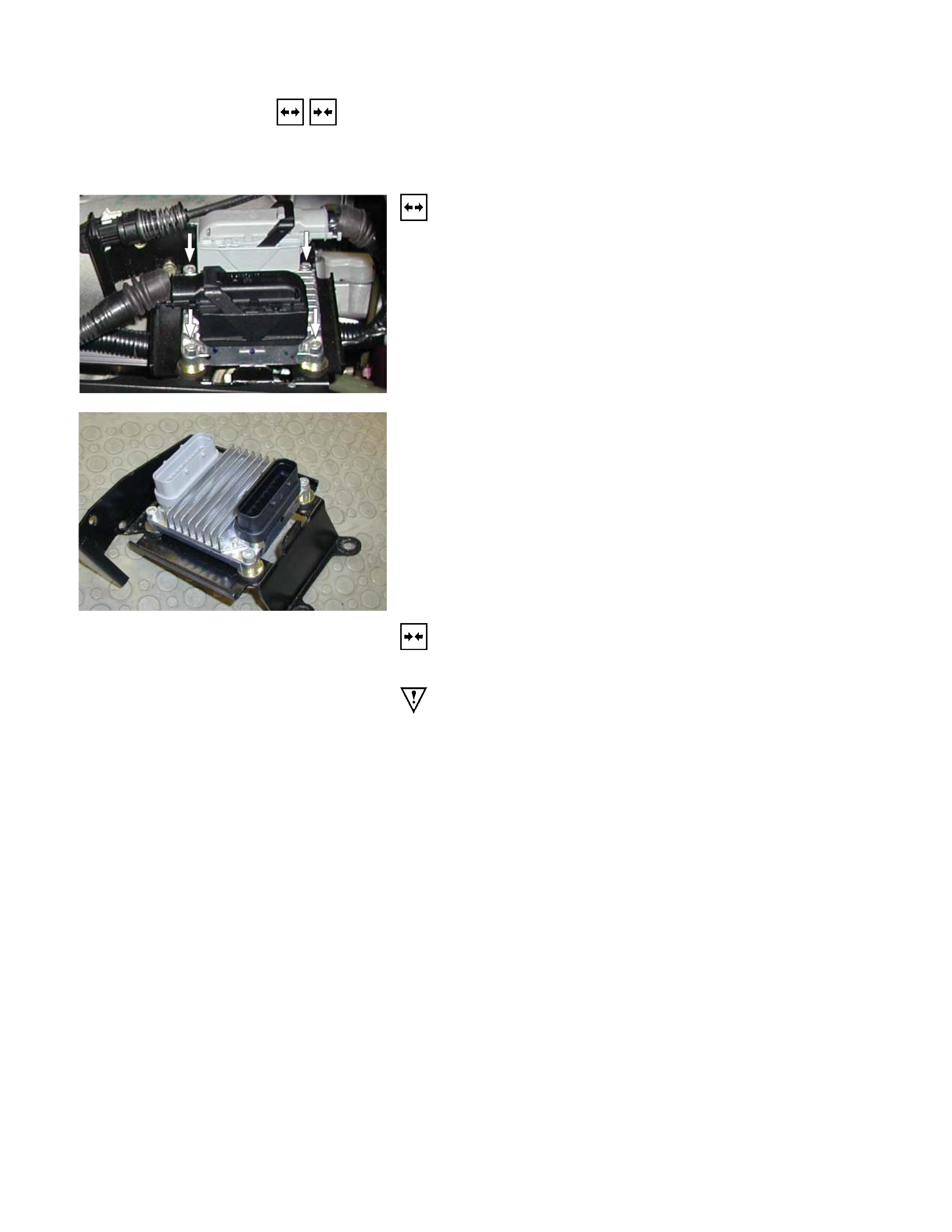
REMOVAL AND INSTALLATION
ECM (ENGINE CONTROL MODULE):
4JA1-TC / 4JH1-TC
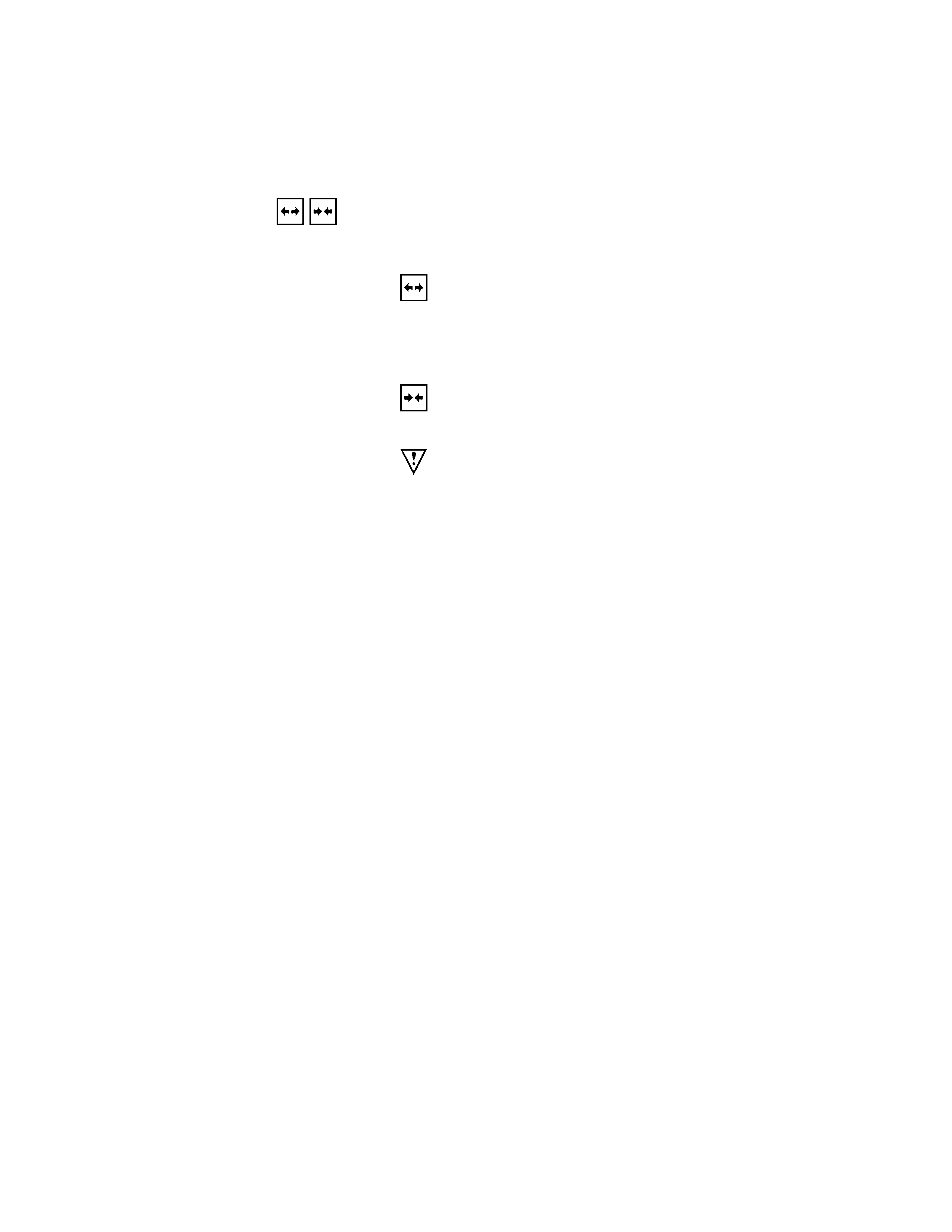
Removal
1. Remove the passenger side front seat – refer to Section 10
CAB.
2. Remove the passenger side front door opening scuff plate.
3. Raise the carpet to gain access to the four hex-head bolts
securing the ECM and ECM cover to the floor pan.
4. Remove the four hex-head bolts.
5. Pull the two harness connector locks away from the
harness connectors and then remove the connectors form
the ECM.
6. Remove the ECM from the vehicle.
Refer to the Section 6E-ENGINE of this Manual.
IMPORTANT: The replacement ECM must be programmed.
“SPS (Service Programming System) and immobilizer
programming (if equipped) is/are necessary”
Installation
Follow the removal procedure in the reverse order to install the
ECM.
Torque passenger seat securing bolts to the specified value –
refer to Section 10 CAB
Pay close attention to the important points mentioned in the
following paragraphs.
Connector
Be absolutely sure that ECM is securely connected.
This will prevent a poor contact and open circuit.
REMOVAL AND INSTALLATION
FUEL PUMP
Removal
1. Remove the fuel tank.
Refer to the Section 6C-ENGINE FUEL of this Manual.
• Disconnect the fuel pipe.
Installation
Follow the removal procedure in the reverse order to install the
fuel pump.
Pay close attention to the important points mentioned in the
following paragraphs.
Rubber Seal
Be absolutely sure that the fuel pump rubber seals correctly
seated.
Connector
Be absolutely sure that the fuel pump connector is securely
connected.
This will prevent a poor contact and an open circuit.
POWERTRAIN INTERFACE MODULE (PIM) : HFV6
PARTS LOCATION HFV6
RTW68AXF018001 & RTW68AXF018101
PARTS LOCATION HFV6
RTW68AXF012201
CIRCUIT DIAGRAM HFV6 Sheet 1/2
RTW68AXF013601
CIRCUIT DIAGRAM HFV6 Sheet 2/2
RTW68AXF013701
REMOVAL AND INSTALLATION
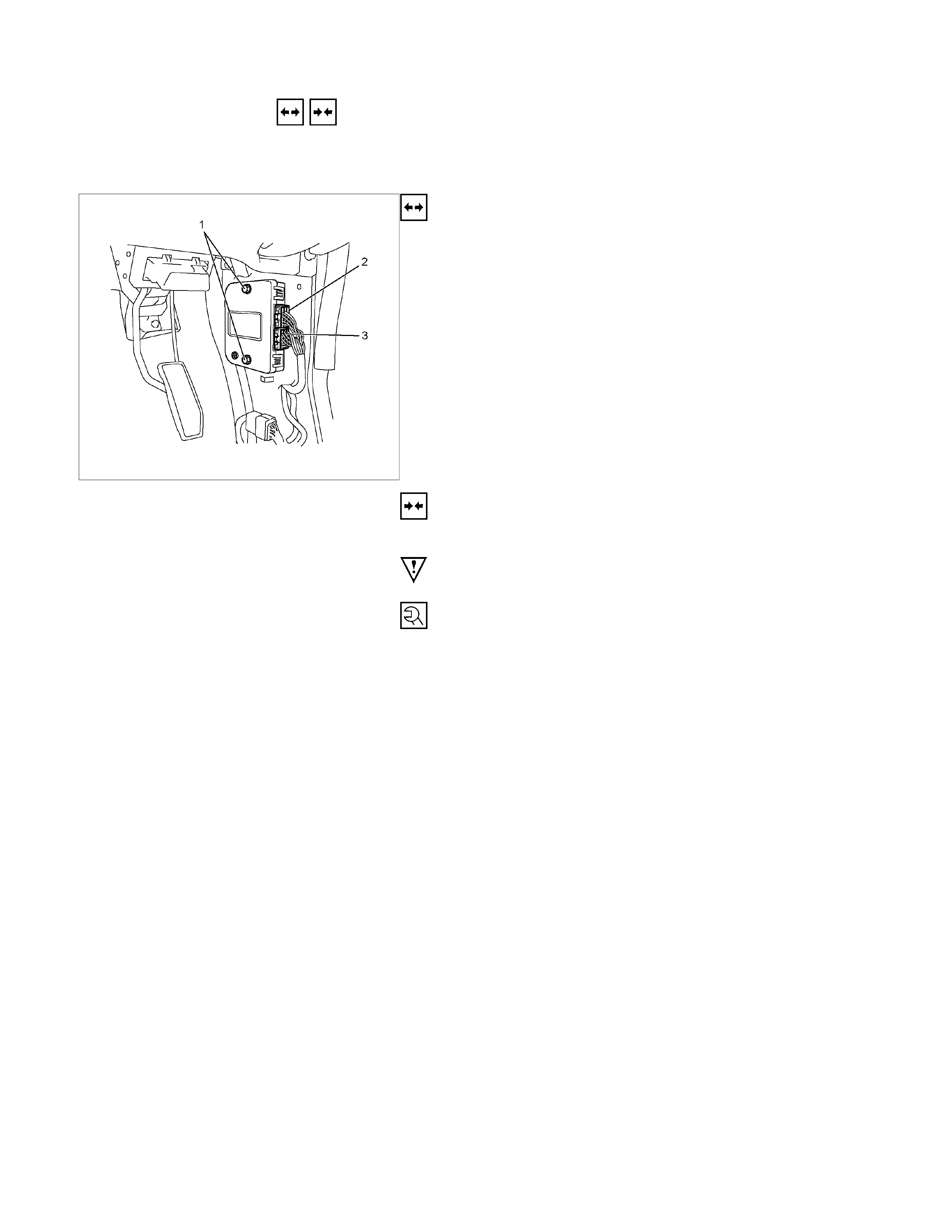
PIM (POWERTRAIN INTERFACE
MODULE):
RTW68ASH001201
Removal
1. Turn the ignition switch off.
2. Disconnect the battery.
3. Remove the sill plate and dash side trim cover. Refer to the
Section 10 CAB of this Manual.
4. Remove the bolt (1) and remove the PIM from vehicle
body.
5. Disconnect the PIM harness connector (2), (3).
Installation
Follow the removal procedure in the reverse order to install the
PIM.
Pay close attention to the important points mentioned in the
following paragraphs.
PIM attaching bolt
Torque: 10 N⋅m (1.0 kgf⋅m)
Connector
Be absolutely sure that PIM is securely connected.
This will prevent a poor contact and open circuit.
EXHAUST GAS RECALCULATION (EGR): 4JA1-L ONLY
PARTS LOCATION (RHD)
RTW48AXF0136 & RTW48AMF000101
PARTS LOCATION (RHD)
RTW48AXF013701

PARTS LOCATION (LHD)
RTW48AXF01381 & RTW48AMF000101
PARTS LOCATION (LHD)
RTW48AXF013901
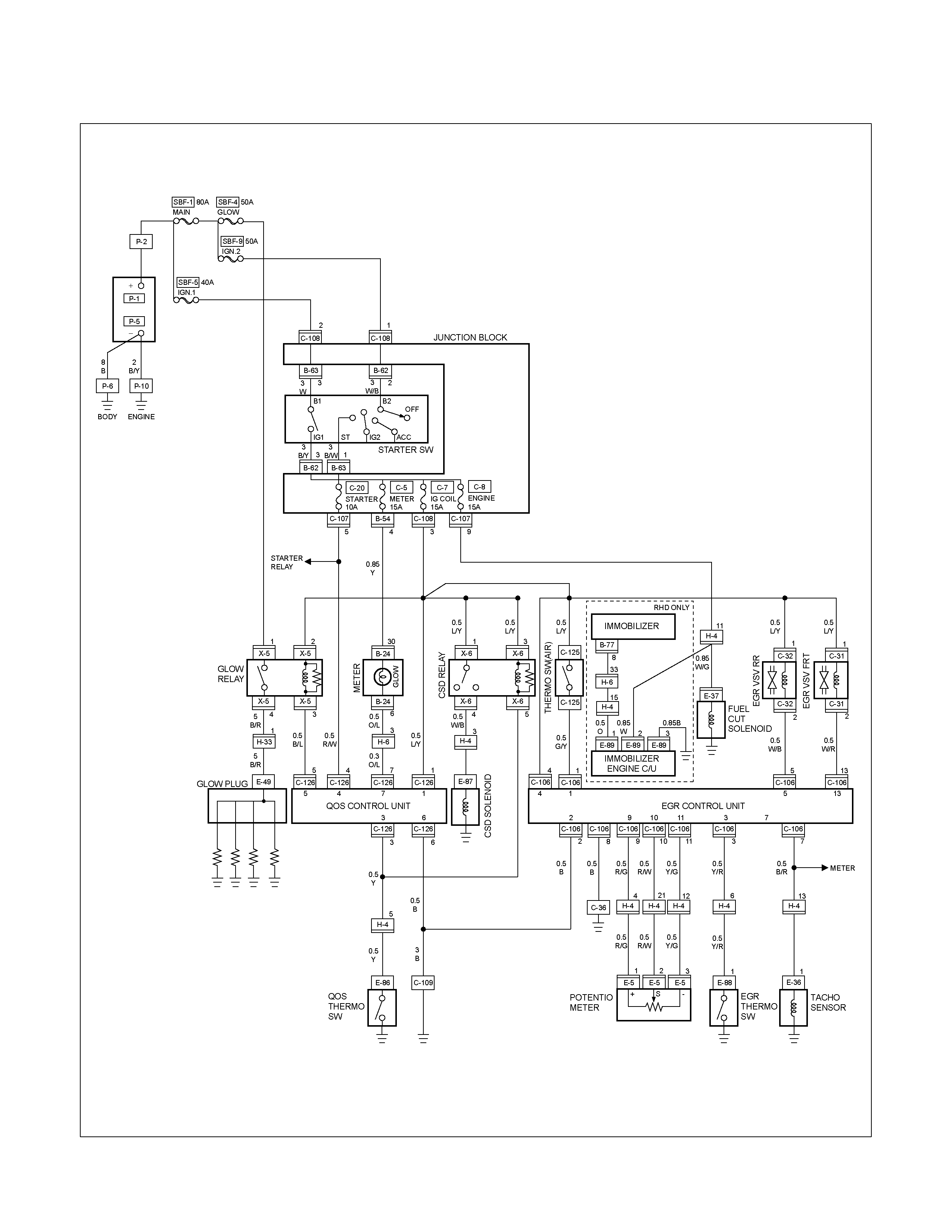
CIRCUIT DIAGRAM
RTW680XF006401
LIGHTING
PARTS LOCATION (RHD)
RTW68AXF014001 & RTW48AXF014601
PARTS LOCATION (LHD)
RTW48AXF014701 & RTW48AXF014801

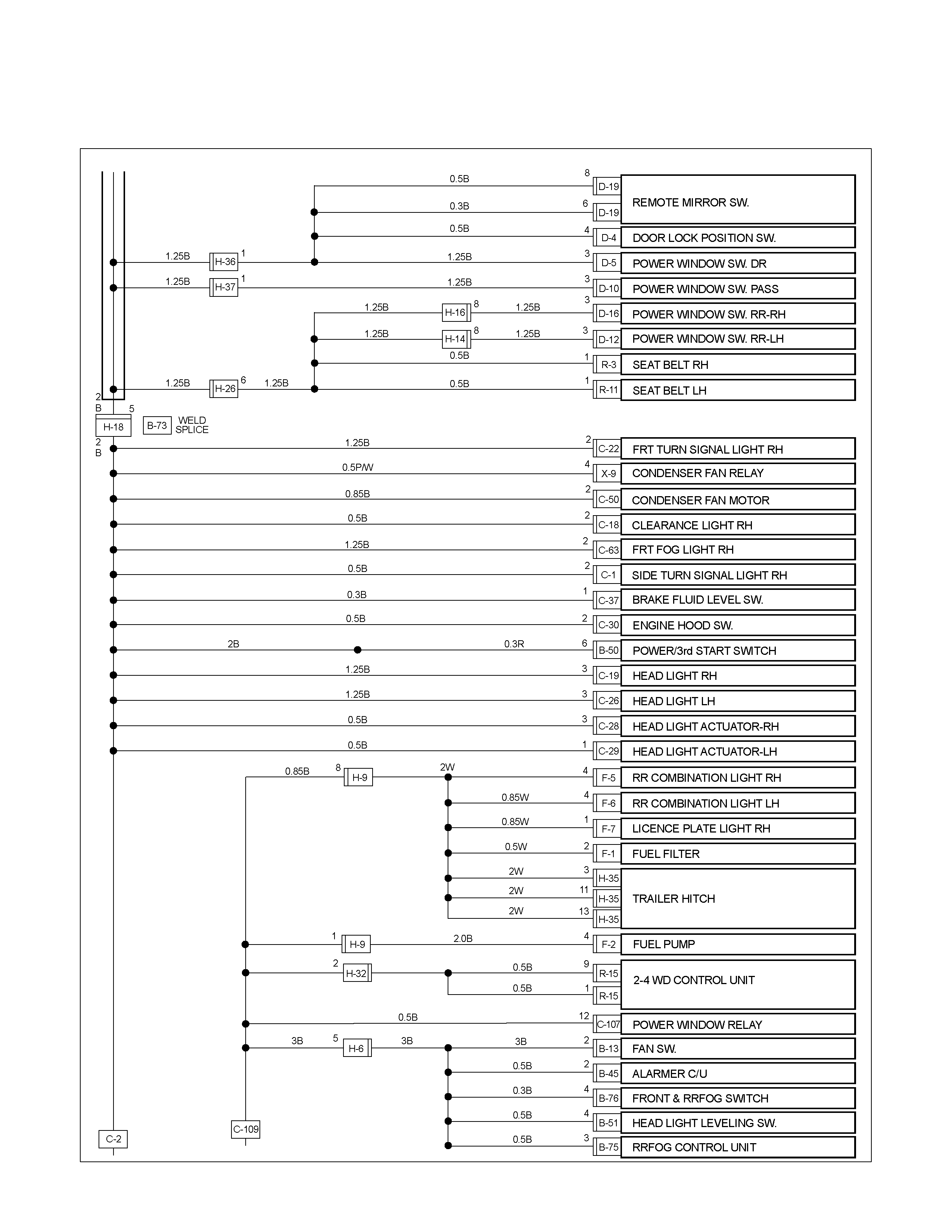
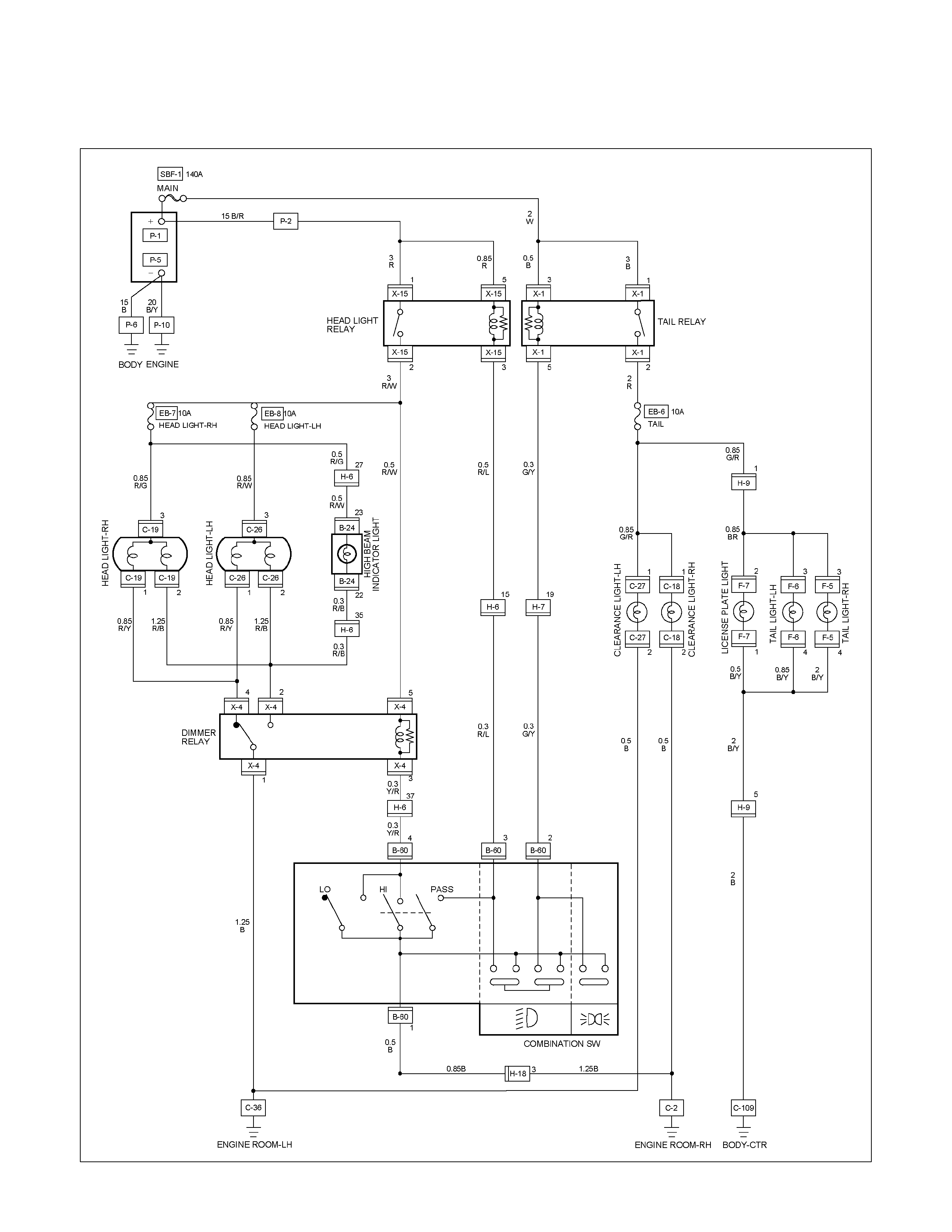
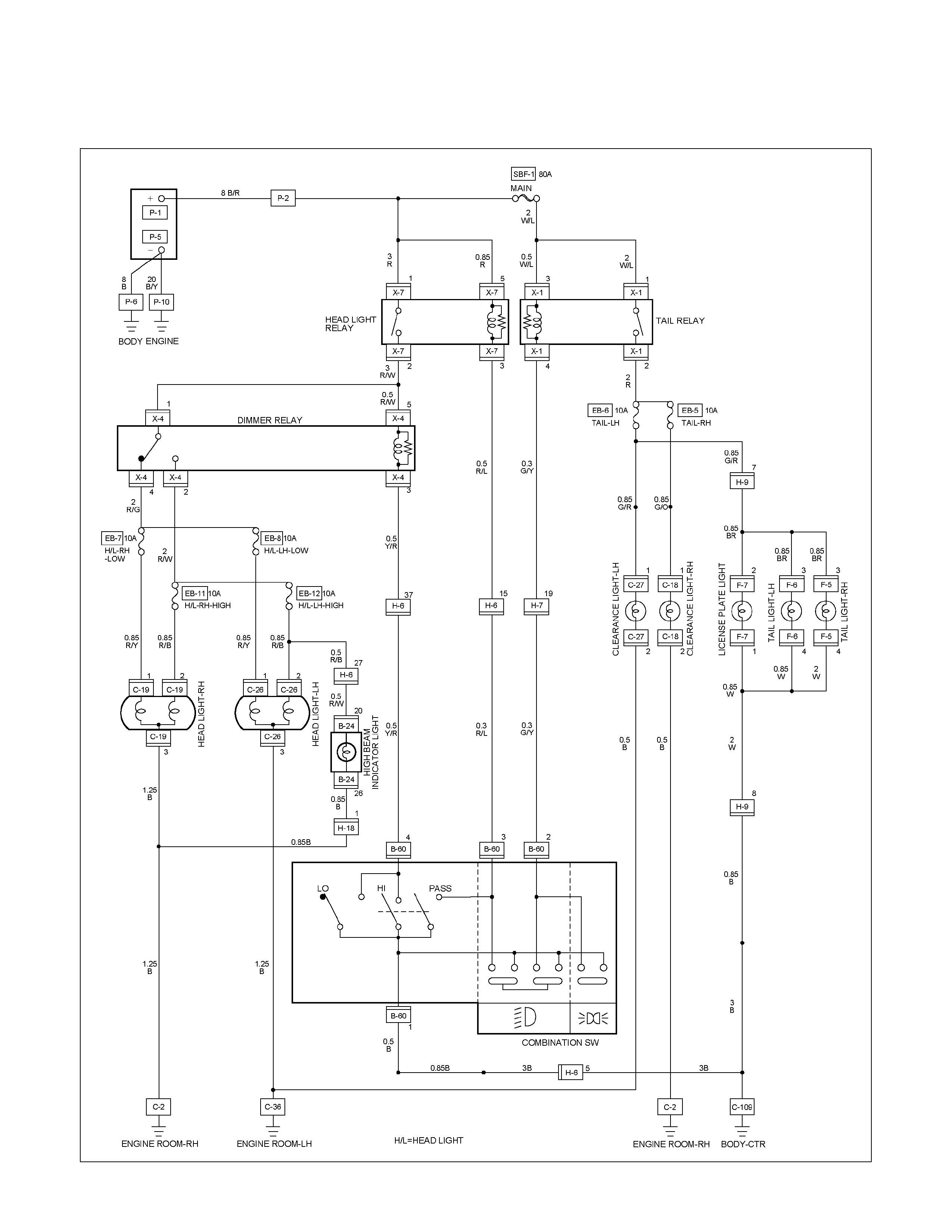
CIRCUIT DIAGRAM (RHD) WITHOUT EMISSION SYSTEM EURO3
RTW680XF006501
CIRCUIT DIAGRAM (RHD) HFV6 WITH EMISSION SYSTEM EURO3
RTW68AXF010601
CIRCUIT DIAGRAM (RHD) EXCEPT HFV6 WITH EMISSION SYSTEM EURO3
RTW680XF006601
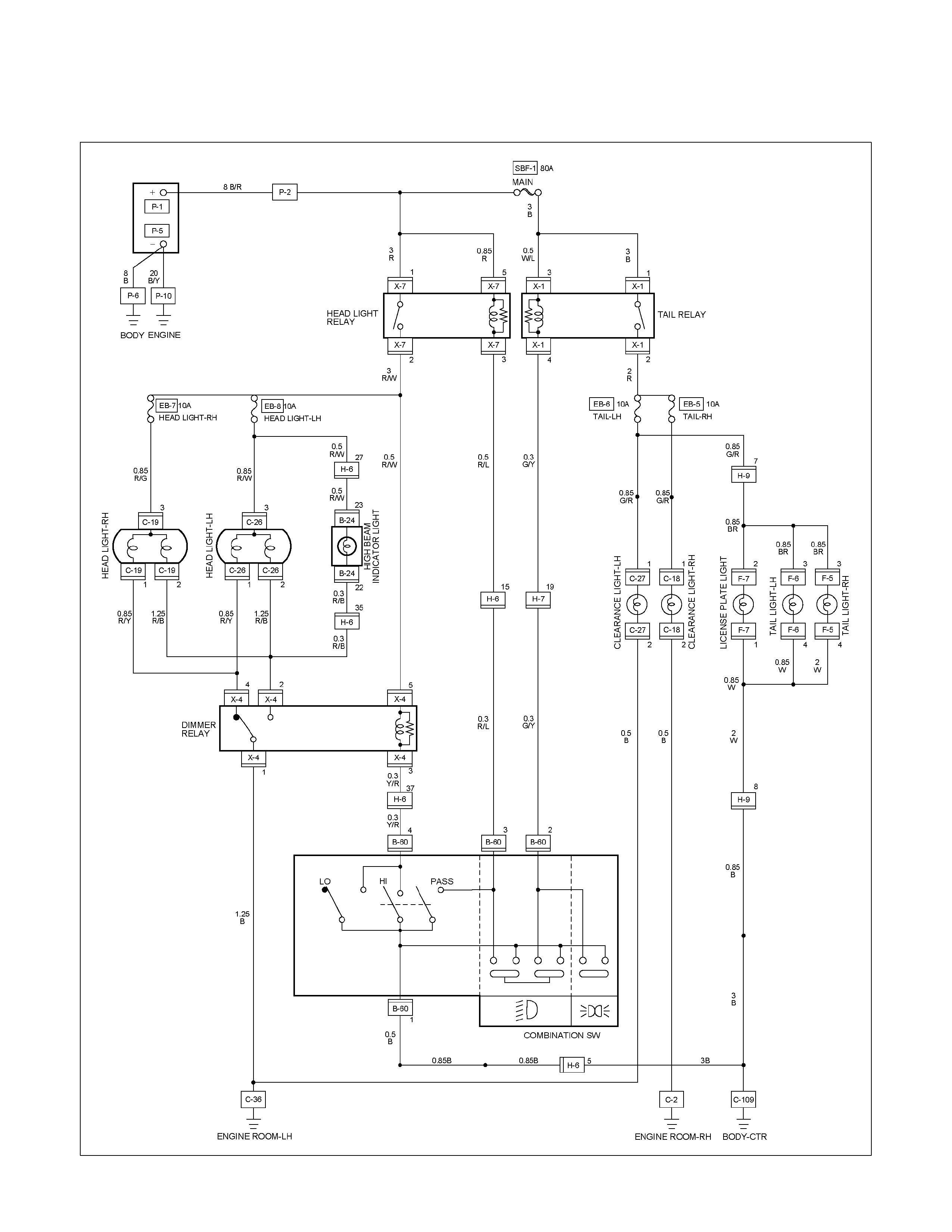
CIRCUIT DIAGRAM (LHD) WITHOUT HEADLIGHTS LEVELING
RTW680XF006701
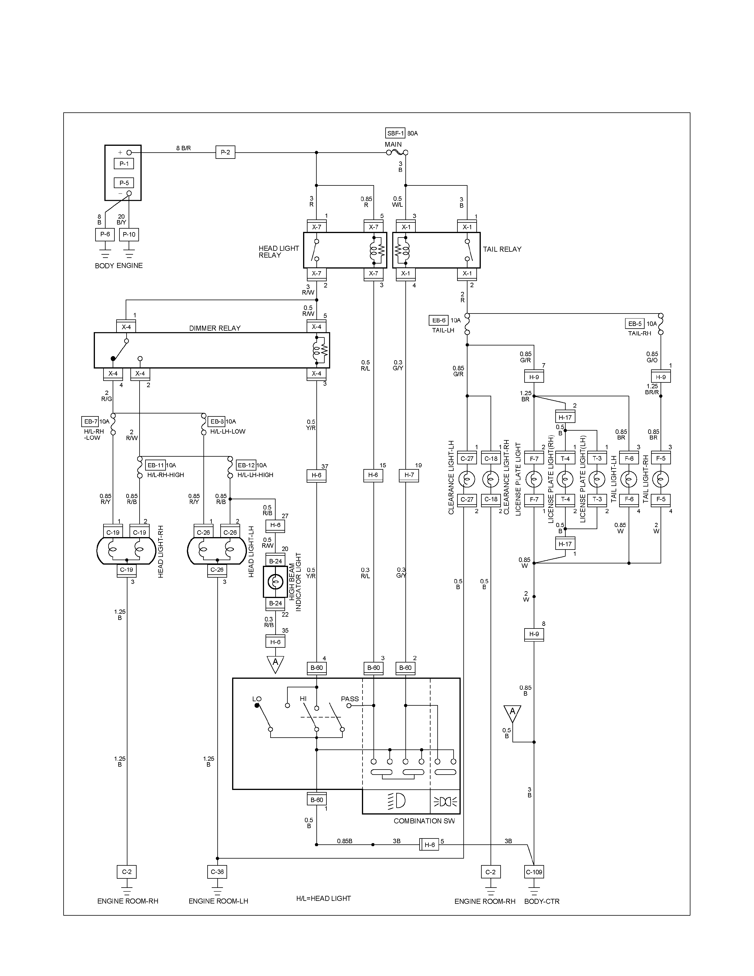
CIRCUIT DIAGRAM (LHD) WITH HEADLIGHTS LEVELING
RTW680XF006801

TROUBLE SHOOTING
HEADLIGHT
1. Both the headlights (high and low beam) do not light
Checkpoint Trouble Cause Countermeasure
Repair the wiring
Poor ground point contact
NG
Repair open circuit or
connector contact
Repair open circuit
Repair or replace the
combination switch
Voltage between 1 B-60 -
ground
Open circuit between lighting
relay and lighting switch
Open circuit between battery
positive terminal and lighting
relay
Combination switch continuity
Poor switch contact or sw
faulty
Voltage between
5 X-7 - ground and
1 X-7 - ground
Reinstall or replace the
lighting relay
Lighting relay
Poor relay contact or relay
faulty
NG
NG
NG
NG
OK
OK
OK
OK
Ground point contact (C-36)
Repair open circuit
Wiring continuity betw een
B-60 - C-36
Open circuit
NG
OK
∗
2. High or low beam does not light on both headlights
Checkpoint Trouble Cause Countermeasure
Repair or replace the
combination switch
Dimmer⋅passing switch
continuity
Poor switch contact or switch
faulty
NG
Repair open circuit or
connector contact
Voltage between
4 X-4 - ground and
4 B-60 - ground
Open circuit between
headlight and dimmer⋅passing
switch
NG
OK
3. RH (or LH) high and low beam does not light
Replace the headlight bulb
Headlight connector continuity
Blown filament or air leakage
NG
Repair or replace the wire
and/or connector
Wiring continuity betw een
connector 3 C-19 - fuse No.
EB-7 or 3 C-26 fuse No.
EB-8
Open circuit and/or poor
connector contact
NG
OK
Reinstall or replace fuse No.
EB-7 or No. EB-8
Fuse No. EB-7 (10A) or
No. EB-8 (10A) (Relay and
fuse box)
(No. EB-7 RH, No. EB-8: LH)
Poor installation or blown fuse
NG
OK
4. High or low beam does not light on one headlight (RH or LH)
Replace the headlight
assembly
Headlight connector continuity Blown filament
NG
Repair open circuit or
connector contact
Wiring continuity betw een
headlight and dimmer⋅passing
switch
Open circuit between
headlight and dimmer⋅passing
switch
NG
OK
5. Headlight does not go out
Checkpoint Trouble Cause Countermeasure
Replace the lighting relay
Lighting relay continuity
between connector 5 X-7
- 2 X-7 (Should be no
continuity)
Relay point fused
NG
Replay the combination switch
Lighting switch continuity
between connector 4 B-60
-1 B-60 when switch is
OFF(Should be no continuity)
point fused or faulty
NG
OK
OK
Repair or replace the
combination switch
Dimmer⋅passing switch con-
tinuity between connector
3 B-60 - 1 B-60 when switch
is not operating
(Should be no continuity)
Switch point fused or faulty
NG
Repair short circuit
between 3 X-7 - 3 B-60
and 4 X-1 - 2 B-60
Check if headlight goes out
when connector C-36 is
disconnected
Short circuit
NG
OK
∗
∗
6. Insufficient headlight brightness
Replace the headlight bulb
Headlight bulb
Bulb filament faulty
NG
Repair the wiring
Dimmer⋅passing switch
Wire continuity between con-
nector 1 B-60 - C-36
Poor ground point contact
NG
OK
Clean the light lens
Headlight lens
Lens dirty
NG
OK
7. Passing light does not function when dimmer switch is operated
Checkpoint Trouble Cause Countermeasure
Repair or replace the dimmer
switch
Dimmer switch
Poor switch point contact
NG
Repair open circuit between
3 X-7 - 3 B-60
Voltage between
3 B-60 - ground (Should
be battery voltage present)
Open circuit
NG
OK ∗
8. Headlight beam does not change when dimmer switch is operated
Repair or replace the dimmer
switch
Dimmer switch Loose beam lever or foreign
material in switch
NG
TAIL LIGHT, LICENSE PLATE LIGHT, CLEARANCE LIGHT
1. All lights do not light
Checkpoint Trouble Cause Countermeasure
Repair or replace the
combination switch
Lighting switch continuity
between connector
2 B-60 - 1 B-60
Poor switch point or connector
contact
NG
Reinstall or replace the tail
relay
Tail relay
Poor relay contact or relay
faulty
NG
OK
Reinstall or replace the fuse
No. EB-6 (LH), EB-5 (RH)
Fuse No. EB-6 (LH) or EB-5
(RH) (10A, Relay and fuse
box)
Poor fuse contact or blown
NG
OK
2. Tail light does not light
Replace the bulb or repair
connector contact
Tail light bulb continuity
Bulb burned out or poor
connector contact
NG
Repair open circuit or
connector contact
Continuity between connector
3 F-5 - 4 F-5 (RH)
or 3 F-6 - 4 F-6 (LH)
Open circuit or poor connector
contact
NG
OK
3. License plate light does not light
Checkpoint Trouble Cause Countermeasure
Repair open circuit or
connector contact
Continuity between
connector 1 F-7 - 2 F-7 or 1
T-4 - 2
T-4 / 1
T-3 - 2
T-3
(
LHD HEADLIGHTS LEVELING
)
Open circuit or poor connector
contact
NG
Replace the bulb or repair
connector contact
License plate light bulb
continuity
Bulb burned out or poor
connector contact
NG
OK
4. Clearance light does not light
Replace the bulb or repair
connector contact
Clearance light bulb continuity Bulb burned out or poor
connector contact
NG
LIGHTING SYSTEM
REMOVAL AND INSTALLATION
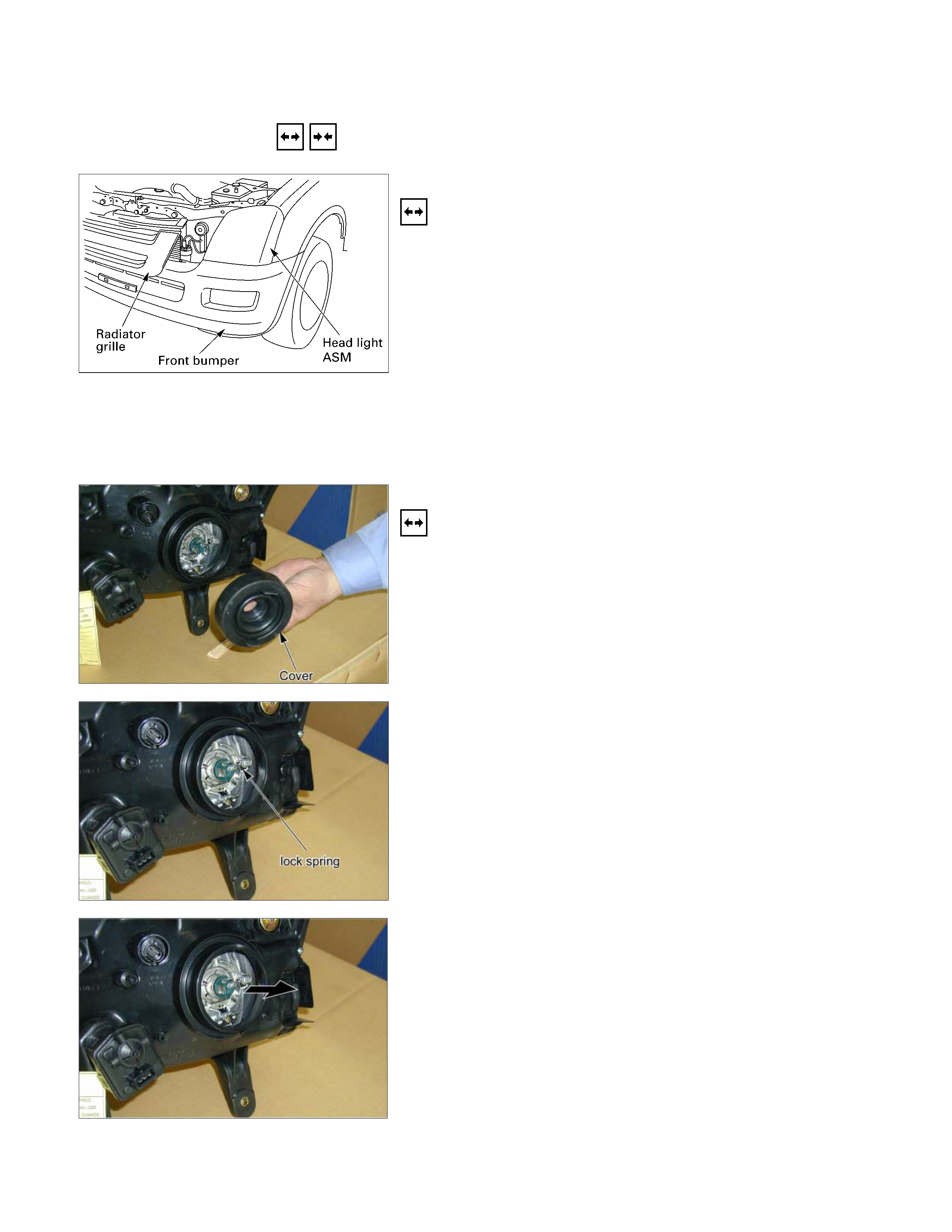
HEADLIGHT
Removal
1. Remove the radiator grille center bolt.
2. Use a screwdriver to raise the clip and release the lock.
Place a clean rag beneath the screwdriver tip to protect the
body painted surfaces.
3. Remove the radiator grille.
4. Remove the front bumper.
5. Disconnect the headlight connector.
6. Remove the headlight assembly.
7. Remove the headlight cover.
• Remove the guide.
8. Remove the headlight.
HALOGEN HEADLIGHT
Removal
1. Remove the head light socket.
2. Remove the headlight cover.
3. Out side the lock spring.
4. Remove the bulb.
Installation
Follow the removal procedure in the reverse order to install the
headlight.
Pay close attention to the important points mentioned in the
following paragraphs.
Connector
Be absolutely sure that the headlight connector is securely
connected.
This will prevent a contact and an open circuit.
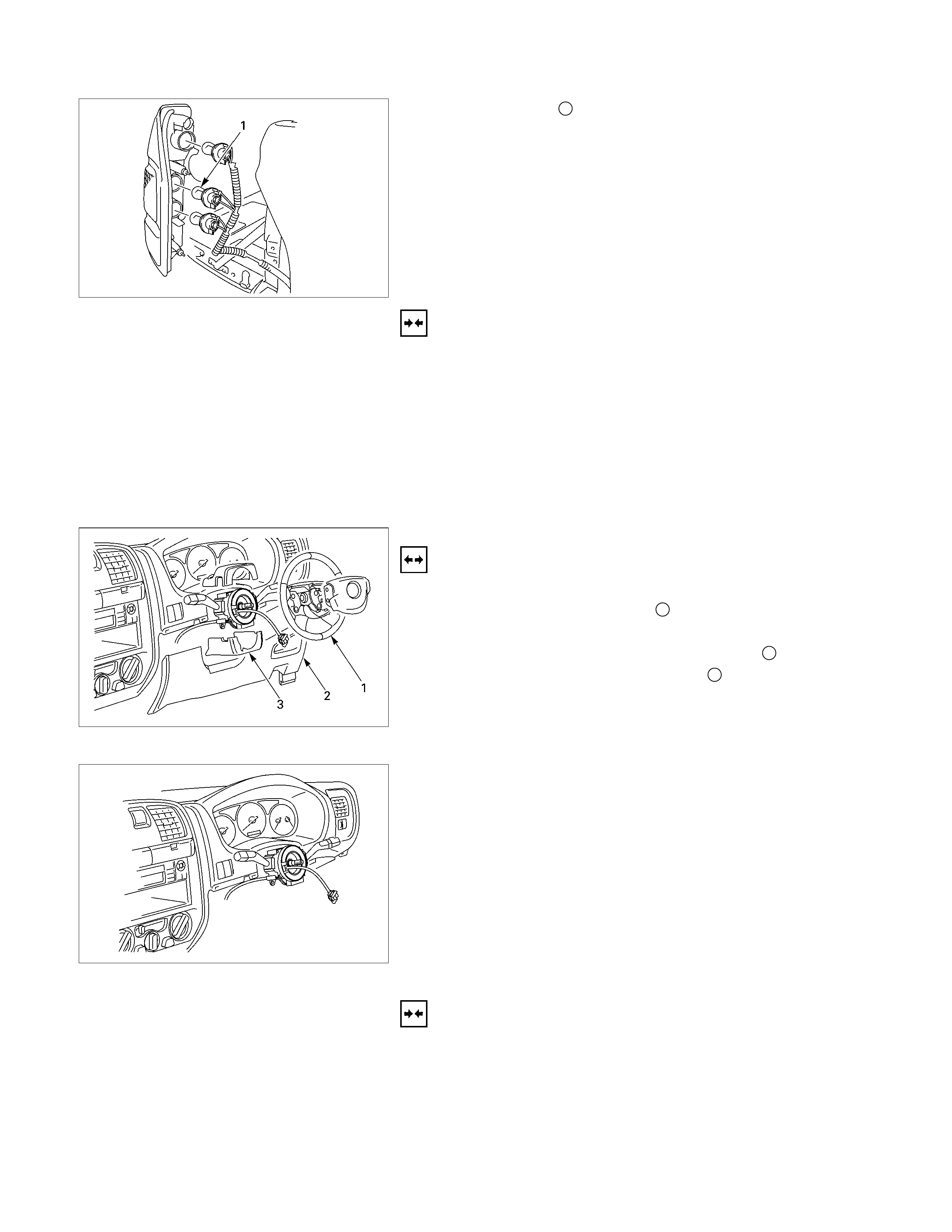
This illustration is based on RHD model
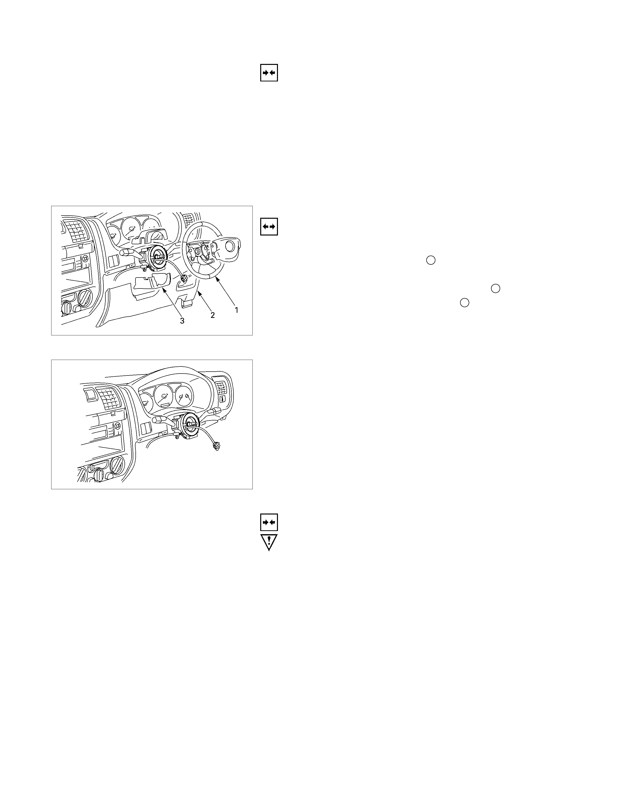
LIGHTING SWITCH
Removal
1. Disconnect the battery ground cable.
2. Remove the steering wheel 1.
Refer to the “STEERING” Section of this manual.
3. Remove the Instrument panel lower cover 2.
4. Remove the steering column cover 3.
This illustration is based on RHD model
5. Disconnect the connector.
6. Remove the lighting switch from the steering shaft.
Installation
Follow the removal procedure in the reverse order to install the
lighting switch.
Pay close attention to the important points mentioned in the
following paragraphs.
Connector
Be absolutely sure that the lighting switch connector is
securely connected.
This will prevent a poor contact and an open circuit.
Wire Harness
Do not pinch the wire harnesses between the cluster and the
meter hood during the cluster installation procedure.
Wire damage will result.

FRONT TURN LIGHT
Removal
RTW38DSH000601
1. Turn the socket counterclockwise to disconnect it from the
front turn light housing.
2. Pull the bulb from the socket.
Installation
Follow the removal procedure in the reverse order to install the
front turn light.
Pay close attention to the important points mentioned in the
following paragraphs.
Connector
Be absolutely sure that the clearance light connector is
securely connected.
This will prevent a poor contact and an open circuit.
CLEARANCE LIGHT
Removal
RTW38DSH000601
1. Turn the socket counterclockwise to disconnect it from the
clearance light housing.
2. Pull the bulb from the socket.
Installation
Follow the removal procedure in the reverse order to install the
clearance light.
Pay close attention to the important points mentioned in the
following paragraphs.
Connector
Be absolutely sure that the clearance light connector is
securely connected.
This will prevent a poor contact and an open circuit.
LICENSE PLATE LIGHT
Removal
1. Remove the lens cover 1 and the connector 2.
2. Pull the bulb 3 to remove it.
Installation
Follow the removal procedure in the reverse order to install the
license plate light.
Pay close attention to the important points mentioned in the
following paragraphs.
Bulb
Be absolutely sure that the license plate light bulb is correctly
installed.
This will prevent a poor contact and open circuit.
HEADLIGHT BEAM SWITCH
(COMBINATION SWITCH)
Removal
1. Disconnect the battery ground cable.
2. Remove the screws on the lower part of the steering wheel.
3. Remove the horn pad.
4. Remove the wiring connector.
5. Remove the steering wheel fixing nuts.
6. Remove the steering wheel.
Refer to the "STEERING" Section of this manual.
7. Remove the Instrument panel lower cover.
8. Remove the steering column cover.
9. Disconnect the connector.
10. Remove the headlight beam switch (lever) from the
steering shaft (combination switch).
Installation
Follow the removal procedure in the reverse order to install the
headlight beam switch (lever).
Pay close attention to the important points mentioned in the
following paragraphs.
Connector
Be absolutely sure that the headlight beam switch connector is
securely connected.
This will prevent a poor contact and an open circuit.

Wire Harness
Do not pinch the wire harnesses between the cluster and the
meter hood during the cluster installation procedure.
Wire damage will result.
AIMING OF HEADLIGHT
Before adjusting the headlights, park the vehicle on a level
surface. Remove any cargo from the vehicle to bring it to curb
weight. Check the tire inflation pressures and correct as
required. Clean the headlight lenses.
Without Head light Leveling
RTW48DMH000101
With Head light Leveling
RTW48DMH000301
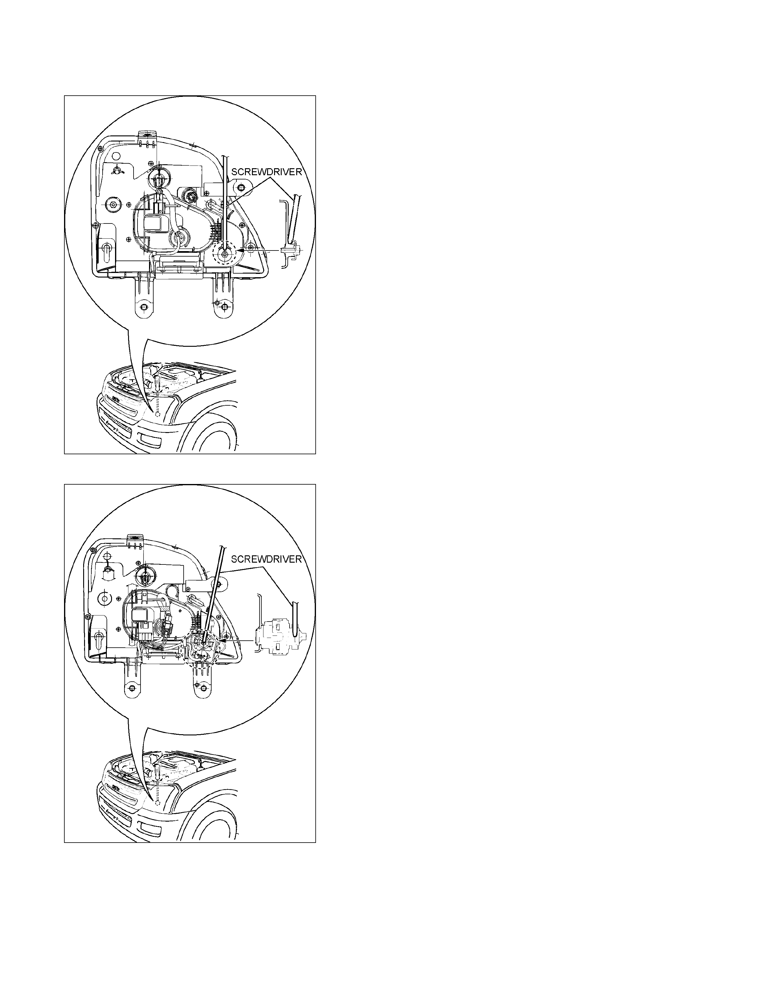
VERTICAL ADJUSTMENT
Use a Phillips-head screwdriver with a long shaft. Hold the
screwdriver straight up-and-down as shown in the illustration.
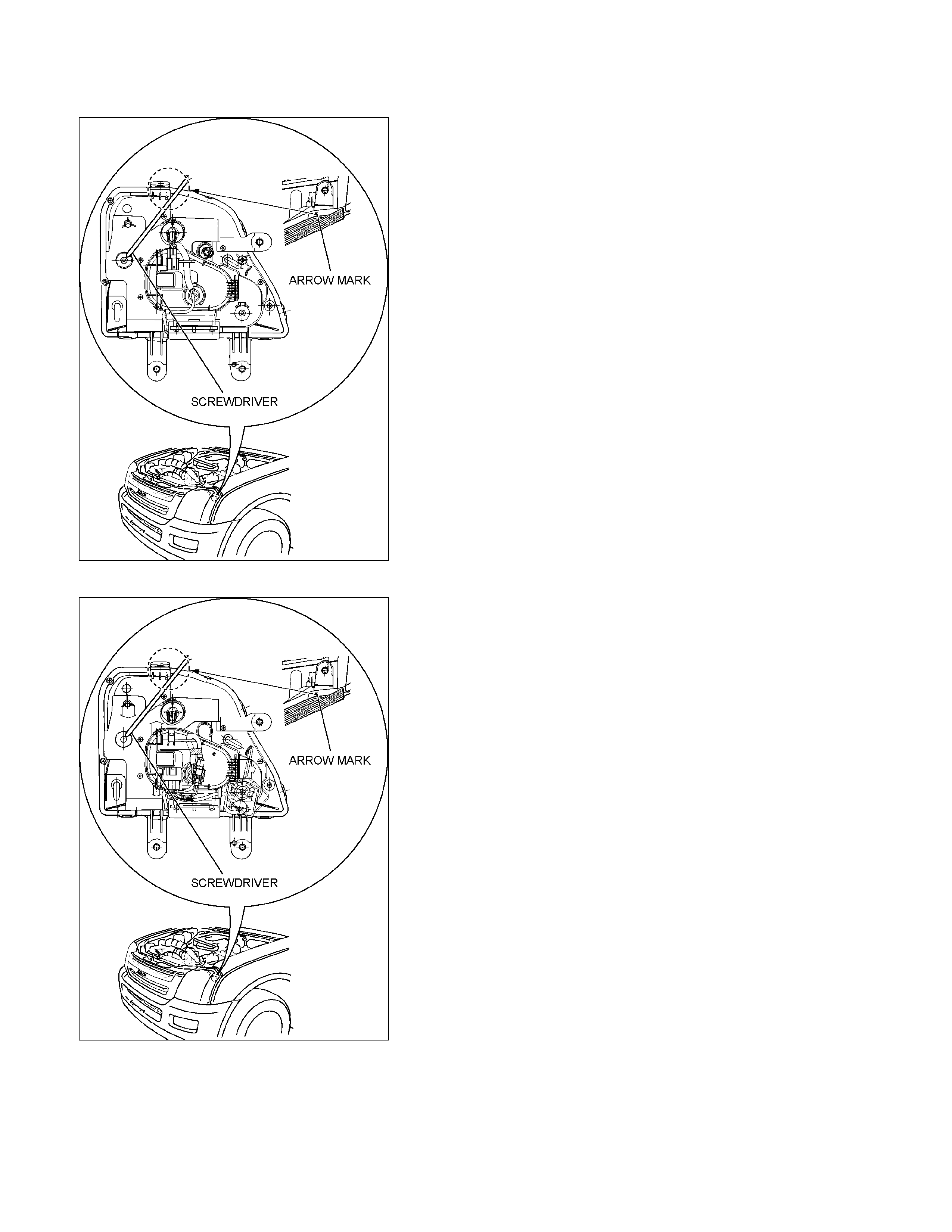
Without Head light Leveling
RTW48DMH000201
With Head light Leveling
RTW48DMH000401
HORIZONTAL ADJUSTMENT
Use a Phillips-head screwdriver with a long shaft. Hold the
screwdriver at an angle as shown by the arrow in the
illustration.
Installation
To install, follow the removal steps in the reverse order.
Noting the following point:
1. After installing the headlight, be sure to adjust the headlight
aim.
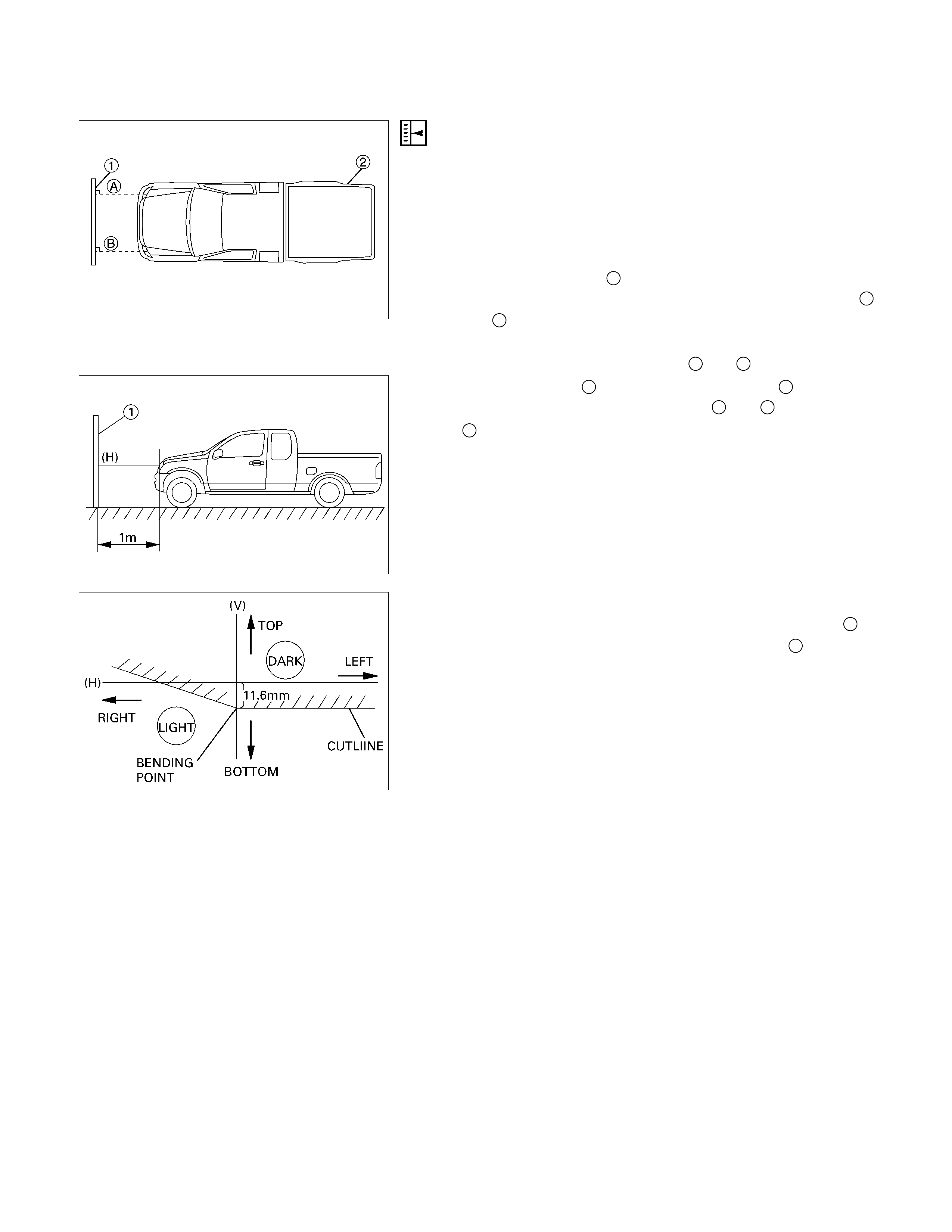
HEADLIGHT ADJUSTMENT
Preparation
Place the vehicle with 1 person in driver seat on a level
surface and check to see if the inflation pressure of the tires is
correct, the lenses are clean, the battery is sufficiently
charged, and adjust to place vehicle by using the screen.
1. Set a vertical screen on a level surface.
2. Toward the screen 1from the bulb center mark of the
headlight, extend parallel lines to the floor. Mark point A
and B on the screen at the intersection of parallel line and
the screen.
3. Draw vertical lines through point A and B on the screen.
4. Keep the vehicle 2 1m apart from the screen 1.
5. Draw a horizontal line through point A and Bon the screen
1.
6. Turn the headlight low beam on.
7. Adjust the CUTLINE 11.6 mm below the horizontal line H.
8. Adjust the BENDING POINT to the vertical line V.
NOTE:
Always adjust vertical adjustment first.
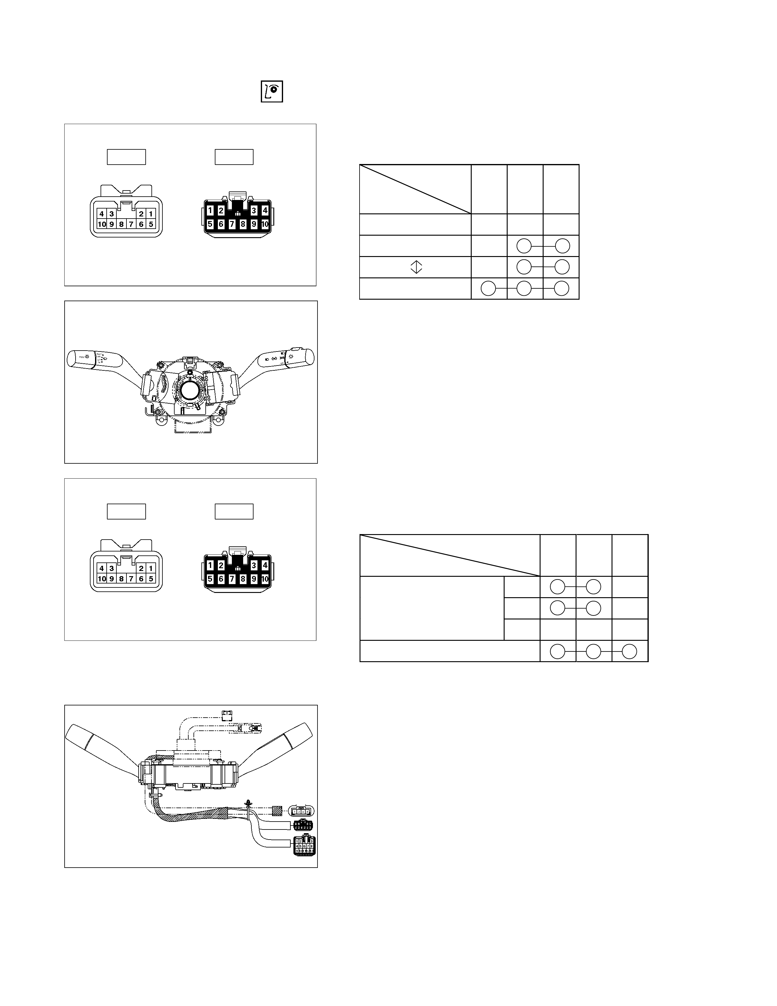
INSPECTION AND REPAIR
Switch side Harness side
B-60 B-60
LIGHTING SWITCH
Lighting Switch Connections
Terminal
SW No.
position 3 2 1
OFF
Tail
Headlight
Switch side Harness side
B-60 B-60
HEADLIGHT BEAM SWITCH
Headlight Beam and Passing Switch
Connections
Terminal NO.
SW position 1 4
HI
At “Dimmer” position
LO
At “Passing” Position
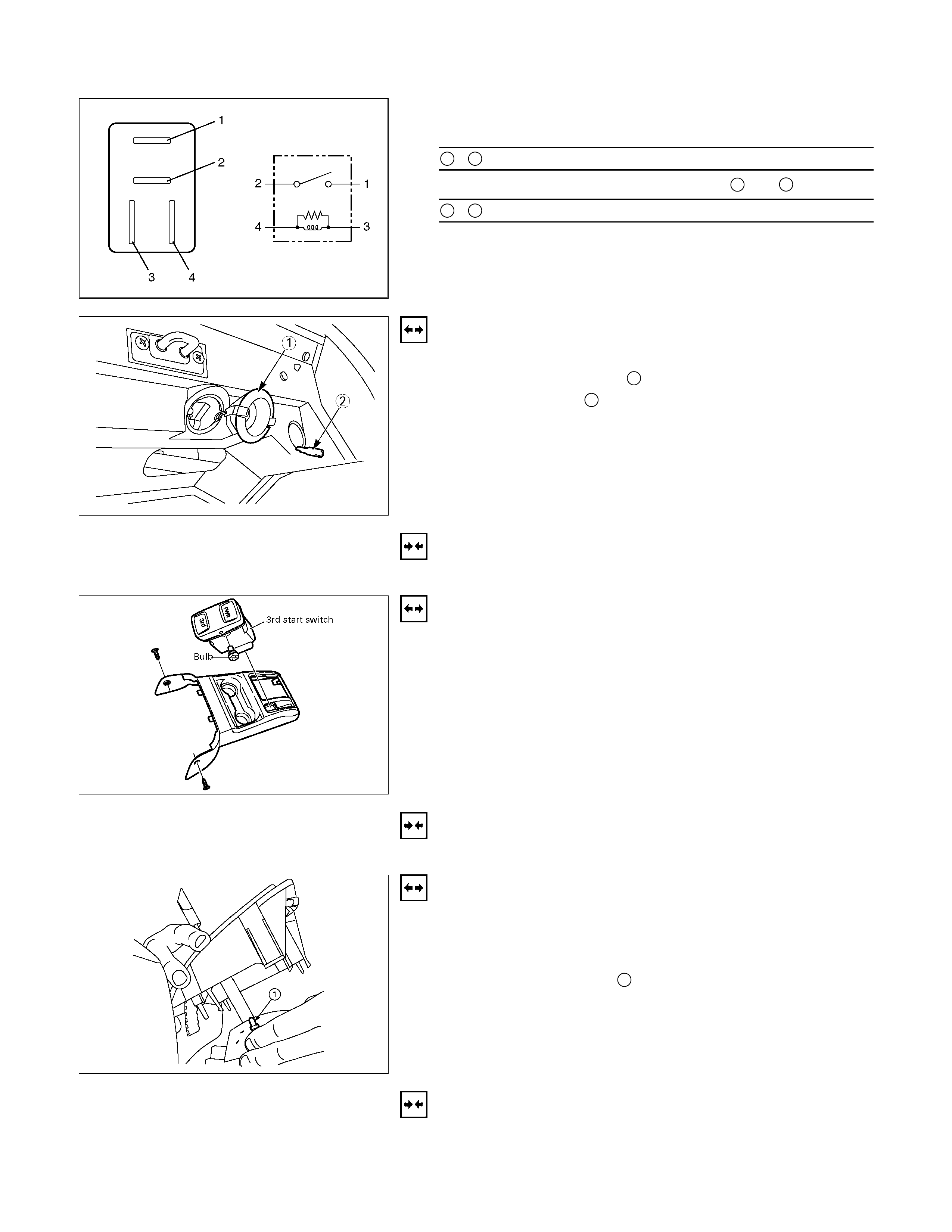
LIGHTING RELAY, TAIL RELAY
Check continuity between the relay terminals.
2 - 1............................ No continuity
(When battery voltage is applied between 3 and 4)
2 - 1............................ Continuity
GLOVE BOX ILLUMINATION
Removal
1. Remove the bulb cover 1.
2. Remove the bulb 2.
Installation
To install, follow the removal steps in the reverse order.
POWER/3rd START SW
Removal
• Refer to the “Front consol” Section 10 of this manual.
1. Disconnect the battery ground cable.
2. Remove the power/3rd start switch.
3. Remove the bulb.
Installation
To install, follow the removal steps in the reverse order.
A/T LEVER LIGHT BULB
Removal
• Refer to the “Front consol” Section 10 of this manual.
1. Remove the A/T lever cover.
2. Remove the light bulb 1.
Installation
To install, follow the removal steps in the reverse order.
FRONT FOG LIGHT
PARTS LOCATION (RHD)
RTW68AXF014101 & RTW68AXF014201
PARTS LOCATION (LHD)
RTW48AXF015201 & RTW48AXF015301
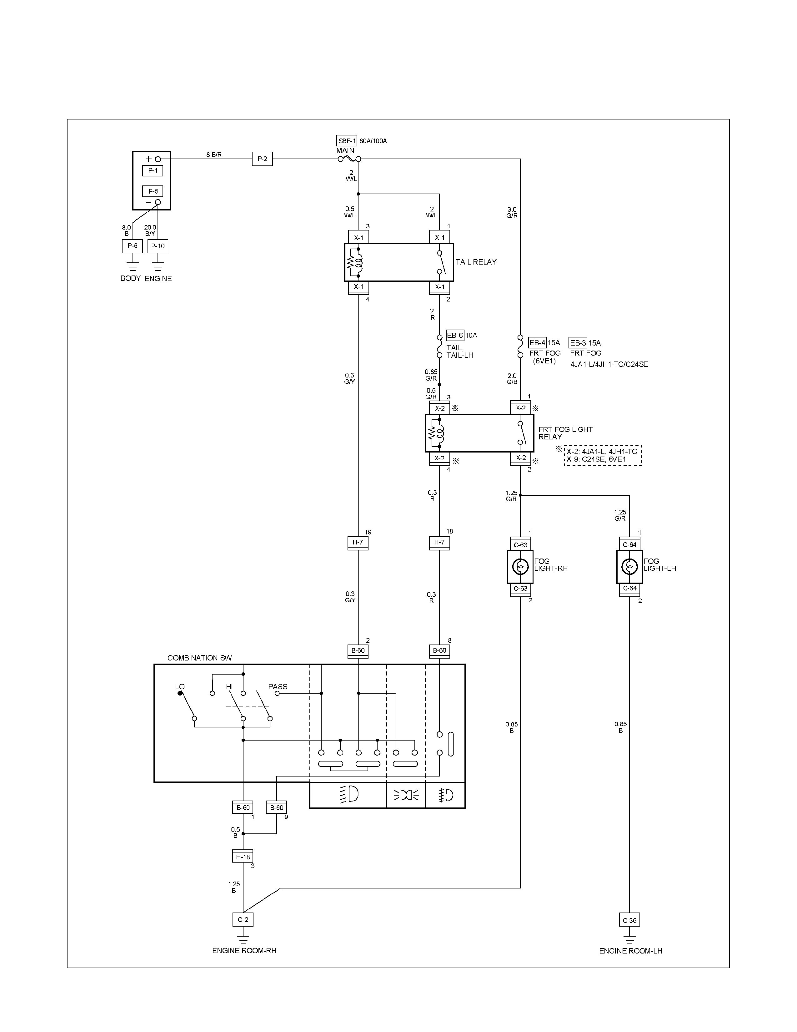
CIRCUIT DIAGRAM (RHD) EXCEPT HFV6 WITHOUT REAR FOG LIGHT
RTW680XF006901
CIRCUIT DIAGRAM (RHD) HFV6 WITHOUT REAR FOG LIGHT
RTW68AXF010701
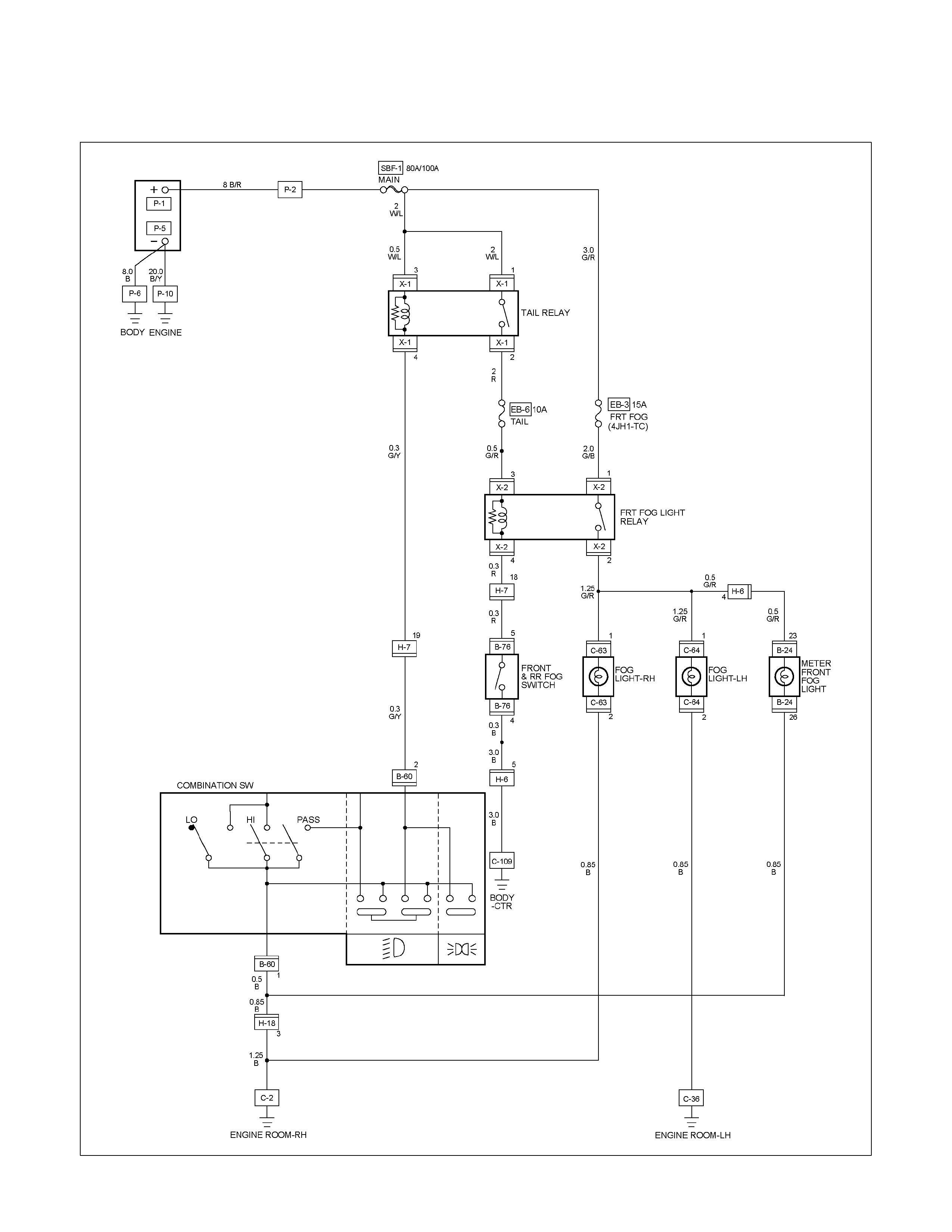
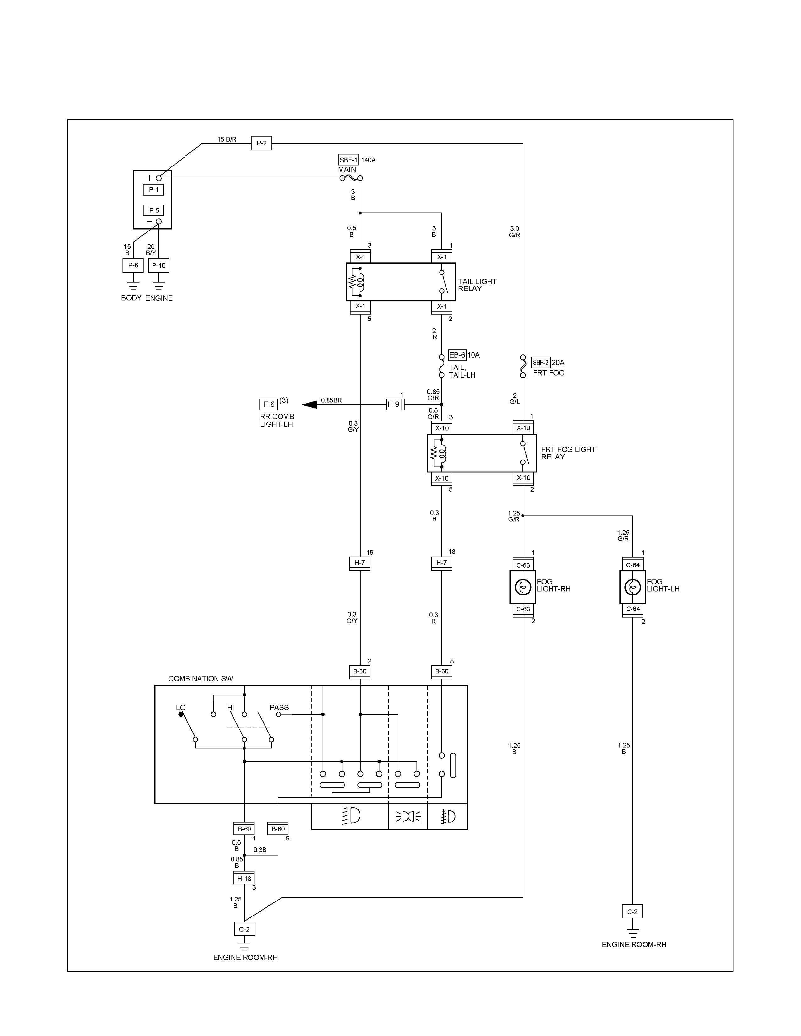
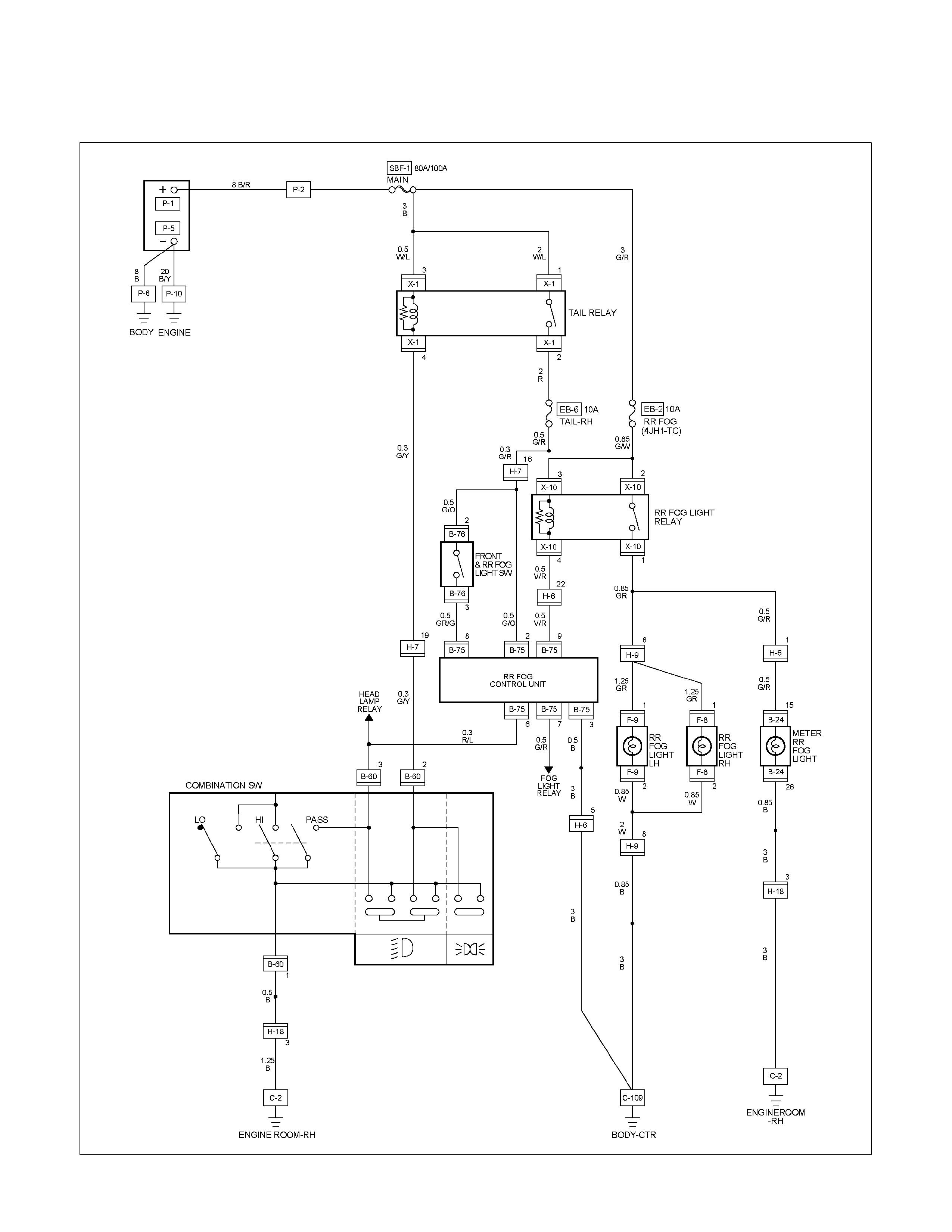
CIRCUIT DIAGRAM (RHD) WITH REAR FOG LIGHT
RTW680XF007001
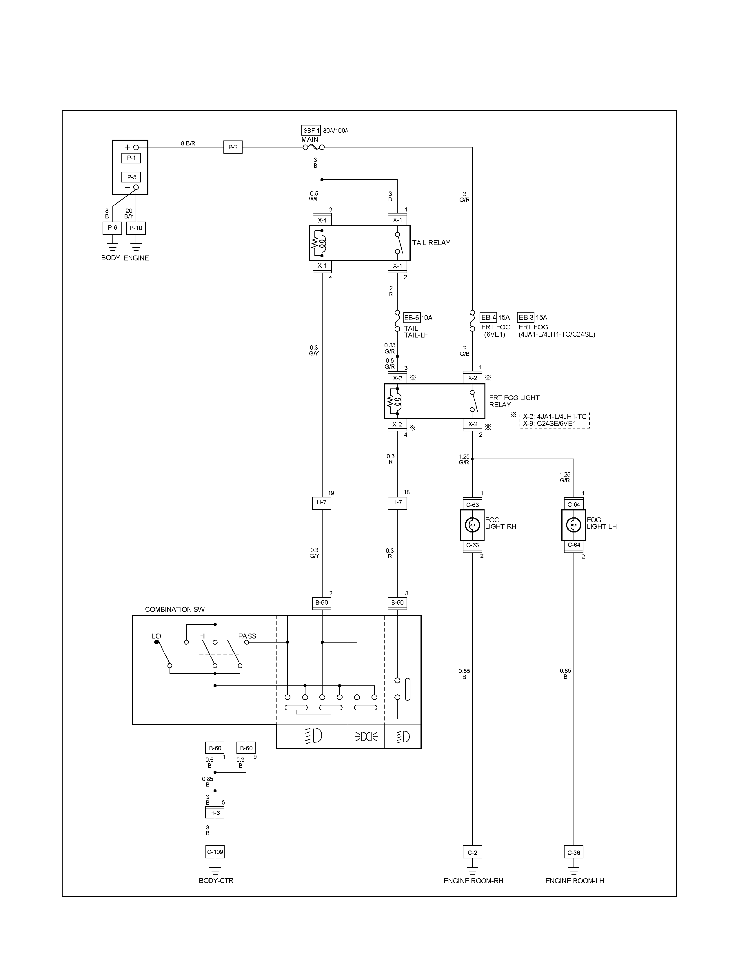
CIRCUIT DIAGRAM (LHD) WITHOUT REAR FOG LIGHT
RTW680XF007101

CIRCUIT DIAGRAM (LHD) WITH REAR FOG LIGHT
RTW680XF007201
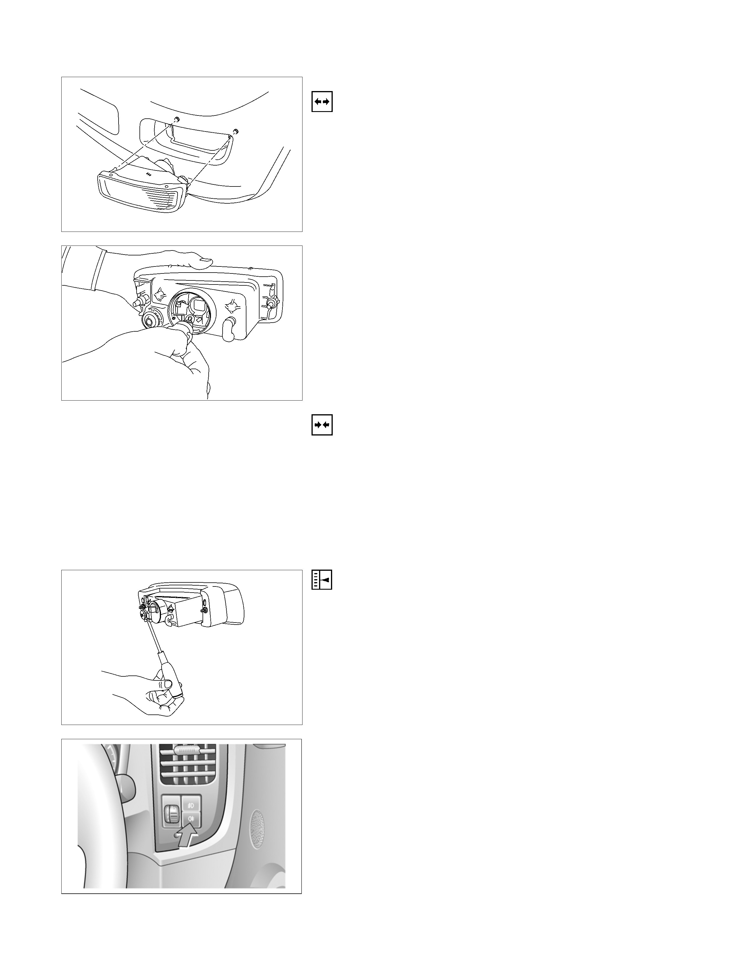
FRONT FOG LIGHT
Removal
1. Remove the radiator grille.
2. Remove the front bumper
3. Disconnect the fog light connector.
4. Remove the fog light.
5. Remove the bulb from the socket.
• Remove the socket by turning it counterclockwise.
Installation
Follow the removal procedure in the reverse order to install the
fog light.
Pay close attention to the important points mentioned in the
following paragraphs.
Bulb
Be absolutely sure that the fog light bulb is correctly installed.
This will prevent a poor contact and open circuit.
FRONT FOG LIGHT ADJUSTMENT
Vertical Adjustment
Turn the adjusting screw (1) with a screwdriver to adjust the
aim of the fog light vertically.
RTU4Z0SH000601
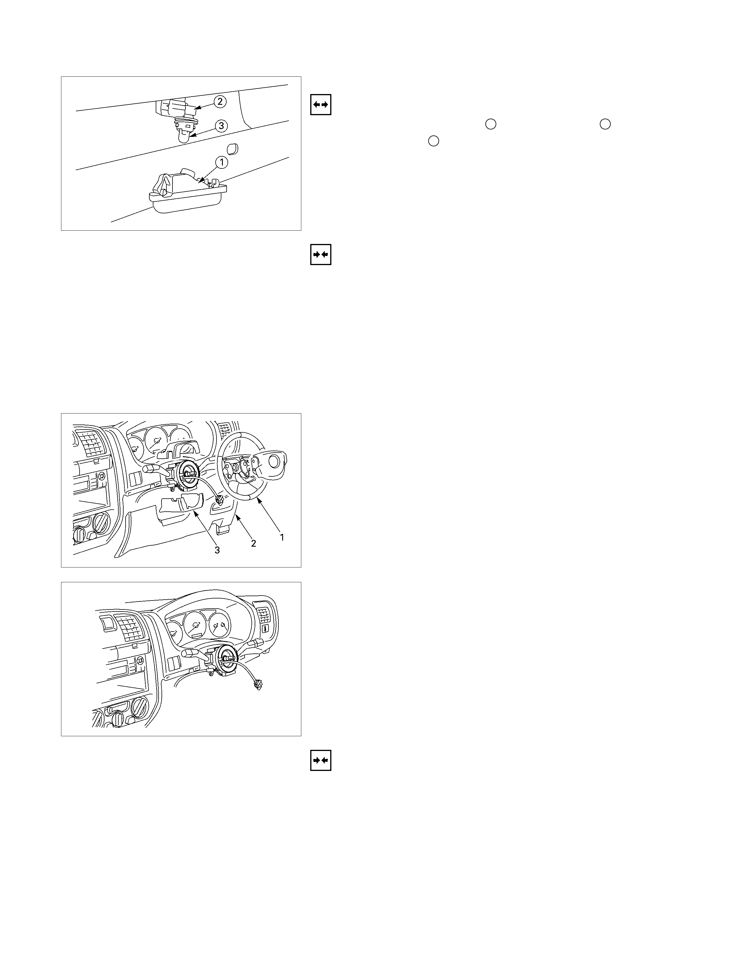
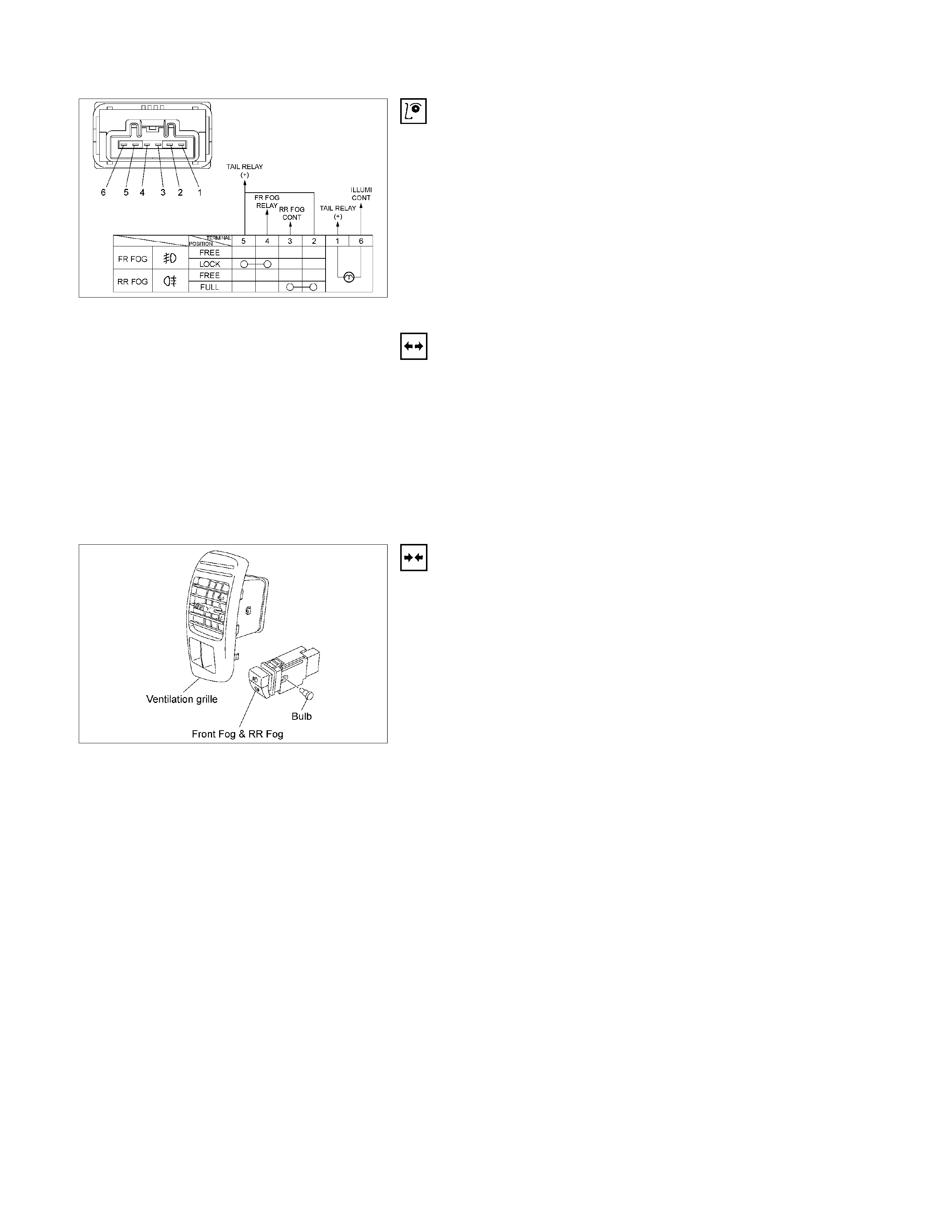
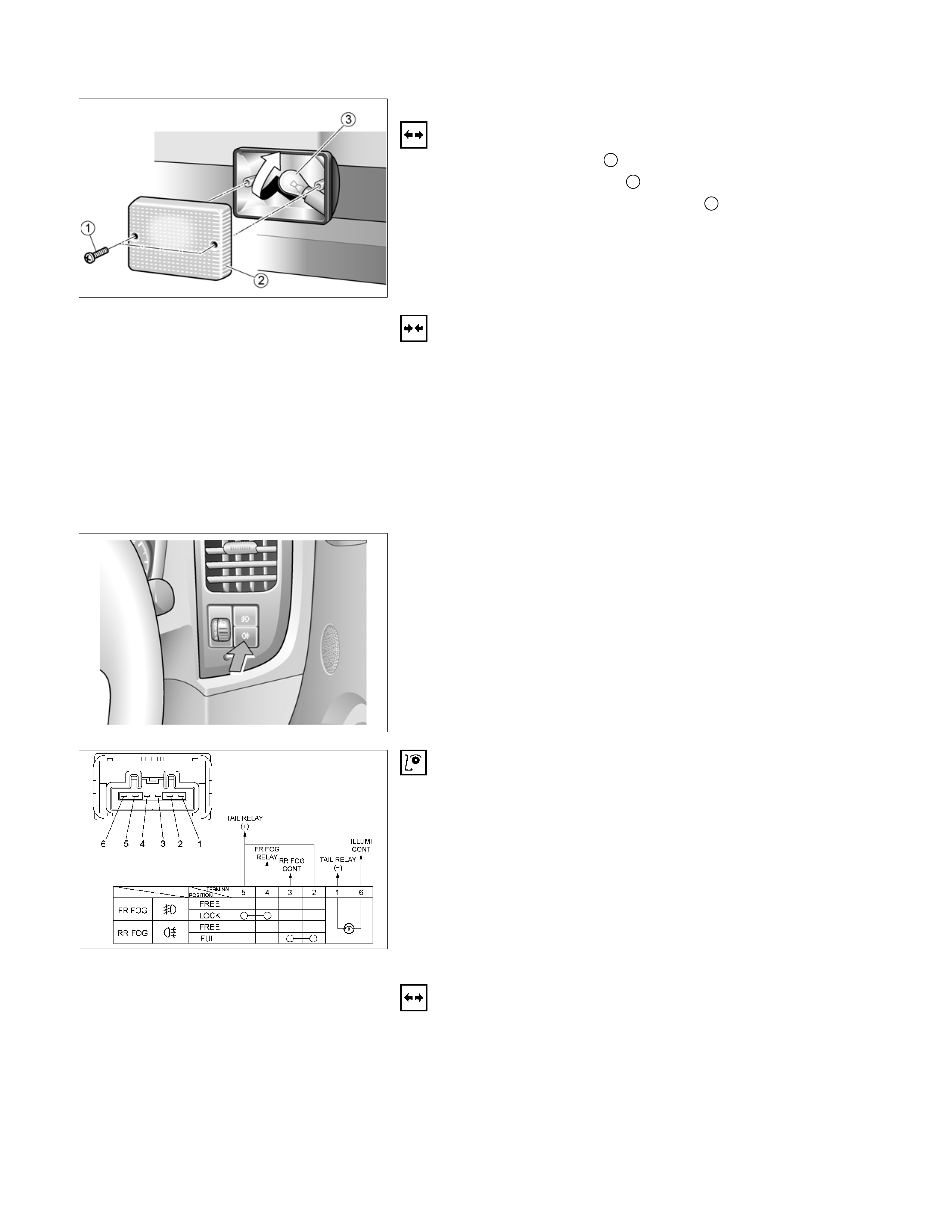
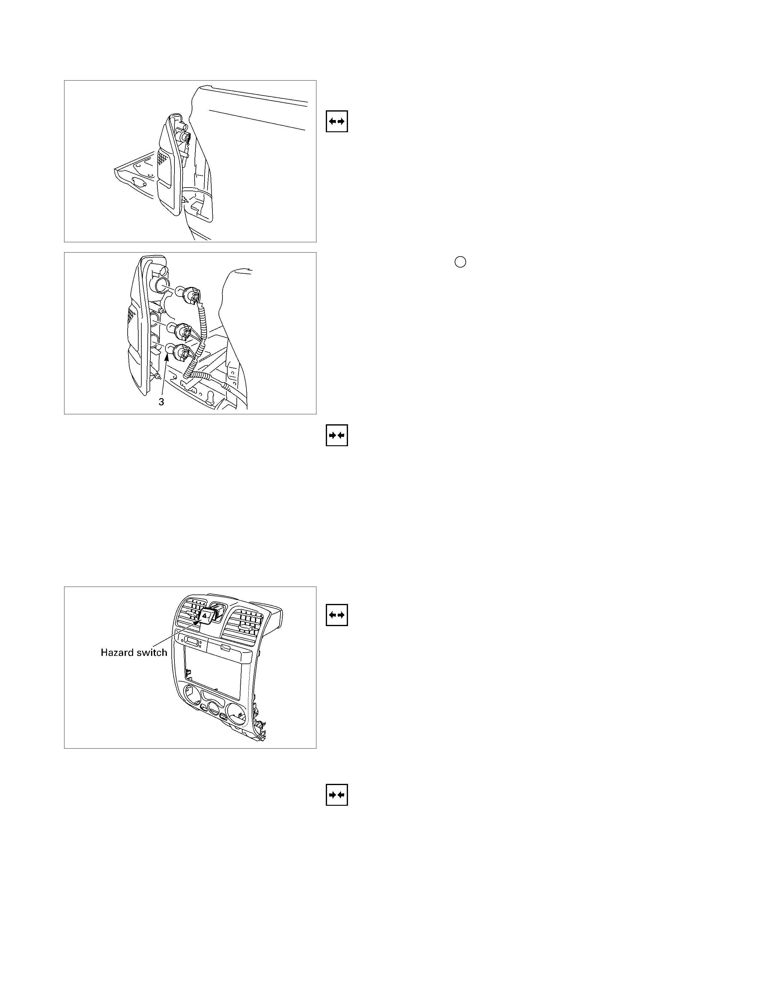
FRONT FOG & REAR FOG SWITCH
RTW48ASH000401
Inspection
Check to see if there is any continuity between the terminals of
the front fog light switch.
Replace the switch when the result of inspection is found
abnormal.
Removal
Preparation:
Disconnect the battery ground cable.
1. Ventilation grille
2. Harness connector
3. Front fog light & Rear fog light switch
To remove the switch, push the lock from the back side of
the cluster assembly.
4. Remove the bulb.
RTW48ASH000301
Installation
To install, follow the removal steps in the reverse noting the
following point.
1. Push in the switch with your fingers until it locks securely.
REAR FOG LIGHT
PARTS LOCATION (RHD)
RTW48AXF015401 & RTW48AXF015501
PARTS LOCATION (LHD)
RTW48AXF015601 & RTW48AXF015701
CIRCUIT DIAGRAM (RHD)
RTW680XF007401

CIRCUIT DIAGRAM (LHD)
RTW680XF007301
RTW48ASH000701
REAR FOG LIGHT
Removal
1. Remove the screws 1.
2. Remove the lens cover 2.
3. Rear fog push turn the bulb 3 counterclockwise to
disconnect it from the light housing.
Installation
Follow the removal procedure in the reverse order to install the
rear fog light.
Pay close attention to the important points mentioned in the
following paragraphs.
Bulb
Be absolutely sure that the license plate light bulb is correctly
installed.
This will prevent a poor contact and open circuit.
RTU4Z0SH000601
FRONT FOG & RR FOG SWITCH
RTW48ASH000401
Inspection
Check to see if there is any continuity between the terminals of
the leveling switch.
Replace the switch when the result of inspection is found
abnormal.
Removal
Preparation:
Disconnect the battery ground cable.
1. Ventilation grille
2. Harness connector
3. Front fog light & Rear fog light switch
To remove the switch, push the lock from the back side of
the cluster assembly.
4. Remove the bulb.
HEADLIGHT LEVELING
PARTS LOCATION (RHD)
RTW48AXF015801 & RTW48AXF015901
PARTS LOCATION (LHD)
RTW48AXF016001 & RTW48AXF016101
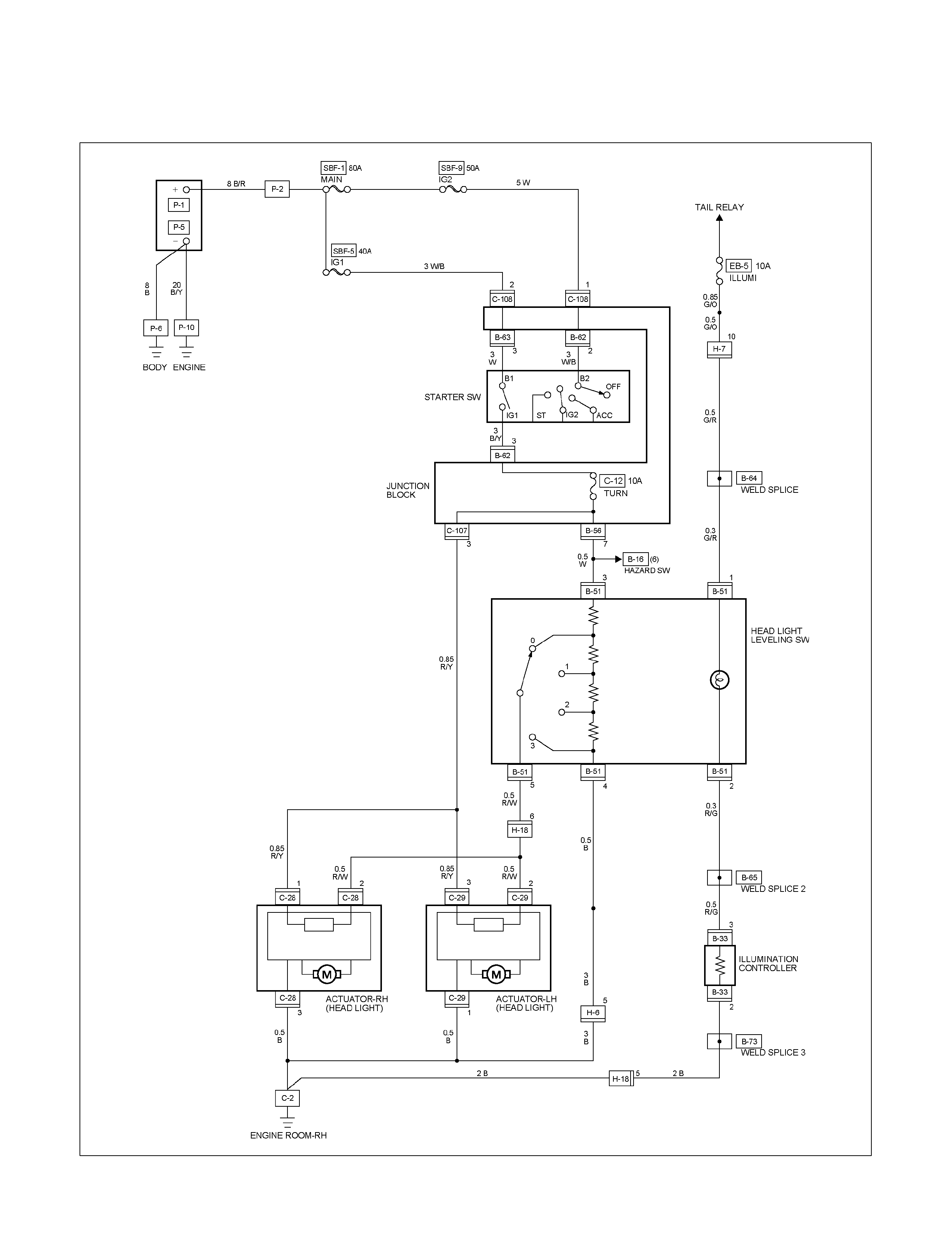
CIRCUIT DIAGRAM (RHD)
RTW680XF007601
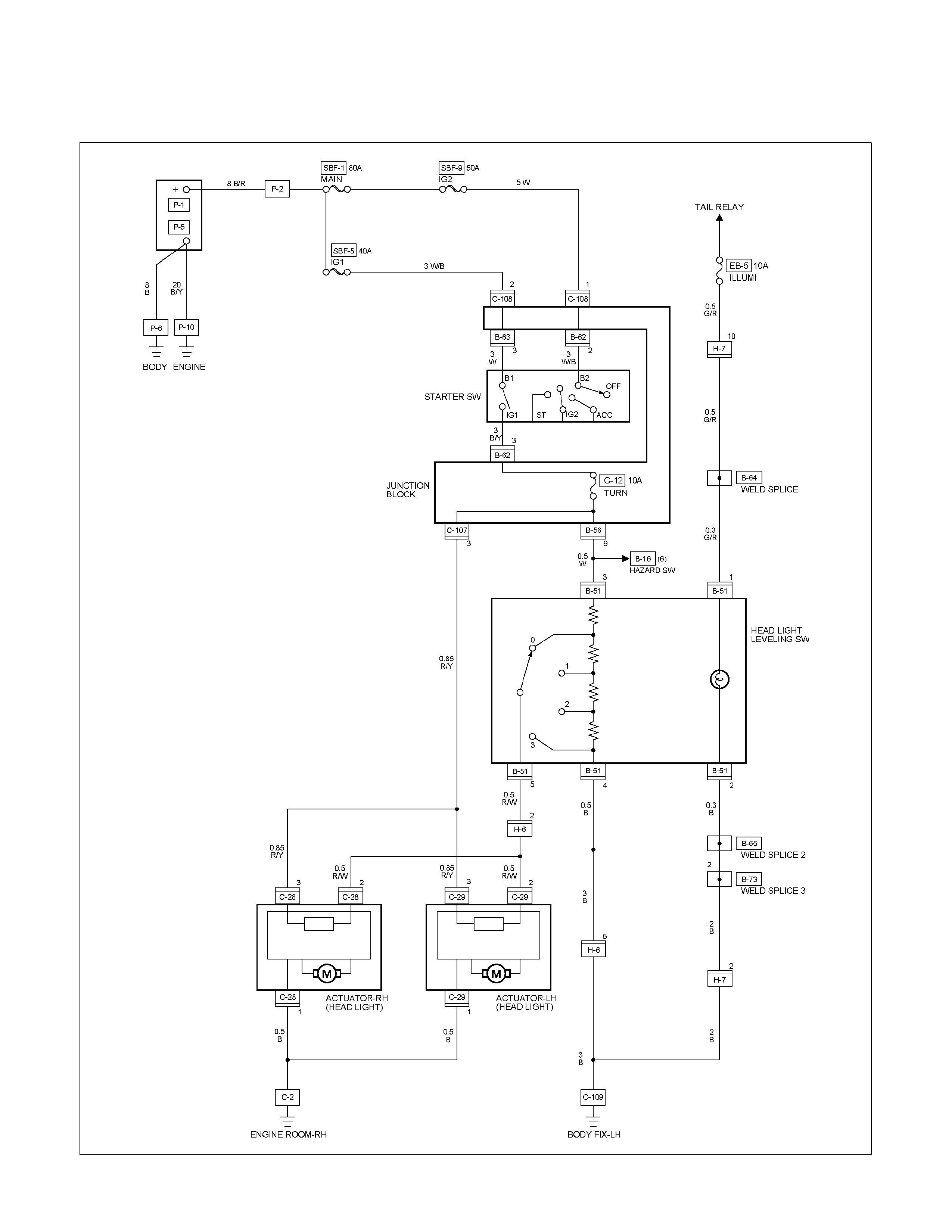
CIRCUIT DIAGRAM (LHD)
RTW680XF007501

HEADLIGHT LEVELING SWITCH
Incorrect beam angle due to load change can be corrected.
A four position switch, 0-3, can alter the beam angle through
1.7 degrees on the long wheel base model and 2.17 degrees
on the short wheel base model.
RTW68ASH000501
Inspection
Check to see if there is any continuity between the terminals of
the leveling switch.
Replace the switch when the result of inspection is found
abnormal.
Removal
Preparation:
Disconnect the battery ground cable.
1. Ventilation grille
2. Harness connector
3. Headlight leveling switch
To remove the switch, push the lock from the back side of
the cluster assembly.
Installation
To install, follow the removal steps in the reverse noting the
following point.
1. Push in the switch with your fingers until it locks securely.
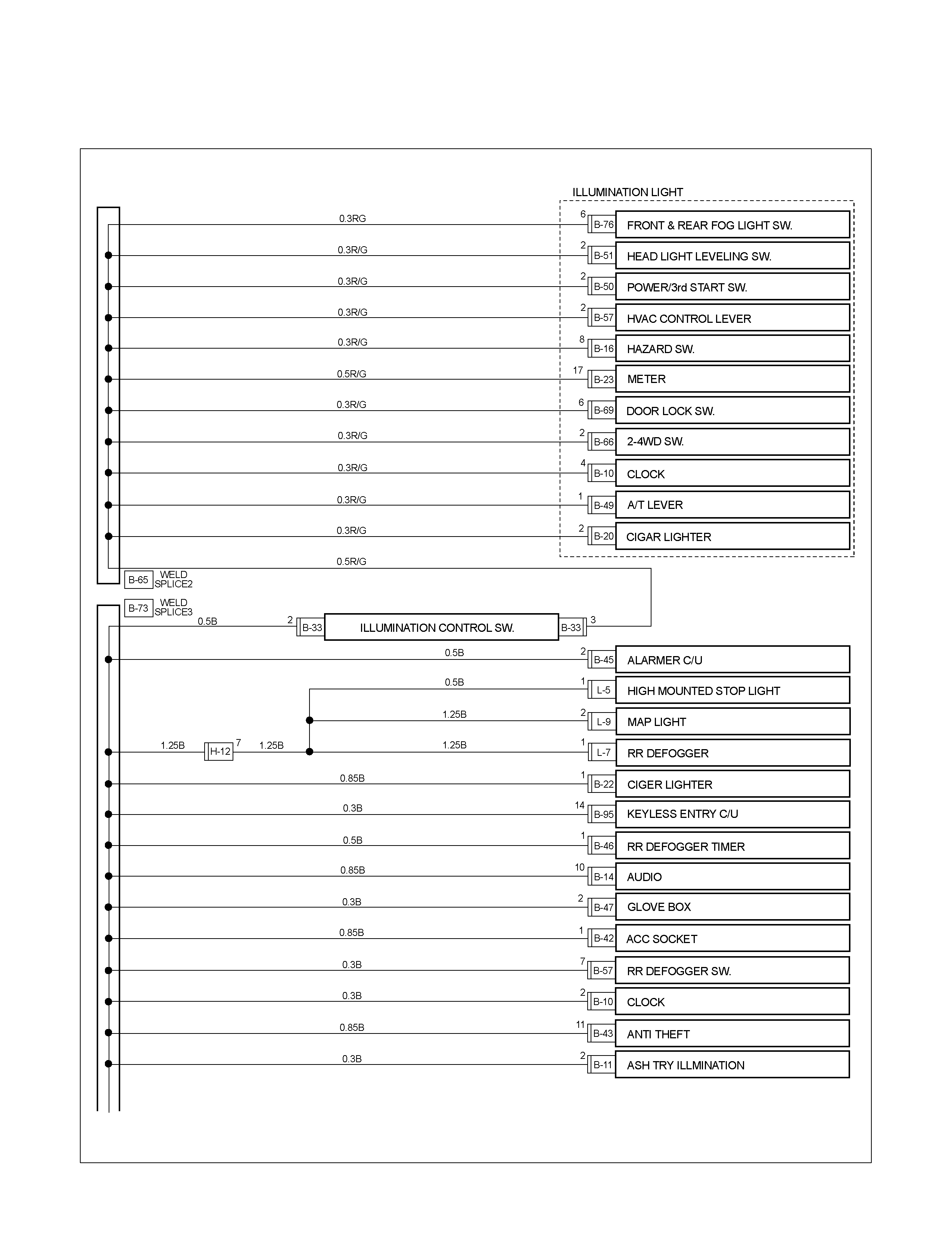
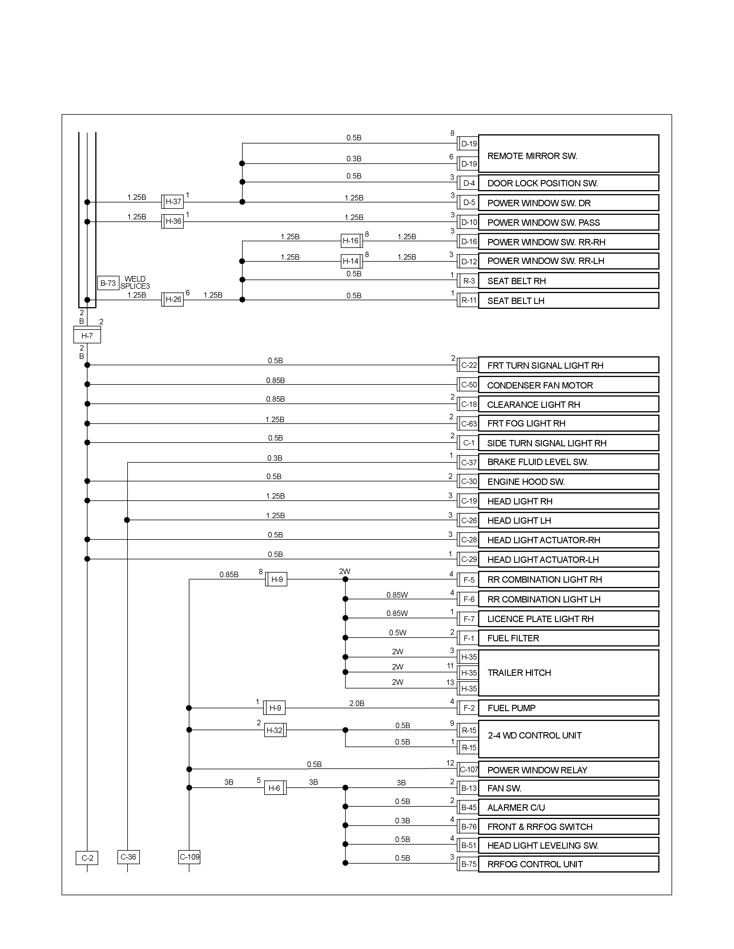
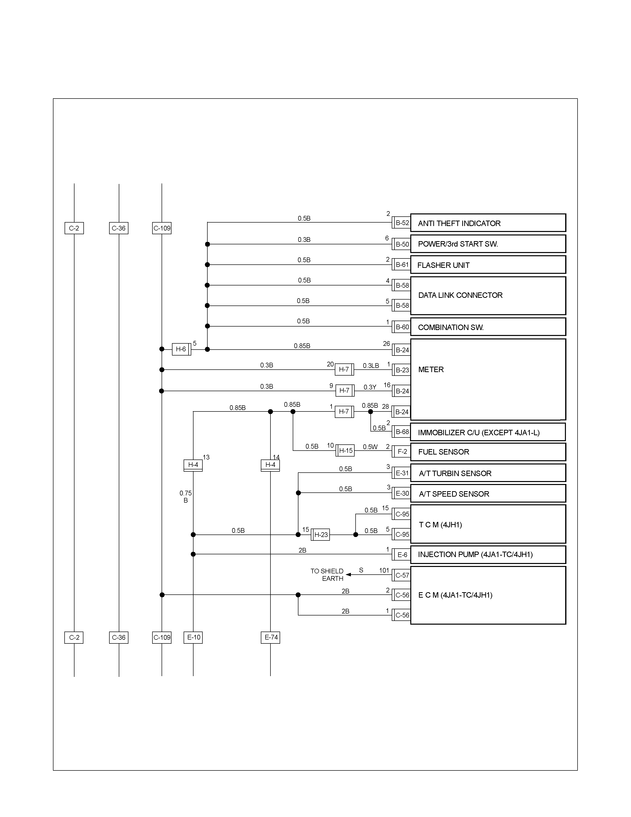
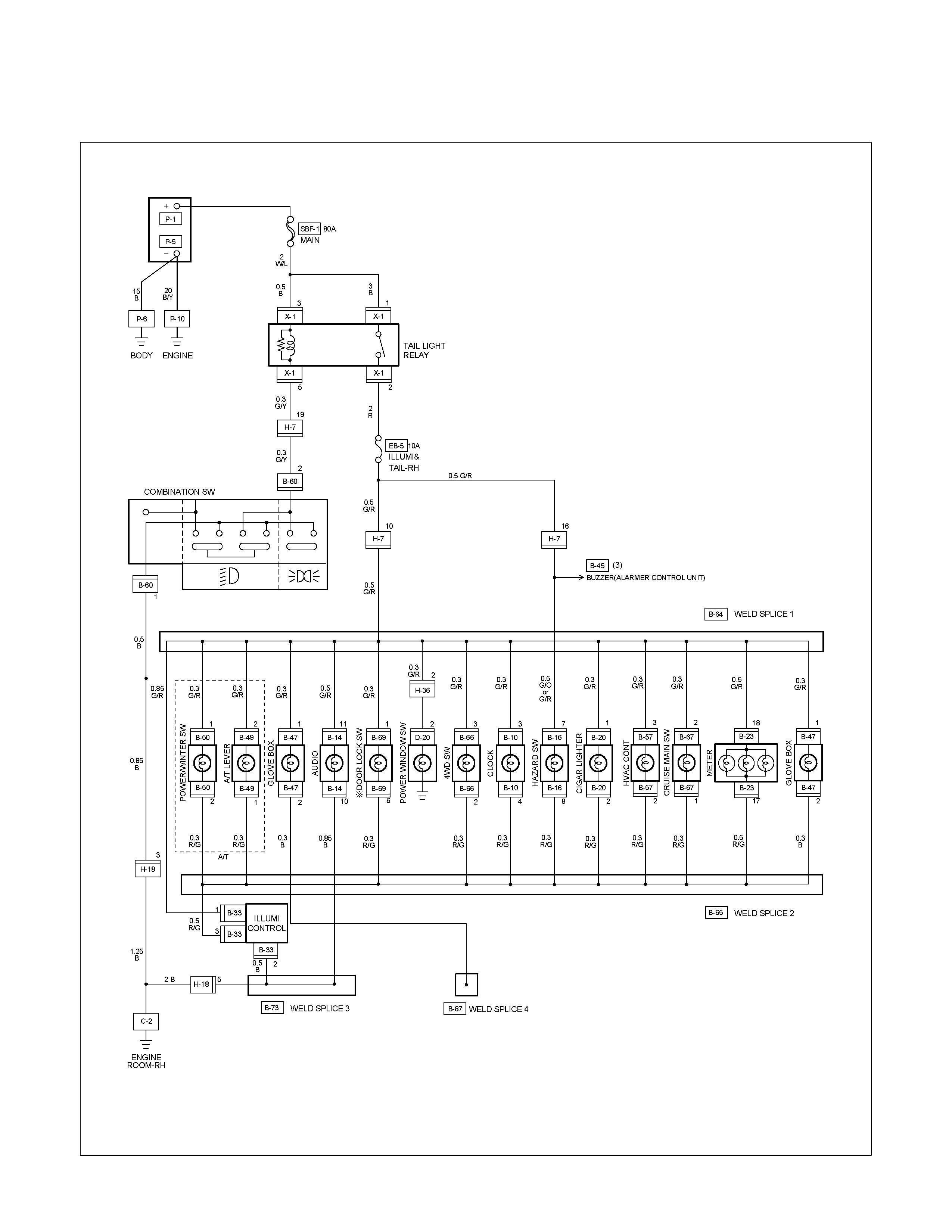
ILLUMINATION
PARTS LOCATION (RHD)
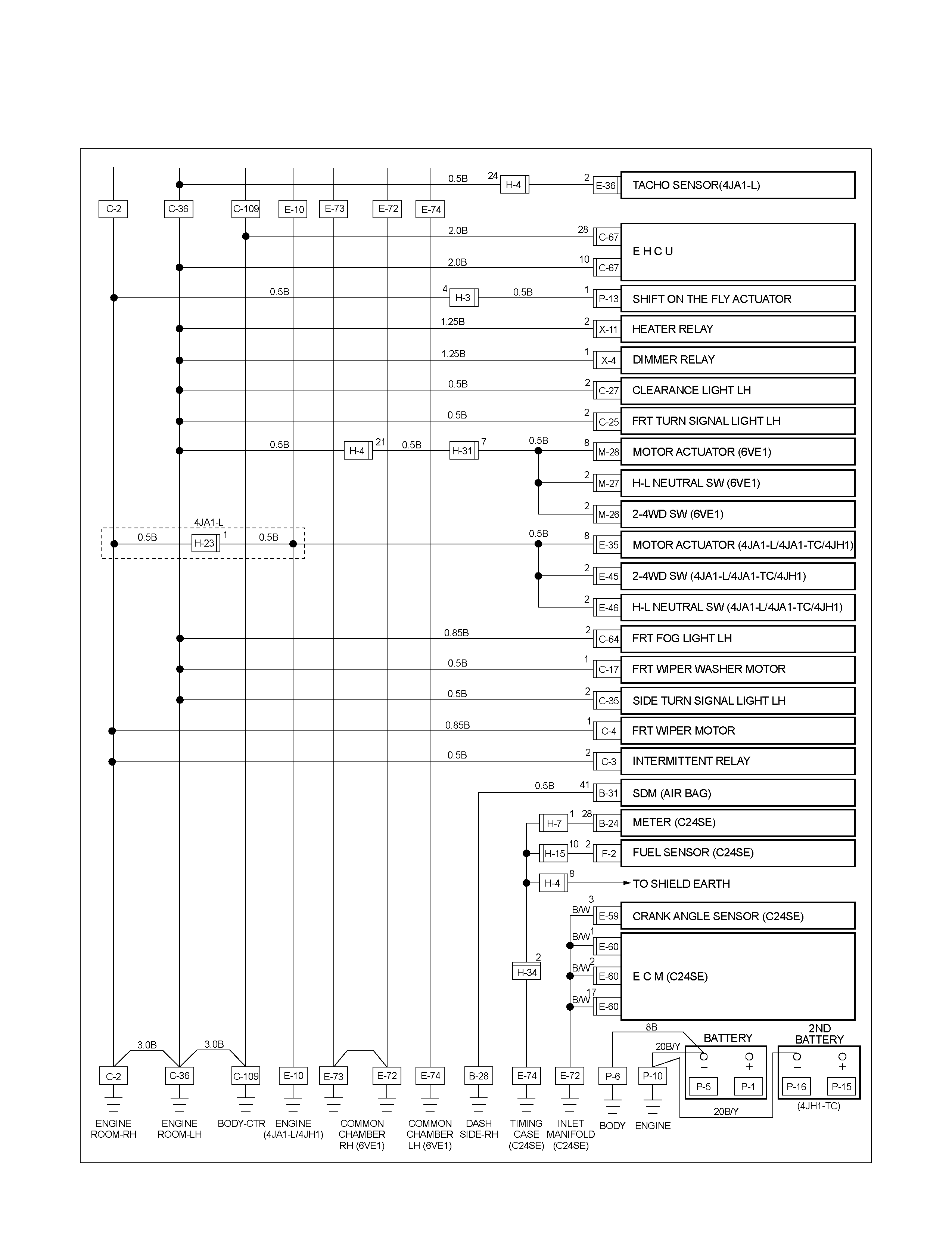
RTW68AXF014301 & RTW68AXF014401
PARTS LOCATION (LHD)
RTW48AXF016401 & RTW48AXF016501
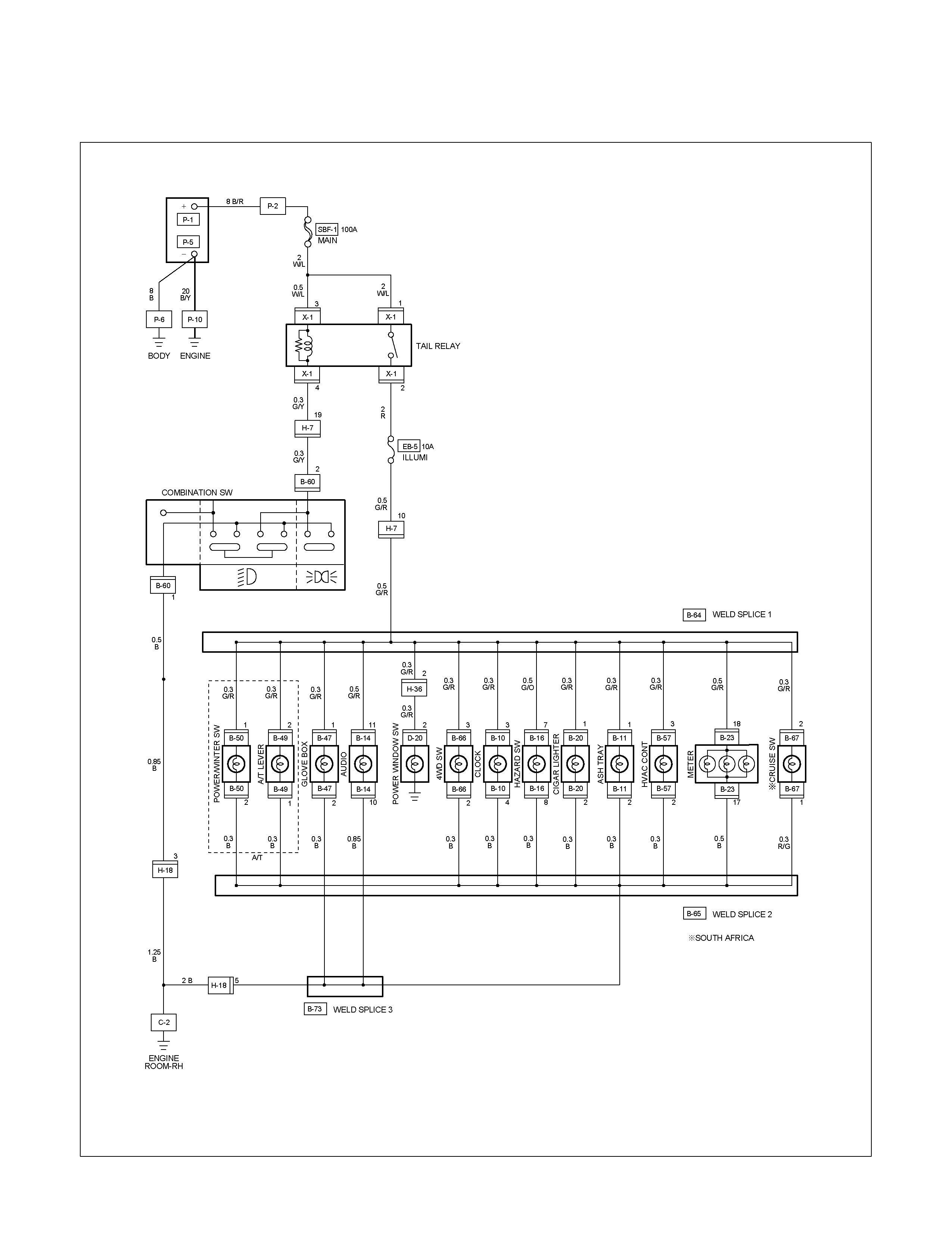
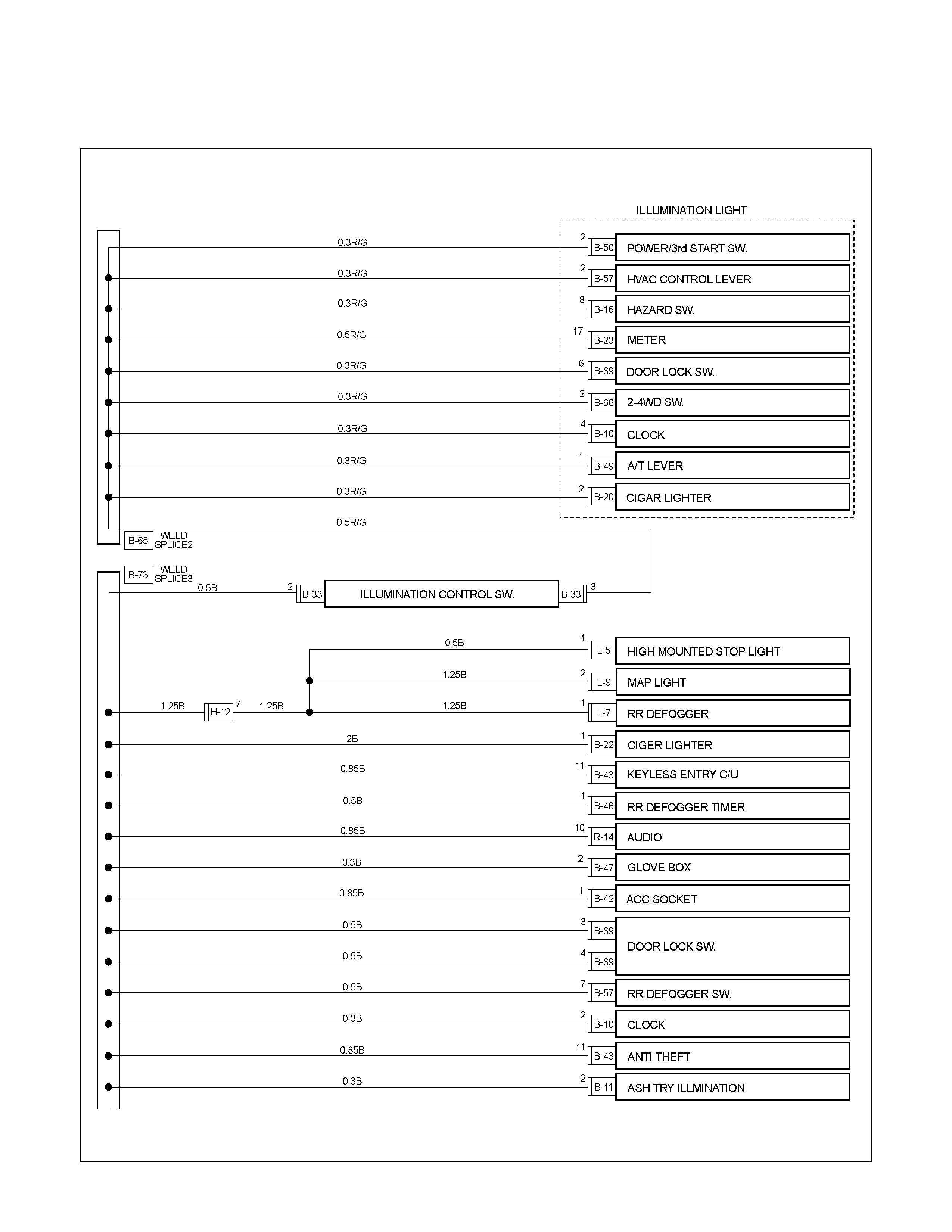
CIRCUIT DIAGRAM (RHD) WITHOUT ILLUMINATION CONTROL
RTW680XF007701

CIRCUIT DIAGRAM (RHD) EXCEPT HFV6 WITH ILLUMINATION CONTROL
RTW680XF007801
CIRCUIT DIAGRAM HFV6 WITH ILLUMINATION CONTROL
RTW68AXF010801
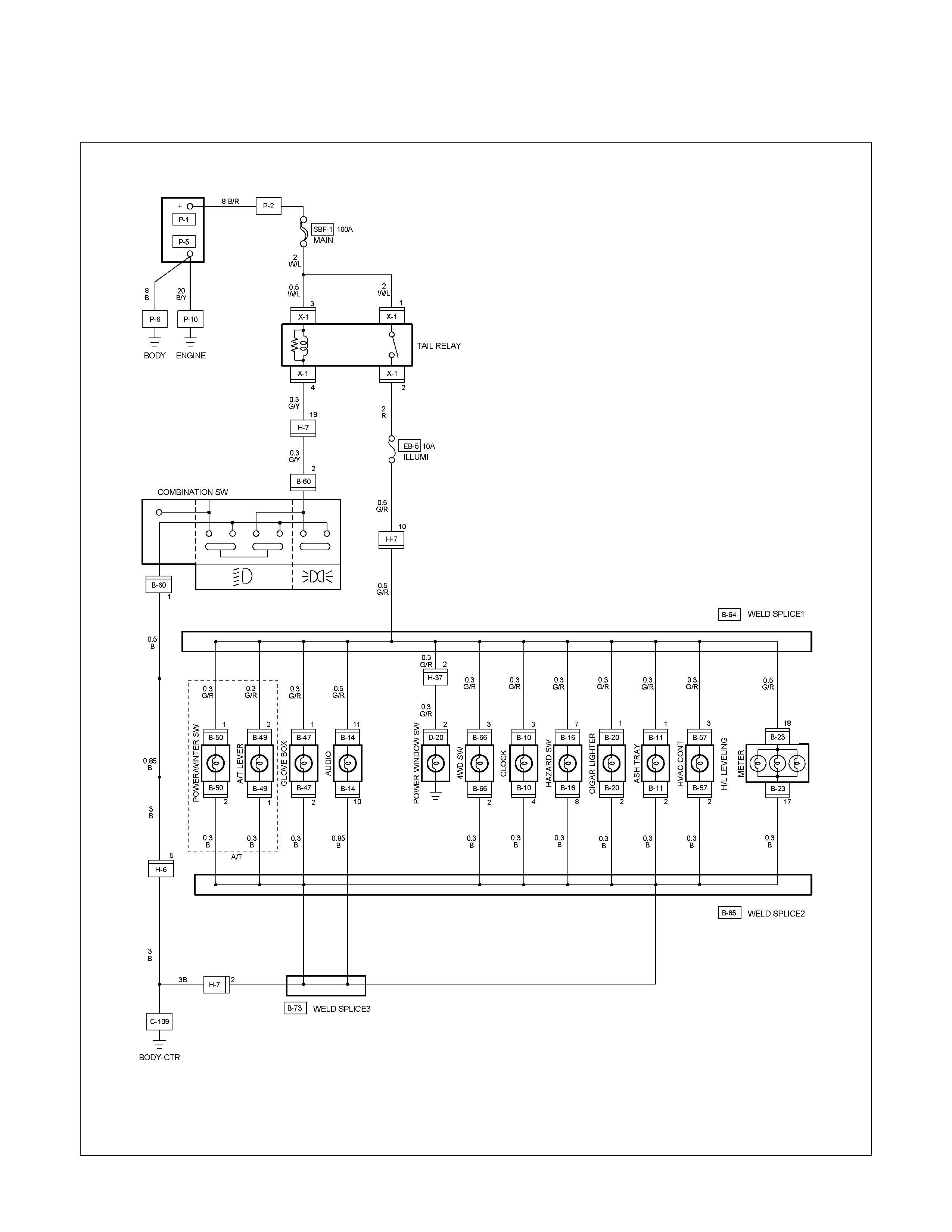
CIRCUIT DIAGRAM (LHD) WITHOUT ILLUMINATION CONTROL
RTW680XF007901
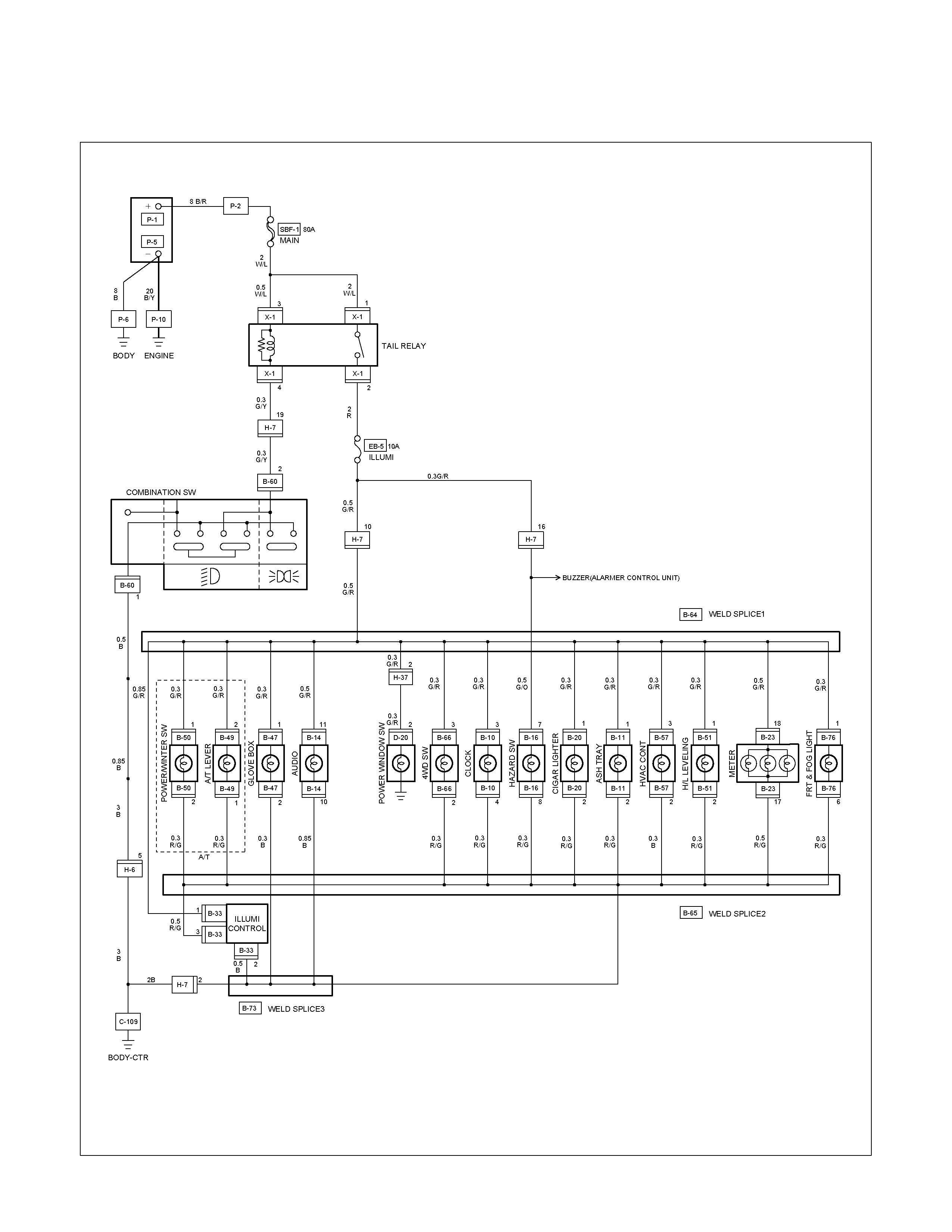
CIRCUIT DIAGRAM (LHD) WITH ILLUMINATION CONTROL
RTW680XF008001
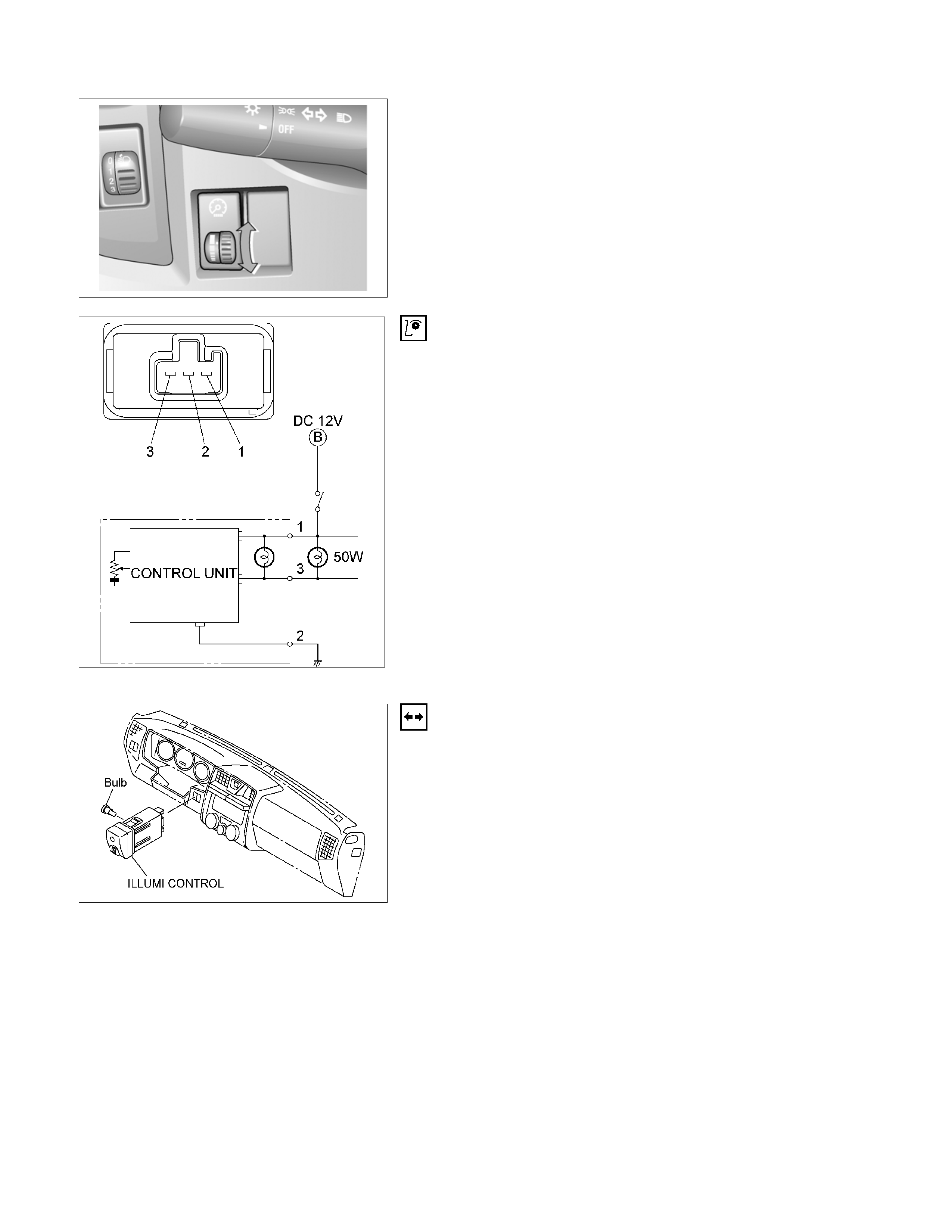
RTU4Z0SH000901
ILLUMINATION SWITCH
RTW48ASH000601
Inspection
Check to see if there is any continuity between the terminals of
the switch.
Replace the switch when the result of inspection is found
abnormal.
RTW48ASH000501
Removal
Preparation:
Disconnect the battery ground cable.
1. Instrument panel driver lower cover assembly
Refer to the removal steps Sec.10
2. Harness switch
3. Illumination control
To remove the switch, push the lock from the back side of
the cluster assembly.
4. Remove the bulb.
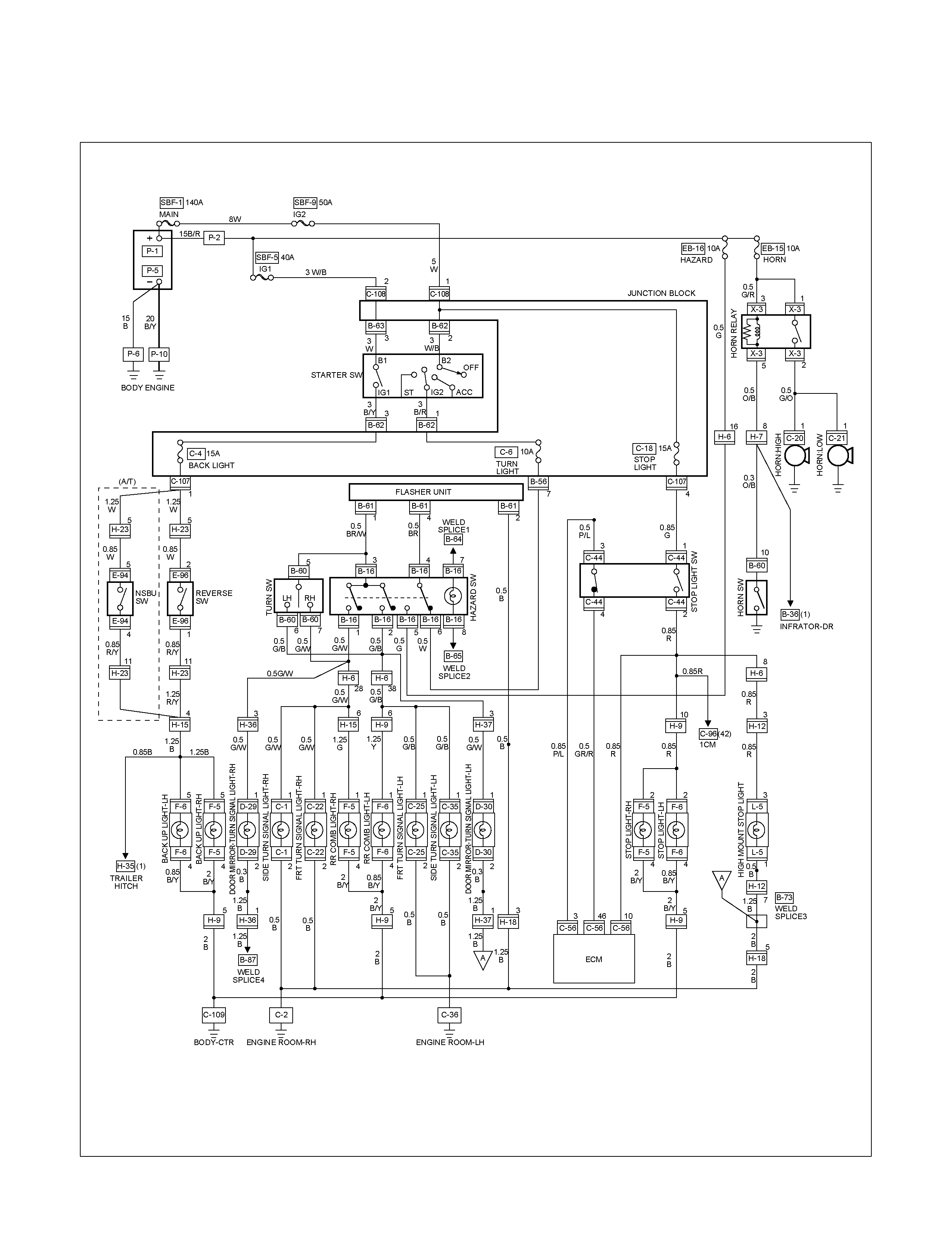
HAZARD WARNING FLASHER, TURN SIGNAL LIGHT, BACK UP
LIGHT, HORN AND STOP LIGHT
PARTS LOCATION (RHD)
RTW68AXF014501 & RTW68AXF014601
PARTS LOCATION (LHD)
RTW68AXF009301 & RTW48AXF16901
PARTS LOCATION (LHD)
RTW68AXF012201

PARTS LOCATION
RTW38DXF007501
PARTS LOCATION
RTW48AXF013001
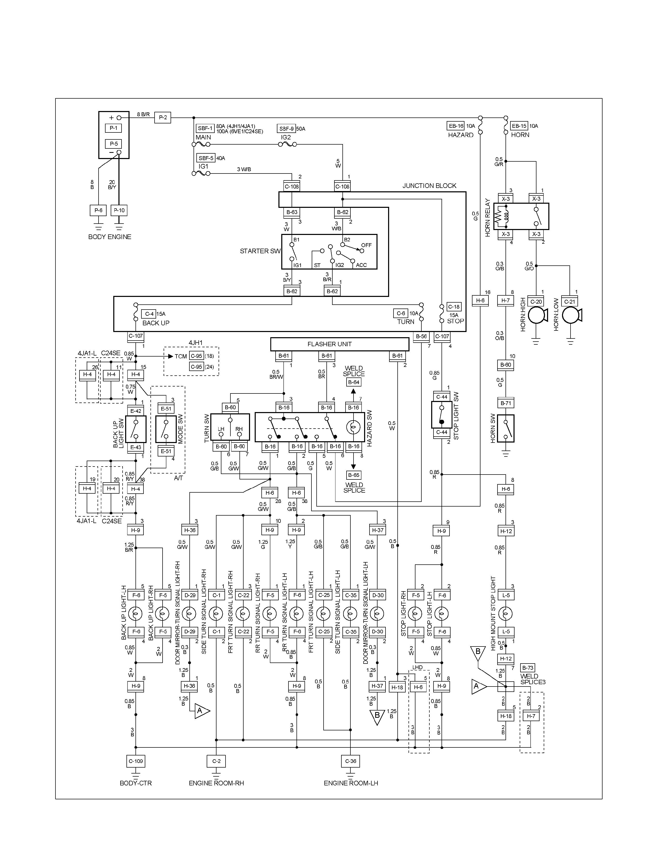
CIRCUIT DIAGRAM EXCEPT AUSTRALIA
RTW680XF008101
CIRCUIT DIAGRAM HFV6 AUSTRALIA
RTW68AXF010901
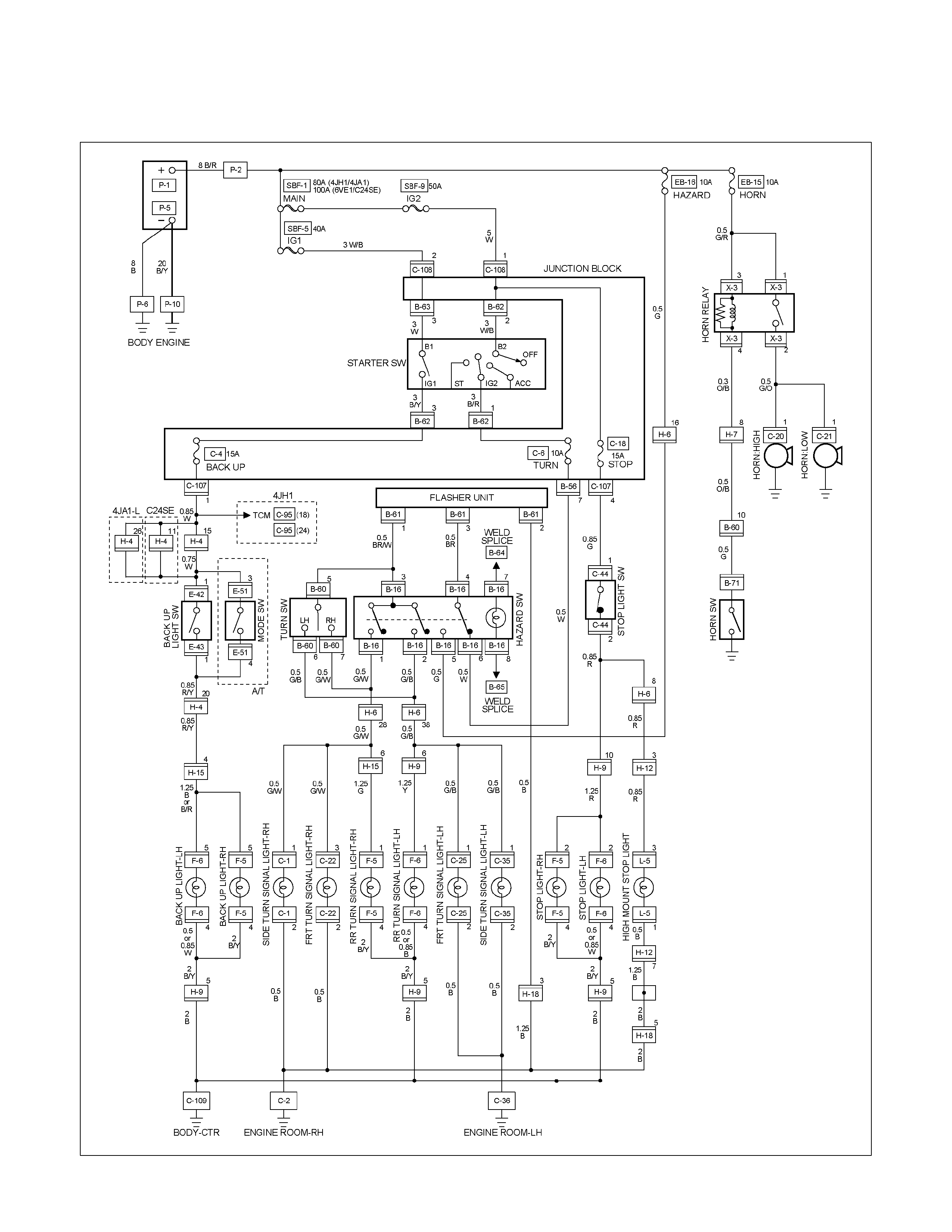
CIRCUIT DIAGRAM EXCEPT HFV6 AUSTRALIA
RTW680XF008201
TROUBLESHOOTING
STOPLIGHT AND HIGH MOUNTED STOPLIGHT
1. One side of stoplight does not light
Checkpoint Trouble Cause Countermeasure
Replace the bulb or repair
connector contact
Burned out bulb or poor
connector contact
NG
Repair open circuit or
connector contact
Repair open circuit or
connector contact
Open circuit or poor connector
contact
Continuity between
9 H-9 - 2 F-6 (LH) (or
2 F-5 (RH))
Open circuit or poor connector
contact
Continuity between
8 H-9 - 4 F-6 (LH) (or
4 F-5 (RH))
NG
NG
OK
OK
Stoplight bulb continuity
2. Both sides of stoplight do not light
Adjust the switch insta llation
position
Stop light switch (or brake
switch) function
Incorrect the switch installation
or adjustment
NG
Repair open circuit or
connector contact
Voltage between 2 F-6
ground or 2 F-5 - ground
with brake pedal depressed
(Should be battery voltage
present)
Open circuit or poor connector
contact between stoplight
switch (or brake switch) and
stoplight
NG
OK
Reinstall or replace fuse No.
SBF-9 (50A)
or 1
C-108 - 4
C-107
Fuse No. C-18 (15A)
Fuse No. SBF-9 (50A, Fuse
and Relay box)
or 1
C-108 - 4
C-107
Fuse No. C-18 (15A)
Poor fuse contact or blown
NG
OK
3. High mounted stoplight does not light
Checkpoint Trouble Cause Countermeasure
Repair or replace the high
mounted stoplight
Continuity between 3 L-5 -
1 L-5
High mounted stoplight
malfunction
NG
Repair an open circuit or
connector contact between
3 L-5 - 5 H-18 (RHD) or
2 H-7 (LHD)
Voltage between 1 L-5 -
ground with brake pedal
depressed
(Should be battery voltage
present)
Open circuit or poor connector
contact
NG
OK
Repair grounding point contact
C-2
Grounding point C-2
Poor grounding point contact
NG
OK
TURN SIGNAL LIGHT AND HAZARD WARNING LIGHT
1. Turn signal light does not light on both sides (RH and LH)
Checkpoint Trouble Cause Countermeasure
Replace the flasher unit
Flasher unit malfunction
NG
Repair or replace the
combination switch
Turn signal switch continuity
between connector
5 B-60 - 6 B-60 and
5 B-60 - 7 B-60 when
turn signal switch operates
Short circuit between
connector 3 B-61 - 1 B-61
when turn signal switch
operates with starter switch
in “ON” position (Turn
signal light should be ON)
Poor switch point contact or
faulty switch
NG
OK
Reinstall or replace fuse No.
EB-16 (10A)
Fuse No. EB-16 (10A, Fuse
box)
Poor fuse contact or blown
fuse
NG
OK
OK
Repair open circuit or
connector contact
Continuity between
connector 2 B-61 -ground
(Should be continuity)
Open circuit or poor connector
contact
NG
2. Turn signal light does not light on one side (RH or LH)
Checkpoint Trouble Cause Countermeasure
Repair open circuit or
connector contact
Open circuit or poor connector
contact
NG
(LH)
Continuity between
1 C-25 - 6 B-60 (FRT),
1 C-35 - 6 B-60 (SIDE)
1 F-6 - 6 B-60 (RR)
(RH)
Continuity between
3 C-22 - 7 B-60 (FRT),
1 C-1 - 7 B-60 (SIDE)
1 F-5 - 7 B-60 (RR)
Repair or replace the
combination switch
Turn signal switch continuity
Poor switch point contact or
faulty switch
NG
OK
OK
Repair open circuit or
connector contact
Open circuit or poor connector
contact
NG
3. Hazard warning light does not light
Repair or replace the hazard
SW.
Hazard SW. malfunction
NG
Voltage between 5 B-16 -
ground (Should be battery
voltage present)
Hazard SW. continuity
Reinstall or replace the fuse
No. EB-16 (10A)
Fuse No. EB-16 (10A, Relay
and fuse box)
Poor fuse contact or blown
fuse
NG
OK
OK
Repair open circuit or
connector contact
Open circuit or poor
connector contact between
fuse No. EB-16 (10A) -
5 B-16
NG
4. Flashing rate too fast (One side)
Replace the bulb or repair
open circuit
Inspect bulb Burned out bulb
NG
BACKUP LIGHT
1. Backup light does not light on one side (RH or LH)
Checkpoint Trouble Cause Countermeasure
Repair grounding point contactPoor ground contact
NG
Grounding point
Replace the bulb or repair
connector contact
Backup light bulb continuity Burned out bulb or poor
connector contact
NG
OK
2. Backup light does not light on both sides
Repair or replace the switch
Poor switch point contact of
faulty switch
NG
Voltage between 5 F-6
(5 F-5 ) - ground with
starter switch ON and shift
lever into reverse position
(Should be battery voltage
present)
Back up light switch (mode
switch) continuity
Reinstall or replace fuse No.
C-4 (15A)
Fuse No. C-4 (15A, Fuse box)
Poor fuse contact or blown
fuse
NG
OK
OK
Repair open circuit or
connector contact
Open circuit or poor connector
contact
NG
HORN
1. Both sides of horn do not sound
Checkpoint Trouble Cause Countermeasure
Repair the grounding point
Poor ground contact
NG
Horn relay
Grounding point
Reinstall or replace fuse No.
EB-15 (10A)
Fuse No EB-15 (10A, Relay
and fuse box)
Poor fuse contact or blown
fuse
NG
OK
OK
Reinstall or replace the horn
relay
Poor relay contact or faulty
horn relay
NG
Voltage between connector
3 X-3 - ground or 1 X-3
- ground (Should be battery
voltage present)
OK
Repair open circuit or
reconnect the connector
Open circuit or poor connector
contact between fuse No. EB-
15 (10A) and horn relay
NG
Remove steering pad and
steering wheel
OK
Horn switch continuity
OK
Repair or replace the horn
switch
Poor switch point contact or
faulty switch
NG
Continuity between
4 X-3 - 10 B-60
2 X-3 - 1 C-20 (1 C-21 )
OK
Repair open circuit or
connector contact
Open circuit or poor connector
contact
NG
2. One side of horn does not blow
Checkpoint Trouble Cause Countermeasure
Repair open circuit or
reconnect the connector
Open circuit or poor connector
contact
NG
Voltage between 1 C-20
(1 C-21 ) - ground with
horn switch depressed
(Should be battery voltage
present)
Replace the horn assembly
Horn continuity between
connectors Faulty horn assembly
NG
OK
3. Insufficient horn volume
Clfean and/or remove the
foreign material
Stain foreign material in the
horn
NG
Horn
Recharge or replace the
battery
Battery condition Discharged battery
NG
OK
REMOVAL AND INSTALLATION
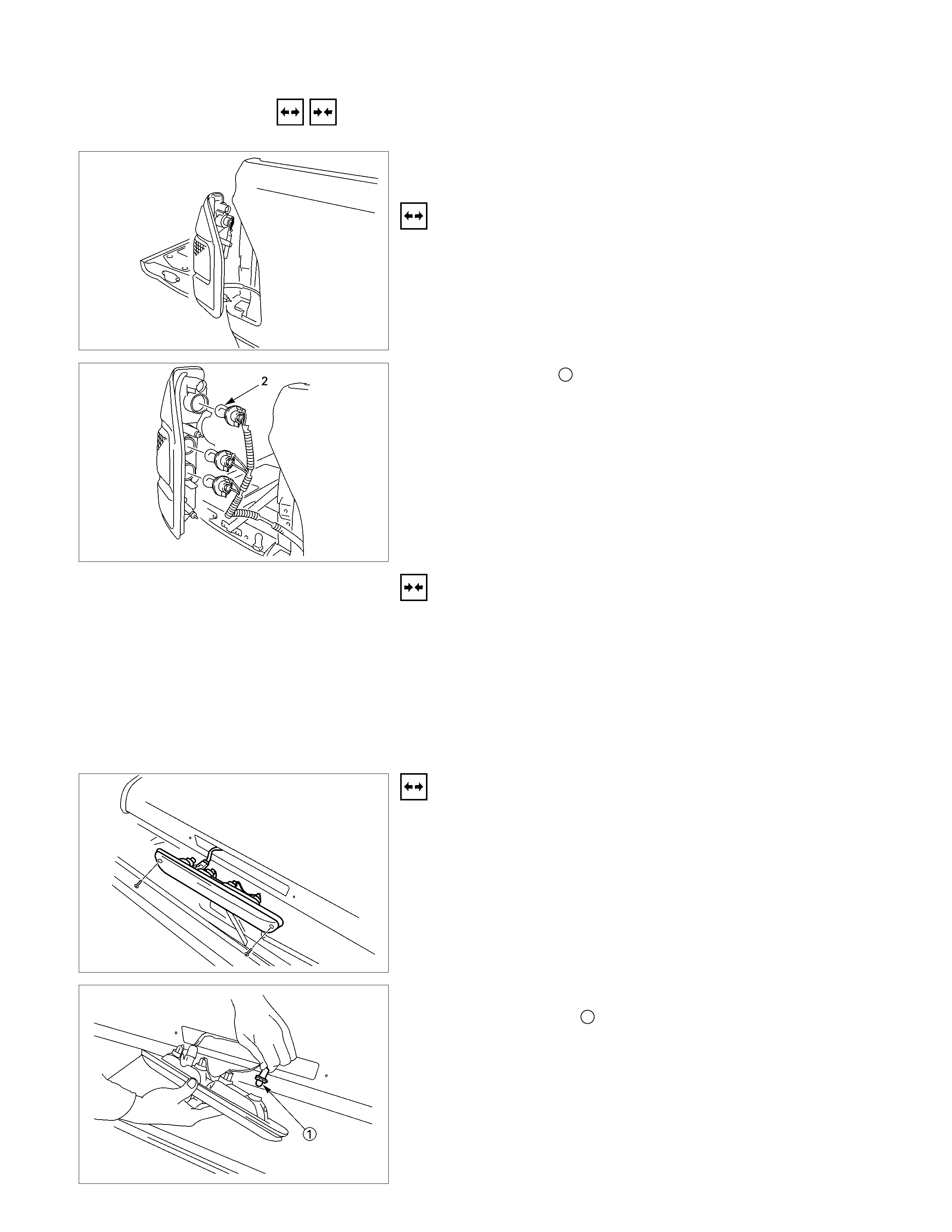
REAR COMBINATION LIGHT
Stoplight
Removal
1. Open the rear gate.
2. Remove the screws of rear combination light.
3. Remove the rear combination light assembly.
4. Turn the bulb 2 counterclockwise to remove it.
Installation
Follow the removal procedure in the reverse order to install the
rear combination light.
Pay close attention to the important points mentioned in the
following paragraphs.
Bulb
Be absolutely sure that each bulb is correctly installed.
This will prevent a poor contact and an open circuit.
HIGH MOUNTED STOPLIGHT
Remove the bulb socket
1. Remove the high mounted stoplight ASM.
• Remove the screws.
• Disconnect the connector.
2. Remove the bulb socket.
• Turn the bulb 1 counterclockwise to remove it.
Installation
Follow the removal procedure in the reverse order to install the
rear combination light.
Pay close attention to the important points mentioned in the
following paragraphs.
Bulb
Be absolutely sure that each bulb is correctly installed.
This will prevent a poor contact and an open circuit.
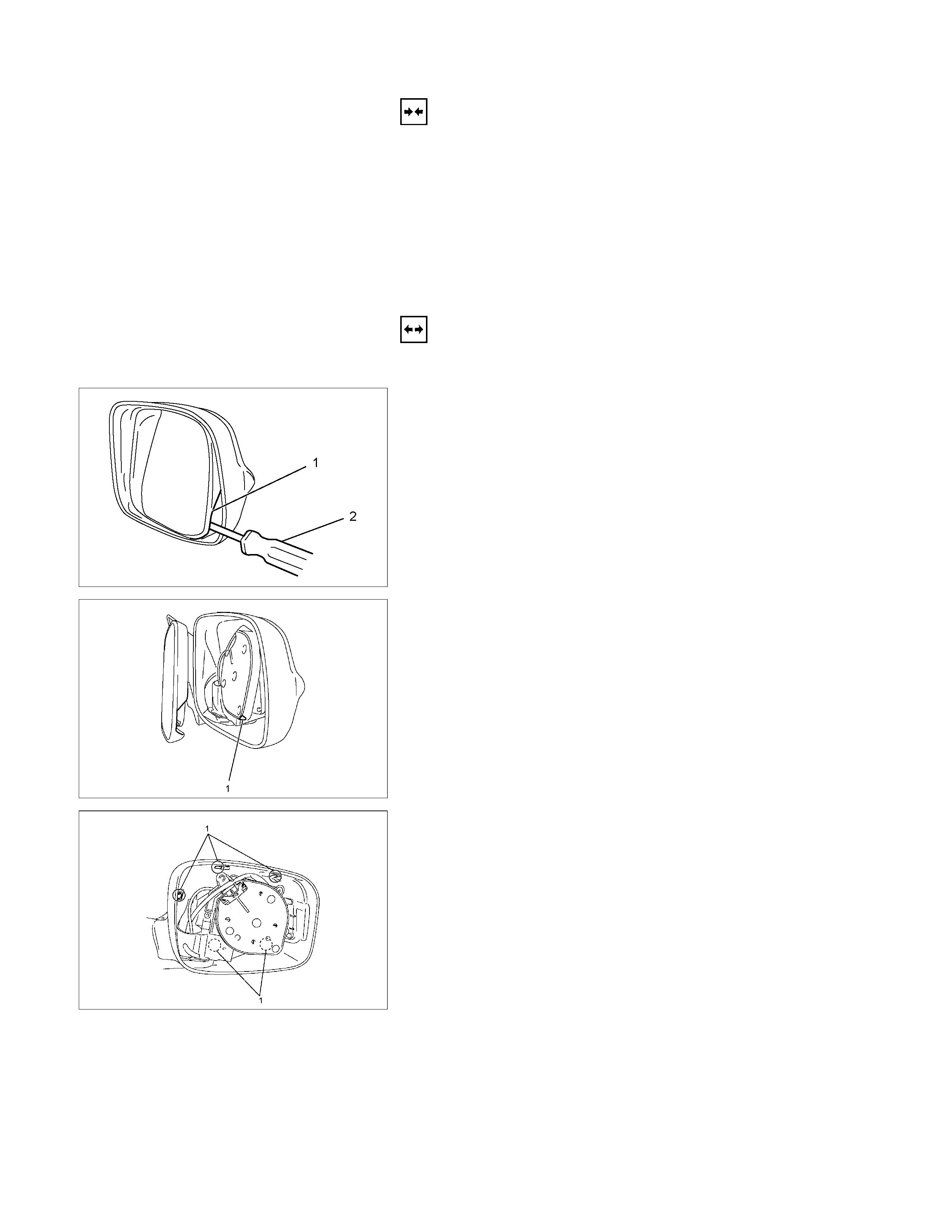
DOOR MIRROR - TURN SIGNAL LIGHT
Removal
1. Pull the lower outside corner of the mirror toward you.
RUW580SH000701
2. Press the blade of an ordinary screwdriver (2) into the
mirror outside groove near the mirror base hole (1).
RUW580SH000801
3. Turn the blade of the screwdriver 90 degrees to separate
the parts (1).
RUW580SH000901
4. Use an ordinary screwdriver inserted into the inner groove
(1) of the outside mirror case to pry off the outside panel (it
pasts up on butyl tape). Do this at 5 points around the
groove.
RUW580SH001001
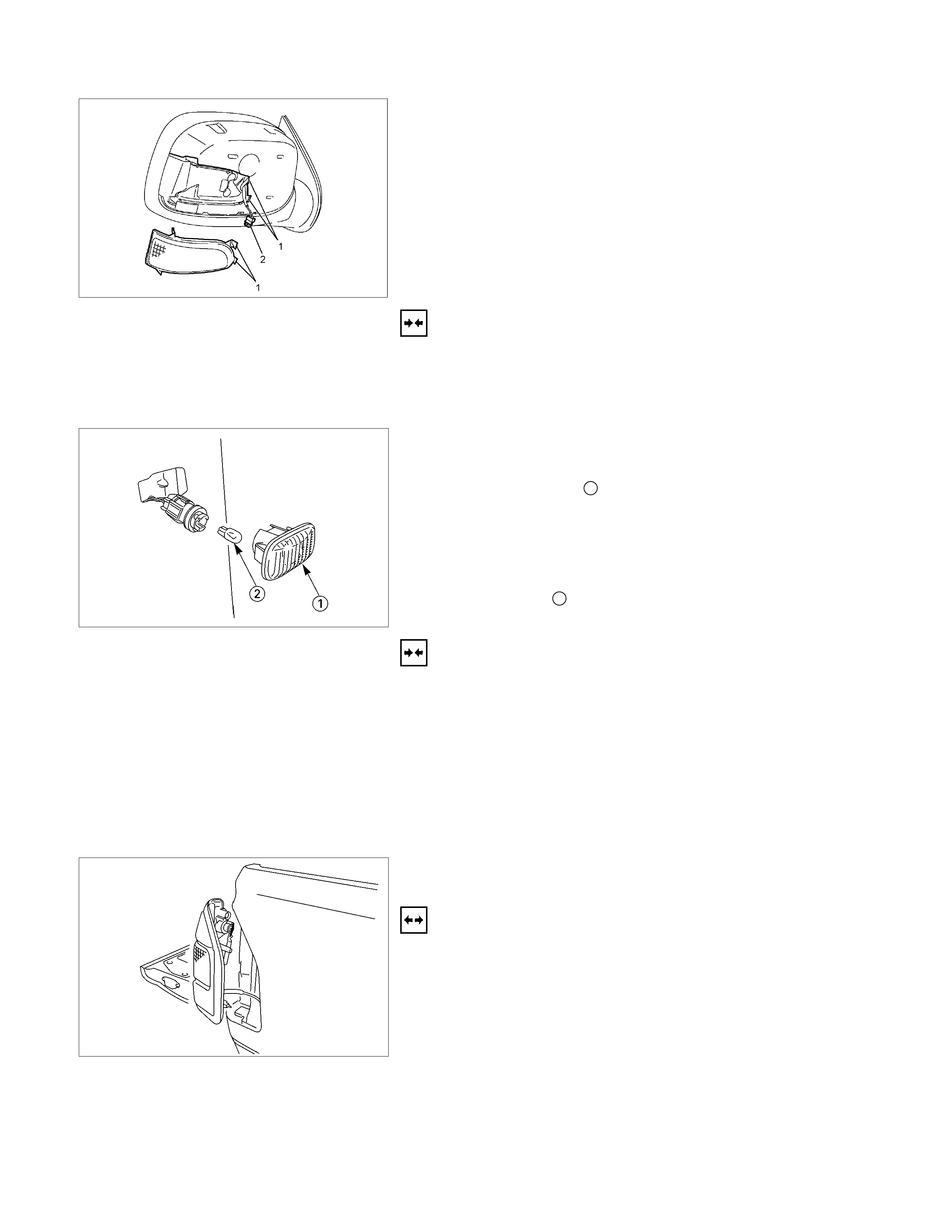
5. Insert an ordinary screwdriver into the inner groove (1) o
f
the door mirror - turn signal light. Pry the light free.
6. Disconnect the connector (2).
Installation
Follow the removal procedure in the reverse order to install the
door mirror - turn signal light.
Pay close attention to the important points mentioned in the
following paragraphs.
SIDE TURN LIGHT
Removal
1. Remove the lens 1.
• Pull the light/bulb toward you while pushing the light
housing in the rear direction of the vehicle to release its
lock.
• Remove the socket by turning it counterclockwise.
2. Pull the bulb 2 to remove it.
Installation
Follow the removal procedure in the reverse order to install the
side turn light.
Pay close attention to the important points mentioned in the
following paragraphs.
Bulb
Be absolutely sure that the side turn light bulb is correctly
installed.
This will prevent a poor contact and an open circuit.
REAR COMBINATION LIGHT
Turn Signal Light
Removal
1. Open the rear gate.
2. Remove the screws.
3. Remove the rear combination light assembly.
4. Turn the bulb 1 counterclockwise to remove it.
Installation
Follow the removal procedure in the reverse order to install the
rear combination light.
Pay close attention to the important points mentioned in the
following paragraphs.
Bulb
Be absolutely sure that the rear combination light bulb is
correctly installed.
This will prevent a poor contact and an open circuit.
This illustration is based on RHD model
TURN SIGNAL SWITCH
Removal
1. Disconnect the battery ground cable.
2. Remove the steering wheel 1.
Refer to the “STEERING” Section of this Manual.
3. Remove the instruments panel lower cover 2.
4. Remove the steering column cover 3.
This illustration is based on RHD model
5. Disconnect the connector.
6. Remove the turn signal switch from the steering shaft.
Installation
Follow the removal procedure in the reverse order to install the
turn signal switch (lever).
Pay close attention to the important points mentioned in the
following paragraphs.
Connector
Be absolutely sure that the turn signal switch connector is
securely connected.
This will prevent a poor contact and at an open circuit.
REAR COMBINATION LIGHT
Back Up Light
Removal
1. Open the rear gate.
2. Remove the screws.
3. Remove the rear combination light assembly.
4. Turn the bulb 3 counterclockwise to remove it.
Installation
Follow the removal procedure in the reverse order to install the
rear combination light.
Pay close attention to the important points mentioned in the
following paragraphs.
Bulbs
Be absolutely sure that each bulb is correctly installed.
This will prevent a poor contact and an open circuit.
This illustration is based on RHD model
HAZARD WARNING FLASHER SWITCH
Removal
1. Disconnect the battery ground cable.
2. Instrument Panel Cluster Assembly
• Refer to Section 10 “BODY” for instrument panel cluste
r
assembly removal steps.
3. Hazard Warning Switch
• Disconnect the switch connector.
• To remove the switch, push the lock from the back side
of the cluster assembly.
Installation
To install, follow the removal procedure in the reverse order.
Connector
Be absolutely sure that the hazard warning flasher switch
connector is securely connected.
This will prevent a poor contact and an open circuit.
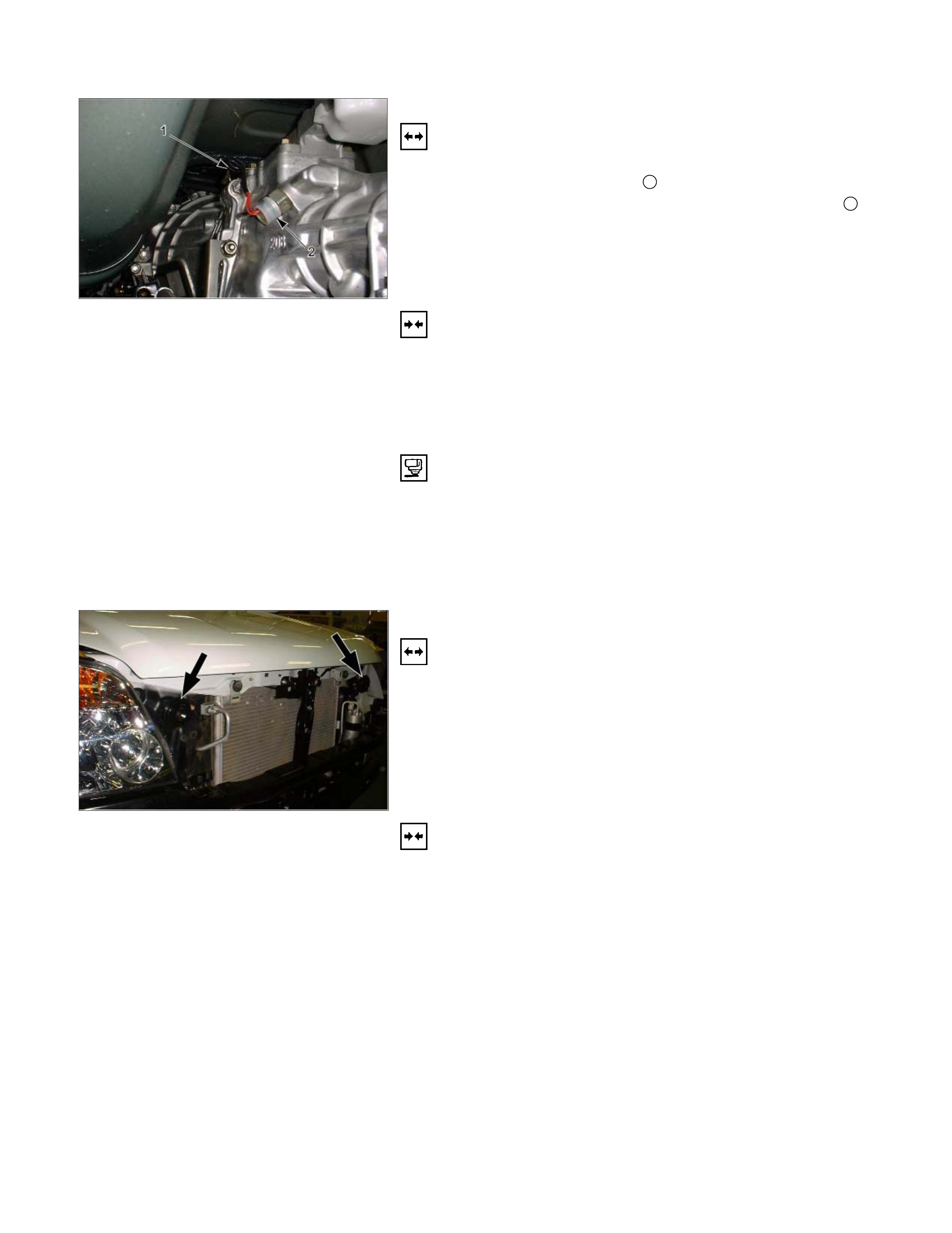
BACK UP LIGHT SWITCH
Removal
1. Disconnect the battery ground cable.
2. Disconnect the connector 1.
3. Remove the back up light switch from the transmission 2.
Installation
Follow the removal procedure in the reverse order to install the
back up light switch.
Pay close attention to the important points mentioned in the
following paragraphs.
Back up Light Switch Threads
Apply liquid gasket to the threaded portion and install the back
up light switch.
Connector
Be absolutely sure that the back up light connector is securely
connected.
This will prevent a poor contact and an open circuit.
HORN
Removal
1. Remove the radiator grille.
Refer to the “HEADLIGHT” removal procedure.
2. Loosen the horn bolt.
3. Disconnect the horn connector.
Installation
Follow the removal procedure in the reverse order to install the
horn.
Pay close attention to the important point mentioned in the
following paragraphs.
Connector
Be absolutely sure the horn connector is securely connected.
This will prevent a poor contact and open circuit.
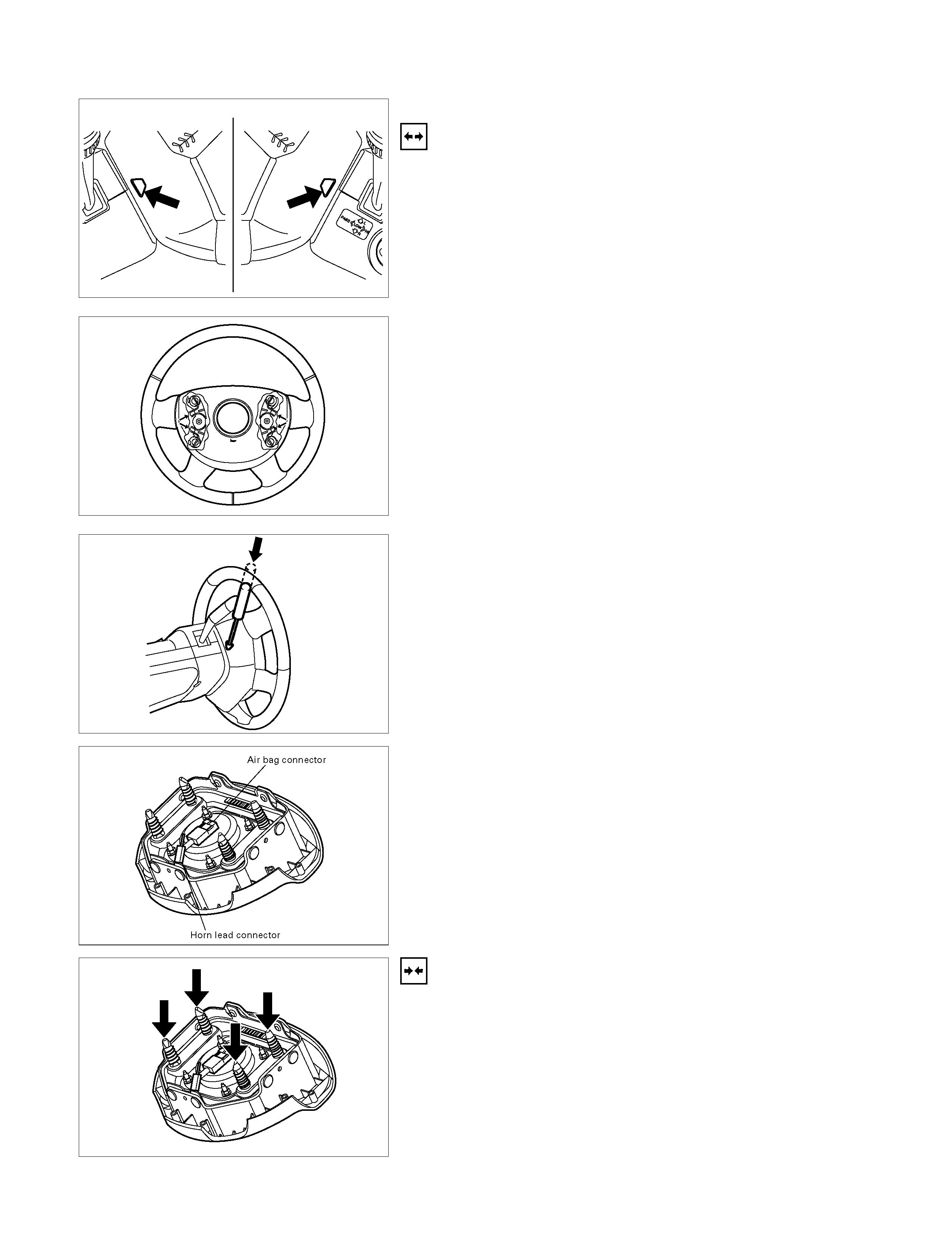
HORN SWITCH
Removal
1. Disconnect the battery ground cable.
2. Disable the SRS (Refer to “Disabling the SRS” in this
section).
3. Check the both side hole of the steering cover.
4. Check the position of the pins in a hole. Push the pin in the
direction of an arrow.
5. Push the four pins at φ5∼6 mm bar.
6. Cancel the lock four pins.
7. Disconnect the SRS air bag connector and horn lead
connector located behind the air bag assembly and remove
the air bag assembly.
Installation
1. Connect the SRS bag connector and horn lead connector.
2. Align the each snap stud of driver air bag to the hole o
f
steering wheel.
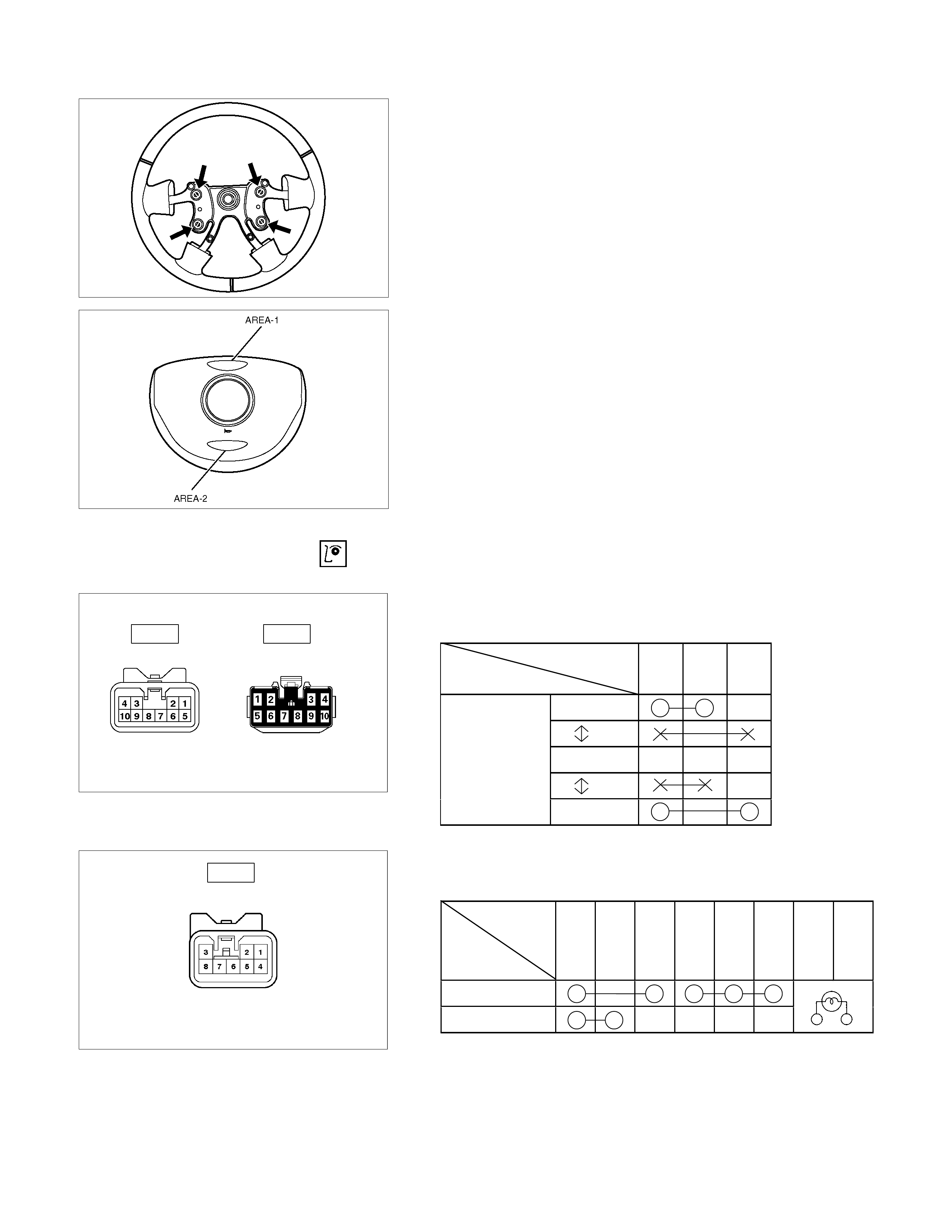
3. Push the SRS air bag area1 and area2. At that time
confirm the audible noise of each stud.
4. Enable the SRS (Refer to “Enabling the SRS” in this
section).
INSPECTION AND REPAIR
Switch side Harness side
B-60 B-60
TURN SIGNAL SWITCH
Lighting Switch Connections
Terminal No.
SW position 5 6 7
Left
Neutral
Right
Turning
direction
Switch side
B-16
HAZARD WARNING FLASHER SWITCH
Hazard Warning Flasher Switch Connections
Terminal
No.
SW position
4
6
5
3
2
1
7
8
ON
OFF
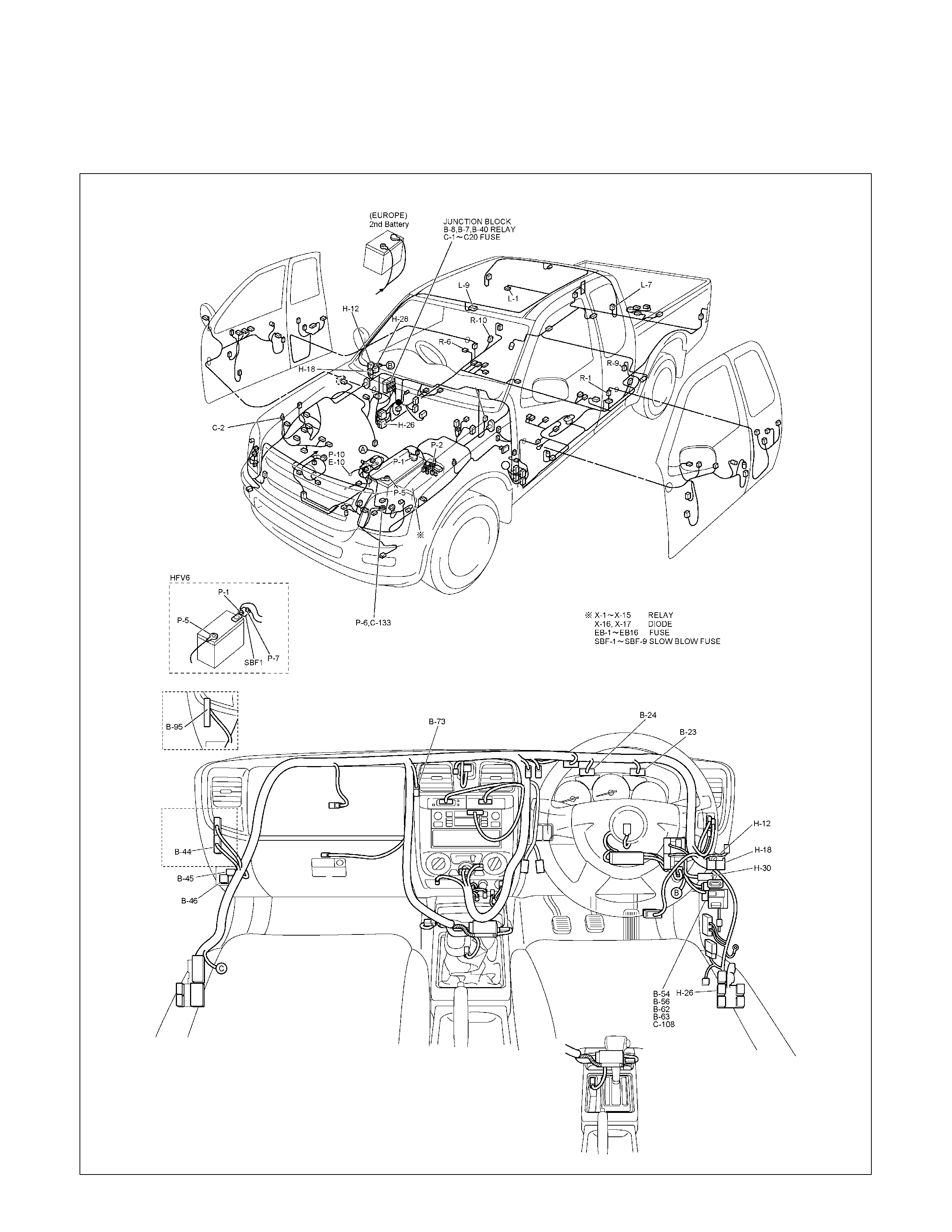
DOME LIGHT, SPOT LIGHT, MAP LIGHT AND WARNING BUZZER
PARTS LOCATION (RHD)
RTW68AXF014801 & RTW68AXF014901
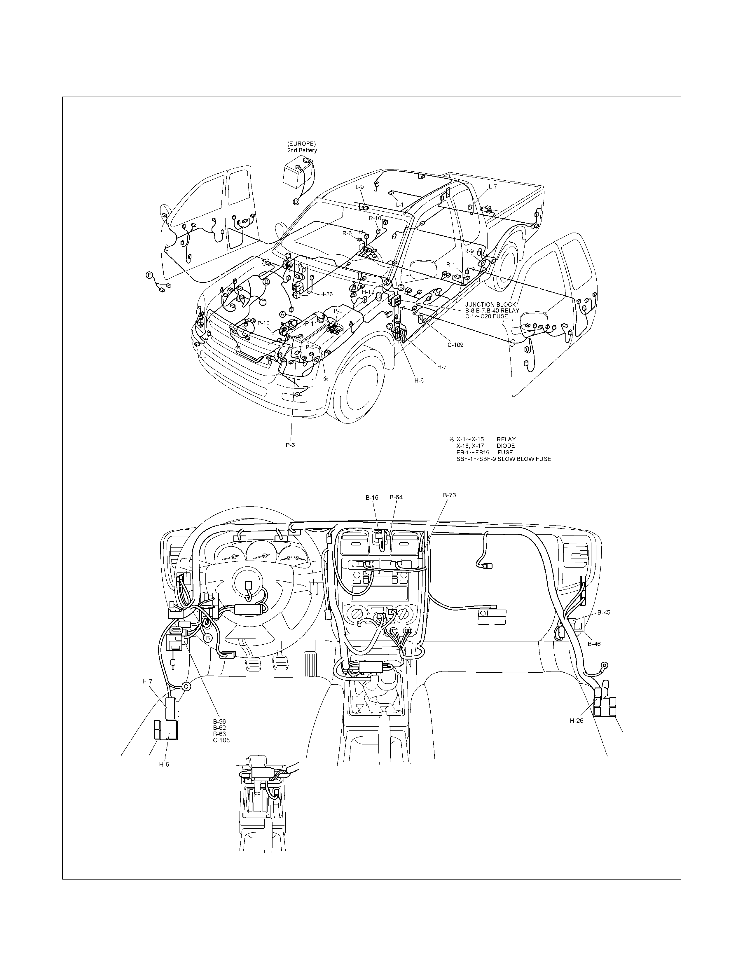
PARTS LOCATION (LHD)
RTW48AXF017201 & RTW48AXF017301
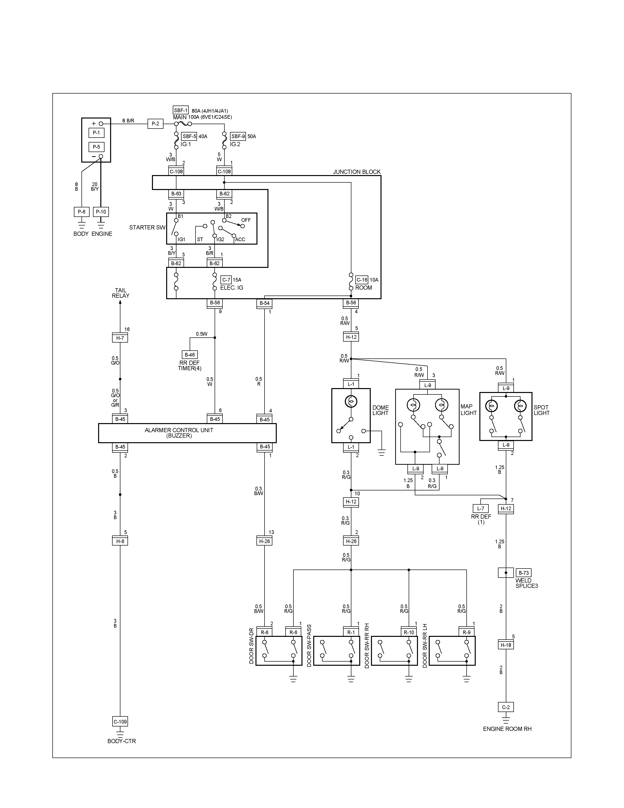
CIRCUIT DIAGRAM WITHOUT ANTI THEFT (RHD)
RTW680XF008301
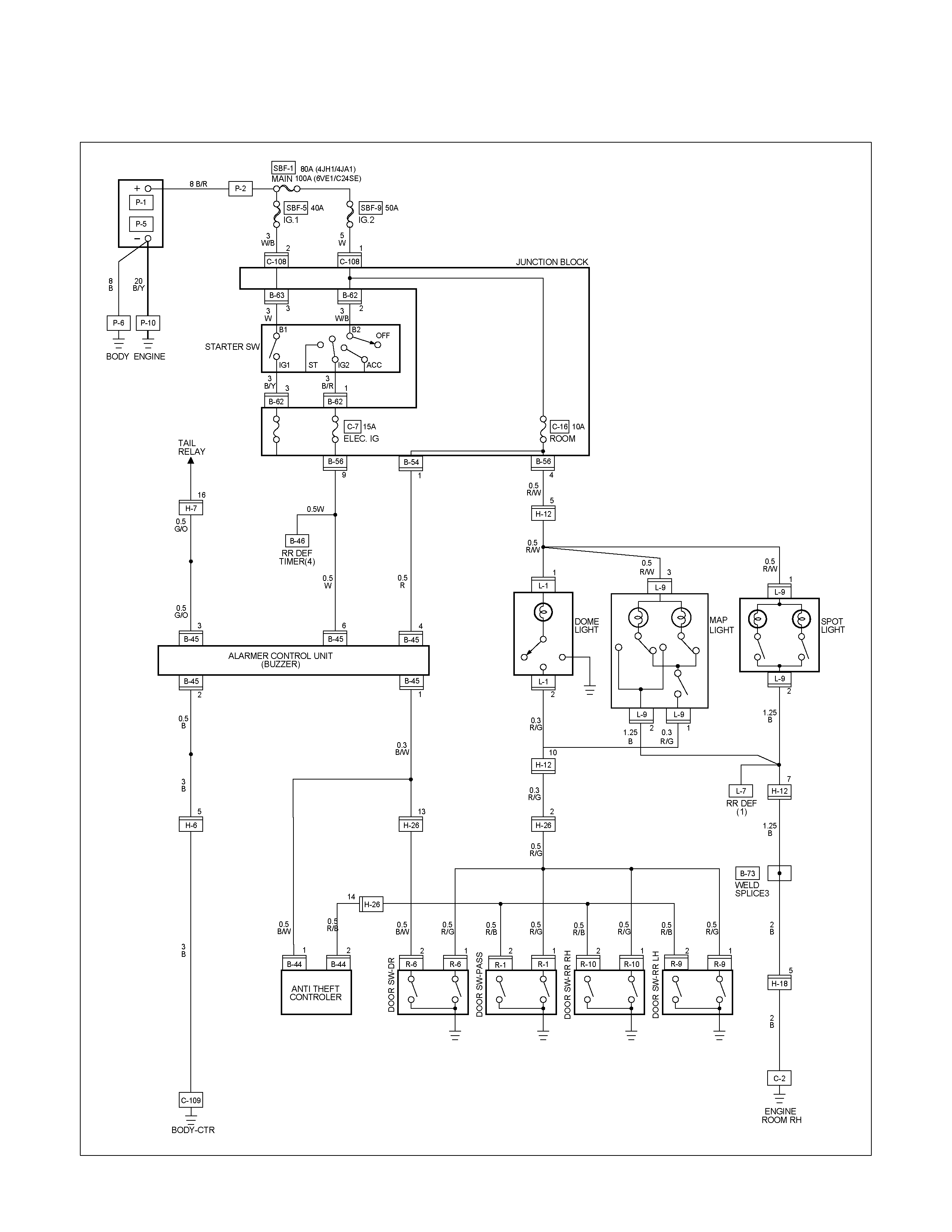
CIRCUIT DIAGRAM WITH ANTI THEFT (RHD)
RTW680XF008401
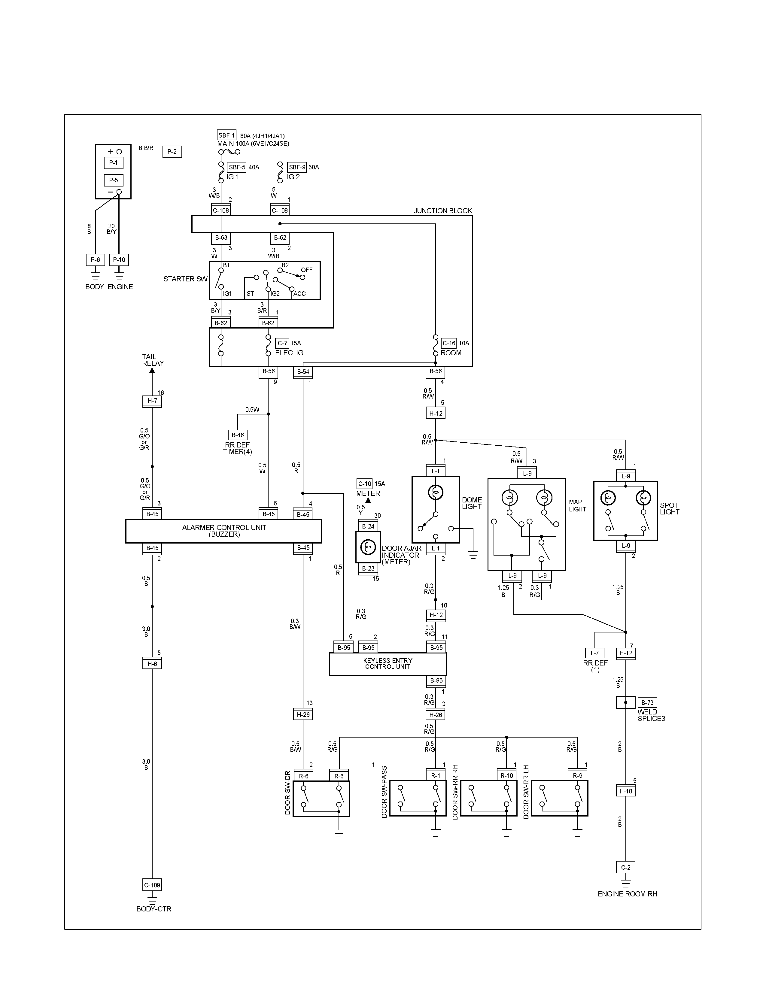
CIRCUIT DIAGRAM EXCEPT HFV6 WITH KEYLESS ENTRY (RHD)
RTW680XF008501

CIRCUIT DIAGRAM HFV6 WITH KEYLESS ENTRY (RHD)
RTW68AXF011001
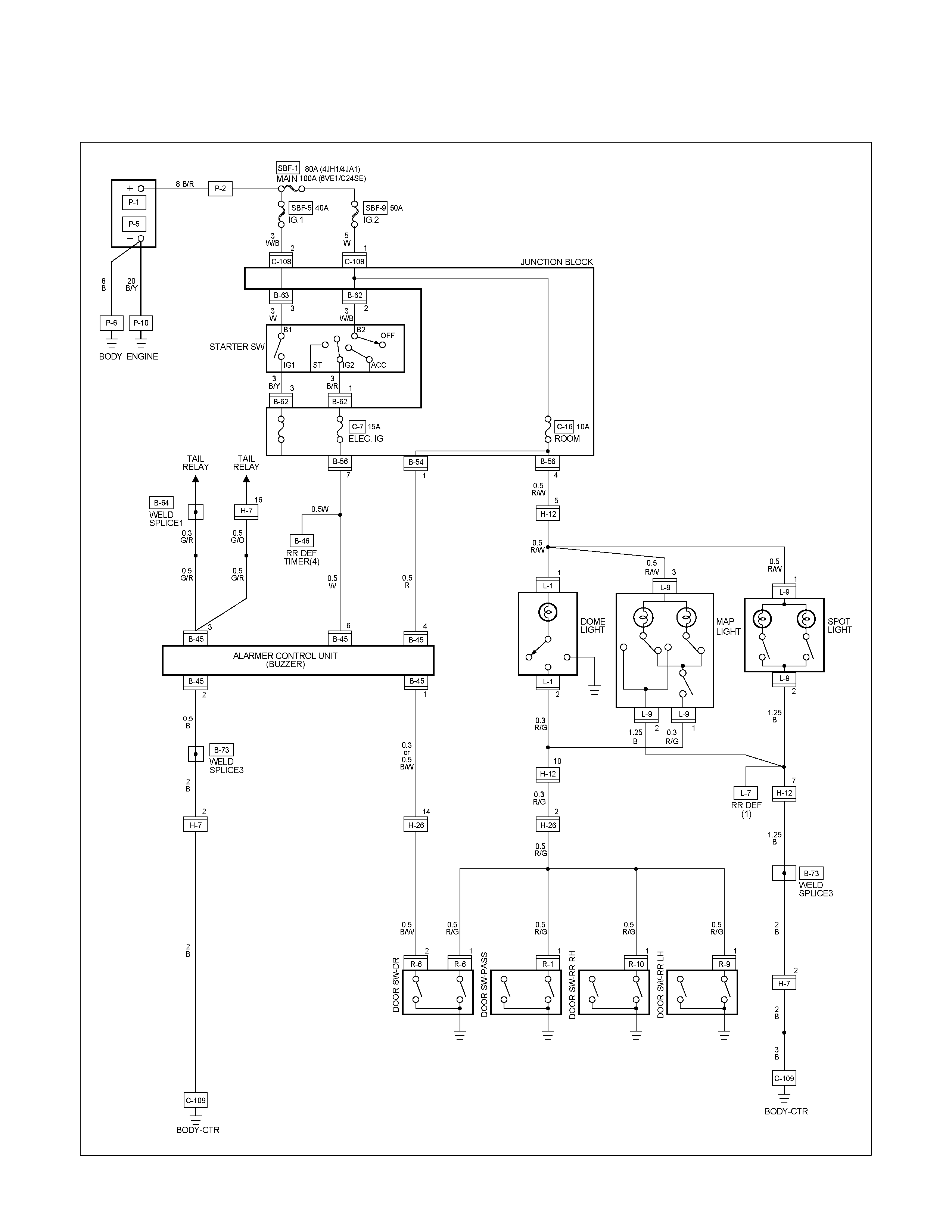
CIRCUIT DIAGRAM WITHOUT ANTI THEFT (LHD)
RTW680XF008601
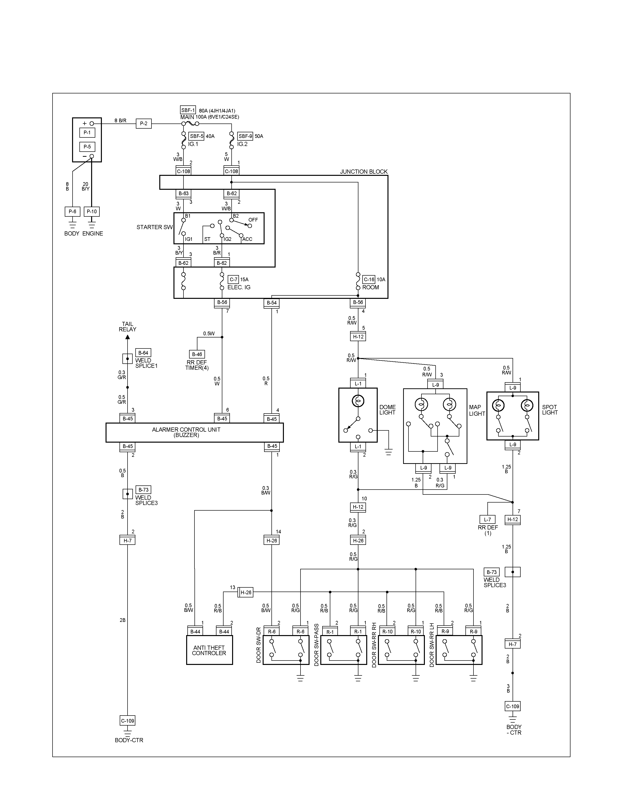
CIRCUIT DIAGRAM WITH ANTI THEFT (LHD)
RTW680XF008701
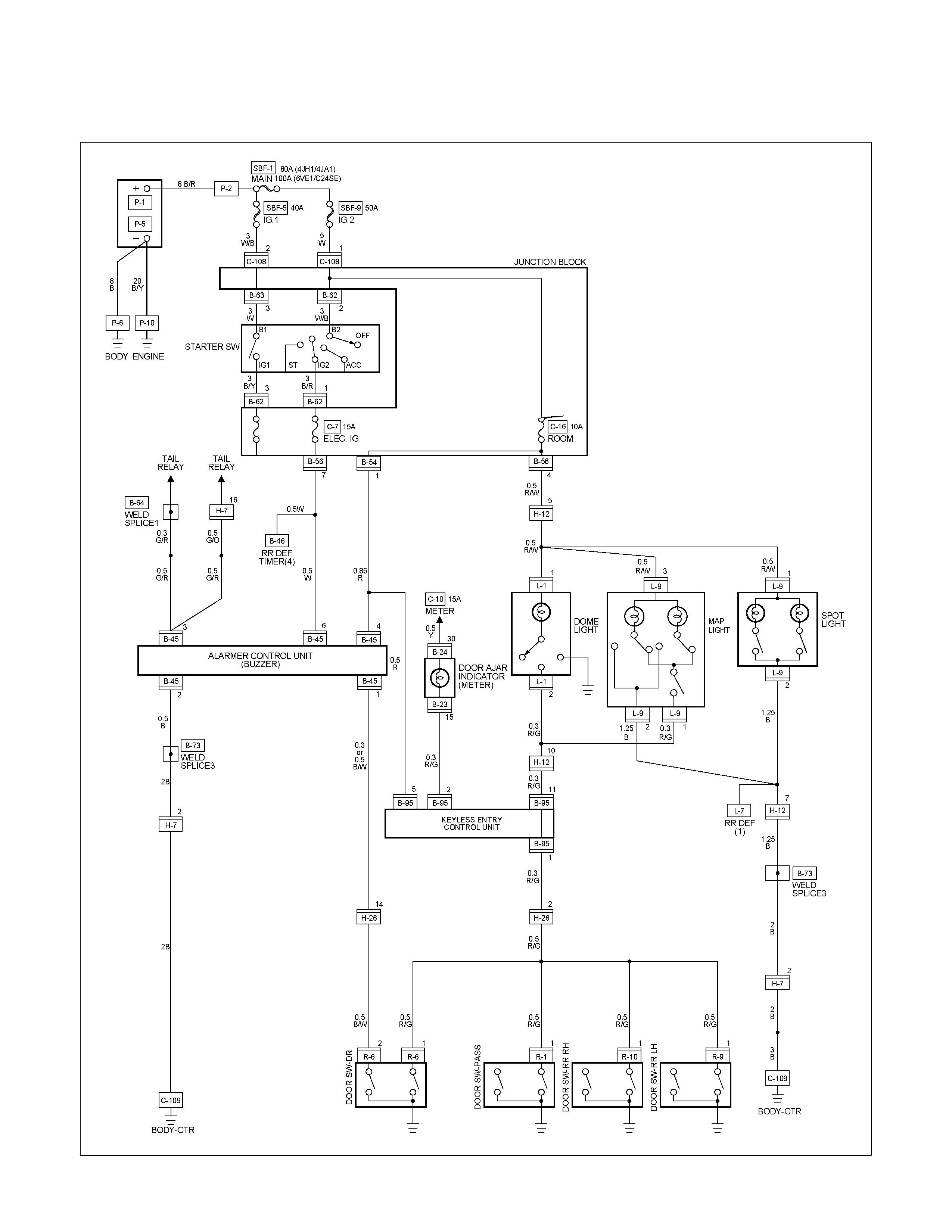
CIRCUIT DIAGRAM WITH KEYLESS ENTRY (LHD)
RTW680XF008801
TROUBLESHOOTING
1. Dome light dose not light
Checkpoint Trouble Cause Countermeasure
Replace the dome light bulb
Burned out the bulb
NG
Repair or replace the dome
light assembly
Dome light switch function
Switch malfunction
Repair open circuit or
connector contact
Continuity between
connector 5 H-12 - 1 L-1
Open circuit or poor connector
contact
NG
NG
OK
OK
Dome light bulb continuity
2. Dome light does not go out
Repair or replace the door
switch
Switch malfunction or foreign
material switch
NG
Repair short circuit or
connector contact
Continuity between
connector 2 L-1 -ground
when shutting the door
(Should be no continuity)
Short circuit
NG
OK
Door switch function (Both
side)
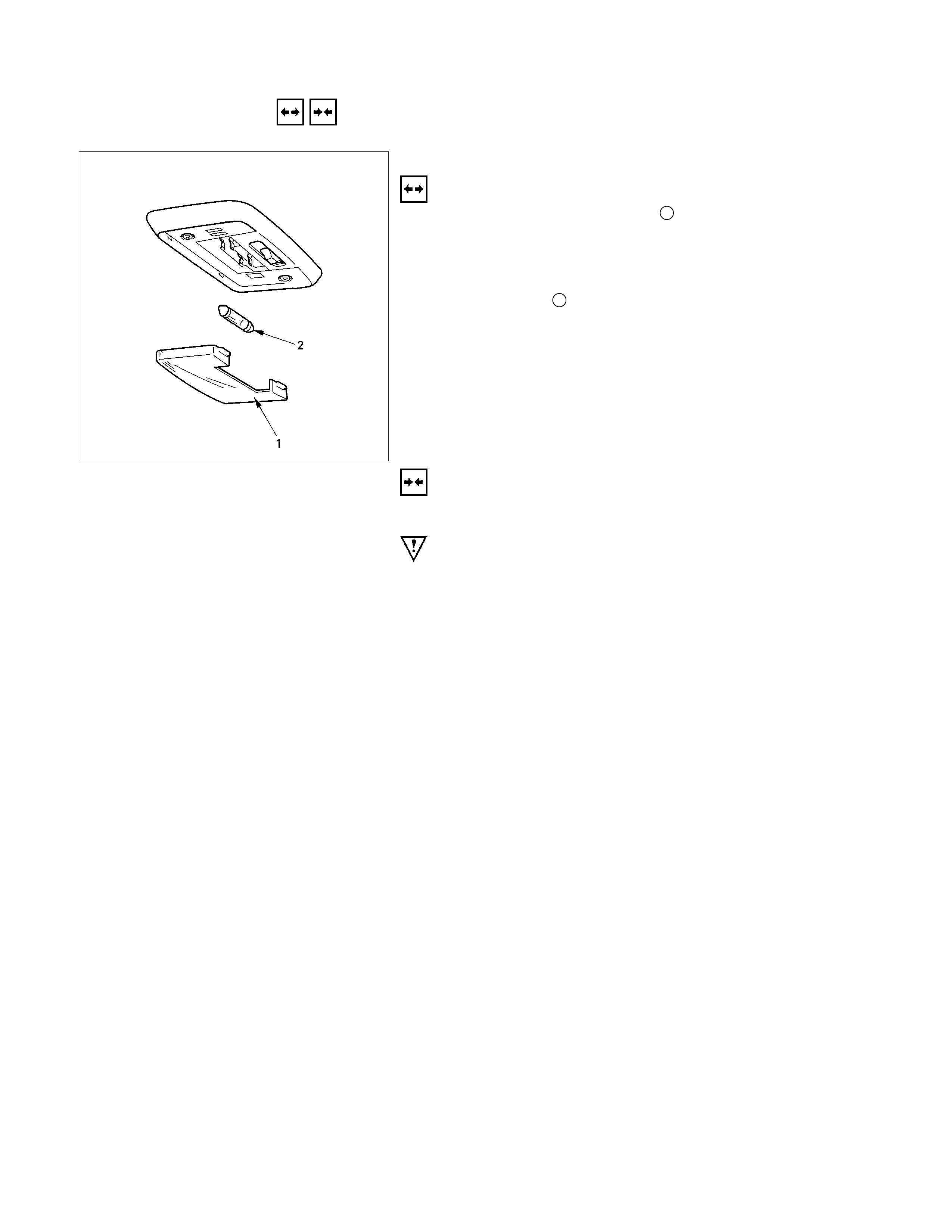
REMOVAL AND INSTALLATION
DOME LIGHT
Removal
1. Remove the dome light lens 1 free.
2. Remove two dome light fixing screws.
3. Remove the wiring connector.
4. Remove the dome light.
5. Pull the bulb 2 to remove it.
Installation
Follow the removal procedure in the reverse order to install the
dome light.
Pay close attention to the important points mentioned in the
following paragraphs.
Bulb
Be absolutely sure that the dome light bulb is correctly
installed.
This will prevent a poor contact and an open circuit.
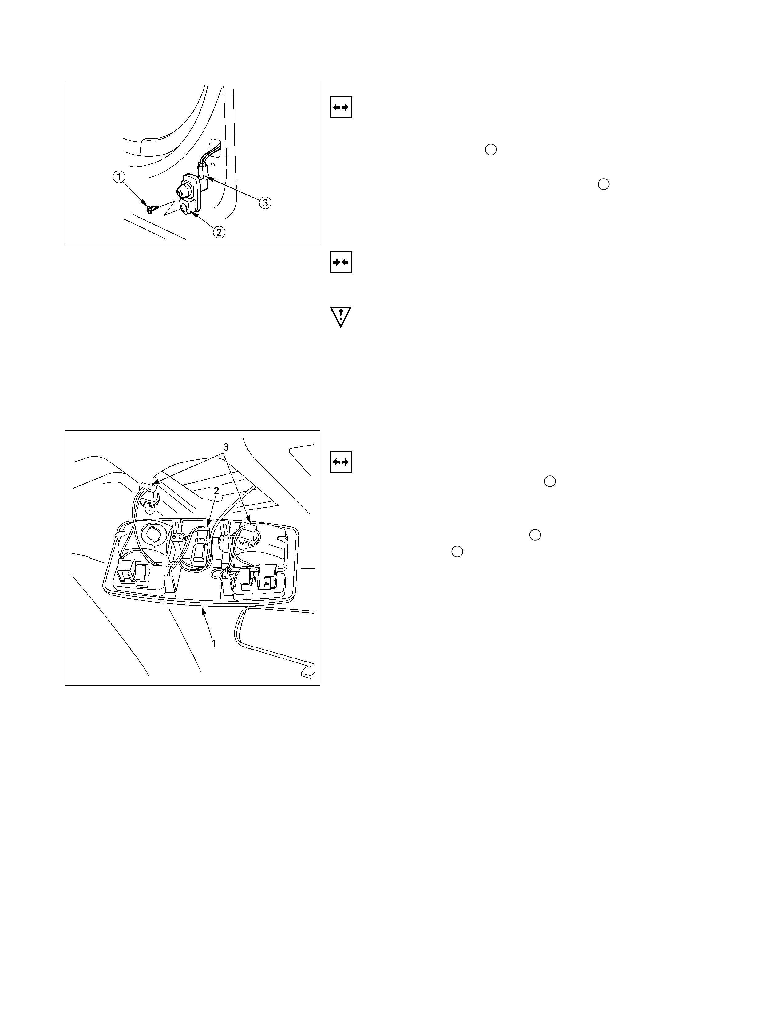
DOOR SWITCH
Removal
1. Disconnect the battery ground cable.
2. Loosen the screw 1.
3. Remove the door switch.
4. Disconnect the door switch connector 3.
Installation
Follow the removal procedure in the reverse order to install the
spot light.
Pay close attention to the important points mentioned in the
following paragraphs.
Connector
Be absolutely sure that the door switch connector is securely
connected.
This will prevent a poor contact and an open circuit.
SPOT LIGHT (MAP Light)
Removal
1. Grasp the spot light housing 1 with both hands.
Pull the housing straight down.
This will release the clip.
2. Disconnect the connector 2.
3. Turn socket 3 counterclockwise to remove it.

Installation
Follow the removal procedure in the reverse order to install the
spot light.
Pay close attention to the important points mentioned in the
following paragraphs.
Connector
Be absolutely sure that the spot light connector is securely
connected.
This will prevent a poor contact and an open circuit.
Bulb
Be absolutely sure that the spot light bulb is correctly installed.
This will prevent a poor contact and an open circuit.
RUW580SH001501
RUW580SH001601
OVER HEAD CONSOLE (MAP Light)
Removal
1. Open the lid (1) and a remove the fastener (2).
2. A steel scale equivalent article is inserted in a lens side
hook part and the crevice A section with roof lining, a metal
clip (5) is pushed in, and a over head consol (3) is removed
3. Disconnect the connector.
4. Push the bulb socket (4) in and turn it counterclockwise to
remove it.
Installation
Follow the removal procedure in the reverse order to install the
front map light.
Pay close attention to the important points mentioned in the
following paragraphs.
Bulb
Be absolutely sure that the front map light bulb is correctly
installed.
This will prevent a poor contact and an open circuit.
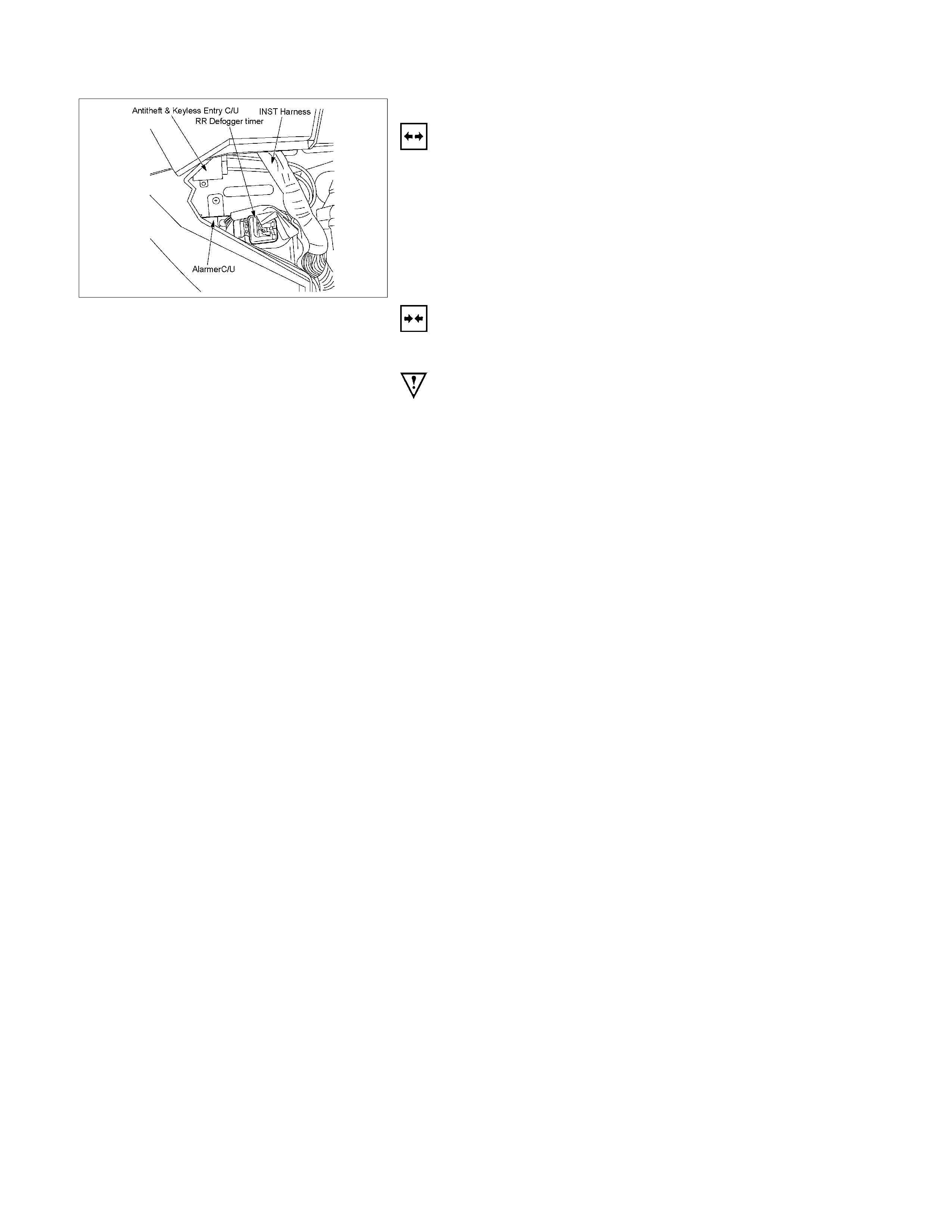
RTW48ASH000801
WARNING BUZZER (ALARMER
CONTROL UNIT)
Removal
1. Disconnect the battery ground cable.
2. Remove the glove box
• Remove the screw.
3. Remove the Alarmer C/U assembly
• Remove the screw.
Installation
Follow the removal procedure in the reverse order to install the
warning buzzer.
Pay close attention to the important points mentioned in the
following paragraphs.
Connector
Be absolutely sure that the warning buzzer connector is
securely connected.
This will prevent a poor contact and an open circuit.
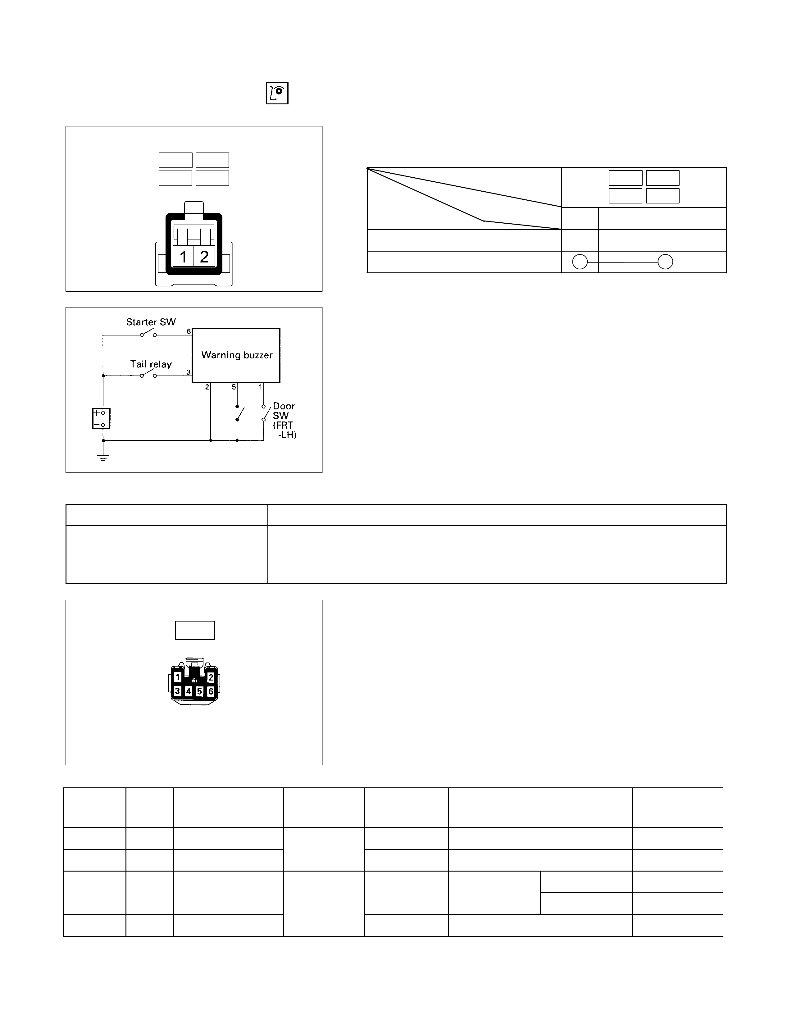
INSPECTION AND REPAIR
R-9 R-10
R-1 R-6
DOOR SWITCH
Door Switch Connections
Connector
SW No. R-9 R-10
R-1 R-6
position Terminal No.
1 Body Ground
PUSHED
RELEASED
WARNING BUZZER
1. Warning Buzzer Circuit
Warning function Operational conditions
Taillights left on The buzzer sounds when both the tail relay and the FRT door switch-drive
side are turned on. To stop the sound of the buzzer, turn on the starter
switch.
Harness side
B-45
2. Warning Buzzer Harness Side Connector Circuit
Disconnect the warning buzzer connector and check
continuity and voltage between the warning buzzer harness
side connector terminals.
Terminal
NO. Wire
color Connecting to Check item Connecting
terminal Check condition Standard
3 G/R Tail relay 3-Ground Lighting SW “ON” Approx. 12V
6 Y Fuse CB-5 Voltage 6-Ground Starter SW “ON” Approx. 12V
Door SW Open Continuity
(FRT-LH) Continuity Close No continuity
2 B Ground 2-Ground - Continuity
1 1-Ground FRT door-LH
B/W

WINDSHIELD WIPER AND WASHER
PARTS LOCATION (RHD)
RTW68AXF015001 & RTW68AXF015101
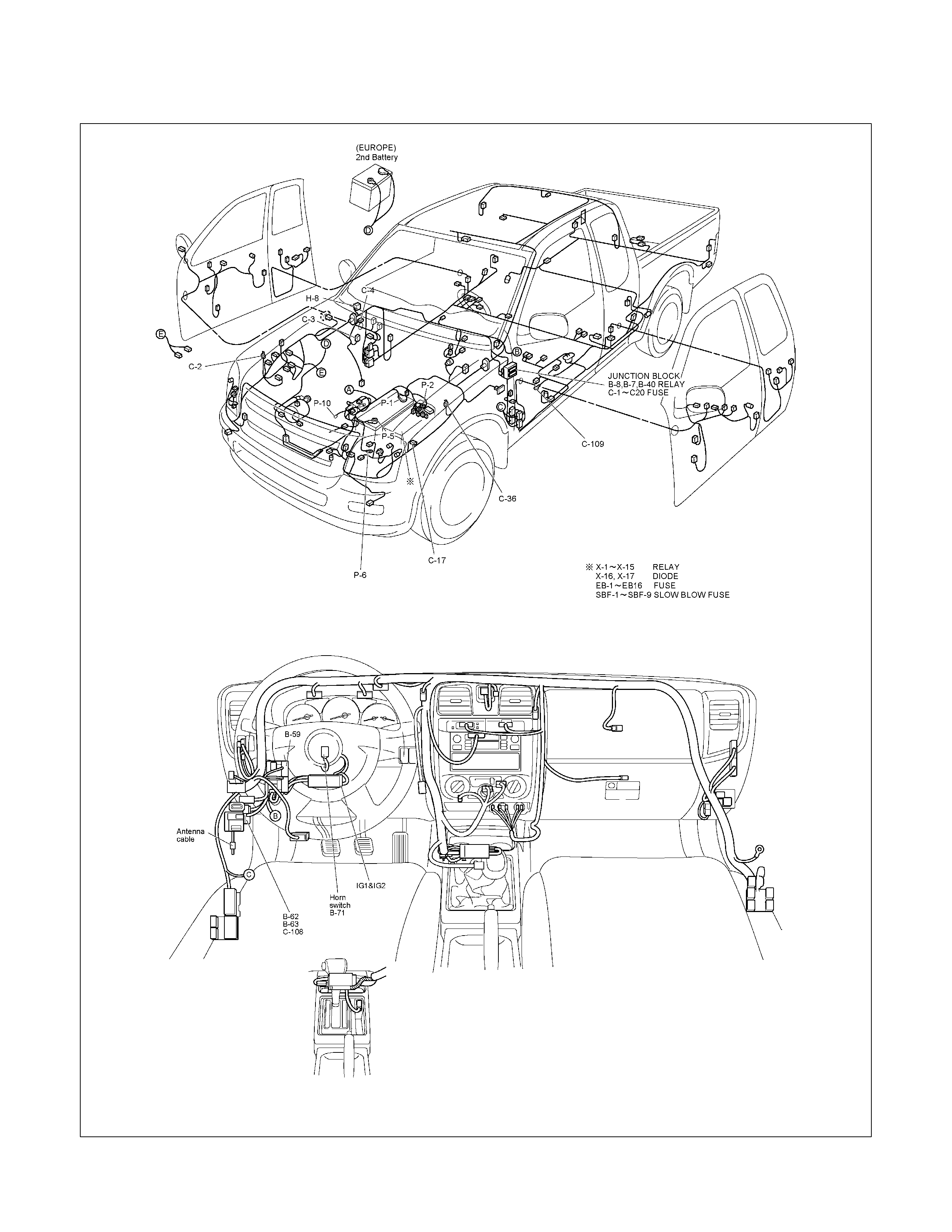
PARTS LOCATION (LHD)
RTW48AXF017601 & RTW48AXF017701
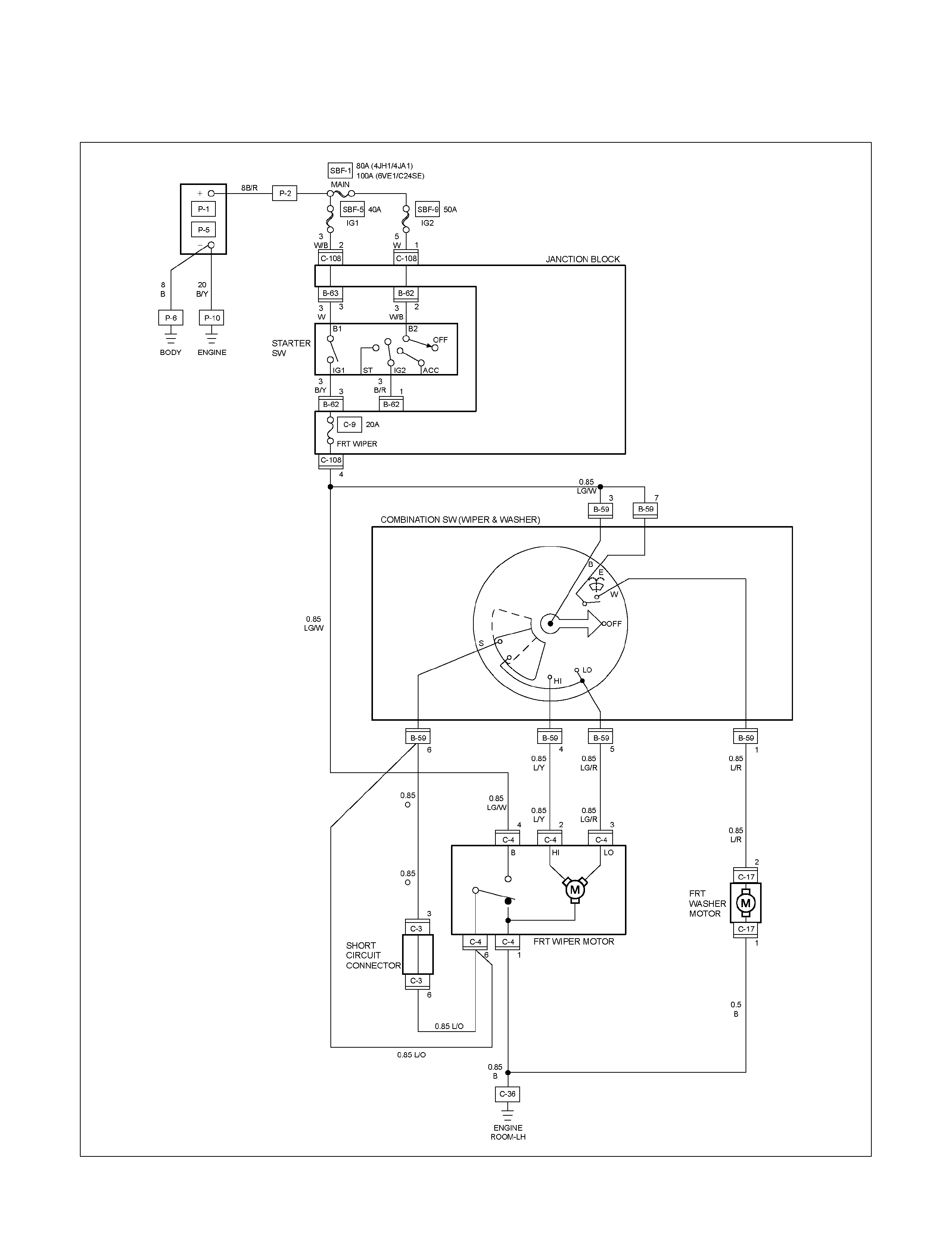
CIRCUIT DIAGRAM WITHOUT INTERMITTENT RELAY (RHD)
RTW680XF008901

CIRCUIT DIAGRAM EXCEPT HFV6 WITH INTERMITTENT RELAY (RHD)
RTW680XF009001
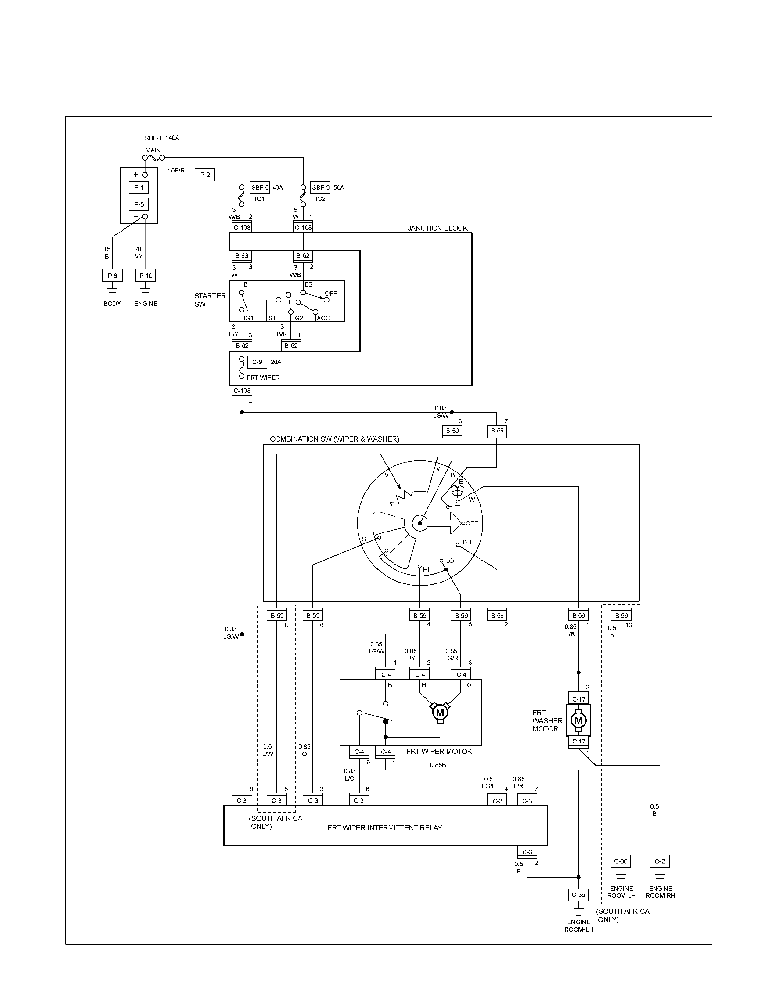
CIRCUIT DIAGRAM HFV6 WITH INTERMITTENT RELAY (RHD)
RTW68AXF011101
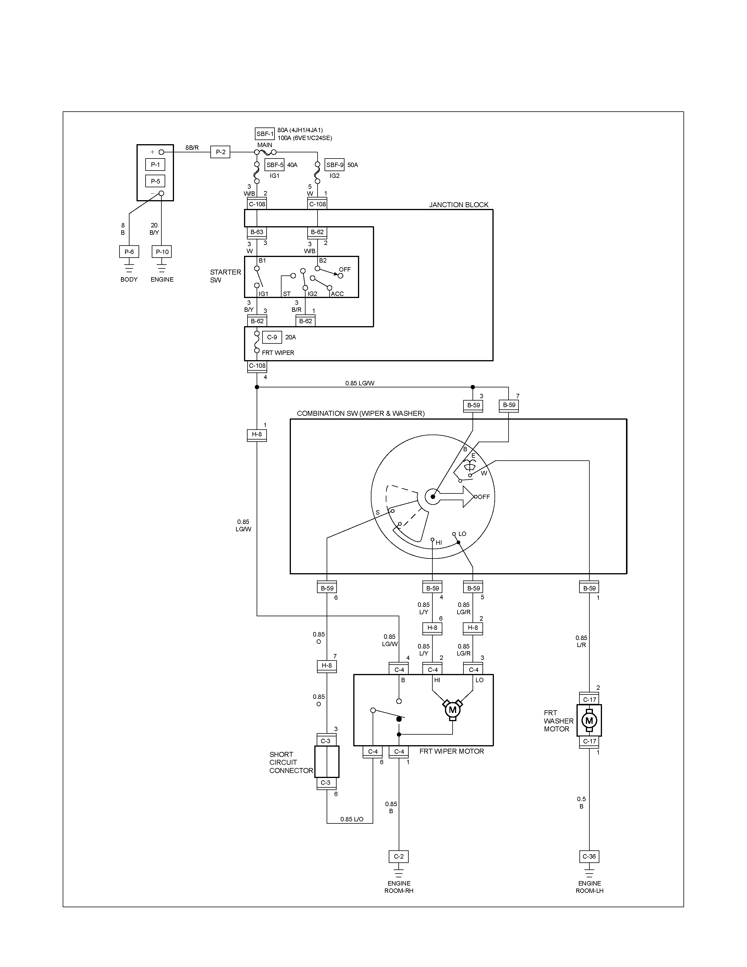
CIRCUIT DIAGRAM WITHOUT INTERMITTENT RELAY (LHD)
RTW680XF009101
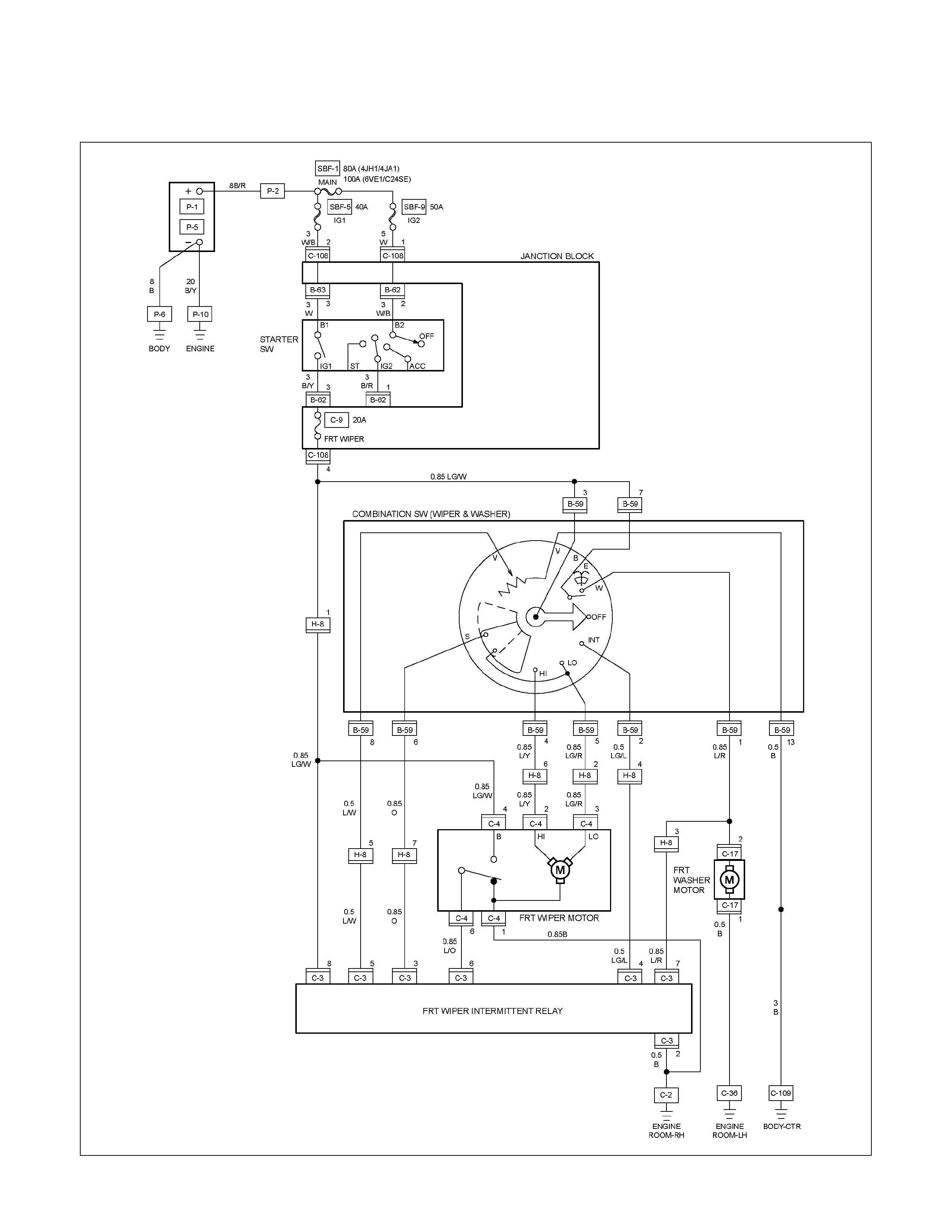
CIRCUIT DIAGRAM WITH INTERMITTENT RELAY (LHD)
RTW680XF009201
TROUBLESHOOTING
WINDSHIELD WIPER
1. Wiper dose not operate at any switch position
Checkpoint Trouble Cause Countermeasure
Reinstall or replace the fuse
No. C-9 (20A)
Poor fuse contact or blown
NG
Repair open circuit or
connector contact
1. Wiper motor function when
connecting the motor
connector 3 C-4 to the
battery (+) terminal, and 1
C-4 to the (-) terminal
(Should the wiper motor
rotate at a low speed)
2. Wiper motor function when
connecting the motor
connector 2 C-4 to the
battery (+) terminal, 1 C-4
to the (-) terminal (Should
the wiper motor rotate at a
high speed)
Voltage between 3 B-59 and
the ground (Should be battery
voltage present)
Open circuit or poor connector
contact
Replace the wiper & washer
SW.
Continuity in the wiper &
washer SW.
SW. malfunction
NG
NG
OK
OK
Fuse No. C-9 (20A)
Repair grounding point contact
Grounding point C-2 (LHD),
C-36 (RHD)
Poor grounding point contact
NG
OK
OK
Replace the wiper motor
Wiper motor malfunction
NG
Repair open circuit or
connector contact
Continuity between 1 C-4
and C-36 (RHD), C-2 (LHD)
Open circuit or poor connector
contact
NG
OK
2. Wiper dose not operate at “ INT “ position
Checkpoint Trouble Cause Countermeasure
Replace the wiper & washer
SW.
SW. malfunction
NG
Repair grounding point contact
Grounding point C-36 (RHD),
C-2 (LHD)
Poor grounding point contact
Repair open circuit or
connector contact
Voltage between the
intermittent relay harness side
connector terminal 4 C-3
and the ground at the “INT”
position (Should be battery
voltage present)
Open circuit or poor connector
contact
NG
NG
OK
OK
Continuity between the wiper
& washer SW connector
terminals 4 B-59 and 2 B-59
at the “ INT “ position
Replace the intermittent relay
Intermittent relay function
Relay malfunction
NG
OK
3. Wiper does not operate at “LO” position
Replace the wiper motor
Wiper motor function
1. Disconnect the wiper &
washer SW. connector
2. Turn the starter SW. on
3. Short-circuit between the
wiper & washer SW.
harness side connector
terminal 4 B-59 and 5
B-59 .
4. Check to see if the wiper
motor rotates at a low
speed
Wiper motor malfunction
NG
Replace the wiper & washer
SW.
Wiper & washer SW. function
SW. malfunction
NG
OK
4. Wiper does not operate at “HI” position
Checkpoint Trouble Cause Countermeasure
Repair open circuit or
connector contact
Open circuit or poor connector
contact
NG
Replace the wiper motor
Wiper motor function when
connecting the motor
connector 2 C-4 to the
battery (+) terminal, and 1
C-4 to the (-) terminal
(Should the wiper motor rotate
at a high speed)
Wiper motor malfunction
NG
OK
Continuity between the wiper
& washer SW. connector
terminals 4 B-59 at the “HI”
position
Repair open circuit or
connector contact
Continuity between 4 B-59
and 2 C-4
Open circuit or poor connector
contact
NG
OK
5. Rotation of the wiper motor does not stop
Replace the wiper & washer
SW.
SW. malfunction
NG
OK
Continuity in the wiper &
washer SW.
Replace the wiper motorWiper motor function Wiper motor malfunction
NG
6. Auto-stop function of the wiper motor does not operate
Checkpoint Trouble Cause Countermeasure
Repair open circuit or
connector contact
Open circuit or poor connector
contact
NG
Repair open circuit or
connector contact
Open circuit or poor connector
contact
NG
Continuity between the
intermittent relay harness side
connector 6 C-3 and the
wiper motor harness side
connector 6 C-4
Replace the intermittent relay
Relay malfunction
NG
Intermittent relay function
Wiper motor function
1. Disconnect the wiper motor
connector
2. Connect the motor
connector 5 B-59 to the
battery (+) terminal and 1
C-4 to the (-) terminal,
and then change the
connection of the battery (+)
terminal to the connector 4
C-4 while the motor
rotating at a low speed
3. Check to see if the wiper
motor stops at the auto stop
position when connecting
the connector terminals 3
C-4 and 1 C-4 in this
condition
Continuity between the wiper
& washer SW. connector
terminals 5 B-59 and 6 B-59
at the “OFF” position
OK
Replace the wiper motor
Wiper motor malfunction
NG
Repair an open circuit or a
poor connection of the
connectors between the fuse
No. C-9 (20A) and 4 C-4
Voltage between the wiper
motor harness side connector
terminal 4 C-4 and the
ground (Should be battery
voltage present)
Open circuit or poor connector
contact
NG
OK
OK
OK
WASHER
1. Washer motor does not operate
Checkpoint Trouble Cause Countermeasure
Reinstall or replace the fuse
No. C-9 (20A)
Poor fuse contact or blown
NG
Repair or an open circuit or a
poor connection of the
connectors between 2 C-17
and 1 B-59
Open circuit or poor connector
contact
NG
Voltage between the washer
motor harness side connector
terminal 2 C-17 and the
ground when the washer
button is depressed (Should
be battery voltage present)
Repair grounding point C-36
contact
Poor grounding point contact
NG
Grounding point C-36
Replace the washer motor
Motor malfunction
NG
Washer motor function when
connecting the motor side
connector 2 C-17 to the
battery (+) terminal, and the
connector 1 C-17 to the (-)
terminal (Should the washer
motor rotate)
OK
Repair open circuit or
connector contact
Open circuit or poor connector
contact
NG
Continuity between 1 C-17
and C-36
OK
Continuity between the wiper
& washer SW. side connector
terminals 1 B-59 and 7 B-59
when the washer button is
depressed
Fuse No. C-9 (20A)
OK
Replace the wiper & washer
SW.
SW. malfunction
NG
Repair or an open circuit or a
poor connection of the
connectors between the fuse
No. C-9 (20A) and 7 B-59
Voltage between the wiper &
washer SW. harness side
connector terminal 7 B-59
and the ground (Should be
battery voltage preset)
Open circuit or poor connector
contact
NG
OK
OK
OK
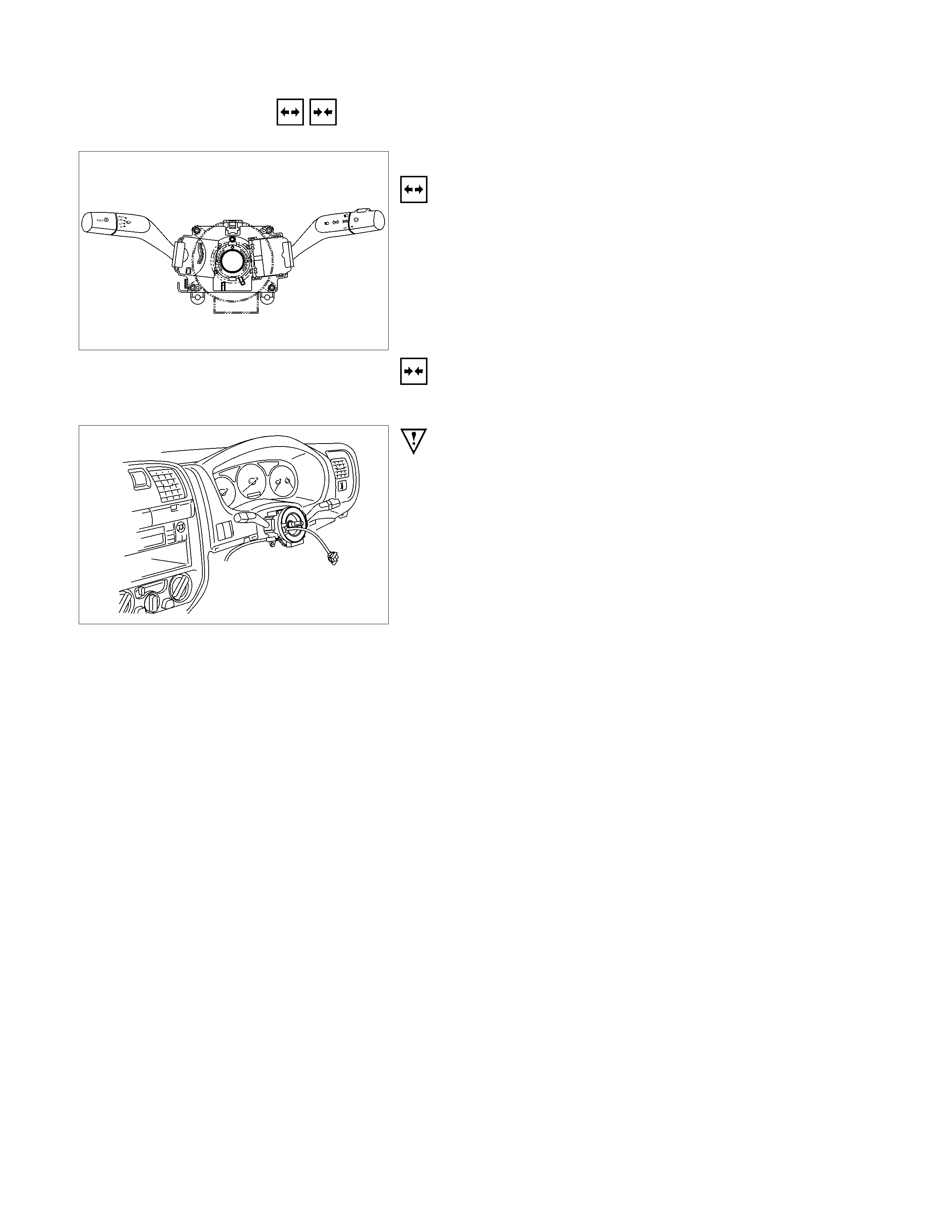
REMOVAL AND INSTALLATION
WIPER AND WASHER SWITCH
Removal
Refer to the removal steps of the LIGHTING SWITCH
(COMBINATION SWITCH) in “ LIGHTING “ of this section.
Installation
Follow the removal procedure in the reverse order to install the
wiper and washer switch.
This illustration is based on RHD model
Pay close attention to the important points mentioned in the
following paragraphs.
Connector
Be absolutely sure that the wiper and washer switch connector
is securely connected.
This will prevent a poor contact and an open circuit.
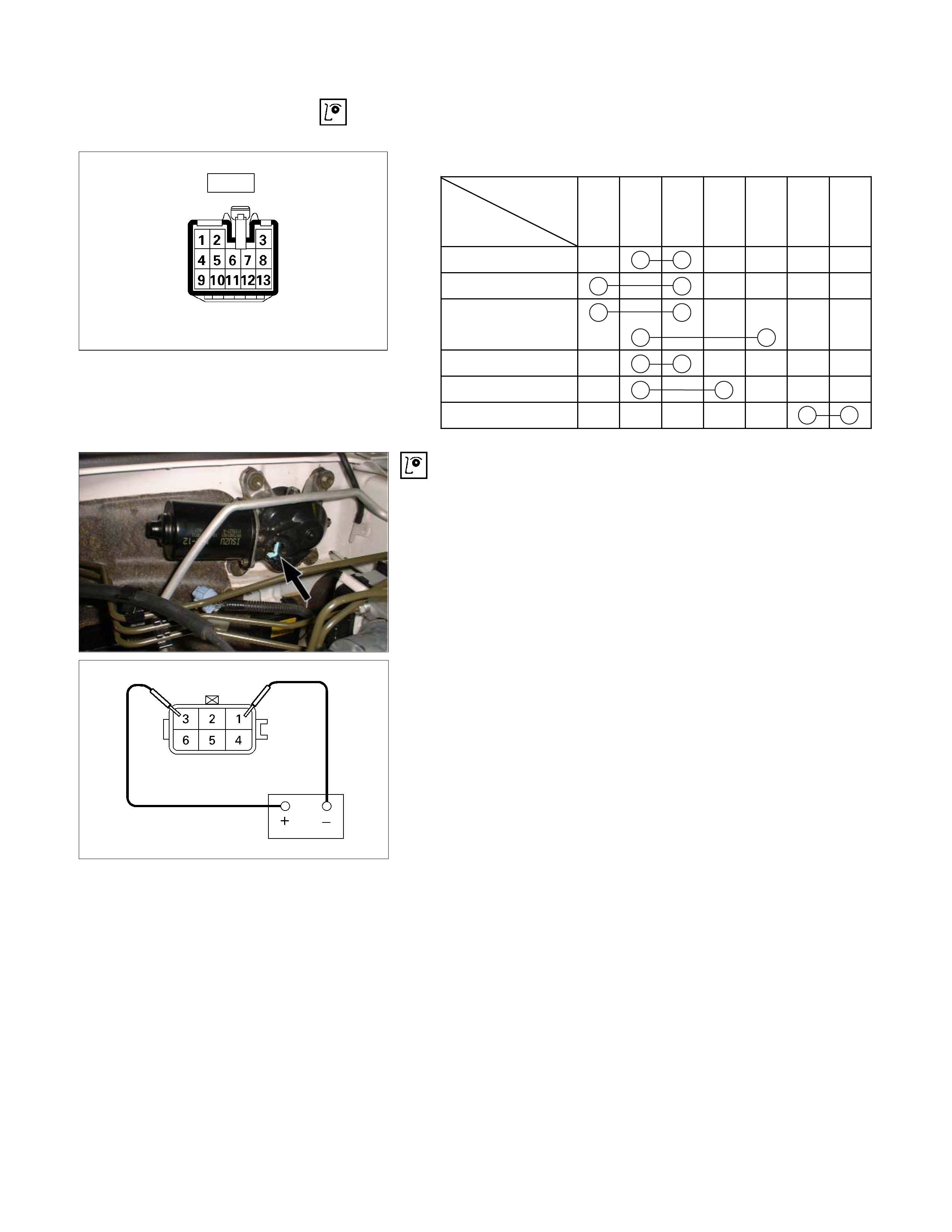
INSPECTION AND REPAIR
Switch side
B-59
Control Switch Connections
Terminal
No.
SW position 6 3 5 4 2 7 1
Mist
Off
INT
Lo
Hi
Wash
Wiper Motor Inspection
Connector
Low Speed Inspection
1. Clamp the wiper motor in a vise.
The moving parts must be clear of the vise.
2. Connect the connector terminals to the battery.
Refer to the illustration.
3. Check the wiper motor low speed operation.
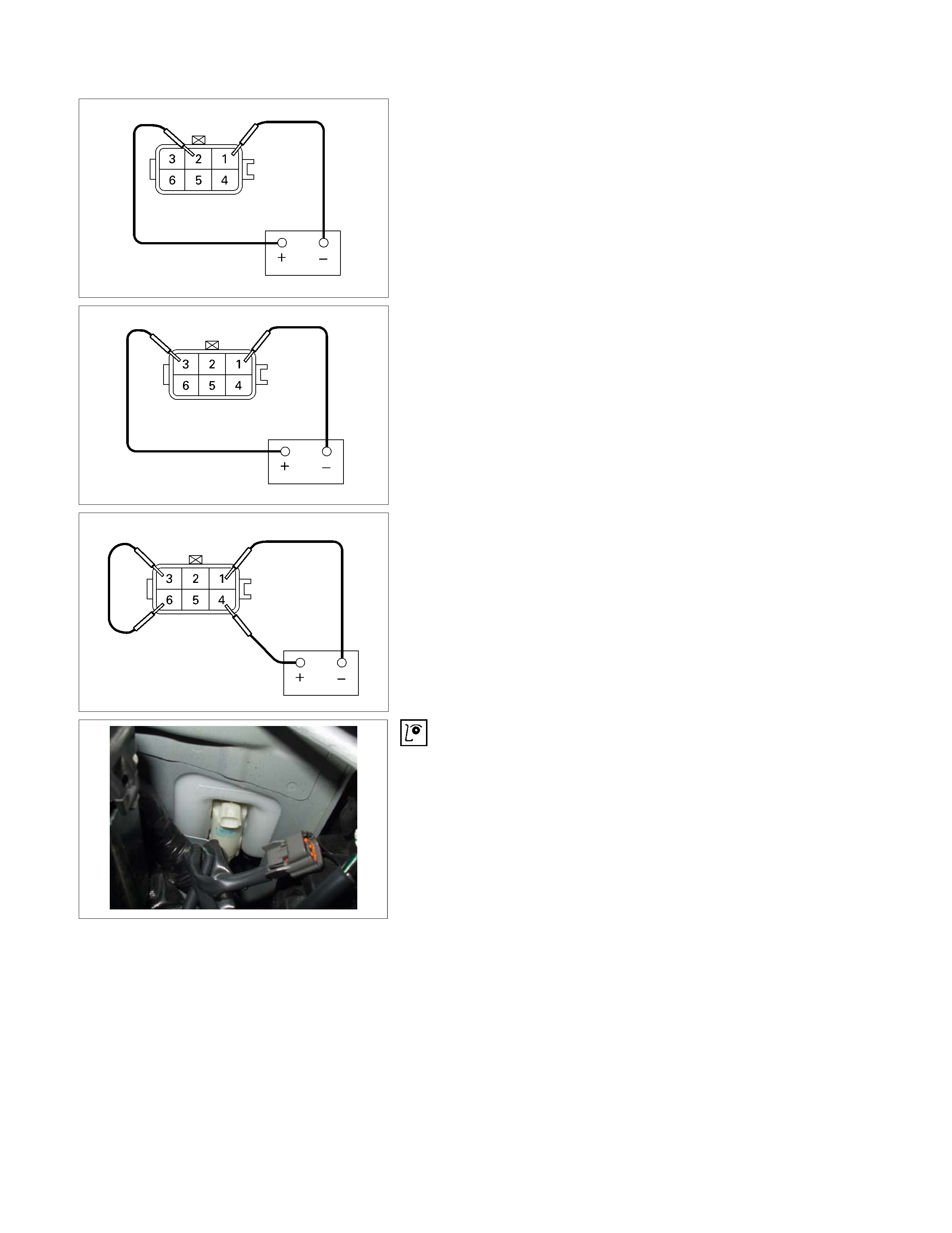
High Speed Inspection
1. Clamp the wiper motor in a vise.
The moving parts must be clear of the vise.
2. Connect the connector terminals to the battery.
Refer to the illustration.
3. Check the wiper motor high speed operation.
Auto-Stop Inspection
1. Clamp the wiper motor in a vise.
The moving parts must be clear of the vise.
2. Connect the connector terminals to the battery.
Refer to the illustration.
3. Check the wiper motor low speed operation.
4. Disconnect the positive battery terminal.
This will stop the motor.
5. Connect the connector terminals No. 3 and No. 6 with a
lead wire.
Refer to the illustration.
6. Reconnect the positive battery terminal to connecto
r
terminal No. 4.
This will restart the motor.
Refer to the illustration.
7. Check the auto-stop operation.
Washer Motor Inspection
1. Fill the washer tank with washing solution.
2. Disconnect the motor connector.
3. Apply battery voltage to the washer motor connector.
4. Check the washer motor operation.
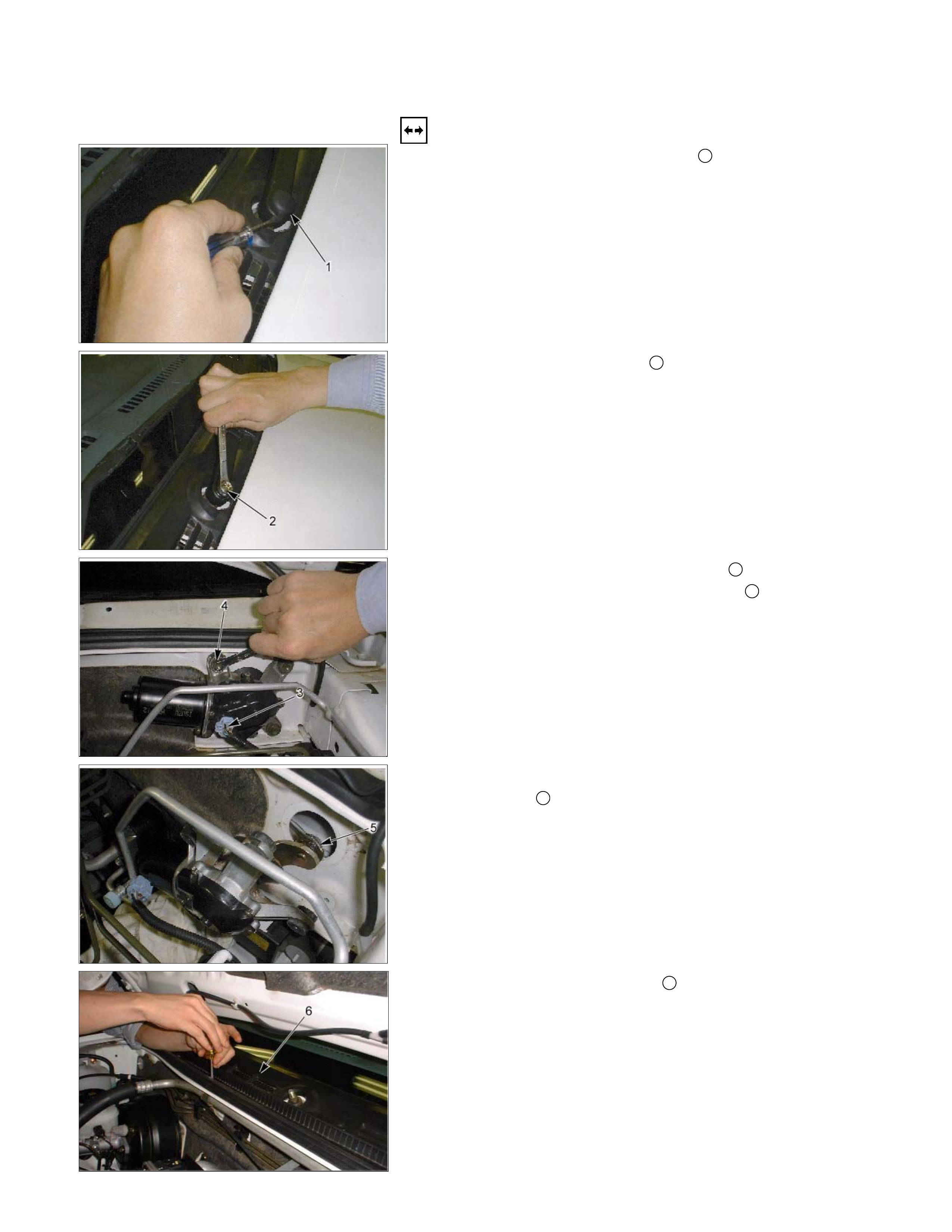
WIPER MOTOR AND LINKAGE
Removal
1. Disconnect the wiper arm nut cap 1 .
2. Remove the wiper arm nut 2.
3. Remove the wiper arm with blade.
4. Disconnect the wiper motor connector 3 .
5. Remove the wiper motor bracket screws 4 .
6. Disconnect the wiper motor from the wiper linkage at the
crank arm 5.
7. Remove the vent cowl cover 6.
• Remove the 6 screw.
This illustration is based on RHD model
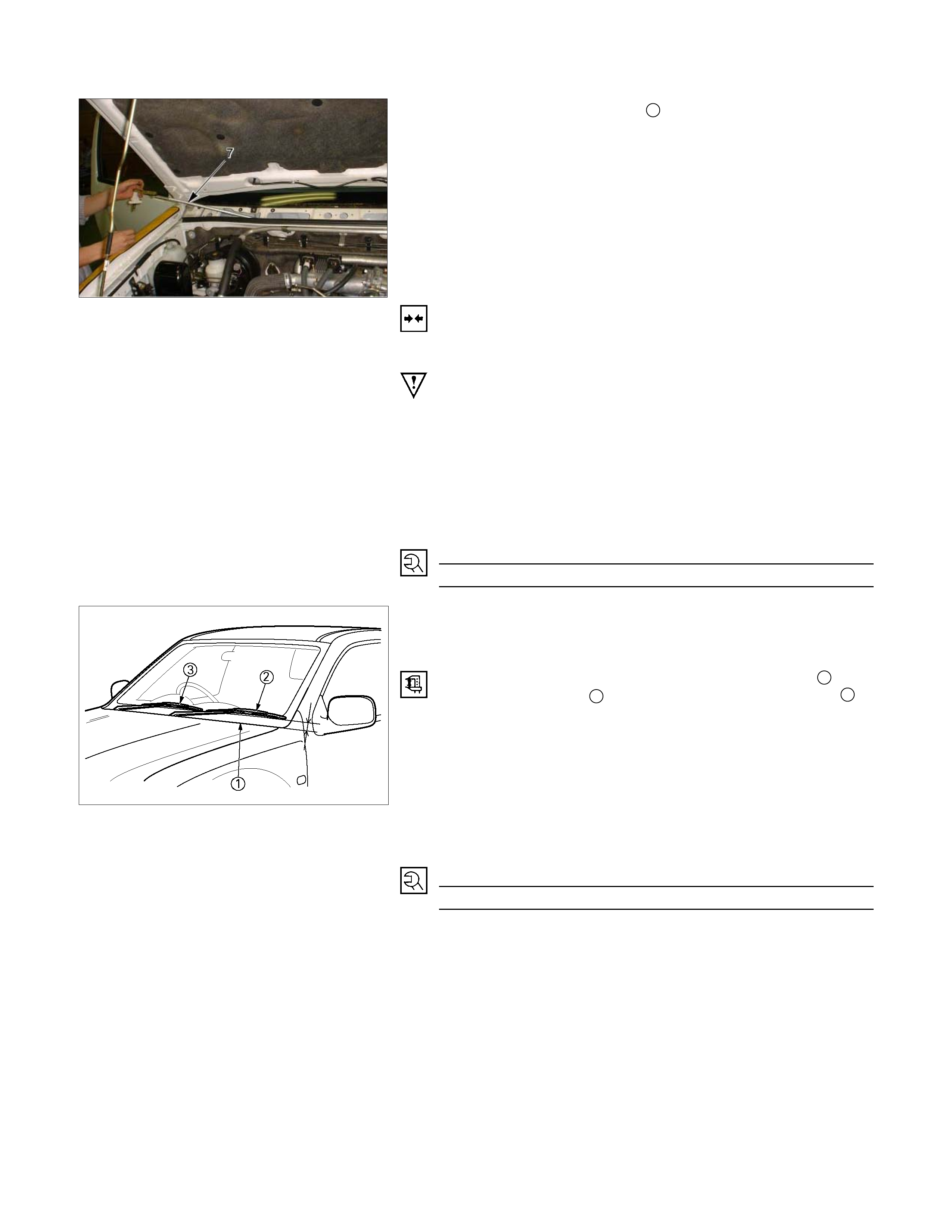
8. Remove the wiper linkage 7 from the access hole.
Installation
Follow the removal procedure in the reverse order to install the
wiper motor and linkage.
Pay close attention to the important points mentioned in the
following paragraphs.
Wiper Linkage
Take care not to scratch the painted surfaces of the body
when installing the wiper linkage to the body.
In case crank arm of wiper motor is removed, confirm the
position of auto stop prior to reinstall the crank arm to the
wiper motor.
Crank Arm Nut Torque N⋅m (kg⋅m/lb ft
)
20 − 26 (2.0 − 2.6 / 14.5 − 18.8)
880R300006
Wiper Blade Position
Confirm the auto stop position of wiper motor prior to the
installation of the wiper blade and arm.
The distance between the vent cowl cover rubber seal 1 and
the wiper blade edge 2 is about 52±7.5 mm (2.05±0.3 in) 3
40±7.5 mm (1.57±0.3 in).
Wiper Arm Nut
Tighten the wiper arm nut to the specified torque.
Wiper Arm Nut Torque N⋅m (kg⋅m/lb ft)
27 − 35 (2.75 − 3.57/19.94 − 25.85)
This illustration is based on RHD model
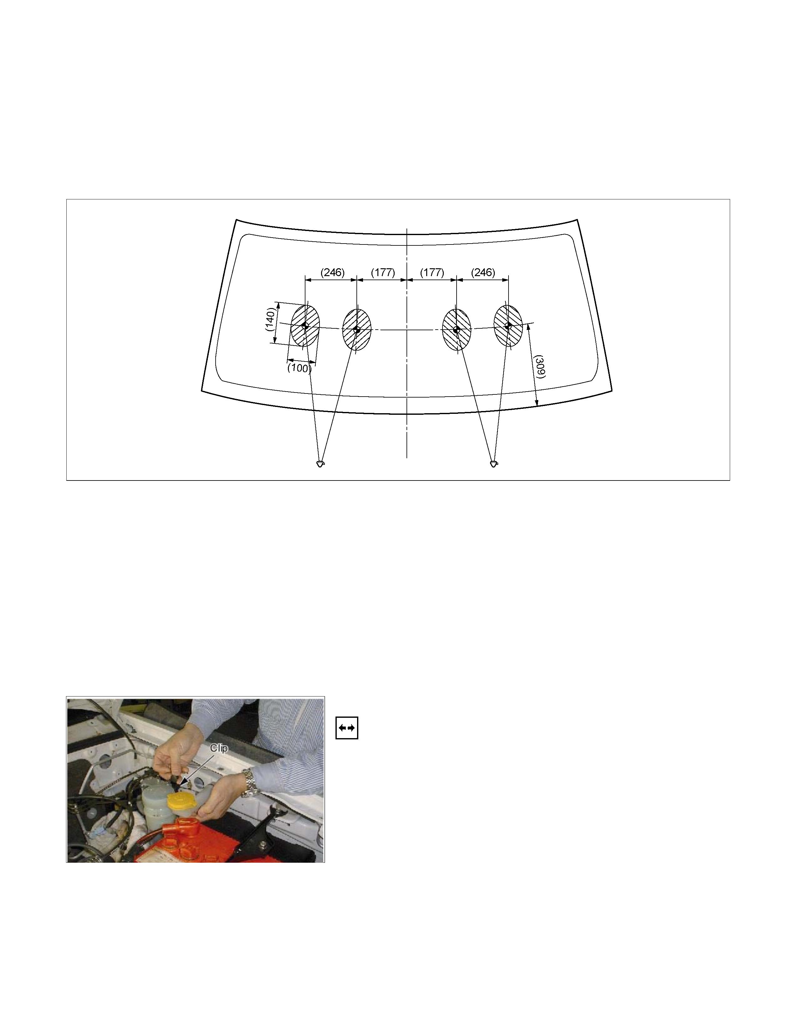
Windshield Washer Spray
Be sure that the engine hood is completely closed before
checking the windshield washer spray adjustment.
Windshield Washer Spray Position: Refer to the illustration.
RTW38DSF000201
Connector
Be absolutely sure that the wiper motor connector is securely
connected.
This will prevent a poor contact and an open circuit.
Note:
Windshield wiper arm and blade assembly configurations
are different for the right-hand and left-hand side of the
vehicle.
Be careful not to confuse the right-hand and left-hand
side assemblies.
This illustration is based on RHD model
WASHER TANK MOTOR
Removal
1. Remove the head light.
• Refer to the head light in this manual.
2. Remove the inner liner.
3. Pull out the clip washer filler.
4. Remove the washer tank nuts.
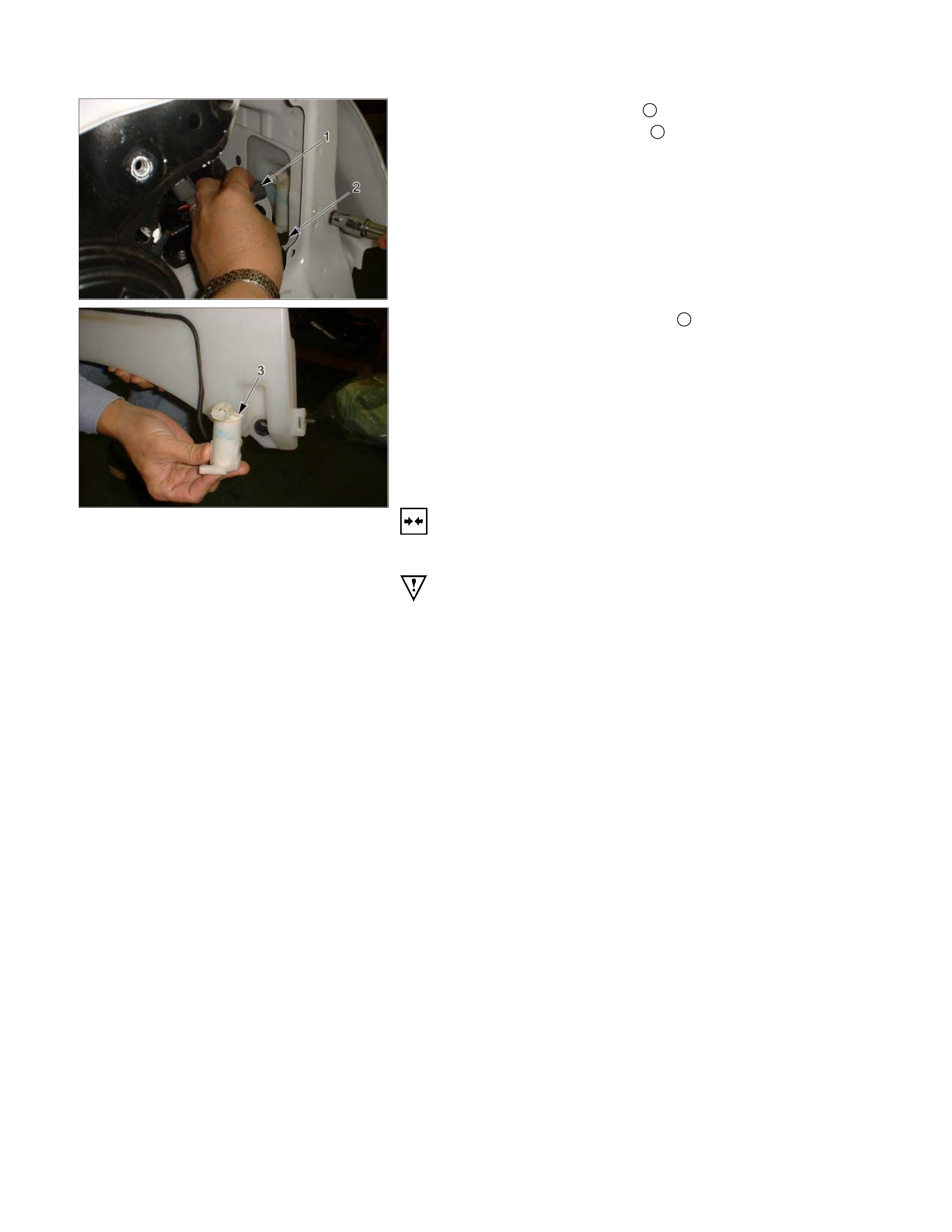
4. Disconnect the connector 1.
5. Disconnect the water hose 2.
6. Pull out the washer tank motor 3.
Installation
Follow the removal procedure in the reverse order to install the
washer tank motor.
Pay close attention to the important points mentioned in the
following paragraphs.
Connector
Be absolutely sure that the washer tank motor connector is
securely connected.
This will prevent a poor contact and an open circuit.
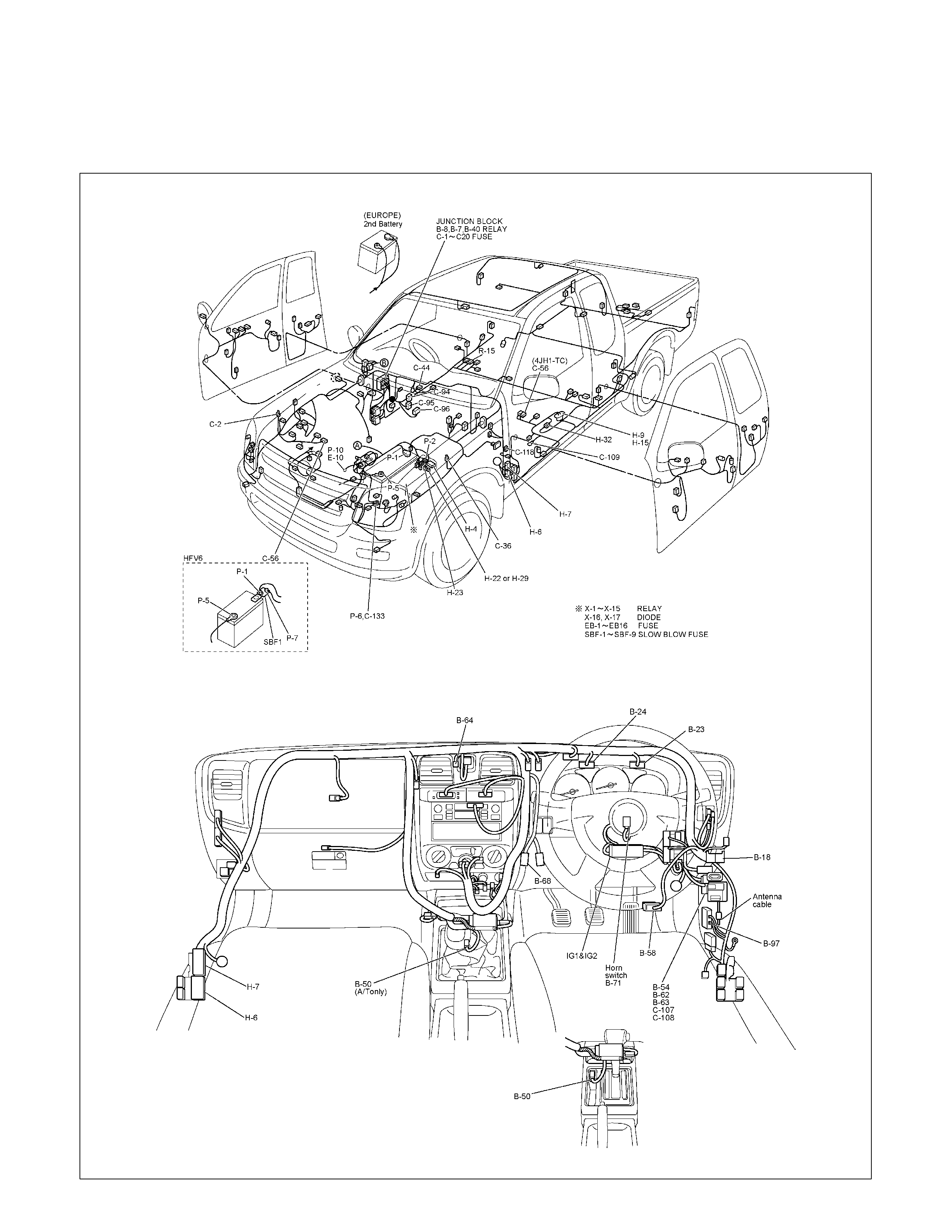
TRANSMISSION CONTROL MODULE (TCM)
PARTS LOCATION (RHD)
RTW68AXF018201 & RTW68AXF015201
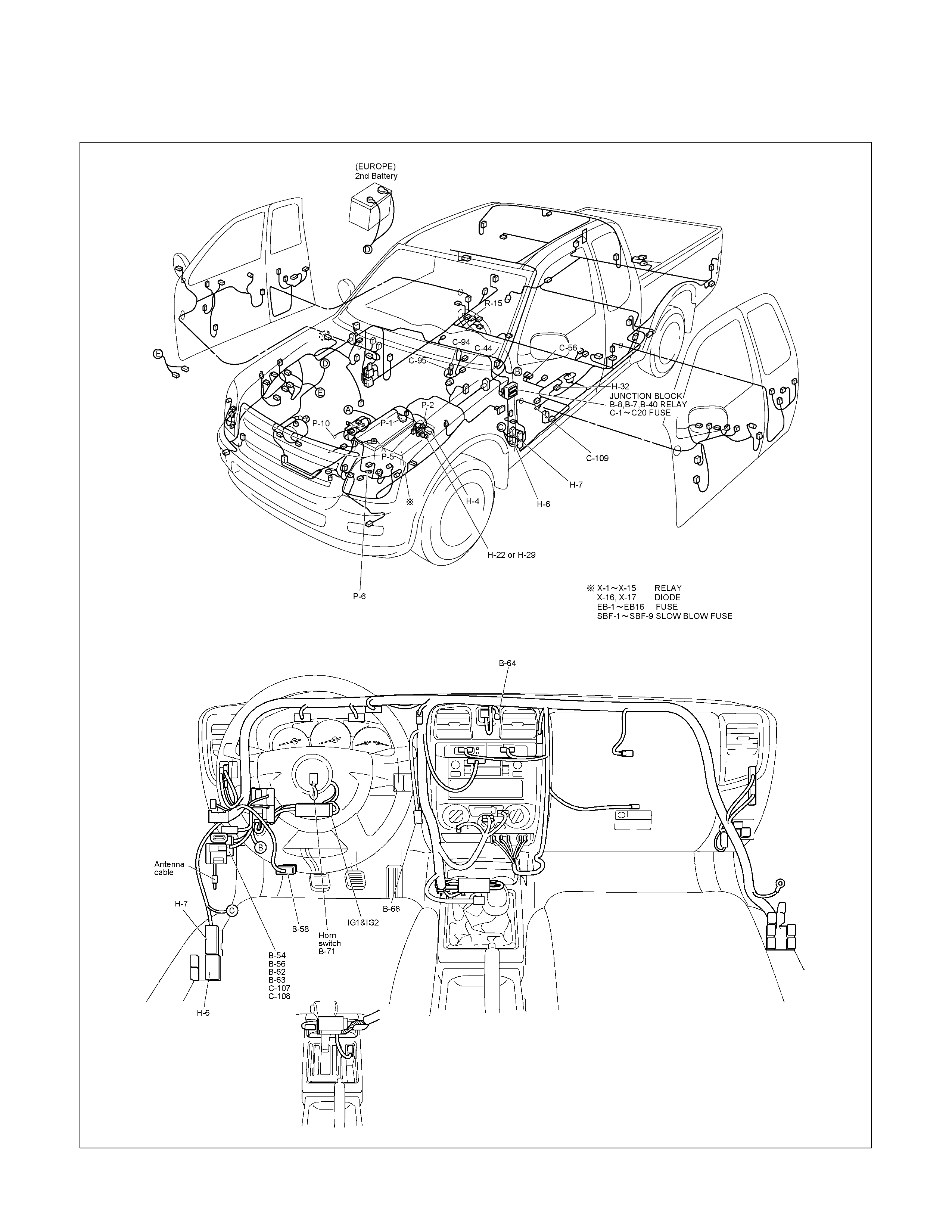
PARTS LOCATION (LHD)
RTW48AXF018001 & RTW48AXF018101

PARTS LOCATION 6VE1

PARTS LOCATION 4JH1-TC
RTW38DXF007601

PARTS LOCATION HFV6
RTW68AXF012201

PARTS LOCATION
RTW68AXF012801
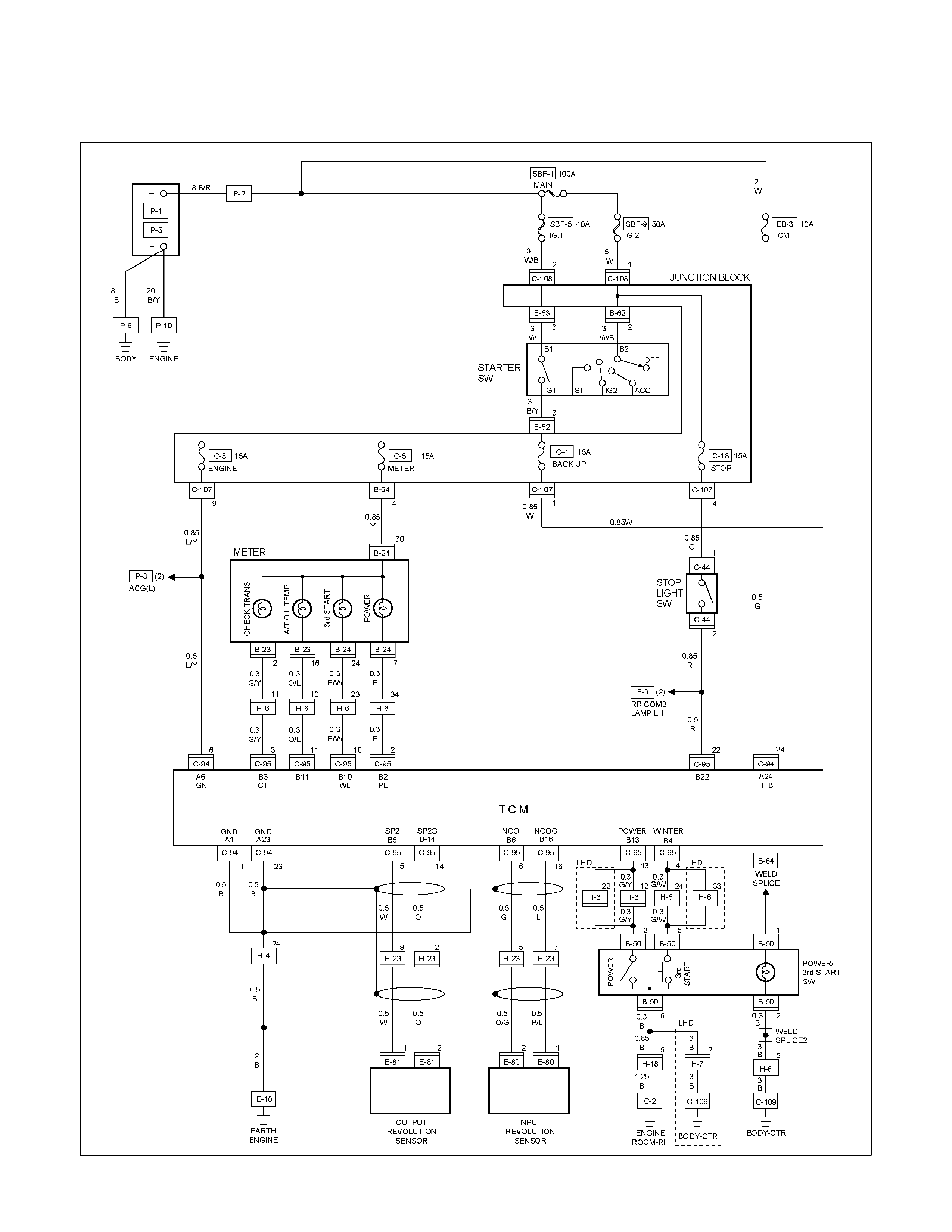
CIRCUIT DIAGRAM 6VE1 Sheet 1/2
RTW680XF009301
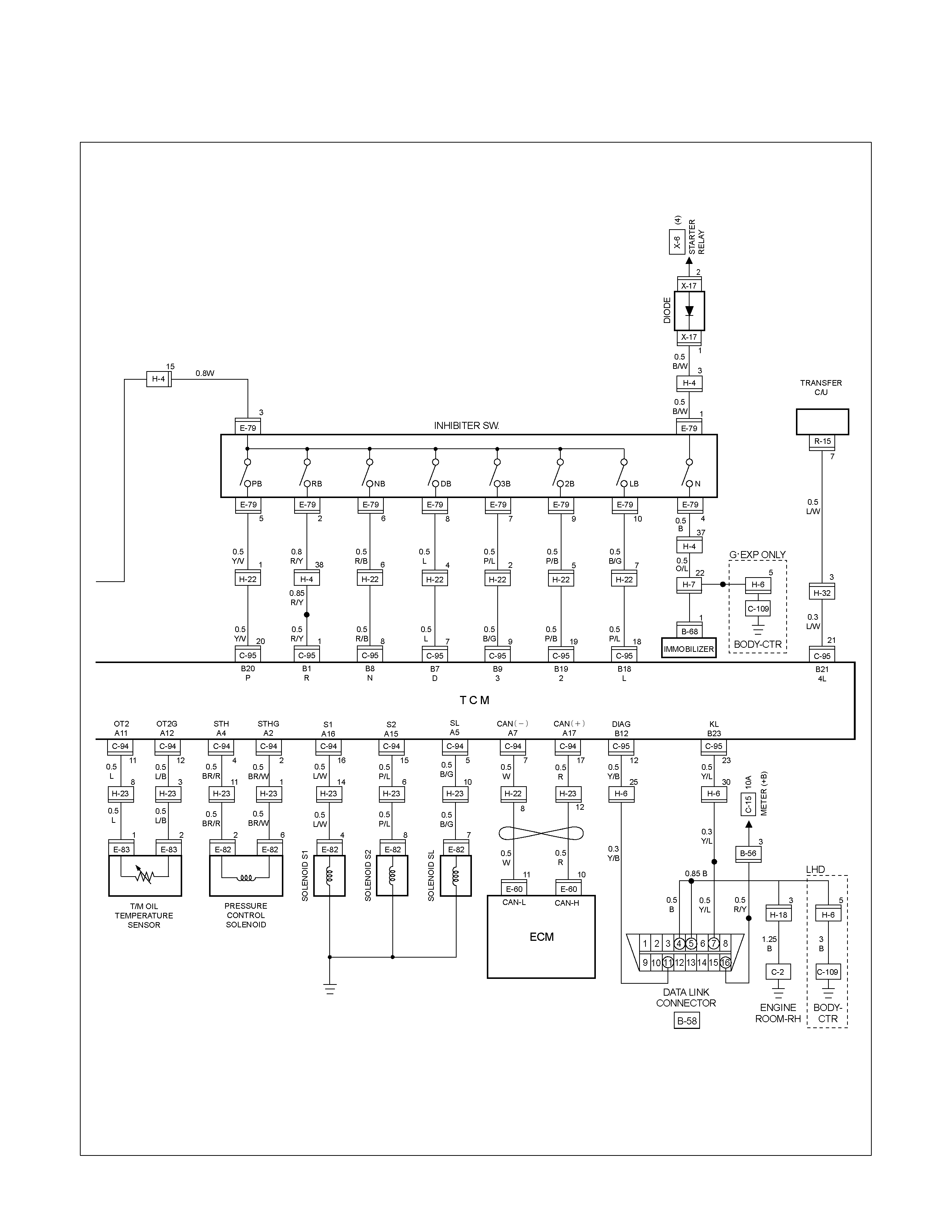
CIRCUIT DIAGRAM 6VE1 Sheet 2/2
RTW680XF009401
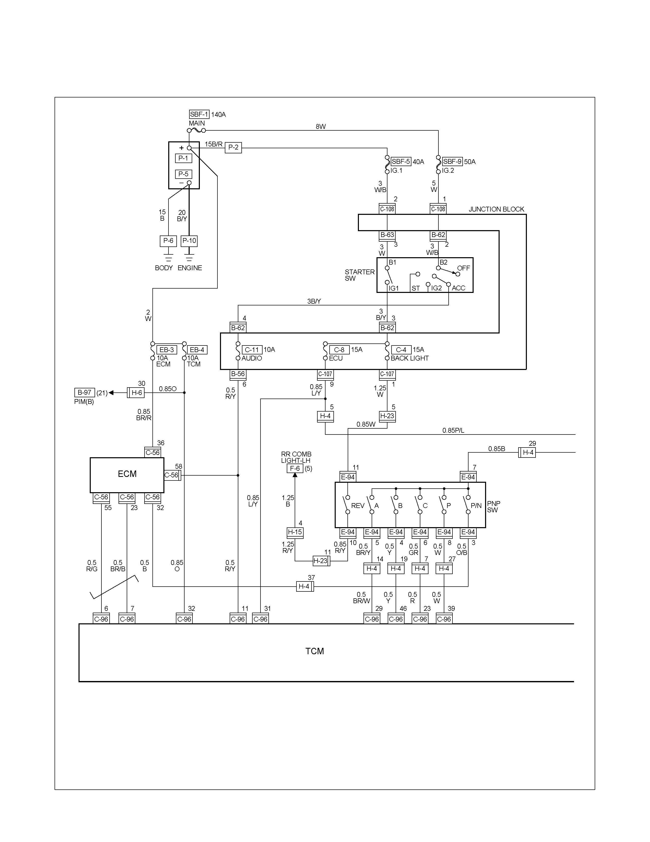
CIRCUIT DIAGRAM HFV6 Sheet 1/2
RTW68AXF011201
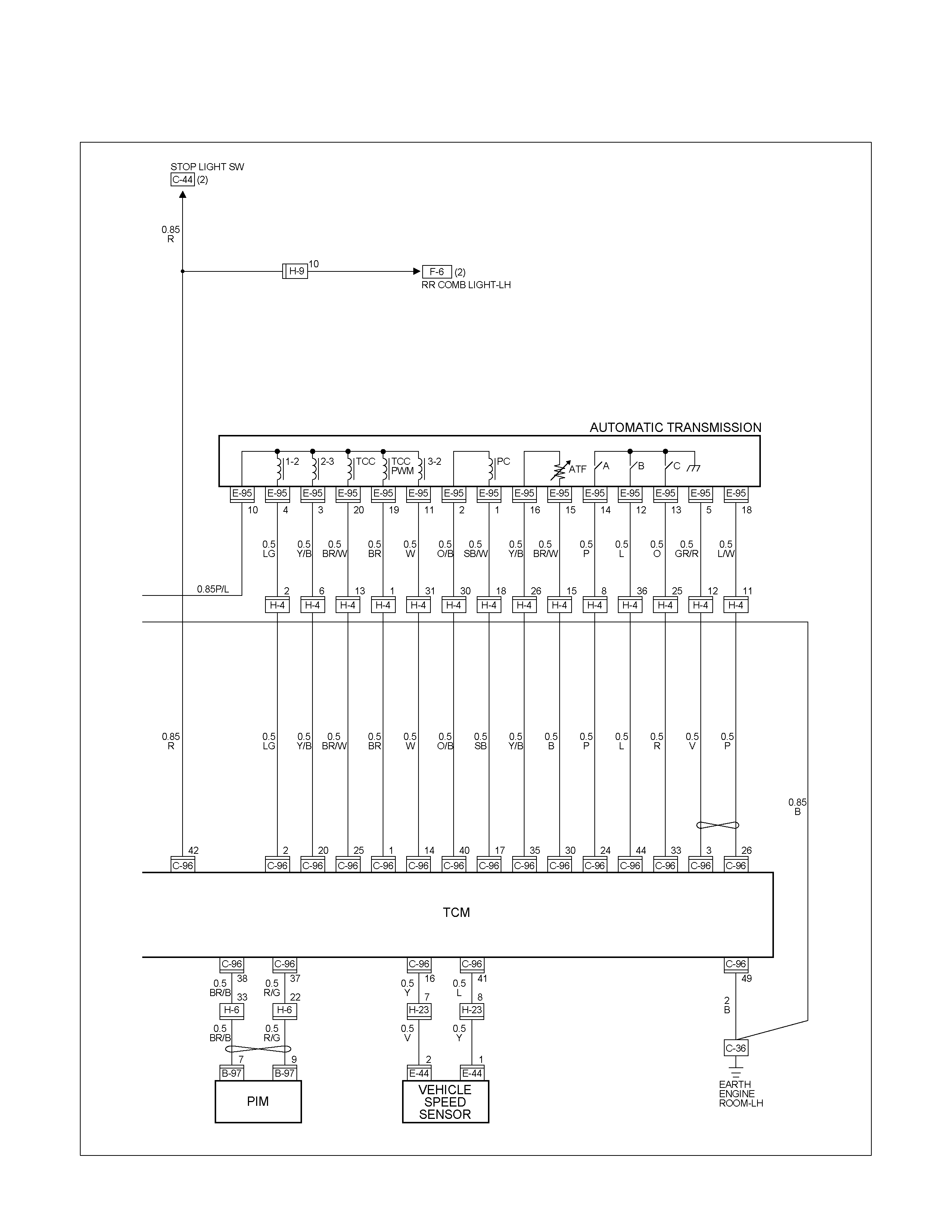
CIRCUIT DIAGRAM HFV6 Sheet 2/2
RTW68AXF011301
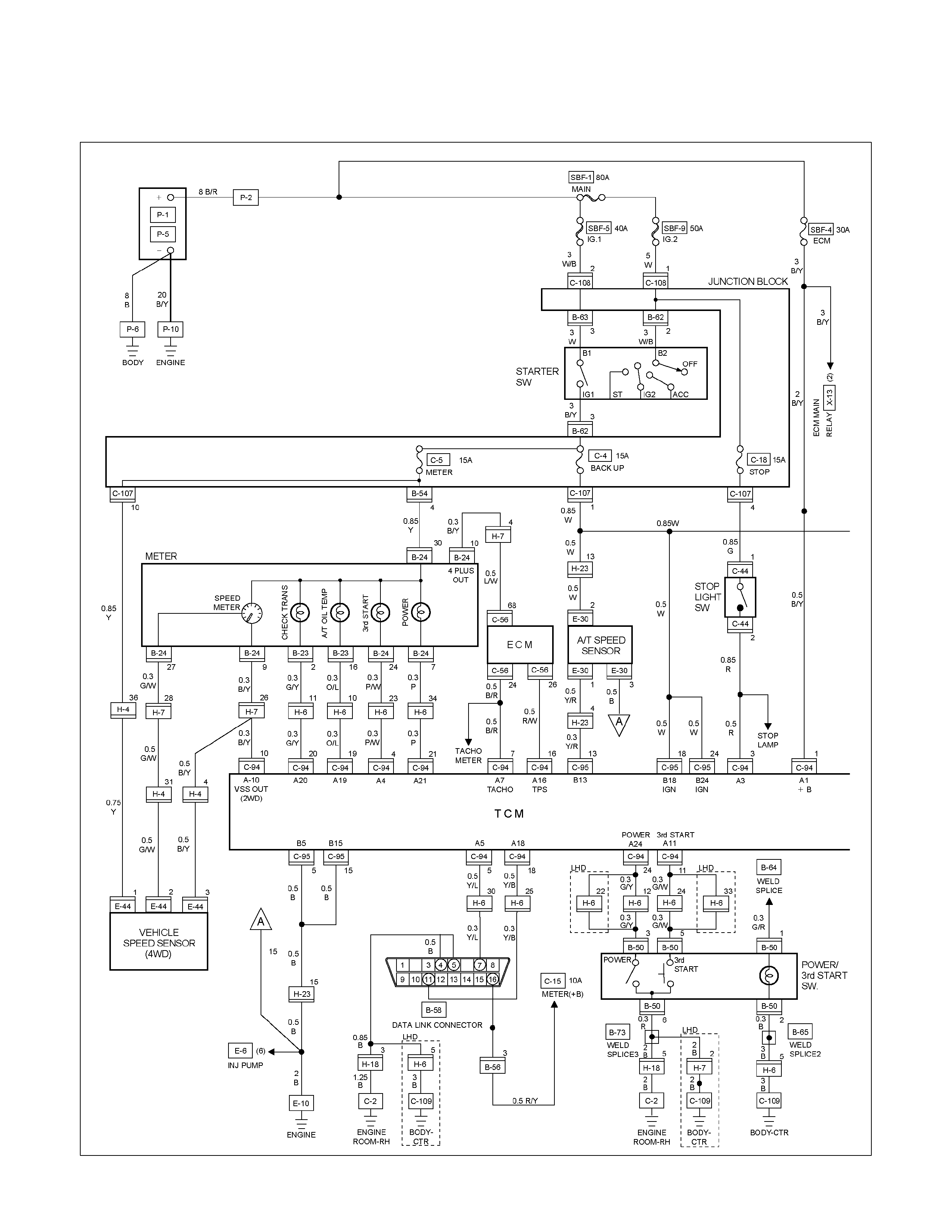
CIRCUIT DIAGRAM 4JH1-TC Sheet 1/2
RTW680XF009501
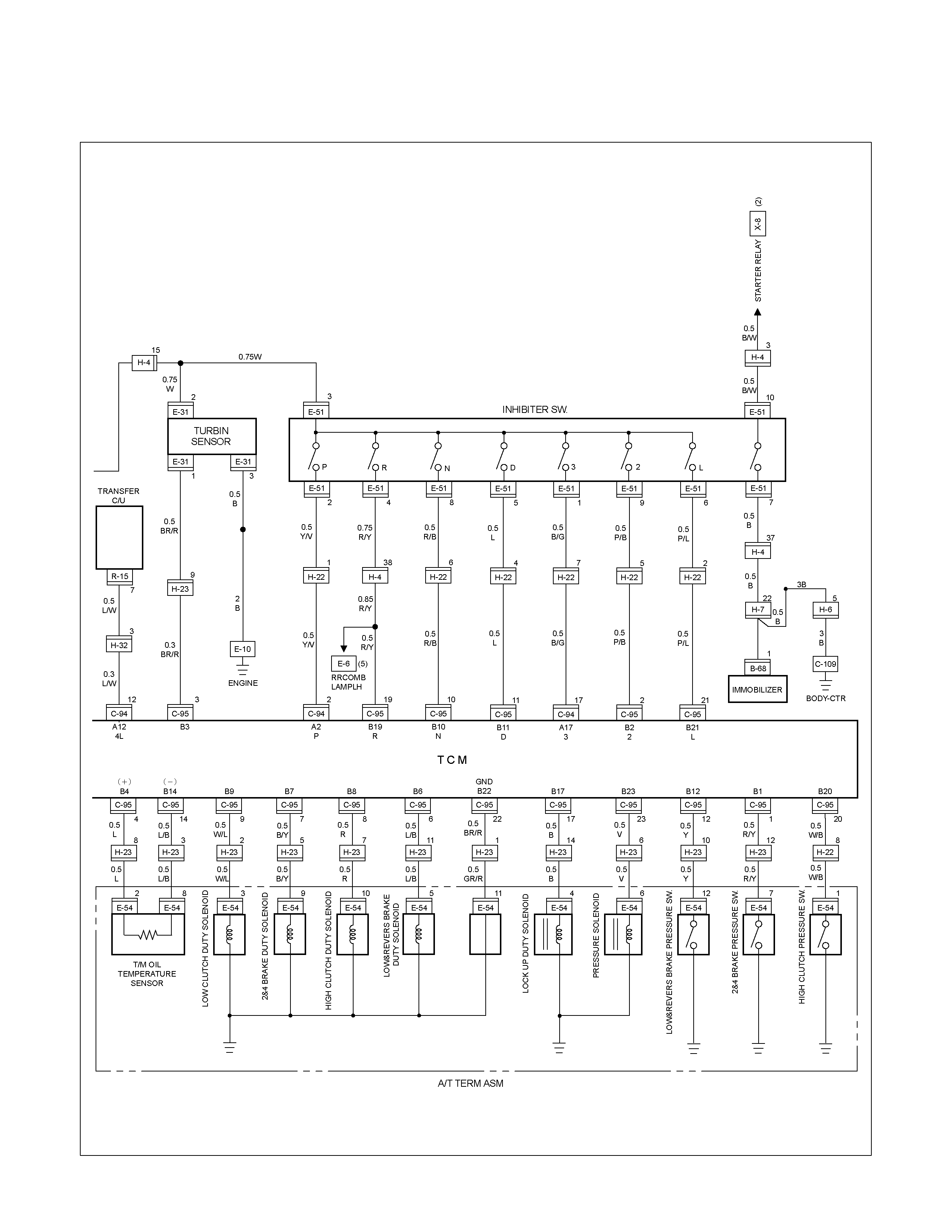
CIRCUIT DIAGRAM 4JH1-TC Sheet 2/2
RTW680XF009601
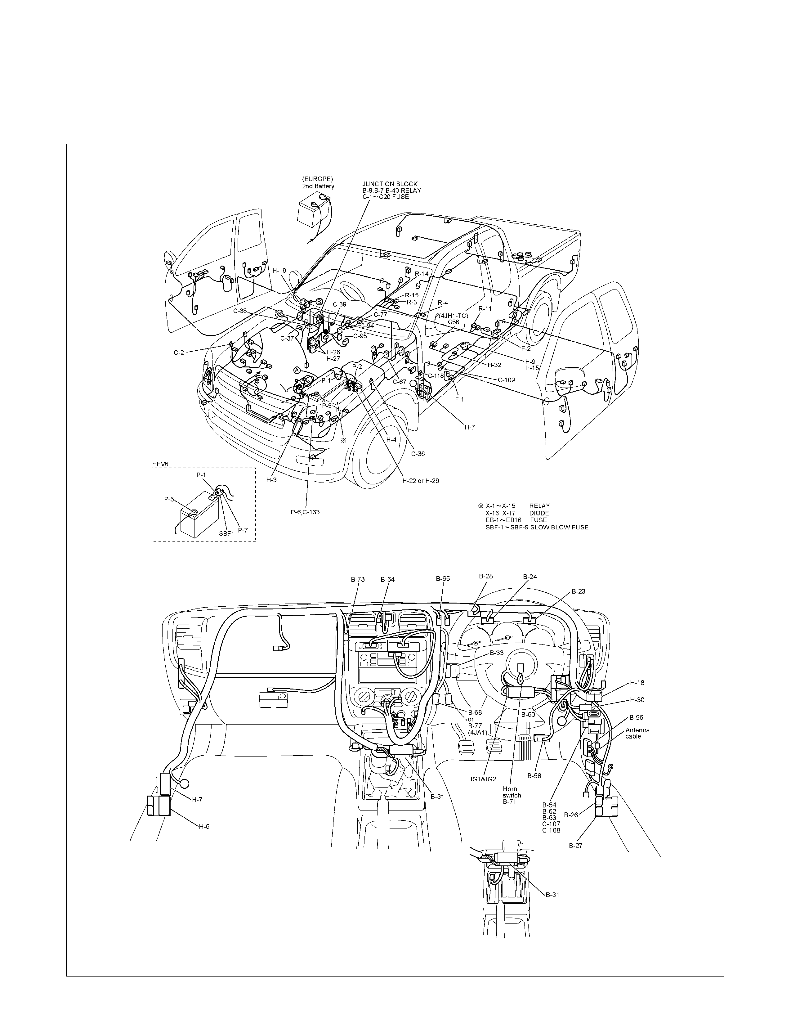
METER, WARNING LIGHT AND INDICATOR LIGHT
PARTS LOCATION (RHD)
RTW68AXF015301 & RTW68AXF015401
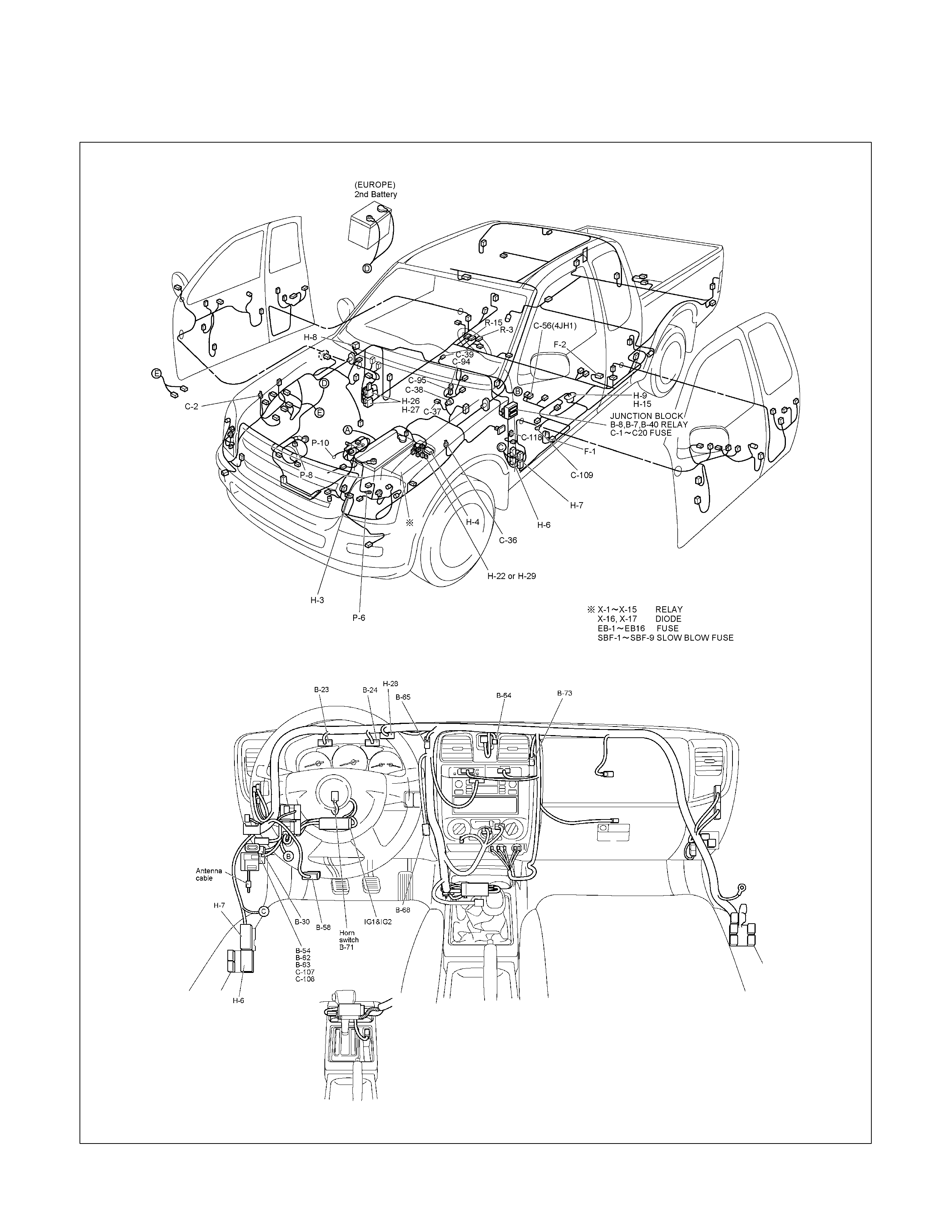
PARTS LOCATION (LHD)
RTW48AXF018601 & RTW48XF018701

PARTS LOCATION C24SE

PARTS LOCATION 6VE1

PARTS LOCATION 4JA1-TC / 4JH1-TC
RTW38DXF007601
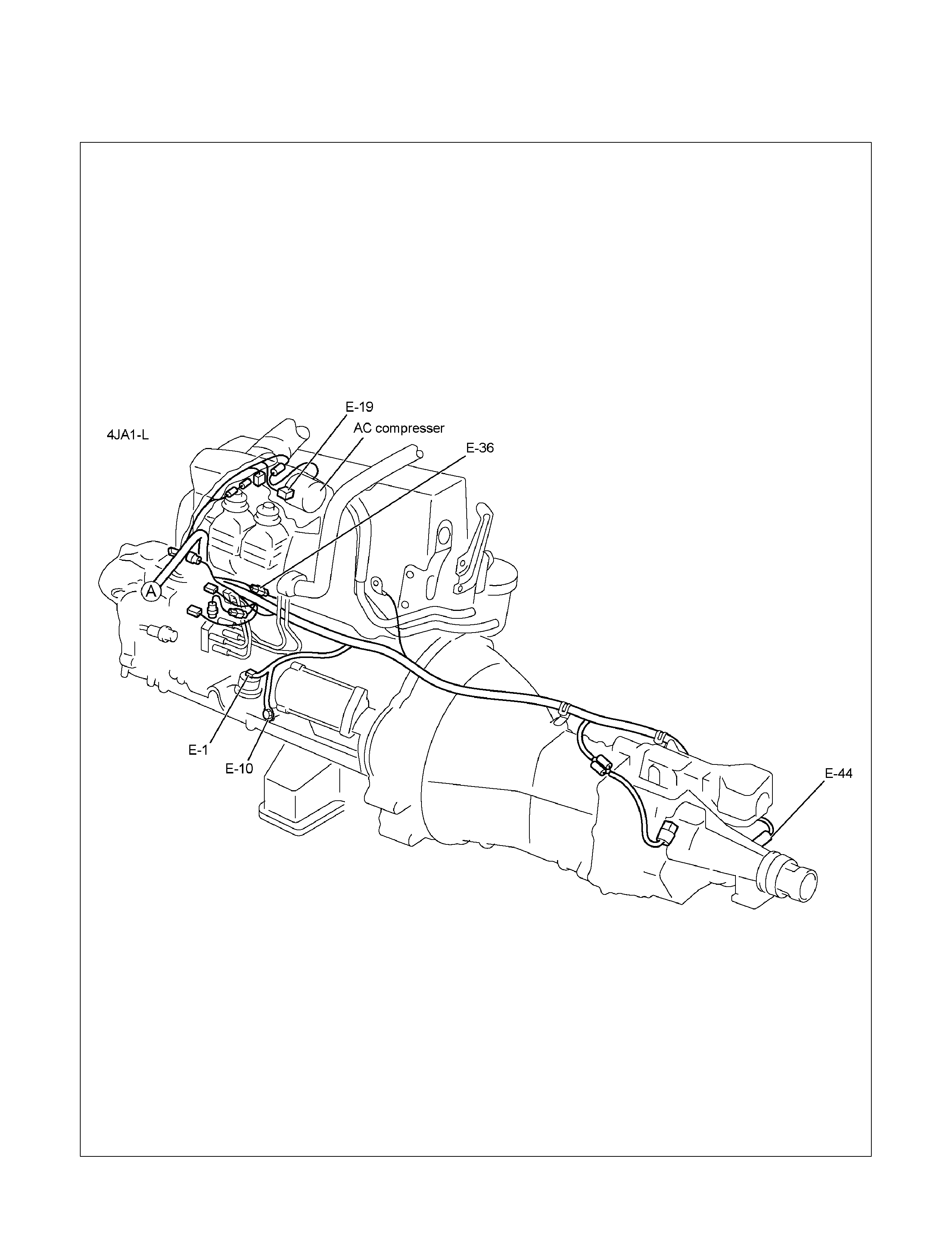
PARTS LOCATION 4JA1-L
RTW48AMF000301
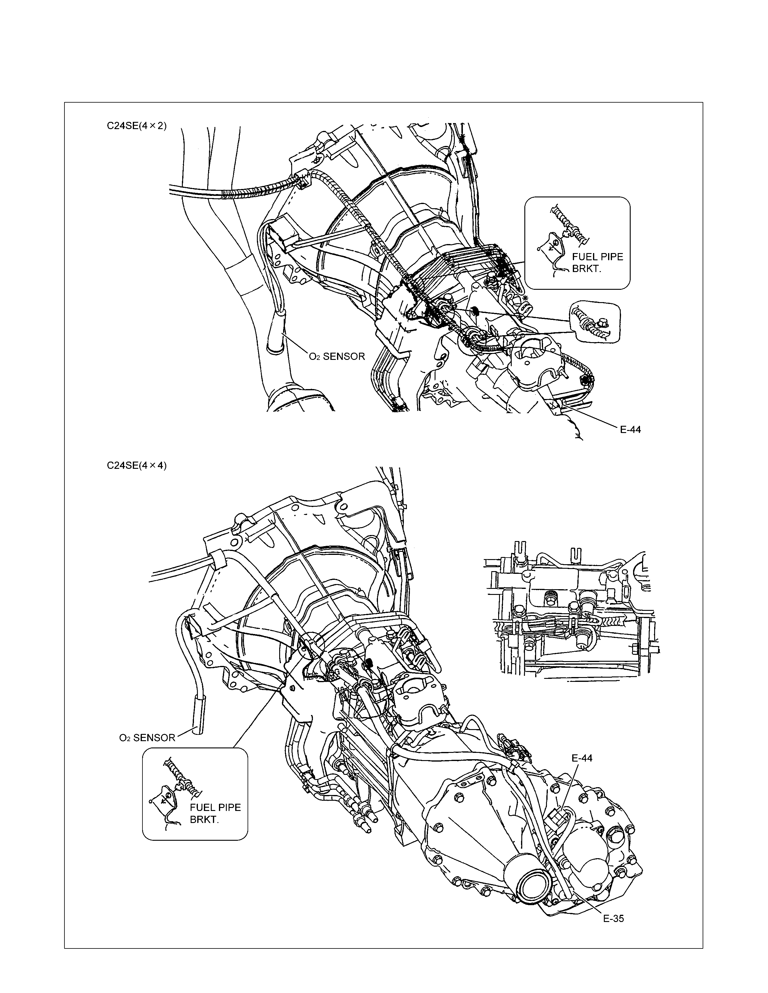
PARTS LOCATION
RTW48AXF018201

PARTS LOCATION
RTW68AXF012801
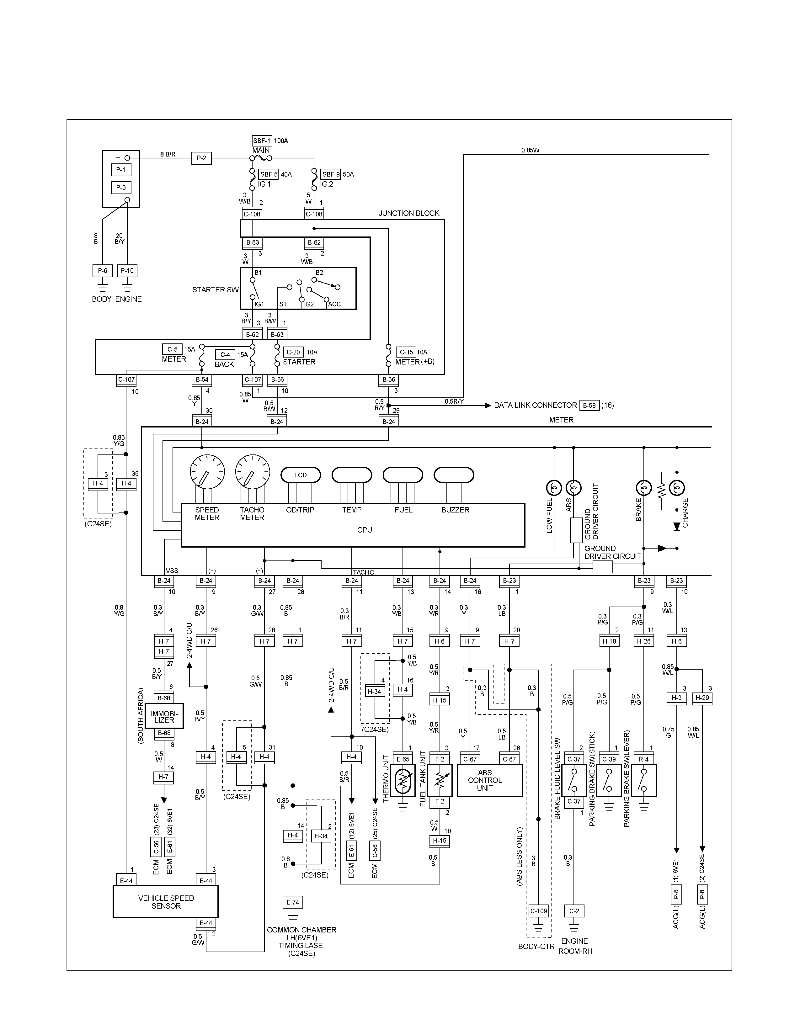
CIRCUIT DIAGRAM C24SE / 6VE1 (RHD) Sheet 1/3
RTW680XF009701
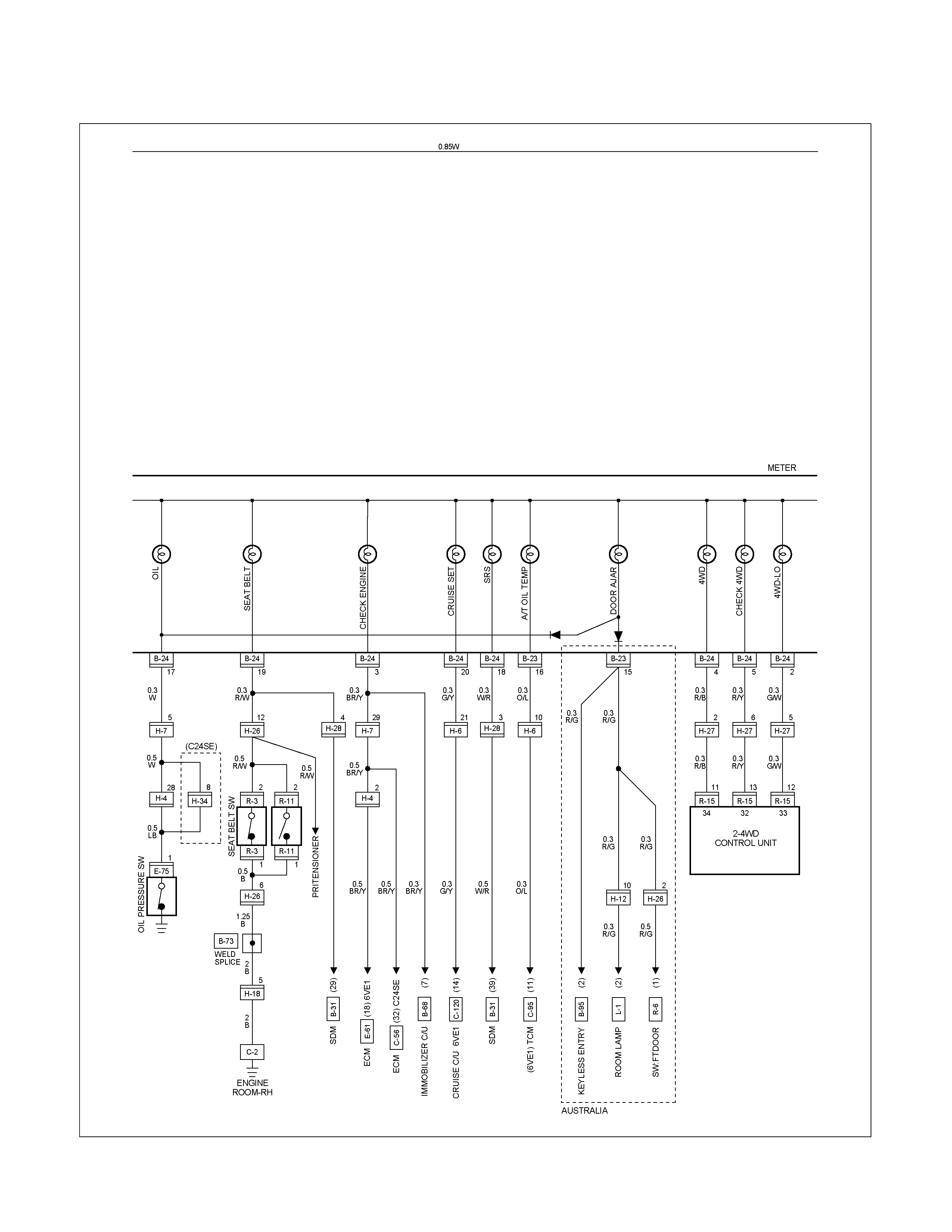
CIRCUIT DIAGRAM C24SE / 6VE1 (RHD) Sheet 2/3
RTW680XF009801
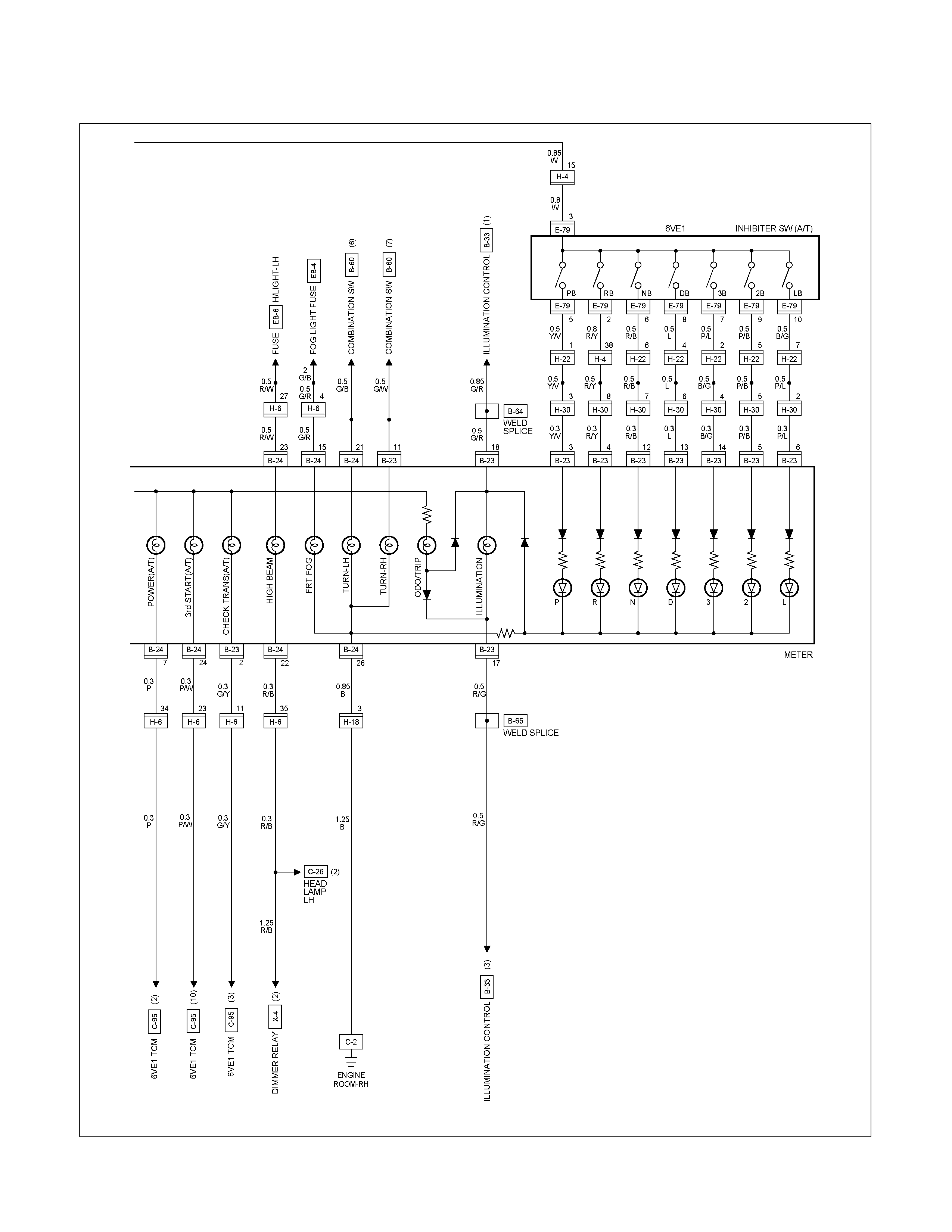
CIRCUIT DIAGRAM C24SE / 6VE1 RHD Sheet 3/3
RTW680XF009901
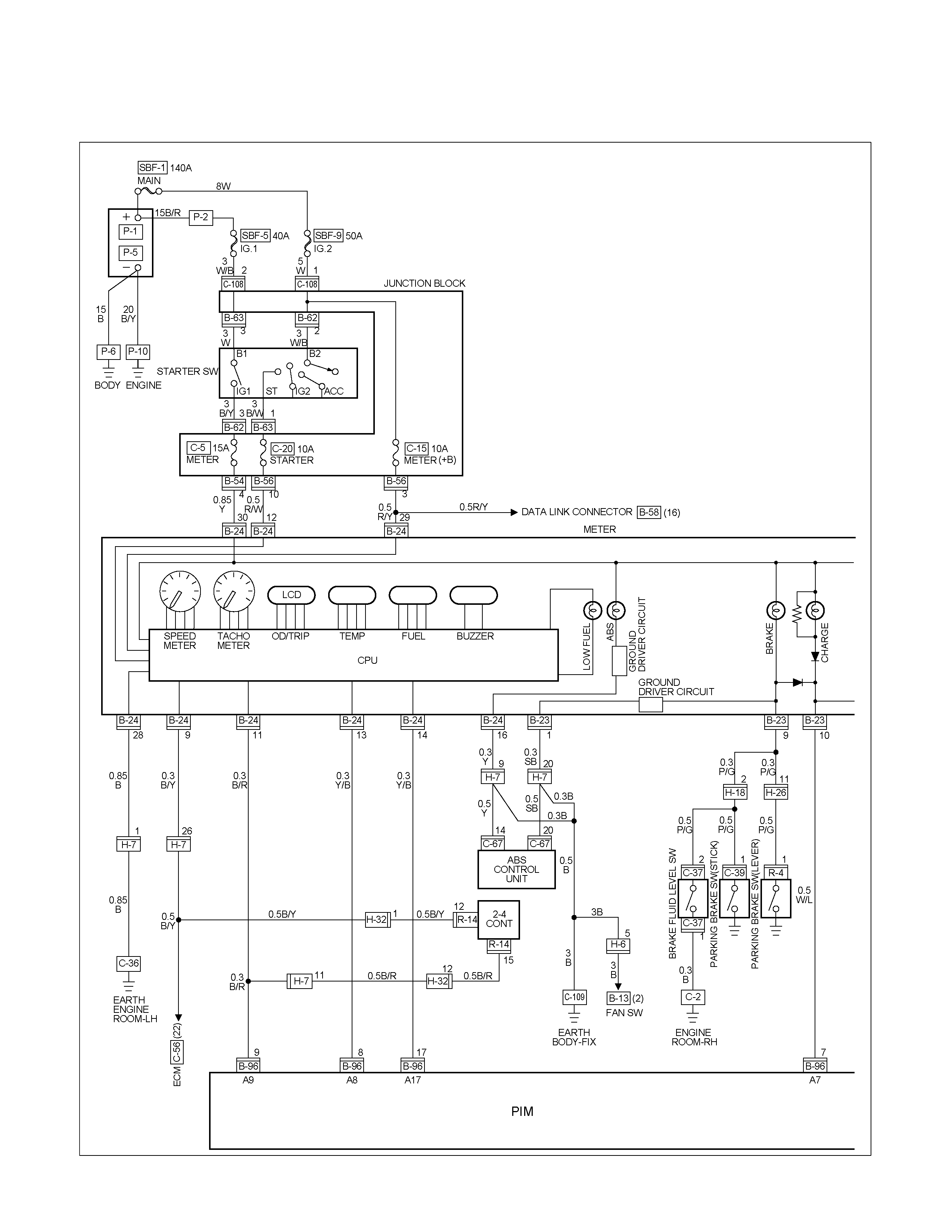
CIRCUIT DIAGRAM HFV6 (RHD) Sheet 1/3
RTW68AXF011401
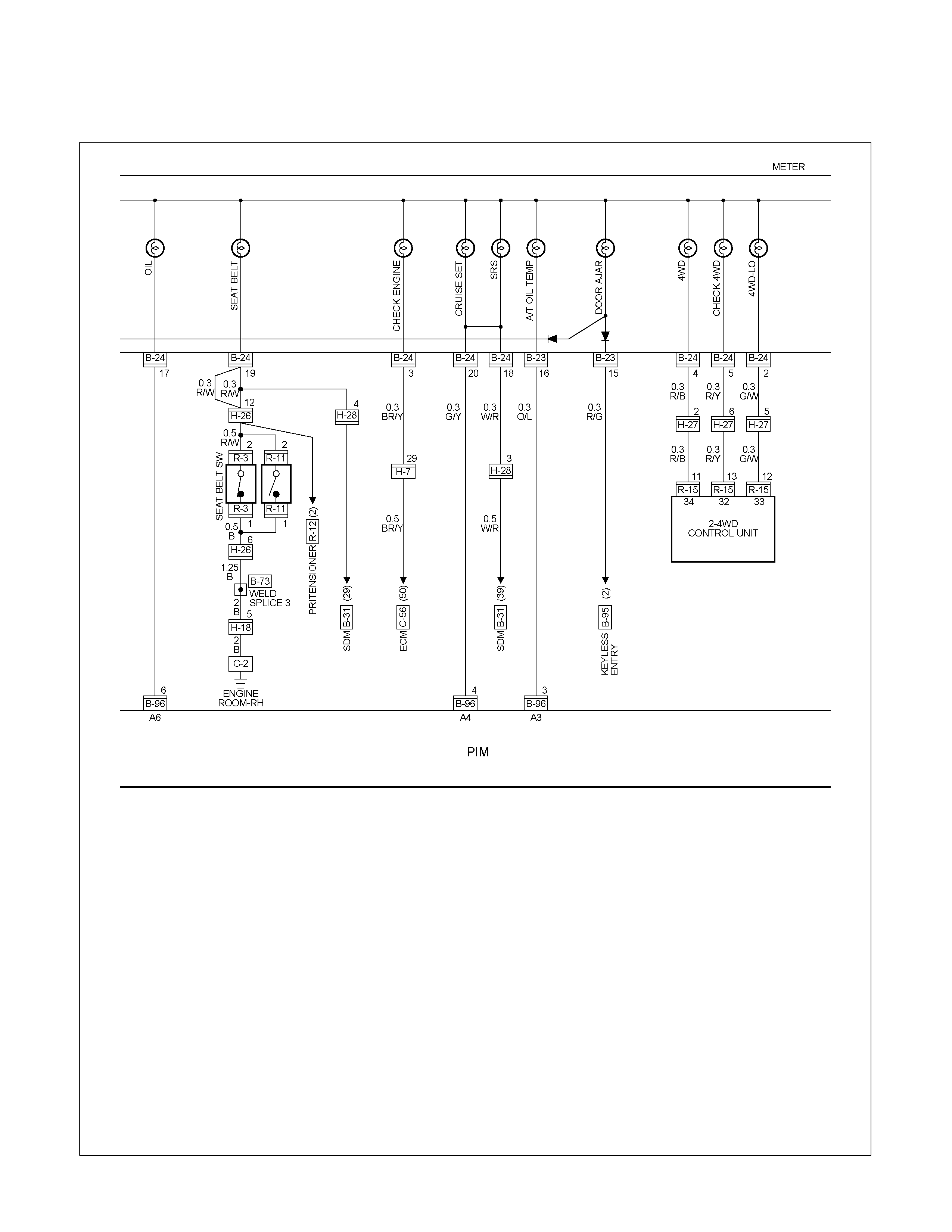
CIRCUIT DIAGRAM HFV6 (RHD) Sheet 2/3
RTW68AXF011501
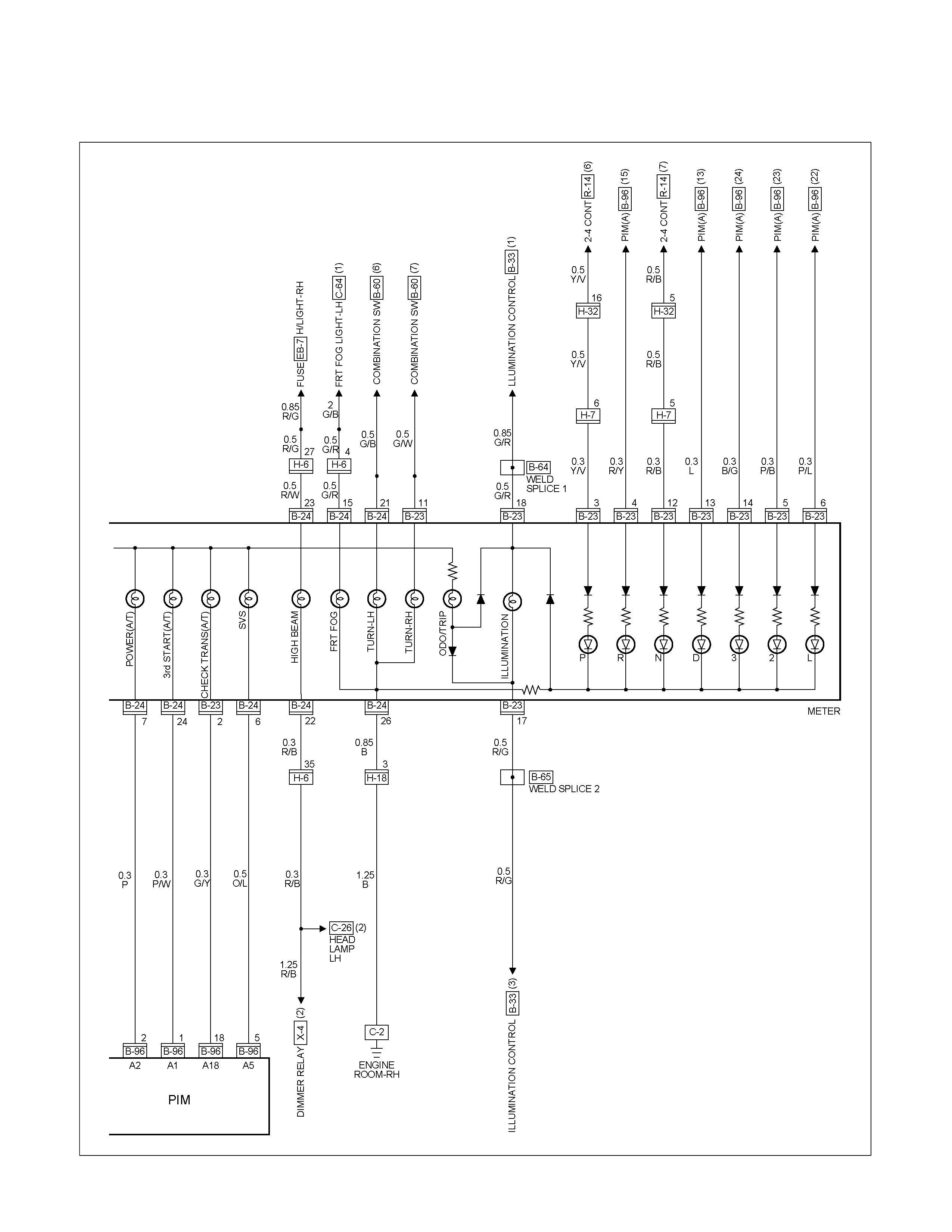
CIRCUIT DIAGRAM HFV6 (RHD) Sheet 3/3
RTW68AXF011601

CIRCUIT DIAGRAM 4JA1-TC / 4JH1-TC (RHD) G.EXP Sheet 1/3
RTW680XF010001

CIRCUIT DIAGRAM 4JA1-TC / 4JH1-TC (RHD) G.EXP Sheet 2/3
RTW680XF010101
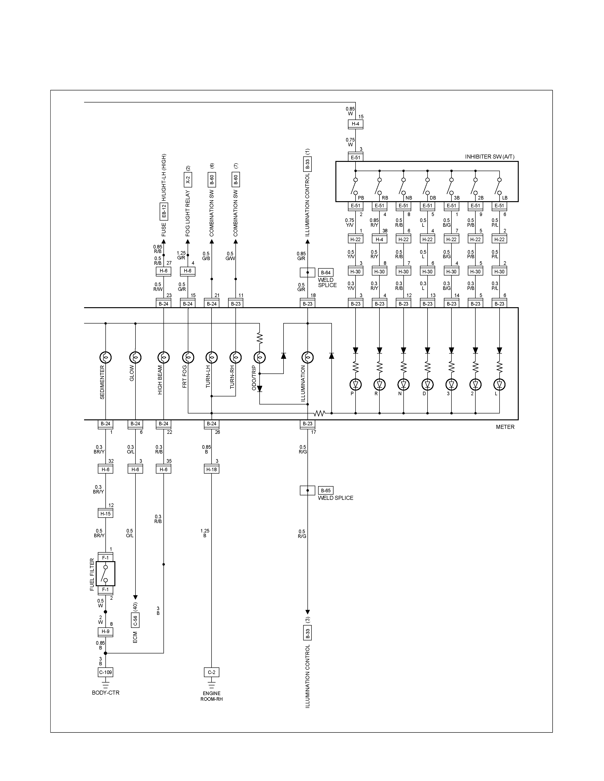
CIRCUIT DIAGRAM 4JA1-TC / 4JH1-TC (RHD) G.EXP Sheet 3/3
RTW680XF010201
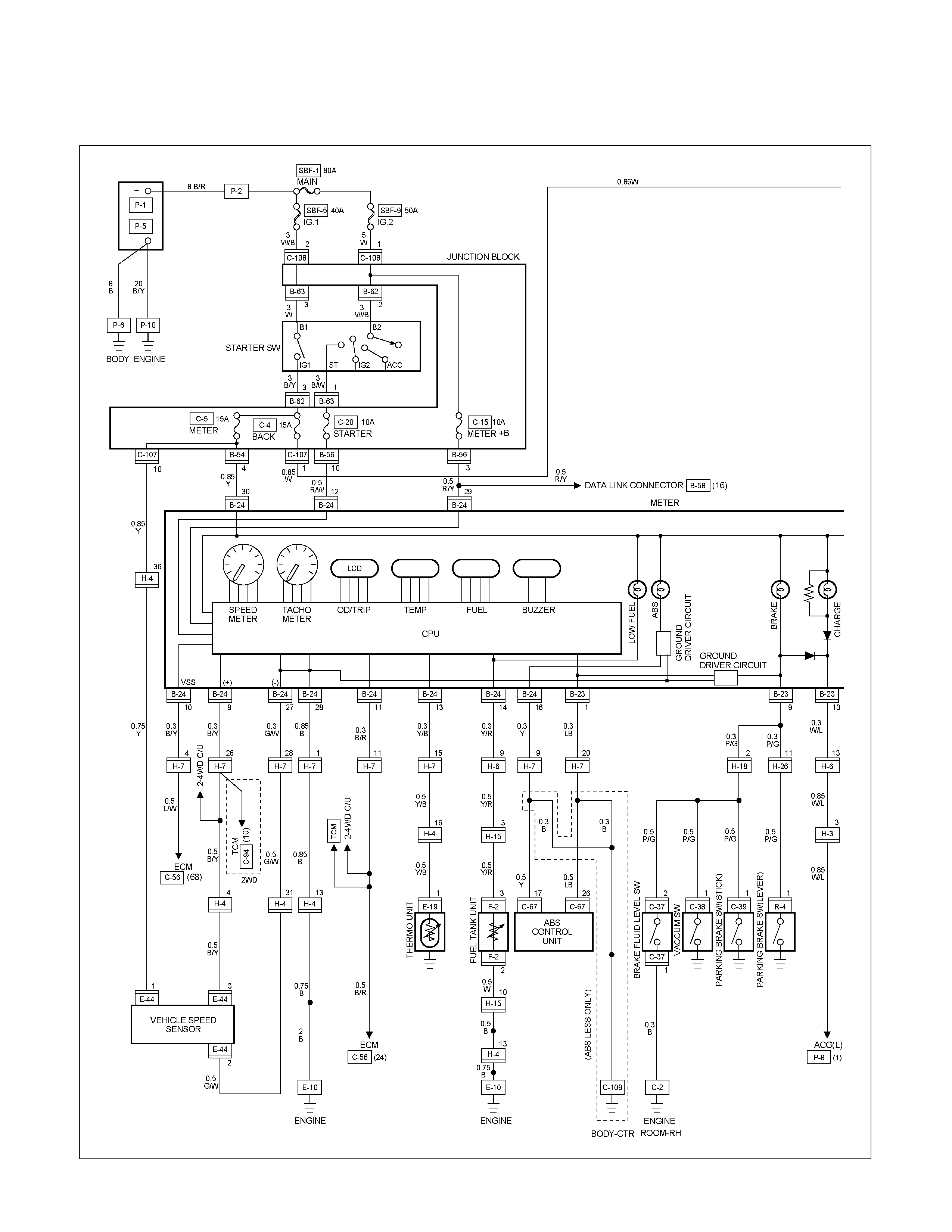
CIRCUIT DIAGRAM 4JA1-TC / 4JH1-TC (RHD) EUROPE Sheet 1/3
RTW680XF010301
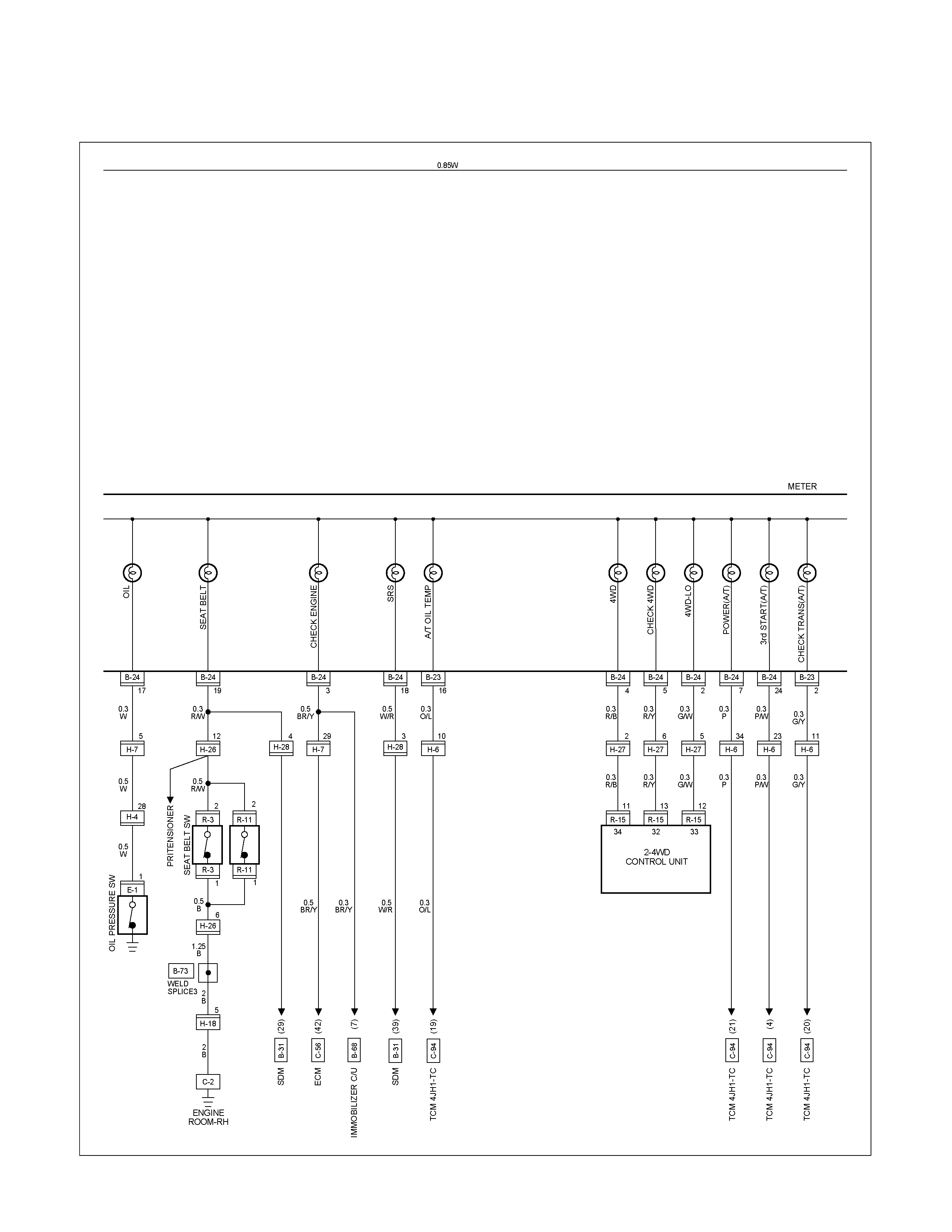
CIRCUIT DIAGRAM 4JA1-TC / 4JH1-TC (RHD) EUROPE Sheet 2/3
RTW680XF010401
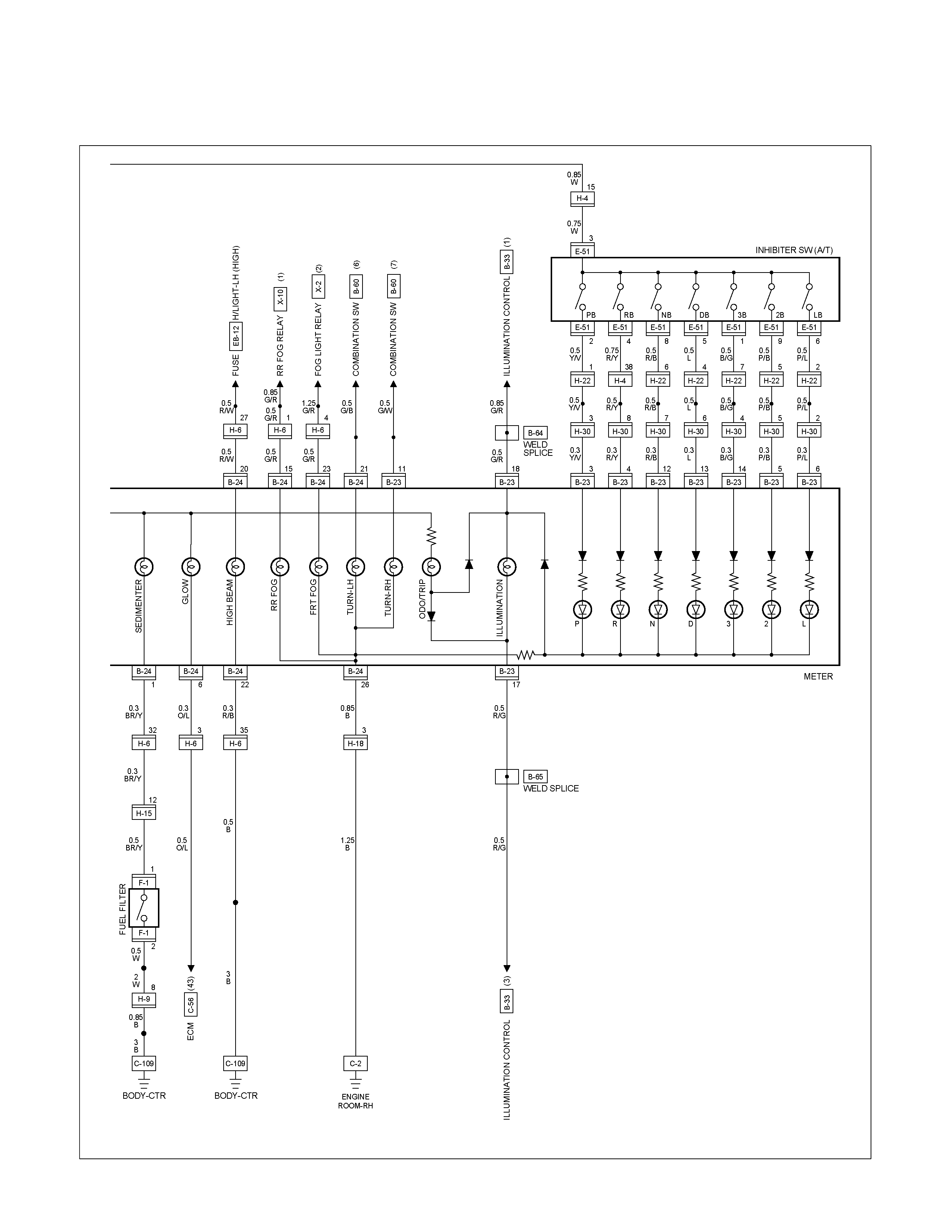
CIRCUIT DIAGRAM 4JA1-TC / 4JH1-TC (RHD) EUROPE Sheet 3/3
RTW680XF010501
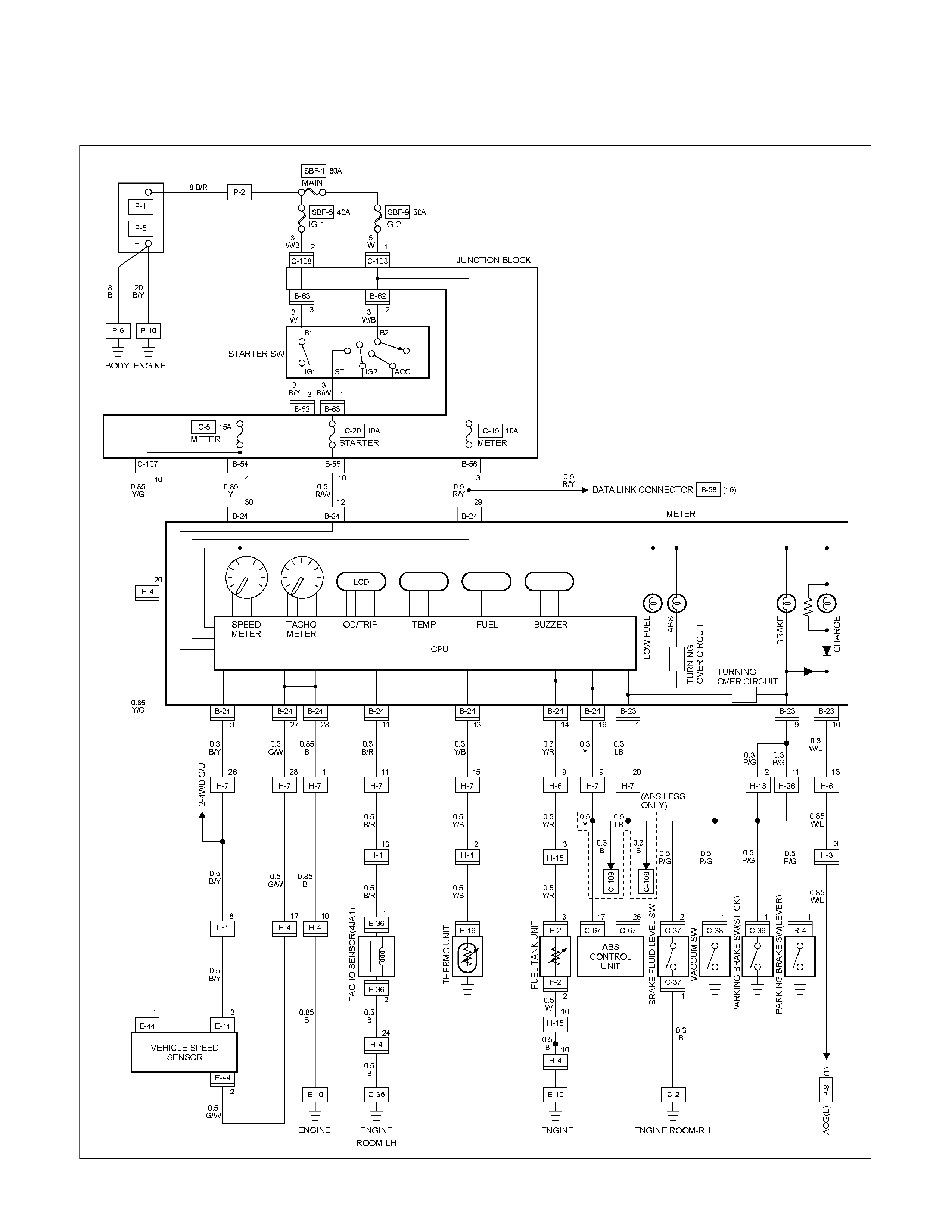
CIRCUIT DIAGRAM 4JA1-L (RHD) Sheet 1/3
RTW680XF010601
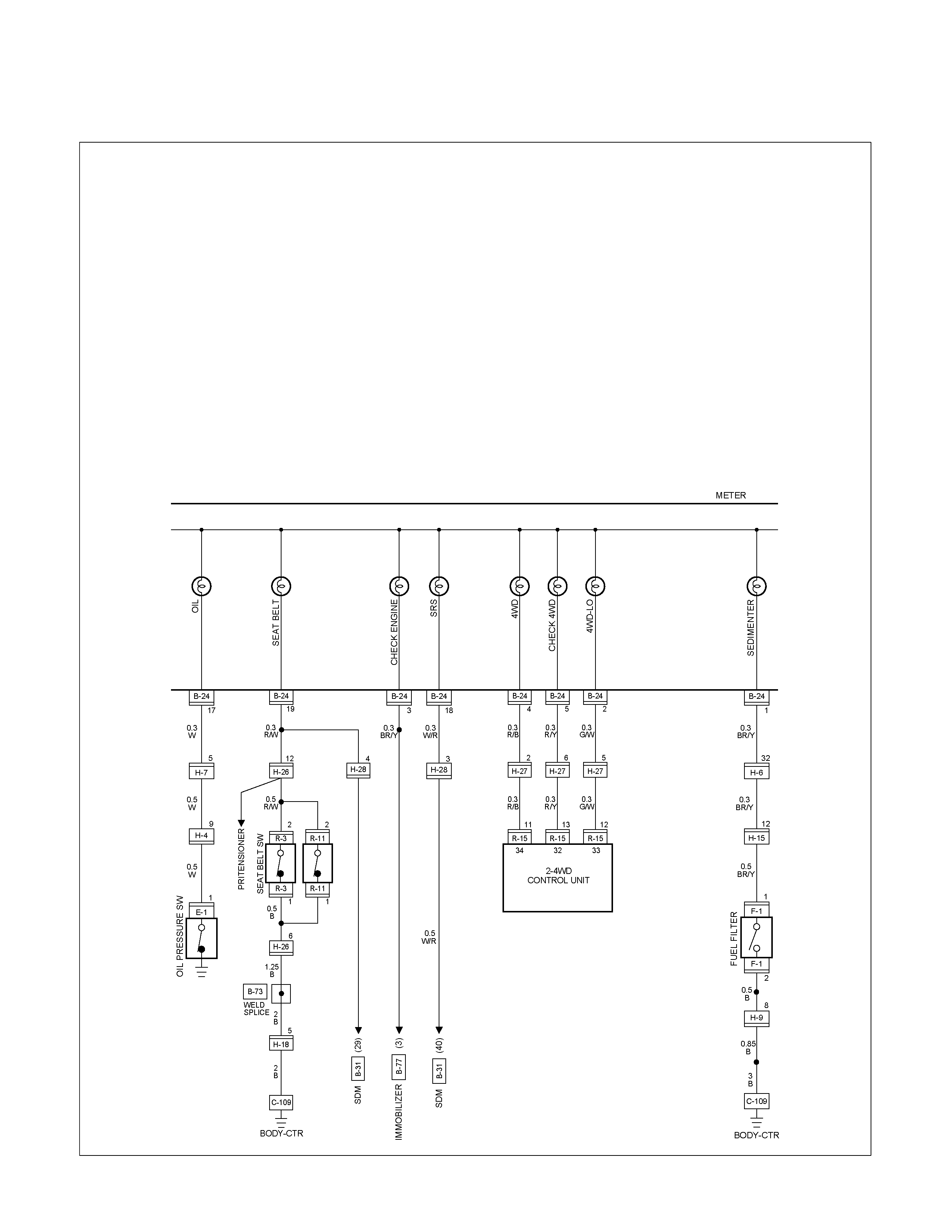
CIRCUIT DIAGRAM 4JA1-L (RHD) Sheet 2/3
RTW680XF010701
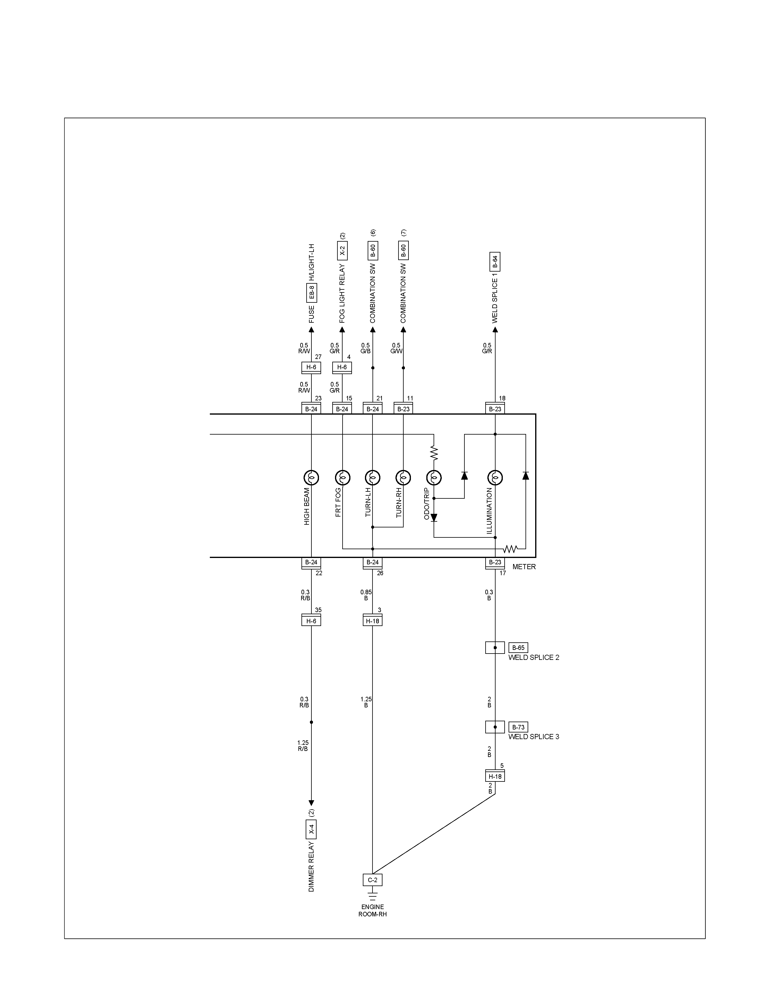
CIRCUIT DIAGRAM 4JA1-L (RHD) Sheet 3/3
RTW680XF010801
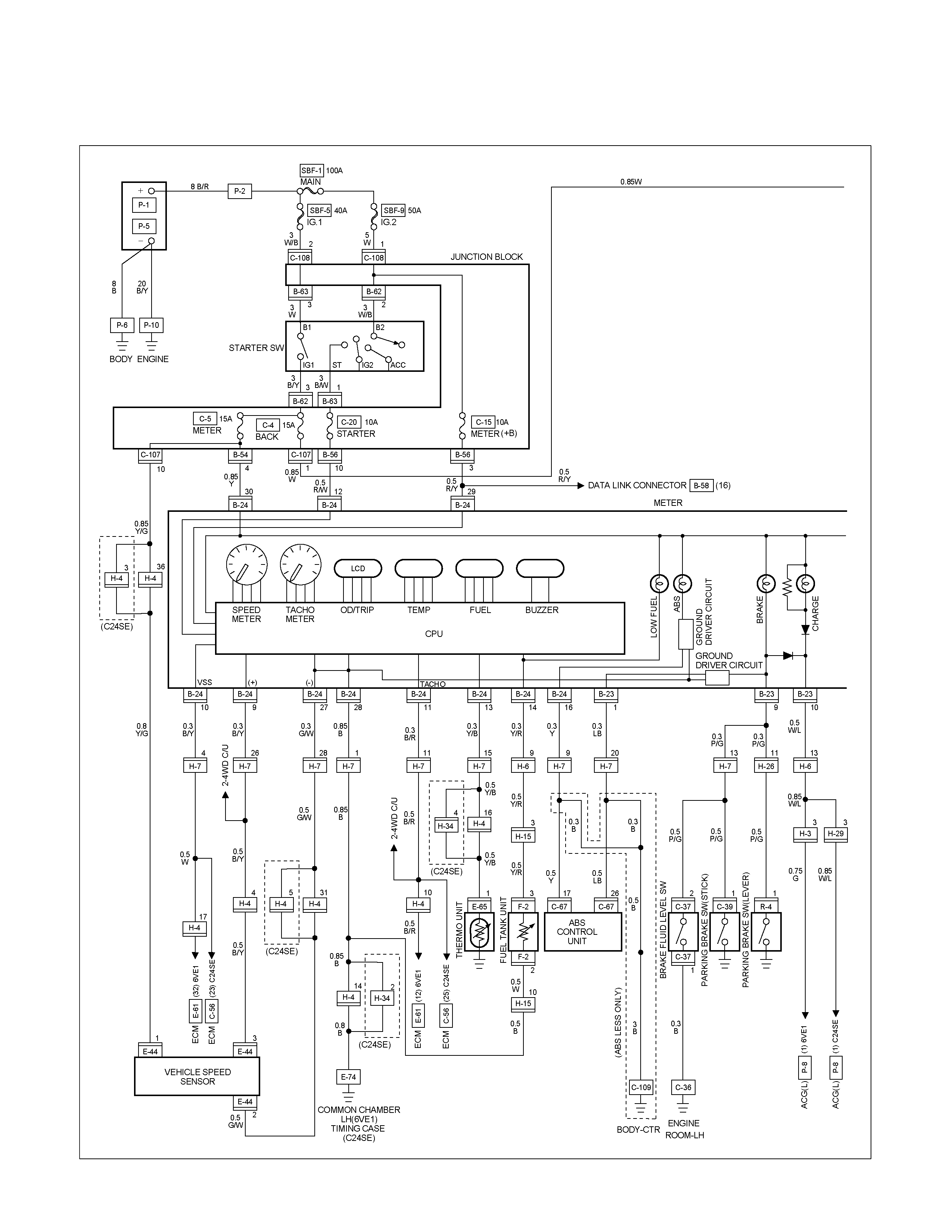
CIRCUIT DIAGRAM C24SE / 6VE1 (LHD) Sheet 1/3
RTW680XF010901
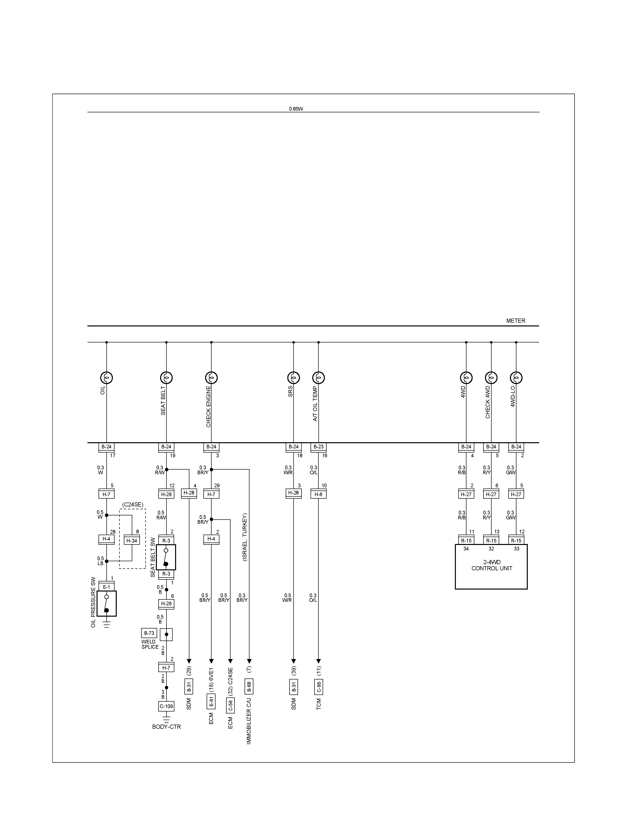
CIRCUIT DIAGRAM C24SE / 6VE1 (LHD) Sheet 2/3
RTW680XF011001
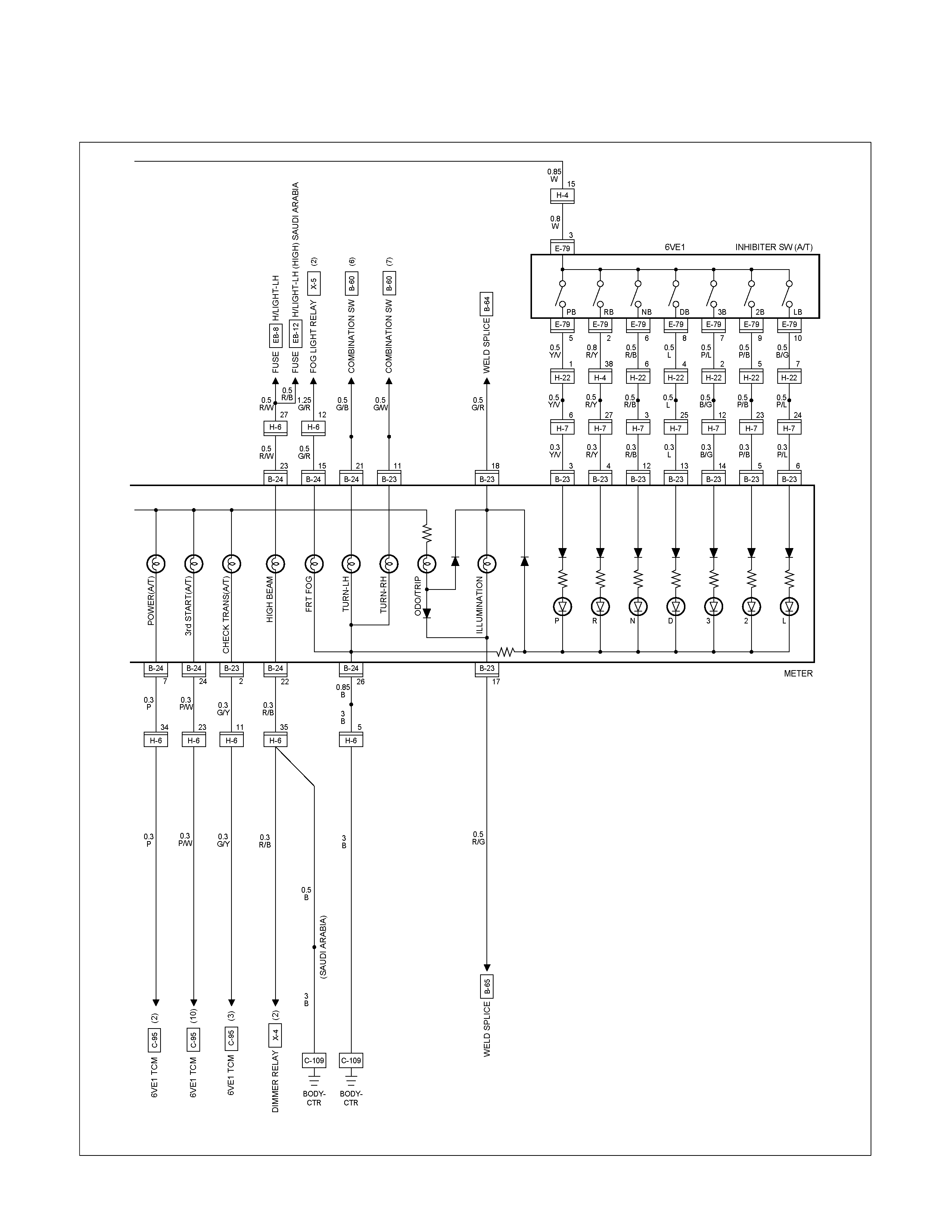
CIRCUIT DIAGRAM C24NE / 6VE1 (LHD) Sheet 3/3
RTW680XF011101
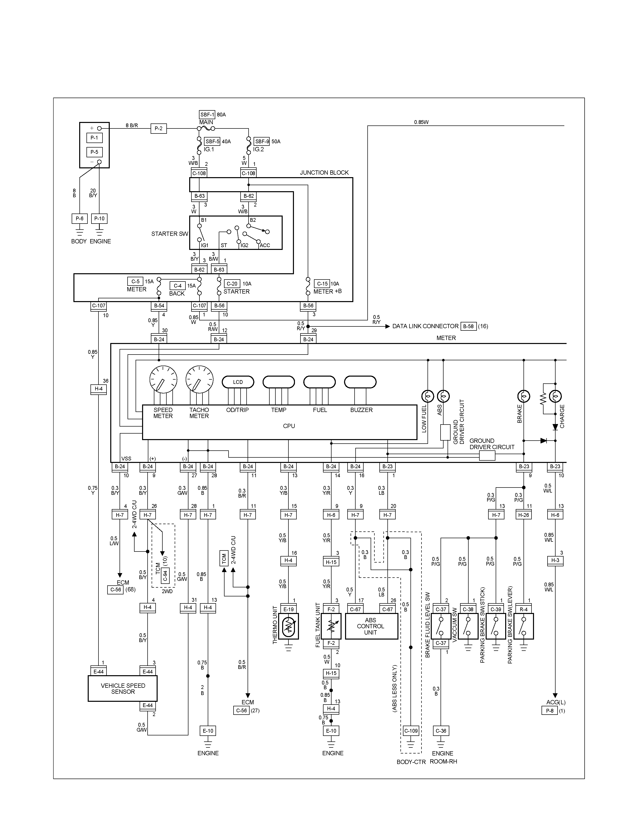
CIRCUIT DIAGRAM 4JA1-TC / 4JH1-TC (LHD) G.EXP Sheet 1/3
RTW680XF011201
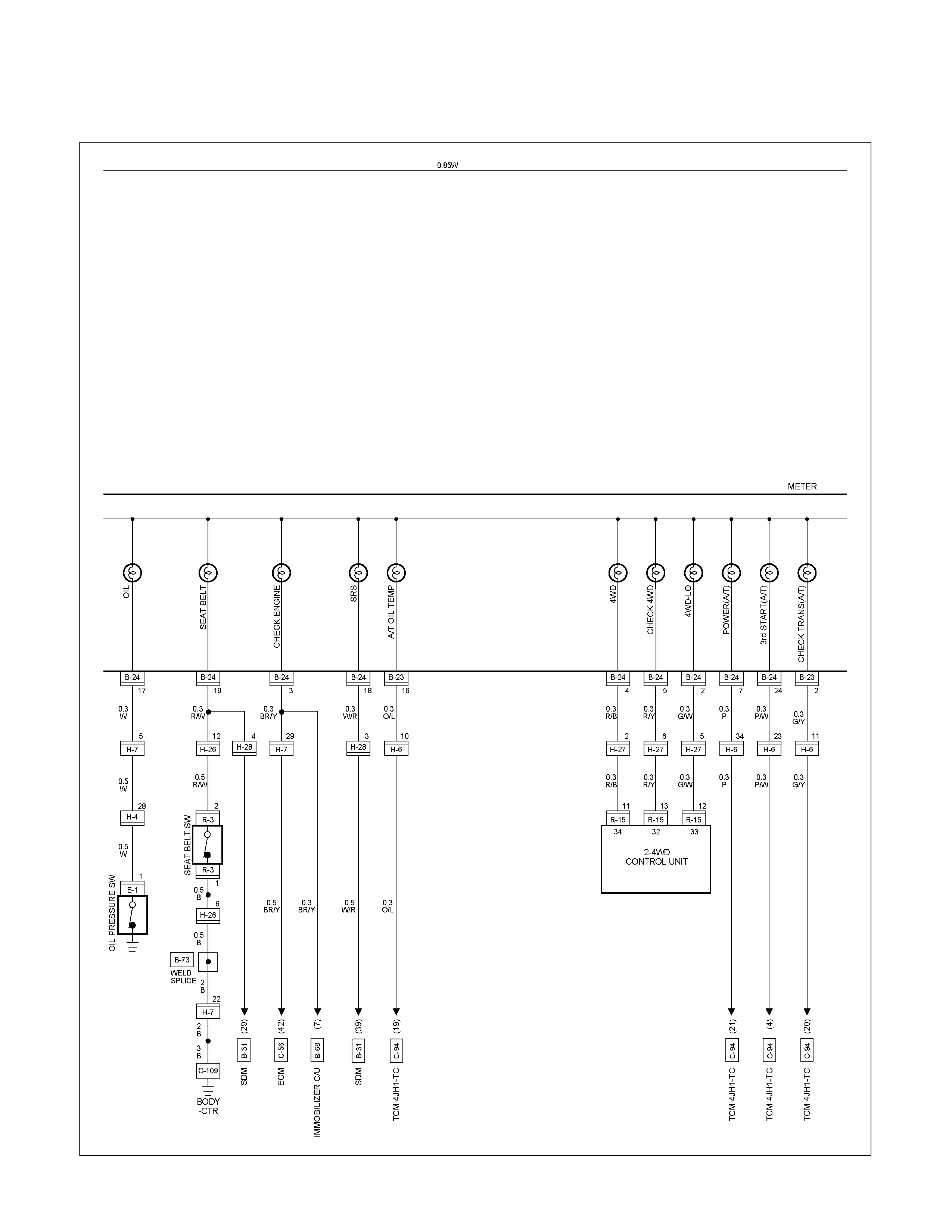
CIRCUIT DIAGRAM 4JA1-TC / 4JH1-TC (LHD) G.EXP Sheet 2/3
RTW680XF011301
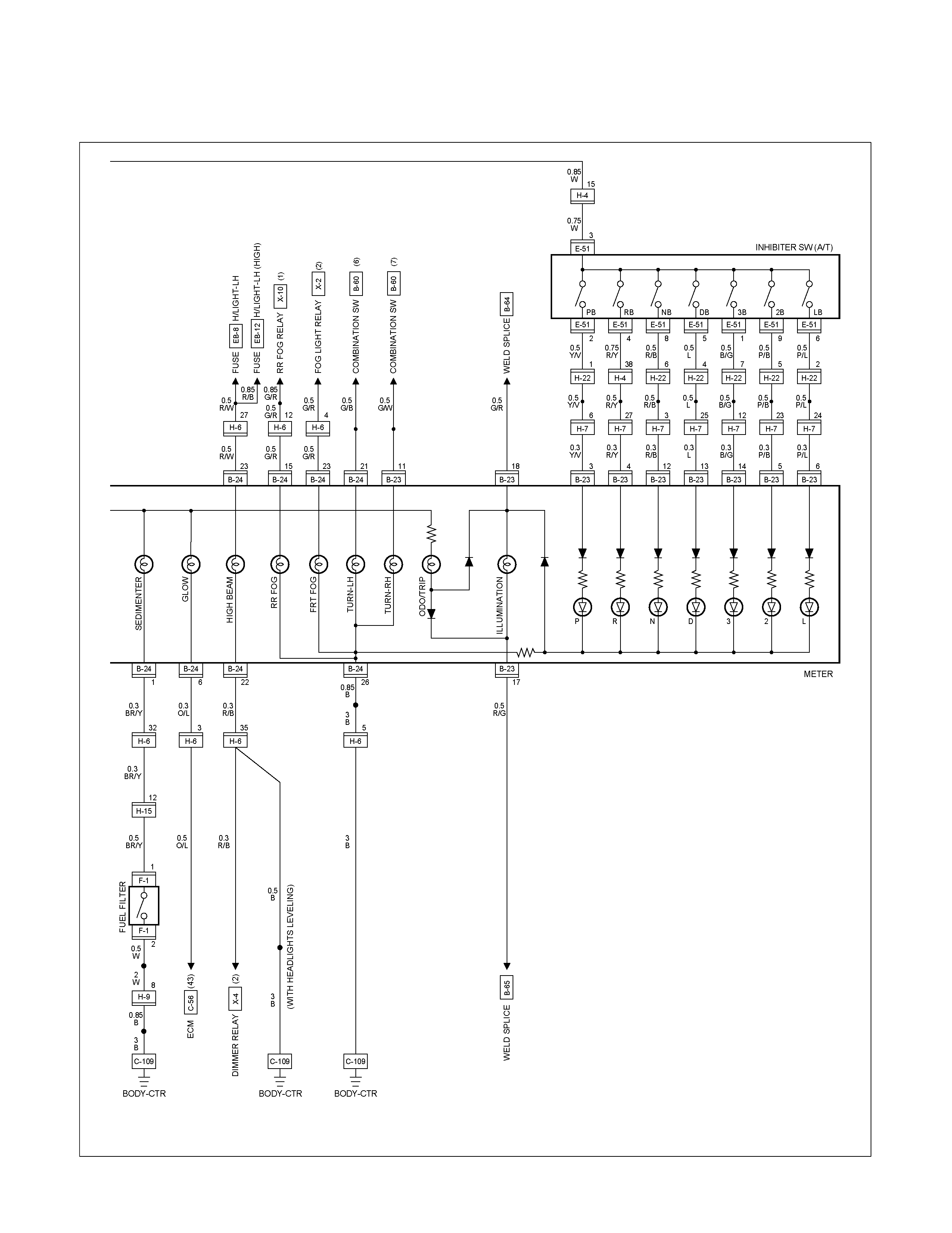
CIRCUIT DIAGRAM 4JA1-TC / 4JH1-TC (LHD) G.EXP Sheet 3/3
RTW680XF011401

CIRCUIT DIAGRAM 4JA1-TC / 4JH1-TC (LHD) EUROPE Sheet 1/3
RTW680XF011501
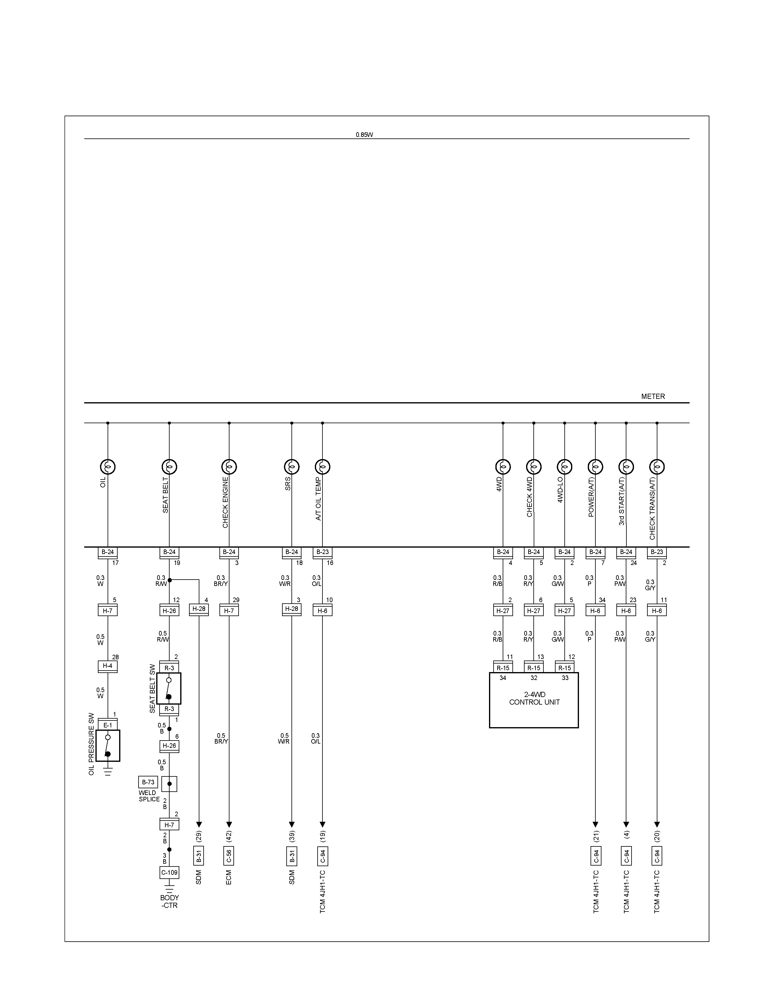
CIRCUIT DIAGRAM 4JA1-TC / 4JH1-TC (LHD) EUROPE Sheet 2/3
RTW680XF011601
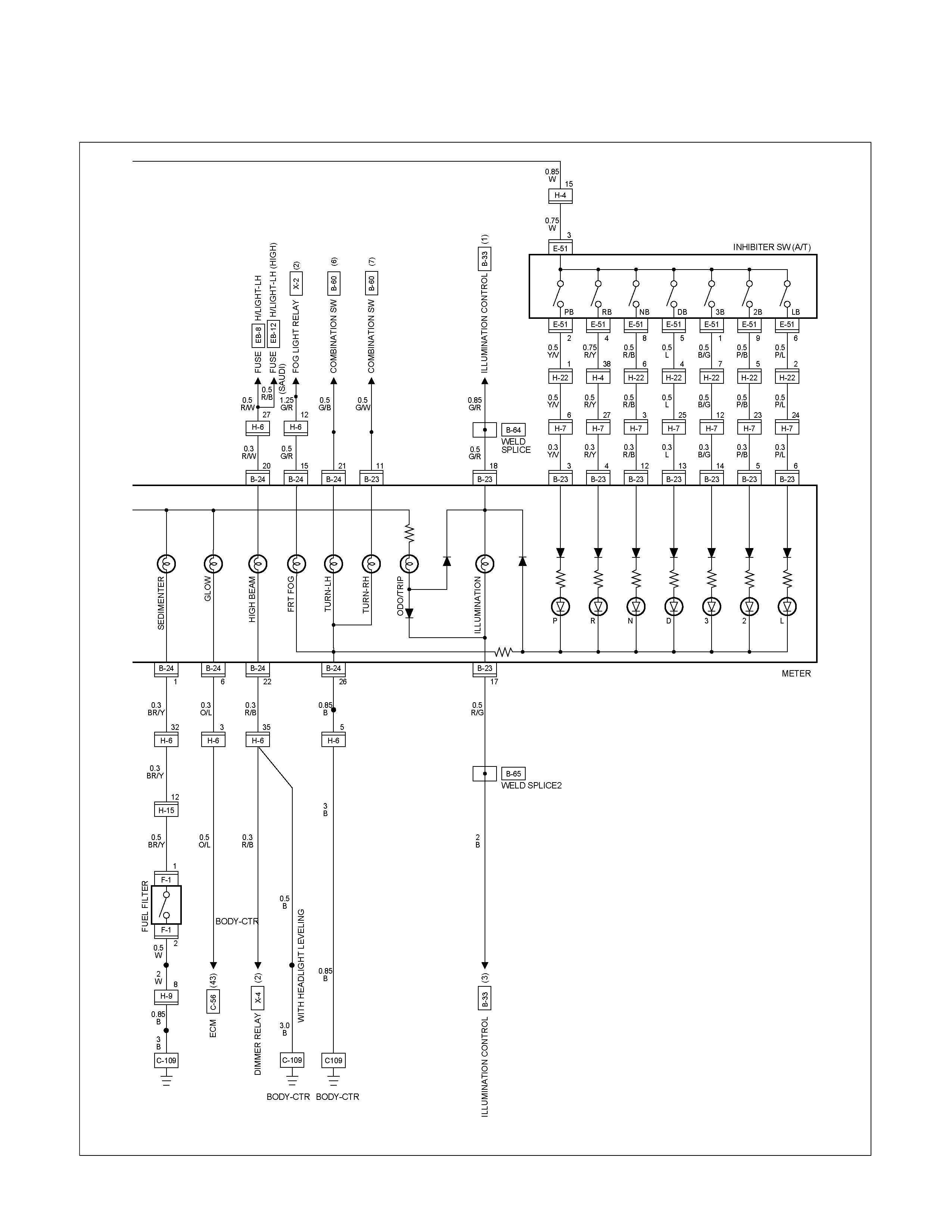
CIRCUIT DIAGRAM 4JA1-TC / 4JH1-TC (LHD) EUROPE Sheet 3/3
RTW680XF011701

CIRCUIT DIAGRAM 4JA1-L (LHD) Sheet 1/3
RTW680XF011801
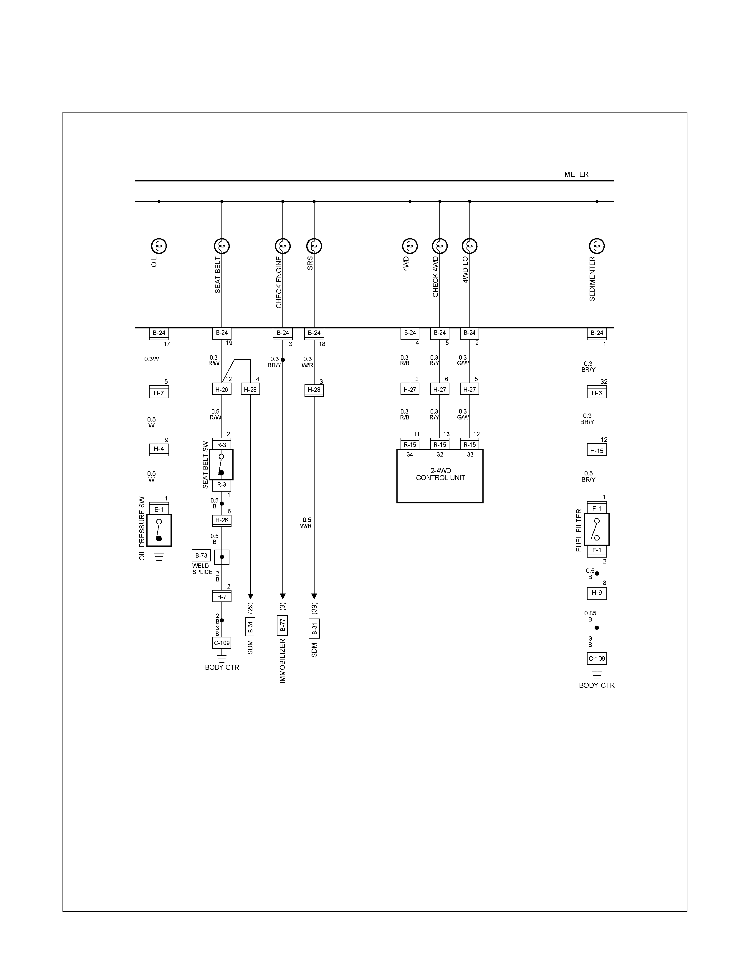
CIRCUIT DIAGRAM 4JA1-L (LHD) Sheet 2/3
RTW680XF011901
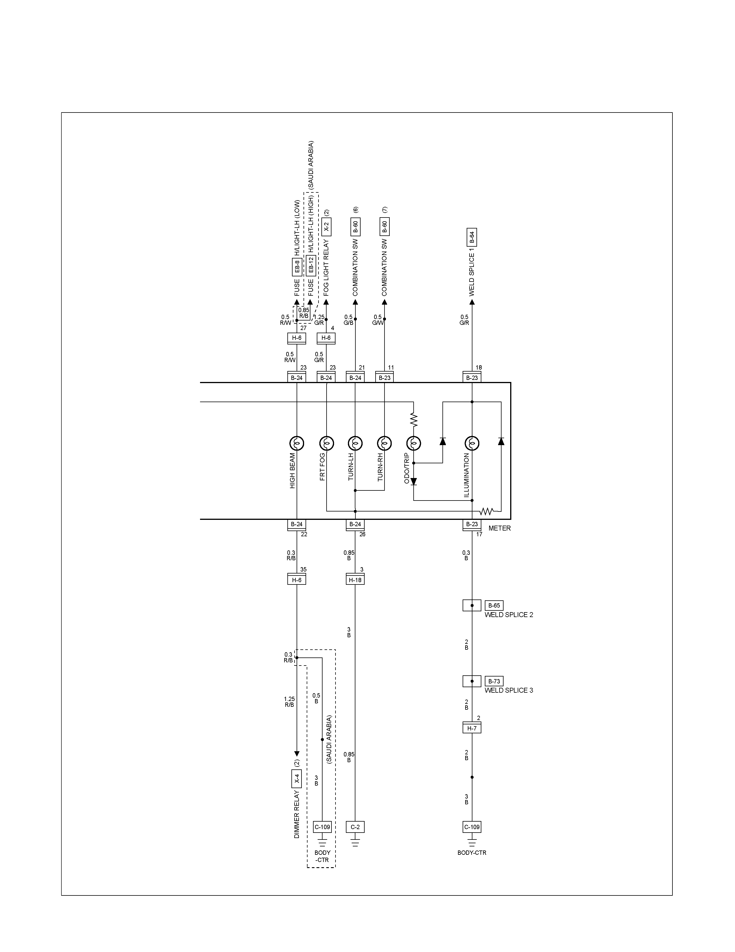
CIRCUIT DIAGRAM 4JA1-L (LHD) Sheet 3/3
RTW680XF012001
TROUBLESHOOTING
SPEEDOMETER
1. Speedometer and odometer do not function
Checkpoint Trouble Cause Countermeasure
Replace the vehicle speed
sensor
Vehicle speed sensor
malfunction
NG
Repair an open circuit in the
circuit or a poor connection at
the connectors
Continuity between the vehicle
speed sensor and the meter,
or the fuse C-5 (15A) and the
ground
Open circuit or poor connector
contact
Replace the case baseboard
assy
Use a meter tester to check
the speedometer function
Speedometer malfunction
NG
NG
OK
OK
Check the vehicle speed
sensor output
(4 pulses/1 rotation)
2. Speedometer pointer fluctuates
(May be wide fluctuation)
Replace the vehicle speed
sensor, or repair an open
circuit in the circuit or a
connectors
Vehicle speed sensor
malfunction, or open circuit or
poor connector contact
NG
Replace the case baseboard
assy
Use a meter tester to check
the speedometer function
Speedometer malfunction
NG
OK
Check the speed sensor
output by using the
oscilloscope
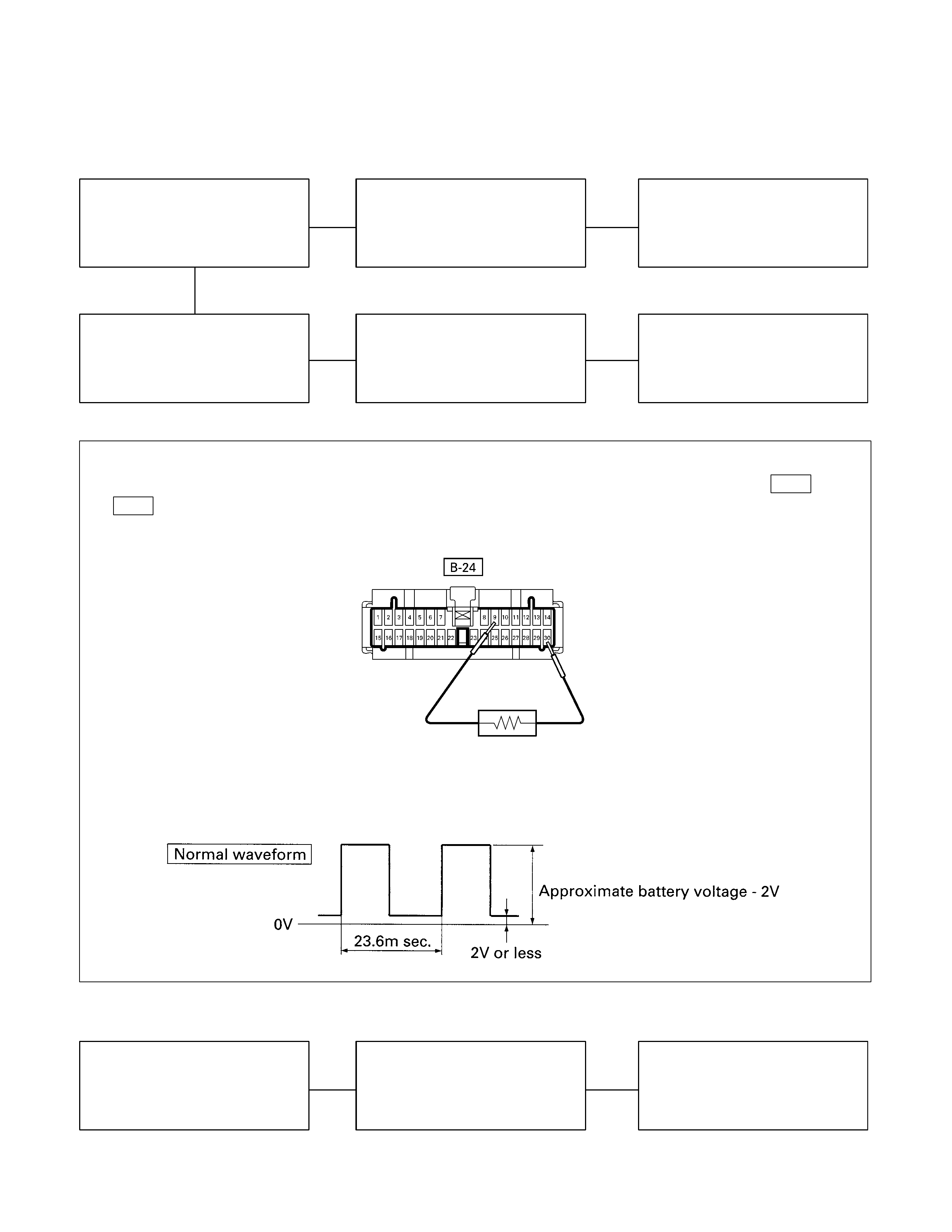
3. Speedometer pointer jumps erratically
Checkpoint Trouble Cause Countermeasure
Replace the vehicle speed
sensor, or repair an open
circuit in the circuit or a poor
connection at the connectors
Vehicle speed sensor
malfunction, or open circuit or
poor connector contact
NG
Replace the case baseboard
assy
Use meter tester to check the
speedometer function
Speedometer malfunction
NG
OK
Check the vehicle speed
sensor output by using the
oscilloscope
Inspection of a waveform by oscilloscope
1. Connect a resistance of 1.3 to 5k ohm (1.4W or more) between the harness side connectors 30 B-24 and 9
B-24 of the meter.
2. Install a speedometer tester.
2. Turn on the starter SW.
3. Check the waveform at the time when the vehicle speed is at 60km/h.
4. Trip odometer does not reset
Replace the case baseboard
assy
Faulty reset mechanism
NG
Check at other kilometer
figures given by meter tester
(Reset should be made to
zero kilometer)
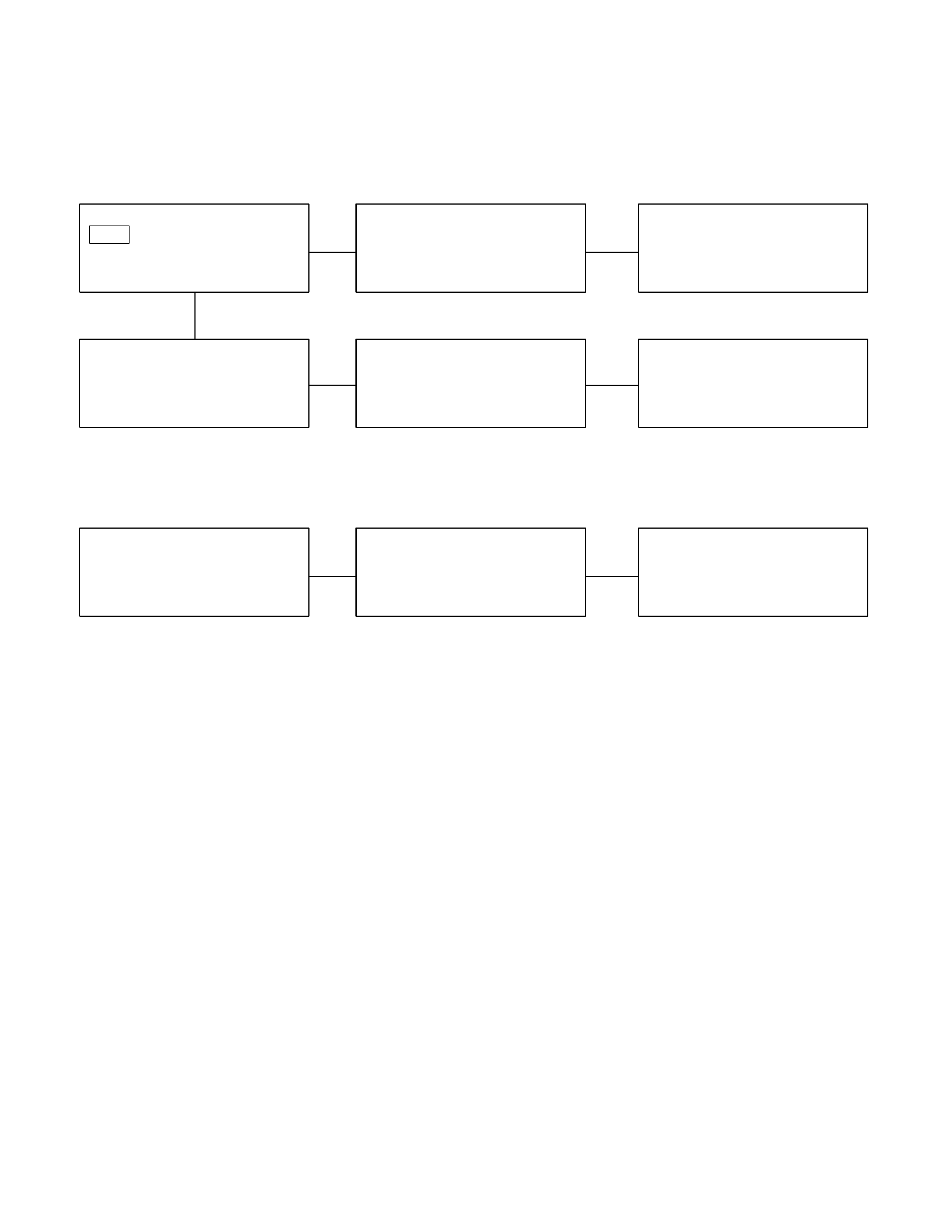
TACHOMETER
1. Tachometer does not function when engine is running
Checkpoint Trouble Cause Countermeasure
Replace the tacho sensor, or
repair open circuit or
connector contact
Tacho sensor malfunction, or
open circuit or poor connector
contact
NG
Replace the case baseboard
assy
Tachometer function
Tachometer malfunction
NG
OK
Pulse between connector 28
B-24 and the ground when
engine is running (Should be
pulse present)
2. Meter pointer fluctuates
(May be wide fluctuation)
Replace the case baseboard
assy
Tachometer malfunction
NG
Use a meter tester to check
the tachometer function
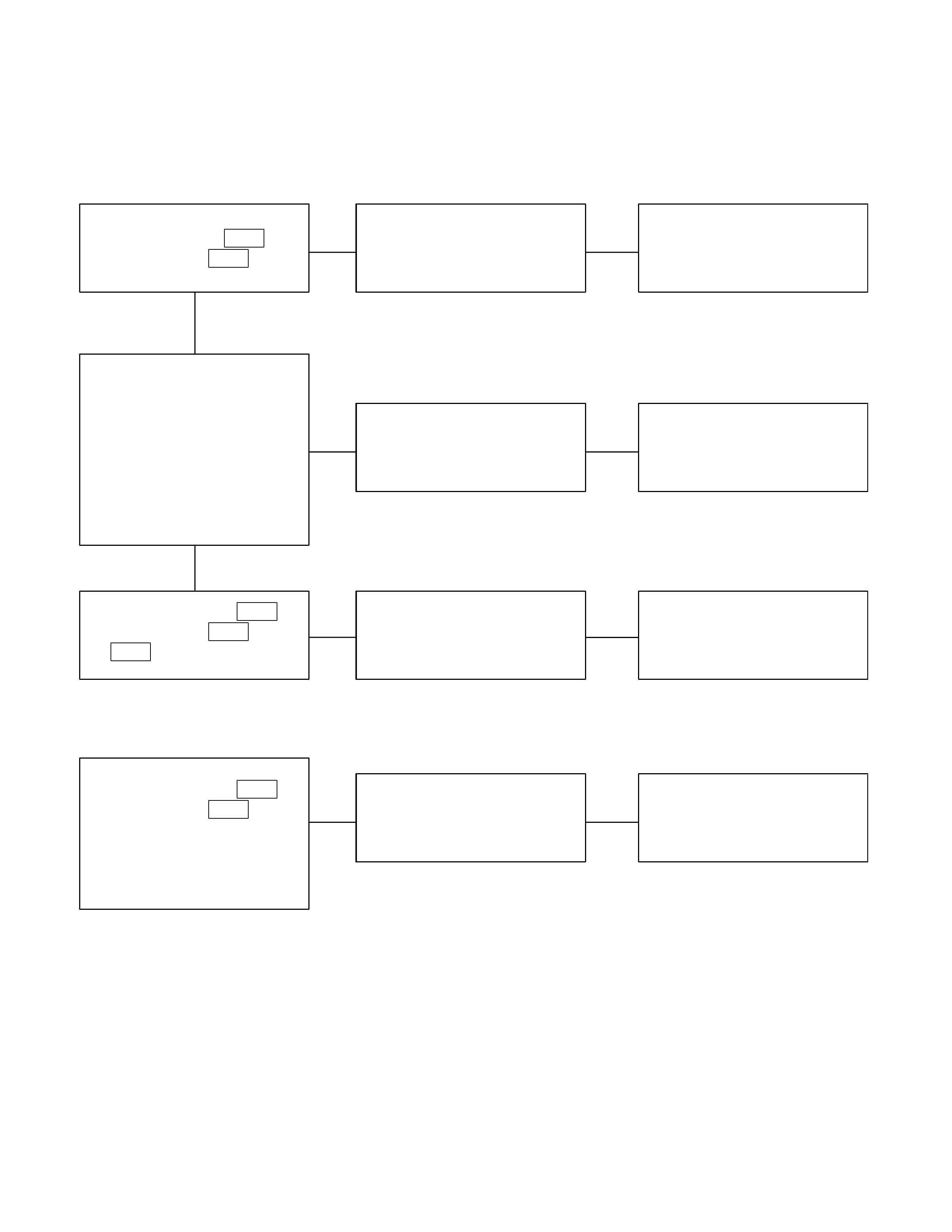
TEMPERATURE GAUGE AND THERMO UNIT
1. No temperature indicates at all
Checkpoint Trouble Cause Countermeasure
Replace the thermo unit
Thermo unit malfunction
NG
Replace the case baseboard
assy
Gauge function
1. Disconnect the unit
connector then connect
3.4W bulb to wire harness
side with ground
2. Check indicating point
when starter SW. is ON
position (Temperature
should indicate)
Gauge malfunction
Repair open circuit or
connector contact
Continuity between 1 E-19
(C24SE & 6VE1: E-65 ) and
13 B-24
Open circuit or poor connector
contact
NG
NG
OK
OK
Thermo unit continuity
between connector E-19
(C24SE & 6VE1: E-65 ) and
the ground
2. Temperature gauge incorrect readings in all ranges
Replace the thermo unit
Thermo unit malfunction
NG
Thermo unit resistance
between connector 1 E-19
(C24SE & 6VE1: E-65 ) and
the ground when
disconnecting the connector
(Specified resistance should
indicate)
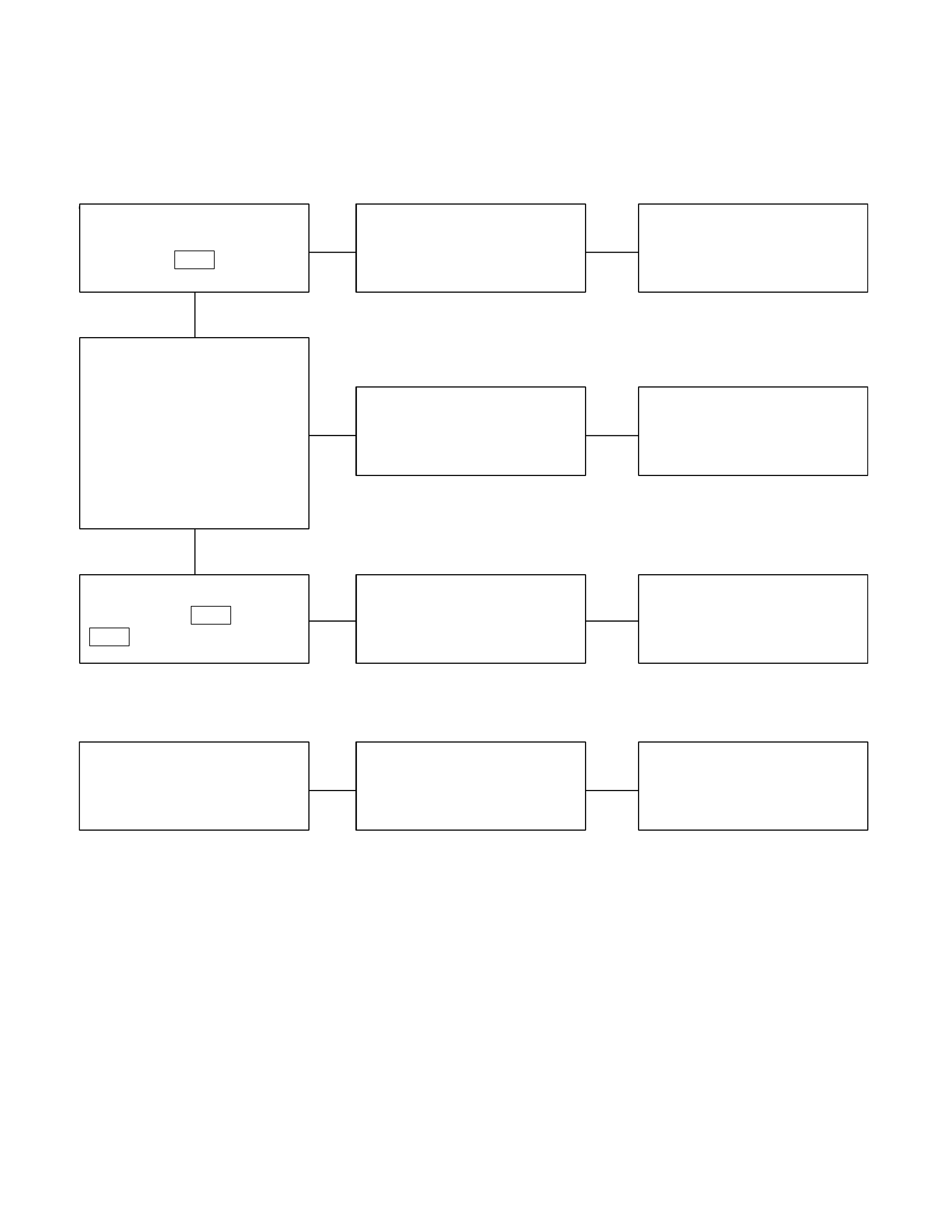
FUEL GAUGE AND FUEL TANK UNIT
1. No fuel level indicates at all
Checkpoint Trouble Cause Countermeasure
Replace the tank unit
Open circuit inside the tank
unit
NG
Thermo unit ma lfunction
Replace the case baseboard
assy
Fuel gauge function
1. Disconnect the tank unit
connector then connect
3.4W bulb to wire harness
side
2. Check indicating point
when starter SW. is ON
position (Fuel level should
indicate)
Gauge malfunction
Repair open circuit or
connector contact
Continuity between
connectors 14 B-24 and 3
F-2
Open circuit or poor connector
contact
NG
NG
OK
OK
Tank unit continuity between
connector 3 F-2 and ground
2. Fuel gauge gives incorrect readings in all ranges
Replace the tank unitTank unit malfunction
NG
Tank unit resistance position
with the float at checking
points (Specified resistance
should indicate)
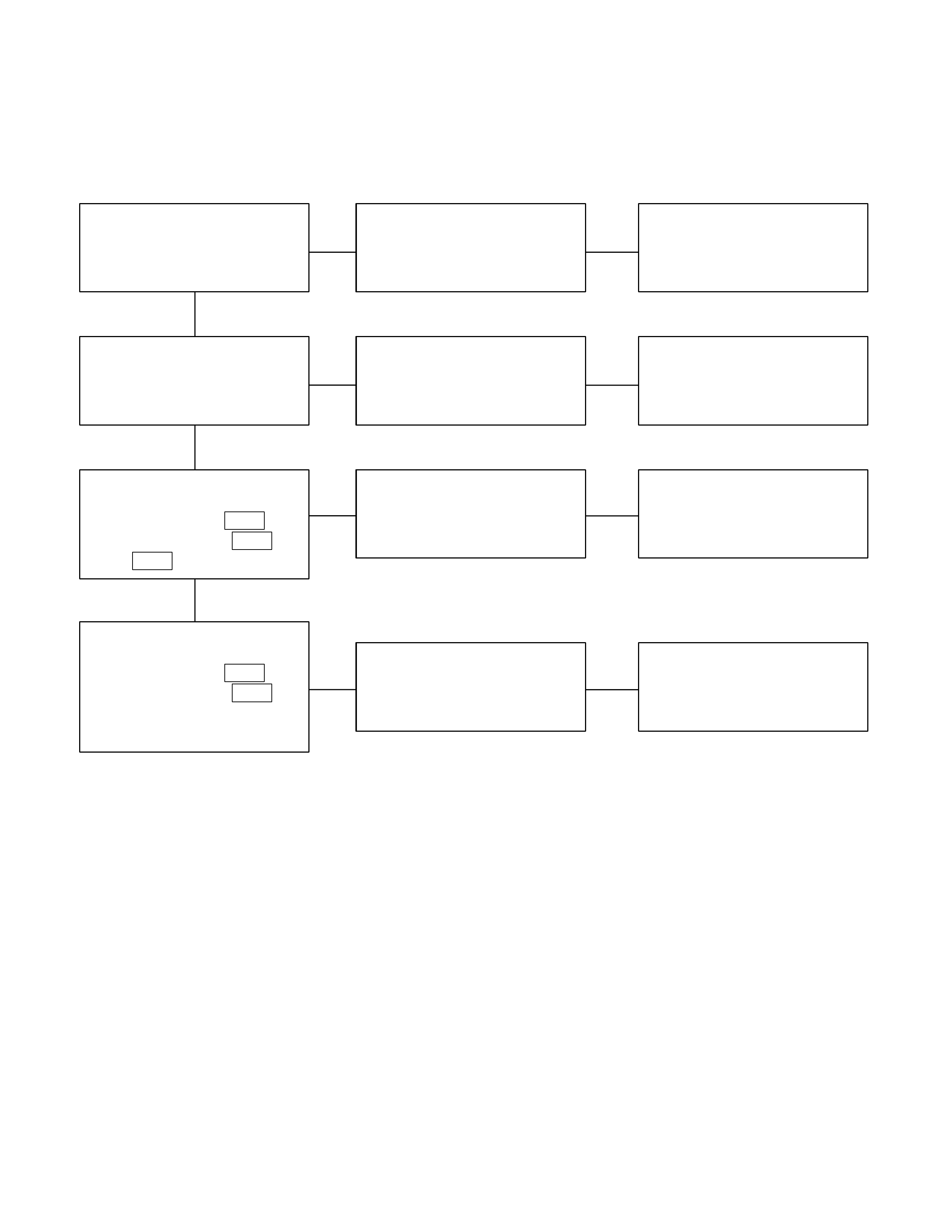
WARNING AND INCIDATOR LIGHT
1. When the parking brake lever is pulled, the indicator light does not light up
Checkpoint Trouble Cause Countermeasure
Replace or reinstall the bulb
Bulb burned out or loose
contact
NG
Adjust or replace the parking
brake SW.
Parking brake SW. installation
position and function
Incorrect SW. adjustment or
poor SW. point contact
Repair open circuit or
connector contact
Continuity between the
parking brake SW. connector
Stem (Stick) type 1 C-39
(Floor mount type: 1 R-4 )
and 9 B-23
Open circuit or poor connector
contact
NG
NG
OK
OK
Brake indicator light bulb
continuity
Replace the parking brake
SW.
Continuity between the
parking brake SW. connector
Stem (Stick) type 1 C-39
(Floor mount type: 1 R-4 )
and the ground when the
parking brake is operated
Parking brake SW.
malfunction
NG
OK
2. Even when the parking brake lever is pulled, the indicator light does not go off
Checkpoint Trouble Cause Countermeasure
Adjust the SW. installation
position or replace the parking
brake SW.
Incorrect the parking brake
SW. adjustment or brake SW.
faulty
NG
Thermo unit ma lfunction
Replace the brake fluid level
SW., or vacuum SW., or
repair a short circuit between
the parking brake SW.
connector Stem (Stick) type 1
C-39 (Floor mount type: 1
R-4 ) and 9 B-23 or the
brake fluid level SW.
connector 2 C-37 and 9
B-23 , (or the vacuum SW.
connector 1 C-38 and 9
B-23 : 4JH1-TC ONLY)
Check to see if the indicator
light goes off when the parking
brake SW. connector Stem
(Stick) type 1 C-39 (Floor
mount type: 1 R-4 ) is
disconnected
Brake fluid level SW. or
vacuum SW. faulty or short
circuit
NG
OK
Parking brake SW. installation
position and function
3. Oil pressure warning light does not go off while engine is running
Refer to ENGINE Section
Refer to ENGINE Section
NG
Thermo unit ma lfunction
Repair a short circuit between
1 E-1 and 17 B-24
Check to see the warning light
goes off when the oil pressure
SW. connector
1 E-1 (C24SE& 6VE1 :
E-75 ) is disconnected
Short circuit
Replace the oil pressure unit
(or the oil pressure SW.)
Continuity between the oil
pressure SW. connector
1 E-1 and the body ground
when the engine is operating
Oil pressure unit (or oil
pressure SW) faulty
NG
NG
OK
OK
Engine oil pressure
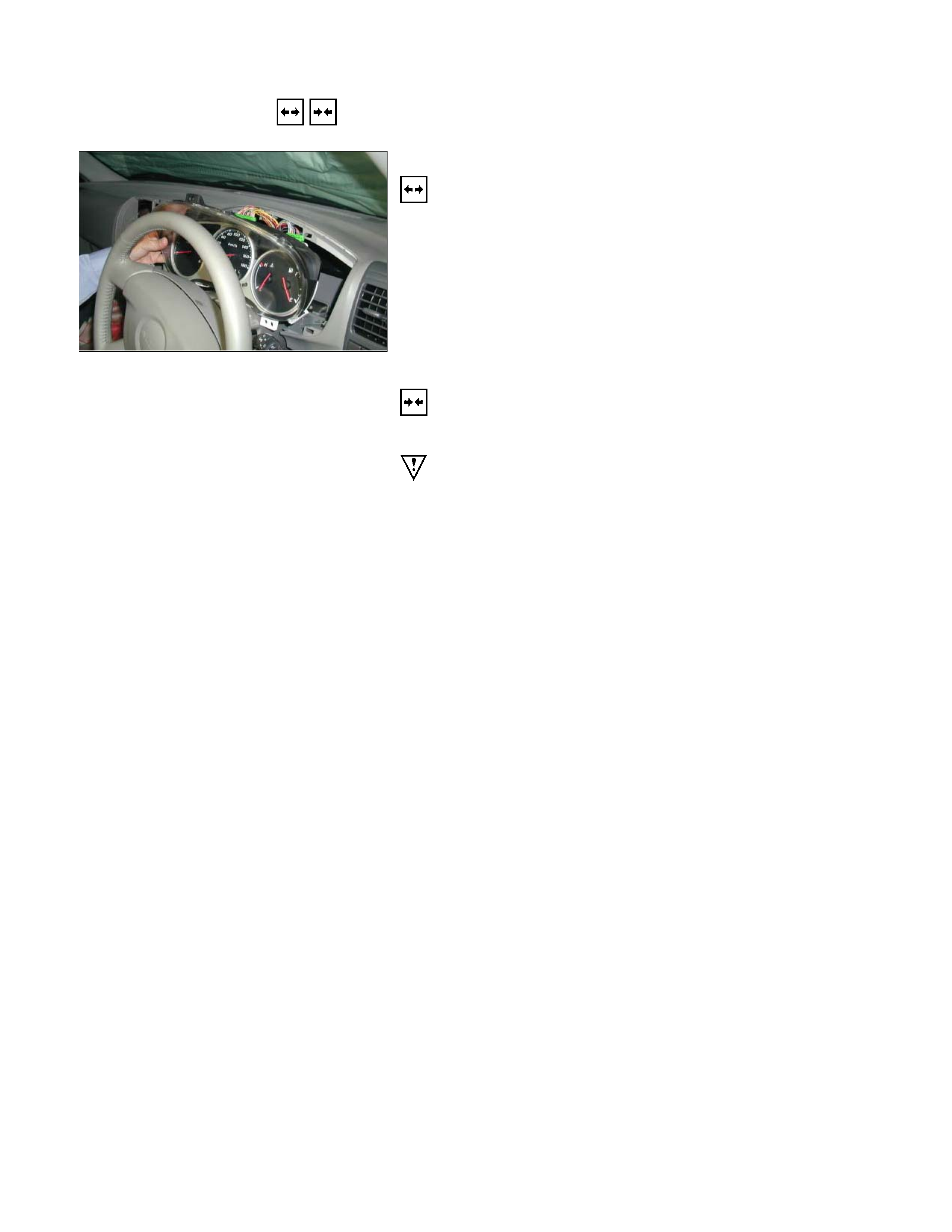
REMOVAL AND INSTALLATION
This illustration is based on RHD model
METER ASSEMBLY
Removal
1. Meter Cluster Assembly
• Refer to the removal steps of “INSTRUMENT PANEL” in
Section 10 “CAB”
2. Meter Assembly
• Remove three screws of the meter assembly.
• Disconnect the meter connectors.
Installation
Follow the removal procedure in the reverse order to install the
meter.
Pay close attention to the important points mentioned in the
following paragraphs.
Connector
Be absolutely sure that the meter connectors are securely
connected.
This will prevent a poor contact and an open circuit.
Wire Harness
Do not pinch the wire harness between the cluster and the
meter hood during the meter assembly installation procedure.
Wire damage will result.
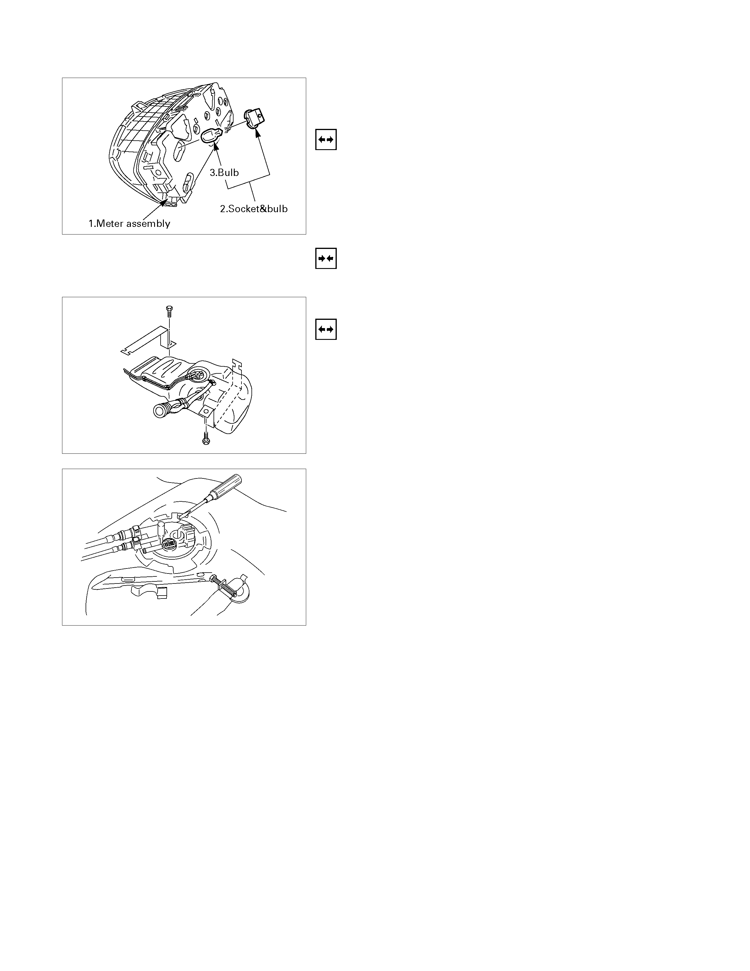
WARNING LIGHT BULB, INDICATOR
LIGHT BULB AND ILLUMINATION LIGHT
BULB
Removal
Turn the bulb socket counterclockwise and pull the bulb out.
Installation
To Install, follow the removal steps in the reverse order.
FUEL TANK UNIT
Removal
Dismount the fuel tank first, then remove the fuel tank unit.
1. Remove the rear inner liner -LH
• Remove the clip
2. Remove the filler neck.
• Remove the screw
3. Remove the ground with cable.
4. Remove the fuel tank band.
• Disconnect fuel line quick connectors.
5. Remove the fuel tank unit from the fuel tank.
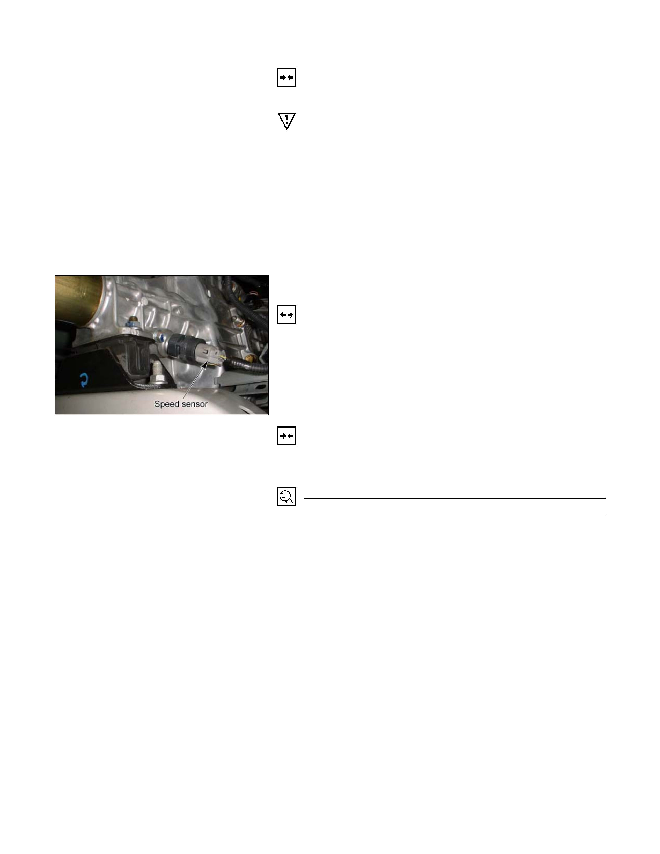
Installation
Follow the removal procedure in the reverse order to install the
fuel tank unit.
Pay close attention to the important points mentioned in the
following paragraphs.
Rubber Seal
Be absolutely sure that the fuel tank unit rubber seal is
correctly seated.
Connector
Be absolutely sure that the fuel tank unit connector is securely
connected.
This will prevent a poor contact and an open circuit.
VEHICLE SPEED SENSOR (INSTALLED
ON THE TRANSMISSION)
Removal
1. Disconnect the connector.
2. Remove the vehicle speed sensor body by rotating it.
Installation
To Install, follow the removal steps in the reverse order, noting
the following point.
Tighten the vehicle speed sensor to the specified torque.
Vehicle Speed Sensor Tightening Torque N⋅m (kg⋅m/lb.ft)
25 ± 4.9 (2.5 ± 0.5/18 ± 3.6)
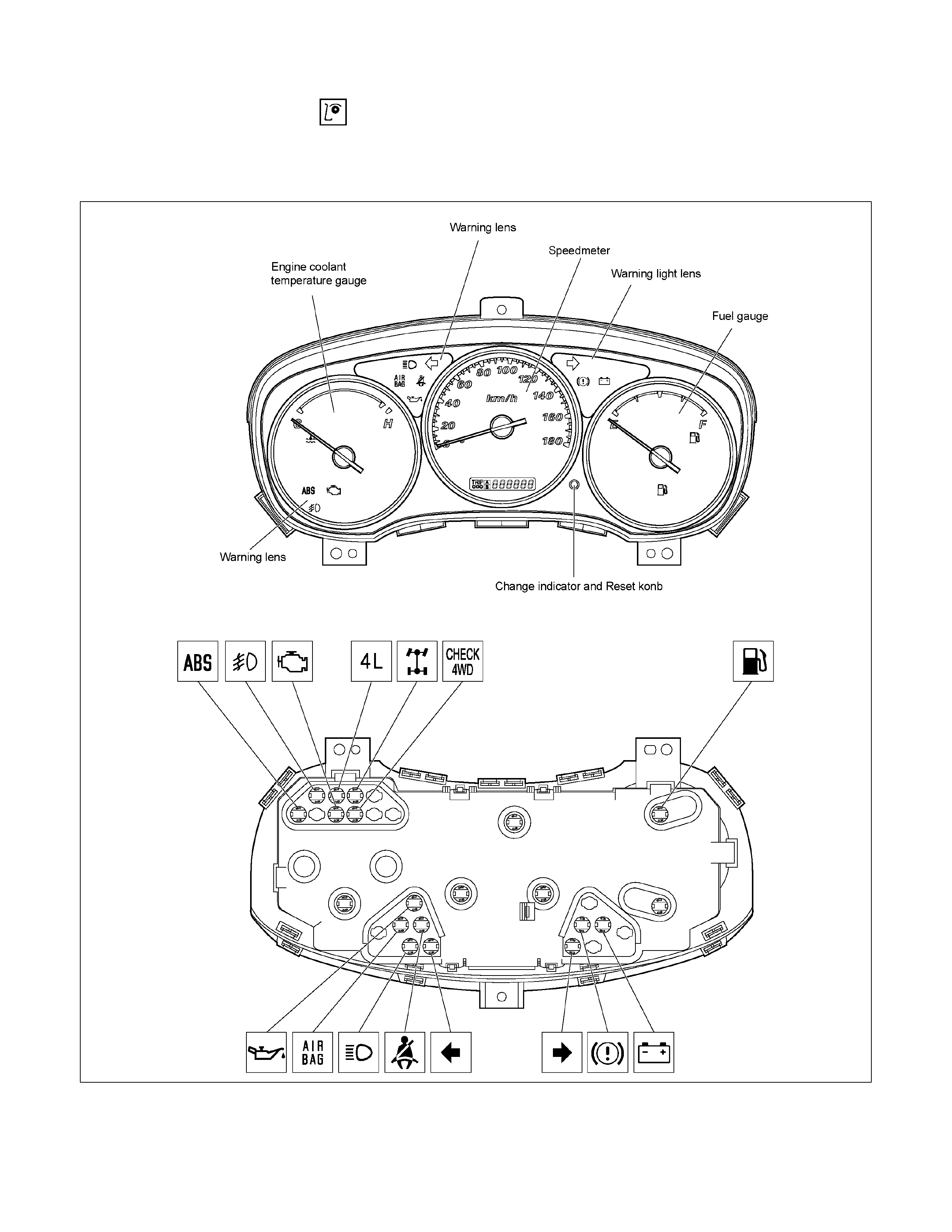
INSPECTION AND REPAIR
WARNING, INDICATOR AND ILLUMINATION LIGHT POSITION
Without tachometer (C24SE)
RTW68AXF008401
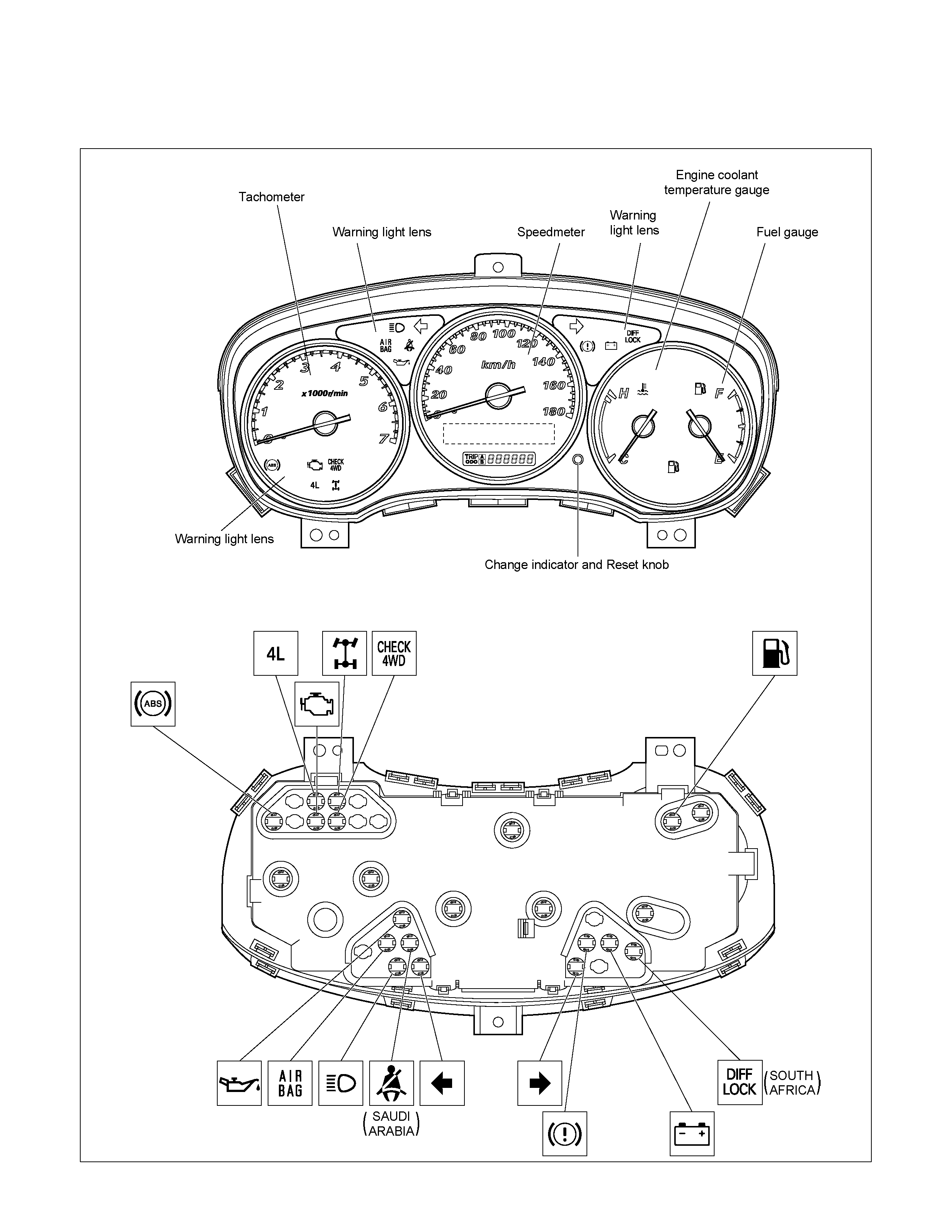
WARNING, INDICATOR AND ILLUMINATION LIGHT POSITION
With tachometer (C24SE)
RTW68AXF008501
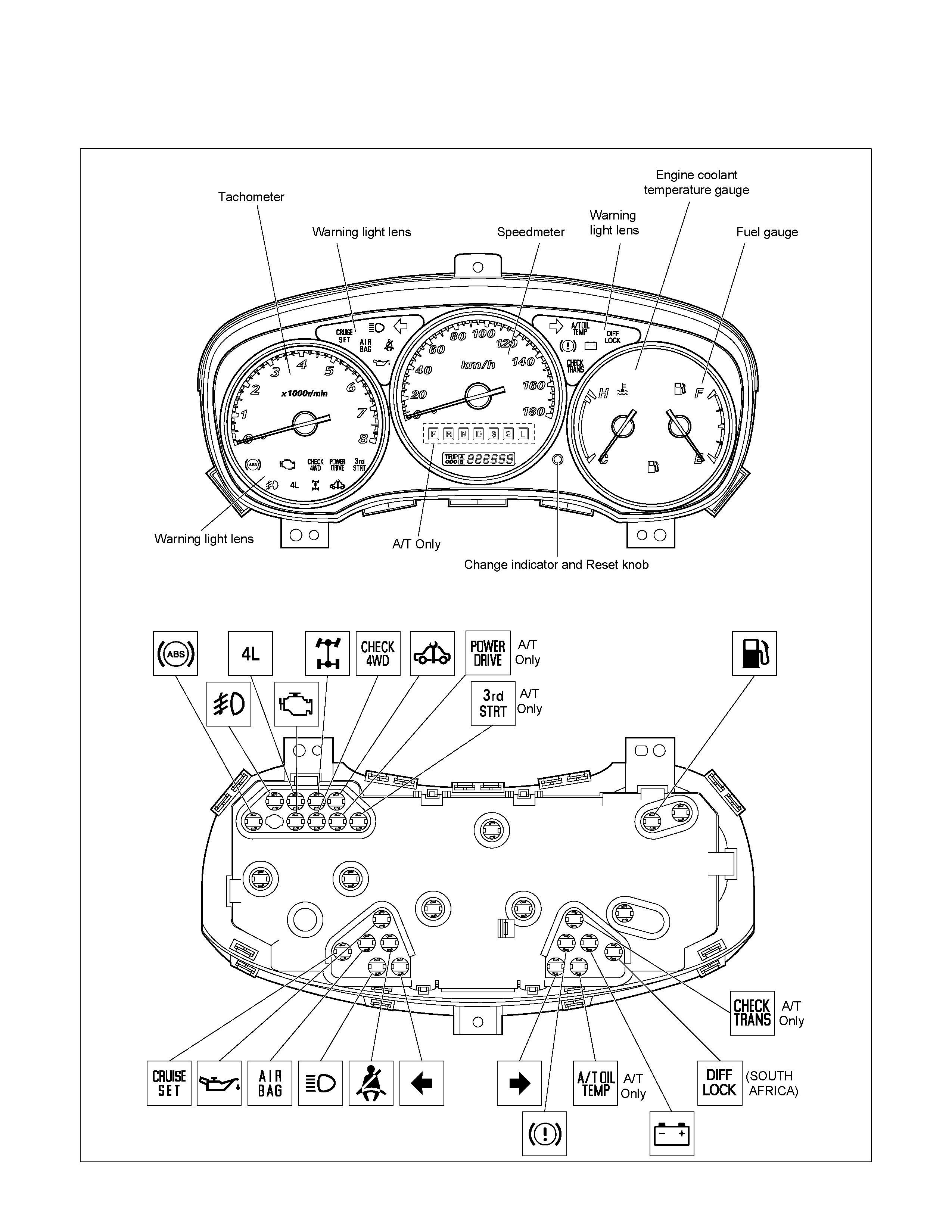
WARNING, INDICATOR AND ILLUMINATION LIGHT POSITION
With Tachometer (6VE1)
RTW68AXF008601

WARNING, INDICATOR AND ILLUMINATION LIGHT POSITION
With Tachometer (HFV6)
RTW68AXF018301
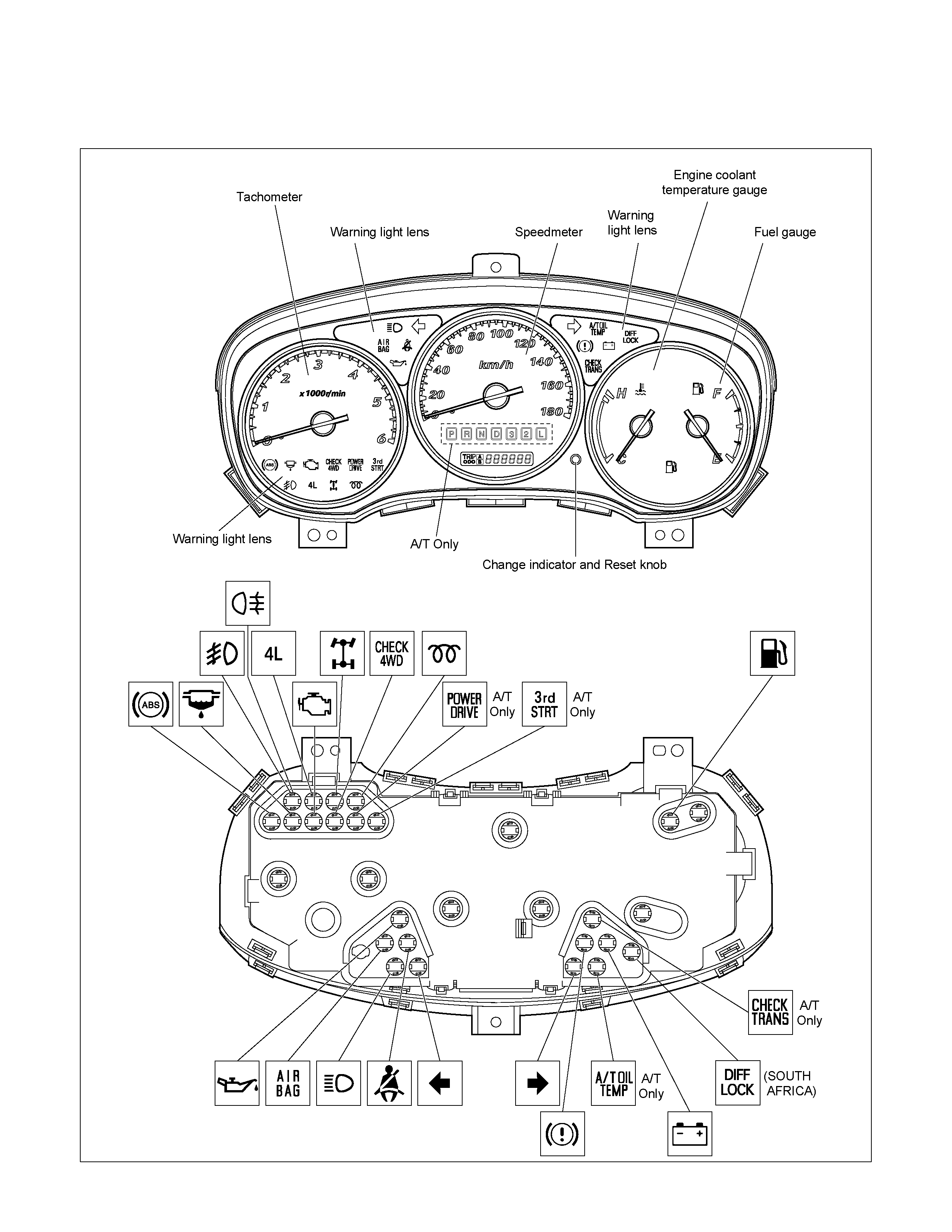
WARNING, INDICATOR AND ILLUMINATION LIGHT POSITION
With Tachometer (4JA1-TC / 4JH1-TC)
RTW68AXF008701
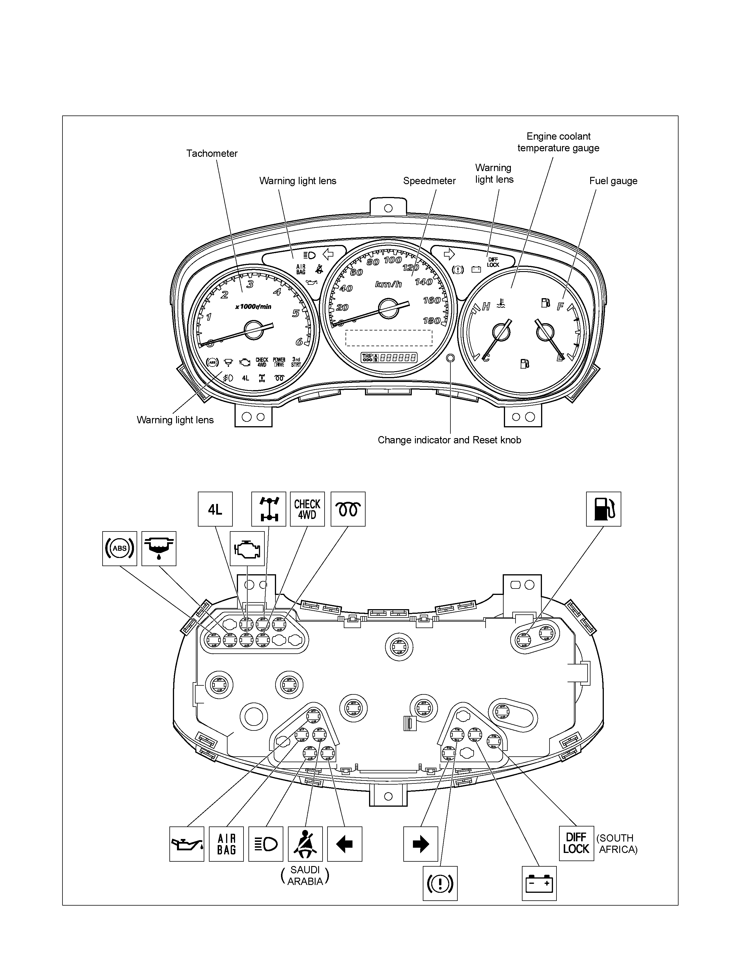
WARNING, INDICATOR AND ILLUMINATION LIGHT POSITION
With Tachometer (4JA1-L)
RTW68AXF008801
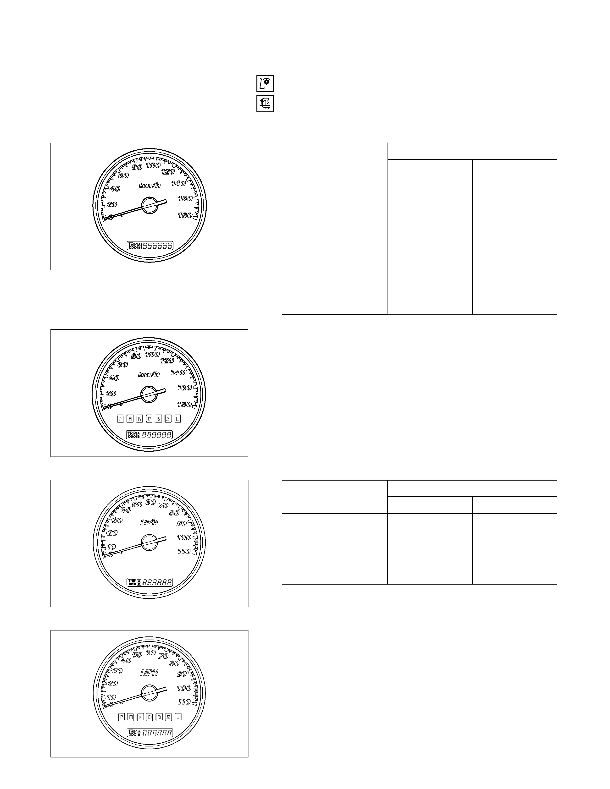
SPEEDOMETER AND TACHOMETER
Speedometer On-Vehicle Inspection
Check the speedometer accuracy with a speedometer tester.
Carefully follow the tester manufacturer’s instructions.
Manual Transmission (km/h)
RTW38DSH000201
km/h meter
Permissible Range
Indication G.EXP EUROPE,
SAUDI ARABIA
ISRAEL,
SOUTH AFRICA
20 17.5 - 22.5 20 – 25
40 37.5 - 42.5 40 – 45
60 57.5 - 62.5 60 – 65
80 77.5 - 82.5 80 – 85
100 97.6 - 103.4 99.8 – 105.6
120 117.6 - 123.4 119.8 – 125.6
140 137.6 - 143.4 139.8 – 145.6
160 157.2 - 163.8 159.4 - 166
Automatic Transmission (km/h)
RTW38DSH000101
Manual Transmission (mPH)
RTW48ASH001301
mPH meter
Permissible Range
Indication G.EXP UK
20 18.5 - 21.5 20 – 23
40 48.5 - 41.5 40 – 43
60 58.5 - 61.5 60 – 63
80 79.1 - 82.5 80 – 83.4
100 98.9 – 102.7 99.8 – 103.6
Automatic Transmission (mPH)
RTW48ASH000201
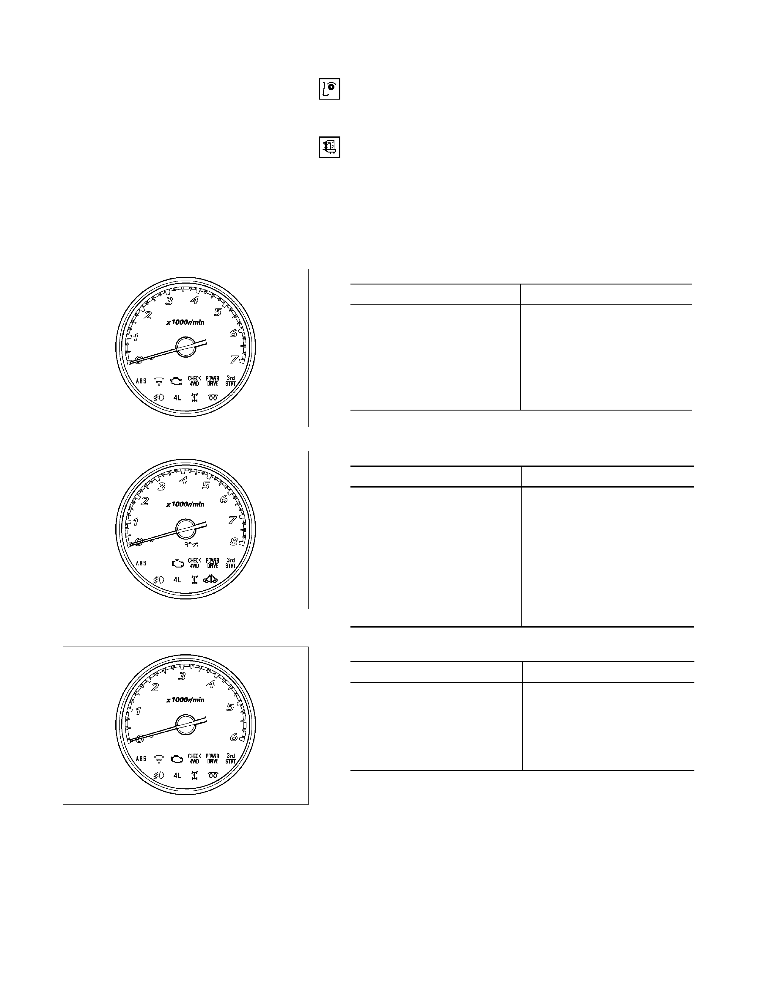
Tachometer On-Vehicle Inspection
1. Attach a tune-up tester to the engine.
2. Start the engine.
3. Compare the tachometer reading and the tester reading.
If the tachometer indication is outside the permissible
range, the tachometer must be replaced.
4. Gradually increase and decrease the engine speed.
Note the movement of the tachometer needle.
If the needle movement is sluggish, the tachometer must
be replaced.
RTW68ASH000201
C24SE rp
m
Indication Permissible Range
1,000 940-1,060
2,000 1,875-2,1250
3,000 2,850-3,150
4,000 3,820-4,180
5,000 4,820-5,180
6,000 5,820-6,180
RTW68ASH000301
6VE1, HFV6 rp
m
Indication Permissible Range
750 690-770
1,000 900-1,060
2,000 1,820-2,070
3,000 2,820-3,120
4,000 3,820-4,180
5,000 4,820-5,180
6,000 5,820-6,180
7,000 6,820-7,180
RTW68ASH000401
4JH1-TC rp
m
Indication Permissible Range
750 690-810
2,000 1,875-2,125
3,000 2,850-3,150
4,000 3,820-4,180
5,000 4,820-5,180
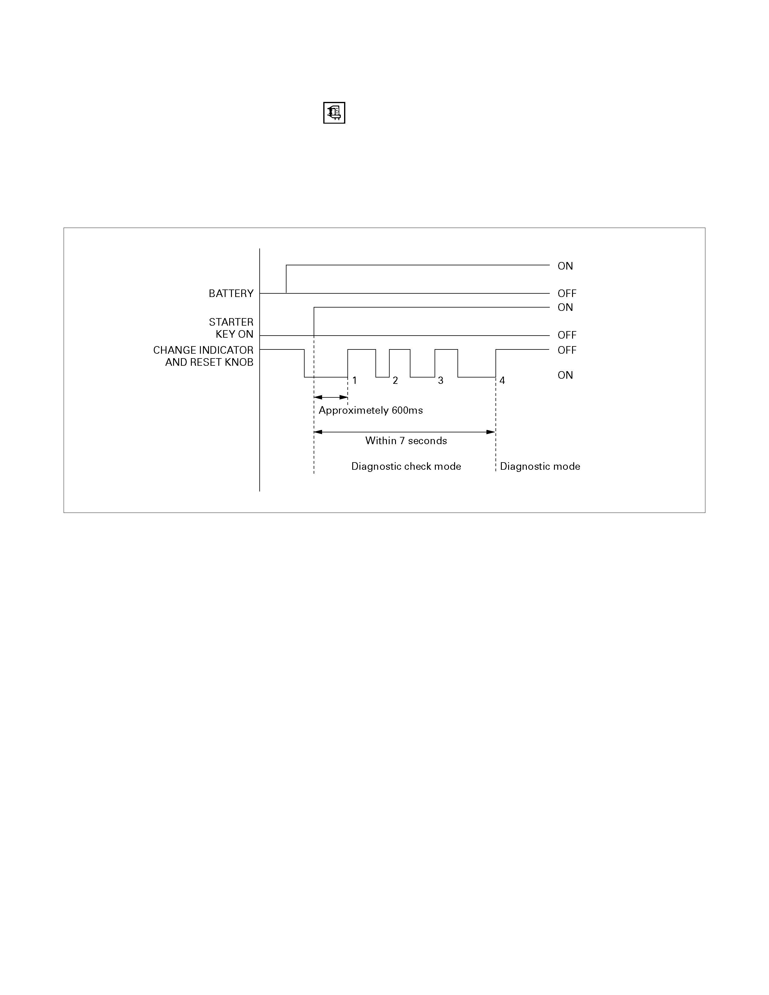
Tachometer Off-Vehicle Inspection
Remove the tachometer from the meter assembly and
measure the resistance value and the current consumption
between each terminal.
SELF DIAGNOSTIC FUNCTION
Check that the speedometer, tachometer, fuel gauge, and
temperature gauge operate properly.
821R300033
Entering the self-diagnostic mode
1. Push in and hold the “Change Indicator and Reset” knob.
2. Turn the ignition ON.
3. When the LCD odometer turns ON, release the “Change
Indicator and Reset” knob.
4. Push in and release the “Change Indicator and Reset” knob
three times in quick succession.
The meter cluster is now in “Self-diagnostic” mode.
NOTE: Steps 2-4 must be performed within 7 seconds.
The meter cluster will not enter “Self-diagnostic” mode if any of
the following conditions occur:
1. The “Change Indicator and Reset” knob is not depressed
when the ignition is turned ON.
2. The “Change Indicator and Reset” knob is released within
600ms of turning the ignition ON.
3. The “Change Indicator and Reset” knob is not depressed
and released three times within 7 seconds.
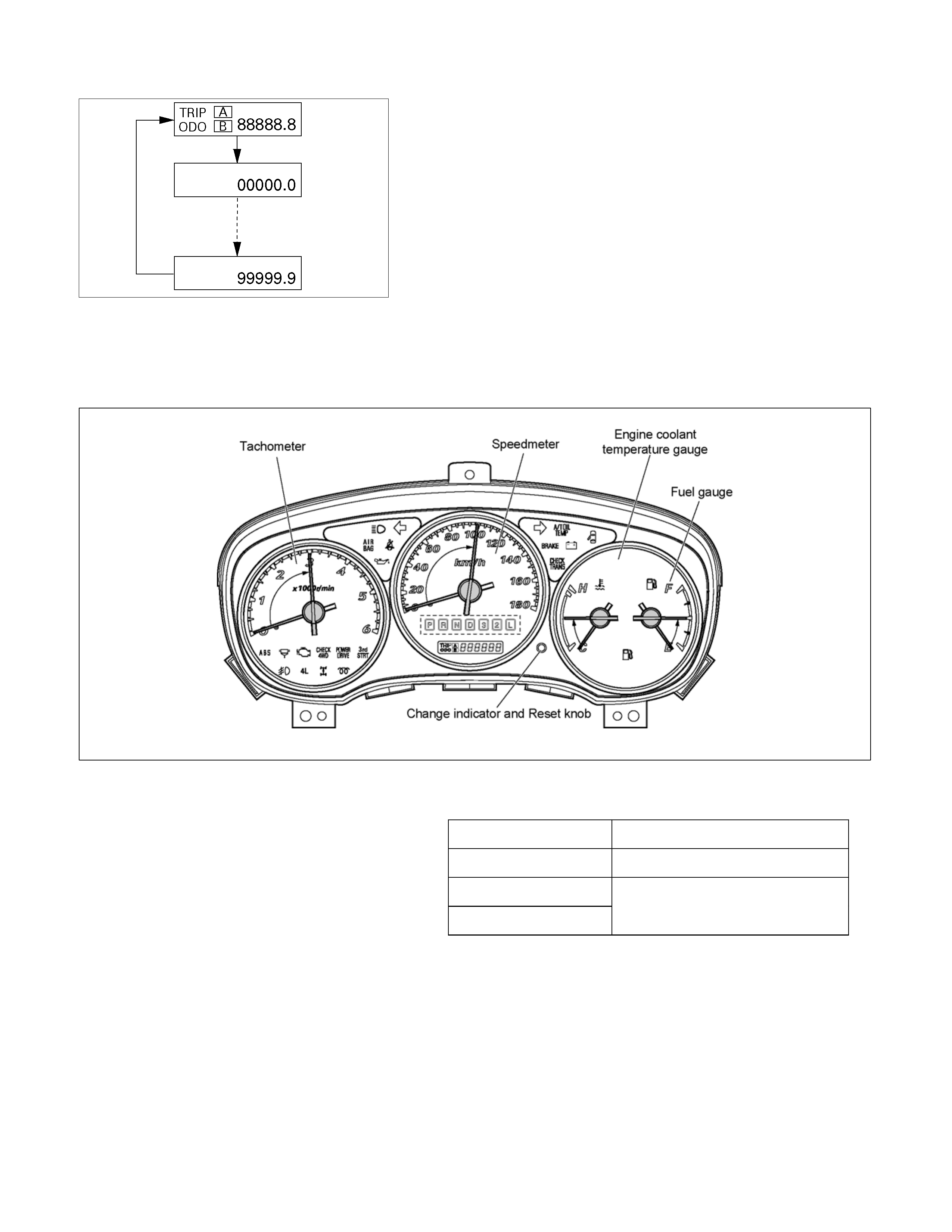
Self –diagnostic mode
LCD condition
• All LCDs are lit during the transition from self-diagnostic
decision mode to self-diagnostic mode
• The odometer/trip indicator scrolls throng its entire range
approximately once every 600 ms. All digits are lit
(segment check indication). This continues until the self-
diagnostic mode is terminated.
Meter and gauge indications
Meter and gauge indications with the change indicator and
reset knob on (self-diagnostic mode) are as shown in the
following table.
RTW68ASF000301
Speedometer 100 kilometers per hour
Tachometer 3,000 rpm
Fuel gauge
Temperature gauge Mid-point on the dial
All indications return to zero when the change indicator and
reset knob is turned off.
The self-diagnostic mode and the self-diagnostic decision
mode are cancelled when the ignition switch is turned to the
OFF position. They also cancel when a speed pulse is sensed.
If either of the self-diagnostic modes are cancelled by turning
the ignition switch to the OFF position, the diagnostic unit
remains in the stand-by condition.
If cancellation occurs when a speed pulse is sensed, the unit
remains in the ordinary operating condition.
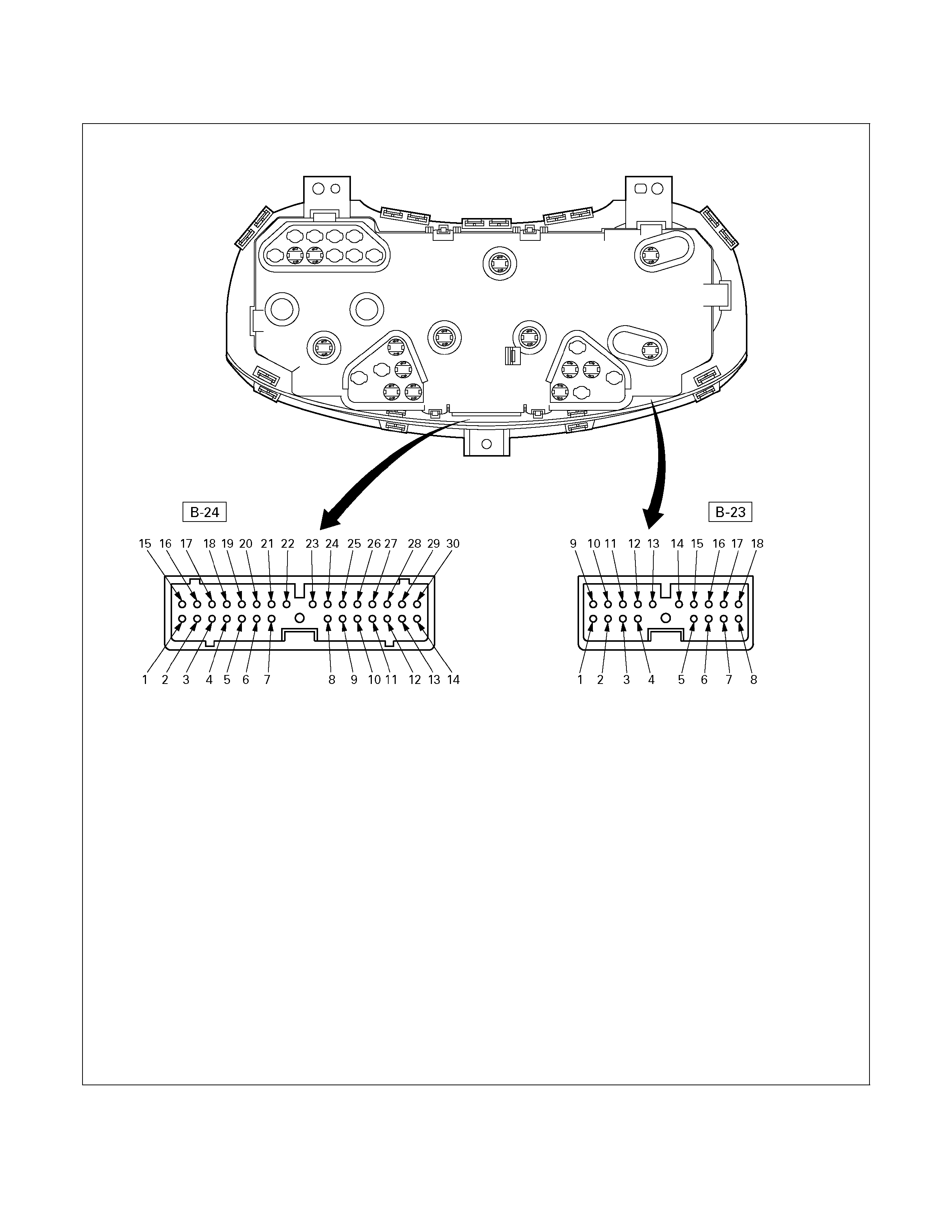
Meter connector pin arrangement
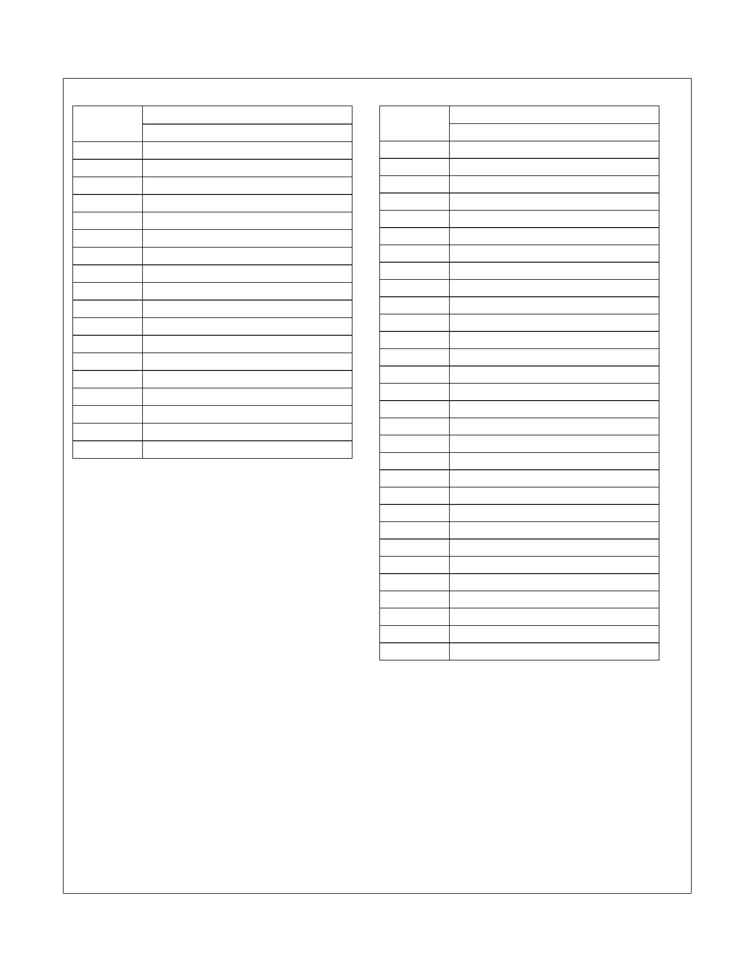
Terminal Connector No. B-23
No. C24SE
1 ABS CONT. (BRAKE)
2 ⎯
3 ⎯
4 ⎯
5 ⎯
6 ⎯
7 ⎯
8 ⎯
9 BRAKE
10 CHARGE
11 TURN (RIGHT)
12 ⎯
13 ⎯
14 ⎯
15 ⎯
16 ⎯
17 ILLUMI (-)
18 ILLUMI (+)
Terminal Connector No. B-24
No. C24SE
1 ⎯
2 4L
3 CHECK ENGINE
4 ⎯
5 4WD
6 CHECK 4WD
7 ⎯
8 ⎯
9 SPEED (+)
10 4P OUTPUT
11 ⎯
12 STARTER
13 TEMP
14 FUEL
15 FRONT FOG
16 ⎯
17 OIL PRESSURE
18 AIR BAG
19 SEAT BELT
20 BEAM (+)
21 TURN (LEFT)
22 BEAM (-)
23 BEAM (+)
24 ⎯
25 ⎯
26 POWER GND
27 SPEED (-)
28 GND UNIT
29 +B
30 IGN
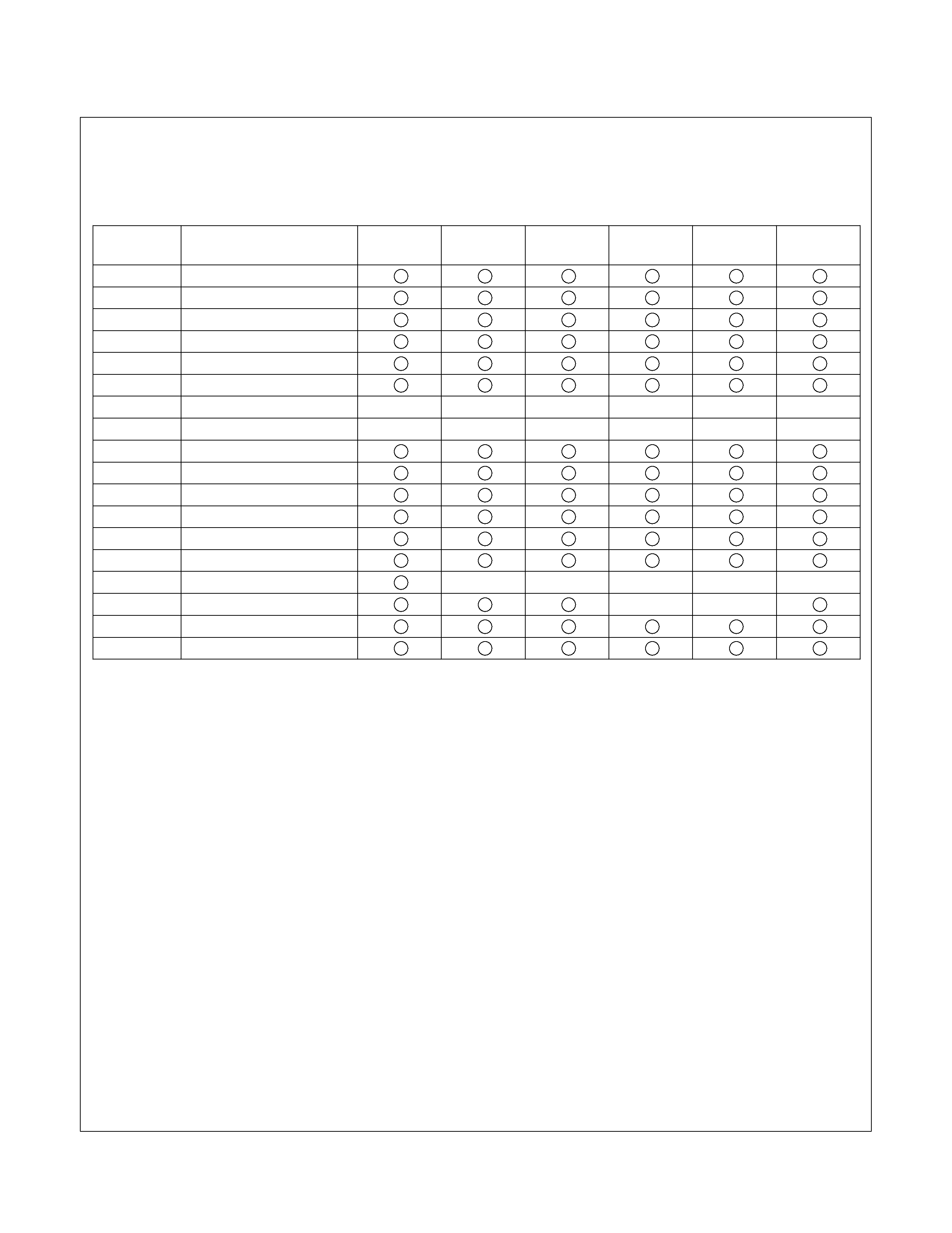
Connector No. B-23
Terminal Connector place SOUTH
AFRICA SAUDI
ARABIA ISRAEL EUROPE UK OTHER
1 ABS CONT. (BRAKE)
2 CHECK TRANS
3 A/T-P
4 A/T-R
5 A/T-2
6 A/T-L
7 \
\
\
\
\
\
\
8 \
\
\
\
\
\
\
9 BRAKE
10 CHARGE
11 TURN (R)
12 A/T-N
13 A/T-D
14 A/T-3
15 DIFF. LOCK \
\
\
\
\
16 A/T OIL TEMP \
\
17 ILL (-)
18 ILL (+)
RTW48AXF005901
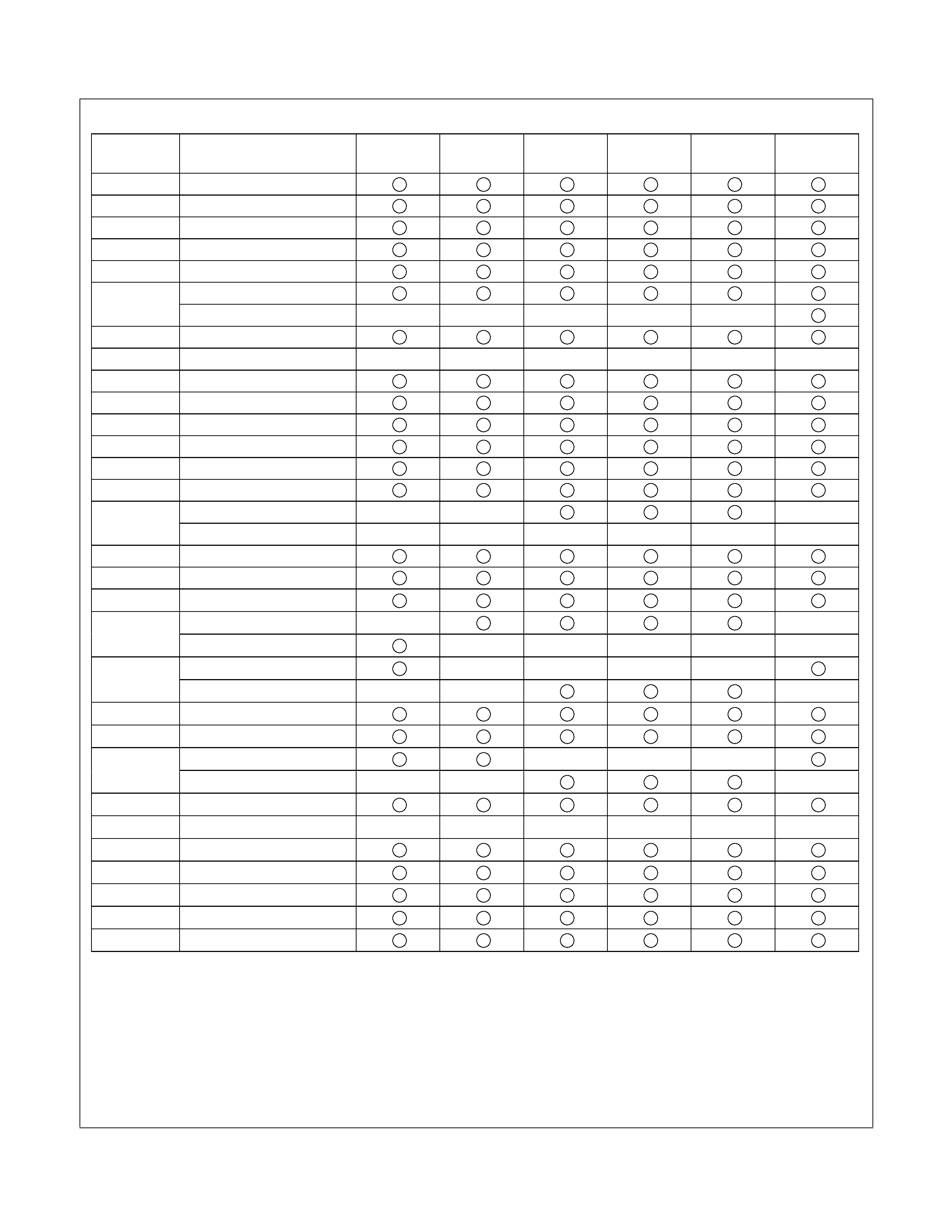
Connector No. B-24
Terminal Connector place SOUTH
AFRICA SAUDI
ARABIA ISRAEL EUROPE UK OTHER
1 SEDIMENTER
2 4L
3 CHECK ENGINE
4 4WD
5 CHECK 4WD
GLOW
6 SVS \
\
\
\
\
7 POWER DRIVE
8 \
\
\
\
\
\
\
9 SPEED (+)
10 4P OUTPUT
11 TACHO
12 STARTER
13 TEMP
14 FUEL
RR FOG \
\
\
15 FRONT FOG \
\
\
\
\
\
16 ABS CONT. (ABS)
17 OIL PRESS
18 AIR BAG
SEAT BELT
19 LOW COOLANT \
\
\
\
\
CRUISE SET \
\
\
\
20 BEAM (+) \
\
\
21 TURN (LEFT)
22 BEAM (-)
BEAM (+) \
\
\
23 FRONT FOG \
\
\
24 3rd START (A/T)
25 \
\
\
\
\
\
\
26 POWER GND
27 SPEED (-)
28 GND UNIT
29 +B
30 IGN
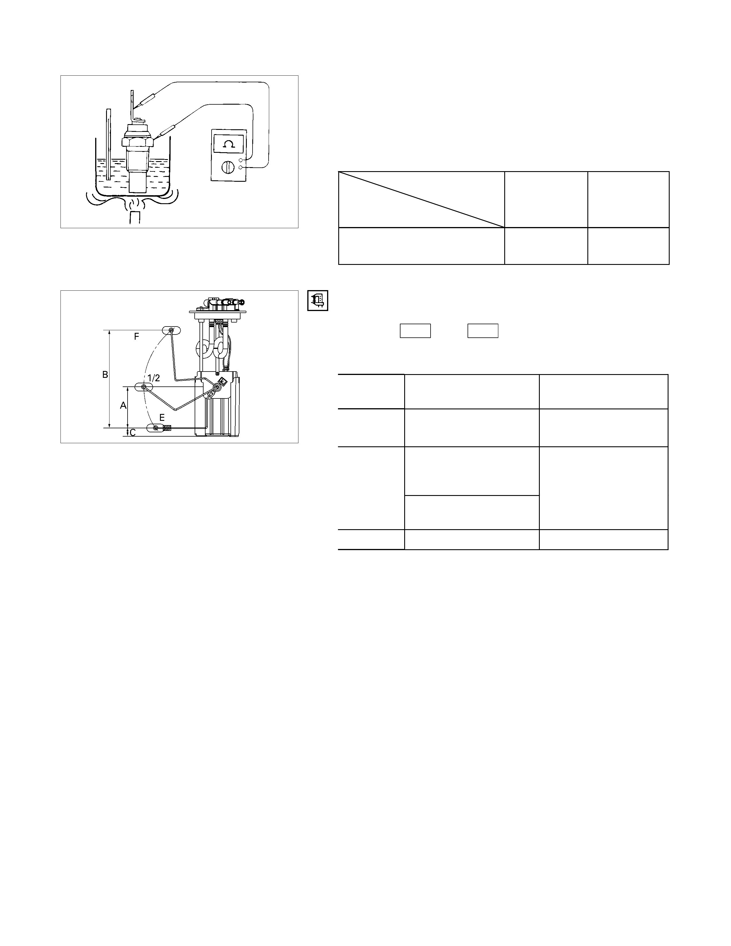
140R300007
Thermo Unit Inspection
INSPECTION
Use a circuit tester to measure the thermo unit resistance.
Replace the unit when the result of inspection is found
abnormal.
Temperature
Check
condition
60°C
(140°F) 115°C
(239°F)
Resistance
value (Ω) 168 ±3.5 +2.5
30.9 –2.0
041R300002
Fuel Tank Unit Inspection
Measure the fuel tank unit resistance between the connector
terminals 1 F-2 and 3 F-2 while shifting the float from “E”
to “F” point.
Fuel Tank Resistance
Level Float position
mm Standard resistance
Ω
F (B) 217.5 +2.2
17 –0.8
105.1
(C24SE, 6VE1, HFV6,
4JA1-L)
1/2 (A) 112.8
(4JA1-TC, 4JH1-TC)
45 ± 4.5
E (C) 16.2 120
± 2.0
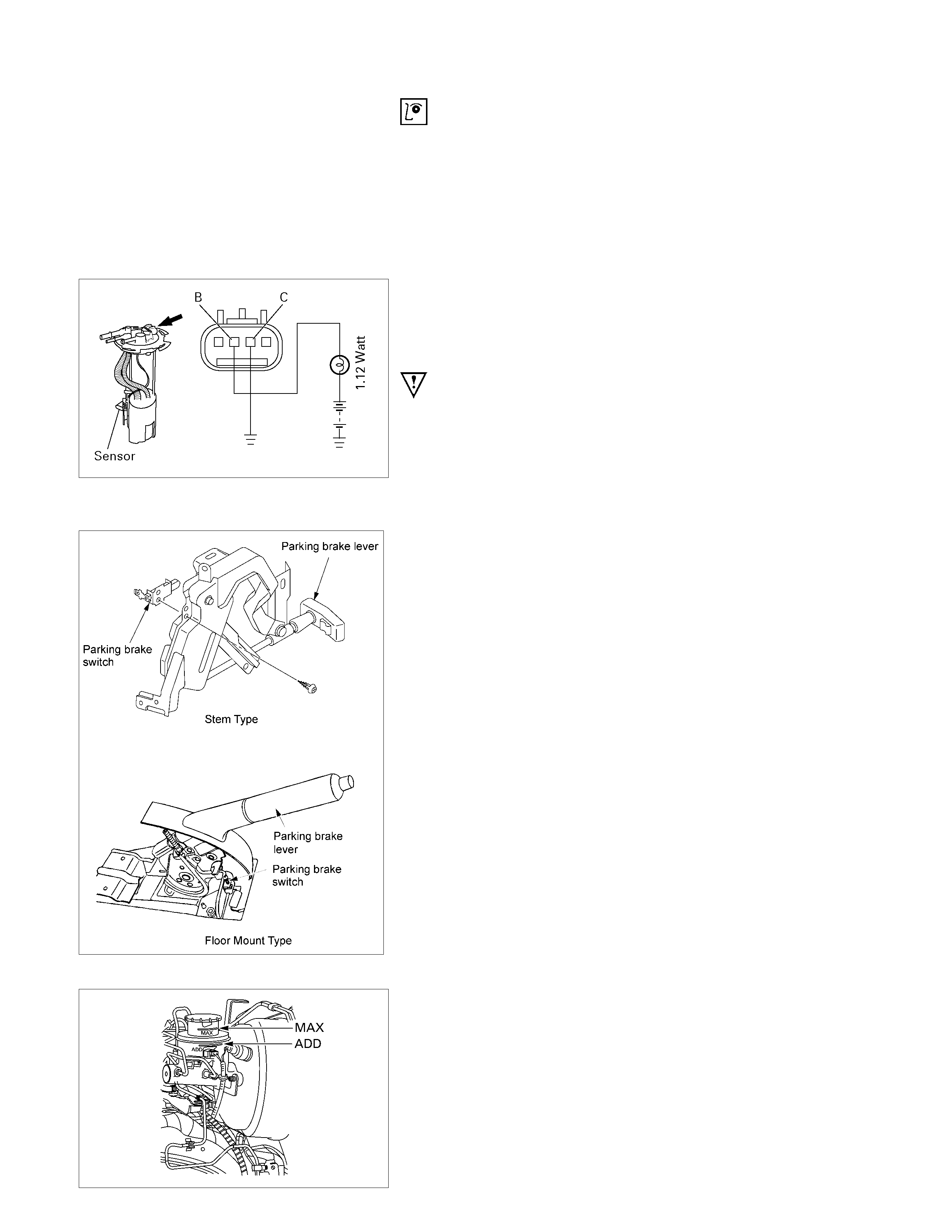
Low Fuel Indicator Light
1. Disconnect the fuel tank unit wire connector.
2. Turn the key switch on. Check that the bulb lights.
If operation is not correct, remove and check the bulb or
circuit.
or If check whether low fuel turns on fuel input (B-24) at the
time of open and key on.
∗ meter is check at low fuel
140R300006
Check level sensor operation
1. Remove the fuel tank unit.
2.
A
pply battery voltage between terminal (B) and (C) through
a 1.12 watt bulb. Check that the bulb lights.
Note:
It will take a short time for the bulb light.
3. Submerge the sensor in fuel. Check that the bulb goes out.
If operation is not correct, replace the fuel tank unit.
BRAKE SYSTEM WARNING LIGHT
The brake system warning light comes on while the parking
brake is set and the engine run position.
RTW48AMH000101
Note:
The parking brake indicator light circuit is designed to
prevent driving of the vehicle with the parking brake on.
It does not indicate the condition of the parking brake
system.
The parking brake switch is in parallel with the brake fluid
switch.
The brake system warning light also comes on when reservoir
brake fluid level falls below the specified limit with the parking
brake released and the engine run position.

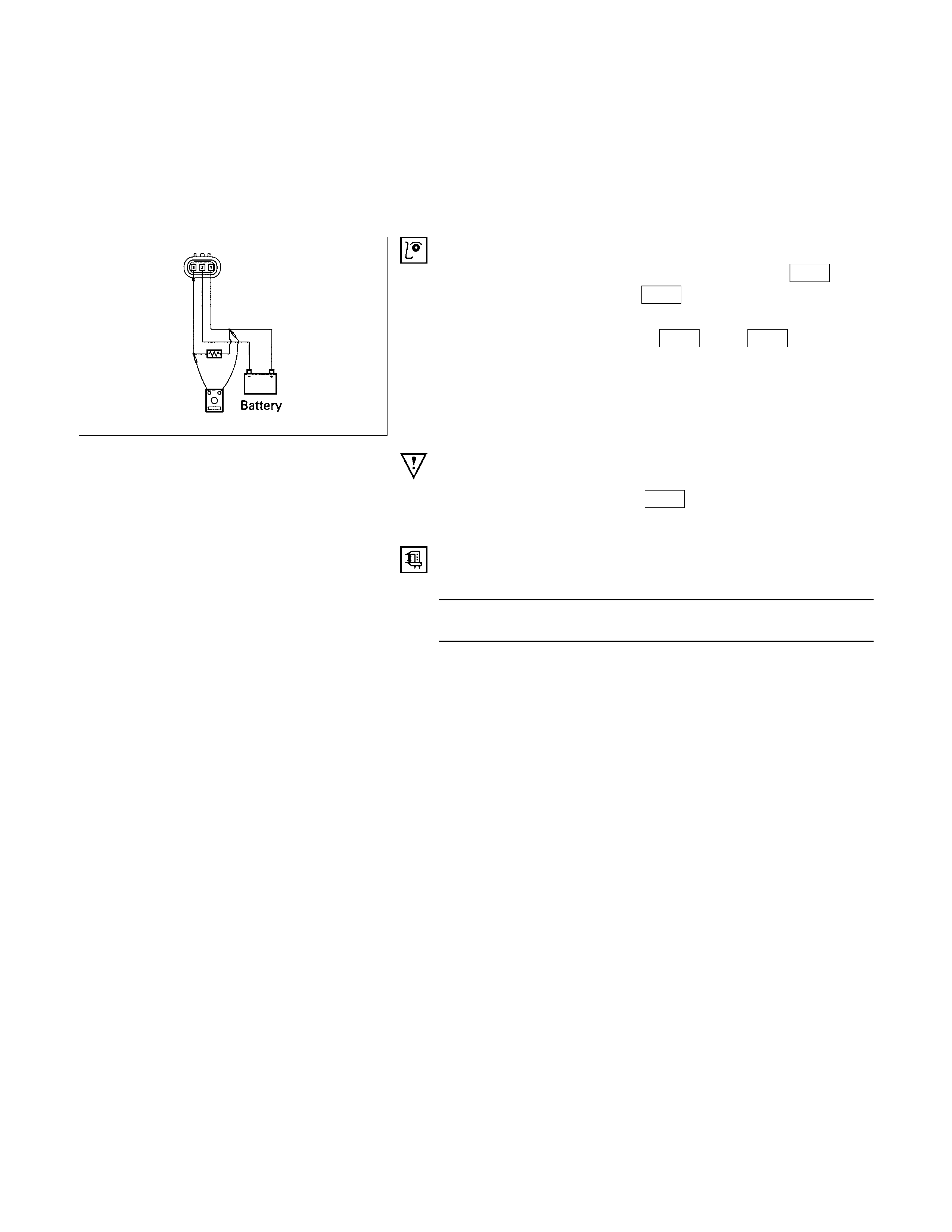
VEHICLE SPEED SENSOR (INSTALLED
ON THE TRANSMISSION)
The speed sensor is installed on the rear portion of the
transmission.
The number of pulses generated is four pulses per one
rotation of the pinion shaft.
Vehicle Speed Sensor Inspection
1. Connect the vehicle speed sensor connector 1 E-44 to the
battery (+) terminal and 2 E-44 to the (-) terminal.
2. Connect a resistance of 1.3K ohm to 5K ohm (1/4 W o
r
more) between connectors 1 E-44 and 3 E-44
CAUTION:
Be extremely careful not to connect the battery (+)
terminal to the connector 3 E-44 .
This may damage the vehicle speed sensor.
3. Rotate the shaft of the vehicle speed sensor slowly and
measure the voltage at the both ends with a digital tester.
The voltage, with one rotation of shaft fluctuates four times in
the following range: 10 to 14V - 2V or less.
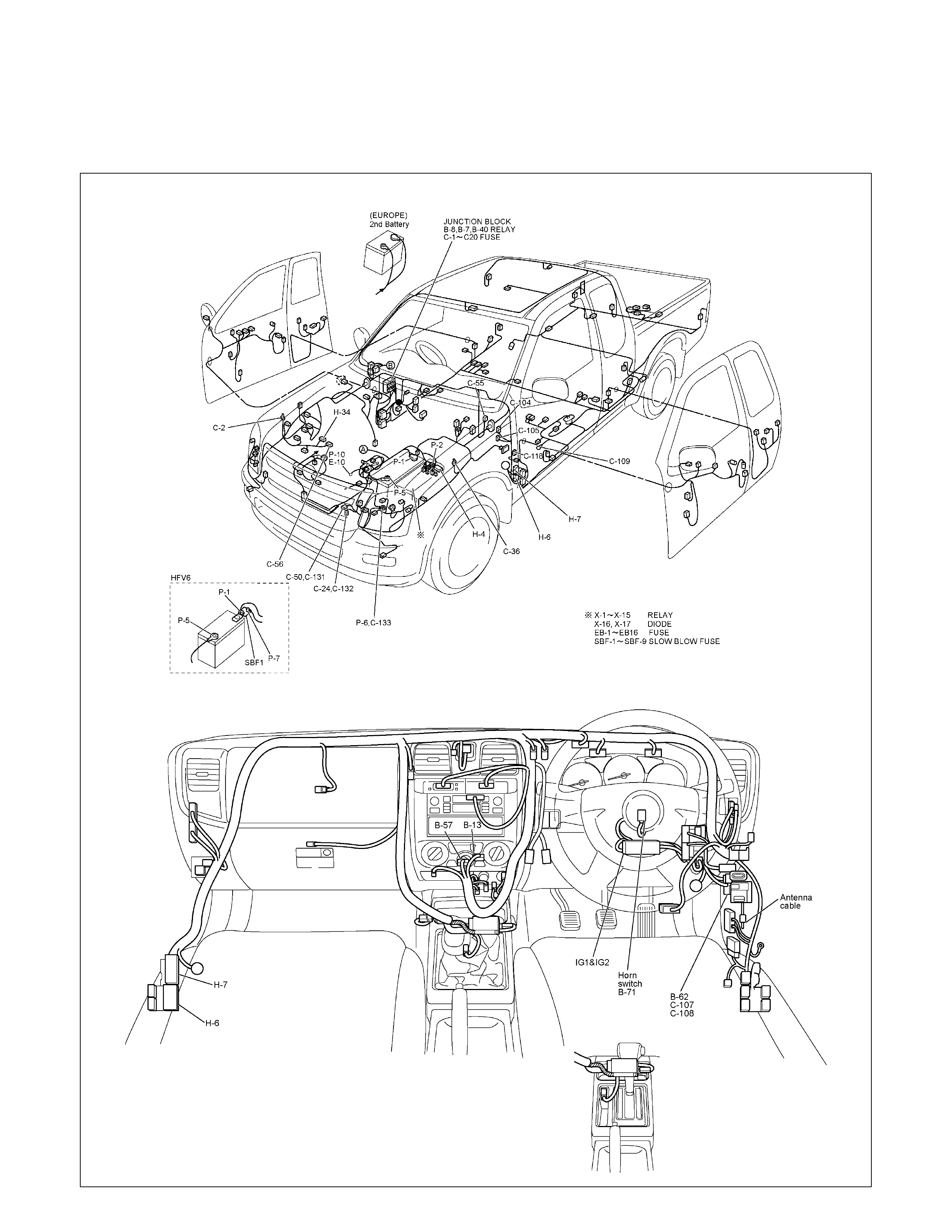
HEATER AND AIR CONDITIONING
PARTS LOCATION (RHD)
RTW68AXF018401 & RTW68AXF015501
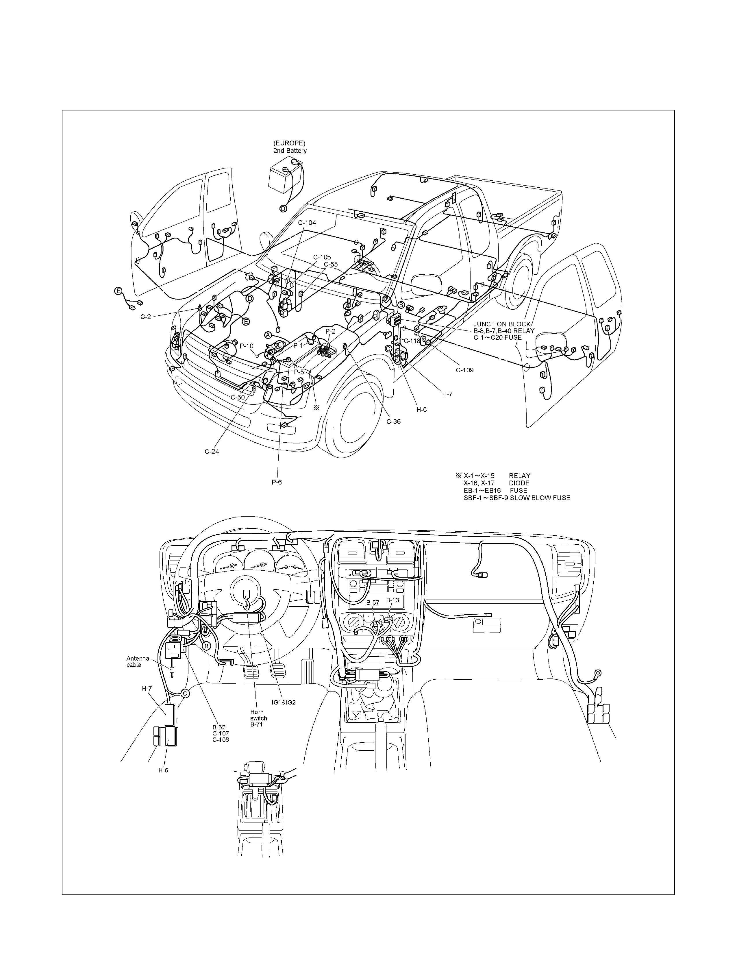
PARTS LOCATION (LHD)
RTW48AXF019001 & RTW48AXF019101
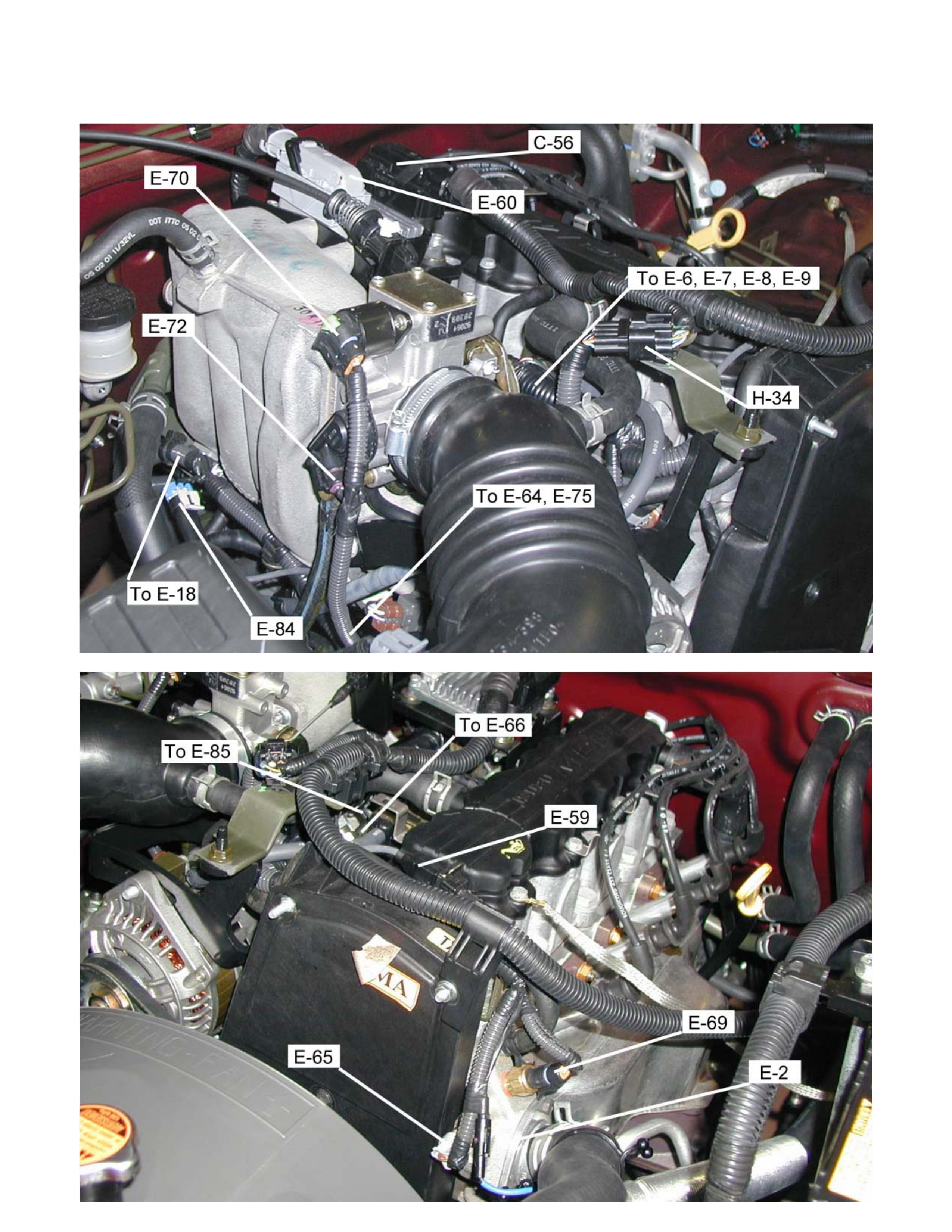
PARTS LOCATION (C24SE)

PARTS LOCATION 6VE1
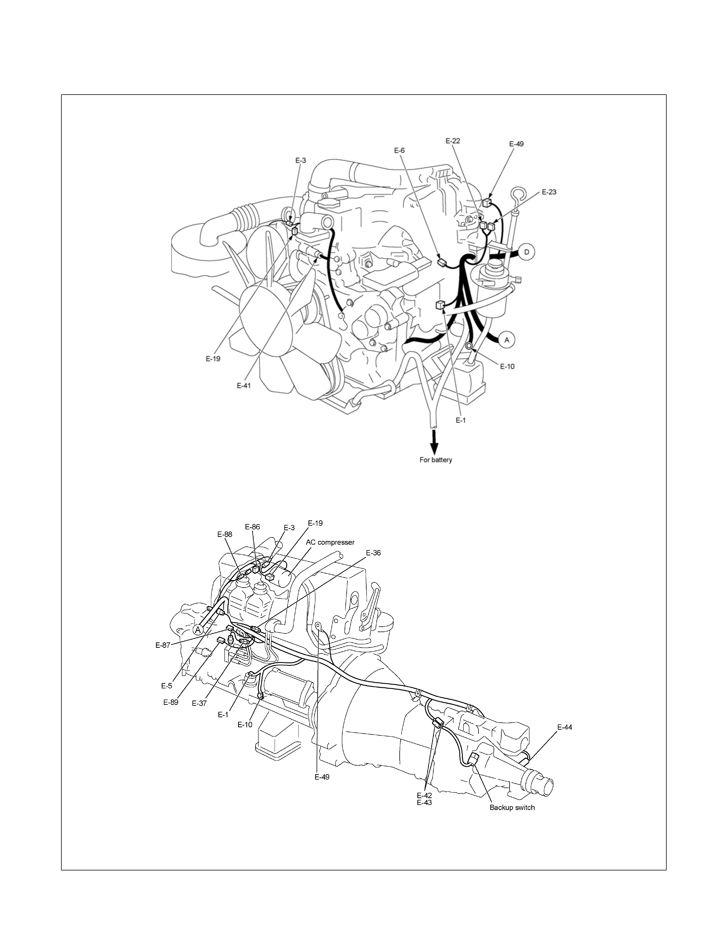
PARTS LOCATION
4JA1-TC / 4JH1-TC
4JA1-L
RTW38DXF007601 & RTW48ALF000101
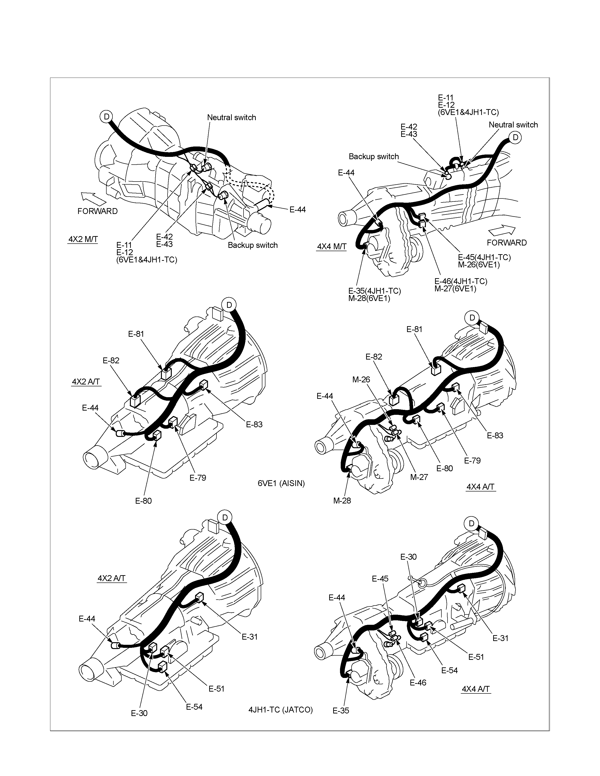
PARTS LOCATION
RTW38DXF007501
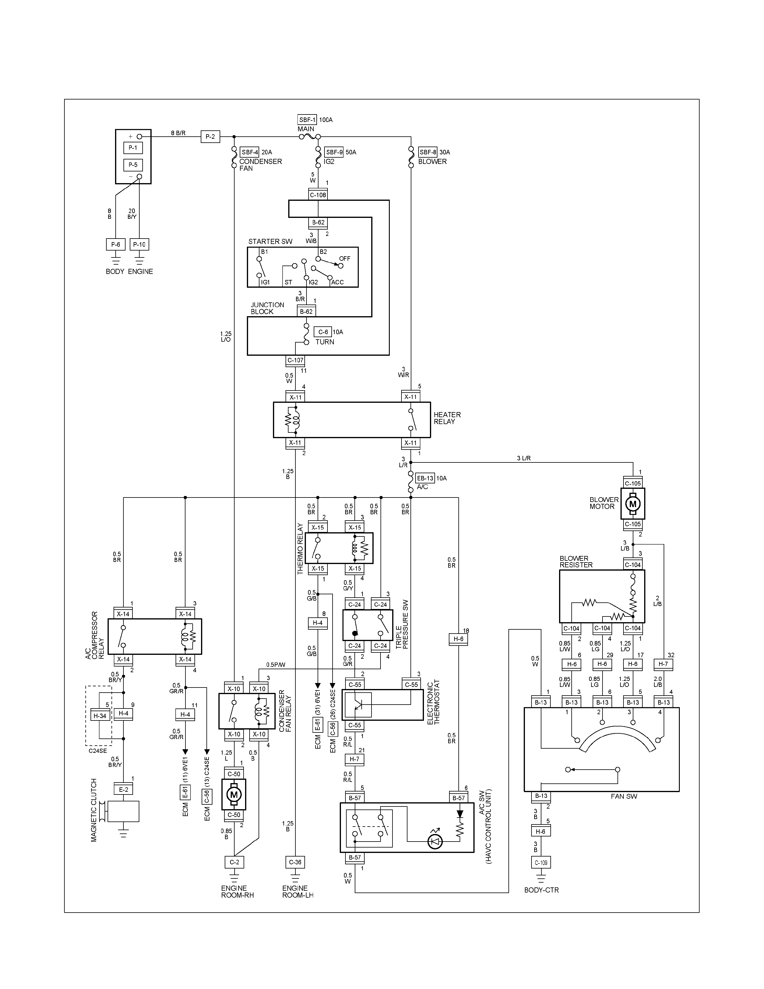
CIRCUIT DIAGRAM A/C WITH HEATER C24SE / 6VE1
RTW680XF012101
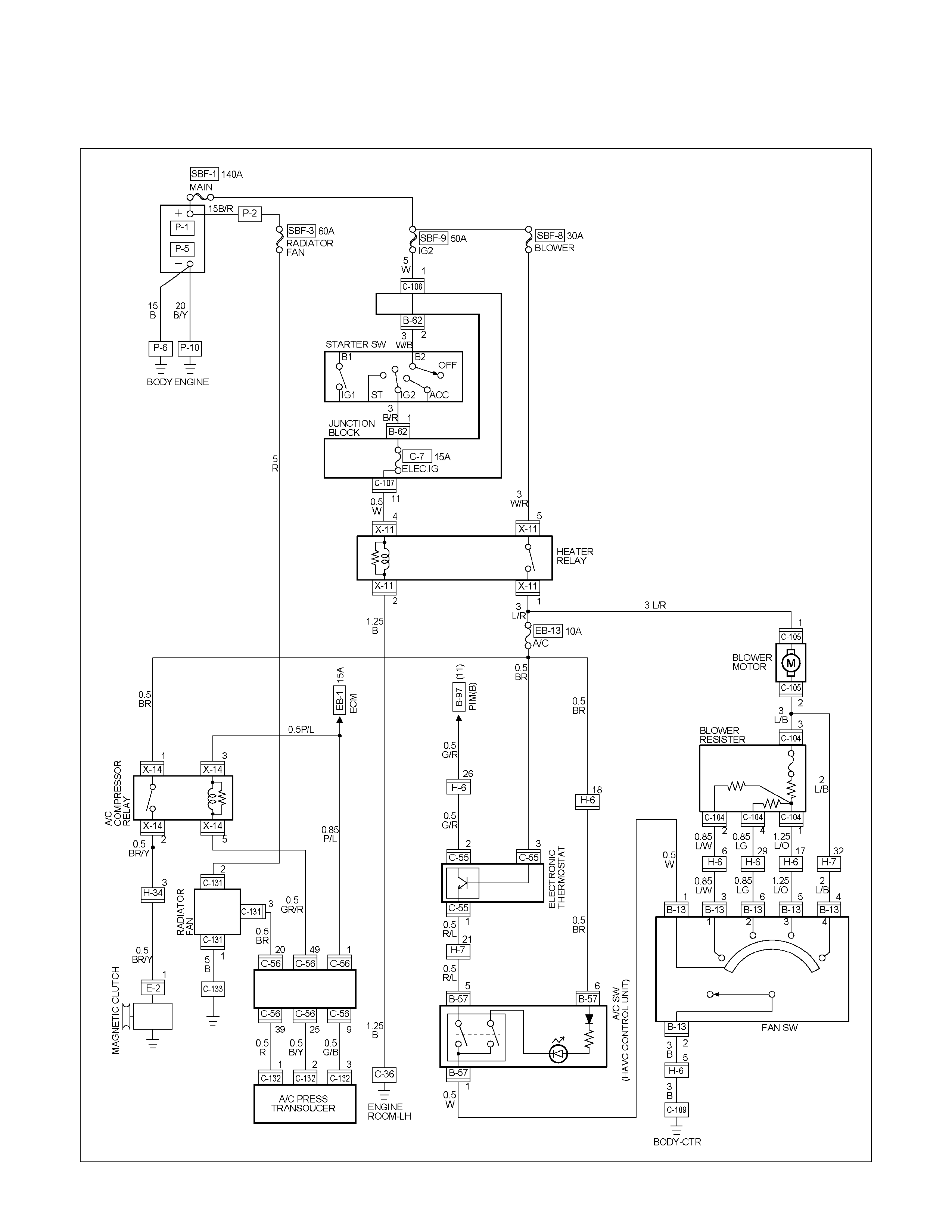
CIRCUIT DIAGRAM A/C WITH HEATER HFV6
RTW68AXF011701
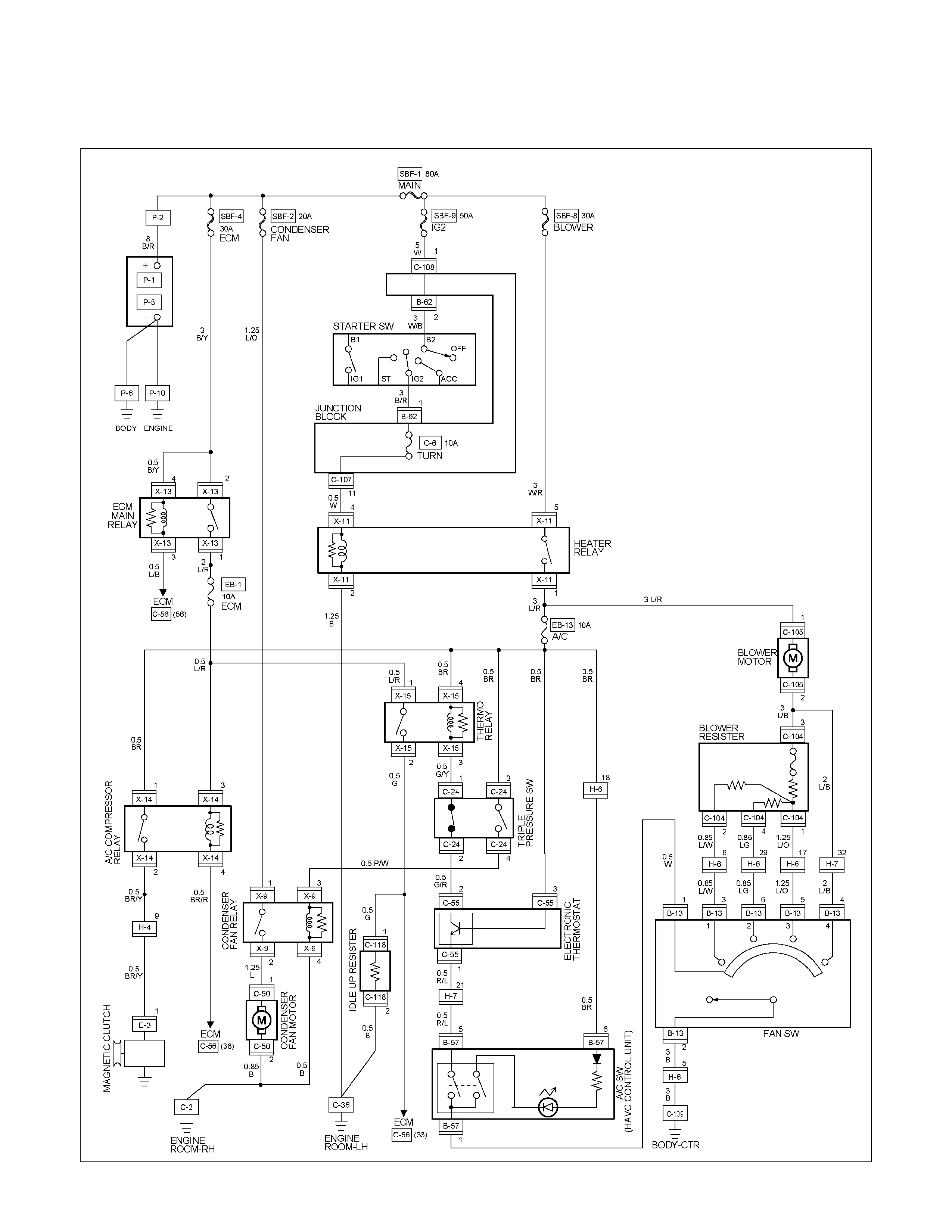
CIRCUIT DIAGRAM A/C WITH HEATER 4JA1-TC / 4JH1-TC
RTW680XF012201

CIRCUIT DIAGRAM A/C WITH HEATER 4JA1-L
RTW680XF012301
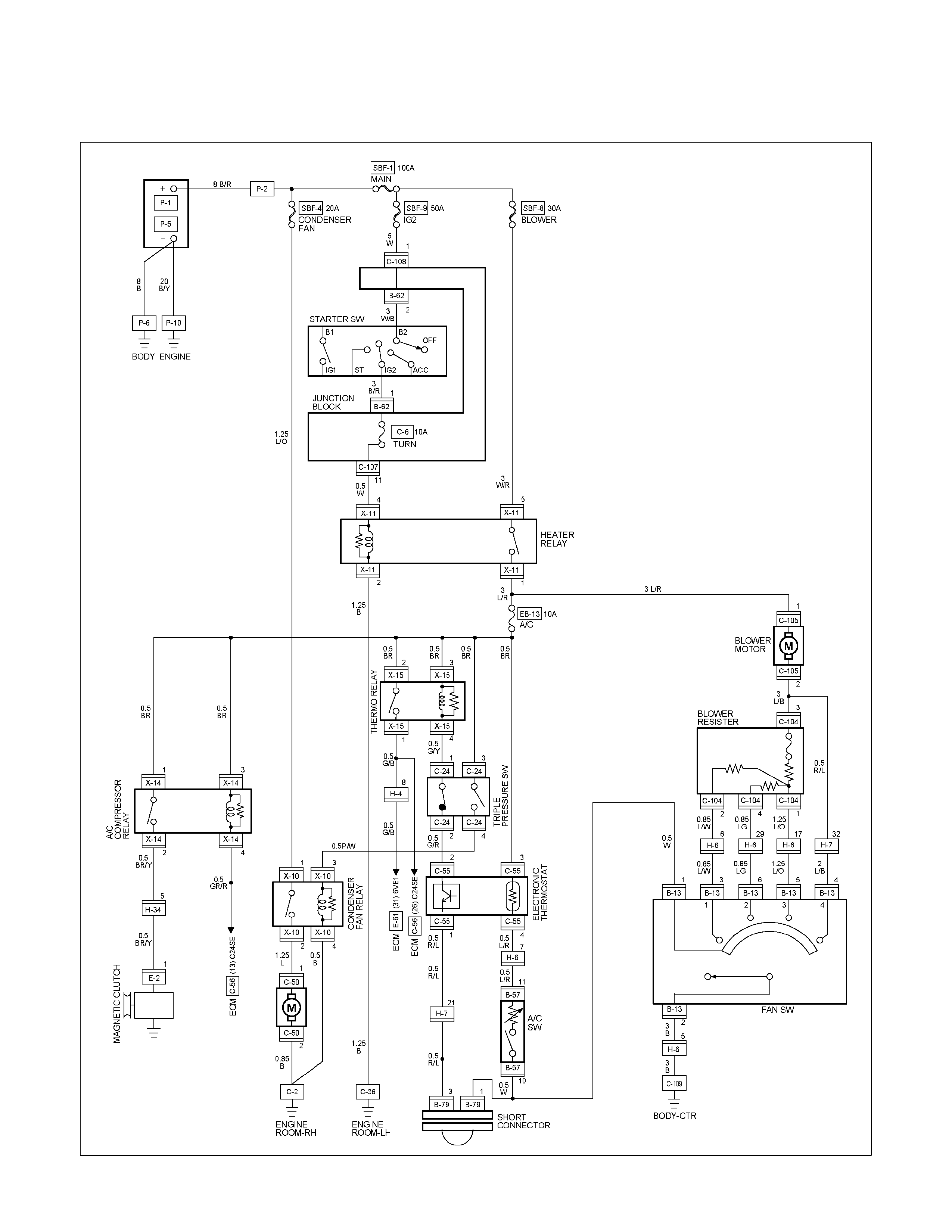
CIRCUIT DIAGRAM COOLER WITHOUT HEATER C24SE
RTW680XF012401
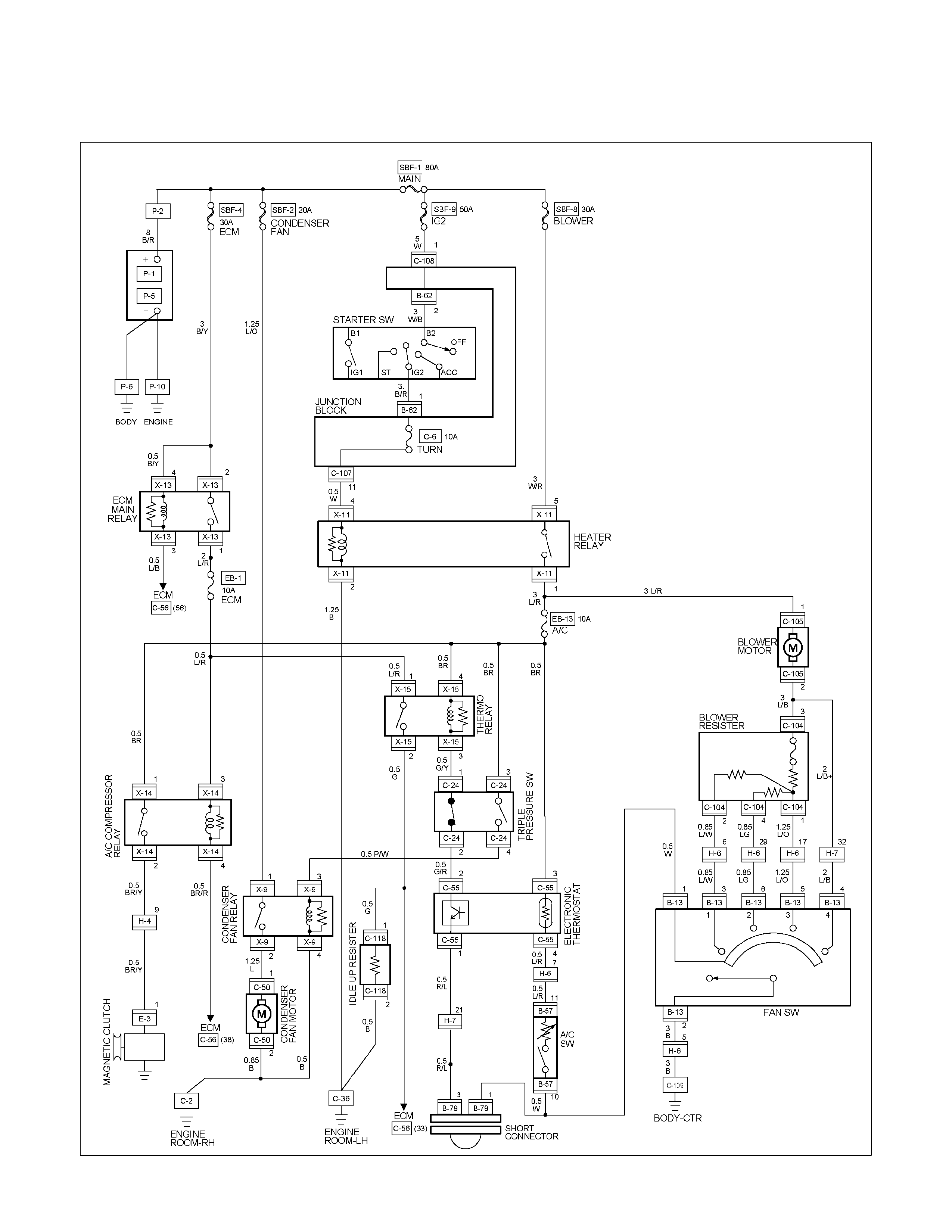
CIRCUIT DIAGRAM COOLER WITHOUT HEATER 4JA1-TC / 4JH1-TC
RTW680XF012501
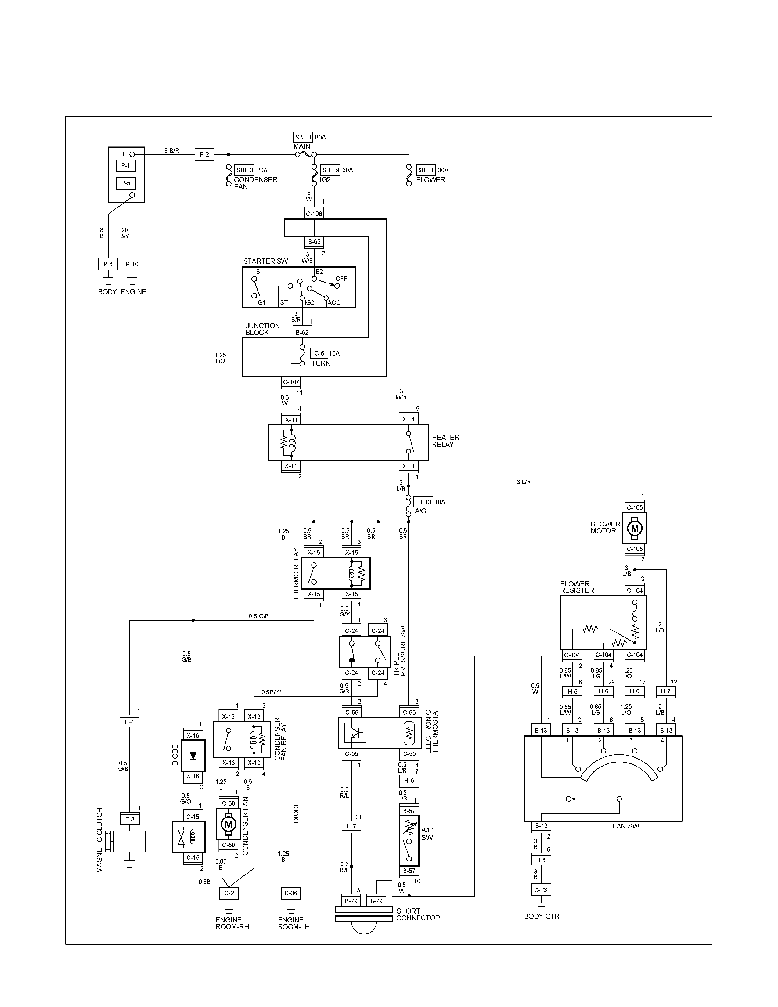
CIRCUIT DIAGRAM COOLER WITHOUT HEATER 4JA1-L
RTW680XF012601
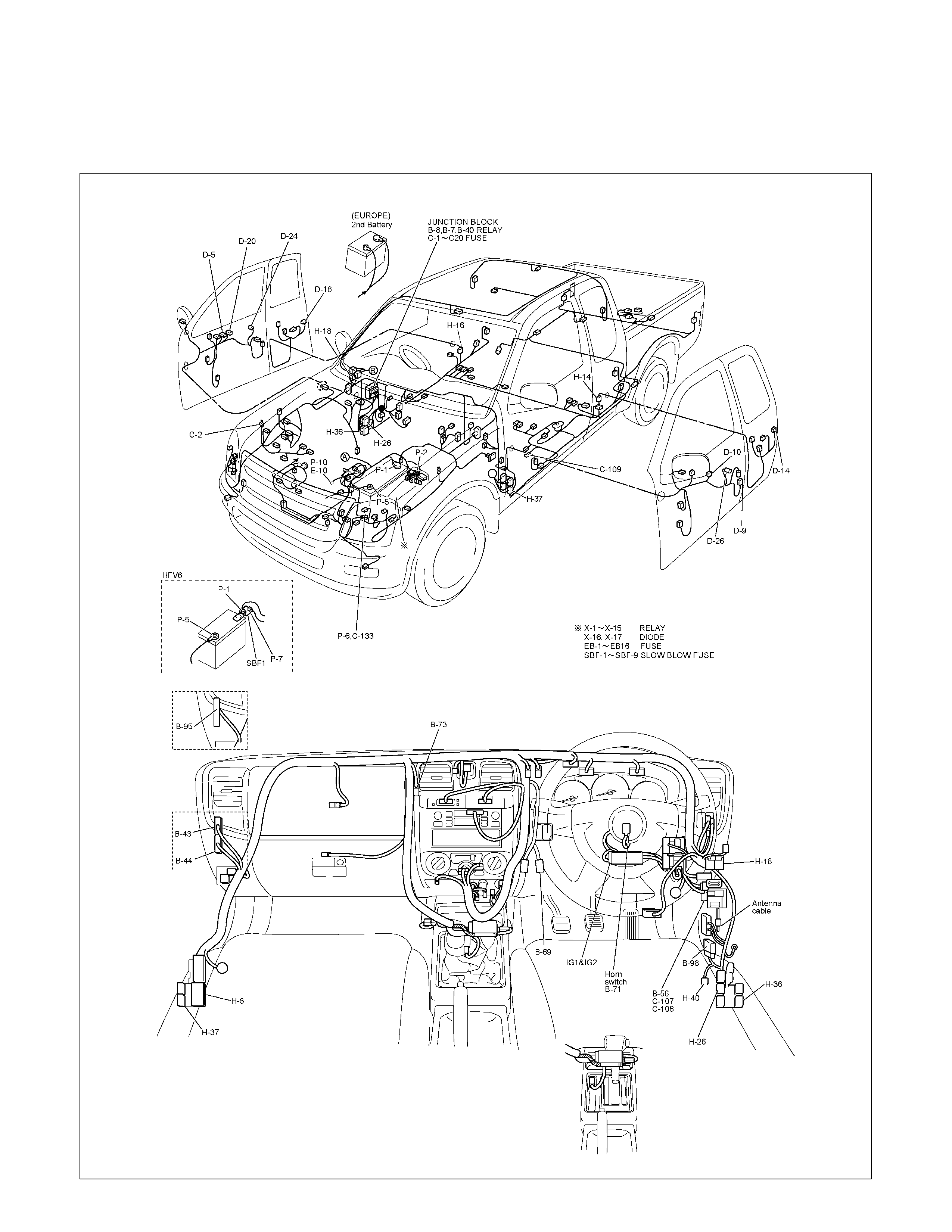
POWER DOOR LOCK
PARTS LOCATION (RHD)
RTW68AXF015601 & RTW68AXF015701

PARTS LOCATION (LHD)
RTW68AXF009601 & RTW68AXF009801
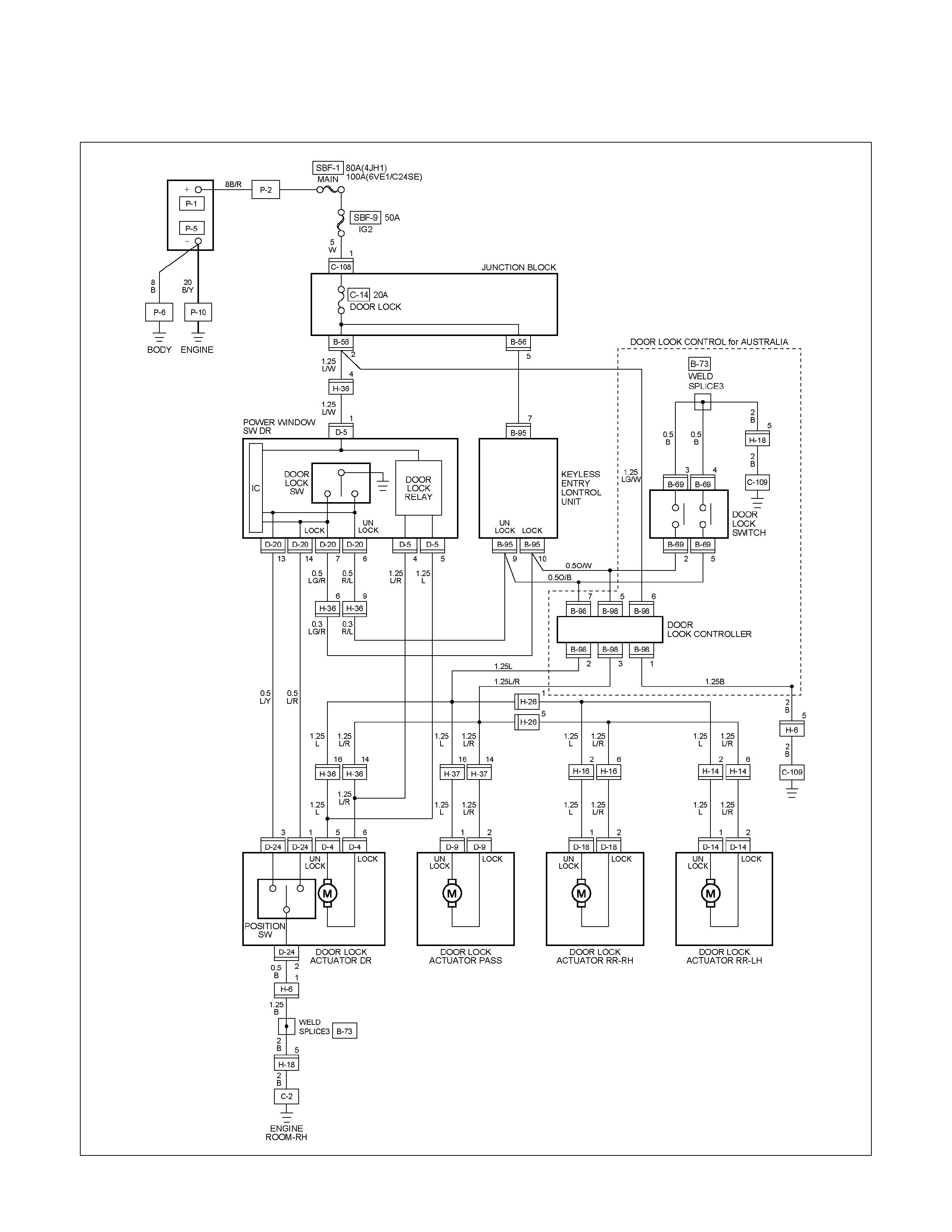
CIRCUIT DIAGRAM EXCEPT HFV6 WITHOUT ANTI THEFT (RHD)
RTW680XF012701
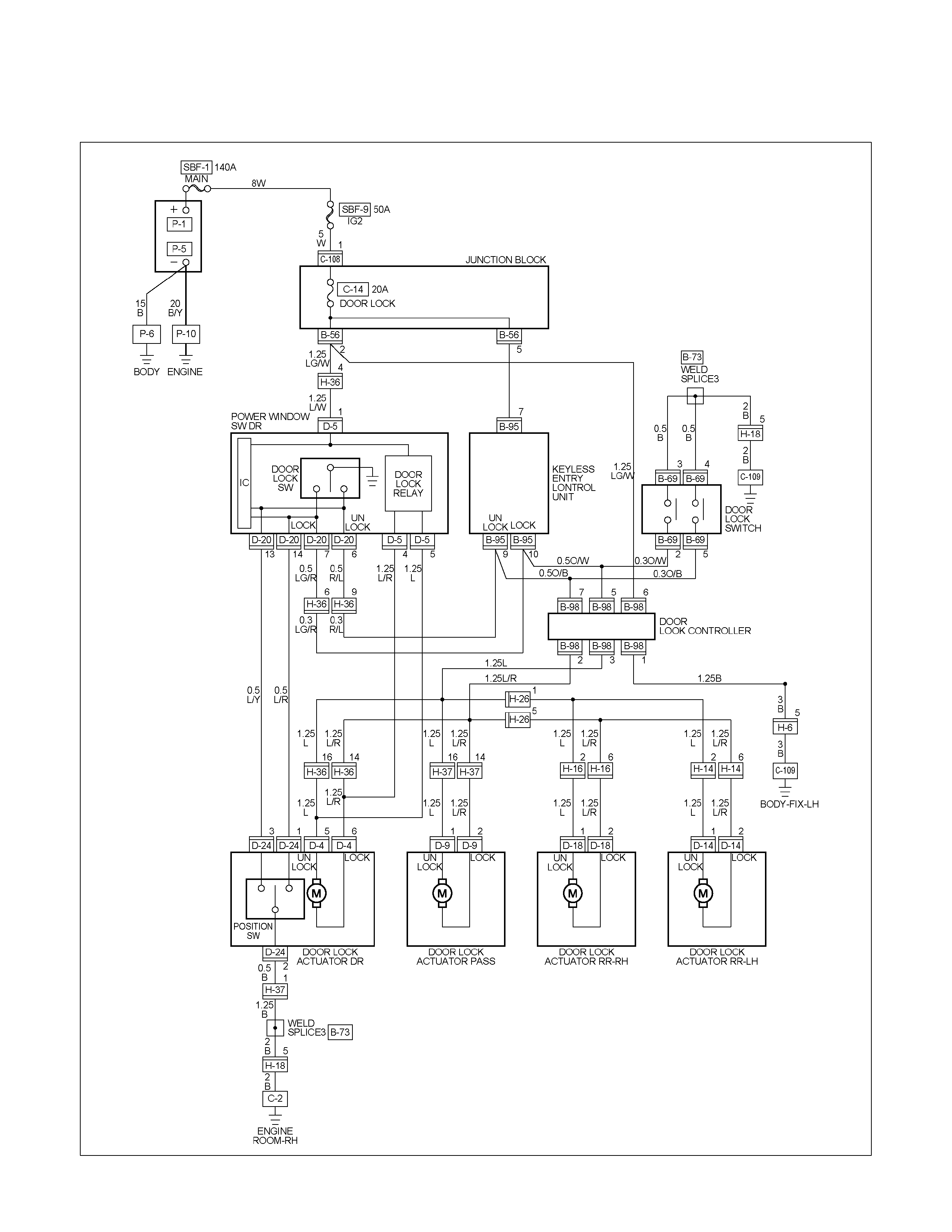
CIRCUIT DIAGRAM HFV6 WITHOUT ANTI THEFT (RHD)
RTW68AXF011801
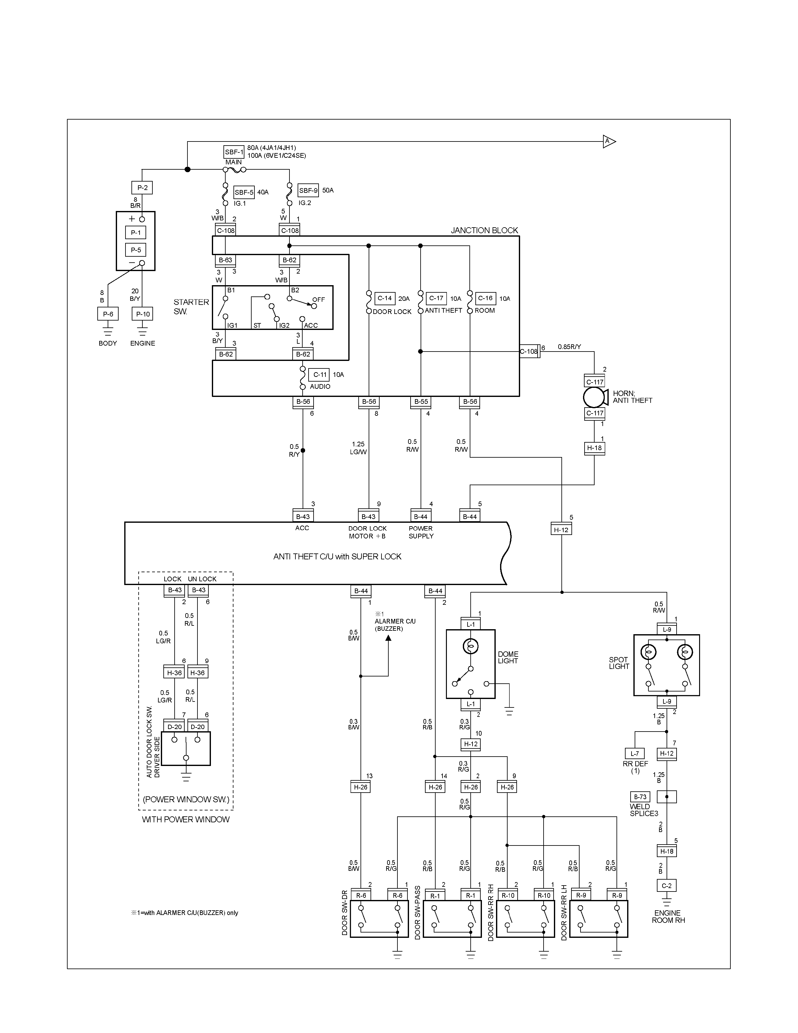
CIRCUIT DIAGRAM WITH SUPER LOCK (RHD ONLY) Sheet 1/3
RTW680XF015401
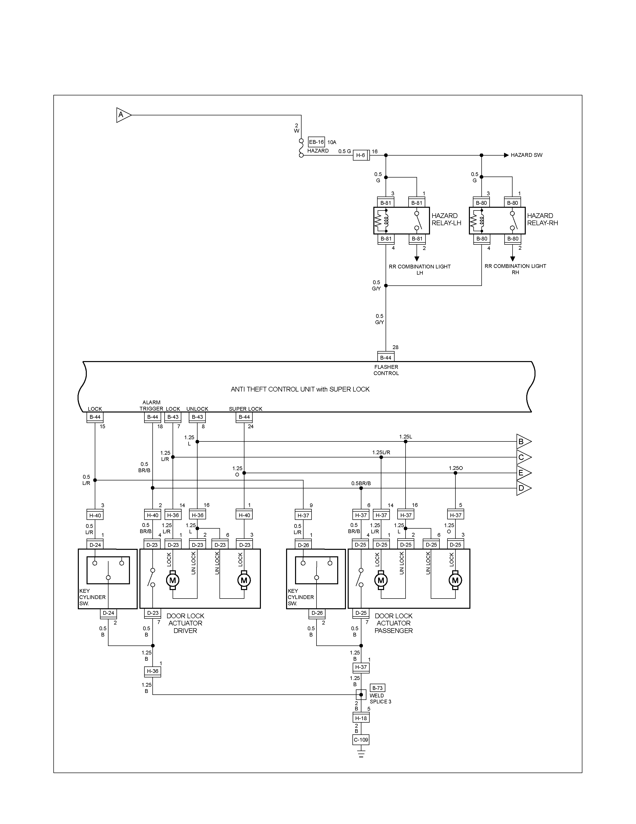
CIRCUIT DIAGRAM WITH SUPER LOCK (RHD ONLY) Sheet 2/3
RTW680XF015501
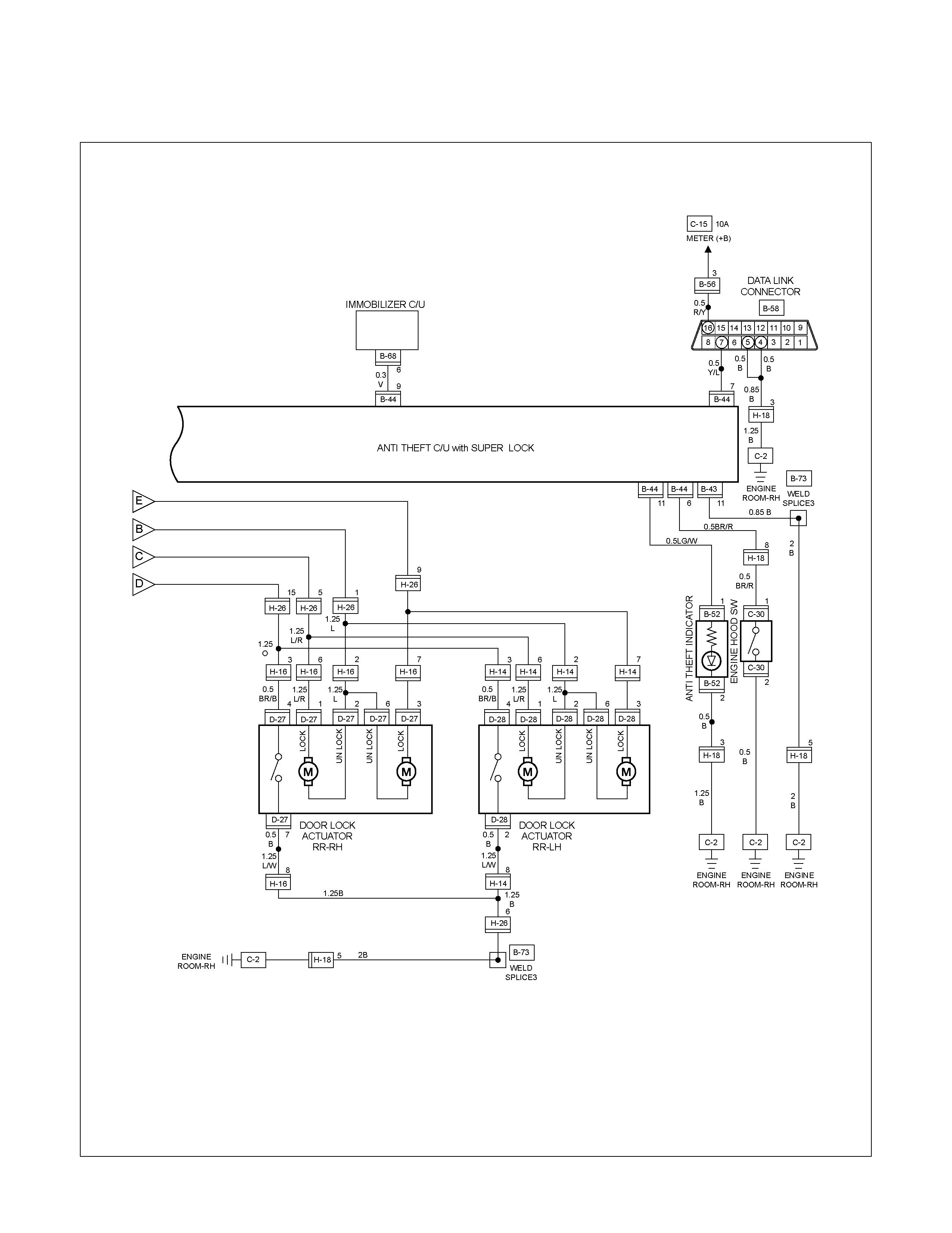
CIRCUIT DIAGRAM WITH SUPER LOCK (RHD ONLY) Sheet 3/3
RTW680XF015601
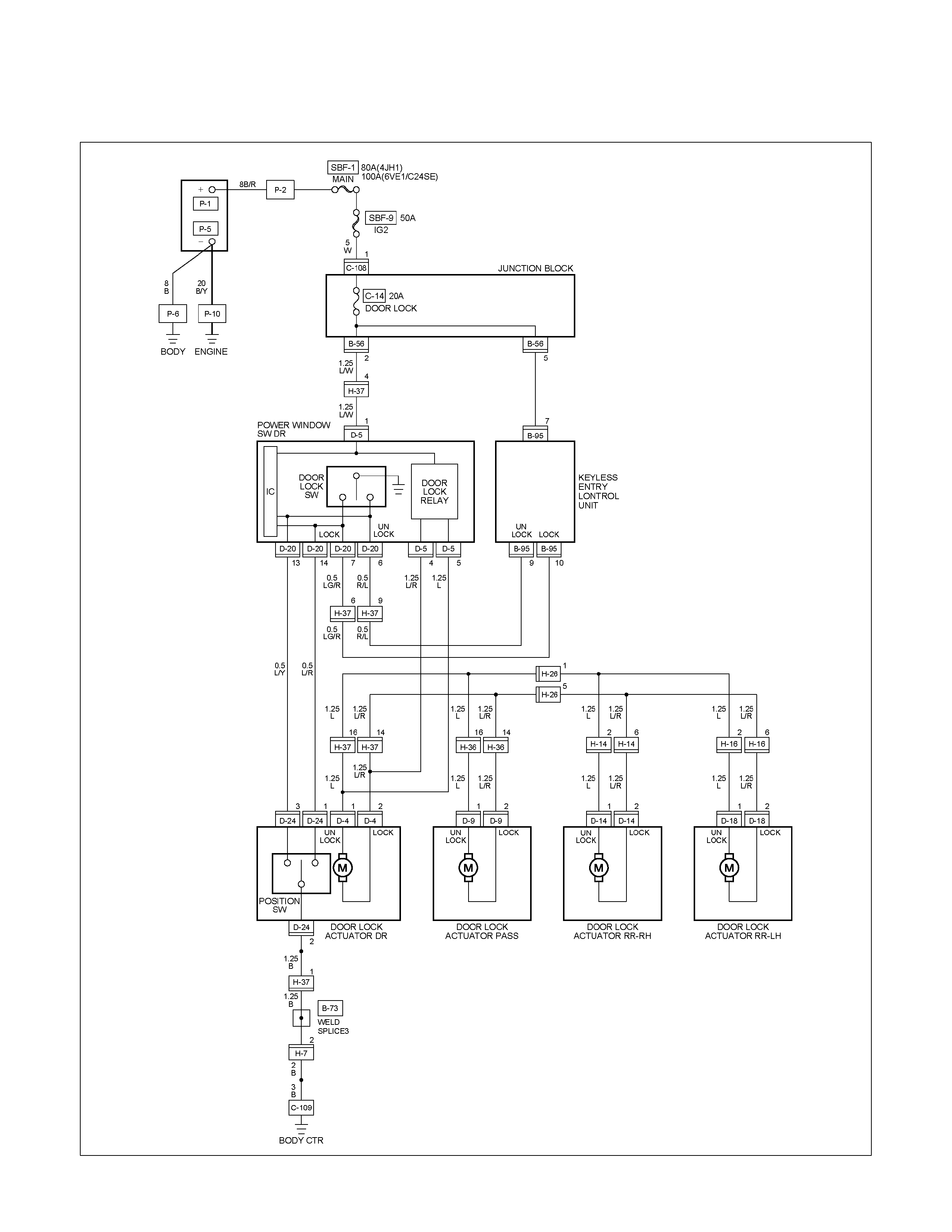
CIRCUIT DIAGRAM WITHOUT ANTI THEFT (LHD)
RTW680XF012801
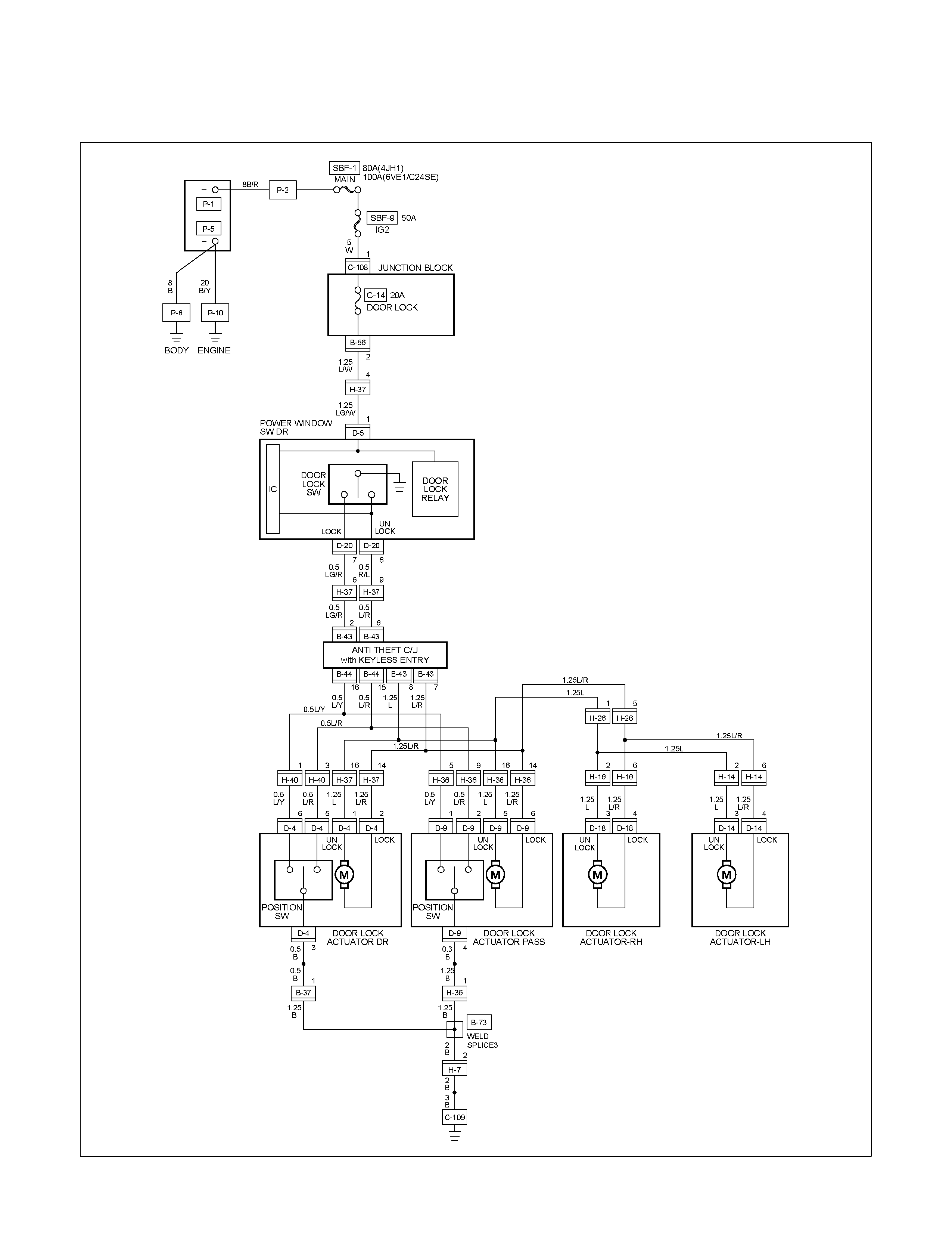
CIRCUIT DIAGRAM WITH ANTI THEFT (LHD)
RTW680XF012901
TROUBLESHOOTING
QUICK CHART FOR CHECK POINTS
Check Points
Fuse
C-14
(20A)
Power
Window &
Door Lock
Switch
Door
Lock
Switch
Key Cylinder
switch Door Lock Actuator
Cable
Trouble Mode
Driver’s
side Driver’s
side D/S P/S Passen
ger’s
side
RR-RH RR-LH
Harness
1. All the doors do not
lock and unlock
2. All the doors do not
get locked (or
unlocked)
3. Driver’s side door
does not get locked
(or unlocked)
4. FRT passenger’s side
door does not get
locked (or unlocked)
5. RR door-RH does not
get locked (or
unlocked)
6. RR door-LH does not
get locked (or
unlocked)
7. Door lock does not
operate when
operating from the
driver’s seat side
1. All the doors do not lock and unlock
Checkpoint Trouble Cause Countermeasure
Reinstall or replace the fuse
No. C-14 (20A)
Poor fuse contact or blown
NG
Repair grounding point contact
Grounding point C-2 (RHD),
C-109 (LHD) (SUPER LOCK)
Poor grounding point contact
Repair open circuit or
connector contact
Voltage between the driver’s
side power window & door
lock SW harness side
connector terminal 1 D-5
and the ground (Should be
battery voltage present)
Open circuit or poor connector
contact
NG
NG
OK
OK
OK
Fuse No. C-14 (20A, Fuse
box)
Repair open circuit or
connector contact
Open circuit or poor connector
contact
NG
Replace the driver’s side
power window & door lock
SW.
Driver’s side power window &
door lock SW. function
SW. malfunction
NG
OK
Continuity between 4 D-4
and C-2 (RHD),
C-109 (LHD)
2. All the doors do not get locked (or unlocked)
Repair open circuit or
connector contact
Open circuit or poor connector
contact
NG
Replace the driver’s side
power window & door lock
SW.
Driver’s side power window &
door lock SW. function
SW. malfunction
NG
OK
Continuity between the driver’s
side power window & door
lock SW harness side
connector terminals 14 D-20
and 6 D-20
3. Driver’s side door does not get locked (or unlocked)
Checkpoint Trouble Cause Countermeasure
Replace the door lock SW.Door lock SW. function SW. malfunction
NG
4. FRT passenger’s side door does not get locked (or unlocked)
Replace the FRT passenger’s
side door lock actuator
FRT passenger’s side door
lock actuator function Actuator malfunction
NG
5. RR door-RH does not get locked (or unlocked)
Replace the RR door lock
actuator-RH
RR door lock actuator-RH
function Actuator malfunction
NG
6. RR door-LH does not get locked (or unlocked)
Replace the RR door lock
actuator-LH
RR door lock actuator-LH
function Actuator malfunction
NG
7. Door lock does not operate when operated from the driver’s seat side
Repair grounding point C-2
contact
Poor grounding point contact
NG
Replace the door lock SW.
Continuity between the door
lock SW. side connector
terminals 1 D-4 and 2 D-4
when the SW is locked and
between is unlocked 2 D-4
and 4 D-4 when the SW.
SW. malfunction
NG
OK
Grounding point C-2 (RHD),
C-109 (LHD), (SUPER LOCK)
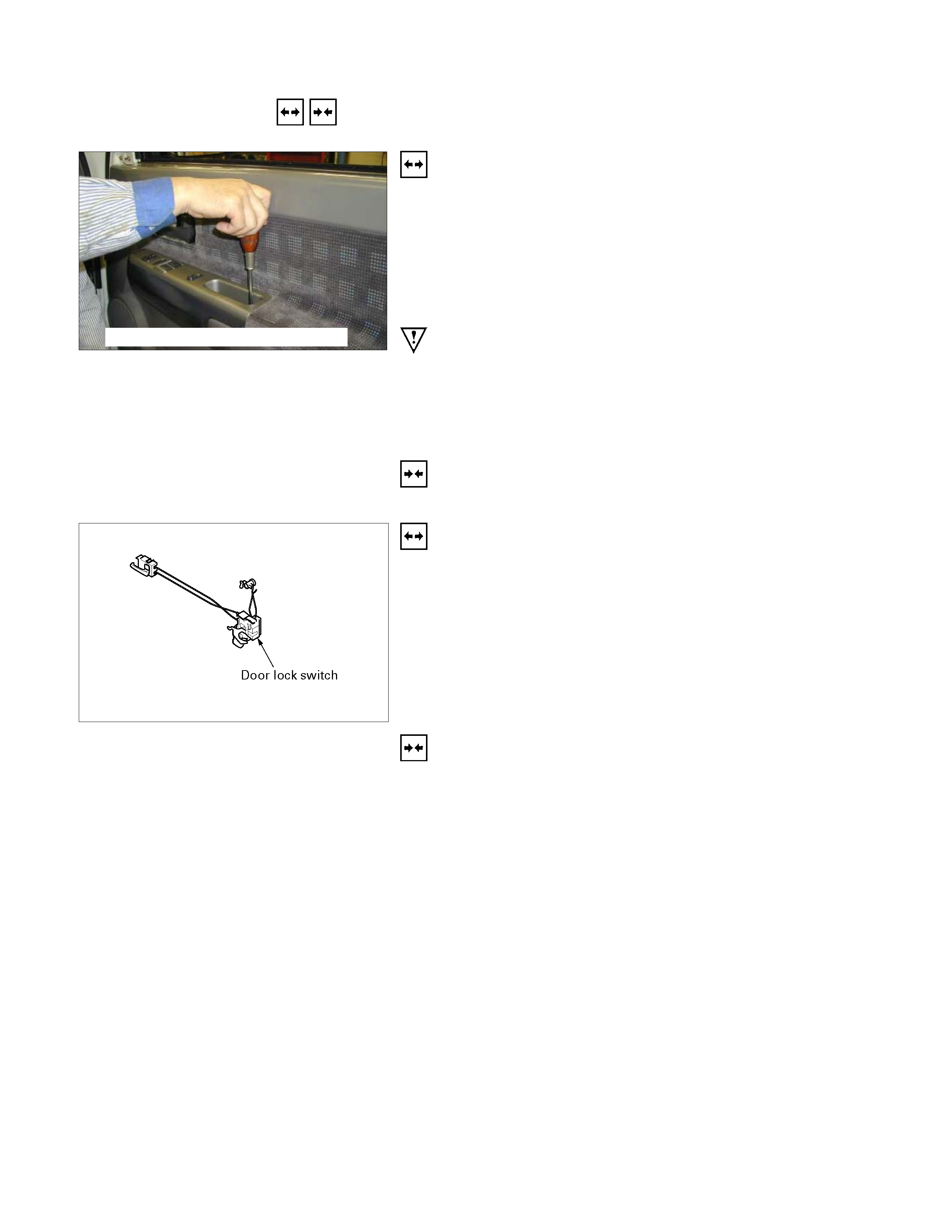
REMOVAL AND INSTALLATION
This photo is based on 2 doors
DRIVER SEAT SIDE POWER WINDOW &
DOOR LOCK SWITCH
Removal
1. Disconnect the battery ground cable.
2. Removes the screw in pull cup with the screwdriver.
3. Remove the switch bezel by pushing the spring with the tip
of a screwdriver.
4. Disconnect the connector.
ATTENTION:
When removing a switch bezel lift from the front in the
bezel.
It follows the front with the screwdriver.
The clip has broken when lifting from the rear in the bezel.
Installation
To install, follow the removal steps in the reverse order.
DRIVER’S SIDE DOOR LOCK SWITCH
Removal
1. Door Lock ASM
• Refer to the removal steps of the DOORS in section 10
“BODY”.
2. Door Lock Switch
Installation
To install, follow the removal steps in the reverse order.
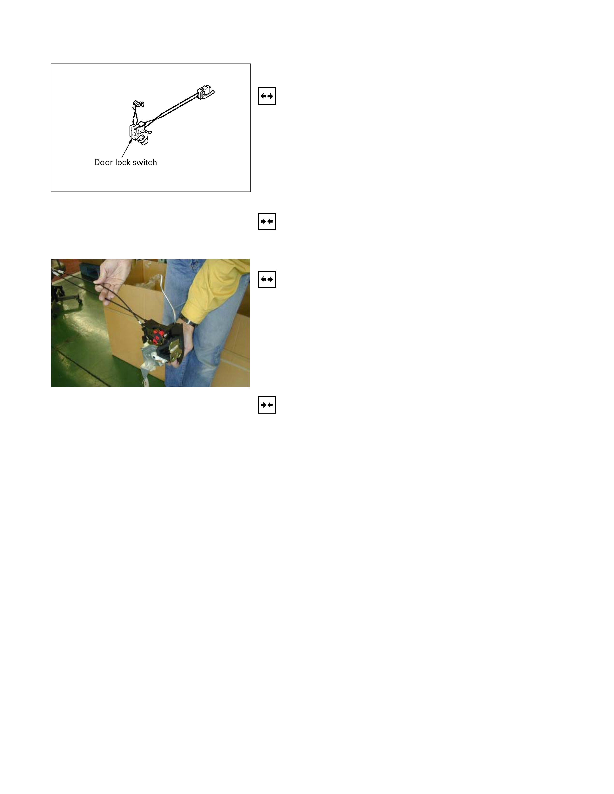
FRT PASSENGER’S SIDE DOOR LOCK
ACTUATOR
Removal
1. Door Lock ASM
• Refer to the removal steps of the DOORS in Section 10
“BODY”.
2. Door Lock Actuator
• Remover the actuator fixing bolts.
• Disconnect the door lock link rod.
• Disconnect the actuator connector.
Installation
To install, follow the removal steps in the reverse order.
RR DOOR LOCK ACTUATOR-LH & RH
Removal
1. Door Lock ASM
• Refer to the removal steps of the DOORS in section 10
“BODY”.
2. Door Lock Actuator
• Remove the actuator fixing bolts.
• Disconnect the door lock link rod.
• Disconnect the actuator connector.
Installation
To install, follow the removal steps in the reverse order.
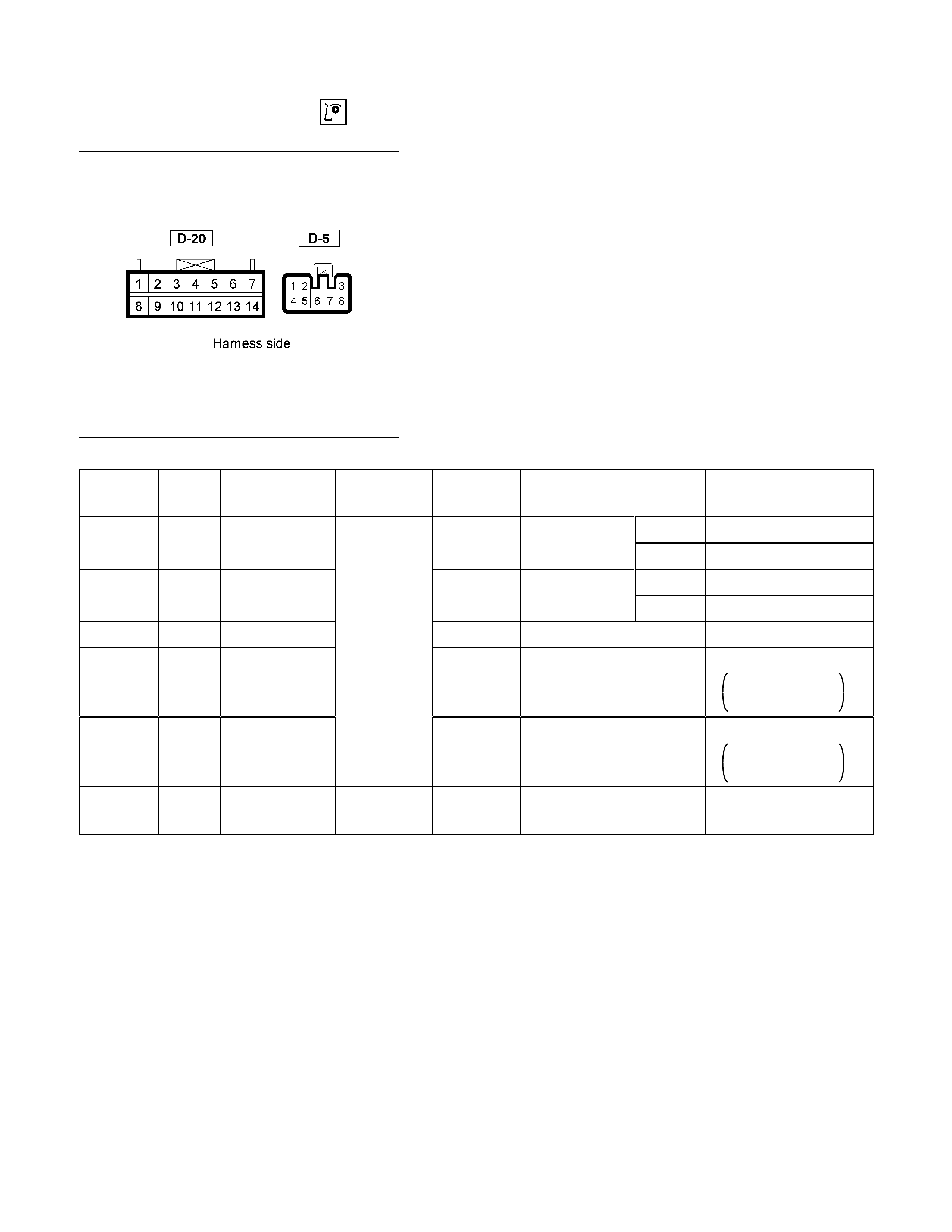
INSPECTION AND REPAIR
RUW680SH000301
Driver Seat Side Power Window & Door Lock
Switch
1. Harness Side Connector Circuit
Check voltage and continuity between the switch harness
side connector terminals as shown in the following table.
Terminal
No. Wire
color Connecting to Check item Connectin
g terminal Check condition Standard
Door lock SW Driver seat Lock Continuity
(Lock)
side door Unlock No continuity
Door lock SW Driver seat Lock No continuity
(Unlock)
side door Unlock Continuity
3 (D-5) L/R Ground Continuity 3-Ground - Continuity
4 (D-5)
L/R Door lock
actuator (Lock)
(Resistance)
4-5
- Continuity
There is some
resistance
5 (D-5)
L Door lock
actuator
(Unlock)
5-4
- Continuity
There is some
resistance
1 (D-5) LG/W Fuse
C-14 (20A) Voltage 1- Ground - Battery voltage
(Approx. 12V)
14 (D-20) L/R 14-Ground
13-Ground
L/Y
13 (D-20)

Harness side
D-20 D-5
2. Switch Side Connector Circuit
Remove the switch connector, and check continuity and
voltage between the switch connector terminals.
(Connect the (+) terminal of the battery to 1 D-5 and the
(-) terminal to 3 D-5 .)
3 D-5 - 4 D-5 .................. Continuity
3 D-5 - 5 D-5 .................. Continuity
(Then, ground 3 D-5 .)
4 D-5 ..........Current flow for approx. 1 second
(Disconnect the ground of 14 D-20 , and ground 13 D-20 .)
5 D-5 ..........Current flow for approx. 1 second
Harness side
D-5
3. Door Lock Operation Test
After confirming that there is continuity between the switch
harness side connector terminals 4 D-5 and 5 D-5 ,
apply the battery voltage to each of the terminals to
conduct the operation test.
When the door lock will not operate, check the door lock
actuator for any trouble.
Connecting terminals
5 (L) 4 (L/R)
+ - Unlock
- + Lock
Operation
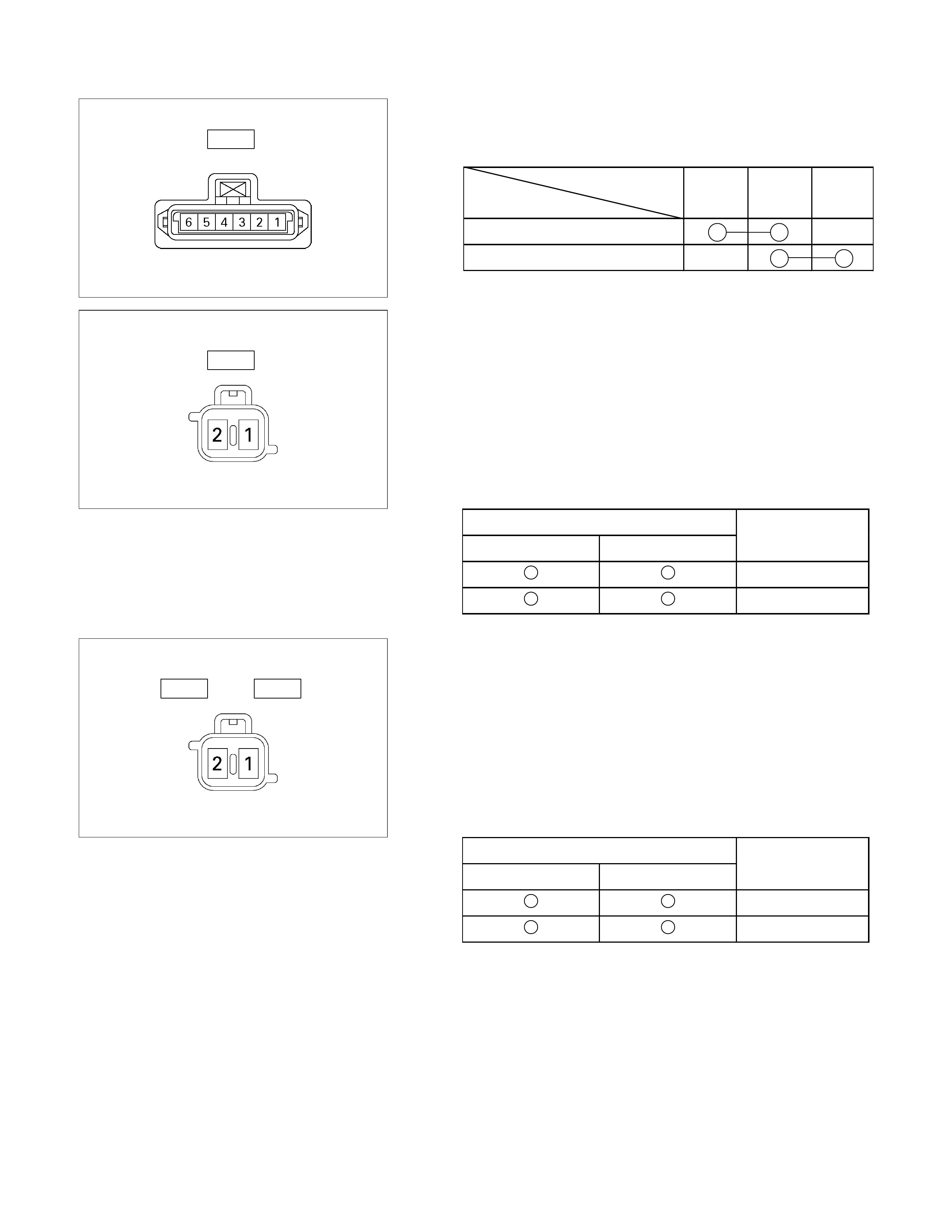
Switch side
D-4
Driver’s Side Door Lock Switch
1. Switch Side Connector Circuit
Check continuity between the switch connector terminals
Terminal No.
SW position 1 2 3
Lock
Unlock
Actuator side
D-9
Front Passenger’s Side Door Lock Actuator
1. Actuator Side Connector Circuit
A
pply the battery voltage to the actuator connecto
r
terminals to check the operation.
When the door lock actuator is checked on the vehicle and
there is no continuity, and when the door lock actuator itsel
f
is checked and no trouble is found, check the circuit
between the door lock actuator and the driver seat side
power window & door lock switch for any failure.
Connecting terminals
1 2
+ - Lock
- + Unlock
Operation
Actuator side
D-14 D-18
Rear Door Lock Actuator -LH & RH
1. Actuator Side Connector Circuit
A
pply the battery voltage to the actuator connecto
r
terminals to check the operation.
When the door lock actuator is checked on the vehicle and
there is no continuity, and when the door lock actuator itsel
f
is checked and no trouble is found, check the circuit
between the door lock actuator and the driver seat side
power window & door lock switch for any failure.
Connecting terminals
1 2
+ - Lock
- + Unlock
Operation
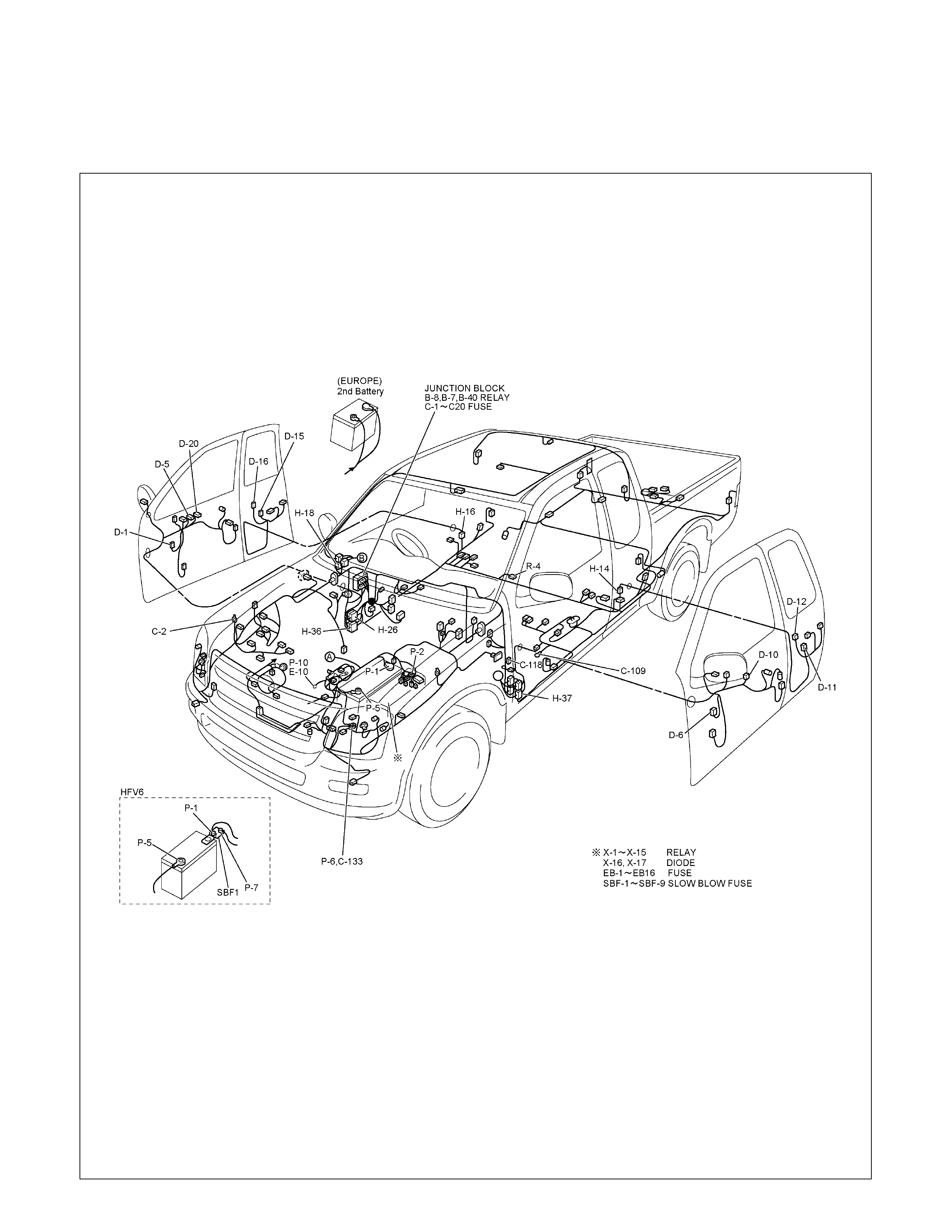
POWER WINDOW
PARTS LOCATION (RHD)
RTW68AXF015801
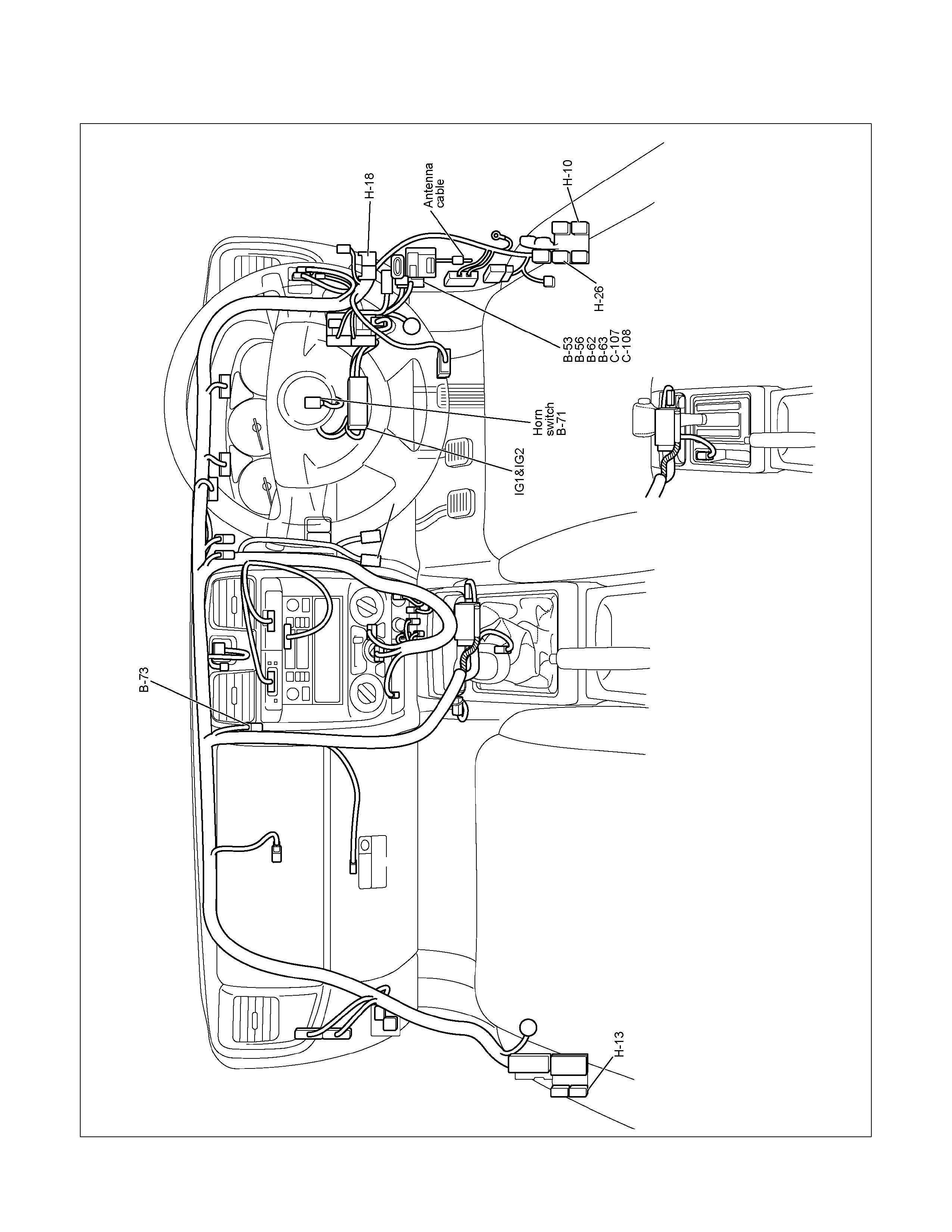
PARTS LOCATION (RHD)
RTW68AXF015901
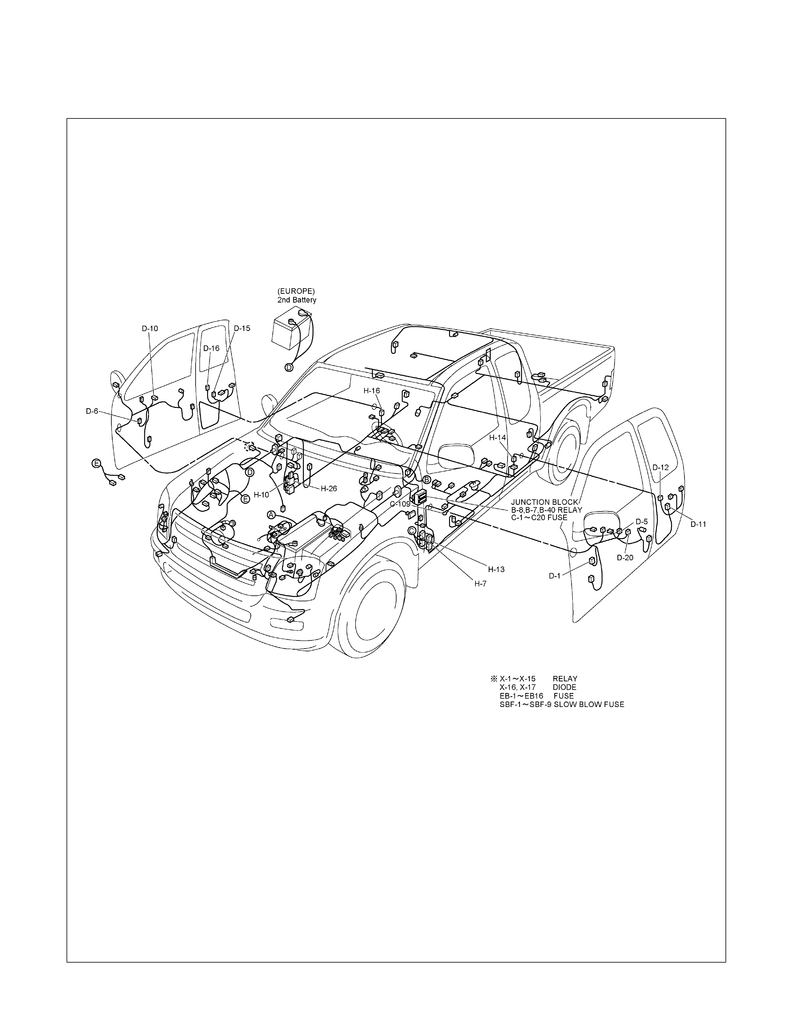
PARTS LOCATION (LHD)
RTW48AXF019801
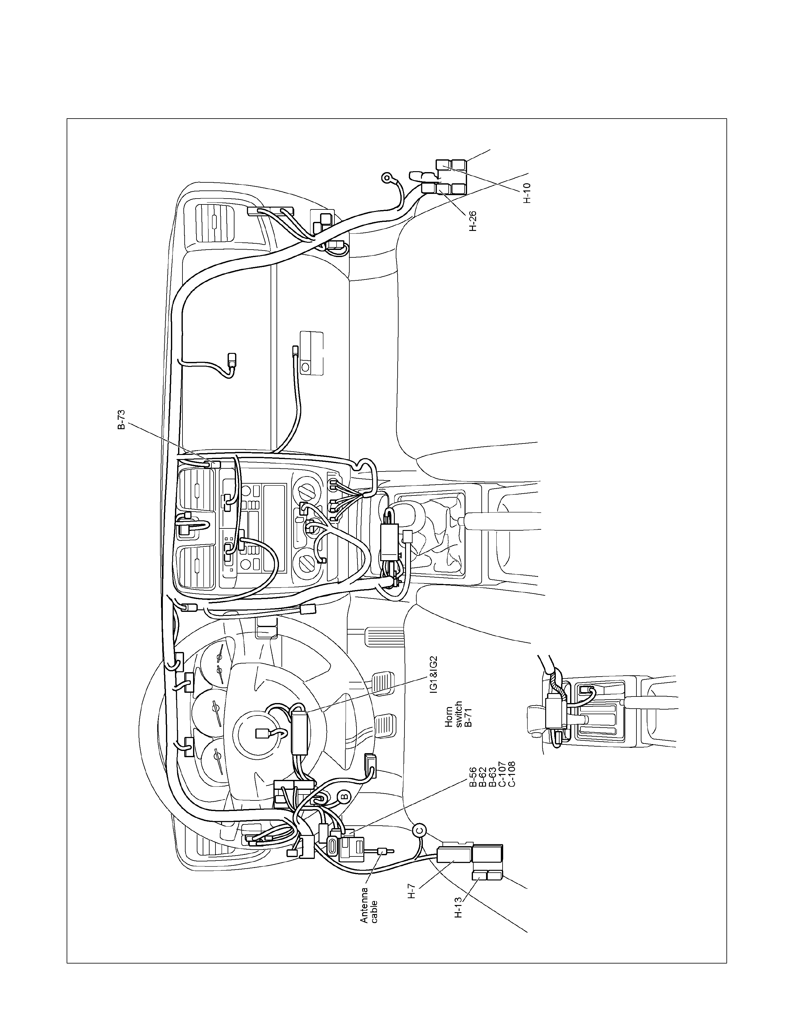
PARTS LOCATION (LHD)
RTW48AXF019901
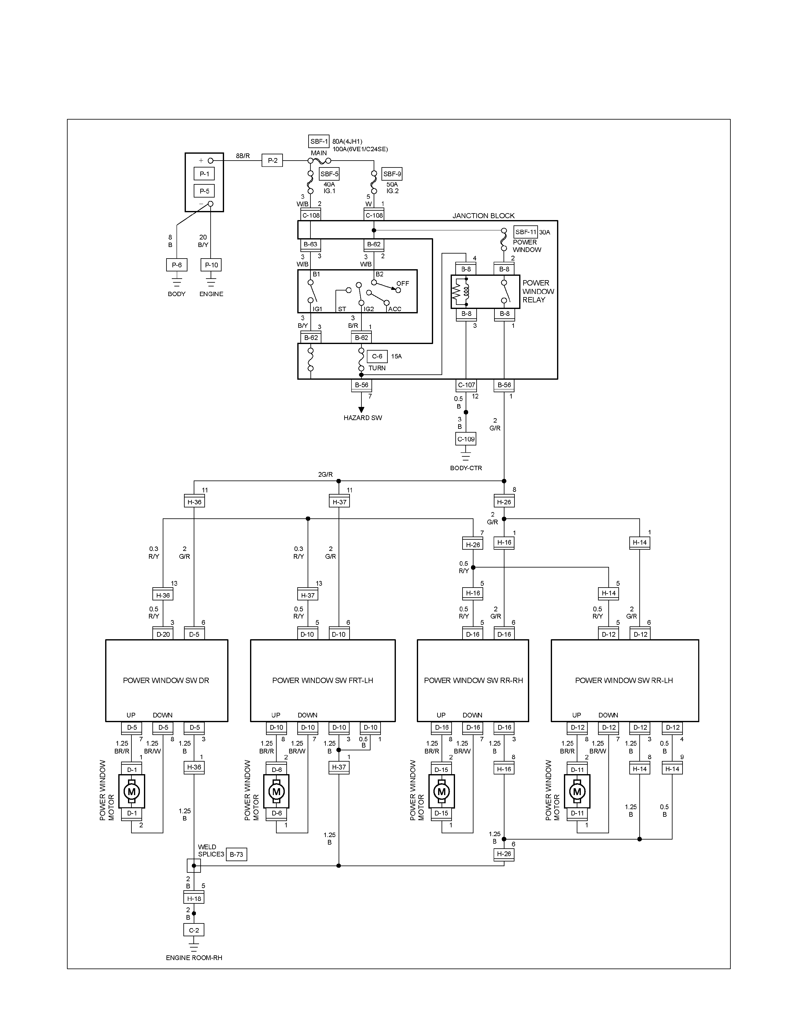
CIRCUIT DIAGRAM EXCEPT HFV6 (RHD)
RTW680XF013001
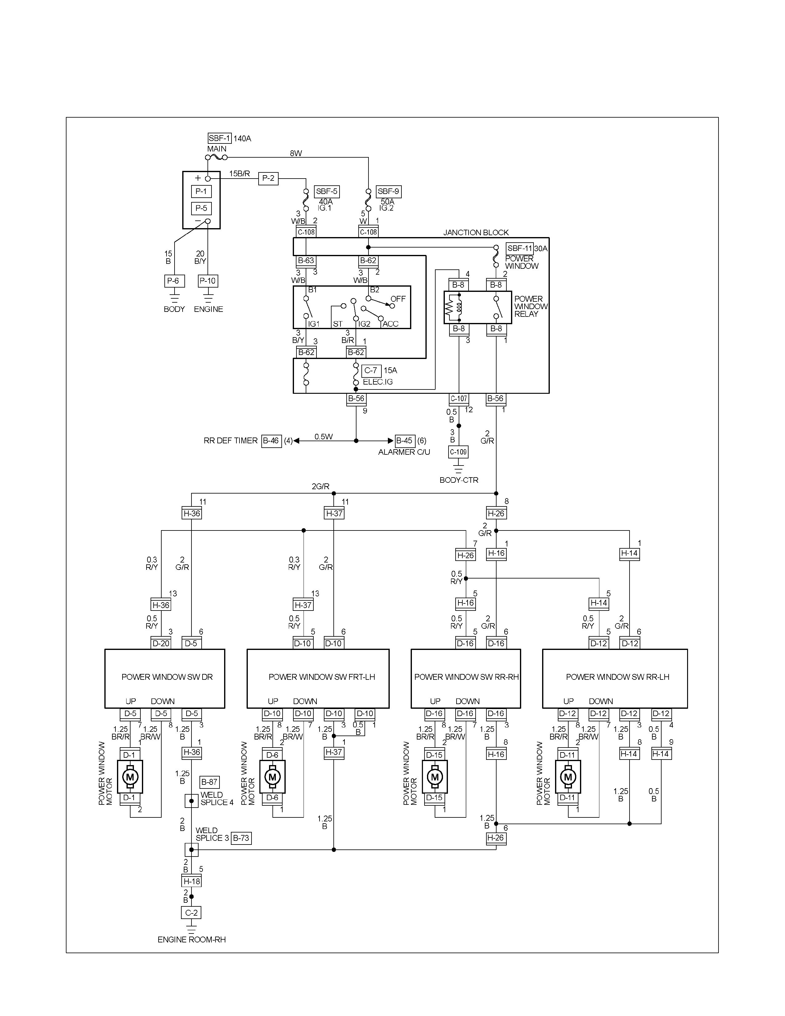
CIRCUIT DIAGRAM HFV6 (RHD)
RTW68AXF011901
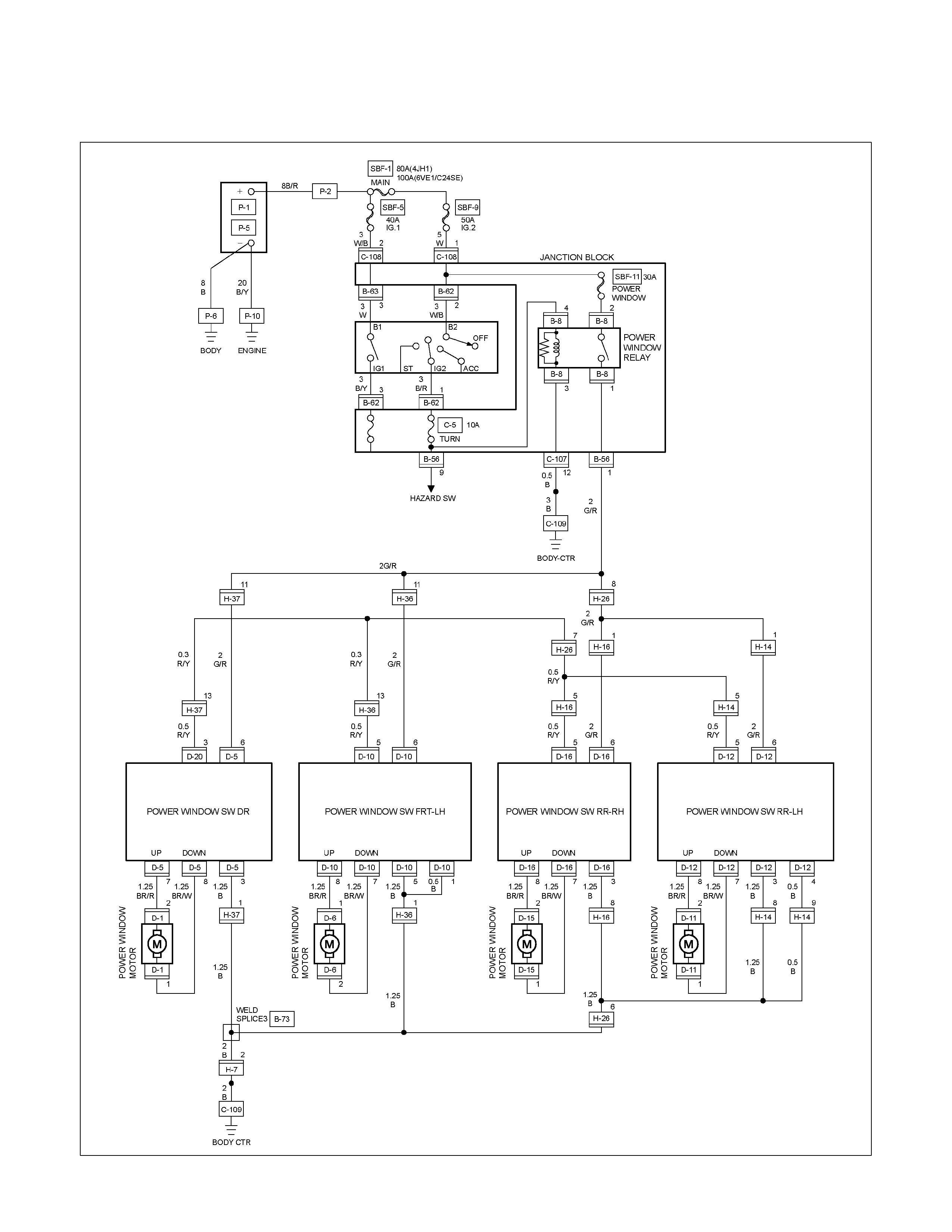
CIRCUIT DIAGRAM (LHD)
RTW680XF013101
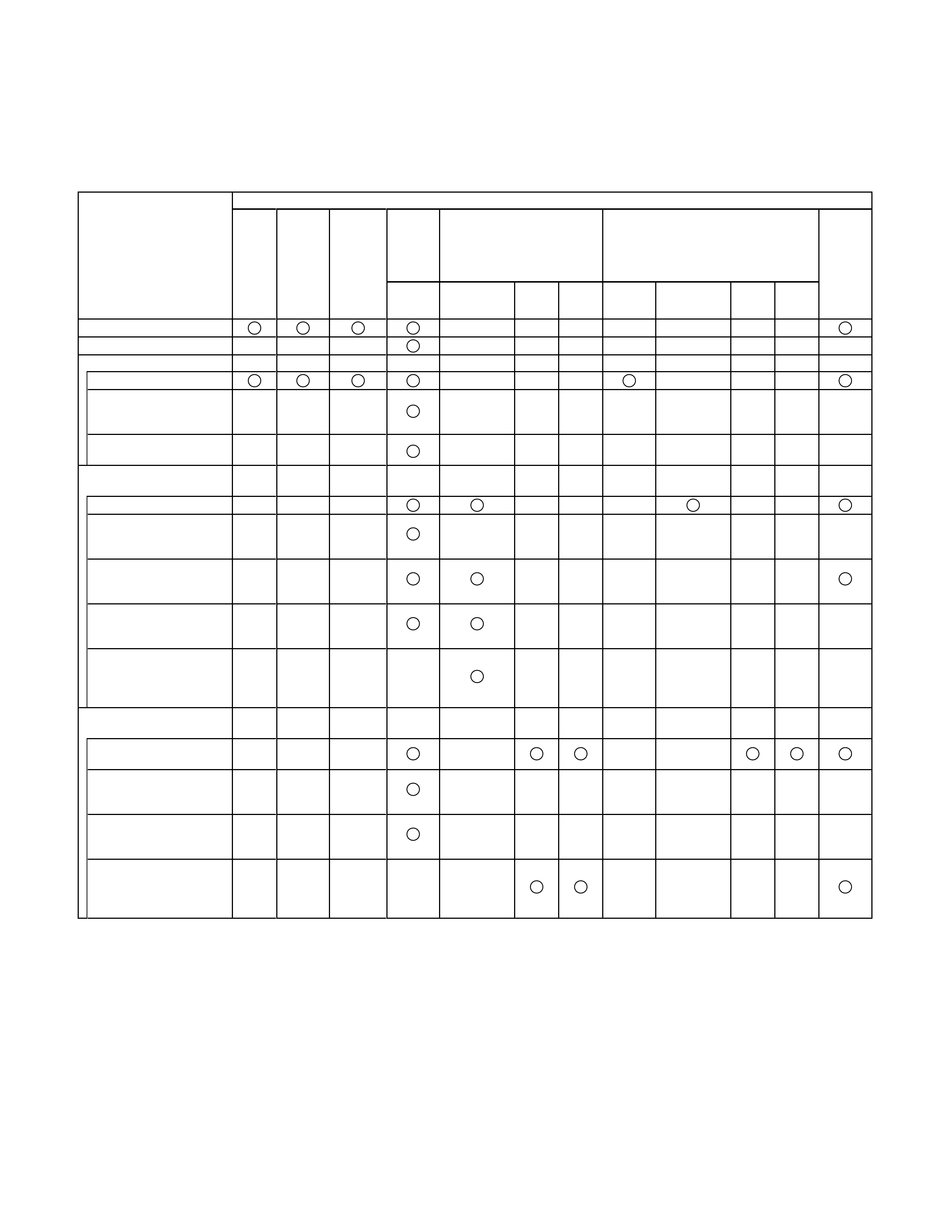
TROUBLESHOOTING
QUICK CHART FOR CHECK POINTS
Check Points
Trouble Mode
Power
Window
& Door
Lock
Switch
Power Wi ndow Switch Power Window Motor
Driver’s
Side Passenger’s
Side RR-LH RR-
RH
Driver’s
Side Passenger’s
Side RR-LH RR-
RH
All windows will not operate
Lock SW does not function
Driver’s Window:
Window does not operate
One-touch operation for
“DOWN” movement will not
operate
Window operates in only
one direction
Front window on passenger
seat side:
Window does not operate
Window does not operate
when operating the driver’s
SW
Window does not operate
when operating the
passenger’s SW
Window does operate in
only one direction when
operating the driver’s SW
Window does operate in
only one direction when
operating the passenger’s
seat side SW
Rear window on left (or right)
side:
Window on left (or right)
side does not operate
Window does not operate
when operating the driver’s
SW
Window does operate in
only one direction when
operating the driver’s SW
Window does operate in
only one direction when
operating the RR-LH (or
RH) side SW
SBF-11
SBF-9 Relay;
Power
Window Cable
Harness
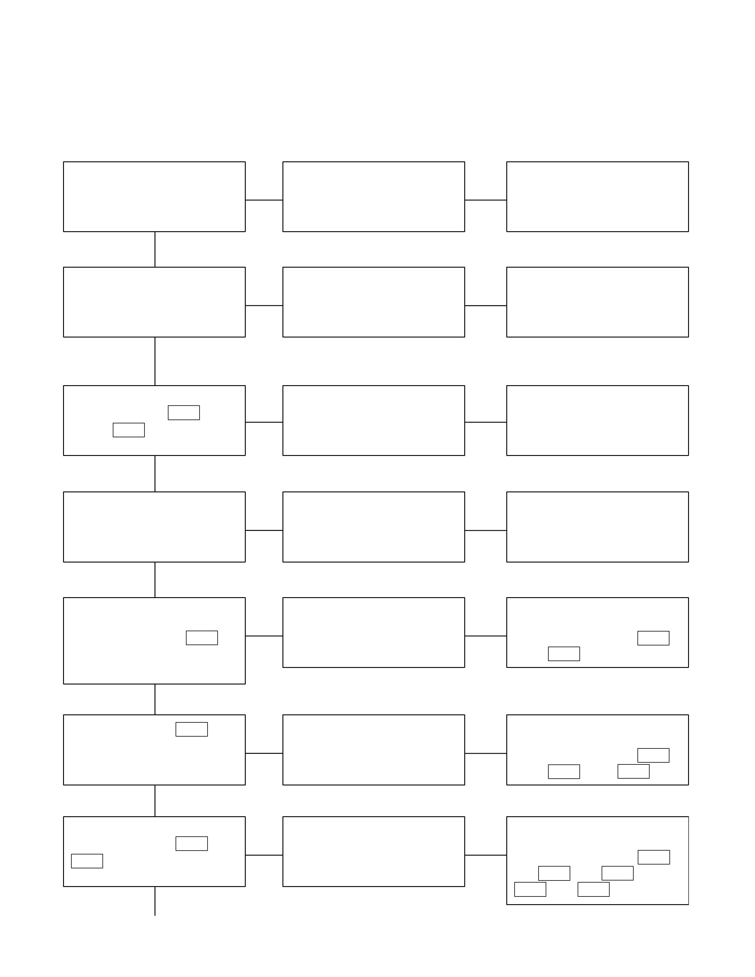
1. All windows do not operate
Checkpoint Trouble Cause Countermeasure
Reinstall or replace the fuse
SBF-11 (30A)
Poor fuse contact or blown
NG
Replace the circuit breaker
SBF-9 (50A)
SBF-9 (50A, Fuse box)
function
Circuit breaker malfunction
Repair grounding points
contact
Grounding points C-2
(RHD),
C-109 (LHD)
Poor grounding point contact
NG
NG
OK
OK
OK
Fuse SBF-11 (30A, Fuse box)
Replace the power window
relay
Power window relay
malfunction
NG
Repair an open circuit or a
poor connection of the
connectors between 1
C-108
and 2 B-8
Voltage between the power
window relay harness side
connector terminal 2 B-8
and the ground (Should be
battery voltage present)
Open circuit or poor connector
contact
NG
OK
Power window relay function
OK
Repair an open circuit or a
poor connection of the
connectors between 1 B-8
and 1 B-56 and 6 D-5
Open circuit or poor connector
contact
NG
Voltage between 6 D-5 and
the ground (Should be battery
voltage present)
OK
Repair an open circuit or a
poor connection of the
connectors between 3 D-5
and C-2 , or 3 B-8 (12
C-107 ) and
C-109
Open circuit or poor connector
contact
NG
Continued on the next page
Voltage between 3 D-5 or 3
B-8 and the ground
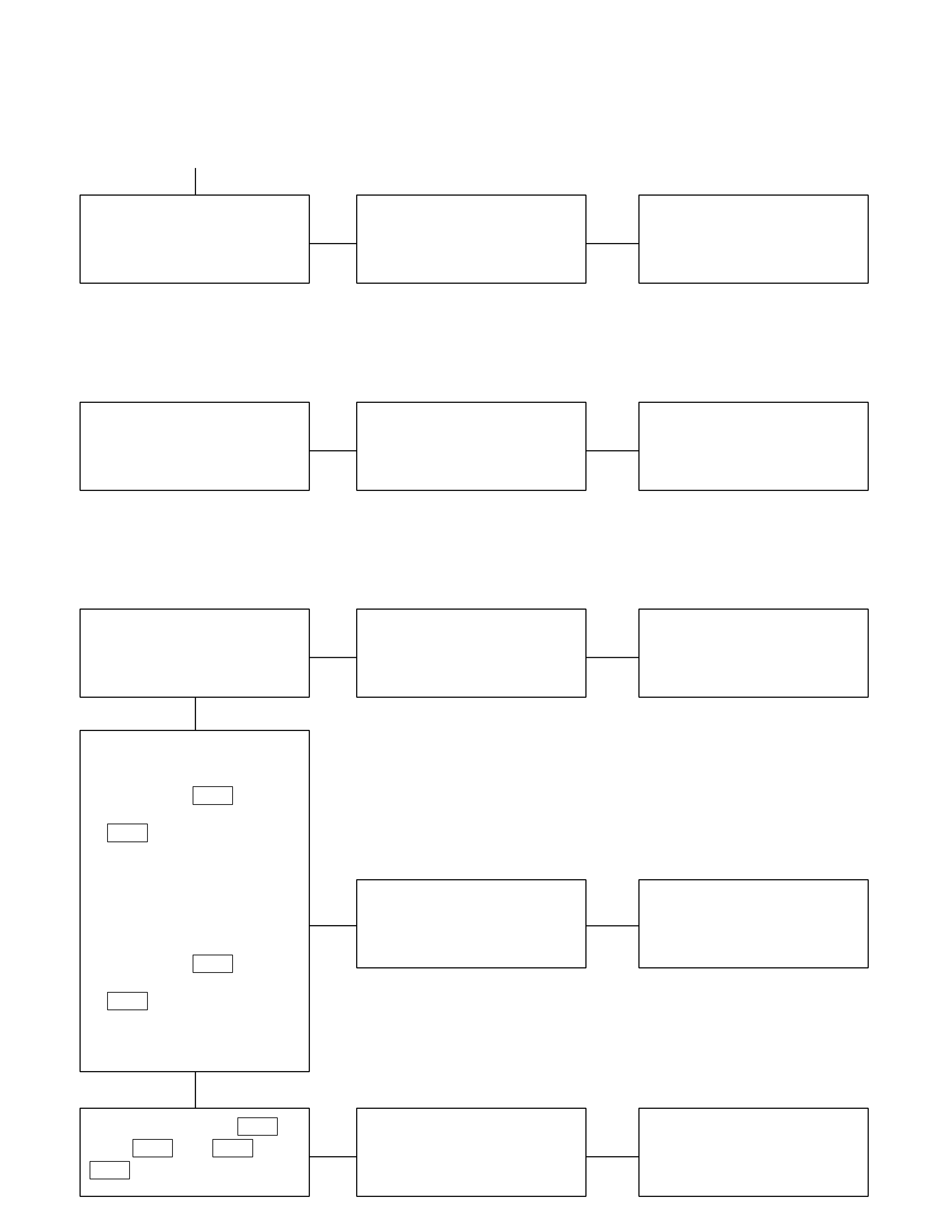
Checkpoint Trouble Cause Countermeasure
Replace the driver seat side
power window & door lock
SW.
SW. malfunction
OK
NG
Driver seat side power window
& door lock SW. function
Continued from the previous page
2. Lock switch does not function
Checkpoint Trouble Cause Countermeasure
Replace the driver seat side
power window & door lock
SW.
SW. malfunction
NG
Driver seat side power window
& door lock SW. function
3. Window on the driver’s side does not operate
Checkpoint Trouble Cause Countermeasure
Replace the driver seat side
power window & door lock
SW.
SW. malfunction
NG
Replace the driver seat side
power window motor
Motor malfunction
NG
OK
Driver seat side power window
& door lock SW. function
OK
Repair open circuit or
connector contact
Open circuit or poor connector
contact
NG
Continuity between 7 D-5
and 1 D-1 , or 8 D-5 and 2
D-1
1. Driver seat side power
window motor function
when connection the motor
connector 1 D-1 to the
battery (+) terminal, and 2
D-1 to the (-) terminal
(Should the motor rotate in
the “UP” direction of the
window)
2. Driver seat side power
window motor function
when connecting the motor
connector 2 D-1 to the
battery (+) terminal, and 1
D-1 to the (-) terminal
(Should the motor rotate in
the “DOWN” direction of the
window)
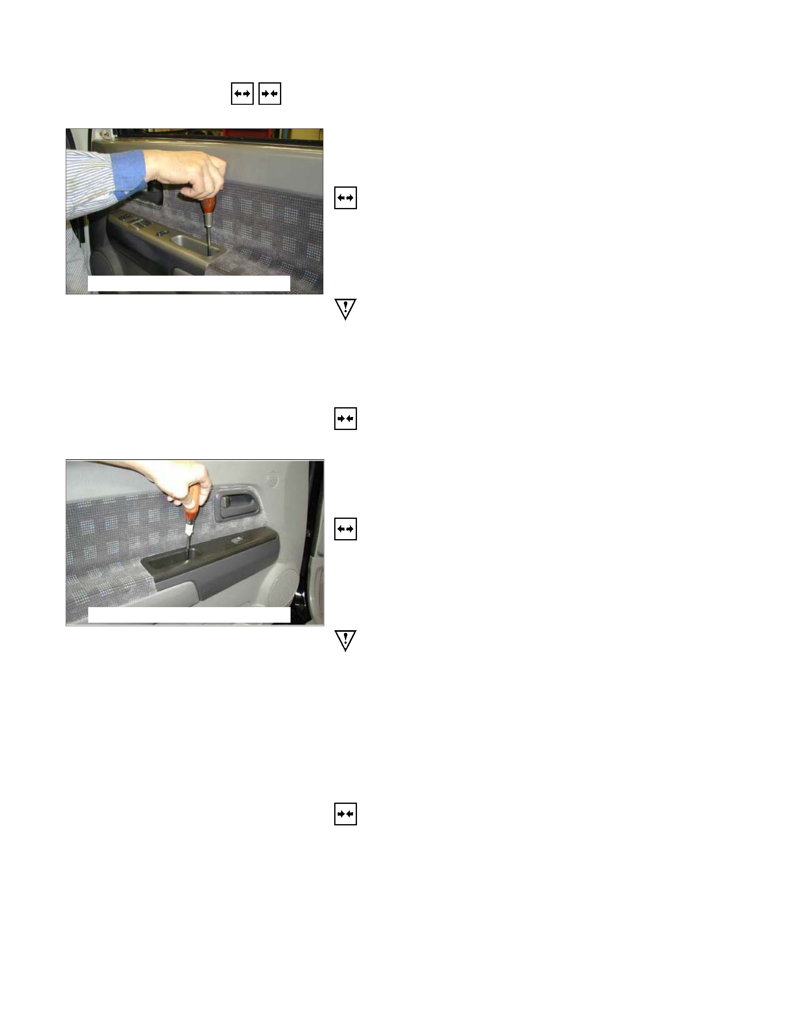
REMOVAL AND INSTALLATION
This photo is based on RHD
DRIVER SEAT SIDE POWER WINDOW &
DOOR LOCK SWITCH
(2 DOORS MODEL)
Removal
1. Disconnect the battery ground cable.
2. Removes the screw in pull cup with the tip of a screwdriver.
3. Remove the switch bezel by pushing the spring with the tip
of a screwdriver.
4. Disconnect the connector.
ATTENTION:
When removing a switch bezel lift from the front in the
bezel.
It follows the front with the screwdriver.
The clip has broken when lifting from the rear in the bezel.
Installation
To install, follow the removal steps in the reverse order.
This photo is based on RHD
FRONT PASSENGER’S POWER WINDOW
SWITCH
(2 DOORS MODEL)
Removal
1. Disconnect the battery ground cable.
2. Removes the screw in pull cup with the tip of a screwdriver.
3. Remove the switch bezel by pushing the spring with the tip
of a screwdriver.
4. Disconnect the connector.
ATTENTION:
When removing a switch bezel lift from the front in the
bezel.
It follows the front with the screwdriver.
The clip has broken when lifting from the rear in the bezel.
Installation
To install, follow the removal steps in the reverse order.
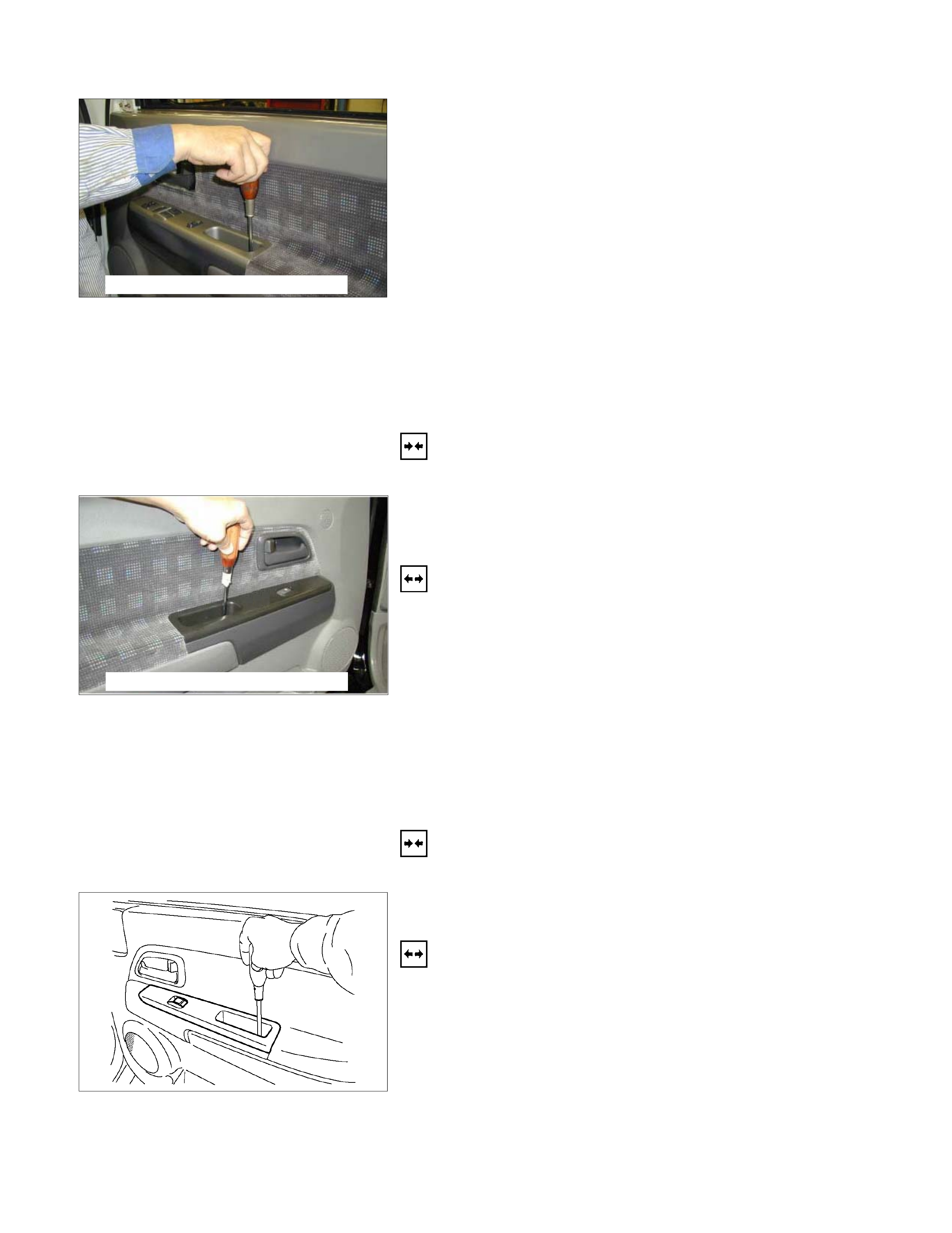
This photo is based on RHD
DRIVER SEAT SIDE POWER WINDOW &
DOOR LOCK SWITCH
(4 DOORS MODEL)
Removal
1. Disconnect the battery ground cable.
2. Removes the screw in pull cup with the tip of a screwdriver.
3. Remove the switch bezel by pushing the spring with the tip
of a screwdriver.
4. Disconnect the connector.
ATTENTION:
When removing a switch bezel lift from the front in the
bezel.
It follows the front with the screwdriver.
The clip has broken when lifting from the rear in the bezel.
Installation
To install, follow the removal steps in the reverse order.
This photo is based on RHD
FRONT PASSENGER’S POWER WINDOW
SWITCH
(4 DOORS MODEL)
Removal
1. Disconnect the battery ground cable.
2. Removes the screw in pull cup with the tip of a screwdriver.
3. Remove the switch bezel by pushing the spring with the tip
of a screwdriver.
4. Disconnect the connector.
ATTENTION:
When removing a switch bezel lift from the front in the
bezel.
It follows the front with the screwdriver.
The clip has broken when lifting from the rear in the bezel.
Installation
To install, follow the removal steps in the reverse order.
RUW580SH002101
REAR POWER WINDOW & DOOR LOCK
SWITCH-LH & RH
Removal
1. Disconnect the battery ground cable.
2. Removes the screw in pull cup with the tip of a screwdriver.
3. Remove the switch bezel by pushing the spring with the tip
of a screwdriver.
4. Disconnect the connector.
ATTENTION:
When removing a switch bezel lift from the front in the
bezel.
It follows the front with the screwdriver.
The clip has broken when lifting from the rear in the bezel.

Installation
To install, follow the removal steps in the reverse order.
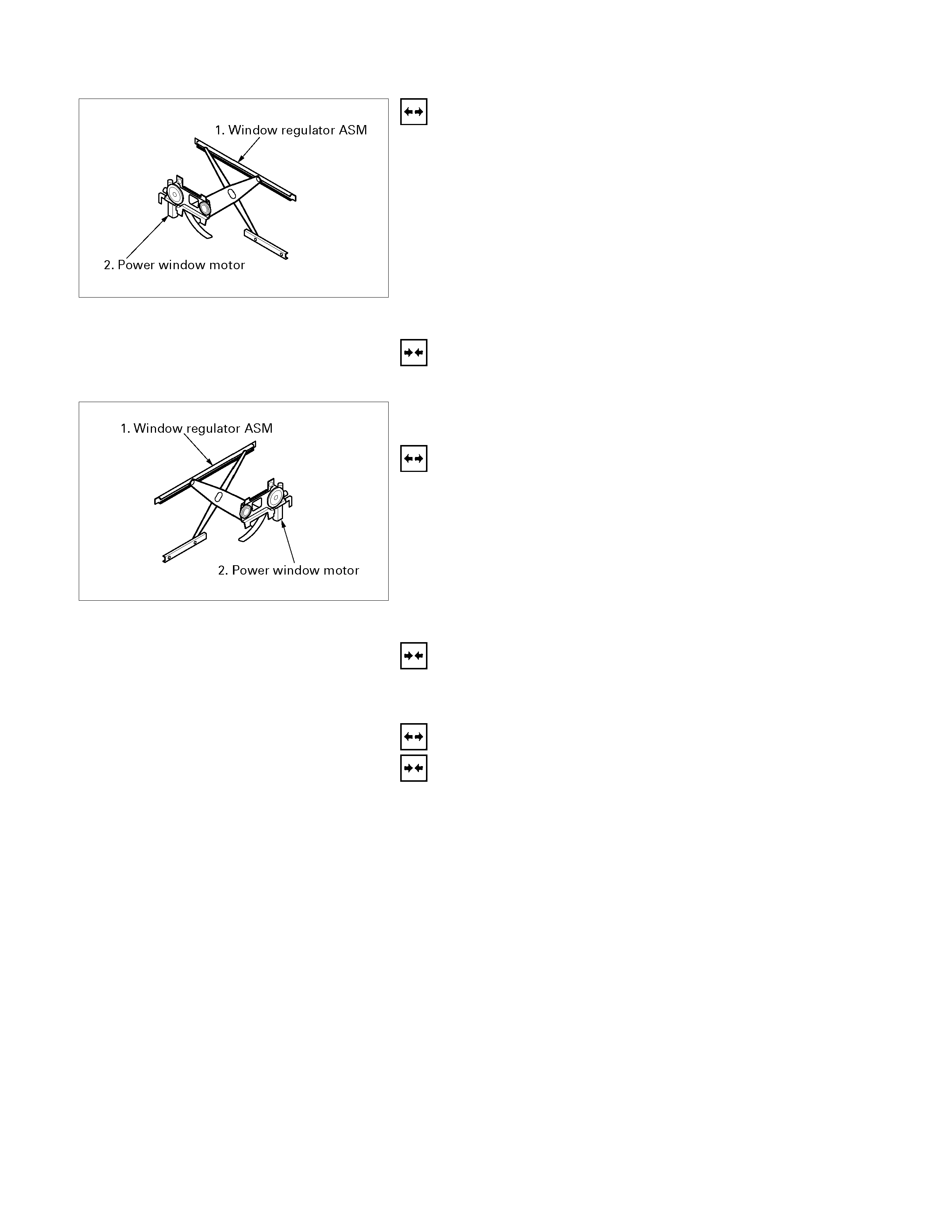
DRIVER SEAT SIDE POWER WINDOW
MOTOR
Removal
1. Window Regulator ASM
• Refer to the removal steps of the WINDOW
REGULATOR/POWER WINDOW MOTOR in Section
10 “BODY”.
2. Power Window Motor
• Loosen the fixing bolts to remove the power window
motor from the regulator.
Installation
To install, follow the removal steps in the reverse order.
FRONT PASSENGER’S POWER WINDOW
MOTOR
Removal
1. Window Regulator ASM
• Refer to the removal steps of the WINDOW
REGULATOR/POWER WINDOW MOTOR in Section
10 “BODY”.
2. Power Window Motor
• Loosen the fixing bolts to remove the power window
motor from the regulator.
Installation
To install, follow the removal steps in the reverse order.
REAR POWER WINDOW MOTOR-LH &
RH
Removal and Installation
Refer to the “DRIVER SEAT SIDE POWER WINDOW
MOTOR” removal and installation steps in this section.
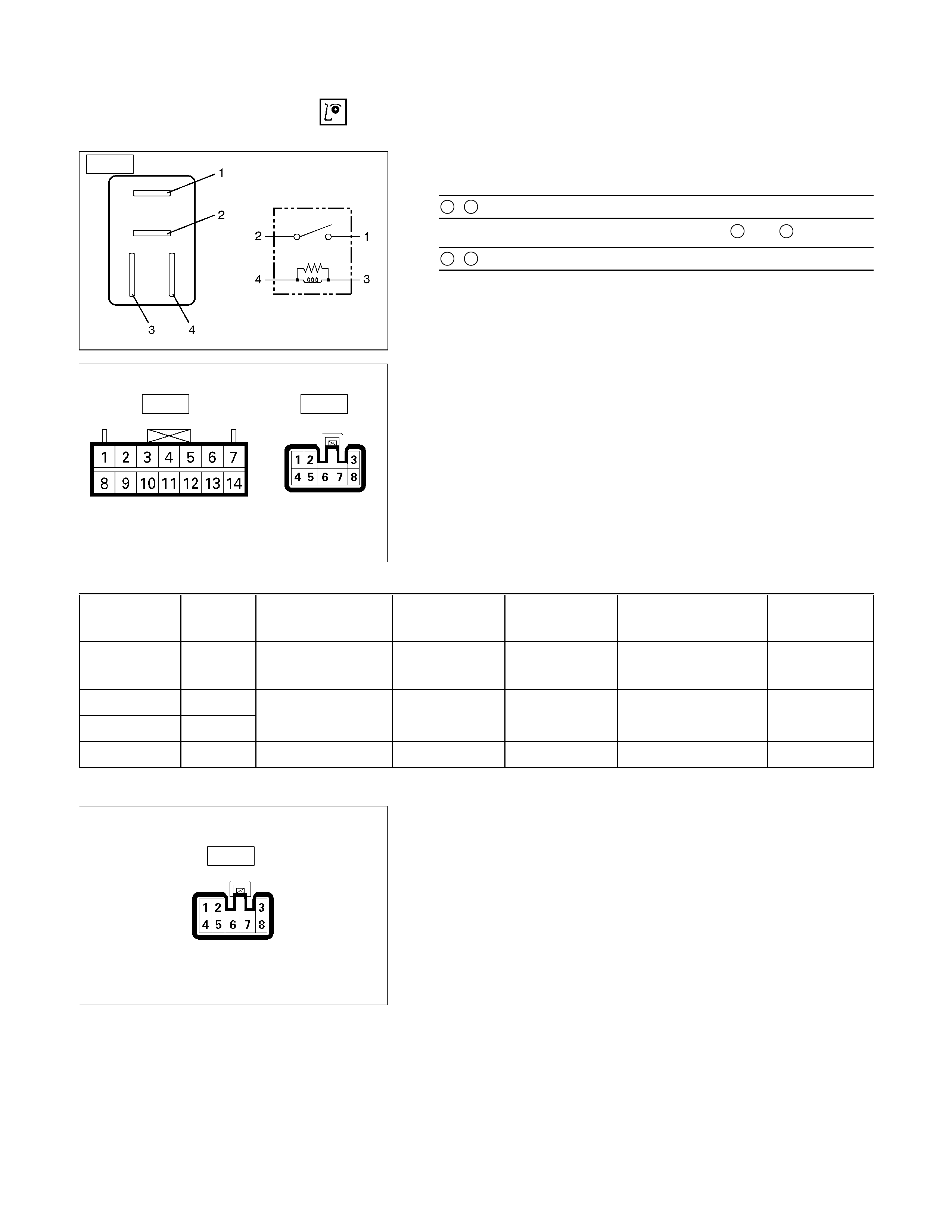
INSPECTION AND REPAIR
B-8
Power Window Relay
Check continuity between the relay terminals.
2- 1........................No continuity
(When battery voltage is applied between 3 and 4)
2- 1........................Continuity
Harness side
D-20 D-5
Driver Seat Side Power Window & Door Lock
Switch
1. Harness Side Connector Circuit
Disconnect the switch connector, and check voltage and
continuity between the harness side connector terminals as
shown in the following table.
Terminal
No. Wire
color Connecting to Check item Connectin
g terminal Check condition Standard
6 G/R
Power window
relay Voltage 6-Ground Starter SW “ON” Approx.
12V
7 BR/R
Power window
8 BR/W
motor Continuity 7-8 - Continuity
3 B Ground Continuity 3-Ground - Continuity
Harness side
D-10
Front Passenger’s Power Window Switch
1. Harness Side Connector Circuit
Disconnect the switch connector, and check voltage and
continuity between the harness side connector terminals as
shown in the following table.
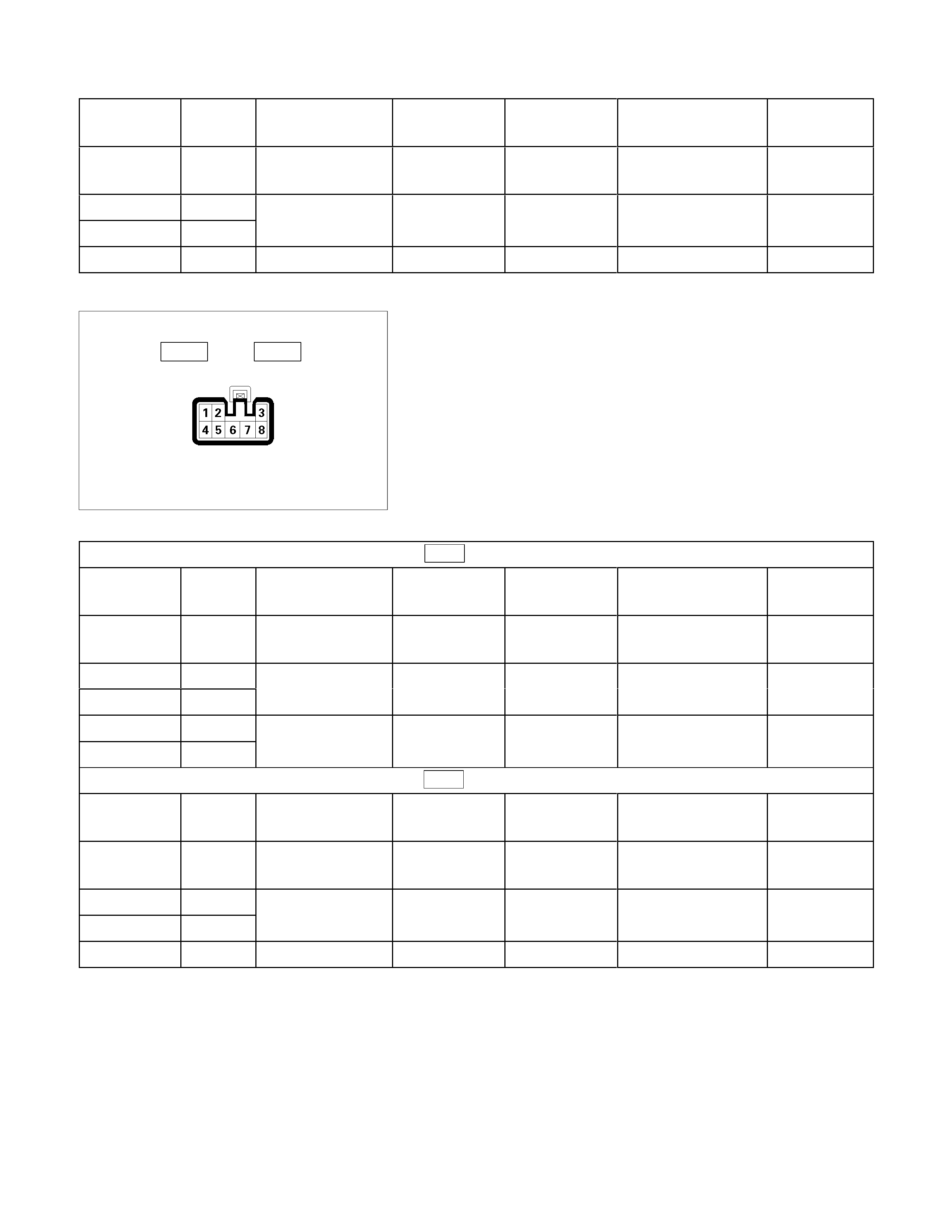
Terminal
No. Wire
color Connecting to Check item Connectin
g terminal Check condition Standard
6 G/R
Power window
relay Voltage 6-Ground Starter SW “ON” Approx.
12V
8 BR/R
7 BR/W
Power window
motor Continuity 8-7 - Continuity
1,3 B Ground Continuity 1,3-Ground - Continuity
Harness side
D-12 D-16
Rear Power Window Switch-LH & RH
1. Harness Side Connector Circuit
Disconnect the switch connector, and check voltage and
continuity between the harness side connector terminals as
shown in the following tables.
D-12 (RR-LH)
Terminal
No. Wire
color Connecting to Check item Connectin
g terminal Check condition Standard
6 G/R
Power window
relay Voltage 6-Ground Starter SW “ON” Approx.
12V
8 BR/R
7 BR/W
Power window
motor Continuity 8-7 - Continuity
3 B
4 B
Ground Continuity 3,4-Ground - Continuity
D-16 (RR-RH)
Terminal
No. Wire
color Connecting to Check item Connectin
g terminal Check condition Standard
6 G/R
Power window
relay Voltage 6-Ground Starter SW “ON” Approx.
12V
8 BR/R
7 BR/W
Power window
motor Continuity 8-7 - Continuity
3 B Ground Continuity 3-Ground - Continuity
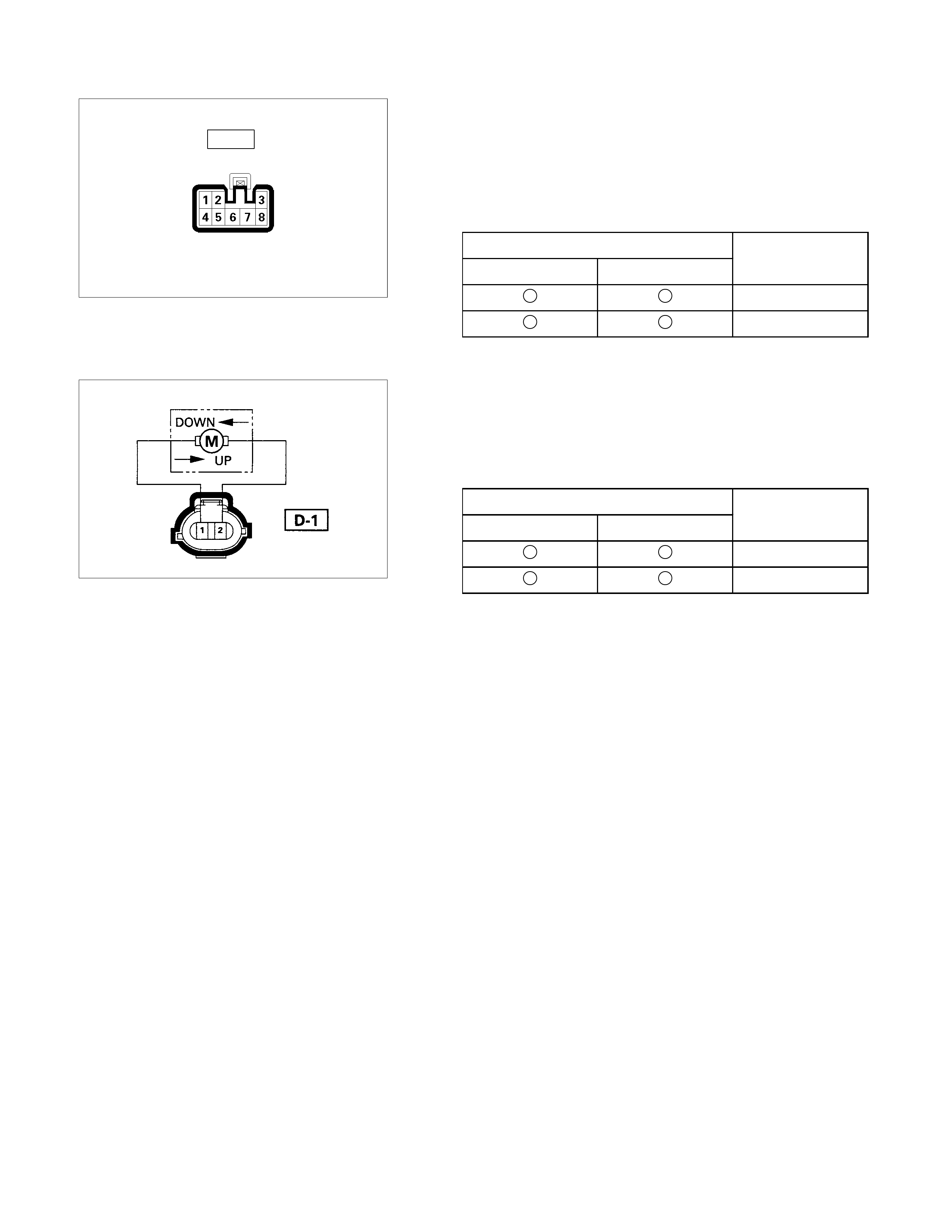
Harness side
D-5
Driver Seat Side Power Window Motor
1. Driver Seat Side Power Window & Door Lock Switch
Connector Circuit
Disconnect the switch connector, apply the battery voltage
(12V) to the harness side connector terminals and check
operation.
Connecting terminals Operation
7 (BR/R) 8 (BR/W) direction
- + DOWN
+ - UP
2. Driver Seat Side Power Window Motor Connecto
r
Circuit
Disconnect the switch connector, apply the battery voltage
(12V) to the motor side connector terminals and check
operation.
Connecting terminals Operation
1 2
direction
+ - DOWN
- + UP
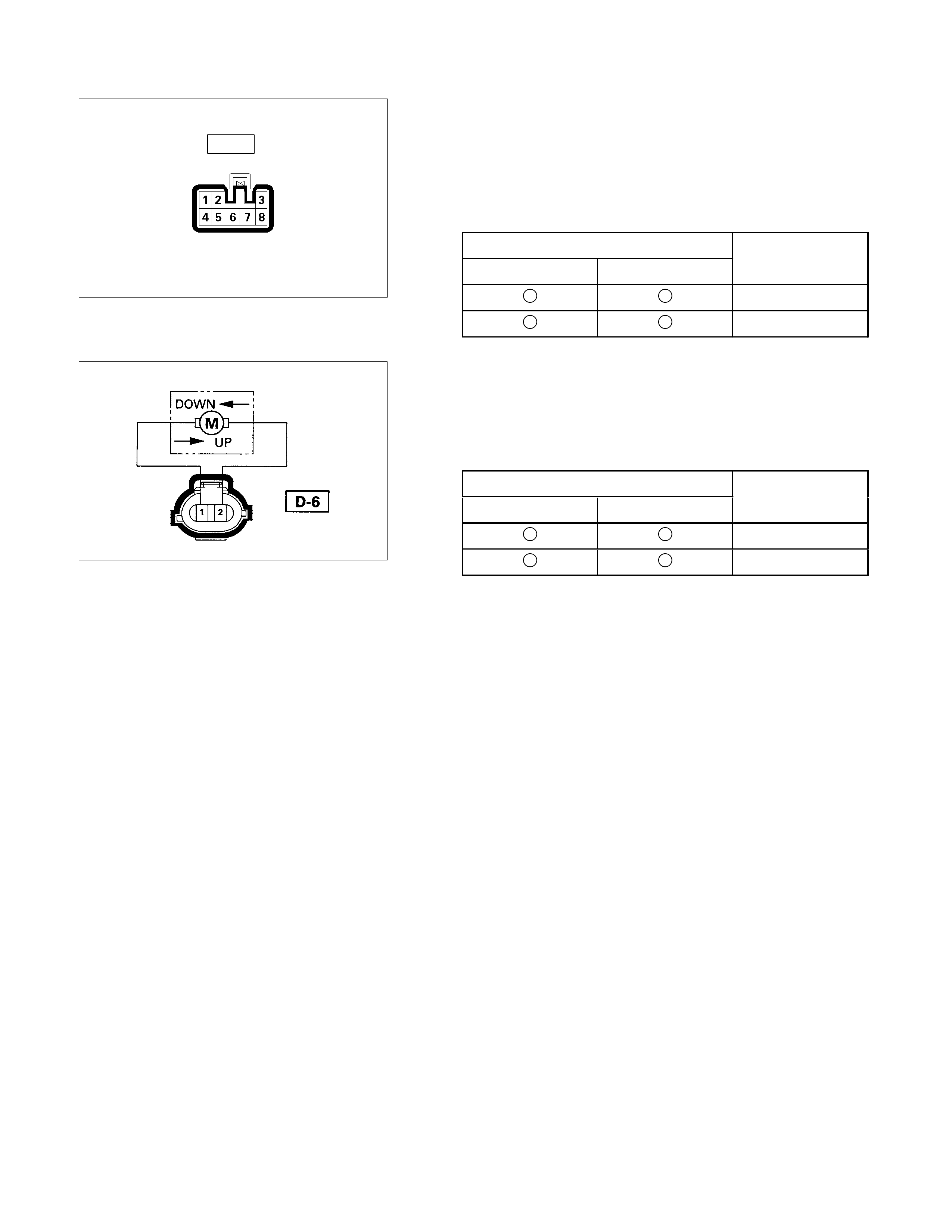
Harness side
D-10
Front Passenger’s Power Window Motor
1. Front Passenger’s Power Window Switch Connecto
r
Circuit
Disconnect the motor connector, apply the battery voltage
(12V) to the harness side connector terminals and check
operation.
Connecting terminals Operation
8 (BR/R) 7 (BR/W) direction
- + DOWN
+ - UP
2. Front Passenger’s Power Window Motor Connecto
r
Circuit
Disconnect the switch connector, apply the battery voltage
(12V) to the motor side connector terminals and check
operation.
Connecting terminals Operation
1 2
direction
+ - DOWN
- + UP
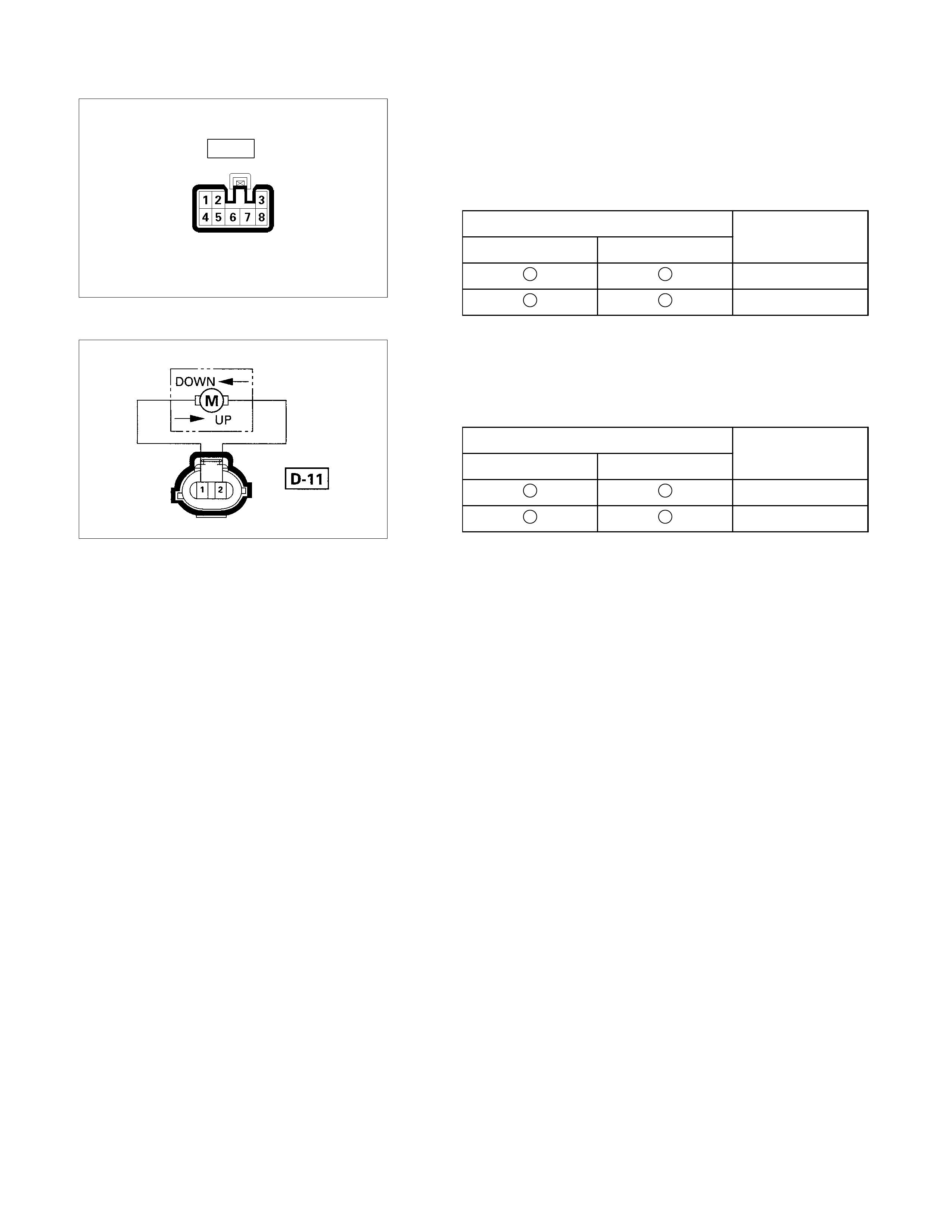
Harness side
D-12
Rear Passenger’s Power Window Motor-LH
1. Rear Power Window Switch-LH Connector Circuit
Disconnect the motor connector, apply the battery voltage
(12V) to the harness side connector terminals and check
operation.
Connecting terminals Operation
8 (BR/R) 7 (BR/W) direction
- + DOWN
+ - UP
2. Rear Power Window Motor-LH Connector Circuit
Disconnect the switch connector, apply the battery voltage
(12V) to the motor side connector terminals and check
operation.
Connecting terminals Operation
1 2
direction
+ - DOWN
- + UP
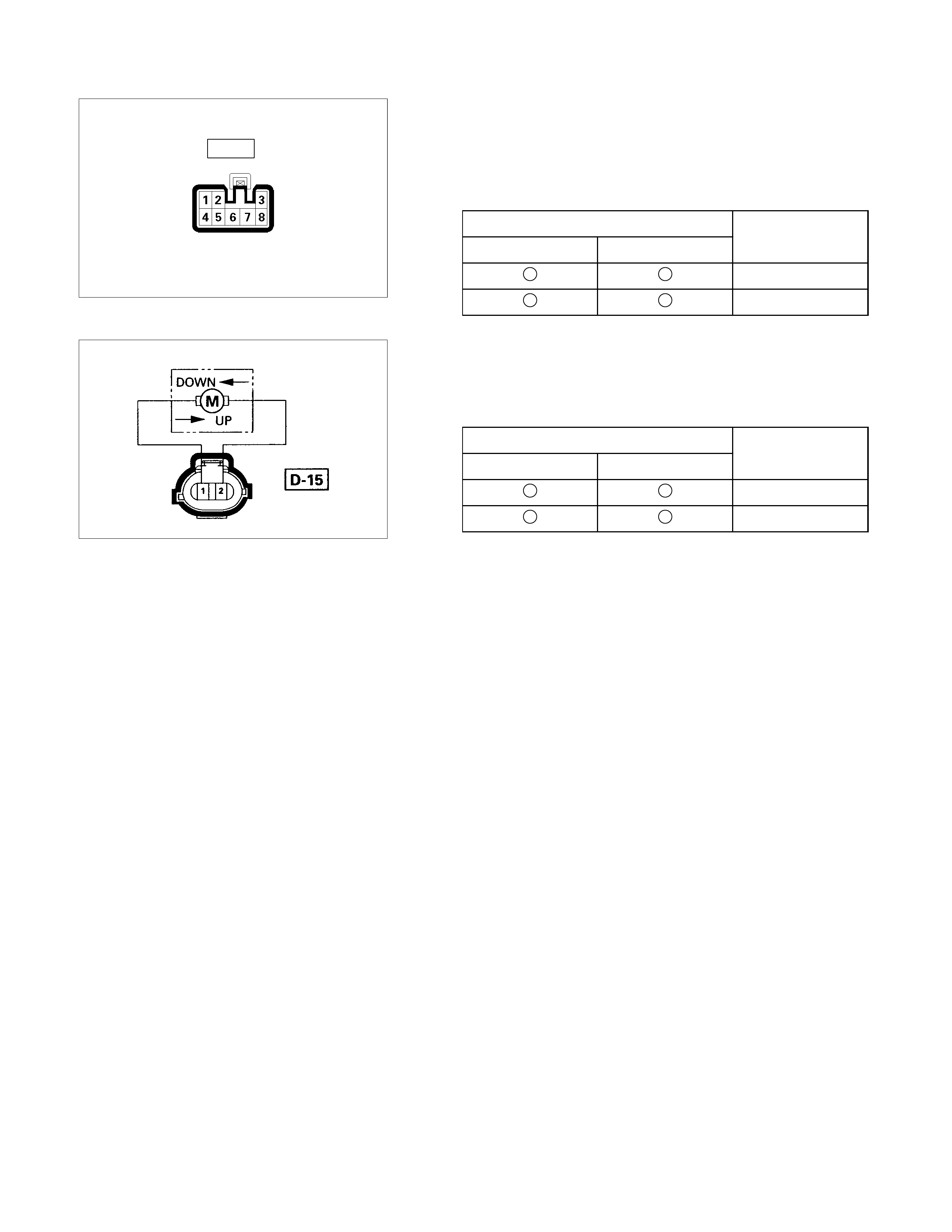
Harness side
D-16
Rear Power Window Motor-RH
1. Rear Power Window Switch-RH Connector Circuit
Disconnect the motor connector, apply the battery voltage
(12V) to the harness side connector terminals and check
operation.
Connecting terminals Operation
8 (BR/R) 7 (BR/W) direction
- + DOWN
+ - UP
2. Rear Power Window Motor-RH Connector Circuit
Disconnect the switch connector, apply the battery voltage
(12V) to the motor side connector terminals and check
operation.
Connecting terminals Operation
1 2
direction
+ - DOWN
- + UP
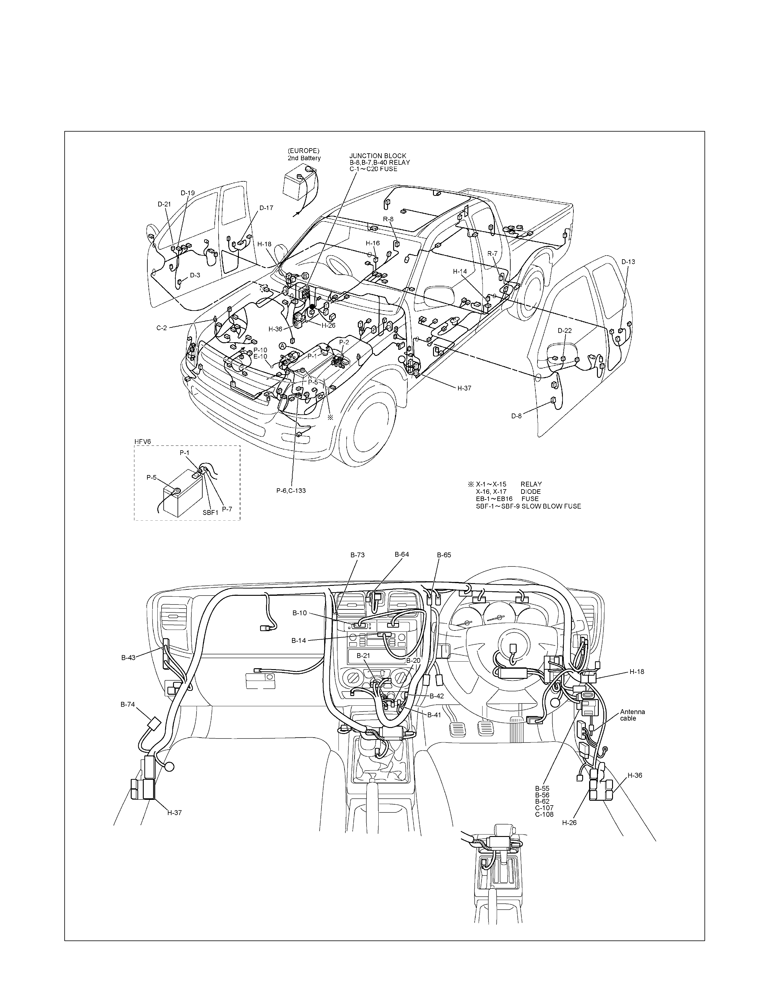
AUDIO, CLOCK AND CIGARETTE LIGHTER
PARTS LOCATION (RHD)
RTW68AXF016001 & RTW68AXF016101
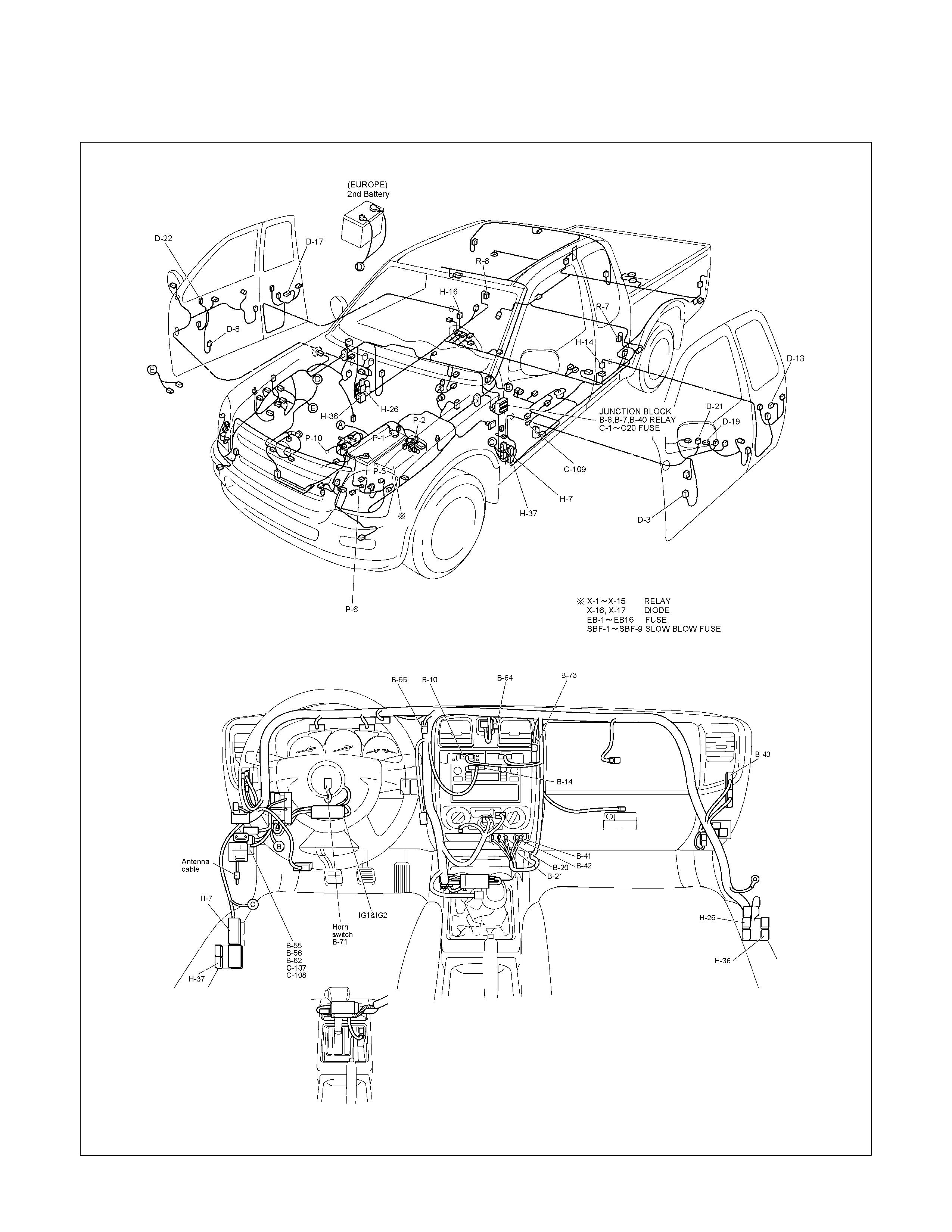
PARTS LOCATION (LHD)
RTW690XF000301 & RTW690XF000401
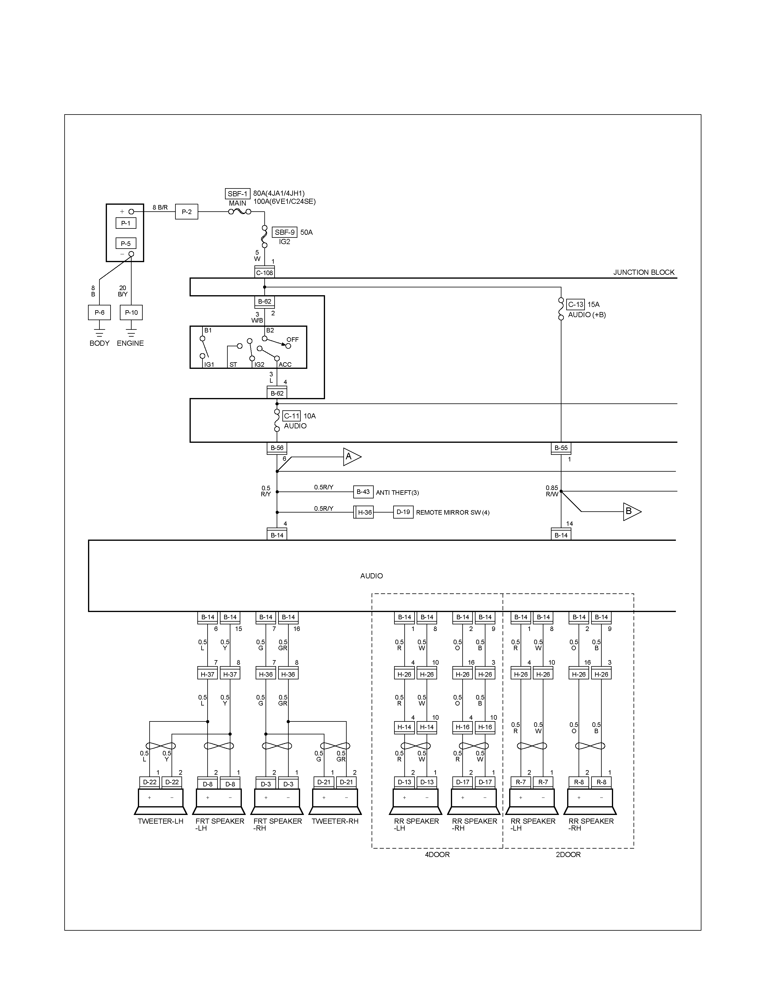
CIRCUIT DIAGRAM EXCEPT HFV6 (RHD) Sheet 1/2
RTW680XF013201
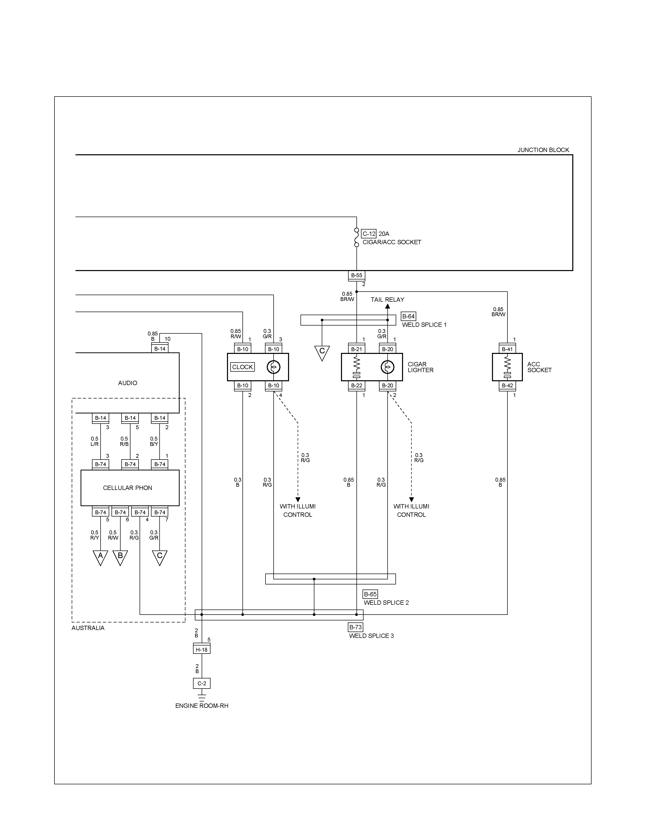
CIRCUIT DIAGRAM EXCEPT HFV6 (RHD) Sheet 2/2
RTW680XF013301
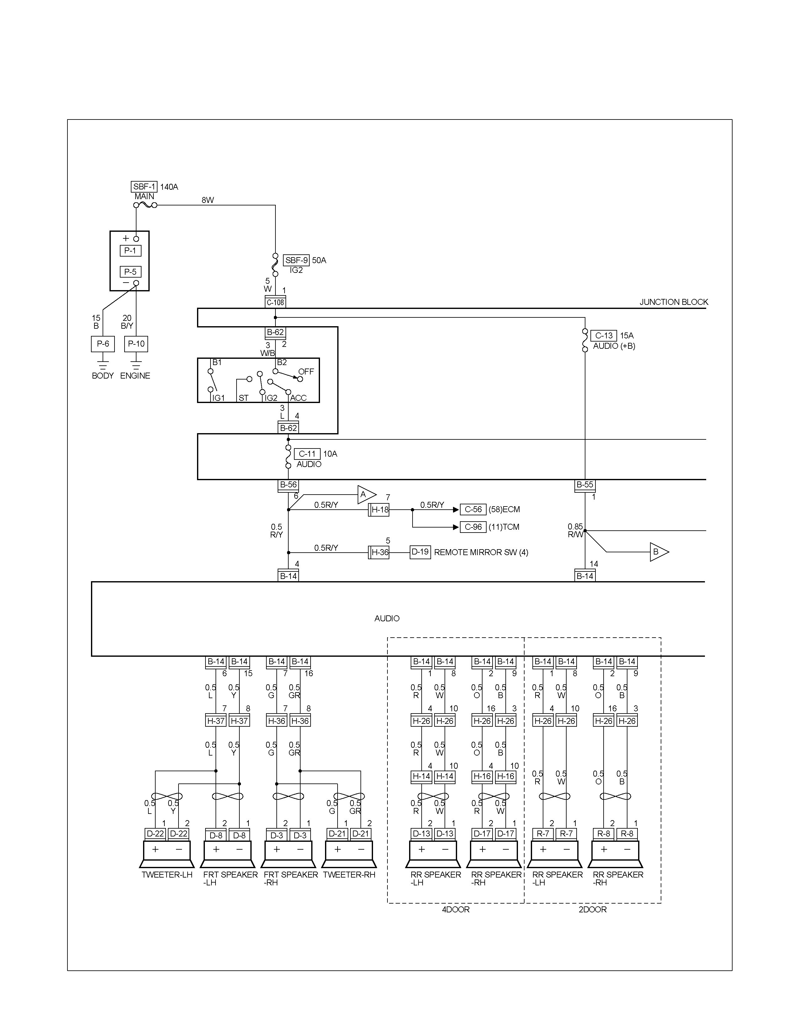
CIRCUIT DIAGRAM HFV6 (RHD) Sheet 1/2
RTW68AXF012001
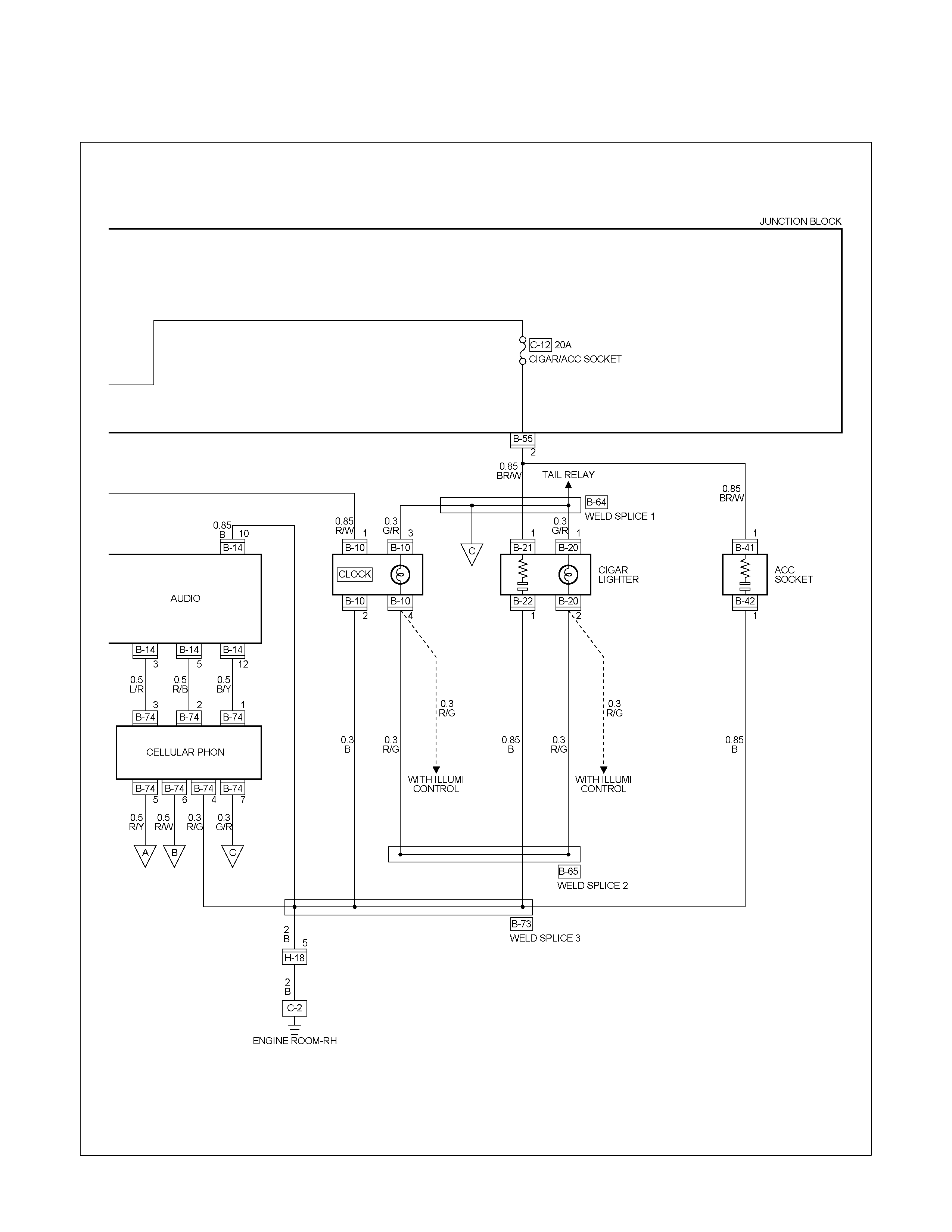
CIRCUIT DIAGRAM HFV6 (RHD) Sheet 2/2
RTW68AXF012101
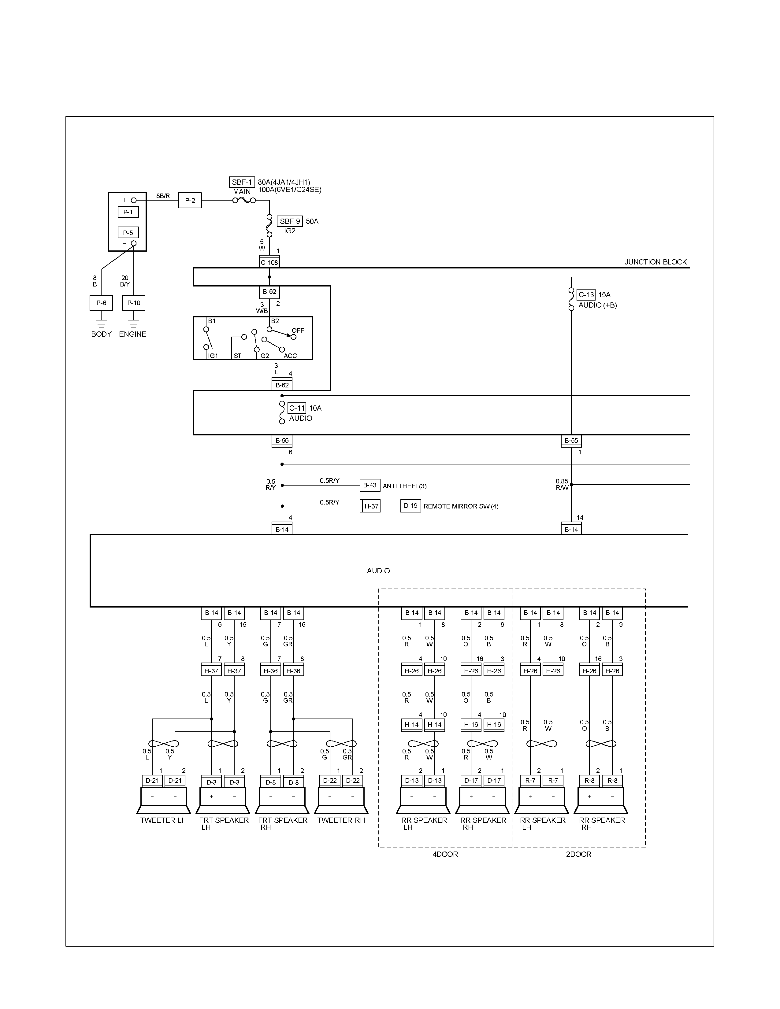
CIRCUIT DIAGRAM (LHD) Sheet 1/2
RTW680XF013401
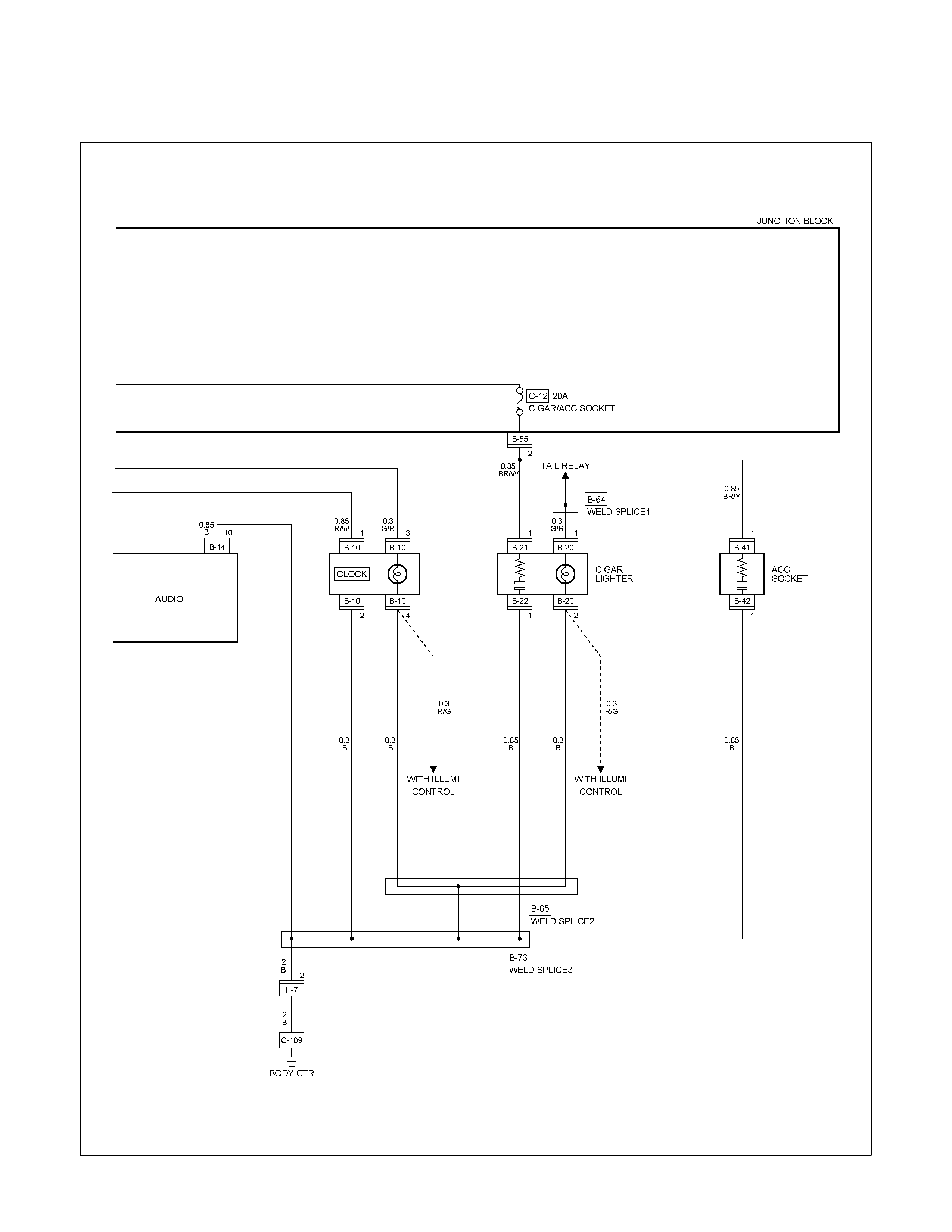
CIRCUIT DIAGRAM (LHD) Sheet 2/2
RTW680XF013501
TROUBLESHOOTING
CIGARETTE LIGHTER
1. Lighter does not pop out after being pushed in. It does not become hot.
Checkpoint Trouble Cause Countermeasure
Reinstall or replace the fuse
No. C-12 (20A)
Poor Fuse No. C-12 (20A,
Fuse box) contact or blown
NG
Replace the lighter
Lighter continuity between
center part and outer area
Open circuit or poor connector
contact
Repair open circuit or
connector contact
Voltage between connector 1
B-21 and the ground at
starter SW. is ACC position
(Should be battery voltage
present)
Open circuit or poor connector
contact
NG
NG
OK
OK
OK
Audio system (System should
receive power)
Repair open circuit or
connector contact
Open circuit or poor connector
contact
NG
Continuity between connector
1 B-22 and the ground
2. Lighter pops out prematurely before becoming hot
Repair or replace the lighter
and/or casing
Deformed lighter or casing
NG
Lighter and casing
3. Lighter becomes too hot
Repair or replace the lighter
and/or casing
Deformed lighter and casing
NG
Lighter and casing
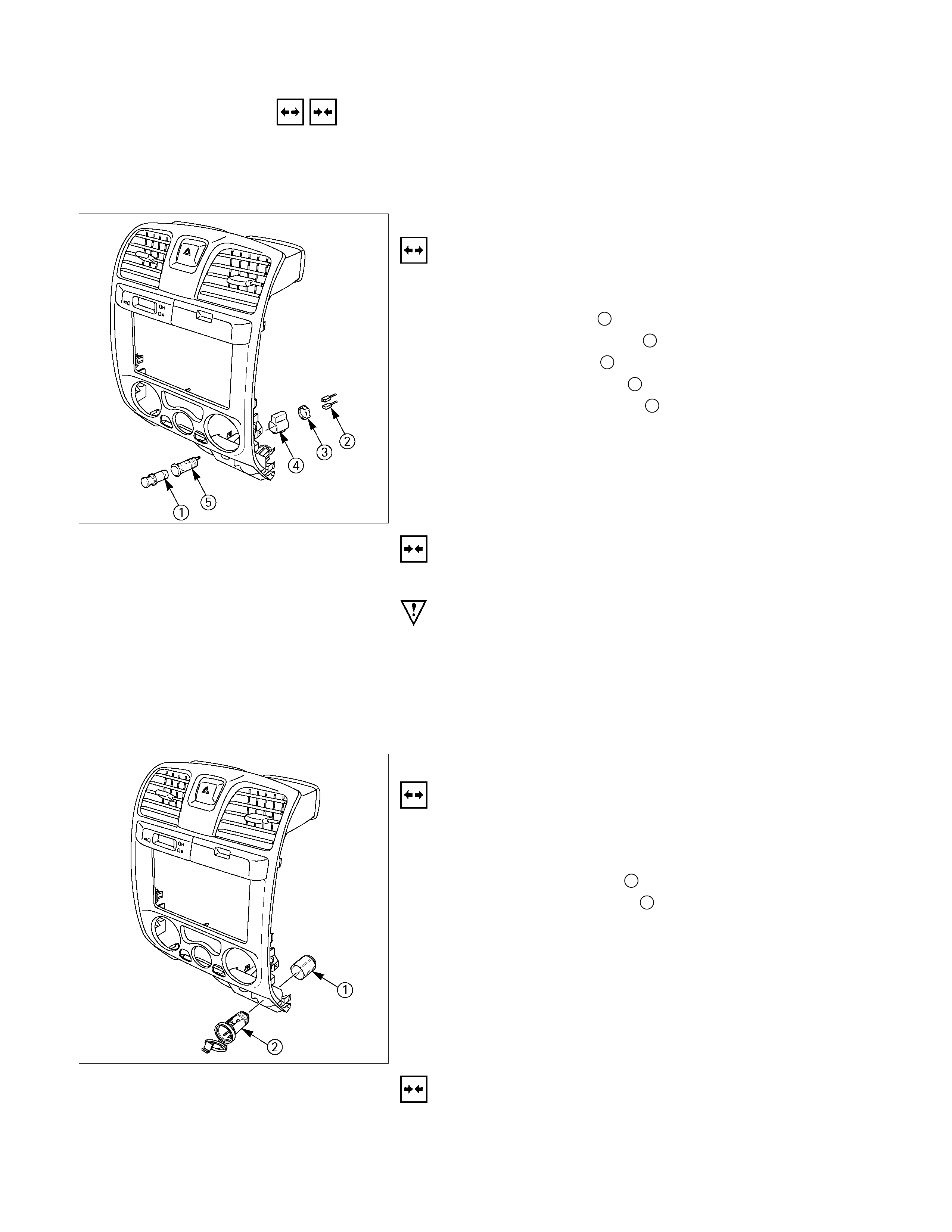
REMOVAL AND INSTALLATION
AUDIO
Refer to Section 9 “ACCESSORIES” for details.
CIGARETTE LIGHTER
Removal
1. Disconnect the battery ground cable.
2. Remove the center cluster ASM.
3. Remove the lighter 1.
4. Disconnect the connector 2.
5. Loosen the ring nut 3 at the back side.
6. Remove the outer case 4.
7. Remove the lighter holder 5 from the bezel.
Installation
Follow the removal procedure in the reverse order to install the
lighter.
Pay close attention to the important points mentioned in the
following paragraphs.
Connector
Be absolutely sure that the lighter connector is securely
connected.
This will prevent a poor contact and an open circuit.
ACC SOCKET
Removal
1. Disconnect the battery ground cable.
2. Remove the center cluster ASM.
3. Disconnect the connector.
4. Remove the holder nut 1.
5. Remove the ACC Socket 2
Installation
Follow the removal procedure in the reverse order to install the
lighter.
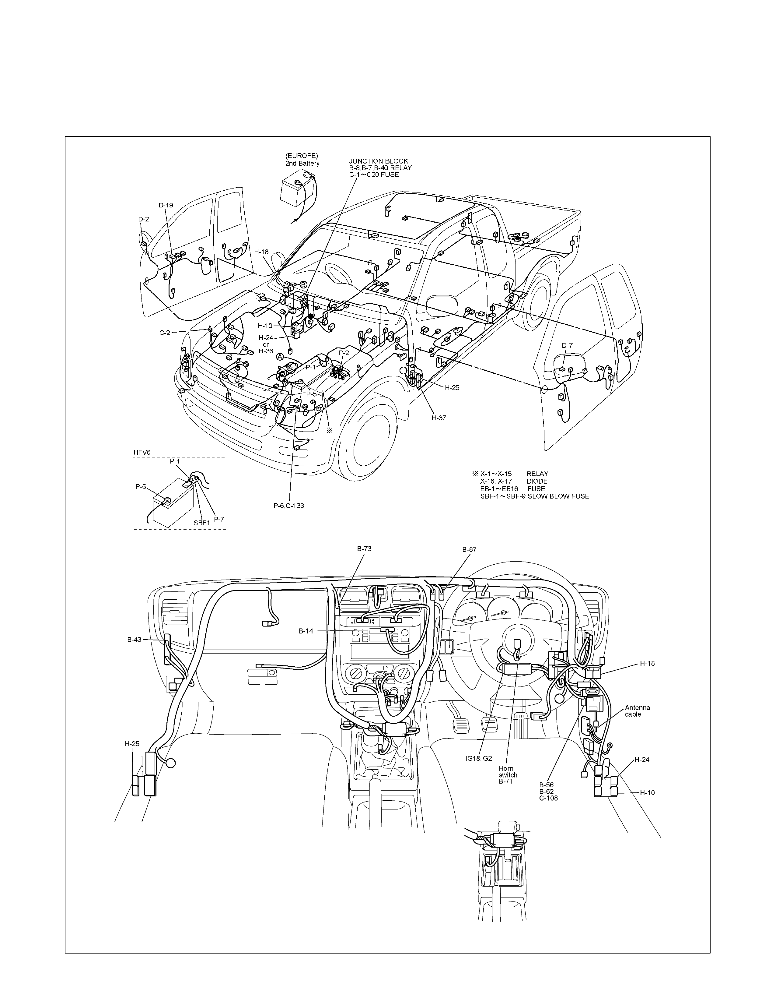
POWER DOOR MIRROR
PARTS LOCATION (RHD)
RTW68AXF016201 & RTW68AXF016301

PARTS LOCATION (LHD)
RTW48AXF020601 & RTW48AXF020701
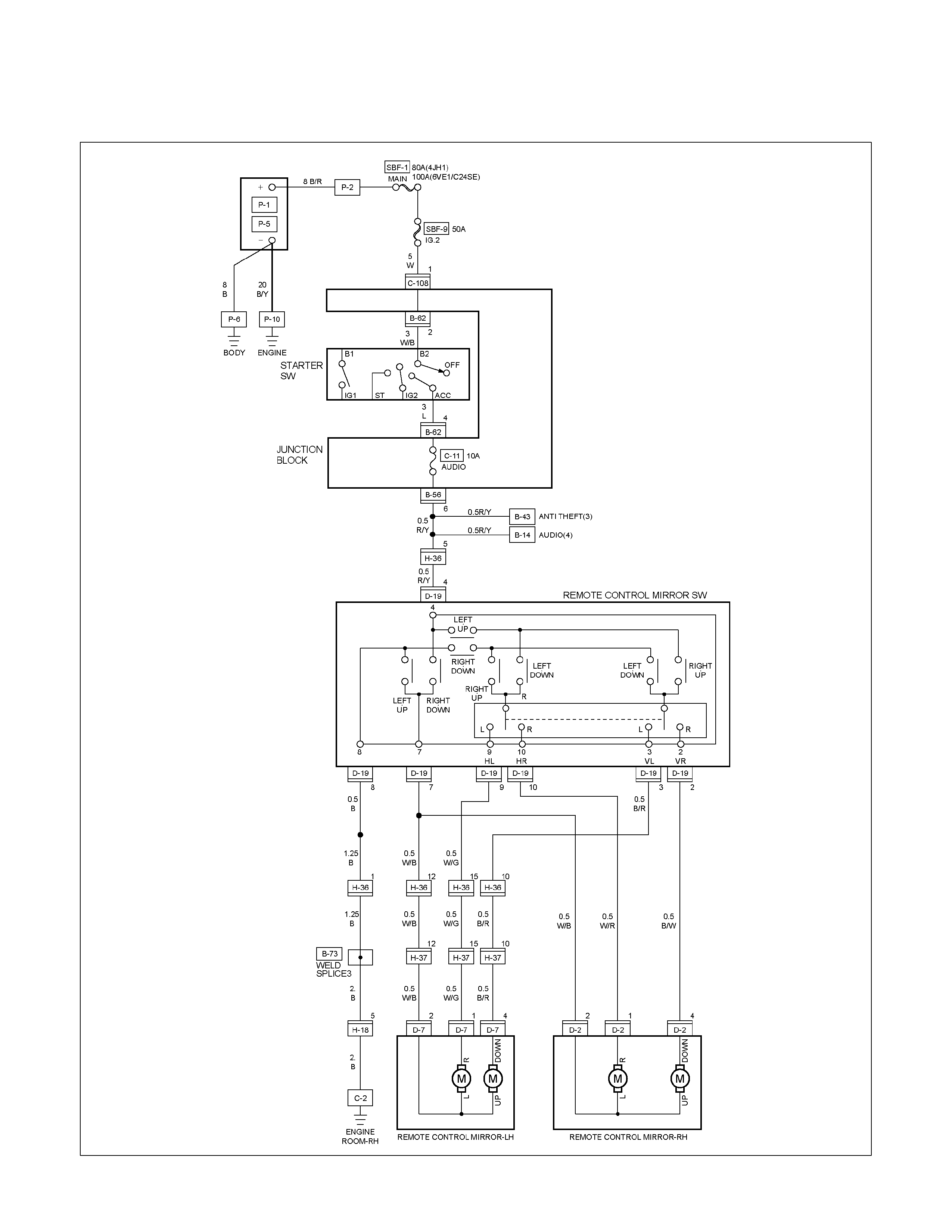
CIRCUIT DIAGRAM EXCEPT HFV6 (RHD)
RTW680XF013601
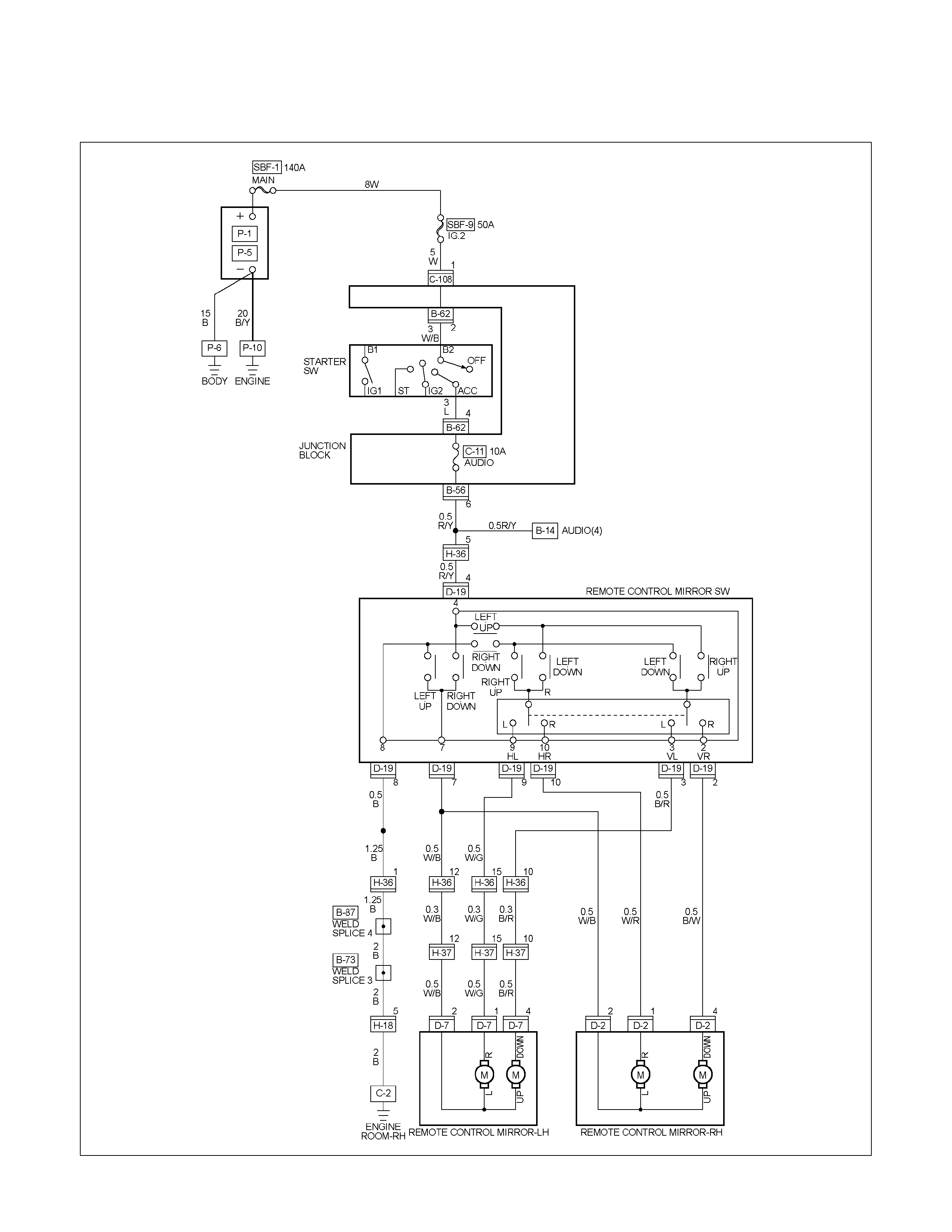
CIRCUIT DIAGRAM HFV6 (RHD)
RTW68AXF012301

CIRCUIT DIAGRAM (LHD)
RTW680XF013701
TROUBLESHOOTING
QUICK CHART FOR CHECK POINT
Check Point Fuse Door Mirror Door Mirror
Trouble Mode
C-11
(10A)
Control
Switch LH RH
1. Mirrors on the both sides do not operate
2. Mirror on the left (or right) side does not
operate
3. Mirrors on the both sides operate only in
the vertical
(or horizontal) direction
4. Mirror on the left side operates only in
the vertical
(or horizontal) direction
5. Mirror on the right side operates only in
the vertical
(or horizontal) direction
Cable
Harness
DOOR MIRROR CONTROL SWITCH
1. Mirrors on the both sides do not operate
Checkpoint Trouble Cause Countermeasure
Reinstall or replace the fuse
No. C-11 (10A)
Poor fuse contact or blown
NG
Repair grounding point C-2
(RHD)
C-109 (LHD) contact
Grounding point C-2 (RHD),
C-2 (LHD)
Poor grounding point contact
Repair an open circuit or a
poor connection of the
connectors between the fuse
No. C-11 (10A) and 4 D-19
Voltage between the door
mirror control SW. harness
side connector terminal
4 D-19 and the ground
(Should be battery voltage
present)
Open circuit or poor connector
contact
NG
NG
OK
OK
OK
Fuse No. C-11 (10A, Fuse
box)
Repair open circuit or
connector contact
Open circuit or poor connector
contact
NG
Continuity between the door
mirror control SW harness
side connector terminal
8 D-19 and C-2 (RHD),
C-109 (LHD)
Replace the door mirror
control SW.
Door mirror control SW.
function
SW. malfunction
NG
OK
Repair open circuit or
connector contact
Continuity between 7 D-19
and 12 H-36 (or 12 H-37 )
Open circuit or poor connector
contact
NG
OK

2. Mirror on the right side does not operate
Checkpoint Trouble Cause Countermeasure
Replace the door mirror
control SW.
SW. malfunction
NG
Repair or replace the door
mirror
Mirror function on the left (or
right) side
Mirror malfunction on the left
(or right)
Repair open circuit or
connector contact
Continuity between
7 D-19 and 2 D-7 (7 D-19
and 2 D-2 )
Open circuit or poor connector
contact
NG
NG
OK
OK
Door mirror control SW.
function
3. Mirrors on the both sides operate only in the vertical (or horizontal) direction
Replace the door mirror
control SW.
SW. malfunction
NG
Door mirror control SW.
function
4. Mirror on the left side operates only in the vertical (or horizontal) direction
Checkpoint Trouble Cause Countermeasure
Replace the door mirror
control SW.
SW. malfunction
NG
Repair or replace the door
mirror
Door mirror function
Door mirror malfunction
Repair open circuit or
connector contact
Continuity between
4 D-19 and 4 D-7 (10
D-19 and 1 D-2 )
Open circuit or poor connector
contact
NG
NG
OK
OK
Door mirror control SW.
function
5. Mirror on the right side operates only in the v ertical (or horizontal) direction
Replace the door mirror
control SW.
Door mirror control
malfunction
NG
Repair or replace the door
mirror
Door mirror function
Door mirror malfunction
Repair open circuit or
connector contact
Continuity between
4 D-19 and 4 D-2 (10
D-19 and 1 D-2 )
Open circuit or poor connector
contact
NG
NG
OK
OK
Door mirror control SW.
function
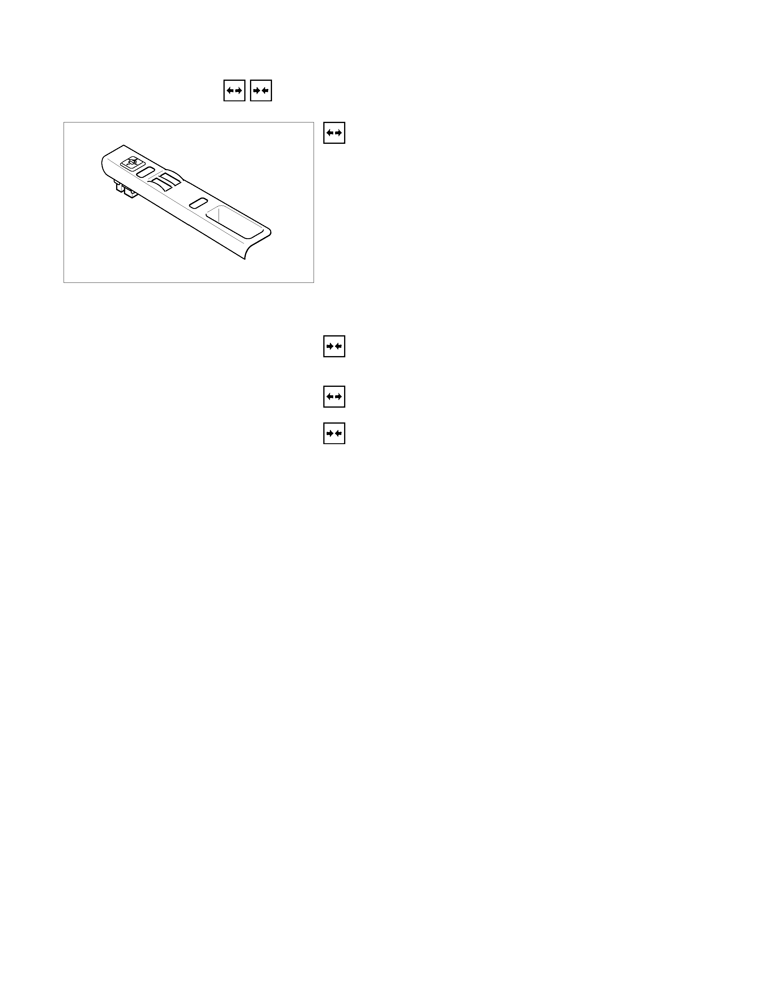
REMOVAL AND INSTALLATION
DOOR MIRROR CONTROL SWITCH
Removal
1. Disconnect the battery ground cable.
2. Door trim pad Assembly
• Refer to section 10 “BODY” for door trim pad assembly
removal steps.
3. Door Mirror Control Switch
Remove the power window switch bezel.
• Remove the screw.
• Disconnect the switch connector.
• To remove the switch panel assembly.
Installation
To install, follow the removal steps in the reverse order.
DOOR MIRROR
Removal and Installation
Refer to the DOOR MIRROR in section 10 “BODY”.
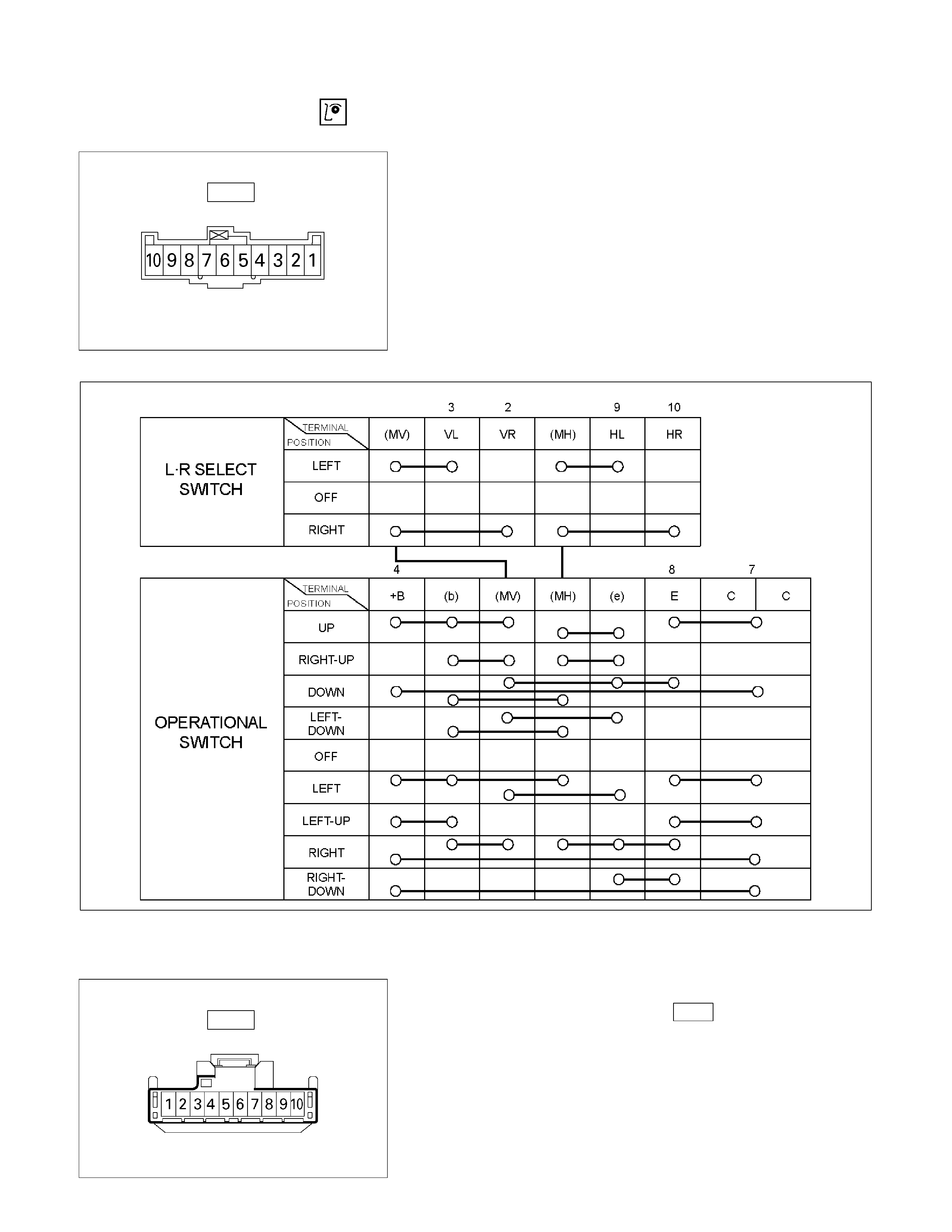
INSPECTION AND REPAIR
Switch side
D-19
Door Mirror Control Switch
1. Switch side Connector Circuit
Check continuity between the switch connector terminals
while operating the door mirror control switch as shown in
the following table.
RTW48AMF000601
MV, MH, b, and e terminals have internal connections (circuitry).
4-point switch (Will not operate at intermediate positions.)
Harness side
D-19
2. Harness Side Connector Circuit
Remove the connector No. D-19 of the mirror control
switch and check voltage and continuity of the harness side
connector.
• When there is no continuity at the terminal No. 2, 3, 9
and 10, it is considered that the circuit with terminal No.
7 (W/B) is defective.

• When there is no continuity at either one of the circuit
No, 5, 7, 8, or 10, the motor in the mirror of the circuit o
r
the circuit itself is defective.
Terminal
No. Wire
color Connection to Check item Connecting
terminal Check condition Standard
7 W/B
LH mirror & RH
mirror Continuity 7-Ground - No continuity
4 R/Y Fuse C-11 (10A) Voltage 4-Ground Starter SW “ACC”
position Approx.
12V
10 W/R RH mirror-LH/RH 10-7 -
2 B/W RH mirror-Up/Down 2-7 -
3 B/R LH mirror-Up/Down Continuity 3-7 - Continuity
8 B Ground 8-Ground -
9 W/G LH mirror-LH/RH 9-7 -
Harness side
D-19
Door Mirror
1. Door Mirror Control Switch Connector Circuit
Disconnect the switch connector D-19 , apply the battery
voltage to the harness side connector terminals and check
its function.
Connector
No. D-19
Operating
Terminal
Mirror No. 9 10 7 3 2 direction
+ - Left
- + Right
- +Up
+ -Down
+ - Left
- + Right
- + Up
+ - Down
Left
Right
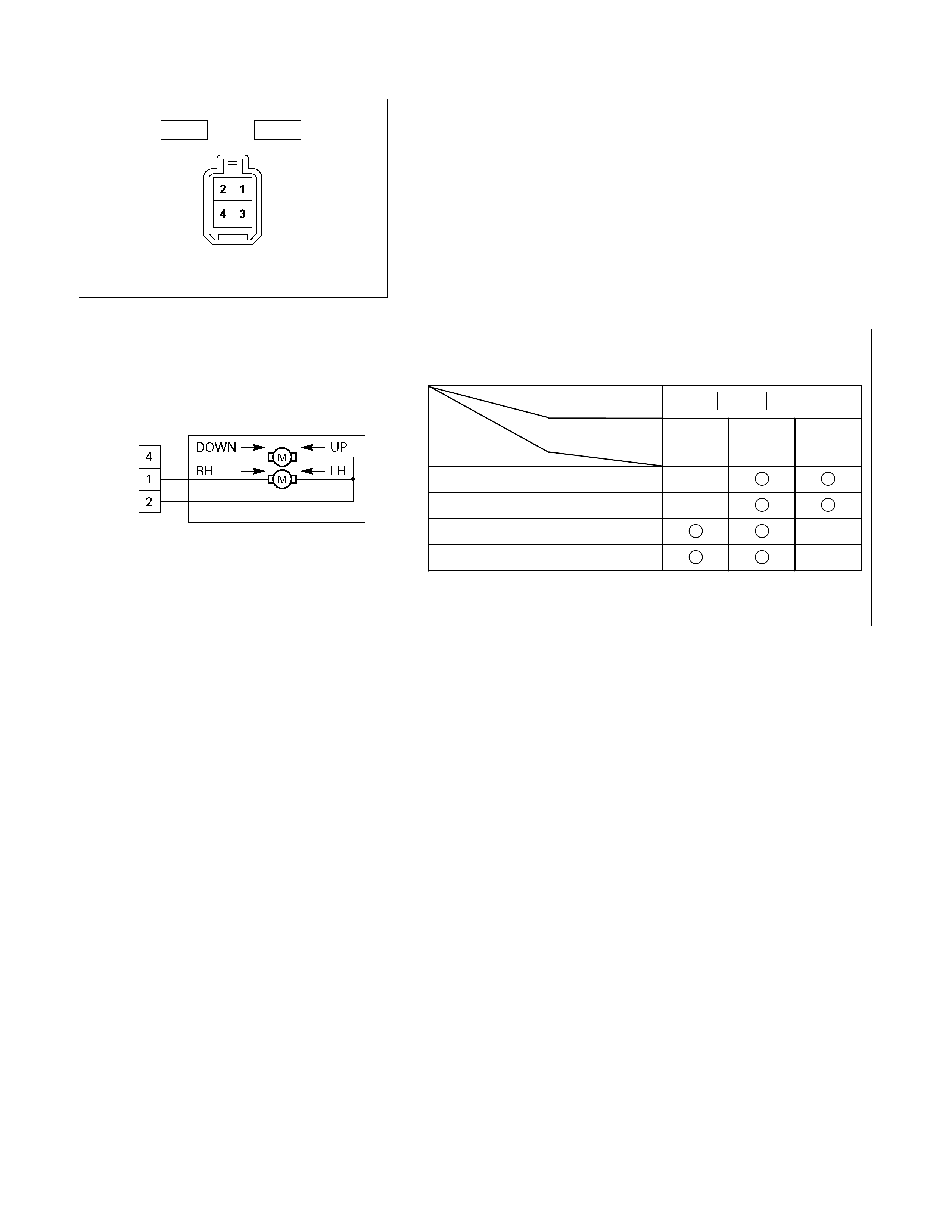
Door mirror side
D-2 D-7
2. Door Mirror Connector Circuit
Disconnect the door mirror connector, apply the battery
voltage to the door mirror side connector ( D-2 and D-7 )
terminals and check its function.
Connector No. D-2 D-7
Terminal No.
Operation 1 2 4
Up
- +
Down
+ -
Left + -
Right - +
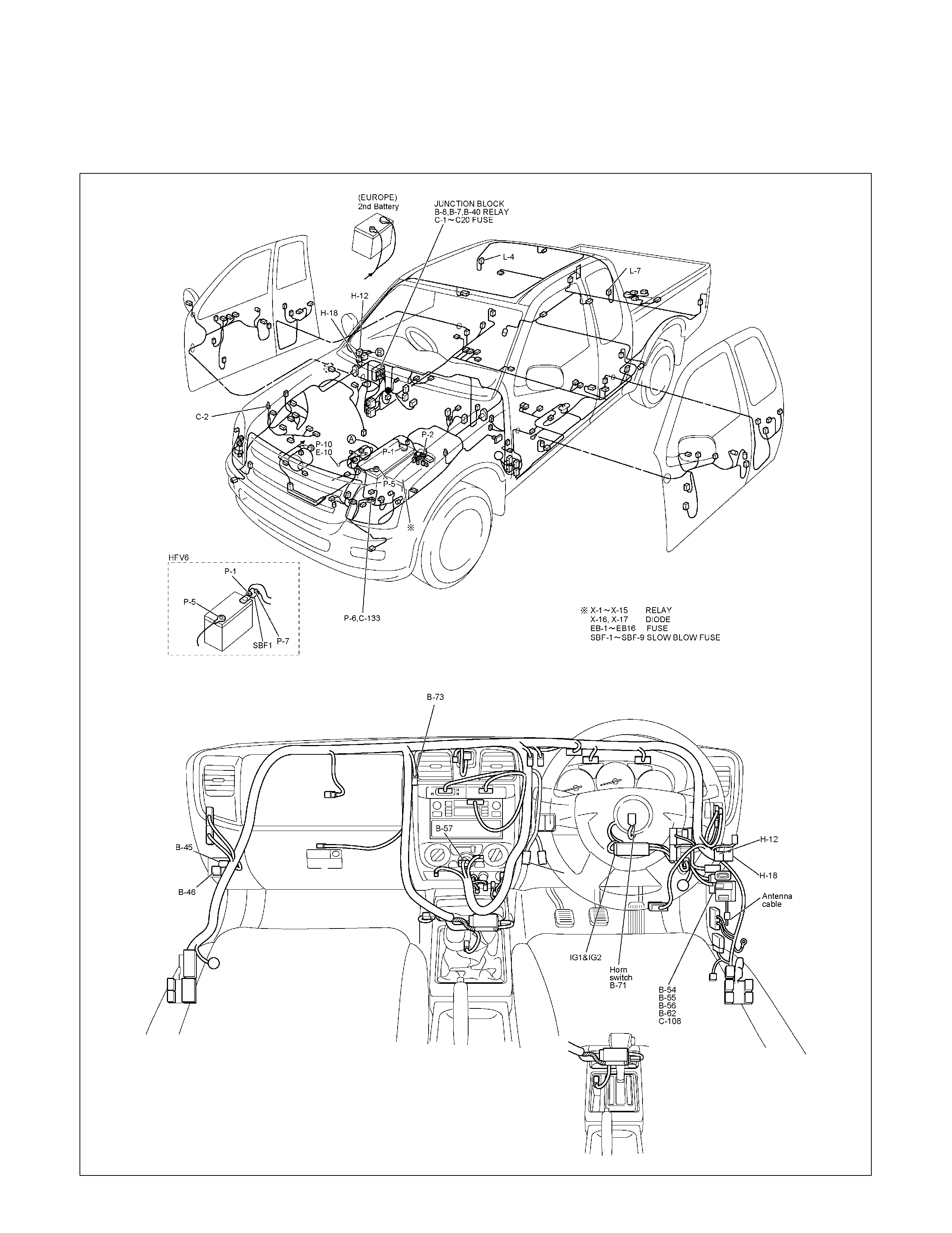
REAR DEFOGGER
PARTS LOCATION (RHD)
RTW68AXF016401 & RTW68AXF016501
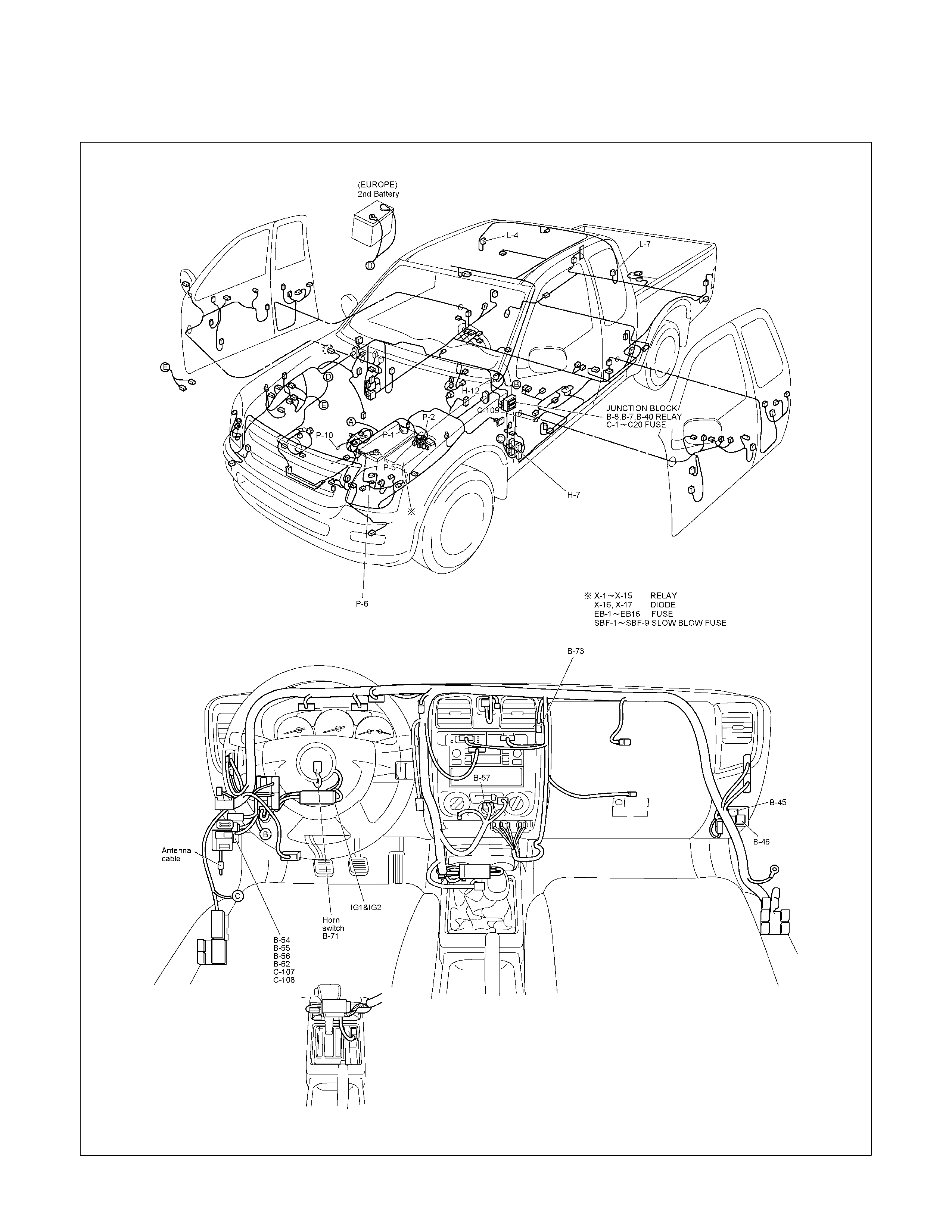
PARTS LOCATION (LHD)
RTW48AXF021001 & RTW48AXF021101

CIRCUIT DIAGRAM EXCEPT HFV6 (RHD)
RTW680XF013801
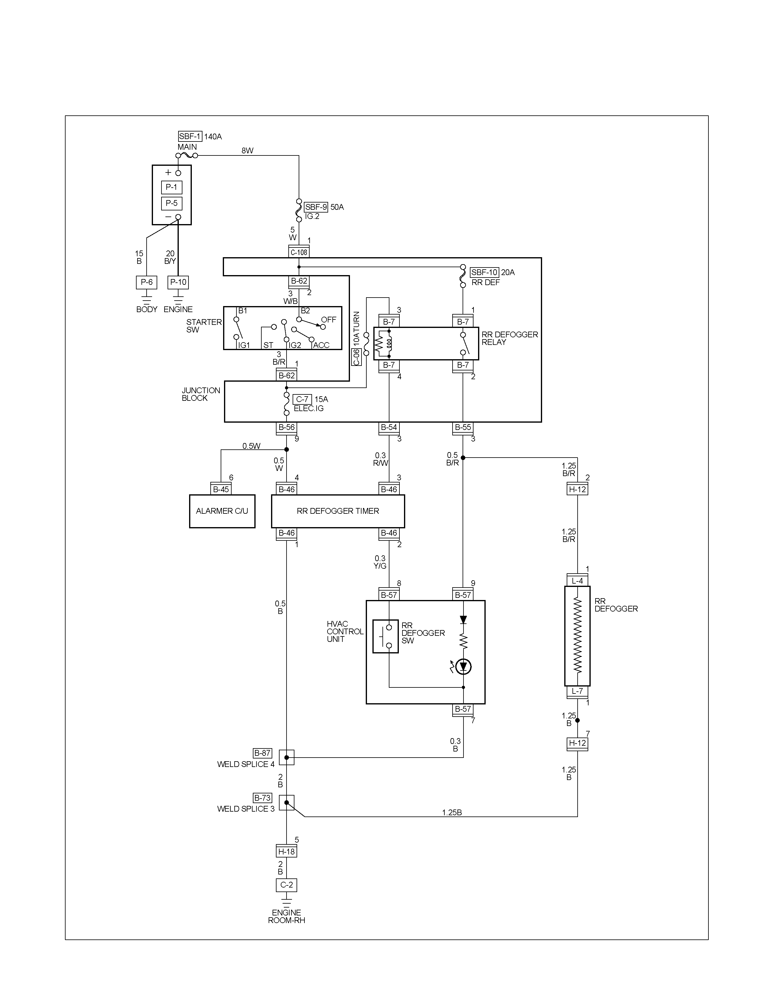
CIRCUIT DIAGRAM HFV6 (RHD)
RTW68AXF012401
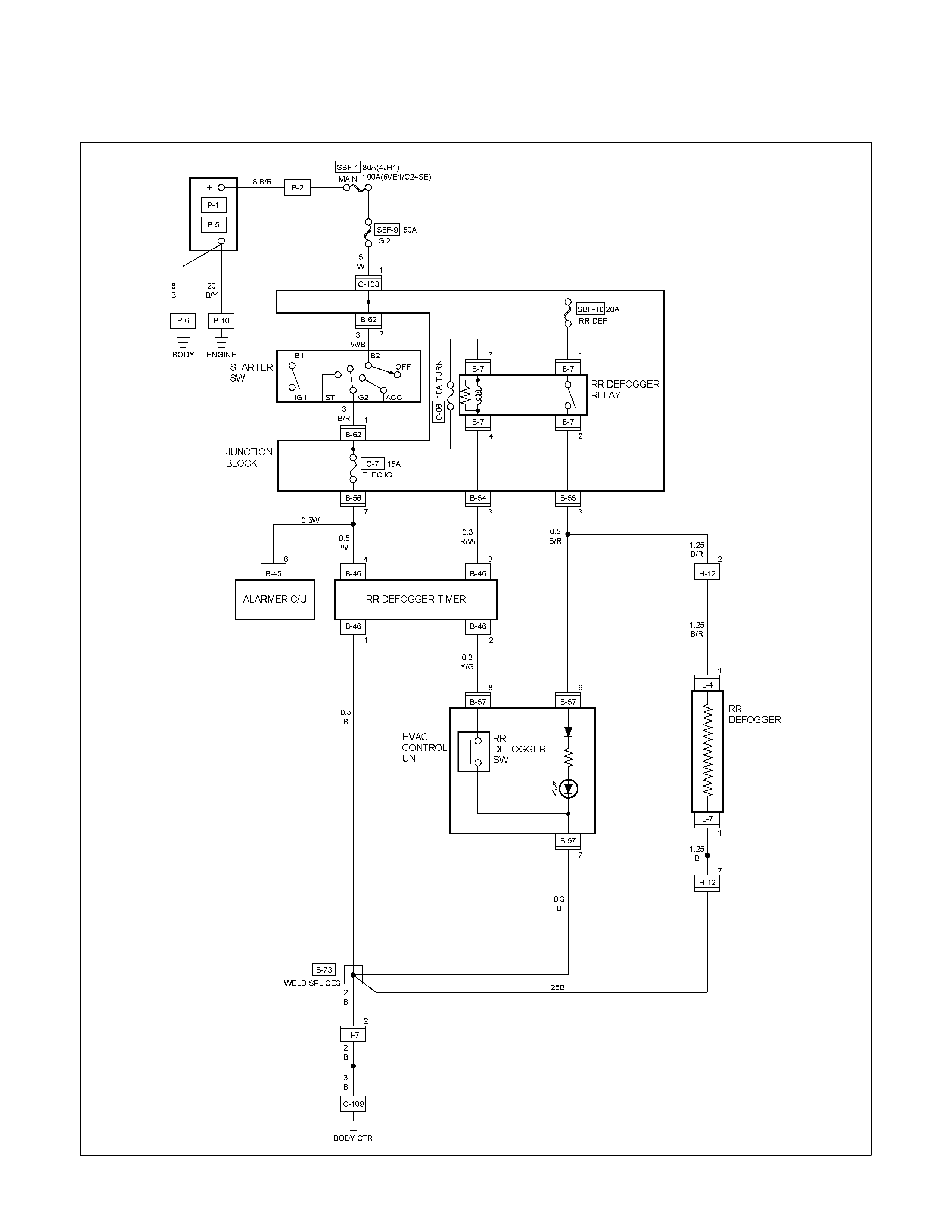
CIRCUIT DIAGRAM (LHD)
RTW680XF013901

TROUBLE SHOOTING
Rear defogger inoperative
Checkpoint Trouble Cause Countermeasure
Reinstall or replace the fuse
No. C-7 (15A) and 9 B-56
Poor fuse contact or blown
NG
Reinstall or replace the fuse
SBF-10 (20A)
SBF-10 (20A, Fuse box)
Poor fuse contact or blown
Replace the rear defogger
switch
Rear defogger switch function
Switch malfunction
NG
NG
OK
OK
OK
Fuse No. C-7 (15A, Fuse box)
and 9 B-56
Replace the rear defogger
relay
Relay malfunction
NG
Continued on the next page
Rear defogger relay function
Repair grounding point contact
Grounding point C-2 (RHD),
C-109 (LHD)
Poor grounding point contact
NG
OK
Repair open circuit or poor
connector contact between
fuse No. C-7 (15A) and 3
B-7 , SBF-10 (20A) and 1
B-7 , 2 B-7 (3 B-55 ) and
1 L-4 , 4 B-7 (3 B-54 )
and 3 B-46 or 1 B-46 and
C-2 (RHD),
C-109 (LHD)
Voltage between 1 L-4 -
ground when the starter switch
and the rear defogger switch
are at on position (should be
battery voltage present)
Open circuit or poor connector
contact
NG
OK
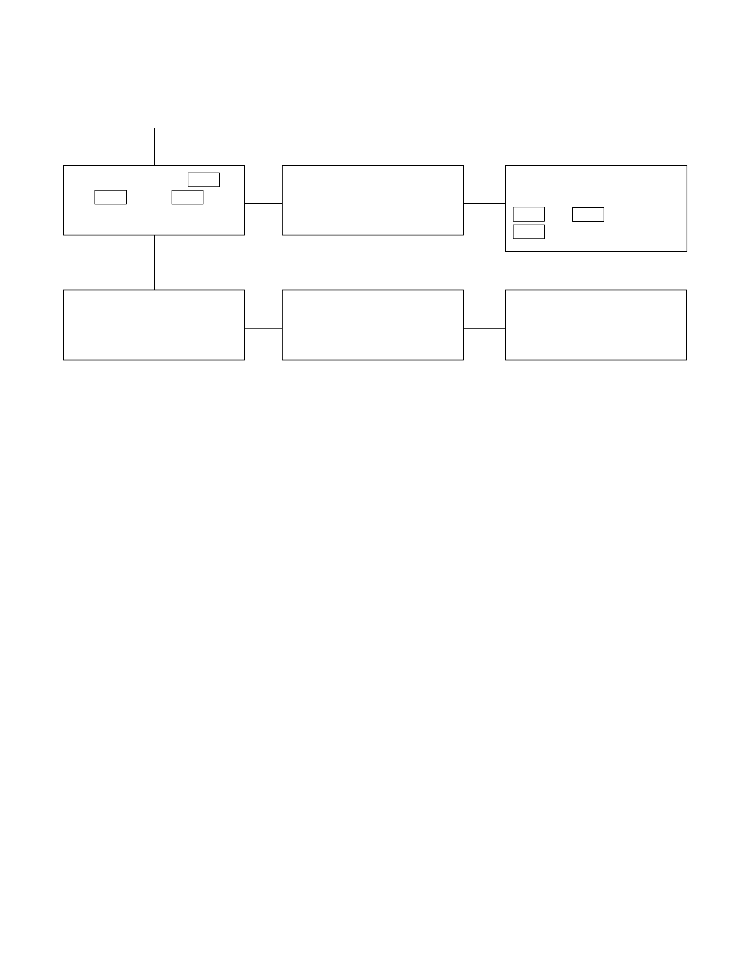
Checkpoint Trouble Cause Countermeasure
OK
Repair open circuit or
connector contact between 1
L-7 and C-2 (RHD),
C-109 (LHD)
Open circuit or poor connector
contact
NG
Continued from the previous page
Continuity between 1 L-7
and C-2 (RHD),
C-109
(LHD)
Repair heat wire
Continuity between rear
defogger terminals
Broken heat wire of rear
defogger
NG
OK
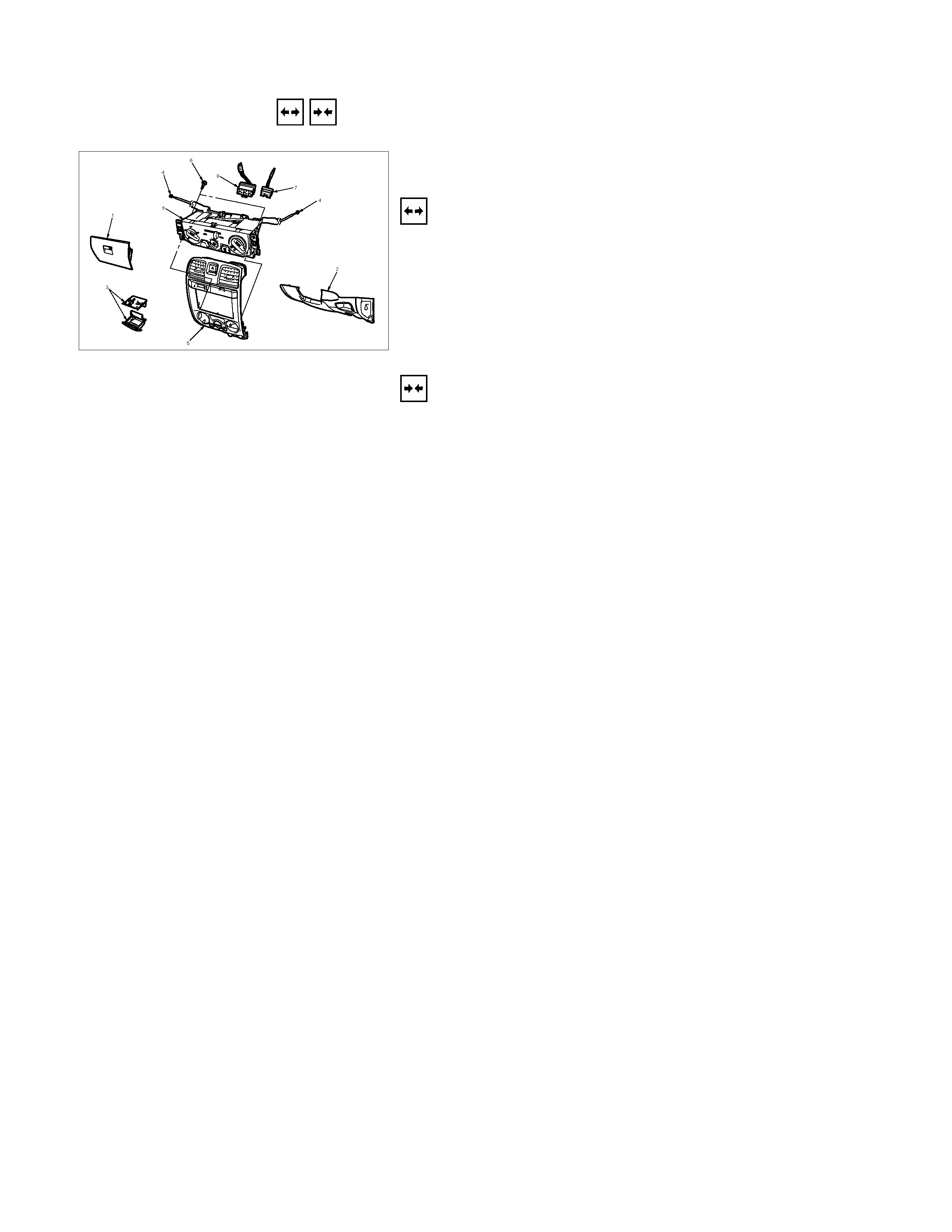
REMOVAL AND INSTALLATION
865R300008
REAR DEFOGGER SWITCH
Removal
1. Instrument Panel Cluster Assembly
• Refer to Section 10 “BODY” for center cluster panel
assembly removal steps.
2. Rear Defogger Switch (With HVAC control unit)
Refer to Section 1 “HVAC” HVAC control unit assembly
removal steps.
Installation
Follow the removal procedure in the reverse order to install the
rear defogger switch.
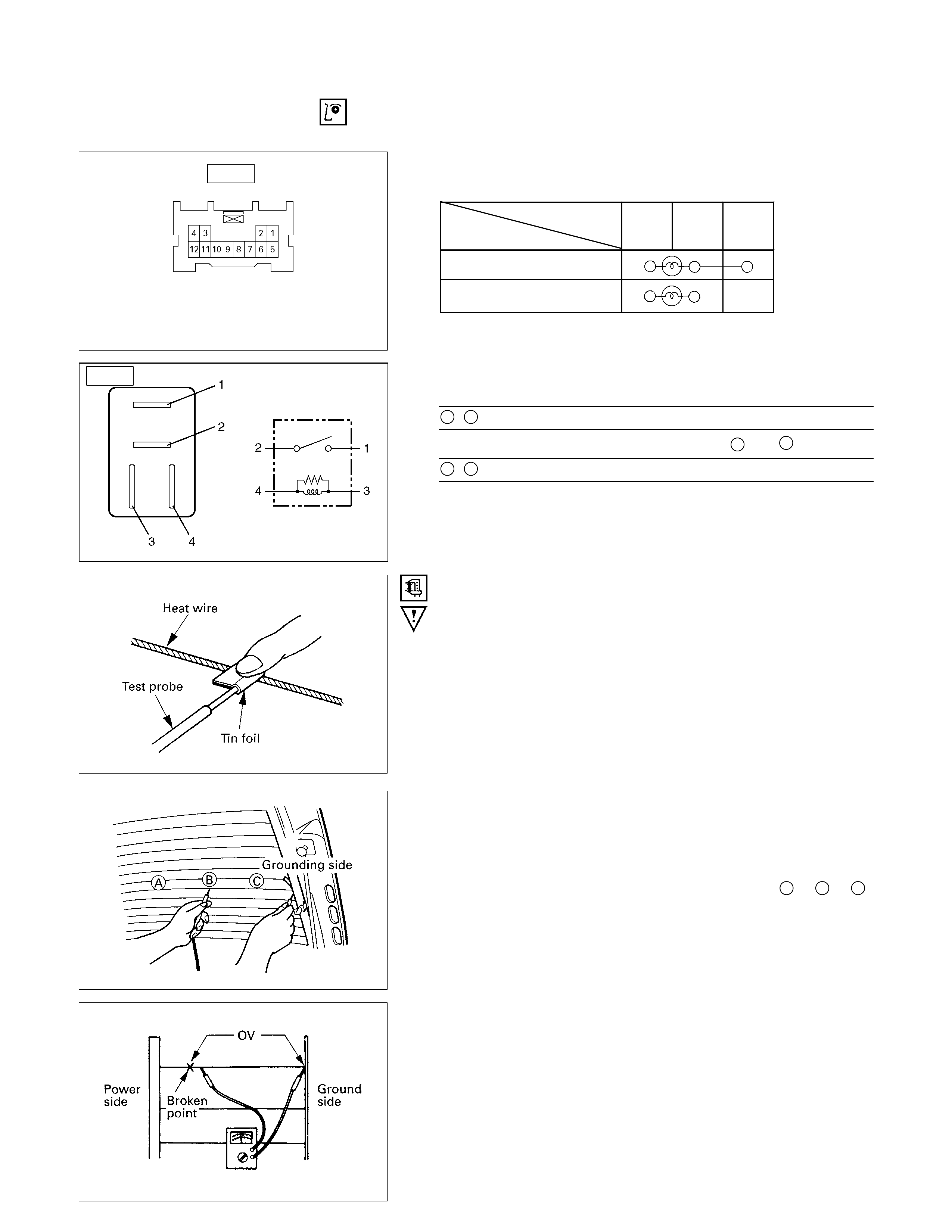
INSPECTION AND REPAIR
Switch side
B-57
REAR DEFOGGER SWITCH
Rear Defogger Switch Connections
Terminal No.
SW position 9 7 8
ON
OFF
B-7
REAR DEFOGGER RELAY
Check continuity between the relay terminals.
2- 1........................ No continuity
(When battery voltage is applied between 4 and 3)
2- 1........................ Continuity
INSPECTION OF REAR DEFOGGER HEAT
WIRE
• Heat wires are printed on the inner side of glass.
To clean, use a soft cloth and wipe horizontally along the
wires.
• Never use glass cleaner or equivalent.
• When measuring voltage, wind a piece of tin foil around the
tip of the negative probe and press the foil against the wire
with your finger as shown.
(1) Turn the ignition switch on.
(2) Turn the defogger switch on.
(3) Measure the voltage between the three points on the heat
wire and the (-) terminal with a voltmeter.
(4) Check that the voltage becomes smaller from A to B to C.
(5) If there is a place where the voltage suddenly changes to
0V, there is a broken wire between there and the powe
r
side.
(6) Move the tester probe from the position where the voltage
changes to 0V toward the power side and find where the
voltage suddenly increases.
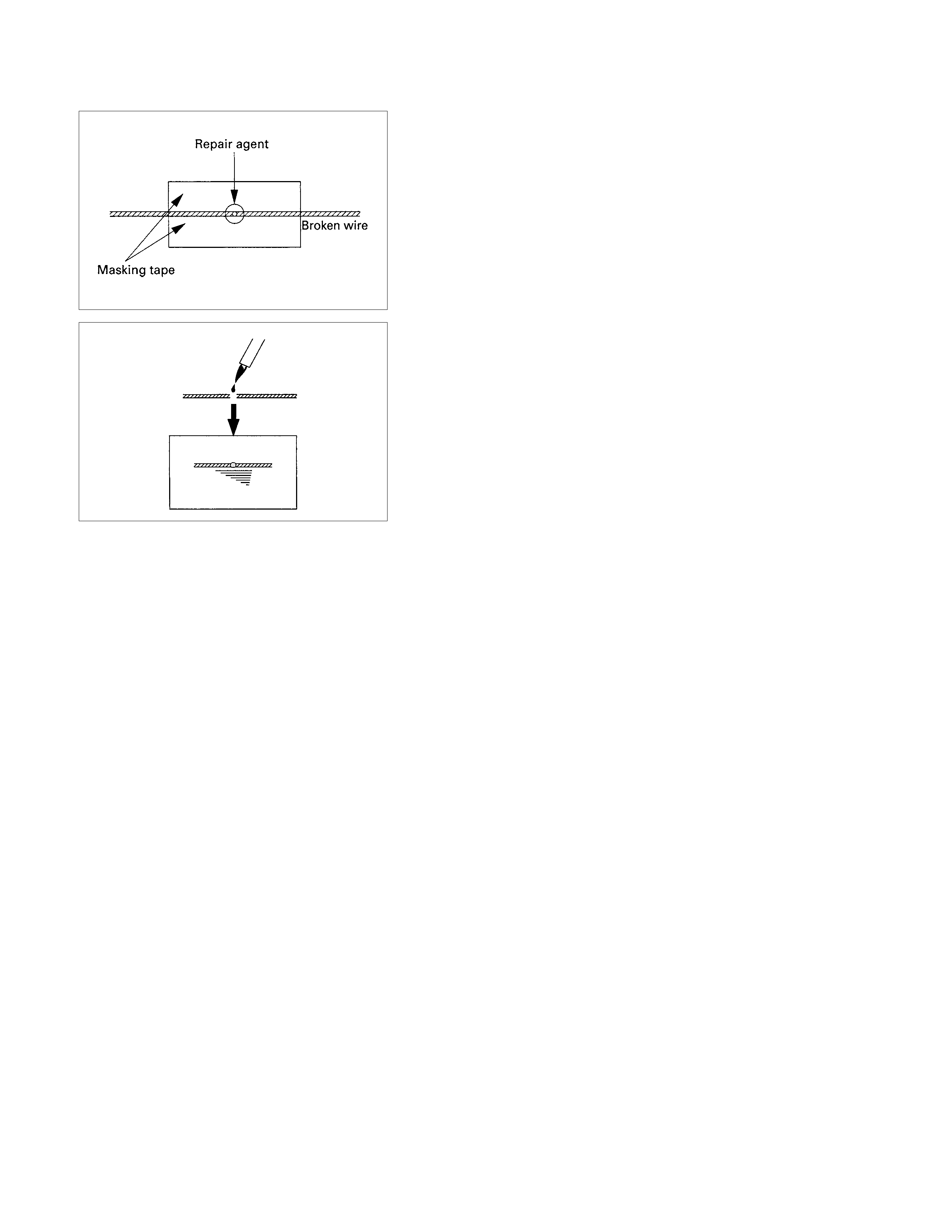
REPAIR OF BROKEN HEAT WIRE
(1) Clean broken wire tips with white gasoline.
(2) Place masking tape along both sides of wire to be repaired.
(3) Thoroughly mix the repair agent (Dupont paste No. 4817 o
r
equivalent).
(4) Using a fine tip brush, apply a small amount to the wire.
(5) After a couple of minutes, remove the masking tape.
(6) Allow to stand at least 24 hours.
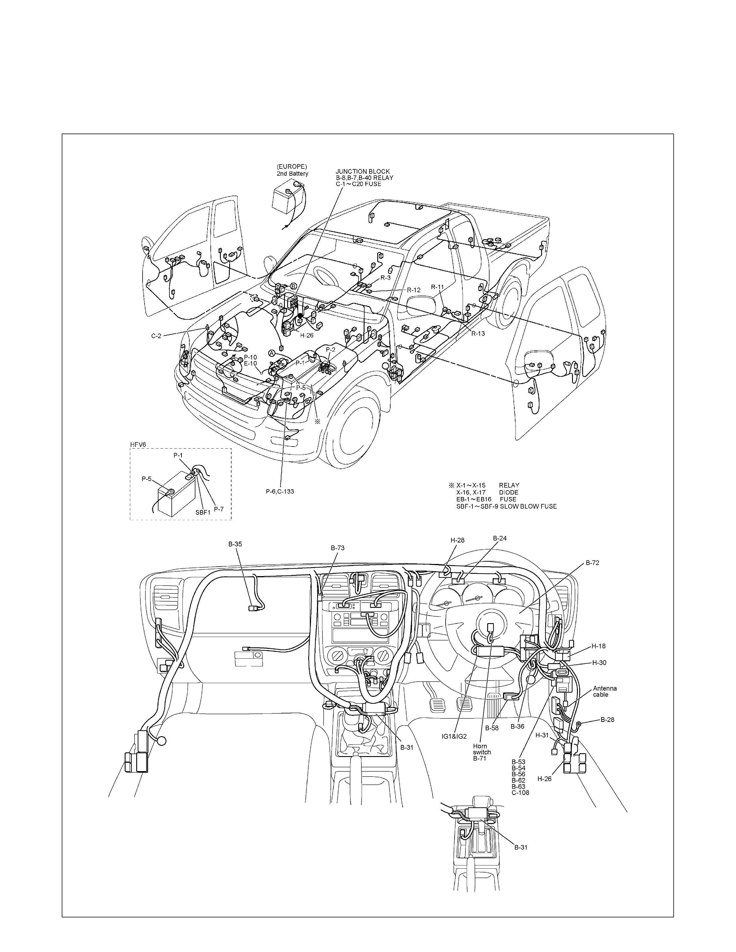
SRS-AIR BAG
PARTS LOCATION (RHD)
RTW68AXF016601 & RTW68AXF016701
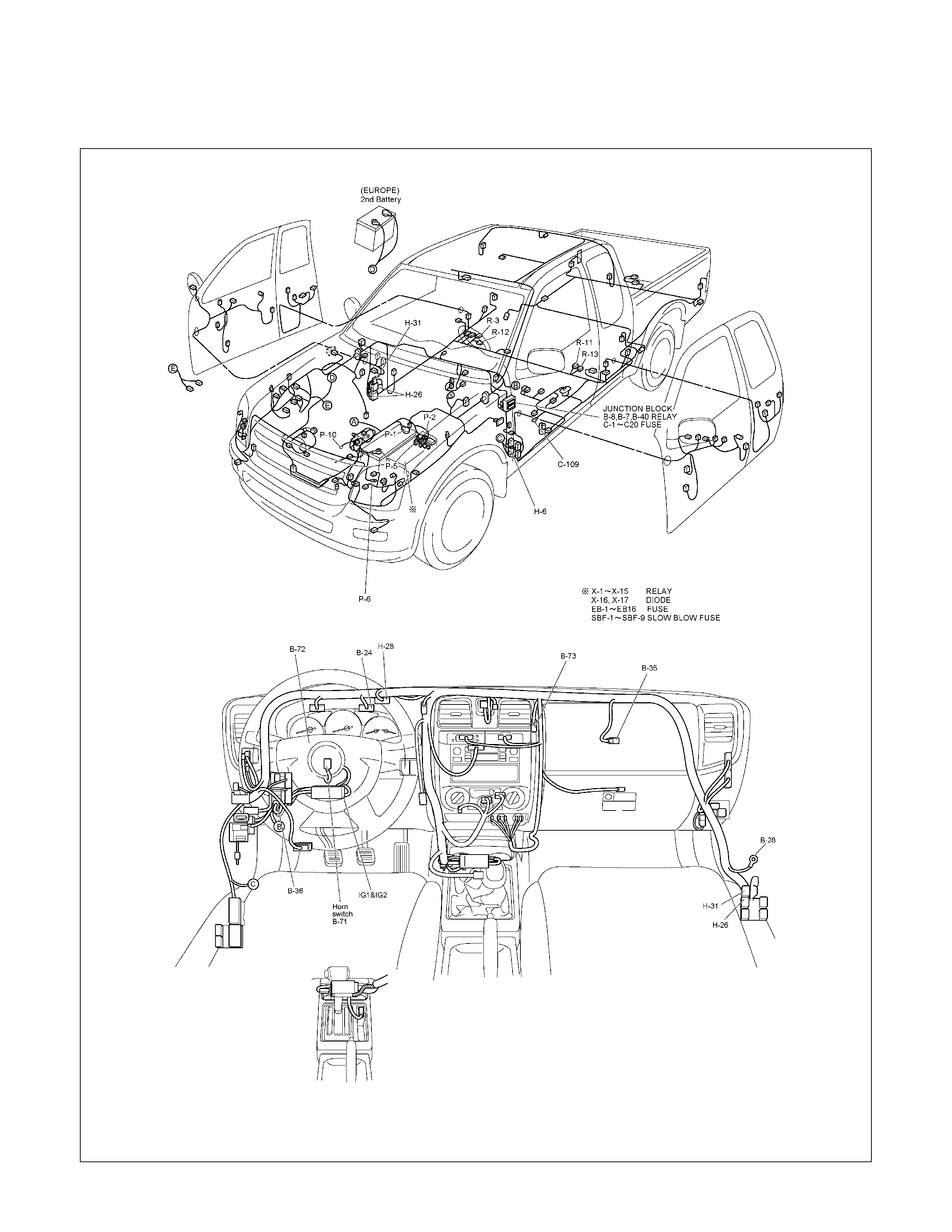
PARTS LOCATION (LHD)
RTW48AXF021401 & RTW48AXF021501
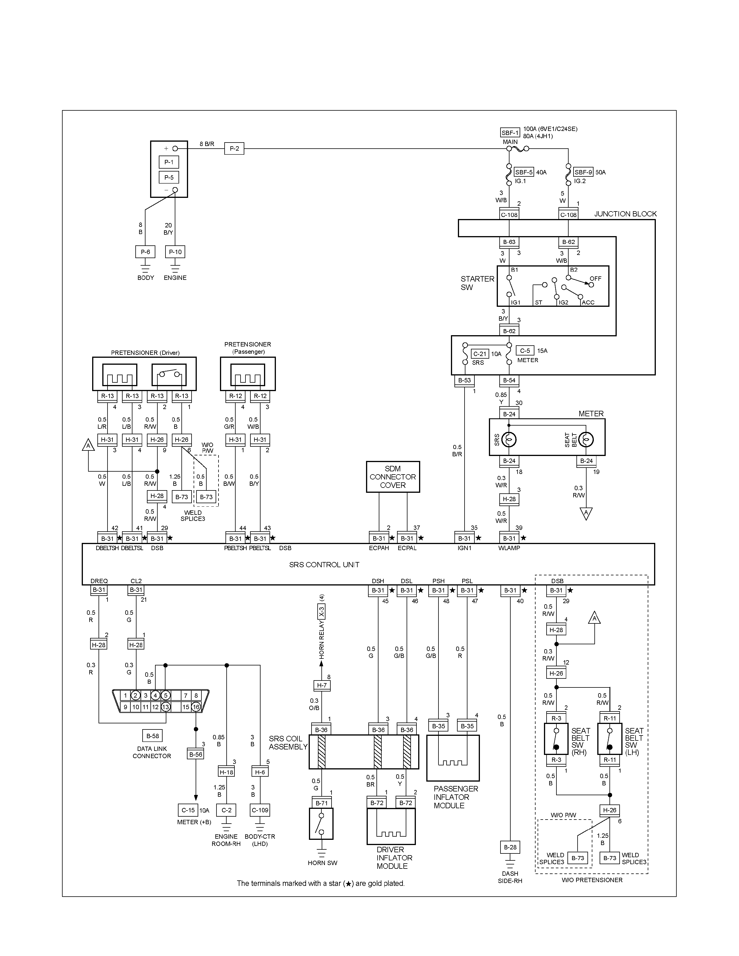
CIRCUIT DIAGRAM EXCEPT HFV6
RTW680XF014001
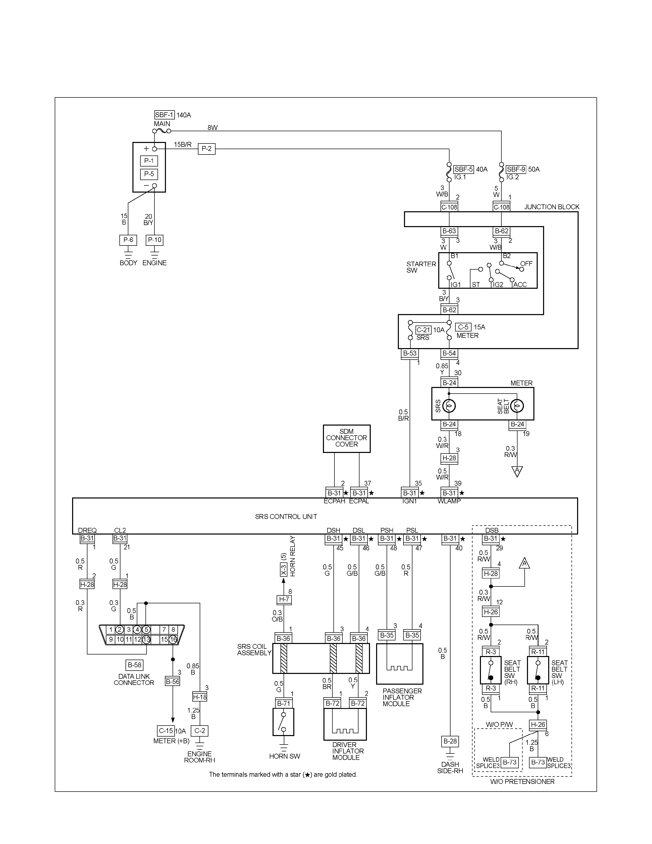
CIRCUIT DIAGRAM HFV6
RTW68AXF012501
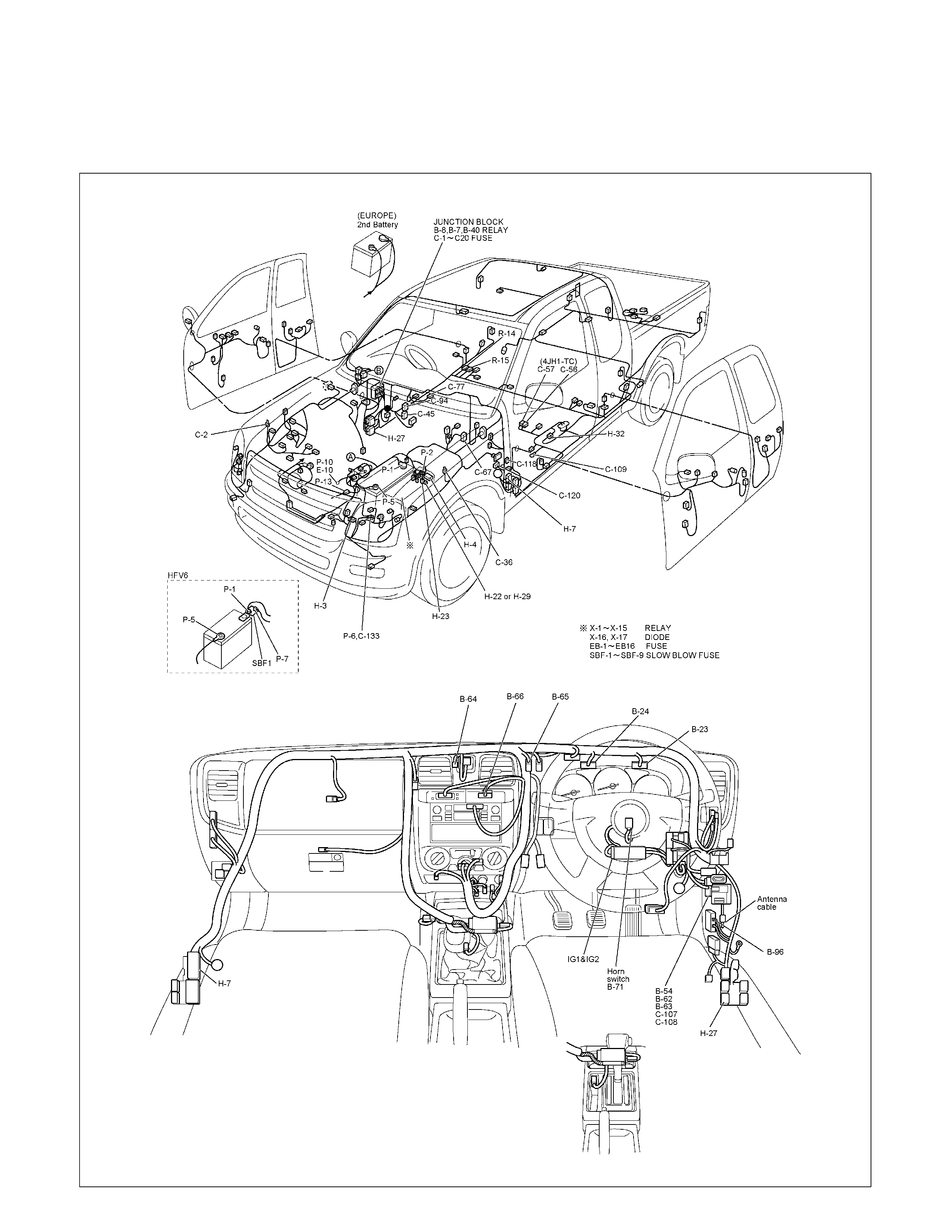
TRANSFER CASE CONTROL MODULE
PARTS LOCATION (RHD)
RTW68AXF016801 & RTW68AXF016901
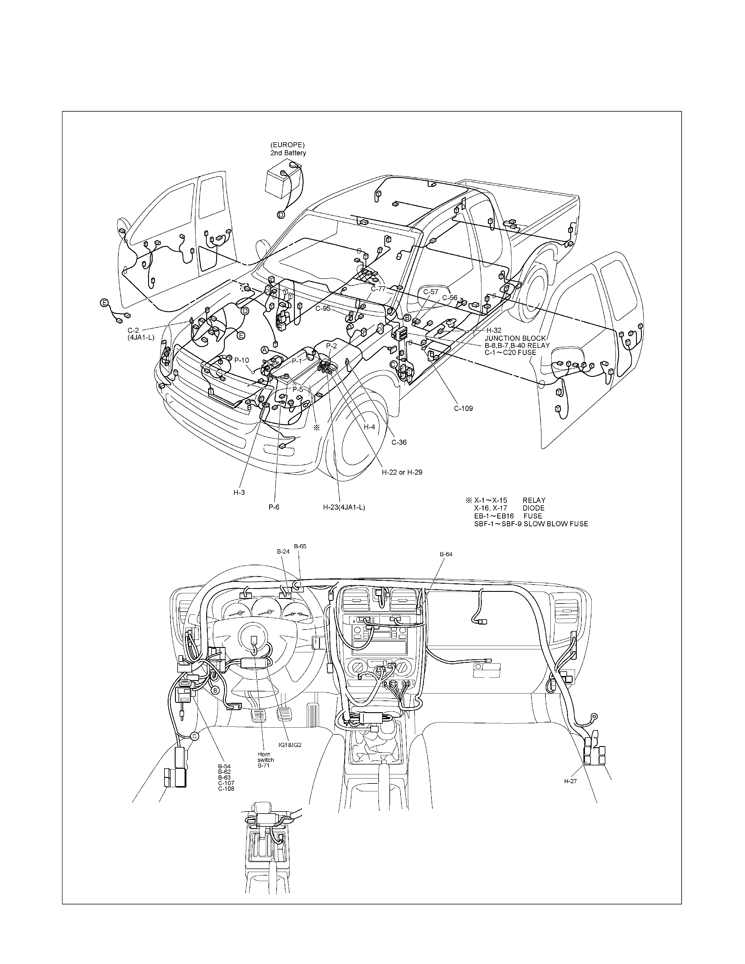
PARTS LOCATION (LHD)
RTW48AXF021901 & RTW48AXF022001
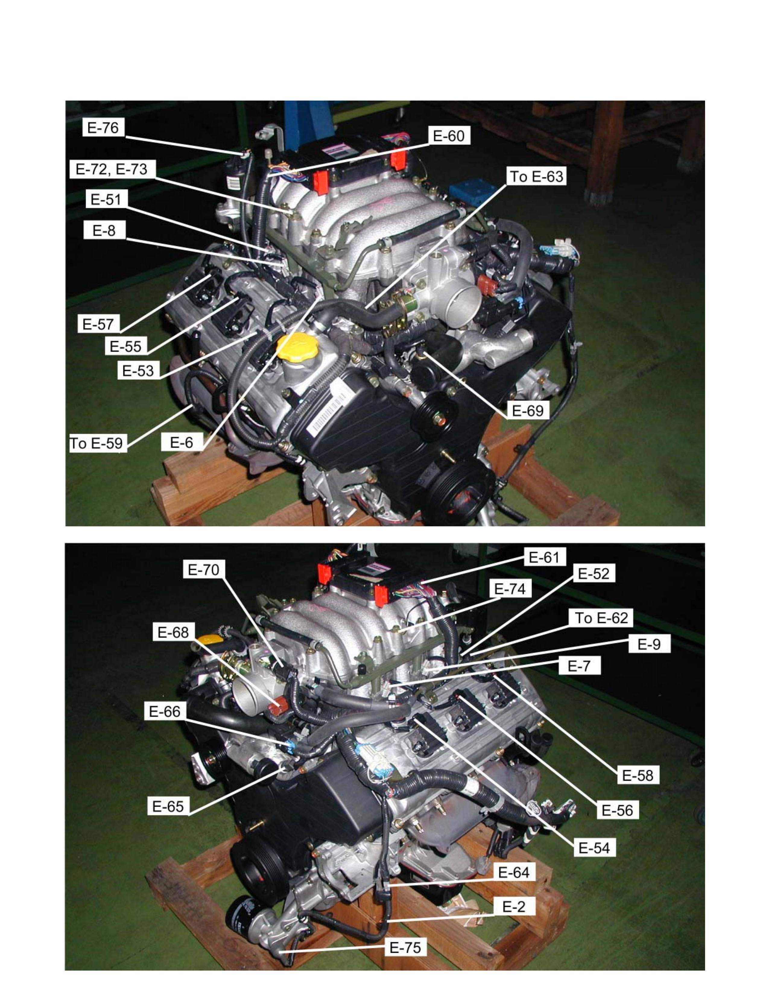
PARTS LOCATION 6VE1

PARTS LOCATION C24SE

PARTS LOCATION 4JA1-TC / 4JH1-TC
RTW38DXF007601

PARTS LOCATION 4JA1-TC / 4JH1-TC
RTW68AXF012201
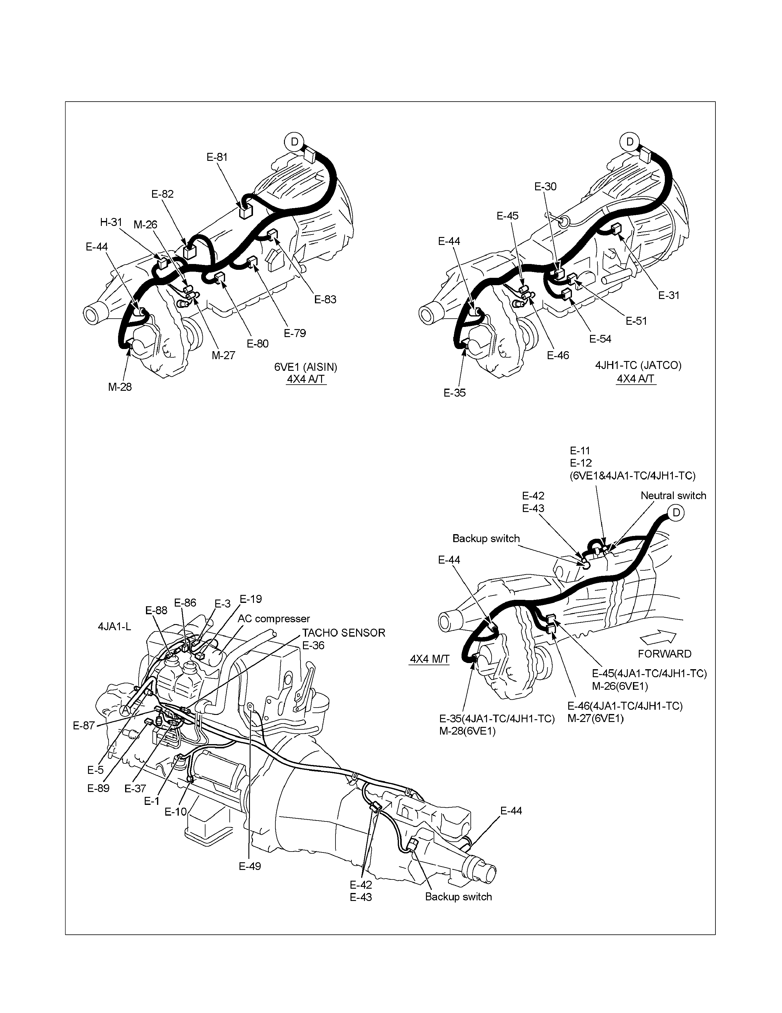
PARTS LOCATION
RTW48AXF021601
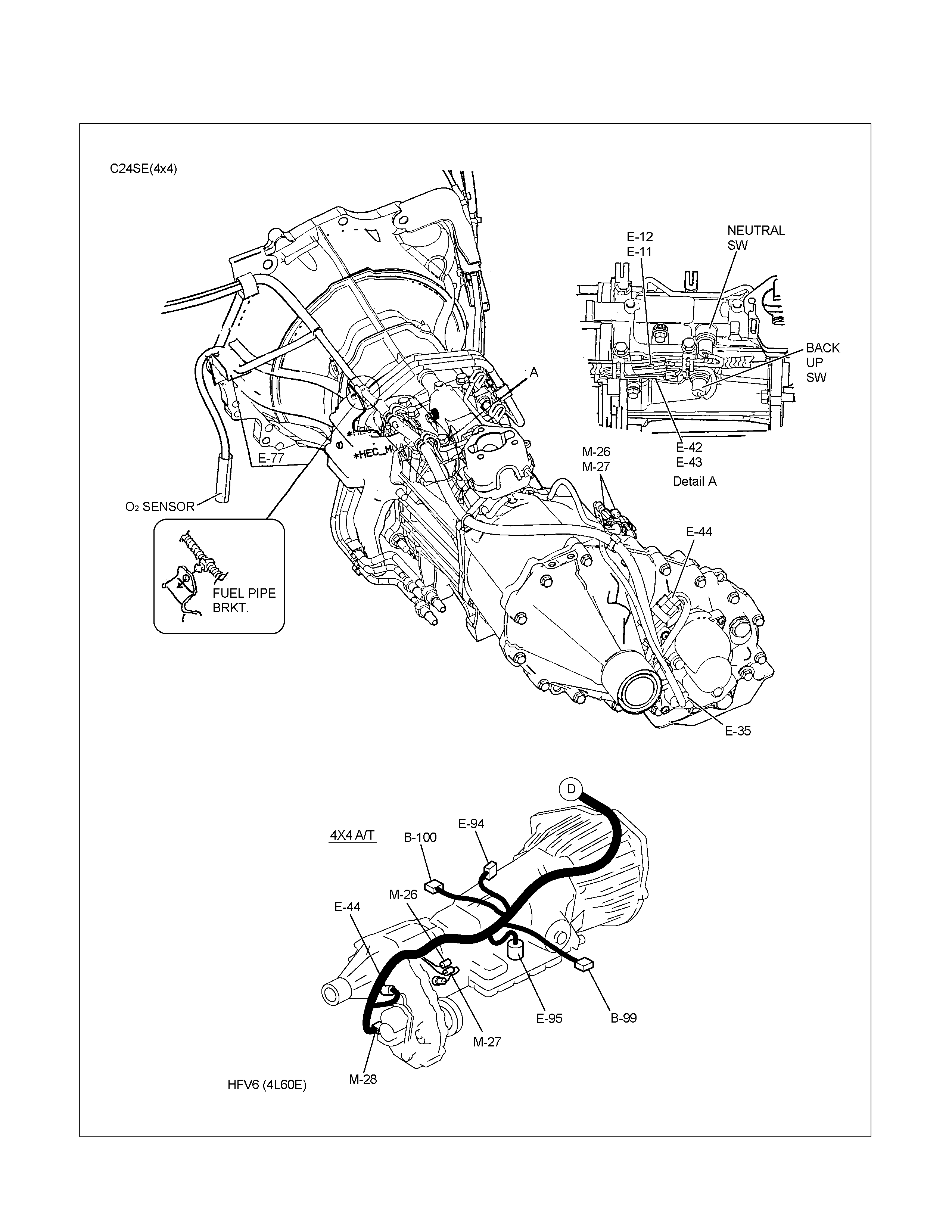
PARTS LOCATION
RTW68AXF018501
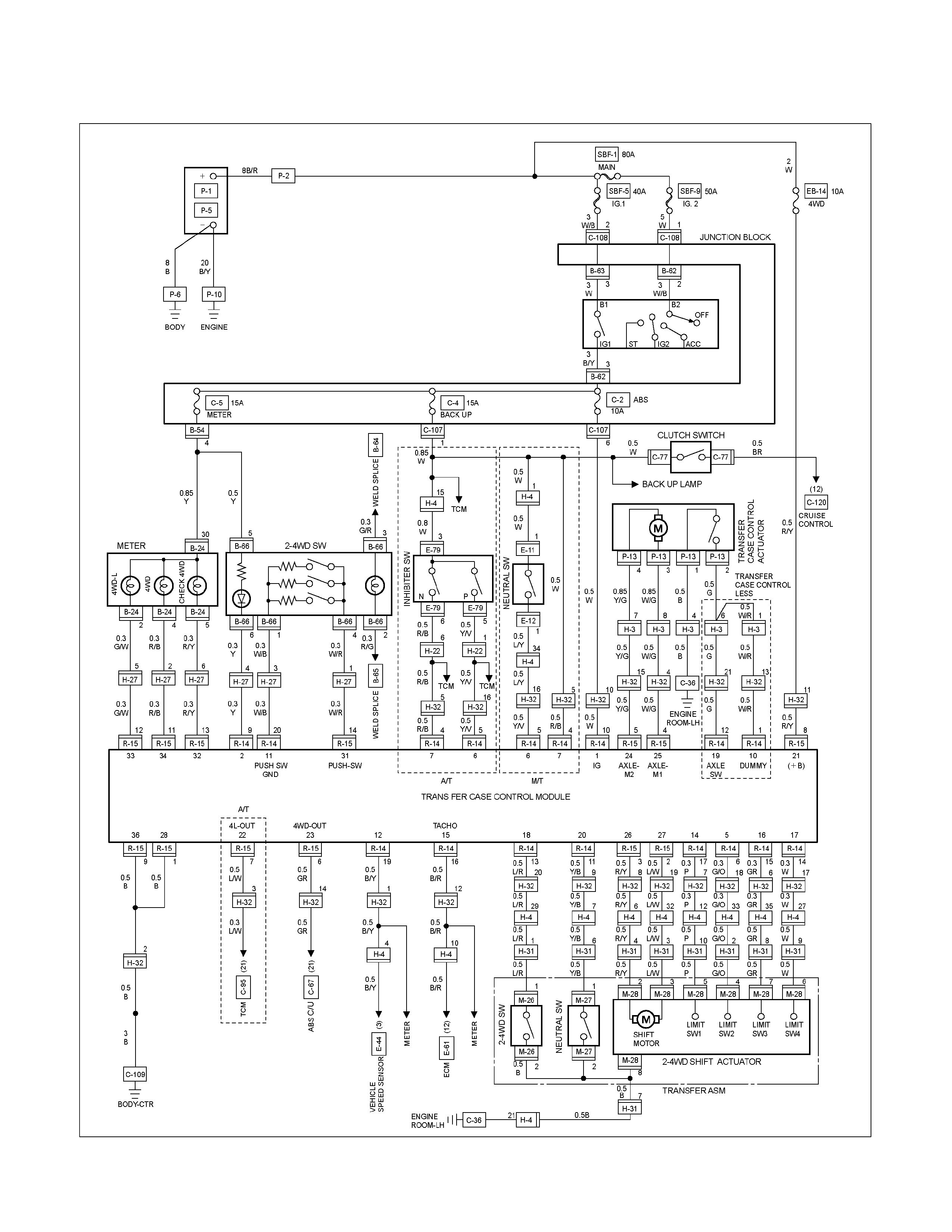
CIRCUIT DIAGRAM 6VE1
RTW680XF014101
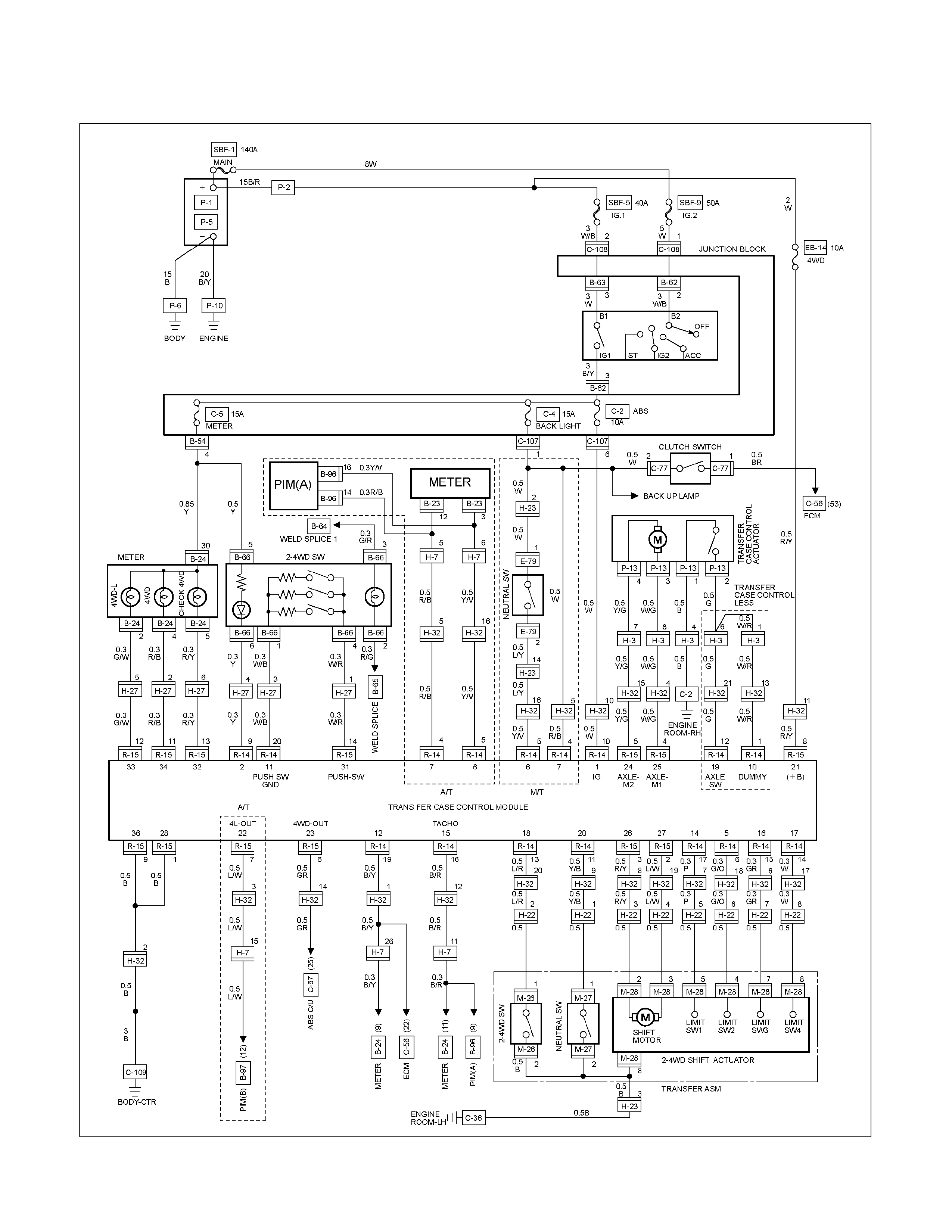
CIRCUIT DIAGRAM HFV6
RTW68AXF012601
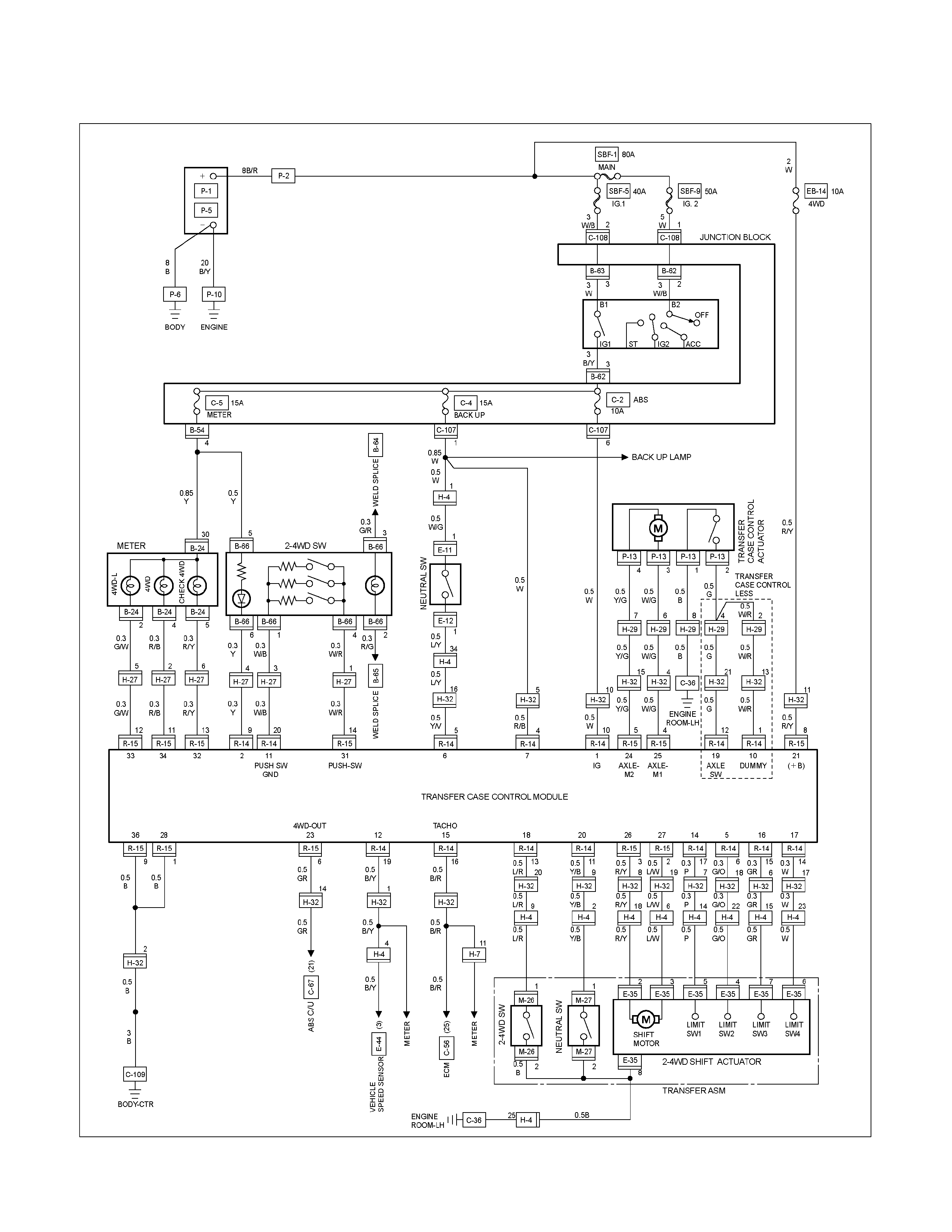
CIRCUIT DIAGRAM C24SE
RTW680XF014201
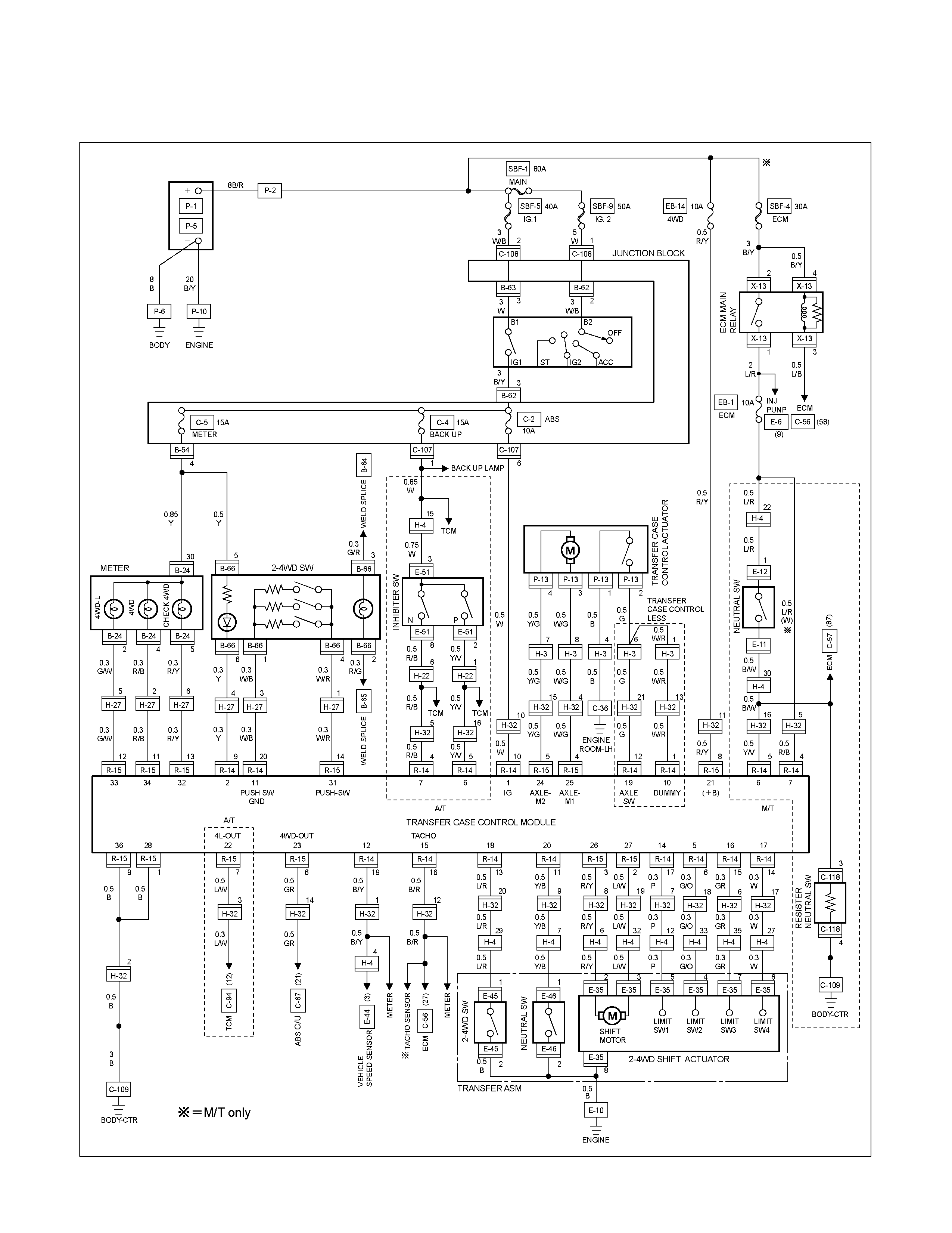
CIRCUIT DIAGRAM 4JA1-TC / 4JH1-TC
RTW680XF014301
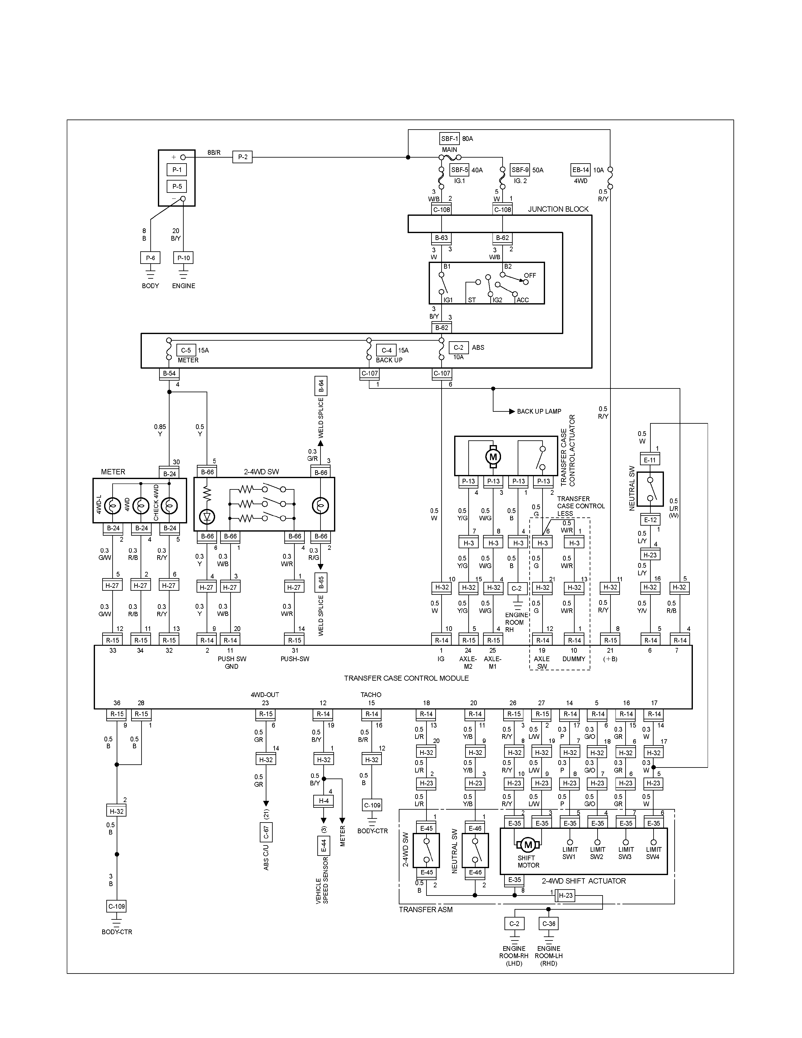
CIRCUIT DIAGRAM 4JA1-L
RTW680XF014401
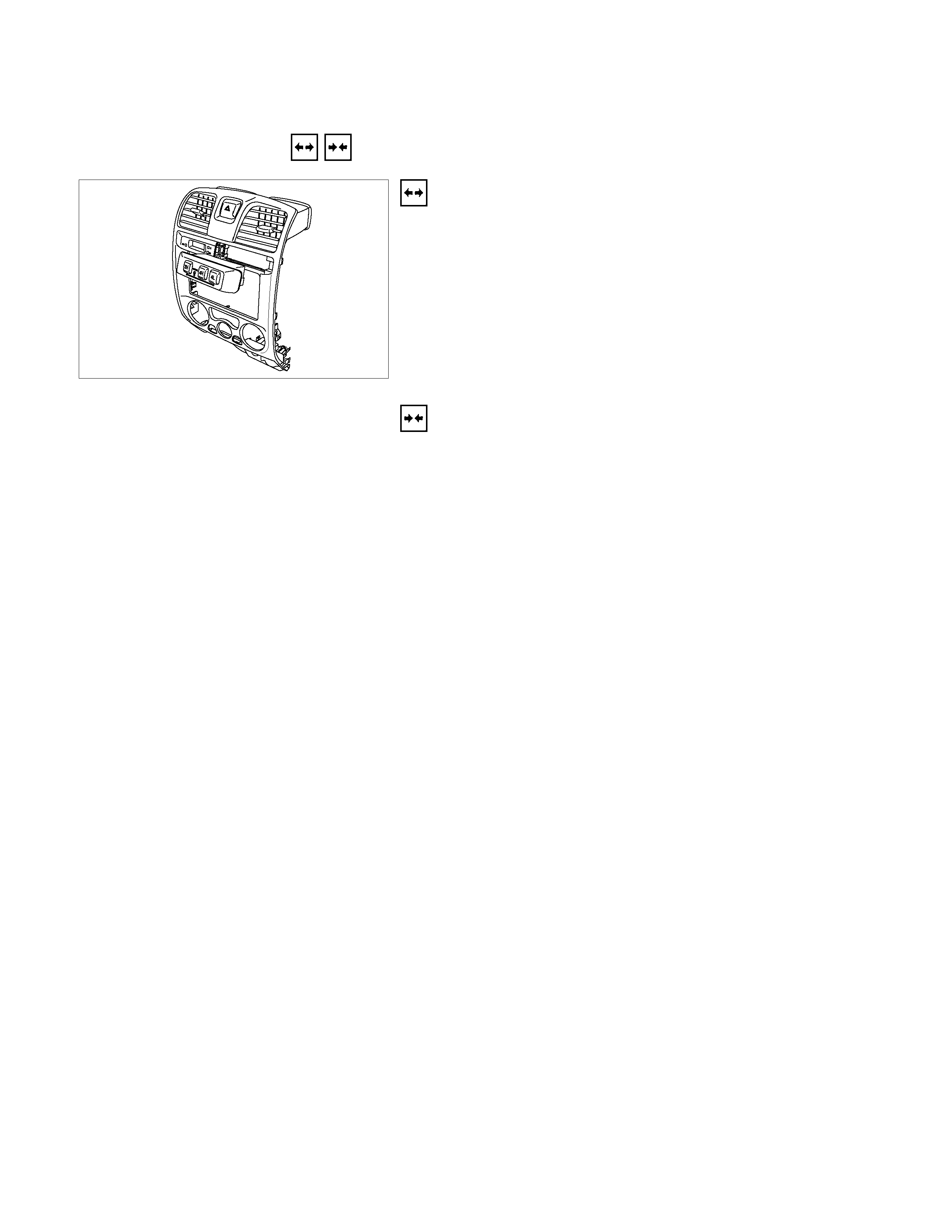
2WD-4WD Switch
REMOVAL AND INSTALLATION
825R300018
Removal
1. Remove the center cluster ASM
2. Disconnect the connector.
3. Remove the 2WD-4WD switch.
Installation
To install, follow the removal steps in the reverse order.
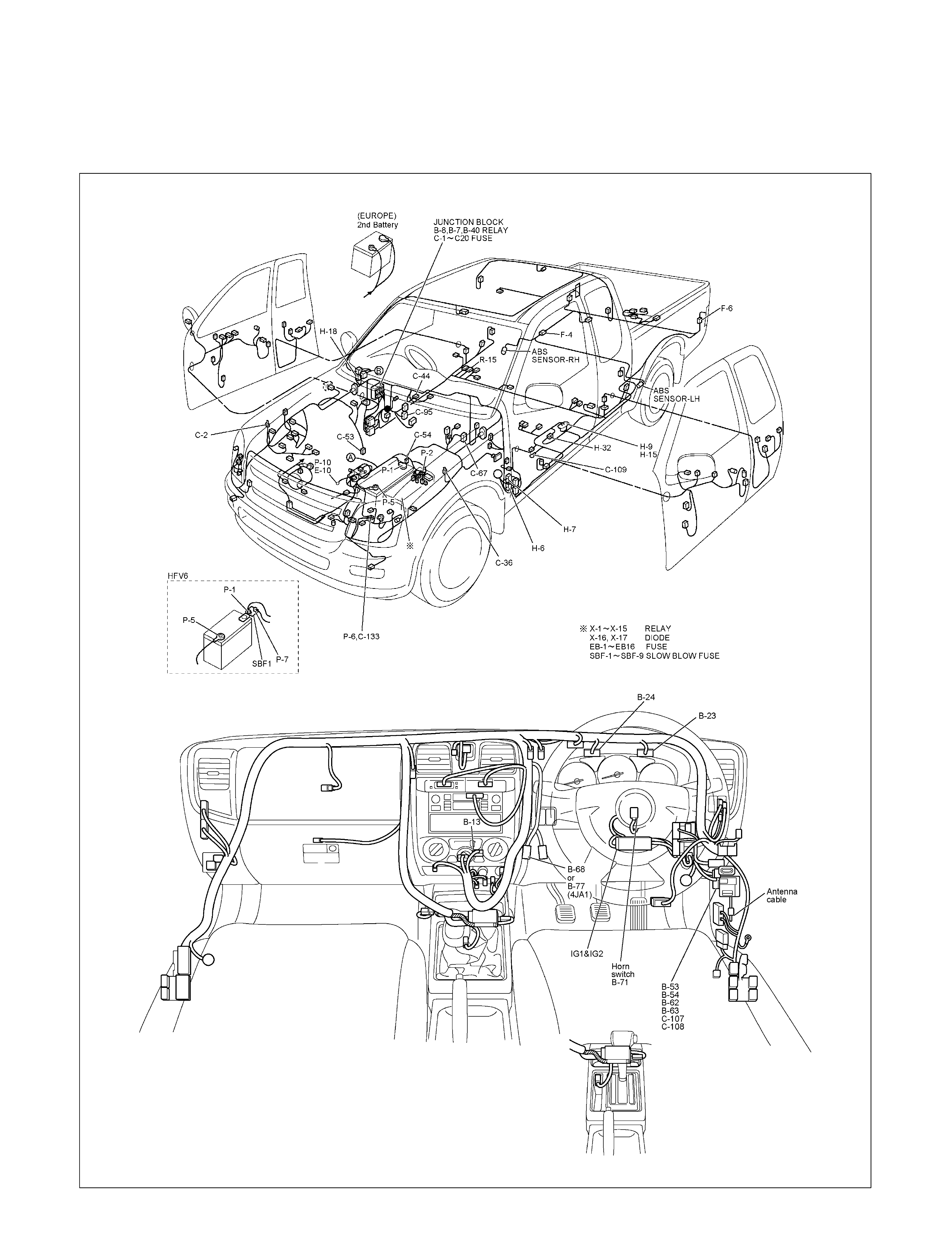
ANTI-LOCK BRAKE SYSTEM
PARTS LOCATION (RHD)
RTW68AXF017001 & RTW68AXF013901
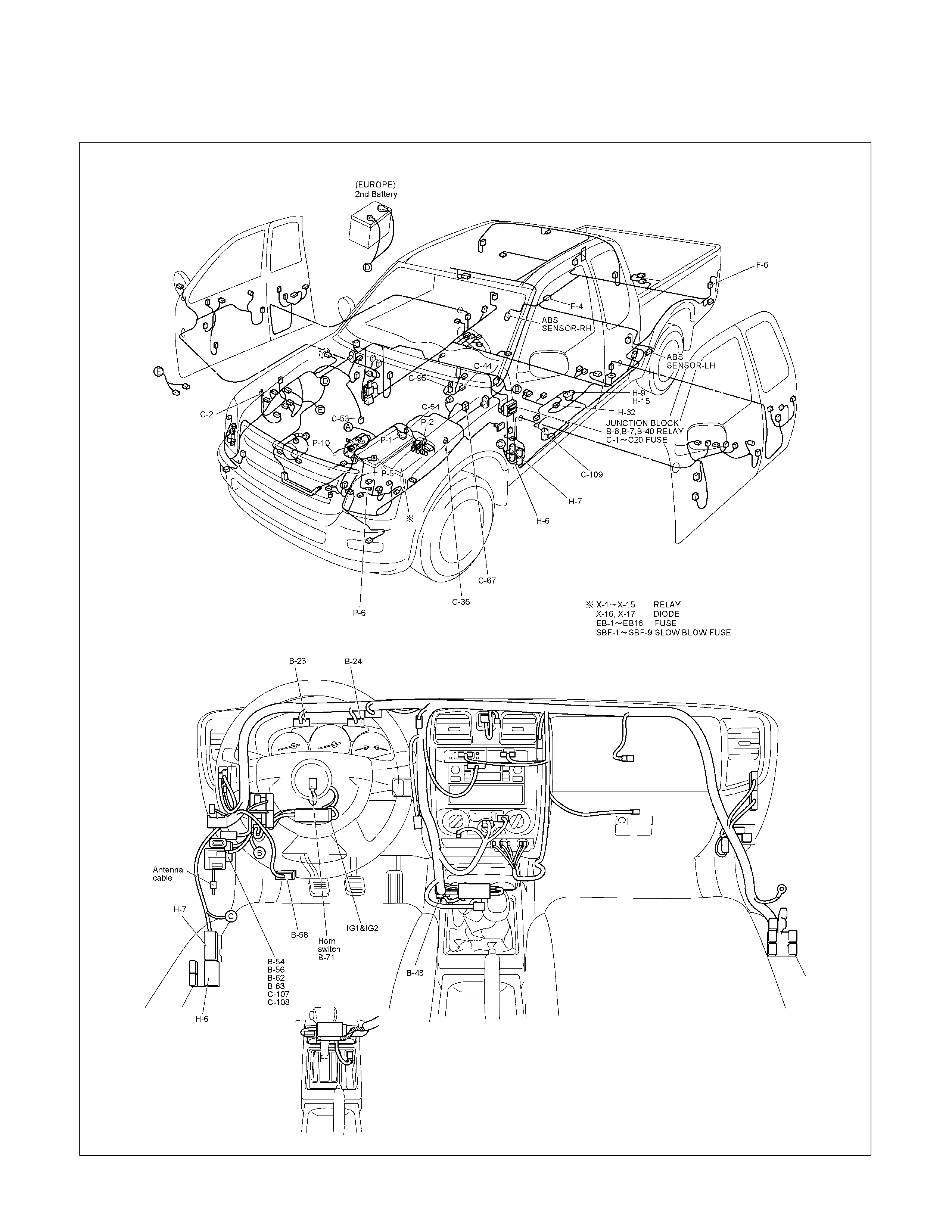
PARTS LOCATION (LHD)
RTW65AXF000301 & RTW48AXF022401
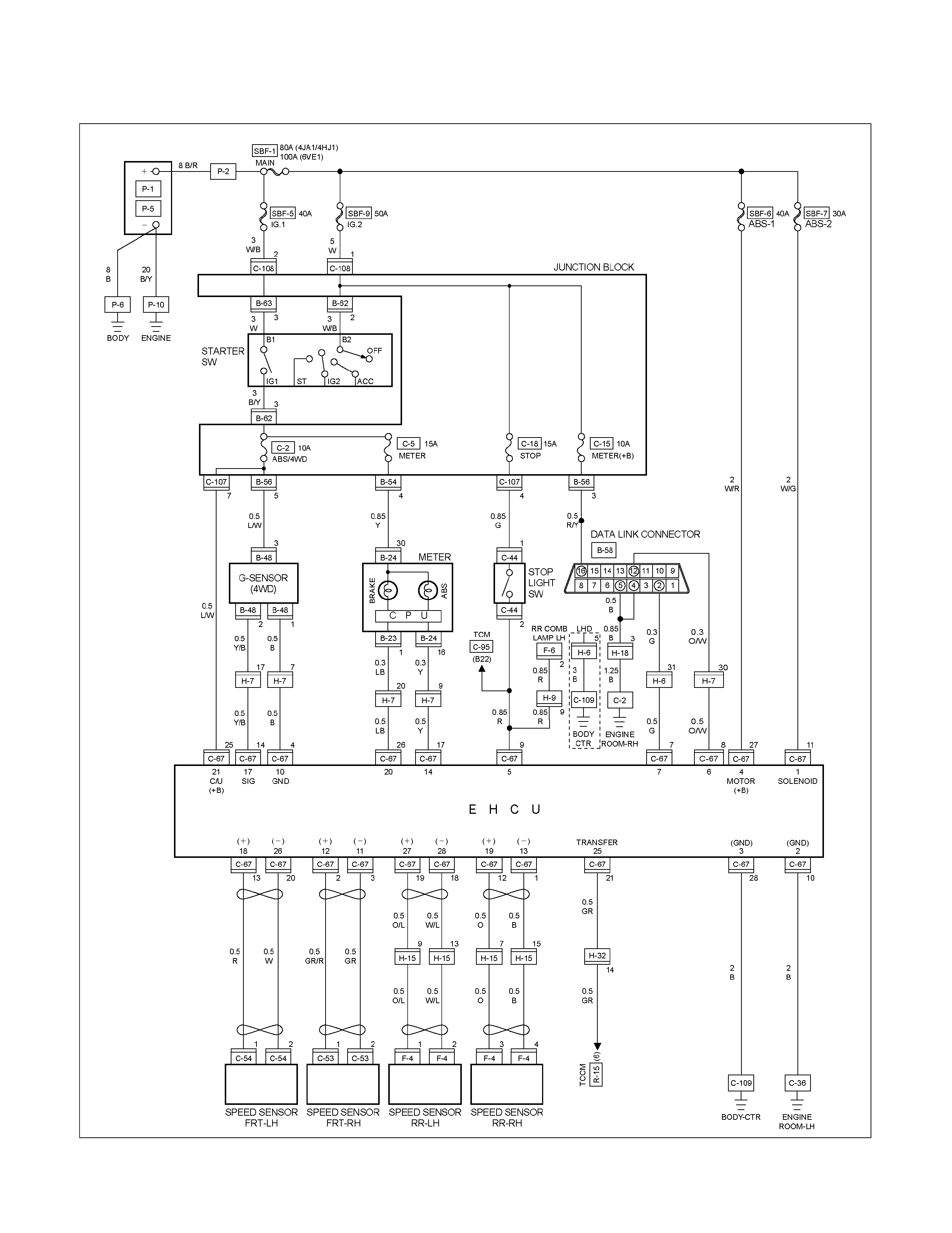
CIRCUIT DIAGRAM EXCEPT HFV6
RTW680XF014501
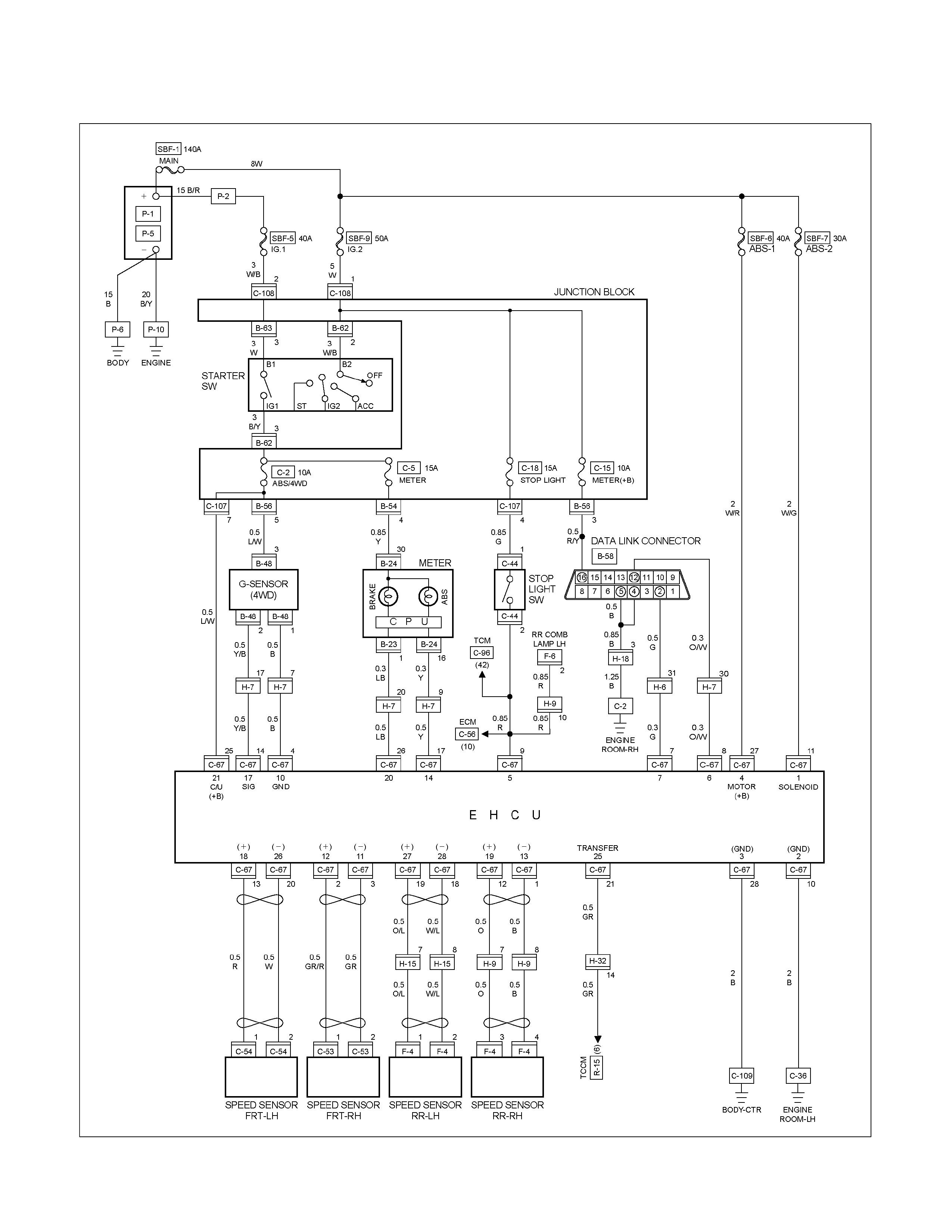
CIRCUIT DIAGRAM HFV6
RTW68AXF012701
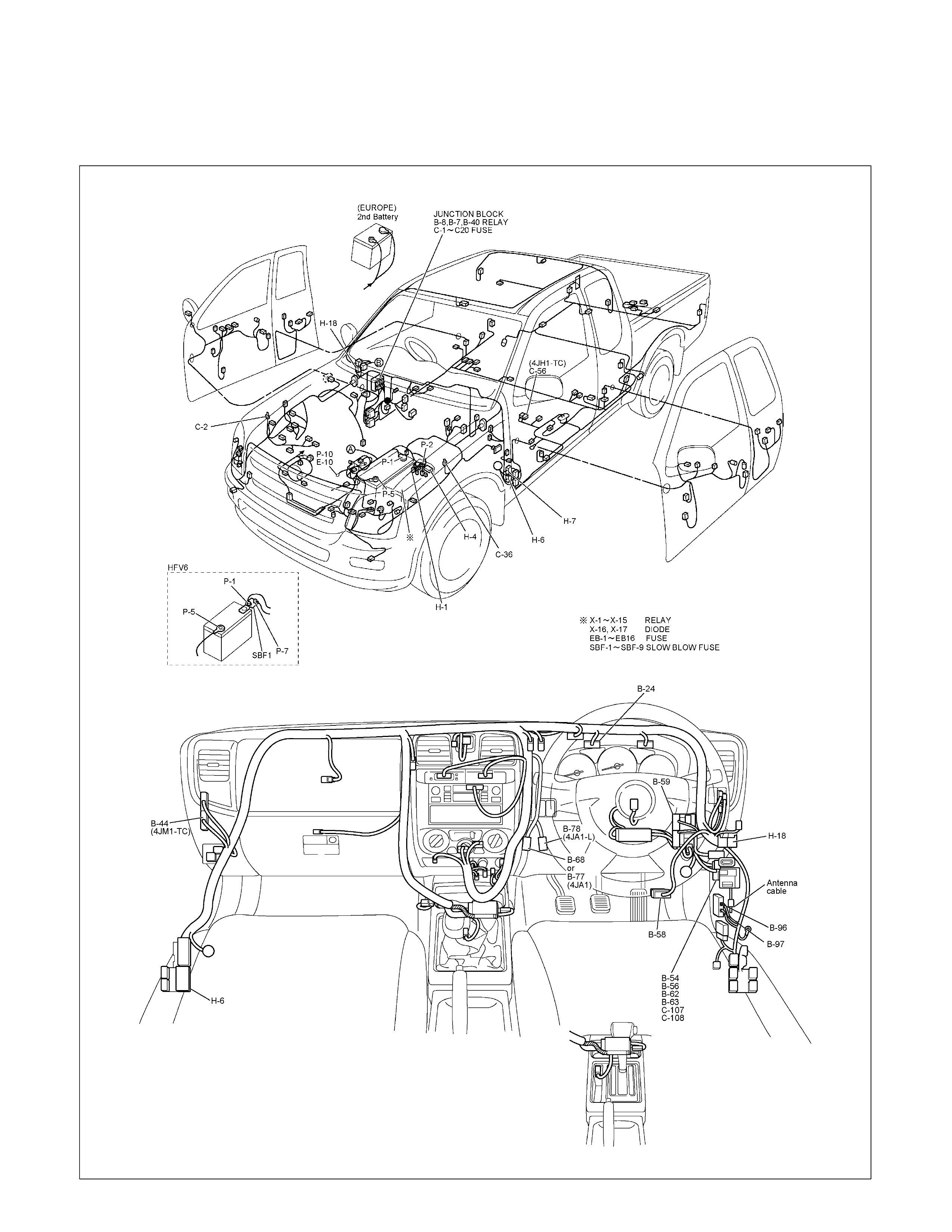
IMMOBILIZER
PARTS LOCATION (RHD)
RTW68AXF017201 & RTW68AXF017301

PARTS LOCATION (LHD)
RTW48AXF022901 & RTW48AXF023001

PARTS LOCATION C24SE

PARTS LOCATION 6VE1
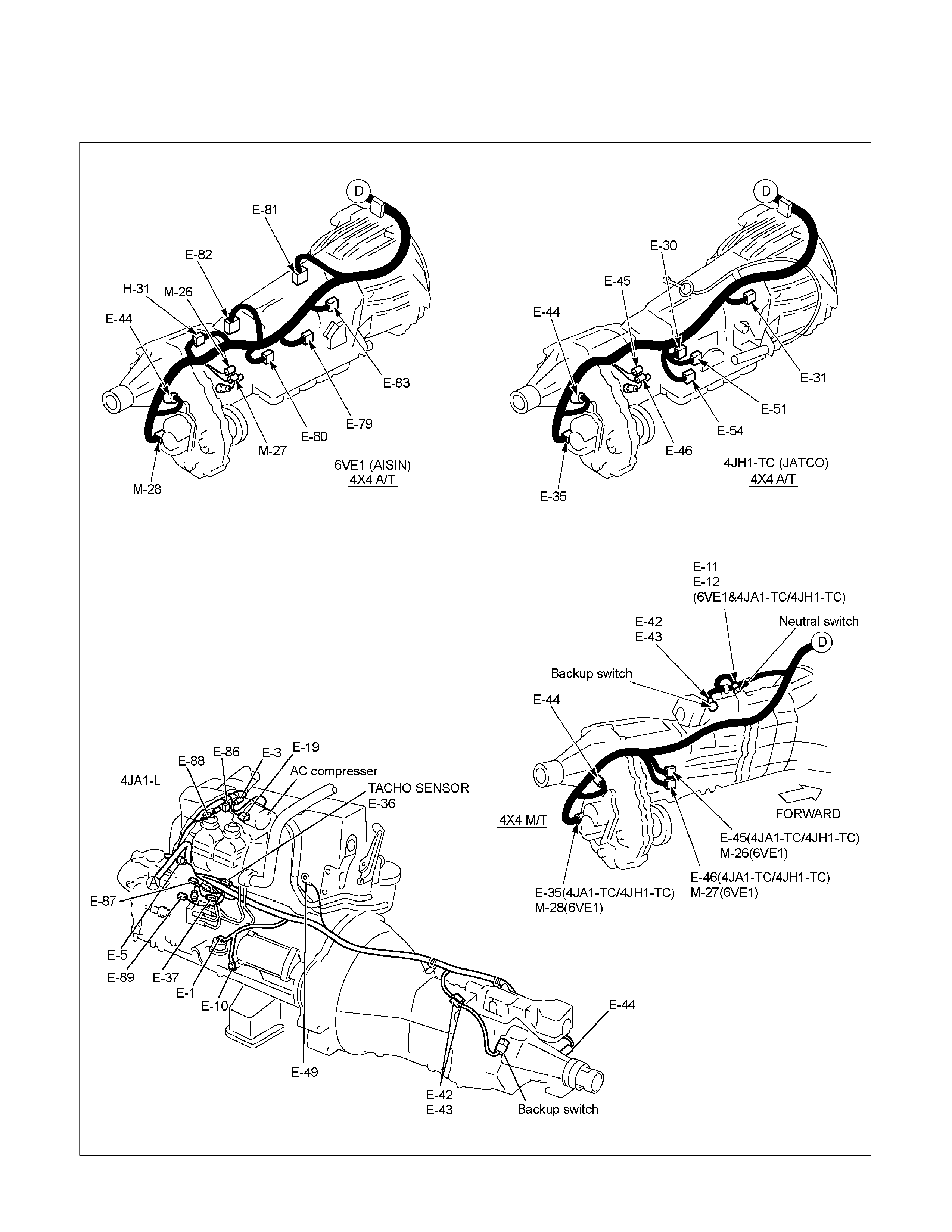
PARTS LOCATION
RTW48AXF021601
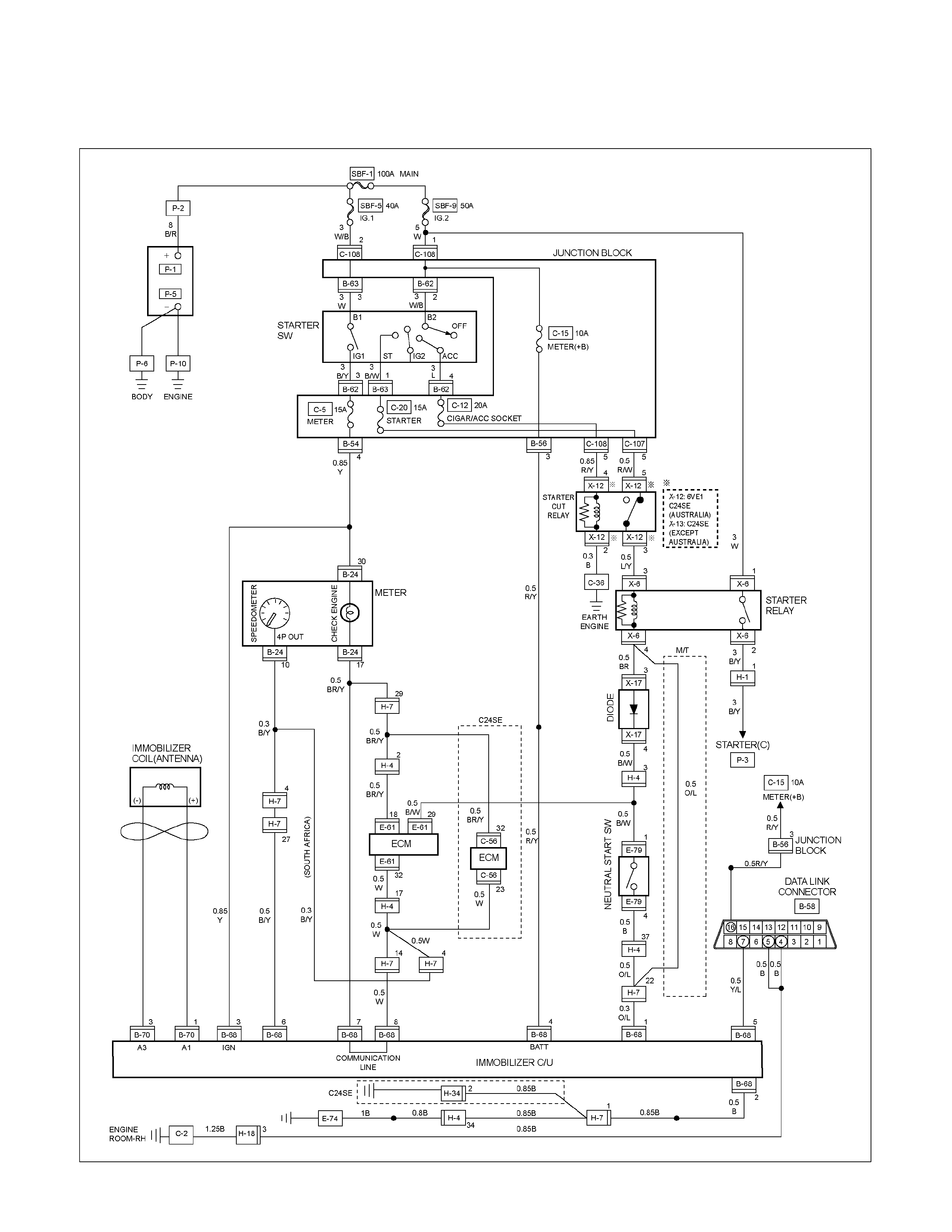
CIRCUIT DIAGRAM C24SE / 6VE1
RTW680XF014601
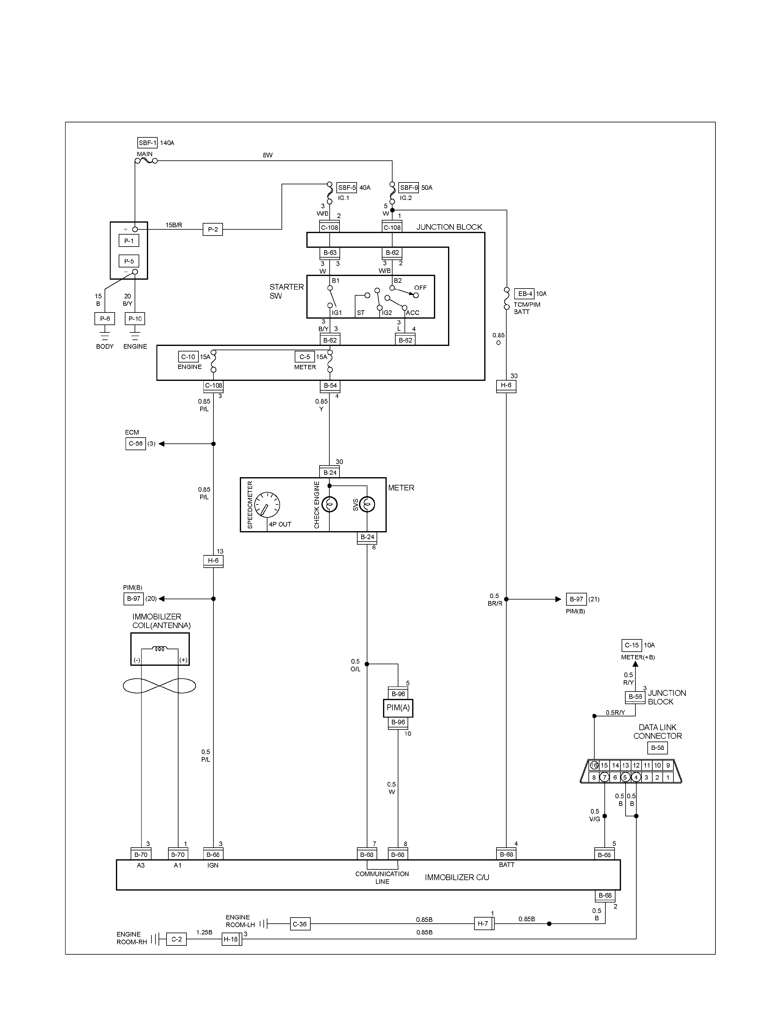
CIRCUIT DIAGRAM HFV6
RTW68AXF013101
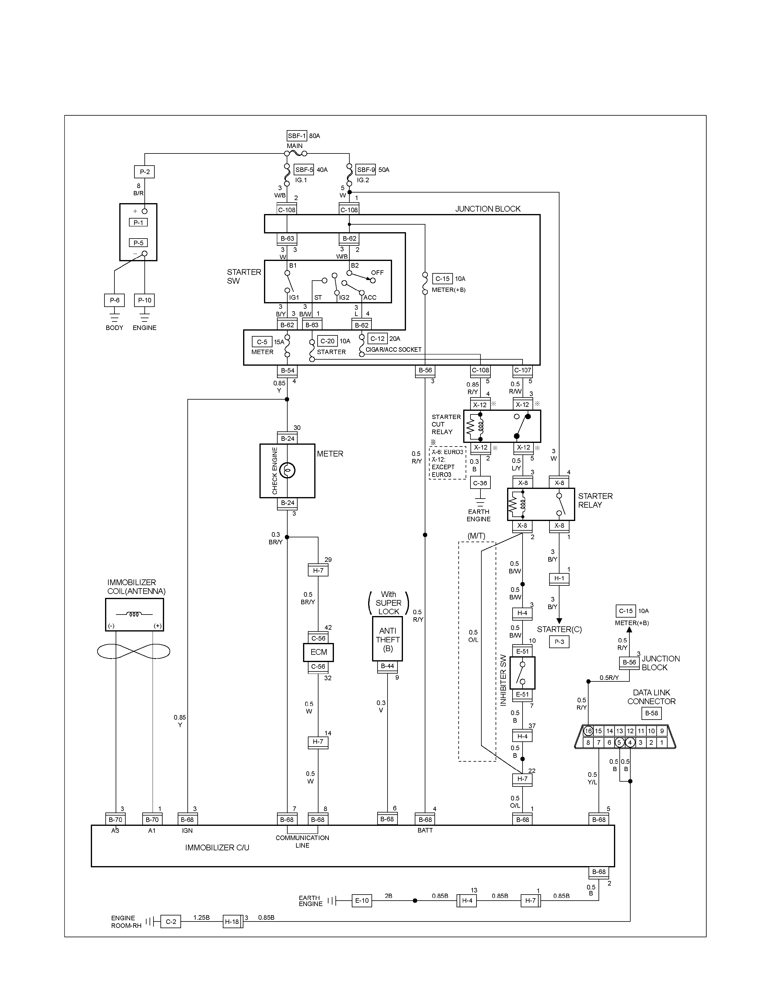
CIRCUIT DIAGRAM 4JA1-TC / 4JH1-TC (RHD)
RTW680XF014701
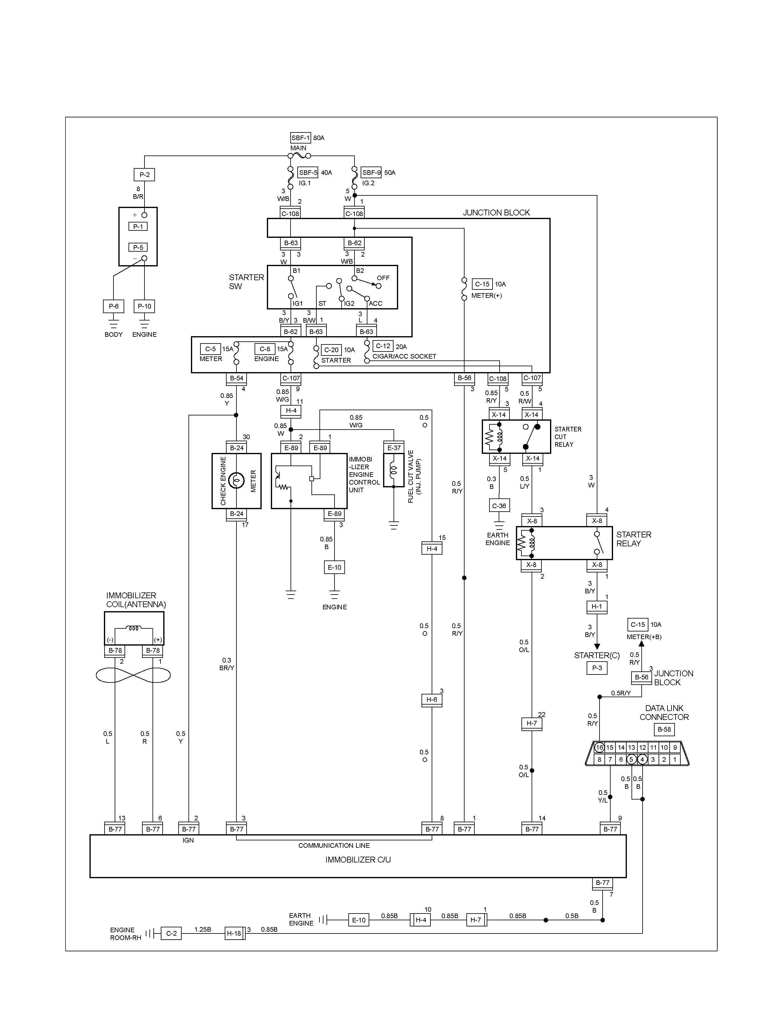
CIRCUIT DIAGRAM 4JA1-L (RHD)
RTW680XF014901
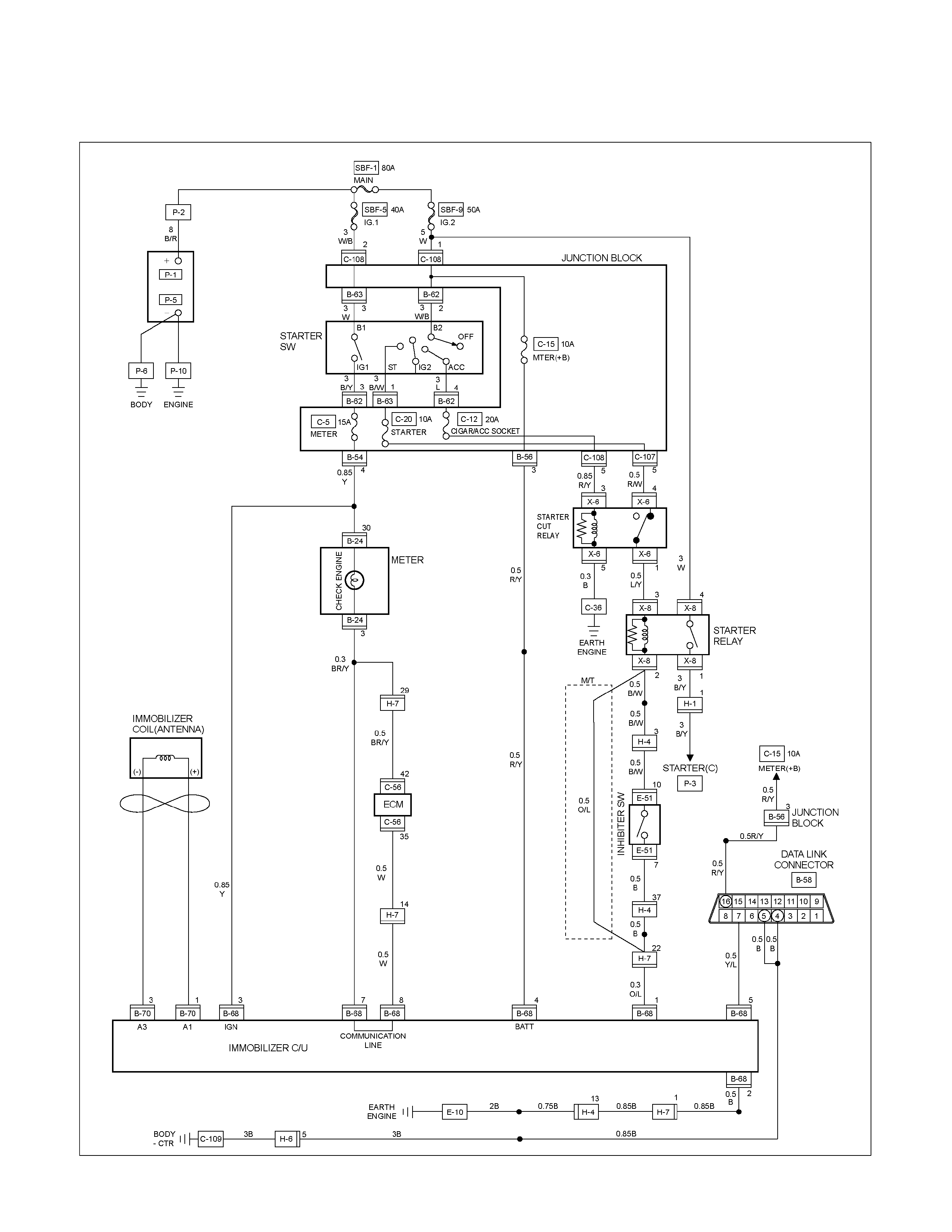
CIRCUIT DIAGRAM 4JA1-TC / 4JH1-TC (LHD)
RTW680XF014801
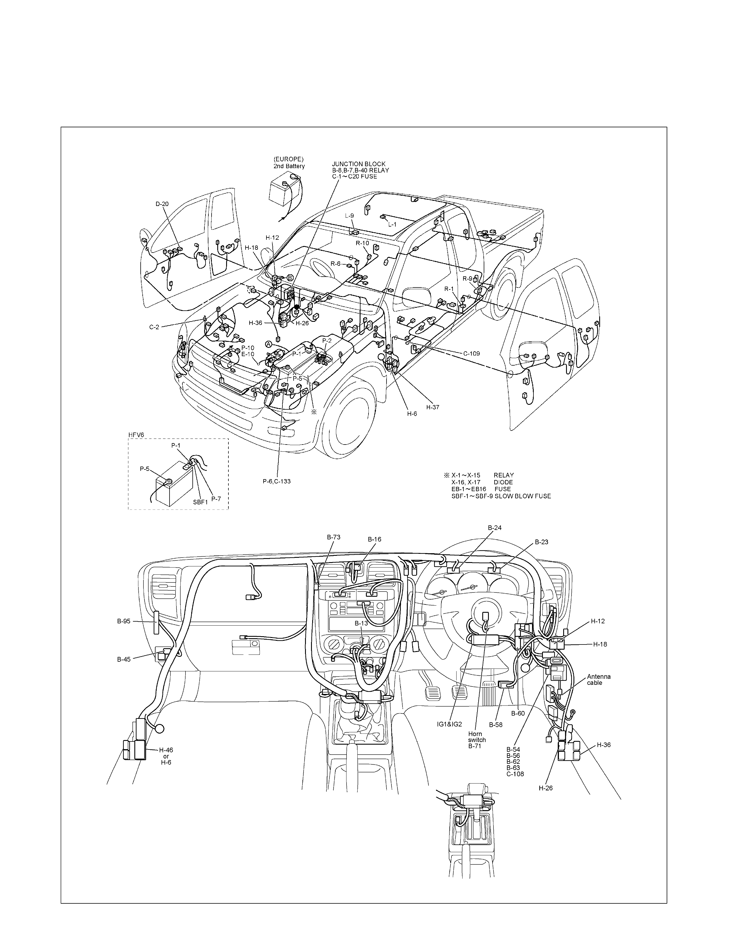
KEYLESS ENTRY
PARTS LOCATION (RHD)
RTW68AXF017401 & RTW68AXF017501
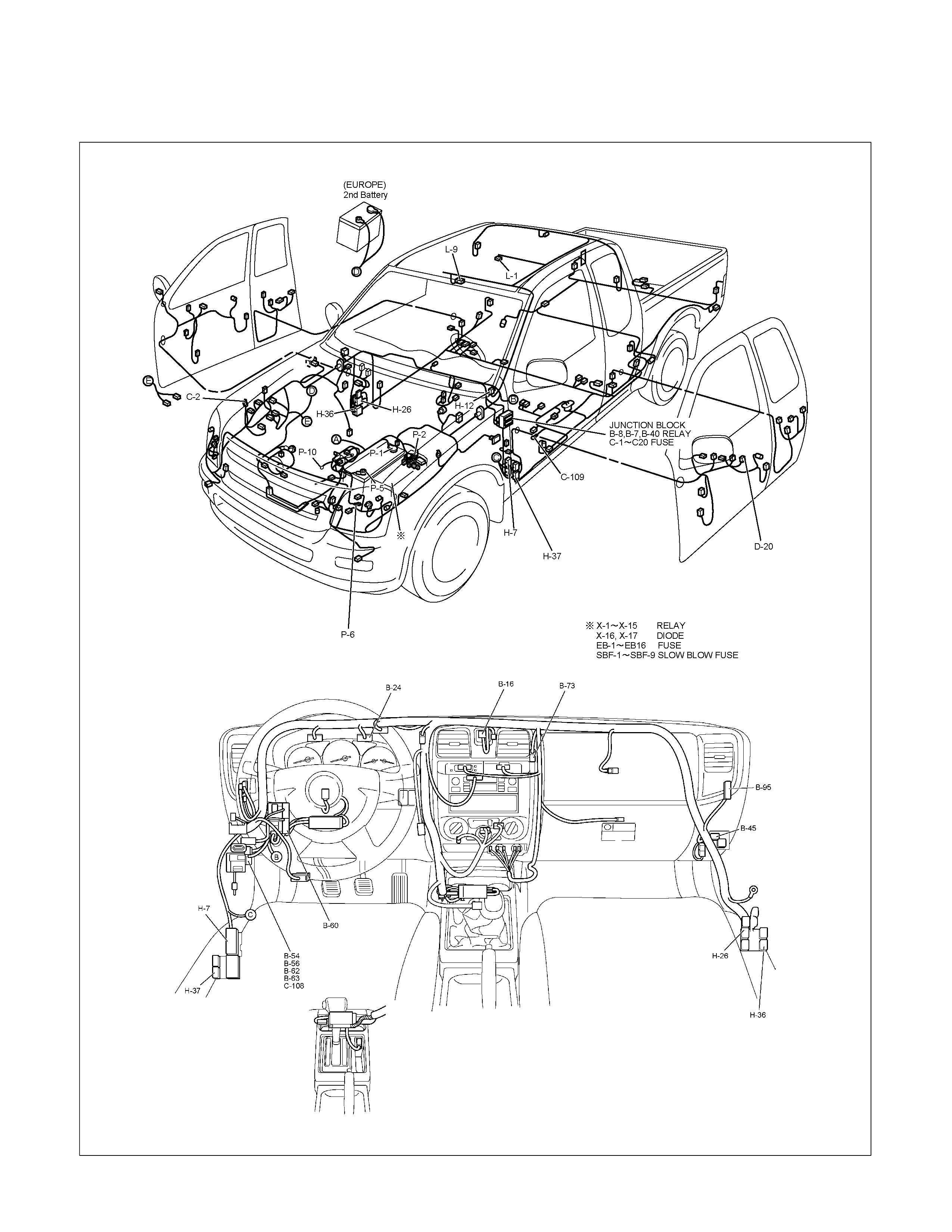
PARTS LOCATION (LHD)
RTW68AXF009001 & RTW68AXF009201
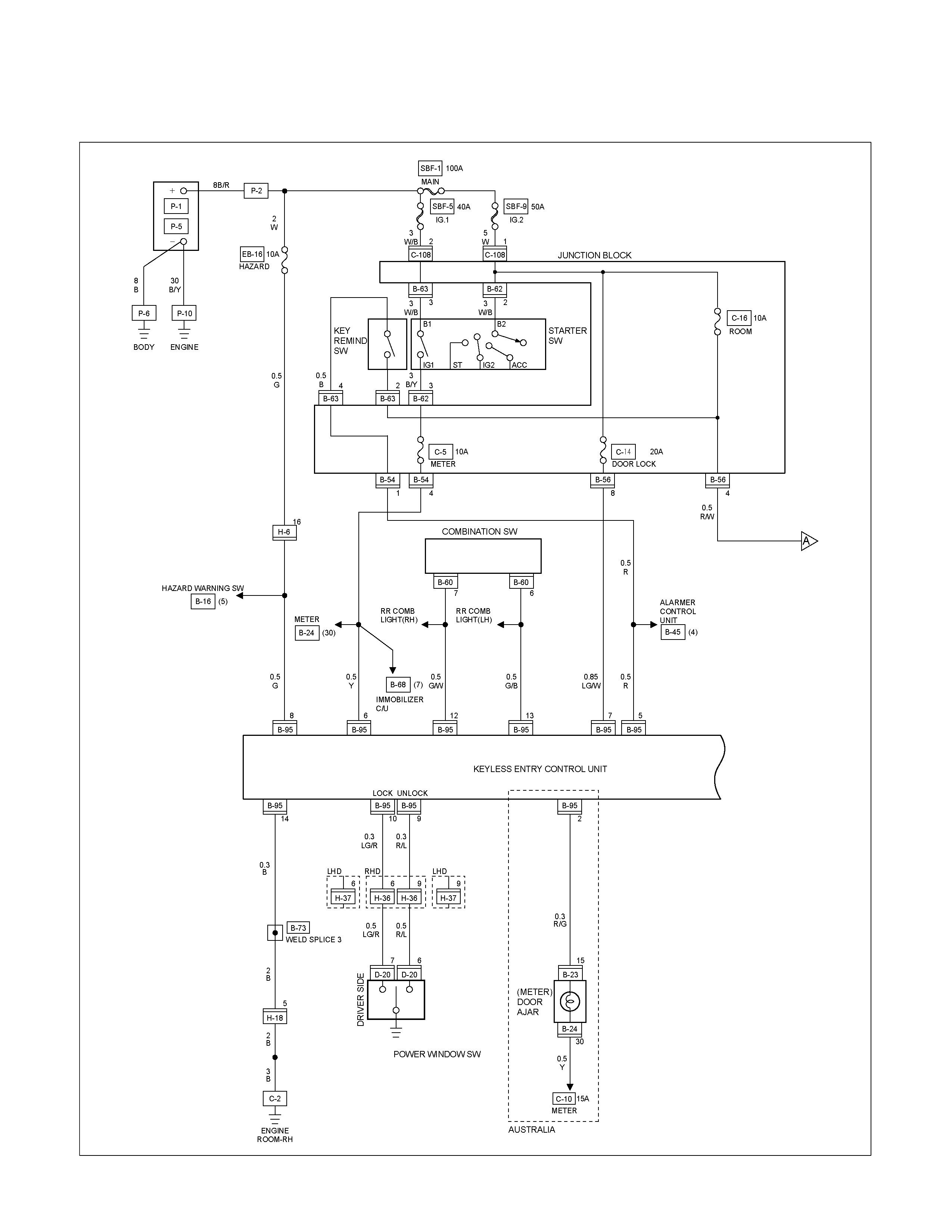
CIRCUIT DIAGRAM EXCEPT HFV6 Sheet 1/2
RTW680XF015001
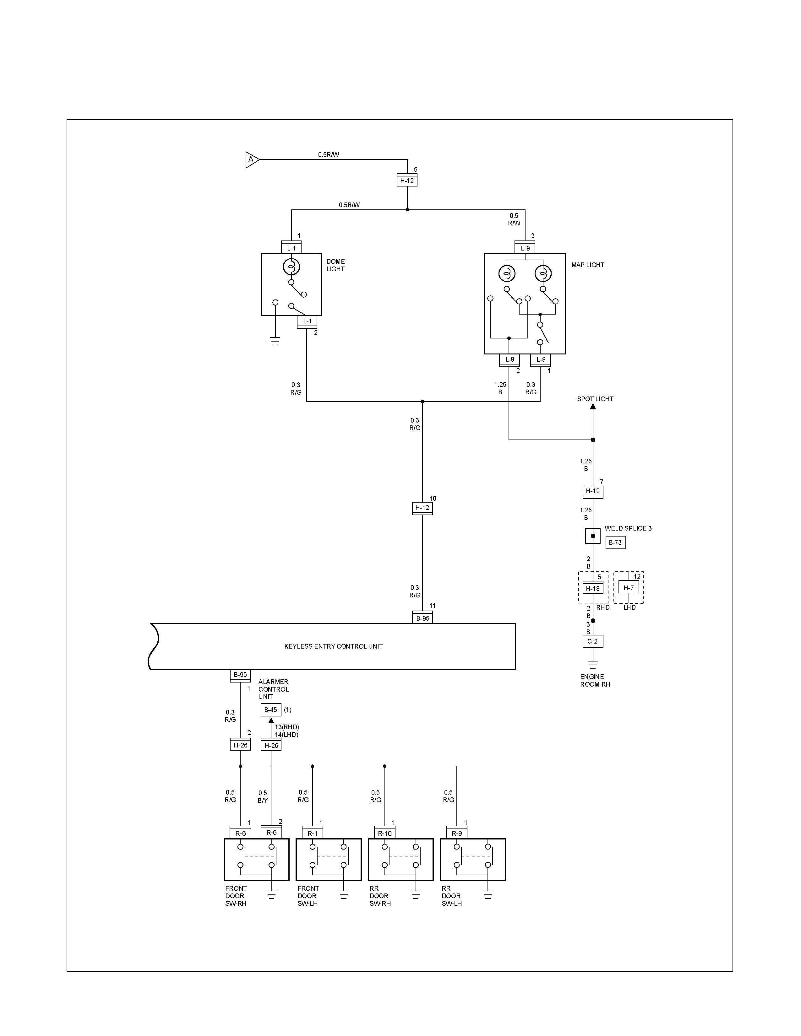
CIRCUIT DIAGRAM EXCEPT HFV6 Sheet 2/2
RTW680XF015101
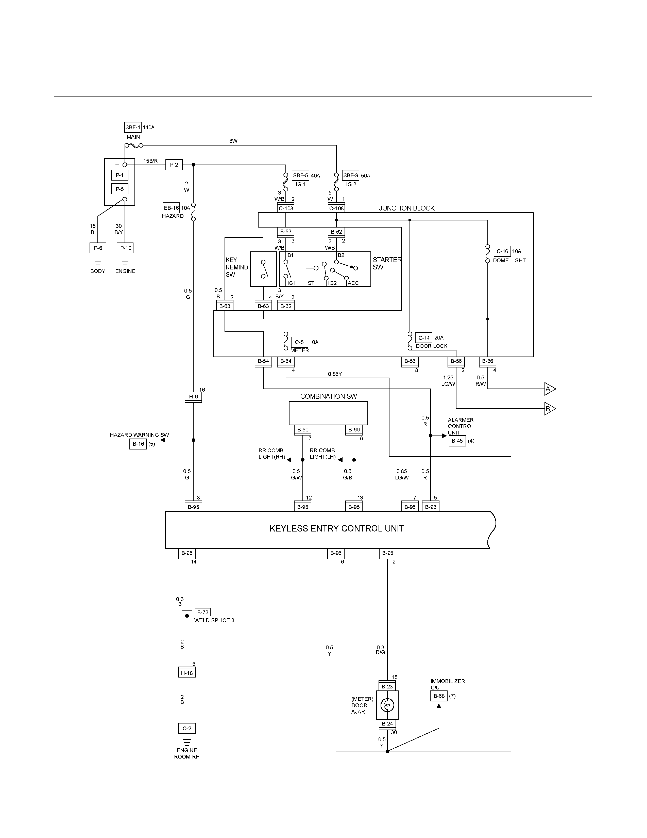
CIRCUIT DIAGRAM HFV6 Sheet 1/2
RTW68AXF013201
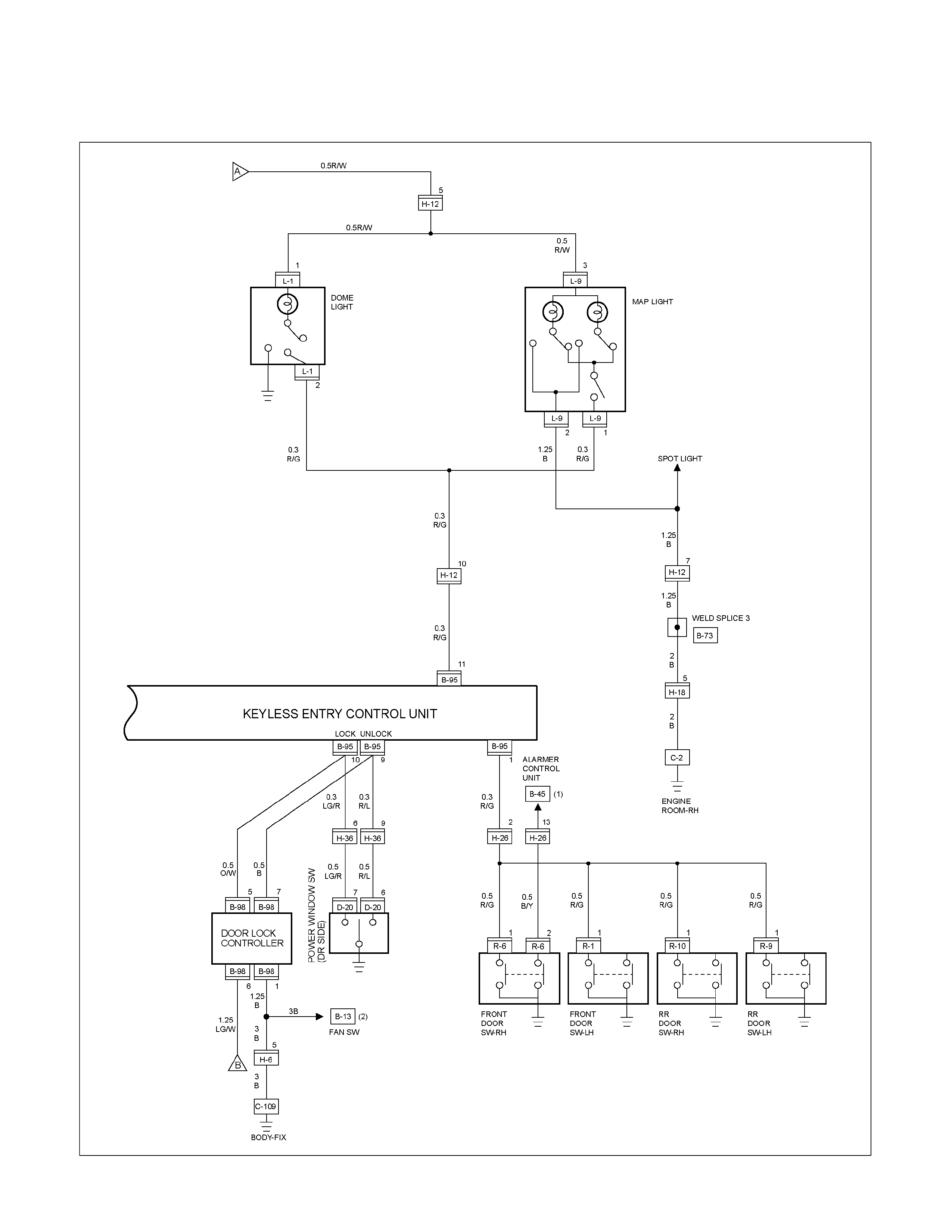
CIRCUIT DIAGRAM HFV6 Sheet 2/2
RTW68AXF013301

TROUBLESHOOTING
Diagnostic procedure
• Check the operation "Lock / unlock" by using
transmitter (remote key) on the vehicle.
• Check the operation "ON / OFF" for Driver side
door SW on the vehicle.
• Perform the Keyless entry System Check.
Diagnostic Aids
An intermittent may be caused by the following:
• Poor connections.
• Miss routed harness.
• Rubbed through wire insulation.
• Broken wire inside the insulation.
Check for the following conditions:
• Poor connection at keyless entry control unit-
Inspect harness connectors for backed out
terminals, improper mating, broken locks,
improperly formed or damaged terminals, and
poor terminal to wire connection.
• Damaged harness-Inspect the wiring harness fo
r
damage.
Check the Electro-Magnetic Interference (EMI)
• Location of vehicle check
Move the vehicle to a new location and perform
the check again.
• Non-OEM Parts.
Switch is “OFF” or remove the Non-OEM parts
and perform the check again.
• Other
Remove the accessory and another key from key.
Check the other items.
• Battery voltage is low.
• Keyless entry programming functions.
• Registration for security code.
• Ignition switch operation.
• Meter system is malfunction.
Check the operation
Check the operation "Lock / unlock" by using
transmitter (remote key) on the vehicle.
Notice
If so equipped the Anti Theft, Refer to ANTI
THEFT SYSTEM in 11B Section.

Keyless Entry System Check
Step Action Value (s) Yes No
1 Check the fuse for the keyless entry power feed
circuit. (EB-16 10A)
If a problem found, repair as necessary.
Was the problem found? — Verify repair Go to Step 2
2 1. Check the KCU (Keyless Entry Control Unit)
ground circuit for an open, or short to voltage.
Also, check the KCU ignition feed circuit for an
open or short to ground and the KCU ground
circuit for an open.
2. If a problem is found, repair as necessary.
Was the problem found? — Verify repair Go to Step 3
3 1. Check the front drive side SW circuit for an open,
or short to voltage.
2. If a problem is found, repair as necessary.
Was the problem found? — Verify repair Go to Step 4
4 1. Check the operation "Lock / unlock" by using
transmitter (Remote key) on the vehicle.
Was the problem found? —
Go to
Diagnostic
Chart
Go to
Diagnostic
Aids

ID Code not yet programmed
Step Action Value (s) Yes No
1 Was the Keyless entry System Check performed?
— Go to Step 2
Go to Keyless
entry
System Check
2 Check the key.
Is a key peculiar to a vehicle? — Go to Step 3 Refer to
Diagnostic Aids
3 Check the Keyless entry programming functions.
• All transmitters (Remote Key).
If a problem is found, reprogramming as necessary.
(Refer to “ID code new registration”)
Was the action complete? — Go to Step 4 Go to ID code
new registration
4 Check the operation "Lock / unlock" by using
transmitter (Remote key) on the vehicle.
Was the problem found? — Go to Step 5 Verify repair
5 Recheck the following condition.
1. Non-OEM parts switch is “OFF” or remove the
Non-OEM parts.
2. Move the vehicle to a new location.
3. Check the operation "Lock / unlock" by using
transmitter (Remote key) on the vehicle.
Was the problem found? — Go to Step 6 Verify repair
6 Replace the Keyless entry control unit (KCU).
IMPORTANT: The replacement KCU must be
programmed the security code.
Was the problem found? — Go to Step 7 Verify repair
7 Replace the key and lock cylinder assembly with
Keyless entry sy stem (KCU ).
IMPORTANT:
• KCU is not replacing simultaneously.
• After replace lock cylinders, perform the following
below the items.
• Replace the keys and key cylinders.
• Program the Keyless entry system.
(Refer to “ID code new registration”)
Was the action complete? — Verify repair —

No Remote Key Programmed
Step Action Value (s) Yes No
1 Was the Keyless entry System Check performed?
— Go to Step 2
Go to keyless
entry
System Check
2 Check the key.
Is a key peculiar to a vehicle? — Go to Step 3 Refer to
Diagnostic Aids
3 Check the keyless entry programming functions.
• Transmitter (Remote Key).
Was a problem found? — Go to Step 4 Go to Step 5
4 Perform the keyless entry programming functions.
• Transmitter (Remote Key).
(Refer to “ID code new registration”)
Was the action complete? — Go to Step 5 —
5 Replace the transmitter (Remote Key).
IMPORTANT: The replacement transmitter (Remote
Key) must be programmed the ID code.
Was the action complete? — Verify repair —
Door Lock Actuators Short Circuit to Ground
Step Action Value (s) Yes No
1 Was the Keyless entry System Check performed?
— Go to Step 2
Go to keyless
entry
System Check
2 Check the door lock actuators circuit.
1. Ignition key position is “OFF”.
2. Disconnect the keyless entry control unit (KCU).
3. Check the door lock actuator circuit for short to
ground.
If the problem found, repair as necessary.
Was a problem found? — Verify repair Go to Step 3
3 Check the operation "Lock / unlock" by using
transmitter (Remote key) on the vehicle.
Was the problem found? — Go to Step 4 Verify repair
4 Check the door lock actuator.
If the problem found, repair as necessary.
Was a problem found? — Verify repair Go to Step 5
5 Replace the Keyless entry control unit (KCU).
IMPORTANT: The replacement KCU must be
programmed the security code.
Was the problem found? — Go to Step 7 Verify repair
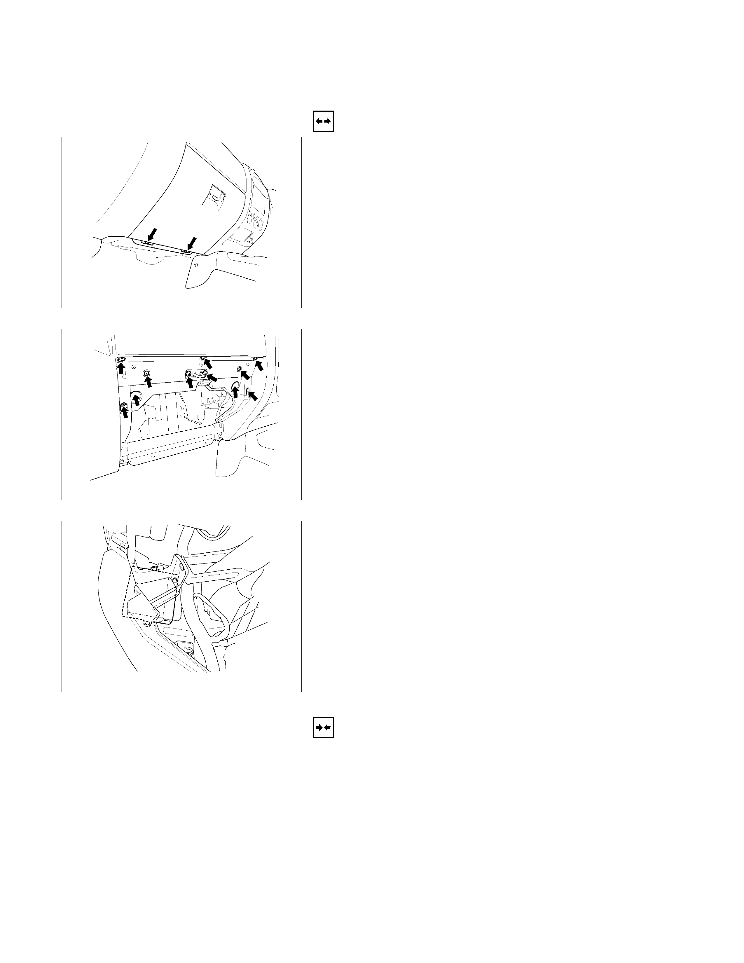
KEYLESS ENTRY CONTROL UNIT
Removal
1. Remove the glove box.
This Illustration is based on RHD
RTW580SH001601
2. Disconnect the glove box lamp connector.
This Illustration is based on RHD
RTW580SH001701
3. Remove the glove box cover.
This Illustration is based on RHD
RTW580SH001801
4. Remove the bolt of antitheft and keyless entry control unit.
5. Disconnect the keyless entry control unit connector.
6. Remove the keyless entry control unit.
Installation
Follow the removal procedure in the reverse order to install the
keyless entry control unit.
Connector
Be absolutely sure that the keyless entry control unit harness
connector is correctly installed.
This will prevent a poor contact and an open circuit.
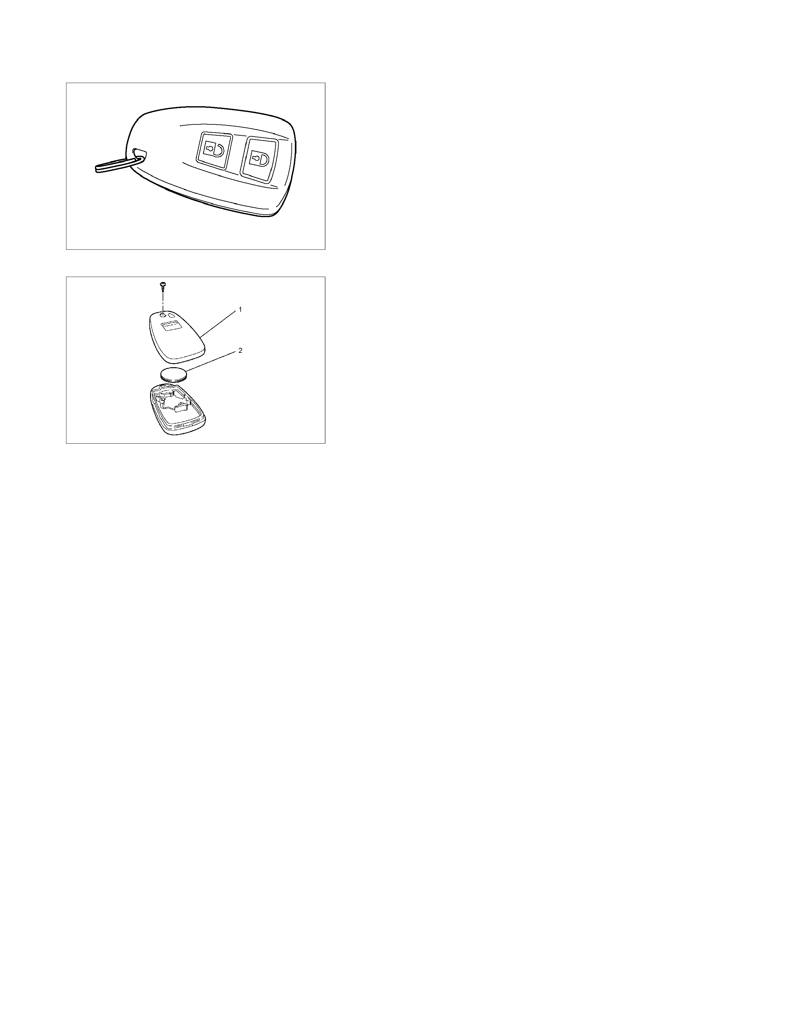
RUW580SH001101
Remove Transmitter (Remote Key)
Replacing the battery in the transmitter (remote key)
Replace the battery(2) as soon as the range of the remote
control starts to become reduced.
Open the underside of the transmitter (remote key) by
removing the battery cover(1) with a screwdriver as shown in
the illustration.
Replace the battery, ensuring that it is inserted correctly.
Replace the battery cover so that it engages audibly. Make
sure that you dispose of old batteries in accordance with
environmental protection regulations.
RUW580SH003901

Keyless Entry System
General Description
The system’s main features are summarized as follows.
Keyless entry with visual feedback
Highly secure encrypted transmission format
incorporating rolling code strategy
Field programmable remote keys
Door lock control
Illuminated entry with fade out
Illuminated exit
Remote door lock / ignition key interlock
Door ajar warning indicator in the cluster

Power Door Lock System
General Description
The circuit consists of the door lock (& power window)
switch, door lock actuator for the front and rear door,
tailgate lock actuator and the door lock key switch.
The front door lock switchRH is always provided with
the battery voltage.
The key or the inside lock button on both driver's and
front passenger's door can activate the lock mechanism
of all the doors (including the tailgate).
When the driver's door lock switch or the front
passenger's door lock switch is turned on, current flows
for about one second to the door lock actuator of each
door connected in parallel with the front door lock (&
power window) switchLH to activate the actuator to
lock and unlock the doors.
Door Lock Key Switch
Removal and Installation
Refer to the Front Door Lock Assembly removal
and installation steps in this section.
Front Door Lock Actuator
Removal and Installation
Refer to the Front Door Lock Assembly removal
and installation steps in this section.
Rear Door Lock Actuator
Removal and Installation
Refer to the Rear Door Lock Assembly removal
and installation steps in this section.
Tailgate Lock Actuator
Removal and Installation
Refer to the Tailgate Lock Assembly removal and
installation steps in this section.
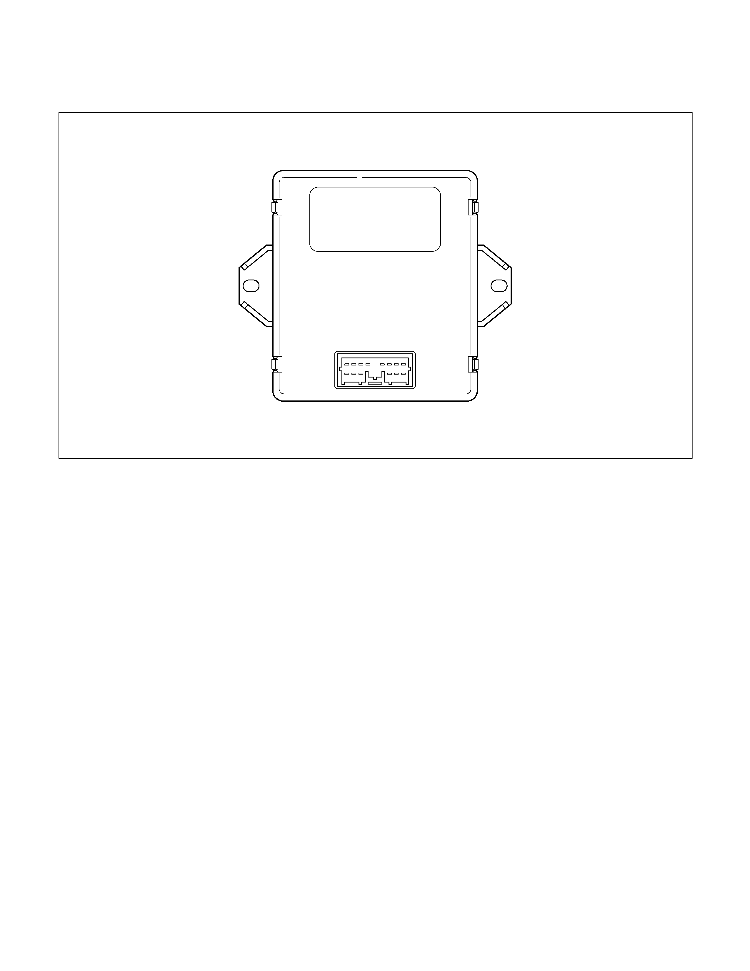
Keyless entry control unit
RUW580SF000201
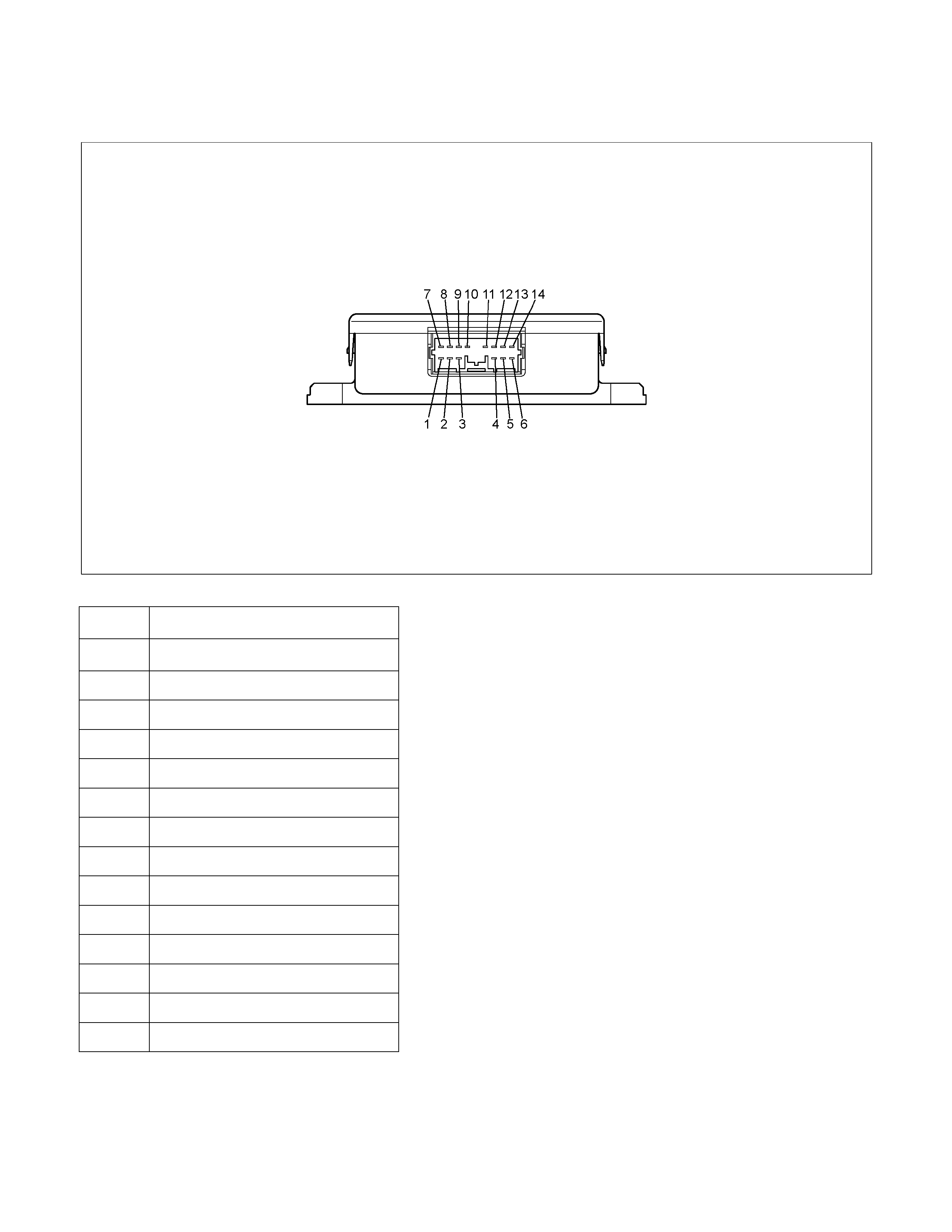
Pin-outs
RUW580SF000301
No. Pin Function
1 Door ajar switch
2 Door ajar indicator light
3 Tailgate switch
4 Test pin (Internal use only)
5 Key switch remote
6 Ignition switch
7 Battery
8 Hazard battery
9 Unlock
10 Lock
11 Front map light
12 Hazard-RH
13 Hazard-LH
14 Ground

ID Code New Registration
All registered ID codes shall be erased, and a new
received
ID code shall be registered instead of old codes.
Carefully read each of the steps before beginning the
operation.
Step Action Yes No
1 NOTE: Make sure that the all the doors are closed and
unlocked. Remove the ignition key from the ignition switch.
1. Open the driver's side door.
2. Insert the ignition key into the starter switch.
Is the action complete? Go to Step 2 ⎯
2 Turn the ignition switch to ON position and return it to OFF
position three times.
NOTE: This step must be carried out within five seconds.
Is the action complete? Go to Step 3 Go to Step 1
3 Close and open the drive's side door twice.
NOTE: This step must be carried out within five seconds after
step 2 is finished.
Is the action complete? Go to Step 4 Go to Step 1
4 1. Turn the ignition switch to ON position and return it to OFF
position twice.
NOTE: This step must be carried out within ten seconds after
step 3 is finished.
Is the action complete? Go to Step 5 Go to Step 1
5 Operate the lock or unlock button of the transmitter.
NOTE: Confirm that the system is functioning by pressing the
transmitter button to lock and unlock the doors. Listen for the
sound of the actuator operation.
Is the action complete? ⎯ Go to Step 1
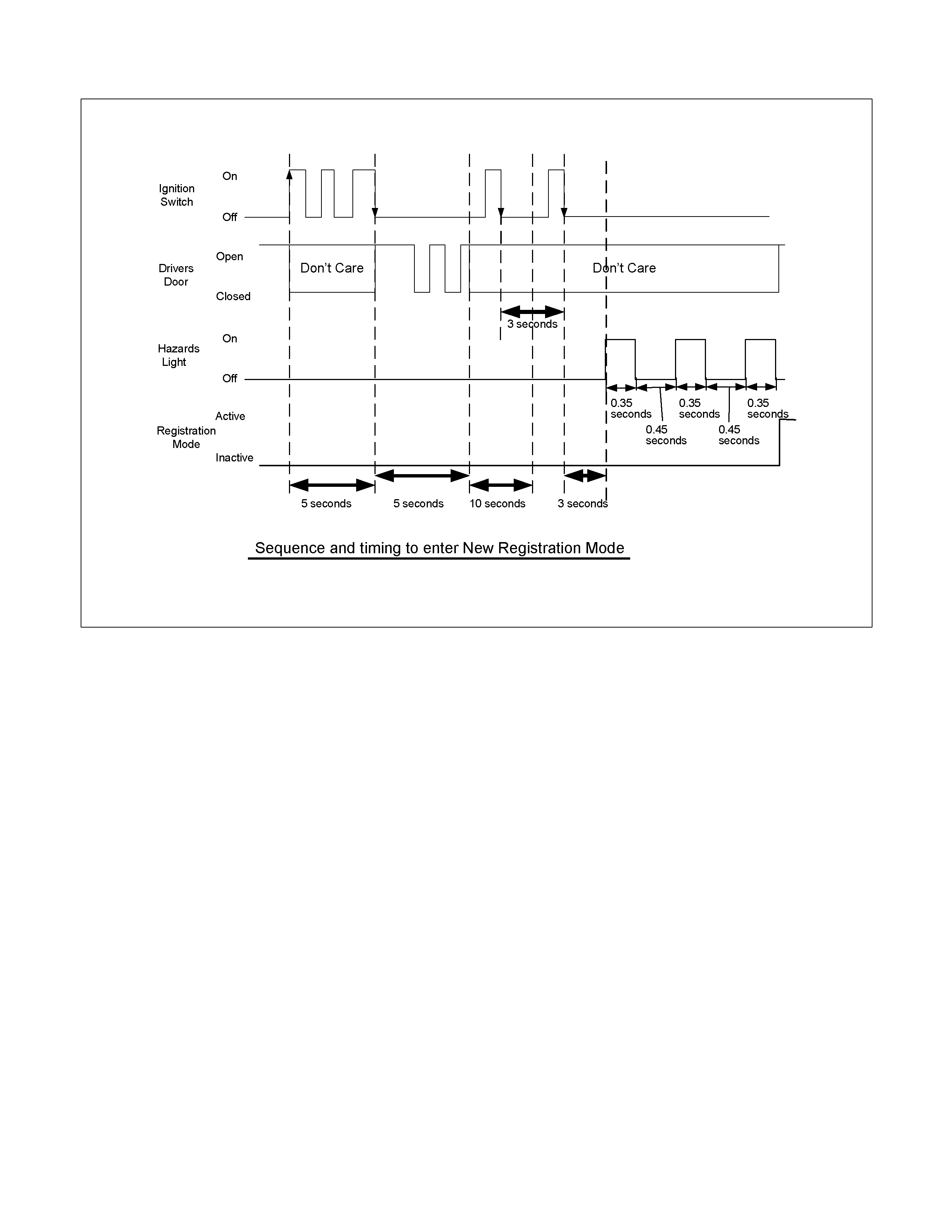
RUW59DMF000101

ID Code Additional Registration
A new received ID code shall be additionally registered
with holding registered ID codes. When a total of
already registered and newly
registered ID code exceeds 4, the oldest one shall be
erased.
Step Action Yes No
1 NOTE: Make sure that the all the doors are closed and
unlocked. Remove the ignition key from the ignition switch.
1. Open the driver's side door.
2. Insert the ignition key into the starter switch.
Is the action complete? Go to Step 2 ⎯
2 Turn the ignition switch to ON position and return it to OFF
position three times.
NOTE: This step must be carried out within five seconds .
Is the action complete? Go to Step 3 Go to Step 1
3 Close and open the driver's side door once.
NOTE: This step must be carried out within five seconds after
step 2 is finished.
Is the action complete? Go to Step 4 Go to Step 1
4 1. Turn the ignition switch to ON position and return it to OFF
position once.
Check that the hazard lamp blinks 3 times.
NOTE: This step must be carried out within ten seconds after
step 3 is finished.
Is the action complete? Go to Step 5 Go to Step 1
5 Operate the lock or unlock button of the transmitter.
NOTE: Confirm that the system is functioning by pressing the
transmitter button to lock and unlock the doors. Listen for the
sound of the actuator operation.
Is the action complete? ⎯ Go to Step 1

RUW59DMF000201
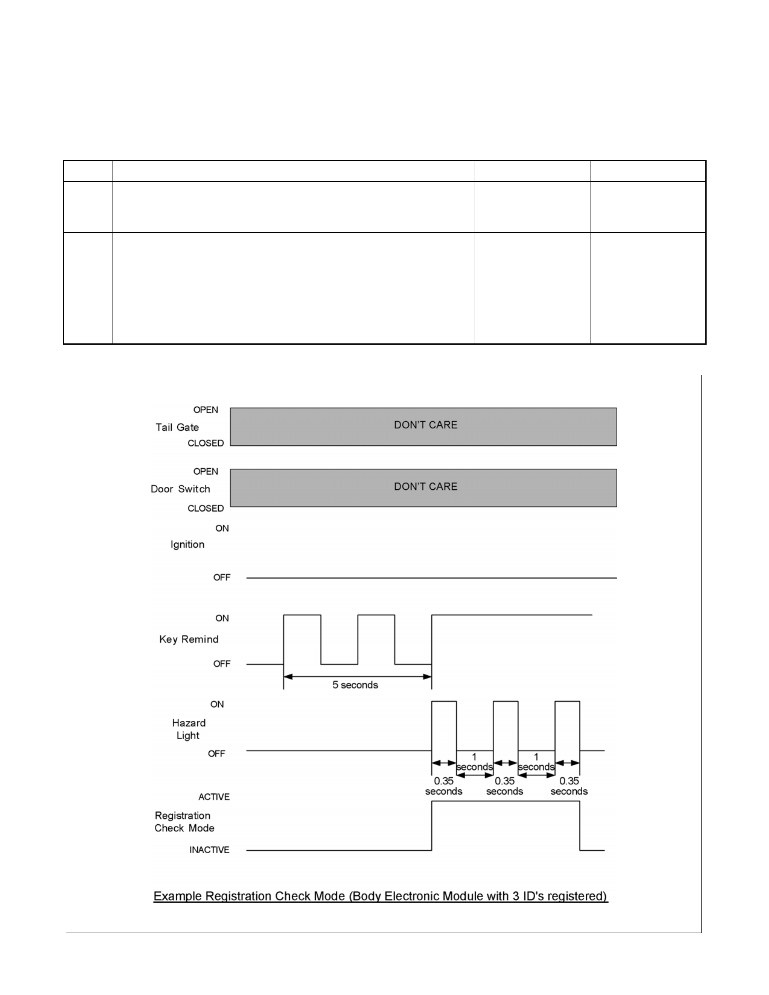
ID Code Check
Numbers of registered ID code shall be checked in this
mode.
Step Action Yes No
1 NOTE: Make sure that the all the doors are closed.
Is the action complete? Go to Step 2 ⎯
2 Insert the ignition key into the key lock twice, and then re-
inserted.
NOTE: This step must be carried out within five seconds.
Count the number of times the hazard lights flash on and off.
This number is equal to the number of registrations.
Is the action complete? Go to Step 1 Go to Step 1
RTW68ALF000101
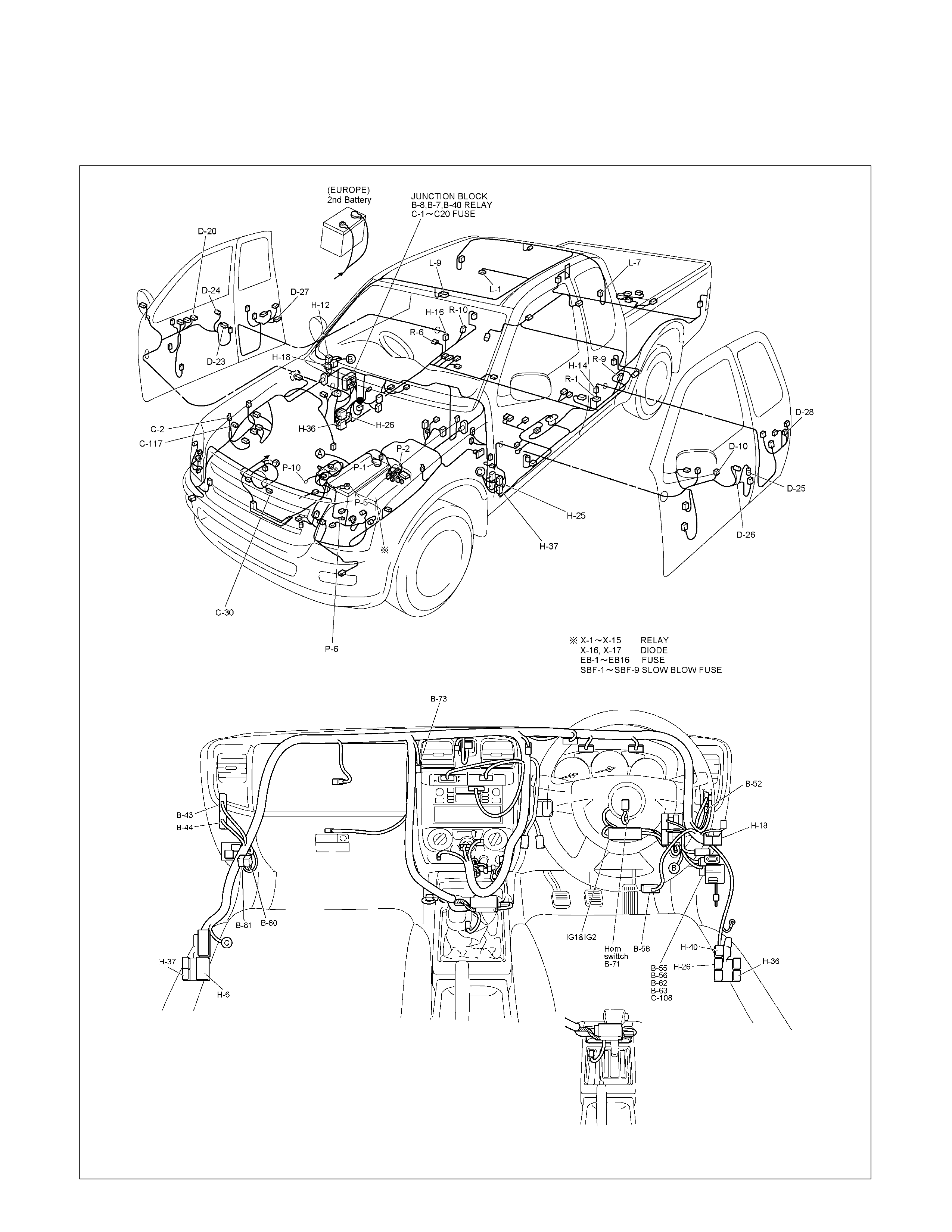
ANTI THEFT AND KEYLESS ENTRY
PARTS LOCATION WITH SUPER LOCK (RHD)
RTW6BBXF000101 & RTW6BBXF000201
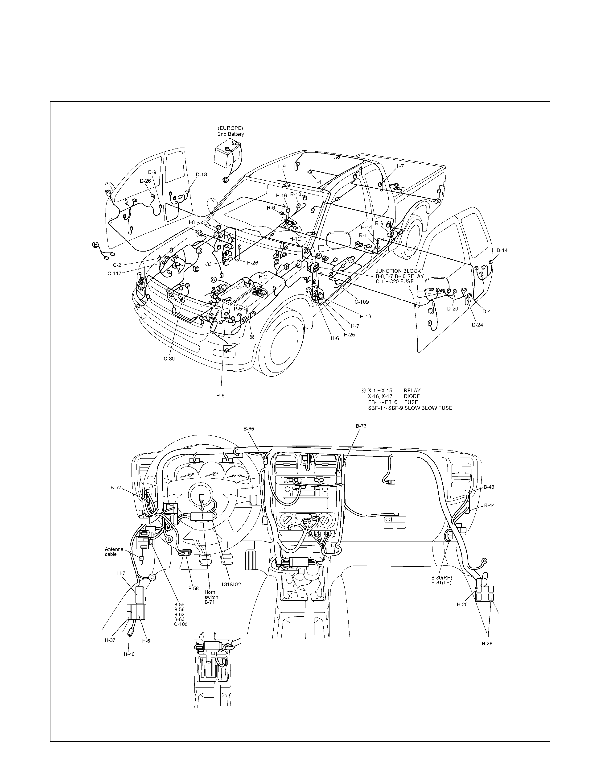
PARTS LOCATION (LHD)
RTW6BBXF000301 & RTW6BBXF000401
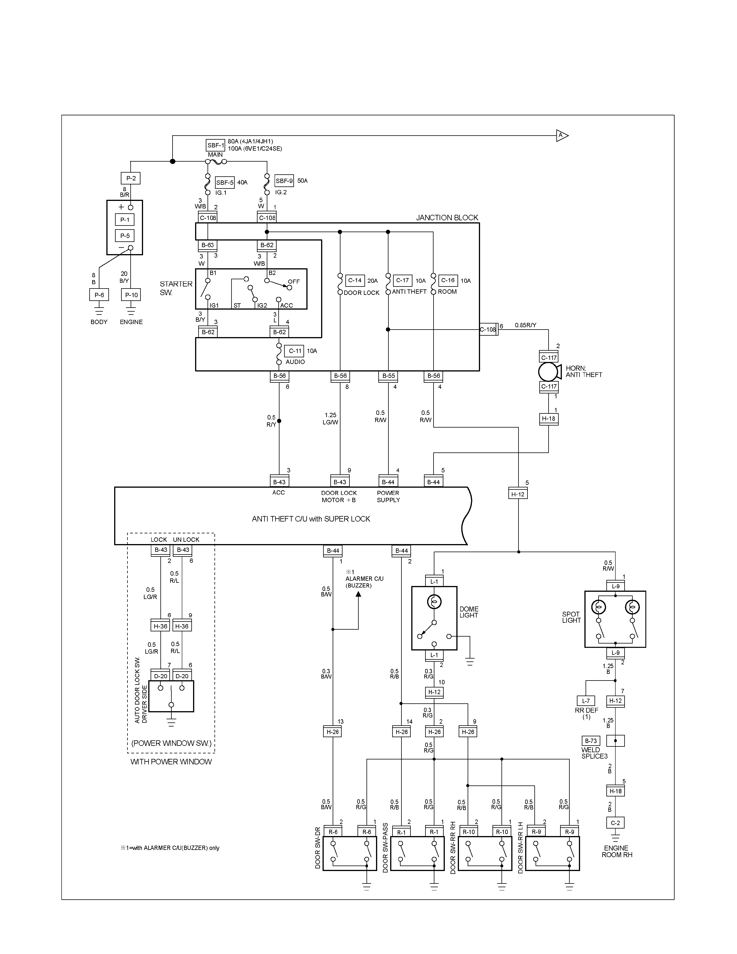
CIRCUIT DIAGRAM WITH SUPER LOCK (RHD) Sheet 1/3
RTW680XF015401
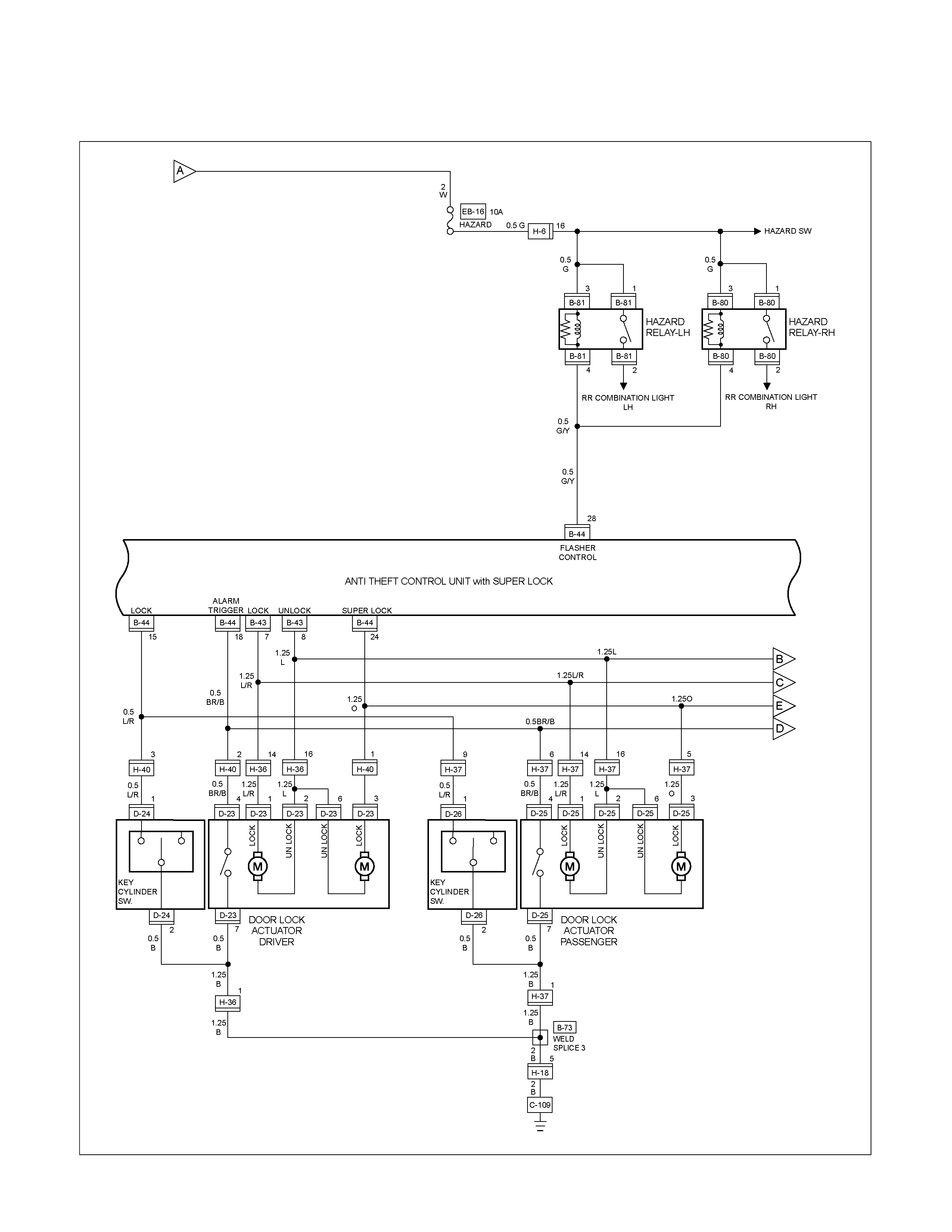
CIRCUIT DIAGRAM WITH SUPER LOCK (RHD) Sheet 2/3
RTW680XF015501
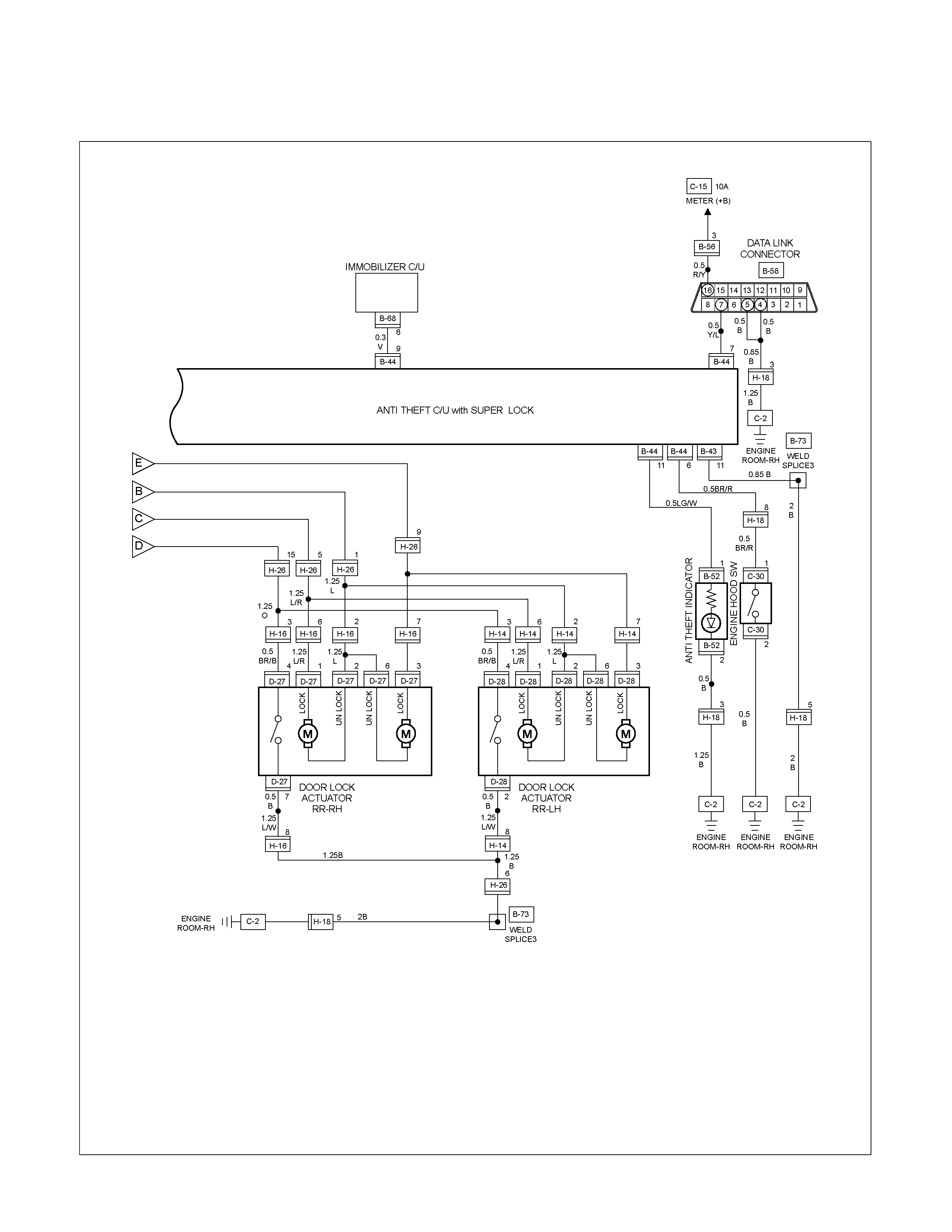
CIRCUIT DIAGRAM WITH SUPER LOCK (RHD) Sheet 3/3
RTW680XF015601
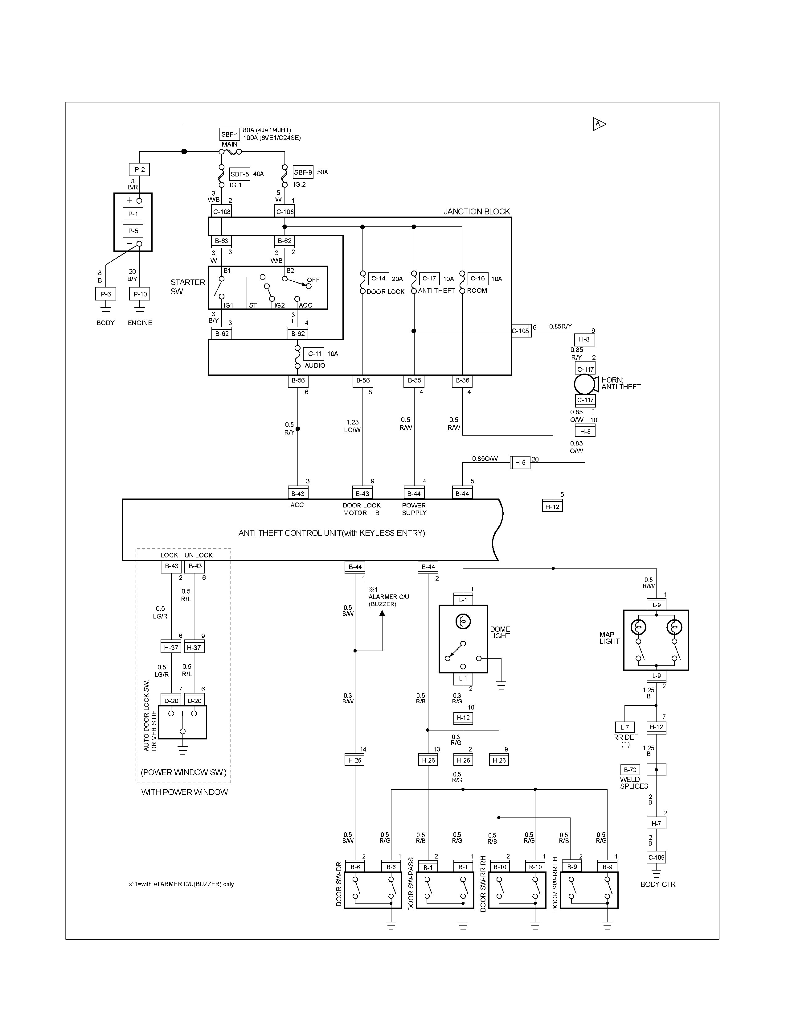
CIRCUIT DIAGRAM (LHD) Sheet 1/2
RTW680XF015701
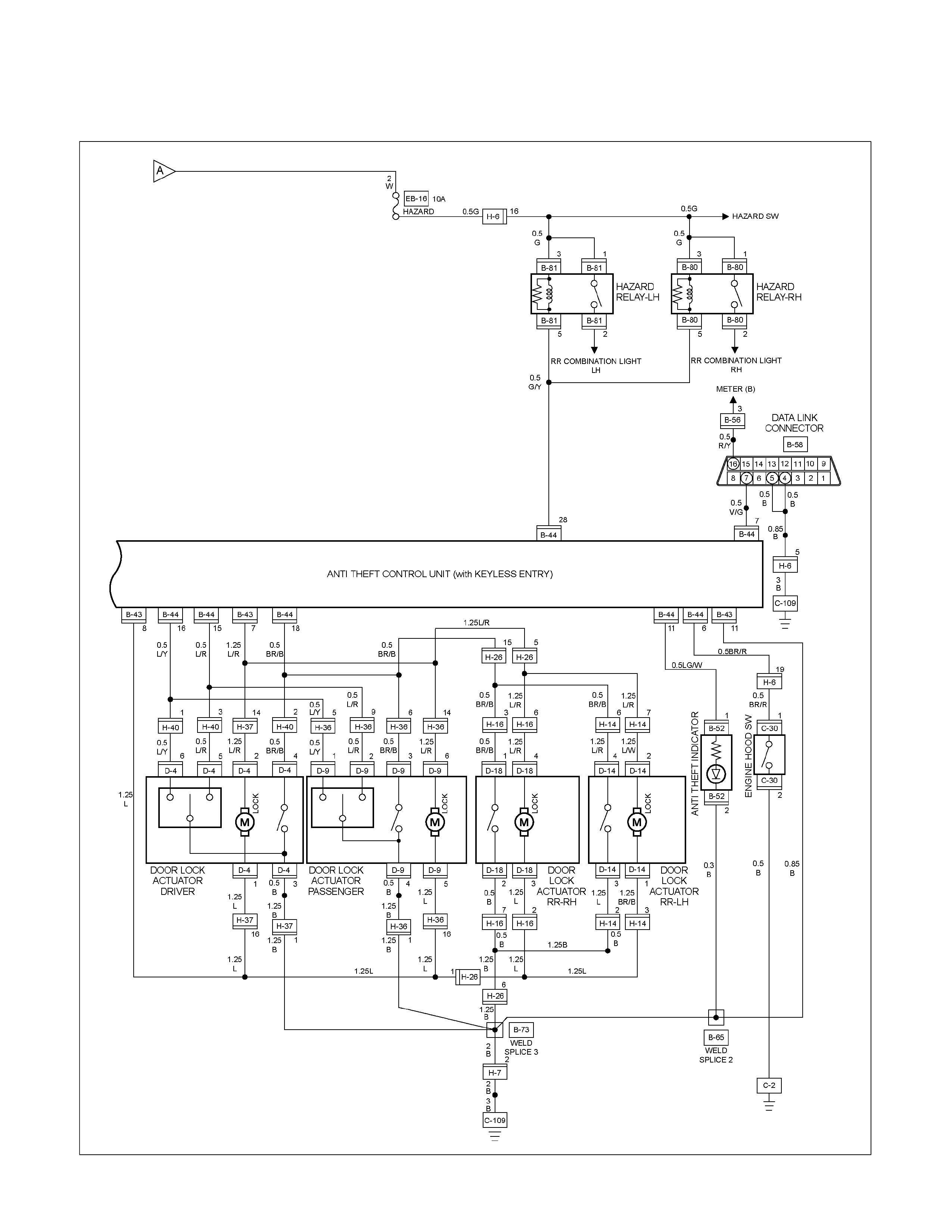
CIRCUIT DIAGRAM (LHD) Sheet 2/2
RTW680XF015801
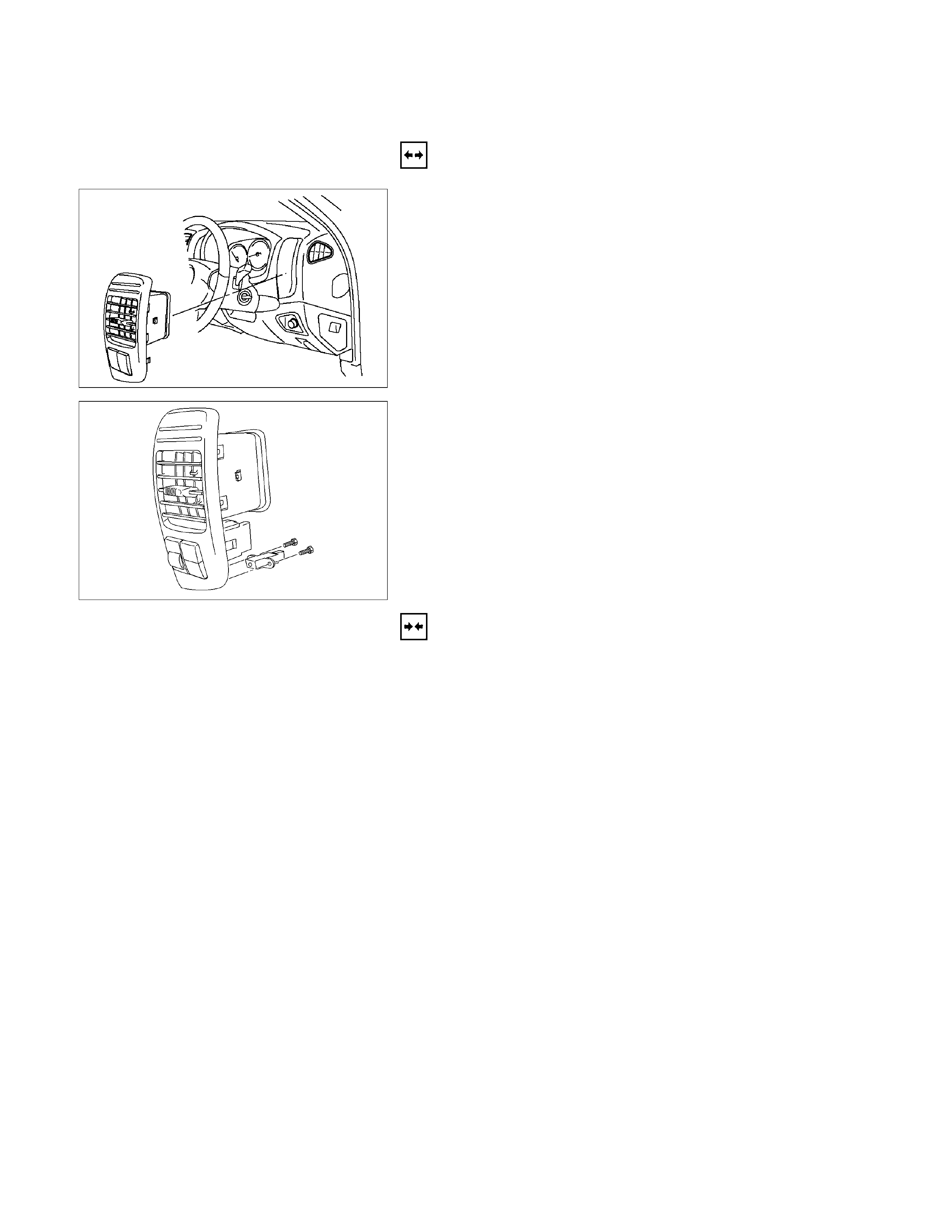
ANTI THEFT INDICATOR
Removal
1. Disconnect the battery ground cable.
RTW3A0SH001301
2. Remove the side ventilation grille.
RTW08ASH000101
3. Disconnect the indicator connector and screw from the
backside of the side ventilation grille to remove the anti
theft indicator.
Installation
To install, follow the removal steps in the reverse order, noting
the following point.
1. Push in the switch with your fingers until it locks securely.
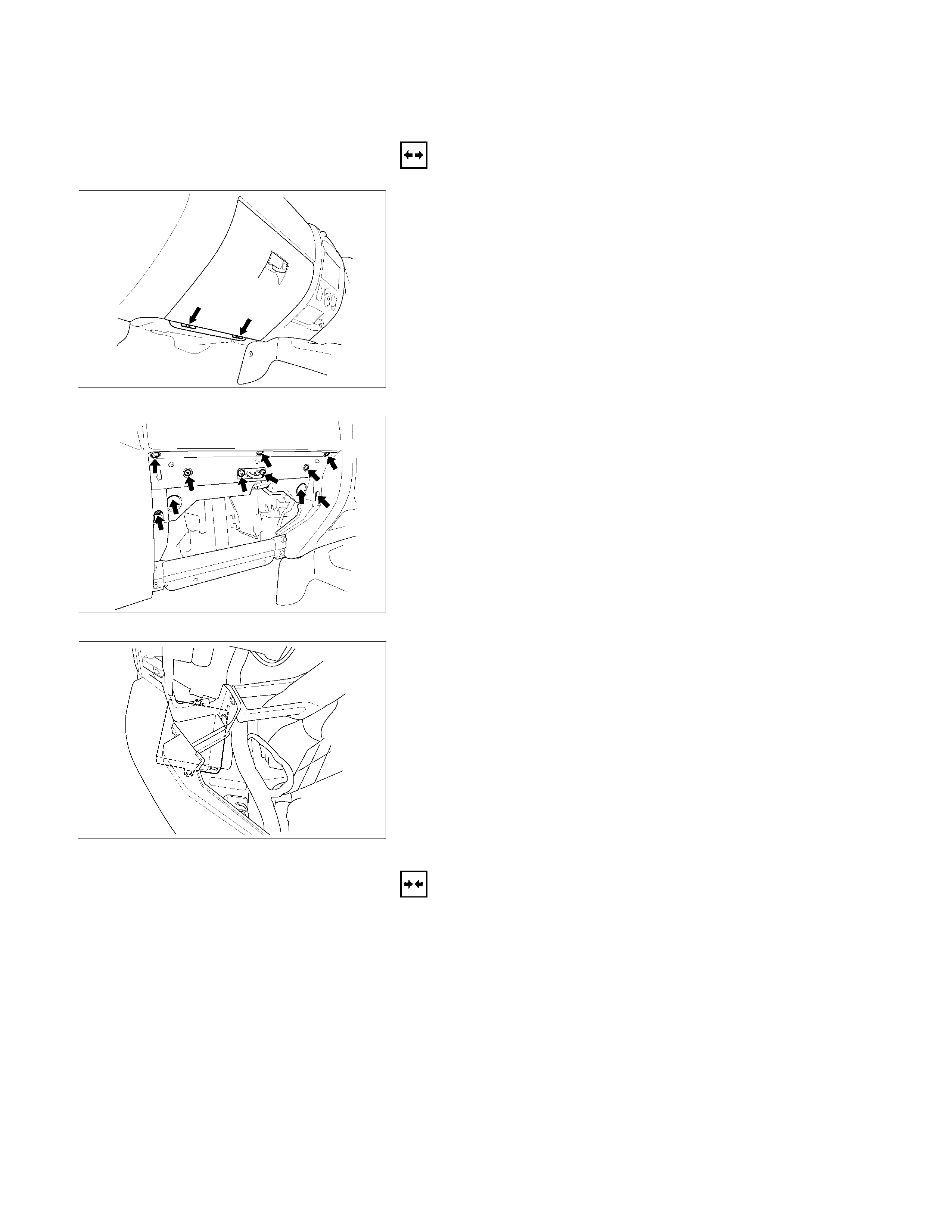
ANTITHEFT AND KEYLESS ENTRY CONTROL UNIT
Removal
1. Remove the glove box.
RTW580SH001601
2. Disconnect the glove box lamp connector.
RTW580SH001701
3. Remove the glove box cover.
RTW580SH001801
4. Remove the bolt of antitheft and keyless entry control unit.
5. Disconnect the antitheft and keyless entry control unit
connector.
6. Remove the antitheft and keyless entry control unit.
Installation
Follow the removal procedure in the reverse order to install the
antitheft and keyless entry control unit.
Connector
Be absolutely sure that the antitheft and keyless entry control
unit harness connector is correctly installed.
This will prevent a poor contact and an open circuit.
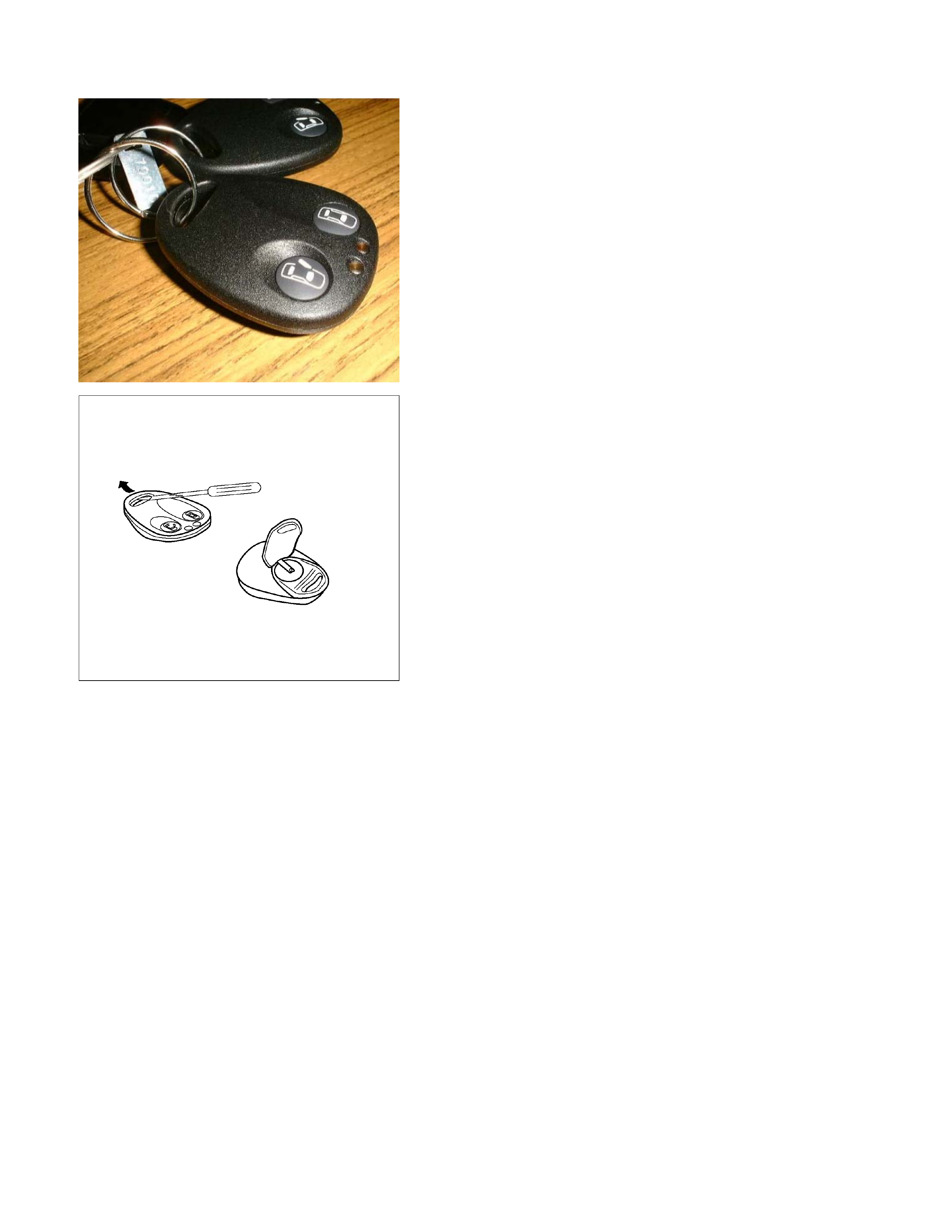
Remote key
Remove Key Assembly
Replacing the battery in the remote control unit
Replace the battery as soon as the range of the remote control
starts to become reduced.
Open the underside of the remote control unit by removing the
battery cover with a screwdriver as shown in the illustration.
Replace the battery, ensuring that it is inserted correctly.
Replace the battery cover so that it engages audibly. The
battery change must be performed within 3 minutes, otherwise
the remote control will have to be reprogrammed. Make sure
that you dispose of old batteries in accordance with
environmental protection regulations.
604RW055
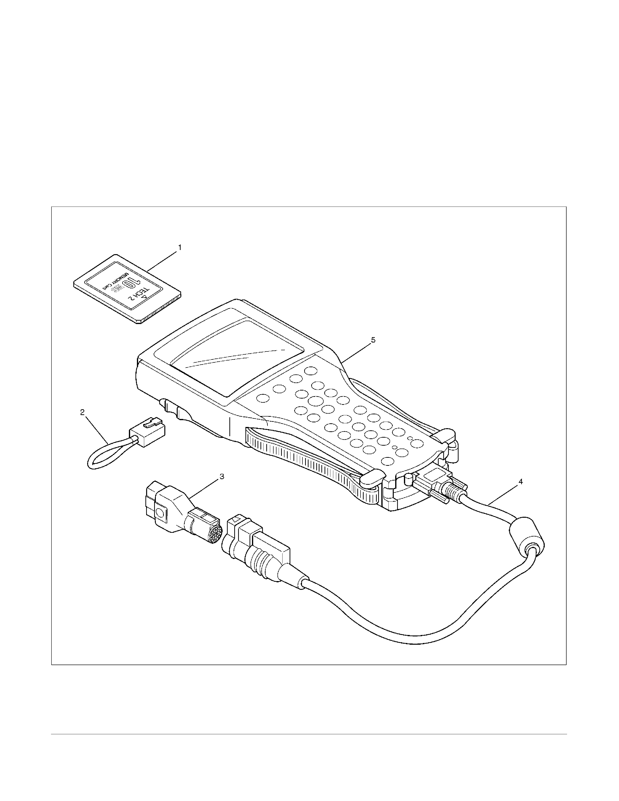
TECH-2 OPERATION AND PROGRAMING
KEYLESS ENTRY
General Description
When the anti-theft and keyless entry control unit and/or the
transmitters (remote keys) are replaced, the security codes
and/or transmitter ID codes must be programmed by using he
Tech-2. The following pages show the procedures to program
in regard to the anti-theft and keyless entry system. Please
refer to Tech-2 scan tool user’s guide in detail.
901RW180
Legend
(1) PCMCIA Card (4) DLC Cable
(2) RS 232 Loop Back Connector (5) Tech–2
(3)
S
AE 16/19 Adaptor
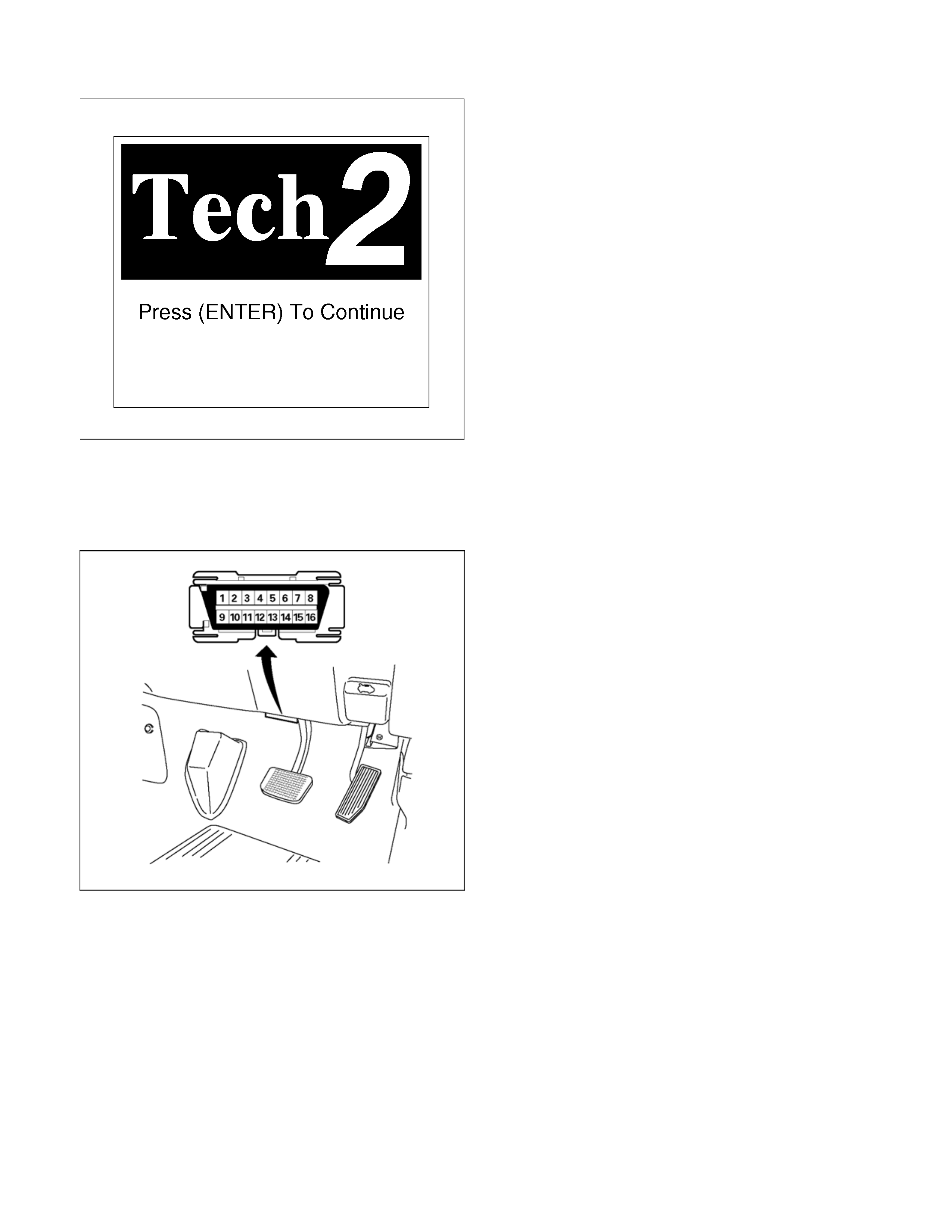
060RW009
Tech-2 Features
1. Tech-2 is a 12volt system. Do not apply 24 volts.
2.
A
fter connecting and/or installing the vehicle
communication interface (VCI) module, PCMCIA
card and data link connector (DLC) to the Tech-
2, connect the tool to the vehicle DLC.
3. Make sure the Tech-2 is OFF when removing o
r
installing the PCMCIA card.
4. The Tech-2 has the capability of two snapshot.
5. The PCMCIA card is sensitive to magnetism and
static electricity, so care should be taken in the
handling of the card.
6. The Tech-2 can not plot a graph when replaying
a snapshot.
7.
A
lways return to the Main Menu by pressing the
EXIT key several times before shutting down.
8. To clear diagnostic trouble codes (DTCs), open
Application Menu and press "Clear DTC ".
060R300015
Getting Started
Before operating the Isuzu PCMCIA card with the
Tech-2, the following steps must be performed:
1. The Isuzu System PCMCIA card inserts into the
Tech-2.
2. Connect the SAE 16/19 adapter to the DLC
cable.
3. Connect the DLC cable to the Tech-2.
4. Mark sure the vehicle ignition is off.
5. Connect the Tech-2 SAE 16/19 adapter to the
vehicle DLC.
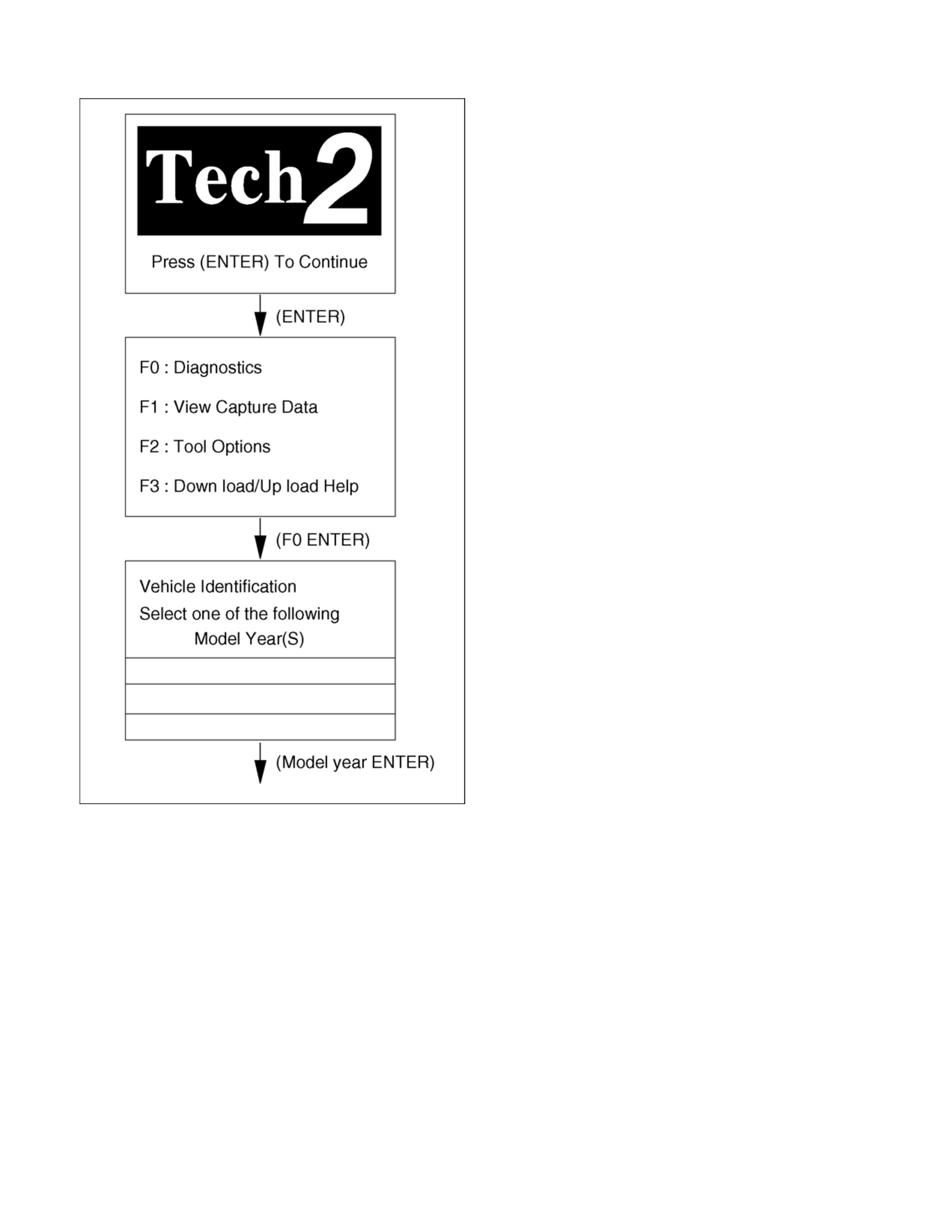
060R100102
Operating Procedure
The power up screen is displayed when you power
up the tester with the Isuzu systems PCMCIA card.
Follow the operating procedure.
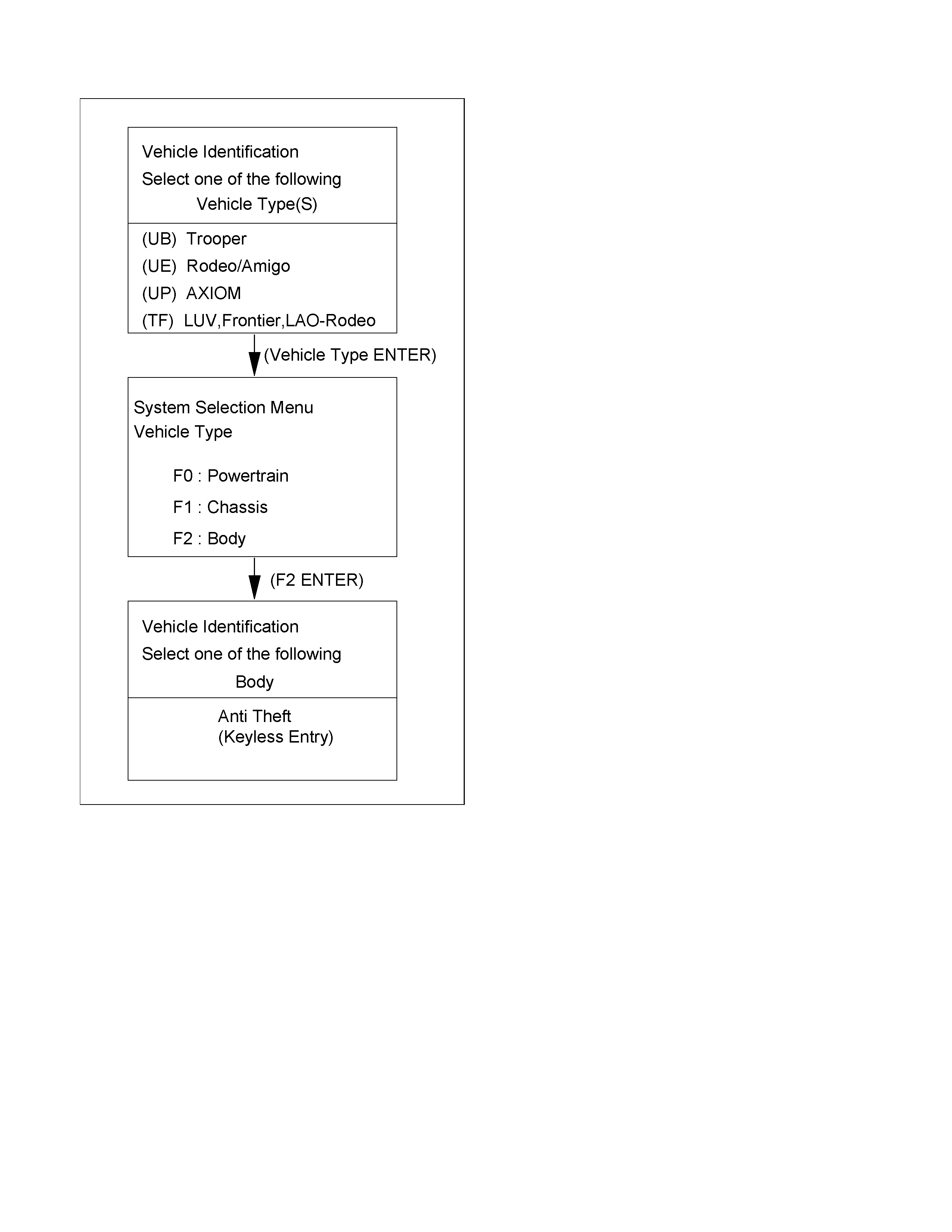
RTW38DLH000201
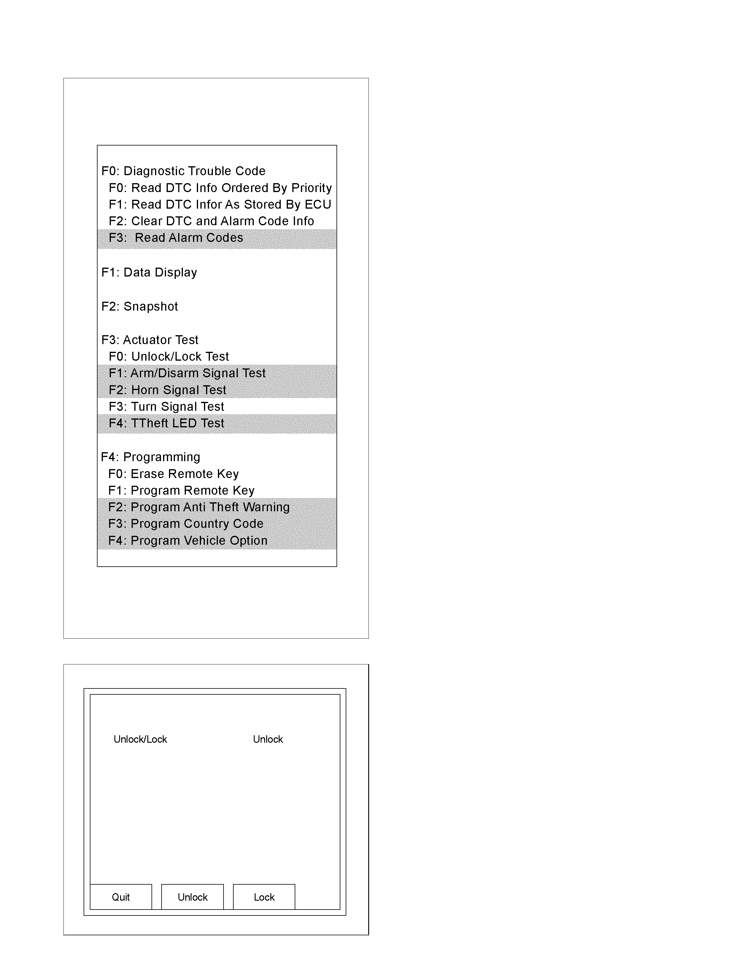
RTW38DLH000101
Menu
The left table shows witch functions are used for the
available equipment versions.
NOTE: Marked items are not applied for keyless entry
system.
DTC
On OBD has three options available in the Tech-2
DTC mode to display the enhanced information
available.
• Read DTC Info Ordered By Priority.
• Read DTC Info As Stored By ECU.
• Clear DTC and Alarm Code Info.
Clear DTC Information
To clear Diagnostic Trouble Codes (DTCs), Use the
diagnostic scan tool “Clear DTC Information” function.
Tech-2 Data Display
The Tech-2 data values represent values that would
be seen on a normally-keyless entry system.
RTW38DSH001601
Actuator Test
Unlock/Lock Test
Check whether opening and closing of a door lock
can be performed by operation of Tech-2.
1. Turn the key “OFF”.
2. Turn the key “ON”.
3. Check the display and test menu.
4. Operate the Tech-2.
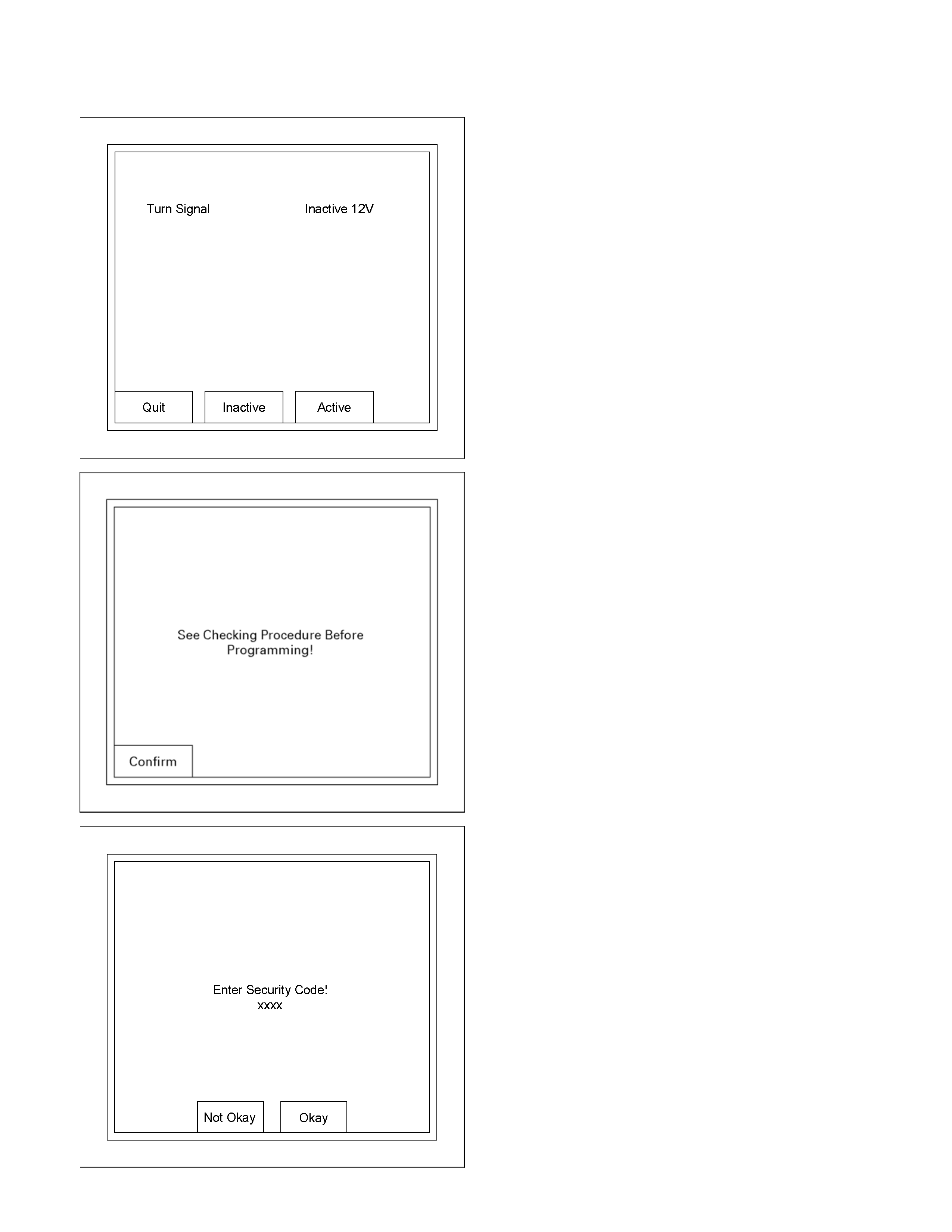
RTW38DSH001701
Turn Signal Test
Check the turn signal lamp lights up by operation of
Tech-2.
1. Turn the key “OFF”.
2. Turn the key “ON”.
3. Check the display and test menu.
4. Operate the Tech-2.
060R200289
Programming
Erase Remove Key
To erase remove control key code in the control unit.
1. Check the display of Tech-2 and press “Confirm”
key.
RTW38DSH001001
2. Enter security code.
3. Press “Not Okay” or “Okay” key.
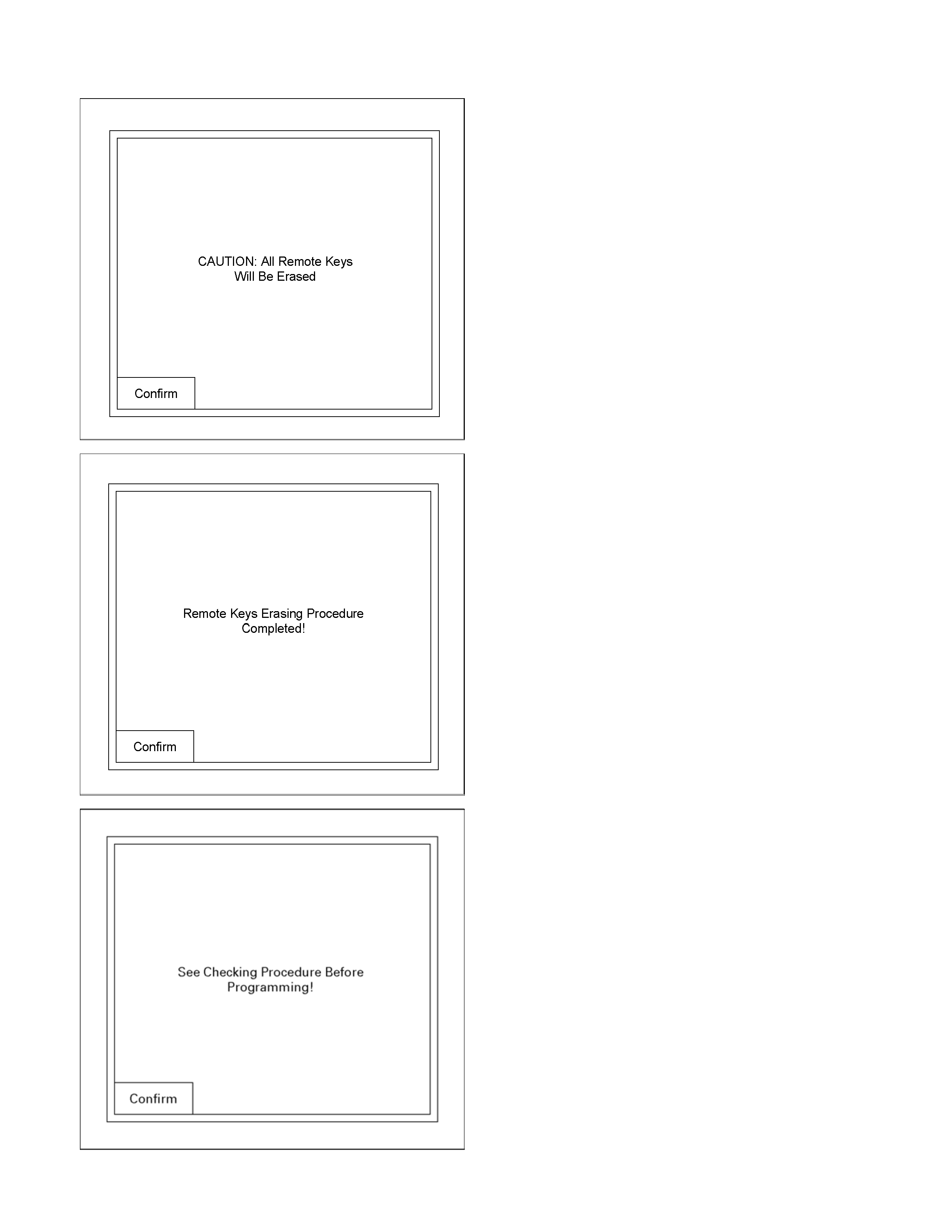
RTW38DSH001101
4. Check the display of Tech-2 and press “Confirm”
key.
RTW38DSH001201
5. Check the display of Tech-2 and press “Confirm”
key.
060R200289
Program Remote Key
To program remote control key code in the control
unit.
1. Check the display of Tech-2 and press “Confirm”
key.
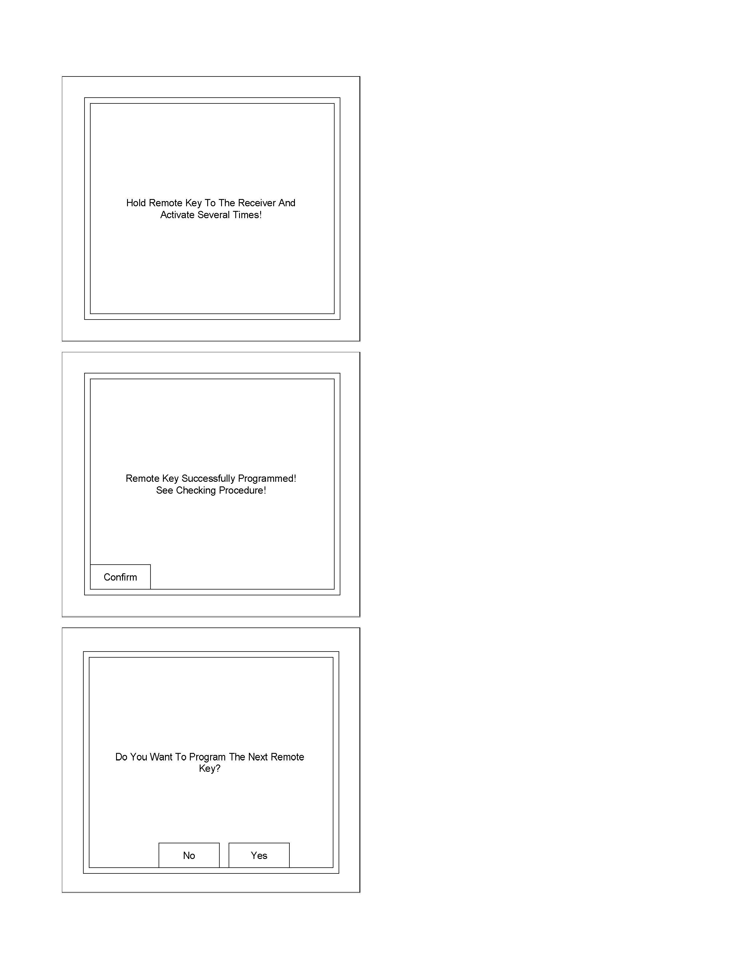
RTW38DSH001301
2. Check the following table in the display of Tech-2.
3. Operate the remote key.
RTW38DSH001401
4. Check the display of Tech-2 and press “Confirm”
key.
RTW38DSH001501
5. Check the display of Tech-2 and press “No” o
r
“Yes” key.
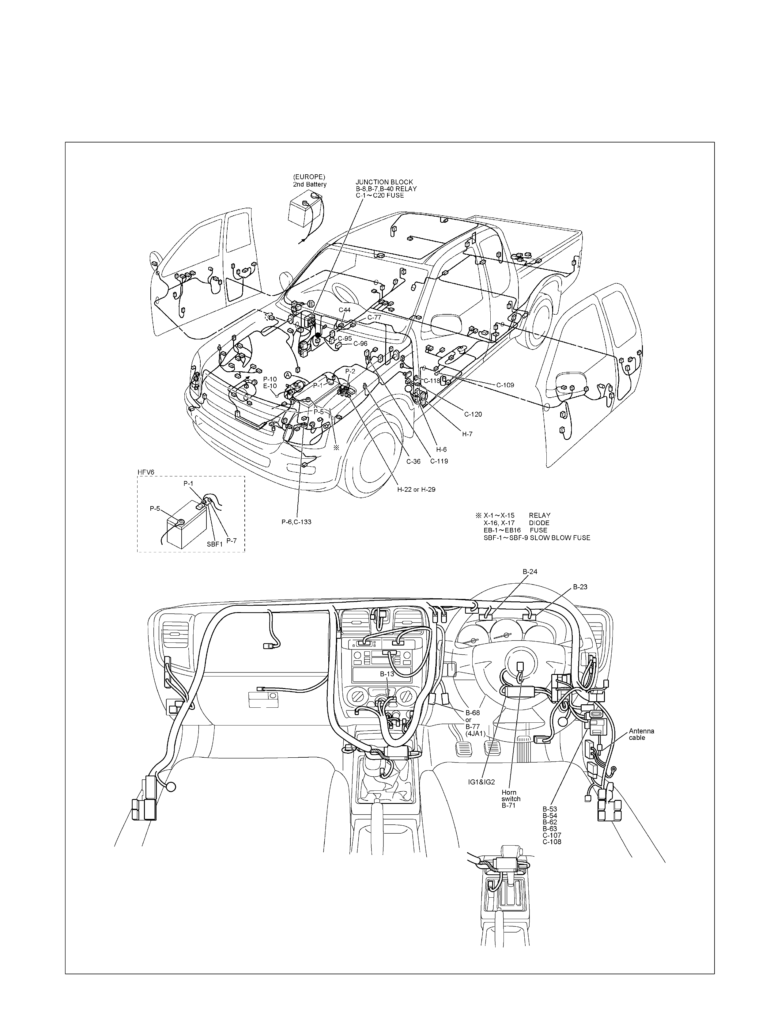
AUTO CRUISE
PARTS LOCATION
RTW68AXF017601 & RTW68AXF013901

PARTS LOCATION HFV6
RTW68AXF012201
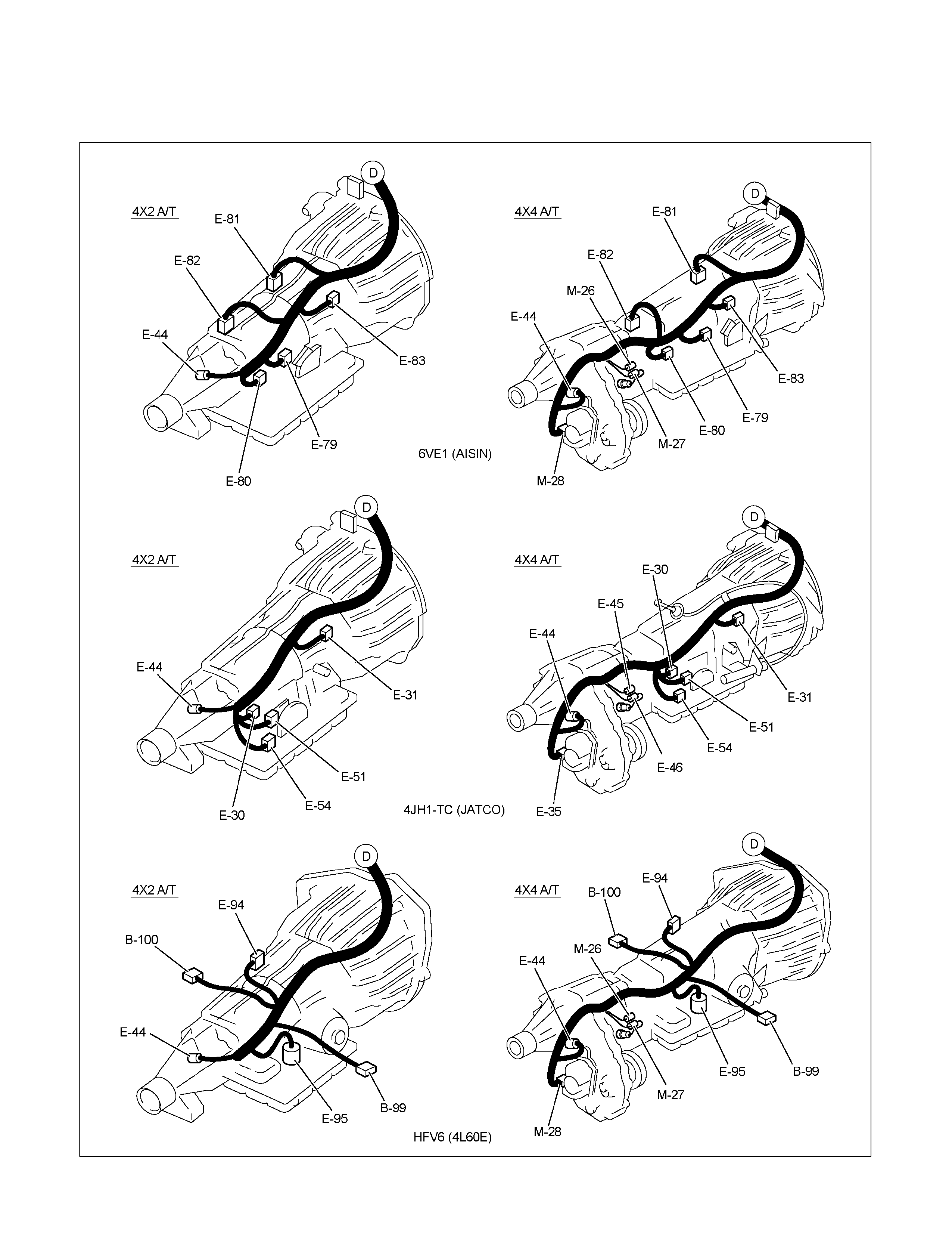
PARTS LOCATION
RTW68AXF012801
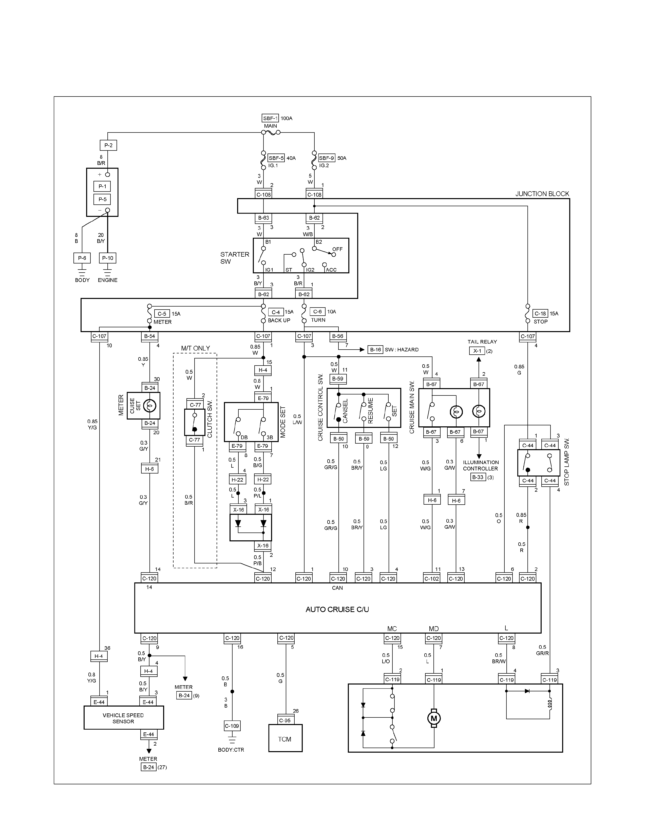
CIRCUIT DIAGRAM EXCEPT HFV6
RTW680XF015901
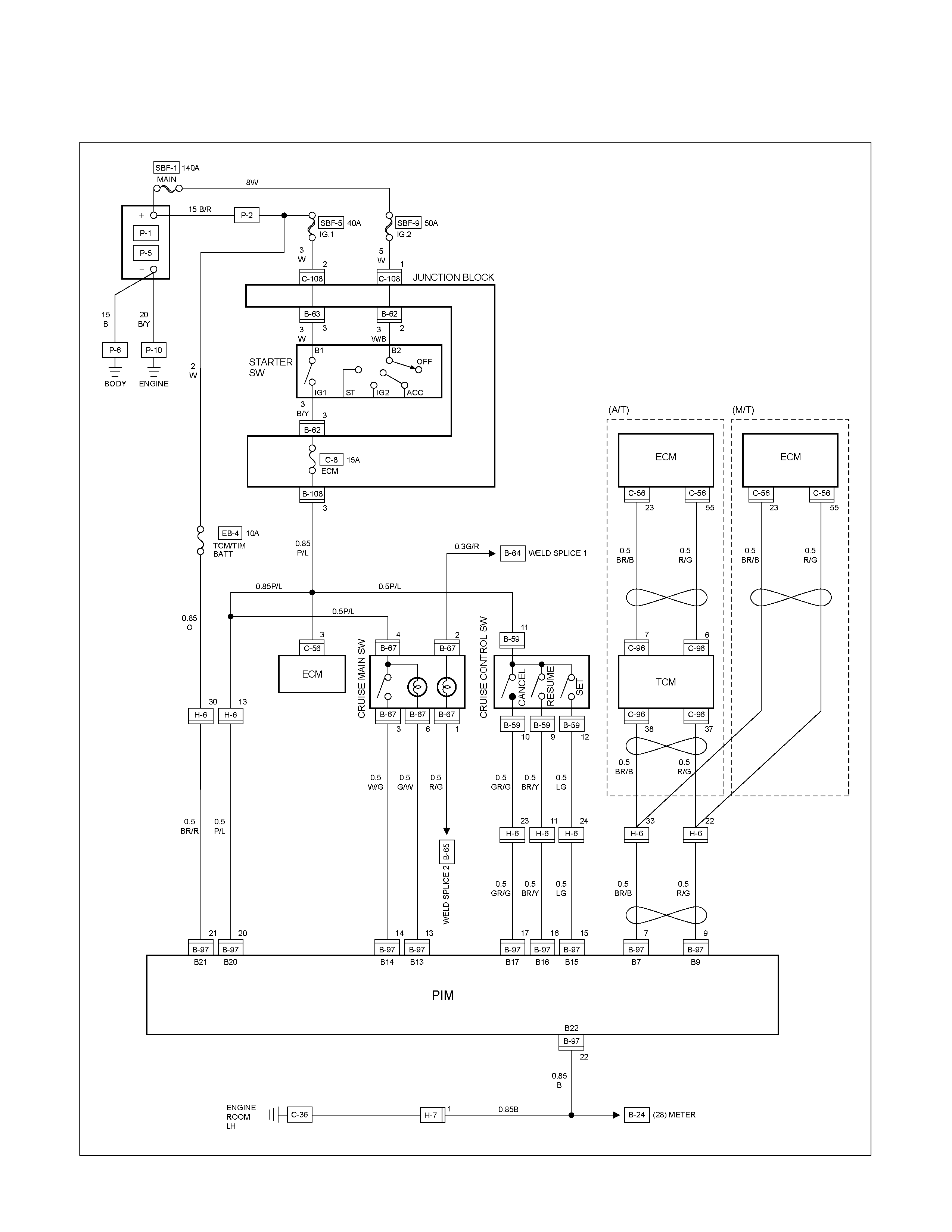
CIRCUIT DIAGRAM HFV6
RTW68AXF013401
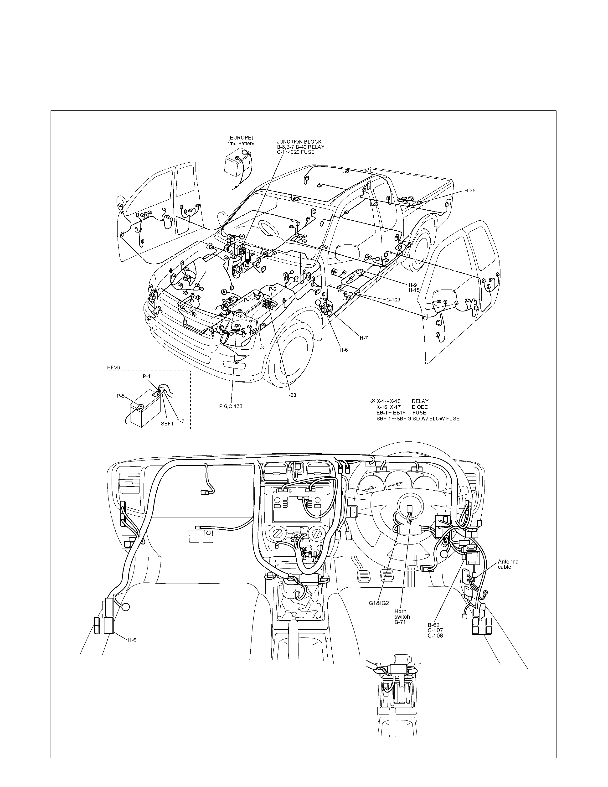
TRAILER HITCH
PARTS LOCATION (RHD)
RTW68AXF017801 & RTW68AXF017901
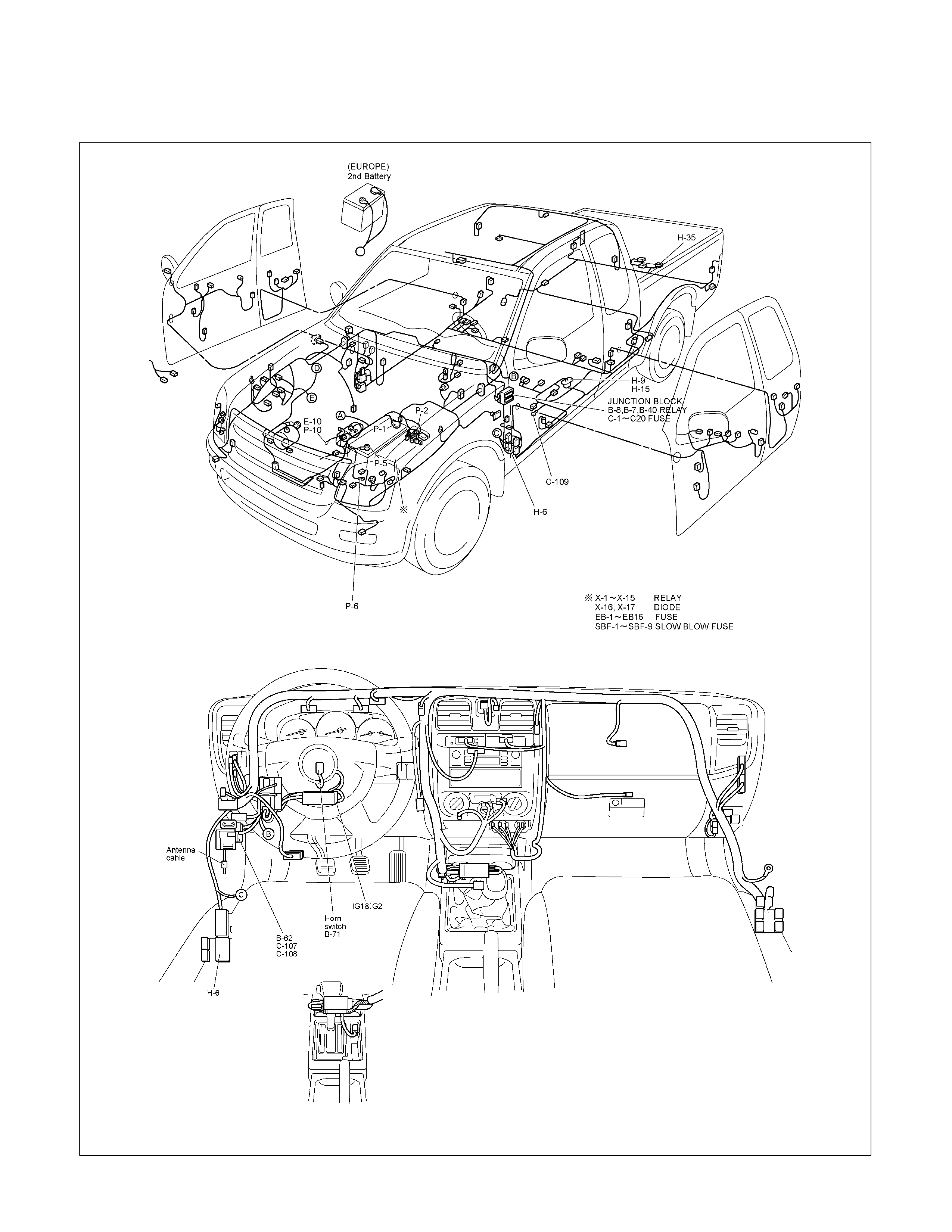
PARTS LOCATION (LHD)
RTW48AXF023301 & RTW48AXF023401
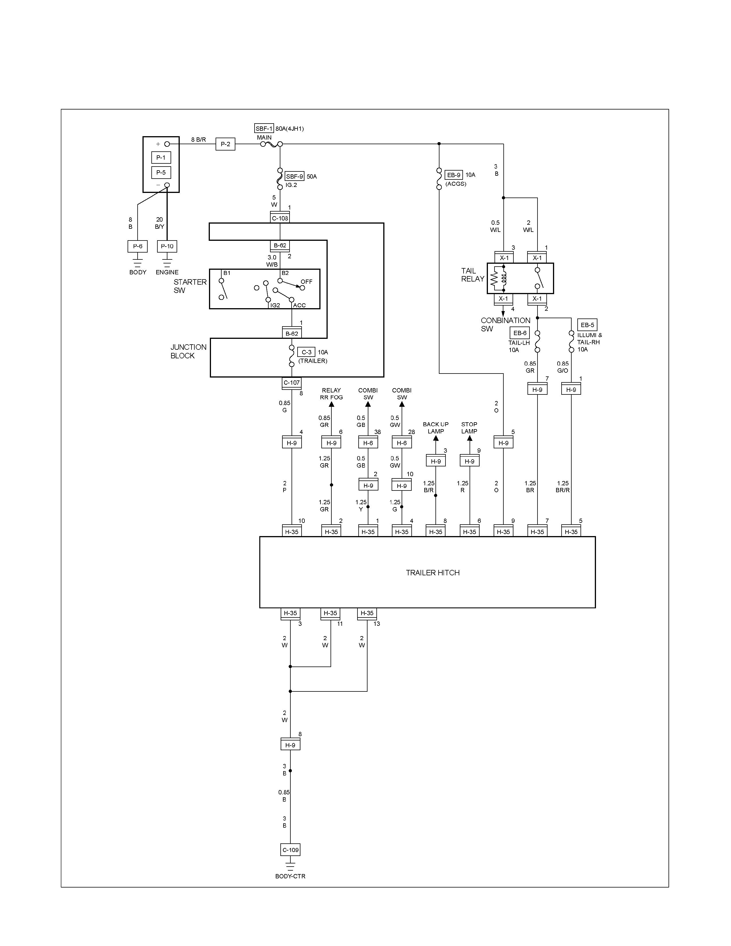
CIRCUIT DIAGRAM EXCEPT AUSTRALIA
RTW680XF016001
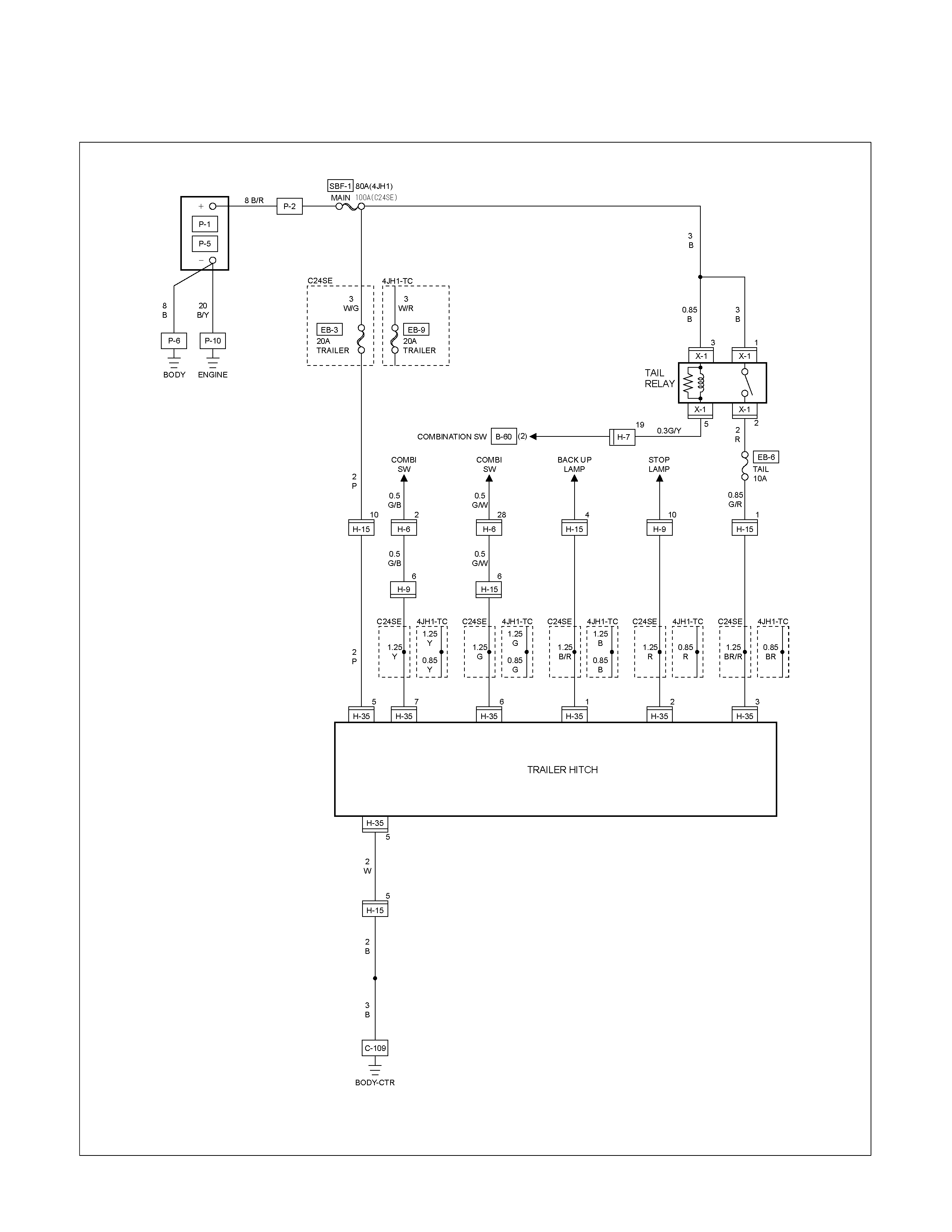
CIRCUIT DIAGRAM EXCEPT HFV6 AUSTRALIA
RTW680XF016101
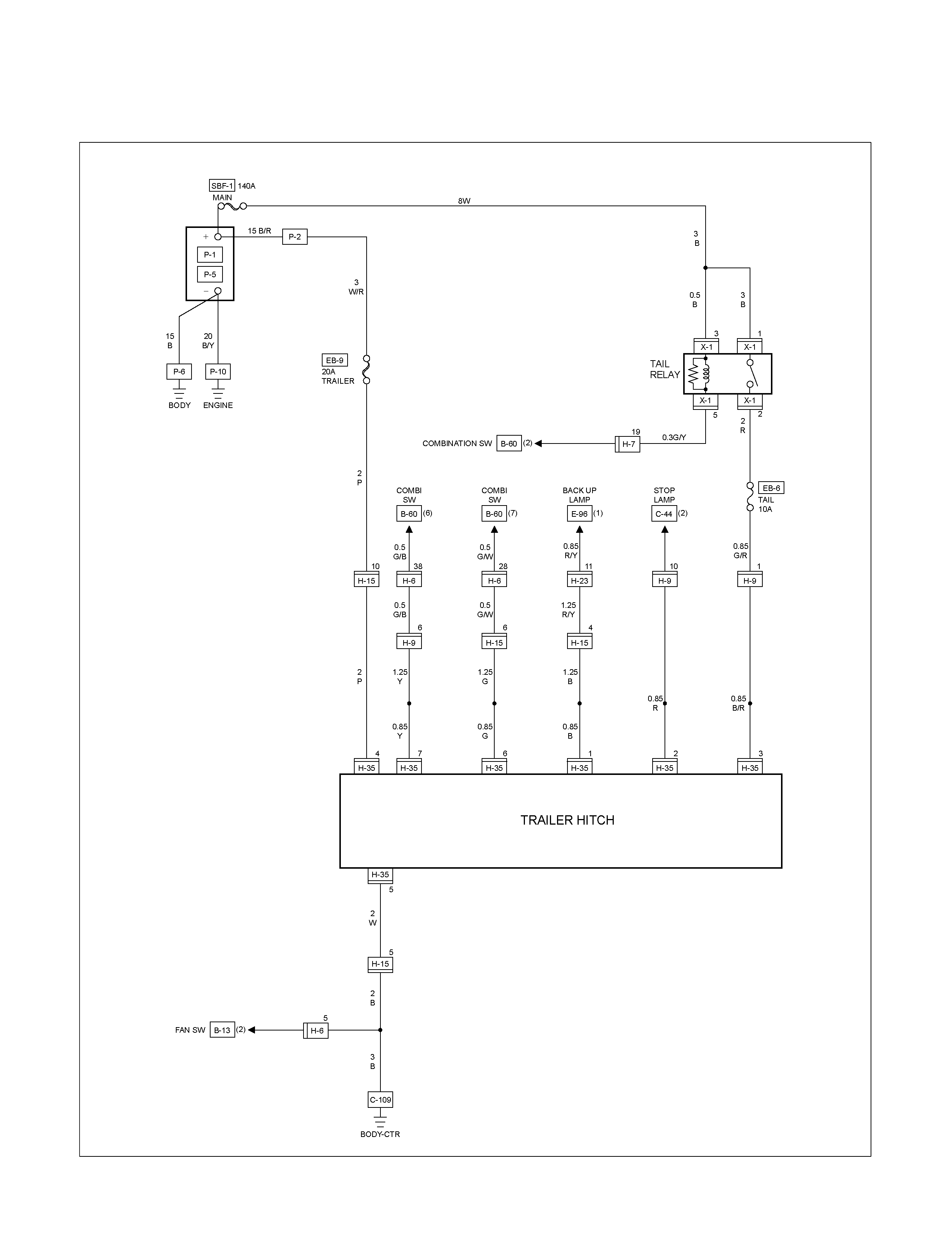
CIRCUIT DIAGRAM HFV6 AUSTRALIA
RTW68AXF013501
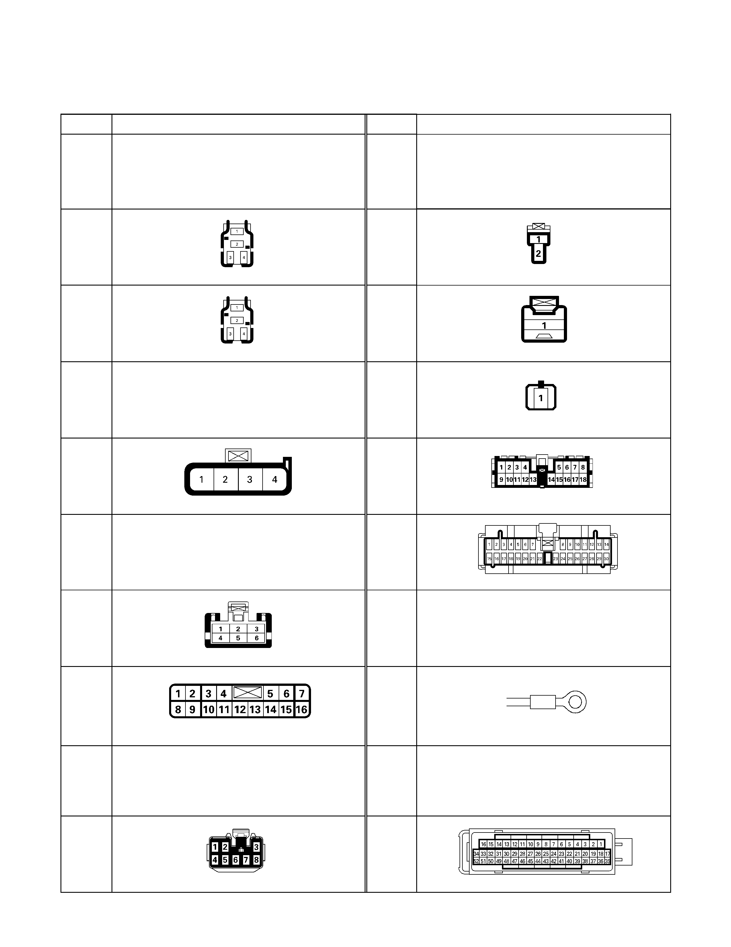
CONNECTOR LIST
No. Connector face No. Connector face
B-1
~
B-6
NOT USED
B-17
~
B-19
NOT USED
B-7
Black
Rear defogger relay
B-20
White
Cigar lighter illumination
B-8
Black
Power Window Relay
B-21
White
Cigar lighter
B-9
NOT USED
B-22
Black
Cigar lighter
B-10
White
Clock
B-23
Green
Meter-A
B-11
∼
B-12
NOT USED
B-24
Green
Meter-B
B-13
White
Fan switch
B-25
~
B-27
NOT USED
B-14
Gray
Audio
B-28
Green Ground Driver Side
B-15
NOT USED
B-30
~
B-29
NOT USED
B-16
White
Hazard switch
B-31
SDM
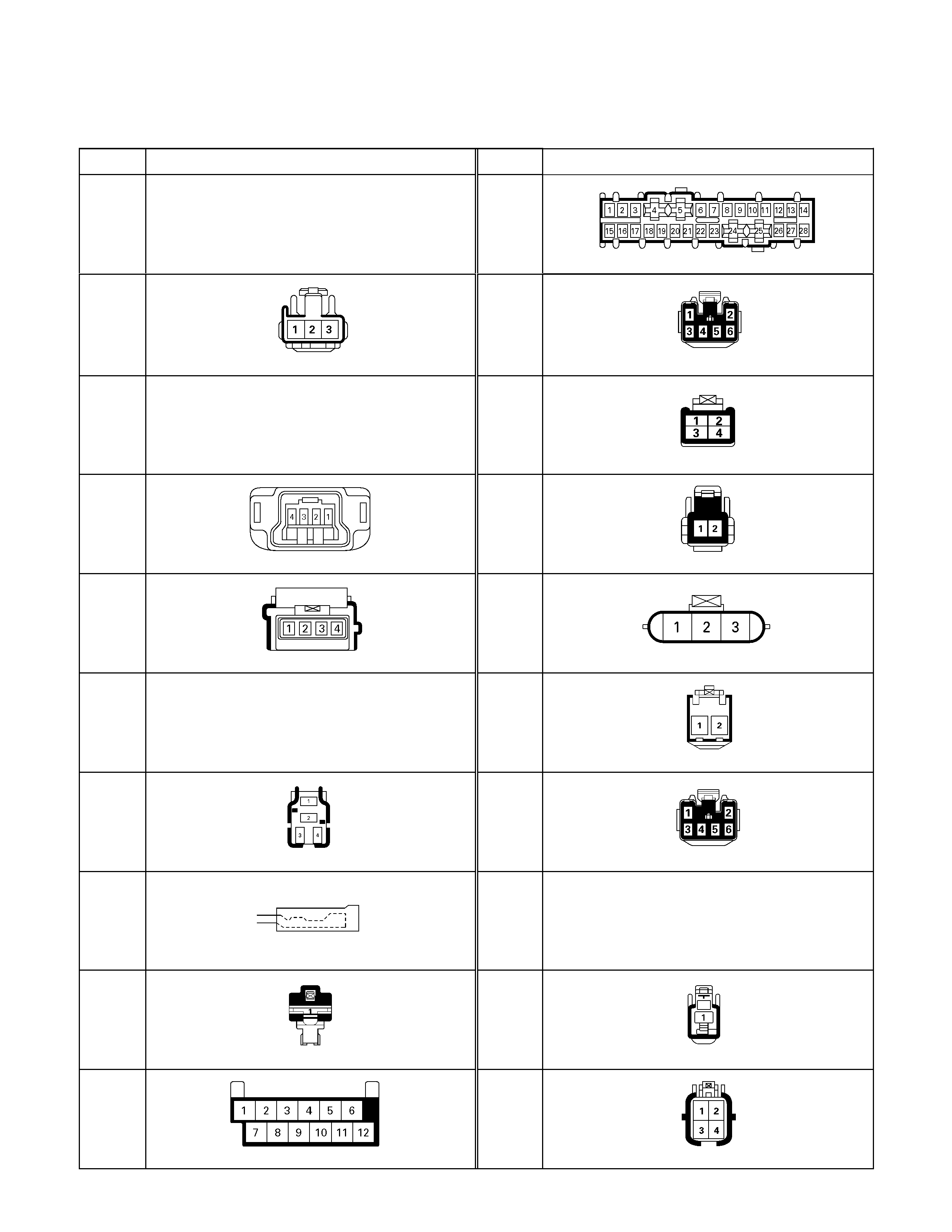
No. Connector face No. Connector face
B-32
NOT USED
B-44
Keyless Entry (B)
B-33
Illumination control
B-45
White
Alarmer control unit
B-34
NOT USED
B-46
Gray
Rear defogger timer
B-35
Yellow
Infrator; passenger side
B-47
White
Glove box illumination
B-36
Yellow
Infrator; Driver side
B-48
Black
G/sensor
B-37
~
B-39
NOT USED
B-49
White
A/T Lever
B-40
Black
Acc socket relay
B-50
White
Power/3rd start switch
B-41
Natural
Acc socket
B-51
~
B-52
NOT USED
B-42
White
Acc socket
B-53
White
J/B I1
B-43
Keyless Entry (A)
B-54
White
J/B I2
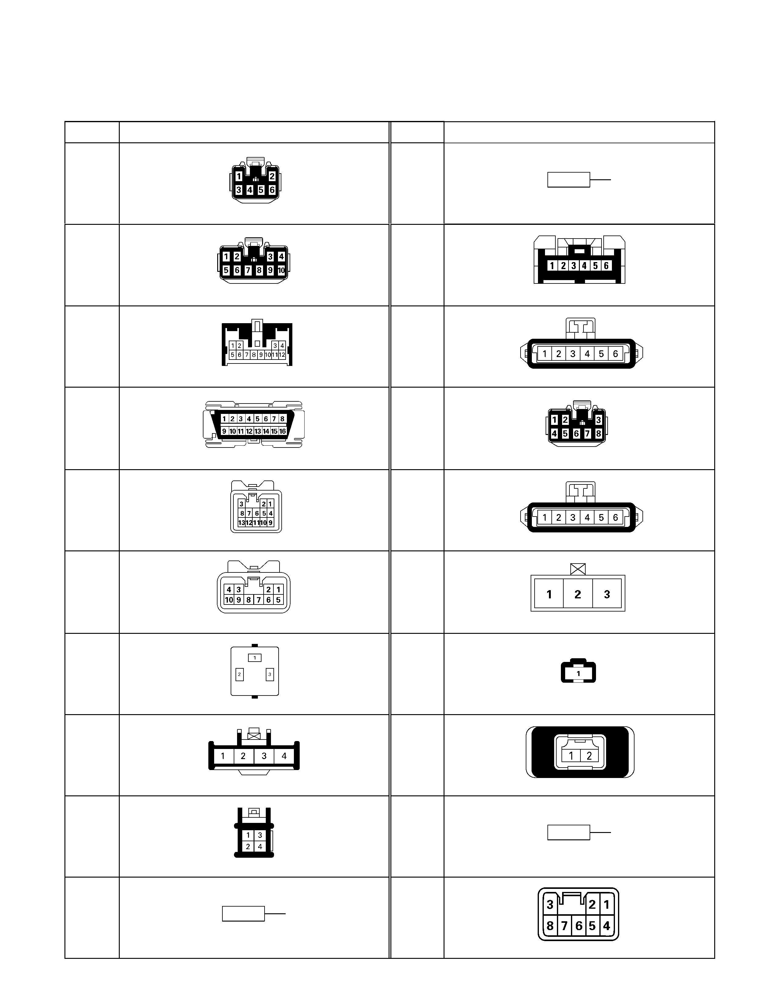
No. Connector face No. Connector face
B-55
White
J/B I3
B-65
Silver
Weld splice 2 (Ground)
B-56
White
J/B I4
B-66
White
4×4 switch
B-57
White
HVAC control unit
B-67
(6VE1)
(HFV6)
Black
Cruise main
B-58
Black
Check connector
B-68
(6VE1)
(4JH1-TC)
(C24SE)
(HFV6)
Immobilizer
B-59
White
Combination switch-A
B-69
Door lock switch
B-60
White
Combination switch-B
B-70
(6VE1)
(4JH1-TC)
(C24SE)
(HFV6)
Immobilizer Coil
B-61
Black
Flasher relay
B-71
Yellow
Horn
B-62
White
Ignition switch (IGSUB : G1)
B-72
Yellow
SRS
B-63
White
Ignition switch (IGSUB : G2)
B-73
Black
Weld Splice 3
B-64
Silver
Weld splice 1 (Illumination)
B-74
White
Cellular phone
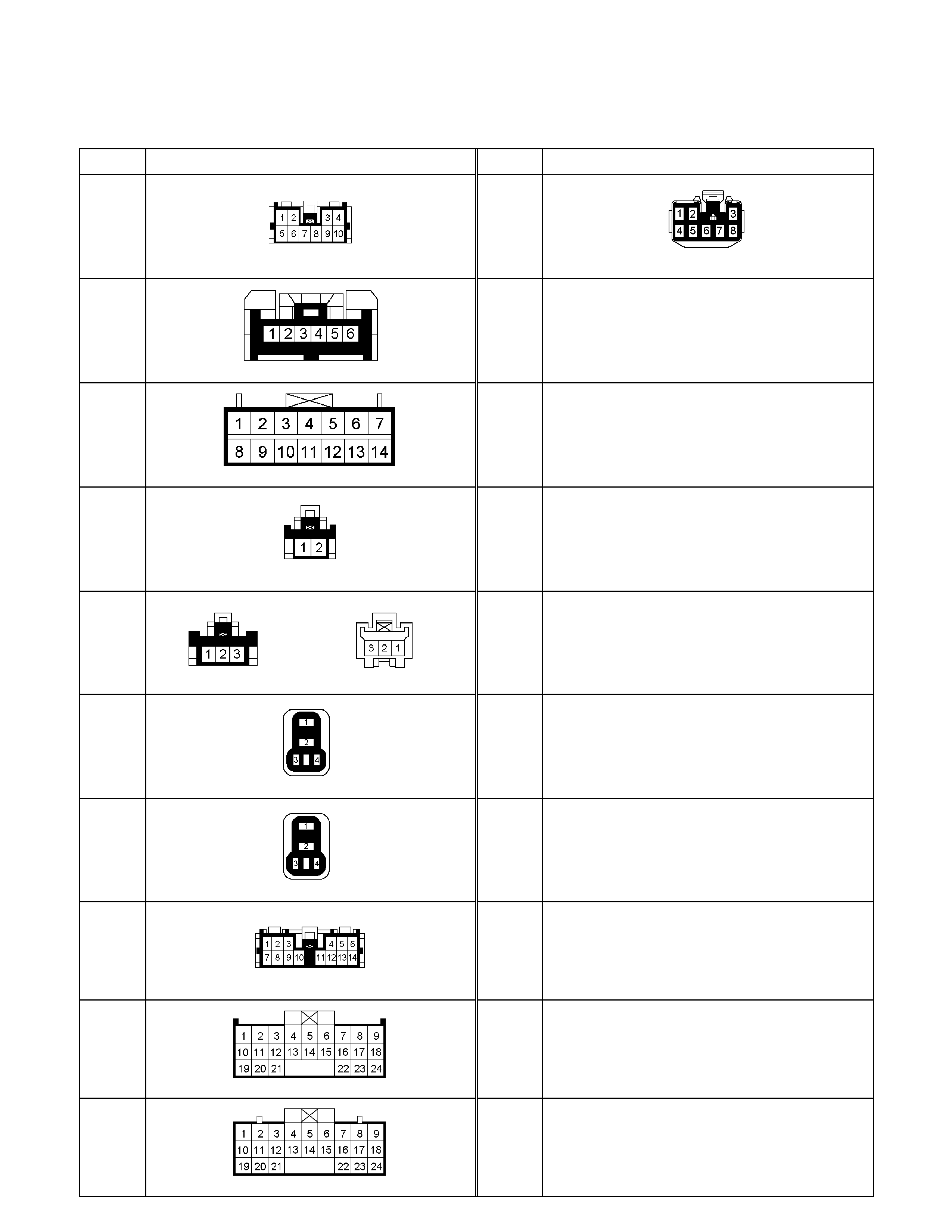
No. Connector face No. Connector face
B-75
Black Rear fog C/U
B-98
Green
Door Lock Controller
B-76
White Front & rear fog light switch
B-77
(4JA1-L)
White Immobilizer C/U
B-78
White Immobilizer antenna coil
B-79
White
Short connector (cooler only)
B-80
Black Hazard relay (RH)
B-81
Black
Hazard relay (LH)
B-95
White
Keyless entry control unit
B-96
Gray
PIM A
B-97
White
PIM B
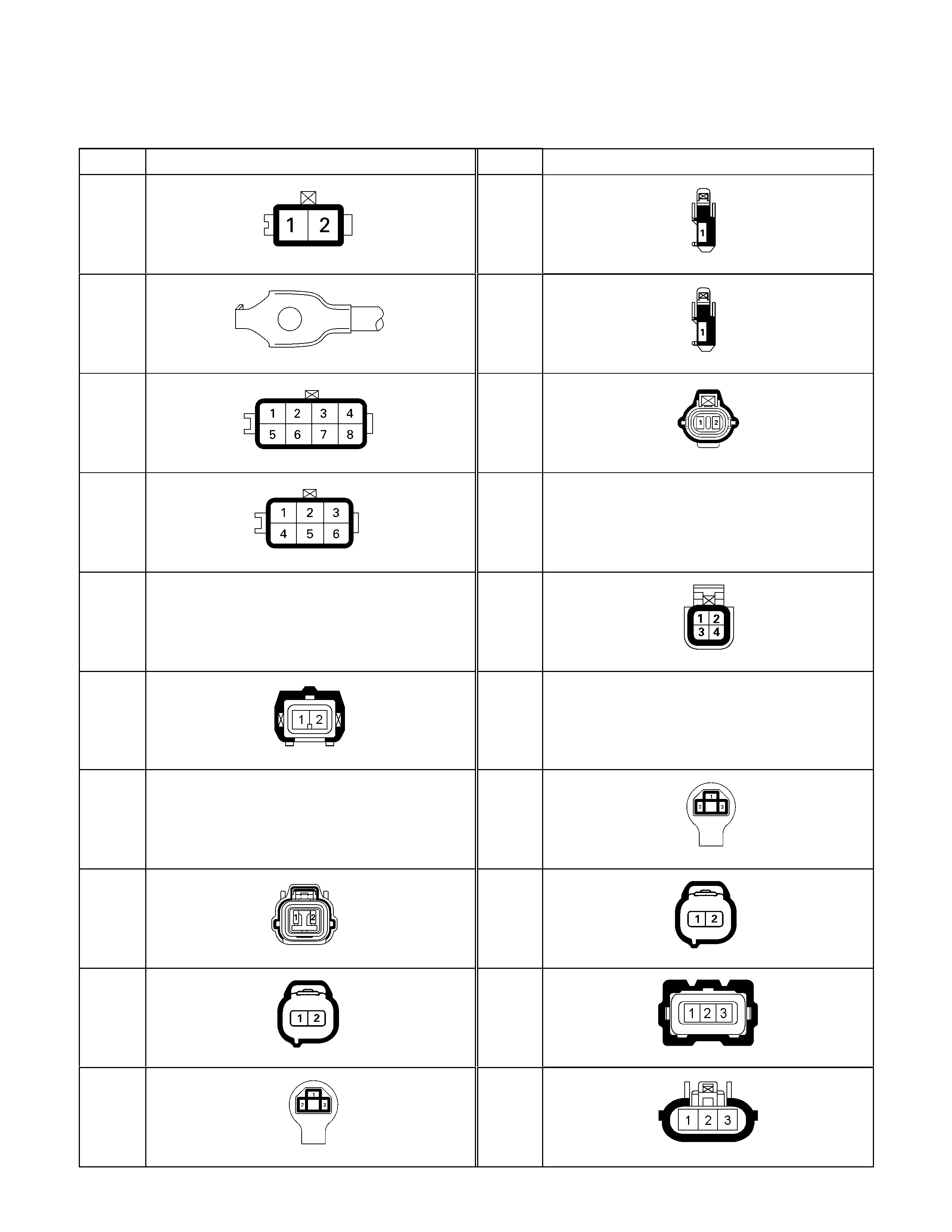
No. Connector face No. Connector face
C-1
Gray
Side turn lamp-RH
C-20
(6VE1)
(4JH1-TC)
Horn ; high note
C-2
Silver
Engine room-RH ground
C-21
Black
Horn ; Low note
C-3
(6VE1)
(4JH1-TC)
INT Relay
C-22
Front turn lamp-RH
C-4
Light-
blue
Front wiper motor
C-23
NOT USED
C-5
~
C-14
NOT USED
C-24
Triple pressure switch
C-15
White
FICD VSV
C-25
NOT USED
C-16
NOT USED
C-26
Black
Head lamp-LH
C-17
Gray
Front wiper motor
C-27
Clearance lamp-LH
C-18
Clearance lamp-RH
C-28
Gray
Head Light - RH
C-19
Black
Head lamp-RH
C-29
Gray
Head Light - LH
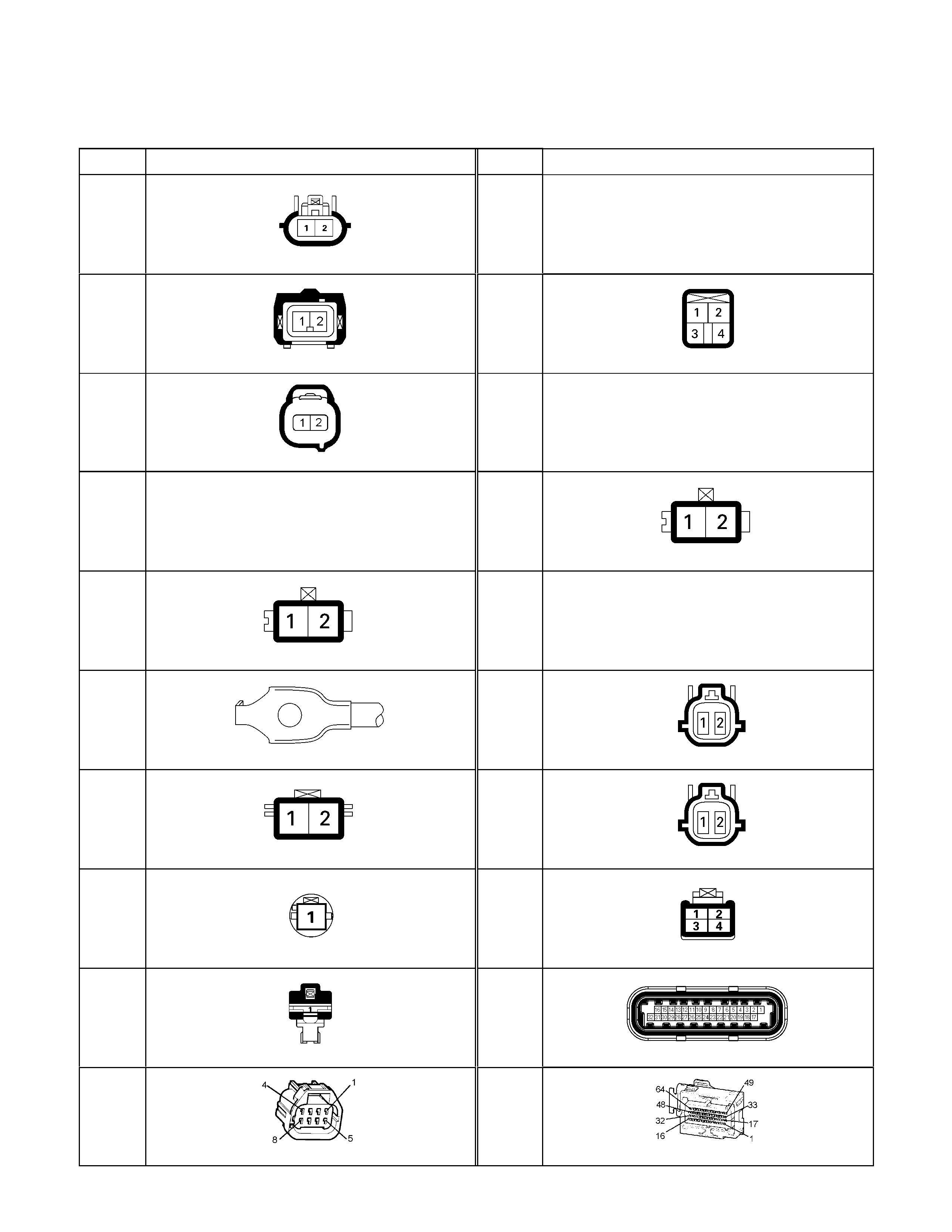
No. Connector face No. Connector face
C-30
Black
Engine hood switch
C-41
~
C-43
NOT USED
C-31
EGR VSV FRONT
C-44
White
Stop lamp switch
C-32
EGR VSV REAR
C-45
~
C-49
NOT USED
C-33
~
C-34
NOT USED
C-50
Condenser fan
C-35
Gray
Side turn lamp-LH
C-51
~
C-52
NOT USED
C-36
Silver
Engine room-LH ; Ground
C-53
(6VE1)
(4JH1-TC)
(HFV6)
Orange
ABS sensor Front-RH
C-37
Black
Brake fluid level switch
C-54
(6VE1)
(4JH1-TC)
(HFV6)
Orange
ABS sensor Front-LH
C-38
(4JH1-TC)
Vacuum switch
C-55
Brown
Thermo AMP
C-39
Parking brake switch (stick type)
C-56
(C24SE)
ECM
C-40
Black
APP Sensor
C-56
(HFV6)
ECM
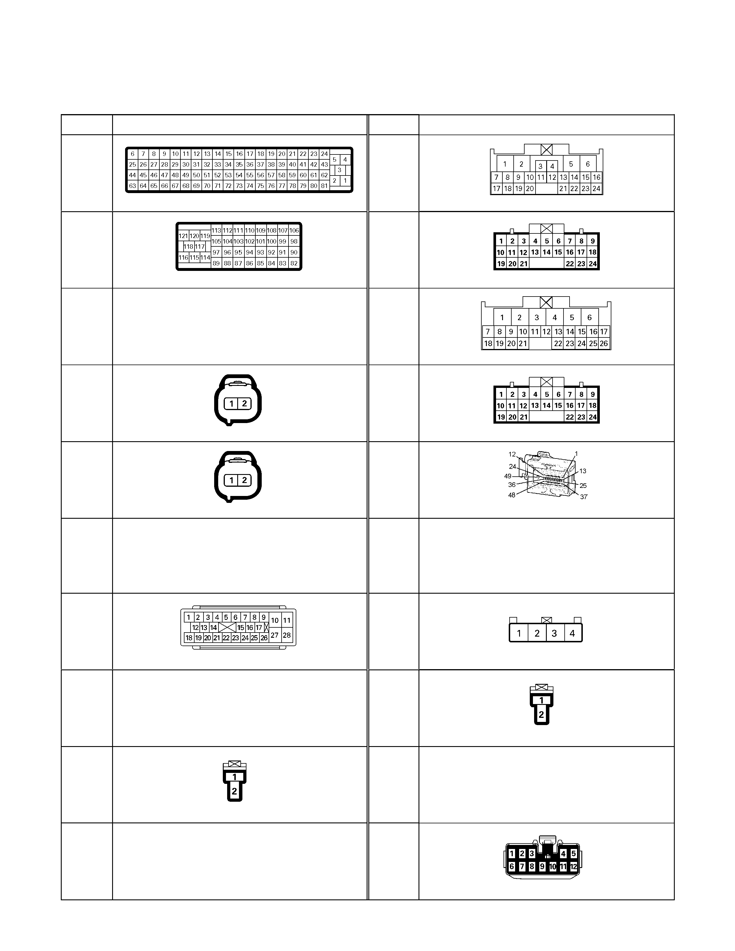
No. Connector face No. Connector face
C-56
(4JA1-TC
4JH1-TC)
ECM-A
C-94
(6VE1)
Gray
TCM-(A)
C-57
(4JA1-TC
4JH1-TC)
ECM-B
C-94
(4JA1-TC /
4JH1-TC)
White
TCM
C-58
~
C-62
NOT USED
C-95
(6VE1)
White
TCM-(B)
C-63
(6VE1)
(4JH1-TC)
Gray
Front Fog lamp-RH
C-95
(4JA1-TC /
4JH1-TC)
White
TCM
C-64
(6VE1)
(4JH1-TC)
Gray
Front Fog lamp-LH
C-96
(HFV6)
Black
TCM
C-65
~
C-66
NOT USED
C-97
~
C103
NOT USED
C-67
(6VE1)
(4JH1-TC)
(HFV6)
Black
EHCU
C-104
Brown
Resister
C-68
~
C-76
NOT USED
C-105
White
Blower motor
C-77
Clutch switch
C-106
NOT USED
C-78
~
C-93
NOT USED
C-107
White
J/B E2
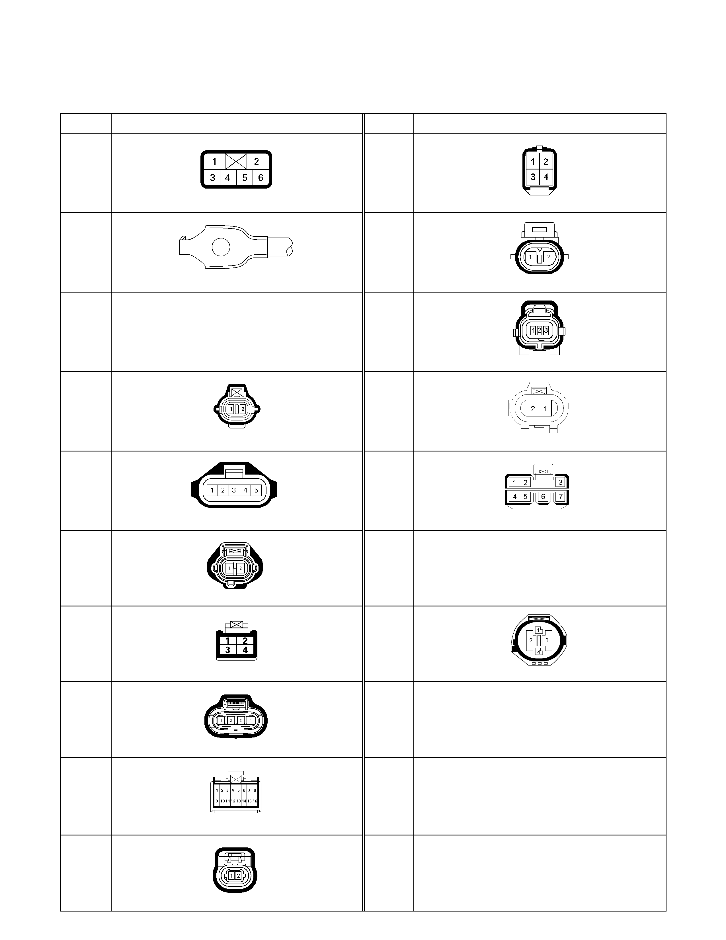
No. Connector face No. Connector face
C-108
White
J/B E1
C-122
(C24SE)
White Co adjuster connector
C-109
Silver
Body-LH ; ground
C-123
(4JA1-TC/
4JH1-TC)
Black EVRV; T/C
C-110
~
C-114
NOT USED
C-124
Black Lowe pressure sensor
C-115
(4JH1-TC)
Brown
EVRV
C-125
White Thermoswitch (Air)
C-116
C-126
White QOS control unit
C-117
(6VE1)
(4JH1-TC)
Anti theft horn
C-127
~
C-130
NOT USED
C-118
(4JH1-TC)
A/C Resister & Neutral switch
C-131
Black
Radiator Fan Motor
C-119
(6VE1)
Auto cruise actuator
C-132
Black
A/C Refrigerant Pressure Sensor
C-120
(6VE1)
Auto cruise control
C-121
(C24SE)
IAT sensor
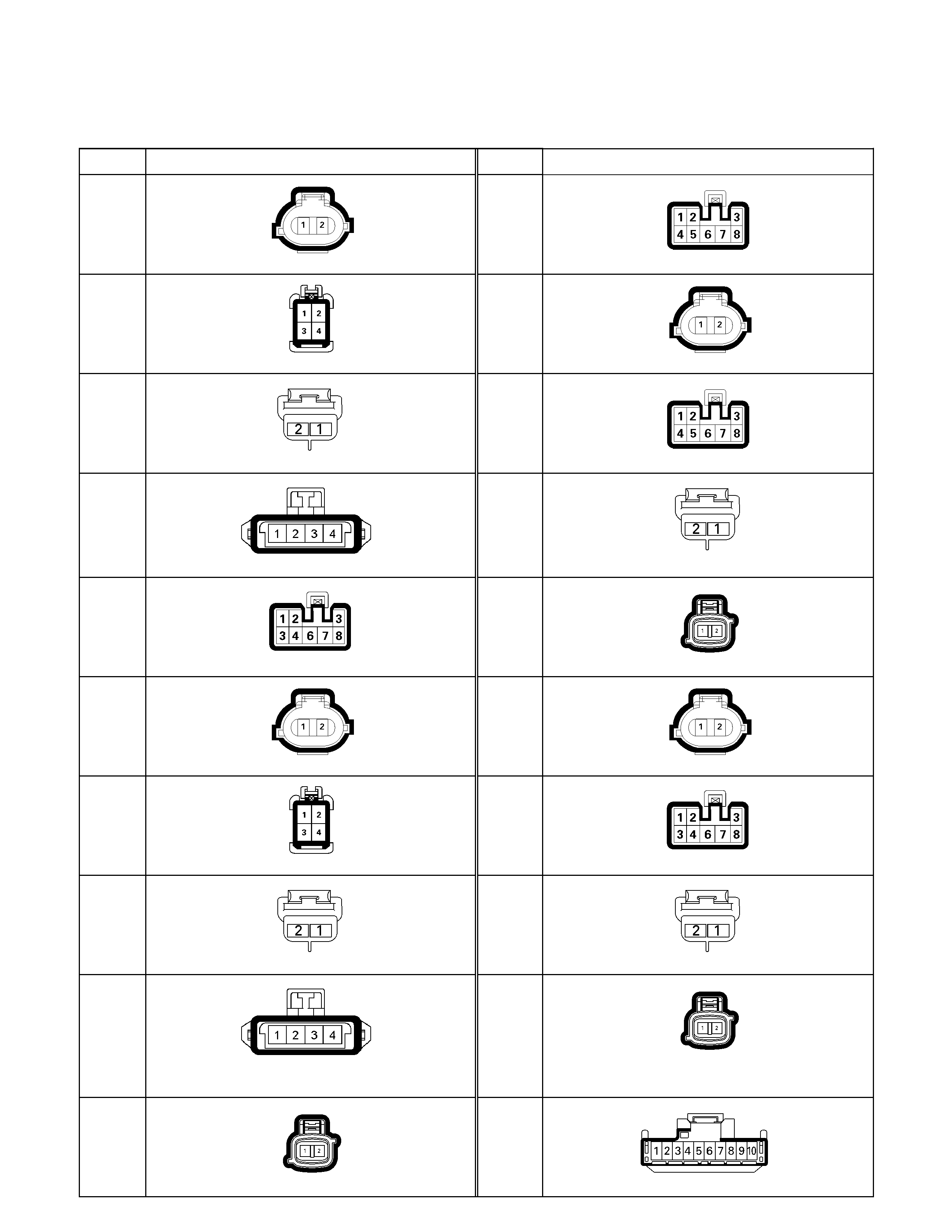
No. Connector face No. Connector face
D-1
Brown
Power window motor-RH
D-10
White
Power window switch passenger side
D-2
White
Remote mirror-RH
D-11
Brown
Power window motor Rear-LH
D-3
Black
Front speaker-RH
D-12
White
Power window switch Rear-LH
D-4
Black Door lock actuator driver side
D-13
Black
Rear speaker-LH
D-5
White
Power window driver side
D-14
Black
Door lock actuator Rear-LH
D-6
Brown
Power window motor-LH
D-15
Brown
Power window motor Rear-RH
D-7
White
Remote mirror-LH
D-16
White
Power window switch-RH
D-8
Black
Speaker-LH
D-17
Black
Rear speaker-RH
D-9
Black Door lock actuator passenger side
(keyless & antitheft)
D-18
Black
Door lock actuator Rear-RH
D-9
Black
Door lock actuator passenger side
D-19
White
Remote mirror switch driver side
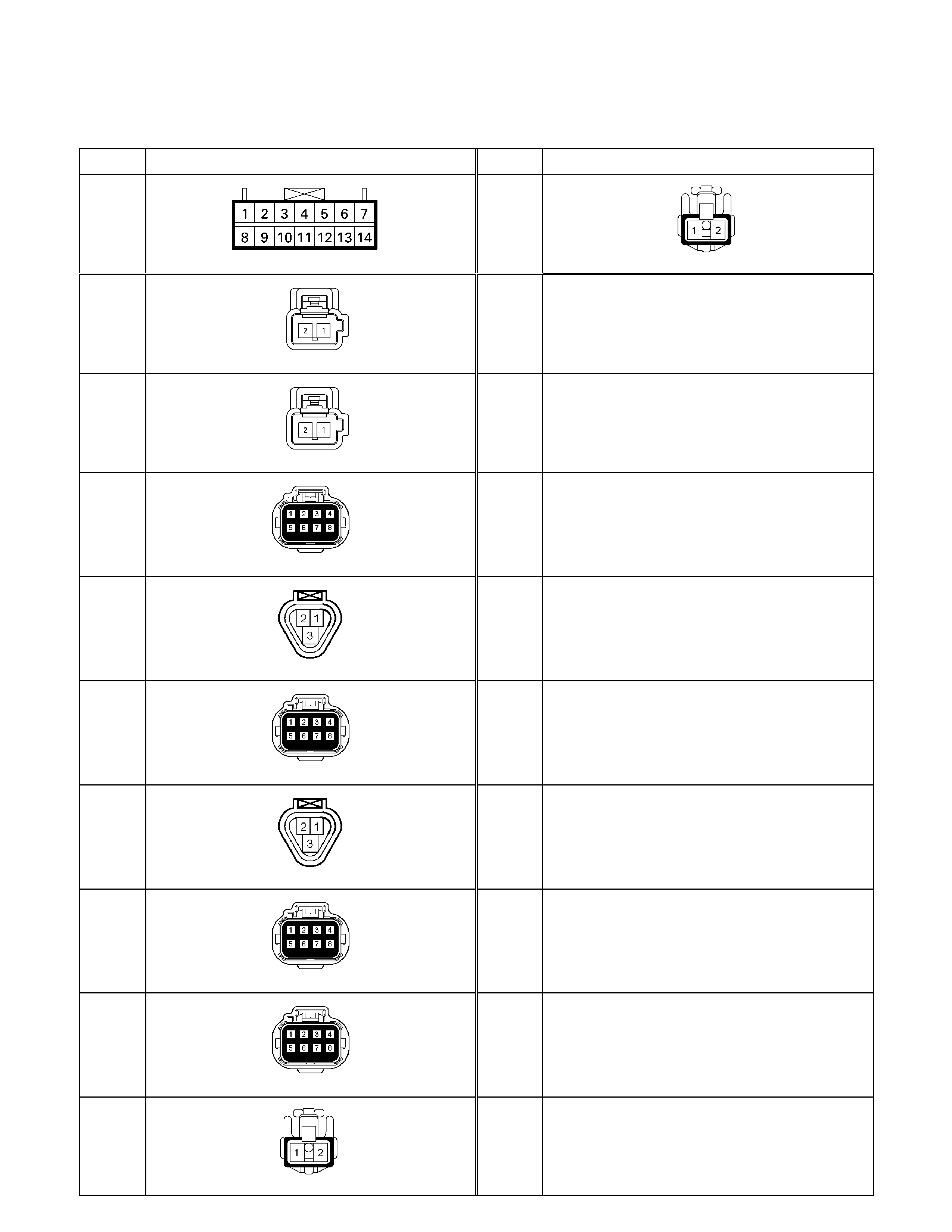
No. Connector face No. Connector face
D-20
White
Power window switch driver side
D-30
White
Door mirror-turn signal light-LH
D-21
White
Tweeter-RH
D-22
White
Tweeter-LH
D-23
White Door lock & super actuator front (RH)
D-24
White Key cylinder switch front –(RH)
D-25
White Door lock & super lock actuator front (LH)
D-26
White Key cylinder switch front – (LH)
D-27
White Door lock & super lock actuator RR (RH)
D-28
White Door lock & super lock actuator RR (LH)
D-29
White
Door mirror-turn signal light-RH
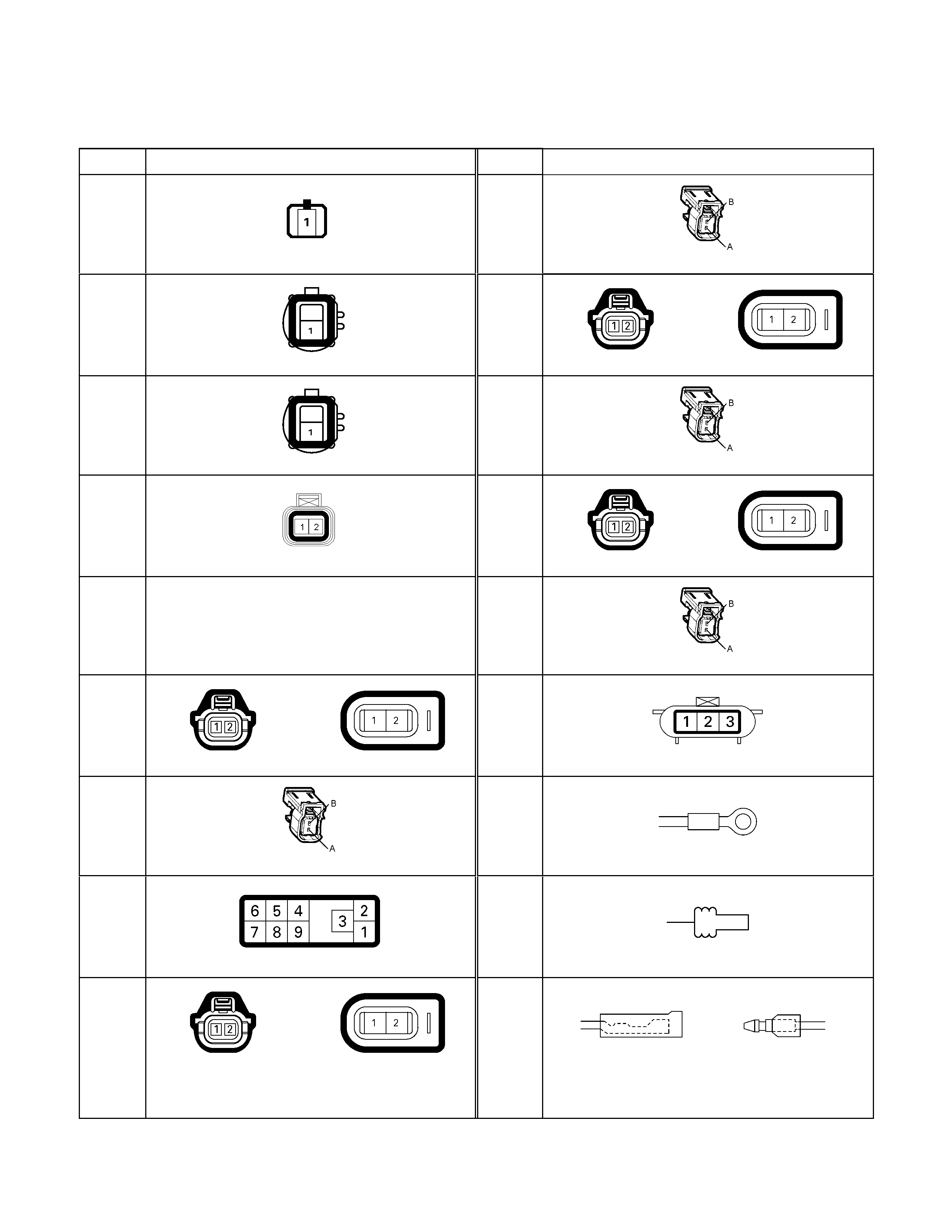
No. Connector face No. Connector face
E-1
(4JH1-TC)
White
Oil pressure switch
E-7
(HFV6)
Fuel Injector #2
E-2
(C24SE)
(6VE1)
(HFV6)
Magnetic clutch
E-8
(C24SE)
(6VE1)
(6VE1) Fuel injector (C24SE)
E-3
(4JH1-TC)
Black
Magnetic clutch AC COMP
E-8
(HFV6)
Fuel Injector #3
E-4
(HFV6)
Black
ACG (L)
E-9
(C24SE)
(6VE1)
(6VE1) Fuel injector (C24SE)
E-5
NOT USED
E-9
(HFV6)
Fuel Injector #4
E-6
(C24SE)
(6VE1)
(6VE1) Fuel injector (C24SE)
E-9
(4JA1-TC /
4JH1-TC)
Gray
T.D.C sensor
E-6
(HFV6)
Fuel Injector #1
E-10
Silver
Engine ground
E-6
(4JH1-TC)
Injector pump
E-11
(6VE1)
Neutral switch
E-7
(C24SE)
(6VE1)
(6VE1) Fuel injector (C24SE)
E-11
(4JA1-TC /
4JH1-TC /
C24SE)
Natural
green
Neutral switch
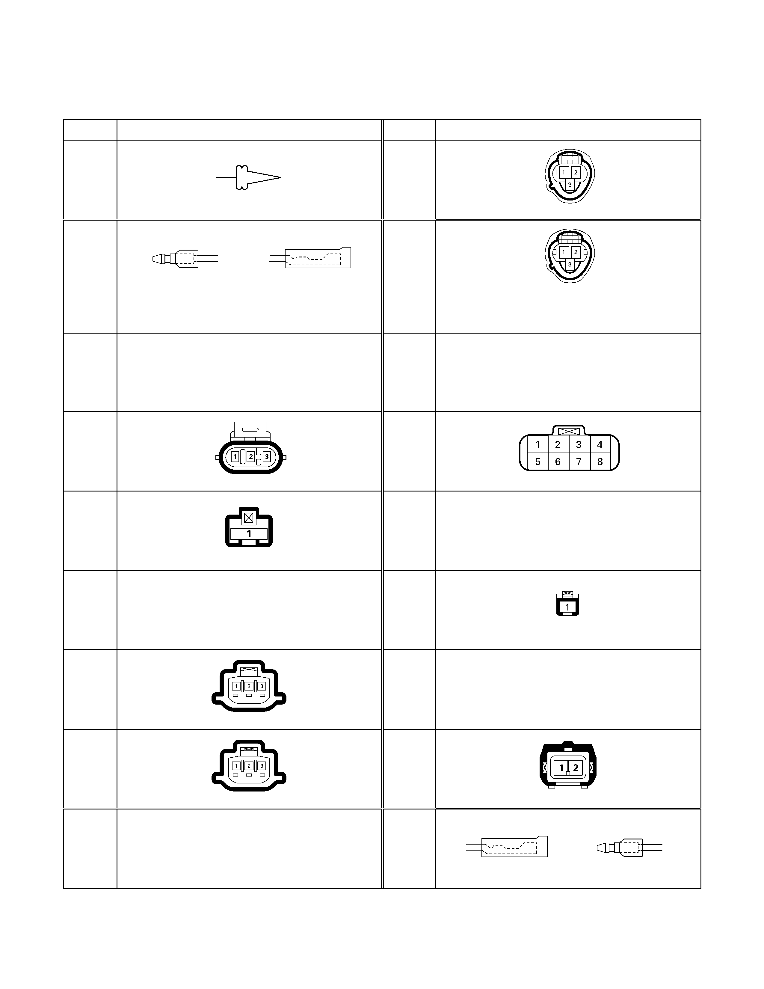
No. Connector face No. Connector face
E-12
(6VE1)
Neutral switch
E-30
(4JH1-TC)
Gray
A/T speed sensor
E-12
(4JA1-TC /
4JH1-TC /
C24SE)
Natural
green
Neutral switch
E-31
(4JH1-TC)
Gray
Turbine sensor
E-13
~
E-17
NOT USED
E-32
~
E-34
NOT USED
E-18
(C24SE)
Ignition coil
E-35
(4JH1-TC)
(C24SE)
Black
Motor actuator
E-19
(4JA1-TC /
4JH1-TC)
Blue
Thermo meter unit
E-36
NOT USED
E-20
~
E-21
NOT USED
E-37
(4JH1)
White
Fuel Cut Solenoid Valve
E-22
(4JA1-TC /
4JH1-TC)
Brown
TPS 1 main
E-40
NOT USED
E-23
(4JA1-TC /
4JH1-TC)
Gray
TPS 2 main
E-41
(4JA1-TC /
4JH1-TC)
Black
ECT sensor
E-24
~
E-29
NOT USED
E-42
Natural
green
Backup lamp switch
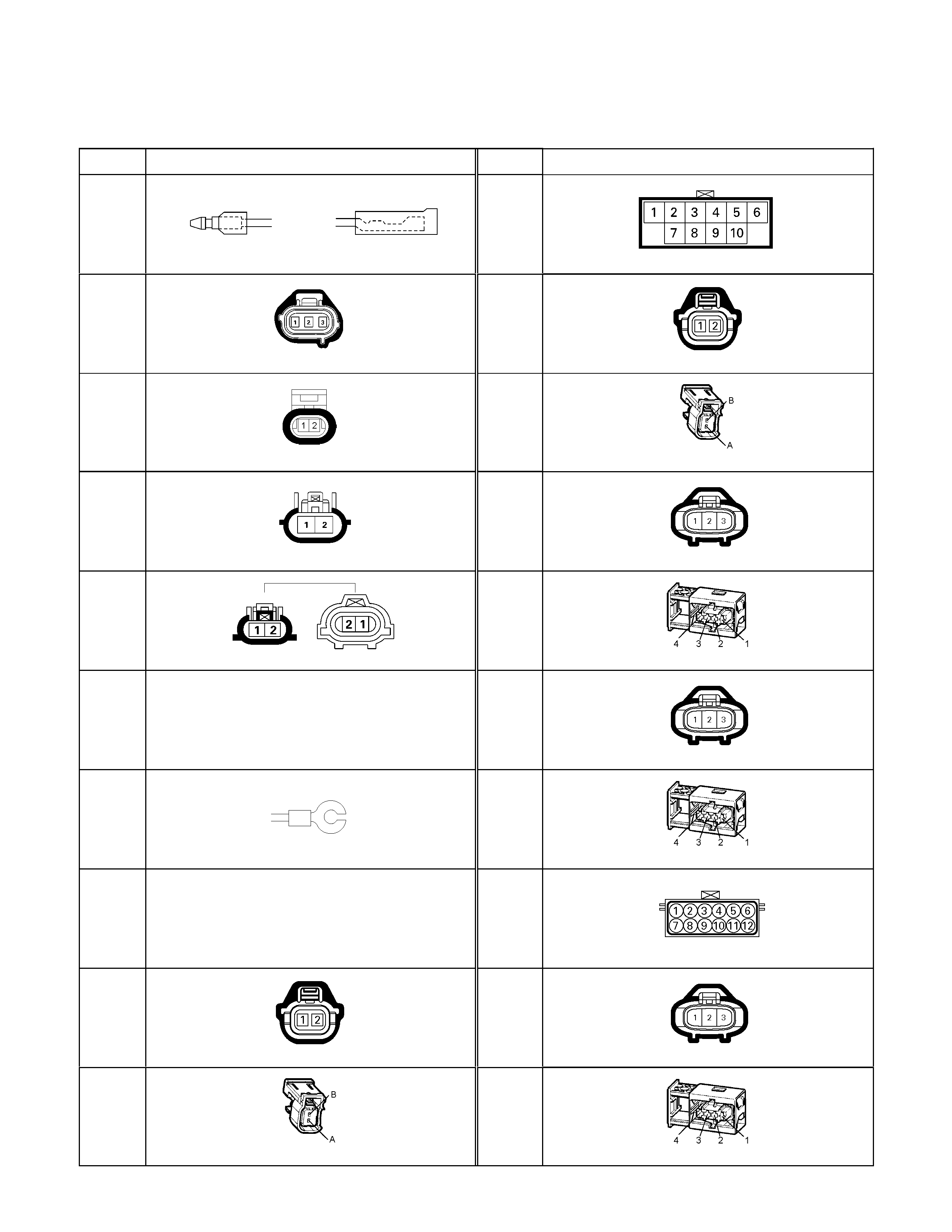
No. Connector face No. Connector face
E-43
Natural
green
Backup lamp switch
E-51
(4JH1-TC)
Black
Inhibiter switch
E-44
(Except
HFV6)
Gray
Vehicle speed sensor
E-52
(6VE1)
Fuel injector
E-44
(HFV6)
Black
Vehicle speed sensor
E-52
(HFV6)
Fuel Injector #5
E-45
(4JH1-TC)
Gray
2WD-4WD switch
E-53
(6VE1)
Ignition coil
E-46
(4JH1-TC)
Brown
H-L neutral switch
E-53
(HFV6)
Ignition coil #1
E-47
~
E-48
NOT USED
E-54
(6VE1)
Ignition coil
E-49
(4JA1-TC /
4JH1-TC)
Glow plug
E-54
(HFV6)
Ignition coil #2
E-50
NOT USED
E-54
(4JH1-TC)
Black
A/T term ASM
E-51
(6VE1)
Fuel injector
E-55
(6VE1)
Ignition coil
E-51
(HFV6)
Fuel Injector #5
E-55
(HFV6)
Ignition coil #3

No. Connector face No. Connector face
E-56
(6VE1)
Ignition coil
E-60
(6VE1)
ECM-A
E-56
(HFV6)
Ignition coil #4
E-61
(6VE1)
ECM-B
E-57
(6VE1)
Ignition coil
E-62
(6VE1)
CMP sensor
E-57
(HFV6)
Ignition coil #5
E-62
(HFV6)
CMP sensor
E-58
(6VE1)
Ignition coil
E-63
(6VE1)
MAF sensor
E-58
(HFV6)
Ignition coil #6
E-64
(C24SE)
(6VE1)
Oil pressure switch (P/STRG)
E-59
(C24SE)
(6VE1)
(6VE1) CKP sensor (C24SE)
E-65
(C24SE)
(6VE1)
Thermo unit
E-59
(HFV6)
CKP sensor
E-66
(C24SE)
(6VE1)
Duty solenoid
E-60
(C24SE)
ECM
E-67
NOT USED
E-60
(HFV6)
ECM
E-68
(C24SE)
Throttle position sensor
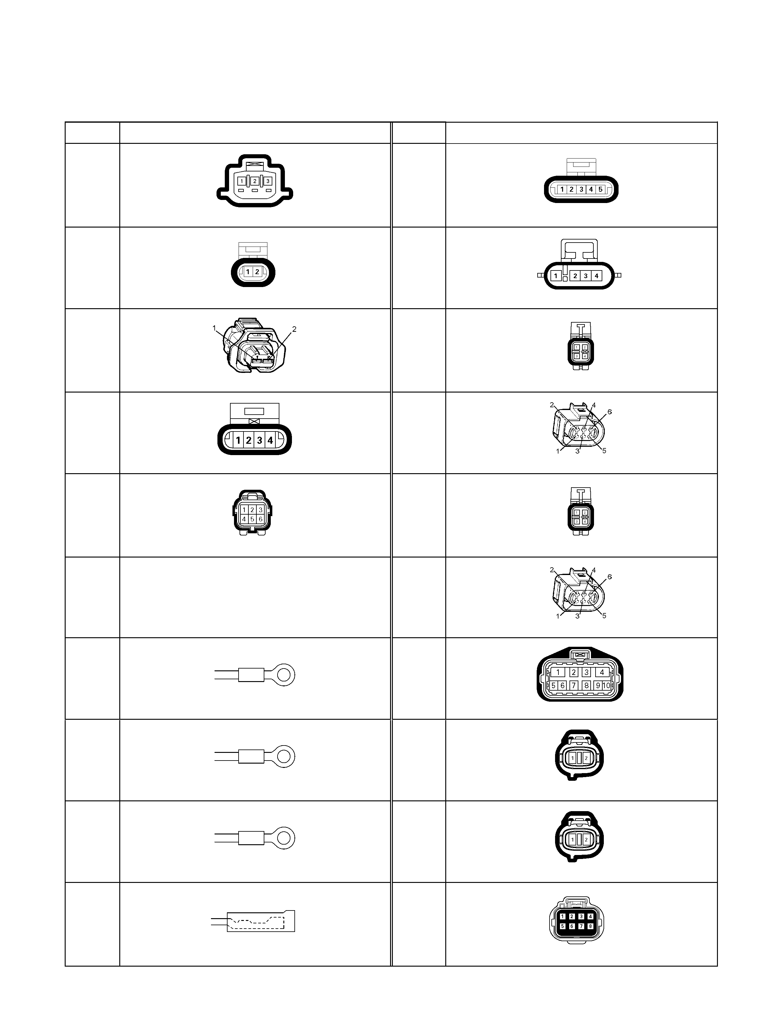
No. Connector face No. Connector face
E-68
(6VE1)
Throttle position sensor
E-76
(6VE1)
EGR valve
E-69
(6VE1)
(C24SE)
ECT sensor
E-77
(C24SE)
O2 sensor
E-69
(HFV6)
ECT sensor
E-77
(6VE1)
O2 sensor RH-Front
E-70
(C24SE)
IACV
E-77
(HFV6)
Heated oxygen sensor bank1 sensor1
E-70
(6VE1)
IACV
E-78
(6VE1)
O2 sensor LH-Front
E-71
NOT USED
E-78
(HFV6)
Heated oxygen sensor bank2 sensor1
E-72
(C24SE)
(6VE1)
Engine earth-A
E-79
(6VE1)
Neutral start switch
E-73
(6VE1)
Engine earth-A
E-80
(6VE1)
Cylinder revolution
E-74
(C24SE)
(6VE1)
Engine earth-B
E-81
(6VE1)
Speed sensor
E-75
(C24SE)
(6VE1)
Oil pressure switch
E-82
(6VE1)
Transmission wire
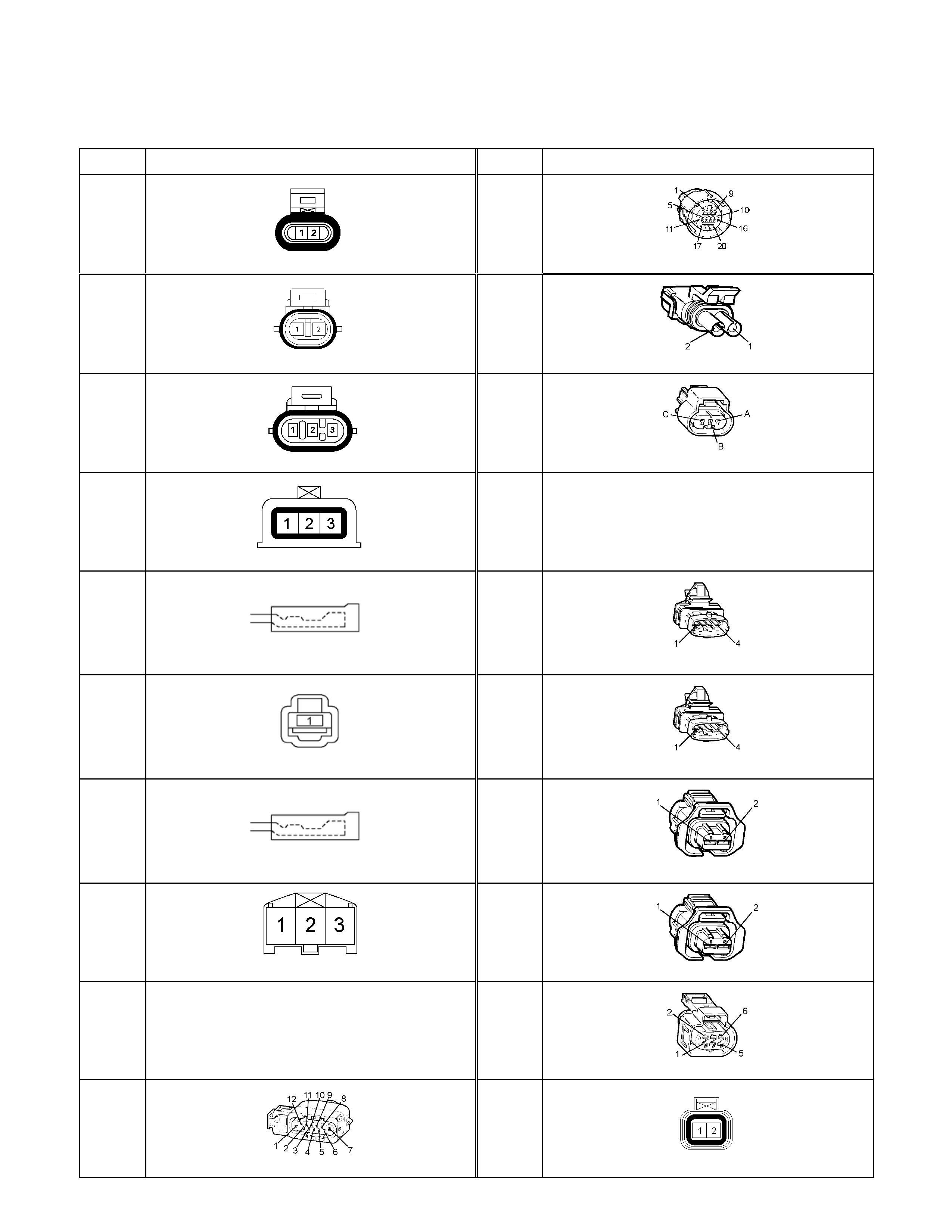
No. Connector face No. Connector face
E-83
(6VE1)
Oil temperature sensor
E-95
(HFV6)
Transmission sonnector
E-84
(C24SE)
Knock sensor
E-96
(HFV6)
PNP switch
E-85
(C24SE)
MAP sensor
E-97
(HFV6)
Engine oil level switch& EOT sensor
E-85
(HFV6)
Barometric pressure sensor
E-98
(HFV6)
Engine oil pressure sensor
E-86
(4JA1-L)
Silver Thermo switch; QOS
E-99
(HFV6)
Heated Oxygen sensor bank1 sensor2
E-87
(4JA1-L)
White Solenoid CSD
E-100
(HFV6)
Heated Oxygen sensor bank2 sensor2
E-88
(4JA1-L)
Silver Thermo switch; EGR
E-101
(HFV6)
Knock sensor Bank1
E-89
(4JA1-L)
White
Immobilizer engine control unit
E-102
(HFV6)
Knock sensor Bank2
E-90
~
E-93
NOT USED
E-103
(HFV6)
Thottle body
E-94
(HFV6)
Park/Neutral Position switch
E-105
(HFV6)
EVAP purge solenoid valve
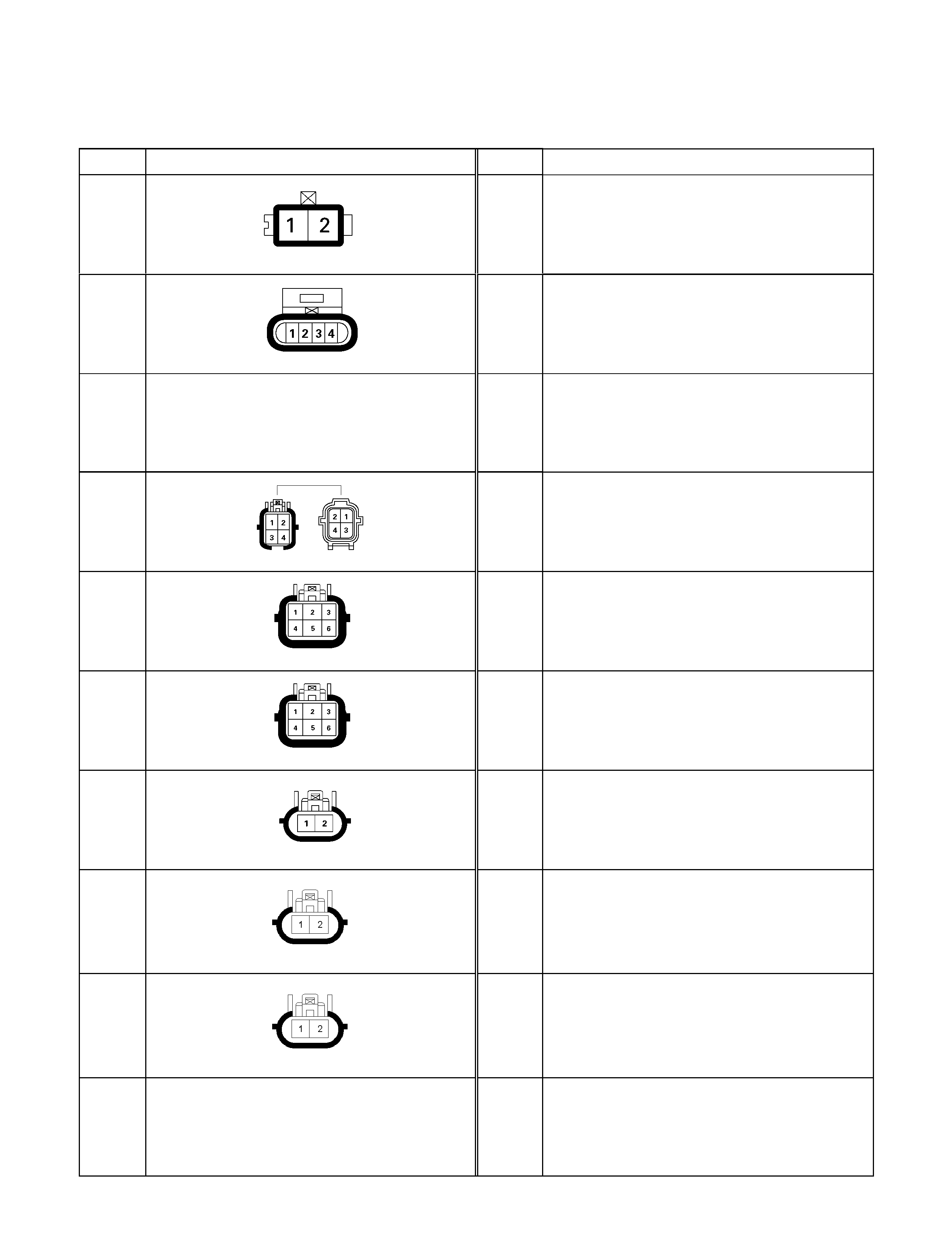
No. Connector face No. Connector face
F-1
White
Fuel filter
F-2
White
Fuel pump & sensor
F-3
NOT USED
F-4
Gray
ABS sensor
F-5
Gray
Rear combination lamp-RH
F-6
Gray
Rear combination lamp-LH
F-7
Gray
License plate lamp
F-8
Black Rear fog light – RH
F-9
Black Rear fog light - LH
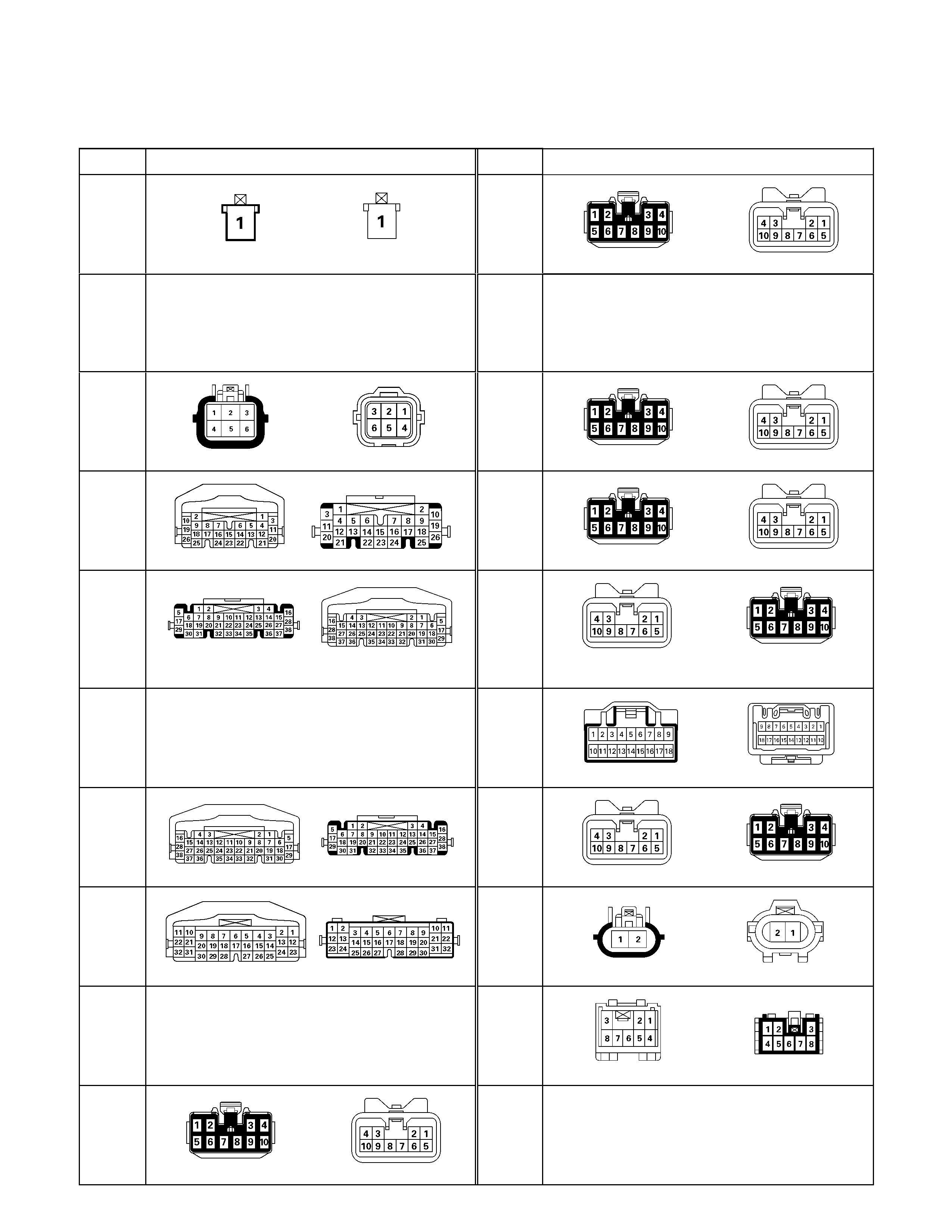
No. Connector face No. Connector face
H-1
White
Battery (+) ~ Fuse & relay box
H-10
White
INST ~ Front Door-RH
H-2
NOT USED
H-11
NOT USED
H-3
(6VE1,
4JH1-TC)
White
Battery (+) ~ Engine room
H-12
Black
INST ~ Roof
H-4
(C24SE)
White
Engine room ~ Mission
H-13
White
INST ~ Door -LH
H-4
(6VE1,
4JA1-TC,
4JH1-TC)
White
Engine ~ Engine room
H-14
White
Rear body ~ Rear door-LH
H-5
NOT USED
H-15
White
Engine room ~ Chassis
H-6
White
Engine room ~ INST
H-16
White
Rear body ~ Rear door-RH
H-7
White
Engine room ~ INST
H-17
White
Chassis ~ License plate lamp
H-8
NOT USED
H-18
White
Engine room ~ INST
H-9
Blue
Engine room ~ Chassis
H-19
~
H-21
NOT USED
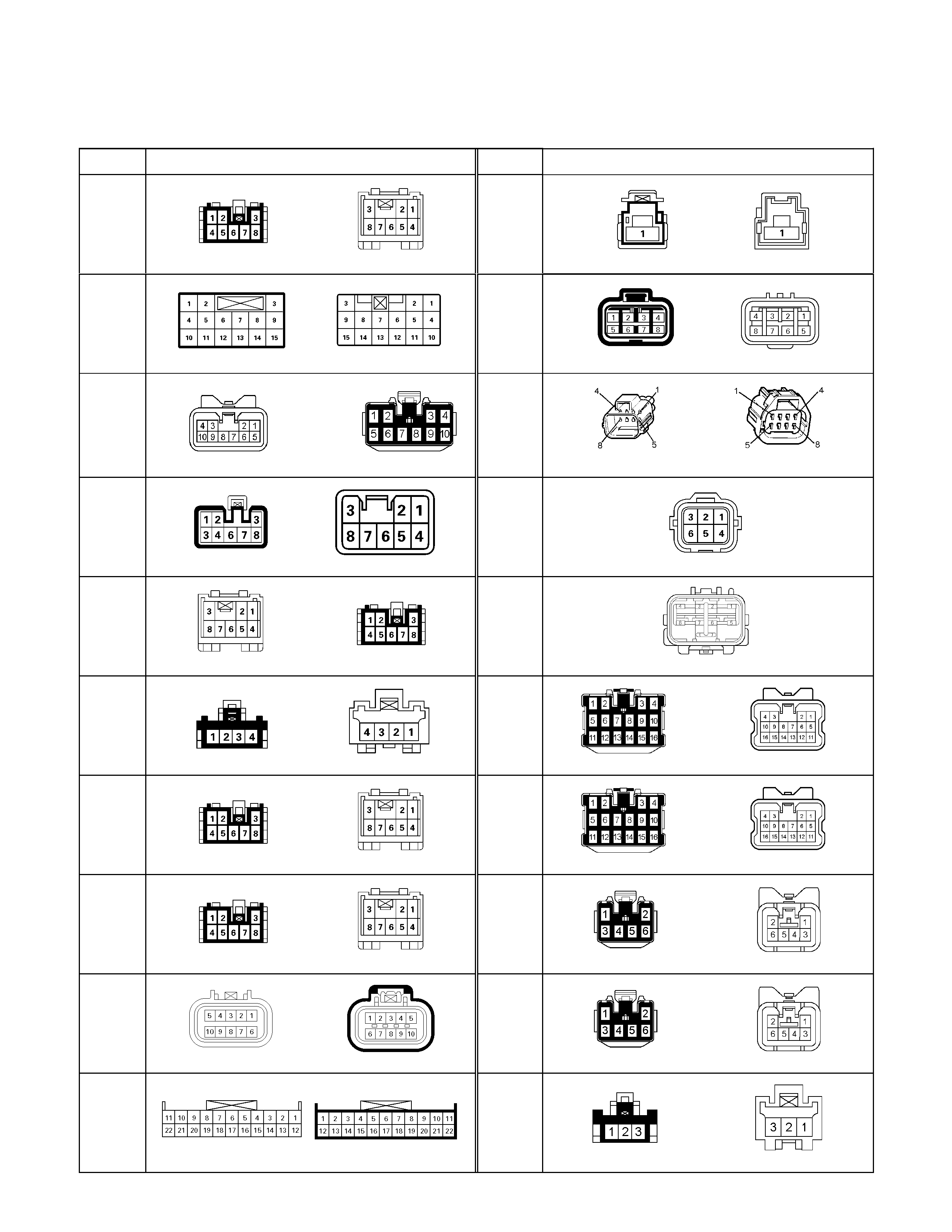
No. Connector face No. Connector face
H-22
(6VE1)
(4JH1-TC)
White
Engine ~ Engine room C
H-33
(4JH1-TC)
Engine ~ Engine room
H-23
(6VE1)
(4JH1-TC)
White
Engine ~ Engine room B
H-34
(C24SE)
Engine ~ Engine room
H-23
(4JA1-L)
White Engine room B ~ T/misson
H-34
(HFV6)
Engine room ~ Engine
H-26
White
INST ~ Rear body
H-35
Trailer
H-27
Black
INST ~ Rear body
H-35
(Australia)
Trailar
H-28
White
Sub harness connector
H-36
Natural
INST ~ Front Door-RH
H-29
(C24SE)
Battery(+) ~ Engine room
H-37
Natural
INST ~ Front Door-LH
H-30
(6VE1)
(4JH1-TC)
Engine room ~ INST
H-38
Natural
INST ~ Front Door-RH
H-31
(C24SE)
Engine room ~ Mission
H-39
Natural
INST ~ Front Door-LH
H-32
(C24SE)
(6VE1)
(4JA1-L)
Engine room ~ Rear body
H-40
(with anti
theft)
INST ~ Front Door-RH
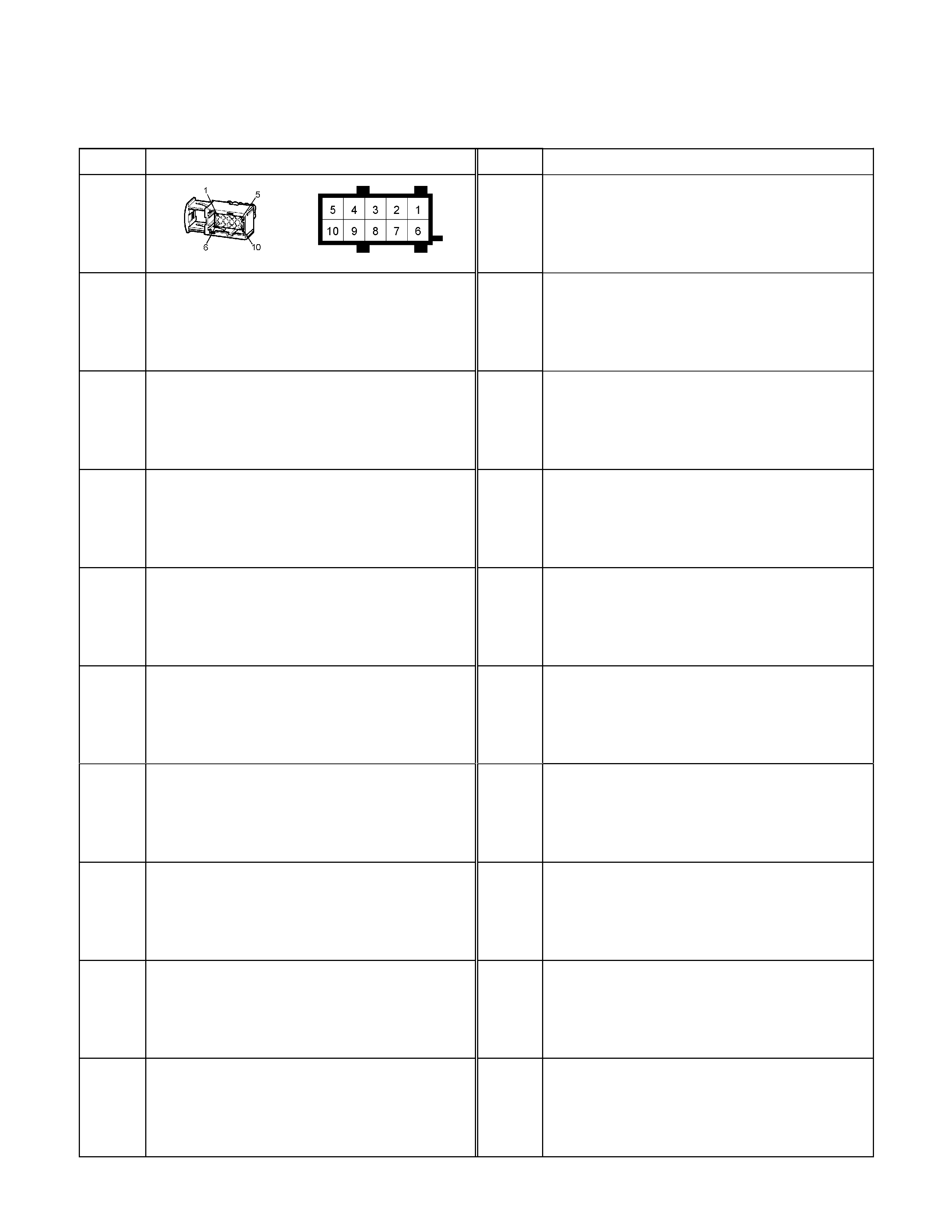
No. Connector face No. Connector face
H-41
(HFV6)
Engine ~ Injector
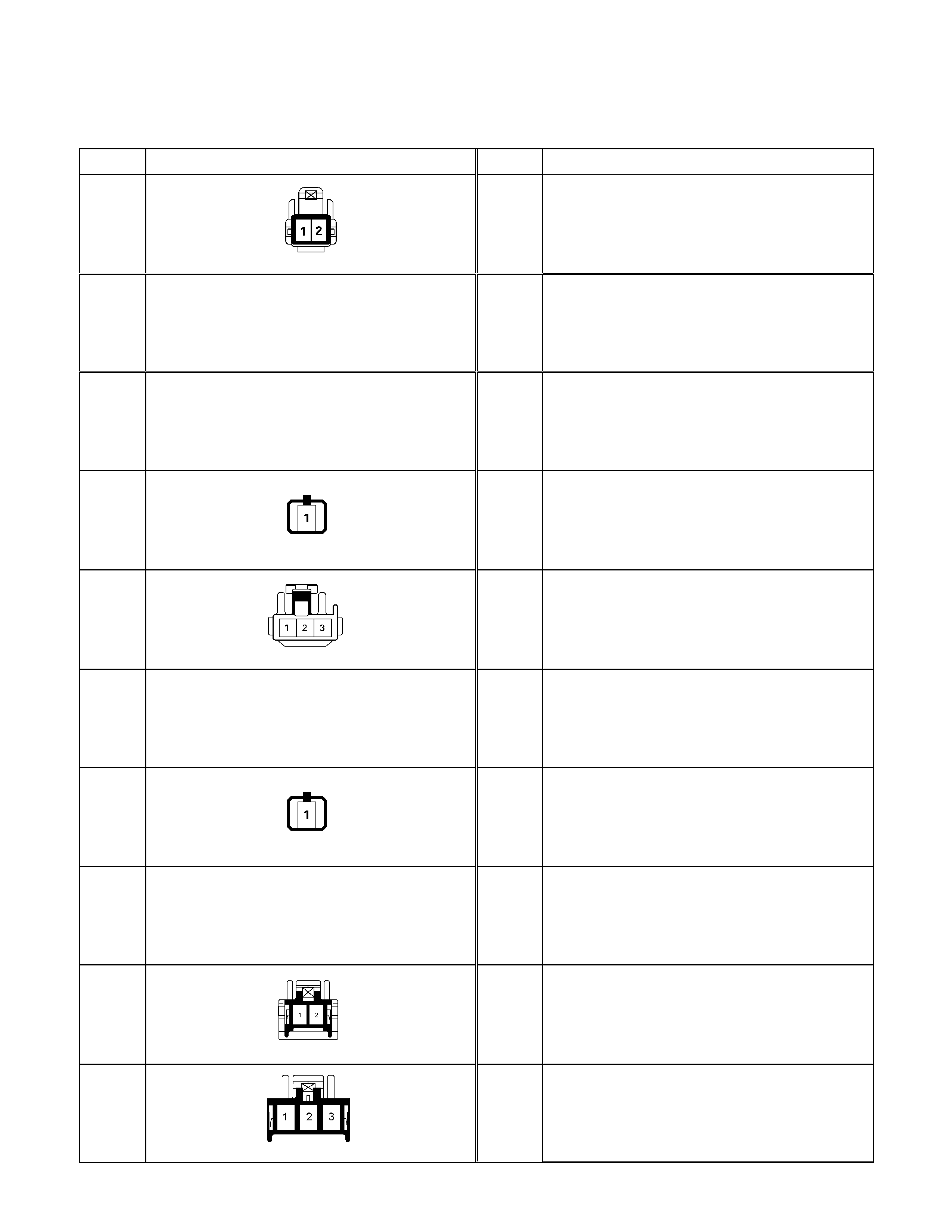
No. Connector face No. Connector face
L-1
White
Dome light
L-2
NOT USED
L-3
NOT USED
L-4
Black
Rear defogger driver side
L-5
White
High mounted stop lamp
L-6
NOT USED
L-7
Black
Rear defogger passenger side
L-8
NOT USED
L-9
Gray
Spot light
L-9
White
Map light
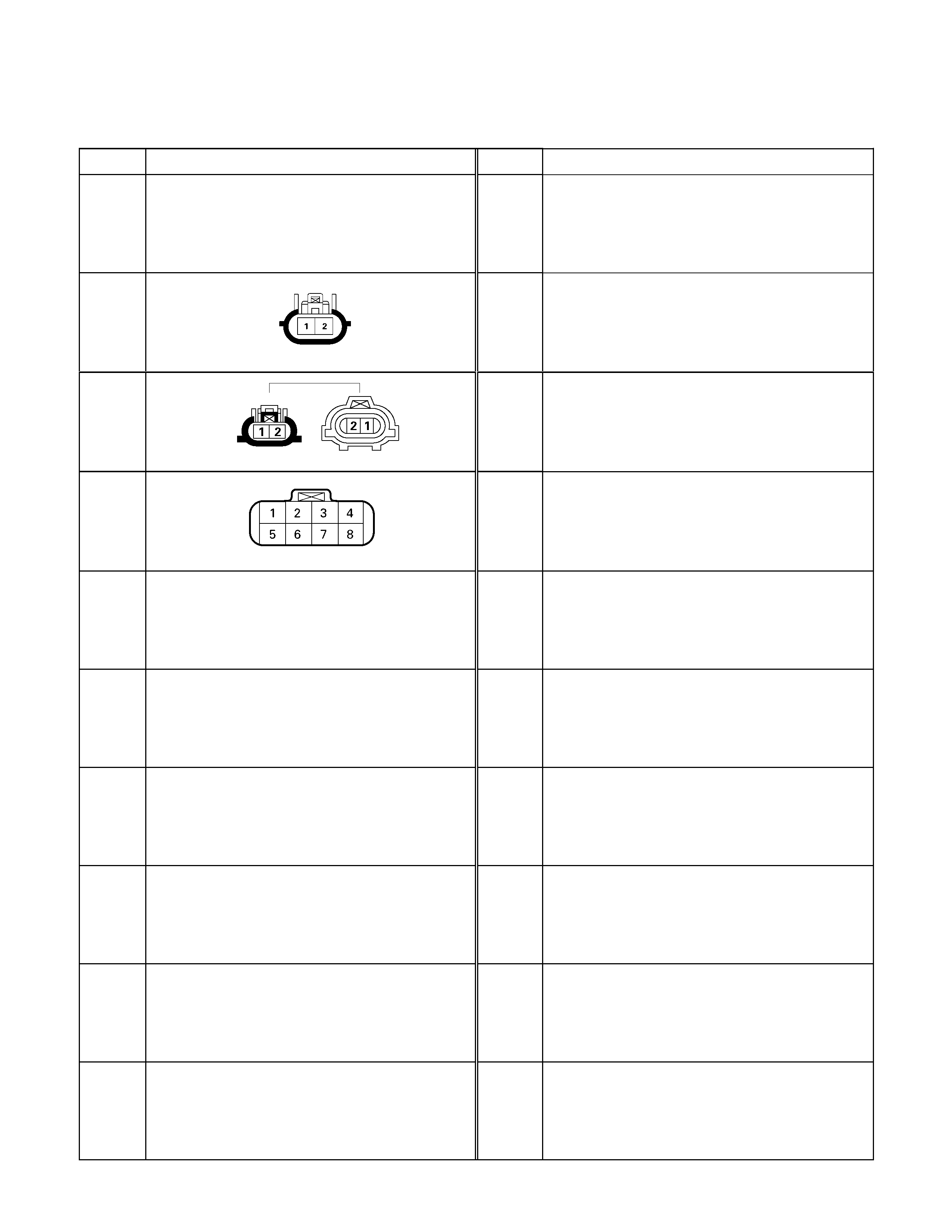
No. Connector face No. Connector face
M-1
~
M-25
NOT USED
M-25
(6VE1)
(HFV6)
2WD-4WD Switch
M-27
(6VE1)
(HFV6)
H-L Neutral Switch
M-28
(6VE1)
(HFV6)
Motor Actuator
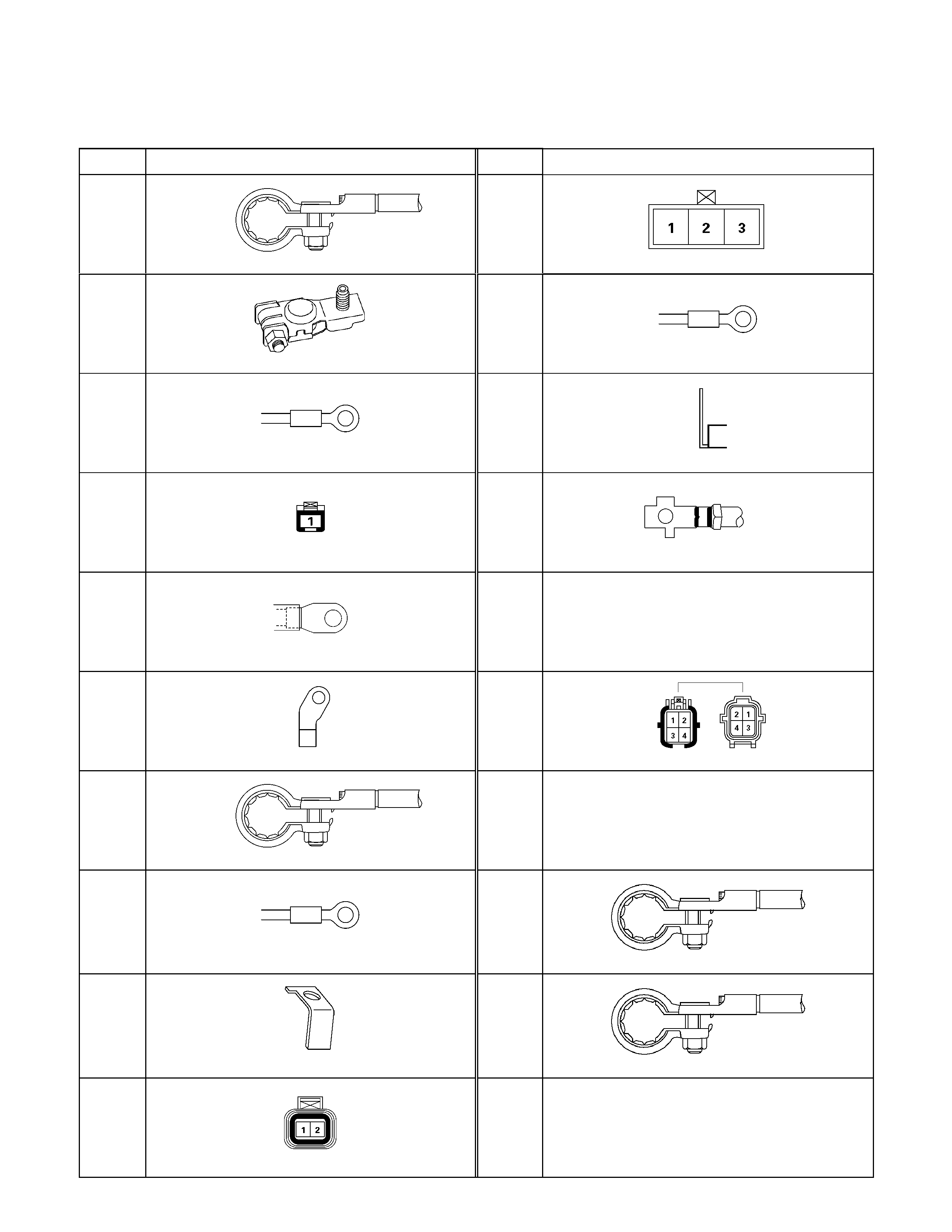
No. Connector face No. Connector face
P-1
Silver
Battery (+)
P-8
(6VE1)
White
ACG (L)
P-1
(HFV6)
Silver
Battery (+)
P-9
Silver
ACG (B)
P-2
Silver
Relay & Fuse box
P-10
Silver
Engine ground
P-3
Brown
Starter (S)
P-11
Silver
Fuse & relay box
P-4
Silver
Starter (B)
P-12
NOT USED
P-4
Silver
Starter (B)
P-13
Gray
Shift on the fly actuator
P-5
Silver
Battery (-)
P-14
NOT USED
P-6
Silver
Body earth (Ground)
P-15
Silver 2nd battery (+)
P-7
(HFV6)
Silver
Battery (+)
P-16
Silver 2nd battey (-)
P-8
(C24SE)
(4JH1-TC
Green
ACG (L)
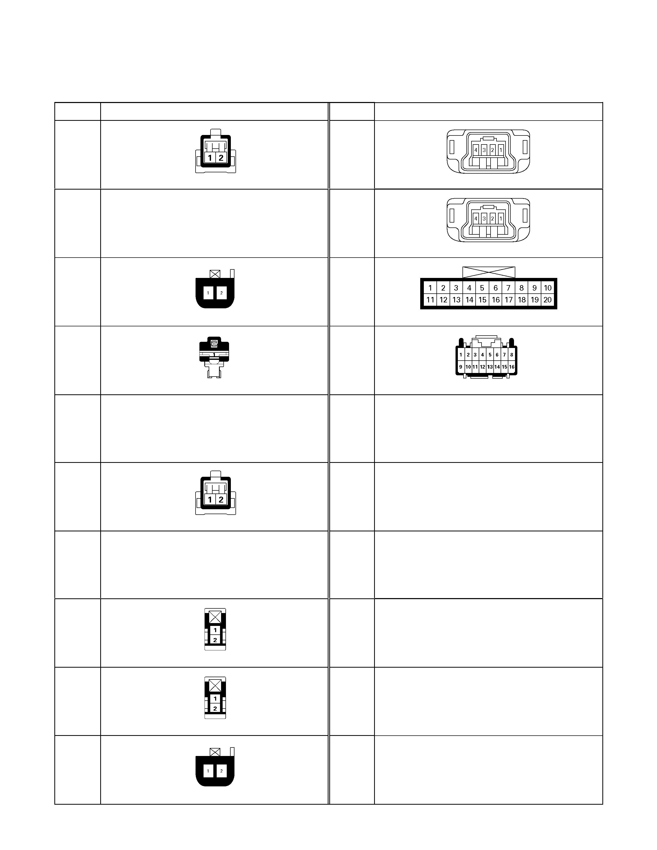
No. Connector face No. Connector face
R-1
Black
Front door switch-LH
R-12
Pretensioner - RH
R-2
NOT USED
R-13
Pretensioner - LH
R-3
Gray
Seat belt switch
R-14
2-4WD control
R-4
Natural
Parking brake switch (Floor mount type)
R-15
2-4WD control
R-5
NOT USED
R-6
Black
Front door switch-RH
R-7
~
R-8
NOT USED
R-9
Black
Rear speaker-LH
R-10
Black
Rear speaker-RH
R-11
Seat belt switch
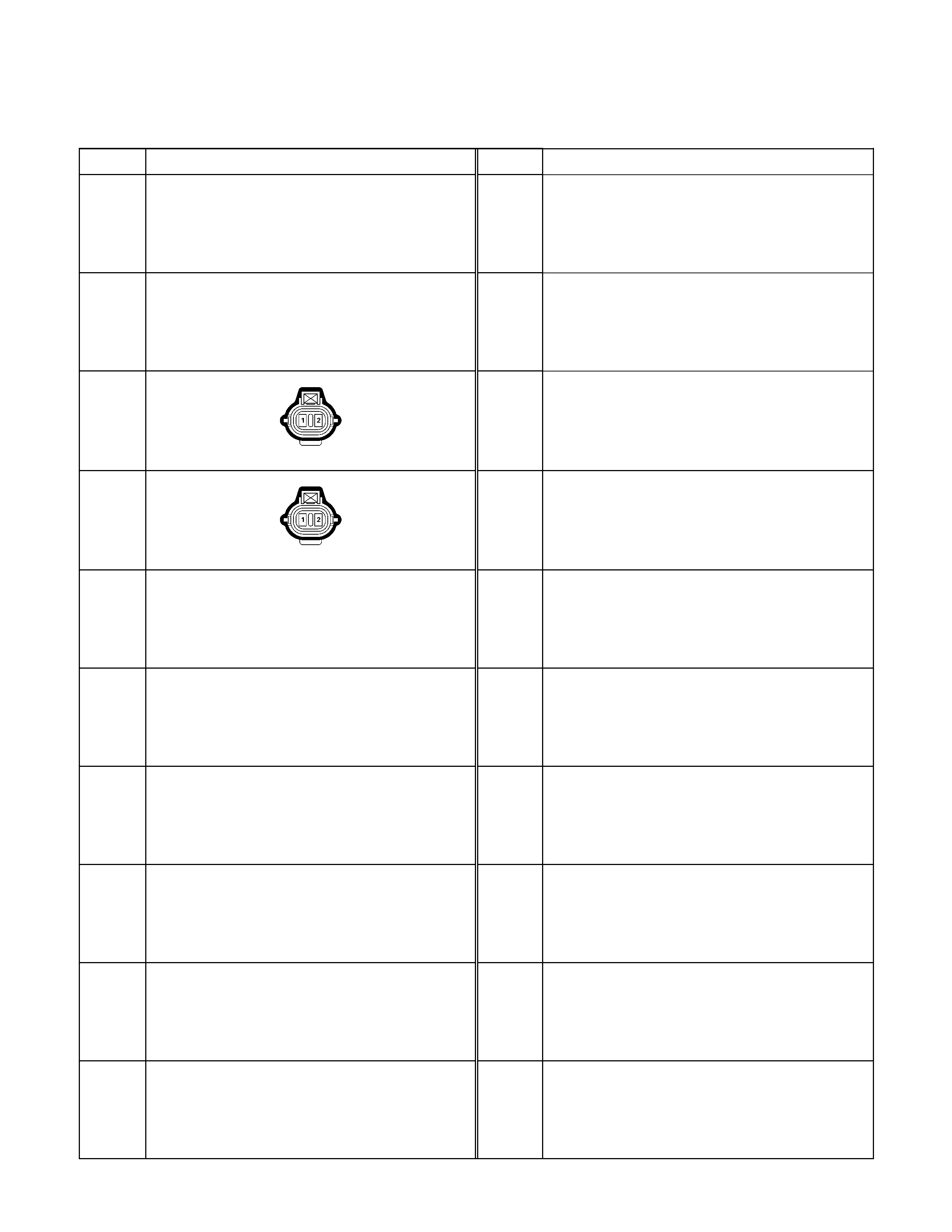
No. Connector face No. Connector face
T-1
NOT USED
T-2
NOT USED
T-3
Gray
License plate lamp-LH
T-4
Gray
License plate lamp-RH
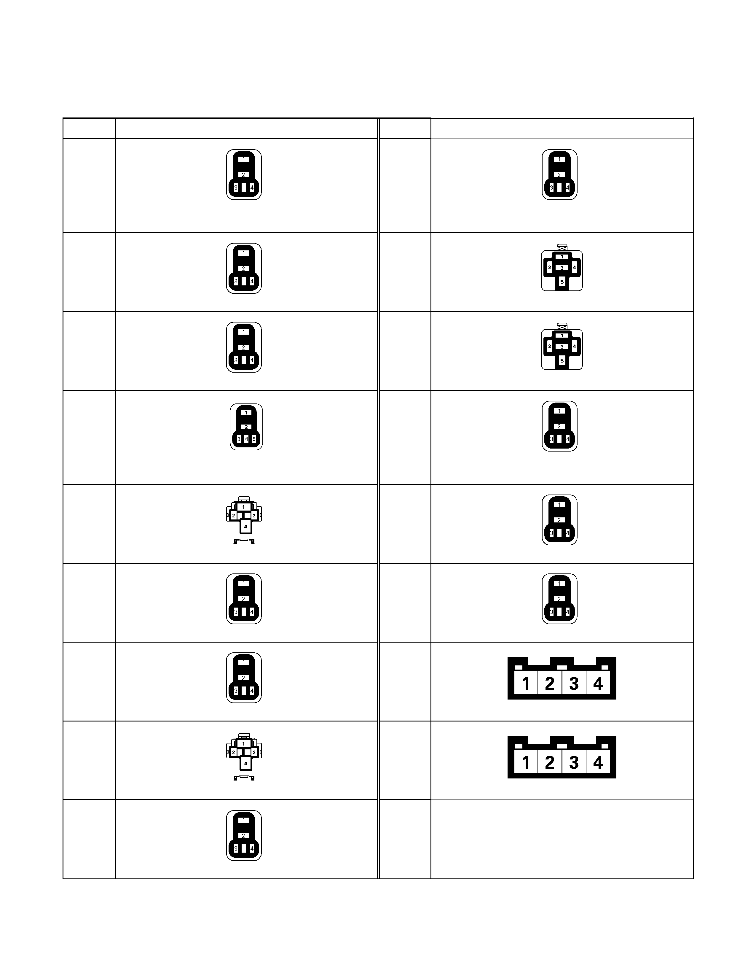
No. Connector face No. Connector face
X-1
Black
Relay ; Tail lamp
X-10
Black
Relay ; front fog lamp condenser fan / Rear
fog light / Head lamp
X-2
Black
Relay ; Front fog lamp / Fuel pump
X-11
Black
Relay ; Heater
X-3
Relay ; Horn
X-12
Black
Relay ; Starter cut / ECM Main
X-4
Relay ; Dimmer
X-13
Black
Relay ; Starter / Starter cut / Head lump /
ECM Main / Condenser fan
X-5
Black
Relay ; Glow
X-14
Black
Relay ; A/C Compressor fan / Starter cut
X-6
Relay ; Starter / Starter cut / CSD
X-15
Black
Relay ; Thermo fan / Head lamp
X-7
Relay ; Condenser fan / Head lamp
X-16
(6VE1)
(4JH1-TC)
Black
DIODE
X-8
Black
Relay ; Starter
X-17
Black
DIODE
X-9
Black
Relay ; Front fog / Condenser fan

MEMO