
SECTION 8B
CRUISE CONTROL SYSTEM - HFV6
Service Precaution
General Description
Brake Switch
Removal
Installation
Adjustment
Clutch Switch
Removal and Installation
Adjustment
Starter Switch
Removal
Installation
Cruise Control Main Switch
Removal
Installation
Cruise Control Switch (Combination
Switch)
Removal and Installation
Cruise Control Unit
Removal
Installation
Cruise Actuator
Actuator Cable Diagram
Removal
Installation
Adjustment
Mode Switch
Removal and Installation
Cruise Control System Check
Cruise Main Lamp Inoperative
Cruise Set Lamp Inoperative
Diagnosis
DTC Display Condition
DTC Display Format
Circuit Diagram
DTC 1-1 Motor System Short Circuit
DTC 1-2 Clutch Open or Short Circuit
DTC 1-3 Mechanical Defect
DTC 1-4 Close Side of Motor System
DTC 2-1 Signal of Vehicle Speed
Malfunction
DTC 3-1 Turning On Switch At All Time
Or At The Same Time
Techline
Service Precaution
WARNING: THIS VEHICLE HAS A SUPPLEMENTAL RESTRAIN SYSTEM (SRS). REFER TO THE SRS
COMPONENT AND WIRING LOCATION VIEW IN ORDER TO DETERMINE WHETHER YOU ARE
PERFORMING SERVICE ON OR NEAR THE SRS COMPONENTS OR THE SRS WIRING. WHEN YOU ARE
PERFORMING SERVICE ON OR NEAR THE SRS COMPONENTS OR THE SRS WIRING, REFER TO THE SRS
SERVICE INFORMATION. FAILURE TO FOLLOW WARNINGS COULD RESULT IN POSSIBLE AIR BAG
DEPLOYMENT, PERSONAL INJURY, OR OTHER WISE UNNEEDED SRS SYSTEM REPAIRS.
CAUTION: Always use the correct fastener in the proper location. When you replace a faster, use ONLY the
exact part number for that application. Dealer will call out those fasteners that require a replacement after
removal. Dealer will also call out the fasteners that require thread lockers or thread sealant. UNLESS
OTHERWISE SPECIFIED, do not use supplemental coatings (Paints, greases, or other corrosion inhibitors)
on threaded fasteners or fastener joint interfaces. Generally, such coatings adversely affect the fastener
torque and joint Clamping force, and may damaged the fastener. When you install fasteners, use the
correct tightening sequence and specifications. Following these instructions can help you avoid damage
to parts and systems.
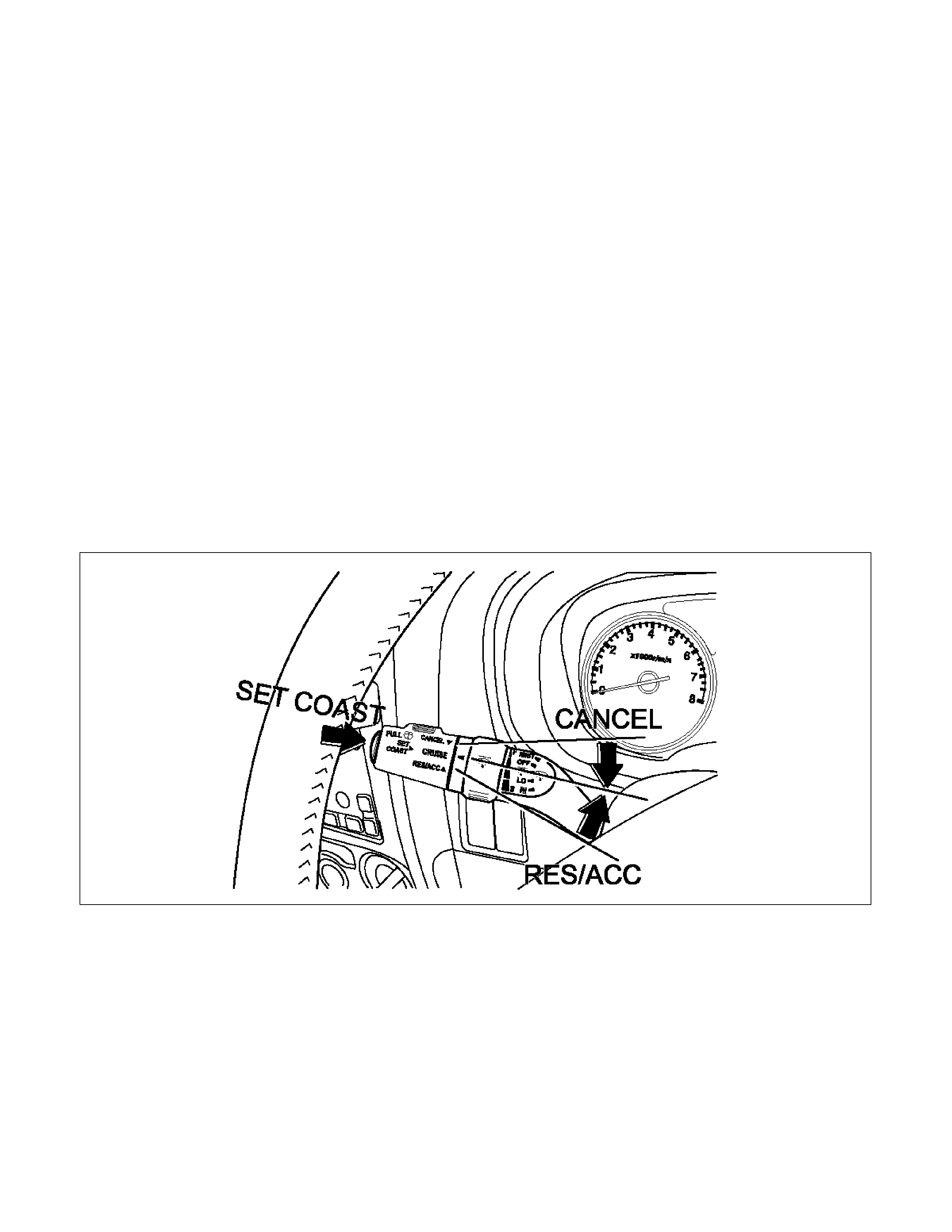
General Description
The cruise control keeps the vehicle running at a fixed speed until a signal canceling this fixed speed is received.
When the main switch “AUTO CRUISE” is turned on with the vehicle in the running mode, the battery voltage is
applied to the control unit. When a signal from the control unit while the vehicle is in this state, the cruise control
actuator is activated to operate the system. Also, while the system is operating, the “AUTO CRUISE” indicator light
in the meter assembly lights up.
LTW48BSH000101
1. SET/COAST Switch Function
1. Set Function: When the SET/COAST switch is pressed and released with the main switch on, the speed at
which the vehicle is running at that moment is stored in the memory, and the vehicle automatically runs at
the stored speed.
2. COAST-down Function: When the SET/COAST switch is kept on while the vehicle in running, the vehicle
decelerates during that time. The speed at which vehicle is running when the control switch is pressed in the
memory, and the vehicle automatically returns to the stored speed.
3. Tap-down Function: When the SET/COAST switch is pressed and released instantaneously while the
vehicle is running, the vehicle decelerates a mile for each on/off operation. The vehicle speed at which the
vehicle was running when the SET/COAST was released last is stored in the memory, and the vehicle
automatically returns to this stored speed.

2. RESUME/ACCEL Switch Function
1. Resume Function: When the RESUME/ACCEL switch is turned on/off after the system is temporarily
deactivated by pressing the brake or clutch pedal while the vehicle is running, the vehicle resumes the
speed stored before the system was released, and the vehicle automatically runs at the stored speed.
2. Accelerate Function: When the RESUME/ACCEL switch is kept on the vehicle accelerates its speed during
that time. The vehicle speed at which the vehicle was running when the switch was turned off is stored in the
memory, and the vehicle automatically returns to this speed.
3. Tap-up Function: When the RESUME/ACCEL switch is turned on and off instantaneously while the vehicle
is running, the vehicle decelerates a mile for each on/off operation. The vehicle speed at which the vehicle
was running when the switch was turned off last is stored in the memory, and the vehicle automatically
returns to this stored speed.
3. CANCEL Function
1. Temporary Cancellation:
• Brake pedal is pressed.
• Clutch pedal is pressed. (M/T)
• Select lever is shifted to any position other than “D”, “3”, “2” or “L”. (A/T)
• Cancel switch is operated.
• Vehicle speed exceeds about 12.5mph over the vehicle speed stored in the memory.
Turning the RESUME/ACCEL switch will return the vehicle to the speed stored in the cruise control memory.
2. Complete Cancellation:
• Starter switch or the main switch is turned off.
• Fail-safe function is activated.
• Vehicle speed is about 38 km/h mph.
• Speed becomes 20 (12.5) km/h (mph) or less form the speed memorized by Control unit.
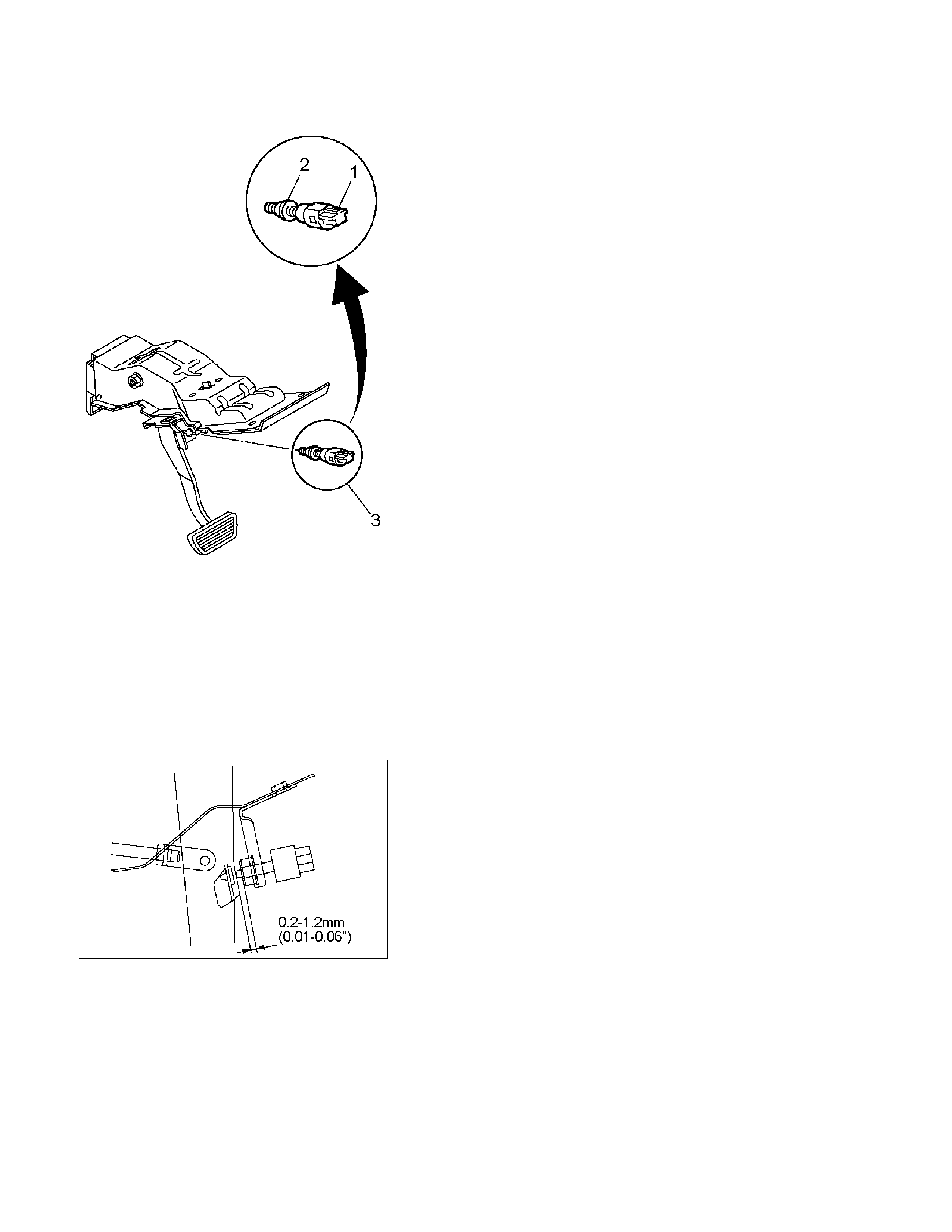
Brake Switch
RTW3A0MH000101
Removal
1. Disconnect the battery ground cable.
2. Remove the brake switch.
• Disconnect the connector (1).
• Loosen lock nuts of the switch (2).
• Remove the switch by turning it (3).
Installation
To install, follow the removal steps in the reverse order, noting
the following points.
1. Check to see if the brake pedal has been returned by the
return spring to the specified position.
2. Turn the switch clock-wise until the tip of the threaded
portion of the brake switch contacts the pedal arm.
RTW3A0SH000901
3. Turn the switch counter-clock-wise until the space between
the tip of the threaded portion and the pedal arm is 0.2 to
1.2 mm (0.01-0.06 in.) as shown in the figure.
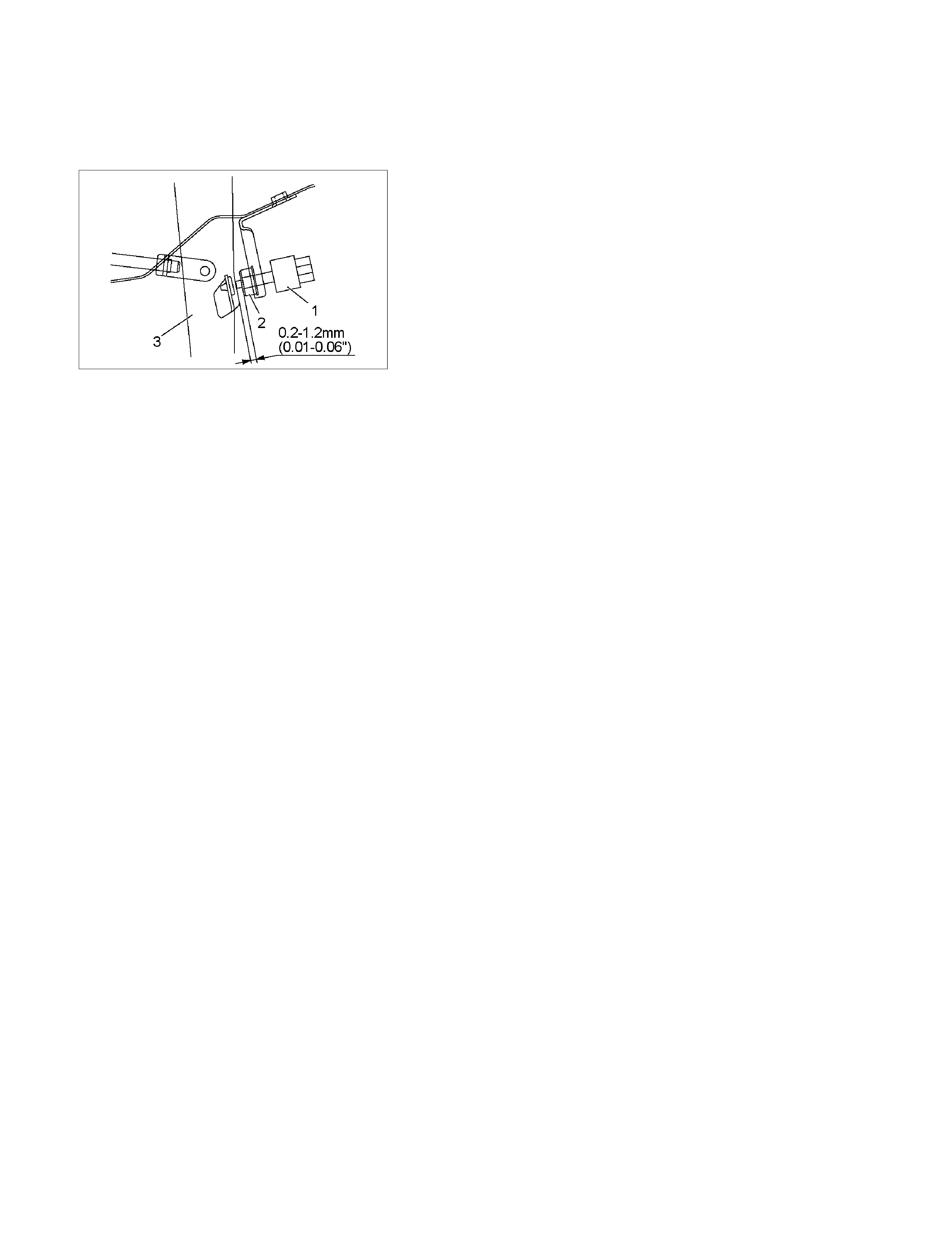
Adjustment
1. Check to be sure that the brake pedal has been completely
returned by the return spring.
2. Disconnect the switch connector.
RTW3A0SH001201
3. Release the lock (2) by turning the switch (1) counter-clock-
wise.
4.
A
fter doing so, pull the pedal arm (3) to you a little so that
the pedal arm is not pushed in.
5. Making the pedal arm not movable with one hand, push in
the whole switch with the other hand until the plunger of the
switch is pushed in and the switch itself hits the rubber o
f
the pedal arm.
In the condition, turn the switch clock-wise until "click"
sound is made and lock it.
By doing this, the switch is adjusted at 0.2 to 1.2mm (0.01-
0.06 in.) clearance.
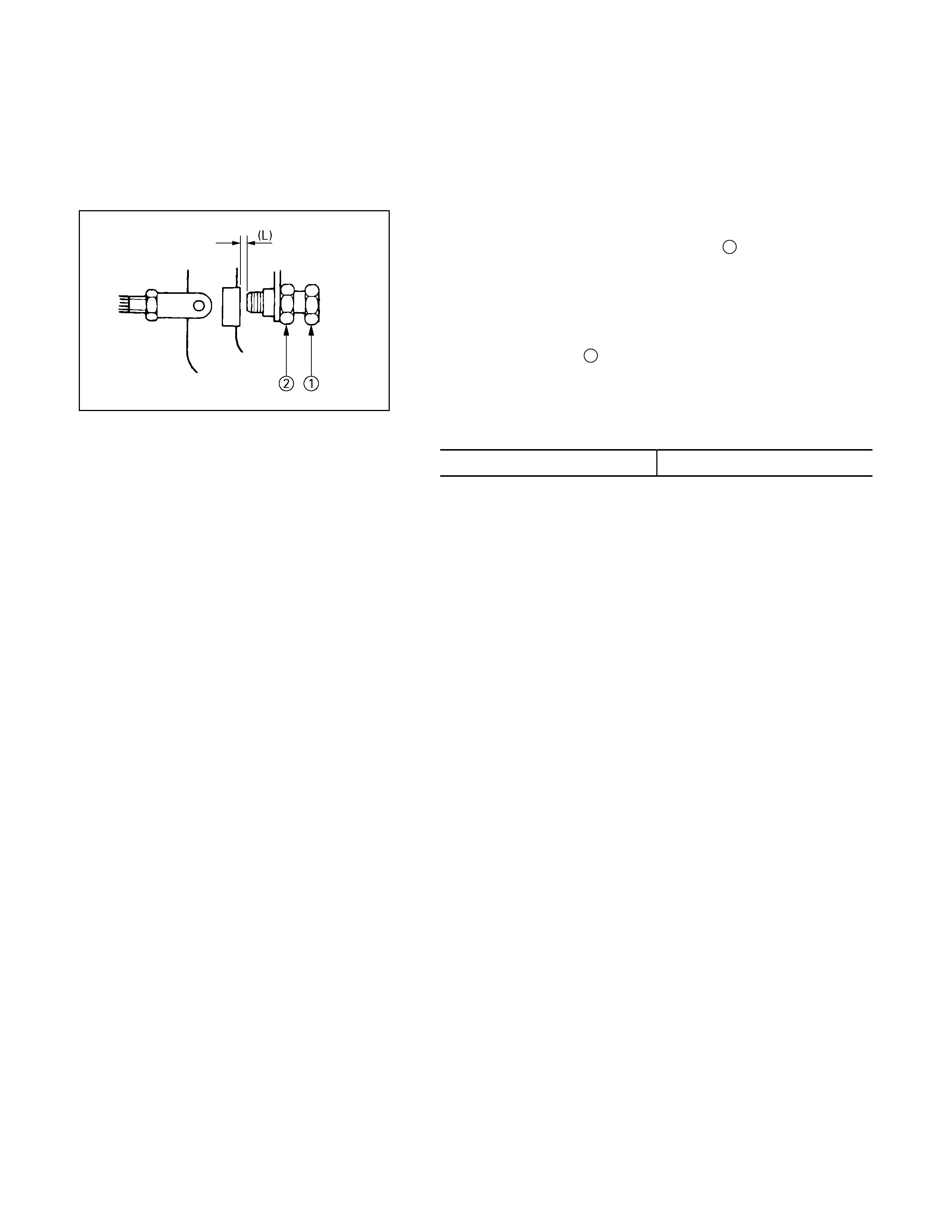
Clutch Switch
Removal and Installation
Refer to the Clutch Control removal and installation steps in
Clutch section.
Adjustment
1. Turn the clutch switch or stopper bolt 1 until the switch bolt
or stopper bolt just touches the clutch pedal arm.
2.
A
djust clutch switch or stopper bolt by backing it out half a
turn, and measure the clearance (L) between the clutch
pedal arm and the clutch switch bolt end or stopper bolt.
3. Lock the lock nut 2.
4. Connect the clutch switch connector.
Clutch switch and clutch and clutch pedal clearance
mm (in)
Limit 0.5-1.5 (0.020-0.059)
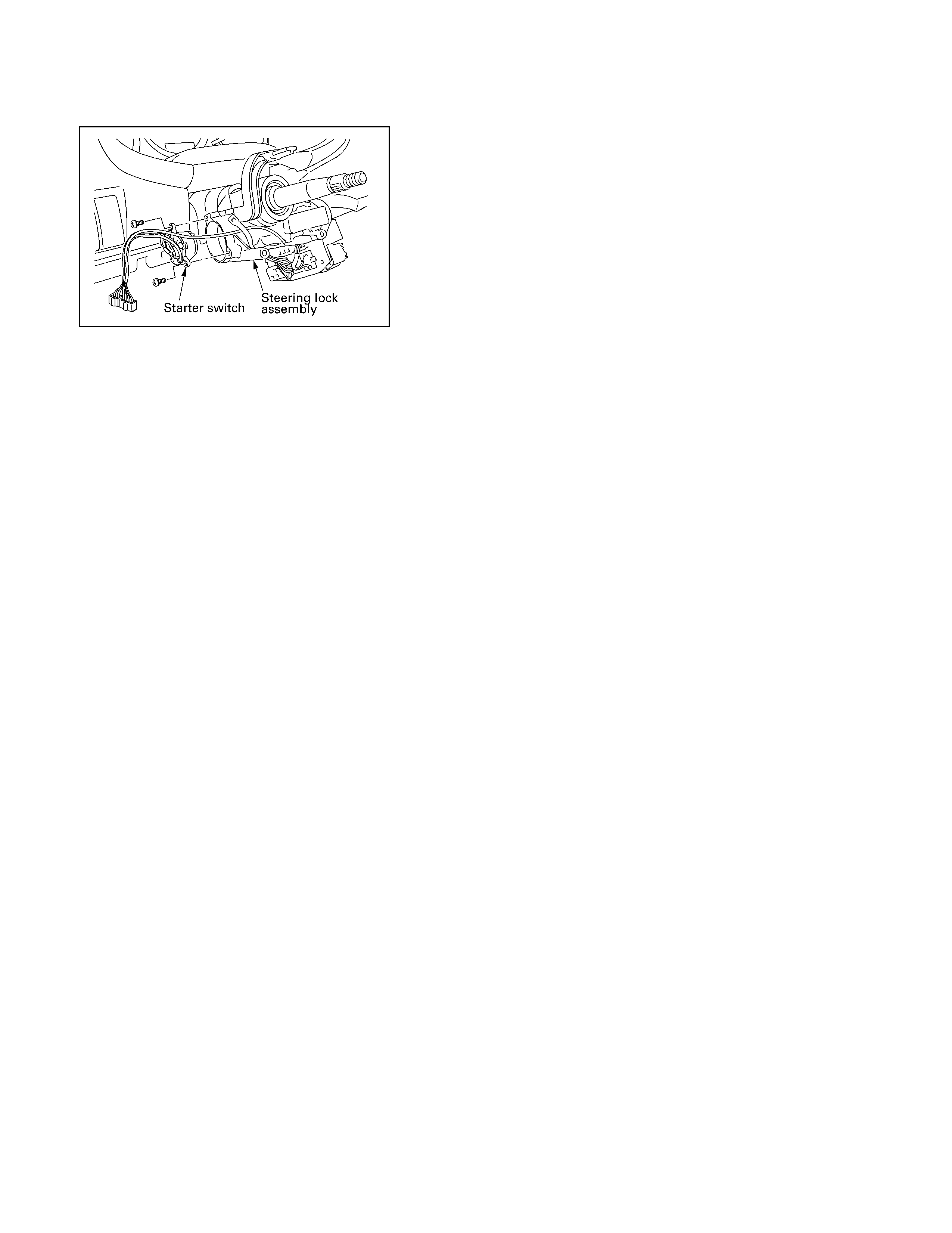
Starter Switch
431R300001
Removal
1. Steering Lock Assembly
• Refer to the Steering Lock assembly removal steps o
f
"Steering Column" in Power-
A
ssisted Steering System
section.
2. Starter Switch
Installation
Follow the removal procedure in the reverse order to install the
starter switch.
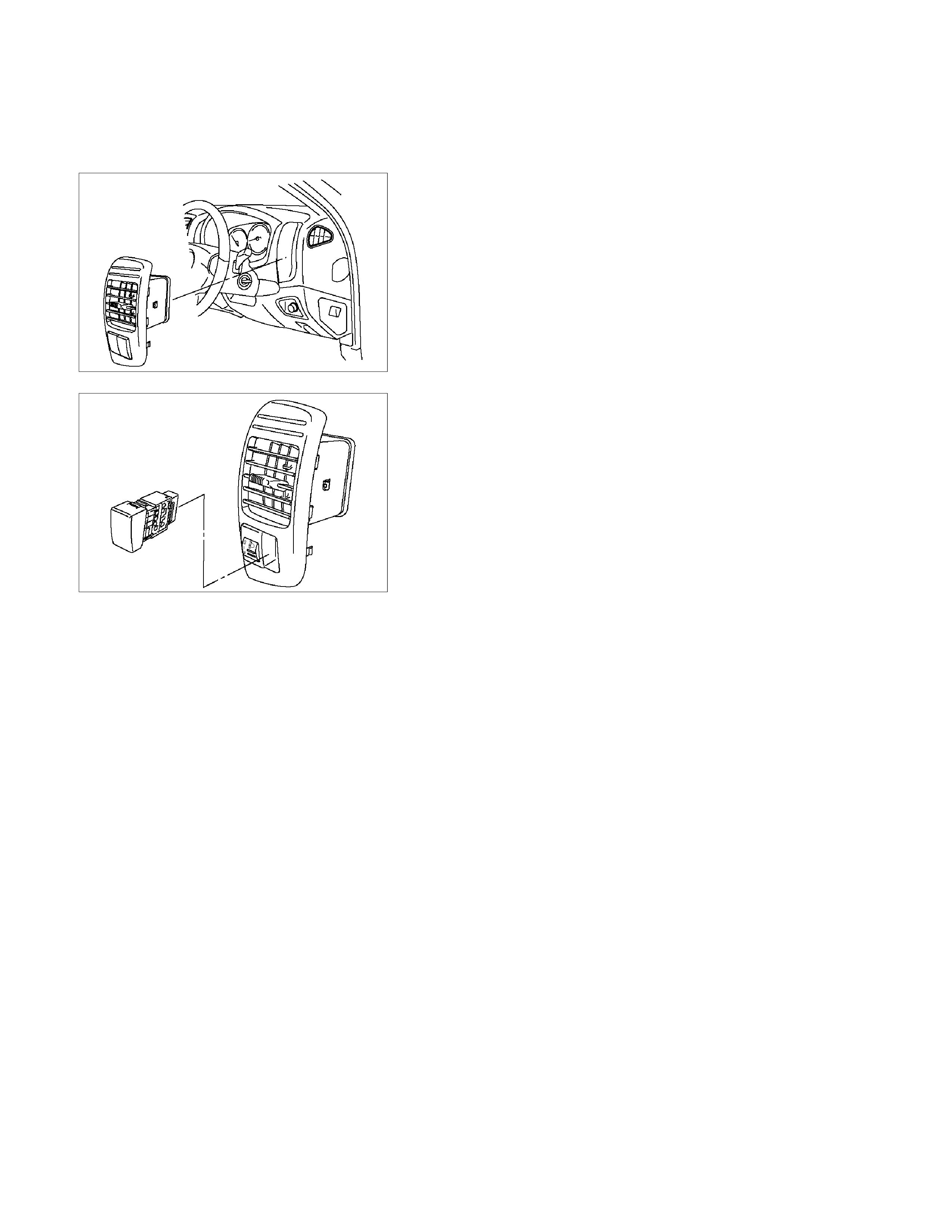
Cruise Control Main Switch
Removal
1. Disconnect the battery ground cable.
RTW3A0SH001301
2. Remove the side ventilation grille.
RTW3A0SH001401
3. Disconnect the switch connector and push the lock from
the backside of the side ventilation grille to remove the
cruise control main switch.
Installation
To install, follow the removal steps in the reverse order, noting
the following point.
1. Push in the switch with your fingers until it locks securely.

Cruise Control Switch (Combination Switch)
Removal and Installation
Refer to the Lighting Switch (Combination Switch) removal and
installation steps of Lighting System in Body and Accessories
section.

Cruise Control Unit
RTW3A0SH001101
Removal
1. Disconnect the battery ground cable.
2. Remove the dash side trim panel (LH) (1).
3. Disconnect the connector.
4. Remove a fixing nut to remove the cruise control unit (2).
Installation
To install, follow the removal steps in the reverse order.
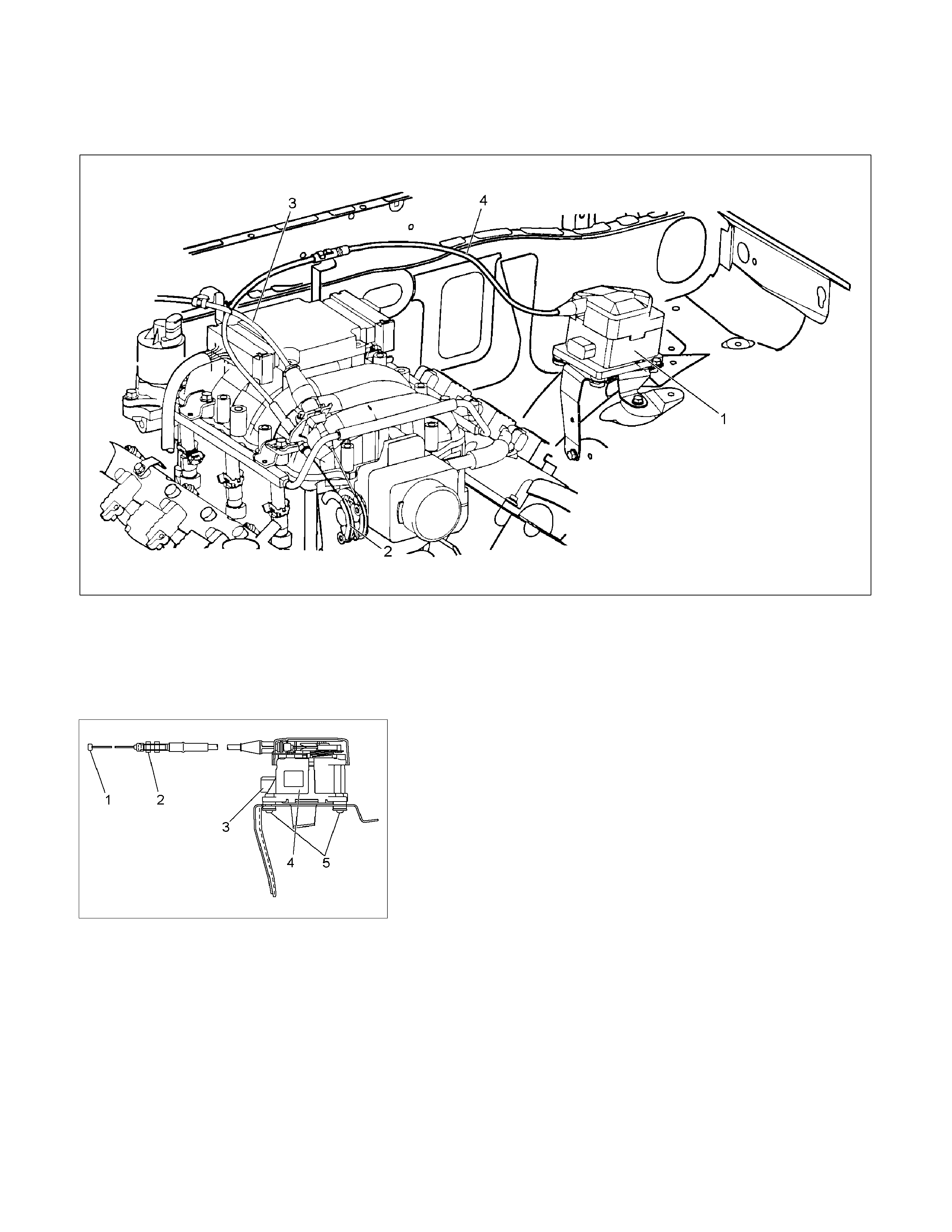
Cruise Actuator
Actuator Cable Diagram
RTW3A0SF000301
Legend
(1) Cruise Actuator Assembly
(2) Cruise Control Cable
(3) Accelerator Cable
(4) Throttle Link (Cruise Control Side)
RTW3A0SH001001
Removal
1. Disconnect the battery cable.
2. Remove the cruise actuator Assembly (4).
• Disconnect the connector (3).
• Remove the cable end (1) from the throttle link (cruise
control side).
• Loosen a fixing nut of the cruise control cable (2).
• Remove fixing screws of the actuator (5).
Installation
To install, follow the removal steps in the reverse order, noting
the following point.
1. Take care not to bend the cable excessively.
RTW3A0SH001501
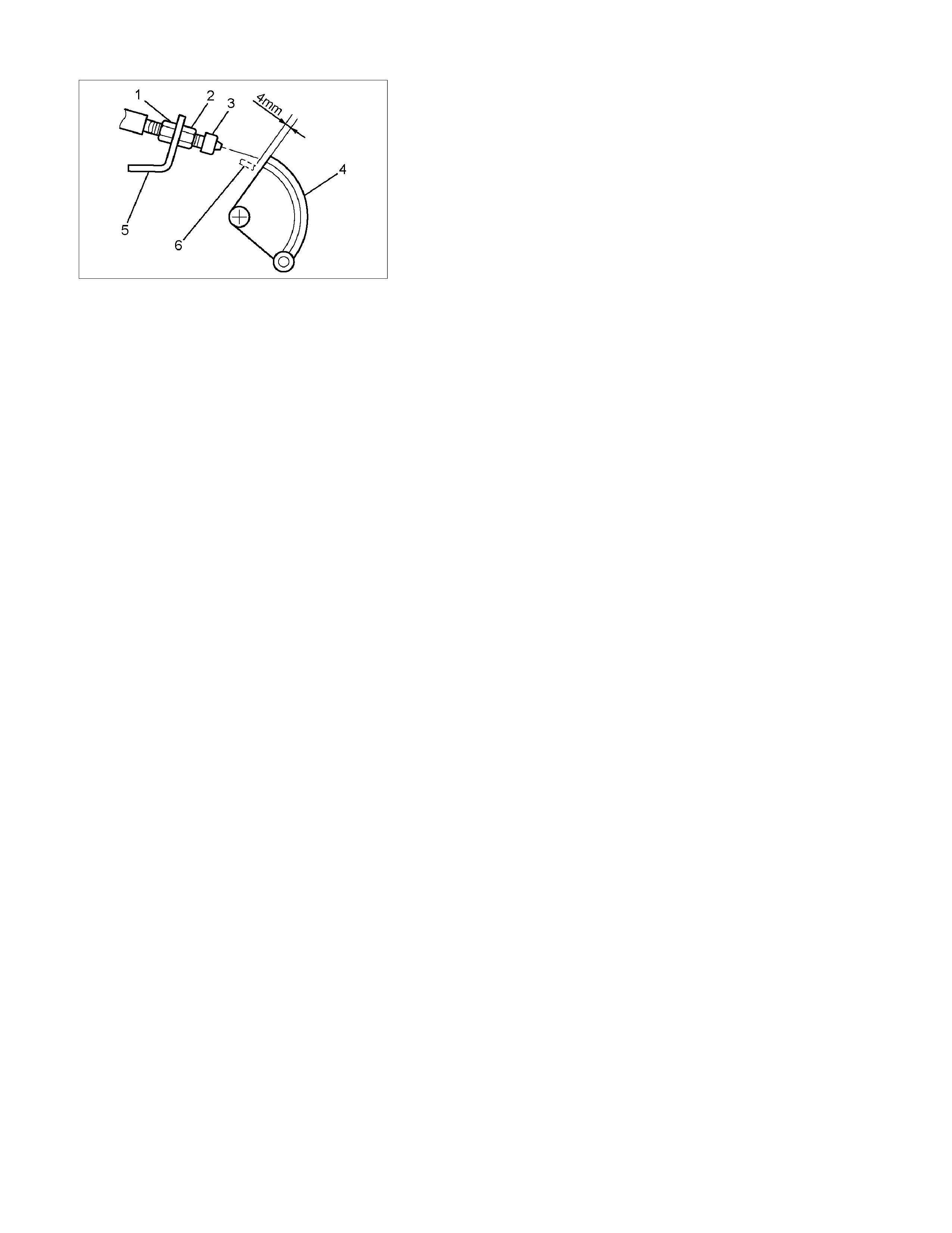
Adjustment
After installing the cruise actuator, the following steps must be
carried out for cruise control cable adjustment.
1. Install the cruise control cable end (3) to the throttle link (4).
2. Put the screw portion of the cable in the bracket (5).
3. Put the nut (1) to the bracket and then tighten the nut (2).
CAUTION: Don't move a position of the nut (1) from
supplied condition.
4. If the distance between the throttle link (4) and the throttle
link lever (6) is out of the specified range, loosen the nut (2)
to adjust it.

Mode Switch
Removal and Installation
Refer to the Mode Switch removal and installation steps in
Automatic Transmission section.

Cruise Control System Check
Step Action Value YES NO
1 1. Start the engine.
2. Turn ON the cruise main switch.
3. Check the cruise main lamp in the cruise main switch.
Does the cruise main lamp ON?
–
Go to Step 2
Go to Cruise
Main Lamp
Inoperative
2 Does the cruise main lamp flash? Refer to
Diagnosis in
this section Go to Step 3
3 1. Drive the vehicle at 80 km/h (50 MPH) on a flat level
road.
2. Press and release the cruise set/coast switch.
3. Verify the 80 km/h (50 MPH) vehicle speed is
maintained.
4. Tap the cruise set/coast switch 10 times.
Did the vehicle maintain the set speed of 40 km/h (25
MPH), and then decrease by 1.6 km/h (1 MPH) each time
the switch was tapped?
–
Go to Step 4 Go to Step 9
4 Check the cruise set lamp in the instrument panel.
Is the cruise set lamp illuminated? – Go to Step 5
Go to Cruise
Set Lamp
Inoperative
5 Tap the cruise resume/accel. switch 10 times.
Does the vehicle increase by 1.6 km/h (1 MPH) each time
the switch was tapped? – Go to Step 6 Go to Step 15
6 Press and release the brake pedal.
Is the cruise set lamp turned OFF? – Go to Step 7 Go to Step 18
7 1. Drive the vehicle at 40 km/h (25 MPH).
2. Press and release the cruise set/coast switch.
3. Press and release the clutch pedal (for M/T) or place
the shift lever at the neutral position (for A/T).
Is the cruise set lamp turned OFF?
–
Go to Step 8 Go to Step 25
8 1. Drive the vehicle at 40 km/h (25 MPH).
2. Press and release the cruise set/coast switch.
3. Turn the end of the cruise control lever to CANCEL
position.
Is the cruise set lamp turned OFF?
–
System OK Go to Step 32
9 1. Stop the vehicle.
2. Verify the cruise main switch that is turned ON.
3. Turn ON and OFF the cruise cancel switch for 3 times
within 2 seconds.
4. Observe the flashing of the cruise main lamp.
Does the cruise main lamp indicate any DTC?
– Go to
Applicable
Diagnostic
Trouble Code Go to Step 10

Step Action Value YES NO
10 1. Turn OFF the ignition.
2. Disconnect the cruise control unit harness connector.
3. Connect a DMM between the cruise set/coast switch
circuit (pin 4 of C-120 connector) and a known good
ground.
4. Turn ON the ignition, with the engine OFF.
5. Turn ON the cruise set/coast switch.
Is the DMM voltage more than the specified value?
10 volts
Go to Step 42 Go to Step 11
11 1. Turn OFF the ignition.
2. Disconnect the cruise control switch harness
connector.
3. Connect a 3-amp fused jumper wire between the
cruise set/coast switch circuits (pins 11 and 12 of B-59
connector).
4. Connect a DMM between the cruise set/coast switch
circuit (pin 4 of C-120 connector) and a known good
ground.
5. Turn ON the ignition, with the engine OFF.
Is the DMM voltage more than the specified value?
10 volts
Go to Step 38 Go to Step 12
12 1. Disconnect a 3-amp fused jumper wire.
2. Connect a DMM between the cruise control switch
power supply circuit (pin 11 of B-59 connector) and a
known good ground.
Is the DMM voltage more than the specified value?
10 volts
Go to Step 13 Go to Step 14
13 Repair the circuit between the cruise set/coast switch (pin
12 of B-59 connector) and the cruise control unit (pin 4 of
C-120 connector).
Did you complete the repair?
–
Go to Step 48 –
14 Repair the circuit between the Turn (10A) fuse and the
cruise set/coast switch (pin 12 of B-59 connector).
Did you complete the repair? – Go to Step 48 –
15 1. Turn OFF the ignition.
2. Disconnect the cruise control unit harness connector.
3. Connect a DMM between the cruise resume/accel.
switch circuit (pin 3 of C-120 connector) and a known
good ground.
4. Turn ON the ignition, with the engine OFF.
5. Turn ON the cruise set/coast switch.
Is the DMM voltage more than the specified value?
10 volts
Go to Step 42 Go to Step 16

Step Action Value YES NO
16 1. Turn OFF the ignition.
2. Disconnect the cruise control switch harness
connector.
3. Connect a 3-amp fused jumper wire between the
cruise resume/accel. switch circuits (pins 11 and 9 of
B-59 connector).
4. Connect a DMM between the cruise resume/accel.
switch circuit (pin 3 of C-120 connector) and a known
good ground.
5. Turn ON the ignition, with the engine OFF.
Is the DMM voltage more than the specified value?
10 volts
Go to Step 39 Go to Step 17
17 Repair the circuit between the cruise resume/accel. switch
(pin 9 of B-59 connector) and the cruise control unit (pin 3
of C-120 connector).
Did you complete the repair?
–
Go to Step 48 –
18 1. Turn OFF the ignition.
2. Disconnect the cruise control unit harness connector.
3. Connect a DMM between the stop lamp switch circuit
(pin 2 of C-120 connector) and a known good ground.
4. Turn ON the ignition, with the engine OFF.
5. Press the brake pedal.
Is the DMM voltage more than the specified value?
10 volts
Go to Step 35 Go to Step 19
19 1. Turn OFF the ignition.
2. Inspect the Stop (15A) fuse.
Is the Stop (15A) fuse open? – Go to Step 20 Go to Step 21
20 Replace the Stop (15A) fuse. If the fuse continues to
open, repair the short to ground on one of the circuits that
is fed by the Stop (15A) fuse or replace the shorted
attached component fed by the Stop (15A) fuse.
Did you complete the replacement?
–
Go to Step 48 –
21 1. Turn OFF the ignition.
2. Disconnect the stop lamp switch harness connector.
3. Connect a 3-amp fused jumper wire between the stop
lamp switch circuits (pins 1 and 2 of C-44 connector).
4. Connect a DMM between the stop lamp switch circuit
(pin 2 of C-120 connector) and a known good ground.
5. Turn ON the ignition, with the engine OFF.
6. Press the brake pedal.
Is the DMM voltage more than the specified value?
10 volts
Go to Step 40 Go to Step 22
22 1. Disconnect a 3-amp fused jumper wire.
2. Connect a DMM between the stop lamp switch power
supply circuit (pin 1 of C-44 connector) and a known
good ground.
Is the DMM voltage more than the specified value?
10 volts
Go to Step 23 Go to Step 24
23 Repair the circuit between the stop lamp switch (pin 2 of
C-44 connector) and the cruise control unit (pin 2 of C-120
connector).
Did you complete the repair?
–
Go to Step 48 –

Step Action Value YES NO
24 Repair the circuit between the Stop (15A) fuse and the
stop lamp switch (pin 1 of C-44 connector).
Did you complete the repair? – Go to Step 48 –
25 Does the vehicle have the automatic transmission? – Go to Step 26 Go to Step 29
26 1. Turn OFF the ignition.
2. Install a scan tool.
3. Monitor the Diagnostic Trouble Code (DTC)
Information of the automatic transmission control
system with a scan tool.
Is DTC P0705 set?
–
Go to DTC
P0705 in
Transmission
Control
System
(AW30-40LE)
section Go to Step 27
27 1. Turn OFF the ignition.
2. Disconnect the cruise control unit harness connector.
3. Connect a DMM between the inhibitor switch circuit
(pin 12 of C-120 connector) and a known good ground.
4. Turn ON the ignition, with the engine OFF.
5. Place the shift lever at the neutral position.
Is the DMM voltage less than the specified value?
0.1 volts
Go to Step 35 Go to Step 28
28 Repair the circuit between the diode (pin 2 of X-16
connector) and the cruise control unit (pin 12 of C-120
connector).
Did you complete the repair?
–
Go to Step 48 –
29 1. Turn OFF the ignition.
2. Disconnect the cruise control unit harness connector.
3. Connect a DMM between the clutch switch circuit (pin
12 of C-120 connector) and a known good ground.
4. Turn ON the ignition, with the engine OFF.
5. Press the clutch pedal.
Is the DMM voltage less than the specified value?
0.1 volts
Go to Step 35 Go to Step 30
30 1. Turn OFF the ignition.
2. Disconnect the clutch switch harness connector.
3. Connect a DMM between the clutch switch circuits
(pins 1 and 2 of C-77 connector) and a known good
ground.
4. Turn ON the ignition, with the engine OFF.
Is the DMM voltage less than the specified value?
0.1 volts
Go to Step 45 Go to Step 31
31 Repair the circuit between the clutch switch (pin 1 of C-77
connector) and the cruise control unit (pin 12 of C-120
connector).
Did you complete the repair?
–
Go to Step 48 –
32 1. Turn OFF the ignition.
2. Disconnect the cruise control unit harness connector.
3. Connect a DMM between the cruise cancel switch
circuit (pin 10 of C-120 connector) and a known good
ground.
4. Turn ON the ignition, with the engine OFF.
5. Turn ON the cruise cancel switch.
Is the DMM voltage more than the specified value?
10 volts
Go to Step 35 Go to Step 33

Step Action Value YES NO
33 1. Turn OFF the ignition.
2. Disconnect the cruise control switch harness
connector.
3. Connect a 3-amp fused jumper wire between the
cruise cancel switch circuits (pins 11 and 10 of B-59
connector).
4. Connect a DMM between the cruise cancel switch
circuit (pin 10 of C-120 connector) and a known good
ground.
5. Turn ON the ignition, with the engine OFF.
Is the DMM voltage more than the specified value?
10 volts
Go to Step 41 Go to Step 34
34 Repair the circuit between the cruise cancel switch (pin 10
of B-59 connector) and the cruise control unit (pin 10 of C-
120 connector).
Did you complete the repair?
–
Go to Step 48 –
35 Check the cruise set lamp in the instrument panel.
Does the cruise set lamp illuminate? – Go to Step 36 Go to Step 47
36 1. Turn OFF the ignition.
2. Remove the instrument panel cluster (IPC) enough to
disconnect the B-24 harness connector.
3. Connect a DMM between the cruise set lamp circuits
(pins 30 and 20 of B-24 connector.
4. Turn ON the ignition, with the engine OFF.
Is the DMM voltage less than the specified value?
0.1 volts
Go to Step 46 Go to Step 37
37 Repair the circuit between the IPC (pin 20 of B-59
connector) and the cruise control unit (pin 14 of C-120
connector).
Did you complete the repair?
–
Go to Step 48 –
38 1. Turn OFF the ignition.
2. Inspect for an intermittent and for poor connections on
the cruise set/coast switch circuit at the cruise control
switch harness connector (pin 12 of B-59 connector).
3. Repair the connection(s) as necessary.
Did you find and correct the condition?
–
Go to Step 48 Go to Step 43
39 1. Turn OFF the ignition.
2. Inspect for an intermittent and for poor connections on
the cruise resume/accel. switch circuit at the cruise
control switch harness connector (pin 9 of B-59
connector).
3. Repair the connection(s) as necessary.
Did you find and correct the condition?
–
Go to Step 48 Go to Step 43
40 1. Turn OFF the ignition.
2. Inspect for an intermittent and for poor connections on
the stop lamp switch circuits (pins 1 and 2 of C-44
connector).
3. Repair the connection(s) as necessary.
Did you find and correct the condition?
–
Go to Step 48 Go to Step 44

Step Action Value YES NO
41 1. Turn OFF the ignition.
2. Inspect for an intermittent and for poor connections on
the cruise cancel switch circuit at the cruise control
switch harness connector (pin 10 of B-59 connector).
3. Repair the connection(s) as necessary.
Did you find and correct the condition?
–
Go to Step 48 Go to Step 43
42 1. Turn OFF the ignition.
2. Inspect for an intermittent and for poor connections on
applicable circuit at the cruise control unit harness
connector (pin 4, 3, 10 or 2 of C-120 connector).
3. Repair the connection(s) as necessary.
Did you find and correct the condition?
–
Go to Step 48 Go to Step 47
43 Replace the combination switch.
Did you complete the replacement? – Go to Step 48 –
44 Replace the stop lamp switch.
Did you complete the replacement? – Go to Step 48 –
45 Replace the clutch switch.
Did you complete the replacement? – Go to Step 48 –
46 Replace the IPC.
Did you complete the replacement? – Go to Step 48 –
47 Replace the cruise control unit
Did you complete the replacement? – Go to Step 48 –
48 1. Reconnect all previously disconnected harness
connector(s).
2. Turn OFF the ignition.
Is the action complete?
–
Go to Step 1 –

Cruise Main Lamp Inoperative
Step Action Value YES NO
1 1. Turn OFF the ignition.
2. Disconnect the cruise control unit harness connector.
3. Connect a DMM between the cruise main switch circuit
(pin 11 of C-120 connector) and a known good ground.
4. Turn ON the ignition, with the engine OFF.
5. Turn ON the cruise main switch.
Is the DMM voltage more than the specified value?
10 volts
Go to Step 8 Go to Step 2
2 1. Turn OFF the ignition.
2. Disconnect the cruise main switch harness connector.
3. Connect a 3-amp fused jumper wire between the
cruise main switch circuits (pins 4 and 3 of B-67
connector).
4. Connect a DMM between the cruise main switch circuit
(pin 11 of C-120 connector) and a known good ground.
5. Turn ON the ignition, with the engine OFF.
Is the DMM voltage more than the specified value?
10 volts
Go to Step 11 Go to Step 3
3 1. Disconnect a 3-amp fused jumper wire.
2. Connect a DMM between the cruise main switch power
supply circuit (pin 4 of B-67 connector) and a known
good ground.
Is the DMM voltage more than the specified value?
10 volts
Go to Step 6 Go to Step 4
4 1. Turn OFF the ignition.
2. Inspect the Turn (10A) fuse.
Is the Turn (10A) fuse open? – Go to Step 5 Go to Step 7
5 Replace the Turn (10A) fuse. If the fuse continues to
open, repair the short to ground on one of the circuits that
is fed by the Turn (10A) fuse or replace the shorted
attached component fed by the Turn (10A) fuse.
Did you complete the replacement?
–
Go to Step 16 –
6 Repair the circuit between the cruise main switch (pin 3 of
B-67 connector) and the cruise control unit (pin 11 of C-
120 connector).
Did you complete the repair?
–
Go to Step 16 –
7 Repair the circuit between the Turn (10A) fuse and the
cruise main switch (pin 4 of B-67 connector).
Did you complete the repair? – Go to Step 16 –
8 Connect a 3-amp fused jumper wire between the cruise
main lamp circuit (pin 13 of C-120 connector) and a
known good ground.
Does the cruise main lamp illuminate?
–
Go to Step 13 Go to Step 9
9 1. Turn OFF the ignition.
2. Disconnect the cruise main switch harness connector.
3. Connect a 3-amp fused jumper wire between the
cruise main lamp circuits (pins 4 and 6 of B-67
connector).
4. Connect a DMM between the cruise main lamp circuit
(pin 13 of C-120 connector) and a known good ground.
10 volts
Go to Step 12 Go to Step 10

Step Action Value YES NO
5. Turn ON the ignition, with the engine OFF.
Is the DMM voltage more than the specified value?
10 Repair the circuit between the cruise main lamp (pin 6 of
B-67 connector) and the cruise control unit (pin 13 of C-
120 connector).
Did you complete the repair?
–
Go to Step 16 –
11 1. Turn OFF the ignition.
2. Inspect for an intermittent and for poor connections on
the cruise main switch circuits at the cruise main switch
harness connector (pins 4 and 3 of B-67connector).
3. Repair the connection(s) as necessary.
Did you find and correct the condition?
–
Go to Step 16 Go to Step 14
12 1. Turn OFF the ignition.
2. Inspect for an intermittent and for poor connections on
the cruise main lamp circuit at the cruise main switch
harness connector (pin 6 of B-67 connector).
3. Repair the connection(s) as necessary.
Did you find and correct the condition?
–
Go to Step 16 Go to Step 14
13 1. Turn OFF the ignition.
2. Inspect for an intermittent and for poor connections on
cruise main switch circuit and cruise main lamp circuit
at the cruise control unit harness connector (pins 11
and 13 of C-120 connector).
3. Repair the connection(s) as necessary.
Did you find and correct the condition?
–
Go to Step 16 Go to Step 15
14 Replace the cruise main switch.
Did you complete the replacement? – Go to Step 16 –
15 Replace the cruise control unit
Did you complete the replacement? – Go to Step 16 –
16 1. Reconnect all previously disconnected harness
connector(s).
2. Turn OFF the ignition.
Is the action complete?
– Go to Cruise
Control
System Check
Step 1 –

Cruise Set Lamp Inoperative
Step Action Value YES NO
1 1. Turn OFF the ignition.
2. Disconnect the cruise control unit harness connector.
3. Connect a 3-amp fused jumper wire between the
cruise main lamp circuit (pin 14 of C-120 connector)
and a known good ground.
4. Turn ON the ignition, with the engine OFF.
Does the cruise main lamp illuminate?
–
Go to Step 9 Go to Step 2
2 1. Turn OFF the ignition.
2. Remove the instrument panel cluster (IPC) enough to
disconnect the B-24 harness connector.
3. Connect a DMM between the cruise set lamp circuits
(pins 30 and 20 of B-24 connector.
4. Turn ON the ignition, with the engine OFF.
Is the DMM voltage more than the specified value?
10 volts
Go to Step 8 Go to Step 3
3 1. Disconnect a 3-amp fused jumper wire.
2. Connect a DMM between the cruise set lamp power
supply circuit (pin 30 of B-24 connector) and a known
good ground.
Is the DMM voltage more than the specified value?
10 volts
Go to Step 6 Go to Step 4
4 1. Turn OFF the ignition.
2. Inspect the Meter (15A) fuse.
Is the Meter (15A) fuse open? – Go to Step 5 Go to Step 7
5 Replace the Meter (15A) fuse. If the fuse continues to
open, repair the short to ground on one of the circuits that
is fed by the Meter (15A) fuse or replace the shorted
attached component fed by the Meter (15A) fuse.
Did you complete the replacement?
–
Go to Step 12 –
6 Repair the circuit between the IPC (pin 20 of B-24
connector) and the cruise control unit (pin 14 of C-120
connector).
Did you complete the repair?
–
Go to Step 12 –
7 Repair the circuit between the Meter (15A) fuse and the
IPC (pin 30 of B-24 connector).
Did you complete the repair? – Go to Step 12 –
8 1. Turn OFF the ignition.
2. Inspect for an intermittent and for poor connections on
the cruise set lamp circuits at the IPC harness
connector (pins 20 and 30 of B-67 connector).
3. Repair the connection(s) as necessary.
Did you find and correct the condition?
–
Go to Step 12 Go to Step 10
9 1. Turn OFF the ignition.
2. Inspect for an intermittent and for poor connections on
cruise main lamp circuit at the cruise control unit
harness connector (pin 14 of C-120 connector).
3. Repair the connection(s) as necessary.
Did you find and correct the condition?
–
Go to Step 12 Go to Step 11

Step Action Value YES NO
10 Replace the cruise set lamp bulb or the IPC.
Did you complete the replacement? – Go to Step 12 –
11 Replace the cruise control unit
Did you complete the replacement? – Go to Step 12 –
12 1. Reconnect all previously disconnected harness
connector(s).
2. Turn OFF the ignition.
Is the action complete?
– Go to Cruise
Control
System Check
Step 3 –

Diagnosis
The cruise control unit uses the cruise main indicator light and diagnosis the failure, when the control unit detects
abnormality on the table below.
PART POSSIBLE CAUSE DETECTION PERIOD DTC
Actuator Motor system short circuit Energizing motor 1-1
Clutch system short circuit Energizing clutch 1-2
Clutch system open circuit Energizing clutch 1-2
Mechanical defect Cruise controlling 1-3
Close side of motor system open circuit Cruise controlling 1-1
Cruise control unit Close side of motor system open circuit While starter sw on 1-4
Clutch output abnormality While starter sw on 1-4
Vehicle speed sensor Signal of vehicle speed disconnection Cruise controlling 2-1
Signal of vehicle speed abnormality Cruise controlling 2-1
Switch Turning on switch at all times While starter sw on 3-1
Turning on switch at the same time While starter sw on 3-1
DTC : Diagnostic Trouble Code
DTC Display Condition
1. Turn the ignition ON, with engine OFF or let the engine run at idle.
2. Turn the cruise main switch ON.
3. Turn the cruise cancel switch ON and OFF for three times within 2 seconds.
4. Observe the cruise main warning lamp on the cruise main switch.
5. Read flashing of the cruise main warning lamp.
NOTE:
• Flashing of the cruise main warning lamp is stopped when the vehicle speed rises above 10km/h or the cruise
resume switch is turned ON.
• The DTC is cleared when the ignition is turned OFF.
DTC Display Format
1. When no DTCs are detected. (The unit : sec.)
F08RW003
2. When two or more DTCs are detected. (The unit : sec.)
F08RW009
Circuit Diagram
RTW680XF015901

DTC 1–1 Motor System Short Circuit
Step Action Value(s) YES NO
1 1. Turn the starter switch off.
2. Disconnect the actuator connector C-119.
3. Measure resistance between actuator side
connector terminal 1 and 2.
If control plate position is fully opened or fully
closed, resistance can not be measure.
Is there resistance within range specified in the
value(s) column?
More than
4.2Ω
Go to Step 2
Replace the
actuator
2 Measure continuity between harness side connector
C-119 terminal 1 and the ground, terminal 2 and the
ground, and terminals 1 and 2.
Are the results same as specified in the value(s)
column?
No
continuity
Replace the
control unit
Repair or
replace the
harness

DTC 1–2 Clutch System Open or Short Circuit
Step Action Value(s) YES NO
1 1. Turn the starter switch off.
2. Disconnect the actuator connector C–119.
3. Measure resistance between actuator side
connector terminal 3 and 4.
Is there resistance within range specified in the
value(s) column?
34.7 –
42.4Ω
Go to Step 2
Replace the
actuator
2 1. Disconnect the brake switch connector C–44.
2. Check continuity between switch side connector
terminal 3 and 4.
Is there continuity between terminals?
—
Go to Step 3
Replace the
switch
3 1. Reconnect the brake switch connector C–44.
2. Check continuity between harness side
connector C–120 terminal 6 and connector C–44
terminal 3, connector C–119 terminal 4 and
connector C–120 terminal 8.
Is there continuity between terminals?
—
Go to Step 4
Replace open
circuit
4 Check continuity between harness side connector
C–119 terminal 3 and the ground, connector C–119
terminal 4 and the ground, connector C–120
terminal 6 and the ground.
Are the results same as specified in the value(s)
column?
No
continuity
Replace the
control unit
Repair short
circuit

DTC 1–3 Mechanical Defect
Step Action Value(s) YES NO
1 1. Turn the starter switch off.
2. Disconnect the actuator connector C–119.
3. Connect the battery positive terminal with the
actuator side connector terminal 3 and the battery
negative terminal with terminal 4.
Does the control plate move by hand?
—
Replace the
actuator
Go to Step 2
2 Connect the battery positive terminal with the
actuator side connector terminal 1 and 3, and the
battery negative terminal with terminal 2 and 4.
Does the control plate move to full open side?
—
Go to Step 3
Replace the
actuator
3 Connect the battery positive terminal with the
actuator side connector terminal 2 and 3, and the
battery negative terminal with terminal 1 and 4.
Does the control plate move to full close side?
—
Go to Step 4
Replace the
actuator
4 Is there continuity between harness side connector
C–119 terminal 1 and connector C–120 terminal 7,
connector C–119 terminal 2 and connector C–120
terminal 15?
—
Replace the
control unit
Repair or
replace
harness

DTC 1–4 Close Side of Motor System Open Circuit
Step Action Value(s) YES NO
1 1. Turn the starter switch off.
2. Disconnect the actuator connector C–119.
3. Measure resistance between actuator side
connector terminal 1 and 2.
If control plate position is fully opened or fully
closed, resistance can not be measured.
Is there resistance within range specified in the
value(s) column?
More than
4.2Ω
Go to Step 2
Replace the
actuator
2 Is there continuity between harness side connector
C–119 terminal 1 and connector C–120 terminal 7,
harness side connector C–119 terminal 2 and
connector C–120 terminal 15?
—
Replace the
control unit
Repair or
replace the
harness

DTC 2–1 Signal of Vehicle Speed Malfunction
Step Action Value(s) YES NO
1 Check the DTC for engine.
Is the vehicle speed sensor DTC set?
— Go to DTC for
engine
Go to Step 2
2 Check continuity between harness side connector
E–44 terminal 3 and connector C–120 terminal 9.
Is there continuity between terminals?
—
Go to Step 3
Replace open
circuit
3 Check the continuity between harness side
connector E–44 terminal 3 and ground, connector
C–120 terminal 9 and ground.
Are the results same as specified in the value(s)
column?
No continuity
Replace the
control unit
Repair short
circuit

DTC 3–1 Turning On Switch At All Time Or At The Same Time
Step Action Value(s) YES NO
1 1. Turn the starter switch off.
2. Disconnect the auto cruise control unit connector
C-120.
3. Turn the starter switch on.
4. Turn the cruise control switch “cancel”.
5. Check voltage at the harness side connector C–
120 terminal 10, terminal 3 and terminal 4.
Is the voltage specified value?
0V
Go to Step 3
Go to Step 2
2 1. Turn the starter switch off.
2. Disconnect the cruise control switch connector
B–59.
3. Check voltage at the harness side connector C–
120 terminal 10, terminal 3 and terminal 4.
Is the voltage specified value?
0V
Replace the
cruise control
switch
Repair short
circuit
3 1. Turn the starter switch off.
2. Turn the cruise control switch “cancel”.
3. Check the continuity between harness side
connector C–120 terminal 10 and terminal 3,
connector C–120 terminal 3 and terminal 4,
connector C–120 terminal 10 and terminal 4.
Are the results same as specified in the value(s)
column?
No continuity
Go to Step 5
Go to Step 4
4 1. Disconnect the cruise control switch connector
B–59.
2. Check the continuity between harness side
connector C–120 terminal 10 and terminal 3,
connector C–120 terminal 3 and terminal 4,
connector C–120 terminal 10 and terminal 4.
Are the results same as specified in the value(s)
column?
No continuity
Replace the
cruise control
switch
Repair short
circuit
5 Check the continuity between harness side
connector C–120 terminal 10 and connector B–59
terminal 10.
Is there continuity between terminals?
—
Replace the
control unit
Replace open
circuit