
SECTION 8B - CRUISE CONTROL SYSTEM
Service Precaution
General Description
Brake Switch
Removal
Installation
Adjustment
Clutch Switch
Removal and Installation
Adjustment
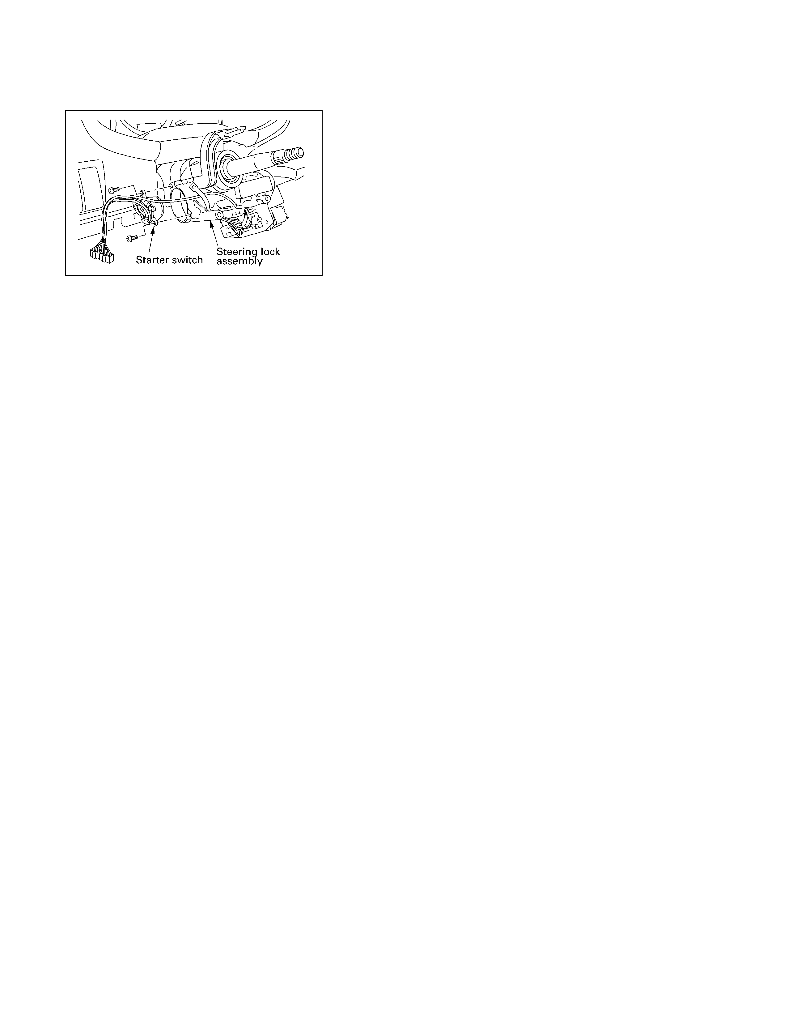
Starter Switch
Removal
Installation
Cruise Control Main Switch
Removal
Installation
Cruise Control Sw itch
(Combination Sw itch)
Removal and Installation
Cruise Control Unit
Removal
Installation
Cruise Actuator
Actuator Cable Diagram
Removal
Installation
Adjustment
Mode Sw itch
Removal and Installation
Diagnosis
DTC Display Condition
DTC Display Format
Circuit Diagram
DTC 1-1 Motor System Short Circuit
DTC 1-2 Clutch Open or Short Circuit
DTC 1-3 Mechanical Defect
DTC 1-4 Close Side of Motor System
DTC 2-1 Signal of Vehicle Speed
Disconnection or Abnormality
DTC 3-1 Turning On Switch at All time
or at the same time
Techline
Techline
Techline

Service Precaution
WARNING: THIS VEHICLE HAS A SUPPLEMENTAL RESTRA IN SYSTEM (SRS). REFER TO THE SRS
COMPONENT AND WIRING LOCATION VIEW IN ORDER TO DETERMINE WHETHER YOU ARE PERFORMING
SERVICE ON OR NEAR THE SRS COMPONENTS OR THE SRS WIRING. WHEN YOU ARE PERFORMING
SERVICE ON OR NEAR THE SRS COMPONENTS OR THE SRS WIRING, REFER TO THE SRS SERVICE
IMFORMETION. FAILURE TO FOLLOW WARNINGS COULD RESULT IN POSSIBLE AIR BAG DEPLOYMENT,
PERSONAL INJURY, OR OTHER WISE UNNEEDED SRS SYSTEM REPAIRS.
CAUTION: Always use the correct fastener in the proper location. When you replace a faster, use ONLY the
exact part number for that application. Dealer will call out those fasteners that require a replacement after
removal. Dealer will also call out the fasteners that require thread lockers or thread sealant. UNLESS
OTHERWISE SPECIFIED, do not use supplemental coatings (Paints, greases, or other corrosion inhibitors) on
threaded fasteners or fastener joint interfaces. Generally, such coatings adversely affect the fastener torque
and joint Clamping force, and may damaged the fastener. When you install fasteners, use the correct
tightening sequence and specifications. Following these instructions can help you avoid damage to parts and
systems.

General Description
The cruise control keeps the vehicle running at a fixed speed until a signal canceling this fixed speed is received. When
the main switch “AUTO CRUISE” is turned on with the vehicle in the running mode, the battery voltage is applied to the
control unit. When a signal from the control unit while the vehicle is in this state, the cruise control actuator is activated
to operate the system. Also, while the system is operating, the “AUTO CRUISE” indicator light in the meter assembly
lights up.
1. SET/COAST Switch Function
1. Set Function: When the SET/COAST switch is pressed and released with the main switch on, the speed at
which the vehicle is running at that moment is stored in the memory, and the vehicle automatically runs at the
stored speed.
2. COAST-down Function: When the SET/COAST switch is kept on while the vehicle in running, the vehicle
decelerates during that time. The speed at which vehicle is running when the control switch is turned in the
memory, and the vehicle automatically returns to the stored speed.
3. Tap-down Function: When the SET/COAST switch is turned on and off instantaneously while the vehicle is
running, the vehicle decelerates a mile for each on/off operation. The vehicle speed at which the vehicle was
running when the SET/CO AST was turned of f last is stored in the m emor y, and the vehicle autom atically returns
to this stored speed.
2. RESUME/ACCEL Switch Function
1. Resume Function: When the RESUME/ACCEL switch is turned on/off after the system is temporarily
deactivated by pressing the brake or clutch pedal while the vehicle is running, the vehicle resumes the speed
stored before the system was released, and the vehicle automatically runs at the stored speed.
2. Accelerate Function: When the RESUME/ACCEL switch is kept on the vehicle acce lerates its speed during that
time. The vehicle speed at which the vehicle was running when the switch was turned off is stored in the memory,
and the vehicle automatically returns to this speed.
3. Tap-up Function: When the RESUME/ACCEL switch is turned on and off instantaneously while the vehicle is
running, the vehicle decelerates a mile for each on/off operation. The vehicle speed at which the vehicle was
running when the switch was turned of f last is s tored in the m emor y, and the vehicle autom atically returns to this
stored speed.
3. CANCEL Function
1. Temporary Cancellation:
• When the brake pedal is pressed.
• When the clutch pedal is pressed. (M/T)
• When the select lever is shifted to any position other than “D”, “3”, “2” or “L”. (A/T)
• When the cancel switch is operated.
• When the vehicle speed exceeds about 12.5mph over the vehicle speed stored in the memory.
• Turning the RESUME/ACCEL switch will return the vehicle to the speed stored in the cruise control memory.
2. Complete Cancellation:
• When the starter switch or the main switch is turned off.
• When the fail-safe function is activated.
• When the vehicle speed is about 24 mph.
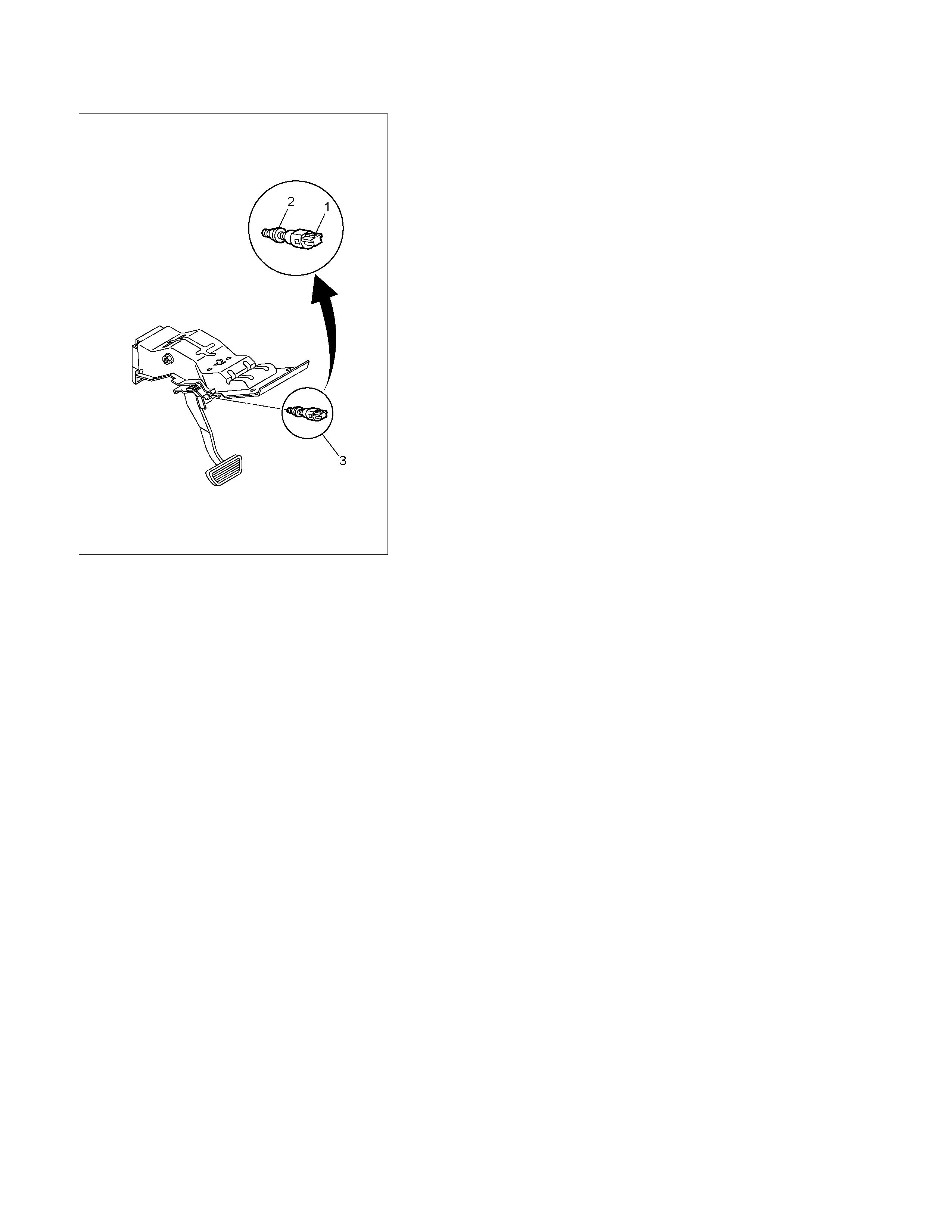
Brake Switch
RTW3A0MH000101
Removal
1. Disconnect the battery ground cable.
2. Remove the brake switch.
• Disconnect the connector (1).
• Loosen lock nuts of the switch (2).
• Remove the switch by turning it (3).
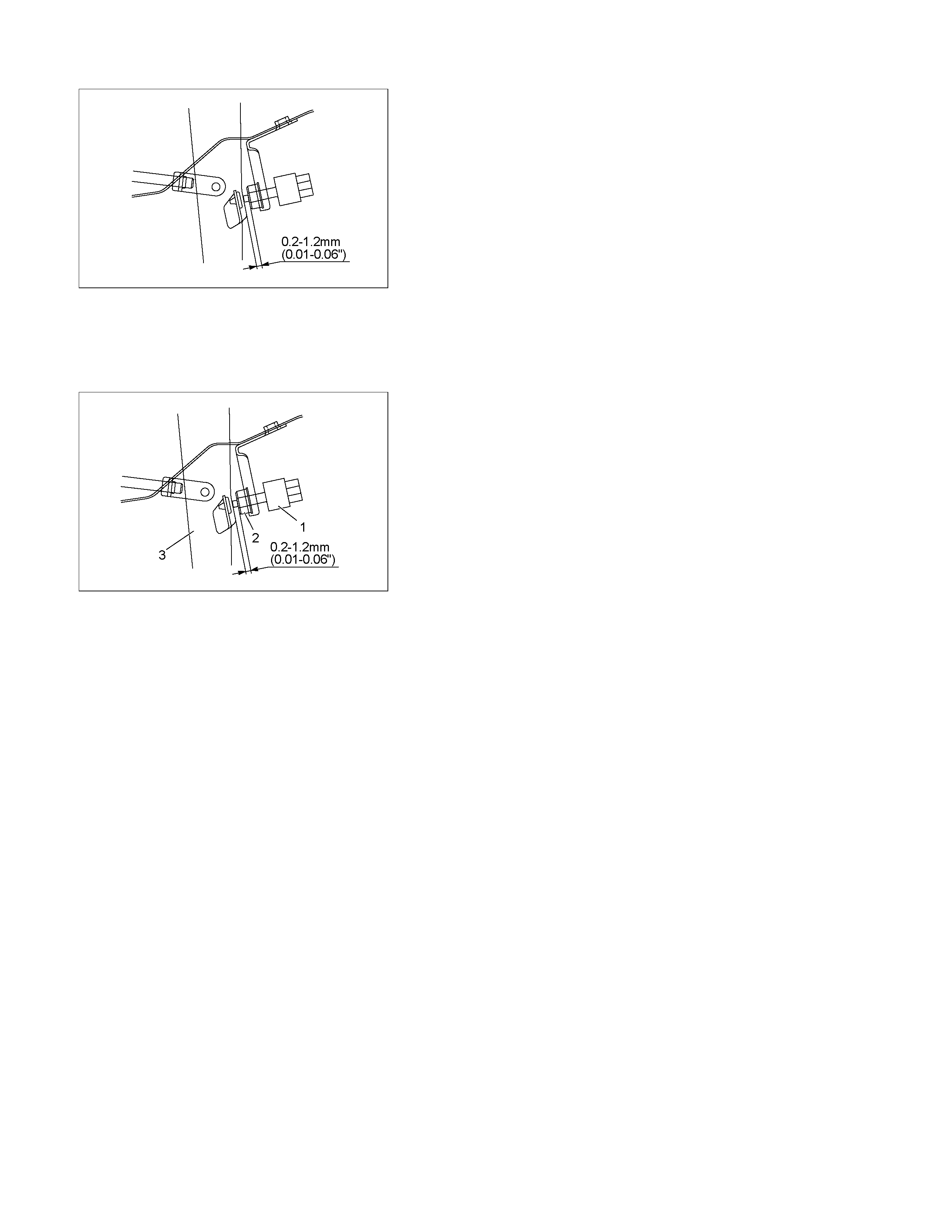
Installation
To install, follow the removal steps in the reverse order, noting
the following points.
1. Check to see if the brake pedal has been returned by the
return spring to the specified position.
2. Turn the switch clock-wise until the tip of the threaded
portion of the brake switch contacts the pedal arm.
RTW3A0SH000901
3. Turn the switch counter-clock-wise until the space between
the tip of the threaded portion and the pedal arm is 0.2 to
1.2 mm (0.01-0.06 in.) as shown in the figure.
Adjustment
1. Check to be sure that the brak e pedal has been com pletel
y
returned by the return spring.
2. Disconnect the switch connector.
RTW3A0SH001201
3. Release the lock (2) by turning the switch (1) counter-cloc k -
wise.
4.
A
fter doing so, pull the pedal arm (3) to you a little so that
the pedal arm is not pushed in.
5. Making the pedal arm not movable with one hand, push in
the whole switch with the other hand until the plunger of the
switch is pushed in and the switch itself hits the rubber o
f
the pedal arm.
In the condition, turn the switch clock-wise until "click"
sound is made and lock it.
By doing this, the switch is adjusted at 0.2 to 1.2m m (0.01-
0.06 in.) clearance.
Clutch Switch
Removal and Installation
Refer to the Clutch Control removal and installation steps in
Clutch sect ion.
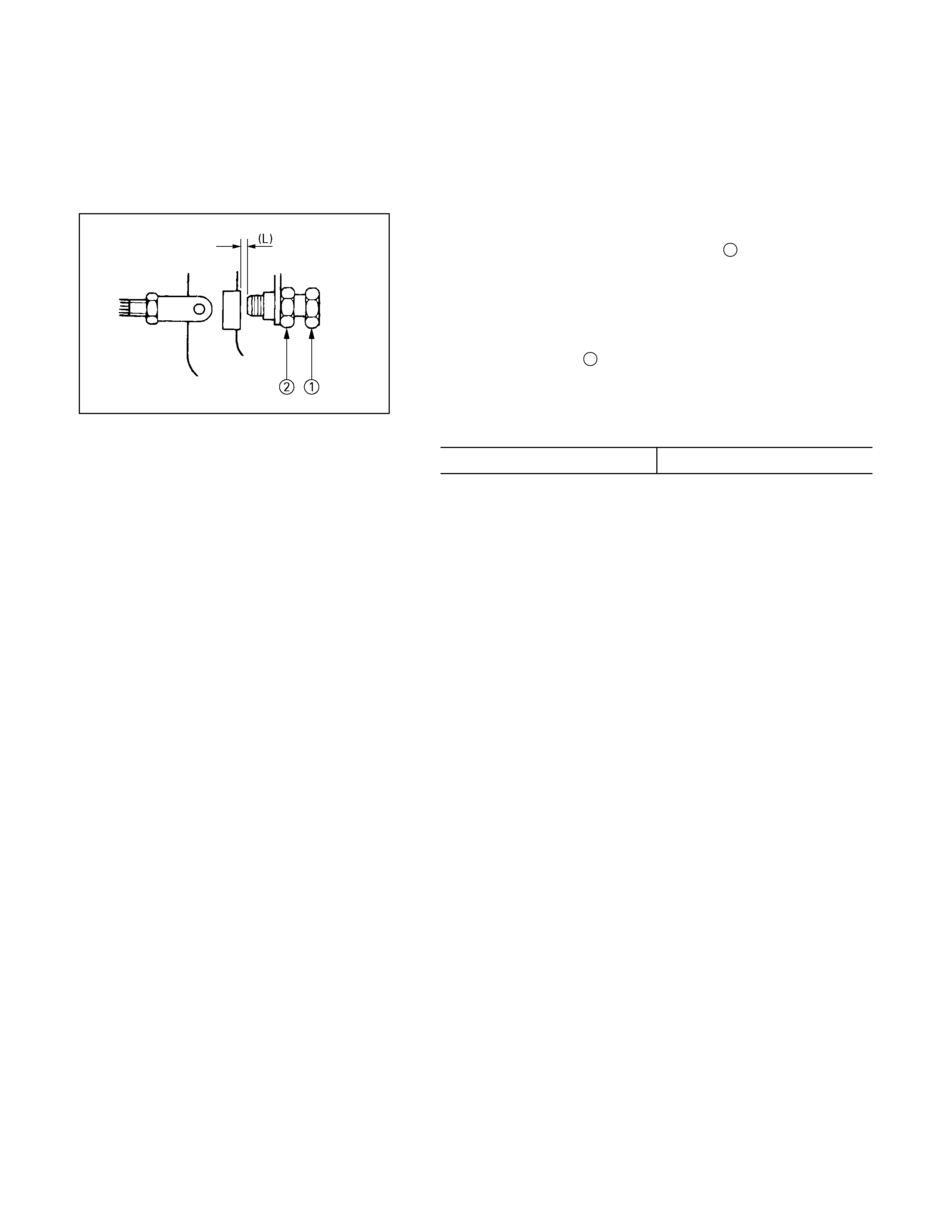
Adjustment
1. T urn the clutch s witch or stopper bolt 1until the switch bolt
or stopper bolt just touches the clutch pedal arm.
2.
A
djust clutch switch or stopper bolt by backing it out half a
turn, and measure the clearance (L) between the clutch
pedal arm and the clutch switch bolt end or stopper bolt.
3. Lock the lock nut 2.
4. Connect the clutch switch connector.
Clutch switch and clutch and clutch pedal clearance
mm (in)
Limit 0.5-1.5 (0.020-0.059)
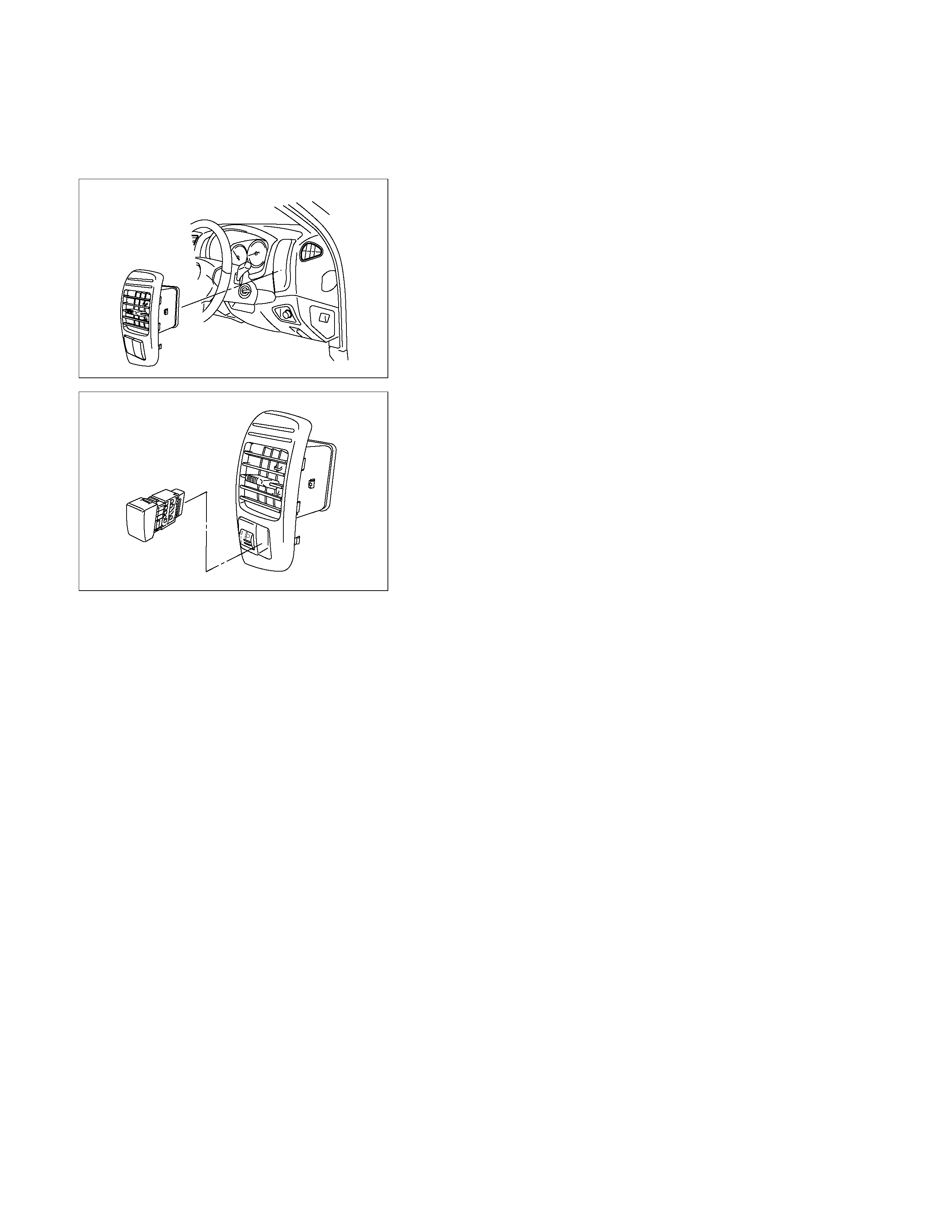
Cruise Control Main Switch
Removal
1. Disconnect the battery ground cable.
RTW3A0SH001301
2. Remove the side ventilation grille.
RTW3A0SH001401
3. Disconnect the s witch c onnector and pus h the lock from the
backside of the side ventilation grille to remove the cruise
control main swit ch.
Installation
To install, follow the removal steps in the reverse order, noting
the following point.
1. Push in the switch with your fingers until it locks securely.


Cruise Control Unit
RTW3A0SH001101
Removal
1. Disconnect the battery ground cable.
2. Remove the dash side trim panel (LH) (1).
3. Disconnect the connector.
4. Remove a fixing nut to remove the cruise control unit (2).
Installation
To install, follow the removal steps in the reverse order.
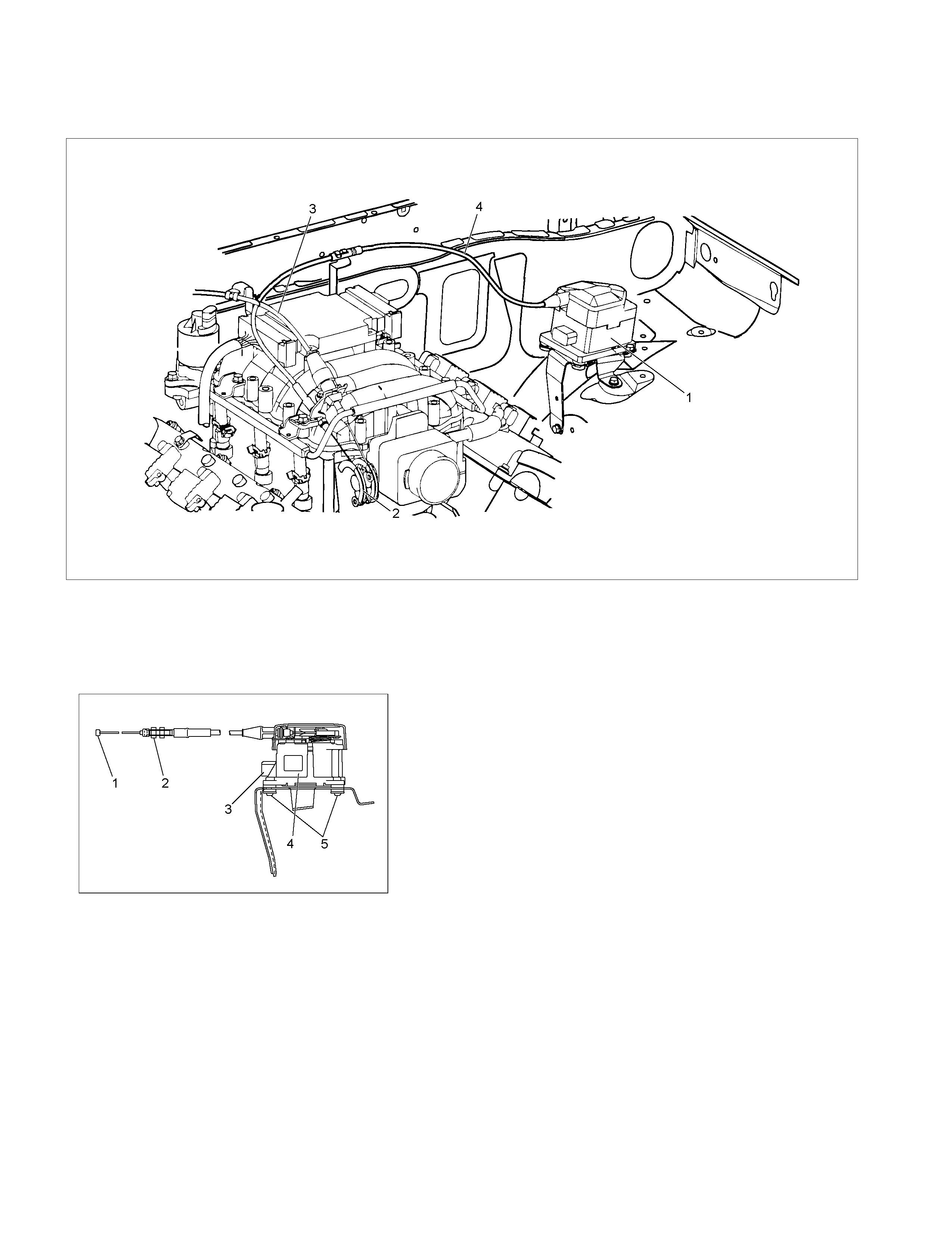
Cruise Actuator
Actuator Cable Diagram
RTW3A0SF000301
Legend
(1) Cruise Actuator Assembly
(2) Cruise Control Cable
(3) Accelerator Cable
(4) Throttle Link (Cruise Control Side)
RTW3A0SH001001
Removal
1. Disconnect the battery cable.
2. Remove the cruise actuator Assembly (4).
• Disconnect the connector (3).
• Remove the cable end (1) from the throttle link (cruise
control side).
• Loosen a fixing nut of the cruise control cable (2).
• Remove fixing screws of the actuator (5).
Installation
To install, follow the removal steps in the reverse order, noting
the following point.
1. Take care not to bend the cable excessively.
RTW3A0SH001501
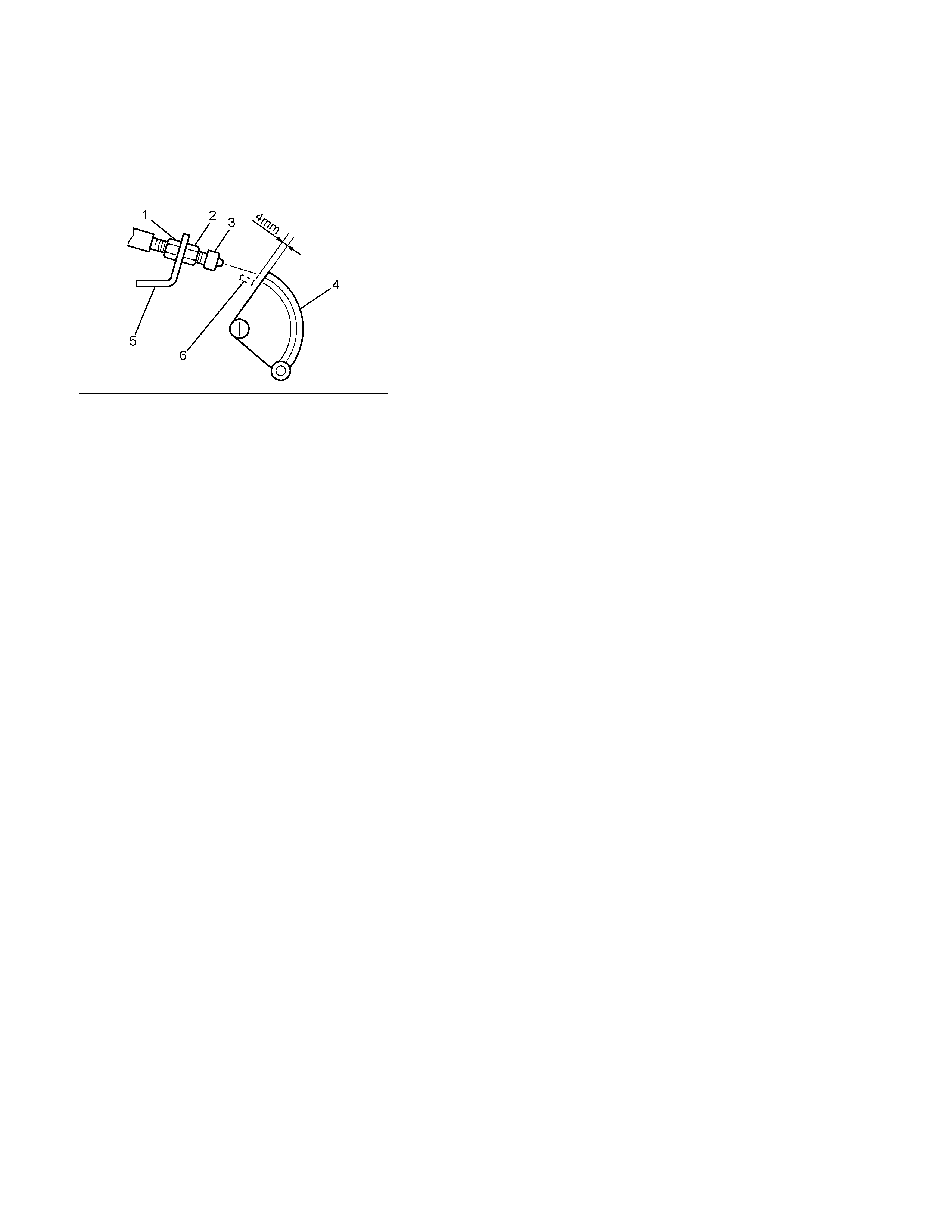
Adjustment
After installing the cruise actuator, the following steps must be
carried out for cruise control cable adjustment.
1. Install the cruise control cable end (3) to the throttle link (4).
2. Put the screw portion of the cable in the bracket (5).
3. Put the nut (1) to the bracket and then tighten the nut (2).
CAUTION: Don't move a position of the nut (1) from
supplied condition.
4. If the distance between the throttle link (4) and the throttle
link lever (6) is out of the s pecified r ange, loosen the nut (2)
to adjust it.


Diagnosis
The cruise control unit uses the cruise main indicator light and diagnosis the failure, when the control unit detects
abnormality on the table below.
PART POSSIBLE CAUSE DETECTION PERIOD DTC
Actuator Motor system - short circuit Energising motor 1-1
Clutch system - short circuit Energising clutch 1-2
Clutch system - open circuit Energising clutch 1-2
Mechanical defect Cruise operating 1-3
Motor system - open circuit Cruise operating 1-1
Cruise control unit Motor system - open circuit Ignition ON 1-4
Clutch output abnormality Ignition ON 1-4
Vehicle speed sensor Loss of vehicle speed signal Cruise operating 2-1
Abnormal vehicle speed signal Cruise operating 2-1
Switch Cancel switch always ON Ignition ON 3-1
Cancel switch Ignition ON 3-1
DTC : Diagnostic Trouble Code
DTC Display Condition
1. With the engine stationary and the ignition switch ON, operate the Cruise Cancel switch three times within 2
seconds.
2. If there are no DTCs stored in the Cruise control unit, the LED on the Cruise Main switch will blink rapidly (2Hz).
3. Any DTCs stored in the Cruise control unit will be displayed by the CRUISE SET warning lamp in the meter cluster.
4. Read the DTCs by referring to the chart on this page.
NOTE:
• The DTC display will be aborted if either the vehicle speed rises above 10km/h or the RESUME switch is operated.
• T he Cr uise control unit s tores the DT Cs in a ‘volatile’ m em ory, - that is, the m em ory is only active when the ignition
is ON. Turning the ignition switch to the OFF position will clear any stored DTCs.
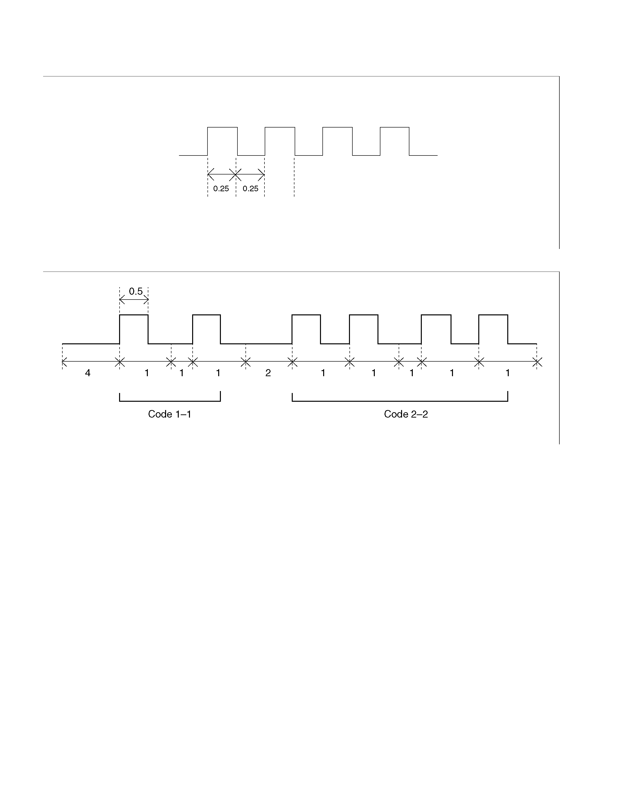
DTC Display Format
1. When no DTCs are detected. (The unit : sec.)
F08RW003
2. When two or more DTCs are detected. (The unit : sec.)
F08RW009
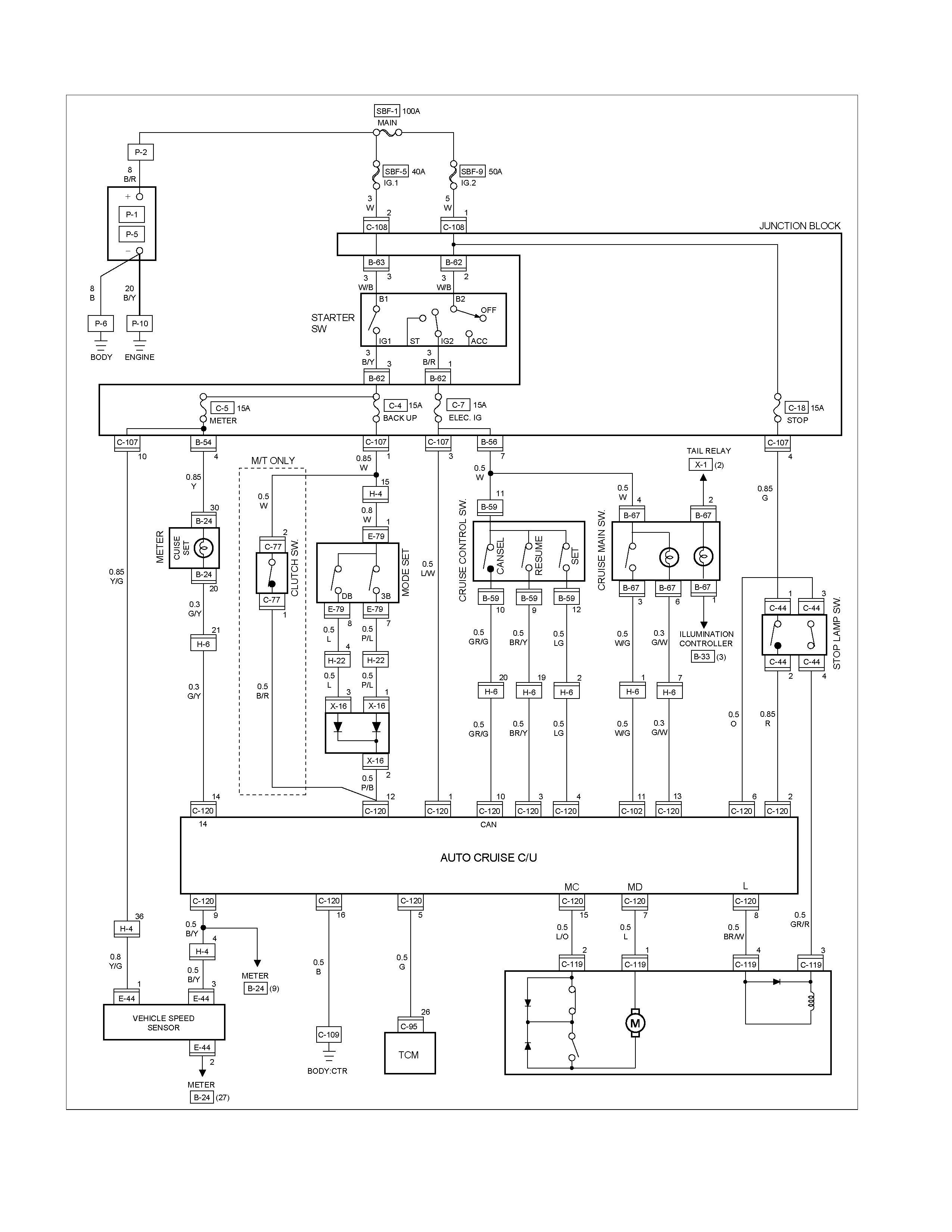
Circuit Diagram
RTW38DXF001201

DTC 1–1 Motor System - Short Circ ui t
Step Action Value(s) YES NO
1 1. Turn the starter switch off.
2. Disconnect the actuator connector C-119.
3. Measure resistance between actuator side
connector terminal 1 and 2.
If control plate position is fully opened or fully
closed, resistance can not be measure.
Is there resistance within range specified in the
value(s) co lumn?
More than
4.2Ω
Go to Step 2
Replace the
actuator
2 Measure continuity between harness side
connector C-119 terminal 1 and the ground,
terminal 2 and the ground, and terminals 1 and 2.
Are the results same as specified in the value(s)
column?
No
continuity
Replace the
control unit
Repair or
replace the
harness
DTC 1–2 Clutch System - Open or Short Circuit
Step Action Value(s) YES NO
1 1. Turn the starter switch off.
2. Disconnect the actuator connector C–119.
3. Measure resistance between actuator side
connector terminal 3 and 4.
Is there resistance within range specified in the
value(s) co lumn?
34.7 –
42.4Ω
Go to Step 2
Replace the
actuator
2 1. Disconnect the brake switch connector C–44.
2. Check continuity between switch side connector
terminal 3 and 4.
Is there continuity between terminals?
—
Go to Step 3
Replace the
switch
3 1. Reconnect the brake switch connector C–44.
2. Chec k continuity between harness side connec tor
C–120 term inal 6 and connector C–44 terminal 3,
connector C–119 ter minal 4 and connector C–120
terminal 8.
Is there continuity between terminals?
—
Go to Step 4
Replace
open circuit
4 Check continuity between harness side connector
C–119 terminal 3 and the ground, connector C–
119 terminal 4 and the ground, connector C–120
terminal 6 and the ground.
Are the results same as specified in the value(s)
column?
No
continuity
Replace the
control unit
Repair short
circuit

DTC 1–3 Mechanical Defect
Step Action Value(s) YES NO
1 1. Turn the starter switch off.
2. Disconnect the actuator connector C–119.
3. Connect the battery positive terminal with the
actuator side connector term inal 3 and the battery
negative terminal with terminal 4.
Does the control plate move by hand?
—
Replace the
actuator
Go to Step 2
2 Connect the battery positive terminal with the
actuator side connector terminal 1 and 3, and the
battery negative terminal with terminal 2 and 4.
Does the control plate move to full open side?
—
Go to Step 3
Replace the
actuator
3 Connect the battery positive terminal with the
actuator side connector terminal 2 and 3, and the
battery negative terminal with terminal 1 and 4.
Does the control plate move to full close side?
—
Go to Step 4
Replace the
actuator
4 Is there continuity between harness side connector
C–119 terminal 1 and connector C–120 terminal 7,
connector C–119 terminal 2 and connector C–120
terminal 15?
—
Replace the
control unit
Repair or
replace
harness
DTC 1–4 Motor System - Open Ci rcuit
Step Action Value(s) YES NO
1 1. Turn the starter switch off.
2. Disconnect the actuator connector C–119.
3. Measure resistance between actuator side
connector terminal 1 and 2.
If control plate position is fully opened or fully
closed, resistance can not be measured.
Is there resistance within range specified in the
value(s) co lumn?
More than
4.2Ω
Go to Step 2
Replace the
actuator
2 Is there continuity between harness side connector
C–119 terminal 1 and connector C–120 terminal 7,
harness side connector C–119 terminal 2 and
connector C–120 terminal 15?
—
Replace the
control unit
Repair or
replace the
harness
DTC 2–1 Loss of Vehicle Speed signal or Abnormal Vehicle Speed signal
Step Action Value(s) YES NO
1 Check the DTC for engine.
Is the vehicle speed sensor DTC set?
— Go to DTC for
engine
Go to Step 2
2 Check continuity between harness side connector
E–44 terminal 3 and connector C–120 terminal 9.
Is there continuity between terminals?
—
Go to Step 3
Replace
open circuit
3 Check the continuity between harness side
connector E–44 terminal 3 and ground, connector
C–120 terminal 9 and ground.
Are the results same as specified in the value(s)
column?
No
continuity
Replace the
control unit
Repair short
circuit
DTC 3–1 Cancel switch always ON
Step Action Value(s) YES NO
1 1. Turn the starter switch off.
2. Disconnect the auto cruise control unit connector
C-120.
3. Turn the starter switch on.
4. Turn the cruise control switch “cancel”.
5. Check voltage at the harness side connector C–
120 terminal 10, terminal 3 and terminal 4.
Is the voltage specified value?
0V
Go to Step 3
Go to Step 2
2 1. Turn the starter switch off.
2. Disc onnec t the cr uis e contr ol s witch connec tor B–
59.
3. Check voltage at the harness side connector C–
120 terminal 10, terminal 3 and terminal 4.
Is the voltage specified value?
0V
Replace the
cruise control
switch
Repair short
circuit
3 1. Turn the starter switch off.
2. Turn the cruise control switch “cancel”.
3. Check the continuity between harness side
connector C–120 terminal 10 and terminal 3,
connector C–120 terminal 3 and terminal 4,
connector C–120 terminal 10 and terminal 4.
Are the results same as specified in the value(s)
column?
No
continuity
Go to Step 5
Go to Step 4
4 1. Disc onnec t the cr uis e contr ol s witch connec tor B–
59.
2. Check the continuity between harness side
connector C–120 terminal 10 and terminal 3,
connector C–120 terminal 3 and terminal 4,
connector C–120 terminal 10 and terminal 4.
Are the results same as specified in the value(s)
column?
No
continuity
Replace the
cruise control
switch
Repair short
circuit
5 Check the continuity between harness side
connector C–120 terminal 10 and connector B–59
terminal 10.
Is there continuity between terminals?
—
Replace the
control unit
Replace
open circuit