
Cruise Control – HFV6 Page 8C–1
Section 8C
Cruise Control – HFV6
ATTENTION
Before performing any Service Operation or other procedure described in this Section, refer to General
Information Warnings, Cautions and Notes for correct workshop practices with regard to safety and/or
property damage.
1 General Information ...............................................................................................................................3
1.1 WARNINGS, CAUTIONS and NOTES.................................................................................................................... 4
Definition of WARNING, CAUTION and NOTE Statements................................................................................. 4
WARNING Defined............................................................................................................................................. 4
CAUTION Defined.............................................................................................................................................. 4
NOTE Defined.................................................................................................................................................... 4
1.2 System Components............................................................................................................................................. 5
Cruise Control Switch Assembly........................................................................................................................ 6
Instrument Cluster Assembly ............................................................................................................................. 6
Clutch Pedal Switch (Manual Only).................................................................................................................... 6
Stop Lamp Switch Assembly.............................................................................................................................. 6
Powertrain Interface Module .............................................................................................................................. 7
Engine Control Module....................................................................................................................................... 7
Throttle Actuator Control (TAC) Assembly ......................................................................................................... 7
1.3 System Operation.................................................................................................................................................. 8
Preliminary Information......................................................................................................................................... 8
Enabled and Disabled........................................................................................................................................ 8
Activated and Deactivated.................................................................................................................................. 8
Enabling the Cruise Control.................................................................................................................................. 9
Brake Before Cruise .............................................................................................................................................. 9
Activating the Cruise Control ............................................................................................................................... 9
Deactivating the Cruise Control ........................................................................................................................... 9
Pressing the Brake Pedal................................................................................................................................... 9
Pressing the Cruise ON–OFF Button................................................................................................................. 9
Rotating the Cruise Control Switch Assembly.................................................................................................... 9
Pressing the Clutch Pedal (Manual Vehicles Only)............................................................................................ 9
Decelerating While Cruise Control is Activated.................................................................................................. 9
Resuming a Speed After Cruise Control Has Been Deactivated ....................................................................... 9
Accelerating While Cruise Control is Activated................................................................................................ 10
Using the Cruise Control Switch Assembly ...................................................................................................... 10
Pressing the Accelerator Pedal........................................................................................................................ 10
2 Diagnostics...........................................................................................................................................11
2.1 Diagnostic General Information.......................................................................................................................... 11
Basic Knowledge Required................................................................................................................................. 11
Basic Diagnostic Tools Required....................................................................................................................... 11
Tech 2 Data List ................................................................................................................................................... 12
2.2 Diagnostic Systems Check................................................................................................................................. 13
Diagnostic Systems Check................................................................................................................................. 13
2.3 Wiring Diagrams .................................................................................................................................................. 14
2.4 Cruise Control Inoperative / Malfunctioning...................................................................................................... 16
Circuit Description............................................................................................................................................ 16
Manual Vehicles Only....................................................................................................................................... 16
Test Description ............................................................................................................................................... 16
Diagnostic Table Notes .................................................................................................................................... 16
Diagnostic Table............................................................................................................................................... 17
Page 8C–1

Cruise Control – HFV6 Page 8C–2
3 Service Operations...............................................................................................................................22
3.1 Cruise Control Main Switch ................................................................................................................................ 22
Remove................................................................................................................................................................. 22
Test ....................................................................................................................................................................... 22
Terminal Testing............................................................................................................................................... 22
Reinstall................................................................................................................................................................ 22
3.2 Cruise Control Switch Assembly........................................................................................................................ 23
Remove................................................................................................................................................................. 23
Test ....................................................................................................................................................................... 23
Terminal Testing............................................................................................................................................... 23
Reinstall................................................................................................................................................................ 23
3.3 Stop Lamp Switch Assembly.............................................................................................................................. 24
Remove................................................................................................................................................................. 24
Test ....................................................................................................................................................................... 24
Terminal Testing............................................................................................................................................... 24
Reinstall................................................................................................................................................................ 25
3.4 Clutch Pedal Switch (Manual Only).................................................................................................................... 26
Remove................................................................................................................................................................. 26
Test ....................................................................................................................................................................... 26
Reinstall................................................................................................................................................................ 27
4 Special Tools ........................................................................................................................................28
Page 8C–2

Cruise Control – HFV6 Page 8C–3
1 General Information
A new cruise control system has been introduced d ue to changes in the powertrain architecture and components. There
is no longer a cruise control modu le; instead the management has been taken over by the engine control module (ECM).
To the user, the system operates as previously, with all controls from the cruise control s witch assembly and the cruise
control messages presented by the instrument cluster. For vehicles fitted wit h the HF V6 engine refer to
1.3 System Operation .
The cruise control system now has an
additional fail-safe feature. The brake pedal
must be pressed in the ignition cycle for the
cruise control to be engaged. The cruise
control will not engage until this is done.
Page 8C–3

Cruise Control – HFV6 Page 8C–4
1.1 WARNINGS, CAUTIONS and NOTES
This Section contains various W ARNING S, CAUTIONS and NOTE statements that you must observe carefull y to reduce
the risk of death or injury during service, repair procedures or vehicle op eration. Incorrect service or repair procedures
may damage the vehicle or cause operational faults. WARNINGS, CAUTION and NOTE statements are not exhaustive .
GM HOLDEN LTD can not possibly warn of all the potentially hazardous consequences of failure to follow these
instructions.
Definition of WARNING, CAUTION and NOTE Statements
Diagnosis and repair proce dures in this Section contain both general and specific WARNING, CAUTION and NOTE
statements. GM HOLDEN LTD is dedicated to the presentation of service information that helps the technician to
diagnose and repair the systems necessary for proper operation of the vehicle. C ertain pr ocedures may present a hazard
to the technician if they are not followed in the recommended manner. WARNING, CAUTION and NOTE statements are
designed to help prevent these hazards from occurring, but not all hazards can be foreseen.
WARNING Defined
A WARNING statement immediately precedes an operating procedure or maintenance practice which, if not correctly
followed, could result in death or injury. A WARNING statement alerts yo u to take necessary action or not to take a
prohibited action. If a WARNING statement is ignored, the following conseque nces may occur:
• Death or injury to the technician or other personn el working on the vehicle,
• Death or injury to other people in or near the workplace area, and / or
• Death or injury to the driver / or passenger(s) of the vehicle or other people, if the vehicle has been improperly
repaired.
CAUTION Defined
A CAUTION statement immediately precedes an operating procedure or mainte nance practice which, if not correctly
followed, could result in damage to or destru c tion of equipment, or corruption of data. If a CAUTION statement is
ignored, the following consequences may occur:
• Damage to the vehicle,
• Unnecessary vehicle repairs or component replacement,
• Faulty operation or performa nce of any system or component being repaired,
• Damage to any system or components which depend on the proper operation of the system or component being
repaired,
• Faulty operation or performance of any systems or components which depend on the proper operation or
performance of the system or component un der repair,
• Damage to fasteners, basic tools or special tools and / or
• Leakage of coolant, lubricant or other vital fluids.
NOTE Defined
A NOTE statement immediately precedes or follows an operating proc edure, maintenance practice or condition that
requires highlighting. A NOTE statement also emphasises necessary characteristics of a diagnostic or repair procedure.
A NOTE statement is designed to:
• Clarify a procedure,
• Present additional information for accomplishing a procedure,
• Give insight into the reasons for performing a procedure in the recommended manner, and / or
• Present information that gives the technician the benefit of past experience in accomplishing a procedure with
greater ease.
Page 8C–4
Cruise Control – HFV6 Page 8C–5
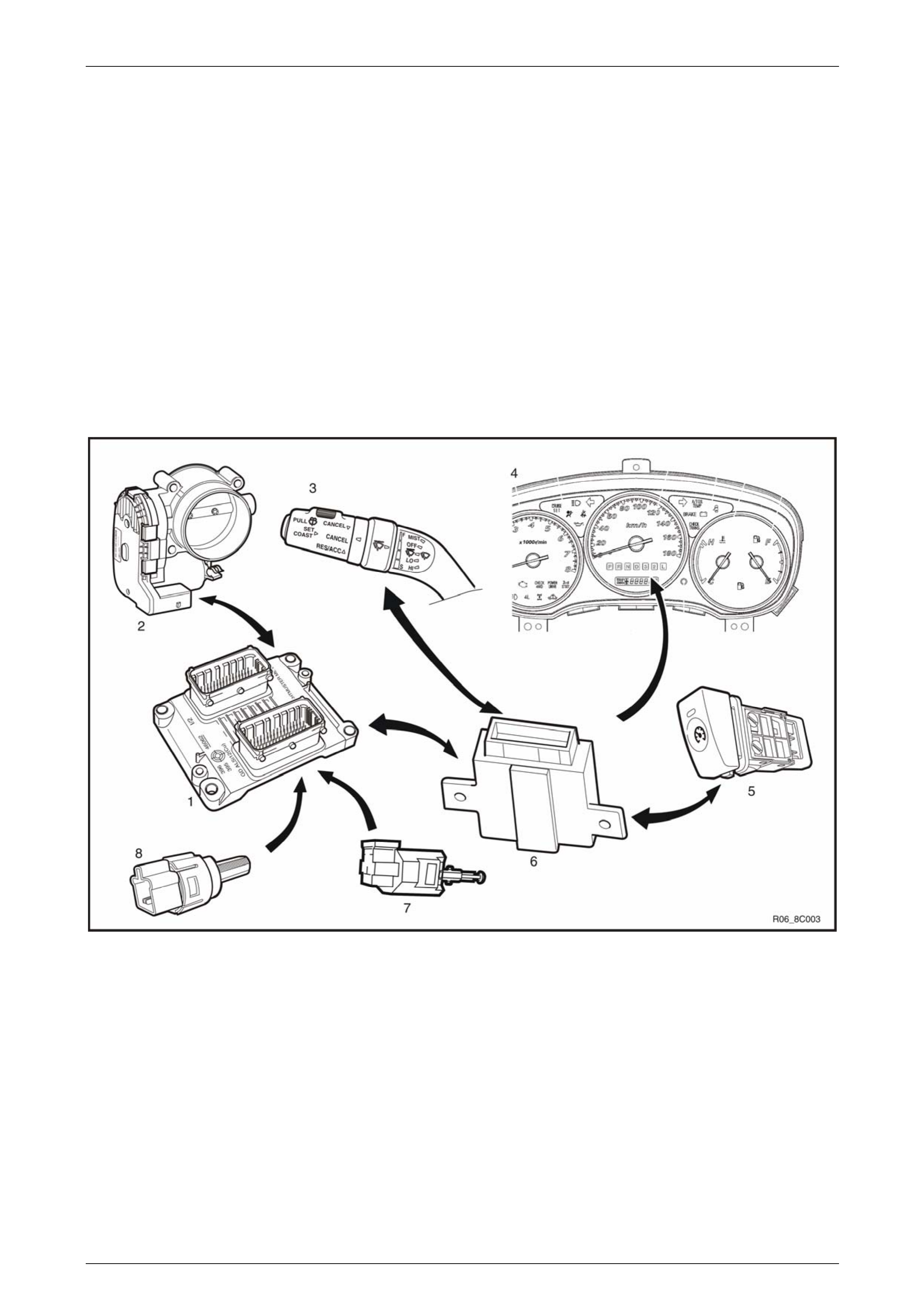
1.2 System Components
The main components of the electronic cruise control s ystem are:
• cruise control ON / OFF switch (in dash pa nel).
• cruise control switch assembly (incorporated into wiper and washer switch assembl y),
• instrument cluster assembly (cruise set lamp),
• clutch pedal switch assembly (manua l transmission vehicles only),
• stop lamp switch assembly,
• powertrain interface module (PIM),
• engine control module (ECM),
• throttle actuator control (TAC) assembly, and
• electrical wiring (incorporated into the main wiring harness).
Figure 8C – 1
Legend
1 Engine Control Module
2 Throttle Actuator Control (TAC) Assembly
3 Cruise Control Switch Assembly
4 Instrument Cluster Assembly
5 Cruise Control ON / OFF Switch
6 Powertrain Interface Module
7 Clutch Pedal Switch Assembly (Manual Only)
8 Stop Lamp Switch Assembly
Page 8C–5
Cruise Control – HFV6 Page 8C–6
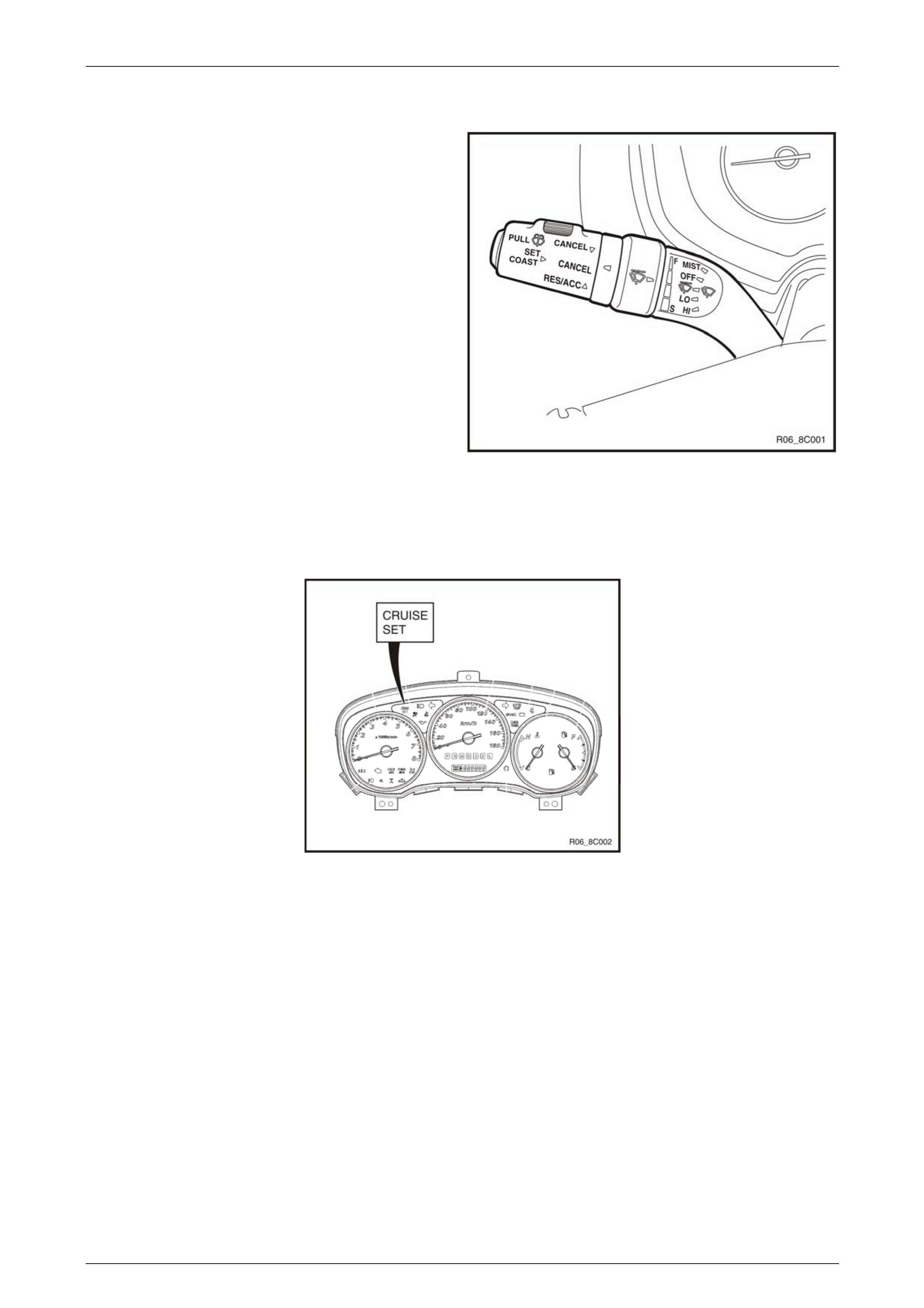
Cruise Control Switch Assembly
The cruise control switch assembly is located on the end of
the wiper and washer switch assembly.
• For harness routing from the cruise control switch
assembly to the powertrain interface module, refer to
Section 8A Electrical – Body and Chassis.
• For wiring and to see how the switch integrat es into
the system, refer to 2.3 Wiring Diagrams.
Figure 8C – 2
Instrument Cluster Assembly
The instrument cluster assembly displays the status of the cruise control system as well as other inform ation via the
warning indicat ors.
Figure 8C – 3
Clutch Pedal Switch (Manual Only)
This switch assembly is attached to the clutch pedal support bracket. The switch is norm al ly closed when the clutch
pedal is at rest, opening when the pedal is pressed. Activation of this switch removes the signal to the ECM, which will
then deactivate the cruise control.
Stop Lamp Switch Assembly
The stop lamp switch assembly is located o n the brake pedal support bracket. This switch has two sets of contacts with
two independent functions. The function of the switch assembly in the cruise control system is to deactivate the cruise
control when the brake pedal is pressed as well as an initial safety check of the switch operation prior to activating cruise
control.
The stop lamp switch contacts are normally open with the brake peda l at rest and close when the brake pedal is pressed
turning on the vehicles brake lamps. These switch contacts also double as the cruise canc el signal for the cruise control
operation.
The cruise control initial brake apply signal function switch contacts are normall y clos ed with the brake pedal at rest and
open when the brake pedal is presse d. This switch function is a safety requirement of the vehicle as it ens ures that the
cruise control cannot be activated without the brake pedal first being pressed.
Page 8C–6

Cruise Control – HFV6 Page 8C–7
Powertrain Interface Module
The Powertrain Interface Module (PIM) is located on the driver ’s side, kick trim panel. The purpose of the PIM is to act as
an interface between the drivet rain serial data bus (GMLAN protocol) and the body side data bus (UART Bus protocol).
All inputs from the cruise control switch assembly are directly wired to the PIM. The PIM then takes these inputs,
converts them to GMLAN protocol and sends the messages via the data bus to the engine control mod ule (ECM). The
PIM also receives signals for the cruise control system from the ECM. When the ECM activates cruise control, it sends a
signal through the PIM (which converts it from GMLAN to UART protocol) to displa y the various cruise control messag es
on the instrument cluster assembly.
For further information on the operation of the PIM, refer to Section 6E1 Powertrain Interface Module – V6.
Engine Control Module
The Engine Control Module (ECM) is mounted on the front of the engine. The role of the ECM is to receive all the inputs
from various sensors (vehicle speed (VSS) etc.) and switches to manage the engine. When a request is sent from the
cruise control switch assembly via the PIM to the ECM, the ECM will activate cruise control providing given parameters
are satisfied. Once the cruise is set, the ECM monitors the vehicle speed a nd controls the throttle actuator assembly thus
controlling the spee d of the vehicle.
For further information on the operation of the ECM, refer to
Section 6C1-1 Engine Management – V6 – General Information.
Throttle Actuator Control (TAC) Assembly
The throttle actuator control assembly is loca ted on the front of the inlet manifold. The throttle actuator co ntrol assembly
receives signals from the ECM and controls the angle of the throttle plate. Refer to
Section 6C1-1 Engine Management – V6 – General Information for further information.
Page 8C–7
Cruise Control – HFV6 Page 8C–8
1.3 System Operation
Preliminary Information
Enabled and Disabled
The cruise control is enable d / disabled by pressing the cruise control ON–O F F switch mounted on the lower right hand
side of the dash panel. When cruise co ntrol is enabled, the cruise control ON–OFF switch illuminates and the cruise
control is ready for a speed to be set (cruise control activated). When the cruise control is disable d, the cruise co ntrol
cannot be activated.
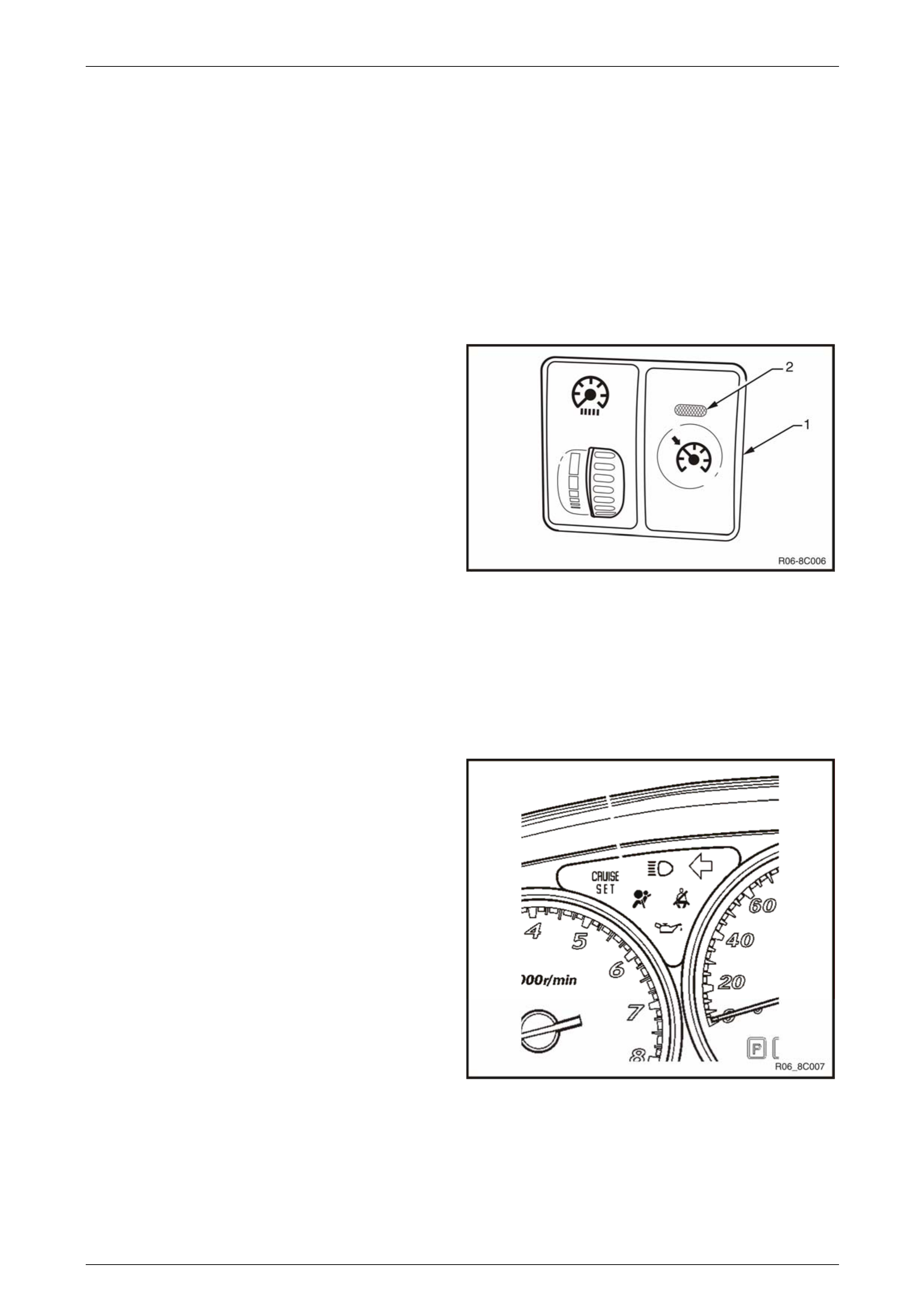
Cruise Enabled
1 The cruise control ON–OFF switc h (1) sup plies 12
Volts to the Powertrain Interface Module (PIM) when it
is pressed.
2 The cruise control ON–OFF switch lamp (2) turns on.
Cruise Disabled
1 When cruise control ON–OFF switch (1) is pressed
again, power is removed from the PIM disabl ing the
cruise control.
2 The cruise control ON–OFF switch lamp (2) turns off. Figure 8C – 4
Activated and Deactivated
When the cruise control is enabled, the vehicle speed must be above 40 km/h and the cruise co ntrol switch assembly
pressed to SET–COAST, the cruise control will be activated and the vehicle will maintain the set speed. When
deactivated by the methods described within this section, the vehicle will no longer maintain the set speed, but the crui se
control will still be engaged.
Cruise Active
When the cruise control is activated via the cruise control
switch assembly, the cruise set warning lamp will illuminate
the instrument cluster assembly.
Cruise Deacti vat ed
Upon receiving a signa l to deactivate the cruise control the
ECM will provide a signal to the instrument cluster, via the
PIM, to inform the user the cruise control is deactivated.
When the cruise control is deactivated via the cruise control
switch assembly, the brake pedal, or the clutch ped al, the
cruise set warning lamp will turn OFF within the instrument
cluster assembly.
Figure 8C – 5
Page 8C–8

Cruise Control – HFV6 Page 8C–9
Enabling the Cruise Control
Refer to 2.3 Wiring Diagrams for the following description.
When the cruise control ON-OFF button is pressed, 12 V is applied to the powertrain interface module (PIM) connector
B – 97 pin 14. This informs the PIM the user has requested the cruise control function be engaged or disengaged. This
signal is then output by the PIM as GM LAN protocol along the bus to the engine control modu le (ECM). The ECM
recognises the command from the PIM to engage the cruise control. T he PIM then provides a ground signal to B – 97 pin
13 the cruise control ON-OFF switch indicator lamp, to inform the user the cruise control is enga ged.
Brake Before Cruise
Before the cruise control can be activated the driver must have ap plied the brakes and the system recei ved a valid
response at least once per ignition cycle. If the driv er manages to drive the vehicle without having used the brakes before
pressing the cruise control ON–OFF button, the cruise control cannot be activated.
Activating the Cruise Control
The user activates the cruise control at a desired speed above 40 km/h by pressing the cruise control switch assembly
SET–COAST button. This provides a 12 V signal to the PIM through connector B – 97 pin 15. The PIM then outputs this
signal as GM LAN protocol through the data bus to the ECM. If the ECM already has cruise co ntrol engaged, upon
receipt of the message from the PIM, the ECM will activate cruise control and set the speed. The ECM receiv es all the
various inputs required to maintain the correct speed and then controls the throttle actuator control assembly depending
on the load on the engine (as c ending or descending hills, etc).
Deactivating the Cruise Control
When the cruise control is activated, it can be deactivated by any of the following:
Pressing the Brake Pedal
When the brake pedal is pressed, two signals are sent directl y to the ECM by the circuits from the brake pedal switch
assembly. The cruise cancel circuit will open (normally closed) thus dropping the supply voltage from the ECM connector
C – 56 pin 46. Simultaneousl y, the stop lamp circuit will close (normall y open) and supply 12 V to the ECM at connector
C – 56 pin 10. This is a double redundancy system so that if either switch or circuit from the brake pedal switch assembl y
fails, the cruise control will still be deactivated.
Pressing the Cruise ON–OFF Button
Pressing the cruise control switch assembly ON–OFF button will send a si gnal via the PIM to the ECM to deactivate the
cruise control.
Rotating the Cruise Control Switch Assembly
Rotating the cruise control switch assembly to the CANCEL position will send a signal via the PIM to the ECM to
deactivate the cruise control.
Pressing the Clutch Pedal (Manual Ve hicles Only)
When the clutch pedal is pressed, the cruise control cancel circuit will open (normally closed) thus removing the supply
voltage from the ECM connector C – 56 pin 53. The ECM then deactivates the cruise co ntrol.
Decelerating While Cruise Control is Activated
When the cruise control is activated, the speed can be redu ced by pressing and holding the cruis e control switch
assembly to SET–COAST. When this is don e, 12 V is app lied to PIM connector B – 97 pin 15. The PIM will then translate
the command to GM LAN protocol and sends the request to the ECM to reduce the sp eed. The ECM will then
temporarily disabl e the cruise control and close the throttle plate. The vehicle should th en start to decelerate. Once the
operator releases the cruise c ontrol switch assembly, the ECM will receive this signal through the PIM and will then set
the speed according to the curr ent VSS and maintain that speed.
Resuming a Speed After Cruise Control Has Been Deactivated
If the cruise control system is engaged but deactivated, the last speed at which it was activated can be resumed. T urning
the cruise control switch assembly to RES–ACC will apply 12 V to the PIM at connector B – 97 pin 16. The PIM will then
translate the command to GM LAN protocol and transmit the request to the ECM. The ECM will then recall the last stored
speed at which the cruise control was activated and increase or reduce engine RPM to maintain that spe ed.
Page 8C–9

Cruise Control – HFV6 Page 8C–10
Accelerating While Cruise Control is Activated
Using the Cruise Control Switch Assembly
When the cruise control is active, rotating the cruise control switch assembly to RES–ACC will accelerate the vehicle.
The cruise control s witch assembly will supply a 12 V signal to the PIM connector B – 97 p in 16, which is continuous as
long as the switch is held. While the PIM is receiving the 12 V signal, it will continuously transmit to the ECM to
accelerate the vehicle. The ECM will open the throttle plate to accelerate the vehicle. When the desired speed is
achieved and the cruise control switch assembl y is released, the ECM will maintain the vehicle at that speed.
Pressing the Accelerator Pedal
When the cruise control is active, pressing the accelerator pedal will accelerate the vehicle.
Once pressure is removed from the accelerator pedal, the vehicle will return to the last stored speed at which the cruise
control was activated and control the throttle plate to maintain that speed.
Page 8C–10

Cruise Control – HFV6 Page 8C–11
2 Diagnostics
2.1 Diagnostic General Information
Basic Knowledge Required
A lack of basic understanding regarding
electronics, electrical wiring circuits and use
of electrical circuit testing tools when
performing the cruise control diagnostic
procedures could result in incorrect
diagnostic results or damage to components.
A general understanding of ba sic electronics, electrical wiring circuits and the correct use of the basic electrical circuit
testing tools is required to perform the diagnos tic procedures detailed in this Section. Refer to
Section 8A Electrical – Body and Chassis Wiring Diagrams for information on electrical circuits.
In addition, a general understanding of the cruise control and its component operation is essential to prevent
misdiagnosis and component damage.
Basic Diagnostic Tools Required
Use of incorrect electrical circuit diagnostic
tools when performing the cruise control
diagnostic procedures could result in
incorrect diagnostic results or damage to
components.
The following electrical circuit testing tools are required to perform the diagnostic procedures detailed in this Section:
• test lamp,
• digital multimeter with 10 meg ohms impedance, and
• connector test adapter kit Tool No. KM609.
For further information on the use of these tools, refer to Section 8A Electrical – Bod y and Chassis Wiring Diagrams
Page 8C–11

Cruise Control – HFV6 Page 8C–12
Tech 2 Data List
The Tech 2 displays the status of certain cruise control s ystem input parameters.
To view the data list:
1 Connect Tech 2 to the data link connector (DLC) and turn on the ignition.
2 On Tech 2 select Body / Powertrain Interface Module / Diagnostic Data Display / Data List.
Tech 2 Parameter Units Displayed Typical Display Values
Cruise Cancel Switch Inactive / Active Inactive
Cruise Resume Switch Off / Enabled Off
Cruise Set Switch Inactive / Active Inactive
Cruise Main Switch Inactive / Active Inactive
Cruise Control Set Lamp Off / On Off
Cruise Control On Lamp Off / On Off
3 On Tech 2 select Engine / V6 Engine / Data Display / Data List / Cruise Control Data.
Tech 2 Parameter Units Displayed Typical Display Values
Brake Lamp Switch Inactive / Active Inactive
Initial Brake Apply Sig Inactive / Active Inactive
Cruise Set / Decel Swit Inactive / Active Inactive
Cruise Resume / Accelerat Inactive / Active Inactive
Cruise Control Disengag Engine Speed / Brake Engine Speed
4 On Tech 2 select Engine / V6 Engine / Data Display / Data List / Engine Data 1.
Tech 2 Parameter Units Displayed Typical Display Values
Clutch Pedal Switch Inactive / Active Inactive
Page 8C–12

Cruise Control – HFV6 Page 8C–13
2.2 Diagnostic Systems Check
Diagnostic Systems Check
Refer to 2.3 Wiring Diagram to aid in the diagnosis of the cruise control s ystem.
For the cruise control system to work effectively the following s ystems / components need to be serviceable:
Step Action Yes No
1 Is the fault specifically isolated to this system / module?
Go to Step 2
Go to 6E1
Powertrain Interface
Module – V6
2 1 Connect Tech 2 to the DLC.
2 Ignition ON, engine OFF.
3 On Tech 2 select
Body / Powertrain Interface Module / Diagno stic T rouble
codes / Read DTCs’.
Are there any set DTC’s?
Go to the
appropriate DTC
table in 6E1
Powertrain Interface
Module – V6. Go to Step 3
3 On Tech 2 select
Engine / V6 Engine / Diagnostic Trouble codes / Read DTCs’.
Are there any set DTC’s?
Go to the
appropriate DTC
table in 6C1-2
Engine
Management – V6 –
Diagnostics Go to Step 4
4 Is the instrument cluster assembly functioning correctly? Go to 2.4 Cruise
Control Inoperative /
Malfunctioning
Refer to 8A
Electrical – Body
and Chassis.
When all diagno sis an d repairs are completed, clear all DT Cs and check the system fo r correct operation.
Page 8C–13
Cruise Control – HFV6 Page 8C–14
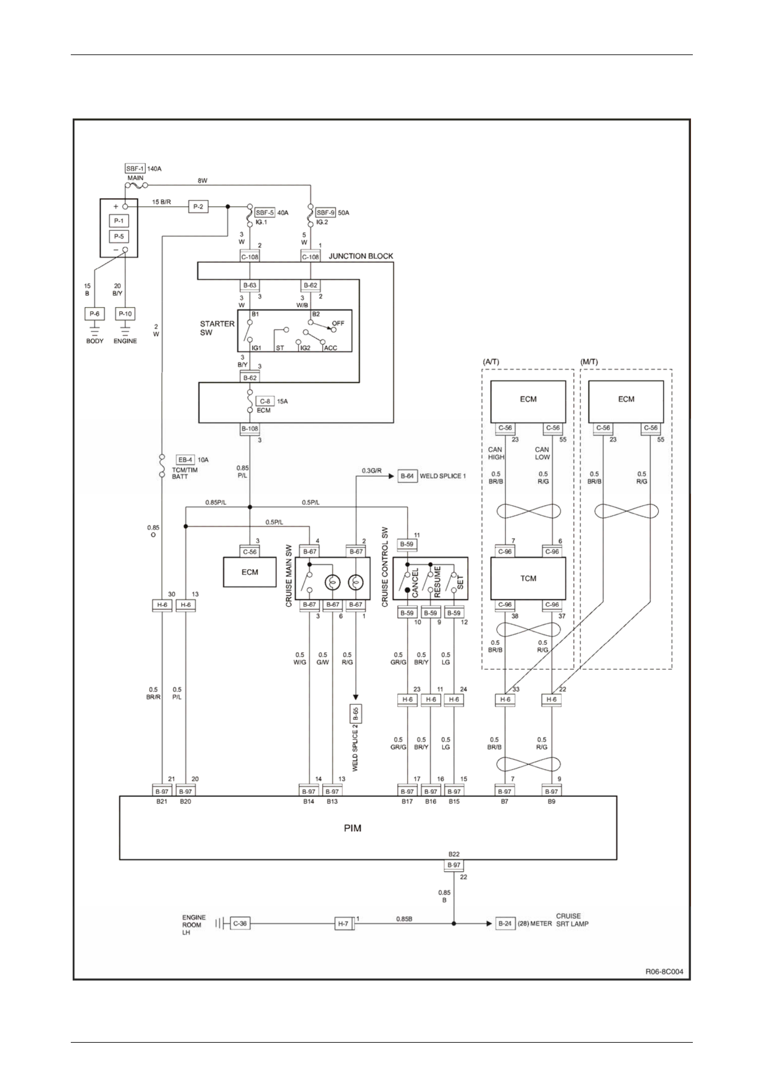
2.3 Wiring Diagrams
Figure 8C – 6
Page 8C–14

Cruise Control – HFV6 Page 8C–15
Figure 8C – 7
Page 8C–15

Cruise Control – HFV6 Page 8C–16
2.4 Cruise Control Inoperative /
Malfunctioning
Circuit Description
When the ON-OFF button is pressed, 12 V i s applied to the Powertrain Interface Module (PIM) connector B – 97 pin 14.
This enables and dis ables cruise control operation.
Pressing the cruise control switch assembly to SET–COAST button activates the cruise control at a desired speed above
40 km/h. This provides a 12 V signal to the PIM through connector B – 97 pin 1 5.
Pressing and holding the cruis e control switch to SET–COAST provides a 12 V signal to the PIM at connector B – 97
pin 15. Turning the cruise control switch to RES–ACC will apply a 12 V signal to the PIM at connector B – 97 pin 16.
Turning the cruise control switch to CANCEL will apply a 12 V signal to the PIM at connector B – 97 pi n 17.
Pressing the brake pedal opens the cruise Initial Brake Apply Signal circuit thus removing the supply voltage from the
ECM connector C – 56 pin 46. Simultane ously, the stop lamp circuit will close (normall y open) and supply 12 V to the
ECM at connector C – 56 pin 10. Both these signals must b e present so as to ensure the safe operation of the vehicle’s
cruise cancel function.
Manual Vehicles Only
Pressing the clutch pedal opens the cruise cance l circuit thus removing th e supply voltage from the ECM at connector C
– 56 pin 53.
For detailed information refer to 3.4 Clutch Pedal Switch (Manual Only) in this Section.
Test Description
The following numbers refer to the step numbers in the diagnostic table:
4–7 Checks the cruise control switch and ass oci ated circuits are functioning correctly.
8–9 Checks the brake pedal switch assembly and associated circuit are functioning correctly.
10 Checks the clutch pedal switch assembly and associated circuits are functioni ng correctly.
11–21 Covers the testing and replac ement of system components.
22–28 Checks for intermittent faults in associated circuits and connectors.
Diagnostic Table Notes
1 For all wiring harness fault diagnoses an d repairs, refer to 2.3 Wiring Diagrams in this Section.
2 Tech 2 can display a stored history of which system parameter or input caused the cruise control to disenga ge.
This can aid diagnosis of intermittent faults.
Page 8C–16

Cruise Control – HFV6 Page 8C–17
Diagnostic Table
Step Action Yes No
1 Did you review the System Operation? Go to Step 2 Go to 1.3 System
Operation
2 Did you read Diagnostic Systems Check ? Go to Step 3 Go to Diagnostic
Systems Check
3 Check the ignition supply circuits to the Stop Lamp Switch assembl y
connector C – 44 pin 1 is serviceable using a multimeter set to
measure voltage, refer to 2.3 Wiring Diagrams in this Section
Is there a +12 volt signal present at connector C – 44 pin 1?
Go to Step 4
Replace the faulty
fusible link Main,
IG2 or Stop Light
fuse (refer to
Note 1).
If either of the
fusible links or fuse
blows again, repair
or replace the faulty
circuit (refer to
Note 1)
4 1 Connect Tech 2 to the DLC.
2 On Tech 2 select:
Body / Powertrain Interface Module / Diagnostic Data
Display.
3 Scroll to Cruise Main Switch.
4 While monitoring Tech 2, press the cruise control switch ON–
OFF button.
Does Tech 2 display the fol lowing:
• Inactive and Active as the cruise control switch is pressed? Go to Step 5 Go to Step 11
5 1 Scroll to Cruise Resume Switch.
2 While monitoring Tech 2, rotate the cruise control switch.
Does Tech 2 display the fol lowing:
• Inactive when the cruise control switch is in the neutral
position?
• Res / Acc when the cruise control switch is rotated to the RES–
ACC. Position? Go to Step 6 Go to Step 12
6 1 Scroll to Cruise Set Switch.
2 While monitoring Tech 2, press the cruise control switch.
Does Tech 2 display the fol lowing:
• Inactive when the cruise control switch is in the neutral
position?
• Set / Coast when the cruise control switch is pressed to the
SET–COAST position? Go to Step 7 Go to Step 13
7 1 Scroll to Cruise Cancel Sw itch.
2 While monitoring Tech 2, rotate the cruise control switch.
Does Tech 2 display the fol lowing:
• Inactive when the cruise control switch is in the neutral
position?
• Cancel when the cruise control switch is rotated to the CANCEL
position? Go to Step 8 Go to Step 14
Page 8C–17

Cruise Control – HFV6 Page 8C–18
Step Action Yes No
8 1 Return to the Main Menu on Tech 2.
2 On Tech 2 select:
Engine / V6 Engine / Data Display / Cruise Control Data.
3 Scroll to Brake Lamp Switch.
4 While monitoring Tech 2, press and then release to the brake
pedal.
Does Tech 2 display the fol lowing:
• Active as the brake pedal is pressed?
• Inactive when the pedal is release d? Go to Step 9 Go to Step 15
9 1 Scroll to Initial Brake Apply Sig.
2 While monitoring Tech 2, press and then release to the brake
pedal.
Does Tech 2 display the fol lowing:
• Inactive when the pedal is release d?
• Active as the brake pedal is pressed? Go to Step 10 Go to Step 16
10 NOTE
This procedure is only required on vehicles fitted with
manual transmissions. If the vehicle is fitted with an
automatic transmission, go to Step 24.
1 Scroll to Cruise Control Active.
2 While monitoring Tech 2, press and then release to the clutch
pedal.
Does Tech 2 display the fol lowing:
• Active when the pedal is releas ed?
• Inactive as the clutch pedal is pressed? Go to Step 30 Go to Step 17
11 Test the cruise control main switch, refer to 3.1 Cruise Control Main
Switch
Is the cruise control switch serviceable? Go to Step 22 Go to Step 18
12 Test the cruise control switch assembly, refer to 3.2 Cruise Control
Switch Assembly
Is the cruise control switch assembly serviceable? Go to Step 23 Go to Step 18
13 Test the cruise control switch assembly, refer to 3.2 Cruise Control
Switch Assembly
Is the cruise control switch assembly serviceable? Go to Step 24 Go to Step 18
14 Test the cruise control switch assembly, refer to 3.2 Cruise Control
Switch Assembly
Is the cruise control switch assembly serviceable? Go to Step 25 Go to Step 18
15 Test the stop lamp switch assembly, refer to 3.3 Stop Lamp Switch
Assembly.
Is the stop lamp switch serviceable? Go to Step 26 Go to Step 19
16 Test the stop lamp switch assembly, refer to 3.3 Stop Lamp Switch
Assembly.
Is the stop lamp switch serviceable? Go to Step 26 Go to Step 20
Page 8C–18

Cruise Control – HFV6 Page 8C–19
Step Action Yes No
17 NOTE
This procedure is only required on vehicles fitted with
manual transmissions. If the vehicle is fitted with an
automatic transmission go to Step 26.
Test the clutch pedal switch, refer to
3.4 Clutch Pedal Switch.
Is the clutch pedal switch serviceable? Go to Step 28 Go to Step 21
18 Replace the faulty cruise control switch assembly with a serviceable
item. To replace the switch assembly, refer to 8 B Cruise Control
System. Go to Step 32 —
19 Replace the faulty stop lamp switch, refer to 3.3 Stop Lamp S witch
Assembly Go to Step 32 —
20 Replace the faulty stop lamp switch, refer to 3.3 Stop Lamp S witch
Assembly Go to Step 32 —
21 Replace the faulty clutch pedal switch, refer to
3.4 Clutch Pedal Switch Go to Step 32 —
22 1 Disconnect the PIM connector B – 97.
2 Using a multimeter set to measure voltage, back probe between
the harness connector B – 97 pin 14 and a known ground.
3 With the aid of an assistant, monitor the voltage on the
multimeter and press and release the cruise control switch ON–
OFF button.
• With the button in the rest position, the multimeter should
display 0 V.
• With the button pressed, the multimeter should displ ay
battery voltage.
Does the multimeter display a s described? Go to Step 30
Check for short to
ground or open
circuit.
Repair as required
(refer to Note 1).
Go to Step 32
23 1 Disconnect the PIM connector B – 97.
2 Using a multimeter set to measure voltage, back probe between
the harness connector B – 97 pin 16 and a known ground.
3 With the aid of an assistant, monitor the voltage on the
multimeter and rotate and release the cruise control switch to
RES–ACC position.
• With the switch in the rest position, the multimeter should
display 0 V.
• With the switch rotated, the multimeter should display
battery voltage.
Does the multimeter display a s described? Go to Step 30
Check for short to
ground or open
circuit on circuit.
Repair as required
(refer to Note 1).
Go to Step 32
Page 8C–19

Cruise Control – HFV6 Page 8C–20
Step Action Yes No
24 1 Disconnect the PIM connector B – 97.
2 Using a multimeter set to measure voltage, back probe between
the harness connector B – 97 pin 15 and a known ground.
3 With the aid of an assistant, monitor the voltage on the
multimeter and press and release the cruise control switch to
SET–COAST button.
• With the switch in the rest position, the multimeter should
display 0 V.
• With the switch pressed, the multimeter should display
battery voltage.
Does the multimeter display a s described? Go to Step 30
Check for short to
ground or open
circuit on circuit.
Repair as required
(refer to Note 1).
Go to Step 32
25 1 Disconnect the PIM connector B – 97.
2 Using a multimeter set to measure voltage, back probe between
the harness connector B – 97 pin 17 and a known ground.
3 With the aid of an assistant, monitor the voltage on the
multimeter and rotate and release the cruise control switch to
CANCEL position.
• With the switch in the rest position, the multimeter should
display 0 V.
• With the switch rotated clockwise, the multimeter should
display battery voltag e.
Does the multimeter display a s described? Go to Step 30
Check for short to
ground or open
circuit on circuit.
Repair as required
(refer to Note 1).
Go to Step 32
26 1 Disconnect the ECM connector C – 56.
2 Using a multimeter set to measure voltage, back probe between
the harness connector C – 56 pin 10 and ground.
3 With the aid of an assistant, monitor the voltage on the
multimeter and press and release the brake pedal.
• With the brake pedal in the rest position, the multimeter
should display 0 V
• With the brake pedal pressed, the multimeter should
display battery voltag e
Does the multimeter display a s described? Go to Step 30
Check for a blown
fuse C-18.
Check for short to
ground or open
circuit
Repair as required
(refer to Note 1).
Go to Step 32
27 1 Disconnect the ECM connector C – 56.
2 Using a multimeter set to measure voltage, back probe between
the harness connector C – 56 pin 46 and ground.
3 With the aid of an assistant, monitor the voltage on the
multimeter and press and release the brake pedal.
• With the brake pedal in the rest position, the multimeter
should display battery voltage
• With the brake pedal pressed, the multimeter should
display 0 V.
Does the multimeter display a s described? Go to Step 28
Check for a blown
fuse C-10.
Check for short to
ground or open
circuit
Repair as required
(refer to Note 1).
Go to Step 32
Page 8C–20

Cruise Control – HFV6 Page 8C–21
Step Action Yes No
28 1 Disconnect the ECM connector C – 56.
2 Using a multimeter set to measure voltage, back probe between
the harness connector C – 56 pin 53 and ground.
3 With the aid of an assistant, monitor the voltage on the
multimeter and press and release the clutch ped al.
• With the clutch pedal in the rest position, the multimeter
should display battery voltage
• With the clutch pedal pressed, the multimeter should
display 0 V
Does the multimeter display a s described? Go to Step 31
Check for a blown
fuse C-4.
Check for short to
ground or open
circuit
Repair as required
(refer to Note 2).
Go to Step 32
29 Check all associated circuits and connectors for the following:
• Loose or damaged co nnections
• Intermittent faults.
Refer to the Wiring Diagrams in this Section and repair as required.
Was the repair completed? Go to Step 32 —
30 Replace the PIM, refer to 6E1 Powertrain Interface Module – V6.
Was the repair completed? Go to Step 32 —
31 Replace the ECM module, refer to 6C1-3 Engine Management – V6
Service Operations.
Was the repair completed? Go to Step 32 —
32 Operate the system in order to verify the repair.
Did you correct the conditi on? System OK Go to Step 1
When all diagno sis an d repairs are completed, clear all DT Cs and check the system fo r correct operation.
Page 8C–21
Cruise Control – HFV6 Page 8C–22
3 Service Operations
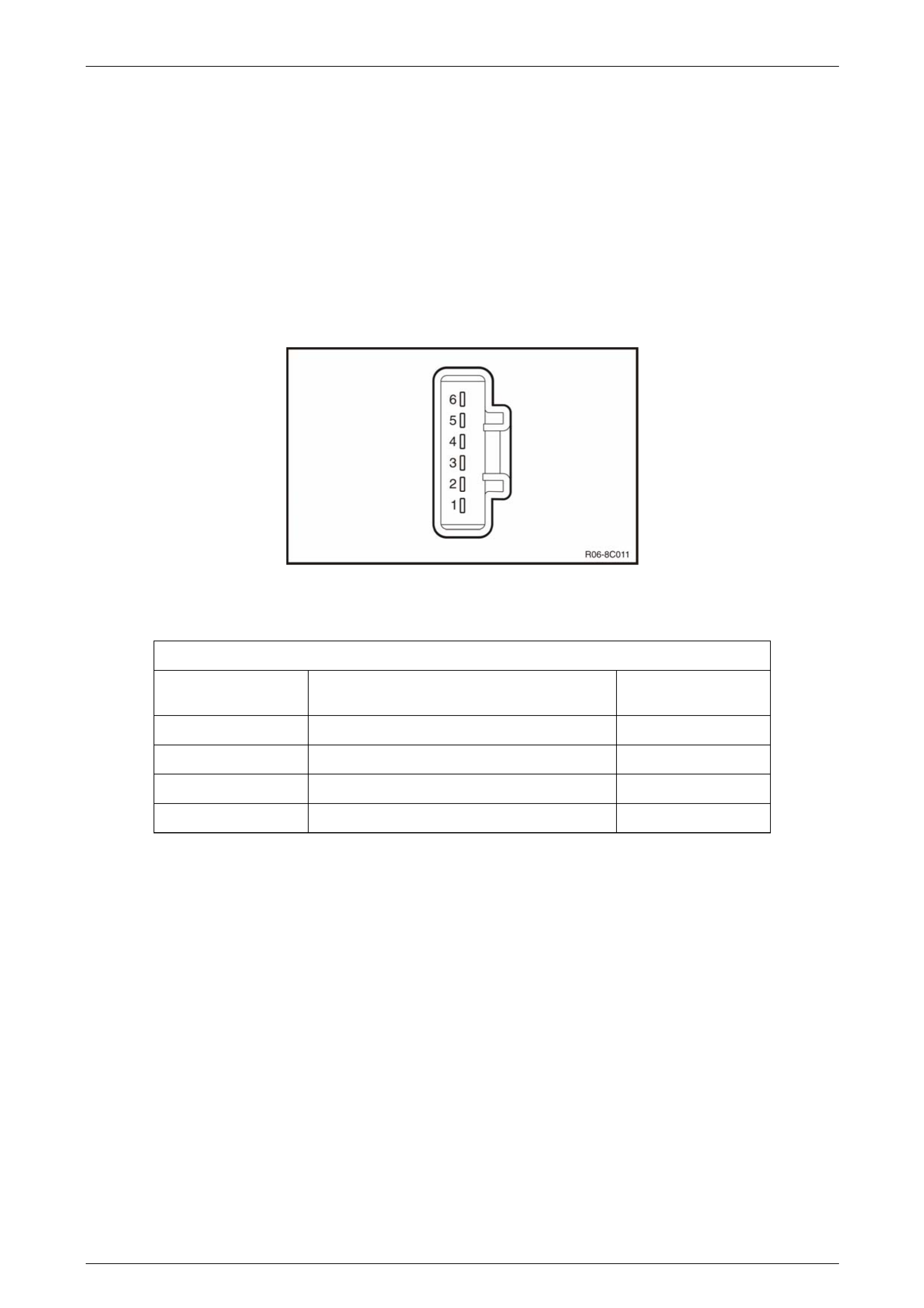
3.1 Cruise Control Main Switch
Remove
To remove the cruise control main switch, refer to Section 8B Cruise Control System.
Test
Test the cruise control main switch, using a multimeter set to measure o hms check the continuity.
Figure 8C – 8
Terminal Testing
Cruise Control Main Switch
Switch Terminals Switch
Position Indication if Switch
is Serviceable
1 and 2 Switch Illumination Approx. 22 ohms
4 and 6 Cruise Lamp On Illumination Approx. 22 ohms
4 and 3 Cruise Switch Released Open circuit
4 and 3 Cruise Switch Pressed Short circuit
Reinstall
To reinstall the cruise control main switch, refer to Section 8B Cruise Control System.
Page 8C–22
Cruise Control – HFV6 Page 8C–23
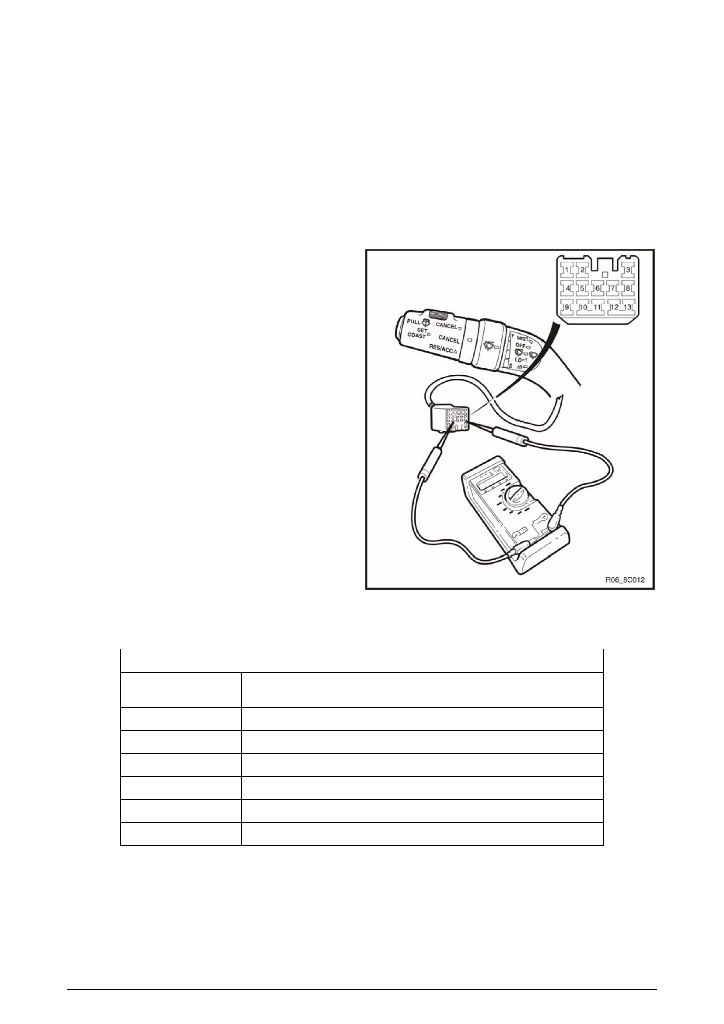
3.2 Cruise Control Switch Assembly
Remove
To remove the cruise control switch assembly, refer to Section 8B Cruise Control System.
Test
To test the cruise control switch assembly, use a multimeter to check the continuity.
1 Remove the lower dash trim panel a nd locate the
cruise control switch assembly wiring harness that
connects a white 13 pin male plug to a connector sub
panel located on the right hand side below of the
steering column.
2 Disconnect the 13 pin male plug B – 59 from its mating
connector socket.
3 Place the turn signal and cruise control switch
assembly into the positions detaile d in the following
table, refer to Terminal Testing. Position the contacts
of the multimeter onto the terminals and take the
reading. Compare the multimeter readings with the
values in the table.
4 If the switch assembly fails any part of the test, replace
the cruise control switch assembly with a serviceable
item. To replace the switch assembly, refer to
Section 8B Cruise Control System.
Figure 8C – 9
Terminal Testing
Cruise Control Switch Assembly
Switch Terminals Switch
Position Indication if Switch
is Serviceable
11 and 10 CANCEL Applied Open Circuit
11 and 10 CANCEL Released Short Circuit
11 and 12 SET–COAST Pressed Short Circuit
11 and 12 SET–COAST Released Open Circuit
11 and 9 RES–ACC Applied Short Circuit
11 and 9 RES–ACC Released Open Circuit
Reinstall
To reinstall the cruise control switch assembly, refer to Section 8B Cruise Control System.
Page 8C–23
Cruise Control – HFV6 Page 8C–24
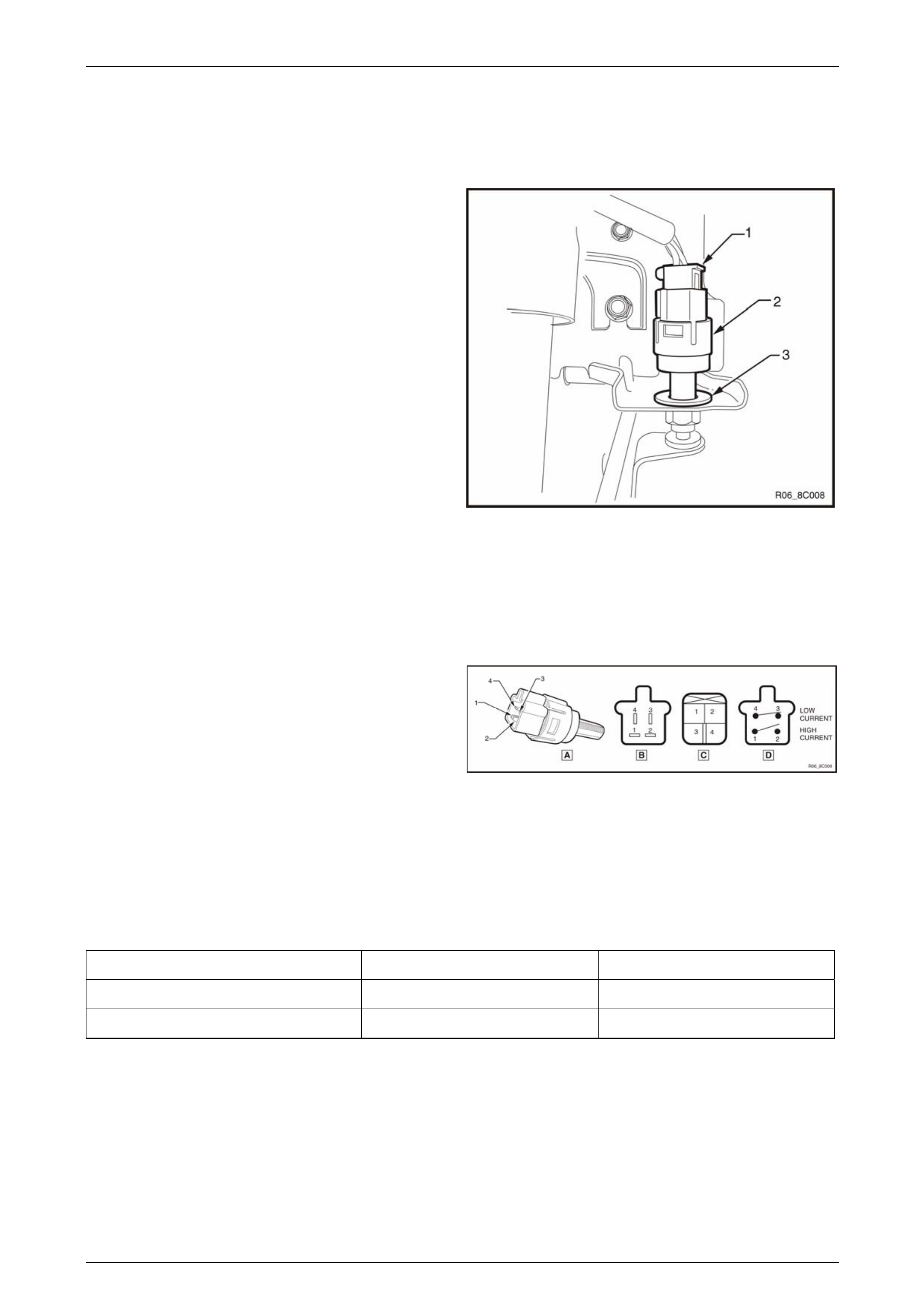
3.3 Stop Lamp Switch Assembly
Remove
1 Press the connector locking tab while pulling on the
stop lamp connector (1) and remove from the switch
assembly (2).
2 Twist the stop lamp switch assembly (2) anticlock wise
a quarter of a turn and pull out of the brake p edal
support bracket.
3 If required, remove the plastic clip (3) by pressing the
locking tabs on the rear of the clip and pulling from the
brake pedal support bracket.
Figure 8C – 10
Test
Terminal Testing
1 Using a multimeter, probe the pins of the switch
assembly and compare to the table below.
NOTE
The pins are as follo ws:
• C44 – pins 1 and 2
• C44 – pins 3 and 4
NOTE
Holding the plunger (5) with tape will help when
performing the test with the plunger in the active
position (plunger pressed).
Figure 8C – 11
Plunger Position Connector C44 – 1 and 2 Connector C44 – 3 and 4
Neutral position (plunger extended) Open circuit Continuity
Active position (plunger pressed) Continuity Open circuit
Page 8C–24
Cruise Control – HFV6 Page 8C–25
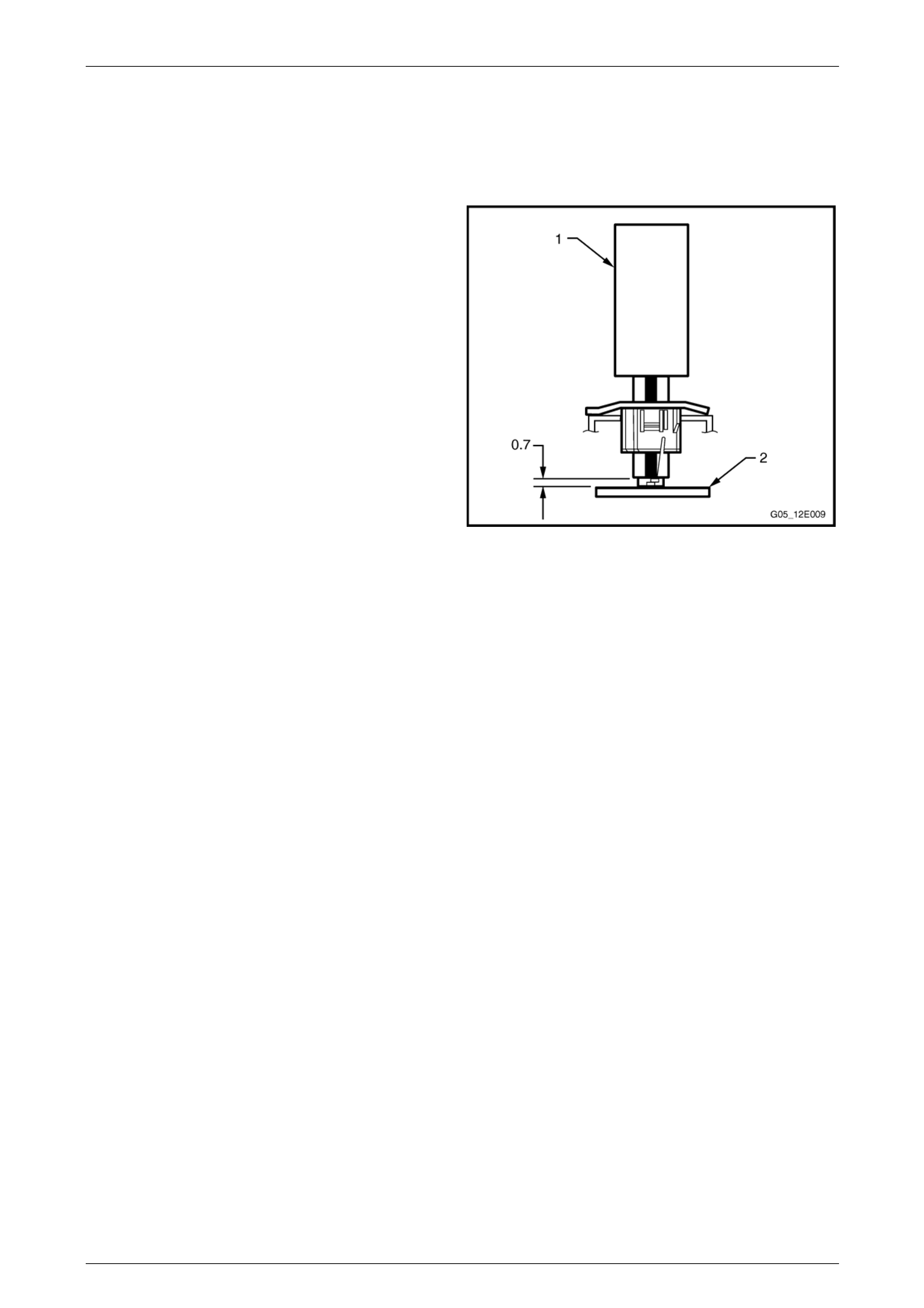
Reinstall
1 If removed, install the plastic clip (2) with the arrow pointing upwards, refer to Figure 8C – 11.
2 With the connectors pointing upwards (12 o’clock position), insert the switch assembly (1) into the plastic clip.
3 Ensure the brake pedal is in the rest position.
4 Push the switch assembly (1) so the plunger is
pressed and the end switch barrel is against the brake
pedal (2).
5 Twist the switch assembly clockwise to lock into place.
The distance between the brak e pedal and the switch
barrel should be 0.7 ± 0.5 mm.
6 Install the wiring connector to the switch assembly.
Figure 8C – 12
Page 8C–25
Cruise Control – HFV6 Page 8C–26
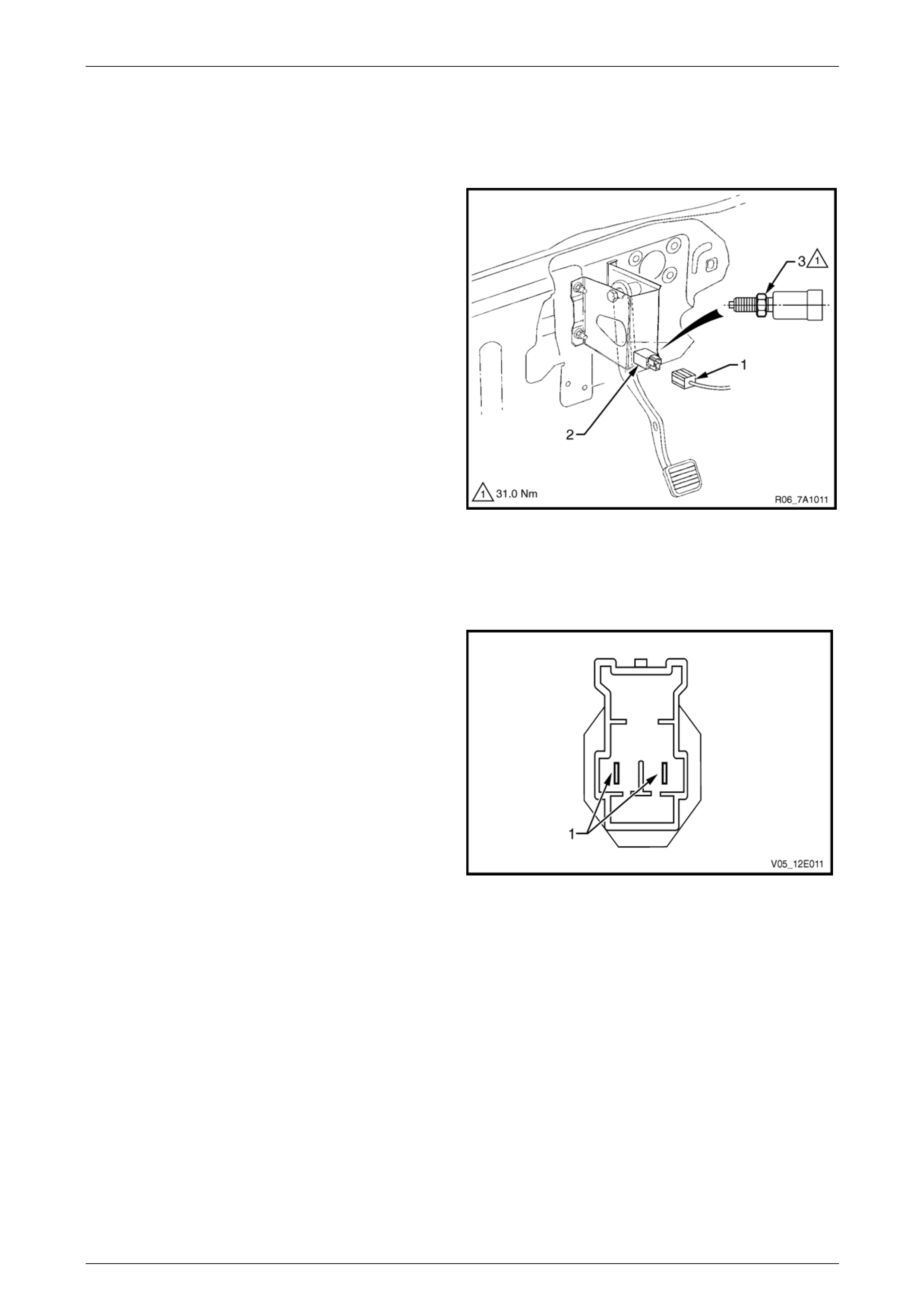
3.4 Clutch Pedal Switch (Manual Only)
Remove
1 Disconnect the electrical connector (1) from the clutch
switch (2).
2 Loosen the lock nut (3) and remove the clutch switch
from the pedal bracket.
Figure 8C – 13
Test
1 Using a multimeter set to measure ohms, probe the
pins (1) of the switch assembly.
2 In the neutral position (plunger extended) there should
be an open circuit across the s witch.
3 In the active position (plunger extended) there should
be a closed circuit across the switch.
4 Replace the switch as per the following rein stall
procedure if the tests prove the switch to be faulty.
5 If the test proves the switch to be serviceable,
reinstall it as per the following procedure.
Figure 8C – 14
Page 8C–26
Cruise Control – HFV6 Page 8C–27
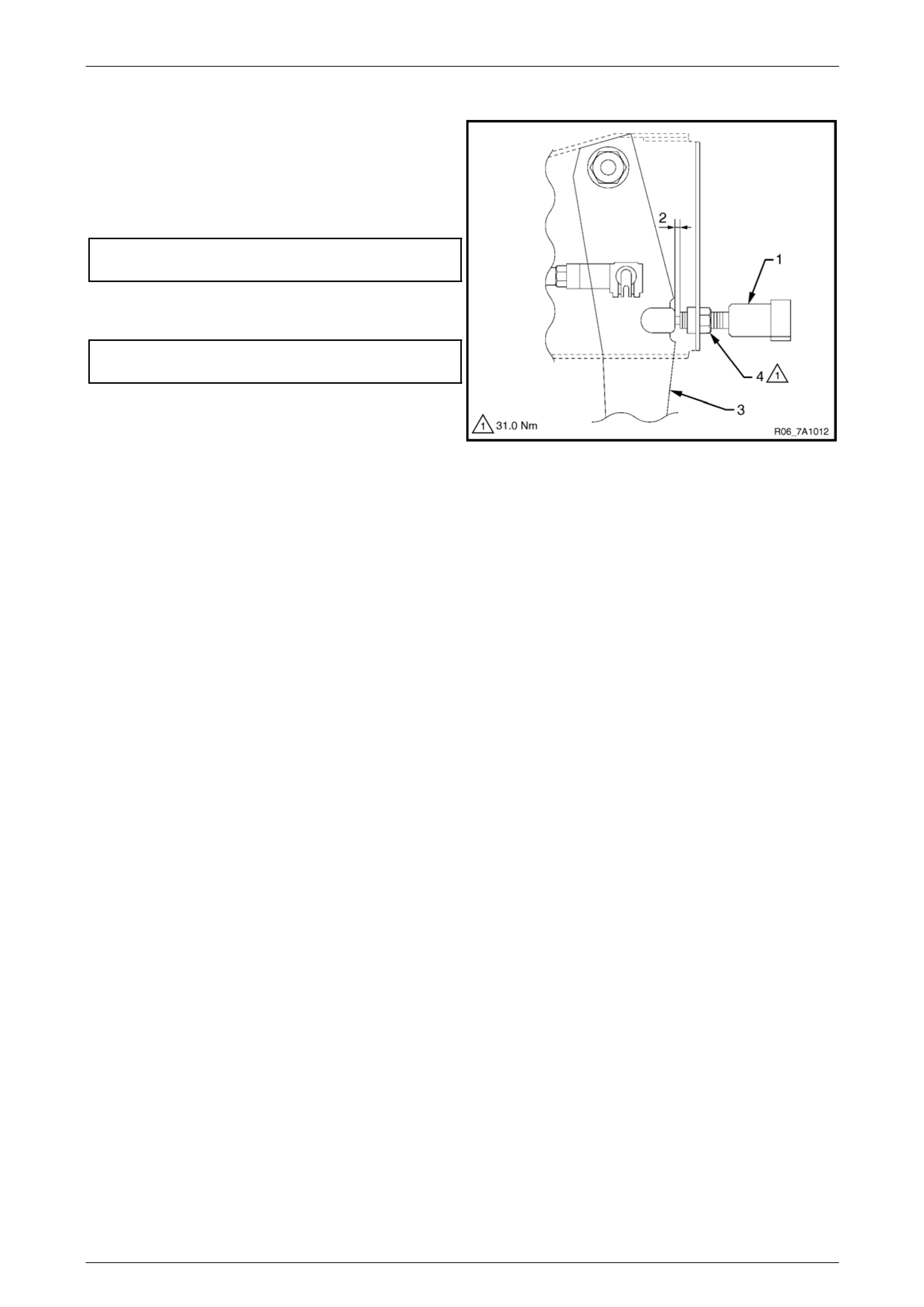
Reinstall
6 Install the clutch switch (1) as follows:
a Insert the switch into the clutch pedal bracket.
b Rotate the switch clockwise until obta ining the
clearance (2) between the pedal (3) a nd the
pedal stoper.
Clutch pedal and pedal stoper
clearance specification............................... 0.5 – 1.5 mm
c Tighten the lock nut (4) to the correct torque
specification.
Clutch switch lock nut
torque specification............................................31.0 Nm
d Recheck the clutch switch clearance, readju st
clearance if required.
NOTE
No adjustment is required for the clutch switch
itself.
Figure 8C – 15
7 Reconnect the electrical conn ector to the clu t ch switch.
8 Verify the operation of the clutch switch by operating the cruise control and checking the clutch switch stops
operation of the cruise control when the clutch pedal is pressed.
Page 8C–27
Cruise Control – HFV6 Page 8C–28
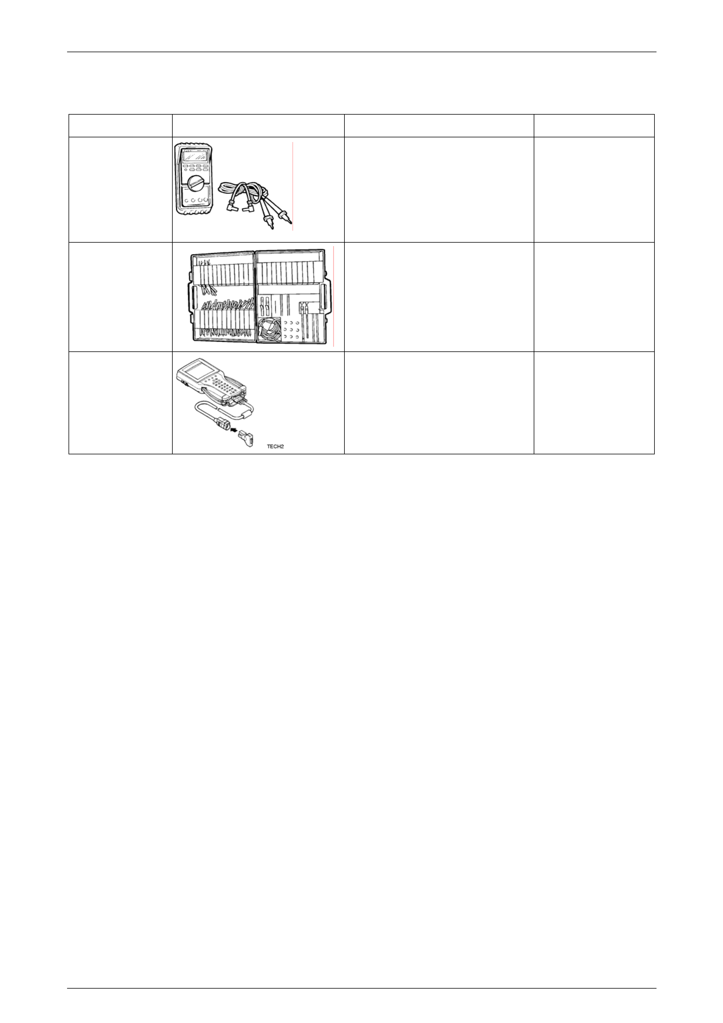
4 Special Tools
Tool Number Illustration Description Tool Classification
3588
Digital Multimeter
Previously released as J3920 0 or
equivalent.
NOTE: The instrument must have 10
meg ohms impedance and be capable
of reading frequencies.
Mandatory
KM-609
Electronic Kit.
Used in conjunction with a multimeter
for measuring voltages and
resistances without damaging wiring
harness connectors. Desirable.
70000861
Tech 2 Diagnostic Scan Tool
Previously released.
Mandatory
Page 8C–28