
SECTION 9A1 – RESTRAINTS - RESTRAINT
CONTROL SYSTEM
Service Precaution
Diagnosis Information
Diagnostic Procedures
Diagnostic Codes
How To Read Trouble Codes
How To Clear Trouble Codes
Scan Tool Diagnostics
Basic Knowledge Required
Basic Electrical Circuits
"Flash Code" Diagnostics
DATA LIST (Tech2)
Diagnostic Trouble Codes
System Schematic
Chart A SRS control unit Inte grity Che ck
Chart B "AIR BAG" Warning Lamp Comes "ON" Steady
Chart C "AIR BAG" Warning Lamp Does Not Come "ON" Steady
DTC B0016 (Flash Code 16) Passenger Airbag Squib Circuit (Stage1) Low Resistance
DTC B0017 (Flash Code 17) Passenger Airbag Squib Circuit (Stage1) High Resistance
DTC B0018 (Flash Code 18) Passenger Airbag Squib Circuit (Stage1) Voltage Range/Performance
DTC B0022 (Flash Code 22) Driver A irbag Squib Circuit (Stage1) Low Resistance
DTC B0024 (Flash Code 24) Driver Airbag Squib Circuit (Stage1) Voltage Range/Performance
DTC B0026 (Flash Code 26) Driver A irbag Squib Circuit (Stage1) High Resistance
DTC B0033 (Flash Code 33) ECU Connector Poor Connection
DTC B0051 (Flash Code 51) Squib Circuit Activated (Clash)
DTC B0053 (Flash Code 53) Deployment Command Despite Present Trouble Code
DTC B0670 (Flash Code 63) Airbag Telltale Circuit Malfunction
DTC B1000 (Flash Code 72) SDM Internal Fault
DTC U1000 (Flash Code 75) Class2 Data Link Malfunction
DTC U1*** (Flash Code 73) Unknown Message
DTC U1300 (Flash Code 76) Class2 Data Link Low
DTC U1301 (Flash Code 76) Class2 Data Link High
Techline

Service Precaution
WARNING: THIS VEHICLE HAS A SUPPLEMENTAL
RESTRAINT SYSTEM (SRS). REFER TO THE SRS
COMPONENT AND WIRING LOCATION VIEW IN
ORDER TO DETERMINE WHETHER YOU ARE
PERFORMING SERVICE ON OR NEAR THE SRS
COMPONENTS OR THE SRS WIRING. WHEN YOU
ARE PERFORMING SERVICE ON OR NEAR THE
SRS COMPONENTS OR THE SRS WIRING, REFER
TO THE SRS SERVICE INFORMATION. FAILURE TO
FOLLOW WARNINGS COULD RESULT IN
POSSIBLE AIR BAG DEPLOYMENT, PERSONAL
INJURY, OR OTHERWISE UNNEEDED SRS SYSTEM
REPAIRS.
CAUTION: Always use the correct fastener in the
proper location. When you replace a fastener, use
ONLY the exact part number for that application.
HOLDEN will call out those fasteners that require a
replacement after removal. HOLDEN will also call
out the fasteners that require thread lockers or
thread sealant. UNLESS OTHERWISE SPECIFIED,
do not use supplemental coatings (Paints, greases,
or other corrosion inhibitors) on threaded fasteners
or fastener joint interfaces. Generally, such
coatings adversely affect the fastener torque and
the joint clamping force, and may damage the
fastener. When you install fasteners, use the
correct tightening sequence and specifications.
Following these instructions can help you avoid
damage to parts and systems.

Diagnostic Information
CAUTION: When fasteners are removed, always
reinstall them at the same location from which they
were removed. if a fastener needs to be replaced,
use the correct part number fastener for that
application. if the correct part number fastener is
not available, a fastener of equal size and strength
(or stronger) may be used. fasteners that are not
reused, and those requiring thread locking
compound will be called out. the correct torque
value must be used when installing fasteners that
require it. if the above conditions are not followed,
parts or system damage could result.
Diagnostic Procedures
WARNING: TO AVOID DEPLOYMENT WHEN
TROUBLESHOOTING THE SRS, DO NOT USE
ELECTRICAL TEST EQUIPMENT SUCH AS A
BATTERY-POWERED OR AC-POWERED
VOLTMETER, OHMMETER, ETC., OR ANY TYPE OF
ELECTRICAL EQUIPMENT OTHER THAN THAT
SPECIFIED IN THIS MANUAL. DO NOT USE A NON
POWERED, PROBE-TYPE TESTER.
INSTRUCTIONS IN THIS MANUAL MUST BE
FOLLOWED CAREFULLY, OTHERWISE PERSONAL
INJURY MAY RESULT.
The diagnostic procedures used in this section are
designed to aid in finding and repairing SRS problems.
Outlined below are the steps to find and repair SRS
problems quickly and effectively. Failure to carefully
follow these procedures may result in extended
diagnostic time, incorrect diagnosis and incorrect parts
replacement.
1. Perform The “SRS Diagnostic System Check”.
The “SRS Diagnostic System Check” should always
be the starting point of any SRS diagnostics. The
“SRS Diagnostic System Check” checks for prope
r
“AIR BAG” warning lamp operation and checks fo
r
SRS trouble codes using both “Flash Code” and
“Scan Tool” Methods.
2. Refer To The Proper Diagnostic Chart As
Directed By The “SRS Diagnostic System
Check”.
The “SRS Diagnos tic System Chec k ” will lead you to
the correct chart to diagnose any SRS problems.
Bypassing these procedures may result in extended
diagnostic time, incorrect diagnosis and incorrect
parts replacement.
3. Repeat The “SRS Diagnostic System Check”
After Any Repair Or Diagnostic Procedur es Have
Been Performed.
Preforming the “SRS Diagnostic System Check”
after all repair or diagnostic procedures will assure
that the repair has been made correctly and that no
other conditions exist.
Diagnostic Codes
The SRS control unit maintains a history record of all
diagnostic codes that have been detected since the
SRS codes were last cleared during service.
1. Active Codes - Faults that are presently detected this
ignition cycle. Active codes are stored in RAM
(Random Access Memory).
2. History Codes - All f aults detec ted s ince the las t time
the history fault m emory was cleared. History codes
are stored in EEPROM. (Electronically Erasable
Programmable Read only Memory)
How To Read Trouble Codes
All codes (Active and history) can be read (or cleared)
by using a scan tool or equivalent.
If a PDT is not available, have the vehicle serviced by
HOLDEN dealer.
How To Clear Trouble Codes
Trouble codes can only be cleared by using a Scan
Tool. If a “scan tool” is not available then inform the
owner of the stored codes and suggest that the codes
are cleared upon the next visit to an Holden dealership.
Scan Tool Diagnostics
A scan tool can be used to read current and history
codes and to clear all history codes after a repair is
complete. The scan tool must be updated to
communicate with the SRS through a replaceable
cartridge or a manufacturer's update before it can be
used for SRS diagnostics. To use the scan tool,
connect it to the DLC connector and turn the ignition
switch “ON”. Then follow the manufacturer's directions
for communication with the SRS. The scan tool reads
serial data from the SRS control unitSRS control unit
“Serial Data” output (terminal 21) to the DLC connector
(terminal 2).
Basic Know ledge Required
Before using this section of the Service Manual, there is
some basic knowledge which will be required. Without
this knowledge, you will have trouble using the
diagnostic procedures in this section. Use care to
prevent harm or unwanted deployment. Read all
cautions in the service manual and on warning labels
attached to SRS components.
Basic Electrical Circuits
You should understand the basic theory of electricity
including series and parallel circuits, and understand
the voltage drops across series resistors. You should
know the meaning of voltage (volts), current (amps),
and resistance (ohms). You should understand what
happens in a circuit with an open or a shorted wire. You
should be able to read and understand a wiring
diagram.
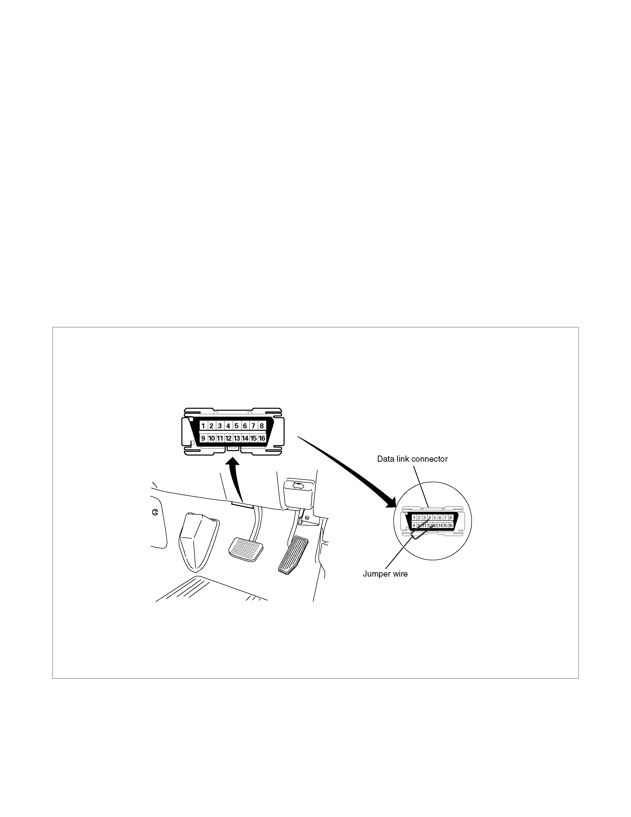
“Flash Code” Diagnostics
Flash code diagnostics can be used to read active
codes and to determine if history codes are present but
cannot be used to clear codes or read history codes.
Flash code diagnostics is enabled by grounding by
terminal 4 shorting to terminal 13 of the DLC connector
with the ignition switch “ON”. Grounding terminal 4 of
the DLC connector pulls the “Diagnostics Request”
input (Terminal 1) of the SRS control unit low and
signals the SRS control unit to enter the flash code
diagnostic display mode.
060R300052
The SRS control unit displays the trouble codes by
flashing the warning lamp. Each code that is displayed
will consist of a number of flashes which represents the
tens digit, a 1.2 second pause, following by a number of
flashes which represents the ones digit of the code.
Each code is displayed one time before moving on to
Two special codes exist when reading in the flash code
mode (Flash Code 12 and Flash Code 13). “Flash
Code 12” will always be the first code displayed when
the flash code mode is enable Code 12 is not an
indication of a SRS problem but an indication that the
flash code mode has been enabled. If there are no
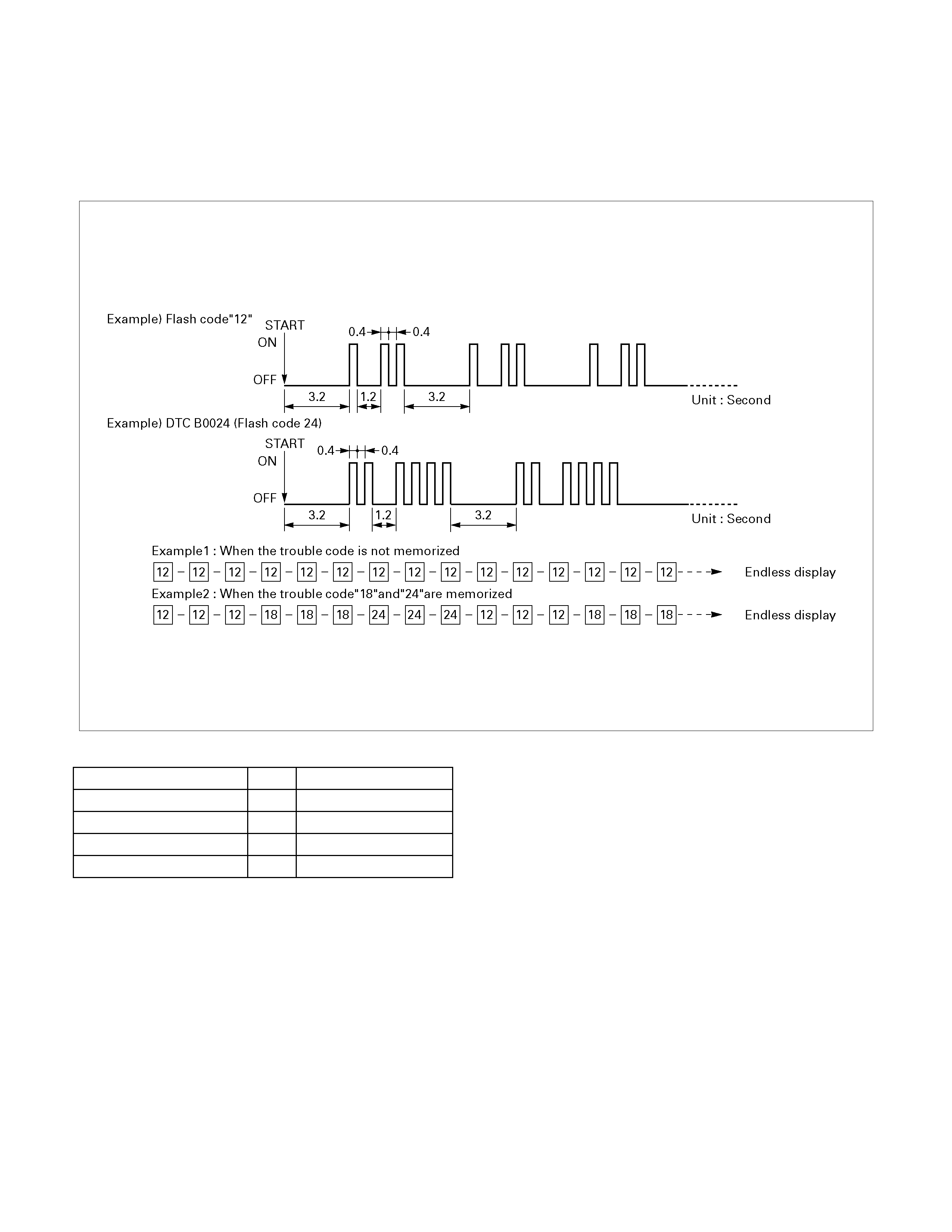
the next code. After all of the codes have been
displayed, the entire code sequence will continually by
repeated until ground is removed from terminal 4 of the
DLC connector.
active or history codes present, the SRS control unit will
display code 12 until ground is removed from the DLC
connector at terminal 4. “flash Code 13” will be
displayed if history codes are present. To read the
history codes a scan tool must be used.
060R300051
DATA LIST (Tech 2)
DISPLAY on Tech 2 UNIT VALUE
Driver Airbag Loop Enabled/Disabled
Passenger Airbag Loop Enabled/Disabled
System Voltage V 12.0
Driver Seat Belt Status Not Backled/Backled

Diagnostic Trouble Codes
Choose and trace an appropriate flowchart by the numbers listed below to find fault and repair.
DTC
(Flash
Code) Description
—
(12) Diagnostic Display Mode (Flash Code only)
—
(13) Diagnostic Display Mode (Flash Code only)
B0016
(16) Passenger Air bag Squib Cir cuit Low Resistance
B0017
(17) Passenger Air bag Squib Cir cuit High Resist ance
B0018
(18) Passenger Air bag Squib Cir cuit Voltag e Range / Perfor m ance
B0022
(22) Driver Airbag Squib Circuit Low Resistance
B0024
(24) Driver Airbag Squib Circuit Voltage Range / Perfor m ance
B0026
(26) Driver Airbag Squib Circuit High Resistance
B0033
(33) ECU Connector Poor Connection
B0051
(51) Squib Circuit Activated (Clash)
B0053
(53) Deploymant Command Despit e Pr esent Tr ouble Code
B0670
(63) Airbag Telltale Cir cuit Malfunction
B1000
(72) SDM Internal Fault (SDM= SRS control unit)
U1000
(75) Class2 Data Link Malf unct ion
U1∗∗∗
(73) Unknown Massage (The ∗∗∗ section change a number accor ding to conditions)
U1300
(76) Class2 Data Link Low
U1301
(76) Class2 Data Link High
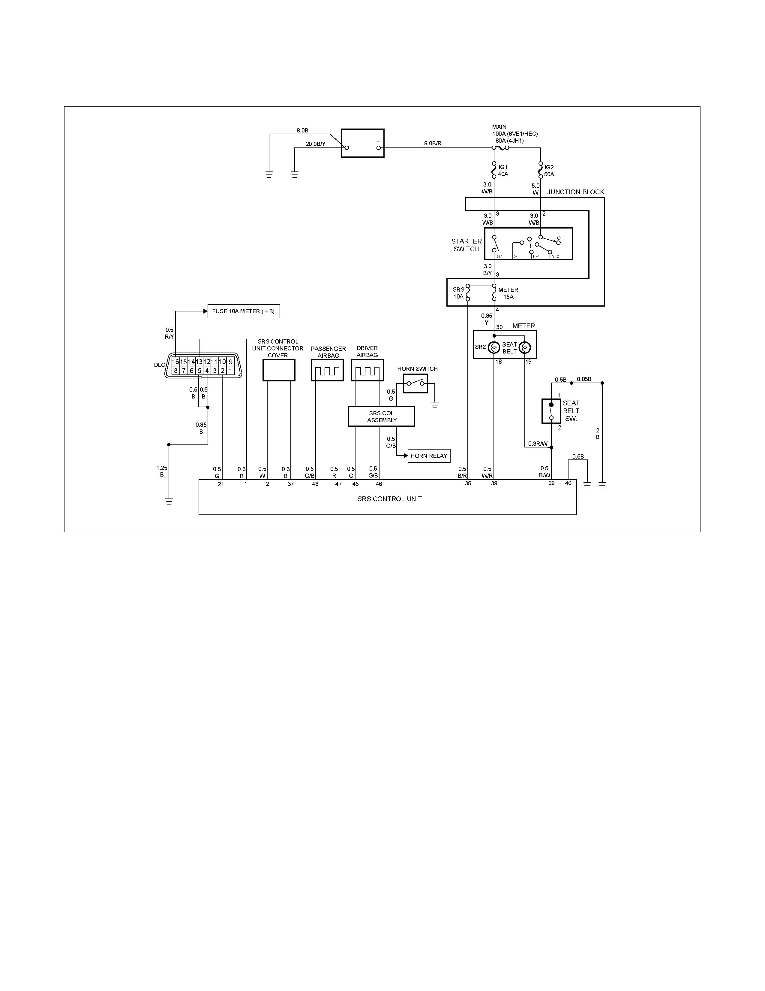
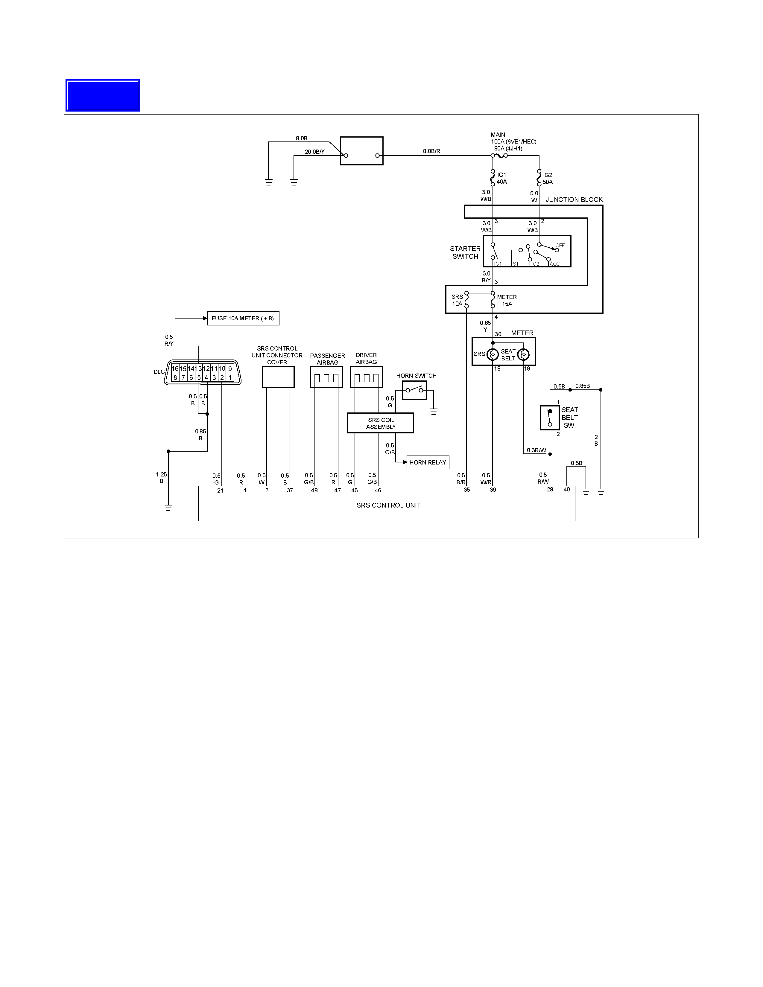
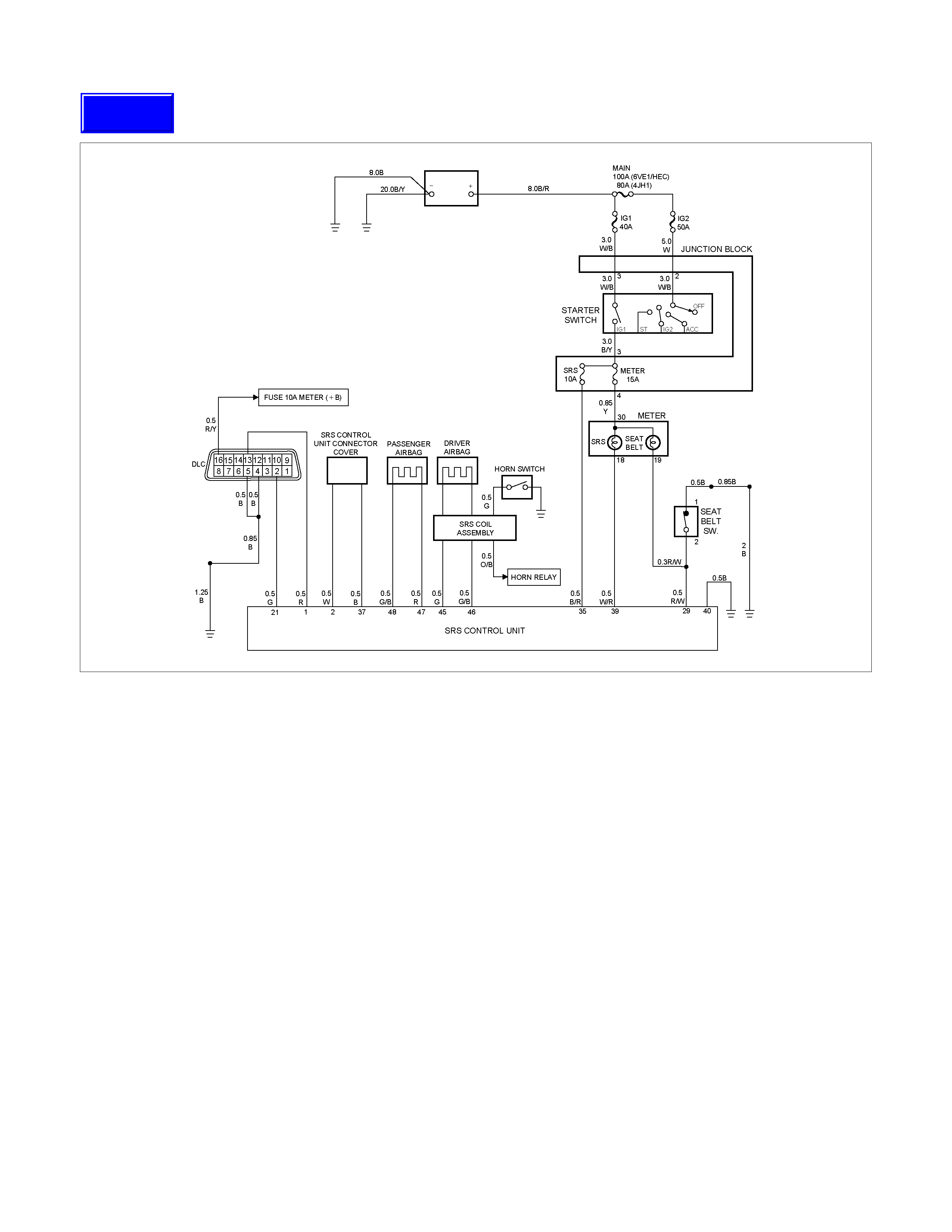
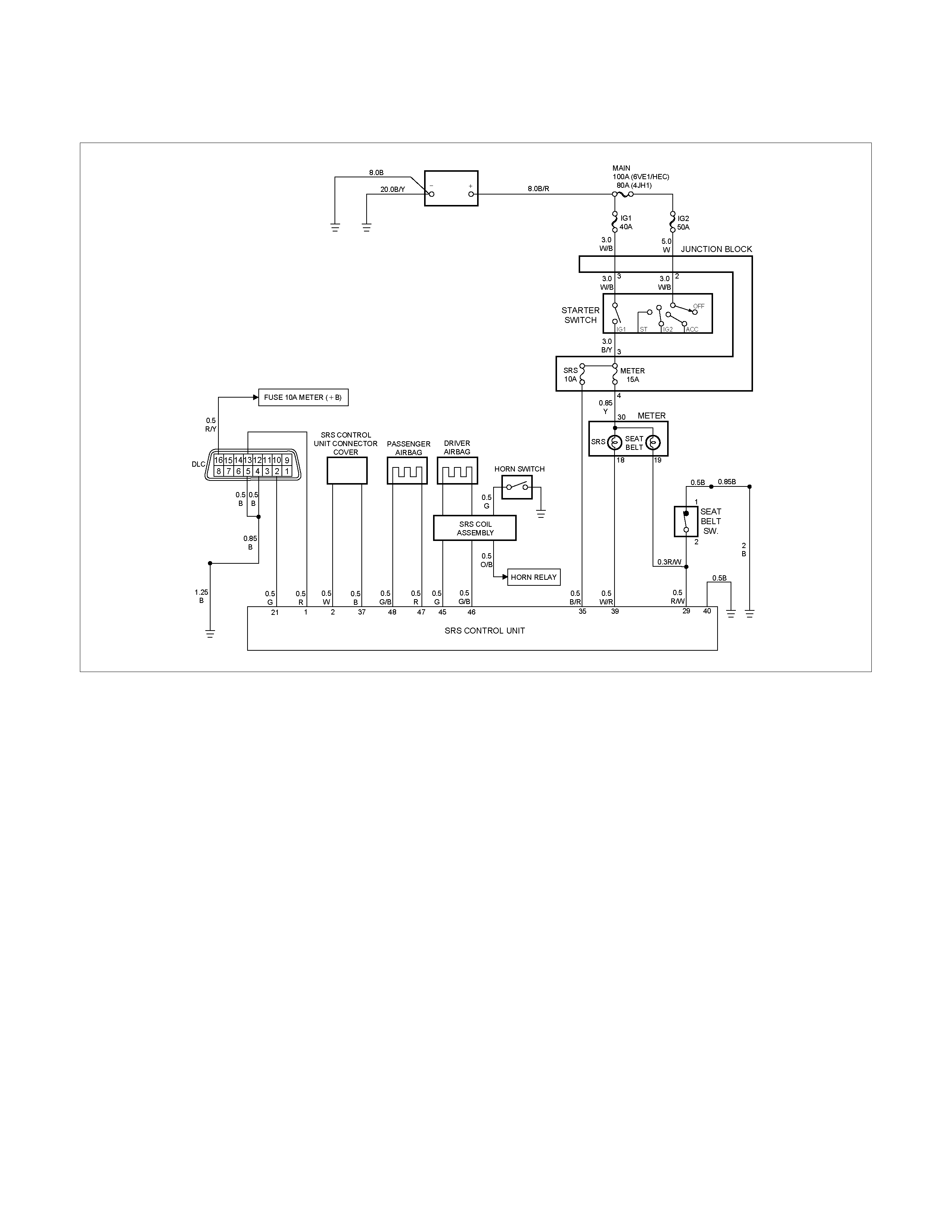
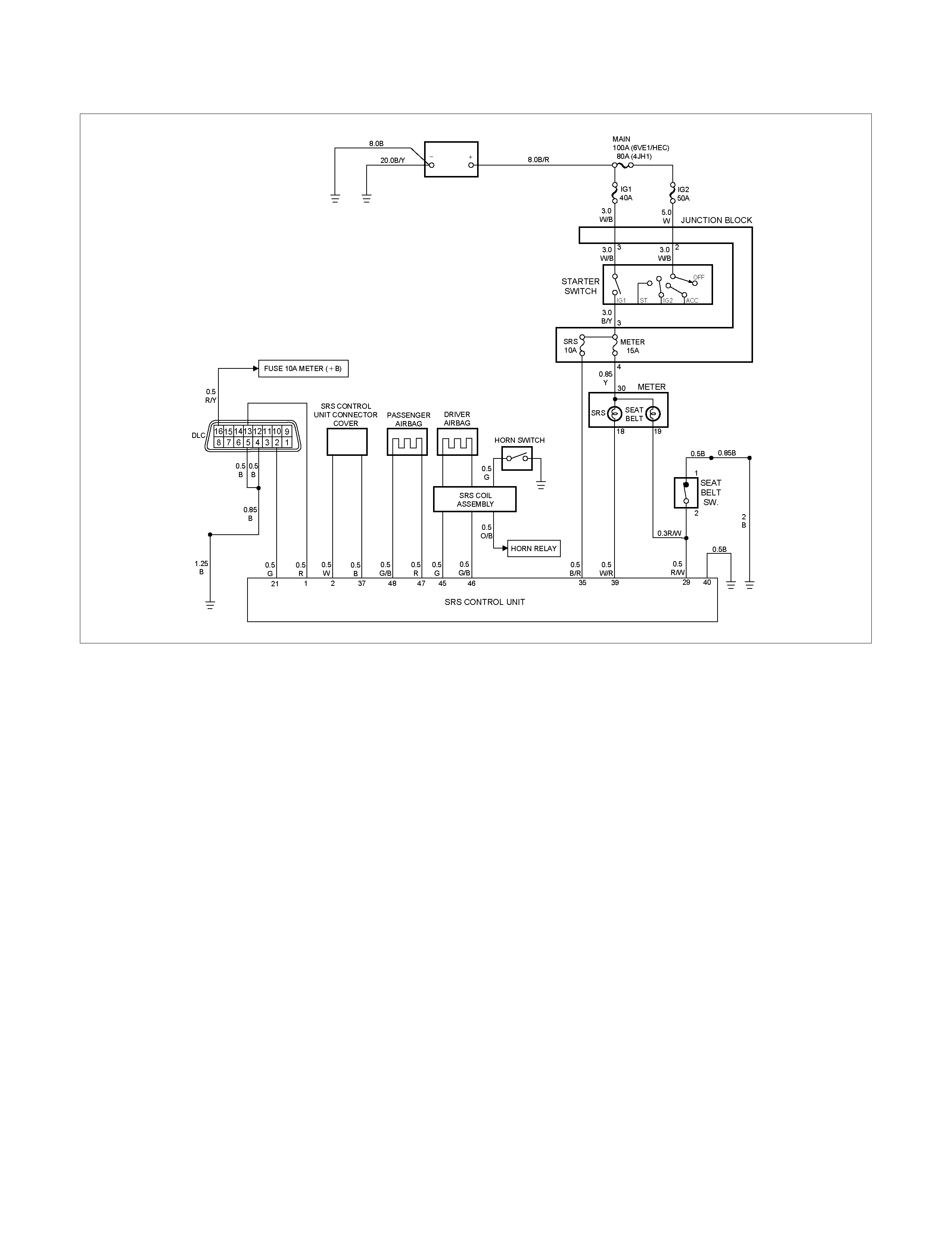
System Schematic
RTW39JMF000101
SRS Diagnostic System Check
The diagnostic procedures used in this section are
designed to find and repair SRS malfunctions. To get
the best results, it is important to use the diagnostic
charts and follow the sequence listed below:
A Perform the “SRS Diagnostic System Check.”
The “SRS Diagnostic System Check” must be the
starting point of any SRS diagnostics. The “SRS
Diagnostic System Check” checks for proper “AIR
BAG” warning lamp operation, the ability of the SRS
control unit to communicate through the “Serial
Data” line and whether SRS diagnostic trouble codes
exist.
B Refer to the proper diagnostic chart as directed by
the “SRS Diagnostic System Check.”
The “SRS Diagnostic System Check” will lead you to
the correct chart to diagnose any SRS malfunctions.
Bypassing these procedures may result in extended
diagnostic time, incorrect diagnosis and incorrect
parts replacement.
C Repeat the “SRS Diagnostic System Check” after
any repair or diagnostic procedures have been
preformed.
Performing the “SRS Diagnostic System Check”
after all repair or diagnostic procedures will ensure
that the repair has been made correctly and that no
other malfunctions exist

Circuit Description
When the ignition switch is first turned “ON”, “Ignition 1”
voltage is applied from the “SRS” fuse to the SRS
control unit at the “Ignition 1” input terminals “35”. The
SRS control unit responds by flashing the “AIR BAG”
warning lamp seven times, while performing tests on
the SRS.
Notes On System Check Chart
1. The “AIR BAG” warning lamp should flash seven
times after ignition is first turned “ON”.
2. After the “AIR BAG” warning lamp flashes seven
times, it should turn “OFF”
3. This test checks for the proper operation of the
“Serial Data” line. This test will also determine
whether history diagnostic trouble codes are stored
and, if so, identify them.
4. Improper operation of the “AIR BAG” warning lamp
is indicated. This test differentiates a warning lamp
stays “ON” condition from a warning lamp does not
come “ON” condition.
5. This test checks for proper operation of the “Serial
Data” line. This test will also identify the stored
diagnostic trouble codes and whether they are
current or history.
Diagnostic Aids
The order in which diagnostic trouble codes are
diagnosed is very important. Failure to diagnose the
diagnostic trouble codes in the order specified may
result in extended diagnostic time, incorrect diagnosis
and incorrect parts replacement.

SRS Diagnostic System Check
Step Action Yes No
1 Note the “Air Bag” warning lamp as ignition switch is turned “ON.”
Does the “AIR BAG” warning lamp flash seven 7 times? Go to Step 2 Go to Step 3
2 Note the “AIR BAG” warning lamp after it flashed 7 times.
Does the “AIR BAG” warning lamp go “OFF”? Go to Step 4 Go to Step 5
3 Note the “AIR BAG” warning lamp as ignition switch is turned
“ON”.
Does the “AIR BAG” warning lamp come “ON” steady ?
Go to Chart B. Go to Chart C.
4 1. Note the “AIR BAG” warning lamp as that ignition switch is
turned “ON.”
Ignition switch “OFF.”
2. Connect a scan tool to data link connector.
3. Follow direction given in the scan tool instruction manual.
Ignition switch “ON.”
4. Request the SRS diagnostic trouble code display, recode all
history diagnostic trouble code(s). specify as such, on repair
order
Is (are) diagnostic trouble code(s) displayed?
Ignition switch
“OFF.”
When DTC B1000 is
set, go to DTC
B1000 Chart.
For all other history
codes refer to
“Diagnostic Aids”
For that specific
DTC.
A history DTC
indicates the
malfunction has
been repaired or is
intermittent.
SRS is functional
and free of
malfuncitons, no
further diagnosis is
required.
If scan tool indicated
“NO DATA
RECEIVED,” refer to
chassis electrical
section 8.
5 1. Ignition switch “OFF.”
2. Connect a scan tool to data link connector.
3. Follow directions as given in the scan tool instruction
manual.
4. Ignition switch “ON.”
5. Request the SRS diagnostic trouble code display, Recode
all diagnostic trouble code(s), specifying as current or history
on repair order.
Is (are) diagnostic trouble code (s) displayed?
Ignition switch
“OFF”.
When DTC B0053 is
set, go to DTC
B0053 chart.
When DTC B0051 is
set, go to DTC
B0051 chart.
When DTC B0018
is set, go to DTC
B0018 chart.
When DTC B0024
is set, go to DTC
B0024 chart.
Diagnose remaining
current DTCs from
lowest to highest.
When only history
DTCs exist, refer to
“Diagnostics Aids”
for that specific
DTC.
A history DTC
indicates the
malfunction has
been repaired or is
intermittent.
If scan tool indicates
“No Data Received,”
refer to chassis
electrical section 8.

Chart A SRS control unit Integrity Check
RTW39JMF000101
Circuit Description
When the SRS control unit recognizes “Ignition 1”
voltage, applied to terminals “35”, is greater than 9
volts, the “AIR BAG” warning lamp is flashed 7 times to
verify operation. At this time the SRS control unit
performs “Turn–ON” tests followed by “Continuous
Monitoring” tests. When a malfunction is detected, the
SRS control unit sets a current diagnostic trouble code
and illuminates the “AIR BAG” warning lamp. The SRS
control unit will clear current diagnostic trouble codes
and move them to a history file when the malfunction is
no longer detected and/or the ignition switch is cycled,
except for DTCs B0051 and B0053.
Chart Test Description
Number(s) below refer to step number(s) on the
diagnostic chart:
1. This test confirms a current malfunction. If no
current malfunction is occurring (history DTC set)
the “Diagnostic Aids” for the appropriate diagnostic
trouble code should be referenced. The SRS control
unit should not be replaced for a history diagnostic
trouble code.
2. This test checks for a malfunction introduced into the
SRS during the diagnostic process. It is extremely
unlikely that a malfunctioning SRS control unit would
cause a new malfunction to occur during the
diagnostic process.
3. When all circuitry outside the SRS control unit has
been found to operate properly, as indicated by the
appropriate diagnostic chart, then and only then
should the SRS control unit be replaced.

Chart A SRS control unit Integrity Check
WARNING: DURING SERVICE PROCEDURES. BE VERY CAREFUL WHEN HA NDLING A SRS CONTROL UNIT.
NEVER STRIKE OR JAR THE SRS CONTROL UNIT. NEVER POWER UP THE SRS WHEN THE SRS CONTROL
UNIT IS NOT RIGIDLY ATTACHED TO THE VEHICLE. A LL SRS CONTROL UNIT AND MOUNTING BRACKET
FASTENERS MUST BE CAREFULLY TORQUED AND THE ARROW MUST BE POINTING TOWA RD THE FRONT
OF THE VEHICLE TO ENSURE PROPER OPERATION OF THE SRS. THE SRS CONTROL UNIT COULD BE
ACTIVATED WHEN POWERED WHILE NOT RIGIDLY A TTACHED TO THE VEHICLE WHICH COULD CAUSE
DEPLOYMENT AND RESULT IN PERSONAL INJURY
Step Action Yes No
1 1. This chart assumes that the “SRS Diagnostic System
Check” and either a symptom chart or a diagnostic trouble
code chart diagnosis have been performed. When all
circuitry outside the SRS control unit has been found to
operate properly, as indicated by the appropriate diagnostic
chart, and the symptom or DTC remains current, the
following
2. Diagnostic procedures m us t be perf orm ed to ver ify the need
for SRS control unit replacement.
3. Ignition switch “OFF”.
4. Reconnect all SRS components , ensur e all c omponents are
properly mounted.
5. Ensure the ignition switch has been “OFF” for at least 15
seconds.
6. Note “AIR BAG” warning lamp as ignition switch is turned
“ON.”
Does warning lamp flash 7 times then go “OFF”?
The symptom or
DTC is no longer
occurring.
Clear SRS
diagnostic trouble
codes.
Repeat “SRS
Diagnostic System
Check”
Go to Step 2
2 Using a scan tool request diagnostic trouble code display.
Is the same symptom or DTC occurring as was when the “SRS
Diagnostic System Check” was first performed?
Go to Step 3 Ignition switch
“OFF”.
Go to the
appropriate chart for
the indicated
malfunction.
3 1. Clear “SRS Diagnostic Trouble Codes”.
2. Ignition switch “OFF” for at least two minutes.
3. Note “AIR BAG” warning lamp as ignition switch is turned
“ON.”
Does warning lamp flash 7 times then go “OFF”?
SRS is functional
and free of
malfunctions.
No further diagnosis
is required.
Go to Step 4
Ignition switch
“OFF”.
Replace SRS control
unit.
Go to Step 4
4 Reconnect all SRS components, ensure all components are
properly mounted.
Was this step finished?
Repeat the “SRS
Diagnostic System
Check”
Go to Step 4

Chart B “AIR BAG” Warning Lamp Comes “ON” Steady
RTW39JMF000101
Circuit Description
W hen the ignition switch is f irst turned “ON” , “Ignition 1”
voltage is applied from the “METER” fuse to “AIR
BAG”, warning lamp which is connected to “SRS
W ar ning Lam p”, term inal “39”. The “ SRS” fuses appl
y
system voltage to the “Ignition 1” inputs, term inals “35”.
The SRS control unit responds by flashing the “AIR
BAG” warning lamp 7 times. If “Ignition 1” is less than
9 volts, the “AIR BAG” warning lamp will come “ON”
solid with no DTCs set.
Chart Test Description
Number(s) below refer to step number(s) on the
diagnostic chart:
2. This test checks for an open in the “Ignition 1” circuit
to the SRS control unit.
3. This test checks for the voltage of “Ignition 1”.
4. This test determines whether the malfunction is a
short to ground in SRS waring lamp circuit.

Chart B “AIR BAG” warning lamp comes “ON” Steady
Step Action Yes No
1 1. When meas urements are reques ted in this c har t use 5- 8840-
0285-0 DVM with correct terminal adapter from 5-8840-
0385-0.
2. Ignition switch “OFF.”
3. Connect scan tool to data link connec tor, follow directions as
given in the scan tool instruction MANUAL.
4. Ignition switch “ON.”
5. Request SRS diagnostic trouble code display.
Dose scan tool indicate “No Data Received”?
Go to Step 2 Go to Step 3
2 1. Ignition switch “OFF”.
2. Inspect SRS control unit harness connector connection to
SRS control unit.
Is it securely connected to the SRS control unit?
Ignition switch
“OFF.”
Replace SRS
control unit.
Go to Step 5
Connect SRS
control unit
securely to de–
activate shorting
clip in SRS control
unit harness
connector.
Go to Step 5
3 Using scan tool, request SRS data list.
Is “ignition” more than 9 volts? Go to Step 4 Ignition switch
“OFF.”
Replace SRS
control unit.
Go to Step 5
4 1. Ignition switch “OFF.”
2. Disconnect SRS coil and passenger air bag assemblies.
yellow connector located at base of steering column and
behind the glove box assembly.
Disconnect SRS control unit.
3. Disconnect the connector of “SRS Warning Lamp” of
instrument cluster.
4. Measur e resistance fr om SRS control unit harness c onnector
terminal “40” to ground.
Does 5-8840-0285-0 DVM display “OL” (Infinite)?
Go to Chart A Replace SRS
harness.
Go to Step 5
5 Reconnect all SRS components, ensure all components are
properly mounted.
Was this step finished?
Repeat the “SRS
Diagnostic System
Check”
Go to Step 5

Chart C “AIR BAG” Warning Lamp Does Not Come “ON” Steady
RTW39JMF000101
Circuit Description
W hen the ignition switch is f irst turned “ON” , “Ignition 1”
voltage is applied from the “METER” fuse to the “AIR
BAG” warning lamp which is connected to “SRS
Warning Lamp”, terminal “39”. The “SRS” fuse appl
y
system voltage to the “Ignition 1” inputs, term inals “35”.
The SRS control unit responds by flashing the “AIR
BAG” warning lam p s even tim es. If “Ignition 1” is mo re
than 16 volts, the “AIR BAG” warning lamp will be still
“OFF” solid with no DTCs set.
Chart Test Description
Number(s) below refer to step number(s) on the
diagnostic chart:
1. This test decides whether power is available to SRS
control unit warning lamp power feed circuit.
2. This test determines whether the voltage is present
in the warning lamp circuit.
3. This test determines if the malfunction is in the
instrument cluster.
4. This test checks for open in the warning lamp
circuitry.
5. This test isolates the SRS warning lamp circuit and
check s f or a s hort in the SRS warning lam p c ircuit to
B+.
8. This test checks for a short from the SRS control
unit warning lamp power feed circuit to ground.
9. This test determines whether the short to ground is
due to a short in the wiring.

Chart C “AIR BAG” Warning Lamp Does Not Come “ON” Steady
Step Action Yes No
1 1. When meas urements are r eques ted in this c har t, use 5- 8840-
0285-0 DVM with correct terminal adapter from 5-8840-
0385-0.
2. Ignition switch “OFF.”
3. Remove and inspect “METER” fuse to the “AIR BAG”
warning lamp.
Is fuse good?
Go to Step 2 Go to Step 7
2 1. Ignition switch “OFF.”
2. Disconnect SRS coil and passenger air bag assemblies.
Yellow connector located at base of steering column and
behind the glove box assembly.
3. Disconnect SRS control unit.
4. Ignition switch “ON.”
5. Measure voltage on SRS control unit harness connector from
terminal “39” to terminal “40” (ground).
Is system voltage present on terminal “39”?
Go to Step 4 Go to Step 3
3 1. Ignition switch “OFF.”
2. Remove instrument meter cluster.
3. Check for proper connection to instrument cluster at SRS
warning lamp circuit terminal.
4. If ok, then remove and inspect “AIR BAG” bulb.
Is bulb good?
Go to Step 5 Replace bulb.
Go to Step 6
4 1. Ignition switch “OFF.”
2. Disconnect instrument meter cluster harness connector.
3. Ignition switch “ON.”
4. Measure voltage on SRS contr ol unit harnes s c onnector f rom
terminal “39” to terminal “40” (ground).
Is voltage 1 volt or less?
Go to Chart A Replace SRS
harness.
Go to Step 6
5 1. Install bulb.
2. Measure resistance from instrument meter cluster harness
connector SRS warning lam p circuit terminal to SRS control
unit harness connector terminal “7”.
Is resistance 5.0 ohms or less?
Service instrument
meter cluster.
Install instrument
meter cluster.
Go to Step 6
Replace SRS
harness.
Go to Step 6
6 Reconnect all SRS components, ensure all components are
properly mounted.
Was this step finished?
Repeat the “SRS
Diagnostic System
Check”
Go to Step 6

Step Action Yes No
7 Perform chart C.
Was this step finished? Go to Step 8 Go to Step 1
8 1. Replace “METER” fuse.
2. Ignition switch “ON” wait 10 Sec onds then ignition s witch “ O f f .
“
3. Remove and inspect “METER” fuse.
Is fuse good?
Install “METER”
fuse.
Go to Step 10
Go to Step 9
9 1. Disconnect SRS coil and passenger air bag assemblies.
Yellow connectors located at base of steering column and
behind the glove box assembly.
2. Disconnect SRS control unit.
3. Replace “METER” fuse.
4. Ignition switch “ON” wait 10 seconds.
5. Ignition switch “OFF”.
6. Remove and inspection “METER” fuse.
Is fuse good?
Install “METER”
fuse.
Go to Chart A
Replace SRS
harness.
Replace “METER”
fuse.
Go to Step 10
10 Reconnect all SRS components, ensure all components are
properly mounted.
Was this step finished?
Repeat the “SRS
Diagnostic System
Check”
Go to Step 10
DTC B0016 (Flash Code 16) Passenger Airbag Squib
Circuit Low Resistance
RTW39JMF000101
Circuit Description
When the ignition switch is turned “ON”, the SRS
control unit will perform tests to diagnose critical
malfunctions within itself. Upon passing these tests
“Ignition 1”, and deployment loop voltages are
measured to ensure they are within their respective
normal voltage ranges. The SRS control unit then
proceeds with the “Resistance Measurement Test”.
“Passenger Bag Low” term inal “47” is grounded through
a resistor and the passenger current source connected
to “Passenger Bag High” terminal “48” allows a known
amount of current to flow. By monitoring the voltage
difference between “Passenger Bag High” and
“Passenger Bag Low”, the SRS control unit calculates
the combined resistance of the passenger air bag
assem bly, harness wiring circuits “Pass enger Bag High”
and “Passenger Bag Low” connector terminal contact.
DTC Will Set When
The combined resistance of the passenger air bag
assembly, harness wiring circuits “Passsenger Bag
High” and “Passenger Bag Low”, and connector
terminal contact is above a specified value. This test
is run once each ignition cycle during the “Resistance
Measurement Test” when:
1. No “higher priority f aults” are detected during “T urn–
ON”,
2. “Ignition 1” voltage is in the specified value.
Action Taken
SRS control unit turns “ON” the “AIR BAG” warning
lamp and sets a diagnostic trouble code.
DTC Will Clear When
The ignition switch is turned “OFF.”
Techline

DTC Chart Test Description
Number(s) below refer to step number(s) on the
diagnostic chart:
2. This test determines whether the malfunction is in
the SRS control unit.
3. This test verifies connection of the yellow connector.
4. This test cheek s for proper operation of the shorting
clip in the yellow connector.
5. The tes t checks for a m alfunction pas senger air bag
assembly.
6. This test determines whether the malfunctioning is
due to shortening in the wiring.
Diagnostic Aids
A
n intermittent condition is likely to be caused by a short
between circuits “Passenger Bag High” and “Passenger
Bag Low” or a malfunctioning shorting clip on the
passenger air bag assembly which would require
replacement of the air bag assembly. The test for this
diagnostic trouble code is only run while “AIR BAG”
warning lamp is performing the bulb check. When a
scan tool “Clear Codes” command is issued and the
malfunction is still present, the DTC will not reappear
until the next ignition cycle.

DTC B0016 (Flash Code 16) Passeng er Airbag Squib Circuit Low Resistance
Step Action Yes No
1 Was the “SRS Diagnostic System Check performed?
Go to Step 2
Repeat the
“SRS Diagnostic
System Check”
2 1. Ignition switch in the ‘LOCK’ position.
2. Check that the passenger air bag assembly yellow connect or,
located behind the glove box assembly is correctly installed.
Is the yellow connector correctly installed? Go to Step 3
Install the
passenger air bag
assembly yellow
connector correctly.
Go to Step 6
3
1. Disconnect the passenger air bag assembly, yellow wiring
connector, located behind the glov e box assembly.
2. If OK, reinstall the passenger air bag assem bly connector.
3. Turn the ignition switch to the ‘ON’ position.
Is DTC B0016 current? Go to Step 4 Go to Step 6
4
1. Ignition switch in the ‘LOCK’ position.
2. Disconnect SRS coil and passeng er air bag assembly yellow
wiring connector, located at the base of the steering column
and behind the glove bo x ass embly.
3. Connect 5-8840-2421-0 SRS driver/p assenger load tool and
appropriate adaptors to the SRS coil and passenger air bag
harness connectors.
4. Turn the ignition switch to the ‘ON’ position.
T
C B0016 current? Go to Step 5
Ignition switch in the
‘LOCK’ position.
Replace the
passenger air bag
assembly.
Go to Step 6
5
1. Ignition switch in the ‘LOCK’ position.
2. There has been a decrease in the total circu it resistance of the
passenger inflator deployment loop.
3. Use the high resolution ohmmeter mode of the DMM while
checking circuits “Passenger Bag High” and “Passenger Bag
Low”, and SRS control unit connector terminal “48” and “47” to
locate the root cause.
Was a fault found?
Replace the SRS
harness.
Go to Step 6 Go to Chart A
6
1. Reconnect all removed components, ensuri ng that all are
correctly mounted.
2. Check that all electrical connections are correctly installed.
3. Clear all diagnostic trouble codes.
4. Check that the DTC does not reset.
Does the DTC reset? Go to Step 1 System OK

DTC B0017 (Flash Code 17) Passenger Airbag
Squib Circuit High Resistance
RTW39JMF000101
Circuit Description
When the ignition switch is turned “ON”, the SRS
control unit will perform tests to diagnose critical
malfunctions within itself. Upon passing these tests
“Ignition 1”, and deployment loop voltages are
measured to ensure they are within their respective
normal voltage ranges. The SRS control unit then
proceeds with the “Resistance Measurement Test”.
“Passenger Bag Low” term inal “47” is grounded through
a resister and the passenger current source connected
to “Passenger Bag High” terminal “48” allows a known
amount of current to flow. By monitoring the voltage
difference between “Passenger Bag High” and
“Passenger Bag Low” the SRS control unit calculates
the combined resistance of the passenger air bag
assem bly, harness wiring circuits “Pass enger Bag High”
and “Passenger Bag Low” connector terminal contact.
DTC Will Set When
The combined resistance of the passenger air bag
assembly, harness wiring circuits “Passenger Bag High”
and “Passenger Bag Low”, and connector terminal
contact is above a specified value. This test is run
once each ignition cycle during the “Resistance
Measurement Test” when:
1. No “higher priority f aults” are detected during “T urn–
ON”,
2. “Ignition 1” voltage is in the specified value.
Action Taken
SRS control unit turns “ON” the “AIR BAG” warning
lamp and sets a diagnostic trouble code.

DTC Will Clear When
The ignition switch is turned “OFF.”
DTC Chart Test Description
Number(s) below refer to step number(s) on the
diagnostic chart:
2. This test determines whether the malfunction is in
the SRS control unit.
3. This test verifies proper connection of the yello
w
connector.
4. This test checks for proper contact and/or corrosion
of the yellow connector terminals.
5. The test checks for a malfunctioning passenger ai
r
bag assembly.
6. This test determines whether the malfunction is due
to high resistance in the wiring.
Diagnostic Aids
A
n intermittent condition is likely to be caused by a poor
connection at the passenger air bag assembly harness
connector terminals “1” and “2”, SRS control unit
terminal “48” and “47”, or a poor wire to terminal
connection in circuits “Passenger Bag High” and
“Passenger Bag Low”. This test for this diagnostic
trouble code is only run while the “AIR BAG” warning
lamp is performing the bulb check. When a scan tool
“Clear Codes” command is issued and the malfunction
is still present, the DTC will not reappear until the next
ignition cycle.

DTC B0017 (Flash Code 17) Passenger Airbag Squib Circuit High Resistance
Step Action Yes No
1 Was the “SRS Diagnostic System Check” Performed? Go to Step 2 Go to The “SRS
Diagnostic System
Check”
2 1. When meas urements are reques ted in this c har t use 5- 8840-
0285-0 DVM with correct terminal adapter from 5-8840-
0385-0.
2. Use scan tool data list function, read and record the
passenger deployment loop resistance.
Is passenger resist. more than 6.5 ohms?
Go to Step 3 Go to Chart A
3 1. Ignition switch “Off.”
2. Make sure the passenger air bag assembly yellow connector
located behind the glove box assembly is seated properly.
Is the yellow connector connected properly?
Go to Step 4 Seat passenger Air
Bag assembly
yellow connector
properly.
Go to Step 7
4 1. Disconnect and inspect the passenger air bag assembly
yellow connector located behind the glove box assembly.
2. If ok, reconnect the passenger air bag assembly connector.
3. Ignition switch “ON.”
Is DTC B0017 current?
Go to Step 5 Go to Step 7
5 1. Ignition switch “Off.”
2. Disc onnect SRS coil and passenger air bag as sembly, yellow
connector located at the base of the steering column and
behind the glove box assembly.
3. Connect 5-8840-2421-0 SRS driver / passenger load tool and
appropriate adapters to SRS coil and passenger air bag
assembly harness connectors.
4. Ignition switch “ON.”
Is DTC B0017 Current?
Go to Step 6 Ignition switch
“Off.”
Replace the
passenger air bag
assembly.
Go to Step 7
6 1. Ignition switch “Off.”
2. There has been an increase in the total circuit resistance of
the passenger inflator deployment loop.
3. Use the high resolution ohmmeter mode of the DVM while
checking circuits “Pasenger Bag High” and “Passenger Bag
Low”, and SRS control unit connector term inal “48” and “47”
to locate the root cause.
Was a fault found?
Replace SRS
harness.
Go to Step 7
Go to Chart A
7 1. Reconnect all com ponents ens ure all com ponent are properly
mounted.
2. Clear diagnostic trouble codes.
Was This step finished?
Repeat the “SRS
Diagnostic System
Check”
Go to Step 7

DTC B0018 (Flash Code 18) Passenger Airbag Squib
Circuit Voltage Range/Performance
RTW39JMF000101
Circuit Description
When the ignition switch is turned “ON”, the SRS
control unit will perform tests to diagnose critical
malfunctions within itself. Upon passing these tests,
“Ignition 1”, and deployment loop voltages are
measured to ensure they are within their respective
normal voltage ranges.
The SRS control unit monitors the voltages at “Drive
r
Bag Low” terminal “46” and “Passenger Bag Low”
term inal “47” to detect short to ground/+B in the air bag
assembly circuits.
DTC Will Set When
Neither of the two air bag assemblies is open.
“Ignition 1” is within the normal operating voltage range.
Once these conditions are me and the voltage at
“Passenger Bag Low” is out of a specified value, DTC
B0018 will set. This test is run once each ignition cycle
and “Continuous Monitoring”.
Action Taken
SRS control unit turns “ON” the “AIR BAG” warning
lamp and sets a diagnostic trouble code.

DTC Will Clear When
This malfunction is no longer occurring and the ignition
switch is turned “OFF”.
DTC Chart Test Description
Number(s) below refer to circled number(s) on the
diagnostic chart.
2. This test determines whether the SRS control unit is
malfunctioning.
3. This test isolates the malfunction to one side of the
passenger air bag assembly yellow connector behind
glove box compartment.
4. This test determines whether the malfunction is in
“Passenger Bag High” circuit.
5. This test determines whether the malfunction is in
“Passenger Bag Low” circuit.
6. This test determines whether the malfunction is in
“Driver Bag High” circuit.
7. This test determines whether the malfunction is in
“Driver Bag Low” circuit.
Diagnostic Aids
A
n intermittent condition is likely to be caused by a short
to ground/+B in the passenger air bag assembly circuit.
Inspect circuits “Passenger Bag High” and “Passenger
Bag Low” carefully for cutting or chafing. If the wiring
pigtail of the passenger air bag assembly is damaged,
the component must be replaced.

DTC B0018 (Flash Code 18) Passenger Airbag Squib Circuit Voltage Range/Performance
Step Action Yes No
1 Was the “SRS Diagnostic System Check” performed? Go to Step 2 Go to the “SRS
Diagnostic System
Check”
2 1. When meas urements are reques ted in this c har t use 5- 8840-
0285-0 DVM with correct terminal adapter from 5-8840-
0385-0.
2. Ignition switch “OFF.”
3. Connect scan tool data link connector. follow directions as
given in the scan tool operator's MANUAL.
4. Ignition switch “ON.”
5. Read passenger sense LO.
Is passenger sense LO less than 2.0 volts or more than 6.0
volts?
Go to Step 3 Go to Chart A
3 1. Ignition switch “OFF.”
2. Disconnect passenger air bag assembly yellow connector
behind the glove box assembly.
3. Leave driver air bag assembly connected.
4. Connect SRS driver / passenger load tool 5-8840-2421-0 and
appropriate adapter to pas senger air bag ass embly harness
connector.
5. Ignition switch “ON.”
Is DTC B0018 current?
Go to Step 4 Ignition switch
“OFF.”
Replace
passenger air bag
assembly .
Go to Step 8
4 1. Ignition switch “OFF”.
2. Disconnect SRS driver / passenger load tool
3. Measure resistance on SRS control unit harness connector
from terminal “48” to terminal “40” (ground).
Does 5-8840-0285-0 display “OL” (Infinite)?
Go to Step 5 Replace SRS
Harness.
Go to Step 8
5 Measure resistance on SRS control unit harness connector from
terminal “47” to terminal “40” (ground).
Does 5-8840-0285-0 display “OL” (Infinite)?
Go to Step 6 Replace SRS
Harness.
Go to Step 8
6 Measure resistance on SRS control unit harness connector from
terminal “48” to terminal “35” (ignition).
Does 5-8840-0285-0 display “OL” (Infinite)?
Go to Step 7 Replace SRS
Harness.
Go to Step 8
7 Measure resistance on SRS control unit harness connector from
terminal “47” to terminal “35” (ignition).
Does 5-8840-0285-0 display “OL” (Infinite)?
Go to Chart A Replace SRS
Harness.
Go to Step 8
8 1. Reconnect all components and ensure all component are
properly mounted.
2. Clear diagnostic trouble codes.
Was this step finished?
Go to the “SRS
Diagnostic system
Check”
Go to Step 8
DTC B0022 (Flash Code 22) Driver Airbag
Squib Circuit Low Resistance
RTW39JMF000101
Circuit Description
When the ignition switch is turned “ON”, the SRS
control unit will perform tests to diagnose critical
malfunctions within itself. Upon passing these tests
“Ignition 1”, and deployment loop voltages are
measured to ensure they are within their respective
normal voltage ranges.
The SRS control unit then proceeds with the
“Resistance Measurement Test” “Driver Bag Low”
terminal “46” is grounded through a current sink and
the driver current source connected to “Driver Bag
High” term inal “45” allows a known am ount of curr ent to
flow. By monitoring the voltage difference between
“Driver Bag High” and “D river Bag Low” the SRS contr ol
unit calculates the combined res istance of the driver air
bag assembly, SRS coil assembly, harness wiring
circuits “Driver Bag High” and “Driver Bag Low” and
connector terminal contact.
Techline

DTC Will Set When
The combined resistance of the driver air bag
assembly, SRS Coil assembly, harness wiring circuits
“Driver Bag High” and “Driver Bag Low”, and connector
terminal contact is above a specified value. This test is
run once each ignition cycle during the “Resistance
Measurement Test” when:
1. No “higher priority f aults” are detected during “T urn–
ON”
2. “Ignition 1” voltage is in the specified value.
Action Taken
SRS control unit turns “ON” the “AIR BAG” warning
lamp and sets DTC B0022.
DTC Will Clear When
The ignition switch is turned “OFF.”
DTC Chart Test Description
Number(s) below refer to circled number(s) on the
diagnostic chart:
2. This test determines whether the malfunction is in
the SRS control unit.
3. This test verifies proper connection of the yellow
connector at the base of the steering column.
4. This test checks for proper operation of the shorting
clip in the yellow connector.
5. This test isolate the malfunction to one side of the
SRS coil assembly yellow connector located at the
base of steering column.
6. This test determines whether the malfunction is due
to shortening in the wiring.
7. This test determines whether the malfunction is in
the SRS coil assembly or the driver air bag
assembly.
Diagnostic Aids
An intermittent condition is likely to be caused by a short
between circuit “Driver Bag High” or “Driver Bag Low”
or a malfunctioning shorting clip on the driver air bag
assembly or SRS coil assembly which would require
replacement of the component. The test for this
diagnostic trouble code is only run while the “AIR BAG”
warning lamp is performing the bulb check. When a
scan tool “Clear Codes” command is issued and the
malfunction is still present, the DTC will not reappear
until the next ignition cycle.

DTC B0022 (Flash Code 22) Driv er Airbag Squib Circuit Low Resistance
Step Action Yes No
1 Was the “SRS Diagnostic System Check performed?
Go to Step 2
Repeat the
“SRS Diagnostic
System Check”
2 1. Ignition switch in the ‘LOCK’ position.
2. Check that the SRS coil assembly yellow connector, located at
the base of the steering column is correctly installed.
Is the yellow connector correctly installed? Go to Step 3
Install the driver air
bag assembly
yellow connector
correctly.
Go to Step 7
3
1. Disconnect and inspect the SRS coil assem bly, yellow wiring
connector, located at t he base of the steering colum n
assembly.
2. If OK, reinstall the SRS coil assembly, yellow connector.
3. Turn the ignition switch to the ‘ON’ position.
Is DTC B0022 current? Go to Step 4 Go to Step 7
4
1. Ignition switch in the ‘LOCK’ position.
2. Disconnect SRS coil and passeng er air bag assembly yellow
wiring connector, located at the base of the steering column
and behind the glove bo x ass embly.
3. Connect 5-8840-2421-0 SRS driver/p assenger load tool and
appropriate adaptors to the SRS coil and passenger air bag
harness connectors.
4. Turn the ignition switch to the ‘ON’ position.
Is DTC B0022 current? Go to Step 5 Go to Step 6
5
1. Ignition switch in the ‘LOCK’ position.
2. There has been a decrease in the total circuit resistance of the
driver inflator deployment loop.
3. Use the high resolution ohmmeter mode of the DMM while
checking circuits “Driver Bag High” and “Driver Bag Low”, and
SRS control unit connector terminal “45” an d “46” to locate the
root cause.
Was a fault found?
Replace the SRS
harness.
Go to Step 6 Go to Chart A
6
1. Ignition switch in the ‘LOCK’ position.
2. Disconnect SRS driver/passenger load tool from the driver bag
assembly harness connector.
3. Connect the SRS driver/passenger load tool 5-8840-2421-0 to
the top of the steering column connector.
4. Reconnect the SRS coil assembly harness connector st the
base of the steering column.
5. Turn the ignition switch to the ‘ON’ position.
Is DTC B0022 current?
Ignition switch in the
‘LOCK’ position.
Replace SRS coil
assembly.
Go to Step 7
Ignition switch in the
‘LOCK’ position.
Replace driver air
bag assembly.
Go to Step 7
7
1. Reconnect all removed components, ensuri ng that all are
correctly mounted.
2. Check that all electrical connections are correctly installed.
3. Clear all diagnostic trouble codes.
4. Check that the DTC does not reset.
Does the DTC reset? Go to Step 1 System OK

DTC B0024 (Flash Code 24) Driver Airbag Squib
Circuit Voltage Range/Performance
RTW39JMF000101
Circuit Description
When the ignition switch is turned “ON”, the SRS
control unit will perform tests to diagnose critical
malfunctions within itself. Upon passing these tests,
“Ignition 1”, and deployment loop voltages are
measured to ensure they are within their respective
normal voltage ranges.
The SRS control unit monitors the voltage at “Drive
r
Bag Low” terminal “46” and “Passenger Bag Low”
terminal “47” to detect shorts to ground/+B in the air bag
assembly circuits.
DTC Will Set When
Neither of the two air bag assemblies is open.
“Ignition 1” is within the normal operating voltage range.
This test is run once each ignition cycle and
“Continuous Monitoring”. Once these conditions are
met and the voltage at “Driver Bag Low” is out of a
specified value, DTC B0024 will set.
Action Taken
SRS control unit turns “ON” the “AIR BAG” warning
lamp and sets a diagnostic trouble code.
DTC Will Clear When
The malfunction is no longer occurring and the ignition
is turned “OFF”.

DTC Chart Test Description
Number(s) below refer to step number(s) on the
diagnostic chart:
2. This test determines whether the SRS control unit is
malfunctioning
3. This test isolates the malfunction to one side of the
SRS coil assembly yellow 2–pin connector at the
base of the steering column.
4. This test determines whether the malfunction is in
“Driver Bag High” circuit.
5. This test determines whether the malfunction is in
“Driver Bag Low” circuit.
6. This test determines whether the malfunction is in
“Driver Bag High” circuit.
7. This test determines whether the malfunction is in
“Driver Bag Low” circuit.
8. This test determines whether the malfunction is in
the SRS coil assembly or the driver air bag
assembly.
Diagnostic Aids
An intermittent condition is likely to be caused by a short
to ground/+B in the driver air bag assembly circuit.
Inspect circuits “Driver Bag High” and “Driver Bag Low”
carefully for cutting or chafing.
DTC B0024 (Flash Code 24) Driver Airbag Squib Circuit Voltage Range/Performance
Step Action Yes No
1 Was the “SRS Diagnostic System Check” performed? Go to Step 2 Go to the “SRS
Diagnostic System
Check”
2 1. When meas urements are reques ted in this c har t use 5- 8840-
0285-0 DVM with correct terminal adapter from 5-8840-
0385-0.
2. Ignition switch “OFF.”
3. Connect scan tool data link connector. follow directions as
given in the scan tool operator's manual.
4. Ignition switch “ON.”
5. Read driver sense LO.
Is driver sense LO less than 2.0 volts or more than 6.0 volts?
Go to Step 3 Go to Chart A
3 1. Ignition switch “OFF.”
2. Disconnect SRS coil assembly yellow connector located at
base of the steering column. leave passenger air bag
assembly connected.
3. Connect SRS driver / passenger load tool 5-8840-2421-0 and
appropriate adapter to SRS coil assembly harness
connector.
4. ignition switch “ON.”
Is DTC B0024 current?
Go to Step 4 Go to Step 8

Step Action Yes No
4 1. Ignition switch “OFF.”
2. Disconnect SRS control unit.
3. Disconnect SRS driver / passenger load tool.
4. Measure resistance on SRS control unit harness connector
“45” to terminal “40” (ground).
Does 5-8840-0285-0 display “OL” (infinite)?
Go to Step 5 Replace SRS
harness.
Go to Step 9
5 Measure resistance on SRS control unit harness connector from
terminal “46” to terminal “40” (ground).
Does 5-8840-0285-0 display “OL” (infinite)?
Go to Step 6 Replace SRS
harness.
Go to Step 9
6 Measure resistance on SRS control unit harness connector from
terminal “45” to terminal “35” (ignition).
Does 5-8840-0285-0 display “OL” (infinite)?
Go to Step 7 Replace SRS
harness.
Go to Step 9
7 Measure resistance on SRS control unit harness connector from
terminal “46” to terminal “35” (ignition).
Does 5-8840-0285-0 display “OL” (infinite)?
Go to Chart A Replace SRS
harness.
Go to Step 9
8 1. Ignition switch “OFF.”
2. Disconnect SRS driver / passenger load tool 5-8840-2421-0
from SRS coil assembly harness connector.
3. Connect SRS driver / passenger load tool 5-8840-2421-0 and
appropriate adapter to driver air bag assembly harness
connector. located top of the steering column connector.
4. Reconnect SRS coil assembly harness connector as the base
of steering column.
5. Ignition switch “ON.”
Is DTC B0024 current?
Ignition switch
“OFF.”
Replace SRS coil
assembly.
Go to Step 9
Ignition switch
“OFF.”
Replace driver air
bag assembly.
Go to Step 9
9 1. Reconnect all com ponents ens ure all com ponent are properly
mounted.
2. Clear diagnostic trouble codes.
Was this step finished?
Go to the “SRS
Diagnostic System
Check”
Go to Step 9
DTC B0026 (Flash Code 26) Driver Airbag
Squib Circuit High Resistance
RTW39JMF000101
Circuit Description
When the ignition switch is turned “ON”, the SRS
control unit will perform tests to diagnose critical
malfunctions within itself. Upon passing these tests,
“Ignition 1”, and deployment loop voltages are
measured to ensure they are within their respective
normal voltage ranges.
The SRS control unit then proceeds with the
“Resistance Measurement Test” “Driver Bag Low”
term inal “ 46” is grounded thr ough a c urr ent s ink and the
driver current source connected to “Driver Bag High”
terminal “45” allows a k nown am ount of current to flow.
By monitoring the voltage difference between “Driver
Bag High” and “Driver Bag Low”, the SRS control unit
calculates the c ombined resis tance of the driver air bag
assembly, SRS coil assembly, harness wiring circuits
“Driver Bag High” and “Driver Bag Low” and connector
terminal contact.

DTC Will Set When
The combined resistance of the driver air bag
assembly, SRS Coil assembly, harness wiring circuits
“Driver Bag High” and “Driver Bag Low”, and connector
terminal contact is above a specified value. This test
run once each ignition cycle during the “Resistance
Measurement Test” when:
1. No “higher priority f aults” are detected during “T urn–
ON”
2. “Ignition 1” voltage is in the specified value.
Action Taken
SRS control unit turns “ON” the “AIR BAG” warning
lamp and sets DTC B0026.
DTC Will Clear When
The ignition switch is turned “OFF”.
DTC Chart Test Description
Number(s) below refer to step number(s) on the
diagnostic chart:
2. This test determines whether the malfunction is in
the SRS control unit.
3. This test verifies proper connection of the yellow
connector at the base of the steering column.
4. This test checks for proper contact and/or corrosion
of the connector terminals at the base of steering
column.
5. This test isolate the malfunction to one side of the
SRS coil assembly yellow connector located at the
base of the steering column.
6. This test determines whether the malfunction is due
to high resistance in the wiring.
7. This test determines whether the malfunction is in
the SRS coil assembly or the driver air bag
assembly.
Diagnostic Aids
An interm ittent condition is likely to be caused by a poor
connection at terminals “1” and “2” of the SRS coil
connector at the base of the steering column, terminal
“1” and “2” of the driver air bag assem bly connector at
the top of the steering column, SRS control unit
terminals “45” and “46” or a poor wire to terminal
connection in circuit “Driver Bag High” or “Driver Bag
Low” The test for this diagnostic trouble code is onl
y
run while the “AIR BAG” warning lamp is performing
the bulb check. When a scan tool “Clear Codes”
com mand is issued and the m alfunc tion is still pr esent,
the DTC will not reappear until the next ignition cycle.

DTC B0026 (Flash Code 26) Driver Airbag Squib Circuit High Resistance
Step Action Yes No
1 Perform the “SRS Diagnostic System Check”.
Was the “SRS Diagnostic System Check” performed? Go to Step 2 Repeat the “SRS
Diagnostic System
Check”
2 1. When meas urements are reques ted in this c har t use 5- 8840-
0285-0 DVM with correct terminal adapter from 5-8840-
0385-0.
2. Use scan tool data list function, read and record the driver
deployment loop resistance.
Is driver resistance more than 6.5 ohms?
Go to Step 3 Go to Chart A
3 1. Ignition switch “OFF.”
2. Disconnect SRS coil assembly yellow connector located at
base of steering column is seated properly.
Is the connector connected properly?
Go to Step 4 Seat SRS coil
assembly
connector
properly.
Go to Step 8
4 1. Disconnect and inspect the SRS coil assembly yellow
connector located base of steering column.
2. If ok, reconnect the SRS coil assembly yellow connector.
3. Ignition switch “ON.”
Is DTC B0026 current?
Go to Step 5 Go to Step 8
5 1. Ignition switch “OFF.”
2. Disc onnect SRS coil and passenger air bag as sembly, yellow
2–pin connector loc ated at the base of steering c olumn and
behind the glove box assembly.
3. Connect SRS driver / passenger load tool 5-8840-2421-0 and
appropriate adapter to SRS coil and passenger air bag
assembly harness connectors.
4. Ignition switch “ON.”
Is DTC B0026 current?
Go to Step 6 Go to Step 7
6 1. Ignition switch “Off. “
2. There has been a increase in the total circuit resistance of
the driver deployment loop.
3. Use the high resolution ohmmeter mode of the DVM while
checking circuits “Driver Bag High” and “Driver Bag Low”,
and SRS control unit connector terminal “45” and “46” to
locate the root cause.
Was a fault found?
Replace SRS
harness.
Go to Step 8
Go to Chart A
7 1. Ignition switch “OFF.”
2. Disconnect SRS driver / passenger load tool from SRS coil
assembly harness connector.
3. Connect SRS driver / passenger load tool 5-8840-2421-0 on
the top of steering column.
4. Reconnect SRS coil assembly harness connector as the base
of steering column.
5. Ignition switch “ON.”
Is DTC B0026 current?
Ignition switch
“OFF.”
Replace SRS coil
assembly.
Go to Step 8
Ignition switch
“OFF.”
Replace driver air
bag assembly.
Go to Step 8
8 1. Reconnect all components ensure all component are
properly mounted.
2. Clear diagnostic trouble codes.
Was this step finished?
Repeat the “SRS
Diagnostic System
Check”
Go to Step 8
DTC B0033 (Flash Code33) ECU Connector Poor Connection
RTW39JMF000101
Circuit Description
The connector of SRS control unit is connected
completely. ECPA(Electrical Connector Position
Assurance) circuit is closed after that.
SRS control unit supervises it by self-diagnosis.
DTC Will Set When
ECPA circuit is open.
Action Taken
Connect completely the SRS control unit.
DTC Will Clear When
The ignition switch is turned “OFF”.

DTC (Flash Code33) B0033 ECU Connector Poor Connection
Step Action Yes No
1 Was the “SRS Diagnostic System Check” performed? Go to Step 2 Go to the “SRS
Diagnostic System
Check”
2 Ignition switch “OFF”
Reconnect the ECPA on SRS control unit connector yellow 52-
pin connector located at the base of instrument panel center.
Ignition switch “ON”
Is DTC B0033 current?
Go to Step 3 Reconnect the
ECPA properly.
Go to Step2
3 Clear Diagnostic trouble codes.
Is the action complete? Go to “SRS
Diagnostic System
Check”
Go to Step 3

DTC B0051 (Flash Code 51) Squib Circuit Activated (Crash)
RTW39JMF000101
Circuit Description
The SRS control unit contains a sensing device which
converts vehicle velocity changes to an electrical
signal. The electrical signal generated is processed b
y
the SRS control unit and then compared to a value
stored in m emory. W hen the generated s ignal exceeds
the stored value, the SRS control unit will cause current
to flow through the air bag assembly deploying the ai
r
bags and causing DTC B0051 to set.
DTC Will Set When
The SRS control unit detects a frontal crash, up to 30
degrees off the centerline of the vehicle, of sufficient
force to warrant deployment of the air bags.
Action Taken
SRS control unit turns “ON” the “AIR BAG” warning
lamp records “Crash Data”, and sets a diagnostic
trouble code.
DTC Will Clear When
The SRS control unit is replaced.
DTC Chart Test Description
Number(s) below refer to step number(s) on the
diagnostic chart:
2. If air bag assem bly(s) has not deployed, DT C B0051
may have falsely set.
3. If DT C B0051 has set with no signs of fr ontal impac t,
the diagnostic trouble code has falsely set.

DTC B0051 (Flash Code 51) Squib Circuit Activated (Crash)
WARNING: DURING SERVICE PROCEDURES. BE VERY CAREFUL WHEN HA NDLING A SRS CONROL UNIT.
NEVER STRIKE OR JAR THE SRS CONTROL UNIT. NEVER POWER UP THE SRS WHEN THE SRS CONTROL
UNIT IS NOT RIGIDLY ATTACHED TO THE VEHICLE. A LL SRS CONTROL UNIT AND MOUNTING BRACKET
FASTENERS MUST BE CAREFULLY TORQUED AND THE ARROW MUST BE POINTING TOWARD THE FRONT
OF THE VEHICLE TO ENSURE PROPER OPERATION OF THE SRS. THE SRS CONTROL UNIT CAUSE
DEPLOYMENT AND RESULT IN PERSONAL INJURY.
Step Action Yes No
1 Was the “SRS Diagnostic System Check” performed? Go to Step 2. Go to the “SRS
Diagnostic System
Check”
2 Ignition switch “OFF.”
Have air bag assemblies deployed? Replace
components and
perform
inspections as
directed in
“repairs and
inspections
required after an
accident” in this
section.
clear diagnostic
trouble codes.
Repeat “SRS
Diagnostic System
Check”
Go to Step 3
3 Inspect front of vehicle and undercarriage for sings of impact.
Were signs of impact found? Replace
components and
perform
inspections as
directed in
“Repairs and
Inspections
Required After An
Accident” in this
section.
Clear diagnostic
trouble codes.
Repeat “SRS
Diagnostic System
Check”
Ignition switch
“OFF”.
Replace SRS
control unit.
Reconnect all SRS
system
components,
ensure all
components are
properly mounted.
Repeat “SRS
Diagnostic System
Check”

DTC B0053 (Flash Code 53) Deployment Command
Despite Present Trouble Code
RTW39JMF000101
Circuit Description
The SRS control unit contains a sensing circuit, which
converts vehic le velocity changes to an electrical signal.
The electrical signal generated is processed by the SRS
control unit and then compared to a value stored in
memory. When the generated signal exceeds the
stored value, the SRS control unit will cause current to
flow through the air bag assembly deploying the ai
r
bags. DTC B0053 is set accompanying with DTC
B0051 when a deployment occurs while an air bag
assembly circuit fault is present that could possible
result in a no deployment situation in one or both air bag
assemblies.
DTC Will Set When
The SRS control unit detects a frontal crash, up to 30
degrees off the centerline of the vehicle, of sufficient
force to warrant deployment of the air bags and an
inflator circuit fault is present.
Action Taken
SRS control unit turns “ON” the “AIR BAG” warning
lamp records “Crash Data”, and sets a diagnostic
trouble code.
DTC Will Clear When
The SRS control unit is replaced.
DTC Chart Test Description
Number(s) below refer to step number(s) on the
diagnostic chart:
2. If air bag assembly have not deployed, DTC B0053
may have falsely set.
3. If DTC B0053 has set with no signs of frontal
impact, the diagnostic trouble code has falsely set.

DTC B0053 (Flash Code 53) Deployment Command Despite Present Trouble Code
WARNING: DURING SERVICE PROCEDURES. BE VERY CAREFUL WHEN HA NDLING A SRS CONTROL UNIT.
NEVER STRIKE OR JAR THE SRS CONTROL UNIT. NEVER POWER UP THE SRS WHEN THE SRS CONTROL
UNIT IS NOT RIGIDLY ATTACHED TO THE VEHICLE. A LL SRS CONTROL UNIT AND MOUNTING BRACKET
FASTENERS MUST BE CAREFULLY TORQUED AND THE ARROW MUST BE POINTING TOWA RD THE FRONT
OF THE VEHICLE TO ENSURE PROPER OPERATION OF THE SRS. THE SRS CONTROL UNIT COULD BE
ACTIVATED WHEN POWERED WHILE NOT RIGIDLY A TTACHED TO THE VEHICLE WHICH COULD CAUSE
DEPLOYMENT AND RESULT IN PERSONAL INJURY.
Step Action Yes No
1 Was the “SRS Diagnostic System Check” performed? Go to Step 2 Go to the “SRS
Diagnostic System
Check”
2 Ignition switch “OFF.”
Have air bag assembles deployed? Replace
components and
perform
inspections as
directed in
“Repairs And
Inspections
Required After An
Accident” in this
section.
Clear diagnostic
trouble codes.
Repeat the “SRS
Diagnostic System
Check”
Go to Step 3
3 Inspect front of vehicle and undercarriage for signs of impact.
Were signs of impact found? Replace
components and
perform
inspections as
directed in
“Repairs And
Inspections
Required After An
Accident” in this
section.
Clear diagnostic
trouble codes.
Repeat “SRS
Diagnostic System
Check”
Ignition switch
“OFF.”
Replace SRS
control unit.
Reconnect all SRS
system
components,
ensure all
components are
properly mounted.
Repeat the “SRS
Diagnostic System
Check”

DTC B0670 (Flash Code 63) Airbag Telltale Circuit Malfunction
RTW39JMF000101
Circuit Description
W hen the ignition switch is turned “ON”, battery voltage
is applied to the “AIR BAG” warning lamp and to the
“Ignition 1” input terminal “35”. The SRS control unit
responds by flashing the “AIR BAG” warning lamp
seven times. The SRS control unit monitors the lamp
driver output by comparing the output state at “SRS
Warning Lamp” terminal “39” to the microprocesso
r
com manded s tate. When “Ignition 1” is in the s pecified
value, and the output state does not match the
commanded state of the lamp driver for 500
milliseconds, DTC B0670 is set.
DTC Will Set When
“Ignition 1” voltage is in the specified value and the
output state at the “SRS Warning Lamp” terminal does
not match the commanded state of the lamp driver for
500 milliseconds. This test is run every 100
milliseconds during “Continuous Monitoring” tests and
once per each ignition cycle at the beginning.
Action Taken
SRS control unit attempts to turn “ON” the “AIR BAG”
warning lamp and sets a diagnostic trouble code.
DTC Will Clear When
The ignition switch is turned “OFF.”
DTC Chart Test Description
Refer to Charts B and C to diagnose warning lamp
circuit malfunctions.

DTC B0670 (Flash Code 63) Airbag Telltale Circuit Malfunction
Step Action Yes No
1 Was the “SRS Diagnostic System Check” performed? Go to Step 2 Go to the “SRS
Diagnostic System
Check”
2 1. Malfunctions within the “AIR BAG” warning lamp circuitry will
set this diagnostic trouble code.
2. These malfunctions are addressed in the “SRS Diagnostic
System Check” via Chart B and Chart C.
3. Failure to properly perform the “SRS Diagnostic System
Check” may result in misdiagnosis.
4. Ignition switch “ON.”
5. Clear SRS diagnostic trouble codes.
Is DTC B0670 set?
Ignition switch
“OFF.”
Go to Chart A
Repeat the “SRS
Diagnostic System
Check”

DTC B1000 (Flash Code 72) SDM Internal Fault
(SDM=SRS control unit)
RTW39JMF000101
Circuit Description
DTC B1000 is an indication of a potential internal SRS
control unit malfunction and will set if any of the
following conditions are detected:
1) Microprocessor energy reverse time failure.
2) EEPROM read / write failure.
3) ROM check sum.
4) Calibration check sum fault.
5) Inflators reserve voltage low.
6) Inflators electronic sensor active signal not detected
during commanded deployment.
7) QSDD (High-side/Low-side) FET failure.
8) Frontal accelerometer failure.
9) Phase lock loop lost lock.
10) QSDD communication fault.
DTC Will Set When
A
ny of the above indicated malfunctions are detected by
the SRS control unit. The malfunctions described
above are tested mainly during “Continuous Monitoring”
and some ones run each ignition cycle.
Action Taken
SRS control unit turns “ON” the “AIR BAG” warning
lamp and sets a diagnostic trouble code.
DTC Will Clear When
SRS control unit is replaced.

DTC B1000 (Flash Code 72) SDM Internal Fault (SDM=SRS control unit)
WARNING: DURING SERVICE PROCEDURES. BE VERY CAREFUL WHEN HA NDLING A SRS CONTROL UNIT.
NEVER STRIKE OR JAR THE SRS CONTROL UNIT. NEVER POWER UP THE SRS WHEN THE SRS CONTROL
UNIT IS NOT RIGIDLY ATTACHED TO THE VEHICLE. A LL SRS CONTROL UNIT AND MOUNTING BRACKET
FASTENERS MUST BE CAREFULLY TORQUED AND THE ARROW MUST BE POINTING TOWA RD THE FRONT
OF THE VEHICLE TO ENSURE PROPER OPERATION OF THE SRS. THE SRS CONTROL UNIT COULD BE
ACTIVATED WHEN POWERED WHILE NOT RIGIDLY A TTACHED TO THE VEHICLE WHICH COULD CAUSE
DEPLOYMENT AND RESULT IN PERSONAL INJURY.
CAUTION: If DTC B1000 can not clear by Tech2, it is necessary to replace the SRS control unit.
Step Action Yes No
1 Was the “SRS Diagnostic System Check” performed? Ignition switch
“OFF.”
Replace SRS
control unit.
Repeat the “SRS
Diagnostic System
Check”
Go to the “SRS
Diagnostic System
Check”

DTC U1000 (Flash Code 75) Class2 Data Link Malfunction
RTW39JMF000101
Circuit Description
The communication system of self-diagnosis of SRS
control unit is Class2. The circuit is formed by terminal 2
of a DLC connector, and terminal 21 of SRS control
unit.
DTC Will Set When
Requested data not provided.
Action Taken
The abnorm alities about data link circuit. It is not f ailure
of SRS control unit and SRS airbag.
DTC Will Clear When
Requested data not provided.
Diagnostic Aids
Check the data link circuit between the terminal 2 of a
DTC connector and terminal 21 of SRS control unit for
following conditionl:
• An open circuit
• A short to ground
• A short to battery voltage

DTC U1 ∗
∗∗
∗∗
∗∗
∗∗
∗∗
∗ (Flash Code 73) Unknown Message
RTW39JMF000101
Circuit Description
The communication system of self-diagnosis of SRS
control unit is Class2. The circuit is formed by terminal 2
of a DLC connector, and terminal 21 of SRS control
unit.
DTC Will Set When
Learned source node state of health missing for 5
seconds or no response to reset message.
Action Taken
The abnorm alities about data link circuit. It is not f ailure
of SRS control unit and SRS airbag.
DTC Will Clear When
Learned source node state of health message received
or clear codes command.
Diagnostic Aids
Check the data link circuit between the terminal 2 of a
DTC connector and terminal 21 of SRS control unit for
following conditionl:
• An open circuit
• A short to ground
• A short to battery voltage
About the DTC U1∗
∗∗
∗∗
∗∗
∗∗
∗∗
∗
The ∗∗∗ section changes a number according to
conditions.

DTC U1300 (Flash Code 76) Class2 Data Link Low
RTW39JMF000101
Circuit Description
The communication system of self-diagnosis of SRS
control unit is Class2. The circuit is formed by terminal 2
of a DLC connector, and terminal 21 of SRS control
unit.
DTC Will Set When
When Class2 data signal voltage is low continues for
2.5 seconds.
Action Taken
The abnorm alities about data link circuit. It is not f ailure
of SRS control unit and SRS airbag.
DTC Will Clear When
When set to Class2 data signal voltage is high.
Diagnostic Aids
Check the data link circuit between the terminal 2 of a
DTC connector and terminal 21 of SRS control unit for
following conditionl:
• An open circuit
• A short to ground
• A short to battery voltage

DTC U1301 (Flash Code 76) Class2 Data Link High
RTW39JMF000101
Circuit Description
The communication system of self-diagnosis of SRS
control unit is Class2. The circuit is formed by terminal 2
of a DLC connector, and terminal 21 of SRS control
unit.
DTC Will Set When
When Class2 data signal voltage is high continues for
2.5 seconds.
Action Taken
The abnorm alities about data link circuit. It is not f ailure
of SRS control unit and SRS airbag.
DTC Will Clear When
When set to Class2 data signal voltage is low.
Diagnostic Aids
Check the data link circuit between the terminal 2 of a
DTC connector and terminal 21 of SRS control unit for
following conditionl:
• An open circuit
• A short to ground
• A short to battery voltage