
CONTENTS
Y24SE ENGINE DRIVEABILITY AND EMISSIONS
ABBREVIATIONS CHARTS
COMPONENT LOCATOR
ECM CIRCUIT DIAGRAM
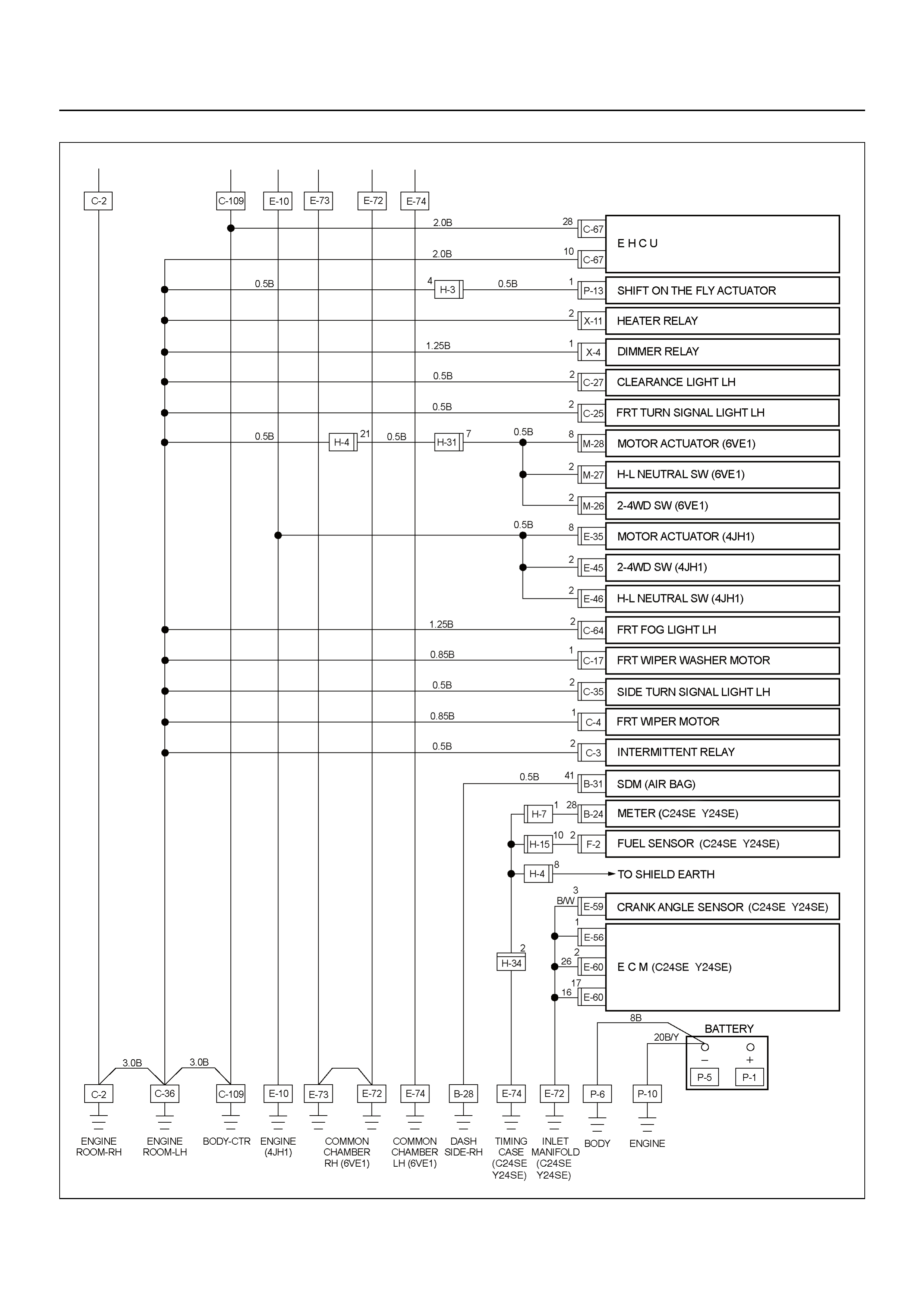
GROUND POINT CHART (1/4)
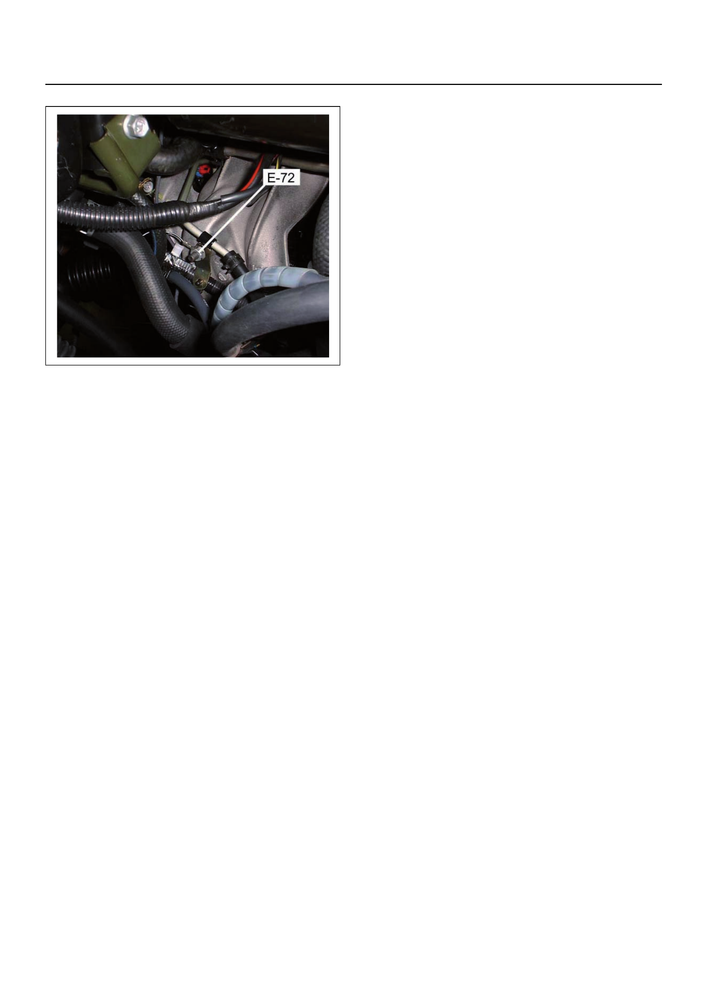
LOCATION
CABLE HARNESS & CONNECTOR
LOCATION
CONNECTOR LIST
RELAY AND FUSE
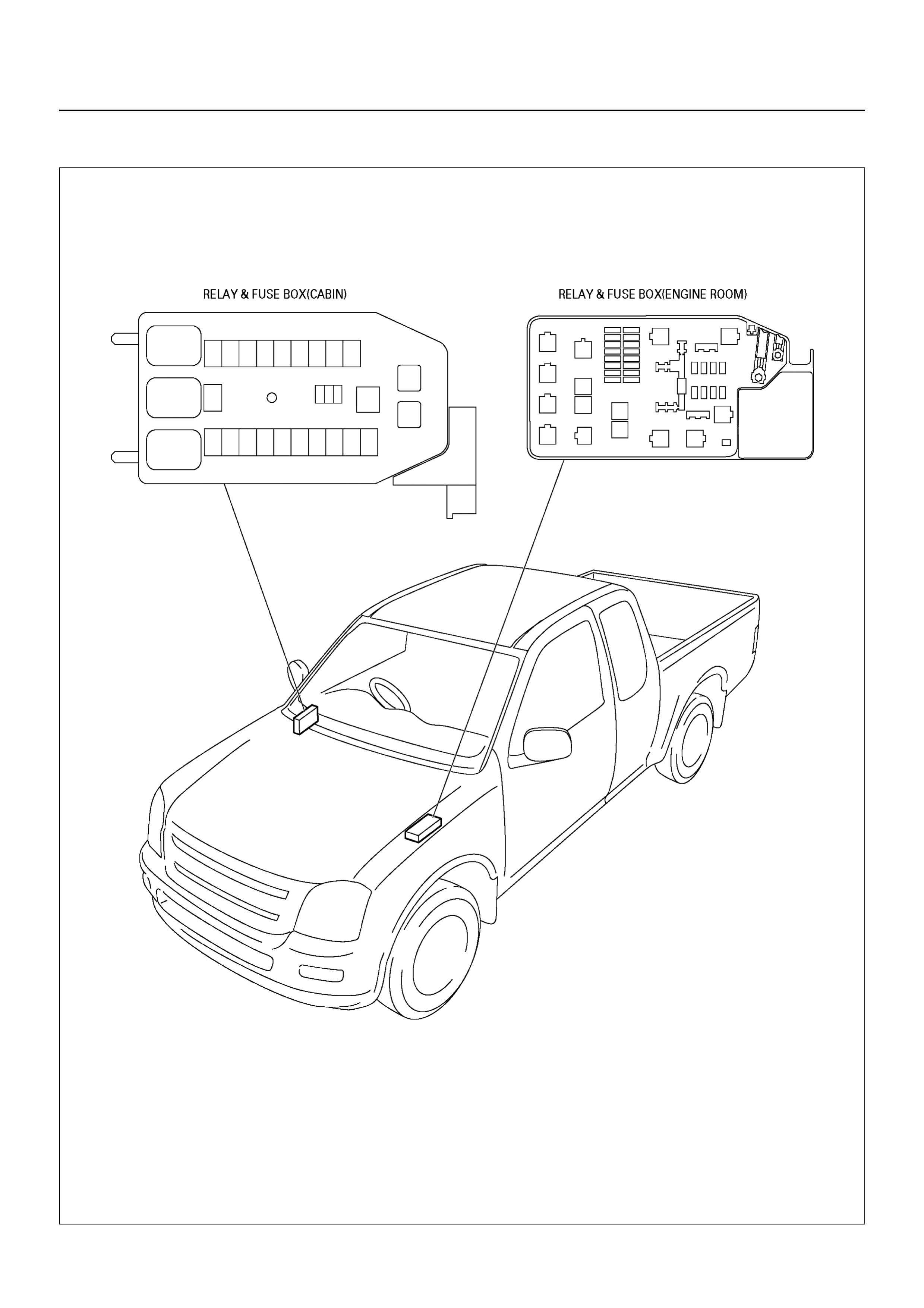
RELAY AND FUSE BOX LOCATION
RELAY AND FUSE BOX LOCATION
FUSE AND RELAY LOCATION
ECM WIRING DIAGRAM (1/8)
ECM WIRING DIAGRAM (2/8)
ECM WIRING DIAGRAM (3/8)
ECM WIRING DIAGRAM (4/8)
ECM WIRING DIAGRAM (5/8)
ECM WIRING DIAGRAM (6/8)
ECM WIRING DIAGRAM (7/8)
ECM WIRING DIAGRAM (8/8)
ECM CONNECTOR PIN ASSIGNMENT &
OUTPUT SIGNAL
GENERAL DESCRIPTION FOR ECM AND
SENSORS
Engine Control Module (ECM)
Manifold Absolute Pressure (MAP) Sensor
Throttle Position Sensor (TPS)
Idle Air Control (IAC) Valve
Crankshaft Position (CKP) Sensor
Knock (KS) Sensor
Engine Coolant Temperature (ECT) Sensor
Intake Air Temperature (IAT) Sensor
Vehicle Speed Sensor (VSS)
Heated Oxygen (O2) Pre Sensor
Heated Oxygen (O2) Post Sensor
Vertical G (RRID) Sensor
GENERAL DESCRIPTION FOR FUEL
METERING
Battery Voltage Correction Mode
Clear Flood Mode
Deceleration Fuel Cutoff (DFCO) Mode
Engine Speed/ Vehicle Speed/ Fuel Disable
Mode
Acceleration Mode
Fuel Cutoff Mode
Starting Mode
Run Mode
Fuel Metering System Components
Fuel Injector
Fuel Pressure Regulator
Fuel Rail
Fuel Pump Electrical Circuit
Throttle Body Unit
GENERAL DESCRIPTION FOR ELECTRIC
IGNITION SYSTEM
Spark Plug
GENERAL DESCRIPTION FOR EVAPORATIVE
EMISSION SYSTEM
EVAP Emission Control System Purpose
EVAP Emission Control System Operation
System Fault Detection
POSITIVE CRANKCASE VENTILATION (PCV)
SYSTEM
Crankcase Ventilation System Purpose
A/C CLUTCH DIAGNOSIS
A/C Clutch Circuit Operation
A/C Clutch Circuit Purpose
A/C Request Signal
HOLDEN STRATEGY BASED DIAGNOSTICS
Overview
STRATEGY BASED DIAGNOSTICS CHART
Diagnostic Thought Process
1. Verify the Complaint
2. Perform Preliminary Checks
3. Check Bulletins and Troubleshooting
Hints
4. Perform Service Manual Diagnostic
Checks
5a and 5b. Perform Service Manual Diagnostic
Procedures
5c. Technician Self Diagnoses
5d. Intermittent Diagnosis
5e. Vehicle Operates as Designed
6. Re-examine the complaint
7. Repair and Verify Fix
GENERAL SERVICE INFORMATION
On-Board Diagnostic (OBD)
On-Board Diagnostic Tests
The Diagnostic Executive
Diagnostic Information
Malfunction Indicator (Check Engine) Lamp
Data Link Connector (DLC)
SECTION 6E

Verifying Vehicle Repair
Reading Diagnostic Trouble Codes Using
Tech 2
Diagnosis with Tech 2
Tech 2 Operating Flow Chart (Start Up)
TYPICAL SCAN DATA & DEFINITIONS
(ENGINE DATA)
ACTUATOR TEST
ECU Control
Injector Cutoff Test
PLOTTING SNAPSHOT GRAPH
Plotting Graph Flow Chart (Plotting graph after
obtaining vehicle information)
Flow Chart for Snapshot Replay
(Plotting Graph)
SNAPSHOT DISPLAY WITH TIS2000
SERVICE PROGRAMMING SYSTEM (SPS)
HOW TO USE BREAKER BOX
Breaker Box Connection Type A
Breaker Box Connection Type B
ON-BOARD DIAGNOSTIC (OBD) SYSTEM
CHECK
Circuit Description
Diagnostic Aids
Test Description
ON-BOARD DIAGNOSTIC (OBD) SYSTEM
CHECK
NO CHECK ENGINE LAMP (MIL)
Circuit Description
Diagnostic Aids
No Check Engine Lamp (MIL)
CHECK ENGINE LAMP (MIL) “ON”
STEADY
Circuit description
Diagnostic Aids
Check Engine Lamp (MIL) “ON” Steady
NO SERVICE VEHICLE SOON LAMP (SVS)
Circuit description
Diagnostic Aids
NO SERVICE VEHICLE SOON LAMP (SVS)
SERVICE VEHICLE SOON (SVS) “ON”
STEADY
Circuit description
Diagnostic Aids
Service Vehicle Soon (SVS) “ON”
Steady
FUEL METERING SYSTEM CHECK
FUEL INJECTOR COIL TEST PROCEDURE
AND FUEL INJECTOR BALANCE TEST
PROCEDURE
Test Description
Injector Coil Test Procedure (Steps 1-6)
and Injector Balance Test Procedure
(Steps 7-11)
Injector Coil Test Procedure (Steps 1-6)
and Injector Balance Test Procedure
(Steps 7-11)
FUEL SYSTEM ELECTRICAL TEST
Circuit Description
Diagnostic Aids
Fuel Pressure Relief Procedure
Fuel Pressure Gauge Installation
Fuel System Electrical Test 8
FUEL SYSTEM DIAGNOSIS
Circuit Description
Test Description
Fuel Pressure Relief Procedure
Fuel Pressure Gauge Installation
Fuel System Diagnosis
ECM DIAGNOSTIC TROUBLE CODES
(DTC)
DTC DIAGNOSTIC TABLE
DIAGNOSTIC TROUBLE CODE (DTC) P0107
MANIFOLD ABSOLUTE PRESSURE
CIRCUIT LOW INPUT
Circuit Description
Diagnostic Aids
Diagnostic Trouble Code (DTC) P0107
Manifold Absolute Pressure Circuit Low
Input
DIAGNOSTIC TROUBLE CODE (DTC) P0108
MANIFOLD ABSOLUTE PRESSURE CIRCUIT
HIGH INPUT
Circuit Description
Diagnostic Aids
Diagnostic Trouble Code (DTC) P0108
Manifold Absolute Pressure Circuit High
Input
DIAGNOSTIC TROUBLE CODE (DTC) P0112
INTAKE AIR TEMPERATURE SENSOR LOW
INPUT
Circuit Description
Diagnostic Aids
Diagnostic Trouble Code (DTC) P0112
Intake Air Temperature Sensor Low
Input
DIAGNOSTIC TROUBLE CODE (DTC) P0113
INTAKE AIR TEMPERATURE SENSOR
HIGH INPUT
Circuit Description
Diagnostic Aids
Diagnostic Trouble Code (DTC) P0113
Intake Air Temperature Sensor High Input

DIAGNOSTIC TROUBLE CODE (DTC) P0117
ENGINE COOLANT TEMPERATURE
SENSOR LOW INPUT
Circuit Description
Diagnostic Aids
Diagnostic Trouble Code (DTC) P0117
Engine Coolant Temperature Sensor Low
Input
DIAGNOSTIC TROUBLE CODE (DTC) P0118
ENGINE COOLANT TEMPERATURE
SENSOR HIGH INPUT
Circuit Description
Diagnostic Aids
Diagnostic Trouble Code (DTC) P0118
Engine Coolant Temperature Sensor High
Input
DIAGNOSTIC TROUBLE CODE (DTC) P0122
THROTTLE POSITION SENSOR LOW
INPUT
Circuit Description
Diagnostic Aids
Diagnostic Trouble Code (DTC) P0122
Throttle Position Sensor Low Input
DIAGNOSTIC TROUBLE CODE (DTC) P0123
THROTTLE POSITION SENSOR HIGH
INPUT
Circuit Description
Diagnostic Aids
Diagnostic Trouble Code (DTC) P0123
Throttle Position Sensor High Input
DIAGNOSTIC TROUBLE CODE (DTC) P0131
O2 SENSOR CIRCUIT LOW VOLTAGE
(BANK 1 SENSOR 1 PRE)
Circuit Description
Diagnostic Aids
Diagnostic Trouble Code (DTC) P0131
O2 Sensor Circuit Low Voltage
(Bank 1 Sensor 1 PRE)
DIAGNOSTIC TROUBLE CODE (DTC) P0132
O2 SENSOR CIRCUIT HIGH VOLTAGE
(BANK 1 SENSOR 1 PRE)
Circuit Description
Diagnostic Aids
Diagnostic Trouble Code (DTC) P0132
O2 Sensor Circuit High Voltage
(Bank 1 Sensor 1 PRE)
DIAGNOSTIC TROUBLE CODE (DTC) P0134
O2 SENSOR NO ACTIVITY DEFECTED
CIRCUIT (BANK 1 SENSOR 1 PRE)
Circuit Description
Diagnostic Aids
Diagnostic Trouble Code (DTC) P0134
O2 Sensor Circuit No Activity Detected
(Bank 1 Sensor 1 PRE)
DIAGNOSTIC TROUBLE CODE (DTC) P0135
O2 SENSOR HEATER CIRCUIT
(BANK 1 SENSOR 1 PRE)
Circuit Description
Diagnostic Aids
Diagnostic Trouble Code (DTC) P0135
O2 Sensor Heater Circuit
(Bank 1 Sensor 1 PRE)
DIAGNOSTIC TROUBLE CODE (DTC) P0137
O2 SENSOR CIRCUIT LOW VOLTAGE
(BANK 1 SENSOR 2 POST)
Circuit Description
Diagnostic Aids
Diagnostic Trouble Code (DTC) P0137
O2 Sensor Circuit Low Voltage
(Bank 1 Sensor 2 POST)
DIAGNOSTIC TROUBLE CODE (DTC) P0138
O2 SENSOR CIRCUIT HIGH VOLTAGE
(BANK 1 SENSOR 2 POST)
Circuit Description
Diagnostic Aids
Diagnostic Trouble Code (DTC) P0138
O2 Sensor Circuit High Voltage
(Bank 1 Sensor 2 POST)
DIAGNOSTIC TROUBLE CODE (DTC) P0140
O2 SENSOR NO ACTIVITY DEFECTED
CIRCUIT (BANK 1 SENSOR 2 POST)
Circuit Description
Diagnostic Aids
Diagnostic Trouble Code (DTC) P0140
O2 Sensor Circuit No Activity Detected
(Bank 1 Sensor 2 POST)
DIAGNOSTIC TROUBLE CODE (DTC) P0141
O2 SENSOR HEATER CIRCUIT
(BANK 1 SENSOR 2 POST)
Circuit Description
Diagnostic Aids
Diagnostic Trouble Code (DTC) P0141
O2 Sensor Heater Circuit
(Bank 1 Sensor 2 POST)
DIAGNOSTIC TROUBLE CODE (DTC) P0201
INJECTOR 1 CONTROL CIRCU IT
DIAGNOSTIC TROUBLE CODE (DTC) P0202
INJECTOR 2 CONTROL CIRCU IT
DIAGNOSTIC TROUBLE CODE (DTC) P0203
INJECTOR 3 CONTROL CIRCU IT
DIAGNOSTIC TROUBLE CODE (DTC) P0204
INJECTOR 4 CONTROL CIRCU IT
Circuit Description

Diagnostic Aids
Diagnostic Trouble Code (DTC) P0201
Injector 1 Control Circuit
Diagnostic Trouble Code (DTC) P0202
Injector 2 Control Circuit
Diagnostic Trouble Code (DTC) P0203
Injector 3 Control Circuit
Diagnostic Trouble Code (DTC) P0204
Injector 4 Control Circuit
DIAGNOSTIC TROUBLE CODE (DTC) P0325
KNOCK SENSOR (KS) CIRCUIT
MALFUNCTION
Circuit Description
Diagnostic Aids
Diagnostic Trouble Code (DTC) P0325
Knock Sensor Module Circuit
DIAGNOSTIC TROUBLE CODE (DTC) P0327
KNOCK SENSOR (KS) CIRCUIT LOW
INPUT
Circuit Description
Diagnostic Aids
Diagnostic Trouble Code (DTC) P0327
Knock Sensor Circuit
DIAGNOSTIC TROUBLE CODE (DTC) P0336
CRANKSHAFT POSITION (CKP) SENSOR
CIRCUIT RANGE/PERFORMANCE (58X)
DIAGNOSTIC TROUBLE CODE (DTC) P0337
CRANKSHAFT POSITION (CKP) SENSOR
CIRCUIT LOW INPUT (58X)
Circuit Description
Diagnostic Aids
Diagnostic Trouble Code (DTC) P0336
Crankshaft Position Sensor Circuit Range/
performance (58x)
Diagnostic Trouble Code (DTC) P0337
Crankshaft Position Sensor Circuit Low
Input (58x)
DIAGNOSTIC TROUBLE CODE (DTC) P0351
IGNITION 1 CONTROL CIRCUIT
DIAGNOSTIC TROUBLE CODE (DTC) P0352
IGNITION 2 CONTROL CIRCUIT
Circuit Description
Diagnostic Aids
Diagnostic Trouble Code (DTC) P0351
Ignition 1 Control Circuit
Diagnostic Trouble Code (DTC) P0352
Ignition 2 Control Circuit
DIAGNOSTIC TROUBLE CODE (DTC) P0443
EVAPORATIVE EMISSION (EVAP) CONTROL
SYSTEM PURGE CONTROL VALVE CIRCUIT
MALFUNCTION
Circuit Description
Diagnostic Aids
Diagnostic Trouble Code (DTC) P0443
Evap. Emission Control System Purge Control
Circuit
DIAGNOSTIC TROUBLE CODE (DTC) P0502
VEHICLE SPEED SENSOR (VSS) CIRCUIT
LOW INPUT
Circuit Description
Diagnostic Aids
Diagnostic Trouble Code (DTC) P0502 Vehicle
Speed Sensor Circuit Low Input
DIAGNOSTIC TROUBLE CODE (DTC) P0562
SYSTEM VOLTAGE LOW
Circuit Description
Diagnostic Aids
Diagnostic Trouble Code (DTC) P0562
System Voltage Low
DIAGNOSTIC TROUBLE CODE (DTC) P0563
SYSTEM VOLTAGE HIGH
Circuit Description
Diagnostic Aids
Diagnostic Trouble Code (DTC) P0563
System Voltage High
DIAGNOSTIC TROUBLE CODE (DTC) P0601
ECM MEMORY CHECKSUM
Circuit Description
Diagnostic Aids
Diagnostic Trouble Code (DTC) P0601
ECM Memory Checksum
DIAGNOSTIC TROUBLE CODE (DTC) P0602
PROGRAMMING ERROR
Circuit Description
Diagnostic Aids
Diagnostic Trouble Code (DTC) P0602
Programming Error
DTC P0650 MALFUNCTION INDICATOR
LAMP (MIL) CONTOROL CIRCUIT
MALFUNCTION
Circuit Description
Diagnostic Aids
Diagnostic Trouble Code (DTC) P0650
Malfunctio n Indi ca tor La m p (M IL ) Con tr ol
Circuit Malfunction
DIAGNOSTIC TROUBLE CODE (DTC) P1167
FUEL SUPPLY SYSTEM RICH DURING
DECELERATION FUEL CUT OFF
Circuit Description
Diagnostic Aids
Diagnostic Trouble Code (DTC) P1167
Fuel Supply System Rich During Deceleration
Fuel Cutoff

DIAGNOSTIC TROUBLE CODE (DTC) P1171
FUEL SUPPLY SYSTEM LEAN DURING
POWER ENRICHMENT
Circuit Description
Diagnostic Aids
Diagnostic Trouble Code (DTC) P1171
Fuel Supply System Lean During Power
Enrichment
DIAGNOSTIC TROUBLE CODE (DTC) P1391
RRID G Sen. Rationality
Circuit Description
Diagnostic Aids
Diagnostic Trouble Code (DTC) P1391
RRID G Sen. Rationality
DIAGNOSTIC TROUBLE CODE (DTC) P1392
RRID G Sen. Short Low
Circuit Description
Diagnostic Aids
Diagnostic Trouble Code (DTC) P1392
RRID G Sen. Short Low
DIAGNOSTIC TROUBLE CODE (DTC) P11393
RRID G Sen. Short High
Circuit Description
Diagnostic Aids
Diagnostic Trouble Code (DTC) P11393
RRID G Sen. Short High
DIAGNOSTIC TROUBLE CODE (DTC) P1625
ECM SYSTEM RESET
Circuit Description
Diagnostic Aids
Diagnostic Trouble Code (DTC) P1625
ECM System Reset
DIAGNOSTIC TROUBLE CODE (DTC) P1626
IMMOBILISER NO SIGNAL
Circuit Description
Diagnostic Aids
Diagnostic Trouble Code (DTC) P1626
Immobiliser No Signal
DIAGNOSTIC TROUBLE CODE (DTC) P1631
IMMOBILISER WRONG SIGNAL
Circuit Description
Diagnostic Aids
Diagnostic Trouble Code (DTC) P1631
Immobiliser Wrong Signal
DIAGNOSTIC TROUBLE CODE (DTC) P1648
WRONG SECURITY CODE ENTERED
Circuit Description
Diagnostic Aids
Diagnostic Trouble Code (DTC) P1648
Wrong Security Code Entered
DIAGNOSTIC TROUBLE CODE (DTC) P1649
IMMOBILISER FUNCTION NOT
PROGRAMMED
Circuit Description
Diagnostic Aids
Diagnostic Trouble Code (DTC) P1649
Immobiliser Function Not Programmed
DIAGNOSTIC TROUBLE CODE (DTC) P1693
TACHOMETER OUTPUT LOW VOLTAGE
Circuit Description
Diagnostic Aids
Diagnostic Trouble Code (DTC) P1693
Tachometer Output Low Voltage
SYMPTOM DIAGNOSIS
PRELIMINARY CHECKS
VISUAL/PHYSICAL CHECKS
INTERMITTEN T PRO B LE MS
ENGINE CRANKS BUT WILL NOT RUN
HARD START SYMPTOM
ROUGH, UNSTABLE, OR INCORRECT IDLE,
STALLING SYMPTOM
SURGES AND/OR CHUGS SYMPTOM
HESITATION, SAG, STUMBLE SYMPTOM
CUTS OUT, MISSES SYMPTOM
LACK OF POWER, SLUGGISH OR
SPONGY SYMPTOM
DETONATION/SPARK KNOCK SYMPTOM
POOR FUEL ECONOMY SYMPTOM
EXCESSIVE EXHAUST EMISSIONS OR
ODORS SYMPTOM
DIESELING, RUN-ON SYMPTOM
BACKFIRE SYMPTOM
ON-VEHICLE SERVICE PROCEDURE
ENGINE CONTROL MODULE (ECM)
CRANKSHAFT POSITION (CKP)
SENSOR
ENGINE COOLANT TEMPERATURE (ECT)
SENSOR
INTAKE AIR TEMPERATURE (IAT)
SENSOR
MANIFOLD ABSOLUTE PRESSURE (MAP)
SENSOR
THROTTLE POSITION SENSOR (TPS)
IDLE AIR CONTROL (IAC) VALVE
KNOCK SENSOR (KS)
VERTICAL-G (RRID) SENSOR
HEATED OXYGEN SENSOR (HO2S)
EVAP CANISTER PURGE VALVE
SOLENOID
FUEL PRESSURE RELIEF
FUEL RAIL ASSEMBLY
FUEL INJECTOR


ABBREVIATIONS CHARTS
Abbreviations Appellation
A/C Air Conditioner
A/T Automatic Transmission
ACC Accessory
BLK Black
BLU Blue
BRN Brown
CEL Check Engine Lamp
CKP Crankshaft Position
DLC Data Link Connector
DTC Diagnostic Trouble Code
DVM Digital Volt Meter
ECM Engine Control Module
ECT Engine Coolant Temperature
EEPROM Electrically Erasable & Programmable Read Only Memory
EVAP Evaporative Emission
EVRV Electric Vacuum Regulating Valve
EXH Exhaust
FT Fuel Temperature
GND Ground
GRY Grey
HO2S Heated Oxyge n Sens or
IAC Idle Air Control
IAT Intake Air Temperature
IG Ignition
ITP Intake Throttle Position
KS Knock Sensor
M/T Manual Transmission
MAP Manifold Absolute Pressure
MIL Malfunction Indicator Lamp
OBD On-Bo ar d Dia gn os tic
ORN Orange
OT Oil Temperature
PNK Pink
RED Red
SW Switch
TB Throttle Body
TEMP Temperature
TP Throttle Position
VSS Vehicle Speed Sensor
WHT White
YEL Yellow
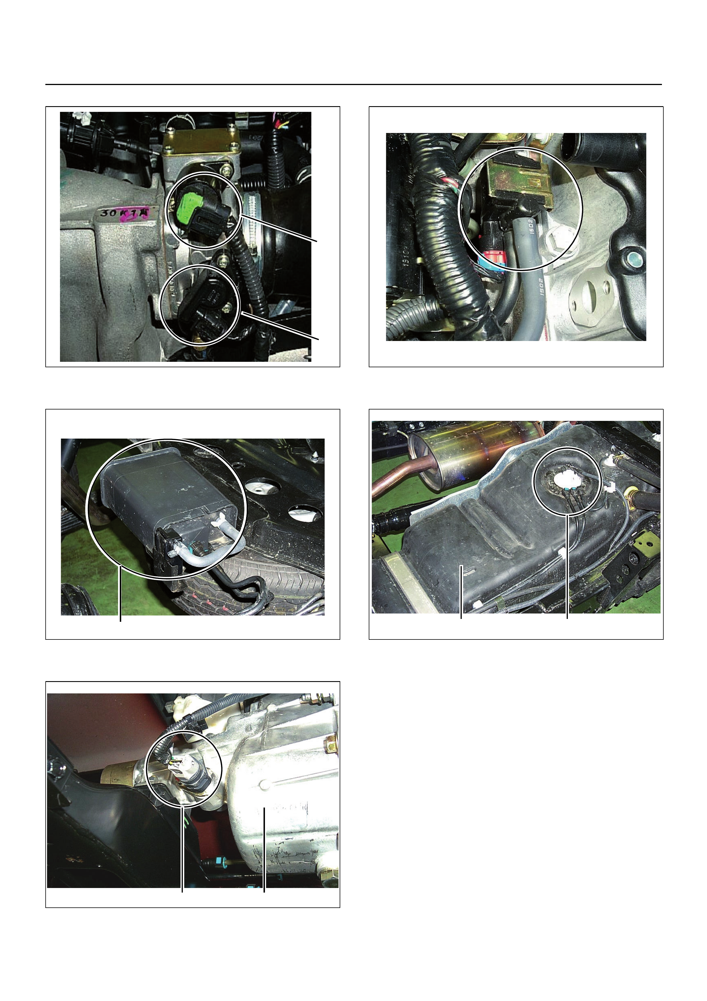
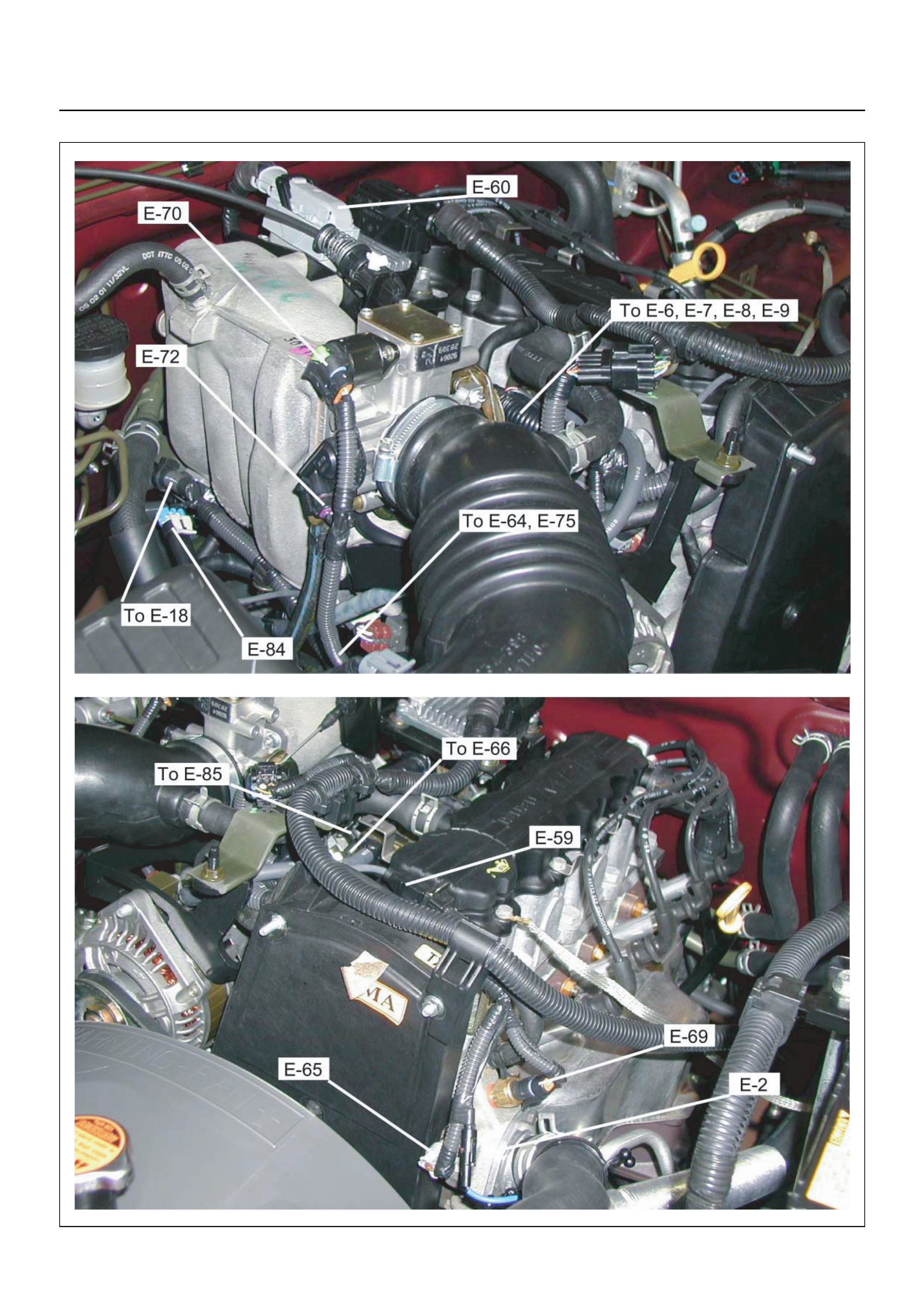
COMPONENT LOCATOR
EndOFCallout
21
1
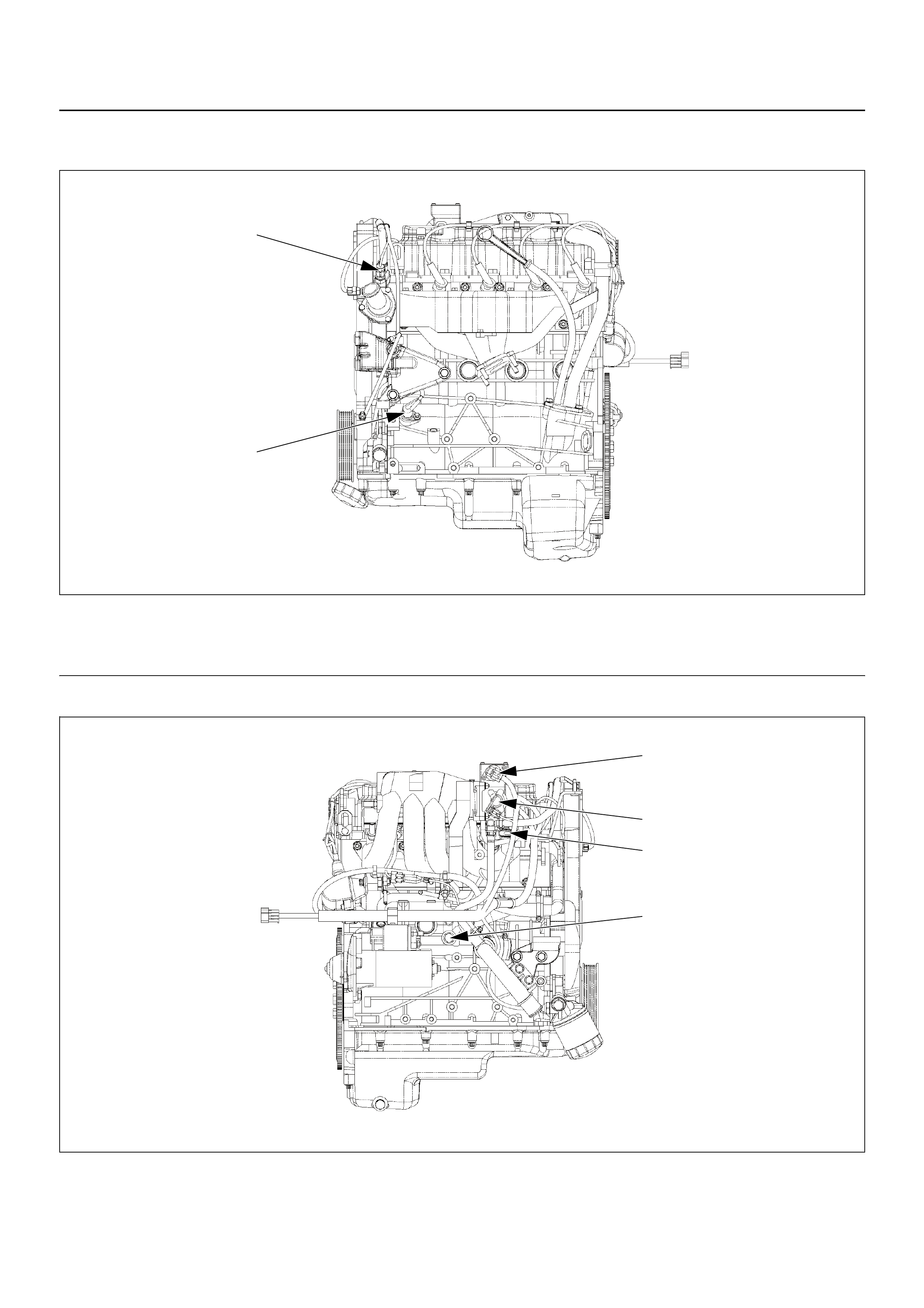
Legend
(1) Engine Coolant Tem p er at ur e (EC T) Sen sor
(2) Crankshaft Position (CKP) Sensor
1
1
2
3
4
Legend
(1) Idle Air Control (IAC) Valv e
(2) Throttle Position Sensor (TPS)
(3) Knock Sensor (KS)
(4) Manifold Absolute Pressure (MAP) Sensor
EndOFCallout
1
2
3
4
5
26
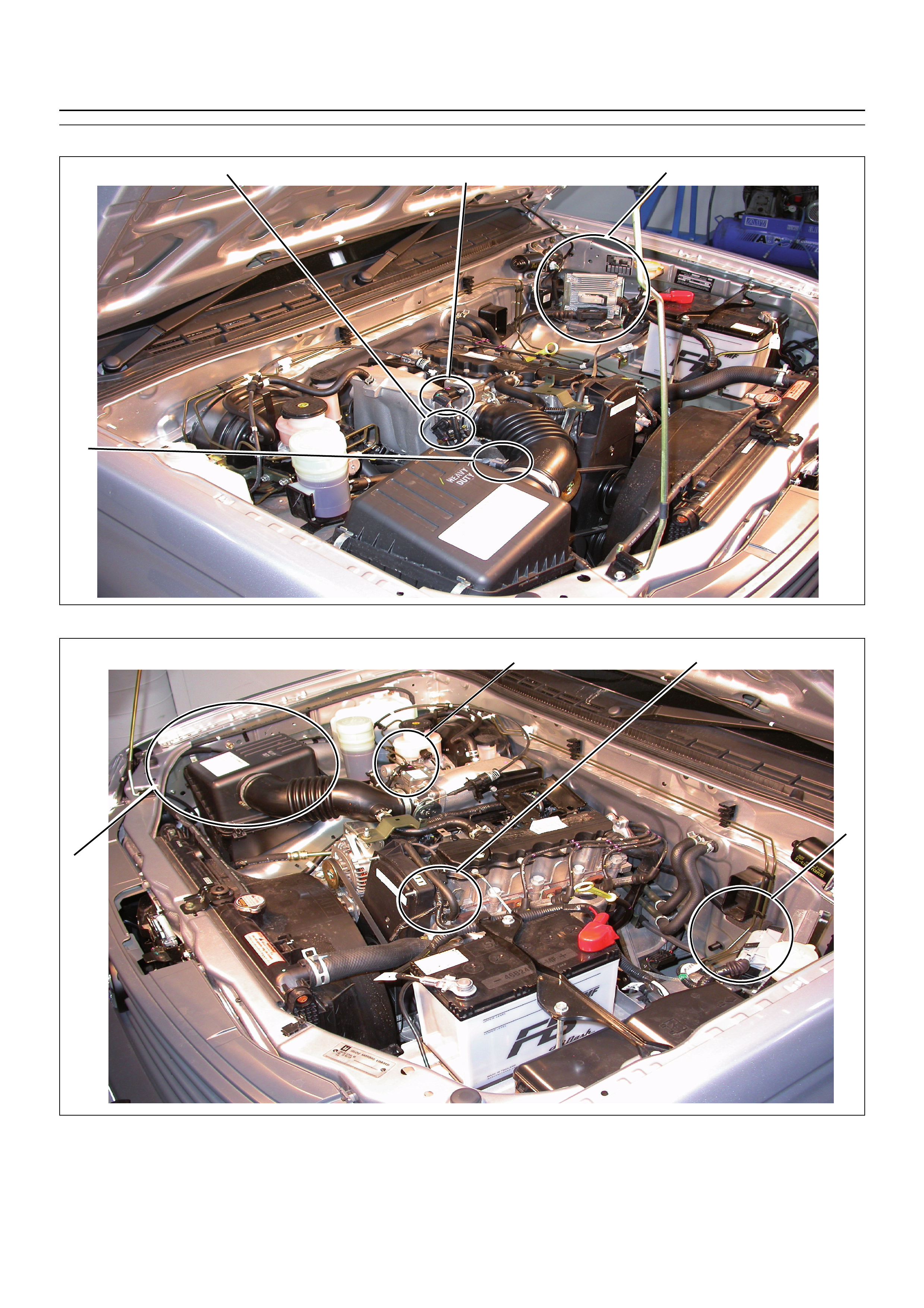
1
(1)
(2) Engine Control Module (ECM)
Idle Air Control (IAC) Valve
(3) Throttle Position Sensor (TPS)
(4)
(5) Intake Air Temperature (IAT) Sensor
Air Cleaner
(6) Engine Coolant Temperature (ECT) Sensor
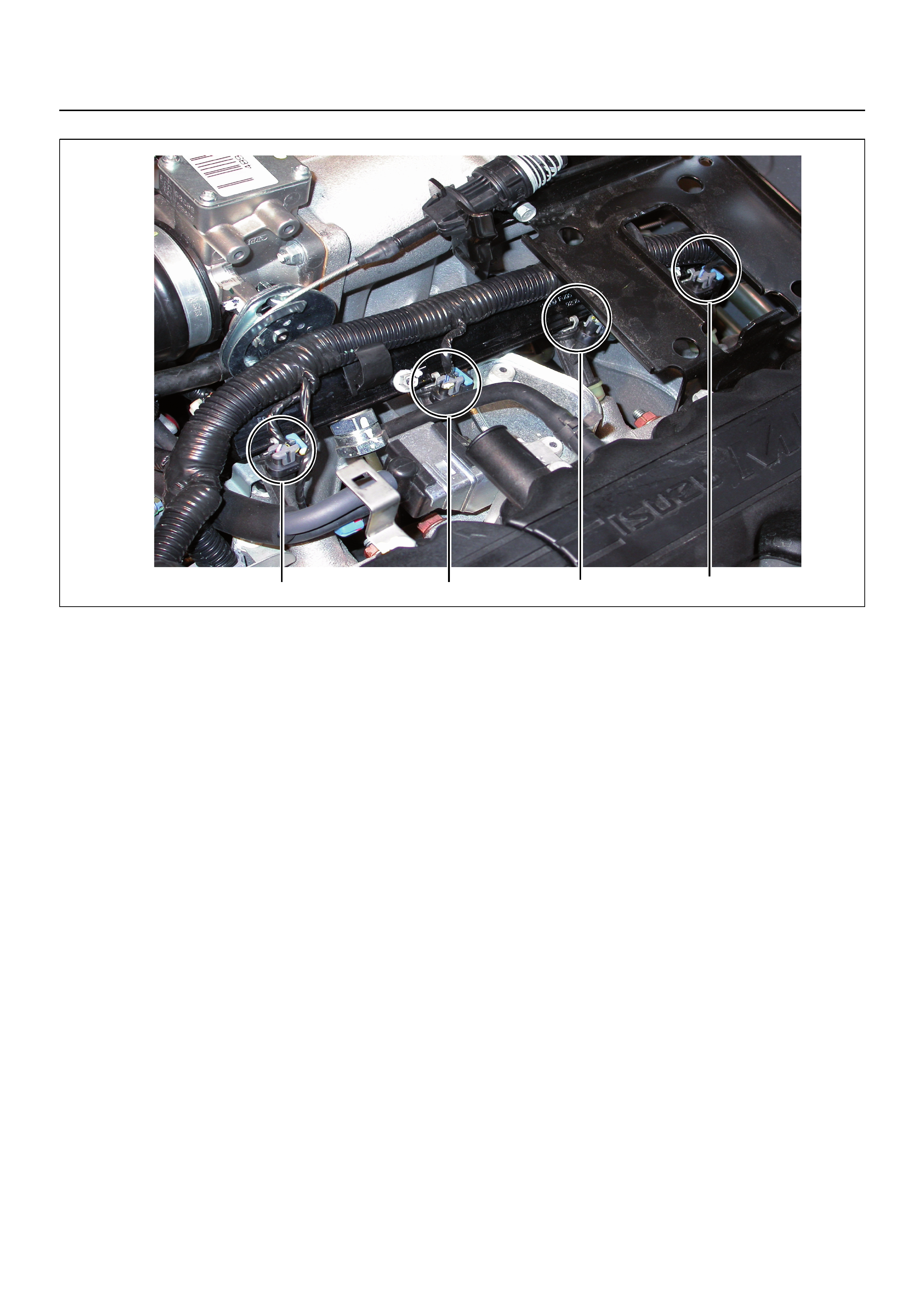
1234
(1)
(2) Injector #1 Cylinder
Injector #2 Cylinder (3)
(4) Injector #3 Cylinder (Under bracket)
Injector #4 Cylinder (Under bracket)
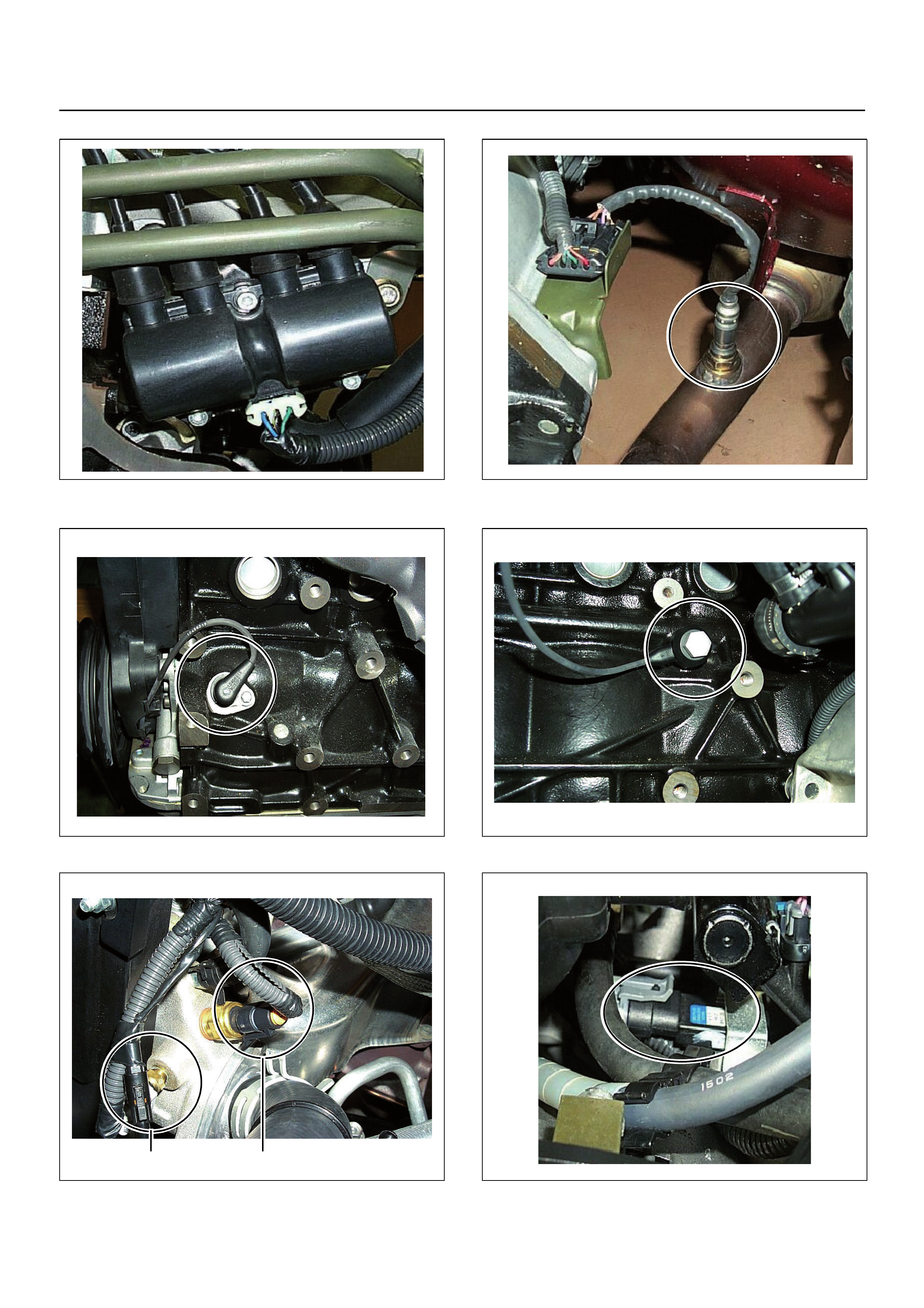
(1) Ignition Coil Module Assembly (1) Heated Oxygen Sensor Pre O2
(1) Crankshaft Position (CKP) Sensor (1) Knock Sensor (KS)
(1)
(2) Engine Coolant Temperature (ECT) Sensor
Thermo Meter Sensor
2 1
(1) Manifold Absolute Pressure (MAP) Sensor
(1)
(2) Throttle Position Sensor
Idle Air Control (IAC) Valve
2
1
(1) EVAP Purge Solenoid
(1) Canister
1
(1)
(2) Fuel Tank
Fuel Pump
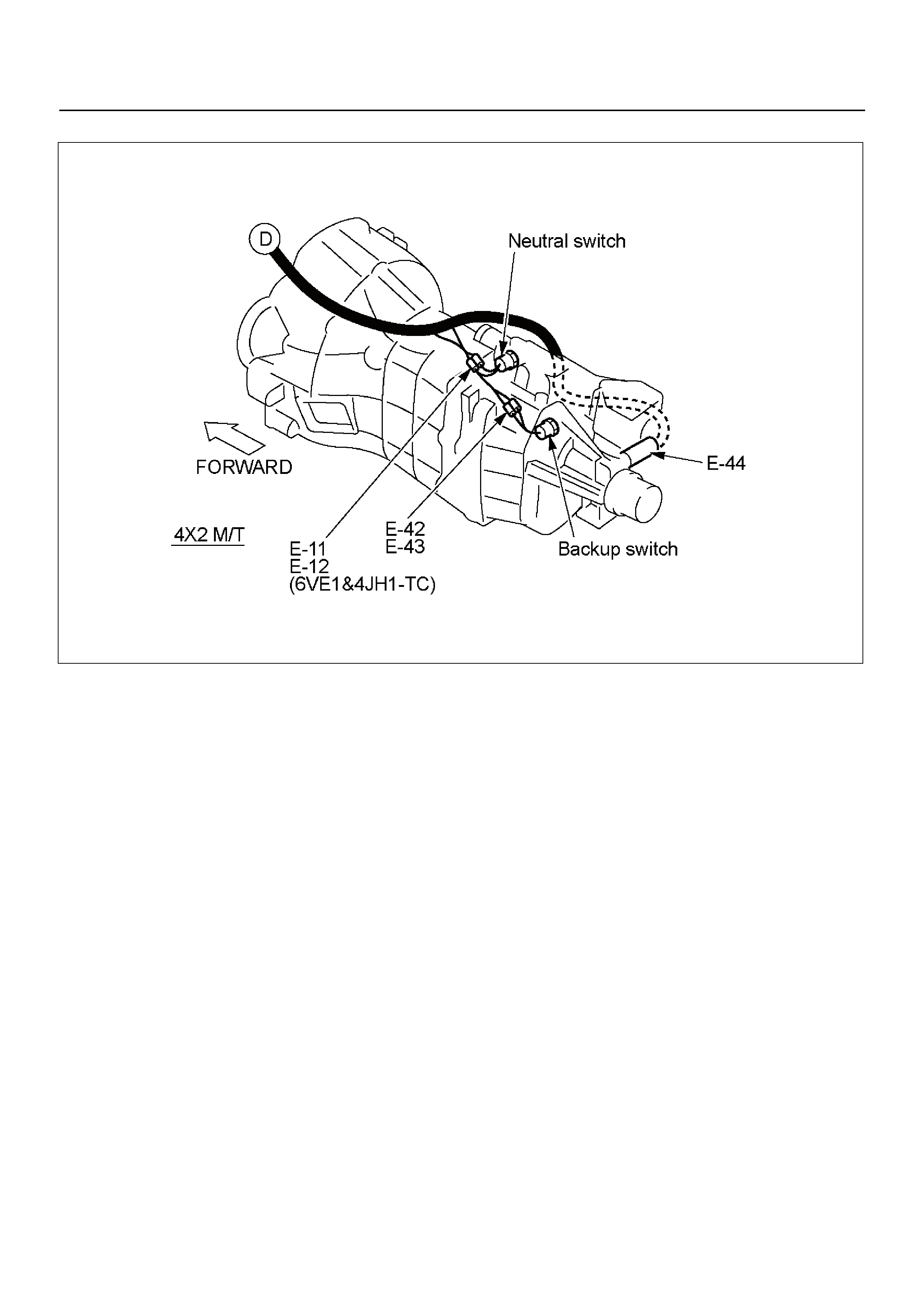
21
1 2
(1)
(2) Vehicle Speed Sensor (VSS)
Transmission Assembly
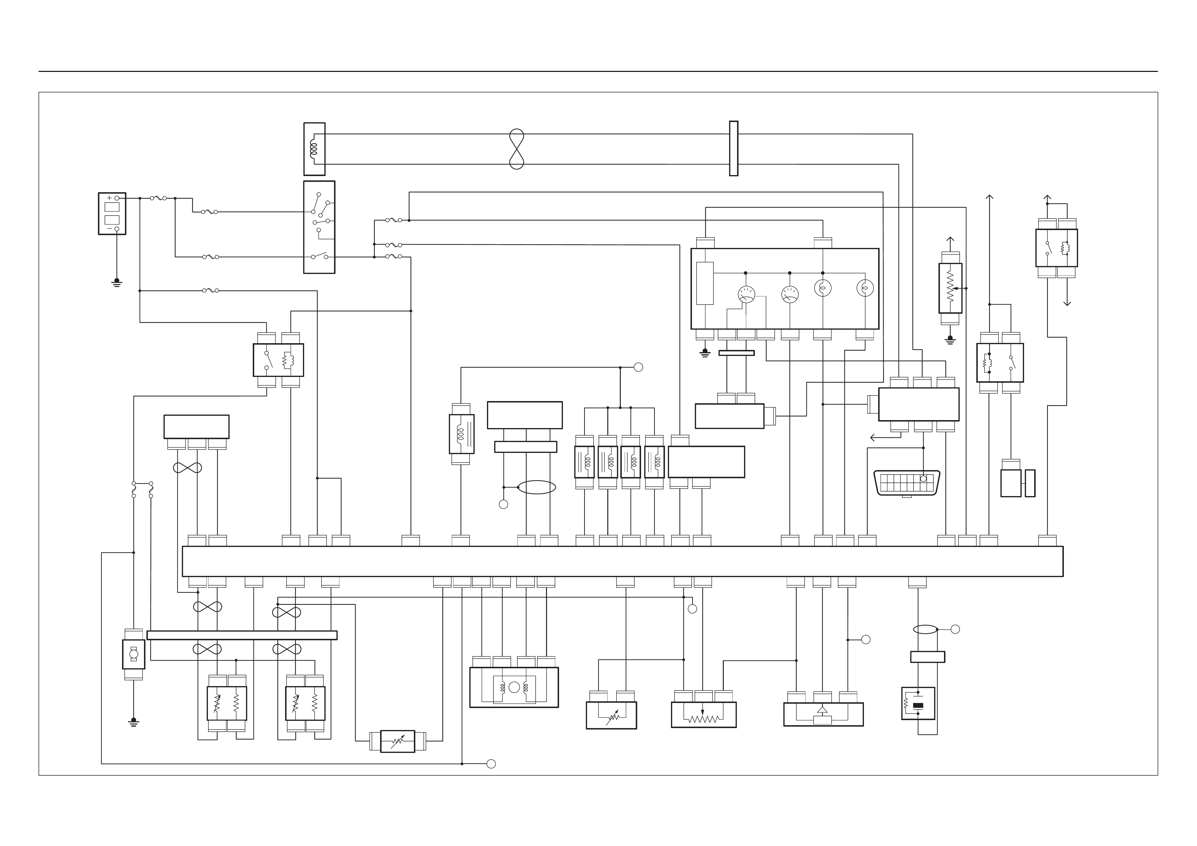
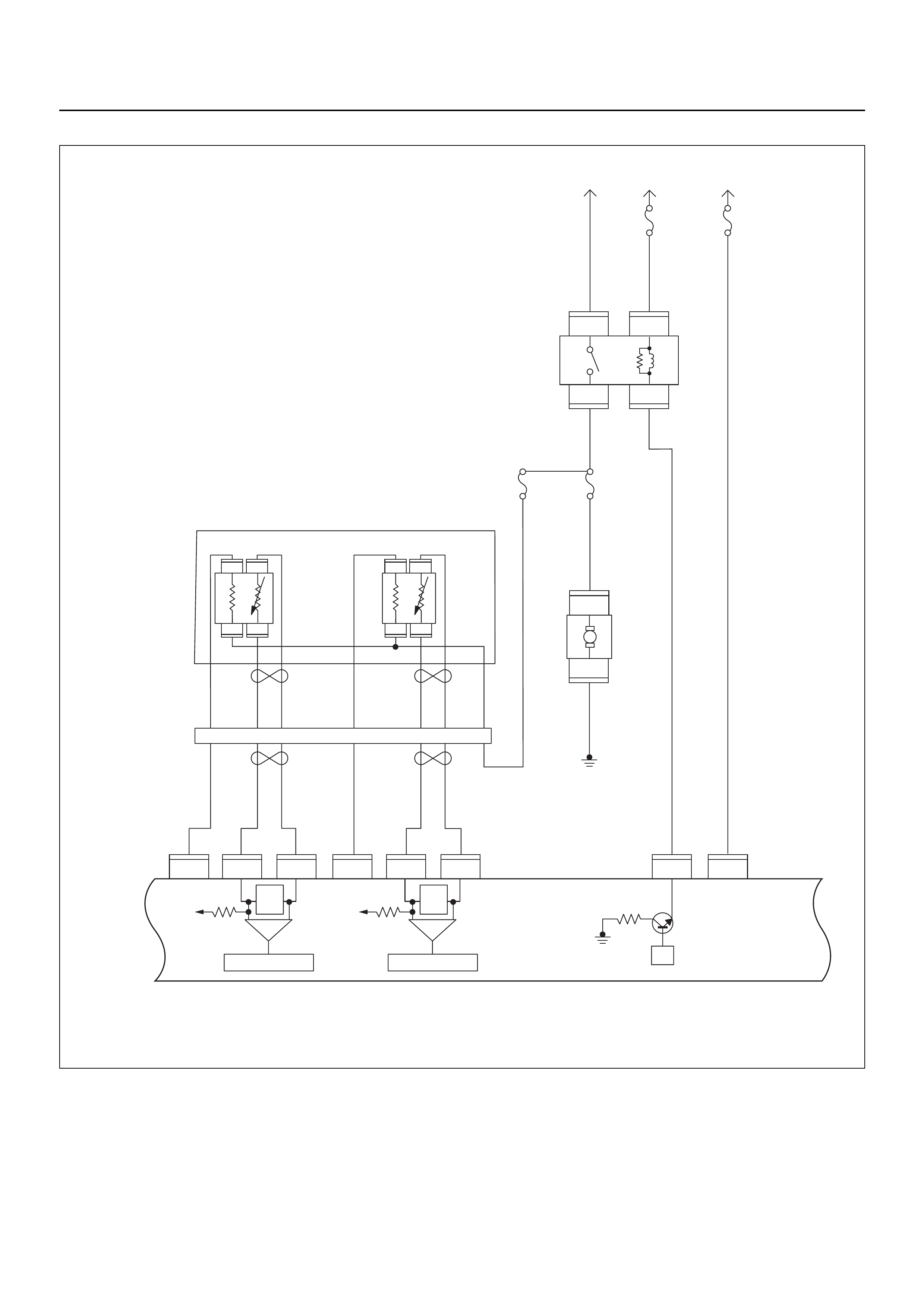
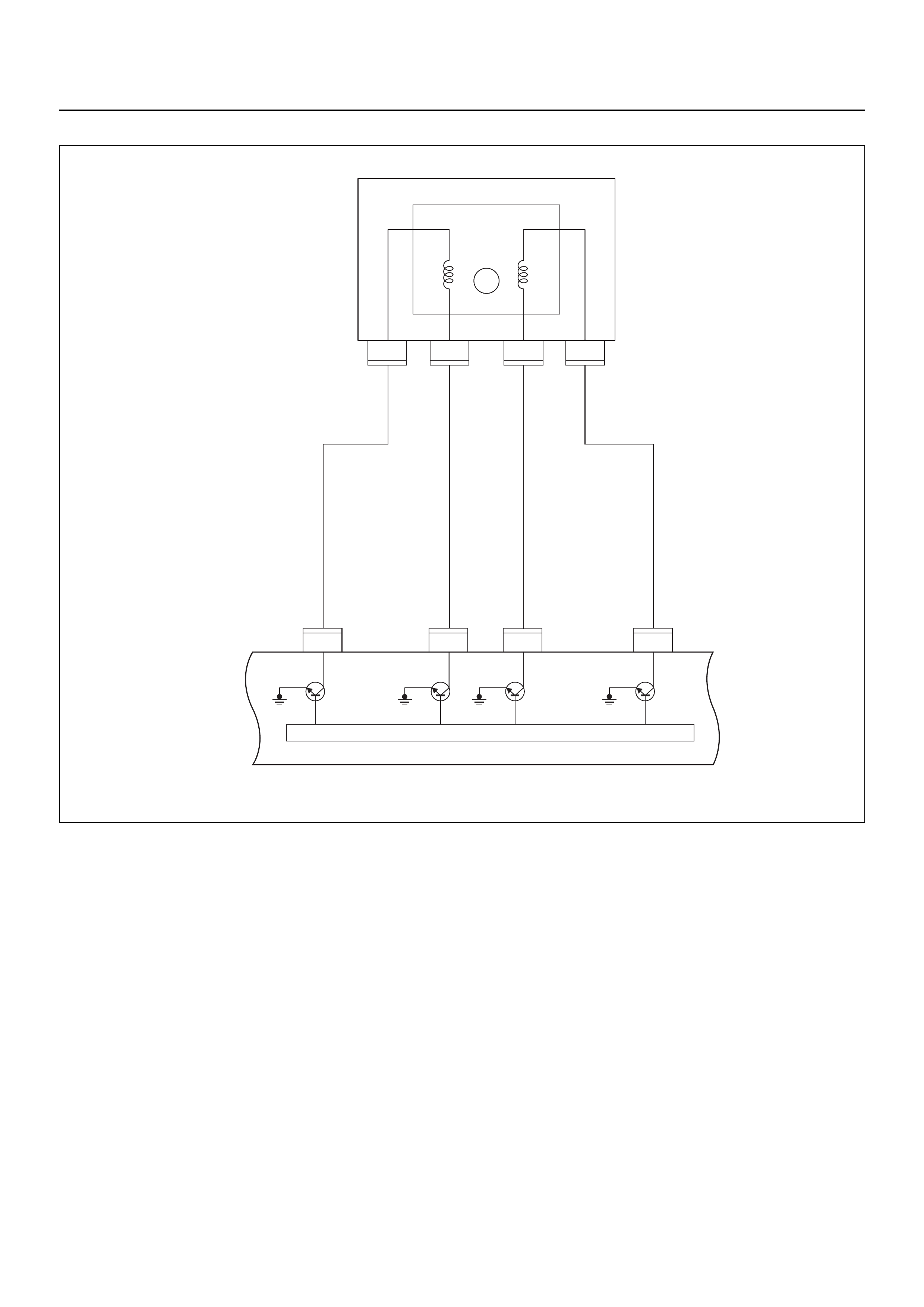
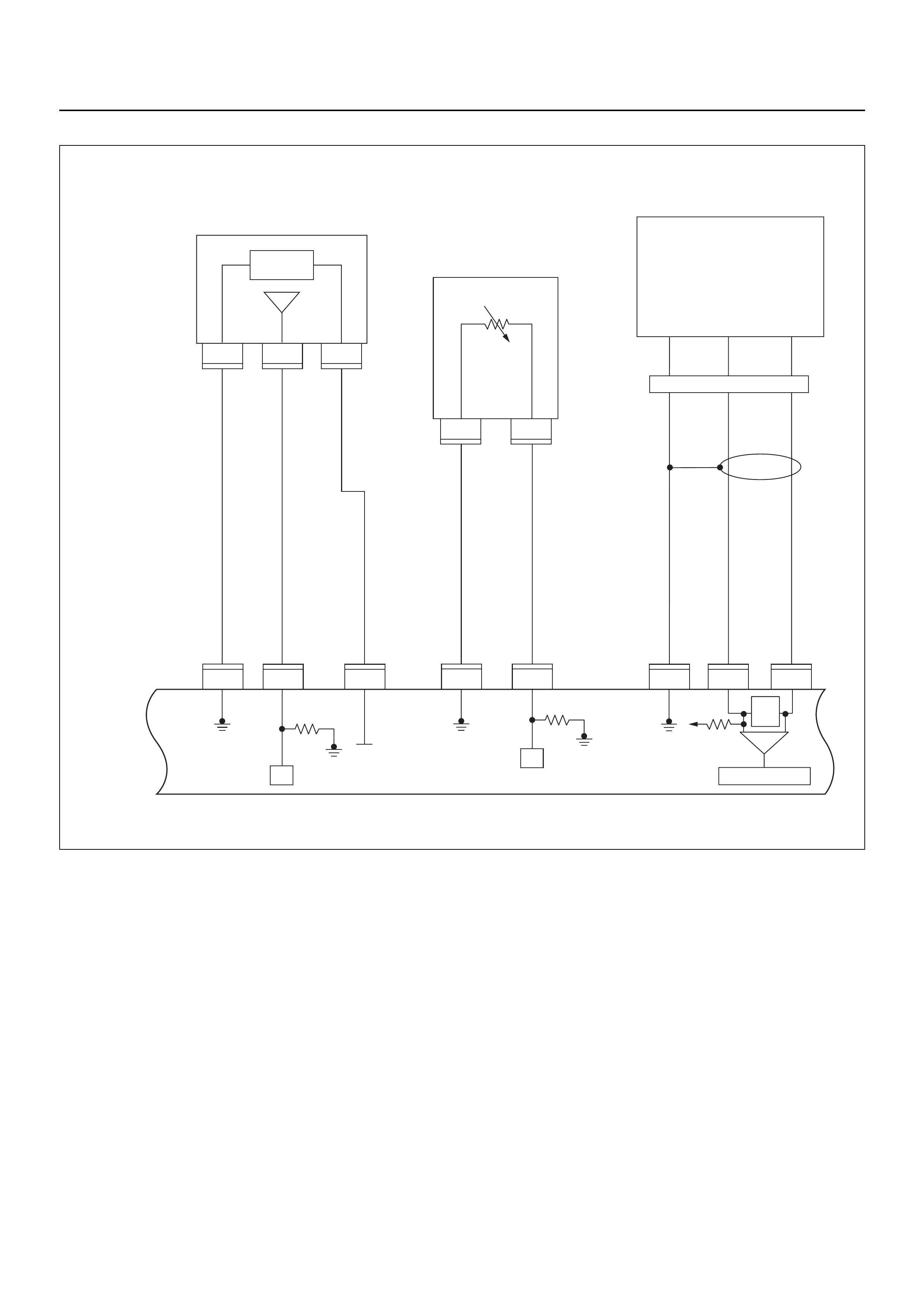
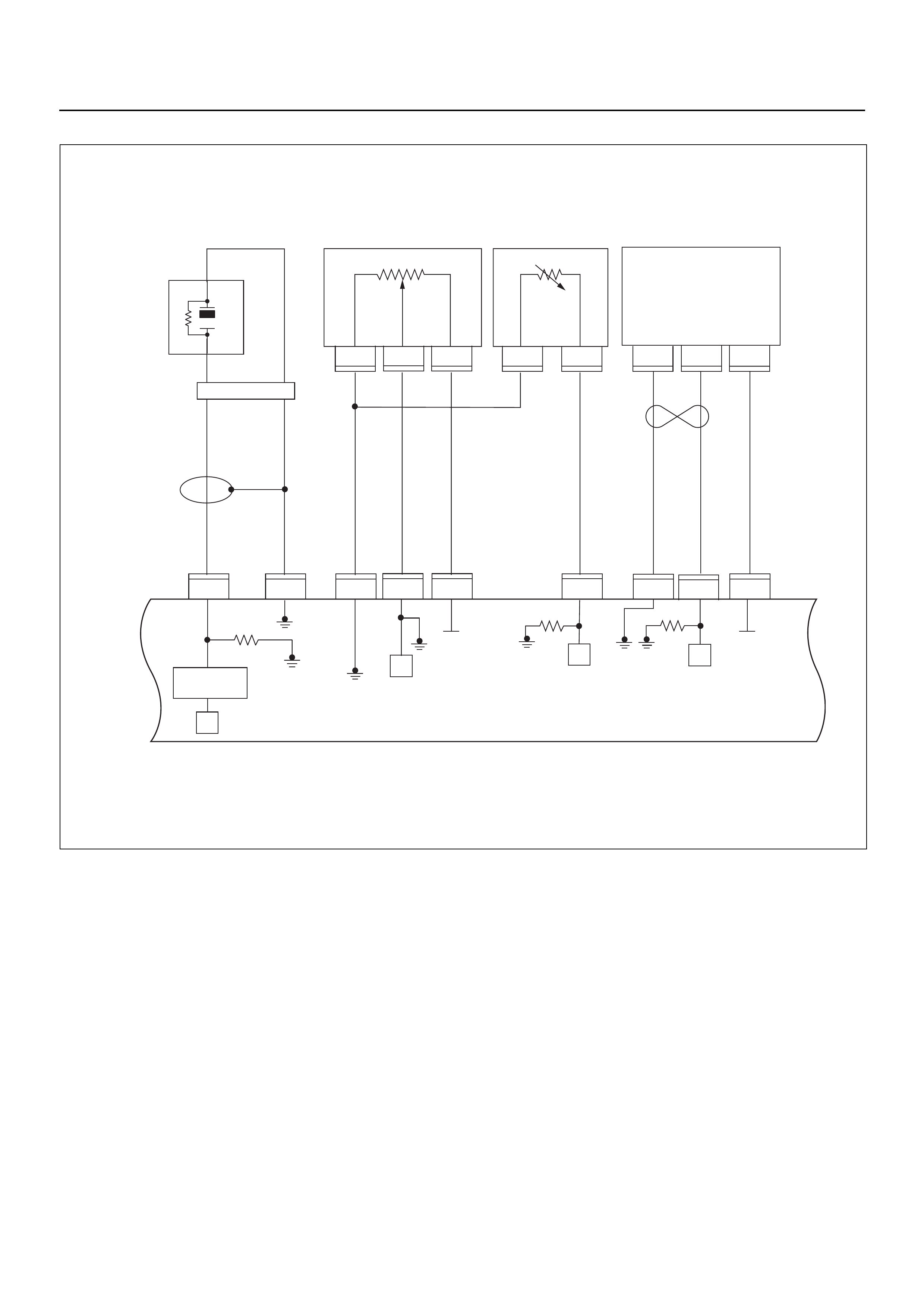
ECM CIRCUIT DIAGRAM
Immobiliser
Coil
(Antenna)
F2
F2
4
E69
2
E69
1
E68
1
E68
3
E68
2
E85
2
E85
3
E85
1
2
1
2
3
F2
F2
2
1111
E66
2
24
13
(+)
(–)
X2 X2
X2 X2
C56
321
17
C56
E78 E78E77 E77
25
1
E70
1
E70
2
E70
3
E70
4
1
2
C121
C121
C56
26
C56
3
C56
2
C56
18
E60
5
E60
21
E60
9
E60
22
E60
8
E60
11
E60
1
E60
17
E60
6
M
H31
HI
LO
HI
LO
AB
16151413121110987654321
E78 E78
C56
J2-1
J2-25 J2-17 J2-26 J2-2 J2-18 J2-3 J1-5 J1-6 J1-21 J1-9 J1-22 J1-8 J1-11 J1-1 J1-17 J2-9 J2-32 J2-13 J2-15 J2-7 J2-4 J2-28 J2-20
J2-21 J2-31 J1-28 J1-19 J1-23 J1-20 J1-13 J1-30 J1-29 J1-14 J1-27 J1-16 J1-7 J1-31 J1-24 J1-26
C56
121
C56 E60 E60
31 28 19
E60
23
E60
20
E60
13
E60
30
E60
29
E60
14
E60
27
E60
16
E60
7
E60
31
E60
24
E60
26
1
3
2
HI
Low Low
23
14
23
HI
GND LO
2
231
22231
5
7
8
27
(–)(+)
10
28 3 6
8
X15 X15
E66
1
C56
28
C56
B58
4
C56
7
C56
15
C56
32
C56
13
C56
9
1,4 2,3
3
3014
2
1
C56
20
6
2
X15X15
1
E2
1
X14
2
X14
1
X14
4
X14
3
43
B24B24
B24 B24 B24
11
B24B24 B24 B24
1
J1-3
3
E60
3
RO7_6E1010
B68B70B70
13
B68B68
1
B68
B68
E44
E18
E9E8E7E6
E9E8E7E6 E18 E18
E44
E44
HI 14
ABC
20A
IGN1
40A
ECM
15A
IGN2
50A
Main
100A
Meter
15A
Ign Coil
20A
Engine
15A
10A
E77 E77
F10 F10 F10
2
2.0
BLK
0.5
YEL/
RED
0.8
YEL/
GRN
0.85
YEL
2.0
BLK/
YEL
0.85
BLK/
YEL
3.0
WHT
2.0
WHT
3.0
BLK/
RED
3.0
WHT/
BLK
2.0
WHT
0.5
RED/
WHT
0.5
GRN/
WHT
0.5
BLU/
YEL
0.5
BLU/
YEL
0.85
RED/
WHT
0.5
BLK
2.0
BLU/
BLK
2.0
BLK
2.0
BLU/
BLK
0.5
BLU
WHT
2.0
RED/
GRN
0.5
ORG
0.5
PU
0.5
BRN
0.5
BLK
0.5
BLU/
ORG 0.5
YEL 0.5
ORG 0.5
BLK
0.5
BLU/
YEL
2.0
BLK/
RED
0.5
GRN
0.5
BRN
0.5
YEL
0.5
YEL
0.5
PU
0.5
BRN
0.5
BLK 0.5
BLK/
WHT
0.5
PINK 0.5
BLU/
BLK
0.5
BLU/
WHT
0.5
BLU/
YEL
0.85
GRN 0.85
BLU
0.5
GRN/
WHT
0.5
BLK/
RED
0.5
WHT
0.85
RED/
GRN
0.5
BRN/
RED
0.5
WHT 0.5
YEL/
RED
0.3
BRN/
YEL
0.5
BRN/
YEL
0.5
GRN/
WHT
0.5
BLK/
YEL
0.5
ORG/
BLU
0.5
YEL/
BLU
0.5
BRN/
YEL
0.5
GRN/
BLK
0.3
BLK/
YEL
0.5
YEL
0.5
BLU/
PUR
0.5
GRY/
BLU
0.5
GRY/
RED
0.5
YEL/
RED
0.5
YEL/
RED
0.5
WHT/
BLU
0.5
BLU/
ORG
0.5
YEL/
BLK
0.5
BLU/
RED
0.5
YEL/
GRN
0.5
YEL/
BLU
0.85
BLK/
BLU
0.5
YEL/
GRN 0.5
GRY
0.5
BLU/
ORG
E59
Meter
A/C
Pressure
Switch
A/C
Compressor
Relay
Thermo
Relay
IGN
SW
IGN
SW
IGN
SW
Coil Module
Vehicle Speed
Sensor (VSS)
Crankshaft
Position (CKP)
Sensor Injector
Fuel Rail
Battery
Fuel
Pump
Relay
SW Ignition
Vertical G-Sensor
Fuel
Pump
Idle Air
Control (IAC)
Valve
Knock
Sensor
Intake Air
Temperature
(IAT) Sensor
Fuel
Pump
O2
Sensor
Manifold
Absolute
Pressure (MAP)
Sensor
O2 Sensor
Pre
O2 Sensor
Post
Coolant
Temperature
(ECT)
Sensor
Throttle
Position (TPS)
Sensor
Magnetic
Clutch
Sensor
Immobiliser
Control Unit
(ICU)
Diagnostic
Connector
Starter
Relay
Engine Control Module (ECM)
EVAP
Purge
Solenoid
Valve
Fuel
Sender
Unit
MIL
Lamp
SVS
Lamp
Speedo
Meter
Tacho
Meter
CPU
OFF
ACC
IGN2
ST
IGN1
E84

GROUND POINT CHART (1/4)
GROUND POINT CHART (2/4)
GROUND POINT CHART (3/4)
GROUND POINT CHART (4/4)
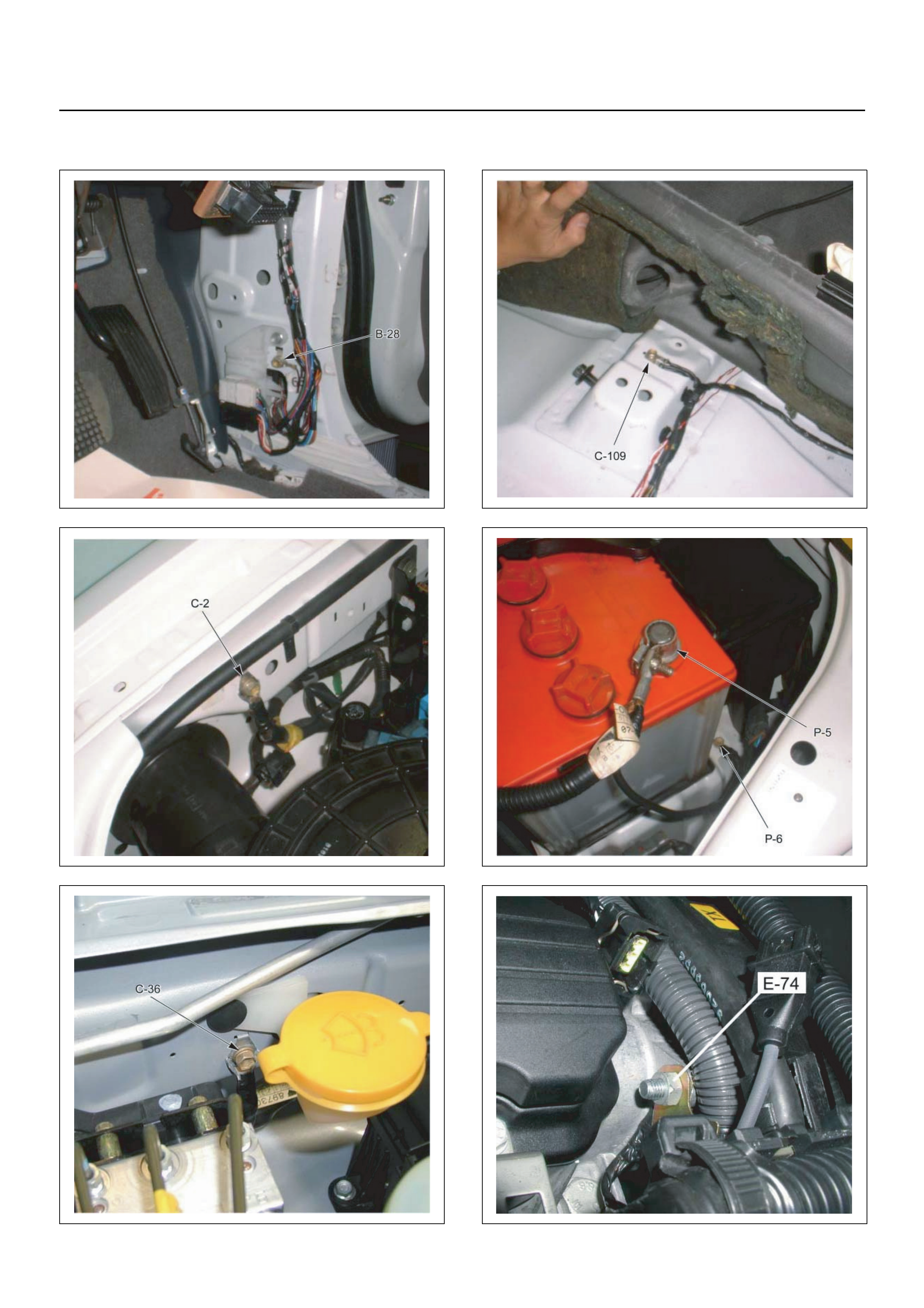
LOCATION
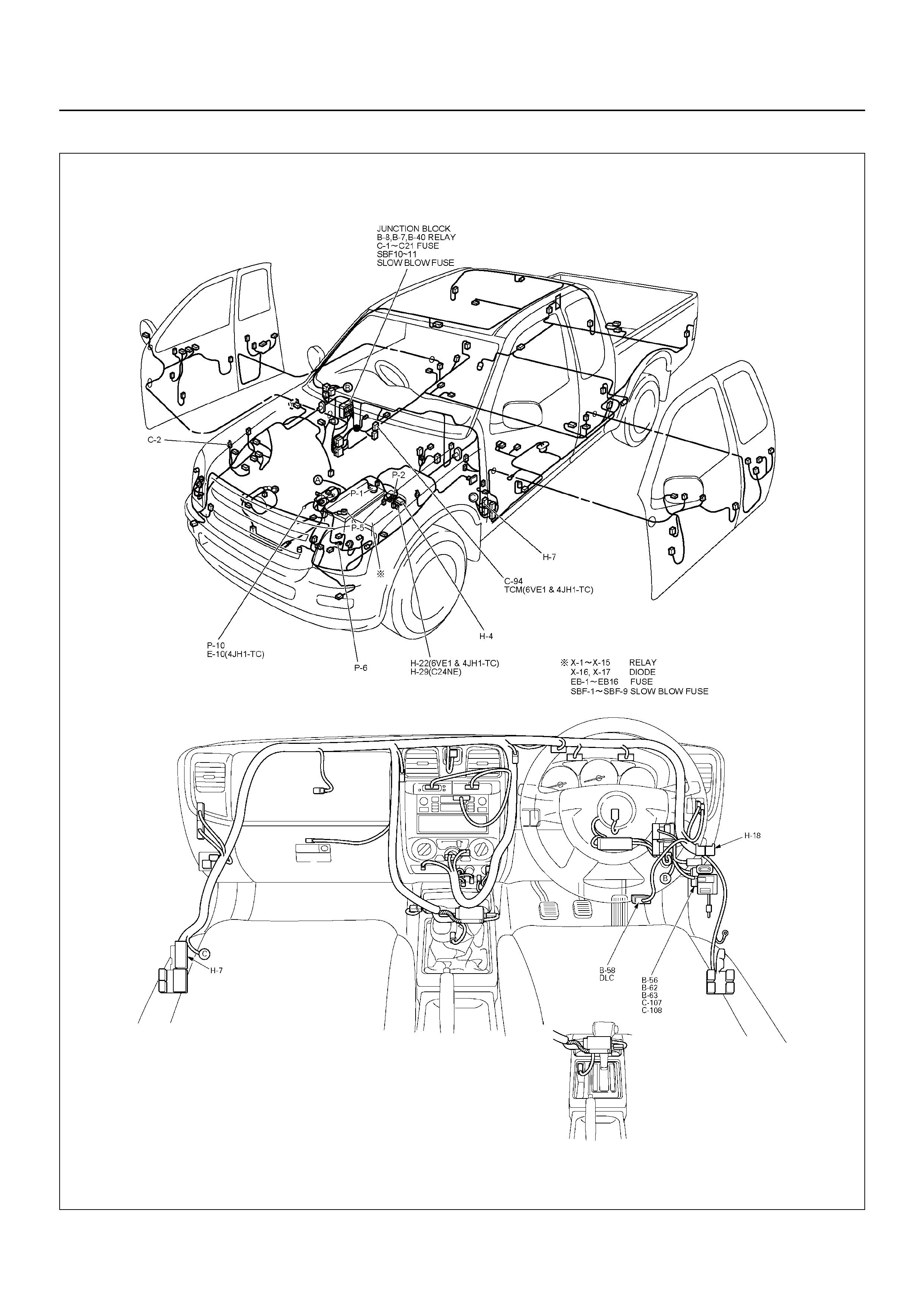
CABLE HARNESS & CONNECTOR LOCATION
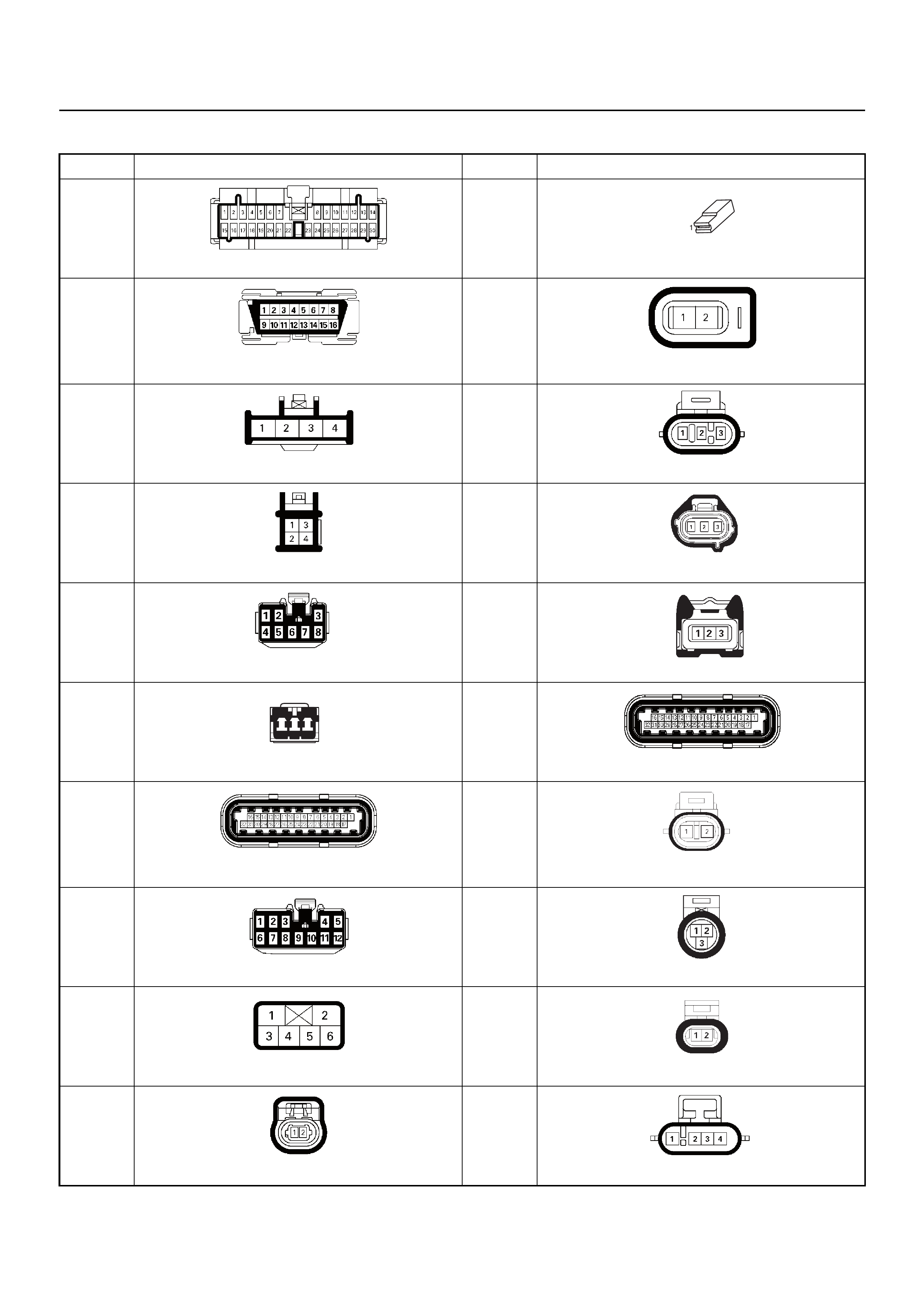
CONNECTOR LIST
No. Connector face No. Connector face
B-24
Green Meter
E-2
Magnetic Clutch Sensor
B-58
Black Diagnostic Connector
E-6
E-7
E-8
E-9
Grey Fuel Injector
B-62
White Ignition Switch (IGSUB : G1)
E-18
Ignition Coil Module
B-63
White Ignition Switch (IGSUB : G2)
E-44
Vehicle Speed Sensor
B-68
White Immobiliser
E-59
Crankshaft Position Sensor
B-70
White Immobiliser Coil Antenna
E-60
ECM
C-56
ECM
E-66
EVAP Canister Purge Valve
C-107
White J/B E2
E68
Throttle Position Sensor (TPS)
C-108
White J/B E1
E-69
Coolant Temper ature Sensor (EC T)
C-121
IAT Sensor
E-70
Idle Air Control Valve (IAC)
123
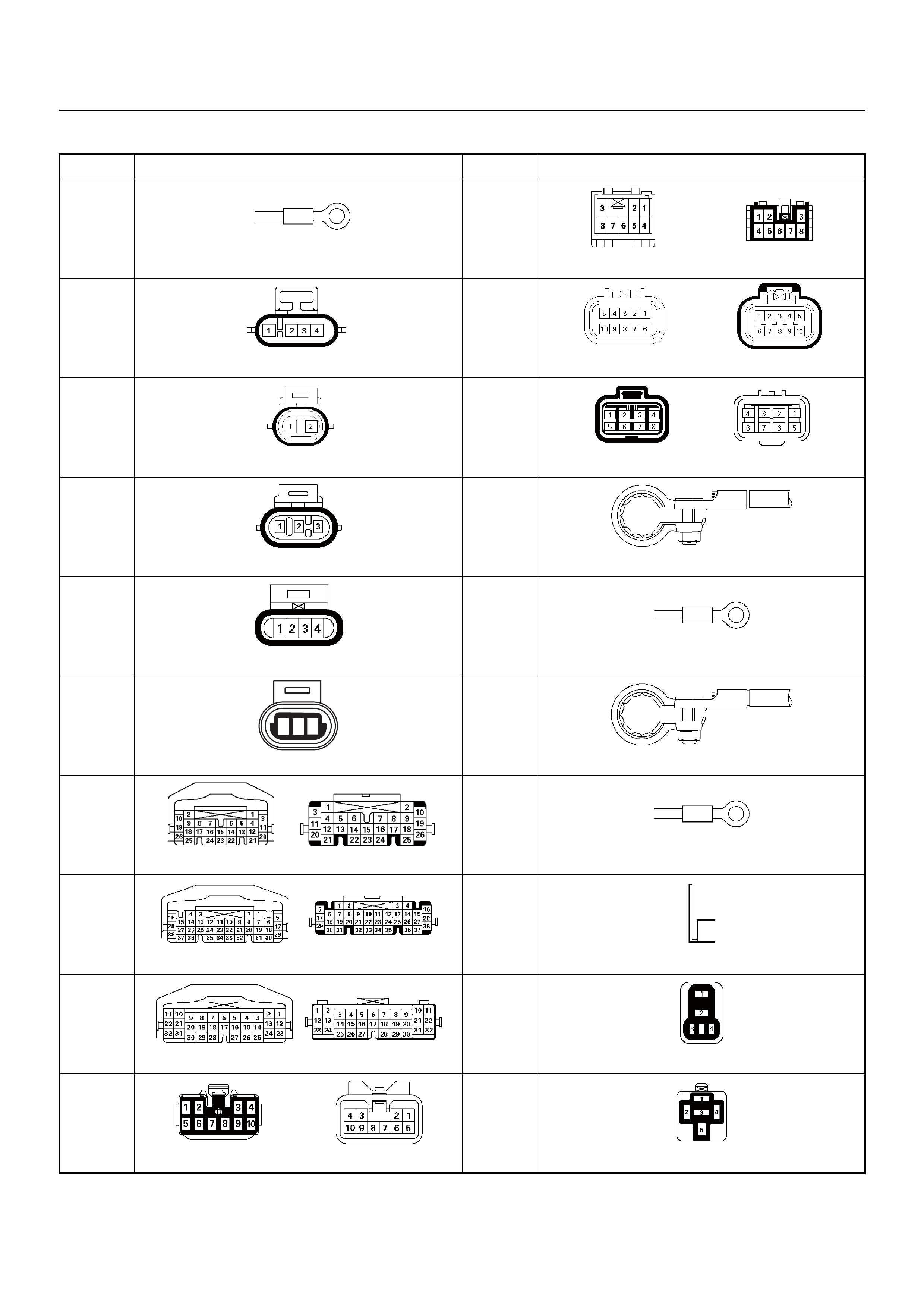
No. Connector face No. Connector face
E-72
E-74
Engine Earth-A & B
H-18
White Engine Room ~ INST
E-77
&
E-78
O2 Sensor (Pre & Post)
H-31
Engine Room ~ Mission
E-84
Knock Sensor (KS)
H-34
Engine ~ Engine Room
E-85
MAP Sensor
P-1
Silver Battery (+)
F-2
White Fuel Pump & Sender Unit
P-2
Silver Relay & Fuse Box
F-10
Vertical G-Sensor
P-5
Silver Battery (-)
H-4
White Engine Room ~ Mission
P-6
Silver Body Earth (Ground)
H-6
White Engine Room ~ INST
P-10
Silver Engine Ground
H-7
White Engine Room ~ INST
X-2
X-14
X-15
Black Relay; Fuel Pump, A/C Comp, Thermo Fan
H-9
Blue Engine Room ~ Chassis
X-11
Black Relay; Heater
123
RELAY AND FUSE
RELAY AND FUSE BOX LOCATION

RELAY AND FUSE BOX LOCATION
RELAY & FUSE BOX
RELAY
No. RELAY (Y24SE)
X-1 RELAY; TAIL LIGHT
X-2 RELAY; FUEL PUMP
X-3 RELAY; HORN
X-4 RELAY; DIMMER
X-5 —
X-6 RELAY; STARTER
X-7 RELAY; COND, FAN
X-8 RELAY; —
X-9 —
X-10 —
X-11 RELAY; HEATER
X-12 STARTER CUT
X-13 RELAY; HEAD LIGHT
X-14 RELAY; A/C COMP
X-15 RELAY; A/C THERMO
FUSE
SLOW BLOW FUSE
ENGINE MODEL
FUSE NO. Y24SE
EB-1 15A ECM
EB-2 —
EB-3 20A TRAILER
EB-4 10A ACG (S)
EB-5 10A TAIL-RH
EB-6 10A TAIL-LH
EB-7 10A H/LIGHT-RH
EB-8 10A H/LIGHT-LH/ILLUMI
EB-9 20A FUEL PUMP
EB-10 10A O2 SENSOR
EB-11 —
EB-12 —
EB-13 10A AIR CON
EB-14 —
EB-15 10A HORN
EB-16 10A HAZARD
ENGINE MODEL
FUSE NO. Y24SE
SBF-1 100A MAIN
SBF-2 —
SBF-3 —
SBF-4 20A COND, FAN
SBF-5 40A IG 1
SBF-6 —
SBF-7 —
SBF-8 30A BLOWER
SBF-9 50A IG 2
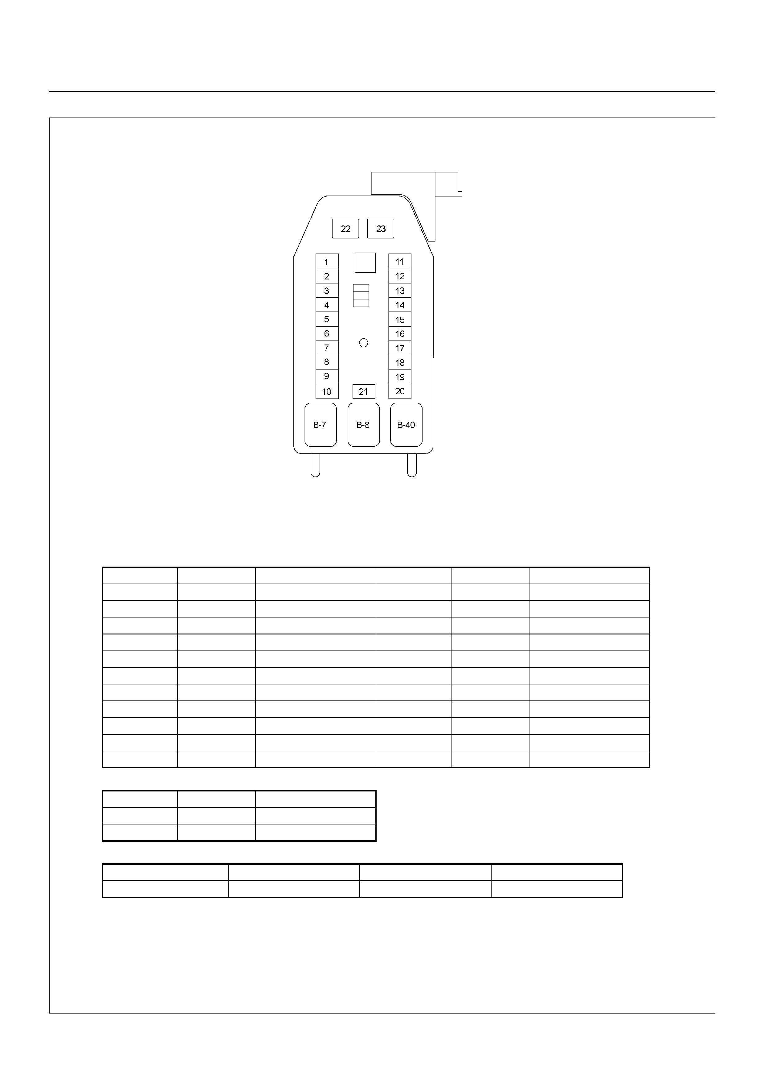
FUSE AND RELAY LOCATION
FUSE
SLOW BLOW FUSE
RELAY
No. Capacity Indication on label No. Capacity Indication on label
1 — — 12 20A CIGER & ACC
2 10A ABS/4WD 13 15A AUDIO (+B)
3 10A TRAILER 14 20A DOOR LOCK
4 15A BACK UP 15 10A METER (+B)
5 15A METER 16 10A DOME LIGHT
6 10A TURN LIGHT 17 10A ANTI THEFT
7 15A ELEC.IG 18 15A STOP LIGHT
8 15A ENGINE / ECU 19 15A —
9 20A FRT WIPER/WASER 20 10A STARTER
10 15A IG. COIL 21 10A SRS
11 10A AUDIO
No. Capacity Indication on label
22 20A RR DEF
23 30A POWER WINDOW
Connector No. B-7 B-8 B-40
Y24SE REAR DEF POWER WINDOW No Relay
FUSE BOX
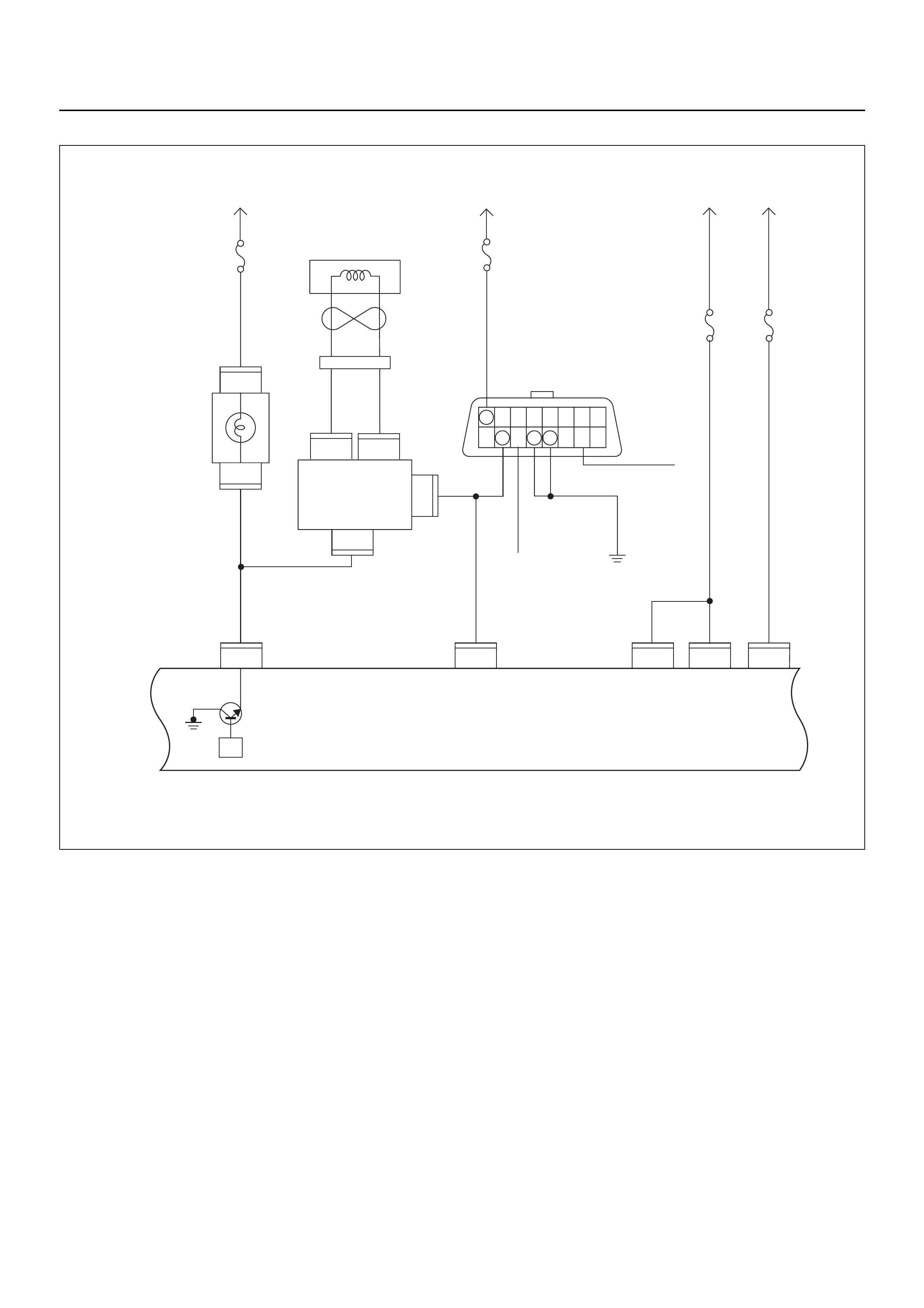
ECM WIRING DIAGRAM (1/8)
C56
7
5
C56
B58
B68
B68
3
B24
32 15
C56
218J2J2J2 J2 J2
C56
3
C56
B24
30
31
(+)(–)
B70 B70
Battery
Voltage
0.85
RED/
YEL
0.85
YEL
Engine
Room-RH
μP
0.5
BRN/
YEL
0.3
BRN/
YEL
Engine
Control
Module
(ECM)
MIL
Lamp
Immobiliser
Coil
(Antenna)
Immobiliser
Control
Unit (ICU)
Meter
15A
Ignition
SW
0.85
RED/
WHT
0.5
RED/
WHT
0.5
BLU/
YEL
2.0
WHT 3.0
BLK/
RED
0.5
YEL/
BLU
Batt
Pwr
MIL
Lamp Batt
Pwr Ign
Pwr
KWP2000
Serial Data
0.85
BLK
Class 2
Class 2
Diagnostic
Connector
16151413121110 9
87654321
Meter
15A
Ignition
SW
Engine
I5A
Battery
Voltage
ECM
I5A
RO7_6E1001
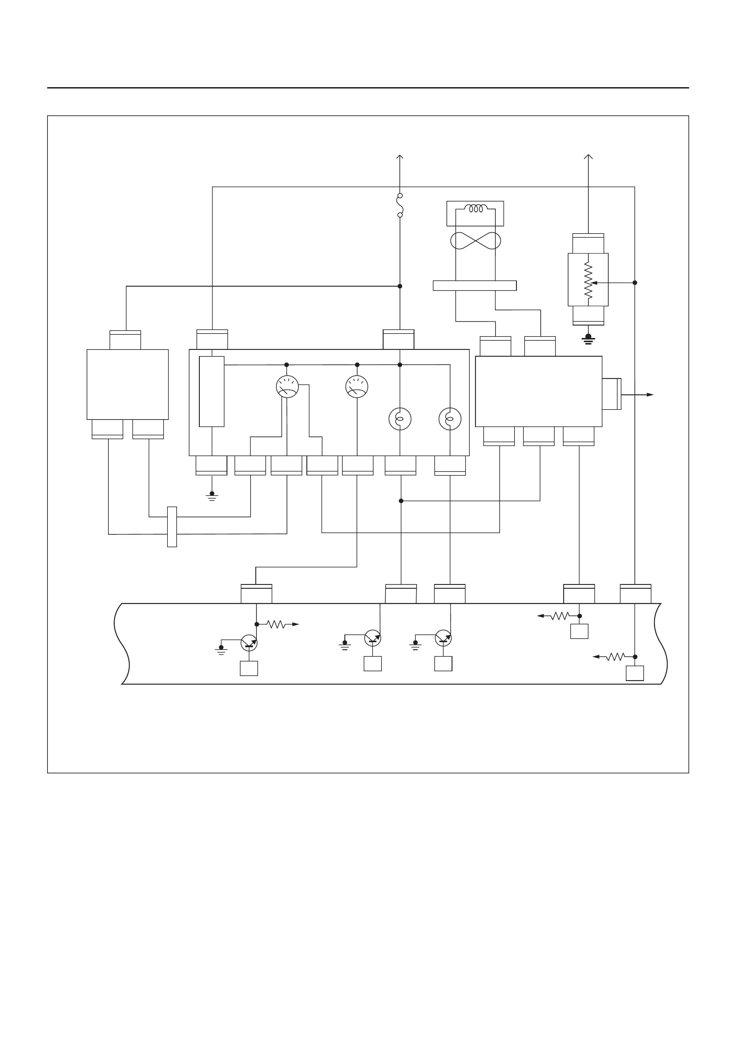
ECM WIRING DIAGRAM (2/8)
VIgn
VIgn
Engine
Control
Module
(ECM)
Fuel
Level
VSSSVS LampMIL Lamp
Tacho Sig
32
14 30
2
C56
13
C56
7J2 J2J2J2
C56
9J2
C56
4
IGN
SW
F2
F2
B68
B24
B24E44
E44E44
B24 B24 B24 B24 B24 B24
B68 B68
B68
IGN
SW
RO7_6E1002
μPμP
μP
μP
μP
Meter
15A
VIgn
MIL
Lamp SVS
Lamp
Speedo
Meter Tacho
Meter
0.85
YEL
0.5
YEL/
RED
0.8
YEL/
GRN
0.3
BRN/
YEL
0.5
GRN/
WHT
0.5
BLK/
RED
0.3
BRN/
YEL
0.5
BLK/
YEL
0.5
WHT
C56
0.5
BRN/
YEL
0.5
ORG/
BLU
2(–)
3
1
(+)
Vehicle
Speed
Sensor
(VSS) Starter
Relay
Fuel
Sender
Unit
METER
6
6
11 310278
B24
28
78
1
3
3
(–) (+)
1
Immobiliser
Coil
(Antenna)
B70 B70
CPU Immobiliser
Control
Unit (ICU)
ECM WIRING DIAGRAM (3/8)
μP
IGN
SW Battery
Voltage
Batt PwrFuel Pump
Pwr
O2 Heater
(Pre)
O2 Heater
(Post)
Battery
Voltage
2.0
WHT
0.5
BLU/
YEL
Engine
15A
450
mV
A/D Converter
Vcc
+5V -+
450
mV
A/D Converter
Vcc
+5V -+
2.0
RED/
BLK
Fuel
Pump
Relay
0.85
RED/
WHT
0.5
GRN/
WHT
RO7_6E1003
Engine
Control
Module
(ECM)
C56
1
C56
F2
F2
21
C56
31J2J1J1J1 J2 J2 J2 J2
E60
16
E60
28
E60
19
32
41
32
41
C56
26
C56
2
2.0
RED/
GRN
O2
Sensor
10A
Fuel
Pump
Heated 02 Sensors
Fuel
Pump
20A
2.0
BLK
0.5
BLU/
ORG
0.5
YEL
0.5
BLU/
YEL
0.5
BLK
0.5
BLK
0.5
BRN 0.5
YEL 0.5
PU 0.5
YEL
0.5
BRN 0.5
PU 0.5
BRN
0.5
ORG
2.0
BLK/
BLU
M
O2 Sensor
POST
O2 Sensor
PRE
LOWLOW
HI
HI
ECM
15A
X2
1
X2
X2 X2
3
1
4
42
E77 E77
E77
E78E78
E78E78
E77
H31

ECM WIRING DIAGRAM (4/8)
Fuel
Pump
20A
Fuel
Pump
Relay
2.0
BLK/
BLU 0.85
BLK/
YEL
0.85
RED/
GRN
2.0
BLK/
YEL
3.0
BLK/
RED
2.0
BLK/
RED
3.0
WHT/
BLK
2.0
WHT
Battery
Voltage Battery
Voltage
0.5
PINK
0.85
BLK/
BLU
Injector
#1
Cylinder
Injector
#2
Cylinder
Injector
#3
Cylinder
Injector
#4
Cylinder
0.5
BLU/
BLK
0.5
BLU/
WHT
Coil Module
0.5
BLU/
YEL
EVAP
Purge
Solenoid
Valve
0.5
GRN/
WHT
0.85
GRN 0.85
BLU
μP
IGN
Switch
IGN
Coil
20A
Main
100A
Engine
Control
Module
(ECM)
E60
8
E60
22
E60
9
E60
20J1 J1 J1 J1 J1 J1 J1 J1
E60
E18
E18 E18
11
E60
1
1,4 2,3
3
22
1
E66
1
E9
2
E60
17
E60
5
RO7_6E1004
E66
1
1
E9
E8
2
E8
1
E7
2
E7
1
E6
2
E6
Fuel Pump
on INJ 1 INJ 2 INJ 3 INJ 4 1,4 IGN
Coil 2,3 IGN
Coil EVAP
ECM WIRING DIAGRAM (5/8)
Idle Air
Control (IAC)
Valve
HI
LO
HI
LO
AB
0.5
YEL/
BLU
0.5
YEL/
GRN
0.5
BLU/
RED
0.5
YEL/
BLK
Engine
Control
Module
(ECM)
E60
29
E60
14
E60
E70 E70 E70E70
12 34
30
E60
13J1 J1 J1 J1
RO7_6E1005
μP
IAC D IAC C IAC B IAC A
ECM WIRING DIAGRAM (6/8)
E60
16
E60
31
321
E60
24
E60
E85
2
C121
1
C121
32 1
E85
E85
26J1 J1 J1 J1 J1 J1 J1 J1
E60
6
E60
21
Manifold
Absolute
Pressure (MAP)
Sensor
Crankshaft
Position(CKP)
Sensor
μP
0.5
GRY/
BLU
AB
AB
CHIGH LOW
E59
GND
0.5
GRY/
RED
0.5
YEL/
RED
0.5
BLU/
ORG
0.5
WHT
0.5
BLK 0.5
BLK/
WHT
5 Volts
Ref
MAP
Sensor
5V Ref
Signal
GND Signal
GND Signal
GND
MAP
Signal IAT Signal
RO7_6E1007
Engine
Control
Module
(ECM)
Intake
Air
Temperature (IAT)
Sensor
0.5
GRN 0.5
YEL/
GRN
μP
E60
23
E60
16
450
mV
A/D Converter
Vcc
+5V -+
ECM WIRING DIAGRAM (7/8)
1
C56
μP
E60
27
12231
12
E60
31
E60
7
E60
26
E60
3J1 J1 J1 J1 J1J1 J2 J2 J2
E60
E68 E68 E68 E69 E69 F10 F10 F10
16
C56
17 25
C56
1
A
23
CB
B
A
E84
0.5
GRY
μP
μP
5Volts
Ref 5Volts
Ref
RO7_6E1008
Knock
Sensor
0.5
YEL
0.5
WHT/
BLU
0.5
BLU/
ORG
0.5
BLU/
ORG
0.5
YEL/
RED
0.5
PUR/
BLU
0.5
GRY/
BLU
0.5
BLK 0.5
ORG 0.5
BLU/
WHT
Engine
Coolant
Temperature (ECT)
Sensor Vertical
G-Sensor
Throttle
Position Sensor
(TPS)
Knock Filter
Module
Engine
Control
Module
(ECM)
μP

ECM WIRING DIAGRAM (8/8)
X15
1
X15
X15X15
2
34
C56
20
43
21
C56
X14 X14
X14X14
28J2 J2
E2
AC Relay AC Req
RO7_6E1009
IGN
SW
A/C
10A
A/C
Compressor
Relay
0.5
BRN/
YEL
0.5
BRN/
RED
0.5
GRN/
BLK
Magnetic
Clutch
Sensor
μP
A/C Pressure S/W
Thermo
Relay
μP
Engine
Control
Module
(ECM)

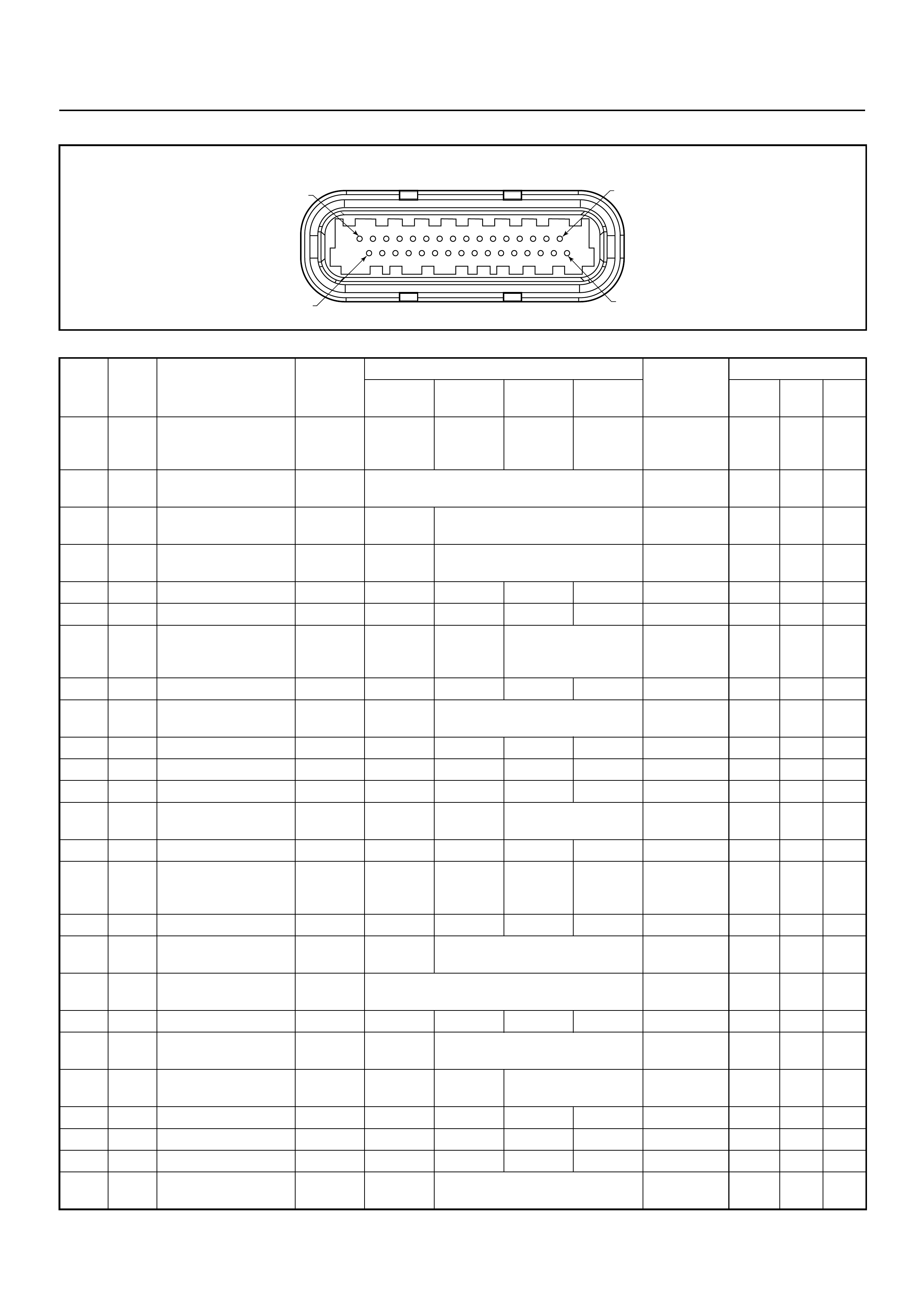
ECM CONNECTOR PIN ASSIGNMENT & OUTPUT SIGNAL
Connector (GREY) J1 Port: View Looking Into ECM Case
1
17 16
32
PIN16PIN1
PIN17 PIN32
Pin
No.
B/Box
No. Pin Function Wire
Color
Signal or Continuity ECM
Connection
Tester Position
Key SW
Off
Key SW
On
Engine
Idle
Engine
2000rpm Range (+) (-)
J1-1 1 Coil Module No. 1 &
No. 4 GRN Less than
1V Battery
voltage Pulse waveform Connect DC V 1 GND
J1-2 2 No Connection - - - - - - - - -
J1-3 3 Knock Sensor Signal YEL - - - - - - - -
J1-4 4 No Connection - - - - - - - - -
J1-5 5 EVAP Purge Solenoid
Valve GRN/
WHT Less than
1V Battery
voltage Wave form/ battery
voltage while solenoid
is not activated
Connect DC V 5 GND
J1-6 6 Crankshaft Position
(CKP) Sensor (High) BLK - - - - - - - -
J1-7 7 Throttle Position
Sensor (TPS) Output
Signal
WHT/BLU Approx. 6.0kΩ at idle /
Approx. 1.7kΩ at WOT
Approx. 2.3kΩ at idle /
Approx. 6.6kΩ at WOT
- - Disconnect Ω7 1 6 /
31
J1-8 8 No. 3 Injector BLU/WHT Less than
1V Battery
voltage Pulse waveform Connect DC V 8 GND
J1-9 9 No. 1 Injector PINK Less than
1V Battery
voltage Pulse waveform Connect DC V 9 GND
J1-10 10 No Connection - - - - - - - - -
J1-11 11 No. 4 Injector YEL Less than
1V Battery
voltage Pulse waveform Connect DC V 11 GND
J1-12 12 No Connection - - - - - - - - -
J1-13 13 Idle Air Control Valve
(IACV) Coil A High YEL/BLU Less than
1V Less than 1V / Battery voltage
Square waveform Connect DC V 13 GND
J1-14 14 Idle Air Control Valve
(IACV) Coil B Low YEL/BLK Less than
1V Less than 1V / Battery voltage
Square waveform Connect DC V 30 GND
J1-15 15 No Connection - - - - - - - - -
J1-16 16 TPS, IAT, ECT &
Crankshaft Position
Sensor Signal Ground
5VRTN A
BLU/ORG Continuity
with
ground
- - - Connect Ω16 GND
J1-17 17 Coil Module No 2 & No
3BLU GRN Battery
voltage Pulse waveform Connect DC V 17 GRD
J1-18 18 No Connection - - - - - - - - -
J1-19 19 Oxygen Sensor Heater
(Post) BLU/YEL Continuity
with
ground
- - - Connect Ω19 GND
J1-20 20 Fuel Pump On Signal BLK/BLU Less than
1V Battery Voltage Connect DC V 20 GRD
J1-21 21 Crankshaft Position
(CKP) Sensor Signal
(LOW)
BLK/WHT - - Wave
form or
approx.
3.7V
Wave
form or
approx.
7.7V
Connect AC V 21 6

J1-22 22 No.2 Injector BLU/BLK Less than
1V Battery
voltage Wave form Connect DC V 22 GND
J1-23 23 Inlet Air Temp. (IAT)
Sensor Signal YEL/GRN Less than
1V Approx. 1.8V at IAT 30°C Connect DC V 23 16
J1-24 24 MAP Sensor Signal GRY/RED Less than
1V Approx.
4.8V Approx.
1.3V Approx.
0.9V Connect DC V 24 16
J1-25 25 No Connection - - - - - - - - -
J1-26 26 Knock Sensor & MAP
Sensor Signal Ground
5VRTN A
GRY/BLU Continuity
with
ground
- - - Connect Ω26 GND
J1-27 27 Engine Coolant Temp.
(ECT) Sensor Signal GRY Less than
1V Approx. 2.5V at ECT 80°C Connect DC V 27 16
J1-28 28 Oxygen Sensor Signal
(Post) BLK Less than
1V Approx.
0.4V 0.1 - 0.9V Connect DC V 28 16
J1-29 29 Idle Air Control Valve
(IACV) Coil B High BLU/RED Less than
1V Less than 1V / Battery voltage
Square waveform Connect DC V 29 GND
J1-30 30 Idle Air Control Valve
(IACV) Coil A Low YEL/GRN Less than
1V Less than 1V / Battery voltage
Square waveform Connect DC V 30 GND
J1-31 31 Manifold Absolute
Pressure (MAP) &
Throttle Position (TPS)
Sensor 5 Volt Ref
YEL/RED Less than
1 V Approx.. 5V Connect DC V 31 16
J1-32 32 No Connection - - - - - - - - -
Pin
No.
B/Box
No. Pin Function Wire
Color
Signal or Continuity ECM
Connection
Tester Position
Key SW
Off
Key SW
On
Engine
Idle
Engine
2000rpm Range (+) (-)
Connector (BLACK) J2 Port: View Looking Into ECM Case
1
17 16
32
PIN32
PIN1
PIN17
PIN16
Pin
No.
B/Box
No. Pin Function Wire
Color
Signal or Continuity ECM
Connection
Tester Position
Key SW
Off
Key SW
On
Engine
Idle
Engine
2000rpm Range (+) (-)
J2-1 33 Oxygen Sensor (Pre)
& Lateral G-Sensor
(Ground)
BLK Continuity
with
ground
- - - Connect Ω33 GND
J2-2 34 Battery Power Supply RED/
WHT Battery voltage Connect DC V 34 GND
J2-3 35 Ignition Power Supply BLU/YEL Less than
1V Battery voltage Connect DC V 35 GND
J2-4 36 Fuel Level Signal YEL/RED Less than
1V Varying voltage with fuel contents Connect DC V 36 GND
J2-5 37 No Connection - - - - - - - - -
J2-6 38 No Connection - - - - - - - - -
J2-7 39 Vehicle Speed Signal
VSS (Immobiliser
Control Unit B8)
WHT - - Approx. 16Hz by wave
form or approx. 4.8V at
20km/h
Connect AC V 39 GND
J2-8 40 No Connection - - - - - - - - -
J2-9 41 Tachometer Signal
from ECM BLK/RED Less than
1 V Wave form Connect AC V 41 GRD
J2-10 42 No Connection - - - - - - - - -
J2-11 43 No Connection - - - - - - - - -
J2-12 44 No Connection - - - - - - - - -
J2-13 45 SVS Lamp ORG/BLU Less than
1V Less than
1V Battery voltage while
lamp is turned off Connect DC V 45 GND
J2-14 46 No Connection - - - - - - - - -
J2-15 47 Diagnostic Connector
KWP 2000 Serial Data
& ICU
YEL/BLU---- ----
J2-16 48 No Connection - - - - - - - - -
J2-17 49 Vertical G-Sensor BLU/WHT Less than
1 V Approx.. 5V Connect DC V 49 GRD
J2-18 50 Battery Power Supply RED/
WHT Battery voltage Connect DC V 50 GND
J2-19 51 No Connection - - - - - - - - -
J2-20 52 Thermo Relay GRN/BLK Less than
1V Battery voltage when A/C request is
activated Connect DC V 52 GND
J2-21 53 Oxygen Sensor signal
(Pre) BLU/ORG Less than
1V Approx.
0.4V 0.1 - 0.9V Connect DC V 53 33
J2-22 54 No Connection - - - - - - - - -
J2-23 55 No Connection - - - - - - - - -
J2-24 56 No Connection - - - - - - - - -
J2-25 57 Vertical G-Sensor ORG Less than
1V 1.8 to 3.3 Volts
During movement Connect AC V 57 33

J2-26 58 Fuel Pump Relay GRN/
WHT Less than
1V Less than
1V /
Battery
voltage
while fuel
pump is
activated
Battery voltage Connect DC V 58 GND
J2-27 59 No Connection - - - - - - - - -
J2-28 60 A/C Compressor
Relay BRN/RED Less than
1V Battery
voltage Less than 1V Connect DC V 60 GND
J2-29 61 No Connection - - - - - - - - -
J2-30 62 No Connection - - - - - - - - -
J2-31 63 Oxygen Sensor Heater
(Pre) YEL Continuity
with
ground
- - - Connect Ω63 GND
J2-32 64 Malfunction Indicator
Lamp (MIL)
(Immobiliser Control
Unit Terminal B7)
BRN/YEL Less than
1V Less than
1V Battery voltage while
lamp is turned off Connect DC V 64 GND
Pin
No.
B/Box
No. Pin Function Wire
Color
Signal or Continuity ECM
Connection
Tester Position
Key SW
Off
Key SW
On
Engine
Idle
Engine
2000rpm Range (+) (-)
GENERAL DESCRIPTION FOR ECM AND
SENSORS
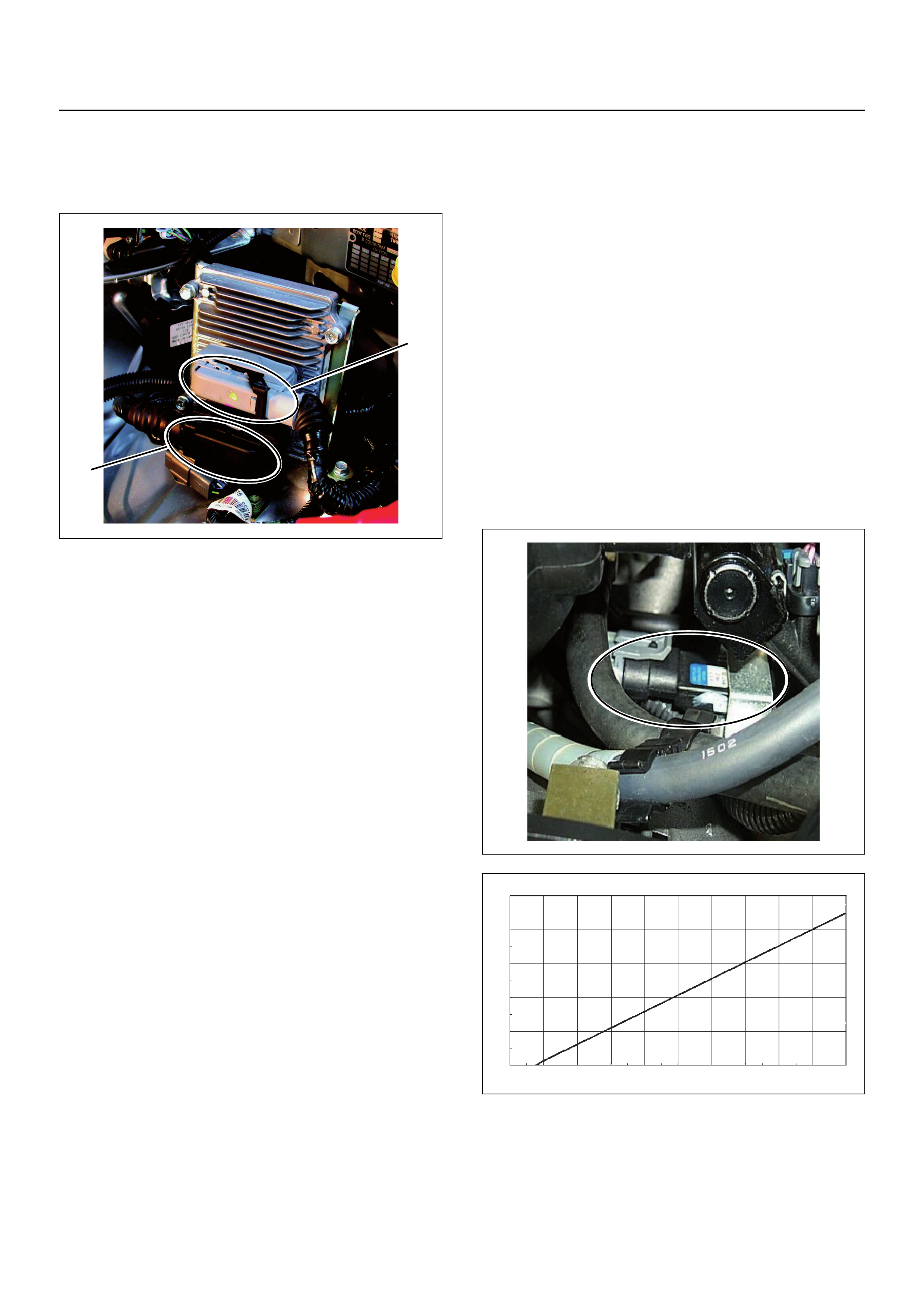
Engine Control Module (ECM)
The Engine Control Module (ECM) is located on the left-
hand side of the engine bay behind the battery and fuse
panel. The ECM controls the following:
• Fuel metering system
• Ignition timing
• On-board diagnostics for electrical functions.
The ECM constantly observes the information from
various sensors. The ECM controls the systems that
affect vehicle performance and it also performs the
diagnostic function checks of the system.
The function can recognize operational problems, and
warn the driver through the check engine lamp
(MIL lamp), and store diagnostic trouble code (DTC).
DTCs identify the problem areas to aid the technician in
making repairs.
The input / output devices in the ECM include analog to
digital converts, signal buffers, counters and drivers.
The ECM controls most components with electronic
switches which complete a ground circuit when
switched on.
Inputs (operating condition read):
• battery voltage
• electrical ignition
• exhaust oxygen content
• inlet manifold pressure
• inlet air temperature
• engine coolant tempera ture
• crankshaft position
• knock signal
• throt tle po sit ion
• vehicle speed
• rough ride signal
• power steering pressure
• air conditioning request on or off.
Outputs (systems controlled):
• ignition control
• fuel control
• idle air control
• fuel pump
• EVAP canister purge valve
• air conditioning
• diagnostics functions.
Manifold Absolute Pressure (MAP) Sensor
The MAP sensor is a strain gauge. The airflow pressure
places strain on the transducer, altering its resistance
which changes the voltage output. In other words it
measures a pressure value. It is installed to the inlet
manifold. Output voltage of the MAP sensor is as low as
the pressure is low.
(1) J1 Port
(2) J2 Port
2
1
O
utput
V
o
l
tage
(V)
0
0
0.5
1
1.5
2
2.5
3
3.5
4
4.5
5
10 20 305 1525354540 50 55
Pressure (KPa)
Characteristic of MAP Sensor (Reference)
60 65 7570 8580 90 95 100
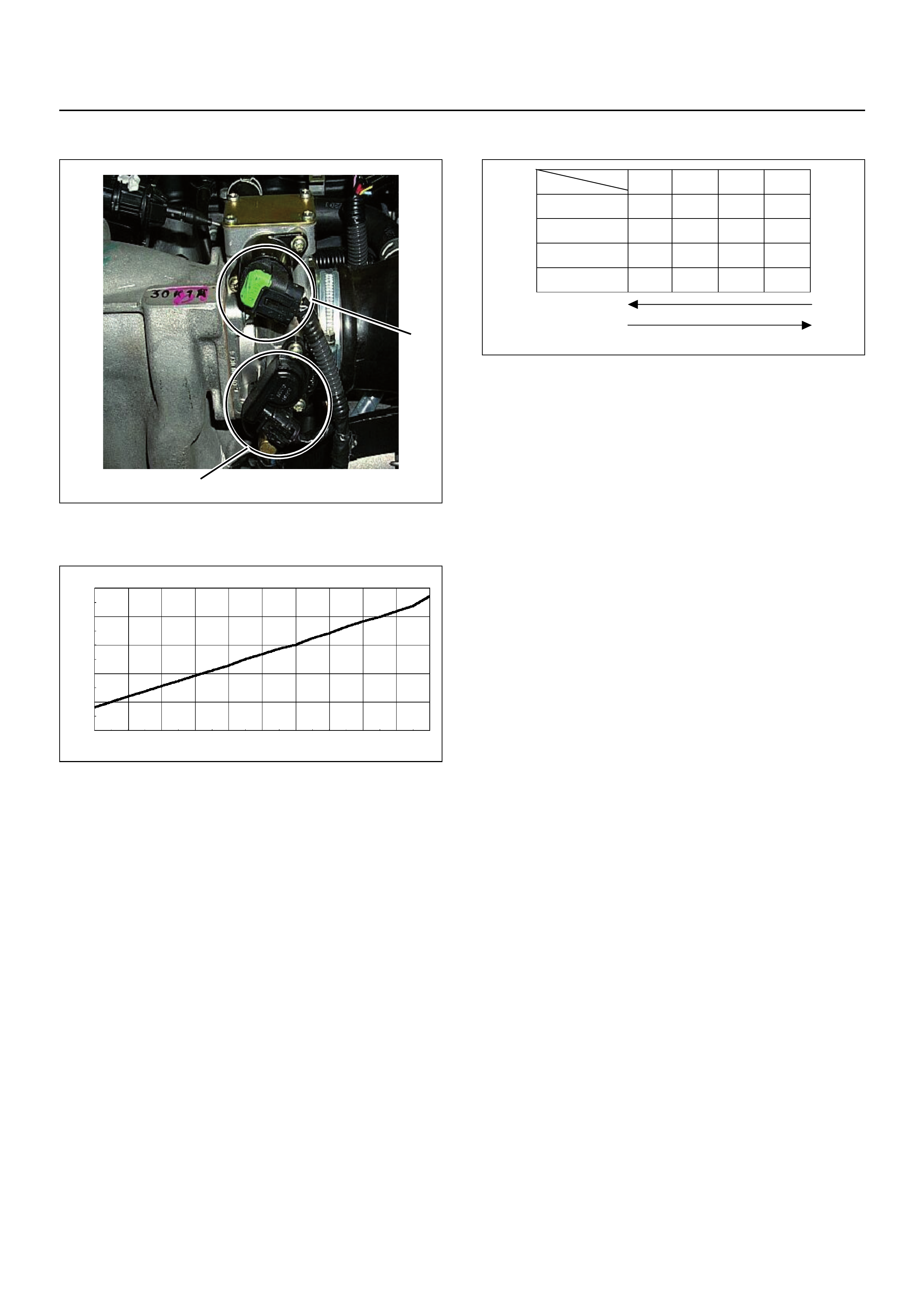
Throttle Position Sensor (TPS)
The TPS is a potentiometer connected to the throttle
shaft on the throttle body.
The engine control module (ECM) monitors the voltage
on the signal line and calculates throttle position, as the
throttle valve angle is changed when the accelerator
pedal is moved. The TPS signal also changes as the
throttle valve moves. As the throttle valve opens, the
output voltage proportionally increases as shown in the
above grap h .
Idle Air Control (IAC) Valve
The idle air control valve (IAC) valve is two directional
and gives 2-way control. With power supply to the coils
controlled steps by the engine control module (ECM),
the IAC valve's pintle is moved to adjust idle speed,
raising it for fast idle when cold or there is extra load
from the air conditioning or power steering.
By moving the pintle in (to decrease air flow) or out (to
increase air flow), a controlled amount of the air can
move around the throttle plate. If the engine speed is
too low, the engine control module (ECM) will retract the
IAC pintle, resulting in more air moving past the throttle
plate to increas e th e en gin e spee d .
If the engine speed is too high, the engine control
module (ECM) will extend the IAC pintle, allowing less
air to move past the throttle plate, decreasing the
engine speed.
The IAC pintle valve moves in small step called counts.
During idle, the proper position of the IAC pintle is
calculated by the engine control module (ECM) based
on battery voltage, coolant temperature, engine load,
and engine speed.
If the engine speed drops below a specified value, and
the throttle plate is closed, the engine control module
(ECM) senses a near-stall condition. The engine control
module (ECM) will then calculate a new IAC pintle valve
position to prev en t sta lls.
If the IAC valve is disconnected and reconnected with
the engine running, the idle speed will be wrong. In this
case, the IAC must be reset. The IAC resets when the
key is cycled “On” then “Off”. When servicing the IAC, it
should only be disconnected or connected with the
ignition “Off”.
The position of the IAC pi ntle valv e affec ts eng ine star t-
up and the idle characteristic of the vehicle.
If the IAC pintle is fully open, too much air will be
allowed into the manifold. This results in high idle
speed, along with possible hard starting and lean air/
fuel ratio.
(1) Throttle Position Sensor (TPS)
(2) Idle Air Control (IAC) Valv e
1
2
Output V oltage (V)
0
0
0.5
1
1.5
2
2.5
3
3.5
4
4.5
5
10 20 305 1525354540 50 55
Throttle Angle (%)
Characteristic of TPS (Reference)
60 65 7570 8580 90 95 100
Step
Coil
ABCD
Coil A High
(ECM J1-28)
On On
Coil A Low
(ECM J1-30)
On On
Coil B High
(ECM J1-13)
On On
Coil B Low
(ECM J1-29)
On On
(IAC Valve Close Direction)
(IAC Valve Open Direction)
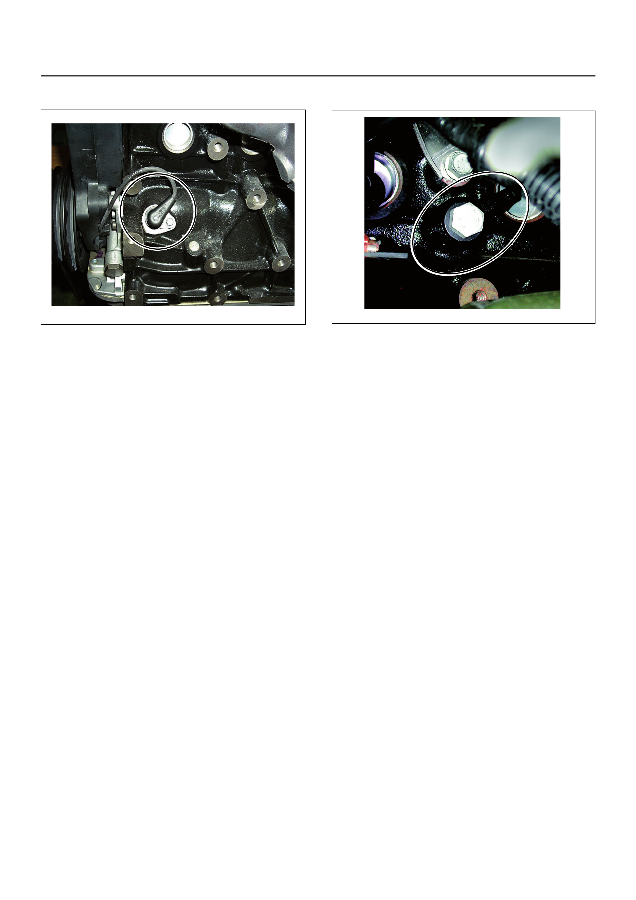
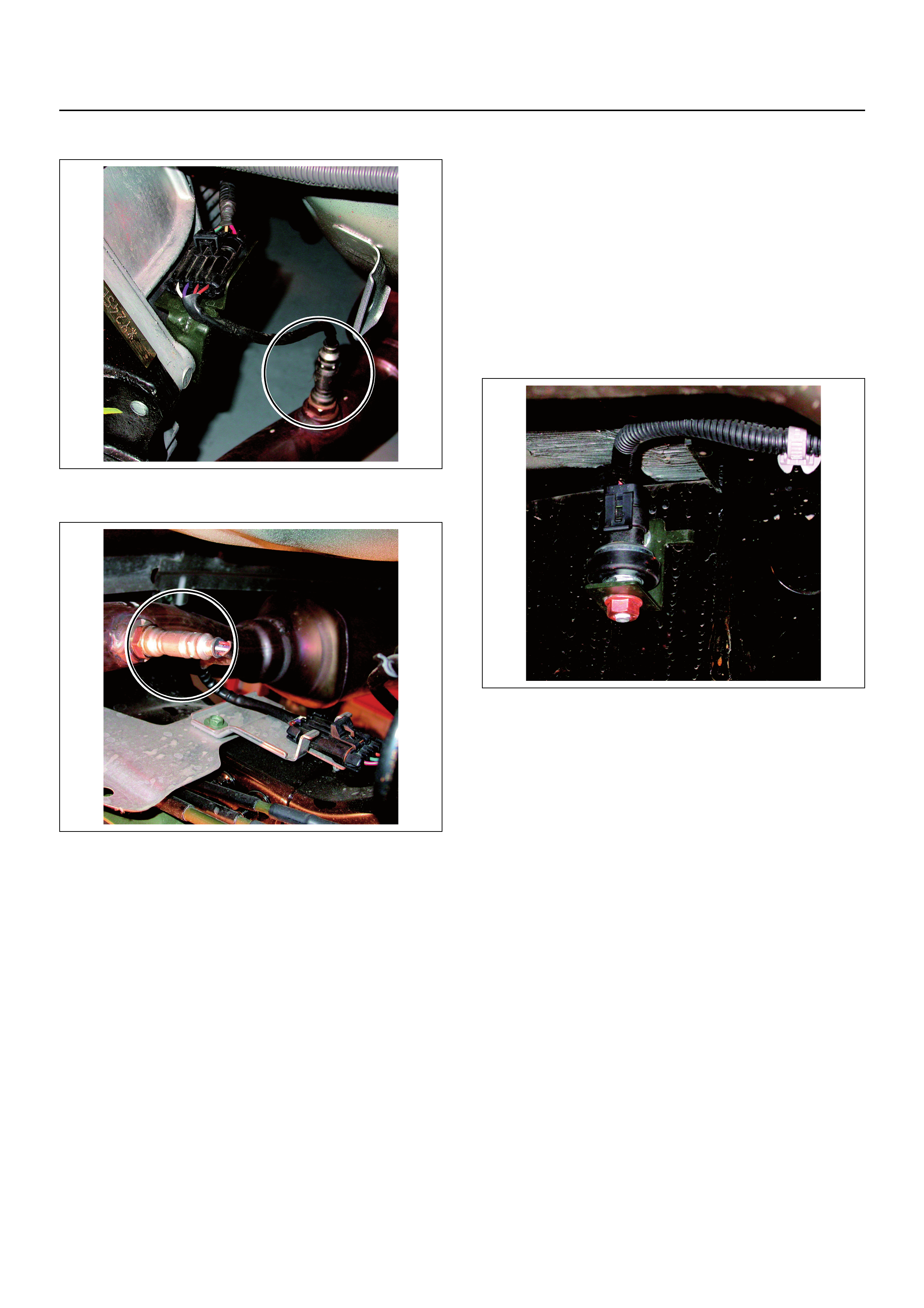
Crankshaft Position (CKP) Sensor
The crankshaft position (CKP) sensor, which sends a
signal necessary for deciding on injection timing to the
ECM, is mounted on the left-hand side of the cylinder
block behind the A/C compressor.
The crankshaft has a 58 teeth press-fit timing disc, from
which the CKP sensor reads the position of the
crankshaft at all times. It converts this to an electrical
signal, which it sends to the ECM.
Using the 58 X signals per rotation and the timing-mark
signal sent by the CKP sensor, the ECM is able to
accurately calculate engine speed and crank position.
The ECM converts the 58 X signals into a square
waveform. This converted signal is sent from the ECM
terminal J2 Pin 9 to the tachometer.
Knock Sensor (KS)
The engine Knock Sensor (KS) is mounted on the
driver’s side of the engine block, slightly forward of the
starter motor. It has a short wiring harness attached to
the sensor body and has a two pin connector that
connects to the main engine wiring harness.
The Knock Sensor signal is used by the ECM to provide
optimum ignition timing while minimising engine knock
or detonation.
If knock occurs in any of the cylinders, the ignition will
be retarded by three degrees. If the knocking then
stops, the ignition will be restored to what it was before
in steps of 0.75 degrees. Should knocking continue
despite of the ignition timing being retarded, the ECM
will retard the ignition an additional step of three
degrees, and so on, up to a maximum of 12.75 degre es.
The knock sensor is tuned to detect the frequ ency of the
vibration created by combustion knock. The vibration is
transfered to the knock sensor through the cylinder
block.
Inside the sensor is an element that is excited by this
vibration, and this element exerts a compressive force
onto a piezo-electric sensor. The compressive force
causes a charge transfer inside the sensor which
produces an AC voltage. The amount of AC voltage
produced is proportional to the amount of knock.
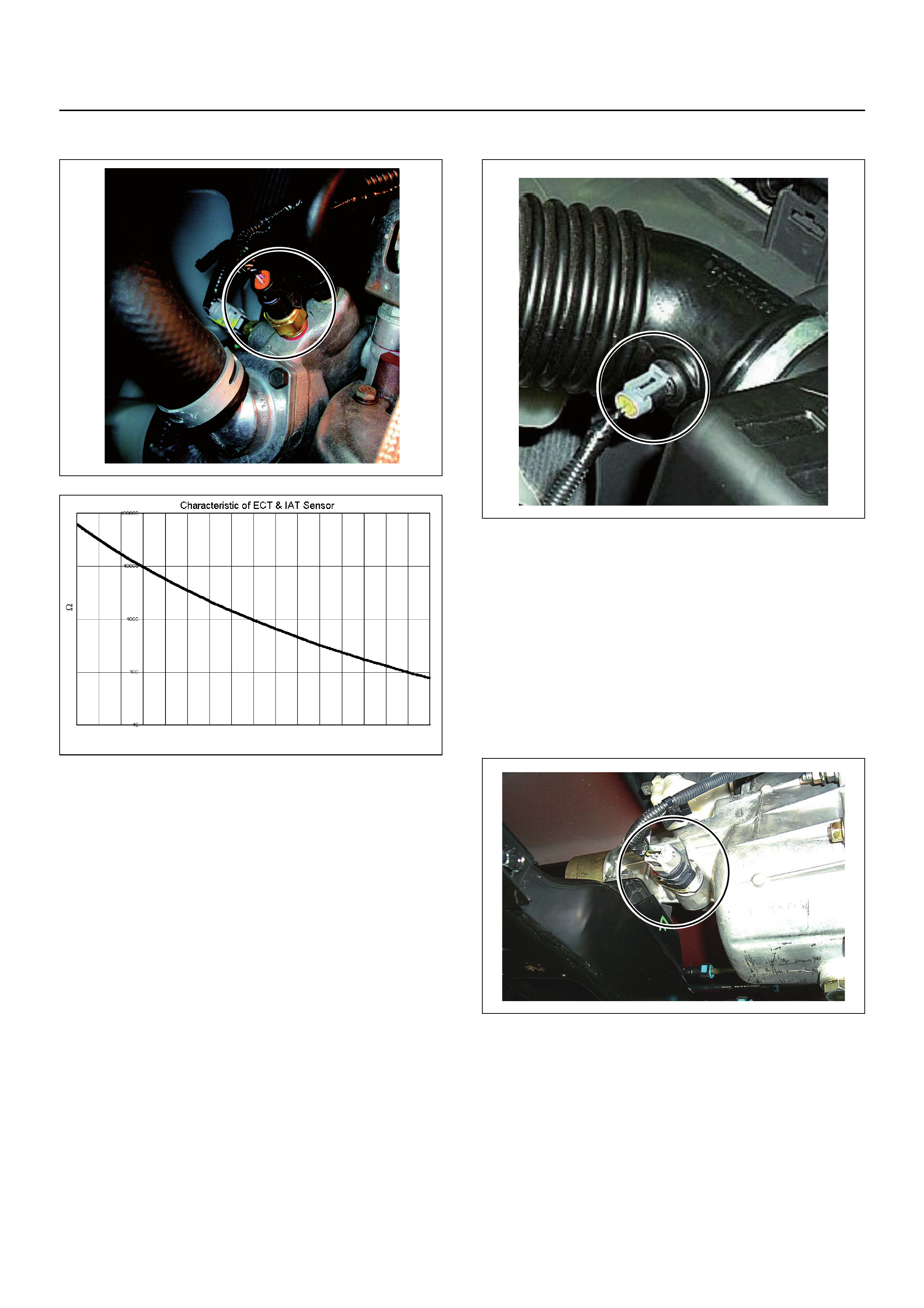
Engine Coolant Temperature (ECT) Sensor
The ECT sensor is a thermistor. As the temperature
changes so does the resistance value, and it changes
output voltage. In other words it measures a
temperature value. It is installed on the coolant stream
at the outlet of the engine block. Low coolant
temperature produces a high resistance.
The ECM supplies 5 volts signal to the ECT sensor
through resisters in the ECM and measures the voltage.
The signal voltage will be high when the engine
temperature is cold, and it will be low when the engine
temperature is hot.
Intake Air Temperature (IAT) Sensor
The IAT sensor is a thermistor. A temperature changes
the resistance value. And it changes voltage. In other
words it measures a temperature value. Low air
temperature produces a high resistance.
The ECM supplies 5 volts signal to the IAT sensor
through resistors in th e ECM an d mea sure s the vo ltage .
The signal voltage will be high when the air temperature
is cold, and it will be low when the air temperature is
hot.
Vehicle Speed Sensor (VSS)
The VSS is a magnet rotated by the transmission output
shaft. The VSS uses a Hall effect element. It interacts
with the magnetic field created by the rotating magnet. It
outputs a pulse signal. It’s operating 12 volts supply
comes from the meter fuse and its ouput signal is is
supplied direct to the instrument cluster connector B24
pins 8 and 27.
-30
Resistance ( )
-20 -10 0 10 20 30 40 50
Temperature (ºC)
60 70 80 90 100 110 120 130
Heated Oxygen (O2 Pre) Sensor
Heated Oxygen (O2 Post) Sensor
The heated oxygen sensors consist of a 4-wire low
temperature activated zir conia oxygen analyzer elem ent
with heater for operating temperature of 315°C. There
are two oxygen sensors, one fitted before the catalatic
converter (Pre 02 sensor) and one fitted after the
catalatic converter (Post 02 sensor). A short wiring
harness is attached to the top of the sensor which
connects to a 4 pin male and female vehicle wiring
harness.
A constant 450 millivolt is supplied by the ECM to the,
02 sensors. The oxygen level presen t in the exhaust gas
reacts with the 02 sensor producing a change to the
ECM output voltage.
The oxygen level present in the exhaust gas is reported
to the ECM by this output voltage which should
constantly fluctuate from approximately 100 to 1000mV.
The ECM calculates the pulse width command for the
injectors to produce the proper combustion chamber
mixture.
Low oxygen sensor output voltage is a lean mixture
which will result in a rich command to compensate.
High oxygen sensor output voltage is a rich mixture
which result in a lean command to compensate.
When the engine is first started the system is in “Open
Loop” operation. In “Open Loop”, the ECM ignores the
signal from the oxygen sensors. When various
conditions (ECT, time from start, engine speed &
oxygen sensor output) are met, the system enters
“Closed Loop” operation. In “Closed Loop”, the ECM
calculates the air fuel ratio based on the signals from
the two oxygen sensors.
Vertical G (RRID) Sensor
The Vertical G (RRID) Sensor is bolted above the rear
axle on the driver’s side inside the chassis rail.
The RRID sensor monitors vertical movements from the
rear of the vehicle. If the vehicle is travelling over rough
terrain a voltage between 1.8 volt to 3.3 volt is
transmitted from the sensor to the ECM which controls
the fuel air mix to optimum vehicle driveability and
exhaust emissions. If the vehicle is stationary the
voltage from this sensor is approximately 1.8 volt.

GENERAL DESCRIPTION FOR FUEL
METERING
The fuel metering system starts with the fuel in the fuel
tank. An electric pump, located in the fuel tank, pumps
fuel to the fuel rail through an in-line filter.
The pump is designed to provide fuel at a pressure
above the pressure needed by the injectors.
A pressure regu lator in the fuel r ail keeps fuel av ailable
to the injectors at a constant pressure.
A return line delivers unused fuel back to the fuel tank.
The basic function of the air/fuel metering system is to
control the air/fuel delivery to the engine. Fuel is
delivered to the engine by individual injectors mounted
in the inlet manifold.
The main control sensors are the heated oxygen
sensors located in the exhaust system. The heated
oxygen sensors report to the ECM how much oxygen is
in the exhaust gas. The ECM changes the air/fuel ratio
to the engine by controlling the amount of time that each
fuel injector is “On”.
The best mixture to minimize exhaust emissions is 14.7
parts of air to 1 pa rt of gasoline by weight, which allows
the catalytic converter to operate most efficiently.
Because of the constant measuring and adjusting of the
air/fuel ratio, the fuel injection system is called a “closed
loop” system.
The ECM monitors signals from several sensors in
order to determ ine the fuel needs of th e engine. Fuel is
delivered under one of se veral conditions called “mode ”.
All modes are controlled by the ECM.
Battery Voltage Correction Mode
When battery voltage is low, the ECM will compensate
for the weak spark by increasing the following:
•The amount of fuel delivered.
•The idle rpm.
Clear Flood Mode
Clear a flooded en gine by push ing th e accelerato r ped al
down all the way. The ECM then de-energises the fuel
injectors. The ECM holds the fuel injectors de-energized
as long as the throttle remains above 75% and the
engine speed is below 800 rpm. If the throttle position
becomes less than 75%, the ECM again begins to pulse
the injectors ON and OFF, allowing fuel into the
cylinders.
Deceleration Fuel Cut Off (DFCO) Mode
The ECM reduces the amount of fuel injected when it
detects a decrease in the throttle position and the air
flow. When deceleration is very fast, the ECM may cut
off fuel completely, until enable conditions meet the
engine revolution less 1000 rpm or manifold absolute
pressure less than 10 kpa.
Engine Speed/ Vehicle Speed/ Fuel Disable
Mode
The ECM monitors engine spe ed. It switches off th e fuel
injectors when the engine speed increases above 6000
rpm. The fuel injectors are turned back on when engine
speed decreases below 3500 rpm.
Acceleration Mode
The ECM provides extra fuel when it detects a rapid
increase in the throttle position and the air flow.
Fuel Cut Off Mode
No fuel is delivered by the fuel injectors when the
ignition is OFF. This prevents engine run-on. In
addition, the ECM suspen ds fu el delivery if n o reference
pulses are detected (engine not running) to prevent
engine flooding.
Starting Mode
When the ignition is first switched ON, the ECM
energises the fuel pump relay for two seconds to allow
the fuel pump to build up pressure. The ECM then
checks the engine coolant temperature (ECT) sensor
and the throttle position sensor to determine the proper
air/fuel ratio for starting.
The ECM controls the amount of fuel delivered in the
starting mode by adjusting how long the fuel injectors
are energized by pulsing the injectors for very short
times.
Run Mode
The run mode has the following two conditions:
•Open loop
•Closed loop.
When the engine is first started, the system is in “Open
Loop” operation. In “Open Loop,” the ECM ignores the
signal from the heated oxygen sensors (HO2S). It
calculates the air/fuel ratio based on inpu ts fr om the TP,
ECT, and MAP sensors.
The system remains in “Open Loop” until the following
conditions are met:
•The HO
2S have a varying voltage output showing
that it is hot enough to operate properly (this depends
on temperature).
•The ECT has reached a specified temperature.
•A specific amount of time has elapsed since starting
the engine.
•Engine speed has been greater than a specified rpm
since start-up.
The specific values for the above conditions vary with
different engines and are stored in the programmable
read only memory (PROM). When these conditions are
met, the system enters “Closed Loop” operation. In
“Closed Loop,” the ECM calculates the air/fuel ratio
(injector on-time) based on the signal from the two
HO2S. This allows the air/fuel ratio to stay very close to
14.7:1.

Fuel Metering System Components
The fuel metering system is made up of the following
parts:
• fuel injector
• throttle body
• fuel rail
• fuel pressure regulator
•ECM
• crankshaft position (CKP) sensor
• idle air control (IAC) valve
• fuel pump.
Fuel Injector
The group fuel injection fuel injector is a solenoid
operated device controlled by the ECM. The ECM
energises the solenoid, which opens a valve to allow
fuel delivery.
The fuel is injected under pressure in a conical spray
pattern at the opening of the inlet valve. Excess fuel not
used by the injectors passes through the fuel pressure
regulator before being returned to the fuel tank.
Fuel Pressure Regulator
The fuel pressure regulator is a diaphragm operated
relief valve. Its mounted on the fuel rail with fuel pump
pressure on one side and manifold pressure on the
other. The fuel pressure regulator maintains the fuel
pressure available to the injector at three times
barometric pre ssure adjuste d for engine lo ad. It may be
serviced separately.
If the pressure is too low or performance is poor , DTC
P0131 or P1171 will be the result. If the pressure is too
high, DTC P0132 or P1167 will be the result. Refer to
Fuel System Diagnosis for information on diagnosing
fuel pressure conditions.
Fuel Rail
The fuel rail is mounted to the top of the engine and
distributes fuel to the individual injectors. Fuel is
delivered to the inlet tube of the fuel rail by the fuel lines.
The fuel goes through the fuel rail to the pressure
regulator. The pressure regulator maintains a constant
fuel pressure at the injectors. Excessive fuel is returned
to the fuel tank.
Fuel Pump Electrical Circuit
When the ignition key is first turned to the ON position,
the ECM energises the fuel pump relay for two seconds
to build up the fuel pressure quickly. If the engine is not
started within two seconds, the ECM shuts the fuel
pump off and waits until the engine is cranked. When
the engine is cranked and the 58X crankshaft position
signal has been detected by the ECM, the ECM
supplies 12 volt to the fuel pump relay to energize the
electric in-tank fuel pu m p.
An inoperative fuel pump will cause a “no-start”
condition. A fuel pump which does not provide enough
pressure will result in poor performance.
Thottle Body Unit
The throttle body has a throttle plate to control the
amount of air delivered to the engine. The Thottle
position sensor and IAC valve are also mounted on the
throttle body.
Vacuum ports located behind the throttle plate provide
the vacuum signals needed by various components.
Engine coolant is directed th rough a cavity in the th rottle
body to warm up the throttle valve and to prevent icing.
GENERAL DESCRIPTION FOR
ELECTRIC IGNITION SYSTEM
The engine use two ignition coils, on e pe r two cylinder s.
A two wire connecto r prov ide s a batte ry volta ge prim ary
supply through the ignition fuse.
The ignition control spark timing is the ECM’s method of
controlling the spark advance and the ignition dwell.
The ignition control spark a dvance and the ignition dwell
are calculated by the ECM using the following inputs.
• engine speed
• crankshaft position (CKP) sensor
• engine coolant tempera ture (ECT) sensor
• throttle position sensor
• vehicle speed sensor
• ECM and ignition system supply voltage.
Ignition coil works to generate only the secondary
voltage be receiving the primary voltage from ECM.
The primary voltage is generated at the coil driver
located in the ECM. The coil driver gener ate the primary
voltage based on the crankshaft position signal. In
accordance with the crankshaft position signal, the
ignition coil driver determines the adequate ignition
timing and also the cylinder number to ignite.
Ignition timing is determined by the coolant
temperature, inlet air temperature, engine speed,
engine load, knock sensor signal, etc.
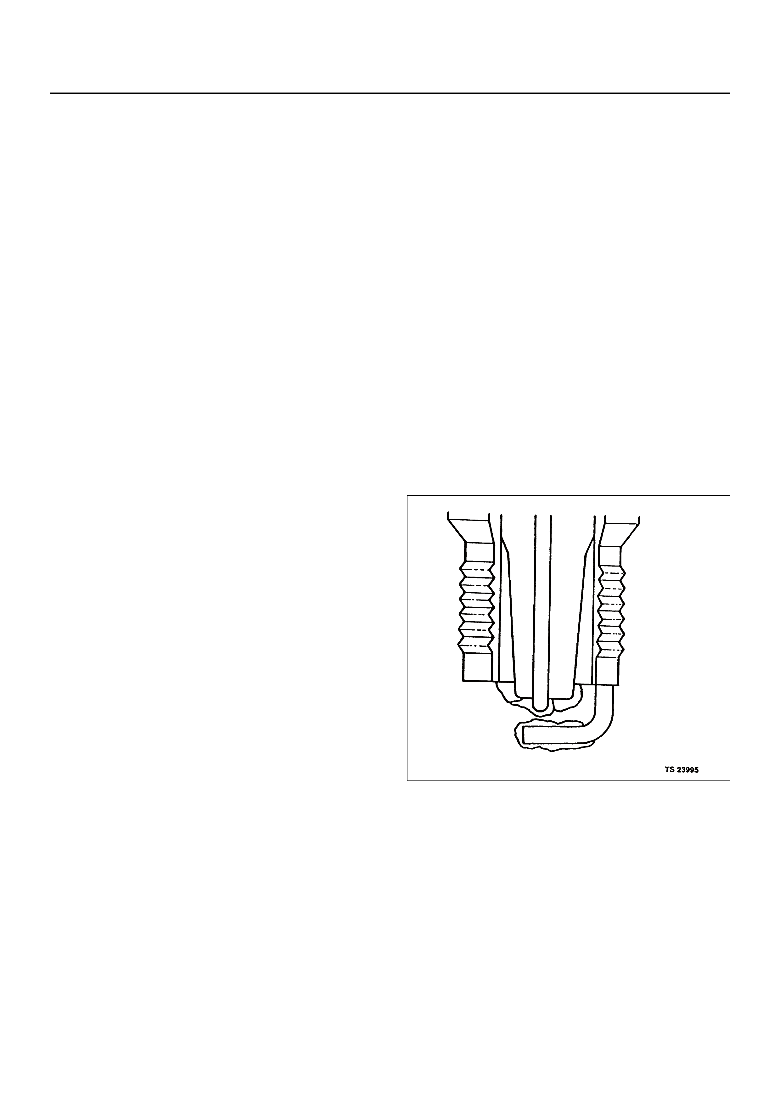
Spark Plug
Although worn or dirty spar k p lugs ma y give satisfactory
operation at idling speed, they frequently fail at higher
engine speeds. Faulty spark plugs may cause poor fuel
economy, power loss, loss of speed, hard starting and
generally poor engine performance. Follow the
scheduled maintenance service recommendations to
ensure satisfactory spark plug performance. Refer to
Section 6G - Engine Lubrication.
Normal spark plug operation will result in brown to
greyish-tan deposits appearing on the insulator portion
of the spark plug. A small amount of red-brown, yellow,
and white powdery material may also be present on the
insulator tip around the centre electrode. These
deposits are normal combustion by-products of fuels
and lubricating oils with additives. Some electrode wear
will also occur. Engines which are not running properly
are often referred to as “misfiring.” This means the
ignition spark is not igniting the air/fuel mixture at the
proper time. While o ther ignition and fu el system causes
must also be considered, possible causes include
ignition system conditions which allow the spark voltage
to reach ground in some other manner than by jumping
across the air gap at the tip of the spark plug, leaving
the air/fuel mixture unburned. Misfiring may also occur
when the tip of the spark plug becomes overheated and
ignites the mixture before the spark jumps. This is
referred to as “pre-ignition.”
Spark plugs may also misfire due to fouling, excessive
gap, or a cracked / broken insulator. If misfiring occurs
before the recommended replacement interval, locate
and correct the cause.
Carbon fouling of the spark plug is indicated by dry,
black carbon (soot) deposits on the portion of the spark
plug in the cylinder. Excessive idling and slow speeds
under light engine loads can keep the spark plug
temperatures so low that these deposits are not burned
off. Very rich fuel mixtures or poor ignition system
output may also be the cause. Refer to DTC P1167.
Oil fouling of the spark plug is indicated by wet oily
deposits on the portion of the spark plug in the cylinder,
usually with little electrode wear. This may be caused by
oil during break-in of new or newly overhauled engines.
Deposit fouling of the spark plug occurs when the
normal red-brown, yellow or white deposits of
combustion by-products become sufficient to cause
misfiring. In some cases, these deposits may melt and
form a shiny glaze on the insulator around the centre
electrode. If the fouling is found in only one or two
cylinders, valve stem clearances or inlet valve seals
may be allowing excess lubricating oil to enter the
cylinder, particularly if the deposits are heavier on the
side of the spark plug facing the inlet valve.
Excessive gap means that the air space between the
centre and the side electrodes at the bottom of the
spark plug is too wide for consistent firing. This may be
due to improper gap adjustment or to excessive wear of
the electrode during use. A check of the gap size and
comparison to the gap specified for the vehicle in
Engine Ignition will tell if the gap is too wide. A spark
plug gap that is too small may cause an unstable idle
condition. Excessive gap wear can be an indication of
continuous operation at high speeds or with engine
loads, causing the spark to run too hot. Another
possible cause is an excessively lean fuel mixture.
Low or high spark plug installation torque or improper
seating can result in the spark plug running too hot and
can cause excessive centre electrode wear. The plug
and the cylinder head seats must be in good contact for
proper heat transfer and spark plug cooling. Dirty or
damaged threads in the head or on the spark plug can
keep it from seating even though the proper torque is
applied. Once spark plugs are properly seated, tighten
them to the correct torque specification. Refer to
Section 6A - Engine Mechanical. Low torque may result
in poor contact of the seats due to a loose spark plug.
Over tightening may cause the spark plug shell to be
stretched and will result in poor contact between the
seats. In extreme cases, exhaust blow-by and damage
beyond simple gap wear may occur.
Cracked or broken insulators may be the result of
improper installation, damage during spark plug re-
gapping, or heat shock to the insulator material. Upper
insulators can be broken when a poorly fitting tool is
used during installation or removal, when the spark plug
is hit from the outside, or is dropped on a hard surface.
Cracks in the upper insulator may be inside the shell
and not visible. Also, the breakage may not cause
problems until oil or moisture penetrates the crack later.
A broken or cracked lower insulator tip (around the
centre electrode) may result from damage during re-
gapping or from “heat shock” (spark plug suddenly
operating too hot).
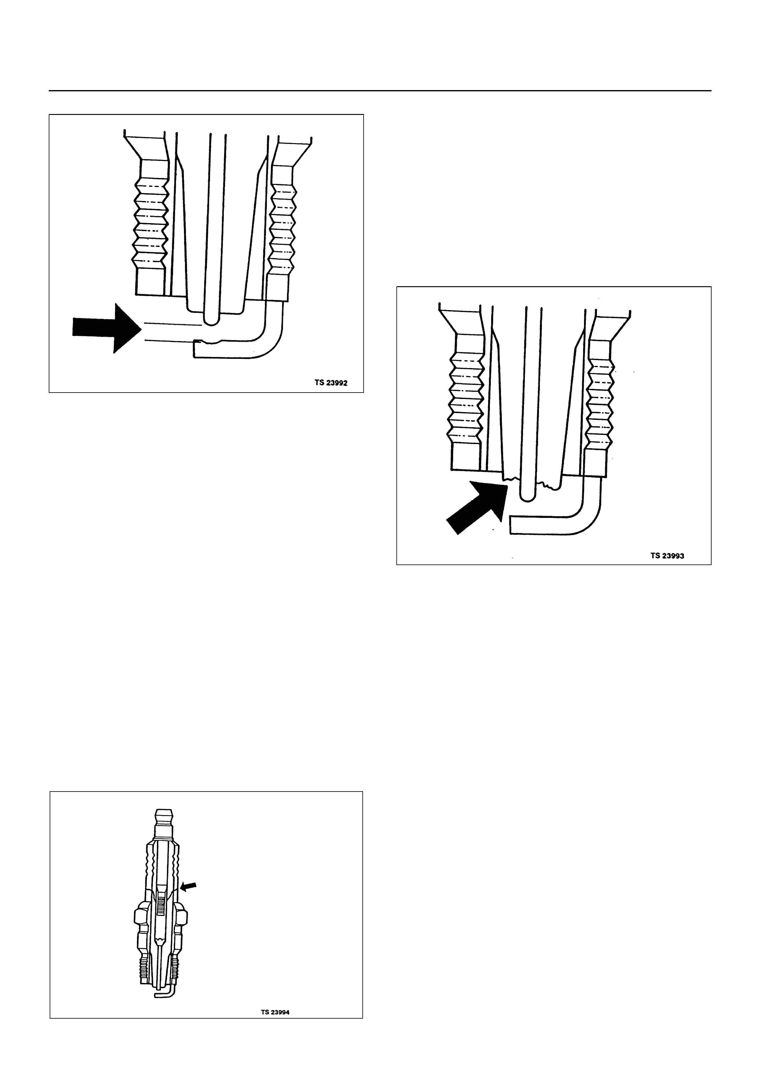
• Damage during re-gapping can happen if the gapping
tool is pushed against the centre electrode or the
insulator around it, causing the insulator to crack.
When re-gapping a spark plug, make the adjustment
by bending only the ground side terminal, keeping the
tool clear of other parts.
• “Heat shock” breakage in the lower insulator tip
generally occurs during several engine operating
conditions (high speeds or heavy loading) and may
be caused by over-advanced timing or low grade
fuels. Heat shock refers to a rapid increase in the tip
temperature that causes the insulator material to
crack.
Spark plugs with less than the recommended amount of
service can sometimes be cleaned and re-gapped, then
returned to service . However, if there is an y doubt abou t
the serviceability of a spark plug, replace it. Spark plugs
with cracked or broken insulators should always be
replaced.
GENERAL DESCRIPTION FOR
EVAPORATIVE EMISSION SYSTEM
EVAP Emission Control System Purpose
The evaporative emission control system is based on
the charcoal canister storage method. Fuel vapours are
transfered from the fuel tank to an activated carbon
(charcoal) storage devise to hold the vapours when the
vehicle is not operating.
The canister is located on the rear axle housing by the
frame cross-member.
When the engine is running, the fuel vapour is purged
from the carbon element by inlet air flow and consumed
in the normal combustion process.
EVAP Emission Control System Operation
The EVAP canister purge is controlled by a solenoid
valve that allows the manifold vacuum to purge the
canister. The engine control module (ECM) supplies a
ground to energise the solenoid valve (purge on). The
EVAP purge solenoid control is pulse-width modulated
(PWM) (switched on and off several times a second).
The duty cycle is determined by engine operating
conditions including load, throttle position, coolant
temperature and ambient temperature. The duty cycle is
calculated by the ECM. The output is command ed wh en
the appropriate conditions have been met. These
conditions are:
•the engine is fully warmed up,
•the engine has been running for a specified time,
•the IAT reading is above 10°C (50°F),
•purge/Vacuum Hoses. Made of rubber compounds,
these hoses route the gasoline fumes from their
sources to the canister and from the canister to the
intlet air flow, and
•EVAP Canister. Mounted on a bracket ahead of the
fuel tank, the canister stores fuel vapours until the
ECM determines that engine conditions are right for
them to be removed and burned.
Poor idle, stalling or poor driveability can be caused by:
•a malfunctioning purge solenoid,
•a damaged canister, and
•hoses that are split, cracked, or not connected
properly.
System Fault Detection
The EVAP leak detection strategy is based on applying
vacuum to the EVAP system and monitoring vacuum
decay. At an appropriate time, the EVAP purge solenoid
is switched “ON,” allowing the engin e va cu um t o dr aw a
small vacuum on the entire evaporative emission
system.
After the desired vacuum level has been achieved, the
EVAP purge solenoid is switched “Off,” sealing the
system. A leak is detected by monitoring for a decrease
in vacuum level over a given time period, all other
variables remaining constant.
If the desired vacuum level can not be achieved in the
test described above, a large leak or a faulty EVAP
purge control solenoid valve is indicated.
Leaks can be caused by the following conditions:
•missing or faulty fuel cap,
•disconnected, damaged, pinched, or blocked EVAP
purge line,
•disconnected, damaged, pinched, or blocked fuel
tank vapour line,
• disconnected or faulty EVAP purge control solenoid
valve,
•open ignition feed circuit to the purge solenoid,
•damaged EVAP canister,
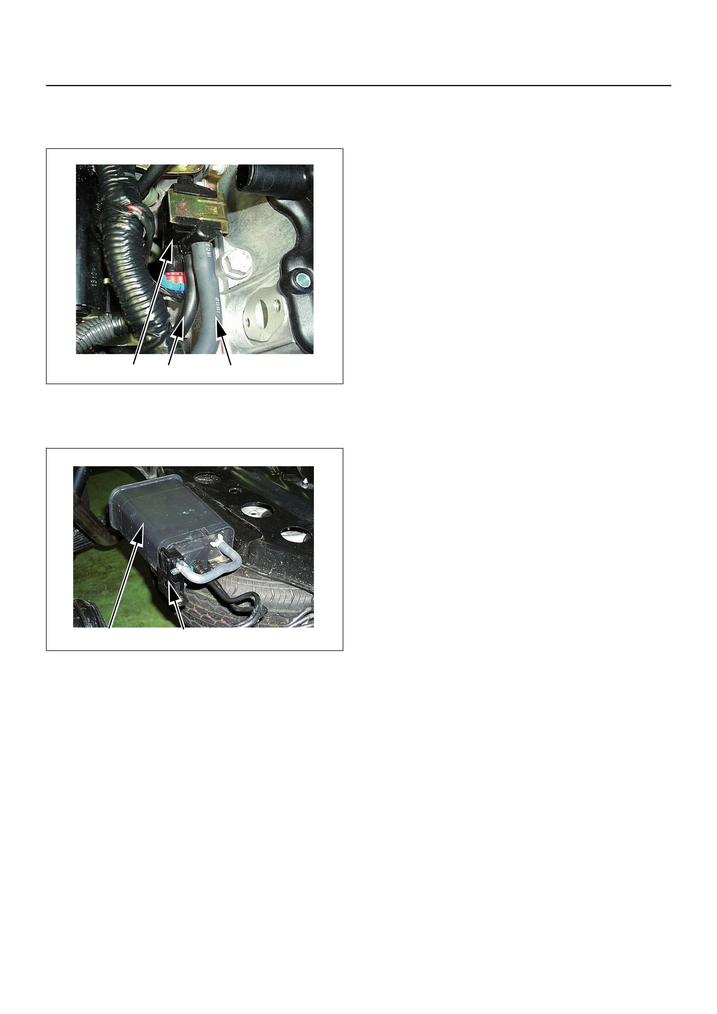
(1) Purge Solenoid Valve
(2) From Canister to Purge Solenoid Valve
(3) From Purge Soleno id Valve to Inlet manifold
(1) Canister
(2) Air Separator
1 3 2
1 2

•leaking fuel sender assembly O-ring, and
• leaking fuel tank or fuel filler neck.
The ECM supplies a ground to energise the purge
control solenoid valve (purge “On” ). The EVAP purge
control is switched “On” and “Off,” several times a
second. The duty cycle is determined by engine
operating conditions including load, throttle position,
coolant temperature an d ambient temperatu re. The duty
cycle is calculated by the ECM and the output is
commanded when the appropriate conditions have
been met.
The system checks for conditions that cause the EVAP
system to purge continuously and commands the EVAP
purge solenoid “Off” with EVAP purge solenoid duty
ratio being “0%”. If fuel tank vacuum level increases
during the test, a continuous purge flow condition is
indicated. This can be caused by the following
conditions:
•EVAP purge solenoid leaking,
•EVAP purge and engine vacuum lines switched at the
EVAP purge control solenoid valve, and
• EVAP purge control solenoid valve driver circuit
grounded.
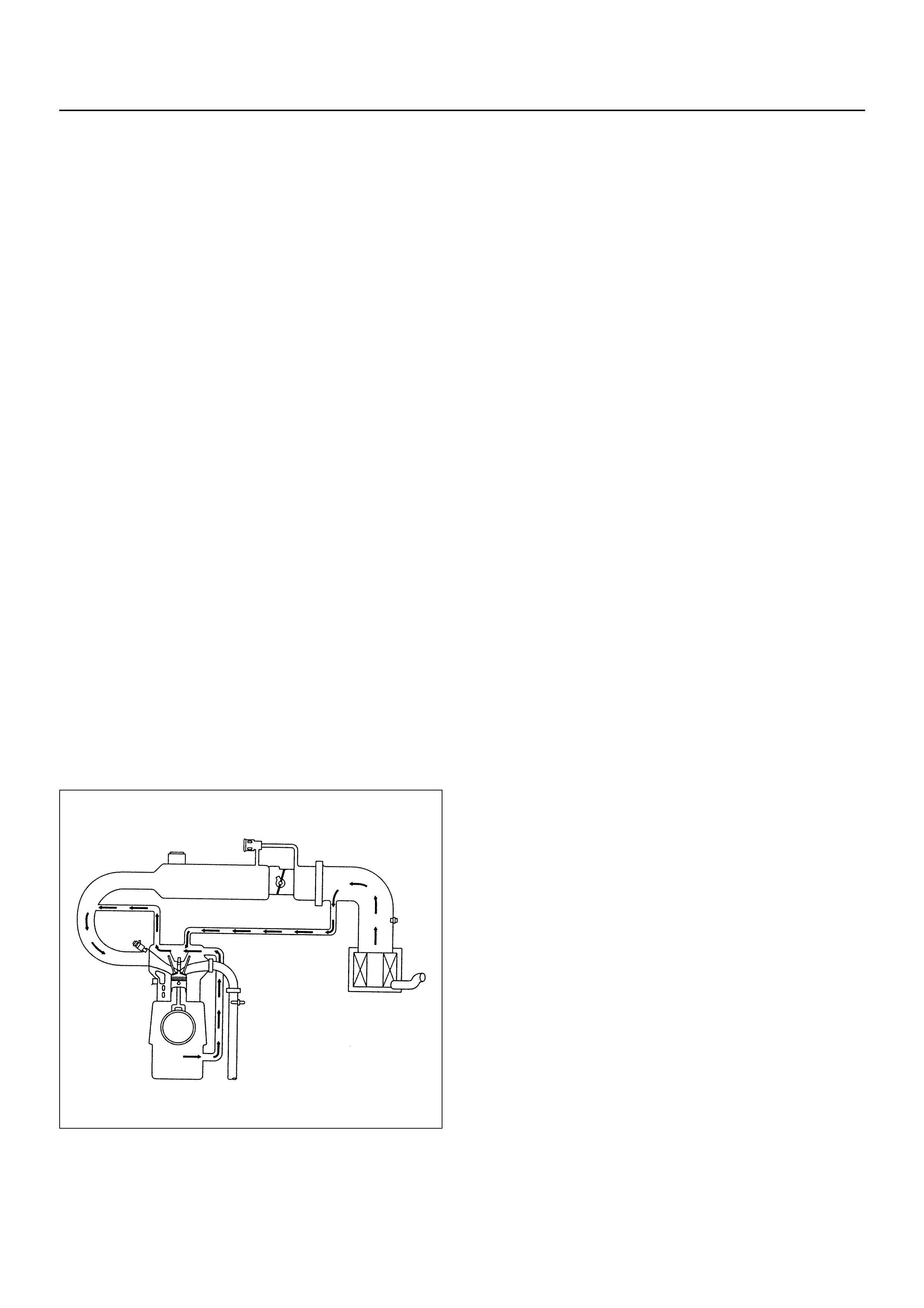
POSITIVE CRANKCASE
VENTILATION (PCV) SYSTEM
Crankcase Ventilation System Purpose
The crankcase ventilation system is used to control
crankcase vapours in the combustion process instead
of venting them to the atmosphere. Fresh air from the
throttle body is supplied to the crankcase and mixed
with blow-by gases. This mixtu re is then pa ssed throug h
the positive crankcase ventilation (PCV) port into the
inlet manifold.
While the engine is running, exhaust gases and small
amounts of the fuel/air mixture escape past the piston
rings and enter the crankcase. These gases are mixed
with clean air entering through a tube from the air inlet
duct.
During normal, part-throttle operation, the system is
designed to allow crankcase gases to flow through the
PCV hose into the inlet manifold to be burnt by normal
combustion.
A plugged positive crankcase ventilation port or PCV
hose may cause the following conditions:
•rough idle,
•stalling or slow idle speed,
•oil leaks, and
• sludge in the engine.
A leaking PCV hose would cause:
•rough idle,
•stalling, and
•high idle speed.

A/C CLUTCH DIAGNOSIS
A/C Clutch Circuit Operation
A 12-volt signal is supplied to the A/C request input of
the ECM when the A/C is selected by the A/C control
switch.
The A/C compressor clutch relay is controlled through
the ECM. This allows the ECM to modify the idle air
control position prior to the A/C clutch engagement for
better idle quality. If the engine operating conditions are
within their specified calibrated acceptable ranges, the
ECM will enable the A/C compressor relay. This is done
by providing a ground path for the A/C relay coil within
the ECM. When the A/C compressor relay is enabled,
battery voltage supplied to the enabled compressor
relay is supplied to the compressor clutch coil.
The ECM will enable the A/C compressor clutch
whenever the engine is running and the A/C has been
requested. The ECM will not enable the A/C
compressor clutch if any of the following conditions are
met:
•the engine speed is greater than 6000 RPM,
•the ECT is greater than 122°C, and
•the throttle is more than 95% open.
A/C Clutch Circuit Purpose
The A/C compressor operation is controlled by the
engine control module (ECM) for the following reasons:
•it improves idle quality during compressor clutch
engagement,
•it improves wide open throttle (WOT) performance,
and
• it provides A/C compressor protection from operation
with incorrect refrigerant pressures.
The A/C electrical system consists of the following
components:
•the A/C control switch,
•the A/C refrigerant pressure switches,
•the A/C compressor clutch,
•the A/C compressor clutch relay, and
•the ECM.
A/C Request Signal
This signal tells the ECM when the A/C mode is
selected at the A/C control switch. The ECM uses this
input to adjust the idle speed before switching on the
A/C clutch. The A/C compressor will be inoperative if
this signal is not available to the ECM.
Refer to A/C Clutch Circuit Diagnosis for A/C wiring
diagrams and diagnosis for the A/C electrical system.
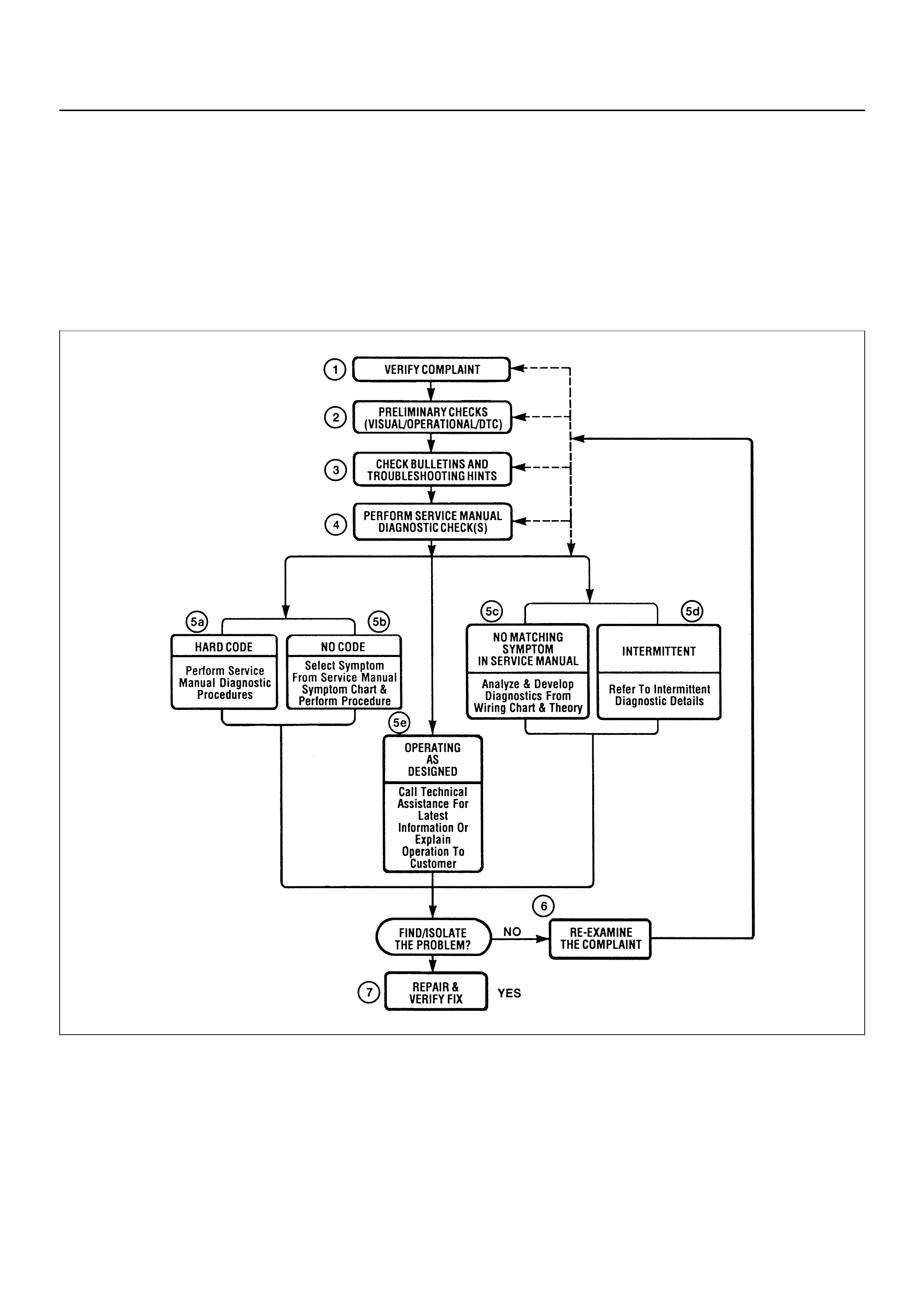
HOLDEN STRATEGY BASED DIAGNOSTICS
Overview
As a retail service technician, yo u are part of th e Holden
service team. The team goal is FIX IT RIGHT THE
FIRST TIME for the satisfaction of every cus tomer. You
are a very important member of the team as you
diagnose and repair customer vehicles.
You have maximum efficiency in diagnosis when you
have an effective, organised plan for your work.
Strategy Based Diagnostics (refer to Figure 1) provides
you with guidance as you create and follow a plan of
action for each specific diagnostic situation.
STRATEGY BASED DIAGNOSTICS CHART

Diagnostic Thought Process
As you follow a diagnostic plan, every box on the
Strategy Based Diagnostics chart requires you to use
the diagnostic thought process. This method of thinking
optimises your diagnosis in the following ways:
• Improves your understanding and definition of the
customer complaint
• Saves time by avoiding testing and/or replacing good
parts
• Allows you to look at the problem from different
perspectives
• Guides you to determine what level of understanding
about system op er at ion is nee ded :
– Owner’s manual level
– Service manual level
– In-depth (engineering) level
1. Verify the Complaint
What you should do
To verify the customer complaint, you need to know the
correct (normal) operating behaviour of the system and
verify if the customer complaint is a valid failure of the
system.
The following information will help you verify the
complaint:
• WHAT the vehicle model/options are
• WHAT aftermarket and dealer-installed accessories
exist
• WHAT related system(s) operate properly
• WHEN the prob le m oc cur s
• WHERE the pr ob lem occurs
• HOW the problem occurs
• HOW LONG the condition has existed (and if the
system ever worked correctly)
• HOW OFTEN the problem occurs
• Whether the severity of the problem has increased,
decreased or stayed the same
What resources you should use
Whenever possible, you should use the following
resources to assist you in verifying the complain t:
• Service manual Theory or Circuit Description
sections
• Service manual “System Performance Check”
• Owner manual operational description
• Technician experience
• Identical vehicle for comparison
• Circuit testing tools
• Vehicle road tests
• Complaint check sheet
• Contact with the customer
2. Perform Preliminary Checks
NOTE: An estimated 10 percent of successful vehicle
repairs are diagnosed with this step!
What you should do
You perform preliminary checks for several reasons:
• To detect if the cause of the complaint is VISUALLY
OBVIOUS
• To identify parts of the system that work correctly
• To accumulate enough data to correctly and
accurately search for a Holden Service Bulletin on
Holden Web site.
The initial checks may vary depending on the
complexity of the system and may include the following
actions:
• Operate the suspect system
• Make a visual inspection of harness routing and
accessible/visible power and ground circuits
• Check for blown fuses
• Make a visual inspection for separated connectors
• Make a visual inspection of connectors (includes
checking terminals for damage and tightness)
• Check for any DTCs stored by the on-board
computers
• Sense unusual noises, smells, vibrations or
movements
• Investigate the vehicle service history (call other
dealerships, if appropriate)
What resources you should use
Whenever appropriate, you should use the following
resources for assistance in performing preliminary
checks:
• Tech II or other technical equipment for viewing
DTCs
• Service manual information:
– Component locations
– Harness rout ing
– Wiring schematics
– Procedures for viewing DTCs
• Dealership service history file
• Vehi cle ro ad tes t
• Identical vehicle or system for comparison

3. Check Bulletins and
Troubleshooting Hints
NOTE: As estimated 30 percent of successful vehicle
repairs are diagnosed with this step!
What you should do
You should have enough information gained from
preliminary checks to accurately search for a bulletin
and other related service information. Some service
manual sections provide troubleshooting hints that
match symptoms with specific complaints.
What resources you should use
You should use the following resources for assistance
in checking for bulletins and troubleshooting hints:
• Printed bulletins
• Access Holden Bulletin Web site, https://
www.holden.com.au
• Videotapes
• Service manual
4. Perform Service Manual
Diagnostic Checks
What you should do
The “System Checks” in most service manual sections
and in most cells of section 8A (electrical) provide you
with:
• A systematic approach to narrowing down the
possible causes of a system fault
• Direction to specific diagnostic procedures in the
service manual
• Assistance to identify what systems work correctly
What resources you should use
Whenever possible, you should use the following
resources to perform service manual checks:
• Service manual
• Technical equipment (for viewing DTCs and
analysing data )
• Digital multimeter and circuit testing tools
• Other tools as needed
5a and 5b. Perform Service Manual
Diagnostic Procedures
NOTE: An estimated 40 percent of successful vehicle
repairs are diagnosed with these steps!
What you should do
When directed by service manual diagnostic checks,
you must then carefully and accurately perform the
steps of diagnostic procedures to locate the fault re lated
to the customer complaint.
What resources you should use
Whenever appropriate, you should use the following
resources to perform service manual diagnostic
procedures:
• Service manual
• Technical equipment (for analysing diagnostic data)
• Digital multimeter and circuit testing tools
• Essential and special tools
5c. Technician Self Diagnoses
When there is no DTC stored and no matching
symptom for the condition identified in the service
manual, you must begin with a thorough understanding
of how the system(s) operates. Efficient use of the
service manual combined with your experience and a
good process of elimination will result in an accurate
diagnosis of the condition.
What you should do
Step 1: Identify and understand the suspect
circuit(s)
Having completed steps 1 through 4 of the Strategy
Based Diagnostics chart, you should have enough
information to identify the system(s) or sub-system(s)
involved. Using the service manual, determine and
investigate the following circuit characteristics:
• Electrical:
– How the circuit is powered (power distribution
charts and/or fuse block details).
– How the circuit is grounded (ground distribution
charts).
– How the circuit is controlled or sensed (theory of
operation):
– If it is a switched circuit, is it normally open or
normally closed?
– Is the power switched or is the ground
switched?
– Is it a variable resistance circuit (ECT sensor
or TP sensor, for example)?
– Is it a signal generating device (MAF sensor of
VSS, for example)?
– Does it rely on some mechanical/vacuum
device to operate?
• Physical:
– Where are the circuit components (component
locators and wire harness routing diagrams):
– Are there areas where wires could be chafed
or pinched (brackets or frames)?
– Are there areas subjected to extreme
temperatures?

– Are there areas subjected to vibration or
movement (engine, transmission or
suspension)?
– Are there areas exposed to moisture, road salt
or other corrosives (battery acid, oil or other
fluids)?
– Are there common mounting areas with other
systems/components?
– Have previous repairs been performed to wiring,
connectors, components or mounting areas
(causing pinched wires between panels and
drivetrain or suspension components without
causing and immediate problem)?
– Does the vehicle have aftermarket or dealer-
installed equipment (radios, telephone, etc.)
Step 2: Isolate the problem
At this point, you should have a good idea of what could
or could not cause th e present condition . Actions to take
include the following:
• Divide (and separate, where possible) the system or
circuit into smaller sections.
• Confine the problem to a smaller area of the vehicle
(start with main harness connections while removing
panels and trim as necessary in order to eliminate
large vehicle sections from further investigation).
• For two or more circuits that do not share a common
power or ground, concentrate on areas where
harnesses are routed together or connectors are
shared (refer to the following hints).
Hints
Though the symptoms may vary, basic electrical failures
are generally caused by:
• Loose conn ections:
– Open/high resistance in terminals, splices,
connectors or grounds.
• Incorrect connector/harness routing (usually in new
vehicles or after a repair has been made):
– Open/high resistance in terminals, splices,
connectors grounds.
• Corrosion and wire damage:
– Open/high resistance in terminals, splices,
connectors grounds.
• Component failure:
– Open/short and high resistance in relays, modules,
switches or loads.
• Aftermarket equipment affecting normal operation of
other systems.
You may isolate circuits by:
• Unplugging connectors or removing a fuse to
separate one part of the circuit from another.
• Operating shared circuits and eliminating those that
function normally.
• If only one component fails to operate, begin testing
the component
• If a number of compon ents do no oper ate, begin tests
at the area of commonality (such as power sources,
ground circuits, switches or major connectors)
What resources you should use
Whenever appropriate, you should use the following
resources to assist in the diagnostic process:
• Service manual,
• Technical equipment (for data analysis),
• Experience,
• Technical Assistance, and
• Circuit testing tools.
5d. Intermittent Diagnosis
By definition, an intermittent problem is one that does
not occur continuously and will occur when certain
conditions are met. All these conditions, however, may
not be obvious or currently known. Generally,
intermittents ar e ca used by:
• Faulty electrical connections and wiring
• Malfunctioning components (such as sticking relays,
solenoids, etc.)
• EMI/RFI (Electromagnetic/ interference radio
frequency interference)
• Aftermarket equipment
Intermittent diagnosis requires careful analysis of
suspected systems to help prevent replacing good
parts. This may involve using creativity and ingenuity to
interpret customer complaints and simulating all
external and internal system conditions to duplicate the
problem.
What you should do
Step 1: Acquire information
A thorough and comprehensive customer check sheet
is critical to intermittent problem diagnosis. This is
required, since it will dictate the diagnostic starting
point. The vehicle service history file is another
source for accumulating information about the
complaint.
Step 2: Analyse the intermittent problem
Analyse the customer check sheet and service history
file to determine conditions relevant to the suspect
system(s).
Using service manual information, you must identify,
trace and locate all electrical circuits related to the
malfunctioning system(s). If there is more than one
system failure, you should identify, trace and locate
areas of commonality shared by the suspect circuits.

Step 3: Simulate the symptom and isolate the
problem
Simulate the symptom and isolate the problem by
reproducing all possible conditions suggested in Step 1
while monitoring suspected circuits/components/
systems to isolate the problem symptom. Begin with the
most logical circuit/component.
Isolate the circuit by dividing the suspect system into
simpler circuits. Next, confine the problem into a smaller
area of the system. Begin at the most logical point (or
point of easiest access) and thoroughly check the
isolated circuit for the fault, using basic circuit tests.
Hints
You can isolate a circuit by:
• Unplugging connectors or removing a fuse to
separate one part of the circuit from another
• If only one component fails to operate, begin testing
the component
• If a number of components do not operate, begin test
at areas of commonality (such as power sources,
ground circuits, switches, main connectors or major
components)
• Substitute a known good part from the parts
department or the vehicle system
• Try the suspect part in a known good vehicle
See Symptom Simulation Tests below for problem
simulation procedures. Refer to service manual
sections 6E and 8A for information about intermittent
diagnosis. Follow procedures for basic circuit testing in
service manual section 8A.
What resources you should use
Whenever appropriate, you should use the following
resources to assist in the diagnostic process:
• Service manual
• Bulletins
• Digital multimeter (with a MIN/MAX feature)
• Tech II and Tech II upload function
• Circuit testing tools (including connector kits/
harnesses and jumper wires)
• Experience
• Intermittent problem solving simulation methods
• Customer complaint check sheet
Symptom Simulation Tests
1. Vibration
This method is useful when the customer complaint
analysis indicates that the problem occurs when the
vehicle/system undergoes some form of vibration.
For connectors and wire harnesses, slightly shake
vertically and horizontally. Inspect the connector joint
and body for damage. Also, tapping lightly along a
suspected circuit may be helpful.
For parts and sensors, apply slight vibration to the part
with a light tap of the finger while monitoring the system
for a malfunction.
2. Heat
This method is important when the complaint suggests
that the problem occurs in a heated environment. Apply
moderate heat to the component with a hair drier or
similar tool while monitoring the system for a
malfunction.
CAUTION: Care must be take to avoid overheating
the component.
3. Water and Moisture
This method may be used when the complaint suggests
that the malfunction occurs on a rainy day or under
conditions of high humidity. In this case, apply water in
a light spray on the vehicle to duplicate the problem.
CAUTION: Care must be take to avoid directly
exposing electrical connections to water.
4. Electrical loads
This method involves turning systems ON (such as the
blower, lights or rear window defogger) to create a load
on the vehicle electrical system at the same time you
are monitoring the suspect circuit/component.
5e. Vehicle Operates as Designed
This condition refers to instances where a system
operating as designed is perceived to be unsatisfactory
or undesirable . In ge ne ra l, th is is due to:
• A lack of understanding by the customer
• A conflict between customer expectations and
vehicle design intent
• A system performance that is unacceptable to the
customer
What you should do
You can verify that a system is operating as designed
by:
• Reviewing service manual functional/diagnostic
checks
• Examining bulletins and other service information for
supplementary information
• Compare system operation to an identical vehicle
If the condition is due to a customer misunderstanding
or a conflict between customer expectation and system
operation, you should explain the system operation to
the customer.
If the complaint is due to a case of unsatisfactory
system performance, you should contact Technical
Assistance for the latest information.
What resources you should use
Whenever possible, you should use the following
resources to facilitate the diagnostic process:

• Vehicle service information (service manual, etc.)
• Holden field support
• Experience
• Identical vehicle or system for comp arison
6. Re-examine the complaint
When you do not successfully find/isolate the problem
after executing a diagnostic path, you should re-
examine the complaint.
What you should do
In this case, you will need to backtrack and review
information accumulated from steps 1 through 4 of
Strategy Based Diagnostics. You also should repeat
any procedures that require additional attention.
A previous path may be eliminated from consideration
only if you are certain that all steps were executed as
directed. You must then select another diagnostic path
(step 5a, 5b, 5c or 5d). If all possible options have been
explored, you may call or seek Holden field support.
What resources you should use
Whenever possible, you should use the following
resources to facilitate the diagnostic process:
• Service manual
• Accumulated information form a previous diagnostic
path
• Service information and publications
• Holden field support
7. Repair and Verify Fix
What you should do
After you have located the cause of the problem, you
must execute a repair by following recommended
service manual procedures.
When the repair is completed, verify the fix by
performing the system checks under the conditions
listed in the customer complaint.
If applicable, you sh ould carry out prev entive measures
to avoid a repeat complaint.
What resources you should use
Whenever possible, you should use the following
resources to facilitate the repair process:
• Electric al re pa ir pr oc ed ur e s
• Service manual information and publications

GENERAL SERVICE INFORMATION
Aftermarket Electrical and Vacuum
Equipment
Aftermarket (add-on) electrical and vacuum equipment
is defined as any non-genuine equipment which
connects to the vehicle's electrical or vacuum systems
that is installed on a vehicle after it leaves the factory.
No allowances have been made in the vehicle design
for this type of equipment.
NOTE: No add-o n vacuum equipment sh ould be added
to this vehicle.
NOTE: Add-on electrical equipment must only be
connected to the vehicle's electrical system at the
battery (pow e r an d gr ou nd).
Add-on electrical equipment, even when installed to
these guidelines, may still cause the electric system to
malfunction. This may also include equipment not
connected to the vehicle electrical system such as
cellular telephones and radios. Therefore, the first step
in diagnosing any electric problem is to eliminate all
aftermarket electrical equipment from the vehicle. After
this is done, and the problem still exists, it may be
diagnosed in the normal manner.
Electrostatic Discharge Damage
Electronic components used in the ECM are often
designed to carry very low voltage. Electronic
components are susceptible to damage caused by
electrostatic discharge. Less than 100 volts of static
electricity can cause damage to some electronic
components. By comparison, it takes as much as 4000
volts for a person to feel the zap of a static discharge.
There are several ways for a person to become
statically charged. The most common methods of
charging are by friction and induction.
• An exam ple of char ging by fricti on is a pers on sliding
across a vehicle seat.
• Charge by induction occurs when a person with well-
insulated shoes stands near a highly charged object
and momentarily touches ground. Charges of the
same polarity are drained off leaving the person
highly charged with the opposite polarity. Static
charges can cause damage, therefore it is important
to use care when handling and testing electronic
components.
Non-OEM Parts
All of the OBD diagnostics have been calibrated to run
with OEM parts. Accordingly, if a commercially sold
sensor or switch is installed, it may make a wrong
diagnosis and switch on the check engine lamp.
Aftermarket electronics, such as cellular phones,
stereos, and anti-theft de vi ce s, may r adia t e EMI into the
control system if they are improperly installed. This may
also cause a false sensor reading and turn on the check
engine lamp.
Poor Vehicle Maintenance
The sensitivity of OBD diagnostics will cause the check
engine lamp to turn on if the vehicle is not maintained
properly. Restricted oil filters, fuel filters, and crankcase
deposits due to lack of oil changes or improper oil
viscosity can trigger actual vehicle faults that were not
previously monitored prior to OBD. Poor vehicle
maintenance can not be classified as a “non-vehicle
fault”, but with the sensitivity of OBD diagnostics,
vehicle maintenance schedules must be more closely
followed.
Related System Faults
Many of the OBD system diagnostics will not run if the
ECM detects a fault on a related system or component.
Visual/Physical Engine Compartment
Inspection
Perform a careful visual and physical engine
compartment inspection when performing any
diagnostic procedure or diagnosing the cause of an
emission test failure. This can often lead to repairing a
problem without further steps. Use the following
guidelines when performing a visual/physical
inspection:
• Inspect all vacuum hoses for punches, cuts,
disconnects, and correct routing.
• Inspect hoses that are difficult to see behind other
components.
• Inspect all wires in the engine compartment for
proper connections, burned or chafed spots, pinched
wires, contact with sharp edges or contact with hot
exhaust manifolds or pipes.
Basic Knowledge of Tools Required
NOTE: Lack of basic knowledge of this powertrain
when performing diagnostic procedures could result in
an incorrect diagnosis or damage to powertrain
components. Do not attempt to diagnose a powertrain
problem without this basic knowledge.
A basic understanding of hand tools is necessary to
effectively use this section of the Service Manual.
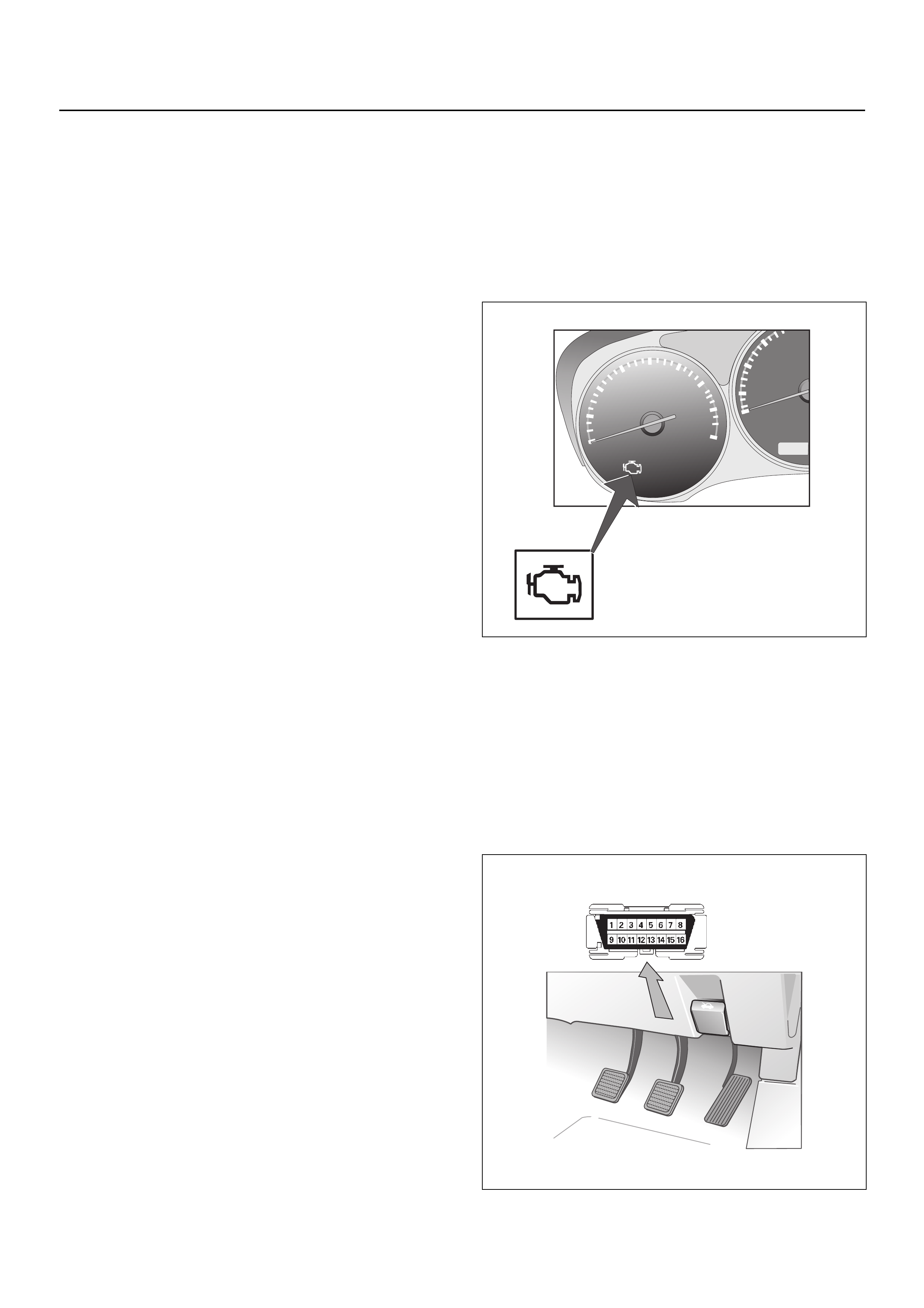
On-Board Diagnostic (OBD)
On-Board Diagnostic Tests
A diagnostic test is a series of steps, the result of which
is a pass or fail reported to the diagnostic executive.
When a diagnostic test reports a pass result, the
diagnostic executive records the following data:
• The diagnostic test has been completed since the
last ignition cycle.
• The diagnostic test has passed during the current
ignition cycle.
• The fault identified by the diagnostic test is not
currently active.
When a diagnostic test reports a fail result, the
diagnostic executive records the following data:
• The diagnostic test has been completed since the
last ignition cycle.
• The fault identified by the diagnostic test is currently
active.
• The fault has been active durin g this ignition cycle.
• The operating conditions at the time of the failure.
The Diagnostic Executive
The Diagnostic Executive is a unique segment of
software which is designed to coordinate and prioritise
the diagnostic procedures as well as define the protocol
for recording and displaying their results. The main
responsibilities of the Diagnostic Executive are listed as
follows:
• Commanding the check engine lamp on and off.
• DTC loggin g an d cle ar ing .
• Current status information on each diagnostic.
Diagnostic Information
The diagnostic charts and functional checks are
designed to locate a faulty circuit or component through
a process o f log ical decis ion s. The charts are prepared
with the requirement that the vehicle functioned
correctly at the time of assembly and that there are no
multiple faults present.
There is a continuous self-diagnosis on certain control
functions. This diagnostic capability is complemented
by the diagnostic procedures contained in this manual.
The language of communicating the source of the
malfunction is a system of diagnostic trouble codes.
When a malfunction is detected by the control m odule, a
diagnostic trouble code is set and the check engine
lamp is illuminated.
Malfunction Indicator (Check Engine) Lamp
The malfunction indicator (Check engine) lamp (MIL) is
located in the instrument cluster. the MIL will display the
following symbol when commanded ‘ON’.
The MIL indicates that an emission related fault has
occured and vehicle service is required. the following is
a list of modes of operation for the MIL:
• The MIL illuminates when the ignition switch is
switched “ON’ with the engine ‘OFF”. This is a bulb
test to ensure that the MIL is able to illuminate.
• The MIL turns ‘OFF’ after the engine is started, if a
diagnostic fault is not present.
• The MIL remains illuminated after the engine is
started. If the engine control module (ECM) detects a
fault, a diagnostic trouble code (DTC) is stored any
time the ECM illuminates the MIL due to an emission
related fault.
Data Link Connector (DLC)
The provision for communication with the control
module is the Data Link Connector (DLC). It is located
behind the lower front instrument panel. The DLC is
used to connect to a Tech2. Some common uses of the
Tech2 are listed below:
• Identifying stored Diagnostic Trouble Cod es (DTCs).
• Clearing DTCs.
• Reading serial data.
1
2
345
6
7
8
x1000r/m/ n
0
20
40
60
80
0
PRN
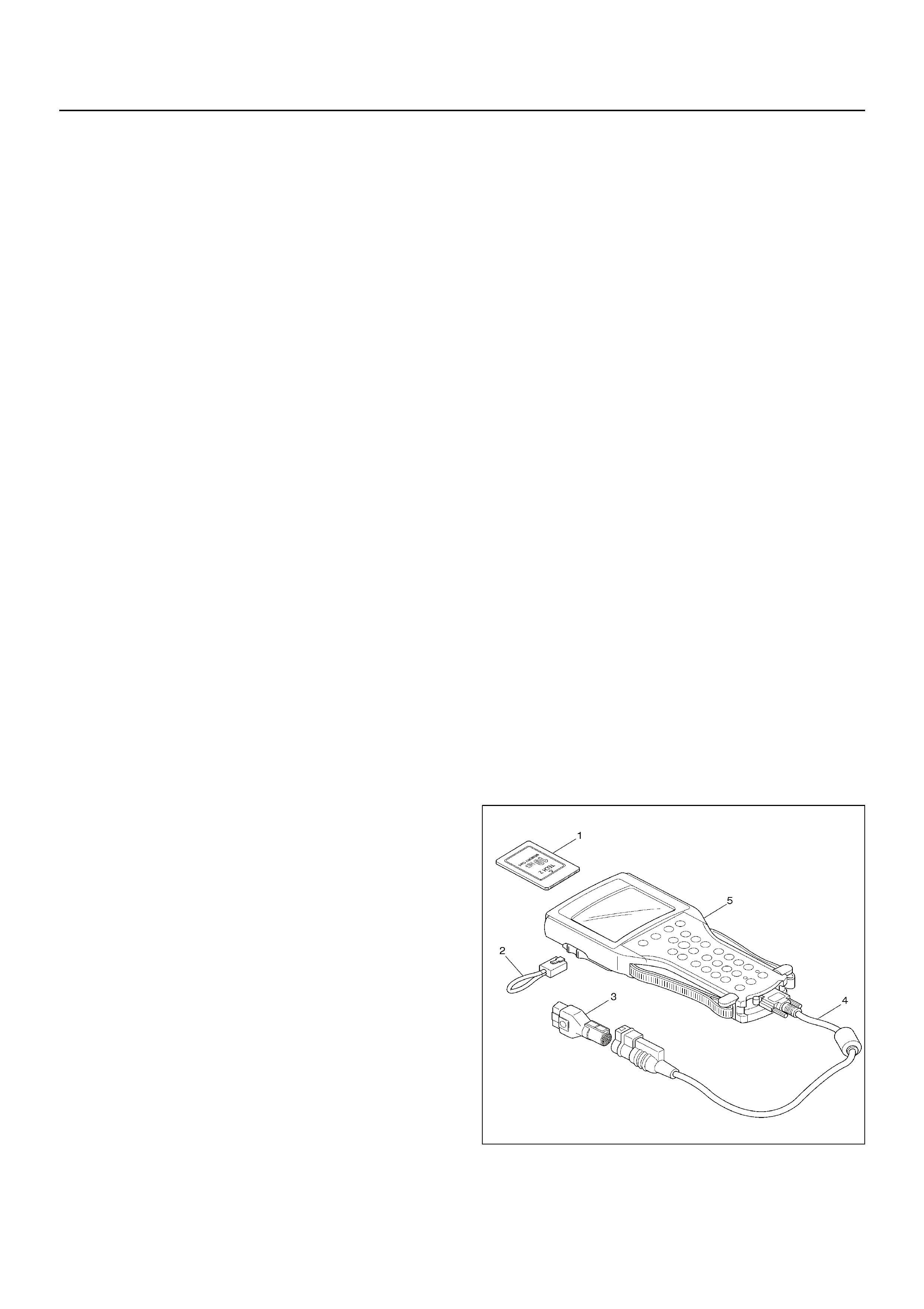
Verifying Vehicle Repair
Verification of vehicle repair will be more
comprehensive for vehicles with OBD system
diagnostic. Following a repair, the technician should
perform the fo llowin g step s:
1. Review and record the Fail Records for the DTC
which has been diagnosed.
2. Clear DTC(s).
3. Operate the vehicle within conditions noted in the
Fail Records.
4. Monitor the DTC status information for the specific
DTC which has been diagnosed until the diagnostic
test associated with that DTC runs.
Following these steps is very important in verifying
repairs on OBD systems. Failure to follow these steps
could result in unnecessary repairs.
Reading Diagnostic Trouble Codes Using a
Tech 2
The procedure for reading diagnostic trouble code(s) is
to use a diagnostic Tech2. When reading DTC(s),
follow instructions supplied by the Tech2 manufacturer.
Clearing Diagnostic Trouble Codes
To clear Diagnostic Trouble Codes (DTCs), use the
Tech2 “clear DTCs” or “clear information” function.
When clearing DTCs follow instructions supplied by the
Tech2.
Diagnosis With Tech 2
If no codes are set:
• Refer to F1: Data Display and identify the electrical
faults that are no t ind ica te d by a DTC.
• Refer to “SYMPTOM DIAGNOSIS”.
If codes are set:
1. Record all trouble codes displayed by Tech 2 and
check identification the codes that are intermittent.
2. Clear the codes.
3. Take the vehicle for a test drive to reproduce the
faulty status.
4. Check trouble codes again using Tech 2.
5. If no codes is displayed by test driving, the fault is
intermittent. In this case, refer to “DIAGNOSIS
AIDS”.
6. If a code is present, refer to DTC Chart for
diagnosis.
7. Check trouble codes again using Tech 2.
Tech 2 CONNECTION
Tech 2 scan tool is used to electrically diagnose the
automatic transmission system and to check the
system. The Tech 2 enhances the diagnosis efficiency
though all the troubleshooting can be done without the
Tech 2.
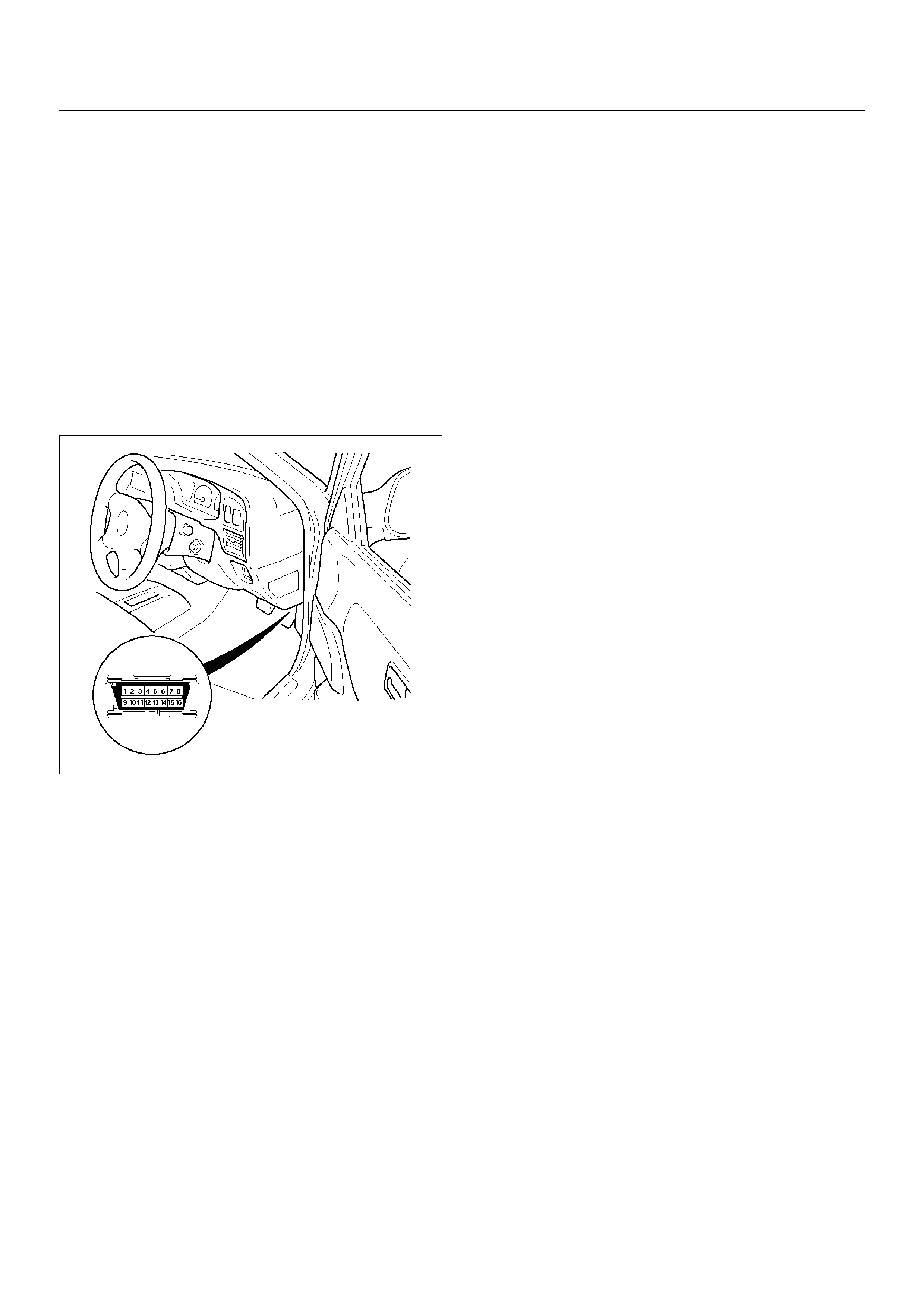
1. Configuration of Tech 2
• Tech 2 scan tool kit (No. 7000086), Tech 2 scan
tool (No. 7000057) and DLC cable (No.
3000095).
• SAE 16/19 adapter (No. 3000098) (3), RS232
loop back connector (No. 3000112) (2) and
PCMCIA card (No. 3000117) (1).
2. Tech 2 Connec tio n
• Check the key switch is turn OFF.
• Insert the PCMCIA card (1) into the Tech 2 (5).
• Connect the SAE 16/19 adapter (3) to the DLC
cable (4).
• Connect the DLC cable (4) to the Tech 2 (5).
• Connect the SAE 16/19 adapter (3) to the data
link connector of the vehicle.
• Turn the key switch of the vehicle ON and press
the “PWR” key of the Tech 2.
• Check the display of the Tech 2.
NOTE: Be s ure to check that the power is not supplied
to the Tech 2 when attaching or removing the PCMCIA
card.
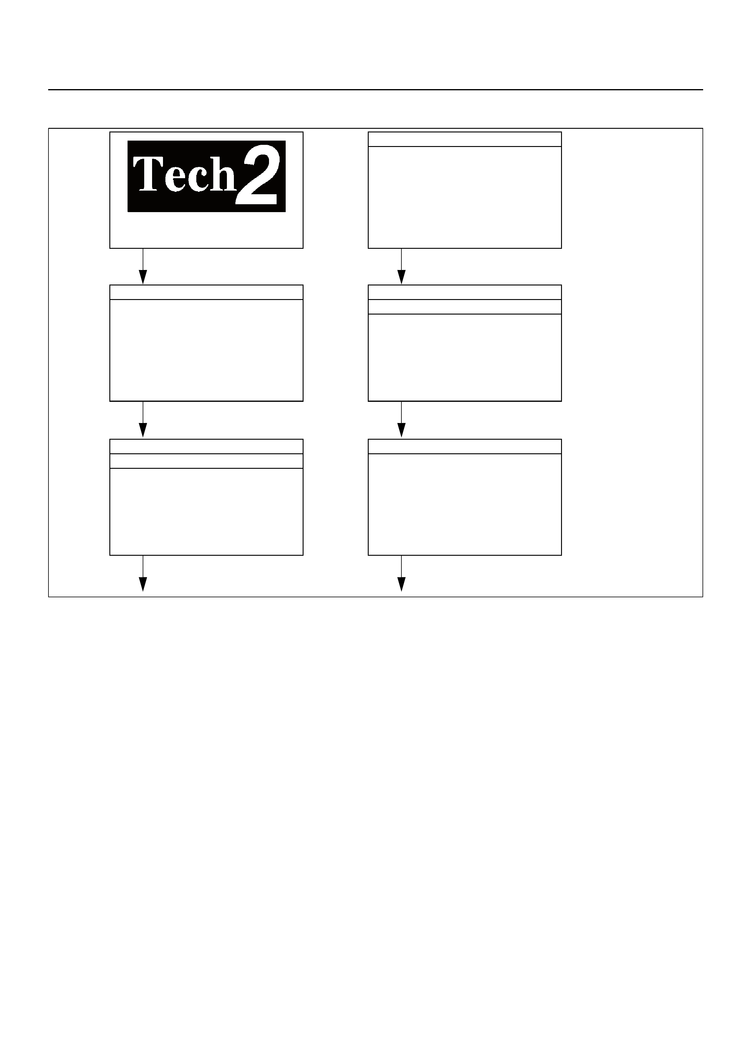
Tech 2 Operating Flow Chart (Start Up)
Refer to the following page for further Tech 2 menu screens and test funtion details.
Main Menu
F0: Diagnostics
F1: View Capture Data
F2: Tool Options
F3: Download/ Upload Help
Press “ENTER” key.
Vehicle Identification
(7) 2007
(6) 2006
(5) 2005
(4) 2004
(3) 2003
(2) 2002
(1) 2001
Select “F0: Diagnostics”.
Select “(6) 2006” or later.
Press (ENTER) to Continue
System Selection Menu
F0: Engine
F1: Transmission
F2: Chassis
F3: Body
Select “(RA Rodeo)”.
Vehicle Identification
2.4L LGI Euro3
V6 Engine
Select “F0: Engine”.
Select “2.4L LG I E ur o3”.
Vehicle Identification
(Scroll down and select)
RA Rodeo

F0: Diagnostic Trouble Code
The purpose of the “Diagnostic Trouble Codes” mode is
to display stored trouble codes in the ECM.
When “Clear DTC Information” is selected, a “Clear
DTC Information”, warning screen appears.
This screen informs you that by clearing DTC's, “all
stored DTC information in the ECM will be erased”.
After clearing codes, confirm system operation by test
driving the vehicle.
Use the “DTC Information” mode to search for a specific
type of stored DTC information.
History
This selection will display only DTCs that are stored in
the ECM's history memory. It will not display Type B
DTCs that have not requested the MIL (“Check Engine
Lamp”). It will display all type A and B DTCs that
requested the MIL and have failed within the last 40
warm-up cycles. In addition, it will display all ty pe C and
D DTCs that have failed within the last 40 warm-up
cycles.
MIL SVC or Message Request
This selection will display only DTCs that are requesting
the MIL. Type C and Type D DTCs cannot be displayed
using the MIL.
This selection will report type B DTCs only after the MIL
has been requested.
Last Test Failed
This selection will display only DTCs that have failed the
last time the test was run. The last test may have run
during a previous ignition cycle where a type A, or type
B DTC was displayed. For type C and type D DTCs, the
last failure must have occurred during the current
ignition cycle to appear as last test fail.
Test Failed Since Code Cleared
The selection will display all active and history DTCs
that have reported a test failure since the last time
DTCs were cleared. DTCs that failed more that 40
warm-up cycles before this option is selected will not be
displayed.
Failed This Ignition
This selection will display all DTCs that have failed
during the present ignition cycle.
F1: Data Display
The purpose of the “Data Display” mode is to
continuously monitor data parameters.
The current actual values of all important sensors and
signals in the system are displayed through F1 mode.
See the “Typical Scan Data” section.
F2: Snapshot
“Snapshot” allows you to focus on making the condition
occur, rather than trying to view all of the data in
anticipation of the fault.
The snapshot will collect parameter information around
a trigger point that you select.
F3: Actuator Test:
The purpose of “Actuator Test” mode is to check for
correct operation of electronic system actuators.
F4: Additional Functions:
The purpose of “Additional Functions” mode is to allow
ECU identification and Immobiliser status to be read.
F5: Programming (Factory Use Only)
The purpose of “Programming” is to program the VIN in
the ECM and lock the programmed data.
F6: ECU Control:
The purpose of “ECU Control” mode is to allow cuttoff
tests to be carried out on the fuel injectors.
F0: Diagnostic Trouble Codes
F0: Read DTC Info Ordered By Priority
F1: Read DTC Info As Stored By ECU
F2: Clear DTC Information
F1: Data Display
Engine Data 1
Refer next page for typical values
F2: Snapshot
F3: Actuator Test
F0: Fuel Pump Relay Test
F1: Idle Air Control Test
F2: A/C Relay Test
F3: Malfunction Indicator (MI) Test
F4: Fuel Open Loop
F4: Additional Functions
F0: Read ECU Identification
F1: Display Immobiliser Status
F5: Programming
F0: Reset O2-Loop Block Learn Map
F1: Reset ECU
F2: Program VIN
F6: ECU Control
F0: Injector Cutoff Test

TYPICAL SCAN DATA & DEFINITIONS (ENGINE DATA 1)
Use the Typical Values Table only after the On-Board Diagnostic System Check has been completed, no DTC(s)
were noted, and you have determined that the on-board diagnostics are func tioning properly. Tech 2 values from a
properly-running engine may be used for comparison with the engine you are diagnosing.
Condition : Vehicle stopped, engine running, air conditioning off & after warm-u p (Co olant tem perat ure ap proximat ely
80 deg.)
Tech 2 Parameter Units Idle 2000rpm Description
1 Battery Voltage V 11.0 - 14.5 11.0 - 14.5 This displays the battery voltage measured by the ECM
at ignition feed.
2 Fuel Pump Relay Active/
Inactive Active Active This displays operating status for the fuel pump main
relay. This should display “Active” when the key switch is
turned on while engine is running.
3 A/C Information
Switch
(Air Conditioning)
Active/
Inactive -- This displays the air conditioner request signal. This
should display “Active” when the air conditioner switch is
switched on.
4 A/C Relay
(Air Conditioning) Active/
Inactive -- This displays whether the ECM has commanded the A/C
compressor clutch “Active” or “Inactive”.
5 Throttle Position V 0.5 - 0.7 0.7 - 0.8 Throttle position operating angle is measured by the
ECM and displayed as a voltage. The voltage increases
proportionally with throttle position operating angle.
6 Calculated Air Flow % 4.0 - 5.0 8.0 - 10.0 This displays intake air amount. The mass air flow is
measured by ECM from the MAF sensor output voltage.
7B1 Long Term Fuel
Trim (Bank 1) %-10 - 0 0 The long term fuel trim is delivered from the short term
fuel term values and represents a long term correction of
fuel delivery for bank in question. A value of 0% indicates
that fuel delivery requires no compensation to maintain
the ECM commanded air fuel ratio. A negative value
indicates that the fuel system is rich and fuel delivery is
being reduced (decreased injector pulse width). A
positive value indicates that a lean condition exists and
the ECM is compensating by add fuel (increased inje ctor
pulse width). Because long term fuel trim tends to follo w
short term fuel trim, a va lue in the negative range due to
canister purge at idle should not be considered unusual.
Fuel trim values at maximum authority may indicate an
excessively rich or lean system.
8B1 Short Term Fuel
Trim (Bank 1) %-3 - 0 -10 - 14 The short term fuel trim to a bank represents a short term
correction to the bank fuel delivery by the ECM in
response to the amount of time the bank fuel control
oxygen sensor voltage spends above or below the
450mV threshold. If the oxygen sensor voltage has
mainly remained less than 450mV, indicating a lean air/
fuel, short term fuel trim will increase into the positive
range above 0% and the ECM will pass fuel. If the
oxygen sensor voltage stays mainly above the threshold,
short term fuel trim will decrease below 0% into the
negative range while the ECM reduces fuel delivery to
compensate for the indicated rich condition. Under
certain conditions such as extended idle and high
ambient temperatures, canister purge may cause short
term fuel trim to read in the negative range during normal
operation. Fuel trim values at maximum authority may
indicate an excessively rich or lean system.
9B1S1 O2 Sensor
(Bank1 Sensor 1) mV 50 - 950 50 -950 This displays the exhau st oxygen sensor output voltage.
Should fluctuate constantly within a range between 10mV
(lean exhaust) and 1000mV (rich exhaust) while
operating in closed loop.
10 B1S2 O2 Sensor
(Bank1 Sensor 2) mV 50 - 950 50 -950 This displays the exhau st oxygen sensor output voltage.
Should fluctuate constantly within a range between 10mV
(lean exhaust) and 1000mV (rich exhaust) while
operating in closed loop.
11 Air Fuel Ratio Ratio 14.6:1 14.6:1 This displays the ECM commanded value. In closed loop,
this should normally be displayed around 14.2:1 - 14.7:1.

12 O2 Sensor Loop Open/
Closed Closed Closed Displays the status of the O2 Sensor control circuit. Will
be in Closed Loop when the engine is running at normal
operating temperature.
13 Coolant Temperature °C 80 - 90 80 - 90 The ECT is measured by ECM from ECT sensor output
voltage. When the engine is normally running
temperature, this data displays approximately 80 °C or
more.
14 Intake Air
Temperature °C Depends on
ambient temp. Depends on
ambient temp. The IAT is measured by ECM from IAT sensor output
voltage. This data is changed by intake air temperature.
15 MAP Sensor Kpa 33 - 38 26 - 30 The MAP (Kpa) is measured by ECM from MAP output
voltage. This data is changed by inlet manifold pressure.
16 Idle Air Control Steps 20 - 30 65 - 75 This displays the ECM commanded position of the idle air
control valve pintle. A larger number means that more air
is being commanded through the idle air passage.
17 Knock Control Active/
Inactive Inactive Inactive This displays engine Knock Control status.
18 Malfunction (MI)
Indicator On/Off Off Off This displays operating status for the Check Engine (MIL)
Lamp. This should display “On” when the Check Engine
(MIL) Lamp is switched on.
19 Fan Relay 1 Active/
Inactive Active/Inactive Active/Inactive Displays the operating Status of Fan Relay 1.
20 Fan Relay 2 Active/
Inactive Active/Inactive Active/Inactive Displays the operating Status of Fan Relay 2.
21 Dec. Fuel Cutoff
(Deceleration) Active/
Inactive Inactive Inactive The ECM reduces the amount of fuel injected when it
detects a decrease in the throttle position and the air
flow. When deceleration is very fast, the ECM may cut off
fuel completely. Until enable conditions meet the engine
revolution less than 1000rpm or MAP less than 10KPa.
22 Engine Speed rpm 775 - 875 1950 - 2050 The actual engine speed is measured by ECM from the
CKP sensor 58X signal.
23 Desired Idle Speed rpm 825 800 - 8 50 The desired engine idle speed commanded by the ECM.
The ECM compensates for various engine loads.
24 Vehicle Speed km/h 00 This displays vehicle speed. The vehicle speed is
measured by the ECM from the vehicle speed sensor.
25 Full Load Enrichment Active/
Inactive Inactive Inactive The ECM provides the extra amount of fuel when it
detects a rapid increase in the throttle position and air
flow (Power Enrichment). Under this condition the ECM
should detect a rich condition (high oxygen sensor
voltage).
26 Knock Retard °CA 00 This displays the commanded ignition spark timing retard
timing based on the signal from the knock sensor.
Tech 2 Parameter Units Idle 2000rpm Description

F3: ACTUATOR TEST
The state of each circuit can be tested by using the
actuator test menus. Especially when DTC can not be
detected, a faulty circuit can be diagnosed by testing
each circuit by means of these menus.
Even if a DTC has been detected, the circuit tests using
these menus could help discriminate between a
mechanical trouble and an electrical trouble.
F0: Fuel Pump Relay Test
When the Tech 2 is operated, fuel pump relay signal
switched “On” or “Off”.
The circuit is normal if fuel pump sound is generated in
when the Active or Inactive soft key is pressed on
Tech 2.
F1: Idle Air Control Test
When the Tech 2 is operated, “Idle Air Control”
increases in steps up to 255 steps.
The circuit is normal if IAC valve can be heard stepping
up to 255 steps in accordance with this operation.
F2: A/C Clutch Relay (if Air Conditioning is fitted)
When the Tech 2 is operated, A/C clutch relay signal
switched “On” or “Off”.
The circuit is normal if A/C compressor clutch is
energized with the engine running when the Active or
Inactive soft key is pressed on Tech 2.
F3: Malfunction Indicator Lamp
When the Tech 2 is operated, “Malfunction Indicator
Lamp (Check Engine Lamp)” is switched “On” or “Off”.
The circuit is normal if the “Malfunction Indicator Lamp
(Check Engine Lamp)” in the instrument panel is
switched “On” or “Off” when the On or Off soft key is
pressed on Tech 2.
F4: Fuel Open Loop
O2 Sensor Loop
When the Tech 2 is operated, the O2 sensor Loop
changes status from Open to Closed.
The circuit is normal if the O2 Sensor Loop operates
with engine idling when the Open or Closed soft key is
pressed on Tech 2.
F6: ECU Control
F0: Injector Cutoff Test
When the Tech 2 is operated, selected injector turns
“On” or “Off”.
The circuit is normal if engine vibration is changed at
selected cylinders with engine idling when the On or Off
soft keys are pressed on Tech 2.
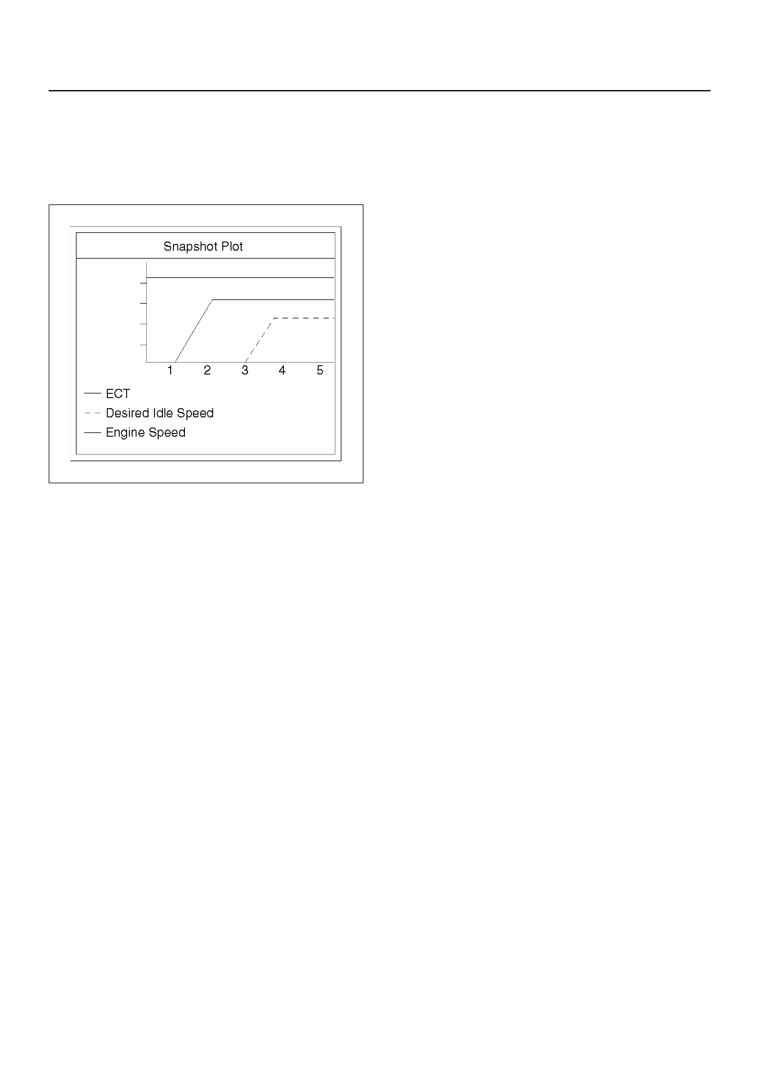
PLOTTING SNAPSHOT GRAPH
This test selects several necessary items from the data
list to plot graphs and makes data comparisons on a
long term basis. It is an effective test particularly in
emission related evaluations.
060RX037
For trouble diagnosis, you can collect graphic data
(snap shot) directly from the vehicle.
The data is recorded on Tech 2 and the snapshot data
can be replayed as needed. Therefore, accurate
diagnosis is possible, even though the vehicle is not
available.
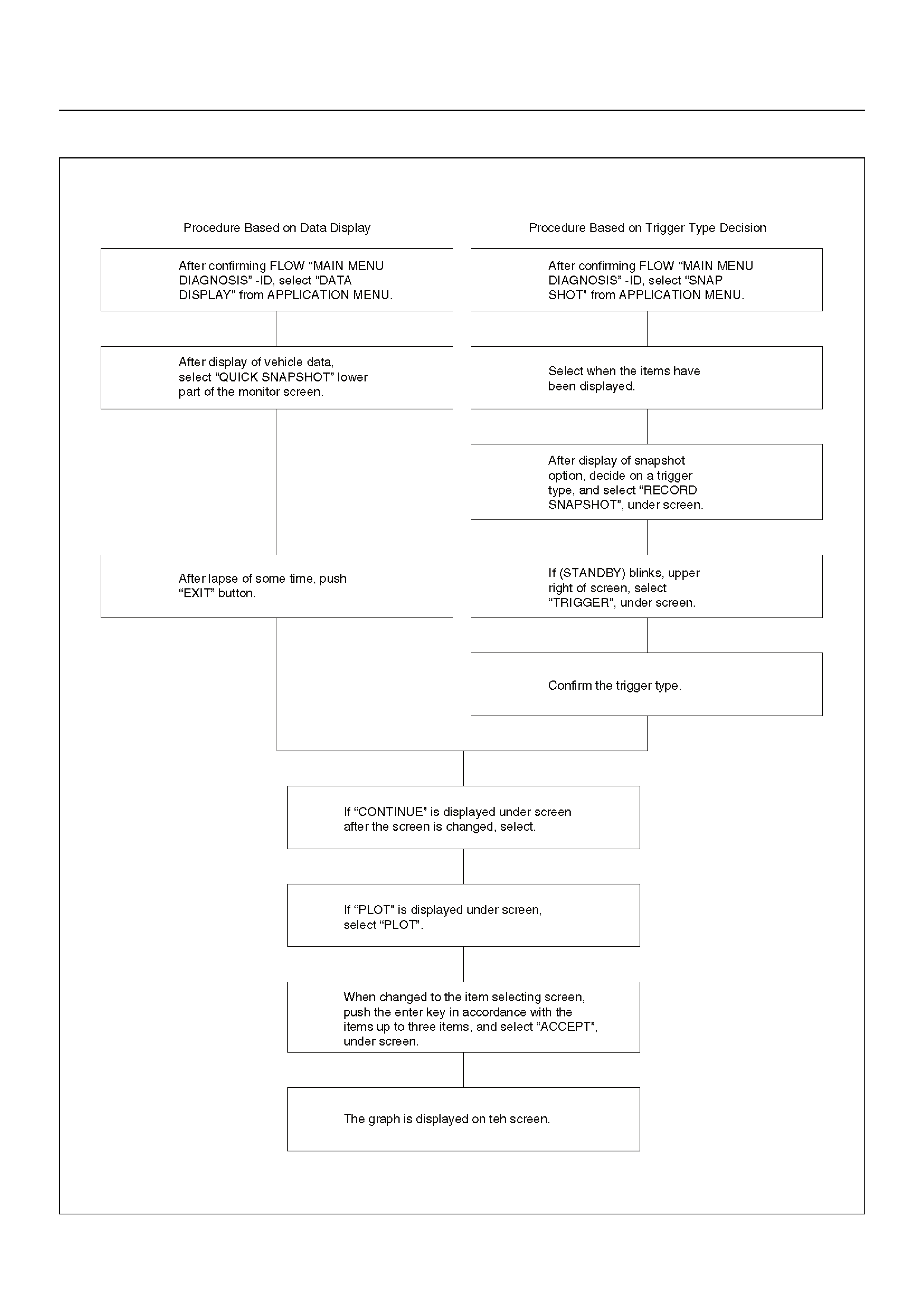
Plotting Graph Flow Chart (Plotting graph after obtaining vehicle information)
D06RY00167
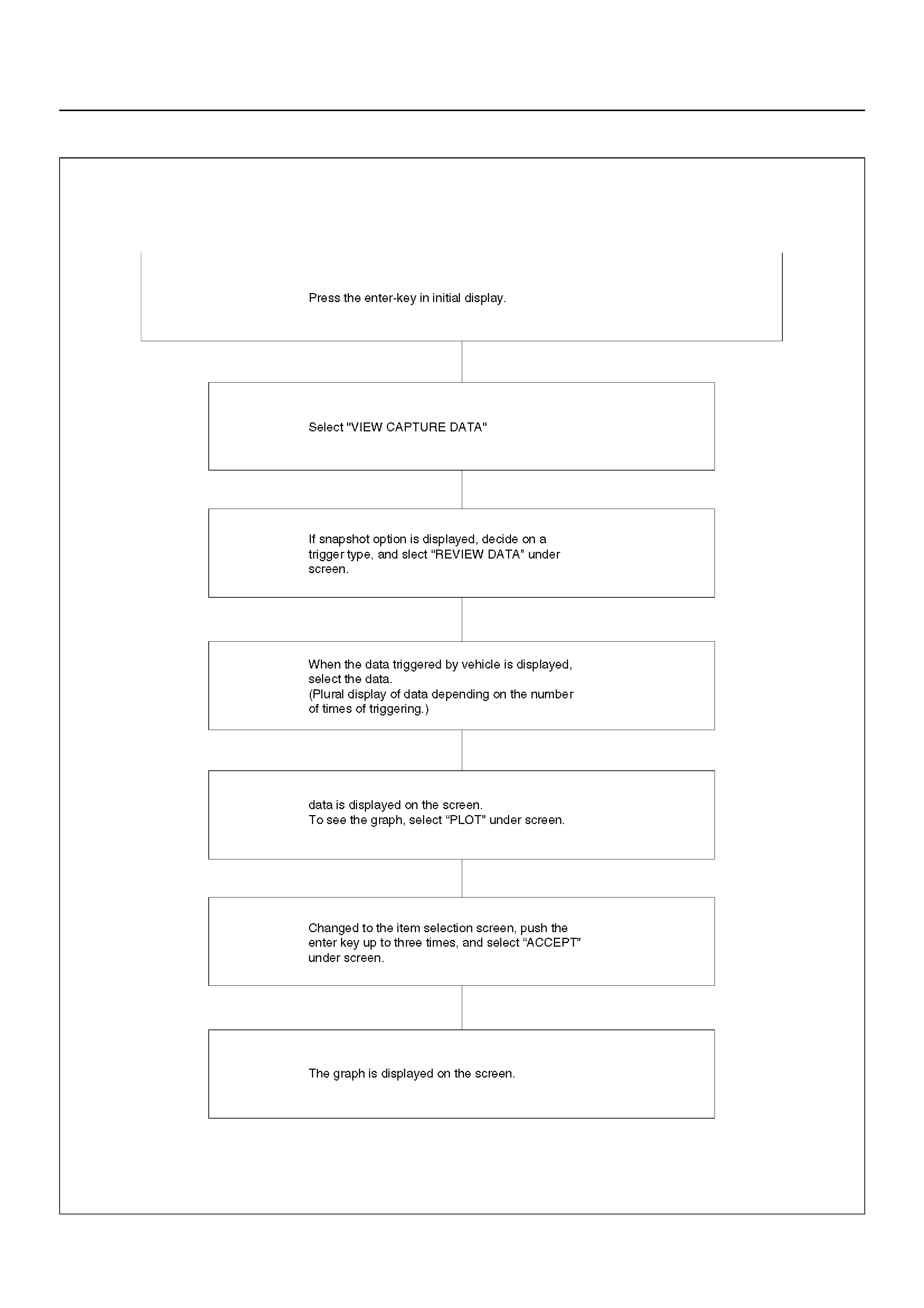
Flow Chart for Snapshot Replay (Plotting Graph)
060RX0-40
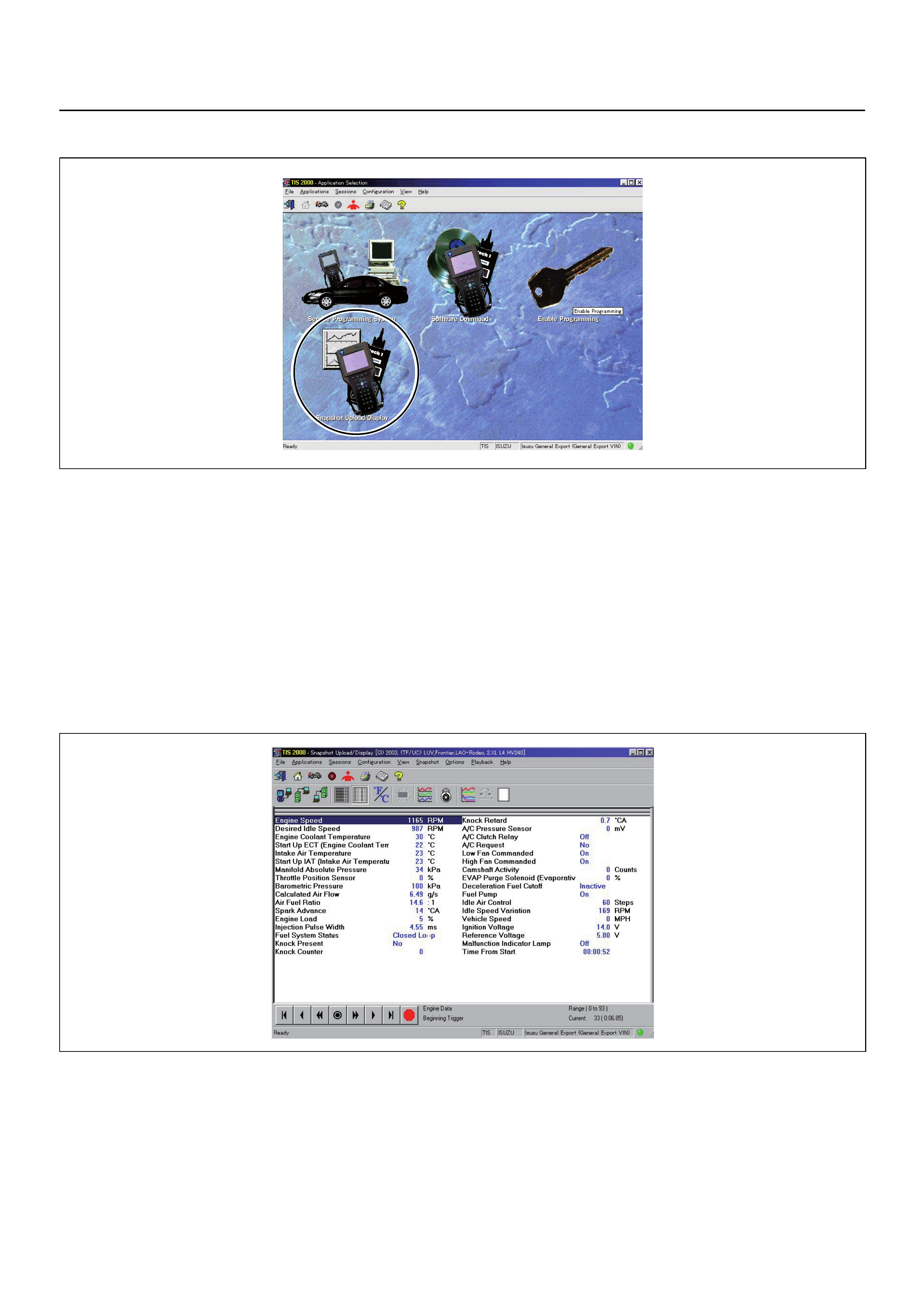
SNAPSHOT DISPLAY WITH TIS2000
Procedures for transferring and displaying Tech 2
snapshot data by using TIS2000 [Snapshot Upload]
function is described below.
Snapshot data can be displaye d with [Snapsh ot Upload]
function included in TIS2000.
By analysing these data in various methods, trouble
conditions can be checked.
Snapshot data is displayed by executing the three steps
below shown:
1. Record the snapshot data, in Tech 2.
2. Transfer the snapshot data to PC.

After recording the snapshot in Tech 2, transfer the data
from Tech 2 to PC by the below procedures.
1. Start TIS2000.
2. Select [Snapshot Upload] on the TIS2000 start
screen.
3. Select [Upload from trouble diagnosis tool (transfer
from diagnosis tester)] or click the corresponding
icon of the tool bar.
4. Select Tech 2, and transfer the recorded snapshot
information.
5. Select the transferred snapshot.
6. After ending transfer of the snapshot, data
parameter list is displayed on the screen.
3. Snapshot data is displayed with TIS2000
[Snapshot Upload] function.
Snapshot is stored in the PC hard disk or floppy disk,
and can be displayed any time.
Stored snapshot can be displayed by the below
procedures.
1. Start TIS2000.
2. Select [Snapshot Upload] on the TIS2000 start
screen.
3. Select [Open the existing files] or click the
corresponding icon of the tool bar.
4. Select the transferred snapshot.
5. Open the snapshot, to display the data parameter
list on the screen.
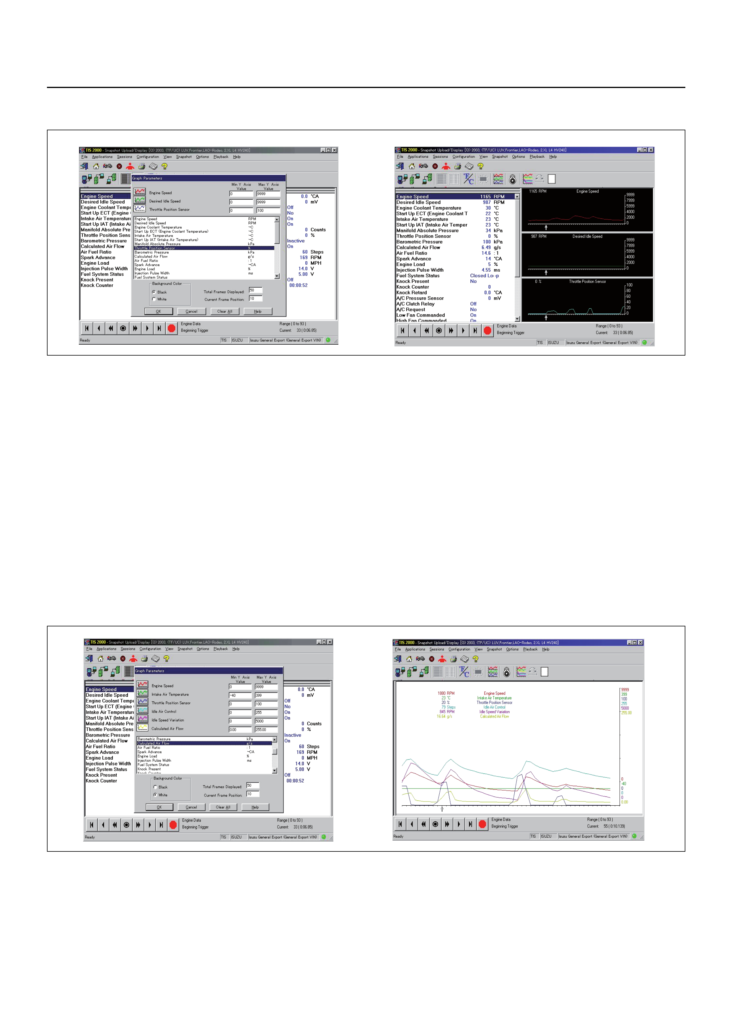
Graph display Values and graphs (Max. 3 graphs):
1. Click the icon for graph display. [Graph Parameter]
window opens.
2. Click the first graph icon of the window upper part,
and select on e paramete r from the list of the win dow
lower part. Selected parameter is displayed nest to
the graph icon. Graph division can be selected in
the field on the parameter right side.
3. Repeat the same procedures with the 2nd and 3rd
icons.
4. After selectin g all parameters t o be displayed (M ax.
3 parameters), click [OK] button.
5. Parameter selected is displayed in graph form on
the right of the data parameter on the screen.
6. Graph display can be moved with the navigation
icon.
7. For displaying another par ameter b y graph, click the
parameter of the list, drag th e mouse to the display
screen while pressing the mouse button and release
the mouse button. New parameter is displayed at
the position of the previous parameter. For
displaying the graph display screen in full size,
move the cursor upward on the screen. When the
cursor is changed to the magnifying glass form, click
the screen. Graph screen is displayed on the wh ole
screen.
Display of graphs on one screen (Max. 6 graphs):
1. Click the 6 graph icon. [Graph Parameter] window
opens.
2. Click the graph icon, select the parameter to be
displayed from the list and change divisions
according to necessity.
3. Repeat the same procedures with the graph icons,
from the 2nd to 6th.
4. Click the [OK] button to display.
5. In this case, pa ramet ers ar e disp lay ed only in grap h
form. All parameters are displayed in one graph.
6. The graph display screen can be moved with the
navigation icon.
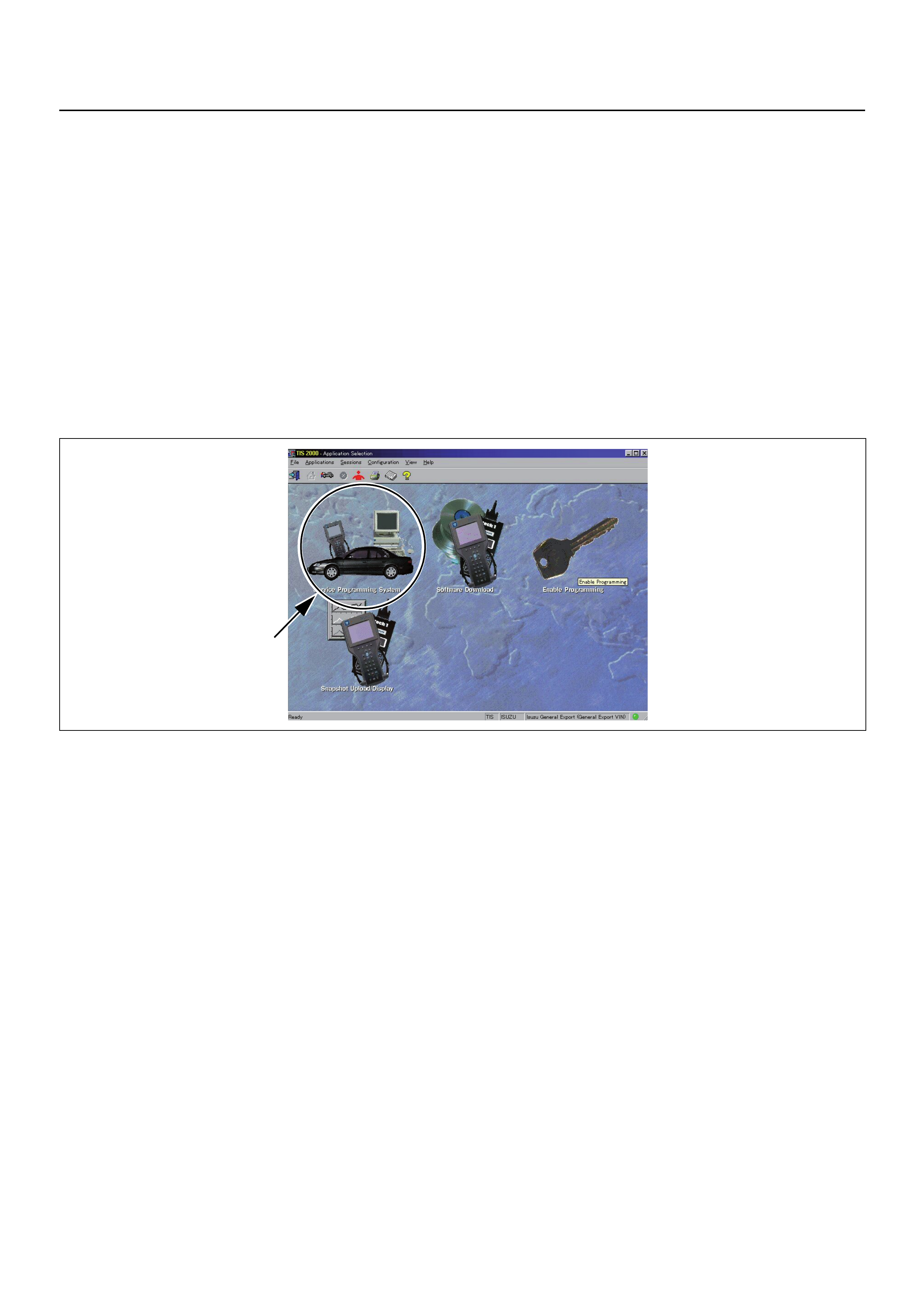
SERVICE PROGRAMMING SYSTEM (SPS)
The procedure to program the control unit by using the
Service Programming System (SPS) software
contained in TIS2000 is explained below.
NOTE:
• If the Engine Control Module (ECM) was
programmed, the Immobiliser System must be linked
to the ECM: Refer to section 11 “Immobiliser System-
ECM replacement” for the ECM/Immobiliser linking
procedure.
Important: Perform the following checks before
attempting to program the control unit:
• The Tech 2 PCMCIA card is programmed with The
latest software release.
• The latest release of TIS2000 is loaded on the PC.
• The vehicle battery is fully charged.
• The control unit to be programmed is connected to
the vehicle.
1. Preparations of TIS 2000
1. Connect Tech 2 to P/C.
2. Check to see if Hardware Key is plugged into Port.
3. Activate TIS 2000 by P/C.
4. On the activating screen of TIS2000, choose
“Service Programming System”
5. On the screen of “Diagnostic Tester and Process i ng
Program Selection”, choose the one that will comply
with the following.
• Diagnostic tester in use
• New programming by the existing module or new
programming by the replaced/new module.
• Fixing position of the control unit.
6. Upon completion of the selection, push the b utton of
“Continue”.
2. Demand of Data
1. Connect Tech 2 to the vehicle. When activated by
switching on the power of Tech 2, push the “Enter”
switch.
2. Switch “On” the ignition switch (without starting the
engine)
3. In the main menu of Diagnostic Tester, push “F1:
Service Programming System (SPS)”.
4. Push “F0: Request Info” of Tech 2.
5. Where vehicle data has been already saved in
Tech 2, the existing data comes on display. In this
instance, as Tech 2 starts asking whether to keep
the data or to continue obtaining new data from the
control unit, choose one of them.
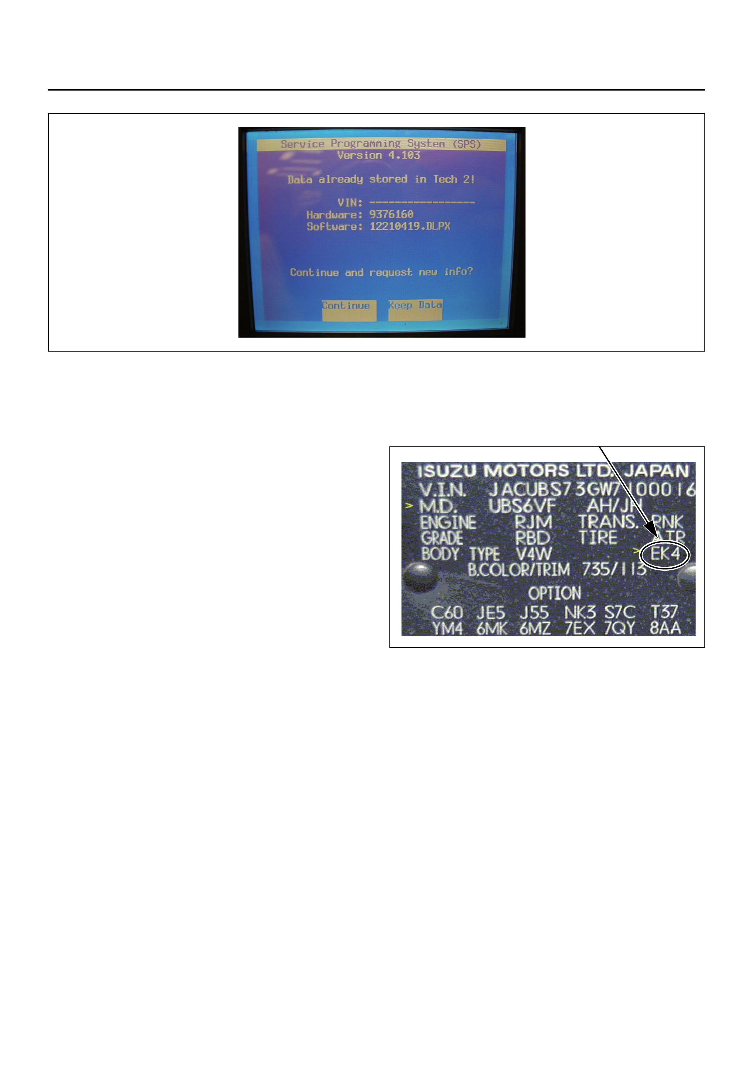
6. If you select “continue”, you have to select “Model
Year”, “Vehicle Type”, “Controller Type (Engine)”.
7. After that, push the button and turn the ignition
switch to On, Off, On following Tech 2 display.
Tech 2 will read information from controller after
this procedur e .
8. During “Obtaining Information”, Tech 2 is receiving
information from the control unit chosen. In
replacing the control unit, please be sure to
undertake “Obtaining Information” from the new
unit. With VIN not being programmed into the new
control unit at the time of shipment, “Obtaining
Information” is not complete (because the vehicle
model, engine model and model year are specified
from VIN). For the procedure, get additional
information on vehicles, instruction will be provided
in dialog form, when TIS2000 is in operation.
9. Following instructions by Tech 2, push the “Exit”
switch of Tech 2, switch off the vehicle ignition and
switch off the power of Tech 2, thereby removing
the contact with the vehicle.
3. Data Exchange
1. Connect Tech 2 to P/C, switch on the power and
click the “Next” button of P/C.
2. Check VIN of the vehicle and choose “Next”.
3. When a lack of data is asked from among the
following menu, enter accordingly.
Select following Menu
• Model Year
• Model
• Engine type
• Transmission type
• Destination code (vehicles for general export)*
• Immobiliser.
* How to read the destination code.
Destination code can be read from ID Plate affixed on
vehicles, while on VIN plate the destination code is
described at the right-hand edge of Body Type line. The
destination code can be read as “EK4 (Europe)”.
4. After choosing the data, click the “Next” button.
5. When all the necessary information is entered, the
“details” of software within the database that match
the entered data will appear for confirmation. Click
the “Program” switch and then download the new
software onto Tech 2.
6. “Data Transfer” comes on display. The progress of
downloading will be displayed on the screen in the
form of a bar graph.
7. Upon completion of the da ta transfer, switch off the
power of Tech 2, removing from P/C.
4. Programming of ECM
1. Check to see if battery is fully charged.
2. Connect Tech 2 to Vehicle Diagnostic Connectors.
3. Switch on the power of Tech 2 and the title screen
displays.
4. Turn the ignition switch to On (without allowing the
engine to start)
5. On the title screen of Tech 2, push the “Enter”
button.

6. Choose “F: Service Programming System” on the
main screen and then choose “Fl: Programming”.
7. While data is being transferred, “Downloading” will
be displayed on the Tec h 2 scr een.
8. Upon finishing the data transfer, Tech 2 will display
“Reprogramming Successful”. Push the “Exit”
button to bring program to completion.
9. Following “Procedure 2: Demand of Data”, try over
again “Information Obtaining” and check to confirm
if the data has been correctly re-loaded.
10. Upon finishing confirmation, switch off the ignition of
the vehicle and then switch off the power of Tech 2,
removing it from the vehicle.
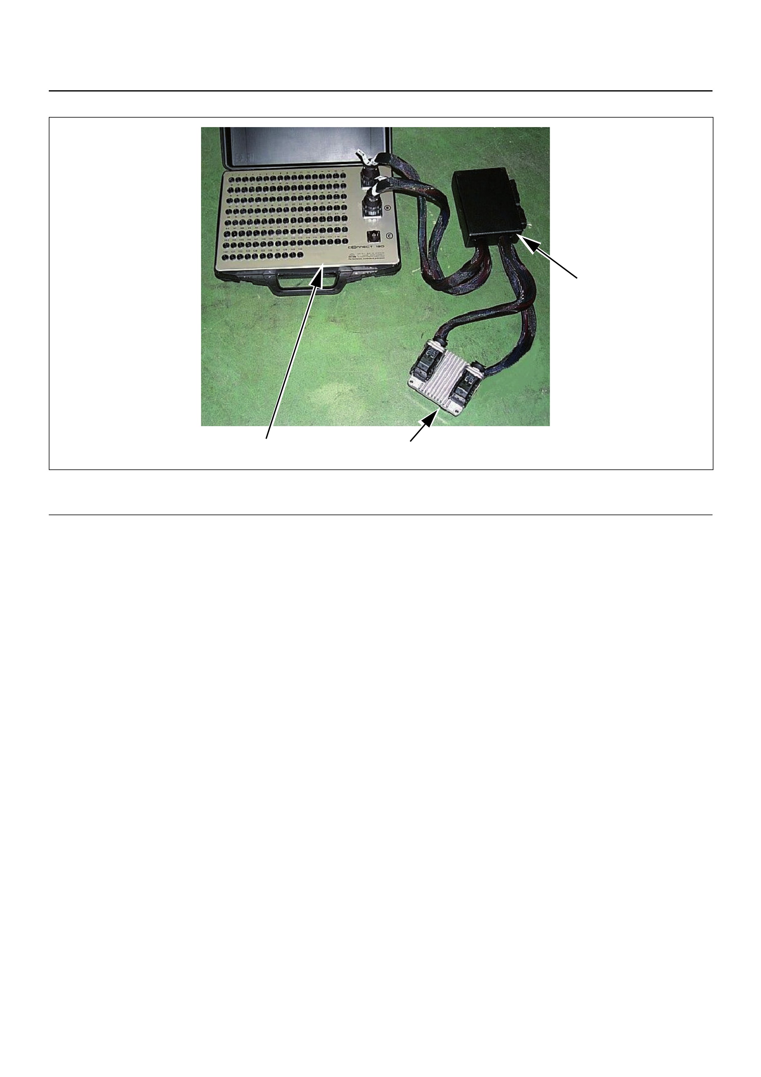
HOW TO USE BREAKER BOX
The engine control module (ECM) and other connectors
have water proof connectors and special terminals. A
water proof terminal can not be back probed. In
addition, the engine control module (ECM) special
terminal can not let regular digital voltage meter prove
to access, because terminal shape is very fin pin type.
In order to prevent damage of female terminal and
connector itself, the breaker box and adapter is the
most suitable special tool.
3 1
2
(1) Engine Control Module (ECM)
(2) Harness Adapter (3) Breaker Box
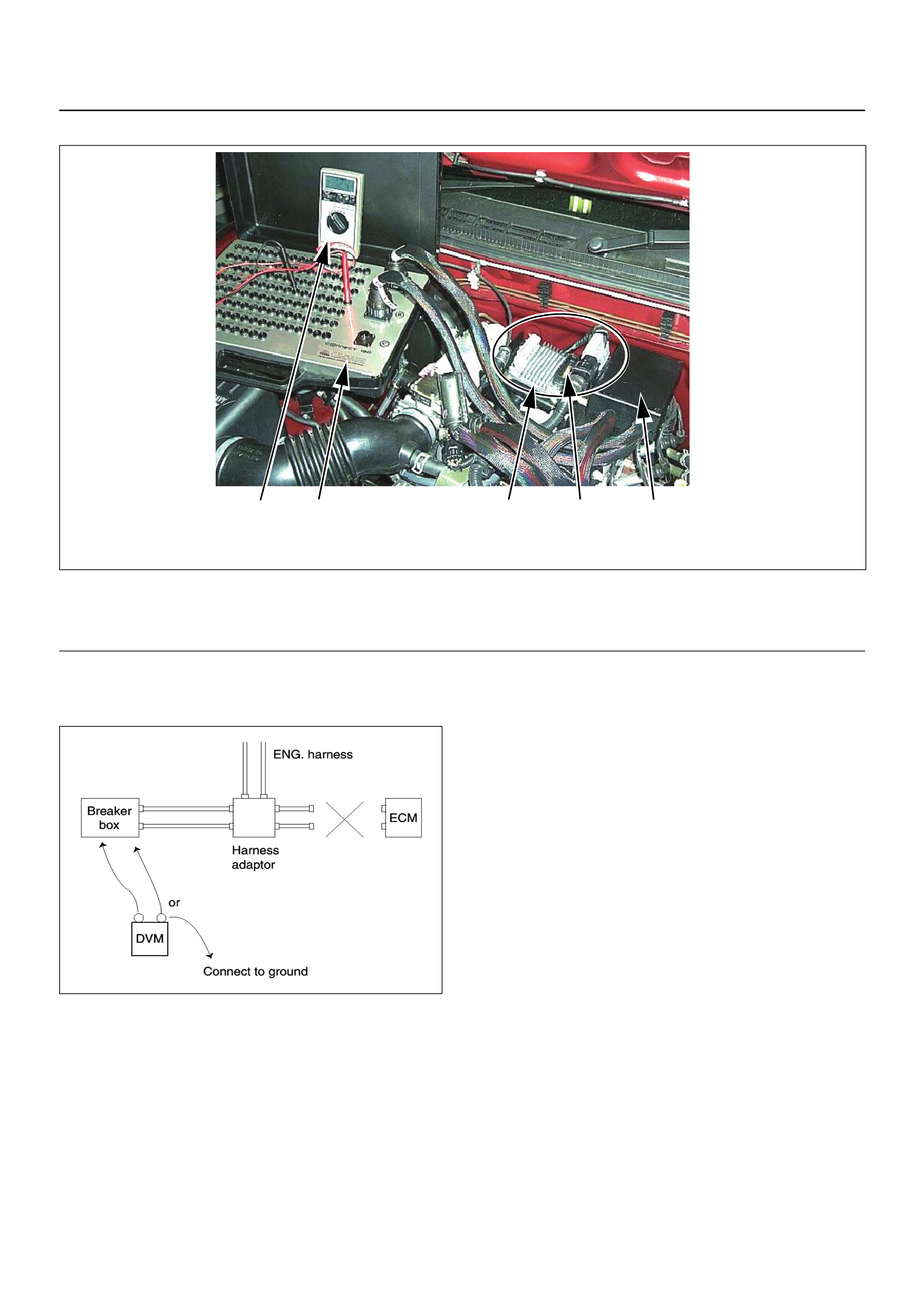
Breaker Box Connection Type A
Breaker box connection type A, check for “open circuit”
and “short to ground circuit”.
4 3 152
NOTE: This picture shows the ECM mounted on the bracket attached to top of the engine as for C24SE (Euro II).
The ECM is attached to the bracket on the left hand side of the engine bay for Y24SE. Refer to 6E-8.
(1) Engine Control Module (ECM)
(2) Harness Adapter
(3) Breaker Box
(4) Digital Voltage Meter
(5) ECM - Harness Adap te r Disc on ne ct ion
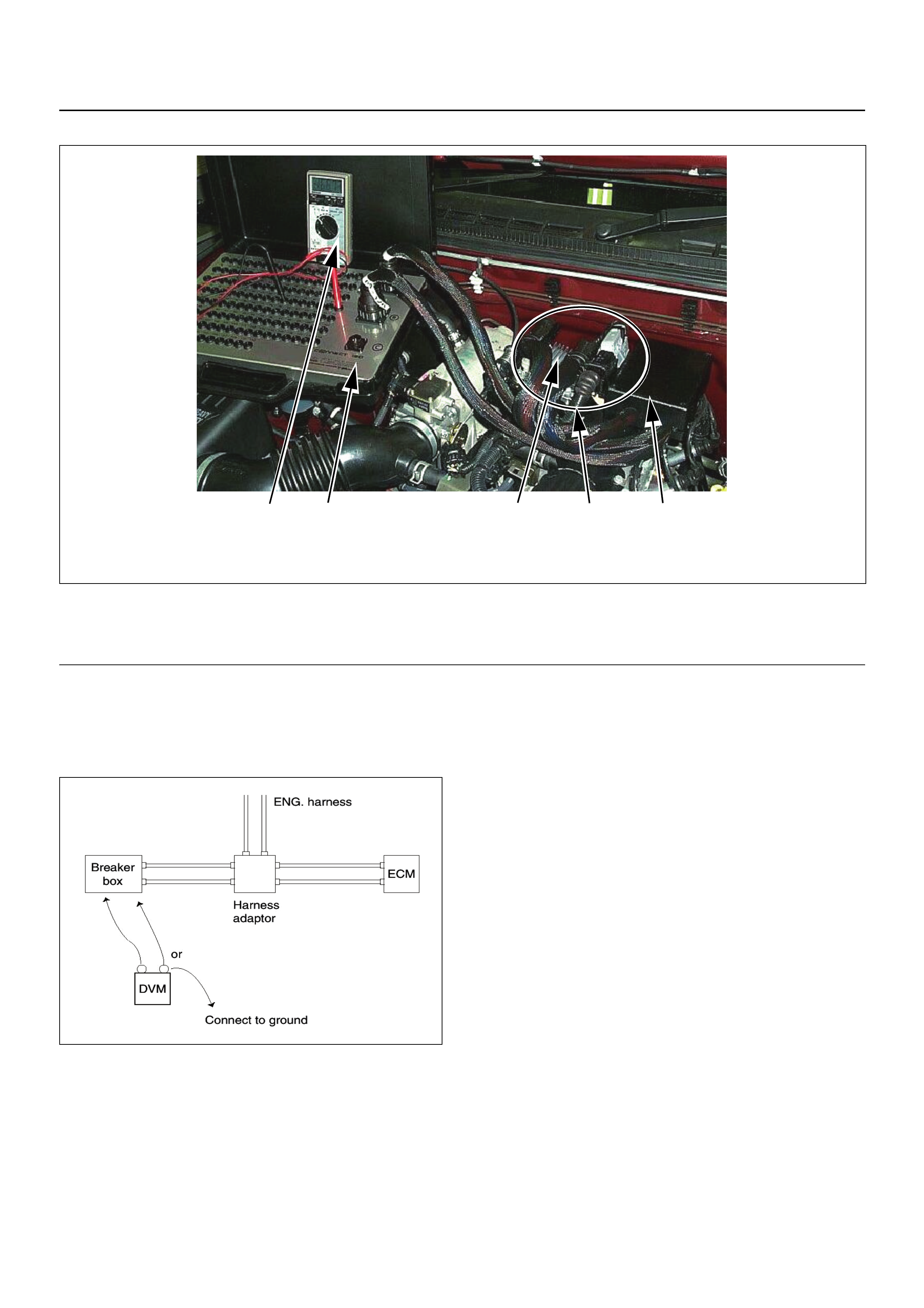
Breaker Box Connection Type B
Breaker box connection type B, check for “short to
power supply circuit” and “power, signal voltage check”
between the engine control module (ECM) and
electrical components.
43152
NOTE: This picture shows the ECM mounted on the bracket attached to top of the engine as for C24SE (Euro II).
The ECM is attached to the bracket on the left hand side of the engine bay for Y24SE. Refer to 6E-8.
(1) Engine Control Module (ECM)
(2) Harness Adapter
(3) Breaker Box
(4) Digital Voltage Meter
(5) ECM - Harness Adap te r Co nn ec tio n
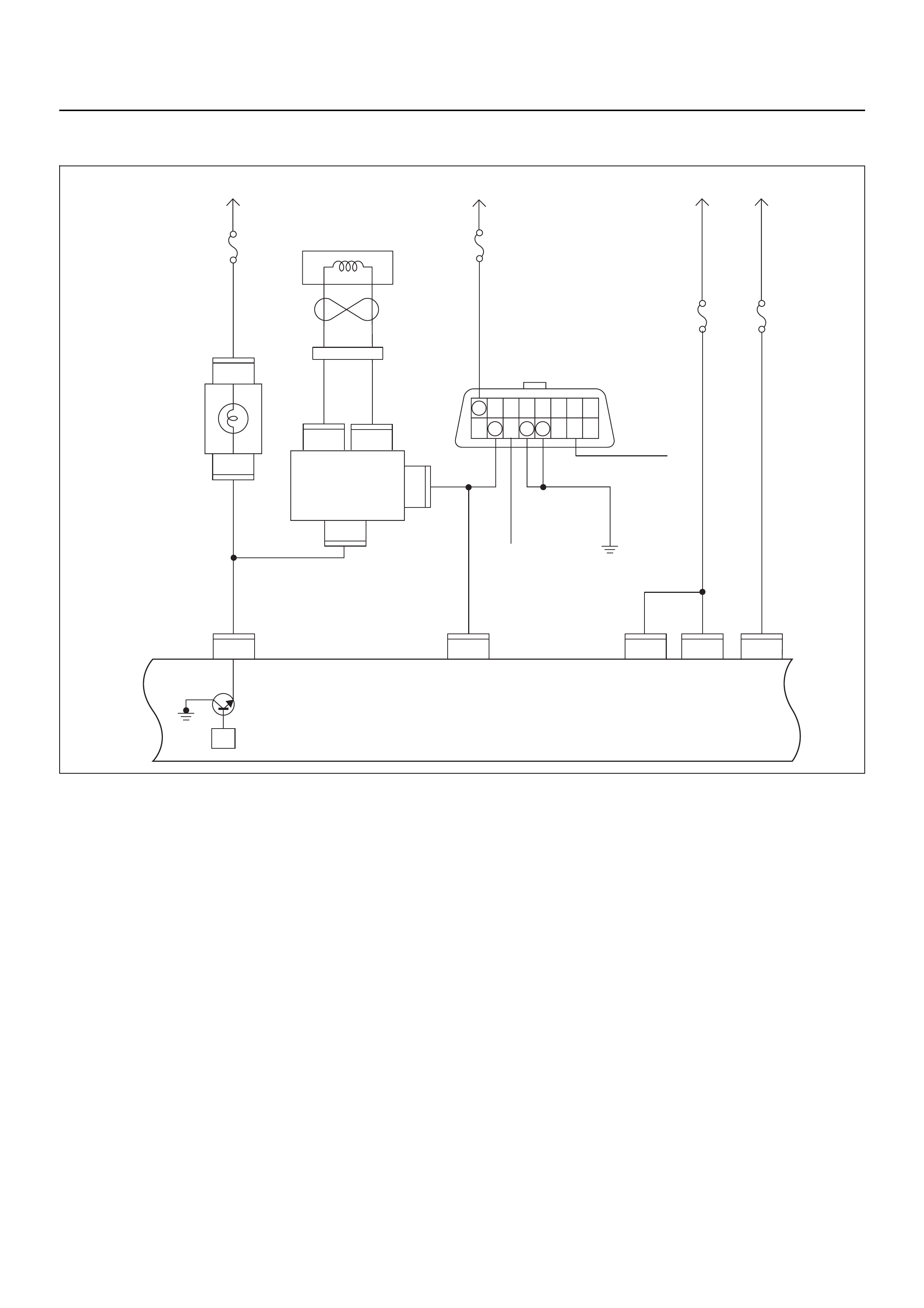
ON-BOARD DIAGNOSTIC (OBD) SYSTEM CHECK
Circuit Description
The on-board diagnostic system check is the starting
point for any driveability complaint diagnosis. Before
using this procedure, perform a careful visual/physical
check of the ECM and engine grounds for cleanliness
and tightness.
The on-board diagnostic system check is an organised
approach to identifying a problem created by an
electronic engine control system malfunction.
Diagnostic Aids
An intermittent fault may be caused by a poor
connection, rubbed-through wire insulation or a wire
broken inside the insulatio n. Check for poor connections
or a damaged harness. Inspect the ECM harness and
connector for improper mating, broken locks, improperly
formed or damaged terminals, poor terminal-to-wire
connection, and damaged harness.
Test Description
Number(s) below refer to the step number(s) on the
Diagnostic Chart:
1. The Check Engine Lamp (MIL) should be ON steady
with the ignition “On”, engine “Off”. If not, “No Check
Engine Lamp (MIL)” chart should be used to isolate the
malfunction.
2. Check the KWP2000 data circuit and ensure that the
ECM is able to transmit serial data.
3. This test ensures that the ECM is capable of
controlling the Check Engine Lamp (MIL) and the Check
Engine Lamp (MIL) driver circuit is not shorted to
ground circuit.
4. If the engine will not start, “Engine Cranks But Will
Not Run” chart should be used to diagnose the fault.
6. The Tech 2 parameters which is not within the typical
range may help to isolate the area which is causing the
problem.
7. This vehicle is equipped with ECM which utilises an
electrically erasable programmable read only memory
(EEPROM).
C56
7
5
C56
B58
B68
B68
3
B24
32 15
C56
218J2J2J2 J2 J2
C56
3
C56
B24
30
31
(+)(–)
B70 B70
Battery
Voltage
0.85
RED/
YEL
0.85
YEL
Engine
Room-RH
μP
0.5
BRN/
YEL
0.3
BRN/
YEL
Engine
Control
Module
(ECM)
MIL
Lamp
Immobiliser
Coil
(Antenna)
Immobiliser
Control
Unit (ICU)
Meter
15A
Ignition
SW
0.85
RED/
WHT
0.5
RED/
WHT
0.5
BLU/
YEL
2.0
WHT 3.0
BLK/
RED
0.5
YEL/
BLU
Batt
Pwr
MIL
Lamp Batt
Pwr Ign
Pwr
KWP2000
Serial Data
0.85
BLK
Class 2
Class 2
Diagnostic
Connector
16151413121110 9
87654321
Meter
15A
Ignition
SW
Engine
I5A
Battery
Voltage
ECM
I5A
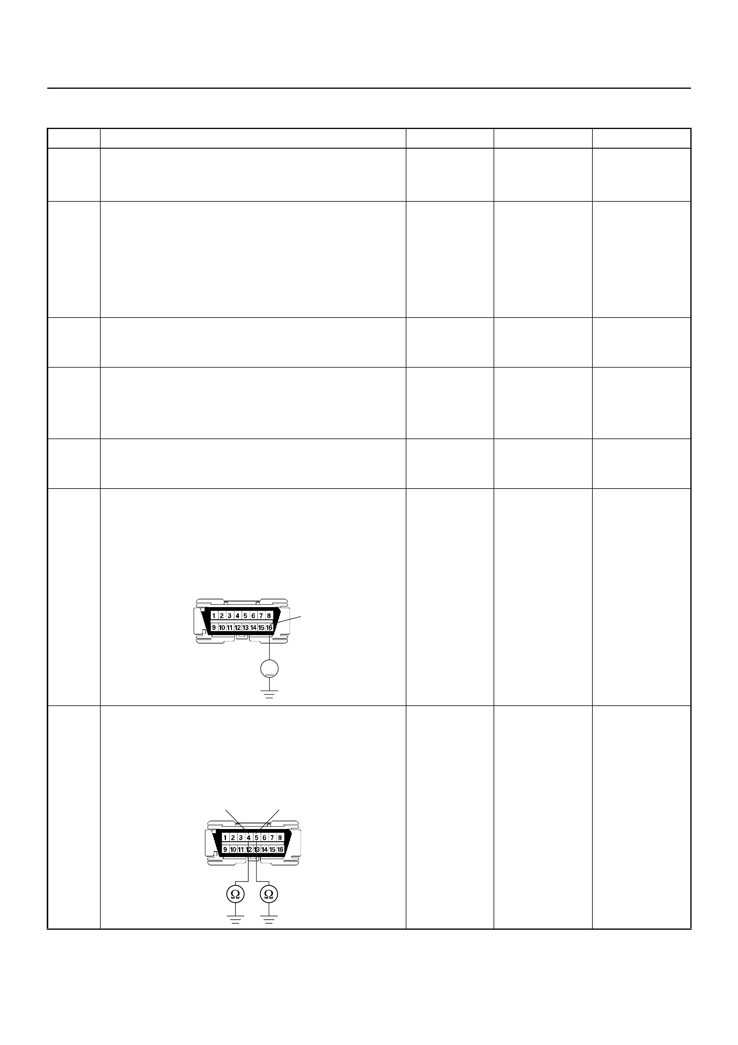
ON-BOARD DIAGNOSTIC (OBD) SYSTEM CHECK
Step Action Value(s) Yes No
1 1. Ignition “On” , en gin e “Off ”.
2. Check the “CHECK ENGINE” lamp (MIL).
Does the “CHECK ENGINE” lamp switch “On”? — Go to Step 2
Go to No
CHECK
ENGINE Lamp
2 1. Using Tech 2, ignition “On” and engine “Off”.
2. Select “F3 Actuator Test” and perform the
“Malfunction Indicator (MI) Test” .
3. Operate T ech 2 in accordance wi th instructions to
manually switch “Off” the Check Engine (MIL)
lamp.
Does the “CHECK ENGINE” lamp switch “Off”? — Go to Step 3
Go to CHECK
ENGINE LAMP
On Steady
3 Attempt to start the engine.
Does the engine start and continue to “Run”? — Go to Step 4
Go to Engine
Cranks But Will
Not Run
4 1. Using Tech 2, ignition “On” and engine “Off”.
2. Select the “Read DTC Info By Priority” in
“Diagnostic Trouble Code”.
3. Are any DTCs stored? — Go to DTC
Chart Go to Step 7
5 Compare typical scan data values displayed on
Tech 2 “Engine Data”.
Are the displayed values within the range? —
Refer to
SYMPTOM
DIAGNOSIS
Refer to
TYPICAL
SCAN DATA
6 Use a DVM to check the data link connector power
supply circuit.
1. Ignition “Off”, engine “Off”.
2. Check the circuit for op en ci rcu it.
Was the problem found?
—
Repair faulty
harness and
verify repair Go to Step 9
7 Use a DVM to check the data link connector ground
circuit.
1. Ignition “Off”, engine “Off”.
2. Check the circuit for op en ci rcu it.
Was the problem found?
—
Repair faulty
harness and
verify repair Go to Step 10
V
16
B58
54 B58
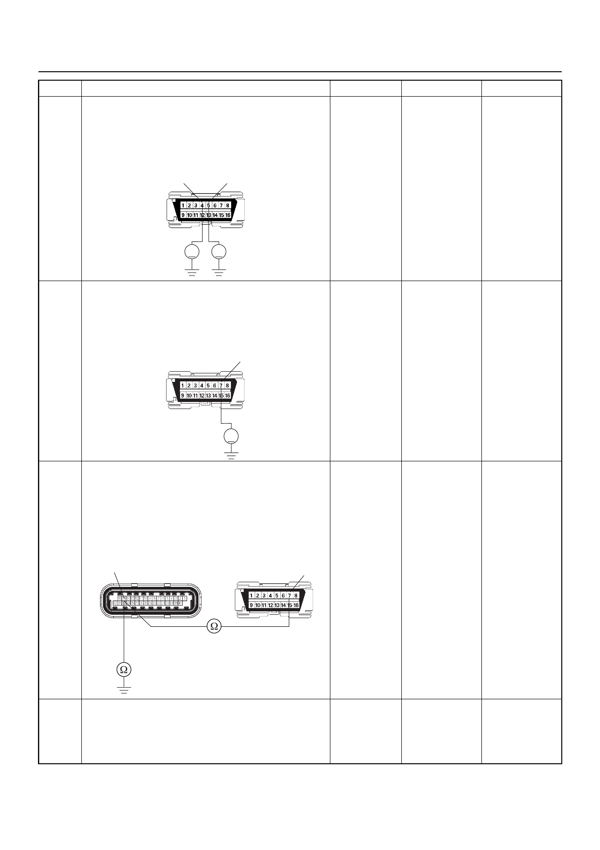
8 Use a DVM to check the data link connector ground
circuit.
1. Ignition “On”, engine “Off”.
2. Check the circuit for short to power supply circuit.
Does the DVM indicate the specified value?
Less than 1V Go to Step 11
Repair faulty
harness and
verify repair
9 Use a DVM to check the data link connector
communication circuit.
1. Ignition “On”, engine “Off”.
2. Check the circuit for short to power supply circuit.
Does the DVM indicate battery voltage?
—
Repair faulty
harness and
verify repair Go to Step 12
10 Use a DVM to check the data link connector
communication circuit.
1. Ignition “Off”, engine “Off”.
2. Disconnect the ECM connector.
3. Check the circuit for open or short to ground
circuit.
Was the problem found?
—
Repair faulty
harness and
verify repair Go to Step 13
11 Is the ECM programmed with the latest software
release?
If not, download the latest software to the ECM using
the “SPS (Service Programming System)”.
Was the problem solved? — Verify repair Go to Step 14
Step Action Value(s) Yes No
V V
54 B58
V
7
B58
B58
C56(J2)
15 7

12 Replace the ECM.
Is the action complete?
IMPORTANT: The replacement ECM must be
programmed. Refer to the Service Programming
System (SPS) section in this manual.
Following ECM programming, the immobiliser system
must be linked to the ECM. Refer to section 11
“Immobiliser System-ECM replacement” for the ECM/
Immobiliser linking procedure. — Verify repair —
Step Action Value(s) Yes No
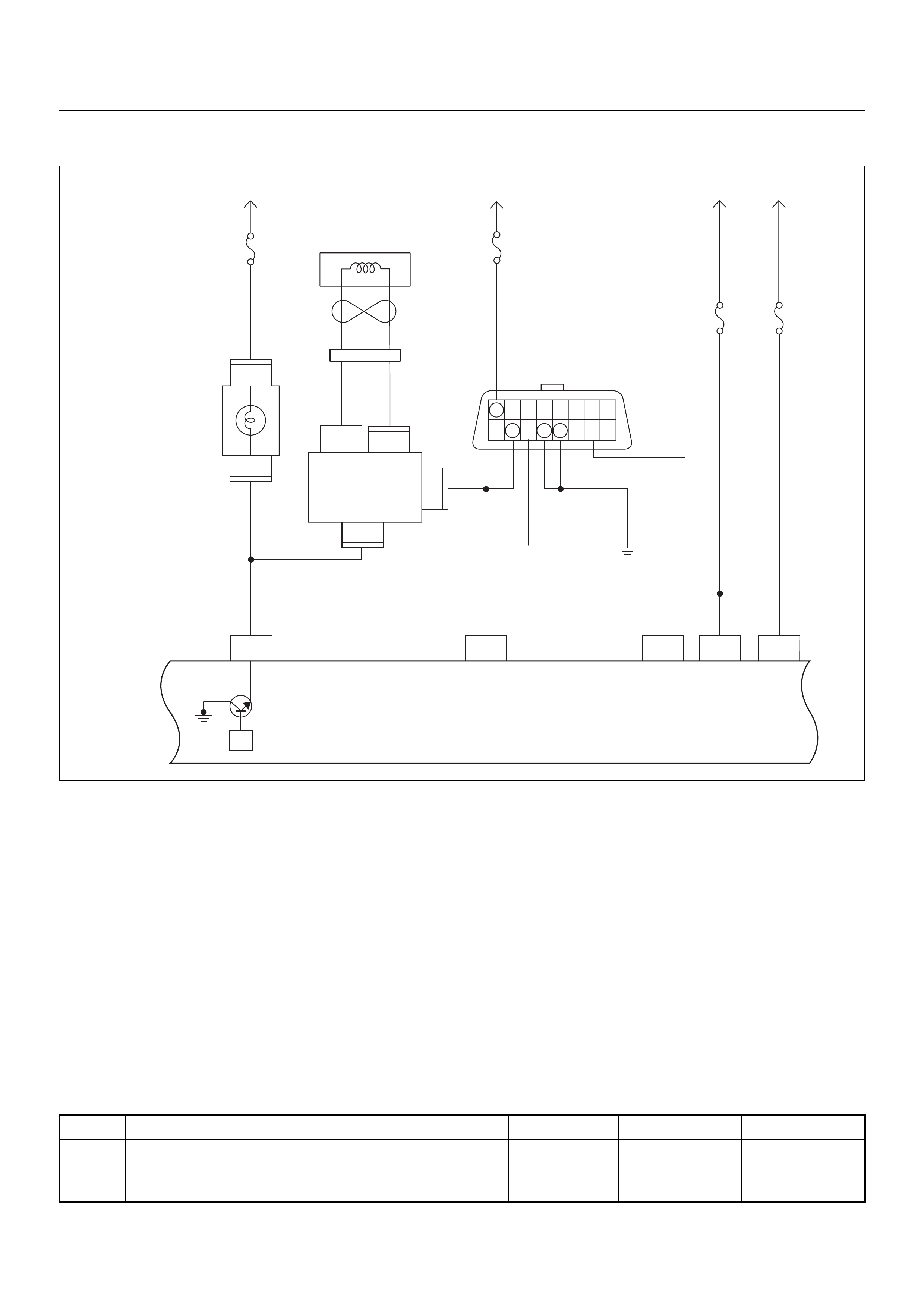
NO CHECK ENGINE LAMP (MIL)
Circuit Description
The check engine lamp should be illuminated with the
ignition “ON” and the engine stopped. Ignition feed
voltage is supplied to the check engine lamp bulb
through the meter fuse. The Engine Control Module
(ECM) switches the check engine lamp “ON” by
grounding the check engine lamp driver circuit.
Diagnostic Aids
An intermittent check engine lamp may be caused by a
poor connection, rubbed-through wire insulation, or a
wire broken inside the insulation. Check for the
following items:
• Inspect the ECM harness and connections for
improper mating, broken locks, improperly formed or
damaged terminals, poor terminal-to- wire connection,
and damaged harness.
• If the engine runs OK, check for a faulty light bulb, an
open in the check engine lamp driver circuit, or an
open in the instrument cluster ignition feed.
• If the engine cranks but will not run, check for an
open ECM ignition or battery feed, or a poor ECM to
engine ground.
No Check Engine Lamp (MIL)
C56
7
5
C56
B58
B68
B68
3
B24
32 15
C56
218J2J2J2 J2 J2
C56
3
C56
B24
30
31
(+)(–)
B70 B70
Battery
Voltage
0.85
RED/
YEL
0.85
YEL
Engine
Room-RH
μP
0.5
BRN/
YEL
0.3
BRN/
YEL
Engine
Control
Module
(ECM)
MIL
Lamp
Immobiliser
Coil
(Antenna)
Immobiliser
Control
Unit (ICU)
Meter
15A
Ignition
SW
0.85
RED/
WHT
0.5
RED/
WHT
0.5
BLU/
YEL
2.0
WHT 3.0
BLK/
RED
0.5
YEL/
BLU
Batt
Pwr
MIL
Lamp Batt
Pwr Ign
Pwr
KWP2000
Serial Data
0.85
BLK
Class 2
Class 2
Diagnostic
Connector
16151413121110 9
87654321
Meter
15A
Ignition
SW
Engine
I5A
Battery
Voltage
ECM
I5A
Step Action Value(s) Yes No
1 Check the “Meter” fuse (15A).
If the fuse is burnt out, replace as necessary.
Was the problem found? — Verify repair Go to Step 2
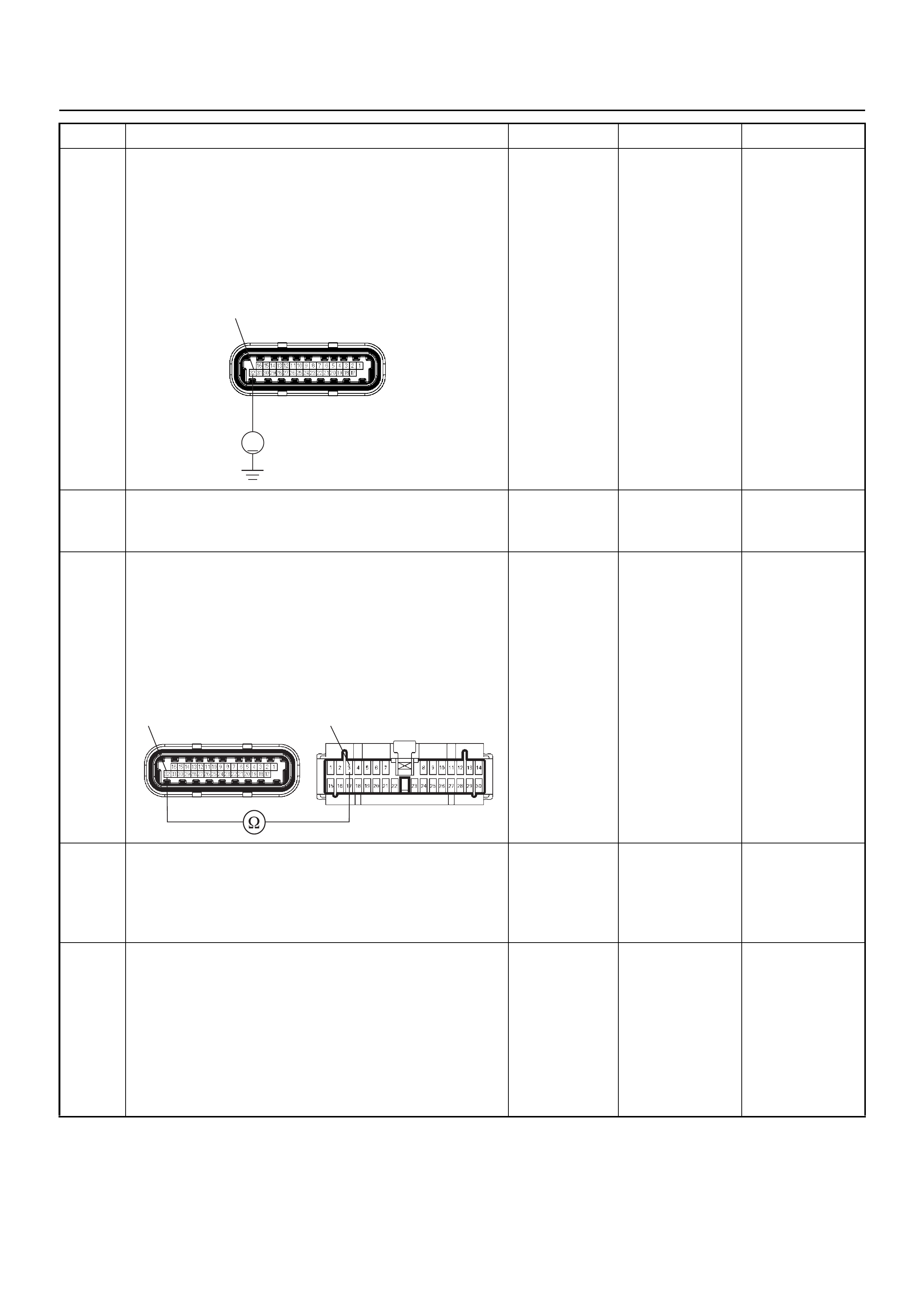
2 Use a DVM to check the “CHECK ENGINE” lamp
circuit.
1. Ignition “Off”, engine “Off”.
2. Disconnect the ECM connector.
3. Ignition “On”.
4. Check the circuit for op en ci rcu it.
Does the DVM indicate battery voltage?
Battery
voltage Go to Step 5 Go to Step 3
3 Check the “CHECK ENGINE” lamp bulb.
If the bulb is burnt out, replace as necessary.
Was the problem found? — Verify repair Go to Step 4
4 Use a DVM to check the “CHECK ENGINE” lamp
circuit.
1. Ignition “Off”, engine “Off”.
2. Disconnect the meter connector and ECM
connector.
3. Check the circuit for op en ci rcu it.
Was the problem found?
— Verify repair Go to Step 5
5 Is the ECM programmed with the latest software
release?
If not, download the latest software to the ECM using
the “SPS (Service Programming System)”.
Was the problem solved? — Verify repair Go to Step 6
6 Replace the ECM.
Is the action complete?
IMPORTANT: The replacement ECM must be
programmed. Refer to the Service Programming
System (SPS) section in this manual.
Following ECM programming, the immobiliser system
must be linked to the ECM. Refer to section 11
“Immobiliser System-ECM replacement” for the ECM/
Immobiliser linking procedure. — Verify repair —
Step Action Value(s) Yes No
V
32 C56(J2)
32 3
C56(J2) B24
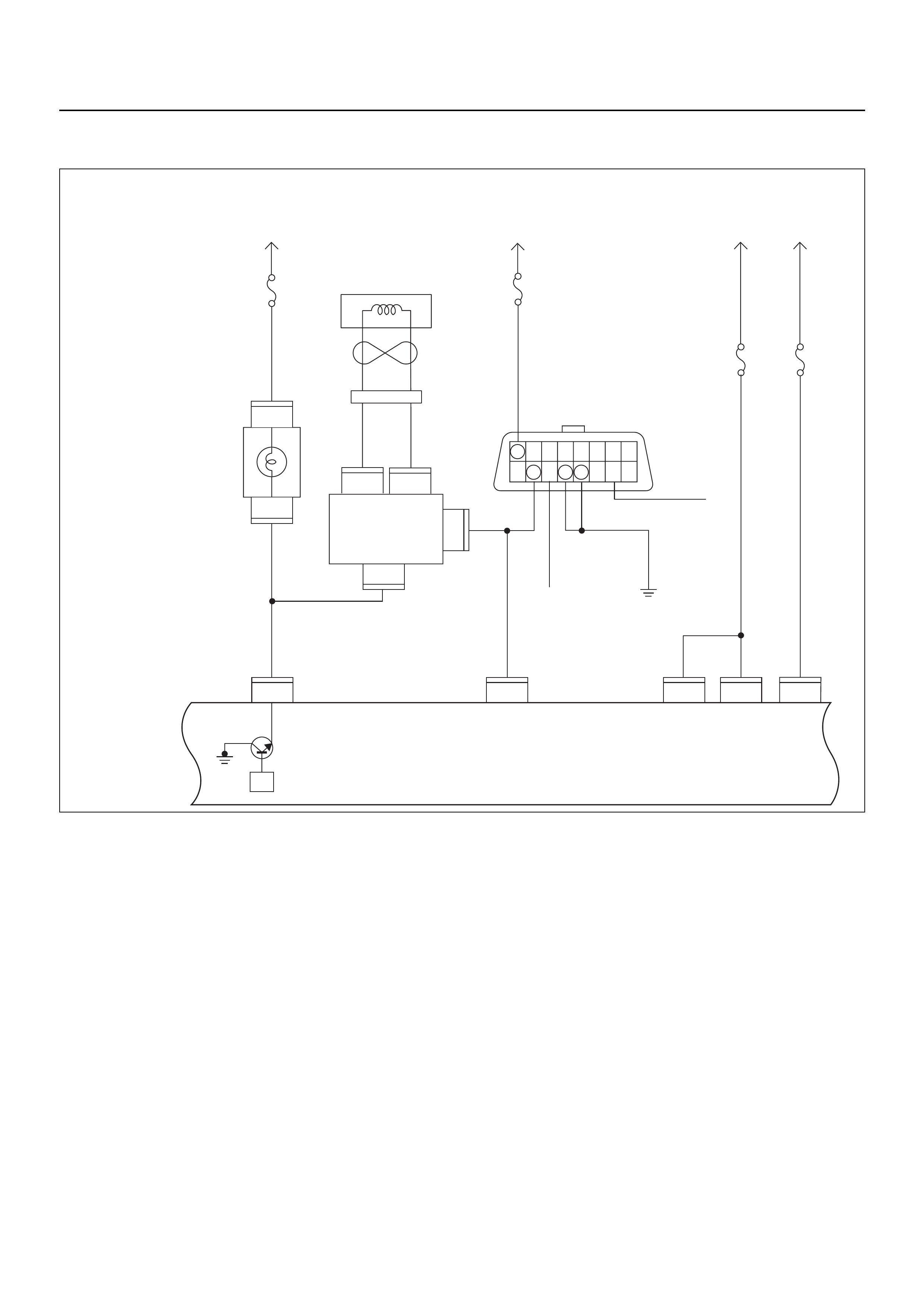
CHECK ENGINE LAMP (MIL) “ON” STEADY
Circuit description
The check engine lamp should always be illuminated
with ignition “ON” and the engine stopped. Ignition feed
voltage is supplied directly to the check engine lamp
indicator. The Engine Control Module (ECM) switches
the check engine lamp “ON” by grounding the check
engine lamp driver circuit.
The check engine lamp should not remain “ON” with the
engine running and no DTC(s) set. A steady check
engine lamp with the engine running and no DTC(s)
suggests a short to ground in the check engine lamp
driver circuit.
Diagnostic Aids
An intermittent fault may be caused by a poor
connection, rubbed-through wire insulation, or a wire
broken inside the insulation. Check for the following
items:
• Poor connection or damaged harness - Inspect the
ECM harness and connectors for improper mating,
broken locks, improperly formed or damaged
terminals, poor terminal-to-wire connection, and
damaged harness.
C56
7
5
C56
B58
B68
B68
3
B24
32 15
C56
218J2J2J2 J2 J2
C56
3
C56
B24
30
31
(+)(–)
B70 B70
Battery
Voltage
0.85
RED/
YEL
0.85
YEL
Engine
Room-RH
μP
0.5
BRN/
YEL
0.3
BRN/
YEL
Engine
Control
Module
(ECM)
MIL
Lamp
Immobiliser
Coil
(Antenna)
Immobiliser
Control
Unit (ICU)
Meter
15A
Ignition
SW
0.85
RED/
WHT
0.5
RED/
WHT
0.5
BLU/
YEL
2.0
WHT 3.0
BLK/
RED
0.5
YEL/
BLU
Batt
Pwr
MIL
Lamp Batt
Pwr Ign
Pwr
KWP2000
Serial Data
0.85
BLK
Class 2
Class 2
Diagnostic
Connector
16151413121110 9
87654321
Meter
15A
Ignition
SW
Engine
I5A
Battery
Voltage
ECM
I5A
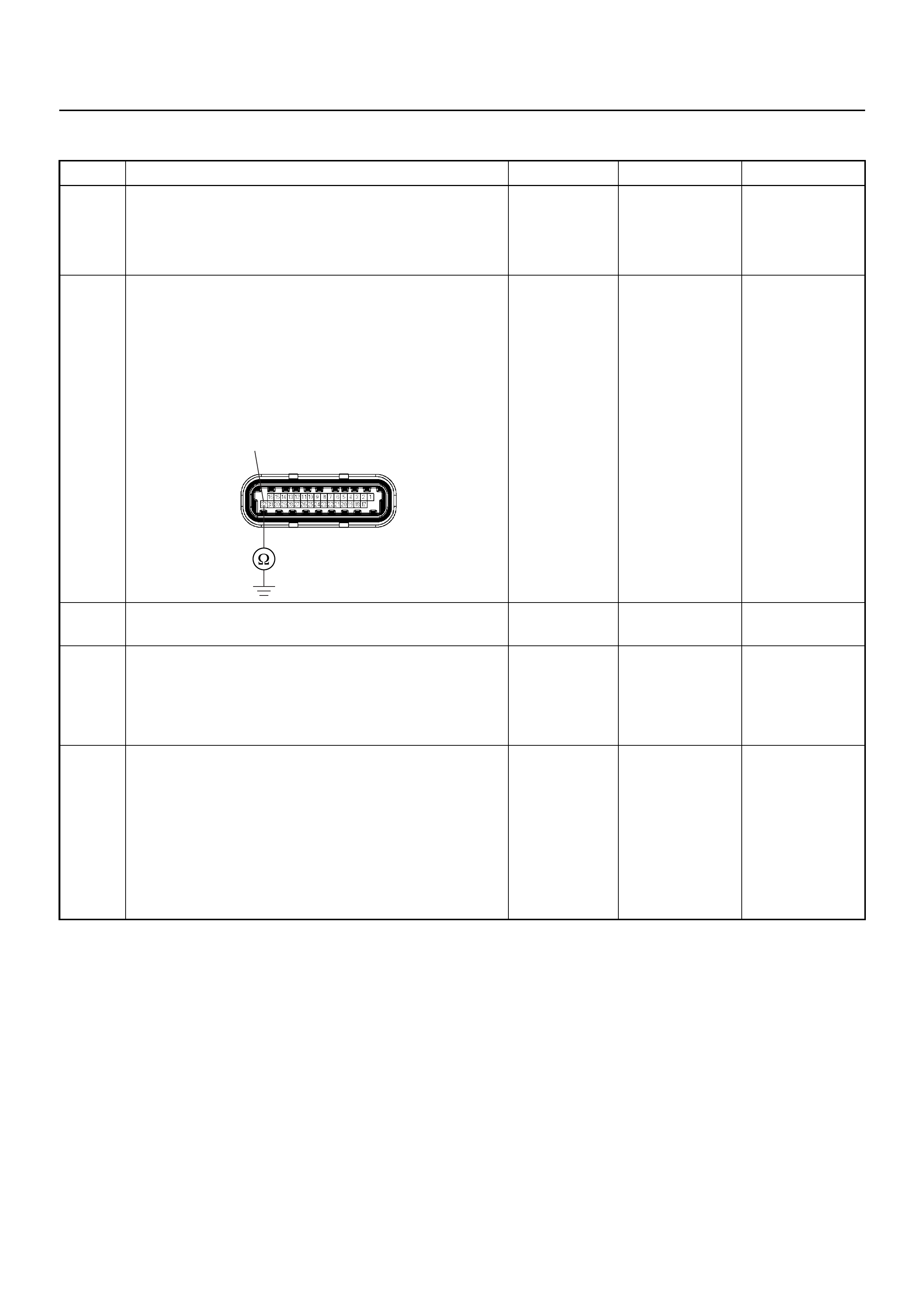
Check Engine Lamp (MIL) “ON” Steady
Step Action Value(s) Yes No
1 1. Ignition “Off” , en gin e “Off ”.
2. Disconnect the ECM connector.
3. Ignition “On”.
Was the “CHECK ENGINE” lamp switched on? — Go to Step 2 Go to Step 4
2 Use a DVM to check the “CHECK ENGINE” lamp
circuit.
1. Ignition “Off”, engine “Off”.
2. Disconnect the meter connector and ECM
connector.
3. Check the circuit for short to ground circuit.
Was the problem found?
— Verify repair Go to Step 3
3 Replace the meter assembly.
Is the action complete? — Verify repair —
4 Is the ECM programmed with the latest software
release?
If not, download the latest software to the ECM using
the “SPS (Service Programming System)”.
Was the problem solved? — Verify repair Go to Step 5
5 Replace the ECM.
Is the action complete?
IMPORTANT: The replacement ECM must be
programmed. Refer to the Service Programming
System (SPS) section in this manual.
Following ECM programming, the immobiliser system
must be linked to the ECM. Refer to section 11
“Immobiliser System-ECM replacement” for the ECM/
Immobiliser linking procedure. — Verify repair —
32 C56(J2)
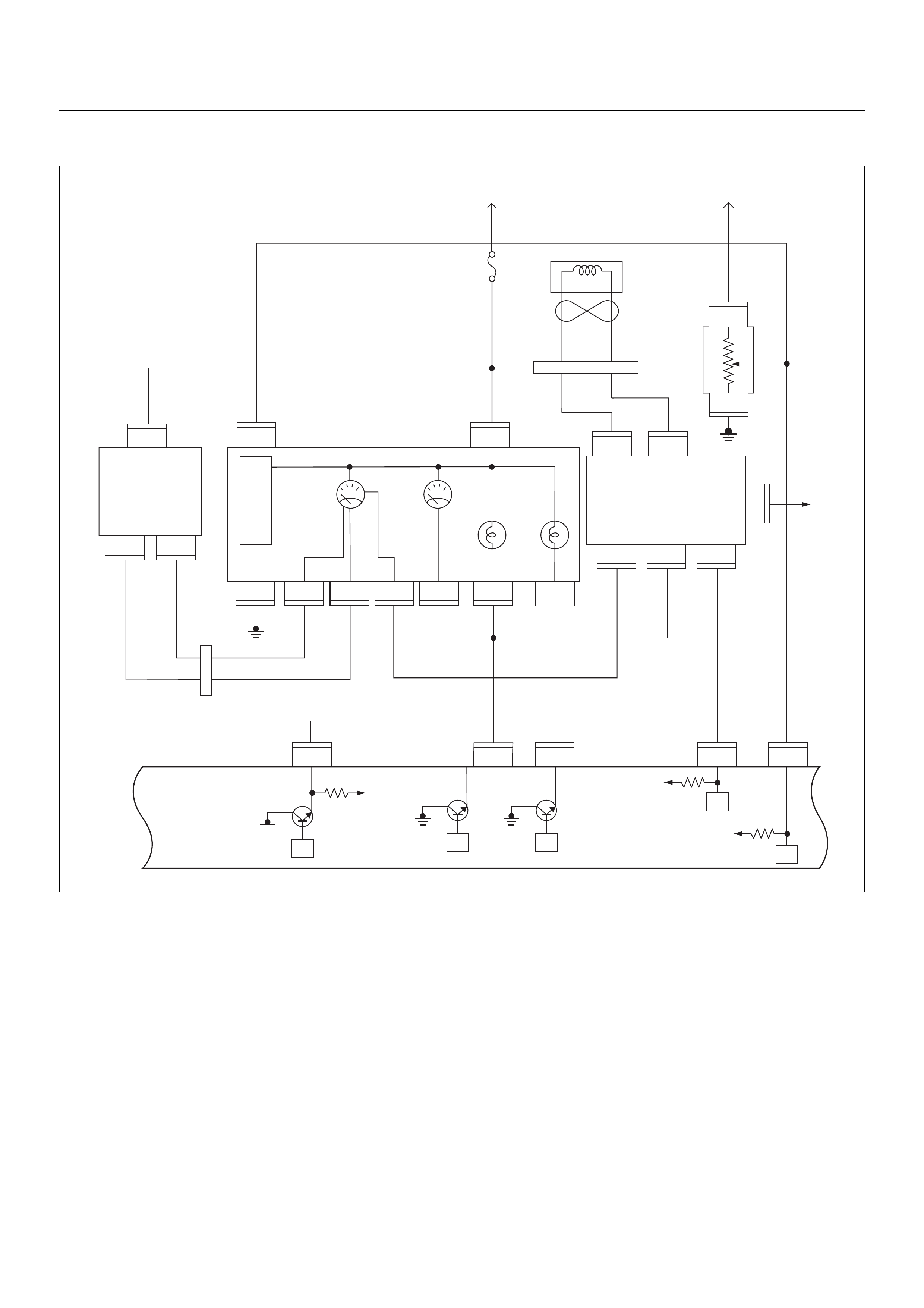
NO SERVICE VEHICLE SOON LAMP (SVS)
Circuit Description
The service vehicle soon (SVS) lamp should be
illuminated with the ignition “ON” and the engine not
started for less than 3 seconds. Ignition feed voltage is
supplied to the check SVS lamp bulb through the meter
fuse. The Engine Control Module (ECM) switches the
SVS lamp “ON” by grounding the lamp driver circuit.
The SVS lamp will illuminate to indicate the need for a
vehicle system service.
Diagnostic Aids
An intermittent SVS lamp may be caused by a poor
connection, rubbed-through wire insulation, or a wire
broken inside the insulation. Check for the following
items:
• Inspect the ECM harness and connections for
improper mating, broken locks, improperly formed or
damaged terminals, poor terminal-to- wire connection,
and damaged harness.
• With the ignition “ON” and with the aid of a grounded
test lead applied to ECM connector J2 pin 13, check
for a faulty light bulb, an open in the SVS lamp driver
circuit, or an open in the instrument cluster ignition
feed.
VIgn
VIgn
Engine
Control
Module
(ECM)
Fuel
Level
VSSSVS LampMIL Lamp
Tacho Sig
32
14 30
2
C56
13
C56
7J2 J2J2J2
C56
9J2
C56
4
IGN
SW
F2
F2
B68
B24
B24E44
E44E44
B24 B24 B24 B24 B24 B24
B68 B68
B68
IGN
SW
μPμP
μP
μP
μP
Meter
15A
VIgn
MIL
Lamp SVS
Lamp
Speedo
Meter Tacho
Meter
0.85
YEL
0.5
YEL/
RED
0.8
YEL/
GRN
0.3
BRN/
YEL
0.5
GRN/
WHT
0.5
BLK/
RED
0.3
BRN/
YEL
0.5
BLK/
YEL
0.5
WHT
C56
0.5
BRN/
YEL
0.5
ORG/
BLU
2(–)
3
1
(+)
Vehicle
Speed
Sensor
(VSS) Starter
Relay
Fuel
Sender
Unit
METER
6
6
11 310278
B24
28
78
1
3
3
(–) (+)
1
Immobiliser
Coil
(Antenna)
B70 B70
CPU Immobiliser
Control
Unit (ICU)
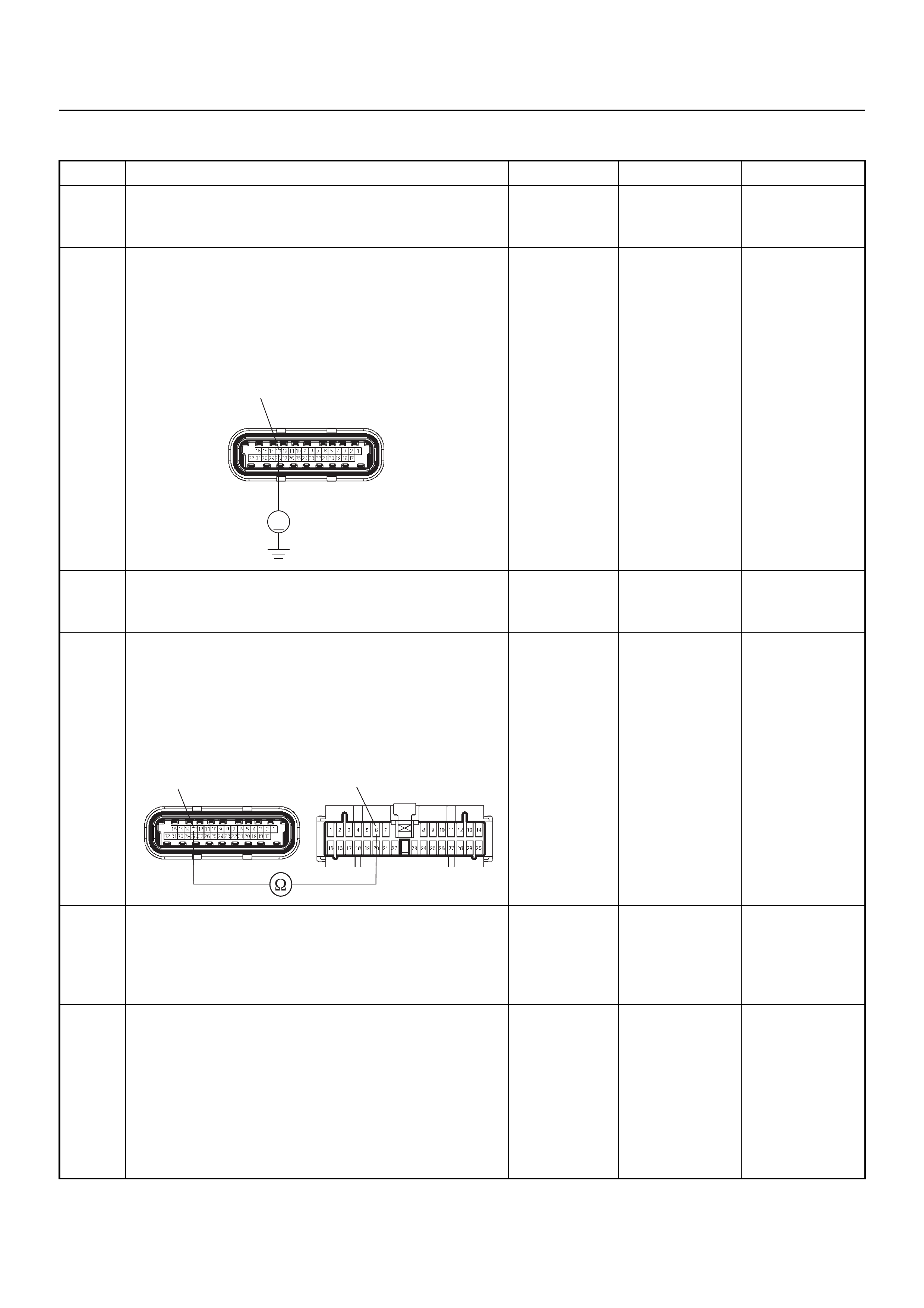
NO SERVICE VEHICLE SOON LAMP (SVS)
Step Action Value(s) Yes No
1 Check the “Meter” fuse (15A).
If the fuse is burnt out, re pa ir as nece ss ar y.
Was the problem found? — Verify repair Go to Step 2
2 Use a DVM to check the “SVS” lamp circuit.
1. Ignition “Off”, engine “Off”.
2. Disconnect the ECM connector.
3. Ignition “On”.
4. Check the circuit for op en ci rcu it.
Does the DVM indicate battery voltage?
Battery
voltage Go to Step 5 Go to Step 3
3 Check the “SVS” lamp bulb.
If the bulb is burnt out, replace as necessary.
Was the problem found? — Verify repair Go to Step 4
4 Use a DVM to check the “SVS” lamp circuit.
1. Ignition “Off”, engine “Off”.
2. Disconnect the meter connector and ECM
connector.
3. Check the circuit for op en ci rcu it.
Was the problem found?
— Verify repair Go to Step 5
5 Is the ECM programmed with the latest software
release?
If not, download the latest software to the ECM using
the “SPS (Service Programming System)”.
Was the problem solved? — Verify repair Go to Step 6
6 Replace the ECM.
Is the action complete?
IMPORTANT: The replacement ECM must be
programmed. Refer to the Service Programming
System (SPS) section in this manual.
Following ECM programming, the immobiliser system
must be linked to the ECM. Refer to section 11
“Immobiliser System-ECM replacement” for the ECM/
Immobiliser linking procedure. — Verify repair —
V
13 C56(J2)
13 6
C56(J2) B24
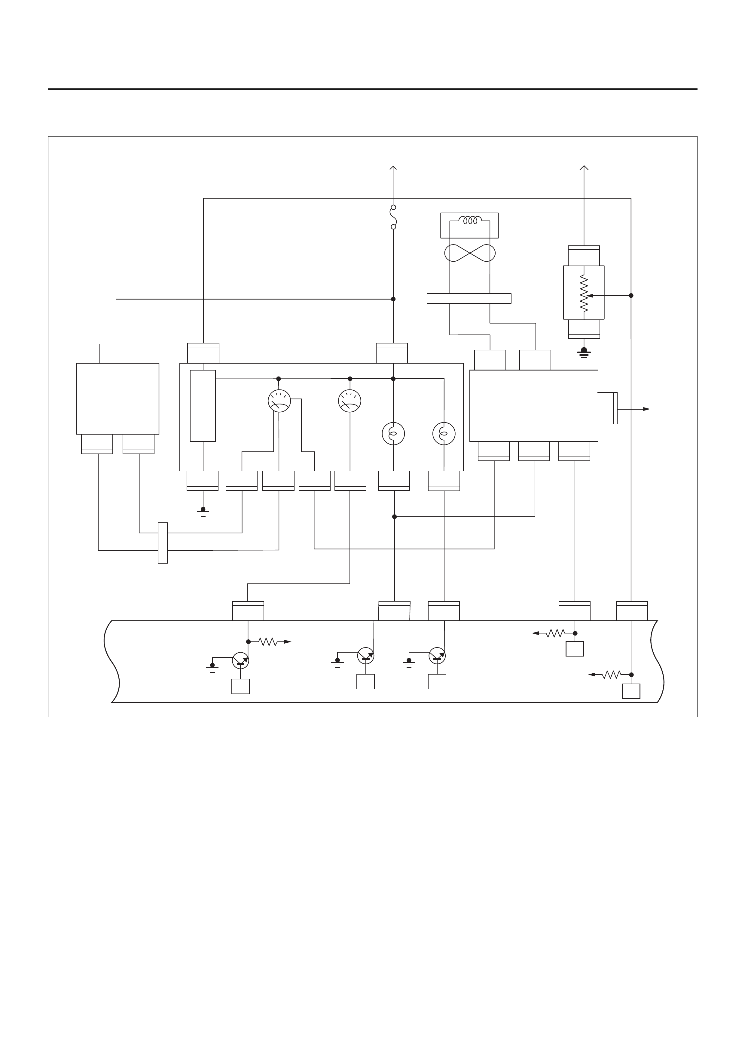
SERVICE VEHICLE SOON (SVS) “ON” STEADY
Circuit description
The service vehicle soon (SVS) lamp should be
illuminated with the ignition “ON” and the engine not
started for less than 3 seconds. Ignition feed voltage is
supplied to the check SVS lamp bulb through the meter
fuse. The Engine Control Module (ECM) switches the
SVS lamp “ON” by grounding the lamp driver circuit.
The SVS lamp will illuminate to indicate the need for a
vehicle system service.
The SVS lamp should not remain “ON” with the engine
running and no DTC(s) set. A steady SVS lamp with the
engine running and no DTC(s) suggests a short to
ground in the SVS lamp driver circuit.
Diagnostic Aids
An intermittent fault may be caused by a poor
connection, rubbed-through wire insulation, or a wire
broken inside the insulation. Check for the following
items:
• Poor connection or damaged harness - Inspect the
ECM harness and connectors for improper mating,
broken locks, improperly formed or damaged
terminals, poor terminal-to-wire connection, and
damaged harness.
VIgn
VIgn
Engine
Control
Module
(ECM)
Fuel
Level
VSSSVS LampMIL Lamp
Tacho Sig
32
14 30
2
C56
13
C56
7J2 J2J2J2
C56
9J2
C56
4
IGN
SW
F2
F2
B68
B24
B24E44
E44E44
B24 B24 B24 B24 B24 B24
B68 B68
B68
IGN
SW
μPμP
μP
μP
μP
Meter
15A
VIgn
MIL
Lamp SVS
Lamp
Speedo
Meter Tacho
Meter
0.85
YEL
0.5
YEL/
RED
0.8
YEL/
GRN
0.3
BRN/
YEL
0.5
GRN/
WHT
0.5
BLK/
RED
0.3
BRN/
YEL
0.5
BLK/
YEL
0.5
WHT
C56
0.5
BRN/
YEL
0.5
ORG/
BLU
2(–)
3
1
(+)
Vehicle
Speed
Sensor
(VSS) Starter
Relay
Fuel
Sender
Unit
METER
6
6
11 310278
B24
28
78
1
3
3
(–) (+)
1
Immobiliser
Coil
(Antenna)
B70 B70
CPU Immobiliser
Control
Unit (ICU)

SERVICE VEHICLE SOON (SVS) “ON” STEADY
Step Action Value(s) Yes No
1 1. Ignition “Off” , en gin e “Off ”.
2. Disconnect the ECM connector.
3. Ignition “On”.
Was the “SVS” lamp switched on? — Go to Step 2 Go to Step 4
2 Use a DVM to check the “SVS” lamp circuit.
1. Ignition “Off”, engine “Off”.
2. Disconnect the meter connector and ECM
connector.
3. Check the circuit for short to ground circuit.
Was the problem found?
— Verify repair Go to Step 3
3 Replace the meter assembly.
Is the action complete? — Verify repair —
4 Is the ECM programmed with the latest software
release?
If not, download the latest software to the ECM using
the “SPS (Service Programming System)”.
Was the problem solved? — Verify repair Go to Step 5
5 Replace the ECM.
Is the action complete?
IMPORTANT: The replacement ECM must be
programmed. Refer to the Service Programming
System (SPS) section in this manual.
Following ECM programming, the immobiliser system
must be linked to the ECM. Refer to section 11
“Immobiliser System-ECM replacement” for the ECM/
Immobiliser linking procedure. — Verify repair —
13C56(J2)
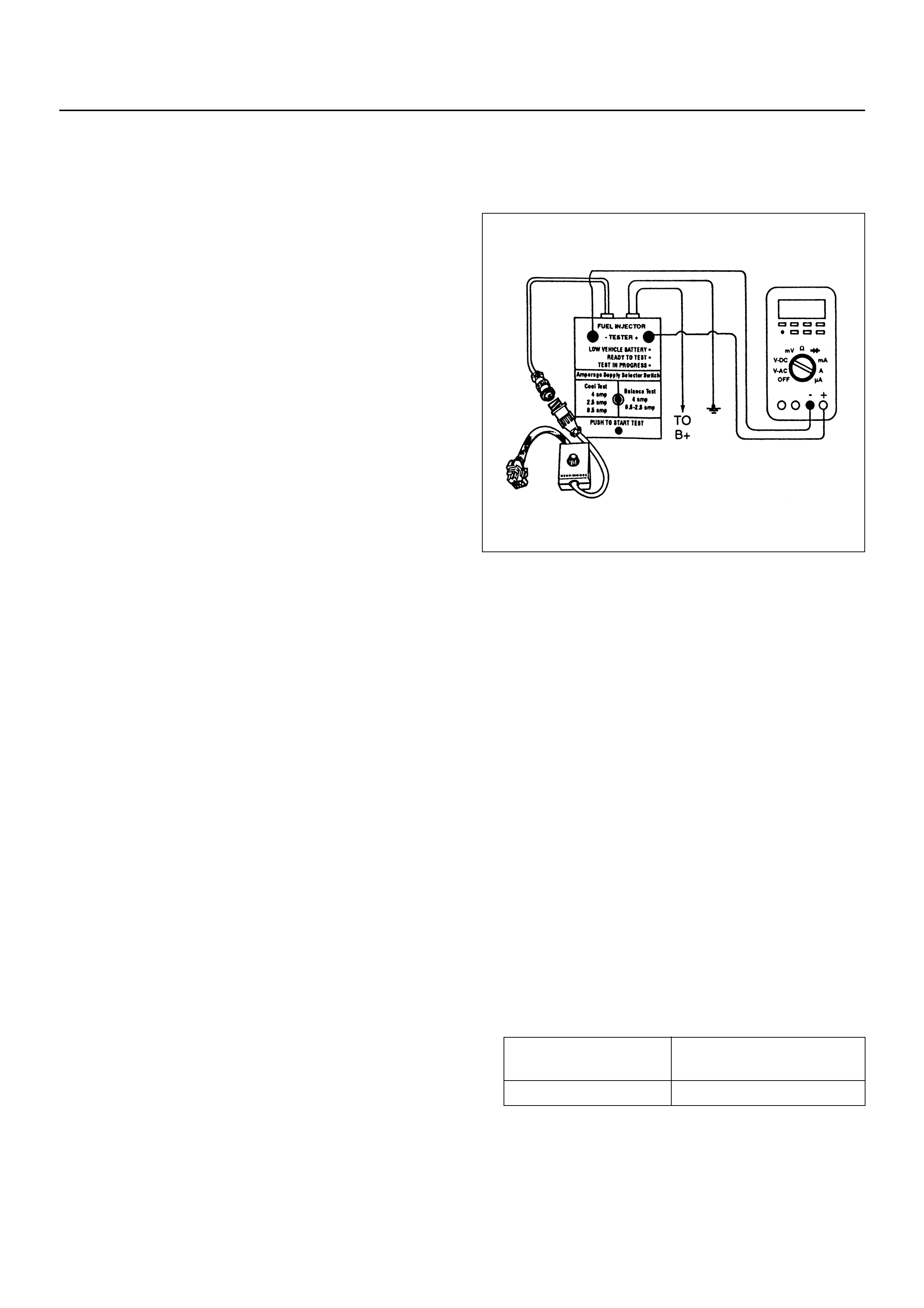
FUEL METERING SYSTEM CHECK
Some failures of the fuel metering system will result in
an “Engine Cranks But Will Not Run” symptom. If this
condition exists, refer to the Engine Cranks But Will Not
Run chart. This chart will determine if the problem is
caused by the ignition system, the ECM, or the fuel
pump electrical circuit.
Refer to Fuel System Electrical Test for the fuel system
wiring schematic.
If there is a fuel delivery problem, refer to Fuel System
Diagnosis, which diagnoses the fuel injectors, the fuel
pressure regulator, and the fuel pump.
Followings are applicable to the vehicles with
closed Loop System:
If a malfunction occurs in the fuel metering system, it
usually results in either a rich HO2S signal or a lean
HO2S signal. This condition is indicated by the HO2S
voltage, which causes the ECM to change the fuel
calculation (fuel injector pulse width) based on the
HO2S reading. Changes made to the fuel calculation
will be indicated by a change in the long term fuel trim
values which can be monitored with a Scan Tool. Ideal
long term fuel trim values are around 0%; for a lean
HO2S signal, the ECM will add fuel, resulting in a fuel
trim value above 0%. Some variations in fuel trim values
are normal because all engines are not exactly the
same. If the evaporative emission canister purge is O2
status may be rich condition. O2 status indicates the
lean condition, refer to DTC P1171 for items which can
cause a lean HO2S signal.
FUEL INJECTOR COIL TEST PROCEDURE
AND FUEL INJECTOR BALANCE TEST
PROCEDURE
Test Description
Number(s) below refer to the step number(s) on the
Diagnostic Chart:
2. Relieve the fuel pressure by connecting 5-8840-
0378-0 T-Joint to the fuel pressure connection on the
fuel rail.
Caution: In order to reduce the risk of fire and
personal injury, wrap a shop towel around the
fuel pressure connection. The towel will absorb
any fuel leakage that occurs during the
connection of the fuel pressure gauge. Place the
towel in an approved container when the
connection of the fuel pressure gauge is
complete.
Place the fuel pressure gauge bleed hose in an
approved gasoline container.
With the ignition switch OFF, open the valve on the
fuel pressure gauge.
3. Record the lowest voltage displayed by the DVM
after the first second of the test. (During the first
second, voltage displayed by the DVM may be
inaccurate due to the initial current surge.)
Injector Specifications:
• The voltage displayed by the DVM should be
within the specified range.
• The voltage displayed by the DVM may increase
throughout the test as the fuel injector windings
warm and the resistance of the fuel injector
windings changes.
Resistance Ohms Voltage Specification at
10°C-35°C (50°F-95°F)
11.8-12.6 5.7-6.6
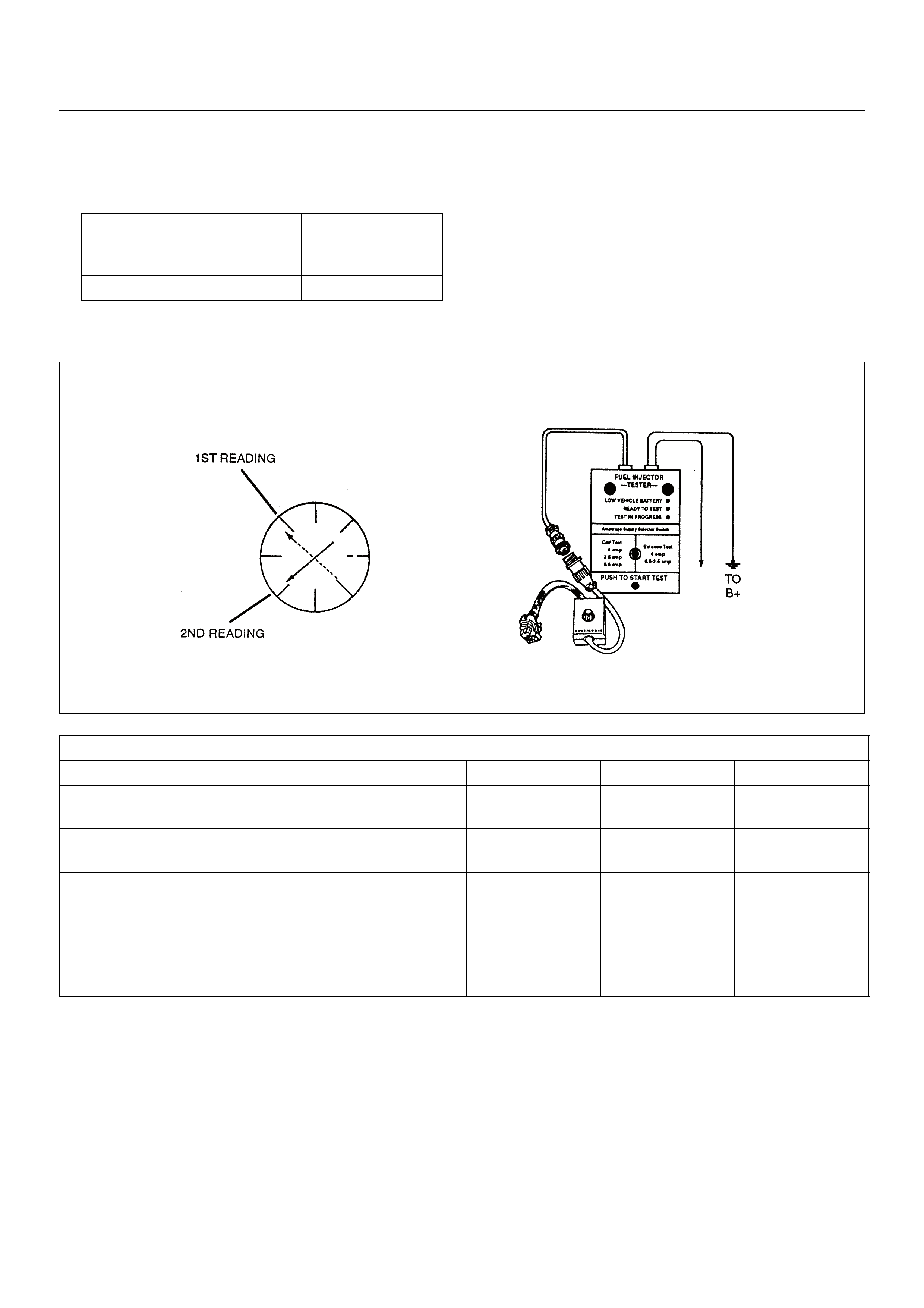
• An erratic voltage reading (large fluctuations in
voltage that do not stabilise) indicates an
intermittent connection within the fuel injector.
5. Injector Specifications:
7. The Fuel Injector Balance Test portion of this chart
(Step 7 through Step 11) checks the mechanical
(fuel delivery) portion of the fuel injector. An engine
cooldown period of 10 minutes is necessary in order
to avoid irregular fuel pressure readings due to “Hot
Soak” fuel boiling.
Injector Coil Test Procedure (Steps 1-6) and Injector Balance Test Procedure (Steps 7-11)
NOTE: These figur es ar e ex am p les only.
Highest Acceptable Voltage
Reading Above/Below
35°C/10°C (95°F/50°F)
Acceptable
Subtracted Value
9.5Volts 0.6Volt
CYLINDER
1234
1st Reading (1) 296kPa
(43psi) 296kPa
(43psi) 296kPa
(43psi) 296kPa
(43psi)
2nd Reading (2) 205kPa
(29psi) 205kPa
(29psi) 196kPa
(28psi) 274kPa
(39psi)
Amount of Drop
(1st Reading-2n d Re ad ing ) 91kPa
(14psi) 91kPa
(14psi) 100kPa
(15psi) 22kPa
(4psi)
Av. Drop = 166kPa/24psi
±10kPa/1.5psi
= 156 - 176kPa or
22.5 - 25.5psi
Faulty, Lean
(Too Little Fuel
Drop)
Faulty, Lea n
(Too Little Fuel
Drop)
Faulty, Lean
(Too Little Fuel
Drop)
Faulty, Lean
(Too Little Fuel
Drop)

Injector Coil Test Procedure (Steps 1-6) and Injector Balance Test Procedure (Steps 7-11)
Step Action Value(s) Yes No
1 Was the “On-Board Diagnostic (OBD) System Check”
performed? — Go to Step 2
Go to OBD
System Check
2 1. Switch the engine OFF.
NOTE: In order to prevent flooding of a single cylinder
and possible engine da mage, relieve the fu el pressure
before performing the fuel injector coil test procedure.
2. Relieve the fuel pressure. Refer to Test
Description Number 2.
3. Connect the 5-8840-2618-0 Fuel Injecto r Tester to
B+ and ground, and to the 5-8840-2589-0 Injector
Adapter Cable.
4. Remove the harness connector of the Fuel
Injector and connect the 5-8840-2589-0 Injector
Adapter Cable for F/I check.
5. Set the amperage supply selector switch on the
fuel injector tester to the “Coil Test” 0.5 amp
position.
6. Connect the leads from the 5-8840-2392-0 Digital
Voltmeter (DVM) to the fuel injector tester. Refer
to the illustrations associated with the test
description.
7. Set the DVM to the tenths scale (0.0).
8. Observe the engine coolant temperature.
Is the eng ine coolant tem perature withi n the specified
values?
10°C (50°F)
to
35°C (95°F) Go to Step 3 Go to Step 5
3 1. Set the injector adapter cable to injector #1.
2. Press the “Push to Start Test” button on the fuel
injector tester.
3. Observe the voltage reading on the DVM.
Important: The voltage reading may rise during the
test.
4. Record the lowest voltage observed after the first
second of the test.
5. Set the injector adapter cable to the next injector
and repeat steps 2, 3, and 4.
Did any fuel injector have an erratic voltage reading
(large fluctuations in voltage that did not stabilise) or a
voltage reading out sid e of th e sp ecif ied valu es ? 5 .7 -6 .6 V Go to Step 4 Go to Step 7
4 Replace the faulty fuel injector(S). Refer to Fuel
Injector.
Is the action complete? — Go to Step 7 —

5 1. Set the Injector Adapter Cable to injector #1.
2. Press the “Push to Start Test” button on the fuel
injector tester.
3. Observe the voltage reading on the DVM.
Important: The voltage reading may rise during the
test.
4. Record the lowest voltage observed after the first
second of the test.
5. Set the Injector Adapter Cable to the next injector
and repeat steps 2, 3, and 4.
Did any fuel injector have an erratic voltage reading
(large fluctuations in voltage that did not stabilise) or a
voltage reading above the specified value? 9.5V Go to Step 4 Go to Step 6
6 1. Identify the highest voltage reading recorded
(other than those above 9.5V).
2. Subtract th e voltage reading of each injector from
the highest vo ltage selected in step 1. Repeat until
you have a subtracted value for each injector.
For any injector, is the subtracted value in step 2
greater than the specified value? 0.6V Go to Step 4 Go to Step 7
7Caution: In order to reduce the risk of fire and
personal injury, wrap a shop towel around the fuel
pressure connection. The towel will absorb any
fuel leakage that occurs during the connection of
the fuel pressure gauge. Place the Towel in an
approved container when the connection of the
fuel pressure gauge is complete.
1. Connect the 5-8840-0378-0 Fuel Pressure Gauge
to the fuel pressure test port.
2. Energise the fuel pump using the Scan Tool.
3. Place the bleed hose of the fuel pressure gauge
into an approved gasoline container.
4. Bleed the air out of the fuel pressure gauge.
5. With the fuel pump running, observe the reading
on the fuel pressure gauge.
Is the fuel pressure within the specified values?
296kPa-
376kPa
(43-55ps i) G o to Step 8
Go to Fuel
System
Diagnosis
8 Switch the fuel pu m p OF F .
Does the fuel pressure remain constant? —Go to Step 9
Go to Fuel
System
Diagnosis
Step Action Value(s) Yes No

9 1. Connect the 5-8840-0378-0 Fuel Injector Tester
and 5-8840-2589-0 Injector Adapter Cable to the
fuel injector harness connector.
2. Set the amperage supply selector switch on the
fuel injector tester to the “Balance Test” 0.5-2.5
amp position .
3. Using the Scan Tool switch the fuel pump ON then
OFF in order to pressurise the fuel system.
4. Record the fuel pressure indicated by the fuel
pressure gauge after the fuel pressure stabilises.
This is the first pressure reading.
5. Energise the fuel injector by depressing the “Push
to Start Test” button on the fuel injector tester.
6. Record the fuel pressure indicated by the fuel
pressure gauge after the fuel pressure gauge
needle has stopped moving. This is the second
pressure reading.
7. Repeat steps 1 through 6 for each fuel injector.
8. Subtract the second pressure reading from the
first pressure reading for one fuel injector. The
result is the pressure drop value.
9. Obtain a pressure drop value for each fuel
injector.
10. Add all of the individual pressure drop values.
This is the total pressure drop.
11. Divide the total pressure drop by the number of
fuel injectors. This is the average pressure drop.
Does any fuel injector ha ve a pressu re dr op value that
is either higher than the average pressure drop or
lower than the average pressure drop by the specified
value? 10kPa
(1.5psi) Go to Step 10
Go to OBD
System Check
10 Re-test any fuel injector that does not meet the
specification. Refer to the procedure in Step 11.
NOTE: Do not repeat any portion of this test before
running the engine in order to prevent the engine from
flooding.
Does any fuel injector still have a pressure drop value
that is either higher than the average pressure drop or
lower than the average pressure drop by the specified
value? 10kPa
(1.5psi) Go to Step 11
Go to
Symptoms
11 1. Replace the faulty fuel injector(s). Refer to Fuel
Injector.
2. Disconnect the 5-8840-2589-0 Injector Adapter
Cable for F/I check and re-connect the original F/I
check connector.
Is the action complete? — Verify repair —
Step Action Value(s) Yes No
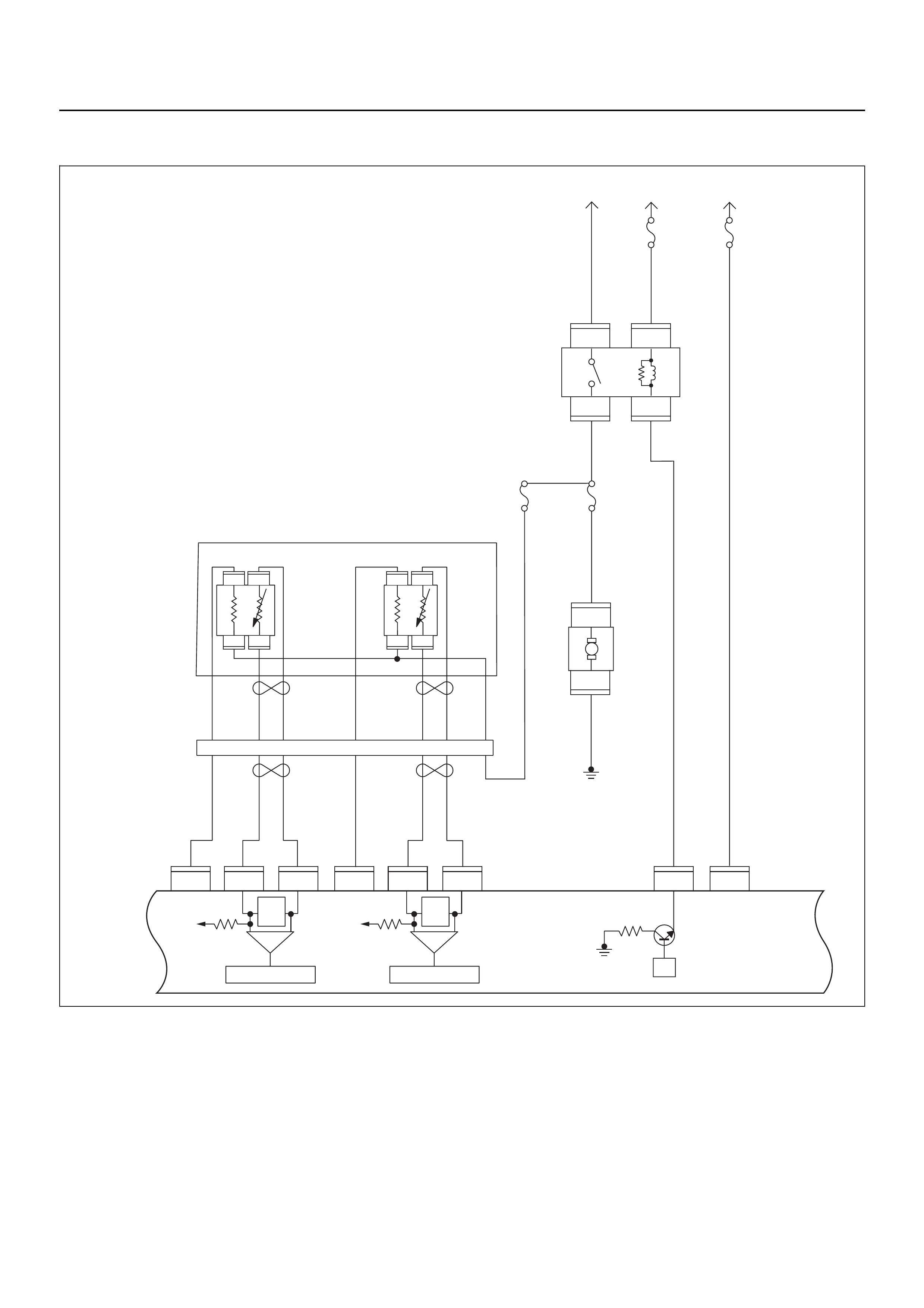
FUEL SYSTEM ELECTRICAL TEST
Circuit Description
When the ignition switch is first switched ON, the engine
control module (ECM) energises the fuel pump relay
which applies power to the in-tank fuel pump. The fuel
pump relay will remain ON as long as the engine is
running or cranking and the ECM is receiving 58X
crankshaft position pulses. If no 58X crankshaft position
pulses are present, the ECM de-energises the fuel
pump relay within 2 seconds after the ignition is
switched ON or the engine is stopped.
The fuel pump delivers fuel to t he fuel ra il and injecto rs,
then to the fuel pressure regulator. The fuel pressure
regulator controls fuel pressure by allowing excess fuel
to be returned to the fuel tank. With the engine stopped
and ignition ON, the fuel pump can be switched ON by
using a command by the scan tool.
μP
IGN
SW Battery
Voltage
Batt PwrFuel Pump
Pwr
O2 Heater
(Pre)
O2 Heater
(Post)
Battery
Voltage
2.0
WHT
0.5
BLU/
YEL
Engine
15A
450
mV
A/D Converter
Vcc
+5V -+
450
mV
A/D Converter
Vcc
+5V -+
2.0
RED/
BLK
Fuel
Pump
Relay
0.85
RED/
WHT
0.5
GRN/
WHT
Engine
Control
Module
(ECM)
C56
1
C56
F2
F2
21
C56
31J2J1J1J1 J2 J2 J2 J2
E60
16
E60
28
E60
19
32
41
32
41
C56
26
C56
2
2.0
RED/
GRN
O2
Sensor
10A
Fuel
Pump
Heated 02 Sensors
Fuel
Pump
20A
2.0
BLK
0.5
BLU/
ORG
0.5
YEL
0.5
BLU/
YEL
0.5
BLK
0.5
BLK
0.5
BRN 0.5
YEL 0.5
PU 0.5
YEL
0.5
BRN 0.5
PU 0.5
BRN
0.5
ORG
2.0
BLK/
BLU
M
O2 Sensor
POST
O2 Sensor
PRE
LOWLOW
HI
HI
ECM
15A
X2
1
X2
X2 X2
3
1
4
42
E77 E77
E77
E78E78
E78E78
E77
H31

Diagnostic Aids
An intermittent fault may be caused by a poor
connection, rubbed-through wire insulation, or a wire
broken inside the insulation. Check for the following
items:
• Poor connection or damaged harness - Inspect the
ECM harness and connectors for improper mating,
broken locks, improperly formed or damaged
terminals, poor terminal-to-wire connection, and
damaged harness.
Caution: To reduce the risk of fire and personal
injury:
• It is necessary to relieve fuel system pressure
before connecting a fuel pressure gauge.
Refer to Fuel Pressure Relief Procedure,
below.
• A small amount of fuel may be released when
disconnecting the fuel lines. Cover fuel line
fittings with a shop towel before
disconnecting, to catch any fuel that may leak
out. Place the towel in an approved container
when the disconnect is completed.
Fuel Pressure Relief Procedure
1. Remove the fuel cap.
2. Remove the fuel pump relay from the underhood
relay center.
3. Start the engine and alow it to stall.
4. Crank the engine for an additional 3 seconds.
Fuel Pressure Gauge Installation
1. Remove the fuel pressure fitting cap.
2. Install fuel pressure gauge 5-8840-0378-0 to the
fuel feed line located in front of and above the right
side valve cover.
3. Reinstall the fuel pump relay.
Fuel System Electrical Test
Step Action Value(s) Yes No
1 Was the “On-Board Diagnostic (OBD) System Check”
performed?
—Go to Step 2
Go to On Board
Diagnostic
(OBD) System
Check
2 1. Using Tech 2, ignition “On” and engine “On”.
2. Select “F3 Actuator Test” and perform the “Fuel
Pump Relay Test”
3. Operate Tech 2 in accordance with procedure to
manually operate the fuel pump relay.
Was the fuel pump heard operating, when Tech 2 soft
key was pressed? —
Go to Fuel
System
Diagnosis Go to Step 3
3 Check the “Fuel Pump” fuse (20A).
If the fuse is burnt out, replace as necessary.
Was the problem found? — Verify repair Go to Step 4
4 Check for poor/faulty connection at the fuel pump, fu el
pump relay or ECM connector. If a poor/faulty
connection is found, repair as necessary.
Was the problem found?
— Verify repair Go to Step 5
26 C56(J2)
F2X2
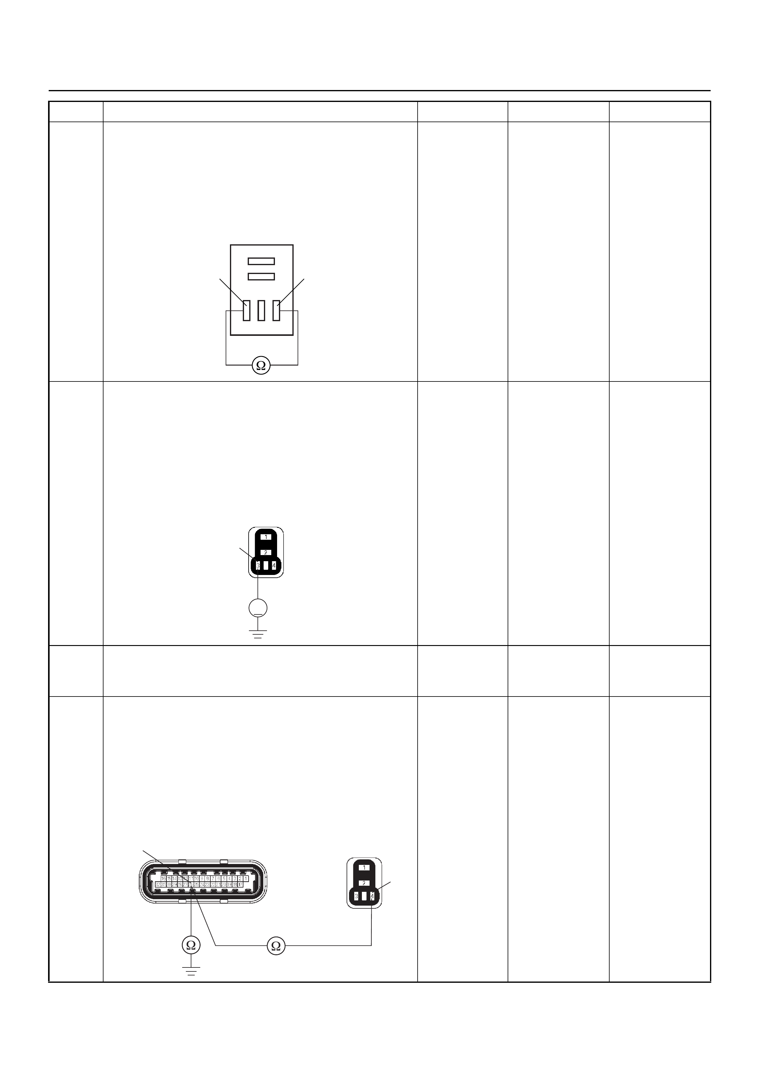
5 Use a DVM to check the fuel pump relay.
1. Ignition “Off”, engine “Off”.
2. Remove the fu el pu m p relay from the relay box.
3. C heck the relay coil.
Does the DVM indicate the specified value?
Continuity Go to Step 6
Replace fuel
pump relay and
verify repair
6 Use a DVM to check the fuel pump relay p ower supply
circuit.
1. Ignition “On”, engine “Off”.
2. Remove the fu el pu m p relay from the relay box.
3. Check the circuit for open or short to ground
circuit.
Does the DVM indicate battery voltage?
Battery
voltage Go to Step 8 Go to Step 7
7 Repair the open or short to ground circuit between the
“ECM” fuse (15A) and fuel pump relay.
Is the action complete? — Verify repair —
8 Use a DVM to check the fuel pump relay ground
circuit.
1. Ignition “Off”, engine “Off”.
2. Disconnect the ECM connector.
3. Remove the fu el pu m p relay from the relay box.
4. Check the circuit for open or short to ground
circuit.
Was the problem found?
—
Repair faulty
harness and
verify repair Go to Step 9
Step Action Value(s) Yes No
Fuel Pump Relay
34
V
3
X2
4
26 C56(J2) X2
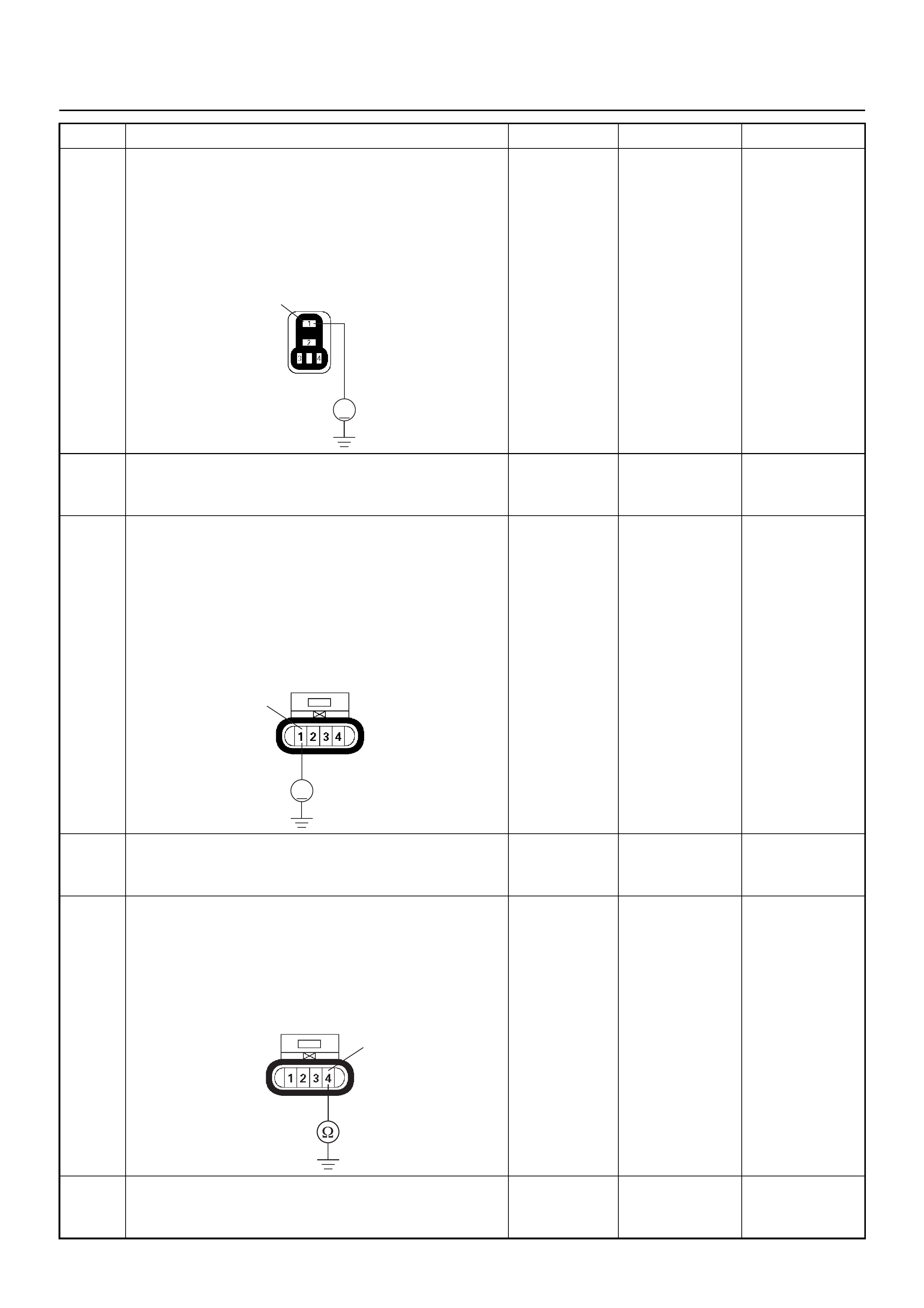
9 Use a DVM to check the fuel pump relay p ower supply
circuit.
1. Ignition “Off”, engine “Off”.
2. Remove the fu el pu m p relay from the relay box.
3. Check the circuit for op en ci rcu it.
Does the DVM indicate battery voltage?
Battery
voltage Go to Step 11 Go to Step 10
10 Repair the open circuit between the fuel pump relay
and battery.
Is the action complete? — Verify repair —
11 Use a DVM to check the fuel pump power supply
circuit.
1. Ignition “On”, engine “Off”.
2. Disconnect the fuel pump connector.
3. Check the circuit for open or short to ground
circuit.
Does the DVM indicate battery voltage?
Battery
voltage Go to Step 13 Go to Step 12
12 Repair the open or short to ground circuit between the
fuel pump relay and fuel pump.
Is the action complete? — Verify repair —
13 Use a DVM to check the fuel pump ground circuit.
1. Ignition “Off”, engine “Off”.
2. Disconnect the fuel pump connector.
3. Check the circuit for op en ci rcu it.
Does the DVM indicate the specified value?
Continuity Go to Step 15 Go to Step 14
14 Repair the open circuit between the fuel pump and
body ground.
Is the action complete? — Verify repair —
Step Action Value(s) Yes No
V
1X2
V
1F2
4
F2

15 Replace the fuel pump.
Was the problem solved? — Verify repair Go to Step 16
16 Is the ECM programmed with the latest software
release?
If not, download the latest software to the ECM using
the “SPS (Service Programming System)”.
Was the problem solved? — Verify repair Go to Step 17
17 Replace the ECM.
Is the action complete?
IMPORTANT: The replacement ECM must be
programmed. Refer to the Service Programming
System (SPS) section in this manual.
Following ECM programming, the immobiliser system
must be linked to the ECM. Refer to section 11
“Immobiliser System-ECM replacement” for the ECM/
Immobiliser linking procedure. — Verify repair —
Step Action Value(s) Yes No

FUEL SYSTEM DIAGNOSIS
Circuit Description
When the ignition switch is turned to “On”, the engine
control module (ECM) will switch “On” the in-tank fuel
pump. The in-tank fuel pump will remain “On” as long as
the engine is cranking or running and the ECM is
receiving 58X cr a nks ha ft p os i tion pu l se s. If th er e ar e no
58X crankshaft position pulses, the ECM will switch the
in-tank fuel pump OFF 2 seconds after the ignition
switch is switched ON or 2 seconds after the engine
stops running.
The in-tank fuel pump is an electric pump within an
integral reservoir. The in-tank fuel pump supplies fuel
through an in-line fuel filter to the fuel rail assembly. The
fuel pump is designed to provide fuel at a pressure
above the pressure needed by the fuel injectors. A fuel
pressure regulator, attached to the fuel rail, keeps the
fuel available to the fuel injectors at a regulated
pressure. Unused fuel is returned to the fuel tank by a
separate fuel return line.
Test Description
The following number(s) refer to the step number(s) on
μP
IGN
SW Battery
Voltage
Batt PwrFuel Pump
Pwr
O2 Heater
(Pre)
O2 Heater
(Post)
Battery
Voltage
2.0
WHT
0.5
BLU/
YEL
Engine
15A
450
mV
A/D Converter
Vcc
+5V -+
450
mV
A/D Converter
Vcc
+5V -+
2.0
RED/
BLK
Fuel
Pump
Relay
0.85
RED/
WHT
0.5
GRN/
WHT
Engine
Control
Module
(ECM)
C56
1
C56
F2
F2
21
C56
31J2J1J1J1 J2 J2 J2 J2
E60
16
E60
28
E60
19
32
41
32
41
C56
26
C56
2
2.0
RED/
GRN
O2
Sensor
10A
Fuel
Pump
Heated 02 Sensors
Fuel
Pump
20A
2.0
BLK
0.5
BLU/
ORG
0.5
YEL
0.5
BLU/
YEL
0.5
BLK
0.5
BLK
0.5
BRN 0.5
YEL 0.5
PU 0.5
YEL
0.5
BRN 0.5
PU 0.5
BRN
0.5
ORG
2.0
BLK/
BLU
M
O2 Sensor
POST
O2 Sensor
PRE
LOWLOW
HI
HI
ECM
15A
X2
1
X2
X2 X2
3
1
4
42
E77 E77
E77
E78E78
E78E78
E77
H31

the Diagnostic Chart.
2. Connect the fuel pressure gauge to the fuel feed line
as shown in the fuel system illustration. Wrap a shop
towel around the fuel pressure connection in order to
absorb any duel leakage that may occur when
installing the fuel pressure gauge. With the ignition
switch ON and the fuel pump running, the fuel
pressure indicated by the fuel pressure gauge
should be 283-376 kPa (41-55 psi). This pressure is
controlled by the amount of pressure the spring
inside the fuel pressure regulator can provide.
3. A fuel system that can not maintain a constant fuel
pressure has a leak in one or more of the following
areas:
• The fuel pump check valve.
• The fuel pump flex line.
• The valve or valve seat within the fuel pressure
regulator.
• The fuel injector(s).
4. Fuel pressure that drops off during acceleration,
cruise, or hard cornering may cause a lean
condition. A lean condition can cause a loss of
power, surging, or misfire. A lean condition can be
diagnosed using a Tech 2 Scan Tool.
The following are applicable to the vehicle with
closed Loop System:
If an extremely lean condition occurs, the oxygen
sensor(s) will stop toggling. The oxygen sensor
output voltage(s) will drop below 500 mV. Also, the
fuel injector pulse width will increase.
Important: Make sure the fuel system is not
operating in the “Fuel Cut-Off Mode.”
When the engine is at idle, the manifold pressure is
low (high vacuum). This low pressure (high vacuum)
is applied to the fuel pressure regulator diaphragm.
The low pressure (high vacuum) will offset the
pressure being applied to the fuel pressure regulator
diaphragm by the spring inside the fuel pressure
regulator. When this happens, the result is lower fuel
pressure. The fuel pressure at idle will vary slightly
as the barometric pressure changes, but the fuel
pressure at idle should always be less than the fuel
pressure noted in step 2 with the engine switched
off.
16.Check the spark plug associated with a particular
fuel injector for fouling or saturation to determine if
that particular fuel injector is leaking. If checking the
spark plug associated with a particular fuel injector
for fouling or saturation does not determine that a
particular fuel injector is leaking, use the following
procedure:
• Remove the fuel rail, but leave the fuel lines and
injectors connected to the fuel rail. Refer to Fuel
Rail Assembly, in On-Vehicle Service Procedure.
• Lift the fuel rail just enough to leave the fuel
injector nozzles in the fuel injector ports.
Caution: To reduce the risk of fire and personal
injury that may result from fuel spraying on the
engine, verify if the fuel rail is positioned over
the fuel injector ports and verify if the fuel
injector retaining clips are intact.
• Pressurise the fuel system by connecting a 20
amp fused jumper between B+ and the fuel
pump relay connector.
• Visually and physically inspect the fuel
injector nozzles for leaks.
17.A rich condition may result from the fuel pressure
being above 376 kPa (55 psi). A rich condition may
cause a 45 to set. Driveability conditions associated
with rich conditions can include hard starting
(followed by black smoke) and a strong sulfur smell
in the exhaust.
20.This test determines if the high fuel pressure is due
to a restricted fuel return line or if the high fuel
pressure is due to a faulty fuel pressure regulator.
21.A lean condition may result from fuel pressure below
333 kPa (48 psi). A lean condition may cause a 44 to
set. Driveability conditions associated with lean
conditions can include hard starting (when the
engine is cold), hesitation, poor driveability, lack of
power, surging, and misfiring.
22.Restricting the fuel return line causes the fuel
pressure to rise above the regulated fuel pressure.
Command the fuel pump ON with the scan tool. The
fuel pressure should rise above 376 kPa (55 psi) as
the fuel return line becomes partially closed.
NOTE: Do not allow the fuel pressure to exceed 414
kPa (60 psi). Fuel pressure in excess of 414 kPa (60
psi) may damage the fuel pressure regulator.
Caution: To reduce the risk of fire and personal
injury:
• It is necessary to relieve fuel system pressure
before connecting a fuel pressure gauge.
Refer to Fuel Pressure Relief Procedure,
below.
• A small amount of fuel may be released when
disconnecting the fuel lines. Cover fuel line
fittings with a shop towel before
disconnecting, to catch any fuel that may leak
out. Place the towel in an approved container
when the disconnect is completed.
Fuel Pressure Relief Procedure
1. Remove the fuel cap, located on the intake manifold
which is at the top right part of the engine.
2. Start the engine and allow it to stall.
3. Crank the engine for an additional 3 seconds.
Fuel Pressure Gauge Installation
1. Remove the fuel pressure fitting cap.
2. Install fuel pressure gauge 5-8840-0378-0 to the
fuel feed line located on the upper right side of the
engine.
3. Reinstall the fuel pump relay.

Fuel System Diagnosis
Step Action Value(s) Yes No
1 Was the “On-Board Diagnostic (OBD) System Check”
performed? — Go to Step 2
Go to OBD
System Check
2 1. Switch the ignition “Off”.
2. Switch the air conditioning system “Off”.
3. Relieve fuel system pressure and install the fuel
pressure gauge.
4. Switch the ignition “On”.
NOTE: The fuel pump will run for approximately 2
seconds. Use the Scan Tool to command the fuel
pump ON.
5. Observe the fuel pressure indicated by the fuel
pressure gauge with the fuel pump running.
Is the fuel pressure within the specified limits? 283-376 kPa
(41-55 psi) Go to Step 3 Go to Step 17
3 Does the fuel pressure indicated by the fuel pressure
gauge remain constant?
NOTE: The fuel pressure will drop when the fuel
pump stops running, then it should stabilise and
remain constant. — Go to Step 4 Go to Step 12
4 1. When the vehicle is at normal operating
temperature, switch the ignition ON to build fuel
pressure and observe the measurement on the
gauge.
2. Start the engine and observe the fuel pressure
gauge.
Did the reading drop by the amount specified after the
engine was started? 21-105 kPa
(3-15 ps i) Go to Step 5 Go to Step 9
5 Is fuel pressure dropping off during acceleration,
cruise, or hard cornering? — Go to Step 6
Check for
improper fuel
6 Visually and physically inspect the following items for
a restriction:
•The in-line fuel filter.
•The fuel feed line.
Was a restriction found? — Verify repair Go to Step 7
7 Remove the fuel tank, then visually and physically
inspect the following items:
•the fuel pump strainer for a restriction,
•the fuel line for a leak,
•verify if the correct fuel pump is in the vehicle.
Was a problem found in any of these areas? — Verify repair Go to Step 8
8 Replace the fuel pump.
Is the action complete? — Verify repair —
9 1. Disconnect the vacuum hose from the fuel
pressure regulator.
2. With the engine idling, apply 12-14 inches of
vacuum to the fuel pressure regulator.
Does the fuel pressure indicated by the fuel pressure
gauge drop by the amount specified? 21-105 kPa
(3-15 ps i) Go to Step 10 Go to Step 11

10 Locate and repair the loss of vacuum to the fuel
pressure regulator.
Is the action complete? — Verify repair —
11 Replace the fuel pressure re gulator.
Is the action complete? — Verify repair —
12 1. Run the fuel pump with the Scan Tool.
2. After pressure has built up, switch off the pump
and clamp the supply hose shut with suitable
locking pliers.
Does the fuel pressure indicated by the fuel pressure
gauge remain constant? — Go to Step 13 Go to Step 15
13 Visually inspect the fuel supply line and repair any
leaks.
Was a problem found? — Verify repair Go to Step 14
14 Remove the fuel tank and inspect for leaky hose or in-
tank fuel line.
Was a problem found? — Verify repair Go to Step 8
15 1. If the pliers are still clamped to the fuel supply
hose, remove the locking pliers.
2. With suitable locking pliers, clamp the fuel return
line to prevent fuel from returning to the fuel tank.
3. Run the fuel pump with the Scan Tool.
4. After pressure has built up, remove power to the
pump.
Does the fuel pressure indicated by the fuel pressure
gauge remain constant? — Go to Step 11 Go to Step 16
16 Locate and replace any leaking fuel injector(s).
Is the action complete? — Verify repair —
17 Is the fuel pressure indicated by the fuel pressure
gauge above the specified limit? 376 kPa
(55 psi) Go to Step 18 Go to Step 21
18 1. Relieve the fuel pressure. Refer to Fuel Pressure
Relief.
2. Disconnect the fuel return line from the fuel rail.
3. Attach a length of flexible hose to the fuel rail
return outlet passage.
4. Place the open end of the flexible hose into an
approved gasoline container.
5. Run the fuel pump with the Scan Tool.
6. Observe the fuel pressure indicated by the fuel
pressure gauge with the fuel pump running.
Is the fuel pressure within the specified limits? 290-376 kPa
(42-55 psi) Go to Step 19 Go to Step 20
19 Locate and correct the restriction in the fuel return
line.
Is the action complete? — Verify repair —
20 Visually and physically inspect the fuel rail outlet
passages for a restriction.
Was a restriction found? — Verify repair Go to Step 11
21 Is the fuel pressure indicated by the fuel pressure
gauge above the specified value? 0 kPa (0 psi) Go to Step 22 Go to Step 23
Step Action Value(s) Yes No

22 1. Command the fuel pump ON with the Scan Tool.
2. Using suitable pliers which will not damage the
fuel hose, gradually apply pressure with the pliers
to pinch the flexible fuel return hose closed. 376 kPa
(55 psi)
Does the fuel pressure indicated by the fuel pressure
gauge rise above the first specified value?
Caution: Do not let the fuel pressure exceed the
second specified value.
414 kPa
(60 psi) Go to Step 11 Go to Step 7
23 1. Command the fuel pump ON with the Scan Tool.
2. Remove the fuel filler cap and listen for the s ound
of the fuel pump running.
3. switch the pump “Off”.
Was the fuel pump running? — Go to Step 7
Go to Fuel
System
Electrical Test
Chart
Step Action Value(s) Yes No

ECM DIAGNOSTIC TROUBLE CODES (DTC)
Type A
• Emissio n re lat ed.
• Requests illumination of the MIL (Malfunction Indicator Lamp = Check Engine Lamp) of the first trip with a fail.
• Stores a history DTC on the first trip.
• Stores a freeze fr ame (If empty).
• Stores a fail record.
• Updates the fail record each time the diagnostic test fails.
Type B
• Emissio n re lat ed.
• “Armed” after one trip with a fail.
• “Disarmed” after one trip with a pass.
• Requests illumination of the MIL on the second consecutive trip with a fail.
• Store a history DTC on the second consecutive trip with a fail. (The DTC will be armed after the first fail.)
• Stores a freeze frame on the secon d consecutive trip with a fail (If empty).
• Stores a fail record when the first test fails (not dependent on consecutive trip).
• Updates the fail record each time the diagnostic test fails.
Type D
• Non emission related.
• Does not request illumination of any lamp.
• Stores a history DTC on the first trip.
• Does not store a freeze frame.
• Stores a fail record when test fails.
• Updates the fail record each time the diagnostic test fails.

DTC DIAGNOSTIC TABLE
Code Type DTC Name DTC Setting Condition Fail-Safe (Back Up) Recovery Condition Related Failure Parts Related ECM
Pin No.
P0107 A Manifold Absolute Pressure Circuit Low
Input 1. No DTC relating to TPS.
2. Throttle position is more than 0% if
engine speed is below 1000rpm, or
throttle position more than 5% if engine
speed is more than 1000rpm.
3. MAP sensor output is below 12KPa.
The ECM uses default manifold
absolute pressure value based on
engine speed and throttle position.
MAP sensor output is more than 12KPa. 1. Sensor power supply circuit open or
short to ground circuit.
2. Sensor signal circuit open or short to
ground circuit.
3. Poor connector connection.
4. MAP sensor malfunction.
5. ECM malfunction.
J1-24/
J1-31
P0108 A Manifold Absolute Pressure Circuit High
Input 1. No DTC relating to TPS.
2. Throttle position is below 15% if eng ine
speed is below 2500rpm, or throttle
position is below 35% if engine speed
is more than 2500rpm.
3. Engine run time is longer than 10
seconds.
4. MAP sensor output is more than
103KPa.
MAP sensor output is below 103KPa. 1. Sensor power supp ly c ircu it sh or t to
voltage circuit.
2. Sensor signal circuit short to voltage
circuit.
3. Sensor ground circuit open or short to
voltage circuit.
4. Poor connector connection.
5. MAP sensor malfunction.
6. ECM malfunction.
J1-26/
J1-24/
J1-31
P0112 A Intake Air Temperature Sensor Lo w Input 1. No DTC relating to VSS.
2. Vehicle speed is more than 25km/h.
3. Engine run time is longer than 120
seconds.
4. IAT sensor output is more than 149°C.
The ECM uses 20°C condition as
substitute.
IAT sensor output is below 149°C 1. Sensor signal circuit short to ground
circuit.
2. IAT sensor malfunction.
3. ECM malfunction.
J1-23
P0113 A Intake Air Temperature Sensor High Inp ut 1. No DTC relating to VSS & ECT sensor.
2. Vehicle speed is below 70km/h.
3. Engine coolant temperature is more
than -8°C.
4. Engine run time is longer than 120
seconds.
5. Mass air flow is below 30g/s.
6. IAT sensor output is below -38°C.
IAT sensor output is more than -38°C.1. Sensor signal circuit open or short to
voltage circuit.
2. Sensor ground circuit open or short to
voltage circuit.
3. Poor connector connection
4. IAT sensor malfunction.
5. ECM malfunction.
J1-16/
J1-23
P0117 A Engine Coolant Temperature Sensor Low
Input 1. Engine run time is longer than 120
seconds.
2. ECT sensor output is more than 149°C.
The ECM uses default engine
coolant temperature value based
on intake air temperature and
engine run time.
ECT sensor output is below 149°C.1. Sensor signal circuit short to ground
circuit.
2. ECT sensor malfunction.
3. ECM malfunction.
J1-27
P0118 A Engine Coolant Temperature Sensor High
Input 1. Engine run time is longer than 120
seconds.
2. ECT sensor output is below -38°C.
ECT sensor output is more than -38°C.1. Sensor signal circuit open or short to
voltage circuit.
2. Sensor ground circuit open or short to
voltage circuit.
3. Poor connector connection
4. ECT sensor malfunction.
5. ECM malfunction.
J1-27/
J1-16

P0122 A Throttle Position Sensor Low Input TPS output voltage is below 0.14V. The ECM uses 0% condition as
substitute. TPS output voltage is more than 0.14V. 1. Sensor power supply circuit open or
short to ground circuit.
2. Sensor signal circuit open or short to
ground circuit.
3. Poor connector connection.
4. TPS malfunction.
5. ECM malfunction.
J1-7/
J1-31/
P0123 A Throttle Position Sensor High Input TPS output voltage is more than 4.9V. TPS output voltage is below 4.9V. 1. Sensor power supply circuit short to
voltage circuit.
2. Sensor signal circuit short to voltage
circuit.
3. Sensor ground circuit open or short to
voltage circuit.
4. Poor connector connection.
5. TPS malfunction.
6. ECM malfunction.
J1-7/
J1-31/
J1-16
P0131 A O2 Sensor Circuit Low Voltage (Bank 1
Sensor 1 PRE) 1. No DTC relating to MAP sensor, TPS,
EVAP purge, ECT sensor, CKP sensor,
VSS, injector control circuit and ignition
control circuit.
2. Engine coolant temperature is more
than 60°C.
3. O2 sensor bank 1 output voltage is
below 50mV in “Closed Loop”
condition.
“Open Loop” fuel control. O2 sensor bank 1 output voltage is more
than 50mV. 1. Sensor harness short to ground circuit.
2. O2 sensor malfunction.
3. ECM malfunction.
J1-16/
J1-28
P0132 A O2 Sensor Circuit High Voltage (Bank 1
Sensor 1 PRE) 1. No DTC relating to MAP sensor, TPS,
EVAP purge, ECT sensor, CKP sensor,
VSS, injector control circuit and ignition
control circuit.
2. Engine coolant temperature is more
than 60°C.
3. O2 sensor bank 1 output voltage is
more than 952mV in “Closed Loop”
condition.
“Open Loop” fuel control. O2 sensor bank 1 output voltage is below
952mV. 1. Sensor harness short to voltage circuit.
2. O2 sensor malfunction.
3. MAF sensor output is incorrect.
4. Air intake line malfunction.
5. IAC valve malfunction.
6. Incorrect fuel pressure.
7. Injector malfunction.
8. ECM malfunction.
J1-16/
J1-28
P0134 A O2 Sensor Circuit No Activity Detected
(Bank 1 Sensor 1 PRE) 1. No DTC relating to MAP sensor, TPS,
EVAP purge, ECT sensor, CKP sensor,
VSS, injector control circuit and ignition
control circuit.
2. Engine coolant temperature is more
than 60°C.
3. Engine run time is longer than 40
seconds.
4. Mass air flow is more than 7g/s.
5. O2 sensor bank 1 output voltage is
between 300mV and 600mV.
“Open Loop” fuel control. O2 sensor bank 1 output voltage is below
300mV consecutive l y.
OR
O2 sensor bank 1 output voltage is more
than 600mV consecutively.
1. Sensor harness open circuit.
2. O2 sensor malfunction.
3. MAF sensor output is incorrect.
4. Air intake line malfunction.
5. IAC valve malfunction.
6. Incorrect fuel pressure.
7. Injector malfunction.
8. ECM malfunction.
J1-16/
J1-28
Code Type DTC Name DTC Setting Condition Fail-Safe (Back Up) Recovery Condition Related Failure Parts Related ECM
Pin No.

P0135 A O2 Sensor Heater Circuit (Bank 1 Sensor 1
PRE) 1. No DTC relating to MAP sensor and
ECT sensor.
2. Engine coolant temperature is more
than 60°C.
3. Engine run time is longer than 20
seconds.
4. MAP sensor output is more than
70KPa.
5. O2 sensor bank 1 heater current more
than 10mA.
No fail-safe function. O2 sensor bank 1 heater circuit is correct
condition. 1. Heater harness ope n, short to grou nd or
short to voltage circuit.
2. O2 sensor heater malfunction .
3. ECM malfunction.
J1-19
P0137 A O2 Sensor Circuit Low Voltage (Bank 1
Sensor 2 POST) 1. No DTC relating to MAP sensor, TPS,
EVAP purge, ECT sensor, CKP sensor,
VSS, injector control circuit and ignition
control circuit.
2. Engine coolant temperature is more
than 60°C.
3. O2 sensor bank 1 output voltage is
below 50mV in “Closed Loop”
condition.
“Open Loop” fuel control. O2 sensor bank 1 output voltage is more
than 50mV. 1. Sensor harness short to ground circuit.
2. O2 sensor malfunction.
3. ECM malfunction.
J2-1/
J2-21
P0138 A O2 Sensor Circuit High Voltage (Bank 1
Sensor 2 POST) 1. No DTC relating to MAP sensor, TPS,
EVAP purge, ECT sensor, CKP sensor,
VSS, injector control circuit and ignition
control circuit.
2. Engine coolant temperature is more
than 60°C.
3. O2 sensor bank 1 output voltage is
more than 952mV in “Closed Loop”
condition.
“Open Loop” fuel control. O2 sensor bank 1 output voltage is below
952mV. 1. Sensor harness short to voltage circuit.
2. O2 sensor malfunction.
3. MAF sensor output is incorrect.
4. Air intake line malfunction.
5. IAC valve malfunction.
6. Incorrect fuel pressure.
7. Injector malfunction.
8. ECM malfunction.
J2-1/
J2-21
P0140 A O2 Sensor Circuit No Activity Detected
(Bank 1 Sensor 2 POST) 1. No DTC relating to MAP sensor, TPS,
EVAP purge, ECT sensor, CKP sensor,
VSS, injector control circuit and ignition
control circuit.
2. Engine coolant temperature is more
than 60°C.
3. Engine run time is longer than 40
seconds.
4. Mass air flow is more than 7g/s.
5. O2 sensor bank 1 output voltage is
between 300mV and 600mV.
“Open Loop” fuel control. O2 sensor bank 1 output voltage is below
300mV consecutive l y.
OR
O2 sensor bank 1 output voltage is more
than 600mV consecutively.
1. Sensor harness open circuit.
2. O2 sensor malfunction.
3. MAF sensor output is incorrect.
4. Air intake line malfunction.
5. IAC valve malfunction.
6. Incorrect fuel pressure.
7. Injector malfunction.
8. ECM malfunction.
J2-1/
J2-21
P0141 A O2 Sensor Heater Circuit (Bank 1 Sensor 2
POST) 1. No DTC relating to MAP sensor and
ECT sensor.
2. Engine coolant temperature is more
than 60°C.
3. Engine run time is longer than 20
seconds.
4. MAP sensor output is more than
70KPa.
5. O2 sensor bank 1 heater current more
than 10mA.
No fail-safe function. O2 sensor bank 1 heater circuit is correct
condition. 1. Heater harness ope n, short to grou nd or
short to voltage circuit.
2. O2 sensor heater malfunction .
3. ECM malfunction.
J2-31
Code Type DTC Name DTC Setting Condition Fail-Safe (Back Up) Recovery Condition Related Failure Parts Related ECM
Pin No.

P0201 A Injector 1 Control Circuit 1. Engine is running.
2. Engine speed is more than 1000rpm.
3. Injector voltage does not meet to the
battery voltage when the injector is
commanded Off or does not meet to
the 0V when the injector is
commanded On.
No fail-safe function. Injector circuit is correct condition. 1. Injector harness open circuit, shor t to
ground or short to voltage circuit.
2. Injector malfunction.
3. ECM malfunction.
J1-9
P0202 A Injector 2 Control Circuit J1-22
P0203 A Injector 3 Control Circuit J1-8
P0204 A Injector 4 Control Circuit J1-11
P0325 A Knock Sensor Module Circuit 1. No DTC relating to MAP sensor.
2. Engine coolant temperature is more
than 50°C.
3. Engine speed is more than 1600rpm.
4. Knock sensor filter module integrated
circuit malfunction.
ECM retards ignition timing 4°C.Knock sensor is correct condition. 1. KS harness open circuit.
2. Poor connector connection.
3. KS sensor malfunction.
4. ECM malfunction.
J1-3/
J1-16
P0327 A Knock Sensor Circuit 1. No DTC relating to MAP sensor.
2. Engine coolant temperature is more
than 50°C.
3. Engine speed is more than 1600rpm.
4. Knock sensor harness short to ground
or short to voltage circuit.
1. KS harness short to ground or short to
voltage circuit.
2. Poor connector connection.
3. KS sensor malfunction.
4. ECM malfunction.
J1-3/
J1-16
P0336 A Crankshaft Position Sensor Circuit Range/
Performance (58X) 1. Engine is running.
2. Extra or missing pulse is detected
consecutively.
No fail-safe function. Correct pulse is detected consecutively. 1. CKP sensor harness open circuit, short
to ground or short to voltage circuit.
2. Poor connector connection.
3. CKP sensor malfunction.
4. Pulse sensing gap incorrect.
5. Pluser malfunction.
6. Electrical interference.
7. Magnetic interference.
8. ECM malfunction.
J1-6/
J1-21
P0337 A Crankshaft Position Sensor Circuit Low
Input (58X) No pulse is detected during engine
cranking. 1. CKP sensor harness open circuit, short
to ground or short to voltage.
2. Poor connector connection.
3. CKP sensor malfunction.
4. Pulse sensing gap incorrect.
5. Pluser malfunction.
6. Electrical interference.
7. Magnetic interference.
8. ECM malfunction.
J1-6/
J1-21
Code Type DTC Name DTC Setting Condition Fail-Safe (Back Up) Recovery Condition Related Failure Parts Related ECM
Pin No.

P0351 A Ignition 1 Control Circuit #2 or #3 cylinder ignition signals are not
detected consecutively. No fail-safe function. Consecutive ignition signals are detected. 1. Ignition coil module 1 harness open
circuit, short to ground or short to
voltage circuit.
2. Ignition coil module malfunction.
3. ECM malfunction.
J1-1
P0352 A Ignition 2 Control Circuit #1 or #4 cylinder ignition signals are not
detected consecutively. 1. Ignition coil module 2 ha rn e ss op en
circuit, short to ground or short to
voltage circuit.
2. Ignition coil module malfunction.
3. ECM malfunction.
J1-17
P0443 B EVAP Emission Control System Purge
Control Circuit EVAP purge solenoid circuit open, short to
ground or short to voltage circuit. No fail-safe function. EVAP purge solenoid circuit is correct
condition. 1. Solenoid harness open circuit, short to
ground or short to voltage circuit.
2. Solenoid malfunction.
3. ECM malfunction.
J1-5
P0502 B Vehicle Speed Sensor Circuit Low Input 1. No DTC relating to MAP sensor, TPS,
ECT sensor, injector control circuit and
ignition control circuit.
2. Engine is running.
3. Vehicle speed is below 3km/h in power
condition or 2km/h in deceleration
condition.
ECM uses 0km/h con d i tion as
substitute. VSS circuit correct condition. 1. Sensor harness open circuit, short to
ground circuit or short to voltage circuit.
2. Poor connector connection.
3. VSS malfunction.
4. ECM malfunction.
J2-7
P0562 D System Voltage Low Battery voltage is below 11V. No fail-safe function. Battery voltage is between 11V and 16V. 1. Battery power feed harness open circuit
or short to ground circuit.
2. ECM ground harness open or poor
connection.
3. Poor connector connection.
4. Battery malfunction.
5. Charge system malfunction.
6. ECM malfunction.
-
P0563 A System Voltage High Battery voltage is above 16V. 1. Charge system malfunction.
2. Battery jump start cable misconnect.
3. ECM malfunction.
-
P0601 A ECM Memory Checksum ECM memory area error. Engine control disabled. Memory are is OK. ECM malfunction. -
P0602 - Programming Error ECM memory area error. Engine control disabled. Memory are is OK. ECM is not programmed. -
P0650 A Malfunction Indicator Lamp (MIL) Control
Circuit Malfunc tio n Check engine lamp circuit open, short to
ground or short to voltage circuit. No fail-safe function. Check engine lamp circuit is correct
condition. 1. Solenoid harness open circuit, short to
ground or short to voltage circuit.
2. Solenoid malfunction.
3. ECM malfunction.
J2-32
Code Type DTC Name DTC Setting Condition Fail-Safe (Back Up) Recovery Condition Related Failure Parts Related ECM
Pin No.

P1167 D Fuel Supply System Rich During
Deceleration Fuel Cutoff 1. No DTC relating to MAP sensor, TPS,
EVAP purge, ECT sensor, CKP
sensor, VSS, injector control circuit
and ignition cont ro l circu it.
2. O2 sensor bank 1 output voltage is
more than 550mV in deceleration fuel
cutoff mode.
No fail-safe function. O2 sensor output voltage is below 550mV. 1. Sensor harness open or short to ground
circuit.
2. O2 sensor malfunction.
3. MAF sensor output is incorrect.
4. Air intake line malfunction.
5. IAC valve malfunction.
6. Low fuel pressure.
7. Injector malfunction.
8. EVAP purge solenoid valve malfunction.
9. Ignition system malfunction.
10. Spark plug malfunction.
11. ECM malfunction.
J1-16/
J1-28
P1171 D Fuel Supply System Lean During Power
Enrichment 1. No DTC relating to MAP sensor, TPS,
EVAP purge, ECT sensor, CKP sensor,
VSS, injector control circuit and ignition
control circuit.
2. Engine coolant temperature is more
than 60°C.
3. Mass air flow is below 13.5m/s.
4. O2 sensor bank 1 output voltage is
below 350mV in power enrichment
mode.
No fail-safe function. O2 sensor output voltage is more than
350mV. 1. Sensor harness open or short to ground
circuit.
2. O2 sensor malfunction.
3. MAF sensor output is incorrect.
4. Air intake line malfunction.
5. IAC valve malfunction.
6. Low fuel pressure.
7. Injector malfunction.
8. ECM malfunction.
J1-16/
J1-28
P1391 A RRID G Sen Rationality Sets when the ECM detects a voltage
lower than 0.41 or higher than 4.59 for one
second.
No fail-safe function. Cleared next ignition cycle. 1. Sensor harness open or shor t to ground
circuit.
2. ECM malfunction.
J2-25/
J2-17
P1392 A RRID G Sen Short Low Sets if input is open circuit or shorted to
ground. No fail-safe function. Cleared next ignitio n cycle. 1. Sensor harness open or short to ground
circuit.
2. ECM malfunction.
J2-1/
J2-25/
J2-17
P1393 A RRID G Sen Short High Sets if input is shorted to supply voltage. No fail-safe function. Cleared next ignition cycle. 1. Sensor harness shorted to voltage.
2. ECM malfunction. J2-1/
J2-25/
J2-17
P1625 B ECM System Reset ECM reset has occurred other than “On”. Engine control disabled. Memory are is OK. 1. Electrical interference.
2. Magnetic interference.
3. ECM malfunction.
-
Code Type DTC Name DTC Setting Condition Fail-Safe (Back Up) Recovery Condition Related Failure Parts Related ECM
Pin No.

P1626 - Immobiliser No Signal No response from immobiliser control unit. 1. Engine does not start.
2. Check engine lamp flash. No recovery. 1. ECM and immobiliser control unit
communication circuit open circuit, short
to ground circuit or short to voltage
circuit.
2. ECM malfunction.
3. Immobiliser control unit malfunction.
4. Transponder key malfunction.
J2-7/
J2-15
P1631 - Immobiliser Wrong Signal Received response is not correct. 1. ECM malfunction.
2. Immobiliser control unit malfunction.
3. Transponder key malfunction.
-
P1648 - Wrong Security Code Entered Received incorrect security code. 1. ECM malfunction.
2. Immobiliser control unit malfunction.
3. Transponder key malfunction.
-
P1649 - Immobiliser Function Not Programmed Immobiliser function is not programmed in
the ECM. ECM malfunction. -
P1693 B Tachomete r Ou tpu t Lo w Volt ag e Tacho output circ uit shor t to gr o un d circ uit . No fail-safe func tio n. Tach o ou tp ut circu it is correct condition. 1. Tacho output circuit short to ground
circuit.
2. Poor connector connection.
3. ECM malfunction.
J2-9
Code Type DTC Name DTC Setting Condition Fail-Safe (Back Up) Recovery Condition Related Failure Parts Related ECM
Pin No.
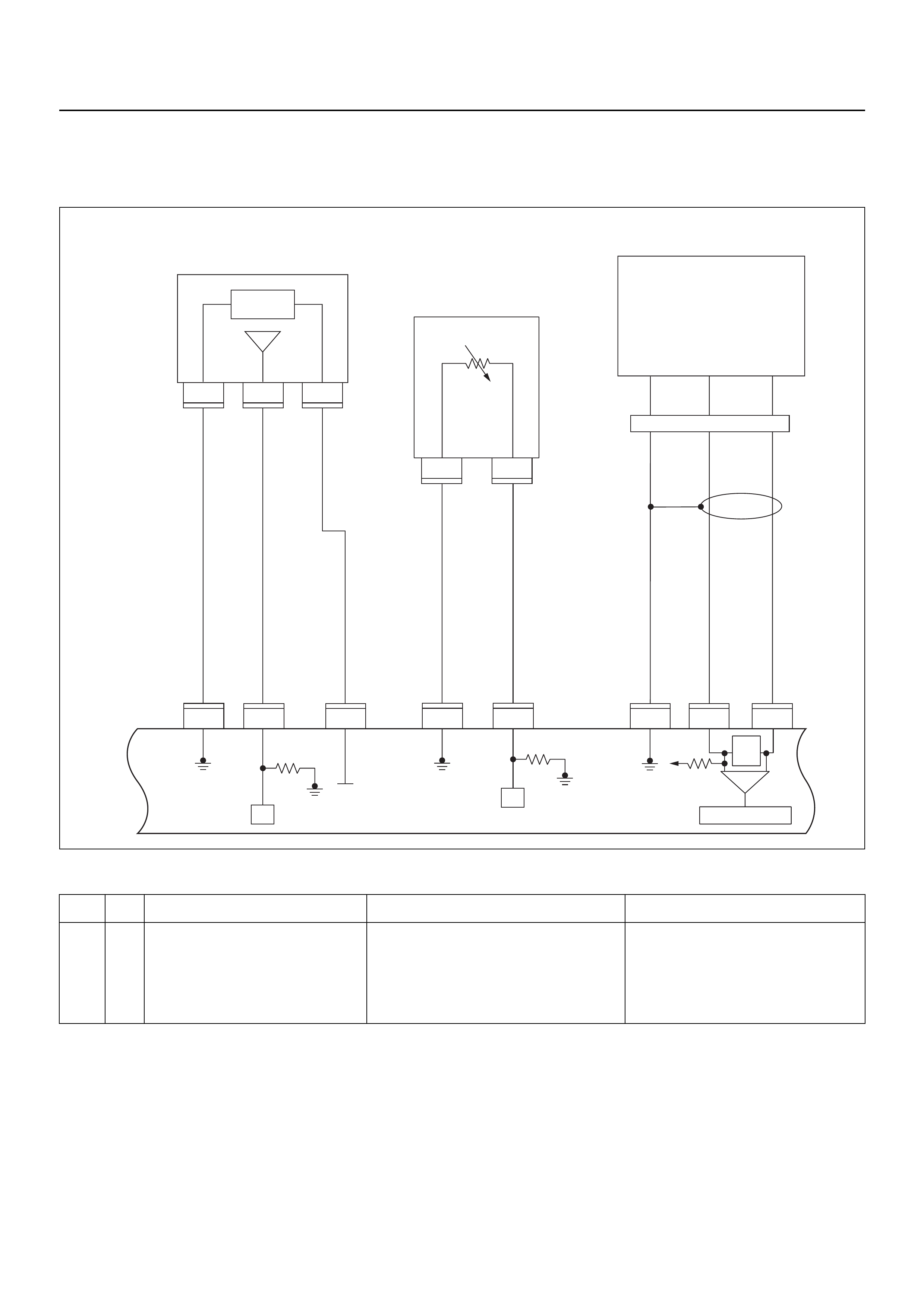
DIAGNOSTIC TROUBLE CODE (DTC) P0107 MANIFOLD ABSOLUTE
PRESSURE CIRCUIT LOW INPUT
Condition for setting the DTC and action taken when the DTC sets
Circuit Description
The manifold absolute pr essure (MAP) senso r responds
to changes in inlet manifold pressure . The MAP sensor
signal voltage to the engine control module (ECM)
varies from below 2 volts at idle (low manifold pressure)
to above 4 volts with the ignition ON, en gine not runnin g
or at wide-open throttle (high manifold pressure).
A “speed density” method of determining engine load is
used on the 2.4L engine. This is calculated using inputs
from the MAP sensor, the CKP Sensor, and the Intake
Air Temperature (IAT) sensor. The MAP sensor is the
main sensor used in this calculation, and measuring
engine load is its main function.
The ECM monitors the MAP signals for voltages outside
the normal range (10-10 4 kpa) of the MAP sensor. If the
ECM detects a MAP signal voltage that is excessively
Code Type DTC Name DTC Setting Condition Fail-Safe (Back Up)
P0107 A Manifold Absolute Pressure Circuit
Low Input 1. No DTC relating to TPS.
2. Throttle position is more than 0% if engine
speed is below 1000rpm, or throttle posi-
tion more than 5% if engine speed is more
than 1000rpm.
3. MAP sensor output is below 12KPa.
The ECM uses default manifold absolute
pressure value based on engine speed
and throttle position.
E60
16
E60
31
321
E60
24
E60
E85
2
C121
1
C121
32 1
E85
E85
26J1 J1 J1 J1 J1 J1 J1 J1
E60
6
E60
21
Manifold
Absolute
Pressure (MAP)
Sensor
Crankshaft
Position(CKP)
Sensor
μP
0.5
GRY/
BLU
AB
AB
CHIGH LOW
E59
GND
0.5
GRY/
RED
0.5
YEL/
RED
0.5
BLU/
ORG
0.5
WHT
0.5
BLK 0.5
BLK/
WHT
5 Volts
Ref
MAP
Sensor
5V Ref
Signal
GND Signal
GND Signal
GND
MAP
Signal IAT Signal
Engine
Control
Module
(ECM)
Intake
Air
Temperature (IAT)
Sensor
0.5
GRN 0.5
YEL/
GRN
μP
E60
23
E60
16
450
mV
A/D Converter
Vcc
+5V -+
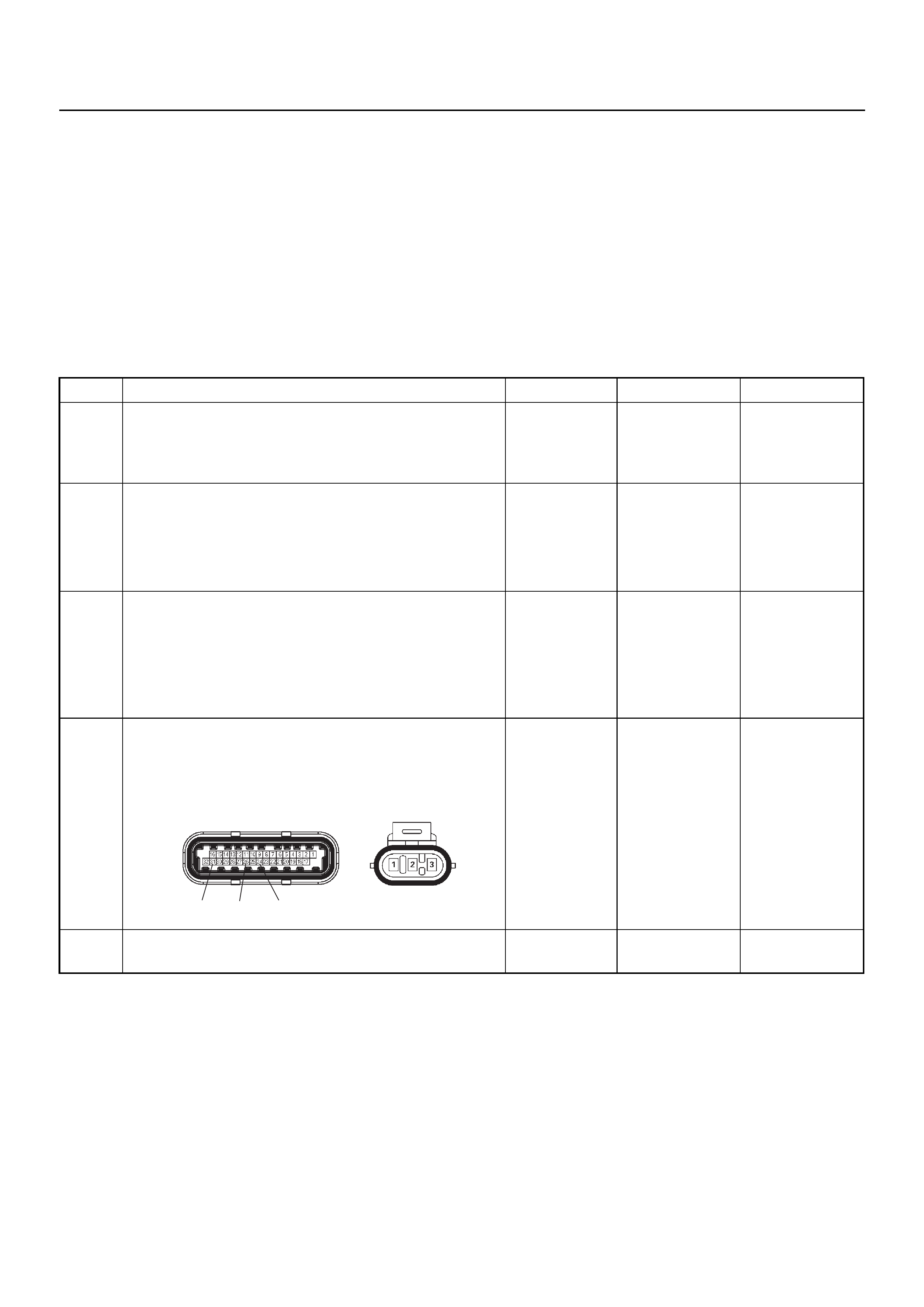
low, Diagnostic Trouble Code P0107 will be set.
Diagnostic Aids
Check for the following conditions:
• Poor connection at ECM - Inspect harness
connectors for backed-out terminals, improper
mating, broken locks, improperly formed or damaged
terminals, and poor terminal-to-wire connection.
• If these codes are also set, it could indicate a
problem with the 5 Volt reference circuit.
• Damaged harness - Inspect the wiring harness for
damage, short to ground, short to battery positive,
and open circuit. If the harness appears to be OK,
observe the MAP display on Tech 2 while moving
connectors and wiring harnesses related to the
sensor. A change in the display will indicate the
location of the fault.
Diagnostic Trouble Code (DTC) P0107
Manifold Absolute Pressure Circuit Low Input
Step Action Value(s) Yes No
1 Was the “On-Board Diagnostic (OBD) System Check”
performed?
—Go to Step 2
Go to On Board
Diagnostic
(OBD) System
Check
2 1. Connect Tech 2.
2. Review and record the failure information.
3. Select “F0: Read DTC Info Ordered By Priority”
and check for DTC’s.
Is the DTC P0107 stored as “Present Failure”? — Go to Step 3
Refer to
Diagnostic Aids
and Go to Step
3
3 1. Using Tech 2, ignition “On” and engine “Off”.
2. Select “F2: Clear DTC Information” and clear the
DTC history information.
3. Operate the vehicle and monitor the “F1: Read
DTC Info as Stored by ECU”
Was the DTC P0107 stored in this ignition cycle? — Go to Step 4
Refer to
Diagnostic Aids
and Go to Step
4
4 Check for poor/faulty connection at the MAP sensor or
ECM connector. If a poor/faulty connection is found,
repair as necess ar y.
Was the problem found?
— Verify repair G o to Step 5
5 Visually check the MAP.
Was the problem found? — Go to Step 9 Go to Step 6
26
31 24
E85E60(J1)
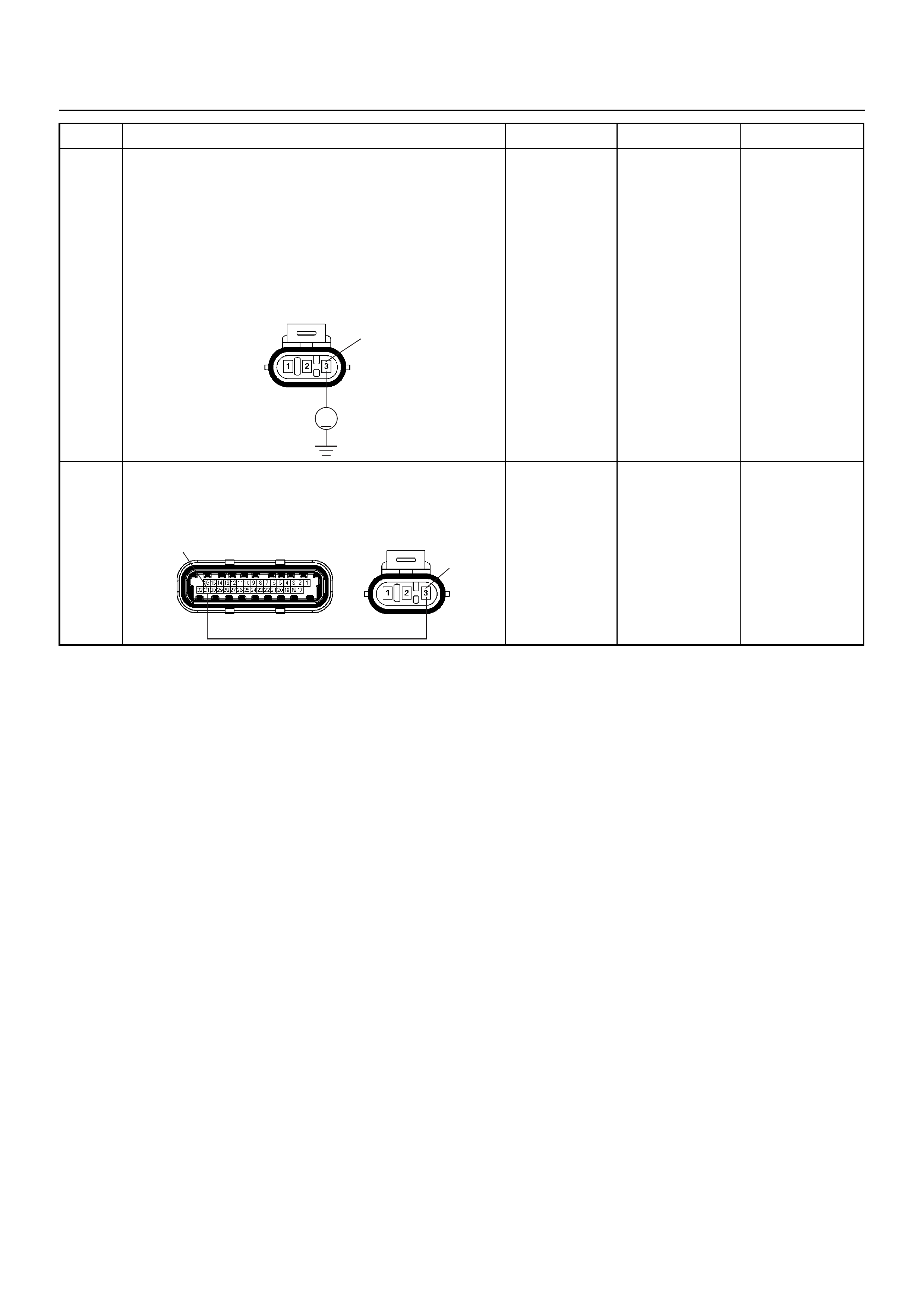
6 Use a DVM to check the MAP sensor power supply
circuit.
1. Ignition “On”, engine “Off”.
2. Disconnect the MAP sensor connector.
3. Check the circuit for open or short to ground
circuit.
Does the DVM indicate the specified value?
Approximately
5.0V Go to Step 8 Go to Step 7
7 Repair the open or short to ground circuit between the
ECM and MAP sensor
Was the problem solved?
— Verify repair G o to Step 11
Step Action Value(s) Yes No
V
E85 3
31 3
E85E60(J1)
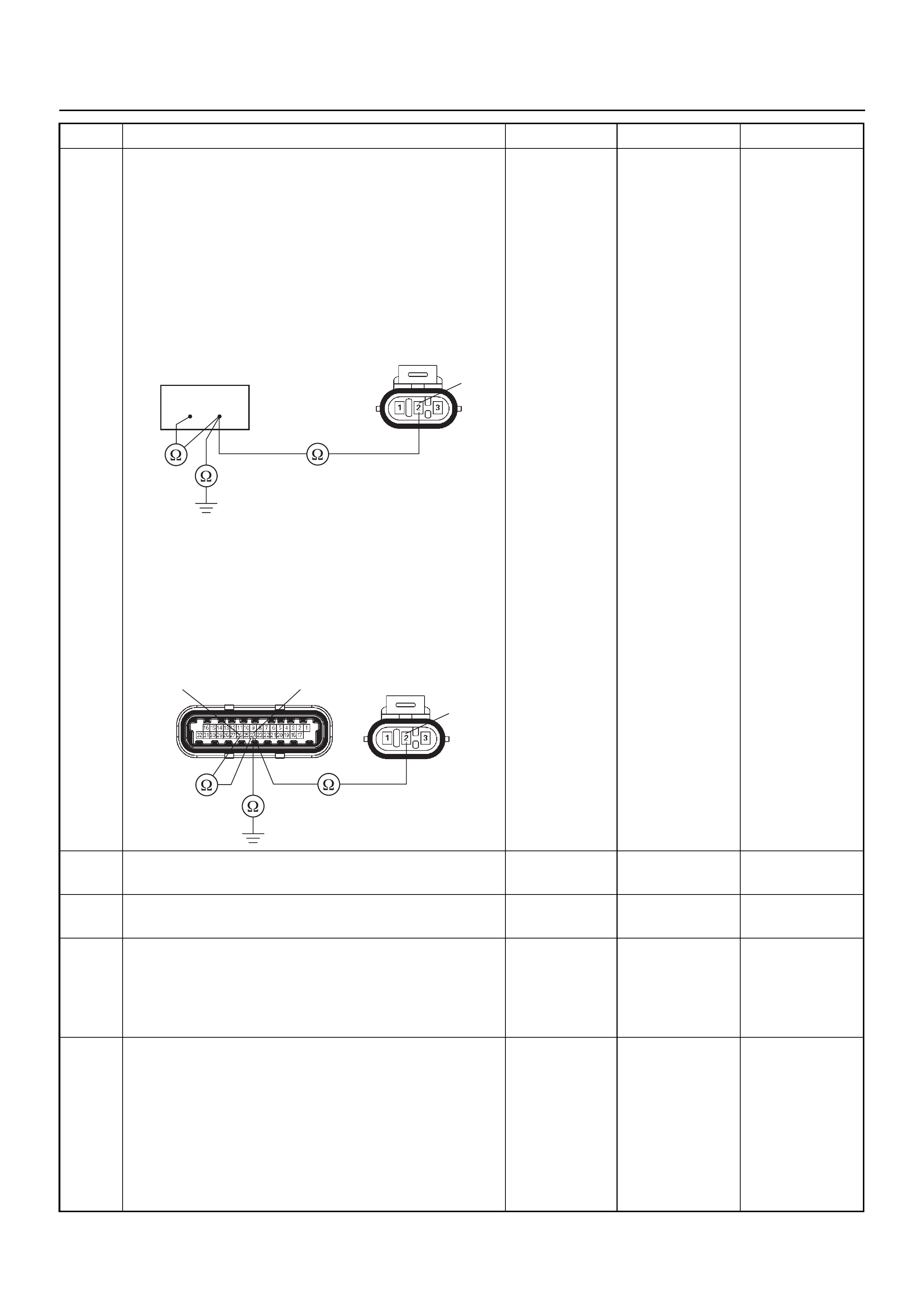
8 Use a DVM to check the MAP sensor signal circuit.
Breaker box is available:
1. Ignition “Off”, engine “Off”.
2. Install the breaker box as type A. (ECM
disconnected) Ref. 6E-77.
3. Disconnect MAP sensor connector.
4. Check the circuit for open, short to sensor ground
or short to ground circuit.
Was the problem found?
Breaker box is not available:
1. Ignition “Off”, engine “Off”.
2. Disconnect the MAP sensor connector and ECM
connector.
3. Check the circuit for open, short to sensor ground
or short to ground circuit.
Was the problem found?
—
Repair faulty
harness and
verify repair Go to Step 9
9 Substitute a known good MAP sensor and recheck.
Was the problem solved? — Go to Step 10 Go to Step 11
10 Replace the MAP sensor.
Is the action complete? — Verify repair —
11 Is the ECM programmed with the latest software
release?
If not, download the latest software to the ECM using
the “SPS (Service Programming System)”.
Was the problem solved? — Verify repair Go to Step 12
12 Replace the ECM.
Is the action complete?
IMPORTANT: The replacement ECM must be
programmed. Refer to the Service Programming
System (SPS) section in this manual.
Following ECM programming, the immobiliser system
must be linked to the ECM. Refer to section 11
“Immobiliser System-ECM replacement” for the ECM/
Immobiliser linking procedure. — Verify repair —
Step Action Value(s) Yes No
2
E85
26 24
26 24
2
E85E60(J1)
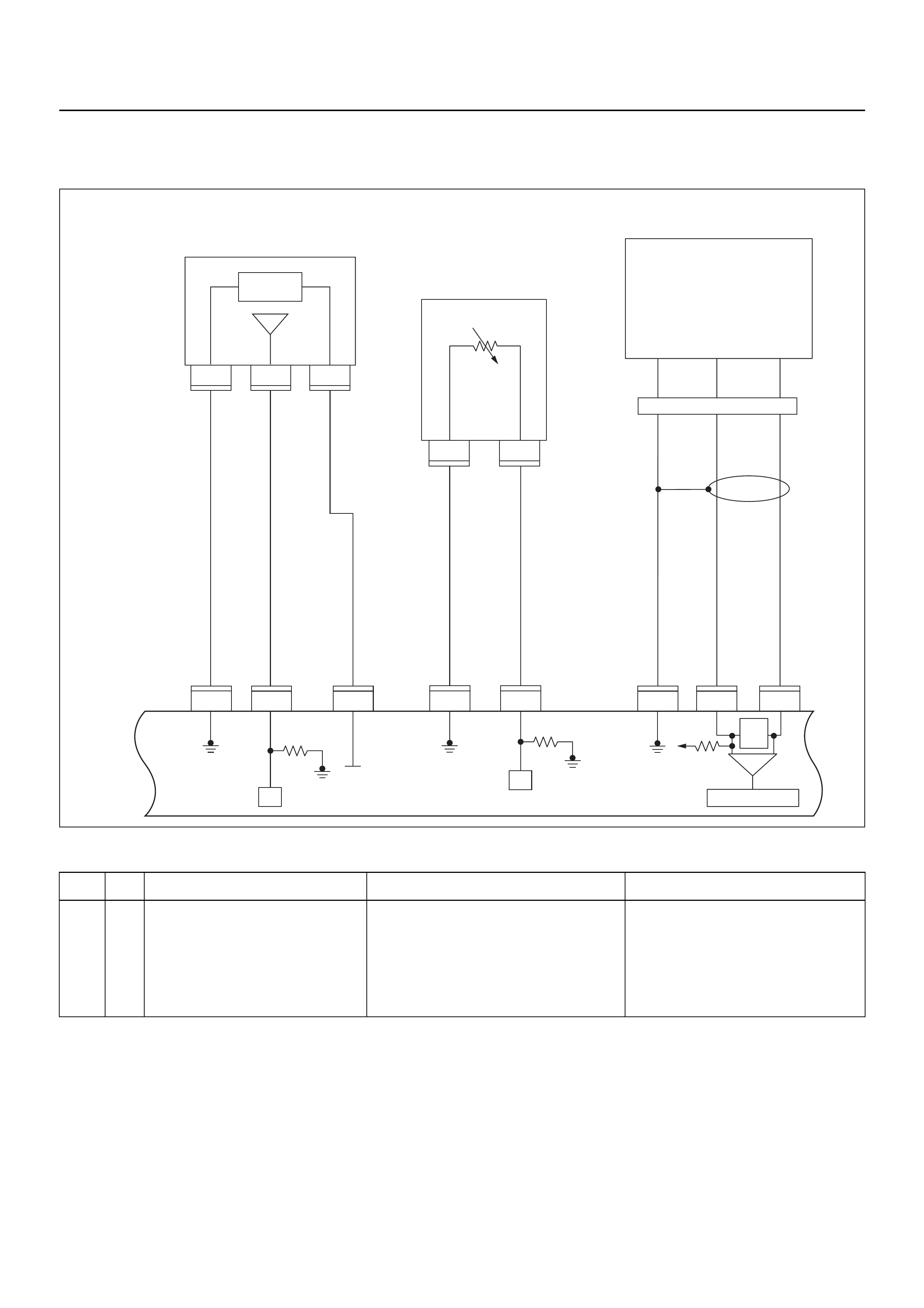
DIAGNOSTIC TROUBLE CODE (DTC) P0108 MANIFOLD ABSOLUTE
PRESSURE CIRCUIT HIGH INPUT
Condition for setting the DTC and action taken when the DTC sets
Circuit Description
The manifold absolute pr essure (MAP) senso r responds
to changes in inlet manifold pressure . The MAP sensor
signal voltage to the engine control module (ECM)
varies from below 2 volts at idle (low manifold pressure)
to above 4 volts with the ignition ON, en gine not runnin g
or at wide-open throttle (high manifold pressure).
A “speed density” method of determining engine load is
used on the 2.4L engine. This is calculated using inputs
from the MAP sensor, rpm, CKP Sensor, and the Intake
Air Temperature (IAT) sensor. The MAP sensor is the
main sensor used in this calculation, and measuring
engine load is its main function.
The ECM monitors the MAP signals for voltages outside
the normal range (10-10 4 kpa) of the MAP sensor. If the
ECM detects a MAP signal voltage that is excessively
high, Diagnostic Trouble Code P0108 will be set.
Code Type DTC Name DTC Setting Condition Fail-Safe (Back Up)
P0108 A Manifold Absolute Pressure Circuit
High Input 1. No DTC relating to TPS.
2. Throttle position is below 15% if engine
speed is below 2500rpm, or throttle posi-
tion is below 35% if engine speed is more
than 2500rpm.
3. Engine run time is longer than 10 seconds.
4. MAP sensor output is more than 103KPa.
The ECM uses default manifold absolute
pressure value based on engine speed
and throttle position.
E60
16
E60
31
321
E60
24
E60
E85
2
C121
1
C121
32 1
E85
E85
26J1 J1 J1 J1 J1 J1 J1 J1
E60
6
E60
21
Manifold
Absolute
Pressure (MAP)
Sensor
Crankshaft
Position(CKP)
Sensor
μP
0.5
GRY/
BLU
AB
AB
CHIGH LOW
E59
GND
0.5
GRY/
RED
0.5
YEL/
RED
0.5
BLU/
ORG
0.5
WHT
0.5
BLK 0.5
BLK/
WHT
5 Volts
Ref
MAP
Sensor
5V Ref
Signal
GND Signal
GND Signal
GND
MAP
Signal IAT Signal
Engine
Control
Module
(ECM)
Intake
Air
Temperature (IAT)
Sensor
0.5
GRN 0.5
YEL/
GRN
μP
E60
23
E60
16
450
mV
A/D Converter
Vcc
+5V -+
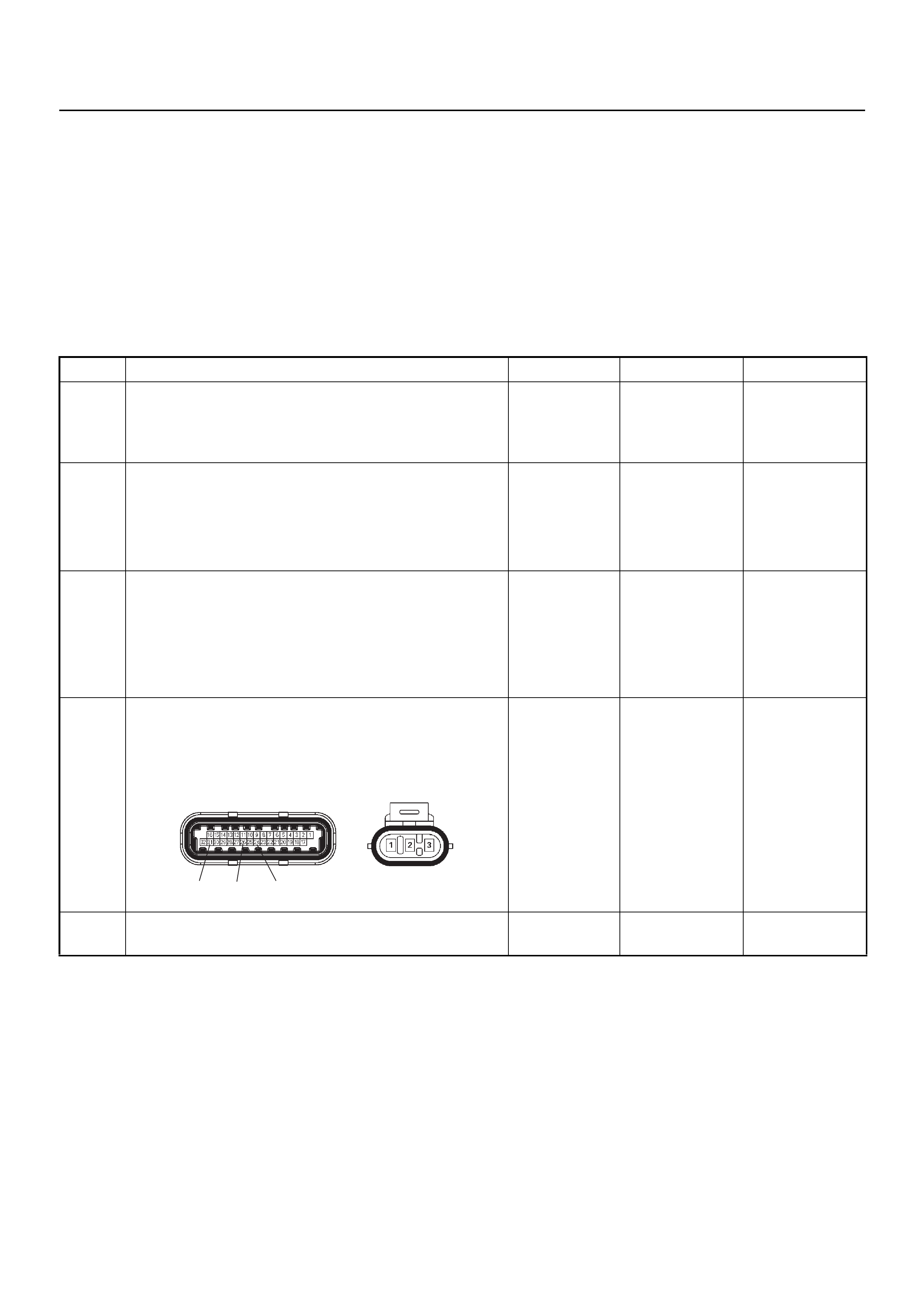
Diagnostic Aids
Check for the following conditions:
• Poor connection at ECM - Inspect harness
connectors for backed-out terminals, improper
mating, broken locks, improperly formed or damaged
terminals, and poor terminal-to-wire connection.
• If these codes are also set, it could indicate a
problem with the 5 Volt reference circuit.
• Damaged harness - Inspect the wiring harness for
damage; an open circuit, a short to ground, or a short
to voltage. If the harness appears to be OK, observe
the MAP display on Tech 2 while moving connectors
and wiring harn esses re lated to th e senso r. A chan ge
in the display will indicate the location of the fault.
Diagnostic Trouble Code (DTC) P0108
Manifold Absolute Pressure Circuit High Input
Step Action Value(s) Yes No
1 Was the “On-Board Diagnostic (OBD) System Check”
performed?
—Go to Step 2
Go to On Board
Diagnostic
(OBD) System
Check
2 1. Connect Tech 2.
2. Review and record the failure information.
3. Select “F0: Read DTC Info Ordered By Priority”
and check for DTC’s.
Is the DTC P0108 stored as “Present Failure”? — Go to Step 3
Refer to
Diagnostic Aids
and Go to Step
3
3 1. Using Tech 2, ignition “On” and engine “Off”.
2. Select “F2: Clear DTC Information” and clear the
DTC history information.
3. Operate the vehicle and monitor the “F1: Read
DTC Info as Stored by ECU”
Was the DTC P0108 stored in this ignition cycle? — Go to Step 4
Refer to
Diagnostic Aids
and Go to Step
4
4 Check for poor/faulty connection at the MAP sensor or
ECM connector. If a poor/faulty connection is found,
repair as necessary.
Was the problem found?
— Verify repair Go to Step 5
5 Visually check the MAP sensor.
Was the problem found? — Go to Step 11 Go to Step 6
26
31 24
E85E60(J1)
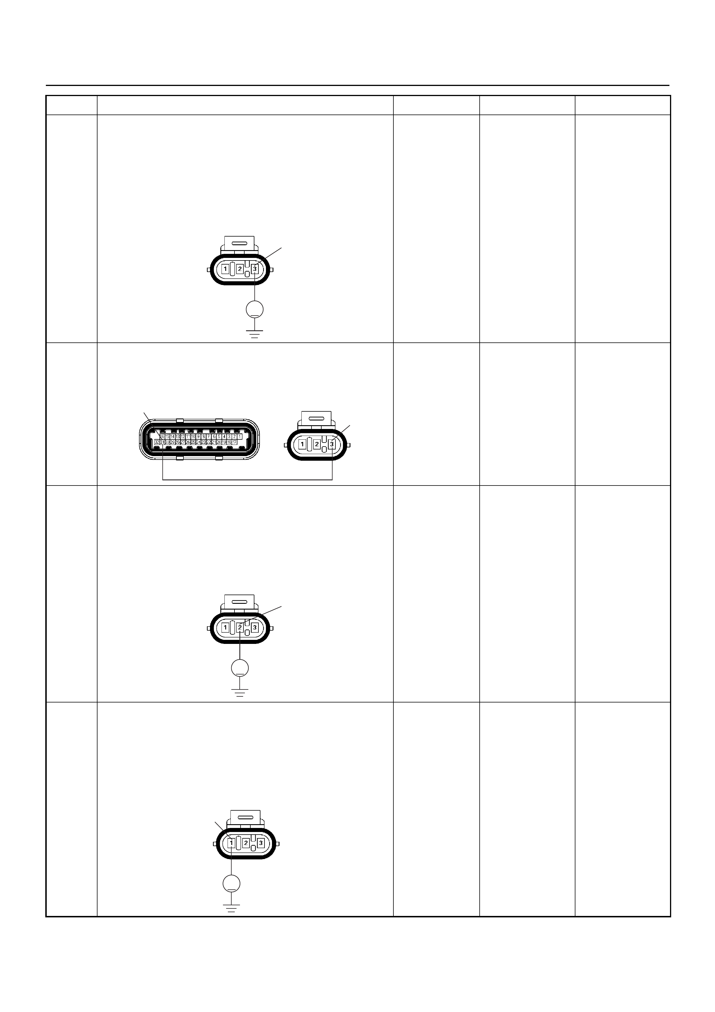
6 Use a DVM to check the MAP sensor power supply
circuit.
1. Ignition “On”, engine “Off”.
2. Disconnect the MAP sensor connector.
3. Check the circuit for short to voltage circuit.
Does the DVM indicate the specified value?
Approximately
5.0V Go to Step 8 Go to Step 7
7 Repair the short to voltage circuit between the ECM
and MAP sensor.
Was the problem solved?
— Verify repair Go to Step 13
8 Use a DVM to check the MAP sensor signal circuit.
1. Ignition “On”, engine “Off”.
2. Disconnect the MAP sensor connector.
3. Check the circuit for short to power supply circuit.
Does the DVM indicate the specified value?
Less than 1V Go to Step 9
Repair faulty
harness and
verify repair
9 Use a DVM to check the MAP sensor ground circuit.
1. Ignition “On”, engine “Off”.
2. Disconnect the MAP sensor connector .
3. Check the circuit for short to power supply circuit.
Does the DVM indicate the specified value?
Less than 1V Go to Step 10
Repair faulty
harness and
verify repair
Step Action Value(s) Yes No
V
E85 3
31 3
E85E60(J1)
V
E85 2
V
E85
1
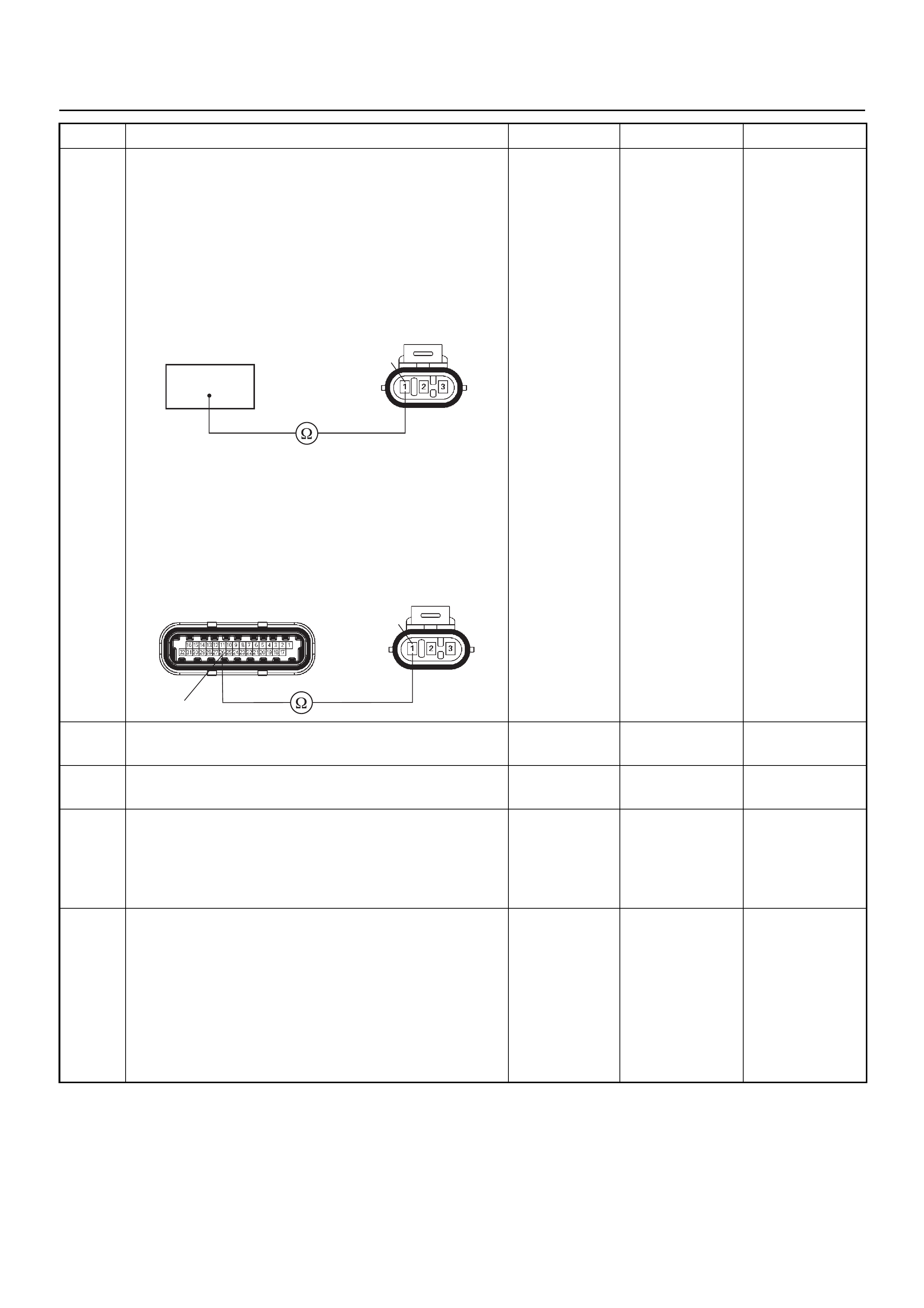
10 Use a DVM to check the MAP sensor ground circuit.
Breaker box is available:
1. Ignition “Off”, engine “Off”.
2. Install the breaker box as type A. (ECM
disconnect ed ) Re f. 6E- 77 .
3. Disconnect the MAP sensor connector.
4. Check the circuit for op en ci rcu it.
Was the problem found?
Breaker box is not available:
1. Ignition “Off”, engine “Off”.
2. Disconnect the MAP sensor connector and ECM
connector.
3. Check the circuit for op en ci rcu it.
Was the problem found?
—
Repair faulty
harness and
verify repair Go to Step 11
11 Substitute a known good MAP sensor and rech eck.
Was the problem solved? — Go to Step 12 Go to Step 13
12 Replace the MAP sensor.
Is the action complete? — Verify repair —
13 Is the ECM programmed with the latest software
release?
If not, download the latest software to the ECM using
the “SPS (Service Programming System)”.
Was the problem solved? — Verify repair Go to Step 14
14 Replace the ECM.
Is the action complete?
IMPORTANT: The replacement ECM must be
programmed. Refer to the Service Programming
System (SPS) section in this manual.
Following ECM programming, the immobiliser system
must be linked to the ECM. Refer to section 11
“Immobiliser System-ECM replacement” for the ECM/
Immobiliser linking procedure. — Verify repair —
Step Action Value(s) Yes No
1E85
26
1
26
E85E60(J1)
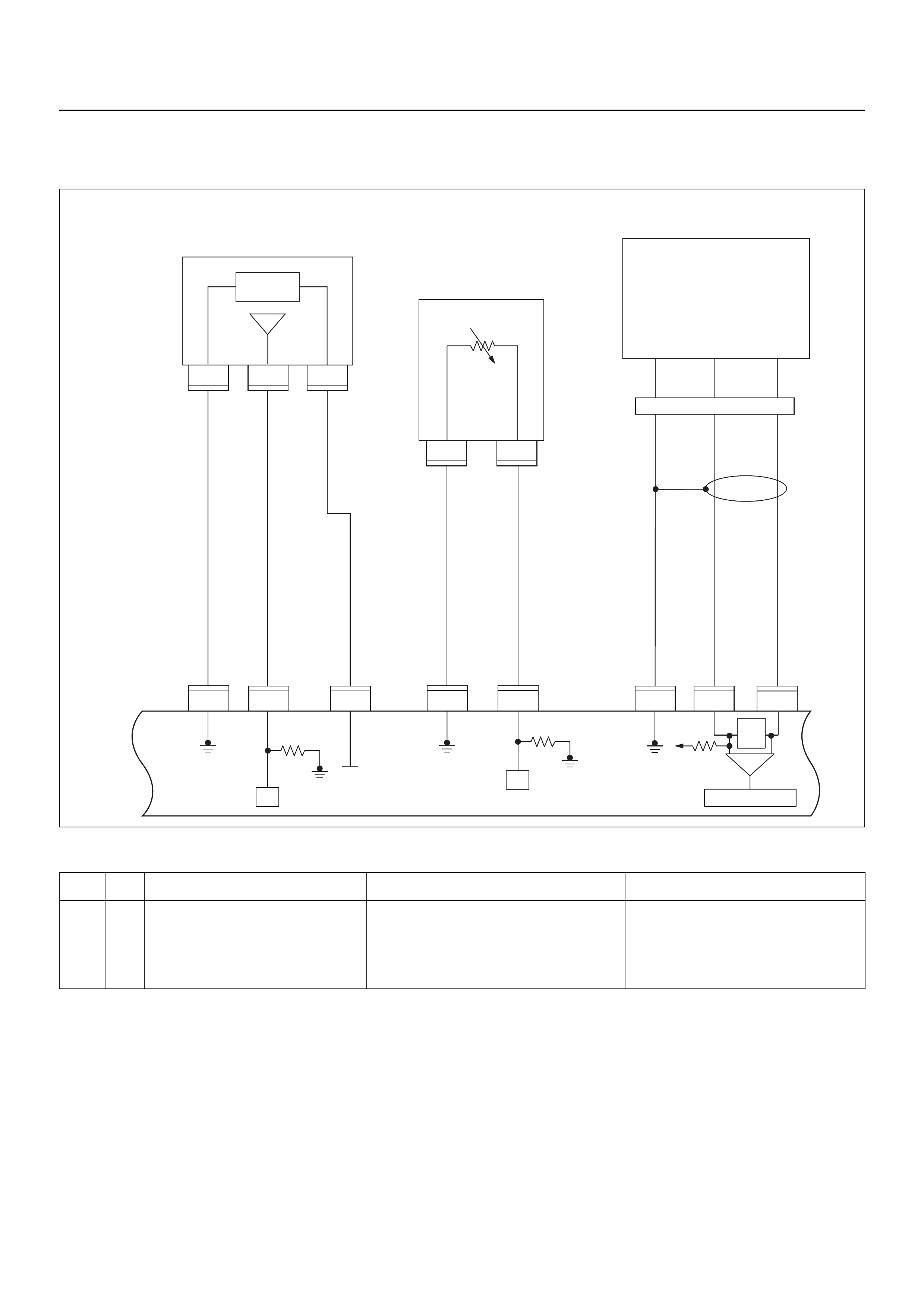
DIAGNOSTIC TROUBLE CODE (DTC) P0112 INTAKE AIR TEMPERATURE
SENSOR LOW INPUT
Condition for setting the DTC and action taken when the DTC sets
Circuit Description
The intake air temperature (IAT) sensor is a thermistor
which measu res the temperat ure of the air ent ering the
engine. The engine control module (ECM) applies 5
volts through a pull-up resistor to the IAT sensor. When
the intake air is cold, the sensor resistance is high and
the ECM will monitor a high signal voltage on the IAT
signal circuit. If the intake air is warm, the sensor
resistance is lower, causing th e ECM to mo nit or a lowe r
voltage. Diagnostic Trouble Code P0112 will set when
the ECM detects an excessively low signal voltage
(short to ground) on the intake air temperature sensor
signal circuit.
Diagnostic Aids
Check for the following conditions:
• Poor connection at ECM - Inspect harness
connectors for backed-out terminals, improper
mating, br oken locks , improperly formed or damaged
terminals, and poor terminal- to-wire connection.
• Damaged harness - Inspect the wiring harness for
damage, short to ground, short to battery and open
Code Type DTC Name DTC Setting Condition Fail-Safe (Back Up)
P0112 A Intake Air Temperature Sensor Low
Input 1. No DTC relating to VSS.
2. Vehicle speed is more than 25km/h.
3. Engine run time is longer than 120 sec-
onds.
4. IAT sensor output is more than 149°C.
The ECM uses 20°C condition as substi-
tute.
E60
16
E60
31
321
E60
24
E60
E85
2
C121
1
C121
32 1
E85
E85
26J1 J1 J1 J1 J1 J1 J1 J1
E60
6
E60
21
Manifold
Absolute
Pressure (MAP)
Sensor
Crankshaft
Position(CKP)
Sensor
μP
0.5
GRY/
BLU
AB
AB
CHIGH LOW
E59
GND
0.5
GRY/
RED
0.5
YEL/
RED
0.5
BLU/
ORG
0.5
WHT
0.5
BLK 0.5
BLK/
WHT
5 Volts
Ref
MAP
Sensor
5V Ref
Signal
GND Signal
GND Signal
GND
MAP
Signal IAT Signal
Engine
Control
Module
(ECM)
Intake
Air
Temperature (IAT)
Sensor
0.5
GRN 0.5
YEL/
GRN
μP
E60
23
E60
16
450
mV
A/D Converter
Vcc
+5V -+
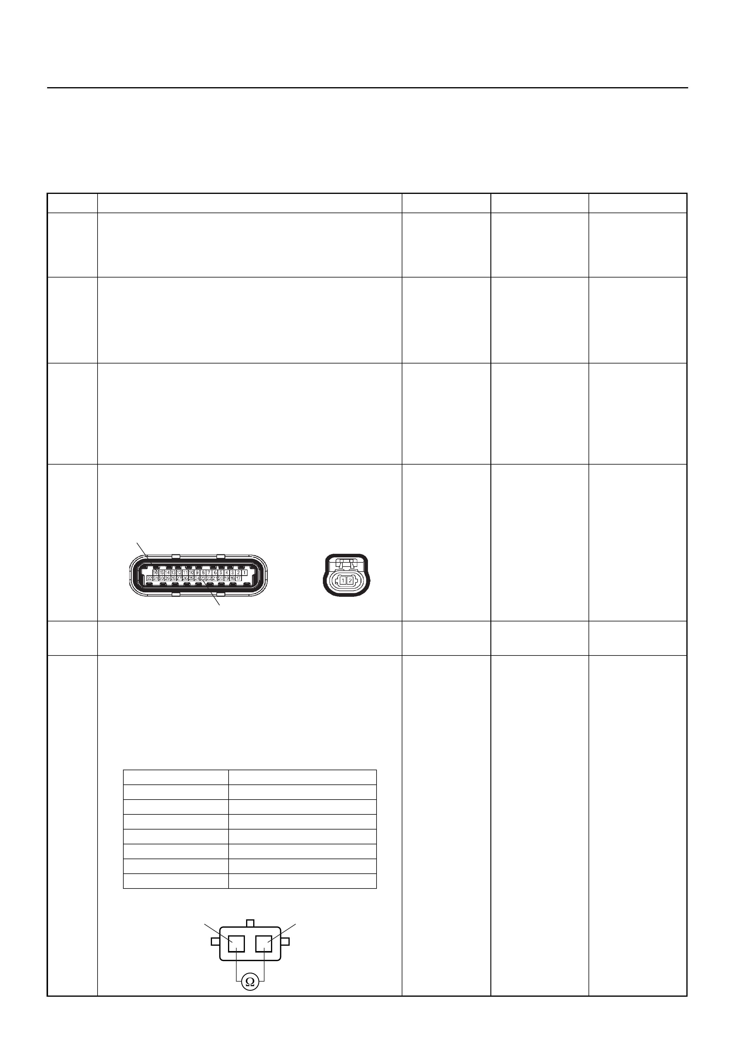
circuit. If the harness appears to be OK, observe the
IAT display on Tech 2 while moving connectors and wiring harnesses related to the IAT sensor. A change
in the IAT display will indicate the location of the fault.
Diagnostic Trouble Code (DTC) P0112
Intake Air Temperature Sensor Low Input
Step Action Value(s) Yes No
1 Was the “On-Board Diagnostic (OBD) System Check”
performed?
—Go to Step 2
Go to On Board
Diagnostic
(OBD) System
Check
2 1. Connect Tech 2.
2. Review and record the failure information.
3. Select “F0: Read DTC Info Ordered By Priority”
and check for DTC’s.
Is the DTC P0112 stored as “Present Failure”? — Go to Step 3
Refer to
Diagnostic Aids
and Go to Step
3
3 1. Using Tech 2, ignition “On” and engine “Off”.
2. Select “F2: Clear DTC Information” with Tech 2
and clear the DTC information.
3. Operate the vehicle and monitor the F1: Read
DTC Info as Stored by ECU”.
Was the DTC P0112 stored in this ignition cycle? — Go to Step 4
Refer to
Diagnostic Aids
and Go to Step
4
4 Check for poor/faulty connection at the IAT sensor or
ECM connector. If a poor/faulty connection is found,
repair as necess ar y.
Was the problem found?
— Verify repair G o to Step 5
5 Remove the IAT sensor and visually check.
Was the problem found? — Go to Step 8 Go to Step 6
6 Use a DVM to check the IAT sensor.
1. Ignition “Off”, engine “Off”.
2. Disconnect IAT sensor connector.
3. Measure the resistance of IAT sensor.
Does the tester indicate standar d resistance as sh own
in the following table?
Standard
resistance Go to Step 7 Go to Step 8
E60(J1) C121
16
23
Temperature (°C) Resistance (Ω) (Approximately)
-20 32040
0 9788
20 3516
40 1439
60 656
80 327
100 175
IAT Sensor 1
1
2
2
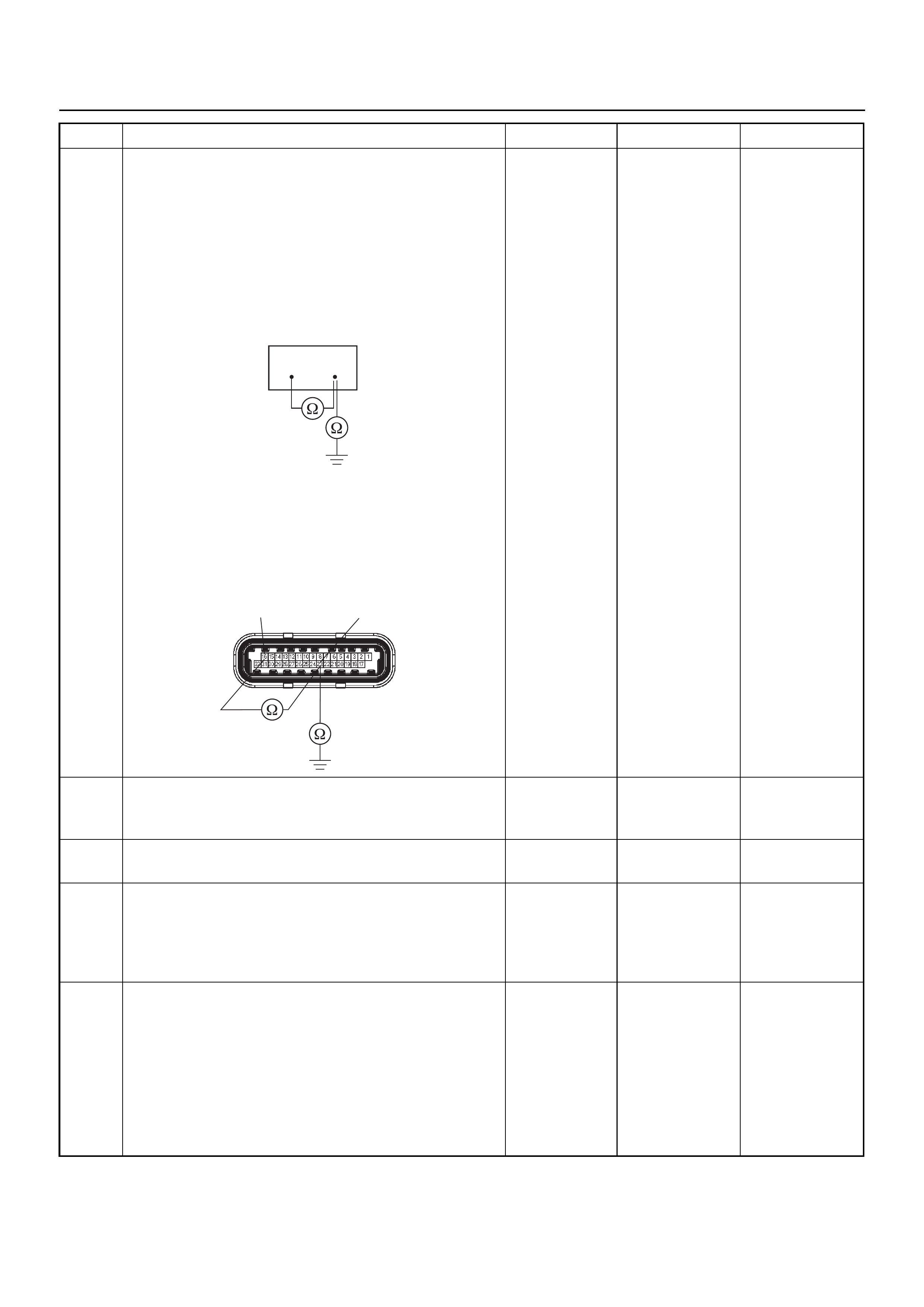
7 Use a DVM to check the IAT sensor signal circuit.
Breaker box is available:
1. Ignition “Off”, engine “Off”.
2. Install the breaker box as type A. (ECM
disconnected) Ref. 6E-77.
3. Disconnect the IAT sensor connector.
4. Check the circuit for short to sensor ground or
ground circuit.
Was the problem found?
Breaker box is not available:
1. Ignition “Off”, engine “Off”.
2. Disconnect the IAT sensor connector.
3. Check the circuit for short to sensor ground or
ground circuit.
Was the problem found?
—
Repair faulty
harness and
verify repair Go to Step 10
8 Substitute a known good IAT sensor assembly and
recheck.
Was the problem solved? — Go to Step 9 Go to Step 10
9 Replace the IAT sensor assembly.
Is the action complete? — Verify repair —
10 Is the ECM programmed with the latest software
release?
If not, download the latest software to the ECM using
the “SPS (Service Programming System)”.
Was the problem solved? — Verify repair Go to Step 11
11 Replace the ECM.
Is the action complete?
IMPORTANT: The replacement ECM must be
programmed. Refer to the Service Programming
System (SPS) section in this manual.
Following ECM programming, the immobiliser system
must be linked to the ECM. Refer to section 11
“Immobiliser System-ECM replacement” for the ECM/
Immobiliser linking procedure. — Verify repair —
Step Action Value(s) Yes No
16 23
E60(J1)
16 23
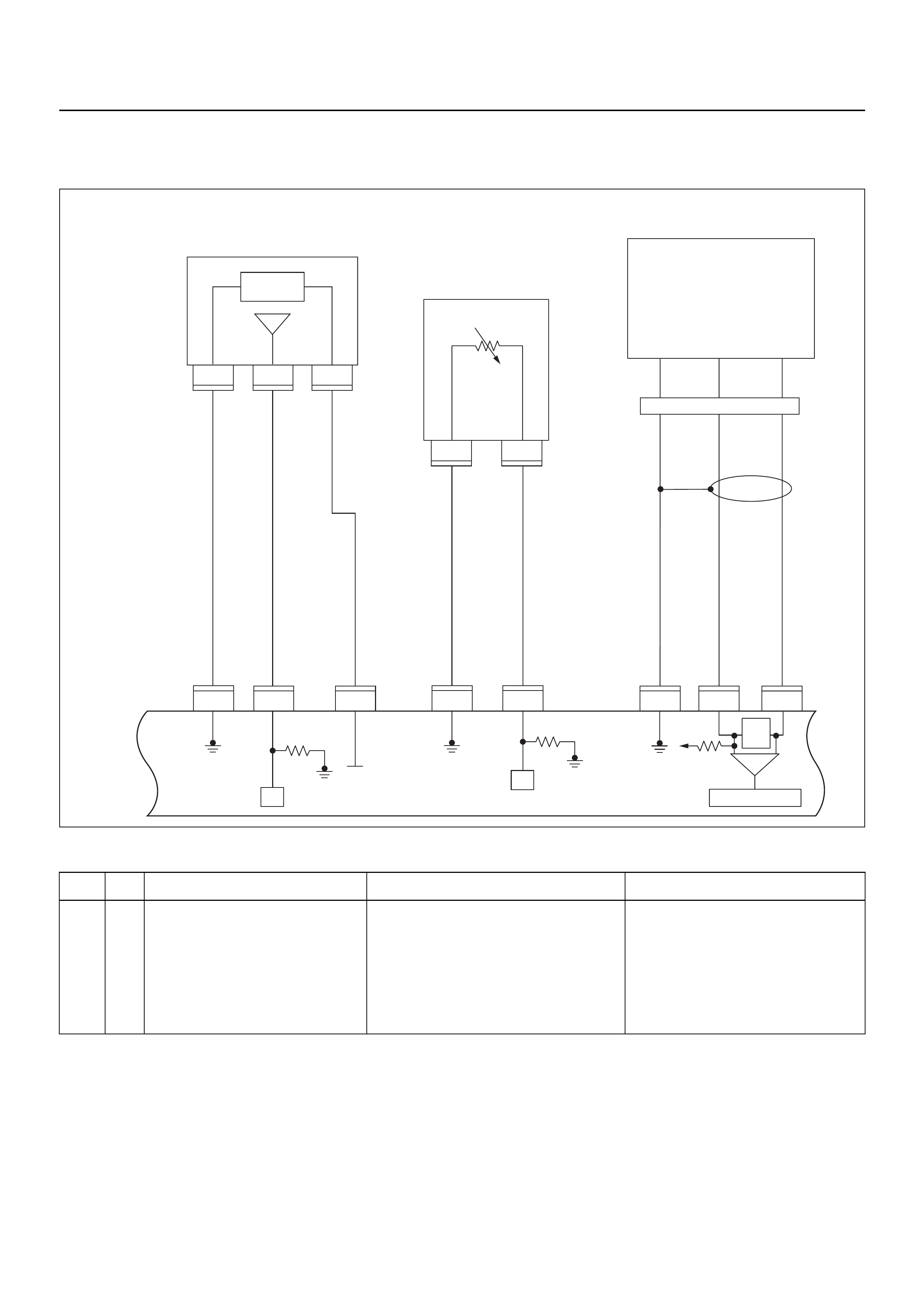
DIAGNOSTIC TROUBLE CODE (DTC) P0113 INTAKE AIR TEMPERATURE
SENSOR HIGH INPUT
Condition for setting the DTC and action taken when the DTC sets
Circuit Description
The intake air temperature (IAT) sensor is a thermistor
which measu res the temperat ure of the air ent ering the
engine. The engine control module (ECM) applies 5
volts through a pull-up resistor to the IAT sensor. When
the intake air is cold, the sensor resistance is high and
the ECM will monitor a high signal voltage on the IAT
signal circuit. If the intake air is warm, the sensor
resistance is lower causing the ECM to monitor a lower
voltage. Diagnostic Trouble Code P0113 will set when
the ECM detects an excessively high signal voltage on
the intake air temperature sensor signal circuit.
Diagnostic Aids
Check for the following conditions:
• Poor connection at ECM - Inspect harness
connectors for backed-out terminals, improper
mating, br oken locks , improperly formed or damaged
Code Type DTC Name DTC Setting Condition Fail-Safe (Back Up)
P0113 A Intake Air Temperature Sensor High
Input 1. No DTC relating to VSS & ECT sensor.
2. Vehicle speed is below 70km/h.
3. 3Engine coolant temperature is more than -
8°C.
4. Engine run time is longer than 120 sec-
onds.
5. Mass air flow is below 30g/s.
6. IAT sensor output is below -38°C.
The ECM uses 20°C condition as substi-
tute.
E60
16
E60
31
321
E60
24
E60
E85
2
C121
1
C121
32 1
E85
E85
26J1 J1 J1 J1 J1 J1 J1 J1
E60
6
E60
21
Manifold
Absolute
Pressure (MAP)
Sensor
Crankshaft
Position(CKP)
Sensor
μP
0.5
GRY/
BLU
AB
AB
CHIGH LOW
E59
GND
0.5
GRY/
RED
0.5
YEL/
RED
0.5
BLU/
ORG
0.5
WHT
0.5
BLK 0.5
BLK/
WHT
5 Volts
Ref
MAP
Sensor
5V Ref
Signal
GND Signal
GND Signal
GND
MAP
Signal IAT Signal
Engine
Control
Module
(ECM)
Intake
Air
Temperature (IAT)
Sensor
0.5
GRN 0.5
YEL/
GRN
μP
E60
23
E60
16
450
mV
A/D Converter
Vcc
+5V -+
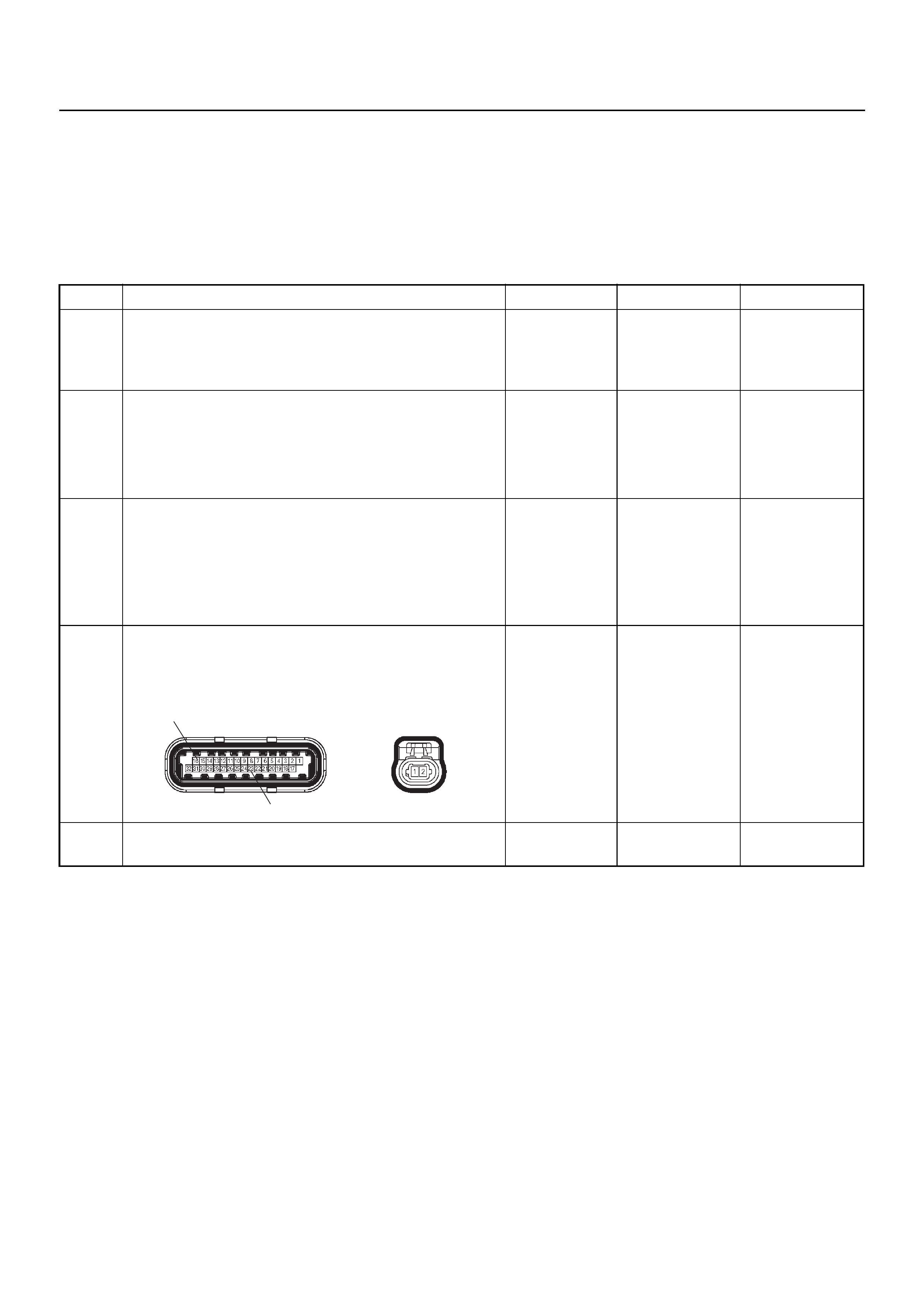
terminals, and poor terminal-to-wire connection.
• Damaged harness - Inspect the wiring harness for
damage, short to ground, short to battery positive,
and open circuit. If the harness appears to be OK,
observe the IAT display on Tech 2 while moving
connectors and wiring harnesses related to the IAT
sensor. A change in the IAT display will indicate the
location of the fault.
Diagnostic Trouble Code (DTC) P0113
Intake Air Temperature Sensor High Input
Step Action Value(s) Yes No
1 Was the “On-Board Diagnostic (OBD) System Check”
performed?
—Go to Step 2
Go to On Board
Diagnostic
(OBD) System
Check
2 1. Connect Tech 2.
2. Review and record the failure information.
3. Select “F0: Read DTC Info Ordered By Priority”
and check for DTC’s.
Is the DTC P0113 stored as “Present Failure”? — Go to Step 3
Refer to
Diagnostic Aids
and Go to Step
3
3 1. Using Tech 2, ignition “On” and engine “Off”.
2. Select “F2: F2: Clear DTC Information” with Tech
2 and clear the DTC information.
3. Operate the vehicle and monitor the F1: Read
DTC Info as Stored by ECU”.
Was the DTC P0113 stored in this ignition cycle? — Go to Step 4
Refer to
Diagnostic Aids
and Go to Step
4
4 Check for poor/faulty connection at the IAT sensor or
ECM connector. If a poor/faulty connection is found,
repair as necess ar y.
Was the problem found?
— Verify repair G o to Step 5
5 Visually check the IAT sensor.
Was the problem found? — Go to Step 12 Go to Step 6
E60(J1) C121
16
23
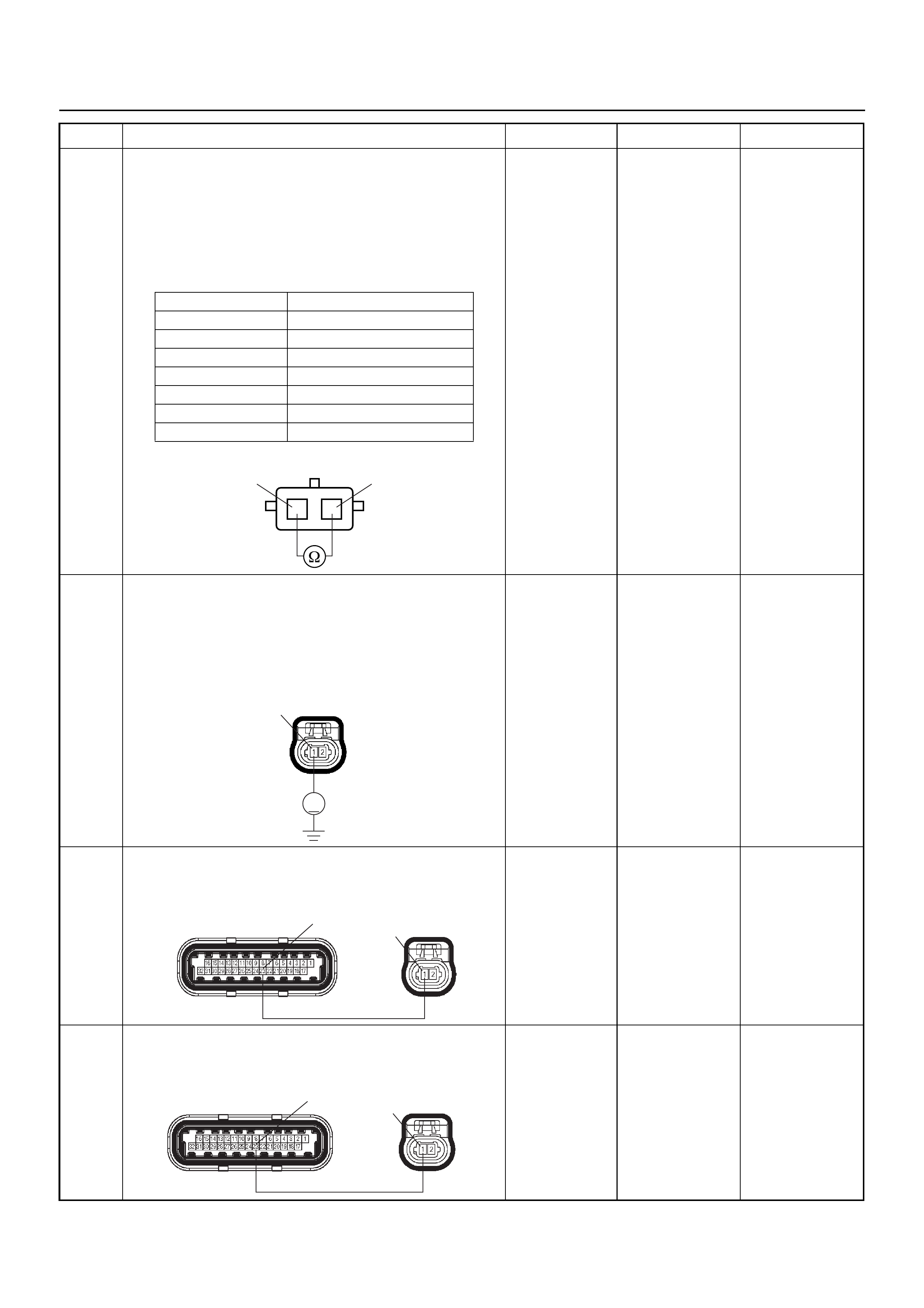
6 Use a DVM to check the IAT sensor.
1. Ignition “Off”, engine “Off”.
2. Disconnect IAT sensor connector.
3. Measure the resistance of IAT sensor.
Does the tester indicate standar d resistance as sh own
in the following table?
Standard
resistance Go to Step 7 Go to Step 12
7 Use a DVM to check the IAT sensor signal circuit.
1. Ignition “On”, engine “Off”.
2. Disconnect the IAT sensor connector.
3. Check the circuit for open circuit.
Does the DVM indicate the specified value?
Approximately
5.0V Go to Step 10
Less than 1V:
Go to Step 8
More than
specified value:
Go to Step 9
8 Repair the open circuit between the ECM and IAT
sensor.
Was the problem solved?
— Verify repair Go to Step 14
9 Repair the short to voltage circuit between the ECM
and IAT sensor.
Was the problem solved?
— Verify repair Go to Step 14
Step Action Value(s) Yes No
Temperature (°C) Resistance (Ω) (Approximately)
-20 32040
0 9788
20 3516
40 1439
60 656
80 327
100 175
IAT Sensor 1
1
2
2
V
C121
1
E60(J1) C121
1
23
E60(J1) C121
1
23
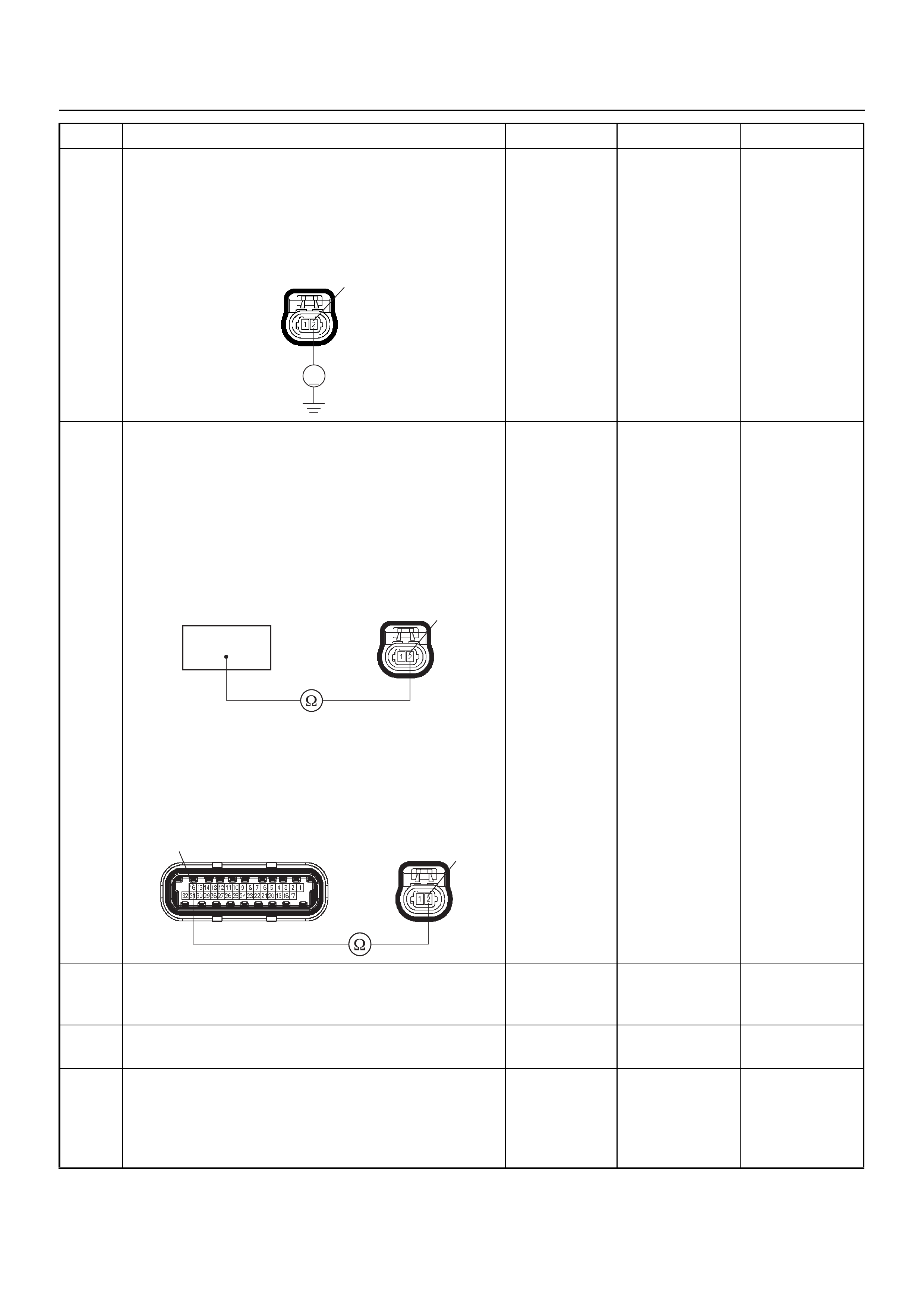
10 Use a DVM to check the IAT sensor ground circuit.
1. Ignition “On”, engine “Off”.
2. Disconnect the IAT sensor connector.
3. Check the circuit for short to power supply circuit.
Does the DVM indicate the specified value?
Less than 1V Go to Step 11
Repair faulty
harness and
verify repair
11 Use a DVM to check the IAT sensor ground circuit.
Breaker box is available:
1. Ignition “Off”, engine “Off”.
2. Install the breaker box as type A. (ECM
disconnected) Ref. 6E-77.
3. Disconnect the IAT sensor connector.
4. Check the circuit for open circuit.
Was the problem found?
Breaker box is not available:
1. Ignition “Off”, engine “Off”.
2. Disconnect the IAT sensor connector.
3. Check the circuit for open circuit.
Was the problem found?
—
Repair faulty
harness and
verify repair Go to Step 14
12 Substitute a known good IAT sensor assembly and
recheck.
Was the problem solved? — Go to Step 13 Go to Step 14
13 Replace the IAT sensor assembly.
Is the action complete? — Verify repair —
14 Is the ECM programmed with the latest software
release?
If not, download the latest software to the ECM using
the “SPS (Service Programming System)”.
Was the problem solved? — Verify repair Go to Step 15
Step Action Value(s) Yes No
V
C121 2
16
C121 2
E60(J1) C121 2
16

15 Replace the ECM.
Is the action complete?
IMPORTANT: The replacement ECM must be
programmed. Refer to the Service Programming
System (SPS) section in this manual.
Following ECM programming, the immobiliser system
must be linked to the ECM. Refer to section 11
“Immobiliser System-ECM replacement” for the ECM/
Immobiliser linking procedure. — Verify repair —
Step Action Value(s) Yes No
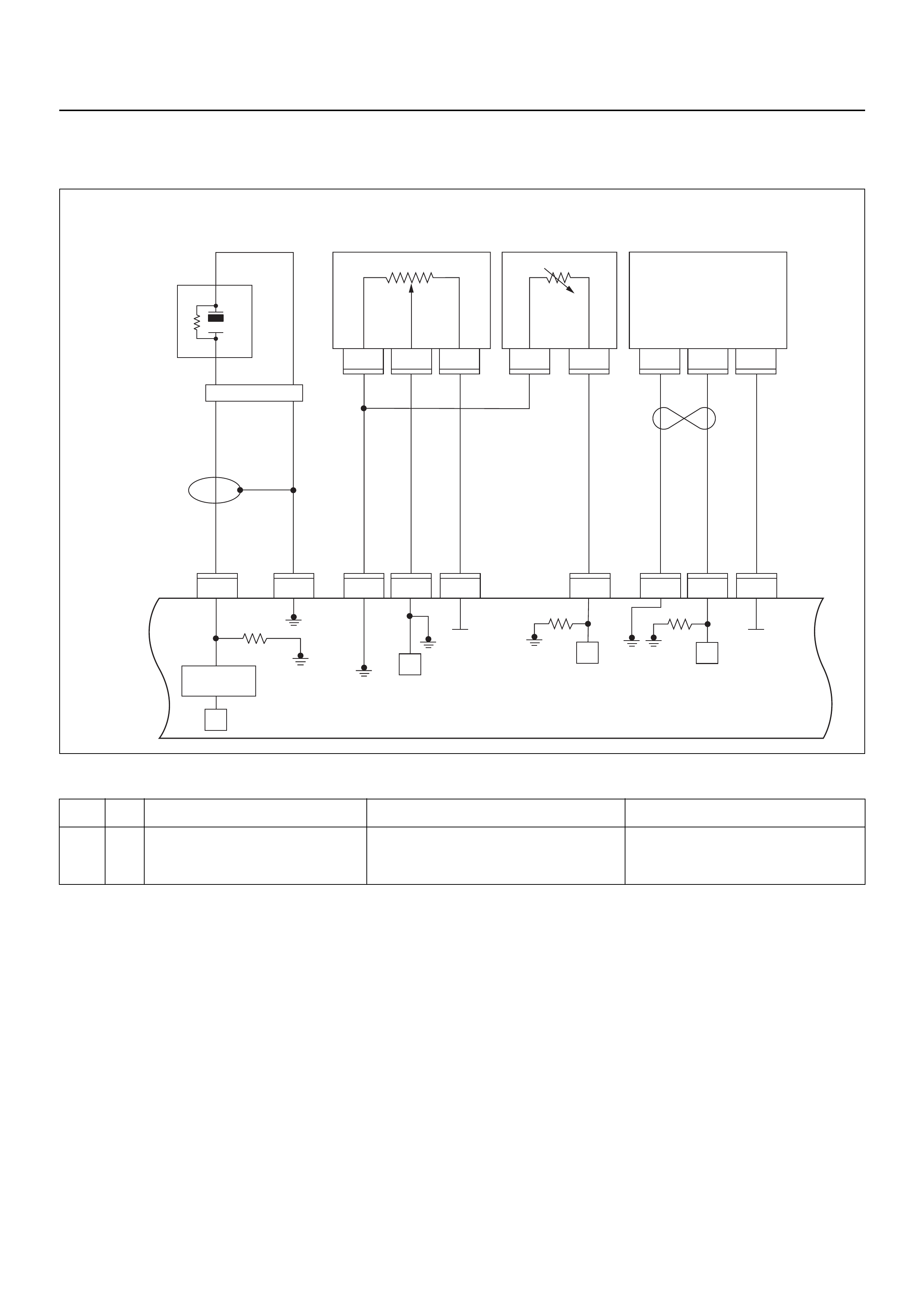
DIAGNOSTIC TROUBLE CODE (DTC) P0117 ENGINE COOLANT
TEMPERATURE SENSOR LOW INPUT
Condition for setting the DTC and action taken when the DTC sets
Circuit Description
The engine coolant temperature (ECT) sensor is a
thermistor mounted in the engine coolant stream. The
engine control modu le (ECM) applies a voltag e ( abo ut 5
volts) through a pull-up resisto r to the ECT signal circui t.
When the engine coolant is co ld, the sen sor (thermistor )
resistance is high, therefore the ECM will measure a
high signal voltage. As the engine coolant warms, the
sensor resistance becomes lower, and the ECT signal
voltage measured at the ECM drops. Diagnostic
Trouble code P0117 set when the ECM detects an
excessively low signal voltage on the engine coolant
temperature sensor signal circuit.
Diagnostic Aids
Check for the following conditions:
• Poor connection at ECM - Inspect harness
connectors for backed-out terminals, improper
mating, br oken locks , improperly formed or damaged
terminals, and poor terminal- to-wire connection.
• Damaged harness - Inspect the wiring harness for
damage, short to ground, short to battery positive,
and open circuit. If the harness appears to be OK,
observe the ECT display on Tech 2 while moving
connectors and wiring harnesses related to the ECT
sensor. A change in the ECT display will indicate the
location of the fault.
Code Type DTC Name DTC Setting Condition Fail-Safe (Back Up)
P0117 A Engine Coolant Temperature Sensor
Low Input 1. Engine run time is longer than 120 sec-
onds.
2. ECT sensor output is more than 149°C.
The ECM uses default engine coolant
temperature value based on intake air
temperature and engine run time.
1
C56
μP
E60
27
12231
12
E60
31
E60
7
E60
26
E60
3J1 J1 J1 J1 J1J1 J2 J2 J2
E60
E68 E68 E68 E69 E69 F10 F10 F10
16
C56
17 25
C56
1
A
23
CB
B
A
E84
0.5
GRY
μP
μP
5Volts
Ref 5Volts
Ref
Knock
Sensor
0.5
YEL
0.5
WHT/
BLU
0.5
BLU/
ORG
0.5
BLU/
ORG
0.5
YEL/
RED
0.5
PUR/
BLU
0.5
GRY/
BLU
0.5
BLK 0.5
ORG 0.5
BLU/
WHT
Engine
Coolant
Temperature (ECT)
Sensor Vertical
G-Sensor
Throttle
Position Sensor
(TPS)
Knock Filter
Module
Engine
Control
Module
(ECM) μP
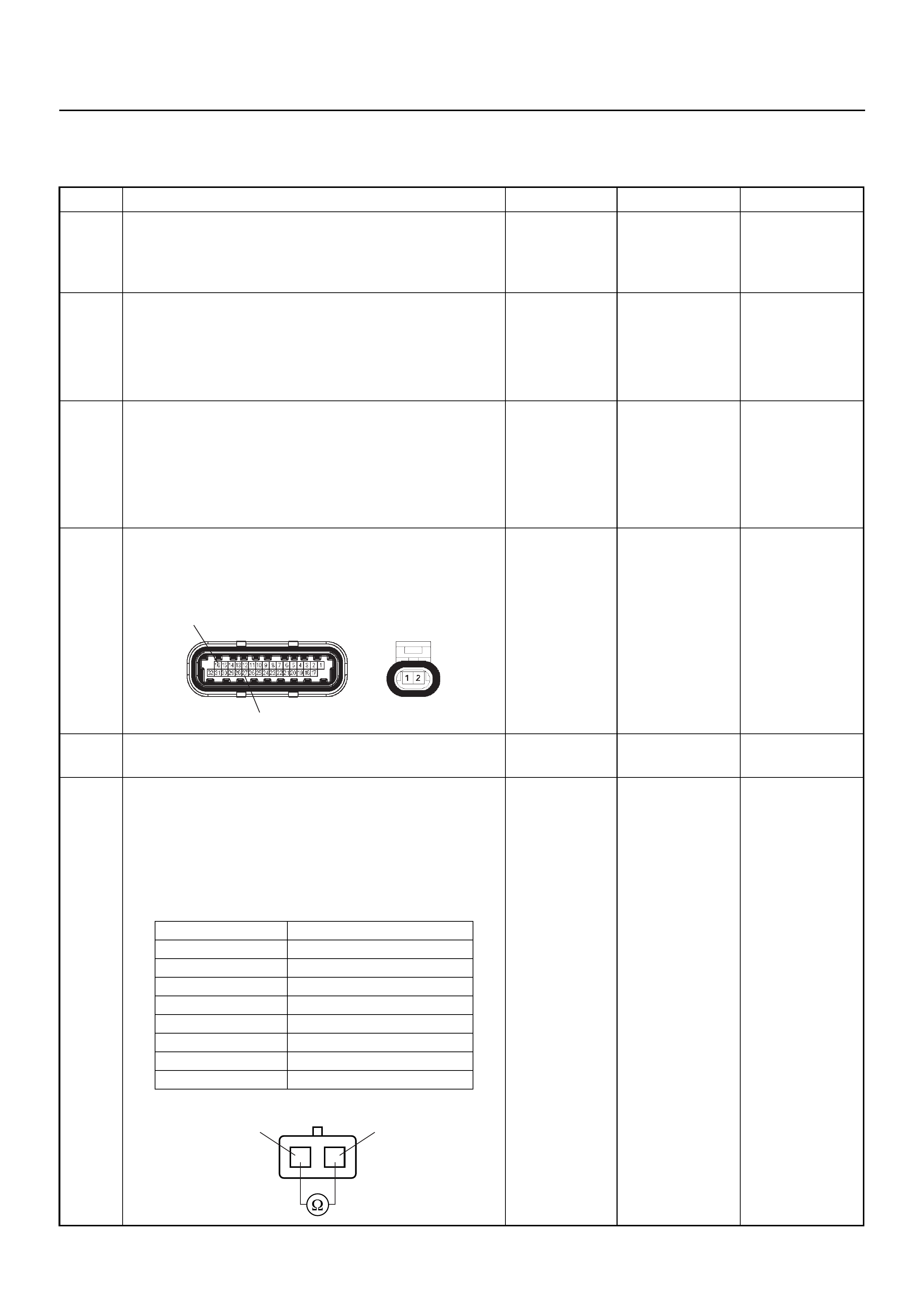
Diagnostic Trouble Code (DTC) P0117
Engine Coolant Temperature Sensor Low Input
Step Action Value(s) Yes No
1 Was the “On-Board Diagnostic (OBD) System Check”
performed?
—Go to Step 2
Go to On Board
Diagnostic
(OBD) System
Check
2 1. Connect Tech 2.
2. Review and record the failure information.
3. Select “F0: Read DTC Info Ordered By Priority”
and check for DTC’s.
Is the DTC P0117 stored as “Present Failure”? — Go to Step 3
Refer to
Diagnostic Aids
and Go to Step
3
3 1. Using Tech 2, ignition “On” and engine “Off”.
2. Select “F2: Clear DTC Information” with Tech 2
and clear the DTC information.
3. Operate the vehicle and monitor the “F1: Read
DTC Info as Stored by ECU”.
Was the DTC P0117 stored in this ignition cycle? — Go to Step 4
Refer to
Diagnostic Aids
and Go to Step
4
4 Check for poor/faulty connection at the ECT sensor or
ECM connector. If a poor/faulty connection is found,
repair as necess ar y.
Was the problem found?
— Verify repair G o to Step 5
5 Visually check the ECT sensor.
Was the problem found? — Go to Step 8 Go to Step 6
6 Use a DVM to check the ECT sensor.
1. Ignition “Off”, engine “Off”.
2. Disconnect ECT sensor connector.
3. Measure the resistance of ECT sensor.
Does the tester indicate standar d resistance as sh own
in the following table?
Standard
resistance Go to Step 7 Go to Step 8
E60(J1) E69
16
27
Temperature (°C) Resistance (Ω) (Approximately)
-20 32040
0 9788
20 3516
40 1439
60 656
80 327
100 175
120 100
ECT Sensor 1
1
2
2
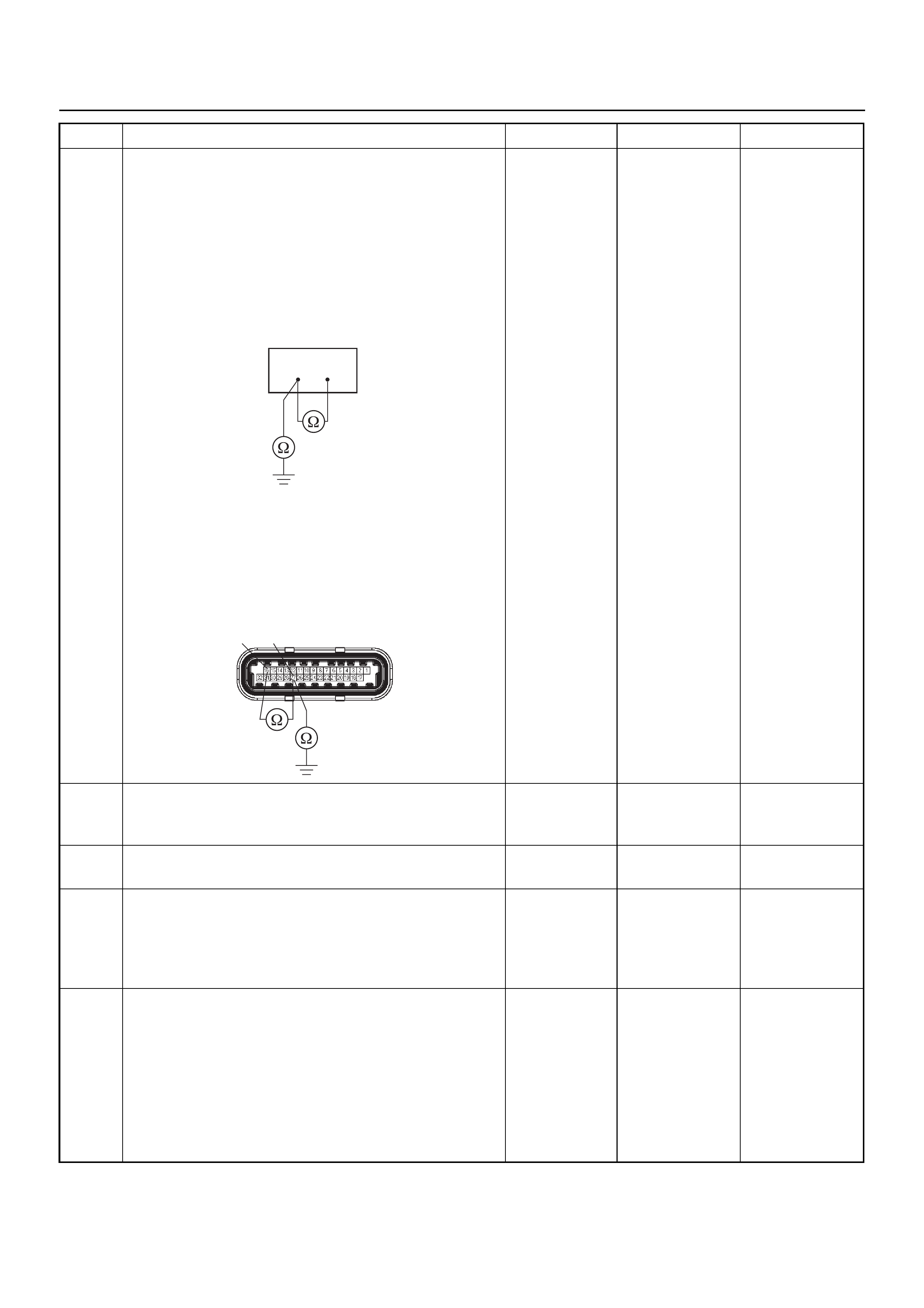
7 Use a DVM to check the ECT sensor signal circuit.
Breaker box is available:
1. Ignition “Off”, engine “Off”.
2. Install the breaker box as type A. (ECM
disconnected) Ref. 6E-77.
3. Disconnect the ECT sensor connector.
4. Check the circuit for short to sensor ground or
ground circuit.
Was the problem found?
Breaker box is not available:
1. Ignition “Off”, engine “Off”.
2. Disconnect the ECT sensor connector.
3. Check the circuit for short to sensor ground or
ground circuit.
Was the problem found?
—
Repair faulty
harness and
verify repair Go to Step 10
8 Substitute a known good ECT sensor assembly and
recheck.
Was the problem solved? — Go to Step 9 Go to Step 10
9 Replace the ECT sensor.
Is the action complete? — Verify repair —
10 Is the ECM programmed with the latest software
release?
If not, download the latest software to the ECM using
the “SPS (Service Programming System)”.
Was the problem solved? — Verify repair Go to Step 11
11 Replace the ECM.
Is the action complete?
IMPORTANT: The replacement ECM must be
programmed. Refer to the Service Programming
System (SPS) section in this manual.
Following ECM programming, the immobiliser system
must be linked to the ECM. Refer to section 11
“Immobiliser System-ECM replacement” for the ECM/
Immobiliser linking procedure. — Verify repair —
Step Action Value(s) Yes No
27 16
E60(J1)
2716
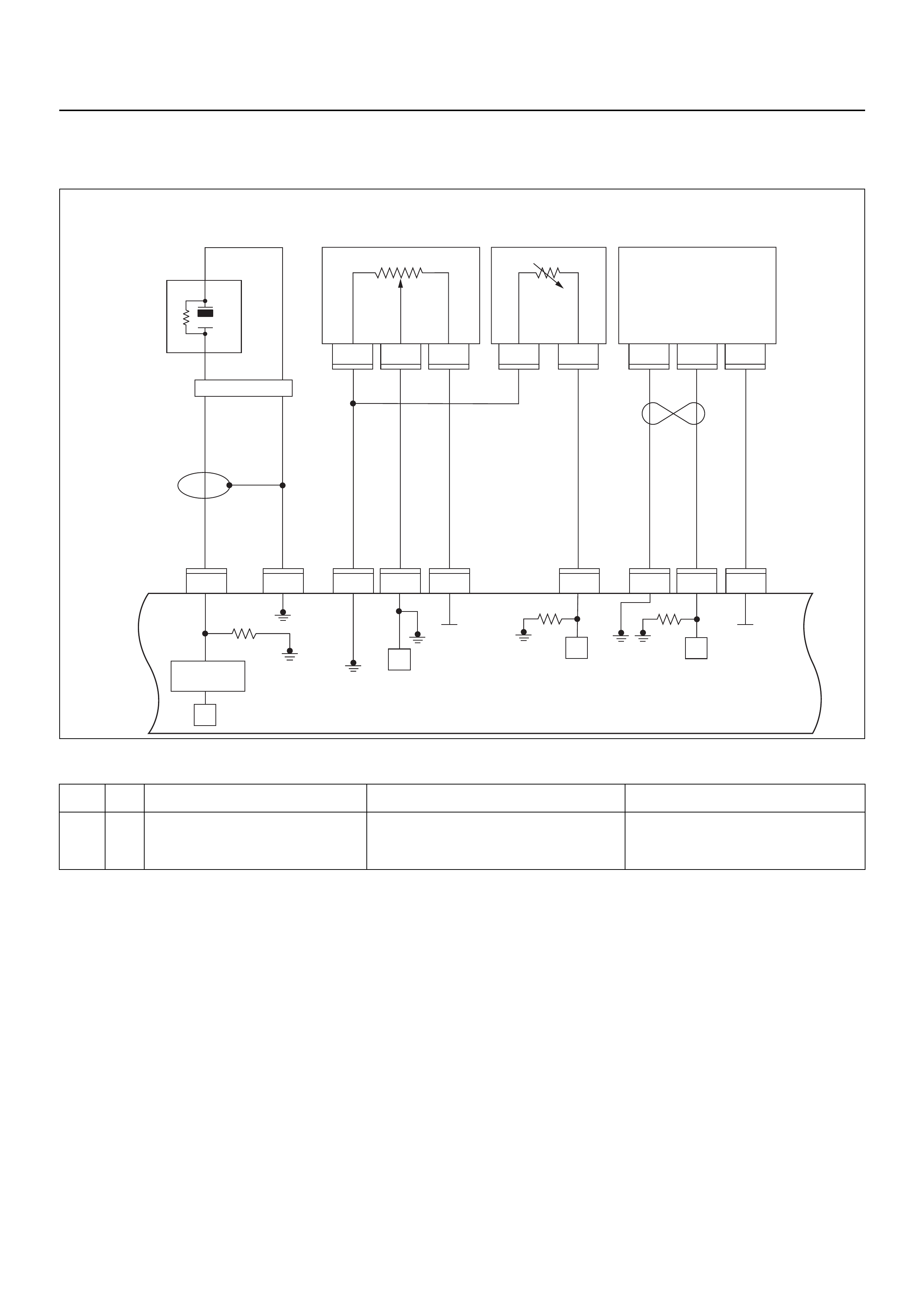
DIAGNOSTIC TROUBLE CODE (DTC) P0118 ENGINE COOLANT
TEMPERATURE SENSOR HIGH INPUT
Condition for setting the DTC and action taken when the DTC sets
Circuit Description
The engine coolant temperature (ECT) sensor is a
thermistor mounted in the engine coolant stream. The
engine control modu le (ECM) applies a voltag e ( abo ut 5
volts) through a pull-up resisto r to the ECT signal circui t.
When the engine coolant is co ld, the sen sor (thermistor )
resistance is high, therefore the ECM will measure a
high signal voltage. As the engine coolant warms, the
sensor resistance becomes less, and the ECT signal
voltage measured at the ECM drops. Diagnostic
Trouble code P0118 set when the ECM detects an
excessively high signal voltage on the engine coolant
temperature sensor signal circuit.
Diagnostic Aids
Check for the following conditions:
• Poor connection at ECM - Inspect harness
connectors for backed-out terminals, improper
mating, br oken locks , improperly formed or damaged
terminals, and poor terminal- to-wire connection.
• Damaged harness - Inspect the wiring harness for
damage, short to ground, short to battery positive,
and open circuit. If the harness appears to be OK,
observe the ECT display on Tech 2 while moving
connectors and wiring harnesses related to the ECT
sensor. A change in the ECT display will indicate the
location of the fault.
Code Type DTC Name DTC Setting Condition Fail-Safe (Back Up)
P0118 A Engine Coolant Temperature Sensor
High Input 1. Engine run time is longer than 120 sec-
onds.
2. ECT sensor output is below -38°C.
The ECM uses default engine coolant
temperature value based on intake air
temperature and engine run time.
1
C56
μP
E60
27
12231
12
E60
31
E60
7
E60
26
E60
3J1 J1 J1 J1 J1J1 J2 J2 J2
E60
E68 E68 E68 E69 E69 F10 F10 F10
16
C56
17 25
C56
1
A
23
CB
B
A
E84
0.5
GRY
μP
μP
5Volts
Ref 5Volts
Ref
Knock
Sensor
0.5
YEL
0.5
WHT/
BLU
0.5
BLU/
ORG
0.5
BLU/
ORG
0.5
YEL/
RED
0.5
PUR/
BLU
0.5
GRY/
BLU
0.5
BLK 0.5
ORG 0.5
BLU/
WHT
Engine
Coolant
Temperature (ECT)
Sensor Vertical
G-Sensor
Throttle
Position Sensor
(TPS)
Knock Filter
Module
Engine
Control
Module
(ECM) μP
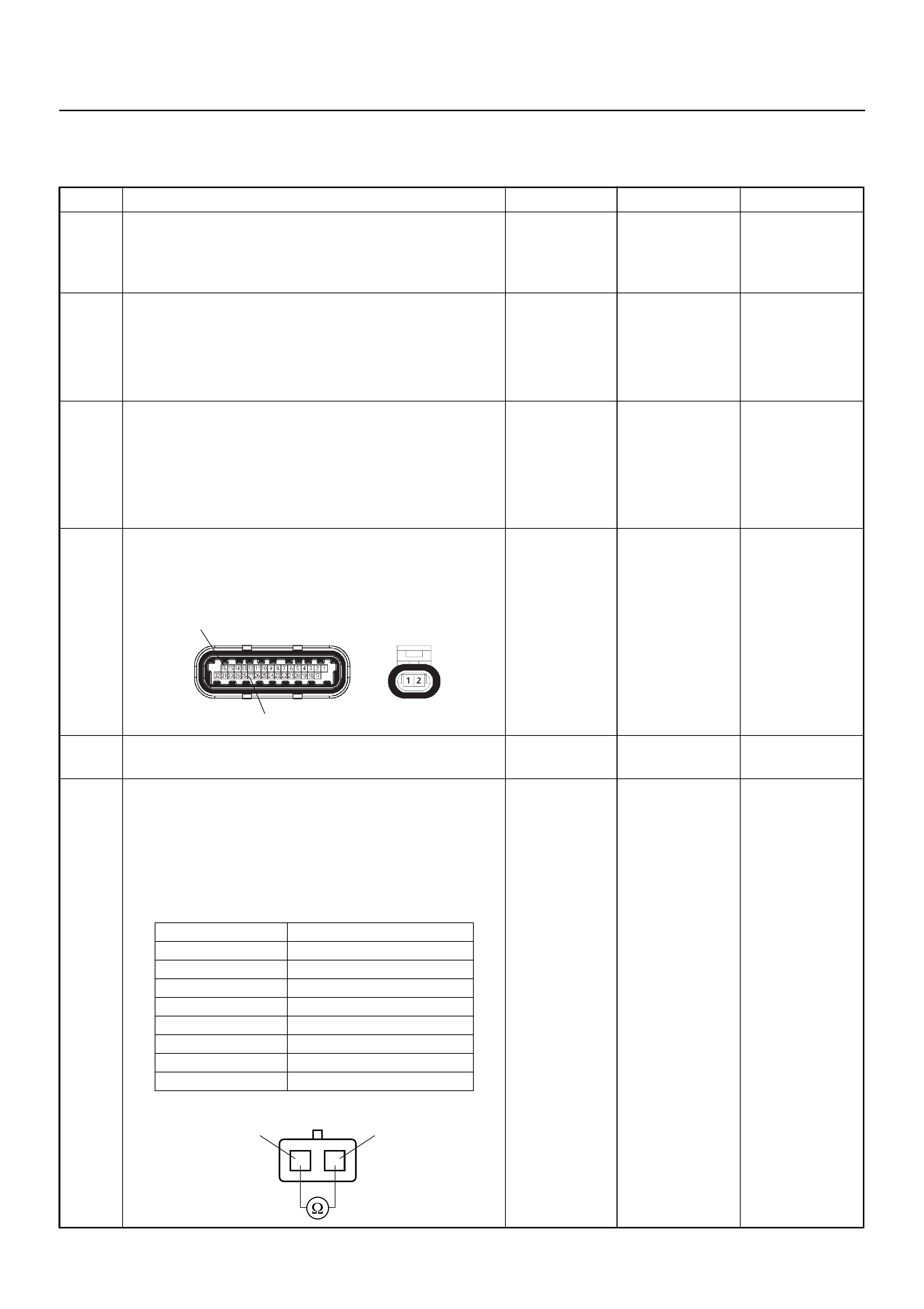
Diagnostic Trouble Code (DTC) P0118
Engine Coolant Temperature Sensor High Input
Step Action Value(s) Yes No
1 Was the “On-Board Diagnostic (OBD) System Check”
performed?
—Go to Step 2
Go to On Board
Diagnostic
(OBD) System
Check
2 1. Connect Tech 2.
2. Review and record the failure information.
3. Select “F0: Read DTC Info Ordered By Priority”
and check for DTC’s.
Is the DTC P0118 stored as “Present Failure”? — Go to Step 3
Refer to
Diagnostic Aids
and Go to Step
3
3 1. Using Tech 2, ignition “On” and engine “Off”.
2. Select “F2: Clear DTC Information” with Tech 2
and clear the DTC information.
3. Operate the vehicle and monitor the “F1: Read
DTC Info as Stored by ECU”.
Was the DTC P0118 stored in this ignition cycle? — Go to Step 4
Refer to
Diagnostic Aids
and Go to Step
4
4 Check for poor/faulty connection at the ECT sensor or
ECM connector. If a poor/faulty connection is found,
repair as necess ar y.
Was the problem found?
— Verify repair G o to Step 5
5 Visually check the ECT sensor.
Was the problem found? — Go to Step 12 Go to Step 6
6 Use a DVM to check the ECT sensor.
1. Ignition “Off”, engine “Off”.
2. Disconnect ECT sensor connector.
3. Measure the resistance of ECT sensor.
Does the tester indicate standar d resistance as sh own
in the following table?
Standard
resistance Go to Step 7 Go to Step 12
E60(J1) E69
16
27
Temperature (°C) Resistance (Ω) (Approximately)
-20 32040
0 9788
20 3516
40 1439
60 656
80 327
100 175
120 100
ECT Sensor 1
1
2
2
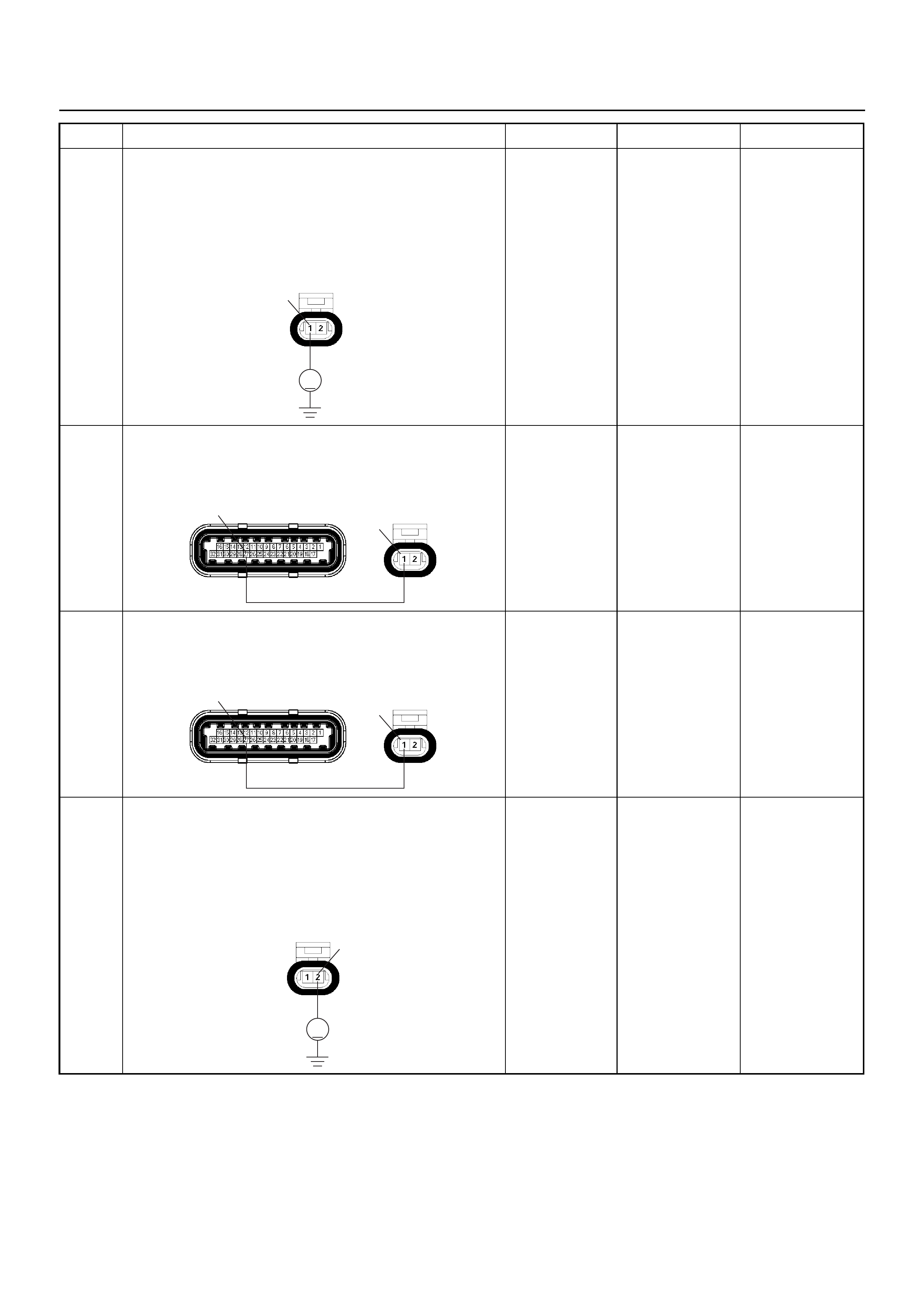
7 Use a DVM to check the ECT sensor signal circuit.
1. Ignition “On”, engine “Off”.
2. Disconnect the ECT sensor connector.
3. Check the circuit for open circuit.
Does the DVM indicate the specified value?
Approximately
5.0V Go to Step 10
Less than 1V:
Go to Step 8
More than
specified value:
Go to Step 9
8 Repair the open circuit between the ECM and ECT
sensor.
Was the problem solved?
— Verify repair Go to Step 14
9 Repair the short to voltage circuit between the ECM
and ECT sensor.
Was the problem solved?
— Verify repair Go to Step 14
10 Use a DVM to check the ECT sensor ground circuit.
1. Ignition “On”, engine “Off”.
2. Disconnect the ECT sensor connector.
3. Check the circuit for short to power supply circuit.
Does the DVM indicate the specified value?
Less than 1V Go to Step 11
Repair faulty
harness and
verify repair
Step Action Value(s) Yes No
V
E69
1
E60(J1) E69
27 1
E60(J1) E69
27 1
V
E69 2
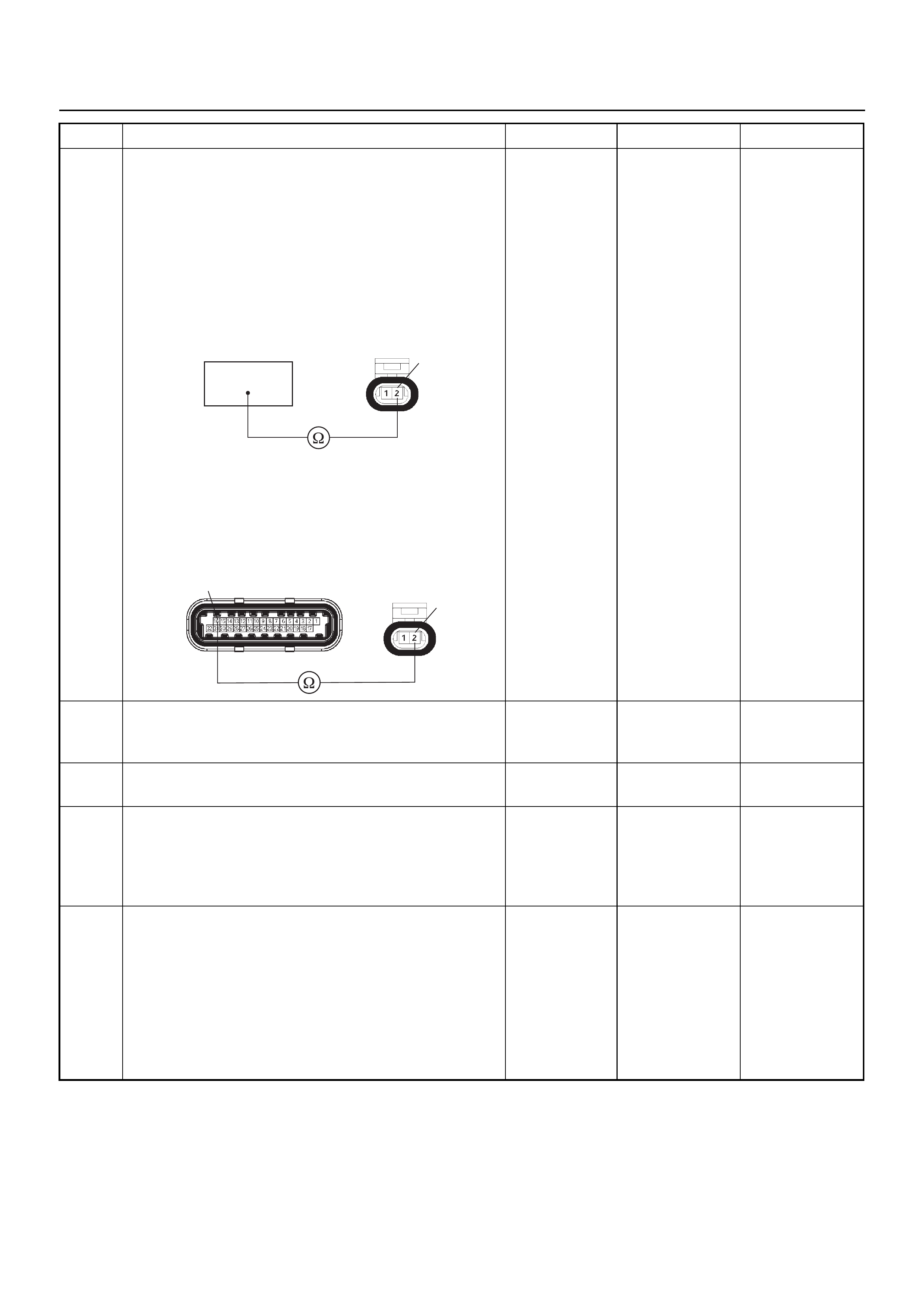
11 Use a DVM to check the ECT sensor ground circuit.
Breaker box is available:
1. Ignition “Off”, engine “Off”.
2. Install the breaker box as type A. (ECM
disconnected) Ref. 6E-77
3. Disconnect the ECT sensor connector.
4. Check the circuit for open circuit.
Was the problem found?
Breaker box is not available:
1. Ignition “Off”, engine “Off”.
2. Disconnect the ECT sensor connector.
3. Check the circuit for open circuit.
Was the problem found?
—
Repair faulty
harness and
verify repair Go to Step 14
12 Substitute a known good ECT sensor assembly and
recheck.
Was the problem solved? — Go to Step 13 Go to Step 14
13 Replace the ECT sensor.
Is the action complete? — Verify repair —
14 Is the ECM programmed with the latest software
release?
If not, download the latest software to the ECM using
the “SPS (Service Programming System)”.
Was the problem solved? — Verify repair Go to Step 15
15 Replace the ECM.
Is the action complete?
IMPORTANT: The replacement ECM must be
programmed. Refer to the Service Programming
System (SPS) section in this manual.
Following ECM programming, the immobiliser system
must be linked to the ECM. Refer to section 11
“Immobiliser System-ECM replacement” for the ECM/
Immobiliser linking procedure. — Verify repair —
Step Action Value(s) Yes No
16
E69 2
2
16 E60(J1) E69
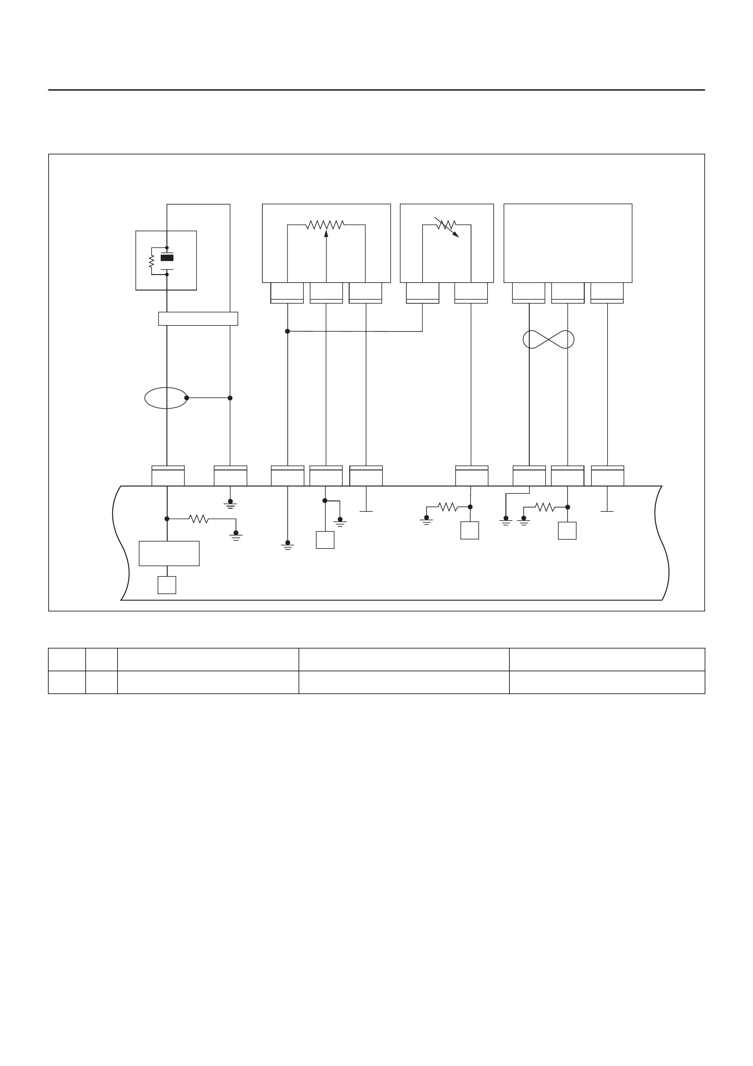
DIAGNOSTIC TROUBLE CODE (DTC) P0122 THROTTLE POSITION SENSOR
LOW INPUT
Condition for setting the DTC and action taken when the DTC sets
Circuit Description
The throttle position sensor circuit provides a signal
voltage that changes relative to throttle blade angle.
The signal voltage will vary from below 1 volt at closed
throttle to about 4 volts at wide open throttle (WOT).
The TPS signal is used by the engine control module
(ECM) for fuel control and most of the ECM-controlled
outputs. If the ECM detect a continuous short to ground
in the TPS or circuit, then a code P0122 will set.
Diagnostic Aids
• Poor connection at ECM - Inspect harness
connectors for backed-out terminals, improper
mating, br oken locks , improperly formed or damaged
terminals, and poor terminal- to-wire connection.
• Damaged harness - Inspect the wiring harness for
damage, short to ground, short to battery positive,
and open circuit. If the harness appears to be OK,
observe the throttle position display on Tech 2 while
moving connectors and wiring harnesses related to
the TPS. A change in the display will indicate the
location of the fault.
Code Type DTC Name DTC Setting Condition Fail-Safe (Back Up)
P0122 A Throttle Position Sensor Low Input TPS output voltage is below 0.14V. The ECM uses 0% condition as substitute.
1
C56
μP
E60
27
12231
12
E60
31
E60
7
E60
26
E60
3J1 J1 J1 J1 J1J1 J2 J2 J2
E60
E68 E68 E68 E69 E69 F10 F10 F10
16
C56
17 25
C56
1
A
23
CB
B
A
E84
0.5
GRY
μP
μP
5Volts
Ref 5Volts
Ref
Knock
Sensor
0.5
YEL
0.5
WHT/
BLU
0.5
BLU/
ORG
0.5
BLU/
ORG
0.5
YEL/
RED
0.5
PUR/
BLU
0.5
GRY/
BLU
0.5
BLK 0.5
ORG 0.5
BLU/
WHT
Engine
Coolant
Temperature (ECT)
Sensor Vertical
G-Sensor
Throttle
Position Sensor
(TPS)
Knock Filter
Module
Engine
Control
Module
(ECM) μP
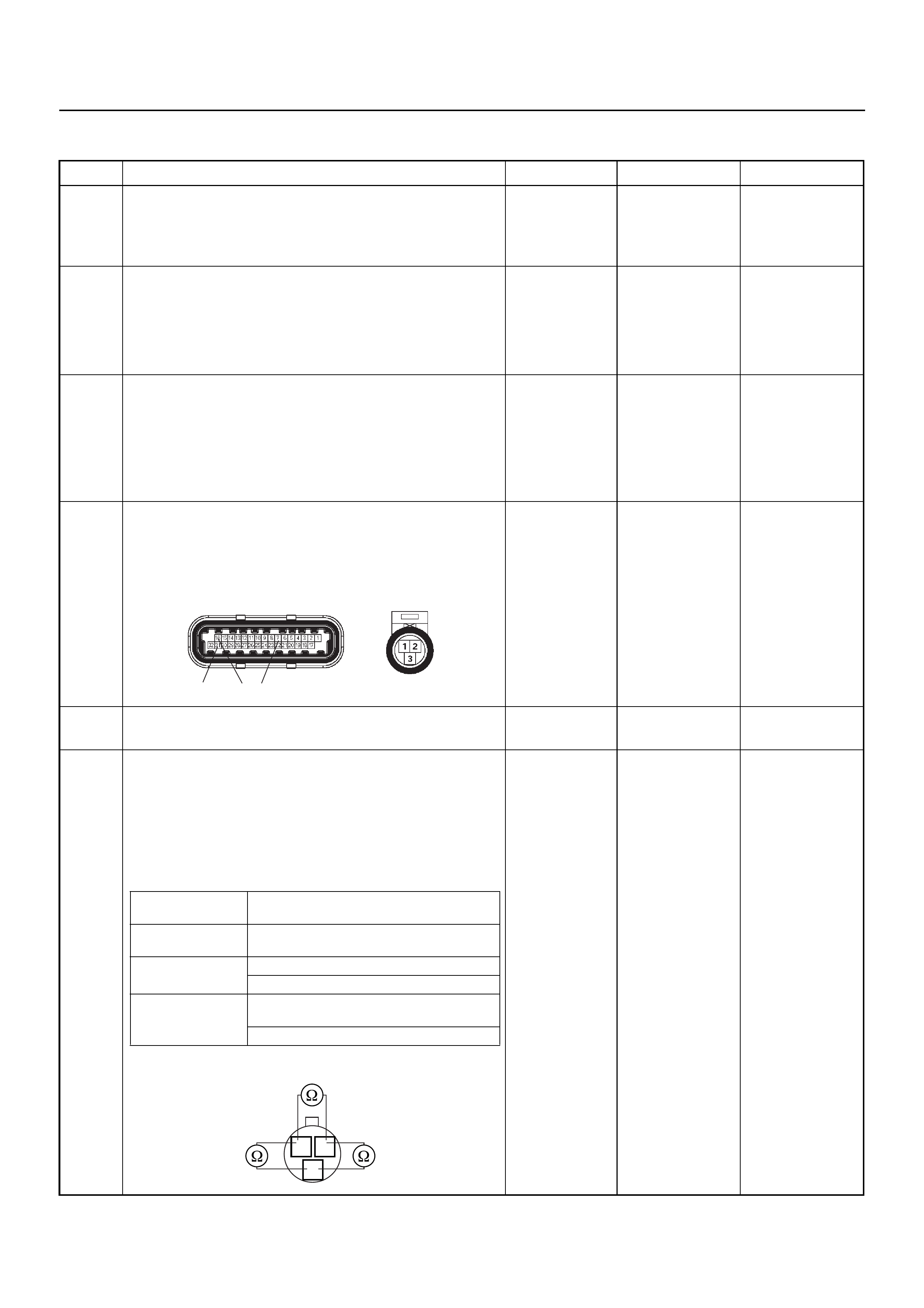
Diagnostic Trouble Code (DTC) P0122 Throttle Position Sensor Low Input
Step Action Value(s) Yes No
1 Was the “On-Board Diagnostic (OBD) System Check”
performed?
—Go to Step 2
Go to On Board
Diagnostic
(OBD) System
Check
2 1. Connect Tech 2.
2. Review and record the failure information.
3. Select “F0: Read DTC Info Ordered By Priority”
and check for DTC’s.
Is the DTC P0122 stored as “Present Failure”? — Go to Step 3
Refer to
Diagnostic Aids
and Go to Step
3
3 1. Using Tech 2, ignition “On” and engine “Off”.
2. Select “F2: Clear DTC Information” with Tech 2
and clear the DTC information.
3. Operate the vehicle and monitor the “F1: Read
DTC Info as Stored by ECU”
Was the DTC P0122 stored in this ignition cycle? — Go to Step 4
Refer to
Diagnostic Aids
and Go to Step
4
4 Check for poor/faulty connection at the TPS or ECM
connector. If a poor/faulty connection is found, repair
as necessary.
Was the problem found?
— Verify repair G o to Step 5
5 Visually check the TPS.
Was the problem found? — Go to Step 10 Go to Step 6
6 Use a DVM to check the TPS.
1. Ignition “Off”, engine “Off”.
2. Disconnect TPS connector.
3. Measure the resistance of TPS.
Does the tester indicate standar d resistance as sh own
in the following table?
Standard
resistance Go to Step 7 Go to Step 10
E60(J1) E68
31 16 7
Measurement
Terminal Resistance (Ω)
1 - 2 Approximately 5.6kΩ at idle position &
WOT
2 - 3 Approximately 6.0kΩ at idle position
Approximately 1.7kΩ at WOT
1 - 3 Approximately 2.3kΩ at idle position &
WOT
Approximately 6.6kΩ at WOT
2 1
3
TPS
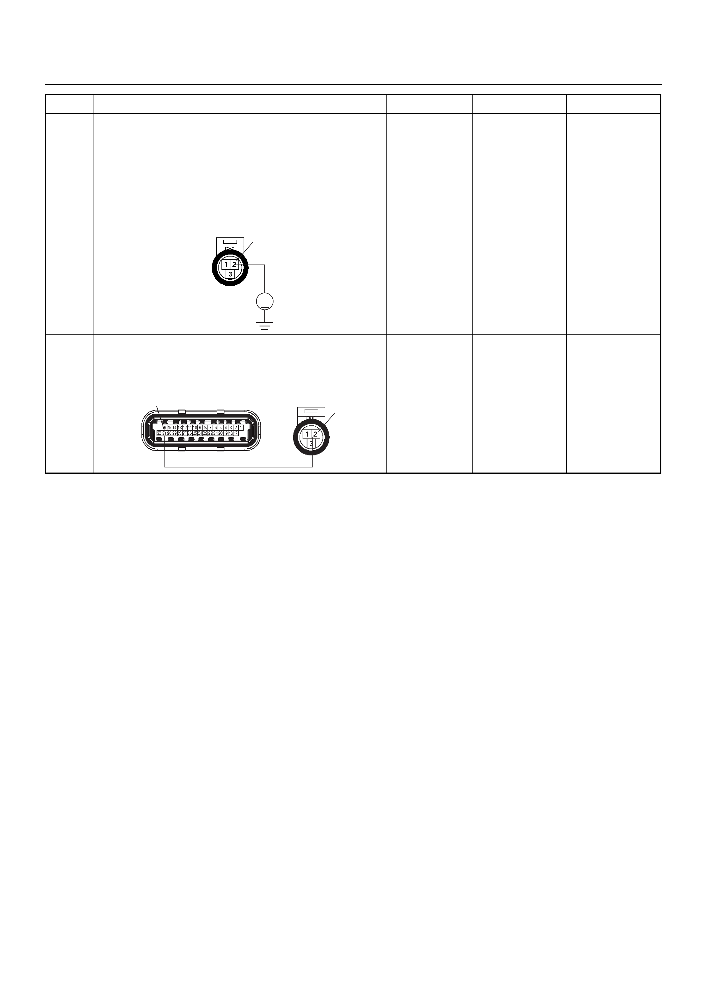
7 Use a DVM to check the TPS power supply circuit.
1. Ignition “On”, engine “Off”.
2. Disconnect the TPS connector.
3. Check the circuit for open or short to ground
circuit.
Does the DVM indicate the specified value?
Approximately
5.0V Go to Step 9 Go to Step 8
8 Repair the open or short to ground circuit between the
ECM and TPS.
Was the problem solved?
— Verify repair Go to Step 12
Step Action Value(s) Yes No
V
E68 2
2
E60(J1) E68
31
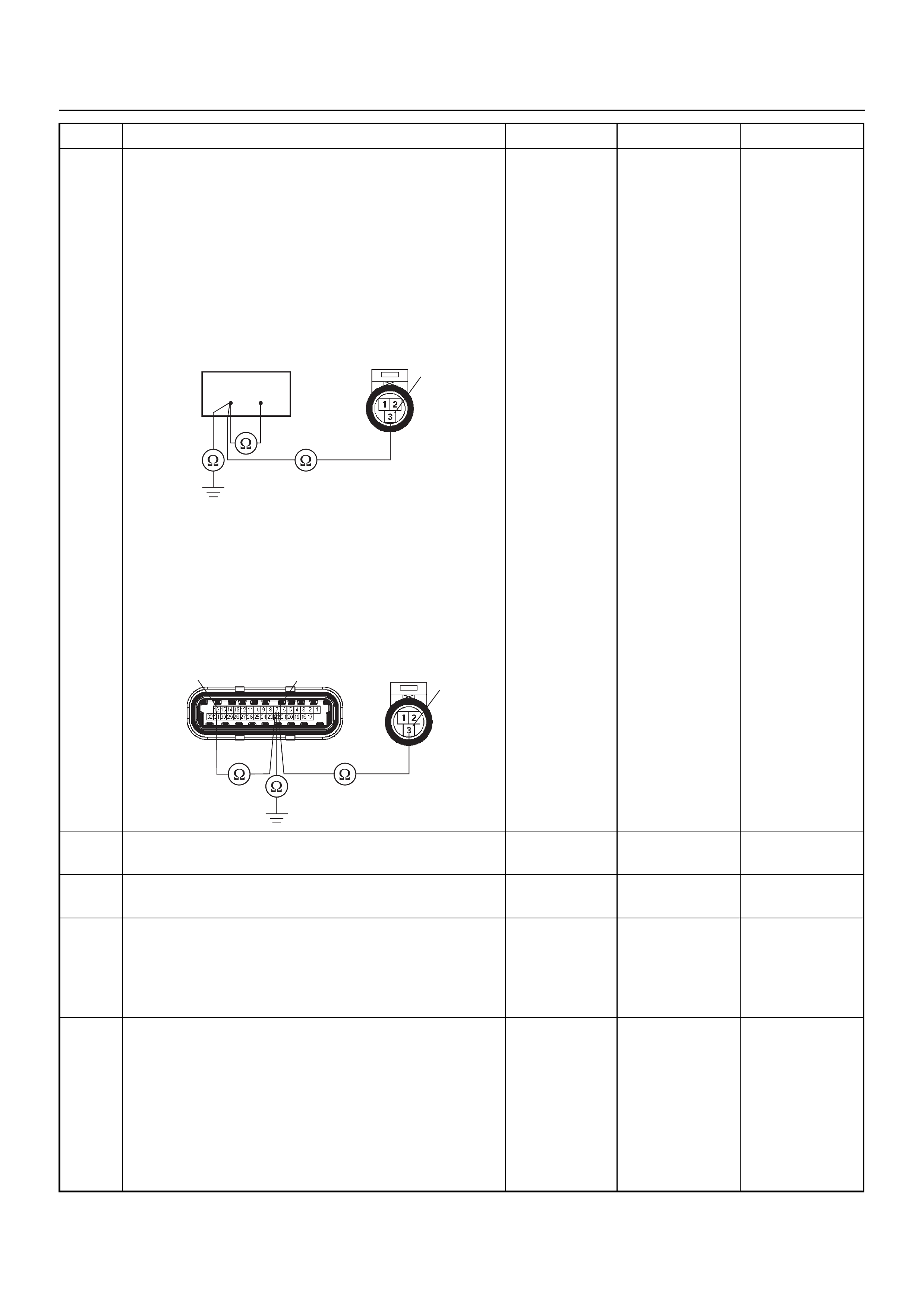
9 Use a DVM to check the TPS signal circuit.
Breaker box is available:
1. Ignition “Off”, engine “Off”.
2. Install the breaker box as type A. (ECM
disconnected) Ref. 6E-77.
3. Disconnect TPS connector.
4. Check the circuit for open, short to sensor ground
or short to ground circuit.
Was the problem found?
Breaker box is not available:
1. Ignition “Off”, engine “Off”.
2. Disconnect the TPS connector and ECM
connector.
3. Check the circuit for open, short to sensor ground
or short to ground circuit.
Was the problem found?
—
Repair faulty
harness and
verify repair Go to Step 12
10 Subst itu te a kn own good TPS and rech ec k.
Was the problem solved? — Go to Step 11 Go to Step 12
11 Replace the TPS.
Is the action complete? — Verify repair -
12 Is the ECM programmed with the latest software
release?
If not, download the latest software to the ECM using
the “SPS (Service Programming System)”.
Was the problem solved? — Verify repair Go to Step 12
13 Replace the ECM.
Is the action complete?
IMPORTANT: The replacement ECM must be
programmed. Refer to the Service Programming
System (SPS) section in this manual.
Following ECM programming, the immobiliser system
must be linked to the ECM. Refer to section 11
“Immobiliser System-ECM replacement” for the ECM/
Immobiliser linking procedure. — Verify repair —
Step Action Value(s) Yes No
716
3
E68
16 7 3
E60(J1) E68
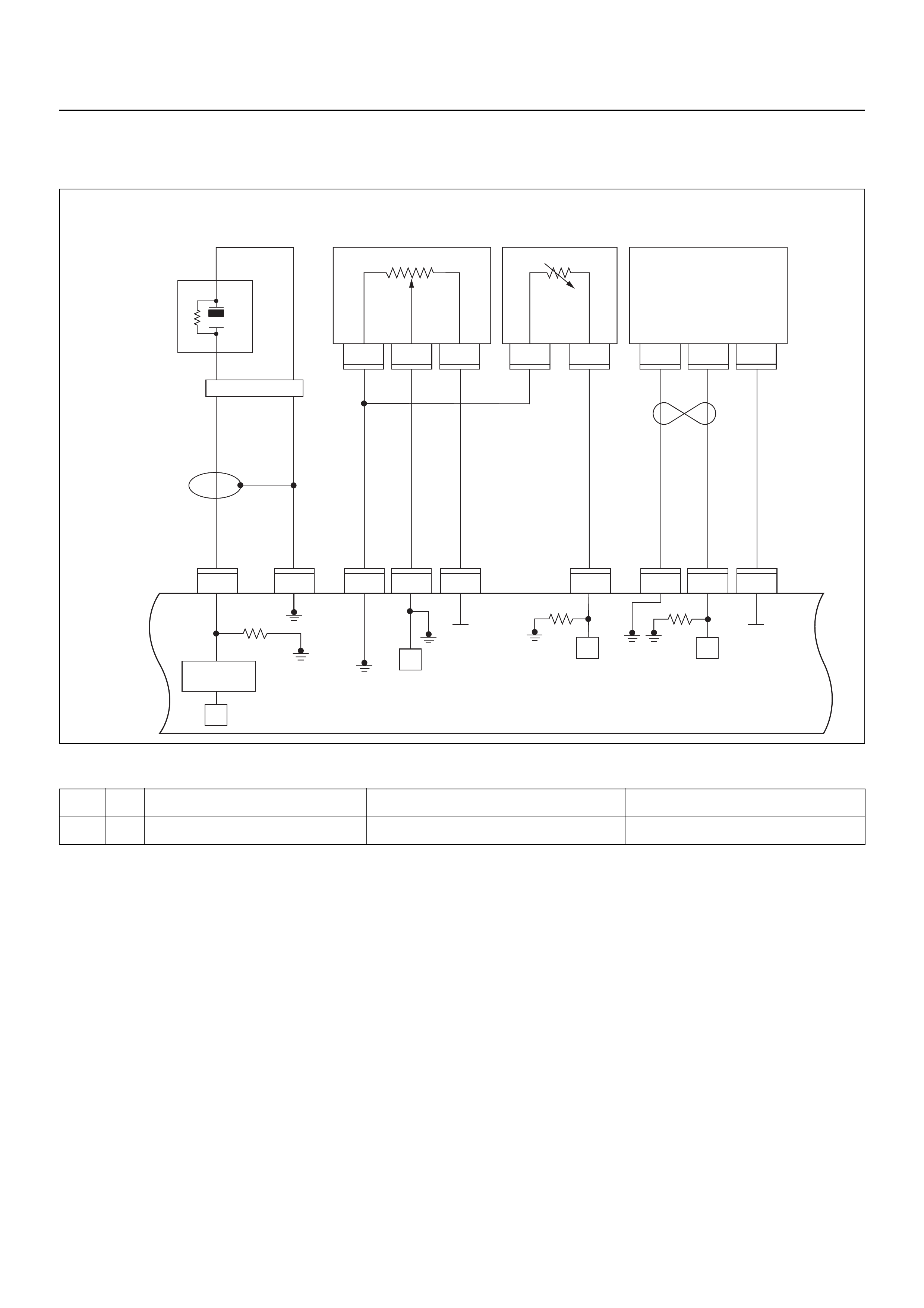
DIAGNOSTIC TROUBLE CODE (DTC) P0123 THROTTLE POSITION SENSOR
HIGH INPUT
Condition for setting the DTC and action taken when the DTC sets
Circuit Description
The throttle position sensor circuit provides a voltage
signal that changes relative to throttle blade angle. The
signal voltage will vary from below 1 volt at closed
throttle to about 4 volts at wide open throttle (WOT).
The TPS is used by the engine control module (ECM)
for fuel contro l and most of the ECM-contr olled outputs .
If the ECM detect a continuous short voltage in the TPS
or circuit, then a code P0123 will set.
Diagnostic Aids
Check for the following conditions:
• Poor connection at ECM - Inspect harness
connectors for backed-out terminals, improper
mating, br oken locks , improperly formed or damaged
terminals, and poor terminal- to-wire connection.
• If these codes are also set, it could indicate a
problem with the 5 Volt reference circuit or
components itself.
• Damaged harness - Inspect the wiring harness for
damage, short to ground, short to ba ttery positive and
open circuit. If the harness appears to be OK,
observe the Throttle Position sensor display on
Tech 2 while moving connectors and wiring
harnesses related to the TP sensor. A change in the
display will indicate the location of the fault.
Code Type DTC Name DTC Setting Condition Fail-Safe (Back Up)
P0123 A Throttle Position Sensor High Input TPS output volt age is more than 4.9V. The ECM uses 0% condition as substitute.
1
C56
μP
E60
27
12231
12
E60
31
E60
7
E60
26
E60
3J1 J1 J1 J1 J1J1 J2 J2 J2
E60
E68 E68 E68 E69 E69 F10 F10 F10
16
C56
17 25
C56
1
A
23
CB
B
A
E84
0.5
GRY
μP
μP
5Volts
Ref 5Volts
Ref
Knock
Sensor
0.5
YEL
0.5
WHT/
BLU
0.5
BLU/
ORG
0.5
BLU/
ORG
0.5
YEL/
RED
0.5
PUR/
BLU
0.5
GRY/
BLU
0.5
BLK 0.5
ORG 0.5
BLU/
WHT
Engine
Coolant
Temperature (ECT)
Sensor Vertical
G-Sensor
Throttle
Position Sensor
(TPS)
Knock Filter
Module
Engine
Control
Module
(ECM) μP
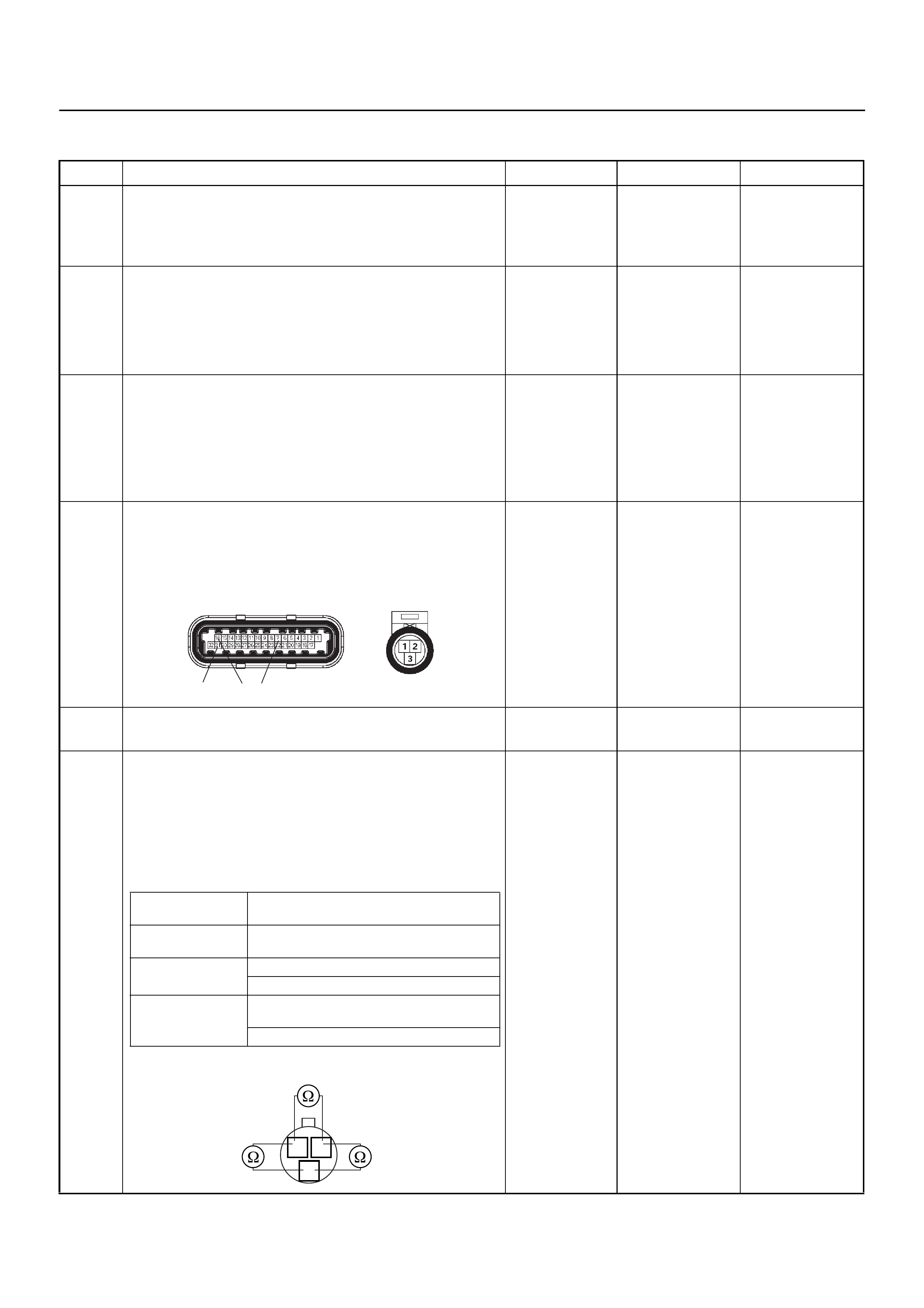
Diagnostic Trouble Code (DTC) P0123 Throttle Position Sensor High Input
Step Action Value(s) Yes No
1 Was the “On-Board Diagnostic (OBD) System Check”
performed?
—Go to Step 2
Go to On Board
Diagnostic
(OBD) System
Check
2 1. Connect Tech 2.
2. Review and record the failure information.
3. Select “F0: Read DTC Info Ordered By Priority”
and check for DTC’s.
Is the DTC P0123 stored as “Present Failure”? — Go to Step 3
Refer to
Diagnostic Aids
and Go to Step
3
3 1. Using Tech 2, ignition “On” and engine “Off”.
2. Select “F2: Clear DTC Information” with Tech 2
and clear the DTC information.
3. Operate the vehicle and monitor the “F1: Read
DTC Info as Stored by ECU”.
Was the DTC P0123 stored in this ignition cycle? — Go to Step 4
Refer to
Diagnostic Aids
and Go to Step
4
4 Check for poor/faulty connection at the TPS or ECM
connector. If a poor/faulty connection is found, repair
as necessary.
Was the problem found?
— Verify repair G o to Step 5
5 Visually check the TPS.
Was the problem found? — Go to Step 12 Go to Step 6
6 Use a DVM to check the TPS.
1. Ignition “Off”, engine “Off”.
2. Disconnect TPS connector.
3. Measure the resistance of TPS.
Does the tester indicate standar d resistance as sh own
in the following table?
Standard
resistance Go to Step 7 Go to Step 12
E60(J1) E68
31 16 7
Measurement
Terminal Resistance (Ω)
1 - 2 Approximately 5.6kΩ at idle position &
WOT
2 - 3 Approximately 6.0kΩ at idle position
Approximately 1.7kΩ at WOT
1 - 3 Approximately 2.3kΩ at idle position &
WOT
Approximately 6.6kΩ at WOT
2 1
3
TPS
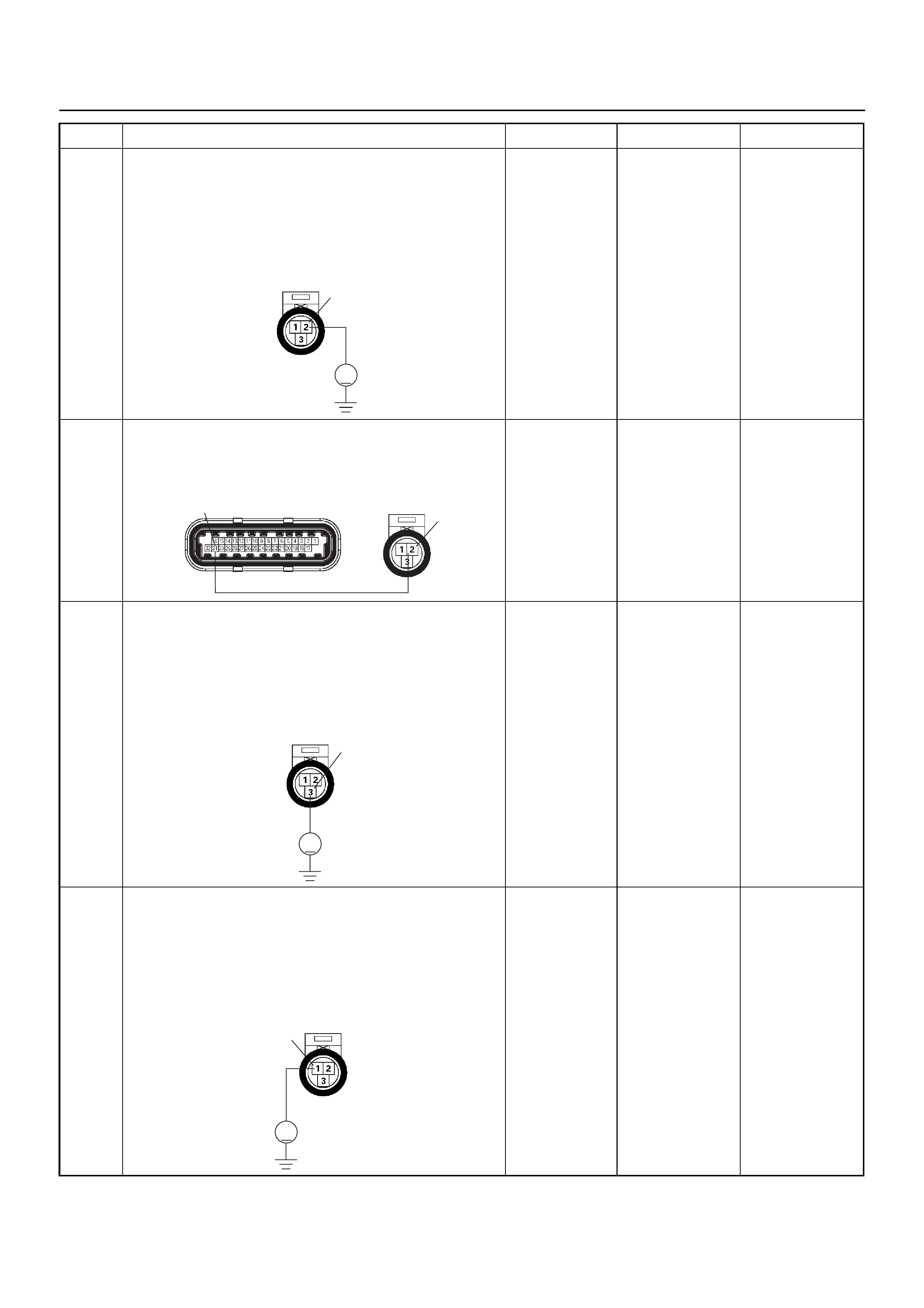
7 Use a DVM to check the TPS power supply circuit.
1. Ignition “On”, engine “Off”.
2. Disconnect the TPS connector.
3. Check the circuit for short to voltage circuit.
Does the DVM indicate the specified value?
Approximately
5.0V Go to Step 9 Go to Step 8
8 Repair the short to voltage circuit between the ECM
and TPS.
Was the problem solved?
— Verify repair Go to Step 14
9 Use a DVM to check the TPS signal circuit.
1. Ignition “On”, engine “Off”.
2. Disconnect the TPS connector.
3. Check the circuit for short to power supply circuit.
Does the DVM indicate the specified value?
Less than 1V Go to Step 10
Repair faulty
harness and
verify repair
10 Use a DVM to check the TPS ground circuit.
1. Ignition “On”, engine “Off”.
2. Disconnect the TPS connector .
3. Check the circuit for short to power supply circuit.
Does the DVM indicate the specified value?
Less than 1V Go to Step 11
Repair faulty
harness and
verify repair
Step Action Value(s) Yes No
V
E68 2
2
E60(J1) E68
31
3
V
E68
1
V
E68
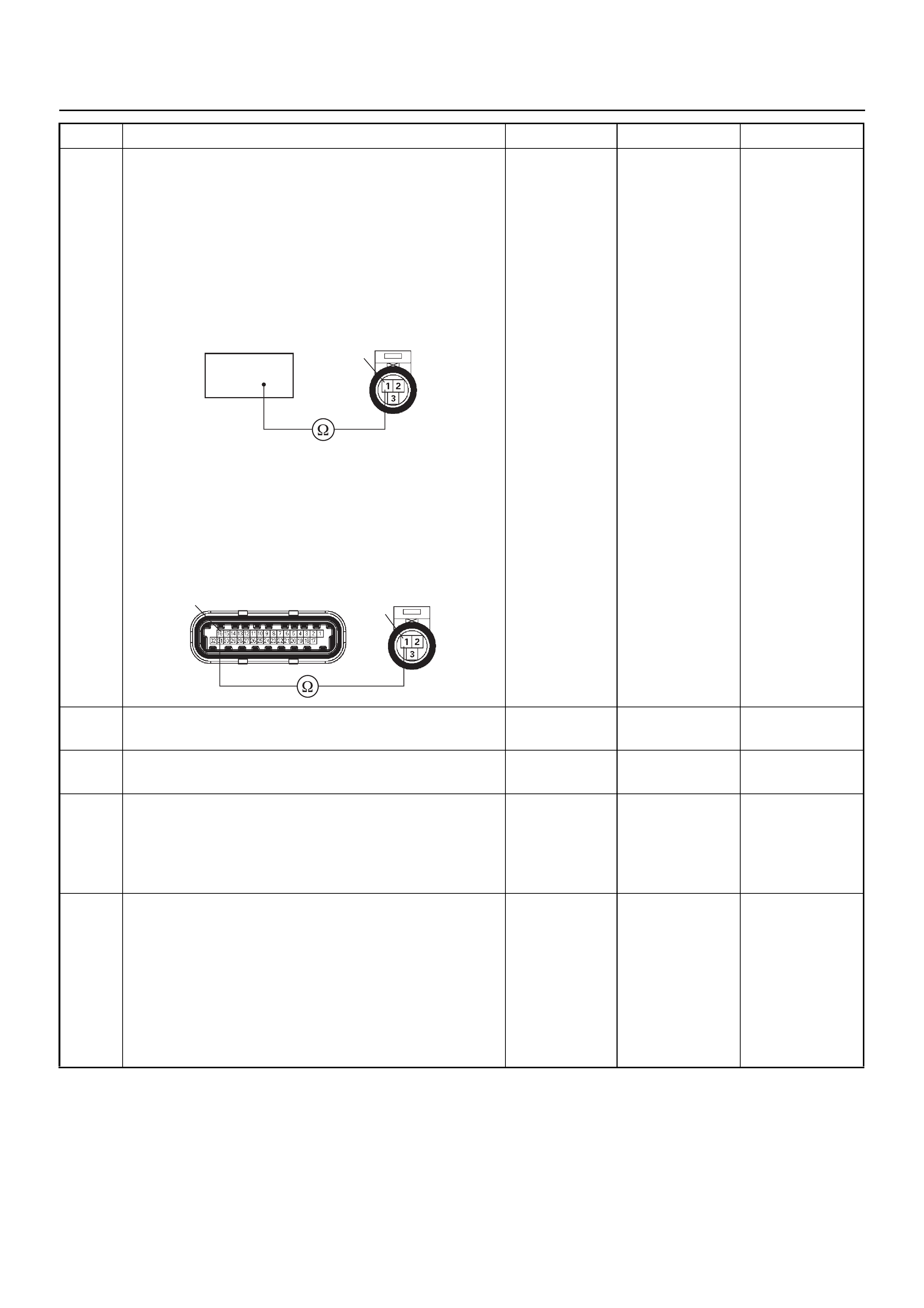
11 Use a DVM to check the TPS ground circuit.
Breaker box is available:
1. Ignition “Off”, engine “Off”.
2. Install the breaker box as type A. (ECM
disconnected) Ref. 6E-77.
3. Disconnect the TPS connector.
4. Check the circuit for open circuit.
Was the problem found?
Breaker box is not available:
1. Ignition “Off”, engine “Off”.
2. Disconnect the TPS connector and ECM
connector.
3. Check the circuit for open circuit.
Was the problem found?
—
Repair faulty
harness and
verify repair Go to Step 14
12 Subst itu te a kn ow n go od TPS an d rech eck.
Was the problem solved? — Go to Step 13 Go to Step 14
13 Replace the TPS.
Is the action complete? — Verify repair —
14 Is the ECM programmed with the latest software
release?
If not, download the latest software to the ECM using
the “SPS (Service Programming System)”.
Was the problem solved? — Verify repair Go to Step 14
15 Replace the ECM.
Is the action complete?
IMPORTANT: The replacement ECM must be
programmed. Refer to the Service Programming
System (SPS) section in this manual.
Following ECM programming, the immobiliser system
must be linked to the ECM. Refer to section 11
“Immobiliser System-ECM replacement” for the ECM/
Immobiliser linking procedure. — Verify repair —
Step Action Value(s) Yes No
16
1E68
16 1
E60(J1) E68
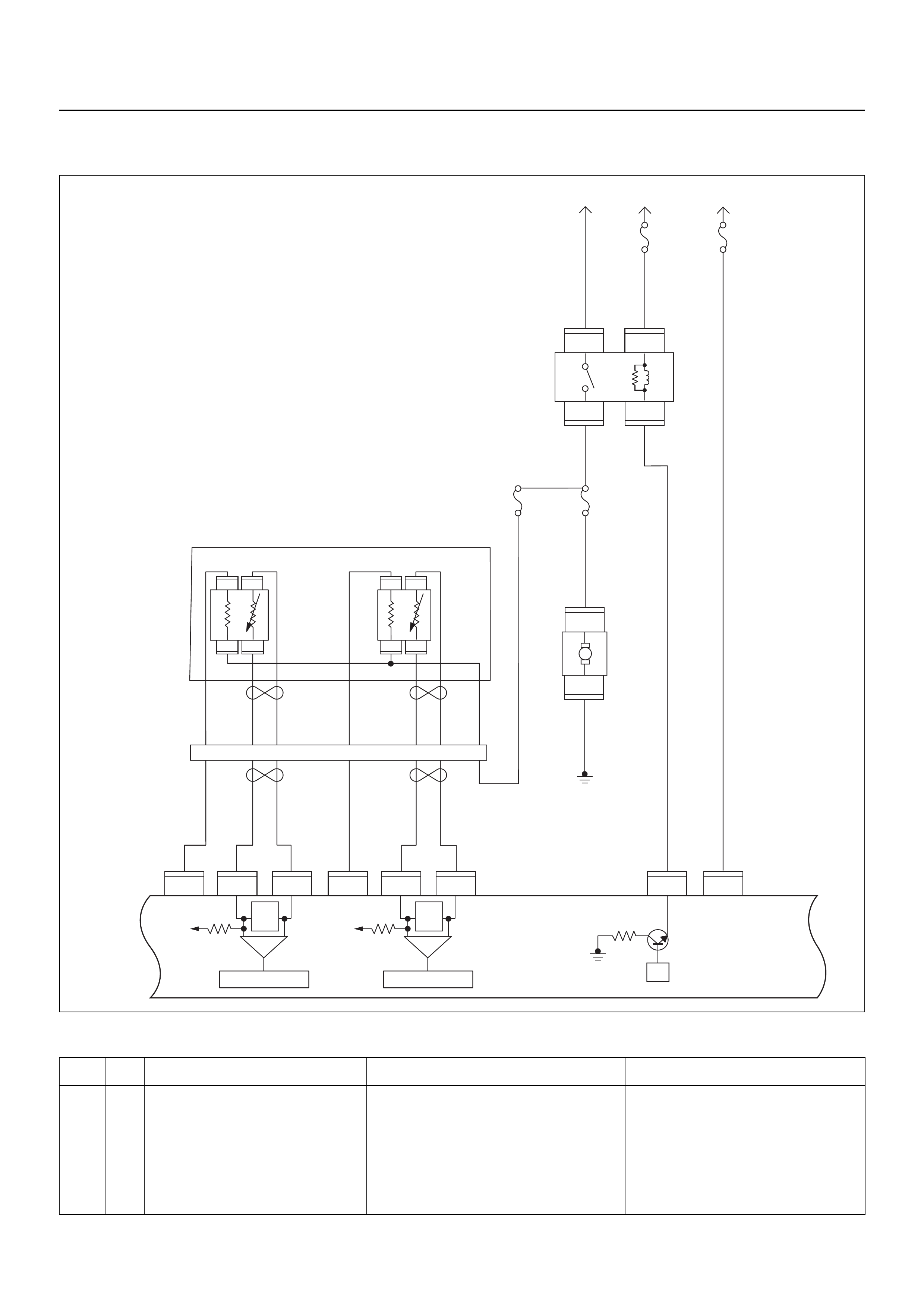
DIAGNOSTIC TROUBLE CODE (DTC) P0131 O2 SENSOR CIRCUIT LOW
VOLTAGE (Bank 1 Sensor 1 PRE)
Condition for setting the DTC and action taken when the DTC sets
Code Type DTC Name DTC Setting Condition Fail-Safe (Back Up)
P0131 A O2 Sensor Circuit Low Voltage (Bank 1
Sensor 1 PRE) 1. No DTC relating to MAP sensor, TPS,
EVAP purge, ECT sensor, CKP sensor,
VSS, injector control circuit and ignition
control circuit.
2. Engine coolant temperature is more than
60°C.
3. O2 sensor bank 1 sensor 1 output voltage
is below 50mV in “Closed Loop” condition.
“Open Loop” fuel control.
μP
IGN
SW Battery
Voltage
Batt PwrFuel Pump
Pwr
O2 Heater
(Pre)
O2 Heater
(Post)
Battery
Voltage
2.0
WHT
0.5
BLU/
YEL
Engine
15A
450
mV
A/D Converter
Vcc
+5V -+
450
mV
A/D Converter
Vcc
+5V -+
2.0
RED/
BLK
Fuel
Pump
Relay
0.85
RED/
WHT
0.5
GRN/
WHT
Engine
Control
Module
(ECM)
C56
1
C56
F2
F2
21
C56
31J2J1J1J1 J2 J2 J2 J2
E60
16
E60
28
E60
19
32
41
32
41
C56
26
C56
2
2.0
RED/
GRN
O2
Sensor
10A
Fuel
Pump
Heated 02 Sensors
Fuel
Pump
20A
2.0
BLK
0.5
BLU/
ORG
0.5
YEL
0.5
BLU/
YEL
0.5
BLK
0.5
BLK
0.5
BRN 0.5
YEL 0.5
PU 0.5
YEL
0.5
BRN 0.5
PU 0.5
BRN
0.5
ORG
2.0
BLK/
BLU
M
O2 Sensor
POST
O2 Sensor
PRE
LOWLOW
HI
HI
ECM
15A
X2
1
X2
X2 X2
3
1
4
42
E77 E77
E77
E78E78
E78E78
E77
H31

Circuit Description
The engine control module (ECM) supplies a bias
voltage of about 450 mV between the heated oxygen
sensor (HO2S) signal and low circuits. The oxygen
sensor varies the voltage within a range of about
1000 mV when the exhaust is rich, down through about
10 mV when exhaust is lean. The ECM constantly
monitors the HO2S signal during “Closed Loop”
operation and compensates for a rich or lean condition
by decreasing or increasing injector pulse width as
necessary. If the Bank 1 HO2S 1 voltage remains
excessively low for an extended period of time,
Diagnostic Trouble Code P0131 will be set.
Diagnostic Aids
Check for the following conditions:
• Heated oxygen sensor wiring - The sensor pigtail
may be routed incorrectly and/or contacting the
exhaust system. Also, check for shorts to ground,
shorts to battery positive and open circuits.
• Poor ECM to engine block grounds.
• Fuel pressure - The system will go lean if pressure is
too low. The ECM can compensate for some
decrease. However, if fuel pressure is too low, a
Diagnostic Trouble Code P0131 may be set. Refer to
Fuel System Diagnosis.
• Lean injector(s) - Perform “Injector Balance Test.”
• Vacuum leaks - Check for disconnected or damaged
vacuum hoses and for vacuum leaks at the inlet
manifold, throttle body, EGR system, and PCV
system.
• Exhaust leaks - An exhaust leak may cause outside
air to be pulled into the exhaust gas stream past the
HO2S, causing the system to appear lean. Check for
exhaust leaks that may cause a false lean condition
to be indicated.
• Fuel contamination - Water, even in small amounts,
can be delivered to the fuel injectors. The water can
cause a lean exhaust to be indicated. Excessive
alcohol in the fuel can also cause this condition. For
the procedure to check for fuel contamination, Refer
to Fuel System Diagnosis.
Diagnostic Trouble Code (DTC) P0131
O2 Sensor Circuit Low Voltage (Bank 1 Sensor 1 PRE)
Step Action Value(s) Yes No
1 Was the “On-Board Diagnostic (OBD) System Check”
performed?
—Go to Step 2
Go to On Board
Diagnostic
(OBD) System
Check
2 1. Connect Tech 2.
2. Review and record the failure information.
3. Select “F0: Read DTC Info Ordered By Priority”
and check for DTC’s.
Is the DTC P0131 stored as “Present Failure”? — Go to Step 3
Refer to
Diagnostic Aids
and Go to Step
3
3 1. Using Tech 2, ignition “On” and engine “Off”.
2. Select “F2: Clear DTC Information” with Tech 2
and clear the DTC information.
3. Operate the vehicle and monitor the “F1: Read
DTC Info as Stored by ECU”.
Was the DTC P0131 stored in this ignition cycle? — Go to Step 4
Refer to
Diagnostic Aids
and Go to Step
4
4 Check for poor/faulty connection at the O2 sensor or
ECM connector. If a poor/faulty connection is found,
repair as necess ar y.
Was the problem found?
— Verify repair G o to Step 5
C56(J2) E77
31 21
1

5 Use a DVM to check the O2 sensor circuit.
1. Ignition “On”, engine “Off”.
2. Disconnect the O2 sensor connector.
3. Check the circuit for short to heater ground or
ground circuit.
Does the DVM indicate the specified value?
Approximatly
450mV Go to Step 7 Go to Step 6
6 Use a DVM to check the O2 sensor circuit.
Breaker box is available:
1. Ignition “Off”, engine “Off”.
2. Install the breaker box as type A. (ECM
disconnected) Ref. 6E-77.
3. Disconnect the O2 sensor.
4. Check the circuit for short to heater ground or
short to ground circuit.
Was the problem found?
Breaker box is not available:
1. Ignition “Off”, engine “Off”.
2. Disconnect the O2 sensor connector and ECM
connector.
3. Check the circuit for short to heater ground or
short to ground circuit.
Was the problem found?
—
Repair faulty
harness and
verify repair Go to Step 15
Step Action Value(s) Yes No
V
21 E77
53 33 63
21
1
31
C56(J2)
31 21 1
C56(J2)

7 Use a DVM to check the O2 sensor circuit.
1. Ignition “Off”, engine “Off”.
2. Disconnect the the O2 sensor connector.
3. Check the circuit for short to heater ground circuit.
Does the DVM indicate the specified value?
No continuity Go to Step 9 Go to Step 8
8 Repair the short to heater ground circuit.
Was the problem found? — Verify repair Go to Step 15
9 1. Using Tech 2, ignition “On” and engine “On”.
2. Monitor the “Manifold Absolute Pressure” in the
data display.
Does Tech 2 indicate correct “Manifold Absolute
Pressure” in accordance with engine speed or
acceleration? — Go to Step 11 Go to Step 10
10 Remove the MAP sensor and check for the following
conditions.
• Objects blocking the air cleaner.
• Objects blocking the MAP sensor.
• Objects blocking the throttle valve.
• Vacuum leaking at inlet duct.
• Vacuum leaking at throttle body.
If a problem is found, re pa ir as nece ss ar y.
Was the problem found? — Verify repair Go to Step 11
11 1. Using Tech 2, ignition “On” and engine “On”.
2. Select the “Actuator Test” and perform the "F1:
Idle Air Control Test".
3. Operate Tech 2 in accordance with procedure.
Was the IAC valve heard stepping through the 255
positions? — Go to Step 13 Go to Step 12
12 Check for the following conditions.
• Objects blocking the IAC valve.
• Objects blocking the throttle valve.
• Vacuum leaking at throttle body.
If a problem is found, re pa ir as nece ss ar y.
Was the problem found? — Verify repair Go to Step 13
13 Check for injector for the affected bank.
Refer to “Injector Coil Test & Injector Balance Test
Procedure”.
Was the injector operation correct? —Go to Step 14
Refer to Injector
Coil Test &
Injector
Balance Test
Procedure
14 Check for fu el pr es su re .
Refer to “Fuel System Diagnosis”.
Was the fuel pressure correct? — Go to Step 15
Refer to Fuel
System
Diagnosis
15 Replace the O2 sensor.
Was the problem solved? — Verify repair Go to Step 16
Step Action Value(s) Yes No
124
1234
O2 Sensor

16 Is the ECM programmed with the latest software
release?
If not, download the latest software to the ECM using
the “SPS (Service Programming System)”.
Was the problem solved? — Verify repair Go to Step 17
17 Replace the ECM.
Is the action complete?
IMPORTANT: The replacement ECM must be
programmed. Refer to the Service Programming
System (SPS) section in this manual.
Following ECM programming, the immobiliser system
must be linked to the ECM. Refer to section 11
“Immobiliser System-ECM replacement” for the ECM/
Immobiliser linking procedure. — Verify repair —
Step Action Value(s) Yes No

DIAGNOSTIC TROUBLE CODE (DTC) P0132 O2 SENSOR CIRCUIT HIGH
VOLTAGE (Bank 1 Sensor 1 PRE)
μP
IGN
SW Battery
Voltage
Batt PwrFuel Pump
Pwr
O2 Heater
(Pre)
O2 Heater
(Post)
Battery
Voltage
2.0
WHT
0.5
BLU/
YEL
Engine
15A
450
mV
A/D Converter
Vcc
+5V -+
450
mV
A/D Converter
Vcc
+5V -+
2.0
RED/
BLK
Fuel
Pump
Relay
0.85
RED/
WHT
0.5
GRN/
WHT
Engine
Control
Module
(ECM)
C56
1
C56
F2
F2
21
C56
31J2J1J1J1 J2 J2 J2 J2
E60
16
E60
28
E60
19
32
41
32
41
C56
26
C56
2
2.0
RED/
GRN
O2
Sensor
10A
Fuel
Pump
Heated 02 Sensors
Fuel
Pump
20A
2.0
BLK
0.5
BLU/
ORG
0.5
YEL
0.5
BLU/
YEL
0.5
BLK
0.5
BLK
0.5
BRN 0.5
YEL 0.5
PU 0.5
YEL
0.5
BRN 0.5
PU 0.5
BRN
0.5
ORG
2.0
BLK/
BLU
M
O2 Sensor
POST
O2 Sensor
PRE
LOWLOW
HI
HI
ECM
15A
X2
1
X2
X2 X2
3
1
4
42
E77 E77
E77
E78E78
E78E78
E77
H31

Condition for setting the DTC and action taken when the DTC sets
Circuit Description
The engine control module (ECM) supplies a bias
voltage of about 450 mV between the heated oxygen
sensor (HO2S) signal and low circuits. The oxygen
sensor varies the voltage within a range of about
1000 mV when the exhaust is rich, down through about
10 mV when exhaust is lean. The ECM constantly
monitors the HO2S signal during “Closed Loop”
operation and compensates for a rich or lean condition
by decreasing or increasing injector pulse width as
necessary. If the Bank 1 HO2S 1 voltage remains
excessively high for an extended period of time,
Diagnostic Trouble Code P0132 will be set.
Diagnostic Aids
Check the following items:
• Fuel pressure - The system will go rich if pressure is
too high. The ECM can compensate for some
increase. However, if fuel pressure is too high, a
Diagnostic Trouble Code P0132 may be set. Refer to
Fuel System Diagnosis.
• Perform “Injector Balance Test” - Refer to Fuel
System Diagnosis.
• Check the EVAP canister for fuel saturation - If full of
fuel, check canister control and hoses. Refer to
Evaporative (EVAP) Emission Control System.
• Check for a leak in the fuel pressure regulator
diaphragm by checking the vacuum line to the
regulator for the presence of fuel.
• An intermittent TPS output will cause the system to
go rich due to a false indication of the engine
accelerating.
• Silicon contamination of the HO2S can also cause a
high HO2S voltage to be indicated. This condition is
indicated by a powdery white deposit on the portion
of the HO2S exposed to the exhaust stream. If
contamination is noticed, replace the affected HO2S.
Diagnostic Trouble Code (DTC) P0132
O2 Sensor Circuit High Voltage (Bank 1 Sensor 1 PRE)
Code Type DTC Name DTC Setting Condition Fail-Safe (Back Up)
P0132 A O2 Sensor Circuit High Voltage (Bank
1 Sensor 1 PRE) 1. No DTC relating to MAP sensor, TPS,
EVAP purge, ECT sensor, CKP sensor,
VSS, injector control circuit and ignition
control circuit.
2. Engine coolant temperature is more than
60°C.
3. O2 sensor bank 1 sensor 1 output voltage
is more than 952mV in “Closed Loop” con-
dition.
“Open Loop” fuel control.
Step Action Value(S) Yes No
1 Was the “On-Board Diagnostic (OBD) System Check”
performed?
—Go to Step 2
Go to On Board
Diagnostic
(OBD) System
Check
2 1. Connect Tech 2.
2. Review and record the failure information.
3. Select “F0: Read DTC Info Ordered By Priority”
and check for DTC’s.
Is the DTC P0132 stored as “Present Failure”? — Go to Step 3
Refer to
Diagnostic Aids
and Go to Step
3
3 1. Using Tech 2, ignition “On” and engine “Off”.
2. Select “F2: Clear DTC Information” with Tech 2
and clear the DTC information.
3. Operate the vehicle and monitor the “F1: Read
DTC Info as Stored by ECU”.
Was the DTC P0132 stored in this ignition cycle? — Go to Step 4
Refer to
Diagnostic Aids
and Go to Step
4
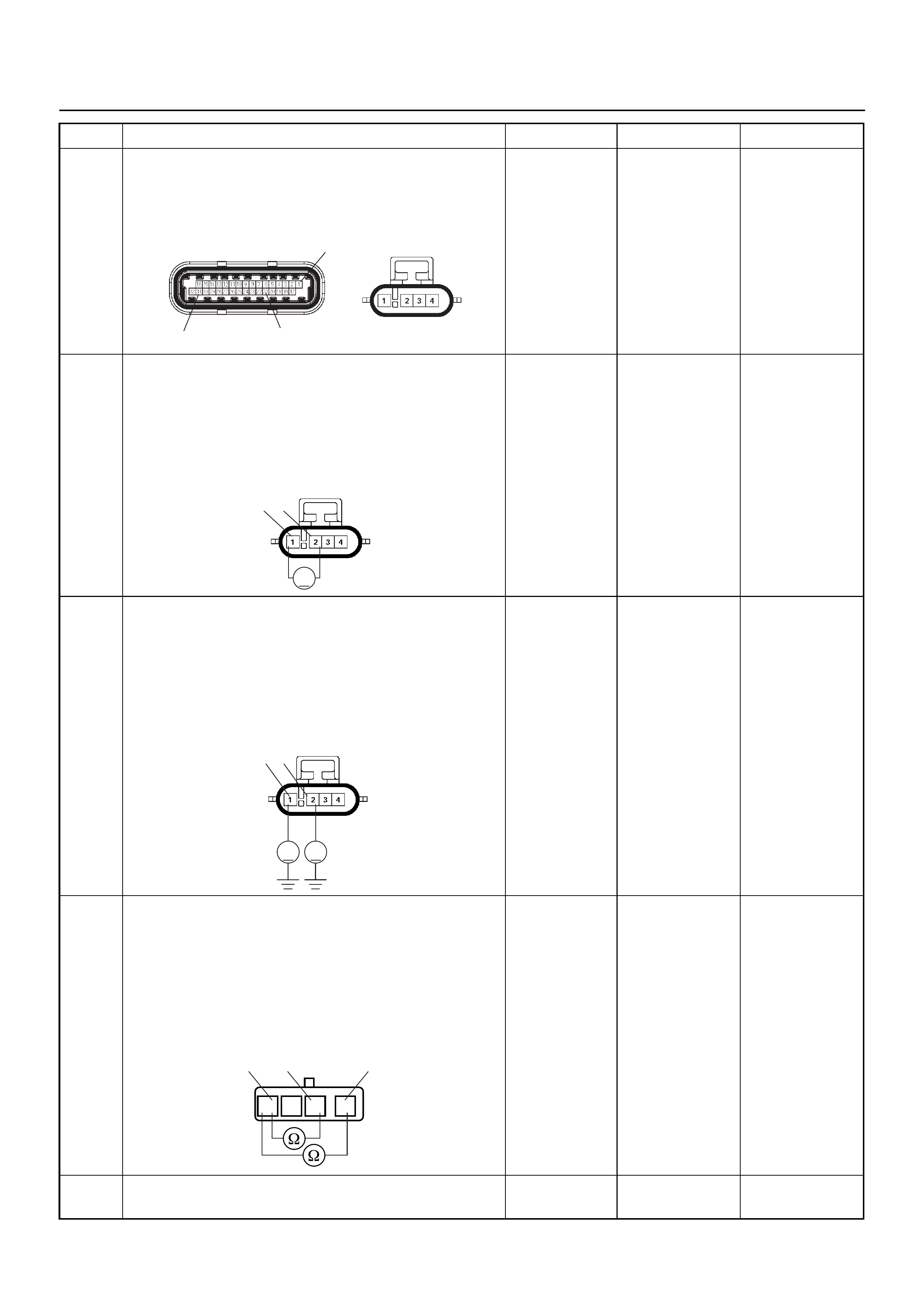
4 Check for poor/faulty connection at the O2 sensor or
ECM connector. If a poor/faulty connection is found,
repair as necess ar y.
Was the problem found?
— Verify repair G o to Step 5
5 Use a DVM to check the O2 sensor circuit.
1. Ignition “On”, engine “Off”.
2. Disconnect the O2 sensor connector.
3. Check the circuit for short to power supply circuit.
Does the DVM indicate the specified value?
Approximatly
450mV Go to Step 7 Go to Step 6
6 Use a DVM to check the O2 sensor circuit.
1. Ignition “On”, engine “Off”.
2. Disconnect the O2 sensor connector.
3. Check the circuit for short to power supply circuit.
Does the DVM indicate the specified value?
Less than 1V Go to Step 15
Repair faulty
harness and
verify repair
7 Use a DVM to check the O2 sensor circuit.
1. Ignition “Off”, engine “Off”.
2. Disconnect the O2 sensor connector.
3. Check the circuit for short to heater power supply
circuit.
Does the DVM indicate the specified value?
No continuity Go to Step 9 Go to Step 8
8 Repair the short to heater power supply circuit.
Was the problem found? — Verify repair Go to Step 15
Step Action Value(S) Yes No
C56(J2) E77
31 21
1
V
21 E77
1 2
VV
E77
124
1234
O
2 Sensor

9 1. Using Tech 2, ignition “On” and engine “On”.
2. Monitor the “Manifold Absolute Pressure” in the
data display.
Does Tech 2 indicate correct “Manifold Absolute
Pressure” in accordance with engine speed or
acceleration? — Go to Step 11 Go to Step 10
10 Remove the MAP sensor and check for the following
conditions.
• Objects blocking the air cleaner.
• Objects blocking the MAP sensor.
• Objects blocking the throttle valve.
• Vacuum leaking at inlet duct.
• Vacuum leaking at throttle body.
If a problem is found, re pa ir as nece ss ar y.
Was the problem found? — Verify repair Go to Step 11
11 1. Using Tech 2, ignition “On” and engine “On”.
2. Select the “Actuator Test” and perform the "F1:
Idle Air Control Test".
3. Operate Tech 2 in accordance with procedure.
Was the IAC valve heard stepping through the 255
positions? — Go to Step 13 Go to Step 12
12 Check for the following conditions.
• Objects blocking the IAC valve.
• Objects blocking the throttle valve.
• Vacuum leaking at throttle body.
If a problem is found, re pa ir as nece ss ar y.
Was the problem found? — Verify repair Go to Step 13
13 Check for inje ct or for the affected bank .
Refer to “Injector Coil Test & Injector Balance Test
Procedure”.
Was the injector operation correct? —Go to Step 14
Refer to Injector
Coil Test &
Injector
Balance Test
Procedure
14 Check for fu el pr es su re .
Refer to “Fuel System Diagnosis”.
Was the fuel pressure correct? — Go to Step 15
Refer to Fuel
System
Diagnosis
15 Replace the O2 sensor.
Was the problem solved? — Verify repair Go to Step 16
16 Is the ECM programmed with the latest software
release?
If not, download the latest software to the ECM using
the “SPS (Service Programming System)”.
Was the problem solved? — Verify repair Go to Step 17
17 Replace the ECM.
Is the action complete?
IMPORTANT: The replacement ECM must be
programmed. Refer to the Service Programming
System (SPS) section in this manual.
Following ECM programming, the immobiliser system
must be linked to the ECM. Refer to section 11
“Immobiliser System-ECM replacement” for the ECM/
Immobiliser linking procedure. — Verify repair —
Step Action Value(S) Yes No
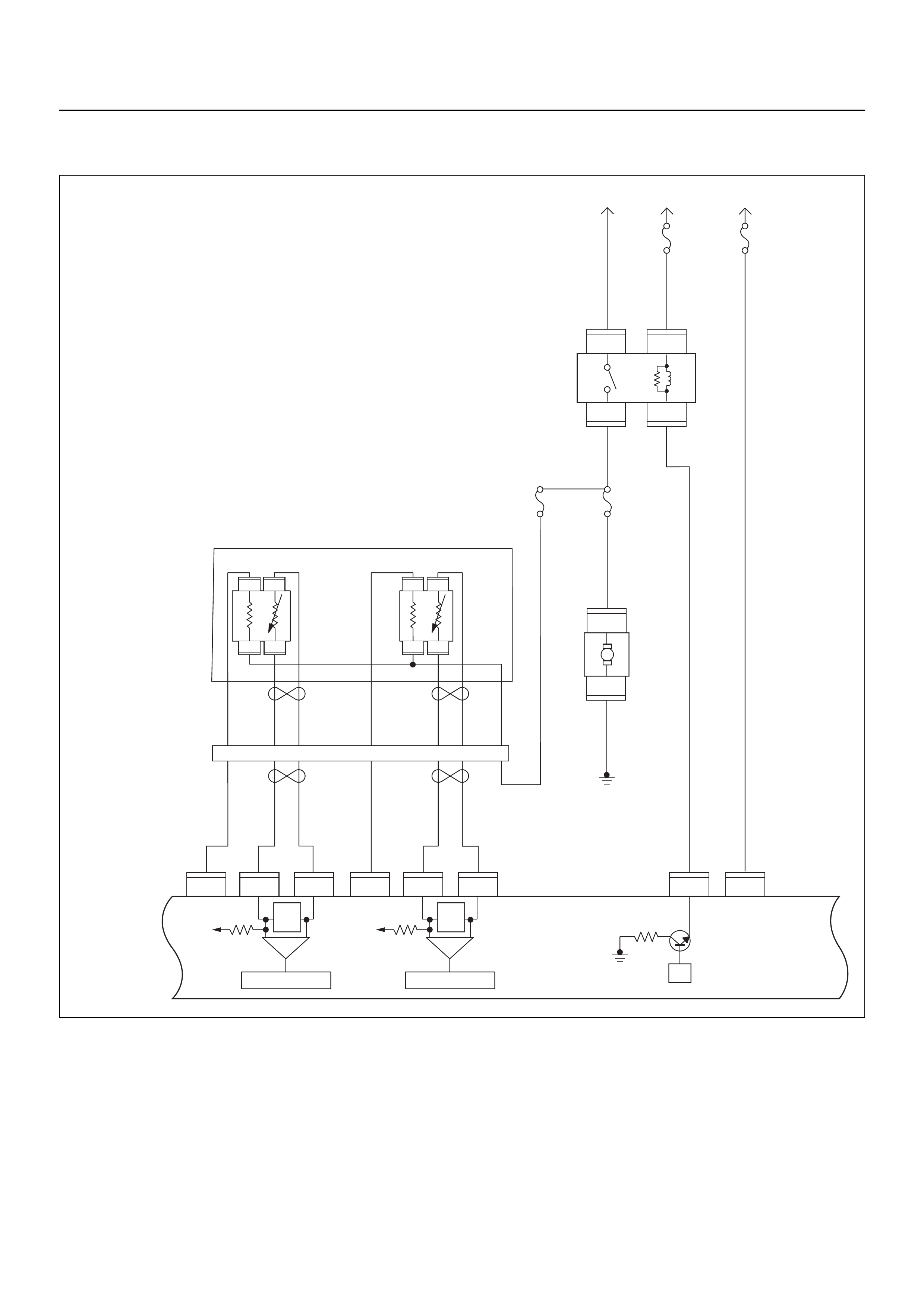
DIAGNOSTIC TROUBLE CODE (DTC) P0134 O2 SENSOR NO ACTIVITY
DEFECTED CIRCUIT (Bank 1 Sensor 1 PRE)
μP
IGN
SW Battery
Voltage
Batt PwrFuel Pump
Pwr
O2 Heater
(Pre)
O2 Heater
(Post)
Battery
Voltage
2.0
WHT
0.5
BLU/
YEL
Engine
15A
450
mV
A/D Converter
Vcc
+5V -+
450
mV
A/D Converter
Vcc
+5V -+
2.0
RED/
BLK
Fuel
Pump
Relay
0.85
RED/
WHT
0.5
GRN/
WHT
Engine
Control
Module
(ECM)
C56
1
C56
F2
F2
21
C56
31J2J1J1J1 J2 J2 J2 J2
E60
16
E60
28
E60
19
32
41
32
41
C56
26
C56
2
2.0
RED/
GRN
O2
Sensor
10A
Fuel
Pump
Heated 02 Sensors
Fuel
Pump
20A
2.0
BLK
0.5
BLU/
ORG
0.5
YEL
0.5
BLU/
YEL
0.5
BLK
0.5
BLK
0.5
BRN 0.5
YEL 0.5
PU 0.5
YEL
0.5
BRN 0.5
PU 0.5
BRN
0.5
ORG
2.0
BLK/
BLU
M
O2 Sensor
POST
O2 Sensor
PRE
LOWLOW
HI
HI
ECM
15A
X2
1
X2
X2 X2
3
1
4
42
E77 E77
E77
E78E78
E78E78
E77
H31

Condition for setting the DTC and action taken when the DTC sets
Circuit Description
The engine control module (ECM) supplies a bias
voltage of about 450 mV between the heated oxygen
sensor (HO2S) high and low circuits. The oxygen
sensor varies the voltage within a range of about
1000 mV when the exhaust is rich, down through about
10 mV when exhaust is lean. The ECM constantly
monitors the HO2S signal during “Closed Loop”
operation and compensates for a rich or lean condition
by decreasing or increasing injector pulse width as
necessary. If the Bank 1 HO 2S 1 voltage remains at or
near the 450 mV bias for an extended period of time,
Diagnostic Trouble Code P0134 will be set, indicating
an open sensor signal or sensor low circuit.
Diagnostic Aids
Check for the following conditions:
• Poor connection or damaged harness - Inspect the
harness connectors for backed-out terminals,
improper mating, broken locks, improperly formed or
damaged terminals, poor terminal-to- wire connection,
and damaged harness.
Diagnostic Trouble Code (DTC) P0134
O2 Sensor Circuit No Activity Detected (Bank 1 Sensor 1 PRE)
Code Type DTC Name DTC Setting Condition Fail-Safe (Back Up)
P0134 A O2 Sensor Circuit No Activity Detected
(Bank 1 Sensor 1 PRE) 1. No DTC relating to MAP sensor, TPS,
EVAP purge, ECT sensor, CKP sensor,
VSS, injector control circuit and ignition
control circuit.
2. Engine coolant temperature is more than
60°C.
3. Engine run time is longer than 40 seconds.
4. Mass air flow is more than 7g/s.
5. O2 sensor bank 1 sensor 1 output voltage
is between 300mV and 600mV.
“Open Loop” fuel control.
Step Action Value(s) Yes No
1 Was the “On-Board Diagnostic (OBD) System Check”
performed?
—Go to Step 2
Go to On Board
Diagnostic
(OBD) System
Check
2 1. Connect Tech 2.
2. Review and record the failure information.
3. Select “F0: Read DTC Info Ordered By Priority”
and check for DTC’s.
Is the DTC P0134 stored as “Present Failure”? — Go to Step 3
Refer to
Diagnostic Aids
and Go to Step
3
3 1. Using Tech 2, ignition “On” and engine “Off”.
2. Select “F2: Clear DTC Information” with Tech 2
and clear the DTC information.
3. Operate the vehicle and monitor the “F1: Read
DTC Info as Stored by ECU”.
Was the DTC P0134 stored in this ignition cycle? — Go to Step 4
Refer to
Diagnostic Aids
and Go to Step
4
4 Check for poor/faulty connection at the O2 sensor or
ECM connector. If a poor/faulty connection is found,
repair as necess ar y.
Was the problem found?
— Verify repair G o to Step 5
C56(J2) E77
31 21
1

5 Use a DVM to check the O2 sensor circuit.
1. Ignition “On”, engine “Off”.
2. Disconnect the O2 sensor connector.
3. Check the circuit for open circuit.
Does the DVM indicate the specified value?
Approximatly
450mV Go to Step 7 Go to Step 6
6 Use a DVM to check the O2 sensor circuit.
Breaker box is available:
1. Ignition “Off”, engine “Off”.
2. Install the breaker box as type A. (ECM
disconnected) Ref. 6E-77.
3. Disconnect the O2 sensor.
4. Check the circuit for open circuit.
Was the problem found?
Breaker box is not available:
1. Ignition “Off”, engine “Off”.
2. Disconnect the O2 sensor connector and ECM
connector.
3. Check the circuit for open circuit.
Was the problem found?
—
Repair faulty
harness and
verify repair Go to Step 13
7 1. Using Tech 2, ignition “On” and engine “On”.
2. Monitor the “Manifold Absolute Pressure” in the
data display.
Does Tech 2 indicate correct “Manifold Absolute
Pressure” in accordance with engine speed or
acceleration? — Go to Step 9 Go to Step 8
Step Action Value(s) Yes No
V
21 E77
1 2
53 33
E77
1
2
21
1
C56(J2) E77

8 Remove the MAP sensor and check for the following
conditions.
• Objects blocking the air cleaner.
• Objects blocking the MAP sensor.
• Objects blocking the throttle valve.
• Vacuum leaking at inlet duct.
• Vacuum leaking at throttle body.
If a problem is found, re pa ir as nece ss ar y.
Was the problem found? — Verify repair Go to Step 9
9 1. Using Tech 2, ignition “On” and engine “On”.
2. Select the “Actuator Test” and perform the "F1:
Idle Air Control Test".
3. Operate Tech 2 in accordance with procedure.
Was the IAC valve heard stepping through the 255
positions? — Go to Step 11 Go to Step 10
10 Check for the following conditions.
• Objects blocking the IAC valve.
• Objects blocking the throttle valve.
• Vacuum leaking at throttle body.
If a problem is found, re pa ir as nece ss ar y.
Was the problem found? — Verify repair Go to Step 11
11 Check for inje ct or for the affected bank .
Refer to “Injector Coil Test & Injector Balance Test
Procedure”.
Was the injector operation correct? —Go to Step 12
Refer to Injector
Coil Test &
Injector
Balance Test
Procedure
12 Check for fu el pr es su re .
Refer to “Fuel System Diagnosis”.
Was the fuel pressure correct? — Go to Step 13
Refer to Fuel
System
Diagnosis
13 Replace the O2 sensor.
Was the problem solved? — Verify repair Go to Step 14
14 Is the ECM programmed with the latest software
release?
If not, download the latest software to the ECM using
the “SPS (Service Programming System)”.
Was the problem solved? — Verify repair Go to Step 15
15 Replace the ECM.
Is the action complete?
IMPORTANT: The replacement ECM must be
programmed. Refer to the Service Programming
System (SPS) section in this manual.
Following ECM programming, the immobiliser system
must be linked to the ECM. Refer to section 11
“Immobiliser System-ECM replacement” for the ECM/
Immobiliser linking procedure. — Verify repair —
Step Action Value(s) Yes No
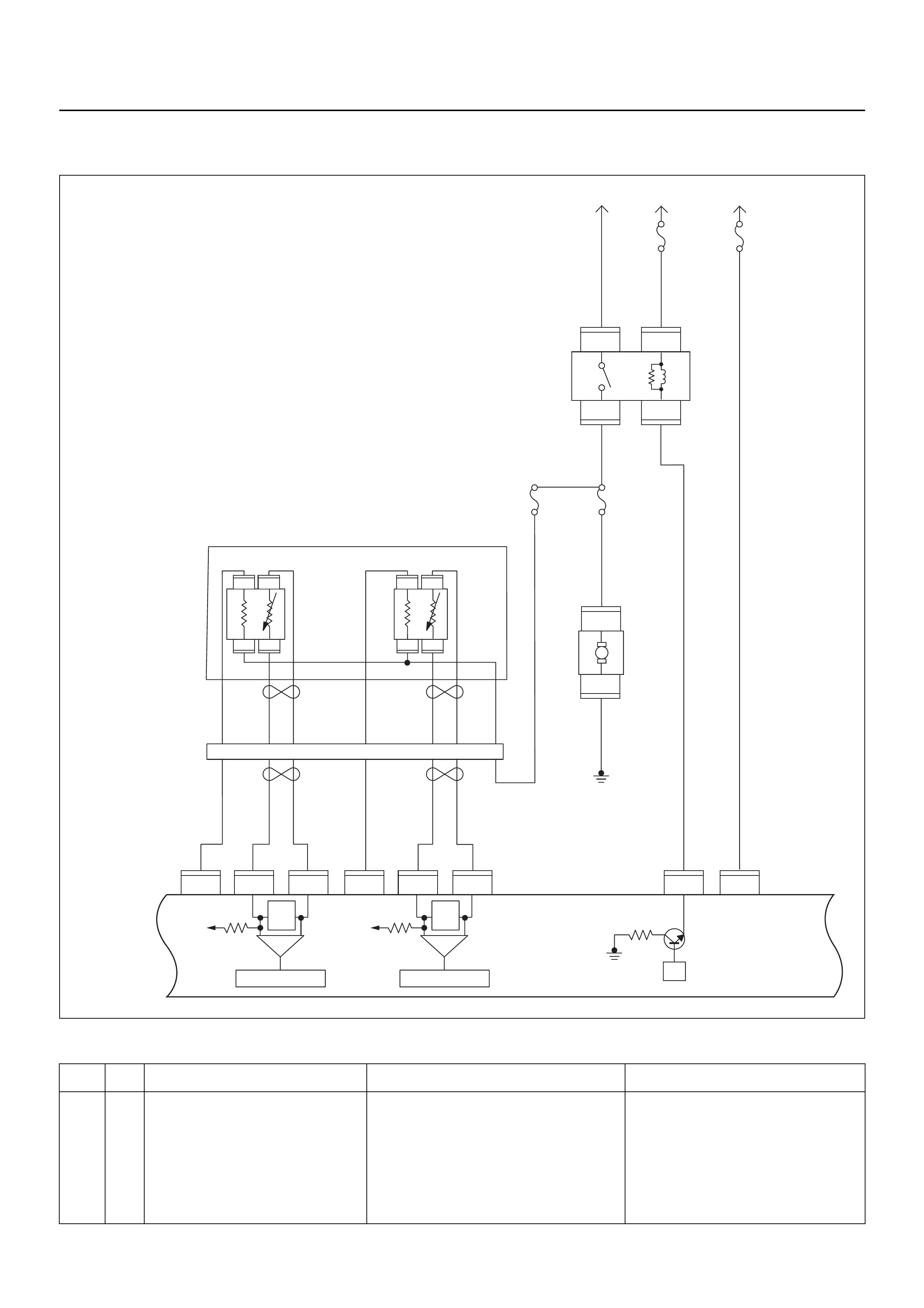
DIAGNOSTIC TROUBLE CODE (DTC) P0135 O2 SENSOR HEATER CIRCUIT
(Bank 1 Sensor 1 PRE)
Condition for setting the DTC and action taken when the DTC sets
Code Type DTC Name DTC Setting Condition Fail-Safe (Back Up)
P0135 A O2 Sensor Heater Circuit (Bank 1 Sen-
sor 1 PRE) 1. No DTC relating to MAP sensor and ECT
sensor.
2. Engine coolant temperature is more than
60°C.
3. Engine run time is longer than 20 seconds.
4. MAP sensor output is more than 70KPa.
5. O2 sensor bank 1 sensor 1 heater current
more than 10mA.
No fail-safe function.
μP
IGN
SW Battery
Voltage
Batt PwrFuel Pump
Pwr
O2 Heater
(Pre)
O2 Heater
(Post)
Battery
Voltage
2.0
WHT
0.5
BLU/
YEL
Engine
15A
450
mV
A/D Converter
Vcc
+5V -+
450
mV
A/D Converter
Vcc
+5V -+
2.0
RED/
BLK
Fuel
Pump
Relay
0.85
RED/
WHT
0.5
GRN/
WHT
Engine
Control
Module
(ECM)
C56
1
C56
F2
F2
21
C56
31J2J1J1J1 J2 J2 J2 J2
E60
16
E60
28
E60
19
32
41
32
41
C56
26
C56
2
2.0
RED/
GRN
O2
Sensor
10A
Fuel
Pump
Heated 02 Sensors
Fuel
Pump
20A
2.0
BLK
0.5
BLU/
ORG
0.5
YEL
0.5
BLU/
YEL
0.5
BLK
0.5
BLK
0.5
BRN 0.5
YEL 0.5
PU 0.5
YEL
0.5
BRN 0.5
PU 0.5
BRN
0.5
ORG
2.0
BLK/
BLU
M
O2 Sensor
POST
O2 Sensor
PRE
LOWLOW
HI
HI
ECM
15A
X2
1
X2
X2 X2
3
1
4
42
E77 E77
E77
E78E78
E78E78
E77
H31

Circuit Description
Heated oxygen sensors are used to minimize the
amount of time required for “Closed Loop” fuel control
operation and to allow accurate catalyst monitoring. The
oxygen sensor heater greatly decreases the amount of
time required for fuel control sensors Bank 1 HO2S 1 to
become active. Oxygen sensor heaters are required by
catalyst monitor sensors Bank 1 HO2S 1 to maintain a
sufficiently high temperature which allows accurate
exhaust oxygen content readings further from the
engine.
The engine control module (ECM) will run the heater
test only after a cold start ( determined by engin e coolant
and intake air temperature at the time of start-up) and
only once during an ignition cycle. When the engine is
started the ECM will monitor the HO2S voltage. When
the HO2S voltage indicates a sufficiently active sensor,
the ECM looks at how much time has elapsed since
start-up. If the ECM determines that too much t ime was
required for the Bank 1 HO2S 1 to become active, a
Diagnostic Trouble Code P0135 will set.
Diagnostic Aids
Check for the following conditions:
• Poor connection at ECM - Inspect harness
connectors for backed-out terminals, improper
mating, br oken locks , improperly formed or damaged
terminals, and poor terminal- to-wire connection.
• Damaged harness - Inspect the wiring harness for
damage; shorts to ground, shorts to battery positive
and open circuits.
Diagnostic Trouble Code (DTC) P0135
O2 Sensor Heater Circuit (Bank 1 Sensor 1 PRE)
Step Action Value(s) Yes No
1 Was the “On-Board Diagnostic (OBD) System Check”
performed?
—Go to Step 2
Go to On Board
Diagnostic
(OBD) System
Check
2 1. Connect Tech 2.
2. Review and record the failure information.
3. Select “F0: Read DTC Info Ordered By Priority”
and check for DTC’s.
Is the DTC P0135 stored as “Present Failure”? — Go to Step 3
Refer to
Diagnostic Aids
and Go to Step
3
3 1. Using Tech 2, ignition “On” and engine “Off”.
2. Select “F2: Clear DTC Information” with Tech 2
and clear the DTC information.
3. Operate the vehicle and monitor the “F1: Read
DTC Info as Stored by ECU”.
Was the DTC P0135 stored in this ignition cycle? — Go to Step 4
Refer to
Diagnostic Aids
and Go to Step
4
4 Check for poor/faulty connection at the O2 sensor or
ECM connector. If a poor/faulty connection is found,
repair as necess ar y.
Was the problem found?
— Verify repair G o to Step 5
5 Visually check the O2 sensor.
Was the problem found? — Go to Step 11 Go to Step 6
3 4
31
C56 (J2) E77
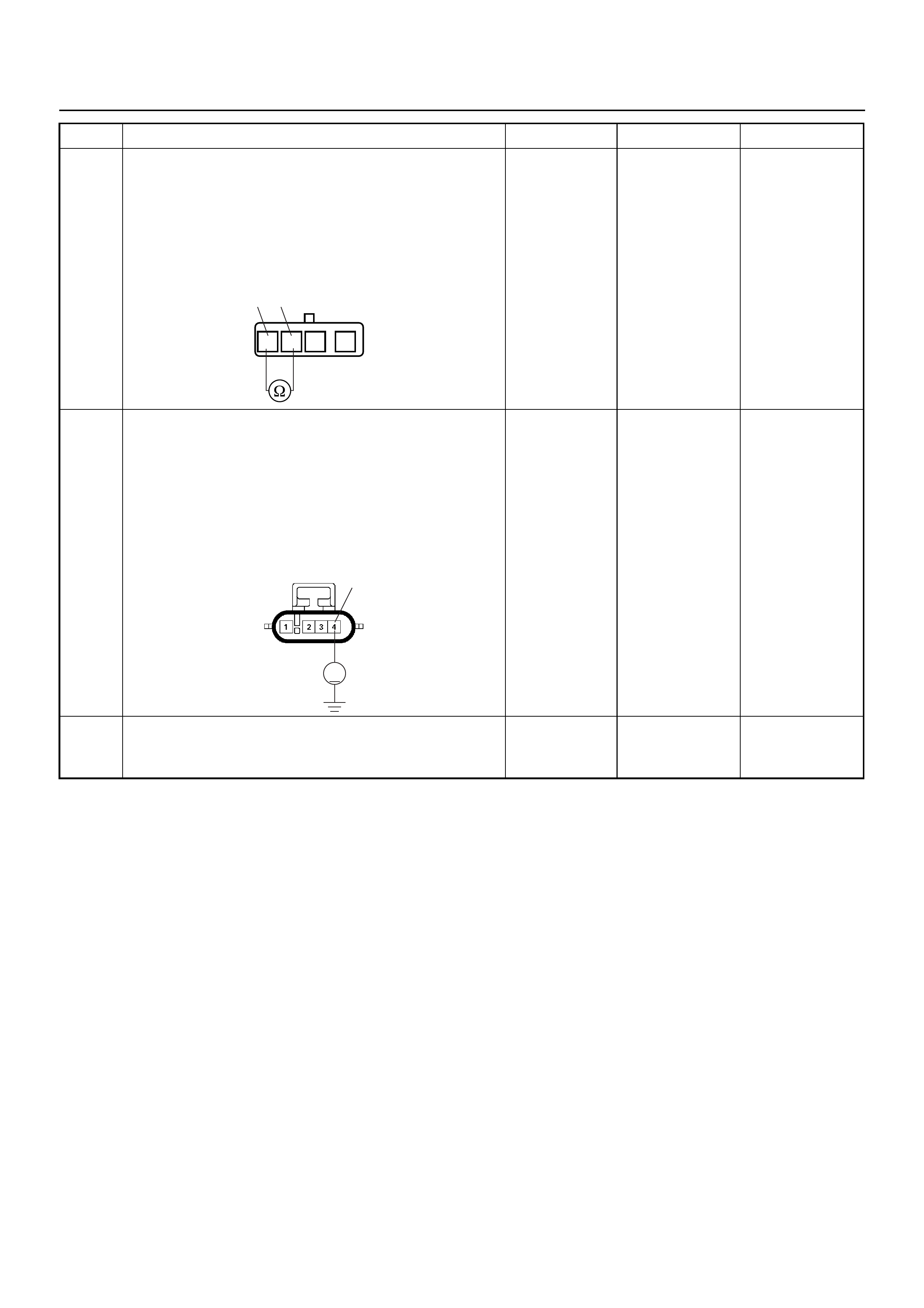
6 Use a DVM to check the O2 sensor.
1. Ignition “Off”, engine “Off”.
2. Disconnect O2 sensor connector
3. Measure the resistance of heater.
Does the tester indica te the sp ec ifie d v alue ?
Approximately
12.5Ω at 20°C Go to Step 7 Go to Step 11
7 Use a DVM to check the heater power supply circuit
for the affected cylinder.
1. Ignition “On”, engine “Off”.
2. Disconnect the O2 sensor connector.
3. Check the circuit for open circuit.
Does the DVM indicate the specified value?
Battery
voltage Go to Step 9 Go to Step 8
8 Repair the open or short to ground circuit between the
“O2 Sensor” fuse (10A) and O2 sensor.
Is the action complete? — Verify repair —
Step Action Value(s) Yes No
34
1234
O2 Sensor
4
V
E77
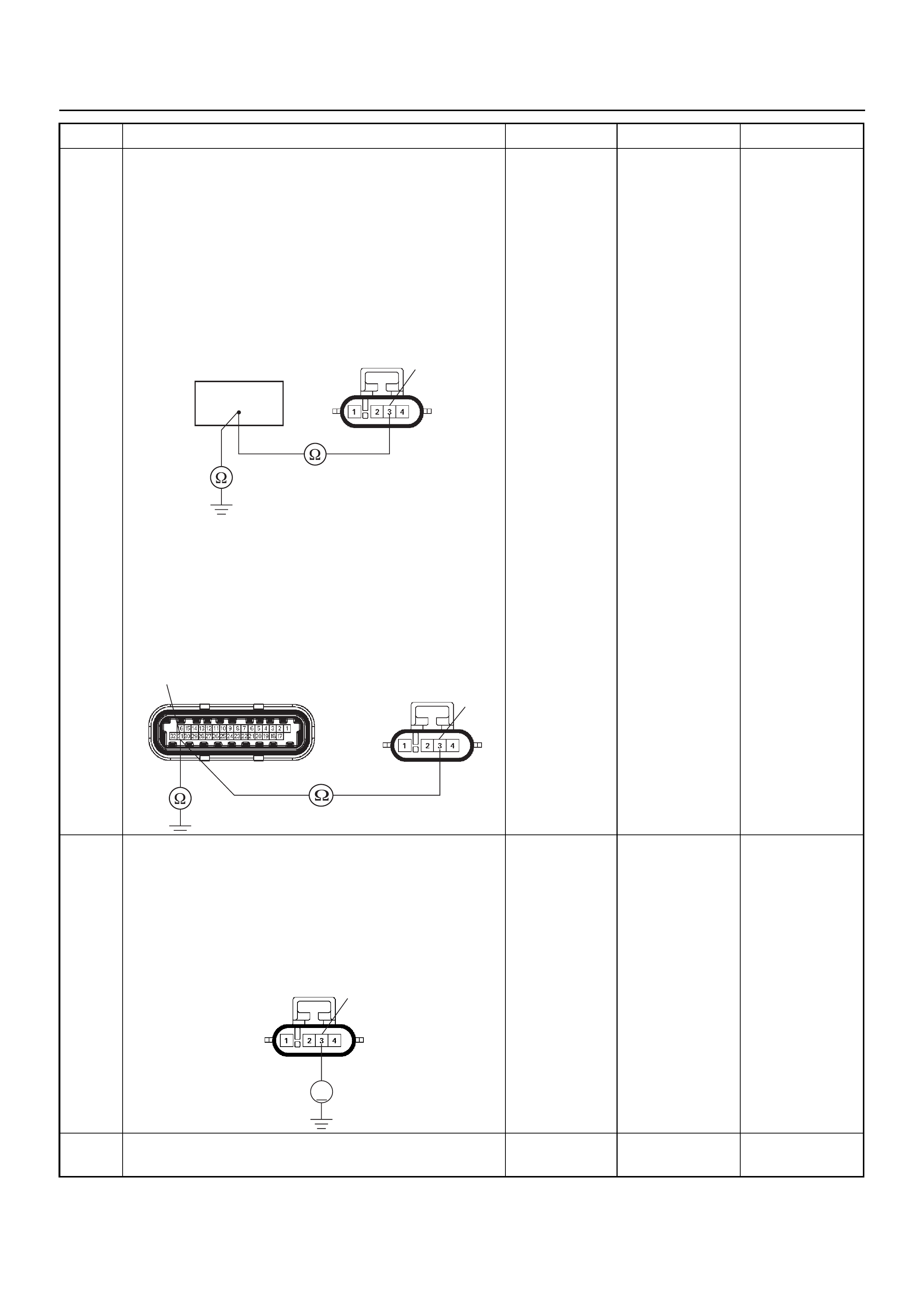
9 Use a DVM to check the heater ground circuit.
Breaker box is available:
1. Ignition “Off”, engine “Off”.
2. Install the breaker box as type A. (ECM
disconnected) Ref. 6E-77.
3. Disconnect the O2 sensor connector.
4. Check the circuit for open or short to ground
circuit.
Was the problem found?
Breaker box is not available:
1. Ignition “Off”, engine “Off”.
2. Disconnect the O2 sensor connector and ECM
connector.
3. Check the circuit for open or short to ground
circuit.
Was the problem found?
—
Repair faulty
harness and
verify repair Go to Step 10
10 Use a DVM to check the heater ground circuit.
1. Ignition “On”, engine “Off”.
2. Disconnect the O2 sensor connector.
3. Check the circuit for short to battery voltage
circuit.
Does the DVM indicate battery voltage?
—
Repair faulty
harness and
verify repair Go to Step 12
11 Replace the O2 sensor.
Was the problem solved? — Verify repair Go to Step 12
Step Action Value(s) Yes No
3
63
E77
3
31 C56(J2) E77
3
V
E77

12 Is the ECM programmed with the latest software
release?
If not, download the latest software to the ECM using
the “SPS (Service Programming System)”.
Was the problem solved? — Verify repair Go to Step 13
13 Replace the ECM.
Is the action complete?
IMPORTANT: The replacement ECM must be
programmed. Refer to the Service Programming
System (SPS) section in this manual.
Following ECM programming, the immobiliser system
must be linked to the ECM. Refer to section 11
“Immobiliser System-ECM replacement” for the ECM/
Immobiliser linking procedure. — Verify repair —
Step Action Value(s) Yes No

DIAGNOSTIC TROUBLE CODE (DTC) P0137 O2 SENSOR CIRCUIT LOW
VOLTAGE (Bank 1 Sensor 2 POST)
Condition for setting the DTC and action taken when the DTC sets
Code Type DTC Name DTC Setting Condition Fail-Safe (Back Up)
P0137 A O2 Sensor Circuit Low Voltage (Bank 1
Sensor 2 POST) 1. No DTC relating to MAP sensor, TPS,
EVAP purge, ECT sensor, CKP sensor,
VSS, injector control circuit and ignition
control circuit.
2. Engine coolant temperature is more than
60°C.
3. O2 sensor bank 1 sensor 2 output voltage
is below 50mV in “Closed Loop” condition.
“Open Loop” fuel control.
μP
IGN
SW Battery
Voltage
Batt PwrFuel Pump
Pwr
O2 Heater
(Pre)
O2 Heater
(Post)
Battery
Voltage
2.0
WHT
0.5
BLU/
YEL
Engine
15A
450
mV
A/D Converter
Vcc
+5V -+
450
mV
A/D Converter
Vcc
+5V -+
2.0
RED/
BLK
Fuel
Pump
Relay
0.85
RED/
WHT
0.5
GRN/
WHT
Engine
Control
Module
(ECM)
C56
1
C56
F2
F2
21
C56
31J2J1J1J1 J2 J2 J2 J2
E60
16
E60
28
E60
19
32
41
32
41
C56
26
C56
2
2.0
RED/
GRN
O2
Sensor
10A
Fuel
Pump
Heated 02 Sensors
Fuel
Pump
20A
2.0
BLK
0.5
BLU/
ORG
0.5
YEL
0.5
BLU/
YEL
0.5
BLK
0.5
BLK
0.5
BRN 0.5
YEL 0.5
PU 0.5
YEL
0.5
BRN 0.5
PU 0.5
BRN
0.5
ORG
2.0
BLK/
BLU
M
O2 Sensor
POST
O2 Sensor
PRE
LOWLOW
HI
HI
ECM
15A
X2
1
X2
X2 X2
3
1
4
42
E77 E77
E77
E78E78
E78E78
E77
H31

Circuit Description
The engine control module (ECM) supplies a bias
voltage of about 450 mV between the heated oxygen
sensor (HO2S) signal and low circuits. The oxygen
sensor varies the voltage within a range of about
1000 mV when the exhaust is rich, down through about
10 mV when exhaust is lean. The ECM constantly
monitors the HO2S signal during “Closed Loop”
operation and compensates for a rich or lean condition
by decreasing or increasing injector pulse width as
necessary. If the Bank 1 HO2S 2 voltage remains
excessively low for an extended period of time,
Diagnostic Trouble Code P0137 will be set.
Diagnostic Aids
Check for the following conditions:
• Heated oxygen sensor wiring - The sensor pigtail
may be routed incorrectly and/or contacting the
exhaust system. Also, check for shorts to ground,
shorts to battery positive and open circuits.
• Poor ECM to engine block grounds.
• Fuel pressure - The system will go lean if pressure is
too low. The ECM can compensate for some
decrease. However, if fuel pressure is too low, a
Diagnostic Trouble Code P0137 may be set. Refer to
Fuel System Diagnosis.
• Lean injector(s) - Perform “Injector Balance Test.”
• Vacuum leaks - Check for disconnected or damaged
vacuum hoses and for vacuum leaks at the inlet
manifold, throttle body, EGR system, and PCV
system.
• Exhaust leaks - An exhaust leak may cause outside
air to be pulled into the exhaust gas stream past the
HO2S, causing the system to appear lean. Check for
exhaust leaks that may cause a false lean condition
to be indicated.
• Fuel contamination - Water, even in small amounts,
can be delivered to the fuel injectors. The water can
cause a lean exhaust to be indicated. Excessive
alcohol in the fuel can also cause this condition. For
the procedure to check for fuel contamination, Refer
to Fuel System Diagnosis.
Diagnostic Trouble Code (DTC) P0137
O2 Sensor Circuit Low Voltage (Bank 1 Sensor 2 POST)
Step Action Value(s) Yes No
1 Was the “On-Board Diagnostic (OBD) System Check”
performed?
—Go to Step 2
Go to On Board
Diagnostic
(OBD) System
Check
2 1. Connect Tech 2.
2. Review and record the failure information.
3. Select “F0: Read DTC Info Ordered By Priority”
and check for DTC’s.
Is the DTC P0137 stored as “Present Failure”? — Go to Step 3
Refer to
Diagnostic Aids
and Go to Step
3
3 1. Using Tech 2, ignition “On” and engine “Off”.
2. Select “F2: Clear DTC Information” with Tech 2
and clear the DTC information.
3. Operate the vehicle and monitor the “F1: Read
DTC Info as Stored by ECU”.
Was the DTC P0137 stored in this ignition cycle? — Go to Step 4
Refer to
Diagnostic Aids
and Go to Step
4
4 Check for poor/faulty connection at the O2 sensor or
ECM connector. If a poor/faulty connection is found,
repair as necess ar y.
Was the problem found?
— Verify repair G o to Step 5
E60(J1) E78
16
19
28
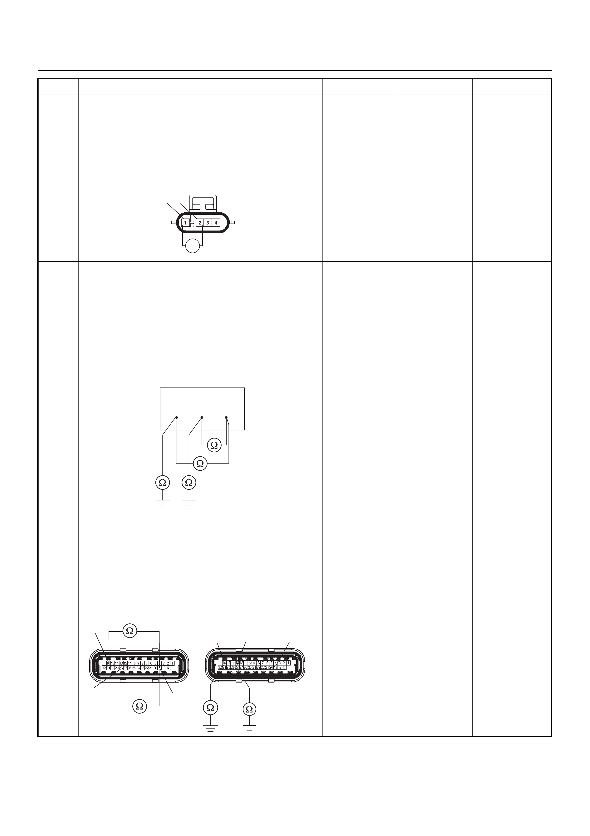
5 Use a DVM to check the O2 sensor circuit.
1. Ignition “On”, engine “Off”.
2. Disconnect the O2 sensor connector.
3. Check the circuit for short to heater ground or
ground circuit.
Does the DVM indicate the specified value?
Approximatly
450mV Go to Step 7 Go to Step 6
6 Use a DVM to check the O2 sensor circuit.
Breaker box is available:
1. Ignition “Off”, engine “Off”.
2. Install the breaker box as type A. (ECM
disconnected) Ref. 6E-77.
3. Disconnect the O2 sensor.
4. Check the circuit for short to heater ground or
short to ground circuit.
Was the problem found?
Breaker box is not available:
1. Ignition “Off”, engine “Off”.
2. Disconnect the O2 sensor connector and ECM
connector.
3. Check the circuit for short to heater ground or
short to ground circuit.
Was the problem found?
—
Repair faulty
harness and
verify repair Go to Step 15
Step Action Value(s) Yes No
V
21 E78
28 16 19
19
16
28
E60(J1)
16 28 19
E60(J1)

7 Use a DVM to check the O2 sensor circuit.
1. Ignition “Off”, engine “Off”.
2. Disconnect the O2 sensor connector.
3. Check the circuit for short to heater ground circuit.
Does the DVM indicate the specified value?
No continuity Go to Step 9 Go to Step 8
8 Repair the short to heater ground circuit.
Was the problem found? — Verify repair Go to Step 15
9 1. Using Tech 2, ignition “On” and engine “On”.
2. Monitor the “Manifold Absolute Pressure” in the
data display.
Does Tech 2 indicate correct “Manifold Absolute
Pressure” in accordance with engine speed or
acceleration? — Go to Step 11 Go to Step 10
10 Remove the MAP sensor and check for the following
conditions.
• Objects blocking the air cleaner.
• Objects blocking the MAP sensor.
• Objects blocking the throttle valve.
• Vacuum leaking at inlet duct.
• Vacuum leaking at throttle body.
If a problem is found, re pa ir as nece ss ar y.
Was the problem found? — Verify repair Go to Step 11
11 1. Using Tech 2, ignition “On” and engine “On”.
2. Select the “Actuator Test” and perform the "F1:
Idle Air Control Test".
3. Operate Tech 2 in accordance with procedure.
Was the IAC valve heard stepping through the 255
positions? — Go to Step 13 Go to Step 12
12 Check for the following conditions.
• Objects blocking the IAC valve.
• Objects blocking the throttle valve.
• Vacuum leaking at throttle body.
If a problem is found, re pa ir as nece ss ar y.
Was the problem found? — Verify repair Go to Step 13
13 Check the injector for the affected bank.
Refer to “Injector Coil Test & Injector Balance Test
Procedure”.
Was the injector operation correct? —Go to Step 14
Refer to Injector
Coil Test &
Injector
Balance Test
Procedure
14 Check for fu el pr es su re .
Refer to “Fuel System Diagnosis”.
Was the fuel pressure correct? — Go to Step 15
Refer to Fuel
System
Diagnosis
15 Replace the O2 sensor.
Was the problem solved? — Verify repair Go to Step 16
Step Action Value(s) Yes No
124
1234
O2 Sensor

16 Is the ECM programmed with the latest software
release?
If not, download the latest software to the ECM using
the “SPS (Service Programming System)”.
Was the problem solved? — Verify repair Go to Step 17
17 Replace the ECM.
Is the action complete?
IMPORTANT: The replacement ECM must be
programmed. Refer to the Service Programming
System (SPS) section in this manual.
Following ECM programming, the immobiliser system
must be linked to the ECM. Refer to section 11
“Immobiliser System-ECM replacement” for the ECM/
Immobiliser linking procedure. — Verify repair —
Step Action Value(s) Yes No
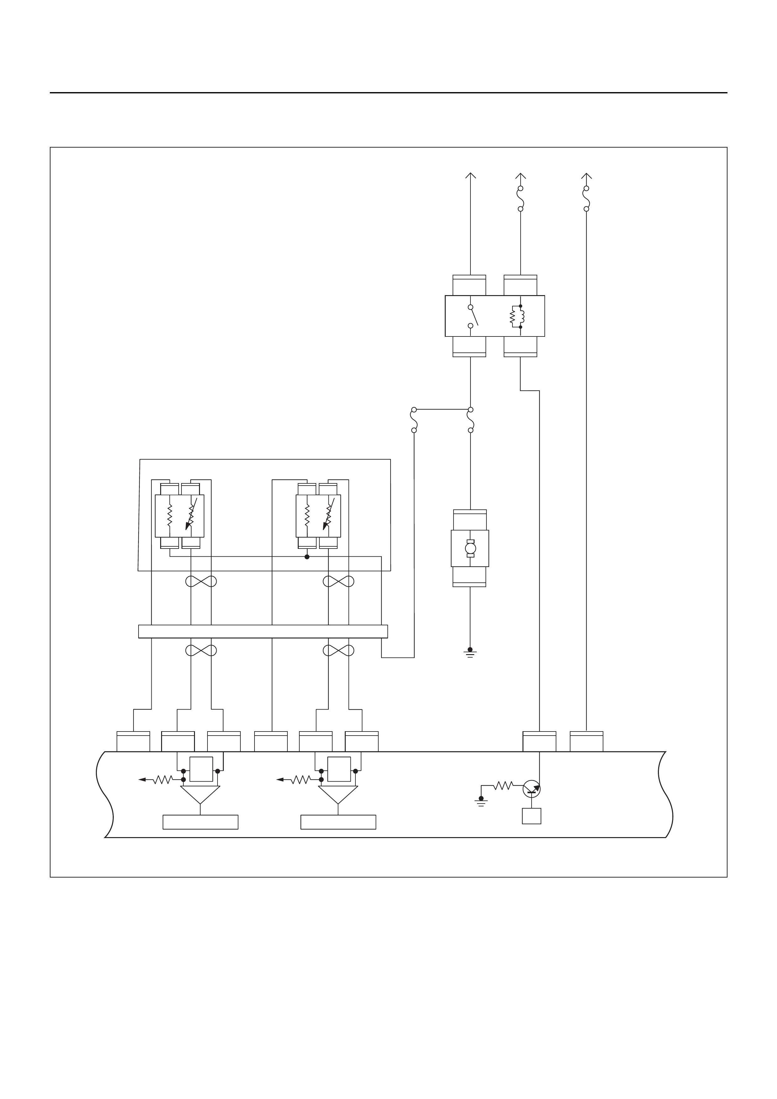
DIAGNOSTIC TROUBLE CODE (DTC) P0138 O2 SENSOR CIRCUIT HIGH
VOLTAGE (Bank 1 Sensor 2 POST)
μP
IGN
SW Battery
Voltage
Batt PwrFuel Pump
Pwr
O2 Heater
(Pre)
O2 Heater
(Post)
Battery
Voltage
2.0
WHT
0.5
BLU/
YEL
Engine
15A
450
mV
A/D Converter
Vcc
+5V -+
450
mV
A/D Converter
Vcc
+5V -+
2.0
RED/
BLK
Fuel
Pump
Relay
0.85
RED/
WHT
0.5
GRN/
WHT
Engine
Control
Module
(ECM)
C56
1
C56
F2
F2
21
C56
31J2J1J1J1 J2 J2 J2 J2
E60
16
E60
28
E60
19
32
41
32
41
C56
26
C56
2
2.0
RED/
GRN
O2
Sensor
10A
Fuel
Pump
Heated 02 Sensors
Fuel
Pump
20A
2.0
BLK
0.5
BLU/
ORG
0.5
YEL
0.5
BLU/
YEL
0.5
BLK
0.5
BLK
0.5
BRN 0.5
YEL 0.5
PU 0.5
YEL
0.5
BRN 0.5
PU 0.5
BRN
0.5
ORG
2.0
BLK/
BLU
M
O2 Sensor
POST
O2 Sensor
PRE
LOWLOW
HI
HI
ECM
15A
X2
1
X2
X2 X2
3
1
4
42
E77 E77
E77
E78E78
E78E78
E77
H31

Condition for setting the DTC and action taken when the DTC sets
Circuit Description
The engine control module (ECM) supplies a bias
voltage of about 450 mV between the heated oxygen
sensor (HO2S) signal and low circuits. The oxygen
sensor varies the voltage within a range of about
1000 mV when the exhaust is rich, down through about
10 mV when exhaust is lean. The ECM constantly
monitors the HO2S signal during “Closed Loop”
operation and compensates for a rich or lean condition
by decreasing or increasing injector pulse width as
necessary. If the Bank 1 HO2S 2 voltage remains
excessively high for an extended period of time,
Diagnostic Trouble Code P0138 will be set.
Diagnostic Aids
Check the following items:
• Fuel pressure - The system will go rich if pressure is
too high. The ECM can compensate for some
increase. However, if fuel pressure is too high, a
Diagnostic Trouble Code P0138 may be set. Refer to
Fuel System Diagnosis.
• Perform “Injector Balance Test” - Refer to Fuel
System Diagnosis.
• Check the EVAP canister for fuel saturation - If full of
fuel, check canister control and hoses. Refer to
Evaporative (EVAP) Emission Control System.
• Check for a leak in the fuel pressure regulator
diaphragm by checking the vacuum line to the
regulator for the presence of fuel.
• An intermittent TPS output will cause the system to
go rich due to a false indication of the engine
accelerating.
• Silicon contamination of the HO2S can also cause a
high HO2S voltage to be indicated. This condition is
indicated by a powdery white deposit on the portion
of the HO2S exposed to the exhaust stream. If
contamination is noticed, replace the affected HO2S.
Diagnostic Trouble Code (DTC) P0138
O2 Sensor Circuit High Voltage (Bank 1 Sensor 2 POST)
Code Type DTC Name DTC Setting Condition Fail-Safe (Back Up)
P0138 A O2 Sensor Circuit High Voltage (Bank
1 Sensor 2 POST) 1. No DTC relating to MAP sensor, TPS,
EVAP purge, ECT sensor, CKP sensor,
VSS, injector control circuit and ignition
control circuit.
2. Engine coolant temperature is more than
60°C.
3. O2 sensor bank 1 sensor 2 output voltage
is more than 952mV in “Closed Loop” con-
dition.
“Open Loop” fuel control.
Step Action Value(S) Yes No
1 Was the “On-Board Diagnostic (OBD) System Check”
performed?
—Go to Step 2
Go to On Board
Diagnostic
(OBD) System
Check
2 1. Connect Tech 2.
2. Review and record the failure information.
3. Select “F0: Read DTC Info Ordered By Priority”
and check for DTC’s.
Is the DTC P0138 stored as “Present Failure”? — Go to Step 3
Refer to
Diagnostic Aids
and Go to Step
3
3 1. Using Tech 2, ignition “On” and engine “Off”.
2. Select “F2: Clear DTC Information” with Tech 2
and clear the DTC information.
3. Operate the vehicle and monitor the “F1: Read
DTC Info as Stored by ECU”.
Was the DTC P0138 stored in this ignition cycle? — Go to Step 4
Refer to
Diagnostic Aids
and Go to Step
4
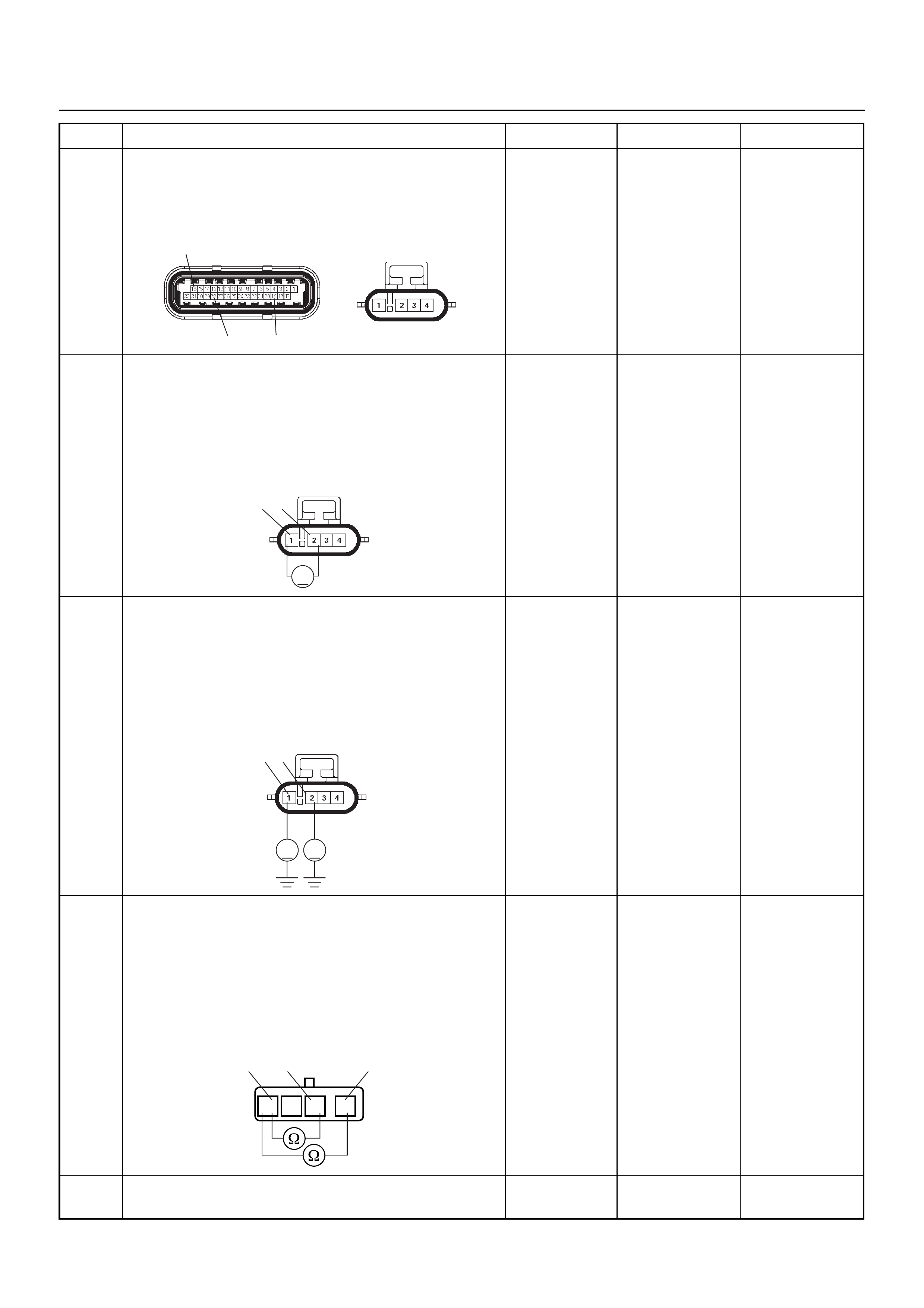
4 Check for poor/faulty connection at the O2 sensor or
ECM connector. If a poor/faulty connection is found,
repair as necess ar y.
Was the problem found?
— Verify repair G o to Step 5
5 Use a DVM to check the O2 sensor circuit.
1. Ignition “On”, engine “Off”.
2. Disconnect the O2 sensor connector.
3. Check the circuit for short to power supply circuit.
Does the DVM indicate the specified value?
Approximatly
450mV Go to Step 7 Go to Step 6
6 Use a DVM to check the O2 sensor circuit.
1. Ignition “On”, engine “Off”.
2. Disconnect the O2 sensor connector.
3. Check the circuit for short to power supply circuit.
Does the DVM indicate the specifed value?
Less than 1V Go to Step 15
Repair faulty
harness and
verify repair
7 Use a DVM to check the O2 sensor circuit.
1. Ignition “Off”, engine “Off”.
2. Disconnect the O2 sensor connector.
3. Check the circuit for short to heater power supply
circuit.
Does the DVM indicate the specified value?
No continuity Go to Step 9 Go to Step 8
8 Repair the short to heater power supply circuit.
Was the problem found? — Verify repair Go to Step 15
Step Action Value(S) Yes No
E60(J1) E78
16
19
28
V
21 E78
1 2
VV
E78
124
1234
O
2 Sensor

9 1. Using Tech 2, ignition “On” and engine “On”.
2. Monitor the “Manifold Absolute Pressure” in the
data display.
Does Tech 2 indicate correct “Manifold Absolute
Pressure” in accordance with engine speed or
acceleration? — Go to Step 11 Go to Step 10
10 Remove the MAP sensor and check for the following
conditions.
• Objects blocking the air cleaner.
• Objects blocking the MAP sensor.
• Objects blocking the throttle valve.
• Vacuum leaking at inlet duct.
• Vacuum leaking at throttle body.
If a problem is found, re pa ir as nece ss ar y.
Was the problem found? — Verify repair Go to Step 11
11 1. Using Tech 2, ignition “On” and engine “On”.
2. Select the “Actuator Test” and perform the "F1:
Idle Air Control Test".
3. Operate Tech 2 in accordance with procedure.
Was the IAC valve heard stepping through the 255
positions? — Go to Step 13 Go to Step 12
12 Check for the following conditions.
• Objects blocking the IAC valve.
• Objects blocking the throttle valve.
• Vacuum leaking at throttle body.
If a problem is found, re pa ir as nece ss ar y.
Was the problem found? — Verify repair Go to Step 13
13 Check the injector for the affected bank.
Refer to “Injector Coil Test & Injector Balance Test
Procedure”.
Was the injector operation correct? —Go to Step 14
Refer to Injector
Coil Test &
Injector
Balance Test
Procedure
14 Check for fu el pr es su re .
Refer to “Fuel System Diagnosis”.
Was the fuel pressure correct? — Go to Step 15
Refer to Fuel
System
Diagnosis
15 Replace the O2 sensor.
Was the problem solved? — Verify repair Go to Step 16
16 Is the ECM programmed with the latest software
release?
If not, download the latest software to the ECM using
the “SPS (Service Programming System)”.
Was the problem solved? — Verify repair Go to Step 17
17 Replace the ECM.
Is the action complete?
IMPORTANT: The replacement ECM must be
programmed. Refer to the Service Programming
System (SPS) section in this manual.
Following ECM programming, the immobiliser system
must be linked to the ECM. Refer to section 11
“Immobiliser System-ECM replacement” for the ECM/
Immobiliser linking procedure. — Verify repair —
Step Action Value(S) Yes No

DIAGNOSTIC TROUBLE CODE (DTC) P0140 O2 SENSOR NO ACTIVITY
DEFECTED CIRCUIT (Bank 1 Sensor 2 POST)
μP
IGN
SW Battery
Voltage
Batt PwrFuel Pump
Pwr
O2 Heater
(Pre)
O2 Heater
(Post)
Battery
Voltage
2.0
WHT
0.5
BLU/
YEL
Engine
15A
450
mV
A/D Converter
Vcc
+5V -+
450
mV
A/D Converter
Vcc
+5V -+
2.0
RED/
BLK
Fuel
Pump
Relay
0.85
RED/
WHT
0.5
GRN/
WHT
Engine
Control
Module
(ECM)
C56
1
C56
F2
F2
21
C56
31J2J1J1J1 J2 J2 J2 J2
E60
16
E60
28
E60
19
32
41
32
41
C56
26
C56
2
2.0
RED/
GRN
O2
Sensor
10A
Fuel
Pump
Heated 02 Sensors
Fuel
Pump
20A
2.0
BLK
0.5
BLU/
ORG
0.5
YEL
0.5
BLU/
YEL
0.5
BLK
0.5
BLK
0.5
BRN 0.5
YEL 0.5
PU 0.5
YEL
0.5
BRN 0.5
PU 0.5
BRN
0.5
ORG
2.0
BLK/
BLU
M
O2 Sensor
POST
O2 Sensor
PRE
LOWLOW
HI
HI
ECM
15A
X2
1
X2
X2 X2
3
1
4
42
E77 E77
E77
E78E78
E78E78
E77
H31

Condition for setting the DTC and action taken when the DTC sets
Circuit Description
The engine control module (ECM) supplies a bias
voltage of about 450 mV between the heated oxygen
sensor (HO2S) high and low circuits. The oxygen
sensor varies the voltage within a range of about
1000 mV when the exhaust is rich, down through about
10 mV when exhaust is lean. The ECM constantly
monitors the HO2S signal during “Closed Loop”
operation and compensates for a rich or lean condition
by decreasing or increasing injector pulse width as
necessary. If the Bank 1 HO 2S 2 voltage remains at or
near the 450 mV bias for an extended period of time,
Diagnostic Trouble Code P0140 will be set, indicating
an open sensor signal or sensor low circuit.
Diagnostic Aids
Check for the following conditions:
• Poor connection or damaged harness - Inspect the
harness connectors for backed-out terminals,
improper mating, broken locks, improperly formed or
damaged terminals, poor terminal-to- wire connection,
and damaged harness.
Diagnostic Trouble Code (DTC) P0140
O2 Sensor Circuit No Activity Detected (Bank 1 Sensor 2 POST)
Code Type DTC Name DTC Setting Condition Fail-Safe (Back Up)
P0140 A O2 Sensor Circuit No Activity Detected
(Bank 1 Sensor 2 POST) 1. No DTC relating to MAP sensor, TPS,
EVAP purge, ECT sensor, CKP sensor,
VSS, injector control circuit and ignition
control circuit.
2. Engine coolant temperature is more than
60°C.
3. Engine run time is longer than 40 seconds.
4. Mass air flow is more than 7g/s.
5. O2 sensor bank 1 sensor 2 output voltage
is between 300mV and 600mV.
“Open Loop” fuel control.
Step Action Value(s) Yes No
1 Was the “On-Board Diagnostic (OBD) System Check”
performed?
—Go to Step 2
Go to On Board
Diagnostic
(OBD) System
Check
2 1. Connect Tech 2.
2. Review and record the failure information.
3. Select “F0: Read DTC Info Ordered By Priority”
and check for DTC’s.
Is the DTC P0140 stored as “Present Failure”? — Go to Step 3
Refer to
Diagnostic Aids
and Go to Step
3
3 1. Using Tech 2, ignition “On” and engine “Off”.
2. Select “F2: Clear DTC Information” with Tech 2
and clear the DTC information.
3. Operate the vehicle and monitor the “F1: Read
DTC Info as Stored by ECU”.
Was the DTC P0140 stored in this ignition cycle? — Go to Step 4
Refer to
Diagnostic Aids
and Go to Step
4
4 Check for poor/faulty connection at the O2 sensor or
ECM connector. If a poor/faulty connection is found,
repair as necess ar y.
Was the problem found?
— Verify repair G o to Step 5
E60(J1) E78
16
19
28
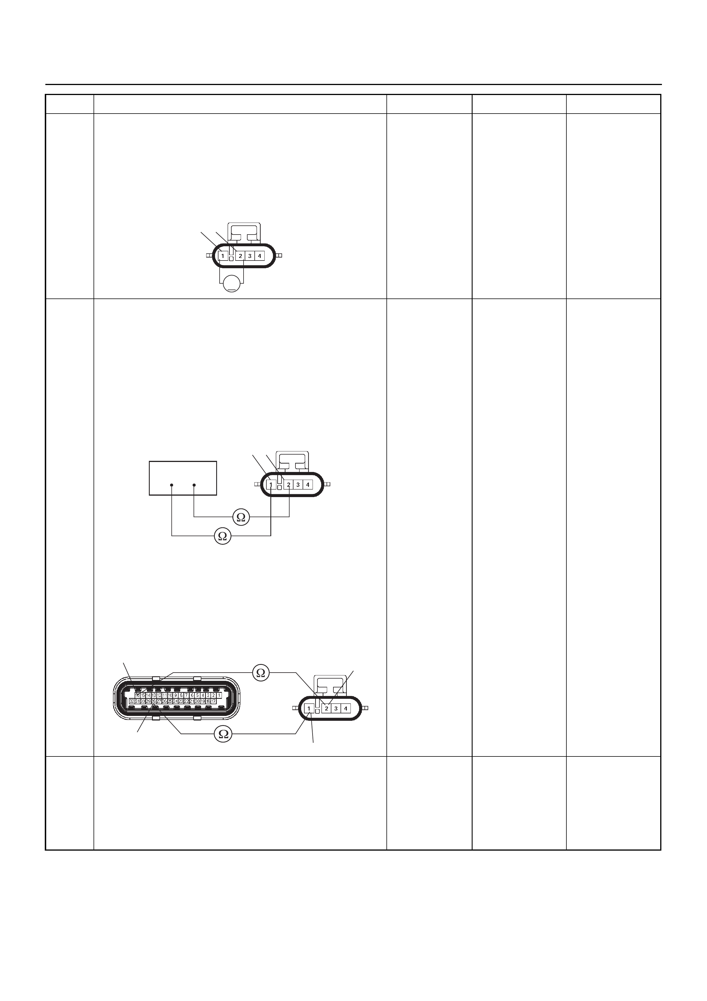
5 Use a DVM to check the O2 sensor circuit.
1. Ignition “On”, engine “Off”.
2. Disconnect the O2 sensor connector.
3. Check the circuit for open circuit.
Does the DVM indicate the specified value?
Approximatly
450mV Go to Step 7 Go to Step 6
6 Use a DVM to check the O2 sensor circuit.
Breaker box is available:
1. Ignition “Off”, engine “Off”.
2. Install the breaker box as type A. (ECM
disconnected) Ref. 6E-77.
3. Disconnect the O2 sensor.
4. Check the circuit for open circuit.
Was the problem found?
Breaker box is not available:
1. Ignition “Off”, engine “Off”.
2. Disconnect the O2 sensor connector and ECM
connector.
3. Check the circuit for open circuit.
Was the problem found?
—
Repair faulty
harness and
verify repair Go to Step 13
7 1. Using Tech 2, ignition “On” and engine “On”.
2. Monitor the “Manifold Absolute Pressure” in the
data display.
Does Tech 2 indicate correct “Manifold Absolute
Pressure” in accordance with engine speed or
acceleration? — Go to Step 9 Go to Step 8
Step Action Value(s) Yes No
V
21 E78
1 2
28 16
E78
1
2
28
16 E60(J1) E78

8 Remove the MAP sensor and check for the following
conditions.
• Objects blocking the air cleaner.
• Objects blocking the MAP sensor.
• Objects blocking the throttle valve.
• Vacuum leaking at inlet duct.
• Vacuum leaking at throttle body.
If a problem is found, re pa ir as nece ss ar y.
Was the problem found? — Verify repair Go to Step 9
9 1. Using Tech 2, ignition “On” and engine “On”.
2. Select the “Actuator Test” and perform the "F1:
Idle Air Control Test".
3. Operate Tech 2 in accordance with procedure.
Was the IAC valve heard stepping through the 255
positions? — Go to Step 11 Go to Step 10
10 Check for the following conditions.
• Objects blocking the IAC valve.
• Objects blocking the throttle valve.
• Vacuum leaking at throttle body.
If a problem is found, re pa ir as nece ss ar y.
Was the problem found? — Verify repair Go to Step 11
11 Check the injector for the affected bank.
Refer to “Injector Coil Test & Injector Balance Test
Procedure”.
Was the injector operation correct? —Go to Step 12
Refer to Injector
Coil Test &
Injector
Balance Test
Procedure
12 Check for fu el pr es su re .
Refer to “Fuel System Diagnosis”.
Was the fuel pressure correct? — Go to Step 13
Refer to Fuel
System
Diagnosis
13 Replace the O2 sensor.
Was the problem solved? — Verify repair Go to Step 14
14 Is the ECM programmed with the latest software
release?
If not, download the latest software to the ECM using
the “SPS (Service Programming System)”.
Was the problem solved? — Verify repair Go to Step 15
15 Replace the ECM.
Is the action complete?
IMPORTANT: The replacement ECM must be
programmed. Refer to the Service Programming
System (SPS) section in this manual.
Following ECM programming, the immobiliser system
must be linked to the ECM. Refer to section 11
“Immobiliser System-ECM replacement” for the ECM/
Immobiliser linking procedure. — Verify repair —
Step Action Value(s) Yes No

DIAGNOSTIC TROUBLE CODE (DTC) P0141 O2 SENSOR HEATER CIRCUIT
(Bank 1 Sensor 2 POST)
Condition for setting the DTC and action taken when the DTC sets
Code Type DTC Name DTC Setting Condition Fail-Safe (Back Up)
P0141 A O2 Sensor Heater Circuit (Bank 1 Sen-
sor 2 POST) 1. No DTC relating to MAP sensor and ECT
sensor.
2. Engine coolant temperature is more than
60°C.
3. Engine run time is longer than 20 seconds.
4. MAP sensor output is more than 70KPa.
5. O2 sensor bank 1 sensor 2 heater current
more than 10mA.
No fail-safe function.
μP
IGN
SW Battery
Voltage
Batt PwrFuel Pump
Pwr
O2 Heater
(Pre)
O2 Heater
(Post)
Battery
Voltage
2.0
WHT
0.5
BLU/
YEL
Engine
15A
450
mV
A/D Converter
Vcc
+5V -+
450
mV
A/D Converter
Vcc
+5V -+
2.0
RED/
BLK
Fuel
Pump
Relay
0.85
RED/
WHT
0.5
GRN/
WHT
Engine
Control
Module
(ECM)
C56
1
C56
F2
F2
21
C56
31J2J1J1J1 J2 J2 J2 J2
E60
16
E60
28
E60
19
32
41
32
41
C56
26
C56
2
2.0
RED/
GRN
O2
Sensor
10A
Fuel
Pump
Heated 02 Sensors
Fuel
Pump
20A
2.0
BLK
0.5
BLU/
ORG
0.5
YEL
0.5
BLU/
YEL
0.5
BLK
0.5
BLK
0.5
BRN 0.5
YEL 0.5
PU 0.5
YEL
0.5
BRN 0.5
PU 0.5
BRN
0.5
ORG
2.0
BLK/
BLU
M
O2 Sensor
POST
O2 Sensor
PRE
LOWLOW
HI
HI
ECM
15A
X2
1
X2
X2 X2
3
1
4
42
E77 E77
E77
E78E78
E78E78
E77
H31

Circuit Description
Heated oxygen sensors are used to minimize the
amount of time required for “Closed Loop” fuel control
operation and to allow accurate catalyst monitoring. The
oxygen sensor heater greatly decreases the amount of
time required for fuel control sensors Bank 1 HO2S 2 to
become active. Oxygen sensor heaters are required by
catalyst monitor sensors Bank 1 HO2S 2 to maintain a
sufficiently high temperature which allows accurate
exhaust oxygen content readings further from the
engine.
The engine control module (ECM) will run the heater
test only after a cold start ( determined by engin e coolant
and intake air temperature at the time of start-up) and
only once during an ignition cycle. When the engine is
started the ECM will monitor the HO2S voltage. When
the HO2S voltage indicates a sufficiently active sensor,
the ECM looks at how much time has elapsed since
start-up. If the ECM determines that too much t ime was
required for the Bank 1 HO2S 2 to become active, a
Diagnostic Trouble Code P0141will set.
Diagnostic Aids
Check for the following conditions:
• Poor connection at ECM - Inspect harness
connectors for backed-out terminals, improper
mating, br oken locks , improperly formed or damaged
terminals, and poor terminal- to-wire connection.
• Damaged harness - Inspect the wiring harness for
damage; shorts to ground, shorts to battery positive
and open circuits.
Diagnostic Trouble Code (DTC) P0141
O2 Sensor Heater Circuit (Bank 1 Sensor 2 POST)
Step Action Value(s) Yes No
1 Was the “On-Board Diagnostic (OBD) System Check”
performed?
—Go to Step 2
Go to On Board
Diagnostic
(OBD) System
Check
2 1. Connect Tech 2.
2. Review and record the failure information.
3. Select “F0: Read DTC Info Ordered By Priority”
and check for DTC’s.
Is the DTC P0141 stored as “Present Failure”? — Go to Step 3
Refer to
Diagnostic Aids
and Go to Step
3
3 1. Using Tech 2, ignition “On” and engine “Off”.
2. Select “F2: Clear DTC Information” with Tech 2
and clear the DTC information.
3. Operate the vehicle and monitor the “F1: Read
DTC Info as Stored by ECU”.
Was the DTC P0141 stored in this ignition cycle? — Go to Step 4
Refer to
Diagnostic Aids
and Go to Step
4
4 Check for poor/faulty connection at the O2 sensor or
ECM connector. If a poor/faulty connection is found,
repair as necess ar y.
Was the problem found?
— Verify repair G o to Step 5
5 Visually check the O2 sensor.
Was the problem found? — Go to Step 11 Go to Step 6
3 4
19
E60 (J1) E78
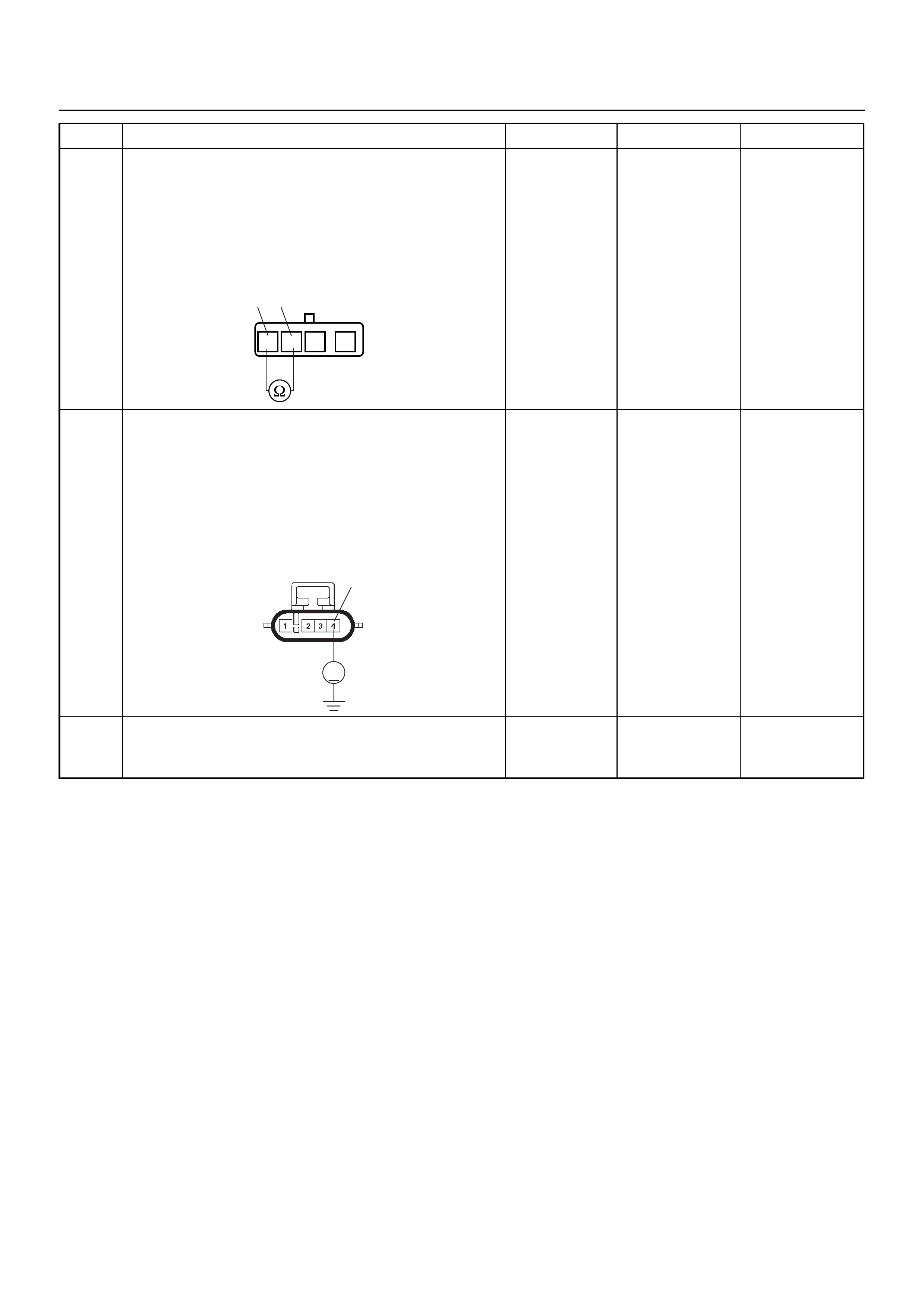
6 Use a DVM to check the O2 sensor.
1. Ignition “Off”, engine “Off”.
2. Disconnect O2 sensor connector
3. Measure the resistance of heater.
Does the DVM indicate the specified value?
Approximately
12.5Ω at 20°C Go to Step 7 Go to Step 11
7 Use a DVM to check the heater power supply circuit
for the affected cylinder.
1. Ignition “On”, engine “Off”.
2. Disconnect the O2 sensor connector.
3. Check the circuit for open circuit.
Does the DVM indicate battery voltage?
Battery
voltage Go to Step 9 Go to Step 8
8 Repair the open or short to ground circuit between the
“O2 Sensor” fuse (10A) and O2 sensor.
Is the action complete? — Verify repair —
Step Action Value(s) Yes No
34
1234
O2 Sensor
4
V
E78
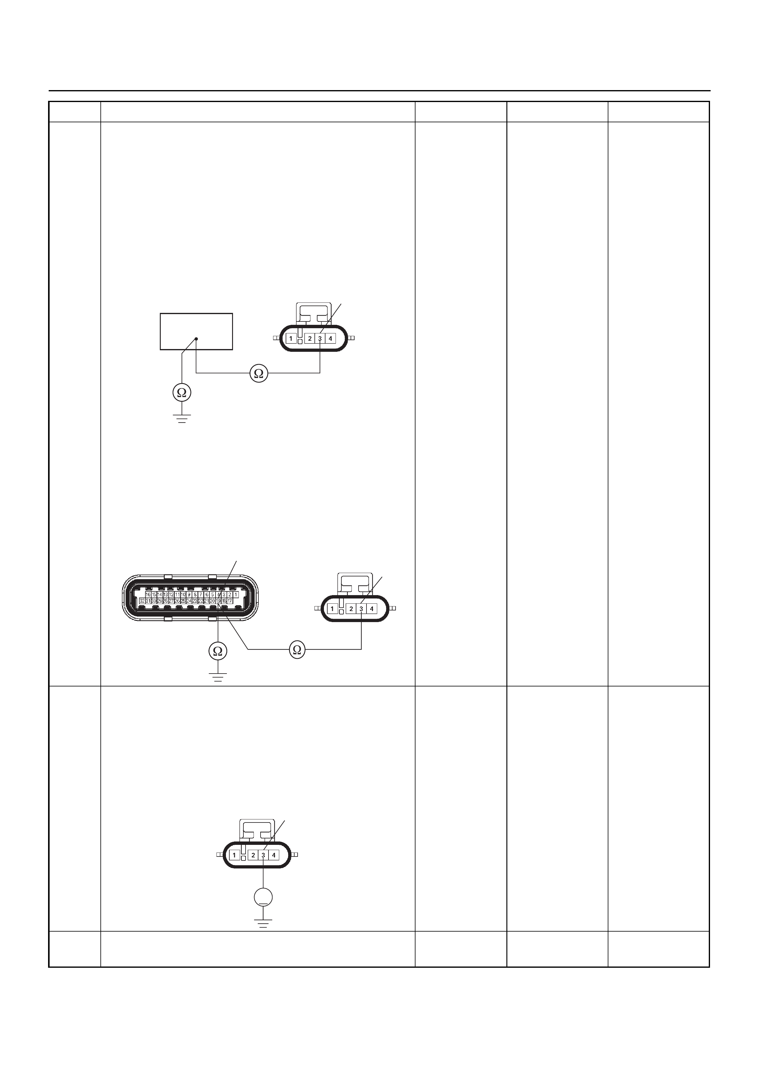
9 Use a DVM to check the heater ground circuit.
Breaker box is available:
1. Ignition “Off”, engine “Off”.
2. Install the breaker box as type A. (ECM
disconnected) Ref. 6E-77.
3. Disconnect the O2 sensor connector.
4. Check the circuit for open or short to ground
circuit.
Was the problem found?
Breaker box is not available:
1. Ignition “Off”, engine “Off”.
2. Disconnect the O2 sensor connector and ECM
connector.
3. Check the circuit for open or short to ground
circuit.
Was the problem found?
Battery
voltage
Repair faulty
harness and
verify repair Go to Step 10
10 Use a DVM to check the heater ground circuit.
1. Ignition “On”, engine “Off”.
2. Disconnect the O2 sensor connector.
3. Check the circuit for short to battery voltage
circuit.
Does the DVM indicate battery voltage?
Battery
voltage
Repair faulty
harness and
verify repair Go to Step 12
11 Replace the O2 sensor.
Was the problem solved? — Verify repair Go to Step 12
Step Action Value(s) Yes No
3
19
E78
3
19
E60(J1) E78
3
V
E78

12 Is the ECM programmed with the latest software
release?
If not, download the latest software to the ECM using
the “SPS (Service Programming System)”.
Was the problem solved? — Verify repair Go to Step 13
13 Replace the ECM.
Is the action complete?
IMPORTANT: The replacement ECM must be
programmed. Refer to the Service Programming
System (SPS) section in this manual.
Following ECM programming, the immobiliser system
must be linked to the ECM. Refer to section 11
“Immobiliser System-ECM replacement” for the ECM/
Immobiliser linking procedure. — Verify repair —
Step Action Value(s) Yes No
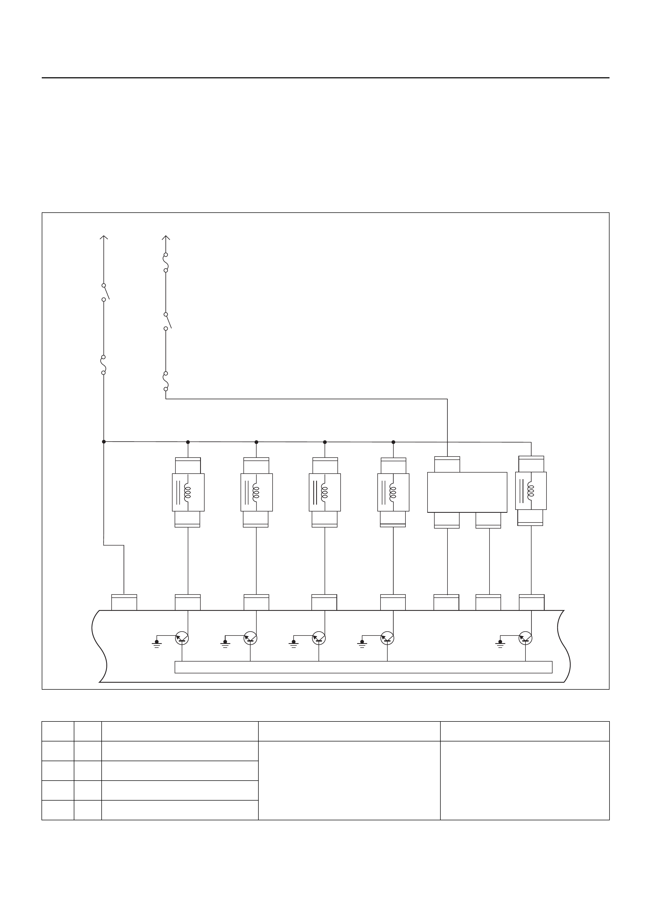
DIAGNOSTIC TROUBLE CODE (DTC) P0201 INJECTOR 1 CONTROL CIRCUIT
DIAGNOSTIC TROUBLE CODE (DTC) P0202 INJECTOR 2 CONTROL CIRCUIT
DIAGNOSTIC TROUBLE CODE (DTC) P0203 INJECTOR 3 CONTROL CIRCUIT
DIAGNOSTIC TROUBLE CODE (DTC) P0204 INJECTOR 4 CONTROL CIRCUIT
Condition for setting the DTC and action taken when the DTC sets
Circuit Description
The engine control module (ECM) has four individual
injector driver circuits. Each controls an injector. When a
driver circuit is grounded by the ECM, the injector is
activated. The ECM monitors the current in each driver
Code Type DTC Name DTC Setting Condition Fail-Safe (Back Up)
P0201 A Injector 1 Control Circuit 1. Engine is running.
2. Engine speed is more than 1000 rpm.
3. Injector voltage does not meet to the bat-
tery voltage when the injector is com-
manded Off or does not meet to the 0V
when the injector is commanded On.
No fail-safe function.
P0202 A Injector 2 Control Circuit
P0203 A Injector 3 Control Circuit
P0204 A Injector 4 Control Circuit
Fuel
Pump
20A
Fuel
Pump
Relay
2.0
BLK/
BLU 0.85
BLK/
YEL
0.85
RED/
GRN
2.0
BLK/
YEL
3.0
BLK/
RED
2.0
BLK/
RED
3.0
WHT/
BLK
2.0
WHT
Battery
Voltage Battery
Voltage
0.5
PINK
0.85
BLK/
BLU
Injector
#1
Cylinder
Injector
#2
Cylinder
Injector
#3
Cylinder
Injector
#4
Cylinder
0.5
BLU/
BLK
0.5
BLU/
WHT
Coil Module
0.5
BLU/
YEL
EVAP
Purge
Solenoid
Valve
0.5
GRN/
WHT
0.85
GRN 0.85
BLU
μP
IGN
Switch
IGN
Coil
20A
Main
100A
Engine
Control
Module
(ECM)
E60
8
E60
22
E60
9
E60
20J1 J1 J1 J1 J1 J1 J1 J1
E60
E18
E18 E18
11
E60
1
1,4 2,3
3
22
1
E66
1
E9
2
E60
17
E60
5
E66
1
1
E9
E8
2
E8
1
E7
2
E7
1
E6
2
E6
Fuel Pump
on INJ 1 INJ 2 INJ 3 INJ 4 1,4 IGN
Coil 2,3 IGN
Coil EVAP

circuit. The ECM measures a voltage drop through a
fixed resistor and controls it. The voltage on each driver
is monitored to detect a fault. If the voltage is not what
the ECM expects to monitor on the circuit, a Diagnostic
Trouble Code is set. This Diagnostic Trouble Code is
also set if an injector driver is shorted to voltage.
Diagnostic Aids
An injector driver circuit that is open or shorted to
voltage will cause a Diagnostic Trouble Code P0201 to
set. It will also cause a misfire due to an inoperative
injector. A misfire Diagnostic Trouble Code will also be
set indicating which cylinder is inoperative.
Long term and shor t term fuel trims that are excessively
high or low are a good indication that an injector is
faulty.
Use Fuel Injector Coil Test Procedur e to ch eck for faulty
injectors.
Diagnostic Trouble Code (DTC) P0201 Injector 1 Control Circuit
Diagnostic Trouble Code (DTC) P0202 Injector 2 Control Circuit
Diagnostic Trouble Code (DTC) P0203 Injector 3 Control Circuit
Diagnostic Trouble Code (DTC) P0204 Injector 4 Control Circuit
Step Action Value(s) Yes No
1 Was the “On-Board Diagnostic (OBD) System Check”
performed?
—Go to Step 2
Go to On Board
Diagnostic
(OBD) System
Check
2 1. Connect Tech 2.
2. Review and record the failure information.
3. Select “F0: Read DTC Info Ordered By Priority”
and check for DTC’s.
Is the DTC P0201, P0202, P0203 or P0204 stored as
“Present Failure”? — Go to Step 3
Refer to
Diagnostic Aids
and Go to Step
3
3 1. Using Tech 2, ignition “On” and engine “Off”.
2. Select “F2: Clear DTC Information” with Tech 2
and clear the DTC information.
3. Operate the vehicle and monitor the “F1: Read
DTC Info as Stored by ECU”.
Was the DTC P0201, P0202, P0203 or P0204 stored
in this ignition cycle? — Go to Step 4
Refer to
Diagnostic Aids
and Go to Step
4
4 Check for poor/faulty connection at the injector or
ECM connector. If a poor/faulty connection is found,
repair as necess ar y.
Was the problem found?
— Verify repair G o to Step 5
5 Visually check the injector for the affected cylinder.
Was the problem found? — Go to Step 11 Go to Step 6
22
8911 E-60(J1)
E-6/E-7/E-8/E-9

6 Use a DVM to check the injector coil for the affected
cylinder.
1. Ignition “Off”, engine “Off”.
2. Disconnect injector connector for the affected
cylinder.
3. Measure the resistance of injector coil.
Was the tester indicated specified value?
Approximately
12.5Ω at 20°C Go to Step 7 Go to Step 11
Step Action Value(s) Yes No
1
1
2
2
Injector
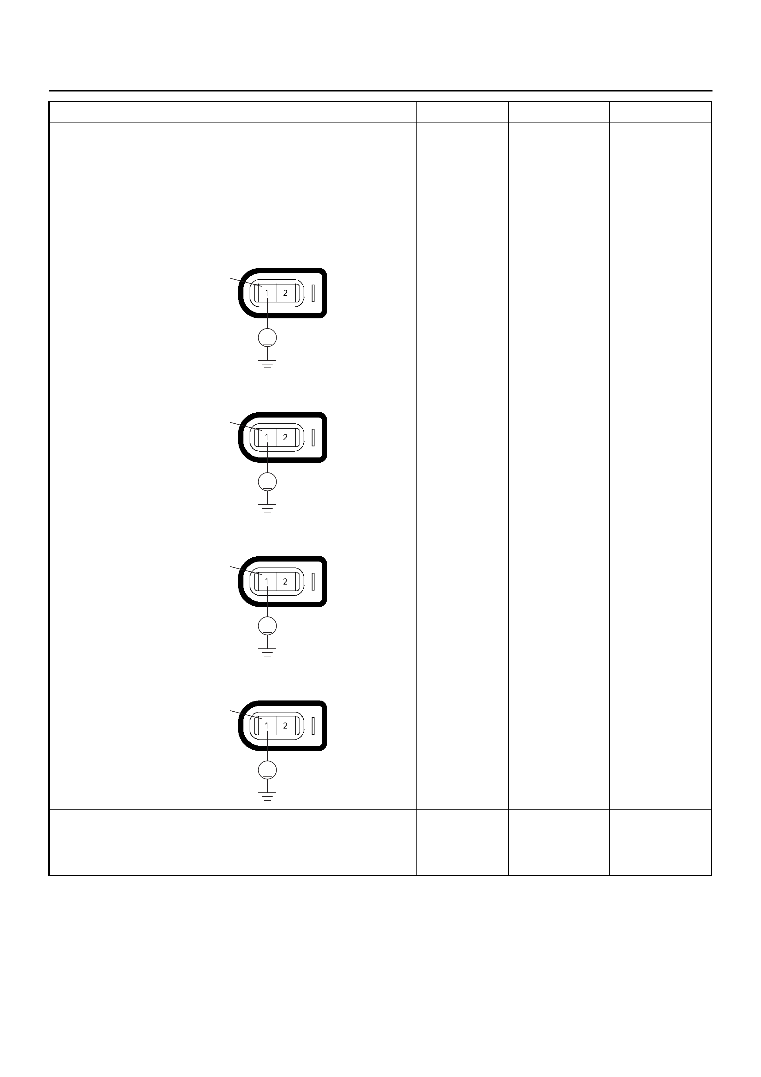
7 Use a DVM to check the injector power supply circuit
for the affected cylinder.
1. Ignition “On”, engine “Off”.
2. Disconnect the injector connector for the affected
cylinder.
3. Check the circuit for open circuit.
Does the DVM indicate battery voltage?
Battery
voltage Go to Step 9 Go to Step 8
8 Repair the open or short to ground circuit between the
“Fuel Pump” fuse (20A) and injector for the affected
cylinder.
Is the action complete? — Verify repair —
Step Action Value(s) Yes No
V
1E-6No.1 Cylinder
V
1E-7No.2 Cylinder
V
1E-8No.3 Cylinder
V
1E-9No.4 Cylinder
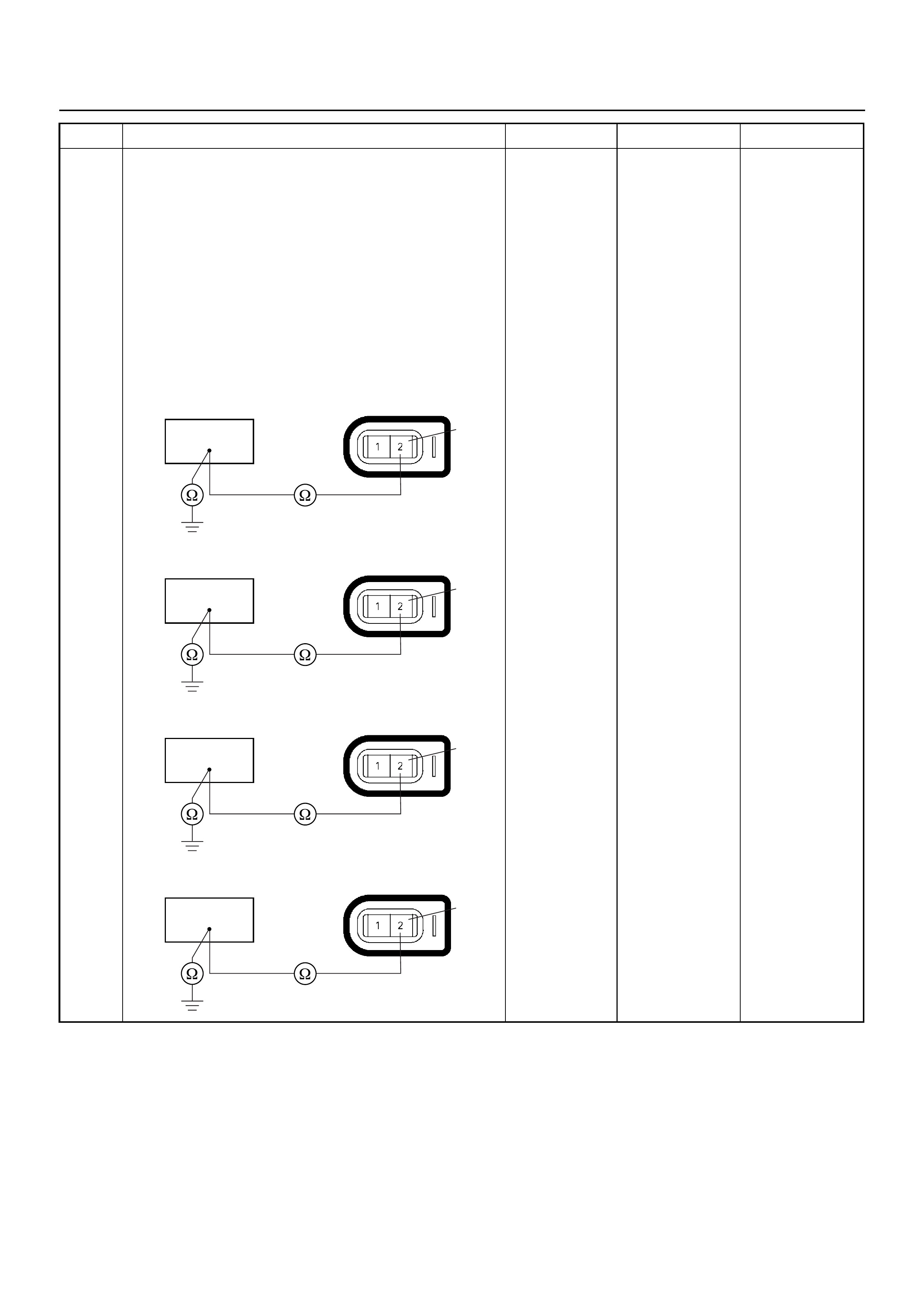
9 Use a DVM to check the injector signal circuit for the
affected cylinder.
Breaker box is available:
1. Ignition “Off”, engine “Off”.
2. Install the breaker box as type A. (ECM
disconnected) Ref. 6E-77.
3. Disconnect the injector connector for the affected
cylinder.
4. Check the circuit for open or short to ground
circuit.
Was the problem found?
—
Repair faulty
harness and
verify repair Go to Step 10
Step Action Value(s) Yes No
92
E-6
No.1 Cylinder
22 2
E-7
No.2 Cylinder
82
E-8
No.3 Cylinder
11 2
E-9
No.4 Cylinder
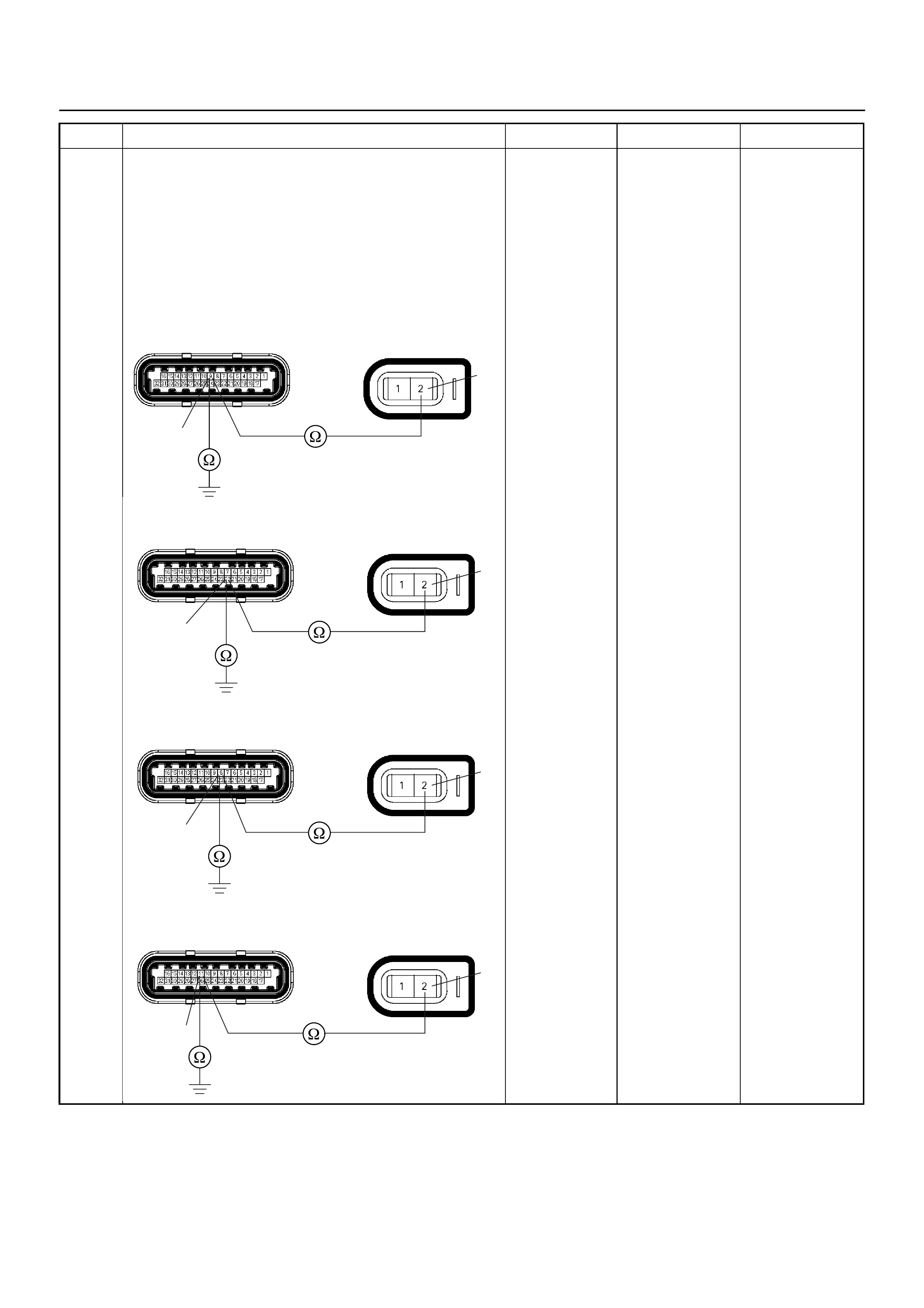
9Breaker box is not available:
1. Ignition “Off”, engine “Off”.
2. Disconnect the injector connector for the affected
cylinder and ECM connector.
3. Check the circuit for open or short to ground
circuit.
Was the problem found?
—
Repair faulty
harness and
verify repair Go to Step 10
Step Action Value(s) Yes No
E-60(J1) E-6
9
2
No.1 Cylinder
E-60(J1) E-7
22
2
No.2 Cylinder
E-60(J1) E-8
8
2
No.3 Cylinder
E-60(J1) E-9
11
2
No.4 Cylinder

10 Use a DVM to check the injector signal circuit.
1. Ignition “On”, engine “Off”.
2. Disconnect the injector connector for the affected
cylinder.
3. Check the circuit for short to battery voltage
circuit.
Is battery voltage indicated by the DVM?
Battery
voltage
Repair faulty
harness and
verify repair Go to Step 12
11 Replace the injector for the affected cylinder.
Was the problem solved? — Verify repair Go to Step 12
12 Is the ECM programmed with the latest software
release?
If not, download the latest software to the ECM using
the “SPS (Service Programming System)”.
Was the problem solved? — Verify repair Go to Step 13
13 Replace the ECM.
Is the action complete?
IMPORTANT: The replacement ECM must be
programmed. Refer to the Service Programming
System (SPS) section in this manual.
Following ECM programming, the immobiliser system
must be linked to the ECM. Refer to section 11
“Immobiliser System-ECM replacement” for the ECM/
Immobiliser linking procedure. — Verify repair —
Step Action Value(s) Yes No
V
2
E-6
No.1 Cylinder
V
2
E-7
No.2 Cylinder
V
2
E-8
No.3 Cylinder
V
2
E-9
No.4 Cylinder
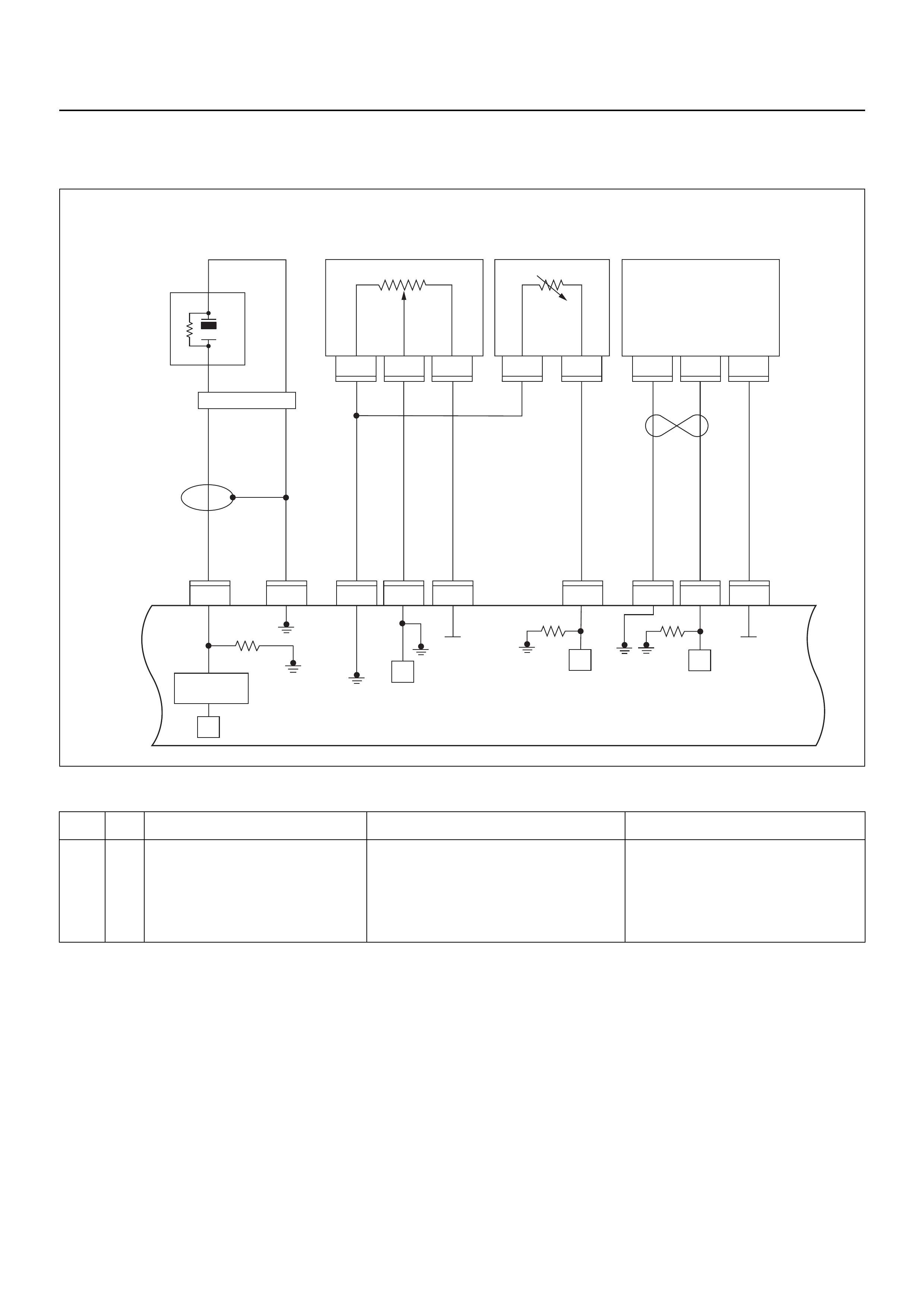
DIAGNOSTIC TROUBLE CODE (DTC) P0325 KNOCK SENSOR (KS) CIRCUIT
MALFUNCTION
Condition for setting the DTC and action taken when the DTC sets
Circuit Description
The knock sensor (KS) system is used to detect engine
detonation. The knock sensor produces an AC voltage
signal. The knock sensor sends this signal to the ECM.
The amplitude and the frequency of the AC voltage
signal depends upon the knock level being detected.
The ECM will then retard the spark timing based on the
signals from the knock sensor.
Diagnostic Aids
Correct any abnormal engine noise before using the
diagnostic table.
Check for an open circuit.
Code Type DTC Name DTC Setting Condition Fail-Safe (Back Up)
P0325 B Knock Sensor Module Circuit 1. No DTC relating to MAP sensor.
2. Engine coolant temperature is more than
50°C.
3. Engine speed is more than 1600 rpm.
4. Knock sensor filter module integrated cir-
cuit malfunction.
ECM retards ignition timing 4°C.
1
C56
μP
E60
27
12231
12
E60
31
E60
7
E60
26
E60
3J1 J1 J1 J1 J1J1 J2 J2 J2
E60
E68 E68 E68 E69 E69 F10 F10 F10
16
C56
17 25
C56
1
A
23
CB
B
A
E84
0.5
GRY
μP
μP
5Volts
Ref 5Volts
Ref
Knock
Sensor
0.5
YEL
0.5
WHT/
BLU
0.5
BLU/
ORG
0.5
BLU/
ORG
0.5
YEL/
RED
0.5
PUR/
BLU
0.5
GRY/
BLU
0.5
BLK 0.5
ORG 0.5
BLU/
WHT
Engine
Coolant
Temperature (ECT)
Sensor Vertical
G-Sensor
Throttle
Position Sensor
(TPS)
Knock Filter
Module
Engine
Control
Module
(ECM) μP
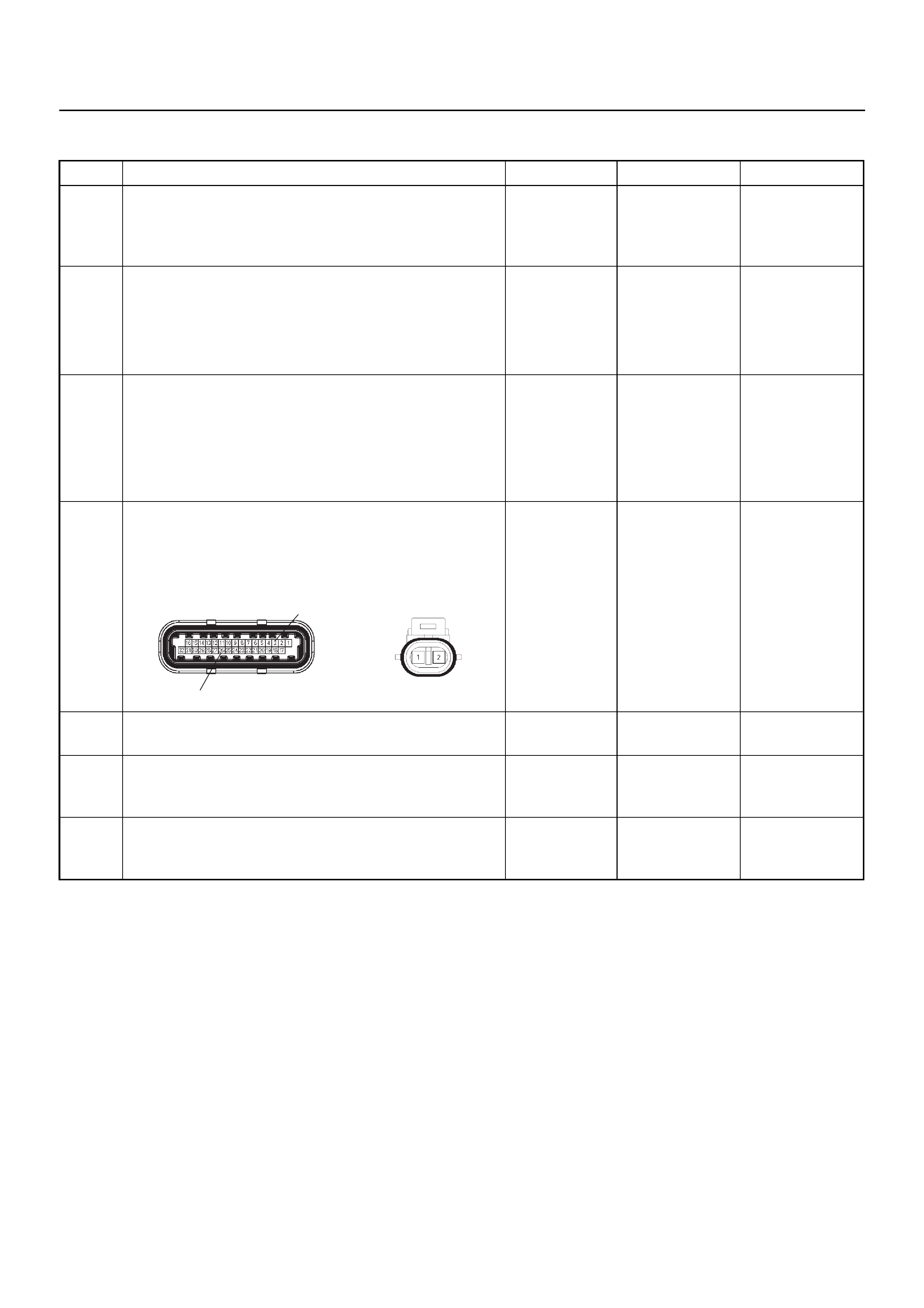
Diagnostic Trouble Code (DTC) P0325 Knock Sensor Module Circuit
Step Action Value(s) Yes No
1 Was the “On-Board Diagnostic (OBD) System Check”
performed?
—Go to Step 2
Go to On Board
Diagnostic
(OBD) System
Check
2 1. Connect Tech 2.
2. Review and record the failure information.
3. Select “F0: Read DTC Info Ordered By Priority”
and check for DTC’s.
Is the DTC P0325 stored as “Present Failure”? — Go to Step 3
Refer to
Diagnostic Aids
and Go to Step
3
3 1. Using Tech 2, ignition “On” and engine “Off”.
2. Select “F2: Clear DTC Information” with Tech 2
and clear the DTC information.
3. Operate the vehicle and monitor the “F1: Read
DTC Info as Stored by ECU”.
Was the DTC P0325 stored in this ignition cycle? — Go to Step 4
Refer to
Diagnostic Aids
and Go to Step
4
4 Check for poor/faulty connection at the knock sensor
or ECM connector. If a poor/faulty connection is
found, repair as necessary.
Was the problem found?
— Verify repair G o to Step 5
5 Visually check the knock sensor.
Was the problem found? — Go to Step 10 Go to Step 6
6 Listen to the engine noise while raising and lowering
the engine speed .
Is a knock or audible noise present? — Go to Step 7 Go to Step 8
7 Repair the mechanical engine problem or a loose
bracket or component.
Is the action complete? — Verify repair —
26
3
E-60(J1) E-84
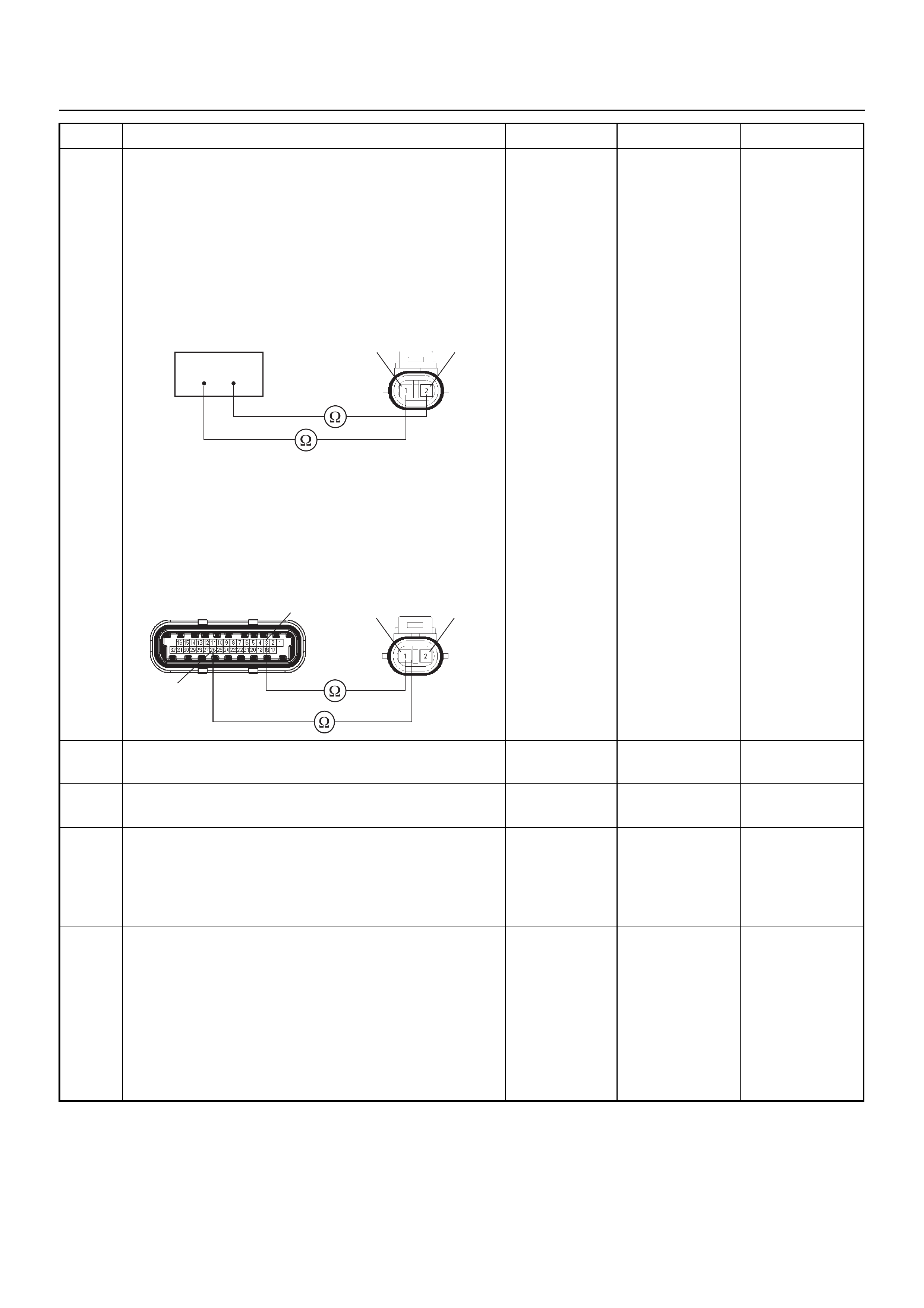
8 Use a DVM to check the knock sensor circuit.
Breaker box is available:
1. Ignition “Off”, engine “Off”.
2. Install the breaker box as type A. (ECM
disconnected) Ref. 6E-77.
3. Disconnect the knock sensor.
4. Check the circuit for open circuit.
Was the problem found?
Breaker box is not available:
1. Ignition “Off”, engine “Off”.
2. Disconnect the knock sensor connector and ECM
connector.
3. Check the circuit for open circuit.
Was the problem found?
—
Repair faulty
harness and
verify repair Go to Step 9
9 Substitute a known good knock sensor and recheck.
Was the problem solved? — Go to Step 10 Go to Step 11
10 Replace the knock sensor.
Was the problem solved? — Verify repair Go to Step 11
11 Is the ECM programmed with the latest software
release?
If not, download the latest software to the ECM using
the “SPS (Service Programming System)”.
Was the problem solved? — Verify repair Go to Step 12
12 Replace the ECM.
Is the action complete?
IMPORTANT: The replacement ECM must be
programmed. Refer to the Service Programming
System (SPS) section in this manual.
Following ECM programming, the immobiliser system
must be linked to the ECM. Refer to section 11
“Immobiliser System-ECM replacement” for the ECM/
Immobiliser linking procedure. — Verify repair —
Step Action Value(s) Yes No
326
E-84 21
3
E-60(J1) E-84
26
21

DIAGNOSTIC TROUBLE CODE (DTC) P0327 KNOCK SENSOR (KS) CIRCUIT
LOW INPUT
Condition for setting the DTC and action taken when the DTC sets
Circuit Description
The ECM uses the Knock Sensor (KS) in order to detect
engine detonation. This allows the ECM to retard the
Ignition Control (IC) spark timing based on the KS sign al
the ECM receives. The knock sensors produce an AC
signal that rides on the 1.3 volt DC. The signal’s
amplitude and frequency are dependent upon the
amount of the knock being experienced.
The ECM determines whether the knock is occurring by
comparing the signal level on the KS circuit with a
voltage level on the noise channel. The normal engine
noise varies depending on the engine speed and load.
Then the ECM determines that an abnormally high
noise channel voltage level is being experienced, a
Diagnostic Trouble Code P0327 sets.
Diagnostic Aids
Check for the following conditions:
A poor connection at the ECM. Inspect the knock
sensor and the ECM connectors for broken locks,
improperly formed or damaged terminals.
• Backed out terminals
• Broken locks
• Improperly formed or damaged terminals.
Also, check the wiring harness for: shorts to ground,
shorts to battery positive, and open circuits.
• A misrouted harness. Inspect the knock sensor
Code Type DTC Name DTC Setting Condition Fail-Safe (Back Up)
P0327 A Knock Sensor Circuit 1. No DTC relating to MAP sensor.
2. Engine coolant temperature is more than
50°C.
3. Engine speed is more than 1600 rpm.
4. Knock sensor harness short to ground or
short to voltage circuit.
ECM retards ignition timing 4°C.
1
C56
μP
E60
27
12231
12
E60
31
E60
7
E60
26
E60
3J1 J1 J1 J1 J1J1 J2 J2 J2
E60
E68 E68 E68 E69 E69 F10 F10 F10
16
C56
17 25
C56
1
A
23
CB
B
A
E84
0.5
GRY
μP
μP
5Volts
Ref 5Volts
Ref
Knock
Sensor
0.5
YEL
0.5
WHT/
BLU
0.5
BLU/
ORG
0.5
BLU/
ORG
0.5
YEL/
RED
0.5
PUR/
BLU
0.5
GRY/
BLU
0.5
BLK 0.5
ORG 0.5
BLU/
WHT
Engine
Coolant
Temperature (ECT)
Sensor Vertical
G-Sensor
Throttle
Position Sensor
(TPS)
Knock Filter
Module
Engine
Control
Module
(ECM) μP
harness in order to ensure that it is not routed too
close to high voltage wires such as spark plug leads.
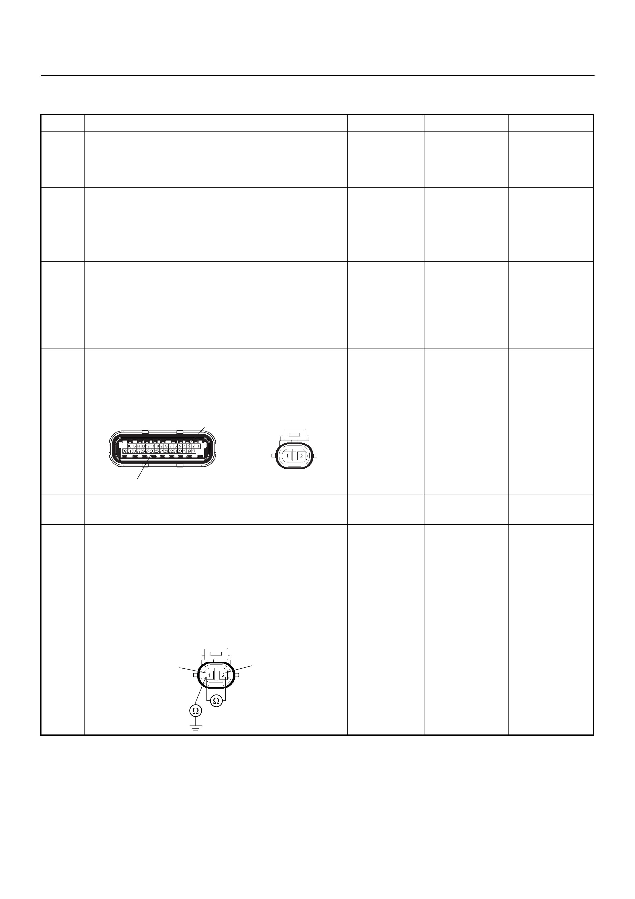
Diagnostic Trouble Code (DTC) P0327 Knock Sensor Circuit
Step Action Value(s) Yes No
1 Was the “On-Board Diagnostic (OBD) System Check”
performed?
—Go to Step 2
Go to On Board
Diagnostic
(OBD) System
Check
2 1. Connect Tech 2.
2. Review and record the failure information.
3. Select “F0: Read DTC Info Ordered By Priority”
and check for DTC’s.
Is the DTC P0327 stored as “Present Failure”? — Go to Step 3
Refer to
Diagnostic Aids
and Go to Step
3
3 1. Using Tech 2, ignition “On” and engine “Off”.
2. Select “F2: Clear DTC Information” with Tech 2
and clear the DTC information.
3. Operate the vehicle and monitor the “F1: Read
DTC Info as Stored by ECU”.
Was the DTC P0327 stored in this ignition cycle? — Go to Step 4
Refer to
Diagnostic Aids
and Go to Step
4
4 Check for poor/faulty connection at the knock sensor
or ECM connector. If a poor/faulty connection is
found, repair as necessary.
Was the problem found?
— Verify repair G o to Step 5
5 Visually check the knock sensor.
Was the problem found? — Go to Step 9 Go to Step 6
6 Use a DVM to check the knock sensor circuit.
1. Ignition “Off”, engine “Off”.
2. Disconnect the knock sensor connector and ECM
connector.
3. Check the circuit for short to sensor ground or
ground circuit.
Was the problem found?
—
Repair faulty
harness and
verify repair Go to Step 7
26
3
E-60(J1) E-84
E-84
2
1

7 Use a DVM to check the knock sensor circuit.
1. Ignition “On”, engine “Off”.
2. Disconnect the knock sensor connector.
3. Check the circuit for short to battery voltage
circuit.
Is battery voltage indicated by the DVM?
Battery
voltage
Repair faulty
harness and
verify repair Go to Step 8
8 Substitute a known good knock sensor and recheck.
Was the problem solved? — Go to Step 9 Go to Step 10
9 Replace the knock sensor.
Was the problem solved? — Verify repair Go to Step 10
10 Is the ECM programmed with the latest software
release?
If not, download the latest software to the ECM using
the “SPS (Service Programming System)”.
Was the problem solved? — Verify repair Go to Step 11
11 Replace the ECM.
Is the action complete?
IMPORTANT: The replacement ECM must be
programmed. Refer to the Service Programming
System (SPS) section in this manual.
Following ECM programming, the immobiliser system
must be linked to the ECM. Refer to section 11
“Immobiliser System-ECM replacement” for the ECM/
Immobiliser linking procedure. — Verify repair —
Step Action Value(s) Yes No
VV
E-84
2
1
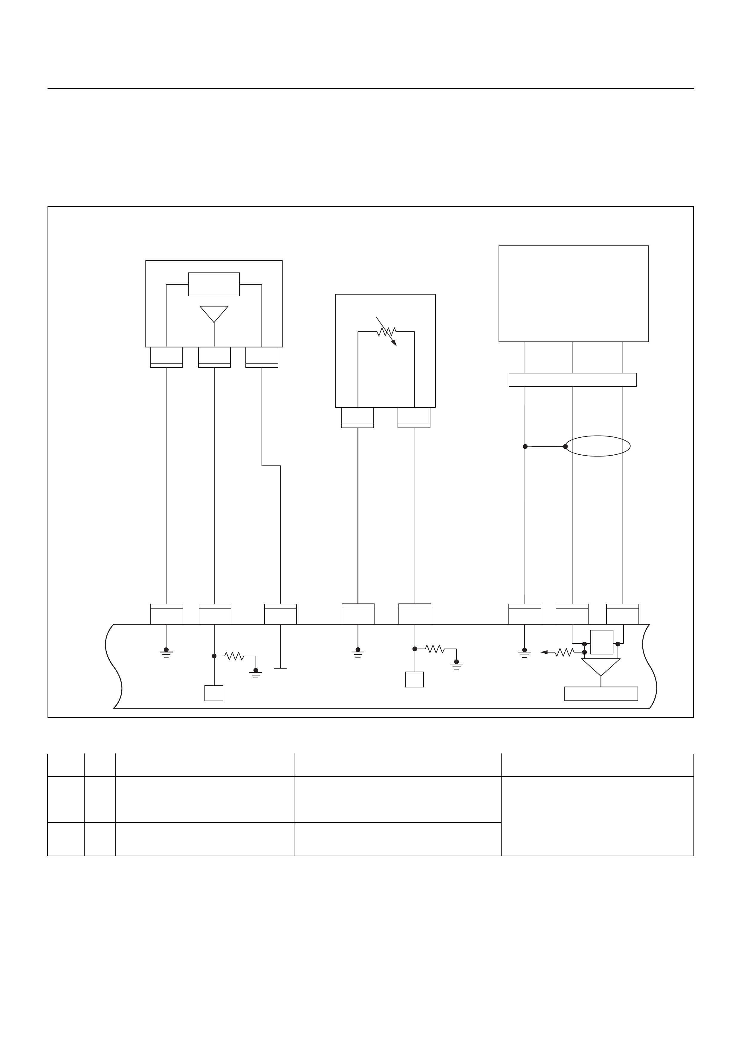
DIAGNOSTIC TROUBLE CODE (DTC) P0336 CRANKSHAFT POSITION (CKP)
SENSOR CIRCUIT RANGE/PERFORMANCE (58X)
DIAGNOSTIC TROUBLE CODE (DTC) P0337 CRANKSHAFT POSITION (CKP)
SENSOR CIRCUIT LOW INPUT (58X)
Condition for setting the DTC and action taken when the DTC sets
Circuit Description
The 58X reference signal is produced by the crankshaft
position (CKP) sensor. During one crankshaft
revolution, 58 crankshaft pulses will be produced. The
engine control module (ECM) uses the 58X reference
signal to calculate engine RPM and crankshaft position.
The ECM constantly monitors the number of pulses on
the 58X reference circuit. If the ECM receives an
incorrect number of pulses on the 58X reference circuit,
Diagnostic Trouble Code P0336 will set. If the ECM
does not receive pluses on the 58X reference circuit,
Diagnostic Trouble Code P0337 will set.
Code Type DTC Name DTC Setting Condition Fail-Safe (Back Up)
P0336 B Crankshaft Position Sensor Circuit
Range/Performance (58X) 1. Engine is running.
2. Extra or missing pulse is detected consecu-
tively.
No fail-safe function.
P0337 B Crankshaft Position Sensor Circuit Low
Input (58X) No pulse is detected during engine cranking.
E60
16
E60
31
321
E60
24
E60
E85
2
C121
1
C121
32 1
E85
E85
26J1 J1 J1 J1 J1 J1 J1 J1
E60
6
E60
21
Manifold
Absolute
Pressure (MAP)
Sensor
Crankshaft
Position(CKP)
Sensor
μP
0.5
GRY/
BLU
AB
AB
CHIGH LOW
E59
GND
0.5
GRY/
RED
0.5
YEL/
RED
0.5
BLU/
ORG
0.5
WHT
0.5
BLK 0.5
BLK/
WHT
5 Volts
Ref
MAP
Sensor
5V Ref
Signal
GND Signal
GND Signal
GND
MAP
Signal IAT Signal
Engine
Control
Module
(ECM)
Intake
Air
Temperature (IAT)
Sensor
0.5
GRN 0.5
YEL/
GRN
μP
E60
23
E60
16
450
mV
A/D Converter
Vcc
+5V -+

Diagnostic Aids
An intermittent signal may be caused by a poor
connection, rubbed-through wire insulation or a wire
broken inside the insulation. Check for:
• Poor connection - Inspect the ECM harness and
connectors for improper mating, broken locks,
improperly formed or damaged terminals, and poor
terminal-to-wire connection.
• Damaged harness - Inspect the wiring harness for
damage; shorts to ground, shorts to battery positive
and open circuits. If the harness appears to be OK,
disconnect the ECM, switch the ignition on and
observe a voltmeter connected to the 58X reference
circuit at the ECM harness connector while moving
connectors and wiring harnesses related to the ECM.
A change in voltage will indicate the location of the
fault.
Diagnostic Trouble Code (DTC) P0336
Crankshaft Position Sensor Circuit Range/performance (58x)
Diagnostic Trouble Code (DTC) P0337
Crankshaft Position Sensor Circuit Low Input (58x)
Step Action Value(s) Yes No
1 Was the “On-Board Diagnostic (OBD) System Check”
performed?
—Go to Step 2
Go to On Board
Diagnostic
(OBD) System
Check
2 1. Connect Tech 2.
2. Review and record the failure information.
3. Select “F0: Read DTC Info Ordered By Priority”
and check for DTC’s.
Is the DTC P0336 or P0337 stored as “Present
Failure”? — Go to Step 3
Refer to
Diagnostic Aids
and Go to Step
3
3 1. Using Tech 2, ignition “On” and engine “Off”.
2. Select “F2: Clear DTC Information” with Tech 2
and clear the DTC information.
3. Operate the vehicle and monitor the “F1: Read
DTC Info as Stored by ECU”.
Was the DTC P0336 or P0337 stored in this ignition
cycle? — Go to Step 4
Refer to
Diagnostic Aids
and Go to Step
4
4 Check for poor/faulty connection at the CKP sensor or
ECM connector. If a poor/faulty connection is found,
repair the faulty terminal.
Was the problem found?
— Verify repair G o to Step 5
5 Visually check the CKP sensor. If a faulty installation
is found, repair as necessary.
Was the problem found? — Verify repair Go to Step 6
21
6
16 E-60(J1) E-59
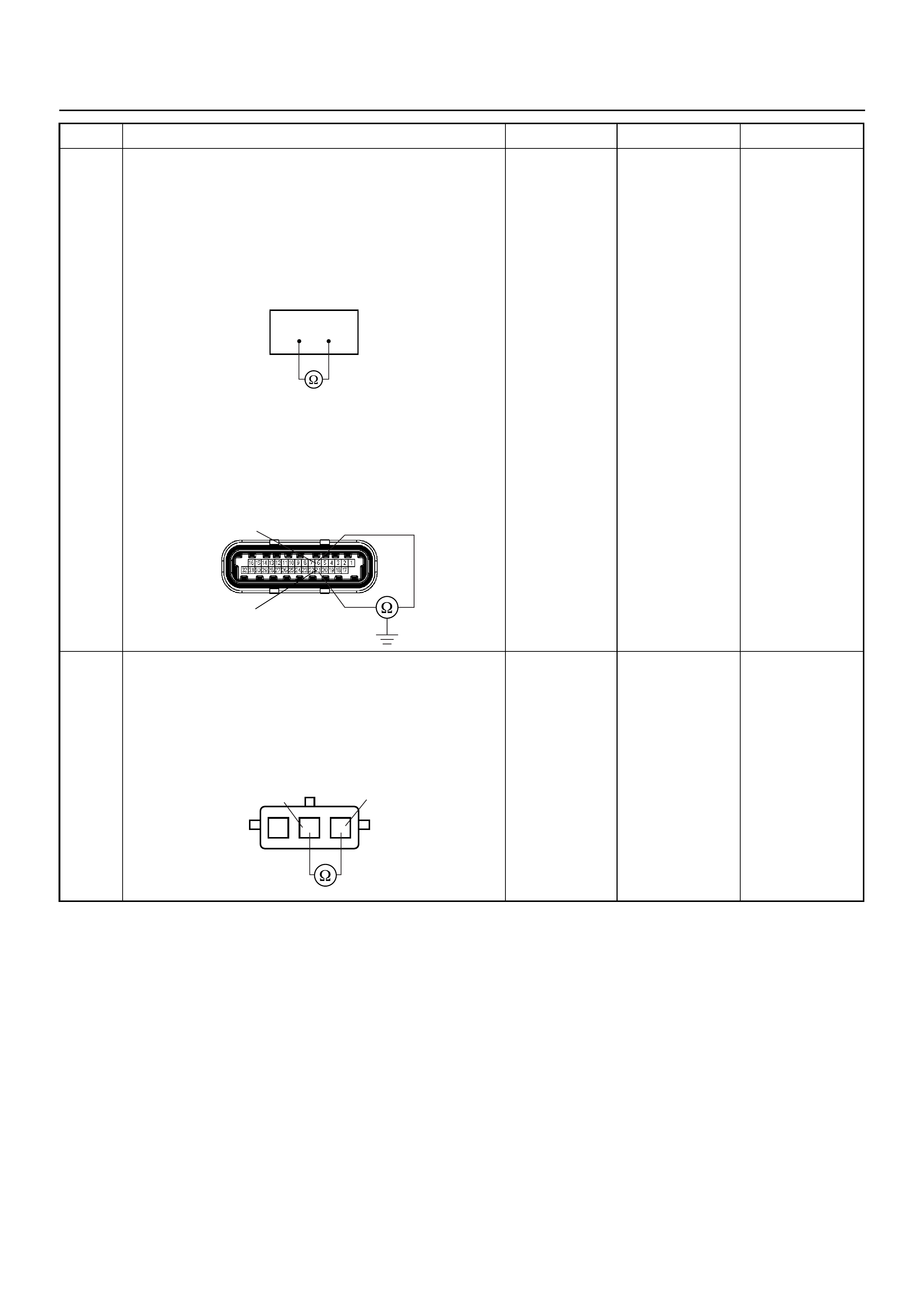
6 Use a DVM to check the CKP sensor circuit.
Breaker box is available:
1. Ignition “Off”, engine “Off”.
2. Install the breaker box as type A. (ECM
disconnected) Ref. 6E-77.
3. Check the resistance of the CKP sensor.
Does the DVM indicate the specified value?
Breaker box is not available:
1. Ignition “Off”, engine “Off”.
2. Disconnect the ECM connector.
3. Check the resistance of the CKP sensor.
Does the DVM indicate the specified value?
Approximately
0.55kΩ at
20°C Go to Step 10 Go to Step 7
7 Use a DVM to check the CKP sensor circuit.
1. Ignition “Off”, engine “Off”.
2. Disconnect the CKP sensor connector.
3. Check the resistance of the CKP sensor.
Does the DVM indicate the specified value?
Approximately
0.55kΩ at
20°C Go to Step 8 Go to Step 14
Step Action Value(s) Yes No
621
6
21
E-60(J1)
1
23
CKP Sensor 1
2
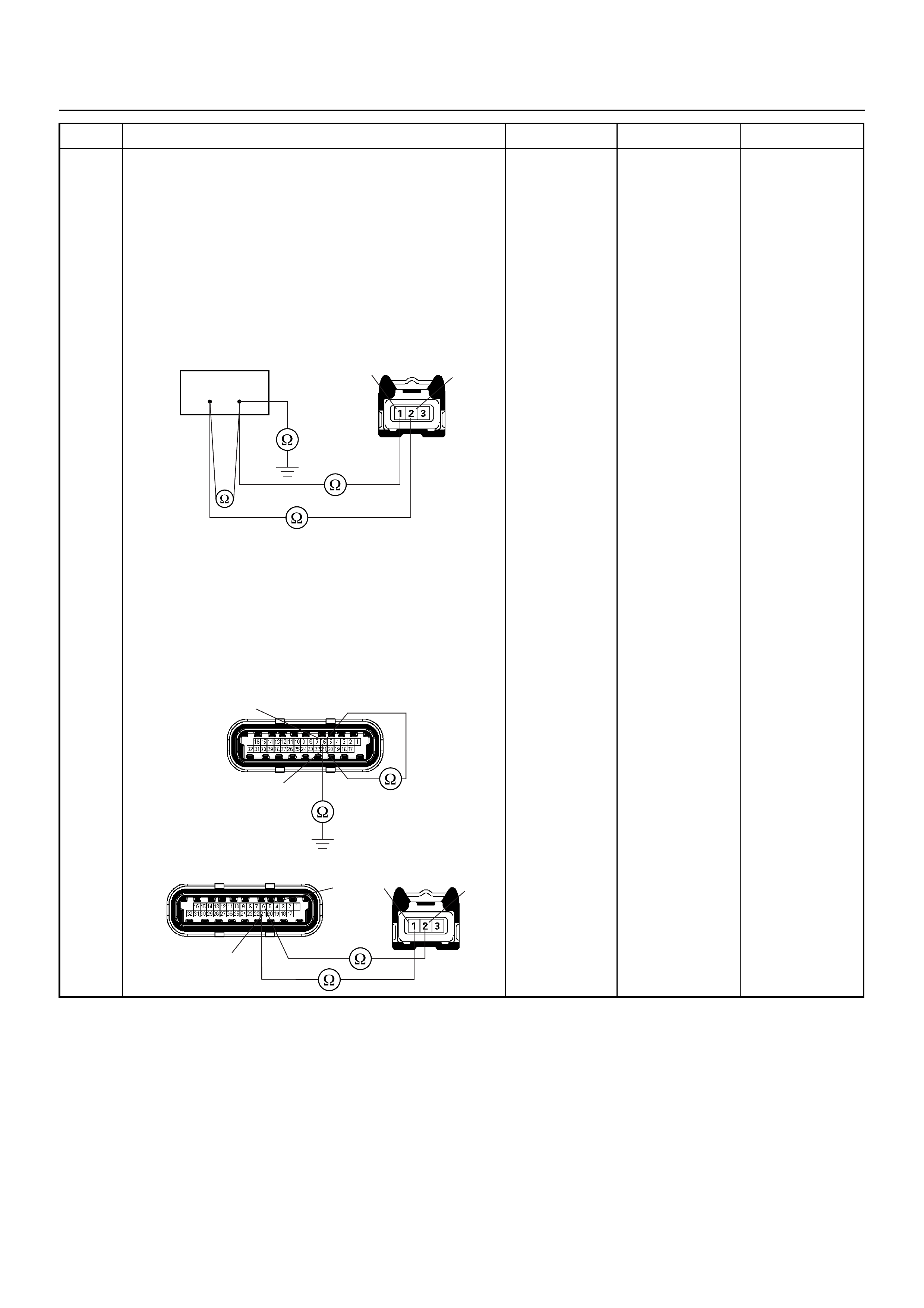
8 Use a DVM to check the CKP sensor circuit.
Breaker box is available:
1. Ignition “Off”, engine “Off”.
2. Install the breaker box as type A. (ECM
disconnected) Ref. 6E-77.
3. Disconnect the CKP sensor connector.
4. Check the circuit for open, short to sensor wire or
short to ground circuit.
Was the problem found?
Breaker box is not available:
1. Ignition “Off”, engine “Off”.
2. Disconnect the ECM connector.
3. Disconnect the CKP sensor connector.
4. Check the circuit for open, short to sensor wire or
short to ground circuit.
Was the problem found?
—
Repair faulty
harness and
verify repair Go to Step 9
Step Action Value(s) Yes No
621
E-59 21
6E-60(J1)
21
E-59
E-60(J1) 6
21
21
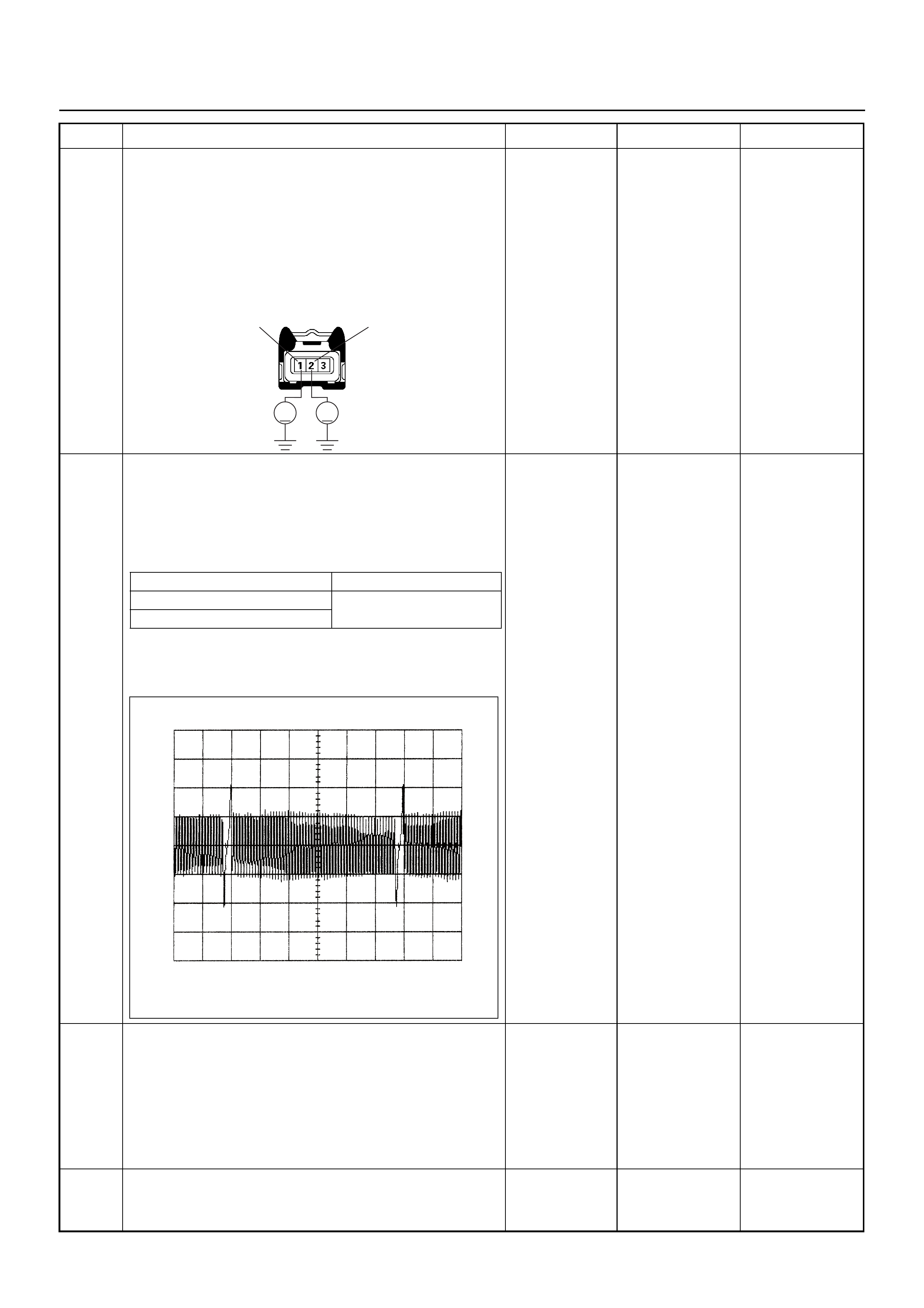
9 Use a DVM to check the CKP sensor circuit.
1. Ignition “On”, engine “Off”.
2. Disconnect the CKP sensor connector.
3. Check the circuit for short to power supply circuit.
If the DVM indicated out of specified value, repair
faulty harness and verify repair.
Is the action complete?
Less than 1V Verify repair —
10 Use a DVM to check the CKP sensor signal.
1. Ignition “On”, engine “On”.
2. Measure the CKP output voltage at the sensor
and ECM.
Does the tester indi ca te standa rd v olt age?
If a oscilloscope is available, monitor the CKP sensor
signal. Does the oscilloscope indicate correct wave
form?
Go to Step 13 Go to Step 11
11 Remove the CKP sensor from the flywheel housing
and visually check.
Check for the following conditions.
• Objects sticking the CKP sensor.
• Objects sticking the CKP sensor pulser.
If a problem is found, re pa ir as nece ss ar y.
Was the problem found? — Verify repair Go to Step 12
12 Check the CKP sensor shield wire for open or short
circuit.
Was the problem found? —
Repair faulty
harness and
verify repair Go to Step 13
Step Action Value(s) Yes No
V V
E-59 2
1
Measurement Point Voltage (V) (AC Range)
At CKP sensor terminal 1 & 2 Approx. 3.7V in engine idle
Approx. 7.7V at 2000rpm
At ECM E60 (J1) connector 21 & 6
CKP Sensor Signal Reference Wave Form
0V→
Measurement Terminal: J1-21 (+) J1-6 (-)
Measurement Scale: 10V/div 5.0ms/div
Measurement Condition: Engine speed at 2000rpm

13 Check any accessory parts which may cause electric
interference or magnetic interference.
Was the problem found? —
Remove the
accessory parts
and verify repair Go to Step 14
14 Substitute a known good CKP sensor and recheck.
Was the problem solved? — Go to Step 15 Go to Step 16
15 Replace the CKP sensor.
Was the problem solved? — Verify repair Go to Step 16
16 Is the ECM programmed with the latest software
release?
If not, download the latest software to the ECM using
the “SPS (Service Programming System)”.
Was the problem solved? — Verify repair Go to Step 17
17 Replace the ECM.
Is the action complete?
IMPORTANT: The replacement ECM must be
programmed. Refer to the Service Programming
System (SPS) section in this manual.
Following ECM programming, the immobiliser system
must be linked to the ECM. Refer to section 11
“Immobiliser System-ECM replacement” for the ECM/
Immobiliser linking procedure. — Verify repair —
Step Action Value(s) Yes No
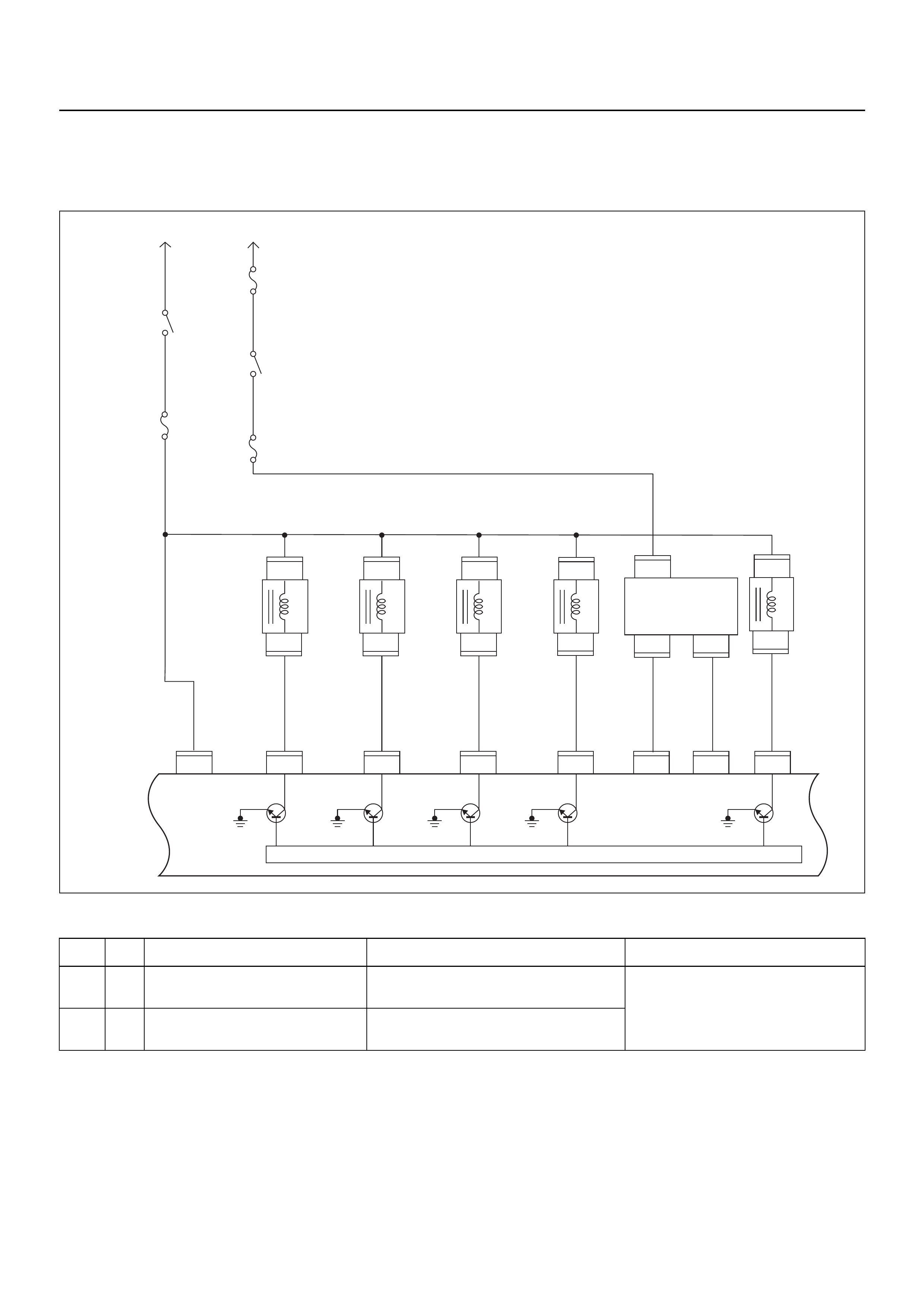
DIAGNOSTIC TROUBLE CODE (DTC) P0351 IGNITION 1 CONTROL CIRCUIT
DIAGNOSTIC TROUBLE CODE (DTC) P0352 IGNITION 2 CONTROL CIRCUIT
Condition for setting the DTC and action taken when the DTC sets
Circuit Description
The ignition control circu it provides a zero volt or a 5 volt
signal to the ignition control module. The normal circuit
voltage is zero volt. When the module receives the
5 volt signal from the ECM, it provides a ground path for
the B+ voltage supplied to the ignition primary coil.
When the ECM turns off the 5 volts to the module, the
module will remove the ground path of the ignition
primary coils; causing the magnetic field produces a
voltage in the secondary coils which fires the spark
plug.
The circuit between the ECM and the ignition control
module is monitored for an open circuit, short to voltage,
and short to ground. When the ECM detects a problem
in the ignition control circuit, it will set DTC P0351 or
P0352.
Code Type DTC Name DTC Setting Condition Fail-Safe (Back Up)
P0351 A Ignition 1 Control Circuit #2 or #3 cylinder ignition signals are not
detected consecutively. No fail-safe function.
P0352 A Ignition 2 Control Circuit #1 or #4 cylinder ignition signals are not
detected consecutively.
Fuel
Pump
20A
Fuel
Pump
Relay
2.0
BLK/
BLU 0.85
BLK/
YEL
0.85
RED/
GRN
2.0
BLK/
YEL
3.0
BLK/
RED
2.0
BLK/
RED
3.0
WHT/
BLK
2.0
WHT
Battery
Voltage Battery
Voltage
0.5
PINK
0.85
BLK/
BLU
Injector
#1
Cylinder
Injector
#2
Cylinder
Injector
#3
Cylinder
Injector
#4
Cylinder
0.5
BLU/
BLK
0.5
BLU/
WHT
Coil Module
0.5
BLU/
YEL
EVAP
Purge
Solenoid
Valve
0.5
GRN/
WHT
0.85
GRN 0.85
BLU
μP
IGN
Switch
IGN
Coil
20A
Main
100A
Engine
Control
Module
(ECM)
E60
8
E60
22
E60
9
E60
20J1 J1 J1 J1 J1 J1 J1 J1
E60
E18
E18 E18
11
E60
1
1,4 2,3
3
22
1
E66
1
E9
2
E60
17
E60
5
E66
1
1
E9
E8
2
E8
1
E7
2
E7
1
E6
2
E6
Fuel Pump
on INJ 1 INJ 2 INJ 3 INJ 4 1,4 IGN
Coil 2,3 IGN
Coil EVAP
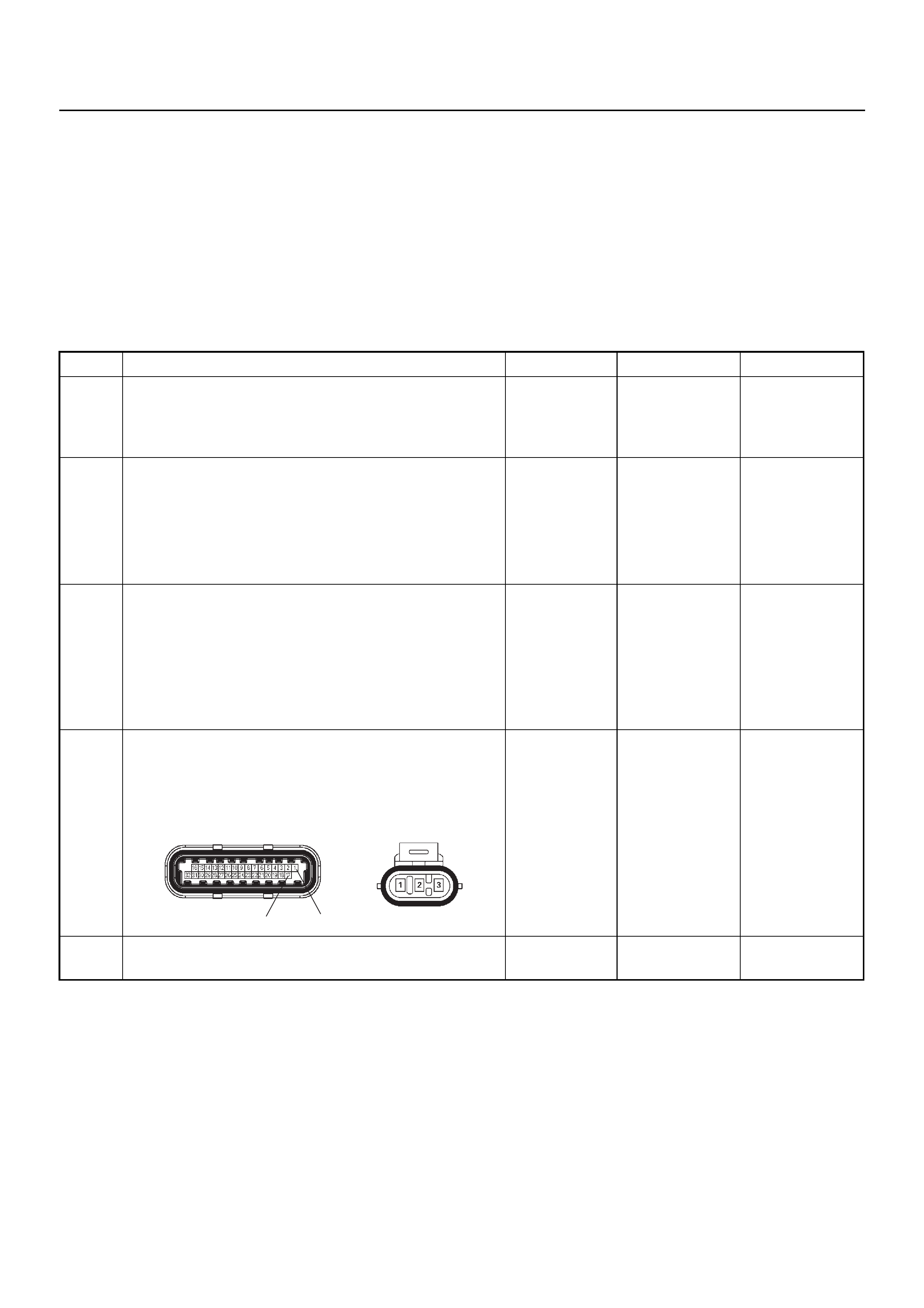
Diagnostic Aids
Check for the following conditions:
• Poor connection at the ECM - Inspect the harness
connectors for backed-out terminals, improper
mating, broken locks, improperly formed or damaged
terminals, and poor terminal-to-wire connections.
• Damaged harness - Inspect the wiring harness for
damage; Open circuits, shorts to ground, or shorts to
Voltage. If the harness appears to be OK, observe
Tech 2 display related to DTC P0351 or P0352 while
moving the connector and wiring related to the
ignition system. A change in the display will indicate
the location of the fault.
Diagnostic Trouble Code (DTC) P0351 Ignition 1 Control Circuit
Diagnostic Trouble Code (DTC) P0352 Ignition 2 Control Circuit
Step Action Value(s) Yes No
1 Was the “On-Board Diagnostic (OBD) System Check”
performed?
—Go to Step 2
Go to On Board
Diagnostic
(OBD) System
Check
2 1. Connect Tech 2.
2. Review and record the failure information.
3. Select “F0: Read DTC Info Ordered By Priority”
and check for DTC’s.
Is the DTC P0351 or P0352 stored as “Present
Failure”? — Go to Step 3
Refer to
Diagnostic Aids
and Go to Step
3
3 1. Using Tech 2, ignition “On” and engine “Off”.
2. Select “F2: Clear DTC Information” with Tech 2
and clear the DTC information.
3. Operate the vehicle and monitor the “F1: Read
DTC Info as Stored by ECU”.
Was the DTC P0351 or P0352 stored in this ignition
cycle? — Go to Step 4
Refer to
Diagnostic Aids
and Go to Step
4
4 Check for poor/faulty connection at the ignition coil
module or ECM connector. If a poor/faulty connection
is found, repair as necessary.
Was the problem found?
— Verify repair G o to Step 5
5 Visually check the ignition coil module.
Was the problem found? — Go to Step 12 Go to Step 6
17 1
E-60(J1) E-18
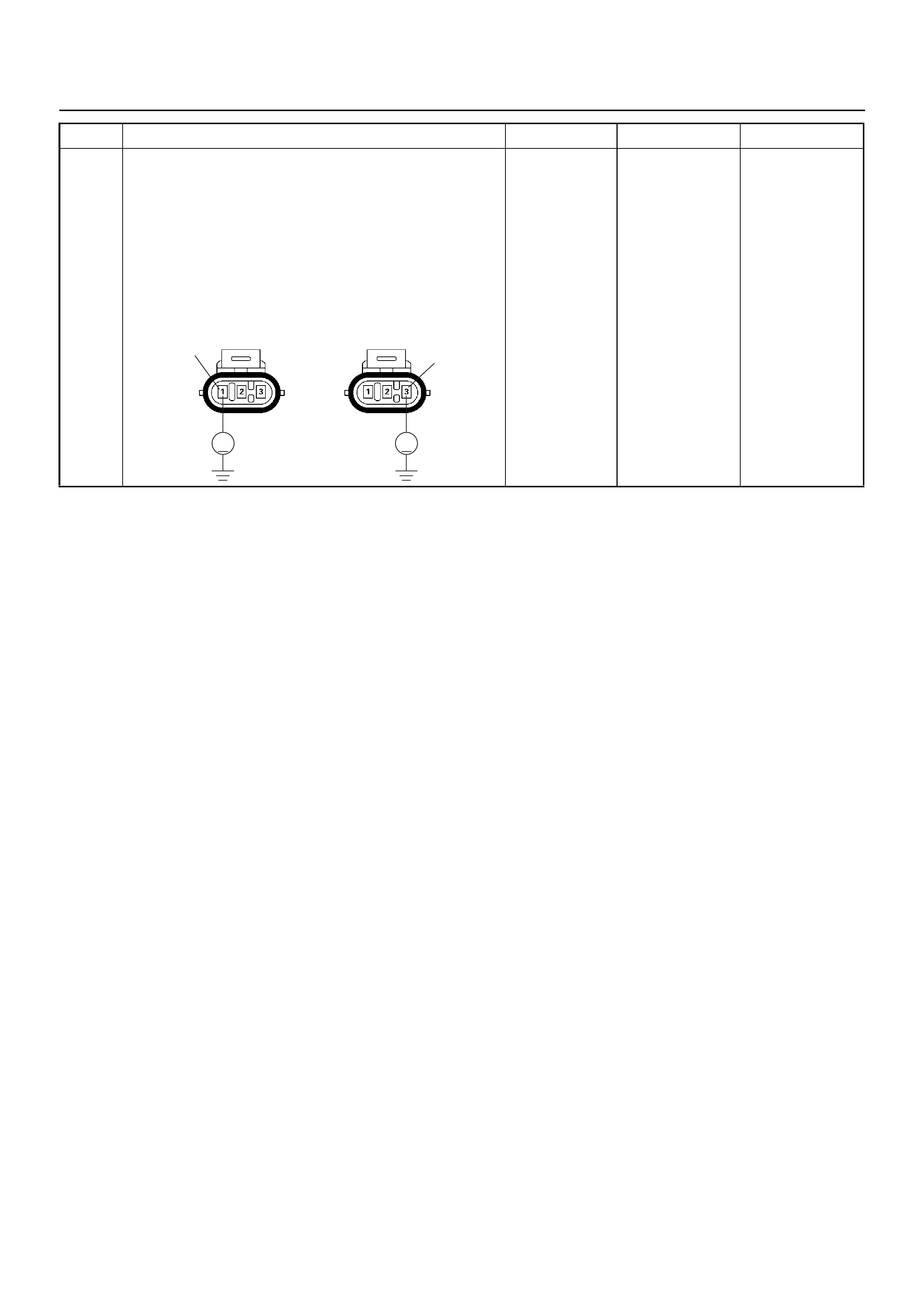
6 Use a DVM to check the ignition coil module signal
circuit for the affec te d coil.
1. Ignition “On”, engine “Off”.
2. Disconnect the ignition coil module connector.
3. Check the circuit for short to battery voltage circuit
for the affected coil.
Is battery voltage indicated by the DVM?
Battery
voltage
Repair faulty
harness and
verify repair Go to Step 7
Step Action Value(s) Yes No
V
E-18
Coil 1
1
V
E-18 3
Coil 2
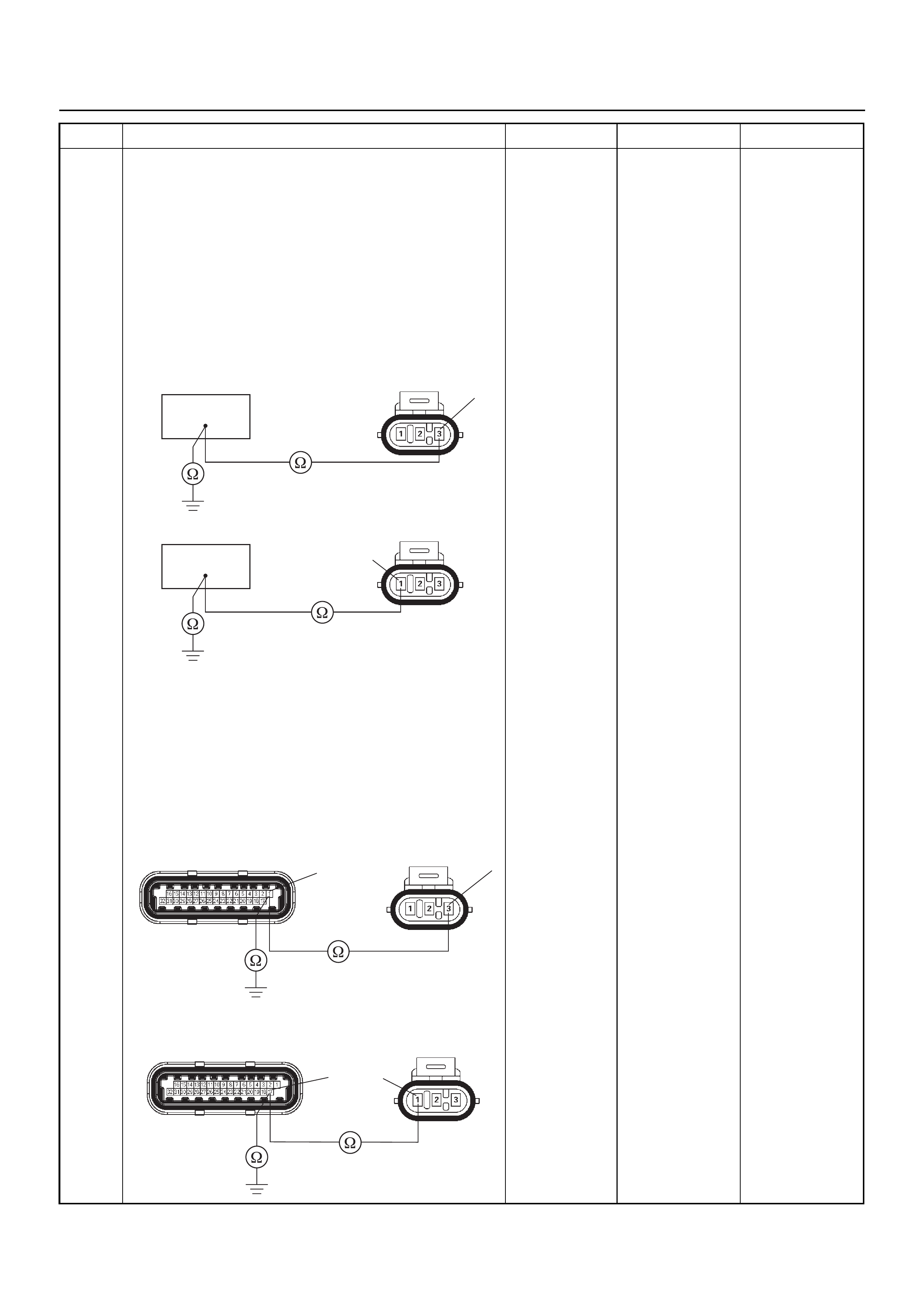
7 Use a DVM to check the ignition coil signal circuit for
the affected coil.
Breaker box is available:
1. Ignition “Off”, engine “Off”.
2. Install the breaker box as type A. (ECM
disconnected) Ref. 6E-77.
3. Disconnect the ignition coil module connector.
4. Check the circuit for open or short to ground circuit
for the affected coil.
Was the problem found?
Breaker box is not available:
1. Ignition “Off”, engine “Off”.
2. Disconnec t the ignition co il module connec tor and
ECM connecto r.
3. Check the circuit for open or short to ground circuit
for the affected coil.
Was the problem found?
—
Repair faulty
harness and
verify repair Go to Step 8
Step Action Value(s) Yes No
1
E-18 3
Coil 1
17
E-18
1
Coil 2
E-18E-60(J1) 13
Coil 1
E-18E-60(J1)
17 1
Coil 2

8 Use a DVM to check the ignition coil module power
supply circuit.
1. Ignition “On”, engine “Off”.
2. Disconnect the ignition coil module connector.
3. Check the circuit for open circuit.
Does the DVM indicate the specified value?
Battery
voltage Go to Step 10 Go to Step 9
9 Repair the open or short to ground circuit between the
“IGN. Coil” fuse (20A) and ignition coil module.
Is the action complete? — Verify repair —
10 Replace the ignition coil module.
Was the problem solved? — Verify repair Go to Step 11
11 Is the ECM programmed with the latest software
release?
If not, download the latest software to the ECM using
the “SPS (Service Programming System)”.
Was the problem solved? — Verify repair Go to Step 12
12 Replace the ECM.
Is the action complete?
IMPORTANT: The replacement ECM must be
programmed. Refer to the Service Programming
System (SPS) section in this manual.
Following ECM programming, the immobiliser system
must be linked to the ECM. Refer to section 11
“Immobiliser System-ECM replacement” for the ECM/
Immobiliser linking procedure. — Verify repair —
Step Action Value(s) Yes No
V
E-18
2

DIAGNOSTIC TROUBLE CODE (DTC) P0443 EVAPORATIVE EMISSION (EVAP)
CONTROL SYSTEM PURGE CONTROL VALVE CIRCUIT MALFUNCTION
Condition for setting the DTC and action taken when the DTC sets
Circuit Description
The engine control module (ECM) controls the
evaporative emission (EVAP) canister purge solenoid
valve through the use of a control (ground) circuit. If the
ECM commands the purge solenoid to maximum duty
cycle (100%) but the voltage remains high (12 Volts); or,
if the ECM commands the purge solenoid to minimum
duty cycle (0%) but the voltage remains low (0 volts),
then DTC P0443 will set.
Diagnostic Aids
• Poor connections, or a damaged harness - Inspect
the harness connectors for: backed-out terminals,
improper mating or damaged terminals. Also check
for open circuits, shorts to ground, and shorts to
voltage.
Code Type DTC Name DTC Setting Condition Fail-Safe (Back Up)
P0443 B EVAP Emission Control System Purge
Control Circuit EVAP purge solenoid circuit open, short to
ground or short to voltage circuit. No fail-safe function.
Fuel
Pump
20A
Fuel
Pump
Relay
2.0
BLK/
BLU 0.85
BLK/
YEL
0.85
RED/
GRN
2.0
BLK/
YEL
3.0
BLK/
RED
2.0
BLK/
RED
3.0
WHT/
BLK
2.0
WHT
Battery
Voltage Battery
Voltage
0.5
PINK
0.85
BLK/
BLU
Injector
#1
Cylinder
Injector
#2
Cylinder
Injector
#3
Cylinder
Injector
#4
Cylinder
0.5
BLU/
BLK
0.5
BLU/
WHT
Coil Module
0.5
BLU/
YEL
EVAP
Purge
Solenoid
Valve
0.5
GRN/
WHT
0.85
GRN 0.85
BLU
μP
IGN
Switch
IGN
Coil
20A
Main
100A
Engine
Control
Module
(ECM)
E60
8
E60
22
E60
9
E60
20J1 J1 J1 J1 J1 J1 J1 J1
E60
E18
E18 E18
11
E60
1
1,4 2,3
3
22
1
E66
1
E9
2
E60
17
E60
5
E66
1
1
E9
E8
2
E8
1
E7
2
E7
1
E6
2
E6
Fuel Pump
on INJ 1 INJ 2 INJ 3 INJ 4 1,4 IGN
Coil 2,3 IGN
Coil EVAP
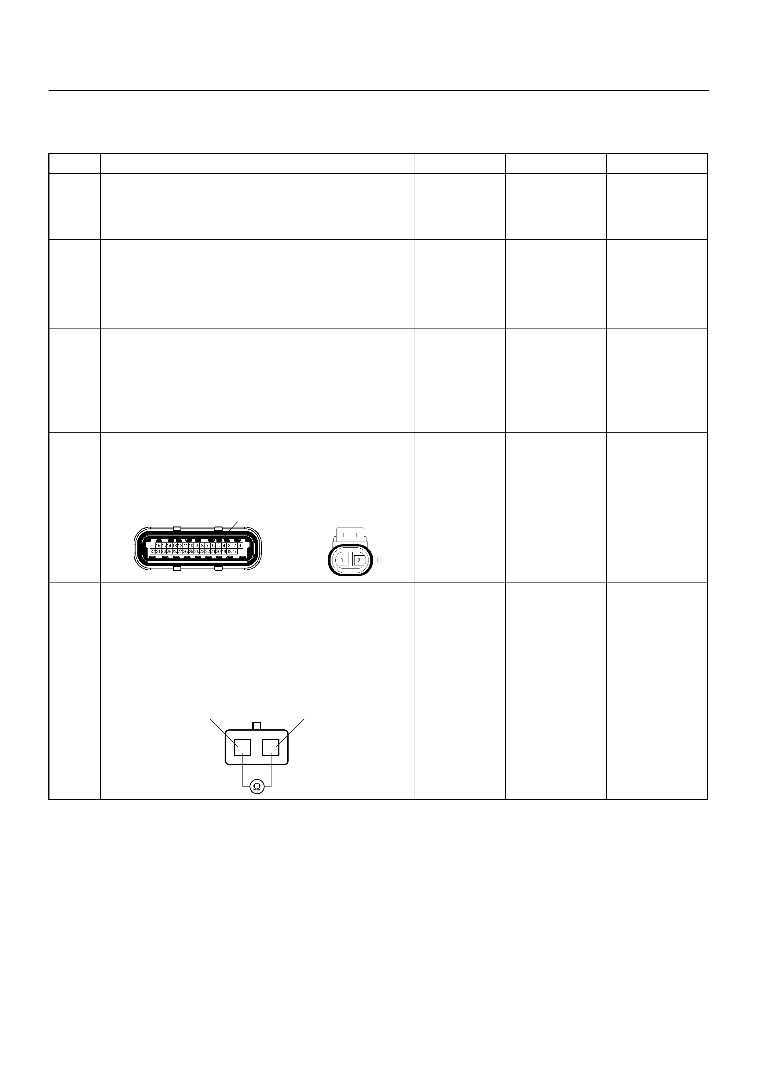
Diagnostic Trouble Code (DTC) P0443
Evap Emission Control System Purge Control Circuit
Step Action Value(s) Yes No
1 Was the “On-Board Diagnostic (OBD) System Check”
performed?
—Go to Step 2
Go to On Board
Diagnostic
(OBD) System
Check
2 1. Connect Tech 2.
2. Review and record the failure information.
3. Select “F0: Read DTC Info Ordered By Priority”
and check for DTC’s.
Is the DTC P0443 stored as “Present Failure”? — Go to Step 3
Refer to
Diagnostic Aids
and Go to Step
3
3 1. Using Tech 2, ignition “On” and engine “Off”.
2. Select “F2: Clear DTC Information” with Tech 2
and clear the DTC information.
3. Operate the vehicle and monitor the “F1: Read
DTC Info as Stored by ECU”.
Was the DTC P0443 stored in this ignition cycle? — Go to Step 4
Refer to
Diagnostic Aids
and Go to Step
4
4 Check for poor/faulty connection at the purge so lenoid
valve or ECM connector. If a poor/faulty connection is
found, repair as necessary.
Was the problem found?
— Verify repair G o to Step 5
5 Use a DVM to check the purge solenoid valve.
1. Ignition “Off”, engine “Off”.
2. Disconnect purge solenoid valve connector.
3. Measure the resistance of purge solenoid valve
coil.
Does the tester indicate standard resistance?
25 - 30Ω at
20°C Go to Step 6 Go to Step 9
5
E-60(J1) E-66
12
EVAP Purge Solenoid
12

6 Use a DVM to check the purge solenoid valve power
supply circuit.
1. Ignition “On”, engine “Off”.
2. Disconnect the purge solenoid valve connector.
3. Check the circuit for open circuit.
Does the DVM indicate the specified value?
Battery
voltage Go to Step 8 Go to Step 7
7 Repair the open or short to ground circuit between the
“Engine” fuse (15A) and purge solenoid valve.
Is the action complete? — Verify repair -
8 Use a DVM to check the purge solenoid valve
solenoid signal circuit.
Breaker box is available:
1. Ignition “Off”, engine “Off”.
2. Install the breaker box as type A. (ECM
disconnected) Ref. 6E-77.
3. Disconnect the purge solenoid valve connector.
4. Check the circuit for open or short to ground
circuit.
Was the problem found?
Breaker box is not available:
1. Ignition “Off”, engine “Off”.
2. Disconnect the purge solenoid valve connector
and ECM connector.
3. Check the circuit for open or short to ground
circuit.
Was the problem found?
—
Repair faulty
harness and
verify repair Go to Step 9
Step Action Value(s) Yes No
V
E-66 2
5
E-66
1
E-66
E-60(J1) 51

9 Use a DVM to check the purge solenoid valve signal
circuit.
1. Ignition “On”, engine “Off”.
2. Disconnect the purge solenoid valve connector.
3. Check the circuit for short to battery voltage
circuit.
Is battery voltage indicated on the DVM?
Battery
voltage
Repair faulty
harness and
verify repair Go to Step 10
10 Substitute a known good purge solenoid valve and
recheck.
Was the problem solved? — Go to Step 11 Go to Step 12
11 Replace the purge solenoid valve.
Was the problem solved? — Verify repair Go to Step 12
12 Is the ECM programmed with the latest software
release?
If not, download the latest software to the ECM using
the “SPS (Service Programming System)”.
Was the problem solved? — Verify repair Go to Step 13
13 Replace the ECM.
Is the action complete?
IMPORTANT: The replacement ECM must be
programmed. Refer to the Service Programming
System (SPS) section in this manual.
Following ECM programming, the immobiliser system
must be linked to the ECM. Refer to section 11
“Immobiliser System-ECM replacement” for the ECM/
Immobiliser linking procedure. — Verify repair —
Step Action Value(s) Yes No
V
E-66
1
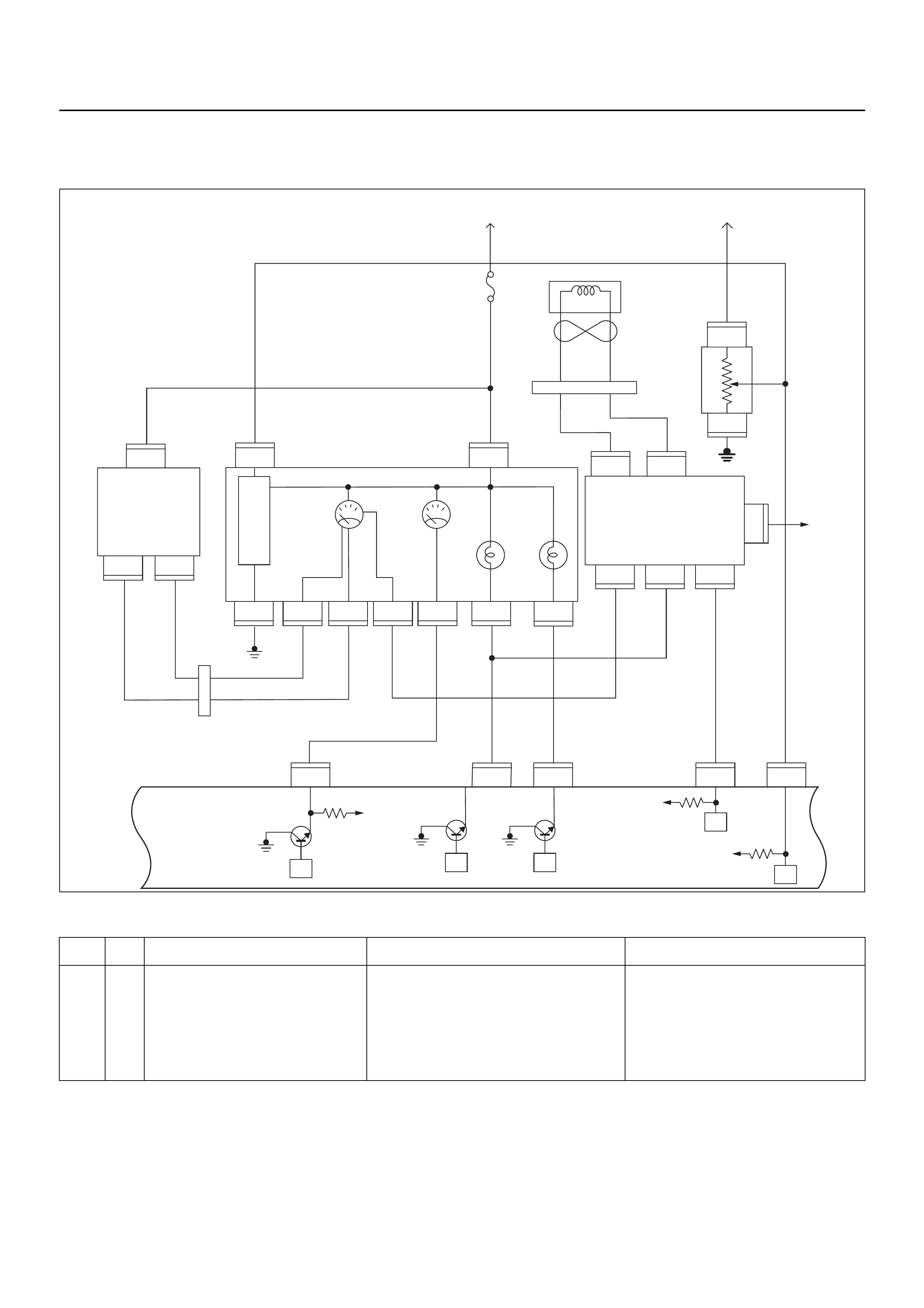
DIAGNOSTIC TROUBLE CODE (DTC) P0502 VEHICLE SPEED SENSOR (VSS)
CIRCUIT LOW INPUT
Condition for setting the DTC and action taken when the DTC sets
Circuit Description
The vehicle speed sensor has a magnet rotated by the
transmission output shaft. Attached to the sensor is a
hall effect circuit that interacts with the magnetic field
created by the rotating magnet. A 12 volt operating
supply for the speed sensor hall circuit is supplied from
the meter fuse.
Diagnostic Aids
• Poor connection at ECM: Inspect harness con nectors
for backed out terminals, improper mating, broken
locks, improperly formed or damaged terminals, and
poor terminal to wire connection.
Code Type DTC Name DTC Setting Condition Fail-Safe (Back Up)
P0502 B Vehicle Speed Sensor Circuit Low
Input 1. No DTC relating to MAP sensor, TPS, ECT
sensor, injector control circuit and ignition
control circuit.
2. Engine is running.
3. Vehicle speed is below 3km/h in power
condition or 2km/h in deceleration condi-
tion.
ECM uses 0km/h condition as substitute.
VIgn
VIgn
Engine
Control
Module
(ECM)
Fuel
Level
VSSSVS LampMIL Lamp
Tacho Sig
32
14 30
2
C56
13
C56
7J2 J2J2J2
C56
9J2
C56
4
IGN
SW
F2
F2
B68
B24
B24E44
E44E44
B24 B24 B24 B24 B24 B24
B68 B68
B68
IGN
SW
μPμP
μP
μP
μP
Meter
15A
VIgn
MIL
Lamp SVS
Lamp
Speedo
Meter Tacho
Meter
0.85
YEL
0.5
YEL/
RED
0.8
YEL/
GRN
0.3
BRN/
YEL
0.5
GRN/
WHT
0.5
BLK/
RED
0.3
BRN/
YEL
0.5
BLK/
YEL
0.5
WHT
C56
0.5
BRN/
YEL
0.5
ORG/
BLU
2(–)
3
1
(+)
Vehicle
Speed
Sensor
(VSS) Starter
Relay
Fuel
Sender
Unit
METER
6
6
11 310278
B24
28
78
1
3
3
(–) (+)
1
Immobiliser
Coil
(Antenna)
B70 B70
CPU Immobiliser
Control
Unit (ICU)
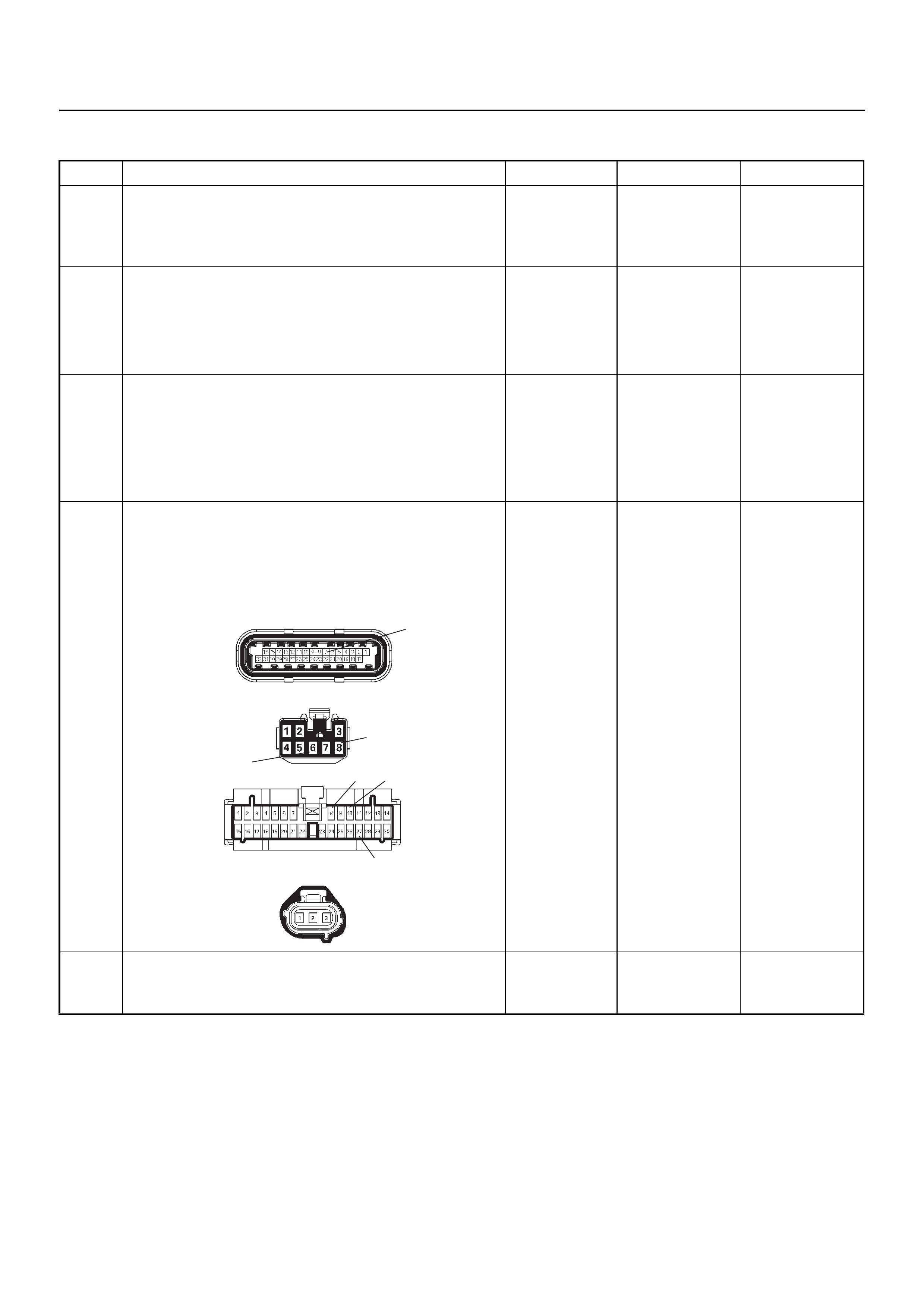
Diagnostic Trouble Code (DTC) P0502 Vehicle Speed Sensor Circuit Low Input
Step Action Value(s) Yes No
1 Was the “On-Board Diagnostic (OBD) System Check”
performed?
—Go to Step 2
Go to On Board
Diagnostic
(OBD) System
Check
2 1. Connect Tech 2.
2. Review and record the failure information.
3. Select “F0: Read DTC Info Ordered By Priority”
and check for DTC’s.
Is the DTC P0502 stored as “Present Failure”? — Go to Step 3
Refer to
Diagnostic Aids
and Go to Step
3
3 1. Using Tech 2, ignition “On” and engine “Off”.
2. Select “F2: Clear DTC Information” with Tech 2
and clear the DTC information.
3. Operate the vehicle and monitor the “F1: Read
DTC Info as Stored by ECU”.
Was the DTC P0502 stored in this ignition cycle? — Go to Step 4
Refer to
Diagnostic Aids
and Go to Step
4
4 Check for poor/faulty connection at the VSS, meter,
immobiliser control unit, ECM and other connectors. If
a poor/faulty connection is found, repair the faulty
terminal.
Was the problem found?
— Verify repair G o to Step 5
5 Remove the VSS from the housing case and visually
check.
Was the problem found? — Go to Step 19 Go to Step 6
6
8
7
27
810
C-56(J2)
B-68
B-24
E-44
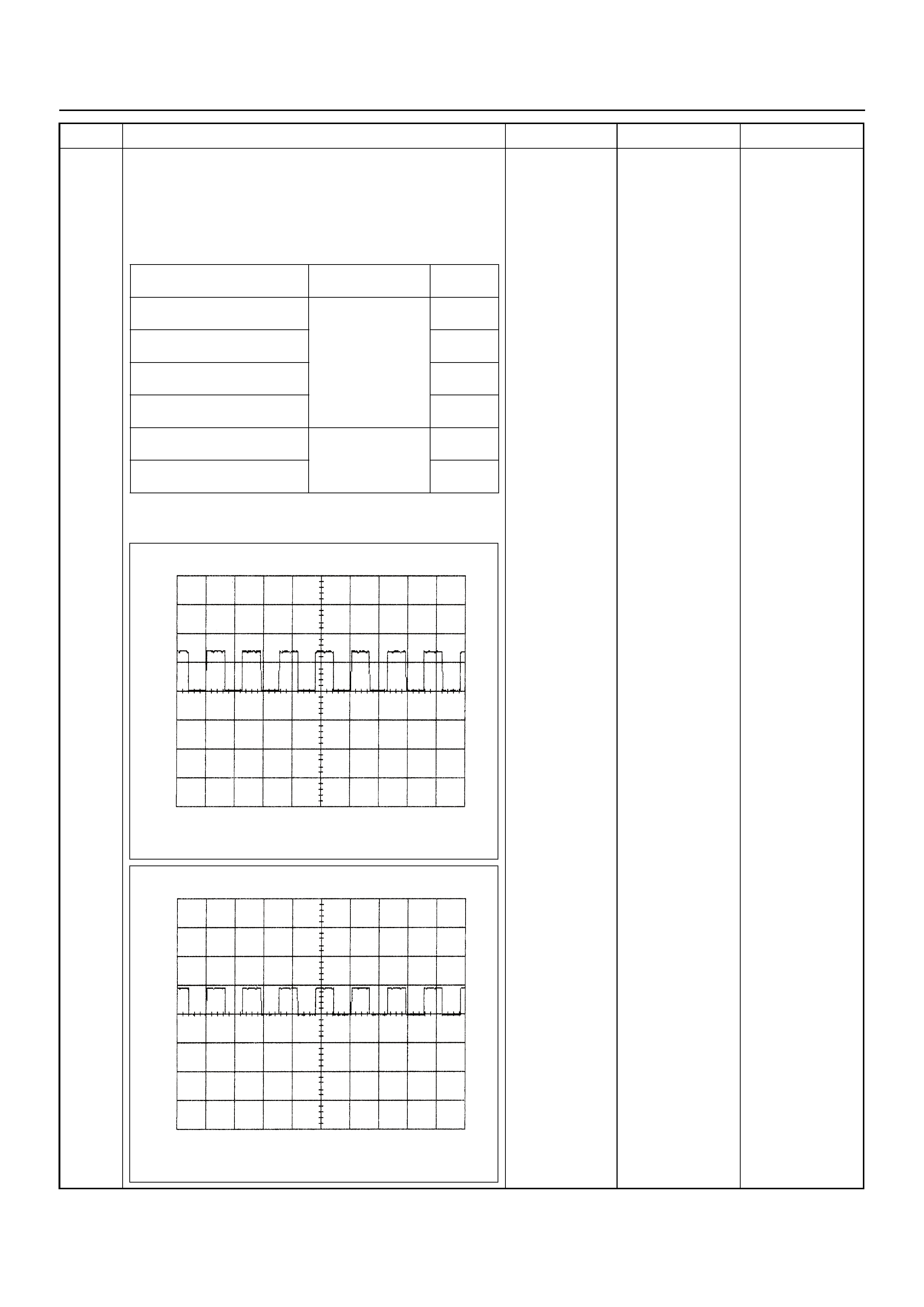
6 Use a DVM to check the VSS signal.
1. Ignition “On”, vehicle “Run (lift up)”.
2. Measure the VSS output voltage at sensor, meter,
immobiliser control unit (if equipped) and ECM.
Does the tester indica te specified value?
If a oscilloscope is available, monitor the VSS signal.
Does the oscilloscope indicate correct wave form?
Refer to
Diagnostic Aids
and Go to Step
21 Refer the table
Step Action Value(s) Yes No
Measurement Position Voltage (V)
(AC Range) If No
Good
VSS terminal 3 & GND Approximately
7.0 V at 20km/h Go to
Step 7
Meter B24 connector 8 &
GND Go to
Step 11
Meter B24 connector 10 &
GND Go to
Step 13
Immobiliser control unit B68
connector 6 & GND Go to
Step 14
Immobiliser control unit B68
connector 8 & GND Approximately
4.8 V at 20km/h Go to
Step 16
ECM C56 (J2) connector 7 &
GND Go to
Step 17
Vehicle Speed Sensor Reference Wave Form
0V→
Measurement Scale: 10V/div 50ms/div
Measurement Condition: Vehicle speed 20km/h
Measurement Terminal: At Vehicle Speed Sensor
Vehicle Speed Sensor Reference Wave Form
0V→
Measurement Scale: 10V/div 50ms/div
Measurement Condition: Vehicle speed 20km/h
Measurement Terminal: At Engine Control Module

7 Use a DVM to check the VSS power supply circuit.
1. Ignition “On”, engine “Off”.
2. Disconnect the VSS connector.
3. Check the circuit for open or short to ground
circuit.
Does the DVM indicate the specified value?
Battery
voltage Go to Step 9 Go to Step 8
8 Repair the open circuit between the VSS and meter
fuse.
Is the action complete? — Verify repair —
9 Use a DVM to check the VSS ground circuit.
1. Ignition “On”, engine “Off”.
2. Disconnect the VSS connector.
3. Check the circuit for short to power supply circuit.
Does the DVM indicate the specified value?
Less than 1V Go to Step 10
Repair faulty
harness and
verify repair
10 Use a DVM to check the VSS ground circuit.
1. Ignition “Off”, engine “Off”.
2. Disconnect the VSS connector.
3. Check the circuit for open circuit.
Was the problem found?
—
Repair faulty
harness and
verify repair Go to Step 19
Step Action Value(s) Yes No
V
E-44
1
V
E-44 2
E-44 2
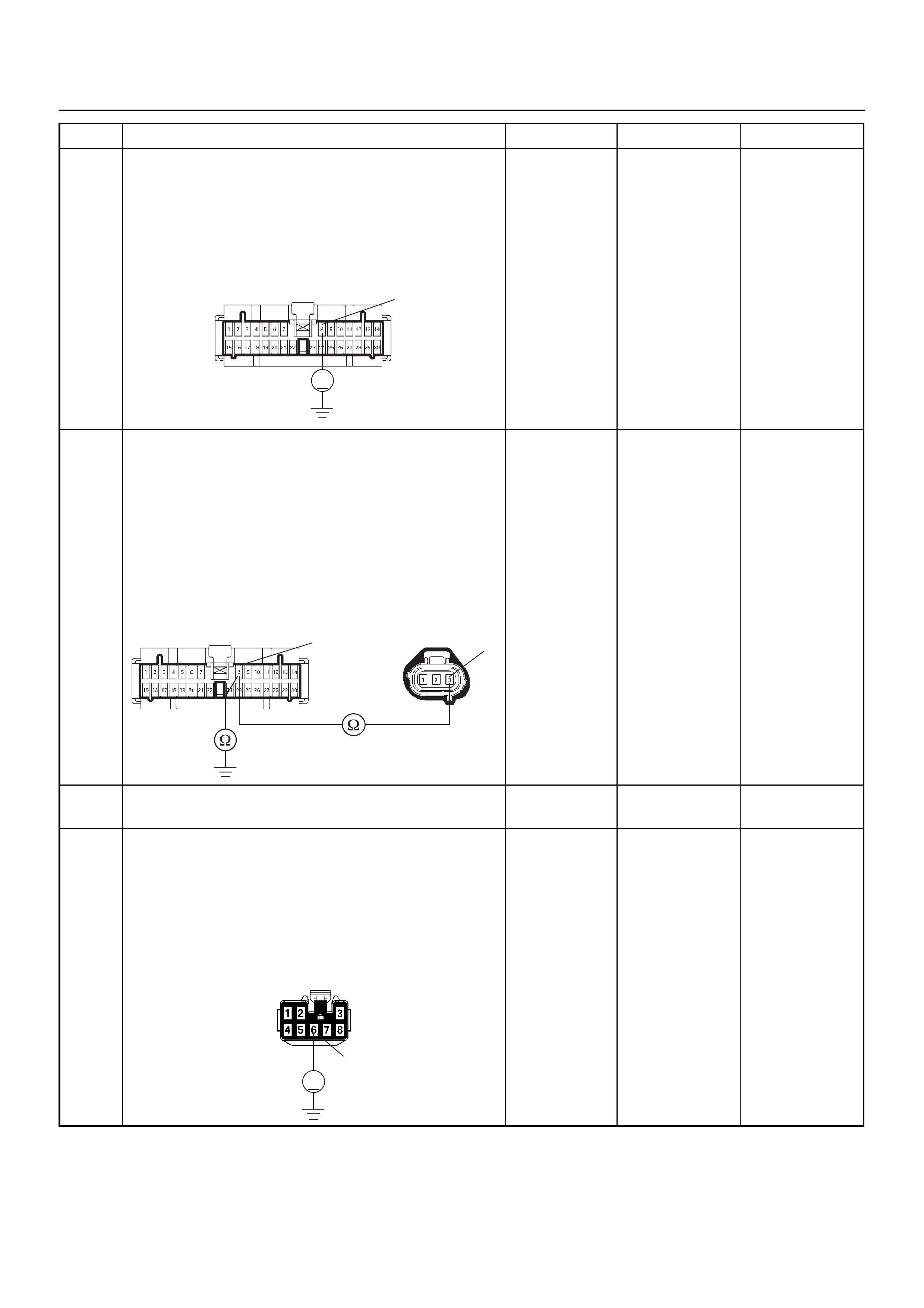
11 Use a DVM to check the VSS signal circuit.
1. Ignition “On”, engine “Off”.
2. Disconnect the VSS connector and meter
connector.
3. Check the circuit for short to power supply circuit.
Does the DVM indicate the specified value?
Less than 1V Go to Step 12
Repair faulty
harness and
verify repair
12 Use a DVM to check the VSS signal circuit.
1. Ignition “Off”, engine “Off”.
2. Disconnect the VSS connector and meter
connector.
3. Check the circuit for open or short to ground
circuit.
If a open or shor t to ground circu it is found, repair the
faulty harness and verify repair.
Is the action complete?
— Verify repair —
13 Replace the speed meter.
Is the action complete? — Verify repair —
14 Use a DVM to check the VSS signal circuit.
1. Ignition “On”, engine “Off”.
2. Disconnect the meter connector and immobiliser
control unit connector (if equipped).
3. Check the circuit for short to power supply circuit.
Does the DVM indicate the specified value?
Less than 1V Go to Step 15
Repair faulty
harness and
verify repair
Step Action Value(s) Yes No
V
B-24 8
B-24 8E-44 3
V
B-68
6
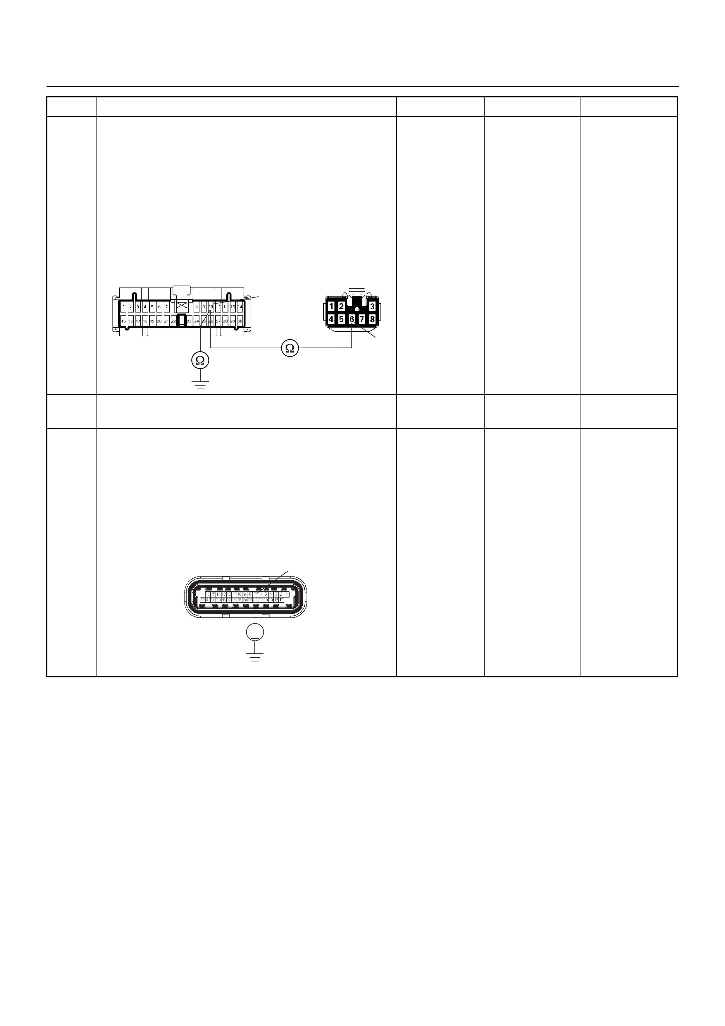
15 Use a DVM to check the VSS signal circuit.
1. Ignition “Off”, engine “Off”.
2. Disconnect the meter connector and immobiliser
control unit connector (if equipped).
3. Check the circuit for open or short to ground
circuit.
If a open or shor t to ground circu it is found, repair the
faulty harness and verify repair.
Is the action complete?
— Verify repair —
16 Replace the immobiliser control unit (if equipped).
Is the action complete? — Verify repair —
17 Use a DVM to check the VSS signal circuit.
1. Ignition “Off”, engine “Off”.
2. Disconnect the immobiliser control unit connector
(if equipped) and ECM connector.
3. Ignition “On”.
4. Check the circuit for short to power supply circuit.
Does the DVM indicate the specified value?
Less than 1V Go to Step 18
Repair faulty
harness and
verify repair
Step Action Value(s) Yes No
B-24
10
B-68
6
V
C-56(J2) 7
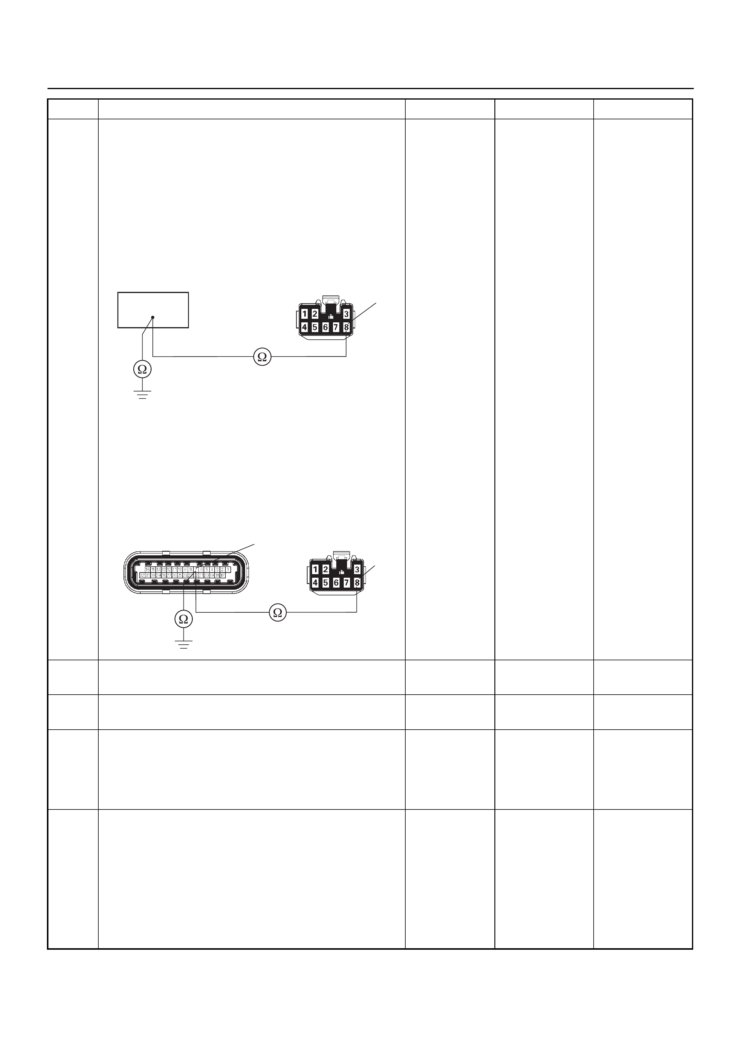
18 Use a DVM to check the VSS signal circuit.
Breaker box is available:
1. Ignition “Off”, engine “Off”.
2. Install the breaker box as type A. (ECM
disconnected) Ref. 6E-77.
3. Disconnect the immobiliser control unit connector
(if equipped).
4. Check the circuit for open or shot to gr ound circuit.
Was the problem found?
Breaker box is not available:
1. Ignition “Off”, engine “Off”.
2. Disconnect the immobiliser control unit connector
(if equipped) and ECM connector.
3. Check the circuit for open or short to ground
circuit.
Was the problem found?
—
Repair faulty
harness and
verify repair Go to Step 21
19 Substitute a known good VSS and recheck.
Was the problem solved? — Go to Step 20 Go to Step 21
20 Replace the VSS.
Was the problem solved? — Verify repair Go to Step 21
21 Is the ECM programmed with the latest software
release?
If not, download the latest software to the ECM using
the “SPS (Service Programming System)”.
Was the problem solved? — Verify repair Go to Step 22
22 Replace the ECM.
Is the action complete?
IMPORTANT: The replacement ECM must be
programmed. Refer to the Service Programming
System (SPS) section in this manual.
Following ECM programming, the immobiliser system
must be linked to the ECM. Refer to section 11
“Immobiliser System-ECM replacement” for the ECM/
Immobiliser linking procedure. — Verify repair —
Step Action Value(s) Yes No
39
B-68 8
B-68C-56(J2) 7
8

DIAGNOSTIC TROUBLE CODE (DTC) P0562 SYSTEM VOLTAGE LOW
Condition for setting the DTC and action taken when the DTC sets
Circuit Description
The engine control module (ECM) monitors the system
voltage on the ignition feed terminal to the ECM. A
system voltage Diagnostic Trouble Code will set
whenever the voltage is below a calibrated value.
Diagnostic Aids
• If the Diagnostic Trouble Code sets when an
accessory is operated, check fo r a poor connection or
excessive current draw.
• Check for open circuits or shorts to ground on the
Code Type DTC Name DTC Setting Condition Fail-Safe (Back Up)
P0562 D System Voltage Low Battery voltage is below 11V. No fail-safe function.
μP
IGN
SW Battery
Voltage
Batt PwrFuel Pump
Pwr
O2 Heater
(Pre)
O2 Heater
(Post)
Battery
Voltage
2.0
WHT
0.5
BLU/
YEL
Engine
15A
450
mV
A/D Converter
Vcc
+5V -+
450
mV
A/D Converter
Vcc
+5V -+
2.0
RED/
BLK
Fuel
Pump
Relay
0.85
RED/
WHT
0.5
GRN/
WHT
Engine
Control
Module
(ECM)
C56
1
C56
F2
F2
21
C56
31J2J1J1J1 J2 J2 J2 J2
E60
16
E60
28
E60
19
32
41
32
41
C56
26
C56
2
2.0
RED/
GRN
O2
Sensor
10A
Fuel
Pump
Heated 02 Sensors
Fuel
Pump
20A
2.0
BLK
0.5
BLU/
ORG
0.5
YEL
0.5
BLU/
YEL
0.5
BLK
0.5
BLK
0.5
BRN 0.5
YEL 0.5
PU 0.5
YEL
0.5
BRN 0.5
PU 0.5
BRN
0.5
ORG
2.0
BLK/
BLU
M
O2 Sensor
POST
O2 Sensor
PRE
LOWLOW
HI
HI
ECM
15A
X2
1
X2
X2 X2
3
1
4
42
E77 E77
E77
E78E78
E78E78
E77
H31
ECM’s battery or ignition inputs.
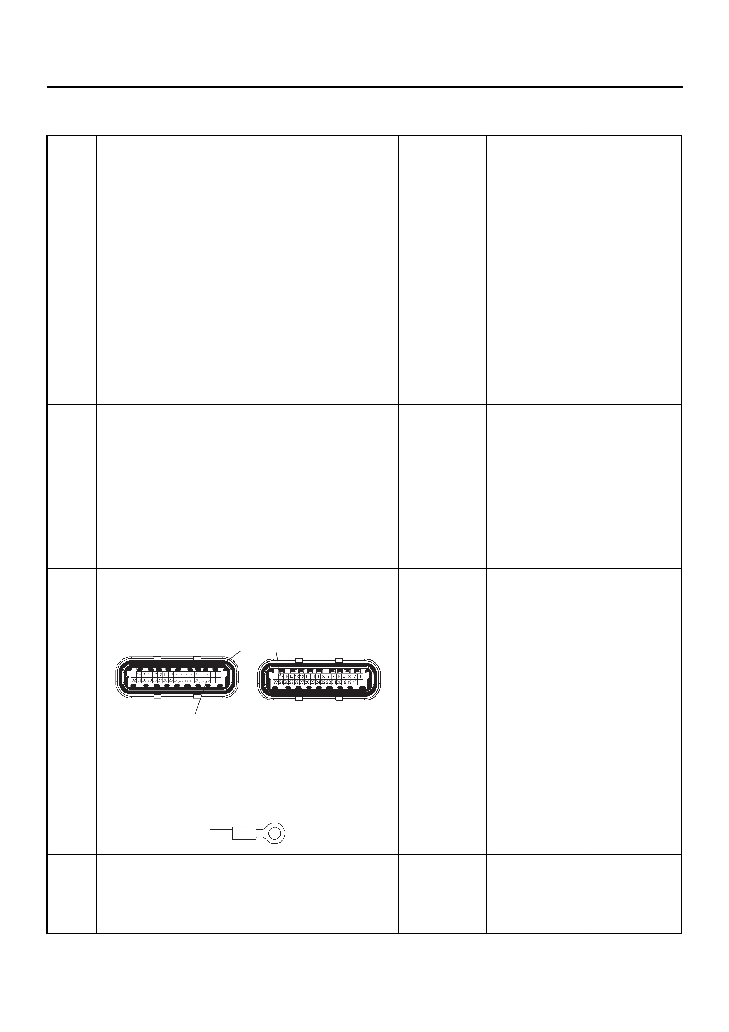
Diagnostic Trouble Code (DTC) P0562 System Voltage Low
Step Action Value(s) Yes No
1 Was the “On-Board Diagnostic (OBD) System Check”
performed?
—Go to Step 2
Go to On Board
Diagnostic
(OBD) System
Check
2 1. Connect Tech 2.
2. Review and record the failure information.
3. Select “F0: Read DTC Info Ordered By Priority”
and check for DTC’s.
Is the DTC P0562 stored as “Present Failure”? — Go to Step 3
Refer to
Diagnostic Aids
and Go to Step
3
3 1. Using Tech 2, ignition “On” and engine “Off”.
2. Select “F2: Clear DTC Information” with Tech 2
and clear the DTC information.
3. Operate the vehicle and monitor the “F1: Read
DTC Info as Stored by ECU”.
Was the DTC P0562 stored in this ignition cycle? — Go to Step 4
Refer to
Diagnostic Aids
and Go to Step
4
4 1. Using Tech 2, ignition “On” and engine “On”.
2. Monitor the “Ignition Voltage” in the data display.
3. Load the electrical system by turning on the
headlights, etc..
Does Tech 2 indicate enough ignition voltage? 10 - 14V Go to Step 6 Go to Step 5
5 Use a DVM to check the battery voltage at the battery
terminal.
Does the tester indicate enough battery voltage?
10 - 14V Go to Step 6
Check the
charging
system, charge
or replace the
battery
6 Check for poor/faulty connection at the ECM
connector. If a poor/faulty connection is found, repair
as necessary.
Was the problem found?
— Verify repair G o to Step 7
7 Check for poor/faulty connection of the ECM ground
at the inlet manifold. If a poor/faulty connection is
found, repair as necessary.
Was the problem found?
— Verify repair G o to Step 8
8 Is the ECM programmed with the latest software
release?
If not, download the latest software to the ECM using
the “SPS (Service Programming System)”.
Was the problem solved? — Verify repair Go to Step 9
18
216
C-56(J2) E-60(J1)
E-72

9 Replace the ECM.
Is the action complete?
IMPORTANT: The replacement ECM must be
programmed. Refer to the Service Programming
System (SPS) section in this manual.
Following ECM programming, the immobiliser system
must be linked to the ECM. Refer to section 11
“Immobiliser System-ECM replacement” for the ECM/
Immobiliser linking procedure. — Verify repair —
Step Action Value(s) Yes No
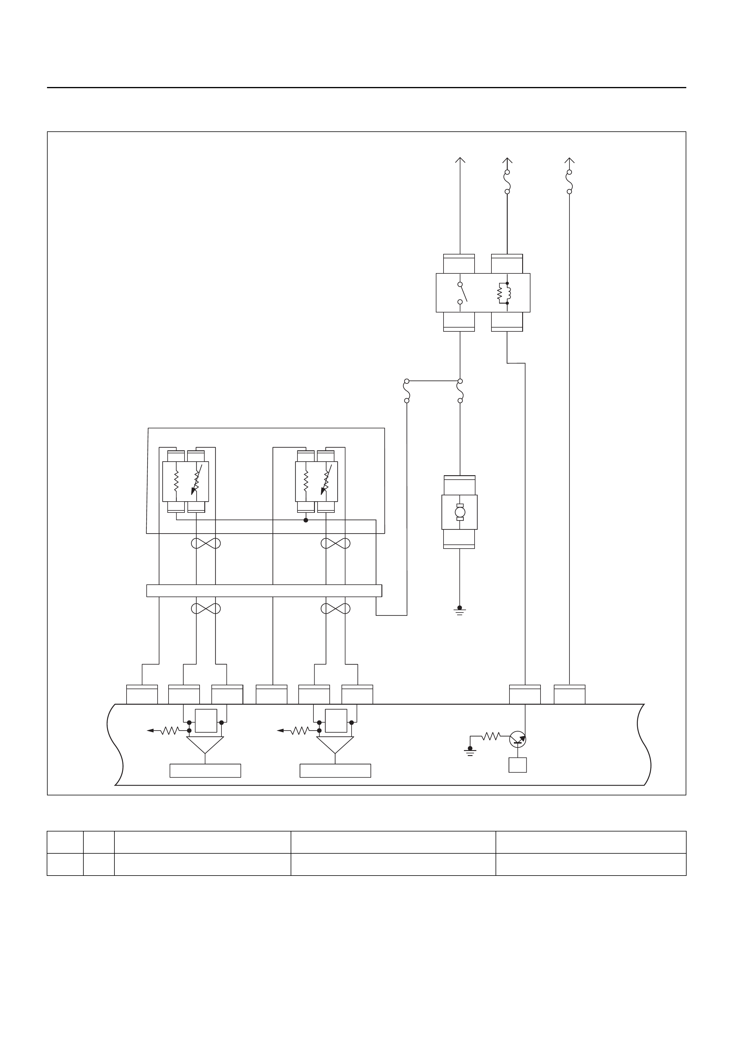
DIAGNOSTIC TROUBLE CODE (DTC) P0563 SYSTEM VOLTAGE HIGH
Condition for setting the DTC and action taken when the DTC sets
Circuit Description
The engine control module (ECM) monitors the system
voltage on the ignition feed terminals to the ECM. A
system voltage Diagnostic Trouble Code will set
whenever the voltage is above a calibrated value.
Diagnostic Aids
Check for a faulty charging system components.
Code Type DTC Name DTC Setting Condition Fail-Safe (Back Up)
P0563 A System Voltage High Battery voltage is above 16V. No fail-safe function.
μP
IGN
SW Battery
Voltage
Batt PwrFuel Pump
Pwr
O2 Heater
(Pre)
O2 Heater
(Post)
Battery
Voltage
2.0
WHT
0.5
BLU/
YEL
Engine
15A
450
mV
A/D Converter
Vcc
+5V -+
450
mV
A/D Converter
Vcc
+5V -+
2.0
RED/
BLK
Fuel
Pump
Relay
0.85
RED/
WHT
0.5
GRN/
WHT
Engine
Control
Module
(ECM)
C56
1
C56
F2
F2
21
C56
31J2J1J1J1 J2 J2 J2 J2
E60
16
E60
28
E60
19
32
41
32
41
C56
26
C56
2
2.0
RED/
GRN
O2
Sensor
10A
Fuel
Pump
Heated 02 Sensors
Fuel
Pump
20A
2.0
BLK
0.5
BLU/
ORG
0.5
YEL
0.5
BLU/
YEL
0.5
BLK
0.5
BLK
0.5
BRN 0.5
YEL 0.5
PU 0.5
YEL
0.5
BRN 0.5
PU 0.5
BRN
0.5
ORG
2.0
BLK/
BLU
M
O2 Sensor
POST
O2 Sensor
PRE
LOWLOW
HI
HI
ECM
15A
X2
1
X2
X2 X2
3
1
4
42
E77 E77
E77
E78E78
E78E78
E77
H31

Diagnostic Trouble Code (DTC) P0563 System Voltage High
Step Action Value(s) Yes No
1 Was the “On-Board Diagnostic (OBD) System Check”
performed?
—Go to Step 2
Go to On Board
Diagnostic
(OBD) System
Check
2 1. Connect Tech 2.
2. Review and record the failure information.
3. Select “F0: Read DTC Info Ordered By Priority”
and check for DTC’s.
Is the DTC P0563 stored as “Present Failure”? — Go to Step 3
Refer to
Diagnostic Aids
and Go to Step
3
3 1. Using Tech 2, ignition “On” and engine “Off”.
2. Select “F2: Clear DTC Information” with Tech 2
and clear the DTC information.
3. Operate the vehicle and monitor the “F1: Read
DTC Info as Stored by ECU”.
Was the DTC P0563 stored in this ignition cycle? — Go to Step 4
Refer to
Diagnostic Aids
and Go to Step
4
4 1. Using Tech 2, ignition “On” and engine “On”.
2. Monitor the “Ignition Voltage” in the data display.
3. Load the electrical system by turning on the
headlights, etc..
Does Tech 2 indicate correct ignition voltage? 10 - 14V Go to Step 5
Check the
charging
system and Go
to Step 5
5 Is the battery jump start cable incorrectly connected? —Verify
procedure Go to Step 6
6 Is the ECM programmed with the latest software
release?
If not, download the latest software to the ECM using
the “SPS (Service Programming System)”.
Was the problem solved? — Verify repair Go to Step 7
7 Replace the ECM.
Is the action complete?
IMPORTANT: The replacement ECM must be
programmed. Refer to the Service Programming
System (SPS) section in this manual.
Following ECM programming, the immobiliser system
must be linked to the ECM. Refer to section 11
“Immobiliser System-ECM replacement” for the ECM/
Immobiliser linking procedure. — Verify repair —

DIAGNOSTIC TROUBLE CODE (DTC) P0601 ECM MEMORY CHECKSUM
Condition for setting the DTC and action taken when the DTC sets
Circuit Description
The engine control module (ECM) used in this vehicle
utilizes an electrically erasable programmable read-only
memory (EEPROM). The EEPROM contains program
information and the calibrations required for engine,
transmission, and powertrain diagnostics operation.
Unlike the PROM used in past applications, the
EEPROM is not replaceable. When the ECM is
replaced or a calibration update is required, the ECM
must be programmed using Tech 2.
Diagnostic Aids
• Diagnostic Trouble Code P0601 indicates the
contents of the EEPROM have changed since the
ECM was programmed. The only possible repair is
ECM reprogramming or replacement. Check service
bulletins to program the replacement ECM with the
correct software and calibration for the vehicle.
Diagnostic Trouble Code (DTC) P0601 ECM Memory Checksum
Code Type DTC Name DTC Setting Condition Fail-Safe (Back Up)
P0601 A ECM Memory Checksum ECM memory area error. Engine control disabled.
Step Action Value(s) Yes No
1 Was the “On-Board Diagnostic (OBD) System Check”
performed?
—Go to Step 2
Go to On Board
Diagnostic
(OBD) System
Check
2 1. Connect Tech 2.
2. Review and record the failure information.
3. Select “F0: Read DTC Info Ordered By Priority”
and check for DTC’s.
Is the DTC P0601 stored as “Present Failure”? — Go to Step 3
Refer to
Diagnostic Aids
and Go to Step
3
3 1. Using Tech 2, ignition “On” and engine “Off”.
2. Select “F2: Clear DTC Information” with Tech 2
and clear the DTC information.
3. Operate the vehicle and monitor the “F1: Read
DTC Info as Stored by ECU”.
Was the DTC P0601 stored in this ignition cycle? — Go to Step 4
Refer to
Diagnostic Aids
4 Is the ECM programmed with the latest software
release?
If not, download the latest software to the ECM using
the “SPS (Service Programming System)”.
Was the problem solved? — Verify repair Go to Step 5
5 Replace the ECM.
Is the action complete?
IMPORTANT: The replacement ECM must be
programmed. Refer to the Service Programming
System (SPS) section in this manual.
Following ECM programming, the immobiliser system
must be linked to the ECM. Refer to section 11
“Immobiliser System-ECM replacement” for the ECM/
Immobiliser linking procedure. — Verify repair —

DIAGNOSTIC TROUBLE CODE (DTC) P0602 PROGRAMMING ERROR
Condition for setting the DTC and action taken when the DTC sets
Circuit Description
The engine control module (ECM) used in this vehicle
utilizes an electrically erasable programmable read-only
memory (EEPROM). The EEPROM contains program
information an d the calib rations r equired for th e engine ,
transmission, and powertrain diagnostics operation.
Unlike the PROM used in past applications, the
EEPROM is not replaceable. When the ECM is
replaced or a calibration update is required, the ECM
must be programmed using Tech 2.
Diagnostic Aids
• Diagnostic Trouble Code P0602 indicates when non
programmed ECM is used without service
programming system (SPS). The replacement ECM
must be programmed.
Diagnostic Trouble Code (DTC) P0602 Programming Error
Code Type DTC Name DTC Setting Condition Fail-Safe (Back Up)
P0602 - Programming Error ECM memory area error. Engine control disabled.
Step Action Value(s) Yes No
1Was the “On-Board Diagnostic (OBD) System Check”
performed?
—Go to Step 2
Go to On Board
Diagnostic
(OBD) System
Check
21. Connect Tech 2.
2. Review and record the failure information.
3. Select “F0: Read DTC Info Ordered By Priority”
and check for DTC’s.
Is the DTC P0602 stored as “Present Failure”? — Go to Step 3 Refer to
Diagnostic Aids
3Download the latest software to the ECM using the
“SPS (Service Programming System)”.
Is the action complete? — Verify repair —
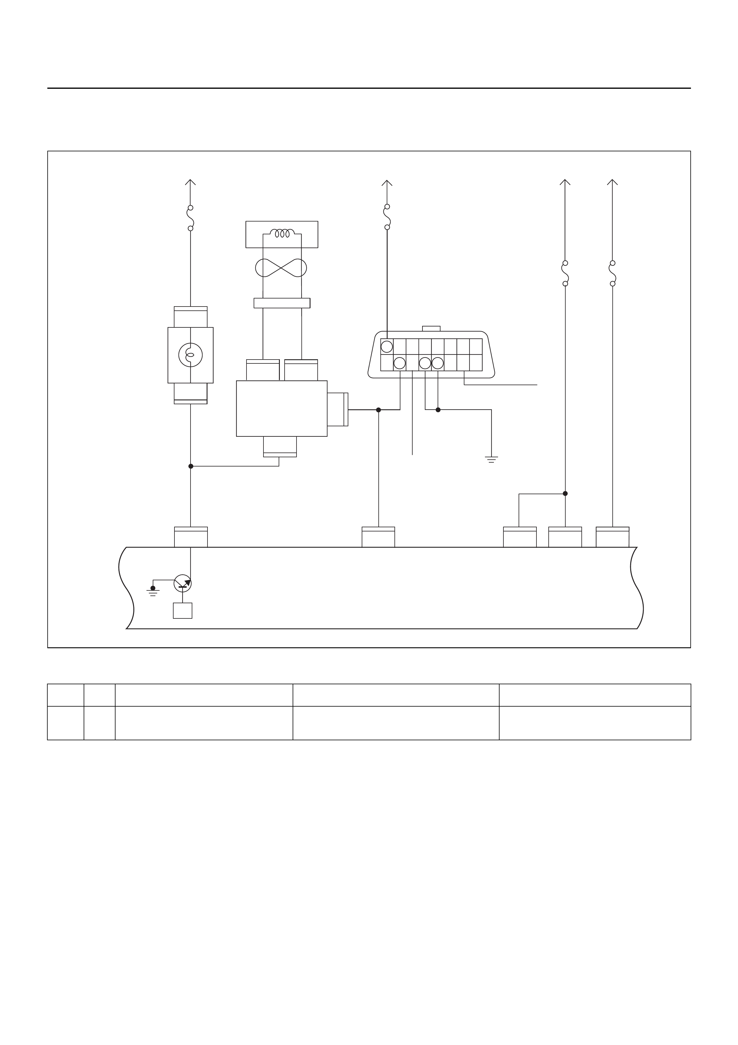
DTC P0650 MALFUNCTION INDICATOR LAMP (MIL) CONTROL CIRCUIT
MALFUNCTION
Condition for setting the DTC and action taken when the DTC sets
Circuit Description
The check engine (MIL) lamp should always be
illuminated and steady with ignition “ON” and the engine
stopped. Ignition feed voltage is supplied directly to the
check engine lam p indicator. The eng ine co ntrol modu le
(ECM) turns the check engine lamp “ON” by grounding
the check engine lamp driver circuit. The check engine
lamp should not remain “ON” with the engine running
and no DTC(s) set. A steady check engine lamp with
the engine running and no DTC(s) suggests a short to
ground in the check engine lamp driver circuit.
Diagnostic Aids
An intermittent signal may be caused by a poor
connection, rubbed-through wire insulation, or a wire
broken inside the insulation. Check for the following
items:
• Poor connection or damaged harness - Inspect the
ECM harness and connectors for improper mating,
broken locks, improperly formed or damaged
terminals, poor terminal-to-wire connection, and
damaged harness.
Code Type DTC Name DTC Setting Condition Fail-Safe (Back Up)
P0650 A Malfunction Indicator Lamp (MIL) Con-
trol Circuit Malfunction Check engine lamp circuit open, short to
ground or short to voltage circuit. No fail-safe function.
C56
7
5
C56
B58
B68
B68
3
B24
32 15
C56
218J2J2J2 J2 J2
C56
3
C56
B24
30
31
(+)(–)
B70 B70
Battery
Voltage
0.85
RED/
YEL
0.85
YEL
Engine
Room-RH
μP
0.5
BRN/
YEL
0.3
BRN/
YEL
Engine
Control
Module
(ECM)
MIL
Lamp
Immobiliser
Coil
(Antenna)
Immobiliser
Control
Unit (ICU)
Meter
15A
Ignition
SW
0.85
RED/
WHT
0.5
RED/
WHT
0.5
BLU/
YEL
2.0
WHT 3.0
BLK/
RED
0.5
YEL/
BLU
Batt
Pwr
MIL
Lamp Batt
Pwr Ign
Pwr
KWP2000
Serial Data
0.85
BLK
Class 2
Class 2
Diagnostic
Connector
16151413121110 9
87654321
Meter
15A
Ignition
SW
Engine
I5A
Battery
Voltage
ECM
I5A
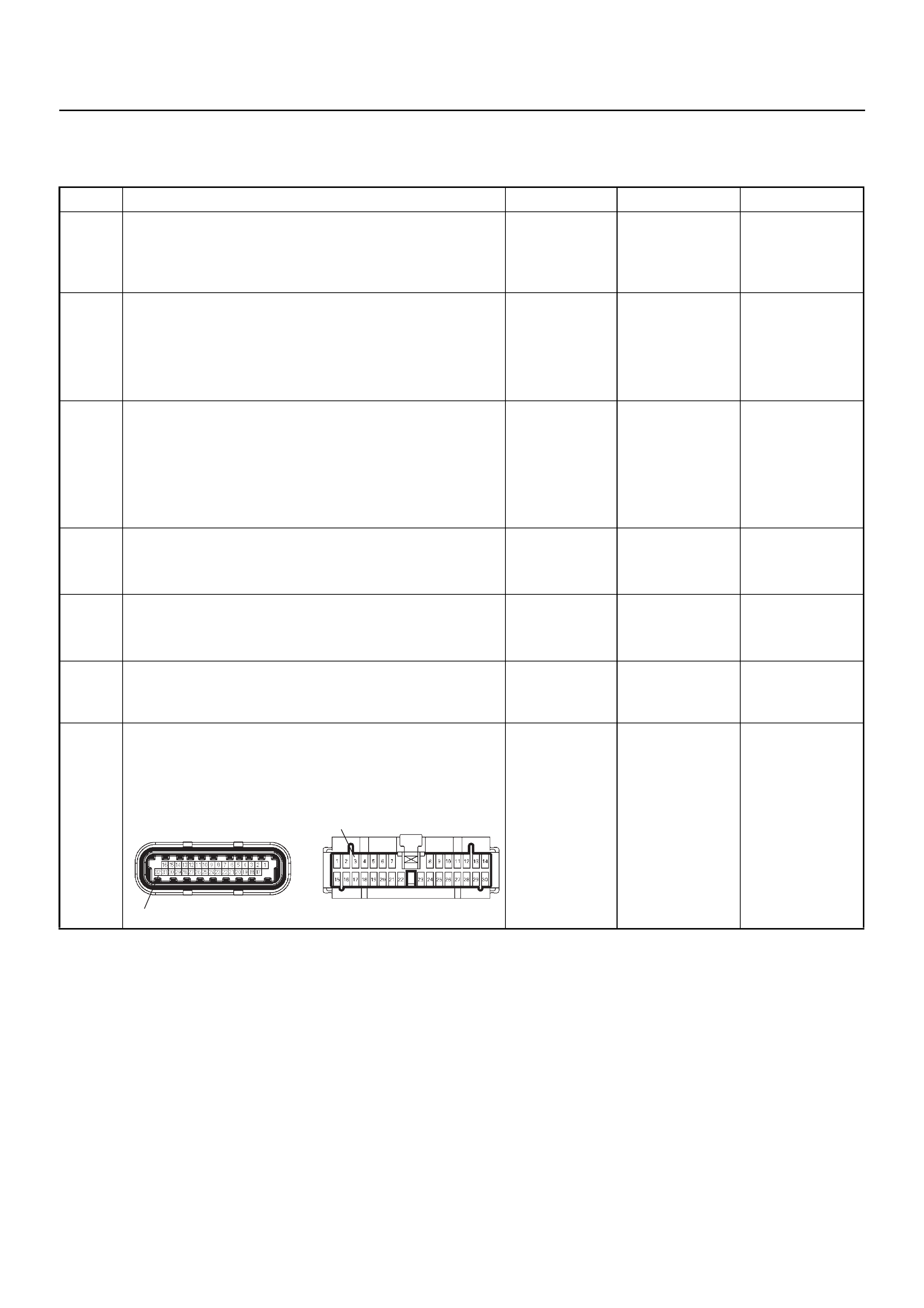
Diagnostic Trouble Code (DTC) P0650
Malfunction Indicator Lamp (MIL) Control Circuit Malfunction
Step Action Value(s) Yes No
1 Was the “On-Board Diagnostic (OBD) System Check”
performed?
—Go to Step 2
Go to On Board
Diagnostic
(OBD) System
Check
2 1. Connect Tech 2.
2. Review and record the failure information.
3. Select “F0: Read DTC Info Ordered By Priority”
and check for DTC’s.
Is the DTC P0650 stored as “Present Failure”? — Go to Step 3
Refer to
Diagnostic Aids
and Go to Step
3
3 1. Using Tech 2, ignition “On” and engine “Off”.
2. Select “F2: Clear DTC Information” with Tech 2
and clear the DTC information.
3. Operate the vehicle and monitor the “F1: Read
DTC Info as Stored by ECU”.
Was the DTC P0650 stored in this ignition cycle? — Go to Step 4
Refer to
Diagnostic Aids
and Go to Step
4
4 1. Ignition “On”, engine “Off”.
2. Check the “Check Engine” lamp.
Does the lamp switch “On”? — Go to Step 5 Go to Step 6
5 1. Ignition “On”, engine “Off”.
2. Check the “Check Engine” lamp.
Does the lamp switch “Off”? — Go to Step 9 Go to Step 7
6 Check the “Check Engine” lamp bulb.
If the bulb is burnt out, repair as necessary.
Was the problem found? — Verify repair Go to Step 7
7 Check for poor/faulty connection at the meter
connector and ECM connector. If a poor/faulty
connection is found , re pa ir as nece ssary.
Was the problem found?
— Verify repair G o to Step 8
32
3
C-56(J2) B-24
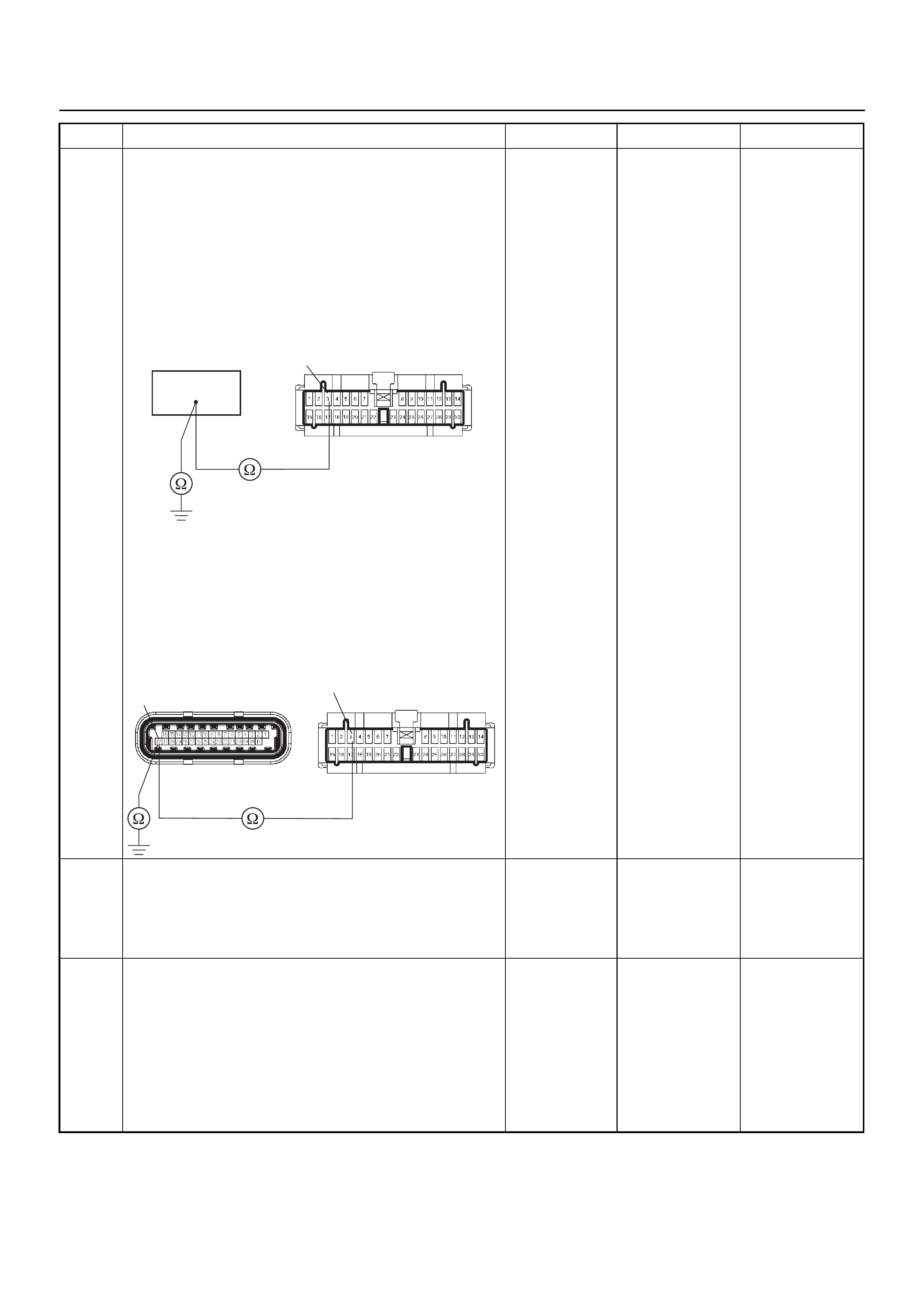
8 Use a DVM to check the “Check Engine” lamp circuit.
Breaker box is available:
1. Ignition “Off”, engine “Off”.
2. Install the breaker box as type A. (ECM
disconnected) Ref. 6E-77.
3. Remove th e me te r co nnector.
4. Check the circuit for open or short to ground
circuit.
Was the problem found?
Breaker box is not available:
1. Ignition “Off”, engine “Off”.
2. Disconnect the ECM connector.
3. Remove th e me te r co nnector.
4. Check the circuit for open or short to ground
circuit.
Was the problem found?
—
Repair faulty
harness and
verify repair Go to Step 9
9 Is the ECM programmed with the latest software
release?
If not, download the latest software to the ECM using
the “SPS (Service Programming System)”.
Was the problem solved? — Verify repair Go to Step 10
10 Replace the ECM.
Is the action complete?
IMPORTANT: The replacement ECM must be
programmed. Refer to the Service Programming
System (SPS) section in this manual.
Following ECM programming, the immobiliser system
must be linked to the ECM. Refer to section 11
“Immobiliser System-ECM replacement” for the ECM/
Immobiliser linking procedure. — Verify repair —
Step Action Value(s) Yes No
64
3B-24
C-56(J2) B-24
32 3
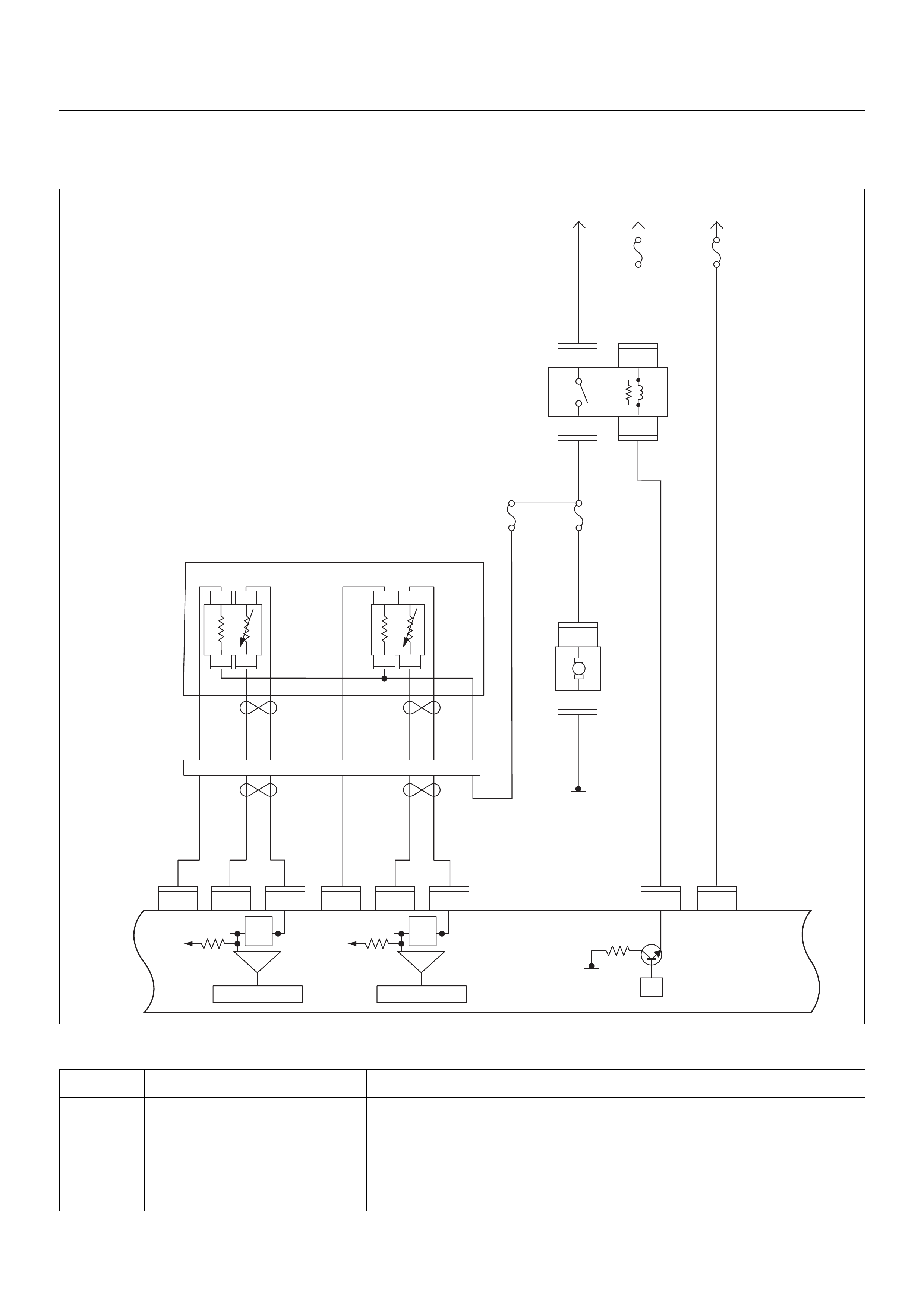
DIAGNOSTIC TROUBLE CODE (DTC) P1167 FUEL SUPPLY SYSTEM RICH
DURING DECELERATION FUEL CUT OFF
Condition for setting the DTC and action taken when the DTC sets
Code Type DTC Name DTC Setting Condition Fail-Safe (Back Up)
P1167 D Fuel Supply System Rich During
Deceleration Fuel Cutoff 1. No DTC relating to MAP sensor, TPS,
EVAP purge, ECT sensor, CKP sensor,
VSS, injector control circuit and ignition
control circuit.
2. O2 sensors bank 1 output voltage is more
than 550mV in deceleration fuel cutoff
mode.
No fail-safe function.
μP
IGN
SW Battery
Voltage
Batt PwrFuel Pump
Pwr
O2 Heater
(Pre)
O2 Heater
(Post)
Battery
Voltage
2.0
WHT
0.5
BLU/
YEL
Engine
15A
450
mV
A/D Converter
Vcc
+5V -+
450
mV
A/D Converter
Vcc
+5V -+
2.0
RED/
BLK
Fuel
Pump
Relay
0.85
RED/
WHT
0.5
GRN/
WHT
Engine
Control
Module
(ECM)
C56
1
C56
F2
F2
21
C56
31J2J1J1J1 J2 J2 J2 J2
E60
16
E60
28
E60
19
32
41
32
41
C56
26
C56
2
2.0
RED/
GRN
O2
Sensor
10A
Fuel
Pump
Heated 02 Sensors
Fuel
Pump
20A
2.0
BLK
0.5
BLU/
ORG
0.5
YEL
0.5
BLU/
YEL
0.5
BLK
0.5
BLK
0.5
BRN 0.5
YEL 0.5
PU 0.5
YEL
0.5
BRN 0.5
PU 0.5
BRN
0.5
ORG
2.0
BLK/
BLU
M
O2 Sensor
POST
O2 Sensor
PRE
LOWLOW
HI
HI
ECM
15A
X2
1
X2
X2 X2
3
1
4
42
E77 E77
E77
E78E78
E78E78
E77
H31

Circuit Description
The engine control module (ECM) internal circuitry can
identify if the vehicle fuel system is capable of supp lyin g
adequate amounts of fuel during deceleration (fuel cut
off). The ECM monitors the voltage of the oxygen
sensors during fuel cut off. When a fuel cut off mode of
operation is requested during “Closed Loop” operation
(by deceleration), the ECM will provide more fuel to the
engine. Under these conditions the ECM should detect
a “lean” condition (low oxygen sensors voltage). If this
“lean” exhaust is not detected at this time, a Diagnostic
Trouble Code P1167 will set.
Diagnostic Aids
Check the following items:
• Fuel pressure - The system will go rich if pressure is
too high. The ECM can compensate for some
increase. However, if fuel pressure is too high, a
Diagnostic Trouble Code P1167 may be set. Refer to
Fuel System Diagnosis.
• Perform “Injector Balance Test” - Refer to Fuel
System Diagnosis.
• Check the EVAP canister for fuel saturation - If full of
fuel, check canister control and hoses. Refer to
Evaporative (EVAP) Emission Control System.
• Check for a leak in the fuel pressure regulator
diaphragm by checking the vacuum line to toe
regulator for the presence of fuel.
• An intermittent TP sensor output will cause the
system to go rich due to a false indication of the
engine accelerating.
• Silicon contamination of the HO2S can also cause a
high HO2S voltage to be indicated. This condition is
indicated by a powdery white deposit on the portion
of the HO2S exposed to the exhaust stream. If
contamination is noticed, replace the affected HO2S.
Diagnostic Trouble Code (DTC) P1167
Fuel Supply System Rich During Deceleration Fuel Cutoff
Step Action Value(s) Yes No
1 Was the “On-Board Diagnostic (OBD) System Check”
performed?
—Go to Step 2
Go to On Board
Diagnostic
(OBD) System
Check
2 1. Connect Tech 2.
2. Review and record the failure information.
3. Select “F0: Read DTC Info Ordered By Priority”
and check for DTC’s.
Is the DTC P1167 stored as “Present Failure”? — Go to Step 3
Refer to
Diagnostic Aids
and Go to Step
3
3 1. Using Tech 2, ignition “On” and engine “Off”.
2. Select “F2: Clear DTC Information” with Tech 2
and clear the DTC information.
3. Operate the vehicle and monitor the “F1: Read
DTC Info as Stored by ECU”.
Was the DTC P1167 stored in this ignition cycle? — Go to Step 4
Refer to
Diagnostic Aids
and Go to S tep
4
4 1. Using Tech 2, ignition “On” and engine “Off”.
2. Monitor the “Throttle Position” in the data display.
Does Tech 2 indicate correct “Throttle Position” in
accordance with acc ele ra to r pe d al oper ation? — Go to Step 6 Go to Step 5
5 Check for the following conditions.
• Objects blocking the throttle valve.
• Incorrectly installed.
If a problem is found, re pa ir as nece ss ar y.
Was the problem found? — Verify repair Go to Step 12
6 1. Using Tech 2, ignition “On” and engine “On”.
2. Monitor the “Manifold Absolute Pressure” in the
data display.
Does Tech 2 indicate correct “Manifold Absolute
Pressure” in accordance with engine speed or
acceleration? — Go to Step 8 Go to Step 7

7 Remove the MAP sensor and check for the following
conditions.
• Objects blocking the air cleaner.
• Objects blocking the MAP sensor.
• Objects blocking the throttle valve.
• Vacuum leaking at inlet duct.
• Vacuum leaking at throttle body.
If a problem is found, re pa ir as nece ss ar y.
Was the problem found? — Verify repair Go to Step 13
8 1. Using Tech 2, ignition “On” and engine “On”.
2. Select the “Actuator Test” and perform the "F1:
Idle Air Control Test".
3. Operate Tech 2 in accordance with procedure.
Was the IAC valve heard stepping through the 255
positions? — Go to Step 10 Go to Step 9
9 Check for the following conditions.
• Objects blocking the IAC valve.
• Objects blocking the throttle valve.
• Vacuum leaking at throttle body.
If a problem is found, re pa ir as nece ss ar y.
Was the problem found? — Verify repair Go to Step 14
10 Check the injectors for the affected bank.
Refer to “Injector Coil Test & Injector Balance Test
Procedure”.
Was the injector operation correct? —Go to Step 11
Refer to Injector
Coil Test &
Injector
Balance Test
Procedure
11 Check for fu el pr es su re .
Refer to “Fuel System Diagnosis”.
Was the fuel pressure correct? — Go to Step 15
Refer to Fuel
System
Diagnosis
12 Replace the TPS.
Is the action complete? — Verify repair —
13 Replace the MAP sensors.
Is the action complete? — Verify repair —
14 Replace the IAC valve.
Is the action complete? — Verify repair —
15 Replace the O2 sensor.
Was the problem solved? — Verify repair Go to Step 16
16 Is the ECM programmed with the latest software
release?
If not, download the latest software to the ECM using
the “SPS (Service Programming System)”.
Was the problem solved? — Verify repair Go to Step 17
17 Replace the ECM.
Is the action complete?
IMPORTANT: The replacement ECM must be
programmed. Refer to the Service Programming
System (SPS) section in this manual.
Following ECM programming, the immobiliser system
must be linked to the ECM. Refer to section 11
“Immobiliser System-ECM replacement” for the ECM/
Immobiliser linking procedure. — Verify repair —
Step Action Value(s) Yes No
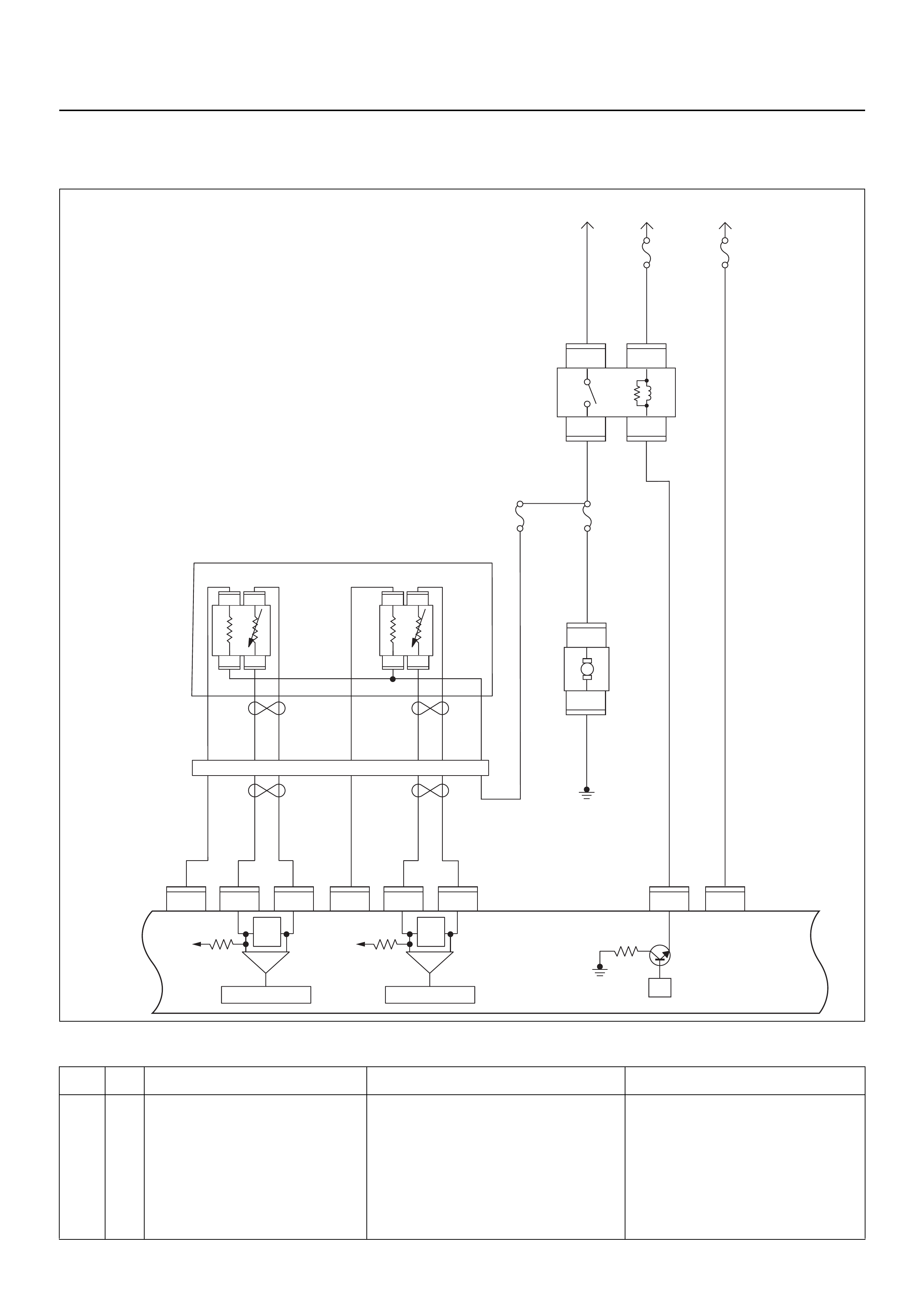
DIAGNOSTIC TROUBLE CODE (DTC) P1171 FUEL SUPPLY SYSTEM LEAN
DURING POWER ENRICHMENT
Condition for setting the DTC and action taken when the DTC sets
Code Type DTC Name DTC Setting Condition Fail-Safe (Back Up)
P1171 D Fuel Supply System Lean During
Power Enrichment 1. No DTC relating to MAP sensor, TPS,
EVAP purge, ECT sensor, CKP sensor,
VSS, injector control circuit and ignition
control circuit.
2. Engine coolant temperature is more than
60°C.
3. Mass air flow is below 13.5m/s.
4. O2 sensors bank 1 output voltage is below
350mV in power enrichment mode.
No fail-safe function.
μP
IGN
SW Battery
Voltage
Batt PwrFuel Pump
Pwr
O2 Heater
(Pre)
O2 Heater
(Post)
Battery
Voltage
2.0
WHT
0.5
BLU/
YEL
Engine
15A
450
mV
A/D Converter
Vcc
+5V -+
450
mV
A/D Converter
Vcc
+5V -+
2.0
RED/
BLK
Fuel
Pump
Relay
0.85
RED/
WHT
0.5
GRN/
WHT
Engine
Control
Module
(ECM)
C56
1
C56
F2
F2
21
C56
31J2J1J1J1 J2 J2 J2 J2
E60
16
E60
28
E60
19
32
41
32
41
C56
26
C56
2
2.0
RED/
GRN
O2
Sensor
10A
Fuel
Pump
Heated 02 Sensors
Fuel
Pump
20A
2.0
BLK
0.5
BLU/
ORG
0.5
YEL
0.5
BLU/
YEL
0.5
BLK
0.5
BLK
0.5
BRN 0.5
YEL 0.5
PU 0.5
YEL
0.5
BRN 0.5
PU 0.5
BRN
0.5
ORG
2.0
BLK/
BLU
M
O2 Sensor
POST
O2 Sensor
PRE
LOWLOW
HI
HI
ECM
15A
X2
1
X2
X2 X2
3
1
4
42
E77 E77
E77
E78E78
E78E78
E77
H31

Circuit Description
The engine control module (ECM) internal circuitry can
identify if the vehicle fuel system is capable of supp lyin g
adequate amounts of fuel during heavy acceleration
(power enrichment). The ECM monitors the voltage of
the oxygen sensors during power enrichment. When a
power enrichment mode of operation is requested
during “Closed Loop” operation (by heavy acceleration),
the ECM will provide more fuel to the engine. Under
these conditions the ECM should detect a “rich”
condition (high oxygen sensors voltage). If this “rich”
exhaust is not detected at this time, a Diagnostic
Trouble Code P1171 will set. A plugged fuel filter or
restricted fuel line can prevent adequate amounts of
fuel from being supplied during power enrichment
mode.
Diagnostic Aids
Check for the following conditions:
• Heated oxygen sensors wiring - The sensor pigtail
may be routed incorrectly and contacting the exhaust
system.
• Poor ECM to engine block ground.
• Fuel pressure - The system will go lean if pressure is
too low. The ECM can compensate for some
decrease. However, if fuel pressure is too low, a
diagnostic Trouble Code P1171 may be set. Refer to
Fuel System Diagnosis.
• Lean injector(s) - Perform “Injector Balance Test.”
• Vacuum leaks - Check for disconnected or damaged
vacuum hoses and for vacuum leaks at the inlet
manifold, throttle body, and PCV system.
• Exhaust leaks - An exhaust leak may cause outside
air to be pulled into the exhaust gas stream past the
HO2S, causing the system to appear lean. Check for
exhaust leaks that may cause a false lean condition
to be indicated.
• Fuel contamination - Water, even in small amounts,
can be delivered to the fuel injectors. The water can
cause a lean exhaust to be indicated, Excessive
alcohol in the fuel can also cause this condition.
Refer to Fuel System Diagnosis for the procedure to
check for fuel contamination.
Diagnostic Trouble Code (DTC) P1171
Fuel Supply System Lean During Power Enrichment
Step Action Value(s) Yes No
1 Was the “On-Board Diagnostic (OBD) System Check”
performed?
—Go to Step 2
Go to On Board
Diagnostic
(OBD) System
Check
2 1. Connect Tech 2.
2. Review and record the failure information.
3. Select “F0: Read DTC Info Ordered By Priority”
and check for DTC’s.
Is the DTC P1171 stored as “Present Failure”? — Go to Step 3
Refer to
Diagnostic Aids
and Go to Step
3
3 1. Using Tech 2, ignition “On” and engine “Off”.
2. Select “F2: Clear DTC Information” with Tech 2
and clear the DTC information.
3. Operate the vehicle and monitor the “F1: Read
DTC Info as Stored by ECU”.
Was the DTC P1171 stored in this ignition cycle? — Go to Step 4
Refer to
Diagnostic Aids
and Go to Step
4
4 1. Using Tech 2, ignition “On” and engine “Off”.
2. Monitor the “Throttle Position” in the data display.
Does Tech 2 indicate correct “Throttle Position” in
accordance with accelerator pedal operation? — Go to Step 6 Go to Step 5

5 Check for the following conditions.
• Objects blocking the throttle valve.
• Incorrectly installed.
If a problem is found, re pa ir as nece ss ar y.
Was the problem found? — Verify repair Go to Step 12
6 1. Using Tech 2, ignition “On” and engine “On”.
2. Monitor the “Manifold Absolute Pressure” in the
data display.
Does Tech 2 indicate correct “Manifold Absolute
Pressure” in accordance with engine speed or
acceleration? — Go to Step 8 Go to Step 7
7 Remove the MAP sensor and check for the following
conditions.
• Objects blocking the air cleaner.
• Objects blocking the MAP sensor.
• Objects blocking the throttle valve.
• Vacuum leaking at inlet duct.
• Vacuum leaking at throttle body.
If a problem is found, re pa ir as nece ss ar y.
Was the problem found? — Verify repair Go to Step 13
8 1. Using Tech 2, ignition “On” and engine “On”.
2. Select the “Actuator Test” and perform the "F1:
Idle Air Control Test".
3. Operate Tech 2 in accordance with procedure.
Was the IAC valve heard stepping through the 255
positions? — Go to Step 10 Go to Step 9
9 Check for the following conditions.
• Objects blocking the IAC valve.
• Objects blocking the throttle valve.
• Vacuum leaking at throttle body.
If a problem is found, re pa ir as nece ss ar y.
Was the problem found? — Verify repair Go to Step 14
10 Check the injectors for the affected bank.
Refer to “Injector Coil Test & Injector Balance Test
Procedure”.
Was the injector operation correct? —Go to Step 11
Refer to Injector
Coil Test &
Injector
Balance Test
Procedure
11 Check for fu el pr es su re .
Refer to “Fuel System Diagnosis”.
Was the fuel pressure correct? — Go to Step 15
Refer to Fuel
System
Diagnosis
12 Replace the TPS.
Is the action complete? — Verify repair —
13 Replace the MAP sensors.
Is the action complete? — Verify repair —
14 Replace the IAC valve.
Is the action complete? — Verify repair —
15 Replace the O2 sensor.
Was the problem solved? — Verify repair Go to Step 16
Step Action Value(s) Yes No

16 Is the ECM programmed with the latest software
release?
If not, download the latest software to the ECM using
the “SPS (Service Programming System)”.
Was the problem solved? — Verify repair Go to Step 17
17 Replace the ECM.
Is the action complete?
IMPORTANT: The replacement ECM must be
programmed. Refer to the Service Programming
System (SPS) section in this manual.
Following ECM programming, the immobiliser system
must be linked to the ECM. Refer to section 11
“Immobiliser System-ECM replacement” for the ECM/
Immobiliser linking procedure. — Verify repair —
Step Action Value(s) Yes No
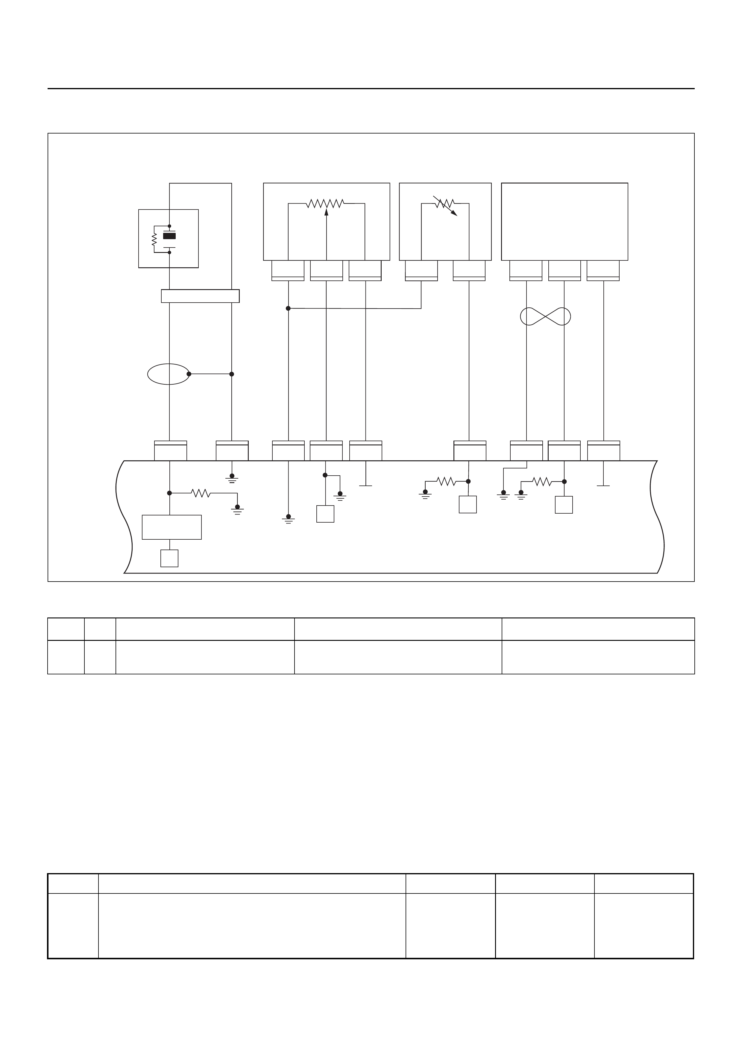
DIAGNOSTIC TROUBLE CODE (DTC) P1391 RRID G Sen Rationality
Condition for setting the DTC and action taken when the DTC sets
Circuit Description
The vertical acceleration sensor monitors the vertical
movement. When the vehicle travels over rough terain
the signal from the vertical sensor is sent to the ECM
and engine pow er is redu ce d consequently.
Diagnostic Aids
Check for the follwing conditions:
A poor connection at th e ECM. Inspec t the RRID sensor
and the ECM connectors for broken locks, improperly
formed or damaged terminals.
• Backed out terminals
• Broken locks
• Improperly formed or damaged terminals.
Also, check the wiring harness for shorts to ground,
shorts to battery positive, and open circuits.
Inspect the RRID sensor harness to ensure that it is not
routed too close to the exhaust system.
Diagnostic Trouble Code (DTC) P1391 RRID G Sen Rationality
Code Type DTC Name DTC Setting Condition Fail-Safe (Back Up)
P1391 A RRID G Sen Rationality Sets when the ECM detects a voltage lower
than 0.41 or higher than 4.59 for one second. No fail safe function.
1
C56
μP
E60
27
12231
12
E60
31
E60
7
E60
26
E60
3J1 J1 J1 J1 J1J1 J2 J2 J2
E60
E68 E68 E68 E69 E69 F10 F10 F10
16
C56
17 25
C56
1
A
23
CB
B
A
E84
0.5
GRY
μP
μP
5Volts
Ref 5Volts
Ref
Knock
Sensor
0.5
YEL
0.5
WHT/
BLU
0.5
BLU/
ORG
0.5
BLU/
ORG
0.5
YEL/
RED
0.5
PUR/
BLU
0.5
GRY/
BLU
0.5
BLK 0.5
ORG 0.5
BLU/
WHT
Engine
Coolant
Temperature (ECT)
Sensor Vertical
G-Sensor
Throttle
Position Sensor
(TPS)
Knock Filter
Module
Engine
Control
Module
(ECM) μP
Step Action Value(s) Yes No
1 Was the “On-Board Diagnostic (OBD) System Check”
performed?
—Go to Step 2
Go to On Board
Diagnostic
(OBD) System
Check
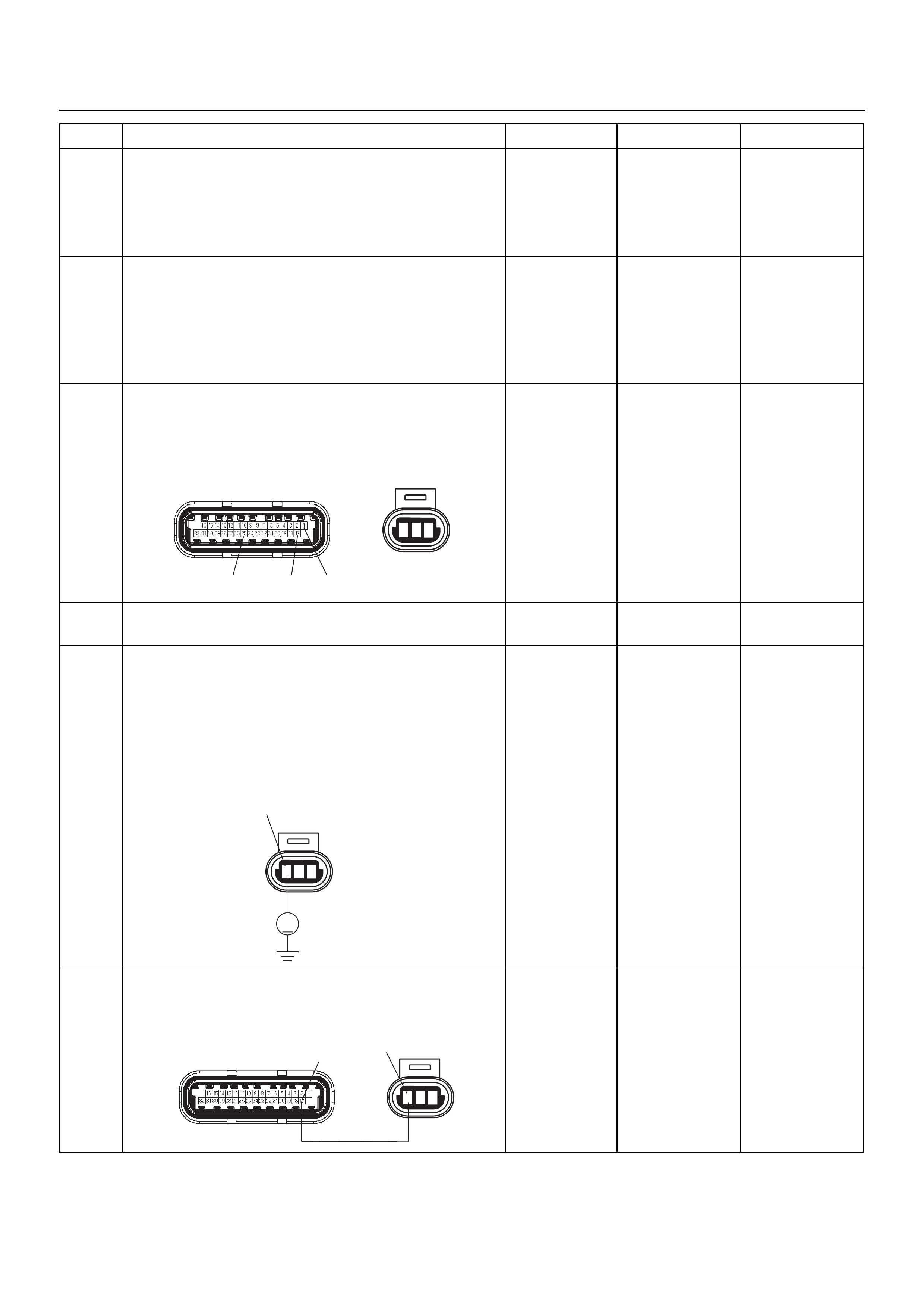
2 1. Connect Tech 2.
2. Review and record the failure information.
3. Select “F0: Read DTC Info Ordered By Priority”
and check for DTC’s.
Is the DTC P1391 stored as “Present Failure”? — Go to Step 3
Refer to
Diagnostic Aids
and Go to Step
3
3 1. Using Tech 2, ignition “On” and engine “Off”.
2. Select “F2: Clear DTC Information” with Tech 2
and clear the DTC information.
3. Operate the vehicle and monitor the “F1: Read
DTC Info as Stored by ECU”.
Was the DTC P1391 stored in this ignition cycle? — Go to Step 4
Refer to
Diagnostic Aids
and Go to Step
4
4 Check for poor/faulty connection at the RRID sensor
or ECM connector. If a poor/faulty connection is
found, repair as necessary.
Was the problem found?
— Verify repair G o to Step 5
5 Visually check the RRID sensor.
Was the problem found? — Go to Step 10 Go to Step 6
6 Use a DVM to check the RRID sensor power supply
circuit.
1. Ignition “On”, engine “Off”.
2. Disconnect the MAP sensor connector.
3. Check the circuit for short to voltage circuit.
Does the DVM indicate the specified value?
Approximately
5.0V Go to Step 8 Go to Step 7
7 Repair the voltage circuit between the ECM and RRID
sensor.
Was the problem solved?
— Verify repair G o to Step 8
Step Action Value(s) Yes No
123
C-56(J2) F-10
17
25 1
123
F-10
V
1
123
C-56(J2) F-10
17 1
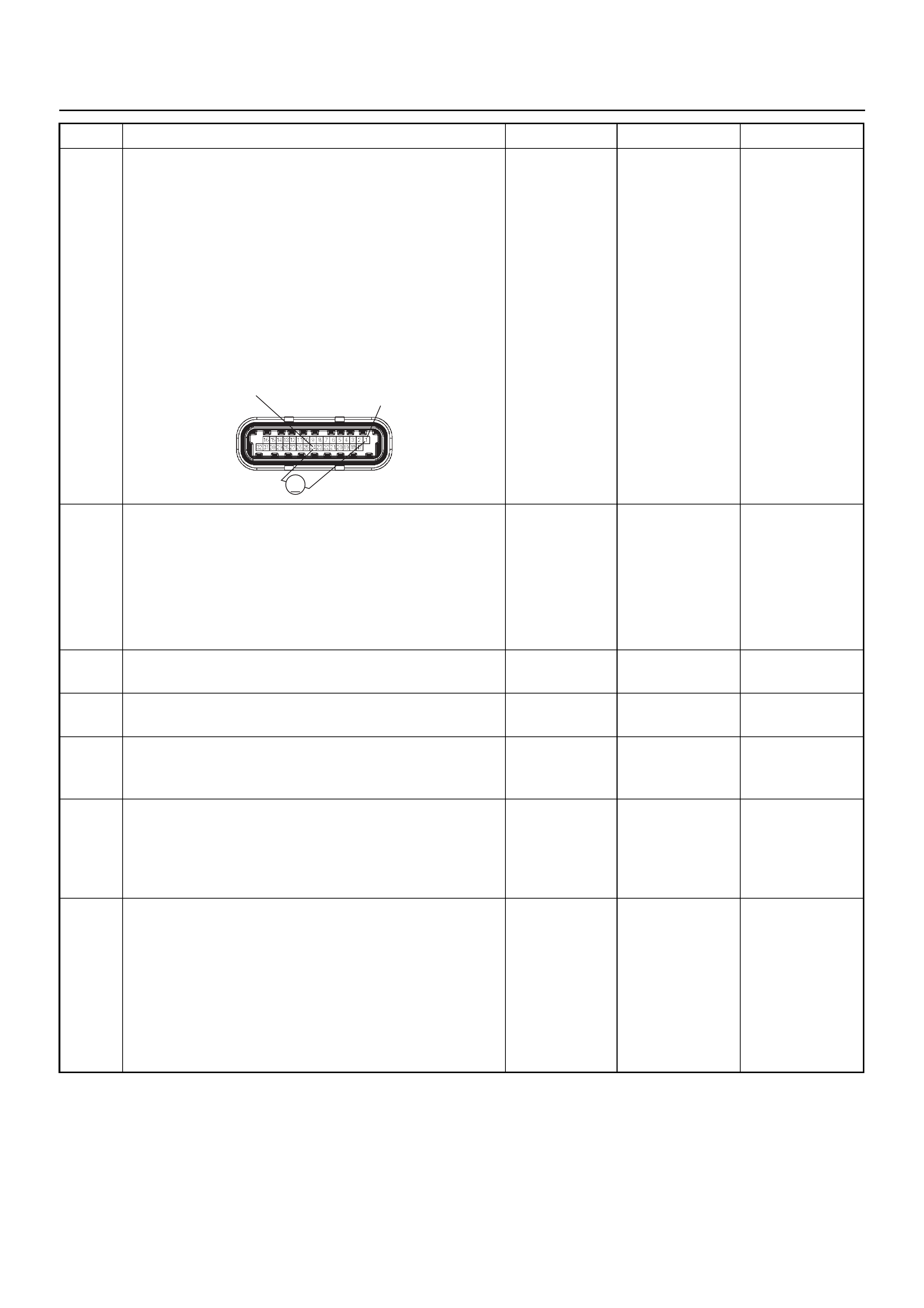
8 Remove the RRID sensor from its mounting bracket
under the vehicle chassis. Refer to On Vehicle
Servicing in this section.
1. Using a DVM check the RRID sensor signal circuit
at the ECM connector.
2. Switch Ignition “On”, engine “Off”.
3. Rapidly move the RRID sensor vertically up and
down.
4. Check the output signal circuit from the RRID
sensor.
Is the DVM indicating the specified value?
Between
1.8 - 3.3V Go to Step 9
Repair faulty
harness and
verify repair
9 Perform the following inspection of the RRID sensor.
1. Inspect the sensor wiring harness for conditions
that may induce electromagnetic interference.
2. Inspect the RRID sensor for incorrect sensor
installation or incorrect attaching nut torque value.
Refer to On Vehicle Servicing in this section.
Was any fault found and rectified? - Go to Step 10
Repair faulty
harness and
verify repair
10 Substitute a known good RRID sensor and recheck.
Was the problem solved? — Go to Step 11 Go to Step 12
11 Replace the RRID sensor.
Is the action complete? — Verify repair —
12 Check any accessory parts which may cause electric
interference or magnetic interference.
Was the problem found? —
Remove the
accessory parts
and verify repair Go to Step 13
13 Is the ECM programmed with the latest software
release?
If not, download the latest software to the ECM using
the “SPS (Service Programming System)”.
Was the problem solved? — Verify repair Go to Step 14
14 Replace the ECM.
Is the action complete?
IMPORTANT: The replacement ECM must be
programmed. Refer to the Service Programming
System (SPS) section in this manual.
Following ECM programming, the immobiliser system
must be linked to the ECM. Refer to section 11
“Immobiliser System-ECM replacement” for the ECM/
Immobiliser linking procedure. — Verify repair —
Step Action Value(s) Yes No
C-56(J2) 1
25
V
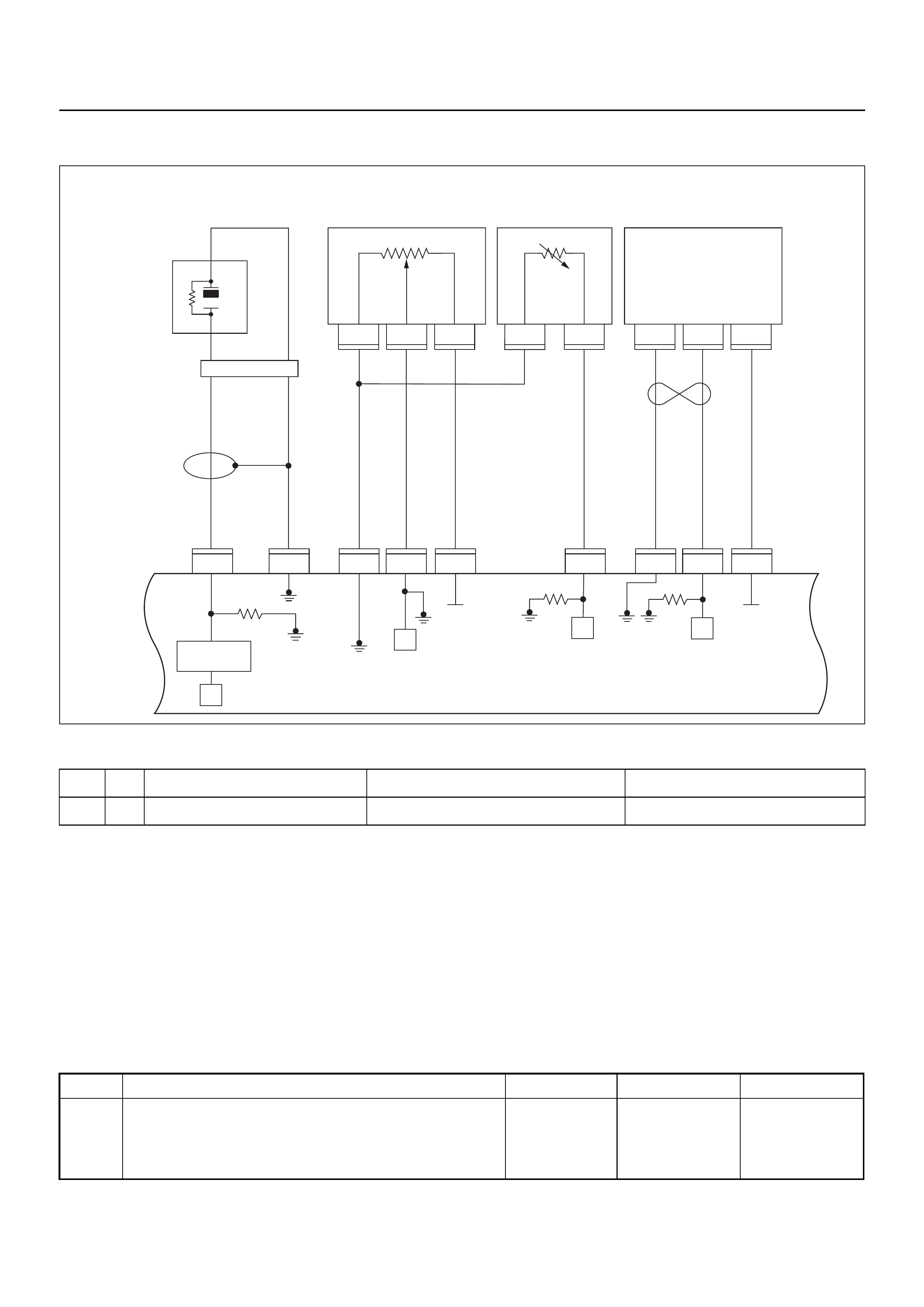
DIAGNOSTIC TROUBLE CODE (DTC) P1392 RRID G Sen Short Low
Condition for setting the DTC and action taken when the DTC sets
Circuit Description
The vertical acceleration sensor monitors the vertical
movement. When the vehicle travels over rough terain
the signal from the vertical sensor is sent to the ECM
and engine pow er is redu ce d consequently.
Diagnostic Aids
Check for the follwing conditions:
A poor connection at th e ECM. Inspec t the RRID sensor
and the ECM connectors for broken locks, improperly
formed or damaged terminals.
• Backed out terminals
• Broken locks
• Improperly formed or damaged terminals.
Also, check the wiring harness for shorts to ground,
shorts to battery positive, and open circuits.
Inspect the RRID sensor harness to ensure that it is not
routed too close to the exhaust system.
Diagnostic Trouble Code (DTC) P1392 RRID G Sen Short Low
Code Type DTC Name DTC Setting Condition Fail-Safe (Back Up)
P1392 A RRID G Sen Short Low Sets if input is shorted to ground. No fail safe function.
1
C56
μP
E60
27
12231
12
E60
31
E60
7
E60
26
E60
3J1 J1 J1 J1 J1J1 J2 J2 J2
E60
E68 E68 E68 E69 E69 F10 F10 F10
16
C56
17 25
C56
1
A
23
CB
B
A
E84
0.5
GRY
μP
μP
5Volts
Ref 5Volts
Ref
Knock
Sensor
0.5
YEL
0.5
WHT/
BLU
0.5
BLU/
ORG
0.5
BLU/
ORG
0.5
YEL/
RED
0.5
PUR/
BLU
0.5
GRY/
BLU
0.5
BLK 0.5
ORG 0.5
BLU/
WHT
Engine
Coolant
Temperature (ECT)
Sensor Vertical
G-Sensor
Throttle
Position Sensor
(TPS)
Knock Filter
Module
Engine
Control
Module
(ECM) μP
Step Action Value(s) Yes No
1 Was the “On-Board Diagnostic (OBD) System Check”
performed?
—Go to Step 2
Go to On Board
Diagnostic
(OBD) System
Check
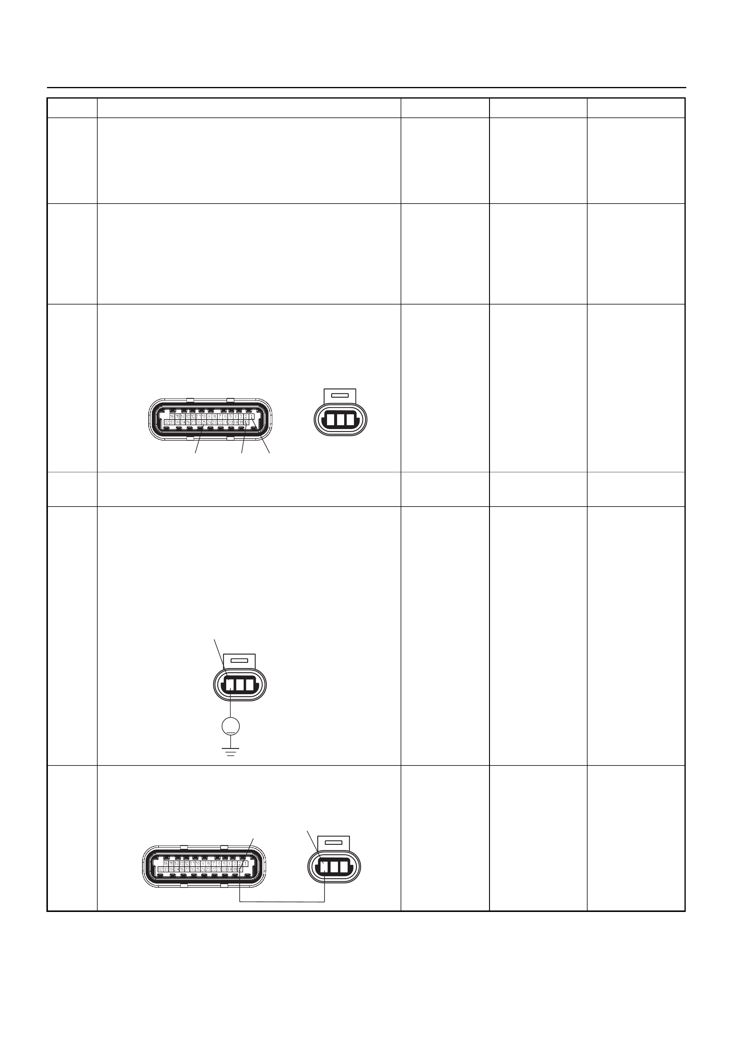
2 1. Connect Tech 2.
2. Review and record the failure information.
3. Select “F0: Read DTC Info Ordered By Priority”
and check for DTC’s.
Is the DTC P1392 stored as “Present Failure”? — Go to Step 3
Refer to
Diagnostic Aids
and Go to Step
3
3 1. Using Tech 2, ignition “On” and engine “Off”.
2. Select “F2: Clear DTC Information” with Tech 2
and clear the DTC information.
3. Operate the vehicle and monitor the “F1: Read
DTC Info as Stored by ECU”.
Was the DTC P1392 stored in this ignition cycle? — Go to Step 4
Refer to
Diagnostic Aids
and Go to Step
4
4 Check for poor/faulty connection at the RRID sensor
or ECM connector. If a poor/faulty connection is
found, repair as necessary.
Was the problem found?
— Verify repair G o to Step 5
5 Visually check the RRID.
Was the problem found? — Go to Step 9 Go to Step 6
6 Use a DVM to check the RRID sensor power supply
circuit.
1. Ignition “On”, engine “Off”.
2. Disconnect the RRID sensor connector.
3. Check the circuit for open or short to ground
circuit.
Does the DVM indicate the specified value?
Approximately
5.0V Go to Step 8 Go to Step 7
7 Repair the open or short to ground circuit between the
ECM and RRID sensor
Was the problem solved?
— Verify repair G o to Step 11
Step Action Value(s) Yes No
123
C-56(J2) F-10
17
25 1
123
F-10
V
1
123
C-56(J2) F-10
17 1
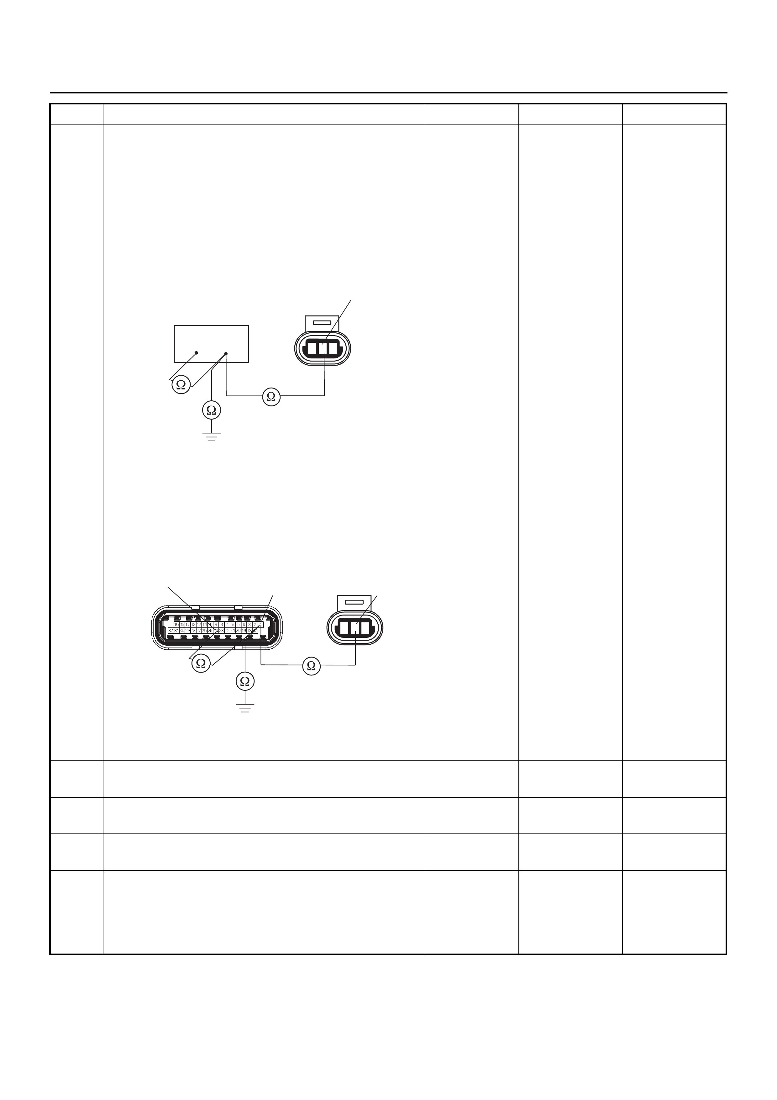
8 Use a DVM to check the RRID sensor signal circuit.
Breaker box is available:
1. Ignition “Off”, engine “Off”.
2. Install the breaker box as type A. (ECM
disconnected) Ref. 6E-77.
3. Disconnect RRID sensor connector.
4. Check the circuit for open, short to sensor ground
or short to ground circuit.
Was the problem found?
Breaker box is not available:
1. Ignition “Off”, engine “Off”.
2. Disconnect the RRID sensor connector and ECM
connector.
3. Check the circuit for open, short to sensor ground
or short to ground circuit.
Was the problem found?
—
Repair faulty
harness and
verify repair Go to Step 9
9 Substitute a known good RRID sensor and recheck.
Was the problem solved? — Go to Step 10 Go to Step 11
10 Replace the RRID sensor.
Is the action complete? — Verify repair —
11 Substitute a known good RRID sensor and recheck.
Was the problem solved? — Go to Step 12 Go to Step 13
12 Replace the RRID sensor.
Is the action complete? — Verify repair —
13 Is the ECM programmed with the latest software
release?
If not, download the latest software to the ECM using
the “SPS (Service Programming System)”.
Was the problem solved? — Verify repair Go to Step 14
Step Action Value(s) Yes No
123
F-10 2
57
33
123
C-56(J2) F-10
12
25

14 Replace the ECM.
Is the action complete?
IMPORTANT: The replacement ECM must be
programmed. Refer to the Service Programming
System (SPS) section in this manual.
Following ECM programming, the immobiliser system
must be linked to the ECM. Refer to section 11
“Immobiliser System-ECM replacement” for the ECM/
Immobiliser linking procedure. — Verify repair —
Step Action Value(s) Yes No
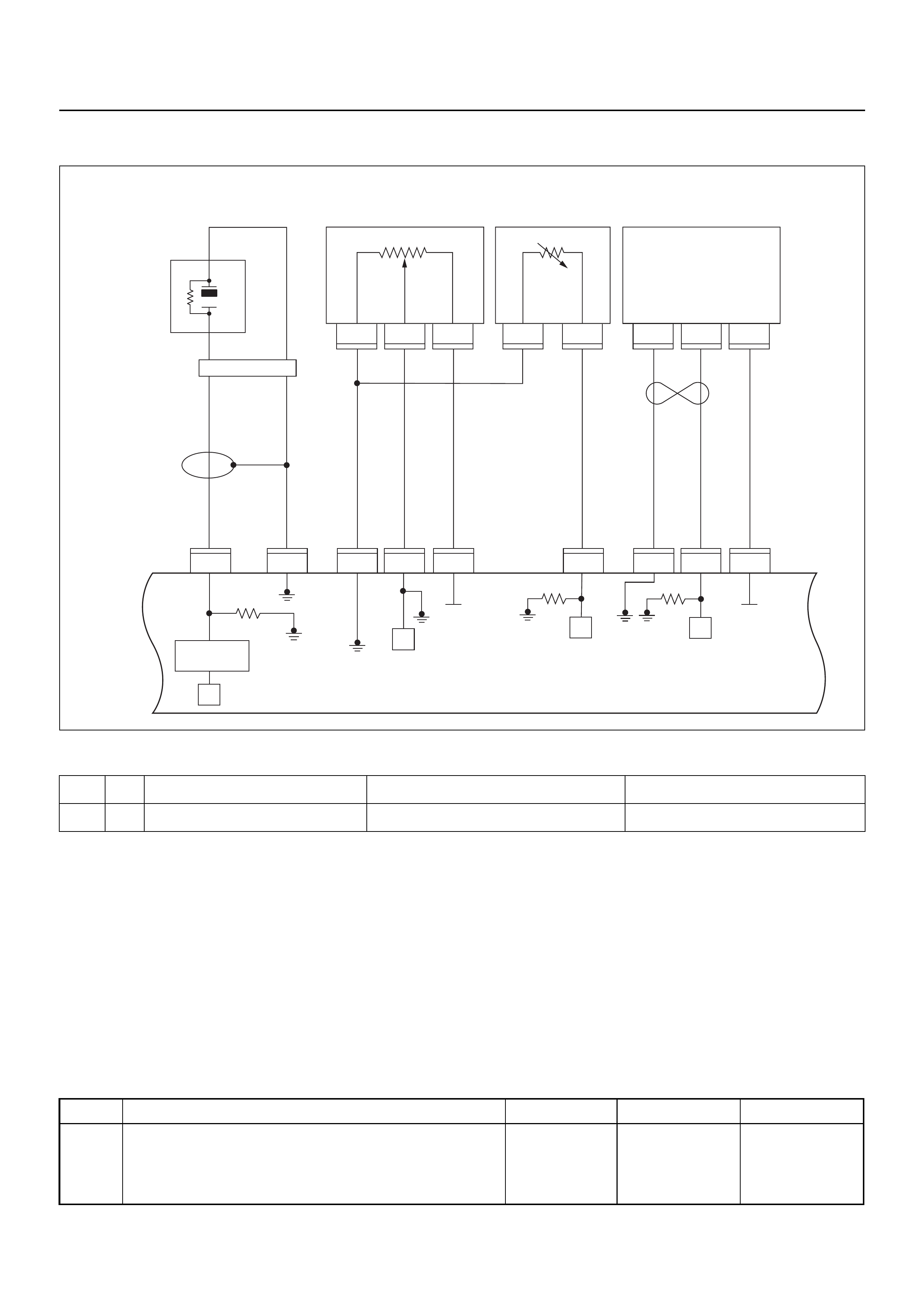
DIAGNOSTIC TROUBLE CODE (DTC) P1393 RRID G Sen Short High
Condition for setting the DTC and action taken when the DTC sets
Circuit Description
The vertical acceleration sensor monitors the vertical
movement. When the vehicle travels over rough terain
the signal from the vertical sensor is sent to the ECM
and engine pow er is redu ce d consequently.
Diagnostic Aids
Check for the follwing conditions:
A poor connection at th e ECM. Inspec t the RRID sensor
and the ECM connectors for broken locks and
improperly formed or damaged terminals.
• Backed out terminals
• Broken locks
• Improperly formed or damaged terminals.
Also, check the wiring harness for shorts to ground,
shorts to battery positive, and open circuits.
Inspect the RRID sensor harness to ensure that it is not
routed too close to the exhaust system.
Diagnostic Trouble Code (DTC) P1393 RRID G Sen Short High
Code Type DTC Name DTC Setting Condition Fail-Safe (Back Up)
P1393 A RRID G Sen Short High Sets if input is shorted to supply voltage. No fail safe function.
1
C56
μP
E60
27
12231
12
E60
31
E60
7
E60
26
E60
3J1 J1 J1 J1 J1J1 J2 J2 J2
E60
E68 E68 E68 E69 E69 F10 F10 F10
16
C56
17 25
C56
1
A
23
CB
B
A
E84
0.5
GRY
μP
μP
5Volts
Ref 5Volts
Ref
Knock
Sensor
0.5
YEL
0.5
WHT/
BLU
0.5
BLU/
ORG
0.5
BLU/
ORG
0.5
YEL/
RED
0.5
PUR/
BLU
0.5
GRY/
BLU
0.5
BLK 0.5
ORG 0.5
BLU/
WHT
Engine
Coolant
Temperature (ECT)
Sensor Vertical
G-Sensor
Throttle
Position Sensor
(TPS)
Knock Filter
Module
Engine
Control
Module
(ECM) μP
Step Action Value(s) Yes No
1 Was the “On-Board Diagnostic (OBD) System Check”
performed?
—Go to Step 2
Go to On Board
Diagnostic
(OBD) System
Check
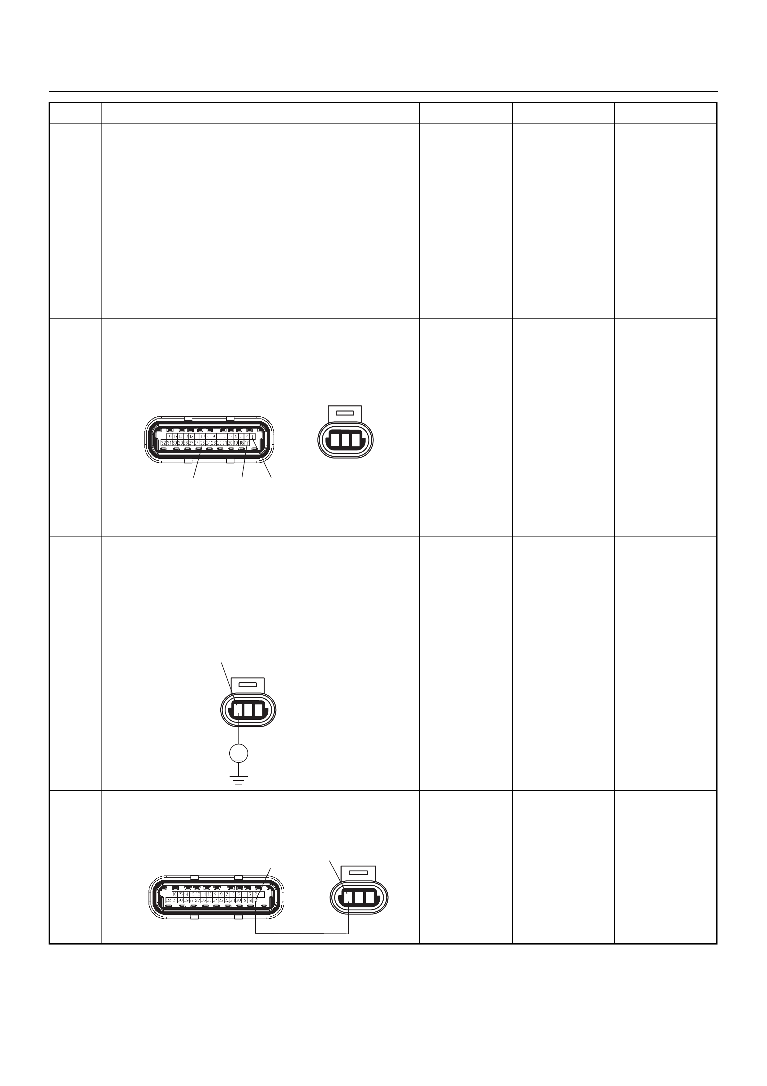
2 1. Connect Tech 2.
2. Review and record the failure information.
3. Select “F0: Read DTC Info Ordered By Priority”
and check for DTC’s.
Is the DTC P1393 stored as “Present Failure”? — Go to Step 3
Refer to
Diagnostic Aids
and Go to Step
3
3 1. Using Tech 2, ignition “On” and engine “Off”.
2. Select “F2: Clear DTC Information” with Tech 2
and clear the DTC information.
3. Operate the vehicle and monitor the “F1: Read
DTC Info as Stored by ECU”.
Was the DTC P1393 stored in this ignition cycle? — Go to Step 4
Refer to
Diagnostic Aids
and Go to Step
4
4 Check for poor/faulty connection at the RRID sensor
or ECM connector. If a poor/faulty connection is
found, repair as necessary.
Was the problem found?
— Verify repair G o to Step 5
5 Visually check the RRID sensor.
Was the problem found? — Go to Step 11 Go to Step 6
6 Use a DVM to check the RRID sensor power supply
circuit.
1. Ignition “On”, engine “Off”.
2. Disconnect the RRID sensor connector.
3. Check the circuit for short to voltage circuit.
Does the DVM indicate the specified value?
Approximately
5.0V Go to Step 8 Go to Step 7
7 Repair the short to voltage circuit between the ECM
and RRID sensor.
Was the problem solved?
— Verify repair Go to Step 13
Step Action Value(s) Yes No
123
C-56(J2) F-10
17
25 1
123
F-10
V
1
123
C-56(J2) F-10
17 1
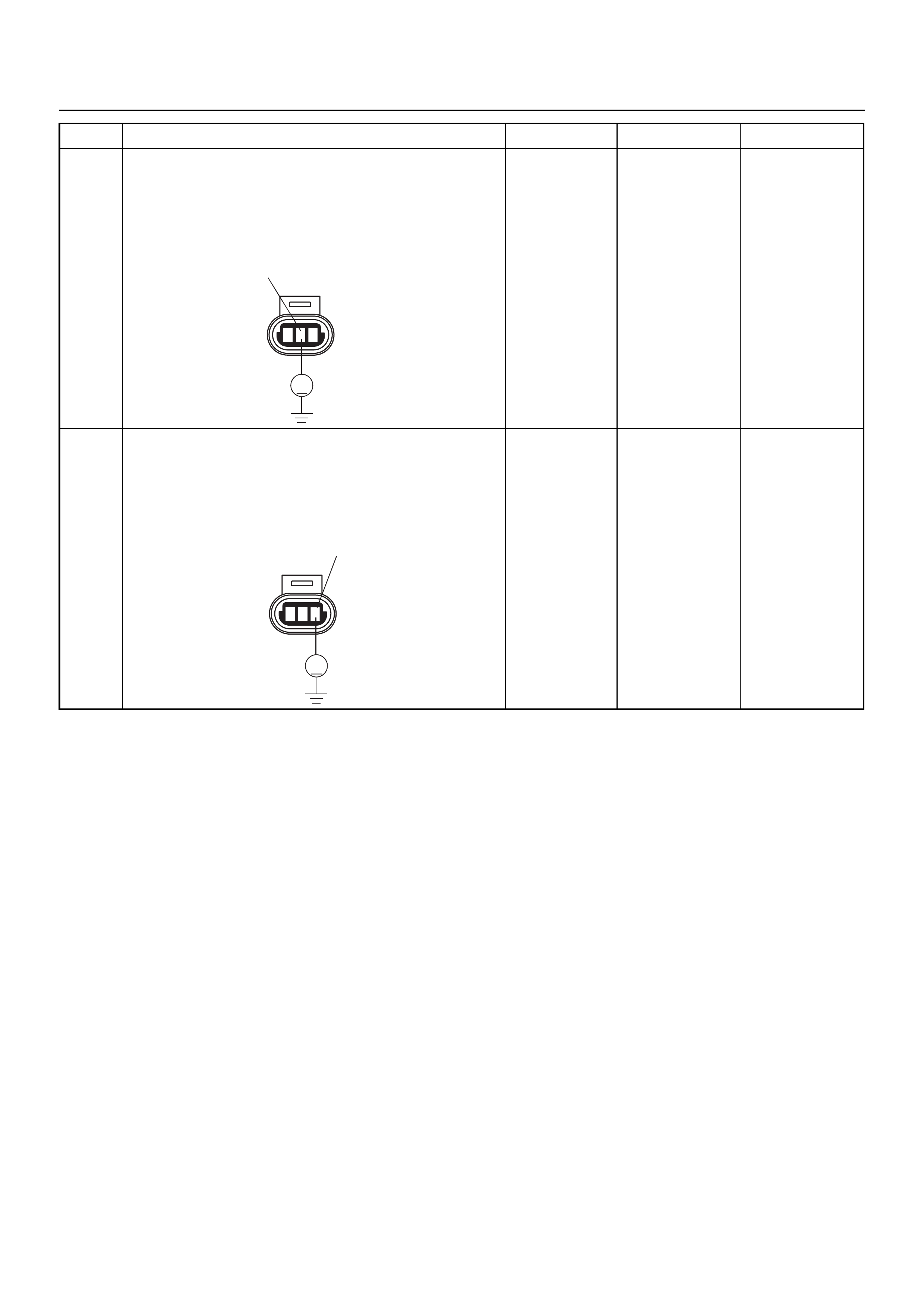
8 Use a DVM to check the RRID sensor signal circuit.
1. Ignition “On”, engine “Off”.
2. Disconnect the RRID sensor connector.
3. Check the circuit for short to power supply circuit.
Does the DVM indicate the specified value?
Less than 1V Go to Step 9
Repair faulty
harness and
verify repair
9 Use a DVM to check the RRID sensor ground circuit.
1. Ignition “On”, engine “Off”.
2. Disconnect the MAP sensor connector .
3. Check the circuit for short to power supply circuit.
Does the DVM indicate the specified value?
Less than 1V Go to Step 10
Repair faulty
harness and
verify repair
Step Action Value(s) Yes No
123
F-10
V
2
123
F-10
V
3
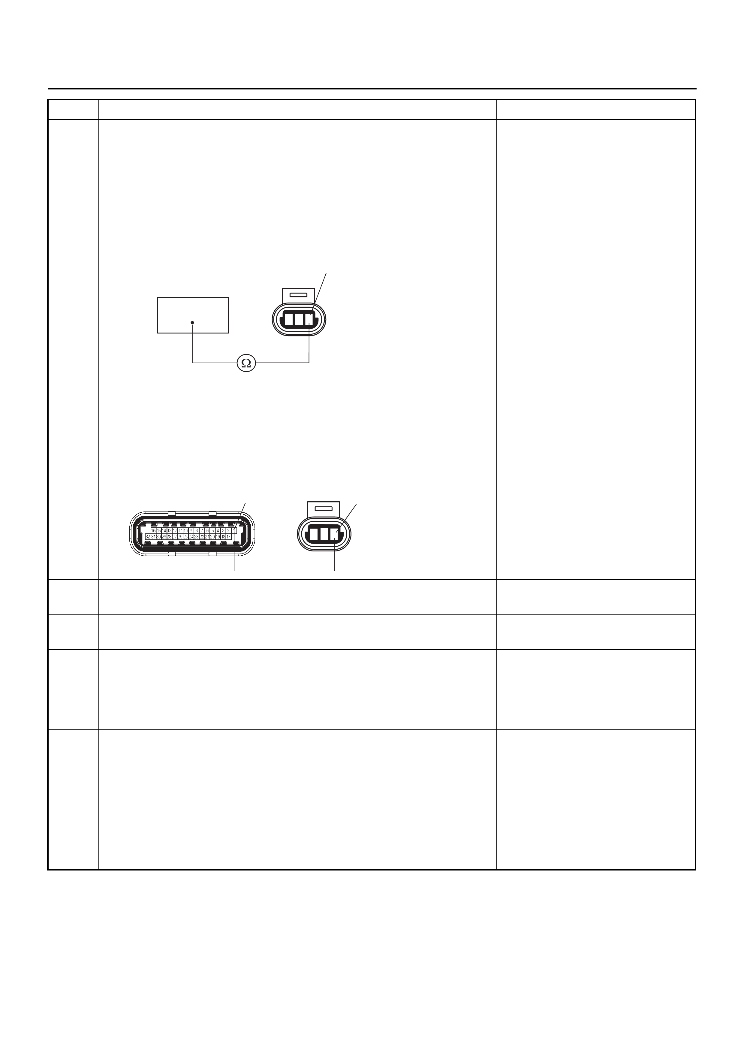
10 Use a DVM to check the RRID sensor ground circuit.
Breaker box is available:
1. Ignition “Off”, engine “Off”.
2. Install the breaker box as type A. (ECM
disconnected) Ref. 6E-77.
3. Disconnect the RRID sensor connector.
4. Check the circuit for open circuit.
Was the problem found?
Breaker box is not available:
1. Ignition “Off”, engine “Off”.
2. Disconnect the RRID sensor connector and ECM
connector.
3. Check the circuit for open circuit.
Was the problem found?
—
Repair faulty
harness and
verify repair Go to Step 11
11 Substitute a known good RRID sensor and recheck.
Was the problem solved? — Go to Step 12 Go to Step 13
12 Replace the RRID sensor.
Is the action complete? — Verify repair —
13 Is the ECM programmed with the latest software
release?
If not, download the latest software to the ECM using
the “SPS (Service Programming System)”.
Was the problem solved? — Verify repair Go to Step 14
14 Replace the ECM.
Is the action complete?
IMPORTANT: The replacement ECM must be
programmed. Refer to the Service Programming
System (SPS) section in this manual.
Following ECM programming, the immobiliser system
must be linked to the ECM. Refer to section 11
“Immobiliser System-ECM replacement” for the ECM/
Immobiliser linking procedure. — Verify repair —
Step Action Value(s) Yes No
123
F-10 3
33
123
C-56(J2) F-10
13

DIAGNOSTIC TROUBLE CODE (DTC) P1625 ECM SYSTEM RESET
Condition for setting the DTC and action taken when the DTC sets
Circuit Description
The engine control module (ECM) monitors unexpected
ECM reset. This will not switch the MIL light on, only
records code DTC P1625.
Diagnostic Aids
Check for the follwing conditions:
• P1625 alone stored does not need diagnosis. Clear
DTC code.
NOTE: DTC P1625 is a DTC to record a ECM reset
history. If DTC P1625 is not reset and no engine
abnormality occurs after learing the DTC, no farther
diagnostic procedures are required.
Diagnostic Trouble Code (DTC) P1625 ECM System Reset
Code Type DTC Name DTC Setting Condition Fail-Safe (Back Up)
P1625 B ECM
System Reset ECM reset has occurred other than “On”. Engine control disabled.
Step Action Value(s) Yes No
1 Was the “On-Board Diagnostic (OBD) System Check”
performed?
—Go to Step 2
Go to On Board
Diagnostic
(OBD) System
Check
2 1. Connect Tech 2.
2. Review and record the failure information.
3. Select “F0: Read DTC Info Ordered By Priority”
and check for DTC’s.
Is the DTC P1625 stored as “Present Failure”? — Go to Step 3
Refer to
Diagnostic Aids
and Go to Step
3
3 1. Using Tech 2, ignition “On” and engine “Off”.
2. Select “F2: Clear DTC Information” with Tech 2
and clear the DTC information.
3. Operate the vehicle and monitor the “F1: Read
DTC Info as Stored by ECU”.
Was the DTC P1625 stored in this ignition cycle? — Go to Step 4
Refer to
Diagnostic Aids
and Go to Step
4
4 Check any accessory parts which may cause electric
interference or magnetic interference.
Was the problem found? —
Remove the
accessory parts
and verify repair Go to Step 5
5 Is the ECM programmed with the latest software
release?
If not, download the latest software to the ECM using
the “SPS (Service Programming System)”.
Was the problem solved? — Verify repair Go to Step 6
6 Replace the ECM.
Is the action complete?
IMPORTANT: The replacement ECM must be
programmed. Refer to the Service Programming
System (SPS) section in this manual.
Following ECM programming, the immobiliser system
must be linked to the ECM. Refer to section 11
“Immobiliser System-ECM replacement” for the ECM/
Immobiliser linking procedure. — Verify repair —
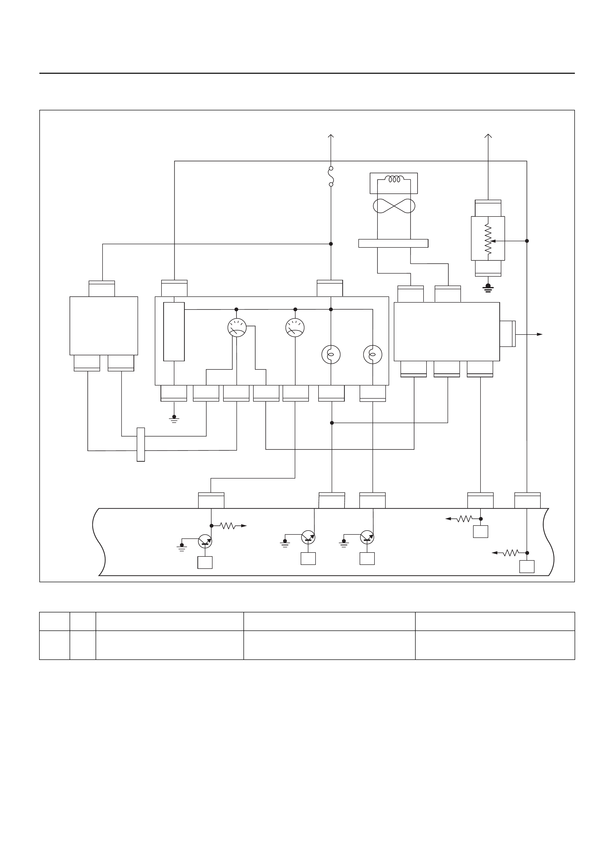
DIAGNOSTIC TROUBLE CODE (DTC) P1626 IMMOBILISER NO SIGNAL
Condition for setting the DTC and action taken when the DTC sets
Circuit Description
The ECM decides if there is an abnomality in the
immobiliser control system. DTC P1626 is recorded by
the ECM when no response from immobiliser.
Diagnostic Aids
Check for the following conditions:
• Poor connection at ECM and Immobiliser. Inspect
harness connectors for backed out terminals,
improper mating, broken locks, improperly formed or
damaged terminals and poor terminal to wire
connection.
• Inspect the wiring harness for damage. If the harness
appears to be OK, disconnect the ECM and
Immobiliser; switch the ignition on. Observe a
voltmeter connected to the suspect driver circuit at
the ECM and Immobiliser harness connector while
moving the connectors and wiring harnesses related
to the MIL. A change in voltage will indicate the
location of the fault.
Code Type DTC Name DTC Setting Condition Fail-Safe (Back Up)
P1626 - Immobiliser No Signal No response from immobiliser control unit. 1. Engine does not start.
2. Check engine lamp flash.
VIgn
VIgn
Engine
Control
Module
(ECM)
Fuel
Level
VSSSVS LampMIL Lamp
Tacho Sig
32
14 30
2
C56
13
C56
7J2 J2J2J2
C56
9J2
C56
4
IGN
SW
F2
F2
B68
B24
B24E44
E44E44
B24 B24 B24 B24 B24 B24
B68 B68
B68
IGN
SW
μPμP
μP
μP
μP
Meter
15A
VIgn
MIL
Lamp SVS
Lamp
Speedo
Meter Tacho
Meter
0.85
YEL
0.5
YEL/
RED
0.8
YEL/
GRN
0.3
BRN/
YEL
0.5
GRN/
WHT
0.5
BLK/
RED
0.3
BRN/
YEL
0.5
BLK/
YEL
0.5
WHT
C56
0.5
BRN/
YEL
0.5
ORG/
BLU
2(–)
3
1
(+)
Vehicle
Speed
Sensor
(VSS) Starter
Relay
Fuel
Sender
Unit
METER
6
6
11 310278
B24
28
78
1
3
3
(–) (+)
1
Immobiliser
Coil
(Antenna)
B70 B70
CPU Immobiliser
Control
Unit (ICU)
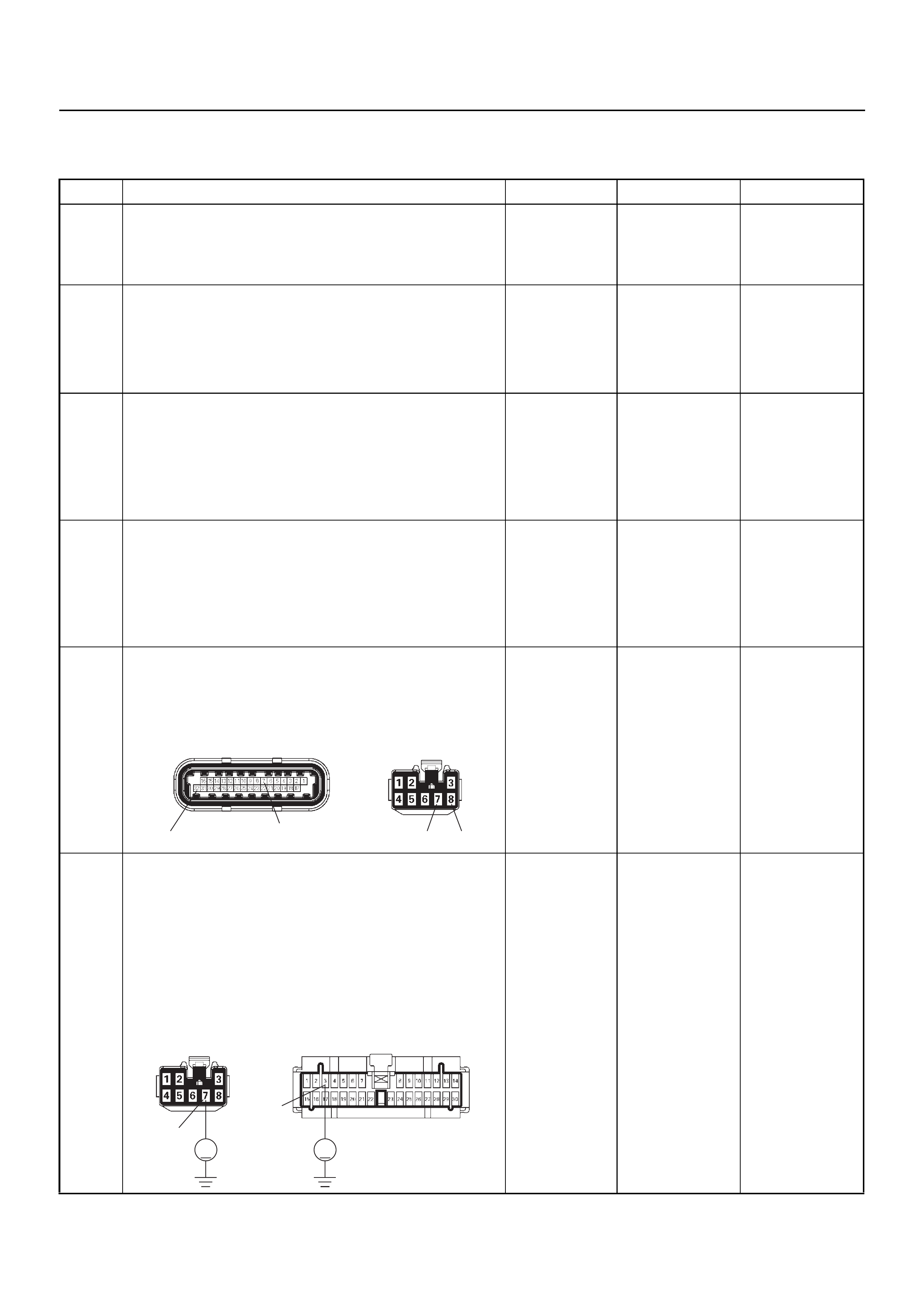
Diagnostic Trouble Code (DTC) P1626 Immobiliser No Signal
Step Action Value(s) Yes No
1 Was the “On-Board Diagnostic (OBD) System Check”
performed?
—Go to Step 2
Go to On Board
Diagnostic
(OBD) System
Check
2 1. Connect Tech 2.
2. Review and record the failure information.
3. Select “F0: Read DTC Info Ordered By Priority”
and check for DTC’s.
Is the DTC P1626 stored as “Present Failure”? — Go to Step 3
Refer to
Diagnostic Aids
and Go to Step
3
3 1. Using Tech 2, ignition “On” and engine “Off”.
2. Select “F2: Clear DTC Information” with Tech 2
and clear the DTC information.
3. Operate the vehicle and monitor the “F1: Read
DTC Info as Stored by ECU”.
Was the DTC P1626 stored in this ignition cycle? — Go to Step 4
Refer to
Diagnostic Aids
and Go to Step
4
4 1. Using Tech 2, ignition “On” and engine “Off”.
2. Select “Immobiliser” in the system selection menu
“Body”.
3. Select “Read DTC Info Ordered By Priority” in the
“Diagnositic Trouble Code”.
Was any DTC's B**** stored in this ignition cycle? —
Refer to
“Immobiliser
Workshop
Manual” & Go
to DTC Chart
B**** Go to Step 5
5 Check for poor/faulty connection at the immobiliser
control unit connector or ECM connector. If a poor/
faulty connection is found, repair as necessary.
Was the problem found?
— Verify repair G o to Step 6
6 Use a DVM to check the “CHECK ENGINE” lamp
circuit.
1. Ignition “Off”, engine “Off”.
2. Disconnect the meter connector and immobiliser
control unit connector.
3. Ignition “On”.
4. Check the circuit for short to power supply circuit.
Was the problem found?
—
Repair faulty
harness and
verify repair Go to Step 7
32 778
C-56(J2) B-68
V V
B-24
B-68
3
7
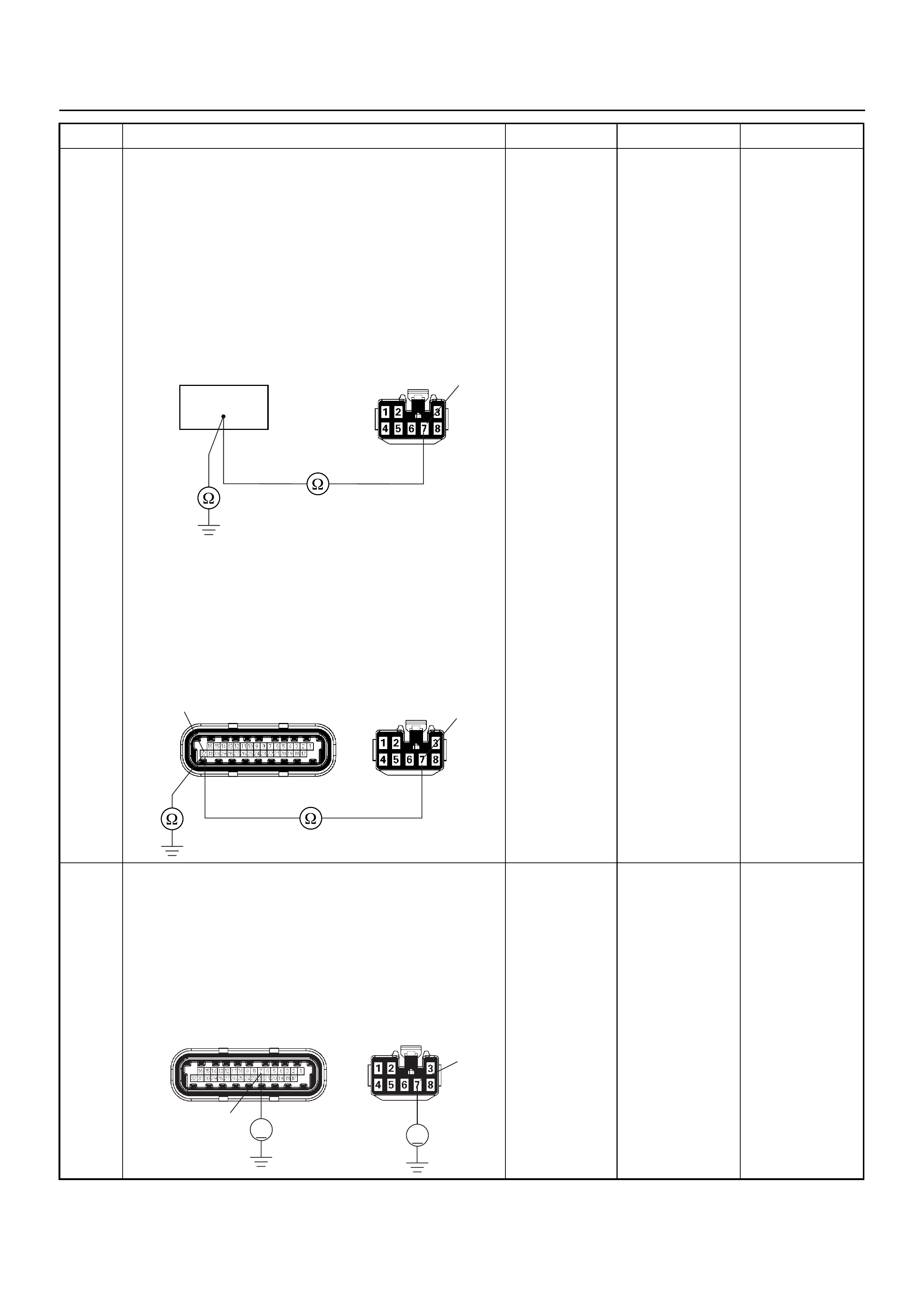
7 Use a DVM to check the “CHECK ENGINE” (MIL)
lamp circuit.
Breaker box is available:
1. Ignition “Off”, engine “Off”.
2. Install the breaker box as type A. (ECM
disconnected) Ref. 6E-77.
3. Disconnect the immobiliser control unit connector.
4. Check the circuit for open or short to ground
circuit.
Was the problem found?
Breaker box is not available:
1. Ignition “Off”, engine “Off”.
2. Disconnect the the immobiliser control unit
connector and ECM connector.
3. Check the circuit for open or short to ground
circuit.
Was the problem found?
—
Repair faulty
harness and
verify repair Go to Step 8
8 Use a DVM to check the VSS signal circuit.
1. Ignition “Off”, engine “Off”.
2. Disconnect the immobiliser control unit connector
and ECM connector.
3. Ignition “On”.
4. Check the circuit for short to power supply circuit.
Was the problem found?
—
Repair faulty
harness and
verify repair Go to Step 9
Step Action Value(s) Yes No
64
B-68 7
C-56(J2)
32 7
B-68
VV
C-56(J2)
7
7
B-68
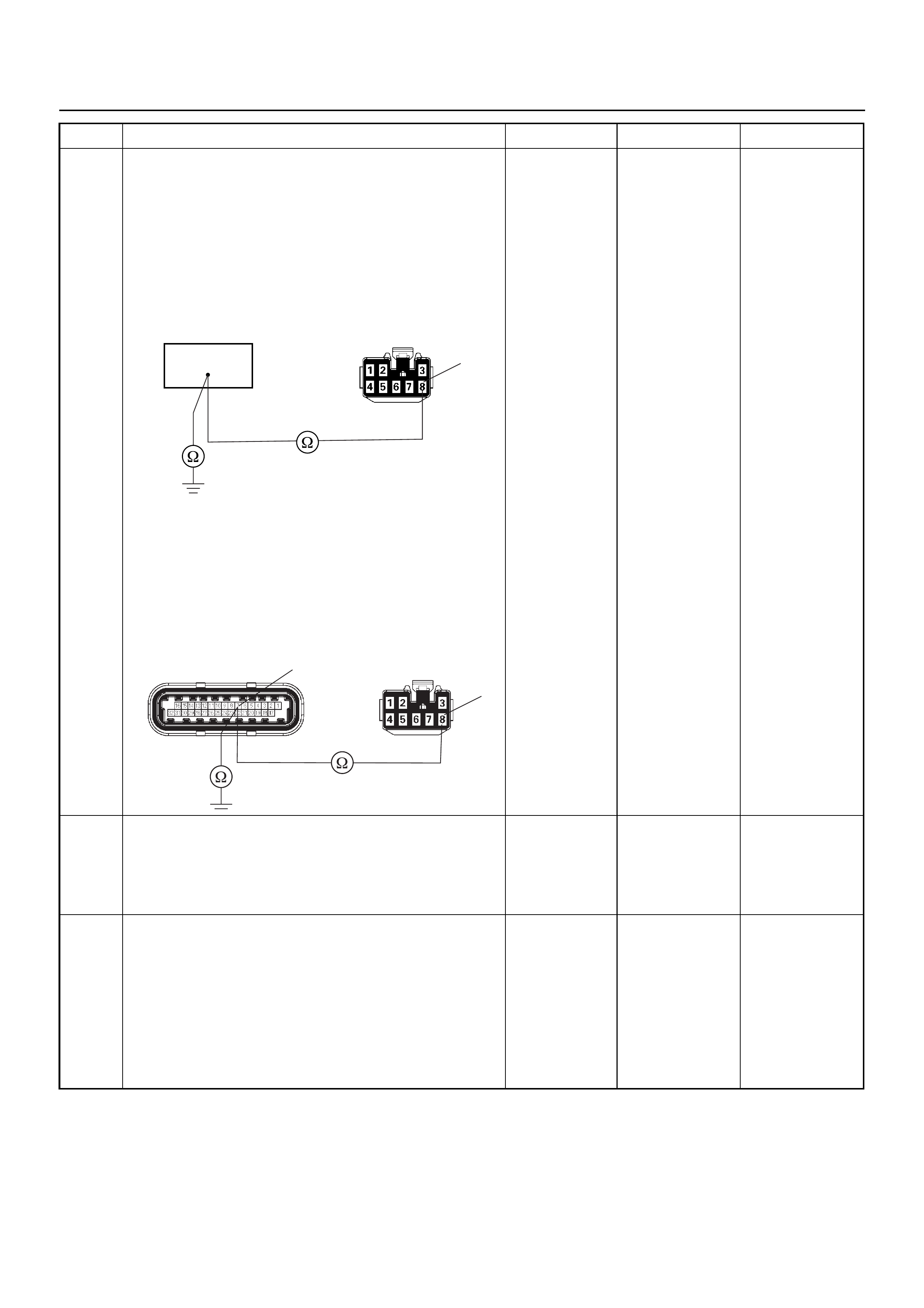
9 Use a DVM to check the VSS signal circuit.
Breaker box is available:
1. Ignition “Off”, engine “Off”.
2. Install the breaker box as type A. (ECM
disconnected) Ref. 6E-77.
3. Disconnect the immobiliser control unit connector.
4. Check the circuit for open or shot to ground circuit.
Was the problem found?
Breaker box is not available:
1. Ignition “Off”, engine “Off”.
2. Disconnect the immobiliser control unit connector
and ECM connector.
3. Check the circuit for open or short to ground
circuit.
Was the problem found?
—
Repair faulty
harness and
verify repair Go to Srtep 10
10 Is the ECM programmed with the latest software
release?
If not, download the latest software to the ECM using
the “SPS (Service Programming System)”.
Was the problem solved? — Verify repair Go to Step 11
11 Replace the ECM.
Is the action complete?
IMPORTANT: The replacement ECM must be
programmed. Refer to the Service Programming
System (SPS) section in this manual.
Following ECM programming, the immobiliser system
must be linked to the ECM. Refer to section 11
“Immobiliser System-ECM replacement” for the ECM/
Immobiliser linking procedure. — Verify repair —
Step Action Value(s) Yes No
55
B-68 8
7B-68
C-56(J2) 8
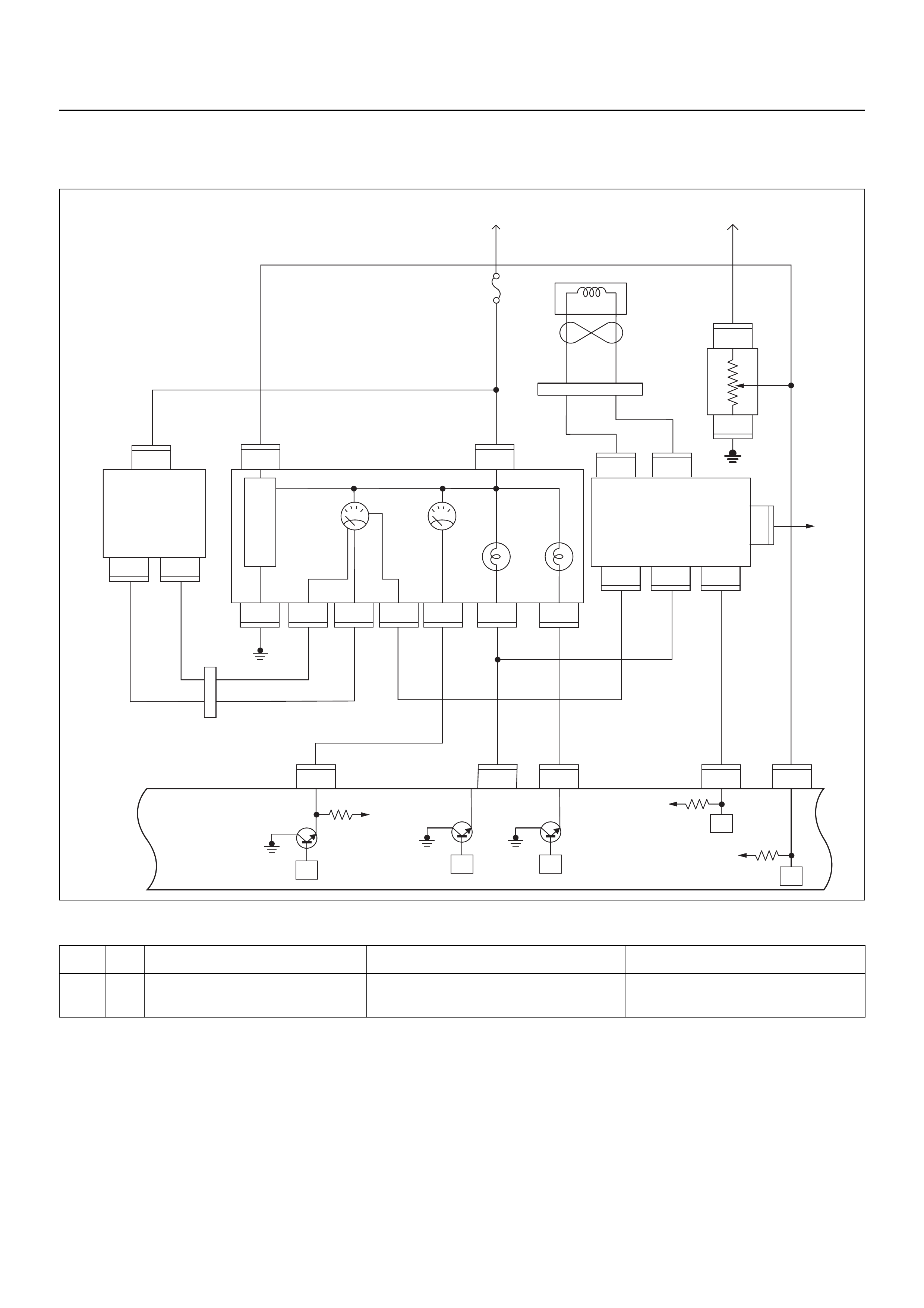
DIAGNOSTIC TROUBLE CODE (DTC) P1631
IMMOBILISER WRONG SIGNAL
Condition for setting the DTC and action taken when the DTC sets
Circuit Description
The ECM decides if there is an abnomality in the
immobiliser control system. DTC P1631 is recorded by
the ECM when received response was not correct.
Diagnostic Aids
Check for the following conditions:
• Poor connection at ECM and Immobiliser. Inspect
harness connectors for backed out terminals,
improper mating, broken locks, improperly formed or
damaged terminals and poor terminal to wire
connection.
• Inspect the wiring harness for damage. If the harness
appears to be OK, disconnect the ECM and
Immobiliser; switch the ignition on. Observe a
voltmeter connected to the suspect driver circuit at
the ECM and Immobiliser harness connector while
moving the connectors and wiring harnesses related
to the MIL. A change in voltage will indicate the
Code Type DTC Name DTC Setting Condition Fail-Safe (Back Up)
P1631 - Immobiliser Wrong Signal Received response is not correct. 1. Engine does not start.
2. Check engine lamp flash.
VIgn
VIgn
Engine
Control
Module
(ECM)
Fuel
Level
VSSSVS LampMIL Lamp
Tacho Sig
32
14 30
2
C56
13
C56
7J2 J2J2J2
C56
9J2
C56
4
IGN
SW
F2
F2
B68
B24
B24E44
E44E44
B24 B24 B24 B24 B24 B24
B68 B68
B68
IGN
SW
μPμP
μP
μP
μP
Meter
15A
VIgn
MIL
Lamp SVS
Lamp
Speedo
Meter Tacho
Meter
0.85
YEL
0.5
YEL/
RED
0.8
YEL/
GRN
0.3
BRN/
YEL
0.5
GRN/
WHT
0.5
BLK/
RED
0.3
BRN/
YEL
0.5
BLK/
YEL
0.5
WHT
C56
0.5
BRN/
YEL
0.5
ORG/
BLU
2(–)
3
1
(+)
Vehicle
Speed
Sensor
(VSS) Starter
Relay
Fuel
Sender
Unit
METER
6
6
11 310278
B24
28
78
1
3
3
(–) (+)
1
Immobiliser
Coil
(Antenna)
B70 B70
CPU Immobiliser
Control
Unit (ICU)
location of the fault.

Diagnostic Trouble Code (DTC) P1631 Immobiliser Wrong Signal
Step Action Value(s) Yes No
1 Was the “On-Board Diagnostic (OBD) System Check”
performed?
—Go to Step 2
Go to On Board
Diagnostic
(OBD) System
Check
2 1. Connect Tech 2.
2. Review and record the failure information.
3. Select “F0: Read DTC Info Ordered By Priority”
and check for DTC’s.
Is the DTC P1631 stored as “Present Failure”? — Go to Step 3
Refer to
Diagnostic Aids
and Go to Step
3
3 1. Using Tech 2, ignition “On” and engine “Off”.
2. Select “F2: Clear DTC Information” with Tech 2
and clear the DTC information.
3. Operate the vehicle and monitor the “F1: Read
DTC Info as Stored by ECU”.
Was the DTC P1631 stored in this ignition cycle? — Go to Step 4
Refer to
Diagnostic Aids
and Go to Step
4
4 1. Using Tech 2, ignition “On” and engine “Off”.
2. Select “Immobiliser” in the system selection menu
“Body”.
3. Select “Read DTC Info Ordered By Priority” in the
“Diagnositic Trouble Code”.
Was any DTC's B**** stored in this ignition cycle? —
Refer to
“Immobiliser
Workshop
Manual” & Go
to DTC Chart
B**** Go to Step 5
5 Is the ECM programmed with the latest software
release?
If not, download the latest software to the ECM using
the “SPS (Service Programming System)”.
Was the problem solved? — Verify repair Go to Step 6
6 Replace the ECM.
Is the action complete?
IMPORTANT: The replacement ECM must be
programmed. Refer to the Service Programming
System (SPS) section in this manual.
Following ECM programming, the immobiliser system
must be linked to the ECM. Refer to section 11
“Immobiliser System-ECM replacement” for the ECM/
Immobiliser linking procedure. — Verify repair —
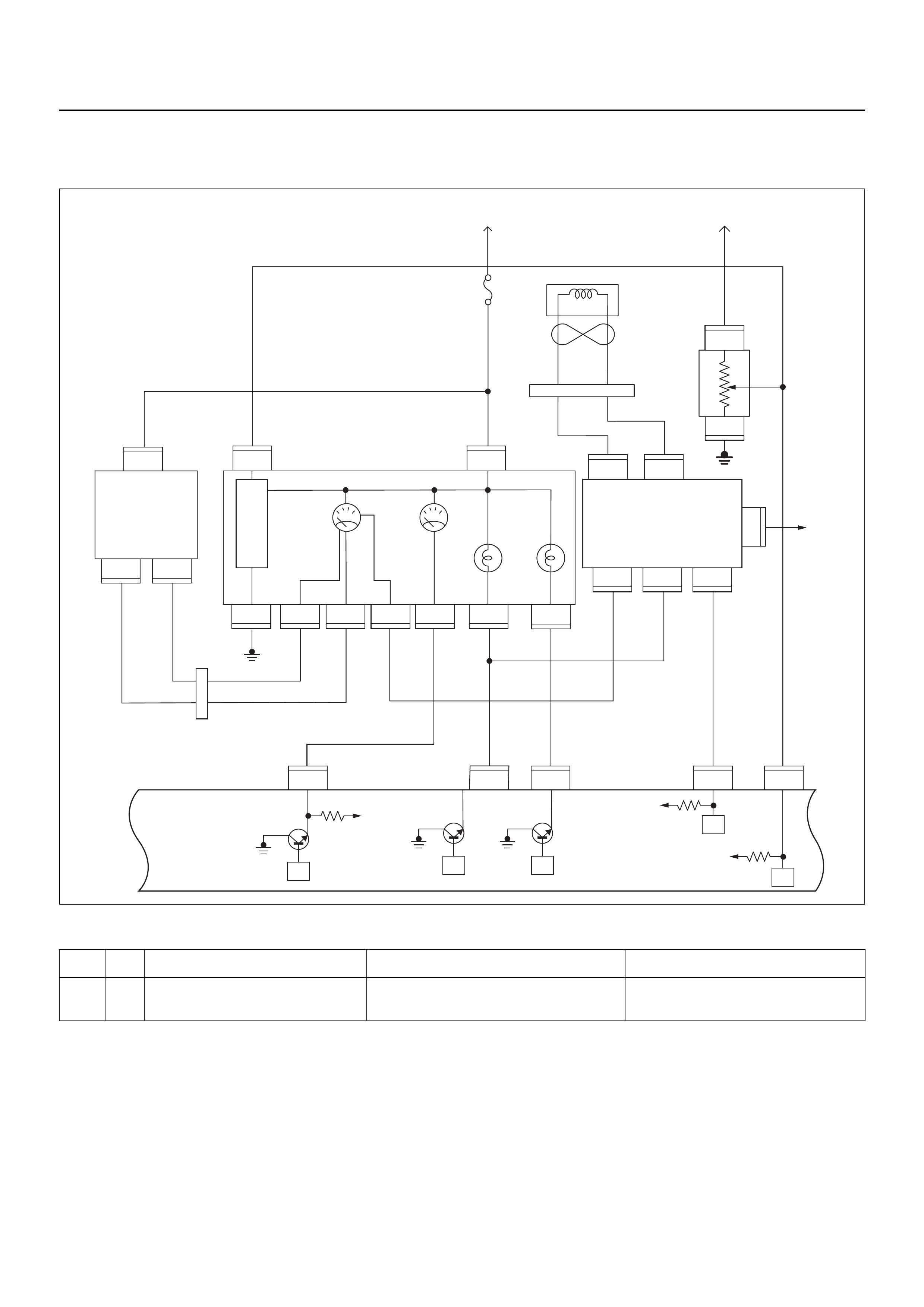
DIAGNOSTIC TROUBLE CODE (DTC) P1648
WRONG SECURITY CODE ENTERED
Condition for setting the DTC and action taken when the DTC sets
Circuit Description
The ECM decides if there is an abnomality in the
immobiliser control system. DTC P1648 is recorded by
the ECM when received incorrect security code.
Diagnostic Aids
Check for the following conditions:
• Poor connection at ECM and Immobiliser. Inspect
harness connectors for backed out terminals,
improper mating, broken locks, improperly formed or
damaged terminals and poor terminal to wire
connection.
• Inspect the wiring harness for damage. If the harness
appears to be OK, disconnect the ECM and
Immobiliser; switch the ignition on. Observe a
voltmeter connected to the suspect driver circuit at
the ECM and Immobiliser harness connector while
moving the connectors and wiring harnesses related
to the MIL. A change in voltage will indicate the
Code Type DTC Name DTC Setting Condition Fail-Safe (Back Up)
P1648 - Wrong Security Code Entered Received incorrect security code. 1. Engine does not start.
2. Check engine lamp flash.
VIgn
VIgn
Engine
Control
Module
(ECM)
Fuel
Level
VSSSVS LampMIL Lamp
Tacho Sig
32
14 30
2
C56
13
C56
7J2 J2J2J2
C56
9J2
C56
4
IGN
SW
F2
F2
B68
B24
B24E44
E44E44
B24 B24 B24 B24 B24 B24
B68 B68
B68
IGN
SW
μPμP
μP
μP
μP
Meter
15A
VIgn
MIL
Lamp SVS
Lamp
Speedo
Meter Tacho
Meter
0.85
YEL
0.5
YEL/
RED
0.8
YEL/
GRN
0.3
BRN/
YEL
0.5
GRN/
WHT
0.5
BLK/
RED
0.3
BRN/
YEL
0.5
BLK/
YEL
0.5
WHT
C56
0.5
BRN/
YEL
0.5
ORG/
BLU
2(–)
3
1
(+)
Vehicle
Speed
Sensor
(VSS) Starter
Relay
Fuel
Sender
Unit
METER
6
6
11 310278
B24
28
78
1
3
3
(–) (+)
1
Immobiliser
Coil
(Antenna)
B70 B70
CPU Immobiliser
Control
Unit (ICU)
location of the fault..

Diagnostic Trouble Code (DTC) P1648 Wrong Security Code Entered
Step Action Value(s) Yes No
1 Was the “On-Board Diagnostic (OBD) System Check”
performed?
—Go to Step 2
Go to On Board
Diagnostic
(OBD) System
Check
2 1. Connect Tech 2.
2. Review and record the failure information.
3. Select “F0: Read DTC Info Ordered By Priority”
and check for DTC’s.
Is the DTC P1648 stored as “Present Failure”? — Go to Step 3
Refer to
Diagnostic Aids
and Go to Step
3
3 1. Using Tech 2, ignition “On” and engine “Off”.
2. Select “F2: Clear DTC Information” with Tech 2
and clear the DTC information.
3. Operate the vehicle and monitor the “F1: Read
DTC Info as Stored by ECU”.
Was the DTC P1648 stored in this ignition cycle? — Go to Step 4
Refer to
Diagnostic Aids
and Go to Step
4
4 1. Using Tech 2, ignition “On” and engine “Off”.
2. Select “Immobiliser” in the system selection menu
“Body”.
3. Select “Read DTC Info Ordered By Priority” in the
“Diagnositic Trouble Code”.
Was any DTC's B**** stored in this ignition cycle? —
Refer to
“Immobiliser
Workshop
Manual” & Go
to DTC Chart
B**** Go to Step 5
5 Is the ECM programmed with the latest software
release?
If not, download the latest software to the ECM using
the “SPS (Service Programming System)”.
Was the problem solved? — Verify repair Go to Step 6
6 Replace the ECM.
Is the action complete?
IMPORTANT: The replacement ECM must be
programmed. Refer to the Service Programming
System (SPS) section in this manual.
Following ECM programming, the immobiliser system
must be linked to the ECM. Refer to section 11
“Immobiliser System-ECM replacement” for the ECM/
Immobiliser linking procedure. — Verify repair —
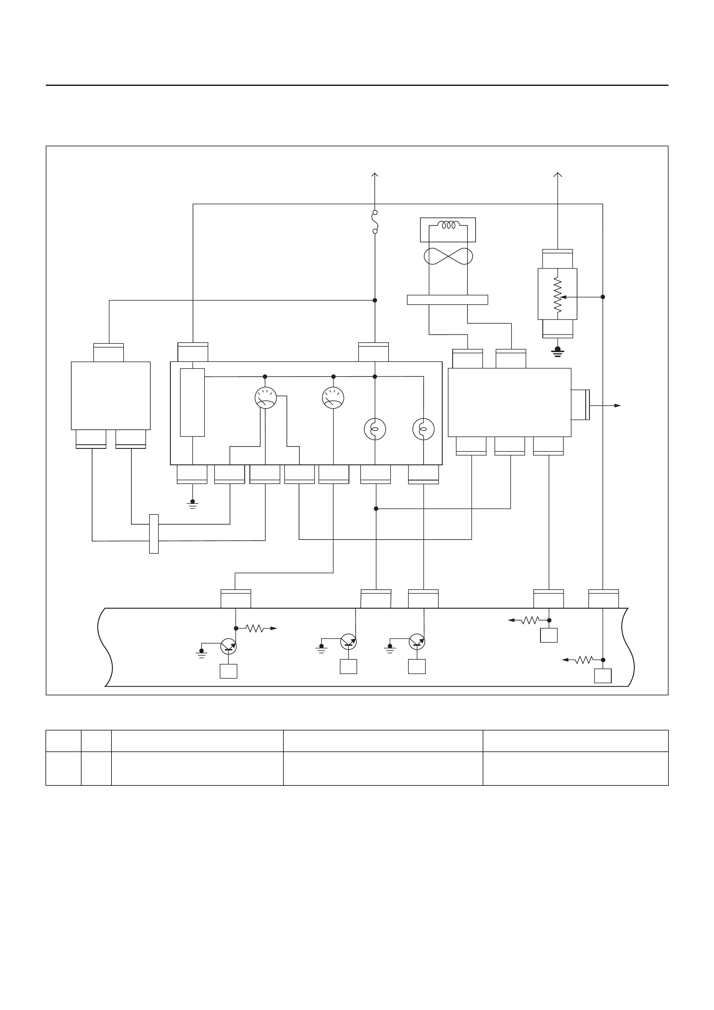
DIAGNOSTIC TROUBLE CODE (DTC) P1649
IMMOBILISER FUNCTION NOT PROGRAMMED
Condition for setting the DTC and action taken when the DTC sets
Circuit Description
The ECM decides if there is an abnomality in the
immobiliser control system. DTC P1649 is recorded by
the ECM when security code & secret key are not
programmed.
Diagnostic Aids
Check for the following conditions:
• Poor connection at ECM and Immobiliser. Inspect
harness connectors for backed out terminals,
improper mating, broken locks, improperly formed or
damaged terminals and poor terminal to wire
connection.
• Inspect the wiring harness for damage. If the harness
appears to be OK, disconnect the ECM and
Immobiliser; switch the ignition on. Observe a
voltmeter connected to the suspect driver circuit at
the ECM and Immobiliser harness connector while
moving the connectors and wiring harnesses related
Code Type DTC Name DTC Setting Condition Fail-Safe (Back Up)
P1649 - Immobiliser Function Not Programmed Immobiliser function is not programmed in the
ECM. 1. Engine does not start.
2. Check engine lamp flash.
VIgn
VIgn
Engine
Control
Module
(ECM)
Fuel
Level
VSSSVS LampMIL Lamp
Tacho Sig
32
14 30
2
C56
13
C56
7J2 J2J2J2
C56
9J2
C56
4
IGN
SW
F2
F2
B68
B24
B24E44
E44E44
B24 B24 B24 B24 B24 B24
B68 B68
B68
IGN
SW
μPμP
μP
μP
μP
Meter
15A
VIgn
MIL
Lamp SVS
Lamp
Speedo
Meter Tacho
Meter
0.85
YEL
0.5
YEL/
RED
0.8
YEL/
GRN
0.3
BRN/
YEL
0.5
GRN/
WHT
0.5
BLK/
RED
0.3
BRN/
YEL
0.5
BLK/
YEL
0.5
WHT
C56
0.5
BRN/
YEL
0.5
ORG/
BLU
2(–)
3
1
(+)
Vehicle
Speed
Sensor
(VSS) Starter
Relay
Fuel
Sender
Unit
METER
6
6
11 310278
B24
28
78
1
3
3
(–) (+)
1
Immobiliser
Coil
(Antenna)
B70 B70
CPU Immobiliser
Control
Unit (ICU)
to the MIL. A change in voltage will indic ate the location of the fault.

Diagnostic Trouble Code (DTC) P1649 Immobiliser Function Not Programmed
Step Action Value(s) Yes No
1 Was the “On-Board Diagnostic (OBD) System Check”
performed?
—Go to Step 2
Go to On Board
Diagnostic
(OBD) System
Check
2 1. Connect Tech 2.
2. Review and record the failure information.
3. Select “F0: Read DTC Info Ordered By Priority”
and check for DTC’s.
Is the DTC P1649 stored as “Present Failure”? — Go to Step 3
Refer to
Diagnostic Aids
and Go to Step
3
3 1. Using Tech 2, ignition “On” and engine “Off”.
2. Select “F2: Clear DTC Information” with Tech 2
and clear the DTC information.
3. Operate the vehicle and monitor the “F1: Read
DTC Info as Stored by ECU”.
Was the DTC P1649 stored in this ignition cycle? — Go to Step 4
Refer to
Diagnostic Aids
and Go to Step
4
4 1. Using Tech 2, ignition “On” and engine “Off”.
2. Select “Immobiliser” in the system selection menu
“Body”.
3. Select “Read DTC Info Ordered By Priority” in the
“Diagnositic Trouble Code”.
Was any DTC's B**** stored in this ignition cycle? —
Refer to
“Immobiliser
Workshop
Manual” & Go
to DTC Chart
B**** Go to Step 5
5 Is the ECM programmed with the latest software
release?
If not, download the latest software to the ECM using
the “SPS (Service Programming System)”.
Was the problem solved? — Verify repair Go to Step 6
6 Replace the ECM.
Is the action complete?
IMPORTANT: The replacement ECM must be
programmed. Refer to the Service Programming
System (SPS) section in this manual.
Following ECM programming, the immobiliser system
must be linked to the ECM. Refer to section 11
“Immobiliser System-ECM replacement” for the ECM/
Immobiliser linking procedure. — Verify repair —

DIAGNOSTIC TROUBLE CODE (DTC) P1693
TACHOMETER OUTPUT LOW VOLTAGE
Condition for setting the DTC and action taken when the DTC sets
Circuit Description
Based on the information from the Crank Position
Sensor (CKP), X58 reference signal is generated at
each rotation of the crankshaft.
The engine control module (ECM) converts X58
reference signal into the square wave signal which is
used to drive the pulse generator of the tachometer.
When the wave length of the output signal is long, the
tacho meter indicates the engine speed is low, and vise
versa.
This malfunction detects a low impedance, short to
ground or open contact on the Tacho output, the
Diagnostic Trouble Code P1693 will be set.
Diagnostic Aids
• Poor connections or a damaged harness. Inspect the
harness connections for backed out terminals,
improper, mating or damaged terminals. Also check
for open circuit, short to ground and short to battery
voltage.
• This malfunction detects a low impedance short to
ground or open contact on the ECM output circuit.
Code Type DTC Name DTC Setting Condition Fail-Safe (Back Up)
P1693 B Tachometer Output Low Voltage Tacho output circuit short to ground circuit. No fail-safe function.
VIgn
VIgn
Engine
Control
Module
(ECM)
Fuel
Level
VSSSVS LampMIL Lamp
Tacho Sig
32
14 30
2
C56
13
C56
7J2 J2J2J2
C56
9J2
C56
4
IGN
SW
F2
F2
B68
B24
B24E44
E44E44
B24 B24 B24 B24 B24 B24
B68 B68
B68
IGN
SW
μPμP
μP
μP
μP
Meter
15A
VIgn
MIL
Lamp SVS
Lamp
Speedo
Meter Tacho
Meter
0.85
YEL
0.5
YEL/
RED
0.8
YEL/
GRN
0.3
BRN/
YEL
0.5
GRN/
WHT
0.5
BLK/
RED
0.3
BRN/
YEL
0.5
BLK/
YEL
0.5
WHT
C56
0.5
BRN/
YEL
0.5
ORG/
BLU
2(–)
3
1
(+)
Vehicle
Speed
Sensor
(VSS) Starter
Relay
Fuel
Sender
Unit
METER
6
6
11 310278
B24
28
78
1
3
3
(–) (+)
1
Immobiliser
Coil
(Antenna)
B70 B70
CPU Immobiliser
Control
Unit (ICU)
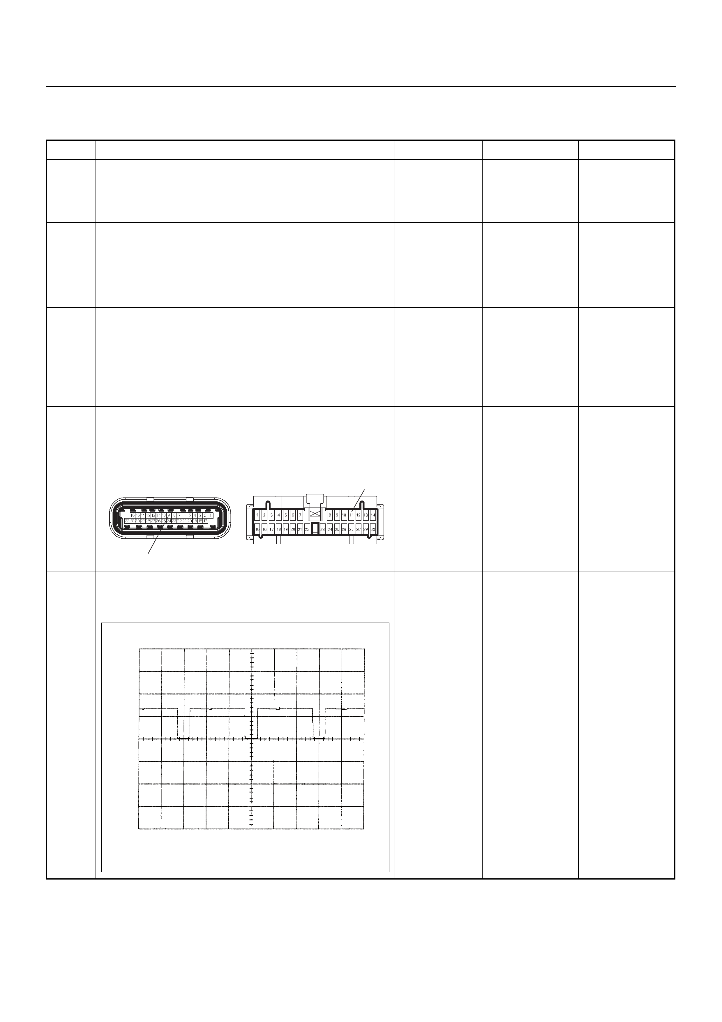
Diagnostic Trouble Code (DTC) P1693 Tachometer Output Low Voltage
Step Action Value(s) Yes No
1 Was the “On-Board Diagnostic (OBD) System Check”
performed?
—Go to Step 2
Go to On Board
Diagnostic
(OBD) System
Check
2 1. Connect Tech 2.
2. Review and record the failure information.
3. Select “F0: Read DTC Info Ordered By Priority”
and check for DTC’s.
Is the DTC P1693 stored as “Present Failure”? — Go to Step 3
Refer to
Diagnostic Aids
and Go to Step
3
3 1. Using Tech 2, ignition “On” and engine “Off”.
2. Select “F2: Clear DTC Information” with Tech 2
and clear the DTC information.
3. Operate the vehicle and monitor the “F1: Read
DTC Info as Stored by ECU”.
Was the DTC P1693 stored in this ignition cycle? — Go to Step 4
Refer to
Diagnostic Aids
and Go to Step
4
4 Check for poor/faulty connection at the ECM or meter
connector. If a poor/faulty connection is found, repair
the faulty terminal.
Was the problem found?
— Verify repair G o to Step 5
5 If a oscilloscope is availa ble, monitor the Tachometer
output signal. Does the oscilloscope indicate correct
wave form?
—Go to Step 10
Not available:
Go to Step 6
Fixed at low:
Go to Step 6
Fixed at High:
Go to Step 7
9
C-56(J2) B-24 11
Tachometer Output Signal Reference Wave Form
0V→
Measurement Terminal: J2-25 (+) J1-1 (-)
Measurement Scale: 10V/div 5.0ms/div
Measurement Condition: Engine Speed at 2000rpm
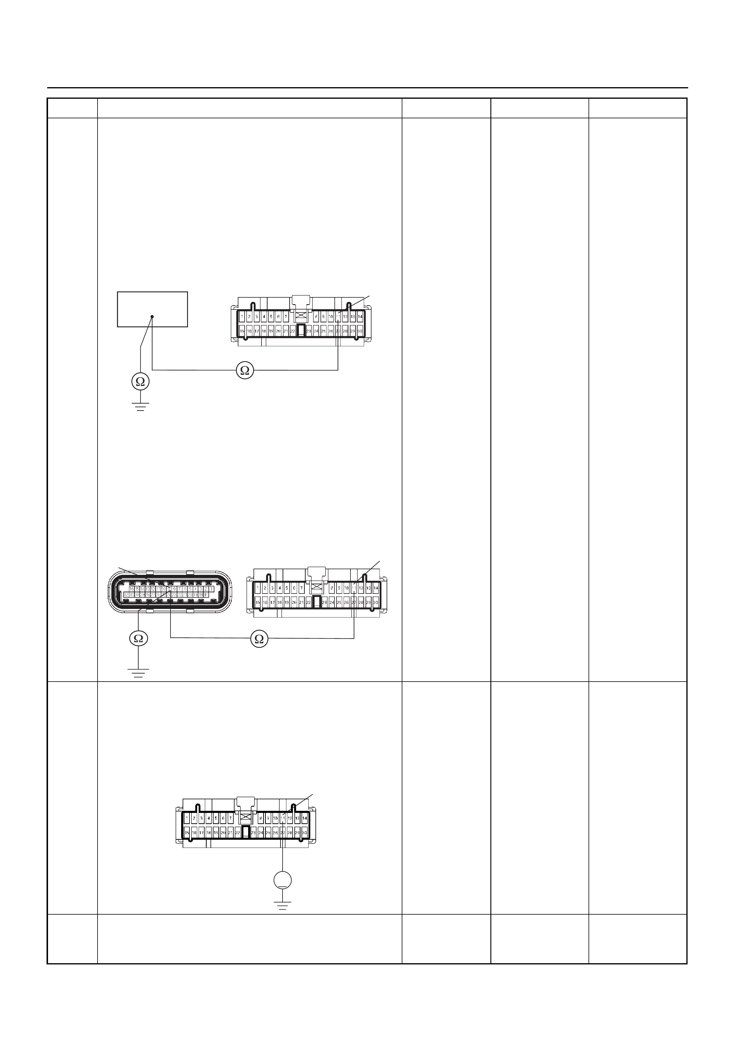
6 Use a DVM to check the Tacho output circuit.
Breaker box is available:
1. Ignition “Off”, engine “Off”.
2. Install the breaker box as type A. (ECM
disconnected) Ref. 6E-77.
3. Disconnect the meter connector.
4. Check the circuit for open or short to ground
circuit.
Was the problem found?
Breaker box is not available:
1. Ignition “Off”, engine “Off”.
2. Disconnect the ECM connector.
3. Disconnect the meter connector.
4. Check the circuit for open or short to ground
circuit.
Was the problem found?
—
Repair faulty
harness and
verify repair Go to Step 7
7 Use a DVM to check the Tacho output circuit.
1. Ignition “On”, engine “Off”.
2. Disconnect the meter connector.
3. Check the circuit for short to power supply circuit.
Does the DVM indicate the specified value?
Less than 1V Go to Step 8
Repair faulty
harness and
verify repair
8 Check any accessory parts which may cause electric
interference or magnetic interference.
Was the problem found? —
Remove the
accessory parts
and verify repair Go to Step 9
Step Action Value(s) Yes No
41
B-24 11
11
9C-56(J2) B-24
V
B-24 11

9 Replace the Tacho meter.
Was the problem solved? — Verify repair Go to Step 10
10 Is the ECM programmed with the latest software
release?
If not, download the latest software to the ECM using
the “SPS (Service Programming System)”.
Was the problem solved? — Verify repair Go to Step 11
11 Replace the ECM.
Is the action complete?
IMPORTANT: The replacement ECM must be
programmed. Refer to the Service Programming
System (SPS) section in this manual.
Following ECM programming, the immobiliser system
must be linked to the ECM. Refer to section 11
“Immobiliser System-ECM replacement” for the ECM/
Immobiliser linking procedure. — Verify repair —
Step Action Value(s) Yes No

SYMPTOM DIAGNOSIS
PRELIMINARY CHECKS
Before using this section, perform the “On-Board
Diagnostic (OBD) System Check” and verify all of the
following items:
• The engine control module (ECM) and malfunction
indicator lamp (MIL = Check Engine Lamp) are
operating correctly.
• There are no Diagnostic Trouble Code(s) stored.
• Tech 2 data is within normal operating range. Refer
to Typical Scan Data Values.
• Verify the customer complaint and locate the correct
symptom in the table of contents. Perform the
procedure included in the symptom chart.
VISUAL/PHYSICAL CHECKS
Several of the symptom procedures call for a careful
visual/physical check. This can lead to correcting a
problem without further checks and can save valuable
time. This check should include the following items:
• ECM grounds for cleanliness, tightness and proper
location.
• Vacuum hoses for splits, kinks, and proper
connection, shown on the “Emission Control System
Schematics”. Check thorough ly for any type o f leak or
restriction.
• Air inlet ducts for collapsed or damaged areas.
• Air leaks at throttle body mounting area, manifold
absolute pressure (MAP) sensor and inlet manifold
sealing surfaces.
• Ignition wires for cracking, harness, and carbon
tracking.
• Wiring for pr op er con ne ct i on s, pin ch es and c uts .
INTERMITTENT PROBLEMS
Important: An intermittent problem may or may not
switch on the malfunction indicator lamp (MIL) or store a
Diagnostic Trouble Code. Do NOT use the Diagnostic
Trouble Code (DTC) charts for intermittent problems.
The fault must be present to locate the problem.
Most intermittent problems are cased by faulty electrical
connections or wiring. Perform a careful visual/physical
check for the following conditions.
• Poor mating of the connector halves or a terminal not
fully seated in the connector (backed out).
• Improperly formed or damaged terminal.
• All connector terminals in the problem circuit should
be carefully checked for proper contact tension.
• Poor terminal-to-wire connection. This requires
removing the terminal from the connector body to
check.
• Ignition coils shorted to ground and arcing at ignition
wires or plugs.
• MIL (Check Engine Lamp) wire to ECM shorted to
ground.
• Poor ECM grounds. Refer to the ECM wiring
diagrams.
Road test the vehicle with a Digital Multimeter
connected to the suspected circuit. An ab normal voltage
when the malfunction occurs is a good indication that
there is a fault in the circuit being monito re d.
Use Tech 2 to help detect intermittent conditions.
Tech 2 has several features that can be used to locate
an intermittent condition.
An intermittent MIL (Check Engine Lamp) with no stored
Diagnostic Trouble Code may be caused by the
following:
• Ignition coil shorted to ground and arcing at ignition
wires or plugs.
• MIL (Check Engine Lamp) wire to ECM short to
ground.
• Poor ECM grounds. Refer to the ECM wiring
diagrams.
Check for improper installation o f electrical o ptions such
as light, cellular phones, etc. Check all wires from ECM
to the ignition control module for poor connections.
Check for an open diode across the A/C compressor
clutch and check for other open diodes (refer to wiring
diagrams in Electrical Diagnosis).
If the problem has not been found, refer to ECM
connector symptom tables.
Check the “Broadcast Code” of the ECM, and compare
it with the latest Holden service bulletins and/or Holden
EEPROM reprogramming equipment to determine if an
update to the ECM’s reprogrammable memory has
been released.
To check the “Broadcast Code”, connect Tech 2, then
look for “ID informaton” and select “Broadcast Code”.
This should display a 4 character code, such as “XBYA”
(example only).
This identifies the contents of the reprogrammable
software and calibration contained in the ECM.
If the “Broadcast Code” is not the most current
available, it is advisable to reprogram the ECM’s
EEPROM memory, which may either help identify a
hard-to find problem or may fix the problem.
The Service Programming System (SPS) will not allow
incorrect software programming or incorrect calibration
changes.

ENGINE CRANKS BUT WILL NOT RUN
DEFINITIONS: Engine cranks, but will not run. (The engine never starts.)
NOTE: The replacement ECM must be programmed. Refer to the Service Programming System (SPS) section in this
manual. Following ECM programming, the immobiliser system must be linked to the ECM.
Refer to section 11 “Immobiliser System-ECM replacement” for the ECM/Immobiliser linking procedure.
NOTE: Vehicle with immobiliser system, this system may be activated. Check the immobiliser system diagosis.
Step Action Value(s) Yes No
1 Was the “On-Board Diagnostic (OBD) System Check”
performed? — Go to Step 2
Go to OBD
System Check
2 1. Perform a bulletin search.
2. If a bulletin that addresses the symptom is found,
correct the co nd itio n as instructed in the bulletin.
Was a bulletin found that addresses the symptom? — Verify repair Go to Step 3
3 Was a visually/physical check performed? —Go to Step 4
Go to Visual /
physical Check.
4 Check the “Ignition coil” fuse (20A) and “ECM” fuse
(15A).
Was a fuse blown? — Verify repair Go to Step 5
5 1. I gnition ON
2. Use a DVM to verify if there is battery voltage at
the ignition coil fuse, and the ECM fuse.
Was battery voltage present at the fuses? — Go to Step 6 Verify & repair
6 1. Visually/physically inspect for the following
conditions:
• Restriction of air inlet system. Check for a
restricted air filter element, or foreign objects
blocking the air inlet system.
• Check for objects blocking the IAC passage or
throttle bore, excessive deposits in the throttle
bore and on the throttle plate.
• Check for a condition that causes a large
vacuum leak, such as an incorrectly installed or
faulty crankcase ventilation hose/brake booster
hose.
Was a problem found? — Verify repair Go to Step 7
7 1. Using Tech 2, display the IAC value.
2. Check for a faulty, plugged, or sticking IAC
operation.
Was the problem found? — Verify repair Go to Step 8
8 1. Using Tech 2, display the MAP sensor value.
2. Check for a faulty, plugged, or incorrectly installed
MAP sensor.
Was the problem found? — Verify repair Go to Step 9
9 If oscilloscope is availab le, check the wave form of th e
CKP signal.
Was the correct wave form found? — Go to Step 12 Go to Step 10
10 Check the CKP sensor wire for open or short circuit.
Was a problem found? — Verify repair Go to Step 11
11 Replace CKP sensor.
Is there still problem? — Replace pulsar
ring. Verify repair

12 Visually/physically inspect the secondary ignition
wires. Check for the following conditions:
• Verify if the resistance of all ignition wires is less
than the specified value.
• Verify that ignition wires are correctly routed to
eliminate cro s s -fit tin g.
• Verify that ignition wires are not arcing to ground.
Spraying the secondary ignition wires with a light
mist of water may help locate an intermittent
problem.
Was a problem found?
#1 cyl. 4.4kΩ
#2 cyl. 3.6kΩ
#3 cyl. 3.1kΩ
#4 cyl. 2.8kΩVerify repair Go to Step 13
13 1. Disconnect the spark plug high tension cable from
No.1 spark plug.
2. Install a spark tester at the end of the
disconnected ignition coil.
3. Clip the spark tester to a good ground.
4. Observe the spark tester while the engine is
cranking.
Was a crisp blue spark observed? (Only one or two
sparks followed by no result is considered the same
as “No Spark”.) — Go to Step 21 Go to Step 14
14 1. Disconnect the ignition coil harness connector.
2. Check for an open or short circuit between the
ignition coil and the ECM .
Was a problem found? — Verify repair Go to Step 15
15 1. Ignition “On”.
2. Use a DVM to check the ignition wire coil at the
ignition coil harness connector.
Does the DVM indicate battery voltage? Battery
voltage Go to Step 16 Verify repair
16 1. Ignition “Off”.
2. With DVM, check for an open circuit in the ground
wire at the ignition coil harness connector.
Was the ground wire OK? — Go to Step 17 Verify repair
17 Replace the ignition coil, verify the repair.
Attempt to start the engine.
Is there still a problem? — Go to Step 18 Verify repair
18 Use an ohmmeter to check the ignition coil primary
winding resistance.
Was the primary winding resistance approximately
equal to the specified value? 0.8-18kΩGo to Step 19 Go to Step 20
19 Use an ohmmeter to check the ignition coil secondary
winding resistance.
Was the primary winding re sistance approxim ately the
specified value ? 2.5kΩGo to Step 21 Go to Step 20
20 Replace the ignition coil. — Verify repair —
21 1. Remove the spark plugs from all cylinders.
2. Visually inspect the spark plug electrodes.
3. Replace any spark plugs with loose or missing
electrodes or cracked insulators.
Did your inspection reveal any spark plugs exhibiting
excessive fouling? —
Correct the
fouling
condition Go to Step 22
Step Action Value(s) Yes No

22 Perform the procedure in Fuel System Pressure Test
to determine if there is a problem with fuel delivery.
Was a problem found? — Verify repair Go to Step 23
23 Refer to Fuel System Diagnosis to determine if there
is a problem with fuel delivery.
Was a problem found? — Verify repair Go to Step 24
24 Check for the following engine mechanical problems
(refer to Engine Mechanical):
• Low compression
• Leakin g cylinde r he a d ga ske ts
• Worn camshaft
• Camshaft drive belt slipped or stripped.
Was a problem found? — Verify repair Go to Step 25
25 1. Review all diagnostic procedures within this table.
2. If all procedures have been completed and no
malfunctions have been found, review/inspect the
following:
• Visual/physical inspection
• Tech 2 data
• All electrical connections within a suspected
circuit and/or system.
Was a problem found? — Verify repair Go to Step 26
26 Is the ECM programmed with the latest software
release?
If not, download the latest software to the ECM using
the “SPS (Service Programming System)”.
Was the problem solved? — Verify repair Go to Step 27
27 Replace the ECM.
Is the action complete?
IMPORTANT: The replacement ECM must be
programmed. Refer to the Service Programming
System (SPS) section in this manual.
Following ECM programming, the immobiliser system
must be linked to the ECM. Refer to section 11
“Immobiliser System-ECM replacement” for the ECM/
Immobiliser linking procedure. — Verify Repair —
Step Action Value(s) Yes No

HARD START SYMPTOM
DEFINITIONS: Engine cranks, but does not start for a long time. Does eventually start, or may start and then
immediately stall.
Step Action Value(s) Yes No
1 Was the “On-Board Diagnostic (OBD) System Check”
performed? — Go to Step 2
Go to OBD
System Check
2 1. Perform a bulletin search.
2. If a bulletin that addresses the symptom is found,
correct the co nd itio n as instructed in the bulletin.
Was a bulletin found that addresses the symptom? — Verify repair Go to Step 3
3 Was a visually/physical check performed? —Go to Step 4
Go to Visual /
physical Check.
4 1. Visually/physically inspect for the following
conditions:
• Restriction of air inlet system. Check for a
restricted air filter element, or foreign objects
blocking the air inlet system.
• Check for objects blocking the IAC passage or
throttle bore, excessive deposits in the throttle
bore and on the throttle plate.
• Check for a condition that causes a large
vacuum leak, such as an incorrectly installed or
faulty crankcase ventilation hose/brake booster
hose.
Was a problem found? — Verify repair Go to Step 5
5 1. Using Tech 2, display the IAC value.
2. Check for a faulty, plugged, or sticking IAC
operation.
Was the problem found? — Verify repair Go to Step 6
6 Check engine coolant temperature (ECT) sensor for
shift in value.
1. After 8 hours with hood up and the engine not
running, connect Tech 2.
2. Ignition On, engine not running.
3. Using Tech 2, compare Engine Coolant
Temperature to Intake Air Temperature.
Are ECT and IAT within the specified value of each
other? ± 5°C Go to Step 8 Go to Step 7

7 1. Using Tech 2, display the engine coolant
temperature and note the value.
2. Check the resistance of the engine coolant
temperature sens or .
Is the actual resistance near the resistance value in
the chart for the temperature that was noted?
—Go to Step 8
Replace the
ECT sensor.
Verify repair
8 1. Using Tech 2, display the MAP sensor value in
comparison with atmosphere temperature.
2. Check for a faulty, plugged, or incorrectly installed
MAP sensor.
Was the problem found? — Verify repair Go to Step 9
9 Visually/physically inspect all spark plug high-tension
cables. Check for the following conditions:
• Verify if the resistance of all spar k plug high -tension
cables is less than the specified value.
• Verify that all spark plug high-tension cables are
correctly fitted to eliminate cross-fitting.
• Verify that all spark plug high-ten sion cables are not
arcing to ground.
Spraying the spark plug high-tension cables with a
light mist of water may help locate an intermittent
problem.
Was a problem found?
#1 cyl. 4.4kΩ
#2 cyl. 3.6kΩ
#3 cyl. 3.1kΩ
#4 cyl. 2.8kΩVerify repair Go to Step 10
10 Check for proper ignition voltage output with a spark
tester.
Was the problem found? — Verify repair Go to Step 11
11 1. Remove the spark plugs and check for gas or oil
fouling cracks, wear, improper gap, burned
electrodes, heavy deposits, or improper heat
range.
2. If spark plugs are fouled, the cause of fouling must
be determined before replacing the spark plugs.
Was a problem found? — Verify repair Go to Step 12
12 Check for a loose ignition control module ground.
Was a problem found? — Verify repair Go to Step 13
13 1. Check the ignition coil secondary resistance.
2. Replace the coil if it is greater than the specified
resistance.
Did the coil require replacement? 2.5kΩVerify repair Go to Step 14
Step Action Value(s) Yes No
Temperature (°C) Resistance (Ω) (Approximately)
-20 32040
0 9788
20 3516
40 1439
60 656
80 327
100 175
120 100

14 Drain sample fuel and perform a visual inspection.
Any suspicion about the fuel, such as discoloration,
particles, contamination, water, unusual smell, then
drain the fuel from the fuel tank.
Replace the fuel from known vehicle source.
If any suspicion of alcohol contamination, completely
drain the fuel, replace by fuel from known vehicle
source. — Verify repair Go to Step 15
15 Perform the procedure in Fuel System Pressure Test
to determine if there is a problem with fuel delivery.
Was a problem found? — Verify repair Go to Step 16
16 1. Check the injector connectors.
2. If any of the connectors are connected to an
improper cylinder, connect as necessary.
Was a problem found? — Verify repair Go to Step 17
17 Check for the following engine mechanical problems
(refer to Engine Mechanical):
• Low compression
• Leakin g cylinde r he a d ga ske ts
• Worn camshaft
• Camshaft drive belt slipped or stripped.
Was a problem found? — Verify repair Go to Step 18
18 1. Review all diagnostic procedures within this table.
2. If all procedures have been completed and no
malfunctions have been found, review/inspect the
following:
• Visual/physical inspection
• Tech 2 data
• All electrical connections within a suspected
circuit and/or system.
Was a problem found? — Verify repair Go to Step 19
19 Is the ECM programmed with the latest software
release?
If not, download the latest software to the ECM using
the “SPS (Service Programming System)”.
Was the problem solved? — Verify repair Go to Step 20
20 Replace the ECM.
Is the action complete?
IMPORTANT: The replacement ECM must be
programmed. Refer to the Service Programming
System (SPS) section in this manual.
Following ECM programming, the immobiliser system
must be linked to the ECM. Refer to section 11
“Immobiliser System-ECM replacement” for the ECM/
Immobiliser linking procedure. — Verify Repair —
Step Action Value(s) Yes No

ROUGH, UNSTABLE, OR INCORRECT IDLE, STALLING SYMPTOM
DEFINITIONS: Engine runs unevenly at idle. If severe,
the engine or vehicle may shake. Engine idle speed
may vary in RPM. Either condition may be severe
enough to stall the engine.
Step Action Value(s) Yes No
1 Was the “On-Board Diagnostic (OBD) System Check”
performed? — Go to Step 2
Go to OBD
System Check
2 1. Perform a bulletin search.
2. If a bulletin that addresses the symptom is found,
correct the co nd itio n as instructed in the bulletin.
Was a bulletin found that addresses the symptom? — Verify repair Go to Step 3
3 Was a visual/physical check performed? —Go to Step 4
Go to Visual /
physical Check.
4 1. Check for faulty, plugged or incorrectly installed
PCV valve.
2. Verify if the PCV system is not plugged.
Was a problem found? — Verify repair Go to Step 5
5 1. Check for incorrect idle speed. Ensure the
following conditions are present.
• Engine fully warm
• Acce sso rie s ar e “O ff”
2. Using Tech 2, monitor IAC position.
Is the IAC position within the specified steps? 20-30 Steps Go to Step 7 Go to Step 6
6 1. Visually/physically inspect for the following
conditions:
• Restriction of the air inlet system. Check for
restricted air filter element, or foreign objects
blocking the air inlet system.
• Check for objects blocking the IAC passage or
throttle bore, excessive deposits in the throttle
bore and on the throttle plate.
• Check for a condition that causes a large
vacuum leak, such as an incorrectly installed or
faulty crankcase ventilation hose/brake booster
hose.
Was a problem found? — Verify repair Go to Step 7

7 1. Using Tech 2, display the engine coolant
temperature and note the value.
2. Check the resistance of the engine coolant
temperature sens or .
Is the actual resistance near the resistance value in
the chart for the temperature that was noted?
—Go to Step 8
Replace the
ECT sensor.
Verify repair
8 1. Using Tech 2, display the MAP sensor value in
comparison with atmosphere temperature.
2. Check for a faulty, plugged, or incorrectly installed
MAP sensor.
Was the problem found? — Verify repair Go to Step 9
9 Using Tech 2, monitor throttle position with the engine
idling.
Is the throttle position at the specified value and
steady?
0% Go to Step 10
Refer to
Diagnostic
Trouble Code
P0123 for
further
diagnosis
10 Check for proper igni tion voltage output with the spark
tester.
Was a problem found? — Verify repair Go to Step 11
11 1. Remove the spark plugs and check for gas or oil
fouling cracks, wear, improper gap, burned
electrodes, heavy deposits, or improper heat
range.
2. If spark plugs are fouled, the cause of fouling must
be determined before replacing the spark plugs.
Was a problem found? — Verify repair Go to Step 12
12 Check for a loose ignition control module ground.
Was a problem found? — Verify repair Go to Step 13
13 Check items that can cause the engine to run rich.
Refer to DTC P1167 “Fuel Supply System Rich During
Deceleration Fuel Cut Off”.
Was a problem found? — Verify repair Go to Step 14
14 Check items that can cause the engine to run lean.
Refer to DTC P1171 “Fuel Supply System Lean
During Power Enrichment”.
Was a problem found? — Verify repair Go to Step 15
15 Check the injector connectors, if any of the injectors
are connected to an incorrect cylinder, correct as
necessary.
Was a problem found? — Verify repair Go to Step 16
16 1. Check for faulty engine mounts.
2. If a problem is found, repair as necessary.
Was a problem found? — Verify repair Go to Step 17
Step Action Value(s) Yes No
Temperature (°C) Resistance (Ω) (Approximately)
-20 32040
0 9788
20 3516
40 1439
60 656
80 327
100 175
120 100

17 Perform the procedure in Fuel System Pressure Test
to determine if there is a problem with fuel delivery.
Was a problem found? — Verify repair Go to Step 18
18 Check for the following engine mechanical problems
(refer to Engine Mechanical):
• Low compression
• Leakin g cylinde r he a d ga ske ts
• Worn camshaft
• Sticking or leaking valves
• Valve timing
• Broken valve springs
• Camshaft drive belt slipped or stripped.
Was a problem found? — Verify repair Go to Step 19
19 1. Review all diagnostic procedures within this table.
2. If all procedures have been completed and no
malfunctions have been found, review/inspect the
following:
• Visual/physical inspection
• Tech 2 data
• All electrical connections within a suspected
circuit and/or system.
Was a problem found? — Verify repair Go to Step 20
20 Is the ECM programmed with the latest software
release?
If not, download the latest software to the ECM using
the “SPS (Service Programming System)”.
Was the problem solved? — Verify repair Go to Step 21
21 Replace the ECM.
Is the action complete?
IMPORTANT: The replacement ECM must be
programmed. Refer to the Service Programming
System (SPS) section in this manual.
Following ECM programming, the immobiliser system
must be linked to the ECM. Refer to section 11
“Immobiliser System-ECM replacement” for the ECM/
Immobiliser linking procedure. — Verify Repair —
Step Action Value(s) Yes No

SURGES AND/OR CHUGS SYMPTOM
DEFINITIONS: Refer to the illustration. It feels like the
vehicle speeds up and slows down with no charge in the
accelerator pe d al.
Step Action Value(s) Yes No
1 Was the “On-Board Diagnostic (OBD) System Check”
performed? — Go to Step 2
Go to OBD
System Check
2 1. Perform a bulletin search.
2. If a bulletin that addresses the symptom is found,
correct the co nd itio n as instructed in the bulletin.
Was a bulletin found that addresses the symptom? — Verify repair Go to Step 3
3 Was a visual/physical check performed? —Go to Step 4
Go to Visual /
physical Check.
4 Be sure the driver understands A/C compressor
operation as explained in the owner’s manual. Inform
the customer how the A/C clutch operate.
Is the customer experiencing a normal condition? — System OK Go to Step 5
5 1. Using Tech 2, display the MAP sensor value in
comparison with atmosphere temperature.
2. Check for a faulty, plugged, or incorrectly installed
MAP sensor.
Was the problem found? — Verify repair Go to Step 6
6 Observe the throttle position display on Tech 2 while
slowly increasing throttle pedal.
Is the throttle position at the specified value and
steady in any position?
—Go to Step 7
Refer to
Diagnostic
Trouble Code
P0123 for
further
diagnosis
7 Check the knock sensor wire, shield wire, or
installation condition.
Was a problem found? — Verify repair Go to Step 8
8 Run the Engine.
Check the fuel control Heated Oxygen Sensors
(HO2S). When monitored on Tech 2, the HO2 Sensors
should respon d qu ickly to differe nt t hrot tle po sit i ons. If
they don’t, check for silicon or other contaminants
from fuel or use of improper seala nt. The se nsors may
have a white powdery coating. Silicon contamination
sends a rich exhaust signal which causes the ECM to
command an excessively lean air/fuel mixture.
Was a problem found? — Verify repair Go to Step 9

9 Check the fuel pressure. Refer to Fuel System
Diagnosis.
Was a problem found? — Verify repair Go to Step 10
10 Monitor “B1S1 (Bank 1 Sensor 1) Status” on Tech 2.
Is the “B1S1 (Bank 1 Sensor 1) Status” in the rich
condition? — Verify repair Go to Step 11
11 Check items that can cause the engine to run rich.
Refer to DTC P1167 “Fuel Supply System Rich During
Deceleration Fuel Cut Off”.
Was a problem found? — Verify repair Go to Step 12
12 Check items that can cause the engine to run lean.
Refer to DTC P1171 “Fuel Supply System Lean
During Power Enrichment”.
Was a problem found? — Verify repair Go to Step 13
13 Check for proper igni tion voltage output with the spark
tester.
Was a problem found? — Verify repair Go to Step 14
14 Check for a loose ignition control module ground.
Was a problem found? — Verify repair Go to Step 15
15 Visually/physically inspect all spark plug high-tension
cables. Check for the following conditions:
• Verify if the resistance of all spar k plug high -tension
cables is less than the specified value.
• Verify that all spark plug high-tension cables are
correctly fitted to eliminate cross-fitting.
• Verify that all spark plug high-ten sion cables are not
arcing to ground.
Spraying the spark plug high-tension cables with a
light mist of water may help locate an intermittent
problem.
Was a problem found?
#1 cyl. 4.4kΩ
#2 cyl. 3.6kΩ
#3 cyl. 3.1kΩ
#4 cyl. 2.8kΩVerify repair Go to Step 16
16 1. Check the ignition coil secondary resistance.
2. Replace the coil if it is greater than the specified
resistance.
Did the coil require replacement? 2.5kΩVerify repair Go to Step 17
17 1. Remove the spark plugs and check for gas or oil
fouling cracks, wear, improper gap, burned
electrodes, heavy deposits, or improper heat
range.
2. If spark plugs are fouled, the cause of fouling must
be determined before replacing the spark plugs.
Was a problem found? — Verify repair Go to Step 18
18 1. Check the injector connectors.
2. If any of the connectors are connected to an
incorrect cylinder, connect as necessary.
Was a problem found? — Verify repair Go to Step 19
19 Check the ECM grounds to ve rify if they ar e clean and
tight. Refer to the ECM wiring diagrams.
Was a problem found? — Verify repair Go to Step 20
20 Visually/physically check the vacuum hose for splits,
kinks and proper connections and routing.
Was a problem found? — Verify repair Go to Step 21
Step Action Value(s) Yes No

21 Check the exhaust system for a possible restriction:
• Damaged or collapsed pipes
• Internal muffler failure.
Was a problem found? — Verify repair Go to Step 22
22 1. Review all diagnostic procedures within this table.
2. If all procedures have been completed and no
malfunctions have been found, review/inspect the
following:
• Visual/physical inspection
• Tech 2 data
• All electrical connections within a suspected
circuit and/or system.
Was a problem found? — Verify repair Go to Step 23
23 Is the ECM programmed with the latest software
release?
If not, download the latest software to the ECM using
the “SPS (Service Programming System)”.
Was the problem solved? — Verify repair Go to Step 24
24 Replace the ECM.
Is the action complete?
IMPORTANT: The replacement ECM must be
programmed. Refer to the Service Programming
System (SPS) section in this manual.
Following ECM programming, the immobiliser system
must be linked to the ECM. Refer to section 11
“Immobiliser System-ECM replacement” for the ECM/
Immobiliser linking procedure. — Verify Repair —
Step Action Value(s) Yes No

HESITATION, SAG, STUMBLE SYMPTOM
DEFINITIONS: Momentary lack of response as the
accelerator is pu shed down. It can occur at any vehicle
speed. Usually most pronounced when first trying to
make the vehicle move, as from a stop sign. May cause
the engine to stall if severe enough.
Step Action Value(s) Yes No
1 Was the “On-Board Diagnostic (OBD) System Check”
performed? — Go to Step 2
Go to OBD
System Check
2 1. Perform a bulletin search.
2. If a bulletin that addresses the symptom is found,
correct the co nd itio n as instructed in the bulletin.
Was a bulletin found that addresses the symptom? — Verify repair Go to Step 3
3 Was a visual/physical check performed? —Go to Step 4
Go to Visual /
physical Check.
4 Check the fuel quality.
Is the customer using improper fuel or degraded fuel? — Replace fuel Go to Step 5
5 1. Using Tech 2, display the MAP sensor value in
comparison with atmosphere temperature.
2. Check for a faulty, plugged, or incorrectly installed
MAP sensor.
Was the problem found? — Verify repair Go to Step 6
6 Observe the throttle position display on Tech 2 while
slowly increasing throttle pedal.
Does the throttle position increase steadily and
smoothly on Tech 2?
—Go to Step 7
Refer to
Diagnostic
Trouble Code
P0123 for
further
diagnosis
7 Check the knock sensor wire, shield wire, and
installation condition.
Was a problem found? — Verify repair Go to Step 8
8 Run the Engine.
Check the fuel control Heated Oxygen Sensors
(HO2S). When monitored on Tech 2, the HO2 Sensors
should respon d qu ickly to differe nt t hrot tle po sit i ons. If
they don’t, check for silicon or other contaminants
from fuel or use of improper seala nt. The se nsors may
have a white powdery coating. Silicon contamination
sends a rich exhaust signal which causes the ECM to
command and excessively lean air/fuel mixture.
Was a problem found? — Verify repair Go to Step 9
9 Check the fuel pressure. Refer to Fuel System
Diagnosis.
Was a problem found? — Verify repair Go to Step 10

10 Monitor “B1S1 (Bank 1 Sensor 1) Status” on Tech 2.
Is the “B1S1 (Bank 1 Sensor 1) Status” in the rich
condition? — Go to Step 11 Go to Step 12
11 Check items that can cause the engine to run rich.
Refer to DTC P1167 “Fuel Supply System Rich During
Deceleration Fuel Cut Off”.
Was a problem found? — Verify repair Go to Step 12
12 Check items that can cause the engine to run lean.
Refer to DTC P1171 “Fuel Supply System Lean
During Power Enrichment”.
Was a problem found? — Verify repair Go to Step 13
13 Check for proper igni tion voltage output with the spark
tester.
Was a problem found? — Verify repair Go to Step 14
14 Check for a loose ignition control module ground.
Was a problem found? — Verify repair Go to Step 15
15 Visually/physically inspect all spark plug high-tension
cables. Check for the following conditions:
• Verify if the resistance of all spar k plug high -tension
cables is less than the specified value.
• Verify that all spark plug high-tension cables are
correctly fitted to eliminate cross-fitting.
• Verify that all spark plug high-ten sion cables are not
arcing to ground.
Spraying the spark plug high-tension cables with a
light mist of water may help locate an intermittent
problem.
Was a problem found?
#1 cyl. 4.4kΩ
#2 cyl. 3.6kΩ
#3 cyl. 3.1kΩ
#4 cyl. 2.8kΩVerify repair Go to Step 16
16 1. Check the ignition coil secondary resistance.
2. Replace the coil if it is greater than the specified
resistance.
Did the coil require replacement? 2.5kΩVerify repair Go to Step 17
17 1. Remove the spark plugs and check for gas or oil
fouling cracks, wear, improper gap, burned
electrodes, heavy deposits, or improper heat
range.
2. If spark plugs are fouled, the cause of fouling must
be determined before replacing the spark plugs.
Was a problem found? — Verify repair Go to Step 18
18 Check the ECM grounds to ve rify if they ar e clean and
tight. Refer to the ECM wiring diagrams.
Was a problem found? — Verify repair Go to Step 19
19 Visually/physically check the vacuum hose for splits,
kinks and proper connections and routing.
Was a problem found? — Verify repair Go to Step 20
Step Action Value(s) Yes No

20 1. Review all diagnostic procedures within this table.
2. If all procedures have been completed and no
malfunctions have been found, review/inspect the
following:
• Visual/physical inspection
• Tech 2 data
• All electrical connections within a suspected
circuit and/or system.
Was a problem found? — Verify repair Go to Step 21
21 Is the ECM programmed with the latest software
release?
If not, download the latest software to the ECM using
the “SPS (Service Programming System)”.
Was the problem solved? — Verify repair Go to Step 22
22 Replace the ECM.
Is the action complete?
IMPORTANT: The replacement ECM must be
programmed. Refer to the Service Programming
System (SPS) section in this manual.
Following ECM programming, the immobiliser system
must be linked to the ECM. Refer to section 11
“Immobiliser System-ECM replacement” for the ECM/
Immobiliser linking procedure. — Verify Repair —
Step Action Value(s) Yes No

CUTS OUT, MISSES SYMPTOM
DEFINITIONS: Steady pulsation or jerking that follows
engine speed; usually more pronounced as engine load
increases.
Step Action Value(s) Yes No
1 Was the “On-Board Diagnostic (OBD) System Check”
performed? — Go to Step 2
Go to OBD
System Check
2 1. Perform a bulletin search.
2. If a bulletin that addresses the symptom is found,
correct the co nd itio n as instructed in the bulletin.
Was a bulletin found that addresses the symptom? — Verify repair Go to Step 3
3 Was a visual/physical check performed? —Go to Step 4
Go to Visual /
physical Check.
4 Check the ECM grounds to verify if th ey ar e clean an d
tight. Refer to the ECM wiring diagrams in Electrical
Diagnosis.
Was a problem found? — Verify repair Go to Step 5
5 Check for a loose or short circuit of ignition coil
module voltage feed.
Was a problem found? — Verify repair Go to Step 6
6 Check for a loose or short circuit of ignition coil
module ground.
Was a problem found? — Verify repair Go to Step 7
7 Visually/physically inspect all spark plug high-tension
cables. Check for the following conditions:
• Verify if the resistance of all spar k plug high -tension
cables is less than the specified value.
• Verify that all spark plug high-tension cables are
correctly fitted to eliminate cross-fitting.
• Verify that all spark plug high-ten sion cables are not
arcing to ground.
Spraying the spark plug high-tension cables with a
light mist of water may help locate an intermittent
problem.
Was a problem found?
#1 cyl. 4.4kΩ
#2 cyl. 3.6kΩ
#3 cyl. 3.1kΩ
#4 cyl. 2.8kΩVerify repair Go to Step 7
8 Check the CKP sensor wire, shield wire, or installation
condition.
Was a problem found? — Verify repair Go to Step 9
9Monitor “B1S1 (Bank 1 Sensor 1) Status” on Tech 2.
Is the “B1S1 (Bank 1 Sensor 1) Status” in the rich
condition? — Go to Step 10 Go to Step 11

10 Check items that can cause the engine to run rich.
Refer to DTC P1167 “Fuel Supply System Rich During
Deceleration Fuel Cut Off”.
Was a problem found? — Verify repair Go to Step 11
11 Monitor “B1S1 (Bank 1 Sensor 1) Status” on Tech 2.
Is the “B1S1 (Bank 1 Sensor 1) Status” in the lean
condition? — Go to Step 12 Go to Step 13
12 Check items that can cause the engine to run lean.
Refer to DTC P1171 “Fuel Supply System Lean
During Power Enrichment”.
Was a problem found? — Verify repair Go to Step 13
13 1. Visually/physically inspect for the following
conditions:
• Restriction of air inlet system. Check for a
restricted air filter element, or foreign objects
blocking the air inlet system.
• Check for objects blocking the IAC passage or
throttle bore, excessive deposits in the throttle
bore and on the throttle plate.
• Check for a condition that causes a large
vacuum leak, such as an incorrectly installed or
faulty crankcase ventilation hose/brake booster
hose.
Was a problem found? — Verify repair Go to Step 14
14 Check the injector connectors, if any of the injectors
are connected to an incorrect cylinder, correct as
necessary.
Was a problem found? — Verify repair Go to Step 15
15 Perform the Injector Coil/Balance Test.
Was a problem found. — Verify repair Go to Step 16
16 1. Check for fuel in the pressure regulator vacuum
hose.
2. If fuel is present, replace the fuel pressure
regulator assembly.
Was a problem found? — Verify repair Go to Step 17
17 Check for proper igni tion voltage output with the spark
tester.
Was a problem found? — Verify repair Go to Step 18
18 1. Remove the spark plugs and check for gas or oil
fouling cracks, wear, improper gap, burned
electrodes, heavy deposits, or improper heat
range.
2. If spark plugs are fouled, the cause of fouling must
be determined before replacing the spark plugs.
Was a problem found? — Verify repair Go to Step 19
Step Action Value(s) Yes No

19 Check for the following engine mechanical problems
(refer to Engine Mechanical):
• Low compression
• Leakin g cylinde r he a d ga ske ts
• Worn camshaft
• Sticking or leaking valves
• Valve timing
• Broken valve springs
• Camshaft drive belt slipped or stripped.
Was a problem found? — Verify repair Go to Step 20
20 1. Check for faulty engine mounts.
2. If a problem is found, repair as necessary.
Was a problem found? — Verify repair Go to Step 21
21 1. Review all diagnostic procedures within this table.
2. If all procedures have been completed and no
malfunctions have been found, review/inspect the
following:
• Visual/physical inspection
• Tech 2 data
• All electrical connections within a suspected
circuit and/or system.
Was a problem found? — Verify repair Go to Step 22
22 Is the ECM programmed with the latest software
release?
If not, download the latest software to the ECM using
the “SPS (Service Programming System)”.
Was the problem solved? — Verify repair Go to Step 23
23 Replace the ECM.
Is the action complete?
IMPORTANT: The replacement ECM must be
programmed. Refer to the Service Programming
System (SPS) section in this manual.
Following ECM programming, the immobiliser system
must be linked to the ECM. Refer to section 11
“Immobiliser System-ECM replacement” for the ECM/
Immobiliser linking procedure. — Verify Repair —
Step Action Value(s) Yes No

LACK OF POWER, SLUGGISH OR SPONGY SYMPTOM
DEFINITIONS: Engine delivers less than expected power. Attempting part-throttle acceleration results in little or no
increase in vehicle speed.
Step Action Value(s) Yes No
1 Was the “On-Board Diagnostic (OBD) System Check”
performed? — Go to Step 2
Go to OBD
System Check
2 1. Perform a bulletin search.
2. If a bulletin that addresses the symptom is found,
correct the co nd itio n as instructed in the bulletin.
Was a bulletin found that addresses the symptom? — Verify repair Go to Step 3
3 Was a visual/physical check performed? —Go to Step 4
Go to Visual /
physical Check.
4 1. Remove and check the air filter element for dirt or
restrictions.
2. Replace the air filter element if necessary.
Was a repair required? — Verify repair Go to Step 5
5 Check the ECM grounds to verify if th ey ar e clean an d
tight. Refer to the ECM wiring diagrams.
Was a problem found? — Verify repair Go to Step 6
6 1. Using Tech 2, display the MAP sensor value in
comparison with atmosphere temperature.
2. Check for a faulty, plugged, or incorrectly installed
MAP sensor.
Was the problem found? — Verify repair Go to Step 7
7 1. Using Tech 2, display the ECT sensor and IAT
sensor value and warm up condition compared
with the typical data.
2. Check the specif ied valu e or wire.
Was the problem found? — Verify repair Go to Step 8
8 Observe the throttle position display on Tech 2 while
slowly increasing throttle pedal.
Does the throttle position increase steadily and
smoothly on Tech 2?
—Go to Step 9
Refer to
Diagnostic
Trouble Code
P0123 for
further
diagnosis
9 Check the knock sensor wire, shield wire, and
installation condition.
Was a problem found? — Verify repair Go to Step 10
10 Run the Engine.
Check the fuel control Heated Oxygen Sensors
(HO2S). When monitored on Tech 2, the HO2 Sensors
should respon d qu ickly to differe nt t hrot tle po sit i ons. If
they don’t, check for silicon or other contaminants
from fuel or use of improper seala nt. The se nsors may
have a white powdery coating. Silicon contamination
sends a rich exhaust signal which causes the ECM to
command and excessively lean air/fuel mixture.
Was a problem found? — Verify repair Go to Step 11
11 Check the fuel pressure. Refer to Fuel System
Diagnosis.
Was a problem found? — Verify repair Go to Step 12

12 Monitor “B1S1 (Bank 1 Sensor 1) Status” on Tech 2.
Is the “B1S1 (Bank 1 Sensor 1) Status” in the rich
condition? — Verify repair Go to Step 13
13 Check items that can cause the engine to run rich.
Refer to DTC P1167 “Fuel Supply System Rich During
Deceleration Fuel Cut Off”.
Was a problem found? — Verify repair Go to Step 14
14 Check items that can cause the engine to run lean.
Refer to DTC P1171 “Fuel Supply System Lean
During Power Enrichment”.
Was a problem found? — Verify repair Go to Step 15
15 Check for proper ignition voltage output with a spark
tester.
Was the problem found? — Verify repair Go to Step 16
16 1. Remove the spark plugs and check for gas or oil
fouling cracks, wear, improper gap, burned
electrodes, heavy deposits, or improper heat
range.
2. If spark plugs are fouled, the cause of fouling must
be determined before replacing the spark plugs.
Was a problem found? — Verify repair Go to Step 17
17 Drain sample fuel, visual inspection.
Any suspicion about the fuel, such as discoloration,
particles, contamination, water, unusual smell, then
drain the fuel from fuel tank.
Replace the fuel from known vehicle source.
If any suspencion of alcohol contamination,
completely drain the fuel, replace by fuel from known
vehicle source. — Veri fy repair Go to Step 18
18 Check the exhaust system for a possible restriction:
• Damaged or collapsed pipes
• Internal muffler failure.
Was a problem found? — Verify repair Go to Step 19
19 Check for the following engine mechanical problems
(refer to Engine Mechanical):
• Low compression
• Leakin g cylinde r he a d ga ske ts
• Worn camshaft
• Loose timing belt.
Was a problem found? — Verify repair Go to Step 20
20 1. Review all diagnostic procedures within this table.
2. If all procedures have been completed and no
malfunctions have been found, review/inspect the
following:
• Visual/physical inspection
• Tech 2 data
• All electrical connections within a suspected
circuit and/or system.
Was a problem found? — Verify repair Go to Step 21
Step Action Value(s) Yes No

21 Is the ECM programmed with the latest software
release?
If not, download the latest software to the ECM using
the “SPS (Service Programming System)”.
Was the problem solved? — Verify repair Go to Step 22
22 Replace the ECM.
Is the action complete?
IMPORTANT: The replacement ECM must be
programmed. Refer to the Service Programming
System (SPS) section in this manual.
Following ECM programming, the immobiliser system
must be linked to the ECM. Refer to section 11
“Immobiliser System-ECM replacement” for the ECM/
Immobiliser linking procedure. — Verify Repair —
Step Action Value(s) Yes No

DETONATION/SPARK KNOCK SYMPTOM
DEFINITIONS: A mild to severe ping, usually wors e under acc eleration. The engine makes a sharp metallic knocking
sound that changes with throttle opening. Prolonged detonation may lead to complete engine tailure.
Step Action Value(s) Yes No
1 Was the “On-Board Diagnostic (OBD) System Check”
performed? — Go to Step 2
Go to OBD
System Check
2 1. Perform a bulletin search.
2. If a bulletin that addresses the symptom is found,
correct the co nd itio n as instructed in the bulletin.
Was a bulletin found that addresses the symptom? — Verify repair Go to Step 3
3 Was a visual/physical check performed? —Go to Step 4
Go to Visual /
physical Check.
4 1. If Tech 2 readings are normal (refer to Typical
Scan Data Values) and there are no engine
mechanical faults, fill the fuel tank with a known
quality gasoline.
2. Re-evaluate the vehicle performance.
Is detonation present? — Go to Step 5 Verify repair
5 1. Check for obvio us ov er hea tin g pr ob lem s :
• Low engine coolant
• Restricted air flow to radiator
• Incor re ct co ola nt solu tion .
2. If a problem is found, repair as necessary.
Was a problem found? — Verify repair Go to Step 6
6 Check the fuel pressure. Refer to Fuel System
Diagnosis.
Was a problem found? — Verify repair Go to Step 7
7 1. Using Tech 2, display the MAP sensor value in
comparison with atmosphere temperature.
2. Check for a faulty, plugged, or incorrectly installed
MAP sensor.
Was the problem found? — Verify repair Go to Step 8
8 1. Using Tech 2, display the ECT sensor and IAT
sensor value and warm up condition compared
with the typical data.
2. Check the specif ied valu e or wire.
Was the problem found? — Verify repair Go to Step 9
9 Observe the throttle position display on Tech 2 while
slowly increasing throttle pedal.
Does the throttle position increase steadily and
smoothly on Tech 2?
—Go to Step 10
Refer to
Diagnostic
Trouble Code
P0123 for
further
diagnosis
10 Check the knock sensor wire, shield wire and
installation condition.
Was a problem found? — Verify repair Go to Step 11
11 Check items that can cause the engine to run lean.
Refer to DTC P1171 “Fuel Supply System Lean
During Power Enrichment”.
Was a problem found? — Verify repair Go to Step 12

12 Check spark plugs for pr oper heat range.
Were incorrect spark plugs installed? — Verify repair Go to Step 13
13 1. Remove excessive carbon buildup with a top
engine cleaner.
2. Re-evaluate vehicle performance.
Is detonation still present? — Verify repair Go to Step 14
14 Check for an engine mechanical problem. Perform a
cylinder compression check. Refer to Engine
Mechanical.
Was a problem found? — Verify repair Go to Step 15
15 1. Review all diagnostic procedures within this table.
2. If all procedures have been completed and no
malfunctions have been found, review/inspect the
following:
• Visual/physical inspection
• Tech 2 data
• All electrical connections within a suspected
circuit and/or system.
Was a problem found? — Verify repair Go to Step 16
16 Is the ECM programmed with the latest software
release?
If not, download the latest software to the ECM using
the “SPS (Service Programming System)”.
Was the problem solved? — Verify repair Go to Step 17
17 Replace the ECM.
Is the action complete?
IMPORTANT: The replacement ECM must be
programmed. Refer to the Service Programming
System (SPS) section in this manual.
Following ECM programming, the immobiliser system
must be linked to the ECM. Refer to section 11
“Immobiliser System-ECM replacement” for the ECM/
Immobiliser linking procedure. — Verify Repair —
Step Action Value(s) Yes No

POOR FUEL ECONOMY SYMPTOM
DEFINITIONS: Fuel economy, as measured by an actual road test, is noticeably lower than expected. Also, economy
is noticeably lower than it was on this vehicle at one time, as previously shown by an actual road test.
Step Action Value(s) Yes No
1 Was the “On-Board Diagnostic (OBD) System Check”
performed? — Go to Step 2
Go to OBD
System Check
2 1. Perform a bulletin search.
2. If a bulletin that addresses the symptom is found,
correct the co nd itio n as instructed in the bulletin.
Was a bulletin found that addresses the symptom? — Verify repair Go to Step 3
3 Was a visual/physical check performed? —Go to Step 4
Go to Visual /
physical Check.
4 Check owner’s driving habits.
• Is the A/C on full time (defroster mode on)?
• Are tires at the correct pressure?
• Are excessively heavy loads being carried?
• Is acceleration too much, too often? — Go to Step 5 Go to Step 6
5 Review the items in Step 4 with the customer and
advise as necessary.
Is the action complete? — System OK —
6 Visually/physically check: Vacuum hoses for splits,
kinks, and improper connections and routing as
shown on the “Emis sio n Con tr ol Syst em S che m at ics” .
Was a problem found? — Verify repair Go to Step 7
7 Check for low engine coolant level.
Was a problem found? — Verify repair Go to Step 8
8 Check for incorrect or faulty engine thermostat. Refer
to Engine Cooling.
Was a problem found? — Verify repair Go to Step 9
9 Remove and check the air filter element for dirt or for
restrictions.
Was a problem found? — Verify repair Go to Step 10
10 1. Using Tech 2, display the MAP sensor value in
comparison with atmosphere temperature.
2. Check for a faulty, plugged, or incorrectly installed
MAP sensor.
Was the problem found? — Verify repair Go to Step 11
11 1. Using Tech 2, display the ECT sensor and IAT
sensor value and warm up condition compared
with the typical data.
2. Check the specif ied valu e or wire.
Was the problem found? — Verify repair Go to Step 12
12 Check the knock sensor wire, shield wire and
installation condition.
Was a problem found? — Verify repair Go to Step 13
13 Check the fuel pressure. Refer to Fuel System
Diagnosis.
Was a problem found? — Verify repair Go to Step 14
14 Monitor “B1S1 (Bank 1 Sensor 1) Status” on Tech 2.
Is the “B1S1 (Bank 1 Sensor 1) Status” in the rich
condition? — Verify repair Go to Step 15

15 Check items that can cause the engine to run rich.
Refer to DTC P1167 “Fuel Supply System Rich During
Deceleration Fuel Cut Off”.
Was a problem found? — Verify repair Go to Step 16
16 1. Remove the spark plugs and check for gas or oil
fouling cracks, wear, improper gap, burned
electrodes, heavy deposits, or improper heat
range.
2. If spark plugs are fouled, the cause of fouling must
be determined before replacing the spark plugs.
Was a problem found? — Verify repair Go to Step 17
17 Check for proper calibra tion of the speedometer.
Does the speed indicated on the speed meter closely
match the vehicle speed displayed on Tech 2? — Go to Step 19 Go to Step 18
17B Check the vehicle speed on accurate chassis dynamo
and check number of pulse from the speed sensor.
18 Diagnose and repair the inaccurate speedometer
condition as necessary. Refer to Vehicle Speed
Sensor in Electrical Diagnosis. — Verify Repair —
19 Check for proper calibra tion of the fuel gauge.
Was a problem found? — Verify repair Go to Step 20
20 Check for the following engine mechanical problems
(refer to Engine Mechanical):
• Low compression
• Worn camshaft
• Sticking or leaking valves
• Valve timing.
Was a problem found? — Verify repair Go to Step 21
21 1. Review all diagnostic procedures within this table.
2. If all procedures have been completed and no
malfunctions have been found, review/inspect the
following:
• Visual/physical inspection
• Tech 2 data
• All electrical connections within a suspected
circuit and/or system.
Was a problem found? — Verify repair Go to Step 22
22 Is the ECM programmed with the latest software
release?
If not, download the latest software to the ECM using
the “SPS (Service Programming System)”.
Was the problem solved? — Verify repair Go to Step 23
23 Replace the ECM.
Is the action complete?
IMPORTANT: The replacement ECM must be
programmed. Refer to the Service Programming
System (SPS) section in this manual.
Following ECM programming, the immobiliser system
must be linked to the ECM. Refer to section 11
“Immobiliser System-ECM replacement” for the ECM/
Immobiliser linking procedure. — Verify Repair —
Step Action Value(s) Yes No

EXCESSIVE EXHAUST EMISSIONS OR ODOURS SYMPTOM
DEFINITIONS: Vehicle fails an emission test. There is excessive “rotten egg” smell. (Excessive odours do not
necessarily indicate excessive emissions.)
Step Action Value(s) Yes No
1 Was the “On-Board Diagnostic (OBD) System Check”
performed? — Go to Step 2
Go to OBD
System Check
2 1. Perform a bulletin search.
2. If a bulletin that addresses the symptom is found,
correct the co nd itio n as instructed in the bulletin.
Was a bulletin found that addresses the symptom? — Verify repair Go to Step 3
3 Was a visual/physical check performed? —Go to Step 4
Go to Visual /
physical Check.
4 Does the customer continual accelerate on/off during
cold condition? — System OK Go to Step 5
5 Is the customer using the incorrect fuel type? —Replace with
unleaded fuel Go to Step 6
6 Check for vacuum leaks (vac uum lines, inlet manifold,
throttle body, etc.)
Were any vacuum leaks found? — Go to Step 17 Go to Step 7
7 1. Check fuel cap for proper installation.
2. Secure the fuel cap if necessary.
Was a problem found? — Go to Step 17 Go to Step 8
8 Check the fuel pressure. Refer to Fuel System
Pressure Test.
Was a problem found? — Go to Step 17 Go to Step 9
9 1. Check for faulty, plugged or incorrectly installed
PCV valve.
2. Verify if PCV system is not plugged.
Was a problem found? — Go to Step 17 Go to Step 10
10 Check the injector connectors, if any of the injectors
are connected to an incorrect cylinder, correct as
necessary.
Was a problem found? — Go to Step 17 Go to Step 11
11 Perform the Injector Coil/Balance Test.
Was a problem found? — Go to Step 17 Go to Step 12
12 Check for a problem with the engine cooling system.
Was a problem found? — Go to Step 17 Go to Step 13
13 Check the EVAP canister for fuel loading. Refer to
Evaporative Emission Control System.
Was a problem found? — Go to Step 17 Go to Step 14
14 Check the EVAP purge solenoid valve op eration.
Is the valve operated normally? — Go to Step 17
Verify repair &
Go to Step 15
15 Check the exhaust system for a possible restriction:
• Damaged or collapsed pipes
• Internal catalytic converter failure.
Was a problem found? — Verify repair &
Go to Step 16 Go to Step 17

16 1. Remove excessive carbon buildup with a top
engine cleaner. Refer to the instructions on the
top engine cleaner can.
2. Perform the exhaust emission test.
Does the vehicle pass the test? — System OK Go to Step 18
17 Perform the exhaust emission test.
Does the vehicle pass the test? — Sys tem OK Go to Step 18
18 Run the Engine.
Check the fuel control Heated Oxygen Sensors
(HO2S). When monitored on Tech 2, the HO2 Senors
should respon d qu ickly to differe nt t hrot tle po sit i ons. If
they don’t, check for silicon or other contaminants
from fuel or use of improper seala nt. The se nsors may
have a white powdery coating. Silicon contamination
sends a rich exhaust signal which causes the ECM to
command and excessively lean air/fuel mixture.
Was a problem found? — Verify repair Go to Step 19
19 Monitor “B1S1 (Bank 1 Sensor 1) Status” on Tech 2.
Is the “B1S1 (Bank 1 Sensor 1) Status” in the rich
condition? — Go to Step 20 Go to Step 21
20 1. Check items that can cause the engine to ru n rich.
Refer to Diagnostic Aids in DTC P1167 “Fuel
Supply System Rich During Deceleration Fuel Cut
Off”. Make any necessary repairs.
2. Perform the exhaust emission test.
Does the vehicle pass the test? — System OK Go to Step 22
21 1. Check items that can cause the engine to run
lean. Refer to Diagnostic Aids in DTC P1171 “Fuel
Supply System Lean During Power Enrichment”.
Make any necessary repairs.
2. Perform the exhaust emission test.
Does the vehicle pass the test? — Sys tem OK Go to Step 22
22 Check for the following engine mechanical problems
(refer to Engine Mechanical):
• Low compression
• Leakin g cylinde r he a d ga ske ts
• Worn camshaft
• Sticking or leaking valves
• Valve timing
• Broken valve springs.
Was a problem found? — Verify repair Go to Step 23
23 1. Review all diagnostic procedures within this table.
2. If all procedures have been completed and no
malfunctions have been found, review/inspect the
following:
• Visual/physical inspection
• Tech 2 data
• All electrical connections within a suspected
circuit and/or system.
Was a problem found? — Verify repair Go to Step 24
Step Action Value(s) Yes No

24 Is the ECM programmed with the latest software
release?
If not, download the latest software to the ECM using
the “SPS (Service Programming System)”.
Was the problem solved? — Verify repair Go to Step 25
25 Replace the ECM.
Is the action complete?
IMPORTANT: The replacement ECM must be
programmed. Refer to the Service Programming
System (SPS ) section in this manual.
Following ECM programming, the immobiliser system
must be linked to the ECM. Refer to section 11
“Immobiliser System-ECM replacement” for the ECM/
Immobiliser linking procedure. — Verify Repair —
Step Action Value(s) Yes No

DIESELING, RUN-ON SYMPTOM
DEFINITIONS: Engine continues to run after ignition key is turned to the OFF position, but runs very rough. If engine
runs smoothly, check the ignition switch and adjustment.
Step Action Value(s) Yes No
1 Was the “On-Board Diagnostic (OBD) System Check”
performed? — Go to Step 2
Go to OBD
System Check
2 1. Perform a bulletin search.
2. If a bulletin that addresses the symptom is found,
correct the co nd itio n as instructed in the bulletin.
Was a bulletin found that addresses the symptom? — Verify repair Go to Step 3
3 Was a visual/physical check performed? —Go to Step 4
Go to Visual /
physical Check.
4 Check for a short circuit between the battery and the
ignition feed circuit.
Was a problem found? — Verify repair Go to Step 5
5 Check the fuel leaking from injector. Refer to Fuel
System Diagnostic.
Was the problem found? — Verify repair Go to Step 6
6 1. Review all diagnostic procedures within this table.
2. If all procedures have been completed and no
malfunctions have been found, review/inspect the
following:
• Visual/physical inspection
• Tech 2 data
• All electrical connections within a suspected
circuit and/or system.
Was a problem found? — Verify repair Go to Step 7
7 Is the ECM programmed with the latest software
release?
If not, download the latest software to the ECM using
the “SPS (Service Programming System)”.
Was the problem solved? — Verify repair Go to Step 8
8 Replace the ECM.
Is the action complete?
IMPORTANT: The replacement ECM must be
programmed. Refer to the Service Programming
System (SPS) section in this manual.
Following ECM programming, the immobiliser system
must be linked to the ECM. Refer to section 11
“Immobiliser System-ECM replacement” for the ECM/
Immobiliser linking procedure. — Verify repair —

BACKFIRE SYMPTOM
DEFINITIONS: Fuel ignites in the inlet manifold, or in the exhaust system, making a loud popping noise.
Step Action Value(s) Yes No
1 Was the “On-Board Diagnostic (OBD) System Check”
performed? — Go to Step 2
Go to OBD
System Check
2 1. Perform a bulletin search.
2. If a bulletin that addresses the symptom is found,
correct the co nd itio n as instructed in the bulletin.
Was a bulletin found that addresses the symptom? — Verify repair Go to Step 3
3 Was a visual/physical check performed? —Go to Step 4
Go to Visual /
physical Check.
4 Check for proper ignition voltage output with the spark
tester.
Was a problem found? — Verify repair Go to Step 5
5 1. Remove the spark plugs and check for gas or oil
fouling cracks, wear, improper gap, burned
electrodes, heavy deposits, or improper heat
range.
2. If spark plugs are fouled, the cause of fouling must
be determined before replacing the spark plugs.
Was a problem found? — Verify repair Go to Step 6
6 Visually/physically inspect all spark plug high-tension
cables. Check for the following conditions:
• Verify if the resistance of all spar k plug high -tension
cables is less than the specified value.
• Verify that all spark plug high-tension cables are
correctly fitted to eliminate cross-fitting.
• Verify that all spark plug high-ten sion cables are not
arcing to ground.
Spraying the spark plug high-tension cables with a
light mist of water may help locate an intermittent
problem.
Was a problem found?
#1 cyl. 4.4kΩ
#2 cyl. 3.6kΩ
#3 cyl. 3.1kΩ
#4 cyl. 2.8kΩVerify repair Go to Step 7
7 Check the fuel pressure. Refer to Fuel System
Pressure Test.
Was a problem found? — Verify repair Go to Step 8
8 Check for an intermittent ignition system malfunction:
• Intermittent CKP 58X signal
• Intermittent ignition feed circuit or sensor ground
circuit to the crankshaft position sensor.
Was a problem found? — Verify repair Go to Step 9
9 Refer to Fuel System Diagnosis to determine if there
is a problem with fuel delivery.
Was a problem found? — Verify repair Go to Step 10

10 Check for the following engine mechanical problems
(refer to Engine Mechanical):
• Low compression
• Leakin g cylinde r he a d ga ske ts
• Worn camshaft
• Sticking or leaking valves
• Valve timing
• Broken valve springs
• Camshaft drive belt slipped or stripped.
Was a problem found? — Verify repair Go to Step 11
11 Check leakage at exhaust system.
Check the inlet and exhau st man ifo ld for ca sting flash.
Refer to Engine Mechanical.
Was a problem found? — Verify repair Go to Step 12
12 1. Review all diagnostic procedures within this table.
2. If all procedures have been completed and no
malfunctions have been found, review/inspect the
following:
• Visual/physical inspection
• Tech 2 data
• All electrical connections within a suspected
circuit and/or system.
Was a problem found? — Verify repair Go to Step 13
13 Is the ECM programmed with the latest software
release?
If not, download the latest software to the ECM using
the “SPS (Service Programming System)”.
Was the problem solved? — Verify repair Go to Step 14
14 Replace the ECM.
Is the action complete?
IMPORTANT: The replacement ECM must be
programmed. Refer to the Service Programming
System (SPS) section in this manual.
Following ECM programming, the immobiliser system
must be linked to the ECM. Refer to section 11
“Immobiliser System-ECM replacement” for the ECM/
Immobiliser linking procedure. — Verify repair —
Step Action Value(s) Yes No
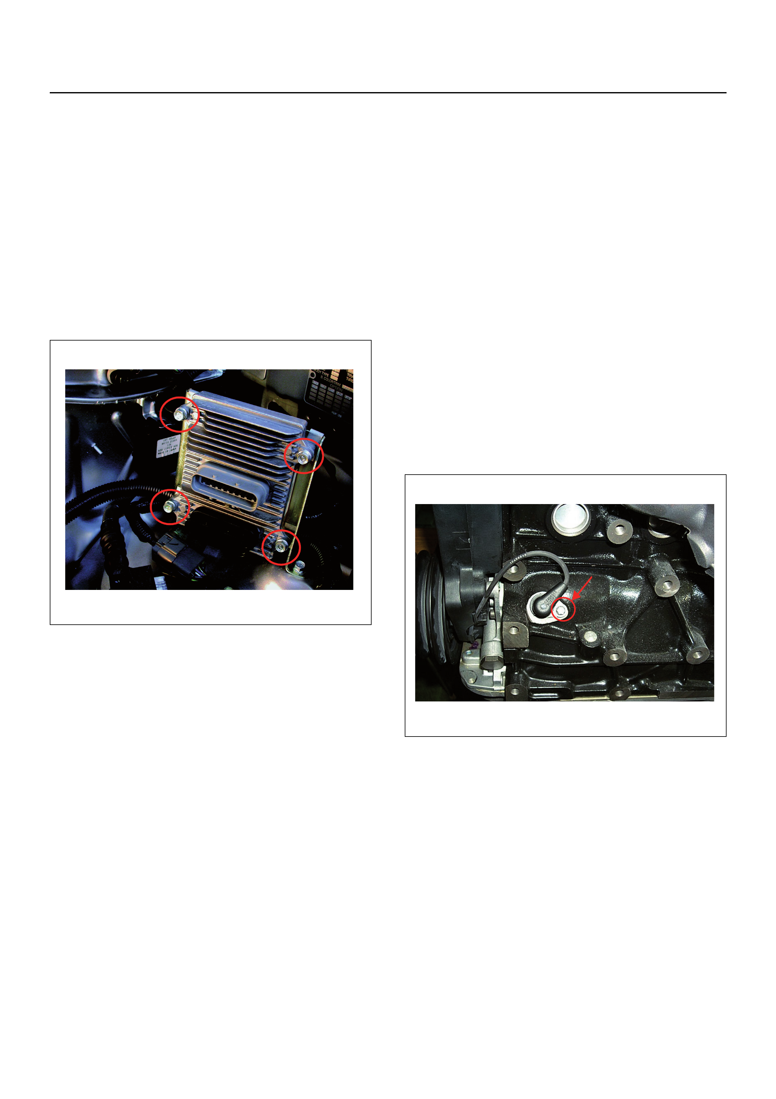
ON-VEHICLE SERVICE PROCEDURE
ENGINE CONTROL MODULE (ECM)
Location
On the left-hand side of the engine bay behind the
battery and fuse panel.
Removal Procedure
1. Disconnect the negative battery cable.
2. Disconnect the two connectors from the ECM.
3. Remove four bolts attaching the ECM.
4. Remove the ECM from mounting bracket.
Installation Procedure
1. Fit the ECM to the mounting bracket.
2. Tighten the four bolts attaching the ECM to the
correct torque specification.
Tightening Torque
•Bolts: 8.0 - 12.0 Nm.
3. Connect the two connectors to the ECM.
4. Connect the ne ga tiv e ba tte r y cab le.
NOTE: Verify that any DTCs (Diagnosis Trouble Code)
are not stored after replacement.
CRANKSHAFT POSITION (CKP)
SENSOR
Location
Left-hand side of the cylinder block behind the A/C
compressor, where fitted.
Removal Procedure
1. Disconnect the negative battery cable.
2. Remove the accessory drive belt, if fitted. Refer to
Engine Mechanical Section.
3. Remove the A/C compressor from engine, if fitted.
Refer to Engine Mechanical Section.
4. Disconnect the CKP sensor harness connector.
5. Remove the bolt and the CKP sensor and harness
from the cylinder block.
NOTE: Use caution to avoid any hot oil that might drip
out.
Installation Procedure
1. Install the CKP sensor to the cylinder block.
2. Tighten the bolt attaching the CKP sensor to the
correct torque specification.
Tightening Torque
•Bolt: 6.0 Nm.
3. Reinstall the A/C compressor to the engine, if fitted.
4. Reinstall the acces sory drive belt, if fitted.
5. Connect the negative battery cable.
NOTE: Verify that any DTCs (Diagnosis Trouble Code)
are not stored after replacement.
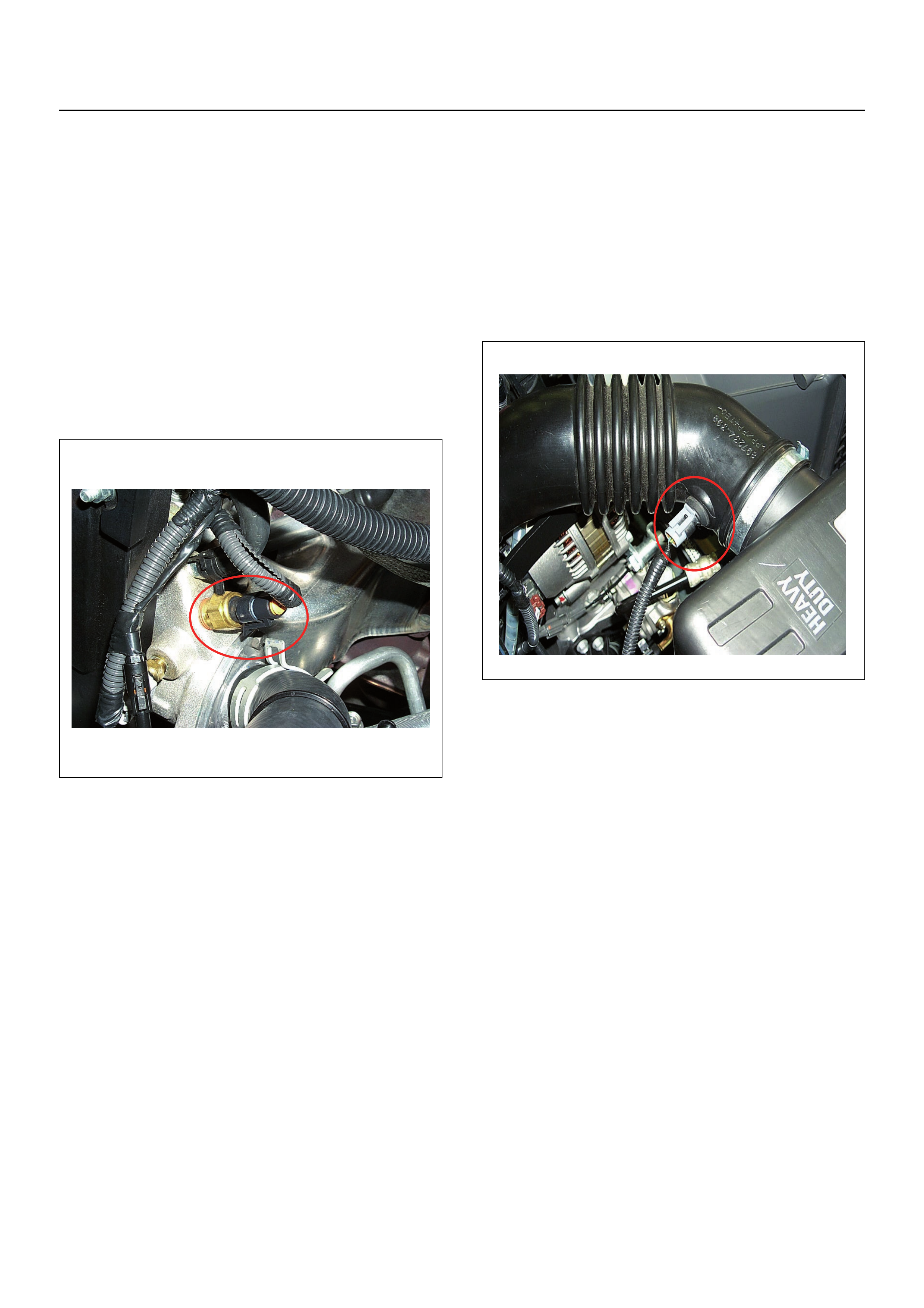
ENGINE COOLANT TEMPERATURE
(ECT) SENSOR
Location
Installed to the thermostat housing.
Removal Procedure
1. Disconnect the negative battery cable.
WARNING: Cool down the engine before the following
procedures are carried out.
2. Drain enough engine coolant so the coolant level
will be below the ECT sensor.
3. Disconnect the connector from the ECT sensor.
4. Loosen and remove the ECT sensor from the
thermostat housing.
Installation Procedure
1. Apply sealer to threads of the ECT sensor.
2. Install and tighten the ECT sensor to the correct
torque specification.
Tightening Torque
•Bolt: 13.0 Nm
3. Connect the connector to the ECT sensor.
4. Top up the engine coolant.
5. Connect the ne ga tiv e ba tte r y cab le.
NOTE: Verify that any DTCs (Diagnosis Trouble Code)
are not stored after replacement.
Verify if no engine coolant is leaking from the sensor
threads after replacement.
INTAKE AIR TEMPERATURE (IAT)
SENSOR
Location
Installed to the air inlet duct housing.
Removal Procedure
1. Disconnect the negative battery cable.
2. Disconnect the connector from the IAT sensor.
3. Pull the IAT sensor out of the air intlet duct.
Installation Procedure
1. Install the IAT sensor into the intlet air duct.
2. Connect the connector to the IAT sensor.
3. Connect the negative battery cable.
NOTE: Verify that any DTCs (Diagnosis Trouble Code)
are not stored after replacement.
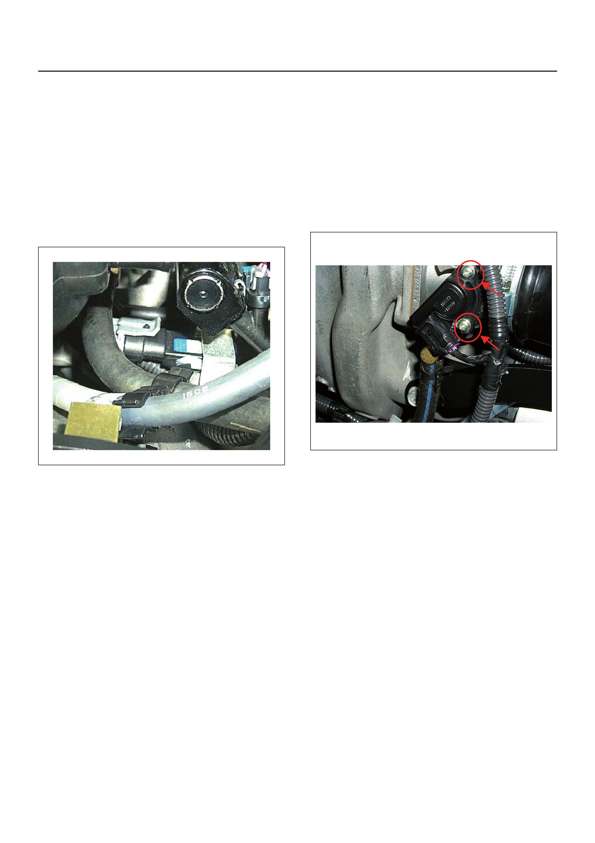
MANIFOLD ABSOLUTE PRESSURE
(MAP) SENSOR
Location
Installed on the inlet manifold.
Removal Procedure
1. Disconenct the negative battery cable.
2. Disconnect the connector from the MAP sensor.
3. Remove the bolt and bracket with the MAP sensor
from the inlet manifold.
4. Remove the MAP sensor from the bracket.
Installation Procedure
1. Install the MAP sensor and the bracket to the inlet
manifold.
2. Tighten the bolt attaching the MAP sensor and the
bracket to the correct torque specification.
Tightening Torque
• Bolt: 8.0 Nm
3. Connect the connector to the MAP sensor.
4. Connect the ne ga tiv e ba tte r y cab le.
NOTE: Verify that any DTCs (Diagnosis Trouble Code)
are not stored after replacement.
THROTTLE POSITION (TPS)
SENSOR
Location
Installed on the throttle body.
Removal Procedure
1. Disconnect the negative battery cable.
2. Disconnect the TPS connector.
3. Remove the two screws and the TPS from the
throttle body.
Installation Procedure
1. Temporary attach the TPS with the two screws.
2. Connect the TPS connector to the TPS.
3. Connect Tech 2 to the vehicle.
4. Connect the negative battery cable.
5. Select "Data Display" with Tech 2.
6. Check the throttle position data and adjust the TPS
position as required.
7. Tighten the two screws.
NOTE: Verify that any DTCs (Diagnosis Trouble Code)
are not stored after replacement.

IDLE AIR CONTROL (IAC) VALVE
Location
Installed on the throttle body.
Removal Procedure
1. Disconnect the negative battery cable.
2. Disconnect the IAC valve connector.
3. Remove the two screws and the IAC valve from the
throttle body.
Cleaning and Inspection
1. Clean the IAC valve O-ring sealing surface, pintle
valve seat and air passage.
2. Use carburetor cleaner and a parts cleaning brush
to remove carbon deposit.
Do not use a cleaner that contain methyl ethyl
ketone. This is an extremely strong solvent and not
necessary for this type of deposit.
3. Shiny spots on the pintle are normal and do not
indicate misalignment or a bent pintle shaft.
4. Inspect the IAC valve O-ring for cuts, cracks or
distortion. Replace the O-ring if damaged.
Installation Procedure
1. Install the IAC valve with the two attaching screws
to the throttle body.
2. Tighten the two screws.
3. Connect the connector to the MAP sensor.
4. Connect the ne ga tiv e ba tte r y cab le.
NOTE: Verify that any DTCs (Diagnosis Trouble Code)
are not stored after replacement.
KNOCK SENSOR (KS)
Location
Right-hand side of the cylinder block.
Removal Procedure
1. Disconnect the negative battery cable.
2. Disconnect the knock sensor harness connector.
3. Remove the attaching bolt and remove the knock
sensor and harness from the cylinder block.
Installation Procedure
1. Install the knock sensor with the attaching bolt to the
cylinder block.
2. Tighten the bolt to the correct torque specification.
Tightening Torque
•Bolt: 20.0 Nm
3. Connect knock sensor harness connector.
4. Connect the negative battery cable.
NOTE: Verify that any DTCs (Diagnosis Trouble Code)
are not stored after replacement.
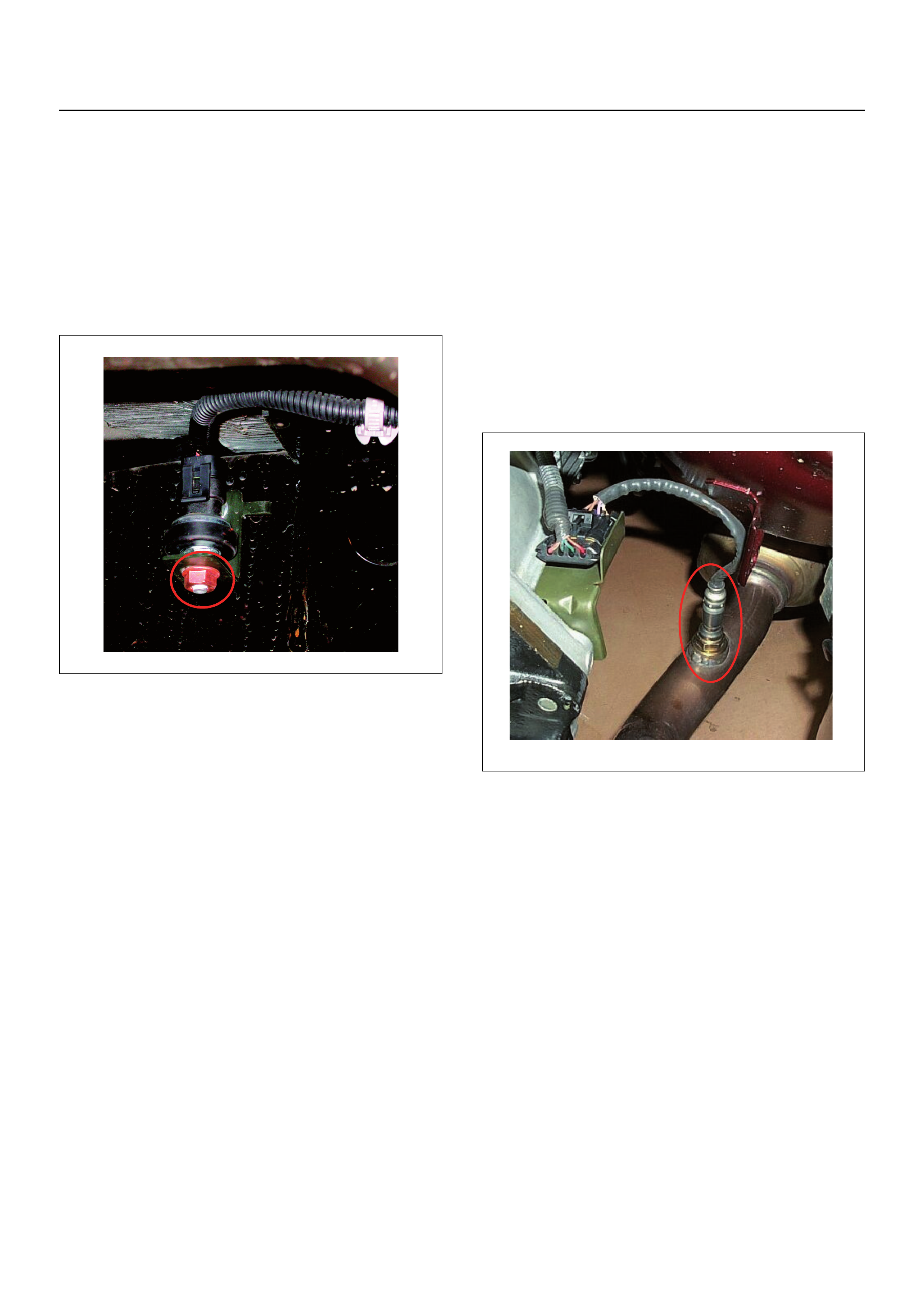
VERTICAL-G (RRID) SENSOR
Location
On chassis RHS just forward of the rear axle.
Removal Procedure
1. Disconnect the negative battery cable.
2. Disconnect the connector from the RRID sensor.
3. Remove the attaching nut and RRID sensor from
the mounting bracket.
Installation Procedure
1. Install the RRID sensor with the attaching nut onto
the mounting bracket.
2. Tighten the nu t to the corr ect tor qu e sp ecif ica tio n.
Tightening Torque
• Bolt: 8.0 Nm
3. Connect the connector to the RRID sensor.
4. Connect the ne ga tiv e ba tte r y cab le.
NOTE: Verify that any DTCs (Diagnosis Trouble Code)
are not stored after replacement.
HEATED OXYGEN (HO2S) SENSORS
Location
Installed on the exhaust pipe, one upsteam of the
catalytic converter and the other downstream from the
catalytic converter.
NOTE: There are two 02 sensors fitted to the exhaust,
the R & R procedure is the same for both 02 sensors.
Removal Procedure
1. Disconnect the negative battery cable.
2. Unclip the O2 sensor harness connector from the
supporting bracket.
3. Disconnect the O2 sensor harness connector.
4. Loosen and remove the O2 sensor from the exhaust
pipe.
Inspection
Inspect the louvered end of the sensor for grease, dirt,
excessive carbon build up or other contamination.
Installation Procedure
1. Install the O2 sensor to the exhaust pipe.
2. Tighten the O2 sensor to the correct torque
specification.
Tightening Torque
•Bolt: 42.0 Nm
3. Connect the O2 sensor harness connector and
secure to the supporting bracket.
4. Connect the negative battery cable.
NOTE: Verify that any DTCs (Diagnosis Trouble Code)
are not stored after replacement.
Verify if no exhaust gas is leaking from the sensor
threads after replacement.
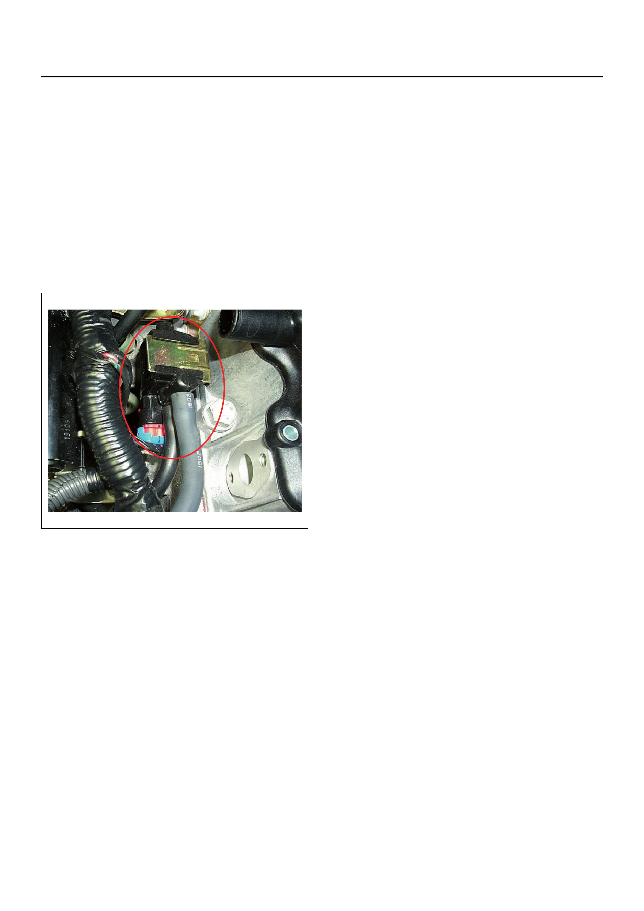
EVAP CANISTER PURGE VALVE
SOLENOID
Location
On the inlet manifold.
Removal Procedure
1. Disconnect the negative battery cable.
2. Disconnect the purge solenoid connector from the
purge solenoid.
3. Disconnect the two hoses from the purge solenoid
valve.
4. Slide from the bracket and remove the purge
solenoid.
Installation Procedure
1. Insert EVAP purge solenoid valve onto the bracket.
2. Connect the two hoses to the purge solenoid valve.
3. Connect the purge solenoid connector to the purge
solenoid.
4. Connect the ne ga tiv e ba tte r y cab le.
NOTE: Verify that any DTCs (Diagnosis Trouble Code)
are not stored after replacement.
Verify proper connection of two hoses.
FUEL PRESSURE RELIEF
WARNING:
• To reduce the risk of fire and personal injury, it is
necessary to relieve the fuel system pressure before
servicing the fue l syst em com p on en ts .
• After relieving the fuel system pressure, a small
amount of fuel may be released when servicing fuel
lines or connections.
• Reduce the risk of personal injury by covering the fuel
line fitting with a shop towel before disconnecting the
fittings. The towel will absorb any fuel that may leak
out. When the process is completed, place the towel
in an approved container.
1. Remove the fuel filler cap.
2. Remove the fuel pump relay from the relay box in
the engine bay .
3. Start the engine and allow it to stall.
4. Crank the engine for about 30 seconds.
5. Disconnect the negative battery cable.
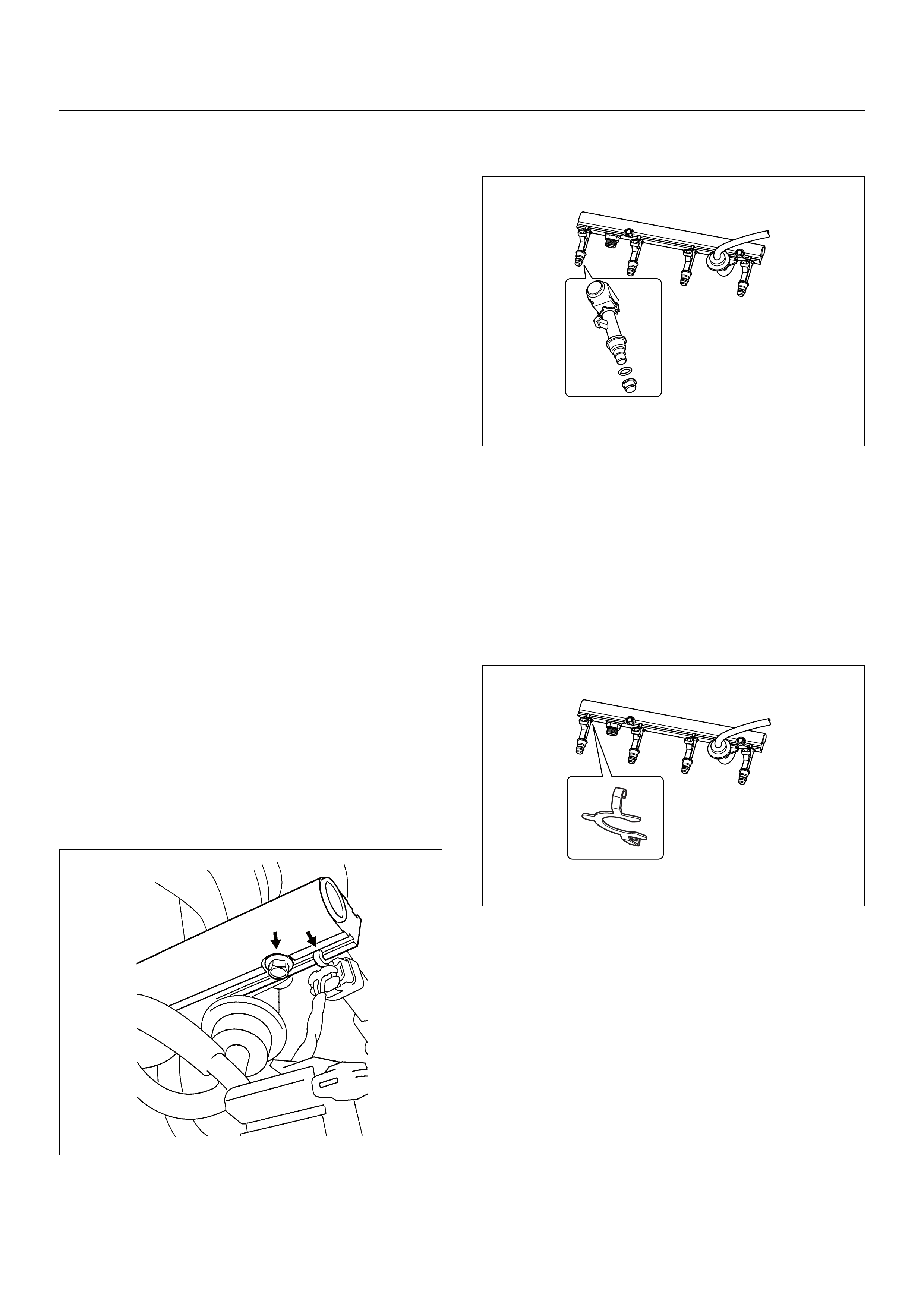
FUEL RAIL ASSEMBLY
Removal Procedure
CAUTION:
• Take care when removing the fuel rail assembly in
order to prevent damage to the injector connector
terminal and the injector spray tips.
• Fitting should be capped and holes plugged during
servicing to prevent dirt and other contaminants from
entering open lines and passages.
• An eight-digit identification number is stamped on
side of the fuel injector. Refer to this number when
you service the fuel rail or when a repla cement par t is
required.
1. Remove the support bracket.
2. Disconnect the four injector connectors.
3. Disconnect the vacuum hose from the pressure
regulator.
4. Remove the wiring harness from the clips on the
fuel rail.
5. Disconnect the fuel supply pipe from the fuel rail.
6. Disconnect the fuel return pipe from the pressure
regulator.
7. Remove the two bolts attaching the fuel rail and do
as follows:
a. Lift up the injectors carefully to separate them
from the inlet manifold.
b. Lift up the fuel rail with the injectors as an
assembly. Do not separate the fuel injectors
from fuel rail.
c. If an injector becomes separated from the fuel
rail, the injector backup O-ring and retainer clip
must be replaced.
d. Drain any residual fuel from the fuel rail into an
approved container.
8. If removal of the fuel pressure regulator is
necessary, Refer to Fuel Pressure Regulator
Removal Procedure.
9. If removal of the fuel injectors is necessary, Refer to
Fuel Injectors Removal Procedure.
Installation Procedure
1. Install the fuel injectors if necessary. Refer to Fuel
Injector Installation Procedure.
2. Install the fuel pressure regulator, if necessary.
Refer to Fuel Pressure Regulator Installation
Procedure.
3. Place the fuel injector rail assembly on the manifold
and insert the injecto rs into each port b y pushing the
fuel rail.
4. Install fuel rail two retaining bolts.
5. Tighten the two bolts to the specified torque.
Tightening Torque
•Bolt: 19.0 Nm
6. Connect the fuel supply line securely to the fuel rail.
Do not over tighten.
7. Connect the hose to the pressure regulator and
secure the clips.
8. Install the wiring harness to the clips on the fuel rail.
9. Connect the four injector connectors.
10. Install the support bracket with the two nuts on the
valve cover and two bolts on the expansion cover.
Refer to Engine Mechanical for correct torque
specification.
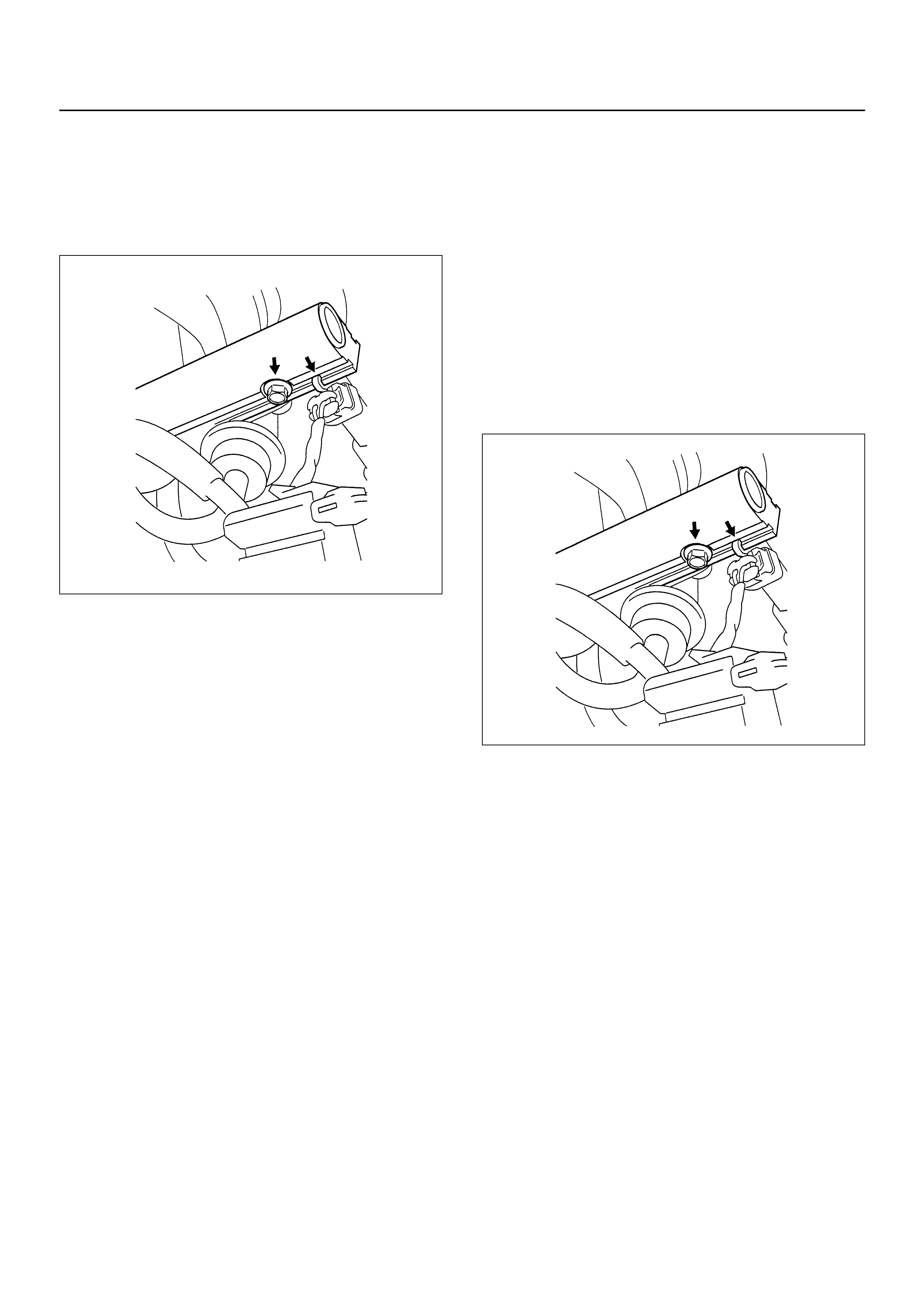
11. Connect the negative battery cable.
12. Crank the engine until it starts. Cranking the engine
may take longer than usual due to trapped air in the
fuel system. Check for leak. If fuel leak is observed,
stop engine immediately. Before correcting fuel
leak, depressurize the system.
FUEL INJECTOR
CAUTION: Fuel injectors are serviced as a complete
assembly only.
Removal Procedure
NOTE: If the fuel injectors are leaking, the engine oil
may be contaminated with fuel. Check the oil for signs
of contamination and change the oil and filter if
necessary.
NOTE: Take care when removing the fuel injectors to
prevent damage to the injectors connector pins or
injectors nozzle. The fuel injectors should not be
immersed in any type of cleaner as this may cause
damage to the injectors.
1. Disconnect the negative battery cable.
2. Remove the fuel rail, refer to Fuel Rail Removal
Procedure.
3. Remove the fuel injector retainer clip. Discard the
retainer clip.
4. Remove the fuel injector assembly from the fuel rail.
5. Remove the O-ring from the fuel injector. Discard
the O-ring.
6. Remove O-ring backup from the fuel injector.
Disgard the O-ring ba ck up .
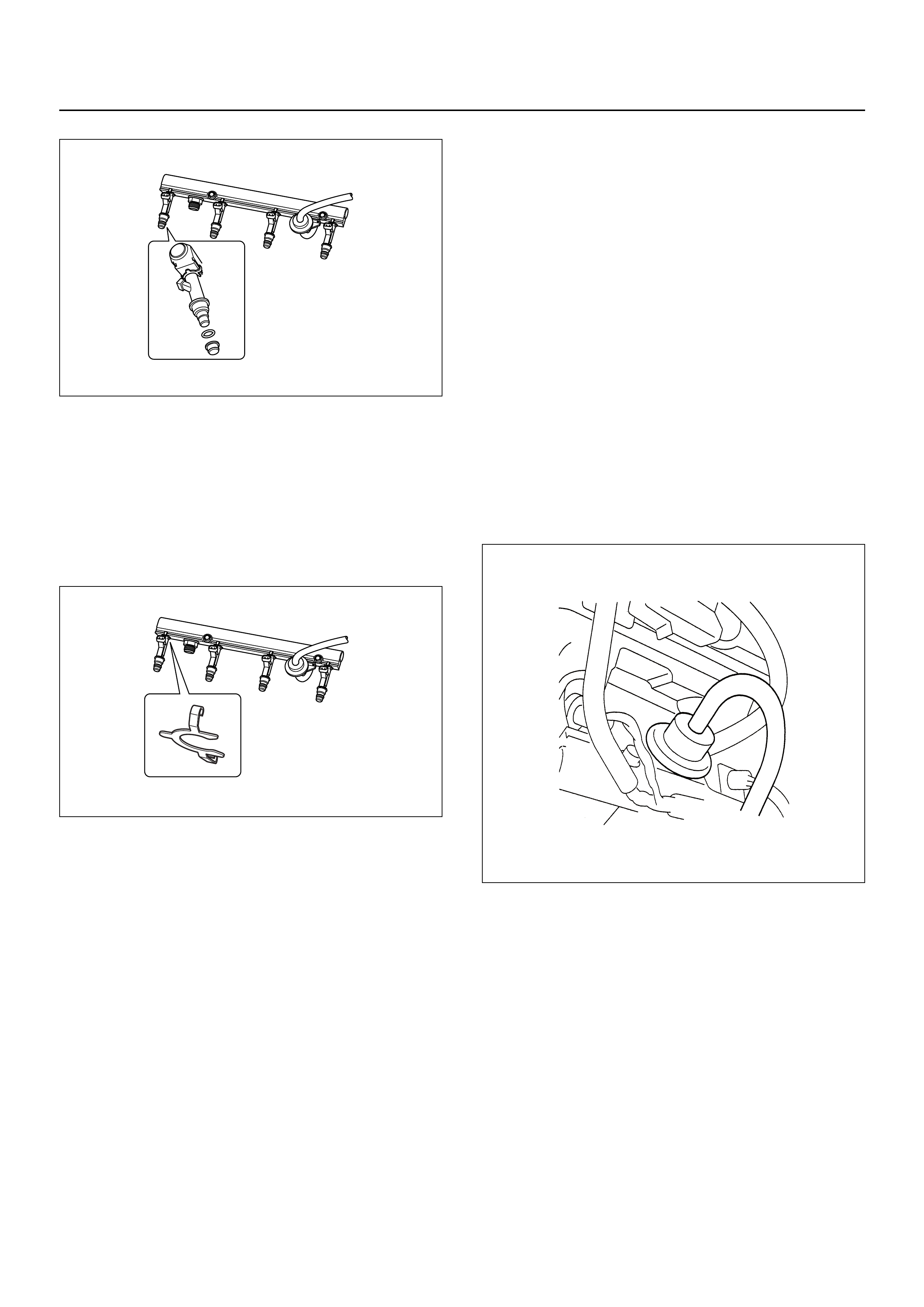
Installation Procedure
1. Lubricate the new O-ring with engine oil.
2. Install the new O-ring backup on the fuel injector.
3. Install new O-ring on the fuel injector.
4. Install all four injectors on the fuel rail.
5. Use new injector retainer clips to secure each
injector to the fuel rail.
6. Install the fuel rail assembly. Refer to Fuel Rail
Installation Procedure.
7. Connect the negative battery cable.
FUEL PRESSURE REGULATOR
CAUTION:
• To reduce the risk of fire and personal injury, it is
necessary to relieve the fuel system pressure before
servicing the fue l syst em com p on en ts .
• After relieving the fuel system pressure, a small
amount of fuel may be released when servicing fuel
lines or connections. Reduce the risk of personal
injury by covering the fuel line fitting with a shop towel
before disconnecting the fittings. The towel will
absorb any fuel that may leak out. When the process
is completed, place the towel in an approved
container.
NOTE:
• Compressed air must never b e used to test or clean a
fuel pressure regulator, as damage to the fuel
pressure regulator may occur.
• To pr event damag e to the fuel pre ssure r egulat or, do
not immerse the pressure regulator in solvent.
Removal Procedure
1. Depressurize the fuel system. Refer to Fuel
Pressure Relief Procedure.
2. Disconnect the negative battery cable.
3. Remove the fuel pump relay.
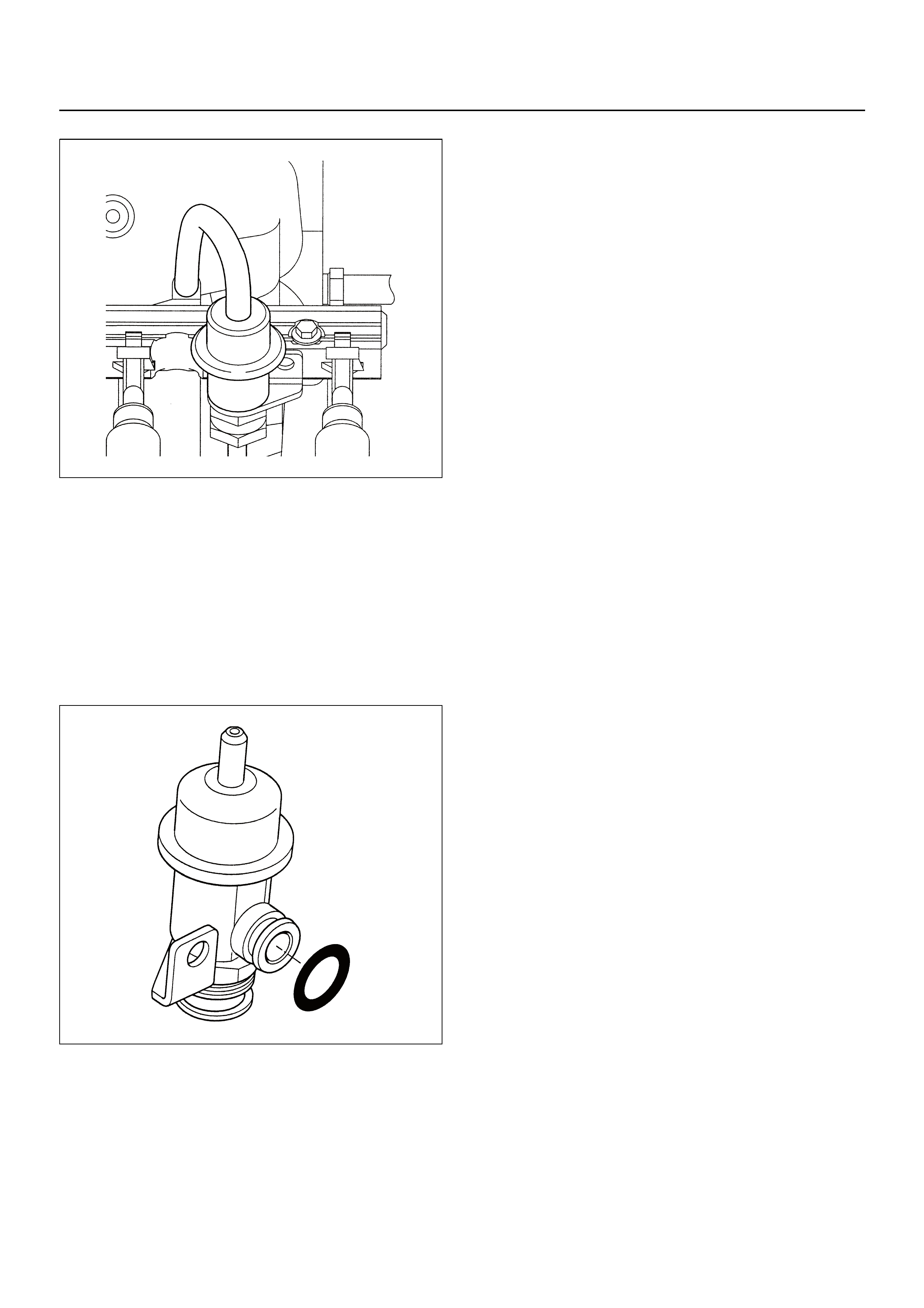
4. Disconnect the vacuum hose from the fuel pressure
regulator.
5. Disconnect the fuel return pipe from the fuel
pressure regulator.
6. Remove the fuel pressure regulator attaching bolt.
7. Remove the fuel pressure regulator from the fuel
rail.
Installation Procedure
1. Insert the fuel pressure regulator into the fuel rail.
2. Install the attaching bolt to the fuel pressure
regulator retaining bracket and tighten the bolt
securely.
3. Connect the fuel return pipe to the fuel pressure
regulator.
4. Connect the vacuum hose to the fuel pressure
regulator.
5. Install the fuel pump relay.
6. Connect the negative battery cable.
7. Crank the engine until it starts. Cranking the engine
may take longer than usual due to trapped air in the
fuel line.
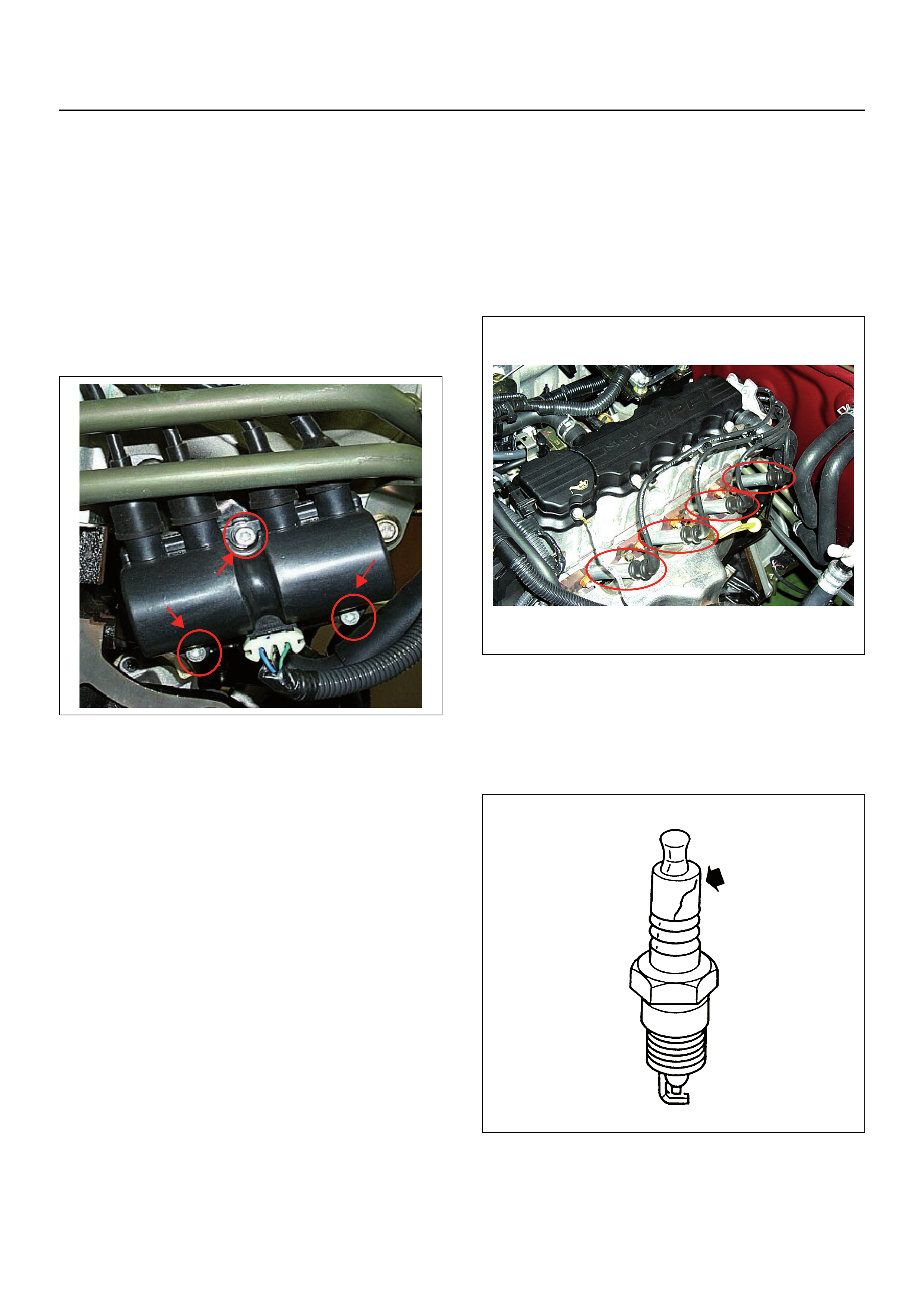
IGNITION COIL
Location
Rear of the engine right-hand side.
Removal Procedure
1. Disconnect the negative battery cable.
2. Disconnect the ignition coil connector.
3. Disconnect the four spark plug cables from the
ignition coil.
4. Remove the three attaching bolts and the ignition
coil from the mounting bracket.
Installation Procedure
1. Install the three attaching bolts and the ignition coil
to the mounting bracket. Tighten the bolts securely.
2. Connect the four spark plug cables to the ignition
coil.
3. Connect the connector to the ignition coil.
NOTE: Verify proper connection of the spark plug
cables for each cylinder.
4. Connect the ne ga tiv e ba tte r y cab le.
NOTE: Verify that any DTCs (Diagnosis Trouble Code)
are not stored after replacement.
SPARK PLUGS
Location
Installed on the left-hand side of the cylinder head.
Removal Procedure
1. Disconnect the negative battery cable.
2. Remove the spark plug cable.
3. Remove the spark plug.
Inspection
1. Check the insulator for cracks. Replace the spark
plug if cracks are present.
2. Check the electrode condition and replace the sp ark
plug if necessary.
If the spark plug electrodes and insulators are fouled
with carbon or oil, the engine will not operate efficiently.
There are a nu m be r of poss ible cau se s:
•Fuel mixture is too rich.
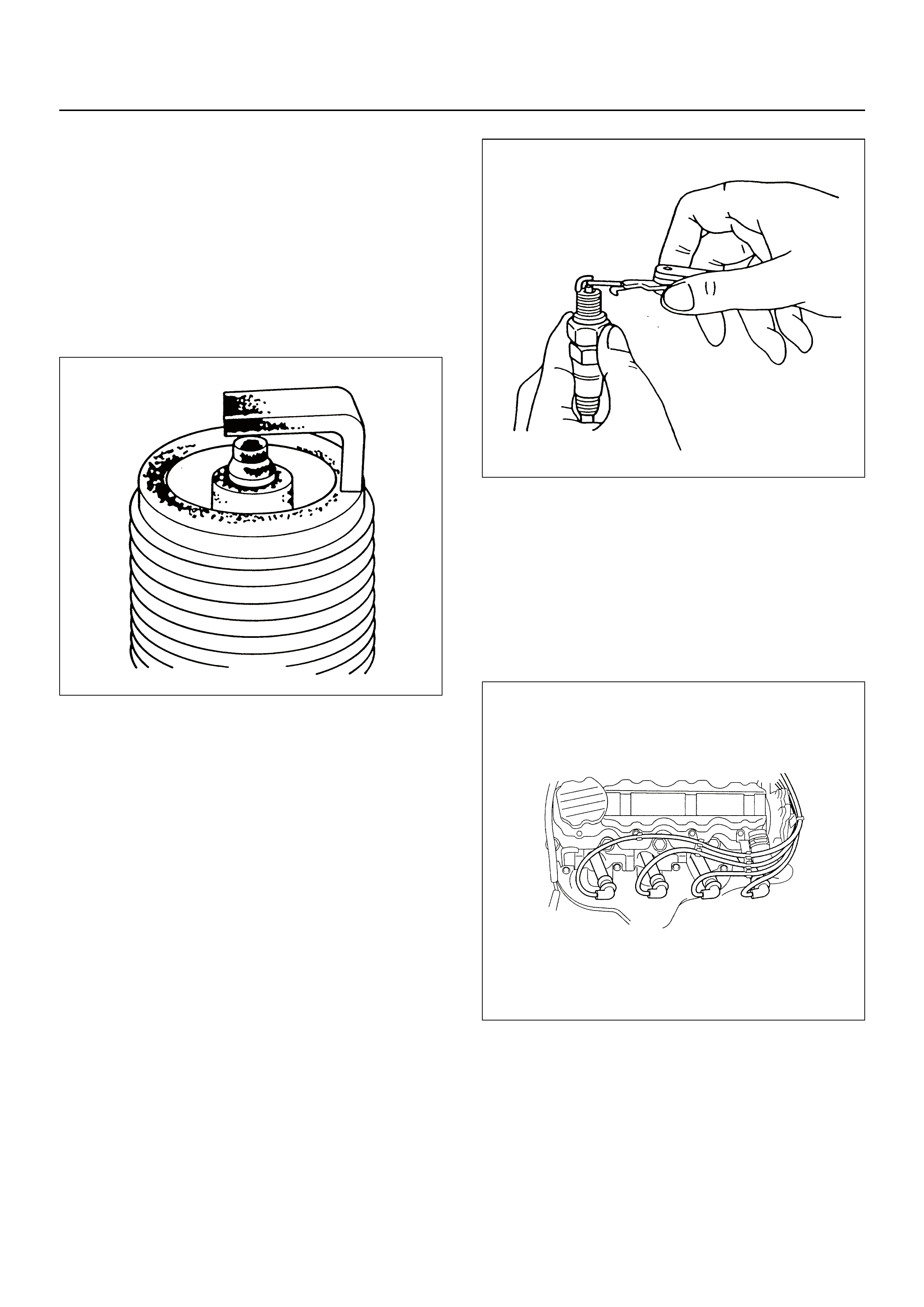
• Oil in the combustion chamber.
• The spark plug gap is not set correctly.
If spark plug fouling is excessive, check the fuel and all
systems for possible causes of trouble. If fuel and all
systems are normal, install spark plugs of a higher heat
range which have the same physical dimensions as the
original equipment spark plugs.
The following symptoms are characteristics of spark
plugs that are running too hot:
• Fuel mixture is too lean.
• Heat range is incorrect.
If vehicle usage does not conform to normal driving
conditions, a more suitable spark plug may be
substituted.
If fuel and all systems are normal, in most cases of this
sort, the problem can be corrected by using a colder
type spark plug with the same physical dimensions as
the original equipm en t sp ar k plu g.
3. Check the gaskets for damage and replace if
necessary.
4. Measure the spark plug gap. The specificati on is 1.0
to 1.1mm.
5. Adjust the spark gap by bending the grounded
electrode.
Installation Procedure
1. Install the spark plug to the cylinder head.
2. Tighten the spark plug to the correct torque
specification.
Tightening Torque
•Bolt: 25.0 Nm
3. Connect the spark plug cable to the spark plug.
NOTE: Verify proper connection of the spark plug
cables for each cylinder
4. Connect the negative battery cable.
NOTE: Verify that any DTCs (Diagnosis Trouble Code)
are not stored after replacement.
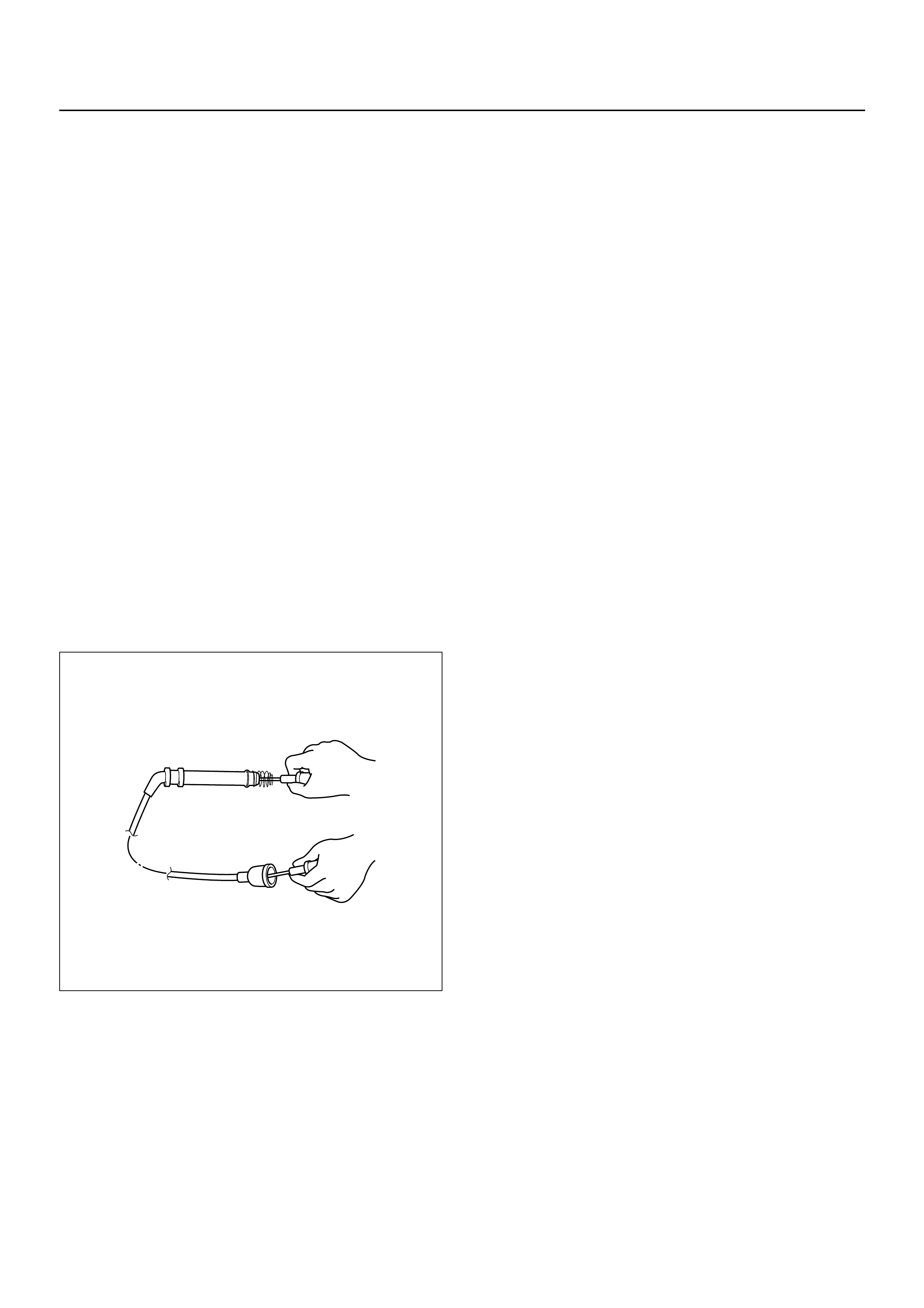
SPARK PLUG CABLES
The cable contains a synthetic conductor which can be
easily damaged. Never stretch or kink the cable.
Disconnect the cable from the spark plug and the
ignition coil.
The original equipment cables and the ignition coil are
marked to show correct location of the cables. If spark
plug cables or the ignition coil have been replaced
previously, mark the cables and the coil before removal
so they can be reconnected in the same position.
Inspection
NOTE: Never puncture the spark plug cable’s insulation
with a needle or the pointed end of a probe into the
cable. An increase in resistance would be created which
would cause the cable to become defective.
1. If the cable has broken or cracked insulation, it must
be replaced.
2. If the terminals are corroded or loose, the cable
must be replaced.
3. Check if the cable resistance does not exceed
specified value.
#1 cylinder: 3.50kΩ - 5.24kΩ
#2 cylinder: 2.89kΩ - 4.33kΩ
#3 cylinder: 2.49kΩ - 3.73kΩ
#4 cylinder: 2.22kΩ - 3.32kΩ.
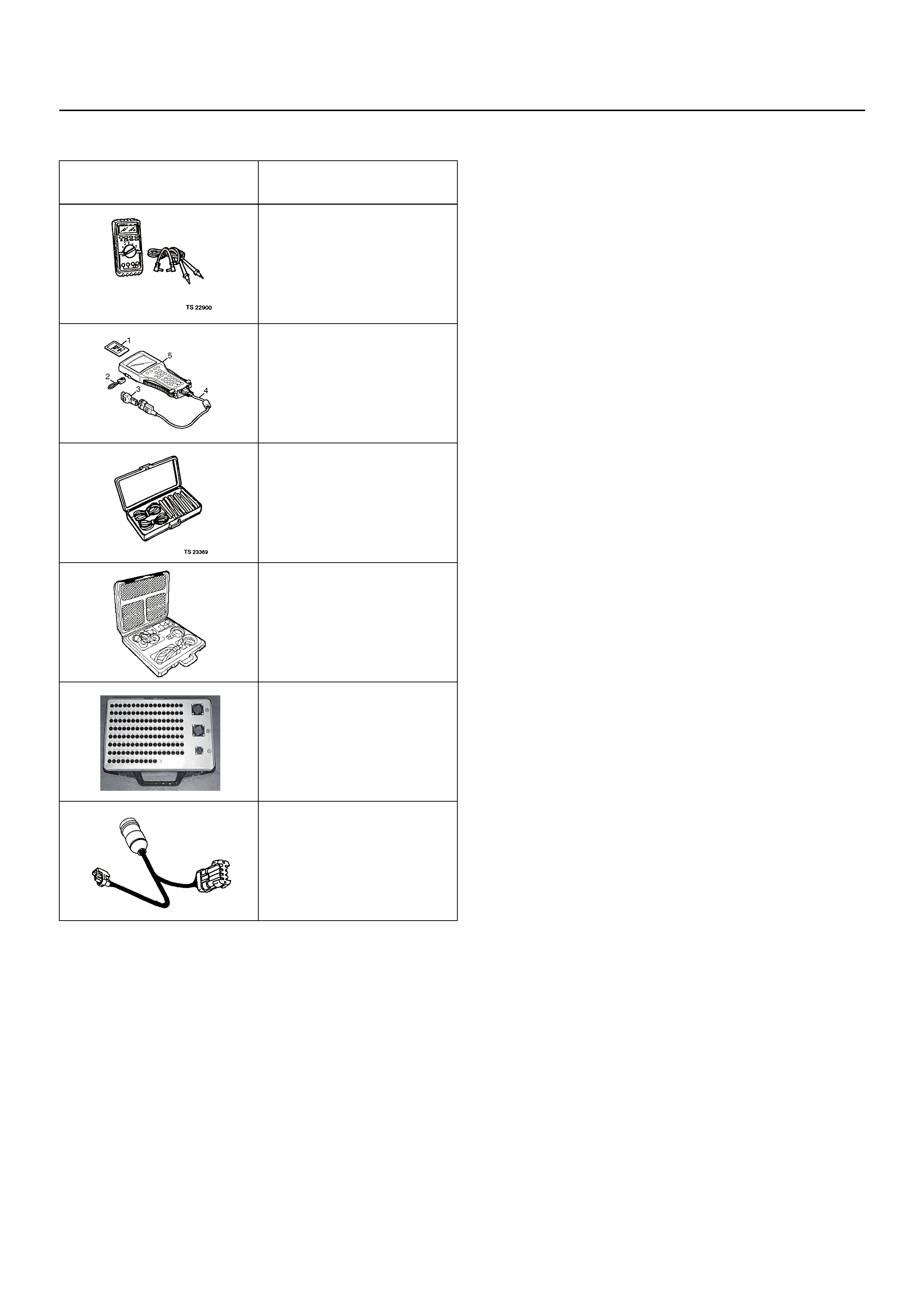
SPECIAL SERVICE TOOLS
ILLUSTRATION TOOL NO.
TOLL NAME
5-8840-0285-0
(J 39200)
High Impedance
Multimeter
(Digital Voltmeter -DVM)
(1) PCMCIA Card
(2) RS232 Loop Back
Connector
(3) SAE 16/19 Adapter
(4) DLC Cable
(5) TECH 2
5-8840-0385-0
(J 35616-A/BT-8637)
Connector Test Adapter Kit
5-8840-0378-0
(J34730-E)
Port Fuel Injection
Diagnostic Kit
Breaker Box
5-8840-2589-0
Injector Adapter Cable