
SECTION 0A - GENERAL INFORMATION
IMPORTANT
Before performing any Service Operation or other procedure described in this Section, refer to Section
00 CAUTIONS AND NOTES for correct workshop practices with regard to safety and/or property damage.
1. GENERAL INFORMATION
1.1 V2 SERIES INTRODUCTION
1.2 MY2003 UPDATE
1.3 UNDERBODY HOIST PAD LOCATIONS
2. MODEL AVAILABILITY AND BASE EQUIPMENT
3. POWERTRAIN COMBINATIONS
4. TRANSMISSION RATIOS
5. ENGINE DATA
6. EXTERIOR DIMENSIONS
7. VEHICLE WEIGHTS
8. SERIAL NUMBERS
8.1 LOCATION OF IDENTIFICATION PLATES
8.2 SAFETY COMPLIANCE PLATE
8.3 BODY AND OPTION IDENTIFICATION PLATE
8.4 FUEL CONSUMPTION LABEL
8.5 VEHICLE IDENTIFICATION NUMBER PLATE
(BODY LOCATION)
8.6 VEHICLE IDENTIFICATION NUMBERING SYSTEM
MY2002 MODELS
MY2003 UPDATE MODELS
8.7 ENGINE SERIAL NUMBER
8.8 MANUAL TRANSMISSION SERIAL NUMBER
8.9 AUTOMATIC TRANSMISSION SERIAL
NUMBER
MY2002 MODELS
MY2003 UPDATE MODELS
8.10 FINAL DRIVE IDENTIFICATION
9. ADDITIONAL GENERAL INFORMATION
9.1 ELECTRICAL TRANSIENTS AND RADIO
FREQUENCY INTERFERENCE
ELECTRICAL TRANSIENTS
RADIO FREQUENCY INTERFERENCE
9.2 STATIC ELECTRICITY
9.3 PUSH OR TOW STARTING
10. CONSOLIDATED TOOL LI ST
MY2002 MODELS
MY2003 UPDATE MODELS
Techline
Techline
Techline
Techline
Techline
Techline

1. GENERAL I NFORMATI O N
1.1 V2 SERIES INTRODUCTION
The V2 Series Monaro is a new coupe (2-door) body design based on the VX Series Commodore. Sheetmetal
changes for V2 Series Monaro include new front doors, rear quarter panels, rear compartment lid (reduced rear
overhang), roof panel and a revised A-pillar rake (increased 2 degrees).
Other changes for V2 Series Models include:
• Modified side skirts.
• New front and rear bumper facias.
• Encapsulated glass in place of rear door window.
• New two passenger rear seat.
• New eight-way EZ Entry front seats.
• New EZ Entry memory type driver’s seat (CV8 only).
• New floor mats.
• New headlining.
• New door sill applique.
• New puddle lamp.
• Retuned sports suspension.
• Multi-link rear suspension.
• A revised Vehicle Identification Numbering (VIN) System.
• The 2003 Model Year update was introduced during October 2002.
The powertrain combinations available for V2 Series Models carry over from VX Series II Models.

1.2 MY2003 UPDATE
The MY2003 V2 Series update is a minor mechanical upgrade of the MY2002 V2 Series Models. The major
changes to the MY2003 V2 Series Models are:
• New condenser, radiator and cooling fans fitted to all Models.
• New engine cooling vent hose and radiator outlet hose fitted to CV8 Models.
• New radiator inlet hose fitted to CV6 Models.
• New air conditioning discharge hose fitted to all Models.
• New air conditioning liquid line fitted to all Models.
• New power steering fluid cooler with extra fins fitted to CV8 Models.
• Revised automatic transmission with new force motor and quick connect fittings for CV6 Models.
• Revised m anual tr ans mission s hif t lever (10 mm longer with a 30-degree twist in the s tub lever) f or CV8 Models
fitted with the six-speed manual transmission.
• New heavy-duty automatic transmission with new force motor and quick connect fittings for CV8 Models.
• Revised side and floor panels for improved occupant protection.
• Modified floor carpet and deadener to accommodate the revisions to the side and floor panels.
• New load limiting seat belts for improved occupant safety.
• A revised Vehicle Identification Numbering (VIN) System.
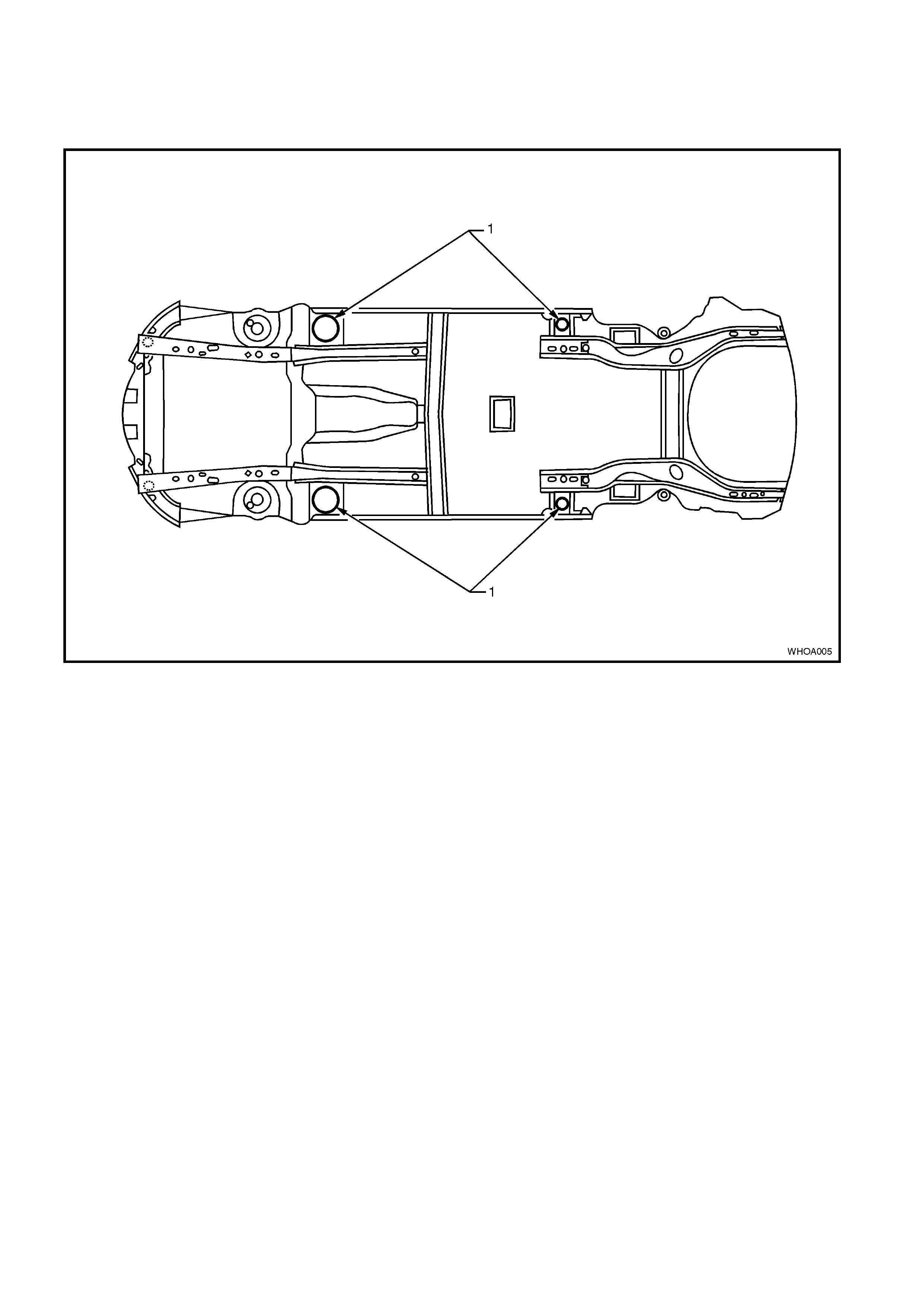
1.3 UNDERBODY HOIST PAD LOCATIONS
NOTE: When using a trolley jack to rais e the vehic le it is important that the jack be positioned under the suspension
cross -m ember or hois t pad loc ations (1). Do not jack under the sus pension control arm . T he vehicle should always
be supported by jack stands at the hoist pad locations when raised.
Figure 0A-1

2. MODEL AVAILABILITY AND BASE EQUIPMENT
MODEL NAME MODEL NO. ENGINE TRANSMISSION FINAL
DRIVE
RATIO TYRES WHEELS
CV6 8VK37 3.8 SEFI
SUPERCHARGED
V6 4-SPEED AUTO 3.07:1 235/45 R17 93V 8.00J X 17
CV8 8VX37 5.7 SEFI GEN III V8 4-SPEED AUTO 3.07:1 235/40 R18 91W 8.00J X 18

3. POWERTRAIN COMBINATIONS
ENGINE TRANSMISSION TYPE
MODEL
AVAILABILITY FIRST GEA R
RATIO FINAL DRIVE
RATIO
3.8 SEFI
SUPERCHARGED V6 4-Speed Automatic CV6 3.06:1 3.07:1
6-Speed Manual CV8 2.66:1 3.46:1
5.7 SEFI GEN III V8 4-Speed Automatic CV8 3.06:1 3.07:1

4. TRANSMISSION RATIOS
GEAR 6-SPEED MANUAL 4-SPEED AUTOMATIC.
1ST 2.66:1 3.06:1
2ND 1.78:1 1.63:1
3RD 1.30:1 1.00:1
4TH 1.00:1 0.70:1
5TH 0.74:1 N/A
6TH 0.50:1 N/A
REV 2.90:1 2.29:1
5. ENGINE DATA
ENGINE
DESIGNA TION 3.8 LITRE
SUPERCHARGED 5.7 LITRE SEFI
(GEN III)
Piston
Displacement
Nom. - cm3 3791 5667
Compression
Ratio 8.5:1 10.1:1
Number of
Cylinders 6 8
Bore x Stroke -
mm 96.5 X
86.3 99 X 92
Taxable H.P.
RAC OR SAE 34 48.6
Power kW
DIN @ RPM 171 kW @ 5200
PULP* 225 kW @ 5200
Torque Nm
DIN @ RPM 375 Nm @ 3000
PULP* 460 Nm @ 4400
*PULP – Premium Unleaded Petrol

6. EXTERIOR DIME NSI O NS
BODY DIMENSIONS
VEHICLE LENGTH 4802 mm
VEHICLE WIDTH 1824 mm
VEHICLE HEIGHT 1400 mm
WHEELBASE 2788 mm
OVERHANG - FRONT 943 mm
OVERHANG - REAR 1071 mm
TREAD - FRONT 1569 mm
TREAD - REAR 1587 mm
7. VEHICLE WEIGHTS
VEHICLE WEIGHTS CV6
AUTOMATIC CV8
AUTOMATIC CV8
MANUAL
KERB MASS 1603 kg 1645 kg 1640 kg
REAR AXLE LOAD 1140 kg 1140 kg 1140 kg
PAYLOAD 340 kg 340 kg 340 kg
NOTE: All figures are estimates only.
Payload figures must include luggage, goods, passengers and a full
tank of fuel. If you are towing, then the weight on the tow bar ball
must also be included.
Rear Axle Load is the maximum for all conditions.
8. SERIAL NUMBERS
The complete vehicle and various com ponents of the vehicle are identified by number plates or numbers stam ped
into the part. It is essential that when compiling warranty claims or product and field reports, the vehicle
identification number (VIN) is quoted in conjunction with the identification number of the component affected.
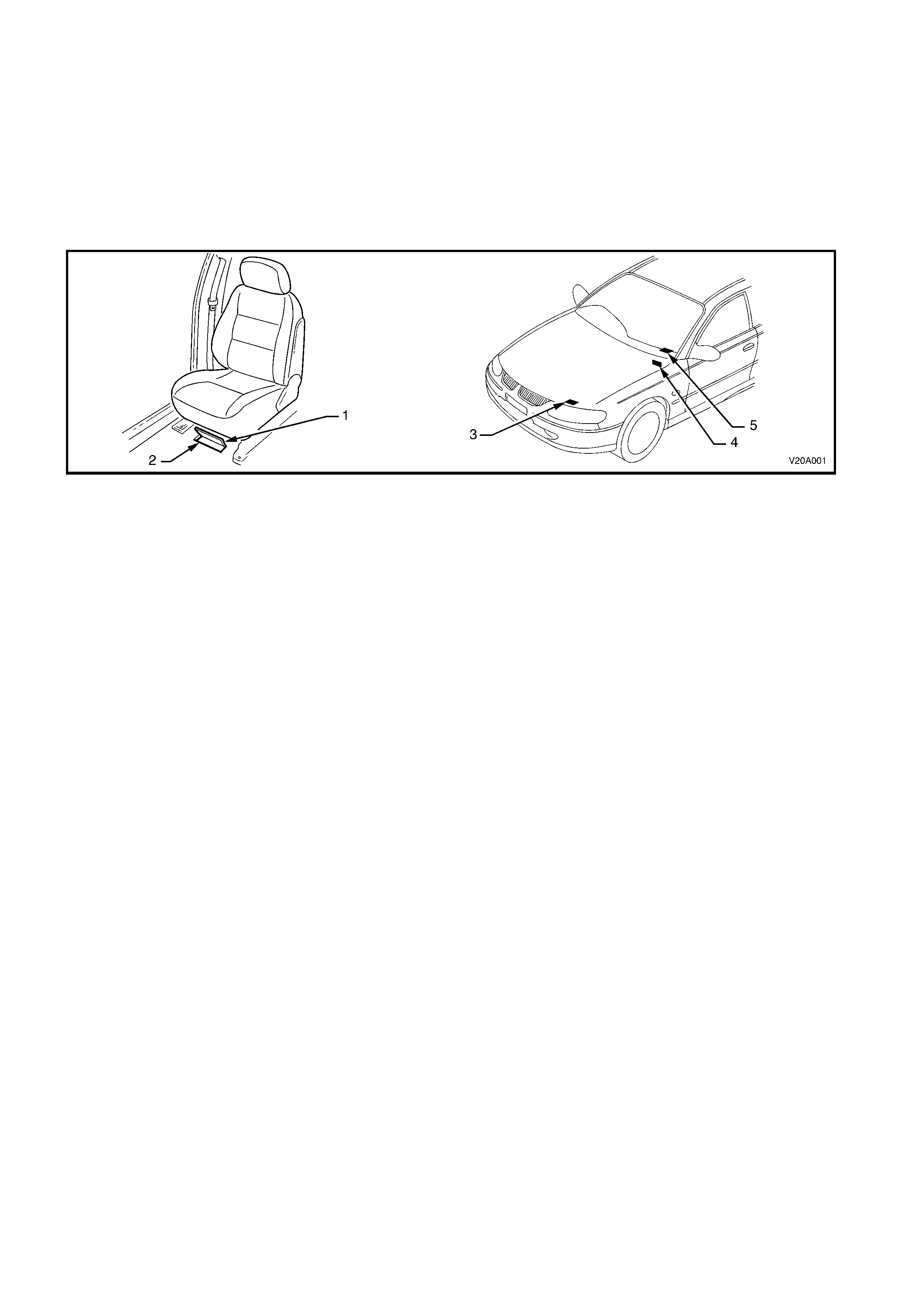
8.1 LOCATION OF IDENTIFICATION PLATES
Identification plates are attached to the upper left side of the dash panel (4), front radiator support panel (3), and
under the windshield lower lef t c orner ( 5). The Vehicle Identif ic ation Number is also s tamped into the f loor ( 2) below
the front right-hand seat, refer to Figure 0A-2.
Figure 0A-2
Legend
1. Carpet flap (under right-hand seat)
2. Vehicle Identification Number
(stamped under right-hand seat)
3. Body and Option Identification Plate
(front upper panel)
4. Safety Compliance Plate
(engine side of dash panel)
5. Vehicle Identification Number Plate
(under windscreen)
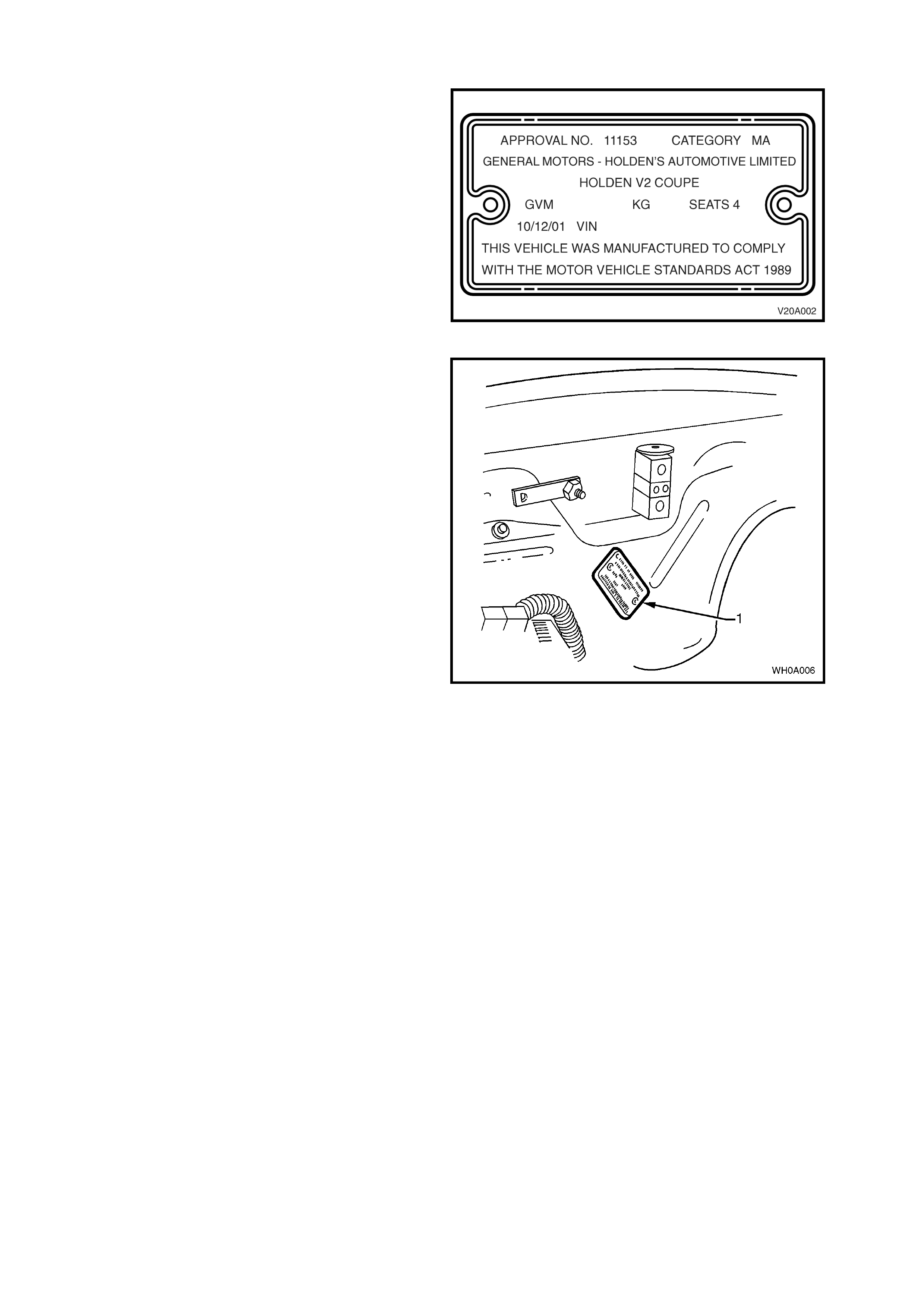
8.2 SAFETY COMPLIANCE PLATE
Plate stamped with the following inform ation, Refer
to Figure 0A-3:
COMPLIANCE PLATE APPROVAL NUMBER.
VEHICLE CATEGORY CODE.
NAME APPEARING ON COMPLIANCE PLATE
APPROVAL.
MAKE/MODEL.
GROSS VEHICLE MASS (KG)
SEATING CAPACITY.
DATE OF MANUFACTURE (* Variable
information).
VEHICLE IDENTIFICATION NUMBER (* Variable
information).
Figure 0A-3
Legend
1. Safety Compliance Plate.
Figure 0A-4
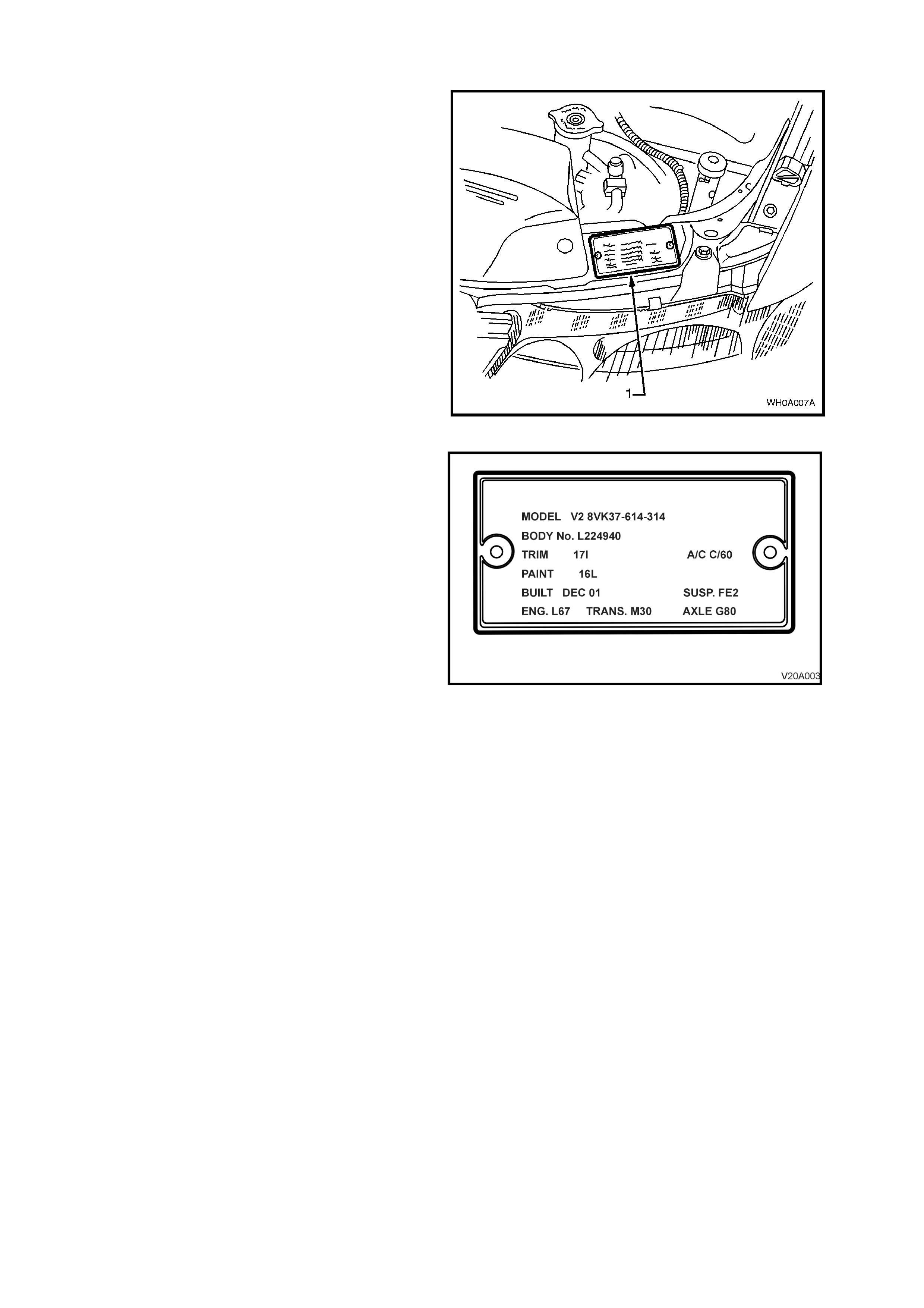
8.3 BODY AND OPTION IDENTIFICATION PLATE
The body and option identification plate (1) is
stamped with the following information, refer to
Figure 0A-6.
Figure 0A-5
MODEL
Combination of letters and numbers identifying the
body style, the mechanical pack and smart pack
options.
NOTE: A listing of Production Option numbers and
Smart Pack Option numbers can be found by
referring to the latest spare parts information
(Partfinder) for the applicable model.
BODY
Production build number, in continuous sequence
regardless of model, body type and series.
TRIM
Trim combination.
PAINT
Exterior paint material and colour identification.
BUILT
The date of manufacture by calendar month and
year in which the body shell and power train are
conjoined and the vehicle is driven or moved from
the production line.
SUSP
Suspension option code identification number, i.e.
FE2.
ENGINE, TRANSMISSION AND AXLE
Identification option codes for specific engine,
transmission and final drive.
A/C
Identification option code C60 identifies vehicles
fitted with air conditioning.
Figure 0A-6
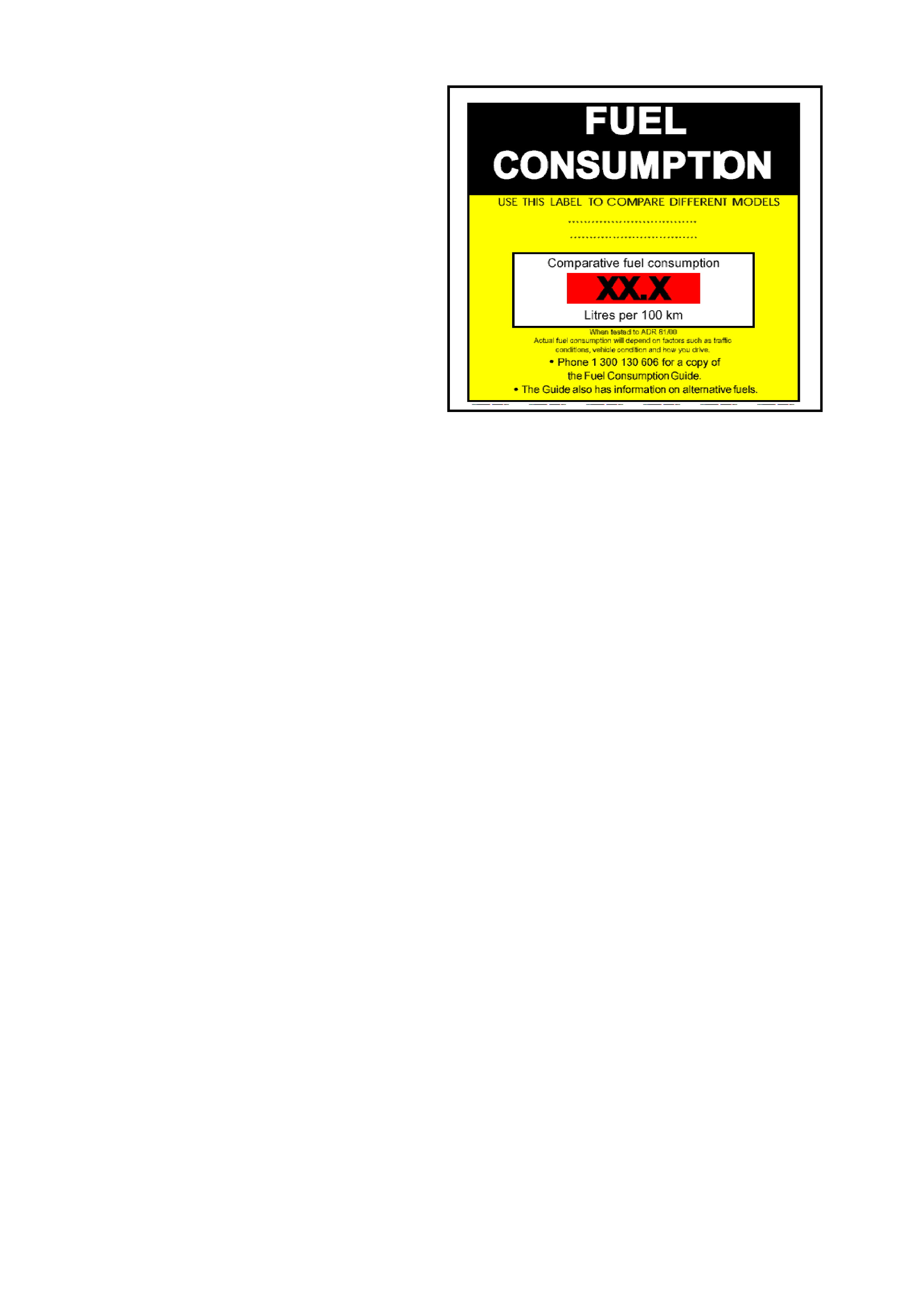
8.4 FUEL CONSUMP TION LABEL
ADR 81/00 requires that from 1st January 2001, a
label similar to that shown in Figure 0A–7 is
attached to the windscreen of any new vehicle
which is displayed for sale.
The f uel c onsumption f igures quoted are the results
of tests carried out in accordance with an
Australian standard for fuel consumption testing.
Each vehicle is tested under identical conditions.
The results therefore enable a comparison to be
made between vehicles.
This label should be removed from the windscreen
immediately prior to the vehicle being delivered to
the owner.
Figure 0A-7
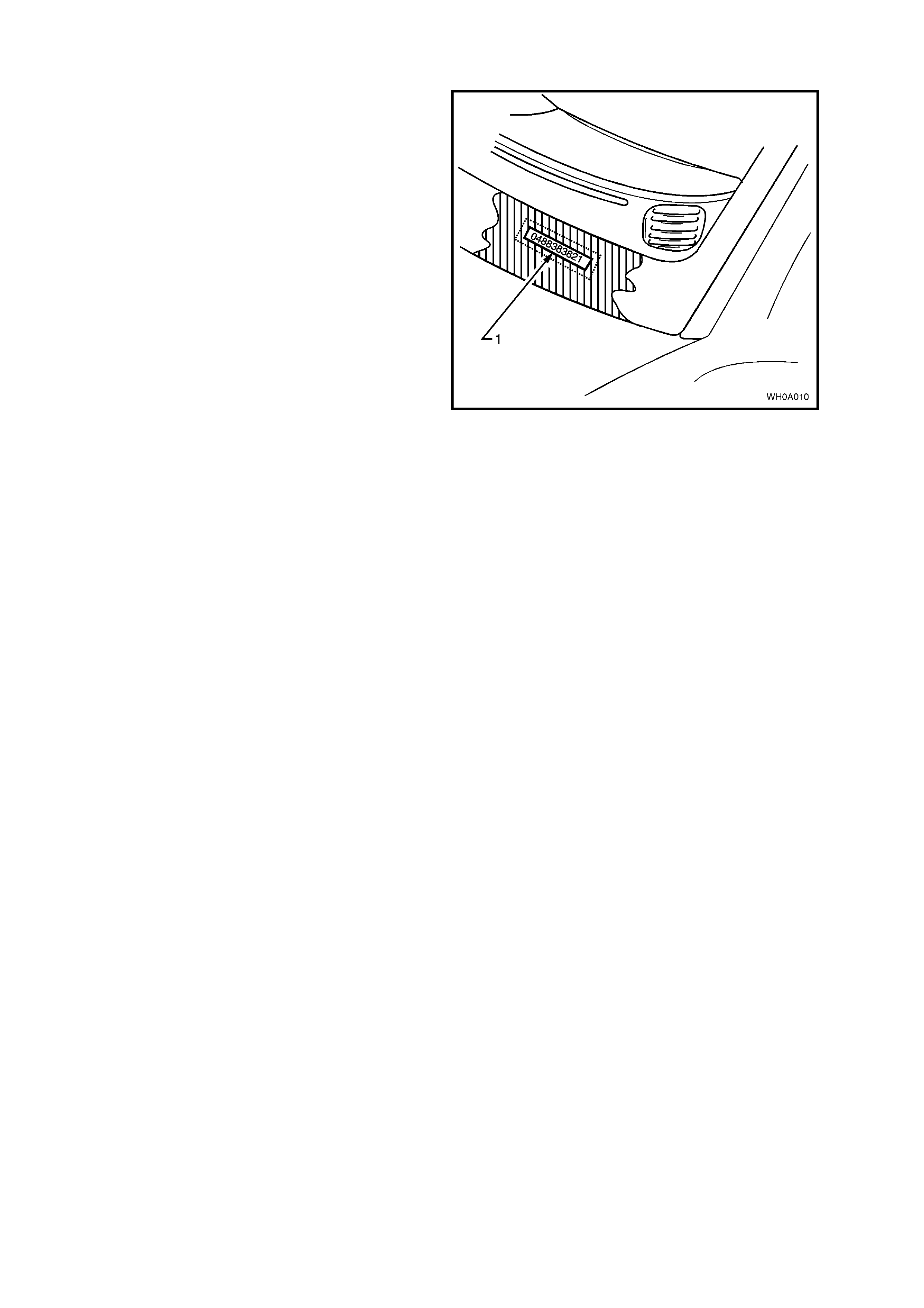
8.5 VEHICLE IDENTIFICATION NUMBER PLATE LOCATION (BODY LOCATION)
The body mounted Vehicle Identification Number
(VIN) plate (1) is located under the windscreen and
is viewed through the windscreen aperture.
The VIN plate is secured to the body by unique
rosette headed rivets.
NOTE: The VIN is also stamped into the floor
sheetmetal under the front right-hand seat, refer to
8.1 LOCATION OF IDENTIFICATION PLATES in
this Section.
Figure 0A-8
8.6 VEHICLE IDE NTIFICATION NUMBERING SYSTEM
A new Vehicle Identification Numbering (VIN) system was introduced with the introduction of the MY2002
V2 Series Models during October 2002. However, all MY2002 V2 Series Models used the VIN system as
previously used in VX Series I. Figure 0A-9 provides the details of the MY2002 type VIN system, while
Figure 0A-10 provides details of the new VIN system used on all MY2003 V2 Series Models.
MY2002 MODELS
The Vehicle Identification Numbering System (VIN) is based on the uniform Car Model Designation
System. The reason for this is to identify the vehicle in one coded series of Characters.
The significance of these characters or blocks of characters are explained below, using an example
identification number 6H8 V2 X 37 F 2 L 123456.
MODEL DESIGNATION
WMI Code
Model Series Code
Degree of Luxury
BODY STYLE CODE
ENGINE CODE
MODEL YEAR CODE
ASSEMBLY PLANT CODE
SERIAL SEQUENCE NUMBER
6H8 V2 X 37 F 2 L 123456
MODEL DESIGNATION
WMI Code – 6H8 – World manufacturer’s identifier allocated to Holden
Model Series Code - V2 = V2 Series
Degree of Luxury - K – CV6
- X – CV8
Body Style Code - 37 – Coupe
ENGINE CODE
Engine Identification Code (R – signifies Supercharged 3.8 engine, F – signifies 5.7 engine)
MODEL YEAR CODE
2 – Identifies Model Year 2 = 2002
This number relates to GM Internal Operation Only.
ASSEMBLY PLANT CODE
Australian Assembly Plant Identification Code:-
L – Adelaide (Elizabeth)
SERIAL (Sequence ) NUMBER
Figure 0A-9
Techline
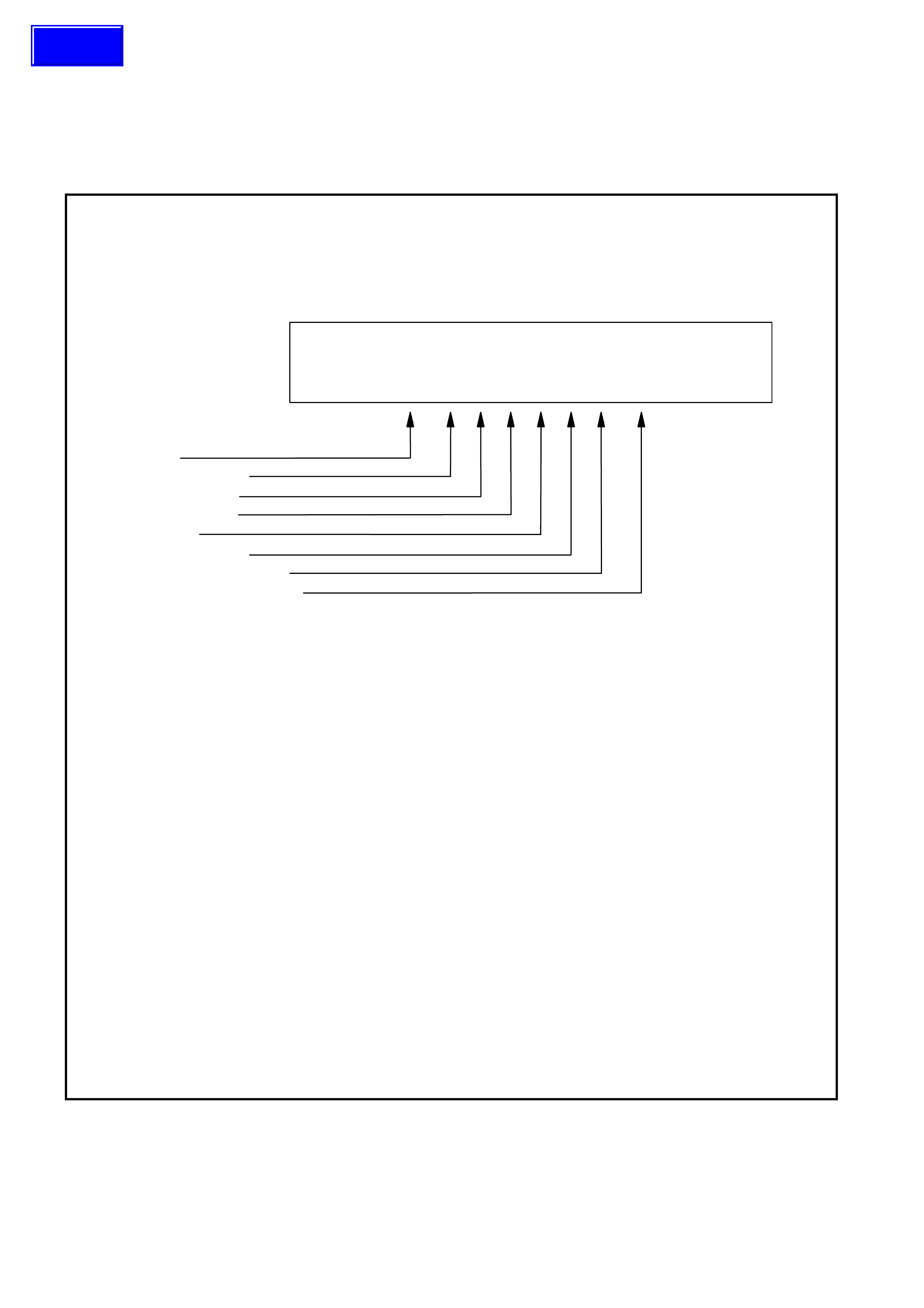
MY2003 UPDATE MODELS
WMI CODE: 6 – Oceania
G – Australia
1 – Holden
CARLINE: 2 – V2 Series
LUXURY LEVEL: K – CV6
X – CV8
BODY STYLE: 1 – 2 door coupe (37)
RESTRAINT CODE: 1 – Active (manual) seat belts
2 – Active (manual) seat belts with driver & passenger inflatable restraint
system – frontal
3 – Active (manual) seat belts with driver inflatable restraint system – frontal
4 – Active (manual) seat belts with driver & passenger inflatable restraint
system – frontal and side
ENGINE TYPE: R – 3.8 litre V6 Supercharged engine
F – 5.7 litre GEN III V8 engine
VIN CHECK DIGIT: Calculated check digit
MODEL YEAR: 3 – 2003
PLANT: L – Adelaide (Elizabeth) South Australia
PRODUCTION SEQUENCE NUMBER:
123456 – Sequential Production Serial Number
NOTE: The pr oduc tion s equence number is s equentially allocated to each vehicle,
regardless of vehicle type.
Figure 0A-10
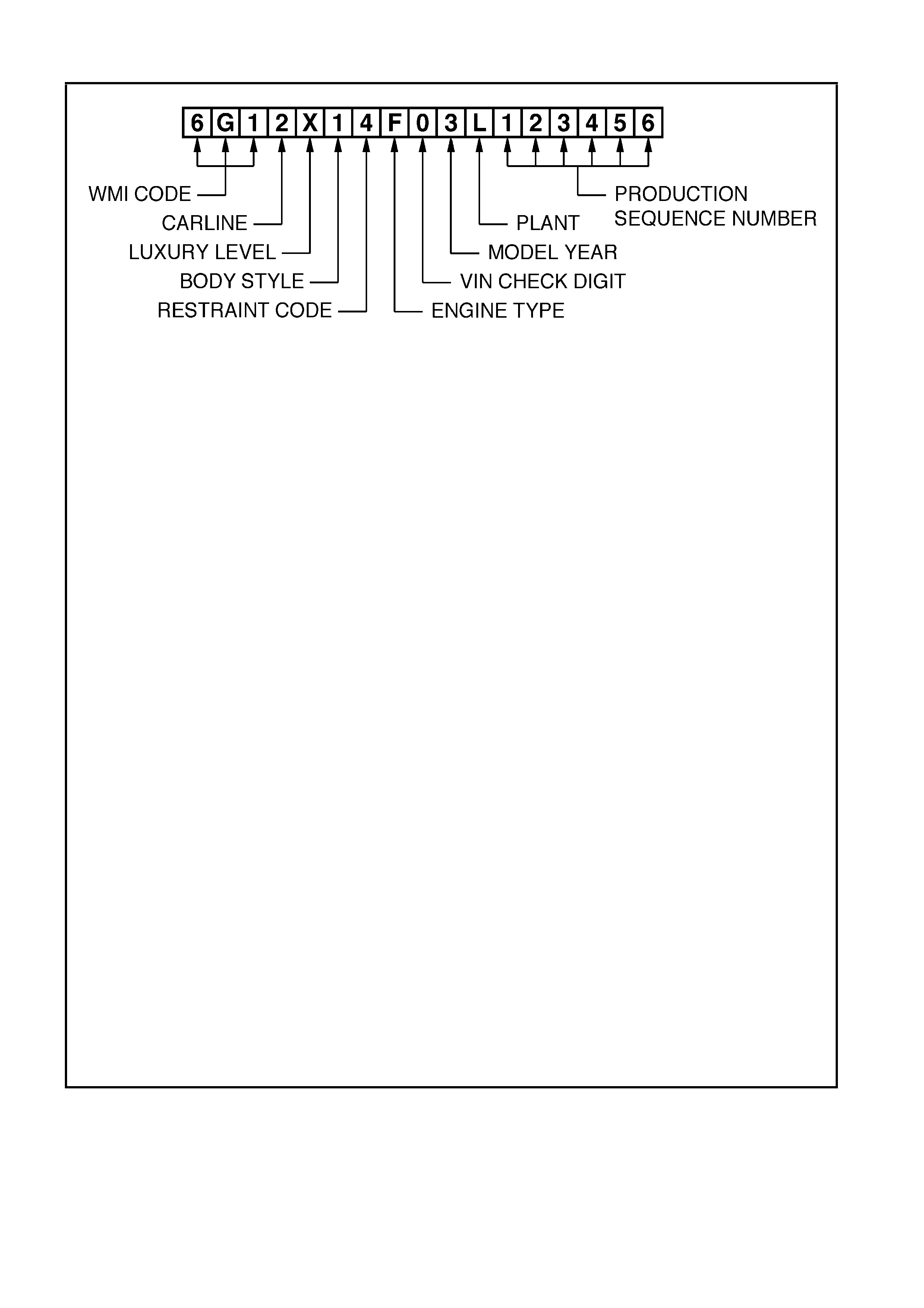
8.7 ENGINE SERIAL NUMBER
The engine num ber (1) f or the 3.8 V6 Superchaged
engine is stamped on the front face of the engine,
below the ignition coil as illustrated in Figure 0A-11.
Figure 0A-11
The 5.7 litre GEN III V8 engine number (1) is
stamped on a pad located adjacent to the engine
coolant outlet pipe, refer to Figure 0A-12.
Figure 0A-12
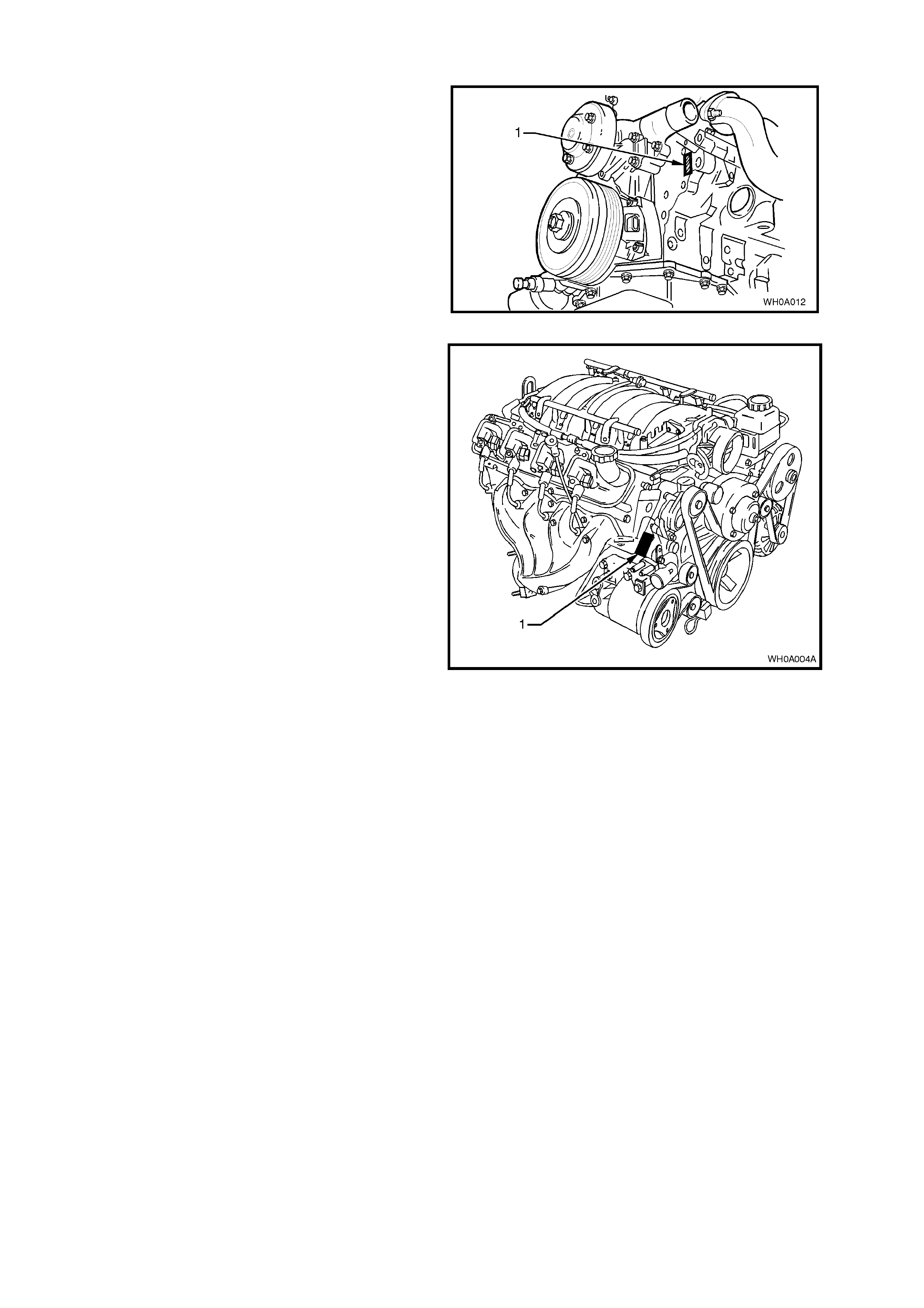
8.8 MANUAL TRANSMISSION SERIAL NUMBER
The Borg-Warner (Tremec) T56 6-speed manual
transmission serial number is located on a self-
adhesive decal attached to the top of the
transmission case refer to Figure 0A-13.
This number provides coded information which
could be significant to parts interpretation and
should be referred to when ordering replacement
parts.
Figure 0A-13
In addition, an identification tag is attached to the
transmission under an extension housing bolt, on
the right-hand side, refer to Figure 0A-14.
Figure 0A-14
Techline
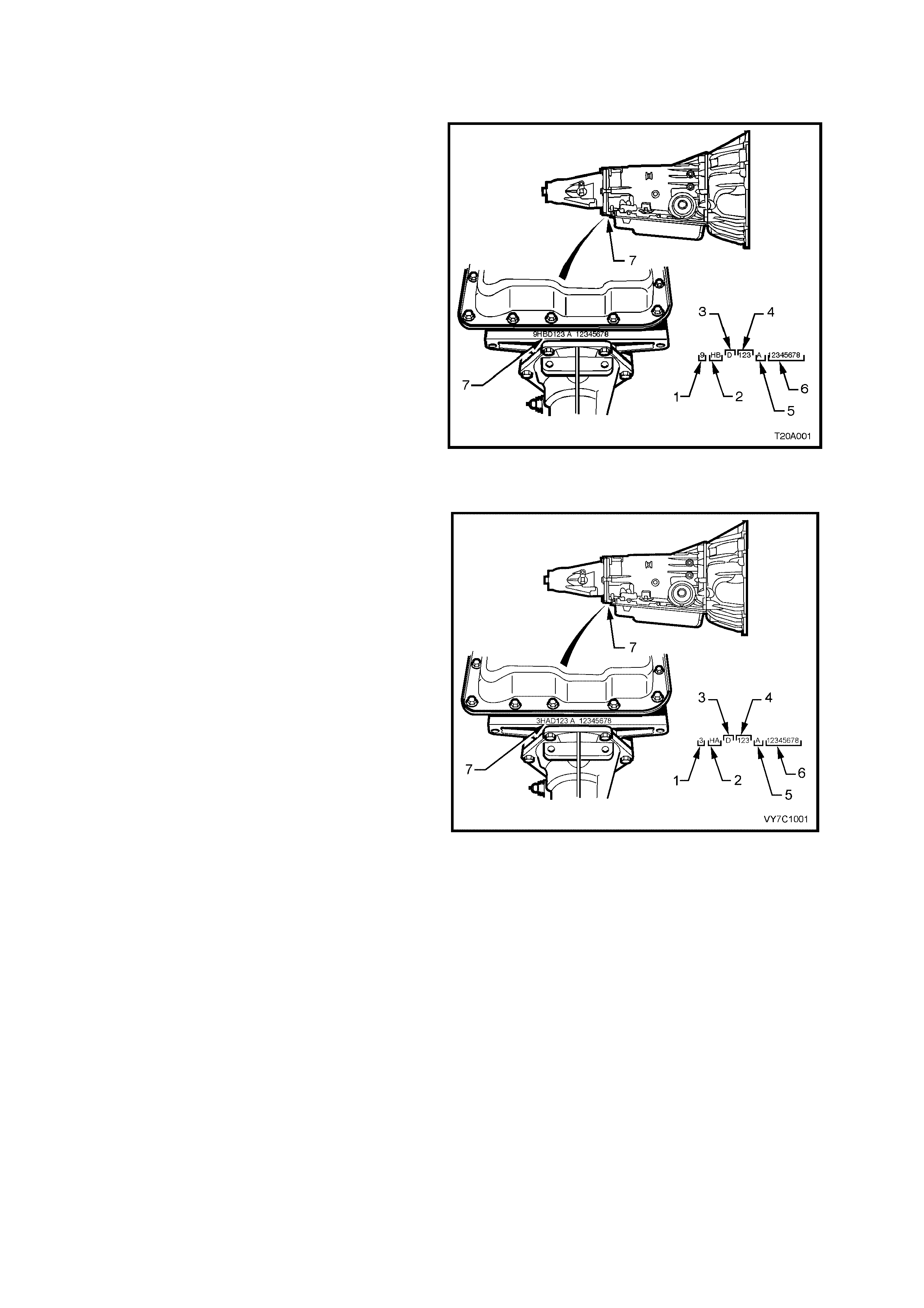
8.9 AUTOMATIC TRANSMIS S ION SERIAL NUMBER
MY2002 MODELS
The MY2002 4L60-E automatic transmission
application and identification can be determined
from the stamping in the rear of the transmission
case at the rear, in the location shown (7), refer to
Figure 0A-15.
Legend
1. Model Year (2 = 2002)
2. Model: V8 – 5.7 GEN III V8 HP
V6 – Supercharged 3.8 HN
3. Transmission Model Identifier (D = 4L60-E)
4. Julian Date (Day of the year)
5. Shift Built (A, B, J = First Shift;
C, H, W = Second Shift)
6. Individual Transmission Serial Number
7. Transmission Identification Number Location
Figure 0A-15
MY2003 UPDATE MODELS
The MY2003 4L60-E automatic transmission
application and identification can be determined
from the stamping in the rear of the transmission
case at the rear, in the location shown (7), refer to
Figure 0A-16.
Legend
1. Model Year (3 = 2003)
2. Model: V8 – 5.7 GEN III V8 HA
V6 – Supercharged 3.8 HN
3. Transmission Model Identifier (D = 4L60-E)
4. Julian Date (Day of the Year)
5. Shift Build (A, B, J = First Shift;
C, H, W = Second Shift
6. Individual Transmission Serial Number
7. Transmission Identification Number Location
Figure 0A-16
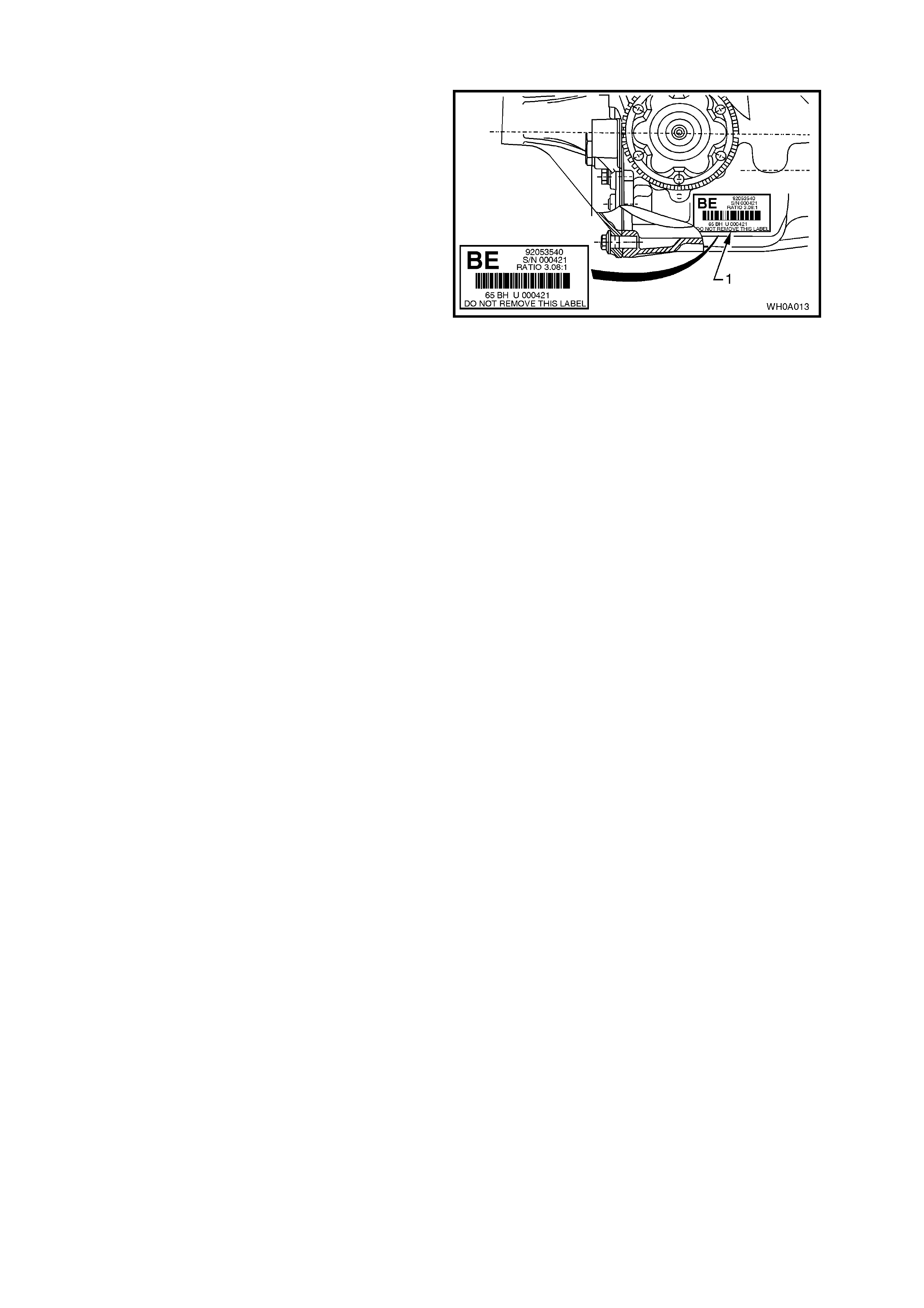
8.10 FINAL DRIVE IDENTIFICATION
An identif ication tag (1) is adhered to the final drive
assembly to the right-hand side of the carrier
housing, refer to Figure 0A-17.
The tag c arries the Holden par t num ber for the final
drive assembly, the final drive ratio and the serial
number of the assembly.
Figure 0A-17
9. ADDI TIONAL GENERAL I NFORMATION
9.1 ELE CTRICAL TRANS I ENTS AND RADIO FREQUENCY INTERFERENCE
Electronic circuits are used in V2 Series Models to perform a number of functions associated with electronic
cruise control, electronic engine and transmission control systems etc. These circuits can be damaged or
malfunction as a result of electrical transients or excessive radio frequency (RF) radiation.
ELECTRICAL TRANSIENTS
Electrical transients are high voltage spikes, produced by the sudden switching or interruption of electric
currents. Older style timing lights and battery chargers can produce serious transients, hence, it is
important to use only good quality equipment suitable for use with electronic systems.
It is also good practice to ensure that the battery is disconnected before using a battery charger.
Indiscriminate fitting of solenoids, indicators or relays can also cause transients.
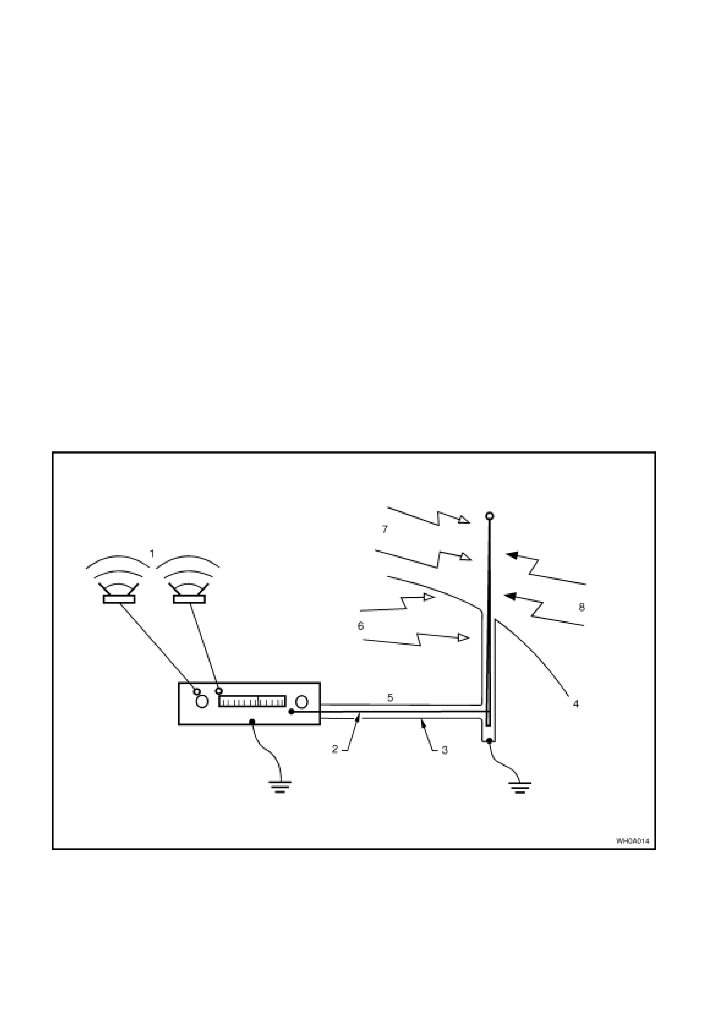
RADIO FREQUENCY INTERFERENCE
One of the chief sources of RF interference is the ignition system. Other sources include CB radio and
radio telephones. The following are normally used to suppress RF interference.
Resistors eg. High Tension Cables and Connectors.
Capacitors and Choke Coils.
Metal Braid for screening leads or suppression covers made from conductive material for screening
equipment.
To prevent damage to equipment:
Do not replace interference suppressed high tension ignition cables or connectors with unsuppressed
types.
Do not remove or reposition interference suppression filters or capacitors.
Figure 0A-18
Legend
1. Music
2. Core
3. Braid
4. Body
5. Antenna cable
6. Internal Interference
7. Signal from station
8. External interference

9.2 STATIC ELECTRICITY
Care should be exer c ised when handling electronic equipment e.g. the powertrain control module (PCM), to
avoid touching the terminals unnecessarily. Static electricity, which is present on every person, can cause
damage to some electronic components.

9.3 PUSH OR TOW STARTING
Do not push or tow start V2 Series vehicles. Push or tow starting can result in unburned fuel passing
through the exhaust to the catalytic converter, causing damage to the converter.
10. CONSOLIDATED TOOL LIST
MY2002 MODELS
Special tools f or V2 Series Models car ry over from VT Series II Models . For information concer ning Special
Tools refer to Section 0A in the VT Series II Service Information.
MY2003 UPDATE MODELS
Apart from the tools listed below, the special tools for MY2003 V2 Series Update Models carry over from VT
Series II Models. For information concerning Special T ools refer to Section 0A in the VT Series II Service
Information.
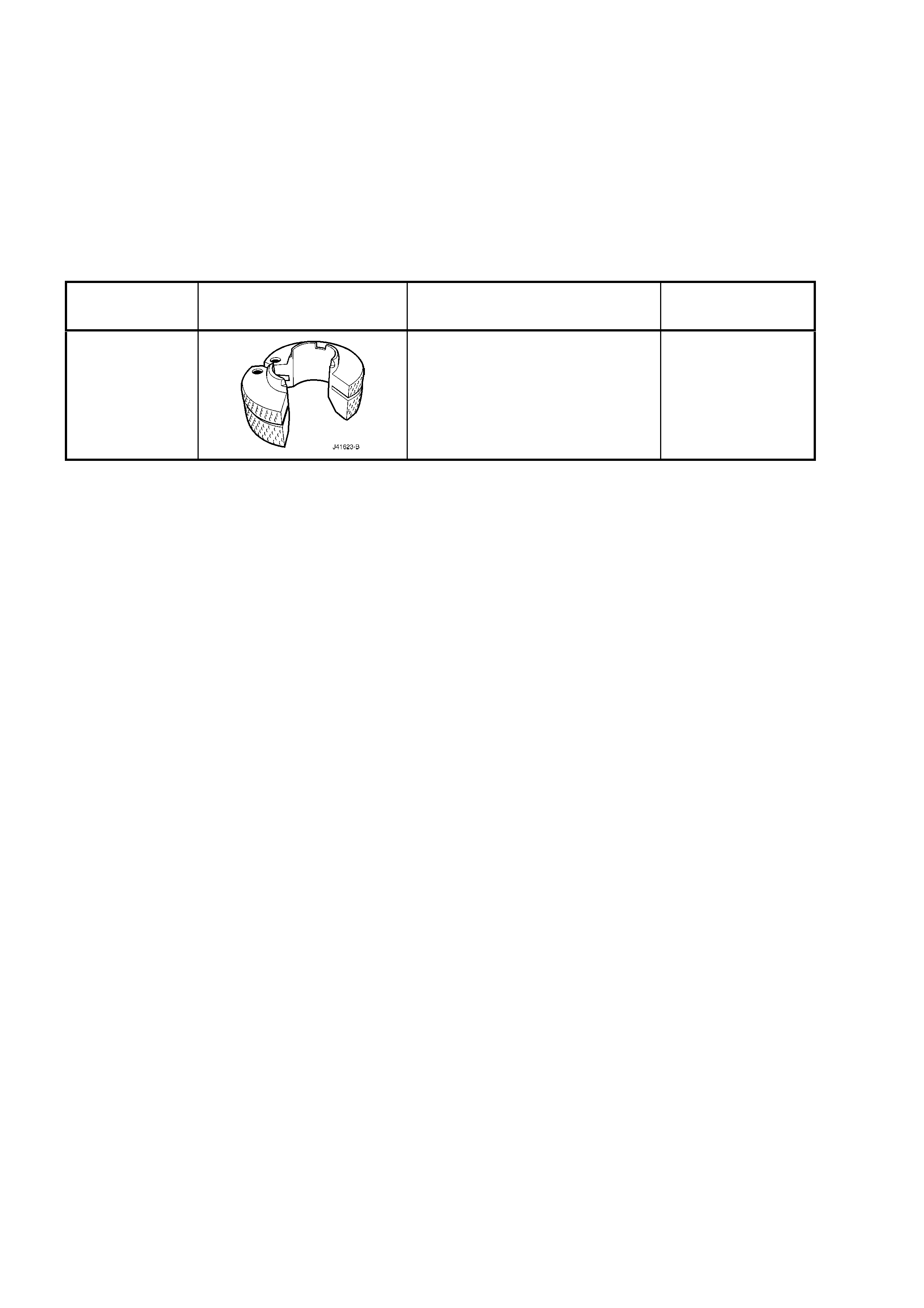
TOOL
NUMBER ILLUSTRATION DESCRIPTION CLASSIFICATION
J41623-B
COOLER PIPE QUICK-
CONNECT
RELEASE TOOL
New release.
Mandatory