
SECTION 1A1 - BODY
IMPORTANT
Before performing any Service Operation or other procedure described in this Section, refer to Section
00 CAUTIONS AND NOTES for correct workshop practices with regard to safety and/or property damage.
1. GENERAL DESCRIPTI ON
The V2 Series Coupe is a new vehicle design based on the VT Series sedan. Sheetmetal forward of the 'A' pillar
carries over from VX Series II Sedan Models, noting the following:
• The A-pillar rake has increased for the coupe body design by 2 degrees.
• The radiator grille, lower air intake and fog lamps are unique.
• The front doors have been increased in length.
• The rear quarter panels are new.
• The rear compartment lid is new and rear overhang has been decreased.
• The front and rear bumper facias are new.
• The roof design has been revised.
• All V2 Series Models include revised glass including new front windscreen, rear windscreen, front door glass
and an encapsulated rear quarter window in place of the rear door glass.
For items not cover ed in this Sect ion ref er to the appr opriate sec tion of the VX Series Service Information for furt her
details.
Techline
Techline

2. SERVICE OPERATIONS
2.1 BODY SHELL PARTS REPLACEMENT
When replacing or repairing a part or sub-assembly, care must be taken to ensure that correct alignment and
strength of unit as a whole is maintained. In some instances, major damage to the body or frame can be more
eff ectively and econom ically repaired by replacing a part or sub-ass embly with a new one, rather than repair ing the
damaged part.
Spot welding is used extensively for joining panels together, particularly around the flanged edges of dash panel,
windshield and back window openings, along edges of rocker panels and lower edge of the rear body.
W hen replacing a section that is normally attached by this m ethod and spot-welding equipment is not available, or
the location of the par ts restric ts access , the part or ass embly should be attached by the welding m ethod known as
‘Plug Welding’, which is as follows:
1. Remove the dam aged part by cutting through the spot welds between the panels with a thin-edged chisel or by
drilling the spot welds.
2. Drill f ive m m diameter holes in either the new or m ating part to cor respond with the spacing and location of the
original spot welds. Parts to be drilled are determined by accessibility for the following operations.
3. Clamp the new par t in pos ition and gas or arc weld the two parts together thr ough eac h hole, f inally dressing off
any high spots on exposed surfaces.
W hen replacing parts such as roof panels, rear quarter or rock er panels; where a butt or overlap weld is required,
the joint of the panels mus t be form ed below the normal c ontour. This allows f or filling over the join and elim inates
the possible reduction of sheet metal thickness following the necessary buffing or grinding of a normal welding
operation.
IMPORTANT: Following replacement or repair of body components, it is essential that effective rust proofing
techniques, as outlined in the following paragraphs, be observed.

2.2 ANTI-CORROSIVE TREATMENT
Precoated and galvanised s teel is us ed extens ively for various body panels for inc reas ed c orr os ion protec tion of the
body. Body panels such as the door and rear compartment lid outer panels are precoated on the inner surface of
the metal to improve corrosion protection. Other body structure members have complete double sided galvanised
protection.
In addition, a r us t pr eventative material is s pr ayed after paint application to areas s uch as inter ior s urfaces of doors,
etc.
Any repair or replacement of panels, assemblies, etc., that disturb this anti-corrosive treatment must be resealed
and should be included as part of the repair or replacement operation.
Anti-corrosive com pounds used for repairs should be light bodied materials designed to penetrate between metal-
to-metal surfaces such as pinch weld flanges and integral panel attaching points.
All bare metal sur f ac es must be tr eated with m etal c onditioner and pr imed. T hes e operations need to be c arr ied out
prior to the application of sealer s, waxes and s ound deadeners. Attac hing points of new replacem ent panels should
be resealed. The hemming flanges of replacement doors, tailgates and rear compartment lids will require resealing.
Open joins which require bridging of the sealer to close a gap should be sealed with a heavy bodied caulking
material. When colour application is required to restore repaired areas to original appearance, conventional
refinishing preparation, undercoat build-up and colour application techniques should be employed.
When deadeners are disturbed during damage repair, or a panel has been replaced, the deadener material must be
replaced with an equivalent material. The location and pattern for replacement material can be determined by
observing the original deadener application outlines.
IMPORTANT: Follow label directions for materials selected.

2.3 WATER AND DUST LEAK DIAGNOSIS
Diagnosis of body leaks are complicated by the fact that the appearance of water at one point can be caused by
seepage thr ough any one or m or e of many possible locations. As an ex ample of this indir ec t entry, the cause of wet
front floor coverings may be due to water entering past the door weatherstrip, through the door inner panel, between
the windshield and its adhesive compound or through any one of the joins in the floor panel, ventilator or dash
panels. Therefore, point or points of water or dust entry must be established before effective resealing can be
carried out.
For additional information refer to the V2 Series Body Structure Repair Manual.
Techline
Techline

2.4 BODY STRUCTURE PANELS
The three lists and corresponding illustrations
below provide a quick reference of the assemblies
and individual panels that are available for
replacement.
The purpose of these illustrations is to provide the
repairer with a better understanding of available
replacement panels.
UNDERBODY
1. Panel assembly - floor side
2. Reinforcement assembly - inner seat attach
3. Reinforcement assembly - front seat outer
4. Floor assembly – front
5. Mount assembly - power unit rear
6. Extension assembly - floor panel front
7. Brace - longitudinal to front floor
8. Panel assembly - front fender skirt
9. Bracket assembly - theft deterrent horn, LH
10. Bracket assembly - hydraulic modulator
11. Tray assembly - battery
12. Panel assembly - front
13. Panel assembly - front headlamp
14. Bracket assembly - side panel front end
15. Bracket – front fender lower
16. Member assembly - front lower
17. Longitudinal assembly - complete
18. Bracket - radiator support side
19. Support assembly - front panel side
20. Bracket - front bumper beam mounting
21. Console - front panel
22. Reinforcement – floor panel side
23. Carrier plate assembly
24. Hook assembly - tie down
25. Bracket assembly - brake hose
26. Longitudinal - complete
27. Brace assembly - rear bumper mounting,
LH/RH
28. Crossmember assembly - rear
29. Reinforcement assembly - centre bearing
30. Reinforcement - rear floor front, LH
31. Anchor assembly - seat belt
32. Panel assembly - rear floor front
33. Reinforcement - rear floor front, RH
34. Plate web - rear, RH
35. Stand assembly – spare wheel
36. Reinforcement assembly - fuel tank mounting
37. Panel assembly - rear floor rear
38. Plate web - rear, LH
39. Reinforcement assembly - panel back lower
40. Panel assembly - back lower
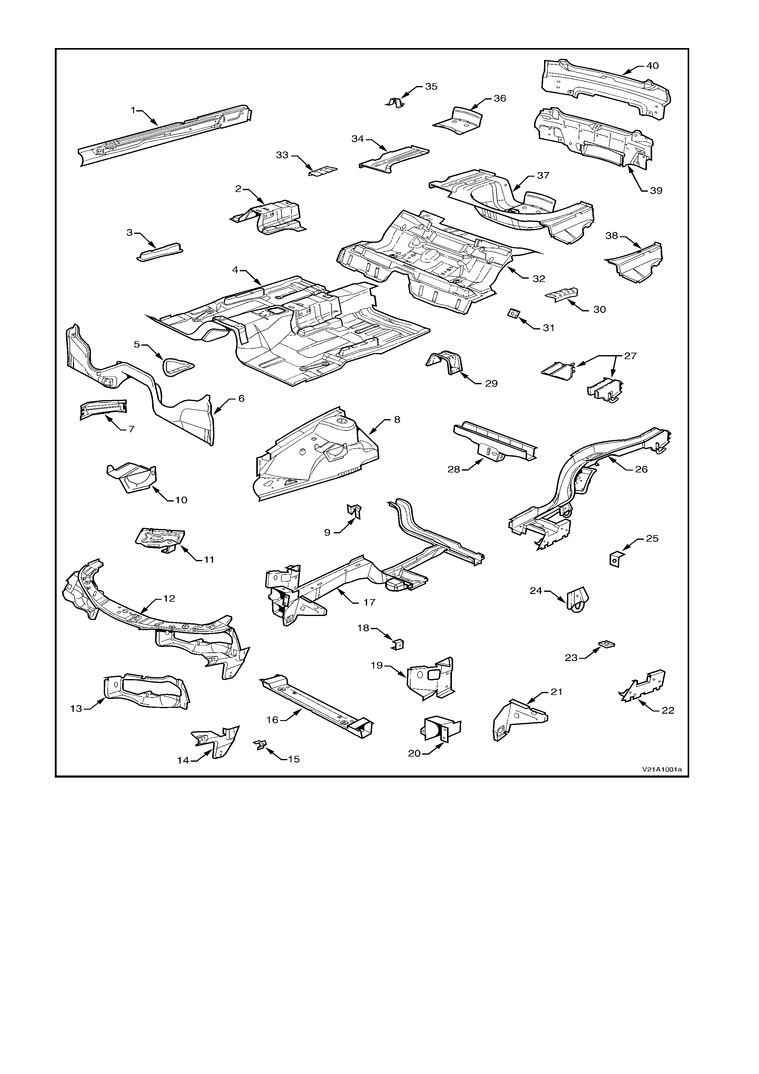
Figure 1A1-1

BODY SIDE
1. Bracket - trim attachment
2. Pillar assembly - front body inner
3. Brace - wheelhouse
4. Fender panel
5. Bracket - rocker skirt front attachment
6. Support - fender to frame
7. Angle - fender lower to frame
8. Frame assembly - door opening
9. Angle - fender upper to frame
10. Anchor plate - door striker
11. Reinforcement - MIG braze
12. Support - centre jacking
13. Side panel - outer
14. Filler panel - side panel outer
15. Clip - wiring harness
16. Gusset - side panel outer
17. Insert assembly - tail lamp
18. Wheelhouse assembly - inner
19. Brace assembly - wheelhouse
20. Brace - upper wheelhouse
21. Cap - fuel filler, RH
22. Side panel assembly - inner
23. Reinforcement - A-pillar upper
24. Bracket - side speaker mounting
25. Rail - windshield header
26. Support assembly - roof
27. Panel - roof
28. Frame - roof rear
29. Panel assembly - back upper
30. Filler panel - back panel upper front
31. Bracket and ball assembly - strut
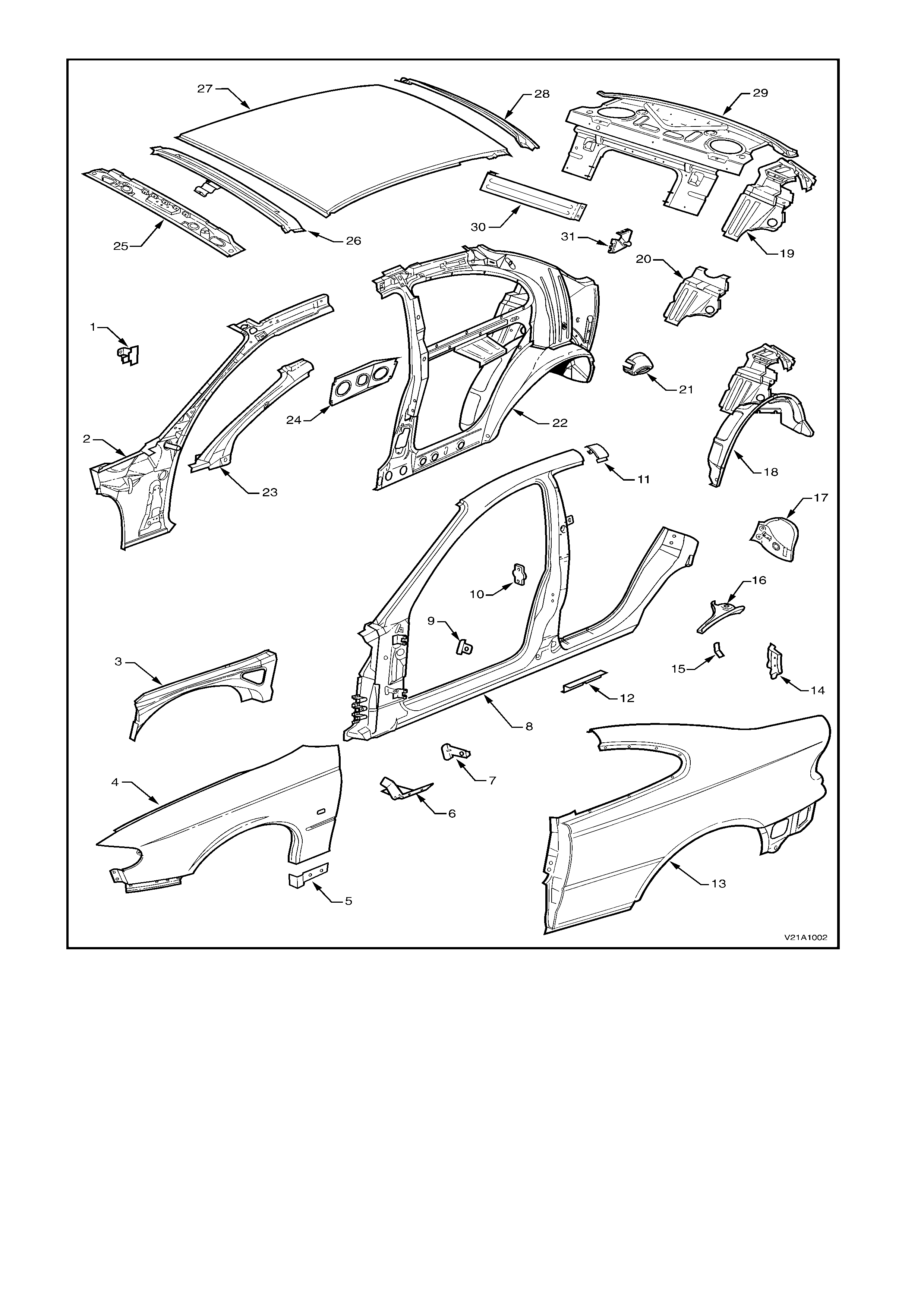
Figure 1A1-2

BODY SHELL
1. Body in white - complete
2. Dash panel assembly
3. Arm and bracket assem bly - rear com partment
lid hinge
4. Rear compartment lid assembly
5. Beam assembly - bumper support
6. Bracket assembly - bumper support mounting
7. Beam assembly - front facia support
8. Door assembly
9. Flap assembly - front hinge, door
10. Flap - rear hinge, door
11. Panel assembly - door outer
12. Hinge assembly - engine hood
13. Panel assembly - engine hood
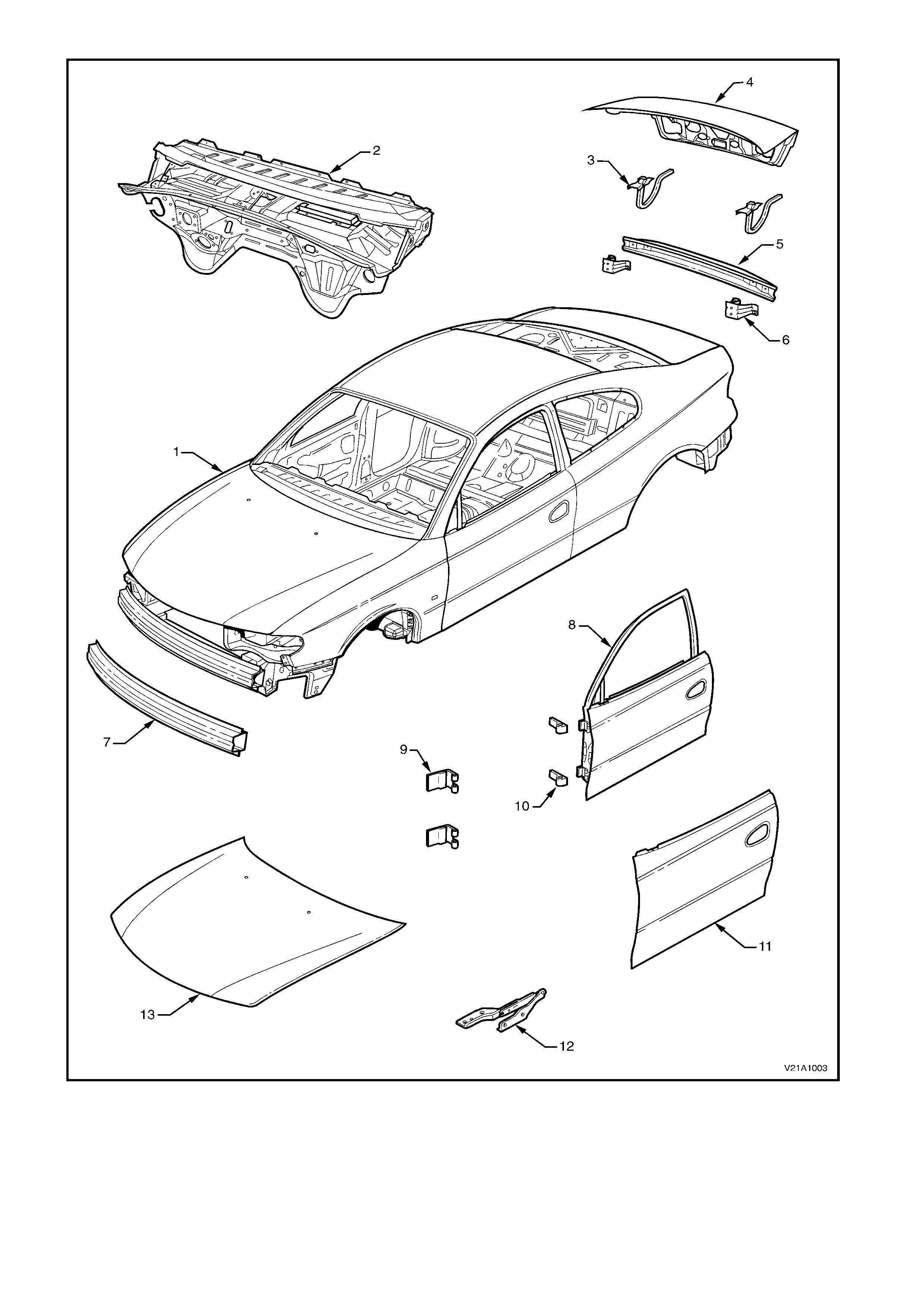
Figure 1A1-3
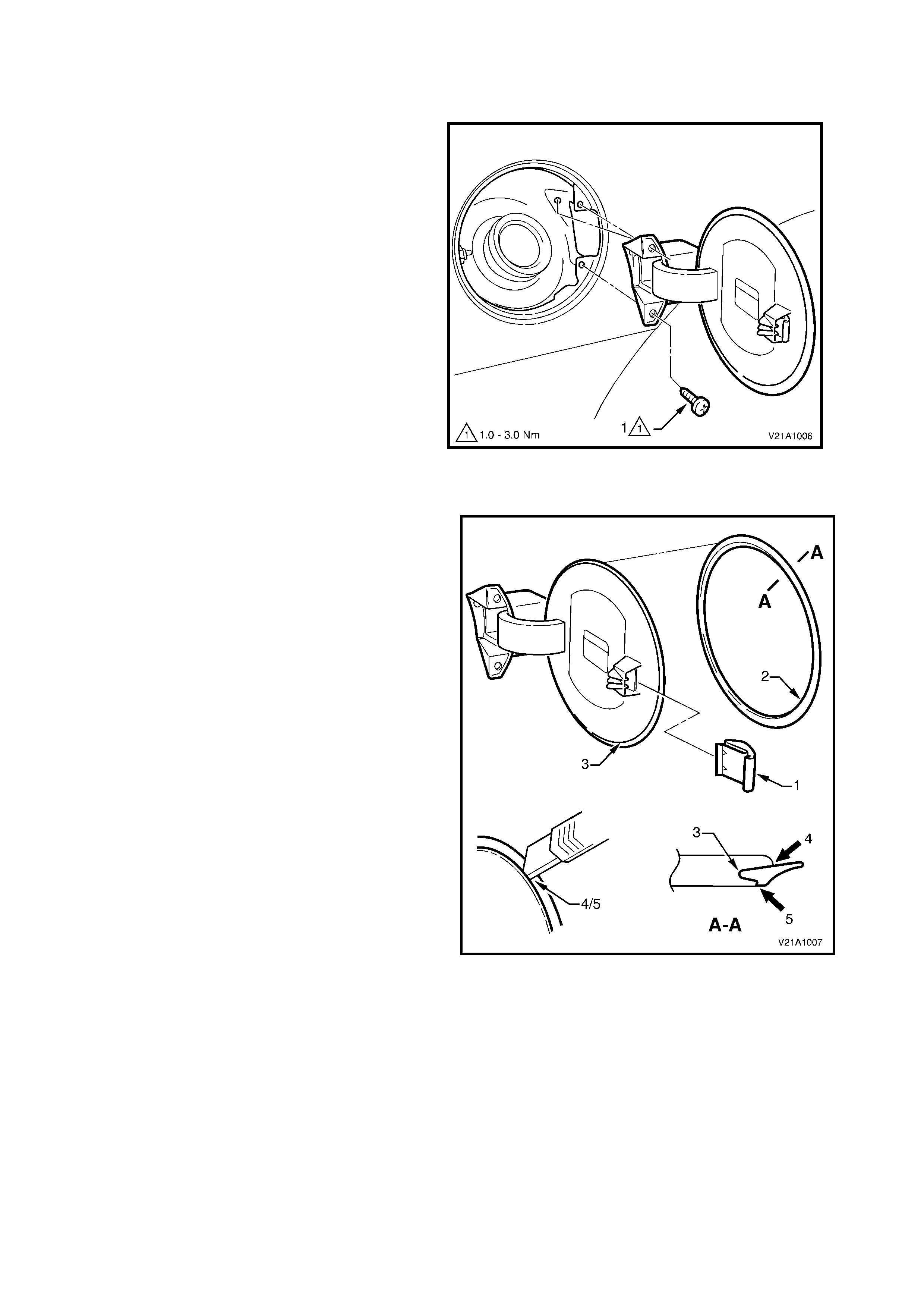
2.5 FUEL FILLER DOOR
REMOVE
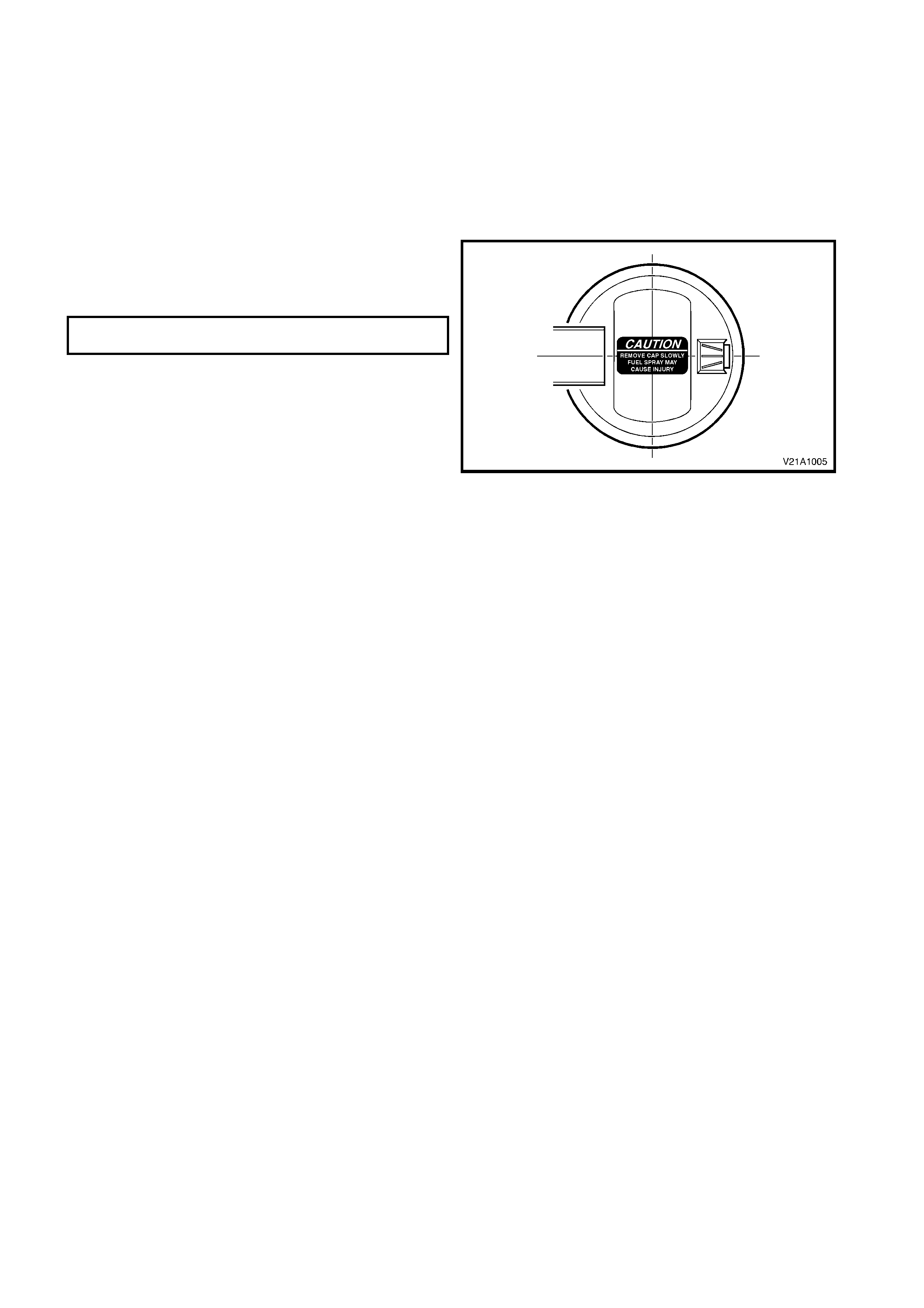
NOTE: If the fuel filler door is being replaced, the
warning labels aff ix ed to the inside of the door must
also be replaced.
1. Remove the fuel filler cap and cover the
opening with a rag as required.
2. Remove the screws (1) three places, attaching
the fuel filler door assembly.
3. Remove the f uel door assem bly by withdrawing
it rearward, ensuring the gasket is also
removed.
NOTE: When withdrawing the fuel filler door from
the fuel filler pocket, a slight interference between
the rear edge of the plastic hinge section and the
fuel filler neck may occur. In this instance, it will be
necessar y to flex the rear edge of the f uel filler door
hinge slightly.
Figure 1A1-4
DISASSEMBLE
The f uel filler door is not des igned to be disassem bled.
However, with care the following parts can be
removed.
Lock Spring
1. Remove the lock spring (1) by inserting a small
screwdriver and levering the spring outwards.
NOTE: The spring has several barbs that will cut into
its mounting surface.
2. To install, push the spring onto the mounting tab
fully.
Moulding
NOTE: The moulding will usually peel off the fuel filler
door. If peeling the moulding off proves difficult, use
the following method.
1. The moulding (2) is seated in the recess (3)
around the circumference of the door and is
affixed with superglue gel. Removal may be
difficult, but by carefully cutting around the inner
(4) and outer sides (5) of the moulding using a
sharp knife, it is possible to remove the moulding.
It will not be able to be reused.
2. To install the moulding, carefully apply a small
amount of Loctite 454 (Superglue Gel or an
equivalent) into the top and bottom of the recess
around the circumference of the fuel filler door.
3. Ensuring it is correctly orientated, fit the moulding
into the recess.
4. Carefully apply Loctite 454 (Superglue Gel or an
equivalent) into the remaining (unsecured) area of
the recess around the fuel filler door recess,
around the complete circumference, press the
moulding into place and leave to cure.
Figure 1A1-5
IMPORTANT 1: Use of superglue can be harmful and
can damage paintwork. Carefully read and follow all
directions and cautions with the product prior to its use.
IMPORTANT 2: Superglue cures instantly. To avoid
repeating this procedure, ensure the moulding is fitted
correctly the first time.
REINSTALL
Installation of the fuel filler door assembly is the
reverse of the removal procedure, noting the following.
1. Ensure that the screws are tightened to the
specified torque.
FUEL FILLER DOOR ATTACHING
SCREW TORQUE SPECIFICATION 1.0 – 3.0 Nm
NOTE: Prior to affixing the label ensure the surface is
clean and dry. Avoid touching the back of the label.
2. Ensure that the fuel filler door closes without the
need of excessive force and is flush with the
surrounding panel.
Figure 1A1-6
2.6 FUEL FILLER DOOR RELEASE CABLE
REMOVE
1. Open the fuel filler door.
2. Remove the right-hand rear quarter trim, refer
to 2.4 REAR QUARTER TRIM in Section 1A8
HEADLINING AND INTERIOR TRIM in this
Service Information.
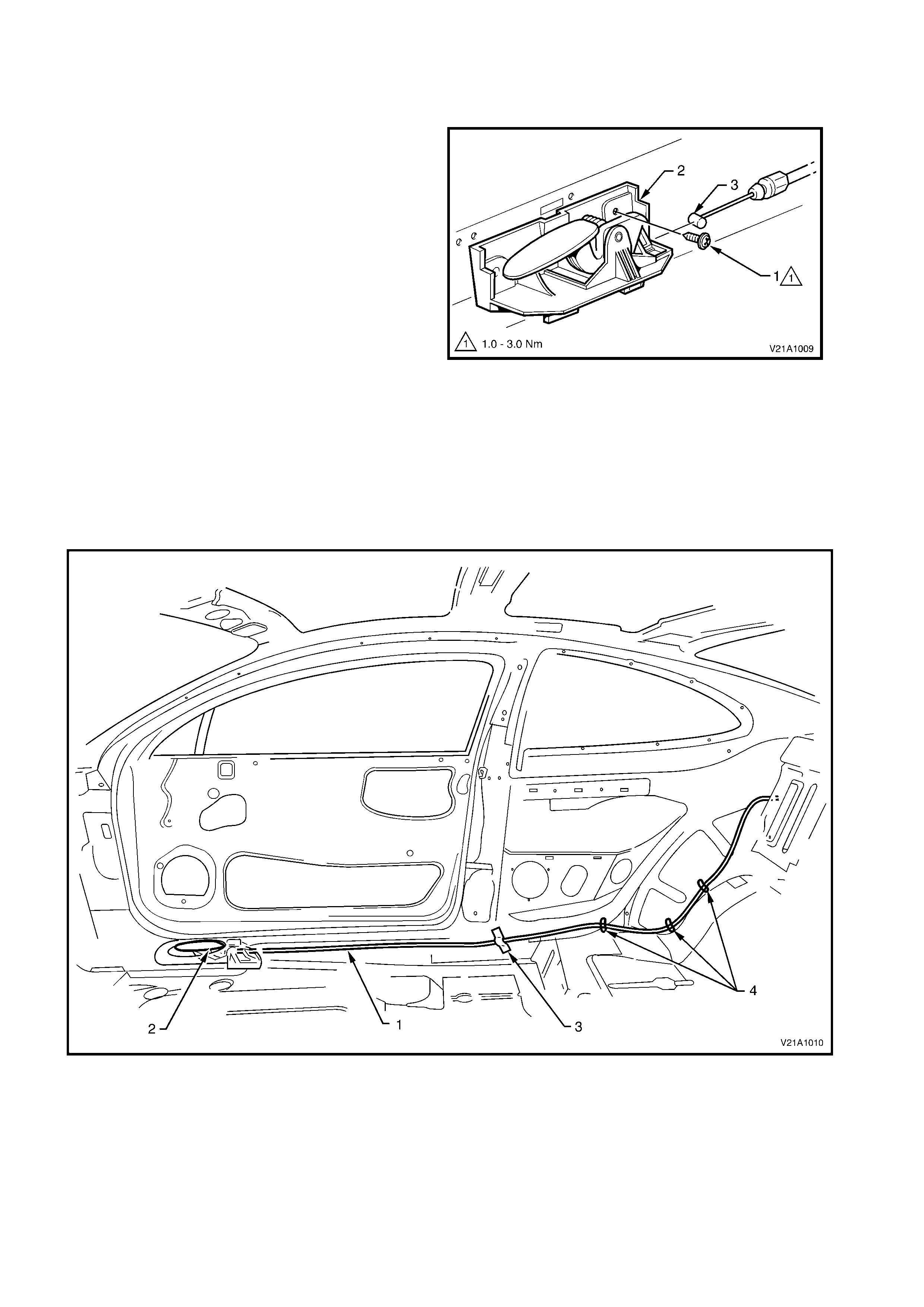
3. Remove the screw (1) attaching the fuel filler
door release lever (2) to the inner rocker panel.
4. Disconnect the fuel filler door release cable (3)
from the fuel filler door release lever.
Figure 1A1-7
5. Remove the tape securing the cable to the
swage in the floor panel.
6. Bend the three tabs that retains the cable to the
inner rear side panel back sufficiently to
release the cable.
7. Feed the cable through the hole in the rear seat
back upper panel and into the rear load
compartment.
Figure 1A1-8
Legend
1. Fuel filler door release cable 3. Adhesive tape
2. Fuel filler door release lever 4. Cable to floor panel retaining tabs
8. Remove the right-hand rear wheelhouse
carpet, refer to 2.12 RH REAR
WHEELHOUSE CARPET in Section 1A8
HEADLINING AND REAR END TRIM in this
Service Information.
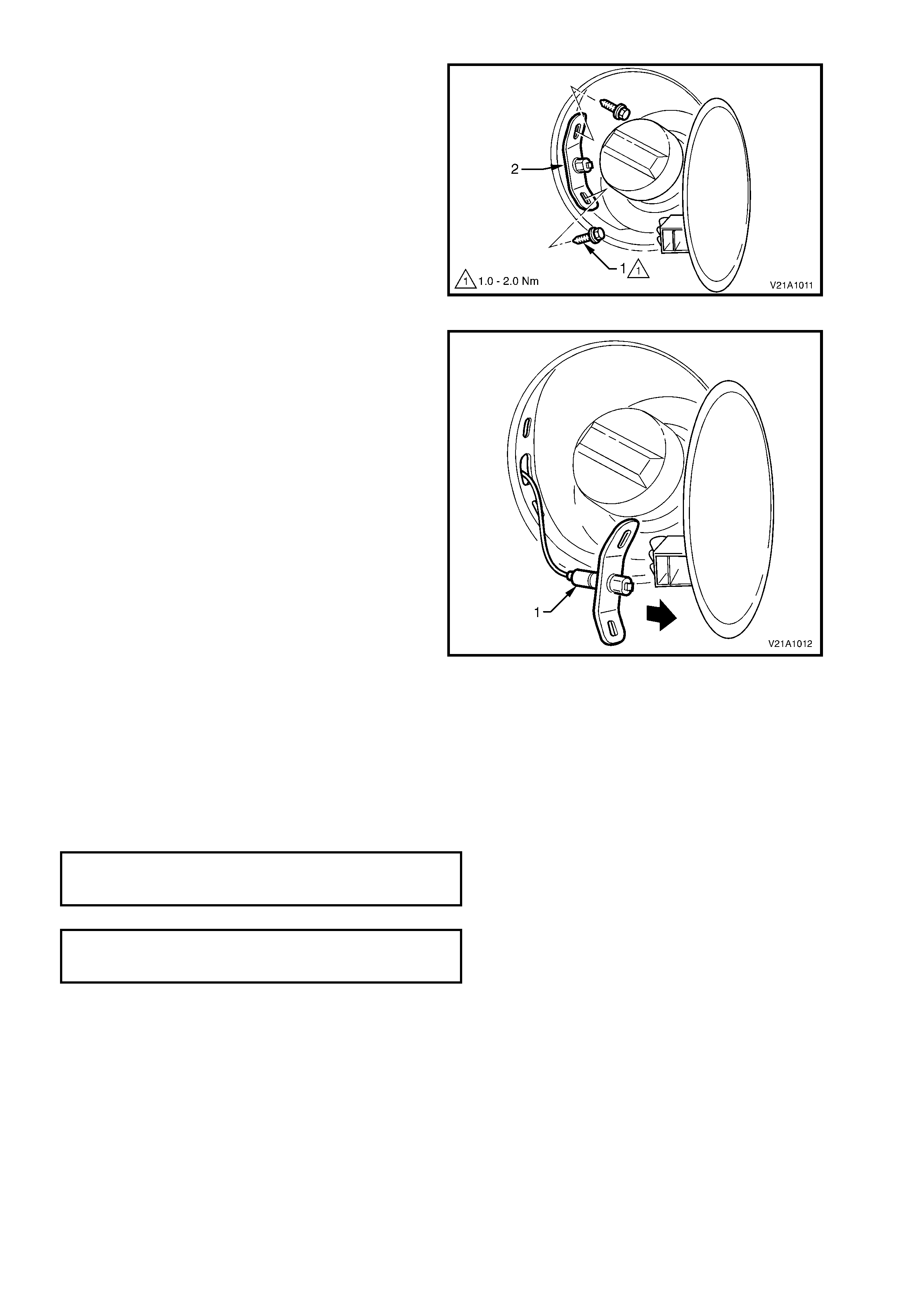
9. Rem ove the two bolts (1) s ecuring the f uel filler
door release cable (2) to the fuel filler recess.
Figure 1A1-9
10. From outs ide the vehic le, car ef ully withdraw the
cable (1) through the hole in the fuel filler door
recess.
Figure 1A1-10
REINSTALL
The installation procedure for the fuel filler door release cable is the reverse of the removal procedure, noting the
following:
• Ensure to tighten all fasteners to the correct torque specifications.
• Ensure to tape the cable into the swage in the floor panel.
• Check that the fuel f iller door lever operates s m oothly and releases the fuel f iller door with a minim al eff ort prior
to reinstalling the trim components.
FUEL FILLER DOOR LEVER TO INNER
ROCKER PANEL ATTACHING SCREW 1.0 – 3.0 Nm
TORQUE SPECIFICATION
FUEL FILLER DOOR RELEASE CABLE TO
FUEL FILLER RECESS ATTACHING BOLT 1.9 – 2.1 Nm
TORQUE SPECIFICATION
2.7 REAR COMPARTMENT LID EMERGENCY RELEASE CABLE ASSEMBLY
REMOVE
1. From within the rear compartment, remove the rear compartment lid liner, refer to Section 1A8 HEADLINING
AND INTERIOR TRIM in this Service Information.
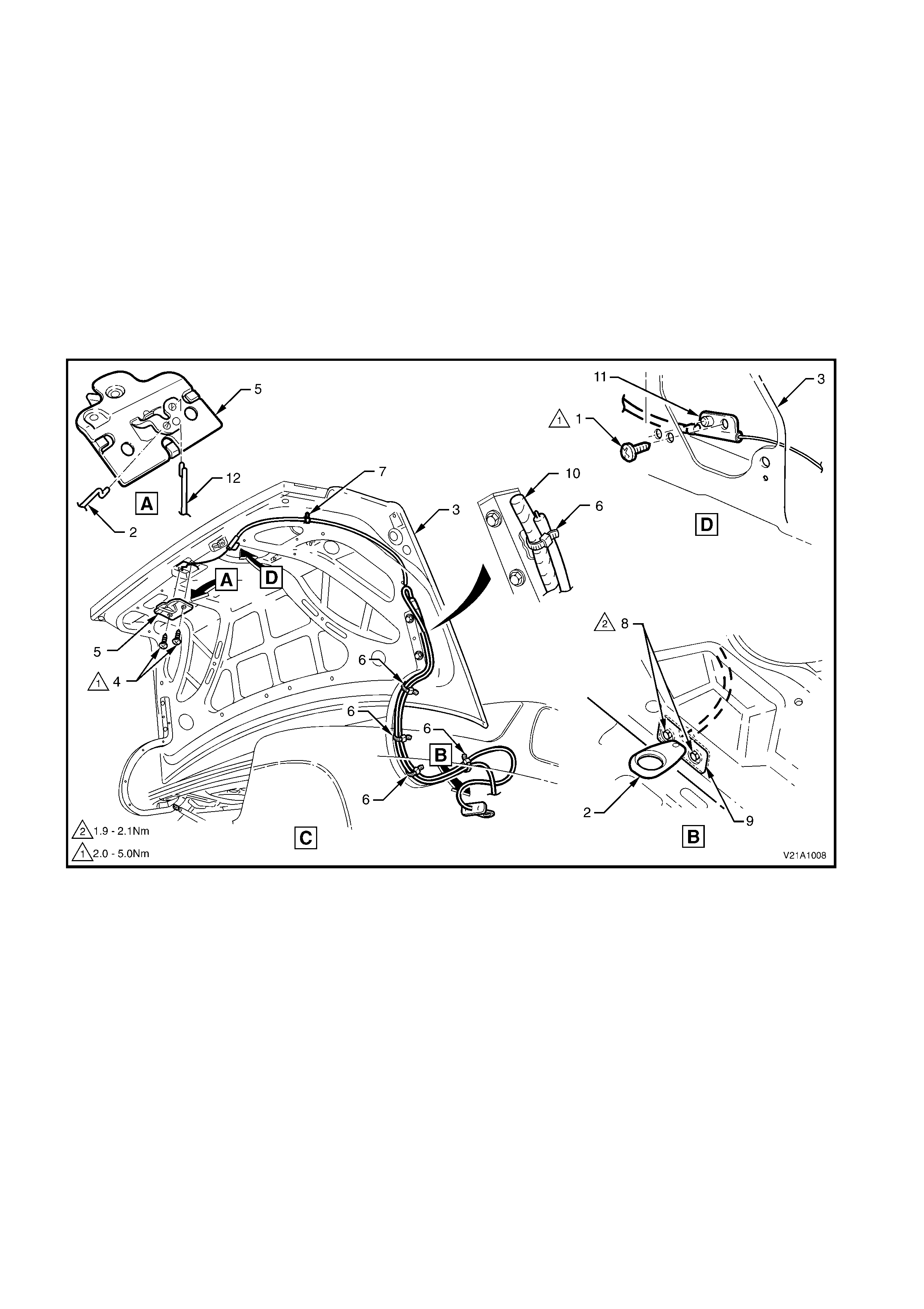
2. Remove the screw securing the rear compartment lid emergency release cable to the rear compartment lid.
3. Remove the two screws securing the rear compartment lid latch assembly to the rear compartment lid.
4. Disengage the rear compartment lid emergency release cable and actuator rod from the rear compartm ent lid
latch and remove the latch.
5. Remove the f ive c able ties and one r etaining c lip s ecur ing the rear c ompartment lid em er genc y release cable to
the rear compartment lid.
6. Remove the rear seat back, refer to Section 1A7 SEAT AND SEAT BELTS in this Service Information.
7. Remove the two bolts securing rear compartment lid emergency release cable to the seat back upper panel.
8. Carefully feed the cable into the passenger compartment.
Figure 1A1-11
Legend
1. Cable to rear compartment lid attaching screw 7. Cable to rear compartment lid attaching clip (1 place)
2. Rear compartment lid emergency release cable 8. Cable to seat upper panel securing bolts
3. Rear compartment lid assembly 9. Seat back upper panel
4. Latch to rear compartment lid attaching screws 10. Rear compartment lid wiring harness
5. Rear compartment lid latch assembly 11. Cable to rear compartment lid locating pin
6. Cable ties (5 places) 12. Rear compartment lid latch actuator rod

REINSTALL
Installation of the rear com par tm ent lid em ergenc y r elease cable is the r everse of the rem oval operation, noting the
following:
• Ensure that the rear compartment lid emergency release cable locating pin (11) is correctly engaged into the
hole in the rear compartment lid prior to tightening screw.
• Tighten all fasteners to the correct torque specifications.
• Replace all cable ties as necessary.
• Check cable operation prior to installing rear compartment trim and rear compartment lid liner.
REAR COMPARTMENT LID EMERGENCY
RELEASE CABLE TO REAR COMPARTMENT 2 – 5
LID ATTACHING SCREW Nm
TORQUE SPECIFICATION
REAR COMPARTMENT LID EMERGENCY
RELEASE CABLE TO SEAT BACK UPPER 1.9 - 2.1
PANEL SECURING BOLT Nm
TORQUE SPECIFICATION
REAR COMPARTMENT LID LATCH TO
REAR COMPARTMENT LID ATTACHING 2 – 5 Nm
SCREW TORQUE SPECIFICATION

3. TORQUE WRENCH SPECIFICATIONS
Nm
Fuel filler door attaching screws ...........................................1 - 3
Rear compartment lid emergency release cable to rear
compartment lid attaching screw..........................................2 - 5
Rear compartment lid emergency release cable to seat
back upper panel securing bolts...........................................1.9 - 2.1
Rear compartment lid latch to rear compartment lid
attaching screws...................................................................2 - 5