
SECTION 1A2 - BODY DIMENSIONS
IMPORTANT
Before performing any Service Operation or other procedure described in this Section, refer to Section
00 CAUTIONS AND NOTES for correct workshop practices with regard to safety and/or property damage.
1. GENERAL INFORMATION
The V2 Series Monaro is a two-door variant of the VX Series II Sedan Model. The V2 Series Coupe retains the
same track and wheelbase as the VX Series II Sedan, and the major exterior changes are new outer side panels,
doors, roof , rear glass , rear quarter panels , rear com partm ent lid and bumper facias. Correct alignm ent of the body
structure is essential to ensure the vehicle perform s as intended. A body structure that is outside design tolerence
can suf fer diff icult operation and poor fitm ent of the doors, hood or r ear compartm ent lid. Suspension perf ormanc e
and vehicle handling can also be adversly affected, and may result in noise, vibration and harshness.
The body structure should therefore be aligned to within ±1.5 mm of the dimensions specified in this Section. In
preperation for an underbody alignment check, the vehicle must be correctly set-up on a level surface, preferably
using a measuring or jigging system specifically designed for the task of checking and correcting vehicle body
alignment. As a m inimum , these dim ensions should be check ed using a tram m el guage consisting of a parallel bar
or rod fitted with two adjustable trammels.
NOTE 1: The dimensions provided for the underbody are projected: the measuring points are transposed onto a
two dimensional (flat) surface and the measurements are taken along the one plane.
NOTE 2: The dimensions provided for the upperbody are actual: the distance measured from point to point.
2. SERVICE OPERATIONS
For Service Operations not covered in this Section, refer to Section 1A2 BODY DIMENSIONS in the VT Series I
Service Information.
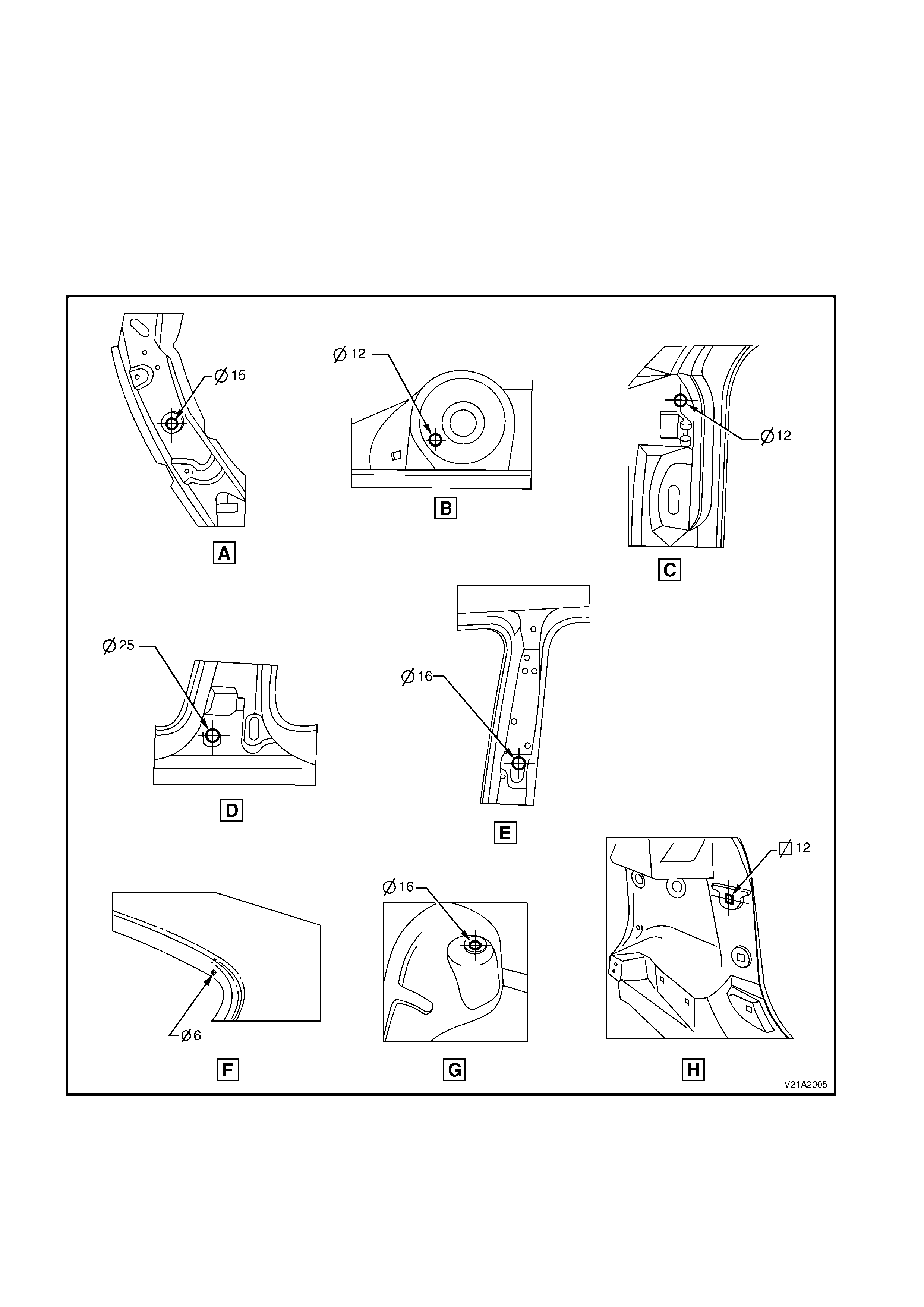
2.1 UNDERBODY DIME NSIONS
All dimensions are given in millimetres and are measured from the centre of holes, on the outer side of the metal
surface.
The main datum surface (1) is the underside of the rail assembly – front compartment side, refer to Figure
1A2-2. The main datum hole (2) is a 19 mm hole on the underside of the front rail assembly – front compartment
side, ref er to Figure 1A2- 2. The das h panel assem bly attaching hole (3) in Figure 1A2-2 is the datum hole depicted
at View C in Figure 1A2-1.
Figure 1A2-1
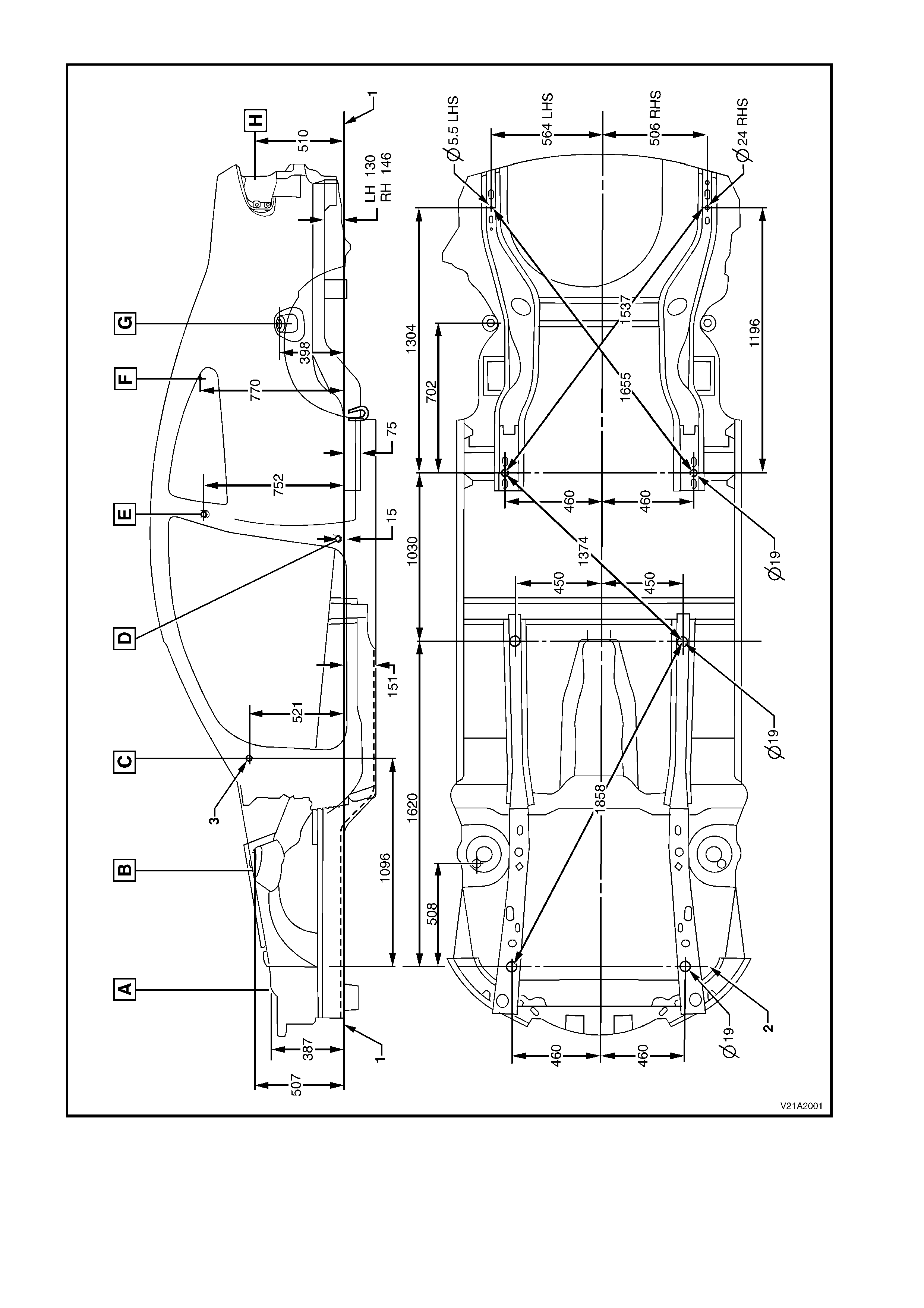
Figure 1A2-2
Legend
1. Main datum surface 2. Main datum hole 3. Dash panel attaching hole
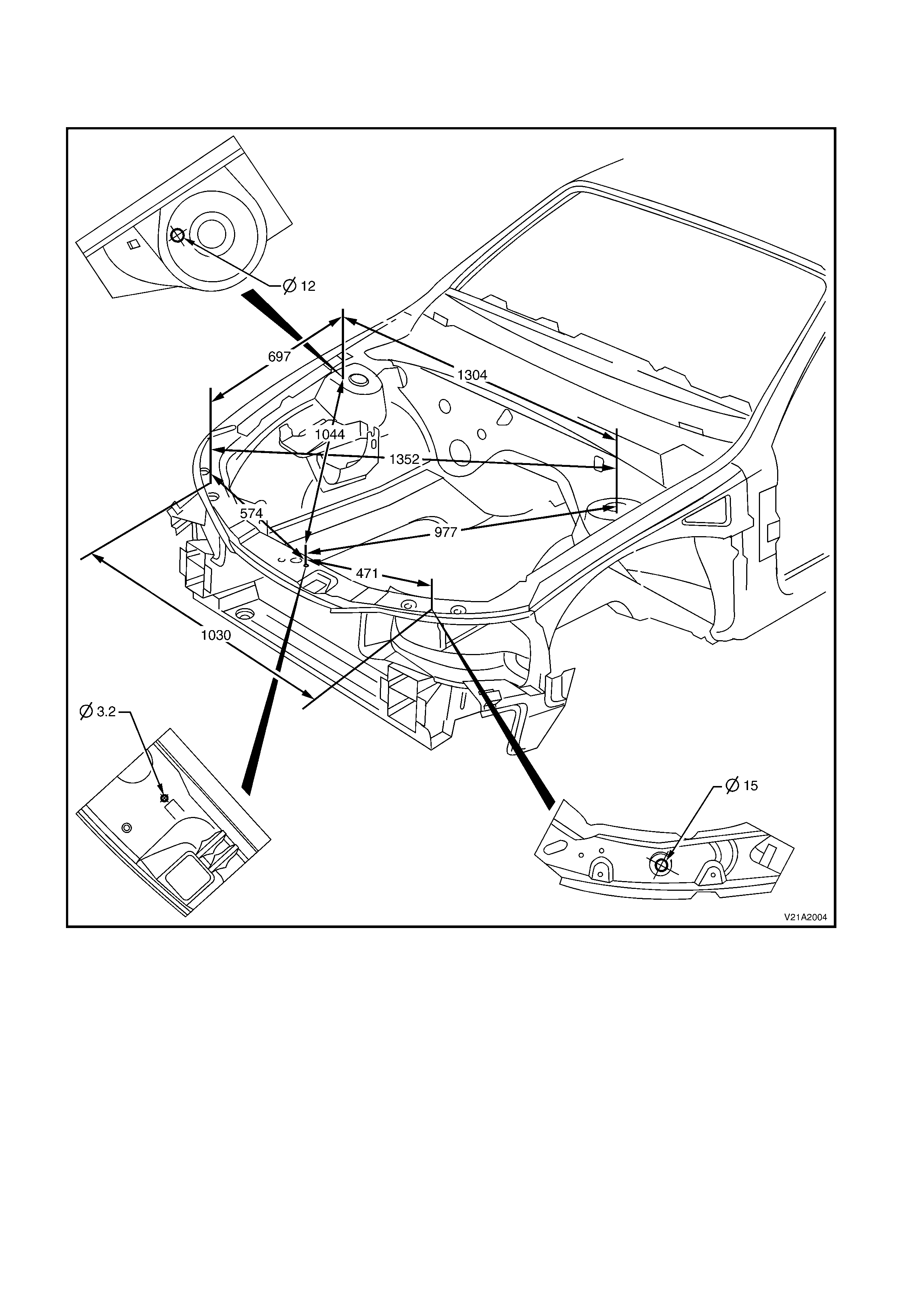
2.2 UPP ERBODY DIMENSIONS
FRONT
Figure 1A2-3
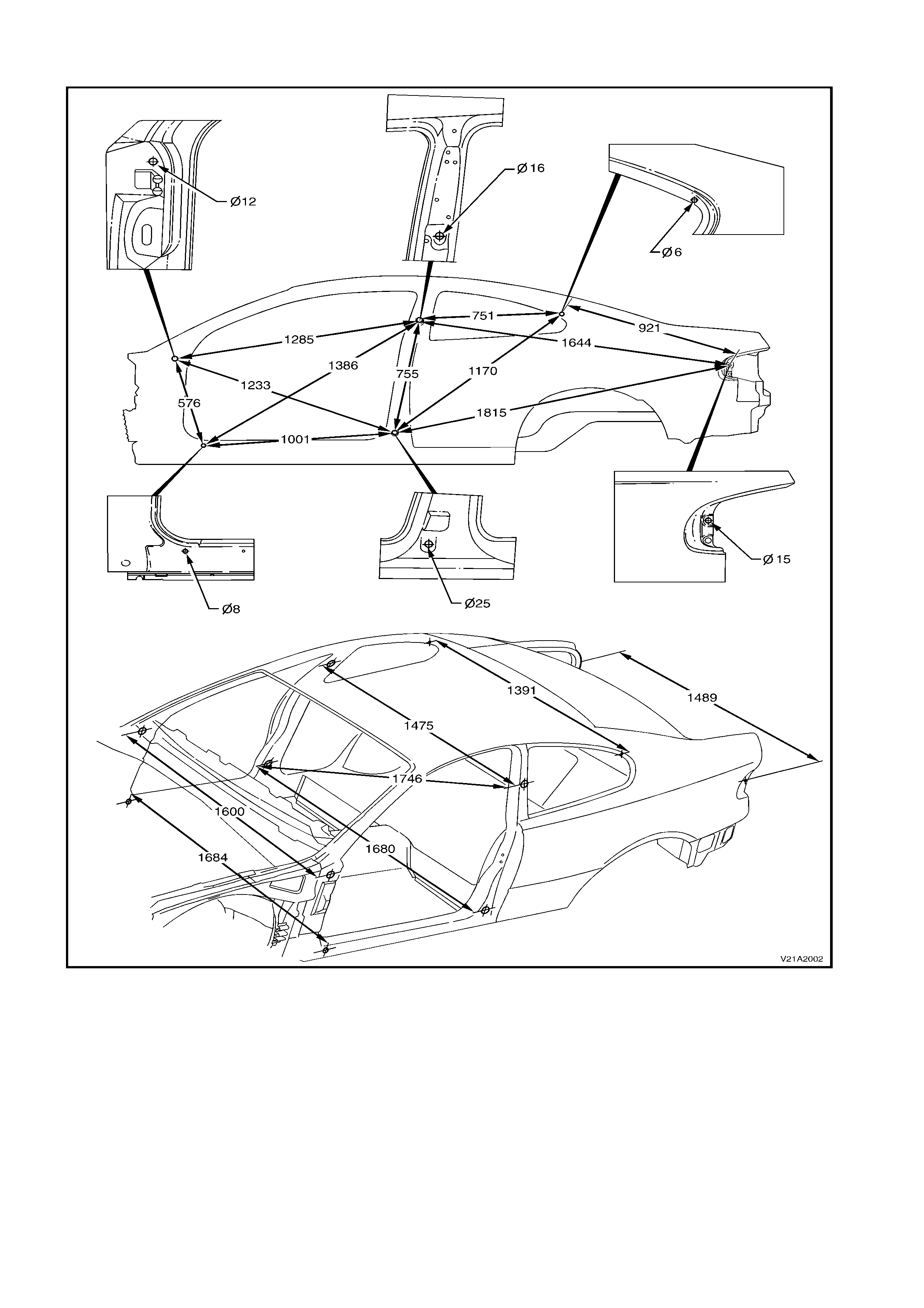
SIDE & INTERIOR
Figure 1A2-4
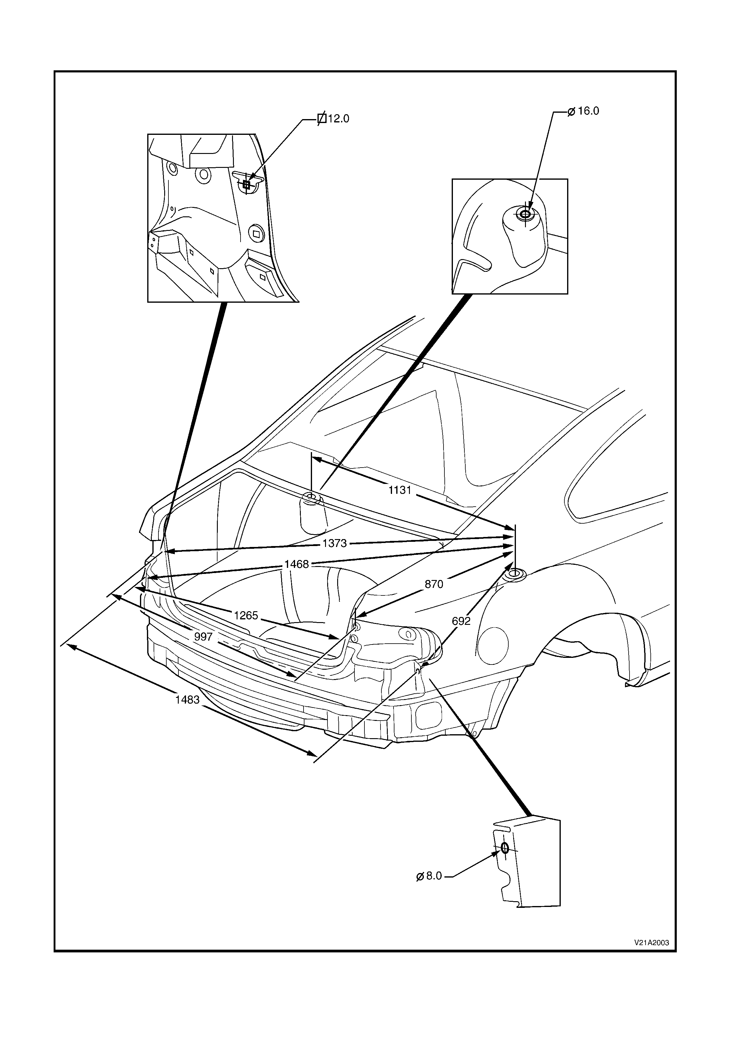
REAR
Figure 1A2-5