
SECTION 1A4 - REAR COMPARTMENT LID
IMPORTANT
Before performing any Service Operation or other procedure described in this Section, refer to Section
00 CAUTIONS AND NOTES for correct workshop practices with regard to safety and/or property damage.
1. GENERAL INFORMATION
The rear compartment lid fitted to V2 Series Models carries over from VT Series I Sedan Models, noting the
following:
• The rear compartment lid has been reworked to accommodate the shorter rear overhang and sport orientated
styling of the coupe body style.
• The rear compartment lid gas strut fitted to V2 Series Models has been revised to accommodate the shorter
rear compartment lid.
• The rear compartment lid lock cylinder has been deleted from V2 Series Models.
• The rear compartment weatherstrip is shorter to accommodate the coupe style rear compartment opening.
• A unique centre high mount stop lamp has been fitted to V2 Series Models.
• The rear decor panel fitted to V2 Series Models is unique.
For information relating to the rear compartment lid fitted to V2 Series Models not covered in this Section, refer to
Section 1A4 REAR COMPARTMENT LID AND TAILGATE in the VT Series I Service Information.
Techline
2. SERVICE OPERATIONS
All service operations for the rear com partment lid and associated com ponents carry over from VT Series I Sedan
Models, noting the following:
• The rear decor panel as fitted to V2 Series Models is unique, and all the applicable service operations are
provided in this Section.
• For the rear rear com partm ent lid liner rem oval and reinstall pr ocedures, re fer to Section 1A8 HEADLINING &
REAR END TRIM in this Service Information.
• For the rear compartment lid emergency release cable removal and reinstall procedures, refer to
Section 1A1 BODY in this Service Information.
• For information relating to the centre high mount stop lamp, refer to 2.11 CENTRE HIGH MOUNT STOP LAMP
ASSEMBLY in Section 12B LIGHTING SYSTEM in this Service Information
For information relating to the service operations for the rear compartment lid and associated components not
covered in this Section, refer to Section 1A4 REAR COMPARTMENT LID & TAILGATE in the VT Series I Ser vice
Information.
2.1 DÉCOR PANEL ASEMBLY
REMOVE
1. Remove the rear compartment lid liner, refer to
2.15 REAR COMPARTMENT LID LINER in
Section 1A8 HEADLINING AND REAR END TRIM
in this Service Information.
2. Remove the rear licence plate.
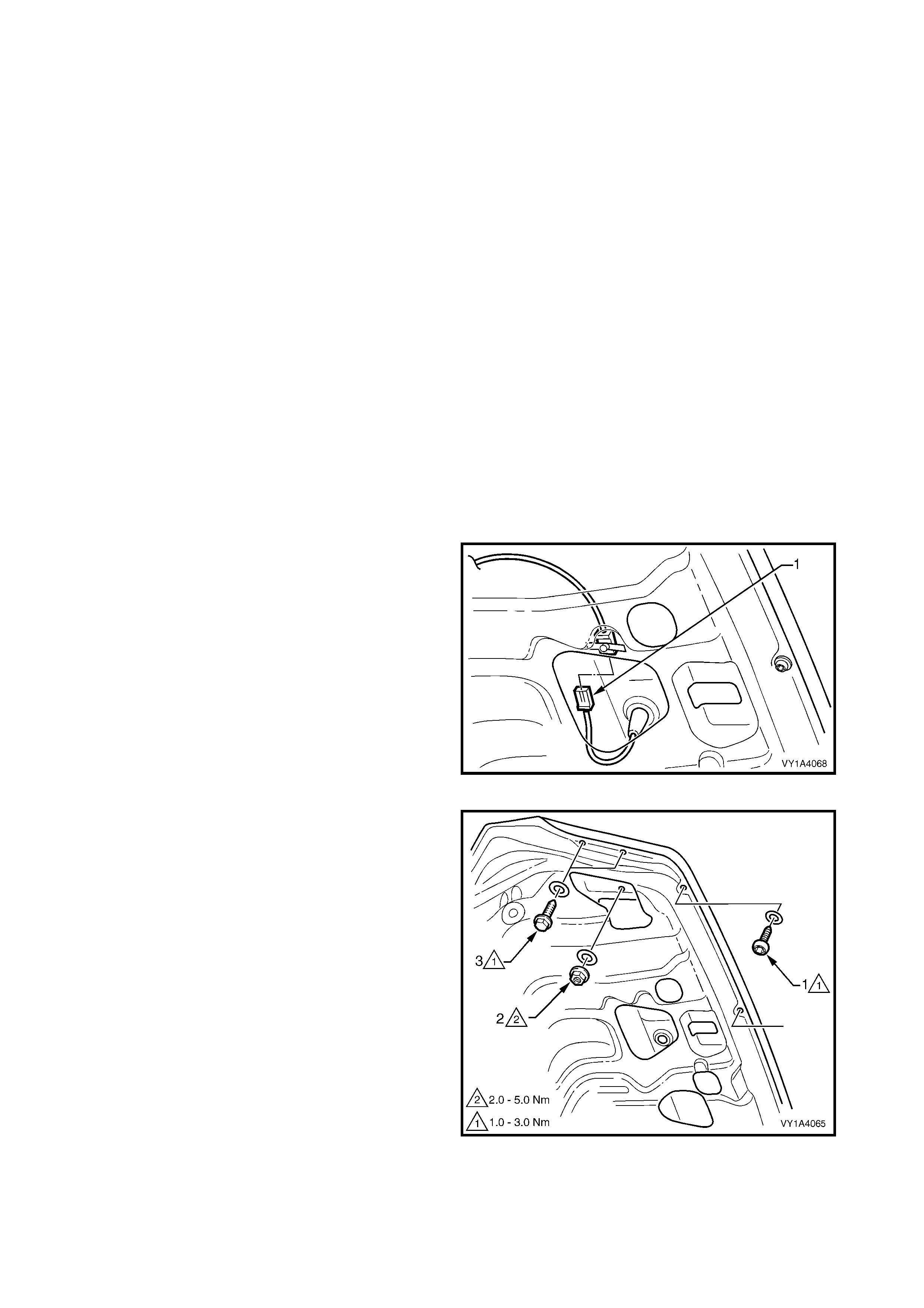
3. From within the rear compartment lid cavity,
disconnect the lic ence plate lamp wiring connec tor
(1).
Figure 1A4-1
4. Remove the Torx Head screw (1) and seal, three
places along the lower edge of the rear
compartment lid.
5. Remove the nut (2) and seal from within the rear
compartment lid cavity, one place each side.
6. Remove the screw (3) and seal, two places each
side of the rear compartment lid.
Figure 1A4-2
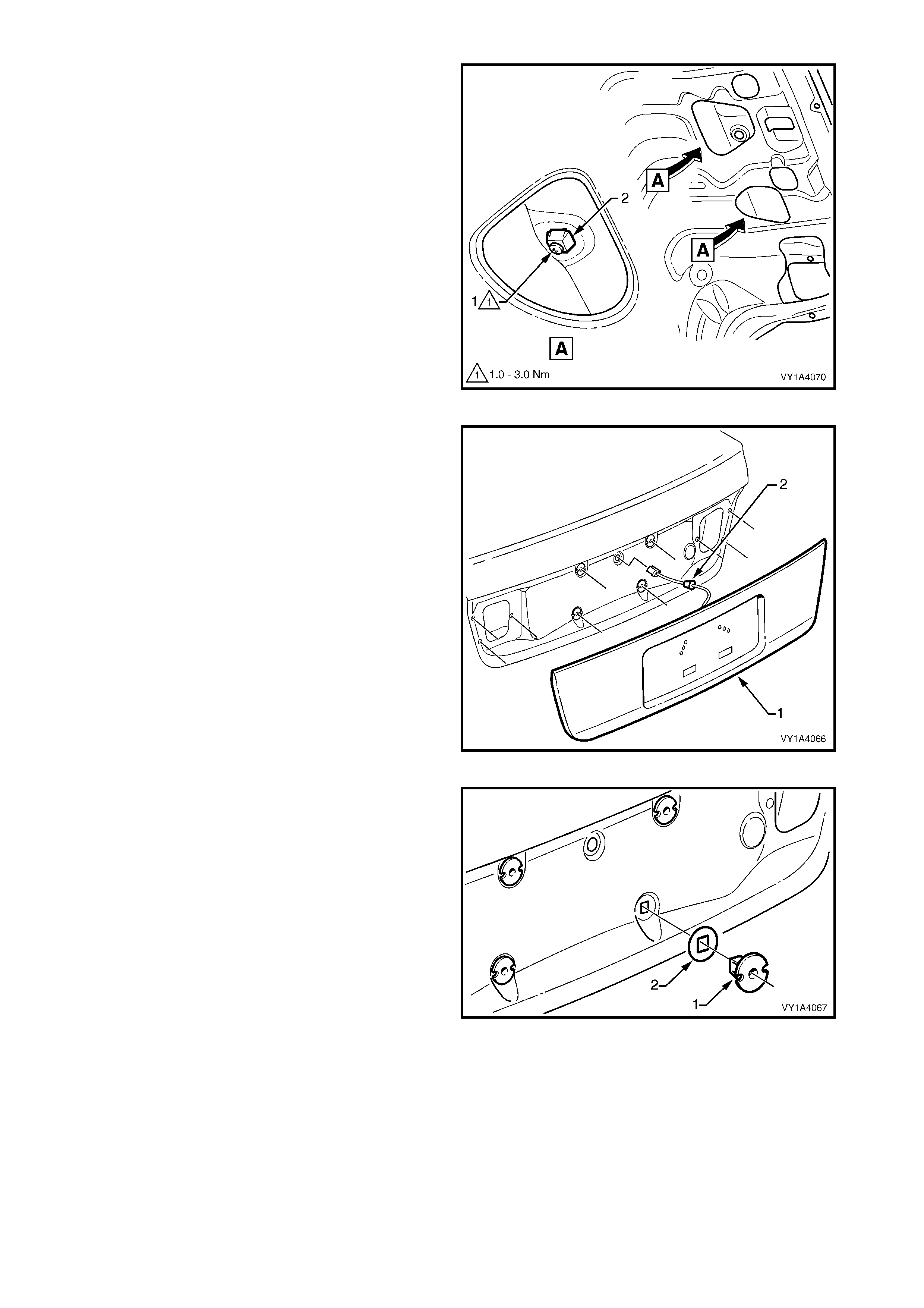
7. Either:
- Remove the screw (1) from the clip within the rear
compartment lid cavity, four places, or
- Depress the tab (2) each side to disengage the clip
from the rear compartment lid panel, four places.
Figure 1A4-3
8. Remove the décor panel assembly (1) away from
the rear compartment lid.
9. Remove the wiring harness grommet (2) and
withdraw the wiring harness.
10. Remove the décor panel assembly.
Figure 1A4-4
11. If not removed with the décor panel assembly, as
required carefully prise the four clips (1) and seals
(2) f rom the r ear com par tm ent lid using a f ine, flat-
blade screwdriver.
Figure 1A4-5

DISASSEMBLE
1. Depress the tab and lower the licence plate lamp
from the décor panel.
2. Rotate the bulb socket and remove from the
licence plate lamp.
3. Remove the licence plate lamp harness from the
rear of the décor panel.
4. Carefully remove the décor panel upper seal from
the upper edge of the décor panel.
NOTE: The seal is attached with adhesive.
5. Remove décor panel to rear compartment lid
gasket from each side of the décor panel.
6. If not already done so, remove the s crew attaching
the clip and seal to the décor panel (four places).
Figure 1A4-6
Legend
1. Licence plate lamp retaining tab 5. Decor panel to rear compartment lid gasket (2 places)
2. Licence plate lamp 6. Decor panel clip attaching screw (4 places)
3. Licence plate lamp harness 7. Decor panel clip (4 places)
4. Decor panel upper seal
REINSTALL
1. Attach the removed components as required.
NOTE: Ensure the upper seal is adhered correctly to
the décor panel.
2. Fit the four clips and seals to the décor panel with
the screws and tighten to the specified torque.
DÉCOR PANEL ASSEMBLY CLIP
ATTACHING SCREW 1 – 3 Nm
TORQUE SPECIFICATION
3. Feed the licence plate lamp wiring harness
through its hole in the rear compartment lid and fit
the grommet in position.
4. Install the décor panel assembly onto the rear
compartment lid, ensuring the four clips snap into
position.
5. Install the nuts and screws, ensuring the s eals are
correctly fitted and tighten to the specified torque.
DÉCOR PANEL ASSEMBLY LOWER
ATTACHING SCREW 1 – 3 Nm
TORQUE SPECIFICATION
DÉCOR PANEL ASSEMBLY
ATTACHING NUT 2 – 5 Nm
TORQUE SPECIFICATION
DÉCOR PANEL ASSEMBLY OUTER
ATTACHING SCREW 1 – 3 Nm
TORQUE SPECIFICATION

3. TORQUE WRENCH SPECIFICATIONS
Nm
Décor panel assembly clip attaching screw..........................1 - 3
Décor panel assembly lower attaching screw.......................1 - 3
Décor panel assembly outer attaching screw.......................1 - 3
Décor panel assembly attaching nut.....................................2 - 5