
SECTION 1A5 - DOOR ASSEMBLIES
IMPORTANT
Before performing any Service Operation or other procedure described in this Section, refer to Section
00 CAUTIONS AND NOTES for correct workshop practices with regard to safety and/or property damage.
1. GENERAL INFORMATION
The door assemblies fitted to V2 Series Models are similar in design to the front doors as fitted to VT Series II
Models, noting the following:
• The ex terior rear vis ion mirr or and inner window frame cover have been r evis ed to acc ommodate the change in
windscreen rake angle.
• The front door and drop glass are longer and lower to accommodate the coupe body style.
• The internal rod from the remote handle to the lock assembly is longer to accommodate the coupe door design.
• The window lifter and motor assembly has been revised to accommodate the drop glass revisions.
• The door check link angle and stops have been revised to accommodate the coupe door design.
• The door trims have been revised to accommodate the coupe door design.
The door ass emblies fitted to V2 Series Models cons ist of outer panels that are hemm ed at their outer edges , over
the inner panels. A rolled upper door frame retains the sliding glass run channels. Door check and hold open links
are located between the door assemblies and the body A-pillars.
Inside the doors, double arm scissor type window regulators attached to the glass lifter channels and door inner
panels operate the sliding windows.
Electric motors for operating the sliding windows are standard equipment on V2 Series Models.
A two key locking system uses a master key (with inbuilt remote security features) to operate all locks on the
vehicle. A secondary key, operates the glove compartment only. A snib locking button operates the door locks
internally.
The door lock cylinder is of the ‘free turning’ design, preventing unlocking of the door by objects other than the
correct key. If any object, except the correct key, is inserted into the lock, the cylinder will rotate without unlocking
the door.
Electric door lock actuators and electric external rear vision mirrors are standard features on all V2 Series Models.
Door weatherstrips inc or porate plas tic clips that r etain the weatherstr ip in holes loc ated ar ound the outer lower edge
of the door inner panel. The upper section of the weatherstrip is retained in a channel, which is an integral part of
the rolled section upper door frame.
Techline
Techline
Techline
Techline
Techline
Techline
2. SERVICE OPERATIONS
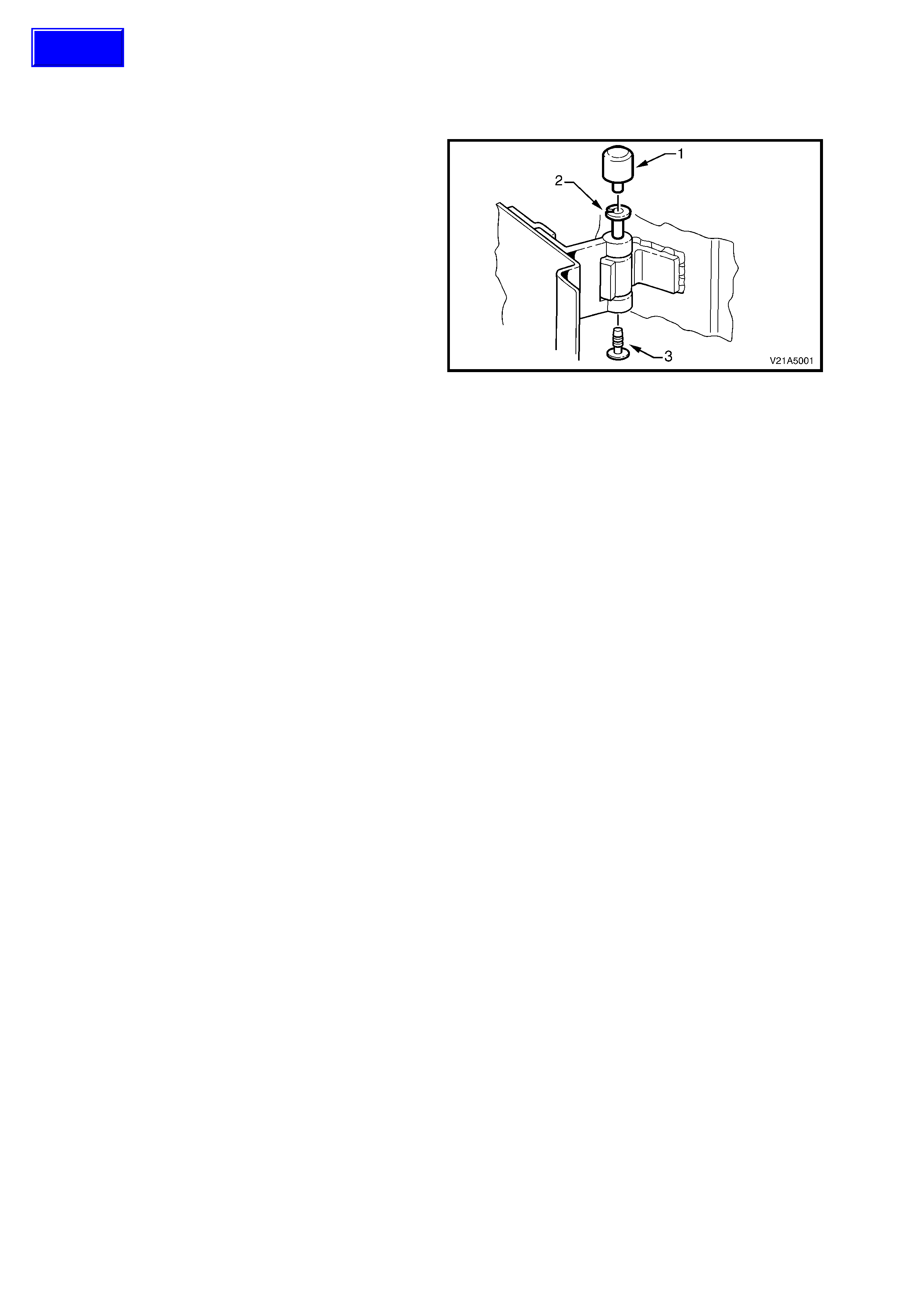
2.1 DOOR HINGE - LUBRICATION
1. Open the front door and remove the large
plastic cap (1) from the door hinge pin (2).
2. Taking care not to dislodge the small plastic
cap (3), use a grease gun to inject a lithium
base grease (NLGI No. 1 Lithium base grease
to Holden Specification HN1225) into the hinge
pivot pin.
3. Install large plastic cap over door hinge pin.
Figure 1A5-1
Techline
2.2 DOOR ASSEMBLIES
REMOVE
1. Disconnect the battery earth lead.
2. Remove door wiring harness gr omm et f r om the
A-pillar
3. Withdraw the door wiring harness connector
plug and disconnect.
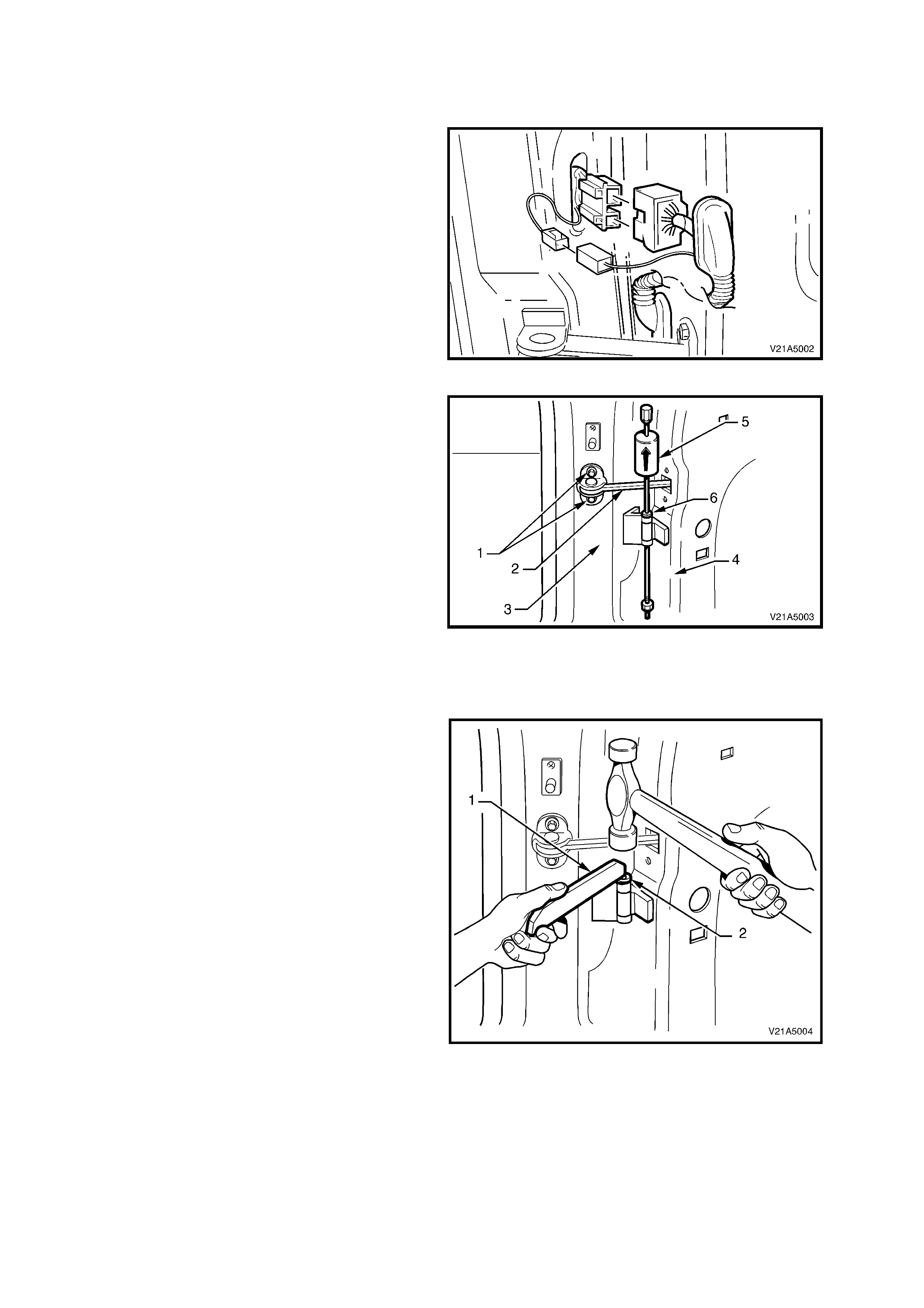
Figure 1A5-2
4. Remove the two bolts (1) securing the door
check link (2) to the A-pillar (3).
5. Using wooden blocks, car jacks or an assistant,
support the door (4) at its base.
6. Remove the plastic caps from the hinge
assemblies.
7. Using Tool No. AU170 (5), hinge pin removal
tool, drive out the upper and lower hinge pins
(6).
8. Remove the door assembly.
NOTE: The lower hinge pin should be driven
upwards and the upper hinge pin should be driven
downwards to remove.
Figure 1A5-3
REINSTALL
Installation of the door is the rever se of the rem oval
operation, noting the following:
1. Apply lithium base grease (NLGI No. 1 Lithium
base grease to Holden Specification HN1225)
to the hinge pivot pins prior to installation.
2. Use Tool No. AU303 (1), to install the hinge
pivot pins (2), refer to Fig. 1A5-4.
NOTE: The lower hinge pin should be driven
downwards and the upper hinge pin should be
driven upwards to install.
Figure 1A5-4

ADJUST
Attention should be given to uniform margins and alignment between the door and surrounding parts when door
adjustments are being carried out.
Uniform margins and alignment of the doors in relation to the body opening can be achieved by setting the
appropriate door hinge.
Take note of the following when adjusting the door alignment:
1. Use Tool No. AU184 to set door hinges by slightly bending the door hinge flaps.
2. Care must be taken when adjusting the doors not to misalign the hinge pins. Any significant misalignment will
cause the pins to shear when the door is opened or closed.
3. Final door adjustment must take place only once all the door components (except striker) and seals are
installed and secured into position.
4. Do not bend or lever the window frame. Excessive deflection of the door window frame will cause damage.
5. Adjust door with the striker assembly removed, refer to 2.3 DOOR LOCK STRIKER ASSEMBLY in this
Section. Striker plates should only be fitted once satisfactory alignment is achieved.
6. Door striker assemblies should not be used to “pull” the door into the correct position.
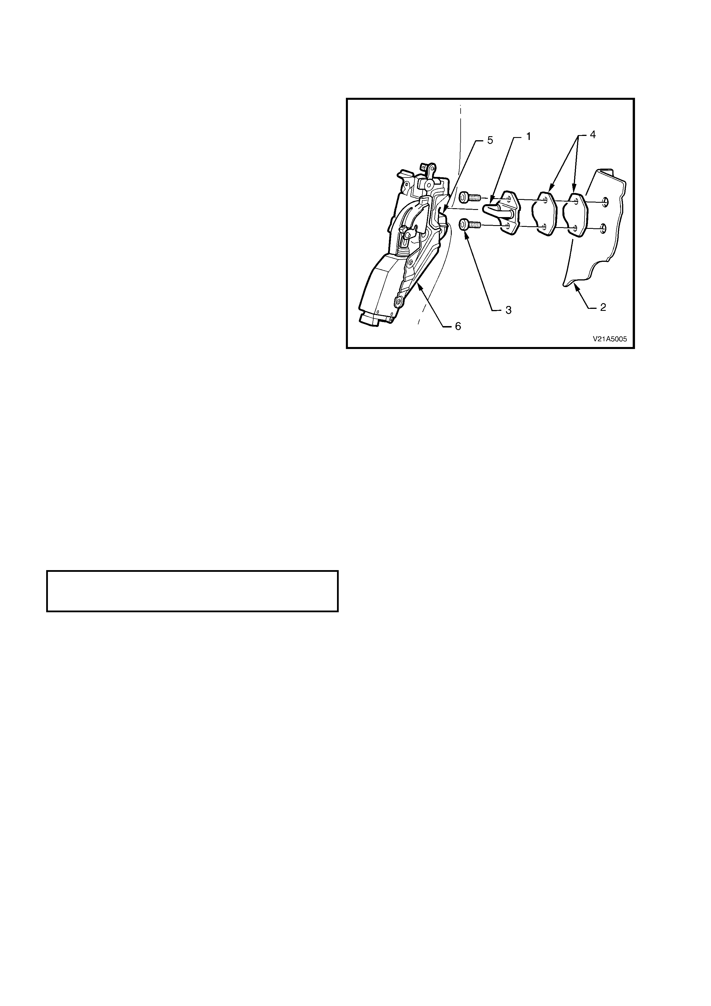
2.3 DOOR LOCK STRIKER ASSEMBLY
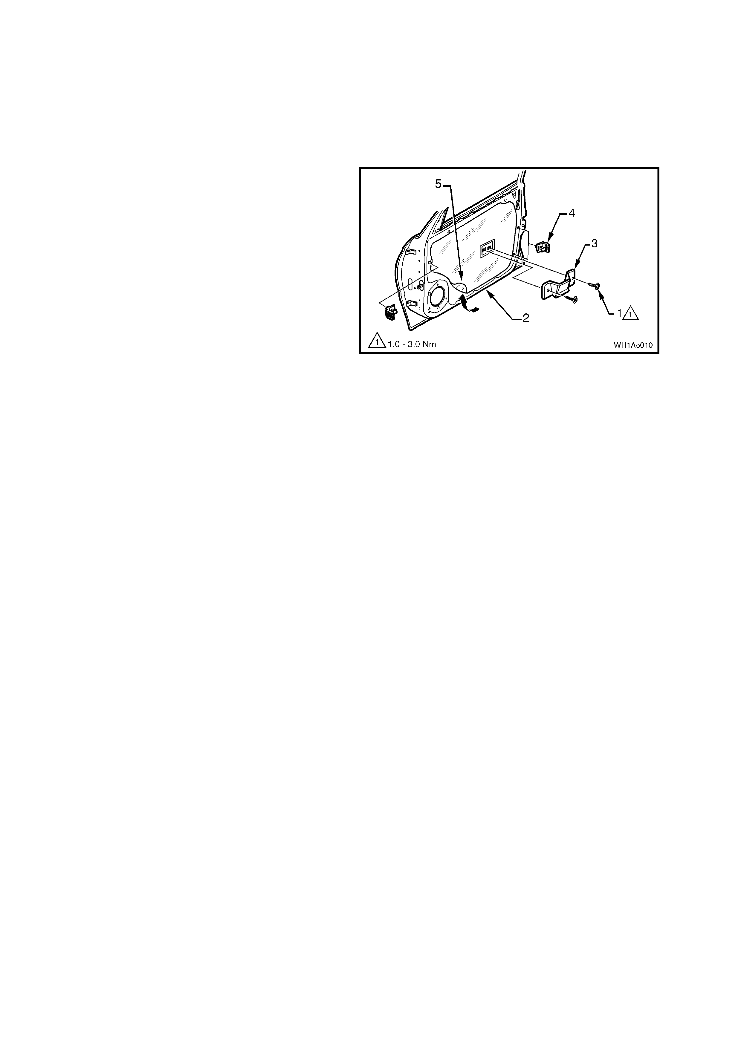
REMOVE OR ADJUST
1. Pencil scribe location of the striker assembly
(1) on the body pillar (2) to assist in correct
alignment during installation.
2. Using a Torx bit (30 T), remove the two bolts
(3) retaining the striker assembly to the pillar.
3. Remove the striker assembly.
4. To adjust, rem ove or ins ert spacer plates (4) as
required until the lock fork (5) in the lock
assembly (6) engages the striker correctly and
an acceptable door closing effort is achieved.
NOTE 1: Door lock striker spacer plates are
available in 1.0 mm and 2.0 mm sizes.
NOTE 2: Adjust hinges in conjunction with
adjustment to lock striker to achieve an acceptable
door closing effort with correct door lock to striker
engagement. Door s triker ass emblies s hould not be
used to “pull” the door into the correct position
Figure 1A5-5
REINSTALL
Installation of the door lock striker is the reverse of the removal operation, noting the following:
1. Align the s triker assem bly so that the leading edge of the s triker locates centr ally in the lock fork as the door is
being closed.
2. Correct engagement can be achieved by vertical adjustment of the door lock striker assembly. Add or delete
spacers between the striker assembly and body pillar to achieve correct engagement of the striker to the lock.
3. When correct alignment of the striker assembly is achieved, tighten striker assembly retaining bolts to the
correct torque specification.
NOTE: If a r eplacement door is being fitted, it is s ound practice to rem ove the door lock strik er assem bly and allow
the door to hang free on the hinges. Set the hinges as necessary to achieve correct alignment and uniform margins,
refer to 2.2 DOOR ASSEMBLIES in this Section, then install the str iker and adj ust. Door strik er ass emblies should
not be used to “pull” the door into the correct position.
DOOR LOCK STRIKER TO B-PILLAR
RETAINING SCREWS 8 – 18 Nm
TORQUE SPECIFICATION
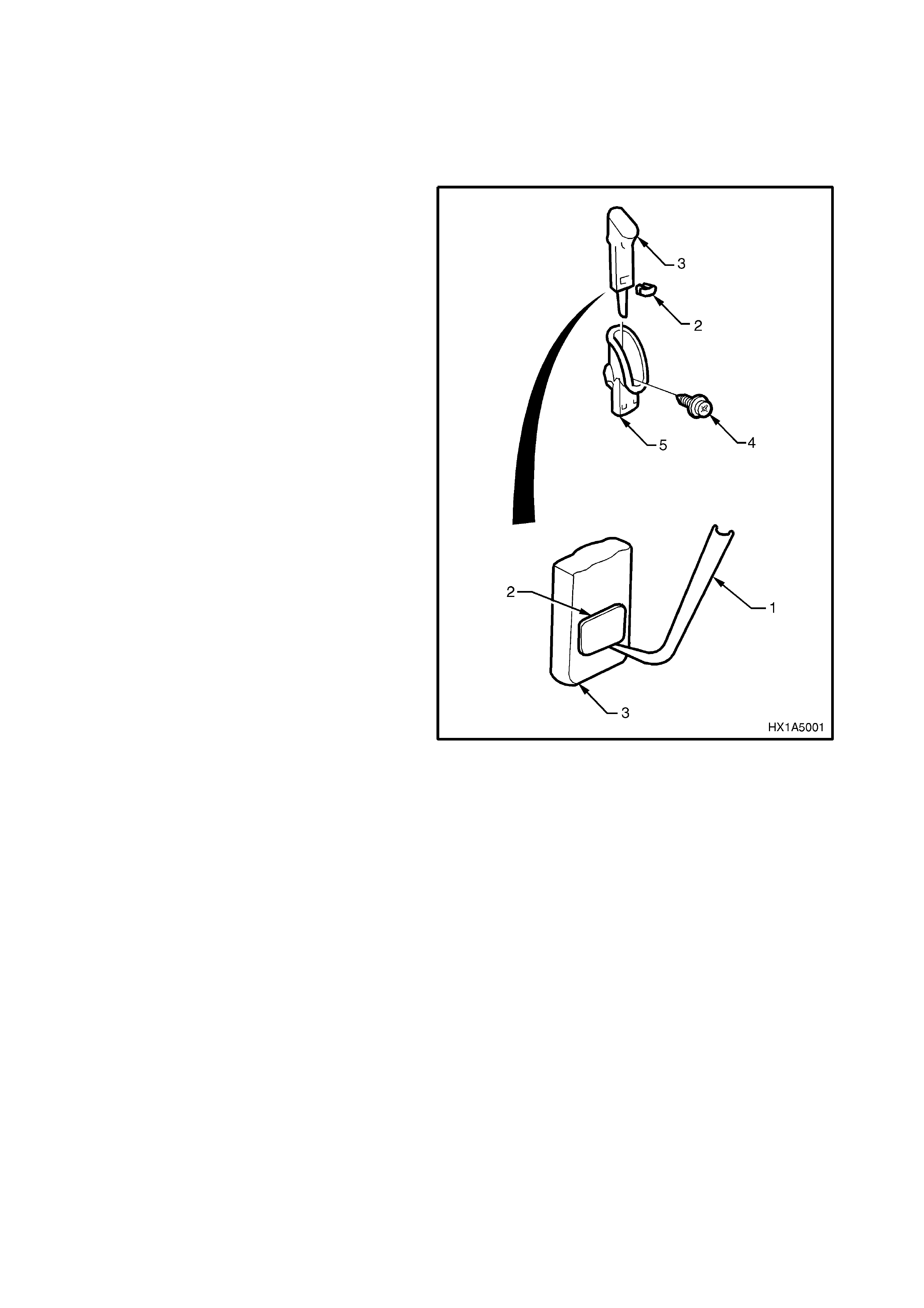
2.4 DOOR INNER TRIM PANEL
NOTE: When perform ing this service operation, it is necessar y to dam age the orange door lock ing button retaining
clamp and it will therefore need to be replaced. Before carrying out this service operation, order a door locking
button retaining clamp from your authorised Holden parts outlet.
REMOVE
1. Disconnect battery earth lead.
2. Using a sm all flat bladed screw driver or scribe
(1), gently prise the orange retaining clamp (2)
from the door locking button (3), taking care not
to damage the door locking button. Remove
the door locking button.
3. Remove the screw (4) securing the door
locking button escutcheon (5) to the door inner
trim panel and remove the escutcheon.
Figure 1A5-6
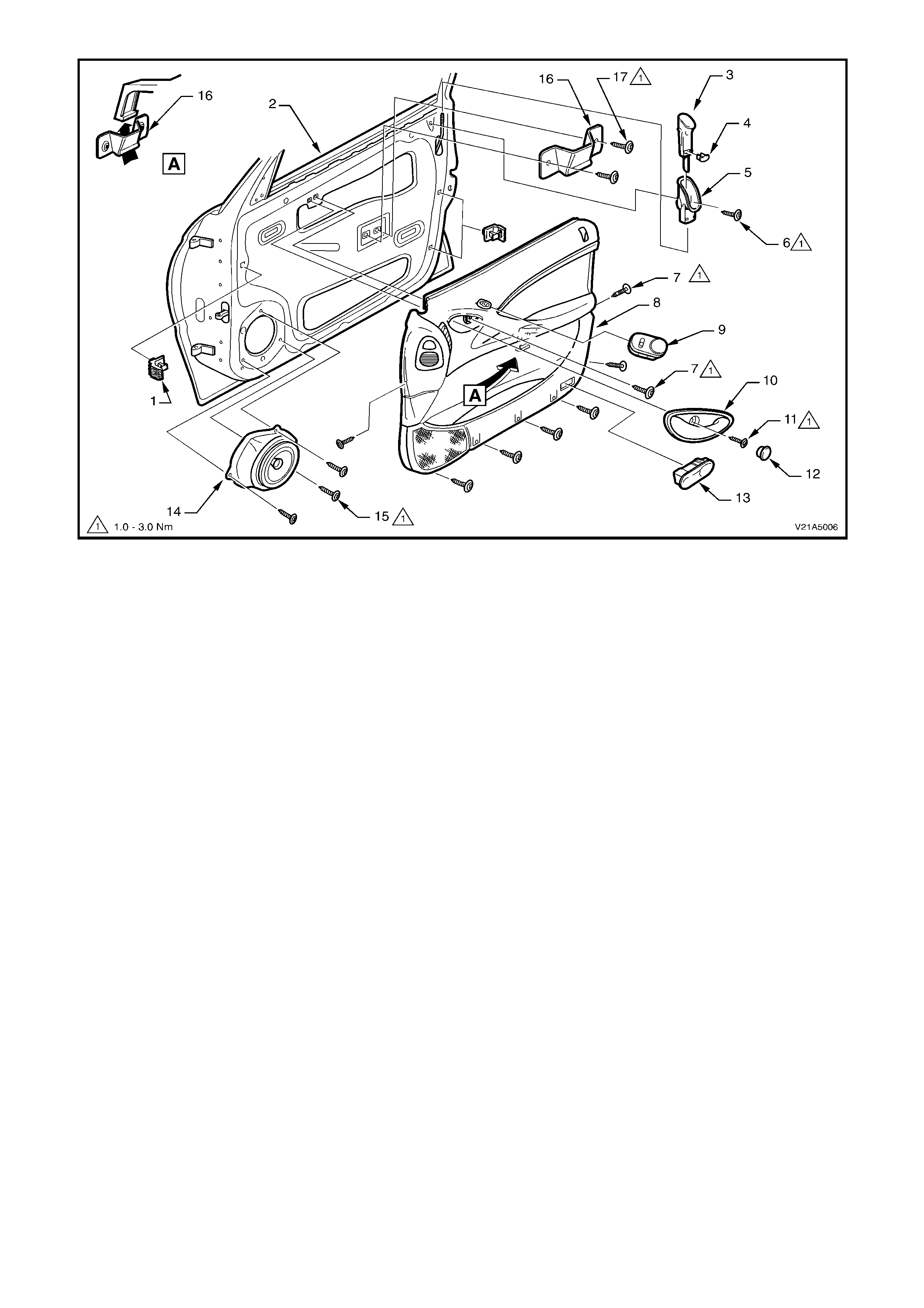
Figure 1A5-7
Legend
1. Door inner trim attaching bracket (3 places) 10. Door remote control handle assembly
2. Door assembly 11. Door remote control handle retaining screw
3. Door lock button 12. Door remote control handle retaining screw cap
4. Lock button retaining clamp 13. Door courtesy lamp
5. Lock button escutcheon 14. Door speaker assembly
6. Lock button escutcheon retaining screw 15. Door speaker retaining screw (3 places)
7. Door inner trim panel retaining screw 16. Door trim locating bracket
8. Door inner trim panel 17. Trim locating bracket retaining screw (2 places)
9. Electric exterior mirror switch (Driver’s side only)
4. Remove the sc rew cap and the screw securing the door remote control handle as sembly to the door inner trim
panel. Remove the door remote control handle assembly in a forward direction.
5. Remove the door inner trim panel retaining screw from the door remote handle assembly aperture.
6. Remove the mirror inner cover cap by gently prising cap away from door.
7. Remove the door inner trim panel retaining screws from around the outside of the door inner trim.
8. From the centre of the door (at the arm rest), push the centr e of the door inner trim panel in to unclip the catch
from the locating bracket behind the door inner trim while lifting the door inner trim panel up and out of inner
channel, refer to Fig. 1A5-7, View A.
NOTE: Wiring harness connectors are still connected.
9. While supporting door inner trim panel, remove all wiring harness connectors.
10. Remove door inner trim panel.
NOTE: Figures 1A5-8 shows the break down of the door trim inner panel assembly.
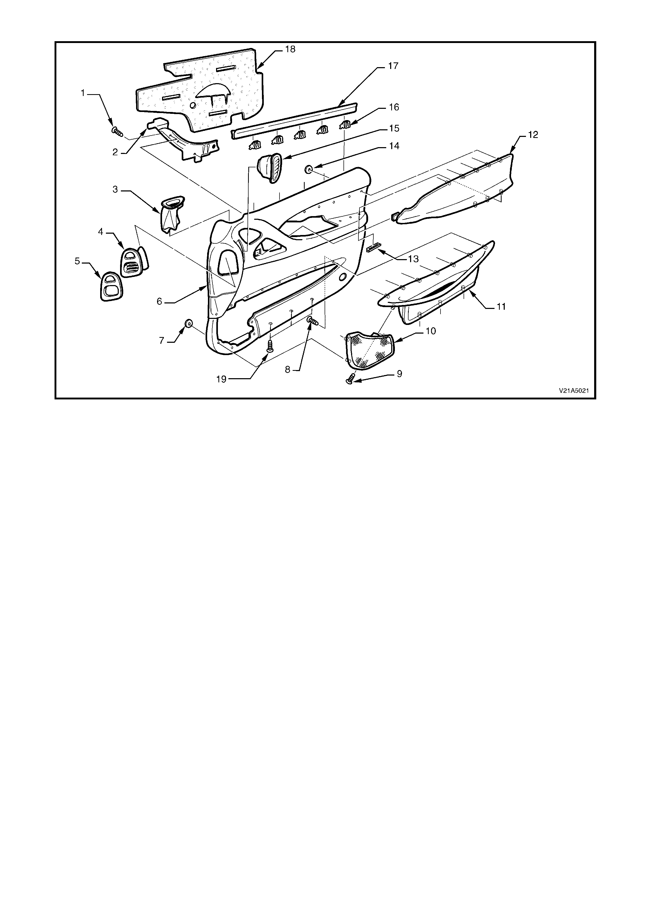
Figure 1A5-8
Legend
1. Screw (4 places) 11. Door deposit box.
2. Door pull handle 12. Armrest insert
3. Door demist duct 13. Clip (3 places)
4. Door vent duct 14. Clip (5 places)
5. Seal 15. Air outlet housing
6. Front door trim substrate 16. Clip (5 places)
7. Clip (6 places) 17. Weatherstrip
8. Screw (7 places) 18. Insulator
9. Screw 19. Screw (3 places)
10. Door speaker grille

REINSTALL
Installation of the door inner trim panel is the reverse of the removal operation, noting the following:
1. Tighten all retaining screws to the correct torque specification.
2. Ensure the door remote handle assembly and remote control rod are engaged before final fitment.
3. W hen installing the door lock button, ens ure lock is in the open position. Slide the loc k button over lock rod as
low as possible and push clamp in to retain lock button to rod.
NOTE: Use a new door locking button retaining clamp.
DOOR REMOTE CONTROL TO
DOOR PANEL RETAINING SCREW 8 – 18 Nm
TORQUE SPECIFICATION
DOOR SPEAKER TO DOOR
PANEL RETAINING SCREW 8 – 18 Nm
TORQUE SPECIFICATION
DOOR LOCK BUTTON ESCUTCHEON
TO DOOR PANEL RETAINING SCREW 8 – 18 Nm
TORQUE SPECIFICATION
DOOR INNER TRIM PANEL TO DOOR
PANEL RETAINING SCREW 8 – 18 Nm
TORQUE SPECIFICATION
DOOR TRIM PANEL LOCATING
BRACKET TO DOOR PANEL RETAINING 8 – 18 Nm
SCREW TORQUE SPECIFICATION
2.5 DOOR INNER DUST SEAL
REMOVE
1. Disconnect battery ground cable.
2. Remove the door inner trim panel refer to
2.4 DOOR INNER TRIM PANEL, in this
Section.
3. Remove the two screws (1) securing the inner
trim panel locating bracket (3) to the door
assembly (2) and remove locating bracket.
4. Remove the three inner trim retaining brackets
(4) by levering out the centre pin.
5. Carefully peel off the door inner dust seal (5)
from the door inner panel in the direction
indicated by the arrow in Fig 1A5-9.
Figure 1A5-9
REINSTALL
The installation procedure for the door inner dust seal as fitted to V2 Series Models is the reverse of the removal
procedure, noting the following:
• Apply f oam hot melt adhesive to Holden Spec if ic ation HN1989 ( or equivalent) ar ound the entire per iphery of the
seal and the courtesy lamp perforation.
• Ensure that the seal is installed over the inner lock rod.
NOTE: The door inner dust seal is not side specific. W hen installing a new seal, ensure adhesive is applied to the
appropriate mating surfaces according to which side of the vehicle the seal will be fitted to.
2.6 DOOR LOCK AND ACTUATOR ASSEMBLY
REMOVE
1. Disconnect battery ground cable.
2. Remove the door inner trim panel refer to 2.4 DOOR INNER TRIM PANEL, in this Section.
3. Remove door inner dust seal, refer to 2.5 DOOR INNER DUST SEAL, in this Section.
4. Refer to Fig 1A5-10. Disconnect the actuator to door harness electrical connector then remove the three screws
securing the door lock and actuator assembly to door inner panel.
5. Disconnect actuator control rods fr om the retainer s then rem ove the assem bly through the aperture in the door
inner panel.
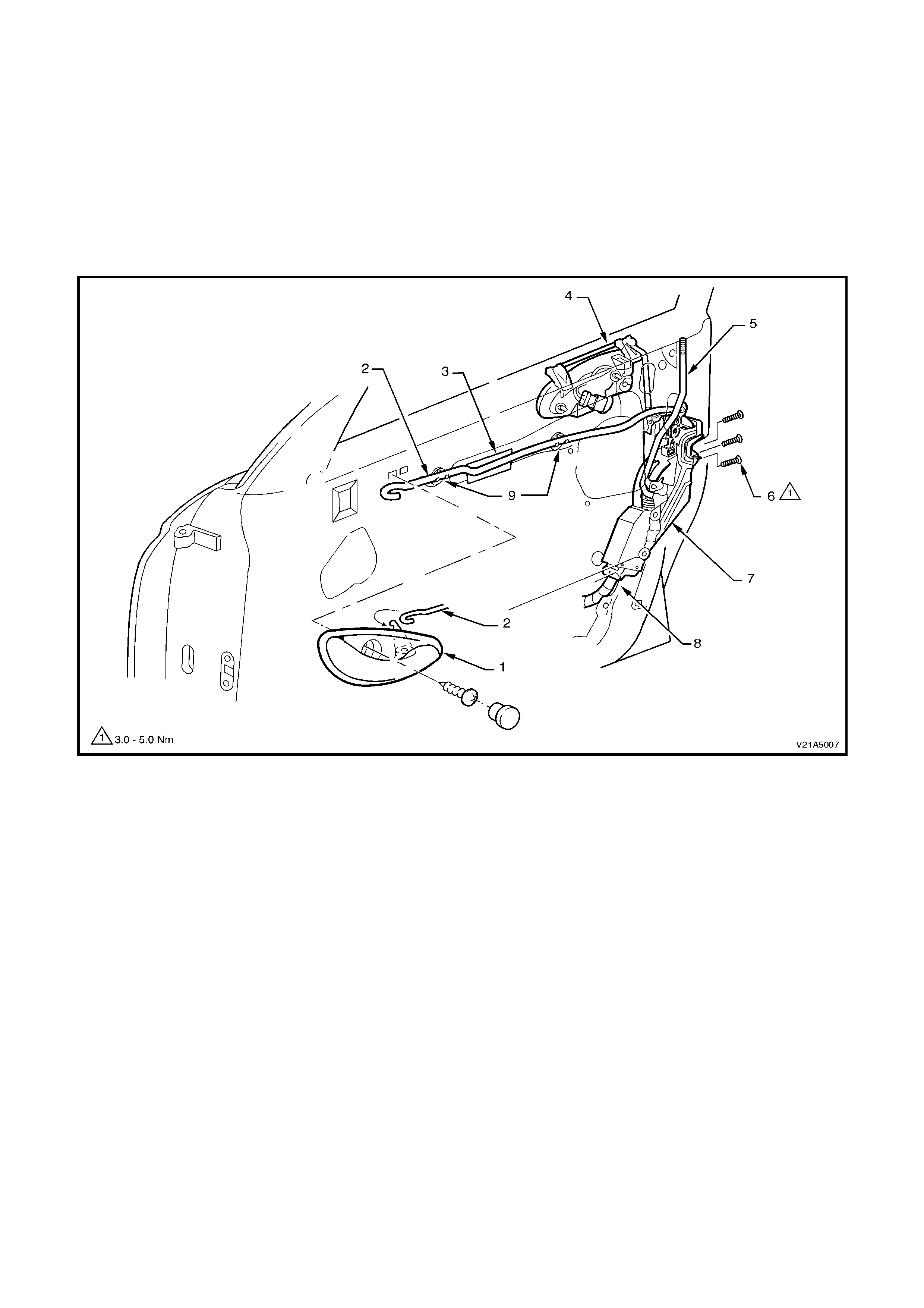
Figure 1A5-10
Legend
1. Door remote control handle 6. Door lock and actuator attaching screws (3 places)
2. Remote control rod 7. Door lock and actuator assembly
3. Remote control rod insulating foam 8. Actuator to door harness electrical connector
4. Exterior door handle assembly 9. Remote control rod retainer (2 places)
5. Exterior handle to actuator rod (drivers side only)
ADJUST
Adjustment of each door lock and actuator is critical to ensure correct operation of the electric door lock system.
The f ollowing adjustm ent procedure is to be per form ed if a diagnostic test in Section 12J- 2 HIGH SERIES BCM of
the VX Series Service inf ormation suggests that the door lock and actuator assem bly m ay be incorrectly adjusted,
or if any of the following symptoms occur:
• Ineffective deadlock operation.
• Failure to lock and unlock.
• Door lock actuator motors oscillate, ie. Machine gunning.
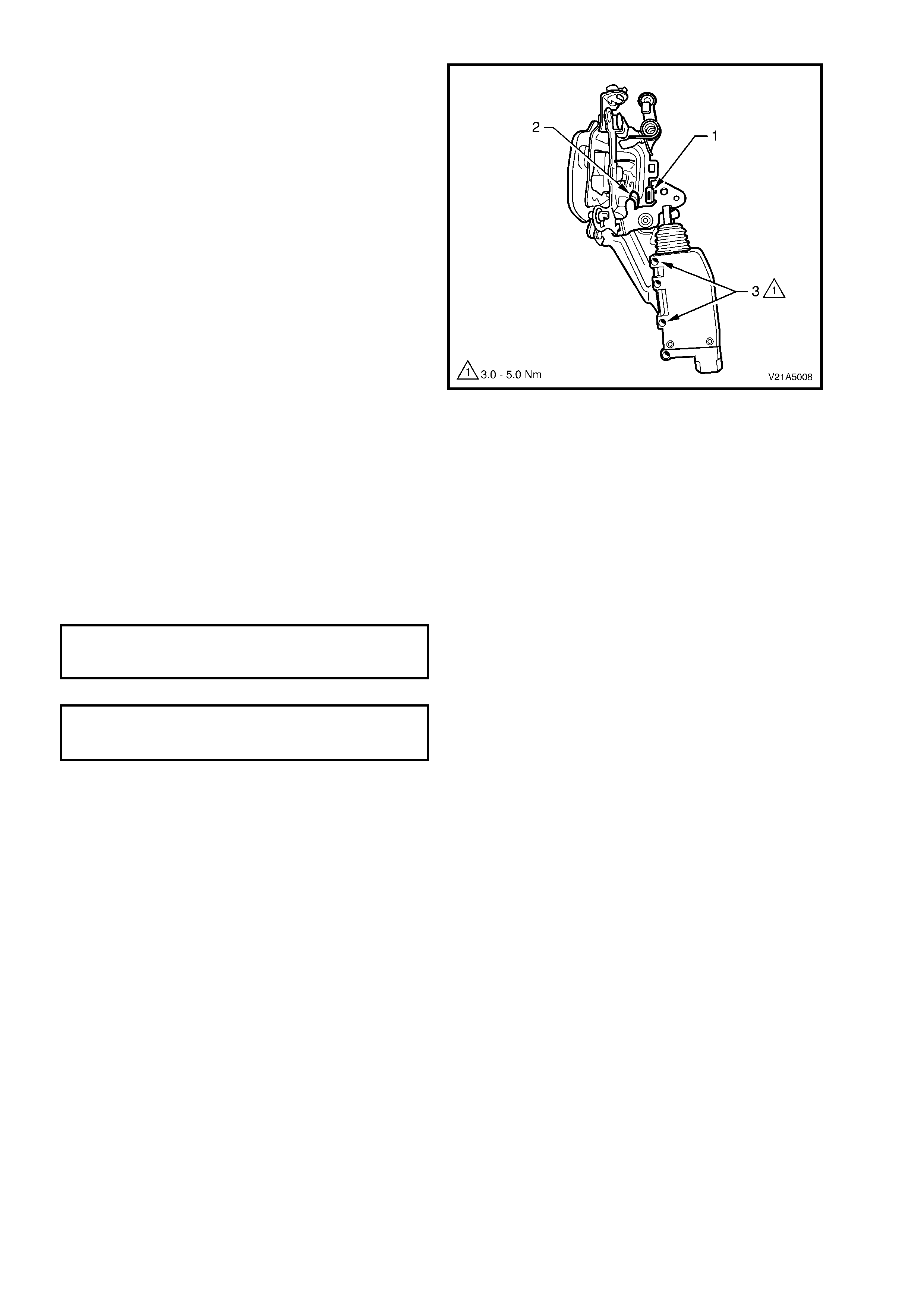
1. With the door lock and actuator assembly
rem oved, use the door loc k ing button rod lever,
LOCK and UNLOCK the actuator mechanism,
checking that the actuator lever (1) rests on
rubber pad (2).
2. If required, loosen screws (3) and reposition
the actuator motor until the required position is
achieved.
3. Tighten actuator to motor screws securely
without moving the motor position.
Figure 1A5-11
REINSTALL
Installation of the front door lock and actuator
assembly is the reverse of the removal operation,
noting the following:
1. Tighten all retaining screws to the correct
torque specification.
2. Ensure that the door inner dust seal is sealed
correctly against the door panel.
3. Use a new door locking button retaining clamp.
DOOR LOCK AND ACTUATOR TO
DOOR PANEL RETAINING SCREW 3 – 5 Nm
TORQUE SPECIFICATION
DOOR LOCK ACTUATOR TO LOCK
ASSEMBLY RETAINING SCREW 3 – 5 Nm
TORQUE SPECIFICATION
2.7 DOOR EXTERIOR HANDLE AND LOCK CYLINDER ASSEMBLY
REMOVE
1. Disconnect battery earth lead.
2. Remove the door inner trim panel refer to 2.4 FRONT DOOR INNER TRIM PANEL in this Section.
3. Remove the door inner dust seal, refer to 2.5 DOOR INNER DUST SEAL, in this Section.
4. Driver’s door only; disconnect the door lock cylinder control rod from the door lock and actuator assembly by
releasing the rod retainer clip, refer to Fig. 1A5-10.
5. Driver’s door only; disconnect door lock microswitch wiring harness connector at exterior door handle.
6. Remove the two exterior door handle retaining nuts, and remove exterior door handle.
NOTE 1: To test the door microswitch, refer to Section 12J-2 HIGH SERIES BCM in the VT Series I Service
Information.
NOTE 2: Fig. 1A5-12 shows the driver’s door exterior handle with microswitch and wiring harness. T he passenger
door exterior handle is just a plain metal bracket.
DISASSEMBLY
1. Rem ove the f ront door exterior handle and loc k
assembly, refer Section 1A5 FRONT AND
REAR DOOR ASSEMBLIES in this Service
Information.
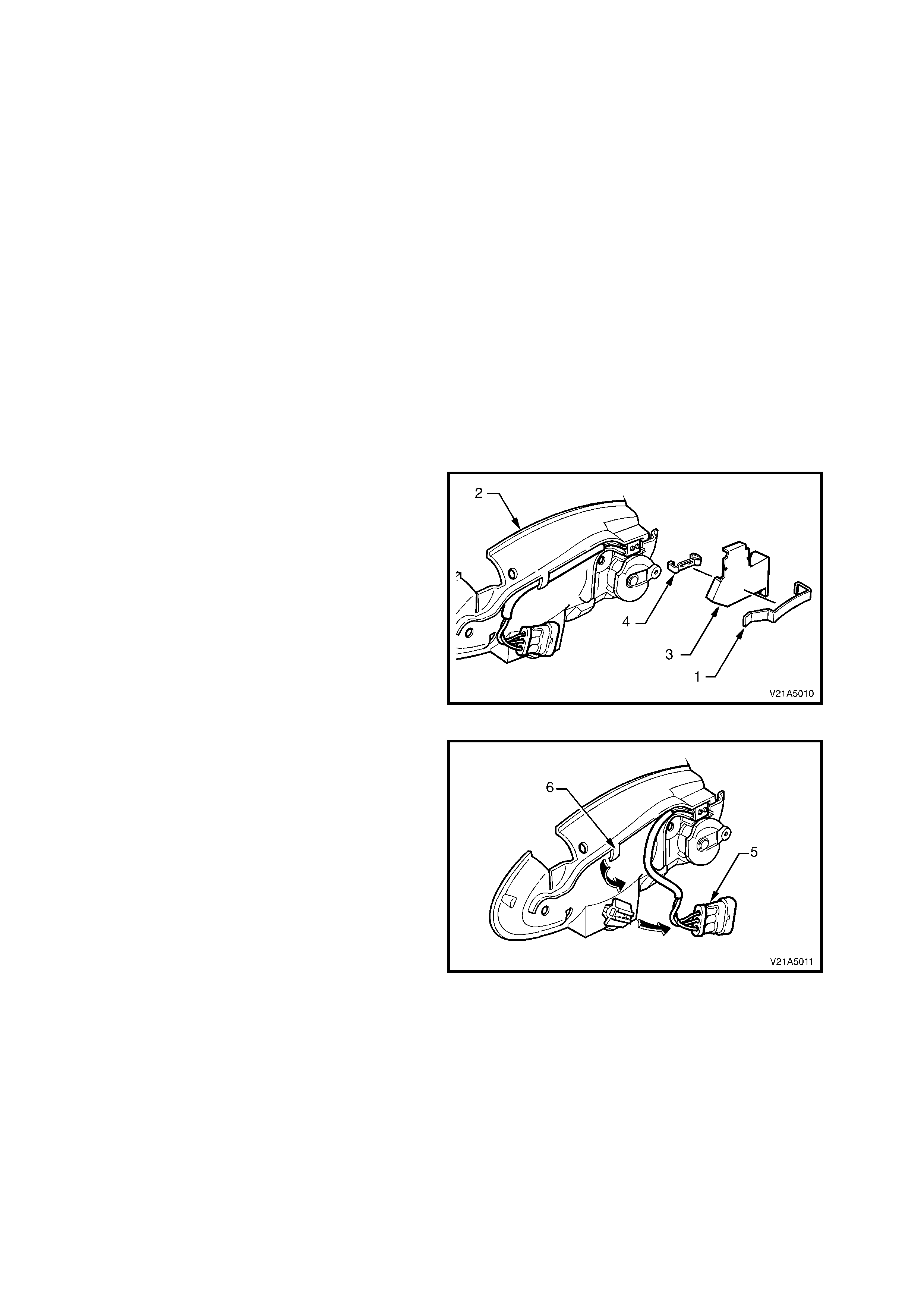
2. Using a small screwdriver, gently prise the
retaining clip (1) away from the door handle
bracket assembly (2) and remove the security
shield (3).
3. Using a small screwdriver, gently prise the
microswitch retaining clip (4) away from the
door handle bracket assembly.
Figure 1A5-12
4. Slide the m icroswitch wiring harness connector
(5) of f the connector retaining brack et and feed
the wiring harness out from under the bracket
assembly retainer (6).
Figure 1A5-13
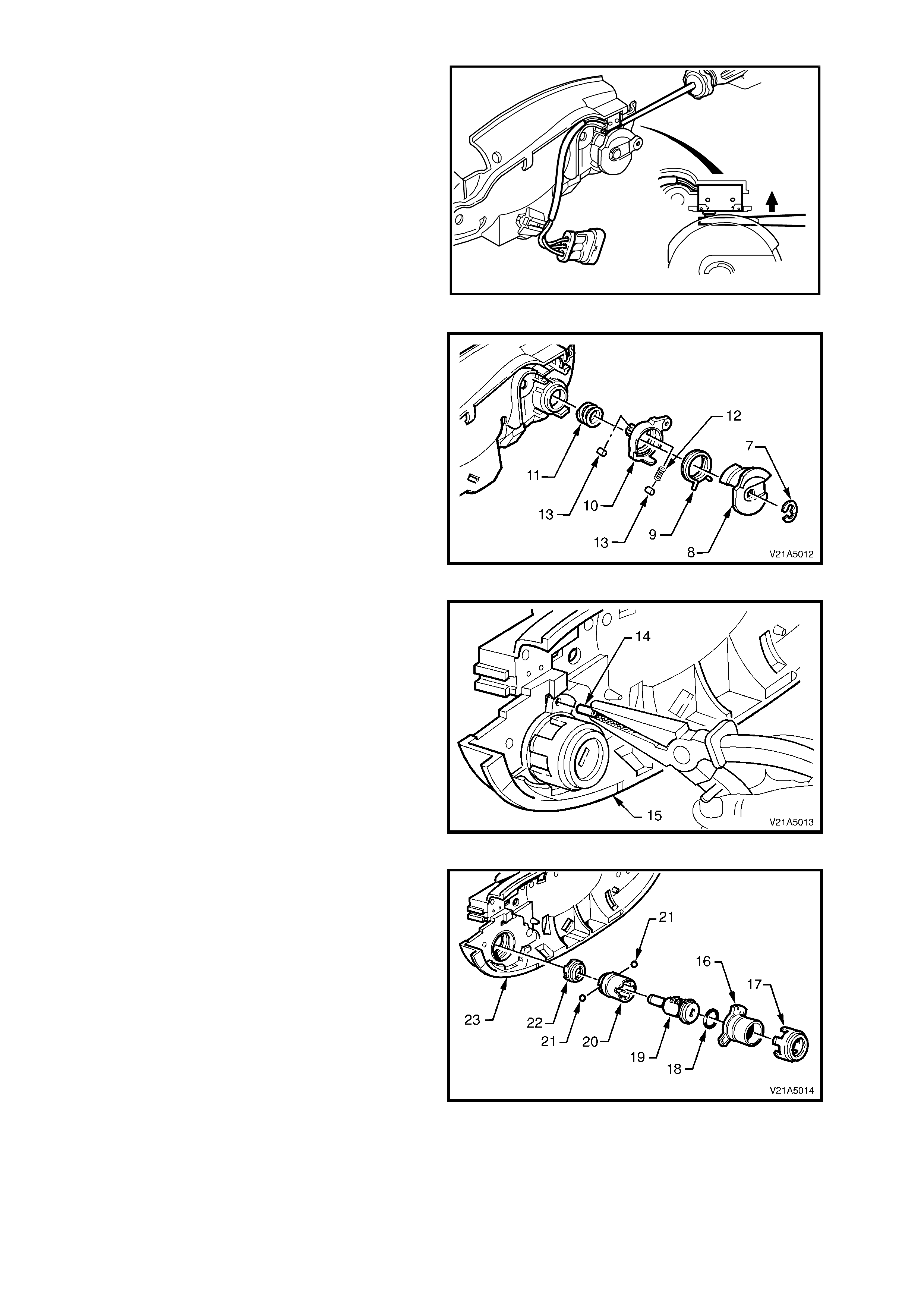
5. Using a sm all flat bladed screwdriver, push the
two microswitch contacts in and remove the
microswitch assembly.
T21A5003
Figure 1A5-14
6. Remove the circlip (7) and slide the cam
control, clips and springs (8, 9, 10, 11, 12 and
13) away from lock assembly.
Figure 1A5-15
7. Using a suitable pair of pliers, pull the roll pin
(14) out of the door handle bracket assembly
(15).
Figure 1A5-16
8. Rotate lock hous ing anti-clock wise and rem ove
decorative housing (16), lock housing (17), O-
ring (18), lock assembly (19), lock assembly
sleeve (20), retaining balls (21) and coupling
(22) from the door handle bracket assembly
(23).
Figure 1A5-17
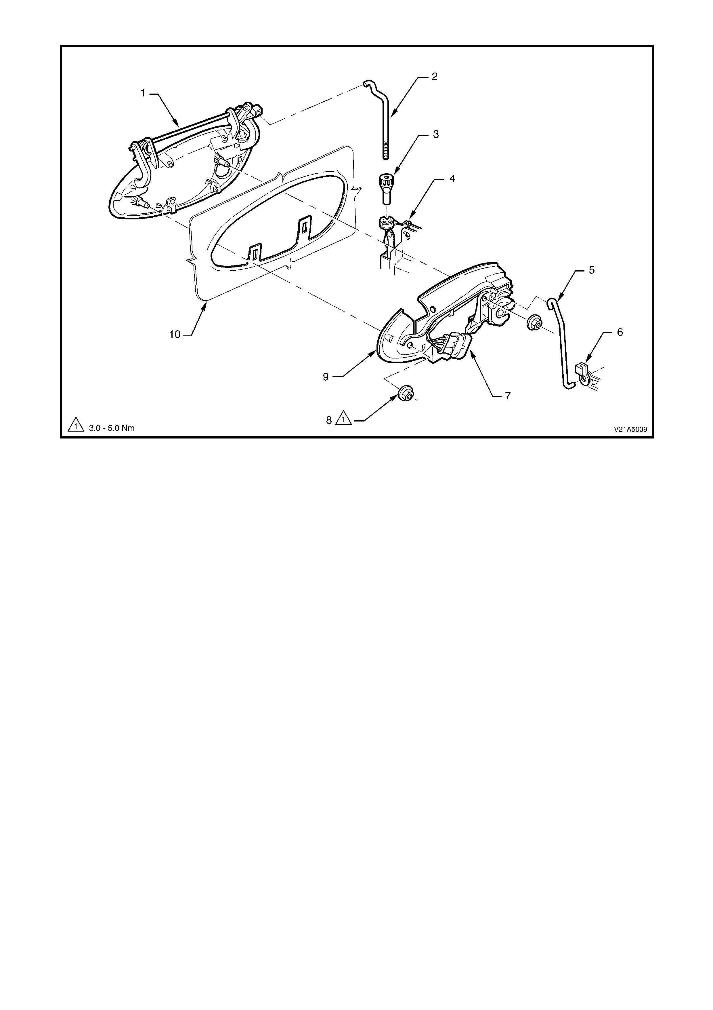
Figure 1A5-18
Legend
1. Exterior door handle 6. Lock and actuator assembly
2. Exterior door handle rod 7. Microswi tch harness connector
3. Adjusting nut 8. Exterior door handle retaining nut
4. Lock and actuator rod 9. Exterior door handle bracket assembly
5. Lock cylinder control rod (driver’s door only) 10. Door outer panel
REASSEMBLY
Reassem bly of the front door exterior handle and lock asse m bly is the reverse of the rem oval procedur e, noting the
following:
1. The Holden Service Parts O perations departm ent supplies s ervice k its with un-coded lock cylinders to facilitate
re-coding of the lock c ylinder to m atc h the original k ey. Holden Ltd. recomm ends that the lock cylinder overhaul
and re-coding be performed by a qualified locksmith, and should be sublet.
2. To assist assembly of the front door exterior handle and lock assembly, the following Fig. 1A5-19 shows an
exploded view of the assembly.
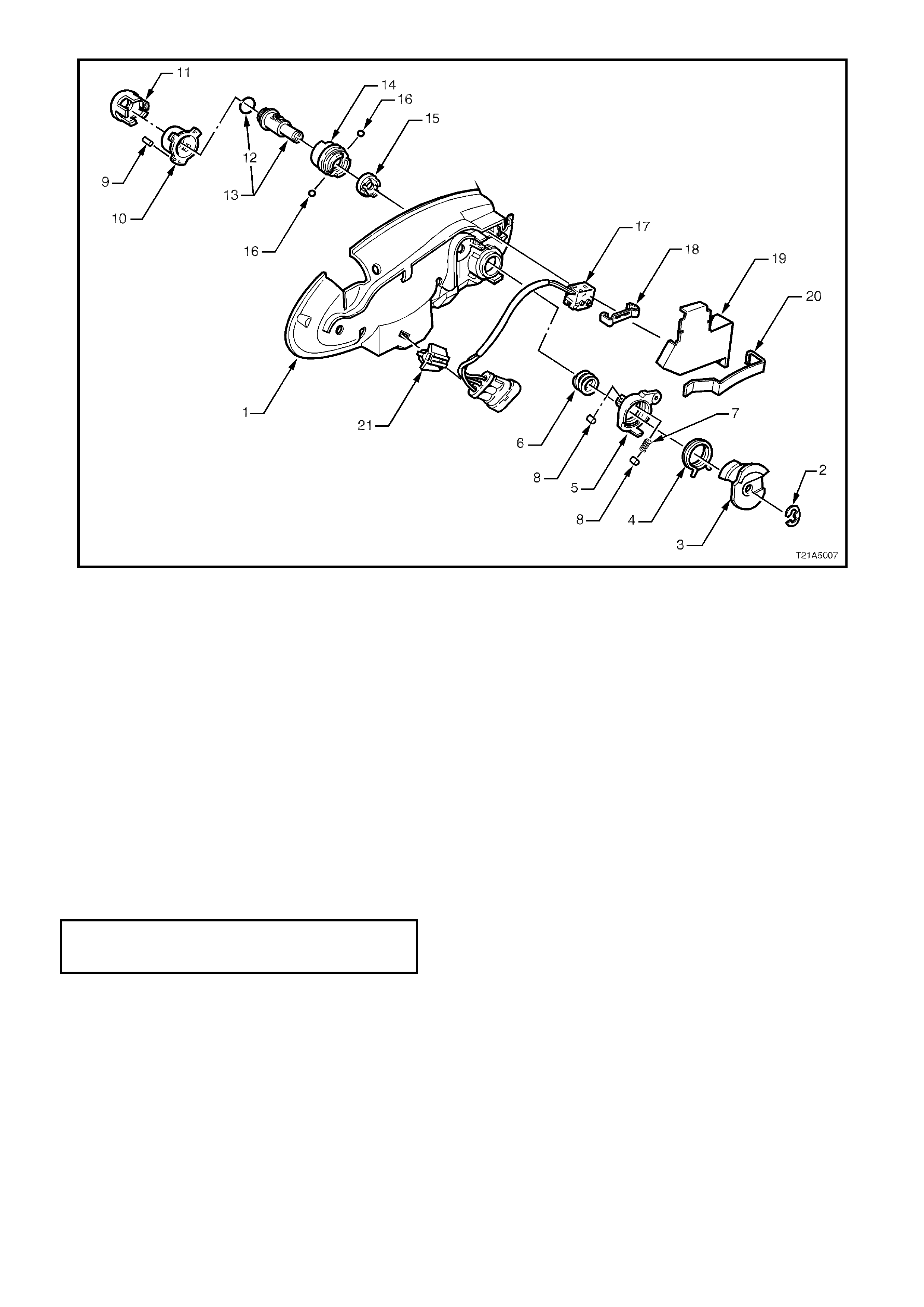
Figure 1A5-19
Legend
1. Exterior door handle bracket 8. Roller 15. Coupling
2. Circlip 9. Roll pin 16. Retaining balls
3. Cam control 10. Lock housing 17. Microswitch assembly
4. Spring 11. Decorative housing 18. Retaining clip
5. Clip 12. O-ring 19. Security shield
6. Push spring 13. Cylinder lock assembly 20. Retaining clip
7. Roller spring 14. Cylinder lock sleeve 21. Connector retaining bracket
REINSTALL
Installation of the front door exterior handle assembly is the reverse of the removal operation, noting the following:
1. Ensure that the adjusting nut is seated in the lock and actuator assembly before installing the exterior door
handle assembly retaining nuts.
2. Tighten retaining nuts to the correct torque specification.
EXTERIOR DOOR HANDLE ASSEMBLY
TO DOOR PANEL RETAINING NUT 3 – 5 Nm
TORQUE SPECIFICATION
3. Check and if nec essary, adj ust the exter ior door handle adjusting nut to allow latch disengagem ent with striker
when the exterior door handle opening is 18° ± 5° from the rest position.
4. Ensure the door inner dust seal is sealed correctly to the door and use a new door locking button retaining
clamp.

RESET (‘FREE TURN’ LOCK CYLINDER)
NOTE: If the ‘free turn’ loc k cylinder becom es misaligned due to the inser tion of an inc or rec t key, a foreign object or
if the correct key is not inserted fully when turned, the following procedure will need to be carried out.
1. Inser t the k ey fully into the lock , pr eferably in the vertical position and tur n the k ey slowly anti-clockwise - until a
click is felt.
2. Then slowly turn key clockwise - until a click is felt.
3. Return the key to the vertical position (if not already there) and withdraw the key.
4. Reinsert the key at the vertical position and check if the key will lock and unlock the vehicle.
NOTE: If the key does not work properly, keep key in lock and turn key 180° anti-clockwise, then repeat the
procedure.

2.8 REMOTE CONTROL HANDLE AND ROD ASSEMBLY
REMOVE
1. Remove the door inner trim panel refer to 2.4 FRONT AND REAR DOOR INNER TRIM PANEL, in this Section.
2. Remove the door inner dust seal, refer to 2.5 DOOR INNER DUST SEAL, in this Section.
3. Unclip the remote control handle rod from the door inner panel (2 places) and disengage the remote control
handle rod from the door lock and actuator assembly by releasing the retainer clip, refer to Fig. 1A5-10.
REINSTALL
Installation of the remote control handle and rod assembly is the reverse of the removal operation, noting the
following:
1. Ensure the door remote handle assembly and remote control rod are engaged before final fitment, refer to
Fig. 1A5-10.
2. Ensure the door inner dust seal is sealed correctly against the door panel.
3. Use a new door locking button retaining clamp.
2.9 DOOR WINDOW AND REGULATOR ASSEMBLY
NOTE: To rem ove, test and install the power window switch, refer to Section 12J-2 HIG H SERIES BCM , in the VT
Series I Service Information.
REMOVE
1. Remove the door inner trim panel, refer to 2.4 FRONT DOOR INNER TRIM PANEL in this Section.
2. Remove the door inner dust seal, refer to 2.5 DOOR INNER DUST SEAL in this Section.
3. Remove the external rear view mirror, refer to 2.13 EXTERNAL REAR VISION MIRROR in this Section.
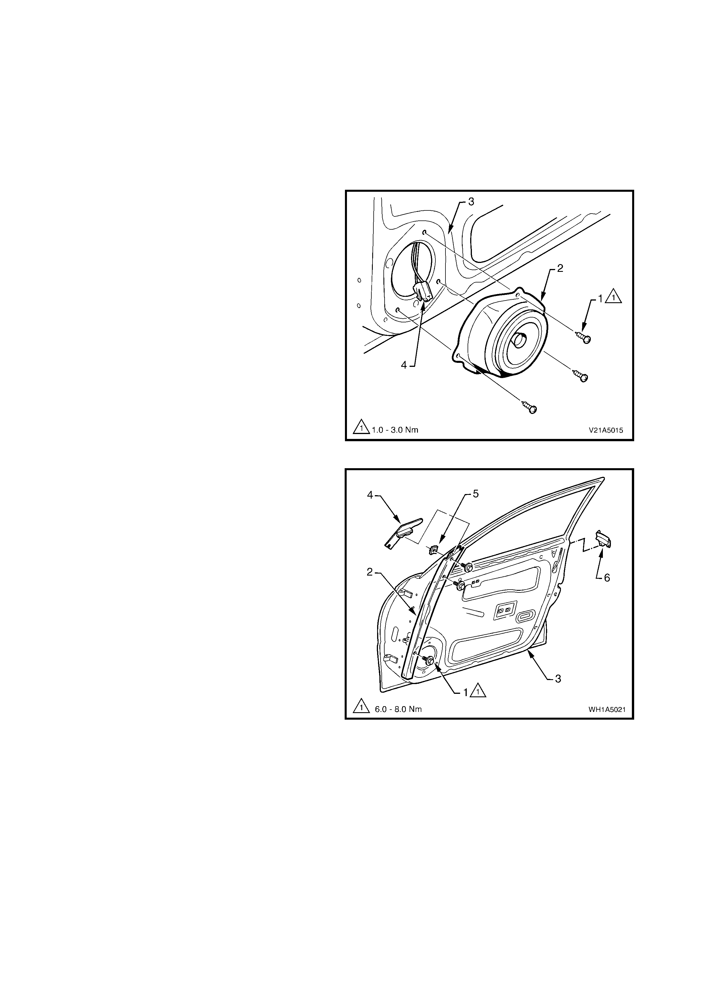
4. Remove the three screws (1) securing the
speaker assembly (2) to the door inner panel
(3), rem ove speak er far enough to gain acces s
to wiring harness connector (4). Disconnect
wiring harness connector and remove the
speaker assembly.
5. With window wound down approximately half
way, remove drop window weatherstrip from
front guide rail.
NOTE: It is not necessary to remove drop window
weatherstrip completely, only from the front guide
rail.
Figure 1A5-20
6. Remove the three bolts (1) securing the front
guide rail (2) to the door panel (3) and remove
guide rail downwards.
7. Remove guide rail cap (4) from top of guide
rail.
NOTE: The top guide rail retaining nut (5) is not
welded to the door and when the guide rail retaining
bolt is removed, this nut may become lost.
8. Gently prise the weatherstrip end cap (6) from
the rear of the door.
9. Remove the two attaching screws securing the
window regulator guide rail and slide the rail out
of window regulator guide runner, refer to Fig.
1A5-22.
10. Disconnect wiring harness connector from
window regulator, refer to Fig. 1A5-22.
11. While having an assistant support the window,
drill out rivets securing the window regulator to
the door panel, slide runners out of window
guide rails, and remove window regulator
through door inner panel aperture, refer to Fig.
1A5-22.
12. Remove the window assembly.
Figure 1A5-21
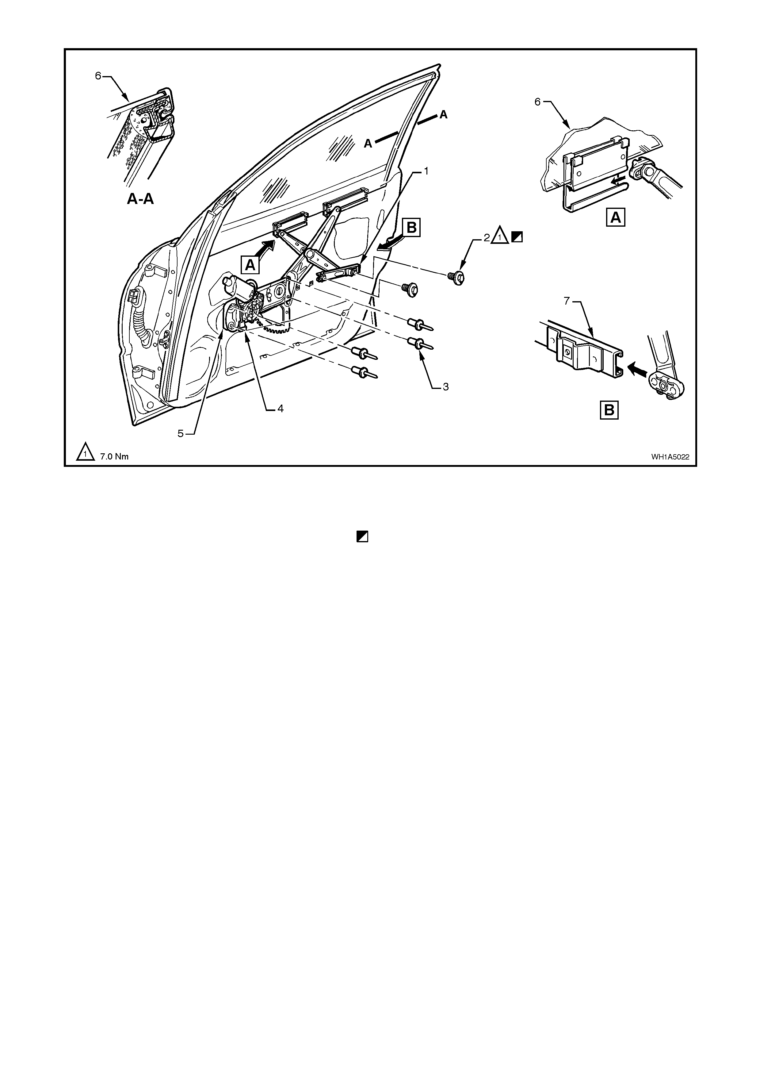
Figure 1A5-22
Legend
1. Window regulator guide rail 6. Glass assembly
2. Window regulator guide rail attaching screw (2 places) 7. Window regulator guide rail lower
3. Rivet (4 places) Initial attachment to be loose, torque screw when glass
4. Wiring harness connector is installed and in down position, refer adjustment
5. Window regulator assembly procedure in this Section.
REINSTALL
Installation of the front door window and regulator assembly is the reverse of the removal procedure, noting the
following:
1. Ensure that all frictional surfaces of the window regulator assembly and associated parts are adequately
lubricated with Lithium grease (to Holden Specification HN1416).
2. Locate the regulator assembly inside the door, aligning the attaching holes in the assembly with the
corres ponding holes in the door inner panel. Attac h the regulator ass embly to the door inner panel using service
replacement screws.
3. Install front guide rail cap before tightening front guide rail retaining bolt and nut.
4. Before installing door inner trim panel, adjust the front door window and regulator as per the following
adjustment procedure.
5. Ensure that the door inner dust seal is correctly sealed against door inner panel.
6. Ensure that the door rem ote control handle assem bly and rem ote control rod are engaged before final fitment,
refer to Fig. 1A5-10.
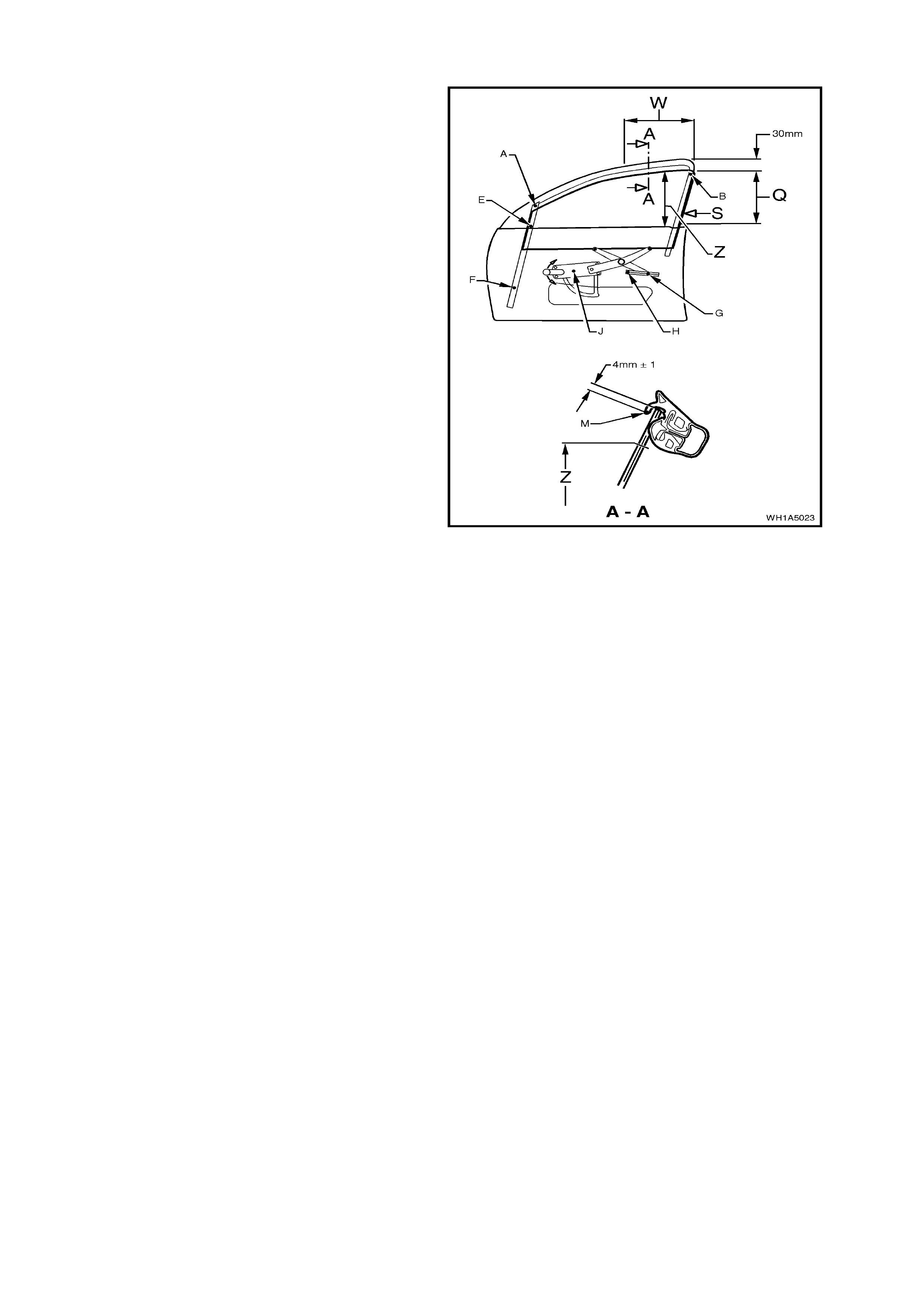
ADJUST
1. Adjust end stop, point ‘B’, at the rear of the
door so that there is a 1 mm gap below the
highest possible end stop position and tighten
attaching screw to approximately 2 Nm.
2. Wind the window glass up through area ‘Q’
while at the same time, pressing the rail which
is bonded to the rear edge of the glass, in the
direction of arrow S. Continue winding window
glass up until window glass is approx im ately 30
mm before the closed position.
3. Screw window regulator guide rail in position
without imposing any stress es by tightening the
rear attachment screw, point ‘G’, to 7 Nm.
4. Tighten the centre attachment screw, point ‘E’,
of the front guide rail to 7 Nm while ensuring
that the window glass is held approximately 30
mm before the closed position.
5. Wind the window glass down to approximately
30 mm above the door belt moulding while at
the same time, pressing the rail which is
bonded to the rear edge of the glass, in the
direction of arrow S. Tighten the bottom
attachment screw, point ‘F’, for the front guide
rail to 7 Nm.
6. Screw window regulator guide rail in position
without imposing any stress es by tightening the
front attachment screw, point ‘H’, to 7 Nm.
Figure 1A5-23
7. W ind window glass up to a pos ition where the upper edge of the glass is flush with the upper edge of the door
mir ror hous ing, as s een f r om outside. In this position, the upper edge of the glas s must be par allel with point ‘M’
of the glass run over area ‘W’.
8. Check cranking load of window glass in area Z. If load feels excessive (more than 2.7 Nm) re-adjust window
glass by correcting the front guide rail attachments, points ‘E’ and ‘F’.
9. Adjust end stop, point ‘A’, so that the end s top contacts with the window glass and tighten attaching screw to 7
Nm.
10. With the window in the closed position, adjust end stop, point ‘J’, so that it contacts the toothed sector of the
window regulator, then tighten attachment screw to 7 Nm.
11. Check upper edge of glass . If the deviation in parallelism and engagem ent exceeds 1 m m , re-adjus t end stops
at point ‘B’, and A-as necessary, so that the upper edge of the glass to the lip of the glass run at, point ‘M’ is
within a tolerance band of 3 to 5 mm.
12. Check the upper edge of the glass to ensure that the lip of the glass run channel, point ‘M’, is parallel over the
area ‘W’.
The upper edge of the glass must be 4 mm above the lip of the glass run channel, point ‘M’, over the area ‘W’.
If either the deviation in parallelism or insertion depth exceed 1 mm, then the end stops at points ‘B’, and ‘A’
mus t be readj usted until the upper edge of the glas s is 3 to 5 mm above the lip of the glass run channel, point
‘M’.
13. Tighten the attachment screw for end stop, point ‘B’ to 4 Nm.
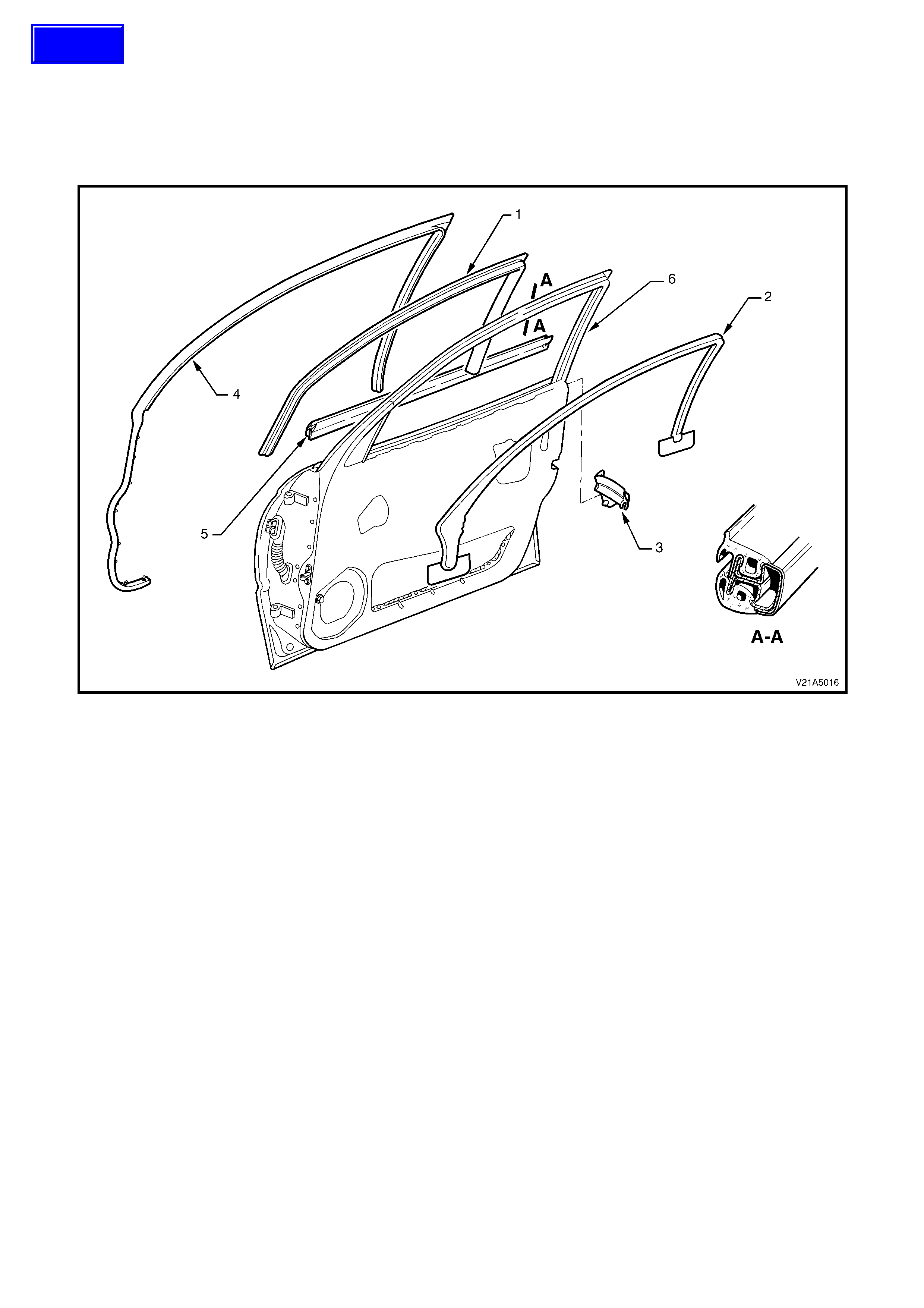
2.10 DOOR UPPER WEATHERSTRIP ASSEMBLY
REMOVE
1. Progressively peel the drop window weatherstrip away from around the door window frame and guide rails.
2. Progressively remove the weatherstrip from the lip on the door upper frame and the retainer clips from the holes
in the door panels. Refer to Fig. 1A5-24.
Figure 1A5-24
Legend
1. Door drop window weatherstrip 4. Weatherstrip assembly
2. Door frame moulding 5. Door belt moulding and weatherstrip assembly
3. Weatherstrip end cap 6. Door frame
REINSTALL
Installation of the door weatherstrips is the reverse of the removal operation, noting the following:
1. Installing weatherstrips corner with alignment locating marks on door frame.
2. Start installation process from the upper rear corner of the door and work outwards.
Techline
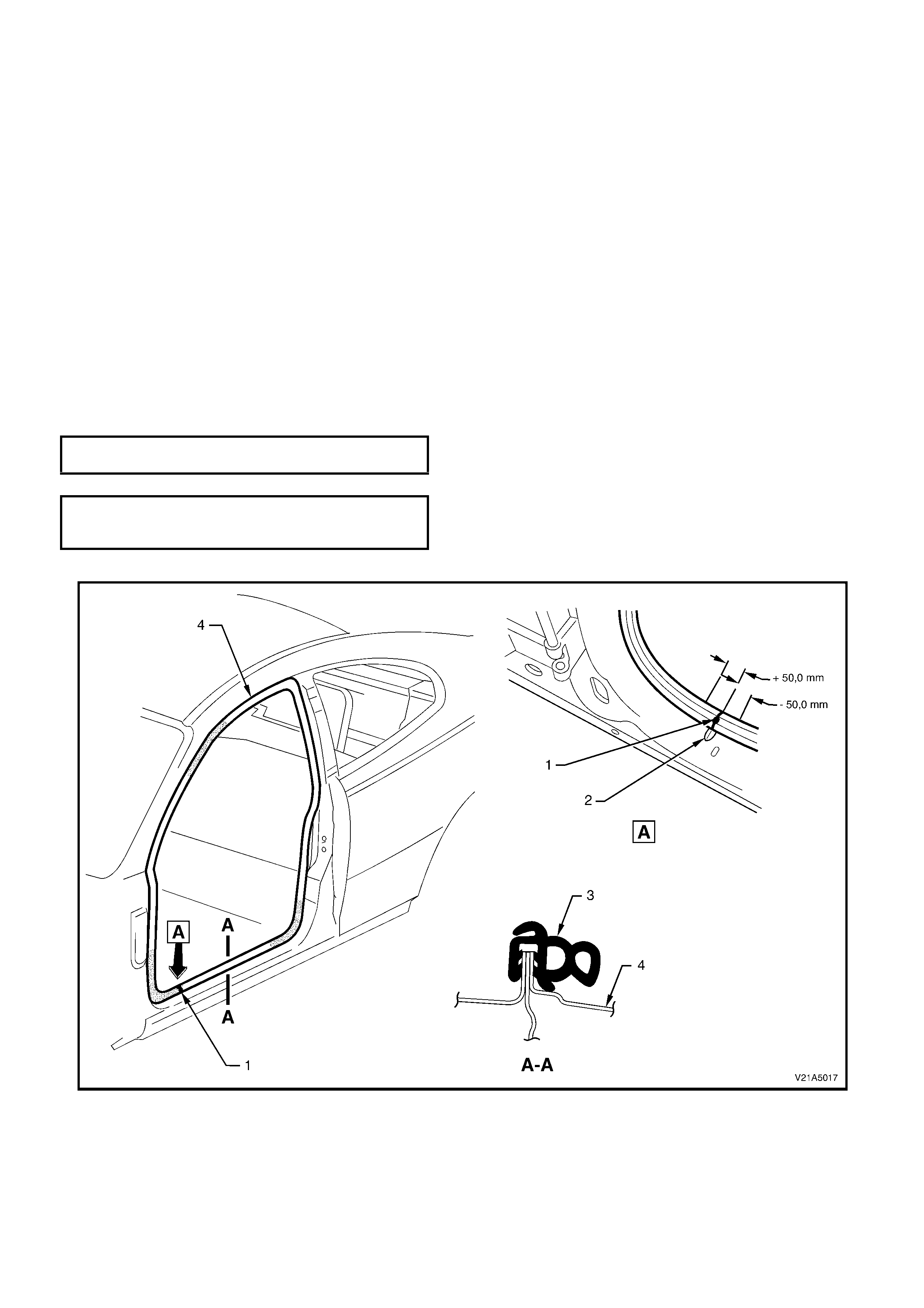
2.11 DOOR OPENING WEATHERSTRIP
REMOVE
1. Rem ove B-pillar trim to gain access to door opening weatherstrip, refer to 2.5 B-PILLAR TRIM in Section 1A8
HEADLINING AND REAR END TRIM.
2. Remove inner rocker panel trim, refer to 2.3 INNER ROCKER PANEL TRIM AND INSERT in Section 1A8
HEADLINING AND REAR END TRIM.
3. Gently prise weatherstrip from door opening.
REINSTALL
Installation of the door opening weatherstrips is the reverse of the removal procedure, noting the following:
1. Ensure that the green identification dot adjacent to the joint in the weatherstrip (1) is centrally located by the
centre line of the dart in the door frame opening (2) ± 50 mm, refer to Fig 1A5-25.
2. Ensure weatherstrip lip sits over trim panels.
NOTE: Allow crowding of the weatherstrip (3) in all corners of the door opening frame (4) to prevent from short
cutting corners and creating a foul condition with the inner door trim.
3. Tighten all screws to the correct torque specification.
B-PILLAR TRIM ATTACHING SCREWS
TORQUE SPECIFICATION 1 – 3 Nm
INNER ROCKER PANEL COVER
ATTACHING SCREWS 1 – 3 Nm
TORQUE SPECIFICATION
Figure 1A5-25
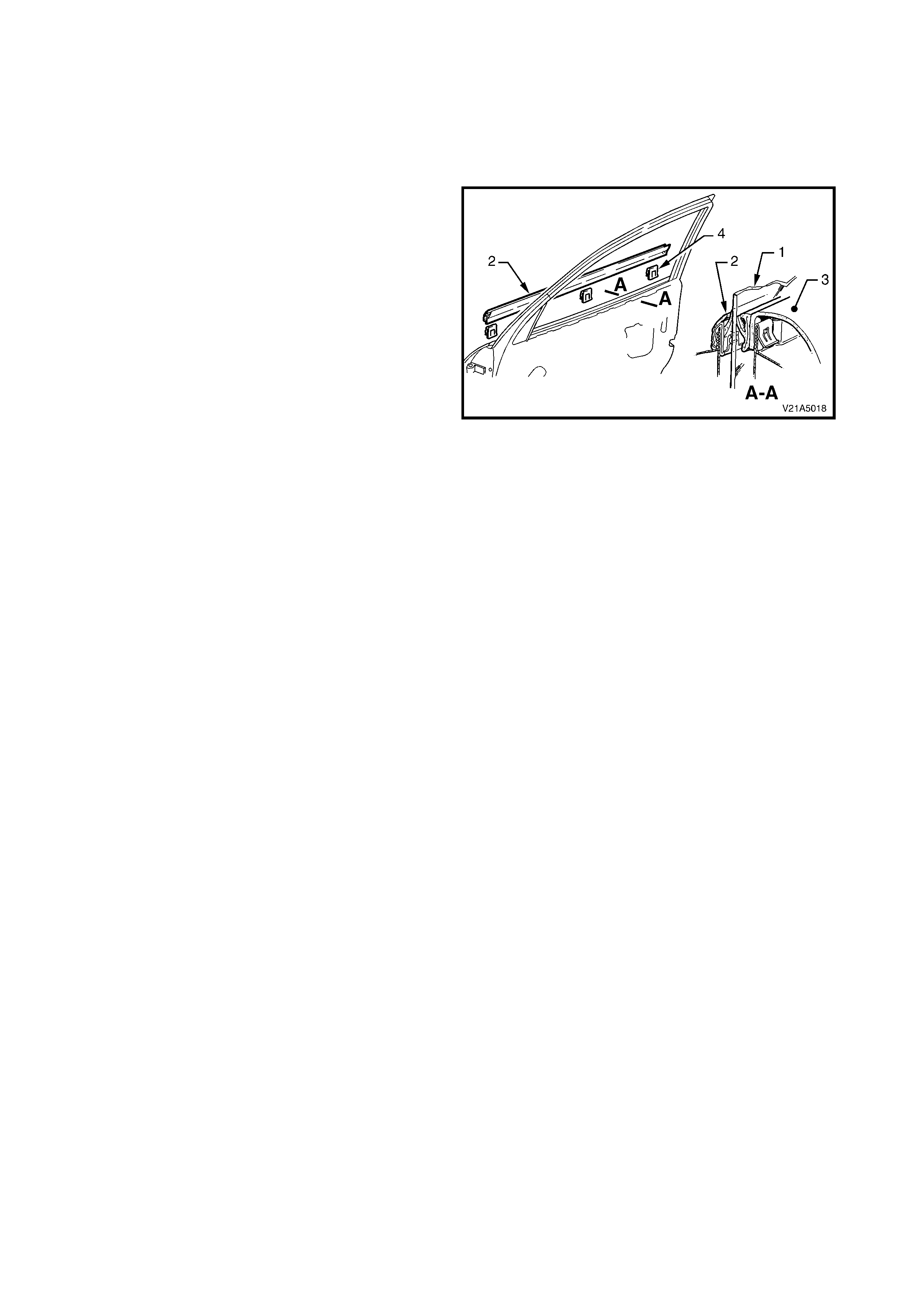
2.12 DOOR BELT MOULDING AND WEATHERSTRIP ASSEMBLY
REMOVE
1. Remove the rear vision m irror assem bly, ref er to
2.13 EXTERIOR REAR VISION MIRROR
ASSEMBLY in this Section.
2. With the door glass (1) lowered, prise the door
belt m oulding and weatherstr ip assem bly (2) off
the door using fingers, taking care not to
damage moulding, inner door trim (3) and the
three door belt moulding retaining clips (4).
REINSTALL
The installation procedure for the door belt
weatherstrip and moulding assembly is the reverse
of the removal operations, noting the following:
1. Locate the door belt weatherstrip and moulding
assembly over the top of the door outer panel,
then using palm of the hand, firmly tap the
assembly down, over the door outer upper
flange.
Figure 1A5-26
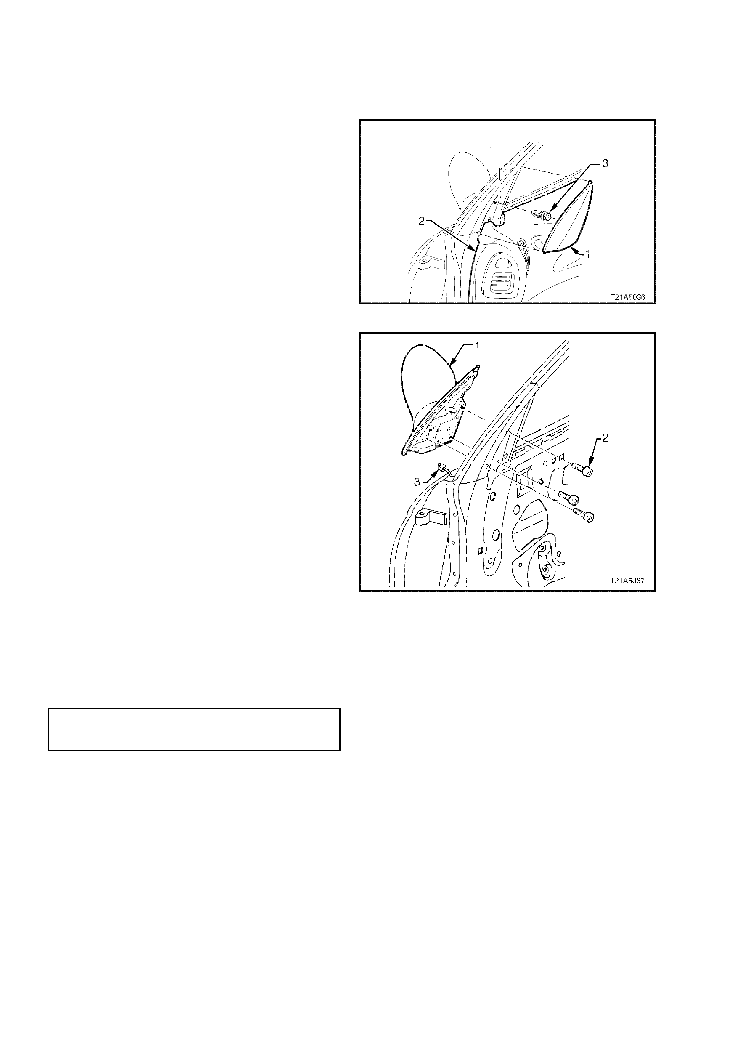
2.13 EXTERIOR REAR VISION MIRROR
REMOVE
1. Disconnect battery earth lead.
2. Remove the mirror inner cover cap (1) by gently
prising the cap away from the door.
NOTE: The inner cover cap retaining clip (3) can
only be used once.
3. Remove door inner trim panel (2), refer to
Section 1A5 FRONT & REAR DOOR
ASSEMBLIES in the VT Series I Service
Information.
Figure 1A5-27
4. Remove the three screws (2) securing the
exterior rear view mirror (1) to the door.
5. While supporting the mirror, disconnect the
mirror wiring harness connector (3).
Figure 1A5-28
REINSTALL
Installation of the exterior rear view mirror assembly is the reverse of the removal procedure, noting the following:
1. Ensure the wiring harness connector for the exterior rear view mirror is routed correctly.
2. Ensure the exterior rear view mirror to door securing screws are tightened to the correct torque specification.
EXTERIOR REAR VIEW MIRROR
TO DOOR SECURING SCREWS 2.5 – 3.0 Nm
TORQUE SPECIFICATION
3. Install mirror inner cover cap using a new retaining clip.
NOTE: If the mirror inner cover cap is removed, its retaining clip will have a reduced tension, and will therefore
provide insufficient retention if it is reused.
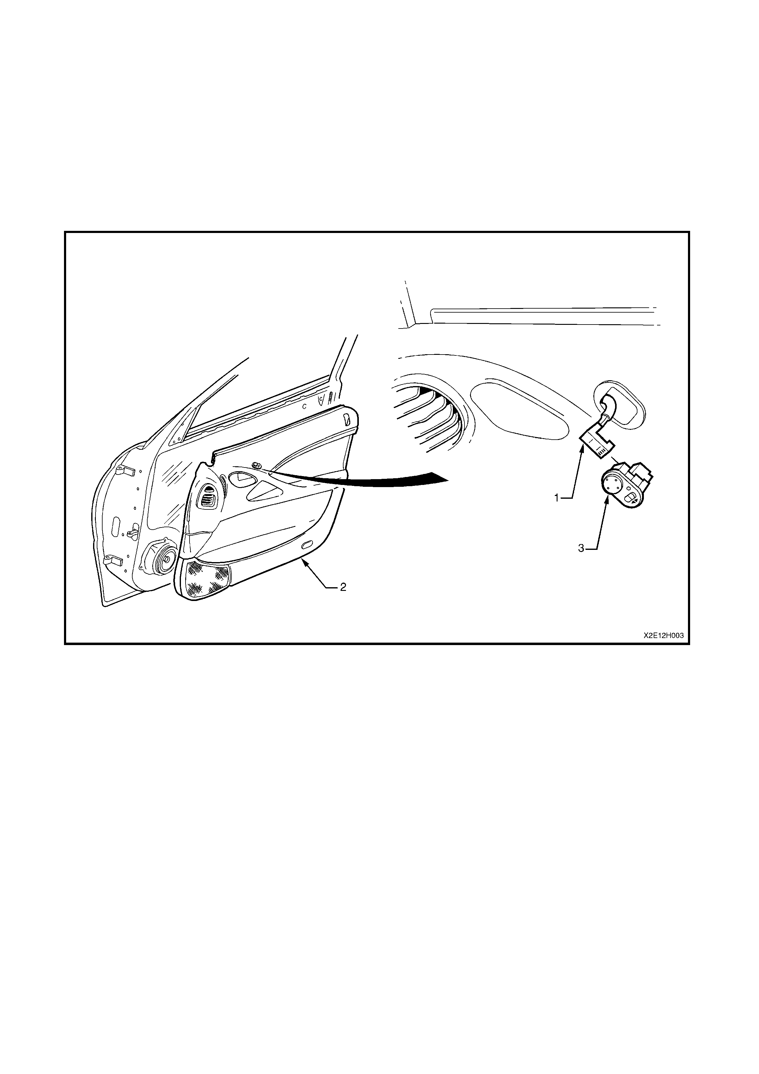
2.14 SWITCH - ELECTRIC EXTERIOR REAR VISION MIRROR CONTROL
NOTE: For further information regarding the external rear vision mirror and switch, refer to
Section 12H ELECTRIC REAR VISION MIRRORS, in the VX Series I Service Information.
REMOVE
1. Remove door inner trim panel (2), refer to 2.4 DOOR INNER TRIM PANEL in this Section.
2. Ref er to Fig. 1A5 - 29, disconnect the door electrical harness connector (1) from the exterior rear vision mirror
control switch assembly (3).
3. From inside of door trim panel, push the elec tric exterior rear vision mirror control switch free of the door inner
trim panel and remove the switch.
Figure 1A5-29
REINSTALL
The installation procedure for the exterior rear vision mirror control switch is the reverse of the removal procedure.
NOTE: For information regarding testing the exterior rear vision mirror control switch, refer to
Section 12H ELECTRICALLY ADJUSTABLE REAR VISION MIRRORS in the VX Series I Service Information.
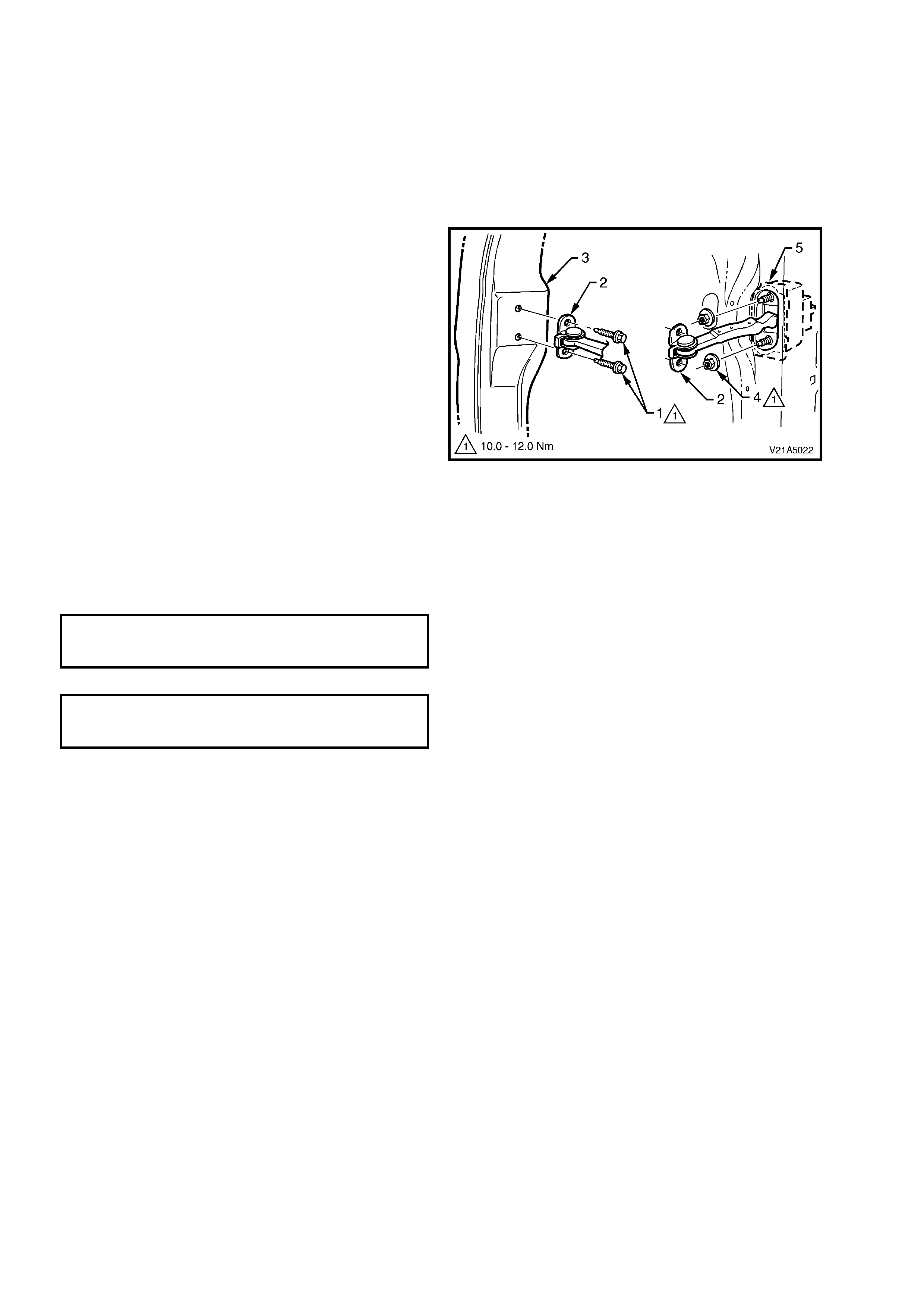
2.15 DOOR CHECK LINK ASSEMBLY
REMOVE
1. Remove door inner trim panel, refer to
2.4 DOOR INNER TRIM PANEL in this
Section.
2. Remove the door inner dust seal, refer to
2.5 DOOR INNER DUST SEAL in this Section.
3. Lower the door drop glass and remove the two
bolts (1) retaining the check link (2) to the A-
pillar (3).
4. Remove the two nuts (4) retaining the check
link to the door assembly (5).
5. Withdraw the c heck link into the door ass em bly
and carefully remove through the door inner
panel aperture.
6. From inside of door trim assembly, push the
control switch free and remove the switch.
Figure 1A5-30
REINSTALL
The installation procedure for the door check link assembly is the reverse of the removal procedure noting the
following:
1. Tighten all retaining screws to the correct torque specification.
CHECK LINK TO A-PILLAR
RETAINING BOLTS 10 – 12 Nm
TORQUE SPECIFICATION
CHECK LINK TO DOOR PANEL
RETAINING NUTS 10 – 12 Nm
TORQUE SPECIFICATION

3. TORQUE WRENCH SPECIFICATIONS
Nm
Door inner trim panel retaining screw...................................1.0 - 3.0
Door inner trim panel retaining bracket screw......................1.0 - 3.0
Door lock and actuator assembly retaining screw................3.0 - 5.0
Door locking button escutcheon retaining screw ..................1.0 - 3.0
Door remote handle assembly retaining screw.....................1.0 - 3.0
Exterior rear vision mirror to door panel ...............................2.5 - 3.0
Front exterior door handle retaining nut................................3.0 - 5.0
Front guide rail retaining bolt ................................................2.5 - 3.5
Rear door guide rail attachment bolt.....................................6.0 - 14.0
Rear door guide rail attachment screw.................................3.5 - 4.5
Rear exterior door handle retaining nut ................................3.0 - 5.0
Speaker assembly retaining screw.......................................1.0 - 3.0
Striker assembly retaining bolt..............................................8.0 - 18.0
Window regulator guide rail attaching screw........................7.0
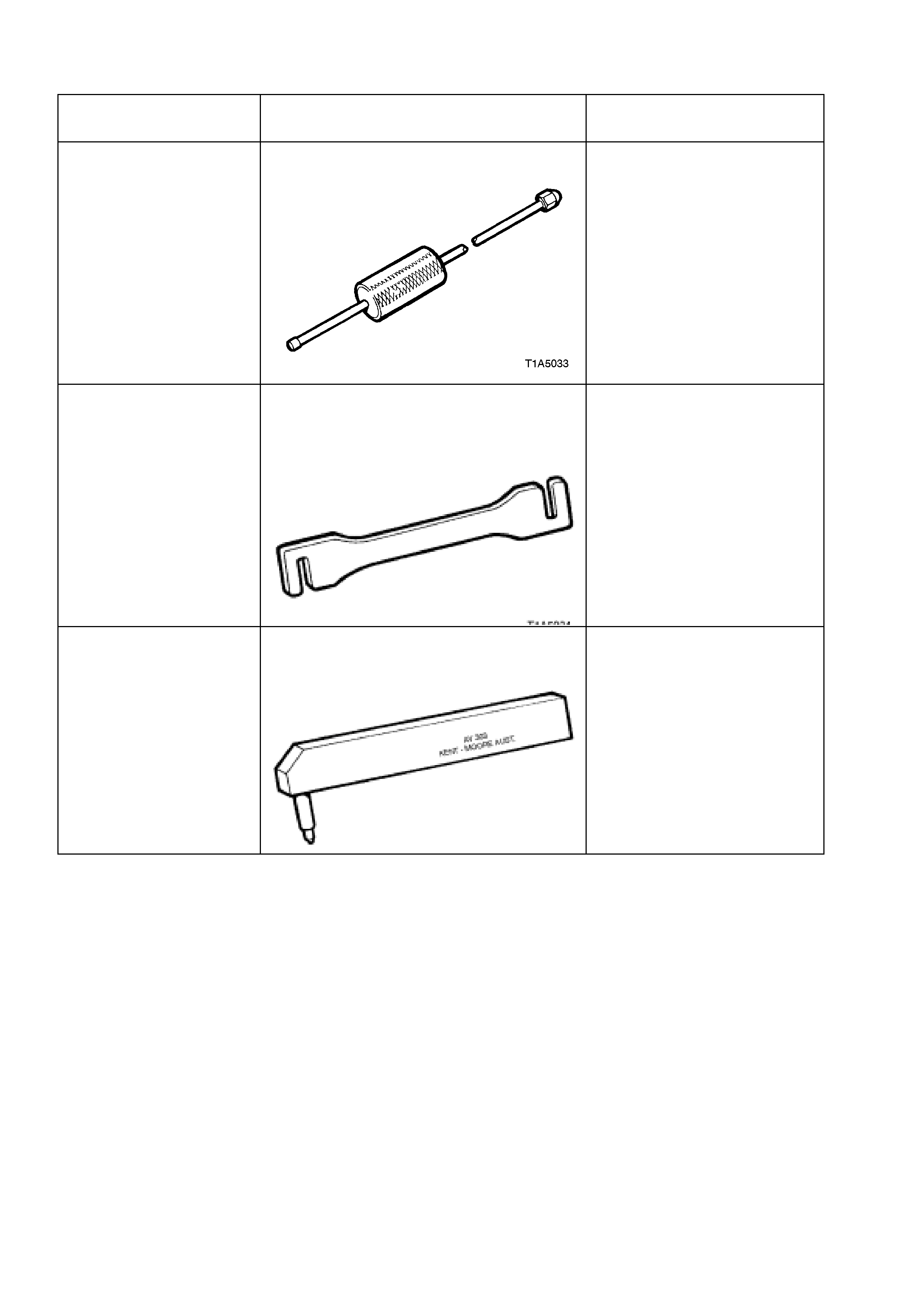
4. SPECIAL TOOLS
TOOL NO. REF
IN TEXT TOOL DESCRIPTION COMMENTS
AU170 DOOR HINGE PIN REMOVAL TOOL
PREVIOUSLY RELEASED
FOR
‘V’ CAR
AU184
DOOR HINGE SETTING TOOL
For front and rear door alignment
PREVIOUSLY RELEASED
FOR
‘V’ CAR
AU303 DOOR HINGE PIN INSTALLER
PREVIOUSLY RELEASED
FOR
‘V’ CAR