
SECTION 1A7 - SEAT & SEAT BELT ASSEMBLIES
IMPORTANT
Before performing any Service Operation or other procedure described in this Section, refer to Section
00 CAUTIONS AND NOTES for correct workshop practices with regard to safety and/or property damage.
1. GENERAL I NFORMATI O N
V2 Series Models are fitted with eight-way electrically adjustable driver and front passenger seats, which also
include s ide impac t airbags . Leather trim is standard and is available in anthracite for V2 Series CV6 Models and a
variety of colours for CV8 Models depending on the exterior paint and trim combination.
The fr ont seat incor porates an Ez-entry feature that provides a s im ple one touch m echanis m to m ove the fr ont seat
and allow rear seat passengers to enter or exit the vehicle. A lever on the outer upper corner of the seat back
disengages the seat back locking mechanism. An internal micro switch senses when the lever is operated and
signals to the module that the Ez-entry feature has been activated, which in turn drives the seat forward. The seat
fore and af t position is m onitored by a potentiometer (incor porated into the fore/aft drive m otor) and recorded in the
seat module. Once the seat back is returned to the locked position, the operator must use the eight-way position
switch to m ove the seat rearwards. W hen the s eat reaches the last rec orded location, the aft m ovement will pause
for approximately three seconds (with the eight way switch in the aft movement position) before continuing.
An internal occupant s ensing m at is incorporated into the f ront seat cus hions. The oc cupant sensing m at signals to
the seat control m odule whenever the seat is occupied with a weight in excess of 12 kg. The m odule then prevents
the seat from driving forward should the Ez-entry lever be operated.
In addition, the driver’s seat in the CV8 is fitted with an integrated memory seat system. On key-less entry to the
vehicle, the m emory seat system in conj unction with the Body Control Module (BCM) recognises which ignition key
has been used (Priority 1 or Priority 2) and adjusts the seat accordingly.
The memory seat system allows the driver to adjust the seat position to any of the positions stored in memory by
pressing one of the three memory buttons.
Audio and visual feedback for the various functions of the memory seat system is provided. The system has a
green LED and an audio c hime located in the s eat as sembly which are used to indicate mem o ry saves, the rec all of
priority memory numbers and for seat diagnostic procedures.
These following Cautions apply to Service Operations detailed in this Section.
CAUT ION 1: Before performing any Service Operation on a front seat assembly, ensure the SRS is disabled.
Refer to Section 12M SUPPLEMENTAL RESTRAINT SYSTEM in the VT Series I Service Information.
CAUTION 2: Accessory and after market seat covers MUST NOT be fitted to a vehicle with side impact
airbags unless approved by Holden Ltd. Seat covers that are not approved by Holden Ltd. could greatly
inhibit the performance of the side impact airbag and occupants safety in the event of side impact airbag
deployment.
IMPORTANT: Som e of the procedures detailed in 3. DIAGNOSTICS require the us e of both the Priority 1 Key and
the Priority 2 Key.
Pyrotechnic seat belt pretensioners are fitted as standard equipment to the front seat belts. These pretensioners
are connected into the SRS and are designed to restrain potentially fatal body movements upon impact in a
collision. Seat belt pretensioners work in conjunction with standard inertia reel seat belt retractors with
webbing clamps. For principles of operation and diagnosis of the seat belt pretensioner system, refer to
Section 12M SUPPLEMENTAL RESTRAINT SYSTEM in this Service Information.
CAUTION: If a seat belt pretensioner is deployed, the seat belt pretensioner assembly together with the
seat adjuster, guide rail assembly and SRS Sensing and Diagnostic Module (SDM) must be replaced.
The rear seat fitted to V2 Series Models is a new 2 passenger design with adjustable rear head restraints.
Retractable rear seat belts with new flush fitting buc k les are f itted to both rear seats . Due to the two passenger rear
seat design, there is no provision to restrain a passenger in a central position on the rear seat.
Techline
Techline
Techline
Techline
Techline

1.1 GENERAL DESCRIPTION
FRONT SEAT ASSEMBLY
Each seat contains four elec tric, revers ible motors . The height of both the front and rear of the seat is controlled by
separate lift motor and gearbox assemblies. Each motor can be operated independently of the other, or operated
together to raise or lower the complete seat assembly. A separate fore/aft movement motor and two gearboxes
control seat forward or rearward positioning. The fourth motor controls the seat backrest recliner position.
Each lift motor and gearbox assembly is bolted to one side of the seat height adjust assembly and when each lift
motor is operating, the lift motor drives the gearbox, which then draws in or extends out the mating worm shaft
which in turn operates on a lever and cross-brace. The cross-brace is connected to another lever on the opposite
side of the s eat height adjust ass embly and this allows the raising or lowering of that section of the seat. Reversing
the polarity on the lift motor terminals causes the motor to operate in the reverse direction and the seat moves in the
opposite direction.
To control seat fore/aft movement, a worm shaft is attached to each seat rail with the movement motor and
gearboxes attached to the seat height adjuster assembly.
When the movement motor is oper ating, the gear boxes ( driven by the movement m otor ) dr aw in or extend out eac h
mating worm s haf t. Sinc e each worm shaft is held f rom moving, the action of the gear box es mes hing with the worm
shafts causes the s eat to move (via the s eat height adjust ass embly) in one direction. Revers ing the polarity on the
movement m otor term inals causes the m otor to operate in the r everse dir ection and the seat m oves in the opposite
direction.
Seat backrest recliner angle is adjusted by a recliner motor attached to the inner seat backrest frame. The motor
output shaft has a drive gear which is meshed with a driven gear attached to the seat backrest frame. Motor
operation causes r otation of the drive gear which turns the dr iven gear and s eat back r es t frame, thereby altering the
seat back rest recliner angle. Reversing the polarity on the r ecliner motor terminals c auses the m otor to drive in the
reverse direction and the seat backrest moves in the opposite direction.
The f ront seats als o contain a seat control m odule under the lower side cover. The seat control module fitted to the
mem ory type seat has a non-volatile m emor y, so that rem oving the battery s upply from the module does not erase
the seat memory settings.
The movement motor is common between each seat and have a potentiometer attached. The lift and recliner
motors an the memory seat also have a potentiometer attached. The potentiometers are used as seat position
sensors by the memory seat system. The wiring harnesses used for the passenger's side and driver's side seats
are different.
W atchdog tim ers in the memory seat system lim it the time a seat drive m otor can operate. The lif t and movement
motors are limited to 25 seconds, while the recliner motor is limited to 50 seconds.
Fig. 1A7-1 illustrates the seat, seat controls and drive motors.
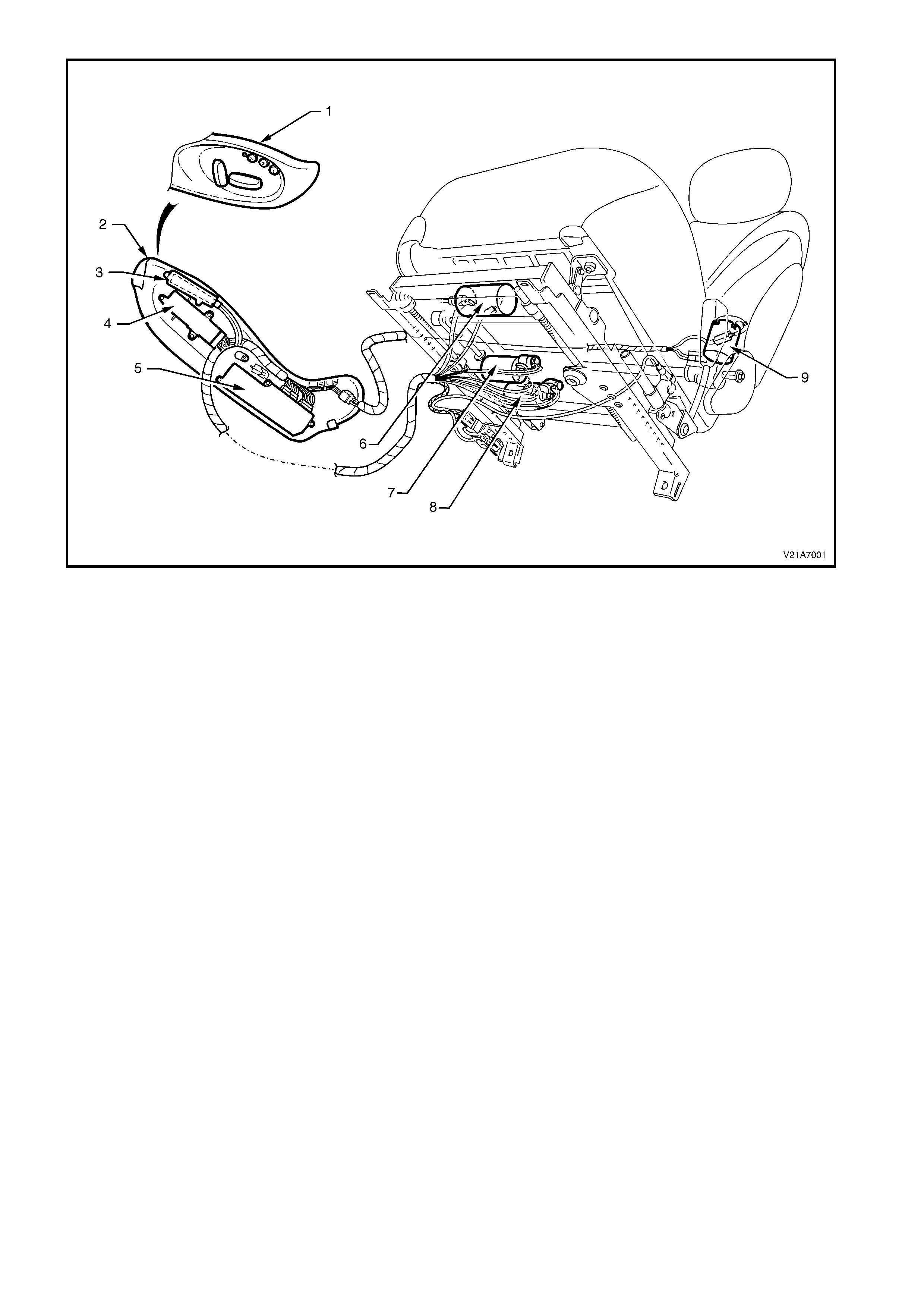
Figure 1A7-1
Legend
1. Seat Control s 4. Eight-way Seat Pos i t i on Switch 7. Front Up/Down Drive Motor (Lift Motor)
2. Seat Lower Side Cover 5. Seat Control Module 8. Rear Up/Down Drive Motor (Lift Motor)
3. Memory Pos i tion Switch 6. Fore/Aft Drive Motor 9. Back rest Recli ner Angle Drive Motor
1.2 EIGHT-WAY ELECTRIC SEAT ADJUSTMENT
CAUTION: For reasons of personal safety, the v ehicle must only be driv en wh en the seat is adjust ed to the
correct driving position.
Do not adjust the driver’s seat when the vehicle is moving as the seat could move away from the driving
position, causing loss of control.
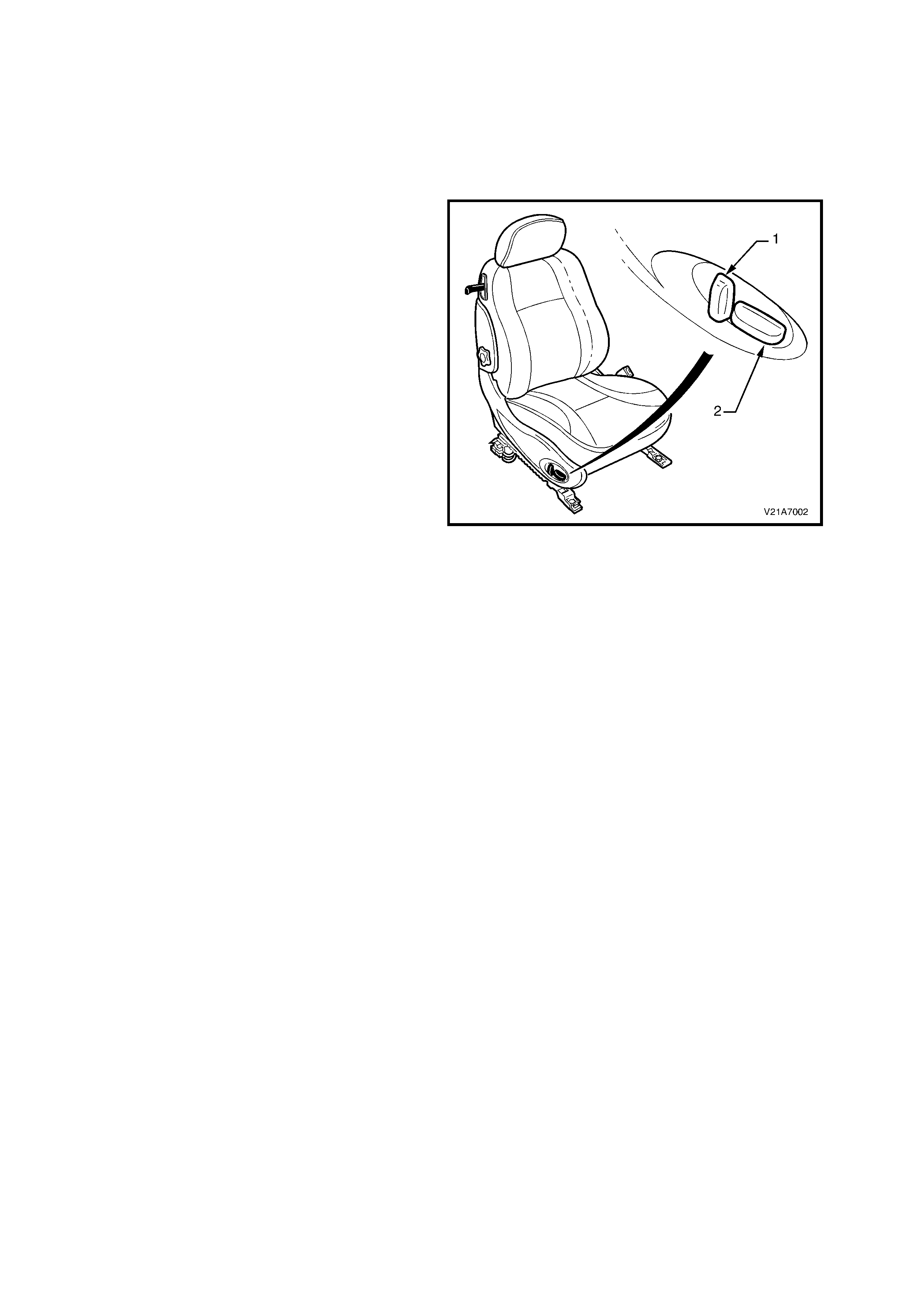
SEAT ADJUSTMENT CONTROL SWITCH ASSEMBLY
A seat control adjustment switch is fitted to the
outside of each seat frame. This switch assembly
provides independent control of:
1. Vertical switch - seat back recliner angle.
2. Horizontal switch - front and rear cushion
height (up and down movement) of seat along
with fore/aft movement.
Figure 1A7-2
To control the seat front and rear heights, and the fore and aft movements, the appropriate electric motor and
gearbox ass embly is driven, drawing in or extending out a mating worm s haf t which in turn operates either the cross
bar, for up and down movem ent, or the seat guide rail for fore/aft m ovement. Reversing the polarity of each of the
mo tor’s term inals causes the m otor to dr ive in the reverse dir ection and theref ore the s eat will move in the oppos ite
direction.
The s eat back rec liner angle is adj usted by a r ecliner motor attac hed to the inner s eat bac k fr ame. T he motor has a
drive gear which is m es hed with a driven gear attached to the seat bac k fram e. Motor operation causes the rotation
of the drive gear which turns the driven gear and seat back frame, thereby altering the seat back recliner angle.
Reversing the polarity of the recliner m otor term inals causes the m otor to drive in the r everse dir ection and the seat
back moves in the opposite direction.
During manual seat adjustment, the seat control module monitors the position of each motor axis and will shut down
the drive motor just before reaching the end of the track, even if the eight-way seat position switch is held on.
The eight-way position switch is disabled during automatic movement requested by operation of either a memory
recall, priority key recall or the Ez-entry function. The switch will be enabled once the automatic movement is
com pleted or c ancelled. The eight-way position switch is monitored by the module during automatic movement, and
if the switch is operated, the automatic movement will be cancelled and the seat will enter the manual mode.
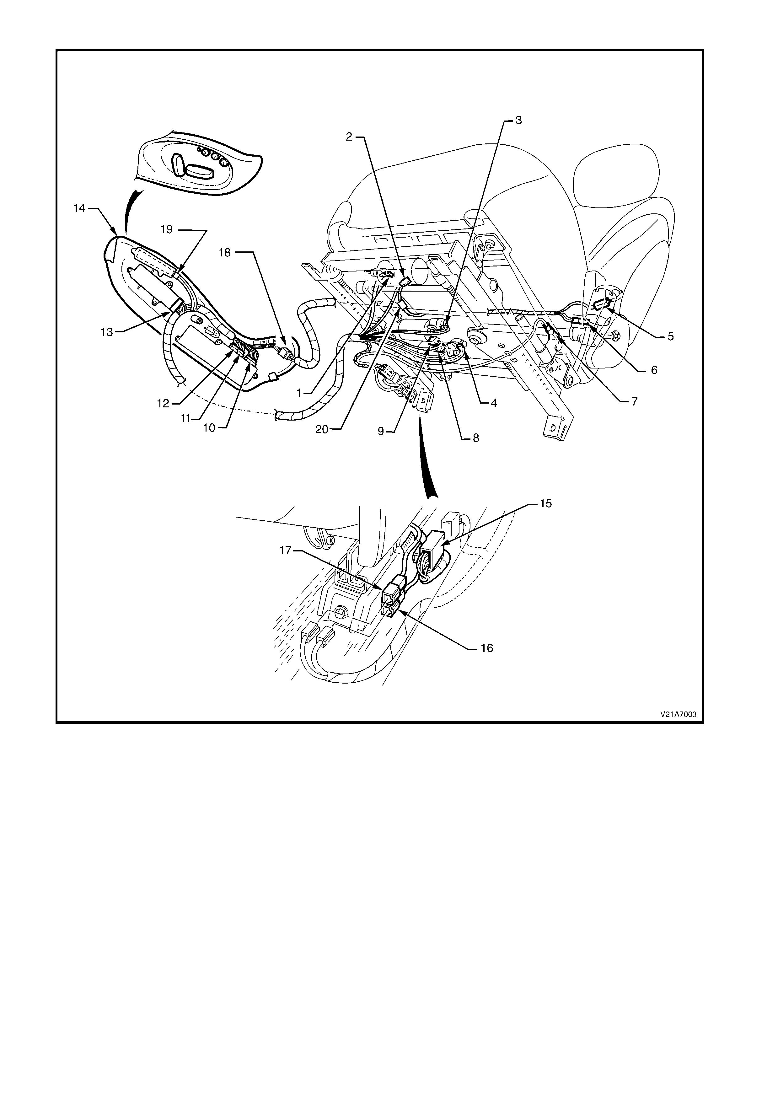
Figure 1A7-3
Legend
1. Fore/Aft Drive Motor 7. Seat Belt Pretensioner (Hard wired) 14. Seat Lower Side Cover
Potenti ometer Connector (YB235) 8. Rear Up/Down Drive 15. Power Seat Harness
2. Fore/Aft Drive Motor Motor Connector (YB221) Connector (YB226)
Connector (YB223) 9. Front Up/Down Drive 16. Seat Bel t Pretensi oner Connector
3. Front Up/Down Drive Motor Motor Connector (YB224) 17. Side Airbag Module Connec tor
Potenti ometer Connec tor (YB235) 10. Seat Control Module Connector (YB225) 18. Front Seat Patch Harnes s
4. Rear Up/Down Drive Motor 11. Seat Control Module Drive Connector (Y B 244)
Potenti ometer Connector (YB235) Motor Connector (YB227) 19. Memory Pos i tion Switch
5. Recliner Up/ Down Drive 12. Seat Control Module Drive Motor Connector (YB246)
Motor Connector (Y B 222) Potentiometer Connector (YB229) 20. Occupant S ensing Mat Harness
6. Recliner Drive Motor 13. Eight-way Seat Pos i tion Switch Connector (YB245)
Potenti ometer Connector (YB236) Connector (YB220)
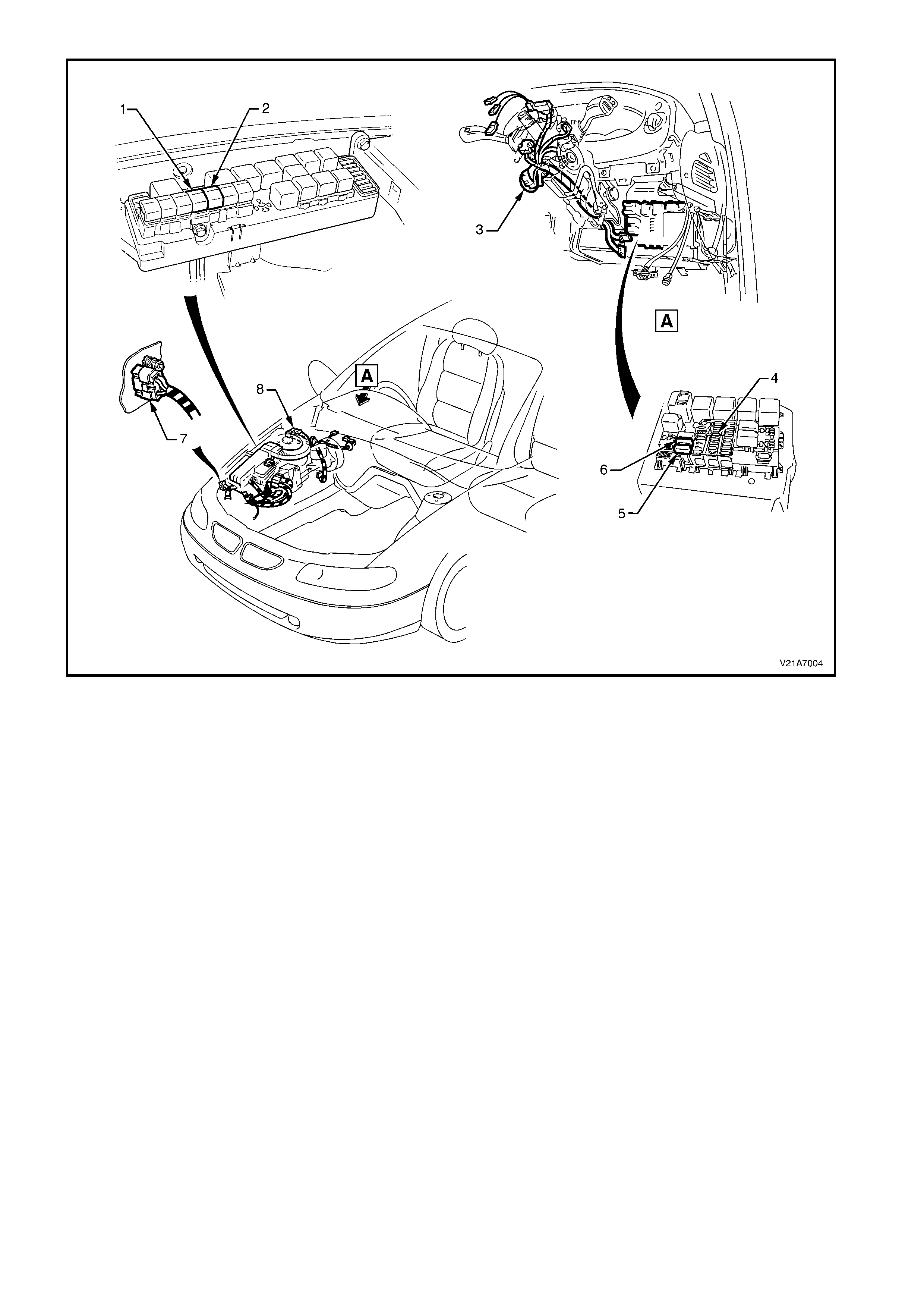
Figure 1A7-4
Legend
1. Fusible Link FS 5. Circuit Breaker F3
2. Fusible Link FJ 6. Circuit Breaker F2
3. Igniti on S witch Connector (Y B44) 7. Earth Location E3 Connector (YE114)
4. Fuse F15 8. Engine Connect or (Y E112)

PASSENGER AND NON-MEMORY TYPE DRIVER’S SEAT
Figure 1A7-5
MEMORY TYPE DRIVER’S SEAT
Figure 1A7-6
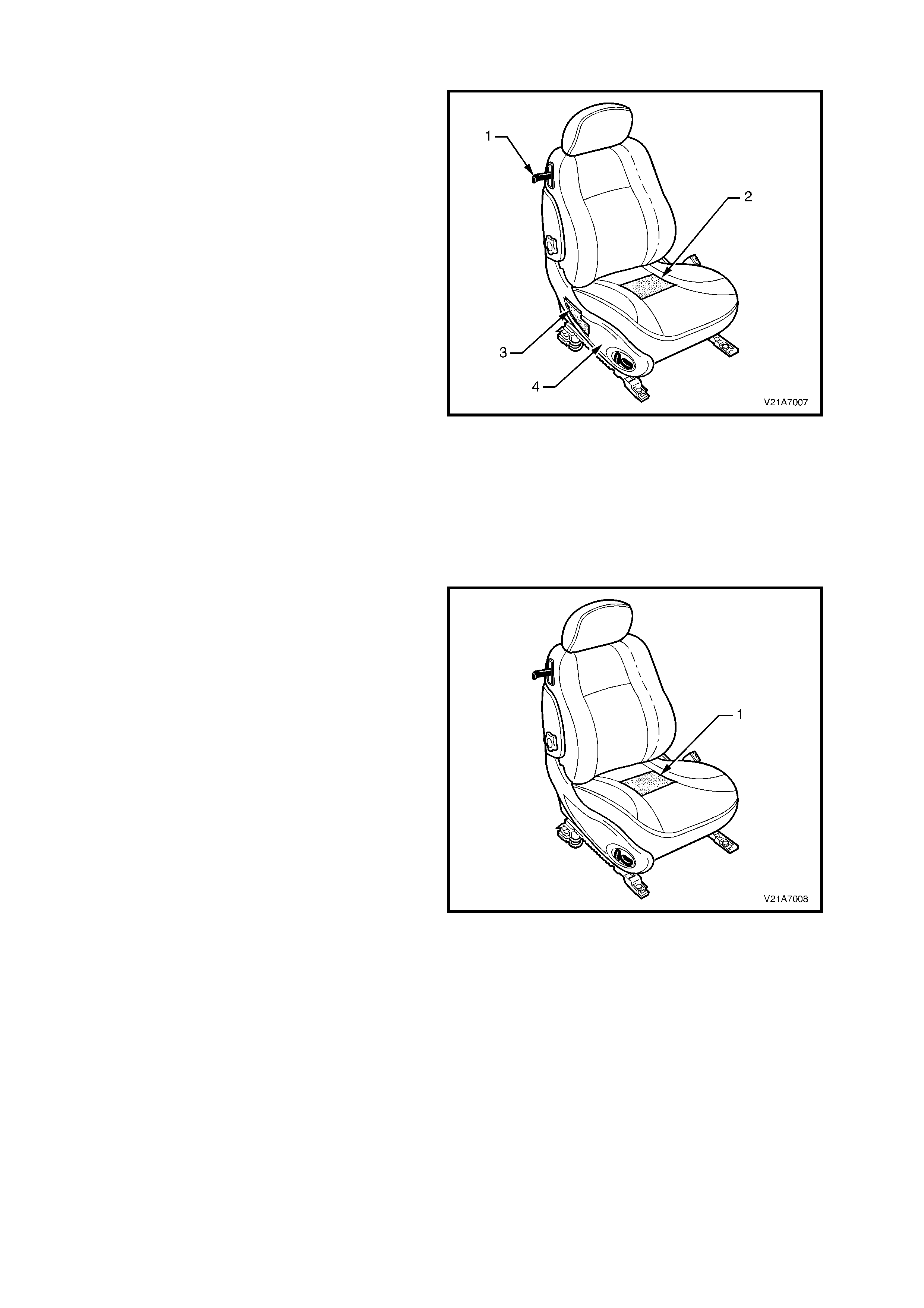
1.3 EZ - ENTRY SYSTEM
The Ez-entry system provides a one touch
mechanism to move the front seat and allow rear
seat passengers to enter or exit the vehicle. The
Ez-entry system comprises:
• An Ez-entry lever (1) on the upper outer side of
the front seat.
• An internal occupant sensor mat (2).
• The front seat control module (3) located under
the seat lower side cover (4).
When the Ez-entry lever is un-latched, the seat
back collapses forward and the seat automatically
launches to the full f orward position. Once the seat
back is retur ned to the loc k ed pos ition, the oper ator
mus t use the eight-way position switch to move the
seat rearwards. When the seat reaches the last
recorded location, the aft movement will pause for
approximately three seconds (with the eight way
switch in the aft movement position) before
continuing. If a passenger (or load in excess of 12
kg) is pres ent in the seat or enters the seat while it
is autom atically m oving forward, the movement will
cease. If weight detection causes the Ez-entry
function to cease, a period of one second must
pass without weight before a restart will
commence.
Figure 1A7-7
OCCUPANT SENSING MAT
The occcupant sensing mat (1) is installed inside
the front seat cushions. The occupant sensing mat
is a pressure switch with a nominal high or open
circuit condition with no weight on the seat. The
resistance decreases as the weight is increased.
An integral diode is provided within the occupant
sensing mat and is used by the module to verify
connection of the occupant s ensing m at prior to the
automatic for ward movem ent of the s eat during the
operation of the Ez-entry function. The module will
test whether for the following conditions on the
occupant sensing mat:
• Either line connected to ground or battery.
• Either line open circuited.
Detection of weight over the occupant sensing mat
(seat cushion) will cause the seat module to either
cancel an automatic forward movement or prevent
an automatic forward movement from
commencing. The module should detect a
minimum weight on the seat of 12 kg.
Figure 1A7-8

1.4 MEMORY SEAT SYSTEM – CV8 DRIVER’S SEAT
The memory seat system comprises:
• the seat control module located under the seat lower side cover (refer to Fig. 1A7-1);
• the memory position switch, which includes memory buttons and associated LED, located on the side of the
driver’s seat (refer to Fig. 1A7-9);
• the ignition keys;
• the body control module (BCM).
The seat control m odule has five mem ory sets which allows up to five individual seat settings to be stored. Two of
these memory settings are associated with the priority keys and the remaining three settings correspond to the
memory buttons 1, 2 and 3 located on the side of the driver’s seat.
The m emory seat system has two modes of operation; a low-current sleep m ode and an awake mode. A 5 minute
timer circuit switches the s ystem between modes as required, and the current m ode is indicated by the green LED
on the side of the seat. When the LED is illuminated the system is in awake mode, and when the LED is
extinguished, the system is in sleep mode.
The sleep mode is entered when:
• the ignition key is in the OFF position, and
• there are no active priority signals, and
• there are no manual seat adjustments for 5 minutes.
The awake mode is entered when:
• the ignition key is in the IGN position, or
• the priority signals are active, or
• there is a manual seat adjustment, or
• a seat memory button is pressed.
Entering the awake mode resets the 5 minute timer.
MEMORY SETS
There are five memory sets, as follows:
• Memory set P1 – Priority Key 1,
• Memory set P2 – Priority Key 2,
• Memory set 1 – Button 1 on seat,
• Memory set 2 – Button 2 on seat, and
• Memory set 3 – Button 3 on seat.
Each memory set comprises four co-ordinates for the seat position (in seat control module); seat cushion front
height, seat cushion rear height, seat stroke and backrest position.
A priority key setting can also be stored and recalled by use of one of the three memory buttons on the seat.
MEMORY BUTTONS
The three m emory buttons and the assoc iated LED are located on the seat lower s ide cover clos e to the front edge
of the seat. The memory buttons are labelled 1, 2 and 3.
Pressing button 1, 2 or 3 f or les s than 2 seconds ac tivates the memory recall on release of that button. A low chim e
acknowledges the initial button press. The one-touch button recall is only active when the vehicle ignition switch is in
the OFF or ACC position.
Pressing button 1, 2 or 3 for more than 2 seconds updates the system’s memory to the current seat positions for
that button. A high chime acknowledges the system save. Memory updating is active irrespective of the ignition
switch position.
For safety reasons, no m emory button recall is allowed when the ignition is on. However, if a recall is initiated and
the ignition is then set to on, the seat movement recalled from memory will continue until completed.
Pressing any other button after a memory recall is initiated will terminate the recall move.
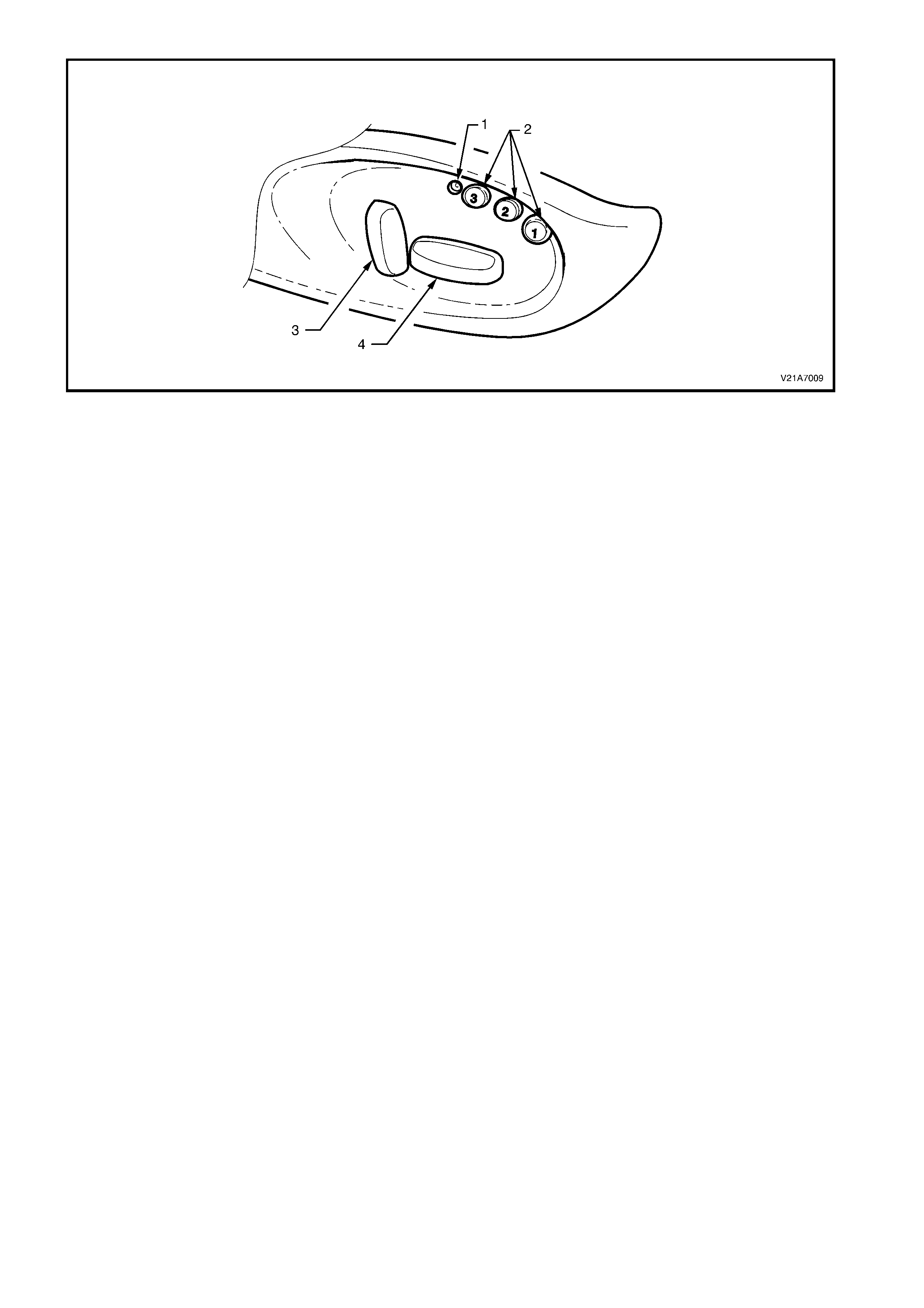
Figure 1A7-9
Legend
1. Diagnosti c LED 3. Backrest Recliner Angle Adjust Button
2. Memory Buttons 4. Fore/Aft/Up/Down/Tilt Adjust Button
PRIORITY RECALL FUNCTION
The priority recall signals generated by the BCM wake up the memory seat system to recall the last saved priority
seat positions associated with the ignition key in use (Priority 1 or Priority 2).
For safety reasons, the priority recall function is activated only when the ignition switch is in the OFF position. No
automatic movement of the system occurs when the ignition switch is set to IGN. If a priority move has been
initiated before the ignition transition from OFF to IGN, the system completes the move before disabling the one-
touch or priority recall function.
For safety reasons, the priority recall function is de-activated when the seat is occupied and a priority move is
initiated. If a priority move has been initiated before the seat is occupied, the system completes the move before
disabling the priority recall.
After the ignition switch is set to IGN, the system notes the active priority key number used. The system only
updates the current memory when the driver makes a manual adjustment to the seat. The update includes the
current seat position.
When the seat is adjusted by the driver using the manual buttons, the current priority memory is updated
immediately after the movement stops.
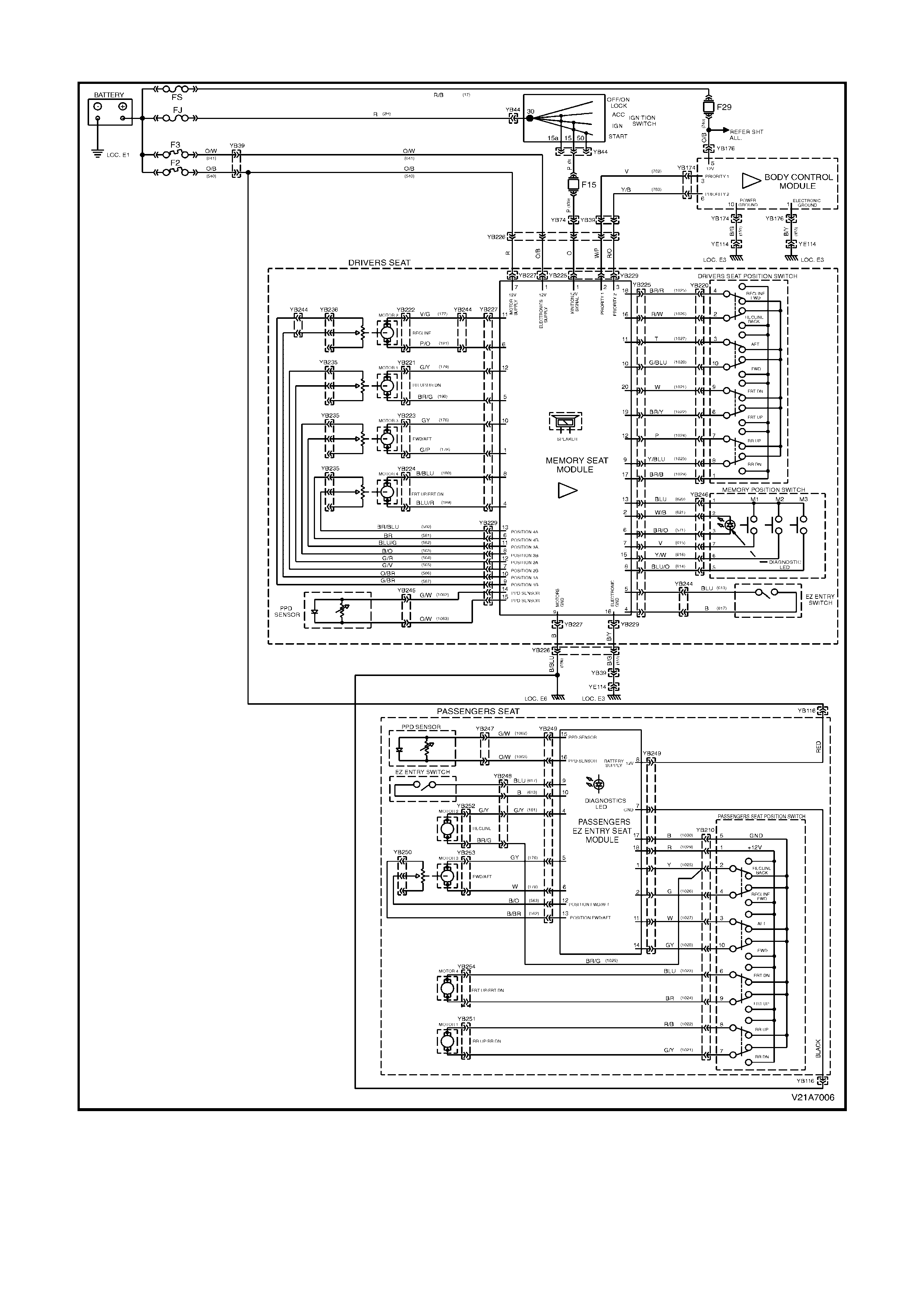
MODULE CONTROL SIGNALS
Three electrical connectors are located on the seat control module. The location of each connector is shown in
Fig. 1A7-3 and circuit information is shown in Fig. 1A7-5 and Fig. 1A7-6. The seat control module connectors are:
• the power connector YB225,
• the drive motor connector YB227, and
• the drive motor potentiometer connector YB229.
W henever a s witch pos ition is selected on the eight-way seat position switch, an earth is applied to the appropr iate
input terminal to indicate to the seat control module that a change in seat position is required.
System power and earth as well as the priority key signals are applied to the seat control module via connectors
YB225, YB227 and YB 229. The 6 signals on these connectors are:
• The 12 V on circuit 540, which supplies the power for the seat drive motors.
• The 12 V on circuit 641, which supplies the power for the seat control module.
• The 12 V on circuit 139, which indicates the status of the ignition switch to the seat control module.
• The Priority 1 (circuit 782) and Priority 2 (circuit 783) signals, which indicate to the seat control module which
priority key has been used to open the vehicle. T his is used to set the s eat to the position required by the priority
key.
• The earth for the seat drive motors is provided by circuit 156.
• The earth for the seat control module is provided by circuit 151.
The drive motor connector YB227 also provides the power and earth circuits for each of the four seat drive motors.
The drive motor potentiometer connector YB229 provides the power and earth circuits for the potentiometers as
well as the seat drive motor position signal from the wiper of each potentiometer.

DIAGNOSTIC READOUT
The green LED located on the side of the driver’s seat is used to indicate the seat m ode of operation as well as to
read out the various diagnostic trouble codes stored within the seat control module for fault diagnosis purposes.
The following table details the indications given by the LED in normal operation. For details on the various
diagnostic trouble codes, refer to 3.3 DIAGNOSTIC TROUBLE CODES in this Section.
LED STATUS INDICA TION
One flash. Priority 1 det ected.
Two flashes. Priority 2 det ec ted.
Three flashes when ignition
set from IGN to OFF. Diagnostic trouble code
logged.
Steady illum ination. System in awake mode.
Extinguished. System in sleep mode.
2. SERVICE OPERATIONS
2.1 FRONT BUCKET SEAT ASSEMBLY
REMOVE
1. Position the relevant front seat to obtain the
easiest access to the seats four retaining bolts
and, if possible, the seat should be fully raised
and the seat back tilted forward.
2. Disable the SRS, refer to Section 12M
SUPPLEMENTAL RESTRAINT SYSTEM in
the VT Series I Service Information.
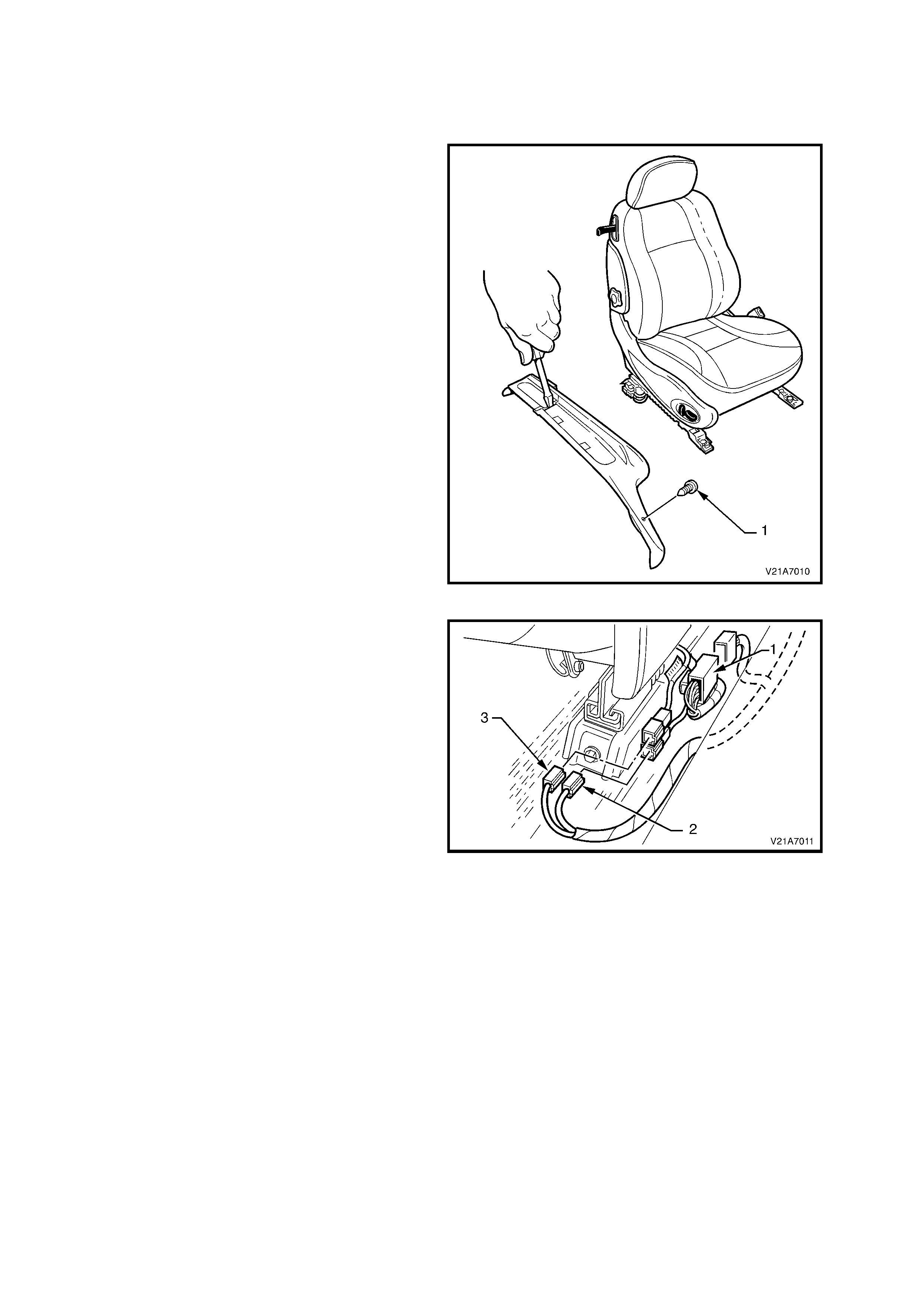
3. If removing the driver’s seat, remove the
retaining screw (1) from the driver’s side outer
front guide rail cover.
4. Using a sm all s cr ewdriver, pus h in the centre of
the rear (2) and front (3) outer seat guide rail
covers where the two parts meet.
5. Remove the front outer guide rail covers by
lifting the outer edge of the front cover up and
pulling it f orward to dis engage the aligning tabs
(4) from the inner rocker panel cover. Lift the
driver’s outer front seat guide rail cover over
fuel filler door release lever.
6. Lift the two rear guide rail covers up and off the
guide rails.
Figure 1A7-10
7. Disconnect seat (1), seat belt pretensioner (2)
and the side airbag module (3) wiring harness
connectors from outer side of the relevant seat.
Figure 1A7-11
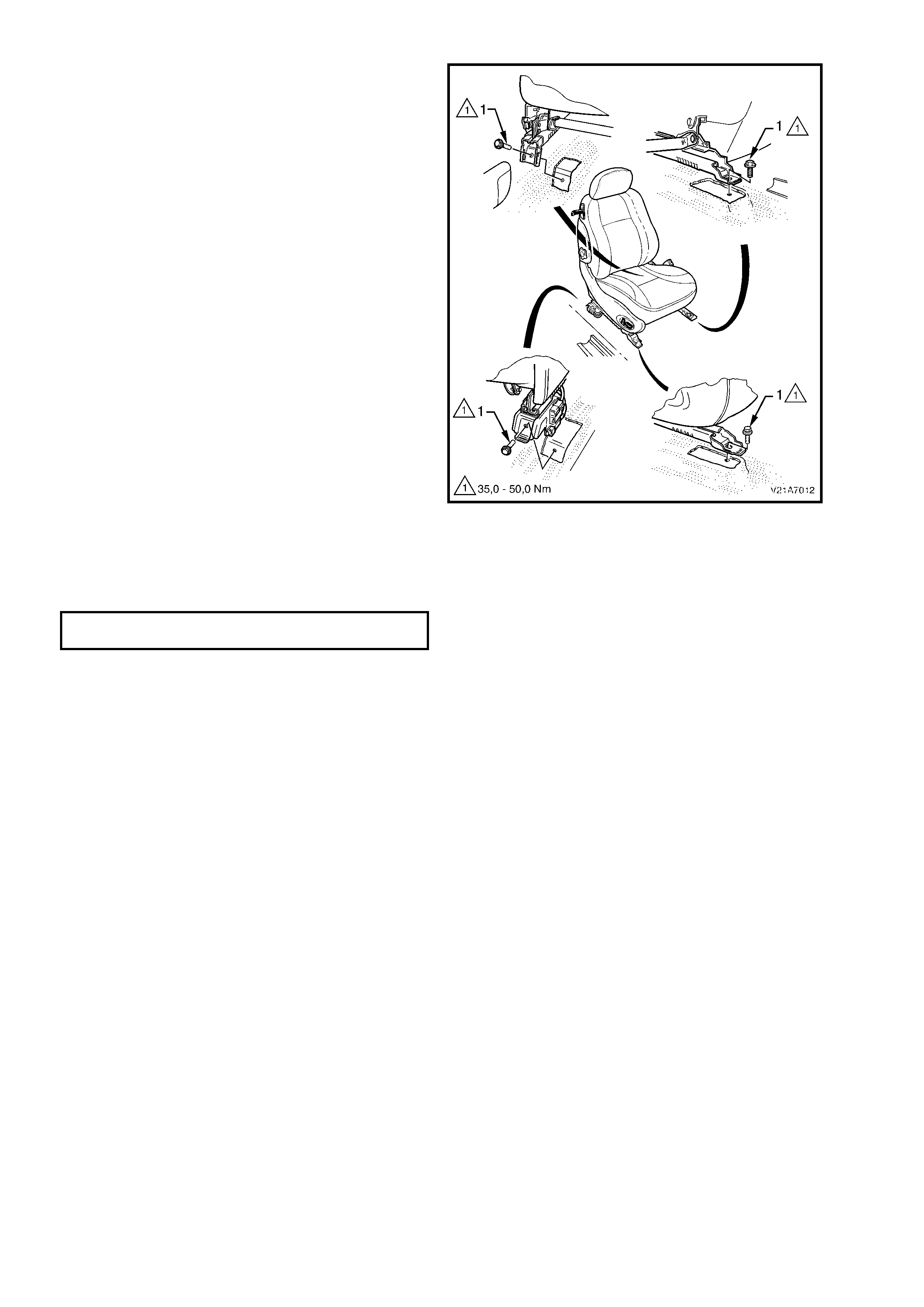
8. Remove the four bolts (1) securing the front
seat to the floor and remove seat.
Figure 1A7-12
REINSTALL
The installation procedure for the front seat assembly is the reverse of the removal, noting the following:
1. Install the four bolts securing the front seat to the floor and tighten to the correct torque specification.
FRONT SEAT TO FLOOR MOUNTING
BOLT TORQUE SPECIFICATION 35 – 50 Nm
2. The two r etaining c lips c an be aligned by using the alignment mar k s on the upper side of the c over , refer to Fig.
1A7-10, (4) in this Section.
3. Switch the ignition on, and observe the SRS warning lamp in the instrument cluster. The warning lamp should
be illuminated for approximately five seconds. During this period the SDM performs a wiring and system self
check.
If no system faults are detected, the SRS warning lamp will be switched off. If the warning lamp remains
illuminated and an audible alarm chimes, or the warning lamp illuminates two seconds after it was originally
switched off, an SRS fault is present. Refer to Section 12M SUPPLEMENTAL RESTRAINT SYSTEM in the VT
Series I Service Information
4. Check the operation of the f ront seat m echanical and electr ical adjustm ents/operation. W hile check ing the seat
adjustment/operation, also check to ensure that the seat wiring harnesses do not foul with any of the seats
moveable components (ie. seat motor drive shafts, etc.).
2.2 FRONT SEAT OUTER SIDE COVER
REMOVE
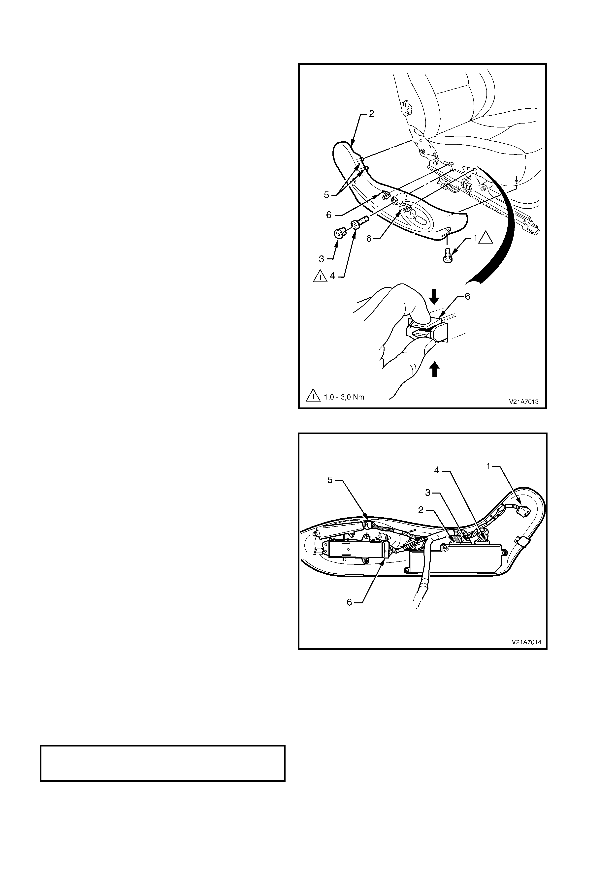
1. Remove the screw (1) from the front of the
outer side cover (2).
2. Remove the front seat outer side cover
fastener (3) by rotating fastener anticlockwise
(one quarter turn) and remove the screw (4)
located behind this fastener.
3. Adjust the seat assembly to its highest position.
4. Gently pull the outer cover away from seat
back recliner to disengage the two clips (5)
either side of the recliner frame.
5. Reach up under the seat assembly and
squeeze the two retaining tangs (6) together
(two positions) on the inner side of the outer
cover, refer to Fig. 1A7-13 while gently pulling
the outer cover.
Figure 1A7-13
NOTE: Only remove the outer cover far enough
away from the seat cushion assembly to gain
access to the seat wiring harness connectors.
6. Disconnect the recliner motor connector (1).
7. Disconnect the seat control module connector
(2).
8. Disc onnect the seat c ontrol m odule drive m otor
connector (3).
9. Disconnect the drive motor potentiometer
connector (4).
10. Disconnect the memory switch connector (5).
11. Disconnect the eight-way switch connector (6).
Figure 1A7-14
REINSTALL
The installation procedure for the front seat outer side cover is the reverse of the removal procedure, noting the
following:
1. Ins tall the two sc rews s ecur ing the outer s ide cover to the f r ont seat to the f loor and tighten to the cor rec t torque
specification.
OUTER SIDE COVER TO FRONT SEAT
ATTACHING SCREWS
TORQUE SPECIFICATION 35 – 50 Nm
2.3 EIGHT-WAY SEAT ADJUSTING SWITCH
REMOVE
1. Remove the front seat outer side cover (1),
refer to 2.2 FRONT SEAT OUTER SIDE
COVER in this Section.
2. Remove the knobs from the seat adjusting
switch (2) by carefully prising them free with a
small flat tip screws driver wrapped in a clean
shop rag.
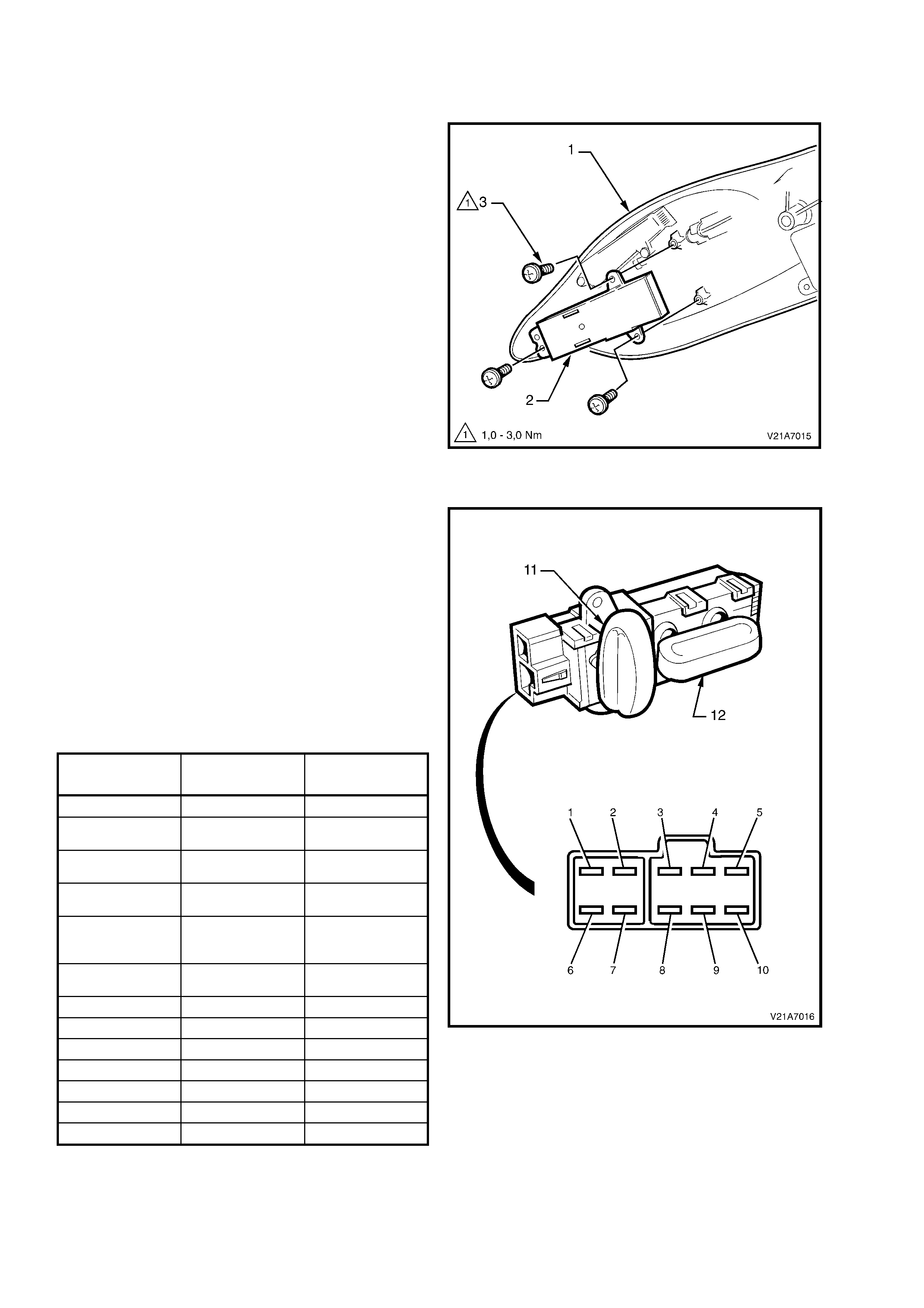
3. Remove the three s crews (3) securing the seat
adjusting switch to the outer side cover and
remove seat adjusting switch.
Figure 1A7-15
TEST
The eight-way seat adjusting switch assembly
contacts can be c heck ed for continuity between the
various ter minals by referring to the following chart,
while referring to Fig. 1A7-16.
1. Attach ohmmeter probes (using connector
leads from KM-609) to the appropriate switch
terminals nominated in the following chart.
2. Hold either the recliner switch (11) or fore/aft
switch (12) in the nominated function position
as per the f ollowing char t while r eferring to Fig.
1A7-16.
NOTE: If any of the readings are not as specified,
replace the switch assembly.
SWITCH
POSITION TERMINALS VALUE
REST 1 – 5 OPEN
RECLINER
(BACK) 1 – 2 CONTINUITY
RECLINER
(FORWARD) 1 – 4 CONTINUI TY
TRACK BACK
(AFT) 1 – 3 CONTINUI TY
TRACK
FORW ARD
(FORE)
1 - 10 CONTINUITY
RH FRONT
DOWN 1 – 9 CONTINUITY
LH FRONT DOWN 1 – 6 CONTINUI TY
RH FRONT UP 1 – 6 CONTI NUI T Y
LH FRONT UP 1 – 9 CONTINUI TY
RH REAR DOWN 1 – 8 CONTI NUI T Y
LH REAR DOWN 1 – 7 CONTINUI TY
RH REAR UP 1 – 7 CONTI NUITY
LH REAR UP 1 – 8 CONTINUI TY
Figure 1A7-16
REINSTALL
The installation procedure for the eight-way seat
adjusting switch is the reverse of the removal
procedure.
2.4 MEMORY POSITION SWITCH
REMOVE
1. Remove the front seat outer side cover (1),
refer to 2.2 FRONT SEAT OUTER SIDE
COVER in this Section.
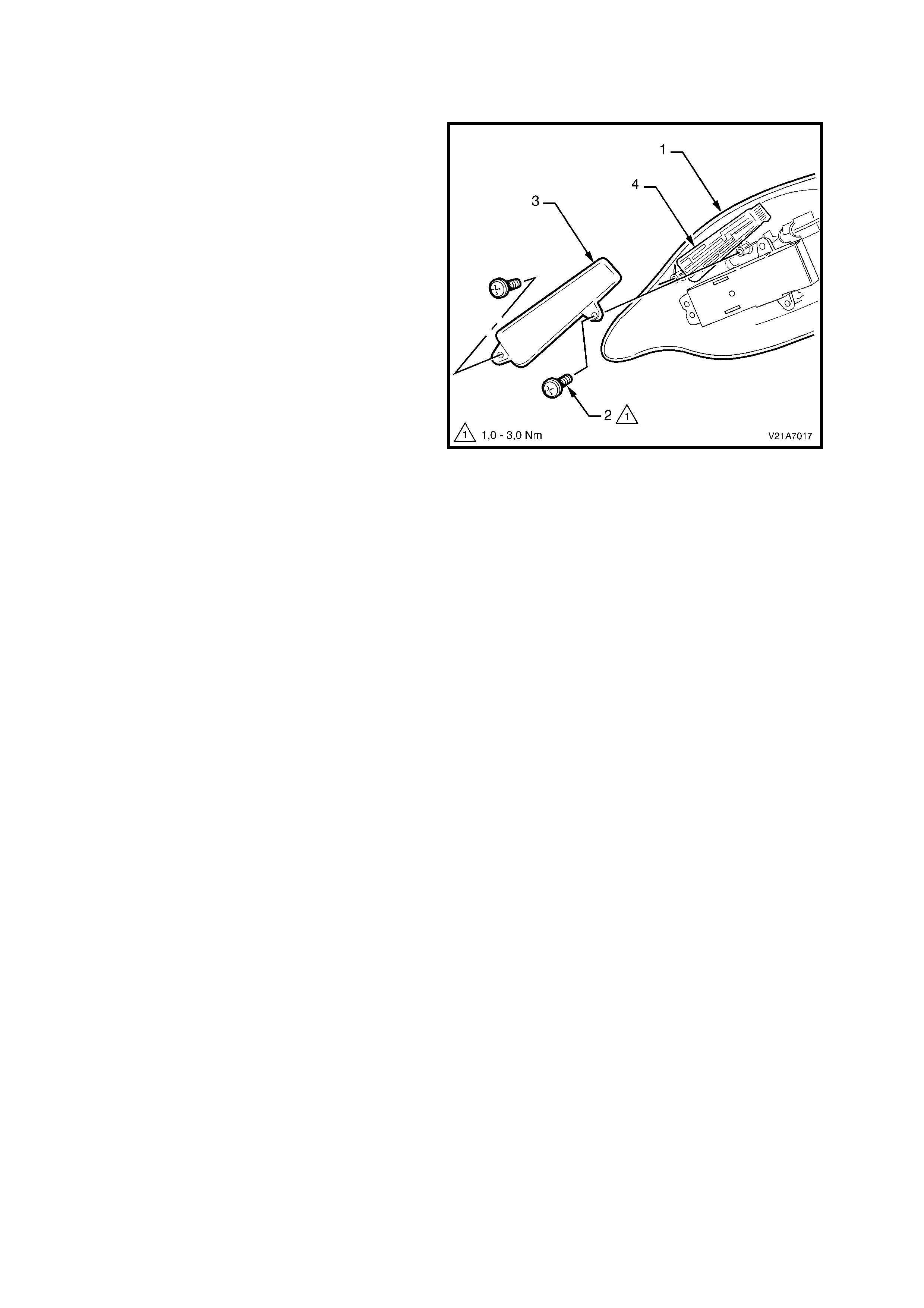
2. Remove the two screws (2) securing the
memory position switch cover (3) to the seat
lower side cover.
3. Remove the memory position switch (4).
Figure 1A7-17
REINSTALL
The installation procedure for the memory position
switch is the reverse of the removal procedure.
2.5 FRONT SEAT CONTROL MODULE
REMOVE
1. Remove the f ront seat outer side cover, ref er to
2.2 FRONT SEAT O UTER SIDE CO VER in this
Section.
2. Remove the three screws (1) securing the seat
control module cover (2) to the seat lower side
cover.
3. Remove the front seat control module (3).
Figure 1A7-18
REINSTALL
The installation procedure for the memory position
switch is the reverse of the removal procedure,
noting the following:
1. After installation, check that the seat functions
correctly.
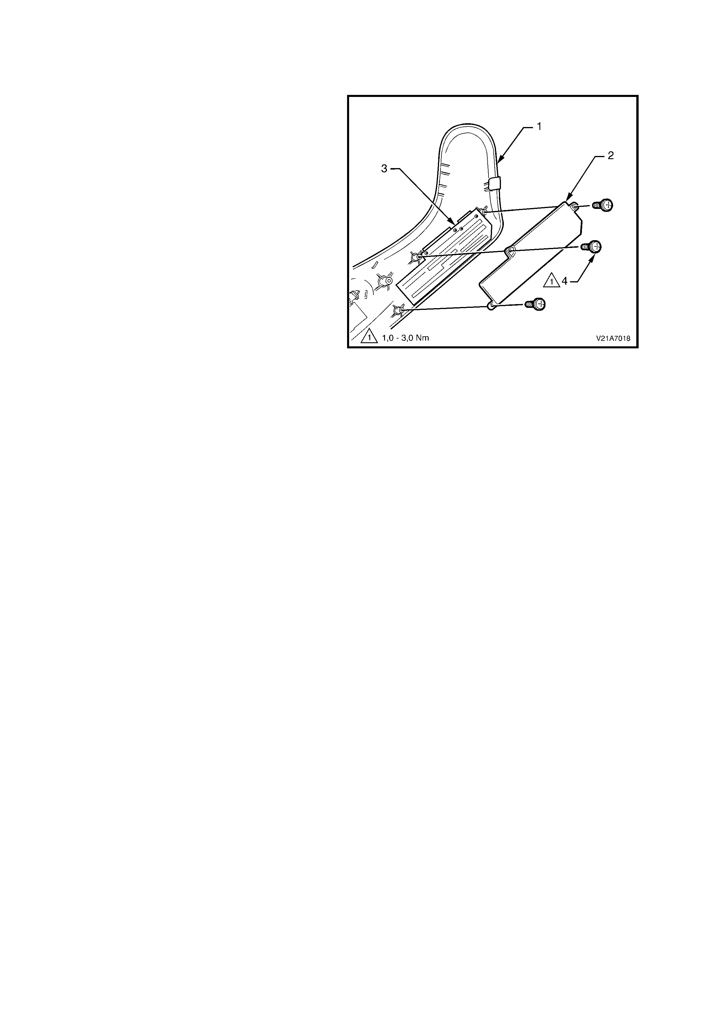
2.6 FRONT SEAT INNER SIDE COVER
REMOVE
1. Remove the front seat assembly, refer to
2.1 FRONT BUCKET SEAT ASSEMBLY in
this Section.
2. Remove the screw (1) securing the inner side
cover (2) to seat (3) and rem ove the inner side
cover.
REINSTALL
Installation of the inner side cover is the reverse of
the removal operation, noting the following:
Ensure all fasteners are tightened to the correct
torque specification.
INNER SIDE COVER RETAINING
SCREW TORQUE SPECIFICATION 1.0 – 3.0 Nm
Figure 1A7-19
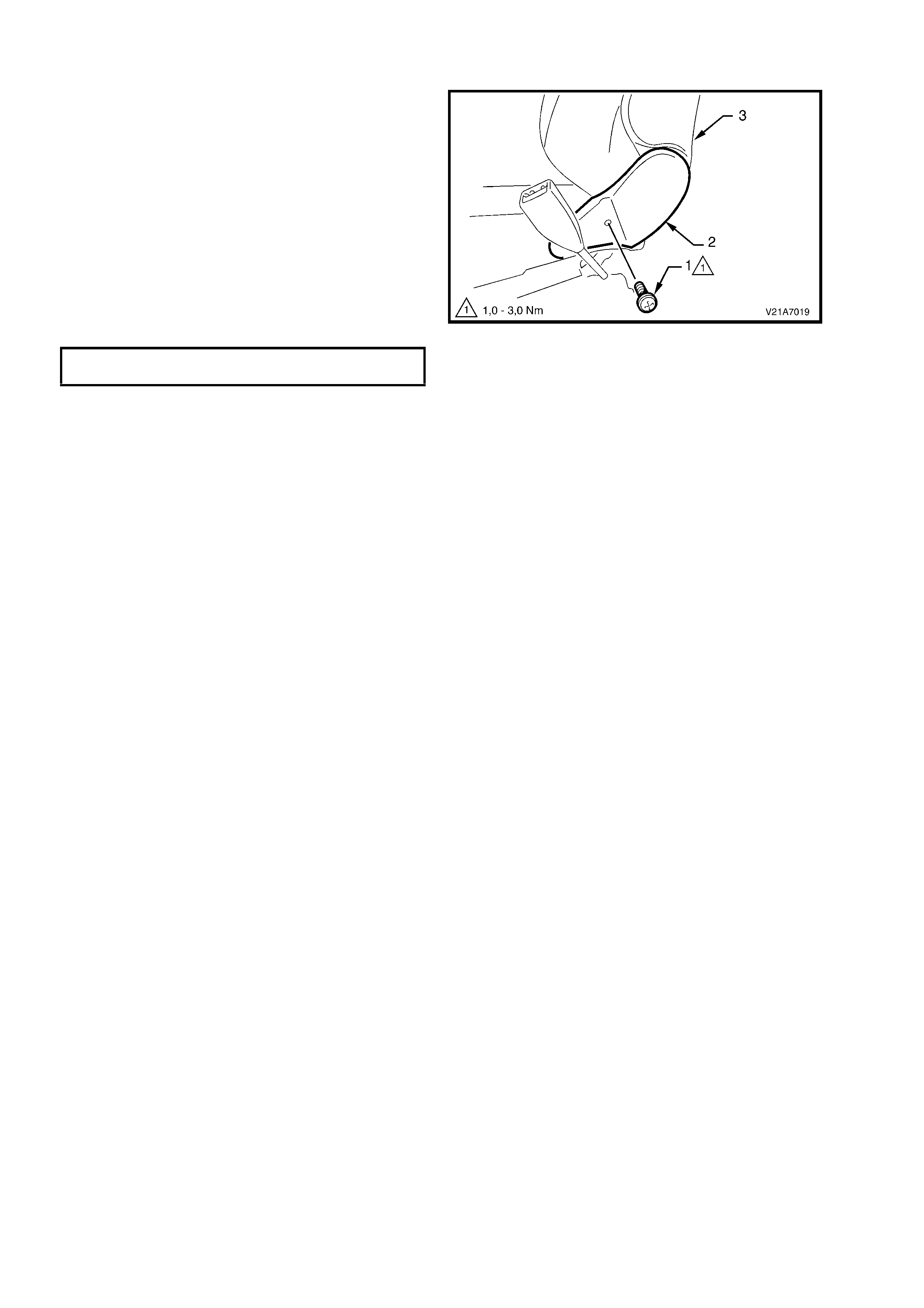
2.7 LUMBAR SUPPORT ADJUSTER KNOB & FRONT SEAT BACK COVER ASSEMBLY
REMOVE
1. Insert a flat-tip screwdriver between the seat
back cover (1) and seat back (2) and push up
on the lower retaining clip (3) (2 places) while
pulling the bottom of the back cover out, away
from seat, to release lower retaining clips.
Figure 1A7-20
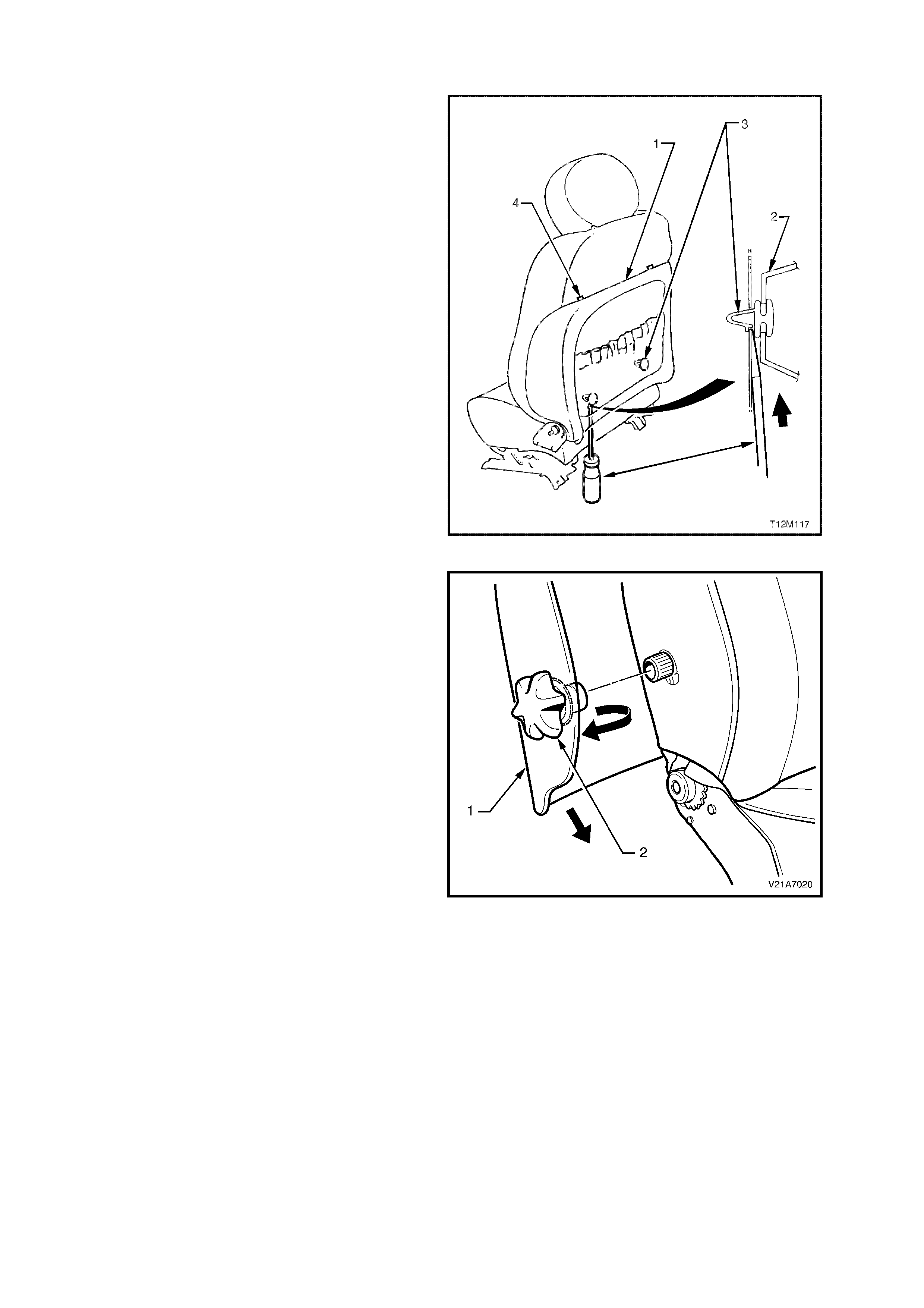
2. From the front side of the seat back cover (1),
in front of the lumbar support k nob (2), pull the
seat back cover outwards from the seat
assembly to disengage the lumbar support
knob.
While holding the side of the seat back cover
out, pull the seat back cover down to release
the top seat back cover retainer s, (ref er to item
4 in Fig. 1A7-20).
4. Remove the seat back cover and lumber
support knob assembly.
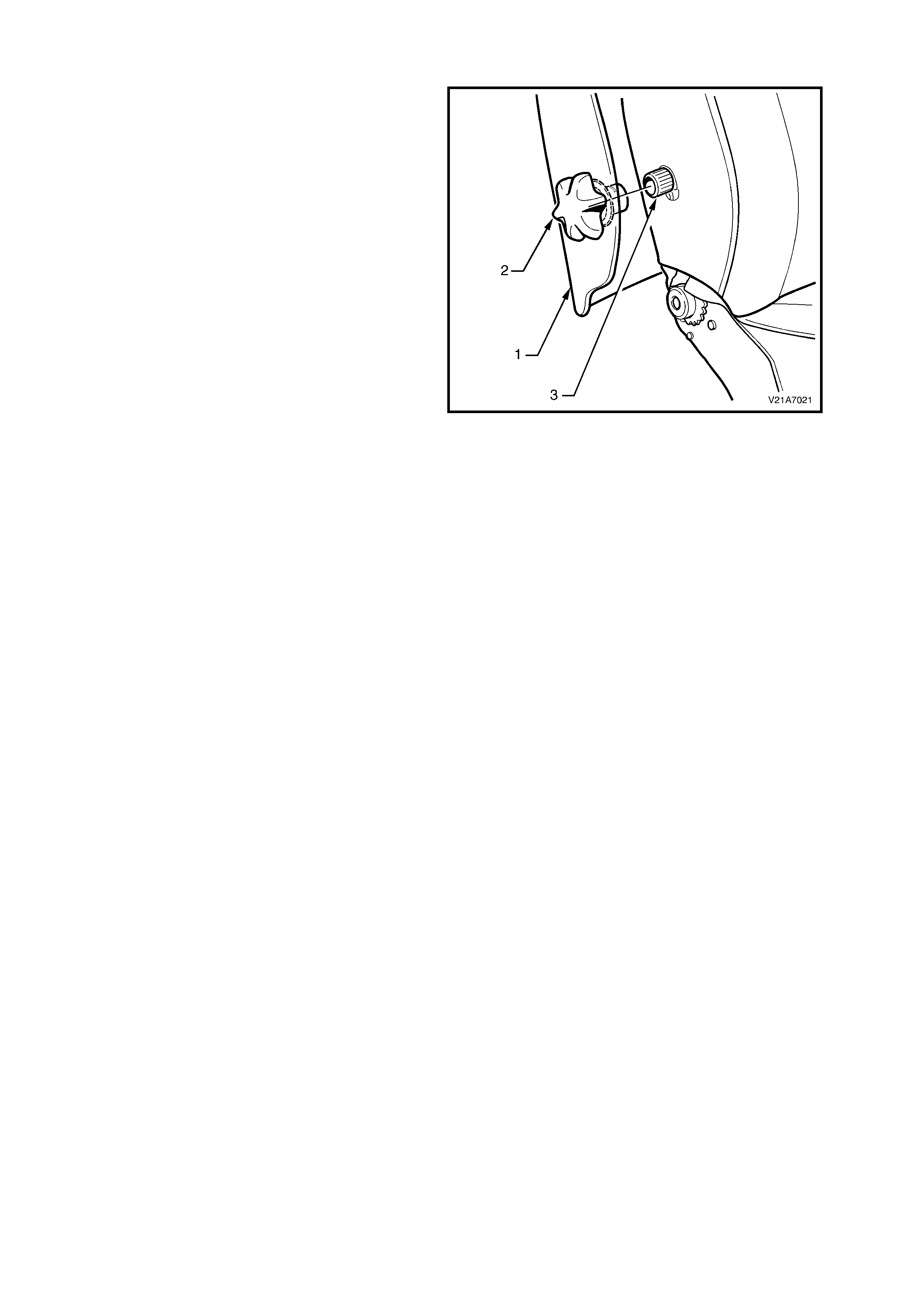
NOTE: It is recommended not to remove the
lumbar support knob from the seat back cover
unless either the knob or the seat back cover is to
be replaced.
4. To remove the lumbar support knob from the
seat back cover by, locate the two retaining
tangs by shining a light between the lumbar
knob and the boss to locate two retaining
tangs.
5. Using a a flat-tip screwdriver between the
lumbar knob and boss, disengage the two
tangs and separate the lumbar knob and boss.
Figure 1A7-21
REINSTALL
NOTE: If a lumbar support knob requires
replacement on a vehicle with side impact airbags,
do not fit a non side impact airbag lumber
support knob (circlip type). Always refer to the
latest V2 Series spare parts information for the
correct part number.
1. Locate the two upper retaining clips (refer item
4 in Fig. 1A7-20) on the seat back cover (1)
with the seat back.
2. Pull the side of the seat back cover out, align
the splines on the lumbar support knob and
adaptor (2) with the splines on the lumbar
support shaft (3). Push lumbar support knob
and adaptor onto lumbar support shaft.
3. Push the seat back cover into the s eat back, to
engage the two lower retaining c lips (refer item
3 in Fig. 1A7-20 in this Section).
Figure 1A7-22
2.8 EZ-ENTRY LEVER ARM & ESCUTCHEON
REMOVE
1. Remove front seat assembly, refer to
2.1 FRONT BUCKET SEAT ASSEMBLY in
this Section.
2. Remove the front seat back cover and lumbar
support adjuster knob assembly, refer to
2.7 LUMBAR SUPPORT ADJUSTER KNOB
AND FRONT SEAT BACK COVER
ASSEMBLY in this Section.
3. Lift the rear of the back trim away from the
back frame to allow access to the Ez-entry
lever assembly.
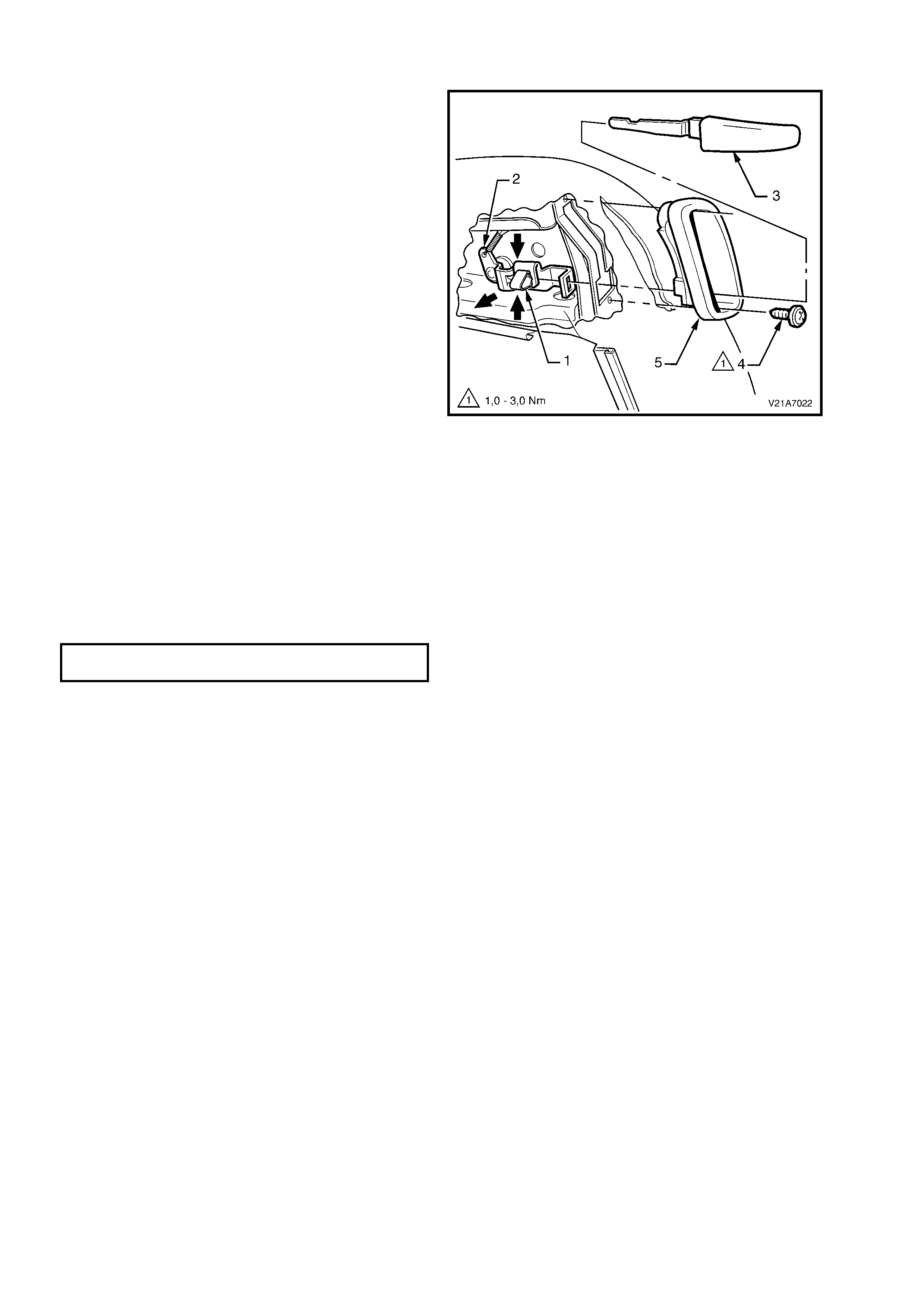
4. Comp ress the spring clip ( 1) retaining the lever
arm (2) to the lever assembly (3).
5. Grasp the lever arm and pull firmly away from
seat to remove.
NOTE: It may be necessary to wriggle the lever
arm to loosen it in the lever assembly.
6. Remove the two screws (4) retaining the Ez-
entry escutcheon (5) to the seat back frame.
7. Remove the escutcheon.
Figure 1A7-23
REINSTALL
The installation procedure for the Ez-entry lever
arm and escutcheon is the reverse of the removal
procedure, noting the following:
1. Tighten all fasteners to the specified torque
settings.
EZ-ENTRY ESCUTCHEON ATTACHING
SCREW TORQUE SPECIFICATION 1 – 3 Nm
2. Ensure that the lever retaining clip is correctly
engaged by pulling the lever handle firm ly away
from the seat and operating the latch several
times.

2.9 EZ-ENTRY CABLE ASSEMBLY
Due to ADR constraints, certain components of the recliner mechanism can not be removed or replaced. If any
part of the r ecliner mec hanism requir es replacem ent (including the Ez-entry cable ass embly), the entire front seat
back frame assembly must be replaced. For information relating to the replacement procedure for the seat back
fram e, lum bar suppport and adj uster assem bly, refer to 2.11 FR ONT SEAT BACK FRAME, LUMBAR SUPPORT
AND ADJUSTER ASSEMBLY in this Section.
2.10 FRONT SEAT BACK PAD AND COVER ASSEMBLY
REMOVE
1. Disconnect the battery earth and positive leads.
NOTE: If the vehicle is equipped with side impact
airbags, wait at least 10 sec onds bef ore perf orm ing
any work on the vehicle.
2. Remove front seat assembly, refer to
2.1 FRONT BUCKET SEAT ASSEMBLY in
this Section.
3. Remove the Ez-entry lever and escutcheon,
refer to 2.8 EZ-ENTRY LEVER AND
ESCUTCHEON in this Section.
4. Remove lumbar support adjuster knob
and seat back cover, refer to
2.7 LUM BER SUPPORT ADJUSTER KNOB &
FRONT SEAT BACK COVER ASSEMBLY in
this Section.
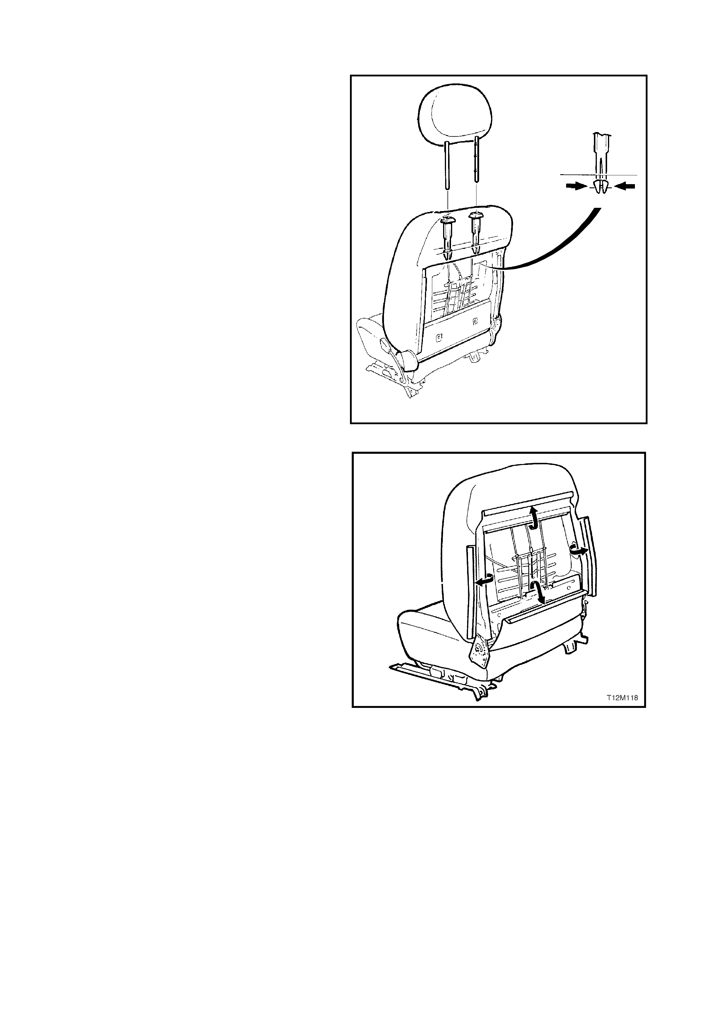
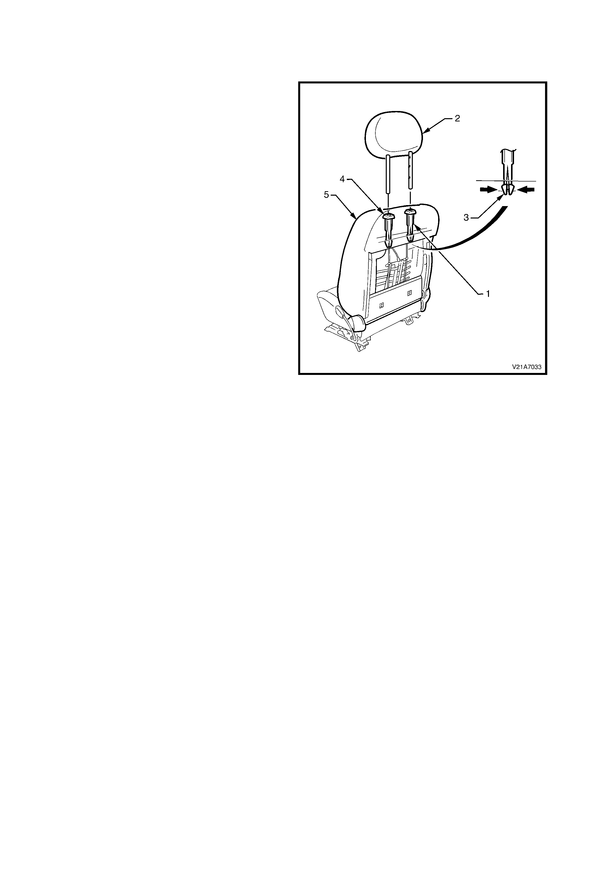
5. While holding head restraint height adjuster
lock in, pull head restraint completely out of
guide.
6. From the back of the front seat, squeeze the
locking prongs of the head restraint guide
together while pulling the top of the guide out of
seat back assembly, refer to Fig 1A7-24.
T12M110
Figure 1A7-24
7. Pull the four ‘J’ strips away from the seat
frame.
8. Lift the cover and pad assem bly away from the
seat back frame.
REINSTALL
Installation is the reverse of the removal operation,
noting the following:
1. Ensure the head restraint guide with adjusting
lock is inst alled on the cor r ect s ide, ie. side with
notches on the head restraint.
2. Ensure all fasteners are tightened to the correct
torque specification.
Figure 1A7-25
2.11 FRONT SEAT BACK FRAME, LUMBAR SUPPORT AND ADJUSTER ASSEMBLY
REMOVE
NOTE: The lum bar support is part of the seat back
frame and can only be replaced as an assembly.
1. Disconnect the battery earth and positive leads.
2. Remove front seat back cover and pad
assembly, refer to 2.5 FRONT SEAT BACK
PAD AND COVER ASSEMBLY in this Section.
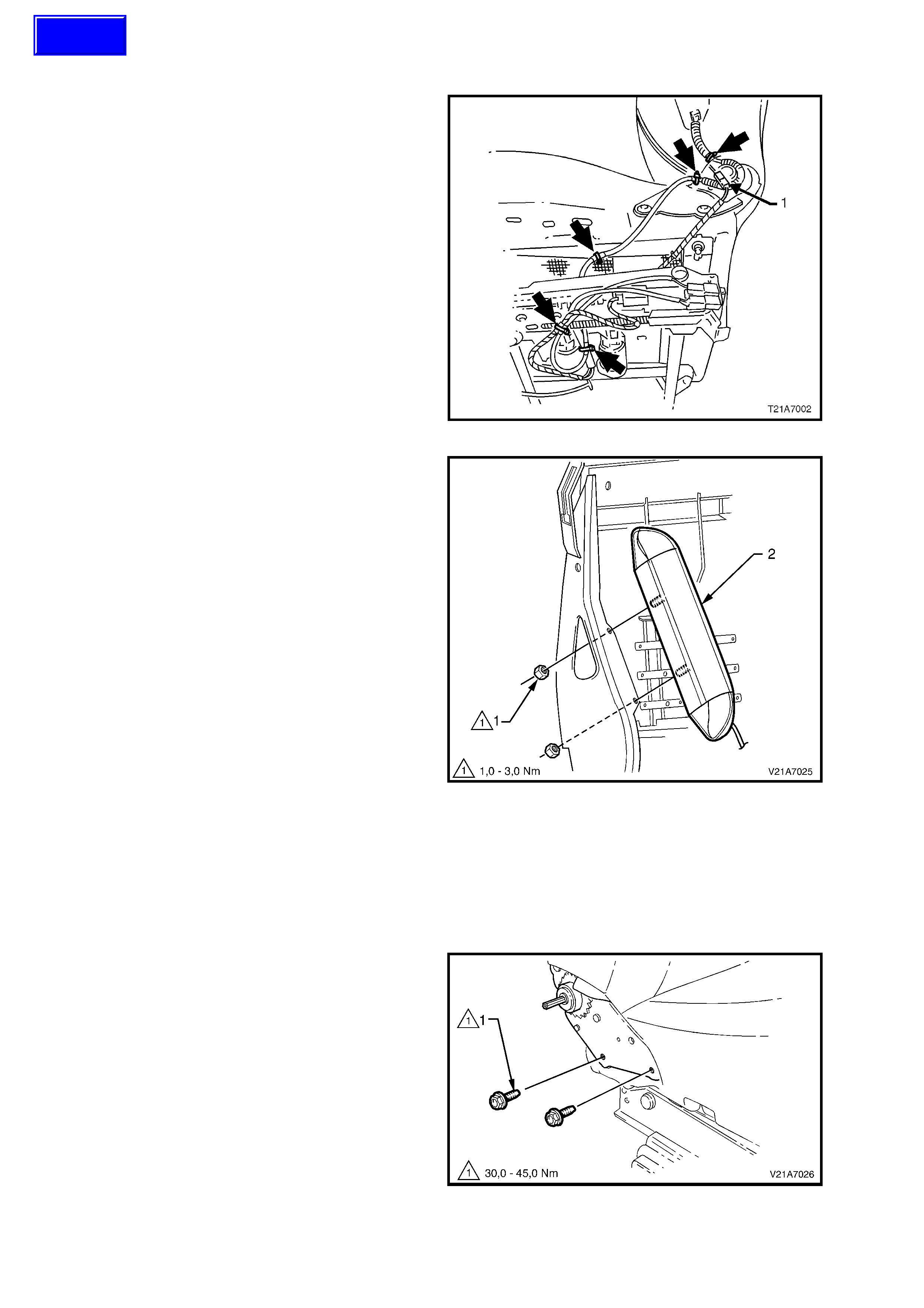
3. Cut the wire ties (f ive places) secur ing the side
airbag module ‘pigtail’ wiring harness to the
front s eat assem bly, tak ing care not to dam age
the wiring harness.
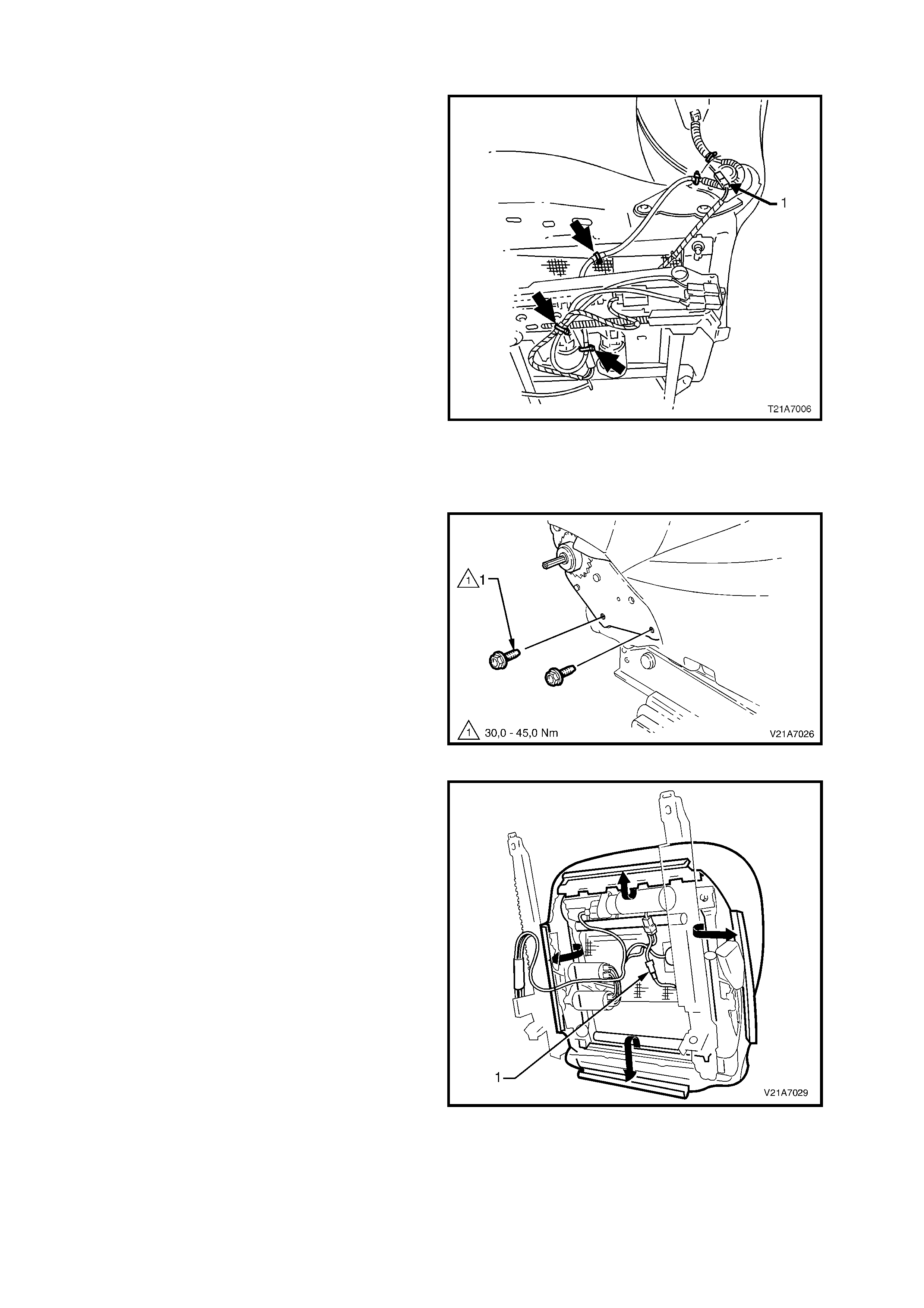
4. Disconnect the wiring harness connector for
the recliner motor (1).
Figure 1A7-26
5. Loosen and remove the two nuts securing the
side airbag assembly to the front seat back
frame.
Remove the side airbag module and ‘pigtail’
wiring harness assembly from the front seat
back frame.
CAUTION: When carrying a live (undeployed)
side airbag inflator module assembly, make
sure the bag opening is pointed away from you.
Never carry the side airbag inflator module
assembly by the wiring harness or connectors.
In case of an accidental deployment, the bag
will then deploy with minimal chance of injury.
When placing a live side airbag inflator module
assembly on a bench or other surface, always
face the airbag opening up, away from the
surface. Never rest the airbag inflator module
assembly with the opening face down. This is
necessary so that a free space is provided to
allow the airbag to expand in th e unlikely event
of accidental deployment. Otherwise, personal
injury may result.
6. If neces sary, remove the two nuts retaining the
front seat foam block insert to the seat frame
and remove foam block insert.
Figure 1A7-27
7. Remove the four (two on each side) bolts (1)
securing the seat back assembly to the seat
height adjuster and cushion frame assembly,
remove the seat back frame assembly .
Figure 1A7-28
Techline
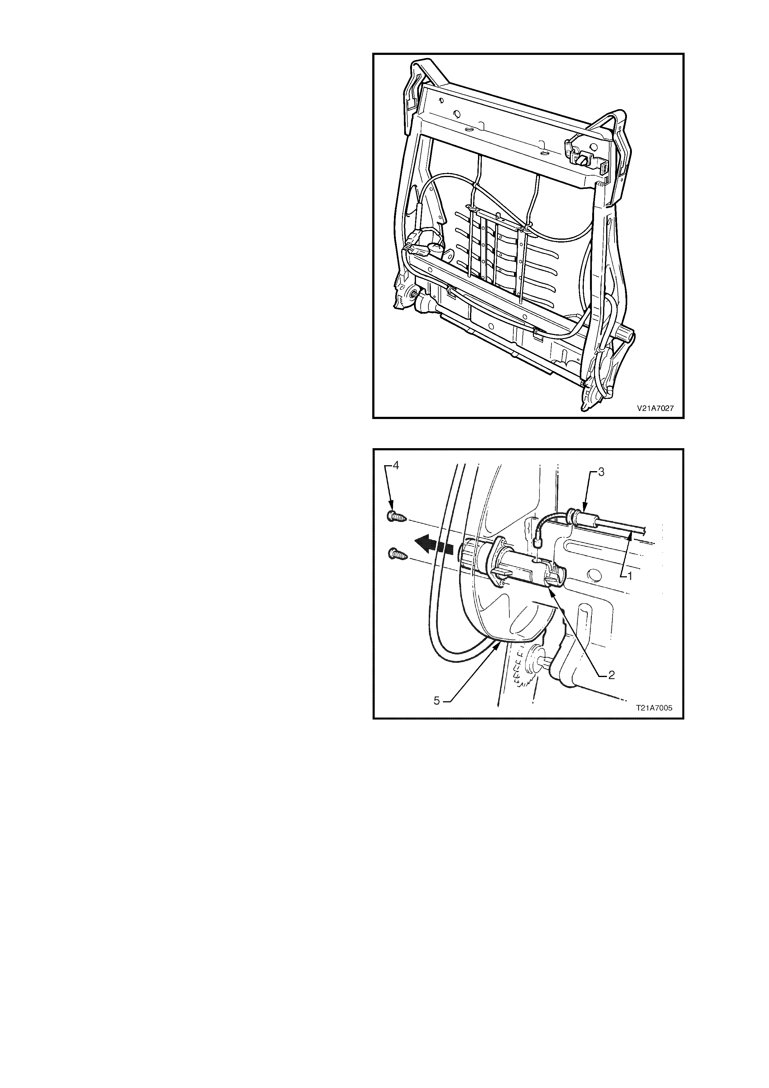
8. From the rear of the front seat back frame,
disengage the lumbar support adjuster cable
wire tie clip (3) by squeezing the tangs on the
wire tie retaining clip together and pushing the
wire tie retaining clip through the seat back
frame (1).
9. Push down the top of the lumbar support to
disengage the two retainers (2) from the guide
rails (4) on the seat back, allowing the lumbar
support to swing freely .
10. While slightly compressing the lumbar support
assembly by hand to release the cable (5)
tension, disengage the cable from the top of
the lumbar support.
11. Unclip the lower cable retainer from the lower
lumbar bracket.
Figure 1A7-29
12. Remove the adjusting cable (1) from the
adjuster (2) by unclipping the outer casing (3)
of the cable from the adjuster.
13. Remove the two screws (4) securing the
lumbar support adjuster to the s eat back fram e
(5) and remove adjuster.
Figure 1A7-30
REINSTALL
Installation of the front seat back frame, lumbar support and adjuster assembly is the reverse of the removal
operation, noting the following:
1. Align the hole in the adjuster (for adjusting cable ball) by turning the adjuster until the access hole lines up,
insert the cable into the adj us ter and pus h the outer cas ing of the c able into the loc k ing s eat of the adj us ter until
it clicks.
2. Ensure all fasteners are tightened to the correct torque specification.
SEAT BACK TO SEAT ADJUSTER AND
GUIDE RAIL ASSEMBLY SECURING BOLT
TORQUE SPECIFICATION 30 – 45 Nm
FRONT SEAT FOAM BLOCK INSERT TO
FRONT SEAT BACK RETAINING NUT
TORQUE SPECIFICATION 5.0 – 6.0 Nm
SIDE IMPACT AIRBAG ASSEMBLY TO
FRONT SEAT BACK RETAINING NUT
TORQUE SPECIFICATION 1.0 – 3.0 Nm
FRONT SEAT TO FLOOR SECURING BOLT
TORQUE SPECIFICATION 35 – 50 Nm
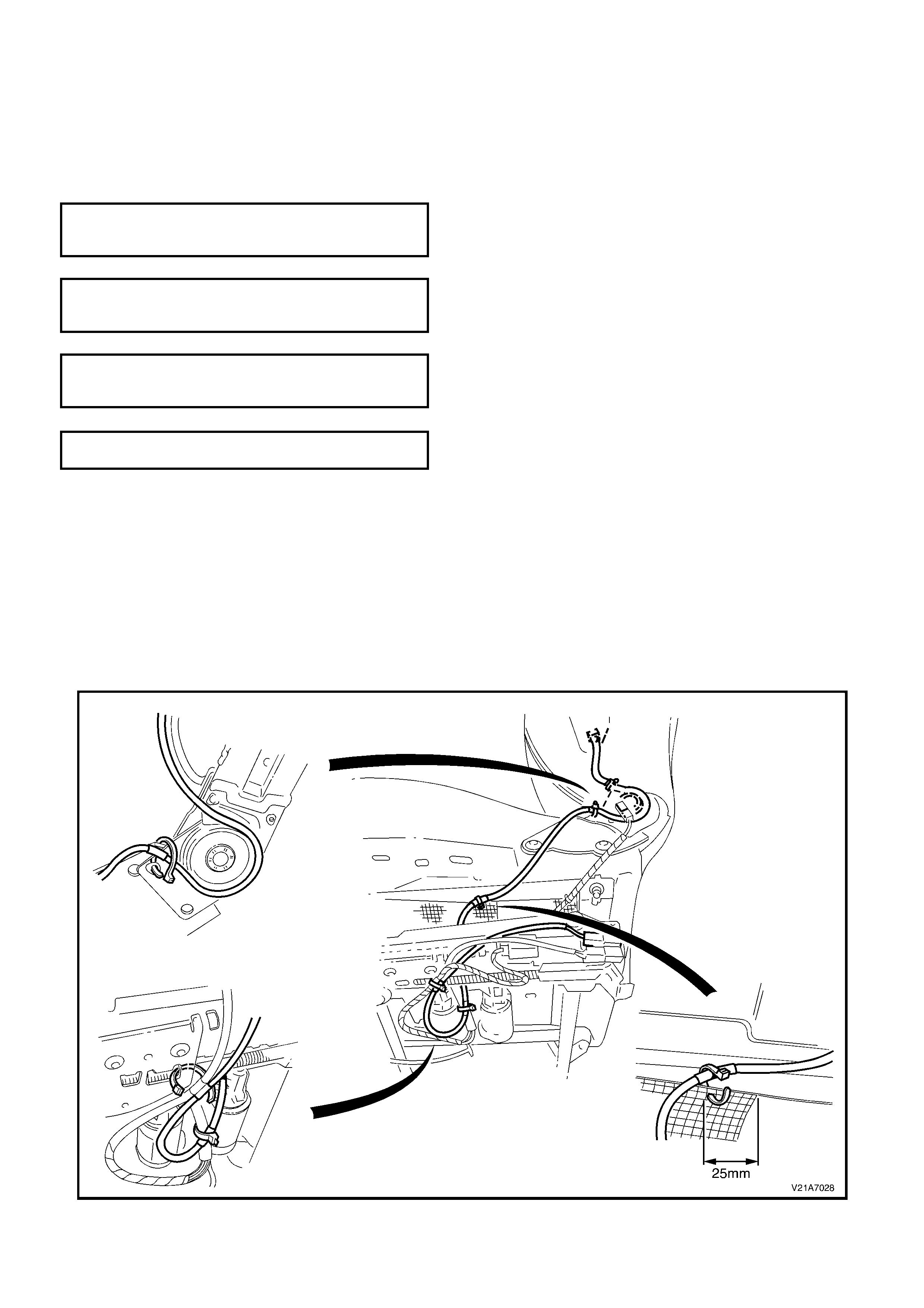
3. Route the side im pact airbag wiring harness through to the side of the seat rail assembly and secure with new
wire ties as per Fig. 1A7-31.
CAUTION: If the side impact airbag modules w iring harness is not routed correctly, damage to the harness
may occur, resulting in the side impact airbag becoming inoperative and setting a Diagnostic T rouble Code
(DTC) (SRS warning lamp on).
NOTE: T he wiring harness that connects to the side im pact airbag module, and r uns through the f ront seat down to
the seat rail, is not serviced separately from the side airbag inflator module due to the design of the anti-back-out
connector on the module assembly.
If this wiring harness, as with any other SRS ‘pigtail’ type wiring harness becom es damaged no wire, connector or
terminal repairs are to be attempted. REPLACE THE SIDE AIRBAG MODULE AND PIGTAIL W IRING HARNESS
ASSEMBLY.
Figure 1A7-31

4. Reconnect battery positive and earth leads, switch the ignition on, and observe the SRS warning lamp in the
instrument cluster. The warning lamp should be illuminated for approximately five seconds. During this period
the SDM performs a wiring and system self check.
If no system faults are detected, the SRS warning lamp will be switched off. If the warning lamp remains
illuminated and an audible alarm chimes, or the warning lamp illuminates two seconds after it was originally
switched off , an SRS fault is pres ent. Ref er to 3 DIAGNOSTICS in Section 12M SUPPLEMENTAL RESTRAINT
SYSTEM in of this Service Information to rectify fault.
5. Check the operation of the f ront seat m echanical and electr ical adjustm ents/operation. W hile check ing the seat
adjustment/operation, also check to ensure that the side airbag harness does not foul with any of the seats
moveable components (ie. seat motor drive shafts, etc.).
2.12 FRONT SEAT CUSHION PAD AND COVER ASSEMBLY
REMOVE
1. Disconnect the battery earth and positive leads.
NOTE: If the vehicle is equipped with side impact
airbags, wait at least 10 sec onds bef ore perf orm ing
any work on the vehicle.
2. Remove the front seat assembly, refer to
2.1 FRONT BUCKET SEAT ASSEMBLY in
this Section.
3. Remove the inner side cover, refer to
2.6 FRONT SEAT INNER SIDE COVER in this
Section.
4. Remove the outer side cover, refer to
2.2 FRONT SEAT OUTER SIDE COVER in
this Section.
5. Taking care not to damage the wiring harness,
cut three of the five wire ties (marked with an
arrow in Fig. 1A7-32) securing the side airbag
module ‘pigtail’ wiring harness to the front seat
assembly.
6. Disconnect the wiring harness connector for
the recliner motor (1 ).
Figure 1A7-32
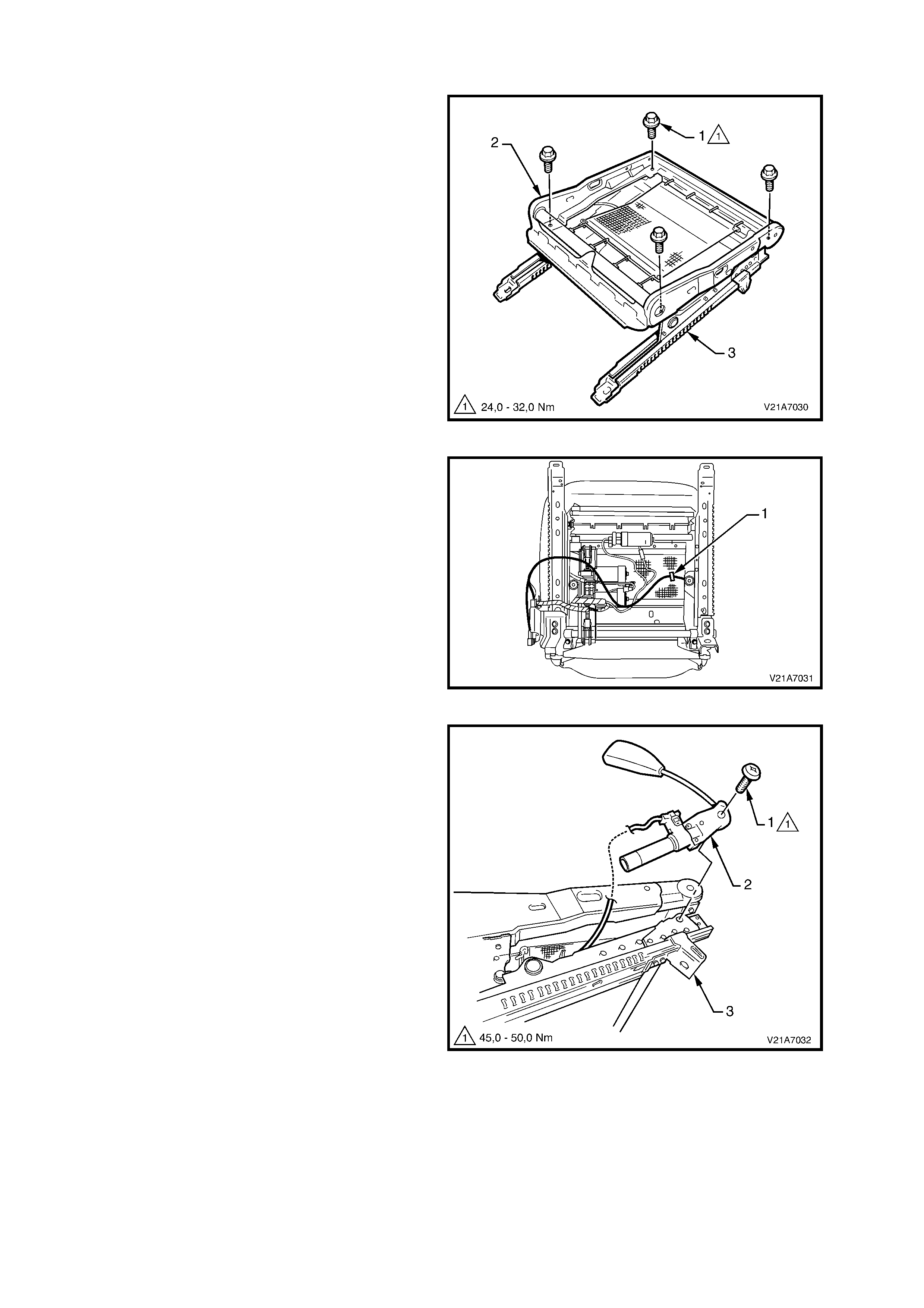
7. Remove the four (two on each side) bolts (1)
securing the seat back assembly to the seat
height adjuster and cushion frame assembly,
remove the seat back frame assembly .
Figure 1A7-33
8. From under the seat cus hion, pull the front and
side ‘J’ strips away from the seat frame.
9. Lift the cover and pad assembly away from
seat frame and then release the rear ‘J’ strip.
10. Disconnect the occupant sensing mat harness
connector (1).
11. Remove the cover and pad assembly.
Figure 1A7-34

REINSTALL
Installation of the front seat cushion pad and cover assembly is the reverse of the removal operation, noting the
following:
1. When ins talling the seat back assem bly to the seat adjus ter and guide rail as sem bly, ensure there is a m etal to
metal contact of parts (no trim material caught between).
2. Ensure all fasteners are tightened to the correct torque specification.
SEAT BACK TO SEAT ADJUSTER AND
GUIDE RAIL ASSEMBLY SECURING BOLT
TORQUE SPECIFICATION 30 – 45Nm
FRONT SEAT TO FLOOR SECURING BOLT
TORQUE SPECIFICATION 35 - 50Nm
3. Route the side im pact airbag wiring harness through to the side of the seat rail assembly and secure with new
wire ties as per Fig. 1A7-32 in this Section.
CAUTION: If the side impact airbag module wiring harness is not routed correctly, damage to the harness
may occur, resulting in the side impact airbag becoming inoperative and setting a Diagnostic T rouble Code
(DTC) (SRS warning lamp on).
NOTE: T he wiring harness that connects to the side im pact airbag module, and r uns through the f ront seat down to
the seat rail, is not serviced separately from the side airbag inflator module due to the design of the anti-back-out
connector on the module assembly.
If this wiring harness, as with any other SRS ‘pigtail’ type wiring harness , becomes dam aged no wire, connector or
terminal repairs are to be attempted. REPLACE THE SIDE AIRBAG MODULE AND PIGTAIL W IRING HARNESS
ASSEMBLY.
4. Rec onnec t the battery positive and earth leads, s witch the ignition on, and observe the SRS warn ing lam p in the
instrument cluster. The warning lamp should be illuminated for approximately five seconds. During this period
the SDM performs a wiring and system self check.
If no system faults are detected, the SRS warning lamp will be switched off. If the warning lamp remains
illuminated and an audible alarm chimes, or the warning lamp illuminates two seconds after it was originally
switched off, an SRS fault is present. Refer to 3. DIAGNOSTICS in Section 12M SUPPLEMENTAL
RESTRAINT SYSTEMS in the VX Series I Service Information to rectify the fault.
5. Check the operation of the f ront seat m echanical and electr ical adjustm ents/operation. W hile check ing the seat
adjustment/operation, also check to ensure that the side airbag harness does not foul with any of the seats
moveable components (ie. seat motor drive shafts, etc.).
2.13 FRONT SEAT CUSHION FRAME ASSEMBLY
REMOVE
1. Remove the front seat cushion cover and pad
assembly, refer to 2.7 FRONT SEAT
CUSHION PAD AND COVER in this Section.
2. Remove the four bolts (1) securing the front
seat cushion frame (2) to adjuster and guide
rail assembly (3).
Figure 1A7-35
NOTE: Before disconnecting the pretensioner
wiring harness connector, take note of wiring
harness routing.
3. Taking care not to damage the wiring harness,
cut the wire tie (1) securing the seat belt
pretensioner wiring harness to the front seat
suspension mat.
4. By squeezing the retaining tangs on the seat
belt pretensioner wiring harness connector
retaining clip at the outer side of the front seat
adjuster and guide rail assembly, disconnect
the connector from the pretensioner assembly.
Figure 1A7-36
5. Remove the bolt (1) securing the seat belt
buckle and pretensioner assembly (2) to the
frame (3) and remove the seat belt buckle and
pretensioner assembly .
Figure 1A7-37
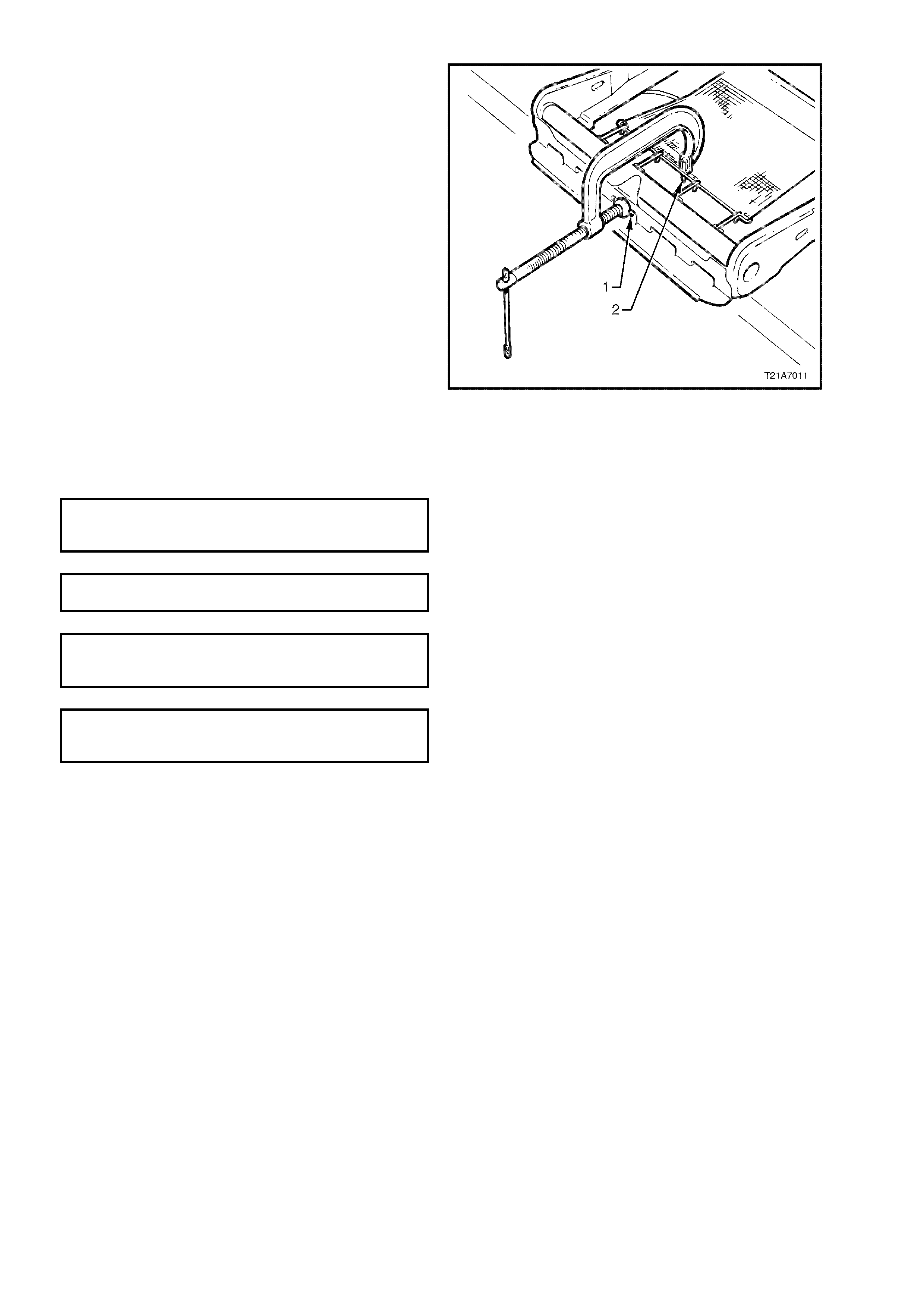
6. Using a pre-fabricated tool:
‘G’ clam p with a 5m m diam eter m etal dowel (1)
welded to one end, approximately 40mm long
and with a 2mm diam eter pin ( 2) approxim ately
20mm long welded to the other end.
Using the pre-fabricated tool, stretch the
suspension mat far enough to allow for
webbing clamps to be removed from seat
frame. Back ‘G’ clamp load off and remove
suspension mat.
NOTE: When using pre-fabricated tool, use
existing holes in sus pens ion mat to ensur e that mat
deformation does not occur.
Figure 1A7-38
REINSTALL
Installation of the front seat cushion frame assembly is the reverse of the removal operation, noting the following:
1. Ensure all fasteners are tightened to the correct torque specification.
SEAT BACK TO SEAT ADJUSTER AND
GUIDE RAIL ASSEMBLY SECURING BOLT
TORQUE SPECIFICATION 30 – 45 Nm
FRONT SEAT TO FLOOR SECURING BOLT
TORQUE SPECIFICATION 35 – 50 Nm
SEAT BELT BUCKLE AND PRETENSIONER
ASSEMBLY BOLT ATTACHING BOLT
TORQUE SPECIFICATION 45 – 50 Nm
FRONT SEAT CUSHION FRAME TO SEAT
GUIDE RAIL ASSEMBLY SECURING BOLT
TORQUE SPECIFICATION 24 – 32 Nm
2. Ensure the pretensioner, seat adjuster motor, and (if fitted) side impact airbag wiring harnesses are routed
correctly and retained by wiring ties at each red spot tape location, refer to Figs. 1A7-31 and 1A7-32 in this
Section.
3. When installing seat belt buckle and pretensioner assembly ensure that the front locating pin on the
pretensioner assembly aligns with seat frame.
CAUTION: If the side impact airbag module or seat belt pretensioner wiring harnesses are not routed
correctly, damage to the harness may occur, resulting in the side impact airbag or seat belt pretensioner
becoming inoperative and setting a Diagnostic Trouble Code (DTC) (SRS warning lamp on).
NOTE: T he wiring harness that connects to the side im pact airbag module, and r uns through the f ront seat down to
the seat rail, is not serviced separately from the side airbag inflator module due to the design of the anti-back-out
connector on the module assembly.
If this wiring harness, as with any other SRS ‘pigtail’ type wiring harness , becomes dam aged no wire, connector or
terminal repairs are to be attempted. REPLACE THE SIDE AIRBAG MODULE AND PIGTAIL W IRING HARNESS
ASSEMBLY.
4. Reconnect the battery positive and earth leads, switch ignition on, and observe the SRS warning lamp in the
instrument cluster. The warning lamp should be illuminated for approximately five seconds. During this period
the SDM performs a wiring and system self check.
If no system faults are detected, the SRS warning lamp will be switched off. If the warning lamp remains
illuminated and an audible alarm chimes, or the warning lamp illuminates two seconds after it was originally
switched off, an SRS fault is present. Refer to 3. DIAGNOSTICS in Section 12M SUPPLEMENTAL
RESTRAINT SYSTEM in the VX Series I Service Information to rectify the fault.
5. Check operation of front seat mechanical and electrical adjustments/operation. While checking the seat
adjustment/operation, also check to ensure that the side airbag harness does not foul with any of the seats
moveable components (ie. seat motor drive shafts, etc.).

2.14 FRONT SEAT ADJUSTER ASSEMBLY
The adjuster assembly on the front seats is a non-serviceable item.
If the adjuster assembly, drive motors or drive shafts require replacement, the entire front seat cushion frame
assem bly m ust be replaced. For information r elating to the replacement pr ocedure for the front seat cushion fram e
assembly, refer to 2.13 FRONT SEAT CUSHION FRAME ASSEMBLY in this Section.
2.15 FRONT SEAT HEAD RESTRAINT ASSEMBLY
REMOVE
1. Remove the lumbar support adjusting knob and
front seat back cover assembly, refer to
2.7 LUMBAR SUPPORT ADJUSTER KNOB
AND FRONT SEAT BACK ASSEMBLY in this
Section.
2. While holding the head r estraint height adj uster
lock (1) in, pull the head restraint (2) completely
out of the guide.
3. From the back of the front seat, squeeze the
locking prongs (3) of the head restraint guide
(4) together while pulling the top of the guide
out of the seat back assembly (5).
REINSTALL
Installation of the front seat head restraint
assembly is the reverse of the removal procedure
noting the following:
When installing the head restraint guide, ensure
that the locating slots in the s eat bac k align with the
key-way on the head restraint guide and the head
restraint guide with adjus ting lock is ins talled on the
correct side, ie. align with notches on the head
restraint.
Figure 1A7-39

2.16 FRONT SEAT LIFT MOTORS
The front seat lift motor on the front seats is a non-serviceable item.
If the front seat lift m otor requires replacement, the entire front seat cushion frame assem bly must be replaced.
For information relating to the replacement procedure for the front seat cushion frame assembly, refer to
2.13 FRONT SEAT CUSHION FRAME ASSEMBLY in this Section.

2.17 FRONT SEAT FORE/AFT MOVEMENT MOTOR
The front seat fore/aft movement motor on the front seats is a non-serviceable item.
If the f ront seat for e/aft m ovement m otor or dr ive shafts r equire replacem ent, the entire front seat cushion fram e
assembly must be replaced. For information relating to the replacement procedure for the front seat cushion
frame assembly, refer to 2.13 FRONT SEAT CUSHION FRAME ASSEMBLY in this Section.

2.18 FRONT SEAT RECLINING MOTOR, GEARBOX AND POTENTIOMETER ASSEMBLY
The front seat recliner motor, gearbox and potentiometer assembly on the front seats is a non-serviceable item.
If the front seat recliner motor, gearbox and potentiometer assembly requires replacement, the entire front
seat back frame lumbar support and adjuster assembly must be replaced. For information relating
to the replacement procedure for the front seat back frame lumbar support and adjuster assembly, refer to
2.11 FRONT SEAT BACK FRAME, LUMBAR SUPPORT AND ADJUSTER ASSEMBLY in this Section.

2.19 DRIVE MOTOR POTENTIOMETERS
The front seat drive motor potentiometers on the front seats are non-serviceable items.
If any of the front seat drive motor potentiometer assemblies requires replacement, the entire front seat back
frame, lumbar support and adjuster assembly or the front seat cushion frame assembly must be replaced. For
information relating to the replacement procedure for the front seat back frame lumbar support and adjuster
assembly or the front seat c ushion frame assembly, refer to either 2.11 FRONT SEAT BACK FRAME, LUMBAR
SUPPORT AND ADJUSTER ASSEMBLY or 2.13 FRONT SEAT CUSHION FRAME ASSEMBLY in this
Section.
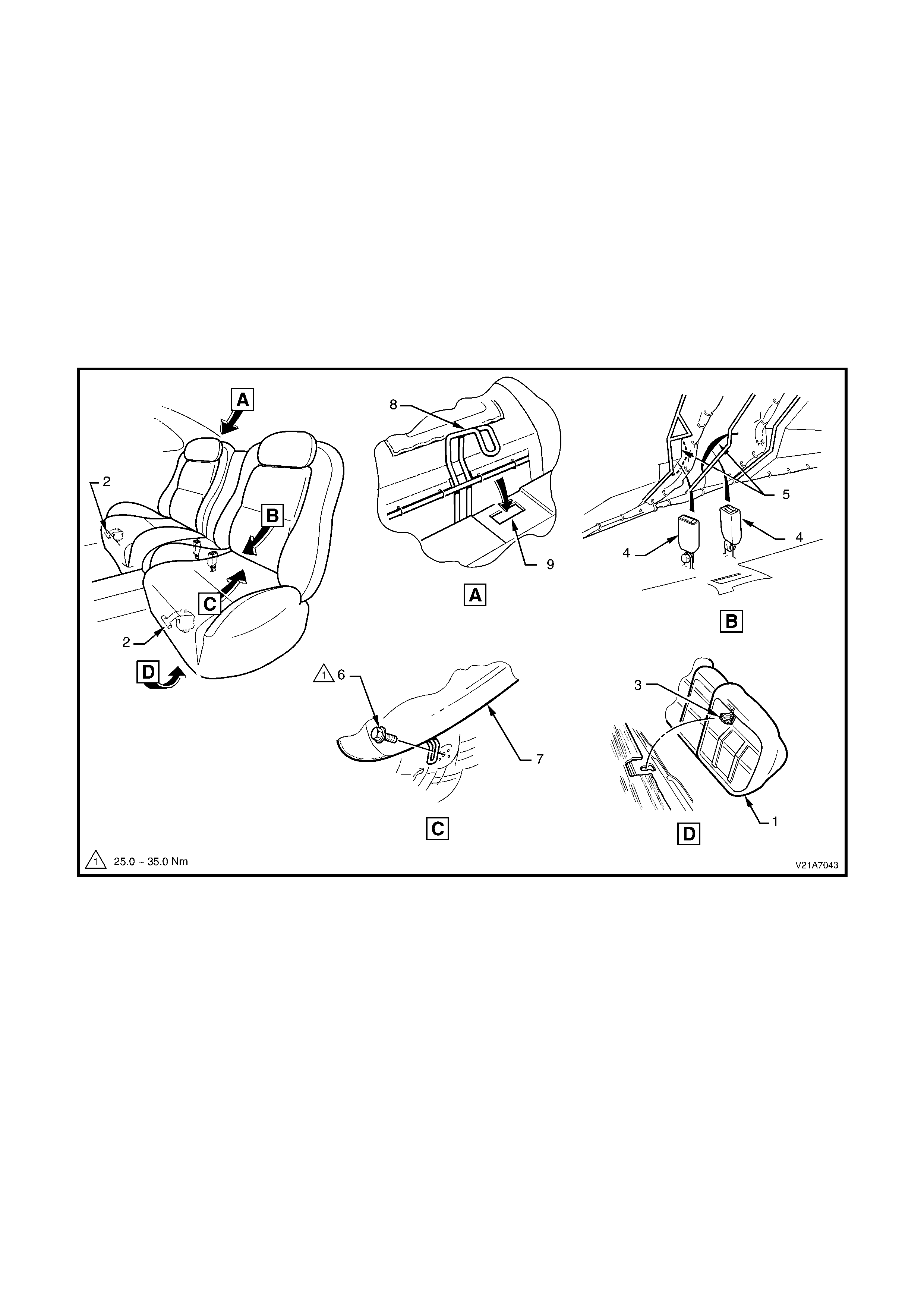
2.20 REAR SEAT CUSHION AND BACK ASSEMBLIES
REMOVE
1. Lift the front edge of the rear seat cushion (1) slightly to gain access to the rear seat cushion release handles
(2).
2. From either the left or right side of the seat, pull the release handle downwards towards the floor, while at the
same time lifting the front of the rear seat cushion until the lock mechanism (3) is released.
1. Repeat step 2 for the opposite side of the seat.
2. W hile manoeuvring the rear seat belt buckles (4) through the two slots (5) in the rear seat centre escutcheon,
lift the front of the rear seat cushion and unhook the rear seat cushion frame from the rear seat back frame.
3. Remove the rear seat cushion.
4. Remove the two bolts (6) securing the rear seat back assembly (7) to the rear floor pan.
5. Lif t the rear s eat back assembly up until the seat back retaining hook (8) r eleases f rom the r etaining slots ( 9) in
the rear compartment front panel.
6. Remove the rear seat back assembly.
Figure 1A7-40
Legend
1. Rear Seat Back Cushi on 6. Rear Seat Back Retaini ng Bolt
2. Rear Seat Cushion Release Handles 7. Rear Seat Back As sembl y
3. Rear Seat Cushion Lock Mechani sm 8. Rear Seat Back Retaini ng Hook
4. Rear Seat Bel t Buck l es 9. Rear Seat Back Retaini ng Slot
5. Rear Seat Centre Escut cheon
REINSTALL
Installation of the rear seat cushion and back assemblies is the reverse of the removal operation.
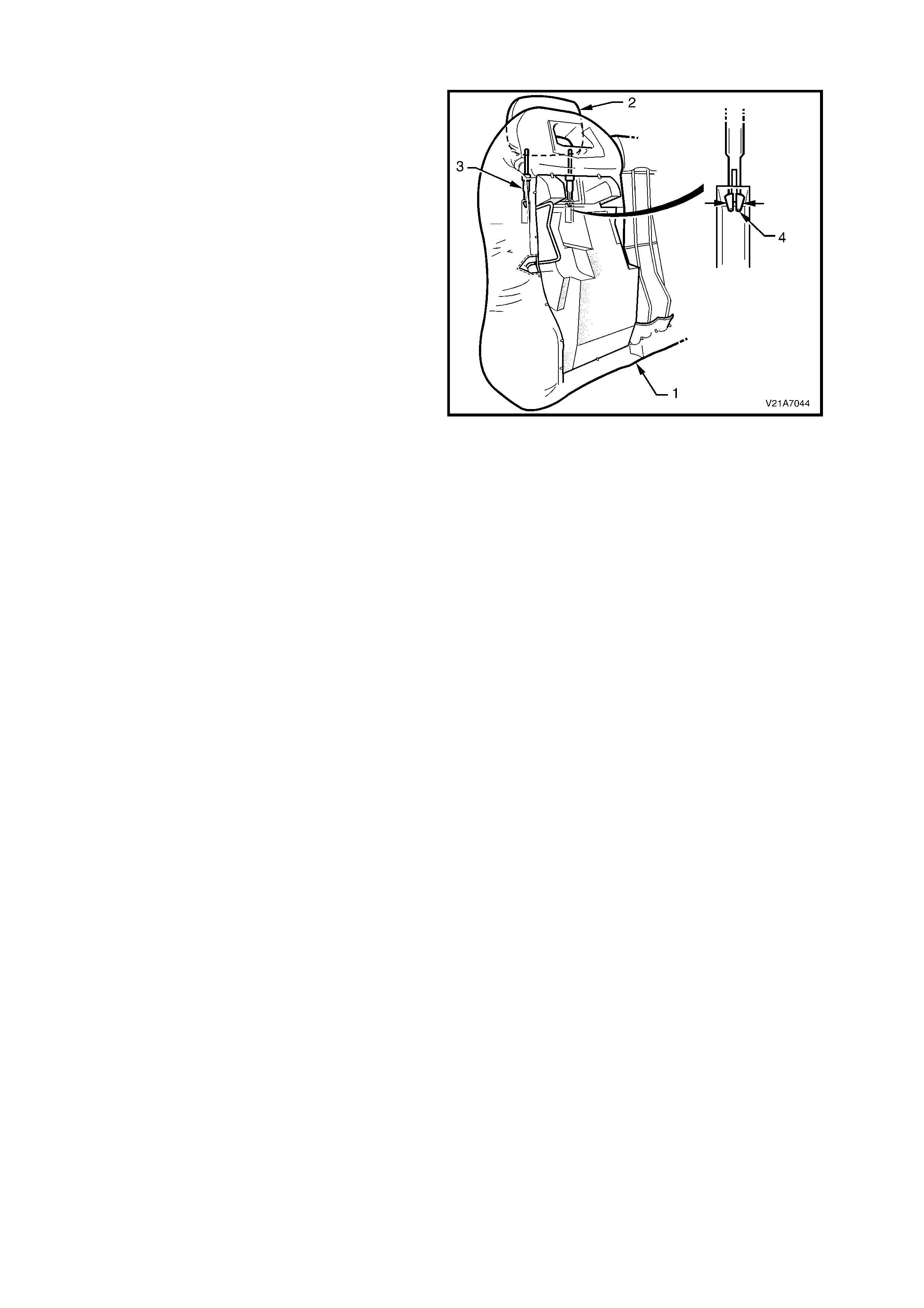
2.21 REAR SEAT HEAD RESTRAINT ASSEMBLY
REMOVE
1. Remove the rear seat back (1), refer to
2.19 REAR SEAT CUSHION AND BACK
ASSEMBLIES in this Section.
2. While holding the head r estraint height adj uster
lock in, pull the head restraint (2) completely
out of the guide (3).
3. From the back of the rear seat back (foam
side), squeeze the locking prongs of the head
restraint guide (4) together while pulling the top
of the guide out of the seat back assembly.
REINSTALL
Installation is the reverse of the removal procedure
noting the following:
When installing the head restraint guide, ensure
that the locating slots in the s eat bac k align with the
key-way on the head restraint guide and that the
head restraint guide with the adjusting lock is
installed on the correct side, ie. align with notches
on the head restraint.
Figure 1A7-41
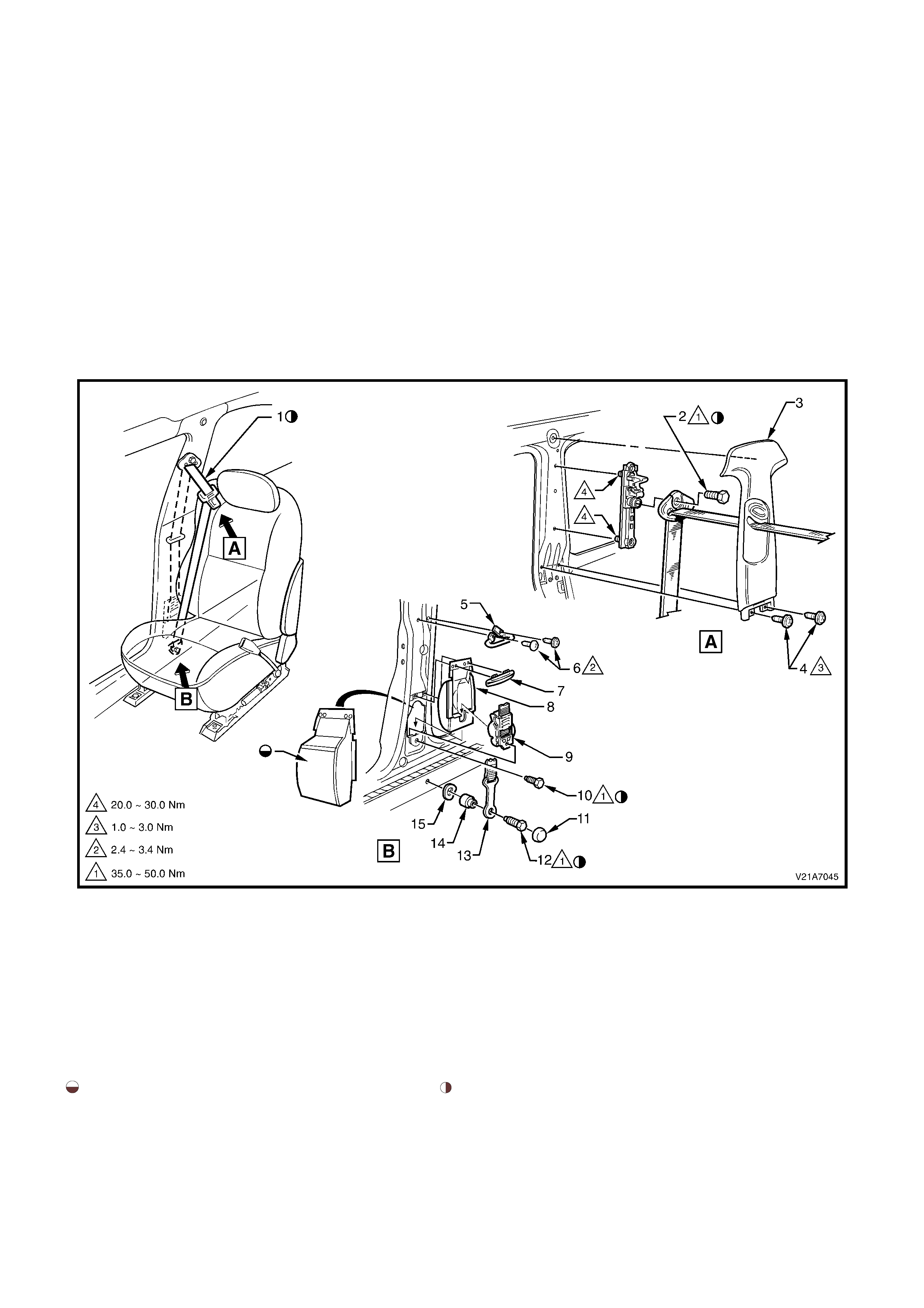
2.22 FRONT SEAT BELT RETRACTOR AND HEIGHT ADJUSTER ASSEMBLY
REMOVE
1. Remove the front seat outer side covers, refer to 2.2 FRONT SEAT OUTER SIDE COVERS in this Section.
2. Remove the cap and bolt securing the seat belt lower anchor to the floor pan, refer to Fig. 1A7-42.
3. Remove the inner r oc ker panel cover and ins ert, r ef er to 2.3 INNER ROCKER PANEL COVER AND INSERT in
Section 1A8 HEADLINING AND INTERIOR TRIM in this Service Information.
4. Remove upper and lower B-pillar trims, refer to Section 1A8, HEADLINING AND REAR END TRIM, in this
Service Information.
5. Feed the seat belt sash, buckle and anchor through the upper B-pillar trim.
6. Remove the bolt securing the seat belt guide to the height adjuster.
7. Remove the two screws securing the intermediate wire type sash guide to the B-pillar and the remove guide.
8. Remove the bolt s ecur ing the f ront s eat belt r etrac tor as s embly to the B-pillar and rem ove the seat belt retractor
assembly.
9. Remove the two bolts securing the seat belt height adjuster to the B-pillar and remove the height adjuster.
Figure 1A7-42
Legend
1. Front Seat B e l t And Retract or A ssem bl y 9. Seat Belt And Ret ractor As sembly
2. Upper Seat Bel t Gui de Attac hi ng B ol t 10. Seat Bel t Retractor Attac hi ng B ol t
3. B-Pillar Upper Trim 11. Seat Belt A nchor Attac hing B olt Cap
4. B-Pillar Upper Trim Attaching Screw 12. Seat Belt A nchor Attac hing B olt
5. Intermediate Sash Guide 13. Seat Bel t Anchor
6. Intermediate Sash Guide Att aching Screw 14. Seat Bel t Anchor Was her
7. Lower Sash Guide 15. Seat Bel t Anchor Spac er
8. Seat Bel t Retract or Dust Cap
Seal Seat Belt Retractor Dust Cap With Non-Hardening Hand Start Seat Belt And Retractor Attaching Bolt Fi ve Ful l Turns
Sealer, t o Hol den Specifi cation HN 1005 Or HN 1044. Before Usi ng Power Tools.

REINSTALL
Installation is the reverse of the removal operation, noting the following:
1. Ensure all seat belt bolts are hand tightened a minimum of 5 turns before using tools.
2. Tighten all bolts to the correct torque specification.
SEAT BELT SECURING BOLT
TORQUE SPECIFICATION 35 – 50 Nm
FRONT SEAT BELT HEIGHT
ADJUSTER SECURING BOLT
TORQUE SPECIFICATION 20 – 30 Nm
3. A visual inspection of the webbing is required to ensure that the webbing is not twisted and is free of abrasions
prior to final assembly.
4. Engage seat belt tongue with corresponding buckle and perform a functional check.
NOTE: T he seat belt height adj uster and the slide in the B-pillar tr im s hould be adjusted to the full up pos ition prior
to fitment of the B-pillar trim to ensure slide and height adjuster are correctly aligned.
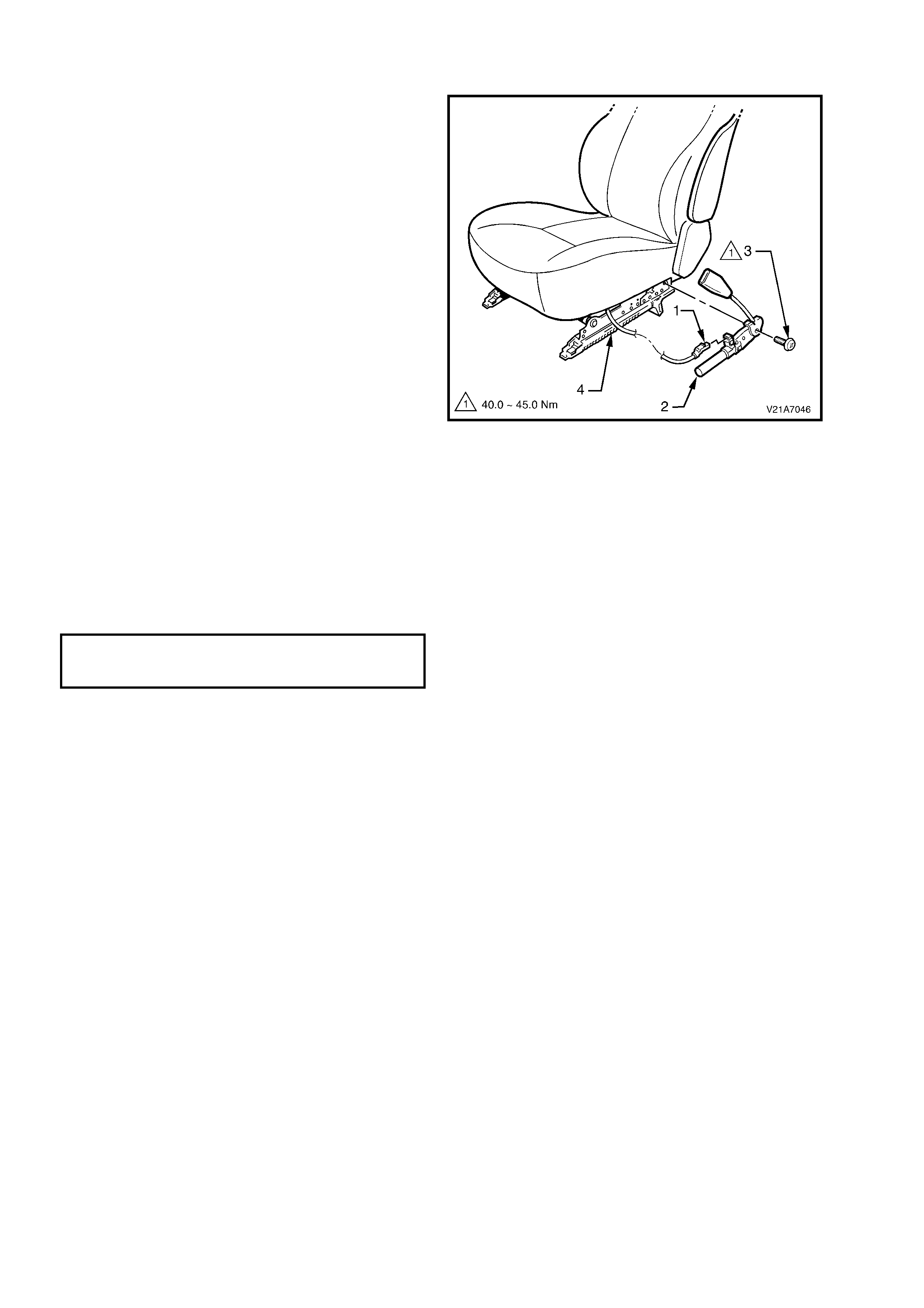
2.23 FRONT SEAT BELT BUCKLE AND PRETENSIONER ASSEMBLY
REMOVE
CAUTION 1: If a seat belt pretensioner is
deployed, the seat belt pretensioner assembly
together with the seat adjuster and guide rail
assembly must be replaced.
CAUTION 2: If disposing of an undeployed
seat belt buckle and pretensioner
assembly, refer to the disabling procedure in
Section 12M SUPPLEMENTAL RESTRAINT
SYSTEM in the VT Series Service Information.
1. Adjust the seat to its rear most position and
disconnect the battery.
2. Disconnect the wiring harness connector (1)
from the seat belt buckle and pretensioner
assembly (2).
3. Remove the bolt (3) securing the seat belt
buckle and pretensioner assembly to the seat
frame (4) and remove the seat belt buckle and
pretensioner assembly .
REINSTALL
Installation is the reverse of the removal operation,
noting the following:
1. When installing the seat belt buckle and
pretensioner assembly, ensure that the front
locating pin is aligned with the seat frame.
2. Ensure all bolts are fastened to the correct
torque specifications.
SEAT BELT BUCKLE AND
PRETENSIONER ATTACHING BOLT
TORQUE SPECIFICATION 45 Nm
Figure 1A7-43

2.24 REAR SEAT BELT RETRACTOR ASSEMBLY
REMOVE
1. Remove the rear seat back assembly, refer to 2.19 REAR SEAT CUSHION AND BACK ASSEMBLIES.
2. Remove the bolt securing the rear seat belt lower anchor to the floor pan.
3. Remove the appropriate C-pillar trim, refer to 2.7 ‘C’ PILLAR TRIM in Section 1A8 HEADLINING AND REAR
END TRIM.
NOTE: The seat belt escutcheon may break if the upper section is pried from the C-pillar trim panel.
4. Feed the seat belt sash, buckle, anchor and guide through the C-pillar trim.
5. Remove the bolt securing the sash guide to the C-pillar.
6. Remove the bolt securing the rear seat belt retractor assembly to the rear quarter inner panel.
7. Remove the seat belt retractor assembly.
Figure 1A7-44
Legend
1. Rear Seat Belt A nchor Retaining Bolt 5. C-Pillar Trim P anel
2. Rear Seat Bel t Anchor 6. Rear Seat Bel t And Retrac t or Assembly
3. Rear Seat Bel t Guide Retaining B o l t 7. Seat Bel t Retracto r Ret ai ni ng Bolt
4. Rear Seat Bel t Esc ut cheon
Hand start seat belt and ret ractor att aching bolts five ful l Seal seat bel t anchor m ounting hole with non-hardening seal er
turns bef ore using power tools. to Holden Spec i ficati on HN1005 or HN1044.

REINSTALL
Installation is the reverse of the removal operation, noting the following:
1. Ensure all seat belt bolts are hand tightened a minimum of five turns before using tools.
2. Ensure that the threads of all seat belt lower securing bolts are adequately s ealed with a non hardening sealer,
to Holden Specification HN1005 or HN1044.
3. Tighten all bolts to the correct torque specification.
SEAT BELT RETRACTOR ATTACHING
BOLT TORQUE SPECIFICATION 35 - 50Nm
4. W hen installing the seat belt escutcheon onto the C-pillar, insert the rear upper clips of the escutcheon into the
C-pillar then gently push the escutcheon into the C-pillar.
5. A visual inspection of the webbing is required to ensure that the webbing is not twisted and is free of abrasions
prior to final assembly.
6. Engage the seat belt tongue with the corresponding buckle and perform a functional check.
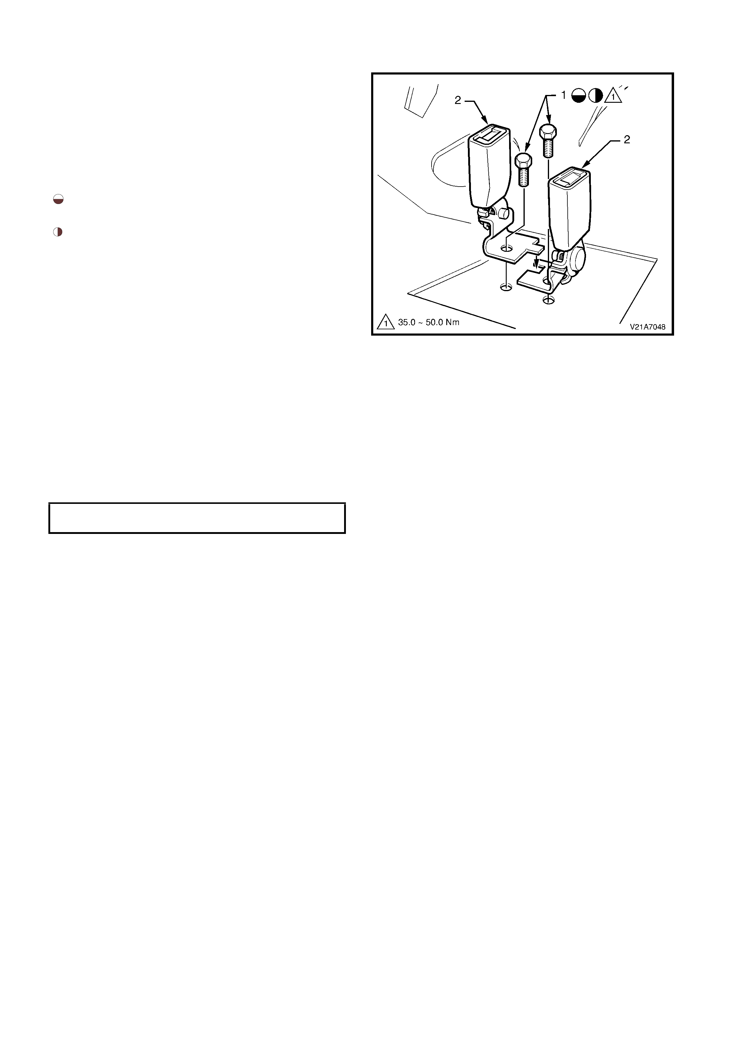
2.25 REAR SEAT BELT BUCKLE ASSEMBLY
REMOVE
1. Remove the rear seat cushion, refer to
2.19 REAR SEAT CUSHION AND BACK
ASSEMBLIES in this Section.
2. Remove the appropriate bolt (1) securing the rear
seat belt buckle (2) to the floor pan.
Legend
Hand start the seat belt and retractor attaching
bolts five full turns before using power tools.
Seal seat belt anchor mounting hole with non-
hardening sealer to Holden Specification HN1005
or HN1044.
Figure 1A7-45
REINSTALL
Installation is the reverse of the removal operation, noting the following:
1. Ensure all seat belt bolts are hand tightened a minimum of five full turns before using tools.
2. Ens ur e that the threads of the s eat belt buckle anchor sec uring bolt are adequately sealed with a non-har dening
sealer, to Holden Specification HN1005 or HN1044.
3. Tighten all bolts to the correct torque specification.
SEAT BELT BUCKLE ATTACHING BOLT
TORQUE SPECIFICATION 35 – 50 Nm
3. Engage the seat belt tongue with the corresponding buckle and perform a functional check.

3. DIAGNOSTICS
3.1 PREREQUISITES TO DIAGNOSIS AND TROUBLE SHOOTING
INTRODUCTION TO DIAGNOSTICS
W hen diagnosing faults in the Ez-entry seats, an inbuilt diagnostic mode can be entered to obtain Diagnostic Test
Codes (DTC) which indicate specific errors within the seat electronic system. DTC based diagnostics should be
completed prior to proceeding with general (strategy based) diagnostics.
PRELIMINARY SYSTEM REQUIREMENTS
The prerequisites before proceeding with system checks are:
• For a non-memory type seat, circuit breaker F2 must be checked before any electrical diagnostic checks are
performed.
• For a memory type seat, fusible links FS and FJ, fuses F15 and F29 and circuit breakers F2 and F3 must be
checked before any electrical diagnostic checks are performed.
• Ensure no moisture is present in the main wiring harness to body wiring harness or seat harness connections.
• Ensure that sound ear th connections ar e available for all f unctioning com ponents, particular ly at the body earth
connection (fender panel inner stud, adjacent to battery).
• Ensure that the battery is in good condition and adequately charged (above 11.5 volts) before carrying out any
electrical checks.
SAFETY REQUIREMENTS
Disconnect the battery when carrying out work which involves the risk of an electrical short circuit.
Do not touch mechanical components during function checks, to avoid the risk of a hand being caught in the
mechanism.
All V2 Series Models are equipped with side impact airbags. Before removing any components on or around the
front s eats , dis able the SRS. Ref er to Sect ion 12M SUPPLEMENT AL RESTRAINT SYST EM in the VT Series I and
VT Series II and VX Series I Service Information.
CHECKING EQUIPMENT
An unpowered test lamp with a current draw of less than 3 Amps.
A digital multimeter, with a minimum 10 Megohm impedance and a diode test function MUST be used when
undertaking any electrical checks on these systems.
Exercise care when taking readings from wiring harness connectors. It is preferred that the back probing method
with individual connectors is employed wherever possible, to avoid terminal damage and subsequent connection
failure.
When carrying out wiring checks as dir ec ted to by the diagnostic charts, rather than probe ter minals and connectors
with incorrec t sized multim eter connec tions, use the adaptors contained in connector tes t adaptor kit KM–609. T his
will prevent any possibility of spreading or damaging wiring harness terminals.
IMPORTANT:
• When checking, the exact order of the test steps should be observed.
• If the requir ed nominal value is not ac hieved in any stage, then the problem must be rec tif ied bef or e pr oceeding
further.
• Unless the multimeter being used has an auto-ranging function, check that the correct range, as specified, is
selected before the test is carried out.

3.2 VISUAL INSPECTION
When investigating any complaint of an electric seat problem or malfunction, start the diagnosis with a visual
inspection of the system.
The visual inspection procedure may quickly identify the cause and eliminate the need for additional diagnosis,
particularly if the problem is a mechanical fault.
If the complaint condition can not be resolved by the visual inspection, proceed to the appropriate diagnostic chart.
VISUAL INSPECTION NO. 1
Condition: No seat operation or operation noisy
INSPECT FOR CORRECTIVE ACTION
Foreign material causing the seat to bind. Remove the foreign material.
Dry components, build up of dirt on the moving
components. Clean and apply Lithium based grease (to Holden
Specification HN 2073) to the noisy component.
Bent, loose or physically damaged components. Repair or replace the faulty components.
VISUAL INSPECTION NO. 2
Condition: Suspected electrical fault
COMPONENTS INSPECT FOR CORRECTIVE ACTION
Seat and switch wiring harness
connectors. 1. Loose connections at individual
motors. Ensure secure connections.
2. Loose connections at the
control switch.
3. Loose connection at the power
supply connector at side of seat
assembly.
Circuit breaker F2. Loose connection, open circuit or
not fitted. Ensure secure connection or install
new circuit breaker.
Circuit breaker F3 and fuse F15
(Memory type seat only) Loose connection, open circuit or
not fitted. Ensure secure connection or install
new circuit breaker or fuse.
Fusible links FS and FJ
(Memory type seat only) Loose connection, open circuit or
not fitted. Ensure secure connection or install
new fusible link.
3.3 DIAGNOSTICS – NON-MEMORY TYPE SEAT
ENTERING DIAGNOSTIC MODE
The non-mem or y type s eat provides the tec hnician with in-built diagnostics . T he diagnostic indicator is a green LED
situated on the seat contr ol module. T he LED c an be viewed through the small hole in the outer side lower seat side
cover. To gain access, it is necessary to partially remove the seat outer side cover. Refer to steps 1 to 5 in
2.2 FRONT SEAT OUTER SIDE COVER in this Section. In diagnostic mode, the seat control module will:
• Check that the occupant sensing mat is connected.
• Check that the occupant sensing mat detects weight.
• Check that the track motor sensor is connected.
• Check if the track motor is stalled.
• Check for stuck buttons on the seat (i.e. if any given switch position is active for 25 seconds or longer).
• Check the status of the battery.
• Check for operation of the Ez-entry lever.
Short Term Diagnostics
The short term diagnostics mode in a non-memory type seat is activated by any one of the following actions:
• Operation of the Ez-entry latch.
• Operation of the track switch.
• Operation of the backrest recliner angle switch.
The s hort ter m diagnostic s are ac tivated appr oximately 3 seconds af ter the operation of the s witch and will continue
until the switch is released or the button stuck period has expired (approximately 25 seconds).
Long Term Diagnostics
The long term diagnostics mode in a non-memory type seat is activated by pressing the track and the backrest
switches in the forward position, at the sam e tim e, f or approx im ately 5 seconds. The long ter m diagnostics m ode is
active for a period of 3 minutes. The time period can be restarted by any one of the following actions:
• Operation of the Ez-entry latch.
• Operation of the track switch.
• Operation of the backrest recliner angle switch.
READING DIAGNOSTIC TEST CODES (DTC)
Diagnostic indication is by means of a Diagnostic Test Code (DTC). The DTC is read by counting the number of
times the gr een LED on the s eat c ontrol module turns of f . T he gr een LED f lashes out two digits per diagnos tic c ode
by flashing firstly the high value (tens) then the low value (units). The phases for reading DTCs are as follows:
PHASE SEAT RESPONSE
1 Flashes out high value.
2 Green LED stays on for 1 second.
3 Flashes out low value.
4 Green LED stays on for 3 seconds.
Return to phase 1 and start with the next code
Each diagnostic cycle begins with code 1–1 and ends with code 6–6. The seat control module will loop through all
current DTCs with no operator input, i.e after completion of the first DTC, the module will proceed onto the next
DTC.
The DTCs are updated at the end of each test loop, i.e. once code 6–6 has been issued, the error codes will be
updated, e.g operate the Ez-entry lever with weight in excess of 15 kg and code 1–5 will be issued. Remove the
weight and following code 6–6, when the next diagnostic cycle begins, code 1–5 will be removed.
NOTE: Diagnos tic T es t Codes are only active while the seat is oper ational. All DTCs are cleared onc e the seat has
been inoperative for a period of 3 minutes.

DIAGNOSTIC TEST CODES – NON-MEMORY TYPE SEATS
The first code issued at the beginning of the diagnostic test code loop identifies the type of seat under test.
HIGH
VALUE
(First flash
group)
LOW
VALUE
(Second
flash
group)
CODE DESCRIPTION CORRECTIVE ACTION
1 1 Ez-entry type seat None required.
1 4 No occupant sensing mat detected Faulty wiring or occupant sensing mat. Go to
the Occupant Sensing Mat Test, refer to
3.5 GENERAL DIAGNOSTIC CHARTS –
NON-MEMORY TYPE SEAT in this Section.
1 5 Occupant sensing mat detected weight None required.
3 3 No track motor sensor Faulty wiring or track motor sensor. Go to the
Track Motor Position Sensor Potentiometer
Test, refer to 3.5 GENERAL DIAGNOSTIC
CHARTS – NON-MEMORY TYPE SEAT in
this Section.
4 3 Track motor stalled Move the track fore/aft switch in the opposing
direction for approximately 2 seconds. If the
seat fails to move in either direction, go to
Seat Forward and/or Aft Function Inoperative
check, refer to 3.5 GENERAL DIAGNOSTIC
CHARTS – NON-MEMORY TYPE SEAT in
this Section.
6 2 Button stuck Stuck eight-way seat adjusting switch. Go to
the Eight-way Seat Adjusting Switch Test,
refer to 3.5 GENERAL DIAGNOSTIC
CHARTS – NON-MEMORY TYPE SEAT in
this Section.
6 3 Battery low (not an error condition but logged
for operator information) Charge or replace the vehicle battery and
verify that the code clears.
6 5 Ez-entry lever actuated None required.
6 6 End of error list None required.
Faults Not Supported by the DTC
The following faults are not supported by the seat control module diagnostic test codes:
• Total failure of the seat, i.e. the seat does not move in any direction.
• Seat front up and/or down function inoperative.
• Seat rear up and/or down function inoperative.
• Seat recliner forward and/or back function inoperative.
Diagnostic charts are provided in 3.5 GENERAL DIAGNOSTIC CHARTS – NON-MEMORY TYPE SEAT in this
Section for faults not supported by the seat control module diagnostic test codes.
RESETTING FULL FORWARD STALL
Should the front seat control module full forward stall require resetting:
1. Press the track switch to move the seat forward until the seat stalls. The operator should hear the relay
contacts disengage and the DTC code for the track motor stall will be display ed (4–3).
2. Move the seat back to the normal position.
3. Operate the Ez-entry lever (unlatch the seat back). The seat will move forward to the stall location.
4. Re-latch the seat back and return the seat to the last recorded location.
5. Unlatch the seat back. The seat will move forward and stop approximately 5 mm prior to the stall location.
Or
1. Remove the seat circuit breaker F2 for a period of 10 seconds.
2. Install the circuit breaker F2.
3. Repeat steps 3 to 5 in previous method.
3.4 DIAGNOSTICS – MEMORY TYPE SEAT
ENTERING DIAGNOSTIC MODE
Prior to entering the diagnostic mode on a memory type driver’s seat, seat position M2 should be recalled.
Diagnostic m ode and the diagnos tic test c odes are only valid when the ignition is in the ON position. T he diagnostic
indicator is a green LED situated in the seat memory button area. In diagnostic mode, the Memory Seat Control
(MSC) module will:
• Check all motor sensor locations.
• Check for deassertion of the priority lines.
• Check for operation of the ignition line.
• Check that the occupant sensing mat is connected.
• Check that the occupant sensing mat detects weight.
• Check for stuck buttons on the seat (i.e. if any given switch position is active for 25 seconds or longer).
• Check the status of the battery.
If operator intervention is presented, then the MSC module will:
• Test for stall conditions on all motors (operator must drive the motor to stall).
• Report on failur e to save or recall a m emor y location (operator must s ave or recall a mem ory setting) . T his will
be reported as an internal error.
Diagnostic m ode for the mem ory type driver’s seat is entered by a sequence of ignition c ycles while holding the M1
and M3 buttons. To enter the diagnostic mode, proceed as follows:
STEP ACTION SEAT RESPONSE
1 • Ignition off. No change.
2 • Press M1 and M3 together. Green LED on memory switch will illuminate.
3 • While holding in the M1 and M3 buttons, turn the
ignition to the ON position. No change.
4 • While holding in the M1 and M3 buttons, turn the
ignition to the OFF position. No change.
5 • While holding in the M1 and M3 buttons, turn the
ignition to the ON position. No change.
6 • While holding in the M1 and M3 buttons, turn the
ignition to the OFF position. No change.
7 • While holding in the M1 and M3 buttons, turn the
ignition to the ON position. No change.
8 • Retain the ignition in the ON position and release the
M1 and M3 buttons. Seat sounds a short continuous tone and the green
LED begins to flash the first code.
READING DIAGNOSTIC TEST CODE (DTC)
Diagnostic indication is by means of a Diagnostic Test Code (DTC). The DTC is read by counting the number of
times the green LED turns off . The green LED flas hes out two digits per diagnostic code by flashing firs tly the high
value (tens) then the low value (units). The phases for reading DTCs are as follows:
PHASE SEAT RESPONSE
1 Flashes out high value.
2 Green LED stays on for 1 second.
3 Flashes out low value.
4 Green LED stays on for 3 seconds.
Return to phase 1 and start with the next code

REQUESTING THE NEXT DIAGNOSTIC TEST CODE
The s eat will continue to issue the cur rent DT C until the operator r equests the nex t code. T o request the next code,
press and release the M2 button. On each new code to be flashed, the MSC module will issue a high chime. The
seat will continue in the diagnostic loop, f lashing out all the active c odes as requested by the operator until the final
test code (6–6) is f ound. At this point, pres sing the M2 button will caus e the seat to cycle back to the start and begin
flashing out the ac tive DT C. The DTCs ar e updated at the end of eac h test loop, i.e once c ode 6–6 is found and any
previously displayed DT C that has been r ectified or no longer exis ts will be deleted. Acc or dingly, an intermittent fault
may be detec ted on one test loop, but deleted on the next test loop. If there are no ac tive errors, the LED will stop
flashing out DT Cs and the LED will rem ain on. If there are no ac tive errors, then any new errors induced will not be
detected, the operator must therefore restart the DTC tests.
To exit the diagnostic mode, cycle the ignition to OFF.
DIAGNOSTIC TEST CODES – MEMORY TYPE SEAT
The first code issued at the beginning of the diagnostic test code loop identifies the type of seat under test.
HIGH
VALUE
(First flash
group)
LOW VALUE
(Second
flash group)
CODE DESCRIPTION CORRECTIVE ACTION
1 1 Ez-entry type seat None required.
1 4 No occupant sensing mat detected Faulty wiring or occupant sensing mat. Go to
the Occupant Sensing Mat Test, refer to
3.6 GENERAL DIAGNOSTIC CHARTS –
MEMORY TYPE SEAT in this Section.
1 5 Occupant sensing mat detected weight None required.
2 1 No priority 1 Assert a priority 1 code using the Priority
Key 1 and verify that the code clears. If not,
go to the Priority Signal Lines Test, refer to
3.6 GENERAL DIAGNOSTIC CHARTS –
MEMORY TYPE SEAT in this Section.
2 2 No priority 2 Assert a priority 2 code using the Priority
Key 2 and verify that the code clears. If not,
go to the Priority Signal Lines Test, refer to
3.6 GENERAL DIAGNOSTIC CHARTS –
MEMORY TYPE SEAT in this Section.
2 5 No ignition Ensure that the ignition is on and verify that
the code clears. If not, check for an open
circuit in the ignition signal line between the
ignition switch and the memory seat control
module.
3 1 No front lift motor sensor Faulty wiring or front lift motor sensor. Go to
Front Lift Motor Position Sensor Potentiometer
Test, refer to 3.6 GENERAL DIAGNOSTIC
CHARTS – MEMORY TYPE SEAT in this
Section.
3 2 No rear lift motor sensor Faulty wiring or rear lift motor sensor. Go to
Rear Lift Motor Position Sensor Potentiometer
Test, refer to 3.6 GENERAL DIAGNOSTIC
CHARTS – MEMORY TYPE SEAT in this
Section.
3 3 No track motor sensor Faulty wiring or track motor sensor. Go to
Track Motor Position Sensor Potentiometer
Test, refer to 3.6 GENERAL DIAGNOSTIC
CHARTS – MEMORY TYPE SEAT in this
Section.
3 4 No recliner motor sensor Faulty wiring or recliner motor sensor. Go to
Recliner Motor Position Sensor Potentiometer
Test, refer to 3.6 GENERAL DIAGNOSTIC
CHARTS – MEMORY TYPE SEAT in this
Section.
4 1 Forward lift motor stalled Move the forward lift switch in the opposing
direction. If the seat fails to move in either
direction, go to Seat Front Up and/or Down
Function Inoperative, refer to 3.6 GENERAL
DIAGNOSTIC CHARTS – MEMORY TYPE
SEAT in this Section.

HIGH
VALUE
(First flash
group)
LOW VALUE
(Second
flash group)
CODE DESCRIPTION CORRECTIVE ACTION
4 2 Rear lift motor stalled Move the rear lift switch in the opposing
direction. If the seat fails to move in either
direction, go to Seat Rear Up and/or Down
Function Inoperative, refer to 3.6 GENERAL
DIAGNOSTIC CHARTS – MEMORY TYPE
SEAT in this Section.
4 3 Track motor stalled Move the track switch in the opposing
direction. If the seat fails to move in either
direction, go to Seat Forward and/or Aft
Function Inoperative, refer to 3.6 GENERAL
DIAGNOSTIC CHARTS – MEMORY TYPE
SEAT in this Section.
4 4 Recliner motor stalled Move the recliner switch in the opposing
direction. If the seat fails to move in either
direction, go to Seat Recliner Forward and/or
Back Function Inoperative, refer to 3.6
GENERAL DIAGNOSTIC CHARTS –
MEMORY TYPE SEAT in this Section.
6 1 EEPROM check error or internal fault Faulty memory seat control module. Replace
the seat control module, refer to 2.5 FRONT
SEAT CONTROL MODULE in this Section.
6 2 Button stuck Stuck memory push-button switch or eight-
way seat switch. go to Eight-way Seat
Adjusting Switch Test, refer to 3.6 GENERAL
DIAGNOSTIC CHARTS – MEMORY TYPE
SEAT in this Section.
6 3 Battery low (not an error condition but
logged for operator information) Charge or replace the vehicle battery and
verify that the code clears.
6 4 VAP test complete not logged Perform a VAP test and verify that the code
clears.
6 6 End of error list None required.
MEMORY SEAT VEHICLE ASSEMBLY PLANT CHECK AND TEST
The MSC module tests a memory location in its EEPROM to verify if it has completed a Vehicle Assembly Plant
(VAP) test. If the MSC module dis covers that the VAP tes t has not been com pleted and logged, it will autom atically
enter into the diagnostic m ode at the ignition cycle until a full VAP test is completed. If the full VAP test operations
are c ompleted during a norm al diagnostic state, then the VAP test m ode is logged as com pleted and a flag written
to the EEPROM. The VAP test mode does not hinder the normal operation of the memory seat.
In VAP test mode, the MSC module will:
• Check all motor sensor locations.
• Check for deassertion of the priority lines.
• Check for operation of the ignition line.
• Check that the occupant sensing mat is connected.
• Check for stuck buttons on the seat (i.e. if any given switch position is active for 25 seconds or longer).
• Check the status of the battery.
Indication of VAP Test Mode
To indicate that the MSC module is in VAP test mode, it will enter the normal diagnostic state, i.e. the green
diagnostics LED will f lash the first DT C code 1–1 (s eat type). T he MSC module r emains in this state until either the
full VAP test has been completed or a period of 5 minutes has elapsed where both the ignition and priority lines
remain off (sleep mode).
Verification of VAP Test Completion
Once the VAP test is c om pleted and the test byte flag written to the EEPROM, the green LED will stop f lashing and
the VAP test mode will exit automatically.

3.5 GENE RAL DIAG NOSTIC CHARTS – NON-ME MORY TYP E SEAT
INTRODUCTION
The general diagnostic charts for the non-memory type seats are designed as both:
• Stand-alone checks f or inves tigating f aults not cover ed by the diagnostic test c odes pr oduc ed by the seat control
module.
• Check s to complim ent the diagnostic test c odes flashed out by the seat control m odule. W hen check ed against
the Diagnostic Test Codes table, refer to 3.3 DIAGNOSTICS – NON-MEMORY TYPE SEAT in this Section.
Reference is made to this Section, in the Corrective Action column, when further investigation is required to
isolate the fault.
Diagnostic Charts Covering Faults Not Supported by the DTC
The following general diagnostic charts provide checks that cover faults not supported by the seat control module
diagnostic test codes:
• Total failure of the seat, i.e. the seat does not move in any direction.
• Seat front up and/or down function inoperative.
• Seat rear up and/or down function inoperative.
• Seat recliner forward and/or back function inoperative.
Diagnostic Charts Covering Faults Supported by the DTC
The following general diagnostic charts provide checks that compliment the diagnostic test codes:
• Seat forward and/or aft function inoperative.
• Track motor position sensor potentiometer test.
• Eight-way seat adjusting switch test.
• Ez-entry seat system test.
• Occupant sensing mat test.
NON-MEMORY SEAT DOES NOT MOVE IN ANY DIRECTION
Test Description
The numbers below refer to Step numbers in the diagnostic chart for the non-memory type seat.
1. Checks the battery supply voltage and earth to the body harness power seat connector YB116.
2. Checks if the fault is in the battery supply voltage circuit 540, up to body harness power seat connector YB116.
3. Checks if the fault is in earth circuit 156, up to the body harness power seat connector YB116.
4. Checks the battery supply voltage and earth to the seat control module connector YB249.
5. Checks the battery supply voltage and earth output from the seat control module connector YB249.
6. Checks the battery supply voltage and earth to the eight-way seat position switch connector YB210.
Non-memory Seat Does Not Move in Any Direction
STEP ACTION VALUE YES NO
1 • From the side of the front seat assembly, back
probe the body harness power seat connector
YB116, circuit 540 (Orange/Black wire) and circuit
156 (Black/Blue wire) with a test lamp.
Does the test lamp illuminate?
Go to Step 4. Go to Step 2.
2 • Disconnect the body harness from the power seat
connector YB116.
• Using a digital multimeter set to measure DC
voltage, measure the voltage at circuit 540
(Orange/Black wire) connection and a sound earth
connection.
Is voltage as specified?
Battery +
Approximately
12 Volts
Go to Step 3. Check and repair
the open circuit
in circuit 540
(including circuit
breaker F2).
Recheck and
verify repair.
3 • With the body harness power seat connector YB116
disconnected.
• Check for continuity between circuit 156 (Black/Blue
wire) connection and earth location E6.
Is continuity present?
Continuity Connect YB116
to the body
harness, then go
to Step 4.
Check and repair
earth circuit 156.
Recheck and
verify repair.

STEP ACTION VALUE YES NO
4 • Back probe the seat control module connector
YB249 circuit 540 (Red wire) and circuit 156 (Black
wire) connections with a test lamp.
Does the test lamp illuminate?
Go to Step 5. Check and repair
the open in
circuit 540 or
circuit 156
between the seat
control module
connector YB249
and the body
harness
connector
YB116. Recheck
and verify repair.
5 • Back probe the seat control module connector
YB249, circuit 1029 (Red wire) and circuit 1030
(Black wire) with a test lamp.
Does the test lamp illuminate?
Go to Step 6. Replace the seat
control module,
refer to 2.5
FRONT SEAT
CONTROL
MODULE in this
Section. Recheck
and verify repair.
6 • Back probe the eight-way seat adjusting switch
connector YB210, circuit 1029 (Red wire) and circuit
1030 (Black wire) with a test lamp.
Does the test lamp illuminate?
Replace the
eight-way seat
adjusting switch,
refer to 2.3
EIGHT-WAY
SEAT
ADJUSTING
SWITCH in this
Section. Recheck
and verify repair.
Check and repair
the open in either
circuit 1029 or
circuit 1030
between the seat
control module
connector YB249
and the eight-
way seat
adjusting switch
connector
YB210. Verify
repair.
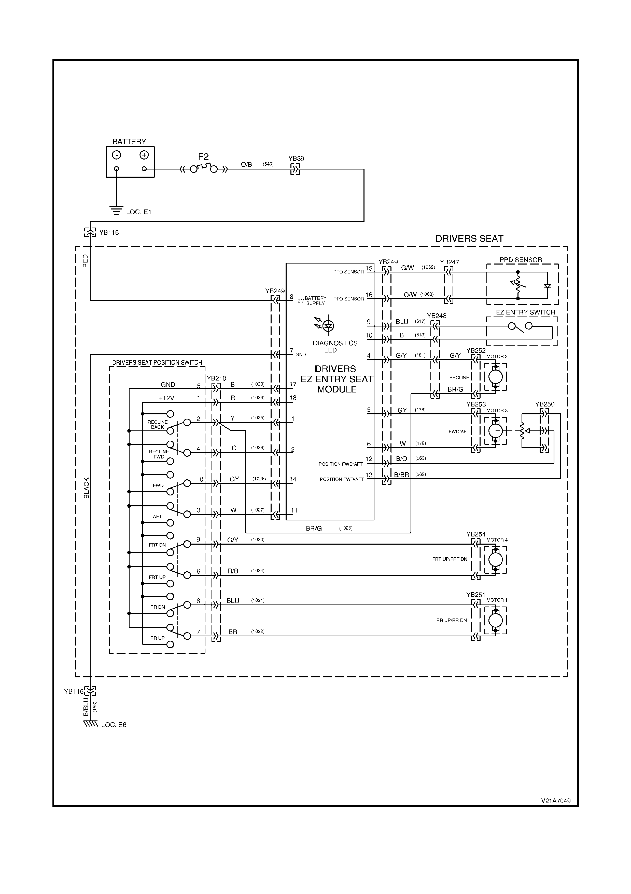
NON-MEMORY TYPE DRIVER’S SEAT CIRCUIT DIAGRAM AND CONNECTORS
Figure 1A7-46
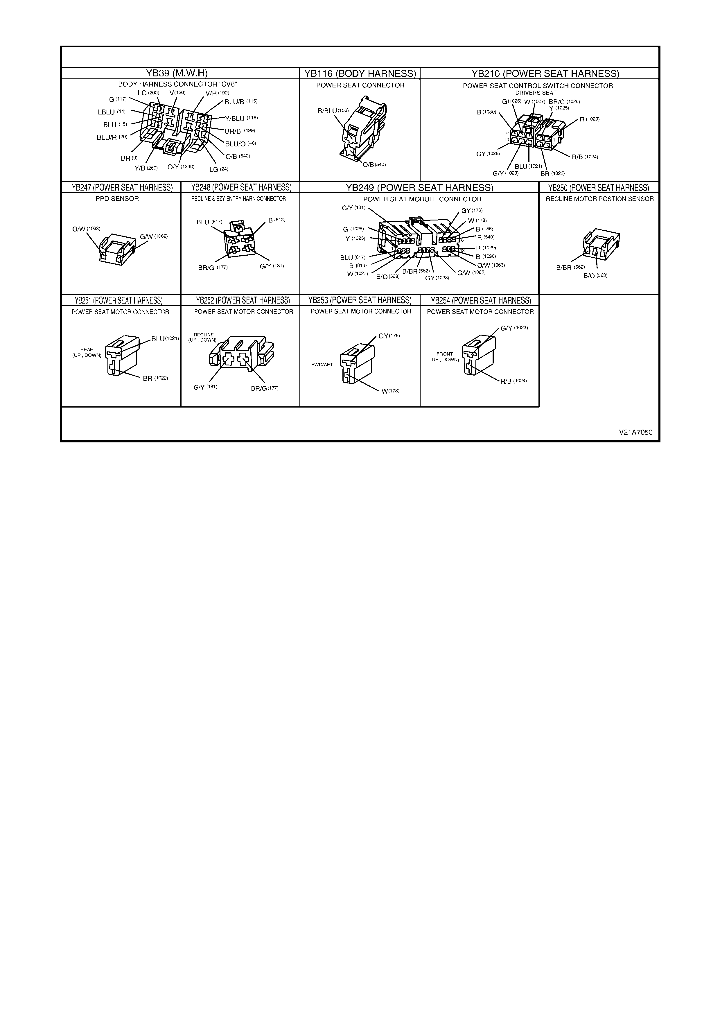
Figure 1A7-47
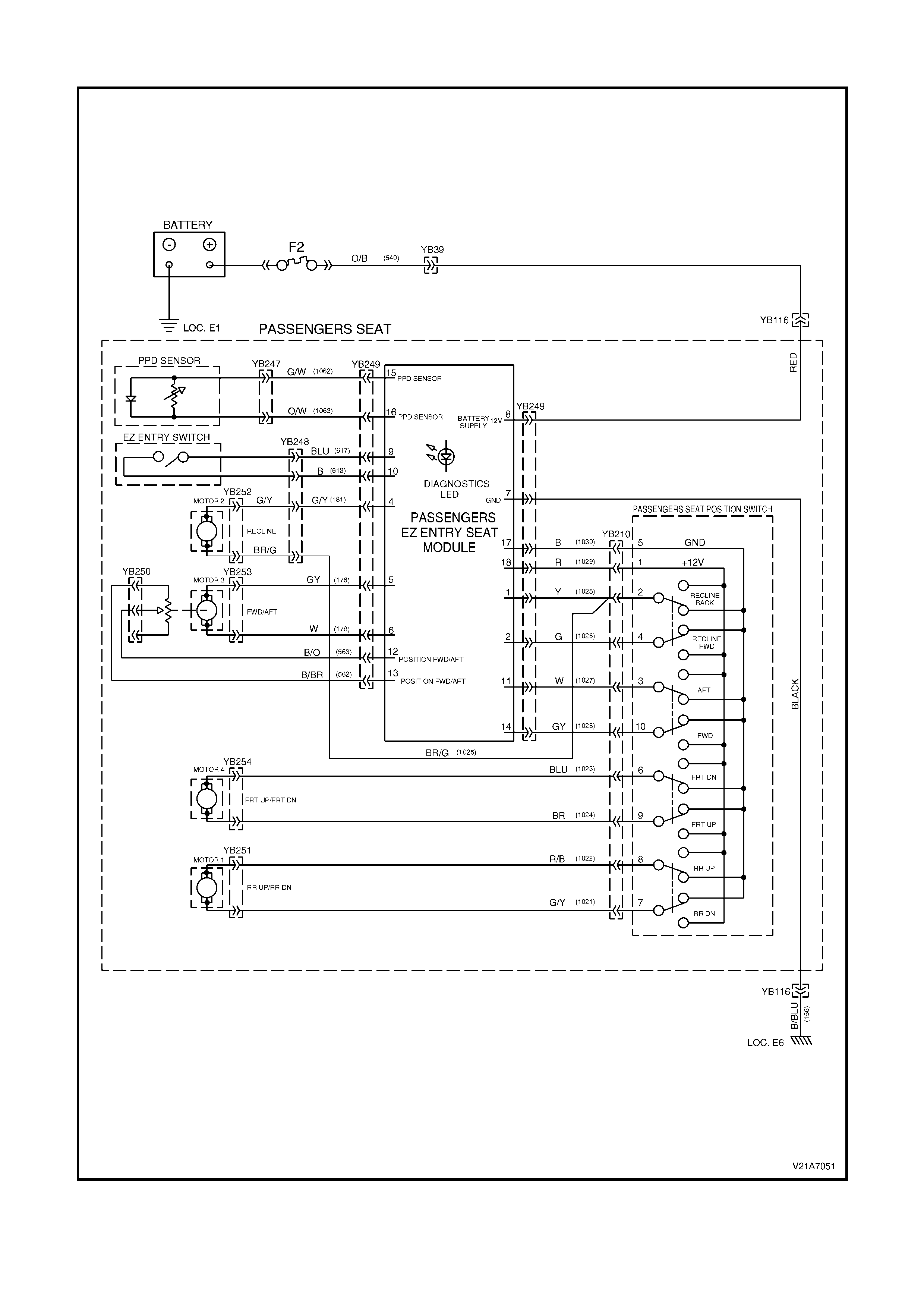
NON-MEMORY TYPE PASSENGER’S SEAT CIRCUIT DIA GRAM AND CONNECTORS
Figure 1A7-48
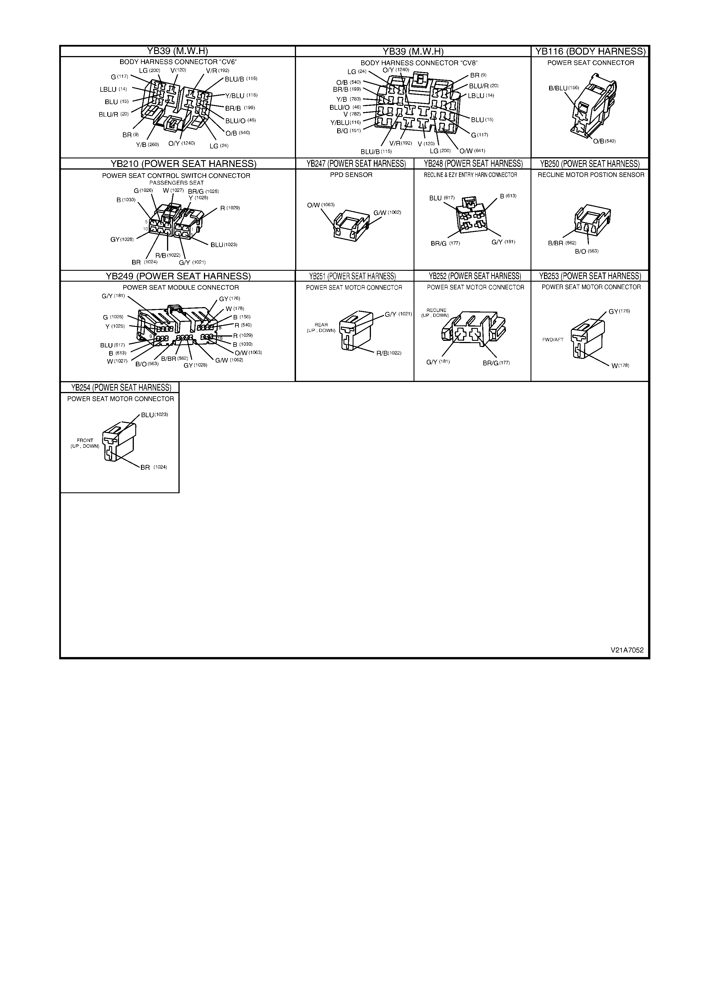
Figure 1A7-49
SEAT FRONT UP AND/OR DOWN FUNCTION INOPERATIVE
Introduction
This test verifies the correct operation of the seat front lift motor assembly and associated circuits and will aid the
technician to isolate a fault.
Test Description
The num bers below refer to Step num bers in the diagnostic chart for the front up and/or down function of the non-
memory type seat.
1. Checks the battery supply voltage and earth to the front lift motor connector YB254 when the function is
selected and determines if the fault is in the front lift motor.
2. Checks if the fault is in the eight-way seat adjusting switch or in the loom wiring between front lift motor
connector YB254 and the eight-way seat adjusting switch connector YB210.

Seat Front Up and/or Down Function Inoperative – Passenger’s Seat
STEP ACTION VALUE YES NO
1 • From under the front seat assembly, back probe the
seat front lift motor wiring harness connector YB254,
between circuit 1023 (Blue wire) and circuit 1024
(Brown wire) connections with a test lamp.
• Operate the seat front lift motor.
Does the test lamp illuminate?
Replace the seat
front lift motor
assembly, refer
2.16 FRONT
SEAT LIFT
MOTORS in this
Section. Recheck
and verify repair.
Go to Step 2.
2 • Back probe the seat switch connector YB210,
between circuit 1023 (Blue wire) and circuit 1024
(Brown wire) connections with a test lamp.
• Operate the seat front lift motor.
Does the test lamp illuminate?
Check and repair
the open in
circuits 1023 or
circuit 1024
between the
eight-way seat
adjusting switch
connector YB210
and the seat front
lift motor
connector
YB254. Recheck
and verify repair.
Replace the
eight-way seat
adjusting switch,
refer to 2.3
EIGHT WAY
SEAT
ADJUSTING
SWITCH in this
Section. Recheck
and verify repair.
Seat Front Up and/or Down Function Inoperative – Driver’s Seat
STEP ACTION VALUE YES NO
1 • From under the front seat assembly, back probe the
seat front lift motor wiring harness connector YB254,
between circuit 1023 (Green/Yellow wire) and circuit
1024 (Red/Black wire) connections with a test lamp.
• Operate the seat front lift motor.
Does the test lamp illuminate?
Replace the seat
front lift motor
assembly, refer
2.16 FRONT
SEAT LIFT
MOTORS in this
Section. Recheck
and verify repair.
Go to Step 2.
2 • Back probe the seat switch connector YB210,
between circuit 1023 (Green/Yellow wire) and circuit
1024 (Red/Black wire) connections with a test lamp.
• Operate the seat front lift motor.
Does the test lamp illuminate?
Check and repair
the open in
circuits 1023 or
circuit 1024
between the
eight-way seat
adjusting switch
connector YB210
and the seat front
lift motor
connector
YB254. Recheck
and verify repair.
Replace the
eight-way seat
adjusting switch,
refer to 2.3
EIGHT WAY
SEAT
ADJUSTING
SWITCH in this
Section. Recheck
and verify repair.
SEAT REAR UP AND/OR DOWN FUNCTION INOPERATIVE
Introduction
This test verifies the correct operation of the seat rear lift motor assembly and associated circuits and will aid the
technician in isolating the faulty assembly/circuit.
Test Description
The numbers below refer to Step numbers in the diagnostic chart for the rear up and/or down function of the non-
memory type seat.
1. Checks the battery supply voltage and earth to the rear lift motor connector YB251 when the function is selected
and determines if the fault is in the rear lift motor.
2. Checks if the fault is in the eight-way seat adjusting switch or in the loom wiring between rear lift motor
connector YB251 and the eight-way seat adjusting switch connector YB210.

Seat Rear Up and/or Down Function Inoperative – Passenger’s Seat
STEP ACTION VALUE YES NO
1 • From under the front seat assembly, back probe the
seat rear lift motor wiring harness connector YB251,
between circuit 1021 (Green/Yellow wire) and circuit
1022 (Red/Black wire) connections with a test lamp.
• Operate the seat rear lift motor.
Does the test lamp illuminate?
Replace the seat
rear lift motor
assembly, refer
2.16 FRONT
SEAT LIFT
MOTORS in this
Section. Recheck
and verify repair.
Go to Step 2.
2 • Back probe the seat switch connector YB210,
between circuit 1021 (Green/Yellow wire) and circuit
1022 (Red/Black wire) connections with a test lamp.
• Operate the seat rear lift motor.
Does the test lamp illuminate?
Check and repair
the open in
circuits 1021 or
circuit 1022
between the
eight-way seat
adjusting switch
connector YB210
and the seat rear
lift motor
connector
YB251. Recheck
and verify repair.
Replace the
eight-way seat
adjusting switch,
refer to 2.3
EIGHT WAY
SEAT
ADJUSTING
SWITCH in this
Section. Recheck
and verify repair.
Seat Rear Up and/or Down Function Inoperative – Driver’s Seat
STEP ACTION VALUE YES NO
1 • From under the front seat assembly, back probe the
seat rear lift motor wiring harness connector YB251,
between circuit 1021 (Blue wire) and circuit 1022
(Brown wire) connections with a test lamp.
• Operate the seat rear lift motor.
Does the test lamp illuminate?
Replace the seat
rear lift motor
assembly, refer
2.16 FRONT
SEAT LIFT
MOTORS in this
Section. Recheck
and verify repair.
Go to Step 2.
2 • Back probe seat switch connector YB210, between
circuit 1021 (Blue wire) and circuit 1022 (Brown wire)
connections with a test lamp.
• Operate the seat rear lift motor.
Does the test lamp illuminate?
Check and repair
the open in
circuits 1021 or
circuit 1022
between the
eight-way seat
adjusting switch
connector YB210
and the seat rear
lift motor
connector
YB251. Recheck
and verify repair.
Replace the
eight-way seat
adjusting switch,
refer to 2.3
EIGHT WAY
SEAT
ADJUSTING
SWITCH in this
Section. Recheck
and verify repair.
SEAT RECLINER FORWARD AND/OR BACK FUNCTION INOPERATIVE
Introduction
This test verifies the correct operation of the seat recliner motor assembly and associated circuits and will aid the
technician in isolating the faulty assembly/circuit.
Test Description
The numbers below refer to Step numbers in the diagnostic chart for the recliner forward and/or back function of the
non-memory type seat.
1. Checks the battery supply voltage and earth to the recliner motor connector YB252 when the function is
selected and determines if the fault is in the recliner motor.
2. Checks if the fault is in the eight-way seat adjusting switch.
3. Checks if the fault is in the loom wiring between the seat control module connector YB249 and the eight-way
seat adjusting switch connector YB210.
4. Isolates the fault to the loom wiring between the seat control module connector YB249 and the seat reclining
motor connector YB252, including connector YB248, or to the seat control module.
5. Checks the recliner motor mechanism for any visible faults that would cause the seat recliner to be inoperative.

Seat Recliner Forward and/or Back Function Inoperative
STEP ACTION VALUE YES NO
1 • From under the front seat assembly, back probe the
seat reclining motor wiring harness connector
YB252, between circuits 181 (Green/Yellow wire)
and circuit 1025 (Brown/Green wire) connections
with a test lamp.
• Operate the seat reclining motor.
Does the test lamp illuminate?
Go to Step 5. Go to Step 2.
2 • Back probe the eight-way seat adjusting switch
connector YB210, between circuit 1026 (Green wire)
and circuit 1025 (Yellow wire) connections with a test
lamp.
• Operate the seat reclining motor.
Does the test lamp illuminate?
Go to Step 3. Replace the
eight-way seat
adjusting switch,
refer to 2.3
EIGHT-WAY
SEAT
ADJUSTING
SWITCH in this
Section. Recheck
and verify repair.
3 • Back probe the seat control module connector
YB249, between circuit 1026 (Green wire) and circuit
1025 (Yellow wire) connections with a test lamp.
• Operate the seat reclining motor.
Does the test lamp illuminate?
Go to Step 4. Check and repair
the open in
circuit 1026
(Green wire) or
circuit 1025
(Yellow wire)
between the
eight-way seat
adjusting switch
connector YB210
and the seat
control module
connector
YB249. Recheck
and verify repair.
4 • Back probe the seat control module connector
YB249, between circuits 1025 (Yellow wire) and
circuit 181 (Green/Yellow wire) connections with a
test lamp.
• Operate the seat reclining motor.
Does the test lamp illuminate?
Check and repair
the open in
circuit 1025 or
circuit 181
between the seat
control module
connector YB249
and the seat
reclining motor
connector
YB252, including
connector
YB248. Recheck
and verify repair.
Replace the seat
control module,
refer to 2.5
FRONT SEAT
CONTROL
MODULE in this
Section. Recheck
and verify repair.
5 • W ith the seat reclining motor and gearbox assembly
exposed (seat back cover and pad removed),
visually inspect the reclining mechanism for the
cause of the fault, i.e. a bent drive shaft, loose motor,
etc.
Are there any visible faults that would cause the seat
recliner to be inoperative?
Repair as
necessary.
Recheck and
verify repair.
Replace the seat
reclining motor,
refer to 2.18
FRONT SEAT
RECLINING
MOTOR,
GEARBOX AND
POTENTIOMETER
ASSEMBLY in
this Section.
Recheck and
verify repair.

SEAT FORWARD AND/OR AFT FUNCTION INOPERATIVE
Introduction
This test verifies the correct operation of the seat track motor assembly and associated circuits and will aid the
technician in isolating the faulty assembly/circuit.
Test Description
The numbers below refer to Step numbers in the diagnostic chart for the forward and/or aft function of the non-
memory type seat.
1. Check s the battery supply voltage and earth to the trac k motor connector YB253 when the function is select ed
and determines if the fault is in the track motor.
2. Checks if the fault is in the eight-way seat adjusting switch.
3. Checks if the fault is in the loom wiring between the seat control module connector YB249 and the eight-way
seat adjusting switch connector YB210.
4. Is olates the f ault to the loom wiring between the seat control module connector YB249 and the seat track motor
connector YB253 or to the seat control module.
Seat Forward and/or Aft Function Inoperative
STEP ACTION VALUE YES NO
1 • Back probe the seat forward/aft track motor wiring
harness connector YB253, between circuit 176 (Grey
wire) and circuit 178 (W hite wire) connections with a
test lamp.
• Operate the seat fore/aft track motor.
Does the test lamp illuminate?
Replace the seat
fore/aft track
motor assembly,
refer to 2.17
FRONT SEAT
FORE/AFT
MOVEMENT
MOTOR in this
Section. Recheck
and verify repair.
Go to Step 2.
2 • Back probe the eight-way seat adjusting switch
connector YB210, between circuit 1028 (Grey wire)
and circuit 1027 (W hite wire) connections with a test
lamp.
• Operate the seat fore/aft track motor.
Does the test lamp illuminate?
Go to Step 3. Replace the
eight-way seat
adjusting switch,
refer to 2.3
EIGHT-WAY
SEAT
ADJUSTING
SWITCH in this
Section. Recheck
and verify repair.
3 • Back probe the seat control module connector
YB249, between circuit 1028 (Grey wire) and circuit
1027 (White wire) connections with a test lamp.
• Operate the seat fore/aft motor.
Does the test lamp illuminate?
Go to Step 4. Check and repair
the open in
circuit 1028 or
circuit 1027
between the
eight-way seat
adjusting switch
connector YB210
and the seat
control module
connector
YB249. Recheck
and verify repair.
4 • Back probe the seat control module connector
YB249, between circuit 176 (Grey wire) and circuit
178 (White wire) connections with a test lamp.
• Operate the seat fore/aft track motor.
Does the test lamp illuminate?
Check and repair
the open in
circuit 176 or
circuit 178
between the seat
control module
connector YB249
and the seat
fore/aft track
motor connector
YB253. Recheck
and verify repair.
Replace the seat
control module,
refer to 2.5
FRONT SEAT
CONTROL
MODULE in this
Section. Recheck
and verify repair.

TRACK MOTOR POSITION SENSOR POTENTIOMETER TEST
Introduction
This test verifies the correct operation of the seat track motor position sensor and associated circuits and will aid the
technician in isolating the faulty assembly/circuit.
Test Description
The numbers below refer to Step numbers in the diagnostic chart f or the track m otor position sens or potentiometer
test of the non-memory type seat.
1. Checks if the fault is in the track motor potentiometer side from connector YB249 or if the fault is in the seat
control module.
2. Isolates the fault to either the track motor potentiometer or the loom wiring between the track motor
potentiometer connector YB250 and the seat control module connector YB249.
Track Motor Position Sensor Potentiometer Test
STEP ACTION VALUE YES NO
1 • Disconnect the seat control module connector
YB249.
• Using a digital multimeter set to measure resistance,
probe between circuit 582 (Black/Brown wire) and
circuit 583 (Black/Orange wire) connections with the
motor at each end of travel.
Is the resistance reading as specified?
Across the
potentiometer
wiper =
0 – 10 kΩ
(variable,
depending on
seat position).
Track motor
potentiometer
and loom wiring
OK. Replace the
seat control
module, refer to
2.5 FRONT
SEAT CONTROL
MODULE in this
Section. Recheck
and verify repair.
Go to Step 2.
2 • Disconnect the seat track motor position sensor
wiring harness connector YB250.
• Using a digital multimeter set to measure resistance,
probe between the motor terminals with the motor at
each end of travel.
Is the resistance reading as specified?
Across the
potentiometer
= 10 kΩ.
Across the
potentiometer
wiper =
0 – 10 kΩ
(variable,
depending on
seat position).
Track motor
potentiometer
OK. Check and
repair the open in
circuit 582 or
circuit 583
between the seat
control module
connector YB249
and the track
motor position
sensor wiring
harness
connector
YB250. Recheck
and verify repair.
Track motor
potentiometer
faulty. Replace
the track motor
and
potentiometer
assembly, refer
to 2.17 FRONT
SEAT FORE/AFT
MOVEMENT
MOTOR in this
Section.
NOTE: The track
motor and
position sensor
potentiometer
form one
assembly and
are not
serviceable as
separate items.
EIGHT-WAY SEAT ADJUSTING SWITCH TEST
Introduction
This test verifies the correct operation of the eight-way seat position switch and associated circuits and will aid the
technician in isolating the faulty assembly/circuit.
Test Description
The numbers below refer to Step numbers in the diagnostic chart for the eight-way seat position switch test of the
non-memory type seat.
1. Checks the correct operation of the eight-way seat position switch and the integrity of the loom wiring from
connector YB249 (for the switched battery supply).
2. Isolates the fault to either the eight-way seat position switch or the loom wiring between the eight-way seat
position switch connector YB210 and the seat control module connector YB249 (for the switched battery
supply).
3. Checks the correct operation of the eight-way seat position switch and the integrity of the loom wiring from
connector YB249 (for the switched earth supply).
4. Isolates the fault to either the eight-way seat position switch or the loom wiring between the eight-way seat
position switch connector YB210 and the seat control module connector YB249 (for the switched earth supply).

Eight-way Seat Adjusting Switch Test
STEP ACTION VALUE YES NO
1 • From under the front seat side cover assembly,
disconnect the seat control module connector
YB249.
• Using a digital multimeter set to measure resistance,
measure the resistance between the switched
battery supply circuit 1029 (Red wire) and each of
the following circuits on connector YB249:
Driver’s seat:
Circuit 1021 (Blue wire – Rear down)
Circuit 1022 (Brown wire – Rear up)
Circuit 1023 (Green/Yellow wire – Front down)
Circuit 1024 (Red/Black wire – Front up)
Circuit 1025 (Yellow wire – Recline back)
Circuit 1026 (Green wire – Recline forward)
Circuit 1027 (White wire – Track aft)
Circuit 1028 (Grey wire – Track forward)
Passenger’s seat:
Circuit 1021 (Green/Yellow wire – Rear down)
Circuit 1022 (Red/Black wire – Rear up)
Circuit 1023 (Blue wire – Front down)
Circuit 1024 (Brown wire – Front up)
Circuit 1025 (Yellow wire – Recline back)
Circuit 1026 (Green wire – Recline forward)
Circuit 1027 (White wire – Track aft)
Circuit 1028 (Grey wire – Track forward)
Are the readings as specified?
Function
selected =
continuity.
Idle state =
open circuit.
Go to Step 3. Go to Step 2.
2 • From under the front seat side cover assembly,
disconnect the eight-way seat adjusting switch
connector YB210.
• Using a digital multimeter set to measure resistance,
measure the resistance between the switched
battery supply terminal 1 and each of the following
terminals on the eight-way seat adjusting switch:
Driver’s seat:
Terminal 2 (Recline back)
Terminal 4 (Recline forward)
Terminal 3 (Track aft)
Terminal 10 (Track forward)
Terminal 9 (Front down)
Terminal 6 (Front up)
Terminal 8 (Rear down)
Terminal 7 (Rear up)
Passenger’s seat:
Terminal 2 (Recline back)
Terminal 4 (Recline forward)
Terminal 3 (Track aft)
Terminal 10 (Track forward)
Terminal 9 (Front up)
Terminal 6 (Front down)
Terminal 8 (Rear up)
Terminal 7 (Rear down)
Are the readings as specified?
Function
selected =
continuity.
Idle state =
open circuit.
Eight-way seat
adjusting switch
OK. Check and
repair the open in
the faulty circuit/s
between the seat
control module
connector YB249
and the eight-
way seat
adjusting switch
wiring harness
connector
YB210. Recheck
and verify repair.
Replace the
eight-way seat
adjusting switch,
refer to 2.3
EIGHT-WAY
SEAT
ADJUSTING
SWITCH in this
Section. Recheck
and verify repair.

STEP ACTION VALUE YES NO
3 • With the seat control module connector YB249
disconnected.
• Using a digital multimeter set to measure resistance,
measure the resistance between the sw itched earth
circuit 1030 (Black wire) and each of the following
circuits on connector YB249.
Driver’s seat:
Circuit 1021 (Blue wire – Rear up)
Circuit 1022 (Brown wire – Rear down)
Circuit 1023 (Green/Yellow wire – Front up)
Circuit 1024 (Red/Black wire – Front down)
Circuit 1025 (Yellow wire – Recline forward)
Circuit 1026 (Green wire – Recline back)
Circuit 1027 (White wire – Track forward)
Circuit 1028 (Grey wire – Track aft)
Passenger’s seat:
Circuit 1021 (Green/Yellow wire – Rear up)
Circuit 1022 (Red/Black wire – Rear down)
Circuit 1023 (Blue wire – Front up)
Circuit 1024 (Brown wire – Front down)
Circuit 1025 (Yellow wire – Recline forward)
Circuit 1026 (Green wire – Recline back)
Circuit 1027 (White wire – Track forward)
Circuit 1028 (Grey wire – Track aft)
Are the readings as specified?
Function
selected =
continuity.
Idle state =
open circuit.
Eight-way seat
adjusting switch
OK.
Go to Step 4.
4 • With the eight-way seat adjusting switch connector
YB210 disconnected.
• Using a digital multimeter set to measure resistance,
measure the resistance between the sw itched earth
terminal 5 and each of the following terminals on the
eight-way seat adjusting switch:
Driver’s seat;
Terminal 2 (Recline forward)
Terminal 4 (Recline back)
Terminal 3 (Track forward)
Terminal 10 (Track aft)
Terminal 6 (Front down)
Terminal 9 (Front up)
Terminal 7 (Rear down)
Terminal 8 (Rear up)
Passenger’s seat;
Terminal 2 (Recline forward)
Terminal 4 (Recline back)
Terminal 3 (Track forward)
Terminal 10 (Track aft)
Terminal 6 (Front up)
Terminal 9 (Front down)
Terminal 7 (Rear up)
Terminal 8 (Rear down)
Are the readings as specified?
Function
selected =
continuity.
Idle state =
continuity.
Eight-way seat
adjusting switch
OK. Check and
repair the open in
the faulty circuit/s
between the seat
control module
connector YB249
and the eight-
way seat
adjusting switch
wiring harness
connector
YB210. Recheck
and verify repair.
Replace the
eight-way seat
adjusting switch,
refer to 2.3
EIGHT-WAY
SEAT
ADJUSTING
SWITCH in this
Section. Recheck
and verify repair.

EZ-ENTRY SEAT SYSTEM TEST
Introduction
This test verif ies the cor rec t oper ation of the Ez-entry seat system and ass oc iated cir cuits and will aid the technician
in isolating the faulty assembly/circuit.
Test Description
The numbers below refer to Step numbers in the diagnostic chart for the Ez-entry seat system test of the non-
memory type seat.
1. Checks the correct operation of the Ez-entry recliner mechanical release mechanism.
2. Checks the correct operation of the Ez-entry triggering circuit, with the track motor engaging and moving the
seat to the full forward position.
3. Checks the correct operation of the Ez-entry recliner mechanical latching mechanism.
4. Isolates the fault to either the Ez-entry switch side of the seat control module connector YB249 or to the seat
control module and track motor drive side.
5. Isolates the fault to either the Ez-entry switch or the loom wiring between the seat control module connector
YB249 and the recline motor/Ez-entry switch connector YB248.
Ez-entry Seat System Test
STEP ACTION VALUE YES NO
1 • Operate the Ez-entry seat lever.
Does the seat back recline mechanism disengage
properly and hinge forward easily?
Go to Step 2. Faulty or broken
Ez-entry cable
assembly or
release
mechanism.
Check the
release
mechanism for
binding or
damage.
Replace the Ez-
entry cable
assembly as
required, refer to
2.9 EZ-ENTRY
CABLE
ASSEMBLY in
this Section.
Recheck and
verify repair.
2 • With the operation of the Ez-entry seat lever.
Does the track motor engage moving the seat to the full
forward position?
Go to Step 3. Go to Step 4.
3 • Push the seat back into the upright position.
Does the seat back recline mechanism re-engage and
latch the seat back into the original position?
Go to Step 4. Faulty or broken
Ez-entry seat
release
mechanism.
Check the
release
mechanism for
binding or
damage.
Replace the front
seat back frame
assembly as
required, refer to
2.11 FRONT
SEAT BACK
FRAME,
LUMBAR
SUPPORT AND
ADJUSTER
ASSEMBLY in
this Section.
Recheck and
verify repair.

STEP ACTION VALUE YES NO
4 • From under the front seat side cover assembly,
disconnect the seat control module connector
YB249.
• Using a digital multimeter set to measure resistance,
measure the resistance between circuit 613 (*Black
wire) and circuit 617 (Blue wire).
Are the readings as specified?
*NOTE: Brown wire on some early production models.
Ez-entry
switch
operated =
continuity.
Ez-entry
switch latched
= open circuit.
Perform a Track
Motor
Potentiometer
Test on the track
motor sensor. If
the track motor
sensor tests OK.,
replace the seat
control module,
refer to 2.5
FRONT SEAT
CONTROL
MODULE in this
Section. Recheck
and verify repair.
Go to Step 5.
5 • From under the front seat side cover assembly,
disconnect the recline motor/Ez-entry switch
connector YB248.
• Using a digital multimeter set to measure resistance,
measure the resistance between circuit 613 (Black
wire) and circuit 617 (Blue wire) on the Ez-entry
switch side of connector YB248.
Are the readings as specified?
Ez-entry
switch
operated =
continuity.
Ez-entry
switch latched
= open circuit.
Check and repair
the open in
circuit 613 or
circuit 617
between the seat
control module
connector YB249
and the recline
motor/Ez-entry
switch connector
YB248. Recheck
and verify repair.
Replace the
Ez-entry seat
switch and wiring
loom assembly,
refer to 2.11
FRONT SEAT
BACK FRAME,
LUMBAR
SUPPORT AND
ADJUSTER
ASSEMBLY in
this Section.
NOTE: The
Ez-entry seat
switch and wiring
loom form one
assembly and
are not
serviceable as
separate items.
OCCUPANT SENSING MAT TEST
Introduction
This test verifies the correct operation of the occupant sensing mat and associated circuits and will aid the
technician in isolating the faulty assembly/circuit.
Test Description
The numbers below refer to Step numbers in the diagnostic chart for the occupant sensing mat test of the non-
memory type seat.
1. Chec k s the cor rect operation of the oc cupant sens ing m at inbuilt diode and the integrity of the loom wiring f rom
the seat control module connector YB249.
2. Checks the correct operation of the occupant sensing mat (including the high impedance reverse bais of the
diode) with no weight on the seat, from the seat control module connector YB249.
3. Checks the correct operation of the occupant sensing mat (including the high impedance reverse bais of the
diode) with a weight in excess of 15 kg on the seat, from the seat control module connector YB249.
4. Isolates the fault to either the occupant sensing mat or the loom wiring between the seat control module
connector YB249 and the occupant sensing mat connector YB247.

Occupant Sensing Mat Test
STEP ACTION VALUE YES NO
1 • From under the front seat side cover assembly,
disconnect the seat control module connector
YB249.
• Using the digital multimeter J39200 set to DIODE
mode, to measure the forward voltage drop, connect
the red probe to circuit 1062 (Green/W hite wire) and
the black probe to circuit 1063 (Orange/White wire).
Is the voltage drop reading as specified?
or
• If using an alternate digital multimeter set to
measure diode forward resistance, connect the red
probe to circuit 1062 (Green/White wire) and the
black probe to circuit 1063 (Orange/White wire).
Is continuity present?
J39200 = less
than 0.75 V
or
Alternate
multimeter =
approximately
continuity
Go to Step 2. Go to Step 4.
2 • With the seat control module connector YB249
disconnected.
• Using a digital multimeter set to measure resistance,
connect the black probe to circuit 1062 (Green/W hite
wire) and the red probe to circuit 1063
(Orange/White wire).
Is the resistance reading as specified?
Greater than
50 kΩ Go to Step 3. Go to Step 4.
3 • With the seat control module connector YB249
disconnected and the digital multimeter still
connected as in Step 2.
• Place a weight great than 15 kg on the seat.
Is the resistance reading as specified?
Less than
50 kΩ
(resistance
decreases as
the weight
increases)
End of diagnosis. Replace the
occupant sensing
mat, refer to 2.12
FRONT SEAT
CUSHION PAD
AND COVER
ASSEMBLY in
this Section.
Recheck and
verify repair.
NOTE: The
occupant sensing
mat is sealed
inside the seat
cushion and is
only available as
part of a seat
cushion
assembly.
4 • From under the front seat, disconnect the occupant
sensing mat connector YB247.
• Repeat Steps 1 to 3 from the occupant sensing mat
side of connector YB247.
Are the resistance readings as specified?
Step 1 = less
than 0.75 V
(using
J39200) or
approximately
continuity
(using
alternate
multimeter).
Step 2 =
greater than
50 kΩ.
Step 3 = less
than 50 kΩ.
Check and repair
the open in
circuit 1062 or
circuit 1063
between the seat
control module
connector YB249
and the occupant
sensing mat
connector
YB247. Recheck
and verify repair.
Replace the
occupant sensing
mat, refer to 2.12
FRONT SEAT
CUSHION PAD
AND COVER
ASSEMBLY in
this Section.
Recheck and
verify repair.
NOTE: The
occupant sensing
mat is sealed
inside the seat
cushion and is
only available as
part of a seat
cushion
assembly.

3.6 GENE RAL DIAG NOSTIC CHARTS – ME MORY TYP E SEAT
INTRODUCTION
The general diagnostic charts for the memory type seats are designed as both:
• Stand-alone checks f or inves tigating f aults not cover ed by the diagnostic test c odes pr oduc ed by the seat control
module.
• Check s to complim ent the diagnostic test c odes flashed out by the seat control m odule. W hen check ed against
the Diagnostic Test Codes table, refer to 3.4 DIAGNOSTICS – MEMORY TYPE SEAT in this Section.
Reference is made to this Section, in the Corrective Action column, when further investigation is required to
isolate the fault.
Diagnostic Charts Covering Faults Not Supported by the DTC
The following general diagnostic charts provide checks that cover faults not supported by the seat control module
diagnostic test codes:
• Total failure of the seat, i.e. the seat does not move in any direction.
• Ez-entry seat system test.
• Diagnostic Charts Covering Faults Supported by the DTC
• The following general diagnostic charts provide checks that compliment the diagnostic test codes:
• Seat forward and/or aft function inoperative.
• Seat front up and/or down function inoperative.
• Seat rear up and/or down function inoperative.
• Seat recliner forward and/or back function inoperative.
• Track motor position sensor potentiometer test.
• Forward lift motor position sensor potentiometer test.
• Aft lift motor position sensor potentiometer test.
• Recliner motor position sensor potentiometer test.
• Eight-way seat adjusting switch test.
• Memory position switch test.
• Priority signal lines test.
• Occupant sensing mat test.
MEMORY SEAT DOES NOT MOVE IN ANY DIRECTION
Test Description
The numbers below refer to Step numbers in the diagnostic chart for the memory type seat.
1. Checks motor supply voltage and earth to body harness power seat connector YB226.
2. Checks if the fault is in the motor supply voltage circuit 540, up to body harness power seat connector YB226.
3. Checks if the fault is in the earth circuit 156, up to body harness power seat connector YB226.
4. Checks motor supply voltage and earth to memory seat control module connector YB227.
5. Checks electronics supply voltage and earth to body harness power seat connector YB226.
6. Checks if the fault is in the electronics supply voltage circuit 641, up to body harness power seat connector
YB226.
7. Checks if the fault is in the earth circuit 151, up to body harness power seat connector YB226.
8. Checks if the fault is between YB226 and YB227/YB229 or in the memory seat control module.
Memory Seat Does Not Move in Any Direction
STEP ACTION VALUE YES NO
1 • Back probe body harness power seat connector
YB226 (at the side of the front seat assembly),
circuit 540 (Orange/Black wire) and circuit 156
(Black/Blue wire) with a test lamp.
Does the test lamp illuminate?
Go to Step 4. Go to Step 2.
2 • Disconnect body harness from the power seat
connector YB226.
• Using a digital multimeter set to measure DC
voltage, measure voltage at circuit 540
(Orange/Black wire) connection and a sound earth
connection.
Is voltage as specified?
Battery +
Approximately
12 volts
Go to Step 3. Check and repair
open circuit in
circuit 540
(including circuit
breaker F2).
Verify repair.

STEP ACTION VALUE YES NO
3 • With body harness power seat connector YB226
disconnected.
• Check for continuity between circuit 156 (Black/Blue
wire) connection and earth location E6.
Is continuity present?
Continuity Connect YB226
to the body
harness, then go
to Step 4.
Check and repair
earth circuit 156.
Verify repair.
4 • Back probe memory seat control module connector
YB227 circuit 540 (Red wire) and circuit 156 (Black
wire) connections with a test lamp.
Does the test lamp illuminate?
Go to Step 5. Check and repair
open in circuit
540 or circuit 156
between memory
seat control
module
connector YB227
and body
harness
connector
YB226. Verify
repair.
5 • Back probe body harness power seat connector
YB226 (at the side of the front seat assembly),
circuit 641 (Orange/White wire) and circuit 151
(Black/Green wire) with a test lamp.
Does the test lamp illuminate?
Go to Step 8. Go to Step 6.
6 • Disconnect body harness from the power seat
connector YB226.
• Using a digital multimeter set to measure DC
voltage, measure voltage at circuit 641
(Orange/White wire) connection and a sound earth
connection.
Is voltage as specified?
Battery +
Approximately
12 volts
Go to Step 7. Check and repair
open circuit in
circuit 641
(including circuit
breaker F3).
Verify repair.
7 • With body harness power seat connector YB226
disconnected.
• Check for continuity between circuit 151
(Black/Green wire) connection and earth location
E3.
Is continuity present?
Continuity Connect YB226
to the body
harness, then go
to Step 8.
Check and repair
earth circuit 151.
Verify repair.
8 • Back probe memory seat control module connector
YB225 circuit 641 (Orange/Black wire) and
connector YB229 circuit 151 (Black/Yellow wire)
connections with a test lamp.
Does the test lamp illuminate?
Replace the
memory seat
control module,
refer to 2.5
FRONT SEAT
CONTROL
MODULE in this
Section. Verify
repair.
Check and repair
open in circuit
641 or circuit 151
between memory
seat control
module
connectors
YB225 and
YB229 and body
harness
connector
YB226. Verify
repair.

MEMORY TYPE DRIVER’S SEAT CIRCUIT DIAGRAM AND CONNECTORS
Figure 1A7-50
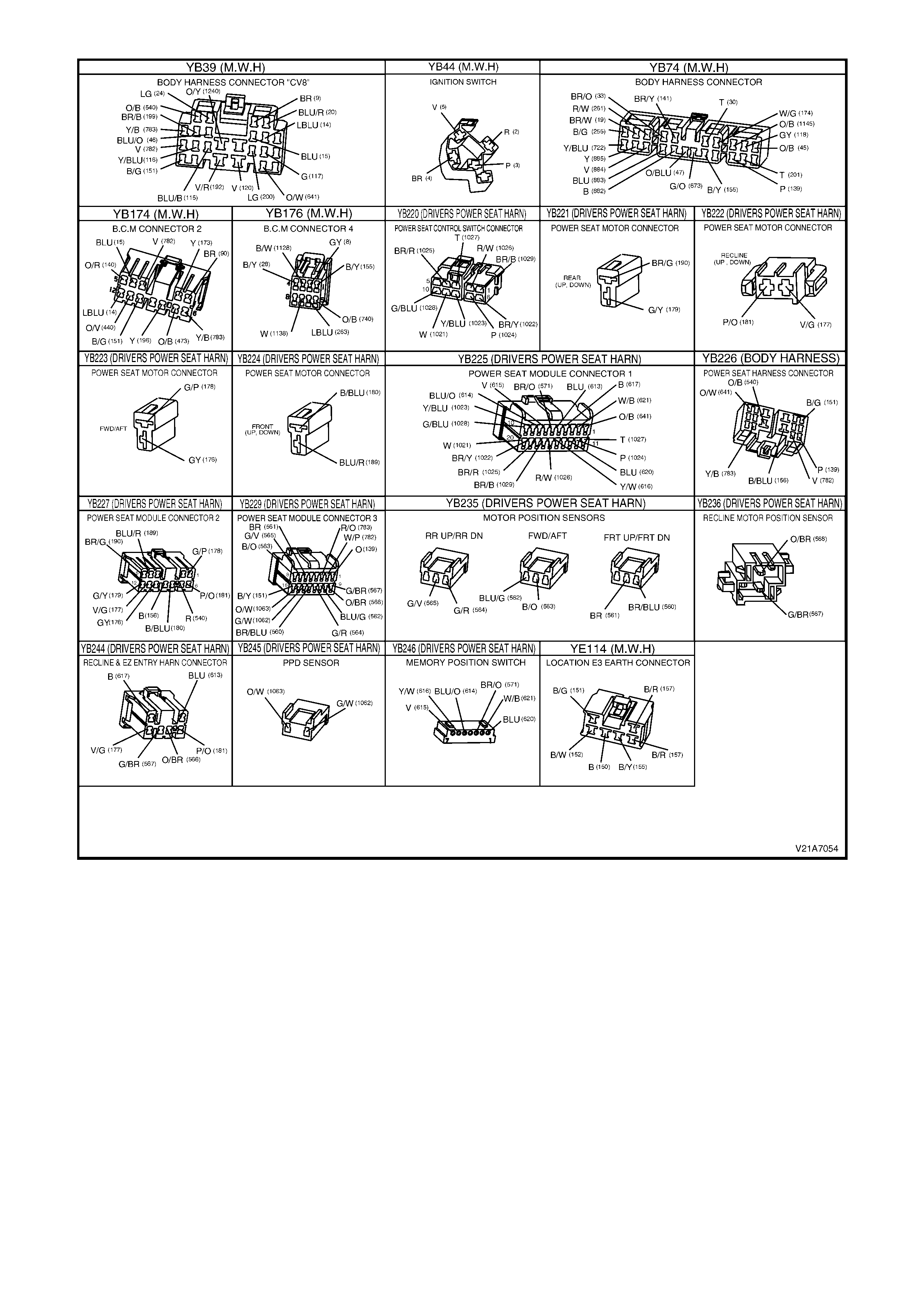
Figure 1A7-51
EZ-ENTRY SEAT SYSTEM TEST
Introduction
This test verif ies the cor rec t oper ation of the Ez-entry seat system and ass oc iated cir cuits and will aid the technician
in isolating the faulty assembly/circuit.
Test Description
The numbers below refer to Step numbers in the diagnostic chart for the Ez-entry seat system test of the memory
type seat.
1. Checks the correct operation of the Ez-entry recliner mechanical release mechanism.
2. Checks the correct operation of the Ez-entry triggering circuit, with the track motor engaging and moving the
seat to the full forward position.
3. Checks the correct operation of the Ez-entry recliner mechanical latching mechanism.
4. Isolates the fault to either the Ez-entry switch side of the seat control module connector YB225 or to the seat
control module and track motor drive side.
5. Isolates the fault to either the Ez-entry switch or the loom wiring between the seat control module connector
YB225 and the Ez-entry switch connector YB244.

Ez-entry Seat System Test
STEP ACTION VALUE YES NO
1 • Operate the Ez-entry seat lever.
Does the seat back recline mechanism disengage
properly and hinge forward easily?
Go to Step 2. Faulty or broken
Ez-entry cable
assembly or
release
mechanism.
Check the
release
mechanism for
binding or
damage.
Replace the Ez-
entry cable
assembly as
required, refer to
2.9 EZ-ENTRY
CABLE
ASSEMBLY in
this Section.
Recheck and
verify repair.
2 • With the operation of the Ez-entry seat lever.
Does the track motor engage moving the seat to the full
forward position?
Go to Step 3. Go to Step 4.
3 • Push the seat back into the upright position.
Does the seat back recline mechanism re-engage and
latch the seat back into the original position?
Go to Step 4. Faulty or broken
Ez-entry seat
release
mechanism.
Check the
release
mechanism for
binding or
damage.
Replace the front
seat back frame
assembly as
required, refer to
2.11 FRONT
SEAT BACK
FRAME,
LUMBAR
SUPPORT AND
ADJUSTER
ASSEMBLY in
this Section.
Recheck and
verify repair.
4 • From under the front seat side cover assembly,
disconnect the seat control module connector
YB225.
• Using a digital multimeter set to measure resistance,
measure the resistance between circuit 613 (*Black
wire) and circuit 617 (Blue wire).
Are the readings as specified?
*NOTE: Brown wire on some early production models.
Ez-entry
switch
operated =
continuity.
Ez-entry
switch latched
= open circuit.
Perform a Track
Motor
Potentiometer
Test on the track
motor sensor. If
the track motor
sensor tests OK,
replace the
memory seat
control module,
refer to 2.5
FRONT SEAT
CONTROL
MODULE in this
Section. Recheck
and verify repair.
Go to Step 5.

STEP ACTION VALUE YES NO
5 • From under the front seat side cover assembly,
disconnect the Ez-entry switch connector YB244.
• Using a digital multimeter set to measure resistance,
measure the resistance between circuit 613 (Black
wire) and circuit 617 (Blue wire) on the Ez-entry
switch side of connector YB244.
Are the readings as specified?
Ez-entry
switch
operated =
continuity.
Ez-entry
switch latched
= open circuit.
Check and repair
the open in
circuit 613 or
circuit 617
between the seat
control module
connector YB225
and the Ez-entry
switch connector
YB244. Recheck
and verify repair.
Replace the
Ez-entry seat
switch and wiring
loom assembly,
refer to 2.11
FRONT SEAT
BACK FRAME,
LUMBAR
SUPPORT AND
ADJUSTER
ASSEMBLY in
this Section.
Recheck and
verify repair.
NOTE: The
Ez-entry seat
switch and wiring
loom form one
assembly and
are not
serviceable as
separate items.
SEAT FORWARD AND/OR AFT FUNCTION INOPERATIVE
Introduction
This test verifies the correct operation of the seat track motor assembly and associated circuits and will aid the
technician in isolating the faulty assembly/circuit.
Test Description
The numbers below ref er to Step num bers in the diagnos tic chart f or the forward and/or af t function of the mem ory
type seat.
1. Check s the battery supply voltage and earth to the trac k motor connector YB223 when the function is select ed
and determines if the fault is in the track motor.
2. Check s if the fault is in the loom wiring between the seat control m odule connector YB227 and the track m otor
connector YB223.
3. Checks if the fault is in the eight-way seat adjusting switch (forward movement).
4. Checks if the fault is in the eight-way seat adjusting switch (aft movement).
5. Isolates the fault to the loom wiring between the seat control module connector YB225 and the eight-way seat
adjusting switch connector YB220 or to the seat control module (forward movement).
6. Isolates the fault to the loom wiring between the seat control module connector YB225 and the eight-way seat
adjusting switch connector YB220 or to the seat control module (aft movement).
Seat Forward and/or Aft Function Inoperative
STEP ACTION VALUE YES NO
1 • Back probe the seat forward/aft track motor wiring
harness connector YB223, between circuit 176 (Grey
wire) and circuit 178 (Green/Pink wire) connections
with a test lamp.
• Operate the seat fore/aft track motor.
Does the test lamp illuminate?
Replace the seat
fore/aft track
motor assembly,
refer to 2.17
FRONT SEAT
FORE/AFT
MOVEMENT
MOTOR in this
Section. Recheck
and verify repair.
Go to Step 2.
2 • Back probe the memory seat control module
connector YB227, between circuit 176 (Grey wire)
and circuit 178 (Green/Pink wire) connections with a
test lamp.
• Operate the seat fore/aft track motor.
Does the test lamp illuminate?
Check and repair
the open in circuit
176 or circuit 178
between the seat
forward/aft track
motor wiring
harness
connector YB223
and the memory
seat control
module connector
YB227. Recheck
and verify repair.
If the seat is in or
close to the full
aft position, go to
Step 3 first and
then move on to
Step 4
(if required).
If the seat is in or
close to the full
forward position,
go to Step 4 first
and then move
back to Step 3
(if required).

STEP ACTION VALUE YES NO
3 • Disconnect the eight-way seat adjusting switch
connector YB220.
• Using a suitable jumper wire from the KM-609
connector test adaptor kit, momentarily bridge
between circuit 1028 (Green/Blue wire) and circuit
1029 (Brown/Black wire) connections.
Does the seat move forward?
Replace the eight-
way seat adjusting
switch, refer to 2.3
EIGHT-WAY
SEAT
ADJUSTING
SWITCH in this
Section. Recheck
and verify repair.
Go to Step 5.
4 • Disconnect the eight-way seat adjusting switch
connector YB220.
• Using a suitable jumper wire from the KM-609
connector test adaptor kit, momentarily bridge
between circuit 1027 (Tan wire) and circuit 1029
(Brown/Black wire) connections with a test lamp.
Does the seat move aft?
Replace the eight-
way seat adjusting
switch, refer to 2.3
EIGHT-WAY
SEAT
ADJUSTING
SWITCH in this
Section. Recheck
and verify repair.
Go to Step 6.
5 • Disconnect the seat control module connector
YB225.
• Using a suitable jumper wire from the KM-609
connector test adaptor kit, momentarily bridge
between circuit 1028 (Green/Blue wire) and circuit
1029 (Brown/Black wire) connections.
Does the seat move forward?
Check and repair
the open in circuit
1028 or circuit
1029 between the
eight-way seat
adjusting switch
connector YB220
and the memory
seat control
module connector
YB225. Recheck
and verify repair.
Replace the
memory seat
control module,
refer to 2.5
FRONT SEAT
CONTROL
MODULE in this
Section. Recheck
and verify repair.
6 • Disconnect the seat control module connector
YB225.
• Using a suitable jumper wire from the KM-609
connector test adaptor kit, momentarily bridge
between circuit 1027 (Tan wire) and circuit 1029
(Brown/Black wire) connections with a test lamp.
Does the seat move aft?
Check and repair
the open in circuit
1027 or circuit
1029 between the
eight-way seat
adjusting switch
connector YB220
and the memory
seat control
module connector
YB225. Recheck
and verify repair.
Replace the
memory seat
control module,
refer to 2.5
FRONT SEAT
CONTROL
MODULE in this
Section. Recheck
and verify repair.
SEAT FRONT UP AND/OR DOWN FUNCTION INOPERATIVE
Introduction
This test verifies the correct operation of the seat front lift motor assembly and associated circuits and will aid the
technician to isolate a fault.
Test Description
The numbers below refer to Step numbers in the diagnostic chart for the front up and/or down function of the
memory type seat.
1. Checks the battery supply voltage and earth to the front lift motor connector YB224 when the function is
selected and determines if the fault is in the front lift motor.
2. Checks if the fault is in the loom wiring between the seat control module connector YB227 and the front lift
motor connector YB224.
3. Checks if the fault is in the eight-way seat adjusting switch (down movement).
4. Checks if the fault is in the eight-way seat adjusting switch (up movement).
5. Isolates the fault to the loom wiring between the seat control module connector YB225 and the eight-way seat
adjusting switch connector YB220 or to the seat control module (down movement).
6. Isolates the fault to the loom wiring between the seat control module connector YB225 and the eight-way seat
adjusting switch connector YB220 or to the seat control module (up movement).

Seat Front Up and/or Down Function Inoperative
STEP ACTION VALUE YES NO
1 • From under the front seat assembly, back probe the
seat front lift motor wiring harness connector YB224,
between circuit 180 (Black/Blue wire) and circuit 189
(Blue/Red wire) connections with a test lamp.
• Operate the seat front lift motor.
Does the test lamp illuminate?
Replace the seat
front lift motor
assembly, refer
2.16 FRONT
SEAT LIFT
MOTORS in this
Section.
Go to Step 2.
2 • Back probe the memory seat control module
connector YB227, between circuit 180 (Black/Blue
wire) and circuit 189 (Blue/Red wire) connections
with a test lamp.
• Operate the seat front lift motor.
Does the test lamp illuminate?
Check and repair
the open in circuit
180 or circuit 189
between the seat
front lift motor
wiring harness
connector YB224
and the memory
seat control
module connector
YB227. Recheck
and verify repair.
If the seat front is
in or close to the
full up position,
go to Step 3 first
and then move
on to Step 4
(if required).
If the seat front is
in or close to the
full down
position, go to
Step 4 first and
then move back
to Step 3
(if required).
3 • Disconnect the eight-way seat adjusting switch
connector YB220.
• Using a suitable jumper wire from the KM-609
connector test adaptor kit, momentarily bridge
between circuit 1021 (White wire) and circuit 1029
(Brown/Black wire) connections.
Does the seat front move down?
Replace the eight-
way seat adjusting
switch, refer to 2.3
EIGHT-WAY
SEAT
ADJUSTING
SWITCH in this
Section. Recheck
and verify repair.
Go to Step 5.
4 • Disconnect the eight-way seat adjusting switch
connector YB220.
• Using a suitable jumper wire from the KM-609
connector test adaptor kit, momentarily bridge
between circuit 1022 (Brown/Yellow wire) and circuit
1029 (Brown/Black wire) connections.
Does the seat front move up?
Replace the eight-
way seat adjusting
switch, refer to 2.3
EIGHT-WAY
SEAT
ADJUSTING
SWITCH in this
Section. Recheck
and verify repair.
Go to Step 6.
5 • Disconnect the seat control module connector
YB225.
• Using a suitable jumper wire from the KM-609
connector test adaptor kit, momentarily bridge
between circuit 1021 (White wire) and circuit 1029
(Brown/Black wire) connections.
Does the seat front move down?
Check and repair
the open in circuit
1021 or circuit
1029 between the
eight-way seat
adjusting switch
connector YB220
and the memory
seat control
module connector
YB225. Recheck
and verify repair.
Replace the
memory seat
control module,
refer to 2.5
FRONT SEAT
CONTROL
MODULE in this
Section. Recheck
and verify repair.
6 • Disconnect the seat control module connector
YB225.
• Using a suitable jumper wire from the KM-609
connector test adaptor kit, momentarily bridge
between circuit 1022 (Brown/Yellow wire) and circuit
1029 (Brown/Black wire) connections.
Does the seat front move up?
Check and repair
the open in circuit
1022 or circuit
1029 between the
eight-way seat
adjusting switch
connector YB220
and the memory
seat control
module connector
YB225. Recheck
and verify repair.
Replace the
memory seat
control module,
refer to 2.5
FRONT SEAT
CONTROL
MODULE in this
Section. Recheck
and verify repair.

SEAT REAR UP AND/OR DOWN FUNCTION INOPERATIVE
Introduction
This test verifies the correct operation of the seat rear lift motor assembly and associated circuits and will aid the
technician to isolate a fault.
Test Description
The numbers below refer to Step numbers in the diagnostic chart for the rear up and/or down function of the
memory type seat.
1. Checks the battery supply voltage and earth to the rear lift motor connector YB223 when the function is selected
and determines if the fault is in the rear lift motor.
2. Checks if the fault is in the loom wiring between the seat control module connector YB227 and the rear lift
motor connector YB223.
3. Checks if the fault is in the eight-way seat adjusting switch (down movement).
4. Checks if the fault is in the eight-way seat adjusting switch (up movement).
5. Isolates the fault to the loom wiring between the seat control module connector YB225 and the eight-way seat
adjusting switch connector YB220 or to the seat control module (down movement).
6. Isolates the fault to the loom wiring between the seat control module connector YB225 and the eight-way seat
adjusting switch connector YB220 or to the seat control module (up movement).
Seat Rear Up and/or Down Function Inoperative
STEP ACTION VALUE YES NO
1 • From under the front seat assembly, back probe the
seat rear lift motor wiring harness connector YB221,
between circuit 179 (Green/Yellow wire) and circuit
190 (Brown/Green wire) connections with a test
lamp.
• Operate the seat rear lift motor.
Does the test lamp illuminate?
Replace the seat
front lift motor
assembly, refer
2.16 FRONT
SEAT LIFT
MOTORS in this
Section.
Go to Step 2.
2 • Back probe the memory seat control module
connector YB227, between circuit 179 (Green/Yellow
wire) and circuit 190 (Brown/Green wire) connections
with a test lamp.
• Operate the seat rear lift motor.
Does the test lamp illuminate?
Check and repair
the open in
circuit 179 or
circuit 190
between the seat
rear lift motor
wiring harness
connector YB221
and the memory
seat control
module
connector
YB227. Recheck
and verify repair.
If the seat rear is
in or close to the
full up position,
go to Step 3 first
and then move
on to Step 4
(if required).
If the seat rear is
in or close to the
full down
position, go to
Step 4 first and
then move back
to Step 3
(if required).
3 • Disconnect the eight-way seat adjusting switch
connector YB220.
• Using a suitable jumper wire from the KM-609
connector test adaptor kit, momentarily bridge
between circuit 1023 (Yellow/Blue wire) and circuit
1029 (Brown/Black wire) connections.
Does the seat rear move down?
Replace the
eight-way seat
adjusting switch,
refer to 2.3
EIGHT-WAY
SEAT
ADJUSTING
SWITCH.
Recheck and
verify repair.
Go to Step 5.
4 • Disconnect the eight-way seat adjusting switch
connector YB220.
• Using a suitable jumper wire from the KM-609
connector test adaptor kit, momentarily bridge
between circuit 1024 (Pink wire) and circuit 1029
(Brown/Black wire) connections.
Does the seat rear move up?
Replace the
eight-way seat
adjusting switch,
refer to 2.3
EIGHT-WAY
SEAT
ADJUSTING
SWITCH in this
Section. Recheck
and verify repair.
Go to Step 6.

STEP ACTION VALUE YES NO
5 • Disconnect the seat control module connector
YB225.
• Using a suitable jumper wire from the KM-609
connector test adaptor kit, momentarily bridge
between circuit 1023 (Yellow/Blue wire) and circuit
1029 (Brown/Black wire) connections.
Does the seat rear move down?
Check and repair
the open in
circuit 1023 or
circuit 1029
between the
eight-way seat
adjusting switch
connector YB220
and the memory
seat control
module
connector
YB225. Recheck
and verify repair.
Replace the
memory seat
control module,
refer to 2.5
FRONT SEAT
CONTROL
MODULE in this
Section. Recheck
and verify repair.
6 • Disconnect the seat control module connector
YB225.
• Using a suitable jumper wire from the KM-609
connector test adaptor kit, momentarily bridge
between circuit 1024 (Pink wire) and circuit 1029
(Brown/Black wire) connections.
Does the seat rear move up?
Check and repair
the open in
circuit 1024 or
circuit 1029
between the
eight-way seat
adjusting switch
connector YB220
and the memory
seat control
module
connector
YB225. Recheck
and verify repair.
Replace the
memory seat
control module,
refer to 2.5
FRONT SEAT
CONTROL
MODULE in this
Section. Recheck
and verify repair.
SEAT RECLINER FORWARD AND/OR BACK FUNCTION INOPERATIVE
Introduction
This test verifies the correct operation of the seat recliner motor assembly and associated circuits and will aid the
technician in isolating the faulty assembly/circuit.
Test Description
The numbers below refer to Step numbers in the diagnostic chart for the recliner forward and/or back function of the
memory type seat.
1. Checks the battery supply voltage and earth to the recliner motor connector YB222 when the function is
selected and determines if the fault is in the recliner motor.
2. Checks if the fault is in the loom wiring between the seat control module connector YB227 and the recliner
motor connector YB222, including connector YB244.
3. Checks if the fault is in the eight-way seat adjusting switch (back movement).
4. Checks if the fault is in the eight-way seat adjusting switch (forward movement).
5. Isolates the fault to the loom wiring between the seat control module connector YB225 and the eight-way seat
adjusting switch connector YB220 or to the seat control module (back movement).
6. Isolates the fault to the loom wiring between the seat control module connector YB225 and the eight-way seat
adjusting switch connector YB220 or to the seat control module (forward movement).
7. Checks the recliner motor mechanism for any visible faults that would cause the seat recliner to be inoperative.
Seat Recliner Forward and/or Back Function Inoperative
STEP ACTION VALUE YES NO
1 • From under the front seat assembly, back probe the
seat reclining motor wiring harness connector
YB222, between circuit 177 (Violet/Green wire) and
circuit 181 (Pink/Orange wire) connections with a
test lamp.
• Operate the seat reclining motor.
Does the test lamp illuminate?
Go to Step 7. Go to Step 2.

STEP ACTION VALUE YES NO
2 • Back probe the memory seat control module
connector YB227, between circuit 177 (Violet/Green
wire) and circuit 181 (Pink/Orange wire) connections
with a test lamp.
• Operate the seat reclining motor.
Does the test lamp illuminate?
Check and repair
the open in circuit
177 or circuit 181
between the seat
recliner motor
wiring harness
connector YB222
and the memory
seat control
module connector
YB227 (including
YB244). Recheck
and verify repair.
If the seat back is
in or close to the
full forward
position, go to
Step 3 first and
then move on to
Step 4
(if required).
If the seat back is
in or close to the
full back position,
go to Step 4 first
and then move
back to Step 3
(if required).
3 • Disconnect the eight-way seat adjusting switch
connector YB220.
• Using a suitable jumper wire from the KM-609
connector test adaptor kit, momentarily bridge
between circuit 1026 (Red/White wire) and circuit
1029 (Brown/Black wire) connections.
Does the seat back move back?
Replace the eight-
way seat adjusting
switch, refer to 2.3
EIGHT-WAY
SEAT
ADJUSTING
SWITCH in this
Section. Recheck
and verify repair.
Go to Step 5.
4 • Disconnect the eight-way seat adjusting switch
connector YB220.
• Using a suitable jumper wire from the KM-609
connector test adaptor kit, momentarily bridge
between circuit 1025 (Brown/Red wire) and circuit
1029 (Brown/Black wire) connections.
Does the seat back move forward?
Replace the eight-
way seat adjusting
switch, refer to 2.3
EIGHT-WAY
SEAT
ADJUSTING
SWITCH in this
Section. Recheck
and verify repair.
Go to Step 6.
5 • Disconnect the seat control module connector
YB225.
• Using a suitable jumper wire from the KM-609
connector test adaptor kit, momentarily bridge
between circuit 1026 (Red/White wire) and circuit
1029 (Brown/Black wire) connections.
Does the seat back move back?
Check and repair
the open in circuit
1026 or circuit
1029 between the
eight-way seat
adjusting switch
connector YB220
and the memory
seat control
module connector
YB225. Recheck
and verify repair.
Replace the
memory seat
control module,
refer to 2.5
FRONT SEAT
CONTROL
MODULE in this
Section. Recheck
and verify repair.
6 • Disconnect the seat control module connector
YB225.
• Using a suitable jumper wire from the KM-609
connector test adaptor kit, momentarily bridge
between circuit 1025 (Brown/Red wire) and circuit
1029 (Brown/Black wire) connections.
Does the seat back move forward?
Check and repair
the open in circuit
1025 or circuit
1029 between the
eight-way seat
adjusting switch
connector YB220
and the memory
seat control
module connector
YB225. Recheck
and verify repair.
Replace the
memory seat
control module,
refer to 2.5
FRONT SEAT
CONTROL
MODULE in this
Section. Recheck
and verify repair.
7 • W ith the seat reclining motor and gearbox assembly
exposed (seat back cover and pad removed),
visually inspect the reclining mechanism for the
cause of the fault, i.e. a bent drive shaft, loose motor,
etc.
Are there any visible faults that would cause the seat
recliner to be inoperative?
Repair as
necessary.
Recheck and
verify repair.
Replace the seat
reclining motor,
refer to 2.18
FRONT SEAT
RECLINING
MOTOR,
GEARBOX AND
POTENTIOMETER
ASSEMBLY in
this Section.

TRACK MOTOR POSITION SENSOR POTENTIOMETER TEST
Introduction
This test verifies the correct operation of the seat track motor position sensor and associated circuits and will aid the
technician in isolating the faulty assembly/circuit.
Test Description
The numbers below refer to Step numbers in the diagnostic chart f or the track m otor position sens or potentiometer
test of the memory type seat.
1. Checks if the fault is in the track motor potentiometer side from connector YB229 or if the fault is in the seat
control module.
2. Isolates the fault to either the track motor potentiometer or the loom wiring between the track motor
potentiometer connector YB235 and the seat control module connector YB229.
Track Motor Position Sensor Potentiometer Test
STEP ACTION VALUE YES NO
1 • Disconnect the seat control module connector
YB229.
• Using a digital multimeter set to measure resistance,
probe between circuit 582 (Blue/Green wire) and
circuit 583 (Black/Orange wire) connections with the
motor at each end of travel.
Is the resistance reading as specified?
Across the
potentiometer
wiper =
0 – 10 kΩ
(variable,
depending on
seat position).
End of diagnosis.
track motor
potentiometer
OK. Reconnect
YB229.
Go to Step 2.
2 • Disconnect the seat track motor position sensor
wiring harness connector YB235.
• Using a digital multimeter set to measure resistance,
probe between the motor terminals with the motor at
each end of travel.
Is the resistance reading as specified?
Across the
potentiometer
= 10 kΩ.
Across the
potentiometer
wiper =
0 – 10 kΩ
(variable,
depending on
seat position).
Track motor
potentiometer
OK. Check and
repair the open in
circuit 582 or
circuit 583
between the seat
control module
connector YB229
and the track
motor position
sensor wiring
harness
connector
YB235. Recheck
and verify repair.
Track motor
potentiometer
faulty. Replace
the track motor
and
potentiometer
assembly, refer
to 2.17 FRONT
SEAT FORE/AFT
MOVEMENT
MOTOR in this
Section.
NOTE: The track
motor and
position sensor
potentiometer
form one
assembly and
are not
serviceable as
separate items.
FRONT LIFT MOTOR POSITION SENSOR POTENTIOMETER TEST
Introduction
This test verifies the c orrect oper ation of the seat f ront lift m otor position sensor and ass ociated circuits and will aid
the technician in isolating the faulty assembly/circuit.
Test Description
The numbers below refer to Step numbers in the diagnostic chart for the front lift motor position sensor
potentiometer test of the memory type seat.
1. Check s if the fault is in the front lif t m otor potentiom eter s ide from connector YB229 or if the fault is in the seat
control module.
2. Isolates the fault to either the front lift motor potentiometer or the loom wiring between the front lift motor
potentiometer connector YB235 and the seat control module connector YB229.
Front Lift Motor Position Sensor Potentiometer Test
STEP ACTION VALUE YES NO
1 • Disconnect the seat control module connector
YB229.
• Using a digital multimeter set to measure resistance,
probe between circuit 580 (Brown/Blue wire) and
circuit 581 (Brown wire) connections with the motor
at each end of travel.
Is the resistance reading as specified?
Across the
potentiometer
wiper =
0 – 10 kΩ
(variable,
depending on
seat position).
End of diagnosis.
Front lift motor
potentiometer
OK. Reconnect
YB229.
Go to Step 2.

STEP ACTION VALUE YES NO
2 • Disconnect the seat front lift motor position sensor
wiring harness connector YB235.
• Using a digital multimeter set to measure resistance,
probe between the motor terminals with the motor at
each end of travel.
Is the resistance reading as specified?
Across the
potentiometer
= 10 kΩ.
Across the
potentiometer
wiper =
0 – 10 kΩ
(variable,
depending on
seat position).
Front lift motor
potentiometer
OK. Check and
repair the open in
circuit 580 or
circuit 581
between the seat
control module
connector YB229
and the front lift
motor position
sensor wiring
harness
connector
YB235. Recheck
and verify repair.
Front lift motor
potentiometer
faulty. Replace
the front lift motor
and
potentiometer
assembly, refer
to 2.16 FRONT
SEAT LIFT
MOTORS in this
Section.
NOTE: The front
lift motor and
position sensor
potentiometer
form one
assembly and
are not
serviceable as
separate items.
REAR LIFT MOTOR POSITION SENSOR POTENTIOMETER TEST
Introduction
This test verifies the cor rect operation of the s eat rear lift m otor position sensor and associated circuits and will aid
the technician in isolating the faulty assembly/circuit.
Test Description
The numbers below refer to Step numbers in the diagnostic chart for the rear lift motor position sensor
potentiometer test of the memory type seat.
1. Check s if the fault is in the rear lift motor potentiom eter side f rom connec tor YB229 or if the fault is in the seat
control module.
2. Isolates the fault to either the rear lift motor potentiometer or the loom wiring between the rear lift motor
potentiometer connector YB235 and the seat control module connector YB229.
Rear Lift Motor Position Sensor Potentiometer Test
STEP ACTION VALUE YES NO
1 • Disconnect the seat control module connector
YB229.
• Using a digital multimeter set to measure resistance,
probe between circuit 584 (Green/Red wire) and
circuit 585 (Green/Violet wire) connections with the
motor at each end of travel.
Is the resistance reading as specified?
Across the
potentiometer
wiper =
0 – 10 kΩ
(variable,
depending on
seat position).
End of diagnosis.
Rear lift motor
potentiometer
OK. Reconnect
YB229.
Go to Step 2.
2 • Disconnect the seat rear lift motor position sensor
wiring harness connector YB235.
• Using a digital multimeter set to measure resistance,
probe between the motor terminals with the motor at
each end of travel.
Is the resistance reading as specified?
Across the
potentiometer
= 10 kΩ.
Across the
potentiometer
wiper =
0 – 10 kΩ
(variable,
depending on
seat position).
Rear lift motor
potentiometer
OK. Check and
repair the open in
circuit 584 or
circuit 585
between the seat
control module
connector YB229
and the rear lift
motor position
sensor wiring
harness
connector
YB235. Recheck
and verify repair.
Rear lift motor
potentiometer
faulty. Replace
the rear lift motor
and
potentiometer
assembly, refer
to 2.16 FRONT
SEAT LIFT
MOTORS in this
Section.
NOTE: The rear
lift motor and
position sensor
potentiometer
form one
assembly and
are not
serviceable as
separate items.

RECLINER MOTOR POSITION SENSOR POTENTIOMETER TEST
Introduction
This test verifies the c orrect oper ation of the seat rec liner m otor position sensor and associated c ircuits and will aid
the technician in isolating the faulty assembly/circuit.
Test Description
The numbers below refer to Step numbers in the diagnostic chart for the recliner motor position sensor
potentiometer test of the memory type seat.
1. Check s if the fault is in the r ecliner motor potentiometer side f rom c onnector YB229 or if the fault is in the seat
control module.
2. Isolates the fault to either the recliner motor potentiometer or the loom wiring between the recliner motor
potentiometer connector YB236 and the seat control module connector YB229.
Recliner Motor Position Sensor Potentiometer Test
STEP ACTION VALUE YES NO
1 • Disconnect the seat control module connector
YB229.
• Using a digital multimeter set to measure resistance,
probe between circuit 586 (Orange/Brown wire) and
circuit 587 (Green/Brown wire) connections with the
motor at each end of travel.
Is the resistance reading as specified?
Across the
potentiometer
wiper =
0 – 10 kΩ
(variable,
depending on
seat position).
End of diagnosis.
Recliner motor
potentiometer
OK. Reconnect
YB229.
Go to Step 2.
2 • Disconnect the seat recliner motor position sensor
wiring harness connector YB236.
• Using a digital multimeter set to measure resistance,
probe between the motor terminals with the motor at
each end of travel.
Is the resistance reading as specified?
Across the
potentiometer
= 10 kΩ.
Across the
potentiometer
wiper =
0 – 10 kΩ
(variable,
depending on
seat position).
Recliner motor
potentiometer
OK. Check and
repair the open in
circuit 586 or
circuit 587
between the seat
control module
connector YB229
and the recliner
motor position
sensor wiring
harness
connector
YB236, including
connector
YB244. Recheck
and verify repair.
Recliner motor
potentiometer
faulty. Replace
the recliner motor
and
potentiometer
assembly, refer
to 2.18 FRONT
SEAT
RECLINING
MOTOR,
GEARBOX
POTENTIOMETER
ASSEMBLY in
this Section.
NOTE: The front
lift motor and
position sensor
potentiometer
form one
assembly and
are not
serviceable as
separate items.
EIGHT-WAY SEAT ADJUSTING SWITCH TEST
Introduction
This test verifies the correct operation of the eight-way seat position switch and associated circuits and will aid the
technician in isolating the faulty assembly/circuit.
Test Description
The numbers below refer to Step numbers in the diagnostic chart for the eight-way seat position switch test of the
memory type seat.
1. Checks the correct operation of the eight-way seat position switch and the integrity of the loom wiring from
connector YB225 (for the switched earth).
2. Isolates the fault to either the eight-way seat position switch or the loom wiring between the eight-way seat
position switch connector YB220 and the seat control module connector YB225 (for the switched earth).

Eight-way Seat Adjusting Switch Test
STEP ACTION VALUE YES NO
1 • From under the front seat side cover assembly,
disconnect the memory seat control module
connector YB225.
• Using a digital multimeter set to measure resistance,
measure the resistance between circuit 1029
(Brown/Black wire) and the following circuits on
connector YB225:
Circuit 1021 (White wire – Front down)
Circuit 1022 (Brown/Yellow wire – Front up)
Circuit 1023 (Yellow/Blue wire – Rear down)
Circuit 1024 (Pink wire – Rear up)
Circuit 1025 (Brown/Red wire – Recline forward)
Circuit 1026 (Red/White wire – Recline back)
Circuit 1027 (Tan wire – Track aft)
Circuit 1028 (Green/Blue wire – Track forward)
Are the readings as specified?
Function
selected =
continuity.
Idle state =
open circuit.
Eight-way seat
adjusting switch
and wiring OK.
End of diagnosis.
Go to Step 2.
2 • From under the front seat side cover assembly,
disconnect the eight-way seat adjusting switch
connector YB220.
• Using a digital multimeter set to measure resistance,
measure the resistance between the switched earth
terminal 1 and each of the following terminals on the
eight-way seat adjusting switch:
Terminal 9 (Seat front down)
Terminal 6 (Seat front up)
Terminal 8 (Seat rear down)
Terminal 7 (Seat rear up)
Terminal 2 (Recline back)
Terminal 4 (Recline forward)
Terminal 3 (Track aft)
Terminal 10 (Track forward)
Are the readings as specified?
Function
selected =
continuity.
Idle state =
open circuit.
Eight-way seat
adjusting switch
OK. Check and
repair the open in
the faulty circuit/s
between the
memory seat
control module
connector YB225
and the eight-
way seat
adjusting switch
wiring harness
connector
YB220. Recheck
and verify repair.
Replace the
eight-way seat
adjusting switch,
refer to 2.3
EIGHT-WAY
SEAT
ADJUSTING
SWITCH in this
Section.
MEMORY POSITION SWITCH TEST
Introduction
This test verif ies the cor rect oper ation of the m emor y position switch and LED and will aid the technician in isolating
the faulty assembly/circuit.
Test Description
The numbers below refer to Step numbers in the diagnostic chart for the memory position switch and LED test of
the memory type seat.
1. Check s the correct operation of the mem ory position s witch and the integrity of the loom wiring from connector
YB225.
2. Checks the correct operation of the memory position switch LED and the integrity of the loom wiring from
connector YB225
3. Isolates the fault to either the memory position switch or the loom wiring between the memory position switch
connector YB246 and the seat control module connector YB225.
4. Isolates the fault to either the memory position switch LED or the loom wiring between the memory position
switch connector YB246 and the seat control module connector YB225.

Memory Position Switch and LED Test
STEP ACTION VALUE YES NO
1 • From under the front seat side cover assembly,
disconnect the memory seat control module
connector YB225.
• Using a digital multimeter set to measure resistance,
measure the resistance between the circuit 620
(Blue wire) and the following circuits on connector
YB225:
M1 – circuit 615 (Violet wire)
M2 – circuit 616 (Yellow/White wire)
M3 – circuit 614 (Blue/Orange wire)
Are the readings as specified?
Function
selected =
continuity.
Idle state =
open circuit.
Go to Step 2. Go to Step 3.
2 • With the memory seat control module connector
YB225 disconnected.
• Using a digital multimeter set to diode test mode,
measure between circuit 621 (White/Black) and
circuit 571 (Brown/Orange) at connector YB225 and
note the reading.
• Reverse the multimeter leads and note the new
reading.
Are the readings as specified?
Between
1 – 2 V in one
direction.
Maximum
scale in the
other
direction.
End of diagnosis. Go to Step 4.
3 • From under the front seat side cover assembly,
disconnect the memory position switch connector
YB246.
• Using a digital multimeter set to measure resistance,
measure the resistance between the following
terminals on the memory position switch:
1 and 7 (M1)
1 and 6 (M2)
1 and 5 (M3)
Are the readings as specified?
Function
selected =
continuity.
Idle state =
open circuit.
Memory position
switch OK.
Check and repair
the open in
circuits 614, 615
or circuit 616
between the
memory seat
control module
connector YB225
and the memory
position switch
wiring harness
connector
YB246. Recheck
and verify repair.
Replace the
memory position
switch, refer to
2.4 MEMORY
POSITION
SWITCH in this
Section.
4 • From under the front seat side cover assembly,
disconnect the memory position switch connector
YB246.
• Using a digital multimeter set to diode test mode,
measure between terminals 2 and 3 on the memory
position switch and note the reading.
• Reverse the multimeter leads and note the new
reading.
Are the readings as specified?
Between
1 – 2 V in one
direction.
Maximum
scale in the
other
direction.
Memory position
switch OK.
Check and repair
the open in
circuits 621 or
circuit 571
between the
memory seat
control module
connector YB225
and the memory
position switch
wiring harness
connector
YB246. Recheck
and verify repair.
Replace the
memory position
switch, refer to
2.4 MEMORY
POSITION
SWITCH in this
Section.
PRIORITY SIGNAL LINES TEST
Introduction
This test verifies the correct operation of the Priority 1 and Priority 2 key signal lines and will aid the technician in
isolating the faulty assembly/circuit.
Test Description
The numbers below ref er to Step numbers in the diagnos tic c har t f or the pr iority signal lines test of the memory type
seat.
1. Checks for the presence of the priority 1 signal from the BCM at the memory seat control module connector
YB229.
2. Checks for the presence of the priority 2 signal from the BCM at the memory seat control module connector
YB229.

3. Isolates the priority 1 signal fault to either the BCM or the loom wiring between the BCM c onnector YB174 and
the memory seat control module connector YB229.
4. Isolates the priority 2 signal fault to either the BCM or the loom wiring between the BCM c onnector YB174 and
the memory seat control module connector YB229.
Priority Signal Lines Test
STEP ACTION VALUE YES NO
1 • Insert the Priority 1 key into the ignition switch.
• Using a digital multimeter set to measure DC
voltage, measure the voltage between the body
harness power seat connector YB229 (from under
the front seat side cover assembly), circuit 782
(White/Pink wire) and a sound earth connection.
Is the voltage as specified?
OFF =
approximately
11.6 V.
IGN =
approximately
0.8 V.
Replace the
memory seat
control module,
refer to 2.5
FRONT SEAT
CONTROL
MODULE in this
Section.
Go to Step 2.
Go to Step 3.
2 • Insert the Priority 2 key into the ignition switch.
• Using a digital multimeter set to measure DC
voltage, measure the voltage between the body
harness power seat connector YB229 circuit 783
(Red/Orange wire) and a sound earth connection.
Is the voltage as specified?
OFF =
approximately
11.6 V.
IGN =
approximately
0.8 V.
Replace the
memory seat
control module,
refer to 2.5
FRONT SEAT
CONTROL
MODULE in this
Section. Verify
repair.
Go to Step 4.
3 • With the Priority 1 key still inserted into the ignition
switch.
• Disconnect the body control module connector
YB174, refer to Section 12J BODY CONTROL
MODULE.
• Using a digital multimeter set to measure DC
voltage, measure the voltage between the body
control module terminal 3 and a sound earth
connection.
Is the voltage as specified?
OFF =
approximately
11.6 V.
IGN =
approximately
0.8 V.
Check and repair
open in circuit
782 between
memory seat
control module
connector YB229
and body control
module
connector
YB174. Verify
repair.
Possible fault in
the body control
module. Refer to
Section 12J
BODY
CONTROL
MODULE for
further diagnostic
procedures to
isolate the fault.
4 • With the Priority 2 key still inserted into the ignition
switch.
• Disconnect the body control module connector
YB174, refer to Section 12J BODY CONTROL
MODULE.
• Using a digital multimeter set to measure DC
voltage, measure the voltage between the body
control module terminal 6 and a sound earth
connection.
Is the voltage as specified?
OFF =
approximately
11.6 V.
IGN =
approximately
0.8 V.
Check and repair
open in circuit
783 between
memory seat
control module
connector YB229
and body control
module
connector
YB174. Verify
repair.
Possible faulty
body control
module. Refer to
Section 12J
BODY
CONTROL
MODULE for
further diagnostic
procedures to
isolate the fault.
OCCUPANT SENSING MAT TEST
Introduction
This test verifies the correct operation of the occupant sensing mat and associated circuits and will aid the
technician in isolating the faulty assembly/circuit.
Test Description
The numbers below ref er to Step num bers in the diagnostic c hart for the oc cupant sensing m at test of the mem ory
type seat.
1. Chec k s the cor rect operation of the oc cupant sens ing m at inbuilt diode and the integrity of the loom wiring f rom
the seat control module connector YB229.
2. Checks the correct operation of the occupant sensing mat (including the high impedance reverse bais of the
diode) with no weight on the seat, from the seat control module connector YB229.
3. Checks the correct operation of the occupant sensing mat (including the high impedance reverse bais of the
diode) with a weight in excess of 15 kg on the seat, from the seat control module connector YB229.
4. Isolates the fault to either the occupant sensing mat or the loom wiring between the seat control module
connector YB229 and the occupant sensing mat connector YB245.

Occupant Sensing Mat Test
STEP ACTION VALUE YES NO
1 • From under the front seat side cover assembly,
disconnect the seat control module connector
YB229.
• Using the J39200 digital multimeter set to DIODE
mode, to measure the forward voltage drop, connect
the red probe to circuit 1062 (Green/W hite wire) and
the black probe to circuit 1063 (Orange/White wire).
Is the voltage drop reading as specified?
or
• If using an alternate digital multimeter set to
measure diode forward resistance, connect the red
probe to circuit 1062 (Green/White wire) and the
black probe to circuit 1063 (Orange/White wire).
Is continuity present?
J39200 = less
than 0.75 V.
or
Alternate
multimeter =
approximately
continuity.
Go to Step 2. Go to Step 4.
2 • With the seat control module connector YB229
disconnected.
• Using a digital multimeter set to measure resistance,
connect the black probe to circuit 1062 (Green/W hite
wire) and the red probe to circuit 1063
(Orange/White wire).
Is the resistance reading as specified?
Greater than
50 kΩ. Go to Step 3. Go to Step 4.
3 • With the seat control module connector YB229
disconnected and the digital multimeter still
connected as in Step 2.
• Place a weight great than 15 kg on the seat.
Is the resistance reading as specified?
Less than
50 kΩ
(resistance
decreases as
the weight
increases).
End of diagnosis. Replace the
occupant sensing
mat, refer to 2.12
FRONT SEAT
CUSHION PAD
AND COVER
ASSEMBLY in
this Section.
NOTE: The
occupant sensing
mat is sealed
inside of the seat
cushion and is
only available as
part of a seat
cushion
assembly.
4 • From under the front seat, disconnect the occupant
sensing mat connector YB245.
• Repeat Steps 1 to 3 from the occupant sensing mat
side of connector YB245.
Are the resistance readings as specified?
Step 1 = less
than 0.75 V
(using
J39200) or
approximately
continuity
(using
alternate
multimeter).
Step 2 =
greater than
50 kΩ.
Step 3 = less
than 50 kΩ.
Check and repair
the open in
circuit 1062 or
circuit 1063
between the seat
control module
connector YB229
and the occupant
sensing mat
connector
YB245. Recheck
and verify repair.
Replace the
occupant sensing
mat, refer to 2.12
FRONT SEAT
CUSHION PAD
AND COVER
ASSEMBLY in
this Section.
NOTE: The
occupant sensing
mat is sealed
inside of the seat
cushion and is
only available as
part of a seat
cushion
assembly.

4. TORQUE WRENCH SPECIFICATIONS
Nm
B pillar Upper Trim Retaining Screw..................................... 1.0 – 3.0
Child Seat Anchor Bolt.......................................................... 14 – 21
Front Seat Belt Guide Retaining Screw ................................ 2.4 – 3.4
Front Seat Cushion Frame to Seat Guide Rail
and Adjuster Assembly Bolt.................................................. 24 – 32
Front Seat to Floor Securing Bolt.......................................... 35 – 50
Garnish Retaining Screw ...................................................... 2.0
Outer Front Seat Guide Rail Cover....................................... 1.0 – 3.0
Rear Seat Back to Floor Retaining Bolt................................ 25 – 30
Rear Seat Back Lock Handle Retaining Screw..................... 3.0
Seat Back to Height Adjuster Assembly Securing Bolt......... 30 – 45
Seat Back to Seat Adjuster & Guide Rail Assembly
Securing Bolt......................................................................... 30 – 45
Seat Belt Buckle and Pre-tensioner Asm Bolt....................... 45 – 50
Seat Belt Buckle Anchor Securing Bolt................................. 35 – 50
Seat Belt guide Bracket Securing Bolt.................................. 20 – 22
Seat Belt Retractor Retaining Nut......................................... 35 – 50
Seat Belt Securing Bolt......................................................... 40 – 54
Side Inner Cover Retaining Screw........................................ 1.0 – 3.0
Side Impact Airbag Assembly to Front Seat Back
Frame Retaining Nut............................................................. 5.0 – 6.0
Front Seat Foam Block Insert Retaining Nut........................ 5.0 – 6.0
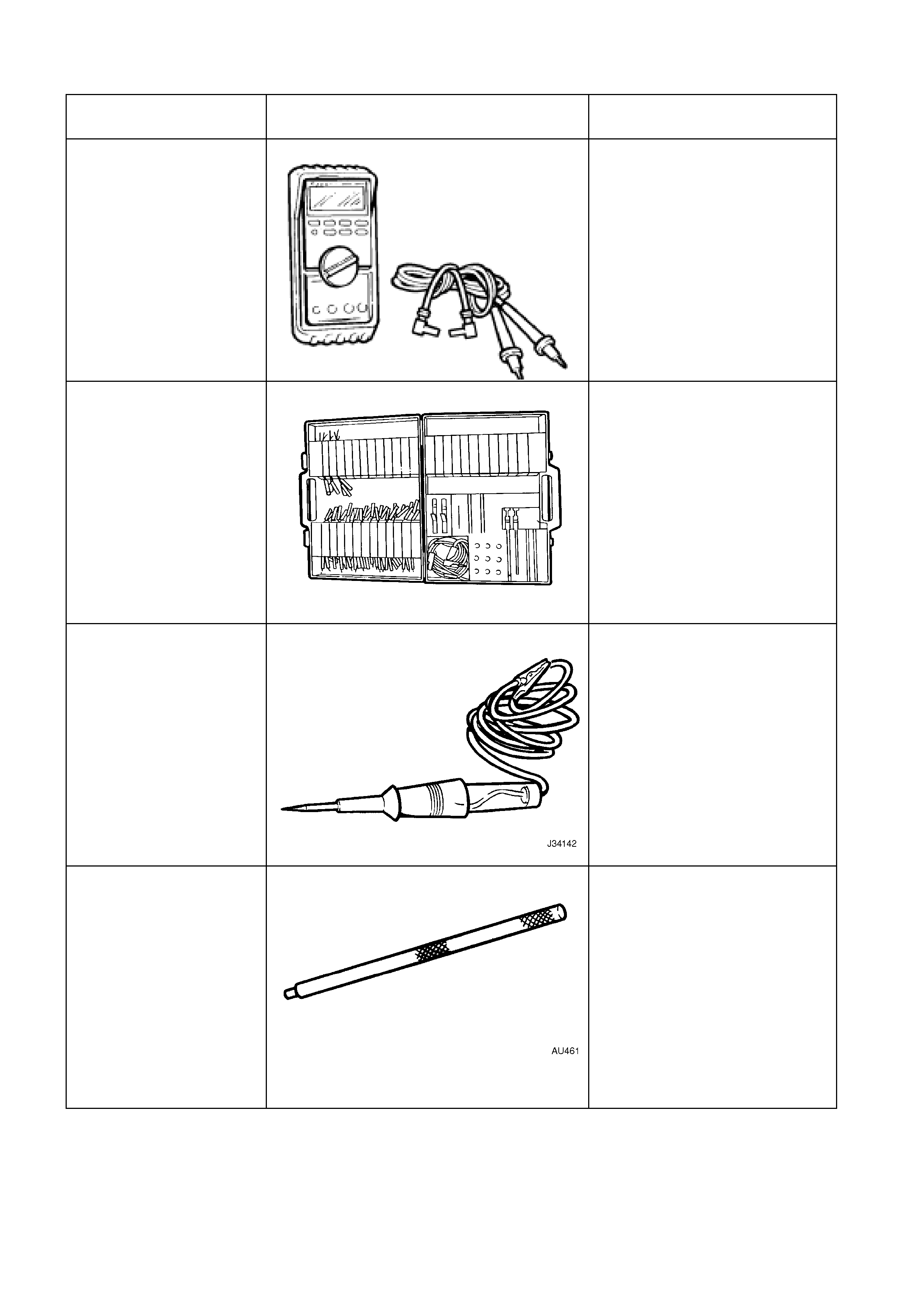
5. SPECIAL TOOLS
TOOL NO. REFERENCE
IN TEXT TOOL DESCRIPTION COMMENTS
J39200
DIGITAL MULTIMETER TOOL NO. J39200 PRE V IOUSLY
RELEASED, OR USE COMMERCIALLY
AVAILABLE EQUIVALENT. MUST HAVE
10 MOHM INPUT IMPEDANCE
KM-609 CONNECTOR TEST A DA P T OR K IT
PREVIOUSLY RELEASED FOR V CAR.
USED IN CONJUNCTION WITH A
MULTIMETER FOR ME ASURING
VOLTAGES AND RESISTANCES
WITHOUT DA MAGING WIRING
HARNESS CONNECTORS
J-34142-B UNPOWERED TEST LIGHT COMMERCIALLY AVAILABLE.
MUST HAVE A CURRENT
DRAW OF LESS THAN 0.3 A
AU461 CLEVIS PIN REMOVAL PUNCH