
SECTION 1A9 - EXTERIOR ORNAMENTATION
IMPORTANT
Before performing any Service Operation or other procedure described in this Section, refer to Section
00 CAUTIONS AND NOTES for correct workshop practices with regard to safety and/or property damage.
1. GENERAL DESCRIPTI ON
Exterior ornamentation on V2 Series Models includes:
• Various nameplates, emblems and decals depending on model variant.
• Door frame-opening mouldings.
• B-pillar mouldings.
• Roof finisher moulding.
• Rocker panel skirts.
• Door belt mouldings.
To help determine which components carry over, the Pictorial Index (refer 2.2 PICTORIAL INDEX in this Section)
provides a reference as to where to find the relevant service information for all exterior ornamentation components.
Exterior ornamentation components are secured to the body using various fasteners, double sided tape and
polyurethane adhesive.

2. SERVICE OPERATIONS
2.1 SERVICE NOTES
Numerous clips, fasteners, retainers, bushes, screws, nuts and contact adhesives are used to secure the various
exterior ornamentation components to the vehicle body. To loc ate the service inform ation applicable to a particular
component, refer to 2.2 PICTORIAL INDEX in this Section.
When removing, handling or installing exterior ornamentation components, the following care should be exercised:
1. Finishers adjacent to the component being removed should be covered with masking tape to prevent damage
to panels and paint work.
2. Removal of adhesive bonded nameplates and emblems is more easily achieved with the aid of a heat lamp
positioned adjacent to the part to be removed.
NOTE: Ensure that the heat lam p is not too close to the body, or the heat too intense to adversely affect the paint
finish.
3. Holes in body panels for scr ews, bolts , clips , etc . that c ould permit water entry into the body m us t be adequately
sealed with either a non-hardening sealer or presealed screws, clips, etc.
4. Using a clean cloth, clean the area of body surface where emblems, mouldings, etc. are to be applied with
‘Prepsol’ solvent or an equivalent.
5. It is essential that the body temperature of the vehicle be at least 21°C before adhering adhesive bonded
components to the vehicle.
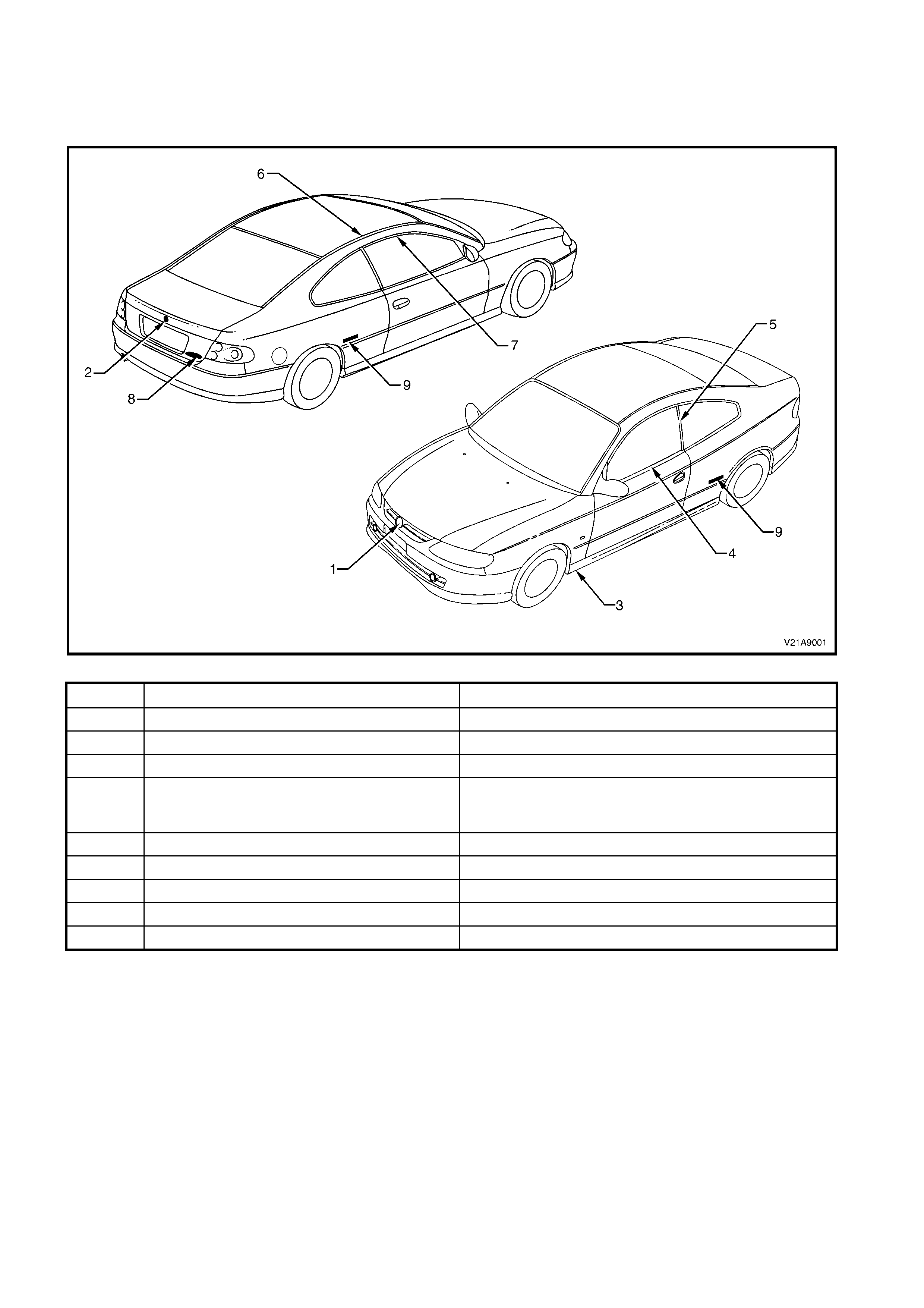
2.2 PICTORIAL INDEX
The following pictograph indexes provide a quick guide to finding the correct service procedure for the applicable
exterior ornam entation com ponent. Within this Sect ion, simply locate the appropriate com ponent in Fig. 1A9-1, and
cross-reference it in the table below the Figure.
Figure 1A9-1
ITEM DESCRIPTION REFERENCE
1 ‘Lion’ emblem – Radiator grille 2.3 LION EMBLEM in this Section
2 ‘Lion’ emblem – Rear compartment lid 2.3 LION EMBLEM in this Section
3 Rocker panel skirt 2.4 ROCKER PANEL SKIRT in this Section
4 Door belt moulding and weatherstrip 2.12 DOOR BELT MOULDING AND WEATHERSTRIP
ASSEMBLY in Section 1A5 DOOR ASSEMBLIES of this
Service Information
5 B-pillar moulding 2.5 B-PILLAR MOULDING in this Section
6 Roof finisher moulding 2.6 ROOF FINISHER MOULDING in this Section
7 Door frame opening moulding 2.7 DOOR FRAME OPENING MOULDING in this Section
8 Nameplate – Model variant, rear decor panel 2.8 NAME PLATES AND DECALS in this Section
9 Nameplate – ‘Monaro’, rear side panel 2.8 NAME PLATES AND DECALS in this Section
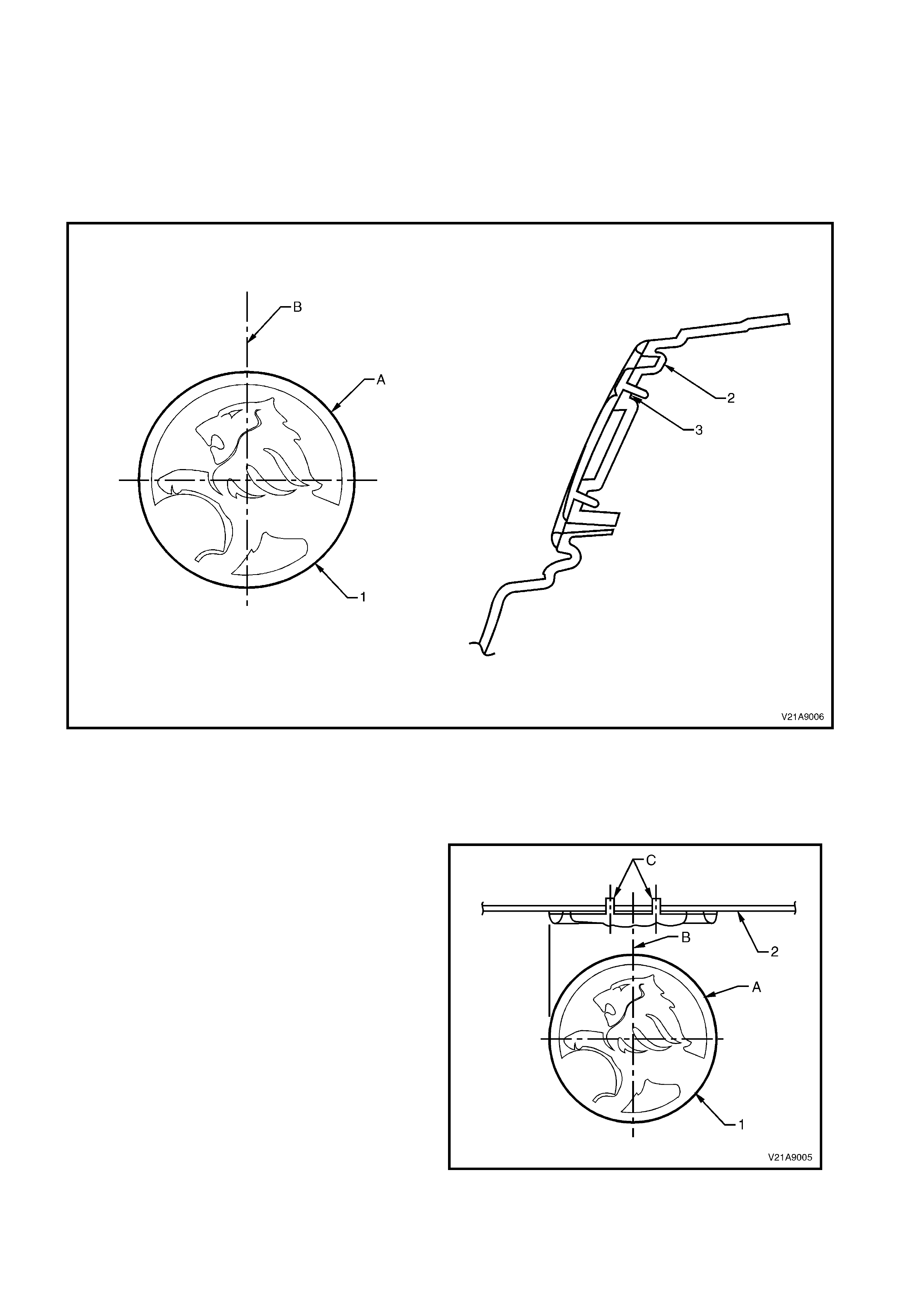
2.3 LION EMBLEM
RADIATOR GRILLE
SERVICE NOTE
A. Install emblem by insert ing the 3 pins and two clips into the corres ponding holes in the radiator grille. Push the
emblem firmly at the top to engage the two clips then attach the three speed nuts over the pins.
B. Centre-line of radiator grille.
Figure 1A9-2
Legend
1. Radiator grille Lion emblem 2. Radiator grille 3. Speed nut (3 places)
REAR COMPARTMENT LID
SERVICE NOTES
A. Before installation, remove release paper from
adhesive foam tape.
B. Centre-line of rear compartment lid.
C. Install ornament in existing holes (one round,
one square) in rear compartment lid outer
panel and press evenly on the emblem to
engage adhesive.
The following items are illustrated in Fig. 1A9-3:
1. Rear compartment lid Lion emblem.
2. Rear compartment lid.
Figure 1A9-3
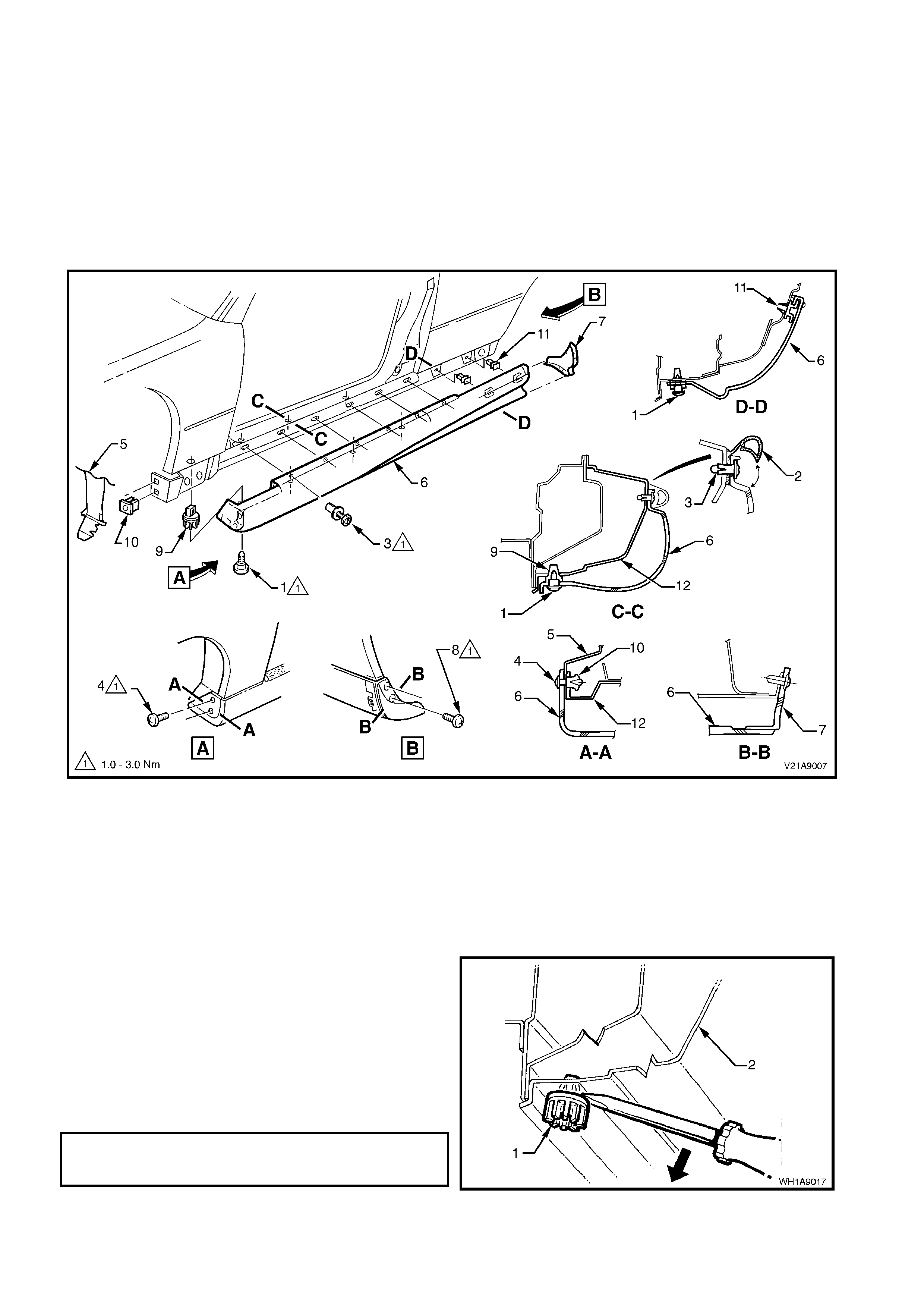
2.4 ROCKER P ANEL SKIRT
REMOVE
1. From under vehicle, remove the six rocker panel skirt lower retaining screws, refer to View C-C in Fig. 1A9-3.
2. Open door, lift up lip of rocker panel sk irt weatherstrip to gain access to the five retaining scrivets and rem ove
scrivets, refer to View C-C in Fig. 1A9-3.
3. Remove the two screws securing the rocker panel front skirt to the fender liner.
4. Slide rocker panel front skirt forward until it is free from the rocker panel rear skirt, and remove rocker panel
front skirt.
5. Remove the two screws securing the rocker panel rear skirt to the body and remove rocker panel rear skirt.
Figure 1A9-4
Legend
1. Screw (6 places per side) 7. Rocker panel rear skirt
2. Rocker panel skirt weatherstrip assembly 8. Screw (2 places per side)
3. Scrivet (5 places per side) 9. Nutsert (6 places per side)
4. Screw (2 places per side) 10. Nut rocker panel skirt attaching bracket
5. Front fender liner 11. Retainer rocker panel skirt (2 places per side)
6. Rocker panel front skirt 12. Door opening frame
6. If necessary, remove the seven nutserts (1) by
gently levering nutser t out f rom the body (2), taking
care not to damage paintwork.
REINSTALL
Installation of the rocker panel front and rear skirts is
the reverse of the removal operation, ensuring that all
fasteners are tightened to the correct torque
specification.
ROCKER PANEL SKIRT
RETAINING SCREWS 1 – 3 Nm
TORQUE SPECIFICATION
Figure 1A9-5
2.5 B-PILLAR MOULDING
REMOVE
1. Open door on relevant side of vehicle.
2. Release the B-pillar moulding (1) from the
upper moulding retainer (2) by gently levering
top of moulding out and away from B-pillar.
Slide moulding upwards removing moulding
from location on B-pillar.
NOTE: When removing the B-pillar moulding, take
care not to scratch the paint work around the B-
pillar or damage the door frame opening moulding
and rear quarter window endcaps.
3. Remove the attaching screw (3) securing the
upper moulding retainer to the B-pillar and
remove retainer.
4. Rem ove the four attaching screws (4) securing
the weatherstrip (5) and B-pillar inner cover (6)
Figure 1A9-6
REINSTALL
Installation of the B-pillar moulding is the reverse of the removal procedure, noting the following:
1. Slide outer moulding down and press in at top to engage retainer.
INNER B-PILLAR COVER AND WEATHERSTRIP
TOB-PILLAR ATTACHING SCREWS 1 - 3 Nm
TORQUE SPECIFICATION
B-PILLAR MOULDING RETAINER TO
B-PILLAR ATTACHING SCREW 1 – 3 Nm
TORQUE SPECIFICATION
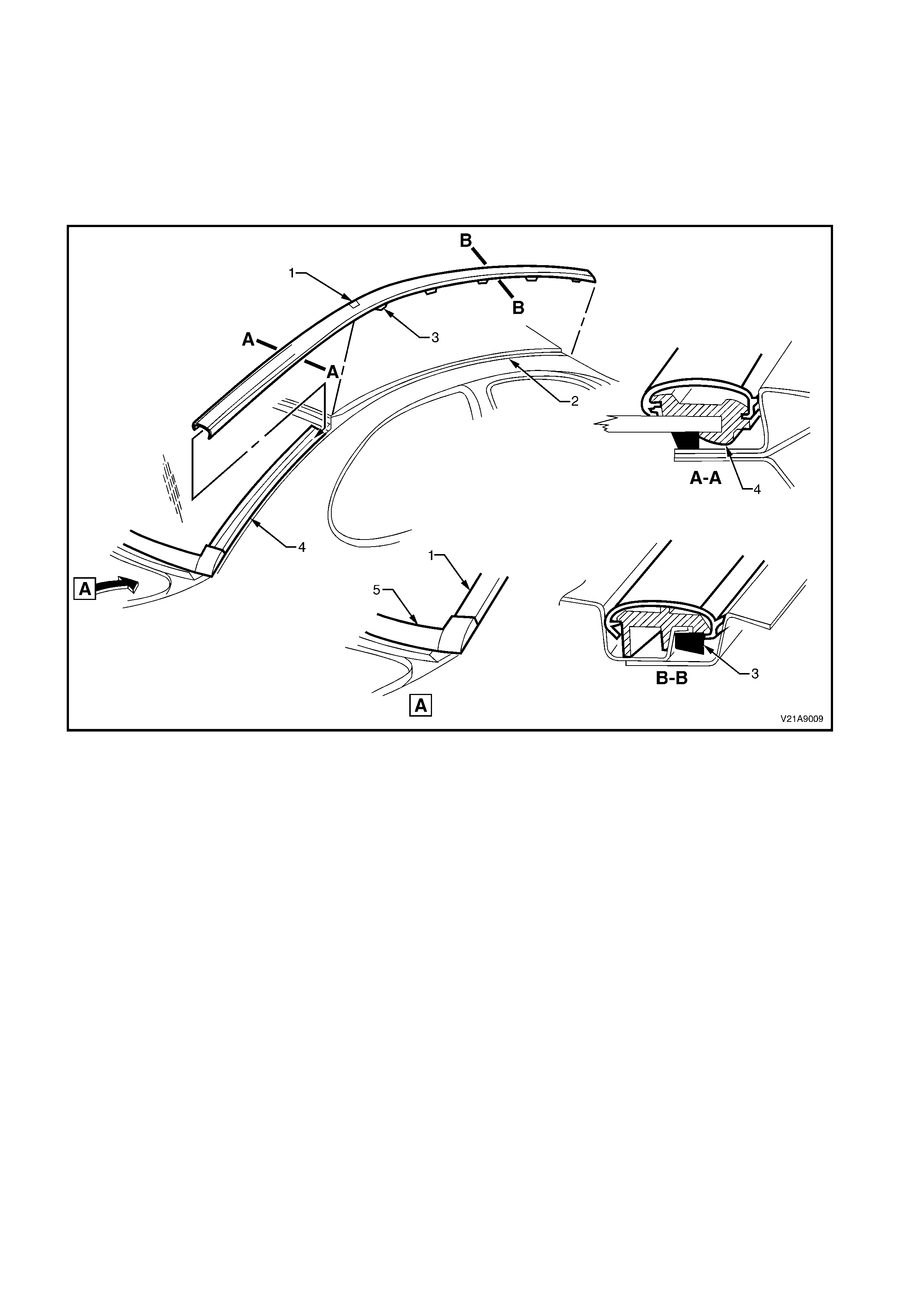
2.6 ROOF FINISHER MOULDING
REMOVE
1. Starting at the front and using a screwdriver with a clean shop rag to prevent paint work damage, pry the roof
finisher m oulding out of the r oof channel while roc king the m oulding sideways, dis engaging the seven retaining
clips.
2. Disengage the roof finisher moulding from the back glass side moulding by sliding it forward, and remove the
roof finisher moulding from vehicle.
Figure 1A9-7
Legend
1. Roof finisher moulding 4. Back glass side moulding
2. Roof channel 5. Back window lower moulding
3. Roof finisher moulding retaining clip (7 places per side)
REINSTALL
1. Engage the r oof finis her m oulding onto the top of the back glass side m oulding and slide it downwards until the
roof finisher engages the end-cap on the back window side moulding (5).
2. Position the forward portion of the roof finisher moulding along the channel in the roof.
3. Engage roof finisher moulding clips along roof until roof finisher moulding sits flush against the roof.
NOTE: The roof finisher moulding must be installed under the windshield moulding cover.
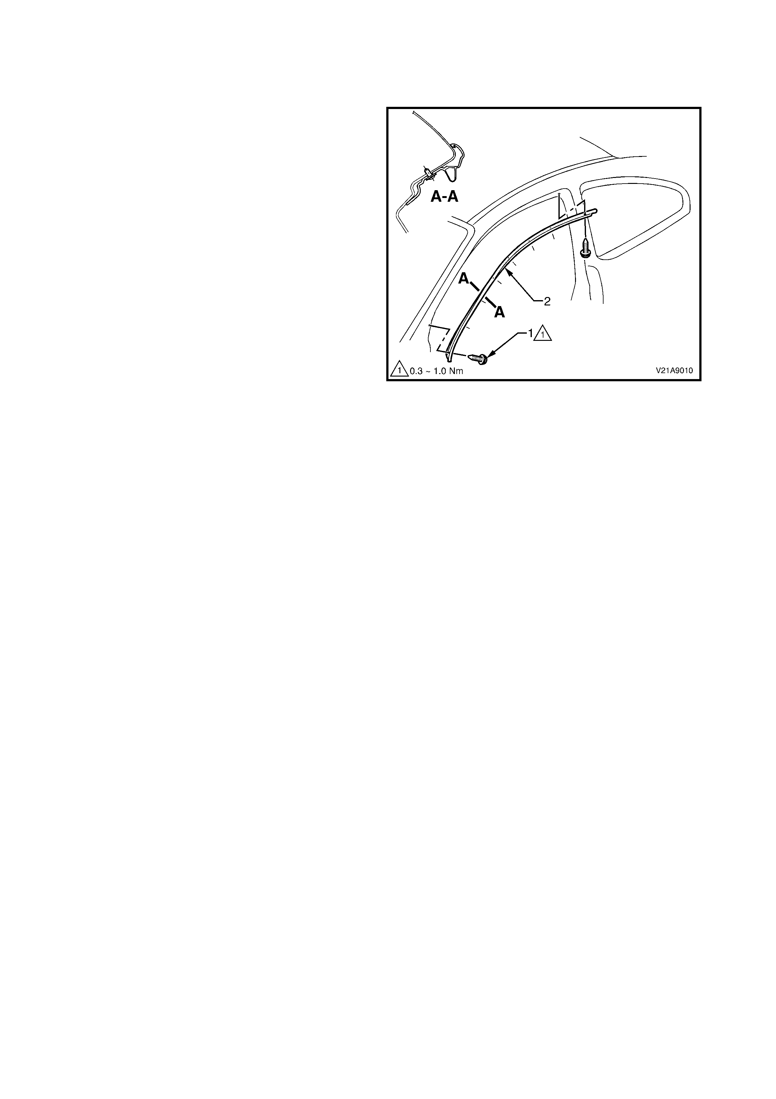
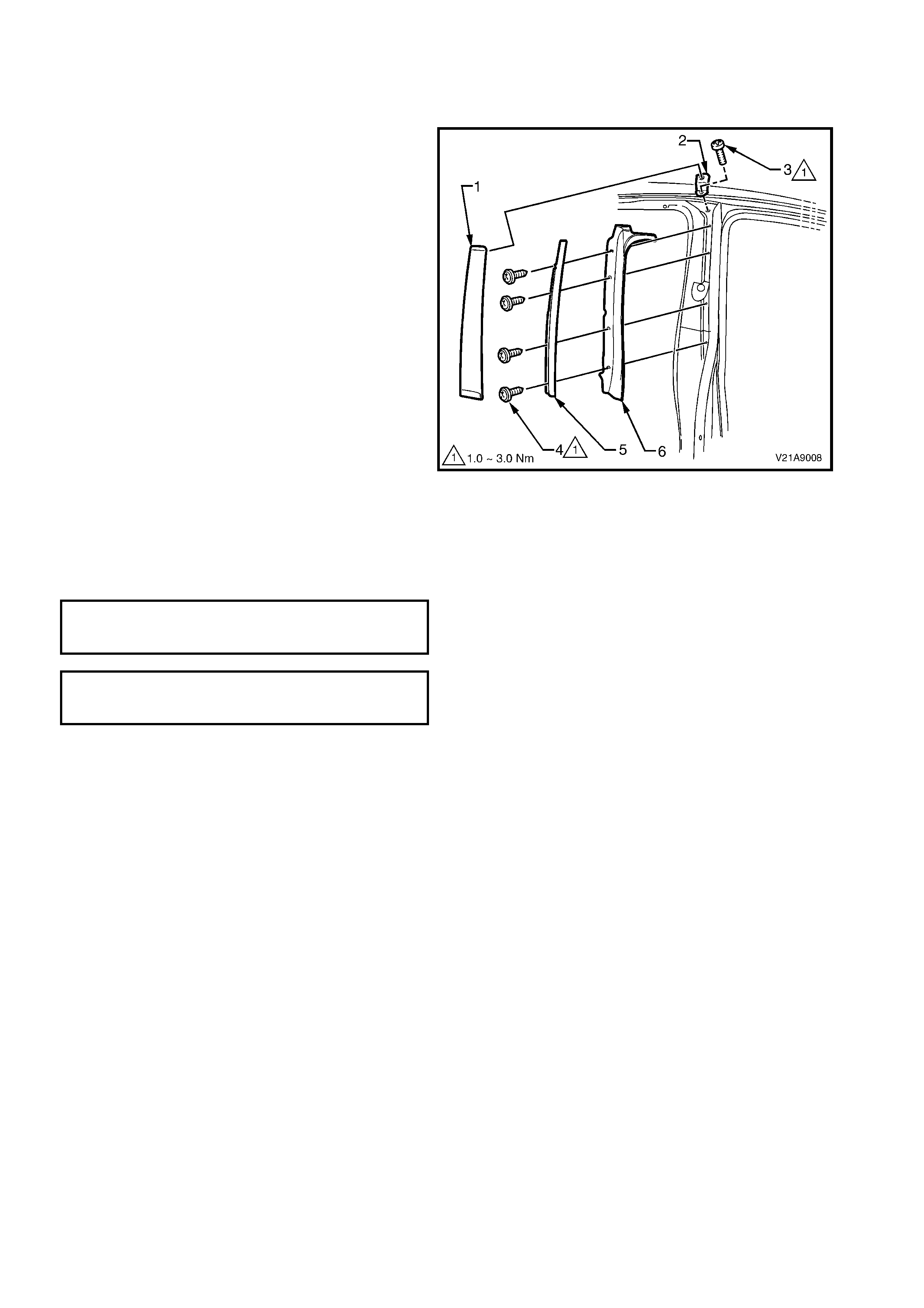
2.7 DOOR FRAME OPENING MOULDING
REMOVE
1. Open door on relevant side of vehicle.
2. Remove the screws (1) securing door frame
opening moulding (2) to body (8 places) and
remove moulding.
Figure 1A9-8
REINSTALL
Installation is the reverse of the removal procedure.
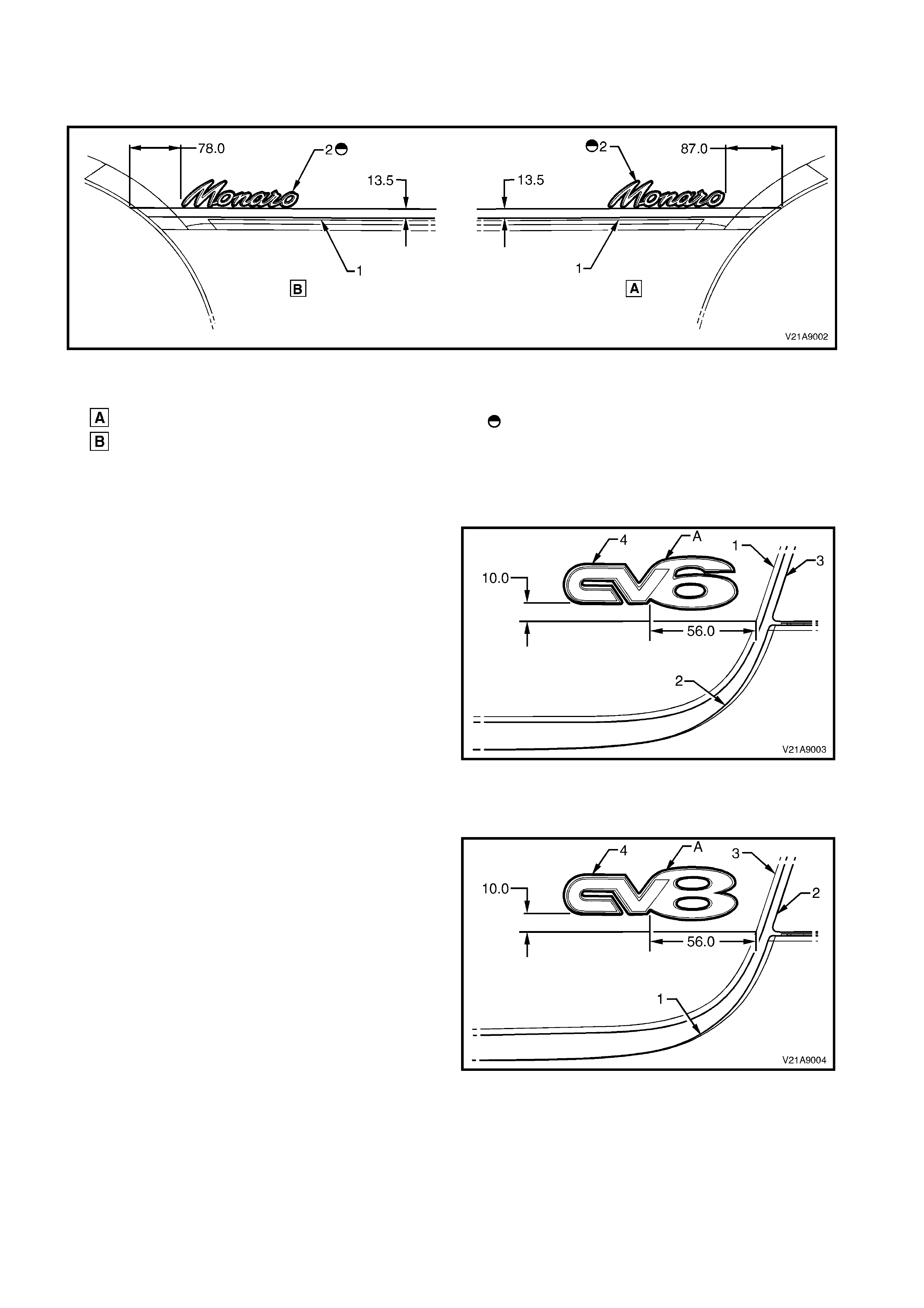
2.8 NAME PLATES AND DECALS
MONARO - REAR SIDE PANEL
Figure 1A9-9
Legend
Left-hand rear side outer panel
Right-hand rear side outer panel Before installation remove release paper.
1. Crease in side panel
2. Monaro nameplate
CV6 – REAR COMPARTMENT LID
SERVICE NOTE
A. Before installation, remove release paper from
adhesive foam tape.
The following items are illustrated in Fig. 1A9-10:
1. Rear decor panel.
2. Rear bumper facia.
3. Rear quarter lamp assembly
4. Nameplate
Figure 1A9-10
CV8 – REAR COMPARTMENT LID
SERVICE NOTE
A. Before installation, remove release paper from
adhesive foam tape.
The following items are illustrated in Fig. 1A9-11:
1. Rear decor panel.
2. Rear bumper facia.
3. Rear quarter lamp assembly
4. Nameplate
Figure 1A9-11

3. TORQUE WRENCH SPECIFICATIONS
Nm
Rocker Panel Skirt Retaining Screw..................................... 1 - 3
B-Pillar Moulding Attaching Screws...................................... 1 - 3
Door Frame Opening Moulding Retaining Screws................ 0.3 - 1.0