
SECTION 1D - BUMPER BARS
IMPORTANT
Before p erf orming any Service O p eratio n o r ot her p roced ure describ ed in t his Sect ion , refer t o Sect ion
00 CAUTIONS AND NOTES for correct workshop practices with regard to safety and/or property
damage.
1. GENERAL I NFORMATION
The front and rear bumper facia assemblies fitted to V2 Series models are constructed of polypropylene
material.
The f r ont bumper f ac ia is a one piece moulded des ign that inc ludes the r adiator gr ille and mounting provision for
the front fog lamps and lower air intake.
The f r ont lower skir t ass embly is m oulded onto the lower edge of the f ront bumper bar f ac ia ass embly and is not
serviced separately.
The lower air intak e grille is m ounted to the facia as sembly by scr ews , locating slots and tabs m oulded into the
upper and lower edge of the grille.
The front facia is mounted to the vehicle by a support beam assembly between the headlamps as fitted to VT
Series Models, and a front facia guide rail as fitted to VX Series Models.
The rear bumper facia for V2 Series Models is similar to the rear bumper facia fitted to VX Series SS Models.
The rear facia is mounted in the same manner as the rear facia fitted to VX Series Models.
A rear lower skirt assembly similar to the lower rear skirt fitted to VX Series SS Models is moulded on to the
lower edge of the rear bumper bar facia on V2 Series Models, and is not serviced separately.
The paint system used on the front and rear bum per bar facias as fitted to V2 Series Models carries over from
VX Series Models . For inform ation relating to the paint system used on the f ront and rear bum per bar facias as
fitted to V2 Series Models, ref er to 2.1 PAINT SYST EM in Sec tion 1D BUMPER BARS in the VX Series Service
Information.
2. SERVICE OPERATIONS
2.1 FRONT BUMPER BAR FACIA ASSEMBLY
REMOVE
1. Raise engine hood.
2. Remove the two facia to support beam scrivets from inside the lower air intake.
3. From behind the bumper facia assembly, disconnect the two fog lamp wiring harness connectors.
4. Remove the two screws securing facia sides to the front fender wheelarch openings.
5. Remove the two screws securing facia sides to front facia guide rails.
6. Remove the screws securing facia to the front panel assembly.
7. W ith the f acia supported, pull the f acia side m embers out, disconnect the f acia side supports, then slide the
facia forward removing the facia assembly.
8. Place the front bumper bar facia assembly face down on a clean protected surface.
NOTE: The s uppor t beam should not be r emoved unless damaged. Ref er to the VX Body Repair Information for
alignment details.
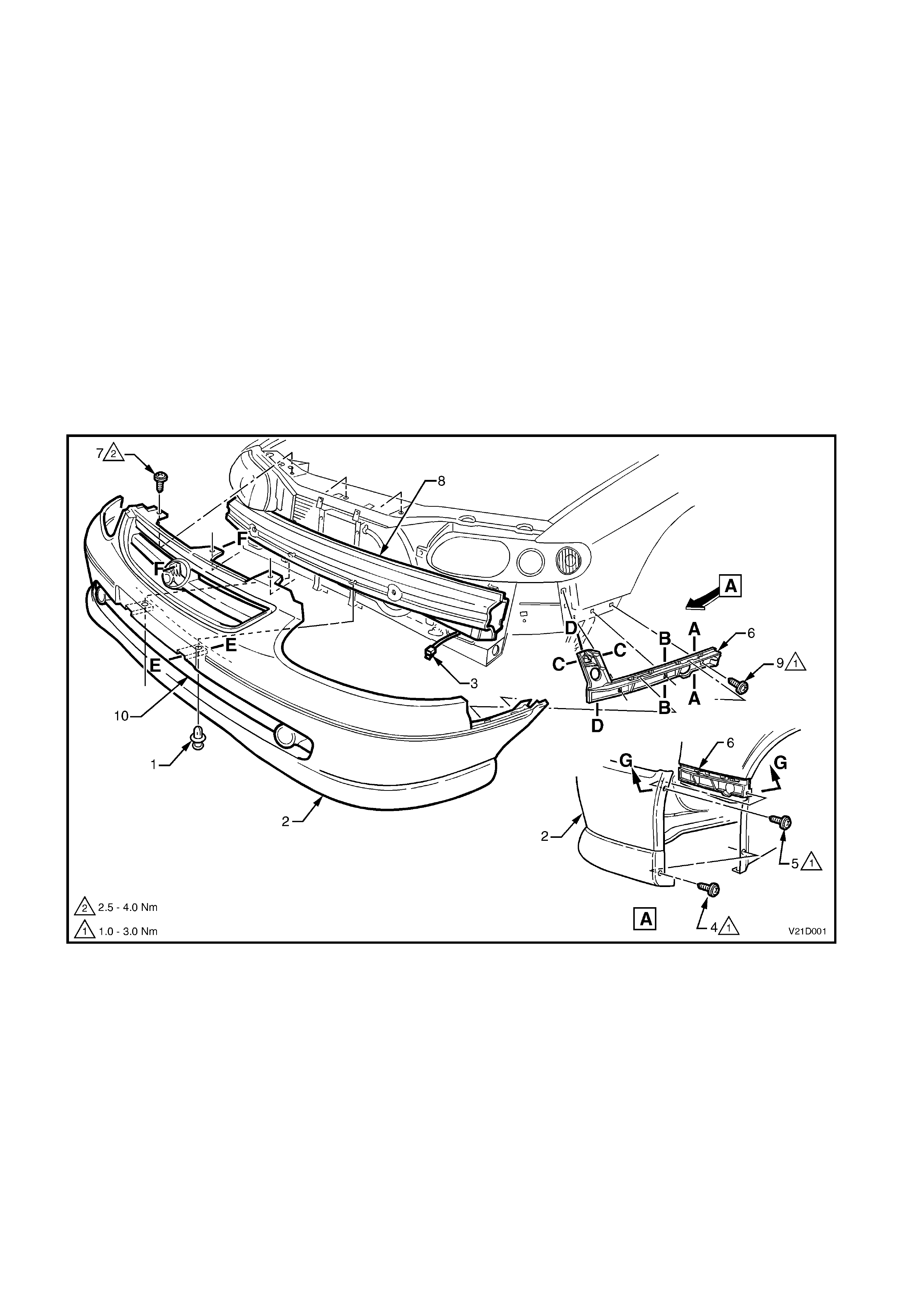
Figure 1D-1
Legend
1. Facia to support beam scrivet (2 places)
2. Front bumper bar facia assembly
3. Fog lamp harness connector (2 places)
4. Facia to front fender attaching screw
(2 places)
5. Facia to guide rail attaching screw
(2 places)
6. Front facia guide rail (2 places)
7. Facia to front panel attaching screw (3 places)
8. Front facia support beam
9. Facia guide rail attaching screw (6 places)
10. Lower air intake grille
NOTE: For Sectional views A-A to G-G, refer to Fig.1D-2
in this Section.
REINSTALL
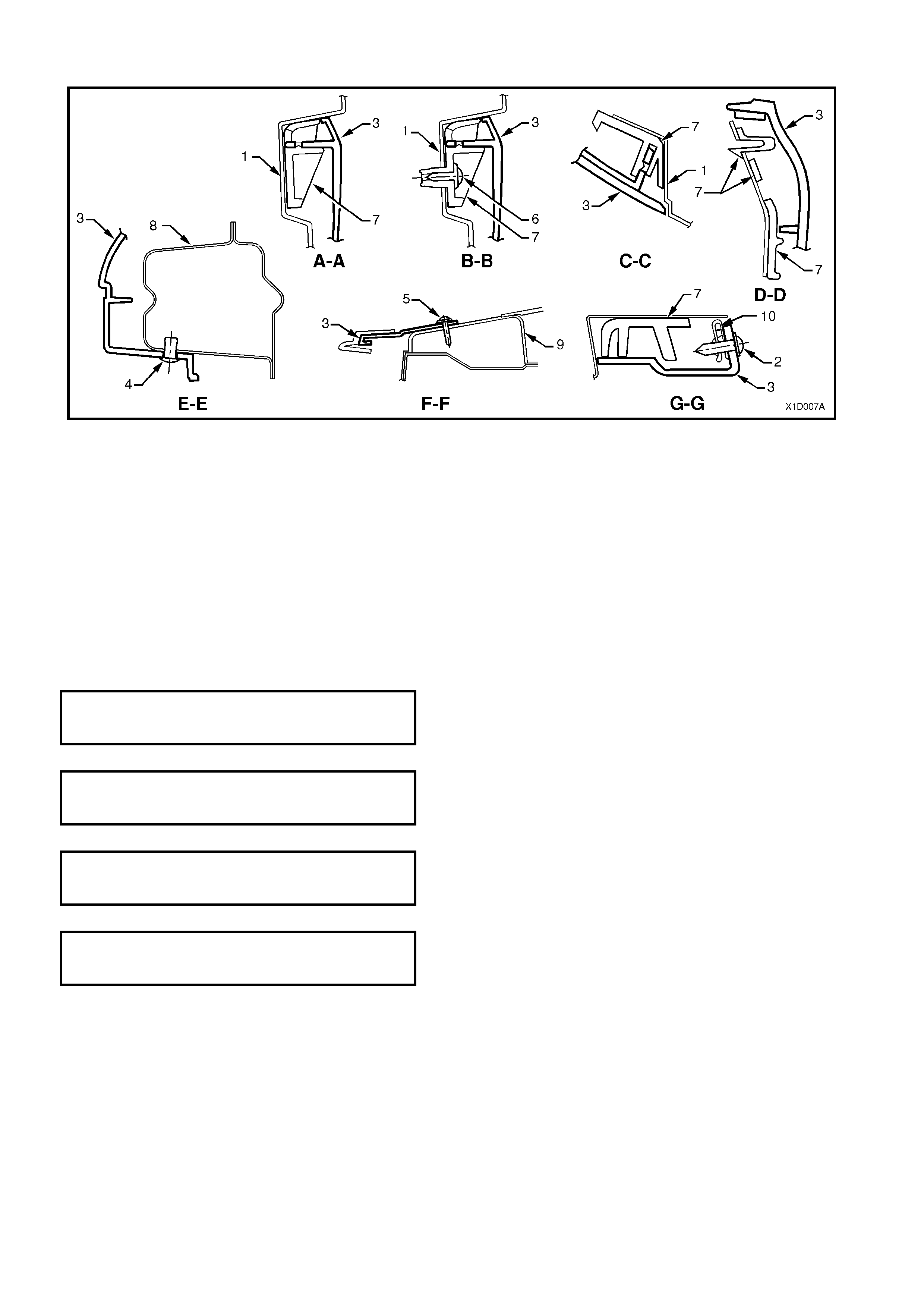
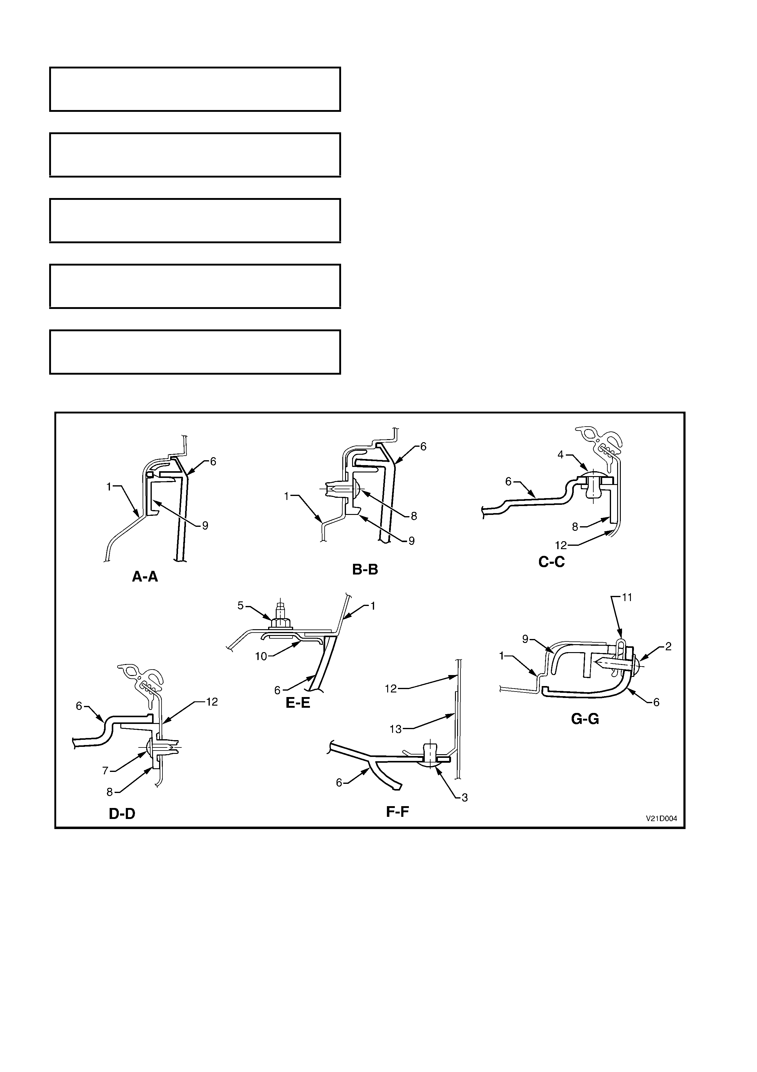
Figure 1D-2
Legend
1. Front fender panel
2. Screw
3. Front bumper facia
4. Scrivet
5. Screw
6. Screw
7. Guide rail
8. Front bumper support beam
9. Front panel upper
10. J nut
The installation procedure for the front bumper bar facia assembly is the reverse of the removal procedure,
noting the following:
• Snap the facia onto retainers at guide rails, one side at a time, (refer to Section C–C, in Fig.1D-2) then
adjust the facia to ensure correct fender, hood/headlamp clearance.
• Ensure all fasteners are tightened to the correct torque specifications.
FRONT BUMPER FACIA GUIDE RAIL TO
FRONT FENDER ATTACHING SCREW 1 – 3 Nm
TORQUE SPECIFICATION
FRONT BUMPER FACIA TO FRONT
WHEELHOUSE ATTACHING SCREW 1 – 3 Nm
TORQUE SPECIFICATION
FRONT BUMPER FACIA TO GUIDE RAIL
ATTACHING SCREW 1 – 3 Nm
TORQUE SPECIFICATION
FRONT BUMPER FACIA TO FRONT PANEL
ATTACHING SCREW 2.5 – 4.0 Nm
TORQUE SPECIFICATION
• Check fog lamp operation and aim, refer to Section 12B LIGHTING SYSTEM in this Service Information.
NOTE: To aid in the installation of the bumper and to ensure correct alignment, Fig. 1D-2 shows the sectional
views from Fig. 1D-1.
2.2 REAR BUMPER BAR FACIA ASSEMBLY
REMOVE
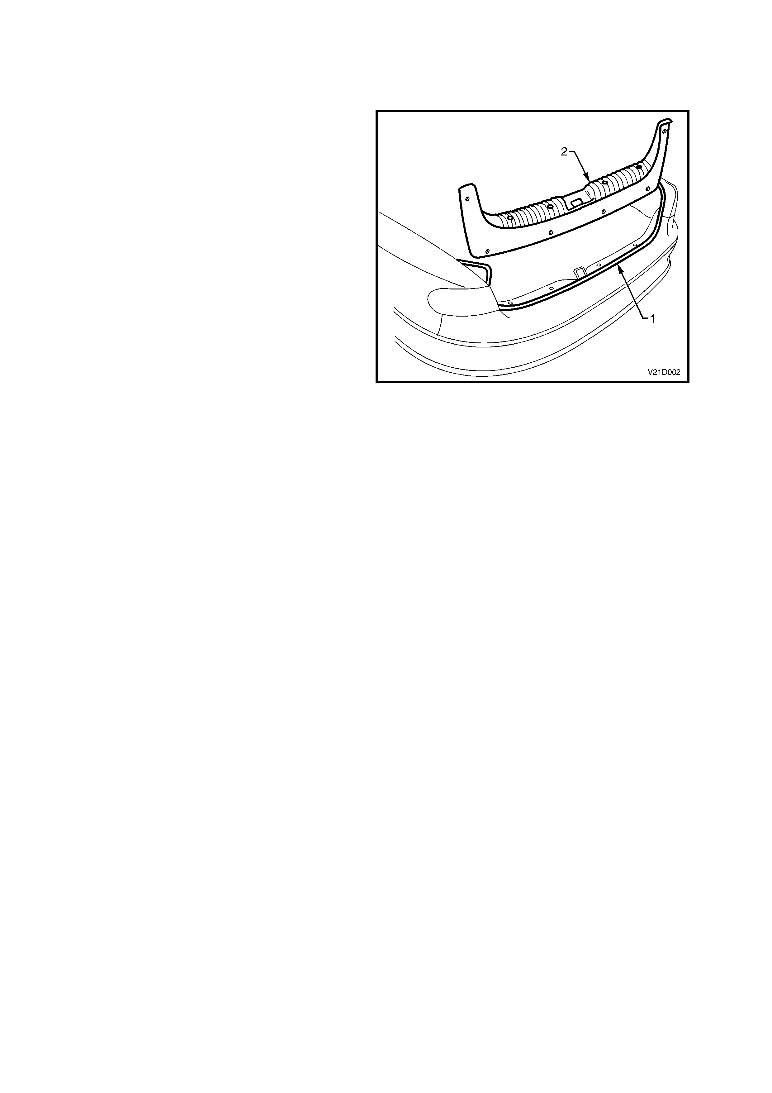
1. Open the rear compartment lid.
2. Gently peel the rear compartment weatherstrip
(1) away from the upturned flange of the rear
compartment opening.
NOTE: Only partly peel the weatherstrip away from
the rear compartment opening to enable access to
the four bum per bar fac ia scrivets (ref er to Fig. 1D-
4) and to allow for re m oval of the rear compartm ent
crossmember cover (2).
3. Remove the rear compartment crossmember
cover, refer to 2.10 REAR COMPARTMENT
CROSSMEMBER COVER in Section 1A8
HEADLINING AND REAR END TRIM.
Figure 1D-3
4. Peel the rear c om partm ent wheelhouse car pets
back slightly and remove the four nuts
attaching the rear bumper bar facia assembly
to the rear quarter panel (below tail lamps).
5. From inside the rear wheel house opening,
remove two screws (one each side) attaching
the rear bumper facia to the J nut on the
leading edge of the facia side support rails.
6. From inside the rear wheel house opening,
remove the four screws (two each side)
attaching the rear bumper facia and rear
wheelhouse liner to the rear fender wheelarch
opening.
7. Remove the four scrivets attaching the upper
edge of facia to the facia centre support rail.
8. Remove the two scrivets attaching the lower
edge of the facia to the rear panel.
9. With the facia supported, pull the facia side
members out to disconnect the facia side
support rails, then slide the facia rearwards,
removing the facia.
10. Place the rear bumper bar facia assembly face
down on a clean protected surface.
NOTE: The bumper support beam assembly
should not be removed unless damaged, refer to
the VX Series Body Repair Information for
alignment details.
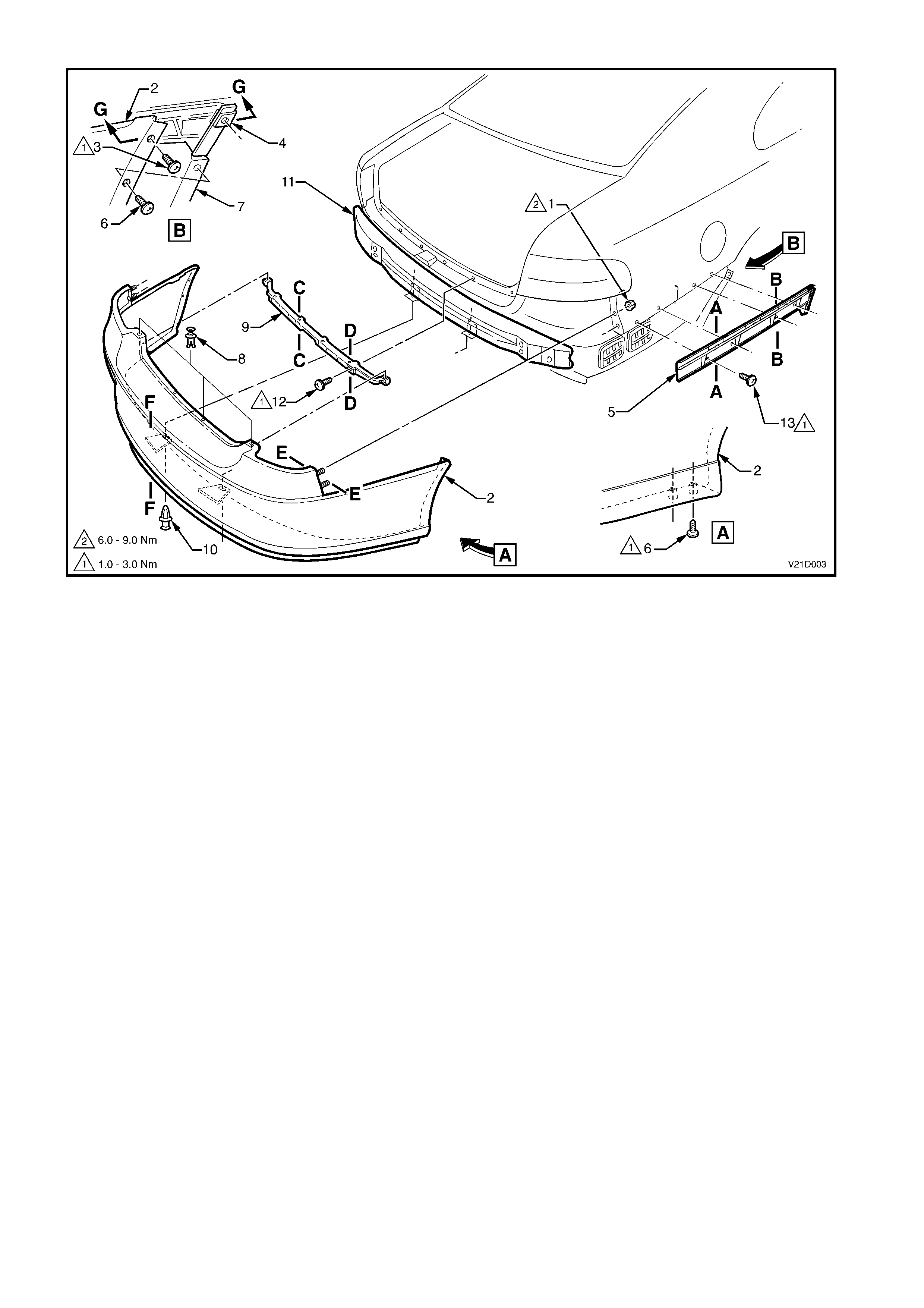
Figure 1D-4
Legend
1. Rear facia to quarter panel attac hing nut (4
places)
2. Rear bumper bar facia
3. Rear facia to facia side support rail
attaching screws (2 places)
4. Side support rail J nut (2 places)
5. Facia side support rail
6. Rear facia to rear fender wheelarch
attaching screws (4 places)
7. Rear wheelhouse liner
8. Rear facia to facia centre support rail attaching
scrivet (4 places)
9. Rear facia centre support rail
10. Rear facia to rear panel attaching scrivets
(2 places)
11. Rear bumper bar facia support beam
12. Rear facia centre support rail attaching screw
(4 places)
13. Rear facia side support rail attaching screw
(8 places)
NOTE: For sectional views of A-A to G-G, refer to Fig.
1D-5 in this Section.
REINSTALL
Installation of the rear bumper facia assembly is the reverse of the removal operations , noting the
following:
1. Locate the studs (two places each side) on the facia to the holes in the rear quarter panel.
2. Snap the facia onto retainers at guide rails, one side at a time, (refer to sections A–A and B-B, in Fig.
1D-5) then adjust the facia to ensure correct clearance.
3. Ensure all fasteners are tightened to the correct torque specifications.
REAR BUMPER FACIA TO REAR
QUARTER PANEL ATTACHING NUT 6 – 9 Nm
TORQUE SPECIFICATION
REAR BUMPER FACIA TO SIDE SUPPORT
RAIL ATTACHING SCREW 1 – 3 Nm
TORQUE SPECIFICATION
REAR BUMPER FACIA TO REAR
WHEELHOUSE ATTACHING SCREW 1 – 3 Nm
TORQUE SPECIFICATION
REAR BUMPER FACIA CENTRE SUPPORT
RAIL TO BODY ATTACHING SCREW 1 – 3 Nm
TORQUE SPECIFICATION
REAR BUMPER FACIA SIDE SUPPORT
RAIL TO BODY ATTACHING SCREW 1 – 3 Nm
TORQUE SPECIFICATION
NOTE: To aid in the installation of the bumper and to ensure correct alignment, Fig. 1D-5 shows the sectional
views from Fig. 1D-4.
Figure 1D-5
Legend
1. Side panel outer
2. Screw
3. Scrivet
4. Scrivet
5. Nut
6. Rear bumper facia
7. Screw
8. Rear facia upper centre support
9. Guide rail
10. Plate assembly
11. J nut
12. Reinforcement – back panel lower
13. Facia attaching bracket
2.3 LOWER AIR INTAKE GRILLE
REMOVE
1. Remove the vehicle licence plate.
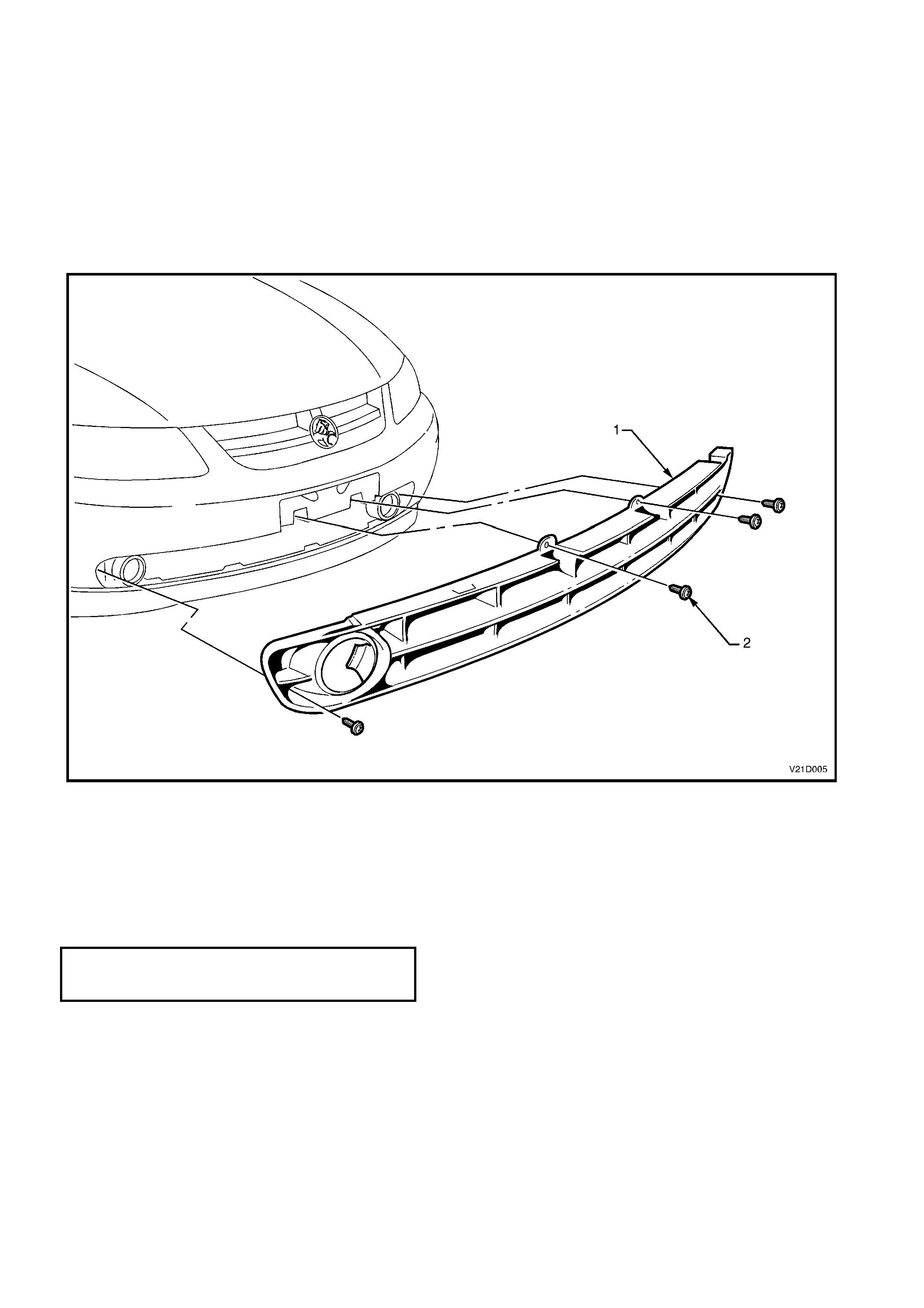
2. Remove the four screws retaining the lower air intake grille to the front facia.
3. Flex the upper edge of the lower air intake grille to disengage the four retaining tabs and four locating tabs
from the front bumper bar facia.
4. Flex the lower edge of the lower air intake grille to disengage the four retaining tabs and five locating tabs
from the front bumper bar facia.
5. Remove the lower air intake grille from the vehicle.
Figure 1D-6
Legend
1. Lower air intake grille 2. Screw (4 places)
REINSTALL
The installation procedure for the lower air intake grille is the reverse of the removal operations, ensuring to
tighten all fasteners to the correct torque specification.
LOWER AIR INTAKE GRILLE
ATTACHING SCREWS 1 – 3 Nm
TORQUE SPECIFICATION

3. TORQUE WRENCH SPECIFICATIONS Nm
Front bumper facia guide rail to fender attaching screws..... 1.0 - 3.0
Front bumper facia to front wheelhouse attaching screws ... 1.0 - 3.0
Front bumper facia to guide rail attaching screws................ 1.0 - 3.0
Front bumper facia to front panel attaching screws.............. 2.0 - 4.0
Rear bumper facia to rear quarter panel attaching nuts....... 6.0 - 9.0
Rear bumper facia to side support rail attaching screws...... 1.0 - 3.0
Rear bumper facia to rear wheelhouse attaching screws..... 1.0 - 3.0
Rear bumper facia centre support rail to body
attaching screws................................................................... 1.0 - 3.0
Rear bumper facia side support rail to body
attaching screws................................................................... 1.0 - 3.0
Lower air intake grille attaching screws................................ 1.0 - 3.0