SECTION 10 - WHEELS AND TYRES
IMPORTANT:
Before performing any Service Operation or other procedure described in this Section, refer to Section
00 CAUTIONS AND NOTES for correct workshop practices with regard to safety and/or property damage.
1. GENERAL I NFORMATI O N
The V2 Series CV6 is fitted with an 8JX17 wheel and 235/45R17 tyre combination. T he wheel and tyre combination
fitted to the V2 Series CV6 c arries over f rom VX Series ‘SS’. For inform ation relating to the wheels and tyres on V2
Series CV6 Models not detailed in this Section, ref er Section 10 - W HEELS AND T YRES in the VX Series Ser vice
Information.
The V2 Series CV8 is fitted with a new 8JX18 wheel and 235/40R18 tyre combination.
The spare wheel fitted to V2 Series Models is a new 4TX 15 temporary use type s teel rim fitted with a T135/90D15
tyre that is unique to V2 Series Models. The spare wheel is located in the spare wheel well by a unique
polypropylene (foam) spacer that also acts as a container for jack and wheel wrench stowage.
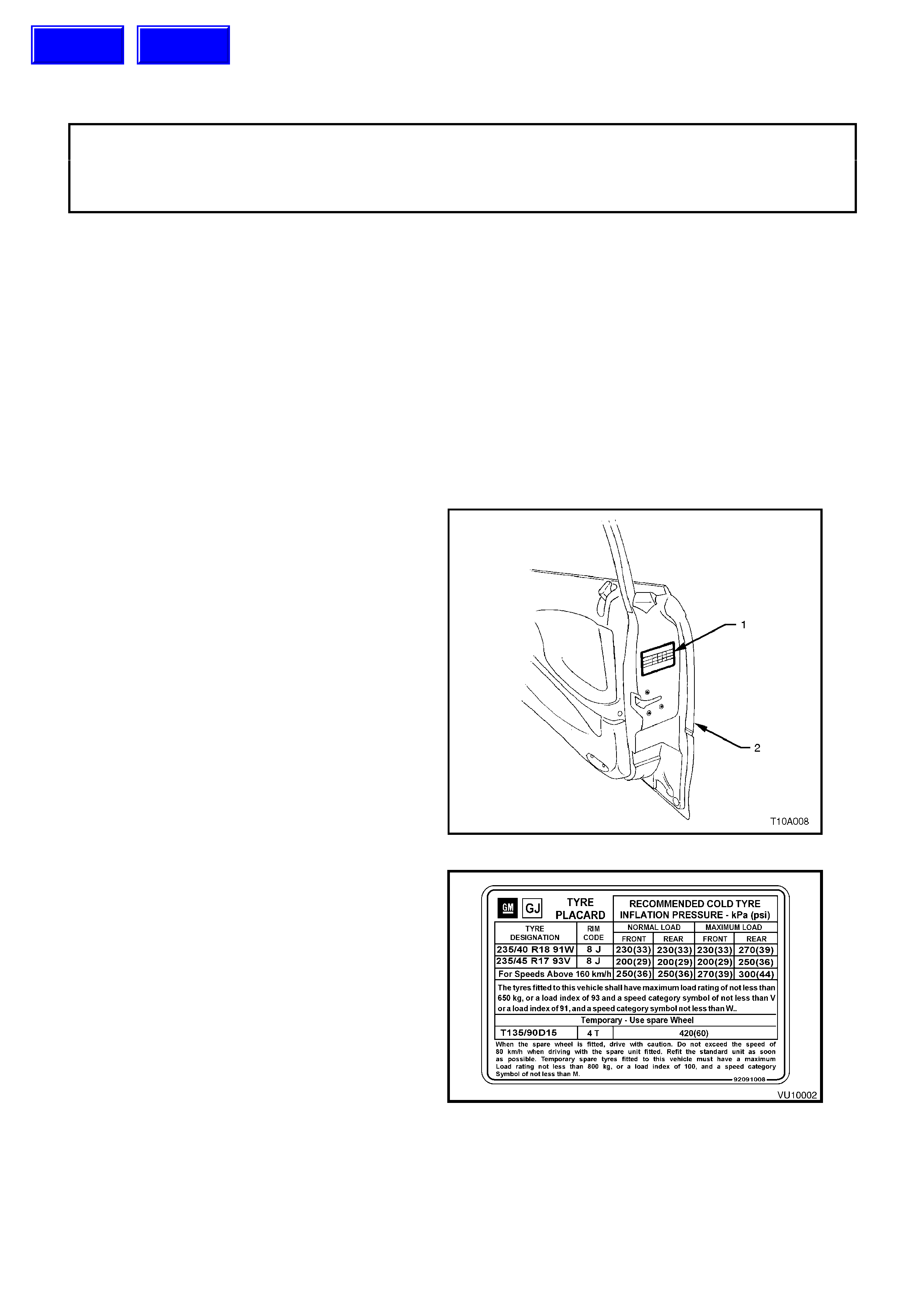
1.1 TYRE PLACARDS
Wheel and tyre sizes, inflation pressures and load
capacity are specif ied on a tyr e placard (1), loc ated
on the end surface of the right-hand front door (2).
Correct sizes and pressures are the subject of an
Australian Design Rule (ADR) and must be
observed at all times.
The tyre placard as fitted to V2 Series Models is
shown in Fig. 10-2.
Figure 10-1
Figure 10-2
Techline
Techline
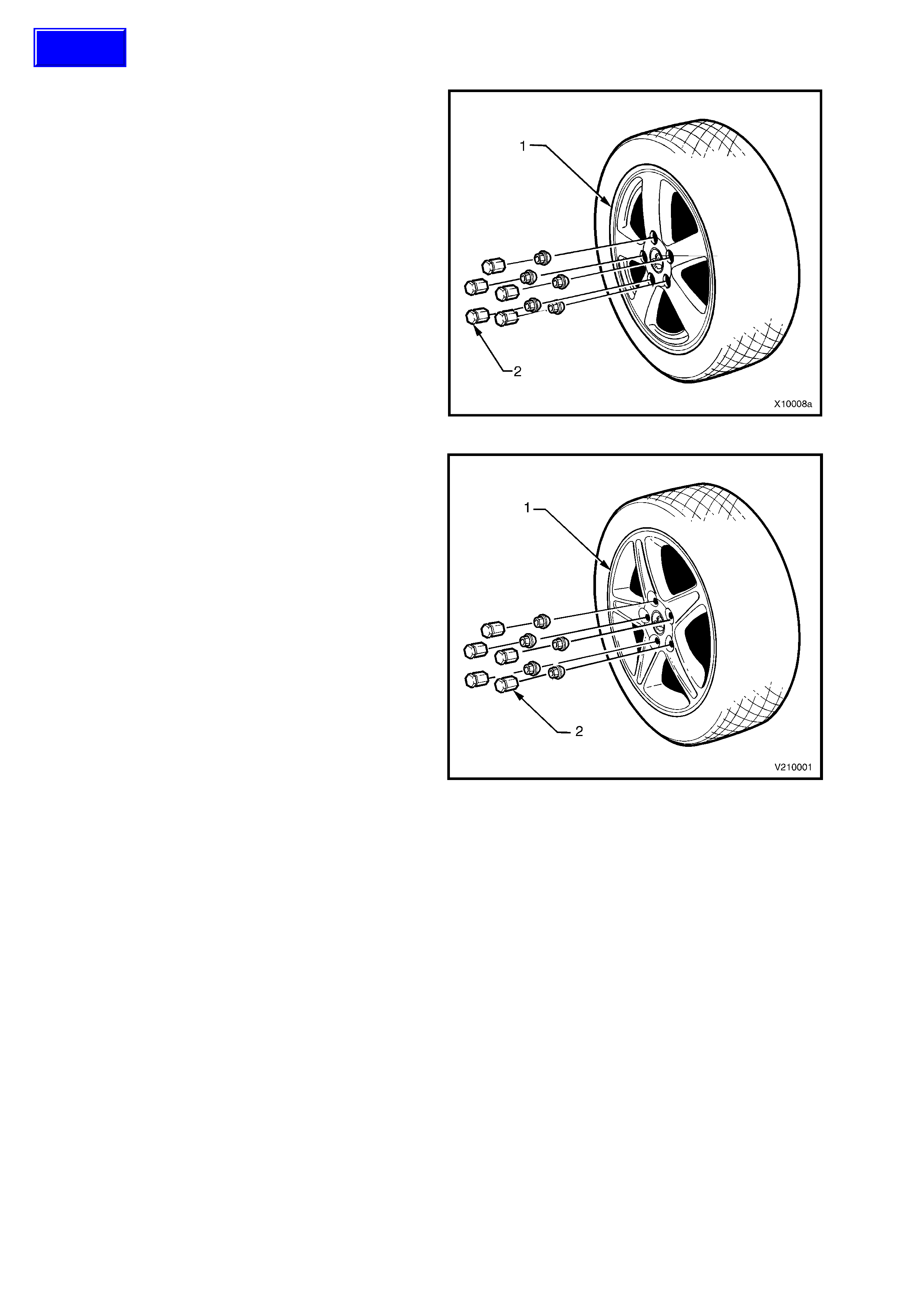
1.2 WHE EL AND TYRE COMBINATIONS
V2 Series CV6 Models are fitted with a light alloy
wheel (1) and wheel nut covers (2) as shown in Fig.
10-3.
Road Wheels........................8J x 17 alloy
Tyres ....................................235/45R17 93V
Figure 10-3
V2 Series CV8 Models ar e f itted with an alloy wheel
(1) and wheel nut covers (2) as shown in Fig. 10-4.
Road Wheels........................8J x 18 alloy
Tyres ....................................235/40R18 91W
Figure 10-4
Techline
2. SERVICE OPERATIONS
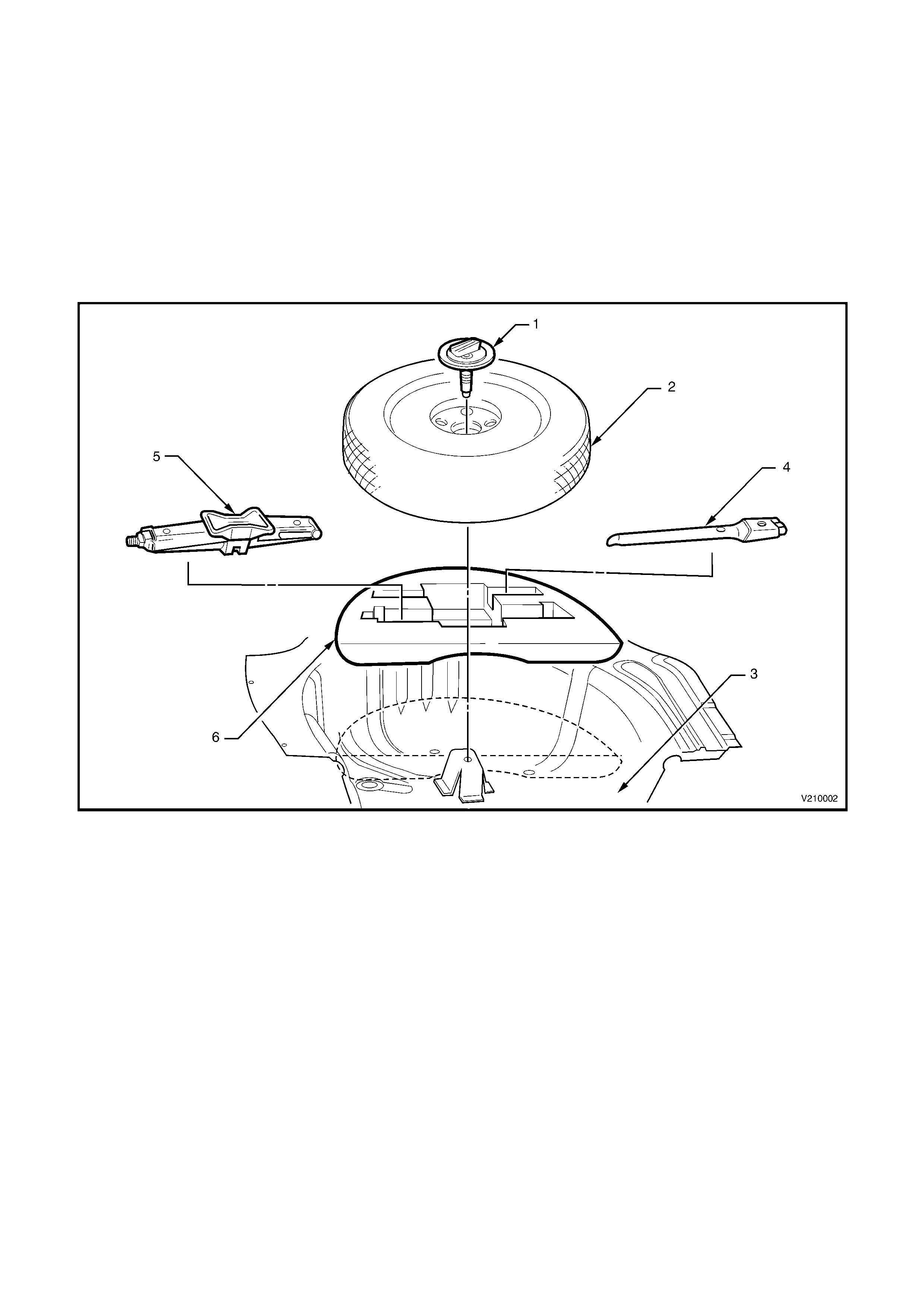
2.1 SPARE WHEEL
REMOVE
1. With the rear compartment lid open, remove the load compartment carpet and spare wheel cover assembly,
refer to Section 1A8 HEADLINING AND REAR END TRIM in this Service Information.
2. Remove the spare wheel retaining bolt and plate assembly (1), refer Fig 10-5.
3. Lift the spare wheel (2) from the spare wheel well (3) in the load compartment floor.
NOTE: T he s pare wheel fitted to V2 Series Models is f or tem porar y us e only. Vehicle speed with the temporar y use
spare wheel fitted should not exceed 80 km/h.
Figure 10-5 Spare Wheel and Jack Stowage
Legend
1. Spare Wheel Retaining Bolt and Plate
Assembly
2. Temporary Use Spare Wheel
3. Spare Wheel Well
4. Jack/Wheel Nut Wrench
5. Jack Assembly
6. Jack Container
REINSTALL
Installation of the temporary use spare wheel is the reverse of the removal procedure.

3. SPECIFICATIONS
Temporary use spare wheel
Rim Width Code...................................................... 4.0T
Diameter Code........................................................ 15
Maximum Permissible Radial Run-out............... 0.6 mm
Maximum Permissible Lateral Run-out.............. 0.8 mm
Offset ................................................................. 13 mm (pos)
Alloy road wheels
Rim Width Code...................................................... 8.0J 8.0J
Diameter Code........................................................ 17 18
Maximum Permissible Radial Run-out
CV6.................................................................... 0.35 mm
CV8.................................................................... 0.35 mm
Maximum Permissible Lateral Run-out
All models........................................................... 0.35 mm
Offset
CV6.................................................................... 48 mm (pos)
CV8.................................................................... 48 mm (pos)
Tyres
Dynamic Balancing – All Models
Maximum Permissible Residual
Imbalance (Per Side) ......................................... 8 g
Maximum Tyre Load (per tyre)
Spare (All Models)............................................ (T135/90D15) 800 kg
CV6.................................................................. (235/45R17 93V) 650 kg
CV8.................................................................. (235/40R18 91W) 615 kg
RECOMMENDED COLD INFLATION – kPa
MODEL WHEEL TYRE
DESIGNA TION Up to 3 Passengers Up to Maximum Load
Front Rear Front Rear
CV6 8J x 17
Light Alloy 235/45 R17 93V 200 200 220 250
CV8 8J x 18
Alloy 235/40 R18 91W 230 230 230 270
SPARE (All Models) 4T x 15 T135/90D15 420 420 420 420
For speeds above 160 km/h. (All applications) 250 250 270 300

4. TORQUE WRENCH SPECIFICATIONS
Nm
Road Wheel Attaching Nuts (All Wheels).............................110-140
Spare Wheel Retaining Bolt and Plate Assembly.................3-4