
SECTION 12B - LIGHTING SYSTEM
IMPORTANT
Before performing any Service Operation or other procedure described in this Section, refer to Section
00 CAUTIONS AND NOTES for correct workshop practices with regard to safety and/or property damage.
1. GENERAL I NFORMATI O N
The front lamp assem blies fitted to V2 Series Models are a resytled version of the assembly as fitted to VT Series
Models. The front lamp assembly in V2 Series Models incorporates projector type low beam, a reflector type high
beam, front turn signal lamp and park lamp in one unit.
The pr ojec tor type headlamp fitted to V2 Series Models c ontain long lif e quar tz halogen bulbs and a clear outer lens
with complex reflector optics on high beam. The front turn signal lamp has also been revised to compliment the
headlamp styling.
The side repeater lamps fitted to V2 Series Models carry over from VT Series II Models and include a clear lens
with amber bulb. F or inf or mation relating to the bulb r eplacement, r emoval and reinst allation proc edur es f or the side
repeater lamps, refer to 2.11 SIDE REPEATER LAMPS in Section 12B LIGHTING SYSTEM of the VT Series I
Service Information
The door courtesy, footwell, glovebox, console, instrument panel and load compartment lamps as fitted to V2 Series
Models carr y over from VT Ser ies I Models . For inf or mation relating to the door cour tes y, footwell, glovebox, cons ol,
instrument panel and load compartment lamps, refer to Section 12B LIGHTING SYSTEM in the VT Series I
Service Information.
The lic ence plate lam p fitted to V2 Series Models c arry over from VX Series Executive, Acc laim, S and SS Models.
For information relating to the licence plate lamps, refer to 2.12 LICENCE PLATE LAMP/BULB — EXECUTIVE
AND ACCLAIM SEDAN, S AND SS MODELS in Section 12B LIGHTING SYSTEM of the VX Series Service
Information.
The rear lam p as sem blies f or the V2 Series Models ar e a r evised vers ion of the r ear lam p ass em bly as fitted to VX
Series Executive, Acclaim, S and SS Models. They comprise a turn signal lamp, stop and tail lamp and back-up
lamp in one unit.
The c entre high m ount stop lam p on V2 Ser ies Models is an LED type lamp assem bly and is mounted on top of the
rear parcel shelf panel at the lower edge of the rear windscreen. The centre high mount stop lamp assembly is
unique to V2 Series Models.
Unique style front fog lam ps are fitted as standard equipm ent on V2 Series Models and are mounted into the front
bumper facia assembly.
The steering column mounted headlamp and turn signal switch fitted to V2 Series Models carries over
from VX Series II Models. For information relating to the headlamp and turn signal switch, refer to
Section 12B LIGHTING SYSTEM in the VX Series II Service Information.
All the remaining lamp control switches fitted to V2 Series Models carries over from VT Series I Models. For
information relating to the lamp control switches, refer to Section 12B LIGHTING SYSTEM in the VT Series I
Service Information.
Techline
Techline
Techline
Techline
2. SERVICE OPERATIONS
2.1 AIMING OF HEADLAMPS AND FOG LAMP S
CAUTION: During headlamp aiming procedures, do not use a cloth or similar material to cover the lens of
the headlamp assembly not being adjusted. Damage to the headlamp assembly will result if the headlamp
beam is obstructed in this manner.
The headlamps and fog lamps must be correctly aimed in order to optimise the road illumination and safety features
built into the vehicle lighting system. The headlam ps /f og lamps must be c hec k ed for cor re ct aim whenever a bulb or
headlamp/fog lamp assembly is replaced as well as after any adjustments or repairs to the front end sheet metal.
Headlamp aiming machines are in general use. When using one of these machines, ensure that it is in good
condition and carefully follow the instructions of the manufacturer.
Regardless of the method us ed f or chec king headlam p and f og lamp aim, the vehicle m us t be at kerb weight, i.e full
fuel level, oil, water and spare tyre but no passengers. The tyres must be uniformly inflated to their specified
pressure.
NOTE: If the vehic le will regular ly carr y an unusual load in the rear c ompartment or tow a trailer , these loads s hould
be on the vehicle when the headlamps/fog lamps are checked.
HEADLAMP AIM
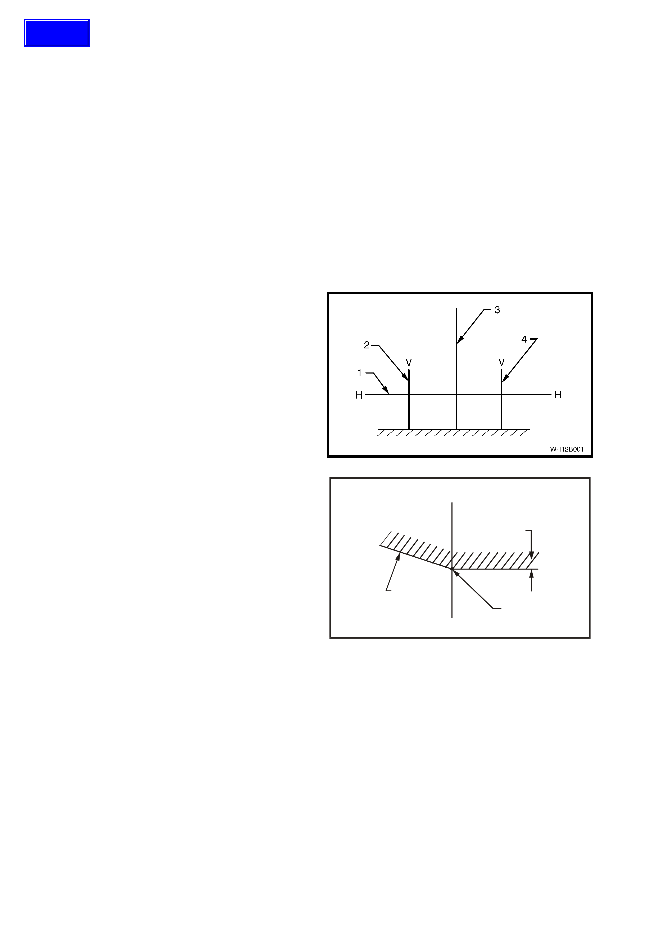
1. If suitable test equipm ent is not available, s et up a
screen or use a vertical wall, in conjunction with a
flat hor izontal f loor. Par k the vehicle imm ediately in
front of the screen and mark horizontal (1) and
vertical centre lines of the left (2) and right (4)
headlamps (corresponding to the c entre of the low
beam bulb) and the vehicle centre line (3) on the
screen or wall.
2. Park the vehicle 10 metres in f r ont of the s cr een or
wall ensuring that the vehicle is aligned with the
vehicle centre line mark on the screen.
Figure 12B-1
3. Individually aim each headlamp to a point ( 1) on its
vertical centre line, 110 mm below the headlamp
horizontal centre line. Item (2) is the cut-off line.
WH12B002
V
HH
V
110 mm
2
1
Figure 12B-2
Techline
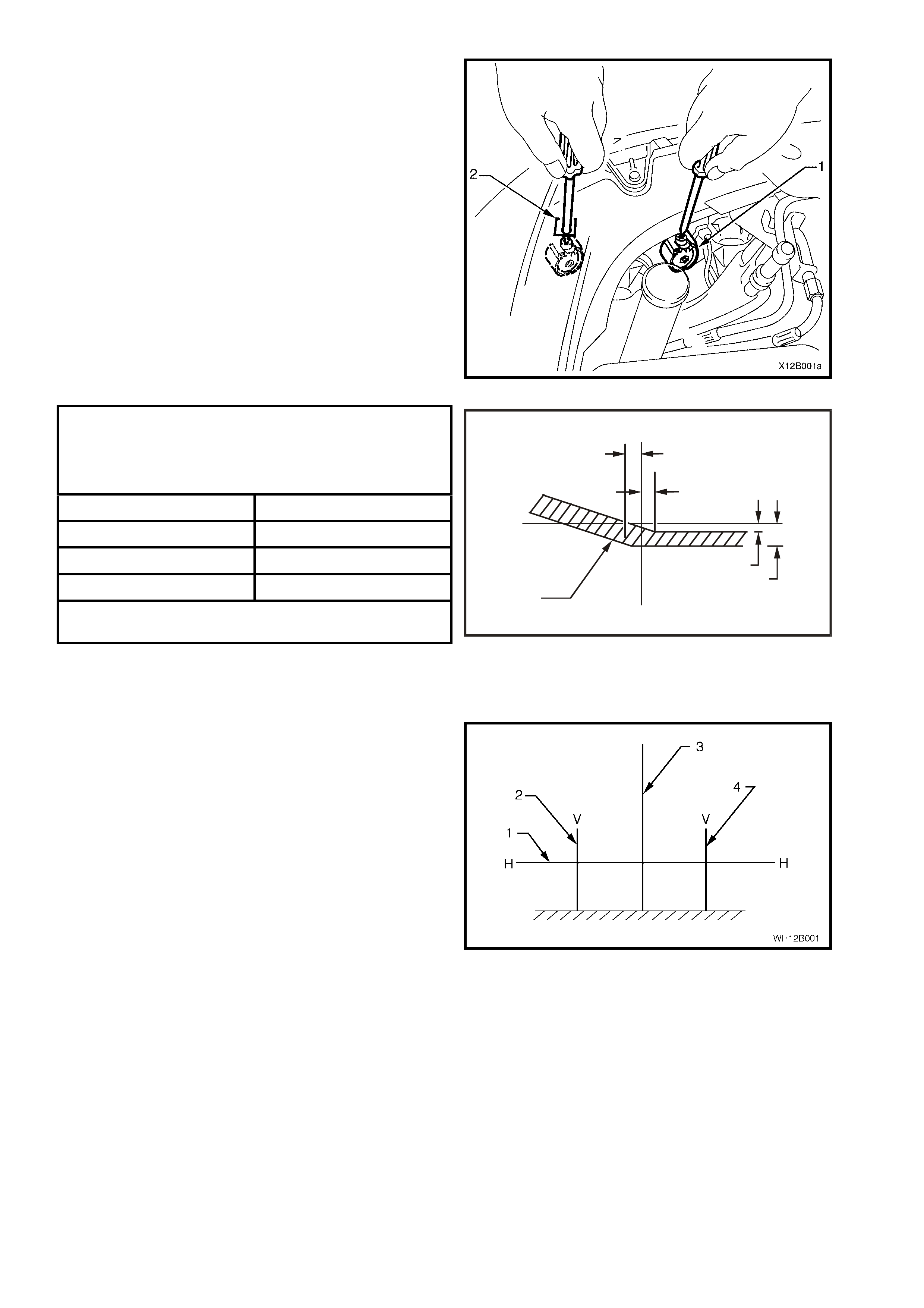
a. Adjust the inboard adjuster (1) to achieve the
correct beam height up and down the vertical
centre line.
b. Adjust the outboard adjuster (2) to centralise
the beam along the horizontal centre line.
4. T he allowable variations on headlam p aim ing point
settings shown in Fig. 12B-1 are specified in the
chart below:
Figure 12B-3
HEADLAMP AIMING
Acceptable Variations In Headlamp Aiming Points
(Refer to Fig 12B-4)
HL 100 mm
HR 0 mm
V1 100 mm
V2 120 mm
Maximum allowable vertical variation between any pair
of headlamps is not to exceed 20 mm
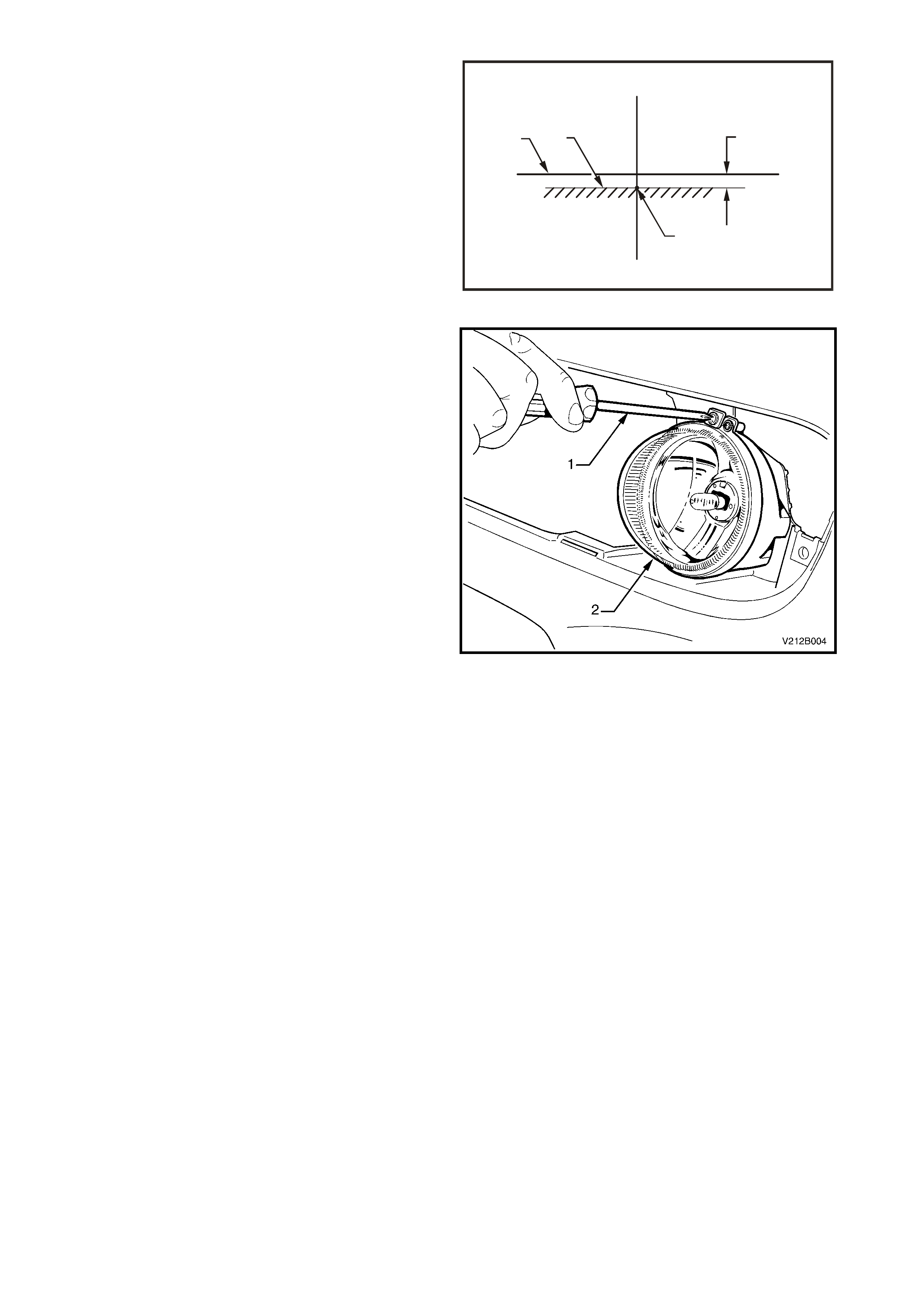
NOTE: Cut-off line (1) must be within the lower
outboard zone, refer to Fig. 12B-4.
WH12B004
V
H
H
V
1V2
V1
HL
HR
Figure 12B-4
FOG L AMP AIM
1. If suitable test equipm ent is not available, s et up a
screen or use a vertical wall, in conjunction with a
flat hor izontal f loor. Par k the vehicle imm ediately in
front of the screen and mark horizontal (1) and
vertical centre lines of the left (2) and right (4) fog
lamps, and the vehicle centre line (3) on the
screen.
2. Park the vehicle 10 metres in front of the screen,
ensuring that the vehicle is aligned with the centre
line mark on the screen.
Figure 12B-5
3. Remove the lower air intake grille from the front
facia assembly, refer to Section 1D BUMPER
BARS, in this Service Information.
4. Turn the fog lamps on. Individually aim each fog
lamp to a central point on its vertical centre line
(2), with the cut off line (3) 200 mm below the fog
lamp horizontal centre line (1).
WH12B005
20 0 mm
2
3
1
V
HH
V
Figure 12B-6
a. Fog lamp aim adjustment is carried out by
rotating the adjuster screw (1) located above
the lamp housing (2).
b. Turning the adjuster screw counter-clockwise
lowers the beam.
c. Turning the adjuster screw clockwise raises
the beam.
d. The adjustment can be carried out by using a
No. 2 Phillips head screw driver.
NOTE: There is no pr ovis ion f or adjus ting the f og lamp
beam along the horizontal centre line. Fog lamps are
fixed to a vertical centre line.
Figure 12B-7
2.2 HEADLAMP AND TURN SIGNAL/PARK LAMP ASSEMBLY
REMOVE
1. Open the engine compartment.
2. Disconnect the battery earth lead.
3. For RH side headlamp and turn signal/park lamp
assembly only, disconnect the battery positive
lead, remove the battery retaining clamp and
remove the battery from the engine compartment.
4. Remove the front bumber facia, refer to
Section 1D BUMPER BARS in this Service
Information.
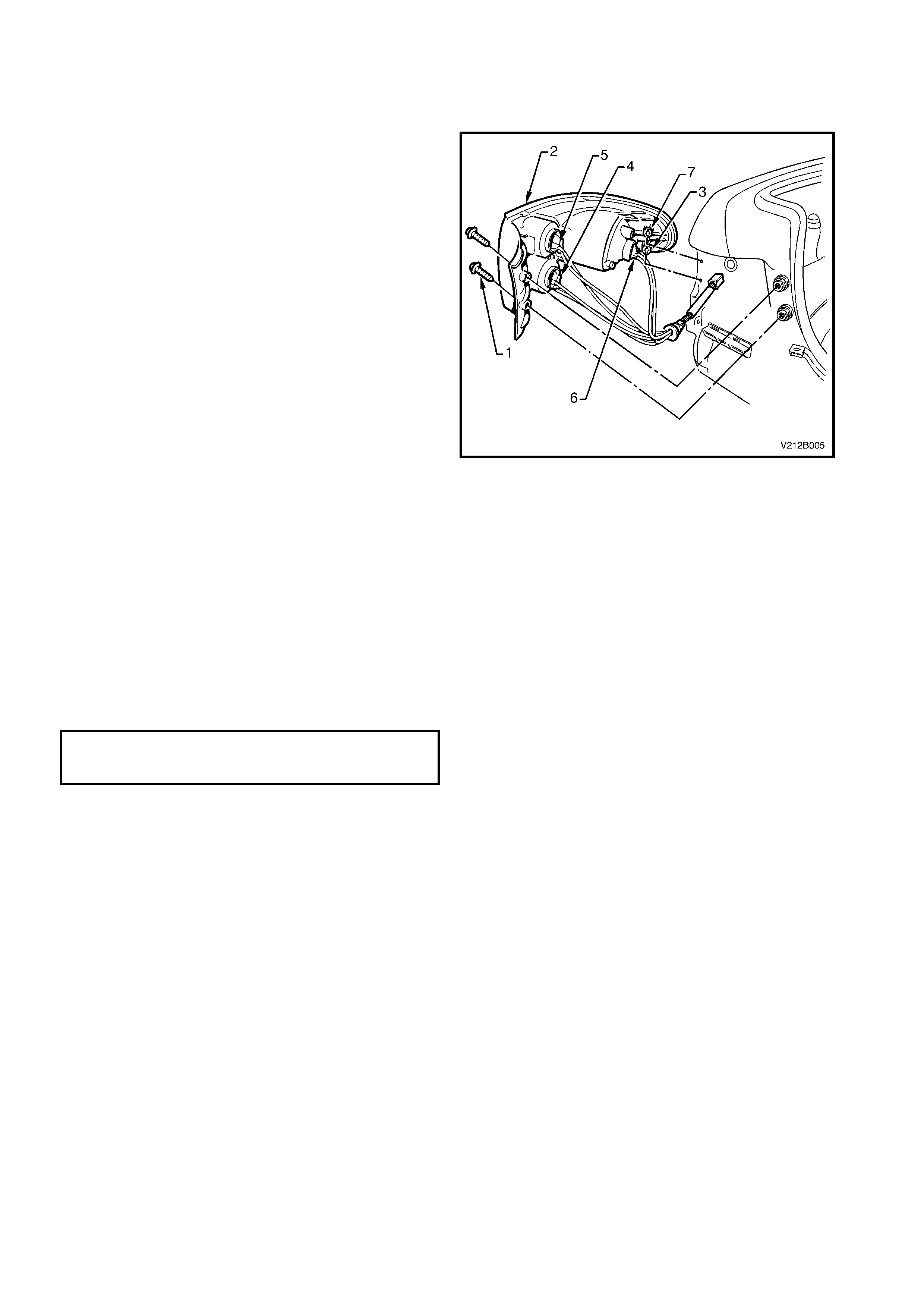
5. Remove the lower retaining screw (1).
6. Remove the centre retaining screw (2).
7. Remove the upper retaining screw (3).
Figure 12B-8
8. Partially remove the headlamp and turn signal/park
lamp assembly until the two harness connectors
are accessible.
9. Disconnect the turn signal wiring harness
connector (1) from the turn lamp.
10. Squeeze the smaller ends of the headlamp wiring
harness connector (2) together and pull rearwards
to disconnect from the headlamp.
11. Remove the headlamp and turn signal/park lamp
assembly (4), taking care not to damage the
rubber seal (5), refer to Fig. 12B-8.
Figure 12B-9
REINSTALL
The installation procedure for the headlamp and turn
signal/park lamp is the reverse of the removal
procedure noting the following:
• The rubber seal around the headlamp and turn
signal/park lamp assembly should be correctly
located.
• The headlamp and turn signal/park lamp retaining
screws should be installed and tightened to the
correct torque setting in the reverse sequence to
the removal procedure.
HEADLAMP AND TURN SIGNAL/PARK
LAMP TO BODY ATTACHING SCREWS
TORQUE SPECIFICATION 2 – 5 Nm
• Check the headlamp and turn signal/park lamp
assembly operation following installation.
• When the headlamp and turn signal/park lamp
assembly has been removed/replaced, the
headlamp aim should be checked and adjusted if
necessary.
2.3 HIGH BEAM BULB
REPLACE
1. Open the engine compartment.
2. Disconnect the battery earth lead.
3. For vehicles with GEN III V8 engine, remove the
four scrivets securing the upper radiator support
cover and remove cover.
4. From inside the engine compartment, remove the
inboard high beam dust cap (1) from the rear of
the headlam p housing assembly (2) by turning the
dust cap counter-clockwise and pulling away from
housing. If the dust cap seal stays on the
headlamp housing, remove the seal and install
onto the cap.
Figure 12B-10
5. Disconnect the harness connector (1) from the
bulb and holder assembly (2).
NOTE: Do not handle the quartz envelope of the high
beam bulb. If touched accidentally, wipe immediately
with methylated spirits or bulb performance will
deteriorate.
6. Turn the bulb and holder assembly counter-
clock wise an eighth of a turn and rem ove from the
headlamp housing.
7. Install the new bulb into housing, ensuring that the
locating lugs on the bulb and holder assembly
mate with the slots on the headlam p housing, and
lock into place by turning clockwise an eighth of a
turn.
NOTE: The different sized locating tangs on the bulb
base and m ating cut-outs in the reflector allow the bulb
to seat correctly into the reflector in one location only.
This ensures correct relationship of the bulb to the
reflector.
8. Connect the bulb harness connector.
9. Inspect the rubber seal in the dust cap to ensure
that it is not damaged and that it is seated
correctly.
10. Install the dust cap onto the rear of headlamp
housing and lock into place by turning clockwise.
11. Reconnect the battery earth terminal.
12. Check the high beam lamp operation.
13. For vehicles with GEN III V8 engine, reinstall the
upper radiator s upport cover and the four retaining
scrivets.
Figure 12B-11
2.4 HEADLAMP BULB
REPLACE
1. Open the engine compartment.
2. Disconnect the battery earth lead.
3. For RH headlamp only, disconnect the battery
positive lead, remove the battery retaining clamp
and remove the battery from the engine
compartment to gain access to the headlamp dust
cap.
4. For vehicles with GEN III V8 engine, remove the
four scrivets securing the upper radiator support
cover and remove the cover.
5. For the LH headlamp in vehicles fitted with V6
Supercharged engine, remove the filler neck and
cap from the radiator overflow reservoir by
withdrawing the radiator overflow hose and pulling
the filler neck upwards.
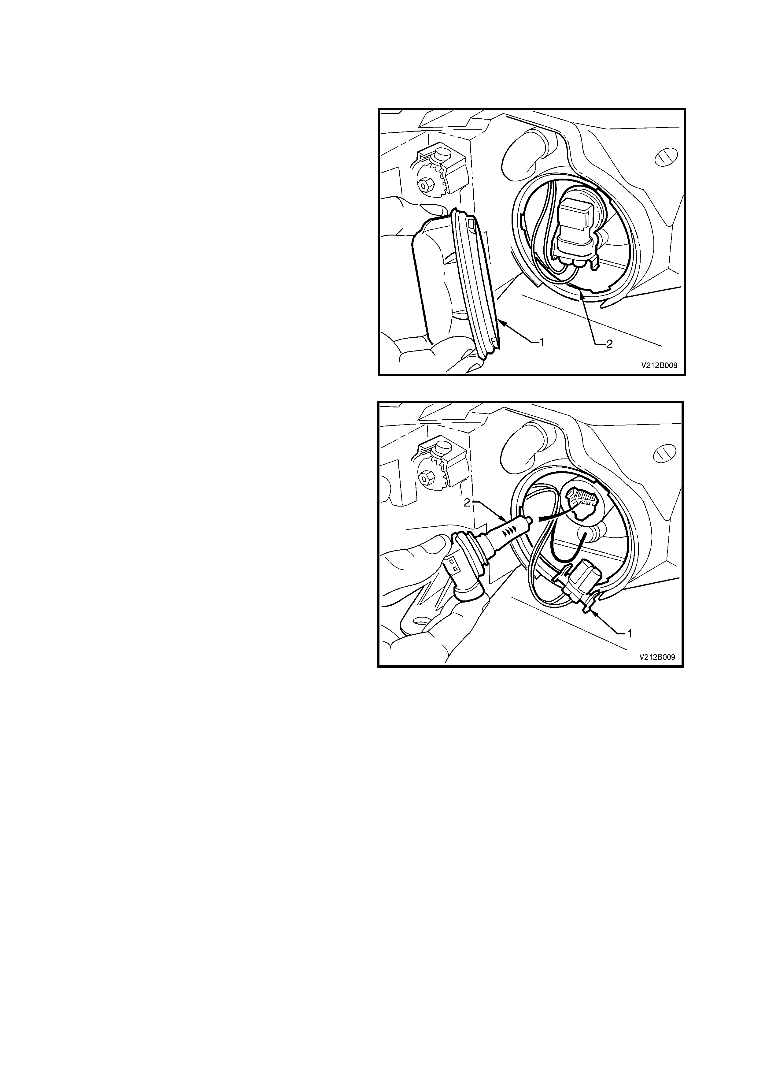
6. From inside the engine compartment, remove the
dust cap (1) from the rear of the headlamp housing
assembly (2) by turning the dust cap counter-
clockwise, and pulling away from housing. If the
dust cap seal stays on the headlamp housing,
remove the seal and install onto the cap.
7. Carefully pull the wiring harness connector (3)
from the rear of the bulb and holder assembly (4).
Figure 12B-12
8. Turn the bulb and holder assembly counter-
clockwise an eighth of a turn and remove from
headlamp housing.
NOTE: Do not handle the quartz envelope of the
headlamp bulb. If touched accidentally, wipe
immediately with methylated spirits or bulb
performance will deteriorate.
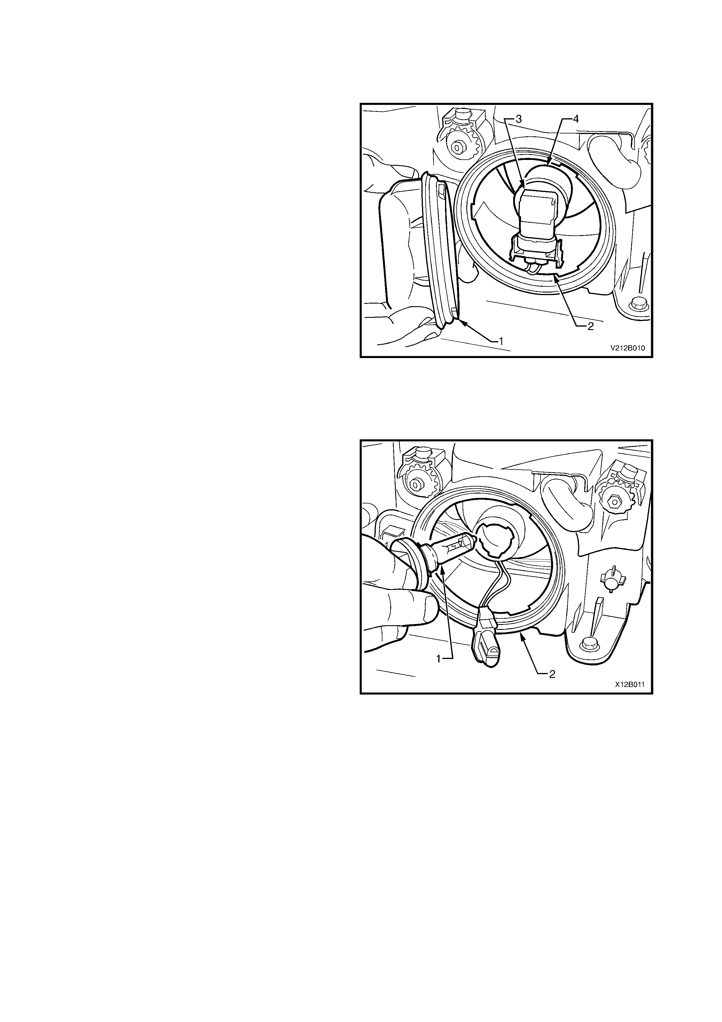
9. Install the new bulb (1) into the headlamp housing
(2), ensuring that the locating lugs on the bulb and
holder assembly mate with slots on the headlamp
housing, and lock into place by turning clockwise
an eighth of a turn.
NOTE: The different sized locating tangs on the bulb
base and mating cut- outs in the reflector allow the bulb
to seat correctly into the reflector in one location only.
This ensures correct relationship of the bulb to the
reflector.
10. Connect the bulb harness connector (3).
Figure 12B-13
11. For LH headlamp for vehicles fitted with V6 Supercharged engine, install the filler neck and cap onto the
radiator overflow reservoir and feed the radiator overflow hose back into the filler neck.
12. Inspec t the rubber seal in the dust c ap to ensure that it is not dam aged and that it is seated correc tly in the
cap. Replace the seal if damaged.
13. Install the cap onto the rear of the headlamp housing and lock the cap into place by turning clockwise.
14. For RH headlamp only, position the battery in the correct location, install the battery retaining clamp and
reconnect the battery positive terminal.
15. Reconnect the battery earth terminal.
16. Check the headlamp low beam lamp operation.
17. For vehicles with GEN III V8 engine, install the upper radiator support cover and the four retaining scrivets.
2.5 PARK LAMP BULB
REPLACE
1. Open the engine compartment.
2. Rem ove the high beam bulb and holder ass embly,
refer to 2.3 HIGH BEAM BULB in this Section.
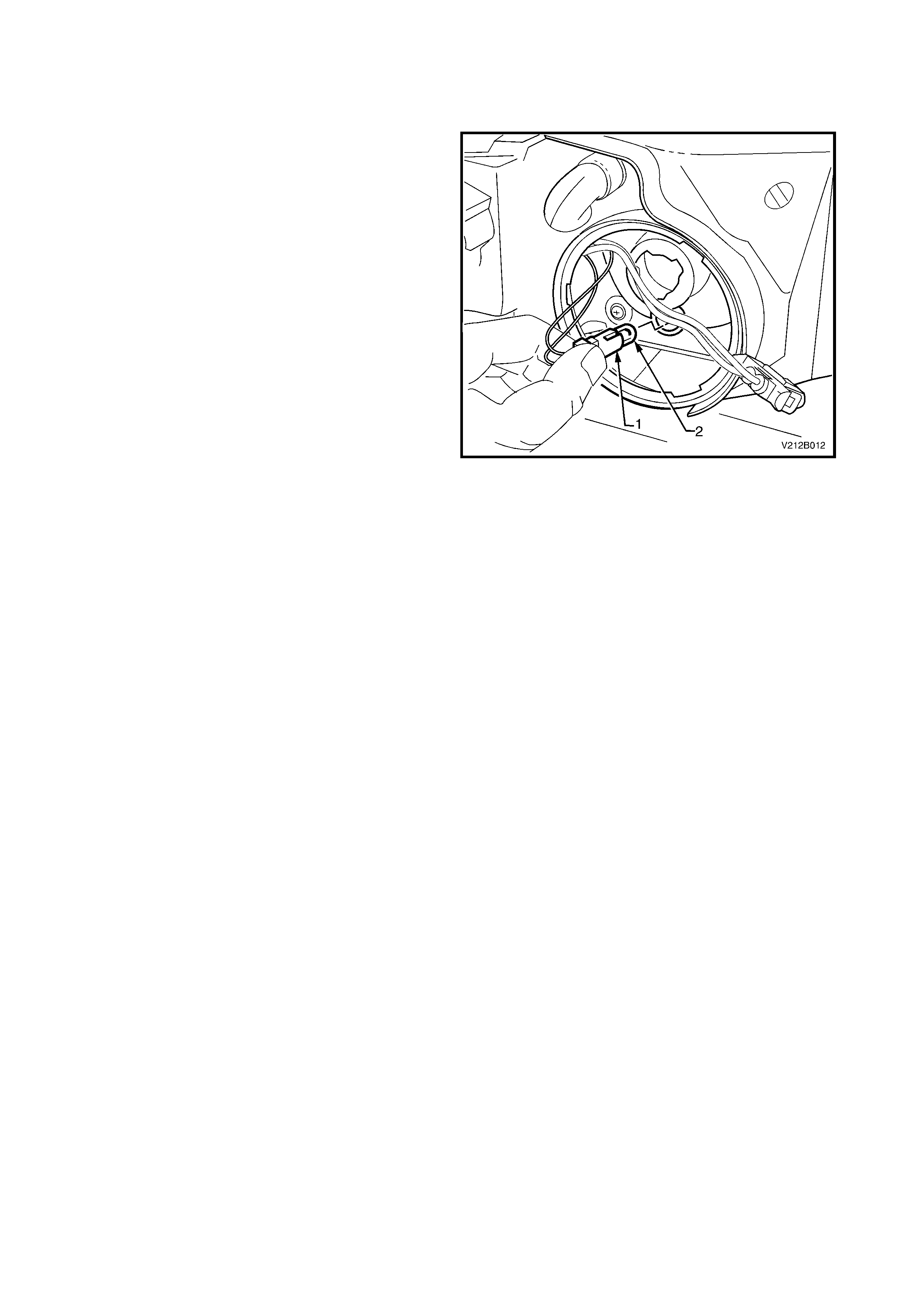
3. Remove the park lamp socket (1) from the
headlamp high beam housing by pulling it firmly
rearwards.
CAUTION: Do not place fingers through the high
beam bulb opening to assist the park lamp socket
from housing.
4. Pull the bulb (2) from the socket.
5. Insert the new bulb into the socket and install the
socket into the reflector.
6. Inspect the rubber seal in the dust cap to ensure
that it is not damaged and that it is seated correctly
in the cap.
7. Install cap onto the rear of headlamp housing and
lock the cap into place by turning clockwise.
8. For the RH headlamp only, position the battery in
the correct location, install the battery retaining
clamp and reconnect the battery terminals.
9. Check the park lamp operation.
10. For vehicles with GEN III V8 engine, install the
upper radiator s upport cover and the four retaining
scrivets.
Figure 12B-14
2.6 FRONT TURN SIGNAL LAMP BULB
REPLACE
NOTE: If replacing a front turn signal lamp bulb,
ensure that the correct type is fitted.
1. Open the engine compartment.
2. Disconnect the battery earth lead.
3. For the RH front turn signal lamp only, disconnect
the battery positive lead, remove the battery
retaining clamp and remove the battery from the
engine compartment.
4. For vehicles with GEN III V8 engine only, remove
the four scrivets securing the upper radiator
support cover and remove the cover.
5. For the LH turn signal lamp in vehicles fitted with
V6 Supercharged engine, remove the filler neck
and cap from the radiator overflow reservoir by
withdrawing the radiator overflow hose and pulling
the filler neck upwards.
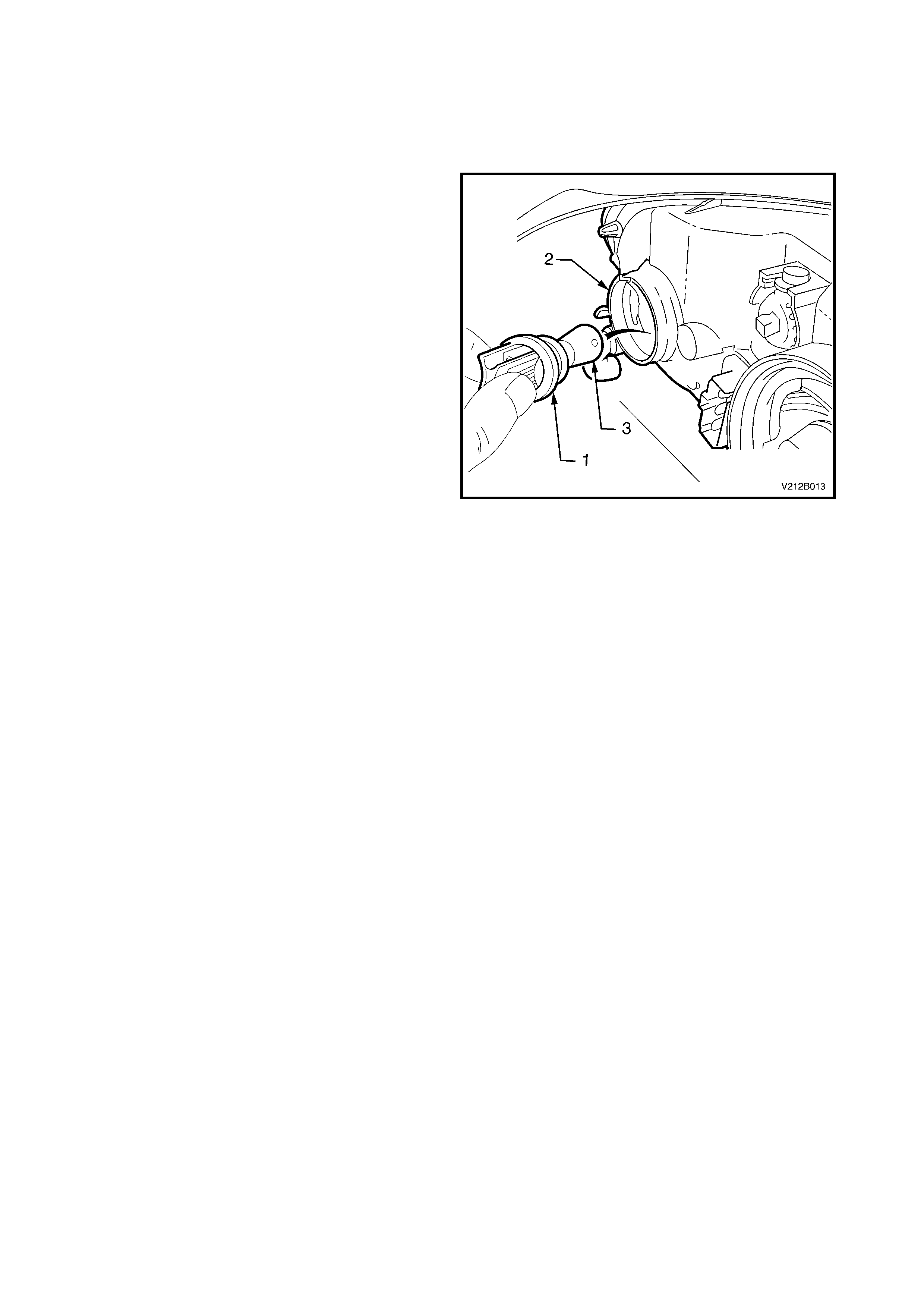
6. From inside the engine compartment, twist to
release the bulb socket (1) from behind headlamp
assembly (2).
7. Depress the bulb into the socket and rotate to
remove.
8. Inspect the O-ring on the bulb socket for damage
and correct seating. Replace the O-ring if
necessary.
9. Install the new bulb (3) into the socket.
10. Install the s ocket into the housing and twist to lock
into position.
11. For the LH turn signal lamp in vehicles fitted with
V6 Supercharged engine, ins tall the filler neck and
cap onto the radiator overflow reservoir and feed
the radiator overflow hose back into the filler neck.
12. For the RH f ront turn signal lam p only, position the
battery in the correct location, install the battery
retaining clamp and reconnect the battery
terminals.
13. Check turn signal lamp operation.
14. For RH headlamp in vehicles with GEN III V8
engine, install the upper radiator support cover and
the four retaining scrivets.
Figure 12B-15
2.7 REAR QUARTER LAMP ASSEMBLY
REMOVE
1. Disconnect the battery earth lead.
2. Open the rear compartment lid.
3. Remove the two rear quarter lamp assembly to
body attaching screws (1).
4. Pull the rear quarter lamp housing (2) sideways out
from panel so that the locating peg (3) on the side
of the the lamp assembly snaps free from the
retainer.
5. While supporting the lamp housing:
a. Remove the back-up light bulb (4) by turning
the socket counter-clockwise and removing.
b. Remove the turn signal bulb socket (5) by
turning socket counter-clockwise and
removing.
c. Remove the stop/tail light bulb socket (6) by
turning socket counter-clockwise and
removing.
NOTE: When removing the rear quarter lamp
assem bly fr om the panel, tak e care not to damage the
integral plastic guide peg (7).
Figure 12B-16
REINSTALL
1. Ins ert the bulb soc k ets into the rear quarter lam p
housing, ensuring that the sockets are correctly
located and lock securely into place.
2. Ensuring that the rear quarter lamp harness
grommet is seated correctly, install the lamp
housing, ensuring that the locating peg snaps
into the retainer.
3. Install and tighten the attaching screws to the
correct torque specification.
REAR QUARTER LAMP HOUSING TO
BODY ATTACHING SCREW
TORQUE SPECIFICATION 1 – 3 Nm
NOTE: Harness length will allow back-up light socket
and turn signal bulb soc ket to be fitted to the corr ect
locations only.
4. Check rear quarter lamp operation.

2.8 REAR TURN SIGNAL LAMP BULB
REPLACE
1. Remove the rear quarter lamp assembly, refer to 2.7 REAR QUARTER LAMP ASSEMBLY in this Section.
2. Remove the r ear turn s ignal lamp bulb fr om the soc ket (ref er to item 5 in Figure 12B-16) by depressing the bulb
into the socket and rotating counter-clockwise.
3. Inspect the bulb socket to lamp housing seals for damage and replace if necessary.
4. Insert the new bulb into the sock et and install the socket into the lam p housing, ensuring that the socket locks
securely into place.
5. Reinstall the rear quarter lamp assembly, refer to 2.7 REAR QUARTER LAMP ASSEMBLY in this Section.
6. Check the rear quarter lamp operation.

2.9 STOP/TAIL LAMP BULB
REPLACE
1. Remove the rear quarter lamp assembly, refer to 2.7 REAR QUARTER LAMP ASSEMBLY in this Section.
2. Remove the stop/tail lam p bulb f rom the s ocket (r efer item 6 in F igure 12B-16) by depres sing the bulb into the
socket and rotating counter-clockwise.
3. Inspect the bulb socket to lamp housing seals for damage and replace if necessary.
4. Insert the new bulb into the sock et and install the socket into the lam p housing, ensuring that the socket locks
securely into place.
5. Reinstall the rear quarter lamp assembly, refer to 2.7 REAR QUARTER LAMP ASSEMBLY in this Section.
6. Check the rear quarter lamp operation.
Techline

2.10 BACK-UP LAMP BULB
REPLACE
1. Remove the rear quarter lamp assembly, refer to 2.7 REAR QUARTER LAMP ASSEMBLY in this Section.
2. Remove the back-up lamp bulb from the socket (refer item 4 in Figure 12B-16) by depressing the bulb into its
socket and rotating counter-clockwise.
3. Inspect the bulb socket to lamp housing seals for damage and replace if necessary.
4. Insert the new bulb into the sock et and install the socket into the lam p housing, ensuring that the socket locks
securely into place.
5. Reinstall the rear quarter lamp assembly, refer to 2.7 REAR QUARTER LAMP ASSEMBLY in this Section.
6. Check the back-up lamp operation.
2.11 CENTRE HIGH MOUNT STOP LAMP ASSEMBLY
REMOVE
1. Disconnect the battery earth lead.
2. Open the rear compartment lid.
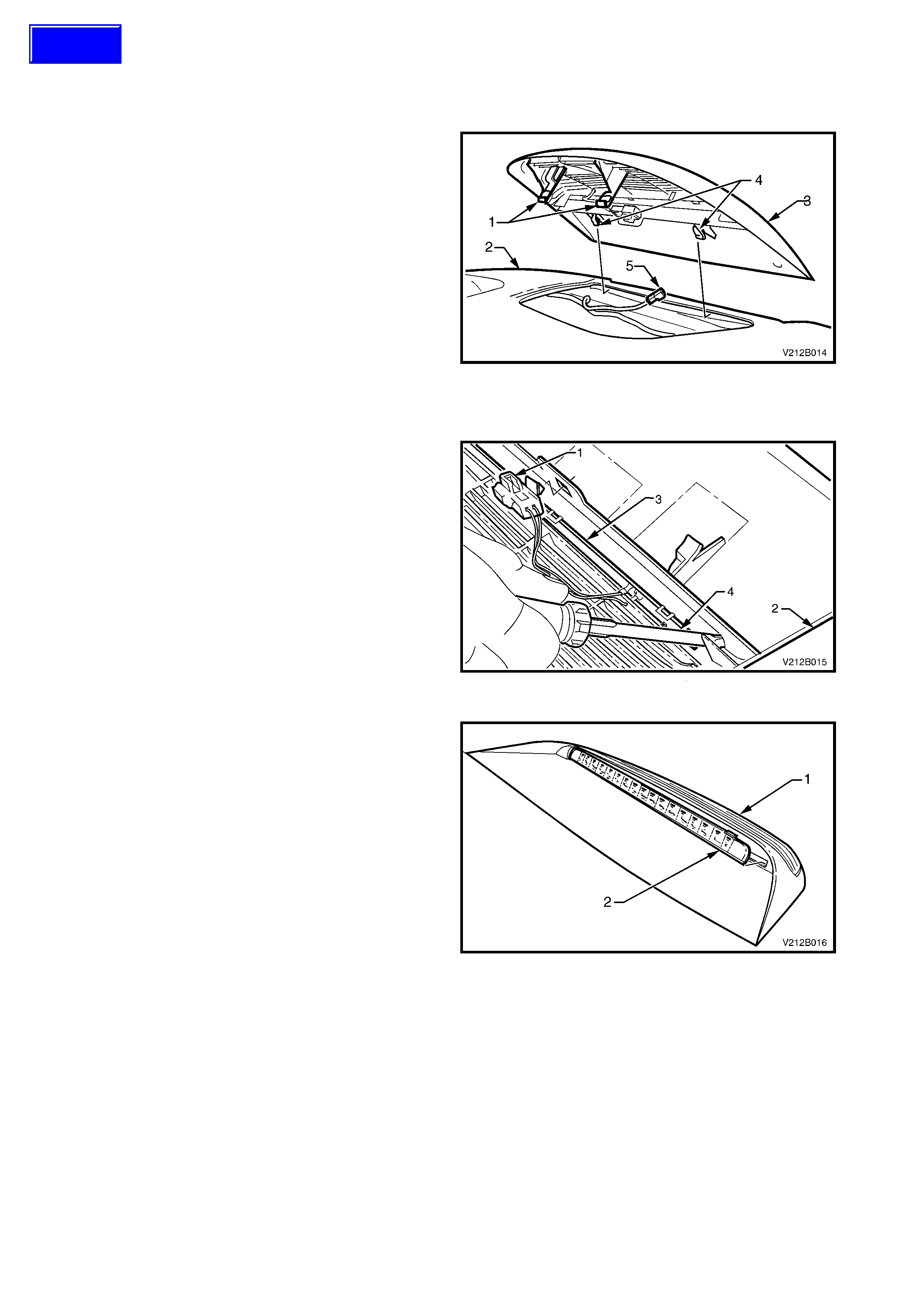
3. F rom inside the rear load com partm ent, disengage
the two retaining tangs (1) from the rear parcel
shelf sheetmetal (2).
4. From inside the vehicle cabin, grasp the edge of
the centre high mount stop lamp (3) and pull the
assembly up and away from the rear windscreen
until the locating tabs (4) are free of the locating
slot.
5. Disconnect the harness connector (5) from the
centre high m ount stop lam p and remove the lamp
from the vehicle.
Figure 12B-17
DISASSEMBLE
1. Unclip the harness connector (1) from the lamp
housing (2).
2. Starting at one end of the LED assembly (3),
carefully disengage the retaining tab with a small
screwdriver (4).
Figure 12B-18
3. Car efully spread the lam p housing (1) by hand and
work the LED assembly (2) sideways and
rearwards until free of the housing.
Figure 12B-19
REASSEMBLE
The reassembly procedure for the centre high mount stop lamp is the reverse of the disassemble procedure
REINSTALL
The installation procedure for the centre high mount stop lam p is the reverse of the removal procedure, noting the
following:
• Ensure that the locating tabs ar e corr ectly engaged into the s lot in the rear of the parc el shelf prior to engaging
the retaining tabs.
• Check centre high mount stop lamp operation once installed.
Techline
2.12 FOG LAMP ASSEMBLY
REMOVE
1. Disconnect the battery earth lead.
2. Remove the lower air intake grille from the front
facia assembly, refer to Section 1D BUMPER
BARS.
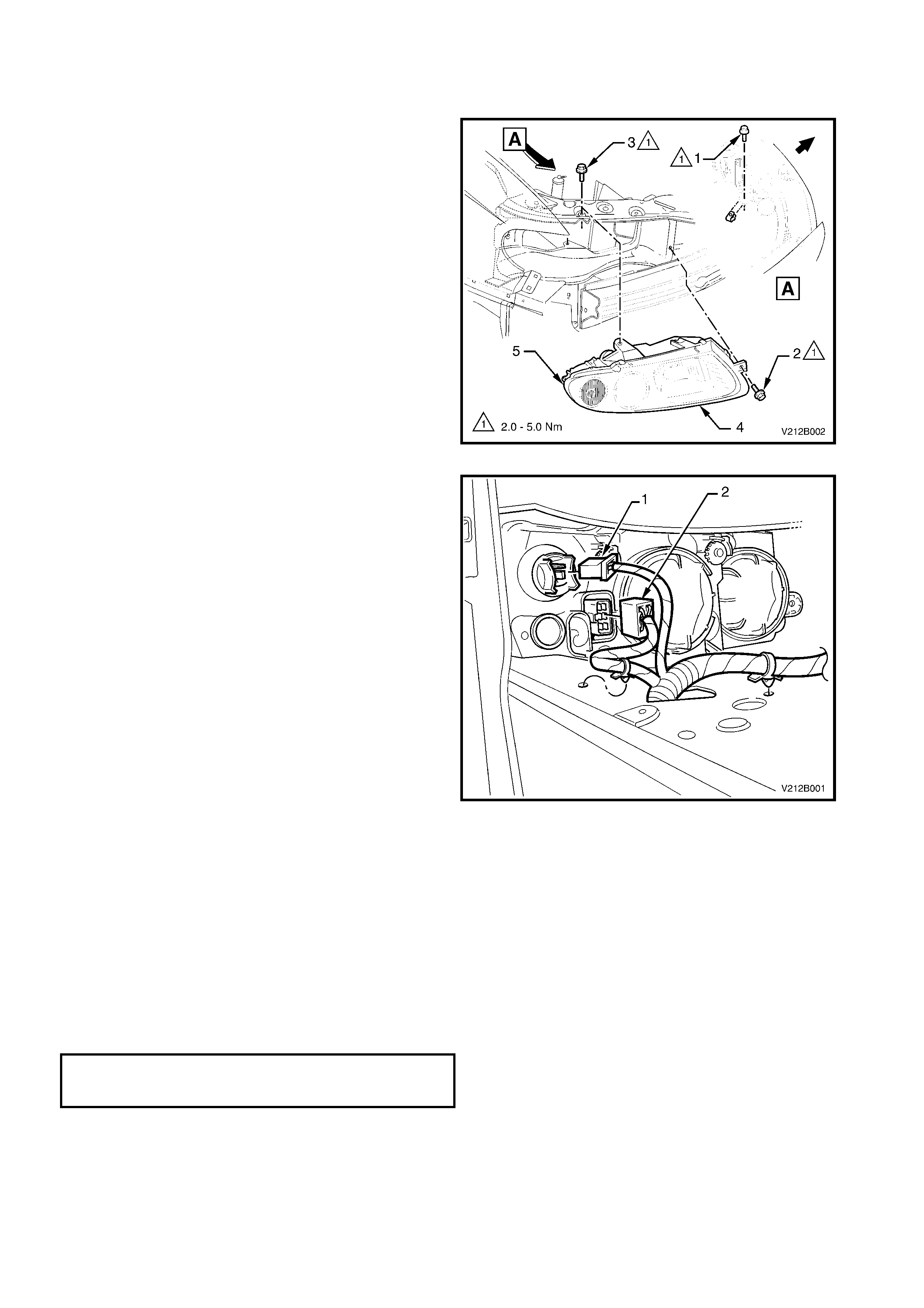
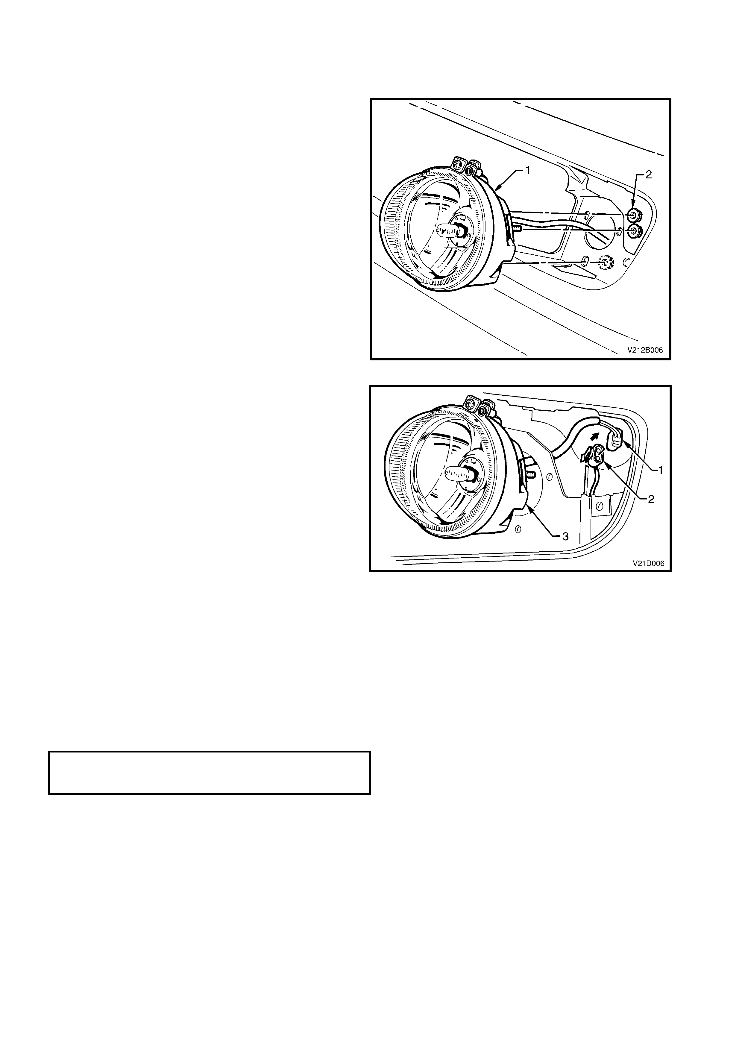
3. From behind the bumper bar facia, remove the
three nuts (2) securing the fog lamp assembly (1)
to bumper bar facia, and parcially remove the fog
lamp assembly.
Figure 12B-20
4. Unclip the fog lamp harness (1) from the front
longitudinal by sliding the connector forward.
5. Dis connect the f oglam p harnes s connec tor (2) and
remove the fog lamp assembly (3).
Figure 12B-21
REINSTALL
The installation procedure for the fog lamp assembly is
the reverse of the removal procedure, noting the
following:
• Ensure that the fog lamp assembly is correctly
orientated with the beam adjustment screw located
to the top.
• Tighten the fog lamp housing to bumper bar facia
nuts to the correct torque specification.
FOG LAMP BRACKET TO FRONT
FACIA RETAINING NUTS
TORQUE SPECIFICATION 2.0 – 2.5 Nm
• Check fog lamp operation and aiming, refer to
2.1 AIMING OF HEADLAMPS AND FOG LAMPS
in this Section.
2.13 FOG LAMP BULB
REPLACE
1. Disconnect the battery earth lead.
2. Remove the lower air intake grille from the front
facia assembly, refer to Section 1D BUMPER
BARS.
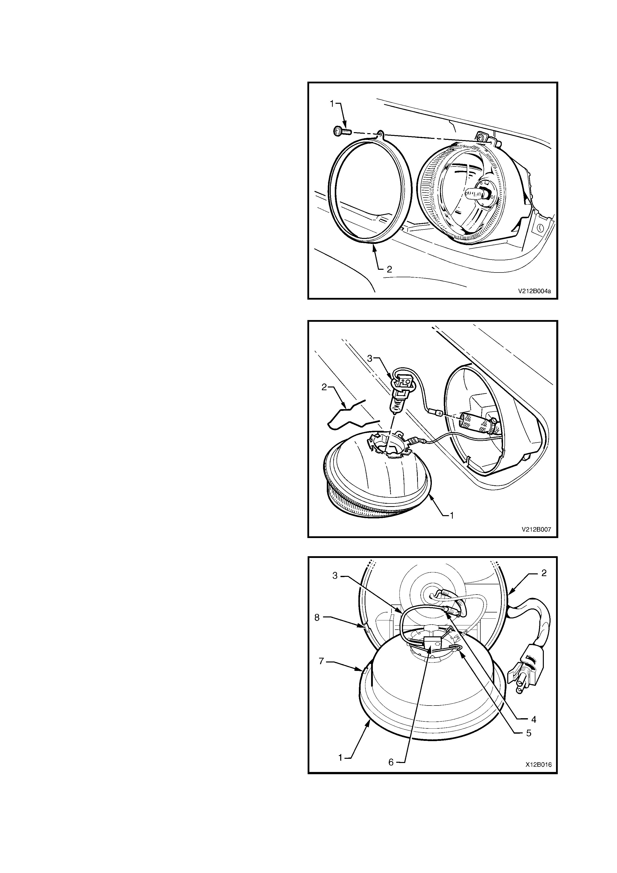
3. Remove the screw (1) securing the lens, reflector
and clamp ring assembly to the fog lamp housing
and remove the clamp ring (2).
Figure 12B-22
4. Pull the lens and reflector assembly (1) out from
the housing.
5. Disconnect the bulb and lead assembly (3) from
the wiring harness connector located inside the
insulating sheath.
6. Squeeze the halves of the spring retainer (2)
together and pivot spring backward clear of bulb.
Lift out bulb and remove.
NOTE: Do not handle quartz envelope of bulb. If
touched, wipe immediately with methylated spirits or
bulb performance will deteriorate.
Figure 12B-23
7. Connect the new bulb lead (4) to the wiring
harness connector, install the bulb (4) into the
correct locating notches in the lens and reflector
assembly (1) and reconnect the spring retainer (5).
8. Install the lens and reflector assembly into the
housing (2) ensuring that the protrusion (7) on the
rim of the lens and reflector assembly aligns
correc tly with the c ut-out on the rim of the housing
(8).
9. Install the clamp ring and screw and tighten the
screw.
11. Check fog lamp operation and aim, refer to
2.1 AIMING OF HEADLAMPS AND FOG LAMPS
in this Section.
Figure 12B-24

3. SPECIFICATIONS
BULB POWER RATING - WATTS BASE TYPE
HEADLAMPS
Low Beam Outboard
Inboard High Beam
55
65
H11
H9
FOG LAMPS 55 H3
PARK LAMPS (Front) 5 Wedge
TURN SIGNAL LAMPS (Front) 21 Offset Pin (Orange Glass)
SIDE REPEATER LAMPS 5 Wedge
TURN SIGNAL LAMPS (Rear) 21 Offset Pin (Silver Gl ass)
BACK-UP LAMPS 21 Standard Parallel Pin
STOP/TAIL LAMPS 21/5 Standard Parallel Pin
LICENCE PLATE LAMPS 5 Wedge
INSTRUMENT CLUSTER
ILLUMINATION LAMPS
CV6
CV8
3.6
5
Wedge
Wedge
INSTRUMENT CLUSTER
WARNING LAMPS
1.2
Wedge
TRIP COMPUTER ILLUMINATION
LAMPS
1.2
Wedge
REAR COMPARTMENT LAMPS 10 Festoon
DOME LAMP 10 Festoon
FRONT SEAT READING LAMP (SS) 5 Standard Parallel Pin
REAR SEAT READING LAMP 5 Festoon
GLOVE COMPARTMENT LAMP 5 Festoon
FRONT FOOTWELL LAMPS 2.7 Wedge
FRONT VANITY MIRROR LAMP 1.2 Wedge
DOOR COURTESY LAMPS 5 Festoon
CONSOLE BIN LAMPS 5 Festoon
CENTRE HIGH MOUNT STOP
LAMP N/A LED Assembly
FRONT AND REAR CIGAR
LIGHTER LAMPS
1.2
Wedge
IGNITION LOCK LAMP 1.4 Wedge

4. TORQUE WRENCH SPECIFICATIONS
Nm
Headlamp and Turn Signal/Park Lamp Attaching Screws.... 2 - 5
Rear Quarter Lamp to Body Attaching Screws..................... 1 - 3
Fog Lamp Bracket to Front Facia Attaching Nuts................. 2.0 – 2.5