
SECTION 12D - AUDIO SYSTEMS
IMPORTANT
Before performing any Service Operation or other procedure described in this Section, refer to Section
00 CAUTIONS AND NOTES for correct workshop practices with regard to safety and/or property damage.
1. GENERAL I NFORMATI O N
The audio system fitted to V2 Series Models carries over from VX Series Models, noting the following:
• Due to the deletion of the rear doors for the coupe body design, the mounting of the rear speakers has been
revised in V2 Series Models.
• The audio system fitted to V2 Series CV6 carries over from VX Series I Acclaim.
• The audio system fitted to V2 Series CV8 carries over from VX Series I Calais.
• Due to the reduced size of the parcel shelf in V2 Series Models, the parcel shelf speakers (sub woofers) fitted
to V2 Series CV8 are 6 inch instead of 8 inch as fitted to the VX Series I Calais.
• The CD changer fitted to V2 Series CV8 is mounted on the left-hand side of the load compartment instead of
the right-hand side as in VX Series I Calais.
• The CD changer lead fitted to V2 Series CV8 is unique f rom the harness connector at the k ick panel to the rear
load compartment.
• A unique amplifier and lead assembly for the diversity antenna is fitted to V2 Series CV8.
For information relating to the audio system fitted to V2 Series Models not covered in this Section, refer to
Section 12D AUDIO SYSTEMS, in the VX Series I Service Information.
Techline
2. SERVICE OPERATIONS
2.1 CD CHANGER ASSEMBLY
REMOVE
1. Open the rear compartment lid and remove
the spare wheel cover, refer to
2.11 SPARE WHEEL COVER in Section 1A8
HEADLINING AND REAR END TRIM in this
Service Information.
2. Remove the cartridge and its contents from the CD
changer.
3. Remove the left-hand rear wheel house
carpet and CD changer cover, refer to
2.13 LH REAR WHEELHOUSE CARPET AND CD
CHANGER COVER in Section 1A8 HEADLINING
AND REAR END TRIM.
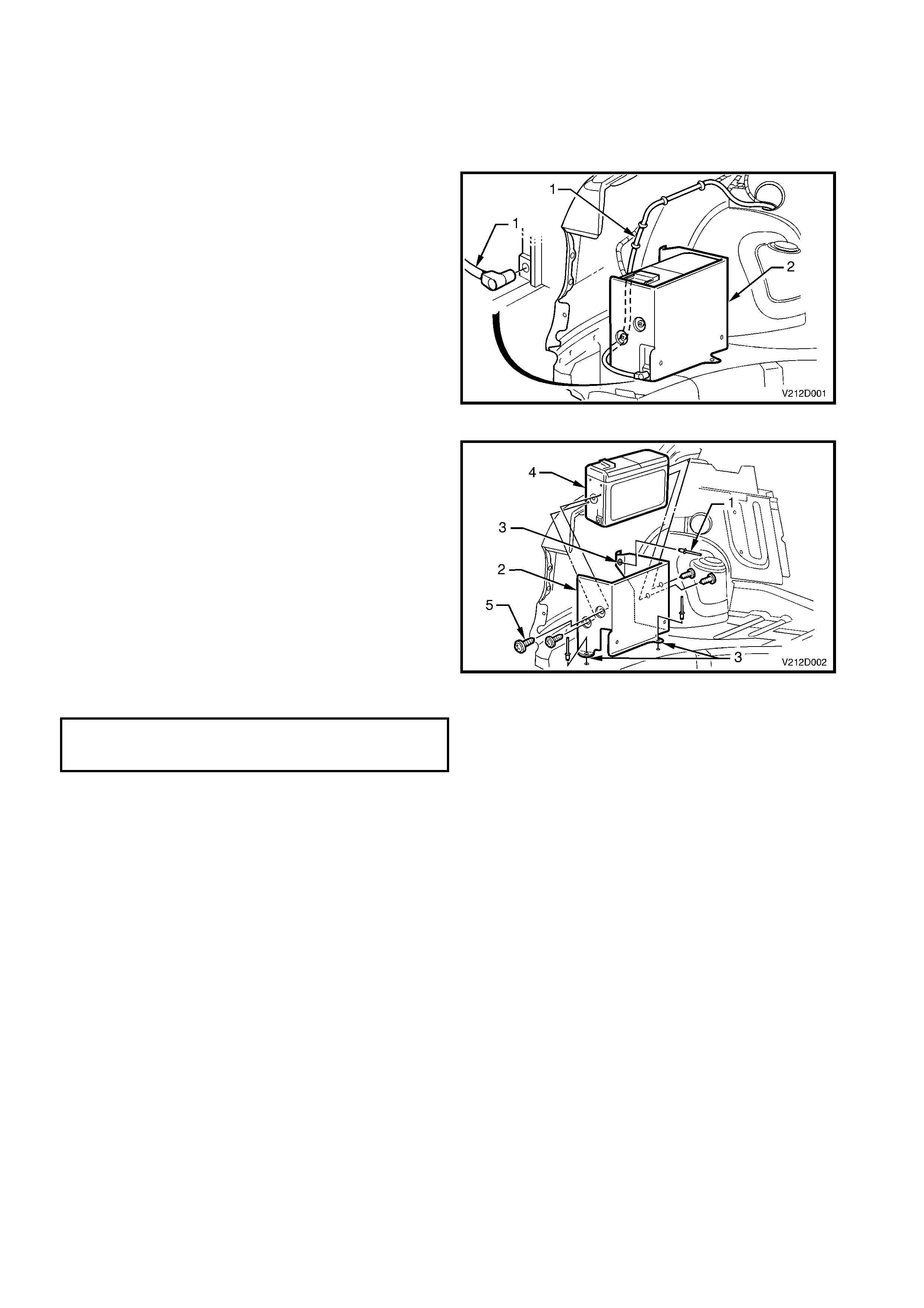
4. Disconnect the CD changer lead (1) from the CD
changer assembly (2).
Figure 12D-1
5. Using a suitable power drill, drill out the three rivets
(1) retaining the CD changer mounting bracket (2)
to the rear compartment sheetmetal, taking care
not to damage the three rubber insulators (3) on
the bracket mounting faces.
6. Remove the CD changer (4) and bracket
assembly.
7. Remove the four screws (5) retaining the CD
changer to the mounting bracket and carefully lift
out the CD changer.
REINSTALL
The reinstall procedure for the CD changer and
bracket as fitted to V2 Series Models is the reverse of
the removal procedure.
CD CHANGER TO MOUNTING
BRACKET RETAINING SCREW
TORQUE SPECIFICATION 2 - 4 Nm
Figure 12D-2

2.4 REAR QUARTER SPEAKER
REMOVE
1. Remove the rear quarter trim, refer to
2.4 REAR QUARTER TRIM in Section 1A8
HEADLINING AND REAR END TRIM in this
Service Information.
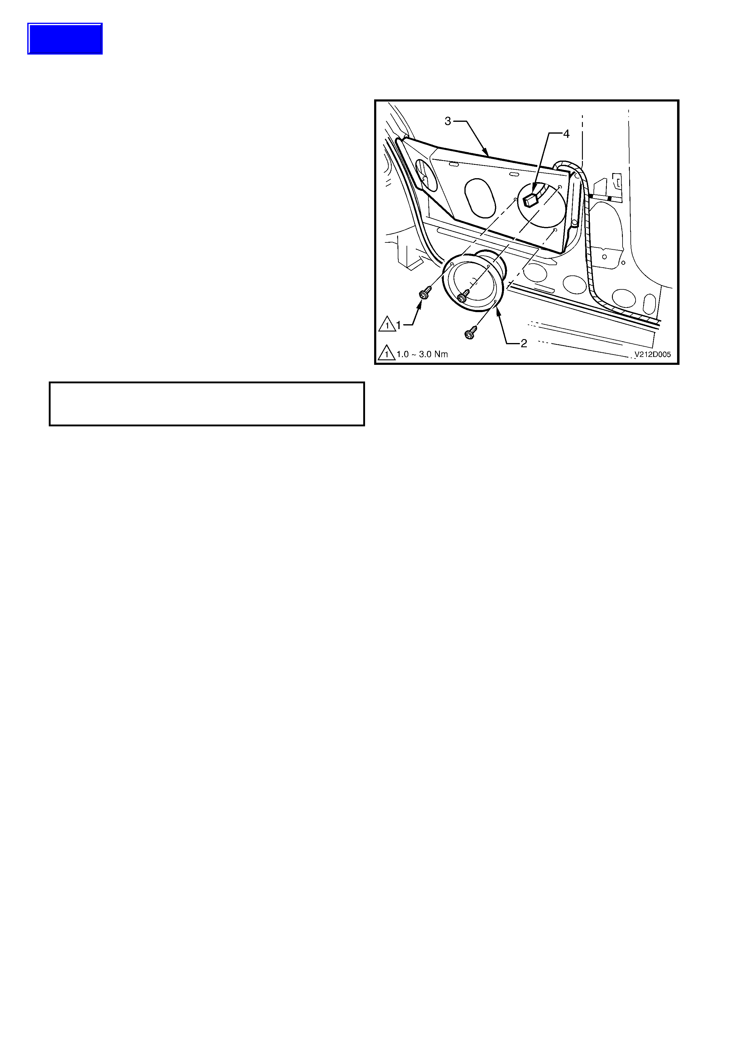
2. Remove the three sc rews ( 1) s ec uring the s peak er
(2) to the mounting bracket (3).
3. Pull the speaker away from the mounting bracket
to gain access, and disconnect the body wiring
harness connector (4).
4. Remove the rear quarter speaker from the vehicle.
REINSTALL
The reinstall procedure for the rear quarter speaker
assembly as fitted to V2 Series Models is the reverse
of the removal procedure, noting the following:
• Tighten all fasteners to the specified torque.
• Check operation prior to installing rear quarter trim
assembly.
REAR QUARTER SPEAKER TO
MOUNTING BRACKET ATTACHING
SCREW TORQUE SPECIFICATION 1.5 – 3.0 Nm
Figure 12D-5
Techline
2.4 REAR PARCEL SHELF SPEAKER
REMOVE
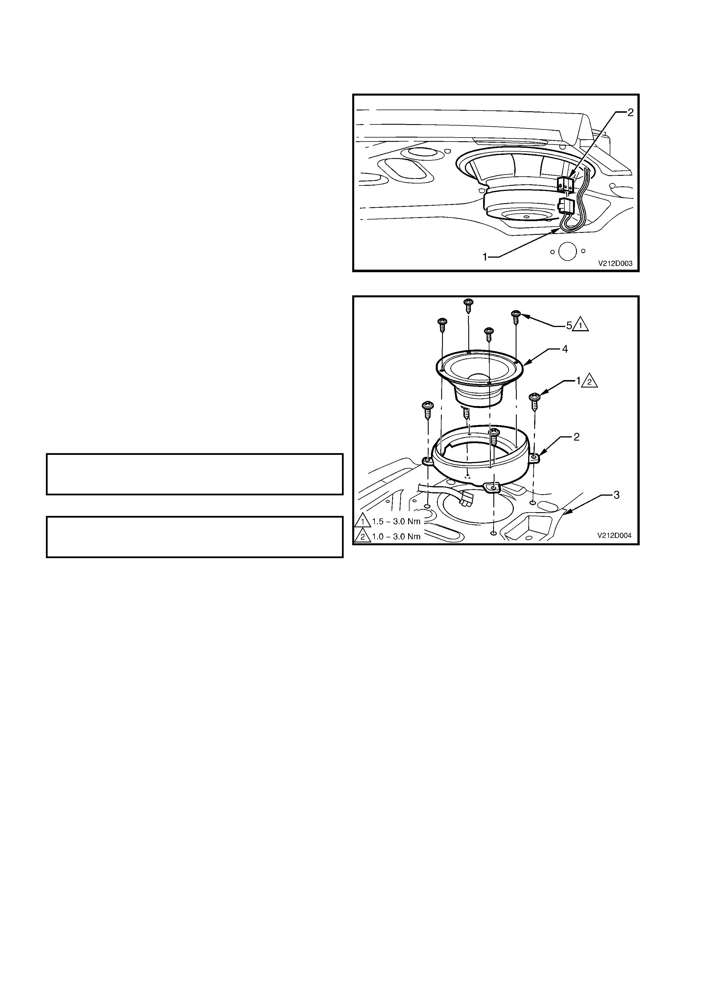
1. Open the rear c ompartm ent lid and disc onnect the
body wiring harness connector (1) from the
speaker (2).
2. Remove the rear parcel shelf assembly, refer to
2.9 REAR PARCEL SHELF ASSEMBLY in
Section 1A8 HEADLINING AND REAR END T RIM
in this Service Information.
Figure 12D-3
3. Remove the four screws (1) securing the speaker
mounting box (2) to the rear parcel shelf (3).
4. Remove the mounting box and speaker (4) from
the vehicle.
5. Remove the four screws (5) securing the speaker
to the mounting box and carefully separate.
REINSTALL
The reinstall procedure for the rear parcel shelf
speaker assem bly as fitted to V2 Series Models is the
reverse of the removal procedure.
SPEAKER MOUNTING BOX TO REAR
PARCEL SHELF ATTACHING SCREW
TORQUE SPECIFICATION 1.0 – 3.0 Nm
REAR PARCEL SHELF SPEAKER TO
MOUNTING BOX SECURING SCREW
TORQUE SPECIFICATION 1.5 – 3.0 Nm
Figure 12D-4

2.5 DIVERSITY ANTENNA AMPLIFIER AND LEAD ASSEMBLY
For V2 Series Models, due to the changes in the coupe body design, the location of the divers ity antenna am plifier
and lead has been revised. For information relating to the diversity antenna amplifier and lead, refer to
Section 12N FUSES, RELAYS AND WIRING HARNESSES in this Service Information.

3. TORQUE WRENCH SPECIFICATIONS
Nm
CD changer to mounting bracket retaining screws...............2.0 – 4.0
Rear parcel shelf speaker to mounting box
securing screws....................................................................1.5 – 3.0
Rear parcel shelf speaker mounting box to parcel shelf
securing screws....................................................................1.0 – 3.0
Rear quarter speaker to mounting bracket securing screws 1.0 – 3.0