
SECTION 12N - FUSES, RELAYS AND
WIRING HARNESSES
IMPORTANT
Before performing any Service Operation or other procedure described in this Section, refer to Section
00 CAUTIONS AND NOTES for correct workshop practices with regard to safety and/or property damage.
1. GENERAL I NFORMATI O N
The fuses, relays and wiring harnes ses as fitted to V2 Series Models carries over from VX Series II Models , noting
the following:
• The headlamp connectors for V2 Series Models are unique.
• The body wiring harness incorporates numerous changes to accomodate the coupe body design.
• The main wiring harness incorporates numerous changes to accomodate the coupe body design.
For inf ormation relating to the fuses, relays and wiring harnesses as fitted to V2 Series Models not covered in this
Section, refer to Section 12N FUSES, RELAYS AND WIRING HARNESSES in the VX Series II Service
Information.
1.1 FUSES AND CIRCUIT BREAKERS
All information relating to the fuses and circuit breakers carry over from VX Series II. For information relating to
fuses and circuit breakers as fitted to V2 Series Models, refer to Section 12N FUSES, RELAYS AND WIRING
HARNESSES in the VX Series II Service Information.
For m ore detailed inform ation regarding circ uit protection details, refe r to Section 12P WIRING DIAGRAM S in this
Service Information.


3. WIRING INSTALLATION DIAGRAMS
The following wiring installation diagrams are applicable to V2 Series Models.
For all other wiring installation diagrams, refer to Section 12N FUSES, RELAYS & WIRING HARNESSES in the
VX Series I Service Information in conjunction with Section 12N FUSES, RELAYS & W IRING HARNESSES in the
VT Series I and VT Series II Service Information.
For m ore detailed infor mation r egarding wiring diagrams , refer to Section 12P W IRING DIAGRAM S in this Service
Information.
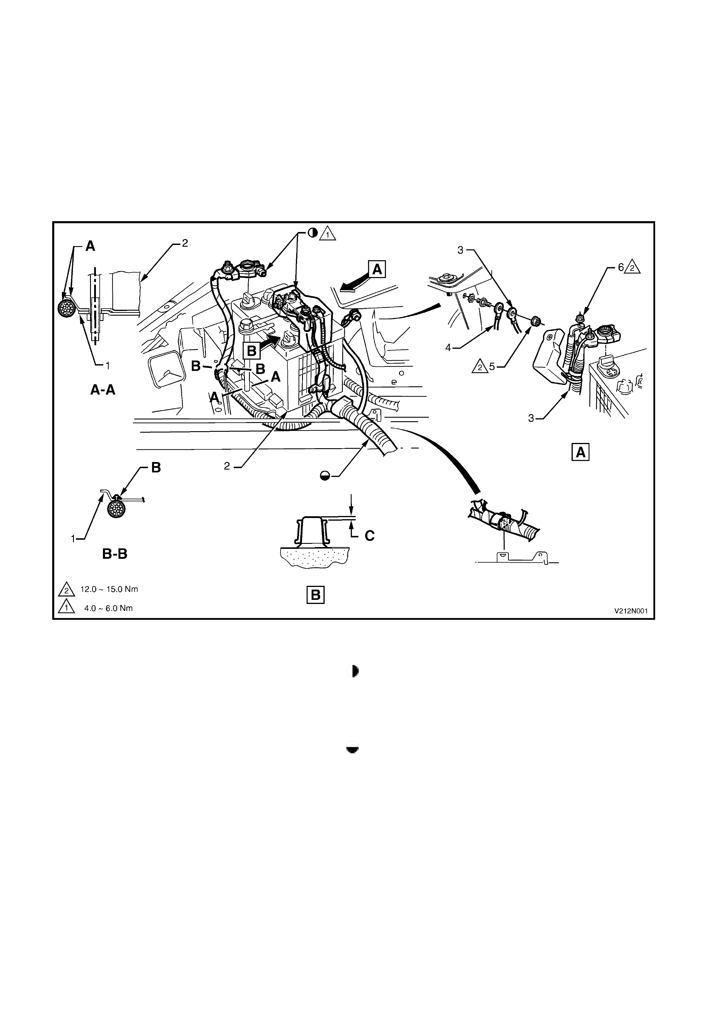
BATTERY WIRING HARNESS - 1
BATTERY TERMINALS
Figure 12N-1
Legend
1. Battery tray Mating surfaces of terminal and posts must be clean
2. Battery and free of grease prior to installation. Coat terminals
3. Battery harness earth with petroleum grease to Holden Specification HN 1198
4. Main wiring harness body earth after installing battery terminals and tightening to the
5. Body earth attaching nut specified torque.
6. Main wiring harness positive terminal attaching nut For harness continuation, refer to Figure 12N-2 for
A. Harness must route under battery tray edge V6 Supercharged or Figure 12N-3 for GEN III V8.
B. Clip harness into hole in battery tray from underneath
C. Battery terminals must be below top of battery posts
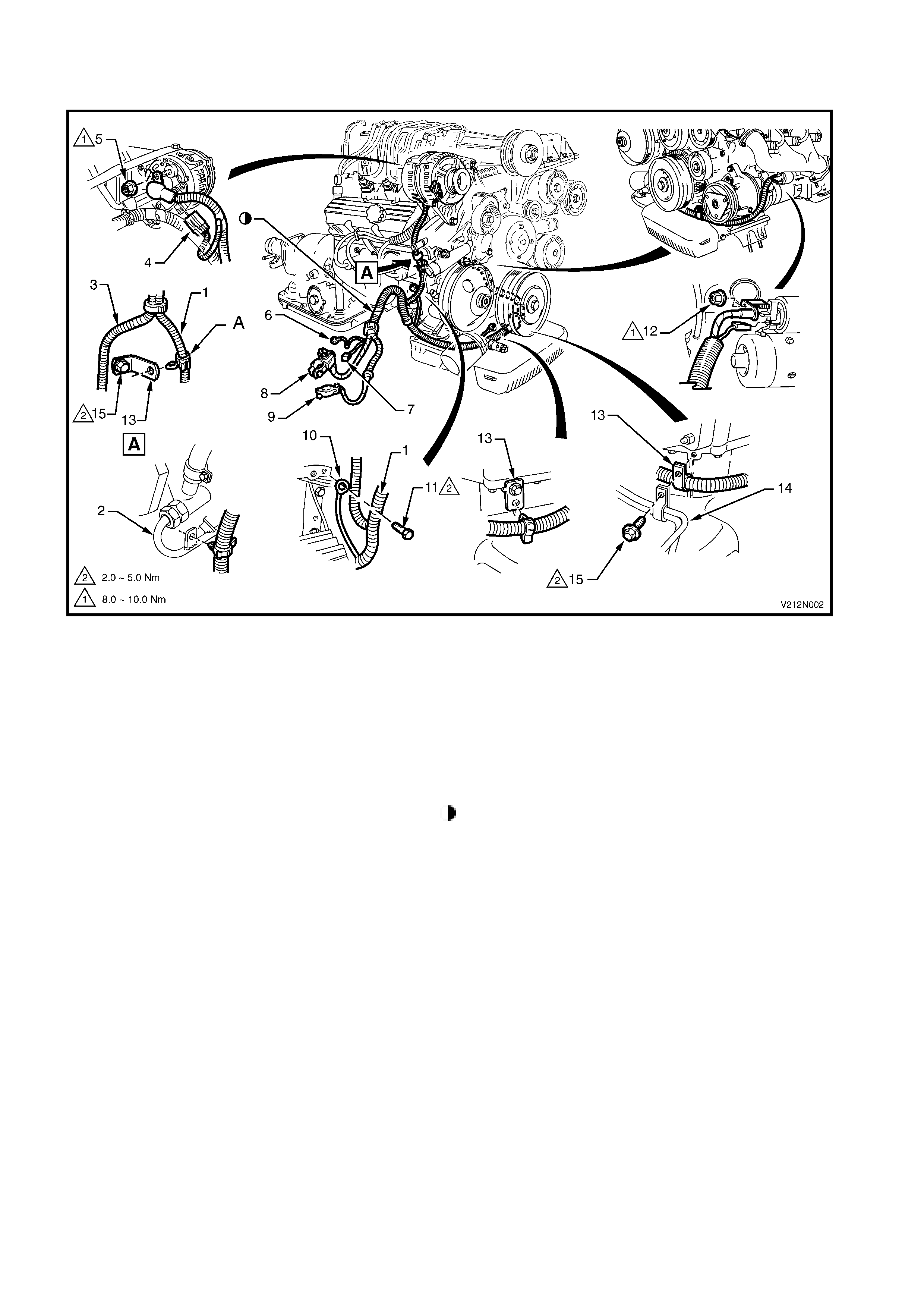
BATTERY WIRING HARNESS - 2
V6 SUPERCHARGED ENGINE
Figure 12N-2
Legend
1. Battery harness 10. Engine earth
2. Power steering pipe 11. Engine earth to cylinder block attaching bolt (1 place)
3. Powertrain harness 12. Battery harness to starter motor attaching nut
4. Generator connector 13. Battery harness to engine retaining bracket (3 places)
5. Battery harness to generator attaching nut (1 place) 14. Transmission oil cooler pipes
6. Body earth 15. Battery harness to engine bracket bolt (2 places)
7. Main wiring harness connector A. Clip to be inserted in a rearward direction.
8. Battery positive terminal For connection of battery harness to battery, refer to
9. Battery negative terminal Figure 12N-1.
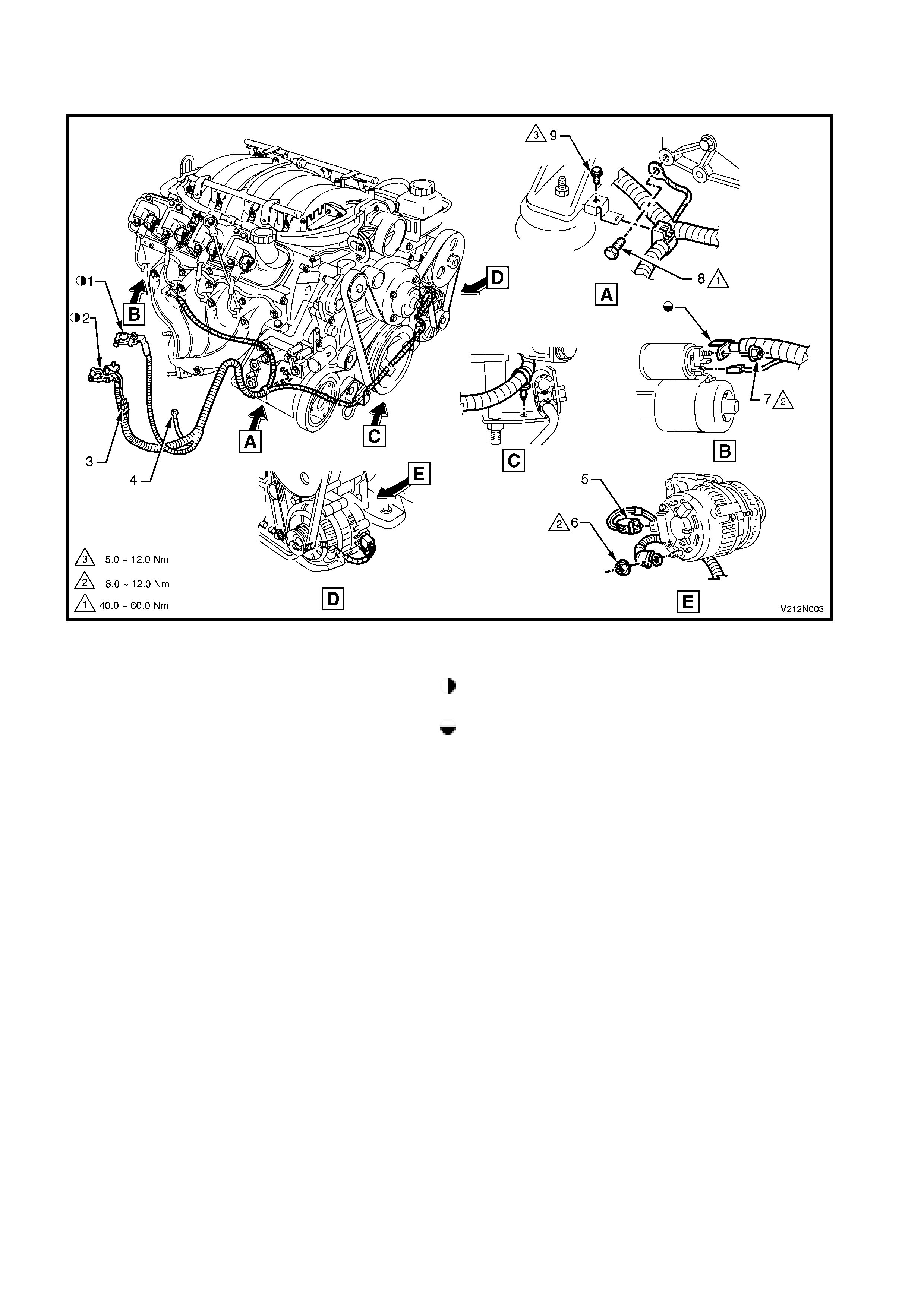
BATTERY WIRING HARNESS - 3
GEN III V8 ENGINE
Figure 12N-3
Legend
1. Battery negative terminal For connection of battery harness to battery, refer to
2. Battery positive terminal Figure 12N-1.
3. Main wiring harness connector Ensure orientation of battery harness terminal to starter
4. Body earth (1 place) motor is as shown.
5. Generator connector
6. Battery harness to generator attaching nut (1 place)
7. Battery harness to starter motor attaching nut (1 place)
8. Engine earth attaching bolt (1 place)
9. Battery harness to engine mount bracket
10. Battery harness bracket attaching bolt
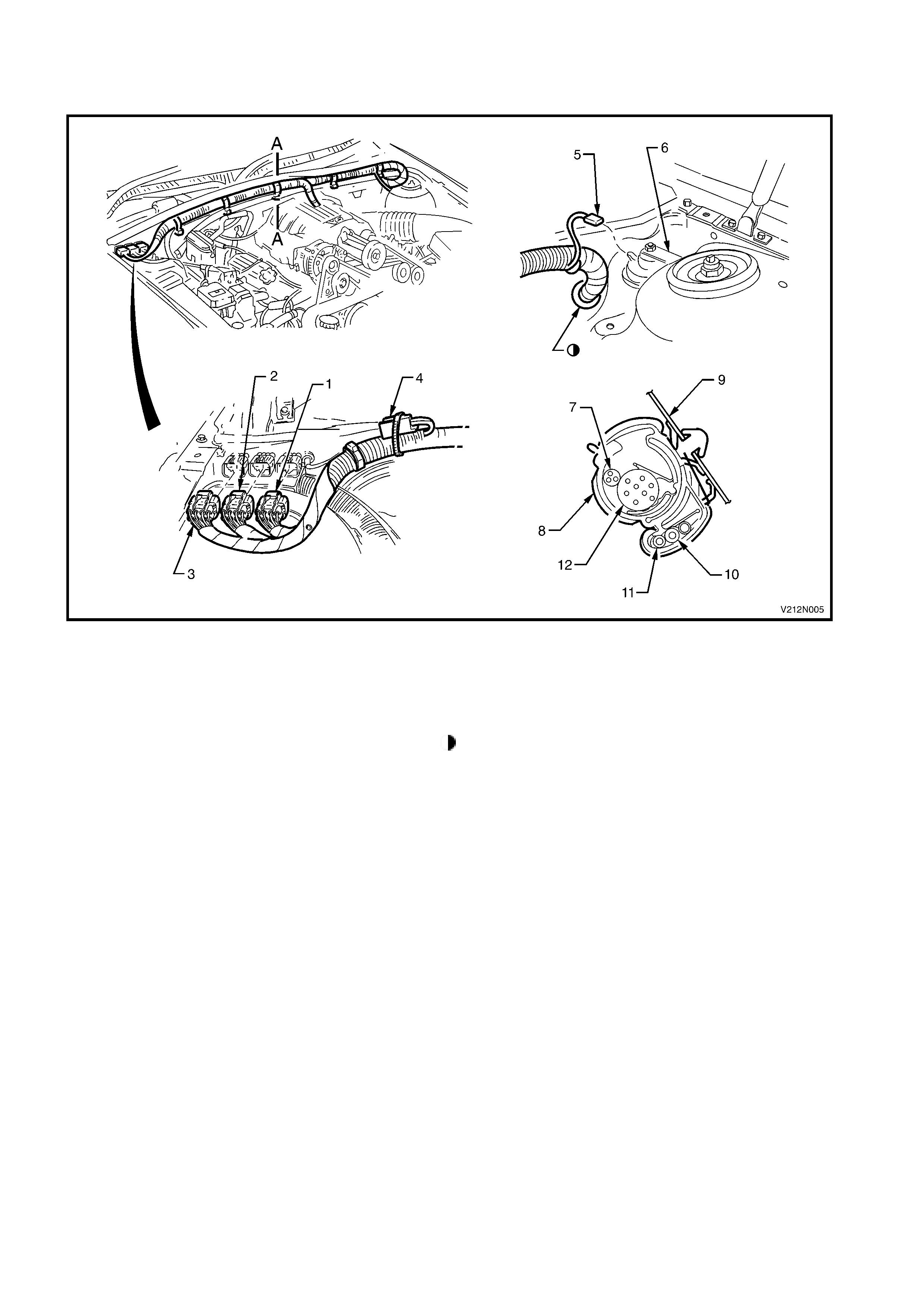
POWERTRAIN WIRING HARNESS - 2
COCKPIT MODULE CONNECTORS
Figure 12N-5
Legend
1. Engine harness connector 1 10. Cruise control cable
2. Engine harness connector 2 11. Throttle cable
3. Engine harness connector 3 12. Powertrain harness
4. Engine harness connector 4 For harness continuation, refer to Figure 12N-4 for
5. Anti-theft horn connector Supercharged V6 or POWERTRAIN HARNESS – 1
6. Anti-theft horn diagram in Section 12N FUSES, RELAYS AND
7. Wiper m o tor harness WIRING HARNESSES of the VT Series II Service
8. Harness to dash panel retaining clip (5 places) Information for GEN III V8.
9. Upper dash panel assembly
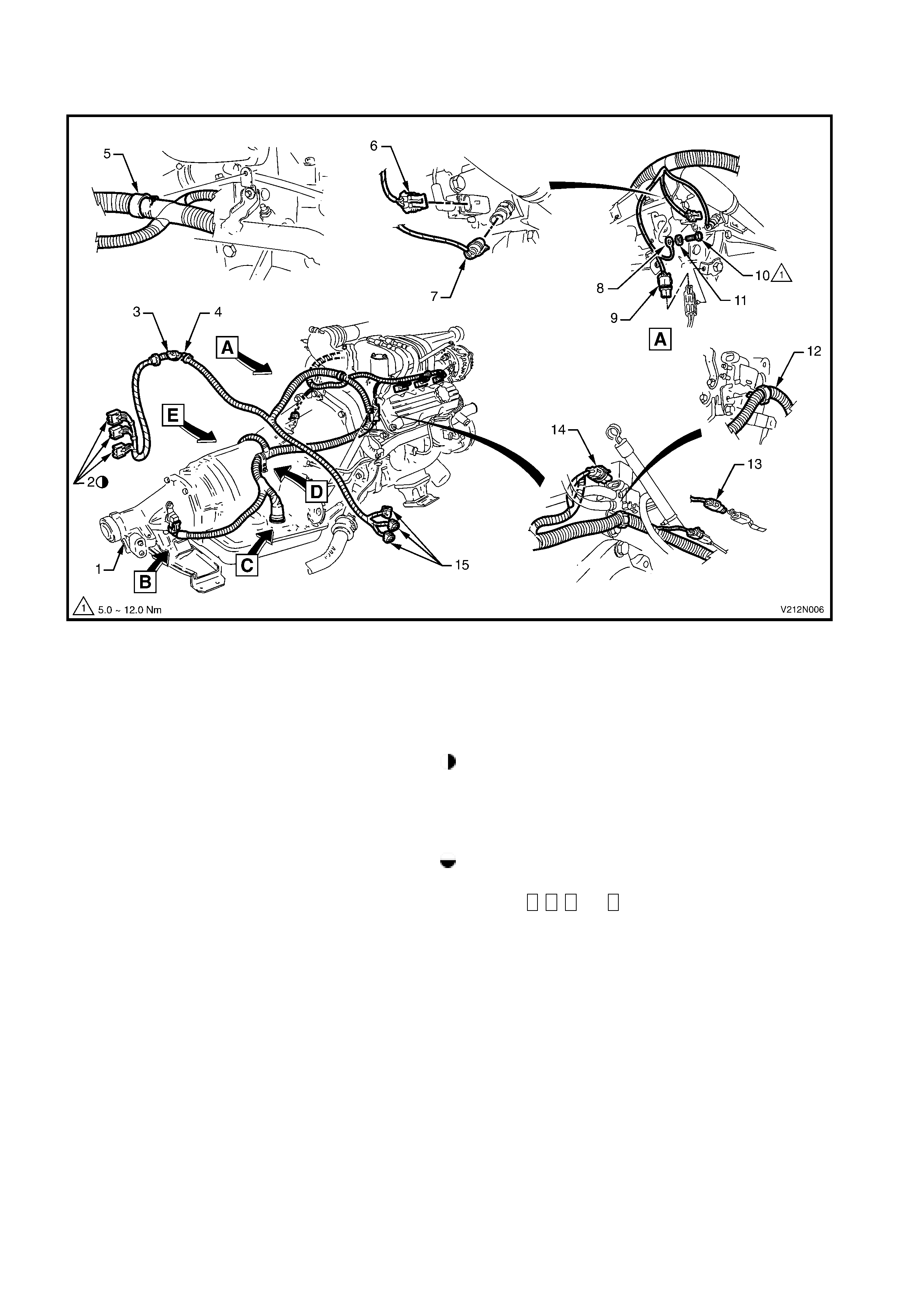
POWERTRAIN WIRING HARNESS - 3
TRANSMISSION AND ENGINE CONNECTORS
Figure 12N-6
Legend
1. Automatic transmission 12. Powertrain harness to canister module retaining clip
2. Powertrain control module connectors 13. RH exhaust gas sensor connector
3. Tachometer signal connector 14. Canister purge module connector
4. Anti-theft horn connector 15. Main wiring harness connectors
5. Powertrain harness to engine attaching clip (1 place) For powertrain control module connection, refer to
6. Anti-boost solenoid connector Figure 12N-4 for Supercharged V6 or POWERTRAIN
7. Coolant temperature sensor connector HARNESS – 1 in Section 12N FUSES, RELAYS AND
8. Earth terminal WIRING HARNESSES of the VT Series II Service
9. LH exhaust gas sensor connector Information for GEN III V8.
10. Earth terminal to engine attaching bolt (1 place) For main wiring harness connection, refer to Figure
11. Washer (1 place) 12N-5.
For View B, C, D and E, refer to Figure 12N-7.
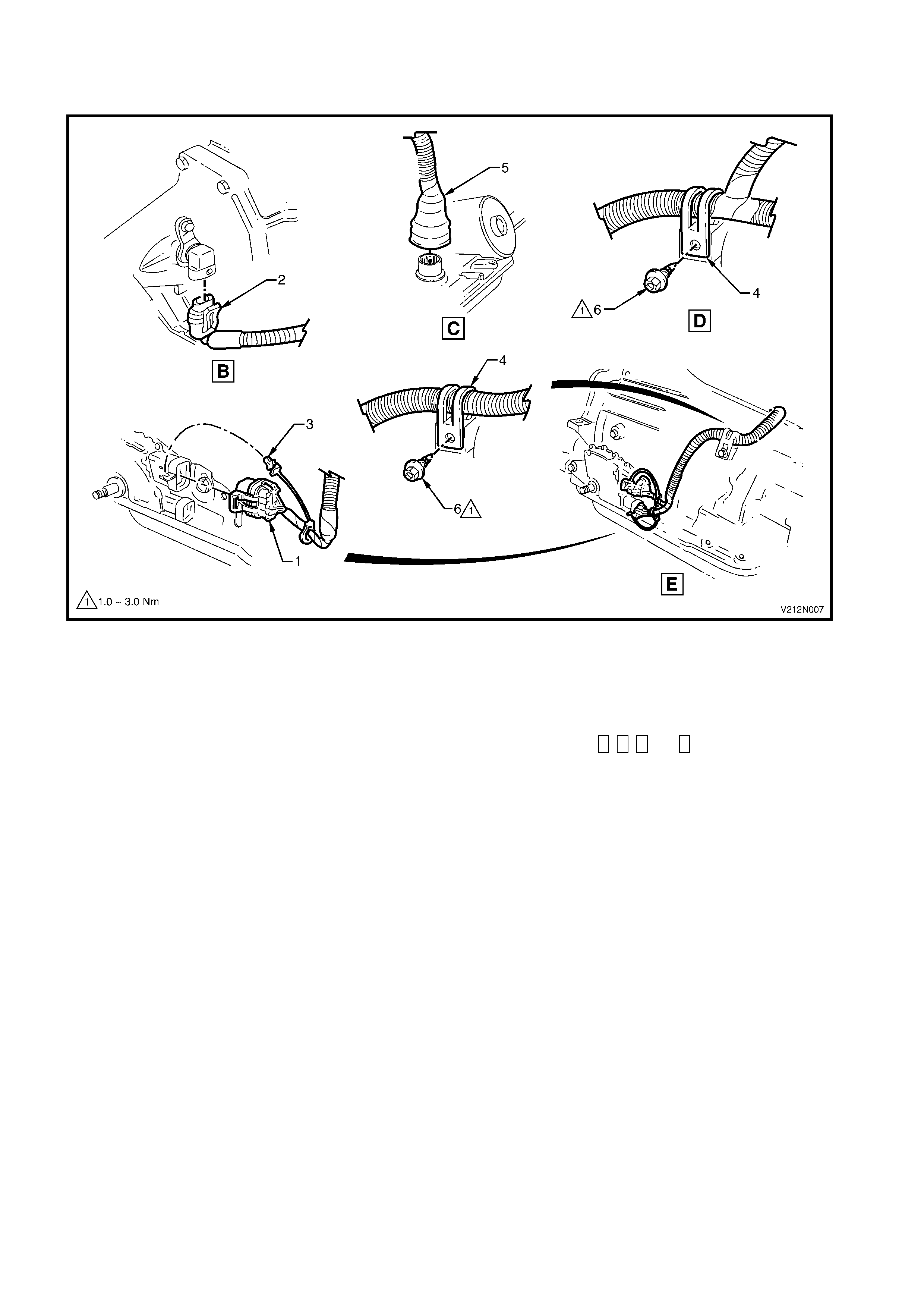
POWERTRAIN WIRING HARNESS - 4
AUTOMATIC TRANSMISSION CONNECTORS
Figure 12N-7
Legend
1. Neutral start and back up switch connector 5. Transmission connector
2. Transmission speed sensor connector 6. Powertrain harness to transmission bracket attaching
3. Neutral start and back up switch connector lock screw (1 place per bracket)
4. Powertrain harness to transmission bracket (2 places) For the location of Views B, C, D and E, refer to
Figure 12N-6.
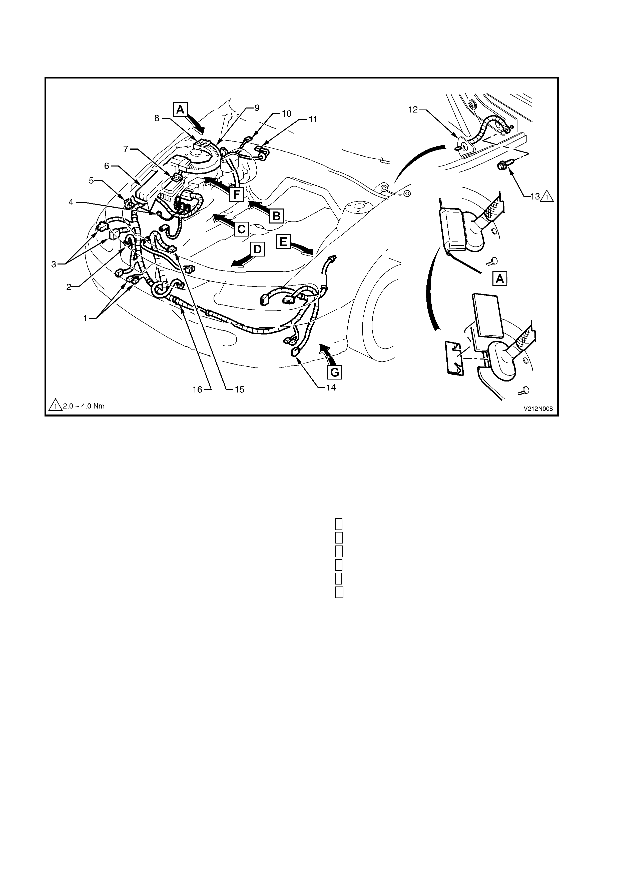
MAIN WIRING HARNESS - 1
ENGINE COMPARTMENT
Figure 12N-8
Legend
1. Horn connectors 12. Body earth terminal (cockpit module)
2. Washer pump connector 13. Body earth to cockpit module securing screw (1 place)
3. RH headlamp and turn signal lamp connectors 14. Fog lamp connector
4. Body earth terminal 15. Cooling fan connector
5. Body earth connector 16. Main wiring harness
6. Fuse and relay panel For View B, refer to Figure 12N-9.
7. Cruise control actuator connector For View C, refer to Figure 12N-10.
8. Engine harness connectors (Number 1, 2 and 3) For View D, refer to Figures 12N-11 and 12N-12.
9. Main wiring harness protector For View E, refer to Figure 12N-14.
10. Engine harness connector (Number 4) For View F, refer to Figure 12N-9.
11. Wiper motor connector For View G, refer to Figure 12N-14.
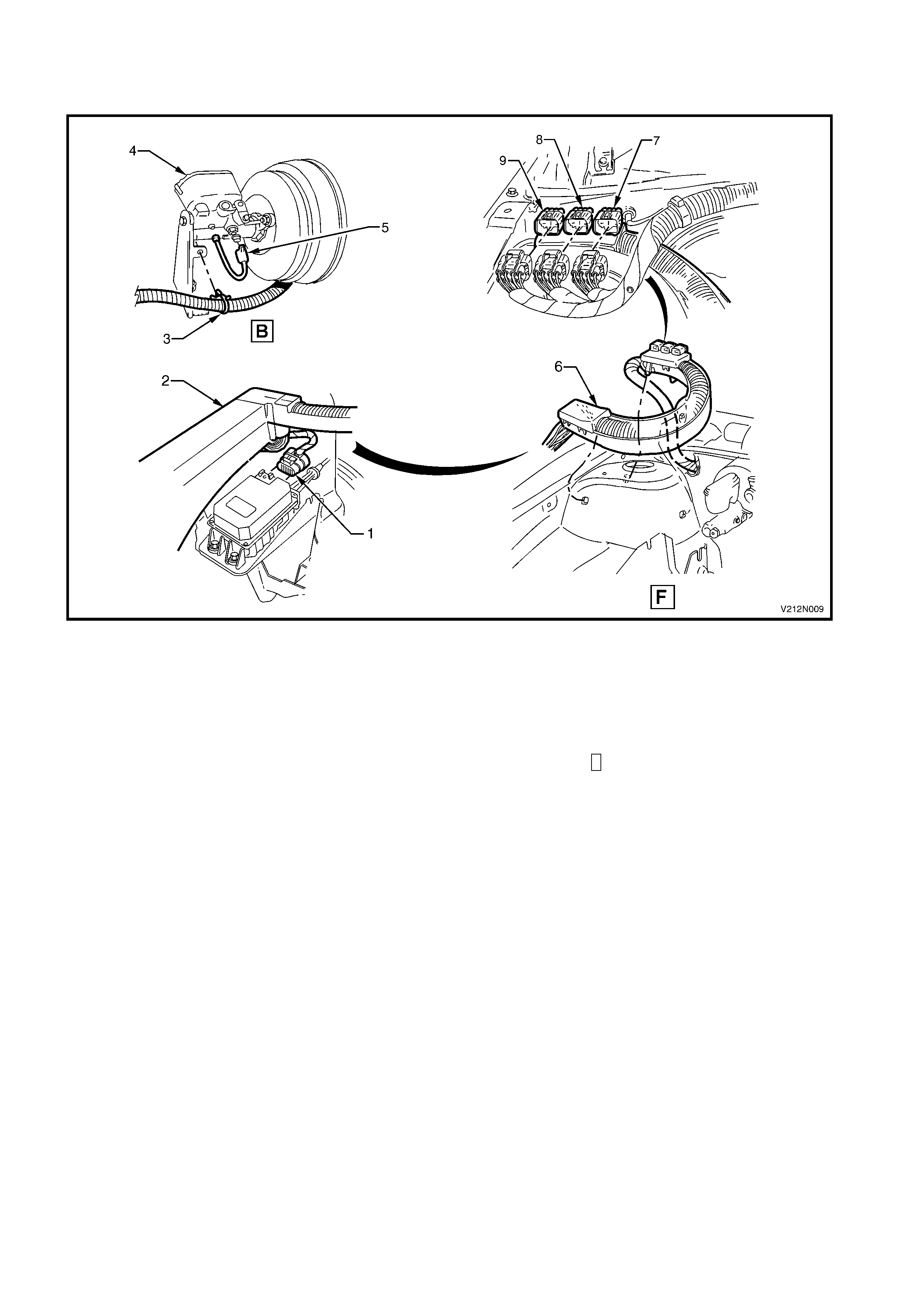
MAIN WIRING HARNESS - 2
ENGINE HARNESS, BRAKE FAIL AND CRUISE CONTROL CONNECTORS
Figure 12N-9
Legend
1. Cruise control actuator connector 6. Harness protector assembly
2. Fuse and relay panel 7. Engine harness connector 1
3. Main wiring harness to master cylinder bracket 8. Engine harness connector 2
attaching clip (1 place) 9. Engine harness connector 3
4. Master cylinder and brake booster For the location of View F, refer to Figure 12N-8.
5. Brake fail switch connector
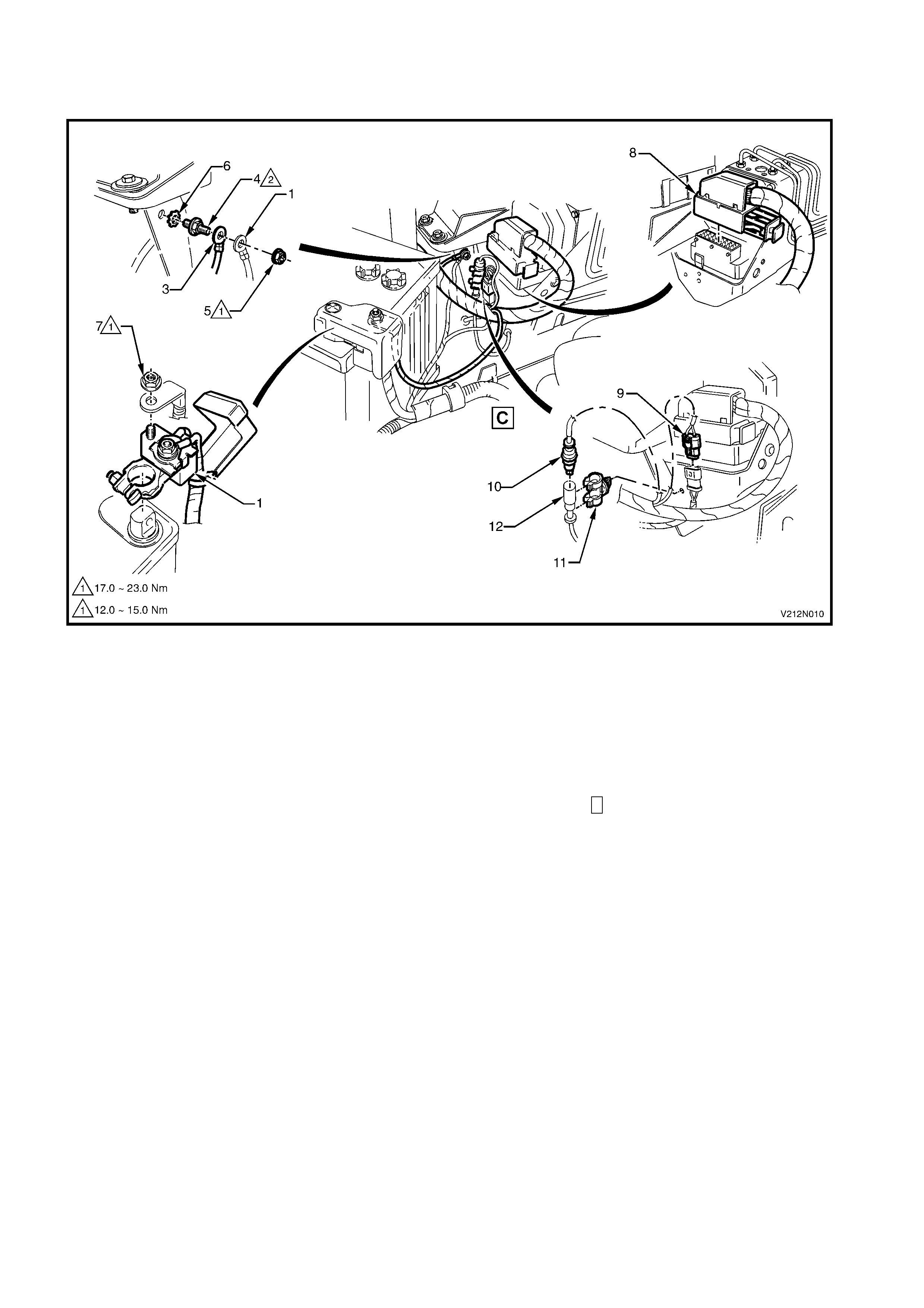
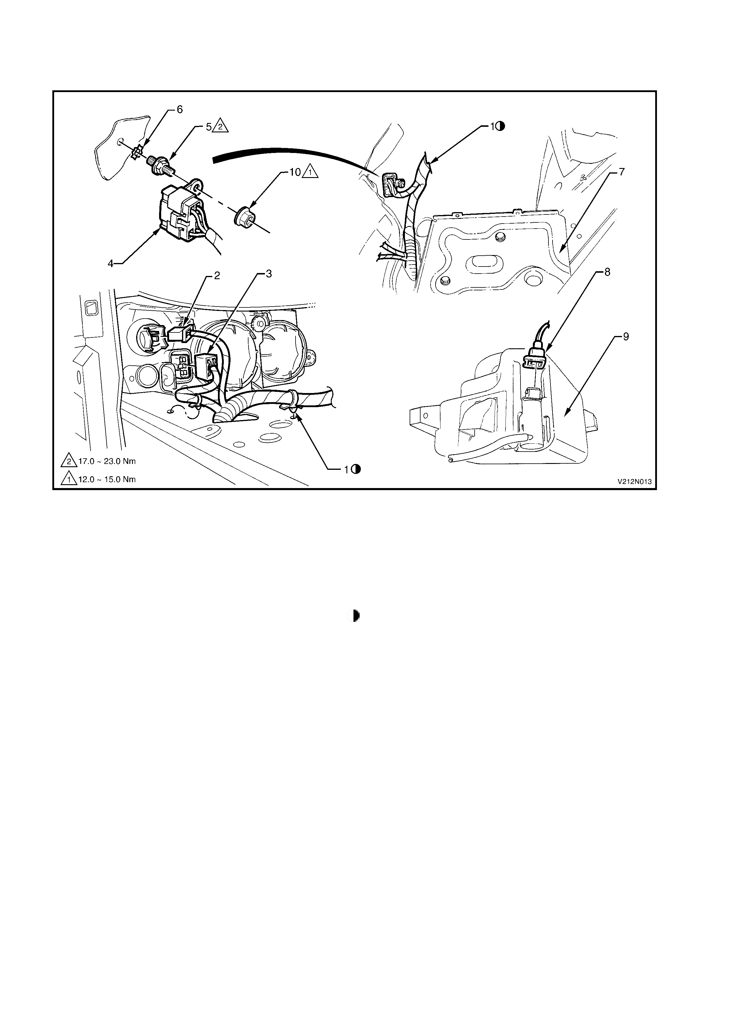
MAIN WIRING HARNESS - 3
ABS, POWER STEERING AND BATTERY CONNECTORS
Figure 12N-10
Legend
1. Battery harness earth 8. ABS control unit connector
2. Main wiring harness battery terminal 9. Main wiring harness to battery harness connector
3. Main wiring harness body earth terminal 10. RH front ABS wheel speed sensor connector
4. Body earth terminal attaching stud (1 place) 11. RH front ABS wheel speed sensor connector clip
5. Body earth terminal attaching nut (1 place) 12. RH front ABS wheel speed sensor lead
6. Washer (1 place)
7. Main wiring harness battery terminal attaching For the location of View C, refer to Figure 12N-8.
nut (1 place)
NOTE: When installing the terminals to the body earth stud, ensure that the crimping faces the engine as illustrated.
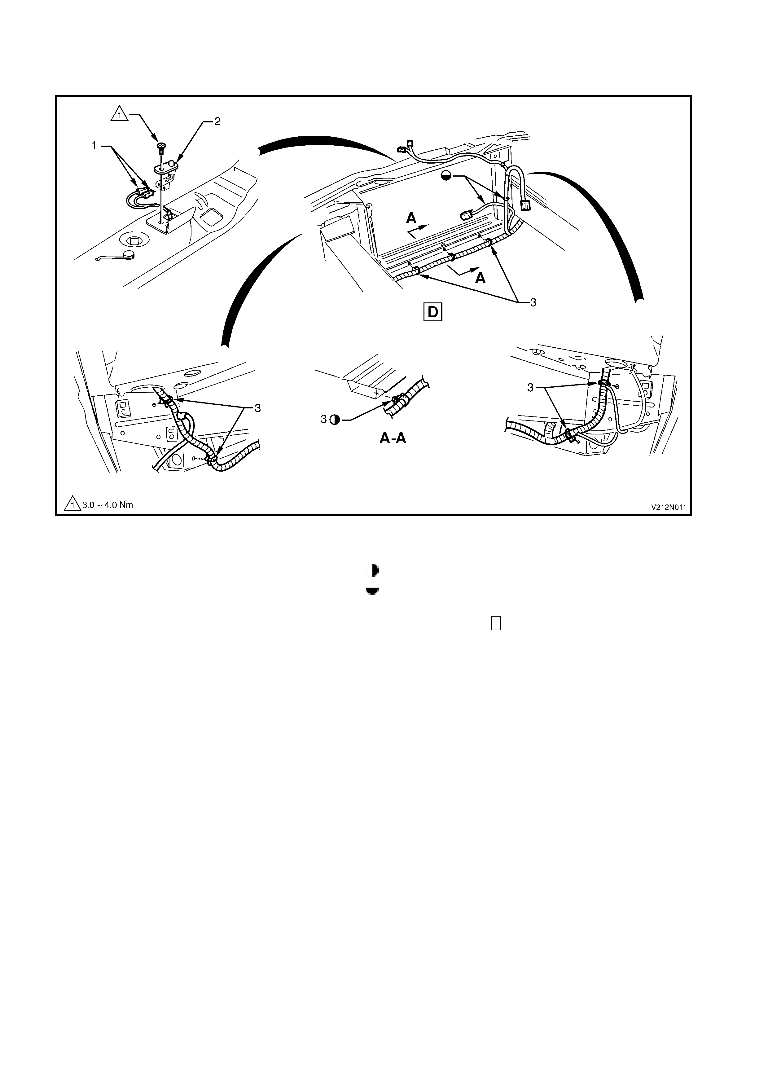
MAIN WIRING HARNESS - 4
ENGINE BAY FRONT
Figure 12N-11
Legend
1. Anti-theft hood switch connectors Blue clip to be aligned with centre line of car
2. Anti-theft hood switch For harness continuation and clipping, refer to
3. Main wiring harness to front panel retaining Figure 12N-12.
clip ( 7 places) For the location of View D, refer to Figure 12N-8.
MAIN WIRING HARNESS - 5
AMBIENT SENSOR, ANTI-THEFT SWITCH AND FAN CONNECTORS
Figure 12N-12
Legend
1. Radiator fan connector 6. Harness to front panel attaching clip (5 places)
2. Ambient sensor connector 7. Anti-theft hood switch connectors
3. Power steering reservoir Feed connectors through front panel upper
4. Condenser assembly reinforcement.
5. Ambient sensor For the harness continuation, refer to Figure 12N-11.
For location of view D, refer to Figure 12N-8.
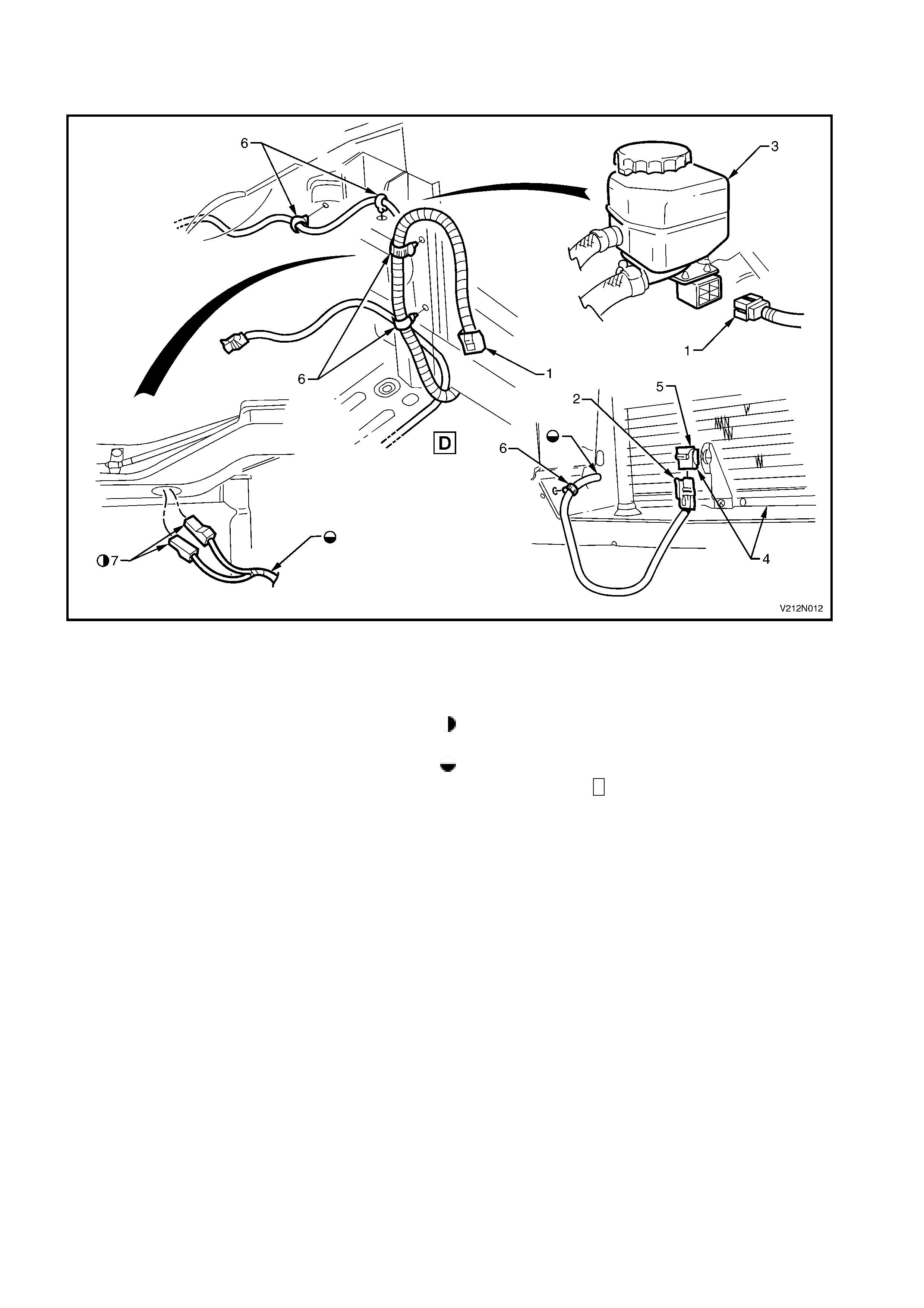
MAIN WIRING HARNESS - 6
FRONT LAMP, BODY EARTH AND WASHER PUMP CONNECTORS
Figure 12N-13
Legend
1. Main wiring harness 6. Earth connector washer
2. LH front turn signal lamp connector 7. Battery tray
3. LH headlamp connector 8. Washer pump connector
4. Body earth connector 9. Washer reservoir
5. Body earth connector to front panel attaching 10. Body earth connector attaching nut (1 place)
stud (1 place) For the harness continuation, refer to Figure 12N-12.
MAIN WIRING HARNESS - 7
HEADLA MP AND HORN CONNECTORS
Figure 12N-14
Legend
1. Harness to wheelhouse attaching clip (1 place) 7. RH horn assembly (LH similair)
2. LH turn signal harness connector 8. LH front ABS wheel sensor harness connector
3. LH headlamp harness connector 9. ABS sensor harness connector attaching clip (2 places)
4. Fog lamp harness connector (lamp side) For harness continuation, refer to Figure 12N-13.
5. Fog lamp harness connector (harness side) For view locations, refer to Fig 12N-8.
6. Horn harness connector (2 per side)
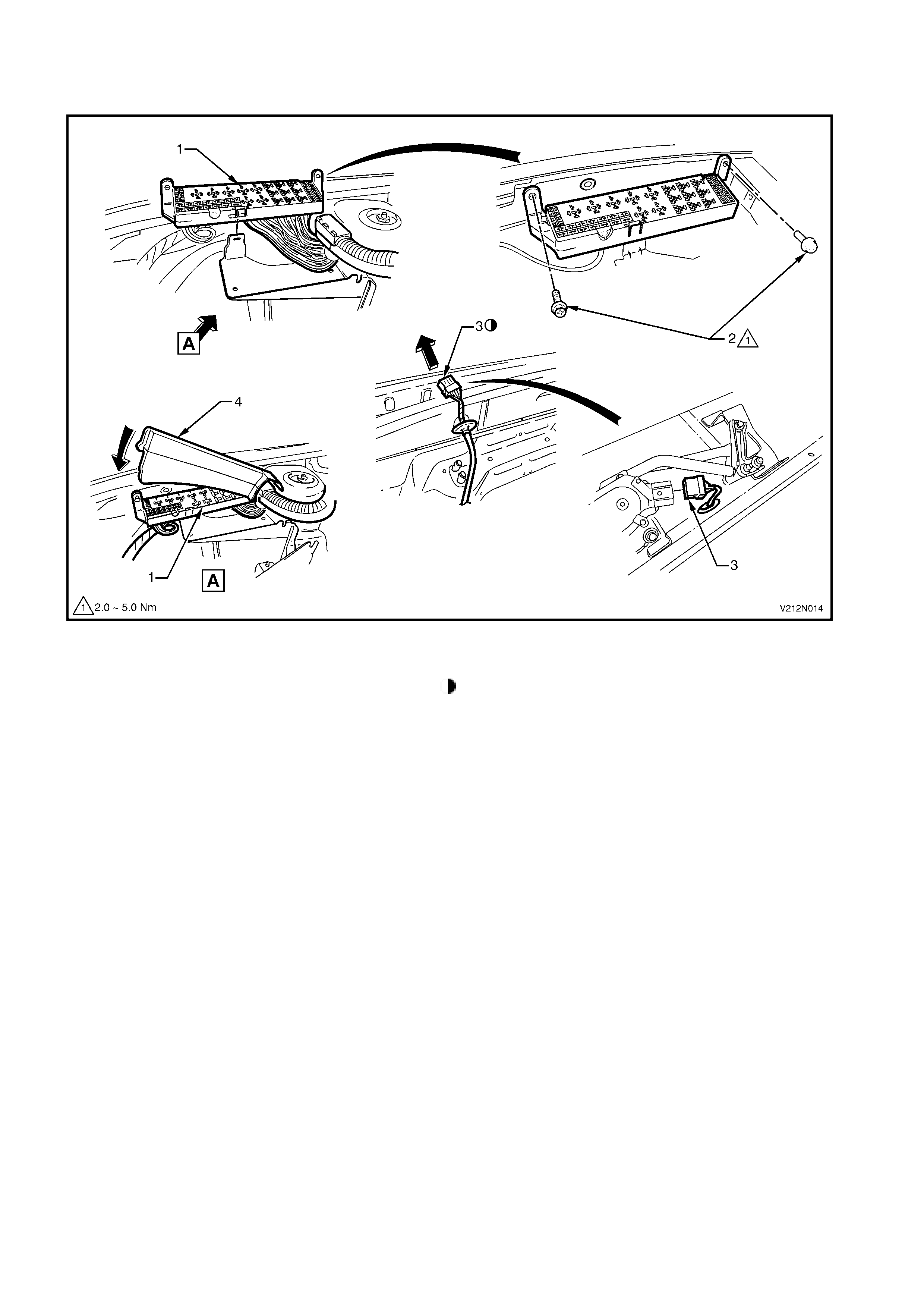
MAIN WIRING HARNESS - 8
FUSE AND RELAY PANEL AND WIPER MOTOR CONNECTORS
Figure 12N-15
Legend
1. Fuse and relay panel Pull wiper motor connector through upper dash panel
2. Fuse and relay panel attaching screw (2 places) and secure grommet as shown.
3. Wiper motor connector
4. Fuse and relay panel lid
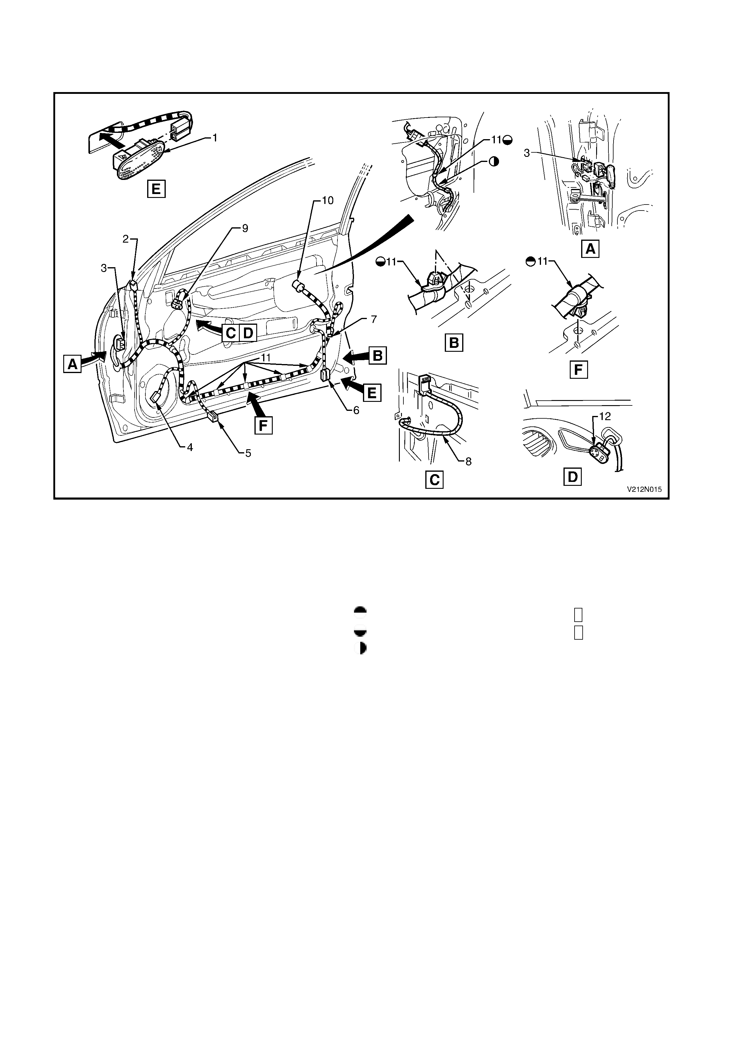
BODY WIRING HARNESS - 1
FRONT DOOR HARNESS
Figure 12N-16
Legend
1. Door courtesy lamp 8. Exterior mirror switch harness
2. Exterior mirror connector 9. Exterior mirror switch (RH only)
3. Body harness connector 10. Door lock switch connector (RH only)
4. Speaker connector 11. Door harness to door attaching clip (9 places)
5. Window lifter motor connector Clip harness to panel as shown in view F (4 places).
6. Door courtesy lamp connector Clip harness to panel as shown in view B (5 places).
7. Door lock actuator connector Ensure harness is routed behind guide piece.
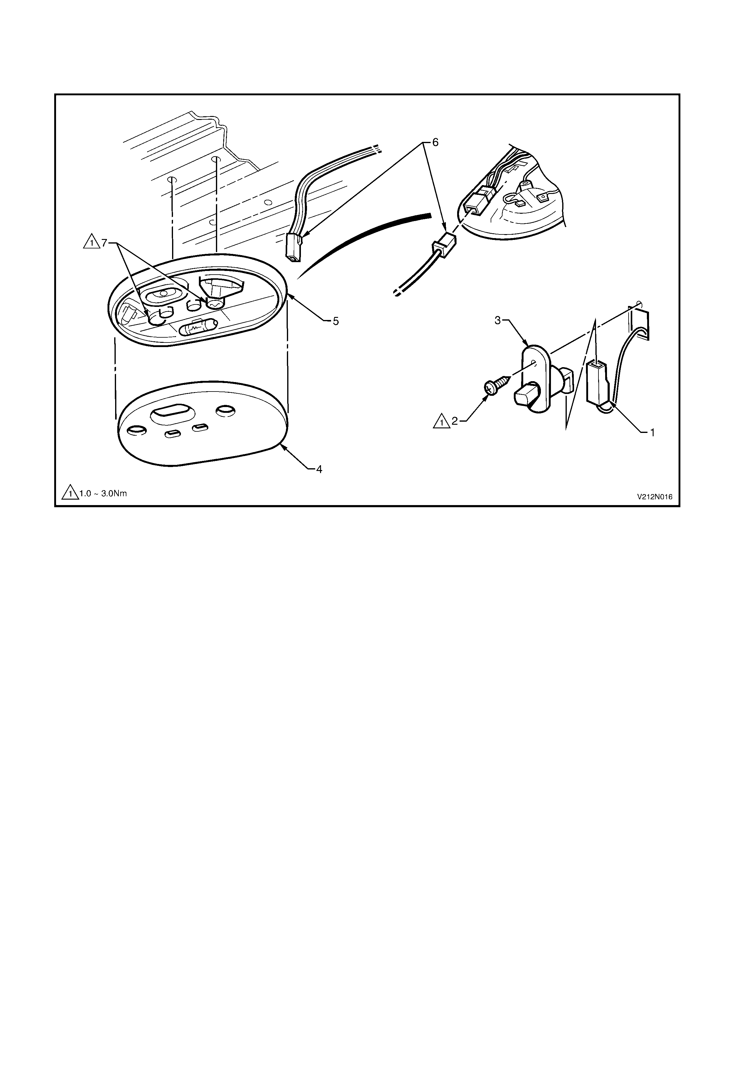
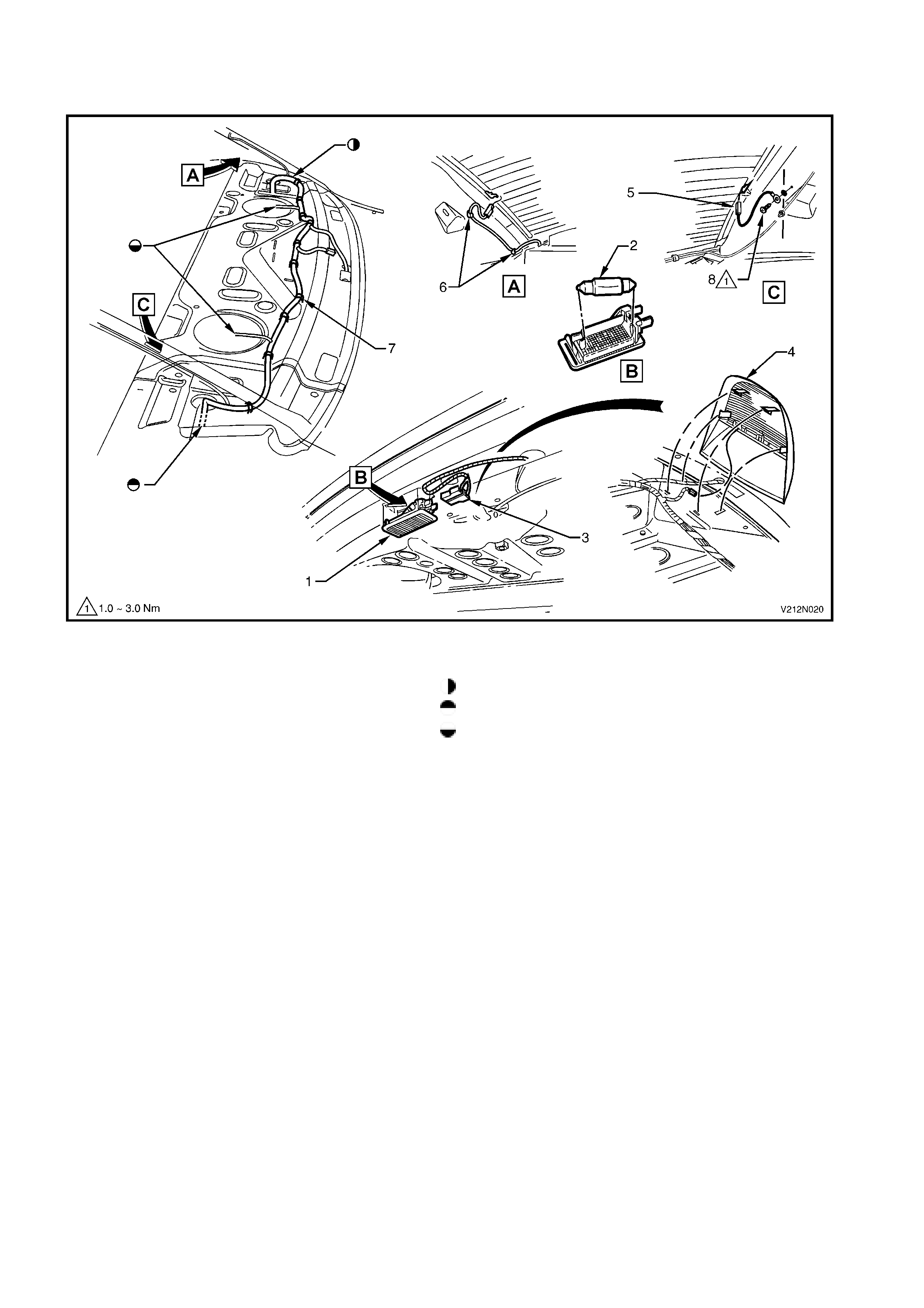
BODY WIRING HARNESS - 2
DOME LAMP AND DOOR JAMB SWITCH CONNECTORS
Figure 12N-17
Legend
1. Door jamb switch connector 5. Dome lamp housing (CV8 shown)
2. Door jamb switch attaching screws 6. Dome lamp connector
3. Door jamb switch 7. Dome lamp attaching screws
4. Dome lamp lens (CV8 shown)
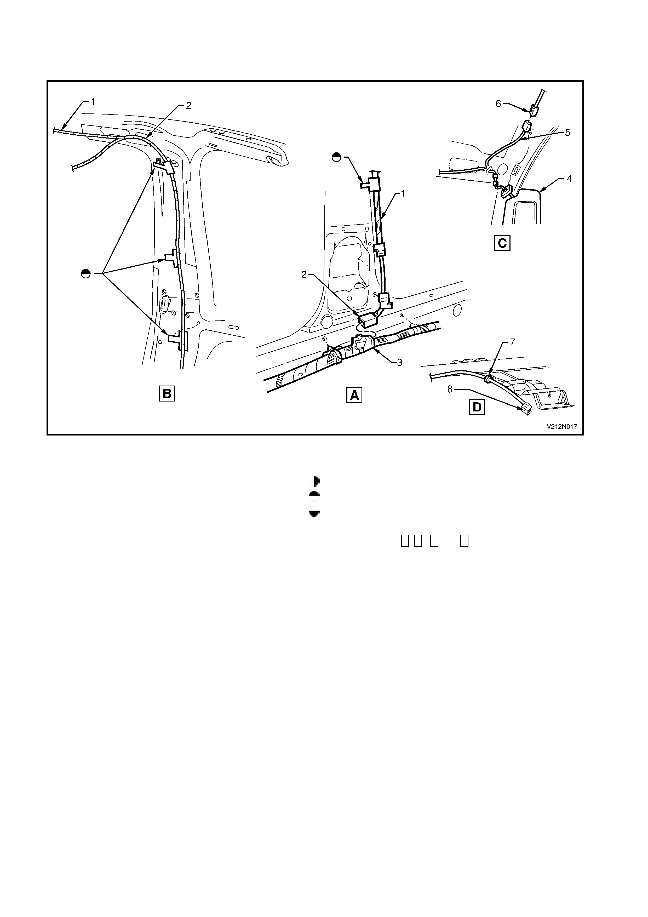
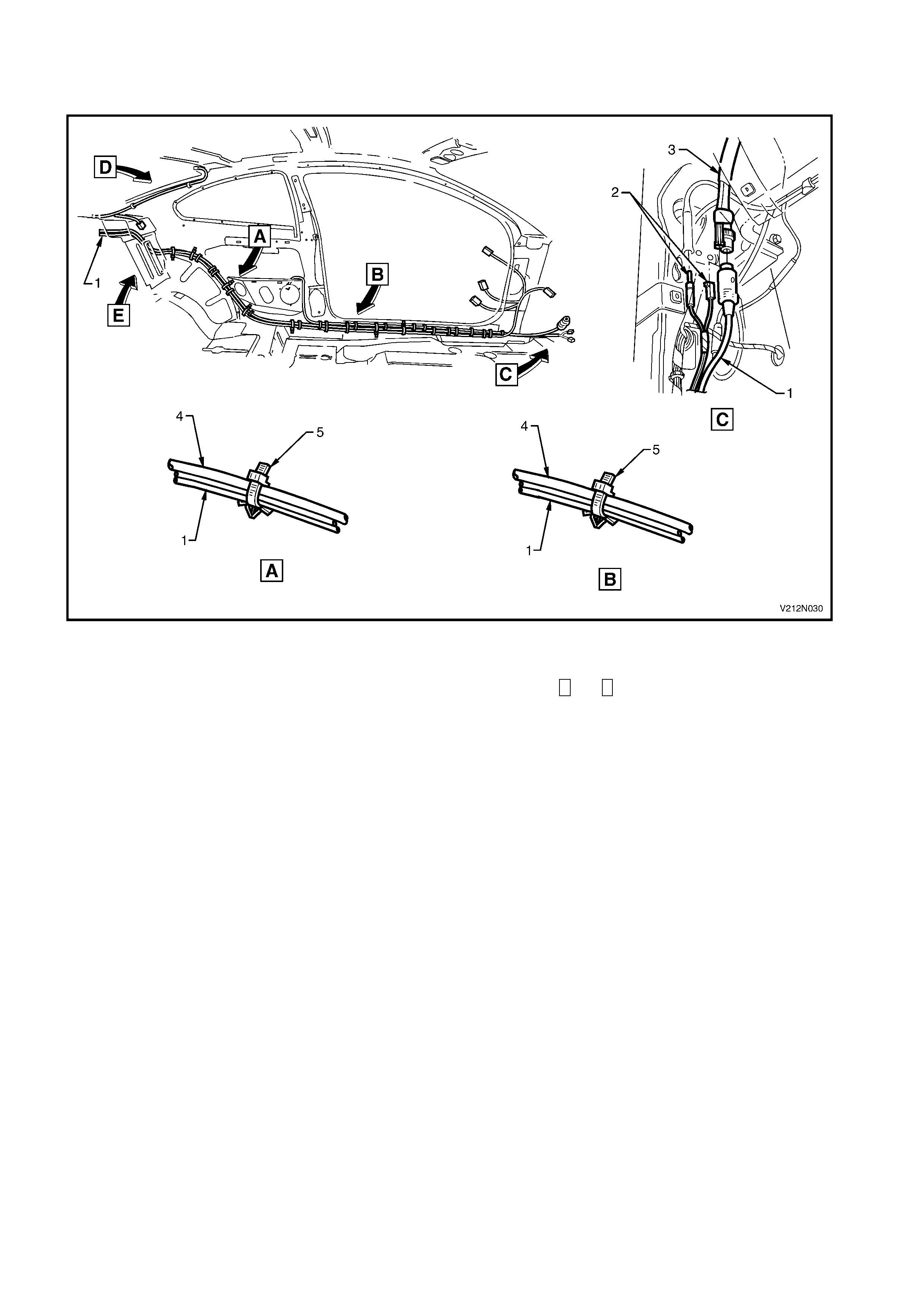
BODY WIRING HARNESS - 3
INTERIOR HARNESS – RIGHT-HAND
Figure 12N-18
Legend
1. Dome lamp For harness continuation, refer to Figure 12N-17.
2. Sunvisor lamp harness connector For harness continuation, refer to Figure 12N-27.
3. Door harness connector For harness continuation, attachment or connector
4. Body wiring harness details, refer to Figure 12N-21.
5. Door jamb switch harness connector For harness continuation, refer to Figure 12N-19.
6. Rear quarter speaker harness connector For harness continuation, refer to Figure 12N-22.
7. Power seat harness connector For views A, B , C and D, refer to Figure 12N-20.
8. Roof harness attaching clip (9 places)
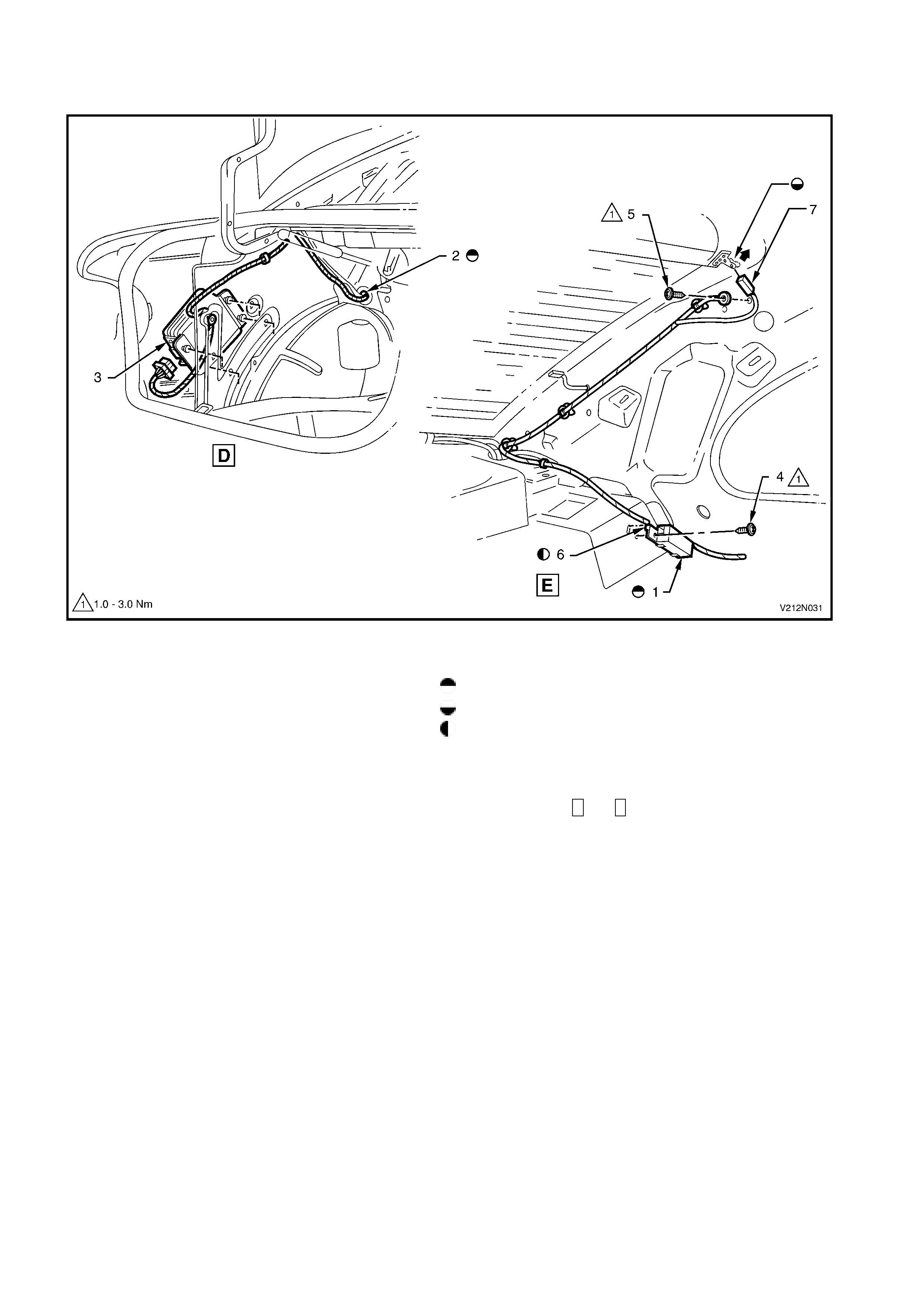
BODY WIRING HARNESS - 4
INTERIOR HARNESS – LEFT-HAND
Figure 12N-19
Legend
1. Power window switch assembly For harness continuation, refer to Figure 12N-18.
2. Console harness connector For harness coontinuation or attachment, refer to
3. Handbrake lever harness connector Figure 12N-30.
4. Harness earth terminal attaching screw (1 place) For harness continuation, refer to Figure 12N-17.
5. Seat belt pre-tensioner harness connector
6. Power seat connectors
7. Door harness connector
8. Door jamb switch harness connector
9. Body harness to floor panel attaching clip (4 places)
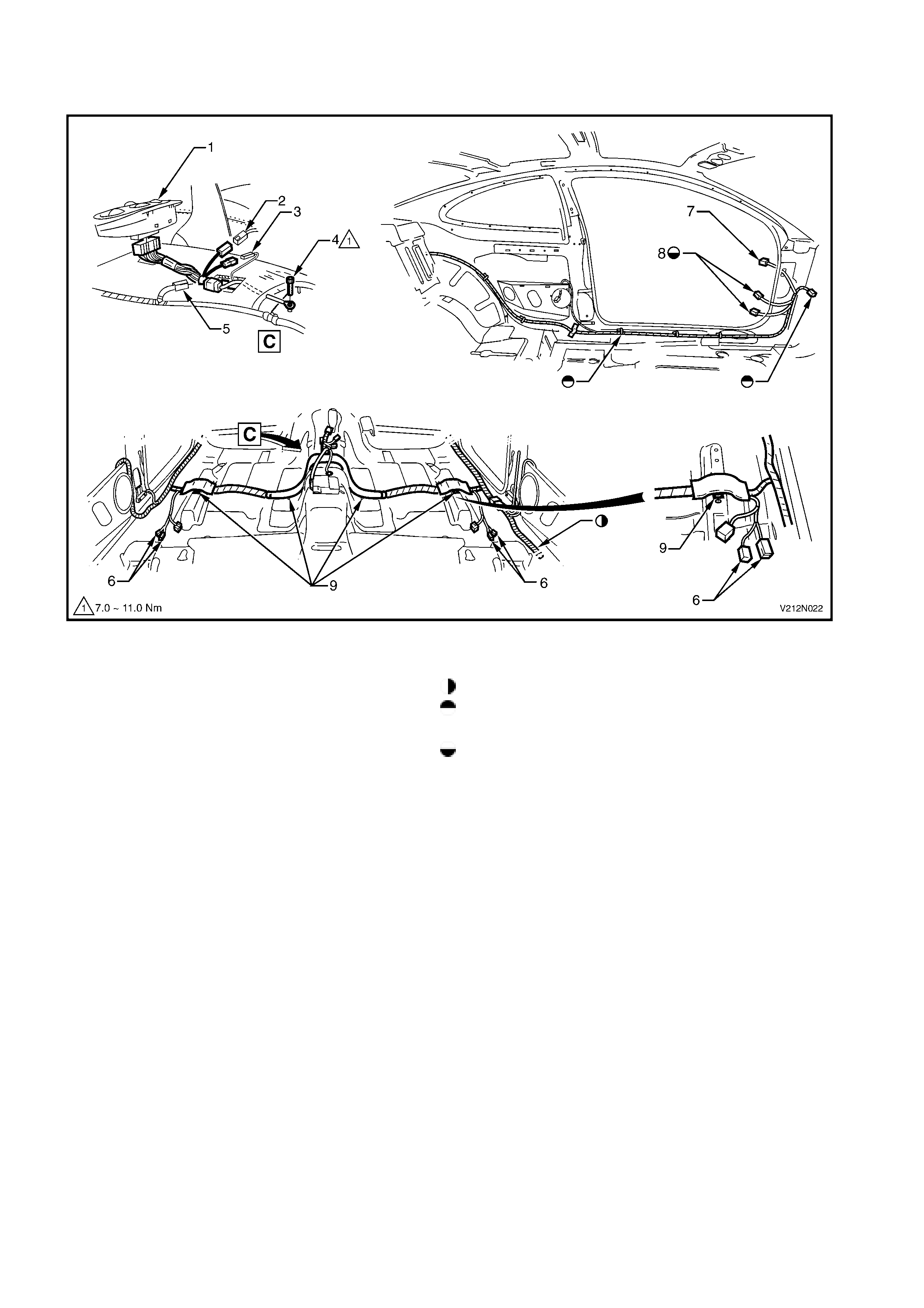
BODY WIRING HARNESS - 5
INTERIOR HARNESS - ROOF
Figure 12N-20
Legend
1. Roof wiring harness Ensure harness is held in groove with black tape.
2. Roof harness to body harness connector For clip usage, refer to Figures 12N-18 and 12N-19.
3. Body wiring harness To dome lamp. For harness continuation, refer to
4. Sun visor assembly Figure 12N-18.
5. Sun visor illumination harness For location of views A, B , C and D, refer to Figure
6. Sun visor connector 12N-18.
7. Dome lamp harness clip (1 place)
8. Dome lamp harness connector

BODY WIRING HARNESS - 6
INTERIOR HARNESS - FRONT
Figure 12N-21
Legend
1. LH turn signal connector 6. Power antenna harness connector
2. Body wiring harness to side panel attaching 7. RH turn signal harness connector
clip (1 place) 8. Body control module harness connector
3. Body wiring harness to underbody attaching 9. Main wiring harness connector 1
clip (6 places) 10. Harness to side panel attaching clips (2 places)
4. Power seat harness connector 11. Body wiring harness to underbody clip (9 places)
5. Pre-tensioner harness connector 12. Main wiring harness connector 2
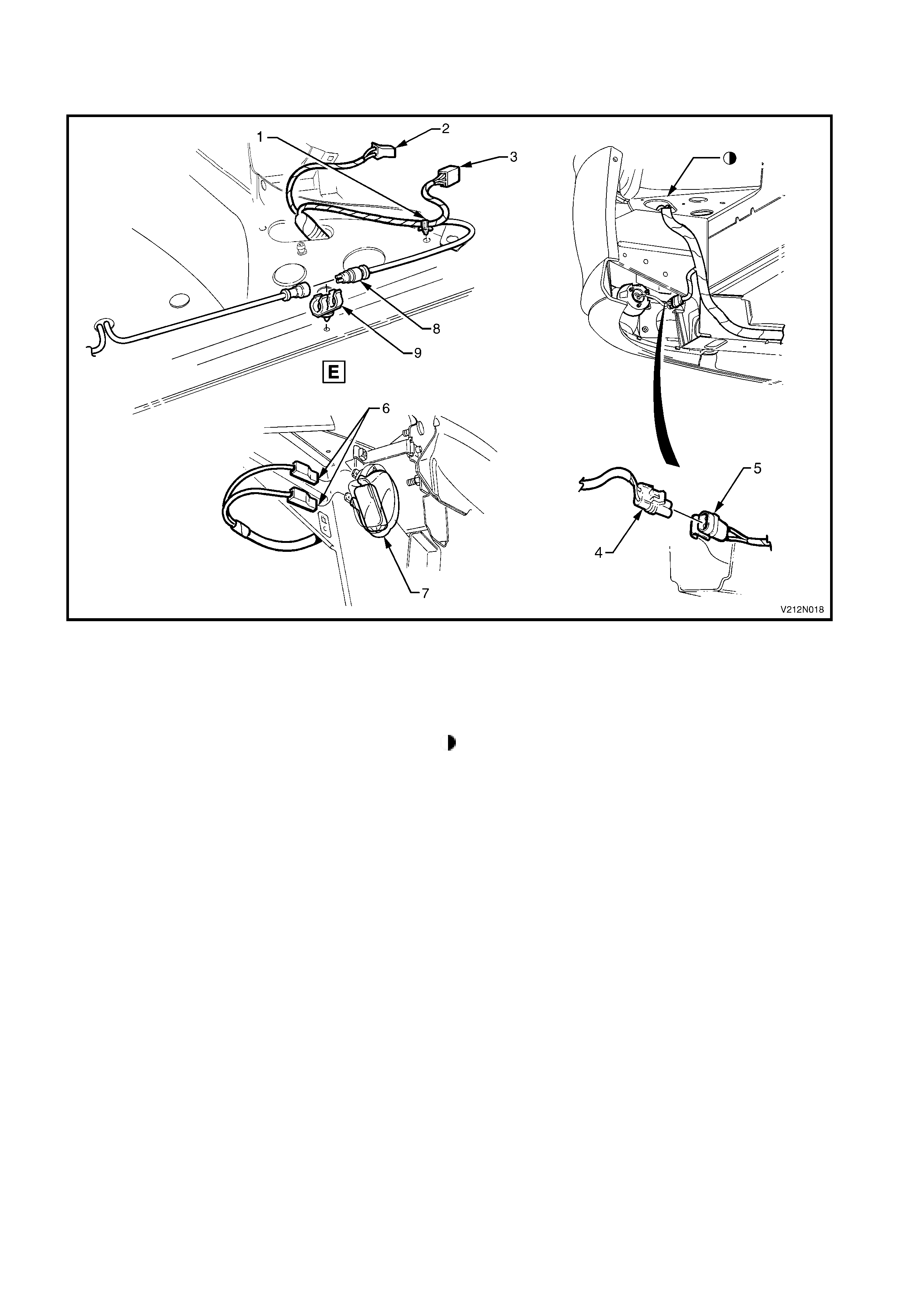
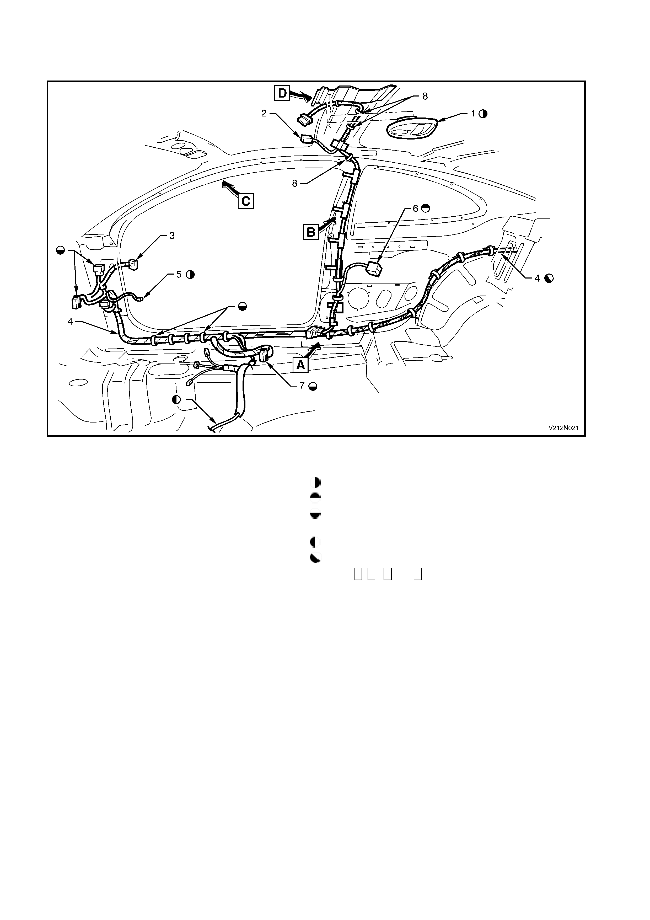
BODY WIRING HARNESS - 7
INTERIOR HARNESS - REAR
Figure 12N-22
Legend
1. Rear compartment lamp assembly For harness continuation, refer to Figure 12N-23.
2. Rear compartment lamp globe For harness continuation, refer to Figure 12N-27.
3. Rear compartment lamp harness connector For harness continuation, refer to Figure 12N-29.
4. High mounted stop lamp assembly
5. Heated rear window earth lead
6. Heated rear window harness to rear pillar attaching clip (2 places)
7. Body harness to parcel shelf attaching clip (8 places for CV8 and 4 places for CV6)
8. Heated rear window earth attaching screw (1 place)
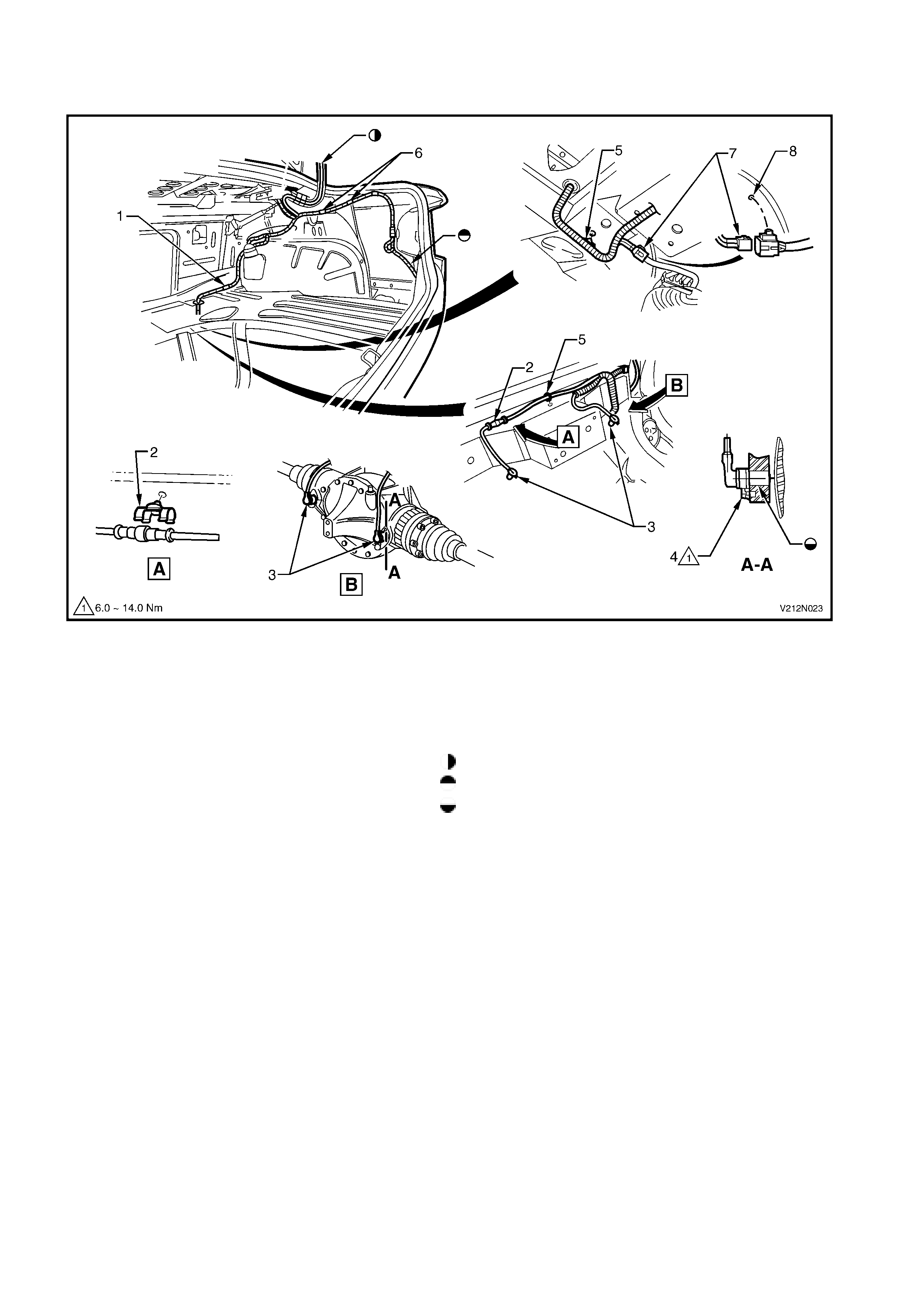
BODY WIRING HARNESS - 8
REAR COMPARTMENT HARNESS – ABS SENSORS AND FUEL TANK
Figure 12N-23
Legend
1. Body wiring harness to wheelhouse attaching 6. Body wiring harness to side inner panel attaching
clip (1 place) clip (2 places)
2. Rear wheel speed sensor cable to rear suspension 7. Fuel tank harness connector
crossmember attaching clip (2 places) 8. Fuel tank harness to longitudianal clip (1 place)
3. Rear wheel speed sensors For harness continuation, refer to Figure 12N-25.
4. Rear wheel speed sensor attaching bolt (2 places) For harness continuation, refer to Figure 12N-24.
5. Body wiring harness to rear suspension crossmember Smear Molykote FB180 grease to Holden Specification
attaching clip (2 places) HN2062 all around sensor boss.
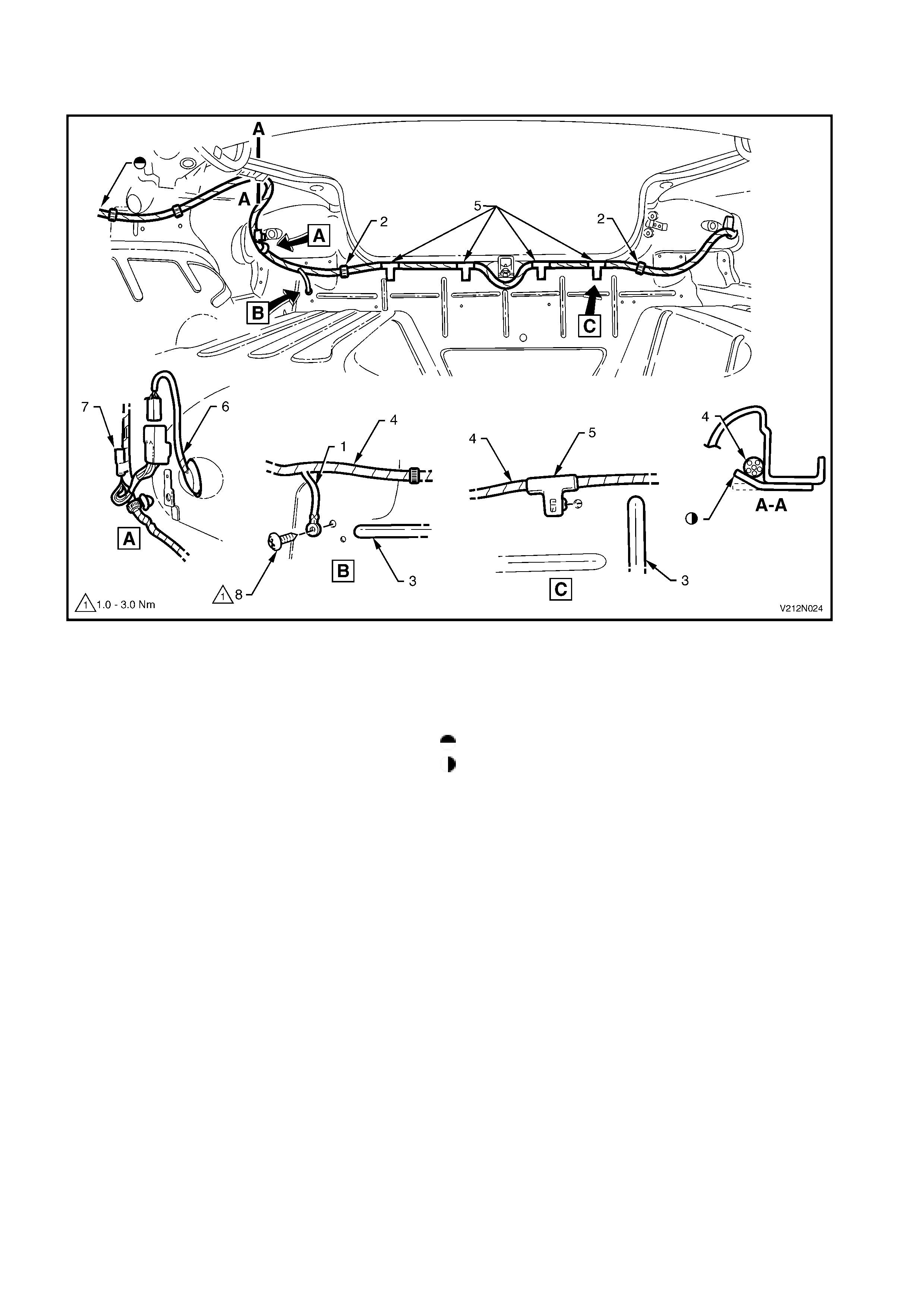
BODY WIRING HARNESS - 9
REAR COMPARTMENT HARNESS – REAR LAMPS
Figure 12N-24
Legend
1. Body earth lead 6. RH rear quarter lamp harness connector
2. Body wiring harness to back panel attaching 7. LH turn trailer connector
clips (2 places) 8. Body earth lead attaching screw (1 place)
3. Back panel lower reinforcement For harness continuation, refer to Figure 12N-23.
4. Body wiring harness Bend clip as shown to retain harness.
5. Body wiring harness to back panel attaching
clips (4 places)
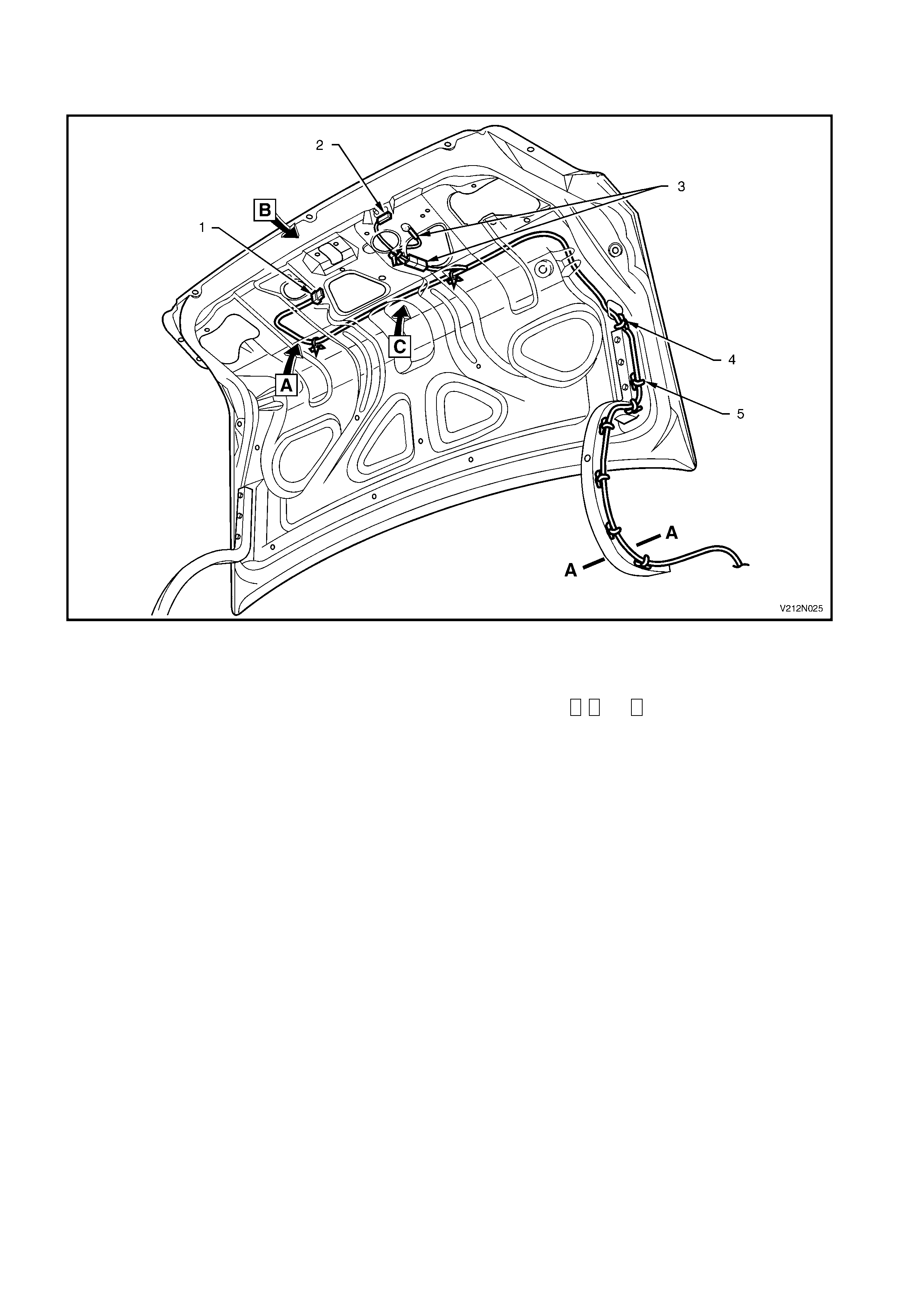
BODY WIRING HARNESS - 10
DECKLID HARNESS - 1
Figure 12N-25
Legend
1. Licence plate lamp harness connector For sectional views, refer to Figure 12N-26.
2. Rear compartment lamp switch harness connector For views A, B and C, refer to Figure 12N-26.
3. Rear compartment lock actuator harness connectors
4. Body wiring harness to rear compartment lid attaching clip (5 places)
5. Body wiring harness to rear compartment lid hinge attaching clips (6 places)
BODY WIRING HARNESS - 11
DECKLID HARNESS - 2
Figure 12N-26
Legend
1. Rear compartment lock actuator For location of sectional view, refer to Figure 12N-25.
2. Rear compartment lock actuator harness connector For location of views A, B and C, refer to Figure 12N-25.
3. Rear compartment lamp switch attaching screw (1 place)
4. Rear compartment lamp switch
5. Rear compartment lamp switch harness connector
6. Rear compartment earth lead securing washer (1 place)
7. Rear compartment earth lead to body attaching screw (1 place)
8. Licence plate lamps harness connector
9. Right-hand rear compartment lid hinge assembly
BODY WIRING HARNESS - 13
CD CHANGER - 2
Figure 12N-28
Legend
1. Diversity antenna leads For diversity antenna lead continuation, refer to Figure
2. Main wiring harness 12N-30.
3. CD changer lead For harness continuation, refer to Figure 12N-27.
4. CD changer lead to inner side panel attaching
clip (14 places)
4. Body wiring harness
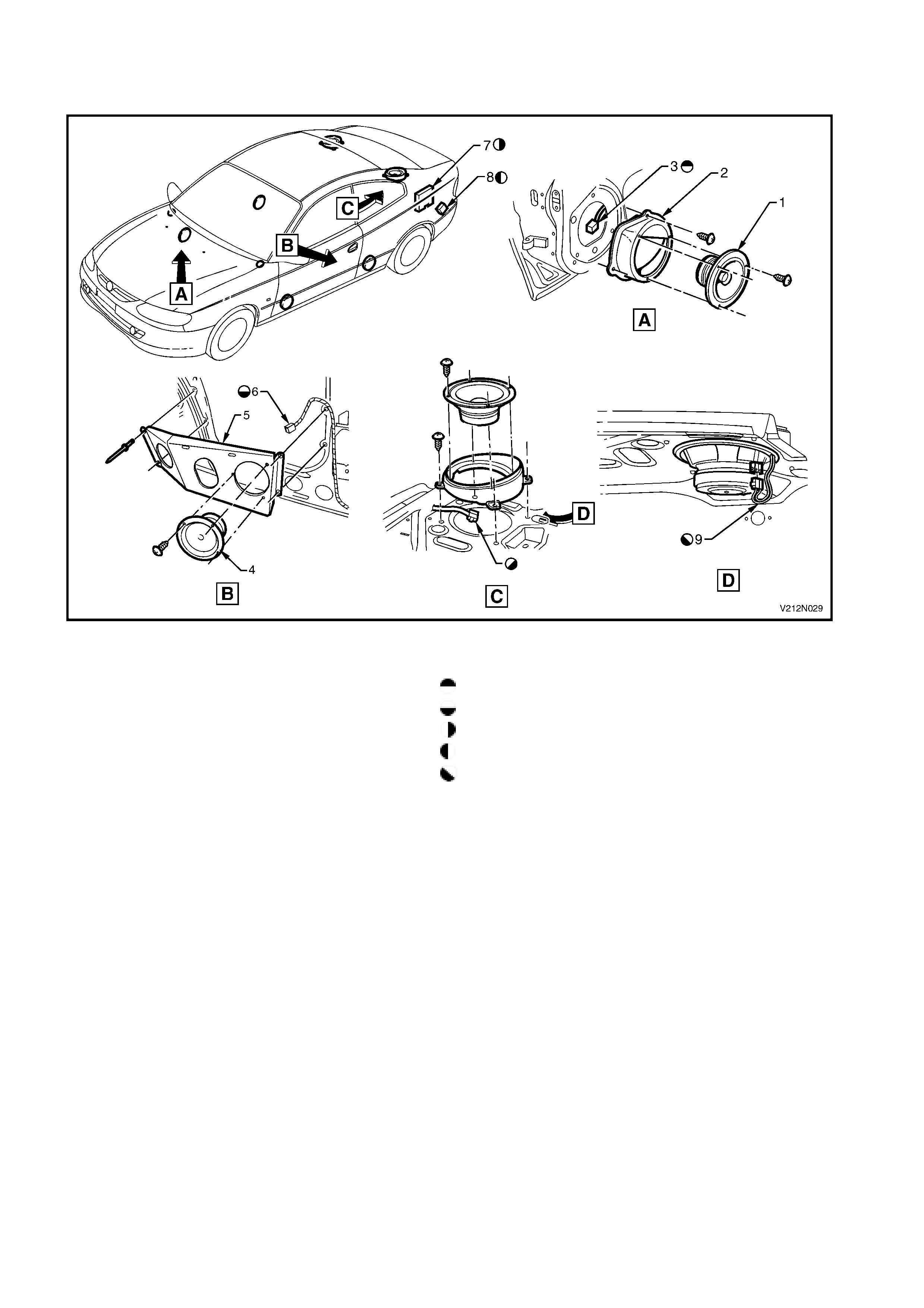
BODY WIRING HARNESS - 14
AUDIO SYSTEM
Figure 12N-29
Legend
1. Front door speaker (2 places) For harness continuation, refer to Figure 12N-16.
2. Front door speaker mounting box (2 places) For harness continuation, refer to Figure 12N-18.
3. Front door speaker harness connector For harness connector details, refer to Figure 12N-27.
4. Rear quarter trim speaker (2 places) For harness connector details, refer to Figure 12N-31.
5. LH rear quarter trim speaker mounting bracket For harness continuation, refer to Figure 12N-22.
6. Rear quarter trim speaker harness connector
7. CD changer assembly
8. Rear speaker amplifier
9. Rear speaker harness connector
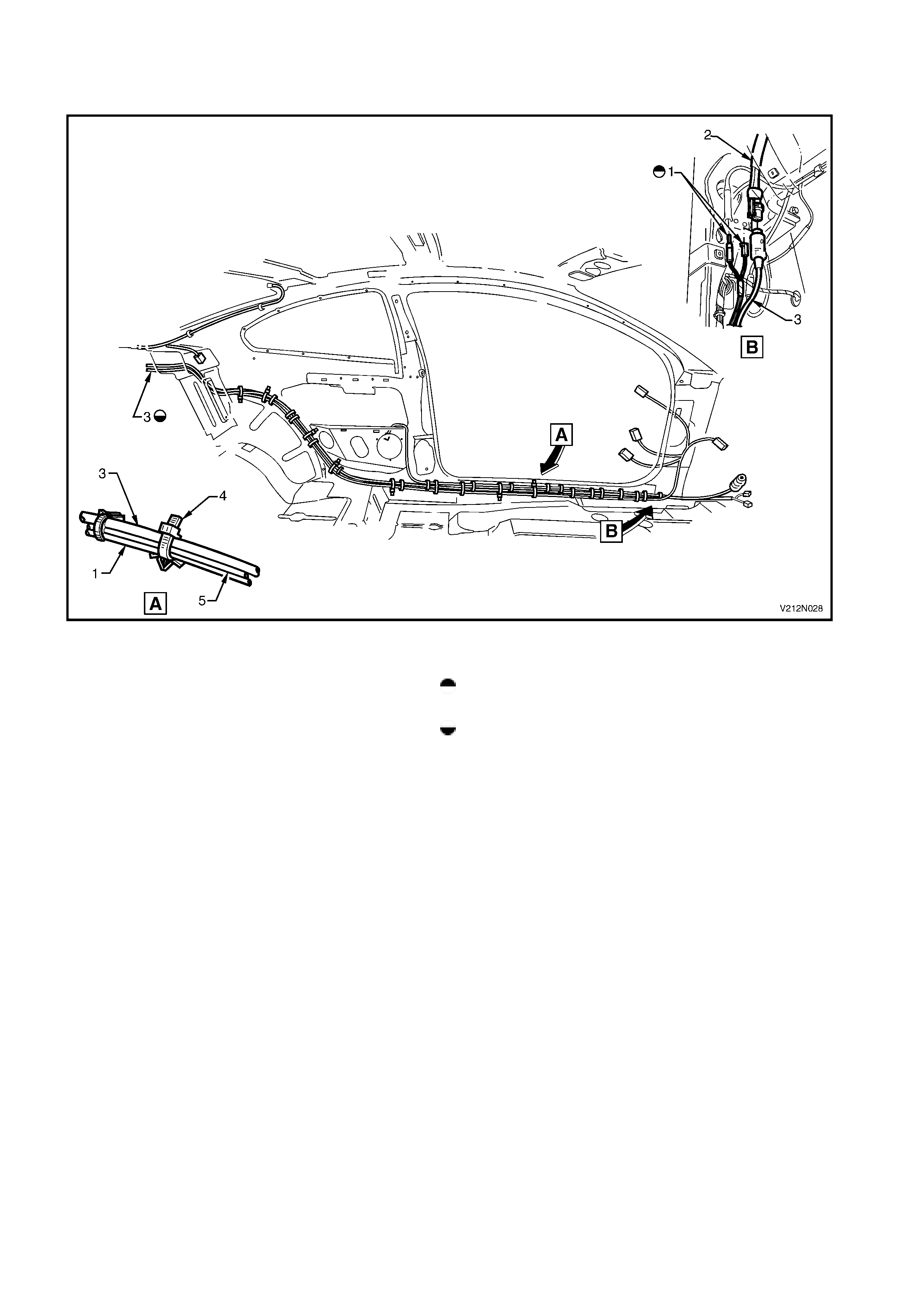
BODY WIRING HARNESS - 16
DIVERSITY ANTENNA - 2
Figure 12N-31
Legend
1. Diversity antenna lead and amplifier assembly For harness continuation, refer to Figure 12N-30.
2. Rear speaker amplifier lead Bend tab in direction shown after connector installation.
3. Rear speaker amplifier assembly Locate tab in slot prior to installing screw.
4. Diversity antenna amplifier attaching screw (1 place)
5. Diversity antenna earth lead attaching screw (1 place)
6. Diversity antenna amplifier locating tab
7. Diversity antenna harness connector For location of views D and E, refer to Figure 12N-30.
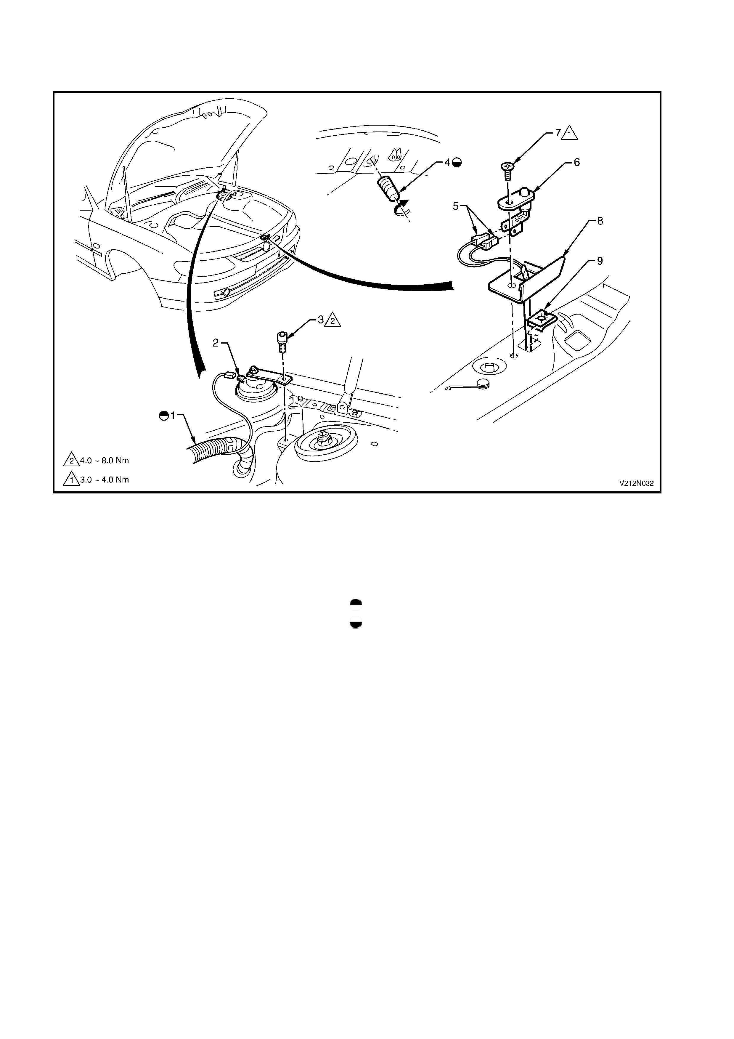
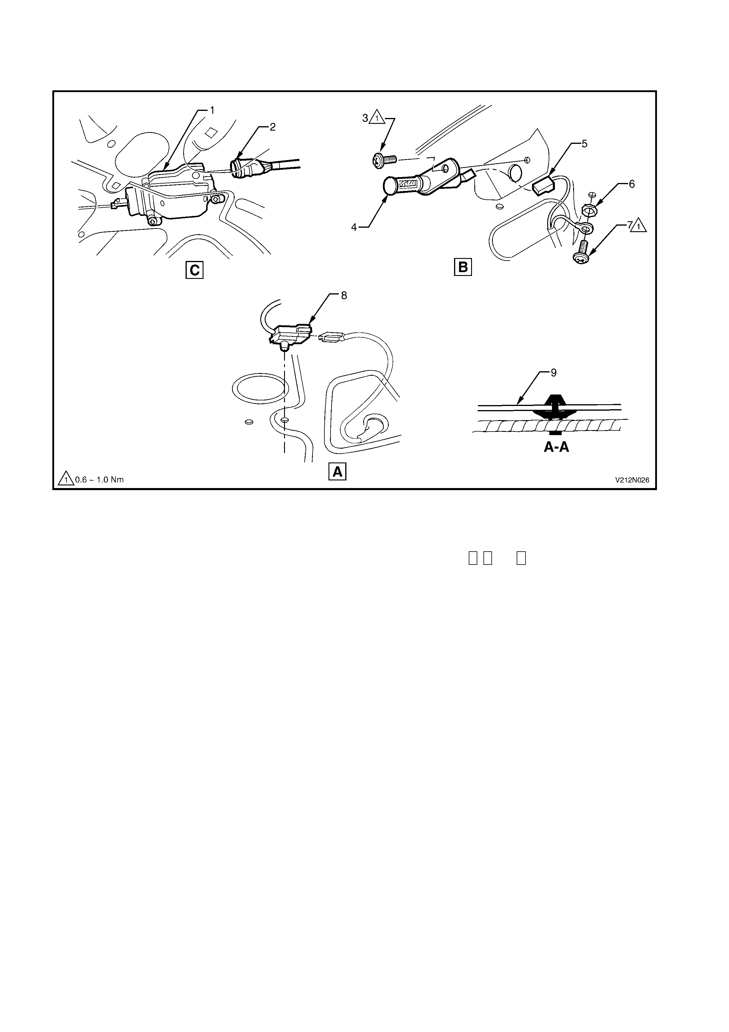
ANTI-THEFT SYSTEM HARNESS
HORN AND HOOD SWITCH
Figure 12N-32
Legend
1. Powertrain harness 7. Anti-theft hood switch to front panel attaching
2. Anti-theft horn screw (1 place)
3. Anti-theft horn to fender attaching screw (1 place) 8. Anti-theft hood switch shield
4. Anti-theft hood switch buffer 9. Anti-theft hood switch to front panel nut (1 place)
5. Main wiring harness to hood switch harness For harness continuation, refer to Figure 12N-5
connectors Screw in fully then adjust to activate switch
6. Anti-theft hood switch assembly
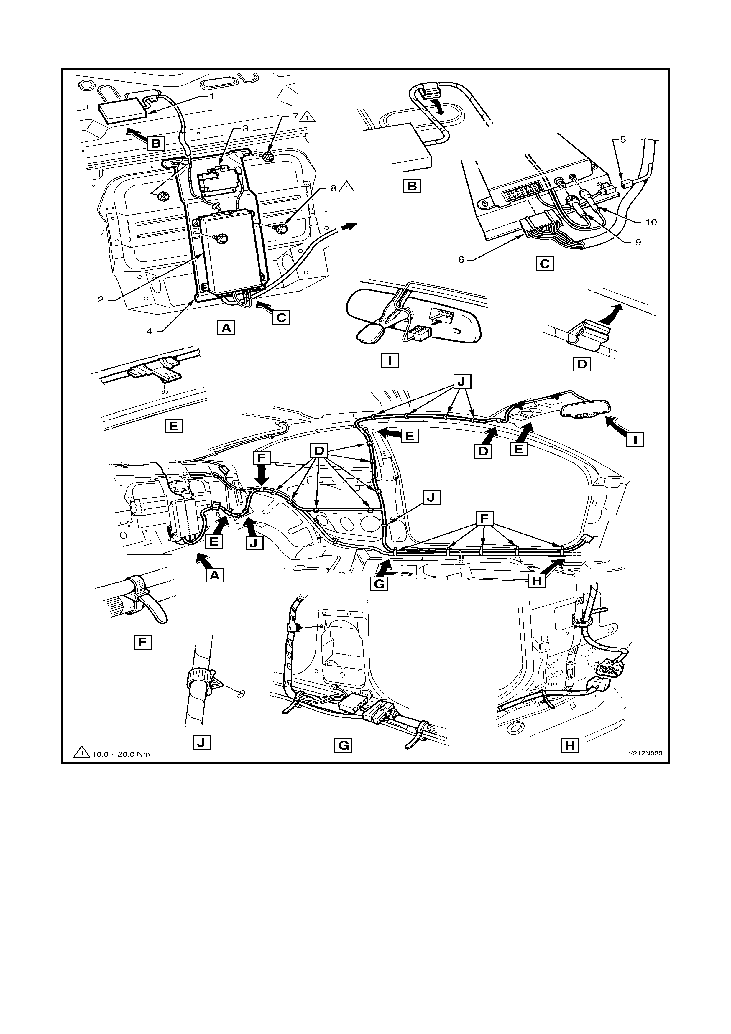
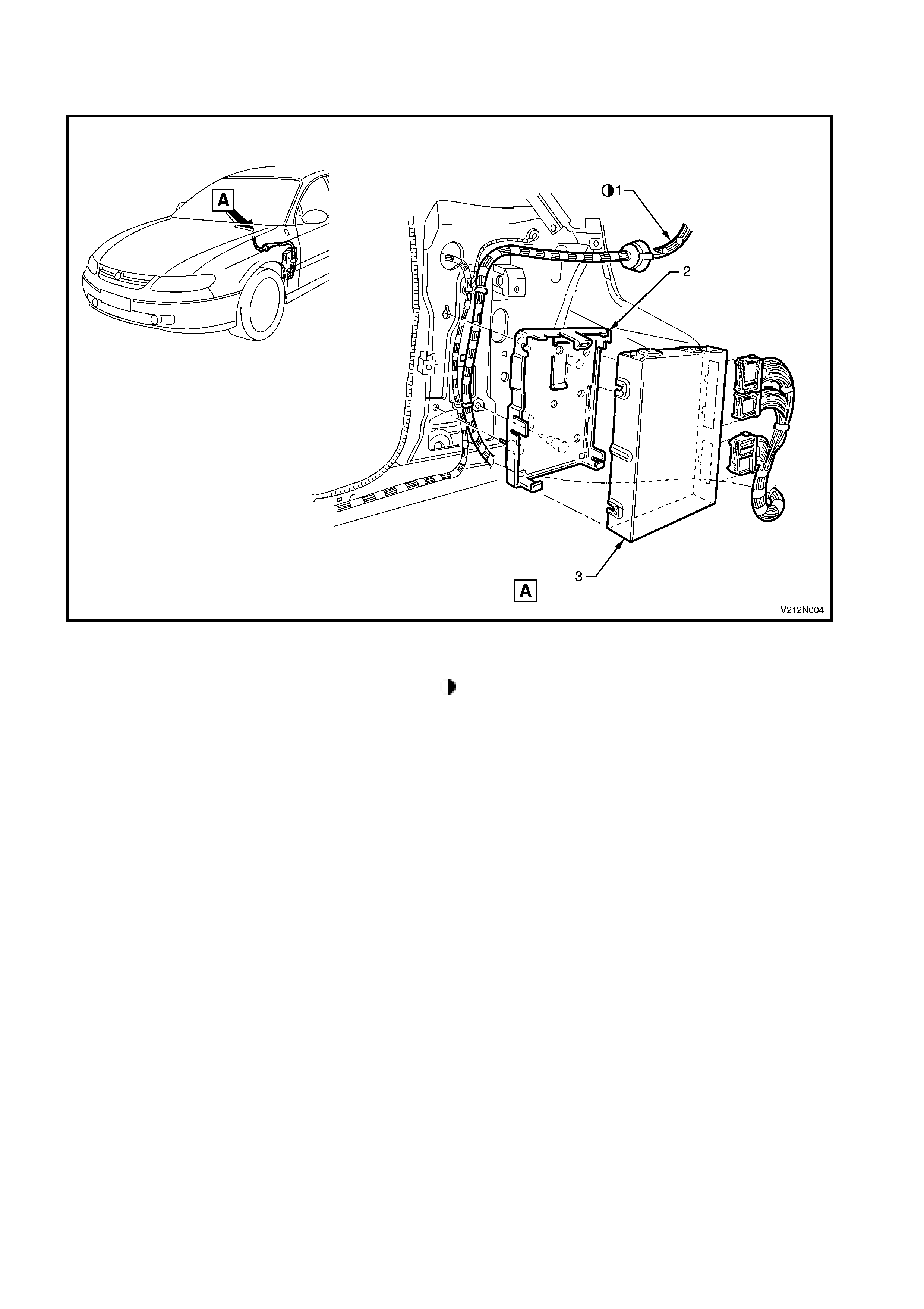
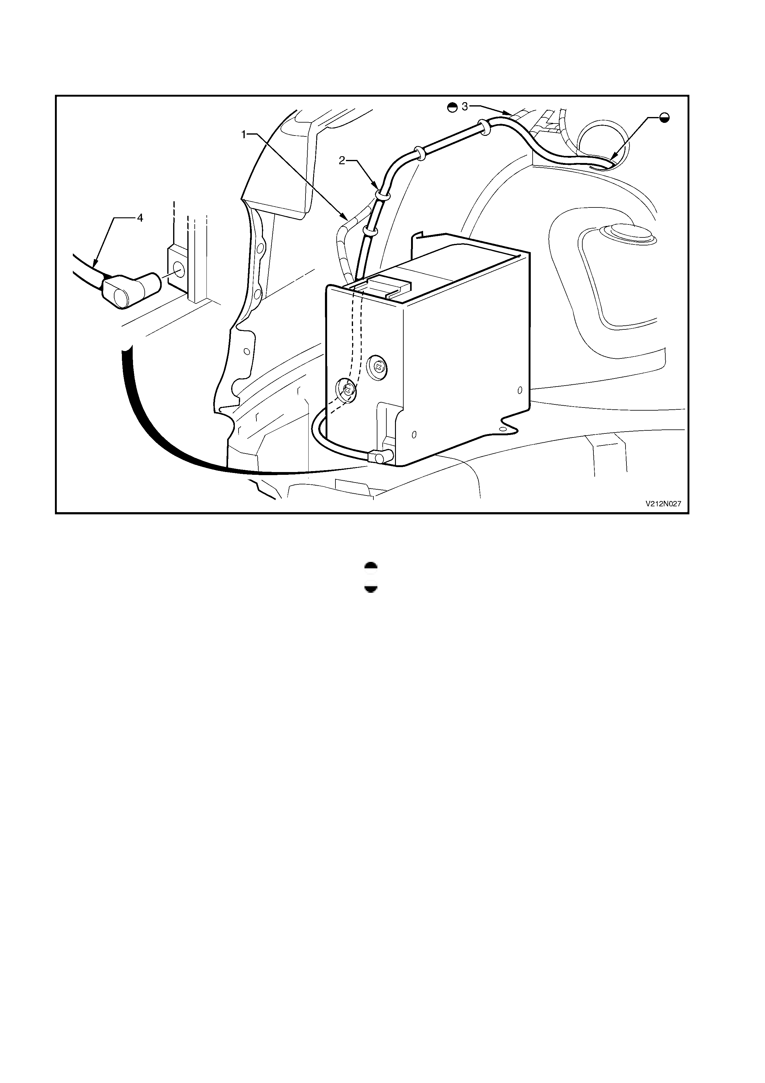
TELEMATICS SYSTEM HARNESS
Figure 12N-33
Legend
1. Telematics antenna 6. Telematics module patch harness connector
2. Telematics module 7. Module mounting bracket attaching nut (2 places)
3. Telematics back-up battery 8. Module mounting bracket attaching screw (2 places)
4. Telematics module mounting bracket 9. GSM antenna connector
5. Back-up battery connector 10. GPS antenna connector