
SECTION 12Q - TELEMATICS
IMPORTANT
Before performing any Service Operation or other procedure described in this Section, refer to Section
00 CAUTIONS AND NOTES for correct workshop practices with regard to safety and/or property
damage.
1. GENERAL INFORMA TION
The telem atics system has been de veloped usin g some of the most advanced Global Position System (GPS) and
Global System for Mobile (GSM) telecommunications technology available. The telematics system provides in-
vehicle safety, security and information services by providing a two way, hands free communication to either the
Holden Assist Centre or, in the case of an emergency, to the National Emergency Response Centre (NERC™).
The telem atics system as fitted to V2 Series Models c arries over from the s ystem as fitted to VX Series I Models,
noting the following:
• The telematics module assembly is mounted to a bracket behind the rear seat back.
• The telematics backup battery is mounted to a bracket behind the rear seat back.
• The telematics antenna is mounted to a bracket behind the rear seat back.
Figure 12Q-1 illustrates the locations of components for the telematics system as fitted to V2 Series Models. For
information regarding the telematics system as fitted to V2 Series Models not provided in this Section, refer to
Section 12Q T ELEMATIC S in the VX Series I Service Information.
NOTE: For a full list of services provided by Holden Assist, refer to the Holden Assist Handbook Supplement.
Techline
Techline
Techline
Techline
Techline
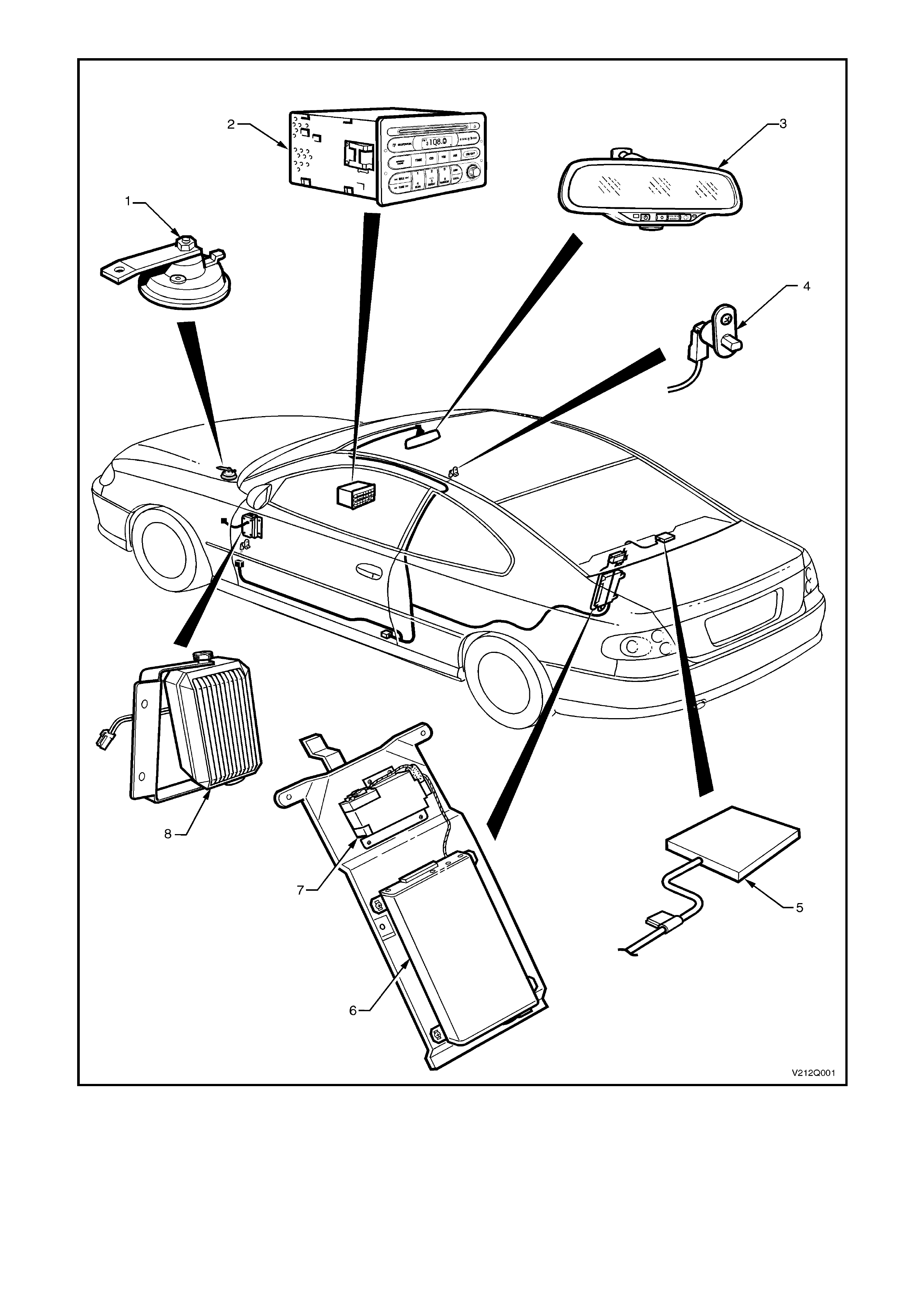
Figure 12Q-1
Legend
1. Theft deterrent horn 4. Driver’s door jamb switch 7. Backup battery
2. Radio 5. Telematics antenna 8. Telematics speaker
3. Interior rear view mirror 6. Telematics module assembly
2. PRINCIPLES OF OPERATION
2.1 TELEMATICS MODULE
The telematics module, mounted to a bracket
behind the r ear seat bac k , controls the o perat ion of
the telematics system. The telematics module
consists of a GPS and GSM engine and a Serial
Data Interface. The telematics module interfaces
with other control modules in the vehicle via the
auxiliary serial data circuit normal mode message.
For further information regarding the serial data
bus and normal mode message, refer to
Section 2.2 SERIAL DATA COMMUNICATION in
Section 12J-1 Low Series Body Control Module
or Section 12J-2 High Series Body Control
Module in the VX Series I Service Information.
Tech 2 is also capable of communicating with the
telematics module via the serial data circuit.
Figure 12Q-2

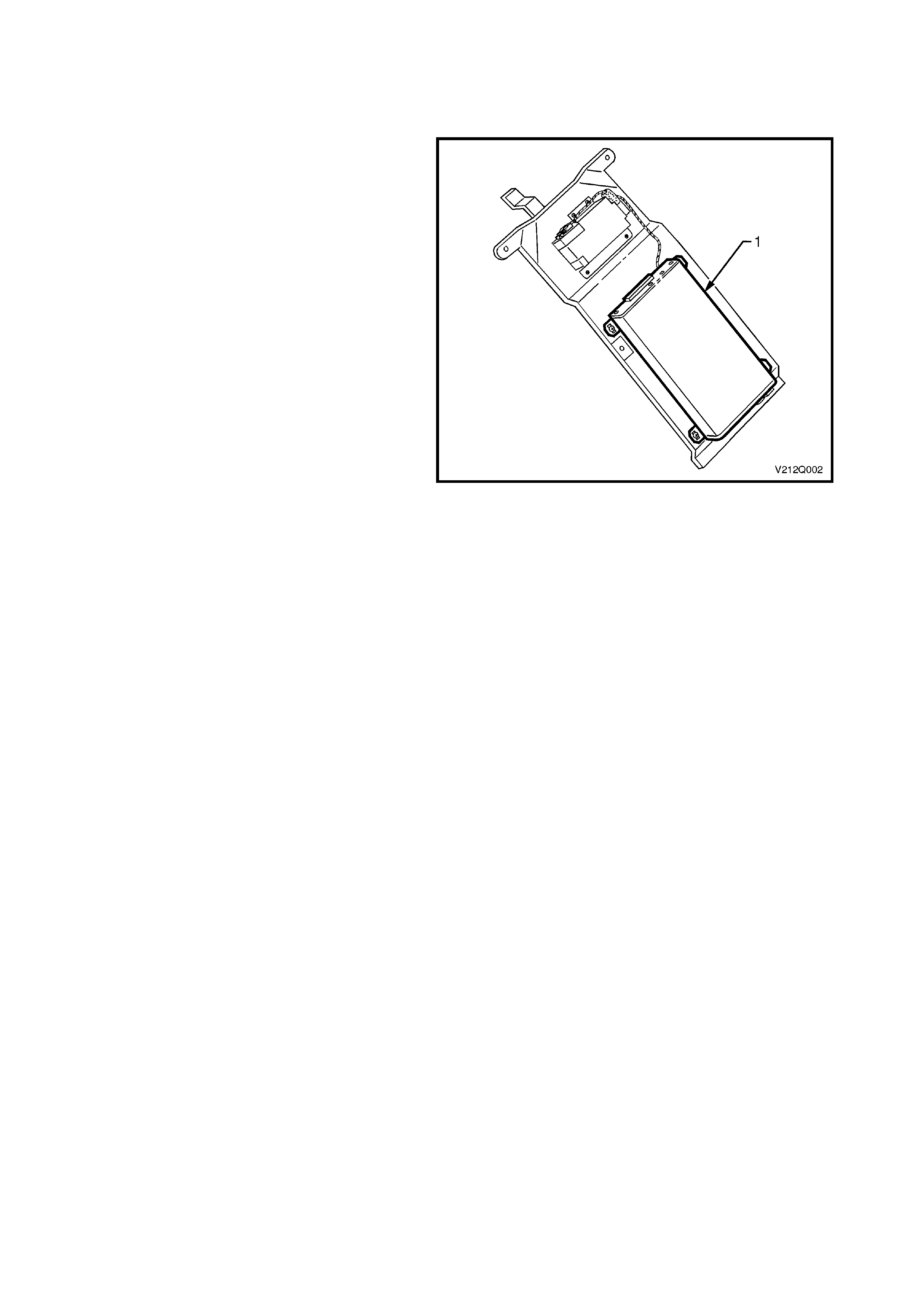
2.2 BACKUP BATTERY
The backup battery (1) is located behind the rear
seat back and is mounted to the same bracket as
the telematics module. The backup battery will
provide power to the telematics module for
approximately 30 minutes in the event of the
vehicle battery being discharged or disconnected.
The telematics module has a backup battery
charging circuit that maintains the backup battery
state of c harge. A 3A f use (2) is used to protec t the
backup battery circuitry.
For further information regarding the backup
battery, including the charging circuit, refer to
Section 12Q TELEMATICS in the VX Series I
Service Information.
Figure 12Q-3
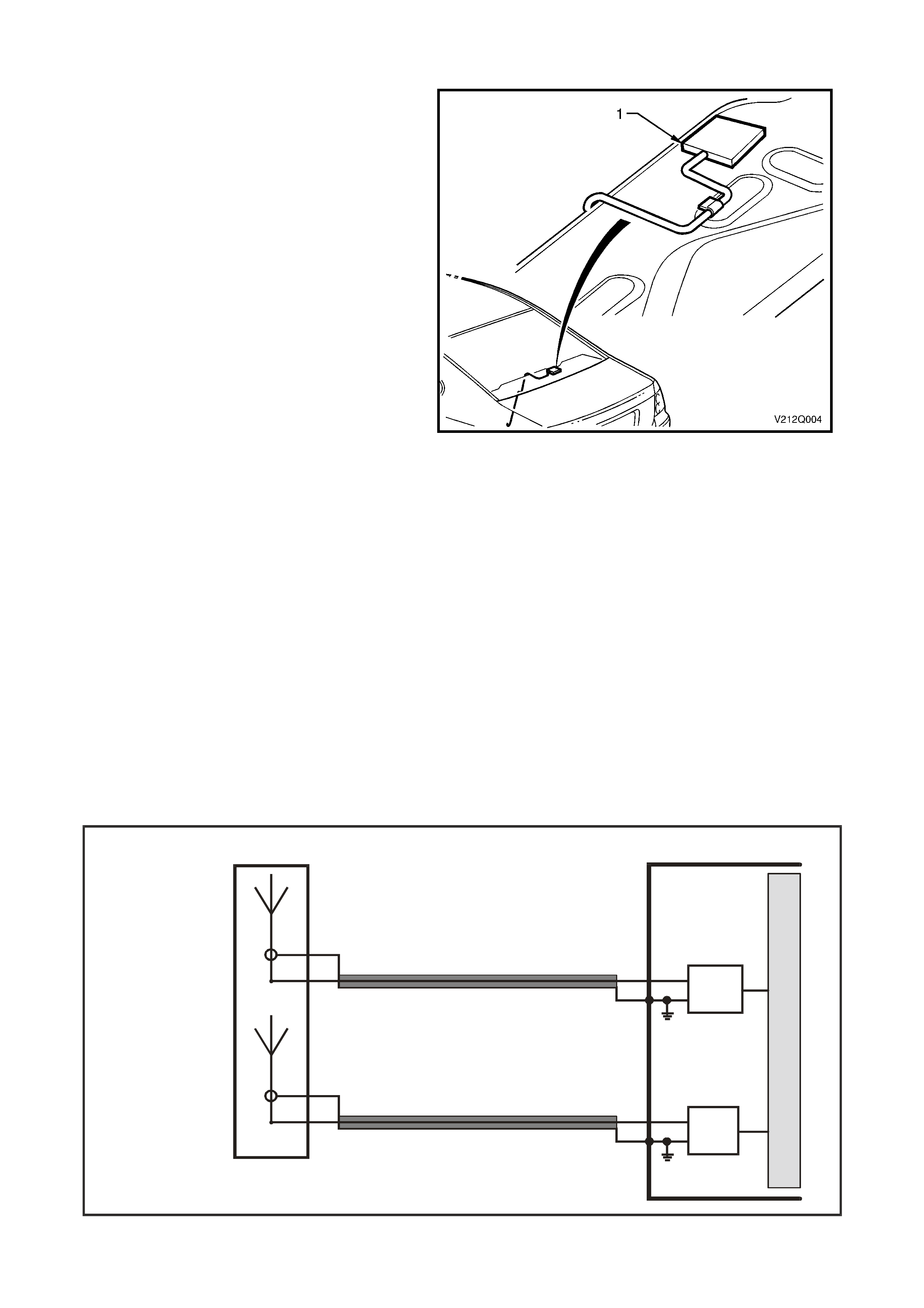
2.3 TELEMATICS ANTENNA
The telematics antenna (1) contains both the GPS
and GSM antennas in one unit, and is located on
the rear parcel shelf, under the rear parcel shelf
trim. The antenna has two leads, one for the GPS
antenna and the other for the GSM antenna.
NOTE 1: The area directly above the telematics
antenna should be free from obstructions (e.g.
accessory sun-visors, parcels, hats etc) as they
may adversely affect antenna reception and the
system will not have full functionality.
GSM ANTENN A
The GSM antenna is capable of transmitting and
receiving both voice and data signals via the GSM
network. The telematics module uses the GSM
network to transmit and receive voice and data.
Signal strength may be affected in locations such
as basement car parks or tunnels. However, in
most cases, as the vehicle emerges from the
obstruction or re-enters the digital phone network
area, the signal will be available again and any
stored data will be transmitted. The GSM antenna
is connected to the telematics module by a screw-
on Mini-UHF type connector.
Figure 12Q-4
G PS AN TEN NA
The G PS ant enn a re cei ves signa ls f r om s atellit es or bit ing t he e art h a nd tra ns mits these to the t e lematic s module to
determine the vehicle’s position. Signals from at least three GPS satellites must be received to accurately
determ ine th e veh ic le’s t wo dimens iona l (2 D) pos i tion. Signa ls f rom at leas t f our G PS s a tel l ites must be r ec ei ved to
accurately determine th e vehic l e’s t hr ee d imensiona l (3D) position. If s ign als f rom onl y three s at el lit es ar e re c eiv ed,
the telematics module cannot determine the vehicle’s altitude. The GPS antenna must not be obscured by any
objects, such as underground car parks, tunnels, bridges or buildings as any of these may affect GPS reception.
The GPS antenna is connected to the telematics module by a screw-on SMA type connector.
The telematics module uses a principle called triangulation to determine the location of the vehicle. This principle
states that you can determine the location of an object if you know its distance from three known locations. GPS
uses 24 satellites orbiting the earth; the location of each satellite is known at any given time. The satellites
constantly broadcast radio signals. The telematics GPS module compares the amount of time it takes for the
signals from at least three different satellites to reach the GPS module. By converting time into distance, it can
calculate the m odule’s location on earth. T he telematics module receives GPS data, decodes it, and transm its the
vehicle’s locati on vi a SMS when re qu ested b y Holden Ass is t or NERCTM.
GSM
ANTENNA (-)
GSM
ANTENNA (+)
M
I
C
R
O
TELEMATICS MODULE
GSM ANTENNA
GSM
MODULE
VX12K119A
GPS ANTENNA
GPS
ANTENNA (-)
GPS
ANTENNA (+)
GPS
MODULE
Figure 12Q-5

2.4 WIRING HARN ESSES
V2 Series ve hicles equipped with the telematics s ystem have specific main and bod y harnesses, and a telem atics
patch harn ess . The telem atic s patch har nes s c onnec t o r 2 (YB178) plugs into th e main harnes s behin d the le f t hand
kick panel trim (view D) and the telem atics patch harness connector 1 (YB177) plugs into the bod y harness at the
bottom of the B pillar (view C). The telematics patch harness is also connected to the telematics module (YR55)
(view B), t he interior rear view mirror (YB186) (view G). T he telematics speaker (view F) is connected to the main
harness connector (YB181).
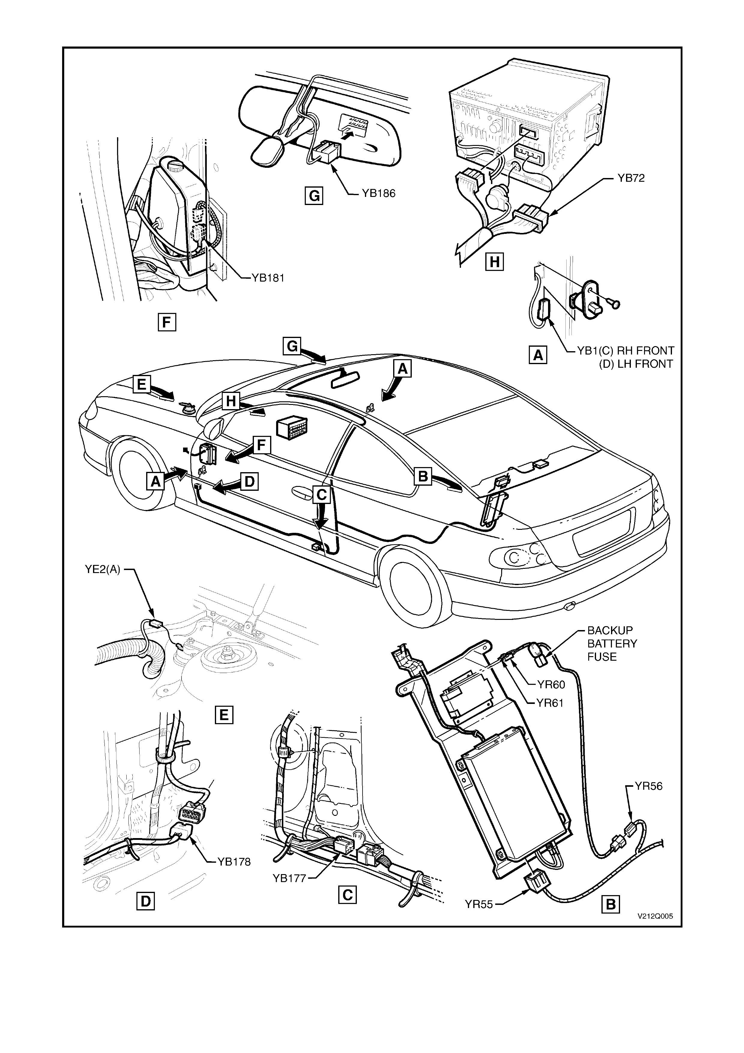
Figure 12Q-6
3. SERVICE OPERATIONS
CAUTION: When carrying out any service proced ure on th e vehicle that involves disconn ecting the b attery
cables or any procedure that may cause the battery voltage to fall below 12 Volts, the telematics module
Service Mode MUST BE ENABLED. Refer to 4.3 TECH 2 TEST MODES F4: Program, F2 Operating Mode,
F1: Service Mode in Section 12Q TELEMATICS in the VX Series I Service Information.
If the telematics module service mode is not enabled, a ‘Battery Removal Alert’ will be transmitted to the
Holden Assist Centre whenever the battery is disconnected, or a ‘Low Battery Voltage Alert’ when the
battery voltage is low.
NOTE : For information regarding the service operations for the telematics system as fitted to V2 Series Models not
covered in this Section, refer to Section 12Q TELEMATICS in the VX Series I Servic e Inf ormation.
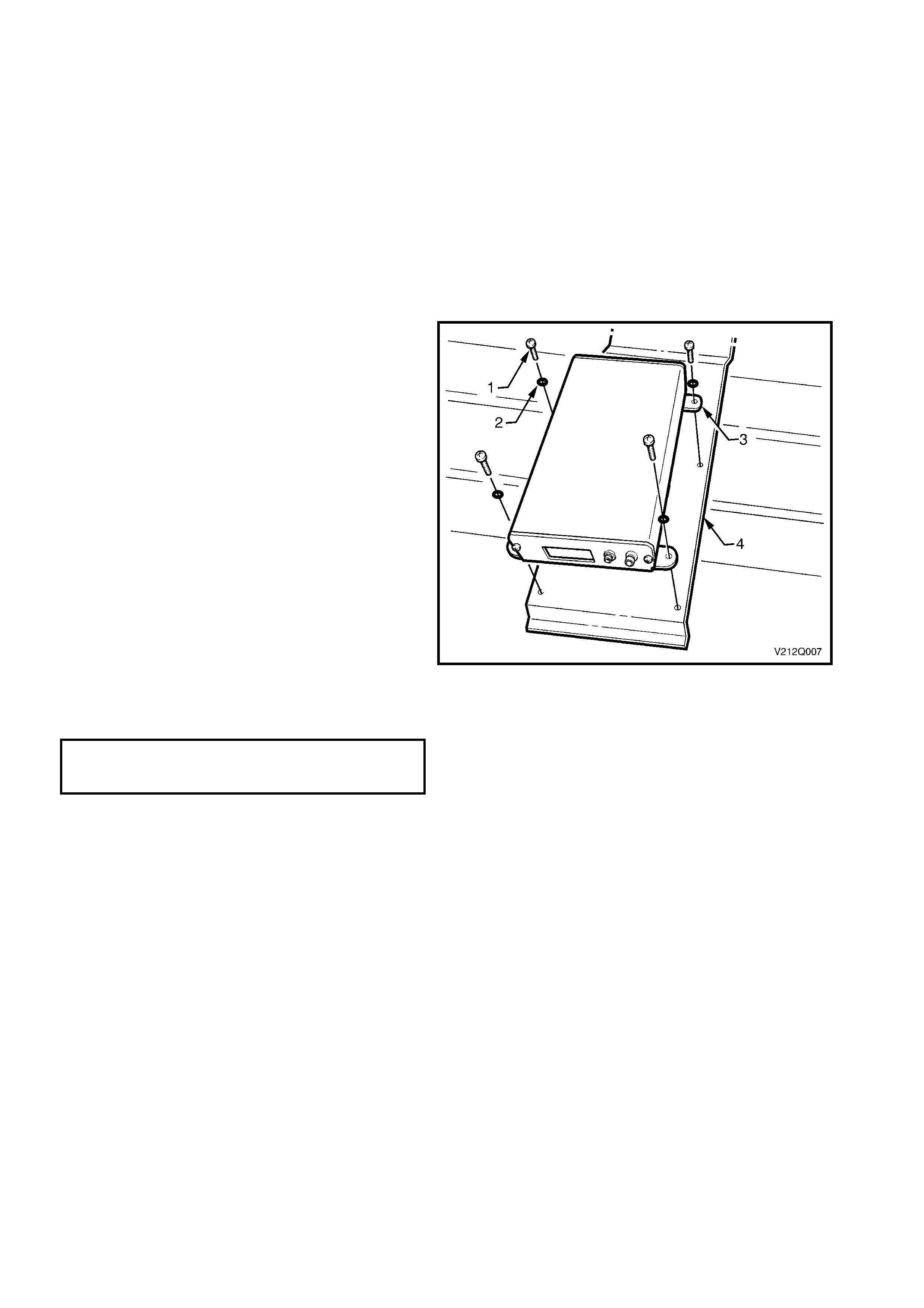
3.1 TELEMATICS MODULE
REMOVE
1. Using Tech 2, enable the telematics module
service mode. Refer to 4.3 TECH 2 TEST
MODES F4: Program, F2: Operating Mode,
F1: Service Mode in Section 12Q
TELEMATICS in the VX Series I Service
Information.
2. Remove the rear seat back and cushion
assemblies, refer to Section 1 A7 SEATS AND
SEAT BELT S in this Service Information.
3. Remove the four telematics module to
mounting bracket retaining screws (1) and
washers.
4. Remove the telematics module (3) from the
mounting bracket (4).
REINST ALL
1. Installation of the telematics module is the
reverse of the removal procedure, noting the
following.
2. Tighten t he tel em atics m odule r etaini ng scr ews
to the correct torque specification.
TELEMATICS MODULE TO MOUNTING
BRACKET RETAINING SCREWS
TORQUE SPECIFICATION 3.0 – 3.5 Nm
3. Use Tech 2 to disable the telematics module
service mode. Refer to 4.3 TECH 2 TEST
MODES F4: Program, F2: Operating Mode,
F1: Service Mode in Section 12Q
TELEMATICS in the VX Series I Service
Information.
NOTE: If the telematics module service mode is
not disabled, the system will not have full
functionality.
Figure 12Q-7
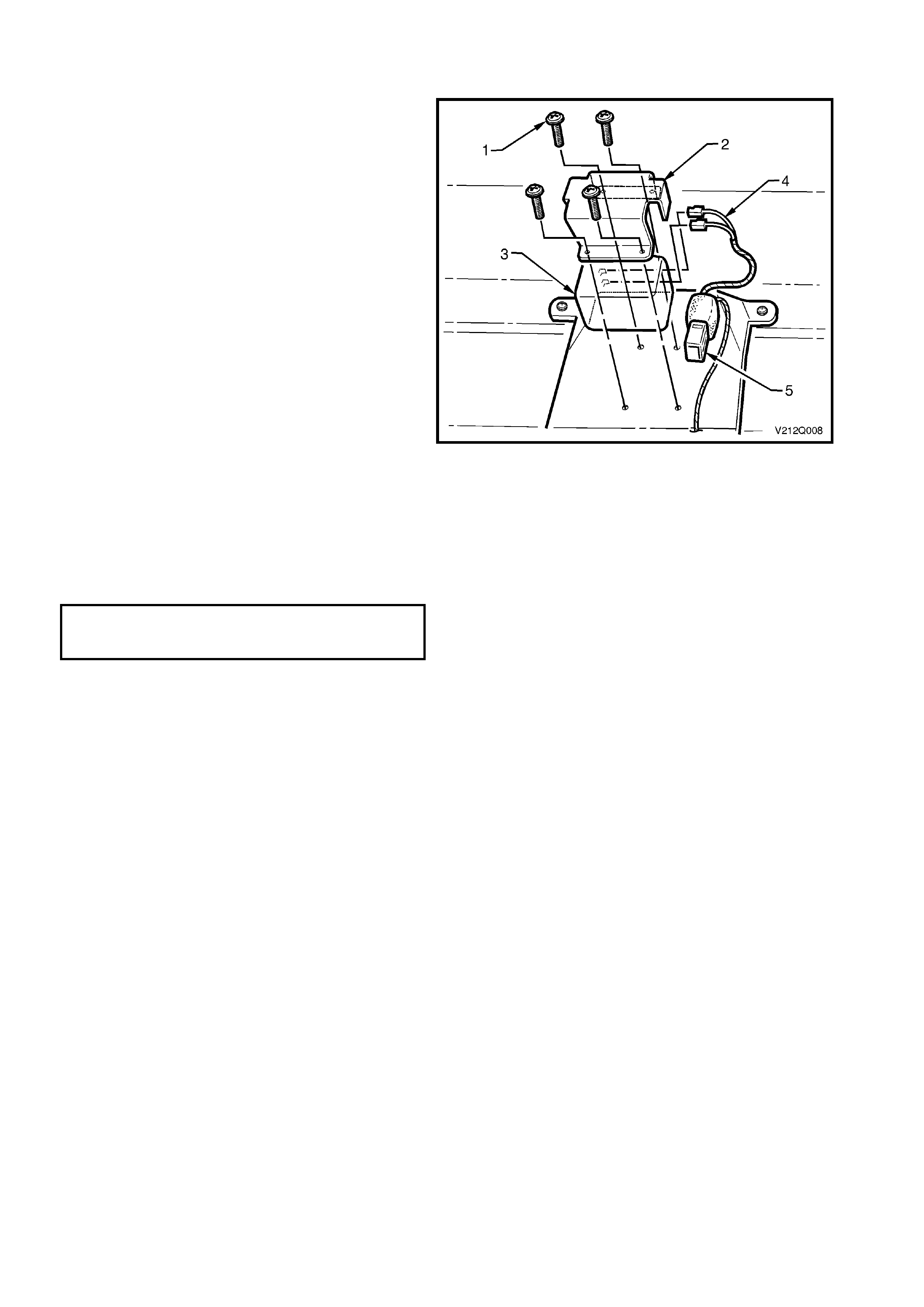
3.2 BACKUP BATTERY
REMOVE
1. Using Tech 2, enable the telematics module
service mode. Refer to 4.3 TECH 2 TEST
MODES F4: Program, F2: Operating Mode,
F1: Service Mode in Section 12Q
TELEMATICS in the VX Series I Service
Information.
2. Remove the rear seat back and cushion
assemblies, refer to Section 1 A7 SEATS AND
SEAT BELT S in this Service Information.
3. Disconnect the two backup battery terminals
(1) from the backup battery (2).
4. Remove the four backup battery to bracket
retaining screws (3) and remove the backup
battery and shield (4) from the bracket (5).
Figure 12Q-8
REINST ALL
1. Installation of the telematics backup battery is
the reverse of the removal procedure, noting
the following.
2. Tighten backup battery retaining screws to the
correct torque specification.
TELEMATICS BACKUP BATTERY
RETAINING SCREWS
TORQUE SPECIFICATION 3.0 – 3.5 Nm
3. Use Tech 2 to disable the telematics module
Service Mode. Refer to 4.3 TECH 2 TEST
MODES F4: Program, F2: Operating Mode,
F1: Service Mode in Section 12Q
TELEMATICS in the VX Series I Service
Information.
NOTE: If the telematics module service mode is
not disabled, the system will not have full
functionality.
3.3 TELEMATICS ANTENNA
REMOVE
1. Using Tech 2, enable the telematics module
service mode. Refer to 4.3 TECH 2 TEST
MODES F4: Program, F2: Operating Mode,
F1: Service Mode in Section 12Q
TELEMATICS in the VX Series I Service
Information.
2. Disconnect the negative batter y cable from the
battery.
3. Remove the rear parcel shelf trim, refer to
2.9 REAR PARCEL SHELF ASSEMBLY in
Section 1A8 HEADLINING AND REAR END
TRIM in this Service Information.
4. Loosen and remove the GSM and GPS
antenna connectors from the telematics
module.
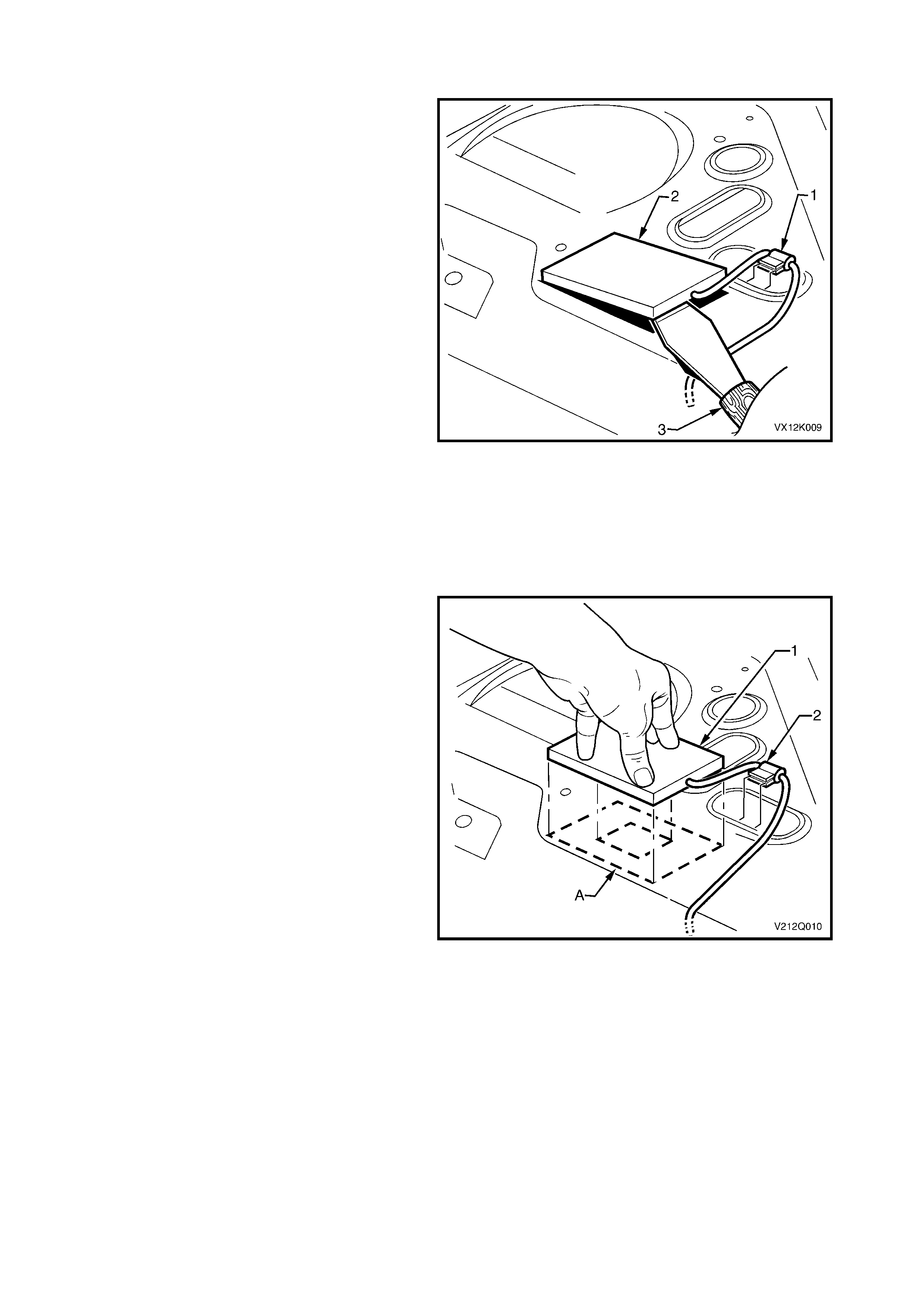
5. Remove the telematics antenna lead retaining
clip (1).
6. Using a felt marker or engineers chalk, mark
the location of the telematics antenna (2) onto
the rear parcel shelf panel to aid in the
installation procedure.
7. Using a com m ercial ava ilable p aint s craper (3),
prise the antenna from the rear parcel shelf.
Figure 12Q-9
REINST ALL
1. Ensure the rear parcel shelf to telematics
antenna mating surface is clean.
2. If you are installing the original antenna (1)
remove the used double sided tape, and apply
new double sided tape 3M 4428 or equivalent,
to the antenna mating surface.
3. Remove the backing from the double sided
tape.
4. Install the antenna to the rear parcel shelf,
ensuring to align the antenna with the
previously marked location (A), then press
down firmly on the antenna.
5. Install the telematics antenna lead retaining
clip (2) by pushing it hard up against the edge
of the hole on the parcel shelf.
6. Install the GSM and GPS antenna connectors
to the telematics module.
7. Install the rear parcel shelf trim, refer
2.9 REAR PARCEL SHELF ASSEMBLY in
Section 1A8 HEADLINING AND REAR END
TRIM in this Service Information.
Figure 12Q-10
8. Reconnect the negative battery cable to the battery.
9. Use Tech 2 to disable the telematics module Service Mode. Refer to 4.3 TECH 2 TEST MODES F4:
Program, F2: Operating Mode, F1: Service Mode in Section 12Q TELEMATICS in the VX Series I Service
Information.
NOTE 1: The ar ea directl y above the t elematic s anten na should be free fr om obstr uctions (e. g. access ory sun-
visors, parcels, hats etc) as they may adversely affect antenna reception and the system will not have full
functionality.
NOTE 2: If the telematics module service mode is not disabled, the system will not operate.


6. TORQUE WRENCH SPECIFIC ATIONS
Nm
Telematics module assembly attaching nuts ................................. 2.0 – 3.0
Telematics module assembly attaching bolts................................. 2.0 – 3.0
Telematics modul e to bracket retain ing screws............................. 3.0 – 3.5
Telematics backup battery to bracket retaining screws.................. 3.0 – 3.5
Telematics speaker bracket retaining screws................................ 3.0 – 3.5
Interior rear view mirror retaining screw ........................................ 2.5 – 4.5