
SECTION 6B2 - COOLING SYSTEM -
V6 SUPERCHARGED ENGINE
IMPORTANT
Before performing any Service Operation or other procedure described in this Section, refer to Section
00 CAUTIONS AND NOTES for correct workshop practices with regard to safety and/or property damage.
1. GENERAL INFORMATION
1.1 ENGINE COOLANT BLEEDER SCREWS
1.2 RADIATOR
1.3 COOLING FANS
GENERAL DESCRIPTION
OPERATION
2. SERVICE OPERATIONS
2.1 SERVICE NOTES
2.2 COOLING SYSTEM HOSES
SERVICE NOTES
2.3 COOLING FAN AND SHROUD ASSEMBLY
REMOVE
REINSTALL
DISASSEMBLE
REASSEMBLE
2.4 RADIATOR
REMOVE
REINSTALL
RADIATOR REPAIR PROCEDURE
3. SPECIFICATIONS
4. TORQUE WRENCH SPECIFICATIONS
5. SPECIAL TOOLS
Techline
1. GENERAL I NFORMATI O N
The cooling system for V2 Series CV6 Models carries over from VT Series I Models, noting the following:
• A new condenser, radiator and f an m odule (CRFM) was introduced with the MY2003 V2 Series Update Models
during October 2002.
The information provided in this Section only applies to MY2003 V2 Series Update CV6 Models fitted with the
revised cooling s ystem. For infor m ation regarding either the ear lier type cooling sys tem or the unchanged portion of
the revised cooling system, refer to Section 6B1-2 ENGINE COOLING - V6 SUPERCHARGED ENGINE, in
conjunction with Section 6B1-1 ENGINE COOLING - V6 ENGINE in the VT Series I Service Information.
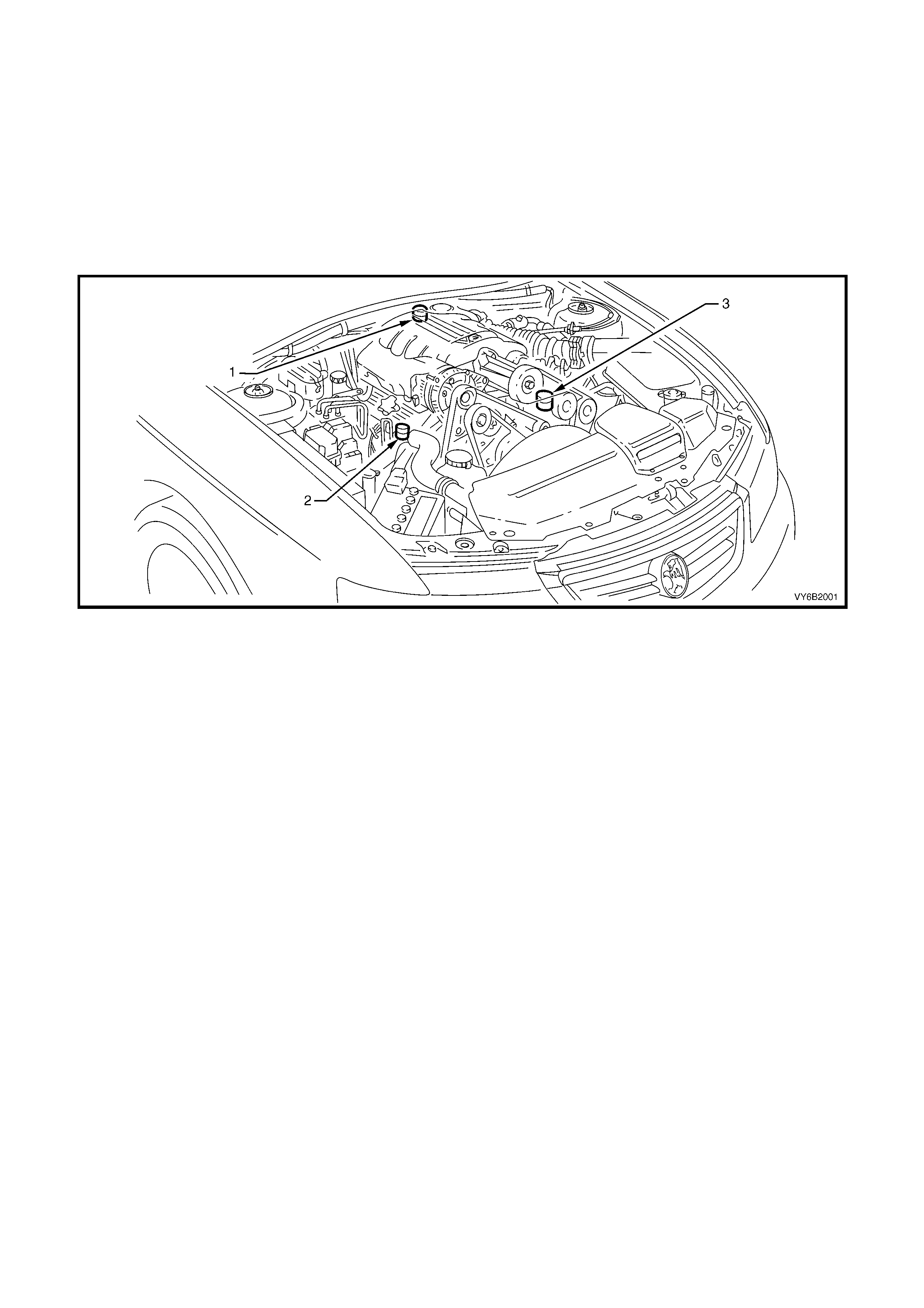
1.1 ENGINE COOLANT BLEEDER SCREWS
Figure 6B2-1
Legend
1. Thermostat Cover Bleeder Screw
2. Radiator Inlet Pipe Bleeder Screw
3. Coolant Bypass Housing Bleeder Screw

1.2 RADIATOR
The radiator utilises an aluminium core and is of the crossflow design, with a radiator cap located on the left-hand
side tank. Plas tic s ide tank s are attac hed to the c ore by the use of clinc h tabs . T he c linc h tabs ar e f or med as part of
the core assembly.
A high temperature rubber seal is used to seal the mating surface between the core and each side tank. The seal(s)
must be replaced any time the side tank is removed from the core.
IMPORTANT: T he radiator core s ide tanks or tr ansm ission oil cooler CANNOT be replac ed separately. If there is a
fault with any of these components, the radiator assembly must be replaced. Small core repairs may be made,
using an Aluminised Silicon based liquid repair agent.
For vehicles with automatic transmission, a transmission oil cooler is located in the left-hand radiator tank. The
cooler pipes fr om and to the transm ission ar e connected to the oil cooler f lexible hoses by means of quick c onnect
fittings.
When air conditioning is fitted, the air conditioning condenser is mounted, by means of clips and brackets, to the
front of the radiator. The air conditioning receiver drier also forms a part of the complete assembly.
Pegs are attached to the lower frame and the upper area of each side tank. These pegs are used to support the
radiator in four rubber mounts. The assembly is held in position by two spring clips at the upper mounting locations.
1.3 COOLING FANS
GENERAL DESCRIPTION
Two, single speed, engine cooling fan m otors are used. The smaller, right fan is 268 mm in diameter with a motor
rated at 120 Watts, while the larger, left fan is 370 mm in diameter with a motor power rating of 160 Watts.
With 12 volts applied and the fans mounted on to the radiator with a condenser fitted, the operating speeds are:
Stage 1 Stage 2
Large Fan 1,900 ± 150
rpm 1,900 ± 150
rpm
Small Fan Inoperative 2,350 ± 150
rpm
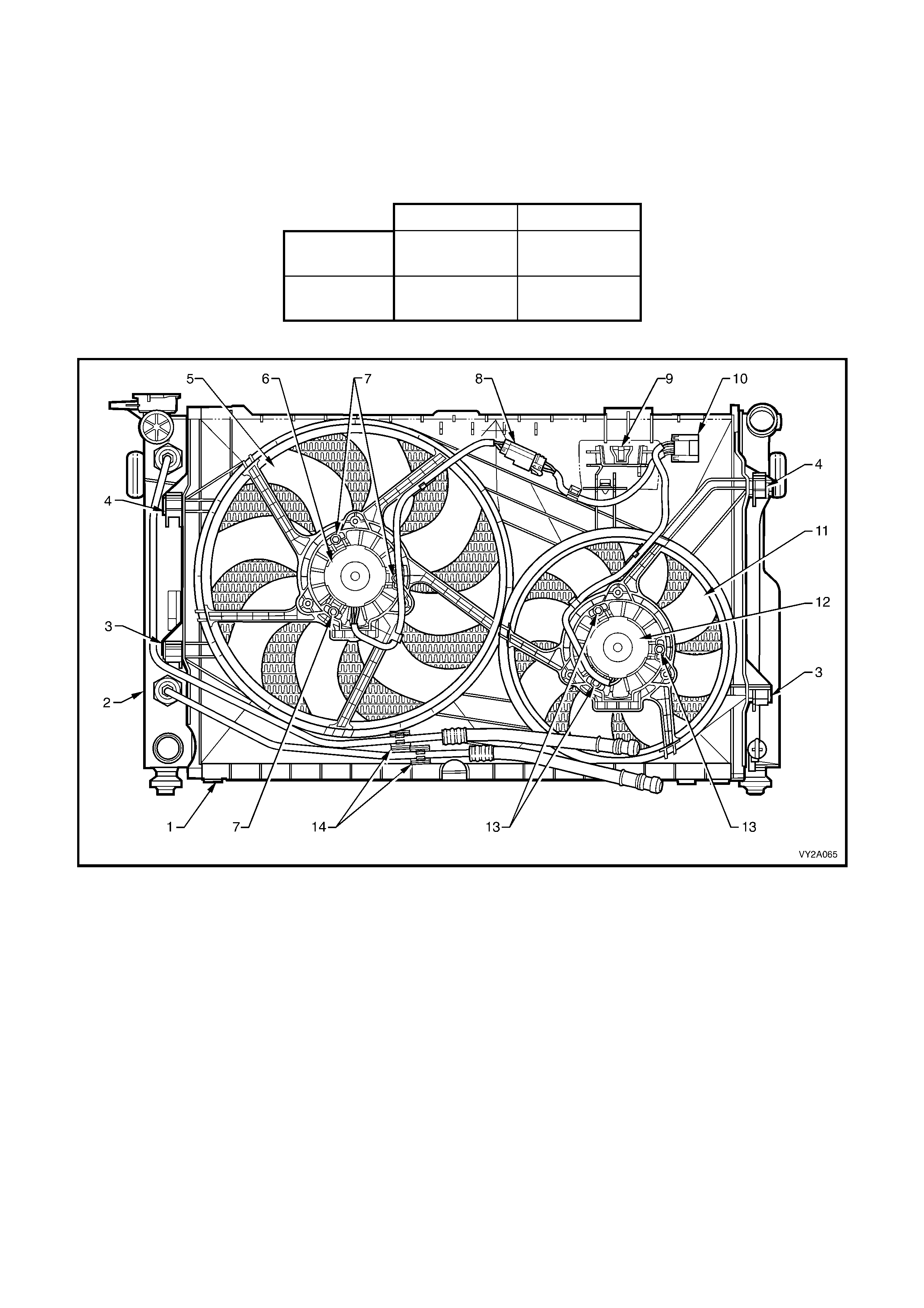
Figure 6B2-2
Legend
1. Fan Shroud
2. Radiator
3. Fan Shroud Lower Support
4. Fan Shroud Upper Support/Locking Retainer
5. Left Fan – 8 Blade, 365 mm Diameter
6. Left Fan Motor – 160 Watt, Single Speed
7. Left Fan Motor Securing Screws (3 places)
8. Left Fan Motor Harness Connector (2 terminal)
9. Power Steering Reservoir Mount
10. Fan Motor Main Harness Connector (4 terminal)
11. Right Fan – 8 Blade, 263 mm Diameter
12. Right Fan Motor – 120 Wa tt, Single Speed
13. Right Fan Motor Securing Screws (3 places)
14. Automatic Transmission Cooling Line Retaining Clips
OPERATION
On MY2003 V2 Series models with V6 Supercharged engine, each of the engine cooling fan motors has two
terminals; one positive and one negative. The positive term inals are permanently connected to battery voltage, via
fusible links F101 (large fan) and F107 (small fan).
When the negative terminal is connected to earth
through engine cooling fan relay 1 (R7), the large
cooling fan (left) will operate. When the negative
terminal is connected to earth via the engine
cooling fan relay 2 (R5), both cooling fans will
operate.
The large (left) cooling fan operation is enabled
when the engine cooling fan relay 1 (located in the
underhood electrical centre) is energised by the
Body Contr ol Module (BCM), via a reques t from the
Powertrain Control Module (PCM). The PCM will
request low speed fan enable or disable, via the
serial data Normal Mode Message to the BCM on
circuit 800 (Red/Black wire). After the PCM
requests a change in the state of the engine
cooling fan relay 1 (i.e. OFF to ON or ON to OFF),
the BCM will send a serial data response m essage
back to the PCM confirming it received the
message.
Should a response from the BCM fail to occur, a
PCM DTC P1064, will set.
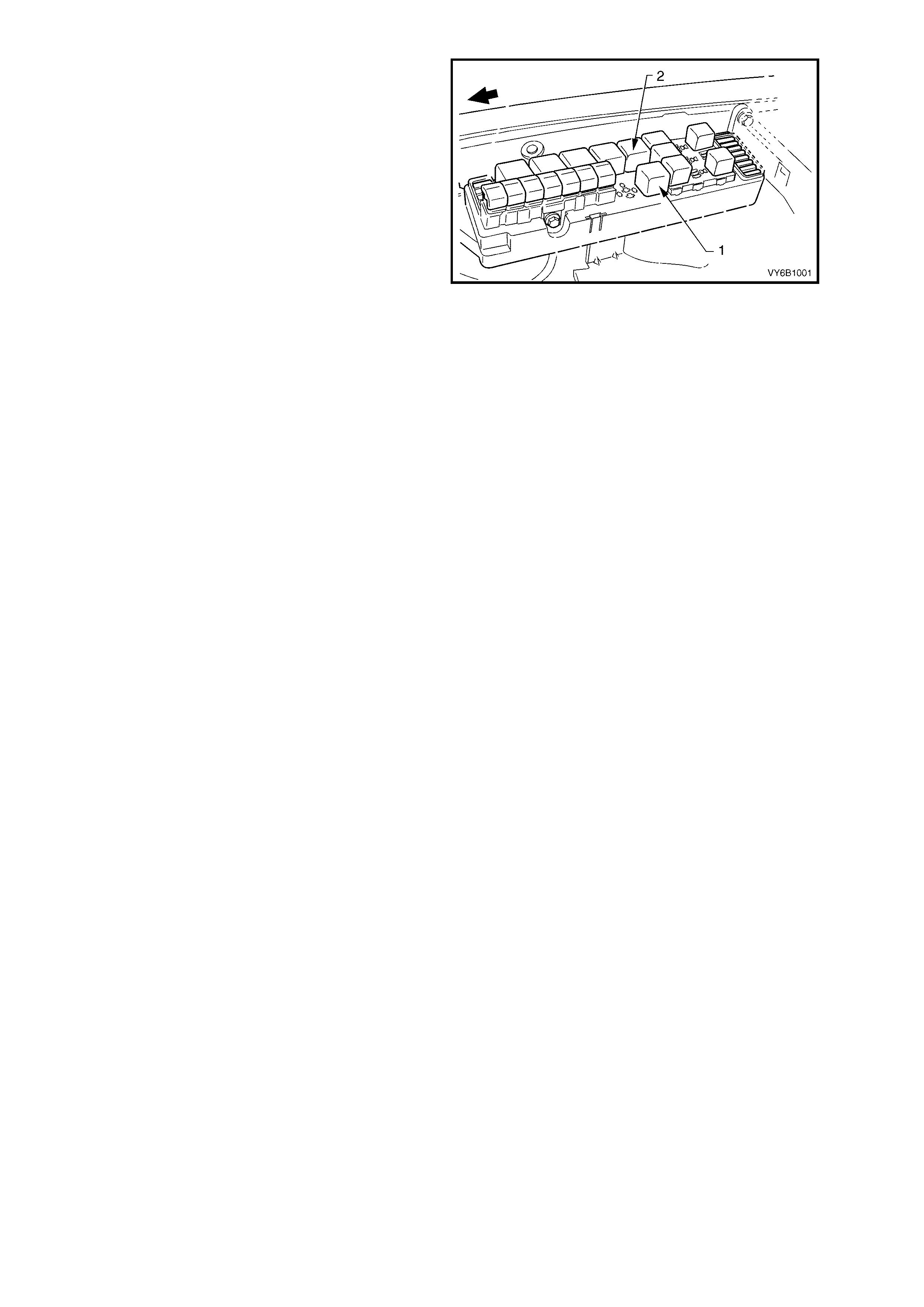
Figure 6B2-3
The PCM determ ines when to enable the low speed fan relay based on inputs from the A/C request signal, Engine
Coolant Temperature (ECT) sensor and the Vehicle Speed Sensor (VSS).
There are also suppression capacitors incorporated into the fan motor, located on the brush holders. These
suppression capacitors help eliminate fan motor noise through the radio speakers. As these capacitors are not
serviced separately, should a problem occur with either capacitor, then the motor assembly must be replaced.
STAGE ONE FAN OPERATION
1. The low speed cooling fan relay will be turned ON when:
• Air conditioning request indicated (YES) and the vehicle speed is less than 30 km/h or:
• Air conditioning pressure is greater than 1,500 kPa or:
• Coolant temperature is greater than 104°C or:
• An engine coolant temperature sensor failure is detected by the PCM or:
• When the ignition switch is tur ned f r om ON to O FF and the engine coolant temper ature is above 117°C, the
BCM will continue to energise the low speed engine cooling fan micro relay for approximately four minutes.
2. The PCM will request the BCM to s witch off the low speed c ooling fan relay when the following conditions have
been met:
• Air conditioning request not indicated (NO) and the coolant temperature is less than 99°C or:
• Air conditioning request indicated (YES) with pressure less than 1,170 kPa, vehicle speed greater than 50
km/h and coolant temperature less than 99°C.
STAGE TWO FAN OPERATION
The PCM determines when to enable the high speed fan relay based on inputs from the ECT sensor.
1. The high speed cooling fan relay will be turned ON if the low speed cooling fan relay has been energised for
one second and the following conditions have been met:
• If there is a BCM message response fault, setting a DTC P1064 or:
• An engine coolant temperature sensor failure is detected by the PCM or:
• Engine coolant temperature is above 108°C or:
• Air conditioning pressure is greater than 2,000 kPa.
NOTE: If the low speed cooling fan is off when the criteria for turning the high speed cooling fan on are first
met, the high speed cooling fan will turn on 5 seconds after the low speed cooling fan is switched on.
2. If both the high and low speed cooling fans are enabled, the PCM will turn the high speed cooling fan OFF
when:
• The engine coolant temperature is less than 103°C and:
• Air conditioning request is not indicated (NO) or:
• Air conditioning request is indicated (YES) and the pressure is less than 1,500 kPa.

2. SERVICE OPERATIONS
Cooling system service operations carry over in general from those described in Section 6B1-2 ENGINE COOLING
- V6 SUPERCHARGED ENGINE, in conjunction with Section 6B1-1 ENGINE COOLING - V6 ENGINE, in the VT
Series I Service Information except for the following operations.
2.1 SERVICE NOTES
1. Before removing the radiator cap, allow the engine to cool, then place a shop rag over the radiator cap and
slowly turn the cap anti-clockwise, without pressing down until the cap reaches the first 'stop'. This is the
pressur e relief stop, which will allow any rem aining press ure within the system to escape. T hen press down on
cap and continue to rotate it anti-clockwise until the cap can be removed.
2. The vehicle is fitted with radiator electric cooling fans. W hen working around the engine com partment with the
engine running or with the ignition 'ON', keep clear of the fan as it may start operating without w arning.
3. The cooling system requires little care except for maintaining the coolant to the correct level in the recovery
reservoir and periodic servicing at the time or distance intervals as outlined in the V2 Series Owner's Handbook.
Periodic servicing includes:
a. Checking coolant level, refer to 2.2 CHECKING AND FILLING COOLING SYSTEM in Section 6B1-2
ENGINE COOLING – V6 SUPERCHARGED ENGINE in the VT Series I Service Information.
b. Checking coolant concentration, refer to 2.2 GLYCOL COOLANT MAINTENANCE – Testing Coolant
Concentration in Section 6B1-1 ENGINE COOLING – V6 ENGINE in the VT Series I Service Information.
c. Pressure test cooling system and radiator cap, refer to 2.7 PRESSURE TESTING in Section 6B1 ENGINE
COOLING – V6 ENGINE in the VT Series I Service Information.
d. Tighten hose clamps and inspect all hoses, refer to 2.2 COOLING SYSTEM HOSES in this Section.
Replace hoses if swollen or deteriorated.
CAUTION: Always wear protective safety glasses when working with spring type hose clamps.
Failure to do so could result in eye injury.
e. Clean out the cooling system, r efer to 2.4 CLEANING COOLING SY STEM – COOLING SYSTEM FLUSH,
in Section 6B1-1 ENGINE CO OLING – V6 ENGINE in the VT Series I Service Inf ormation and refill cooling
system, refer to 2.2 CHECKING AND FILLING COOLING SYSTEM in Section 6B1-2 ENGINE COOLING –
V6 SUPERCHARGED ENGINE in the VT Series I Service Information.
4. To reduce environmental impact and maintenance cost, whenever the coolant is drained from any engine, the
service r ecor ds are to be c hec k ed to deter mine when the coolant was last c hanged. If more than s ix months life
is left before the next coolant change, then the following procedure is to be followed:
a. When draining the coolant from the engine, use a clean container of at least 15 litres capacity and ensure
that the coolant is not contaminated in the draining process.
b. After repairs have been completed, refill the engine cooling system with the drained coolant.
c. Top up as required, using a 50/50 mix of clean water and the recommended coolant, which is ‘New Formula
Long Life All Seasons Coolant (to HN2043 Specification or equivalent)’. Refer to 2.2 GLYCOL COOLANT
MAINTENANCE in Section 6B1- 1 ENG INE CO OLING – V6 ENG INE in the VT Ser ies I Service Inf orm ation
and 2.2 CHECKING AND FILLING COOLING SYSTEM in Section 6B1-2 ENGINE COOLING – V6
SUPERCHARGED ENGINE in the VT Series I Service Information, for the necessary procedures and
further information.
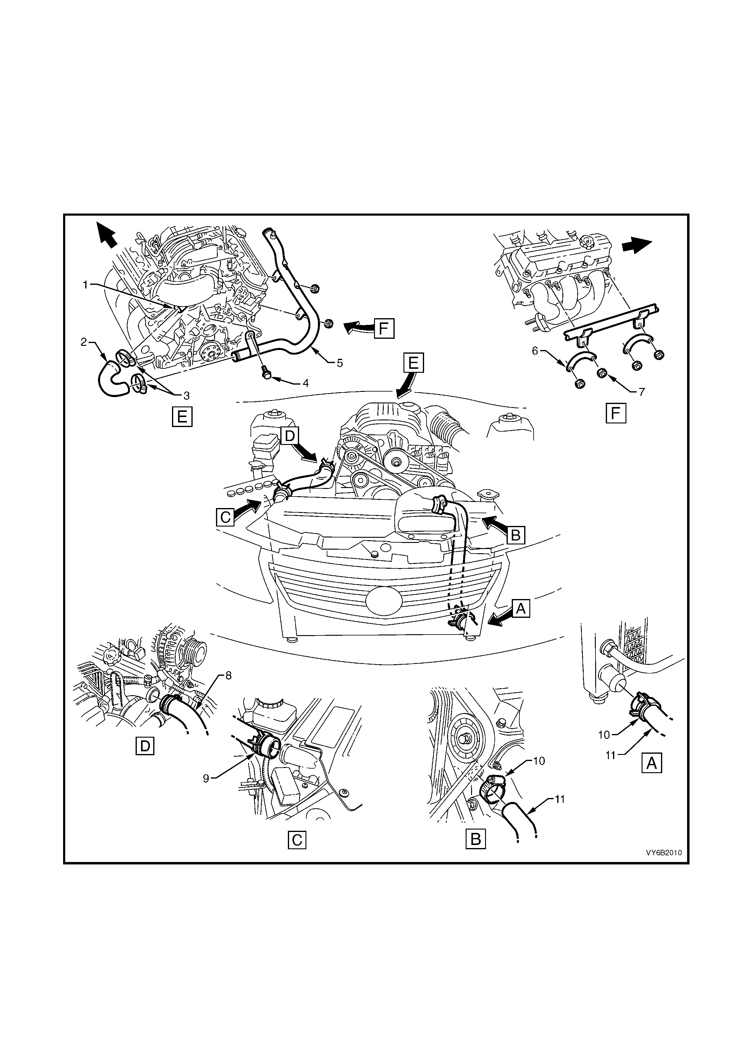
2.2 COOLING SYSTEM HOSES
SERVICE NOTES
1. Coolant hoses are installed as shown in the following illustration.
2. Hose connections should be thoroughly cleaned before installing any new hose.
3. Following hose/s ins tallation, always ref ill the cooling system with the cor rect type and concentration of coolant.
Refer to 2.2 CHECKING AND FILLING COOLING SYSTEM in Section 6B1-2 ENGINE COOLING – V6
SUPERCHARGED ENGINE in the VT Series I Service Information.
CAUTION: Always wear protective safety glasses when working with spring type hose clamps. Failure to do
so could result in eye injury.
Figure 6B2-4
Legend
1. Coolant Outlet
2. Coolant Outlet Hose
3. Hose Clamps
4. Screw
5. Radiator Inlet Pipe
6. Plate
7. Plate Nut
8. Radiator Inlet Hose
9. Radiator Inlet Hose Clamps
10. Radiator Outlet Hose Clamps
11. Radiator Outlet Hose
2.3 COOLING FAN AND SHROUD ASSEMBLY
REMOVE
1. Disconnect the battery ground lead.
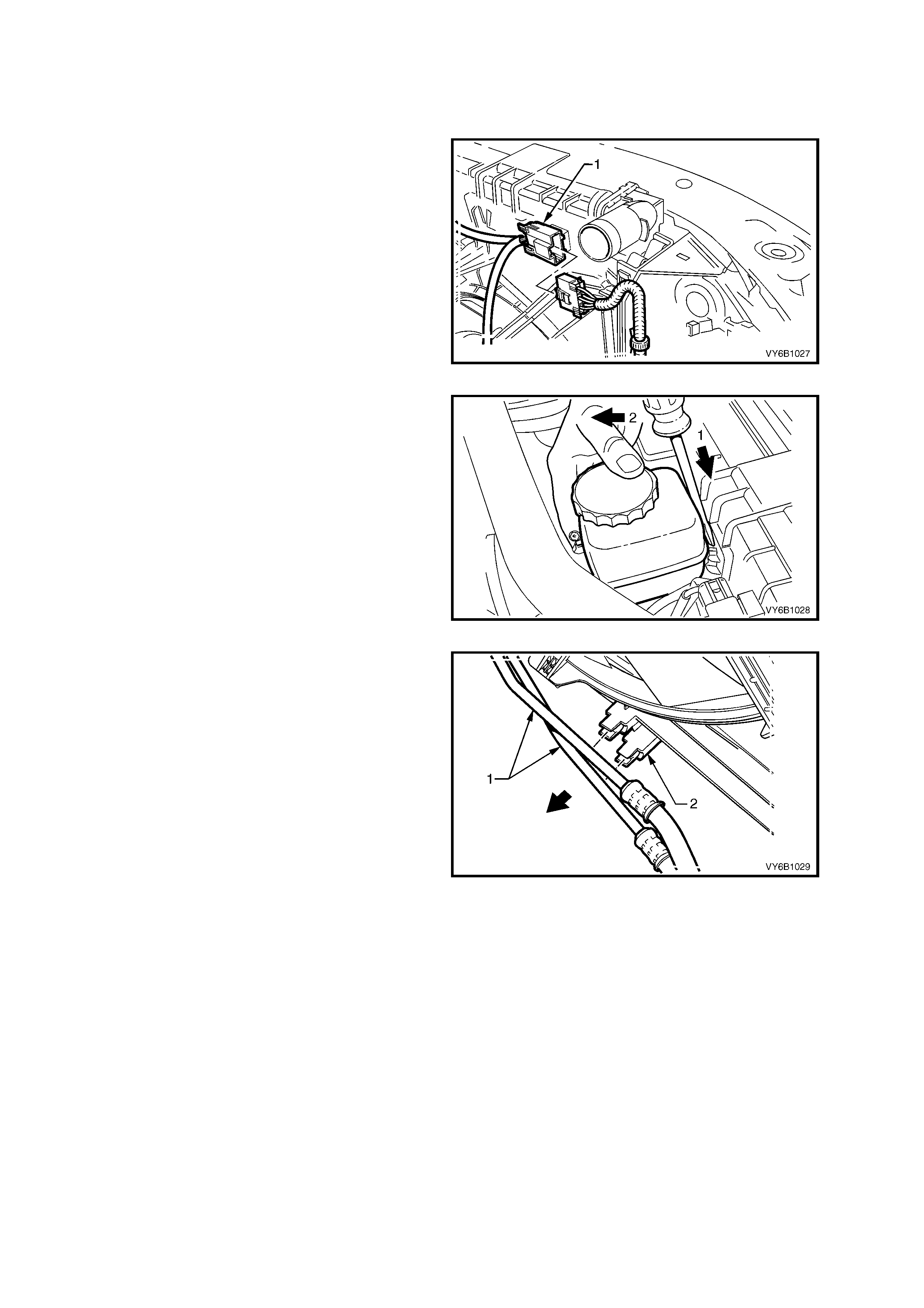
2. Depress the tang on the main wiring harness-
to-cooling fan motor wiring harness connector
and separate the connector.
Figure 6B2-5
3. Remove the power steering pump reservoir
from its clip on the radiator shroud, using a
screwdriver to lever the clip lock, enabling
removal of the reservoir. Lay the reservoir and
hoses to one side.
Figure 6B2-6
4. Release each of the automatic transmission
cooling pipes (if fitted) fr om the integral clips on
the fan shroud.
Figure 6B2-7
5. Release the fan shroud to radiator clips by
holding one of the lugs (1) out with the fingers
of one hand while lifting the shroud with the
other. Repeat this operation to release the
second side.
Figure 6B2-8
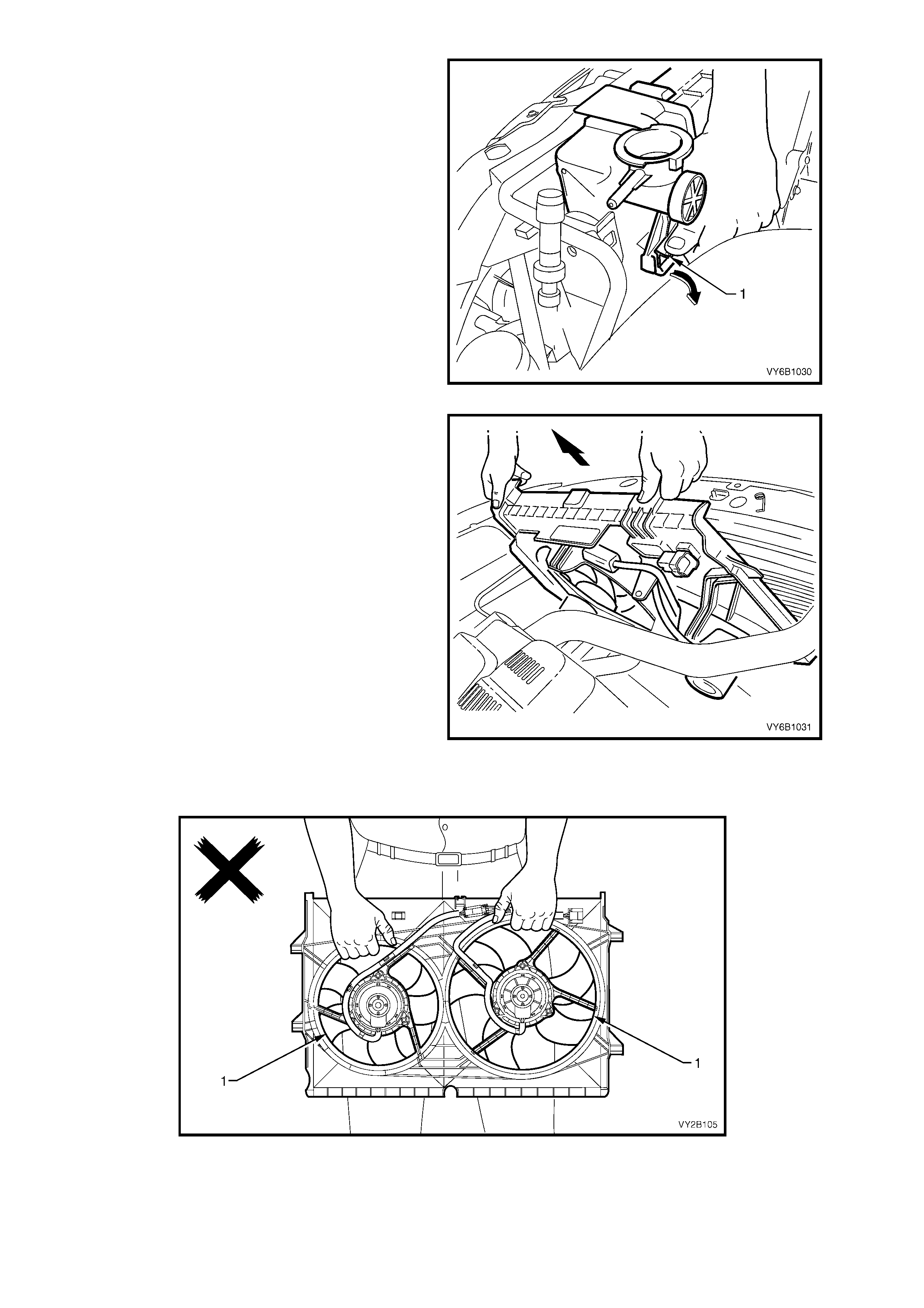
6. Lift the fans and shroud assembly from the
engine bay.
Figure 6B2-9
IMPORTANT: When rem oving, transpor ting or installing the f an ass em bly, do not grasp the assem bly by the fan
rings (1) as this may bend the fan motor shafts and cause fan vibrations.
Figure 6B2-10
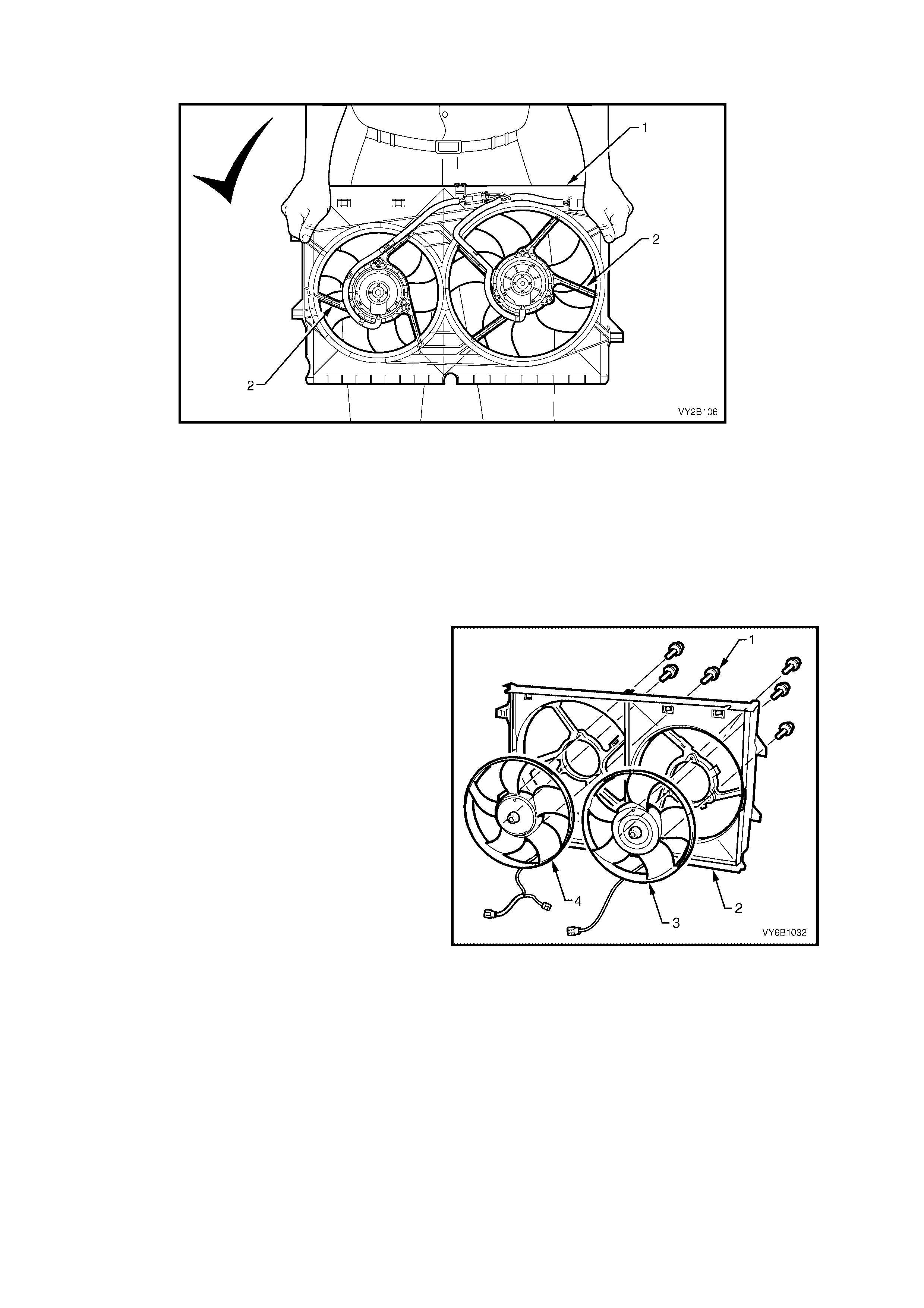
When handling the fan assembly, always hold the assembly at the fan shroud (1) or fan motor mounting
struts (2).
Figure 6B2-11
REINSTALL
Installation of the cooling fan and shroud assembly is the reverse of removal procedures, noting the following points:
1. Ensure that the fan and shroud assembly-to-radiator attaching clips are fully engaged.
2. Ensure that both automatic transmission cooling pipes (if fitted) are installed into the shroud clips.
3. Check the cooling fan operation and rotation direction of the cooling fans.
DISASSEMBLE
1. Remove the cooling fan and shroud assembly as previously described.
IMPORTANT: The fans (3 and 4) are not to be
separated from the fan motor. The assembly is
carefully balanced during manufacture and,
duplicating this balance on reassembly, is not
possible.
2. Remove motor assembly wiring harness from
the integral clips that form a part of the shroud
(2).
NOTE: Separate the intermediate wiring harness
connector.
3. Remove screws (1) attaching the motor
assembly (to the shroud (2), then remove the
motor, fan and wiring (3, 1and 4) from the
shroud.
Figure 6B2-12
REASSEMBLE
Reassembly is the reverse of disassembly procedures, noting the following points:
1. Tighten the motor-to-shroud attaching screws securely but do not over-tighten.
2. Install the motor wiring harness-to-shroud attaching clips. Install the intermediate connector.
3. Install the cooling fan and shroud assembly as previously described.
2.4 RADIATOR
REMOVE
1. Allow the engine to cool to ambient temperature (less than 50°C), then remove the radiator cap.
CAUTION: Do not remov e the rad iator cap w hile th e engine co olant t emperature is abov e 50 °
°°
°C, as personal
injury may result.
2. Disconnect the battery ground lead.
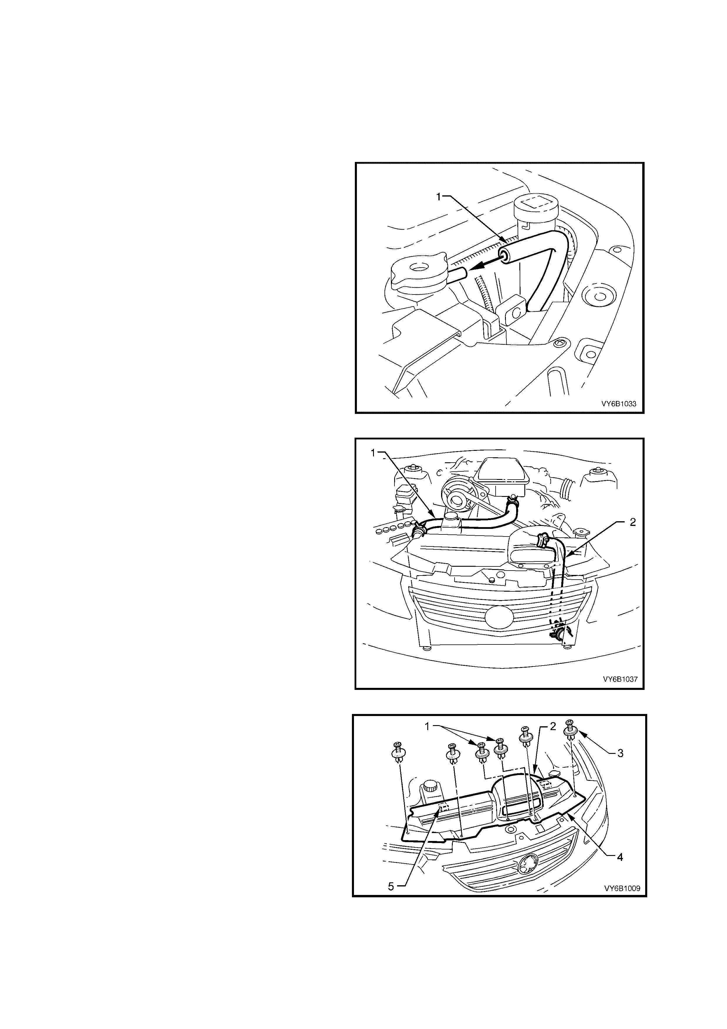
3. Remove the c oolant overflow hose (1) f rom the
radiator filler neck connection.
Figure 6B2-13
4. Remove the radiator lower hose (2) from the
radiator connection, allowing the coolant to
drain into a suitable sized and clean drain tray.
IMPORTANT: Refer to item No. 4 in 2.1 SERVICE
NOTES in this Section regarding the collection of
the drained coolant.
CAUTION: Always wear protective safety
glasses when working with spring type hose
clamps. Failure to do so could result in eye
injury.
5. Remove the radiator upper hose (1) from the
radiator.
Figure 6B2-14
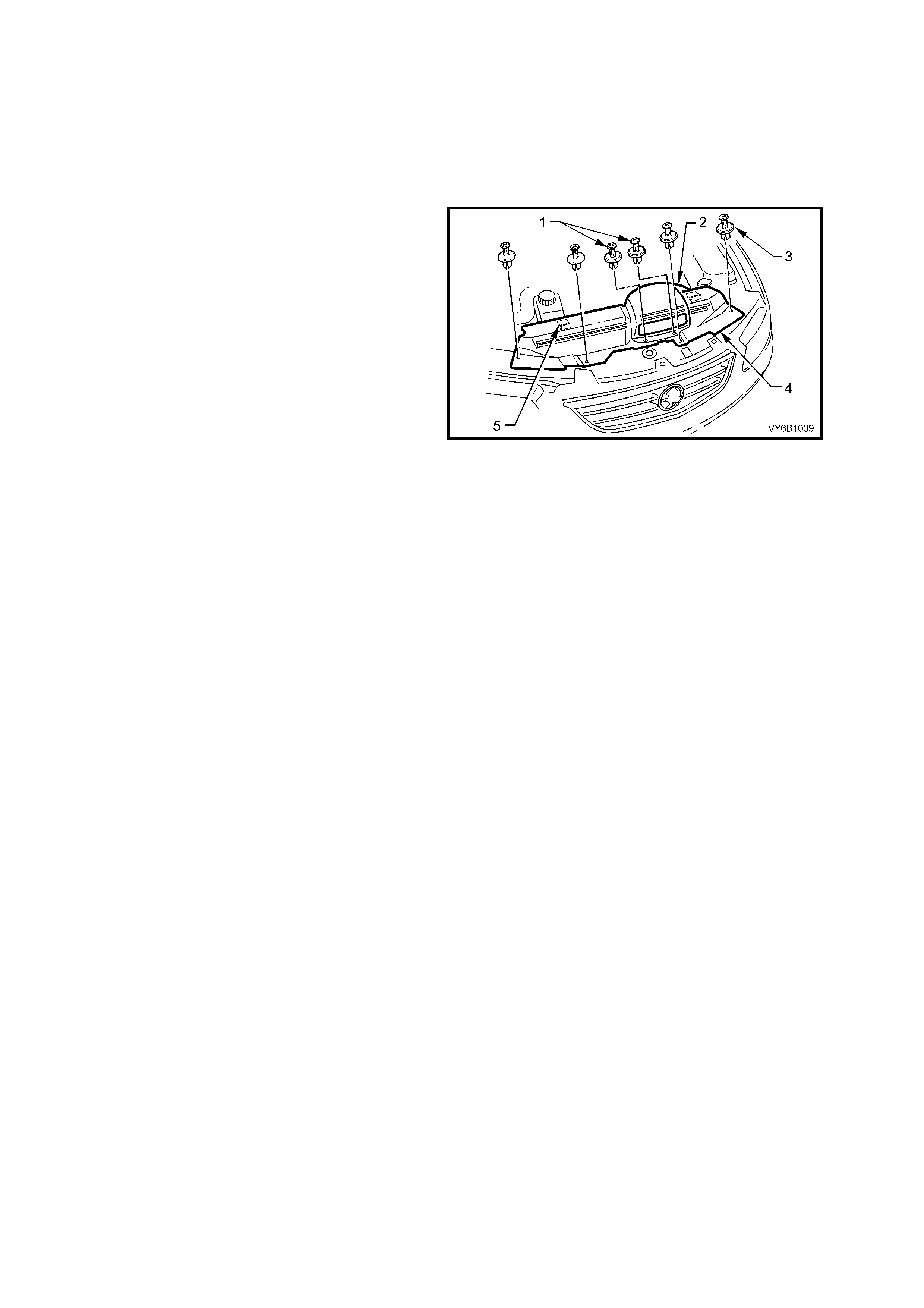
6. Remove the cold air intake duct and radiator
shroud retainer s (1 and 2) . Remove the cold air
intake duct (2), then disengage the shroud
locating tabs (5) by pulling the shroud (4)
towards the front of the vehicle, prior to
removal.
7. Disconnect the retainer clip securing the high
pressure air conditioning pipe to the top of the
front upper panel assembly on the left-hand
side.
Figure 6B2-15
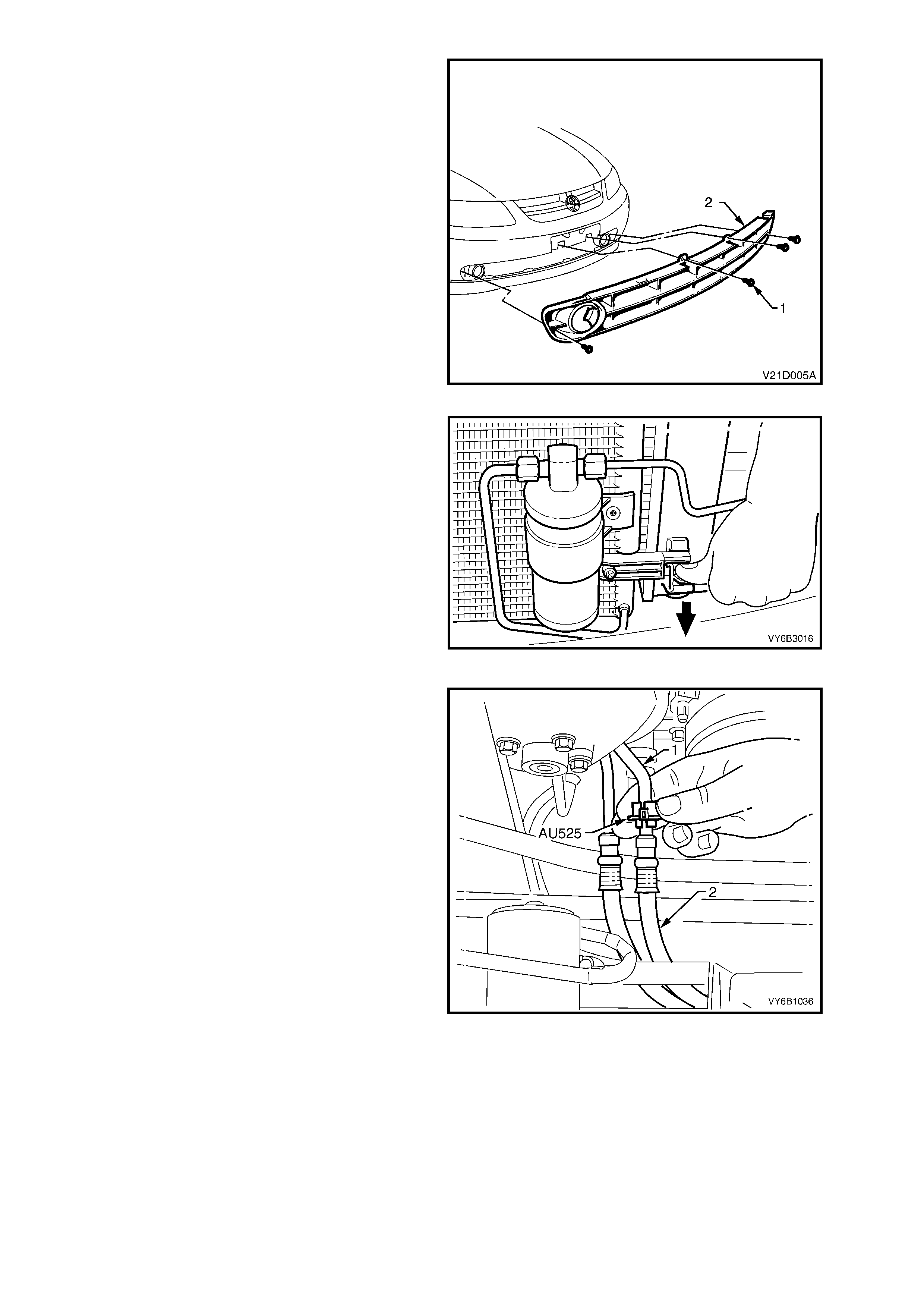
8. Remove the vehicle licence plate.
9. Remove the f our screws (1) r etaining the lower
air intake grille (2) to the front facia.
10. Flex the upper edge of the lower air intake grille
to disengage the four retaining tabs and four
locating tabs from the front bumper bar facia.
11. Flex the lower edge of the lower air intak e grille
to disengage the four retaining tabs and five
locating tabs from the front bumper bar facia.
12. Remove the lower air intake grille from the
vehicle.
Figure 6B2-16
13. Working through the lower air intake grille
opening, release one of the clips securing the
condenser to the radiator (bold arrow) by
pressing down on the lug while lifting the
condenser assembly with the other. Repeat for
the other side.
NOTE: The condens er m us t be separated f rom the
radiator ass embly. This ac tion will allow the radiator
removal without having to open any refrigerant
lines.
14. Once released, pull the condenser assembly
forward to clear the radiator mounting lugs.
Figure 6B2-17
15. Disconnect the transmission oil cooler line
quick connect fittings, using Tool No. AU525:
a. Open release tool AU525, then close and
clip around the pipe to be disconnected.
b. While holding the flexible hose with one
hand, push the tool into connection (1), to
release, then pull back on the pipe (2).
Plug both pipe openings and hos es to minim is e
fluid loss and prevent foreign matter entry.
Figure 6B2-18
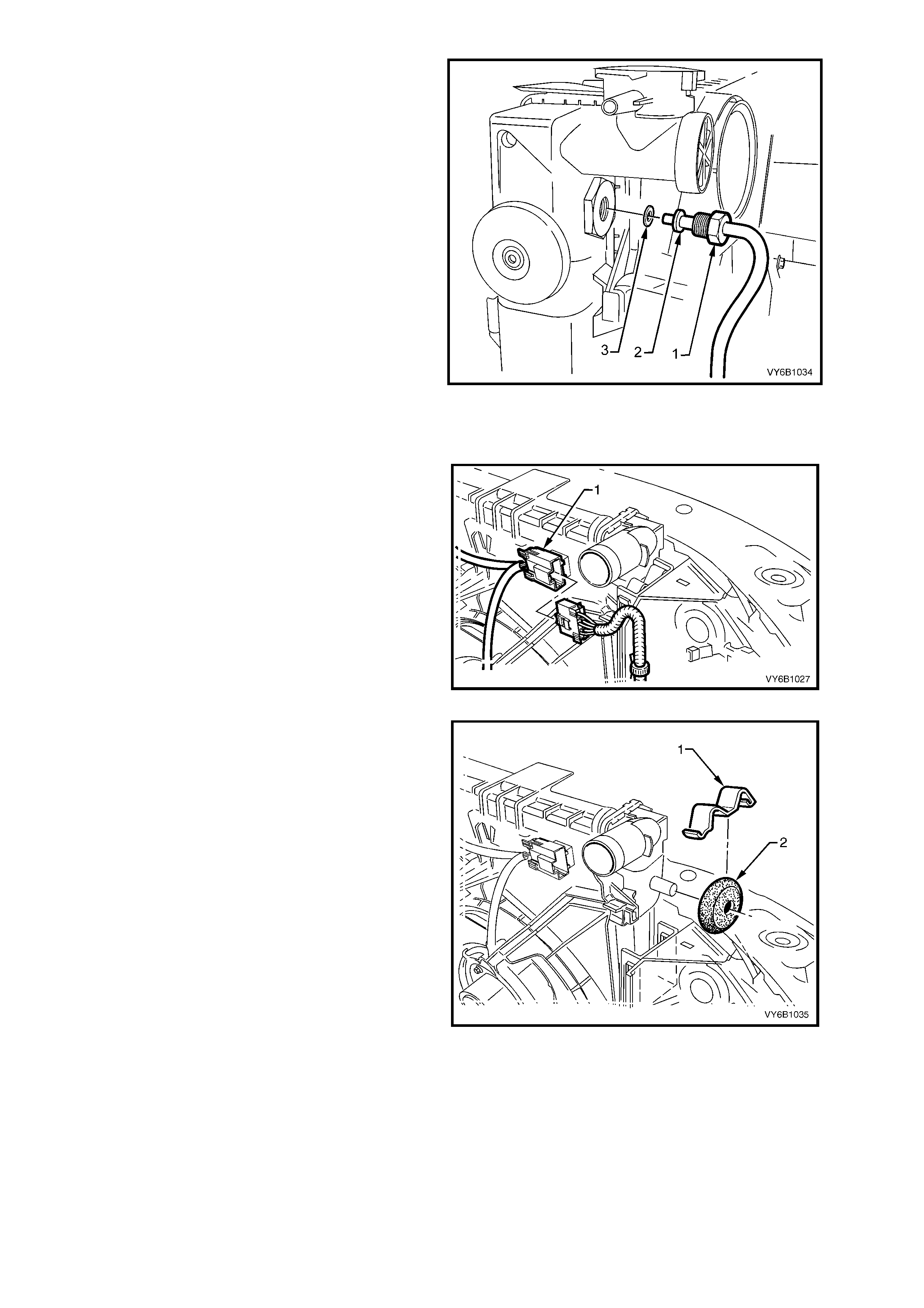
NOTE: If Tool No. AU525 is not available, the
cooler pipes can be disconnected from the cooler,
in the left side radiator tank using the following
method:
c. Using a suitable set spanner, loosen the
cooler pipe tube nut (1), then remove,
taking care not to lose the sealing washer
(3). Plug both open ends to prevent fluid
loss and/or dirt entry.
d. Repeat for the second pipe/hose assembly.
e. Before reinstalling each pipe (2) into the
cooler, carefully inspect the pipe sealing
washer (3). If the centre, silicone portion
shows signs of distress or damage, it must
be replaced.
f. Remove the plugging from the pipe and
fittings, fit the sealing washer (3) to the
cleaned pipe (2) and install into the cooler.
g. Install the tube nut (1) and tighten to the
correct torque specification.
Figure 6B2-19
16. Depress the tang on the main wiring harness-
to-cooling fan motor wiring harness connector
(1) and separate the connector.
Figure 6B2-20
17. Using a screwdriver, compress and lever out
the radiator retaining clips (1) from the radiator
upper mounting brackets.
18. Lift the radiator upwards out of the lower
insulators and remove the radiator from the
vehicle.
IMPORTANT: If removing the fan and shroud as
an assembly to the radiator, do not use the fan
outer rings, as lifting devices, as this will bend the
fan motor shafts causing unnecessary vibration,
when the vehicle is placed back in service.
19. Remove upper (2) and lower insulators from
the radiator.
20. If required, separate the fan and shroud
assembly from the radiator by releasing the two
locking tangs at the upper locations, then slide
the fan shroud up and clear from the radiator.
Figure 6B2-21
REINSTALL
Installation of the radiator is the reverse of removal procedures, noting the following points:
1. Before installing the radiator, inspect the core to ensure that there is no foreign matter in the core fins. Clean out
between the core fins with compressed air, blowing from the rear to the front.
2. Ensure that the radiator lower mounting pins are correctly located in the lower insulators.
3. Ensure that the upper insulators are installed on the upper mounting pins and the radiator retainers are
installed.
4. Install the radiator upper shroud (4) by first
locating each of the two locating tabs (5), then
securing with four plastic fasteners (3).
5. Install the cold air intake duct, securing with
two plastic fasteners (1).
Figure 6B2-22
6. Refill the cooling system, refer 2.2 CHECKING AND FILLING COOLING SYSTEM in Section 6B1-2 ENGINE
COOLING – V6 SUPERCHARGED ENGINE in the VT Series I Service Information.
7. Check for coolant leaks, refer to 2.7 PRESSURE TESTING in Section 6B1-1 ENGINE COOLING – V6
SUPERCHARGED ENGINE in the VT Series I Service Information.
8. Check the cooling fan operation and the fan rotation direction.
RADIATOR REPAIR PROCEDURE
The radiator repair procedures for MY2003 V2 Series Update Models carry over from VT Series I Models. For
inform ation regarding the radiator r epair procedures f or the radiator as fitted to MY2003 V2 Series Update Models ,
refer to RADIATOR REPAIR PROCEDURE, 2.13 RADIATOR in Section 6B1-1 ENGINE COOLING – V6 ENGINE
in the VT Series I Service Information.

3. SPECIFICATIONS
General
Radiator cap pressure rating................................... 135 kPa
Cooling system capacity.......................................... 12 Litres
Coolant corrosion inhibitor....................................... 'New Formula Long Life All Seasons Coolant'
Thermostat
Type ........................................................................ Power element (wax pellet)
Start to open............................................................ 89° – 93° C
Fully open at............................................................ 106° C max
Coolant Pump
Type ........................................................................ Centrifugal
Drive........................................................................ Multi-Vee Serpentine Belt
Bearing type ............................................................ Double Row Ball Bearing
Radiator
Core type................................................................. Aluminium crossflow core
Overall width (including side tanks)......................... 847 mm
Core width............................................................... 674 mm
Overall height.......................................................... 507 mm
Core height.............................................................. 430.5 mm
Core thickness ........................................................ 16 mm
Plastic tanks............................................................ Nylon 6,6 (30% Glass filled)
Radiator Hoses
Lower
Number and type................................................ One, Moulded
Inside diameter................................................... 38.5 mm
Upper
Number and type................................................ One, Moulded
Inside diameter................................................... 34.0
Small Engine Cooling Fan (Right-Hand Side)
Number of blades.................................................... 8
Spacing ................................................................... Symmetrical
Material.................................................................... Nylon 6,6 (25% Glass filled)
Diameter.................................................................. 268 mm
Electric motor drive ................................................. 120 Watts (nominal)
Speed (with 12 volts applied, Radiator and
Condenser installed – Stage 1 ........................ OFF
– Stage 2 ........................ 2,350 ± 150 rpm
Large Engine Cooling Fan (Left-Hand Side)
Number of blades.................................................... 8
Spacing ................................................................... Symmetrical
Material.................................................................... Nylon 6,6 (25% Glass filled)
Diameter.................................................................. 370 mm
Electric motor drive ................................................. 160 Watts (nominal)
Speed (with 12 volts applied, Radiator and
Condenser installed – Stage 1 ........................ 1,900 ± 150 rpm
– Stage 2 ........................ 1,900 ± 150 rpm

4. TORQUE WRENCH SPECIFICATIONS
Nm
Coolant Hose Clamps........................................................... 3
Engine Dress Cover Attaching Nut....................................... 5
Rear Engine Cover Bracket Assembly Securing Bolts ......... 18
Oil Cooler to Side Tank Nut.................................................. 25
Knock Sensor........................................................................ 20
Oil Cooler Pipe to Oil Cooler................................................. 25
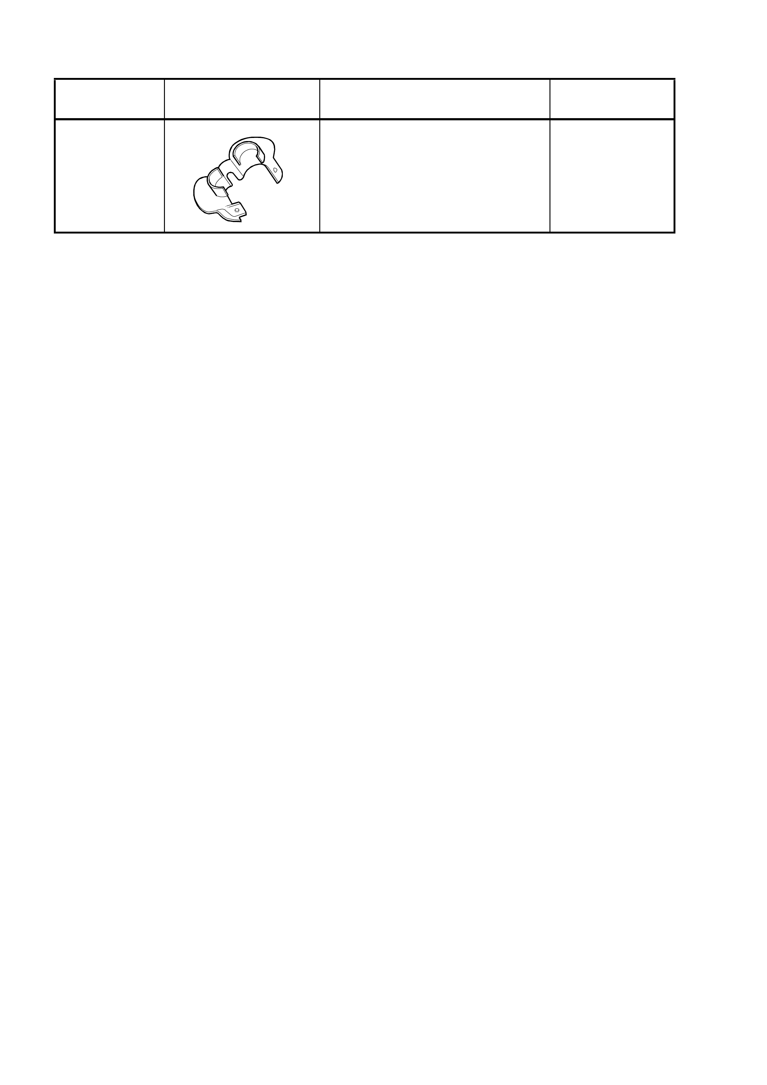
5. SPECIAL TOOLS
TOOL
NUMBER ILLUSTRATION DESCRIPTION CLASSIFICATION
AU525
A
U525
QUICK CONNECT RELEASE TOOL
Use to release the quick connect
fittings on the automatic transmission
fluid cooler lines at the radiator end,
when the vehicle is so equipped.
Previously released.
Mandatory