
SECTION 7C - HYDRA-MATIC 4L60-E
AUTOMATIC TRANSMISSION
IMPORTANT
Before p erf orming any Service Operatio n o r oth er pro cedu re describ ed in th is Sectio n, refer t o Sect ion 00
CAUTIONS AND NOTES for correct workshop practices with regard to safety and/or property damage.
1. GENERAL INFORMATION
SPACER PLATE AND GASKETS
1.1 MY2003 TRANSMISSION
TRANSMISSION IDENTIFICATION – MY2003
PRESSURE CONTROL SOLENOID
BOOST VALVE BUSHING
1.2 ‘HAD’ MODEL TRANSMISSION
3-4 CLUTCH
2. ELECTRICAL DIAGNOSIS
3. HYDRAULIC/MECHANICAL DIAGNOSIS
3.1 LINE PRESSURE CHECK
PRELIMINARY INFORMATION
PROCEDURE
4. ON-VEHICLE SERVICING
4.1 COOLER PIPE QUICK-CONNECT FITTING
REMOVE
REINSTALL
5. UNIT REPAIR
6. SPECIAL TOOLS
Techline
Techline
Techline
Techline
Techline
Techline
Techline
Techline
Techline
Techline
Techline
Techline
1. GENERAL I NFORMATION
The Hydra-Matic 4L60-E automatic transmission fitted to V2 Series Models carries over from VX Series I Models,
noting the following:
• Effective from a Julian build date (refer to Figure 7C1-2), of ‘1HND002 A 0000001’, the Torque Converter
Clutch ( TCC) Regulator Valve exhaust por t was reduced in s ize. T his change has m eant that, not only has the
control valve body changed but the spacer plate and both gas kets have also been m odif ied. The ear ly and later
gaskets and spacer plates can be physically identified as shown in Figure 7C-1.
• With the introduction of the Model Year 2003 Hydra-Matic 4L60-E automatic transmission into V2 Series Models
during O ctober 2002, the press ure control solenoid and boos t valve bushing were revised. As the design of the
wiring harness connec tor for the pr essure contr ol solenoid is also new, the internal trans mis sion wiring harness
also changes.
• With the introduction of the Model Year 2003 Hydra-Matic 4L60-E automatic transmission into V2 Series Models
during October 2002, new quick-connect fittings have replaced the flare nut fittings where the transmission
cooler pipes connect to the radiator and transmission.
• A new HAD (heavy duty) transmission was introduced into V2 Series Models fitted with the GEN III V8 engine
during October 2002.
Apart fr om the inf orm ation regarding the identific ation of the early and late type control valve body spac er plate and
gasket, the general information provided in this Section only applies to the MY2003 transmissions introduced into
V2 Series Models during October 2002. For the general information relating to the Hydra-Matic 4L60-E automatic
transmissions fitted to V2 Series Models not covered in this Section, refer to Section 7C1 – HYDRA-MATIC 4L60-E
AUTOMATIC TRANSMISSION – GENERAL INFORMATION, in the VX Series I Service Information.
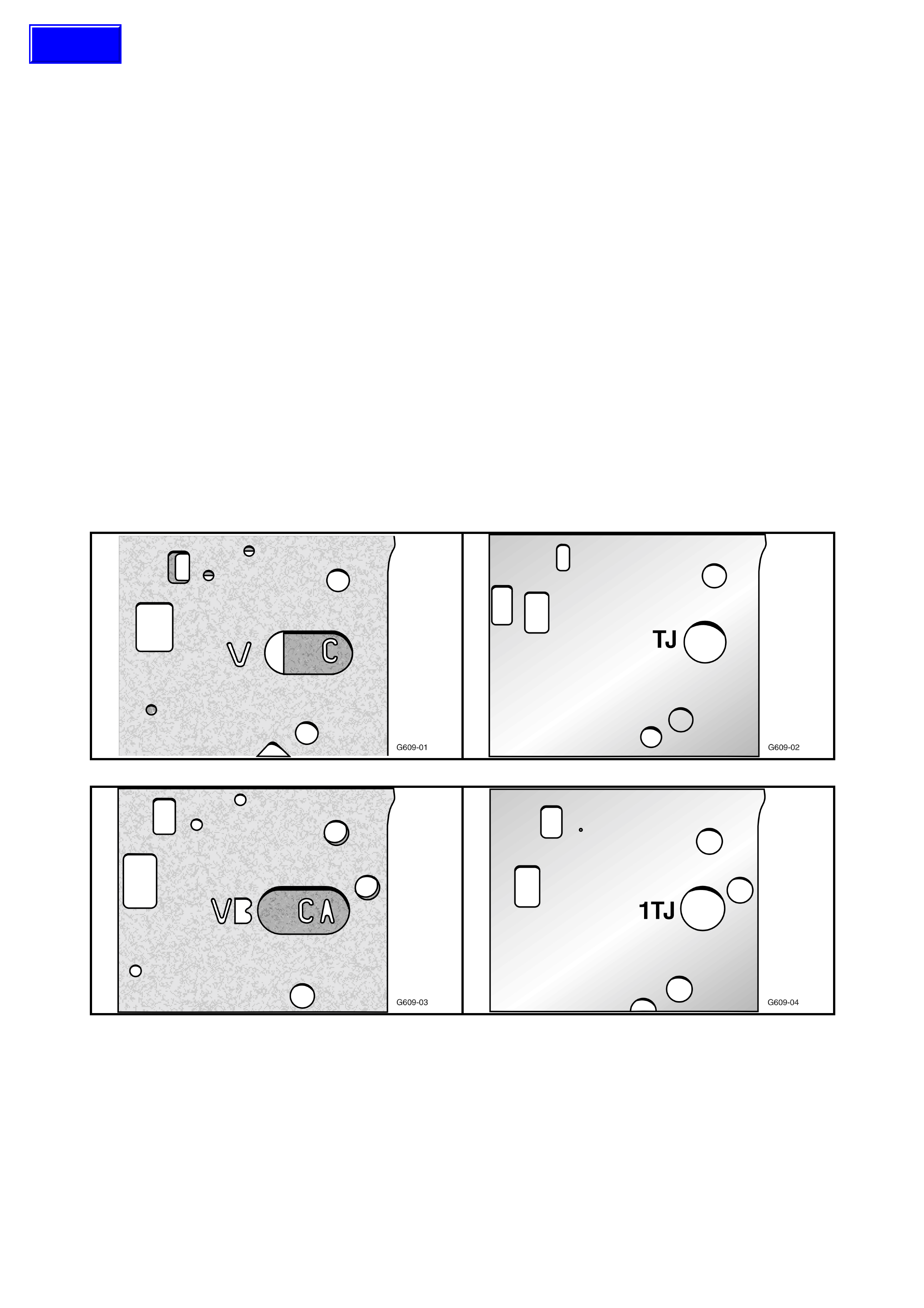
SPACER PLATE AND GASKETS
Control Valve Body Gaskets Control Valve Body Spacer Plate
A B
C D
Figure 7C-1
Legend:
A. Pre-Change Gaskets – ‘V’ is the Valve body side, ‘C’ is the Case Gasket
B. Pre-Change Spacer Plate – Identification in an embossed ‘TJ’
C. Post-Change Gaskets – ‘VB’ is the Valve body side, ‘CA’ is the Case Gasket
D. Post-Change Spacer Plate – Identification in an embossed ‘1TJ’
Techline
1.1 MY2003 TRANSMISSION
With the introduction of the MY2003 release of the 4L60-E automatic transmission into V2 Series Models, the
following changes have been effected;
• The pressure control solenoid was revised.
• The boost valve bushing was revised.
• As the design of the wiring harness connector for the pressure control solenoid is also new, the internal
transmission wiring harness also changes
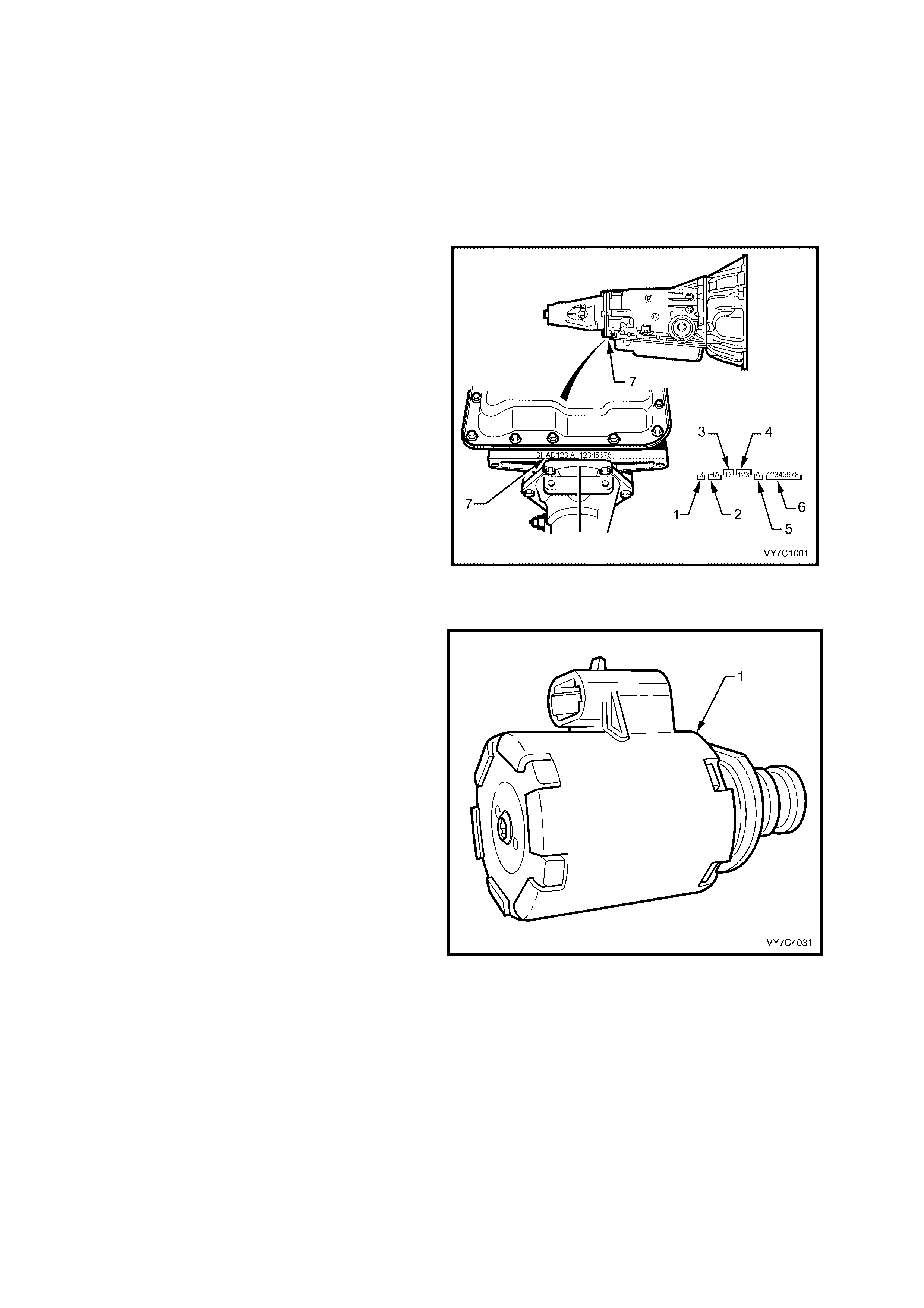
TRANSMISSION IDENTIFICATION – MY2003
The 4L60-E automatic tr ansm iss ion application and
identification can be determined from the stamping
in the rear of the transmission case, in the location
shown (7).
The coded number can be interpreted from the
following breakdown;
Model Year (‘3’ = 2003)
2. Model:
3.8 litre V6 S/C (L67)............... HN
5.7 litre GEN III V8 (LS1) ........ HA
3. Transmission Model Identifier (‘D’ = 4L60-E)
4. Julian Date (Day of the Year)
5. Shift Build ‘A’, ‘B’, ‘J’ = First Shift;
‘C’, ‘H’, ‘W’ = Second Shift
6. Individual Transmission Serial Number
Figure 7C-2
PRESSURE CONTROL SOLENOID (PCS)
The Pressure Control Solenoid (PCS) is a new
design.
As the design of the terminal connection is also
new, the internal transmission wiring harness also
changes.
With the change in the PCS, a change has been
effected in the line pressure that means a change
in the pressure checking procedure and results.
Refer to 3.1 LINE PRESSURE CHECK in this
Section for specific details.
Figure 7C-3
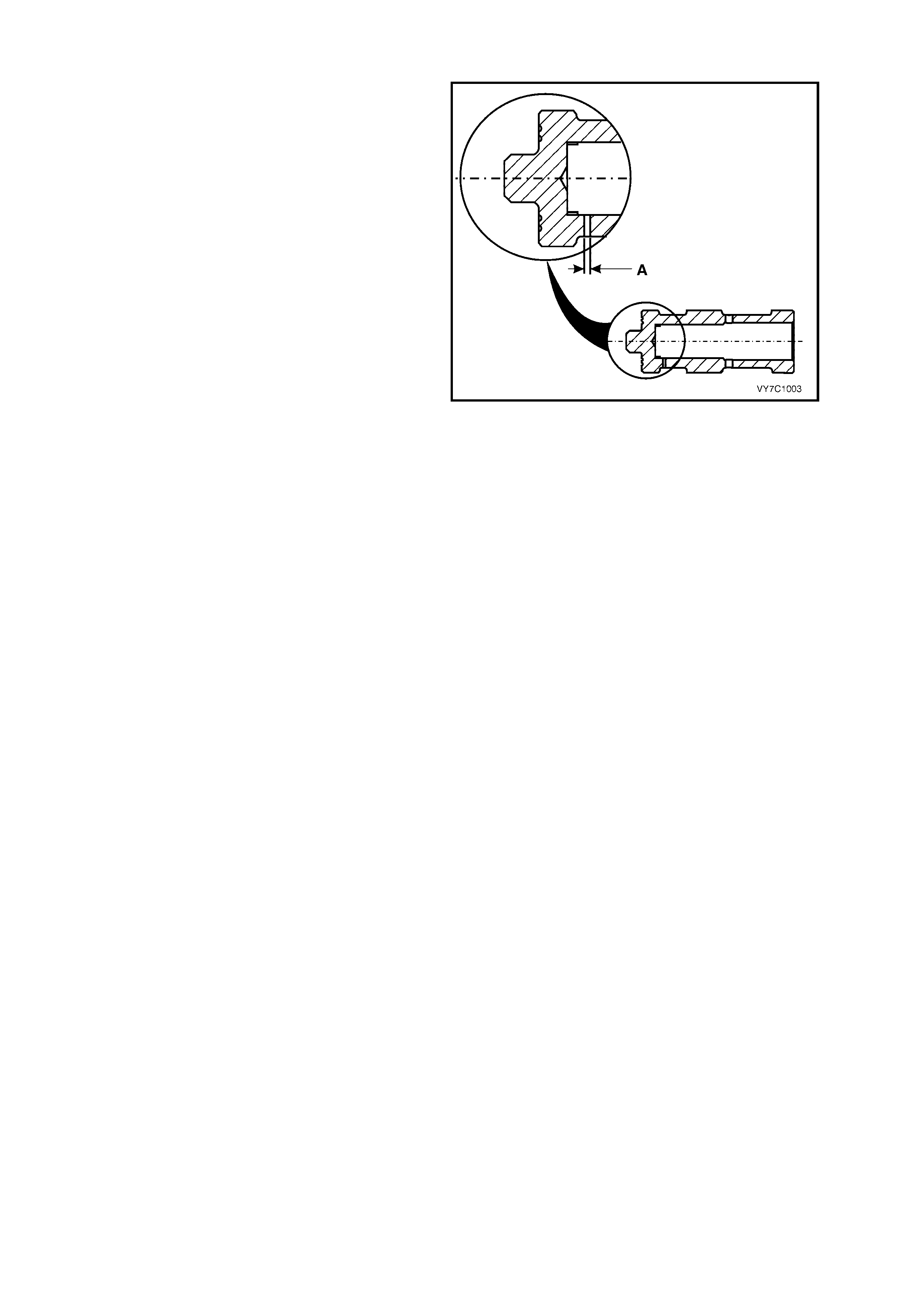
BOOST VALVE BUSHING
The orifice size (‘A’) in the boost valve sleeve,
(mounted in the oil pump housing) has been
reduced from a nominal 1.08 mm to 0.89 mm
(+0.07 mm/–0.06 mm), which affects the ATF
pressure boost characteristics of the valve.
Apart from this changed dimension, the bushing
has a new part number and has yellow dye applied
to it, for identification purposes.
Figure 7C-4

1.2 ‘HAD’ MODEL TRANSMISSION
To increase durability of the 4L60-E autom atic transm ission f itted to the GEN III V8 engine, the number of plates in
the 3-4 clutch pac k has been increas ed f r om six to s even plates. F or identification purposes , the transmission pref ix
has been changed from ‘HPD’ to ‘HAD’.
3-4 CLUTCH
The number of plates in the 3-4 clutch pack has been increased from six to seven plates. To achieve this result
without undergoing major internal component changes, the plates are thinner. This means that the same selective
plates can be used to achieve the same end float specification.
Apart from the change in part number, the HAD clutch plates can be physically identified by;
Composition plates – Thickness of new plates (1.62 ± 0.10 mm) and by one or more lightly coloured stripes
across the friction surfaces.
Steel plates – Thickness of new plates (2.42 +0.08 –0.07 mm).

2. ELECTRICAL DIAGNOSIS
The information regarding the electrical diagnosis of the automatic transmission as fitted to V2 Series Models
carries over from the information provided for VX Series Models, noting the following:
• Although there has been a revised pressure control solenoid wiring harness connector introduced with the
MY2003 automatic transmissions, the internal transmission harness layout remains unchanged.
For information relating to the electrical diagnosis of the Hydra-Matic 4L60-E automatic transmission fitted to V2
Series Models, refer to Section 7C2 – HYDRA-MATIC 4L60-E AUTOMATIC TRANSMISSION – ELECTRICAL
DIAGNOSIS, in the VX Series Service Information.
3. HYDRAULI C/ MECHANI CAL DIAGNOSIS
The information regarding the hydraulic/mechanical diagnosis of the automatic transmission as fitted to V2 Series
Models carries over from the information provided for VX Series Models, noting the following:
• A revised pressure control solenoid was introduced with the MY2003 automatic transmissions, resulting in a
new pressure checking procedure and results.
For information relating to the hydraulic/mechanical diagnosis of the Hydra-Matic 4L60-E automatic transmission
fitted to V2 Ser ies Models not c over ed in this Sec tion, r ef er to Sectio n 7C3 – HY DRA-MATIC 4L60-E AUTOM ATIC
TRANSMISSION – HYDRAULIC/MECHANICAL DIAGNOSIS, in the VX Series Service Information.
3.1 LINE P RE SSURE CHECK
PRELIMINARY INFORMATION
Line pressures are calibrated for two sets of gear ranges – Drive/Park/Neutral and Reverse. This allows the
transmission line pressure to be appropriate for two different pressure needs in different gear ranges:
Gear Range Line Pressure Range
Drive, Park or Neutral...... 380 – 1,300 kPa
Reverse........................... 440 – 2,235 kPa
Before performing a line pressure check, verify that the pressure control (PC) solenoid is receiving the correct
electrical signal from the PCM, as follows:
1. Install Tech 2. Refer to 3.1 CONNECTING TECH 2 TO THE VEHICLE in Section 0C - TECH 2, in the VX
Series I Service Information for the necessary procedure.
2. Start the engine and firmly apply the park brake.
3. Check for stored diagnostic trouble code/s (DTC) and in particular, for a pressure control solenoid DTC.
4. Rectify as necessary.
NOTE: The transmission may experience harsh, soft or mushy shifts for up to two days after this procedure.
PROCEDURE
1. Check engine and transmission fluid levels.
2. Check the manual linkage for correct adjustment and wear.
3. If not previously carried out, install Tech 2 to the vehicle. Refer to 3.1 CONNECTING TECH 2 TO THE
VEHICLE in Section 0C - TECH 2, in the VX Series I Service Information for the necessary procedure.
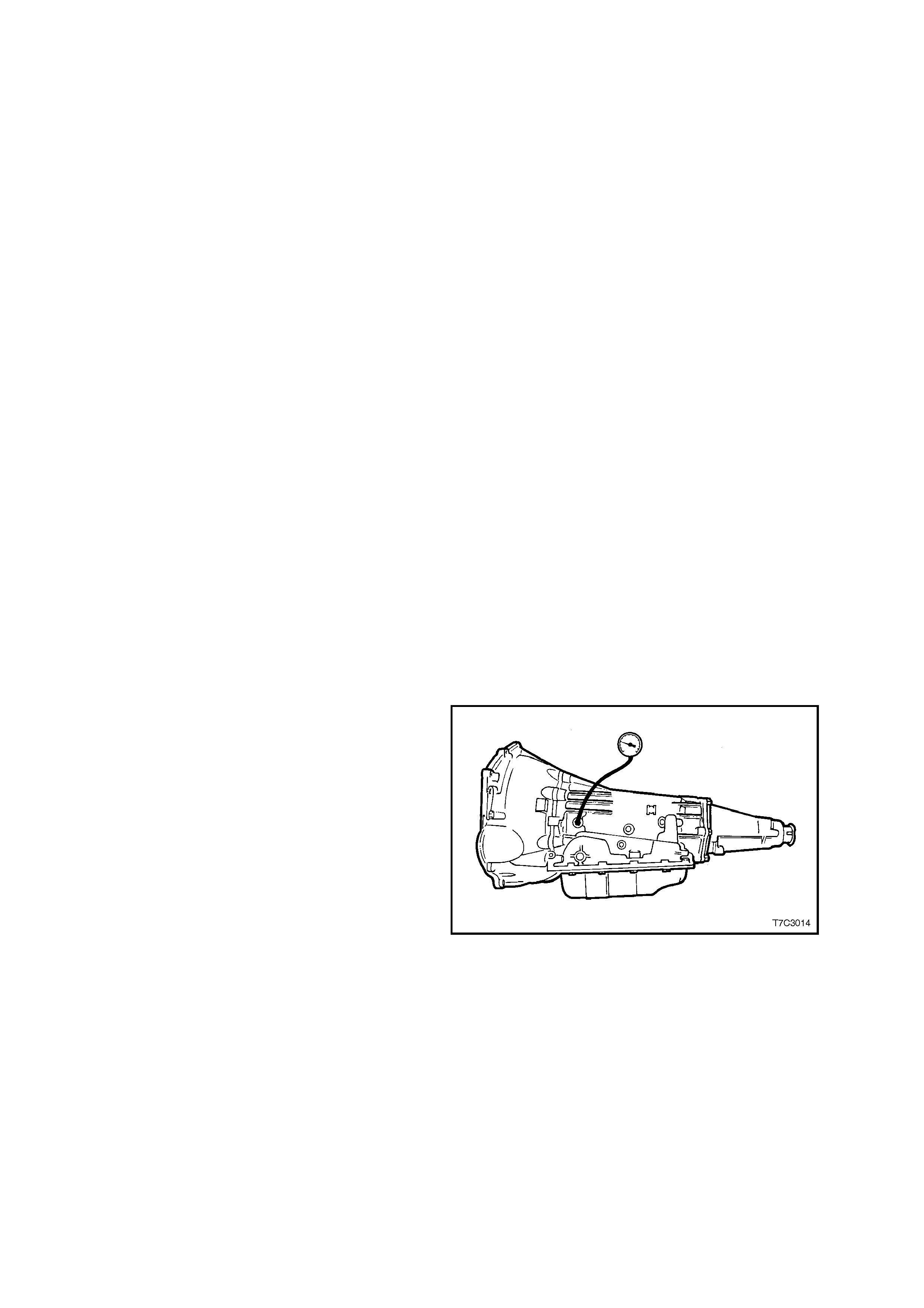
4. Install an oil pressure gauge such as Tool
J21867 or commercial equivalent, into the line
pressure tapping point on the transmission, as
shown.
5. Select ‘P’ (Park) range and firmly apply the
park brake.
6. Start the engine and allow to warm up, at idle.
7. Access ‘Miscellaneous Tests’ on Tech 2, then
the PCS CONTROL test.
8. Increase ACTUAL PCS in 0.1 Amp increments
on Tech 2 and read the corresponding line
pressure reading on the fluid pressure gauge.
(Allow the pressure to stabilise for 5 seconds
after each current change.
9. Compare the pressure readings against the line
pressures provided in the following chart.
IMPORTANT: Total test running time should not
exceed 2 minutes or transmission damage could
occur.
Figure 7C-5
NOTE 1: Pressures are to be taken at an engine speed of 1,500 rpm and a temperature of 66°C. Line pressure
drops as temperature increases.
NOTE 2: If pressure readings differ greatly from the line pressure chart, refer to the Diagnostic Section in either
Section 6C1 POWERTRAIN MANAGEMENT – V6 SUPERCHARGED ENGINE or Section 6C3 POWERTRAIN
MANAGEMENT – GEN III V8 ENGINE in the VX Series Service Information.
NOTE 3: T ech 2 is only able to control the PC solenoid in Park , and Neutral, with the vehicle stopped. This protects
the clutch packs from extremely high or low pressures in Drive or Reverse ranges.
Line Pressure (kPa)
Pressure Control Solenoid
Current (Amp) V6 Engine GEN III V8
Engine
0.00 1,261 – 1,399 1,369 – 1,507
0.10 1,257 – 1,395 1,356 – 1,494
0.20 1,233 – 1,371 1,334 – 1,472
0.30 1,201 – 1,339 1,299 – 1,437
0.40 1,139 – 1,277 1,229 – 1,367
0.50 1,055 – 1,193 1,143 – 1,281
0.60 921 – 1,059 1,016 – 1,154
0.70 818 – 956 868 – 1,006
0.80 649 – 787 693 – 831
0.90 439 – 577 481 – 619
1.00 379 – 517 333 – 471
1.10 339 – 477 —
4. ON-VEHICLE SERVICING
The information regarding the on vehicle servicing of the automatic transmission as fitted to V2 Series Models
carries over from the information provided for VX Series Models, noting the following;
• W ith the introduction of the MY2003 Hydra-Matic 4L60-E automatic transm ission into V2 Series Models during
October 2002, new quick-connect fittings have replaced the flare nut fittings where the transmission cooler
pipes connect to the radiator and transmission.
For inform ation r elating to on- vehicle s ervic ing of the Hydra-Matic 4L60-E automatic trans mission f itted to V2 Series
Models not covered in this Section, ref er to Section 7C4 – HY DRA- M AT IC 4L60-E AUTOM ATIC TRANSMISSION
– ON-VEHICLE SERVICING, in the VX Series Service Information.
4.1 COOLER PIP E QUICK-CONNECT FITTING
REMOVE
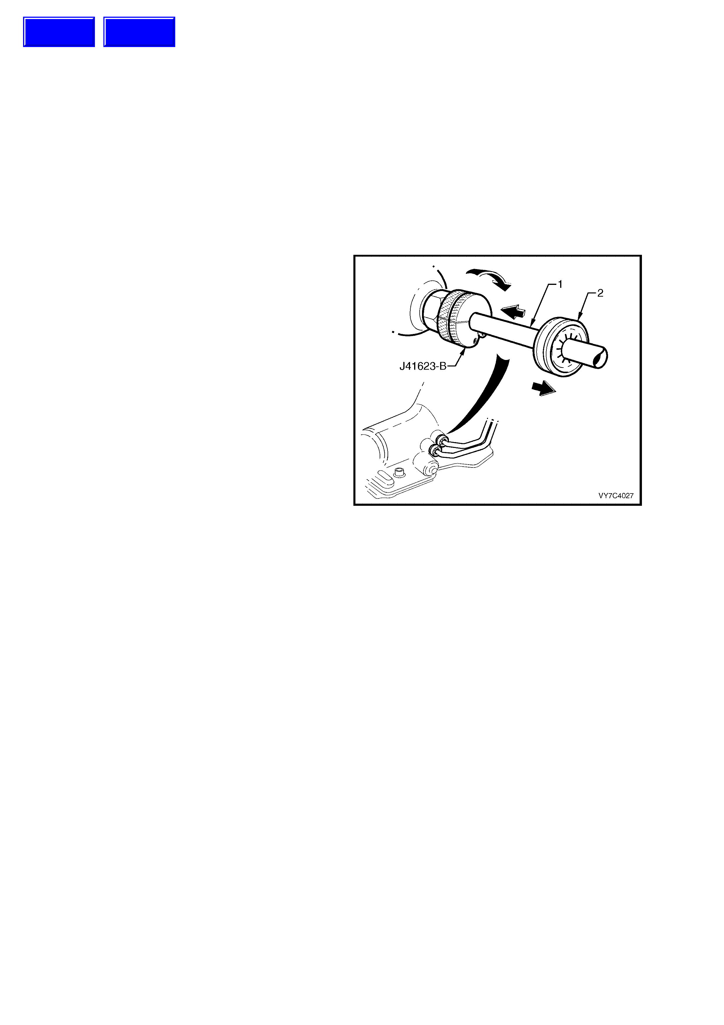
1. Release the verifier disc (2) by pulling back
with the fingertips, then slide back down the
cooler pipe (1).
2. Open the cooler line release Tool J41623-B
and slip over the cooler pipe to be
disconnected from the transmission, above the
verifier disc (2), as shown.
3. Slide the release tool along the pipe to engage
with the quick-connect fitting.
4. While pushing inwards, rotate the tool about
one sixth of a turn to release the spring clip
holding the pipe.
5. With the release tool held in this position, pull
back on the cooler pipe to release.
6. Repeat this process with the remaining pipe
and quick-connect fitting.
7. Plug all openings to prevent foreign matter
entry.
Figure 7C-6
REINSTALL
1. Remove plugs from cooler pipes and quick
connect fittings, wipe the pipes clean, then
smear with clean automatic transmission fluid.
2. Push each pipe into its respective quick
connect fitting.
3. Attempt to pull the pipe free to ensure correct
engagement.
4. Slide each verifier dis c up to the quick c onnect
fitting. If it engages with the fitting, then the
pipe has been correctly installed.
Techline
Techline

5. UNIT REPAIR
The information regarding the hydraulic/mechanical diagnosis of the automatic transmission as fitted to V2 Series
Models carries over from the information provided for VX Series Models, noting the following:
• Eff ect ive f rom a Julian build date of ‘1HX D002 A 0000001’, the Torque Converter Clutc h (TCC) Regulator Valve
exhaust port was r educed in size. This change has m eant that, not only has the control valve body changed but
the spac er plate and both gask ets have also been m odified. T he early and later gaskets and s pacer plates c an
be physically identified as shown in Figure 7C-1.
• W ith the introduction of the MY2003 Hydra-Matic 4L60-E automatic transm ission into V2 Series Models during
October 2002, the pressure control solenoid and boost valve bushing was revised. As the design of the wiring
harness connector for the pressure control solenoid is also new, the internal transmission wiring harness also
changes.
• For the HAD transmission f itted to V2 Series Models with the GEN III V8 engine, the num ber of plates in the 3-4
clutch pack has been increased from six to seven plates. To achieve this result without undergoing major
internal com ponent changes, the plates are thinner. T his means that the same selective plates can be used to
achieve the same end float specification.
For inf ormation relating to unit repair of the Hydra- Matic 4L60-E automatic transmiss ion fitted to V2 Series Models,
refer to Section 7C5 – HYDRA-MATIC 4L60-E AUTOMATIC TRANSMISSION – UNIT REPAIR, in the VX Series
Service Information.
6. SPECIAL TOOLS
TOOL NUMBER ILLUSTRATION DESCRIPTION TOOL
CLASSIFICATION
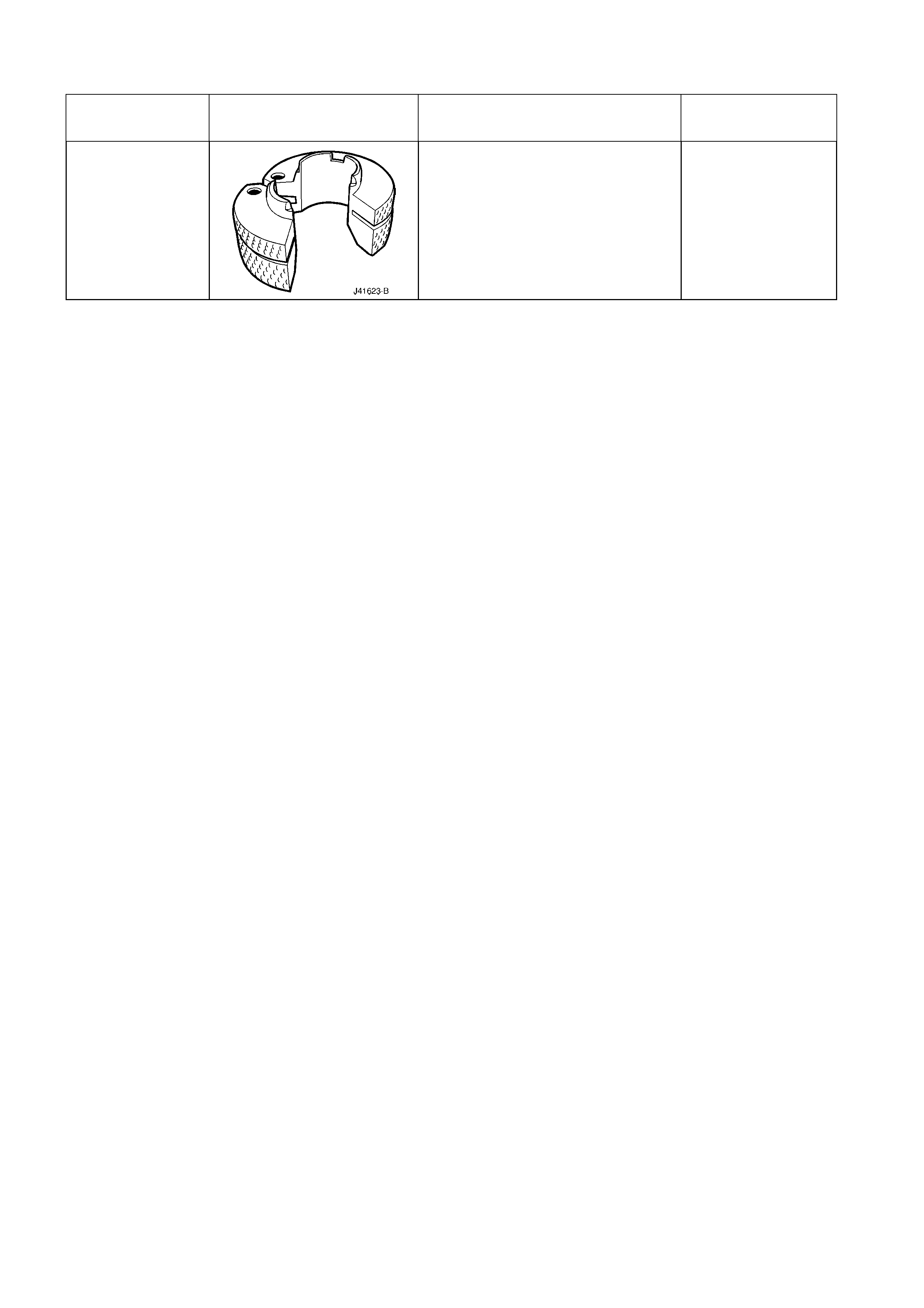
J41623-B
COOLER PIPE QUICK-CONNECT
RELEASE TOOL
New release.
Mandatory