
SECTION 8A1 - FUEL TANK
IMPORTANT
Before performing any Service Operation or other procedure described in this Section, refer to Section
00 CAUTIONS AND NOTES for correct workshop practices with regard to safety and/or property
damage.
1. GENERAL INFORMA TION
The f uel system as fitted to V2 Series Mod els carries over fr om VX Seri es II Models, n oting the f ollowing ch anges
to suit the coupe body style:
• Due to the red uc ed rear o v erhang , the right-hand fuel tank m ounting s tr ap has be en rev ised. The hook and slot
mounting at the rear of the strap has been replaced by a bolt type attachment.
• The stud securing the rear of the left-hand mounting strap has been revised from 10 mm to 12mm diameter.
• A unique fuel filler door and cable assembly is fitted.
For information relating to the fuel system as fitted to V2 Series Models not covered in this Section, refer to
Section 8A1 FUEL TANK in the VX Series II Service Information, in conjunction with Section 8A FUEL TANK in
the VT Series I and VT Series II Service Information.
NOTE: For information regarding the fuel filler door release cable, refer to Section 1A1 BODY in this Service
Information.
Techline
2. SERVICE OPERATIONS
2.1 FUEL TANK
REMOVE
1. De-pressurise the fuel system. Refer to
3.15 FUEL CONTROL SYSTEM in Section
6C3-3 SERVICE OPERATIONS - GEN III V8
ENGINE, in the VX Series I Service
Information.
CAUTION 1: Ensure that there are no naked
flames or other sources of ignition in the
vicinity.
CAUTION 2: Even though the fuel system may
have been de-pressurised, the fuel filter and
lines will contain fuel that will be spilled during
service operations. Therefore, ensure that no
naked flames or other ignition sources are in
the immediate area.
2. Syphon fuel from tank, using commercially
available equipment.
CAUTION 3: Never drain or store fuel into an
open container, due to the possibility of fire or
explosion.
CAUTION 4: Fuel vapour remains in the tank
even when completely empty. Seal the
openings in the fuel tank using a suitable
plastic plug, and avoid all sources of ignition.
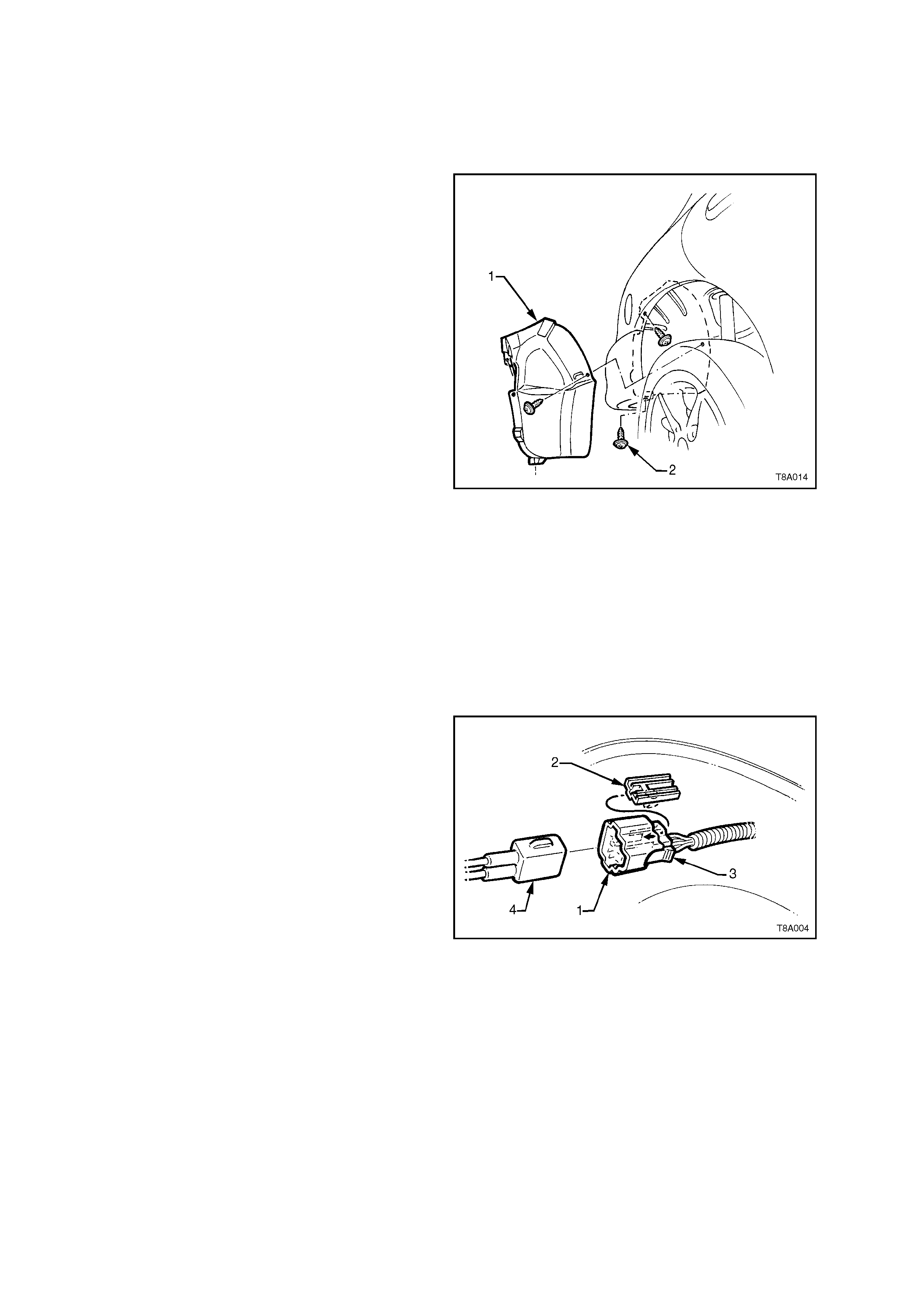
3. Raise vehicle, preferably on a hoist.
4. Remove six right-hand rear wheelhouse liner
retaining screws (2), then remove the
wheelhous e liner ( 1), fr om under the ri ght-hand
rear fender.
Figure 8A-1
5. Remove the fuel sender electrical connector
(1) f rom its mounting f oot (2) b y pulling f orward
to dislodge the assembled connector from the
foot. Once released, depress the locking tab
(3) and separate the connector halves (1 and
4).
6. Place a drain tray under the fuel filter area.
NOTE: Use compressed air to ensure that all dirt
and foreign material is removed from all fuel
connections, before removal.
7. Using special tool number AU533, remove the
quick connect fitting to the vapour canister.
8. Disconnect the vapour canister breather hose
at the canister.
Figure 8A-2
CAUTION: Even though the fuel system may have been de-pressurised, the fuel filter and lines w ill contain
fuel that will be spilled during serv ice operations. T herefore, ensure that no naked flames or other ignition
sources are in the immediate area.
9. For vehicles fitted with the GEN III V8 engine, use special tool number AU533 to remove the fuel feed line
quick connect fitting from the fuel filter. Support the filter during the process.
10. For vehicles fitted with the V6 Supercharged engine, use special tool number AU533 to remove the quick
connect fittings to the return line and fuel filter.
11. For vehicles fitted with the V6 Supercharged engine, use special tool number AU533 to remove the fuel feed
line quick connect fitting.
12. Depress the fuel filter strap tangs on the retainer strap, then remove the filter from the bracket.
13. For vehicl es f itted with with the GEN III V8 en gin e, us e s pec ia l too l n umber AU53 3 to remove t he T-piece q u ick
connect fitting.
14. Remove the fuel filter from the vehicle.
CAUTION: Fuel will spill from the disconnected filter.
Figure 8A-3
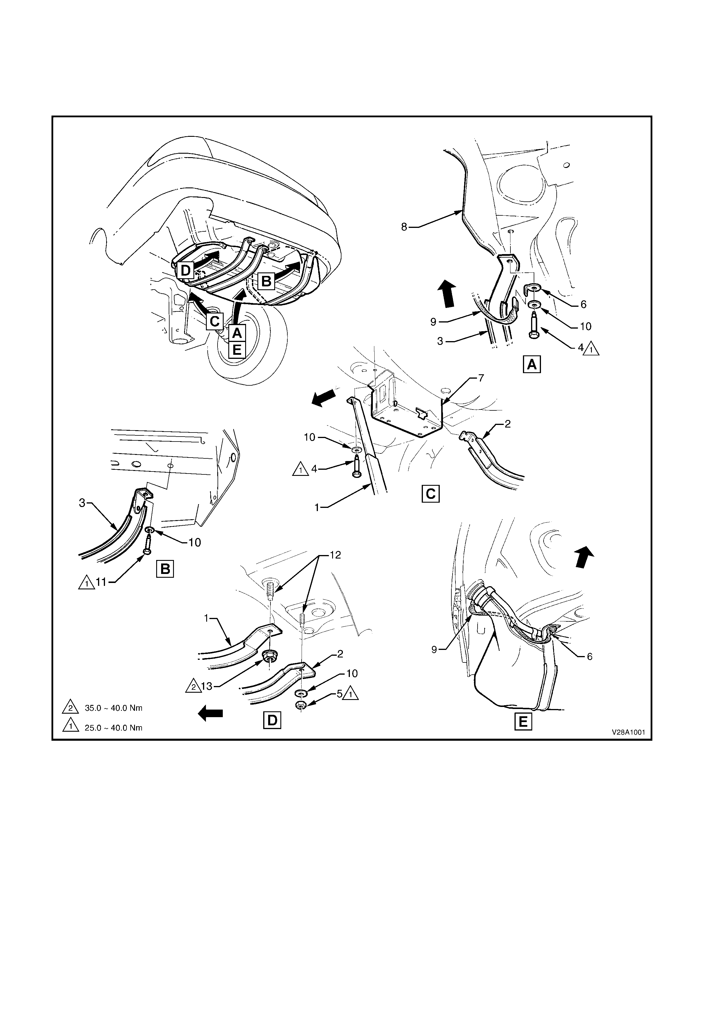
Legend
1. LH fuel tank mounting strap 6. Earth strap spade connector 11. RH strap rear attaching bolt
2. Centre fuel tank mounting strap 7. Final drive support crossmember 12. Fuel tank reinforcement studs
3. RH fuel tank mounting strap 8. RH rear longitudinal extension 13. LH strap rear attaching nut
4. LH strap front attaching bolt 9. Filler neck earth strap
5. Centre strap rear attaching nut 10. Fuel tank strap washer
15. Disconnect the earth strap from the spade connector under the right-hand tank support strap front mounting
bolt.
16. With an assistant supporting the fuel tank in the centre, remove the fuel tank support straps as follows:
a. Remove the centre strap by removing the rear retaining nut and washer, then unhook the strap from the
front support .
b. Remove the right-hand strap, after removing the bolts at the front and rear of the strap.
c. Remove the left-hand strap, after removing the bolt at the front of the strap and the nut at the rear.
17. Lower the fuel tank from the vehicle, left side first, to release the fuel filler neck from the body opening.
REINST ALL
This is the reverse to removal except for the following:
1. Check that the insulation has not become dislodged from the top of the tank.
2. Offer up the fuel neck with the insulator installed, to the body opening, then raise the tank up, into place.
3. Loosely install the two outer fuel tank mounting straps.
4. Check that the filler neck seal is correctly located in the body opening.
5. While pushing th e fuel tank f irml y to the right-hand s ide, tig hten the f ront m ountin g bolt and rear nut f or the lef t-
hand fuel tank mounting strap.
6. Ensuring that the earth strap spade connector is installed, tighten the front bolt for the right-hand fuel tank
mounting strap.
7. Hook the centre fuel tank mounting strap into the front retainer and install the retaining nut and washer.
8. Tighten all strap fasteners to the correct torque specification.
FUEL TANK MOUNTING STRAP
ATTACHING BOLTS AND NUTS (10 mm)
TORQUE SPECIFICATION 25 – 40 Nm
FUEL TANK LEFT HAND MOUNTING
STRAP REAR ATTACHING NUT (12 mm)
TORQUE SPECIFICATION 35 – 40 Nm
9. Assemble the electrical connector, ensuring that both locking tabs are in place. Then engage the assembled
connector to its mounting foot and push rearwards to engage the locking tab.
10. For vehicles fitted with the V6 Supercharged engine, install the disconnected fittings to the fuel filter, canister
and return line, correctly routing components as shown in Figure 8A-4, using the following assembly sequence:
a. Canister vent hose to canister .
b. Fuel vapour return line to canister.
c. Fuel tank vent line to canister.
d. Fuel return line to brake and fuel pipe harness assembly.
e. Fuel lines to the fuel filter.
f. Fuel filter and strap assembly to the filter mounting bracket.
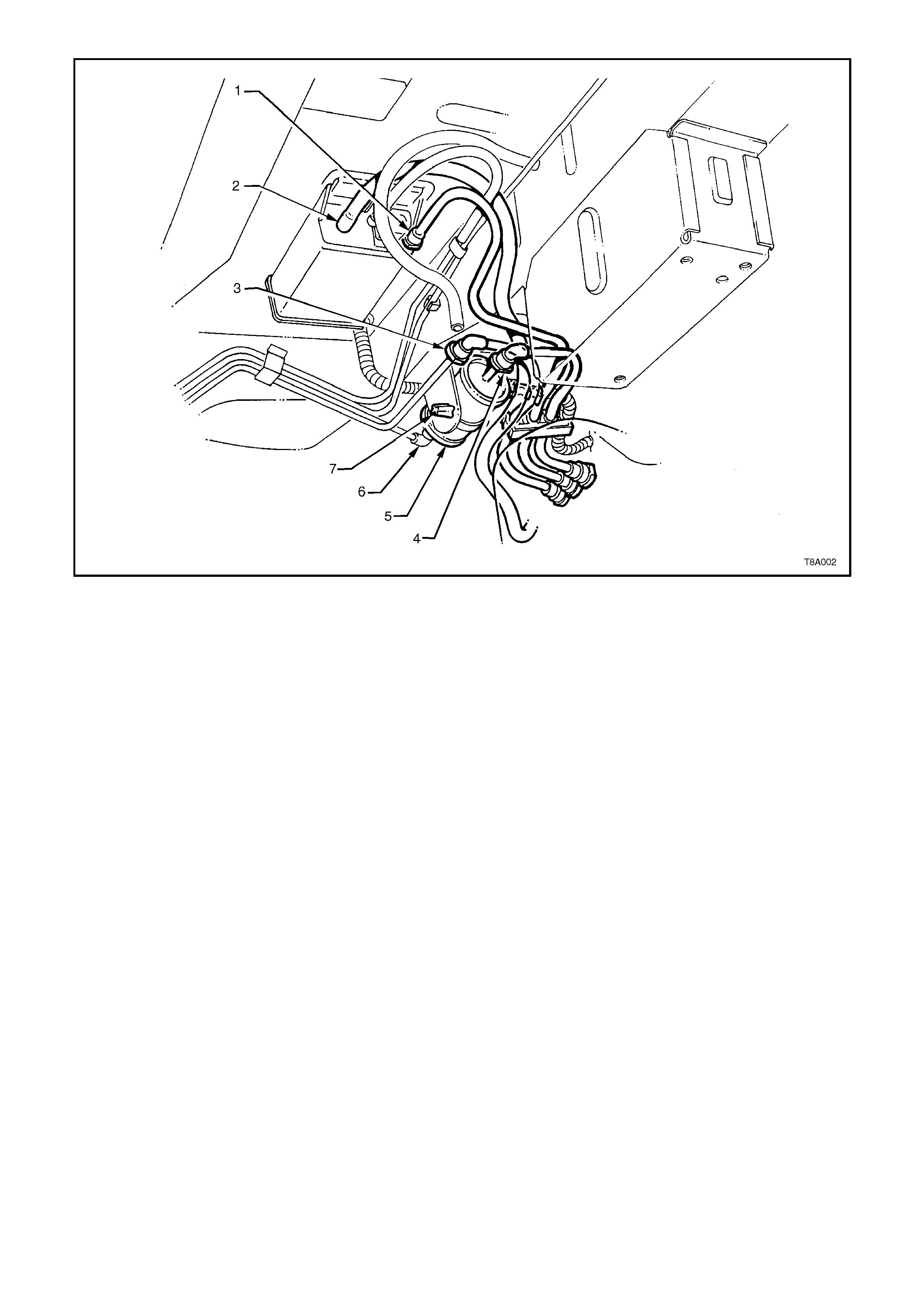
Figure 8A-4
Legend
1. Fuel tank vapour line to canister quick connect 5. Fuel filter
2. Filler neck breather hose 6. Fuel feed pipe to filter quick connect
3. Fuel return line to fuel pipe harness quick connect 7. Fuel filter strap retaining tang
4. Fuel feed flexible line to filter quick connect
11. For vehicles fitted with the GEN III V8 engine, install the disconnected fittings to the fuel filter, canister and
return line, routing correctly, as shown in Figure 8A-5, using the following sequence:
a. Canister vent hose to canister.
b. Fuel tank vent line to canister.
c. Fuel feed line to flexible pipe quick connect.
d. Filter to T-piece quick connect, then filter strap retainer to filter bracket.
e. Fuel filter to fuel feed line quick connect.
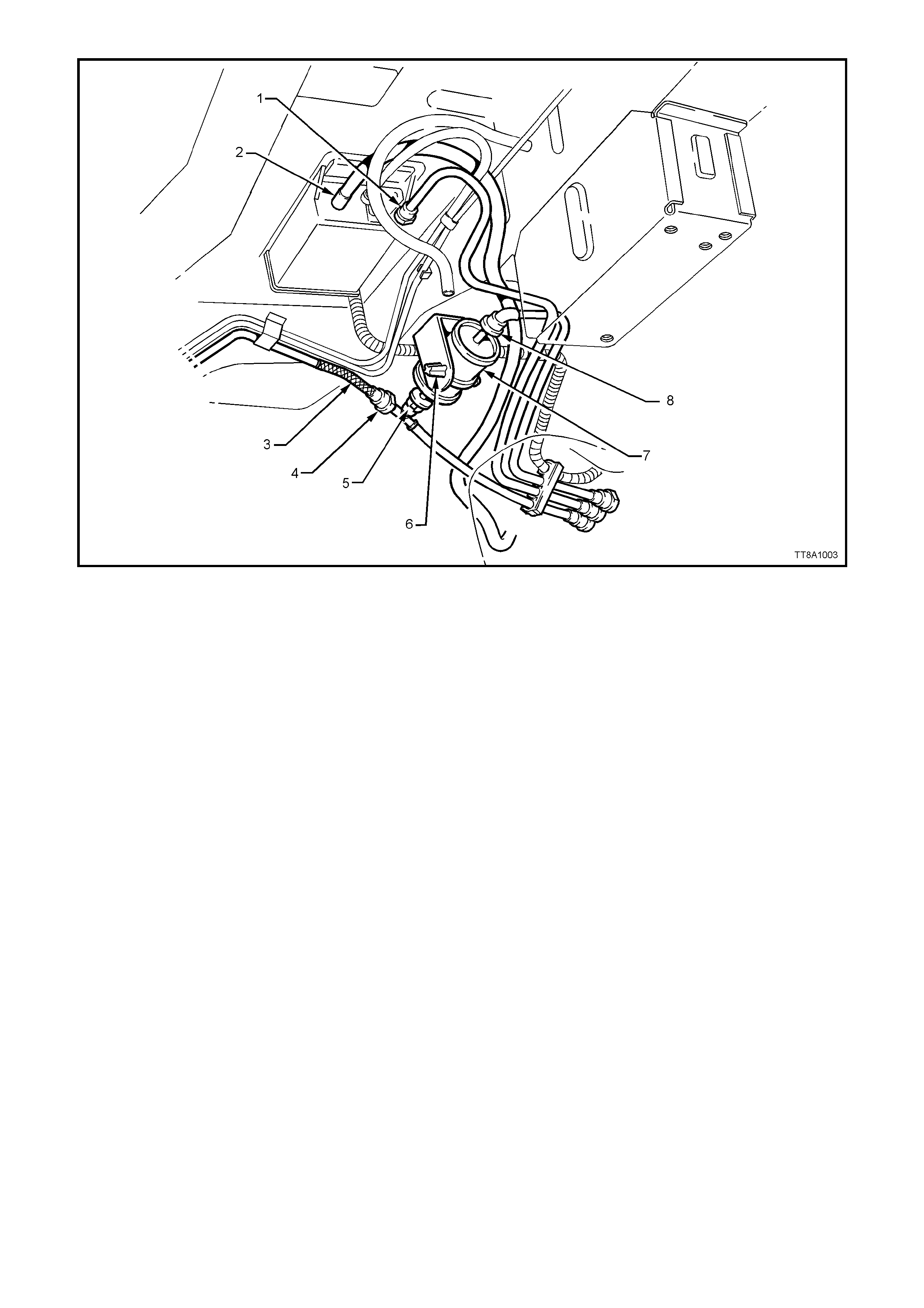
Figure 8A-5
Legend
1. Fuel tank vapour line to canister quick connect 5. Fuel filter T-piece quick connect
2. Filler neck breather hose 6. Fuel filter strap retaining tang
3. Flexible line, fuel feed to engine 7. Fuel filter
4. Fuel feed line quick connect 8. Fuel feed line from fuel tank quick connect
12. Reinstall the stone guard to the right-hand wheel opening, tightening the mounting screws to secure.
13. Before starting the vehicle, carry out a fuel system leak test, refer Section 6C3 POWERTRAIN
MANAGEMENT - GEN III V8 ENGINE or Section 6C1 POWERTRAIN MANAGEMENT – V6
SUPERCHARGED ENGINE in the VX Series I Service Information.


3. TORQUE WRENCH SPECIFIC ATIONS
Nm
Fuel tank mounting strap attaching bolts.............................. 25 - 40
Fuel tank mounting strap attaching nuts (10mm)................. 25 - 40
Fuel tank mounting strap attaching nut (12mm)................... 35 - 40
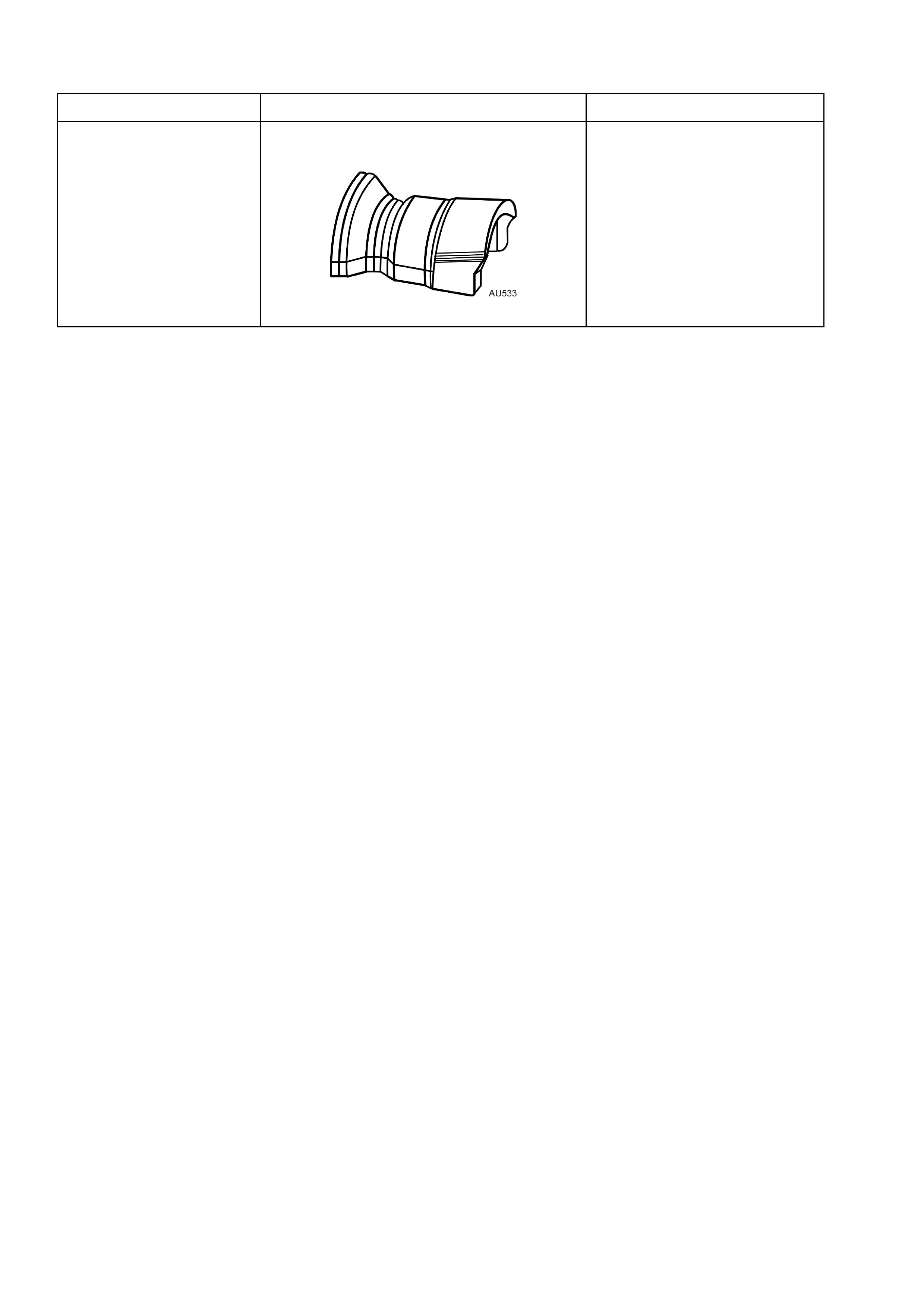
4. SPECIAL TOOLS
TOOL No. REF. IN TEXT TOOL DESCRIPTION COMMENTS
AU533 QUICK CONNECT FITTING RELEASE
TOOL
Released in two sizes;
Red for 5/16” fittings and
Blue for 3/8” fittings.
Also avai lab le com merc ially
under P/N AUSP 45